12.1Предупреждающие сообщения
| Сообщение | Требуемые действия | |
| A | Аккумуляторная батарея разряжена | Необходимо заменить аккумуляторную батарею в течение одного месяца. Свяжитесь с технической службой для замены |
| B | Перегрев генератора рентгеновского излучения: | Нагрузка рентгеновской трубки не соответствует выбранному типу рентгеновской съемки. Подождите пока рентгеновская трубка охладится. |
| C | Установка с системой автоматизированного программирования (САМ): | Ожидайте завершения процедуры инициализации |
| D | Скорректируйте положение кронштейна | Поворотный кронштейн не находится в требуемом положении. Выключите систему и вручную переведите поворотный кронштейн в центральное положение, затем включите систему. |
| E | Ожидайте окончания загрузки ПК | Компьютер не подключен или программное приложение не находится в режиме сбора данных. Запустите программу выполнения рентгеновских снимков на компьютере. |
12.2Сообщения об ошибках
СВЕТОВОЙ ИНДИКАТОР КРАСНОГО ЦВЕТА ТРЕВОГА МЕРЦАЕТ |
Номер ОШИБКИ отображается с мерцающим световым индикатором красного цвета |
 |
Для того чтобы сбросить состояние ошибки, клавишу BACK |
| Сообщение | Требуемые действия | |
| 1 | Опорный сигнал в кВ выходит за пределы диапазона | Выключите установку. Сообщите об этом в службу технического обслуживания. |
| 2 | Опорный сигнал в мА выходит за пределы диапазона | Выключите установку. Сообщите об этом в службу технического обслуживания. |
| 3 | Отказ аналого-цифрового преобразователя вращения каретки | Выключите установку. Сообщите об этом в службу технического обслуживания. |
| 4 | Отказ аналого-цифрового преобразователя перемещения каретки | Выключите установку. Сообщите об этом в службу технического обслуживания. |
| 5 | Отказ датчика вращения каретки | Выключите установку. Сообщите об этом в службу технического обслуживания. |
| 6 | Отказ датчика перемещения каретки | Выключите установку. Сообщите об этом в службу технического обслуживания. |
| 9 | Температура тубуса рентгеновской трубки превысила предельное значение | Подождите, пока рентгеновская трубка охладится |
| 11 | Сеанс рентгеновской съемки прекращен в ходе излучения. | Начните сеанс вновь, если съемку прекратил оператор. Свяжитесь со службой технической поддержки, если прекращение было спонтанным. |
| 12 | Сеанс рентгеновской съемки прекращен перед выполнением облучения. | Начните сеанс вновь, если съемку прекратил оператор. Свяжитесь со службой технической поддержки, если прекращение было спонтанным. |
| 13 | Электропитание 38 В постоянного тока не соответствует установленному диапазону | Выключите установку. Сообщите об этом в службу технического обслуживания. |
| 14 | Электропитание 24 В постоянного тока не соответствует установленному диапазону | Выключите установку. Сообщите об этом в службу технического обслуживания. |
| 15 | Электропитание 15 В постоянного тока не соответствует установленному диапазону | Выключите установку. Сообщите об этом в службу технического обслуживания. |
| 16 | Электропитание 5 В постоянного тока не соответствует установленному диапазону | Выключите установку. Сообщите об этом в службу технического обслуживания. |
| 17 | Отказ высокого напряжения | Выключите установку. Сообщите об этом в службу технического обслуживания. |
| 19 | Превышено время экспозиции | Выключите установку. Сообщите об этом в службу технического обслуживания. |
| 20 | Сеанс рентгеновской съемки прекращен после выполнения облучения. | Свяжитесь со службой технической поддержки, если прекращение было спонтанным. |
| 21 | Отсутствует ток в рентгеновской трубке | Выключите установку. Сообщите об этом в службу технического обслуживания. |
| 23 | Ток накала не соответствует установленному диапазону | Выключите установку. Сообщите об этом в службу технического обслуживания. |
| 25 | Отказ теплового датчика | Выключите установку. Сообщите об этом в службу технического обслуживания. |
| 26 | Отказ аккумуляторной батареи (низкое напряжение) | Выключите установку. Сообщите об этом в службу технического обслуживания. |
| 32 | Отказ блока управления | Выключите установку. Сообщите об этом в службу технического обслуживания. |
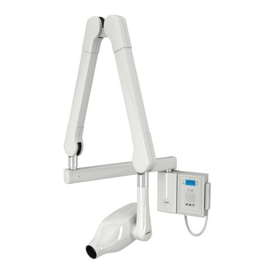
- Manuals
- Brands
- Fona Manuals
- Medical Equipment
- XDC
- Service and instruction manual
-
Contents
-
Table of Contents
-
Bookmarks
Quick Links
FONA XDC
Service and Installation Manual
English
Related Manuals for Fona XDC
Summary of Contents for Fona XDC
-
Page 1
FONA XDC Service and Installation Manual English… -
Page 2
Adult build Upper Incisor Upper cuspid/premolar Upper molar Occlusal Premolar crowns Molar crowns Lower Incisor Lower cuspid/premolar Lower molar New since: 04.2014 Manufactured by FONA S.r.l. Via Galileo Galilei 11 — 20090 Assago (MI) Italy 2/48 69 551 70210 1400409… -
Page 3: Table Of Contents
FONA XDC – Service and Installation Manual Table of contents Introduction 3.5.9 Connecting tube-head and PDCU remote 25 3.5.10 Connecting the Hand-Switch Technical data summary 3.5.11 Optional Remote Hand-Switch Dimensions of wall systems 3.5.12 Final set-up System configurations Installation of mobile system Wall mounted systems 3.6.1…
-
Page 4: Introduction
FONA XDC – Service and Installation Manual 1. Introduction Documentation The accompanying documents supplied with the system include the following docu- ments which are integral parts of the product: FONA XDC Operating Instructions • FONA XDC Service and Installation Manual.
-
Page 5: Dimensions Of Wall Systems
FONA XDC – Service and Installation Manual Dimensions of wall systems 83 cm 32 ⅝” 143 cm with S 30 cm support arm 173 cm with M 60 cm support arm 193 cm with L 90 cm support arm 213 cm with XL 100 cm support arm…
-
Page 6: System Configurations
Support arm XL 100 cm 93 190 17400 Description Code Accessories Cone Extension XDC 10 cm (4”) for 30 cm (12”) SSD 91 190 00010 BLD adaptor 2×3 cm, film size 0 91 190 00030 BLD adaptor 3×4 cm, film size 2…
-
Page 7: Mobile System
Mobile stand XDC 93 190 20080 Description Code Accessories Cone Extension XDC 10 cm (4”) for 30 cm (12”) SSD 91 190 00010 BLD adaptor 2×3 cm, film size 0 91 190 00030 BLD adaptor 3×4 cm, film size 2…
-
Page 8: Accessories
FONA XDC – Service and Installation Manual Accessories Code: Code: 91 190 00030 91 190 00040 BLD adaptor 2×3 cm, BLD adaptor 3×4 cm, film size 0 film size 2 Rectangular adult format of 3.2 x 4.4 cm Rectangular pedo format of 2.2 x 3.2 cm (1-1/4”…
-
Page 9: Spare Parts
FONA XDC – Service and Installation Manual Spare parts Code: Code: 93 190 00140 76 190 30002 Board CPU XDC X-ray hand-switch XDC with coiled cord Code: Code: 76 190 30003 76 190 30004 Control panel XDC Power driver board…
-
Page 10: Layout Of Power Driver Unit
FONA XDC – Service and Installation Manual Layout of power driver unit P- C- P F+ F- output for output for high voltage filament supply to tube-head PE protective earth point Filament supply board Trimmer R104 for filament calibration Trimmer R56…
-
Page 11
FONA XDC – Service and Installation Manual Layout of control unit board Control Unit board Flat cable for local connection to PDCU Connector type RJ45 for remote connection to PDCU Jumper for key lock Connector for remote 2-wire X-ray hand… -
Page 12: Unit In The Treatment Room With Hand
Wire for door contact through the opening at bottom of PDCU Wires for external lights through the opening at bottom of PDCU A Kit of 12 m (40’) supply cables for tube-head XDC is optionally available 12/48 69 551 70210…
-
Page 13: Structural Requirements
FONA XDC – Service and Installation Manual Structural Requirements Useful Reach The wall adaptor has to be mounted in a convenient position on the left or right side of the chair or on the back wall (head of the patient). The useful reach depends on the length of support arm and cone mounted (source skin distance, SSD).
-
Page 14: Electrical Connections
FONA XDC – Service and Installation Manual Electrical connections 3.3.1 Common bolt for earth connection and bonding Lock-washer Bond Lock-washer Bond Metal body Earth provision The earth provision is blocked in place first and blocked in place with lock- •…
-
Page 15: Wiring The Unit With Local Control
FONA XDC – Service and Installation Manual 3.3.3 Wiring the unit with local control It is here considered the case in which the power driver and control unit module (PDCU) is mounted close to the wall adaptor, at one side.
-
Page 16: Wiring The Unit With Remote Control
FONA XDC – Service and Installation Manual 3.3.4 Wiring the unit with remote control It is here considered the case in which the power driver and control unit module (PDCU) is mounted remotely, far from the wall adaptor. Scissor Support…
-
Page 17: Optional Items
FONA XDC – Service and Installation Manual Optional Items 3.4.1 Optional door contact and second enable A block is available on the PDCU main board for connection of the door contact, to prevent X-ray radiation with door open. The unit is provided with two jumpers in place which have to be removed to connect two door contacts, and conversely they have to stay in place if the two door contacts are not used.
-
Page 18: Optional Board For External Lights
FONA XDC – Service and Installation Manual 3.4.3 Optional board for external lights A. An optional board to be mounted on the power driver module (PDCU) is available to handle two ex- ternal warning lights: a. Connect the board on connectors J2 and X10.
-
Page 19: Installation Of Wall System
FONA XDC – Service and Installation Manual Installation of wall system 3.5.1 Mounting the wall adaptor A. Open the packaging box paying attention not to dam- age the internal items. Risk of scratching. Avoid the use of a cutter not to damage the plastic cover.
-
Page 20: Mounting The Pdcu
FONA XDC – Service and Installation Manual 3.5.2 Mounting the PDCU A. Use the mounting plate or the drill template to mark the holes on the wall. B. Take apart the control panel removing the screw at bottom. Pay attention when disconnecting the flat ca- ble of the control panel from the power board.
-
Page 21: Mounting The Scissor Arm
FONA XDC – Service and Installation Manual 3.5.4 Mounting the Scissor Arm Handling Risk of injury. The compressed springs in the scissor arm may cause injury to the installer as well as damage to the arm itself if the arm is not handled properly.
-
Page 22: Mounting And Connecting The X-Ray Head
FONA XDC – Service and Installation Manual 3.5.5 Mounting and Connecting the X-ray Head PE protective Retaining fork earth point in this position A. Remove the retaining fork from the arm shaft. B. Remove the plastic cover from the yoke of the tube head and slide it into the arm shaft passing the cable through, then hold it in place with the retaining fork.
-
Page 23: Connecting The Pdcu To The Mains Line
FONA XDC – Service and Installation Manual 3.5.7 Connecting the PDCU to the mains line PE protective earth point Input mains supply line L (live) & N (neutral) Safety nylon tie strip Mains switch Input D. The terminal block to consider is the one at bottom close to the mains switch, from the mains line holding 2 positions for live (L) and neutral (N) conductors.
-
Page 24: Connecting The Pdcu To The Tube-Head With Wa At Side
FONA XDC – Service and Installation Manual 3.5.8 Connecting the PDCU to the tube-head with WA at side PE protective Output F+ & F- earth point for filament supply Output P-C-P for high voltage to tube-head Protective earth PE point on wall adaptor…
-
Page 25: Connecting Tube-Head And Pdcu Remote
Connecting tube-head and PDCU remote A. Turn the line voltage supply switch of the equipment and of the room “OFF”. B. Use the kit of supply cables for tube-head XDC, optionally provided, which in- cludes the following: a. Cable for high voltage supply. 12 m maximum 3xAWG18 shielded cable to…
-
Page 26: Connecting The Hand-Switch
FONA XDC – Service and Installation Manual 3.5.10 Connecting the Hand-Switch The hand-switch is provided with a 3 m coiled cord with two terminations to be plugged in the body of the hand-switch and in the connector J7 at bottom of the power driver and control unit (PDCU).
-
Page 27: Installation Of Mobile System
FONA XDC – Service and Installation Manual Installation of mobile system 3.6.1 Assembling the Mobile Stand A. Mount the legs under the central base. B. Mount the four wheels with brakes. Attach the pole with the PDCU mounting plate. D. Complete the stand with: a.
-
Page 28: Connecting The Pdcu
FONA XDC – Service and Installation Manual 3.6.5 Connecting the PDCU Input A. Connect the protective earth provision to the PE point at bottom right and block from the mains line in place with lock-washer and nut. B. Connect the live (L) and neutral (N) wires to the mains input block at bottom centre of the PDCU board.
-
Page 29: Service
In case a fuse blows the PDCU board is out of order and must be replaced with a good one. Arrangement have to be made with FONA to return the board for its repair or to purchase a new one.
-
Page 30: Xdc Test Jig
FONA XDC – Service and Installation Manual XDC test JIG A tool is provided to support the meas- To arm connector urement of filament voltage and of the an- ode current. It has to be connected between the tube head and the arm cable.
-
Page 31: Replacement Of Tube-Head Xdc
FONA XDC – Service and Installation Manual Replacement of tube-head XDC Risk of injury. The compressed springs in the WARNING scissor arm may cause injury to the installer as well as damage to the arm itself if the arm is not handled properly.
-
Page 32
Q. In case it is not possible to calibrate the unit with values in the specified ranges put the unit out of service and call for technical assistance. End of tube-head re- R. Disconnect the XDC testing JIG and connect the arm to the tube-head directly. placement S. Perform one exposure to verify proper connection. -
Page 33: Replacement Of Pdcu
End of replacement of O. Disconnect the XDC testing JIG and connect the arm to the tube-head directly. power board of PDCU P. Put back the plastic cover on the tube head joint and the one with control panel.
-
Page 34: Replacement Of Mains Cable
FONA XDC – Service and Installation Manual Replacement of mains cable The mains supply cord which is used on the mobile unit is a three core cable size AWG16 for mains connection. Proceed as indicated for proper replacement: Removing old cord A.
-
Page 35: Maintenance
A. Verify that all labels are in place and legible. B. Note. The warning label on the control panel is applicable for USA only. C. Defaced labels must be replaced. Order same from FONA in writing stating: a. Customer name and address.
-
Page 36: Maintenance Of Wall Adaptor
FONA XDC – Service and Installation Manual Maintenance of wall adaptor Layout of 21 disk springs in friction screw 7 groups of 3 A. Remove the cover (screw under the unit) and verify that the mounting fully adheres to the wall and remains stable and firmly fixed during han- dling of the system.
-
Page 37
FONA XDC – Service and Installation Manual 2nd arm’s section spring tun- ing point Allen key 6 mm Friction point 4 Friction point 3 Friction point 2 1st arm’s section spring tuning point Allen key 6 mm Recommended tools: 6 mm Allen key flexi-… -
Page 38: Maintenance Of X-Ray Head
FONA XDC – Service and Installation Manual Maintenance of X-ray Head Mechanical safety screw blocked 2.5 mm Allen Layout of 8 disk springs in each friction screw: 4 groups of 2 Friction screw 2.5 mm Allen A. Inspect for damages to the X-ray head and its support system.
-
Page 39: Maintenance Of The Control Unit
FONA XDC – Service and Installation Manual Maintenance of the control unit Turning System ON A. Turn the unit ON with mains switch (A) and verify that the green light (B) indi- cating system ready turns ON at the end of the initialization procedure.
-
Page 40: Mechanical Checks
FONA XDC – Service and Installation Manual Mechanical checks The examination to the mechanical parts of the system is divided in checks to be planned during the periodic inspection and activities to be carried out during preven- tive maintenance to be scheduled as recommended.
-
Page 41: Tube Current Verification
B. Remove the plastic covers of the tube head joint. C. Mount the XDC test JIG for the measurement of filament supply voltage and an- ode current with a serial connection of the connectors of the supply cable to the tube head.
-
Page 42: Exposure Time And Kv Verification
FONA XDC – Service and Installation Manual 5.11 Exposure Time and kV verification A. In order to verify the exposure time and to measure the kV level a non invasive Non invasive kV and time meter is used. kV and time meter…
-
Page 43: Radiation Dose Assessment
FONA XDC – Service and Installation Manual 5.12 Radiation dose assessment A. Use a dose meter to verify the dose emitted. Dose meter Warning Risk wrong measurement Measurements have to be done by trained personnel only It is recommended to place the radiation detector at 50 cm (20”) or at 71 cm (28”)
-
Page 44: Reporting
FONA XDC – Service and Installation Manual 6. Reporting The checklist forms for the servicing of the unit are provided in the following: FONA XDC Installation Report, to document proper assembly and installation. • FONA XDC Checklist for Yearly Inspection, covering activities performed periodi- •…
-
Page 45: Periodic Inspection And Preventive Maintenance Report
FONA XDC – Service and Installation Manual Periodic inspection and preventive maintenance report Schedule The FONA XDC unit is a maintenance free equipment, requiring little or no mainte- nance, for which the following activities are recommended: General inspections, by the operator, to be performed every year.
-
Page 46
FONA XDC INSTALLATION REPORT Customer: Dealer: Serial number Date of installation: Tube housing Report of assembly assembly (THA) FDA 2579 # Power Driver and control Unit (PDCU) TEST INSTRUMENTATION Manufacturer Model Accuracy Last calibrated AC /DC Voltmeter kV and time meter… -
Page 47
FONA XDC CHECKLIST for YEARLY INSPECTION Customer: Dealer: Serial number Date of installation: Tube housing Report of assembly assembly (THA) FDA 2579 # Power Driver and control Unit (PDCU) TEST INSTRUMENTATION Manufacturer Model Accuracy Last calibrated AC /DC Voltmeter kV and time meter… -
Page 48
We reserve the right to make any alterations which may be required due to clinical improvements FONA XDC Service and Installation Manual – English Edition 140409 *6955170210* FONA Dental s.r.o. FONA S.r.l. Stefanikova 7 SK-811 06 Via Galileo Galilei 11…
-
#1
Уважаемые, нужен Ваш совет. Заказал новую печь Unox XFT 135 Ariana из Москвы ( находимся на Сахалине). После установки и запуска на дисплее вышла ошибка A02 (на других моделях AF02) (неисправность термостата безопасности), хотя печь абсолютно новая. Прочитав инструкцию по устранению указанной неполадки пришел к выводу, что скорее всего, раз уж печь новая, термостат не правильно подключён. Подскажите где он находится или как выглядит. Разобрал заднюю часть панели, но боюсь ошибиться.
Если есть у кого другие мысли по этому поводу просьба поделиться.
Спасибо
-

image.png
100,7 KB · Просмотры: 408
-
#2
Сбросить ошибку пробовал? Держишь нажатой кнопку Р 6 сек, отпускаешь и кратковременно еще раз нажимаешь. А термостат безопасности скорее всего на плате мощности.

-
#3
А что говорят те, у кого купили эту печку? Она же на гарантии
-
#4
Уважаемые, нужен Ваш совет. Заказал новую печь Unox XFT 135 Ariana из Москвы ( находимся на Сахалине). После установки и запуска на дисплее вышла ошибка A02 (на других моделях AF02) (неисправность термостата безопасности), хотя печь абсолютно новая. Прочитав инструкцию по устранению указанной неполадки пришел к выводу, что скорее всего, раз уж печь новая, термостат не правильно подключён. Подскажите где он находится или как выглядит. Разобрал заднюю часть панели, но боюсь ошибиться.
Если есть у кого другие мысли по этому поводу просьба поделиться.
Спасибо
На Сахалине еще остались места , где 110 Вольт ? )
-
#5
Причем тут 110вольт? Он же на 220 вроде бы. А 110 вольт на караблях есть до сих пор, две фазы по 110 берете и получаете 220
-
#6
Причем тут 110вольт? Он же на 220 вроде бы. А 110 вольт на караблях есть до сих пор, две фазы по 110 берете и получаете 220
Он то да ( на 220 вольт ) , но в тех местах = Сахалин , Камчатка , еще с советских времен есть места , где 110 вольт , как раньше в электробритвах было .
-
#7
Уважаемые, нужен Ваш совет. Заказал новую печь Unox XFT 135 Ariana из Москвы ( находимся на Сахалине). После установки и запуска на дисплее вышла ошибка A02 (на других моделях AF02) (неисправность термостата безопасности), хотя печь абсолютно новая. Прочитав инструкцию по устранению указанной неполадки пришел к выводу, что скорее всего, раз уж печь новая, термостат не правильно подключён. Подскажите где он находится или как выглядит. Разобрал заднюю часть панели, но боюсь ошибиться.
Если есть у кого другие мысли по этому поводу просьба поделиться.
Спасибо
С Юноксом данной модели встречаться не приходилось, но на других термостата как такового нет. В камере стоят два одинаковых датчика, по одному из которых контроллер определяет аварийное превышение температуры. На правой боковой стенке внизу есть пластмассовая вставка со шторкой. Под ней кнопка и разъём RJ45. Если всё так и есть, то алгоритм сброса таков: включаем печь. Как только на индикаторе высветилась ошибка, ничего больше не трогая сдвигаем вверх шторку и нажимаем кнопку на время более шести секунд. Затем нажимаем кнопку «Р» на панели для сброса показаний индикатора. Далее опробуем печь на работоспособность. Если не получилось, делаем всё вышеперечисленное ещё раз, но по окончании обесточиваем печь на время не менее двадцати секунд. Да, и обследуйте сами датчики визуально на предмет повреждений.
-
#8
Попадалась (пару раз) мне с новья печурка с защитным термостатом в состоянии «авария по превышению температуры». Нажал кнопку, дальше все как обычно — работают по сей день без проблем. У Унокса, задняя стенка разделена на 2 части. Нижняя малая часть скрывает собой (в зависимости от модели) плату, контакторы, таймер и термостат. На вашей модели не помню как выглядит доступ к кнопке этого термостата, но найти его будет не большой проблемой, если знаете как обычно выглядят такого рода устройства. Если не найдете на внешней стороне доступа к кнопке — снимите верхнюю часть задней стенки и загляните внутрь. Внутри поищите такие устройства:


у некоторых из них, кнопка скрыта под пластиковым или резиновым колпачком.
-
#9
Доброго времени суток. Такая проблема попадалась с Unox XFT 135 Ariana. В нижней части задней стенке посмотрите, должен быть резиновый колпачек. У меня был черного цвета. Под ним кнопка. Нажмите на него и все должно заработать. У меня так и получилось.
-
#10
@easy Вы не подскажете название термостата (самая большая картинка)?
-
#11
@easy Вы не подскажете название термостата (самая большая картинка)?
Это аварийный термостат 3-х фазный , а если в поисковике » забить «код , который на фотографии , можно узнать больше )
-
#12
«Названия» не знаю. Как написано выше — термостат аварийный (или защитный).
-
#13
На одних уноксах кнопка аварийного термостата расположена с правого боку (смотреть ему в лицо) с низу.
На более новых уноксах ошибка A02 или AF02 хоть и расшифровывается как ошибка по аварийному термостату, но сброс ее производится с панели управления удержанием кнопки P 6 сек.
Если по кнопке P ошибка не сбрасывается, то проблема в силовой плате управления. Могли погореть дорожки из-за дуги, зажженной противо-эдс нескольких контакторов, а также электроники (оптопара о четырех ногах, микросхемы), что тянет следом. Мы с такие проблемы решаем. Обращайтесь в лс.
-
#14
На одних уноксах кнопка аварийного термостата расположена с правого боку …
кстати да, попадалась мне как-то печь с аварийным термостатом расположенным между теплоизоляцией духовки и правой стенкой. Модель печи не помню, но она точно была с механическим управлением. Чтоб добраться до этого аварийника, пришлось мою худую руку изогнуть неестественным образом, протискиваясь меж деталей установленных за передней панелью. И это был как раз один из случаев, когда на новой печи аварийник «сработавший».
-
#15
кстати да, попадалась мне как-то печь с аварийным термостатом расположенным между теплоизоляцией духовки и правой стенкой. Модель печи не помню, но она точно была с механическим управлением. Чтоб добраться до этого аварийника, пришлось мою худую руку изогнуть неестественным образом, протискиваясь меж деталей установленных за передней панелью. И это был как раз один из случаев, когда на новой печи аварийник «сработавший».
Аварийки » сработавшие » идут и на УНОКСах и на ПИРОНах ( механика ), это на заводе так делают специально , что бы монтаж не производили простые электрики и прочие «специалисты «.
-
#16
Против этой теории говорит то, что они не все такие, а «через один».
-
#17
Против этой теории говорит то, что они не все такие, а «через один».
")
Наша страна не входит в состав ЕС ( и таможня работает по разному ) , нам и через один хорошо 
-
#18
Аварийки » сработавшие » идут и на УНОКСах и на ПИРОНах ( механика ), это на заводе так делают специально , что бы монтаж не производили простые электрики и прочие «специалисты «.
Или на морозе аппарат побывал
-
#19
Или на морозе аппарат побывал
Я бы добавил от себя : » побывал однозначно » , т.к теплых складов мало у кого есть «. Не модно это , да и не выгодно.
Последнее редактирование: 31 Май 2016