12 Troubleshooting
12-3 Errors
If the Servo Drive detects an abnormality, it outputs an error (/ERR), turns OFF the power drive circuit,
and displays the error number (main and sub) on the front panel.
Precautions for Correct Use
• Refer to 12-5-1 Troubleshooting Using Error Displays on page 12-14 for information on trou-
bleshooting.
• You can reset the error by turning OFF the power supply and then ON again, or executing the
error reset command via EtherCAT communications or on the Sysmac Studio. Be sure to
remove the cause of the error first.
• Some errors are reset only by turning the power supply OFF then ON again. For details, refer
to 12-3-1 Error List on page 12-10.
• If nothing is displayed on the 7-segment display even when the control power supply is ON, it
indicates that the internal MPU is malfunctioning. If you find this symptom, cut off the power
supply immediately.
12-3-1 Error List
Error No.
Main
Sub
(hex)
(hex)
12
00
13
00
01
14
00
01
15
00
01
16
00
18
00
02
20
00
21
00
01
24
00
01
26
00
27
01
28
00
01
29
03
33
00
09
34
01
35
00
01
02
36
00
12 — 10
AC Servomotors/Servo Drives 1S-series with Built-in EtherCAT® Communications User’s Manual (I586)
Error name
Overvoltage Error
Main Power Supply Undervoltage (insufficient voltage
between P and N)
Main Circuit Power Supply Phase Loss Error
Overcurrent Error
Power Module Error
Servo Drive Overheat
Motor Overheat Error
Overload Error
Regeneration Overload Error
Regeneration Processing Error
*3
Runaway Detected
Encoder Communications Disconnection Error
Encoder Communications Error
Excessive Position Deviation Error
Excessive Speed Deviation Error
Excessive Speed Error
Absolute Value Cleared
Pulse Output Overspeed Error
Pulse Output Setting Error
Following Error Counter Overflow
General Input Allocation Duplicate Error
General Output Allocation Duplicate Error
Software Limit Exceeded
FPGA WDT Error
System Error
Self-diagnosis Error
Non-volatile Memory Data Error
Attribute
Can be
Deceleration
*1
*2
reset
operation
—
B
Yes
B
Yes
B
—
B
—
B
Yes
B
Yes
B
Yes
B
—
B
—
B
—
B
—
B
—
B
Yes
A
Yes
A
Yes
A
—
B
Yes
A
—
A
—
B
—
A
—
A
Yes
A
—
B
—
B
—
B
—
A
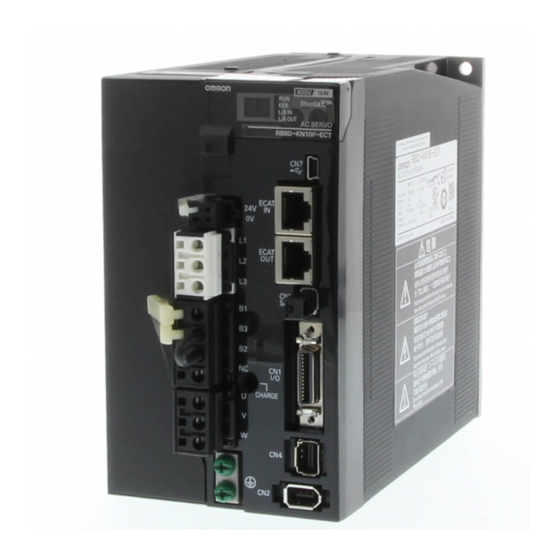
-
Contents
-
Table of Contents
-
Troubleshooting
-
Bookmarks
Quick Links
AC SERVO DRIVES
G5-series WITH BUILT-IN
EtherCAT COMMUNICATIONS
Linear Motor Type
User’s Manual
R88D-KN -ECT-L (AC Servo Drives)
I577-E1-01
Related Manuals for Omron R88D-KN series
Summary of Contents for Omron R88D-KN series
-
Page 1
AC SERVO DRIVES G5-series WITH BUILT-IN EtherCAT COMMUNICATIONS Linear Motor Type User’s Manual R88D-KN -ECT-L (AC Servo Drives) I577-E1-01… -
Page 2
OMRON. No patent liability is assumed with respect to the use of the information contained herein. Moreover, because OMRON is constantly striving to improve its high-quality products, the information contained in this manual is subject to change without notice. -
Page 3: Introduction
Introduction Introduction Thank you for purchasing a G5-series Servo Drive. This manual explains how to install and wire the Servo Drive, set parameters needed to operate the Servo Drive, and remedies to be taken and inspection methods to be used should problems occur. Intended Readers This manual is intended for the following individuals.
-
Page 4: Structure Of This Document
Structure of This Document Structure of This Document This manual consists of the following sections. Outline Section 1 Features and This section explains the features of the Servo Drive, and name of System each part. Configuration Section 2 Models and This section explains the models of Servo Drives and peripheral External equipment, and provides the external dimensions and mounting…
-
Page 5: Manual Structure
Manual Structure Manual Structure Page Structure and Symbol Icons The following page structure and symbol icons are used in this manual. Level 1 heading 11 Adjustment Functions 11-8 Disturbance Observer Function Level 2 heading You can use the disturbance force value estimated with the disturbance observer to lower the effect of the disturbance force and reduce vibration.
-
Page 6
Terms and Expressions Used for the Linear Motor In this manual, the term «Linear Motor» is defined as an OMRON product that consists of a Motor Coil Unit (the coil on the primary side) and a Magnet Trac (the magnet on the secondary side). -
Page 7: Sections In This Manual
Sections in this Manual Sections in this Manual Features and System Operation Configuration Models and Adjustment Functions External Dimensions Troubleshooting and Specifications Maintenance System Design Appendicies EtherCAT Index Communications Basic Control Functions Applied Functions Safety Function Details on Servo Parameter Objects G5 Series AC Servo Drives With Built-in EtherCAT Communications, Linear Motor Type…
-
Page 8: Table Of Contents
CONTENTS CONTENTS Introduction ………………….. 1 Structure of This Document ………………2 Manual Structure ………………….. 3 Sections in this Manual ……………….. 5 CONTENTS …………………… 6 Read and Understand this Manual ……………. 12 Safety Precautions ………………..15 Regulations and Standards………………22 Items to Check after Unpacking…………….24 Revision History ………………….
-
Page 9: Contents
CONTENTS 3-1-2 Characteristics ……………………..3-2 3-1-3 EtherCAT Communications Specifications …………….. 3-5 3-1-4 EtherCAT Communications Connector Specifications (RJ45) ………… 3-5 3-1-5 Control I/O Specifications (CN1)………………..3-6 3-1-6 Control Input Circuits ……………………3-9 3-1-7 Control Input Details ……………………3-9 3-1-8 Control Output Circuits ………………….3-11 3-1-9 Control Output Details ………………….
-
Page 10
6-4-3 Controlword (6040 hex) in Profile Position Mode …………..6-14 6-4-4 Statusword (6041 hex) in Profile Position Mode……………. 6-14 Homing Mode ……………………. 6-15 Connecting with OMRON Controllers ……………… 6-16 Section 7 Applied Functions Sequence I/O Signals ………………….7-2 7-1-1 Input Signals ……………………..7-2 7-1-2 Output Signals…………………….. -
Page 11
CONTENTS 7-9-4 Position Gain Switching Time (3119 Hex) …………….7-36 7-10 Gain Switching 3 Function ………………..7-37 7-10-1 Operating Conditions …………………… 7-37 7-10-2 Objects Requiring Settings ………………….. 7-37 7-10-3 Operation Example ……………………7-37 7-11 Touch Probe Function (Latch Function)…………….7-39 7-11-1 Objects Requiring Settings ………………….. -
Page 12
CONTENTS 11-3-1 Operationg Conditions ………………….11-7 11-3-2 Objects Requiring Settings ………………….. 11-8 11-3-3 Setting Realtime Autotuning…………………. 11-9 11-3-4 Setting Machine Rigidity………………….11-9 11-3-5 Objects to be Changed ………………….11-12 11-4 Manual Tuning……………………11-14 11-4-1 Preparation for Manual Tuning ………………..11-14 11-5 Damping Control…………………… -
Page 13
CONTENTS A-1-1 Controlling the State Machine of the Servo Drive…………… A-2 A-1-2 Modes of Operation ……………………A-4 A-1-3 Communications Cycles and Corresponding Modes of Operation ……….A-5 A-1-4 Modes of Operation and Applied Functions…………….A-6 A-1-5 Changing the Mode of Operation………………..A-7 A-1-6 Homing Mode Specifications ……………….. -
Page 14: Read And Understand This Manual
PROFITS OR COMMERCIAL LOSS IN ANY WAY CONNECTED WITH THE PRODUCTS, WHETHER SUCH CLAIM IS BASED ON CONTRACT, WARRANTY, NEGLIGENCE, OR STRICT LIABILITY. In no event shall the responsibility of OMRON for any act exceed the individual price of the product on which liability is asserted.
-
Page 15
Application Considerations SUITABILITY FOR USE OMRON shall not be responsible for conformity with any standards, codes, or regulations that apply to the combination of products in the customer’s application or use of the products. At the customer’s request, OMRON will provide applicable third party certification documents identifying ratings and limitations of use that apply to the products. -
Page 16
Performance data given in this manual is provided as a guide for the user in determining suitability and does not constitute a warranty. It may represent the result of OMRON’s test conditions, and the users must correlate it to actual application requirements. Actual performance is subject to the OMRON Warranty and Limitations of Liability. -
Page 17: Safety Precautions
Safety Precautions Safety Precautions To ensure that the G5-series Servo Drive as well as peripheral equipment are used safely and correctly, be sure to read this Safety Precautions section and the main text before using the product. Learn all items you should know before use, regarding the equipment as well as the required safety information and precautions.
-
Page 18
When using this product, be sure to install the covers and shields as specified and use the product according to this manual. • If the product has been stored for an extended period of time, contact your OMRON sales representative. DANGER Be sure to ground the frame ground terminals of the Servo Drive and Servomotor to 100 … -
Page 19
Safety Precautions DANGER Install a stopping device on the machine to ensure safety. * The holding brake is not a stopping device to ensure safety. Injury may result. Install an immediate stop device externally to the machine so that the operation can be stopped and the power supply cut off immediately. -
Page 20
Safety Precautions Caution The Servo Drive radiator, Regeneration Resistor, Servomotor, etc., may become hot while the power is supplied or remain hot for a while even after the power supply is cut off. Never touch these components. A burn injury may result. Use the Servomotor and Servo Drive in a specified combination. -
Page 21
Safety Precautions Installation and Wiring Caution Do not block the intake or exhaust openings. Do not allow foreign objects to enter the Servo Drive. Fire may result. Provide the specified clearance between the Servo Drive and the inner surface of the control panel or other equipment. -
Page 22
Safety Precautions Operation and Adjustment Caution If the Servo Drive fails, cut off the power supply to the Servo Drive at the power supply. Fire may result. Conduct a test operation after confirming that the equipment is not affected. Equipment damage may result. Before operating the Servo Drive in an actual environment, check if it operates correctly based on the parameters and switches you have set. -
Page 23
Safety Precautions Location of Warning Label The Servo Drive bears a warning label at the following location to provide handling warnings. When handling the Servo Drive, be sure to observe the instructions provided on this label. Warning label display location (R88D-KN02H-ECT-L) Instructions on Warning Label Disposal… -
Page 24: Regulations And Standards
Regulations and Standards Regulations and Standards To export (or provide to nonresident aliens) any part of this product that falls under the category of goods (or technologies) for which an export certificate or license is mandatory according to the Foreign Exchange and Foreign Trade Control Law of Japan, an export certificate or license (or service transaction approval) according to this law is required.
-
Page 25
Regulations and Standards Trademarks • Sysmac and SYSMAC are trademarks or registered trademarks of OMRON Corporation in Japan and other countries for OMRON factory automation products. ® • EtherCAT is registered trademark and patented technology, licensed by Beckhoff Automation GmbH, Germany. -
Page 26: Items To Check After Unpacking
They must be prepared by the customer. • If any item is missing or a problem is found such as Servo Drive damage, contact the OMRON dealer or sales office where you purchased your product.
-
Page 27: Revision History
Revision History Revision History The manual revision code is a number appended to the end of the catalog number found in the bottom left-hand corner of the front or back cover. Example I577-E1-01 Cat. No. Revision code Revision Revision Date Revised content code October 2011…
-
Page 28
Revision History G5 Series AC Servo Drives With Built-in EtherCAT Communications, Linear Motor Type… -
Page 29: Features And System Configuration
Features and System Configuration This section explains the features of the Servo Drive and name of each part. 1-1 Outline …………1-2 1-1-1 Features of G5-series Servo Drives .
-
Page 30: Outline
Motor Type is designed to provide optimal functionality and ease of use when used in conjunction with a Machine Automation Controller such as NJ series and the automation software Sysmac Studio. *1 Sysmac Device is a generic term for OMRON control devices such as an EtherCAT Slave, designed with unified communications specifications and user interface specifications.
-
Page 31: What Is Ethercat
Definitions of variables that can be used by all servers for designated communications. 2000 to 2FFF hex Manufacturer Specific Area 1 Variables with common definitions for all OMRON products. 3000 to 5FFF hex Manufacturer Specific Area 2 Variables with common definitions for all G5-series Servo Drives (servo parameters).
-
Page 32: System Configuration
1 Features and System Configuration System Configuration The system configuration for a G5-Series AC Servo Drive with Built-in EtherCAT Communications, Linear Motor Type is shown below. Controller (EtherCAT (EtherCAT) ) EtherCAT NJ-series Machine Automation Controller G5 Series AC Servo Drive R88D-KN -ECT-L Programmable Controller Position Control Unit…
-
Page 33: Names And Functions
1 Features and System Configuration Names and Functions This section describes the names and functions of Servo Drive parts. 1-3-1 Servo Drive Part Names The Servo Drive part names are given below. EtherCAT status indicators Seven-segment display Analog monitor connector (CN5) Rotary switches for node address setting USB connector (CN7)
-
Page 34: Servo Drive Functions
1 Features and System Configuration 1-3-2 Servo Drive Functions The functions of each part are described below. Display A 2-digit 7-segment display shows the node address, error codes, and other Servo Drive status. Charge Lamp Lights when the main circuit power supply is turned ON. EtherCAT Status Indicators These indicators show the status of EtherCAT communications.
-
Page 35: System Block Diagram
1 Features and System Configuration System Block Diagram This is the block diagram of the G5-series AC Servo Drive with Built-in EtherCAT Communications, Linear Motor Type. R88D-KN01L-ECT-L/-KN02L-ECT-L/-KN04L-ECT-L/ R88D-KN01H-ECT-L/-KN02H-ECT-L/-KN04H-ECT-L/-KN08H-ECT-L CN A CN B FUSE FUSE − Voltage detection FUSE − SW power 15 V Relay…
-
Page 36
1 Features and System Configuration R88D-KN10H-ECT-L/-KN15H-ECT-L/-KN20H-ECT-L CN B CN A FUSE Internal Regeneration Resistor FUSE − Voltage detection FUSE − SW power 15 V Relay Regeneration Overcurrent Current detection supply main Gate drive drive control detection circuit control 3.3 V Display and Internal 2.5 V… -
Page 37
1 Features and System Configuration R88D-KN30H-ECT-L/-KN50H-ECT-L FUSE Internal Regeneration Resistor FUSE Voltage detection FUSE SW power supply Overcurrent Relay Regeneration Current detection Gate drive main circuit detection drive control control 3.3V Internal 2.5V Display and MPU & ASIC setting circuit 1.5V control area… -
Page 38
1 Features and System Configuration R88D-KN75H-ECT-L FUSE Fuse FUSE − Voltage detection FUSE − SW power 15 V Relay Regeneration Overcurrent Current detection supply main Gate drive drive control detection circuit control 3.3 V Display and Internal 2.5 V setting circuit MPU &… -
Page 39
1 Features and System Configuration R88D-KN150H-ECT-L FUSE Fuse FUSE − Voltage detection FUSE − SW power 15 V Relay Regeneration Overcurrent Current detection supply main Gate drive drive control detection circuit control 3.3 V Display and Internal 2.5 V setting circuit MPU &… -
Page 40
1 Features and System Configuration R88D-KN06F-ECT-L/-KN10F-ECT-L/-KN15F-ECT-L/-KN20F-ECT-L CN A CN D FUSE Internal Regeneration Resistor FUSE − CN B CN C Voltage detection FUSE 24 V DC-DC − − SW power 15 V Relay Regeneration Overcurrent Current detection Gate drive supply main drive control… -
Page 41
1 Features and System Configuration R88D-KN30F-ECT-L/-KN50F-ECT-L FUSE Internal Regeneration Resistor FUSE − Voltage detection FUSE 24 V DC-DC − − SW power 15 V Relay Regeneration Overcurrent Current detection Gate drive supply main drive control detection circuit control 3.3 V Display and Internal 2.5 V… -
Page 42
1 Features and System Configuration R88D-KN75F-ECT-L FUSE Fuse FUSE − Voltage detection FUSE 24 V DC-DC − − SW power 15 V Relay Regeneration Overcurrent Current detection supply main Gate drive drive control detection circuit control 3.3 V Display and Internal 2.5 V setting circuit… -
Page 43
1 Features and System Configuration R88D-KN150F-ECT-L FUSE Fuse FUSE − Voltage detection FUSE 24 V DC-DC − − SW power 15 V Relay Regeneration Overcurrent Current detection supply main Gate drive drive control detection circuit control 3.3 V Display and Internal 2.5 V setting circuit… -
Page 44
1 Features and System Configuration 1-16 G5 Series AC Servo Drives With Built-in EtherCAT Communications, Linear Motor Type… -
Page 45: Models And External Dimensions
Models and External Dimensions This section explains the models of Servo Drive and peripheral devices, and provides the external dimensions and mounting dimensions. 2-1 Servo System Configuration ……..2-2 2-2 How to Read Model Numbers .
-
Page 46: Servo System Configuration
2 Models and External Dimensions Servo System Configuration Support Software Controller ● Automation Software Sysmac Studio NJ-series CPU Unit with EtherCAT Port Machine Automation Controller NJ501-1 00 CJ-series CPU Unit + Position Control Unit with EtherCAT Interface Support Software Support Software ●…
-
Page 47
2 Models and External Dimensions Linear Motor / External Encoder AC Servo Drive Motor power signals EtherCAT communications Feedback Signals USB communications ● G5-series Servo Drive R88D-KN -ECT-L 100 VAC 200 VAC 400 VAC Peripheral Devices ● Reactor 3G3AX-DL External 3G3AX-AL encoder ●… -
Page 48: How To Read Model Numbers
2 Models and External Dimensions How to Read Model Numbers This section describes how to read and understand the model numbers of Servo Drives. 2-2-1 Servo Drive The Servo Drive model number tells the Servo Drive type, applicable Linear Motor, power supply voltage, etc.
-
Page 49: Model Tables
2 Models and External Dimensions Model Tables This section lists the standard models of Servo Drives, Connectors, and peripheral equipment. 2-3-1 Servo Drive Model Table The table below lists the Servo Drive models. Specifications Model Single-phase 100 VAC 100 W R88D-KN01L-ECT-L 200 W R88D-KN02L-ECT-L…
-
Page 50: Cable And Peripheral Device Model Tables
2 Models and External Dimensions 2-3-2 Cable and Peripheral Device Model Tables The following tables list the models of EtherCAT communications cables (recommended) and analog monitor cables, as well as the models of peripheral devices such as External Regeneration Resistors and Reactors.
-
Page 51
2 Models and External Dimensions External Regeneration Resistors Specifications Model Regeneration process capacity: 20 W, 50 (with 150C thermal sensor) R88A-RR08050S Regeneration process capacity: 20 W, 100 (with 150C thermal sensor) R88A-RR080100S Regeneration process capacity: 70 W, 47 (with 150C thermal sensor) R88A-RR22047S1 Regeneration process capacity: 70 W, 47 … -
Page 52: External And Mounting Dimensions
2 Models and External Dimensions External and Mounting Dimensions This section describes the external dimensions and the mounting dimensions of Servo Drives and peripheral devices. 2-4-1 Servo Drive Dimensions The dimensional description starts with a Servo Drive of the smallest capacity, which is followed by the next smallest, and so on.
-
Page 53
2 Models and External Dimensions Front Mounting (Using Front Mounting Brackets) External dimensions Mounting dimensions 19.5 φ5.2 2-M4 Rectangular hole (42)* * Rectangular hole dimensions are reference values. G5 Series AC Servo Drives With Built-in EtherCAT Communications, Linear Motor Type… -
Page 54
2 Models and External Dimensions Single-phase 100 VAC: R88D-KN02L-ECT-L (200 W) Single-phase/3-phase 200 VAC: R88D-KN04H-ECT-L (400 W) Wall Mounting External dimensions Mounting dimensions 2-M4 Front Mounting (Using Front Mounting Brackets) External dimensions Mounting dimensions 19.5 2-M4 φ5.2 Rectangular hole R2.6 (57)*… -
Page 55
2 Models and External Dimensions Single-phase 100 VAC: R88D-KN04L-ECT-L (400 W) Single-phase/3-phase 200 VAC: R88D-KN08H-ECT-L (750 W) Wall Mounting External dimensions Mounting dimensions 2-M4 Front Mounting (Using Front Mounting Brackets) External dimensions Mounting dimensions 19.5 2-M4 φ5.2 Rectangular hole R2.6 (67)*… -
Page 56
2 Models and External Dimensions Single-phase/3-phase 200 VAC: R88D-KN10H-ECT-L/-KN15H-ECT-L (900 W to 1.5 kW) Wall Mounting External dimensions Mounting dimensions 2-M4 Front Mounting (Using Front Mounting Brackets) External dimensions Mounting dimensions 19.5 4-M4 φ5.2 φ5.2 Rectangular hole R2.6 R2.6 (88)* * Rectangular hole dimensions are reference values. -
Page 57
2 Models and External Dimensions 3-phase 200 VAC: R88D-KN20H-ECT-L (2 kW) Wall Mounting External dimensions Mounting dimensions 17.5 φ5.2 42.5 6-M4 R2.6 R2.6 R2.6 R2.6 17.5 φ5.2 42.5 17.5 Front Mounting (Using Front Mounting Brackets) External dimensions Mounting dimensions 17.5 φ5.2 30.7… -
Page 58
2 Models and External Dimensions 3-phase 200 VAC: R88D-KN30H-ECT-L/-KN50H-ECT-L (3 to 5 kW) Wall Mounting External dimensions Mounting dimensions φ5.2 R2.6 R2.6 6-M4 R2.6 R2.6 φ5.2 Front Mounting (Using Front Mounting Brackets) External dimensions Mounting dimensions φ5.2 40.7 R2.6 6-M4 R2.6… -
Page 59
2 Models and External Dimensions 3-phase 200 VAC: R88D-KN75H-ECT-L (7.5 kW) Wall Mounting External dimensions φ5.2 φ5.2 R2.6 R2.6 R2.6 R2.6 R2.6 R2.6 Mounting dimensions 10-M4 G5 Series AC Servo Drives With Built-in EtherCAT Communications, Linear Motor Type 2-15… -
Page 60
2 Models and External Dimensions Front Mounting (Using Front Mounting Brackets) External dimensions φ5.2 φ5.2 R2.6 R2.6 R2.6 R2.6 R2.6 R2.6 Mounting dimensions 10-M4 Rectangular hole (235)* * Rectangular hole dimensions are reference values. 2-16 G5 Series AC Servo Drives With Built-in EtherCAT Communications, Linear Motor Type… -
Page 61
2 Models and External Dimensions 3-phase 200 VAC: R88D-KN150H-ECT-L (15 kW) Wall Mounting External dimensions 30.5 φ7 φ7 30.5 R3.5 R3.5 Mounting dimensions 30.5 4-M6 G5 Series AC Servo Drives With Built-in EtherCAT Communications, Linear Motor Type 2-17… -
Page 62
2 Models and External Dimensions 3-phase 400 VAC: R88D-KN06F-ECT-L/-KN10F-ECT-L/ -KN15F-ECT-L (600 W to 1.5 kW) Wall Mounting External dimensions Mounting dimensions 2-M4 14.5 Front Mounting (Using Front Mounting Brackets) External dimensions Mounting dimensions 19.5 4-M4 φ5.2 φ5.2 Rectangular hole R2.6 (94)*… -
Page 63
2 Models and External Dimensions 3-phase 400 VAC: R88D-KN20F-ECT-L (2 kW) Wall Mounting External dimensions Mounting dimensions 17.5 Ø5.2 42.5 6-M4 R2.6 R2.6 26.5 Ø5.2 17.5 Front Mounting (Using Front Mounting Brackets) External dimensions Mounting dimensions 17.5 Ø5.2 42.5 30.7 6-M4… -
Page 64
2 Models and External Dimensions 3-phase 400 VAC: R88D-KN30F-ECT-L/-KN50F-ECT-L (3 to 5 kW) Wall Mounting External dimensions Mounting dimensions 6-M4 Ø5.2 R2.6 R2.6 Ø5.2 Front Mounting (Using Front Mounting Brackets) External dimensions Mounting dimensions 6-M4 φ5.2 40.7 Rectangular hole R2.6 R2.6… -
Page 65
2 Models and External Dimensions 3-phase 400 VAC: R88D-KN75F-ECT-L (7.5 kW) Wall Mounting External dimensions Ø Ø R2.6 R2.6 R2.6 R2.6 R2.6 R2.6 Ø Ø Mounting dimensions 10-M4 G5 Series AC Servo Drives With Built-in EtherCAT Communications, Linear Motor Type 2-21… -
Page 66
2 Models and External Dimensions Front Mounting (Using Front Mounting Brackets) External dimensions Ø Ø R2.6 R2.6 R2.6 R2.6 R2.6 R2.6 Ø Ø Mounting dimensions 10-M4 Rectangular hole (235)* * Rectangular hole dimensions are reference values. 2-22 G5 Series AC Servo Drives With Built-in EtherCAT Communications, Linear Motor Type… -
Page 67
2 Models and External Dimensions 3-phase 400 VAC: R88D-KN150F-ECT-L (15 kW) Wall Mounting External dimensions 30.5 Ø7 Ø7 R3.5 R3.5 30.5 Mounting dimensions 30.5 4-M6 G5 Series AC Servo Drives With Built-in EtherCAT Communications, Linear Motor Type 2-23… -
Page 68: External Regeneration Resistor Dimensions
2 Models and External Dimensions 2-4-2 External Regeneration Resistor Dimensions R88A-RR08050S/-RR080100S Thermal switch output t1.2 R88A-RR22047S/-RR22047S1 Thermal switch output t1.2 R88A-RR50020S 2-24 G5 Series AC Servo Drives With Built-in EtherCAT Communications, Linear Motor Type…
-
Page 69: Reactor Dimensions
2 Models and External Dimensions 2-4-3 Reactor Dimensions 3G3AX-DL2002 2-M4 Ground terminal (M4) 4-5.2 × 8 3G3AX-DL2004 2-M4 Ground terminal (M4) 4-5.2 × 8 G5 Series AC Servo Drives With Built-in EtherCAT Communications, Linear Motor Type 2-25…
-
Page 70
2 Models and External Dimensions 3G3AX-DL2007 2-M4 Ground terminal (M4) 4-5.2 × 8 3G3AX-DL2015 2-M4 Ground terminal (M4) 4-5.2 × 8 2-26 G5 Series AC Servo Drives With Built-in EtherCAT Communications, Linear Motor Type… -
Page 71
2 Models and External Dimensions 3G3AX-DL2022 2-M4 Ground terminal (M4) 4-6 × 9 3G3AX-AL2025/-AL2055/-AL4025/-AL4055 Ground terminal (M5) Terminal screw 6- Ø Terminal block Ro R So S To T Ro R So S To Connection Diagram Ø Y±1 50±1 (Cutout) Dimensions [mm] Model 3G3AX-AL2025… -
Page 72
2 Models and External Dimensions 3G3AX-AL2110/-AL2220/-AL4110/-AL4220 Terminal hole 6- Ø Ro R So S To T R So S To Connection Diagram X±1 Y±1 Ø W= Terminal width (Cutout) Ground terminal (M6) Dimensions [mm] Model 3G3AX-AL2110 3G3AX-AL2220 16.5 3G3AX-AL4110 12.5 3G3AX-AL4220 2-28 G5 Series AC Servo Drives With Built-in EtherCAT Communications, Linear Motor Type… -
Page 73: Mounting Bracket Dimensions
2 Models and External Dimensions 2-4-4 Mounting Bracket Dimensions L-brackets for rack mounting are brackets attached to the top and bottom of a Servo Drive. Note that each bracket has a different shape when you attach these L-brackets. R88A-TK01K Mounting bracket for top side Mounting bracket for bottom side 2-M4 countersunk 2-M4 countersunk…
-
Page 74
2 Models and External Dimensions R88A-TK04K Mounting bracket for top side Mounting bracket for bottom side 2-M4 countersunk 2-M4 countersunk 36± 0.2 36± 0.2 40±0.2 40±0.2 2-30 G5 Series AC Servo Drives With Built-in EtherCAT Communications, Linear Motor Type… -
Page 75: Specifications
Specifications This section provides the general specifications, characteristics, connector specifications, I/O circuits of the Servo Drives, and other peripheral devices. 3-1 Servo Drive Specifications……..3-2 3-1-1 General Specifications .
-
Page 76: Servo Drive Specifications
3 Specifications Servo Drive Specifications Select a Servo Drive that matches the Linear motor to be used. 3-1-1 General Specifications Item Specifications Ambient operating temperature and operating 0 to 55C, 20 to 85% max. (with no condensation) humidity 20 to 65C, 20 to 85% max. (with no condensation) Storage ambient temperature and humidity Operating and storage atmosphere No corrosive gases…
-
Page 77
3 Specifications 200-VAC Input Models R88D-KN01H- R88D-KN02H- R88D-KN04H- R88D-KN08H- R88D-KN10H- R88D-KN15H- Item ECT-L ECT-L ECT-L ECT-L ECT-L ECT-L Input power Main Power 0.5 KVA 0.5 KVA 0.9 KVA 1.3 KVA 1.8 KVA 2.3KVA supply circuit supply capacity Power Single-phase or 3-phase 200 to 240 VAC (170 to 264 V) 50/60 Hz supply voltage Rated… -
Page 78
3 Specifications 400-VAC Input Models Item R88D-KN06F-ECT-L R88D-KN10F-ECT-L R88D-KN15F-ECT-L R88D-KN20F-ECT-L Input power Main Power supply 1.2 KVA 1.8 KVA 2.3 KVA 3.8 KVA supply circuit capacity Power supply 3-phase 380 to 480 VAC (323 to 528 V) 50/60 Hz voltage Rated current 2.1 A 2.8 A… -
Page 79: Ethercat Communications Specifications
3 Specifications 3-1-3 EtherCAT Communications Specifications Item Specification Communications standard IEC 61158 Type 12, IEC 61800-7 CiA 402 Drive Profile Physical layer 100BASE-TX (IEEE802.3) RJ45 2 (shielded) Connectors ECAT IN: EtherCAT input ECAT OUT: EtherCAT output Communications media Ethernet Category 5 (100BASE-TX) or higher (twisted-pair cable with double, aluminum tape and braided shielding) is recommended.
-
Page 80: Control I/O Specifications (Cn1)
3 Specifications 3-1-5 Control I/O Specifications (CN1) For the control I/O signal cable, use a shielded twisted-pair cable with 0.18 mm or thicker core wires. The cable length must be 3 m or less. Control I/O Signal Connections and External Signal Processing 12 to 24 VDC +24 VIN 4.7 kΩ…
-
Page 81
3 Specifications Control I/O Signal Tables CN1 Control Inputs Signal Symbol Function and interface number Name Default 24 VIN Power supply input 12 to 24 VDC. The positive input terminal of the external power supply (12 to 24 VDC) for sequence inputs General-purpose Immediate Stop… -
Page 82
4 The functions that are allocated by default are given in parentheses. Refer to 7-1 Sequence I/O Signals on page 7-2 for details on the allocations. Connectors for CN1 (Pin 26) Name Model Manufacturer OMRON model number Plug 10126-3000PE Sumitomo 3M R88A-CNW01C Cable Case… -
Page 83: Control Input Circuits
3 Specifications 3-1-6 Control Input Circuits External power supply 4.7 kΩ +24VIN 12 VDC ± 5% to 24 VDC ± 5% Photocoupler input 1.0 kΩ Input current 10 mA max. 4.7 kΩ (per input) Signal level Photocoupler input 1.0 kΩ ON level: 10 V or more OFF level: 3 V or less To another input circuit GND common…
-
Page 84
3 Specifications Positive Drive Prohibition Input (POT) / Negative Drive Prohibition Input (NOT) • These two signals are the inputs to prohibit positive or negative drive (over-travel inputs). • When these terminals are shorted (factory setting), the Servo Drive can drive in the specified movement direction. -
Page 85: Control Output Circuits
3 Specifications Monitor Inputs (MON0, MON1, and MON2) • These are the general-purpose monitor inputs. • The general-purpose monitor inputs do not affect operation and can only be monitored from the host controller. • With the default settings, MON0 is allocated to pin 13. …
-
Page 86: Control Output Details
3 Specifications 3-1-9 Control Output Details Control Output Sequence The chart below illustrates the timing of the command inputs after the control power supply is turned ON. Input the Servo ON/OFF operation, position, speed, and force commands in the correct timing, as shown in the chart. Control power supply (L1C, L2) Approx.
-
Page 87
3 Specifications Error Output (/ALM) Pin 3: Error Output (/ALM) Pin 4: Error Output Common (ALMCOM) Function • This output is turned OFF when the drive detects an error. • This output is OFF when the power supply is turned ON, but turns ON when the drive’s initial processing has been completed. -
Page 88
3 Specifications Motor movement speed [mm/s] Motor speed 3436 hex + 10 3436 hex − 10 Time − (3436 hex − 10) − (3436 hex + 10) Motor Speed Detection Output (TGON) Force Limiting Signal (TLIMT) • The output turns ON when the output force reaches the limit set in the Positive torque limit value (60E0 hex) or the Negative torque limit value (60E1 hex). -
Page 89
3 Specifications Speed command after acceleration or Speed Conformity deceleration process Speed command Detection Range (3435 hex) Speed [mm/s] Motor speed Speed Conformity Detection Range (3435 hex) Time Speed Conformity Detection Range (3435 hex)* Speed Conformity Output (VCMP) *1 Because the Speed Conformity Detection Range has a hysteresis of 10 mm/s, the actual detection range is as follows: Threshold for transition from OFF to ON: (3435 hex — 10) mm/s Threshold for transition from ON to OFF: (3435 hex + 10) mm/s… -
Page 90: External Encoder Specifications
3 Specifications Remote Outputs (R-OUT1 and R-OUT2) • Remote Output 1 (R-OUT1) turns ON and OFF according to the ON/OFF status of bit 16 in the Digital outputs (60FE hex). • Remote Output 2 (R-OUT2) turns ON and OFF according to the ON/OFF status of bit 17 in the Digital outputs (60FE hex).
-
Page 91: External Encoder Connector Specifications (Cn4)
*1 Connect external encoder signals to the serial interface (EXS/EXS) or 90 phase difference inputs according to the encoder type. Connectors for CN4 (10 Pins) Name Model Manufacturer OMRON model number MUF Connector MUF-PK10K-X J.S.T. Mfg. Co., Ltd. R88A-CNK41L G5 Series AC Servo Drives With Built-in EtherCAT Communications, Linear Motor Type…
-
Page 92
3 Specifications Connection of External Encoder Input Signals and Processing of External Signals External encoder E5 V power supply output 5.0 V ±5% E0 V 250 mA max 680 Ω +EXS 120 Ω -EXS Serial signal 680 Ω 20 kΩ +EXA 2 kΩ… -
Page 93
3 Specifications Example of Connection with External Encoder 90 Phase Difference Input (3323 Hex = 0) Servo Drive side (CN4) External encoder side E5 V 5.0 V ±5% 250 mA max +5 V Power supply area E0 V 20 kΩ 2 kΩ… -
Page 94
3 Specifications Serial Communications, Absolute Type External Encoder (3323 Hex = 2) Absolute Linear Scale by Mitutoyo Corporation Servo Drive side (CN4) AT573A/ST770A/ST770AL E5 V +5 V E0 V 2 680 Ω RQ/DT +EXS 120 Ω RQ/DT -EXS Serial signal 680 Ω… -
Page 95: Analog Monitor Connector Specifications (Cn5)
3 Specifications 3-1-12 Analog Monitor Connector Specifications (CN5) Monitor Output Signal Table Monitor Output (CN5) Pin No. Symbol Name Function and interface Analog monitor output 1 Outputs the analog signal for the monitor. Default setting: Motor speed 1 V/(500 mm/s) You can use objects 3416 hex and 3417 hex to change the item and unit.
-
Page 96: Usb Connector Specifications (Cn7)
3 Specifications 3-1-13 USB Connector Specifications (CN7) Through the USB connection with computer, operations such as parameter setting and changing, monitoring of control status, checking error status and error history, and parameter saving and loading can be performed. Pin No. Symbol Name Function and interface…
-
Page 97: Safety Connector Specifications (Cn8)
Shell Frame ground Connected to the ground terminal inside the Servo Drive. Connector for CN8 (8 pins) Name Model Manufacturer OMRON model number Industrial Mini I/O 2013595-1 Tyco Electronics AMP KK R88A-CNK81S Connector (D-SHAPE1) Note The recommended cable is a 6-core shielded cable with a wire size of AWG30 to AWG26 and a finished outer diameter of 6.7 mm or less.
-
Page 98
3 Specifications Safety Input Circuits Servo Drive SF1+ 4.7 kΩ External power supply Photocoupler 12 VDC ± 5% to 1.0 kΩ input 24 VDC ± 5% SF1- 4.7 kΩ SF2+ Photocoupler 1.0 kΩ input SF2- Signal level ON level: 10 V min. OFF level: 3 V max. -
Page 99: Overload Characteristics (Electronic Thermal Function)
3 Specifications Overload Characteristics (Electronic Thermal Function) An overload protection function (electronic thermal) is built into the Servo Drive to protect the drive and linear motor from overloading. Overload protection will be activated according to the timing characteristic if the feedback value for the force command exceeds the overload level.
-
Page 100
3 Specifications When Overload Detection Level Setting is 115% Time (s) 1000 3929 hex=0 3929 Hex=1 3929 Hex=2 3929 Hex=3 3929 Hex=4 3929 Hex=5 3929 hex=5, 6 3929 Hex=6 3929 Hex=7 Force (%) If a constant force command is continuously applied after a period of time equivalent to 3 or more times the overload time constant with the force command value set to 0, the overload time t [s] will be: t [s] = -Overload time constant [s] x log (1 — Overload level [%]/Force command [%]) -
Page 101: Cable And Connector Specifications
3 Specifications Cable and Connector Specifications The specifications of the cables to connect Servo Drives are shown below. The information on the cable types are also provided. 3-3-1 Bend Radius of Robot Cable If the cable is used at a moving part, use a robot cable. For bend radius limit of robot cable, the wire rod with the durability of more than 20 million times of use is used.
-
Page 102: Connector Specifications
3 Specifications 3-3-2 Connector Specifications This section lists the specifications of the control I/O connector, power cable connector, external encoder connector, and safety I/O signal connector. Control I/O Connector (R88A-CNW01C) This is the connector to be connected to the drive’s control I/O connector (CN1). Use this connector when preparing a control cable by yourself.
-
Page 103: Ethercat Communications Cable Specifications
AWG22 x 2P Kuramo Electric Co. KETH-PSB-OMR *1 It is recommended that you use this cable in combination with the OMRON XS6G-T421-1 connector. Precautions for Correct Use Precautions for Correct Use The maximum length between nodes is 100 m. However, some cables are specified for less than 100 m.
-
Page 104
Panduit Corporation MPS588 Panduit Corporation Japan Branch Osaka Sales Office AWG22 x 2P OMRON Corporation OMRON Corporation XS6G-T421-1 Customer Support *1 It is recommended that you use this connector in combination with the Kuramo Electric Co. KETH-PSB-OMR cable. Precautions for Correct Use Precautions for Correct Use When selecting a connector, confirm that it is applicable to the cable that will be used. -
Page 105
3 Specifications Wiring This example shows how to connect a CJ1W-NC281/NC481/NC881/NCF81/NC482/NC882/F82 Position Control Unit to Servo Drives using EtherCAT Communications Cables. Connect the EtherCAT master to the ECAT IN connector on the first Servo Drive. Connect the ECAT OUT connector on the first Servo Drive to the ECAT IN connector on the next Servo Drive. Do not connect the ECAT OUT connector on the last Servo Drive. -
Page 106: Analog Monitor Cable Specifications
3 Specifications 3-3-4 Analog Monitor Cable Specifications Analog Monitor Cable (R88A-CMK001S) Connection Configuration and External Dimensions Symbol Black White Cable: AWG24×3C UL1007 Connector housing: 51004-0600 (Molex Japan) Connector terminal: 50011-8000 (Molex Japan) 1000mm (1m) 3-32 G5 Series AC Servo Drives With Built-in EtherCAT Communications, Linear Motor Type…
-
Page 107: Control Cable Specifications
Connector case: EXT1 EXT1 10326-52A0-008 (Sumitomo 3M) EXT2 EXT2 EXT3 EXT3 Terminal Block Connector BATGND BATGND Connector socket: XG4M-2030 (OMRON) BKIRCOM BKIRCOM Strain relief: XG4T-2004 (OMRON) BKIR BKIR ALMCOM ALMCOM Cable Shell AWG28 × 3P + AWG28 × 8C UL2464 * Before you use the Servo Drive, confirm that the signals of Servo Drive connector are set as shown above.
-
Page 108
3 Specifications Connector-Terminal Block Conversion Unit (XW2B-20G) The Unit is used with a Connector Terminal Block Cable (XW2Z-J-B34). They convert the control input signal (CN1) of the G5-series Servo Drive into a terminal block. Terminal Block Models Model Description XW2B-20G4 M3 screw terminal block XW2B-20G5… -
Page 109
3 Specifications XW2B-20G5 Dimensions Flat cable connector (MIL type plug) 112.5 Ø Terminal block Note The pitch of terminals is 8.5 mm. Precautions for Correct Use Precautions for Correct Use • When using crimp terminals, use crimp terminals with the following dimensions. Round terminal Fork terminal 3.7mm… -
Page 110
3 Specifications XW2D-20G6 Dimensions (39.1) 17.6 Ø Precautions for Correct Use Precautions for Correct Use • When using crimp terminals, use crimp terminals with the following dimensions. Round terminal Fork terminal 3.2mm Ø 5.8 mm max. 5.8 mm max. 3.2mm Applicable crimp terminals Applicable wires… -
Page 111
3 Specifications Terminal Block Wiring Example The example is for the XW2B-20G4, XW2B-20G5, and XW2D-20G6. +24V +24V +24V STOP EXT1 EXT3 BKIR EXT2 BKIRCOM ALMCOM 24 VDC 24 VDC Assign the brake interlock output (BKIR) to pin CN1-1. The XB contact is used to turn ON/OFF the electromagnetic brake. G5 Series AC Servo Drives With Built-in EtherCAT Communications, Linear Motor Type 3-37… -
Page 112: External Regeneration Resistor Specifications
3 Specifications External Regeneration Resistor Specifications Five types of External Regeneration Resistors are available, as shown in the table below. For how to calculate the amount of regeneration, refer to 4-4 Regenerative Energy Absorption on page 4-51. Regeneration Resistance Nominal absorption for Heat radiation Thermal switch…
-
Page 113: Reactor Specifications
3 Specifications Reactor Specifications A Reactor is connected to the Servo Drive to suppress harmonic currents. Select an appropriate Reactor for your Servo Drive model. Reactor Servo Drive model Rated Model Inductance Weight Reactor Type current R88D-KN01H-ECT-L (For single-phase input) 3G3AX-DL2002 1.6 A 21.4 mH…
-
Page 114
3 Specifications 3-40 G5 Series AC Servo Drives With Built-in EtherCAT Communications, Linear Motor Type… -
Page 115: System Design
System Design This section explains the installation conditions, wiring methods (including wiring conforming to EMC Directives), and regenerative energy calculation methods for the Servo Drive. It also explains the performance of External Regeneration Resistors. 4-1 Installation Conditions ……… . 4-2 4-2 Wiring .
-
Page 116: Installation Conditions
4 System Design Installation Conditions This section describes the installation conditions for the Servo Drive. Space Conditions around Servo Drives Install the Servo Drives according to the dimensions shown in the following illustration to ensure proper dispersion of heat from inside the drives and convection inside the panel. If the drives are installed side by side, install a fan for air circulation to prevent uneven temperatures inside the panel.
-
Page 117
4 System Design Additional Information Drives of 100 V or 200 V with a capacity of 750 W max. can be installed side by side with a 1-mm clearance (W in above illustration). However, the specifications for operating ambient temperature depends on the drive. Drive A: 0 to 50C Drive B:… -
Page 118: Wiring
Confirming to EMC Directives. 24 VDC *2. Recommended relay: MY relay by OMRON (24-V) ALMCOM MY2 relay by OMRON can be used because its rated inductive load is 2 A (24 VDC). 24 VDC OUTM1 *3. Models with a built-in Regeneration Resistor…
-
Page 119
Wiring Confirming to EMC Directives. *2. Recommended relay: MY relay by /ALM OMRON (24-V) 24 VDC MY2 relay by OMRON can be used for ALMCOM a rated inductive load of 2 A (24 VDC). *3. Models with a built-in Regeneration 24 VDC… -
Page 120
Wiring Confirming to EMC Directives. *2. Recommended relay: MY relay by /ALM OMRON (24-V) 24 VDC MY2 relay by OMRON can be used for a ALMCOM rated inductive load of 2 A (24 VDC). *3. Models with a built-in Regeneration 24 VDC… -
Page 121
Wiring Confirming to EMC Directives. *2. Recommended relay: MY relay by OMRON (24-V) /ALM 24 VDC MY2 relay by OMRON can be used for a rated inductive load of 2 A (24 VDC). ALMCOM *3. Models with a built-in Regeneration 24 VDC… -
Page 122
Wiring Confirming to EMC Directives. *2. Recommended relay: MY relay by OMRON (24-V) /ALM MY2 relay by OMRON can be used for a 24 VDC rated inductive load of 2 A (24 VDC). ALMCOM *3. When using an externally connected… -
Page 123
Wiring Confirming to EMC Directives. *2. Recommended relay: MY relay by OMRON (24-V) /ALM 24 VDC MY2 relay by OMRON can be used for ALMCOM a rated inductive load of 2 A (24 VDC). *3. Provide auxiliary contacts to protect the 24 VDC… -
Page 124
Wiring Confirming to EMC Directives. *2. Recommended relay: MY relay by OMRON (24-V) /ALM MY2 relay by OMRON can be used for a 24 VDC rated inductive load of 2 A (24 VDC). ALMCOM *3. Models with a built-in Regeneration… -
Page 125
Wiring Confirming to EMC Directives. *2. Recommended relay: MY relay by OMRON (24-V) /ALM MY2 relay by OMRON can be used for a 24 VDC rated inductive load of 2 A (24 VDC). ALMCOM *3. Models with a built-in Regeneration… -
Page 126
*1. A recommended product is listed in 4-3, Wiring Confirming to EMC Directives. *2. Recommended relay: MY relay by OMRON (24-V) MY2 relay by OMRON can be used for a rated inductive load of 2 A (24 VDC). /ALM *3. When using an externally connected… -
Page 127
*1. A recommended product is listed in 4-3, Wiring Confirming to EMC Directives. *2. Recommended relay: MY relay by OMRON (24-V) MY2 relay by OMRON can be used for /ALM a rated inductive load of 2 A (24 VDC). 24 VDC *3. -
Page 128: Main Circuit And Linear Motor Connections
4 System Design 4-2-2 Main Circuit and Linear Motor Connections When wiring the main circuit, use proper wire sizes, grounding systems, and noise resistance. R88D-KN01L-ECT-L/-KN02L-ECT-L/ R88D-KN01H-ECT-L/-KN02H-ECT-L/-KN04H-ECT-L Main Circuit Connector Specifications (CNA) Symbol Name Function Main circuit power supply R88D-KNL-ECT-L input 100 to 200 W : Single-phase 100 to 120 VAC (85 to 132 VAC) 50/60 Hz R88D-KNH-ECT-L…
-
Page 129
4 System Design R88D-KN04L-ECT-L R88D-KN08H-ECT-L/-KN10H-ECT-L/-KN15H-ECT-L Main Circuit Connector Specifications (CNA) Symbol Name Function Main circuit power supply R88D-KNL-ECT-L (400 W) : input Single-phase 100 to 120 VAC (85 to 132 VAC) 50/60 Hz R88D-KNH-ECT-L (750 W to 1.5 kW) : Single-phase 200 to 240 VAC (170 to 264 VAC) 50/60 Hz Control circuit power R88D-KNL-ECT-L :… -
Page 130
4 System Design R88D-KN20H-ECT-L Main Circuit Connector Specifications (CNA) Symbol Name Function Main circuit power supply 3-phase: 200 to 230 VAC (170 to 253 VAC) 50/60 Hz input Control circuit power Single-phase 200 to 230 VAC (170 to 253 VAC) 50/60 Hz supply input … -
Page 131
4 System Design R88D-KN30H-ECT-L/-KN50H-ECT-L Terminal Block Specifications Symbol Name Function Main circuit power supply 3-phase 200 to 230 VAC (170 to 253 VAC) 50/60 Hz input Control circuit power Single-phase 200 to 230 VAC (170 to 253 VAC) 50/60 Hz supply input External Regeneration Normally short B2 and B3. -
Page 132
4 System Design R88D-KN75H-ECT-L Terminal Block Specifications, Left Terminal Block (TB1) Symbol Name Function Main circuit power supply 3-phase 200 to 230 VAC (170 to 253 VAC) 50/60 Hz input External Regeneration Connect an External Regeneration Resistor between B1 and B2. Resistor connection terminals Do not connect. -
Page 133
4 System Design R88D-KN150H-ECT-L Terminal Block Specifications, Top Terminal Block (TB1) Symbol Name Function Control circuit power Single-phase 200 to 230 VAC (170 to 253 VAC) 50/60 Hz supply input Dynamic Brake Resistor These terminals are used to control the MC for externally connected control terminals dynamic brake resistance. -
Page 134
4 System Design R88D-KN06F-ECT-L/-KN10F-ECT-L/-KN15F-ECT-L/-KN20F-ECT-L Main Circuit Connector Specifications (CNA) Symbol Name Function Main circuit power supply 3-phase: 380 to 480 VAC (323 to 528 VAC) 50/60 Hz input Motor Connector Specifications (CNB) Symbol Name Function Motor connection Phase U These are the output terminals to the Linear Motor. terminals Be sure to wire them correctly. -
Page 135
4 System Design R88D-KN30F-ECT-L/-KN50F-ECT-L Control Circuit Terminal Block Specifications (TB1) Symbol Name Function 24 V Control circuit power 24 VDC (20.4 to 27.6 VDC) supply input Main Circuit Terminal Block Specifications (TB2) Symbol Name Function Main circuit power supply 3-phase 380 to 480 VAC (323 to 528 VAC) 50/60 Hz input External Regeneration… -
Page 136
4 System Design R88D-KN75F-ECT-L Terminal Block Specifications, Left Terminal Block (TB1) Symbol Name Function Main circuit power supply 3-phase 380 to 480 VAC (323 to 528 VAC) 50/60 Hz input External Regeneration Connect an External Regeneration Resistor between B1 and B2. Resistor connection terminals Do not connect. -
Page 137
4 System Design R88D-KN150F-ECT-L Terminal Block Specifications, Top Terminal Block (TB1) Symbol Name Function 24 V Control circuit power 24 VDC (20.4 to 27.6 VDC) supply input Dynamic Brake Resistor These terminals are used to control the MC for externally connected control terminals dynamic brake resistance. -
Page 138: Terminal Block Wire Sizes
4 System Design 4-2-3 Terminal Block Wire Sizes This section describes the recommended size of wire to be connected to the terminal blocks. 100-VAC Input Drive Wire Sizes The terminal block wire sizes used for 100-VIC input Servo Drive models are as shown below. Model (R88D-) KN01L-ECT-L KN02L-ECT-L…
-
Page 139
4 System Design 200 VAC Input Drive Wire Sizes The terminal block wire sizes used for 200-VIC input Servo Drive models are as shown below. Model (R88D-) KN01H- KN02H- KN04H- KN08H- KN10H- KN15H- ECT-L ECT-L ECT-L ECT-L ECT-L ECT-L Item Unit Power supply capacity Main circuit… -
Page 140
4 System Design Model (R88D-) KN20H- KN30H- KN50H- KN75H- KN150H- ECT-L ECT-L ECT-L ECT-L ECT-L Item Unit Power supply capacity 11.0 22.0 Main circuit Rated current 11.8 15.1 21.6 32.0 58.0 power supply Wire size AWG12 AWG10 AWG6 AWG14 input (L1 and … -
Page 141
4 System Design 400 VAC Input Drive Wire Sizes The terminal block wire sizes used for 400-VIC input Servo Drive models are as shown below. Model (R88D-) KN06F-ECT-L KN10F-ECT-L KN15F-ECT-L KN20F-ECT-L Item Unit Main circuit Rated current power supply Wire size AWG14 input (L1 and… -
Page 142
4 System Design Model (R88D-) KN30F-ECT-L KN50F-ECT-L KN75F-ECT-L KN150F-ECT-L Item Unit Main circuit Rated current 12.1 16.0 29.0 power supply Wire size AWG12 AWG10 AWG6 input (L1 and Screw size L3, or L1, L2 and L3) Tightening N·m 2.0 to 2.4 2.2 to 2.5 torque… -
Page 143: Terminal Block Wiring Procedure
4 System Design 4-2-4 Terminal Block Wiring Procedure On a Servo Drive with 2.0 kW or less, connector-type terminal blocks are used. The procedure for wiring these terminal blocks is explained below. Connector-type terminal blocks For example, R88D-KN02H-ECT-L Remove the terminal block from the Servo Drive before wiring. The Servo Drive may be damaged if the wiring is done with the terminal block in place.
-
Page 144
4 System Design Mount the terminal block to the Servo Drive. After all of the terminals have been wired, return the terminal block to its original position on the Servo Drive. Additional Information The wire may not be inserted easily depending on the shape of the ferrule connected to it. If this occurs, perform one of the following methods before inserting the wire. -
Page 145: Wiring Conforming To Emc Directives
4 System Design Wiring Conforming to EMC Directives Conformance to the EMC Directives (EN 55011 Class A Group 1 (EMI) and EN 61000-6-2 (EMS)) can be ensured by wiring under the conditions described in this section. These conditions are for conformance of G5-series products to the EMC directives. EMC-related performance of these products, however, may be influenced by the configuration, wiring, and other conditions of the equipment in which the products are installed.
-
Page 146
Single-phase 100/200 VAC (5 A) Industries Co., Ltd. 3SUP-HU10-ER-6 3-phase 200 VAC (10 A) 3SUP-HU30-ER-6 3-phase 200 VAC (30 A) 3SUP-HL50-ER-6B 3-phase 200 VAC (50 A) Servo Drive OMRON Linear Motor Clamp core ZCAT3035-1330 Clamp core Schaffner RJ8035 … -
Page 147
V-801BXZ-4 Industries Co., Ltd. Noise filter Okaya Electric 3SUP-HQ10-ER-6 Industries Co., Ltd. 3SUP-HL50-ER-6B Schaffner FN258-42-07 Servo Drive OMRON Linear Motor Clamp core ZCAT3035-1330 Clamp core Schaffner RJ8035 Clamp core NEC TOKIN ESD-SR-250 Corporation … -
Page 148
4 System Design Cable Details Symbol Supplies from Connects to Cable name Length Comment Shielded Ferrite AC power supply Noise filter Power supply line Noise filter Servo Drive Power supply Optional line Servo Drive Linear Motor Power cable 20 m Optional… -
Page 149
4 System Design Noise filter for power supply input Servo Drive model Rated Leakage current Model Phase Manufacturer current (60 Hz) max 3.5mA Okaya R88D-KN20H-ECT-L 3SUP-HU50-ER-6 50 A 3-phase (at 500VAC) Electric Industries R88D-KN30H-ECT-L 8.0mA 3SUP-HL50-ER-6B 50 A 3-phase (at 500VAC) Co., Ltd. -
Page 150
4 System Design External Dimensions SUP-EK5-ER-6/3SUP-HQ10-ER-6 100±2.0 53.1±2.0 88.0 75.0 Ground terminal 11.6 Attachment 13.0 screw for cover M3 Cover Noise filter unit 3SUP-HU30-ER-6/3SUP-HL50-ER-6B ±3.0 ±1.0 2-φ5.5 2-φ5.5×7 Ground terminal Attachment screw for cover M3 Cover Noise filter unit 4-36 G5 Series AC Servo Drives With Built-in EtherCAT Communications, Linear Motor Type… -
Page 151
4 System Design Circuit Diagram SUP-EK5-ER-6 3SUP-HQ10-ER-6 3SUP-HU30-ER-6 3SUP-HL50-ER-6B LINE LOAD Control Panel Structure Openings in the control panel, such as holes for cables, panel mounting holes, and gaps around the door, may allow electromagnetic waves into the panel. To prevent this, observe the recommendations described below when designing or selecting a control panel. -
Page 152
4 System Design Door Structure • Use a metal door. • Use a water-draining structure where the door and case fit together, and leave no gaps. (Refer to the diagrams.) • Use a conductive gasket between the door and the case. (Refer to the diagrams.) •… -
Page 153: Selecting Connection Component
4 System Design 4-3-2 Selecting Connection Component This section explains the criteria for selecting the connection components required to improve noise resistance. Understand each component’s characteristics, such as its capacity, performance, and applicable range when selecting the connection components. For more details, contact the manufacturers directly. No-fuse Breaker (NFB) When selecting a no-fuse breaker, consider the maximum input current and the inrush current.
-
Page 154
4 System Design Inrush current [Ao-p] Servo Drive model Main circuit power supply Control circuit power supply R88D-KN15F-ECT-L R88D-KN20F-ECT-L R88D-KN30F-ECT-L R88D-KN50F-ECT-L R88D-KN75F-ECT-L R88D-KN150F-ECT-L Leakage Breaker • Select a leakage breaker for high frequencies and surge resistance. • When selecting leakage breakers, remember to add the leakage current from devices other than the motor, such as devices using a switching power supply, noise filters, inverters, and so on. -
Page 155
4 System Design Leakage current Increase per 10 m Servo Drive model Input power supply (Cable: 3 m) of cable R88D-KN06F-ECT-L 3-phase 400 V 2.28 mA 1.8 mA R88D-KN10F-ECT-L 3-phase 400 V 2.20 mA R88D-KN15F-ECT-L 3-phase 400 V 2.55 mA 2.03 mA R88D-KN20F-ECT-L 3-phase 400 V… -
Page 156
4 System Design External Dimensions For single-phase (BWZ series) For 3-phase (BXZ series) φ 4.2 φ 4.2 1 2 3 Equalizing Circuits For single-phase (BWZ series) For 3-phase (BXZ series) (2) (3) Noise Filter for the Brake Power Supply •… -
Page 157
Use one of the following filters to prevent switching noise of PWM of the Servo Drive and to prevent noise emitted from the internal clock circuit. Model Manufacturer Application OMRON For Drive output and power cable 3G3AX-ZCL1 OMRON For Drive output and power cable… -
Page 158
4 System Design ESD-R-47B ZCAT3035-1330 17.5 φ5.1 RJ8035/RJ8095 T400-61D Dimensions [mm] Rated Model Core current thickness RJ8035 R3.5 RJ8095 R3.5 4-44 G5 Series AC Servo Drives With Built-in EtherCAT Communications, Linear Motor Type… -
Page 159
4 System Design Impedance Characteristics 3G3AX-ZCL1 3G3AX-ZCL2 1000 1000 10000 Frequency (kHz) Frequency (kHz) ESD-R-47B ZCAT3035-1330 1000 10000 1000 1000 1000 Frequency (MHz) Frequency (MHz) RJ8035 RJ8095 10000 10000 1000 1000 0.01 0.01 1000 1000 Frequency (kHz) Frequency (kHz) G5 Series AC Servo Drives With Built-in EtherCAT Communications, Linear Motor Type 4-45… -
Page 160
4 System Design T400-61D 0.01 0.001 0.0001 1,000 10,000 100,000 Frequency (kHz) Surge Suppressors • Install surge suppressors for loads that have induction coils, such as relays, solenoids, brakes, clutches, etc. The following table shows the types of surge suppressors and recommended products. Type Feature Recommended product… -
Page 161
4 System Design Improving External Encoder Cable Noise Resistance Take the following steps during wiring and installation to improve the external encoder’s noise resistance. • Always use the specified external encoder cables. • If cables are joined midway, be sure to use connectors. And do not remove more than 50 mm of the cable insulation. -
Page 162
4 System Design Improving Control I/O Signal Noise Resistance Positioning can be affected and I/O signal errors can occur if control I/O is influenced by noise. • Use completely separate power supplies for the control power supply (especially 24 VDC) and the external operation power supply. -
Page 163
• Select a noise filter with a rated current at least twice the Servo Drive’s continuous output current. The following table shows the noise filters that are recommended for motor output lines. Rated Manufacturer Model Comment current OMRON 3G3AX-NF001 For inverter output 3G3AX-NF002 12 A 3G3AX-NF003 25 A… -
Page 164
4 System Design 3G3AX-NF003/-NF004/-NF005/-NF006 4-φ6.5 Dimensions [mm] Model 3G3AX-NF003 3G3AX-NF004 3G3AX-NF005 3G3AX-NF006 4-50 G5 Series AC Servo Drives With Built-in EtherCAT Communications, Linear Motor Type… -
Page 165: Regenerative Energy Absorption
4 System Design Regenerative Energy Absorption A Servo Drive uses its built-in capacitors to absorb the regenerative energy produced during Linear Motor deceleration. If the amount of regenerative energy is too much for the built-in capacitors to absorb, it also uses an Internal Regeneration Resistor. An overvoltage error occurs, however, if the amount of regenerative energy from the Linear Motor is too large.
-
Page 166
4 System Design Determining the Capacity of Regenerative Energy Absorption by Built-in Capacitors If both the values Eg1 and Eg2 [J] mentioned above are equal to or less than the value of the regenerative energy that can be absorbed by Servo Drive’s built-in capacitors Ec [J], the Servo Drive can process regenerative energy only by its built-in capacitors. -
Page 167: Servo Drive Regeneration Absorption Capacity
4 System Design 4-4-2 Servo Drive Regeneration Absorption Capacity The following table shows the regenerative energy (and amount of regeneration) that each drive can absorb. If these values are exceeded, take the processes described above. Internal regeneration resistor Allowable Regenerative minimum Average amount of Servo Drive model…
-
Page 168: Regenerative Energy Absorption With An External Regeneration Resistor
4 System Design 4-4-3 Regenerative Energy Absorption with an External Regeneration Resistor If the regenerative energy exceeds the regeneration absorption capacity of the Servo Drive, connect an External Regeneration Resistor. Connect the External Regeneration Resistor between B1 and B2 terminals on the Servo Drive. Double-check the terminal names when connecting the resistor because the drive may be damaged if connected to the wrong terminals.
-
Page 169: Connecting An External Regeneration Resistor
4 System Design 4-4-4 Connecting an External Regeneration Resistor This section describes how to connect an External Regeneration Resistor. Check your Servo Drive model before connecting an External Regeneration Resistor because the connection method varies depending on the Servo Drive. R88D-KN01L-ECT-L/-KN02L-ECT-L/-KN01H-ECT-L/ R88D-KN02H-ECT-L/-KN04H-ECT-L Normally B2 and B3 are open.
-
Page 170
4 System Design Precautions for Correct Use Precautions for Correct Use Connect the thermal switch output so that the main circuit power supply is shut OFF when the contacts open. When using multiple External Regeneration Resistors, connect each thermal switch in series. The resistor may be damaged by burning, or cause fire if it is used without setting up a power supply shutoff sequence using the output from the thermal switch. -
Page 171
4 System Design Regeneration absorption 140 W 280 W 560 W capacity Model R88A-RR22047S R88A-RR22047S R88A-RR22047S R88A-RR22047S1 R88A-RR22047S1 R88A-RR22047S1 23.5 47 23.5 Resistance value Connection method Regeneration absorption 180 W 360 W 1440 W capacity Model R88A-RR50020S R88A-RR50020S R88A-RR50020S 20 … -
Page 172
4 System Design 4-58 G5 Series AC Servo Drives With Built-in EtherCAT Communications, Linear Motor Type… -
Page 173: Ethercat Communications
EtherCAT Communications This section describes EtherCAT communications under the assumption that the G5- series Servo Drive is connected to the Machine Automation Controller NJ-series (Model: NJ501-100) or CJ1W-NC281/NC481/NC881/NCF81/NC482/NC882/F82 Position Control Unit. 5-1 Display Area and Settings ……..5-2 5-1-1 Node Address Setting.
-
Page 174: Display Area And Settings
5 EtherCAT Communications Display Area and Settings The display area of the G5 Series AC Servo Drives With Built-in EtherCAT Communications, Linear Motor Type is as shown below. Status indicators Node address switch L/A IN L/A OUT 5-1-1 Node Address Setting The node address switches located in the display area are used to set the EtherCAT node address.
-
Page 175: Status Indicators
5 EtherCAT Communications 5-1-2 Status Indicators The following table shows the EtherCAT status indicators and their meaning. Name Color Status Description Green Init state Blinking Pre-Operational state Single flash Safe-Operational state Operational state No error Blinking Communications setting error Single flash Synchronization error or communications data error Double flash Application WDT timeout…
-
Page 176: Structure Of The Can Application Protocol Over Ethercat
5 EtherCAT Communications Structure of the CAN Application Protocol over EtherCAT The structure of the CAN application protocol over EtherCAT (CoE) for the G5 Series AC Servo Drives With Built-in EtherCAT Communications, Linear Motor Type is described in this section. Servo Drive Application layer Servo drive application…
-
Page 177: Ethercat State Machine
5 EtherCAT Communications EtherCAT State Machine The EtherCAT State Machine (ESM) of the EtherCAT slave is controlled by the EtherCAT Master. Init Pre-Operational Safe-Operational Operational State Description communications reception transmission Init Not possible. Not possible. Not possible. Communications are being initialized. Communications are not possible.
-
Page 178: Process Data Objects (Pdos)
5 EtherCAT Communications Process Data Objects (PDOs) The process data objects (PDOs) are used to transfer data during cyclic communications in realtime. PDOs can be reception PDOs (RxPDOs), which receive data from the controller, or transmission PDOs (TxPDOs), which send status from the Servo Drive to the host controller. RxPDO Operation command, target position, etc.
-
Page 179: Sync Manager Pdo Assignment Settings
5 EtherCAT Communications 5-4-2 Sync Manager PDO Assignment Settings A Sync manager channel consists of several PDOs. The Sync manager PDO assignment objects describe how these PDOs are related to the Sync Manager. The number of PDOs is given in sub-index 00 hex of the Sync manager PDO assignment table.
-
Page 180
5 EtherCAT Communications PDO Mapping 2 (Position Control, Speed Control, Force Control, and Touch Probe Function) This is the mapping for an application that uses one of the following modes: Cyclic synchronous position mode (csp), Cyclic synchronous velocity mode (csv), and Cyclic synchronous torque mode (cst). -
Page 181: Variable Pdo Mapping
5 EtherCAT Communications PDO Mapping 5 (Position Control, Speed Control, Touch Probe Function, Force Limit, and Force FF) This is the mapping for an application that switches between Cyclic synchronous position mode (csp) and Cyclic synchronous velocity mode (csv). Touch probe function and force limit can be used. The force feed-forward amount can be specified by using the Torque offset (60B2 hex).
-
Page 182: Multiple Pdo Mapping
5 EtherCAT Communications Maximum Number of Objects and Maximum Total Size Allowed in a PDO Mapping PDO Mapping Object Max. No. of Objects Max. Total Size of Objects RxPDO (1600 hex) 24 bytes TxPDO (1A00 hex) 30 bytes *1 When you assign the PDO mapping other than 1A00 hex simultaneously to TxPDO, total size must be 30 bytes or less.
-
Page 183
5 EtherCAT Communications Available PDO Mapping Combinations Receive PDO mapping (RxPDO)* Transmit PDO mapping (TxPDO) • One of the mappings in 1701 to 1705 hex and • One of the mappings in 1B01 to 1B04 hex and another in 1600 hex another in 1A00 hex •… -
Page 184: Service Data Objects (Sdos)
5 EtherCAT Communications Service Data Objects (SDOs) G5-series Servo Drives support SDO communications. SDO communications are used for setting objects and monitoring the status of G5-series Servo Drives. Objects can be set and the status monitored by reading and writing data to the entries in the object dictionary of the host controller. …
-
Page 185: Synchronization With Distributed Clocks
5 EtherCAT Communications Synchronization with Distributed Clocks A mechanism called a distributed clock (DC) is used to synchronize EtherCAT communications. The DC mode is used for G5-series Servo Drives to perform highly accurate control in a multi-axis system. In DC mode, the master and slaves are synchronized by sharing the same clock. Interruptions (Sync0) are generated in the slaves at precise intervals based on this clock.
-
Page 186: Emergency Messages
5 EtherCAT Communications Emergency Messages When an error or warning occurs in a G5-series Servo Drive, an emergency message is sent to the master using mailbox communications. An emergency message is not sent for a communications error. You can select whether to send emergency messages by setting Diagnosis History (10F3 hex). In the default setting, the Diagnosis History object (10F3 hex, Sub: 05 hex (Flags)) is 0 and no emergency message will be sent.
-
Page 187: Sysmac Device Features
Sysmac Device Features The control device product designed according to standardized communications and user interface specifications for OMRON control devices are called a Sysmac Device. And the features available with such a Device is called Sysmac Device Features. This section describes the features the G5-series Servo Drive provides when combined with a Machine Automation Controller such as NJ series and automation software.
-
Page 188
5 EtherCAT Communications Node Address Switch Setting The value set on the node address switches is the node address. EtherCAT master (1) The Node Address Switch is set at power OFF. Nonvolatile EtherCAT (2) The value of Node Address Switch is applied to memory Slave Controller Register: 0012 hex, when the slave power is ON. -
Page 189
If one of these slaves finds that SII information with which it cannot operate was written, it generates an SII Check Error (Error No. 88.3).If this error persists even after turning OFF and then ON the power again, contact your OMRON sales representative. Precautions for Correct Use Precautions for Correct Use Do not use third-party or any other configuration tools to edit the SII information. -
Page 190
5 EtherCAT Communications 5-18 G5 Series AC Servo Drives With Built-in EtherCAT Communications, Linear Motor Type… -
Page 191: Basic Control Functions
6-5 Homing Mode ……….6-15 6-6 Connecting with OMRON Controllers ……6-16…
-
Page 192: Cyclic Synchronous Position Mode
6 Basic Control Functions Cyclic Synchronous Position Mode In this mode of operation, the controller has a path generation function (an operation profile calculation function) and it gives the target position to the Servo Drive using cyclic synchronization. Position control, speed control, and force control are performed by the Servo Drive. The Velocity offset (60B1 hex) and Torque offset (60B2 hex) can be used as speed feed-forward and force feed-forward amounts.
-
Page 193
6 Basic Control Functions 6-1-1 Related Objects Sub- Default Index Name Access Size Unit Setting range index setting 6040 hex 00 hex Controlword 0 to FFFF hex 0000 hex 6060 hex 00 hex Modes of operation INT8 0 to 10 2,147,483,648 to 607A hex 00 hex… -
Page 194: Block Diagram For Position Control Mode
6 Basic Control Functions 6-1-2 Block Diagram for Position Control Mode The following block diagram is for position control using an R88D-KN-ECT-L-series Servo Drive. 6062 hex 607A hex Motor Velocity Velocity Demand Position demand Motor Velocity Target position Demand Value Value [command Demand Value After value [command…
-
Page 195: Cyclic Synchronous Velocity Mode
6 Basic Control Functions Cyclic Synchronous Velocity Mode In this mode of operation, the controller has a path generation function (an operation profile calculation function) and it gives the target speed to the Servo Drive using cyclic synchronization. Speed control and force control are performed by the Servo Drive.
-
Page 196
6 Basic Control Functions 6-2-1 Related Objects Sub- Default Index Name Access Size Unit Setting range index setting 6040 hex 00 hex Controlword 0 to FFFF hex 0000 hex 6060 hex 00 hex Modes of operation INT8 0 to 10 2,147,483,648 to 60FF hex 00 hex… -
Page 197: Block Diagram For Speed Control Mode
6 Basic Control Functions 6-2-4 Block Diagram for Speed Control Mode The following block diagram is for speed control using an R88D-KN-ECT-L-series Servo Drive. Gain Switching Setting 2 3114 60B2 hex Mode 3120 Torque offset Delay Time 3121 [0.1%] Level 3122 Hysteresis 3123…
-
Page 198: Cyclic Synchronous Torque Mode
6 Basic Control Functions Cyclic Synchronous Torque Mode In this mode of operation, the controller has a path generation function (an operation profile calculation function) and it gives the target torque (force) to the Servo Drive using cyclic synchronization. Force control is performed by the Servo Drive.
-
Page 199
6 Basic Control Functions 6-3-1 Related Objects Sub- Default Index Name Access Size Unit Setting range index setting 6040 hex 00 hex Controlword 0 to FFFF hex 0000 6060 hex 00 hex Modes of operation INT8 0 to 10 5,000 to 5,000 6071 hex 00 hex… -
Page 200: Block Diagram For Force Control Mode
6 Basic Control Functions 6-3-4 Block Diagram for Force Control Mode The following block diagram is for force control using an R88D-KN-ECT-L-series Servo Drive. 60B2 hex Torque offset [0.1%] Gain Switching Setting 2 3114 Mode 3124 Delay Time 3125 6071 hex Target torque [0.1%] Level 3126…
-
Page 201: Profile Position Mode
6 Basic Control Functions Profile Position Mode In this mode of operation, the controller uses the path generation function (an operation profile calculation function) inside the G5-series Servo Drive to perform PTP positioning operation. It executes path generation, position control, speed control, and torque control based on the target position, profile velocity, profile acceleration, profile deceleration, and other information.
-
Page 202: Related Objects
6 Basic Control Functions The following diagram shows the control function configuration of Profile position mode. Position demand value (6062 hex) Position actual value (6064 hex) Limit function Following error actual value (60F4 hex) Velocity actual value (606C hex) Control Following error window (6065 hex) function Torque actual value (6077 hex)
-
Page 203: Description Of Function
6 Basic Control Functions 6-4-2 Description of Function The G5-series Servo Drove can perform PTP positioning operation. Set the Controlword (6040 hex) bit 5 (Change set immediately) to 1. Set the Target position (607A hex) and the Profile velocity (6081 hex). Changing the Controlword (6040 hex) bit 4 (New set point) from 0 to 1 starts positioning to the set target position.
-
Page 204: Controlword (6040 Hex) In Profile Position Mode
6 Basic Control Functions 6-4-3 Controlword (6040 hex) in Profile Position Mode Name Description New set-point Starts positioning at the rising edge, from 0 to 1, of the signal. In this timing, the Target position (607A hex) and Profile velocity (6081 hex) values are obtained.
-
Page 205: Homing Mode
When performing the homing operation using this procedure, refer to the operating manual for the controller and A-1-6 Homing Mode Specifications on page A-15. Additional Information With the OMRON Machine Automation Controllers NJ-series (Model: NJ501-100) and the CJ1W-NC281/NC481/NC881/NCF81/NC482/NC882/NCF82 Position Control Units, use Procedure 1.
-
Page 206: Connecting With Omron Controllers
6 Basic Control Functions Connecting with OMRON Controllers This section describes the settings required to connect the Servo Drive with an OMRON Machine Automation Controller NJ-series (Model: NJ501-100) and CJ1W-NC281/NC481/NC881/NCF81/ NC482/NC882/NCF82 Position Control Unit with EtherCAT Interface. Related Objects Objects listed in the following table can be used without changing them from their default values. If you are changing these settings, read and understand the relevant specifications in advance and set values.
-
Page 207
6 Basic Control Functions CJ1W-NC281/NC481/NC881/NCF81/NC482/NC882/NCF82 Position Control Units Sub- Index Name Default setting Description index 3013 hex 00 hex Force Limit 1 5000 Default setting is 500.0% 3401 hex 00 hex Input Signal Selection 2 00818181 hex Positive Drive Prohibition Input (NC) 3402 hex 00 hex Input Signal Selection 3… -
Page 208
6 Basic Control Functions 6-18 G5 Series AC Servo Drives With Built-in EtherCAT Communications, Linear Motor Type… -
Page 209: Applied Functions
Applied Functions This section outlines the applied functions such as the electronic gear, gain switching and soft start, and explains the settings. 7-1 Sequence I/O Signals ……… . . 7-2 7-1-1 Input Signals .
-
Page 210: Sequence I/O Signals
7 Applied Functions Sequence I/O Signals You can set sequences in various operating conditions. For the connection of I/O signals and processing of external signals, refer to 3-1-5 Control I/O Specifications (CN1) on page 3-6. 7-1-1 Input Signals You can allocate input signal functions to the input pins of the control I/O connector (CN1). In addition, you can change logic.
-
Page 211
7 Applied Functions Objects That Can Be Assigned Use the following objects when changing the input signal allocations. For the setting method, refer to Input Signal Allocation Method on page 7-3. Index Name Explanation Reference 3400 hex Input Signal Selection 1 Set the IN1 input function allocation. -
Page 212
7 Applied Functions Function Number Table The set values to be used for allocations are as follows: Set value Signal name Symbol Disabled 00 hex Setting not available Positive Drive Prohibition Input 01 hex 81 hex Negative Drive Prohibition Input 02 hex 82 hex Immediate Stop Input… -
Page 213: Output Signals
7 Applied Functions 7-1-2 Output Signals You can allocate output signal functions to the output pins for the control I/O connector (CN1). In addition, you can change logic. Output Signal Default Setting The allocations of the default output signals are as follows. Refer to Output Signal Allocation Method on page 7-6 to change the allocations.
-
Page 214
7 Applied Functions Output Signal Allocation Method Input the setting for each control mode to objects 3410 and 3411 hex to allocate the signals. Set the objects based on hexadecimal in the same manner as for the input signal allocations. Set the set value of the function for each control mode in “**”… -
Page 215
7 Applied Functions Precautions for Correct Use Precautions for Correct Use • Do not use any settings other than the settings listed. • You can allocate the same function to more than one output signal, but the set value must be in the same logic. -
Page 216: Positive And Negative Drive Prohibition Functions
7 Applied Functions Positive and Negative Drive Prohibition Functions If the Positive Drive Prohibition Input (POT) or the Negative Drive Prohibition Input (NOT) is turned OFF, the motor will stop moving. You can thus prevent the motor from moving outside of the movement range of the device by using limit inputs from the device connected to the Servo Drive.
-
Page 217
7 Applied Functions Drive Prohibition Input Selection (3504 Hex) Set the operation of the Positive Drive Prohibition Input (POT) and the Negative Drive Prohibition Input (NOT). Install limit switches at both ends of the axis to prohibit the motor from driving in the direction specified by the switch. -
Page 218
7 Applied Functions *2 The term “During deceleration” means the distance until the motor decreases its speed to 30 mm/s or less from the normal operation. Once it decelerates to 30 mm/s or lower, the operation conforms to the description for “post-stopping”, regardless of the actual motor speed. -
Page 219: Overrun Protection
7 Applied Functions Overrun Protection This function detects an Overrun Limit Error (Error No. 34.0) and stops the Linear Motor if the motor exceeds the allowable operating range set for the Overrun Limit Setting (3514 hex) with respect to the position command input.
-
Page 220
7 Applied Functions 7-3-3 Operation Example No Position Command Input (Servo ON) No position command is entered. The motor’s allowable operating range is the range set in object 3514 hex on both the right and left. An overrun limit error will occur (Error No. 34.0) if the load enters the error range due to vibration. -
Page 221: Objects Requiring Settings
7 Applied Functions Backlash Compensation The function compensates for backlash for position control. Additional Information The Servo Drive supports this function although backlash never occurs in a Linear Motor. Objects Requiring Settings Reference Index Name Description page 3704 hex Backlash Compensation Select whether to enable or disable backlash page 9-51 Selection…
-
Page 222
7 Applied Functions Precautions for Correct Use Precautions for Correct Use • When the mode of operation is switched from the Position Control Mode to the Speed/Force Control Mode, the backlash compensation state is retained as it is. Therefore, after returning to the Position Control mode again, the Servo Drive will restart with the backlash compensation state set in the previous Position Control Mode. -
Page 223: Brake Interlock
It is also possible to use the controller’s function to force the brake control via EtherCAT communications. Additional Information It is not supported on the OMRON Machine Automation Controller NJ-series (Model: NJ501- 100) and CJ1W-NC81/82 Position Control Unit. 7-5-1 Objects Requiring Settings…
-
Page 224: Operation Timing
7 Applied Functions 7-5-2 Operation Timing This section shows the timing of the Brake Interlock Output (BKIR). Basic Timing Control power supply (L1C and L2C) Servo ON/OFF Servo OFF Servo ON Servo OFF Brake Interlock Request to release brake Output (BKIR) Forced-braking is possible.
-
Page 225
7 Applied Functions Servo ON/OFF Operation Timing When Motor Is Moving Based on these operation timings, regenerative energy is produced if the motor movement stops abnormally. Accordingly, repeated operation cannot be performed. Provide a wait time of at least 10 minutes for the motor to cool down. -
Page 226
7 Applied Functions Operation Timing When an Error Occurs (Servo ON) Error status Error Normal 0.5 to 5 ms Motor power supply Power supply No power supply Released Dynamic brake DB Released DB engaged Engaged Servo ready READY output (READY) Error Output Normal Error… -
Page 227
7 Applied Functions Operation Timing When Resetting Errors Reset Error reset command 16 ms or more Servo ready READY output (READY) Error Output (/ALM) Error Normal 0 ms or more Servo ON/OFF Servo ON Servo OFF 2 ms or more Released Dynamic brake Brake Engaged… -
Page 228: Electronic Gear Function
Setting Error (Error No. 93.4) will occur if the electronic gear is enabled. Additional Information When connected to an OMRON Machine Automation Controller NJ-series (Model: NJ501-100) or CJ1W-NC81/82 Position Control Unit, the electronic gear ratio is set in the controller. Set the electronic gear ratio in the Servo Drive to 1:1.
-
Page 229: Operation Example
7 Applied Functions 7-6-2 Operation Example Using a Linear Slider with an external encoder that has a resolution of 0.1 µm/pulse, set as follows: 6091-01 hex 10,000 6091-02 hex The resulting movement is the same as that of the Linear Slider with an external encoder having a resolution of 1 mm/pulse.
-
Page 230: Force Limit Switching
7 Applied Functions Force Limit Switching This function switches the force limit according to the movement direction, and depending on the Positive Force Limit Input (PCL), the Negative Force Limit Input (NCL), and the Positive /Negative Force Limit Input Commands from EtherCAT communications. This function is useful in the following conditions.
-
Page 231: Objects Requiring Settings
7 Applied Functions 7-7-2 Objects Requiring Settings Index Name Explanation Reference 3013 hex Force Limit 1 Set the first force limit value of the motor output page 9-5 force. The upper limit of the set value is restricted based on the maximum force of the motor being connected.
-
Page 232
7 Applied Functions Force Limit in Position, Speed, and Force Controls Position control/speed control/force control 3521 hex Positive Direction Force Limit Negative Direction Force Limit set value PCL ON PCL OFF NCL ON NCL OFF 3013 hex 3013 hex 3522 hex 3522 hex 3013 hex 3522 hex… -
Page 233: Soft Start
7 Applied Functions Soft Start This function is used to control the speed. It sets the acceleration and deceleration against the speed command in the Servo Drive. The function can be used for step speed commands, and allows soft starts. The S-curve Acceleration and Deceleration function is used to reduce any impacts by acceleration changes.
-
Page 234: S-Curve Acceleration Or Deceleration Time
7 Applied Functions 7-8-3 S-curve Acceleration or Deceleration Time The function sets the S-curve time for the acceleration and deceleration time set by the Soft Start Acceleration Time (3312 hex) and the Soft Start Deceleration Time (3313 hex). The S-curve time is a duration around an inflection point during acceleration and deceleration.
-
Page 235: Gain Switching Function
7 Applied Functions Gain Switching Function This function switches the position, speed, and force control gains. Select enable or disable using Gain Switching Input Operating Mode Selection (3114 hex). Set the switching condition using the gain switching setting. If the load mass changes or you want to change the responsiveness depending on whether the motor is stopping or operating, you can perform optimal control by using gain switching.
-
Page 236
7 Applied Functions Speed Control Mode Index Name Description Reference 3120 hex Switching Mode in Speed Set the condition for switching between Gain 1 and page 9-14 Control Gain 2. 3121 hex Gain Switching Delay Time in Set the time until the gain is actually switched after page 9-14 Speed Control switching from the Gain 2 to Gain 1. -
Page 237: Gain Switching Based On The Control Mode
7 Applied Functions 7-9-2 Gain Switching Based on the Control Mode The settable switching conditions vary depending on the control mode used. Set the objects for each control mode. Refer to Section 9 Servo Parameter Objects for details on gain-related objects. Position Control Mode In the Position Control mode, operation varies as follows according to Switching Mode in Position Control (3115 hex).
-
Page 238
7 Applied Functions Position Command The gain is switched according to whether there is a position command. Positioning not completed The gain is switched according to the presence/absence of a positioning completion signal (INP1). Actual motor speed The gain is switched via the actual motor speed. -
Page 239
7 Applied Functions Force Control Mode In the Force Control Mode, it varies as follows according to the Switching Mode in Force Control (3124 hex). For operation details, refer to 7-9-3 Diagrams of Gain Switching Setting on page 7-32. Description 3124 Gain Switching Gain Switching… -
Page 240: Diagrams Of Gain Switching Setting
7 Applied Functions 7-9-3 Diagrams of Gain Switching Setting This section describes the timing in which switching between Gain 1 (3100 to 3104 hex) and Gain 2 (3105 to 3109 hex) occurs. Switching between Gain 1 (3100 to 3104 hex) and Gain 2 (3105 to 3109 hex) occurs at the following timing, depending on the set value of the Switching Mode in Position Control (3115 hex), Switching Mode in Speed Control (3120 hex), or Switching Mode in Force Control (3124 hex).
-
Page 241
7 Applied Functions 4: Speed Command Variation The gain can be switched in the Speed Control Mode. In the Position Control Mode, however, the gain is always Gain 1 (3100 to 3104 hex). If the absolute value of the speed command variation exceeds the value of the Gain Switching Level in Speed Control (3122 hex) plus the Gain Switching Hysteresis in Speed Control (3123 hex) [10 mm/s/s], the gain switches to Gain 2. -
Page 242
7 Applied Functions 6: Pulse Position Error If the absolute value of the pulse position error exceeds the value of the Gain Switching Level plus the Gain Switching Hysteresis [pulses], the gain switches to Gain 2. If the absolute value of the position error is less than the value of the Gain Switching Level minus the Gain Switching Hysteresis [pulses] and this condition lasts for the Delay Time, the gain switches back to Gain 1. -
Page 243
7 Applied Functions 8: Positioning Not Completed If the position command is not completed, the gain switches to Gain 2. If the position command is completed and this condition lasts for the Delay Time, the gain switches back to Gain 1. Position command Actual motor speed Positioning completion… -
Page 244: Position Gain Switching Time (3119 Hex)
7 Applied Functions 10: Position Command + Actual Motor Speed If there is a position command in Gain 1, the gain switches to Gain 2. If a condition where there is no position command lasts for the Gain Switching Delay Time in Position Control (3116 hex) and the absolute value of the actual motor speed is less than the value of the Gain Switching Level in Position Control (3117 hex) minus the Gain Switching Hysteresis in Position Control (3118 hex) [mm/s], the gain switches back to Gain 1.
-
Page 245: Gain Switching 3 Function
7 Applied Functions 7-10 Gain Switching 3 Function This function adds a new setting (gain 3) to the gain switching function of the Gain Switching Input Operating Mode Selection (3114 hex). The positioning stabilization time can be reduced by keeping the gain immediately before the stop at a higher level for a certain period of time.
-
Page 246
7 Applied Functions Precautions for Correct Use Precautions for Correct Use • If Gain 3 is not used, set the Gain 3 Effective Time (3605 hex) to 0 and the Gain 3 Ratio Setting (3606 hex) to 100. • In the Gain 3 region, only the position loop gain and the speed loop gain are treated as Gain 3, and the Gain 1 setting is applied for all other gains. -
Page 247: Touch Probe Function (Latch Function)
7 Applied Functions 7-11 Touch Probe Function (Latch Function) The touch probe (latch) function latches the position actual value when an external latch input signal or the external encoder’s phase-Z signal turns ON. G5-series Servo Drives can latch two positions. 7-11-1 Objects Requiring Settings Index Name…
-
Page 248: Operation Sequences
7 Applied Functions General-purpose Input Assignment in (a) Signal Index Assignment 3404 hex Select either EXT1, EXT2, or EXT3. 3405 hex Select either EXT1, EXT2, or EXT3. 3406 hex Select either EXT1, EXT2, or EXT3. *1 The same function cannot be assigned more than once. Touch Probe Trigger Selection (3758 hex) in (b) Latch 1 Latch 2…
-
Page 249
7 Applied Functions Continuous (60B8 Hex Bit 1/9 = 1: Continuous) 60B8 hex Bit 0/8 Trigger input 60B9 hex Bit 0/8 60B9 hex Bit 1/9 60B9 hex Bit 6/14 60B9 hex Bit 7/15 60BA /60BC hex G5 Series AC Servo Drives With Built-in EtherCAT Communications, Linear Motor Type 7-41… -
Page 250
7 Applied Functions 7-42 G5 Series AC Servo Drives With Built-in EtherCAT Communications, Linear Motor Type… -
Page 251
Safety Function This function stops the motor based on a signal from a safety controller or safety sensor. An outline of the function is given together with operation and connection examples. 8-1 Safe Torque OFF Function ……..8-2 8-1-1 Safety Input Signals . -
Page 252: Safe Torque Off Function
8 Safety Function Safe Torque OFF Function The safe torque OFF function (hereinafter referred to as STO according to IEC 61800-5-2) is used to cut off the motor current and stop the motor with the input signals from a safety device, such as a safety controller or safety sensor.
-
Page 253: Safety Input Signals
8 Safety Function 8-1-1 Safety Input Signals There are 2 safety input circuits to operate the STO function. Control mode Signal Symbol Description name number Position Speed Force Safety SF CN8-4 The upper arm drive signal of the power input 1 transistor inside the Servo Drive is cut …
-
Page 254: External Device Monitor (Edm) Output Signal
8 Safety Function 8-1-2 External Device Monitor (EDM) Output Signal This is a monitor output signal that is used to monitor the status of safety input signals using an external device. Connect a safety device, such as a safety controller or a safety sensor. Connect the EDM output signal to the monitoring terminal on a safety device.
-
Page 255: Operation Example
8 Safety Function Operation Example This section provides timing charts showing the operation timings to enter a safety status and the timing of return from a safety status. Operation Timings to a Safety Status Servo ON/OFF Servo ON Servo OFF STO status Safety input 1 Normal status…
-
Page 256
8 Safety Function Timing of Return from Safety Status Servo ON /OFF Servo ON Servo OFF command After the servo Safety input 1 Normal status STO status turns ON, operation Safety input 2 will follow the normal servo Motor power No power supply ON/OFF operation is supplied. -
Page 257: Connection Examples
8 Safety Function Connection Examples Connection with a Safety Controller Safety Controller Drive G9SP-series Safety output 1 SF1+ Safety input Safety output (source) SF1- Safety output 2 SF2+ SF2- Test output EDM+ EDM input EDM output EDM- Safety input G5 Series AC Servo Drives With Built-in EtherCAT Communications, Linear Motor Type…
-
Page 258
8 Safety Function G5 Series AC Servo Drives With Built-in EtherCAT Communications, Linear Motor Type… -
Page 259: Servo Parameter Objects
Servo Parameter Objects This section explains the settings of each object. 9-1 Basic Settings ……….9-2 9-2 Gain Settings .
-
Page 260: Basic Settings
9 Servo Parameter Objects Basic Settings This section describes objects specific to G5-series Servo Drives with built-in EtherCAT communications. G5-series Servo Drive parameters (Pn) are allocated to objects 3000 to 3999 hex. Index 3 hex correspond to G5-series Servo Drive parameters Pn. For example, object 3504 hex is the same as parameter Pn504.
-
Page 261
9 Servo Parameter Objects Movement Direction Setting 3000 hex Setting range 0 to 1 Unit Default setting Data attribute Size 2 bytes (INT16) Access PDO map Not possible. • This object switches the motor movement direction for a position, speed, or force command. Explanation of Settings Set value Description… -
Page 262
9 Servo Parameter Objects Realtime Autotuning Mode Selection 3002 hex Setting range 0 to 6 Unit Default setting Data attribute Size 2 bytes (INT16) Access PDO map Not possible. • Set the operating mode for realtime autotuning. Explanation of Settings Set value Realtime autotuning Description… -
Page 263
9 Servo Parameter Objects 3004 hex Mass Ratio Setting range 0 to 10000 Unit Default setting Data attribute Size 2 bytes (INT16) Access PDO map Not possible. • Set the load mass as a percentage of the Motor Coil Unit Mass. •… -
Page 264
9 Servo Parameter Objects Regeneration Resistor Selection 3016 hex 0 to 3 Default setting Setting range Unit Data attribute Size 2 bytes (INT16) Access PDO map Not possible. *1 The default setting is 0 for a Drive with 100 V and 400 W, with 200 V and 750 W or greater, or with 400 V. •… -
Page 265: Gain Settings
9 Servo Parameter Objects Gain Settings Refer to 11-2 Gain Adjustment on page 11-5 for the settings for gain adjustment. Position Loop Gain 1 csp pp hm 3100 hex Setting range 0 to 30000 Unit 0.1/s Default setting Data attribute Size 2 bytes (INT16) Access…
-
Page 266
9 Servo Parameter Objects Speed Loop Gain 1 3101 hex 1 to 32767 0.1 Hz Default setting Setting range Unit Data attribute Size 2 bytes (INT16) Access PDO map Not possible. *1 The default setting is 180 for a Drive with 200 V and 1 kW or greater, or with 400 V. •… -
Page 267
9 Servo Parameter Objects Speed Feedback Filter Time Constant 1 3103 hex Setting range 0 to 5 Unit Default setting Data attribute Size 2 bytes (INT16) Access PDO map Not possible. • Set the time constant for the low pass filter (LPF) after speed detection to one of 6 levels (0 to 5). •… -
Page 268
9 Servo Parameter Objects Force Command Filter Time Constant 2 3109 hex Setting range 0 to 2500 Unit 0.01 ms Default setting Data attribute Size 2 bytes (INT16) Access PDO map Not possible. *1 The default setting is 126 for a Drive with 200 V and 1 kW or greater, or with 400 V. •… -
Page 269
9 Servo Parameter Objects Force Feed-forward Command Filter 3113 hex pp hm Setting range 0 to 6400 Unit 0.01 ms Default setting Data attribute Size 2 bytes (INT16) Access PDO map Not possible. • Set the time constant for the first-order lag filter inserted into the feed-forward. •… -
Page 270
9 Servo Parameter Objects Description 3115 Gain Switching Gain Switching Gain Switching Delay Time in Level in Position Hysteresis in Gain switching conditions Position Control Control Position Control value (3116 hex) (3117 hex) (3118 hex) Positioning Not Completed Enabled Disabled Disabled Actual Motor Speed Enabled… -
Page 271
9 Servo Parameter Objects Position Gain Switching Time csp pp hm 3119 hex Setting range 0 to 10000 Unit 0.1 ms Default setting Data attribute Size 2 bytes (INT16) Access PDO map Not possible. • Torque fluctuations or vibration will occur if the position loop gain is changed too quickly during position control or fully-closed control. -
Page 272
9 Servo Parameter Objects 3120 hex Switching Mode in Speed Control Setting range 0 to 5 Unit Default setting Data attribute Size 2 bytes (INT16) Access PDO map Not possible. • Select the conditions for switching between Gain 1 and Gain 2 when the Gain Switching Input Operating Mode Selection (3114 hex) is set to 1. -
Page 273
9 Servo Parameter Objects Gain Switching Level in Speed Control 3122 hex Setting range 0 to 20000 Unit Default setting Data attribute Size 2 bytes (INT16) Access PDO map Not possible. • In Speed Control Mode, this is enabled when the Switching Mode in Speed Control (3120 hex) is set to 3 to 5. -
Page 274
9 Servo Parameter Objects *3 The Gain Switching Hysteresis in Force Control (3127 hex) is defined as shown in the diagram to 3126 hex the right. 3127 hex If set to greater than the Level (3126 hex), the Hysteresis (3127 hex) will be automatically adjusted to equal to the Level (3126 hex). -
Page 275: Vibration Suppression Settings
9 Servo Parameter Objects Vibration Suppression Settings For vibration suppression, refer to 11-5 Damping Control on page 11-16. Adaptive Filter Selection 3200 hex pp hm Setting range 0 to 4 Unit Default setting Data attribute Size 2 bytes (INT16) Access PDO map Not possible.
-
Page 276
9 Servo Parameter Objects Notch 2 Frequency Setting 3204 hex Setting range 50 to 5000 Unit Default setting 5000 Data attribute Size 2 bytes (INT16) Access PDO map Not possible. • Set the frequency of resonance suppression notch filter 2. •… -
Page 277
9 Servo Parameter Objects 3209 hex Notch 3 Depth Setting Setting range 0 to 99 Unit Default setting Data attribute Size 2 bytes (INT16) Access PDO map Not possible. • Set the depth of resonance suppression notch filter 3. •… -
Page 278
9 Servo Parameter Objects Damping Filter Selection 3213 hex pp hm Setting range 0 to 3 Unit Default setting Data attribute Size 2 bytes (INT16) Access PDO map Not possible. • Set the method to switch among four damping control filters. Explanation of Set Values Set value Explanation… -
Page 279
9 Servo Parameter Objects Damping Frequency 2 csp pp hm 3216 hex Setting range 0 to 2000 Unit 0.1 Hz Default setting Data attribute Size 2 bytes (INT16) Access PDO map Not possible. • Set 2 to suppress vibration at the end of the load in damping control. damping frequency •… -
Page 280
9 Servo Parameter Objects Damping Filter 4 Setting csp pp hm 3221 hex Setting range 0 to 1000 Unit 0.1 Hz Default setting Data attribute Size 2 bytes (INT16) Access PDO map Not possible. • First set Frequency 4 (3220 hex). Then reduce the setting if torque saturation occurs or Damping increase the setting to increase operation speed. -
Page 281: Analog Control Objects
9 Servo Parameter Objects Analog Control Objects Soft Start Acceleration Time 3312 hex Setting range 0 to 10000 Unit ms/maximum Default Data motor speed setting attribute Size 2 bytes (INT16) Access PDO map Not possible. Soft Start Deceleration Time 3313 hex Setting range 0 to 10000 Unit…
-
Page 282
9 Servo Parameter Objects S-curve Acceleration/Deceleration Time Setting 3314 hex Setting range 0 to 1000 Unit Default setting Data attribute Size 2 bytes (INT16) Access PDO map Not possible. • The S-curve acceleration/deceleration function ensures smooth operation in applications where linear acceleration or deceleration could cause impact due to a large change in the acceleration or deceleration speed during start, stop, or other operation. -
Page 283
9 Servo Parameter Objects External Feedback Pulse Type Selection csp pp hm 3323 hex Setting range 0 to 2 Unit Default setting Data attribute Size 2 bytes (INT16) Access PDO map Not possible. • Select the type of the external encoder to be used. •… -
Page 284
9 Servo Parameter Objects External Feedback Pulse Direction Switching csp pp hm 3326 hex Setting range 0 to 1 Unit Default setting Data attribute Size 2 bytes (INT16) Access PDO map Not possible. • Use this object to change the count direction of the external encoder. Explanation of Settings Set value Description… -
Page 285: Interface Monitor Settings
9 Servo Parameter Objects Interface Monitor Settings Input Signal Selection 1 3400 hex Setting range 0 to 00FF Unit Default 0094 9494 hex Data FFFF hex setting attribute Size 4 bytes (INT32) Access PDO map Not possible. • Set the function and logic for general-purpose input 1 (IN1). Refer to the Details of Control Inputs in Control Input Details on page 3-9, as well as 7-1 Sequence I/O Signals on page 7-2.
-
Page 286
9 Servo Parameter Objects Input Signal Selection 6 3405 hex Setting range 0 to 00FF Unit Default 0021 2121 hex Data FFFF hex setting attribute Size 4 bytes (INT32) Access PDO map Not possible. • Set the function and logic for general-purpose input 6 (IN6). Refer to the Details of Control Inputs in Control Input Details on page 3-9, as well as 7-1 Sequence I/O Signals on page 7-2. -
Page 287
9 Servo Parameter Objects Analog Monitor 1 Selection 3416 hex Setting range 0 to 22 Unit Default setting Data attribute Size 2 bytes (INT16) Access PDO map Not possible. • Analog signals of various monitor values can be output from the analog monitor connector on the front panel. -
Page 288
9 Servo Parameter Objects Analog Monitor 2 Selection 3418 hex Setting range 0 to 22 Unit Default setting Data attribute Size 2 bytes (INT16) Access PDO map Not possible. • Analog signals of various monitor values can be output from the analog monitor connector on the front panel. -
Page 289
9 Servo Parameter Objects Analog Monitor Output Selection 3421 hex Setting range 0 to 2 Unit Default setting Data attribute Size 2 bytes (INT16) Access PDO map Not possible. • Select the analog monitor output voltage direction. • The output voltage range and the data output direction when the Analog Monitor 1 Selection (3416 hex) is set to 0 (motor speed) and the Analog Monitor 1 Scale Setting (3417 hex) is set to 0 are as shown below. -
Page 290
9 Servo Parameter Objects Positioning Completion Condition Selection csp pp hm 3432 hex Setting range 0 to 4 Unit Default setting Data attribute Size 2 bytes (INT16) Access PDO map Not possible. • Select the condition under which the positioning completion signal (INP1) is output. Explanation of Settings Description value… -
Page 291
9 Servo Parameter Objects Zero Speed Detection 3434 hex Setting range 10 to 20000 Unit mm/s Default setting Data attribute Size 2 bytes (INT16) Access PDO map Not possible. • Set the output timing of the Zero Speed Detection Output (ZSP) as motor speed [mm/s]. •… -
Page 292
9 Servo Parameter Objects 3436 hex Speed for Motor Detection Setting range 10 to 20000 Unit mm/s Default setting 1,000 Data attribute Size 2 bytes (INT16) Access PDO map Not possible. • It outputs the Motor Speed Detection Output (TGON) when the motor speed reaches the set Speed for Motor Detection (3436 hex). -
Page 293
9 Servo Parameter Objects Brake Timing During Operation 3438 hex Setting range 0 to 10000 Unit Default setting Data attribute Size 2 bytes (INT16) Access PDO map Not possible. • Set the required time for the Brake Interlock Output (BKIR) to turn OFF after the motor is de- energized, when servo OFF status is entered while the motor is operating. -
Page 294
9 Servo Parameter Objects Warning Output Selection 1 3440 hex Setting range 0 to 13 Unit Default setting Data attribute Size 2 bytes (INT16) Access PDO map Not possible. • Select the warning type to be output by Warning Output 1. Explanation of Settings Set value Description… -
Page 295: Extended Objects
9 Servo Parameter Objects Extended Objects Drive Prohibition Input Selection 3504 hex Setting range 0 to 2 Unit Default setting Data attribute Size 2 bytes (INT16) Access PDO map Not possible. • Set the operation of the Positive Drive Prohibition Input (POT) and the Negative Drive Prohibition Input (NOT).
-
Page 296
9 Servo Parameter Objects Stop Selection for Drive Prohibition Input 3505 hex Setting range 0 to 2 Unit Default setting Data attribute Size 2 bytes (INT16) Access PDO map Not possible. • Set the drive conditions during deceleration and after stopping, when the Positive or Negative Drive Prohibition Input is enabled. -
Page 297
9 Servo Parameter Objects Undervoltage Error Selection 3508 hex Setting range 0 to 1 Unit Default setting Data attribute Size 2 bytes (INT16) Access PDO map Not possible. • Select either to let the servo off or to stop the error when a main power error occurs. Explanation of Settings Set value Description… -
Page 298
9 Servo Parameter Objects Control Input Signal Read Setting 3515 hex Setting range 0 to 3 Unit Default setting Data attribute Size 2 bytes (INT16) Access PDO map Not possible. • Select the signal read cycle for control input (digital input). •… -
Page 299
9 Servo Parameter Objects Force Limit Selection 3521 hex Setting range 0 to 7 Unit Default setting Data attribute Size 2 bytes (INT16) Access PDO map Not possible. • Select the method to set the positive and negative force limits. Explanation of Settings Position control/speed control/force control Set value… -
Page 300
9 Servo Parameter Objects Force Limit 2 csp cst 3522 hex Setting range 0 to 5000 Unit 0.1% Default setting 5000 Data attribute Size 2 bytes (INT16) Access PDO map Not possible. • Set the limit value for the output force (Force Limit 1: 3013 hex, Force Limit 2: 3522 hex) of the motor. •… -
Page 301: Special Objects
9 Servo Parameter Objects Special Objects Excessive Speed Error Setting csp pp hm 3602 hex Setting range 0 to 20000 Unit mm/s Default setting Data attribute Size 2 bytes (INT16) Access PDO map Not possible. • Set the value for an Excessive Speed Deviation Error (Error No. 24.1). •…
-
Page 302
9 Servo Parameter Objects Function Expansion Setting 3610 hex Setting range 0 to 511 Unit Default setting Data attribute Size 2 bytes (INT16) Access PDO map Not possible. • Set the functions by bit. • Set the decimal value that has been converted from the bits. •… -
Page 303
9 Servo Parameter Objects Additional Information Example Instantaneous speed observer function: enabled Disturbance observer function: enabled Disturbance observer operation setting: enabled at all time Electric current response improvement function: enabled Command compensation for communications errors for CSP: Disabled If the settings are as described above, the bit will be 0010011, and the decimal value 19. Therefore, the set value will be 19. -
Page 304
9 Servo Parameter Objects Disturbance Force Compensation Gain 3623 hex 100 to 100 Setting range Unit Default setting Data attribute Size 2 bytes (INT16) Access PDO map Not possible. • Set the compensation gain for the disturbance force. Refer to 11-8 Disturbance Observer Function on page 11-26. Disturbance Observer Filter Setting 3624 hex Setting range… -
Page 305
9 Servo Parameter Objects Realtime Autotuning Customization Mode Setting 3632 hex 32768 to Setting range Unit Default Data 32767 setting attribute Size 2 bytes (INT16) Access PDO map Not possible. • Set the details of the autotuning function when the Realtime Autotuning Mode Selection (3002 hex) is set to 6. -
Page 306
9 Servo Parameter Objects Precautions for Correct Use Precautions for Correct Use This object must be set in units of bits. Users must be fully aware that proper operation of your system is not guaranteed, if you have incorrect object settings. Pay a particular attention when you set them. -
Page 307
9 Servo Parameter Objects Warning Mask Setting 3638 hex 32768 to Setting range Unit Default Data 32767 setting attribute Size 2 bytes (INT16) Access PDO map Not possible. • Set the warning detection mask setting. • If you set the corresponding bit to 1, the corresponding warning detection is disabled. Refer to the General Warnings on page 12-5. -
Page 308
9 Servo Parameter Objects LED Display Selection 3700 hex Setting range 0 to 32767 Unit Default setting Data attribute Size 2 bytes (INT16) Access PDO map Not possible. • Select a data type to display on the 7-segment display on the front panel. Explanation of Settings Set value Indicated item… -
Page 309
9 Servo Parameter Objects Power ON Address Display Duration Setting 3701 hex Setting range 0 to 1000 Unit 100 ms Default setting Data Attribute Size 2 bytes (INT16) Access PDO map Not possible. • Set the time to indicate the node address when the control power is turned ON. Force Limit Flag Output Setting 3703 hex … -
Page 310
9 Servo Parameter Objects Touch Probe Trigger Selection 3758 hex Setting range 0000 to Unit Default 0100 hex Data FFFF hex setting Attribute Size 2 bytes (U16) Access PDO map Not possible. • Select EXT1, EXT2, EXT3, or phase Z at the external latch trigger for the latch function. Explanation of Settings Latch 1 Latch 2… -
Page 311
9 Servo Parameter Objects 3781 hex Data Setting Warning Detection Setting Setting range 0 to 15 Unit Times Default setting Data Attribute Size 2 bytes (INT16) Access PDO map Not possible. • Set how many times the EtherCAT communications data setting warning should be detected continuously without an error. -
Page 312
9 Servo Parameter Objects Warning masks The following table shows the warning you can mask by setting each warning mask bit of the Communications Control object (3800 hex). To mask a warning, set the corresponding warning bit to 1. Warning Communications Warning Control (3800 hex) -
Page 313
9 Servo Parameter Objects Origin Range 3803 hex Setting range 0 to 250 Unit Command unit Default setting Data Attribute Size 2 bytes (INT16) Access PDO map Not possible. • Set the threshold for detecting the origin as an absolute value. Position Command FIR Filter Time Constant csp pp hm 3818 hex… -
Page 314: Linear Motor Objects
9 Servo Parameter Objects Linear Motor Objects External Encoder Resolution 3901 hex Setting range 0 to 16777216 Unit 0.001 µm Default setting Data Attribute Size 4 bytes (INT32) Access PDO map Not possible. • Select the resolution of the external encoder. •…
-
Page 315
9 Servo Parameter Objects Motor Rated Rms Current 3906 hex Setting range 0 to 32767 Unit 0.1 Arms Default setting Data Attribute Size 2 bytes (INT16) Access PDO map Not possible. • Set the rated current of the Linear Motor. Precautions for Correct Use Precautions for Correct Use •… -
Page 316
9 Servo Parameter Objects Overspeed Level 3910 hex Setting range 0 to 20000 Unit mm/s Default setting Data Attribute Size 2 bytes (INT16) Access PDO map Not possible. • Set the detection level for an Overspeed Error (Error No. 26.0). •… -
Page 317
9 Servo Parameter Objects Current Loop Proportional Gain 3913 hex Setting range 0 to 32767 Unit – Default setting Data Attribute Size 2 bytes (INT16) Access PDO map Not possible. • Set the current loop proportional gain. • Normally, use the value automatically set via the Current Response Auto-adjustment (3912 hex) object as is. -
Page 318
9 Servo Parameter Objects Two-stage Force Filter Attenuation Term 3916 hex Setting range 0 to 1000 Unit – Default setting 1000 Data Attribute Size 2 bytes (INT16) Access PDO map Not possible. • Set the two-stage force filter time attenuation term. •… -
Page 319
9 Servo Parameter Objects Magnetic Pole Position Estimation Force Command Time 3922 hex Setting range 0 to 200 Unit Default setting Data attribute Size 2 bytes (INT16) Access PDO map Not possible. • Set the command application time for a single force command during magnetic pole position estimation. -
Page 320
9 Servo Parameter Objects Magnetic Pole Position Estimation Maximum Movement 3924 hex Setting range 0 to 32767 Unit pulse Default setting Data attribute Size 2 bytes (INT16) Access PDO map Not possible. • Set the pulse width to be judged as zero movement during magnetic pole position estimation. •… -
Page 321
9 Servo Parameter Objects Precautions for Correct Use Precautions for Correct Use After applying a force command, the command force stops and the motor decelerates. After that, the motor comes to a stop momentarily but may move in a reverse direction due to cogging or other phenomena. -
Page 322
9 Servo Parameter Objects Motor Overload Curve Selection 3929 hex Setting range 0 to 7 Unit – Default setting Data attribute Size 2 bytes (INT16) Access PDO map Not possible. • Select one of the eight motor overload characteristic curves. For details on the motor overload curves, refer to 3-2 Overload Characteristics (Electronic Thermal Function) on page 3-25. -
Page 323: Operation
Operation This section explains the operating procedures and how to operate in each mode. 10-1 Operational Procedure ……… 10-2 10-2 Preparing for Operation .
-
Page 324: Operational Procedure
10 Operation 10-1 Operational Procedure Turn ON the power supply after the correct installation and wiring to check the operation of the individual motor and drive. Then make the function settings as required according to the use of the motor and drive. If the user objects are set incorrectly, there is a risk of unexpected motor operation, which can be dangerous.
-
Page 325: Preparing For Operation
10 Operation 10-2 Preparing for Operation This section explains the procedure to prepare the mechanical system for operation following installation and wiring of the motor and drive. It explains items to check both before and after turning ON the power supply. 10-2-1 Items to Check Before Turning ON the Power Supply Checking Power Supply Voltage Check to be sure that the power supply voltage is within the ranges shown below.
-
Page 326: Turning On The Power Supply
10 Operation Checking the EtherCAT Communications Connectors • The EtherCAT Communications Cables must be connected securely to the EtherCAT Communications Connectors (ECAT IN and ECAT OUT). Checking the Node Address Setting Make sure that the node address is correctly set on the node address switches. Status indicators Node address switch L/A IN…
-
Page 327: Checking The Displays
10 Operation 10-2-3 Checking the Displays 7-Segment Display The 7-segment display is on the front panel. When the power is turned ON, it shows the node address that is set by the rotary switches. Then the display changes according to the setting of the LED Display Selection (3700 hex). An error code is displayed if an error occurs.
-
Page 328
10 Operation Normal Display (LED Display Selection (3700 hex) set to 0) Main power supply Main power supply turned ON and EtherCAT interrupted and EtherCAT communications communications not established. established. + Dot on right lights. Servo ON Servo OFF + Dot on right lights. Error occurs Error cleared Warning occurs… -
Page 329: Preparing The Linear Motor For Operation
10 Operation 10-2-4 Preparing the Linear Motor for Operation At the Servo Drive, you must perform the following three types of basic settings based on the Linear Motor and external encoder you connect to it. • Setting the Linear Motor and external encoder specifications •…
-
Page 330
10 Operation Adjusting the Current Loop Gain At the Servo Drive, you need to adjust the current loop gain. Using the Current Response Auto-adjustment (3912 hex) object allows the Servo Drive to automatically set the current loop gain. To use the Current Response Auto-adjustment (3912 hex) object, you must set also the Motor Inductance (3908 hex) and Motor Resistance (3909 hex) objects. -
Page 331
10 Operation Index Name Unit Description Reference 3924 hex Magnetic Pole pulse Set the pulse width to be judged as zero movement page 9-62 Position during magnetic pole position estimation. Estimation As a guide, set the number of pulses corresponding to Maximum one degree of electrical angle. -
Page 332
10 Operation Conceptual Diagram of Magnetic Pole Position Estimation Range in which the motor decelerates and External Encoder Pulses once stops after a force command stops Force Command Movement for Stop Judgment Movement for Stop Judgment (3925 hex, 3926 hex) (3925 hex, 3926 hex) 3923 hex 3928 hex… -
Page 333
10 Operation Precautions for Correct Use Precautions for Correct Use • If you have never executed magnetic pole position estimation, a Magnetic Pole Position Estimation Error 3 (Error No. 61.2) will occur when you select the magnetic pole position restoration method. This also applies if you select the magnetic pole position restoration method with the result of magnetic pole position estimation cleared. -
Page 334: Trial Operation
10 Operation 10-3 Trial Operation When you have finished installation, wiring, and switch settings, and have confirmed that status is normal after turning ON the power supply, perform trial operation. The main purpose of trial operation is to confirm that the servo system is electrically correct. If an error occurs during trial operation, refer to Section 12 Troubleshooting and Maintenance to eliminate the cause.
-
Page 335: Test Operation Via Usb Communications From The Cx-Drive
10 Operation 10-3-2 Test Operation via USB Communications from the CX-Drive Use the Connector CN1. Supply 12 to 24 VDC to the control signal connector pins +24 VIN and COM. Turn ON the Servo Drive power. Connect a USB cable to the USB connector (CN7). Start the CX-Drive and go online with the Servo Drive via USB communications.
-
Page 336
10 Operation 10-14 G5 Series AC Servo Drives With Built-in EtherCAT Communications, Linear Motor Type… -
Page 337: Adjustment Functions
Adjustment Functions This section explains the functions, setting methods, and items to note regarding various gain adjustments. 11-1 Analog Monitor ……….11-2 11-2 Gain Adjustment .
-
Page 338: Analog Monitor
11 Adjustment Functions 11-1 Analog Monitor Two types of analog signals can be output from the analog monitor connector on the front panel. They are used when the monitoring is required for adjustment. The monitor items to be output and the scaling (output gain) can be set as required for each of the objects.
-
Page 339
11 Adjustment Functions Description 3416 hex and 3418 hex set Output gain when 3417 hex Monitoring item Unit value and 3419 hex are set to 0 16 to 19 Reserved C Servo Drive Temperature 21 to 22 Reserved *1 The Internal Command Motor Speed is the speed before the command input passes through the command filter (smoothing filter or FIR filter). -
Page 340
11 Adjustment Functions Analog Monitor Output Setting (3421 Hex) Select the direction for analog monitor output voltage. The output voltage range and the data output direction when the Analog Monitor 1 Selection (3416 hex) is set to 0 (motor speed) and the Analog Monitor 1 Scale Setting (3417 hex) is set to 0 are as shown below. -
Page 341: Gain Adjustment
11 Adjustment Functions 11-2 Gain Adjustment G5-Series Servo Drives provide a realtime autotuning function. With this function, gain adjustments can be made easily even by those using a servo system for the first time. If you cannot obtain the desired responsiveness with autotuning, use manual tuning. 11-2-1 Purpose of the Gain Adjustment The Servo Drive must operate the motor in response to commands from the host system with minimal time delay and maximum reliability.
-
Page 342: Gain Adjustment Procedure
(Default setting) Manual tuning Operation OK? Write to EEPROM. Consult OMRON. Adjustment completed. Gain Adjustment and Machine Rigidity To improve machine rigidity, install the machine on a secure base so that it does not have any play. The specific vibration (resonance frequencies) of the mechanical system has a large impact on the gain adjustment of the servo.
-
Page 343: Realtime Autotuning
11 Adjustment Functions 11-3 Realtime Autotuning Realtime autotuning estimates in realtime the load characteristic according to the motor speed and the force command and operates the machine by automatically setting the gain according to the result of the estimation. At the same time, it can lower the resonance and vibration if the adaptive filter is enabled.
-
Page 344: Objects Requiring Settings
11 Adjustment Functions Precautions for Correct Use Precautions for Correct Use • Realtime autotuning may not function properly under the conditions described in the following table. In such cases, change the load condition or the operating pattern, or use manual tuning. Conditions that interfere with the realtime autotuning Load condition •…
-
Page 345: Setting Realtime Autotuning
11 Adjustment Functions 11-3-3 Setting Realtime Autotuning When setting realtime autotuning, turn the servo OFF. Set Realtime Autotuning mode Selection (3002 hex) depending on the load. Normally, set the object to 1 or 2. Use a setting of 3 or 4 when there is an unbalanced load. A setting of 5 is used in combination with a software tool.
-
Page 346
11 Adjustment Functions Precautions for Correct Use Precautions for Correct Use • With realtime autotuning, each object is fixed to the value in the machine rigidity table at the time the machine rigidity is set. By estimating the mass ratio from the operation pattern, the operation coefficient for the speed loop gain and the integral time constant are altered. -
Page 347
11 Adjustment Functions Realtime Autotuning Object Table Gain 1 Gain 2 3100 hex 3101 hex 3102 hex 3104 hex 3105 hex 3106 hex 3107 hex 3109 hex Rigidity Speed Speed Position Speed Force Position Speed Force Integral Integral [0.1/s] [0.1 Hz] [0.01 ms] [0.1/s] [0.1 Hz]… -
Page 348: Objects To Be Changed
11 Adjustment Functions 11-3-5 Objects to be Changed This section lists the objects to be changed by the realtime autotuning function. Objects to be Updated Objects to be updated by the Realtime Autotuning Mode Selection (3002 hex) and Realtime Autotuning Customization Mode Setting (3632 hex) settings Setting the Realtime Autotuning Mode Selection (3002 hex) and the Realtime Autotuning Customization Mode Setting (3632 hex) causes the following objects to be updated using the load characteristic estimation value.
-
Page 349
11 Adjustment Functions Index Name Description 3112 hex Set this object to 0. Force Feed-forward Gain 3113 hex Set this object to 0. Force Feed-forward Command Filter 3114 hex Gain Switching Input Operating Mode If the current setting is “not retained,” set this object to Selection 3115 hex Switching Mode in Position Control… -
Page 350: Manual Tuning
11 Adjustment Functions 11-4 Manual Tuning As described before, the G5-series have a realtime autotuning function. However, there are cases where realtime autotuning cannot adjust the gain properly due to restrictions such as load conditions. Moreover, you may need to ensue optimum responsiveness and stability for each load. Manual tuning is required in these situations.
-
Page 351
11 Adjustment Functions Position Control Mode Adjustment Use the following procedure to perform the adjustment in position control for the Servo Drive. Start adjustment. Never adjust or set parameters to extreme values, as it will make the operation unstable. Disable realtime autotuning (3002 hex = 0). Failure to follow this guideline may result in injury. -
Page 352: Damping Control
11 Adjustment Functions 11-5 Damping Control If the tip of the mechanical unit vibrates or the whole system sways, you can use the damping control function to reduce vibration. This is effective on vibration generated by a machine of low rigidity. The applicable frequencies are from 1 to 200 Hz.
-
Page 353: Objects Requiring Settings
11 Adjustment Functions 11-5-2 Objects Requiring Settings Index Name Description Reference 3213 hex Damping Filter Selection Select the Damping Filter Switching Mode according to page 9-20 the condition of the unit. 0: Up to two filters can be used simultaneously. 3: Switching with command direction.
-
Page 354: Operating Procedure
11 Adjustment Functions 11-5-3 Operating Procedure Adjust the Position Loop Gain 1 (3100 hex), Speed Loop Gain 1 (3101 hex), Speed Loop Integral Time Constant 1 (3102 hex), and Force Command Filter Time Constant 1 (3104 hex) settings. If no problem occurs in realtime autotuning, you can continue to use the settings. Measure the damping frequency at the tip of the mechanical unit.
-
Page 355
11 Adjustment Functions Set the Damping Filter Selection (3213 hex). Damping filters 1 to 4 can be switched according to the conditions of the machine vibration. Set value Description Up to two filters, Damping Filter 1 and Damping Filter 2, can be used simultaneously. Reserved Reserved The damping filters are switched in the direction of the position command. -
Page 356: Adaptive Filter
11 Adjustment Functions 11-6 Adaptive Filter The adaptive filter reduces resonance point vibration by estimating the resonance frequency from the vibration component that appears in the motor speed during actual operation and automatically sets the frequency of the notch filter, which removes the resonance component from the force command. The automatically set notch filter frequency is set in Notch 3 (3207 to 3209 hex) or Notch 4 (3210 to 3212 hex).
-
Page 357: Operating Conditions
11 Adjustment Functions 11-6-1 Operating Conditions The adaptive filter operates under the following conditions. Operating conditions Operating mode Position Control Mode, Speed Control Mode Others • When Servo is ON. • When elements other than control objects, such as the force limits, are set correctly and there is no trouble with the motor’s normal operation.
-
Page 358: Objects To Be Set Automatically
11 Adjustment Functions 11-6-3 Objects to be Set Automatically The adaptive filter function sets the following objects automatically. Index Name Description 3207 hex Notch 3 Frequency Setting The resonance frequency 1 that is assumed by the adaptive filter is automatically set. If no resonance point is found, the value 5000 is set.
-
Page 359: Notch Filters
11 Adjustment Functions 11-7 Notch Filters When the machine rigidity is low, machine resonance may produce vibration and noise. Thus you may not be able to set a high gain. The notch filter can restrict the resonance peak, and allows a high gain setting and vibration reduction.
-
Page 360: Objects Requiring Settings
11 Adjustment Functions 11-7-1 Objects Requiring Settings Index Name Description Reference 3201 hex Notch 1 Frequency Setting Set the center frequency of notch filter 1. page 9-17 The notch filter is enabled at 50 to 4,999 [Hz], and disabled if 5,000 [Hz] is set.
-
Page 361
11 Adjustment Functions Depth Setting This is the I/O ratio at which the center frequency input is completely cut off at a set value of “0” and completely passed at a set value of “100”. If the indication unit is [dB], this value should conform to the right column in the table below. -
Page 362: Disturbance Observer Function
11 Adjustment Functions 11-8 Disturbance Observer Function You can use the disturbance force value estimated with the disturbance observer to lower the effect of the disturbance force and reduce vibration. Disturbance force − Force command Motor+load Add to the direction that Motor speed Force command negates the…
-
Page 363: Objects Requiring Settings
11 Adjustment Functions 11-8-2 Objects Requiring Settings Index Name Description Reference 3610 hex Function Expansion Settings Set the bits related to the disturbance observer. page 9-44 3623 hex Disturbance Force Compensation Set the compensation gain for disturbance force. page 9-46 Gain 3624 hex Disturbance Observer Filter Setting…
-
Page 364: Friction Force Compensation Function
11 Adjustment Functions 11-9 Friction Force Compensation Function Two types of friction force compensations can be set to reduce the influence of mechanical frictions. • Unbalanced load compensation that offsets the constantly applied unbalance force • Dynamic friction compensation that changes the offset direction in accordance with the operating direction 11-9-1 Operating Conditions You can use the function under the following conditions:…
-
Page 365: Operation Example
11 Adjustment Functions 11-9-3 Operation Example The friction force compensation is applied in the input direction of the position command as shown in the drawing below. Command speed Positive 3608 hex (Positive Direction Force Offset) 3607 hex 3609 hex (Force Command (Negative Direction Value Offset) Force Offset)
-
Page 366: Feed-Forward Function
11 Adjustment Functions 11-10 Feed-forward Function The feed-forward function comes in 2 types: speed feed-forward and force feed-forward. The speed feed-forward can minimize the position error and increase the responsiveness during the position control. Responsiveness is improved by adding the speed feed-forward value calculated from the internal position command and related objects (3110 hex and 3111 hex) to the speed command calculated by comparing the internal position command and the position feedback.
-
Page 367: Operating Procedure
11 Adjustment Functions 11-10-2 Operating Procedure Speed Feed-forward Operating Method Set the Speed Feed-forward Command Filter (3111 hex). Set the Speed Feed-forward Command Filter (3111 hex) to approx. 50 (0.5 ms). Adjust the Speed Feed-forward Gain (3110 hex). Gradually increase the value of the Speed Feed-forward Gain (3110 hex) and finely adjust it to avoid overshooting during acceleration/deceleration.
-
Page 368
11 Adjustment Functions Force Feed-forward Operating Method Set the Mass Ratio (3004 hex). Set the Mass ratio as correctly as possible. In the Mass Ratio (3004 hex), use the estimated value obtained during realtime autotuning or set the mass ratio calculated from the machine specifications. Set the Force Feed-forward Command Filter (3113 hex). -
Page 369: Operating Conditions
11 Adjustment Functions 11-11 Instantaneous Speed Observer Function This function uses a load model to estimate the motor speed. It improves the speed detection accuracy and can provide both high responsiveness and minimum vibration when stopping. Motor Controller Force Motor Effort command current…
-
Page 370: Objects Requiring Settings
11 Adjustment Functions 11-11-2 Objects Requiring Settings Index Name Description Reference 3004 hex Mass Ratio Set the Mass ratio. page 9-5 3100 hex Position Loop Gain 1 Set the position loop gain. page 9-7 3101 hex Speed Loop Gain 1 Set the speed loop gain.
-
Page 371: Troubleshooting And Maintenance
Troubleshooting and Maintenance This section describes the items to check when problems occur, troubleshooting using the error displays, troubleshooting based on the operating conditions, and periodic maintenance. 12-1 Actions for Problems ……… . 12-2 12-1-1 Preliminary Checks When a Problem Occurs.
-
Page 372: Actions For Problems
12 Troubleshooting and Maintenance 12-1 Actions for Problems The following sections describe the preliminary checks and precautions that will be required if a problem occurs. 12-1-1 Preliminary Checks When a Problem Occurs This section explains the preliminary checks and analytical software required to determine the cause of a problem if one occurs.
-
Page 373: Precautions When A Problem Occurs
12 Troubleshooting and Maintenance 12-1-2 Precautions When a Problem Occurs When checking and verifying I/O after a problem has occurred, the Servo Drive may suddenly start to operate or suddenly stop. Always take the following precautions. You should assume that anything not described in this manual is not possible with this product. Precautions •…
-
Page 374: Warnings
12 Troubleshooting and Maintenance 12-2 Warnings This function outputs a warning signal and notifies state such as an overload before an error occurs. Set whether to hold warning state by setting the Warning Hold Selection (3759 hex). If not holding warnings is selected, a warning will be cleared automatically when the cause of the warning has been eliminated.
-
Page 375: Warning List
12 Troubleshooting and Maintenance 12-2-2 Warning List There are two types of warnings: general warnings and warnings related to EtherCAT communications. General Warnings Warning Warning Warning Output Hold Mask Warning Selection Warning name Warning condition Selection Setting number (3440 hex, (3759 hex) (3638 hex) 3441 hex)
-
Page 376
12 Troubleshooting and Maintenance Warnings Related to EtherCAT Communications Warning Warning Warning Output Hold Mask Warning Selection Warning name Warning condition Selection Setting number (3440 hex, 3 (3759 hex) (3800 hex) 3441 hex) B0 hex Data Setting An object setting is out of range. Bit 4 Warning … -
Page 377: Errors
12 Troubleshooting and Maintenance 12-3 Errors If the Servo Drive detects an abnormality, it outputs an error (ALM), turns OFF the power drive circuit, and displays the main error number on the front panel. Precautions for Correct Use Precautions for Correct Use •…
-
Page 378
12 Troubleshooting and Maintenance Error No. (hex) Attribute Error detection function Immediate Can be Main History reset stop Interface Input Duplicate Allocation Error 1 Interface Input Duplicate Allocation Error 2 Interface Input Function Number Error 1 … -
Page 379: Immediate Stop Operation At Errors
12 Troubleshooting and Maintenance Error No. (hex) Attribute Error detection function Immediate Can be Main History reset stop Object Setting Error 1 External Encoder Connection Error Function Setting Error *1 An immediate stop error is displayed if an immediate stop is performed when 4 to 7 is set for the Fault reaction option code (605E hex).
-
Page 380
12 Troubleshooting and Maintenance Immediate Stop Operation Speed [mm/s] Motor speed Speed command Speed deemed as stop [30 mm/s] Time Error No error Error occurs for immediate stop Force limit Normal force limit Normal force limit Immediate Stop Force (3511 hex) (measure to reduce shock for immediate stops) Overspeed Normal operation… -
Page 381: Troubleshooting
12 Troubleshooting and Maintenance 12-4 Troubleshooting If an error occurs in the machine, determine the error conditions from the error displays and operation state, identify the cause of the error, and take appropriate measures. 12-4-1 Troubleshooting with Error Displays Error List Error No.
-
Page 382
12 Troubleshooting and Maintenance Error No. (hex) Name Cause Measures Main Main Circuit If the Undervoltage Error Selection Measure the voltage between the connector Power Supply (3508 hex) is set to 1, a momentary power (L1, L2, and L3) lines. Undervoltage interruption occurred between L1 and L3 for (Undervoltage… -
Page 383
12 Troubleshooting and Maintenance Error No. (hex) Name Cause Measures Main Servo Drive The temperature of the Servo Drive radiator Overheat or power elements exceeded the specified value. • The ambient temperature of the Servo • Improve the ambient temperature and the Drive exceeded the specified value. -
Page 384
12 Troubleshooting and Maintenance Error No. (hex) Name Cause Measures Main Error Counter Position error pulses exceeded the setting of Overflow the Following error window (6065 hex). • Motor operation does not follow the • Check to see if the motor operates command. -
Page 385
12 Troubleshooting and Maintenance Error No. (hex) Name Cause Measures Main Error Counter The value that is obtained by dividing the Review the operation range of the absolute Overflow 1 absolute encoder position (in pulses) by the encoder position and the electronic gear electronic gear ratio exceeded 2 ratio. -
Page 386
12 Troubleshooting and Maintenance Error No. (hex) Name Cause Measures Main Overrun Limit The motor exceeded the allowable operating Error range set in the Overrun Limit Setting (3514 hex) with respect to the position command input range. • The gain is not appropriate. •… -
Page 387
12 Troubleshooting and Maintenance Error No. (hex) Name Cause Measures Main External Bit 0 of the external encoder error code Eliminate the cause of the error and then Encoder (ALMC) was set to 1. clear the external encoder error. Status Error Refer to the external encoder specifications. -
Page 388
12 Troubleshooting and Maintenance Error No. (hex) Name Cause Measures Main Magnetic The Magnetic Pole Position Estimation was • Check the specifications of the external Pole Position not completed successfully. encoder and set correct values. Estimation • The external encoder direction setting is •… -
Page 389
12 Troubleshooting and Maintenance Error No. (hex) Name Cause Measures Main Node For details, refer to Troubleshooting Errors Related to EtherCAT Communications on page Address 12-20. Setting Error Initialization Error The SYNC0 interruption is abnormal Verification Error Communications Setting Error Command Error Object… -
Page 390
12 Troubleshooting and Maintenance *3 When Motor Velocity Demand Value After Filtering is forced to 0 during an immediate stop due to a halt or Positive/ Negative Drive Prohibition Input, the speed deviation immediately increases. The speed deviation also increases when the Motor Velocity Demand Value After Filtering starts. -
Page 391
12 Troubleshooting and Maintenance Error No. (hex) Error Name Cause Measures timing Main Node Occurs The node address that was read from • Turn OFF the power supply, then address when the the rotary switches was not turn it ON again. setting error power •… -
Page 392: Troubleshooting Using The Operation State
12 Troubleshooting and Maintenance 12-4-2 Troubleshooting Using the Operation State Symptom Probable cause Items to check Measures The 7-segment display The control power is not Check to see if the power Supply the correct power does not light. supplied. supply input is within the supply voltage.
-
Page 393
12 Troubleshooting and Maintenance Symptom Probable cause Items to check Measures The servo locks but the The host controller does not For a position command, check Enter position and speed data. motor does not operate. give a command. to see if the speed and position Start the motor. -
Page 394
12 Troubleshooting and Maintenance Symptom Probable cause Items to check Measures The motor operates in the The value set in the Check the set value of object Change the set value of object reverse direction from the Movement Direction Setting 3000 hex. -
Page 395
12 Troubleshooting and Maintenance Symptom Probable cause Items to check Measures The Linear Motor or the Vibration occurs due to Check to see if the Linear Retighten the mounting screws. load generates abnormal improper mechanical Motor’s mounting screws are noise or vibration. installation. -
Page 396
12 Troubleshooting and Maintenance Symptom Probable cause Items to check Measures The Linear Motor or the The Position Loop Gain 1 Review the setting of object Use the CX-Drive or the analog load generates abnormal (3100 hex) is too large. 3100 hex. -
Page 397
12 Troubleshooting and Maintenance Symptom Probable cause Items to check Measures Vibration is occurring at Inductive noise is occurring. Check to see if the drive control Shorten the control signal lines. the same frequency as signal lines are too long. the power supply. -
Page 398: Periodic Maintenance
12 Troubleshooting and Maintenance 12-5 Periodic Maintenance Caution After replacing the unit, transfer to the new unit all data needed to resume operation, before restarting the operation. Equipment damage may result. Never repair the product by disassembling it. Electric shock or injury may result. Linear Sliders and Servo Drives contain many components and will operate properly only when each of the individual components is operating properly.
-
Page 399
• If the motor or Servo Drive is not to be used for a long time, or if they are to be used under conditions worse than those described above, a periodic inspection period of 5 years is recommended. • Upon request, OMRON will inspect the Servo Drive and motor and determine if part replacement is required. -
Page 400
12 Troubleshooting and Maintenance 12-30 G5 Series AC Servo Drives With Built-in EtherCAT Communications, Linear Motor Type… -
Page 401: Appendicies
Appendicies The appendix provides explanation for the profile that is used to control the Servo Drive, lists of objects, Sysmac Error Status codes, and other information. A-1 CiA402 Drive Profile ……….A-2 A-1-1 Controlling the State Machine of the Servo Drive.
-
Page 402: Controlling The State Machine Of The Servo Drive
Appendicies CiA402 Drive Profile This section describes the profile that is used to control the Servo Drive. A-1-1 Controlling the State Machine of the Servo Drive The state of G5-series Servo Drives with built-in EtherCAT communications is called «PDS state.» The PDS state is controlled by the Controlword (6040 hex).
-
Page 403
Appendicies 2 The operation to perform when the main circuit power is turned OFF while the Servo is ON can be set using the Undervoltage Error Selection (3508 hex). 3508 hex=0: Moves to a state where the main circuit power supply is turned OFF and stops according to the setting of the Shutdown option code (605B hex). -
Page 404: Modes Of Operation
Appendicies State Coding State is indicated by the combination of bits in Statusword (6041 hex), as shown in the following table. Bit 6 Bit 5 Bit 4 Bit 2 Bit 1 Bit 0 Bit 3 Switch on Quick Voltage Operation Switched Ready to State…
-
Page 405: A-1-3 Communications Cycles And Corresponding Modes Of Operation
Appendicies A-1-3 Communications Cycles and Corresponding Modes of Operation This section describes the Modes of operation that can be used for each combination of communications cycle and PDO mapping set in the RxPDO. Position Control Any of 1701 to 1705 hex or 1600 hex can be set in the RxPDO when 0 to 5 (position control) is set for the Control Mode Selection (3001 hex).
-
Page 406: A-1-4 Modes Of Operation And Applied Functions
Appendicies A-1-4 Modes of Operation and Applied Functions The relationships between the modes of operation of G5-series Servo Drives with built-in EtherCAT communications and the application functions are shown below. ❍: Supported, : Not supported Mode of operation Function csp pp hm ❍…
-
Page 407: A-1-5 Changing The Mode Of Operation
Appendicies A-1-5 Changing the Mode of Operation The operation mode of the G5-series Servo Drives with built-in EtherCAT communications is changed as described below. Changing the Mode of Operation By setting a mode of operation from the controller, the motor can be operated while switching the control mode of the Servo Drive.
-
Page 408
Appendicies Changing the Control Mode to pp or hm Mode When the Motor Is Running If the rising edge of the Controlword (6040 hex) bit 4 (start bit) is not detected when the control mode is changed to pp or hm mode while the Linear Motor is running, the motor will stop differently depending on whether the Halt bit is ON or OFF. -
Page 409
Appendicies Bit Displays According to Modes of Operation Display (6061 Hex) Some of the bits in the Statusword (6041 hex) and Statusword 1 (4000 hex) are dependent on the control mode. Their relationship with Modes of operation display is shown in the following table: Modes of Operation Display (6061 hex) Speed Force… -
Page 410
Appendicies (a) Example of Servo OFF during Operation in csp Servo ON Servo OFF Actual speed 30 mm/s PDS state Operation enabled Switched on 6060 hex 6061 hex No mode assigned 6041 hex: Bit 9 (Remote) 6041 hex: Bit 10 (Target reached) 6041 hex: Bit 12 (Target position ignored) -
Page 411: G5 Series Ac Servo Drives With Built-In Ethercat Communications, Linear Motor Type
Appendicies (b) Example of Servo OFF during Operation in csv Servo ON Servo OFF Actual speed 30 mm/s PDS state Operation enabled Switched on 6060 hex 6061 hex No mode assigned 6041 hex: Bit 9 (Remote) Bit 10 (Target reached) 6041 hex: Bit 12 (Target position ignored) 6041 hex: Bit 13…
-
Page 412
Appendicies (c) Example of Servo OFF during Operation in cst Servo ON Servo OFF Actual speed 30 mm/s PDS state Operation enabled Switched on 6060 hex 6061 hex No mode assigned 6041 hex: Bit 9 (Remote) 6041 hex: Bit 10 (Target reached) 6041 hex: Bit 12 (Target position ignored) -
Page 413
Appendicies (d) Example of Servo OFF during Operation in hm Servo ON Servo OFF Actual speed 30 mm/s PDS state Operation enabled Switched on 6060 hex 6061 hex No mode assigned 6041 hex: Bit 9 (Remote) 6041 hex: Bit 10 (Target reached) 6041 hex: Bit 12 (Target position ignored) -
Page 414
Appendicies (e) Example of Servo OFF during Operation in pp Servo ON Servo OFF Actual speed 30 mm/s PDS state Operation enabled Switched on 6060 hex 6061 hex No mode assigned 6041 hex: Bit 9 (Remote) 6041 hex: Bit 10 (Target reached) 6041 hex: Bit 12 (Target position ignored) -
Page 415: A-1-6 Homing Mode Specifications
Appendicies A-1-6 Homing Mode Specifications This section describes the Homing mode of the G5 Series AC Servo Drives With Built-in EtherCAT Communications, Linear Motor Type. Homing Mode Configuration The configuration of the Homing mode is as follows: Controlword (6040 hex) Statusword (6041 hex) Homing method (6098 hex) Homing speeds (6099 hex)
-
Page 416
Appendicies Related Objects Sub- Default Index Object name Access Size Unit Setting range index setting 6040 hex 00 hex Controlword 0 to FFFF hex 0000 hex 6060 hex 00 hex Modes of operation INT8 0 to 10 0000 hex … -
Page 417
Appendicies Controlword (6040 hex) in Homing Mode Name Code Description Homing operation start Do not start homing procedure. Start or continue homing procedure. Halt Enable bit 4 Stop axis according to halt option code (605D hex) Bit 6 is not used. For details on other bits, refer to Controlword (6040 hex). -
Page 418
Appendicies Homing Operation This section describes the operation of the supported homing methods. Homing Methods 8 and 12: Homing by Origin Proximity Input and Origin Signal These Homing methods use the Origin Proximity Input that is enabled only in some parts of the drive range, and stops when an origin signal is detected. -
Page 419
Appendicies Precautions for Correct Use Precautions for Correct Use • If an origin signal exists near the point where the Origin Proximity Input turns ON or OFF, the first origin signal after the Origin Proximity Input is turned ON or OFF may not be detected. Set the Origin Proximity Input so that the origin signal occurs away from the point where the Origin Proximity Input turns ON or OFF. -
Page 420
Appendicies Precautions for Correct Use Precautions for Correct Use • During the homing operation, the stop function for the Stop Selection for Drive Prohibition Input is disabled. • When the Drive Prohibition Input Selection (3504 hex) is set to 0, a Drive Prohibition Input Error 1 (Error No. -
Page 421
Appendicies Homing Method 35: Present Home Presetting In this Homing method, the present position is considered as the origin. Set the mode in Coordinate System Setting Mode (4103 hex). By using the Coordinate System Setting Position (4104 hex), you can specify the value of the present position. You can use this method even when you are using an absolute encoder, but the position is not saved in the Home offset (607C hex). -
Page 422: Object Dictionary
Definitions of variables that can be used by all servers for designated communications. 2000 to 2FFF hex Manufacturer Specific Area 1 Variables with common definitions for all OMRON products. 3000 to 5FFF hex Manufacturer Specific Area 2 Variables with common definitions for all G5-series Servo Drives (servo parameters).
-
Page 423: A-1-6 Homing Mode Specifications
Appendicies Object Description Format In this manual, objects are described in the following format. Object Description Format The object format is shown below. <Object name> <Index> Modes of Operation Range <Range> Unit <Unit> Default <Default> Attribute <Attribute> Size <Size> Access <Access>…
-
Page 424: A-1-8 Communication Objects
Appendicies Format When There Is Sub-indexing The object description format with subindices is shown below. <Object name> <Index> Modes of Operation Sub-index 00 hex Number of entries Range <Range> Unit <Unit> Default <Default> Attribute <Attribute> Size <Size> Access <Access> PDO map <Possible/Not possible>…
-
Page 425
Appendicies Error Register 1001 hex Range Unit Default Attribute Size 1 byte (U8) Access PDO map Not possible • Gives the error type that has occurred in the Servo Drive. Description of Settings Description Description Generic error Communication error Current error Device profile specific error… -
Page 426
Appendicies Manufacturer Hardware Version 1009 hex Range Unit Default Attribute Size 20 bytes (VS) Access PDO map Not possible • Gives the version of the Servo Drive hardware. • This is not used by G5-series Servo Drives. Manufacturer Software Version 100A hex … -
Page 427
Appendicies Index Sub-index Description 6065 hex 00 hex Following error window 607C hex 00 hex Home offset 607D hex 01 hex Min position limit 607D hex 02 hex Max position limit 6091 hex 01 hex Motor revolutions 6091 hex 02 hex Shaft revolutions 60E0 hex 00 hex… -
Page 428
Appendicies Identity Object 1018 hex Sub-index 00 hex Number of entries Range Unit Default 04 hex Attribute Size 1 byte (U8) Access PDO map Not possible Sub-index 01 hex Vender ID Range Unit Default 0000 0083 hex Attribute Size… -
Page 429
Appendicies Backup Parameters Mode 10F0 hex Sub-index 00 hex Number of entries Range Unit Default 02 hex Attribute Size 1 byte (U8) Access PDO map Not possible Sub-index 01 hex Backup Parameter Checksum Range Unit Default… -
Page 430: Pdo Mapping Objects
Appendicies A-1-9 PDO Mapping Objects Indexes 1600 to 17FF hex are used for Receive PDO mapping and indexes 1A00 to 1BFF hex are used for Transmit PDO mapping. Sub-indexes after sub-index 01 hex provide information about the application object being mapped. Index Sub-index Bit length…
-
Page 431
Appendicies • Since the mappings you changed are not saved in EEPROM, you must specify objects each time you turn ON the power of the G5-series Servo Drive in order to use the mapping other than the default setting. • You can map up to 10 objects in a PDO mapping. If you attempt to map 11 or more objects, a Function Setting Error (Error No. -
Page 432
Appendicies 258th receive PDO Mapping 1701 hex Sub-index 00 hex Number of objects in this PDO Range Unit Default 04 hex Attribute Size 1 byte (U8) Access PDO map Not possible Sub-index 01 hex PDO entry 1 (1st Output Object to be mapped) … -
Page 433
Appendicies 259th receive PDO Mapping 1702 hex Sub-index 00 hex Number of objects in this PDO Range Unit Default 07 hex Attribute Size 1 byte (U8) Access PDO map Not possible Sub-index 01 hex PDO entry 1 (1st Output Object to be mapped) … -
Page 434
Appendicies 260th receive PDO Mapping 1703 hex Sub-index 00 hex Number of objects in this PDO Range Unit Default 07 hex Attribute Size 1 byte (U8) Access PDO map Not possible Sub-index 01 hex PDO entry 1 (1st Output Object to be mapped) … -
Page 435
Appendicies 261th receive PDO Mapping 1704 hex Sub-index 00 hex Number of objects in this PDO Range Unit Default 09 hex Attribute Size 1 byte (U8) Access PDO map Not possible Sub-index 01 hex PDO entry 1 (1st Output Object to be mapped) … -
Page 436
Appendicies 262th receive PDO Mapping 1705 hex Sub-index 00 hex Number of objects in this PDO Range Unit Default 08 hex Attribute Size 1 byte (U8) Access PDO map Not possible Sub-index 01 hex PDO entry 1 (1st Output Object to be mapped) … -
Page 437
Appendicies 1A00 hex 1st transmit PDO Mapping Sub-index 00 hex Number of objects in this PDO Setting range 00 to 0A hex Unit Default 07 hex Attribute Size 1 byte (U8) Access PDO map Not possible Sub-index 01 hex PDO entry 1 (1st Input Object to be mapped) … -
Page 438
Appendicies • The following objects can be mapped to the Receive PDO mapping. Index Sub-Index Bit length Object name 2002 hex 01 hex 08 hex Sysmac Error Status 4000 hex 00 hex 10 hex Statusword1 4001 hex 00 hex 10 hex Sub Error Code 603F hex 00 hex… -
Page 439
Appendicies 258th transmit PDO Mapping 1B01 hex Sub-index 00 hex Number of objects in this PDO Range Unit Default 09 hex Attribute Size 1 byte (U8) Access PDO map Not possible Sub-index 01 hex PDO entry 1 (1st Input Object to be mapped) … -
Page 440
Appendicies 259th transmit PDO Mapping 1B02 hex Sub-index 00 hex Number of objects in this PDO Range Unit Default 09 hex Attribute Size 1 byte (U8) Access PDO map Not possible Sub-index 01 hex PDO entry 1 (1st Input Object to be mapped) … -
Page 441
Appendicies 260th transmit PDO Mapping 1B03 hex Sub-index 00 hex Number of objects in this PDO Range Unit Default 0A hex Attribute Size 1 byte (U8) Access PDO map Not possible Sub-index 01 hex PDO entry 1 (1st Input Object to be mapped) … -
Page 442
Appendicies 261th transmit PDO Mapping 1B04 hex Sub-index 00 hex Number of objects in this PDO Range Unit Default 0A hex Attribute Size 1 byte (U8) Access PDO map Not possible Sub-index 01 hex PDO entry 1 (1st Input Object to be mapped) … -
Page 443: Sync Manager Communication Objects
Appendicies 1BFF hex 512th transmit PDO Mapping Sub-index 00 hex Number of objects in this PDO Setting range Unit Default 01 hex Attribute Size 1 byte (U8) Access PDO map Not possible Sub-index 01 hex PDO entry 1 (1st Input Object to be mapped) …
-
Page 444
Appendicies Sync Manager 0 PDO Assignment 1C10 hex Sub-index 00 hex Number of assigned PDOs Range Unit Default 00 hex Attribute Size 1 byte (U8) Access PDO map Not possible • The PDO mapping used by this sync manager is given. Mailbox reception sync manager does not have PDOs. -
Page 445
Appendicies Sync Manager 3 PDO Assignment 1C13 hex Sub-index 00 hex Number of assigned PDOs Range Unit Default 01 hex Attribute Size 1 byte (U8) Access PDO map Not possible Sub-index 01 hex 1st PDO Mapping Object Index of assigned PDO … -
Page 446
Appendicies Sync Manager 2 Synchronization 1C32 hex Sub-index 00 hex Number of Synchronization Parameters Range Unit Default 20 hex Attribute Size 1 byte (U8) Access PDO map Not possible Sub-index 01 hex Synchronization Type Range Unit Default 0002 hex… -
Page 447
Appendicies Sync Manager 3 Synchronization 1C33 hex Sub-index 00 hex Number of Synchronization Parameters Range Unit Default 20 hex Attribute Size 1 byte (U8) Access PDO map Not possible Sub-index 01 hex Synchronization Type Range Unit Default 0002 hex… -
Page 448: A-1-11 Manufacturer Specific Objects
Appendicies A-1-11 Manufacturer Specific Objects This section describes objects specific to G5-series Servo Drives with built-in EtherCAT communications. G5-series Servo Drive parameters (Pn) are allocated to objects 3000 to 3999 hex. Index 3 hex corresponds to G5-series Servo Drive parameter Pn. For example, object 3504 hex is the same as parameter Pn504.
-
Page 449
Appendicies Error History Clear 2100 hex Range 0000 0000 to Unit Default 0000 0000 hex Attribute FFFF FFFF hex Size 4 bytes (U32) Access PDO map Not possible • This object clears the contents of Diagnosis history (10F3 hex). •… -
Page 450
Appendicies Statusword 1 4000 hex Range 0000 to Unit Default 0000 hex Attribute FFFF hex Size 2 bytes (U16) Access PDO map Possible • This object gives the present state of the Servo Drive. Description of Settings Support in each mode Name Symbol Code… -
Page 451
Appendicies Bit 0: Origin Position (ZPOINT) This bit is 1 when Position actual value (6064 hex) is within the Origin Range (3803 hex) after homing is completed. In the absolute mode, homing is completed when the control power is turned ON or when the Config operation is completed. Bit 1: Distribution Completed (DEN) This bit shows Distribution Completed (DEN) for the position command. -
Page 452
Appendicies Bit 5: Positive Software Limit (PSOT) and Bit 6: Negative Software Limit (NSOT) PSOT is 1 when the Position actual value is greater than the set value of the Max position limit (607D hex, Sub-index: 02 hex). NSOT is 1 when the Position actual value is less than the set value of the Min position limit (607D hex, Sub-index: 01 hex). -
Page 453
Appendicies Sub Error Code 4001 hex Range 0000 to Unit Default 0000 hex Attribute FFFF hex Size 2 bytes (U16) Access PDO map Possible • This object shows errors that have occurred in the Servo Drive. Config 4100 hex … -
Page 454: A-1-12 Servo Drive Profile Object
Appendicies A-1-12 Servo Drive Profile Object This section describes the CiA402 drive profile supported by G5-series Servo Drives. Error code 603F hex Range 0000 to FFFF hex Unit Default 0000 hex Attribute Size 2 bytes (U16) Access PDO map Possible •…
-
Page 455
Appendicies Controlword 6040 hex Range 0000 to FFFF hex Unit Default 0000 hex Attribute Size 2 bytes (U16) Access PDO map Possible • This object controls the state machine of the Servo Drive. Description of Set Values Name Description Switch on The state is controlled by these bits. -
Page 456
For details, refer to 6-5 Homing Mode on page 6-15. *4 Although the Servo Drive need not be updated when combined with an OMRON Controller, when using a third- party controller, update the target value taking the following points into consideration. -
Page 457
Appendicies Shutdown option code 605B hex 5 to 0 1 Range Unit Default Attribute Size 2 bytes (INT16) Access PDO map Not possible • This object sets the operation of the G5-series Servo Drive during deceleration and after stop, following the main circuit power OFF (Shutdown) state. -
Page 458
Appendicies Disable operation option code 605C hex 5 to 0 1 Range Unit Default Attribute Size 2 bytes (INT16) Access PDO map Not possible • This object sets the operation of the G5-series Servo Drive during deceleration and after stop, following the Servo OFF (Disable operation) state. -
Page 459
Appendicies Halt option code 605D hex pp hm Range 1 to 3 Unit Default Attribute Size 2 bytes (INT16) Access PDO map Not possible • This object sets the stop method when bit 8 (Halt) in Controlword (6040 hex) is set to 1 during the Homing mode (hm). -
Page 460
Appendicies *2 Operation A and B indicate whether or not to stop immediately when an error occurs. If this value is set to between 4 and 7, the motor is stopped immediately when a specified error occurs as indicated by operation A. If an error occurs that is not subject to this function, an immediate stop is not applied and dynamic braking is applied or the motor is left to run free as indicated by operation B. -
Page 461
Appendicies Position demand value csp pp hm 6062 hex 2,147,483,648 Range Unit Command Default Attribute to 2,147,483,647 units Size 4 bytes (INT32) Access PDO map Possible • This object gives the Servo Drive’s internal command position. Position actual internal value 6063 hex 2,147,483,648 … -
Page 462
Appendicies Target torque 6071 hex 5,000 to 5,000 Range Unit 0.1% Default Attribute Size 2 bytes (U16) Access PDO map Possible • This object sets the force command in the Cyclic synchronous torque mode. Max torque 6072 hex Range 0 to 5,000 Unit 0.1% Default… -
Page 463
Appendicies Software position limit 607D hex Sub-index 00 hex Number of entries Range Unit Default 02 hex Attribute Size 1 byte (U8) Access PDO map Not possible Sub-index 01 hex Min position limit 1,073,741,823 500,000 Range Unit Command Default Attribute… -
Page 464
Appendicies Profile acceleration 6083 hex pp hm Range 1 to Unit Command Default 1,000,000 Attribute 655,350,000 units/s Size 4 bytes (U32) Access PDO map Not possible • This object sets the acceleration rate in the Cyclic synchronous torque mode (cst). •… -
Page 465
Appendicies Gear ratio 6091 hex Sub-index 00 hex Number of entries Range Unit Default 02 hex Attribute Size 1 byte (U8) Access PDO map Not possible Sub-index 01 hex Motor revolutions Range 0 to Unit Default Attribute 1,073,741,824 Size… -
Page 466
Appendicies Homing speeds 6099 hex Sub-index 00 hex Number of entries Range Unit Default 02 hex Attribute Size 1 byte (U8) Access PDO map Not possible Sub-index 01 hex Speed during search for switch Range 100 to Unit Command Default… -
Page 467
Appendicies Touch probe function (Latch function) 60B8 hex Range Unit Default Attribute Size 2 bytes (U16) Access PDO map Possible • This object sets and controls the latch function. • There are two channels, Latch 1 (bits 1 to 7) and Latch 2 (bits 8 to 15). •… -
Page 468
Appendicies Touch probe status (Latch status) 60B9 hex Range Unit Default Attribute Size 2 bytes (U16) Access PDO map Possible • This object gives the status of the Touch probe function (Latch Function). Description of Settings Code Description Latch 1 is disabled. -
Page 469
Appendicies Negative torque limit value 60E1 hex Range 0 to 5000 Unit 0.1% Default 5000 Attribute Size 2 bytes (U16) Access PDO map Not possible • This object sets the negative force limit. • It is limited by the maximum force of the connected motor. •… -
Page 470
Appendicies Following error actual value csp pp hm 60F4 hex 536,870,912 to Range Unit Command Default Attribute 536,870,912 units Size 4 bytes (INT32) Access PDO map Possible • This object gives the amount of position error. 60FA hex Control effort … -
Page 471
Appendicies Signal name Symbol Code Description External Latch Input 3 EXT3 Monitor Input 0 MON0 Monitor Input 1 MON1 Monitor Input 2 MON2 Positive Force Limit Input Negative Force Limit Input Immediate Stop Input STOP Brake Interlock Output BKIR Brake released Brake locked Safety Input 1 Safety Input 2… -
Page 472
Appendicies Digital outputs 60FE hex Sub-index 00 hex Number of entries Range Unit Default 02 hex Attribute Size 1 byte (U8) Access PDO map Not possible Sub-index 01 hex Physical outputs Range 0000 0000 to Unit Default 0000 0000 hex Attribute… -
Page 473
Appendicies Settings for Sub-index 02 hex Signal name Symbol Code Description Set brake Mask (Brake Interlock BKIR Set brake disable output Output Mask) Set brake enable output 1 to 15 Reserved Remote Output 1 Mask R-OUT1 R-OUT1 disable output R-OUT1 enable output Remote Output 2 Mask R-OUT2… -
Page 474
Appendicies Supported drive modes 6502 hex Range Unit Default 0000 03A1 hex Attribute Size 4 bytes (U32) Access PDO map Not possible • This object indicates the supported operation modes. Bit Descriptions Supported mode Definition pp (Profile position mode) 1: Supported vl (Velocity mode) 0: Not supported… -
Page 475: Object List
Appendicies Object List This section describes the profile that is used to control the Servo Drive. • Some objects are enabled by turning the power supply OFF and then ON again. After changing these objects, turn OFF the power supply, confirm that the power supply indicator has gone OFF, and then turn ON the power supply again.
-
Page 476
Appendicies Sub- Setting Data Corresponding Index Name Default setting Unit Size PDO map Index range attribute Pn number Backup Parameters Mode Number of entries 1 byte 00 hex 02 hex (U8) possible. -
Page 477
Appendicies Sub- Setting Data Corresponding Index Name Default setting Unit Size PDO map Index range attribute Pn number 258th receive PDO Mapping Number of objects in this PDO 1 byte 00 hex 04 hex (U8) -
Page 478
Appendicies Sub- Setting Data Corresponding Index Name Default setting Unit Size PDO map Index range attribute Pn number 261th receive PDO Mapping Number of objects in this PDO 1 byte 00 hex 09 hex (U8) -
Page 479
Appendicies Sub- Setting Data Corresponding Index Name Default setting Unit Size PDO map Index range attribute Pn number 1st transmit PDO Mapping Number of objects in this PDO 1 byte 00 hex 07 hex (U8) -
Page 480
Appendicies Sub- Setting Data Corresponding Index Name Default setting Unit Size PDO map Index range attribute Pn number 259th transmit PDO Mapping Number of objects in this PDO 1 byte 00 hex 09 hex (U8) -
Page 481
Appendicies Sub- Setting Data Corresponding Index Name Default setting Unit Size PDO map Index range attribute Pn number 261th transmit PDO Mapping Number of objects in this PDO 1 byte 00 hex 0A hex (U8) -
Page 482
Appendicies Sub- Setting Data Corresponding Index Name Default setting Unit Size PDO map Index range attribute Pn number Sync Manager 3 PDO Assignment Number of assigned PDOs 1 byte 00 hex 01 hex (U8) possible. -
Page 483
Appendicies Sub- Setting Data Corresponding Index Name Default setting Unit Size PDO map Index range attribute Pn number Sync Not Received Timeout 2 bytes 2201 hex 00 hex 0 to 600 Pn777 Setting (U16) possible. Movement Direction Setting 2 bytes … -
Page 484
Appendicies Sub- Setting Data Corresponding Index Name Default setting Unit Size PDO map Index range attribute Pn number Speed Feed-forward Gain 2 bytes 3110 hex 00 hex 0 to 1000 0.1% Pn110 (INT16) possible. Speed Feed-forward Command 2 bytes 3111 hex 00 hex 0 to 6400 0.01 ms Pn111… -
Page 485
Appendicies Sub- Setting Data Corresponding Index Name Default setting Unit Size PDO map Index range attribute Pn number Notch 4 Frequency Setting 2 bytes 3210 hex 00 hex 5000 50 to 5000 Pn210 (INT16) possible. Notch 4 Width Setting 2 bytes … -
Page 486
Appendicies Sub- Setting Data Corresponding Index Name Default setting Unit Size PDO map Index range attribute Pn number Input Signal Selection 7 0 to 00FF 4 bytes 3406 hex 00 hex 0020 2020 hex Pn406 FFFF hex (INT32) possible. Input Signal Selection 8 0 to 00FF 4 bytes… -
Page 487
Appendicies Sub- Setting Data Corresponding Index Name Default setting Unit Size PDO map Index range attribute Pn number Overload Detection Level Setting 2 bytes 3512 hex 00 hex 0 to 500 Pn512 (INT16) possible. Overrun Limit Setting 2 bytes 3514 hex 00 hex 0 to 1000 magnetic Pn514… -
Page 488
Appendicies Sub- Setting Data Corresponding Index Name Default setting Unit Size PDO map Index range attribute Pn number 32768 to Backlash Compensation Amount Command 2 bytes 3705 hex 00 hex Pn705 32767 units (INT16) possible. Backlash Compensation Time 2 bytes 3706 hex 00 hex 0 to 6400 0.01ms… -
Page 489
Appendicies Sub- Setting Data Corresponding Index Name Default setting Unit Size PDO map Index range attribute Pn number Magnetic Pole Position Estimation 2 bytes 3925 hex 00 hex 0 to 32767 pulse Pn925 Movement for Stop Judgement (INT16) possible. Magnetic Pole Position Estimation 2 bytes 3926 hex 00 hex 0 to 32767… -
Page 490
Appendicies Sub- Setting Data Corresponding Index Name Default setting Unit Size PDO map Index range attribute Pn number Velocity actual value 2147483647 Command 4 bytes 606C hex 00 hex TxPDO units/s (INT32) 2147483647 5000 to Target torque 2 bytes … -
Page 491
Appendicies Sub- Setting Data Corresponding Index Name Default setting Unit Size PDO map Index range attribute Pn number Position offset 2147483648 Command 4 bytes 60B0 hex 00 hex RxPDO units (INT32) 2147483647 Velocity offset 2147483648 Command 4 bytes … -
Page 492
Appendicies Sub- Setting Data Corresponding Index Name Default setting Unit Size PDO map Index range attribute Pn number 60FC hex 00 hex Position demand internal value Encoder 4 bytes TxPDO 1073741823 units (INT32) 1073741823 60FD hex 00 hex Digital inputs 0000 0000 hex 0000 0000 4 bytes… -
Page 493: Sysmac Error Status Codes
Appendicies Sysmac Error Status Codes This section lists and describes the error event codes that you may see in Sysmac Studio. A-3-1 Error Table The errors that may occur for this Unit are listed below. The Level column of the table uses the following abbreviations: Abbreviations Name Major fault level…
-
Page 494
Appendicies Level Event code Event name Meaning Assumed cause Reference Obs Info 04AA0000 hex Main Circuit If the Undervoltage • Insufficient power supply page A-108 Power Error Selection capacity Supply (3508 hex) is set to • The electromagnetic contactor Undervoltage 1, a momentary in the main circuit power supply… -
Page 495
Appendicies Level Event code Event name Meaning Assumed cause Reference Info 04AD0000 hex IPM Error The current flowing • A short-circuit, line-to-ground page A-111 through the fault, contact failure, or converter exceeded insulation failure occurred on the specified value. the U, V, or W motor line. -
Page 496
Appendicies Level Event code Event name Meaning Assumed cause Reference Obs Info 08110000 hex External Bit 03 of the • Bit 03 of the external encoder page A-116 Encoder external encoder error code (ALMC) was set to 1. Status Error error code (ALMC) was set to 1. -
Page 497
Appendicies Level Event code Event name Meaning Assumed cause Reference Info 28030000 hex Motor The value set for • The Motor Rated Rms Current page A-124 Combination the motor exceeds is too low compared with the Error 2 the drive range of maximum motor capacity of the the motor. -
Page 498
Appendicies Level Event code Event name Meaning Assumed cause Reference Obs Info 38400000 hex Overspeed 2 The motor speed • The velocity command value is page A-130 exceeded the value too large. set on Overspeed • There is overshooting. Detection Level •… -
Page 499
Appendicies Level Event code Event name Meaning Assumed cause Reference Info 38490000 hex Interface There is an • There is an undefined number page A-136 Output undefined number specification in the output Function specification in the signal (OUTM1) function Number Error output signal allocation. -
Page 500
Appendicies Level Event code Event name Meaning Assumed cause Reference Obs Info 38530000 hex Magnetic Magnetic pole • Settings associated with the page A-141 Pole Position position estimation external encoder are incorrect. Estimation was not completed • The command time or force Error 1 successfully. -
Page 501
Appendicies Level Event code Event name Meaning Assumed cause Reference Info 64E10000 hex Drive When the Drive • A problem occurred with the page A-144 Prohibition Prohibition Input switches, wires, and power Input Error 2 Selection (3504 supplies that are connected to hex) was set to 0 the Positive Drive Prohibition and either POT or… -
Page 502
Appendicies Level Event code Event name Meaning Assumed cause Reference Obs Info 78010000 hex Operation An attempt was • EtherCAT communications page A-147 Command made to establish (change from Init to Pre- Competition EtherCAT operational state) was communications or established while executing an to turn ON the FFT that operates with the… -
Page 503
Appendicies Level Event code Event name Meaning Assumed cause Reference Info 08020000 hex Fan Warning The fan stop state • There is foreign matter in the page A-152 continued for 1 fan. second. • The Servo Drive failed. 08040000 hex External The external… -
Page 504
Appendicies Level Event code Event name Meaning Assumed cause Reference Obs Info 383E0000 hex Vibration Vibration was • The gain or mass ratio setting is page A-156 Detection detected. not suitable. Warning 74800000 hex Command A command could •… -
Page 505: A-3-2 Error Description
Appendicies A-3-2 Error Description This section describes errors. Controller Error Descriptions The items that are used to describe individual errors are described in the following copy of an error table. Event name Gives the name of the error. Event code Gives the code of the error.
-
Page 506
Appendicies Error Descriptions The following table describes the error codes that are output to ErrorID when errors occur in execution of the instructions. The upper four digits of the event codes that are given in the following table are output as the error code to ErrorID. Event name Control Power Supply Undervoltage Event code… -
Page 507
Appendicies Event name Overvoltage Event code 04A90000 hex Meaning The power supply voltage exceeded the allowable input voltage range. Source EtherCAT Master Function Module Source details Slave Detection Continuously timing Error attributes Level Minor fault Recovery Error reset (after Log category System resetting slave errors) -
Page 508
Appendicies Event name Main Circuit Power Supply Undervoltage (Undervoltage Event code 04AA0000 hex between positive and negative terminals) Meaning If the Undervoltage Error Selection (3508 hex) is set to 1, a momentary power interruption occurred between L1 and L3 for longer than the value specified for the Momentary Hold Time. The voltage between the positive and negative terminals in the main power supply converter dropped below the specified value while the Servo was ON. -
Page 509
Appendicies Event name Main Circuit Power Supply Undervoltage (AC Cutoff Event code 04AB0000 hex Detected) Meaning If the Undervoltage Error Selection (3508 hex) is set to 1, a momentary power interruption occurred between L1 and L3 for longer than the value specified for the Momentary Hold Time. The voltage between the positive and negative terminals in the main power supply converter dropped below the specified value while the Servo was ON. -
Page 510
Appendicies Event name Overcurrent Event code 04AC0000 hex Meaning The current flowing through the converter exceeded the specified value. Source EtherCAT Master Function Module Source details Slave Detection Continuously timing Error attributes Level Minor fault Recovery Error reset (after Log category System cycling slave power) -
Page 511
Appendicies Event name IPM Error Event code 04AD0000 hex Meaning The current flowing through the converter exceeded the specified value. Source EtherCAT Master Function Module Source details Slave Detection Continuously timing Error attributes Level Minor fault Recovery Error reset (after Log category System cycling slave… -
Page 512
Appendicies Event name Regeneration Tr Error Event code 04AE0000 hex Meaning The Servo Drive regeneration drive Tr is faulty. Source EtherCAT Master Function Module Source details Slave Detection While power is timing supplied to motor Error attributes Level Minor fault Recovery Error reset (after Log category… -
Page 513
Appendicies Event name Other Errors Event code 04B20000 hex Meaning The Servo Drive malfunctioned, or an error occurred in the Servo Drive. Source EtherCAT Master Function Module Source details Slave Detection Continuously timing Error attributes Level Minor fault Recovery Error reset (after Log category System cycling slave… -
Page 514
Appendicies Event name External Encoder Connection Error Event code 080C0000 hex Meaning A disconnection was detected because communications between the external encoder and the Servo Drive were stopped more frequently than the specified value. Source EtherCAT Master Function Module Source details Slave Detection Continuously… -
Page 515
Appendicies Event name External Encoder Status Error 0 Event code 080E0000 hex Meaning Bit 00 of the external encoder error code (ALMC) was set to 1. Source EtherCAT Master Function Module Source details Slave Detection Continuously timing Error attributes Level Minor fault Recovery Error reset (after… -
Page 516
Appendicies Event name External Encoder Status Error 2 Event code 08100000 hex Meaning Bit 02 of the external encoder error code (ALMC) was set to 1. Source EtherCAT Master Function Module Source details Slave Detection Continuously timing Error attributes Level Minor fault Recovery Error reset (after… -
Page 517
Appendicies Event name External Encoder Status Error 4 Event code 08120000 hex Meaning Bit 04 of the external encoder error code (ALMC) was set to 1. Source EtherCAT Master Function Module Source details Slave Detection Continuously timing Error attributes Level Minor fault Recovery Error reset (after… -
Page 518
Appendicies Event name Phase-A Connection Error Event code 08140000 hex Meaning An error such as broken wiring was detected in the external encoder phase-A connection. Source EtherCAT Master Function Module Source details Slave Detection Continuously timing Error attributes Level Minor fault Recovery Error reset (after Log category… -
Page 519
Appendicies Event name Phase-Z Connection Error Event code 08160000 hex Meaning An error such as broken wiring was detected in the external encoder phase-Z connection. Source EtherCAT Master Function Module Source details Slave Detection Continuously timing Error attributes Level Minor fault Recovery Error reset (after Log category… -
Page 520
Appendicies Event name Object Error Event code 14A90000 hex Meaning The object area data in non-volatile memory is corrupted. Source EtherCAT Master Function Module Source details Slave Detection When timing establishing communications after turning ON power to the slave Error attributes Level Minor fault Recovery… -
Page 521
Appendicies Event name Object Corrupted Event code 14AB0000 hex Meaning The checksum data in non-volatile memory is corrupted. Source EtherCAT Master Function Module Source details Slave Detection When timing establishing communications after turning ON power to the slave Error attributes Level Minor fault Recovery… -
Page 522
Appendicies Event name Object Corrupted Event code 14AD0000 hex Meaning The checksum data in non-volatile memory is corrupted. Source EtherCAT Master Function Module Source details Slave Detection When timing establishing communications after turning ON power to the slave Error attributes Level Minor fault Recovery… -
Page 523
Appendicies Event name Motor Combination Error 1 Event code 28020000 hex Meaning The value set for the motor current exceeds the maximum motor capacity allowed for the Servo Drive. Source EtherCAT Master Function Module Source details Slave Detection Continuously timing Error attributes Level Minor fault… -
Page 524
Appendicies Event name Motor Combination Error 2 Event code 28030000 hex Meaning The value set for the motor exceeds the drive range of the motor. Source EtherCAT Master Function Module Source details Slave Detection Continuously timing Error attributes Level Minor fault Recovery Error reset (after Log category… -
Page 525
Appendicies Event name Servo Drive Overheat Event code 34E10000 hex Meaning The temperature of the Servo Drive radiator or power elements exceeded the specified value. Source EtherCAT Master Function Module Source details Slave Detection Continuously timing Error attributes Level Minor fault Recovery Error reset (after Log category… -
Page 526
Appendicies Event name Overload Event code 34E20000 hex Meaning When the feedback value for force command exceeds the overload level specified in the Overload Detection Level Setting (3512 hex), overload protection is performed according to the overload characteristics. Source EtherCAT Master Function Module Source details Slave Detection… -
Page 527
Appendicies Event name Regeneration Overload Event code 34E30000 hex Meaning The regenerative energy exceeds the processing capacity of the Regeneration Resistor. Source EtherCAT Master Function Module Source details Slave Detection While power is timing supplied to motor Error attributes Level Minor fault Recovery Error reset (after… -
Page 528
Appendicies Event name Error Counter Overflow Event code 34E40000 hex Meaning Position error pulses exceeded the setting of the Following error window (6065 hex). Source EtherCAT Master Function Module Source details Slave Detection While power is timing supplied to motor Error attributes Level Minor fault… -
Page 529
Appendicies Event name Excessive Velocity Error Event code 34E50000 hex Meaning The difference between the internal position command velocity and the actual velocity (i.e., the velocity error) exceeded the Excessive Velocity Error Setting (3602 hex). Source EtherCAT Master Function Module Source details Slave Detection… -
Page 530
Appendicies Event name Overspeed 2 Event code 38400000 hex Meaning The motor speed exceeded the value set on Overspeed Detection Level Setting at Immediate Stop (3615 hex). Source EtherCAT Master Function Module Source details Slave Detection While power is timing supplied to motor Error attributes Level… -
Page 531
Appendicies Event name Command Generation Error Event code 38420000 hex Meaning During position command processing, an error such as a calculation range error occurred. Source EtherCAT Master Function Module Source details Slave Detection Continuously timing Error attributes Level Minor fault Recovery Error reset (after Log category… -
Page 532
Appendicies Event name Error Counter Overflow 2 Event code 38440000 hex Meaning The position following error in pulses exceeded 2 (536,870,912). Or, the position following error in command units exceeded 2 (1,073,741,824). Source EtherCAT Master Function Module Source details Slave Detection While power is timing… -
Page 533
Appendicies Event name Interface Input Duplicate Allocation Error 2 Event code 38460000 hex Meaning There is a duplicate setting in the input signal (IN5, IN6, IN7, and IN8) function allocations. Source EtherCAT Master Function Module Source details Slave Detection When timing establishing communications… -
Page 534
Appendicies Event name Interface Input Function Number Error 1 Event code 38470000 hex Meaning There is an undefined number specification in the input signal (IN1, IN2, IN3, and IN4) function allocations. Or, a logic setting error was detected. Source EtherCAT Master Function Module Source details Slave Detection… -
Page 535
Appendicies Event name Interface Input Function Number Error 2 Event code 38480000 hex Meaning There is an undefined number specification in the input signal (IN5, IN6, IN7, and IN8) function allocations. Or, a logic setting error was detected. Source EtherCAT Master Function Module Source details Slave Detection… -
Page 536
Appendicies Event name Interface Output Function Number Error 1 Event code 38490000 hex Meaning There is an undefined number specification in the output signal (OUTM1) function allocation. Source EtherCAT Master Function Module Source details Slave Detection When timing establishing communications after turning ON power to the slave or when… -
Page 537
Appendicies Event name External Latch Input Allocation Error Event code 384B0000 hex Meaning There is an error in the latch input function allocation. Source EtherCAT Master Function Module Source details Slave Detection When timing establishing communications after turning ON power to the slave or when transferring EtherCAT… -
Page 538
Appendicies Event name Object Setting Error 1 Event code 384F0000 hex Meaning The electronic gear ratio exceeded the allowable range. Source EtherCAT Master Function Module Source details Slave Detection Continuously timing Error attributes Level Minor fault Recovery Error reset (after Log category System cycling slave… -
Page 539
Appendicies Event name External Encoder Connection Error Event code 38510000 hex Meaning The set value of the External Feedback Pulse Type Selection (3323 hex) differs from the external encoder type that is connected for serial communications. Source EtherCAT Master Function Module Source details Slave Detection… -
Page 540
Appendicies Event name Function Setting Error Event code 38520000 hex Meaning The function that was set does not support the communications period. Source EtherCAT Master Function Module Source details Slave Detection Continuously timing Error attributes Level Minor fault Recovery Error reset (after Log category System resetting slave… -
Page 541
Appendicies Event name Magnetic Pole Position Estimation Error 1 Event code 38530000 hex Meaning Magnetic pole position estimation was not completed successfully. Source EtherCAT Master Function Module Source details Slave Detection During magnetic timing pole position estimation Error attributes Level Minor fault Recovery Error reset (after… -
Page 542
Appendicies Event name Magnetic Pole Position Estimation Error 2 Event code 38540000 hex Meaning Magnetic pole position estimation was not completed successfully because the motor did not stop within the Magnetic Pole Position Estimation Time Limit for Stop. Source EtherCAT Master Function Module Source details Slave Detection… -
Page 543
Appendicies Event name Magnetic Pole Position Estimation Error 3 Event code 38550000 hex Meaning Magnetic pole position restoration was not completed successfully. Source EtherCAT Master Function Module Source details Slave Detection When the magnetic timing pole position restoration method is selected. Error attributes Level Minor fault… -
Page 544
Appendicies Event name Drive Prohibition Input Error 1 Event code 64E00000 hex Meaning • When the Drive Prohibition Input Selection (3504 hex) was set to 0, both the Positive Drive Prohibition Input (POT) and the Negative Drive Prohibition Input (NOT) turned ON. •… -
Page 545
Appendicies Event name Immediate Stop Input Error Event code 64E20000 hex Meaning An Immediate Stop (STOP) signal was input. Source EtherCAT Master Function Module Source details Slave Detection Continuously timing Error attributes Level Minor fault Recovery Error reset (after Log category System resetting slave errors) -
Page 546
Appendicies Event name Command Error Event code 74810000 hex Meaning A mistake was made in using a command. Source EtherCAT Master Function Module Source details Slave Detection Continuously timing Error attributes Level Minor fault Recovery Error reset (after Log category System resetting slave errors) -
Page 547
Appendicies Event name Operation Command Competition Event code 78010000 hex Meaning An attempt was made to establish EtherCAT communications or to turn ON the Servo from the Controller (enable operation) while executing an FFT that operates with the Servo Drive alone or a trial run. Source EtherCAT Master Function Module Source details… -
Page 548
Appendicies Event name EtherCAT Illegal State Change Error Event code 84B20000 hex Meaning An undefined communications state change command was received. Source EtherCAT Master Function Module Source details Slave Detection Continuously timing Error attributes Level Minor fault Recovery Error reset (after Log category System resetting slave… -
Page 549
Appendicies Event name Synchronization Error Event code 84B40000 hex Meaning A synchronization error occurred. Source EtherCAT Master Function Module Source details Slave Detection Continuously timing Error attributes Level Minor fault Recovery Error reset (after Log category System resetting slave errors) Effects User program Continues. -
Page 550
Appendicies Event name ESC Initialization Error Event code 84B60000 hex Meaning An error occurred in ESC initialization. Source EtherCAT Master Function Module Source details Slave Detection When timing establishing communications after turning ON power to the slave Error attributes Level Minor fault Recovery Error reset (after… -
Page 551
Appendicies Event name Communications Setting Error Event code 84B80000 hex Meaning There is an error in the communications settings. Source EtherCAT Master Function Module Source details Slave Detection Continuously timing Error attributes Level Minor fault Recovery Error reset (after Log category System resetting slave errors) -
Page 552
Appendicies Event name Position Data Initialized Event code 98020000 hex Meaning A Config operation was performed during EtherCAT communications. Source EtherCAT Master Function Module Source details Slave Detection Continuously timing Error attributes Level Minor fault Recovery Error reset (after Log category System resetting slave errors) -
Page 553
Appendicies Event name External Encoder Overheating Warning Event code 08040000 hex Meaning The external encoder temperature exceeded the specified value. Source EtherCAT Master Function Module Source details Slave Detection Continuously timing Error attributes Level Observation Recovery Log category System Effects User program Continues. -
Page 554
Appendicies Event name External Encoder Error Warning Event code 08060000 hex Meaning The external encoder detected a warning. Source EtherCAT Master Function Module Source details Slave Detection Continuously timing Error attributes Level Observation Recovery Log category System Effects User program Continues. -
Page 555
Appendicies Event name Data Setting Warning Event code 34E00000 hex Meaning An object setting is out of range. Source EtherCAT Master Function Module Source details Slave Detection Continuously timing Error attributes Level Observation Recovery Log category System Effects User program Continues. -
Page 556
Appendicies Event name Excessive Regeneration Warning Event code 383D0000 hex Meaning The regeneration load ratio is 85% or more of the level. Source EtherCAT Master Function Module Source details Slave Detection While power is timing supplied to motor Error attributes Level Observation Recovery… -
Page 557
Appendicies Event name Command Warning Event code 74800000 hex Meaning A command could not be executed. Source EtherCAT Master Function Module Source details Slave Detection Continuously timing Error attributes Level Observation Recovery Log category System Effects User program Continues. Operation Not affected. -
Page 558
Appendicies Event name EtherCAT Communications Warning Event code 84B00000 hex Meaning An EtherCAT communications error occurred one or more times. Source EtherCAT Master Function Module Source details Slave Detection Continuously timing Error attributes Level Observation Recovery Log category System Effects User program Continues. -
Page 559: Ethercat Terminology
Appendicies EtherCAT Terminology Use the following list of EtherCAT terms for reference. Abbreviati Term Description Object Abstract representation of a component within a device, which consists of data, parameters, and methods. Object Dictionary Data structure addressed by Index and Subindex that contains description of data type objects, communication objects and application objects.
-
Page 560
Appendicies A-160 G5 Series AC Servo Drives With Built-in EtherCAT Communications, Linear Motor Type… -
Page 561
Index G5 Series AC Servo Drives With Built-in EtherCAT Communications, Linear Motor Type Index-1… -
Page 562
Index Index Numerics connectors model list …………..2-6 Connector-terminal Block ……….2-6 7-Segment Display …………10-5 Connector-terminal Block Cables ……..2-6 Connector-Terminal Block Conversion Unit ….3-34 contactors …………..4-46 control cables Accessories …………..1-24 model list …………..2-6 Actions for Problems ……….. 12-2 control circuit connector specifications (CNC) ….. -
Page 563
Index 38480000 hex ……….A-98, A-135 Slave Information file ……….5-2 38490000 hex ……….A-99, A-136 state coding …………. A-4 state descriptions ………… A-3 384A0000 hex ……….. A-99, A-136 State Machine …………5-5 384B0000 hex ……….. A-99, A-137 Status Indicators ……….. 10-6 384C0000 hex ……….. -
Page 564
Index Speed Loop Gain 2 (3106 hex) …….. 9-9 (3323 hex) …………9-25 Speed Loop Integral Time Constant 1 (3102 hex) … 9-8 External Latch Input Signals (EXT1, EXT2 and EXT3) ………. 3-10 Speed Loop Integral Time Constant 2 (3107 hex) … 9-9 External Regeneration Resistor Switching Mode in Position Control (3115 hex) .. -
Page 565
Index Magnetic Pole Detection Method …….. 10-8 Magnetic Pole Detection Method (3920Hex) ….9-60 Magnetic Pole Position Estimation Completion neagtive drive prohibition function ……… 7-8 Output (CS-CMP) …………. 3-16 Negative Drive Prohibition Input (NOT) ……. 3-10 Magnetic Pole Position Estimation Force Command Negative Force Limit Input ………. -
Page 566
Index Profile acceleration (6083 hex) ……A-64 Profile deceleration (6084 hex) ……A-64 Profile velocity (6081 hex) ……..A-63 radio noise filter …………4-43 Shutdown option code (605B hex) ……A-57 Reactor Software position limit (607D hex) ……A-63 model list …………..2-7 Statusword (6041 hex) ………..A-55 Reactor to Reduce Harmonic Current …… -
Page 567
Index Status Indicators …………5-3 Surge Absorber …………4-41 Surge Suppressors …………. 4-46 Warning List …………..12-5 Switching Mode in Force Control (3124 hex) ….9-15 Warning Outputs (WARN1 and WARN2) ….3-15 Sync Manager …………… 5-7 Wiring Conforming to EMC Directives ……4-31 Sync Manager Communication Objects …… -
Page 570
The Netherlands IL 60173-5302 U.S.A. Tel: (31)2356-81-300/Fax: (31)2356-81-388 Tel: (1) 847-843-7900/Fax: (1) 847-843-7787 © OMRON Corporation 2011 All Rights Reserved. OMRON (CHINA) CO., LTD. OMRON ASIA PACIFIC PTE. LTD. In the interest of product improvement, Room 2211, Bank of China Tower, No.
-
Contents
-
Table of Contents
-
Troubleshooting
-
Bookmarks
Quick Links
AC SERVO DRIVES
G5-series WITH BUILT-IN
EtherCAT COMMUNICATIONS
Linear Motor Type
User’s Manual
R88D-KN -ECT-L (AC Servo Drives)
I577-E1-01
Related Manuals for Omron R88D-KN series
Summary of Contents for Omron R88D-KN series
-
Page 1
AC SERVO DRIVES G5-series WITH BUILT-IN EtherCAT COMMUNICATIONS Linear Motor Type User’s Manual R88D-KN -ECT-L (AC Servo Drives) I577-E1-01… -
Page 2
OMRON. No patent liability is assumed with respect to the use of the information contained herein. Moreover, because OMRON is constantly striving to improve its high-quality products, the information contained in this manual is subject to change without notice. -
Page 3: Introduction
Introduction Introduction Thank you for purchasing a G5-series Servo Drive. This manual explains how to install and wire the Servo Drive, set parameters needed to operate the Servo Drive, and remedies to be taken and inspection methods to be used should problems occur. Intended Readers This manual is intended for the following individuals.
-
Page 4: Structure Of This Document
Structure of This Document Structure of This Document This manual consists of the following sections. Outline Section 1 Features and This section explains the features of the Servo Drive, and name of System each part. Configuration Section 2 Models and This section explains the models of Servo Drives and peripheral External equipment, and provides the external dimensions and mounting…
-
Page 5: Manual Structure
Manual Structure Manual Structure Page Structure and Symbol Icons The following page structure and symbol icons are used in this manual. Level 1 heading 11 Adjustment Functions 11-8 Disturbance Observer Function Level 2 heading You can use the disturbance force value estimated with the disturbance observer to lower the effect of the disturbance force and reduce vibration.
-
Page 6
Terms and Expressions Used for the Linear Motor In this manual, the term «Linear Motor» is defined as an OMRON product that consists of a Motor Coil Unit (the coil on the primary side) and a Magnet Trac (the magnet on the secondary side). -
Page 7: Sections In This Manual
Sections in this Manual Sections in this Manual Features and System Operation Configuration Models and Adjustment Functions External Dimensions Troubleshooting and Specifications Maintenance System Design Appendicies EtherCAT Index Communications Basic Control Functions Applied Functions Safety Function Details on Servo Parameter Objects G5 Series AC Servo Drives With Built-in EtherCAT Communications, Linear Motor Type…
-
Page 8: Table Of Contents
CONTENTS CONTENTS Introduction ………………….. 1 Structure of This Document ………………2 Manual Structure ………………….. 3 Sections in this Manual ……………….. 5 CONTENTS …………………… 6 Read and Understand this Manual ……………. 12 Safety Precautions ………………..15 Regulations and Standards………………22 Items to Check after Unpacking…………….24 Revision History ………………….
-
Page 9: Contents
CONTENTS 3-1-2 Characteristics ……………………..3-2 3-1-3 EtherCAT Communications Specifications …………….. 3-5 3-1-4 EtherCAT Communications Connector Specifications (RJ45) ………… 3-5 3-1-5 Control I/O Specifications (CN1)………………..3-6 3-1-6 Control Input Circuits ……………………3-9 3-1-7 Control Input Details ……………………3-9 3-1-8 Control Output Circuits ………………….3-11 3-1-9 Control Output Details ………………….
-
Page 10
6-4-3 Controlword (6040 hex) in Profile Position Mode …………..6-14 6-4-4 Statusword (6041 hex) in Profile Position Mode……………. 6-14 Homing Mode ……………………. 6-15 Connecting with OMRON Controllers ……………… 6-16 Section 7 Applied Functions Sequence I/O Signals ………………….7-2 7-1-1 Input Signals ……………………..7-2 7-1-2 Output Signals…………………….. -
Page 11
CONTENTS 7-9-4 Position Gain Switching Time (3119 Hex) …………….7-36 7-10 Gain Switching 3 Function ………………..7-37 7-10-1 Operating Conditions …………………… 7-37 7-10-2 Objects Requiring Settings ………………….. 7-37 7-10-3 Operation Example ……………………7-37 7-11 Touch Probe Function (Latch Function)…………….7-39 7-11-1 Objects Requiring Settings ………………….. -
Page 12
CONTENTS 11-3-1 Operationg Conditions ………………….11-7 11-3-2 Objects Requiring Settings ………………….. 11-8 11-3-3 Setting Realtime Autotuning…………………. 11-9 11-3-4 Setting Machine Rigidity………………….11-9 11-3-5 Objects to be Changed ………………….11-12 11-4 Manual Tuning……………………11-14 11-4-1 Preparation for Manual Tuning ………………..11-14 11-5 Damping Control…………………… -
Page 13
CONTENTS A-1-1 Controlling the State Machine of the Servo Drive…………… A-2 A-1-2 Modes of Operation ……………………A-4 A-1-3 Communications Cycles and Corresponding Modes of Operation ……….A-5 A-1-4 Modes of Operation and Applied Functions…………….A-6 A-1-5 Changing the Mode of Operation………………..A-7 A-1-6 Homing Mode Specifications ……………….. -
Page 14: Read And Understand This Manual
PROFITS OR COMMERCIAL LOSS IN ANY WAY CONNECTED WITH THE PRODUCTS, WHETHER SUCH CLAIM IS BASED ON CONTRACT, WARRANTY, NEGLIGENCE, OR STRICT LIABILITY. In no event shall the responsibility of OMRON for any act exceed the individual price of the product on which liability is asserted.
-
Page 15
Application Considerations SUITABILITY FOR USE OMRON shall not be responsible for conformity with any standards, codes, or regulations that apply to the combination of products in the customer’s application or use of the products. At the customer’s request, OMRON will provide applicable third party certification documents identifying ratings and limitations of use that apply to the products. -
Page 16
Performance data given in this manual is provided as a guide for the user in determining suitability and does not constitute a warranty. It may represent the result of OMRON’s test conditions, and the users must correlate it to actual application requirements. Actual performance is subject to the OMRON Warranty and Limitations of Liability. -
Page 17: Safety Precautions
Safety Precautions Safety Precautions To ensure that the G5-series Servo Drive as well as peripheral equipment are used safely and correctly, be sure to read this Safety Precautions section and the main text before using the product. Learn all items you should know before use, regarding the equipment as well as the required safety information and precautions.
-
Page 18
When using this product, be sure to install the covers and shields as specified and use the product according to this manual. • If the product has been stored for an extended period of time, contact your OMRON sales representative. DANGER Be sure to ground the frame ground terminals of the Servo Drive and Servomotor to 100 … -
Page 19
Safety Precautions DANGER Install a stopping device on the machine to ensure safety. * The holding brake is not a stopping device to ensure safety. Injury may result. Install an immediate stop device externally to the machine so that the operation can be stopped and the power supply cut off immediately. -
Page 20
Safety Precautions Caution The Servo Drive radiator, Regeneration Resistor, Servomotor, etc., may become hot while the power is supplied or remain hot for a while even after the power supply is cut off. Never touch these components. A burn injury may result. Use the Servomotor and Servo Drive in a specified combination. -
Page 21
Safety Precautions Installation and Wiring Caution Do not block the intake or exhaust openings. Do not allow foreign objects to enter the Servo Drive. Fire may result. Provide the specified clearance between the Servo Drive and the inner surface of the control panel or other equipment. -
Page 22
Safety Precautions Operation and Adjustment Caution If the Servo Drive fails, cut off the power supply to the Servo Drive at the power supply. Fire may result. Conduct a test operation after confirming that the equipment is not affected. Equipment damage may result. Before operating the Servo Drive in an actual environment, check if it operates correctly based on the parameters and switches you have set. -
Page 23
Safety Precautions Location of Warning Label The Servo Drive bears a warning label at the following location to provide handling warnings. When handling the Servo Drive, be sure to observe the instructions provided on this label. Warning label display location (R88D-KN02H-ECT-L) Instructions on Warning Label Disposal… -
Page 24: Regulations And Standards
Regulations and Standards Regulations and Standards To export (or provide to nonresident aliens) any part of this product that falls under the category of goods (or technologies) for which an export certificate or license is mandatory according to the Foreign Exchange and Foreign Trade Control Law of Japan, an export certificate or license (or service transaction approval) according to this law is required.
-
Page 25
Regulations and Standards Trademarks • Sysmac and SYSMAC are trademarks or registered trademarks of OMRON Corporation in Japan and other countries for OMRON factory automation products. ® • EtherCAT is registered trademark and patented technology, licensed by Beckhoff Automation GmbH, Germany. -
Page 26: Items To Check After Unpacking
They must be prepared by the customer. • If any item is missing or a problem is found such as Servo Drive damage, contact the OMRON dealer or sales office where you purchased your product.
-
Page 27: Revision History
Revision History Revision History The manual revision code is a number appended to the end of the catalog number found in the bottom left-hand corner of the front or back cover. Example I577-E1-01 Cat. No. Revision code Revision Revision Date Revised content code October 2011…
-
Page 28
Revision History G5 Series AC Servo Drives With Built-in EtherCAT Communications, Linear Motor Type… -
Page 29: Features And System Configuration
Features and System Configuration This section explains the features of the Servo Drive and name of each part. 1-1 Outline …………1-2 1-1-1 Features of G5-series Servo Drives .
-
Page 30: Outline
Motor Type is designed to provide optimal functionality and ease of use when used in conjunction with a Machine Automation Controller such as NJ series and the automation software Sysmac Studio. *1 Sysmac Device is a generic term for OMRON control devices such as an EtherCAT Slave, designed with unified communications specifications and user interface specifications.
-
Page 31: What Is Ethercat
Definitions of variables that can be used by all servers for designated communications. 2000 to 2FFF hex Manufacturer Specific Area 1 Variables with common definitions for all OMRON products. 3000 to 5FFF hex Manufacturer Specific Area 2 Variables with common definitions for all G5-series Servo Drives (servo parameters).
-
Page 32: System Configuration
1 Features and System Configuration System Configuration The system configuration for a G5-Series AC Servo Drive with Built-in EtherCAT Communications, Linear Motor Type is shown below. Controller (EtherCAT (EtherCAT) ) EtherCAT NJ-series Machine Automation Controller G5 Series AC Servo Drive R88D-KN -ECT-L Programmable Controller Position Control Unit…
-
Page 33: Names And Functions
1 Features and System Configuration Names and Functions This section describes the names and functions of Servo Drive parts. 1-3-1 Servo Drive Part Names The Servo Drive part names are given below. EtherCAT status indicators Seven-segment display Analog monitor connector (CN5) Rotary switches for node address setting USB connector (CN7)
-
Page 34: Servo Drive Functions
1 Features and System Configuration 1-3-2 Servo Drive Functions The functions of each part are described below. Display A 2-digit 7-segment display shows the node address, error codes, and other Servo Drive status. Charge Lamp Lights when the main circuit power supply is turned ON. EtherCAT Status Indicators These indicators show the status of EtherCAT communications.
-
Page 35: System Block Diagram
1 Features and System Configuration System Block Diagram This is the block diagram of the G5-series AC Servo Drive with Built-in EtherCAT Communications, Linear Motor Type. R88D-KN01L-ECT-L/-KN02L-ECT-L/-KN04L-ECT-L/ R88D-KN01H-ECT-L/-KN02H-ECT-L/-KN04H-ECT-L/-KN08H-ECT-L CN A CN B FUSE FUSE − Voltage detection FUSE − SW power 15 V Relay…
-
Page 36
1 Features and System Configuration R88D-KN10H-ECT-L/-KN15H-ECT-L/-KN20H-ECT-L CN B CN A FUSE Internal Regeneration Resistor FUSE − Voltage detection FUSE − SW power 15 V Relay Regeneration Overcurrent Current detection supply main Gate drive drive control detection circuit control 3.3 V Display and Internal 2.5 V… -
Page 37
1 Features and System Configuration R88D-KN30H-ECT-L/-KN50H-ECT-L FUSE Internal Regeneration Resistor FUSE Voltage detection FUSE SW power supply Overcurrent Relay Regeneration Current detection Gate drive main circuit detection drive control control 3.3V Internal 2.5V Display and MPU & ASIC setting circuit 1.5V control area… -
Page 38
1 Features and System Configuration R88D-KN75H-ECT-L FUSE Fuse FUSE − Voltage detection FUSE − SW power 15 V Relay Regeneration Overcurrent Current detection supply main Gate drive drive control detection circuit control 3.3 V Display and Internal 2.5 V setting circuit MPU &… -
Page 39
1 Features and System Configuration R88D-KN150H-ECT-L FUSE Fuse FUSE − Voltage detection FUSE − SW power 15 V Relay Regeneration Overcurrent Current detection supply main Gate drive drive control detection circuit control 3.3 V Display and Internal 2.5 V setting circuit MPU &… -
Page 40
1 Features and System Configuration R88D-KN06F-ECT-L/-KN10F-ECT-L/-KN15F-ECT-L/-KN20F-ECT-L CN A CN D FUSE Internal Regeneration Resistor FUSE − CN B CN C Voltage detection FUSE 24 V DC-DC − − SW power 15 V Relay Regeneration Overcurrent Current detection Gate drive supply main drive control… -
Page 41
1 Features and System Configuration R88D-KN30F-ECT-L/-KN50F-ECT-L FUSE Internal Regeneration Resistor FUSE − Voltage detection FUSE 24 V DC-DC − − SW power 15 V Relay Regeneration Overcurrent Current detection Gate drive supply main drive control detection circuit control 3.3 V Display and Internal 2.5 V… -
Page 42
1 Features and System Configuration R88D-KN75F-ECT-L FUSE Fuse FUSE − Voltage detection FUSE 24 V DC-DC − − SW power 15 V Relay Regeneration Overcurrent Current detection supply main Gate drive drive control detection circuit control 3.3 V Display and Internal 2.5 V setting circuit… -
Page 43
1 Features and System Configuration R88D-KN150F-ECT-L FUSE Fuse FUSE − Voltage detection FUSE 24 V DC-DC − − SW power 15 V Relay Regeneration Overcurrent Current detection supply main Gate drive drive control detection circuit control 3.3 V Display and Internal 2.5 V setting circuit… -
Page 44
1 Features and System Configuration 1-16 G5 Series AC Servo Drives With Built-in EtherCAT Communications, Linear Motor Type… -
Page 45: Models And External Dimensions
Models and External Dimensions This section explains the models of Servo Drive and peripheral devices, and provides the external dimensions and mounting dimensions. 2-1 Servo System Configuration ……..2-2 2-2 How to Read Model Numbers .
-
Page 46: Servo System Configuration
2 Models and External Dimensions Servo System Configuration Support Software Controller ● Automation Software Sysmac Studio NJ-series CPU Unit with EtherCAT Port Machine Automation Controller NJ501-1 00 CJ-series CPU Unit + Position Control Unit with EtherCAT Interface Support Software Support Software ●…
-
Page 47
2 Models and External Dimensions Linear Motor / External Encoder AC Servo Drive Motor power signals EtherCAT communications Feedback Signals USB communications ● G5-series Servo Drive R88D-KN -ECT-L 100 VAC 200 VAC 400 VAC Peripheral Devices ● Reactor 3G3AX-DL External 3G3AX-AL encoder ●… -
Page 48: How To Read Model Numbers
2 Models and External Dimensions How to Read Model Numbers This section describes how to read and understand the model numbers of Servo Drives. 2-2-1 Servo Drive The Servo Drive model number tells the Servo Drive type, applicable Linear Motor, power supply voltage, etc.
-
Page 49: Model Tables
2 Models and External Dimensions Model Tables This section lists the standard models of Servo Drives, Connectors, and peripheral equipment. 2-3-1 Servo Drive Model Table The table below lists the Servo Drive models. Specifications Model Single-phase 100 VAC 100 W R88D-KN01L-ECT-L 200 W R88D-KN02L-ECT-L…
-
Page 50: Cable And Peripheral Device Model Tables
2 Models and External Dimensions 2-3-2 Cable and Peripheral Device Model Tables The following tables list the models of EtherCAT communications cables (recommended) and analog monitor cables, as well as the models of peripheral devices such as External Regeneration Resistors and Reactors.
-
Page 51
2 Models and External Dimensions External Regeneration Resistors Specifications Model Regeneration process capacity: 20 W, 50 (with 150C thermal sensor) R88A-RR08050S Regeneration process capacity: 20 W, 100 (with 150C thermal sensor) R88A-RR080100S Regeneration process capacity: 70 W, 47 (with 150C thermal sensor) R88A-RR22047S1 Regeneration process capacity: 70 W, 47 … -
Page 52: External And Mounting Dimensions
2 Models and External Dimensions External and Mounting Dimensions This section describes the external dimensions and the mounting dimensions of Servo Drives and peripheral devices. 2-4-1 Servo Drive Dimensions The dimensional description starts with a Servo Drive of the smallest capacity, which is followed by the next smallest, and so on.
-
Page 53
2 Models and External Dimensions Front Mounting (Using Front Mounting Brackets) External dimensions Mounting dimensions 19.5 φ5.2 2-M4 Rectangular hole (42)* * Rectangular hole dimensions are reference values. G5 Series AC Servo Drives With Built-in EtherCAT Communications, Linear Motor Type… -
Page 54
2 Models and External Dimensions Single-phase 100 VAC: R88D-KN02L-ECT-L (200 W) Single-phase/3-phase 200 VAC: R88D-KN04H-ECT-L (400 W) Wall Mounting External dimensions Mounting dimensions 2-M4 Front Mounting (Using Front Mounting Brackets) External dimensions Mounting dimensions 19.5 2-M4 φ5.2 Rectangular hole R2.6 (57)*… -
Page 55
2 Models and External Dimensions Single-phase 100 VAC: R88D-KN04L-ECT-L (400 W) Single-phase/3-phase 200 VAC: R88D-KN08H-ECT-L (750 W) Wall Mounting External dimensions Mounting dimensions 2-M4 Front Mounting (Using Front Mounting Brackets) External dimensions Mounting dimensions 19.5 2-M4 φ5.2 Rectangular hole R2.6 (67)*… -
Page 56
2 Models and External Dimensions Single-phase/3-phase 200 VAC: R88D-KN10H-ECT-L/-KN15H-ECT-L (900 W to 1.5 kW) Wall Mounting External dimensions Mounting dimensions 2-M4 Front Mounting (Using Front Mounting Brackets) External dimensions Mounting dimensions 19.5 4-M4 φ5.2 φ5.2 Rectangular hole R2.6 R2.6 (88)* * Rectangular hole dimensions are reference values. -
Page 57
2 Models and External Dimensions 3-phase 200 VAC: R88D-KN20H-ECT-L (2 kW) Wall Mounting External dimensions Mounting dimensions 17.5 φ5.2 42.5 6-M4 R2.6 R2.6 R2.6 R2.6 17.5 φ5.2 42.5 17.5 Front Mounting (Using Front Mounting Brackets) External dimensions Mounting dimensions 17.5 φ5.2 30.7… -
Page 58
2 Models and External Dimensions 3-phase 200 VAC: R88D-KN30H-ECT-L/-KN50H-ECT-L (3 to 5 kW) Wall Mounting External dimensions Mounting dimensions φ5.2 R2.6 R2.6 6-M4 R2.6 R2.6 φ5.2 Front Mounting (Using Front Mounting Brackets) External dimensions Mounting dimensions φ5.2 40.7 R2.6 6-M4 R2.6… -
Page 59
2 Models and External Dimensions 3-phase 200 VAC: R88D-KN75H-ECT-L (7.5 kW) Wall Mounting External dimensions φ5.2 φ5.2 R2.6 R2.6 R2.6 R2.6 R2.6 R2.6 Mounting dimensions 10-M4 G5 Series AC Servo Drives With Built-in EtherCAT Communications, Linear Motor Type 2-15… -
Page 60
2 Models and External Dimensions Front Mounting (Using Front Mounting Brackets) External dimensions φ5.2 φ5.2 R2.6 R2.6 R2.6 R2.6 R2.6 R2.6 Mounting dimensions 10-M4 Rectangular hole (235)* * Rectangular hole dimensions are reference values. 2-16 G5 Series AC Servo Drives With Built-in EtherCAT Communications, Linear Motor Type… -
Page 61
2 Models and External Dimensions 3-phase 200 VAC: R88D-KN150H-ECT-L (15 kW) Wall Mounting External dimensions 30.5 φ7 φ7 30.5 R3.5 R3.5 Mounting dimensions 30.5 4-M6 G5 Series AC Servo Drives With Built-in EtherCAT Communications, Linear Motor Type 2-17… -
Page 62
2 Models and External Dimensions 3-phase 400 VAC: R88D-KN06F-ECT-L/-KN10F-ECT-L/ -KN15F-ECT-L (600 W to 1.5 kW) Wall Mounting External dimensions Mounting dimensions 2-M4 14.5 Front Mounting (Using Front Mounting Brackets) External dimensions Mounting dimensions 19.5 4-M4 φ5.2 φ5.2 Rectangular hole R2.6 (94)*… -
Page 63
2 Models and External Dimensions 3-phase 400 VAC: R88D-KN20F-ECT-L (2 kW) Wall Mounting External dimensions Mounting dimensions 17.5 Ø5.2 42.5 6-M4 R2.6 R2.6 26.5 Ø5.2 17.5 Front Mounting (Using Front Mounting Brackets) External dimensions Mounting dimensions 17.5 Ø5.2 42.5 30.7 6-M4… -
Page 64
2 Models and External Dimensions 3-phase 400 VAC: R88D-KN30F-ECT-L/-KN50F-ECT-L (3 to 5 kW) Wall Mounting External dimensions Mounting dimensions 6-M4 Ø5.2 R2.6 R2.6 Ø5.2 Front Mounting (Using Front Mounting Brackets) External dimensions Mounting dimensions 6-M4 φ5.2 40.7 Rectangular hole R2.6 R2.6… -
Page 65
2 Models and External Dimensions 3-phase 400 VAC: R88D-KN75F-ECT-L (7.5 kW) Wall Mounting External dimensions Ø Ø R2.6 R2.6 R2.6 R2.6 R2.6 R2.6 Ø Ø Mounting dimensions 10-M4 G5 Series AC Servo Drives With Built-in EtherCAT Communications, Linear Motor Type 2-21… -
Page 66
2 Models and External Dimensions Front Mounting (Using Front Mounting Brackets) External dimensions Ø Ø R2.6 R2.6 R2.6 R2.6 R2.6 R2.6 Ø Ø Mounting dimensions 10-M4 Rectangular hole (235)* * Rectangular hole dimensions are reference values. 2-22 G5 Series AC Servo Drives With Built-in EtherCAT Communications, Linear Motor Type… -
Page 67
2 Models and External Dimensions 3-phase 400 VAC: R88D-KN150F-ECT-L (15 kW) Wall Mounting External dimensions 30.5 Ø7 Ø7 R3.5 R3.5 30.5 Mounting dimensions 30.5 4-M6 G5 Series AC Servo Drives With Built-in EtherCAT Communications, Linear Motor Type 2-23… -
Page 68: External Regeneration Resistor Dimensions
2 Models and External Dimensions 2-4-2 External Regeneration Resistor Dimensions R88A-RR08050S/-RR080100S Thermal switch output t1.2 R88A-RR22047S/-RR22047S1 Thermal switch output t1.2 R88A-RR50020S 2-24 G5 Series AC Servo Drives With Built-in EtherCAT Communications, Linear Motor Type…
-
Page 69: Reactor Dimensions
2 Models and External Dimensions 2-4-3 Reactor Dimensions 3G3AX-DL2002 2-M4 Ground terminal (M4) 4-5.2 × 8 3G3AX-DL2004 2-M4 Ground terminal (M4) 4-5.2 × 8 G5 Series AC Servo Drives With Built-in EtherCAT Communications, Linear Motor Type 2-25…
-
Page 70
2 Models and External Dimensions 3G3AX-DL2007 2-M4 Ground terminal (M4) 4-5.2 × 8 3G3AX-DL2015 2-M4 Ground terminal (M4) 4-5.2 × 8 2-26 G5 Series AC Servo Drives With Built-in EtherCAT Communications, Linear Motor Type… -
Page 71
2 Models and External Dimensions 3G3AX-DL2022 2-M4 Ground terminal (M4) 4-6 × 9 3G3AX-AL2025/-AL2055/-AL4025/-AL4055 Ground terminal (M5) Terminal screw 6- Ø Terminal block Ro R So S To T Ro R So S To Connection Diagram Ø Y±1 50±1 (Cutout) Dimensions [mm] Model 3G3AX-AL2025… -
Page 72
2 Models and External Dimensions 3G3AX-AL2110/-AL2220/-AL4110/-AL4220 Terminal hole 6- Ø Ro R So S To T R So S To Connection Diagram X±1 Y±1 Ø W= Terminal width (Cutout) Ground terminal (M6) Dimensions [mm] Model 3G3AX-AL2110 3G3AX-AL2220 16.5 3G3AX-AL4110 12.5 3G3AX-AL4220 2-28 G5 Series AC Servo Drives With Built-in EtherCAT Communications, Linear Motor Type… -
Page 73: Mounting Bracket Dimensions
2 Models and External Dimensions 2-4-4 Mounting Bracket Dimensions L-brackets for rack mounting are brackets attached to the top and bottom of a Servo Drive. Note that each bracket has a different shape when you attach these L-brackets. R88A-TK01K Mounting bracket for top side Mounting bracket for bottom side 2-M4 countersunk 2-M4 countersunk…
-
Page 74
2 Models and External Dimensions R88A-TK04K Mounting bracket for top side Mounting bracket for bottom side 2-M4 countersunk 2-M4 countersunk 36± 0.2 36± 0.2 40±0.2 40±0.2 2-30 G5 Series AC Servo Drives With Built-in EtherCAT Communications, Linear Motor Type… -
Page 75: Specifications
Specifications This section provides the general specifications, characteristics, connector specifications, I/O circuits of the Servo Drives, and other peripheral devices. 3-1 Servo Drive Specifications……..3-2 3-1-1 General Specifications .
-
Page 76: Servo Drive Specifications
3 Specifications Servo Drive Specifications Select a Servo Drive that matches the Linear motor to be used. 3-1-1 General Specifications Item Specifications Ambient operating temperature and operating 0 to 55C, 20 to 85% max. (with no condensation) humidity 20 to 65C, 20 to 85% max. (with no condensation) Storage ambient temperature and humidity Operating and storage atmosphere No corrosive gases…
-
Page 77
3 Specifications 200-VAC Input Models R88D-KN01H- R88D-KN02H- R88D-KN04H- R88D-KN08H- R88D-KN10H- R88D-KN15H- Item ECT-L ECT-L ECT-L ECT-L ECT-L ECT-L Input power Main Power 0.5 KVA 0.5 KVA 0.9 KVA 1.3 KVA 1.8 KVA 2.3KVA supply circuit supply capacity Power Single-phase or 3-phase 200 to 240 VAC (170 to 264 V) 50/60 Hz supply voltage Rated… -
Page 78
3 Specifications 400-VAC Input Models Item R88D-KN06F-ECT-L R88D-KN10F-ECT-L R88D-KN15F-ECT-L R88D-KN20F-ECT-L Input power Main Power supply 1.2 KVA 1.8 KVA 2.3 KVA 3.8 KVA supply circuit capacity Power supply 3-phase 380 to 480 VAC (323 to 528 V) 50/60 Hz voltage Rated current 2.1 A 2.8 A… -
Page 79: Ethercat Communications Specifications
3 Specifications 3-1-3 EtherCAT Communications Specifications Item Specification Communications standard IEC 61158 Type 12, IEC 61800-7 CiA 402 Drive Profile Physical layer 100BASE-TX (IEEE802.3) RJ45 2 (shielded) Connectors ECAT IN: EtherCAT input ECAT OUT: EtherCAT output Communications media Ethernet Category 5 (100BASE-TX) or higher (twisted-pair cable with double, aluminum tape and braided shielding) is recommended.
-
Page 80: Control I/O Specifications (Cn1)
3 Specifications 3-1-5 Control I/O Specifications (CN1) For the control I/O signal cable, use a shielded twisted-pair cable with 0.18 mm or thicker core wires. The cable length must be 3 m or less. Control I/O Signal Connections and External Signal Processing 12 to 24 VDC +24 VIN 4.7 kΩ…
-
Page 81
3 Specifications Control I/O Signal Tables CN1 Control Inputs Signal Symbol Function and interface number Name Default 24 VIN Power supply input 12 to 24 VDC. The positive input terminal of the external power supply (12 to 24 VDC) for sequence inputs General-purpose Immediate Stop… -
Page 82
4 The functions that are allocated by default are given in parentheses. Refer to 7-1 Sequence I/O Signals on page 7-2 for details on the allocations. Connectors for CN1 (Pin 26) Name Model Manufacturer OMRON model number Plug 10126-3000PE Sumitomo 3M R88A-CNW01C Cable Case… -
Page 83: Control Input Circuits
3 Specifications 3-1-6 Control Input Circuits External power supply 4.7 kΩ +24VIN 12 VDC ± 5% to 24 VDC ± 5% Photocoupler input 1.0 kΩ Input current 10 mA max. 4.7 kΩ (per input) Signal level Photocoupler input 1.0 kΩ ON level: 10 V or more OFF level: 3 V or less To another input circuit GND common…
-
Page 84
3 Specifications Positive Drive Prohibition Input (POT) / Negative Drive Prohibition Input (NOT) • These two signals are the inputs to prohibit positive or negative drive (over-travel inputs). • When these terminals are shorted (factory setting), the Servo Drive can drive in the specified movement direction. -
Page 85: Control Output Circuits
3 Specifications Monitor Inputs (MON0, MON1, and MON2) • These are the general-purpose monitor inputs. • The general-purpose monitor inputs do not affect operation and can only be monitored from the host controller. • With the default settings, MON0 is allocated to pin 13. …
-
Page 86: Control Output Details
3 Specifications 3-1-9 Control Output Details Control Output Sequence The chart below illustrates the timing of the command inputs after the control power supply is turned ON. Input the Servo ON/OFF operation, position, speed, and force commands in the correct timing, as shown in the chart. Control power supply (L1C, L2) Approx.
-
Page 87
3 Specifications Error Output (/ALM) Pin 3: Error Output (/ALM) Pin 4: Error Output Common (ALMCOM) Function • This output is turned OFF when the drive detects an error. • This output is OFF when the power supply is turned ON, but turns ON when the drive’s initial processing has been completed. -
Page 88
3 Specifications Motor movement speed [mm/s] Motor speed 3436 hex + 10 3436 hex − 10 Time − (3436 hex − 10) − (3436 hex + 10) Motor Speed Detection Output (TGON) Force Limiting Signal (TLIMT) • The output turns ON when the output force reaches the limit set in the Positive torque limit value (60E0 hex) or the Negative torque limit value (60E1 hex). -
Page 89
3 Specifications Speed command after acceleration or Speed Conformity deceleration process Speed command Detection Range (3435 hex) Speed [mm/s] Motor speed Speed Conformity Detection Range (3435 hex) Time Speed Conformity Detection Range (3435 hex)* Speed Conformity Output (VCMP) *1 Because the Speed Conformity Detection Range has a hysteresis of 10 mm/s, the actual detection range is as follows: Threshold for transition from OFF to ON: (3435 hex — 10) mm/s Threshold for transition from ON to OFF: (3435 hex + 10) mm/s… -
Page 90: External Encoder Specifications
3 Specifications Remote Outputs (R-OUT1 and R-OUT2) • Remote Output 1 (R-OUT1) turns ON and OFF according to the ON/OFF status of bit 16 in the Digital outputs (60FE hex). • Remote Output 2 (R-OUT2) turns ON and OFF according to the ON/OFF status of bit 17 in the Digital outputs (60FE hex).
-
Page 91: External Encoder Connector Specifications (Cn4)
*1 Connect external encoder signals to the serial interface (EXS/EXS) or 90 phase difference inputs according to the encoder type. Connectors for CN4 (10 Pins) Name Model Manufacturer OMRON model number MUF Connector MUF-PK10K-X J.S.T. Mfg. Co., Ltd. R88A-CNK41L G5 Series AC Servo Drives With Built-in EtherCAT Communications, Linear Motor Type…
-
Page 92
3 Specifications Connection of External Encoder Input Signals and Processing of External Signals External encoder E5 V power supply output 5.0 V ±5% E0 V 250 mA max 680 Ω +EXS 120 Ω -EXS Serial signal 680 Ω 20 kΩ +EXA 2 kΩ… -
Page 93
3 Specifications Example of Connection with External Encoder 90 Phase Difference Input (3323 Hex = 0) Servo Drive side (CN4) External encoder side E5 V 5.0 V ±5% 250 mA max +5 V Power supply area E0 V 20 kΩ 2 kΩ… -
Page 94
3 Specifications Serial Communications, Absolute Type External Encoder (3323 Hex = 2) Absolute Linear Scale by Mitutoyo Corporation Servo Drive side (CN4) AT573A/ST770A/ST770AL E5 V +5 V E0 V 2 680 Ω RQ/DT +EXS 120 Ω RQ/DT -EXS Serial signal 680 Ω… -
Page 95: Analog Monitor Connector Specifications (Cn5)
3 Specifications 3-1-12 Analog Monitor Connector Specifications (CN5) Monitor Output Signal Table Monitor Output (CN5) Pin No. Symbol Name Function and interface Analog monitor output 1 Outputs the analog signal for the monitor. Default setting: Motor speed 1 V/(500 mm/s) You can use objects 3416 hex and 3417 hex to change the item and unit.
-
Page 96: Usb Connector Specifications (Cn7)
3 Specifications 3-1-13 USB Connector Specifications (CN7) Through the USB connection with computer, operations such as parameter setting and changing, monitoring of control status, checking error status and error history, and parameter saving and loading can be performed. Pin No. Symbol Name Function and interface…
-
Page 97: Safety Connector Specifications (Cn8)
Shell Frame ground Connected to the ground terminal inside the Servo Drive. Connector for CN8 (8 pins) Name Model Manufacturer OMRON model number Industrial Mini I/O 2013595-1 Tyco Electronics AMP KK R88A-CNK81S Connector (D-SHAPE1) Note The recommended cable is a 6-core shielded cable with a wire size of AWG30 to AWG26 and a finished outer diameter of 6.7 mm or less.
-
Page 98
3 Specifications Safety Input Circuits Servo Drive SF1+ 4.7 kΩ External power supply Photocoupler 12 VDC ± 5% to 1.0 kΩ input 24 VDC ± 5% SF1- 4.7 kΩ SF2+ Photocoupler 1.0 kΩ input SF2- Signal level ON level: 10 V min. OFF level: 3 V max. -
Page 99: Overload Characteristics (Electronic Thermal Function)
3 Specifications Overload Characteristics (Electronic Thermal Function) An overload protection function (electronic thermal) is built into the Servo Drive to protect the drive and linear motor from overloading. Overload protection will be activated according to the timing characteristic if the feedback value for the force command exceeds the overload level.
-
Page 100
3 Specifications When Overload Detection Level Setting is 115% Time (s) 1000 3929 hex=0 3929 Hex=1 3929 Hex=2 3929 Hex=3 3929 Hex=4 3929 Hex=5 3929 hex=5, 6 3929 Hex=6 3929 Hex=7 Force (%) If a constant force command is continuously applied after a period of time equivalent to 3 or more times the overload time constant with the force command value set to 0, the overload time t [s] will be: t [s] = -Overload time constant [s] x log (1 — Overload level [%]/Force command [%]) -
Page 101: Cable And Connector Specifications
3 Specifications Cable and Connector Specifications The specifications of the cables to connect Servo Drives are shown below. The information on the cable types are also provided. 3-3-1 Bend Radius of Robot Cable If the cable is used at a moving part, use a robot cable. For bend radius limit of robot cable, the wire rod with the durability of more than 20 million times of use is used.
-
Page 102: Connector Specifications
3 Specifications 3-3-2 Connector Specifications This section lists the specifications of the control I/O connector, power cable connector, external encoder connector, and safety I/O signal connector. Control I/O Connector (R88A-CNW01C) This is the connector to be connected to the drive’s control I/O connector (CN1). Use this connector when preparing a control cable by yourself.
-
Page 103: Ethercat Communications Cable Specifications
AWG22 x 2P Kuramo Electric Co. KETH-PSB-OMR *1 It is recommended that you use this cable in combination with the OMRON XS6G-T421-1 connector. Precautions for Correct Use Precautions for Correct Use The maximum length between nodes is 100 m. However, some cables are specified for less than 100 m.
-
Page 104
Panduit Corporation MPS588 Panduit Corporation Japan Branch Osaka Sales Office AWG22 x 2P OMRON Corporation OMRON Corporation XS6G-T421-1 Customer Support *1 It is recommended that you use this connector in combination with the Kuramo Electric Co. KETH-PSB-OMR cable. Precautions for Correct Use Precautions for Correct Use When selecting a connector, confirm that it is applicable to the cable that will be used. -
Page 105
3 Specifications Wiring This example shows how to connect a CJ1W-NC281/NC481/NC881/NCF81/NC482/NC882/F82 Position Control Unit to Servo Drives using EtherCAT Communications Cables. Connect the EtherCAT master to the ECAT IN connector on the first Servo Drive. Connect the ECAT OUT connector on the first Servo Drive to the ECAT IN connector on the next Servo Drive. Do not connect the ECAT OUT connector on the last Servo Drive. -
Page 106: Analog Monitor Cable Specifications
3 Specifications 3-3-4 Analog Monitor Cable Specifications Analog Monitor Cable (R88A-CMK001S) Connection Configuration and External Dimensions Symbol Black White Cable: AWG24×3C UL1007 Connector housing: 51004-0600 (Molex Japan) Connector terminal: 50011-8000 (Molex Japan) 1000mm (1m) 3-32 G5 Series AC Servo Drives With Built-in EtherCAT Communications, Linear Motor Type…
-
Page 107: Control Cable Specifications
Connector case: EXT1 EXT1 10326-52A0-008 (Sumitomo 3M) EXT2 EXT2 EXT3 EXT3 Terminal Block Connector BATGND BATGND Connector socket: XG4M-2030 (OMRON) BKIRCOM BKIRCOM Strain relief: XG4T-2004 (OMRON) BKIR BKIR ALMCOM ALMCOM Cable Shell AWG28 × 3P + AWG28 × 8C UL2464 * Before you use the Servo Drive, confirm that the signals of Servo Drive connector are set as shown above.
-
Page 108
3 Specifications Connector-Terminal Block Conversion Unit (XW2B-20G) The Unit is used with a Connector Terminal Block Cable (XW2Z-J-B34). They convert the control input signal (CN1) of the G5-series Servo Drive into a terminal block. Terminal Block Models Model Description XW2B-20G4 M3 screw terminal block XW2B-20G5… -
Page 109
3 Specifications XW2B-20G5 Dimensions Flat cable connector (MIL type plug) 112.5 Ø Terminal block Note The pitch of terminals is 8.5 mm. Precautions for Correct Use Precautions for Correct Use • When using crimp terminals, use crimp terminals with the following dimensions. Round terminal Fork terminal 3.7mm… -
Page 110
3 Specifications XW2D-20G6 Dimensions (39.1) 17.6 Ø Precautions for Correct Use Precautions for Correct Use • When using crimp terminals, use crimp terminals with the following dimensions. Round terminal Fork terminal 3.2mm Ø 5.8 mm max. 5.8 mm max. 3.2mm Applicable crimp terminals Applicable wires… -
Page 111
3 Specifications Terminal Block Wiring Example The example is for the XW2B-20G4, XW2B-20G5, and XW2D-20G6. +24V +24V +24V STOP EXT1 EXT3 BKIR EXT2 BKIRCOM ALMCOM 24 VDC 24 VDC Assign the brake interlock output (BKIR) to pin CN1-1. The XB contact is used to turn ON/OFF the electromagnetic brake. G5 Series AC Servo Drives With Built-in EtherCAT Communications, Linear Motor Type 3-37… -
Page 112: External Regeneration Resistor Specifications
3 Specifications External Regeneration Resistor Specifications Five types of External Regeneration Resistors are available, as shown in the table below. For how to calculate the amount of regeneration, refer to 4-4 Regenerative Energy Absorption on page 4-51. Regeneration Resistance Nominal absorption for Heat radiation Thermal switch…
-
Page 113: Reactor Specifications
3 Specifications Reactor Specifications A Reactor is connected to the Servo Drive to suppress harmonic currents. Select an appropriate Reactor for your Servo Drive model. Reactor Servo Drive model Rated Model Inductance Weight Reactor Type current R88D-KN01H-ECT-L (For single-phase input) 3G3AX-DL2002 1.6 A 21.4 mH…
-
Page 114
3 Specifications 3-40 G5 Series AC Servo Drives With Built-in EtherCAT Communications, Linear Motor Type… -
Page 115: System Design
System Design This section explains the installation conditions, wiring methods (including wiring conforming to EMC Directives), and regenerative energy calculation methods for the Servo Drive. It also explains the performance of External Regeneration Resistors. 4-1 Installation Conditions ……… . 4-2 4-2 Wiring .
-
Page 116: Installation Conditions
4 System Design Installation Conditions This section describes the installation conditions for the Servo Drive. Space Conditions around Servo Drives Install the Servo Drives according to the dimensions shown in the following illustration to ensure proper dispersion of heat from inside the drives and convection inside the panel. If the drives are installed side by side, install a fan for air circulation to prevent uneven temperatures inside the panel.
-
Page 117
4 System Design Additional Information Drives of 100 V or 200 V with a capacity of 750 W max. can be installed side by side with a 1-mm clearance (W in above illustration). However, the specifications for operating ambient temperature depends on the drive. Drive A: 0 to 50C Drive B:… -
Page 118: Wiring
Confirming to EMC Directives. 24 VDC *2. Recommended relay: MY relay by OMRON (24-V) ALMCOM MY2 relay by OMRON can be used because its rated inductive load is 2 A (24 VDC). 24 VDC OUTM1 *3. Models with a built-in Regeneration Resistor…
-
Page 119
Wiring Confirming to EMC Directives. *2. Recommended relay: MY relay by /ALM OMRON (24-V) 24 VDC MY2 relay by OMRON can be used for ALMCOM a rated inductive load of 2 A (24 VDC). *3. Models with a built-in Regeneration 24 VDC… -
Page 120
Wiring Confirming to EMC Directives. *2. Recommended relay: MY relay by /ALM OMRON (24-V) 24 VDC MY2 relay by OMRON can be used for a ALMCOM rated inductive load of 2 A (24 VDC). *3. Models with a built-in Regeneration 24 VDC… -
Page 121
Wiring Confirming to EMC Directives. *2. Recommended relay: MY relay by OMRON (24-V) /ALM 24 VDC MY2 relay by OMRON can be used for a rated inductive load of 2 A (24 VDC). ALMCOM *3. Models with a built-in Regeneration 24 VDC… -
Page 122
Wiring Confirming to EMC Directives. *2. Recommended relay: MY relay by OMRON (24-V) /ALM MY2 relay by OMRON can be used for a 24 VDC rated inductive load of 2 A (24 VDC). ALMCOM *3. When using an externally connected… -
Page 123
Wiring Confirming to EMC Directives. *2. Recommended relay: MY relay by OMRON (24-V) /ALM 24 VDC MY2 relay by OMRON can be used for ALMCOM a rated inductive load of 2 A (24 VDC). *3. Provide auxiliary contacts to protect the 24 VDC… -
Page 124
Wiring Confirming to EMC Directives. *2. Recommended relay: MY relay by OMRON (24-V) /ALM MY2 relay by OMRON can be used for a 24 VDC rated inductive load of 2 A (24 VDC). ALMCOM *3. Models with a built-in Regeneration… -
Page 125
Wiring Confirming to EMC Directives. *2. Recommended relay: MY relay by OMRON (24-V) /ALM MY2 relay by OMRON can be used for a 24 VDC rated inductive load of 2 A (24 VDC). ALMCOM *3. Models with a built-in Regeneration… -
Page 126
*1. A recommended product is listed in 4-3, Wiring Confirming to EMC Directives. *2. Recommended relay: MY relay by OMRON (24-V) MY2 relay by OMRON can be used for a rated inductive load of 2 A (24 VDC). /ALM *3. When using an externally connected… -
Page 127
*1. A recommended product is listed in 4-3, Wiring Confirming to EMC Directives. *2. Recommended relay: MY relay by OMRON (24-V) MY2 relay by OMRON can be used for /ALM a rated inductive load of 2 A (24 VDC). 24 VDC *3. -
Page 128: Main Circuit And Linear Motor Connections
4 System Design 4-2-2 Main Circuit and Linear Motor Connections When wiring the main circuit, use proper wire sizes, grounding systems, and noise resistance. R88D-KN01L-ECT-L/-KN02L-ECT-L/ R88D-KN01H-ECT-L/-KN02H-ECT-L/-KN04H-ECT-L Main Circuit Connector Specifications (CNA) Symbol Name Function Main circuit power supply R88D-KNL-ECT-L input 100 to 200 W : Single-phase 100 to 120 VAC (85 to 132 VAC) 50/60 Hz R88D-KNH-ECT-L…
-
Page 129
4 System Design R88D-KN04L-ECT-L R88D-KN08H-ECT-L/-KN10H-ECT-L/-KN15H-ECT-L Main Circuit Connector Specifications (CNA) Symbol Name Function Main circuit power supply R88D-KNL-ECT-L (400 W) : input Single-phase 100 to 120 VAC (85 to 132 VAC) 50/60 Hz R88D-KNH-ECT-L (750 W to 1.5 kW) : Single-phase 200 to 240 VAC (170 to 264 VAC) 50/60 Hz Control circuit power R88D-KNL-ECT-L :… -
Page 130
4 System Design R88D-KN20H-ECT-L Main Circuit Connector Specifications (CNA) Symbol Name Function Main circuit power supply 3-phase: 200 to 230 VAC (170 to 253 VAC) 50/60 Hz input Control circuit power Single-phase 200 to 230 VAC (170 to 253 VAC) 50/60 Hz supply input … -
Page 131
4 System Design R88D-KN30H-ECT-L/-KN50H-ECT-L Terminal Block Specifications Symbol Name Function Main circuit power supply 3-phase 200 to 230 VAC (170 to 253 VAC) 50/60 Hz input Control circuit power Single-phase 200 to 230 VAC (170 to 253 VAC) 50/60 Hz supply input External Regeneration Normally short B2 and B3. -
Page 132
4 System Design R88D-KN75H-ECT-L Terminal Block Specifications, Left Terminal Block (TB1) Symbol Name Function Main circuit power supply 3-phase 200 to 230 VAC (170 to 253 VAC) 50/60 Hz input External Regeneration Connect an External Regeneration Resistor between B1 and B2. Resistor connection terminals Do not connect. -
Page 133
4 System Design R88D-KN150H-ECT-L Terminal Block Specifications, Top Terminal Block (TB1) Symbol Name Function Control circuit power Single-phase 200 to 230 VAC (170 to 253 VAC) 50/60 Hz supply input Dynamic Brake Resistor These terminals are used to control the MC for externally connected control terminals dynamic brake resistance. -
Page 134
4 System Design R88D-KN06F-ECT-L/-KN10F-ECT-L/-KN15F-ECT-L/-KN20F-ECT-L Main Circuit Connector Specifications (CNA) Symbol Name Function Main circuit power supply 3-phase: 380 to 480 VAC (323 to 528 VAC) 50/60 Hz input Motor Connector Specifications (CNB) Symbol Name Function Motor connection Phase U These are the output terminals to the Linear Motor. terminals Be sure to wire them correctly. -
Page 135
4 System Design R88D-KN30F-ECT-L/-KN50F-ECT-L Control Circuit Terminal Block Specifications (TB1) Symbol Name Function 24 V Control circuit power 24 VDC (20.4 to 27.6 VDC) supply input Main Circuit Terminal Block Specifications (TB2) Symbol Name Function Main circuit power supply 3-phase 380 to 480 VAC (323 to 528 VAC) 50/60 Hz input External Regeneration… -
Page 136
4 System Design R88D-KN75F-ECT-L Terminal Block Specifications, Left Terminal Block (TB1) Symbol Name Function Main circuit power supply 3-phase 380 to 480 VAC (323 to 528 VAC) 50/60 Hz input External Regeneration Connect an External Regeneration Resistor between B1 and B2. Resistor connection terminals Do not connect. -
Page 137
4 System Design R88D-KN150F-ECT-L Terminal Block Specifications, Top Terminal Block (TB1) Symbol Name Function 24 V Control circuit power 24 VDC (20.4 to 27.6 VDC) supply input Dynamic Brake Resistor These terminals are used to control the MC for externally connected control terminals dynamic brake resistance. -
Page 138: Terminal Block Wire Sizes
4 System Design 4-2-3 Terminal Block Wire Sizes This section describes the recommended size of wire to be connected to the terminal blocks. 100-VAC Input Drive Wire Sizes The terminal block wire sizes used for 100-VIC input Servo Drive models are as shown below. Model (R88D-) KN01L-ECT-L KN02L-ECT-L…
-
Page 139
4 System Design 200 VAC Input Drive Wire Sizes The terminal block wire sizes used for 200-VIC input Servo Drive models are as shown below. Model (R88D-) KN01H- KN02H- KN04H- KN08H- KN10H- KN15H- ECT-L ECT-L ECT-L ECT-L ECT-L ECT-L Item Unit Power supply capacity Main circuit… -
Page 140
4 System Design Model (R88D-) KN20H- KN30H- KN50H- KN75H- KN150H- ECT-L ECT-L ECT-L ECT-L ECT-L Item Unit Power supply capacity 11.0 22.0 Main circuit Rated current 11.8 15.1 21.6 32.0 58.0 power supply Wire size AWG12 AWG10 AWG6 AWG14 input (L1 and … -
Page 141
4 System Design 400 VAC Input Drive Wire Sizes The terminal block wire sizes used for 400-VIC input Servo Drive models are as shown below. Model (R88D-) KN06F-ECT-L KN10F-ECT-L KN15F-ECT-L KN20F-ECT-L Item Unit Main circuit Rated current power supply Wire size AWG14 input (L1 and… -
Page 142
4 System Design Model (R88D-) KN30F-ECT-L KN50F-ECT-L KN75F-ECT-L KN150F-ECT-L Item Unit Main circuit Rated current 12.1 16.0 29.0 power supply Wire size AWG12 AWG10 AWG6 input (L1 and Screw size L3, or L1, L2 and L3) Tightening N·m 2.0 to 2.4 2.2 to 2.5 torque… -
Page 143: Terminal Block Wiring Procedure
4 System Design 4-2-4 Terminal Block Wiring Procedure On a Servo Drive with 2.0 kW or less, connector-type terminal blocks are used. The procedure for wiring these terminal blocks is explained below. Connector-type terminal blocks For example, R88D-KN02H-ECT-L Remove the terminal block from the Servo Drive before wiring. The Servo Drive may be damaged if the wiring is done with the terminal block in place.
-
Page 144
4 System Design Mount the terminal block to the Servo Drive. After all of the terminals have been wired, return the terminal block to its original position on the Servo Drive. Additional Information The wire may not be inserted easily depending on the shape of the ferrule connected to it. If this occurs, perform one of the following methods before inserting the wire. -
Page 145: Wiring Conforming To Emc Directives
4 System Design Wiring Conforming to EMC Directives Conformance to the EMC Directives (EN 55011 Class A Group 1 (EMI) and EN 61000-6-2 (EMS)) can be ensured by wiring under the conditions described in this section. These conditions are for conformance of G5-series products to the EMC directives. EMC-related performance of these products, however, may be influenced by the configuration, wiring, and other conditions of the equipment in which the products are installed.
-
Page 146
Single-phase 100/200 VAC (5 A) Industries Co., Ltd. 3SUP-HU10-ER-6 3-phase 200 VAC (10 A) 3SUP-HU30-ER-6 3-phase 200 VAC (30 A) 3SUP-HL50-ER-6B 3-phase 200 VAC (50 A) Servo Drive OMRON Linear Motor Clamp core ZCAT3035-1330 Clamp core Schaffner RJ8035 … -
Page 147
V-801BXZ-4 Industries Co., Ltd. Noise filter Okaya Electric 3SUP-HQ10-ER-6 Industries Co., Ltd. 3SUP-HL50-ER-6B Schaffner FN258-42-07 Servo Drive OMRON Linear Motor Clamp core ZCAT3035-1330 Clamp core Schaffner RJ8035 Clamp core NEC TOKIN ESD-SR-250 Corporation … -
Page 148
4 System Design Cable Details Symbol Supplies from Connects to Cable name Length Comment Shielded Ferrite AC power supply Noise filter Power supply line Noise filter Servo Drive Power supply Optional line Servo Drive Linear Motor Power cable 20 m Optional… -
Page 149
4 System Design Noise filter for power supply input Servo Drive model Rated Leakage current Model Phase Manufacturer current (60 Hz) max 3.5mA Okaya R88D-KN20H-ECT-L 3SUP-HU50-ER-6 50 A 3-phase (at 500VAC) Electric Industries R88D-KN30H-ECT-L 8.0mA 3SUP-HL50-ER-6B 50 A 3-phase (at 500VAC) Co., Ltd. -
Page 150
4 System Design External Dimensions SUP-EK5-ER-6/3SUP-HQ10-ER-6 100±2.0 53.1±2.0 88.0 75.0 Ground terminal 11.6 Attachment 13.0 screw for cover M3 Cover Noise filter unit 3SUP-HU30-ER-6/3SUP-HL50-ER-6B ±3.0 ±1.0 2-φ5.5 2-φ5.5×7 Ground terminal Attachment screw for cover M3 Cover Noise filter unit 4-36 G5 Series AC Servo Drives With Built-in EtherCAT Communications, Linear Motor Type… -
Page 151
4 System Design Circuit Diagram SUP-EK5-ER-6 3SUP-HQ10-ER-6 3SUP-HU30-ER-6 3SUP-HL50-ER-6B LINE LOAD Control Panel Structure Openings in the control panel, such as holes for cables, panel mounting holes, and gaps around the door, may allow electromagnetic waves into the panel. To prevent this, observe the recommendations described below when designing or selecting a control panel. -
Page 152
4 System Design Door Structure • Use a metal door. • Use a water-draining structure where the door and case fit together, and leave no gaps. (Refer to the diagrams.) • Use a conductive gasket between the door and the case. (Refer to the diagrams.) •… -
Page 153: Selecting Connection Component
4 System Design 4-3-2 Selecting Connection Component This section explains the criteria for selecting the connection components required to improve noise resistance. Understand each component’s characteristics, such as its capacity, performance, and applicable range when selecting the connection components. For more details, contact the manufacturers directly. No-fuse Breaker (NFB) When selecting a no-fuse breaker, consider the maximum input current and the inrush current.
-
Page 154
4 System Design Inrush current [Ao-p] Servo Drive model Main circuit power supply Control circuit power supply R88D-KN15F-ECT-L R88D-KN20F-ECT-L R88D-KN30F-ECT-L R88D-KN50F-ECT-L R88D-KN75F-ECT-L R88D-KN150F-ECT-L Leakage Breaker • Select a leakage breaker for high frequencies and surge resistance. • When selecting leakage breakers, remember to add the leakage current from devices other than the motor, such as devices using a switching power supply, noise filters, inverters, and so on. -
Page 155
4 System Design Leakage current Increase per 10 m Servo Drive model Input power supply (Cable: 3 m) of cable R88D-KN06F-ECT-L 3-phase 400 V 2.28 mA 1.8 mA R88D-KN10F-ECT-L 3-phase 400 V 2.20 mA R88D-KN15F-ECT-L 3-phase 400 V 2.55 mA 2.03 mA R88D-KN20F-ECT-L 3-phase 400 V… -
Page 156
4 System Design External Dimensions For single-phase (BWZ series) For 3-phase (BXZ series) φ 4.2 φ 4.2 1 2 3 Equalizing Circuits For single-phase (BWZ series) For 3-phase (BXZ series) (2) (3) Noise Filter for the Brake Power Supply •… -
Page 157
Use one of the following filters to prevent switching noise of PWM of the Servo Drive and to prevent noise emitted from the internal clock circuit. Model Manufacturer Application OMRON For Drive output and power cable 3G3AX-ZCL1 OMRON For Drive output and power cable… -
Page 158
4 System Design ESD-R-47B ZCAT3035-1330 17.5 φ5.1 RJ8035/RJ8095 T400-61D Dimensions [mm] Rated Model Core current thickness RJ8035 R3.5 RJ8095 R3.5 4-44 G5 Series AC Servo Drives With Built-in EtherCAT Communications, Linear Motor Type… -
Page 159
4 System Design Impedance Characteristics 3G3AX-ZCL1 3G3AX-ZCL2 1000 1000 10000 Frequency (kHz) Frequency (kHz) ESD-R-47B ZCAT3035-1330 1000 10000 1000 1000 1000 Frequency (MHz) Frequency (MHz) RJ8035 RJ8095 10000 10000 1000 1000 0.01 0.01 1000 1000 Frequency (kHz) Frequency (kHz) G5 Series AC Servo Drives With Built-in EtherCAT Communications, Linear Motor Type 4-45… -
Page 160
4 System Design T400-61D 0.01 0.001 0.0001 1,000 10,000 100,000 Frequency (kHz) Surge Suppressors • Install surge suppressors for loads that have induction coils, such as relays, solenoids, brakes, clutches, etc. The following table shows the types of surge suppressors and recommended products. Type Feature Recommended product… -
Page 161
4 System Design Improving External Encoder Cable Noise Resistance Take the following steps during wiring and installation to improve the external encoder’s noise resistance. • Always use the specified external encoder cables. • If cables are joined midway, be sure to use connectors. And do not remove more than 50 mm of the cable insulation. -
Page 162
4 System Design Improving Control I/O Signal Noise Resistance Positioning can be affected and I/O signal errors can occur if control I/O is influenced by noise. • Use completely separate power supplies for the control power supply (especially 24 VDC) and the external operation power supply. -
Page 163
• Select a noise filter with a rated current at least twice the Servo Drive’s continuous output current. The following table shows the noise filters that are recommended for motor output lines. Rated Manufacturer Model Comment current OMRON 3G3AX-NF001 For inverter output 3G3AX-NF002 12 A 3G3AX-NF003 25 A… -
Page 164
4 System Design 3G3AX-NF003/-NF004/-NF005/-NF006 4-φ6.5 Dimensions [mm] Model 3G3AX-NF003 3G3AX-NF004 3G3AX-NF005 3G3AX-NF006 4-50 G5 Series AC Servo Drives With Built-in EtherCAT Communications, Linear Motor Type… -
Page 165: Regenerative Energy Absorption
4 System Design Regenerative Energy Absorption A Servo Drive uses its built-in capacitors to absorb the regenerative energy produced during Linear Motor deceleration. If the amount of regenerative energy is too much for the built-in capacitors to absorb, it also uses an Internal Regeneration Resistor. An overvoltage error occurs, however, if the amount of regenerative energy from the Linear Motor is too large.
-
Page 166
4 System Design Determining the Capacity of Regenerative Energy Absorption by Built-in Capacitors If both the values Eg1 and Eg2 [J] mentioned above are equal to or less than the value of the regenerative energy that can be absorbed by Servo Drive’s built-in capacitors Ec [J], the Servo Drive can process regenerative energy only by its built-in capacitors. -
Page 167: Servo Drive Regeneration Absorption Capacity
4 System Design 4-4-2 Servo Drive Regeneration Absorption Capacity The following table shows the regenerative energy (and amount of regeneration) that each drive can absorb. If these values are exceeded, take the processes described above. Internal regeneration resistor Allowable Regenerative minimum Average amount of Servo Drive model…
-
Page 168: Regenerative Energy Absorption With An External Regeneration Resistor
4 System Design 4-4-3 Regenerative Energy Absorption with an External Regeneration Resistor If the regenerative energy exceeds the regeneration absorption capacity of the Servo Drive, connect an External Regeneration Resistor. Connect the External Regeneration Resistor between B1 and B2 terminals on the Servo Drive. Double-check the terminal names when connecting the resistor because the drive may be damaged if connected to the wrong terminals.
-
Page 169: Connecting An External Regeneration Resistor
4 System Design 4-4-4 Connecting an External Regeneration Resistor This section describes how to connect an External Regeneration Resistor. Check your Servo Drive model before connecting an External Regeneration Resistor because the connection method varies depending on the Servo Drive. R88D-KN01L-ECT-L/-KN02L-ECT-L/-KN01H-ECT-L/ R88D-KN02H-ECT-L/-KN04H-ECT-L Normally B2 and B3 are open.
-
Page 170
4 System Design Precautions for Correct Use Precautions for Correct Use Connect the thermal switch output so that the main circuit power supply is shut OFF when the contacts open. When using multiple External Regeneration Resistors, connect each thermal switch in series. The resistor may be damaged by burning, or cause fire if it is used without setting up a power supply shutoff sequence using the output from the thermal switch. -
Page 171
4 System Design Regeneration absorption 140 W 280 W 560 W capacity Model R88A-RR22047S R88A-RR22047S R88A-RR22047S R88A-RR22047S1 R88A-RR22047S1 R88A-RR22047S1 23.5 47 23.5 Resistance value Connection method Regeneration absorption 180 W 360 W 1440 W capacity Model R88A-RR50020S R88A-RR50020S R88A-RR50020S 20 … -
Page 172
4 System Design 4-58 G5 Series AC Servo Drives With Built-in EtherCAT Communications, Linear Motor Type… -
Page 173: Ethercat Communications
EtherCAT Communications This section describes EtherCAT communications under the assumption that the G5- series Servo Drive is connected to the Machine Automation Controller NJ-series (Model: NJ501-100) or CJ1W-NC281/NC481/NC881/NCF81/NC482/NC882/F82 Position Control Unit. 5-1 Display Area and Settings ……..5-2 5-1-1 Node Address Setting.
-
Page 174: Display Area And Settings
5 EtherCAT Communications Display Area and Settings The display area of the G5 Series AC Servo Drives With Built-in EtherCAT Communications, Linear Motor Type is as shown below. Status indicators Node address switch L/A IN L/A OUT 5-1-1 Node Address Setting The node address switches located in the display area are used to set the EtherCAT node address.
-
Page 175: Status Indicators
5 EtherCAT Communications 5-1-2 Status Indicators The following table shows the EtherCAT status indicators and their meaning. Name Color Status Description Green Init state Blinking Pre-Operational state Single flash Safe-Operational state Operational state No error Blinking Communications setting error Single flash Synchronization error or communications data error Double flash Application WDT timeout…
-
Page 176: Structure Of The Can Application Protocol Over Ethercat
5 EtherCAT Communications Structure of the CAN Application Protocol over EtherCAT The structure of the CAN application protocol over EtherCAT (CoE) for the G5 Series AC Servo Drives With Built-in EtherCAT Communications, Linear Motor Type is described in this section. Servo Drive Application layer Servo drive application…
-
Page 177: Ethercat State Machine
5 EtherCAT Communications EtherCAT State Machine The EtherCAT State Machine (ESM) of the EtherCAT slave is controlled by the EtherCAT Master. Init Pre-Operational Safe-Operational Operational State Description communications reception transmission Init Not possible. Not possible. Not possible. Communications are being initialized. Communications are not possible.
-
Page 178: Process Data Objects (Pdos)
5 EtherCAT Communications Process Data Objects (PDOs) The process data objects (PDOs) are used to transfer data during cyclic communications in realtime. PDOs can be reception PDOs (RxPDOs), which receive data from the controller, or transmission PDOs (TxPDOs), which send status from the Servo Drive to the host controller. RxPDO Operation command, target position, etc.
-
Page 179: Sync Manager Pdo Assignment Settings
5 EtherCAT Communications 5-4-2 Sync Manager PDO Assignment Settings A Sync manager channel consists of several PDOs. The Sync manager PDO assignment objects describe how these PDOs are related to the Sync Manager. The number of PDOs is given in sub-index 00 hex of the Sync manager PDO assignment table.
-
Page 180
5 EtherCAT Communications PDO Mapping 2 (Position Control, Speed Control, Force Control, and Touch Probe Function) This is the mapping for an application that uses one of the following modes: Cyclic synchronous position mode (csp), Cyclic synchronous velocity mode (csv), and Cyclic synchronous torque mode (cst). -
Page 181: Variable Pdo Mapping
5 EtherCAT Communications PDO Mapping 5 (Position Control, Speed Control, Touch Probe Function, Force Limit, and Force FF) This is the mapping for an application that switches between Cyclic synchronous position mode (csp) and Cyclic synchronous velocity mode (csv). Touch probe function and force limit can be used. The force feed-forward amount can be specified by using the Torque offset (60B2 hex).
-
Page 182: Multiple Pdo Mapping
5 EtherCAT Communications Maximum Number of Objects and Maximum Total Size Allowed in a PDO Mapping PDO Mapping Object Max. No. of Objects Max. Total Size of Objects RxPDO (1600 hex) 24 bytes TxPDO (1A00 hex) 30 bytes *1 When you assign the PDO mapping other than 1A00 hex simultaneously to TxPDO, total size must be 30 bytes or less.
-
Page 183
5 EtherCAT Communications Available PDO Mapping Combinations Receive PDO mapping (RxPDO)* Transmit PDO mapping (TxPDO) • One of the mappings in 1701 to 1705 hex and • One of the mappings in 1B01 to 1B04 hex and another in 1600 hex another in 1A00 hex •… -
Page 184: Service Data Objects (Sdos)
5 EtherCAT Communications Service Data Objects (SDOs) G5-series Servo Drives support SDO communications. SDO communications are used for setting objects and monitoring the status of G5-series Servo Drives. Objects can be set and the status monitored by reading and writing data to the entries in the object dictionary of the host controller. …
-
Page 185: Synchronization With Distributed Clocks
5 EtherCAT Communications Synchronization with Distributed Clocks A mechanism called a distributed clock (DC) is used to synchronize EtherCAT communications. The DC mode is used for G5-series Servo Drives to perform highly accurate control in a multi-axis system. In DC mode, the master and slaves are synchronized by sharing the same clock. Interruptions (Sync0) are generated in the slaves at precise intervals based on this clock.
-
Page 186: Emergency Messages
5 EtherCAT Communications Emergency Messages When an error or warning occurs in a G5-series Servo Drive, an emergency message is sent to the master using mailbox communications. An emergency message is not sent for a communications error. You can select whether to send emergency messages by setting Diagnosis History (10F3 hex). In the default setting, the Diagnosis History object (10F3 hex, Sub: 05 hex (Flags)) is 0 and no emergency message will be sent.
-
Page 187: Sysmac Device Features
Sysmac Device Features The control device product designed according to standardized communications and user interface specifications for OMRON control devices are called a Sysmac Device. And the features available with such a Device is called Sysmac Device Features. This section describes the features the G5-series Servo Drive provides when combined with a Machine Automation Controller such as NJ series and automation software.
-
Page 188
5 EtherCAT Communications Node Address Switch Setting The value set on the node address switches is the node address. EtherCAT master (1) The Node Address Switch is set at power OFF. Nonvolatile EtherCAT (2) The value of Node Address Switch is applied to memory Slave Controller Register: 0012 hex, when the slave power is ON. -
Page 189
If one of these slaves finds that SII information with which it cannot operate was written, it generates an SII Check Error (Error No. 88.3).If this error persists even after turning OFF and then ON the power again, contact your OMRON sales representative. Precautions for Correct Use Precautions for Correct Use Do not use third-party or any other configuration tools to edit the SII information. -
Page 190
5 EtherCAT Communications 5-18 G5 Series AC Servo Drives With Built-in EtherCAT Communications, Linear Motor Type… -
Page 191: Basic Control Functions
6-5 Homing Mode ……….6-15 6-6 Connecting with OMRON Controllers ……6-16…
-
Page 192: Cyclic Synchronous Position Mode
6 Basic Control Functions Cyclic Synchronous Position Mode In this mode of operation, the controller has a path generation function (an operation profile calculation function) and it gives the target position to the Servo Drive using cyclic synchronization. Position control, speed control, and force control are performed by the Servo Drive. The Velocity offset (60B1 hex) and Torque offset (60B2 hex) can be used as speed feed-forward and force feed-forward amounts.
-
Page 193
6 Basic Control Functions 6-1-1 Related Objects Sub- Default Index Name Access Size Unit Setting range index setting 6040 hex 00 hex Controlword 0 to FFFF hex 0000 hex 6060 hex 00 hex Modes of operation INT8 0 to 10 2,147,483,648 to 607A hex 00 hex… -
Page 194: Block Diagram For Position Control Mode
6 Basic Control Functions 6-1-2 Block Diagram for Position Control Mode The following block diagram is for position control using an R88D-KN-ECT-L-series Servo Drive. 6062 hex 607A hex Motor Velocity Velocity Demand Position demand Motor Velocity Target position Demand Value Value [command Demand Value After value [command…
-
Page 195: Cyclic Synchronous Velocity Mode
6 Basic Control Functions Cyclic Synchronous Velocity Mode In this mode of operation, the controller has a path generation function (an operation profile calculation function) and it gives the target speed to the Servo Drive using cyclic synchronization. Speed control and force control are performed by the Servo Drive.
-
Page 196
6 Basic Control Functions 6-2-1 Related Objects Sub- Default Index Name Access Size Unit Setting range index setting 6040 hex 00 hex Controlword 0 to FFFF hex 0000 hex 6060 hex 00 hex Modes of operation INT8 0 to 10 2,147,483,648 to 60FF hex 00 hex… -
Page 197: Block Diagram For Speed Control Mode
6 Basic Control Functions 6-2-4 Block Diagram for Speed Control Mode The following block diagram is for speed control using an R88D-KN-ECT-L-series Servo Drive. Gain Switching Setting 2 3114 60B2 hex Mode 3120 Torque offset Delay Time 3121 [0.1%] Level 3122 Hysteresis 3123…
-
Page 198: Cyclic Synchronous Torque Mode
6 Basic Control Functions Cyclic Synchronous Torque Mode In this mode of operation, the controller has a path generation function (an operation profile calculation function) and it gives the target torque (force) to the Servo Drive using cyclic synchronization. Force control is performed by the Servo Drive.
-
Page 199
6 Basic Control Functions 6-3-1 Related Objects Sub- Default Index Name Access Size Unit Setting range index setting 6040 hex 00 hex Controlword 0 to FFFF hex 0000 6060 hex 00 hex Modes of operation INT8 0 to 10 5,000 to 5,000 6071 hex 00 hex… -
Page 200: Block Diagram For Force Control Mode
6 Basic Control Functions 6-3-4 Block Diagram for Force Control Mode The following block diagram is for force control using an R88D-KN-ECT-L-series Servo Drive. 60B2 hex Torque offset [0.1%] Gain Switching Setting 2 3114 Mode 3124 Delay Time 3125 6071 hex Target torque [0.1%] Level 3126…
-
Page 201: Profile Position Mode
6 Basic Control Functions Profile Position Mode In this mode of operation, the controller uses the path generation function (an operation profile calculation function) inside the G5-series Servo Drive to perform PTP positioning operation. It executes path generation, position control, speed control, and torque control based on the target position, profile velocity, profile acceleration, profile deceleration, and other information.
-
Page 202: Related Objects
6 Basic Control Functions The following diagram shows the control function configuration of Profile position mode. Position demand value (6062 hex) Position actual value (6064 hex) Limit function Following error actual value (60F4 hex) Velocity actual value (606C hex) Control Following error window (6065 hex) function Torque actual value (6077 hex)
-
Page 203: Description Of Function
6 Basic Control Functions 6-4-2 Description of Function The G5-series Servo Drove can perform PTP positioning operation. Set the Controlword (6040 hex) bit 5 (Change set immediately) to 1. Set the Target position (607A hex) and the Profile velocity (6081 hex). Changing the Controlword (6040 hex) bit 4 (New set point) from 0 to 1 starts positioning to the set target position.
-
Page 204: Controlword (6040 Hex) In Profile Position Mode
6 Basic Control Functions 6-4-3 Controlword (6040 hex) in Profile Position Mode Name Description New set-point Starts positioning at the rising edge, from 0 to 1, of the signal. In this timing, the Target position (607A hex) and Profile velocity (6081 hex) values are obtained.
-
Page 205: Homing Mode
When performing the homing operation using this procedure, refer to the operating manual for the controller and A-1-6 Homing Mode Specifications on page A-15. Additional Information With the OMRON Machine Automation Controllers NJ-series (Model: NJ501-100) and the CJ1W-NC281/NC481/NC881/NCF81/NC482/NC882/NCF82 Position Control Units, use Procedure 1.
-
Page 206: Connecting With Omron Controllers
6 Basic Control Functions Connecting with OMRON Controllers This section describes the settings required to connect the Servo Drive with an OMRON Machine Automation Controller NJ-series (Model: NJ501-100) and CJ1W-NC281/NC481/NC881/NCF81/ NC482/NC882/NCF82 Position Control Unit with EtherCAT Interface. Related Objects Objects listed in the following table can be used without changing them from their default values. If you are changing these settings, read and understand the relevant specifications in advance and set values.
-
Page 207
6 Basic Control Functions CJ1W-NC281/NC481/NC881/NCF81/NC482/NC882/NCF82 Position Control Units Sub- Index Name Default setting Description index 3013 hex 00 hex Force Limit 1 5000 Default setting is 500.0% 3401 hex 00 hex Input Signal Selection 2 00818181 hex Positive Drive Prohibition Input (NC) 3402 hex 00 hex Input Signal Selection 3… -
Page 208
6 Basic Control Functions 6-18 G5 Series AC Servo Drives With Built-in EtherCAT Communications, Linear Motor Type… -
Page 209: Applied Functions
Applied Functions This section outlines the applied functions such as the electronic gear, gain switching and soft start, and explains the settings. 7-1 Sequence I/O Signals ……… . . 7-2 7-1-1 Input Signals .
-
Page 210: Sequence I/O Signals
7 Applied Functions Sequence I/O Signals You can set sequences in various operating conditions. For the connection of I/O signals and processing of external signals, refer to 3-1-5 Control I/O Specifications (CN1) on page 3-6. 7-1-1 Input Signals You can allocate input signal functions to the input pins of the control I/O connector (CN1). In addition, you can change logic.
-
Page 211
7 Applied Functions Objects That Can Be Assigned Use the following objects when changing the input signal allocations. For the setting method, refer to Input Signal Allocation Method on page 7-3. Index Name Explanation Reference 3400 hex Input Signal Selection 1 Set the IN1 input function allocation. -
Page 212
7 Applied Functions Function Number Table The set values to be used for allocations are as follows: Set value Signal name Symbol Disabled 00 hex Setting not available Positive Drive Prohibition Input 01 hex 81 hex Negative Drive Prohibition Input 02 hex 82 hex Immediate Stop Input… -
Page 213: Output Signals
7 Applied Functions 7-1-2 Output Signals You can allocate output signal functions to the output pins for the control I/O connector (CN1). In addition, you can change logic. Output Signal Default Setting The allocations of the default output signals are as follows. Refer to Output Signal Allocation Method on page 7-6 to change the allocations.
-
Page 214
7 Applied Functions Output Signal Allocation Method Input the setting for each control mode to objects 3410 and 3411 hex to allocate the signals. Set the objects based on hexadecimal in the same manner as for the input signal allocations. Set the set value of the function for each control mode in “**”… -
Page 215
7 Applied Functions Precautions for Correct Use Precautions for Correct Use • Do not use any settings other than the settings listed. • You can allocate the same function to more than one output signal, but the set value must be in the same logic. -
Page 216: Positive And Negative Drive Prohibition Functions
7 Applied Functions Positive and Negative Drive Prohibition Functions If the Positive Drive Prohibition Input (POT) or the Negative Drive Prohibition Input (NOT) is turned OFF, the motor will stop moving. You can thus prevent the motor from moving outside of the movement range of the device by using limit inputs from the device connected to the Servo Drive.
-
Page 217
7 Applied Functions Drive Prohibition Input Selection (3504 Hex) Set the operation of the Positive Drive Prohibition Input (POT) and the Negative Drive Prohibition Input (NOT). Install limit switches at both ends of the axis to prohibit the motor from driving in the direction specified by the switch. -
Page 218
7 Applied Functions *2 The term “During deceleration” means the distance until the motor decreases its speed to 30 mm/s or less from the normal operation. Once it decelerates to 30 mm/s or lower, the operation conforms to the description for “post-stopping”, regardless of the actual motor speed. -
Page 219: Overrun Protection
7 Applied Functions Overrun Protection This function detects an Overrun Limit Error (Error No. 34.0) and stops the Linear Motor if the motor exceeds the allowable operating range set for the Overrun Limit Setting (3514 hex) with respect to the position command input.
-
Page 220
7 Applied Functions 7-3-3 Operation Example No Position Command Input (Servo ON) No position command is entered. The motor’s allowable operating range is the range set in object 3514 hex on both the right and left. An overrun limit error will occur (Error No. 34.0) if the load enters the error range due to vibration. -
Page 221: Objects Requiring Settings
7 Applied Functions Backlash Compensation The function compensates for backlash for position control. Additional Information The Servo Drive supports this function although backlash never occurs in a Linear Motor. Objects Requiring Settings Reference Index Name Description page 3704 hex Backlash Compensation Select whether to enable or disable backlash page 9-51 Selection…
-
Page 222
7 Applied Functions Precautions for Correct Use Precautions for Correct Use • When the mode of operation is switched from the Position Control Mode to the Speed/Force Control Mode, the backlash compensation state is retained as it is. Therefore, after returning to the Position Control mode again, the Servo Drive will restart with the backlash compensation state set in the previous Position Control Mode. -
Page 223: Brake Interlock
It is also possible to use the controller’s function to force the brake control via EtherCAT communications. Additional Information It is not supported on the OMRON Machine Automation Controller NJ-series (Model: NJ501- 100) and CJ1W-NC81/82 Position Control Unit. 7-5-1 Objects Requiring Settings…
-
Page 224: Operation Timing
7 Applied Functions 7-5-2 Operation Timing This section shows the timing of the Brake Interlock Output (BKIR). Basic Timing Control power supply (L1C and L2C) Servo ON/OFF Servo OFF Servo ON Servo OFF Brake Interlock Request to release brake Output (BKIR) Forced-braking is possible.
-
Page 225
7 Applied Functions Servo ON/OFF Operation Timing When Motor Is Moving Based on these operation timings, regenerative energy is produced if the motor movement stops abnormally. Accordingly, repeated operation cannot be performed. Provide a wait time of at least 10 minutes for the motor to cool down. -
Page 226
7 Applied Functions Operation Timing When an Error Occurs (Servo ON) Error status Error Normal 0.5 to 5 ms Motor power supply Power supply No power supply Released Dynamic brake DB Released DB engaged Engaged Servo ready READY output (READY) Error Output Normal Error… -
Page 227
7 Applied Functions Operation Timing When Resetting Errors Reset Error reset command 16 ms or more Servo ready READY output (READY) Error Output (/ALM) Error Normal 0 ms or more Servo ON/OFF Servo ON Servo OFF 2 ms or more Released Dynamic brake Brake Engaged… -
Page 228: Electronic Gear Function
Setting Error (Error No. 93.4) will occur if the electronic gear is enabled. Additional Information When connected to an OMRON Machine Automation Controller NJ-series (Model: NJ501-100) or CJ1W-NC81/82 Position Control Unit, the electronic gear ratio is set in the controller. Set the electronic gear ratio in the Servo Drive to 1:1.
-
Page 229: Operation Example
7 Applied Functions 7-6-2 Operation Example Using a Linear Slider with an external encoder that has a resolution of 0.1 µm/pulse, set as follows: 6091-01 hex 10,000 6091-02 hex The resulting movement is the same as that of the Linear Slider with an external encoder having a resolution of 1 mm/pulse.
-
Page 230: Force Limit Switching
7 Applied Functions Force Limit Switching This function switches the force limit according to the movement direction, and depending on the Positive Force Limit Input (PCL), the Negative Force Limit Input (NCL), and the Positive /Negative Force Limit Input Commands from EtherCAT communications. This function is useful in the following conditions.
-
Page 231: Objects Requiring Settings
7 Applied Functions 7-7-2 Objects Requiring Settings Index Name Explanation Reference 3013 hex Force Limit 1 Set the first force limit value of the motor output page 9-5 force. The upper limit of the set value is restricted based on the maximum force of the motor being connected.
-
Page 232
7 Applied Functions Force Limit in Position, Speed, and Force Controls Position control/speed control/force control 3521 hex Positive Direction Force Limit Negative Direction Force Limit set value PCL ON PCL OFF NCL ON NCL OFF 3013 hex 3013 hex 3522 hex 3522 hex 3013 hex 3522 hex… -
Page 233: Soft Start
7 Applied Functions Soft Start This function is used to control the speed. It sets the acceleration and deceleration against the speed command in the Servo Drive. The function can be used for step speed commands, and allows soft starts. The S-curve Acceleration and Deceleration function is used to reduce any impacts by acceleration changes.
-
Page 234: S-Curve Acceleration Or Deceleration Time
7 Applied Functions 7-8-3 S-curve Acceleration or Deceleration Time The function sets the S-curve time for the acceleration and deceleration time set by the Soft Start Acceleration Time (3312 hex) and the Soft Start Deceleration Time (3313 hex). The S-curve time is a duration around an inflection point during acceleration and deceleration.
-
Page 235: Gain Switching Function
7 Applied Functions Gain Switching Function This function switches the position, speed, and force control gains. Select enable or disable using Gain Switching Input Operating Mode Selection (3114 hex). Set the switching condition using the gain switching setting. If the load mass changes or you want to change the responsiveness depending on whether the motor is stopping or operating, you can perform optimal control by using gain switching.
-
Page 236
7 Applied Functions Speed Control Mode Index Name Description Reference 3120 hex Switching Mode in Speed Set the condition for switching between Gain 1 and page 9-14 Control Gain 2. 3121 hex Gain Switching Delay Time in Set the time until the gain is actually switched after page 9-14 Speed Control switching from the Gain 2 to Gain 1. -
Page 237: Gain Switching Based On The Control Mode
7 Applied Functions 7-9-2 Gain Switching Based on the Control Mode The settable switching conditions vary depending on the control mode used. Set the objects for each control mode. Refer to Section 9 Servo Parameter Objects for details on gain-related objects. Position Control Mode In the Position Control mode, operation varies as follows according to Switching Mode in Position Control (3115 hex).
-
Page 238
7 Applied Functions Position Command The gain is switched according to whether there is a position command. Positioning not completed The gain is switched according to the presence/absence of a positioning completion signal (INP1). Actual motor speed The gain is switched via the actual motor speed. -
Page 239
7 Applied Functions Force Control Mode In the Force Control Mode, it varies as follows according to the Switching Mode in Force Control (3124 hex). For operation details, refer to 7-9-3 Diagrams of Gain Switching Setting on page 7-32. Description 3124 Gain Switching Gain Switching… -
Page 240: Diagrams Of Gain Switching Setting
7 Applied Functions 7-9-3 Diagrams of Gain Switching Setting This section describes the timing in which switching between Gain 1 (3100 to 3104 hex) and Gain 2 (3105 to 3109 hex) occurs. Switching between Gain 1 (3100 to 3104 hex) and Gain 2 (3105 to 3109 hex) occurs at the following timing, depending on the set value of the Switching Mode in Position Control (3115 hex), Switching Mode in Speed Control (3120 hex), or Switching Mode in Force Control (3124 hex).
-
Page 241
7 Applied Functions 4: Speed Command Variation The gain can be switched in the Speed Control Mode. In the Position Control Mode, however, the gain is always Gain 1 (3100 to 3104 hex). If the absolute value of the speed command variation exceeds the value of the Gain Switching Level in Speed Control (3122 hex) plus the Gain Switching Hysteresis in Speed Control (3123 hex) [10 mm/s/s], the gain switches to Gain 2. -
Page 242
7 Applied Functions 6: Pulse Position Error If the absolute value of the pulse position error exceeds the value of the Gain Switching Level plus the Gain Switching Hysteresis [pulses], the gain switches to Gain 2. If the absolute value of the position error is less than the value of the Gain Switching Level minus the Gain Switching Hysteresis [pulses] and this condition lasts for the Delay Time, the gain switches back to Gain 1. -
Page 243
7 Applied Functions 8: Positioning Not Completed If the position command is not completed, the gain switches to Gain 2. If the position command is completed and this condition lasts for the Delay Time, the gain switches back to Gain 1. Position command Actual motor speed Positioning completion… -
Page 244: Position Gain Switching Time (3119 Hex)
7 Applied Functions 10: Position Command + Actual Motor Speed If there is a position command in Gain 1, the gain switches to Gain 2. If a condition where there is no position command lasts for the Gain Switching Delay Time in Position Control (3116 hex) and the absolute value of the actual motor speed is less than the value of the Gain Switching Level in Position Control (3117 hex) minus the Gain Switching Hysteresis in Position Control (3118 hex) [mm/s], the gain switches back to Gain 1.
-
Page 245: Gain Switching 3 Function
7 Applied Functions 7-10 Gain Switching 3 Function This function adds a new setting (gain 3) to the gain switching function of the Gain Switching Input Operating Mode Selection (3114 hex). The positioning stabilization time can be reduced by keeping the gain immediately before the stop at a higher level for a certain period of time.
-
Page 246
7 Applied Functions Precautions for Correct Use Precautions for Correct Use • If Gain 3 is not used, set the Gain 3 Effective Time (3605 hex) to 0 and the Gain 3 Ratio Setting (3606 hex) to 100. • In the Gain 3 region, only the position loop gain and the speed loop gain are treated as Gain 3, and the Gain 1 setting is applied for all other gains. -
Page 247: Touch Probe Function (Latch Function)
7 Applied Functions 7-11 Touch Probe Function (Latch Function) The touch probe (latch) function latches the position actual value when an external latch input signal or the external encoder’s phase-Z signal turns ON. G5-series Servo Drives can latch two positions. 7-11-1 Objects Requiring Settings Index Name…
-
Page 248: Operation Sequences
7 Applied Functions General-purpose Input Assignment in (a) Signal Index Assignment 3404 hex Select either EXT1, EXT2, or EXT3. 3405 hex Select either EXT1, EXT2, or EXT3. 3406 hex Select either EXT1, EXT2, or EXT3. *1 The same function cannot be assigned more than once. Touch Probe Trigger Selection (3758 hex) in (b) Latch 1 Latch 2…
-
Page 249
7 Applied Functions Continuous (60B8 Hex Bit 1/9 = 1: Continuous) 60B8 hex Bit 0/8 Trigger input 60B9 hex Bit 0/8 60B9 hex Bit 1/9 60B9 hex Bit 6/14 60B9 hex Bit 7/15 60BA /60BC hex G5 Series AC Servo Drives With Built-in EtherCAT Communications, Linear Motor Type 7-41… -
Page 250
7 Applied Functions 7-42 G5 Series AC Servo Drives With Built-in EtherCAT Communications, Linear Motor Type… -
Page 251
Safety Function This function stops the motor based on a signal from a safety controller or safety sensor. An outline of the function is given together with operation and connection examples. 8-1 Safe Torque OFF Function ……..8-2 8-1-1 Safety Input Signals . -
Page 252: Safe Torque Off Function
8 Safety Function Safe Torque OFF Function The safe torque OFF function (hereinafter referred to as STO according to IEC 61800-5-2) is used to cut off the motor current and stop the motor with the input signals from a safety device, such as a safety controller or safety sensor.
-
Page 253: Safety Input Signals
8 Safety Function 8-1-1 Safety Input Signals There are 2 safety input circuits to operate the STO function. Control mode Signal Symbol Description name number Position Speed Force Safety SF CN8-4 The upper arm drive signal of the power input 1 transistor inside the Servo Drive is cut …
-
Page 254: External Device Monitor (Edm) Output Signal
8 Safety Function 8-1-2 External Device Monitor (EDM) Output Signal This is a monitor output signal that is used to monitor the status of safety input signals using an external device. Connect a safety device, such as a safety controller or a safety sensor. Connect the EDM output signal to the monitoring terminal on a safety device.
-
Page 255: Operation Example
8 Safety Function Operation Example This section provides timing charts showing the operation timings to enter a safety status and the timing of return from a safety status. Operation Timings to a Safety Status Servo ON/OFF Servo ON Servo OFF STO status Safety input 1 Normal status…
-
Page 256
8 Safety Function Timing of Return from Safety Status Servo ON /OFF Servo ON Servo OFF command After the servo Safety input 1 Normal status STO status turns ON, operation Safety input 2 will follow the normal servo Motor power No power supply ON/OFF operation is supplied. -
Page 257: Connection Examples
8 Safety Function Connection Examples Connection with a Safety Controller Safety Controller Drive G9SP-series Safety output 1 SF1+ Safety input Safety output (source) SF1- Safety output 2 SF2+ SF2- Test output EDM+ EDM input EDM output EDM- Safety input G5 Series AC Servo Drives With Built-in EtherCAT Communications, Linear Motor Type…
-
Page 258
8 Safety Function G5 Series AC Servo Drives With Built-in EtherCAT Communications, Linear Motor Type… -
Page 259: Servo Parameter Objects
Servo Parameter Objects This section explains the settings of each object. 9-1 Basic Settings ……….9-2 9-2 Gain Settings .
-
Page 260: Basic Settings
9 Servo Parameter Objects Basic Settings This section describes objects specific to G5-series Servo Drives with built-in EtherCAT communications. G5-series Servo Drive parameters (Pn) are allocated to objects 3000 to 3999 hex. Index 3 hex correspond to G5-series Servo Drive parameters Pn. For example, object 3504 hex is the same as parameter Pn504.
-
Page 261
9 Servo Parameter Objects Movement Direction Setting 3000 hex Setting range 0 to 1 Unit Default setting Data attribute Size 2 bytes (INT16) Access PDO map Not possible. • This object switches the motor movement direction for a position, speed, or force command. Explanation of Settings Set value Description… -
Page 262
9 Servo Parameter Objects Realtime Autotuning Mode Selection 3002 hex Setting range 0 to 6 Unit Default setting Data attribute Size 2 bytes (INT16) Access PDO map Not possible. • Set the operating mode for realtime autotuning. Explanation of Settings Set value Realtime autotuning Description… -
Page 263
9 Servo Parameter Objects 3004 hex Mass Ratio Setting range 0 to 10000 Unit Default setting Data attribute Size 2 bytes (INT16) Access PDO map Not possible. • Set the load mass as a percentage of the Motor Coil Unit Mass. •… -
Page 264
9 Servo Parameter Objects Regeneration Resistor Selection 3016 hex 0 to 3 Default setting Setting range Unit Data attribute Size 2 bytes (INT16) Access PDO map Not possible. *1 The default setting is 0 for a Drive with 100 V and 400 W, with 200 V and 750 W or greater, or with 400 V. •… -
Page 265: Gain Settings
9 Servo Parameter Objects Gain Settings Refer to 11-2 Gain Adjustment on page 11-5 for the settings for gain adjustment. Position Loop Gain 1 csp pp hm 3100 hex Setting range 0 to 30000 Unit 0.1/s Default setting Data attribute Size 2 bytes (INT16) Access…
-
Page 266
9 Servo Parameter Objects Speed Loop Gain 1 3101 hex 1 to 32767 0.1 Hz Default setting Setting range Unit Data attribute Size 2 bytes (INT16) Access PDO map Not possible. *1 The default setting is 180 for a Drive with 200 V and 1 kW or greater, or with 400 V. •… -
Page 267
9 Servo Parameter Objects Speed Feedback Filter Time Constant 1 3103 hex Setting range 0 to 5 Unit Default setting Data attribute Size 2 bytes (INT16) Access PDO map Not possible. • Set the time constant for the low pass filter (LPF) after speed detection to one of 6 levels (0 to 5). •… -
Page 268
9 Servo Parameter Objects Force Command Filter Time Constant 2 3109 hex Setting range 0 to 2500 Unit 0.01 ms Default setting Data attribute Size 2 bytes (INT16) Access PDO map Not possible. *1 The default setting is 126 for a Drive with 200 V and 1 kW or greater, or with 400 V. •… -
Page 269
9 Servo Parameter Objects Force Feed-forward Command Filter 3113 hex pp hm Setting range 0 to 6400 Unit 0.01 ms Default setting Data attribute Size 2 bytes (INT16) Access PDO map Not possible. • Set the time constant for the first-order lag filter inserted into the feed-forward. •… -
Page 270
9 Servo Parameter Objects Description 3115 Gain Switching Gain Switching Gain Switching Delay Time in Level in Position Hysteresis in Gain switching conditions Position Control Control Position Control value (3116 hex) (3117 hex) (3118 hex) Positioning Not Completed Enabled Disabled Disabled Actual Motor Speed Enabled… -
Page 271
9 Servo Parameter Objects Position Gain Switching Time csp pp hm 3119 hex Setting range 0 to 10000 Unit 0.1 ms Default setting Data attribute Size 2 bytes (INT16) Access PDO map Not possible. • Torque fluctuations or vibration will occur if the position loop gain is changed too quickly during position control or fully-closed control. -
Page 272
9 Servo Parameter Objects 3120 hex Switching Mode in Speed Control Setting range 0 to 5 Unit Default setting Data attribute Size 2 bytes (INT16) Access PDO map Not possible. • Select the conditions for switching between Gain 1 and Gain 2 when the Gain Switching Input Operating Mode Selection (3114 hex) is set to 1. -
Page 273
9 Servo Parameter Objects Gain Switching Level in Speed Control 3122 hex Setting range 0 to 20000 Unit Default setting Data attribute Size 2 bytes (INT16) Access PDO map Not possible. • In Speed Control Mode, this is enabled when the Switching Mode in Speed Control (3120 hex) is set to 3 to 5. -
Page 274
9 Servo Parameter Objects *3 The Gain Switching Hysteresis in Force Control (3127 hex) is defined as shown in the diagram to 3126 hex the right. 3127 hex If set to greater than the Level (3126 hex), the Hysteresis (3127 hex) will be automatically adjusted to equal to the Level (3126 hex). -
Page 275: Vibration Suppression Settings
9 Servo Parameter Objects Vibration Suppression Settings For vibration suppression, refer to 11-5 Damping Control on page 11-16. Adaptive Filter Selection 3200 hex pp hm Setting range 0 to 4 Unit Default setting Data attribute Size 2 bytes (INT16) Access PDO map Not possible.
-
Page 276
9 Servo Parameter Objects Notch 2 Frequency Setting 3204 hex Setting range 50 to 5000 Unit Default setting 5000 Data attribute Size 2 bytes (INT16) Access PDO map Not possible. • Set the frequency of resonance suppression notch filter 2. •… -
Page 277
9 Servo Parameter Objects 3209 hex Notch 3 Depth Setting Setting range 0 to 99 Unit Default setting Data attribute Size 2 bytes (INT16) Access PDO map Not possible. • Set the depth of resonance suppression notch filter 3. •… -
Page 278
9 Servo Parameter Objects Damping Filter Selection 3213 hex pp hm Setting range 0 to 3 Unit Default setting Data attribute Size 2 bytes (INT16) Access PDO map Not possible. • Set the method to switch among four damping control filters. Explanation of Set Values Set value Explanation… -
Page 279
9 Servo Parameter Objects Damping Frequency 2 csp pp hm 3216 hex Setting range 0 to 2000 Unit 0.1 Hz Default setting Data attribute Size 2 bytes (INT16) Access PDO map Not possible. • Set 2 to suppress vibration at the end of the load in damping control. damping frequency •… -
Page 280
9 Servo Parameter Objects Damping Filter 4 Setting csp pp hm 3221 hex Setting range 0 to 1000 Unit 0.1 Hz Default setting Data attribute Size 2 bytes (INT16) Access PDO map Not possible. • First set Frequency 4 (3220 hex). Then reduce the setting if torque saturation occurs or Damping increase the setting to increase operation speed. -
Page 281: Analog Control Objects
9 Servo Parameter Objects Analog Control Objects Soft Start Acceleration Time 3312 hex Setting range 0 to 10000 Unit ms/maximum Default Data motor speed setting attribute Size 2 bytes (INT16) Access PDO map Not possible. Soft Start Deceleration Time 3313 hex Setting range 0 to 10000 Unit…
-
Page 282
9 Servo Parameter Objects S-curve Acceleration/Deceleration Time Setting 3314 hex Setting range 0 to 1000 Unit Default setting Data attribute Size 2 bytes (INT16) Access PDO map Not possible. • The S-curve acceleration/deceleration function ensures smooth operation in applications where linear acceleration or deceleration could cause impact due to a large change in the acceleration or deceleration speed during start, stop, or other operation. -
Page 283
9 Servo Parameter Objects External Feedback Pulse Type Selection csp pp hm 3323 hex Setting range 0 to 2 Unit Default setting Data attribute Size 2 bytes (INT16) Access PDO map Not possible. • Select the type of the external encoder to be used. •… -
Page 284
9 Servo Parameter Objects External Feedback Pulse Direction Switching csp pp hm 3326 hex Setting range 0 to 1 Unit Default setting Data attribute Size 2 bytes (INT16) Access PDO map Not possible. • Use this object to change the count direction of the external encoder. Explanation of Settings Set value Description… -
Page 285: Interface Monitor Settings
9 Servo Parameter Objects Interface Monitor Settings Input Signal Selection 1 3400 hex Setting range 0 to 00FF Unit Default 0094 9494 hex Data FFFF hex setting attribute Size 4 bytes (INT32) Access PDO map Not possible. • Set the function and logic for general-purpose input 1 (IN1). Refer to the Details of Control Inputs in Control Input Details on page 3-9, as well as 7-1 Sequence I/O Signals on page 7-2.
-
Page 286
9 Servo Parameter Objects Input Signal Selection 6 3405 hex Setting range 0 to 00FF Unit Default 0021 2121 hex Data FFFF hex setting attribute Size 4 bytes (INT32) Access PDO map Not possible. • Set the function and logic for general-purpose input 6 (IN6). Refer to the Details of Control Inputs in Control Input Details on page 3-9, as well as 7-1 Sequence I/O Signals on page 7-2. -
Page 287
9 Servo Parameter Objects Analog Monitor 1 Selection 3416 hex Setting range 0 to 22 Unit Default setting Data attribute Size 2 bytes (INT16) Access PDO map Not possible. • Analog signals of various monitor values can be output from the analog monitor connector on the front panel. -
Page 288
9 Servo Parameter Objects Analog Monitor 2 Selection 3418 hex Setting range 0 to 22 Unit Default setting Data attribute Size 2 bytes (INT16) Access PDO map Not possible. • Analog signals of various monitor values can be output from the analog monitor connector on the front panel. -
Page 289
9 Servo Parameter Objects Analog Monitor Output Selection 3421 hex Setting range 0 to 2 Unit Default setting Data attribute Size 2 bytes (INT16) Access PDO map Not possible. • Select the analog monitor output voltage direction. • The output voltage range and the data output direction when the Analog Monitor 1 Selection (3416 hex) is set to 0 (motor speed) and the Analog Monitor 1 Scale Setting (3417 hex) is set to 0 are as shown below. -
Page 290
9 Servo Parameter Objects Positioning Completion Condition Selection csp pp hm 3432 hex Setting range 0 to 4 Unit Default setting Data attribute Size 2 bytes (INT16) Access PDO map Not possible. • Select the condition under which the positioning completion signal (INP1) is output. Explanation of Settings Description value… -
Page 291
9 Servo Parameter Objects Zero Speed Detection 3434 hex Setting range 10 to 20000 Unit mm/s Default setting Data attribute Size 2 bytes (INT16) Access PDO map Not possible. • Set the output timing of the Zero Speed Detection Output (ZSP) as motor speed [mm/s]. •… -
Page 292
9 Servo Parameter Objects 3436 hex Speed for Motor Detection Setting range 10 to 20000 Unit mm/s Default setting 1,000 Data attribute Size 2 bytes (INT16) Access PDO map Not possible. • It outputs the Motor Speed Detection Output (TGON) when the motor speed reaches the set Speed for Motor Detection (3436 hex). -
Page 293
9 Servo Parameter Objects Brake Timing During Operation 3438 hex Setting range 0 to 10000 Unit Default setting Data attribute Size 2 bytes (INT16) Access PDO map Not possible. • Set the required time for the Brake Interlock Output (BKIR) to turn OFF after the motor is de- energized, when servo OFF status is entered while the motor is operating. -
Page 294
9 Servo Parameter Objects Warning Output Selection 1 3440 hex Setting range 0 to 13 Unit Default setting Data attribute Size 2 bytes (INT16) Access PDO map Not possible. • Select the warning type to be output by Warning Output 1. Explanation of Settings Set value Description… -
Page 295: Extended Objects
9 Servo Parameter Objects Extended Objects Drive Prohibition Input Selection 3504 hex Setting range 0 to 2 Unit Default setting Data attribute Size 2 bytes (INT16) Access PDO map Not possible. • Set the operation of the Positive Drive Prohibition Input (POT) and the Negative Drive Prohibition Input (NOT).
-
Page 296
9 Servo Parameter Objects Stop Selection for Drive Prohibition Input 3505 hex Setting range 0 to 2 Unit Default setting Data attribute Size 2 bytes (INT16) Access PDO map Not possible. • Set the drive conditions during deceleration and after stopping, when the Positive or Negative Drive Prohibition Input is enabled. -
Page 297
9 Servo Parameter Objects Undervoltage Error Selection 3508 hex Setting range 0 to 1 Unit Default setting Data attribute Size 2 bytes (INT16) Access PDO map Not possible. • Select either to let the servo off or to stop the error when a main power error occurs. Explanation of Settings Set value Description… -
Page 298
9 Servo Parameter Objects Control Input Signal Read Setting 3515 hex Setting range 0 to 3 Unit Default setting Data attribute Size 2 bytes (INT16) Access PDO map Not possible. • Select the signal read cycle for control input (digital input). •… -
Page 299
9 Servo Parameter Objects Force Limit Selection 3521 hex Setting range 0 to 7 Unit Default setting Data attribute Size 2 bytes (INT16) Access PDO map Not possible. • Select the method to set the positive and negative force limits. Explanation of Settings Position control/speed control/force control Set value… -
Page 300
9 Servo Parameter Objects Force Limit 2 csp cst 3522 hex Setting range 0 to 5000 Unit 0.1% Default setting 5000 Data attribute Size 2 bytes (INT16) Access PDO map Not possible. • Set the limit value for the output force (Force Limit 1: 3013 hex, Force Limit 2: 3522 hex) of the motor. •… -
Page 301: Special Objects
9 Servo Parameter Objects Special Objects Excessive Speed Error Setting csp pp hm 3602 hex Setting range 0 to 20000 Unit mm/s Default setting Data attribute Size 2 bytes (INT16) Access PDO map Not possible. • Set the value for an Excessive Speed Deviation Error (Error No. 24.1). •…
-
Page 302
9 Servo Parameter Objects Function Expansion Setting 3610 hex Setting range 0 to 511 Unit Default setting Data attribute Size 2 bytes (INT16) Access PDO map Not possible. • Set the functions by bit. • Set the decimal value that has been converted from the bits. •… -
Page 303
9 Servo Parameter Objects Additional Information Example Instantaneous speed observer function: enabled Disturbance observer function: enabled Disturbance observer operation setting: enabled at all time Electric current response improvement function: enabled Command compensation for communications errors for CSP: Disabled If the settings are as described above, the bit will be 0010011, and the decimal value 19. Therefore, the set value will be 19. -
Page 304
9 Servo Parameter Objects Disturbance Force Compensation Gain 3623 hex 100 to 100 Setting range Unit Default setting Data attribute Size 2 bytes (INT16) Access PDO map Not possible. • Set the compensation gain for the disturbance force. Refer to 11-8 Disturbance Observer Function on page 11-26. Disturbance Observer Filter Setting 3624 hex Setting range… -
Page 305
9 Servo Parameter Objects Realtime Autotuning Customization Mode Setting 3632 hex 32768 to Setting range Unit Default Data 32767 setting attribute Size 2 bytes (INT16) Access PDO map Not possible. • Set the details of the autotuning function when the Realtime Autotuning Mode Selection (3002 hex) is set to 6. -
Page 306
9 Servo Parameter Objects Precautions for Correct Use Precautions for Correct Use This object must be set in units of bits. Users must be fully aware that proper operation of your system is not guaranteed, if you have incorrect object settings. Pay a particular attention when you set them. -
Page 307
9 Servo Parameter Objects Warning Mask Setting 3638 hex 32768 to Setting range Unit Default Data 32767 setting attribute Size 2 bytes (INT16) Access PDO map Not possible. • Set the warning detection mask setting. • If you set the corresponding bit to 1, the corresponding warning detection is disabled. Refer to the General Warnings on page 12-5. -
Page 308
9 Servo Parameter Objects LED Display Selection 3700 hex Setting range 0 to 32767 Unit Default setting Data attribute Size 2 bytes (INT16) Access PDO map Not possible. • Select a data type to display on the 7-segment display on the front panel. Explanation of Settings Set value Indicated item… -
Page 309
9 Servo Parameter Objects Power ON Address Display Duration Setting 3701 hex Setting range 0 to 1000 Unit 100 ms Default setting Data Attribute Size 2 bytes (INT16) Access PDO map Not possible. • Set the time to indicate the node address when the control power is turned ON. Force Limit Flag Output Setting 3703 hex … -
Page 310
9 Servo Parameter Objects Touch Probe Trigger Selection 3758 hex Setting range 0000 to Unit Default 0100 hex Data FFFF hex setting Attribute Size 2 bytes (U16) Access PDO map Not possible. • Select EXT1, EXT2, EXT3, or phase Z at the external latch trigger for the latch function. Explanation of Settings Latch 1 Latch 2… -
Page 311
9 Servo Parameter Objects 3781 hex Data Setting Warning Detection Setting Setting range 0 to 15 Unit Times Default setting Data Attribute Size 2 bytes (INT16) Access PDO map Not possible. • Set how many times the EtherCAT communications data setting warning should be detected continuously without an error. -
Page 312
9 Servo Parameter Objects Warning masks The following table shows the warning you can mask by setting each warning mask bit of the Communications Control object (3800 hex). To mask a warning, set the corresponding warning bit to 1. Warning Communications Warning Control (3800 hex) -
Page 313
9 Servo Parameter Objects Origin Range 3803 hex Setting range 0 to 250 Unit Command unit Default setting Data Attribute Size 2 bytes (INT16) Access PDO map Not possible. • Set the threshold for detecting the origin as an absolute value. Position Command FIR Filter Time Constant csp pp hm 3818 hex… -
Page 314: Linear Motor Objects
9 Servo Parameter Objects Linear Motor Objects External Encoder Resolution 3901 hex Setting range 0 to 16777216 Unit 0.001 µm Default setting Data Attribute Size 4 bytes (INT32) Access PDO map Not possible. • Select the resolution of the external encoder. •…
-
Page 315
9 Servo Parameter Objects Motor Rated Rms Current 3906 hex Setting range 0 to 32767 Unit 0.1 Arms Default setting Data Attribute Size 2 bytes (INT16) Access PDO map Not possible. • Set the rated current of the Linear Motor. Precautions for Correct Use Precautions for Correct Use •… -
Page 316
9 Servo Parameter Objects Overspeed Level 3910 hex Setting range 0 to 20000 Unit mm/s Default setting Data Attribute Size 2 bytes (INT16) Access PDO map Not possible. • Set the detection level for an Overspeed Error (Error No. 26.0). •… -
Page 317
9 Servo Parameter Objects Current Loop Proportional Gain 3913 hex Setting range 0 to 32767 Unit – Default setting Data Attribute Size 2 bytes (INT16) Access PDO map Not possible. • Set the current loop proportional gain. • Normally, use the value automatically set via the Current Response Auto-adjustment (3912 hex) object as is. -
Page 318
9 Servo Parameter Objects Two-stage Force Filter Attenuation Term 3916 hex Setting range 0 to 1000 Unit – Default setting 1000 Data Attribute Size 2 bytes (INT16) Access PDO map Not possible. • Set the two-stage force filter time attenuation term. •… -
Page 319
9 Servo Parameter Objects Magnetic Pole Position Estimation Force Command Time 3922 hex Setting range 0 to 200 Unit Default setting Data attribute Size 2 bytes (INT16) Access PDO map Not possible. • Set the command application time for a single force command during magnetic pole position estimation. -
Page 320
9 Servo Parameter Objects Magnetic Pole Position Estimation Maximum Movement 3924 hex Setting range 0 to 32767 Unit pulse Default setting Data attribute Size 2 bytes (INT16) Access PDO map Not possible. • Set the pulse width to be judged as zero movement during magnetic pole position estimation. •… -
Page 321
9 Servo Parameter Objects Precautions for Correct Use Precautions for Correct Use After applying a force command, the command force stops and the motor decelerates. After that, the motor comes to a stop momentarily but may move in a reverse direction due to cogging or other phenomena. -
Page 322
9 Servo Parameter Objects Motor Overload Curve Selection 3929 hex Setting range 0 to 7 Unit – Default setting Data attribute Size 2 bytes (INT16) Access PDO map Not possible. • Select one of the eight motor overload characteristic curves. For details on the motor overload curves, refer to 3-2 Overload Characteristics (Electronic Thermal Function) on page 3-25. -
Page 323: Operation
Operation This section explains the operating procedures and how to operate in each mode. 10-1 Operational Procedure ……… 10-2 10-2 Preparing for Operation .
-
Page 324: Operational Procedure
10 Operation 10-1 Operational Procedure Turn ON the power supply after the correct installation and wiring to check the operation of the individual motor and drive. Then make the function settings as required according to the use of the motor and drive. If the user objects are set incorrectly, there is a risk of unexpected motor operation, which can be dangerous.
-
Page 325: Preparing For Operation
10 Operation 10-2 Preparing for Operation This section explains the procedure to prepare the mechanical system for operation following installation and wiring of the motor and drive. It explains items to check both before and after turning ON the power supply. 10-2-1 Items to Check Before Turning ON the Power Supply Checking Power Supply Voltage Check to be sure that the power supply voltage is within the ranges shown below.
-
Page 326: Turning On The Power Supply
10 Operation Checking the EtherCAT Communications Connectors • The EtherCAT Communications Cables must be connected securely to the EtherCAT Communications Connectors (ECAT IN and ECAT OUT). Checking the Node Address Setting Make sure that the node address is correctly set on the node address switches. Status indicators Node address switch L/A IN…
-
Page 327: Checking The Displays
10 Operation 10-2-3 Checking the Displays 7-Segment Display The 7-segment display is on the front panel. When the power is turned ON, it shows the node address that is set by the rotary switches. Then the display changes according to the setting of the LED Display Selection (3700 hex). An error code is displayed if an error occurs.
-
Page 328
10 Operation Normal Display (LED Display Selection (3700 hex) set to 0) Main power supply Main power supply turned ON and EtherCAT interrupted and EtherCAT communications communications not established. established. + Dot on right lights. Servo ON Servo OFF + Dot on right lights. Error occurs Error cleared Warning occurs… -
Page 329: Preparing The Linear Motor For Operation
10 Operation 10-2-4 Preparing the Linear Motor for Operation At the Servo Drive, you must perform the following three types of basic settings based on the Linear Motor and external encoder you connect to it. • Setting the Linear Motor and external encoder specifications •…
-
Page 330
10 Operation Adjusting the Current Loop Gain At the Servo Drive, you need to adjust the current loop gain. Using the Current Response Auto-adjustment (3912 hex) object allows the Servo Drive to automatically set the current loop gain. To use the Current Response Auto-adjustment (3912 hex) object, you must set also the Motor Inductance (3908 hex) and Motor Resistance (3909 hex) objects. -
Page 331
10 Operation Index Name Unit Description Reference 3924 hex Magnetic Pole pulse Set the pulse width to be judged as zero movement page 9-62 Position during magnetic pole position estimation. Estimation As a guide, set the number of pulses corresponding to Maximum one degree of electrical angle. -
Page 332
10 Operation Conceptual Diagram of Magnetic Pole Position Estimation Range in which the motor decelerates and External Encoder Pulses once stops after a force command stops Force Command Movement for Stop Judgment Movement for Stop Judgment (3925 hex, 3926 hex) (3925 hex, 3926 hex) 3923 hex 3928 hex… -
Page 333
10 Operation Precautions for Correct Use Precautions for Correct Use • If you have never executed magnetic pole position estimation, a Magnetic Pole Position Estimation Error 3 (Error No. 61.2) will occur when you select the magnetic pole position restoration method. This also applies if you select the magnetic pole position restoration method with the result of magnetic pole position estimation cleared. -
Page 334: Trial Operation
10 Operation 10-3 Trial Operation When you have finished installation, wiring, and switch settings, and have confirmed that status is normal after turning ON the power supply, perform trial operation. The main purpose of trial operation is to confirm that the servo system is electrically correct. If an error occurs during trial operation, refer to Section 12 Troubleshooting and Maintenance to eliminate the cause.
-
Page 335: Test Operation Via Usb Communications From The Cx-Drive
10 Operation 10-3-2 Test Operation via USB Communications from the CX-Drive Use the Connector CN1. Supply 12 to 24 VDC to the control signal connector pins +24 VIN and COM. Turn ON the Servo Drive power. Connect a USB cable to the USB connector (CN7). Start the CX-Drive and go online with the Servo Drive via USB communications.
-
Page 336
10 Operation 10-14 G5 Series AC Servo Drives With Built-in EtherCAT Communications, Linear Motor Type… -
Page 337: Adjustment Functions
Adjustment Functions This section explains the functions, setting methods, and items to note regarding various gain adjustments. 11-1 Analog Monitor ……….11-2 11-2 Gain Adjustment .
-
Page 338: Analog Monitor
11 Adjustment Functions 11-1 Analog Monitor Two types of analog signals can be output from the analog monitor connector on the front panel. They are used when the monitoring is required for adjustment. The monitor items to be output and the scaling (output gain) can be set as required for each of the objects.
-
Page 339
11 Adjustment Functions Description 3416 hex and 3418 hex set Output gain when 3417 hex Monitoring item Unit value and 3419 hex are set to 0 16 to 19 Reserved C Servo Drive Temperature 21 to 22 Reserved *1 The Internal Command Motor Speed is the speed before the command input passes through the command filter (smoothing filter or FIR filter). -
Page 340
11 Adjustment Functions Analog Monitor Output Setting (3421 Hex) Select the direction for analog monitor output voltage. The output voltage range and the data output direction when the Analog Monitor 1 Selection (3416 hex) is set to 0 (motor speed) and the Analog Monitor 1 Scale Setting (3417 hex) is set to 0 are as shown below. -
Page 341: Gain Adjustment
11 Adjustment Functions 11-2 Gain Adjustment G5-Series Servo Drives provide a realtime autotuning function. With this function, gain adjustments can be made easily even by those using a servo system for the first time. If you cannot obtain the desired responsiveness with autotuning, use manual tuning. 11-2-1 Purpose of the Gain Adjustment The Servo Drive must operate the motor in response to commands from the host system with minimal time delay and maximum reliability.
-
Page 342: Gain Adjustment Procedure
(Default setting) Manual tuning Operation OK? Write to EEPROM. Consult OMRON. Adjustment completed. Gain Adjustment and Machine Rigidity To improve machine rigidity, install the machine on a secure base so that it does not have any play. The specific vibration (resonance frequencies) of the mechanical system has a large impact on the gain adjustment of the servo.
-
Page 343: Realtime Autotuning
11 Adjustment Functions 11-3 Realtime Autotuning Realtime autotuning estimates in realtime the load characteristic according to the motor speed and the force command and operates the machine by automatically setting the gain according to the result of the estimation. At the same time, it can lower the resonance and vibration if the adaptive filter is enabled.
-
Page 344: Objects Requiring Settings
11 Adjustment Functions Precautions for Correct Use Precautions for Correct Use • Realtime autotuning may not function properly under the conditions described in the following table. In such cases, change the load condition or the operating pattern, or use manual tuning. Conditions that interfere with the realtime autotuning Load condition •…
-
Page 345: Setting Realtime Autotuning
11 Adjustment Functions 11-3-3 Setting Realtime Autotuning When setting realtime autotuning, turn the servo OFF. Set Realtime Autotuning mode Selection (3002 hex) depending on the load. Normally, set the object to 1 or 2. Use a setting of 3 or 4 when there is an unbalanced load. A setting of 5 is used in combination with a software tool.
-
Page 346
11 Adjustment Functions Precautions for Correct Use Precautions for Correct Use • With realtime autotuning, each object is fixed to the value in the machine rigidity table at the time the machine rigidity is set. By estimating the mass ratio from the operation pattern, the operation coefficient for the speed loop gain and the integral time constant are altered. -
Page 347
11 Adjustment Functions Realtime Autotuning Object Table Gain 1 Gain 2 3100 hex 3101 hex 3102 hex 3104 hex 3105 hex 3106 hex 3107 hex 3109 hex Rigidity Speed Speed Position Speed Force Position Speed Force Integral Integral [0.1/s] [0.1 Hz] [0.01 ms] [0.1/s] [0.1 Hz]… -
Page 348: Objects To Be Changed
11 Adjustment Functions 11-3-5 Objects to be Changed This section lists the objects to be changed by the realtime autotuning function. Objects to be Updated Objects to be updated by the Realtime Autotuning Mode Selection (3002 hex) and Realtime Autotuning Customization Mode Setting (3632 hex) settings Setting the Realtime Autotuning Mode Selection (3002 hex) and the Realtime Autotuning Customization Mode Setting (3632 hex) causes the following objects to be updated using the load characteristic estimation value.
-
Page 349
11 Adjustment Functions Index Name Description 3112 hex Set this object to 0. Force Feed-forward Gain 3113 hex Set this object to 0. Force Feed-forward Command Filter 3114 hex Gain Switching Input Operating Mode If the current setting is “not retained,” set this object to Selection 3115 hex Switching Mode in Position Control… -
Page 350: Manual Tuning
11 Adjustment Functions 11-4 Manual Tuning As described before, the G5-series have a realtime autotuning function. However, there are cases where realtime autotuning cannot adjust the gain properly due to restrictions such as load conditions. Moreover, you may need to ensue optimum responsiveness and stability for each load. Manual tuning is required in these situations.
-
Page 351
11 Adjustment Functions Position Control Mode Adjustment Use the following procedure to perform the adjustment in position control for the Servo Drive. Start adjustment. Never adjust or set parameters to extreme values, as it will make the operation unstable. Disable realtime autotuning (3002 hex = 0). Failure to follow this guideline may result in injury. -
Page 352: Damping Control
11 Adjustment Functions 11-5 Damping Control If the tip of the mechanical unit vibrates or the whole system sways, you can use the damping control function to reduce vibration. This is effective on vibration generated by a machine of low rigidity. The applicable frequencies are from 1 to 200 Hz.
-
Page 353: Objects Requiring Settings
11 Adjustment Functions 11-5-2 Objects Requiring Settings Index Name Description Reference 3213 hex Damping Filter Selection Select the Damping Filter Switching Mode according to page 9-20 the condition of the unit. 0: Up to two filters can be used simultaneously. 3: Switching with command direction.
-
Page 354: Operating Procedure
11 Adjustment Functions 11-5-3 Operating Procedure Adjust the Position Loop Gain 1 (3100 hex), Speed Loop Gain 1 (3101 hex), Speed Loop Integral Time Constant 1 (3102 hex), and Force Command Filter Time Constant 1 (3104 hex) settings. If no problem occurs in realtime autotuning, you can continue to use the settings. Measure the damping frequency at the tip of the mechanical unit.
-
Page 355
11 Adjustment Functions Set the Damping Filter Selection (3213 hex). Damping filters 1 to 4 can be switched according to the conditions of the machine vibration. Set value Description Up to two filters, Damping Filter 1 and Damping Filter 2, can be used simultaneously. Reserved Reserved The damping filters are switched in the direction of the position command. -
Page 356: Adaptive Filter
11 Adjustment Functions 11-6 Adaptive Filter The adaptive filter reduces resonance point vibration by estimating the resonance frequency from the vibration component that appears in the motor speed during actual operation and automatically sets the frequency of the notch filter, which removes the resonance component from the force command. The automatically set notch filter frequency is set in Notch 3 (3207 to 3209 hex) or Notch 4 (3210 to 3212 hex).
-
Page 357: Operating Conditions
11 Adjustment Functions 11-6-1 Operating Conditions The adaptive filter operates under the following conditions. Operating conditions Operating mode Position Control Mode, Speed Control Mode Others • When Servo is ON. • When elements other than control objects, such as the force limits, are set correctly and there is no trouble with the motor’s normal operation.
-
Page 358: Objects To Be Set Automatically
11 Adjustment Functions 11-6-3 Objects to be Set Automatically The adaptive filter function sets the following objects automatically. Index Name Description 3207 hex Notch 3 Frequency Setting The resonance frequency 1 that is assumed by the adaptive filter is automatically set. If no resonance point is found, the value 5000 is set.
-
Page 359: Notch Filters
11 Adjustment Functions 11-7 Notch Filters When the machine rigidity is low, machine resonance may produce vibration and noise. Thus you may not be able to set a high gain. The notch filter can restrict the resonance peak, and allows a high gain setting and vibration reduction.
-
Page 360: Objects Requiring Settings
11 Adjustment Functions 11-7-1 Objects Requiring Settings Index Name Description Reference 3201 hex Notch 1 Frequency Setting Set the center frequency of notch filter 1. page 9-17 The notch filter is enabled at 50 to 4,999 [Hz], and disabled if 5,000 [Hz] is set.
-
Page 361
11 Adjustment Functions Depth Setting This is the I/O ratio at which the center frequency input is completely cut off at a set value of “0” and completely passed at a set value of “100”. If the indication unit is [dB], this value should conform to the right column in the table below. -
Page 362: Disturbance Observer Function
11 Adjustment Functions 11-8 Disturbance Observer Function You can use the disturbance force value estimated with the disturbance observer to lower the effect of the disturbance force and reduce vibration. Disturbance force − Force command Motor+load Add to the direction that Motor speed Force command negates the…
-
Page 363: Objects Requiring Settings
11 Adjustment Functions 11-8-2 Objects Requiring Settings Index Name Description Reference 3610 hex Function Expansion Settings Set the bits related to the disturbance observer. page 9-44 3623 hex Disturbance Force Compensation Set the compensation gain for disturbance force. page 9-46 Gain 3624 hex Disturbance Observer Filter Setting…
-
Page 364: Friction Force Compensation Function
11 Adjustment Functions 11-9 Friction Force Compensation Function Two types of friction force compensations can be set to reduce the influence of mechanical frictions. • Unbalanced load compensation that offsets the constantly applied unbalance force • Dynamic friction compensation that changes the offset direction in accordance with the operating direction 11-9-1 Operating Conditions You can use the function under the following conditions:…
-
Page 365: Operation Example
11 Adjustment Functions 11-9-3 Operation Example The friction force compensation is applied in the input direction of the position command as shown in the drawing below. Command speed Positive 3608 hex (Positive Direction Force Offset) 3607 hex 3609 hex (Force Command (Negative Direction Value Offset) Force Offset)
-
Page 366: Feed-Forward Function
11 Adjustment Functions 11-10 Feed-forward Function The feed-forward function comes in 2 types: speed feed-forward and force feed-forward. The speed feed-forward can minimize the position error and increase the responsiveness during the position control. Responsiveness is improved by adding the speed feed-forward value calculated from the internal position command and related objects (3110 hex and 3111 hex) to the speed command calculated by comparing the internal position command and the position feedback.
-
Page 367: Operating Procedure
11 Adjustment Functions 11-10-2 Operating Procedure Speed Feed-forward Operating Method Set the Speed Feed-forward Command Filter (3111 hex). Set the Speed Feed-forward Command Filter (3111 hex) to approx. 50 (0.5 ms). Adjust the Speed Feed-forward Gain (3110 hex). Gradually increase the value of the Speed Feed-forward Gain (3110 hex) and finely adjust it to avoid overshooting during acceleration/deceleration.
-
Page 368
11 Adjustment Functions Force Feed-forward Operating Method Set the Mass Ratio (3004 hex). Set the Mass ratio as correctly as possible. In the Mass Ratio (3004 hex), use the estimated value obtained during realtime autotuning or set the mass ratio calculated from the machine specifications. Set the Force Feed-forward Command Filter (3113 hex). -
Page 369: Operating Conditions
11 Adjustment Functions 11-11 Instantaneous Speed Observer Function This function uses a load model to estimate the motor speed. It improves the speed detection accuracy and can provide both high responsiveness and minimum vibration when stopping. Motor Controller Force Motor Effort command current…
-
Page 370: Objects Requiring Settings
11 Adjustment Functions 11-11-2 Objects Requiring Settings Index Name Description Reference 3004 hex Mass Ratio Set the Mass ratio. page 9-5 3100 hex Position Loop Gain 1 Set the position loop gain. page 9-7 3101 hex Speed Loop Gain 1 Set the speed loop gain.
-
Page 371: Troubleshooting And Maintenance
Troubleshooting and Maintenance This section describes the items to check when problems occur, troubleshooting using the error displays, troubleshooting based on the operating conditions, and periodic maintenance. 12-1 Actions for Problems ……… . 12-2 12-1-1 Preliminary Checks When a Problem Occurs.
-
Page 372: Actions For Problems
12 Troubleshooting and Maintenance 12-1 Actions for Problems The following sections describe the preliminary checks and precautions that will be required if a problem occurs. 12-1-1 Preliminary Checks When a Problem Occurs This section explains the preliminary checks and analytical software required to determine the cause of a problem if one occurs.
-
Page 373: Precautions When A Problem Occurs
12 Troubleshooting and Maintenance 12-1-2 Precautions When a Problem Occurs When checking and verifying I/O after a problem has occurred, the Servo Drive may suddenly start to operate or suddenly stop. Always take the following precautions. You should assume that anything not described in this manual is not possible with this product. Precautions •…
-
Page 374: Warnings
12 Troubleshooting and Maintenance 12-2 Warnings This function outputs a warning signal and notifies state such as an overload before an error occurs. Set whether to hold warning state by setting the Warning Hold Selection (3759 hex). If not holding warnings is selected, a warning will be cleared automatically when the cause of the warning has been eliminated.
-
Page 375: Warning List
12 Troubleshooting and Maintenance 12-2-2 Warning List There are two types of warnings: general warnings and warnings related to EtherCAT communications. General Warnings Warning Warning Warning Output Hold Mask Warning Selection Warning name Warning condition Selection Setting number (3440 hex, (3759 hex) (3638 hex) 3441 hex)
-
Page 376
12 Troubleshooting and Maintenance Warnings Related to EtherCAT Communications Warning Warning Warning Output Hold Mask Warning Selection Warning name Warning condition Selection Setting number (3440 hex, 3 (3759 hex) (3800 hex) 3441 hex) B0 hex Data Setting An object setting is out of range. Bit 4 Warning … -
Page 377: Errors
12 Troubleshooting and Maintenance 12-3 Errors If the Servo Drive detects an abnormality, it outputs an error (ALM), turns OFF the power drive circuit, and displays the main error number on the front panel. Precautions for Correct Use Precautions for Correct Use •…
-
Page 378
12 Troubleshooting and Maintenance Error No. (hex) Attribute Error detection function Immediate Can be Main History reset stop Interface Input Duplicate Allocation Error 1 Interface Input Duplicate Allocation Error 2 Interface Input Function Number Error 1 … -
Page 379: Immediate Stop Operation At Errors
12 Troubleshooting and Maintenance Error No. (hex) Attribute Error detection function Immediate Can be Main History reset stop Object Setting Error 1 External Encoder Connection Error Function Setting Error *1 An immediate stop error is displayed if an immediate stop is performed when 4 to 7 is set for the Fault reaction option code (605E hex).
-
Page 380
12 Troubleshooting and Maintenance Immediate Stop Operation Speed [mm/s] Motor speed Speed command Speed deemed as stop [30 mm/s] Time Error No error Error occurs for immediate stop Force limit Normal force limit Normal force limit Immediate Stop Force (3511 hex) (measure to reduce shock for immediate stops) Overspeed Normal operation… -
Page 381: Troubleshooting
12 Troubleshooting and Maintenance 12-4 Troubleshooting If an error occurs in the machine, determine the error conditions from the error displays and operation state, identify the cause of the error, and take appropriate measures. 12-4-1 Troubleshooting with Error Displays Error List Error No.
-
Page 382
12 Troubleshooting and Maintenance Error No. (hex) Name Cause Measures Main Main Circuit If the Undervoltage Error Selection Measure the voltage between the connector Power Supply (3508 hex) is set to 1, a momentary power (L1, L2, and L3) lines. Undervoltage interruption occurred between L1 and L3 for (Undervoltage… -
Page 383
12 Troubleshooting and Maintenance Error No. (hex) Name Cause Measures Main Servo Drive The temperature of the Servo Drive radiator Overheat or power elements exceeded the specified value. • The ambient temperature of the Servo • Improve the ambient temperature and the Drive exceeded the specified value. -
Page 384
12 Troubleshooting and Maintenance Error No. (hex) Name Cause Measures Main Error Counter Position error pulses exceeded the setting of Overflow the Following error window (6065 hex). • Motor operation does not follow the • Check to see if the motor operates command. -
Page 385
12 Troubleshooting and Maintenance Error No. (hex) Name Cause Measures Main Error Counter The value that is obtained by dividing the Review the operation range of the absolute Overflow 1 absolute encoder position (in pulses) by the encoder position and the electronic gear electronic gear ratio exceeded 2 ratio. -
Page 386
12 Troubleshooting and Maintenance Error No. (hex) Name Cause Measures Main Overrun Limit The motor exceeded the allowable operating Error range set in the Overrun Limit Setting (3514 hex) with respect to the position command input range. • The gain is not appropriate. •… -
Page 387
12 Troubleshooting and Maintenance Error No. (hex) Name Cause Measures Main External Bit 0 of the external encoder error code Eliminate the cause of the error and then Encoder (ALMC) was set to 1. clear the external encoder error. Status Error Refer to the external encoder specifications. -
Page 388
12 Troubleshooting and Maintenance Error No. (hex) Name Cause Measures Main Magnetic The Magnetic Pole Position Estimation was • Check the specifications of the external Pole Position not completed successfully. encoder and set correct values. Estimation • The external encoder direction setting is •… -
Page 389
12 Troubleshooting and Maintenance Error No. (hex) Name Cause Measures Main Node For details, refer to Troubleshooting Errors Related to EtherCAT Communications on page Address 12-20. Setting Error Initialization Error The SYNC0 interruption is abnormal Verification Error Communications Setting Error Command Error Object… -
Page 390
12 Troubleshooting and Maintenance *3 When Motor Velocity Demand Value After Filtering is forced to 0 during an immediate stop due to a halt or Positive/ Negative Drive Prohibition Input, the speed deviation immediately increases. The speed deviation also increases when the Motor Velocity Demand Value After Filtering starts. -
Page 391
12 Troubleshooting and Maintenance Error No. (hex) Error Name Cause Measures timing Main Node Occurs The node address that was read from • Turn OFF the power supply, then address when the the rotary switches was not turn it ON again. setting error power •… -
Page 392: Troubleshooting Using The Operation State
12 Troubleshooting and Maintenance 12-4-2 Troubleshooting Using the Operation State Symptom Probable cause Items to check Measures The 7-segment display The control power is not Check to see if the power Supply the correct power does not light. supplied. supply input is within the supply voltage.
-
Page 393
12 Troubleshooting and Maintenance Symptom Probable cause Items to check Measures The servo locks but the The host controller does not For a position command, check Enter position and speed data. motor does not operate. give a command. to see if the speed and position Start the motor. -
Page 394
12 Troubleshooting and Maintenance Symptom Probable cause Items to check Measures The motor operates in the The value set in the Check the set value of object Change the set value of object reverse direction from the Movement Direction Setting 3000 hex. -
Page 395
12 Troubleshooting and Maintenance Symptom Probable cause Items to check Measures The Linear Motor or the Vibration occurs due to Check to see if the Linear Retighten the mounting screws. load generates abnormal improper mechanical Motor’s mounting screws are noise or vibration. installation. -
Page 396
12 Troubleshooting and Maintenance Symptom Probable cause Items to check Measures The Linear Motor or the The Position Loop Gain 1 Review the setting of object Use the CX-Drive or the analog load generates abnormal (3100 hex) is too large. 3100 hex. -
Page 397
12 Troubleshooting and Maintenance Symptom Probable cause Items to check Measures Vibration is occurring at Inductive noise is occurring. Check to see if the drive control Shorten the control signal lines. the same frequency as signal lines are too long. the power supply. -
Page 398: Periodic Maintenance
12 Troubleshooting and Maintenance 12-5 Periodic Maintenance Caution After replacing the unit, transfer to the new unit all data needed to resume operation, before restarting the operation. Equipment damage may result. Never repair the product by disassembling it. Electric shock or injury may result. Linear Sliders and Servo Drives contain many components and will operate properly only when each of the individual components is operating properly.
-
Page 399
• If the motor or Servo Drive is not to be used for a long time, or if they are to be used under conditions worse than those described above, a periodic inspection period of 5 years is recommended. • Upon request, OMRON will inspect the Servo Drive and motor and determine if part replacement is required. -
Page 400
12 Troubleshooting and Maintenance 12-30 G5 Series AC Servo Drives With Built-in EtherCAT Communications, Linear Motor Type… -
Page 401: Appendicies
Appendicies The appendix provides explanation for the profile that is used to control the Servo Drive, lists of objects, Sysmac Error Status codes, and other information. A-1 CiA402 Drive Profile ……….A-2 A-1-1 Controlling the State Machine of the Servo Drive.
-
Page 402: Controlling The State Machine Of The Servo Drive
Appendicies CiA402 Drive Profile This section describes the profile that is used to control the Servo Drive. A-1-1 Controlling the State Machine of the Servo Drive The state of G5-series Servo Drives with built-in EtherCAT communications is called «PDS state.» The PDS state is controlled by the Controlword (6040 hex).
-
Page 403
Appendicies 2 The operation to perform when the main circuit power is turned OFF while the Servo is ON can be set using the Undervoltage Error Selection (3508 hex). 3508 hex=0: Moves to a state where the main circuit power supply is turned OFF and stops according to the setting of the Shutdown option code (605B hex). -
Page 404: Modes Of Operation
Appendicies State Coding State is indicated by the combination of bits in Statusword (6041 hex), as shown in the following table. Bit 6 Bit 5 Bit 4 Bit 2 Bit 1 Bit 0 Bit 3 Switch on Quick Voltage Operation Switched Ready to State…
-
Page 405: A-1-3 Communications Cycles And Corresponding Modes Of Operation
Appendicies A-1-3 Communications Cycles and Corresponding Modes of Operation This section describes the Modes of operation that can be used for each combination of communications cycle and PDO mapping set in the RxPDO. Position Control Any of 1701 to 1705 hex or 1600 hex can be set in the RxPDO when 0 to 5 (position control) is set for the Control Mode Selection (3001 hex).
-
Page 406: A-1-4 Modes Of Operation And Applied Functions
Appendicies A-1-4 Modes of Operation and Applied Functions The relationships between the modes of operation of G5-series Servo Drives with built-in EtherCAT communications and the application functions are shown below. ❍: Supported, : Not supported Mode of operation Function csp pp hm ❍…
-
Page 407: A-1-5 Changing The Mode Of Operation
Appendicies A-1-5 Changing the Mode of Operation The operation mode of the G5-series Servo Drives with built-in EtherCAT communications is changed as described below. Changing the Mode of Operation By setting a mode of operation from the controller, the motor can be operated while switching the control mode of the Servo Drive.
-
Page 408
Appendicies Changing the Control Mode to pp or hm Mode When the Motor Is Running If the rising edge of the Controlword (6040 hex) bit 4 (start bit) is not detected when the control mode is changed to pp or hm mode while the Linear Motor is running, the motor will stop differently depending on whether the Halt bit is ON or OFF. -
Page 409
Appendicies Bit Displays According to Modes of Operation Display (6061 Hex) Some of the bits in the Statusword (6041 hex) and Statusword 1 (4000 hex) are dependent on the control mode. Their relationship with Modes of operation display is shown in the following table: Modes of Operation Display (6061 hex) Speed Force… -
Page 410
Appendicies (a) Example of Servo OFF during Operation in csp Servo ON Servo OFF Actual speed 30 mm/s PDS state Operation enabled Switched on 6060 hex 6061 hex No mode assigned 6041 hex: Bit 9 (Remote) 6041 hex: Bit 10 (Target reached) 6041 hex: Bit 12 (Target position ignored) -
Page 411: G5 Series Ac Servo Drives With Built-In Ethercat Communications, Linear Motor Type
Appendicies (b) Example of Servo OFF during Operation in csv Servo ON Servo OFF Actual speed 30 mm/s PDS state Operation enabled Switched on 6060 hex 6061 hex No mode assigned 6041 hex: Bit 9 (Remote) Bit 10 (Target reached) 6041 hex: Bit 12 (Target position ignored) 6041 hex: Bit 13…
-
Page 412
Appendicies (c) Example of Servo OFF during Operation in cst Servo ON Servo OFF Actual speed 30 mm/s PDS state Operation enabled Switched on 6060 hex 6061 hex No mode assigned 6041 hex: Bit 9 (Remote) 6041 hex: Bit 10 (Target reached) 6041 hex: Bit 12 (Target position ignored) -
Page 413
Appendicies (d) Example of Servo OFF during Operation in hm Servo ON Servo OFF Actual speed 30 mm/s PDS state Operation enabled Switched on 6060 hex 6061 hex No mode assigned 6041 hex: Bit 9 (Remote) 6041 hex: Bit 10 (Target reached) 6041 hex: Bit 12 (Target position ignored) -
Page 414
Appendicies (e) Example of Servo OFF during Operation in pp Servo ON Servo OFF Actual speed 30 mm/s PDS state Operation enabled Switched on 6060 hex 6061 hex No mode assigned 6041 hex: Bit 9 (Remote) 6041 hex: Bit 10 (Target reached) 6041 hex: Bit 12 (Target position ignored) -
Page 415: A-1-6 Homing Mode Specifications
Appendicies A-1-6 Homing Mode Specifications This section describes the Homing mode of the G5 Series AC Servo Drives With Built-in EtherCAT Communications, Linear Motor Type. Homing Mode Configuration The configuration of the Homing mode is as follows: Controlword (6040 hex) Statusword (6041 hex) Homing method (6098 hex) Homing speeds (6099 hex)
-
Page 416
Appendicies Related Objects Sub- Default Index Object name Access Size Unit Setting range index setting 6040 hex 00 hex Controlword 0 to FFFF hex 0000 hex 6060 hex 00 hex Modes of operation INT8 0 to 10 0000 hex … -
Page 417
Appendicies Controlword (6040 hex) in Homing Mode Name Code Description Homing operation start Do not start homing procedure. Start or continue homing procedure. Halt Enable bit 4 Stop axis according to halt option code (605D hex) Bit 6 is not used. For details on other bits, refer to Controlword (6040 hex). -
Page 418
Appendicies Homing Operation This section describes the operation of the supported homing methods. Homing Methods 8 and 12: Homing by Origin Proximity Input and Origin Signal These Homing methods use the Origin Proximity Input that is enabled only in some parts of the drive range, and stops when an origin signal is detected. -
Page 419
Appendicies Precautions for Correct Use Precautions for Correct Use • If an origin signal exists near the point where the Origin Proximity Input turns ON or OFF, the first origin signal after the Origin Proximity Input is turned ON or OFF may not be detected. Set the Origin Proximity Input so that the origin signal occurs away from the point where the Origin Proximity Input turns ON or OFF. -
Page 420
Appendicies Precautions for Correct Use Precautions for Correct Use • During the homing operation, the stop function for the Stop Selection for Drive Prohibition Input is disabled. • When the Drive Prohibition Input Selection (3504 hex) is set to 0, a Drive Prohibition Input Error 1 (Error No. -
Page 421
Appendicies Homing Method 35: Present Home Presetting In this Homing method, the present position is considered as the origin. Set the mode in Coordinate System Setting Mode (4103 hex). By using the Coordinate System Setting Position (4104 hex), you can specify the value of the present position. You can use this method even when you are using an absolute encoder, but the position is not saved in the Home offset (607C hex). -
Page 422: Object Dictionary
Definitions of variables that can be used by all servers for designated communications. 2000 to 2FFF hex Manufacturer Specific Area 1 Variables with common definitions for all OMRON products. 3000 to 5FFF hex Manufacturer Specific Area 2 Variables with common definitions for all G5-series Servo Drives (servo parameters).
-
Page 423: A-1-6 Homing Mode Specifications
Appendicies Object Description Format In this manual, objects are described in the following format. Object Description Format The object format is shown below. <Object name> <Index> Modes of Operation Range <Range> Unit <Unit> Default <Default> Attribute <Attribute> Size <Size> Access <Access>…
-
Page 424: A-1-8 Communication Objects
Appendicies Format When There Is Sub-indexing The object description format with subindices is shown below. <Object name> <Index> Modes of Operation Sub-index 00 hex Number of entries Range <Range> Unit <Unit> Default <Default> Attribute <Attribute> Size <Size> Access <Access> PDO map <Possible/Not possible>…
-
Page 425
Appendicies Error Register 1001 hex Range Unit Default Attribute Size 1 byte (U8) Access PDO map Not possible • Gives the error type that has occurred in the Servo Drive. Description of Settings Description Description Generic error Communication error Current error Device profile specific error… -
Page 426
Appendicies Manufacturer Hardware Version 1009 hex Range Unit Default Attribute Size 20 bytes (VS) Access PDO map Not possible • Gives the version of the Servo Drive hardware. • This is not used by G5-series Servo Drives. Manufacturer Software Version 100A hex … -
Page 427
Appendicies Index Sub-index Description 6065 hex 00 hex Following error window 607C hex 00 hex Home offset 607D hex 01 hex Min position limit 607D hex 02 hex Max position limit 6091 hex 01 hex Motor revolutions 6091 hex 02 hex Shaft revolutions 60E0 hex 00 hex… -
Page 428
Appendicies Identity Object 1018 hex Sub-index 00 hex Number of entries Range Unit Default 04 hex Attribute Size 1 byte (U8) Access PDO map Not possible Sub-index 01 hex Vender ID Range Unit Default 0000 0083 hex Attribute Size… -
Page 429
Appendicies Backup Parameters Mode 10F0 hex Sub-index 00 hex Number of entries Range Unit Default 02 hex Attribute Size 1 byte (U8) Access PDO map Not possible Sub-index 01 hex Backup Parameter Checksum Range Unit Default… -
Page 430: Pdo Mapping Objects
Appendicies A-1-9 PDO Mapping Objects Indexes 1600 to 17FF hex are used for Receive PDO mapping and indexes 1A00 to 1BFF hex are used for Transmit PDO mapping. Sub-indexes after sub-index 01 hex provide information about the application object being mapped. Index Sub-index Bit length…
-
Page 431
Appendicies • Since the mappings you changed are not saved in EEPROM, you must specify objects each time you turn ON the power of the G5-series Servo Drive in order to use the mapping other than the default setting. • You can map up to 10 objects in a PDO mapping. If you attempt to map 11 or more objects, a Function Setting Error (Error No. -
Page 432
Appendicies 258th receive PDO Mapping 1701 hex Sub-index 00 hex Number of objects in this PDO Range Unit Default 04 hex Attribute Size 1 byte (U8) Access PDO map Not possible Sub-index 01 hex PDO entry 1 (1st Output Object to be mapped) … -
Page 433
Appendicies 259th receive PDO Mapping 1702 hex Sub-index 00 hex Number of objects in this PDO Range Unit Default 07 hex Attribute Size 1 byte (U8) Access PDO map Not possible Sub-index 01 hex PDO entry 1 (1st Output Object to be mapped) … -
Page 434
Appendicies 260th receive PDO Mapping 1703 hex Sub-index 00 hex Number of objects in this PDO Range Unit Default 07 hex Attribute Size 1 byte (U8) Access PDO map Not possible Sub-index 01 hex PDO entry 1 (1st Output Object to be mapped) … -
Page 435
Appendicies 261th receive PDO Mapping 1704 hex Sub-index 00 hex Number of objects in this PDO Range Unit Default 09 hex Attribute Size 1 byte (U8) Access PDO map Not possible Sub-index 01 hex PDO entry 1 (1st Output Object to be mapped) … -
Page 436
Appendicies 262th receive PDO Mapping 1705 hex Sub-index 00 hex Number of objects in this PDO Range Unit Default 08 hex Attribute Size 1 byte (U8) Access PDO map Not possible Sub-index 01 hex PDO entry 1 (1st Output Object to be mapped) … -
Page 437
Appendicies 1A00 hex 1st transmit PDO Mapping Sub-index 00 hex Number of objects in this PDO Setting range 00 to 0A hex Unit Default 07 hex Attribute Size 1 byte (U8) Access PDO map Not possible Sub-index 01 hex PDO entry 1 (1st Input Object to be mapped) … -
Page 438
Appendicies • The following objects can be mapped to the Receive PDO mapping. Index Sub-Index Bit length Object name 2002 hex 01 hex 08 hex Sysmac Error Status 4000 hex 00 hex 10 hex Statusword1 4001 hex 00 hex 10 hex Sub Error Code 603F hex 00 hex… -
Page 439
Appendicies 258th transmit PDO Mapping 1B01 hex Sub-index 00 hex Number of objects in this PDO Range Unit Default 09 hex Attribute Size 1 byte (U8) Access PDO map Not possible Sub-index 01 hex PDO entry 1 (1st Input Object to be mapped) … -
Page 440
Appendicies 259th transmit PDO Mapping 1B02 hex Sub-index 00 hex Number of objects in this PDO Range Unit Default 09 hex Attribute Size 1 byte (U8) Access PDO map Not possible Sub-index 01 hex PDO entry 1 (1st Input Object to be mapped) … -
Page 441
Appendicies 260th transmit PDO Mapping 1B03 hex Sub-index 00 hex Number of objects in this PDO Range Unit Default 0A hex Attribute Size 1 byte (U8) Access PDO map Not possible Sub-index 01 hex PDO entry 1 (1st Input Object to be mapped) … -
Page 442
Appendicies 261th transmit PDO Mapping 1B04 hex Sub-index 00 hex Number of objects in this PDO Range Unit Default 0A hex Attribute Size 1 byte (U8) Access PDO map Not possible Sub-index 01 hex PDO entry 1 (1st Input Object to be mapped) … -
Page 443: Sync Manager Communication Objects
Appendicies 1BFF hex 512th transmit PDO Mapping Sub-index 00 hex Number of objects in this PDO Setting range Unit Default 01 hex Attribute Size 1 byte (U8) Access PDO map Not possible Sub-index 01 hex PDO entry 1 (1st Input Object to be mapped) …
-
Page 444
Appendicies Sync Manager 0 PDO Assignment 1C10 hex Sub-index 00 hex Number of assigned PDOs Range Unit Default 00 hex Attribute Size 1 byte (U8) Access PDO map Not possible • The PDO mapping used by this sync manager is given. Mailbox reception sync manager does not have PDOs. -
Page 445
Appendicies Sync Manager 3 PDO Assignment 1C13 hex Sub-index 00 hex Number of assigned PDOs Range Unit Default 01 hex Attribute Size 1 byte (U8) Access PDO map Not possible Sub-index 01 hex 1st PDO Mapping Object Index of assigned PDO … -
Page 446
Appendicies Sync Manager 2 Synchronization 1C32 hex Sub-index 00 hex Number of Synchronization Parameters Range Unit Default 20 hex Attribute Size 1 byte (U8) Access PDO map Not possible Sub-index 01 hex Synchronization Type Range Unit Default 0002 hex… -
Page 447
Appendicies Sync Manager 3 Synchronization 1C33 hex Sub-index 00 hex Number of Synchronization Parameters Range Unit Default 20 hex Attribute Size 1 byte (U8) Access PDO map Not possible Sub-index 01 hex Synchronization Type Range Unit Default 0002 hex… -
Page 448: A-1-11 Manufacturer Specific Objects
Appendicies A-1-11 Manufacturer Specific Objects This section describes objects specific to G5-series Servo Drives with built-in EtherCAT communications. G5-series Servo Drive parameters (Pn) are allocated to objects 3000 to 3999 hex. Index 3 hex corresponds to G5-series Servo Drive parameter Pn. For example, object 3504 hex is the same as parameter Pn504.
-
Page 449
Appendicies Error History Clear 2100 hex Range 0000 0000 to Unit Default 0000 0000 hex Attribute FFFF FFFF hex Size 4 bytes (U32) Access PDO map Not possible • This object clears the contents of Diagnosis history (10F3 hex). •… -
Page 450
Appendicies Statusword 1 4000 hex Range 0000 to Unit Default 0000 hex Attribute FFFF hex Size 2 bytes (U16) Access PDO map Possible • This object gives the present state of the Servo Drive. Description of Settings Support in each mode Name Symbol Code… -
Page 451
Appendicies Bit 0: Origin Position (ZPOINT) This bit is 1 when Position actual value (6064 hex) is within the Origin Range (3803 hex) after homing is completed. In the absolute mode, homing is completed when the control power is turned ON or when the Config operation is completed. Bit 1: Distribution Completed (DEN) This bit shows Distribution Completed (DEN) for the position command. -
Page 452
Appendicies Bit 5: Positive Software Limit (PSOT) and Bit 6: Negative Software Limit (NSOT) PSOT is 1 when the Position actual value is greater than the set value of the Max position limit (607D hex, Sub-index: 02 hex). NSOT is 1 when the Position actual value is less than the set value of the Min position limit (607D hex, Sub-index: 01 hex). -
Page 453
Appendicies Sub Error Code 4001 hex Range 0000 to Unit Default 0000 hex Attribute FFFF hex Size 2 bytes (U16) Access PDO map Possible • This object shows errors that have occurred in the Servo Drive. Config 4100 hex … -
Page 454: A-1-12 Servo Drive Profile Object
Appendicies A-1-12 Servo Drive Profile Object This section describes the CiA402 drive profile supported by G5-series Servo Drives. Error code 603F hex Range 0000 to FFFF hex Unit Default 0000 hex Attribute Size 2 bytes (U16) Access PDO map Possible •…
-
Page 455
Appendicies Controlword 6040 hex Range 0000 to FFFF hex Unit Default 0000 hex Attribute Size 2 bytes (U16) Access PDO map Possible • This object controls the state machine of the Servo Drive. Description of Set Values Name Description Switch on The state is controlled by these bits. -
Page 456
For details, refer to 6-5 Homing Mode on page 6-15. *4 Although the Servo Drive need not be updated when combined with an OMRON Controller, when using a third- party controller, update the target value taking the following points into consideration. -
Page 457
Appendicies Shutdown option code 605B hex 5 to 0 1 Range Unit Default Attribute Size 2 bytes (INT16) Access PDO map Not possible • This object sets the operation of the G5-series Servo Drive during deceleration and after stop, following the main circuit power OFF (Shutdown) state. -
Page 458
Appendicies Disable operation option code 605C hex 5 to 0 1 Range Unit Default Attribute Size 2 bytes (INT16) Access PDO map Not possible • This object sets the operation of the G5-series Servo Drive during deceleration and after stop, following the Servo OFF (Disable operation) state. -
Page 459
Appendicies Halt option code 605D hex pp hm Range 1 to 3 Unit Default Attribute Size 2 bytes (INT16) Access PDO map Not possible • This object sets the stop method when bit 8 (Halt) in Controlword (6040 hex) is set to 1 during the Homing mode (hm). -
Page 460
Appendicies *2 Operation A and B indicate whether or not to stop immediately when an error occurs. If this value is set to between 4 and 7, the motor is stopped immediately when a specified error occurs as indicated by operation A. If an error occurs that is not subject to this function, an immediate stop is not applied and dynamic braking is applied or the motor is left to run free as indicated by operation B. -
Page 461
Appendicies Position demand value csp pp hm 6062 hex 2,147,483,648 Range Unit Command Default Attribute to 2,147,483,647 units Size 4 bytes (INT32) Access PDO map Possible • This object gives the Servo Drive’s internal command position. Position actual internal value 6063 hex 2,147,483,648 … -
Page 462
Appendicies Target torque 6071 hex 5,000 to 5,000 Range Unit 0.1% Default Attribute Size 2 bytes (U16) Access PDO map Possible • This object sets the force command in the Cyclic synchronous torque mode. Max torque 6072 hex Range 0 to 5,000 Unit 0.1% Default… -
Page 463
Appendicies Software position limit 607D hex Sub-index 00 hex Number of entries Range Unit Default 02 hex Attribute Size 1 byte (U8) Access PDO map Not possible Sub-index 01 hex Min position limit 1,073,741,823 500,000 Range Unit Command Default Attribute… -
Page 464
Appendicies Profile acceleration 6083 hex pp hm Range 1 to Unit Command Default 1,000,000 Attribute 655,350,000 units/s Size 4 bytes (U32) Access PDO map Not possible • This object sets the acceleration rate in the Cyclic synchronous torque mode (cst). •… -
Page 465
Appendicies Gear ratio 6091 hex Sub-index 00 hex Number of entries Range Unit Default 02 hex Attribute Size 1 byte (U8) Access PDO map Not possible Sub-index 01 hex Motor revolutions Range 0 to Unit Default Attribute 1,073,741,824 Size… -
Page 466
Appendicies Homing speeds 6099 hex Sub-index 00 hex Number of entries Range Unit Default 02 hex Attribute Size 1 byte (U8) Access PDO map Not possible Sub-index 01 hex Speed during search for switch Range 100 to Unit Command Default… -
Page 467
Appendicies Touch probe function (Latch function) 60B8 hex Range Unit Default Attribute Size 2 bytes (U16) Access PDO map Possible • This object sets and controls the latch function. • There are two channels, Latch 1 (bits 1 to 7) and Latch 2 (bits 8 to 15). •… -
Page 468
Appendicies Touch probe status (Latch status) 60B9 hex Range Unit Default Attribute Size 2 bytes (U16) Access PDO map Possible • This object gives the status of the Touch probe function (Latch Function). Description of Settings Code Description Latch 1 is disabled. -
Page 469
Appendicies Negative torque limit value 60E1 hex Range 0 to 5000 Unit 0.1% Default 5000 Attribute Size 2 bytes (U16) Access PDO map Not possible • This object sets the negative force limit. • It is limited by the maximum force of the connected motor. •… -
Page 470
Appendicies Following error actual value csp pp hm 60F4 hex 536,870,912 to Range Unit Command Default Attribute 536,870,912 units Size 4 bytes (INT32) Access PDO map Possible • This object gives the amount of position error. 60FA hex Control effort … -
Page 471
Appendicies Signal name Symbol Code Description External Latch Input 3 EXT3 Monitor Input 0 MON0 Monitor Input 1 MON1 Monitor Input 2 MON2 Positive Force Limit Input Negative Force Limit Input Immediate Stop Input STOP Brake Interlock Output BKIR Brake released Brake locked Safety Input 1 Safety Input 2… -
Page 472
Appendicies Digital outputs 60FE hex Sub-index 00 hex Number of entries Range Unit Default 02 hex Attribute Size 1 byte (U8) Access PDO map Not possible Sub-index 01 hex Physical outputs Range 0000 0000 to Unit Default 0000 0000 hex Attribute… -
Page 473
Appendicies Settings for Sub-index 02 hex Signal name Symbol Code Description Set brake Mask (Brake Interlock BKIR Set brake disable output Output Mask) Set brake enable output 1 to 15 Reserved Remote Output 1 Mask R-OUT1 R-OUT1 disable output R-OUT1 enable output Remote Output 2 Mask R-OUT2… -
Page 474
Appendicies Supported drive modes 6502 hex Range Unit Default 0000 03A1 hex Attribute Size 4 bytes (U32) Access PDO map Not possible • This object indicates the supported operation modes. Bit Descriptions Supported mode Definition pp (Profile position mode) 1: Supported vl (Velocity mode) 0: Not supported… -
Page 475: Object List
Appendicies Object List This section describes the profile that is used to control the Servo Drive. • Some objects are enabled by turning the power supply OFF and then ON again. After changing these objects, turn OFF the power supply, confirm that the power supply indicator has gone OFF, and then turn ON the power supply again.
-
Page 476
Appendicies Sub- Setting Data Corresponding Index Name Default setting Unit Size PDO map Index range attribute Pn number Backup Parameters Mode Number of entries 1 byte 00 hex 02 hex (U8) possible. -
Page 477
Appendicies Sub- Setting Data Corresponding Index Name Default setting Unit Size PDO map Index range attribute Pn number 258th receive PDO Mapping Number of objects in this PDO 1 byte 00 hex 04 hex (U8) -
Page 478
Appendicies Sub- Setting Data Corresponding Index Name Default setting Unit Size PDO map Index range attribute Pn number 261th receive PDO Mapping Number of objects in this PDO 1 byte 00 hex 09 hex (U8) -
Page 479
Appendicies Sub- Setting Data Corresponding Index Name Default setting Unit Size PDO map Index range attribute Pn number 1st transmit PDO Mapping Number of objects in this PDO 1 byte 00 hex 07 hex (U8) -
Page 480
Appendicies Sub- Setting Data Corresponding Index Name Default setting Unit Size PDO map Index range attribute Pn number 259th transmit PDO Mapping Number of objects in this PDO 1 byte 00 hex 09 hex (U8) -
Page 481
Appendicies Sub- Setting Data Corresponding Index Name Default setting Unit Size PDO map Index range attribute Pn number 261th transmit PDO Mapping Number of objects in this PDO 1 byte 00 hex 0A hex (U8) -
Page 482
Appendicies Sub- Setting Data Corresponding Index Name Default setting Unit Size PDO map Index range attribute Pn number Sync Manager 3 PDO Assignment Number of assigned PDOs 1 byte 00 hex 01 hex (U8) possible. -
Page 483
Appendicies Sub- Setting Data Corresponding Index Name Default setting Unit Size PDO map Index range attribute Pn number Sync Not Received Timeout 2 bytes 2201 hex 00 hex 0 to 600 Pn777 Setting (U16) possible. Movement Direction Setting 2 bytes … -
Page 484
Appendicies Sub- Setting Data Corresponding Index Name Default setting Unit Size PDO map Index range attribute Pn number Speed Feed-forward Gain 2 bytes 3110 hex 00 hex 0 to 1000 0.1% Pn110 (INT16) possible. Speed Feed-forward Command 2 bytes 3111 hex 00 hex 0 to 6400 0.01 ms Pn111… -
Page 485
Appendicies Sub- Setting Data Corresponding Index Name Default setting Unit Size PDO map Index range attribute Pn number Notch 4 Frequency Setting 2 bytes 3210 hex 00 hex 5000 50 to 5000 Pn210 (INT16) possible. Notch 4 Width Setting 2 bytes … -
Page 486
Appendicies Sub- Setting Data Corresponding Index Name Default setting Unit Size PDO map Index range attribute Pn number Input Signal Selection 7 0 to 00FF 4 bytes 3406 hex 00 hex 0020 2020 hex Pn406 FFFF hex (INT32) possible. Input Signal Selection 8 0 to 00FF 4 bytes… -
Page 487
Appendicies Sub- Setting Data Corresponding Index Name Default setting Unit Size PDO map Index range attribute Pn number Overload Detection Level Setting 2 bytes 3512 hex 00 hex 0 to 500 Pn512 (INT16) possible. Overrun Limit Setting 2 bytes 3514 hex 00 hex 0 to 1000 magnetic Pn514… -
Page 488
Appendicies Sub- Setting Data Corresponding Index Name Default setting Unit Size PDO map Index range attribute Pn number 32768 to Backlash Compensation Amount Command 2 bytes 3705 hex 00 hex Pn705 32767 units (INT16) possible. Backlash Compensation Time 2 bytes 3706 hex 00 hex 0 to 6400 0.01ms… -
Page 489
Appendicies Sub- Setting Data Corresponding Index Name Default setting Unit Size PDO map Index range attribute Pn number Magnetic Pole Position Estimation 2 bytes 3925 hex 00 hex 0 to 32767 pulse Pn925 Movement for Stop Judgement (INT16) possible. Magnetic Pole Position Estimation 2 bytes 3926 hex 00 hex 0 to 32767… -
Page 490
Appendicies Sub- Setting Data Corresponding Index Name Default setting Unit Size PDO map Index range attribute Pn number Velocity actual value 2147483647 Command 4 bytes 606C hex 00 hex TxPDO units/s (INT32) 2147483647 5000 to Target torque 2 bytes … -
Page 491
Appendicies Sub- Setting Data Corresponding Index Name Default setting Unit Size PDO map Index range attribute Pn number Position offset 2147483648 Command 4 bytes 60B0 hex 00 hex RxPDO units (INT32) 2147483647 Velocity offset 2147483648 Command 4 bytes … -
Page 492
Appendicies Sub- Setting Data Corresponding Index Name Default setting Unit Size PDO map Index range attribute Pn number 60FC hex 00 hex Position demand internal value Encoder 4 bytes TxPDO 1073741823 units (INT32) 1073741823 60FD hex 00 hex Digital inputs 0000 0000 hex 0000 0000 4 bytes… -
Page 493: Sysmac Error Status Codes
Appendicies Sysmac Error Status Codes This section lists and describes the error event codes that you may see in Sysmac Studio. A-3-1 Error Table The errors that may occur for this Unit are listed below. The Level column of the table uses the following abbreviations: Abbreviations Name Major fault level…
-
Page 494
Appendicies Level Event code Event name Meaning Assumed cause Reference Obs Info 04AA0000 hex Main Circuit If the Undervoltage • Insufficient power supply page A-108 Power Error Selection capacity Supply (3508 hex) is set to • The electromagnetic contactor Undervoltage 1, a momentary in the main circuit power supply… -
Page 495
Appendicies Level Event code Event name Meaning Assumed cause Reference Info 04AD0000 hex IPM Error The current flowing • A short-circuit, line-to-ground page A-111 through the fault, contact failure, or converter exceeded insulation failure occurred on the specified value. the U, V, or W motor line. -
Page 496
Appendicies Level Event code Event name Meaning Assumed cause Reference Obs Info 08110000 hex External Bit 03 of the • Bit 03 of the external encoder page A-116 Encoder external encoder error code (ALMC) was set to 1. Status Error error code (ALMC) was set to 1. -
Page 497
Appendicies Level Event code Event name Meaning Assumed cause Reference Info 28030000 hex Motor The value set for • The Motor Rated Rms Current page A-124 Combination the motor exceeds is too low compared with the Error 2 the drive range of maximum motor capacity of the the motor. -
Page 498
Appendicies Level Event code Event name Meaning Assumed cause Reference Obs Info 38400000 hex Overspeed 2 The motor speed • The velocity command value is page A-130 exceeded the value too large. set on Overspeed • There is overshooting. Detection Level •… -
Page 499
Appendicies Level Event code Event name Meaning Assumed cause Reference Info 38490000 hex Interface There is an • There is an undefined number page A-136 Output undefined number specification in the output Function specification in the signal (OUTM1) function Number Error output signal allocation. -
Page 500
Appendicies Level Event code Event name Meaning Assumed cause Reference Obs Info 38530000 hex Magnetic Magnetic pole • Settings associated with the page A-141 Pole Position position estimation external encoder are incorrect. Estimation was not completed • The command time or force Error 1 successfully. -
Page 501
Appendicies Level Event code Event name Meaning Assumed cause Reference Info 64E10000 hex Drive When the Drive • A problem occurred with the page A-144 Prohibition Prohibition Input switches, wires, and power Input Error 2 Selection (3504 supplies that are connected to hex) was set to 0 the Positive Drive Prohibition and either POT or… -
Page 502
Appendicies Level Event code Event name Meaning Assumed cause Reference Obs Info 78010000 hex Operation An attempt was • EtherCAT communications page A-147 Command made to establish (change from Init to Pre- Competition EtherCAT operational state) was communications or established while executing an to turn ON the FFT that operates with the… -
Page 503
Appendicies Level Event code Event name Meaning Assumed cause Reference Info 08020000 hex Fan Warning The fan stop state • There is foreign matter in the page A-152 continued for 1 fan. second. • The Servo Drive failed. 08040000 hex External The external… -
Page 504
Appendicies Level Event code Event name Meaning Assumed cause Reference Obs Info 383E0000 hex Vibration Vibration was • The gain or mass ratio setting is page A-156 Detection detected. not suitable. Warning 74800000 hex Command A command could •… -
Page 505: A-3-2 Error Description
Appendicies A-3-2 Error Description This section describes errors. Controller Error Descriptions The items that are used to describe individual errors are described in the following copy of an error table. Event name Gives the name of the error. Event code Gives the code of the error.
-
Page 506
Appendicies Error Descriptions The following table describes the error codes that are output to ErrorID when errors occur in execution of the instructions. The upper four digits of the event codes that are given in the following table are output as the error code to ErrorID. Event name Control Power Supply Undervoltage Event code… -
Page 507
Appendicies Event name Overvoltage Event code 04A90000 hex Meaning The power supply voltage exceeded the allowable input voltage range. Source EtherCAT Master Function Module Source details Slave Detection Continuously timing Error attributes Level Minor fault Recovery Error reset (after Log category System resetting slave errors) -
Page 508
Appendicies Event name Main Circuit Power Supply Undervoltage (Undervoltage Event code 04AA0000 hex between positive and negative terminals) Meaning If the Undervoltage Error Selection (3508 hex) is set to 1, a momentary power interruption occurred between L1 and L3 for longer than the value specified for the Momentary Hold Time. The voltage between the positive and negative terminals in the main power supply converter dropped below the specified value while the Servo was ON. -
Page 509
Appendicies Event name Main Circuit Power Supply Undervoltage (AC Cutoff Event code 04AB0000 hex Detected) Meaning If the Undervoltage Error Selection (3508 hex) is set to 1, a momentary power interruption occurred between L1 and L3 for longer than the value specified for the Momentary Hold Time. The voltage between the positive and negative terminals in the main power supply converter dropped below the specified value while the Servo was ON. -
Page 510
Appendicies Event name Overcurrent Event code 04AC0000 hex Meaning The current flowing through the converter exceeded the specified value. Source EtherCAT Master Function Module Source details Slave Detection Continuously timing Error attributes Level Minor fault Recovery Error reset (after Log category System cycling slave power) -
Page 511
Appendicies Event name IPM Error Event code 04AD0000 hex Meaning The current flowing through the converter exceeded the specified value. Source EtherCAT Master Function Module Source details Slave Detection Continuously timing Error attributes Level Minor fault Recovery Error reset (after Log category System cycling slave… -
Page 512
Appendicies Event name Regeneration Tr Error Event code 04AE0000 hex Meaning The Servo Drive regeneration drive Tr is faulty. Source EtherCAT Master Function Module Source details Slave Detection While power is timing supplied to motor Error attributes Level Minor fault Recovery Error reset (after Log category… -
Page 513
Appendicies Event name Other Errors Event code 04B20000 hex Meaning The Servo Drive malfunctioned, or an error occurred in the Servo Drive. Source EtherCAT Master Function Module Source details Slave Detection Continuously timing Error attributes Level Minor fault Recovery Error reset (after Log category System cycling slave… -
Page 514
Appendicies Event name External Encoder Connection Error Event code 080C0000 hex Meaning A disconnection was detected because communications between the external encoder and the Servo Drive were stopped more frequently than the specified value. Source EtherCAT Master Function Module Source details Slave Detection Continuously… -
Page 515
Appendicies Event name External Encoder Status Error 0 Event code 080E0000 hex Meaning Bit 00 of the external encoder error code (ALMC) was set to 1. Source EtherCAT Master Function Module Source details Slave Detection Continuously timing Error attributes Level Minor fault Recovery Error reset (after… -
Page 516
Appendicies Event name External Encoder Status Error 2 Event code 08100000 hex Meaning Bit 02 of the external encoder error code (ALMC) was set to 1. Source EtherCAT Master Function Module Source details Slave Detection Continuously timing Error attributes Level Minor fault Recovery Error reset (after… -
Page 517
Appendicies Event name External Encoder Status Error 4 Event code 08120000 hex Meaning Bit 04 of the external encoder error code (ALMC) was set to 1. Source EtherCAT Master Function Module Source details Slave Detection Continuously timing Error attributes Level Minor fault Recovery Error reset (after… -
Page 518
Appendicies Event name Phase-A Connection Error Event code 08140000 hex Meaning An error such as broken wiring was detected in the external encoder phase-A connection. Source EtherCAT Master Function Module Source details Slave Detection Continuously timing Error attributes Level Minor fault Recovery Error reset (after Log category… -
Page 519
Appendicies Event name Phase-Z Connection Error Event code 08160000 hex Meaning An error such as broken wiring was detected in the external encoder phase-Z connection. Source EtherCAT Master Function Module Source details Slave Detection Continuously timing Error attributes Level Minor fault Recovery Error reset (after Log category… -
Page 520
Appendicies Event name Object Error Event code 14A90000 hex Meaning The object area data in non-volatile memory is corrupted. Source EtherCAT Master Function Module Source details Slave Detection When timing establishing communications after turning ON power to the slave Error attributes Level Minor fault Recovery… -
Page 521
Appendicies Event name Object Corrupted Event code 14AB0000 hex Meaning The checksum data in non-volatile memory is corrupted. Source EtherCAT Master Function Module Source details Slave Detection When timing establishing communications after turning ON power to the slave Error attributes Level Minor fault Recovery… -
Page 522
Appendicies Event name Object Corrupted Event code 14AD0000 hex Meaning The checksum data in non-volatile memory is corrupted. Source EtherCAT Master Function Module Source details Slave Detection When timing establishing communications after turning ON power to the slave Error attributes Level Minor fault Recovery… -
Page 523
Appendicies Event name Motor Combination Error 1 Event code 28020000 hex Meaning The value set for the motor current exceeds the maximum motor capacity allowed for the Servo Drive. Source EtherCAT Master Function Module Source details Slave Detection Continuously timing Error attributes Level Minor fault… -
Page 524
Appendicies Event name Motor Combination Error 2 Event code 28030000 hex Meaning The value set for the motor exceeds the drive range of the motor. Source EtherCAT Master Function Module Source details Slave Detection Continuously timing Error attributes Level Minor fault Recovery Error reset (after Log category… -
Page 525
Appendicies Event name Servo Drive Overheat Event code 34E10000 hex Meaning The temperature of the Servo Drive radiator or power elements exceeded the specified value. Source EtherCAT Master Function Module Source details Slave Detection Continuously timing Error attributes Level Minor fault Recovery Error reset (after Log category… -
Page 526
Appendicies Event name Overload Event code 34E20000 hex Meaning When the feedback value for force command exceeds the overload level specified in the Overload Detection Level Setting (3512 hex), overload protection is performed according to the overload characteristics. Source EtherCAT Master Function Module Source details Slave Detection… -
Page 527
Appendicies Event name Regeneration Overload Event code 34E30000 hex Meaning The regenerative energy exceeds the processing capacity of the Regeneration Resistor. Source EtherCAT Master Function Module Source details Slave Detection While power is timing supplied to motor Error attributes Level Minor fault Recovery Error reset (after… -
Page 528
Appendicies Event name Error Counter Overflow Event code 34E40000 hex Meaning Position error pulses exceeded the setting of the Following error window (6065 hex). Source EtherCAT Master Function Module Source details Slave Detection While power is timing supplied to motor Error attributes Level Minor fault… -
Page 529
Appendicies Event name Excessive Velocity Error Event code 34E50000 hex Meaning The difference between the internal position command velocity and the actual velocity (i.e., the velocity error) exceeded the Excessive Velocity Error Setting (3602 hex). Source EtherCAT Master Function Module Source details Slave Detection… -
Page 530
Appendicies Event name Overspeed 2 Event code 38400000 hex Meaning The motor speed exceeded the value set on Overspeed Detection Level Setting at Immediate Stop (3615 hex). Source EtherCAT Master Function Module Source details Slave Detection While power is timing supplied to motor Error attributes Level… -
Page 531
Appendicies Event name Command Generation Error Event code 38420000 hex Meaning During position command processing, an error such as a calculation range error occurred. Source EtherCAT Master Function Module Source details Slave Detection Continuously timing Error attributes Level Minor fault Recovery Error reset (after Log category… -
Page 532
Appendicies Event name Error Counter Overflow 2 Event code 38440000 hex Meaning The position following error in pulses exceeded 2 (536,870,912). Or, the position following error in command units exceeded 2 (1,073,741,824). Source EtherCAT Master Function Module Source details Slave Detection While power is timing… -
Page 533
Appendicies Event name Interface Input Duplicate Allocation Error 2 Event code 38460000 hex Meaning There is a duplicate setting in the input signal (IN5, IN6, IN7, and IN8) function allocations. Source EtherCAT Master Function Module Source details Slave Detection When timing establishing communications… -
Page 534
Appendicies Event name Interface Input Function Number Error 1 Event code 38470000 hex Meaning There is an undefined number specification in the input signal (IN1, IN2, IN3, and IN4) function allocations. Or, a logic setting error was detected. Source EtherCAT Master Function Module Source details Slave Detection… -
Page 535
Appendicies Event name Interface Input Function Number Error 2 Event code 38480000 hex Meaning There is an undefined number specification in the input signal (IN5, IN6, IN7, and IN8) function allocations. Or, a logic setting error was detected. Source EtherCAT Master Function Module Source details Slave Detection… -
Page 536
Appendicies Event name Interface Output Function Number Error 1 Event code 38490000 hex Meaning There is an undefined number specification in the output signal (OUTM1) function allocation. Source EtherCAT Master Function Module Source details Slave Detection When timing establishing communications after turning ON power to the slave or when… -
Page 537
Appendicies Event name External Latch Input Allocation Error Event code 384B0000 hex Meaning There is an error in the latch input function allocation. Source EtherCAT Master Function Module Source details Slave Detection When timing establishing communications after turning ON power to the slave or when transferring EtherCAT… -
Page 538
Appendicies Event name Object Setting Error 1 Event code 384F0000 hex Meaning The electronic gear ratio exceeded the allowable range. Source EtherCAT Master Function Module Source details Slave Detection Continuously timing Error attributes Level Minor fault Recovery Error reset (after Log category System cycling slave… -
Page 539
Appendicies Event name External Encoder Connection Error Event code 38510000 hex Meaning The set value of the External Feedback Pulse Type Selection (3323 hex) differs from the external encoder type that is connected for serial communications. Source EtherCAT Master Function Module Source details Slave Detection… -
Page 540
Appendicies Event name Function Setting Error Event code 38520000 hex Meaning The function that was set does not support the communications period. Source EtherCAT Master Function Module Source details Slave Detection Continuously timing Error attributes Level Minor fault Recovery Error reset (after Log category System resetting slave… -
Page 541
Appendicies Event name Magnetic Pole Position Estimation Error 1 Event code 38530000 hex Meaning Magnetic pole position estimation was not completed successfully. Source EtherCAT Master Function Module Source details Slave Detection During magnetic timing pole position estimation Error attributes Level Minor fault Recovery Error reset (after… -
Page 542
Appendicies Event name Magnetic Pole Position Estimation Error 2 Event code 38540000 hex Meaning Magnetic pole position estimation was not completed successfully because the motor did not stop within the Magnetic Pole Position Estimation Time Limit for Stop. Source EtherCAT Master Function Module Source details Slave Detection… -
Page 543
Appendicies Event name Magnetic Pole Position Estimation Error 3 Event code 38550000 hex Meaning Magnetic pole position restoration was not completed successfully. Source EtherCAT Master Function Module Source details Slave Detection When the magnetic timing pole position restoration method is selected. Error attributes Level Minor fault… -
Page 544
Appendicies Event name Drive Prohibition Input Error 1 Event code 64E00000 hex Meaning • When the Drive Prohibition Input Selection (3504 hex) was set to 0, both the Positive Drive Prohibition Input (POT) and the Negative Drive Prohibition Input (NOT) turned ON. •… -
Page 545
Appendicies Event name Immediate Stop Input Error Event code 64E20000 hex Meaning An Immediate Stop (STOP) signal was input. Source EtherCAT Master Function Module Source details Slave Detection Continuously timing Error attributes Level Minor fault Recovery Error reset (after Log category System resetting slave errors) -
Page 546
Appendicies Event name Command Error Event code 74810000 hex Meaning A mistake was made in using a command. Source EtherCAT Master Function Module Source details Slave Detection Continuously timing Error attributes Level Minor fault Recovery Error reset (after Log category System resetting slave errors) -
Page 547
Appendicies Event name Operation Command Competition Event code 78010000 hex Meaning An attempt was made to establish EtherCAT communications or to turn ON the Servo from the Controller (enable operation) while executing an FFT that operates with the Servo Drive alone or a trial run. Source EtherCAT Master Function Module Source details… -
Page 548
Appendicies Event name EtherCAT Illegal State Change Error Event code 84B20000 hex Meaning An undefined communications state change command was received. Source EtherCAT Master Function Module Source details Slave Detection Continuously timing Error attributes Level Minor fault Recovery Error reset (after Log category System resetting slave… -
Page 549
Appendicies Event name Synchronization Error Event code 84B40000 hex Meaning A synchronization error occurred. Source EtherCAT Master Function Module Source details Slave Detection Continuously timing Error attributes Level Minor fault Recovery Error reset (after Log category System resetting slave errors) Effects User program Continues. -
Page 550
Appendicies Event name ESC Initialization Error Event code 84B60000 hex Meaning An error occurred in ESC initialization. Source EtherCAT Master Function Module Source details Slave Detection When timing establishing communications after turning ON power to the slave Error attributes Level Minor fault Recovery Error reset (after… -
Page 551
Appendicies Event name Communications Setting Error Event code 84B80000 hex Meaning There is an error in the communications settings. Source EtherCAT Master Function Module Source details Slave Detection Continuously timing Error attributes Level Minor fault Recovery Error reset (after Log category System resetting slave errors) -
Page 552
Appendicies Event name Position Data Initialized Event code 98020000 hex Meaning A Config operation was performed during EtherCAT communications. Source EtherCAT Master Function Module Source details Slave Detection Continuously timing Error attributes Level Minor fault Recovery Error reset (after Log category System resetting slave errors) -
Page 553
Appendicies Event name External Encoder Overheating Warning Event code 08040000 hex Meaning The external encoder temperature exceeded the specified value. Source EtherCAT Master Function Module Source details Slave Detection Continuously timing Error attributes Level Observation Recovery Log category System Effects User program Continues. -
Page 554
Appendicies Event name External Encoder Error Warning Event code 08060000 hex Meaning The external encoder detected a warning. Source EtherCAT Master Function Module Source details Slave Detection Continuously timing Error attributes Level Observation Recovery Log category System Effects User program Continues. -
Page 555
Appendicies Event name Data Setting Warning Event code 34E00000 hex Meaning An object setting is out of range. Source EtherCAT Master Function Module Source details Slave Detection Continuously timing Error attributes Level Observation Recovery Log category System Effects User program Continues. -
Page 556
Appendicies Event name Excessive Regeneration Warning Event code 383D0000 hex Meaning The regeneration load ratio is 85% or more of the level. Source EtherCAT Master Function Module Source details Slave Detection While power is timing supplied to motor Error attributes Level Observation Recovery… -
Page 557
Appendicies Event name Command Warning Event code 74800000 hex Meaning A command could not be executed. Source EtherCAT Master Function Module Source details Slave Detection Continuously timing Error attributes Level Observation Recovery Log category System Effects User program Continues. Operation Not affected. -
Page 558
Appendicies Event name EtherCAT Communications Warning Event code 84B00000 hex Meaning An EtherCAT communications error occurred one or more times. Source EtherCAT Master Function Module Source details Slave Detection Continuously timing Error attributes Level Observation Recovery Log category System Effects User program Continues. -
Page 559: Ethercat Terminology
Appendicies EtherCAT Terminology Use the following list of EtherCAT terms for reference. Abbreviati Term Description Object Abstract representation of a component within a device, which consists of data, parameters, and methods. Object Dictionary Data structure addressed by Index and Subindex that contains description of data type objects, communication objects and application objects.
-
Page 560
Appendicies A-160 G5 Series AC Servo Drives With Built-in EtherCAT Communications, Linear Motor Type… -
Page 561
Index G5 Series AC Servo Drives With Built-in EtherCAT Communications, Linear Motor Type Index-1… -
Page 562
Index Index Numerics connectors model list …………..2-6 Connector-terminal Block ……….2-6 7-Segment Display …………10-5 Connector-terminal Block Cables ……..2-6 Connector-Terminal Block Conversion Unit ….3-34 contactors …………..4-46 control cables Accessories …………..1-24 model list …………..2-6 Actions for Problems ……….. 12-2 control circuit connector specifications (CNC) ….. -
Page 563
Index 38480000 hex ……….A-98, A-135 Slave Information file ……….5-2 38490000 hex ……….A-99, A-136 state coding …………. A-4 state descriptions ………… A-3 384A0000 hex ……….. A-99, A-136 State Machine …………5-5 384B0000 hex ……….. A-99, A-137 Status Indicators ……….. 10-6 384C0000 hex ……….. -
Page 564
Index Speed Loop Gain 2 (3106 hex) …….. 9-9 (3323 hex) …………9-25 Speed Loop Integral Time Constant 1 (3102 hex) … 9-8 External Latch Input Signals (EXT1, EXT2 and EXT3) ………. 3-10 Speed Loop Integral Time Constant 2 (3107 hex) … 9-9 External Regeneration Resistor Switching Mode in Position Control (3115 hex) .. -
Page 565
Index Magnetic Pole Detection Method …….. 10-8 Magnetic Pole Detection Method (3920Hex) ….9-60 Magnetic Pole Position Estimation Completion neagtive drive prohibition function ……… 7-8 Output (CS-CMP) …………. 3-16 Negative Drive Prohibition Input (NOT) ……. 3-10 Magnetic Pole Position Estimation Force Command Negative Force Limit Input ………. -
Page 566
Index Profile acceleration (6083 hex) ……A-64 Profile deceleration (6084 hex) ……A-64 Profile velocity (6081 hex) ……..A-63 radio noise filter …………4-43 Shutdown option code (605B hex) ……A-57 Reactor Software position limit (607D hex) ……A-63 model list …………..2-7 Statusword (6041 hex) ………..A-55 Reactor to Reduce Harmonic Current …… -
Page 567
Index Status Indicators …………5-3 Surge Absorber …………4-41 Surge Suppressors …………. 4-46 Warning List …………..12-5 Switching Mode in Force Control (3124 hex) ….9-15 Warning Outputs (WARN1 and WARN2) ….3-15 Sync Manager …………… 5-7 Wiring Conforming to EMC Directives ……4-31 Sync Manager Communication Objects …… -
Page 570
The Netherlands IL 60173-5302 U.S.A. Tel: (31)2356-81-300/Fax: (31)2356-81-388 Tel: (1) 847-843-7900/Fax: (1) 847-843-7787 © OMRON Corporation 2011 All Rights Reserved. OMRON (CHINA) CO., LTD. OMRON ASIA PACIFIC PTE. LTD. In the interest of product improvement, Room 2211, Bank of China Tower, No.
Политика конфиденциальности
Политика конфиденциальности
- Любая информация, переданная Сторонами друг другу при пользовании ресурсами Сайта (http://www.techtrends.ru), является конфиденциальной информацией.
- Пользователь дает разрешение Администрации Сайта на сбор, обработку и хранение своих личных персональных данных, а также на рассылку текстовой и графической информации рекламного характера.
- Стороны обязуются соблюдать данное соглашение, регламентирующее правоотношения связанные с установлением, изменением и прекращением режима конфиденциальности в отношении личной информации Сторон и не разглашать конфиденциальную информацию третьим лицам.
- Администрация Сайта собирает два вида информации о Пользователе:
— персональную информацию, которую Пользователь сознательно раскрыл Администрации Сайта в целях пользования ресурсами Сайта;
— техническую информацию, автоматически собираемую программным обеспечением Сайта во время его посещения.Во время посещения Пользователем Сайта службе поддержки автоматически становится доступной информация из стандартных журналов регистрации сервера (server logs). Сюда входит IP-адрес компьютера Пользователя (или прокси-сервера, если он используется для выхода в интернет), имя интернет-провайдера, имя домена, тип браузера и операционной системы, информация о сайте, с которого Пользователь совершил переход на Сайт, страницах Сайта, которые посещает Пользователь, дате и времени этих посещений, файлах, которые Пользователь загружает. Эта информация анализируется программно в агрегированном (обезличенном) виде для анализа посещаемости Сайта, и используется при разработке предложений по его улучшению и развитию. Связь между IP-адресом и персональной информацией Пользователя никогда не раскрывается третьим лицам, за исключением тех случаев, когда это требуется законодательство страны, резидентом которой является Пользователь.
- Администрация Сайта очень серьезно относится к защите персональных данных Пользователя и никогда не предоставляет персональную информацию Пользователя кому бы то ни было, кроме случаев, когда этого прямо требует уполномоченный государственный орган (например, по письменному запросу суда). Вся персональная информация Пользователя используются для связи с ним, для исполнения сделки, заключенной между Пользователями Сайта с помощью ресурсов Сайта, для анализа посещаемости Сайта, для разработки предложений по его улучшению и развитию и может быть раскрыта иным третьим лицам только с его разрешения.
- Администрация Сайта осуществляет защиту персональной информации Пользователя, применяя общепринятые методы безопасности для обеспечения защиты информации от потери, искажения и несанкционированного распространения. Безопасность реализуется программными средствами сетевой защиты, процедурами проверки доступа, применением криптографических средств защиты информации, соблюдением политики конфиденциальности.
- С любыми вопросами по обработке Ваших персональных данных, а также с запросами об информации, предложениями и жалобами просим обращаться на почту: info@ntc-eco.ru
 Р88Д-1СН04Х-ЭСТ
Сервопривод 1S, типо EtherCAT, 400 Вт, 1~ 230 В переменного тока
Индустриальная автоматизация
Характеристики
| Метод сервоуправления | EtherCAT |
| Объем питания приводаtage | 230 В, одна фаза |
| Номинальная мощность | 0.4 кВт |
| Вес | 500 г |
совместимый
 |
|||
| Р88М-1М40030Х-БС2 Серводвигатель переменного тока 1S, 400 Вт, 230 В переменного тока, 3000 об/мин, 1.27 Nm, инкрементальный энкодер, с тормозом |
Р88М-1М40030Х-С2 Серводвигатель переменного тока 1S, 400 Вт, 230 В переменного тока, 3000 об/мин, 1.27 Nm, инкрементальный энкодер |
Р88М-1М40030Т-БС2 Серводвигатель переменного тока 1S, 400 Вт, 230 В переменного тока, 3000 об/мин, 1.27 Нм, абсолютный энкодер, с тормоз |
Р88М-1М40030Т-С2 Серводвигатель переменного тока 1S, 400 Вт, 230 В переменного тока, 3000 об/мин, 1.27 Нм, абсолютный энкодер |
Комплектация
| Р88А-CN101A | Сервопривод 1S, разъем двигателя (ЧПУ) на приводе, приводы низкой мощности |
| Р88А-ФИ1С105-СЭ | 1S сервофильтр радиопомех; 230 В переменного тока, одна фаза, привод 400 Вт |
 Р88А-СК011С-Э Р88А-СК011С-Э |
Запасная часть сервопривода 1S, кабель Clamp для моделей на 230 В (до 750 Вт) |
|
|||
| Р88М-1М40030Х-БС2 Серводвигатель переменного тока 1S, 400 Вт, 230 В переменного тока, 3000 об/мин, 1.27 Nm, инкрементальный энкодер, с тормозом |
Р88М-1М40030Х-С2 Серводвигатель переменного тока 1S, 400 Вт, 230 В переменного тока, 3000 об/мин, 1.27 Nm, инкрементальный энкодер |
Р88М-1М40030Т-БС2 Серводвигатель переменного тока 1S, 400 Вт, 230 В переменного тока, 3000 об/мин, 1.27 Нм, абсолютный энкодер, с тормоз |
Р88М-1М40030Т-С2 Серводвигатель переменного тока 1S, 400 Вт, 230 В переменного тока, 3000 об/мин, 1.27 Нм, абсолютный энкодер |
Ливрария CAD
 |
1S серии Брошюра EN PDF 1 МБ |
 |
1S серии Руководство де Усуарио EN PDF 30 МБ |
 |
Серия 1S — расширенная с высокой пропускной способностью диапазон: 4 – 15 кВт Листовка EN PDF 2 МБ |
 |
Инкрементальная серия 1S Пользователи типа кодировщика Вручную Руководство де Усуарио EN PDF 40 МБ |
 |
Серия 1S Многоосевой Установка и настройка Краткое руководство EN PDF 4 МБ |
 |
Сервосистема 1S Брошюра PT PDF 6 МБ |
 |
1S-серия Установка вручную EN PDF 6 МБ |
 |
Сервоприводы серии 1S Руководство по обучению EN PDF 6 МБ |
 |
Серводвигатель переменного тока_Сервопривод Диски — Руководство по замене Substituição da guia EN PDF 5 МБ |
 |
Инструмент для определения размера двигателя Руководство по эксплуатации EN PDF 4 МБ |
 |
Инструмент для определения размера двигателя V1.60.1.15 Конфигурадор EN ZIP 30 МБ |
 |
R88D-1SN_-ECT 1Sсерия Сервопривод Диск Даташит EN PDF 3 МБ |
 |
R88D-1SNxxx-ECT Фишейро EtherCAT ESI EN ZIP 2 МБ |
 |
Резервирование и движение Сохранность Листовка EN PDF 1000 КБ |
 |
Библиотека SYSMAC-XR011 для серии EtherCAT® 1S Руководство де Усуарио EN PDF 3 МБ |
 |
Сисмак каталог EN PDF 40 МБ |
 |
Sysmac: полностью интегрированная платформа Брошюра EN PDF 10 МБ |
R88D-1SN04H-ECT | ОМРОН ЕВРОПА
WEBУСЛОВИЯ ИСПОЛЬЗОВАНИЯ САЙТА
Этот документ в формате PDF был создан на основе европейского webсайте Industrial Automation 5 июля 2022 г. Нажмите здесь, чтобы получить информацию о сотрудниках.
ИНДУСТРИАЛЬНАЯ АВТОМАТИЗАЦИЯ
ПРОМЫШЛЕННОСТЬ.OMRON.EU
Документы / Ресурсы
Рекомендации
AC Servomotors/Servo Drives
1S-series with Built-in
EtherCAT
®
Communications
User’s Manual
I586-E1-04
R88M-1L/-1M (AC Servomotors)
R88D-1SN-ECT (AC Servo Drives)
All rights reserved. No part of this publication may be reproduced, stored in a retrieval system, or transmitted, in
any form, or by any means, mechanical, electronic, photocopying, recording, or otherwise, without the prior
written permission of OMRON.
No patent liability is assumed with respect to the use of the information contained herein. Moreover, because
OMRON is constantly striving to improve its high-quality products, the information contained in this manual is
subject to change without notice. Every precaution has been taken in the preparation of this manual. Neverthe-
less, OMRON assumes no responsibility for errors or omissions. Neither is any liability assumed for damages
resulting from the use of the information contained in this publication.
• Sysmac and SYSMAC are trademarks or registered trademarks of OMRON Corporation in Japan and other
countries for OMRON factory automation products.
• EtherCAT® is registered trademark and patented technology, licensed by Beckhoff Automation GmbH, Germany.
• Safety over EtherCAT® is registered trademark and patented technology, licensed by Beckhoff Automation GmbH,
Germany.
• ODVA, CIP, CompoNet, DeviceNet, and EtherNet/IP are trademarks of ODVA.
Other company names and product names in this document are the trademarks or registered trademarks of their
respective companies.
Trademarks
NOTE
1
Introduction
AC Servomotors/Servo Drives 1S-series with Built-in EtherCAT® Communications User’s Manual (I586)
Introduction
Thank you for purchasing a 1S-series Servo Drive. This User’s Manual describes the installation and
wiring methods of the 1S-series Servo Drives and parameter setting method which is required for the
operation, as well as troubleshooting and inspection methods.
This User’s Manual is intended for the following personnel, who must also have electrical knowledge
(certified electricians or individuals who have equivalent knowledge).
• Personnel in charge of introducing the FA equipment
• Personnel in charge of designing the FA systems
• Personnel in charge of installing and connecting the FA equipment
• Personnel in charge of managing the FA systems and facilities
This User’s Manual contains information you need to know to correctly use the 1S-series Servo Drives
and peripheral equipment.
Before using the Servo Drive, read this User’s Manual and gain a full understanding of the information
provided herein.
After you finished reading this User’s Manual, keep it in a convenient place so that it can be referenced
at any time.
Make sure this User’s Manual is delivered to the end user.
Intended Audience
Notice
Manual Structure
2
AC Servomotors/Servo Drives 1S-series with Built-in EtherCAT® Communications User’s Manual (I586)
Manual Structure
This section explains the page structure and symbol icons.
The following page structure is used in this manual.
Note The above page is only a sample for illustrative purposes. It is not the actual content of this User’s Manual.
Page Structure
7 Applied Functions
7 - 30
1S-series AC Servomotors and Servo Drives User’s Manual (with Built-in EtherCAT Communications)
7-9 Soft Start Function
This function sets the acceleration and deceleration against the velocity command input inside the
Servo Drive and uses these values for speed control.
With this function, soft starts are possible when the step rotation velocity commands are input. To
reduce any impacts made by acceleration changes, you can also use the velocity command filter
(first-order lag).
For a step velocity command input, set the time until the velocity command reaches 1,000 r/min in
Acceleration Time.
Similarly, set the time until the velocity command slows from 1,000 r/min down to 0 r/min in Decelera-
tion Time.
Acceleration Time (ms) = Vc/1,000 r/min × Acceleration Time × 0.1 ms
Deceleration Time (ms) = Vc/1,000 r/min × Deceleration Time × 0.1 ms
7-9-1 Objects Requiring Settings
Index
(hex)
Subindex
(hex)
Name Description
Refer-
ence
3021
–
Velocity Command Filter
–
P. 9 - 1 9
01 Acceleration Time Sets the acceleration time during accelera-
tion.
P. 9 - 1 9
02 Deceleration Time Sets the deceleration time during decelera-
tion.
P. 9 - 1 9
03 IIR Filter Enable Selects whether to enable or disable the
IIR filter in the velocity command filter.
0: Disabled
1: Enabled
P. 9 - 2 0
04 Filter Cutoff Frequency Sets the cutoff frequency for the IIR filter. P. 9-20
7-9-2 Soft Start Acceleration/Deceleration Time
Time
Velocity command [r/min]
Acceleration Time × 0.1 ms Deceleration Time × 0.1 ms
1,000 [r/min]
Velocity command before
acceleration control
(step type command)
Velocity command after
acceleration control
(trapezoidal type command)
Level 1
heading
Level 2
heading
Level 3
heading
Manual name
3
Manual Structure
AC Servomotors/Servo Drives 1S-series with Built-in EtherCAT® Communications User’s Manual (I586)
Note This illustration is provided only as a sample. It may not literally appear in this manual.
Special information in this manual is classified as follows:
Precautions for Safe Use
Precautions on what to do and what not to do to ensure safe usage of the product.
Precautions for Correct Use
Precautions on what to do and what not to do to ensure proper operation and performance.
Additional Information
Additional information to read as required.
This information is provided to increase understanding or make operation easier.
Version Information
Information on differences in specifications and functionality for Servo Drives with different unit
versions and for different versions of the Sysmac Studio is given.
Special Information
7 - 31
7 Applied Functions
1S-series AC Servomotors and Servo Drives User’s Manual (with Built-in EtherCAT Communications)
7-9 Soft Start Function
7
7-9-3 Velocity Command Filter (First-order Lag)
Precautions for Correct Use
Do not set the Acceleration Time and the Deceleration Time when the position loop structure
with a host controller is used.
The velocity command filter (first-order lag) is an IIR filter used for speed commands.
7-9-3 Velocity Command Filter (First-order Lag)
Vc × 0.632
(s)
Vc × 0.368
Time
Velocity command [r/min]
Target velocity
Target velocity
Target velocity
Velocity command
before filter process
Velocity command
after filter process
1/(2π × Filter Cutoff Frequency)
Icons indicate precautions,
additional information, or
reference information.
Special information
Level 2 heading
Gives the current heading.
Page tab
Gives the number of
the main section.
Level 3 heading
Gives the current heading.
Manual Configuration
4
AC Servomotors/Servo Drives 1S-series with Built-in EtherCAT® Communications User’s Manual (I586)
Manual Configuration
This User’s Manual consists of the following sections.
Read the necessary section or sections by reference to the following table.
Section Outline
Section 1
Features and Sys-
tem Configuration
This section explains the features of the Servo Drive and name of each part.
Section 2
Models and Exter-
nal Dimensions
This section explains the models of Servo Drives, Servomotors, Decelera-
tors, and peripheral devices, and provides the external dimensions and
mounting dimensions.
Section 3 Specifications
This section provides the general specifications, characteristics, connector
specifications, and I/O circuits of the Servo Drives as well as the general
specifications, characteristics, encoder specifications of the Servomotors
and other peripheral devices.
Section 4
Configuration and
Wiring
This section explains the conditions for installing Servo Drives, Servomotors,
and Decelerators, the wiring methods including wiring conforming to EMC
Directives, the regenerative energy calculation methods, as well as the per-
formance of External Regeneration Resistors.
Section 5
EtherCAT Commu-
nications
This section explains EtherCAT communications under the assumption that
the Servo Drive is connected to a Machine Automation Controller
NJ/NX-series CPU Unit or Position Control Unit (Model: CJ1W-NC8)
Section 6
Basic Control
Functions
This section explains the outline and settings of basic control functions.
Section 7 Applied Functions
This section provides the outline and settings of the applied functions such
as electronic gear and gain switching.
Section 8 Safety Function
This function stops the motor based on a signal from a safety controller.
This section provides the outline of the function and examples of operation
and connection.
Section 9
Details on Servo
Parameters
This section explains the details on each servo parameter, including the set
values, settings, and the display.
Section 10 Operation
This section provides the operational procedure and explains how to operate
in each mode.
Section 11
Adjustment Func-
tions
This section explains the functions, setting methods, and items to note
regarding adjustments.
Section 12 Troubleshooting
This section explains the items to check when problems occur, and trouble-
shooting by the use of error displays or operation state.
Section 13
Maintenance and
Inspection
This section explains maintenance and inspection of the Servomotors and
Servo Drives.
Appendices
The appendices provide explanation for the profile that is used to control the
Servo Drive, lists of objects, and Sysmac error status codes.
5
Sections in this Manual
AC Servomotors/Servo Drives 1S-series with Built-in EtherCAT® Communications User’s Manual (I586)
1
10
2
11
3
4
13
5
6
7
8
9
1
10
2
11
12
3
4
13
5A
6 I
7
8
9
A
I
Features and System
Configuration
Models and External
Dimensions
Operation
Specifications
Adjustment Functions
12
Troubleshooting
Configuration and
Wiring
Maintenance and
Inspection
EtherCAT
Communications
Appendices
Applied Functions
Basic Control
Functions
Index
Safety Function
Details on Servo Parameters
Sections in this Manual
CONTENTS
6
AC Servomotors/Servo Drives 1S-series with Built-in EtherCAT® Communications User’s Manual (I586)
CONTENTS
Introduction ..............................................................................................................1
Manual Structure ......................................................................................................2
Manual Configuration ..............................................................................................4
Sections in this Manual ...........................................................................................5
Terms and Conditions Agreement ........................................................................16
Safety Precautions .................................................................................................18
Items to Check After Unpacking ...........................................................................29
Related Manuals .....................................................................................................38
Terminology ............................................................................................................40
Revision History .....................................................................................................42
Section 1 Features and System Configuration
1-1 Outline .................................................................................................................................. 1-2
1-1-1 Features of 1S-series Servo Drives..........................................................................................1-2
1-1-2 EtherCAT .................................................................................................................................. 1-3
1-1-3 Object Dictionary ...................................................................................................................... 1-4
1-2 System Configuration .........................................................................................................1-5
1-3 Names and Functions ......................................................................................................... 1-6
1-3-1 Servo Drive Part Names........................................................................................................... 1-6
1-3-2 Servo Drive Functions ............................................................................................................1-10
1-3-3 Servomotor Part Names ......................................................................................................... 1-12
1-3-4 Servomotor Functions............................................................................................................. 1-13
1-4 System Block Diagram...................................................................................................... 1-14
1-5 Applicable Standards ........................................................................................................ 1-18
1-5-1 EU Directives .......................................................................................................................... 1-18
1-5-2 UL and cUL Standards............................................................................................................1-19
1-5-3 Korean Radio Regulations (KC) .............................................................................................1-20
1-5-4 SEMI F47................................................................................................................................ 1-20
1-5-5 Australian EMC Labeling Requirements (RCM) ..................................................................... 1-20
1-6 Unit Versions...................................................................................................................... 1-21
1-6-1 Confirmation Method .............................................................................................................. 1-21
1-6-2 Unit Versions and Sysmac Studio Versions ............................................................................ 1-21
1-7 Procedures to Start Operation ......................................................................................... 1-22
1-7-1 Overall Procedure................................................................................................................... 1-22
1-7-2 Procedure Details ................................................................................................................... 1-24
7
CONTENTS
AC Servomotors/Servo Drives 1S-series with Built-in EtherCAT® Communications User’s Manual (I586)
Section 2 Models and External Dimensions
2-1 Servo System Configuration .............................................................................................. 2-2
2-2 How to Read Model Numbers............................................................................................. 2-4
2-2-1 Servo Drive............................................................................................................................... 2-4
2-2-2 Servomotor............................................................................................................................... 2-5
2-2-3 Decelerator (Backlash: 3 Arcminutes Max.) ............................................................................. 2-6
2-2-4 Decelerator (Backlash: 15 Arcminutes Max.) ........................................................................... 2-7
2-3 Model Tables ........................................................................................................................ 2-8
2-3-1 Servo Drive Model Table .......................................................................................................... 2-8
2-3-2 Servomotor Model Tables......................................................................................................... 2-9
2-3-3 Servo Drive and Servomotor Combination Tables ................................................................. 2-13
2-3-4 Decelerator Model Tables....................................................................................................... 2-14
2-3-5 Servomotor and Decelerator Combination Tables.................................................................. 2-17
2-3-6 Cable and Connector Model Tables ....................................................................................... 2-18
2-3-7 External Regeneration Resistor and External Regeneration
Resistance Unit Model Tables ................................................................................................ 2-23
2-3-8 Reactor Model Table .............................................................................................................. 2-24
2-3-9 Noise Filter Model Table......................................................................................................... 2-24
2-4 External and Mounting Dimensions ................................................................................ 2-25
2-4-1 Servo Drive Dimensions......................................................................................................... 2-25
2-4-2 Servomotor Dimensions ......................................................................................................... 2-29
2-4-3 Decelerator Dimensions ......................................................................................................... 2-65
2-4-4 Dimensions of External Regeneration Resistors and External Regeneration
Resistance Units..................................................................................................................... 2-79
2-4-5 Reactor Dimensions ............................................................................................................... 2-80
2-4-6 Noise Filter Dimensions ......................................................................................................... 2-89
Section 3 Specifications
3-1 Servo Drive Specifications ................................................................................................. 3-3
3-1-1 General Specifications.............................................................................................................. 3-3
3-1-2 Characteristics.......................................................................................................................... 3-4
3-1-3 EtherCAT Communications Specifications ............................................................................... 3-8
3-1-4 Main Circuit and Motor Connections ........................................................................................ 3-9
3-1-5 Control I/O Connector (CN1) Specifications........................................................................... 3-14
3-1-6 Control Input Circuits.............................................................................................................. 3-17
3-1-7 Control Input Details............................................................................................................... 3-18
3-1-8 Control Output Circuits ........................................................................................................... 3-18
3-1-9 Control Output Details ............................................................................................................ 3-18
3-1-10 Encoder Pulse Output Specifications ..................................................................................... 3-19
3-1-11 Safety I/O Specifications ........................................................................................................ 3-20
3-1-12 Brake Interlock Connector (CN12) Specifications .................................................................. 3-21
3-1-13 Encoder Connector (CN2) Specifications............................................................................... 3-22
3-1-14 EtherCAT Communications Connector (RJ45) Specifications................................................ 3-22
3-1-15 USB Connector (CN7) Specifications ..................................................................................... 3-23
3-1-16 Power ON Sequence.............................................................................................................. 3-23
3-1-17 Overload Characteristics (Electronic Thermal Function)........................................................ 3-24
3-2 Servomotor Specifications ............................................................................................... 3-28
3-2-1 General Specifications............................................................................................................ 3-28
3-2-2 Encoder Specifications ........................................................................................................... 3-29
3-2-3 Characteristics........................................................................................................................ 3-30
3-3 Decelerator Specifications ............................................................................................... 3-48
3-4 Cable and Connector Specifications ............................................................................... 3-53
3-4-1 Encoder Cable Specifications................................................................................................. 3-53
3-4-2 Motor Power Cable Specifications.......................................................................................... 3-58
3-4-3 Resistance to Bending of Flexible Cable................................................................................ 3-84
3-4-4 Connector Specifications........................................................................................................ 3-86
3-4-5 EtherCAT Communications Cable Specifications................................................................... 3-90
CONTENTS
8
AC Servomotors/Servo Drives 1S-series with Built-in EtherCAT® Communications User’s Manual (I586)
3-5 Specifications of External Regeneration Resistors and External Regeneration
Resistance Units................................................................................................................3-93
3-5-1 General Specifications ............................................................................................................3-93
3-5-2 Characteristics........................................................................................................................3-94
3-5-3 External Regeneration Resistance Unit Specifications...........................................................3-96
3-6 Reactor Specifications...................................................................................................... 3-97
3-6-1 General Specifications ............................................................................................................3-97
3-6-2 Characteristics........................................................................................................................3-97
3-6-3 Terminal Block Specifications .................................................................................................3-98
3-7 Noise Filter Specifications................................................................................................ 3-99
3-7-1 General Specifications ............................................................................................................3-99
3-7-2 Characteristics......................................................................................................................3-100
3-7-3 Terminal Block Specifications ...............................................................................................3-101
Section 4 Configuration and Wiring
4-1 Installation Conditions ........................................................................................................ 4-2
4-1-1 Servo Drive Installation Conditions........................................................................................... 4-2
4-1-2 Servomotor Installation Conditions ........................................................................................... 4-5
4-1-3 Decelerator Installation Conditions ...........................................................................................4-9
4-1-4 External Regeneration Resistance Unit Installation Conditions.............................................. 4-11
4-1-5 Footprint-type Noise Filter Installation Conditions ..................................................................4-12
4-2 Wiring ................................................................................................................................. 4-13
4-2-1 Peripheral Equipment Connection Examples .........................................................................4-14
4-2-2 Terminal Block Wiring Procedure............................................................................................4-24
4-2-3 Connector Attachment Procedure........................................................................................... 4-26
4-2-4 Power/Brake Connector Attachment Procedure..................................................................... 4-27
4-2-5 Terminal Block Wiring Procedure for Footprint-type Noise Filter ............................................ 4-28
4-3 Wiring Conforming to EMC Directives ............................................................................ 4-29
4-3-1 Peripheral Equipment Connection Examples .........................................................................4-30
4-3-2 Selecting Connection Component .......................................................................................... 4-39
4-4 Regenerative Energy Absorption..................................................................................... 4-45
4-4-1 Calculating the Regenerative Energy .....................................................................................4-45
4-4-2 Servo Drive Regeneration Absorption Capacity ..................................................................... 4-48
4-4-3 Regenerative Energy Absorption by an External Regeneration Resistance Device............... 4-49
4-4-4 Connecting an External Regeneration Resistor......................................................................4-50
4-5 Adjustment for Large Load Inertia................................................................................... 4-51
Section 5 EtherCAT Communications
5-1 Display Area and Settings .................................................................................................. 5-2
5-1-1 Node Address Setting............................................................................................................... 5-2
5-1-2 Status Indicators ....................................................................................................................... 5-3
5-2 Structure of the CAN Application Protocol over EtherCAT ............................................. 5-5
5-3 EtherCAT State Machine ..................................................................................................... 5-6
5-4 Process Data Objects (PDOs)............................................................................................. 5-7
5-4-1 PDO Mapping Settings .............................................................................................................5-7
5-4-2 Sync Manager PDO Assignment Settings ................................................................................ 5-8
5-4-3 Fixed PDO Mapping ................................................................................................................. 5-8
5-4-4 Variable PDO Mapping ........................................................................................................... 5-11
5-4-5 Sync Manager PDO Mapping Assignment Settings ...............................................................5-12
5-5 Service Data Objects (SDOs)............................................................................................ 5-13
5-6 Synchronization Mode and Communications Cycle ...................................................... 5-14
5-6-1 Distributed Clock (DC) Mode .................................................................................................. 5-14
5-6-2 Free-Run Mode.......................................................................................................................5-14
9
CONTENTS
AC Servomotors/Servo Drives 1S-series with Built-in EtherCAT® Communications User’s Manual (I586)
5-7 Emergency Messages ....................................................................................................... 5-15
5-8 Sysmac Device Features .................................................................................................. 5-16
Section 6 Basic Control Functions
6-1 Outline of Control Functions.............................................................................................. 6-2
6-1-1 Basic Control and Control Methods..........................................................................................6-2
6-1-2 Control Method......................................................................................................................... 6-3
6-2 Control Blocks ..................................................................................................................... 6-5
6-2-1 Block Diagram for Position Control .......................................................................................... 6-5
6-2-2 Block Diagram for Velocity Control........................................................................................... 6-7
6-2-3 Block Diagram for Torque Control ............................................................................................ 6-9
6-3 Cyclic Synchronous Position Mode ................................................................................ 6-10
6-4 Cyclic Synchronous Velocity Mode ................................................................................. 6-12
6-5 Cyclic Synchronous Torque Mode................................................................................... 6-14
6-6 Profile Position Mode........................................................................................................6-16
6-7 Profile Velocity Mode ........................................................................................................6-21
6-8 Homing Mode..................................................................................................................... 6-24
6-9 Connecting with OMRON Controllers.............................................................................. 6-25
Section 7 Applied Functions
7-1 General-purpose Input Signals .......................................................................................... 7-3
7-1-1 Objects Requiring Settings....................................................................................................... 7-4
7-1-2 Default Setting.......................................................................................................................... 7-6
7-1-3 Function Input Details............................................................................................................... 7-7
7-2 General-purpose Output Signals ....................................................................................... 7-8
7-2-1 Objects Requiring Settings....................................................................................................... 7-8
7-2-2 Default Setting........................................................................................................................ 7-10
7-2-3 Function Output Details...........................................................................................................7-11
7-3 Drive Prohibition Functions ............................................................................................. 7-15
7-3-1 Objects Requiring Settings..................................................................................................... 7-15
7-3-2 Description of Operation......................................................................................................... 7-16
7-4 Software Position Limit Functions .................................................................................. 7-17
7-4-1 Operating Conditions.............................................................................................................. 7-17
7-4-2 Objects Requiring Settings..................................................................................................... 7-17
7-4-3 Description of Operation......................................................................................................... 7-18
7-5 Backlash Compensation................................................................................................... 7-20
7-5-1 Operating Conditions.............................................................................................................. 7-20
7-5-2 Objects Requiring Settings..................................................................................................... 7-20
7-5-3 Description of Operation......................................................................................................... 7-21
7-6 Brake Interlock................................................................................................................... 7-22
7-6-1 Objects Requiring Settings..................................................................................................... 7-22
7-6-2 Operation Timing.................................................................................................................... 7-24
7-7 Electronic Gear Function.................................................................................................. 7-28
7-7-1 Objects Requiring Settings..................................................................................................... 7-28
7-7-2 Operation Example................................................................................................................. 7-29
7-8 Torque Limit Switching ..................................................................................................... 7-30
7-8-1 Operating Conditions.............................................................................................................. 7-30
7-8-2 Objects Requiring Settings..................................................................................................... 7-30
7-8-3 Torque Limit Switching Method ..............................................................................................7-31
CONTENTS
10
AC Servomotors/Servo Drives 1S-series with Built-in EtherCAT® Communications User’s Manual (I586)
7-9 Soft Start............................................................................................................................. 7-32
7-9-1 Objects Requiring Settings ..................................................................................................... 7-32
7-9-2 Soft Start Acceleration/Deceleration Time ..............................................................................7-32
7-9-3 Velocity Command First-order Lag Filter ................................................................................ 7-33
7-10 Gain Switching Function .................................................................................................. 7-34
7-10-1 Objects Requiring Settings ..................................................................................................... 7-34
7-10-2 Mode Selection .......................................................................................................................7-36
7-10-3 Gain Switching in Position Control.......................................................................................... 7-37
7-11 Touch Probe Function (Latch Function).......................................................................... 7-38
7-11-1 Related Objects ......................................................................................................................7-38
7-11-2 Trigger Signal Settings............................................................................................................7-40
7-11-3 Operation Sequence............................................................................................................... 7-41
7-12 Encoder Dividing Pulse Output Function ....................................................................... 7-42
7-12-1 Objects Requiring Settings ..................................................................................................... 7-43
7-12-2 Dividing Ratio..........................................................................................................................7-43
7-12-3 Output Reverse Selection....................................................................................................... 7-44
7-12-4 Z-phase Output.......................................................................................................................7-44
7-13 Dynamic Brake................................................................................................................... 7-45
7-13-1 Operating Conditions.............................................................................................................. 7-45
7-13-2 Objects Requiring Settings ..................................................................................................... 7-45
7-13-3 Description of Operation......................................................................................................... 7-46
Section 8 Safety Function
8-1 Safe Torque OFF Function.................................................................................................. 8-2
8-2 STO Function via Safety Input Signals.............................................................................. 8-4
8-2-1 I/O Signal Specifications...........................................................................................................8-4
8-2-2 Operation Example ................................................................................................................... 8-6
8-2-3 Connection Example.................................................................................................................8-7
8-3 STO Function via EtherCAT Communications................................................................ 8-10
8-3-1 Connection and Setting .......................................................................................................... 8-10
8-3-2 Operation Example ................................................................................................................. 8-12
8-3-3 Connection Example...............................................................................................................8-14
Section 9 Details on Servo Parameters
9-1 Object Description Format ................................................................................................. 9-4
9-2 Common Control Objects ................................................................................................... 9-6
9-2-1 3000 hex: Basic Functions........................................................................................................ 9-6
9-2-2 3001 hex: Machine ................................................................................................................. 9-12
9-2-3 3002 hex: Optimized Parameters ...........................................................................................9-13
9-2-4 3010 hex: Position Command.................................................................................................9-15
9-2-5 3011 hex: Position Command Filter ........................................................................................9-17
9-2-6 3012 hex: Damping Control .................................................................................................... 9-18
9-2-7 3013 hex: Damping Filter 1.....................................................................................................9-19
9-2-8 3014 hex: Damping Filter 2.....................................................................................................9-20
9-2-9 3020 hex: Velocity Command .................................................................................................9-22
9-2-10 3021 hex: Velocity Command Filter........................................................................................9-23
9-2-11 3030 hex: Torque Command ..................................................................................................9-24
9-2-12 3031 hex: Velocity Limit in Torque Control..............................................................................9-24
9-2-13 3040 hex: Profile Command ...................................................................................................9-25
9-2-14 3041 hex: Command Dividing Function.................................................................................. 9-26
9-3 Control Method Objects .................................................................................................... 9-27
9-3-1 3112 hex: ODF Velocity Feed-forward....................................................................................9-27
9-3-2 3113 hex: ODF Torque Feed-forward .....................................................................................9-28
9-3-3 3120 hex: TDF Position Control..............................................................................................9-29
9-3-4 3121 hex: TDF Velocity Control ..............................................................................................9-30
11
CONTENTS
AC Servomotors/Servo Drives 1S-series with Built-in EtherCAT® Communications User’s Manual (I586)
9-4 Control Loop Objects........................................................................................................ 9-32
9-4-1 3210 hex: Internal Position Command ................................................................................... 9-32
9-4-2 3211 hex: Position Detection .................................................................................................. 9-33
9-4-3 3212 hex: Gain Switching in Position Control ........................................................................ 9-33
9-4-4 3213 hex: 1st Position Control Gain....................................................................................... 9-34
9-4-5 3214 hex: 2nd Position Control Gain...................................................................................... 9-35
9-4-6 3220 hex: Internal Velocity Command.................................................................................... 9-35
9-4-7 3221 hex: Velocity Detection .................................................................................................. 9-36
9-4-8 3222 hex: Gain Switching in Velocity Control......................................................................... 9-37
9-4-9 3223 hex: 1st Velocity Control Gain ....................................................................................... 9-37
9-4-10 3224 hex: 2nd Velocity Control Gain ...................................................................................... 9-38
9-4-11 3230 hex: Internal Torque Command ..................................................................................... 9-39
9-4-12 3231 hex: Torque Detection ................................................................................................... 9-39
9-4-13 3232 hex: Filter Switching in Torque Control.......................................................................... 9-39
9-4-14
3233
hex: 1st Torque Command Filter ................................................................................... 9-40
9-4-15 3234 hex: 2nd Torque Command Filter .................................................................................. 9-41
9-5 Torque Output Setting Objects......................................................................................... 9-42
9-5-1 3310 hex: Torque Compensation ........................................................................................... 9-42
9-5-2 3320 hex: Adaptive Notch Filter ............................................................................................. 9-44
9-5-3 3321 hex: 1st Notch Filter ...................................................................................................... 9-45
9-5-4 3322 hex: 2nd Notch Filter ..................................................................................................... 9-47
9-5-5 3323 hex: 3rd Notch Filter ...................................................................................................... 9-49
9-5-6 3324 hex: 4th Notch Filter ...................................................................................................... 9-51
9-5-7 3330 hex: Torque Limit ........................................................................................................... 9-53
9-6 Homing Objects ................................................................................................................. 9-55
9-7 Applied Function Objects ................................................................................................. 9-59
9-7-1 3B10 hex: Drive Prohibition.................................................................................................... 9-59
9-7-2 3B11 hex: Software Position Limit..........................................................................................9-60
9-7-3 3B20 hex: Stop Selection ....................................................................................................... 9-62
9-7-4 3B21 hex: Deceleration Stop.................................................................................................. 9-66
9-7-5 3B30 hex: Touch Probe 1 ....................................................................................................... 9-66
9-7-6 3B31 hex: Touch Probe 2 ....................................................................................................... 9-69
9-7-7 3B40 hex: Zone Notification 1 ................................................................................................ 9-70
9-7-8 3B41 hex: Zone Notification 2 ................................................................................................ 9-71
9-7-9 3B50 hex: Position Detection Function .................................................................................. 9-72
9-7-10 3B51 hex: Positioning Completion Notification....................................................................... 9-72
9-7-11 3B52 hex: Positioning Completion Notification 2.................................................................... 9-73
9-7-12 3B60 hex: Speed Detection Function ..................................................................................... 9-74
9-7-13 3B70 hex: Vibration Detection................................................................................................ 9-75
9-7-14 3B71 hex: Runaway Detection ...............................................................................................9-76
9-7-15 3B80 hex: Load Characteristic Estimation ............................................................................. 9-77
9-8 Error- and Warning-related Objects................................................................................. 9-80
9-8-1 4000 hex: Error Full Code ...................................................................................................... 9-80
9-8-2 4020 hex: Warning Customization.......................................................................................... 9-81
9-8-3 4021 hex: Warning Output 1 Setting ...................................................................................... 9-84
9-8-4 4022 hex: Warning Output 2 Setting ...................................................................................... 9-85
9-8-5 4030 hex: Information Customization..................................................................................... 9-86
9-9 Monitoring-related Objects............................................................................................... 9-87
9-9-1 4110 hex: Monitor Data via PDO ............................................................................................ 9-87
9-9-2 4120 hex: EtherCAT Communications Error Count................................................................ 9-88
9-9-3 4130 hex: Safety Status Monitor ............................................................................................9-88
9-9-4 4131 hex: Safety Command Monitor 1................................................................................... 9-90
9-9-5 4132 hex: Safety Command Monitor 2................................................................................... 9-91
9-9-6 4140 hex: Lifetime Information ............................................................................................... 9-92
9-9-7 4150 hex: Overload ................................................................................................................ 9-94
9-10 Display-related Objects.....................................................................................................9-96
9-11 Power Device-related Objects .......................................................................................... 9-97
9-11-1 4310 hex: Regeneration ......................................................................................................... 9-97
9-11-2 4320 hex: Main Circuit Power Supply .................................................................................... 9-98
9-12 External Device-related Objects..................................................................................... 9-100
CONTENTS
12
AC Servomotors/Servo Drives 1S-series with Built-in EtherCAT® Communications User’s Manual (I586)
9-13 Encoder-related Objects ................................................................................................. 9-102
9-14 I/O-related Objects........................................................................................................... 9-105
9-14-1 4600 hex: I/O Monitor ........................................................................................................... 9-105
9-14-2 4601 hex: Function Input ...................................................................................................... 9-106
9-14-3 4602 hex: Function Output ................................................................................................... 9-108
9-14-4 4604 hex: Control Input Change Count ................................................................................9-109
9-14-5 4605 hex: Control Output Change Count ............................................................................. 9-110
9-14-6 4610 hex: Brake Interlock Output ..........................................................................................9-111
9-14-7 4620 hex: Encoder Dividing Pulse Output ............................................................................ 9-112
9-15 General-purpose Input Setting Objects......................................................................... 9-114
9-15-1 Setting................................................................................................................................... 9-114
9-15-2 4630 hex: Positive Drive Prohibition Input ............................................................................ 9-115
9-15-3 4631 hex: Negative Drive Prohibition Input .......................................................................... 9-115
9-15-4 4632 hex: External Latch Input 1 ..........................................................................................9-115
9-15-5 4633 hex: External Latch Input 2 ..........................................................................................9-116
9-15-6 4634 hex: Home Proximity Input........................................................................................... 9-116
9-15-7 4635 hex: Positive Torque Limit Input................................................................................... 9-116
9-15-8 4636 hex: Negative Torque Limit Input ................................................................................. 9-117
9-15-9 4637 hex: Error Stop Input.................................................................................................... 9-117
9-15-10 4638 hex: Monitor Input 1 ..................................................................................................... 9-117
9-15-11 4639 hex: Monitor Input 2 ..................................................................................................... 9-118
9-15-12 463A hex: Monitor Input 3..................................................................................................... 9-118
9-15-13 463B hex: Monitor Input 4..................................................................................................... 9-118
9-15-14 463C hex: Monitor Input 5 .................................................................................................... 9-119
9-15-15 463D hex: Monitor Input 6 .................................................................................................... 9-119
9-15-16 463E hex: Monitor Input 7..................................................................................................... 9-119
9-15-17 463F hex: Monitor Input 8..................................................................................................... 9-120
9-16 General-purpose Output Setting Objects...................................................................... 9-121
9-16-1 Setting................................................................................................................................... 9-121
9-16-2 4650 hex: Error Output .........................................................................................................9-122
9-16-3 4651 hex: Servo Ready Output ............................................................................................ 9-122
9-16-4 4652 hex: Positioning Completion Output 1 ......................................................................... 9-122
9-16-5 4653 hex: Positioning Completion Output 2 ......................................................................... 9-123
9-16-6 4654 hex: Velocity Attainment Detection Output...................................................................9-123
9-16-7 4655 hex: Torque Limit Output.............................................................................................. 9-123
9-16-8 4656 hex: Zero Speed Detection Output ..............................................................................9-124
9-16-9 4657 hex: Velocity Conformity Output ..................................................................................9-124
9-16-10 4658 hex: Warning Output 1.................................................................................................9-124
9-16-11 4659 hex: Warning Output 2.................................................................................................9-125
9-16-12 465A hex: Velocity Limiting Output .......................................................................................9-125
9-16-13 465B hex: Error Clear Attribute Output................................................................................. 9-125
9-16-14 465C hex: Remote Output 1 .................................................................................................9-126
9-16-15 465D hex: Remote Output 2 .................................................................................................9-126
9-16-16 465E hex: Remote Output 3 .................................................................................................9-126
9-16-17 465F hex: Zone Notification Output 1 ...................................................................................9-127
9-16-18 4660 hex: Zone Notification Output 2 ................................................................................... 9-127
9-16-19 4661 hex: Position Command Status Output........................................................................9-127
9-16-20 4662 hex: Distribution Completed Output............................................................................. 9-128
Section 10 Operation
10-1 Operational Procedure...................................................................................................... 10-2
10-2 Preparing for Operation .................................................................................................... 10-3
10-2-1 Items to Check Before Turning ON the Power Supply............................................................ 10-3
10-2-2 Turning ON the Power Supply ................................................................................................10-4
10-2-3 Checking the Displays ............................................................................................................10-5
10-2-4 Absolute Encoder Setup......................................................................................................... 10-7
10-2-5 Setting Up an Absolute Encoder from the Sysmac Studio......................................................10-7
13
CONTENTS
AC Servomotors/Servo Drives 1S-series with Built-in EtherCAT® Communications User’s Manual (I586)
10-3 Test Run ............................................................................................................................. 10-8
10-3-1 Preparations for Test Run....................................................................................................... 10-8
10-3-2 Test Run via USB Communications from the Sysmac Studio ................................................ 10-9
Section 11 Adjustment Functions
11-1 Outline of Adjustment Functions..................................................................................... 11-3
11-1-1 Adjustment Methods................................................................................................................11-3
11-1-2 Adjustment Procedure.............................................................................................................11-4
11-2 Easy Tuning ....................................................................................................................... 11-6
11-2-1 Objects That Are Set ...............................................................................................................11-6
11-2-2 Executing Easy Tuning............................................................................................................11-8
11-3 Advanced Tuning............................................................................................................... 11-9
11-3-1 Objects That Are Set ...............................................................................................................11-9
11-3-2 Executing Advanced Tuning..................................................................................................11-10
11-4 Manual Tuning ..................................................................................................................11-11
11-4-1 Objects That Are Set .............................................................................................................11-11
11-4-2 Executing Manual Tuning......................................................................................................11-11
11-5 Data Trace ........................................................................................................................ 11-12
11-6 FFT .................................................................................................................................... 11-13
11-7 Damping Control ............................................................................................................. 11-14
11-7-1 Objects Requiring Settings....................................................................................................11-14
11-7-2 Operating Procedure.............................................................................................................11-16
11-7-3 Setting Frequency with Sysmac Studio .................................................................................11-17
11-8 Load Characteristic Estimation...................................................................................... 11-18
11-8-1 Objects Requiring Settings....................................................................................................11-19
11-8-2 Setting Load Characteristic Estimation Function...................................................................11-20
11-9 Adaptive Notch Filter ...................................................................................................... 11-21
11-9-1 Objects Requiring Settings....................................................................................................11-21
11-9-2 Operating Procedure.............................................................................................................11-22
11-10 Notch Filters..................................................................................................................... 11-23
11-10-1 Objects Requiring Settings....................................................................................................11-24
11-10-2 Notch Filter Width and Depth ................................................................................................11-25
11-11 Friction Torque Compensation Function ...................................................................... 11-26
11-11-1 Operating Conditions.............................................................................................................11-26
11-11-2 Objects Requiring Settings....................................................................................................11-26
11-11-3 Operation Example................................................................................................................11-27
11-12 Feed-forward Function.................................................................................................... 11-29
11-12-1 Feed-forward Control in TDF Control ....................................................................................11-29
11-12-2 Feed-forward Control in ODF Control ...................................................................................11-31
Section 12 Troubleshooting
12-1 Actions for Problems ........................................................................................................12-2
12-1-1 Preliminary Checks When a Problem Occurs ........................................................................ 12-2
12-1-2 Precautions When a Problem Occurs .................................................................................... 12-3
12-1-3 Replacing the Servomotor or Servo Drive.............................................................................. 12-4
12-2 Warnings ............................................................................................................................ 12-6
12-2-1 Related Objects...................................................................................................................... 12-6
12-2-2 Warning List............................................................................................................................ 12-8
12-3 Errors................................................................................................................................ 12-10
12-3-1 Error List............................................................................................................................... 12-10
12-3-2 Deceleration Stop Operation at Errors ................................................................................. 12-12
CONTENTS
14
AC Servomotors/Servo Drives 1S-series with Built-in EtherCAT® Communications User’s Manual (I586)
12-4 Information....................................................................................................................... 12-13
12-4-1 Related Objects ....................................................................................................................12-13
12-4-2 Information List .....................................................................................................................12-13
12-5 Troubleshooting .............................................................................................................. 12-14
12-5-1 Troubleshooting Using Error Displays ..................................................................................12-14
12-5-2 Troubleshooting Using AL Status Codes .............................................................................. 12-34
12-5-3 Troubleshooting Using the Operation State .......................................................................... 12-38
Section 13 Maintenance and Inspection
13-1 Periodic Maintenance........................................................................................................ 13-2
13-2 Servo Drive Lifetime.......................................................................................................... 13-3
13-3 Servomotor Lifetime.......................................................................................................... 13-4
Appendices
A-1 CiA 402 Drive Profile ...........................................................................................................A-2
A-1-1 Controlling the State Machine of the Servo Drive .....................................................................A-2
A-1-2 Modes of Operation ..................................................................................................................A-4
A-1-3 Modes of Operation and Applied/Adjustment Functions...........................................................A-5
A-1-4 Changing the Mode of Operation..............................................................................................A-5
A-1-5 Homing Mode Specifications ....................................................................................................A-7
A-2 CoE Objects .......................................................................................................................A-12
A-2-1 Object Dictionary Area............................................................................................................A-12
A-2-2 Data Type ...............................................................................................................................A-12
A-2-3 Object Description Format ......................................................................................................A-13
A-2-4 Communication Objects..........................................................................................................A-14
A-2-5 PDO Mapping Objects ............................................................................................................A-20
A-2-6 Sync Manager Communication Objects..................................................................................A-35
A-2-7 Manufacturer Specific Objects ................................................................................................A-38
A-2-8 Servo Drive Profile Object ......................................................................................................A-41
A-2-9 Safety Function Objects..........................................................................................................A-63
A-3 Object List ..........................................................................................................................A-67
A-4 Sysmac Error Status Codes .............................................................................................A-98
A-4-1 Error List .................................................................................................................................A-98
A-4-2 Error Descriptions.................................................................................................................A-109
A-5 Response Time in EtherCAT Process Data Communications.....................................A-171
A-5-1 Input Response Time............................................................................................................A-171
A-5-2 Output Response Time.........................................................................................................A-171
A-6 Version Information.........................................................................................................A-172
A-6-1 Relationship between Unit Versions and Sysmac Studio Versions.......................................A-172
A-6-2 Functions That Were Added or Changed for Each Unit Version...........................................A-173
Index
15
CONTENTS
AC Servomotors/Servo Drives 1S-series with Built-in EtherCAT® Communications User’s Manual (I586)
Terms and Conditions Agreement
16
AC Servomotors/Servo Drives 1S-series with Built-in EtherCAT® Communications User’s Manual (I586)
Terms and Conditions Agreement
z Exclusive Warranty
Omron’s exclusive warranty is that the Products will be free from defects in materials and workman-
ship for a period of twelve months from the date of sale by Omron (or such other period expressed in
writing by Omron). Omron disclaims all other warranties, express or implied.
z Limitations
OMRON MAKES NO WARRANTY OR REPRESENTATION, EXPRESS OR IMPLIED, ABOUT
NON-INFRINGEMENT, MERCHANTABILITY OR FITNESS FOR A PARTICULAR PURPOSE OF
THE PRODUCTS. BUYER ACKNOWLEDGES THAT IT ALONE HAS DETERMINED THAT THE
PRODUCTS WILL SUITABLY MEET THE REQUIREMENTS OF THEIR INTENDED USE.
Omron further disclaims all warranties and responsibility of any type for claims or expenses based
on infringement by the Products or otherwise of any intellectual property right.
z Buyer Remedy
Omron’s sole obligation hereunder shall be, at Omron’s election, to (i) replace (in the form originally
shipped with Buyer responsible for labor charges for removal or replacement thereof) the non-com-
plying Product, (ii) repair the non-complying Product, or (iii) repay or credit Buyer an amount equal
to the purchase price of the non-complying Product; provided that in no event shall Omron be
responsible for warranty, repair, indemnity or any other claims or expenses regarding the Products
unless Omron’s analysis confirms that the Products were properly handled, stored, installed and
maintained and not subject to contamination, abuse, misuse or inappropriate modification. Return of
any Products by Buyer must be approved in writing by Omron before shipment. Omron Companies
shall not be liable for the suitability or unsuitability or the results from the use of Products in combi-
nation with any electrical or electronic components, circuits, system assemblies or any other materi-
als or substances or environments. Any advice, recommendations or information given orally or in
writing, are not to be construed as an amendment or addition to the above warranty.
See http://www.omron.com/global/ or contact your Omron representative for published information.
OMRON COMPANIES SHALL NOT BE LIABLE FOR SPECIAL, INDIRECT, INCIDENTAL, OR CON-
SEQUENTIAL DAMAGES, LOSS OF PROFITS OR PRODUCTION OR COMMERCIAL LOSS IN ANY
WAY CONNECTED WITH THE PRODUCTS, WHETHER SUCH CLAIM IS BASED IN CONTRACT,
WARRANTY, NEGLIGENCE OR STRICT LIABILITY.
Further, in no event shall liability of Omron Companies exceed the individual price of the Product on
which liability is asserted.
Warranty, Limitations of Liability
Warranties
Limitation on Liability; Etc
17
Terms and Conditions Agreement
AC Servomotors/Servo Drives 1S-series with Built-in EtherCAT® Communications User’s Manual (I586)
Omron Companies shall not be responsible for conformity with any standards, codes or regulations
which apply to the combination of the Product in the Buyer’s application or use of the Product. At
Buyer’s request, Omron will provide applicable third party certification documents identifying ratings
and limitations of use which apply to the Product. This information by itself is not sufficient for a com-
plete determination of the suitability of the Product in combination with the end product, machine, sys-
tem, or other application or use. Buyer shall be solely responsible for determining appropriateness of
the particular Product with respect to Buyer’s application, product or system. Buyer shall take applica-
tion responsibility in all cases.
NEVER USE THE PRODUCT FOR AN APPLICATION INVOLVING SERIOUS RISK TO LIFE OR
PROPERTY WITHOUT ENSURING THAT THE SYSTEM AS A WHOLE HAS BEEN DESIGNED TO
ADDRESS THE RISKS, AND THAT THE OMRON PRODUCT(S) IS PROPERLY RATED AND
INSTALLED FOR THE INTENDED USE WITHIN THE OVERALL EQUIPMENT OR SYSTEM.
Omron Companies shall not be responsible for the user’s programming of a programmable Product, or
any consequence thereof.
Data presented in Omron Company websites, catalogs and other materials is provided as a guide for
the user in determining suitability and does not constitute a warranty. It may represent the result of
Omron’s test conditions, and the user must correlate it to actual application requirements. Actual perfor-
mance is subject to the Omron’s Warranty and Limitations of Liability.
Product specifications and accessories may be changed at any time based on improvements and other
reasons. It is our practice to change part numbers when published ratings or features are changed, or
when significant construction changes are made. However, some specifications of the Product may be
changed without any notice. When in doubt, special part numbers may be assigned to fix or establish
key specifications for your application. Please consult with your Omron’s representative at any time to
confirm actual specifications of purchased Product.
Information presented by Omron Companies has been checked and is believed to be accurate; how-
ever, no responsibility is assumed for clerical, typographical or proofreading errors or omissions.
Application Considerations
Suitability of Use
Programmable Products
Disclaimers
Performance Data
Change in Specifications
Errors and Omissions
Safety Precautions
18
AC Servomotors/Servo Drives 1S-series with Built-in EtherCAT® Communications User’s Manual (I586)
Safety Precautions
• To ensure that the 1S-series Servomotor/Servo Drive as well as peripheral equipment are used
safely and correctly, be sure to read this Safety Precautions section and the main text before using
the product. Learn all items you should know before use, regarding the equipment as well as the
required safety information and precautions.
• Make an arrangement so that this User’s Manual also gets to the end user of this product.
• After reading this User’s Manual, keep it in a convenient place so that it can be referenced at any
time.
• The precautions indicated here provide important information for safety. Be sure to heed the informa-
tion provided with the precautions.
• The following signal words are used to indicate and classify precautions in this User’s Manual.
Even those items denoted by the caution symbol may lead to a serious outcome depending on the situ-
ation. Accordingly, be sure to observe all safety precautions.
This User’s Manual uses the following symbols.
Explanation of Displays
Explanation of Symbols
The circle and slash symbol indicates operations that you must not do.
The specific operation is shown in the circle and explained in text.
This example indicates prohibiting disassembly.
The triangle symbol indicates precautions and warnings.
The specific operation is shown in the triangle and explained in text.
This example indicates a precaution for electric shock.
The triangle symbol indicates precautions and warnings.
The specific operation is shown in the triangle and explained in text.
This example indicates a general precaution.
The filled circle symbol indicates operations that you must do.
The specific operation is shown in the circle and explained in text.
This example indicates a requirement for the ground.
Indicates an imminently hazardous situation which, if
not avoided, is likely to result in serious injury or may
result in death. Additionally there may be severe
property damage.
Indicates a potentially hazardous situation which, if not
avoided, will result in minor or moderate injury, or may
result in serious injury or death. Additionally there may
be significant property damage.
DANGER
WARNING
Indicates a potentially hazardous situation which,
if not avoided, may result in minor or moderate
injury or in property damage.
Caution
19
Safety Precautions
AC Servomotors/Servo Drives 1S-series with Built-in EtherCAT® Communications User’s Manual (I586)
• Illustrations contained in this manual sometimes depict conditions without covers and safety shields
for the purpose of showing the details. When you use this product, be sure to install the covers and
shields as specified and use the product according to this manual.
• If the product has been stored for an extended period of time, contact your OMRON sales represen-
tative.
If the functions of safety products cannot attain their full potential, it will result in minor or moderate
injury, or may result in serious injury or death. When building the system, observe the following warn-
ings and optimize safety product selection for your equipment and devices to ensure the integrity of the
safety-related components.
z Setting Up a Risk Assessment System
The process of selecting these products should include the development and execution of a risk
assessment system early in the design development stage to help identify potential dangers in your
equipment and optimize safety product selection.
The following is an example of related international standards.
• ISO12100 General Principles for Design - Risk Assessment and Risk Reduction
z Protective Measure
When developing a safety system for the equipment and devices that use safety products, make
every effort to understand and conform to the entire series of international and industry standards
available, such as the examples given below.
The following are examples of related international standards.
• ISO12100 General Principles for Design - Risk Assessment and Risk Reduction
• IEC60204-1 Electrical Equipment of Machines - Part 1: General Requirements
• ISO13849-1, -2 Safety-related Parts of Control Systems
• ISO14119 Interlocking Devices Associated with Guards - Principles for Design and Selection
• IEC/TS 62046 Application of Protective Equipment to Detect the Presence of Persons
z Role of Safety Products
Safety products incorporate standardized safety functions and mechanisms, but the benefits of
these functions and mechanisms are designed to attain their full potential only within properly
designed safety-related systems. Make sure you fully understand all functions and mechanisms,
and use that understanding to develop systems that will ensure optimal usage.
The following are examples of related international standards.
• ISO14119 Interlocking Devices Associated with Guards - Principles for Design and Selection
• ISO13857 Safety Distances to Prevent Hazard Zones being Reached by Upper and Lower Limbs
Precautionary Information
Handling of Safety Products
WARNING
Safety Precautions
20
AC Servomotors/Servo Drives 1S-series with Built-in EtherCAT® Communications User’s Manual (I586)
z Installing Safety Products
Qualified engineers must develop your safety-related system and install safety products in devices
and equipment. Prior to machine commissioning, verify through testing that the safety products work
as expected.
The following are examples of related international standards.
• ISO12100 General Principles for Design - Risk Assessment and Risk Reduction
• IEC60204-1 Electrical Equipment of Machines - Part 1: General Requirements
• ISO13849-1, -2 Safety-related Parts of Control Systems
• ISO14119 Interlocking Devices Associated with Guards - Principles for Design and Selection
z Observing Laws and Regulations
Safety products must conform to pertinent laws, regulations, and standards. Make sure that they are
installed and used in accordance with the laws, regulations, and standards of the country where the
devices and equipment incorporating these products are distributed.
z Observing Usage Precautions
Carefully read the specifications and precautions as well as all items in the Instruction Manual for
your safety product to learn appropriate usage procedures. Any deviation from instructions will lead
to unexpected device or equipment failure not anticipated by the safety-related system.
z Transferring Devices and Equipment
When you transfer devices and equipment, be sure to retain one copy of the Instruction Manual for
safety devices and the User’s Manual, and supply another copy with the device or equipment so the
person receiving it will have no problems with operation and maintenance.
The following are examples of related international standards.
• ISO12100 General Principles for Design - Risk Assessment and Risk Reduction
• IEC60204-1 Electrical Equipment of Machines - Part 1: General Requirements
• ISO13849-1, -2 Safety-related Parts of Control Systems
• IEC62061 Functional Safety of Safety-related Electrical, Electronic and Programmable Electronic
Control Systems
• IEC61508 Functional Safety of Electrical/Electronic/Programmable Electronic Safety-related Sys-
tems
Transporting and Unpacking
Do not damage, pull, or put excessive stress or heavy objects on the cables.
Doing so may cause electric shock, malfunction, or burning.
WARNING
21
Safety Precautions
AC Servomotors/Servo Drives 1S-series with Built-in EtherCAT® Communications User’s Manual (I586)
Installation, Wiring and Maintenance
Install the Servo Drive, Servomotor, and peripheral equipment before wiring.
Not doing so may cause electric shock.
Be sure to ground the 100-VAC or 200-VAC input model Servo Drive and Servomotor to
100 Ω or less, and the 400-VAC input model to 10 Ω or less.
Not doing so may cause electric shock.
Do not remove the front cover, terminal covers, cables, or peripheral equipment while the
power is supplied.
Doing so may cause electric shock.
Before carrying out wiring or inspection, turn OFF the main circuit power and wait for at
least the following specific time.
Not doing so may cause electric shock or burning.
10 minutes: R88D-1SN06F-ECT, R88D-1SN10F-ECT, R88D-1SN15F-ECT,
R88D-1SN20F-ECT, R88D-1SN30F-ECT
15 minutes: R88D-1SN01L-ECT, R88D-1SN02L-ECT, R88D-1SN01H-ECT,
R88D-1SN02H-ECT, R88D-1SN04H-ECT
20 minutes: R88D-1SN04L-ECT, R88D-1SN08H-ECT, R88D-1SN10H-ECT,
R88D-1SN15H-ECT, R88D-1SN20H-ECT, R88D-1SN30H-ECT
Do not damage, pull, or put excessive stress or heavy objects on the cables.
Doing so may cause electric shock, malfunction, or burning.
Use appropriate tools to wire terminals and connectors. Check that there is no short-circuit
before use.
Not doing so may cause electric shock.
Connect the frame ground wire in the motor cable securely to the or FG of the Servo
Drive.
Not doing so may cause electric shock.
Operation Check
Use the Servomotor and Servo Drive in a specified combination.
Not doing so may cause fire or equipment damage.
WARNING
WARNING
Safety Precautions
22
AC Servomotors/Servo Drives 1S-series with Built-in EtherCAT® Communications User’s Manual (I586)
Usage
Do not enter the operating area during operation.
Doing so may cause injury.
Do not touch the Servo Drive radiator, Regeneration Resistor, or Servomotor while the
power is supplied or for a while after the power is turned OFF because they get hot.
Doing so may cause fire or a burn injury.
Take appropriate measures to ensure that the specified power with the rated voltage is sup-
plied. Be particularly careful in locations where the power supply is unstable.
Not doing so may cause failure.
When the power is restored after a momentary power interruption, the machine may restart
suddenly. Do not come close to the machine when restoring power.
Implement measures to ensure safety of people nearby even when the machine is
restarted.
Doing so may cause injury.
Use appropriate tools to wire terminals and connectors. Check that there is no short-circuit
before use.
Not doing so may cause electric shock.
Be sure to observe the radiator plate installation conditions that are specified in the manual.
Not doing so may cause the Servo Drive or Servomotor to burn.
If the load that exceeds the allowable range is installed, it may cause the dynamic brake to
be damaged. Be sure to use the appropriate load. For the selection of the appropriate load,
refer to 4-5 Adjustment for Large Load Inertia on page 4-51.
Not doing so may cause the Servo Drive to be damaged.
The dynamic brake is intended for the stop at the time of an error and therefore it has a
short-time rating.
If the dynamic brake is activated, provide an interval of 3 minutes or more before the next
activation to prevent a circuit failure and burning of the Dynamic Brake Resistor.
WARNING
23
Safety Precautions
AC Servomotors/Servo Drives 1S-series with Built-in EtherCAT® Communications User’s Manual (I586)
Transporting and Unpacking
When transporting the Servo Drive, do not hold it by the cables or motor shaft.
Injury or failure may result.
Do not step on the Servo Drive or place heavy articles on it.
Injury may result.
Do not overload the product. (Follow the instructions on the product label.)
Injury or failure may result.
Be sure to observe the specified amount when piling up products.
Injury or failure may result.
The allowable number of piled-up products Servo Drive, Servomotor, Reactor:
Follow the instructions on the individual package.
External Regeneration Resistor: 12
External Regeneration Resistance Unit: 4
Noise Filter: 15
Wiring
Be careful about sharp parts such as the corner of the equipment when handling the Servo
Drive and Servomotor.
Injury may result.
Caution
Caution
Safety Precautions
24
AC Servomotors/Servo Drives 1S-series with Built-in EtherCAT® Communications User’s Manual (I586)
• Do not store or install the Servo Drive in the following locations. Doing so may result in electric shock,
fire, equipment damage, or malfunction.
Locations subject to direct sunlight
Locations subject to temperatures outside the range specified in the specifications
Locations subject to humidity outside the range specified in the specifications
Locations subject to condensation as the result of severe changes in temperature
Locations subject to corrosive or flammable gases
Locations subject to dust (especially iron dust) or salts
Locations subject to exposure to water, oil, or chemicals
Locations subject to shock or vibration
• Medical electronics such as cardiac pacemakers may malfunction or injury may result.
• Provide safety measures, such as a fuse, to protect against short circuiting of external wiring and fail-
ure of the Servo Drive. Fire may result.
• If an error occurs, remove the cause of the error and ensure safety, and then perform the error reset
and restart the operation. Injury, equipment damage, or burning may result.
• Use a robot cable for the wiring to separately install the Servo Drive and Servomotor to moving and
fixed parts of the equipment. Equipment damage may result.
• Connect the Servo Drive to the Servomotor without a contactor, etc. Malfunction or equipment dam-
age may result.
• Take appropriate and sufficient countermeasures to provide shielding when installing systems in the
following locations. Not doing so may result in failure.
Locations subject to static electricity or other forms of noise
Locations subject to strong electromagnetic fields
Locations subject to possible exposure to radioactivity
Locations close to power lines
• When lifting a 20-kg or more Servo Drive during moving or installation, always have two people lift
the product by grasping a metal part other than the shaft.
Do not grasp a plastic part. Injury or failure may result.
Relevant model: R88M-1M2K010T0-B, R88M-1M3K010T-, R88M-1M2K010C-B,and
R88M-1M3K010C-
• Check that the eye bolts are not loose after replacing them.
If they are loose, the screws can come off and the Servomotor may fall during the transportation by
the use of eye bolts.
Do not put the human body under the Servomotor during the transportation.
Precautions for Safe Use
General Precaution
Wiring
Precautions for Correct Use
General Precaution
Transporting and Unpacking
25
Safety Precautions
AC Servomotors/Servo Drives 1S-series with Built-in EtherCAT® Communications User’s Manual (I586)
• Be sure to observe the mounting direction. Failure may result.
• Provide the specified clearance between the Servo Drive and the inner surface of the control panel or
other equipment. Fire or failure may result.
• Install the Servomotor, Servo Drive, and Regeneration Resistor on non-flammable materials such as
metals. Fire may result.
• Do not apply strong impact on the motor shaft or Servo Drive. Failure may result.
• Do not touch the key grooves with bare hands if the Servomotor with shaft-end key grooves is used.
Injury may result.
• Use non-magnetic mounting screws. Note also that the depth of any mounted screw does not reach
the effective thread length. Equipment damage may result.
• Be sure to observe the allowable axial load for the Servomotor. Equipment damage may result.
• Install equipment to prevent crash and reduce shock.
Do not run the Servomotor outside the operable range by the use of the drive prohibition function
such as overtravel.
Crash against the stroke edge may occur depending on stopping distance and equipment damage
may result.
• Do not block the intake or exhaust openings. Do not allow foreign objects to enter the Servo Drive.
Fire may result.
• Use the attached exclusive screws when you mount the Servo Drive to the Footprint-type Noise Fil-
ter. Electric shock or failure may result.
• Wire the cables correctly and securely. Runaway motor, injury, or failure may result.
• Tighten the mounting screws, terminal block screws, and cable screws for the Servo Drive, Servomo-
tor, and peripheral equipment to the specified torque. Failure may result.
• Use crimp terminals to wire screw type terminal blocks. Do not connect bare stranded wires directly
to terminals blocks. Fire may result.
• Always use the power supply voltage specified in this document. Burning may result.
• Do not apply a commercial power supply directly to the Servomotor. Fire or failure may result.
• When constructing a system that includes safety functions, be sure you understand the relevant
safety standards and all related information in user documentation, and design the system to comply
with the standards. Injury or equipment damage may result.
• Disconnect all connections to the Servo Drive and Servomotor before attempting a megger test (insu-
lation resistance measurement) on the Servo Drive or Servomotor. Not doing so may result in Servo
Drive or Servomotor failure. Do not perform a dielectric strength test on the Servo Drive or Servomo-
tor. Doing so may result in damage of the internal elements.
• Keep conductive or flammable foreign objects such as screws, metal pieces, and oil out of the Servo
Drive and connectors. Pay particular attention to the connector on the top part of Servo Drive. Fire or
electric shock may result.
• Carefully perform the wiring and assembling. Injury may result.
• Wear the protective equipment when installing or removing the main circuit connector, main circuit
connector A, main circuit connector B, control power supply connector, or motor connector. Do not
apply a force after the protrusion of the connector opener reaches the bottom dead center. (As a
guide, do not apply a force of 100 N or more.)
• Design the configuration to cut off the main circuit power supply when the ERR signal (normally close
contact) of the control output function is output (open).
• Do not block the intake or exhaust openings. Do not allow foreign objects to enter the Servo Drive.
Fire may result.
• Do not apply excessive force to wire terminals and connectors. Injury or failure may result.
Installation
Wiring
Safety Precautions
26
AC Servomotors/Servo Drives 1S-series with Built-in EtherCAT® Communications User’s Manual (I586)
• Install an immediate stop device externally to the machine so that the operation can be stopped and
the power supply is cut off immediately. Injury may result.
• Do not adjust or set parameters to extreme values, because it will make the operation unstable. Injury
may result.
• Ensure that the Servomotor has a sufficient rigidity. Equipment damage or malfunction may result.
• If a problem occurs in serial communications or the computer during a test operation, you have no
means to stop the Servomotor.
Connect an externally installed emergency stop switch, etc. to the Error Stop Input of the general-pur-
pose input so that the Servomotor can be stopped without fail.
• When using the Servomotor with key, run the Servomotor in a state in which the key cannot jump out
of the shaft.
Not doing so may result in hurting people around the equipment due to the jumping key.
• Before operating the Servo Drive in an actual environment, check if it operates correctly based on the
newly set parameters. Equipment damage may result.
• Do not adjust or set parameters to extreme values, because it will make the operation unstable. Injury
may result.
• Do not drive the Servomotor by the use of an external drive source. Fire may result.
• Check the newly set parameters for proper execution before actually using them.
• Tighten the mounting screws, terminal block screws, and cable screws for the Servo Drive, Servomo-
tor, and peripheral equipment to the specified torque. Failure may result.
• Install a stopping device on the machine to ensure safety.
The holding brake is not a stopping device to ensure safety. Injury may result.
• Install an immediate stop device externally to the machine so that the operation can be stopped and
the power supply is cut off immediately. Injury may result.
• Conduct a test operation after confirming that the equipment is not affected. Equipment damage may
result.
• Do not use the built-in brake of the Servomotor for normal braking operation. Failure may result.
• After an earthquake, be sure to conduct safety checks. Electric shock, injury, or fire may result.
• Do not place flammable materials near the Servomotor, Servo Drive, or peripheral equipment. Fire
may result.
• Connect an emergency stop (immediate stop) relay in series with the brake interlock output. Injury or
failure may result.
• Do not use the cable when it is laying in oil or water. Electric shock, injury, or fire may result.
• Install safety devices to prevent idling or locking of the electromagnetic brake or the gear head, or
leakage of grease from the gear head. Injury, damage, or taint damage result.
• If the Servo Drive fails, cut off the power supply to the Servo Drive at the power supply. Fire may
result.
• Be sure to turn OFF the power supply when not using the Servo Drive for a prolonged period of time.
Not doing so may result in injury or malfunction.
• When constructing a system that includes safety functions, be sure you understand the relevant
safety standards and all related information in user documentation, and design the system to comply
with the standards. Injury or equipment damage may result.
• If the Servomotor is not controlled, it may not be possible to maintain the stop. To ensure safety,
install a stop device. Equipment damage or injury may result.
Adjustment
Operation Check
Usage
27
Safety Precautions
AC Servomotors/Servo Drives 1S-series with Built-in EtherCAT® Communications User’s Manual (I586)
• Periodically run the Servomotor approximately one rotation when the oscillation operation continues
at a small angle of 45° or smaller. Servomotor failure may result.
• Immediately stop the operation and cut off the power supply when unusual smell, noise, smoking,
abnormal heat generation, or vibration occurs. Not doing so may result in Servo Drive or Servomotor
damage or burning.
• Use an appropriate External Regeneration Resistor. Install an external protective device such as
temperature sensor to ensure safety when using the External Regeneration Resistor.
• After replacing the Servo Drive, transfer to the new Servo Drive all data needed to resume operation,
before restarting operation. Equipment damage may result.
• Do not repair the Servo Drive by disassembling it. Electric shock or injury may result.
The Servo Drive bears a warning label at the following location to provide handling warnings.
When you handle the Servo Drive, be sure to observe the instructions provided on this label.
Note The above is an example of warning display.
Maintenance
Location of Warning Display
Instructions on Warning Display
Ether
CAT
RUN
FS
ERR
ERR
PWR
ECAT
IN
OUT
L/A
L/A
Location of warning
Safety Precautions
28
AC Servomotors/Servo Drives 1S-series with Built-in EtherCAT® Communications User’s Manual (I586)
Dispose of the Servo Drive as industrial waste.
Disposal
29
Items to Check After Unpacking
AC Servomotors/Servo Drives 1S-series with Built-in EtherCAT® Communications User’s Manual (I586)
Items to Check After Unpacking
After you unpack the product, check the following items.
• Is this the model you ordered?
• Was there any damage sustained during shipment?
The model, rating and lot number of the 1S-series Servo Drive are given on the product nameplate.
*1. The notifications and their meanings are explained below.
Notation: Lot No. DDMYY xxxx
DDMYY: Lot number, : For use by OMRON, xxxx: Serial number
“M” gives the month (1 to 9: January to September, X: October, Y: November, Z: December)
This product comes with the following accessories.
• INSTRUCTION MANUAL × 1 copy
• Warning label × 1 sheet
• General Compliance Information and instructions for EU × 1 copy
• Attached connectors (Depends on the model. Refer to the following table.)
When UL/CSA certification is required, attach the warning label to a place around the Servo Drive.
Servo Drive
Nameplate of Servo Drive
Accessories of Servo Drive
RUN
ERR
IN
L/A
R88D-1SN
L/A
FS
OUT
Ether
CAT
Nameplate display location
Name plate example: 100 VAC 100 W Servo Drive
Servo Drive model
Servo Drive rating
Lot number and serial number
*1
Items to Check After Unpacking
30
AC Servomotors/Servo Drives 1S-series with Built-in EtherCAT® Communications User’s Manual (I586)
Connectors, mounting screws, mounting brackets, and other accessories other than those in the table
below are not supplied. They must be prepared by the customer.
If any item is missing or a problem is found such as Servo Drive damage, contact the OMRON dealer or
sales office where you purchased your product.
*1. Four short-circuit wires are connected to the connector.
*2. The connector with 11 terminals is included. Two short-circuit wires are connected.
*3. The connector with 6 terminals is included. One short-circuit wire is connected.
*4. One opener is included.
*1. One short-circuit wire is connected to the connector.
*2. The connector with 3 terminals is included.
*3. The connector with 4 terminals is included.
*4. One opener is included.
Specifications
Control I/O connector
(CN1)
Brake interlock connector
(CN12)
Main circuit connector
and main circuit
connector A
(CNA)
Single-
phase 100
VAC
100 W
Included
*1
Included
Included
*2 *4
200 W
400 W
Single-
phase/3-ph
ase 200
VAC
100 W
200 W
400 W
750 W
1.5 kW
Included
*3 *4
3-phase
200 VAC
1 kW
Included
*2 *4
2 kW
Included
*3 *4
3 kW
3-phase
400 VAC
600 W
1 kW
1.5 kW
2 kW
3 kW
Specifications
Main circuit connector B
(CNB)
Motor connector
(CNC)
Control power supply
connector (CND)
Single-
phase 100
VAC
100 W
---
Included
*2
---
200 W
400 W
Single-
phase/3-ph
ase 200
VAC
100 W
200 W
400 W
750 W
1.5 kW
Included
*1
Included
*3
Included
*4
3-phase
200 VAC
1 kW
---
Included
*2
---
2 kW
Included
*1
Included
*3
Included
*4
3 kW
3-phase
400 VAC
600 W
1 kW
1.5 kW
2 kW
3 kW
31
Items to Check After Unpacking
AC Servomotors/Servo Drives 1S-series with Built-in EtherCAT® Communications User’s Manual (I586)
The model, rating and serial number of the 1S-series Servomotor are given on the product nameplate.
Servomotor
R88M-1M2K020T-BOS2
10150700003
200VAC 13.3 A
250 Hz
10kg
2.0 kW
2,000
Nameplate display location
From the left,
Rated rotation speed
(Example: 2,000 r/min)
Rated frequency (Example: 250 Hz)
Motor weight (Example: 10 kg)
*1
*1. The weight is not given for the Servomotor with a flange size of
80 x 80 or less.
From the left,
Number of phases (Example: 3)
Rated voltage
(Example: 200 VAC)
Rated current
(Example: 13.3 A)
Rated output
(Example: 2.0 kW)
From the left,
Insulation class (Example: F)
Totally enclosed protection
type motor (Example: TE)
Operating ambient
temperature (Example: 40°C)
Protective structure
(Example: IP67)
Motor model
Serial number
Items to Check After Unpacking
32
AC Servomotors/Servo Drives 1S-series with Built-in EtherCAT® Communications User’s Manual (I586)
For Decelerators (backlash: 3 arcminutes max.), the model number given on the nameplate does not
match the model number of the Decelerator. Therefore, refer to the following table for correspondence
between the model numbers on nameplates and Decelerators.
Example of nameplate: 200-W Decelerator (backlash: 3 arcminutes max., reduction ratio: 1/5) for
3,000-r/min Servomotors
Decelerator (Backlash: 3 Arcminutes Max.)
HPG-14A-05-J2AXT
ΧΧ-ΧΧΧΧΧΧΧ-ΧΧΧ
Upper row: Model on nameplate
Lower row: Serial No. (the OMRON logo at the end)
The model on nameplate HPG-14A-05-J2AXT
corresponds to the decelerator model HPG14A05200B.
33
Items to Check After Unpacking
AC Servomotors/Servo Drives 1S-series with Built-in EtherCAT® Communications User’s Manual (I586)
z Decelerator (backlash: 3 arcminutes max.) for 3,000-r/min Servomotors
Specifications Without key With key and tap
Servo-
motor
rated
output
Reduc-
tion
ratio
Decelerator model Model on nameplate Decelerator model Model on nameplate
100 W
1/5
R88G-
HPG11B05100B
HPG-11B-05-J2ADG R88G-
HPG11B05100BJ
HPG-11B-05-J6ADG
1/11
R88G-
HPG14A11100B
HPG-14A-11-J2ABK R88G-
HPG14A11100BJ
HPG-14A-11-J6ABK
1/21
R88G-
HPG14A21100B
HPG-14A-21-J2ABK R88G-
HPG14A21100BJ
HPG-14A-21-J6ABK
1/33
R88G-
HPG20A33100B
HPG-20A-33-J2JBLA R88G-
HPG20A33100BJ
HPG-20A-33-J6JBLA
1/45
R88G-
HPG20A45100B
HPG-20A-45-J2JBLA R88G-
HPG20A45100BJ
HPG-20A-45-J6JBLA
200 W
1/5
R88G-
HPG14A05200B
HPG-14A-05-J2AXT R88G-
HPG14A05200BJ
HPG-14A-05-J6AXT
1/11
R88G-
HPG14A11200B
HPG-14A-11-J2AXU R88G-
HPG14A11200BJ
HPG-14A-11-J6AXU
1/21
R88G-
HPG20A21200B
HPG-20A-21-J2GDH R88G-
HPG20A21200BJ
HPG-20A-21-J6GDH
1/33
R88G-
HPG20A33200B
HPG-20A-33-J2GDI R88G-
HPG20A33200BJ
HPG-20A-33-J6GDI
1/45
R88G-
HPG20A45200B
HPG-20A-45-J2GDI R88G-
HPG20A45200BJ
HPG-20A-45-J6GDI
400 W
1/5
R88G-
HPG14A05400B
HPG-14A-05-J2AXW R88G-
HPG14A05400BJ
HPG-14A-05-J6AXW
1/11
R88G-
HPG20A11400B
HPG-20A-11-J2GDK R88G-
HPG20A11400BJ
HPG-20A-11-J6GDK
1/21
R88G-
HPG20A21400B
HPG-20A-21-J2GDK R88G-
HPG20A21400BJ
HPG-20A-21-J6GDK
1/33
R88G-
HPG32A33400B
HPG-32A-33-J2NELA R88G-
HPG32A33400BJ
HPG-32A-33-J6NELA
1/45
R88G-
HPG32A45400B
HPG-32A-45-J2NELA R88G-
HPG32A45400BJ
HPG-32A-45-J6NELA
750 W
(200 V)
1/5
R88G-
HPG20A05750B
HPG-20A-05-J2FFO R88G-
HPG20A05750BJ
HPG-20A-05-J6FFO
1/1
1
R88G-
HPG20
A11750B
HPG-20A-11-J2FFP R88G-
HPG20A11750BJ
HPG-20A-11-J6FFP
1/21
R88G-
HPG32A21750B
HPG-32A-21-J2NAI R88G-
HPG32A21750BJ
HPG-32A-21-J6NAI
1/33
R88G-
HPG32A33750B
HPG-32A-33-J2NAJ R88G-
HPG32A33750BJ
HPG-32A-33-J6NAJ
1/45
R88G-
HPG32A45750B
HPG-32A-45-J2NAJ R88G-
HPG32A45750BJ
HPG-32A-45-J6NAJ
750 W
(400 V)
1/5
R88G-
HPG32A052K0B
HPG-32A-05-J2NFG R88G-
HPG32A052K0BJ
HPG-32A-05-J6NFG
1/11
R88G-
HPG32A112K0B
HPG-32A-11-J2NFH R88G-
HPG32A112K0BJ
HPG-32A-11-J6NFH
1/21
R88G-
HPG32A211K5B
HPG-32A-21-J2NFI R88G-
HPG32A211K5BJ
HPG-32A-21-J6NFI
1/33
R88G-
HPG32A33600SB
HPG-32A-33-J2NFJ R88G-
HPG32A33600SBJ
HPG-32A-33-J6NFJ
1/45
R88G-
HPG50A451K5B
HPG-50A-45-J2ADBA R88G-
HPG50A451K5BJ
HPG-50A-45-J6ADBA
Items to Check After Unpacking
34
AC Servomotors/Servo Drives 1S-series with Built-in EtherCAT® Communications User’s Manual (I586)
1 kW
1/5
R88G-
HPG32A052K0B
HPG-32A-05-J2NFG R88G-
HPG32A052K0BJ
HPG-32A-05-J6NFG
1/11
R88G-
HPG32A112K0B
HPG-32A-11-J2NFH R88G-
HPG32A112K0BJ
HPG-32A-11-J6NFH
1/21
R88G-
HPG32A211K5B
HPG-32A-21-J2NFI R88G-
HPG32A211K5BJ
HPG-32A-21-J6NFI
1/33
R88G-
HPG50A332K0B
HPG-50A-33-J2ADBA R88G-
HPG50A332K0BJ
HPG-50A-33-J6ADBA
1/45
R88G-
HPG50A451K5B
HPG-50A-45-J2ADBA R88G-
HPG50A451K5BJ
HPG-50A-45-J6ADBA
1.5 kW
1/5
R88G-
HPG32A052K0B
HPG-32A-05-J2NFG R88G-
HPG32A052K0BJ
HPG-32A-05-J6NFG
1/11
R88G-
HPG32A112K0B
HPG-32A-11-J2NFH R88G-
HPG32A112K0BJ
HPG-32A-11-J6NFH
1/21
R88G-
HPG32A211K5B
HPG-32A-21-J2NFI R88G-
HPG32A211K5BJ
HPG-32A-21-J6NFI
1/33
R88G-
HPG50A332K0B
HPG-50A-33-J2ADBA R88G-
HPG50A332K0BJ
HPG-50A-33-J6ADBA
1/45
R88G-
HPG50A451K5B
HPG-50A-45-J2ADBA R88G-
HPG50A451K5BJ
HPG-50A-45-J6ADBA
2 kW
1/5
R88G-
HPG32A052K0B
HPG-32A-05-J2NFG R88G-
HPG32A052K0BJ
HPG-32A-05-J6NFG
1/11
R88G-
HPG32A112K0B
HPG-32A-11-J2NFH R88G-
HPG32A112K0BJ
HPG-32A-11-J6NFH
1/21
R88G-
HPG50A212K0B
HPG-50A-21-J2ADBA R88G-
HPG50A212K0BJ
HPG-50A-21-J6ADBA
1/33
R88G-
HPG50A332K0B
HPG-50A-33-J2ADBA R88G-
HPG50A332K0BJ
HPG-50A-33-J6ADBA
3 kW
1/5
R88G-
HPG32A053K0B
HPG-32A-05-J2MCK R88G-
HPG32A053K0BJ
HPG-32A-05-J6MCK
1/11
R88G-
HPG50A113K0B
HPG-50A-11-J2AABB R88G-
HPG50A113K0BJ
HPG-50A-11-J6AABB
1/21
?R88G-
HPG5
0A21
3K0B
HPG-50A-21-J2AABB R88G-
HPG50A213K0BJ
HPG-50A-21-J6AABB
Specifications Without key With key and tap
Servo-
motor
rated
output
Reduc-
tion
ratio
Decelerator model Model on nameplate Decelerator model Model on nameplate
35
Items to Check After Unpacking
AC Servomotors/Servo Drives 1S-series with Built-in EtherCAT® Communications User’s Manual (I586)
z Decelerator (backlash: 3 arcminutes max.) for 2,000-r/min Servomotors
Specifications Without key With key and tap
Servo-
motor
rated
output
Reduc-
tion
ratio
Decelerator model Model on nameplate Decelerator model Model on nameplate
400 W
1/5
R88G-
HPG32A052K0B
HPG-32A-05-J2NFG R88G-
HPG32A052K0BJ
HPG-32A-05-J6NFG
1/11
R88G-
HPG32A112K0B
HPG-32A-11-J2NFH R88G-
HPG32A112K0BJ
HPG-32A-11-J6NFH
1/21
R88G-
HPG32A211K5B
HPG-32A-21-J2NFI R88G-
HPG32A211K5BJ
HPG-32A-21-J6NFI
1/33
R88G-
HPG32A33600SB
HPG-32A-33-J2NFJ R88G-
HPG32A33600SBJ
HPG-32A-33-J6NFJ
1/45
R88G-
HPG32A45400SB
HPG-32A-45-J2NFJ R88G-
HPG32A45400SBJ
HPG-32A-45-J6NFJ
600 W
1/5
R88G-
HPG32A052K0B
HPG-32A-05-J2NFG R88G-
HPG32A052K0BJ
HPG-32A-05-J6NFG
1/11
R88G-
HPG32A112K0B
HPG-32A-11-J2NFH R88G-
HPG32A112K0BJ
HPG-32A-11-J6NFH
1/21
R88G-
HPG32A211K5B
HPG-32A-21-J2NFI R88G-
HPG32A211K5BJ
HPG-32A-21-J6NFI
1/33
R88G-
HPG32A33600SB
HPG-32A-33-J2NFJ R88G-
HPG32A33600SBJ
HPG-32A-33-J6NFJ
1/45
R88G-
HPG50A451K5B
HPG-50A-45-J2ADBA R88G-
HPG50A451K5BJ
HPG-50A-45-J6ADBA
1 kW
1/5
R88G-
HPG32A053K0B
HPG-32A-05-J2MCK R88G-
HPG32A053K0BJ
HPG-32A-05-J6MCK
1/11
R88G-
HPG32A112K0SB
HPG-32A-11-J2MCL R88G-
HPG32A112K0SBJ
HPG-32A-11-J6MCL
1/21
R88G-
HPG32A211K0SB
HPG-32A-21-J2MCM R88G-
HPG32A211K0SBJ
HPG-32A-21-J6MCM
1/33
R88G-
HPG50A332K0SB
HPG-50A-33-J2AABB R88G-
HPG50A332K0SBJ
HPG-50A-33-J6AABB
1/45
R88G-
HPG50A451K0SB
HPG-50A-45-J2AABB R88G-
HPG50A451K0SBJ
HPG-50A-45-J6AABB
1.5 kW
1/5
R88G-
HPG32A053K0B
HPG-32A-05-J2MCK R88G-
HPG32A053K0BJ
HPG-32A-05-J6MCK
1/11
R88G-
H
P
G32A112K0SB
HPG-32A-11-J2MCL R88G-
HPG32A112K0SBJ
HPG-32A-11-J6MCL
1/21
R88G-
HPG50A213K0B
HPG-50A-21-J2AABB R88G-
HPG50A213K0BJ
HPG-50A-21-J6AABB
1/33
R88G-
HPG50A332K0SB
HPG-50A-33-J2AABB R88G-
HPG50A332K0SBJ
HPG-50A-33-J6AABB
2 kW
1/5
R88G-
HPG32A053K0B
HPG-32A-05-J2MCK R88G-
HPG32A053K0BJ
HPG-32A-05-J6MCK
1/11
R88G-
HPG32A112K0SB
HPG-32A-11-J2MCL R88G-
HPG32A112K0SBJ
HPG-32A-11-J6MCL
1/21
R88G-
HPG50A213K0B
HPG-50A-21-J2AABB R88G-
HPG50A213K0BJ
HPG-50A-21-J6AABB
1/33
R88G-
HPG50A332K0SB
HPG-50A-33-J2AABB R88G-
HPG50A332K0SBJ
HPG-50A-33-J6AABB
Items to Check After Unpacking
36
AC Servomotors/Servo Drives 1S-series with Built-in EtherCAT® Communications User’s Manual (I586)
z Decelerator (backlash: 3 arcminutes max.) for 1,000-r/min Servomotors
3 kW
1/5
R88G-
HPG32A054K0B
HPG-32A-05-J2PAO R88G-
HPG32A054K0BJ
HPG-32A-05-J6PAO
1/11
R88G-
HPG50A115K0B
HPG-50A-11-J2BADC R88G-
HPG50A115K0BJ
HPG-50A-11-J6BADC
1/21
R88G-
HPG50A213K0SB
HPG-50A-21-J2BADC R88G-
HPG50A213K0SBJ
HPG-50A-21-J6BADC
1/25
R88G-
HPG65A253K0SB
HPG-65A-25-J2BACC R88G-
HPG65A253K0SBJ
HPG-65A-25-J6BACC
Specifications Without key With key and tap
Servo-
motor
rated
output
Reduc-
tion
ratio
Decelerator model Model on nameplate Decelerator model Model on nameplate
900 W
1/5
R88G-
HPG32A05900TB
HPG-32A-05-J2PAK R88G-
HPG32A05900TBJ
HPG-32A-05-J6PAK
1/11
R88G-
HPG32A11900TB
HPG-32A-11-J2PAL R88G-
HPG32A11900TBJ
HPG-32A-11-J6PAL
1/21
R88G-
HPG50A21900TB
HPG-50A-21-J2BADB R88G-
HPG50A21900TBJ
HPG-50A-21-J6BADB
1/33
R88G-
HPG50A33900TB
HPG-50A-33-J2BADB R88G-
HPG50A33900TBJ
HPG-50A-33-J6BADB
2 kW
1/5
R88G-
HPG32A052K0TB
HPG-32A-05-J2PBS R88G-
HPG32A052K0TBJ
HPG-32A-05-J6PBS
1/11
R88G-
HPG50A112K0TB
HPG-50A-11-J2BBDH R88G-
HPG50A112K0TBJ
HPG-50A-11-J6BBDH
1/21
R88G-
HPG50A212K0TB
HPG-50A-21-J2BBDH R88G-
HPG50A212K0TBJ
HPG-50A-21-J6BBDH
1/25
R88G-
HPG65A255K0SB
HPG-65A-25-J2EBCH R88G-
HPG65A255K0SBJ
HPG-65A-25-J6EBCH
3 kW
1/5
R88G-
HPG50A055K0SB
HPG-50A-05-J2EBCH R88G-
HPG50A055K0SBJ
HPG-50A-05-J6EBCH
1/11
R88G-
HPG50A115K0SB
HPG-50A-11-J2EBDH R88G-
HPG50A115K0SBJ
HPG-50A-11-J6EBDH
1/20
R88G-
HPG65A205K0SB
HPG-65A-20-J2EBCH R88G-
HPG65A205K0SBJ
HPG-65A-20-J6EBCH
1/25
R88G-
HPG65A255K0SB
HPG-65A-25-J2EBCH R88G-
HPG65A255K0SBJ
HPG-65A-25-J6EBCH
Specifications Without key With key and tap
Servo-
motor
rated
output
Reduc-
tion
ratio
Decelerator model Model on nameplate Decelerator model Model on nameplate
37
Items to Check After Unpacking
AC Servomotors/Servo Drives 1S-series with Built-in EtherCAT® Communications User’s Manual (I586)
For Decelerators (backlash: 15 arcminutes max.), the product nameplate indicates the model number,
rated output, reduction ratio, serial number, and ship date.
Decelerator (Backlash: 15 Arcminutes Max.)
MADE IN CHINA
GEAR
R88G-
100
W
XXXXXXXXX
XXXX.XX
RATIO
1:5
VRXF05B100CJ
POWER
LOT NO.
DATE
OMRON Corporation
Reduction ratio
(Example: 1/5)
Rated output
(Example: 100 W)
Decelerator model number
Serial number
Ship date
Nameplate display location
(Rubber cap side)
(Rubber cap)
Related Manuals
38
AC Servomotors/Servo Drives 1S-series with Built-in EtherCAT® Communications User’s Manual (I586)
Related Manuals
The following are the manuals related to this manual. Use these manuals for reference.
Manual name Cat. No. Model numbers Application Description
NX-series CPU
Unit Hardware
User’s Manual
W535 NX701- Learning the basic speci-
fications of the NX-series
CPU Units, including
introductory information,
designing, installation,
and maintenance.
Mainly hardware infor-
mation is provided.
An introduction to the entire
NX-series system is pro-
vided along with the follow-
ing information on the CPU
Unit.
• Features and system con-
figuration
• Introduction
• Part names and functions
• General specifications
• Installation and wiring
• Maintenance and inspec-
tion
Use this manual together
with the NJ-series CPU Unit
Software User’s Manual
(Cat. No. W501).
NJ-series CPU
Unit Hardware
User’s Manual
W500 NJ501-
NJ301-
NJ101-
Learning the basic speci-
fications of the NJ-series
CPU Units, including
introductory information,
designing, installation,
and maintenance.
Mainly hardware infor-
mation is provided.
An introduction to the entire
NJ-series system is provided
along with the following infor-
mation on the CPU Unit.
• Features and system con-
figuration
• Introduction
• Part names and functions
• General specifications
• Installation and wiring
• Maintenance and inspec-
tion
Use this manual together
with the NJ-series CPU Unit
Software User’s Manual
(Cat. No. W501).
39
Related Manuals
AC Servomotors/Servo Drives 1S-series with Built-in EtherCAT® Communications User’s Manual (I586)
NJ/NX-series CPU
Unit Software
User’s Manual
W501 NX701-
NX1P2-
NJ501-
NJ301-
NJ101-
Learning how to program
and set up an
NJ/NX-series CPU Unit.
Mainly software informa-
tion is provided.
The following information is
provided on a Controller built
with an NJ/NX-series CPU
Unit.
• CPU Unit operation
• CPU Unit features
• Initial settings
• Programming based on
IEC 61131-3 language
specifications
Use this manual together
with the NX-series CPU Unit
Hardware User's Manual
(Cat. No. W535) or NJ-series
CPU Unit Hardware User's
Manual (Cat. No. W500).
NJ/NX-series CPU
Unit Motion Con-
trol User’s Manual
W507 NX701-
NX1P2-
NJ501-
NJ301-
NJ101-
Learning about motion
control settings and pro-
gramming concepts.
The settings and operation of
the CPU Unit and program-
ming concepts for motion
control are described.
When programming, use this
manual together with the
NX-series CPU Unit Hard-
ware User's Manual (Cat.
No. W535) or NJ-series CPU
Unit Hardware User's Man-
ual (Cat. No. W500) and with
the NJ/NX-series CPU Unit
Software User's Manual
(Cat. No. W501).
NX-series Safety
Control Units
User's Manual
Z930 NX-SL
NX-SI
NX-SO
Learning how to use the
NX-series Safety Con-
trol Units.
Describes the hardware,
setup methods and functions
of the NX-series Safety Con-
trol Units.
Sysmac Studio
Version 1 Opera-
tion Manual
W504 SYSMAC-SE2
Learning about the oper-
ating procedures and
functions of the Sysmac
Studio.
Describes the operating pro-
cedures of the Sysmac Stu-
dio.
Sysmac Studio
Drive Functions
Operation Manual
I589 SYSMAC-SE2
Learning how to set up
and adjust the Servo
Drives.
Describes the operating pro-
cedures of the Sysmac Stu-
dio.
SYSMAC
CJ-series Position
Control Unit Oper-
ation Manual
W487 CJ1W-NC281
CJ1W-NC481
CJ1W-NC881
CJ1W-NCF81
CJ1W-NC482
CJ1W-NC882
CJ1W-NCF82
Learning about the NC
Units (CJ1W-NC281/
481/ 881/ F81/ 482/ 882/
F82).
Describes the setup meth-
ods and operating proce-
dures of the NC Units.
G9SP-series
Safety Controller
Operation Manual
Z922 G9SP-N10S
G9SP-N10D
G9SP-N20S
Learning how to use the
G9SP-series safety Con-
trollers.
Describ
es the
hardware,
setup methods and functions
of the G9SP-series safety
Controllers.
Manual name Cat. No. Model numbers Application Description
Terminology
40
AC Servomotors/Servo Drives 1S-series with Built-in EtherCAT® Communications User’s Manual (I586)
Terminology
Term
Abbrevi-
ation
Description
CAN application protocol over EtherCAT CoE A CAN application protocol service implemented on
EtherCAT.
CAN in Automation CiA CiA is the international users’ and manufacturers’
group that develops and supports higher-layer proto-
cols.
Device Profile --- Collection of device dependent information and func-
tionality providing consistency between similar
devices of the same device type.
Distributed Clocks DC Method to synchronize slaves and maintain a global
time base.
EtherCAT Slave Controller ESC A controller for EtherCAT slave communication.
EtherCAT Slave Information ESI An XML file that contains setting information for an
EtherCAT slave.
EtherCAT State Machine ESM An EtherCAT communication state machine.
EtherCAT Technology Group ETG The ETG is a global organization in which OEM, End
Users and Technology Providers join forces to sup-
port and promote the further technology develop-
ment.
Fieldbus Memory Management Unit FMMU Single element of the fieldbus memory management
unit: one correspondence between a coherent logi-
cal address space and a coherent physical memory
location.
Index --- Address of an object within an application process.
Object --- Abstract representation of a particular component
within a device, which consists of data, parameters,
and methods.
Object Dictionary OD Data structure addressed by Index and Subindex
that contains description of data type objects, com-
munication objects and application objects.
Physical Device Internal Interface PDI A series of elements to access data link services
from the application layer.
Power Drive System PDS A power drive system consisting of a Servo Drive, an
inverter, and other components.
Process Data --- Collection of application objects designated to be
transferred cyclically or acyclically for the purpose of
measurement and control.
Process Data Object PDO Structure described by mapping parameters that
contain one or several process data entities.
Receive PDO RxPDO A process data object received by an EtherCAT
slave.
safe state --- The status of a device or piece of equipment when
the risk of danger to humans has been reduced to an
acceptable level.
safety control --- A type of control that uses devices, functions, and
data that are designed with special safety measures.
Safety over EtherCAT FSoE A system to communicate for the functional safety
over EtherCAT.
safety process data communications --- A type of I/O data communications that is used for
safety control purposes.
41
Terminology
AC Servomotors/Servo Drives 1S-series with Built-in EtherCAT® Communications User’s Manual (I586)
safety reaction time --- The time required for the system to enter a safe state
in a worst-case scenario after the occurrence of a
safety-related input (press of an emergency stop
pushbutton switch, interruption of a light curtain,
opening of a safety door, etc.) or device failure.
The reaction time of the system includes the reaction
times of sensors and actuators, just like the reaction
time for a Controller or network.
Service Data Object SDO CoE asynchronous mailbox communications where
all objects in the object dictionary can be read and
written.
Slave Information Interface SII Slave information stored in the nonvolatile memory
of each slave.
standard control --- A type of control that use devices, functions, and
data that are designed for general control purposes.
This term is used to differentiate from a safety con-
trol.
Subindex --- Sub-address of an object within the object dictionary.
Sync Manager SM Collection of control elements to coordinate access
to concurrently used objects.
Transmit PDO TxPDO A process data object sent from an EtherCAT slave.
Term
Abbrevi-
ation
Description
Revision History
42
AC Servomotors/Servo Drives 1S-series with Built-in EtherCAT® Communications User’s Manual (I586)
Revision History
The manual revision code is a number appended to the end of the catalog number found in the front
and back cover.
Example
Revision
code
Date Revised content
01 June 2016 Original production
02 August 2016 • Made changes accompanying release of R88M-1L
• Corrected mistakes.
03 March 2017 • Revised for the upgrade to the unit version 1.1.
• Corrected mistakes.
04 October 2017 • Added Decelerators.
• Corrected mistakes.
Cat. No.
I586-E1-04
Revision code
1 - 1
1
AC Servomotors/Servo Drives 1S-series with Built-in EtherCAT® Communications User’s Manual (I586)
This section explains the features of the Servo Drive and name of each part.
1-1 Outline . . . . . . . . . . . . . . . . . . . . . . . . . . . . . . . . . . . . . . . . . . . . . . . . . . . . . . . 1-2
1-1-1 Features of 1S-series Servo Drives . . . . . . . . . . . . . . . . . . . . . . . . . . . . . . . . 1-2
1-1-2 EtherCAT . . . . . . . . . . . . . . . . . . . . . . . . . . . . . . . . . . . . . . . . . . . . . . . . . . . . 1-3
1-1-3 Object Dictionary . . . . . . . . . . . . . . . . . . . . . . . . . . . . . . . . . . . . . . . . . . . . . . 1-4
1-2 System Configuration . . . . . . . . . . . . . . . . . . . . . . . . . . . . . . . . . . . . . . . . . . 1-5
1-3 Names and Functions . . . . . . . . . . . . . . . . . . . . . . . . . . . . . . . . . . . . . . . . . . 1-6
1-3-1 Servo Drive Part Names . . . . . . . . . . . . . . . . . . . . . . . . . . . . . . . . . . . . . . . . . 1-6
1-3-2 Servo Drive Functions . . . . . . . . . . . . . . . . . . . . . . . . . . . . . . . . . . . . . . . . . 1-10
1-3-3 Servomotor Part Names . . . . . . . . . . . . . . . . . . . . . . . . . . . . . . . . . . . . . . . . 1-12
1-3-4 Servomotor Functions . . . . . . . . . . . . . . . . . . . . . . . . . . . . . . . . . . . . . . . . . 1-13
1-4 System Block Diagram . . . . . . . . . . . . . . . . . . . . . . . . . . . . . . . . . . . . . . . . 1-14
1-5 Applicable Standards . . . . . . . . . . . . . . . . . . . . . . . . . . . . . . . . . . . . . . . . . . 1-18
1-5-1 EU Directives . . . . . . . . . . . . . . . . . . . . . . . . . . . . . . . . . . . . . . . . . . . . . . . . 1-18
1-5-2 UL and cUL Standards . . . . . . . . . . . . . . . . . . . . . . . . . . . . . . . . . . . . . . . . . 1-19
1-5-3 Korean Radio Regulations (KC) . . . . . . . . . . . . . . . . . . . . . . . . . . . . . . . . . . 1-20
1-5-4 SEMI F47 . . . . . . . . . . . . . . . . . . . . . . . . . . . . . . . . . . . . . . . . . . . . . . . . . . . 1-20
1-5-5 Australian EMC Labeling Requirements (RCM) . . . . . . . . . . . . . . . . . . . . . . 1-20
1-6 Unit Versions . . . . . . . . . . . . . . . . . . . . . . . . . . . . . . . . . . . . . . . . . . . . . . . . 1-21
1-6-1 Confirmation Method . . . . . . . . . . . . . . . . . . . . . . . . . . . . . . . . . . . . . . . . . . 1-21
1-6-2 Unit Versions and Sysmac Studio Versions . . . . . . . . . . . . . . . . . . . . . . . . . 1-21
1-7 Procedures to Start Operation . . . . . . . . . . . . . . . . . . . . . . . . . . . . . . . . . . 1-22
1-7-1 Overall Procedure . . . . . . . . . . . . . . . . . . . . . . . . . . . . . . . . . . . . . . . . . . . . . 1-22
1-7-2 Procedure Details . . . . . . . . . . . . . . . . . . . . . . . . . . . . . . . . . . . . . . . . . . . . . 1-24
Features and System Configura-
tion
1 Features and System Configuration
1 - 2
AC Servomotors/Servo Drives 1S-series with Built-in EtherCAT® Communications User’s Manual (I586)
1-1 Outline
The 1S-series Servo Drives with Built-in EtherCAT communications support 100-Mbps EtherCAT.
When you use the 1S-series Servo Drive with a Machine Automation Controller NJ/NX-series CPU Unit
or Position Control Unit with EtherCAT (Model: CJ1W-NC8), you can construct a high-speed and
sophisticated positioning control system.
You need only one communications cable to connect the Servo Drive and the Controller. Therefore, you
can realize a position control system easily with reduced wiring effort.
With adjustment functions, adaptive notch filter, notch filter, and damping control, you can set up a sys-
tem that provides stable operation by suppressing vibration in low-rigidity machines.
Moreover, with the two-degree-of-freedom (TDF) control structure, you can easily adjust high-precision
positioning.
The 1S-series Servo Drives have the following features.
As a Sysmac Device, 1S-series Servo Drives with built-in EtherCAT communications is designed to
achieve optimum functionality and ease of operation when it is used together with the NJ/NX-series
Machine Automation Controller and the Sysmac Studio Automation Software.
Sysmac Device is a generic term for OMRON control devices such as an EtherCAT Slave, designed
with unified communications specifications and user interface specifications.
Combining the 1S-series Servo Drive with a Machine Automation Controller NJ/NX-series CPU Unit or
Position Control Unit with EtherCAT (Model: CJ1W-NC8) enables you to exchange all position
information with the controller in high-speed data communications.
Since the various control commands are transmitted via data communications, Servomotor’s opera-
tional performance is maximized without being limited by interface specifications such as the response
frequency of the encoder feedback pulses.
You can use the Servo Drive’s various control parameters and monitor data on a host controller, and
unify the system data for management.
Combination with an NX7 Machine Automation Controller enables high-speed and high-precision
motion control at the communications cycle of 125 µs.
The 400-V models are provided for use with large equipment, at overseas facilities and in wide-ranging
applications and environment. Since the utilization ratio of facility equipment also increases, the TCO
(Total Cost of Ownership) will come down.
1-1-1 Features of 1S-series Servo Drives
Optimal Functionality and Operability by Standardizing Specifica-
tions
Data Transmission Using EtherCAT Communications
EtherCAT Communications Cycle of 125 µs
High Equipment Utilization Efficiency with 400-V Models
1 - 3
1 Features and System Configuration
AC Servomotors/Servo Drives 1S-series with Built-in EtherCAT® Communications User’s Manual (I586)
1-1 Outline
1
1-1-2 EtherCAT
You can cut off the motor current to stop the motor based on a signal from an emergency stop button or
other safety equipment. This can be used for an emergency stop circuit that is compliant with safety
standards without using an external contactor. Even during the torque OFF status, the present position
of the motor is monitored by the control circuits to eliminate the need to perform the homing at the time
of restart.
You can use NX-series Safety Control Units to integrate safety controls in a sequence and motion con-
trol system.
The 1S-series Servo Drive supports the FSoE (Safety over EtherCAT) protocol as the safety com-
munincations. You can build the safety system that uses the STO function from the safety controller on
the EtherCAT network.
The damping control function suppresses vibration of low-rigidity machines or devices whose tips tend
to vibrate. The function can also be used for damping control for larger constructions as it supports
vibration ranging from 0.5 to 300 Hz. You can maximize the performance of the Servomotor by
adjusting the trade-off between the damping time and the amount of peak control.
The TDF control structure allows you to separately adjust the amount of overshooting and the
resistance against disturbance. With this feature, you can easily achieve high-precision positioning,
which is difficult to achieve with the one-degree-of-freedom (ODF) control.
EtherCAT is an open high-speed industrial network system that conforms to Ethernet (IEEE 802.3).
Each node achieves a short communications cycle time by transmitting Ethernet frames at high speed.
A mechanism that allows sharing clock information enables high-precision synchronization control with
low communications jitter.
Safe Torque OFF (STO) Function to Ensure Safety
Achievement of Safety on EtherCAT Network
Suppressing Vibration of Low-rigidity Machines During Accelera-
tion/Deceleration
Easy Adjustment with TDF Control Structure
1-1-2 EtherCAT
1 Features and System Configuration
1 - 4
AC Servomotors/Servo Drives 1S-series with Built-in EtherCAT® Communications User’s Manual (I586)
1S-series Servo Drives with Built-in EtherCAT Communications use the object dictionary for CAN appli-
cation protocol over EtherCAT (CoE) as a base for communications.
An object is an abstract representation of a particular component within a device, which consists of
data, parameters, and methods.
An object dictionary is a data structure that contains description of data type objects, communication
objects and application objects.
All objects are assigned four-digit hexadecimal indexes in the areas shown in the following table.
1-1-3 Object Dictionary
Index (hex) Area Description
0000 to 0FFF Data Type Area Definitions of data types.
1000 to 1FFF CoE Communications Area Definitions of objects that can be used by all serv-
ers for designated communications.
2000 to 2FFF Manufacturer Specific Area 1 Objects with common definitions for all OMRON
products.
3000 to 5FFF Manufacturer Specific Area 2 Objects with common definitions for all 1S-series
Servo Drives (servo parameters).
*1
*1. For details on servo parameters, refer to Section 9 Details on Servo Parameters.
6000 to DFFF Device Profile Area Variables defined in the Servo Drive’s CiA402 drive
profile.
E000 to EFFF Device Profile Area 2 Objects defined in the Servo Drive’s FSoE CiA402
slave connection.
F000 to FFFF Device Area Objects defined in a device.
1 - 5
1 Features and System Configuration
AC Servomotors/Servo Drives 1S-series with Built-in EtherCAT® Communications User’s Manual (I586)
1-2 System Configuration
1
1-2 System Configuration
The system configuration for a 1S-series Servo Drive with Built-in EtherCAT Communications is shown
below.
ID211
0
1
3
2
4
5
7
6
8
9
11
10
12
13
14
15
24 VDC
7 mA
COM
MACH
No
.
AD042
RUN
ERC
ERH
B1 A1
x10
1
x10
0
0
9
8
7
6
5
4
3
2
1
0
9
8
7
6
5
4
3
2
1
0123 4567
8
9
10 11 12 13 14 15
RUN
ERR
IN
L/A
R88D-1SN
L/A
FS
OUT
Ether
CAT
EtherCAT
CJ-series
Controller (EtherCAT type)Controller (EtherCAT type)
Programmable Controller
Position Control Unit
CJ1W-NC
8
1S-series
Servo Drive
R88D-1SN-ECT
Machine Automation Controller
NJ/NX-series
1S-series
Servomotor
R88M-1L/-1M
1 Features and System Configuration
1 - 6
AC Servomotors/Servo Drives 1S-series with Built-in EtherCAT® Communications User’s Manual (I586)
1-3 Names and Functions
This section describes the names and functions of Servo Drive parts.
The Servo Drive part names are given below.
1-3-1 Servo Drive Part Names
R88D-1SN01L-ECT/-1SN02L-ECT/-1SN04L-ECT/-1SN01H-ECT/
-1SN02H-ECT/-1SN04H-ECT/-1SN08H-ECT/-1SN10H-ECT
CN7
ID
x1
x16
0
1
2
3
4
5
6
7
8
9
A
B
C
D
E
F
9
A
B
C
0
1
2
3
4
5
6
7
8
9
A
B
C
D
E
F
9
A
B
C
Main circuit connector (CNA)
terminal
7-segment LED display
ID switches
Status indicators
Charge lamp
Control I/O connector
(CN1)
terminal
Status indicators
USB connector (CN7)
EtherCAT communications
connector (ECAT IN CN10)
EtherCAT communications
connector (ECAT OUT CN11)
1 - 7
1 Features and System Configuration
AC Servomotors/Servo Drives 1S-series with Built-in EtherCAT® Communications User’s Manual (I586)
1-3 Names and Functions
1
1-3-1 Servo Drive Part Names
Motor connector
(CNC)
terminal
Encoder connector (CN2)
Brake interlock connector
(CN12)
1 Features and System Configuration
1 - 8
AC Servomotors/Servo Drives 1S-series with Built-in EtherCAT® Communications User’s Manual (I586)
R88D-1SN15H-ECT/-1SN20H-ECT/-1SN30H-ECT/-1SN06F-ECT/
-1SN10F-ECT/-1SN15F-ECT/-1SN20F-ECT/-1SN30F-ECT
ECAT OUT
CN11
CN1
ECAT IN
CN10
CHARGE
CN7
ID
x1
x16
0
1
2
3
4
5
6
7
8
9
A
B
C
D
E
F
9
A
B
C
0
1
2
3
4
5
6
7
8
9
A
B
C
D
E
F
9
A
B
C
Main circuit
connector A (CNA)
Control power
supply connector
(CND)
Main circuit
connector B (CNB)
7-segment
LED display
ID switches
Status indicators
Charge lamp
Control I/O connector
(CN1)
terminal
Status indicators
USB connector
EtherCAT
communications
connector
(ECAT IN CN10)
EtherCAT
communications
connector
(ECAT OUT CN11)
Top view
terminal
1 - 9
1 Features and System Configuration
AC Servomotors/Servo Drives 1S-series with Built-in EtherCAT® Communications User’s Manual (I586)
1-3 Names and Functions
1
1-3-1 Servo Drive Part Names
Motor connector
(CNC)
Encoder connector (CN2)
Brake interlock connector
(CN12)
terminal
1 Features and System Configuration
1 - 10
AC Servomotors/Servo Drives 1S-series with Built-in EtherCAT® Communications User’s Manual (I586)
The functions of each part of the Servo Drive are described below.
The following seven indicators are mounted.
For details on display, refer to 5-1-2 Status Indicators on page 5-3.
A 2-digit 7-segment LED display shows error numbers, the Servo Drive status, and other information.
Refer to 10-2-3 Checking the Displays on page 10-5 for details.
Two rotary switches (0 to F hex) are used to set the EtherCAT node address.
Lights when the main circuit power supply carries electric charge.
Used for command input signals, I/O signals, and as the safety device connector. The short-circuit wire
is installed on the safety signals before shipment.
Connector for the encoder installed in the Servomotor.
1-3-2 Servo Drive Functions
Status Indicators
Name Color Description
PWR Green Displays the status of control power supply.
ERR Red Gives the Servo Drive error status.
ECAT-RUN Green Displays the EtherCAT communications status.
ECAT-ERR Red
ECAT-L/A IN,
ECAT-L/A OUT
Green Lights or flashes according to the status of a link in the EtherCAT physical
layer.
FS Red/green Displays the safety communications status.
7-segment LED Display
ID Switches
Charge Lamp
Control I/O Connector (CN1)
Encoder Connector (CN2)
1 - 11
1 Features and System Configuration
AC Servomotors/Servo Drives 1S-series with Built-in EtherCAT® Communications User’s Manual (I586)
1-3 Names and Functions
1
1-3-2 Servo Drive Functions
These connectors are for EtherCAT communications.
USB-Micro B Communications connector for the computer. This connector enables USB 2.0 Full Speed
(12 Mbps) communications.
Used for brake interlock signals.
Connector for the main circuit power supply input, control power supply input, external regeneration
resistor, and DC reactor.
Applicable models: R88D-1SN01L-ECT/-1SN02L-ECT/-1SN04L-ECT/-1SN01H-ECT/
-1SN02H-ECT/-1SN04H-ECT/-1SN08H-ECT/-1SN10H-ECT
Connector for the main circuit power supply input and external regeneration resistor.
Applicable models: R88D-1SN15H-ECT/-1SN20H-ECT/-1SN30H-ECT/-1SN06F-ECT/
-1SN10F-ECT/-1SN15F-ECT/-1SN20F-ECT/-1SN30F-ECT
Connector for a DC reactor.
Applicable models: R88D-1SN15H-ECT/-1SN20H-ECT/-1SN30H-ECT/-1SN06F-ECT/
-1SN10F-ECT/-1SN15F-ECT/-1SN20F-ECT/-1SN30F-ECT
Connector for control power supply input.
Applicable models: R88D-1SN15H-ECT/-1SN20H-ECT/-1SN30H-ECT/-1SN06F-ECT/
-1SN10F-ECT/-1SN15F-ECT/-1SN20F-ECT/-1SN30F-ECT
Connector for the power line to the phase U, V, and W of the Servomotor.
The connector differs depending on the model.
EtherCAT Communications Connectors (ECAT IN CN10, ECAT OUT
CN11)
USB Connector (CN7)
Brake Interlock Connector (CN12)
Main Circuit Connector (CNA)
Main Circuit Connector A (CNA)
Main Circuit Connector B (CNB)
Control Power Supply Connector (CND)
Motor Connector (CNC)
1 Features and System Configuration
1 - 12
AC Servomotors/Servo Drives 1S-series with Built-in EtherCAT® Communications User’s Manual (I586)
The number of terminals of the Servo Drives and their connection targets are as follows.
The Servomotor part names are given below.
Terminal
Servo Drive model
Number of
terminals
Connection to
R88D-1SN01L-ECT/
-1SN02L-ECT/-1SN04L-ECT/
-1SN01H-ECT/-1SN02H-ECT/
-1SN04H-ECT/-1SN08H-ECT/
-1SN10H-ECT
1 on top PE wire of the main circuit power supply cable.
FG wire inside the control panel, and FG wire for
the motor cable and shielded wire.
2 on front
1 on bottom
R88D-1SN15H-ECT/
-1SN20H-ECT/-1SN30H-ECT/
-1SN06F-ECT/-1SN10F-ECT/
-1SN15F-ECT/-1SN20F-ECT/
-1SN30F-ECT
1 on top PE wire of the main circuit power supply cable.
FG wire inside the control panel and the motor
cable shielded wire.
2 on front
1 on bottom
1-3-3 Servomotor Part Names
Flange Size of 80 x 80 or less
Flange
Mating part
Encoder
Connector
Power
Connector
Shaft
100 VAC 100 W Servomotors (without Brake)
Brake connector
Power connector
Shaft
Encoder
connector
Flange
Mating part
200 VAC 200 W Servomotors (with Brake)
1 - 13
1 Features and System Configuration
AC Servomotors/Servo Drives 1S-series with Built-in EtherCAT® Communications User’s Manual (I586)
1-3 Names and Functions
1
1-3-4 Servomotor Functions
The functions of each part of the Servomotor are described below.
The load is mounted on this shaft.
The direction which is in parallel with the shaft is called the thrust direction, and the direction which is
perpendicular to the shaft is called the radial direction.
Used for mounting the Servomotor on the equipment.
Fit the mating part into the equipment and use the mounting holes to screw the Servomotor.
Used for supplying power to the phase U, V, and W of the Servomotor.
For Servomotors with a brake and flange size of 100 x 100 or more, the pins for power and brake are
set on the same connector.
Used for supplying power to the encoder of the Servomotor and communicating with the Servo Drive.
Used for supplying power to the brake coil of the Servomotor.
This part is attached only to the Servomotors with a brake and flange size of 80 x 80 or less.
Flange Size of 100 x 100 or more
1-3-4 Servomotor Functions
Shaft
Flange
Power Connector
Encoder Connector
Brake Connector
Power/brake connector
Encoder
connector
Flange
Mating part
Shaft
200 VAC 1.5 kW Servomotors (with Brake)
1 Features and System Configuration
1 - 14
AC Servomotors/Servo Drives 1S-series with Built-in EtherCAT® Communications User’s Manual (I586)
1-4 System Block Diagram
The block diagram of a 1S-series Servo Drive with Built-in EtherCAT Communications is shown below.
z R88D-1SN01L-ECT/-1SN02L-ECT/-1SN01H-ECT/-1SN02H-ECT/
-1SN04H-ECT
L1
N2
P/B1
B2
B3
U
V
W
N1
ECAT IN
CN10
ECAT OUT
CN11
CN1 CN1CN2 CN12 CN7
L2
L3
24 V
DC/DC
0
N3
CNA
CNA
Fuse
CNA
CNC
USB
Power
supply
Brake
interlock
SafetyEncoderControl
interface
EtherCAT
communications
connector
EtherCAT
communications
connector
MPU, FPGA
Control circuit
Display area
rotary switch
Input voltage monitoring
Relay
drive
Voltage detection
Regeneration
control
error detection
Overcurrent detection
(IPM error)
HS temperature
monitoring
Gate drive
Current detection
1 - 15
1 Features and System Configuration
AC Servomotors/Servo Drives 1S-series with Built-in EtherCAT® Communications User’s Manual (I586)
1-4 System Block Diagram
1
z R88D-1SN04L-ECT/-1SN08H-ECT/-1SN10H-ECT
Fuse
ECAT IN
CN10
ECAT OUT
CN11
L1
N2
P/B1
B2
B3
U
V
W
N1
DC
FAN
CN1 CN1CN2 CN12 CN7
L2
L3
24 V
DC/DC
0
N3
CNA
CNA
CNA
CNC
Power
supply
Display area
rotary switch
USB
Brake
interlock
SafetyEncoderControl
interface
EtherCAT
communications
connector
EtherCAT
communications
connector
Gate drive
Input voltage monitoring
Voltage detection
Relay
drive
Regeneration
control
error detection
Overcurrent
detection
(IPM error)
Current detection
HS temperature
monitoring
MPU, FPGA
Control circuit
1 Features and System Configuration
1 - 16
AC Servomotors/Servo Drives 1S-series with Built-in EtherCAT® Communications User’s Manual (I586)
z R88D-1SN15H-ECT/-1SN20H-ECT/-1SN30H-ECT
ECAT IN
CN10
ECAT OUT
CN11
L1
N3
B1
B2
B3
U
V
W
N1
DC
FAN
CN1 CN1CN2 CN12 CN7
L2
L3
P
+24
V
DC/DC
0V
CND
CNA
N2
CNB
Fuse
CNA
FG
CNC
EtherCAT
communications
connector
EtherCAT
communications
connector
Encoder Brake
interlock
Safety
USB
Power
supply
Control
interface
Display area
rotary switch
Input voltage monitoring
Relay
drive
Voltage detection
MPU, FPGA
Control circuit
Gate drive
Current detection
HS temperature
monitoring
Overcurrent
detection
(IPM error)
Regeneration control
1 - 17
1 Features and System Configuration
AC Servomotors/Servo Drives 1S-series with Built-in EtherCAT® Communications User’s Manual (I586)
1-4 System Block Diagram
1
z R88D-1SN06F-ECT/-1SN10F-ECT/-1SN15F-ECT/-1SN20F-ECT/
-1SN30F-ECT
ECAT IN
CN10
ECAT OUT
CN11
L1
B1
B2
B3
U
V
W
DC
FAN
CN1 CN1CN2 CN12 CN7
L2
L3
P
+24
V
DC/DC
0V
CND
CNA
CNB
Fuse
N3
N1
N2
CNA
CNC
FG
USB
Safety
Relay
drive
Regeneration control
Overcurrent
detection
(IPM error)
MPU, FPGA
Control circuit
HS temperature
monitoring
Current detection
Gate drive
power
supply
Input voltage monitoring
Display area
rotary switch
Voltage detection
EtherCAT
communications
connector
EtherCAT
communications
connector
Control
interface
Encoder Brake
interlock
1 Features and System Configuration
1 - 18
AC Servomotors/Servo Drives 1S-series with Built-in EtherCAT® Communications User’s Manual (I586)
1-5 Applicable Standards
This section describes applicable standards.
The 1S-series Servomotors, Servo Drives, and Footprint-type Noise Filters conform to the following
standards.
Note To conform to EMC Directives, install the Servo Drive and Servomotor under the conditions described in 4-3
Wiring Conforming to EMC Directives on page 4-29.
The Servo Drives and Servomotors comply with EN 61800-5-1 as long as the following installation
conditions (a) and (b) are met.
(a) Use the Servo Drive in pollution degree 2 or 1 environment as specified in IEC 60664-1.
Example: Installation inside an IP54 control panel.
(b) Be sure to connect a fuse, which complies with IEC 60269-1 CLASS gG, between the power supply
and noise filter.
Select a fuse from the following table.
1-5-1 EU Directives
EU Directives Product Applicable standards
EMC Directive Servo Drives EN61800-3 second environment,
C3 Category
(EN 61326-3-1 Functional Safety)
Low Voltage Directive Servo Drives EN 61800-5-1
Servomotors EN 60034-1/-5
Footprint-type Noise
Filters
EN 60939-2
Machinery Directive Servo Drives EN ISO 13849-1 (Cat.3)
EN 61508
EN 62061
EN 61800-5-2
Servo Drive model Fuse
R88D-1SN01L-ECT CLASS gG 16A
R88D-1SN02L-ECT CLASS gG 16A
R88D-1SN04L-ECT CLASS gG 16A
R88D-1SN01H-ECT CLASS gG 16A
R88D-1SN02H-ECT CLASS gG 16A
R88D-1SN04H-ECT CLASS gG 16A
R88D-1SN08H-ECT CLASS gG 16A
R88D-1SN10H-ECT CLASS gG 16A
R88D-1SN15H-ECT CLASS gG 40A
R88D-1SN20H-ECT CLASS gG 40A
R88D-1SN30H-ECT CLASS gG 40A
R88D-1SN06F-ECT CLASS gG 20A
R88D-1SN10F-ECT CLASS gG 20A
R88D-1SN15F-ECT CLASS gG 20A
R88D-1SN20F-ECT CLASS gG 20A
R88D-1SN30F-ECT CLASS gG 20A
1 - 19
1 Features and System Configuration
AC Servomotors/Servo Drives 1S-series with Built-in EtherCAT® Communications User’s Manual (I586)
1-5 Applicable Standards
1
1-5-2 UL and cUL Standards
The 1S-series Servomotors, Servo Drives, and Footprint-type Noise Filters conform to the following
standards.
The Servo Drives and Servomotors comply with UL 61800-5-1 as long as the following installation con-
ditions (a) and (b) are met.
(a) Use the Servo Drive in pollution degree 2 or 1 environment as specified in IEC 60664-1.
Example: Installation inside an IP54 control panel.
(b) Be sure to connect a fuse, which is a UL-listed product with LISTED and mark, between the
power supply and noise filter.
Select the fuse from the following table.
Use copper wiring with a temperature rating of 75°C or higher.
1-5-2 UL and cUL Standards
Standard Product Applicable standards File number
UL standards Servo Drives UL 61800-5-1 E179149
Servomotors UL 1004-1, UL 1004-6 E331224
Footprint-type Noise Filters UL1283 E191135
CSA standards
*1
*1. IN CANADA, TRANSIENT SURGE SUPPRESSION SHALL BE INSTALLED ON THE LINE SIDE OF THIS
EQUIPMENT AND SHALL BE RATED 277 V (PHASE TO GROUND), SUITABLE FOR OVERVOLTAGE
CATEGORY III, AND SHALL PROVIDE PROTECTION FOR A RATED IMPULSE WITHSTAND VOLTAGE
PEAK OF 6 KV
Servo Drives CSA C22.2 No. 274 E179149
Servomotors CSA C22.2 No. 100 E331224
Servo Drive model Fuse
R88D-1SN01L-ECT UL CLASS RK5 15 A
R88D-1SN02L-ECT UL CLASS RK5 15 A
R88D-1SN04L-ECT UL CLASS RK5 15 A
R88D-1SN01H-ECT UL CLASS RK5 15 A
R88D-1SN02H-ECT UL CLASS RK5 15 A
R88D-1SN04H-ECT UL CLASS RK5 15 A
R88D-1SN08H-ECT UL CLASS RK5 15 A
R88D-1SN10H-ECT UL CLASS RK5 15 A
R88D-1SN15H-ECT UL CLASS RK5 40 A
R88D-1SN20H-ECT UL CLASS RK5 40 A
R88D-1SN30H-ECT UL CLASS RK5 40 A
R88D-1SN06F-ECT UL CLASS RK5 20 A
R88D-1SN10F-ECT UL CLASS RK5 20 A
R88D-1SN15F-ECT UL CLASS RK5 20 A
R88D-1SN20F-ECT UL CLASS RK5 20 A
R88D-1SN30F-ECT UL CLASS RK5 20 A
1 Features and System Configuration
1 - 20
AC Servomotors/Servo Drives 1S-series with Built-in EtherCAT® Communications User’s Manual (I586)
• Observe the following precaution if you use this product in Korea.
Class A Device (Broadcasting Communications Device for Office Use)
This device obtained EMC registration for office use (Class A), and it is intended to be used in places
other than homes. Sellers and/or users need to take note of this.
• The 1S-series Servo Drives comply with the Korean Radio Regulations (KC).
• The 1S-series Servomotors are exempt from the Korean Radio Regulations (KC).
• The main power supply inputs can conform to the SEMI F47 standard for momentary power interrup-
tions (voltage sag immunity) for no-load operation.
• This standard applies to semiconductor manufacturing equipment.
Precautions for Correct Use
• This standard does not apply to the 24-VDC control power input. Use the power supply.
• This standard does not apply to single-phase 100-V Servo Drives.
• Be sure to perform evaluation tests for SEMI F47 compliance in the entire machine and system.
• The 1S-series Servo Drives comply with the Australian EMC Labeling Requirements (RCM).
• The 1S-series Servomotors comply with the Australian EMC Labeling Requirements (RCM).
1-5-3 Korean Radio Regulations (KC)
1-5-4 SEMI F47
1-5-5 Australian EMC Labeling Requirements (RCM)
1 - 21
1 Features and System Configuration
AC Servomotors/Servo Drives 1S-series with Built-in EtherCAT® Communications User’s Manual (I586)
1-6 Unit Versions
1
1-6-1 Confirmation Method
1-6 Unit Versions
The 1S-series Servo Drive uses unit versions.
Unit versions are used to manage differences in supported functions due to product upgrades, etc.
The unit version of 1S-series is displayed at the location shown below.
The supported functions depend on the unit version of the 1S-series. When you use the functions that
were added for an upgrade, you must use the version of Sysmac Studio that supports those functions.
Refer to A-6 Version Information on page A-172 for the relationship between the unit versions and the
Sysmac Studio versions, and for the functions that are supported by each unit version.
1-6-1 Confirmation Method
1-6-2 Unit Versions and Sysmac Studio Versions
RUN
ERR
IN
L/A
R88D-1SN
L/A
FS
OUT
Ether
CAT
Unit version
Display location
Display on the product
1 Features and System Configuration
1 - 22
AC Servomotors/Servo Drives 1S-series with Built-in EtherCAT® Communications User’s Manual (I586)
1-7 Procedures to Start Operation
This section explains the procedures to operate a system that incorporates 1S-series Servo Drives.
Use the following procedures to build a system that incorporates 1S-series Servo Drives.
To use the Servo Drive safety function, you must build the standard control and safety control together.
1-7-1 Overall Procedure
STEP 1 System Design
STEP 1-1 Determining safety measures based on risk assessment
STEP 1-2 Selecting standard devices, Servo Drive, Servomotor, and safety devices
STEP 1-3 Designing interface between standard control and safety control
STEP 2 Software and hardware design for
standard control
STEP 2-1 Designing I/O and processing
STEP 2-2 Designing tasks
STEP 2-3 Designing user programs
STEP 4 Calculation and verification of safety
control responsivity
STEP 4-1 Calculating safety reaction time
and safety distance
STEP 3 Software and hardware design for
safety control
STEP 3-1 Determining wiring for communications,
power supply, and connection with external I/O devices
STEP 3-2 Designing I/O and processing
STEP 3-3 Designing safety programs
STEP 4-2 Verifying specification requirement satisfaction
STEP 5 Software setting and programming for
standard control
STEP 5-1 Creating project
STEP 5-2 Creating slave and unit configuration
STEP 6 Software setting and programming for
safety control
STEP 5-3 Controller settings
STEP 5-4 Programming
STEP 5-5 Offline debugging
STEP 6-1 Creating safety control system
configuration
STEP 6-4 Assigning device variables to I/O ports
STEP 6-5 Programming
STEP 6-6 Offline debugging
STEP 6-2 Checking/setting safety process
data communications
STEP 6-3 Assigning devices to safety
I/O terminal
STEP 7 Servo Drive setting, adjustment, and operation check
STEP 7-1 Installation and mounting
STEP 7-2 Wiring and connections
STEP 7-3 Device setting
STEP 7-4 Test run
STEP 7-5 Adjustment
1 - 23
1 Features and System Configuration
AC Servomotors/Servo Drives 1S-series with Built-in EtherCAT® Communications User’s Manual (I586)
1-7 Procedures to Start Opera-
tion
1
1-7-1 Overall Procedure
STEP 8 Mounting and wiring
STEP 8-1 Mounting
STEP 8-2 Wiring
STEP 9 Standard control operation check
STEP 9-1 Placing Sysmac Studio online
and downloading project
STEP 9-2 Online Debugging
STEP 10 Safety control operation check
STEP 10-1 Transferring configuration information
STEP 10-2 Checking operation with actual machine
STEP 10-3 Conducting safety validation test
STEP 10-4 Setting security of unit
STEP 10-5 Executing safety validation
from Sysmac Studio
STEP 11 Operation and maintenance
STEP 11-1 Operation
STEP 11-2 Troubleshooting
STEP 11-3 Inspection and replacement
1 Features and System Configuration
1 - 24
AC Servomotors/Servo Drives 1S-series with Built-in EtherCAT® Communications User’s Manual (I586)
As described previously, the procedures for the standard control and safety control are performed in
parallel.
This section explains the procedure details for using the Servo Drive safety function.
If you use an NJ/NX-series CPU Unit to perform the standard control, refer to NJ/NX-series CPU Unit
Software User's Manual (Cat. No. W501) together with this manual.
If you use an NX-series Safety Control Unit to perform the safety control, refer to NX-series Safety Con-
trol Unit User’s Manual (Cat. No. Z930) together with this manual.
1-7-2 Procedure Details
STEP 1 System Design
Procedure Description Reference
STEP 1-1
Determining safety mea-
sures based on risk
assessment
• Identify the source of danger and perform the risk
assessment (estimation and evaluation).
• Consider and determine the measures for risk mini-
mization.
STEP 1-2
Selecting standard
device, Servo Drive, Ser-
vomotor, and safety
device
• Select the device that configures inputs, logics, and
outputs for standard control.
• Select the Servo Drive and Servomotor.
• Select the safety device used to configure inputs,
logics, and outputs for safety control.
Manuals for each unit
STEP 1-3
Designing interface
between standard con-
trol and safety control
Design the interface between the standard control and
safety control.
Safety Control Unit User's
Manual
STEP 2 Software and Hardware Design for Standard Control
Procedure Description Reference
STEP 2-1
Designing I/O and pro-
cessing
Design I/O and processing.
• External I/O devices and unit configuration
• Refresh periods for external devices
• Program contents
NJ/NX-series CPU Unit
User’s Manuals
STEP 2-2
Designing tasks
Design the tasks.
• Task configuration
• Relationship between tasks and programs
• Task periods
• Slave and Unit refresh times
• Exclusive control methods for variables between
tasks
NJ/NX-series CPU Unit
User’s Manuals
STEP 2-3
Designing user pro-
grams
• Design POUs (Program Organization Unit).
• Design variables.
NJ/NX-series CPU Unit
User’s Manuals
1 - 25
1 Features and System Configuration
AC Servomotors/Servo Drives 1S-series with Built-in EtherCAT® Communications User’s Manual (I586)
1-7 Procedures to Start Opera-
tion
1
1-7-2 Procedure Details
STEP 3 Software and Hardware Design for Safety Control
Procedure Description Reference
STEP 3-1
Determining wiring for
communications, power
supply, and connection
with external I/O devices
Determine wiring used for the communication network,
power supply, and safety I/O devices.
Safety Control Unit User's
Manual
STEP 3-2
Designing I/O and pro-
cessing
Design the configuration of the safety I/O devices and
Safety I/O Unit.
• Safety I/O devices
• Program contents
Safety Control Unit User's
Manual
STEP 3-3
Designing safety pro-
grams
Design POUs (Program Organization Unit).
•Programs
• Function blocks
Safety Control Unit User's
Manual
STEP 4 Calculation and Verification of Safety Control Responsivity
Procedure Description Reference
STEP 4-1
Calculating safety reac-
tion time and safety dis-
tance
Calculate the safety reaction time and then determine
the safety distance.
Safety Control Unit User's
Manual
STEP 4-2
Verifying specification
requirement satisfaction
Verify whether the specification requirements are satis-
fied. If not, reconsider the system design.
Safety Control Unit User's
Manual
STEP 5 Software Design and Programming for Standard Control
Procedure Description Reference
STEP 5-1
Creating project
• Create a new project in the Sysmac Studio.
• Insert a Controller.
NJ/NX-series CPU Unit
User’s Manuals
STEP 5-2
Creating slave and unit
configuration
• Create the slave configuration and Unit configuration
either offline or online.
• Include the safety PDOs (1710 hex and 1B10 hex) in
PDO mapping for the Servo Drive.
• Register the device variables in the variable table.
• Create the axes and set them as real axes or virtual
axes. Create axes groups to perform interpolated
axes control.
NJ/NX-series CPU Unit
User’s Manuals
STEP 5-3
Controller settings
Set PLC Function Modules, Motion Control Function
Modules, etc. in the Sysmac Studio.
NJ/NX-series CPU Unit
User’s Manuals
1 Features and System Configuration
1 - 26
AC Servomotors/Servo Drives 1S-series with Built-in EtherCAT® Communications User’s Manual (I586)
STEP 5-4
Programming
• Register variables in the Sysmac Studio.
• Write the algorithms for the POUs (programs, func-
tion blocks, and functions) in the required languages.
• Make task settings.
NJ/NX-series CPU Unit
User’s Manuals
STEP 5-5
Offline Debugging
Check the algorithms and task execution times on the
Simulator (virtual controller).
NJ/NX-series CPU Unit
User’s Manuals
STEP 6 Software Design and Programming for Safety Control
Procedure Description Reference
STEP 6-1
Creating safety control
system configuration
Arrange the Communications Coupler Unit, Safety
CPU Unit, and Safety I/O Unit in the Sysmac Studio.
Safety Control Unit User's
Manual
STEP 6-2
Checking/setting Safety
Process Data Communi-
cations
• Select Safety Controller from the Controller Selection
Box in the Sysmac Studio.
• Check or change the settings of Safety Process Data
Communications.
• Make sure that the Servo Drive is displayed, and
then select the Active check box.
Safety Control Unit User's
Manual
STEP 6-3
Assigning devices to
safety I/O terminal
In the parameter setting view for the Safety I/O Unit,
select the safety I/O devices connected to the safety
I/O terminal.
Safety Control Unit User's
Manual
STEP 6-4
Assigning device vari-
ables to I/O ports
Register the device variables in the variable table.
(Variable names are user defined or automatically cre-
ated.)
Safety Control Unit User's
Manual
STEP 6-5
Programming
• Register the variables used by more than one POU
in the global variable table with the Sysmac Studio.
• Register the variables in the local variable table for
each program.
• Register the variables in the local variable table for
each function block.
• Write the algorithms for the POUs (programs and
function blocks) in FBD language.
Safety Control Unit User's
Manual
STEP 6-6
Offline Debugging
Execute program debugging with the Simulator. Safety Control Unit User's
Manual
STEP 7 Servo Drive Setting, Adjustment, and Operation Check
Procedure Description Reference
STEP 7-1
Installation and mount-
ing
Install the Servomotor and Servo Drive according to the
installation conditions. Do not connect the Servomotor
to mechanical systems before checking the operation
without any load.
Section 4, 4-1
STEP 5 Software Design and Programming for Standard Control
Procedure Description Reference
1 - 27
1 Features and System Configuration
AC Servomotors/Servo Drives 1S-series with Built-in EtherCAT® Communications User’s Manual (I586)
1-7 Procedures to Start Opera-
tion
1
1-7-2 Procedure Details
STEP 7-2
Wiring and connections
Connect the Servomotor and Servo Drive to the power
supply and peripheral equipment.
Satisfy specified installation and wiring conditions, par-
ticularly for models that conforms to the EU Directives.
Section 4, 4-2
STEP 7-3
Device setting
Set the objects related to the functions required for
application conditions.
Section 9
STEP 7-4
Test run
• First, check motor operation without any load. Then
turn the power supply OFF and connect the Servo-
motor to mechanical systems.
• Use the STO function via safety input signals if you
need the function while you perform the test run or
adjustment using the Servo Drive with no load.
Section 10, 10-3
STEP 7-5
Adjustment
Manually adjust the gain if necessary.
Section 11
STEP 8 Mounting and Wiring
Procedure Description Reference
STEP 8-1
Mounting
Install each unit according to the installation conditions. Manuals for each unit
STEP 8-2
Wiring
Connect the network cables and wire the I/O. Manuals for each unit
STEP 9 Standard Control Operation Check
Procedure Description Reference
STEP 9-1
Placing Sysmac Studio
online and downloading
project
• Turn ON the power supply to the Controller and place
the Sysmac Studio online.
• Download the project.
NJ/NX-series CPU Unit
User’s Manuals
STEP 9-2
Online Debugging
• Check the wiring by using forced refreshing of real
I/O from the I/O Map or Watch Tab Page.
• For motion control, use the MC Test Run operations
in PROGRAM mode to check the wiring. Then check
the motor rotation directions for jogging, travel dis-
tances for relative positioning (e.g., for electronic
gear settings), and homing operation.
• Change the Controller to RUN mode and check the
operation of the user program.
NJ/NX-series CPU Unit
User’s Manuals
STEP 7 Servo Drive Setting, Adjustment, and Operation Check
Procedure Description Reference
1 Features and System Configuration
1 - 28
AC Servomotors/Servo Drives 1S-series with Built-in EtherCAT® Communications User’s Manual (I586)
STEP 10 Safety Control Operation Check
Procedure Description Reference
STEP 10-1
Transferring configura-
tion information
• Connect the computer (Sysmac Studio) to the
NJ/NX-series CPU Unit.
• Download the project data to the CPU Unit.
• In the Safety CPU Unit Setup and Programming
View, change the mode of the Safety CPU Unit to
DEBUG mode. By doing this, the safety application
data is transferred to the Safety CPU Unit and the
test run for debugging is enabled.
• NJ/NX-series CPU Unit
User’s Manuals
• Safety Control Unit
User's Manual
STEP 10-2
Checking operation with
actual machine
Perform the wiring check and program operation check
to confirm that the Safety Control Unit operates as
intended.
Safety Control Unit User's
Manual
STEP 10-3
Conducting safety vali-
dation test
Conduct the test to check whether all safety functions
operate as designed.
Safety Control Unit User's
Manual
STEP 10-4
Setting security of unit
Set the safety password. Safety Control Unit User's
Manual
STEP 10-5
Executing safety valida-
tion from Sysmac Studio
If the safety validation test is completed successfully,
then execute the safety validation command from Sys-
mac Studio.
By doing this, the safety application data is transferred
to the non-volatile memory in the Safety CPU Unit, and
the operation-ready status is established.
Safety Control Unit User's
Manual
STEP 11 Operation and Maintenance
Procedure Description Reference
STEP 11-1
Operation
Start actual operation.
---
STEP 11-2
Troubleshooting
In case of an error, use the troubleshooting function of
the Sysmac Studio to check the error and identify its
cause, and then remove the cause of the error.
• Section 9
• Manuals for each unit
STEP11-3
Inspection and replace-
ment
Perform periodic maintenance.
If any defect is found during inspection, replace the
device.
• Section 10
• Manuals for each unit
2 - 1
2
AC Servomotors/Servo Drives 1S-series with Built-in EtherCAT® Communications User’s Manual (I586)
This section explains the models of Servo Drives, Servomotors, Decelerators, and
peripheral devices, and provides the external dimensions and mounting dimensions.
2-1 Servo System Configuration . . . . . . . . . . . . . . . . . . . . . . . . . . . . . . . . . . . . . 2-2
2-2 How to Read Model Numbers . . . . . . . . . . . . . . . . . . . . . . . . . . . . . . . . . . . . 2-4
2-2-1 Servo Drive . . . . . . . . . . . . . . . . . . . . . . . . . . . . . . . . . . . . . . . . . . . . . . . . . . . 2-4
2-2-2 Servomotor . . . . . . . . . . . . . . . . . . . . . . . . . . . . . . . . . . . . . . . . . . . . . . . . . . . 2-5
2-2-3 Decelerator (Backlash: 3 Arcminutes Max.) . . . . . . . . . . . . . . . . . . . . . . . . . . 2-6
2-2-4 Decelerator (Backlash: 15 Arcminutes Max.) . . . . . . . . . . . . . . . . . . . . . . . . . 2-7
2-3 Model Tables . . . . . . . . . . . . . . . . . . . . . . . . . . . . . . . . . . . . . . . . . . . . . . . . . . 2-8
2-3-1 Servo Drive Model Table . . . . . . . . . . . . . . . . . . . . . . . . . . . . . . . . . . . . . . . . 2-8
2-3-2 Servomotor Model Tables . . . . . . . . . . . . . . . . . . . . . . . . . . . . . . . . . . . . . . . . 2-9
2-3-3 Servo Drive and Servomotor Combination Tables . . . . . . . . . . . . . . . . . . . . 2-13
2-3-4 Decelerator Model Tables . . . . . . . . . . . . . . . . . . . . . . . . . . . . . . . . . . . . . . . 2-14
2-3-5 Servomotor and Decelerator Combination Tables . . . . . . . . . . . . . . . . . . . . 2-17
2-3-6 Cable and Connector Model Tables . . . . . . . . . . . . . . . . . . . . . . . . . . . . . . . 2-18
2-3-7 External Regeneration Resistor and External Regeneration Resistance Unit
Model Tables . . . . . . . . . . . . . . . . . . . . . . . . . . . . . . . . . . . . . . . . . . . . . . . . 2-23
2-3-8 Reactor Model Table . . . . . . . . . . . . . . . . . . . . . . . . . . . . . . . . . . . . . . . . . . . 2-24
2-3-9 Noise Filter Model Table . . . . . . . . . . . . . . . . . . . . . . . . . . . . . . . . . . . . . . . . 2-24
2-4 External and Mounting Dimensions . . . . . . . . . . . . . . . . . . . . . . . . . . . . . . 2-25
2-4-1 Servo Drive Dimensions . . . . . . . . . . . . . . . . . . . . . . . . . . . . . . . . . . . . . . . . 2-25
2-4-2 Servomotor Dimensions . . . . . . . . . . . . . . . . . . . . . . . . . . . . . . . . . . . . . . . . 2-29
2-4-3 Decelerator Dimensions . . . . . . . . . . . . . . . . . . . . . . . . . . . . . . . . . . . . . . . . 2-65
2-4-4 Dimensions of External Regeneration Resistors and External Regeneration
Resistance Units . . . . . . . . . . . . . . . . . . . . . . . . . . . . . . . . . . . . . . . . . . . . . . 2-79
2-4-5 Reactor Dimensions . . . . . . . . . . . . . . . . . . . . . . . . . . . . . . . . . . . . . . . . . . . 2-80
2-4-6 Noise Filter Dimensions . . . . . . . . . . . . . . . . . . . . . . . . . . . . . . . . . . . . . . . . 2-89
Models and External Dimensions
2 Models and External Dimensions
2 - 2
AC Servomotors/Servo Drives 1S-series with Built-in EtherCAT® Communications User’s Manual (I586)
2-1 Servo System Configuration
This section shows the Servo system configuration that consists of Controllers, Servo Drives, Servomo-
tors, Decelerators, and other devices.
*1. You cannot use the CX-One to make the settings of 1S-series Servo Drives. Obtain the Sysmac Studio.
ID211
0
1
3
2
4
5
7
6
8
9
11
10
12
13
14
15
24 VDC
7 mA
COM
MACH
No
.
AD042
RUN
ERC
ERH
B1 A1
×10
1
×10
0
0
9
8
7
6
5
4
3
2
1
0
9
8
7
6
5
4
3
2
1
01234567
8
9
10 11 12 13 14 15
● FA Integrated Tool Package
CX-One
*1
(CX-Programmer
included)
NJ/NX-series CPU Unit
(with EtherCAT port)
Controller
Machine Automation Controller
NJ/NX-series
CJ-series CPU Unit
+ Position Control Unit (with EtherCAT Interface)
Programmable Controller
CJ-CPU
Position Control Unit (NC)
CJ1W-NC8
Support Software
● Automation Software
Sysmac Studio
Support Software
2 - 3
2 Models and External Dimensions
AC Servomotors/Servo Drives 1S-series with Built-in EtherCAT® Communications User’s Manual (I586)
2-1 Servo System Configuration
2
RUN
ERR
IN
L/A
R88D-1SN
L
/A
FS
OUT
Ether
CAT
Servo Drive
Power cable
Brake cable for 750 W max.
Encoder cable
USB
communications
EtherCAT
communications
● 1S-series Servo Drive
R88D-1SN-ECT
100 VAC
200 VAC
400 VAC
Feedback signal
● 1S-series Servomotor
R88M-1L/-1M
3,000 r/min
2,000 r/min
1,000 r/min
● Backlash: 3 Arcminutes max.
R88G-HPG
●
Backlash: 15 Arcminutes max.
R88G-VRXF
Decelerator
Servomotor
Power signal
● Standard cable
· Without brake wire
R88A-CA1S
· With brake wire
R88A-CA1B
● Flexible cable
· Without brake wire
R88A-CA1SF
· With brake wire
R88A-CA1BF
● Standard cable
R88A-CA1AB
● Flexible cable
R88A-CA1ABF
● Standard cable
R88A-CR1AC
R88A-CR1BN
● Flexible cable
R88A-CR1ACF
R88A-CR1BNF
2 Models and External Dimensions
2 - 4
AC Servomotors/Servo Drives 1S-series with Built-in EtherCAT® Communications User’s Manual (I586)
2-2 How to Read Model Numbers
This section describes how to read and understand the model numbers of Servo Drives, Servomotors,
and Decelerators.
The Servo Drive model number tells the Servo Drive type, applicable Servomotor, power supply volt-
age, etc.
2-2-1 Servo Drive
01
02
04
06
08
10
15
20
30
R88D-1SN01H-ECT
100 W
200 W
400 W
600 W
750 W
1 kW
1.5 kW
2 kW
3 kW
N
L
H
F
100 VAC
200 VAC
400 VAC
ECT
Communications type
Applicable Servomotor rated output
Power supply voltage
Servo Drive type
1S-series
Servo Drive
Communications type
EtherCAT communications
2 - 5
2 Models and External Dimensions
AC Servomotors/Servo Drives 1S-series with Built-in EtherCAT® Communications User’s Manual (I586)
2-2 How to Read Model Numbers
2
2-2-2 Servomotor
The Servomotor model number tells the Servomotor type, rated output, rated rotation speed, voltage,
etc.
2-2-2 Servomotor
Combinations of Options
Without oil seal With oil seal
Straight shaft With key and tap Straight shaft With key and tap
Without
brake
None -S2 -O -OS2
With brake -B -BS2 -BO -BOS2
100
200
400
600
750
900
1K0
1K5
2K0
3K0
10
20
30
S
T
C
R88M-1M10030S-BOS2
100 W
200 W
400 W
600 W
750 W
900 W
1 kW
1.5 kW
2 kW
3 kW
1,000 r/min
2,000 r/min
3,000 r/min
L
M
Low inertia
Middle inertia
100 VAC absolute encoder
200 VAC absolute encoder
400 VAC absolute encoder
Brake
None
B
Oil seal
None
O
Key and tap
None
S2
Options
Servo Drive main power supply voltage and encoder type
Rated output
Rated rotation speed
Servomotor type
1S-series Servomotor
Without brake
With 24-VDC brake
Without oil seal
With oil seal
Straight shaft
With key and tap
2 Models and External Dimensions
2 - 6
AC Servomotors/Servo Drives 1S-series with Built-in EtherCAT® Communications User’s Manual (I586)
The Decelerator model number tells the Decelerator series, flange size number, reduction ratio, appli-
cable Servomotor, backlash, etc.
2-2-3 Decelerator (Backlash: 3 Arcminutes Max.)
R88G-HPG14A05100SBJ
100
200
400
600
750
900
1K0
1K5
2K0
3K0
4K0
5K0
05
11
20
21
25
33
45
11B
14A
20A
32A
50A
65A
B
1/5
1/11
1/20
1/21
1/25
1/33
1/45
100 W
200 W
400 W
600 W
750 W
900 W
1 kW
1.5 kW
2 kW
3 kW
4 kW
5 kW
J
40 x 40
60 x 60
90 x 90
120 x 120
170 x 170
230 x 230
Decelerator
for Servomotor
Applicable Servomotor rated output
*1
Backlash: 3 Arcminutes max.
Reduction ratio
Flange size number
Motor type
None
Backlash
Options
None
S
T
3,000-r/min Servomotors
2,000-r/min Servomotors
1,000-r/min Servomotors
Backlash: 3 Arcminutes max.
Straight shaft
With key and tap
*1 This is based on the rated output of a typical applicable Servomotor.
For the selection, check the Servomotor and Decelerator Combination Tables.
2 - 7
2 Models and External Dimensions
AC Servomotors/Servo Drives 1S-series with Built-in EtherCAT® Communications User’s Manual (I586)
2-2 How to Read Model Numbers
2
2-2-4 Decelerator (Backlash: 15 Arcminutes Max.)
The Decelerator model number tells the Decelerator series, flange size number, reduction ratio, appli-
cable Servomotor, backlash, etc.
2-2-4 Decelerator (Backlash: 15 Arcminutes Max.)
100
200
400
750
: 100 W
: 200 W
: 400 W
: 750 W
05
09
15
25
: 1/5
: 1/9
: 1/15
: 1/25
B
C
D
: 52
: 78
: 98
C
J
R88G-VRXF09B100CJ
Options
Decelerator
for Servomotor
Backlash: 15 Arcminutes max.
Reduction ratio
Flange size number
Backlash
: Backlash: 15 Arcminutes max.
: With key and tap
*1 This is based on the rated output of a typical applicable Servomotor.
For the selection, check the Servomotor and Decelerator Combination Tables.
Applicable Servomotor rated output
*1
2 Models and External Dimensions
2 - 8
AC Servomotors/Servo Drives 1S-series with Built-in EtherCAT® Communications User’s Manual (I586)
2-3 Model Tables
This section lists the models of Servo Drives, Servomotors, Decelerators, cables, connectors, periph-
eral devices, etc. in the tables.
The following table lists the Servo Drive models.
2-3-1 Servo Drive Model Table
Specifications Model Reference
Single-phase 100 VAC 100 W R88D-1SN01L-ECT P. 2-25
200 W R88D-1SN02L-ECT P. 2-26
400 W R88D-1SN04L-ECT P. 2-27
Single-phase/3-phase
200 VAC
100 W R88D-1SN01H-ECT P. 2-25
200 W R88D-1SN02H-ECT
400 W R88D-1SN04H-ECT P. 2-26
750 W R88D-1SN08H-ECT P. 2-27
1.5 kW R88D-1SN15H-ECT P. 2-28
3-phase 200 VAC 1 kW R88D-1SN10H-ECT P. 2-27
2 kW R88D-1SN20H-ECT P. 2-28
3 kW R88D-1SN30H-ECT
3-phase 400 VAC 600 W R88D-1SN06F-ECT
1 kW R88D-1SN10F-ECT
1.5 kW R88D-1SN15F-ECT
2 kW R88D-1SN20F-ECT
3 kW R88D-1SN30F-ECT
2 - 9
2 Models and External Dimensions
AC Servomotors/Servo Drives 1S-series with Built-in EtherCAT® Communications User’s Manual (I586)
2-3 Model Tables
2
2-3-2 Servomotor Model Tables
The following tables list the Servomotor models by the rated motor speed.
2-3-2 Servomotor Model Tables
3,000-r/min Servomotors
Specifications
Model
Refer-
ence
Without oil seal With oil seal
Straight shaft With key and tap Straight shaft With key and tap
Without brake
100 VAC 100 W R88M-
1M10030S
R88M-
1M10030S-S2
R88M-
1M10030S-O
R88M-
1M10030S-OS2
P. 2- 29
200 W R88M-
1M20030S
R88M-
1M20030S-S2
R88M-
1M20030S-O
R88M-
1M20030S-OS2
P. 2- 31
400 W R88M-
1M40030S
R88M-
1M40030S-S2
R88M-
1M40030S-O
R88M-
1M40030S-OS2
P. 2- 31
200 VAC 100 W R88M-
1M10030T
R88M-
1M10030T-S2
R88M-
1M10030T-O
R88M-
1M10030T-OS2
P. 2- 29
200 W R88M-
1M20030T
R88M-
1M20030T-S2
R88M-
1M20030T-O
R88M-
1M20030T-OS2
P. 2- 31
400 W R88M-
1M40030T
R88M-
1M40030T-S2
R88M-
1M40030T-O
R88M-
1M40030T-OS2
P. 2- 31
750 W R88M-
1M75030T
R88M-
1M75030T-S2
R88M-
1M75030T-O
R88M-
1M75030T-OS2
P. 2- 33
1 kW R88M-
1L1K030T
R88M-
1L1K030T-S2
R88M-
1L1K030T-O
R88M-
1L1K030T-OS2
P. 2- 35
1.5 kW R88M-
1L1K530T
R88M-
1L1K530T-S2
R88M-
1L1K530T-O
R88M-
1L1K530T-OS2
P. 2- 35
2 kW R88M-
1L2K030T
R88M-
1L2K030T-S2
R88M-
1L2K030T-O
R88M-
1L2K030T-OS2
P. 2- 35
3 kW R88M-
1L3K030T
R88M-
1L3K030T-S2
R88M-
1L3K030T-O
R88M-
1L3K030T-OS2
P. 2- 37
400 VAC 750 W R88M-
1L75030C
R88M-
1L
750
30C-S2
R88M-
1L75030C-O
R88M-
1L75030C-OS2
P. 2- 39
1 kW R88M-
1L1K030C
R88M-
1L1K030C-S2
R88M-
1L1K030C-O
R88M-
1L1K030C-OS2
P. 2- 39
1.5 kW R88M-
1L1K530C
R88M-
1L1K530C-S2
R88M-
1L1K530C-O
R88M-
1L1K530C-OS2
P. 2- 39
2 kW R88M-
1L2K030C
R88M-
1L2K030C-S2
R88M-
1L2K030C-O
R88M-
1L2K030C-OS2
P. 2- 39
3 kW R88M-
1L3K030C
R88M-
1L3K030C-S2
R88M-
1L3K030C-O
R88M-
1L3K030C-OS2
P. 2- 41
2 Models and External Dimensions
2 - 10
AC Servomotors/Servo Drives 1S-series with Built-in EtherCAT® Communications User’s Manual (I586)
With brake
100 VAC 100 W R88M-
1M10030S-B
R88M-
1M10030S-BS2
R88M-
1M10030S-BO
R88M-
1M10030S-BOS2
P. 2 -3 0
200 W R88M-
1M20030S-B
R88M-
1M20030S-BS2
R88M-
1M20030S-BO
R88M-
1M20030S-BOS2
P. 2 -3 2
400 W R88M-
1M40030S-B
R88M-
1M40030S-BS2
R88M-
1M40030S-BO
R88M-
1M40030S-BOS2
P. 2 -3 2
200 VAC 100 W R88M-
1M10030T-B
R88M-
1M10030T-BS2
R88M-
1M10030T-BO
R88M-
1M10030T-BOS2
P. 2 -3 0
200 W R88M-
1M20030T-B
R88M-
1M20030T-BS2
R88M-
1M20030T-BO
R88M-
1M20030T-BOS2
P. 2 -3 2
400 W R88M-
1M40030T-B
R88M-
1M40030T-BS2
R88M-
1M40030T-BO
R88M-
1M40030T-BOS2
P. 2 -3 2
750 W R88M-
1M75030T-B
R88M-
1M75030T-BS2
R88M-
1M75030T-BO
R88M-
1M75030T-BOS2
P. 2 -3 4
1 kW R88M-
1L1K030T-B
R88M-
1L1K030T-BS2
R88M-
1L1K030T-BO
R88M-
1L1K030T-BOS2
P. 2 -3 6
1.5 kW R88M-
1L1K530T-B
R88M-
1L1K530T-BS2
R88M-
1L1K530T-BO
R88M-
1L1K530T-BOS2
P. 2 -3 6
2 kW R88M-
1L2K030T-B
R88M-
1L2K030T-BS2
R88M-
1L2K030T-BO
R88M-
1L2K030T-BOS2
P. 2 -3 6
3 kW R88M-
1L3K030T-B
R88M-
1L3K030T-BS2
R88M-
1L3K030T-BO
R88M-
1L3K030T-BOS2
P. 2 -3 8
400 VAC 750 W R88M-
1L75030C-B
R88M-
1
L75
030C-BS2
R88M-
1L75030C-BO
R88M-
1L75030C-BOS2
P. 2 -4 0
1 kW R88M-
1L1K030C-B
R88M-
1L1K030C-BS2
R88M-
1L1K030C-BO
R88M-
1L1K030C-BOS2
P. 2 -4 0
1.5 kW R88M-
1L1K530C-B
R88M-
1L1K530C-BS2
R88M-
1L1K530C-BO
R88M-
1L1K530C-BOS2
P. 2 -4 0
2 kW R88M-
1L2K030C-B
R88M-
1L2K030C-BS2
R88M-
1L2K030C-BO
R88M-
1L2K030C-BOS2
P. 2 -4 0
3 kW R88M-
1L3K030C-B
R88M-
1L3K030C-BS2
R88M-
1L3K030C-BO
R88M-
1L3K030C-BOS2
P. 2 -4 2
Specifications
Model
Refer-
ence
Without oil seal With oil seal
Straight shaft With key and tap Straight shaft With key and tap
2 - 11
2 Models and External Dimensions
AC Servomotors/Servo Drives 1S-series with Built-in EtherCAT® Communications User’s Manual (I586)
2-3 Model Tables
2
2-3-2 Servomotor Model Tables
2,000-r/min Servomotors
Specifications
Model
Refer-
ence
Without oil seal With oil seal
Straight shaft With key and tap Straight shaft With key and tap
Without brake
200 VAC 1 kW R88M-
1M1K020T
R88M-
1M1K020T-S2
R88M-
1M1K020T-O
R88M-
1M1K020T-OS2
P. 2 -4 3
1.5 kW R88M-
1M1K520T
R88M-
1M1K520T-S2
R88M-
1M1K520T-O
R88M-
1M1K520T-OS2
P. 2 -4 3
2 kW R88M-
1M2K020T
R88M-
1M2K020T-S2
R88M-
1M2K020T-O
R88M-
1M2K020T-OS2
P. 2 -4 3
3 kW R88M-
1M3K020T
R88M-
1M3K020T-S2
R88M-
1M3K020T-O
R88M-
1M3K020T-OS2
P. 2 -4 5
400 VAC 400 W R88M-
1M40020C
R88M-
1M40020C-S2
R88M-
1M40020C-O
R88M-
1M40020C-OS2
P. 2 -4 7
600 W R88M-
1M60020C
R88M-
1M60020C-S2
R88M-
1M60020C-O
R88M-
1M60020C-OS2
P. 2 -4 7
1 kW R88M-
1M1K020C
R88M-
1M1K020C-S2
R88M-
1M1K020C-O
R88M-
1M1K020C-OS2
P. 2 -4 9
1.5 kW R88M-
1M1K520C
R88M-
1M1K520C-S2
R88M-
1M1K520C-O
R88M-
1M1K520C-OS2
P. 2 -4 9
2 kW R88M-
1M2K020C
R88M-
1M2K020C-S2
R88M-
1M2K020C-O
R88M-
1M2K020C-OS2
P. 2 -4 9
3 kW R88M-
1M3K020C
R88M-
1M3K020C-S2
R88M-
1M3K020C-O
R88M-
1M3K020C-OS2
P. 2 -5 1
With brake
200 VAC 1 kW R88M-
1M1K020T-B
R88M-
1M1K020T-BS2
R88M-
1M1K020T-BO
R88M-
1M1K020T-BOS2
P. 2 -4 4
1.5 kW R88M-
1M1K520T-B
R88M-
1M1K520T-BS2
R88M-
1M1K520T-BO
R88M-
1M1K520T-BOS2
P. 2 -4 4
2 kW R88M-
1M2K020T-B
R88M-
1M2K020T-BS2
R88M-
1M2K020T-BO
R88M-
1M2K020T-BOS2
P. 2 -4 4
3 kW R88M-
1M3K020T-B
R88M-
1M3K020T-BS2
R88M-
1M3K020T-BO
R88M-
1M3K020T-BOS2
P. 2 -4 6
400 VAC 400 W R88M-
1M40020C-B
R88M-
1M40020C-BS2
R88M-
1M40020C-BO
R88M-
1M40020C-BOS2
P. 2 -4 8
600 W R88M-
1M60020C-B
R88M-
1M60020C-BS2
R88M-
1M60020C-BO
R88M-
1M60020C-BOS2
P. 2 -4 8
1 kW R88M-
1M1K020C-B
R88M-
1M1K020C-BS2
R88M-
1M1K020C-BO
R88M-
1M1K020C-BOS2
P. 2 -5 0
1.5 kW R88M-
1M1K520C-B
R88M-
1M1K520C-BS2
R88M-
1M1K520C-BO
R88M-
1M1K520C-BOS2
P. 2 -5 0
2 kW R88M-
1M2K020C-B
R88M-
1M2K020C-BS2
R88M-
1M2K020C-BO
R88M-
1M2K020C-BOS2
P. 2 -5 0
3 kW R88M-
1M3K020C-B
R88M-
1M3K020C-BS2
R88M-
1M3K020C-BO
R88M-
1M3K020C-BOS2
P. 2 -5 2
2 Models and External Dimensions
2 - 12
AC Servomotors/Servo Drives 1S-series with Built-in EtherCAT® Communications User’s Manual (I586)
1,000-r/min Servomotors
Specifications
Model
Refer-
ence
Without oil seal With oil seal
Straight shaft With key and tap Straight shaft With key and tap
Without brake
200 VAC 900 W R88M-
1M90010T
R88M-
1M90010T-S2
R88M-
1M90010T-O
R88M-
1M90010T-OS2
P. 2-53
2 kW R88M-
1M2K010T
R88M-
1M2K010T-S2
R88M-
1M2K010T-O
R88M-
1M2K010T-OS2
P. 2-55
3 kW R88M-
1M3K010T
R88M-
1M3K010T-S2
R88M-
1M3K010T-O
R88M-
1M3K010T-OS2
P. 2-57
400 VAC 900 W R88M-
1M90010C
R88M-
1M90010C-S2
R88M-
1M90010C-O
R88M-
1M90010C-OS2
P. 2-59
2 kW R88M-
1M2K010C
R88M-
1M2K010C-S2
R88M-
1M2K010C-O
R88M-
1M2K010C-OS2
P. 2-61
3 kW R88M-
1M3K010C
R88M-
1M3K010C-S2
R88M-
1M3K010C-O
R88M-
1M3K010C-OS2
P. 2-63
With brake
200 VAC 900 W R88M-
1M90010T-B
R88M-
1M90010T-BS2
R88M-
1M90010T-BO
R88M-
1M90010T-BOS2
P. 2-54
2 kW R88M-
1M2K010T-B
R88M-
1M2K010T-BS2
R88M-
1M2K010T-BO
R88M-
1M2K010T-BOS2
P. 2-56
3 kW R88M-
1M3K010T-B
R88M-
1M3K010T-BS2
R88M-
1M3K010T-BO
R88M-
1M3K010T-BOS2
P. 2-58
400 VAC 900 W R88M-
1M90010C-B
R88M-
1M90010C-BS2
R88M-
1M90010C-BO
R88M-
1M90010C-BOS2
P. 2-60
2 kW R88M-
1M2K010C-B
R88M-
1M2K010C-BS2
R88M-
1M2K010C-BO
R88M-
1M2K010C-BOS2
P. 2-62
3 kW R88M-
1M3K010C-B
R88M-
1M3K010C-BS2
R88M-
1M3K010C-BO
R88M-
1M3K010C-BOS2
P. 2-64
2 - 13
2 Models and External Dimensions
AC Servomotors/Servo Drives 1S-series with Built-in EtherCAT® Communications User’s Manual (I586)
2-3 Model Tables
2
2-3-3 Servo Drive and Servomotor Combination Tables
The following tables show the possible combinations of 1S-series Servo Drives and Servomotors. The
Servomotors and Servo Drives can only be used in the listed combinations. “” at the end of the motor
model number is for options, such as the shaft type and brake.
2-3-3 Servo Drive and Servomotor Combination Tables
3,000-r/min Servomotors and Servo Drives
Main circuit power
supply voltage
Servomotor
rated output
Servomotor Servo Drive
Single-phase 100 VAC 100 W R88M-1M10030S- R88D-1SN01L-ECT
200 W R88M-1M20030S- R88D-1SN02L-ECT
400 W R88M-1M40030S- R88D-1SN04L-ECT
Single-phase/3-phase
200 VAC
100 W R88M-1M10030T- R88D-1SN01H-ECT
200 W R88M-1M20030T- R88D-1SN02H-ECT
400 W R88M-1M40030T- R88D-1SN04H-ECT
750 W R88M-1M75030T- R88D-1SN08H-ECT
1.5 kW
R88M-1L1K530T-
R88D-1SN15H-ECT
3-phase 200 VAC 1 kW
R88M-1L1K030T-
R88D-1SN10H-ECT
2 kW
R88M-1L2K030T-
R88D-1SN20H-ECT
3 kW
R88M-1L3K030T-
R88D-1SN30H-ECT
3-phase 400 VAC 750 W
R88M-1L75030C-
R88D-1SN10F-ECT
1 kW
R88M-1L1K030C-
R88D-1SN10F-ECT
1.5 kW
R88M-1L1K530C-
R88D-1SN15F-ECT
2 kW
R88M-1L2K030C-
R88D-1SN20F-ECT
3 kW
R88M-1L3K030C-
R88D-1SN30F-ECT
2,000-r/min Servomotors and Servo Drives
Main circuit power
supply voltage
Servomotor
rated output
Servomotor Servo Drive
Single-phase/3-phase
200 VAC
1.5 kW R88M-1M1K520T- R88D-1SN15H-ECT
3-phase 200 VAC 1 kW R88M-1M1K020T- R88D-1SN10H-ECT
2 kW R88M-1M2K020T- R88D-1SN20H-ECT
3 kW R88M-1M3K020T- R88D-1SN30H-ECT
3-phase 400 VAC 400 W R88M-1M40020C- R88D-1SN06F-ECT
600 W R88M-1M60020C- R88D-1SN06F-ECT
1 kW R88M-1M1K020C- R88D-1SN10F-ECT
1.5 kW R88M-1M1K520C- R88D-1SN15F-ECT
2 kW R88M-1M2K020C- R88D-1SN20F-ECT
3 kW R88M-1M3K020C- R88D-1SN30F-ECT
2 Models and External Dimensions
2 - 14
AC Servomotors/Servo Drives 1S-series with Built-in EtherCAT® Communications User’s Manual (I586)
The following tables list the Decelerator models for 1S-series Servomotors.
The standard shaft type is a straight shaft. A model with a key and tap is indicated with “J” at of the
Decelerator model number in the following table. Select an appropriate model based on the Servomotor
rated output.
z For 3,000-r/min Servomotors
1,000-r/min Servomotors and Servo Drives
Main circuit power
supply voltage
Servomotor
rated output
Servomotor Servo Drive
3-phase 200 VAC 900 W R88M-1M90010T- R88D-1SN10H-ECT
2 kW R88M-1M2K010T- R88D-1SN20H-ECT
3 kW R88M-1M3K010T- R88D-1SN30H-ECT
3-phase 400 VAC 900 W R88M-1M90010C- R88D-1SN10F-ECT
2 kW R88M-1M2K010C- R88D-1SN20F-ECT
3 kW R88M-1M3K010C- R88D-1SN30F-ECT
2-3-4 Decelerator Model Tables
Backlash: 3 Arcminutes Max.
Specifications
Model Reference
Servomotor
rated output
Reduction
ratio
100 W 1/5 R88G-HPG11B05100B P. 2-65
1/11 R88G-HPG14A11100B
1/21 R88G-HPG14A21100B
1/33 R88G-HPG20A33100B
1/45 R88G-HPG20A45100B
200 W 1/5 R88G-HPG14A05200B
1/11 R88G-HPG14A11200B
1/21 R88G-HPG20A21200B
1/33 R88G-HPG20A33200B
1/45 R88G-HPG20A45200B
400 W 1/5 R88G-HPG14A05400B P. 2-67
1/11 R88G-HPG20A11400B
1/21 R88G-HPG20A21400B
1/33 R88G-HPG32A33400B
1/45 R88G-HPG32A45400B
750 W (200 V) 1/5 R88G-HPG20A05750B
1/11 R88G-HPG20A11750B
1/21 R88G-HPG32A21750B
1/33 R88G-HPG32A33750B
1/45 R88G-HPG32A45750B
750 W (400 V) 1/5 R88G-HPG32A052K0B
1/11 R88G-HPG32A112K0B
1/21 R88G-HPG32A211K5B
1/33 R88G-HPG32A33600SB
1/45 R88G-HPG50A451K5B
2 - 15
2 Models and External Dimensions
AC Servomotors/Servo Drives 1S-series with Built-in EtherCAT® Communications User’s Manual (I586)
2-3 Model Tables
2
2-3-4 Decelerator Model Tables
z For 2,000-r/min Servomotors
1 kW 1/5 R88G-HPG32A052K0B P. 2- 6 9
1/11 R88G-HPG32A112K0B
1/21 R88G-HPG32A211K5B
1/33 R88G-HPG50A332K0B
1/45 R88G-HPG50A451K5B
1.5 kW 1/5 R88G-HPG32A052K0B
1/11 R88G-HPG32A112K0B
1/21 R88G-HPG32A211K5B
1/33 R88G-HPG50A332K0B
1/45 R88G-HPG50A451K5B
2 kW 1/5 R88G-HPG32A052K0B P. 2- 6 9
1/11 R88G-HPG32A112K0B
1/21 R88G-HPG50A212K0B
1/33 R88G-HPG50A332K0B
3 kW 1/5 R88G-HPG32A053K0B
1/11 R88G-HPG50A113K0B
1/21 R88G-HPG50A213K0B
Specifications
Model Reference
Servomotor
rated output
Reduction
ratio
400 W 1/5 R88G-HPG32A052K0B P. 2 -71
1/11 R88G-HPG32A112K0B
1/21 R88G-HPG32A211K5B
1/33 R88G-HPG32A33600SB
1/45 R88G-HPG32A45400SB
600 W 1/5 R88G-HPG32A052K0B
1/11 R88G-HPG32A112K0B
1/21 R88G-HPG32A211K5B
1/33 R88G-HPG32A33600SB
1/45 R88G-HPG50A451K5B
1 kW 1/5 R88G-HPG32A053K0B
1/11 R88G-HPG32A112K0SB
1/21 R88G-HPG32A211K0SB
1/33 R88G-HPG50A332K0SB
1/45 R88G-HPG50A451K0SB
1.5 kW 1/5 R88G-HPG32A053K0B P. 2 - 73
1/11 R88G-HPG32A112K0SB
1/21 R88G-HPG50A213K0B
1/33 R88G-HPG50A332K0SB
2 kW 1/5 R88G-HPG32A053K0B
1/11 R88G-HPG32A112K0SB
1/21 R88G-HPG50A213K0B
1/33 R88G-HPG50A332K0SB
3 kW 1/5 R88G-HPG32A054K0B
1/11 R88G-HPG50A115K0B
1/21 R88G-HPG50A213K0SB
1/25 R88G-HPG65A253K0SB
Specifications
Model Reference
Servomotor
rated output
Reduction
ratio
2 Models and External Dimensions
2 - 16
AC Servomotors/Servo Drives 1S-series with Built-in EtherCAT® Communications User’s Manual (I586)
z For 1,000-r/min Servomotors
z For 3,000-r/min Servomotors
Specifications
Model Reference
Servomotor
rated output
Reduction
ratio
900 W 1/5 R88G-HPG32A05900TB P. 2-75
1/11 R88G-HPG32A11900TB
1/21 R88G-HPG50A21900TB
1/33 R88G-HPG50A33900TB
2 kW 1/5 R88G-HPG32A052K0TB
1/11 R88G-HPG50A112K0TB
1/21 R88G-HPG50A212K0TB
1/25 R88G-HPG65A255K0SB
3 kW 1/5 R88G-HPG50A055K0SB
1/11 R88G-HPG50A115K0SB
1/20 R88G-HPG65A205K0SB
1/25 R88G-HPG65A255K0SB
Backlash: 15 Arcminutes Max.
Specifications
Model Reference
Servomotor
rated output
Reduction
ratio
100 W 1/5 R88G-VRXF05B100CJ P. 2-77
1/9 R88G-VRXF09B100CJ
1/15 R88G-VRXF15B100CJ
1/25 R88G-VRXF25B100CJ
200 W 1/5 R88G-VRXF05B200CJ
1/9 R88G-VRXF09C200CJ
1/15 R88G-VRXF15C200CJ
1/25 R88G-VRXF25C200CJ
400 W 1/5 R88G-VRXF05C400CJ
1/9 R88G-VRXF09C400CJ
1/15 R88G-VRXF15C400CJ
1/25 R88G-VRXF25C400CJ
750 W (200 V) 1/5 R88G-VRXF05C750CJ
1/9 R88G-VRXF09D750CJ
1/15 R88G-VRXF15D750CJ
1/25 R88G-VRXF25D750CJ
2 - 17
2 Models and External Dimensions
AC Servomotors/Servo Drives 1S-series with Built-in EtherCAT® Communications User’s Manual (I586)
2-3 Model Tables
2
2-3-5 Servomotor and Decelerator Combination Tables
The following tables show the possible combinations of 1S-series Servomotors and Decelerators. You
cannot use a Servomotor with a key and tap (model numbers with -S2 at the end) in combination with a
Decelerator.
2-3-5 Servomotor and Decelerator Combination Tables
3,000-r/min Servomotors and Decelerators (Backlash: 3 Arcminutes
Max.)
Servomotor
models
Reduction ratio
1/5 1/11 1/21 1/33 1/45
R88M-
1M10030
R88G-HPG
11B05100B
R88G-HPG
14A11100B
R88G-HPG
14A21100B
R88G-HPG
20A33100B
R88G-HPG
20A45100B
R88M-
1M20030
R88G-HPG
14A05200B
R88G-HPG
14A11200B
R88G-HPG
20A21200B
R88G-HPG
20A33200B
R88G-HPG
20A45200B
R88M-
1M40030
R88G-HPG
14A05400B
R88G-HPG
20A11400B
R88G-HPG
20A21400B
R88G-HPG
32A33400B
R88G-HPG
32A45400B
R88M-
1M75030
(200 VAC)
R88G-HPG
20A05750B
R88G-HPG
20A11750B
R88G-HPG
32A21750B
R88G-HPG
32A33750B
R88G-HPG
32A45750B
R88M-
1L75030
(400 VAC)
R88G-HPG
32A052K0B
R88G-HPG
32A112K0B
R88G-HPG
32A211K5B
R88G-HPG
32A33600SB
R88G-HPG
50A451K5B
R88M-
1L1K030
R88G-HPG
50A332K0B
R88M-
1L1K530
R88M-
1L2K030
R88G-HPG
50A212K0B
--
-
R88M-
1L3K030
R88G-HPG
32A053K0B
R88
G-HPG
50A113K0B
R88G-HPG
50A213K0B
--- ---
2,000-r/min Servomotors and Decelerators (Backlash: 3 Arcminutes
Max.)
Servomotor
models
Reduction ratio
1/5 1/11 1/21 1/25 1/33 1/45
R88M-
1M40020
(400 VAC)
R88G-HPG
32A052K0B
R88G-HPG
32A112K0B
R88G-HPG
32A211K5B
---
R88G-HPG
32A33600SB
R88G-HPG
32A45400SB
R88M-
1M60020
(400 VAC)
---
R88G-HPG
50A451K5B
R88M-
1M1K020
R88G-HPG
32A053K0B
R88G-HPG
32A112K0SB
R88G-HPG
32A211K0SB
---
R88G-HPG
50A332K0SB
R88G-HPG
50A451K0SB
R88M-
1M1K520
R88G-HPG
50A213K0B
--- ---
R88M-
1M2K020
--- ---
R88M-
1M3K020
R88G-HPG
32A054K0B
R88G-HPG
50A115K0B
R88G-HPG
50A213K0SB
R88G-HPG
65A253K0SB
--- ---
2 Models and External Dimensions
2 - 18
AC Servomotors/Servo Drives 1S-series with Built-in EtherCAT® Communications User’s Manual (I586)
The following tables list the models of cables and connectors. The cables include encoder cables,
motor power cables, and brake cables.
1,000-r/min Servomotors and Decelerators (Backlash: 3 Arcminutes
Max.)
Servomotor
models
Reduction ratio
1/5 1/11 1/20 1/21 1/25 1/33
R88M-
1M90010
R88G-HPG
32A05900TB
R88G-HPG
32A11900TB
---
R88G-HPG
50A21900TB
---
R88G-HPG
50A33900TB
R88M-
1M2K010
R88G-HPG
32A052K0TB
R88G-HPG
50A112K0TB
---
R88G-HPG
50A212K0TB
R88G-HPG
65A255K0SB
---
R88M-
1M3K010
R88G-HPG
50A055K0SB
R88G-HPG
50A115K0SB
R88G-HPG
65A205K0SB
--- ---
3,000-r/min Servomotors and Decelerators (Backlash: 15 Arcmin-
utes Max.)
Servomotor
models
Reduction ratio
1/5 1/9 1/15 1/25
R88M-1M10030 R88G-VRXF05B100CJ R88G-VRXF09B100CJ R88G-VRXF15B100CJ R88G-VRXF25B100CJ
R88M-1M20030 R88G-VRXF05B200CJ R88G-VRXF09C200CJ R88G-VRXF15C200CJ R88G-VRXF25C200CJ
R88M-1M40030 R88G-VRXF05C400CJ R88G-VRXF09C400CJ R88G-VRXF15C400CJ R88G-VRXF25C400CJ
R88M-1M75030
(AC200V)
R88G-VRXF05C750CJ R88G-VRXF09D750CJ R88G-VRXF15D750CJ R88G-VRXF25D750CJ
2-3-6 Cable and Connector Model Tables
Encoder Cables (Standard Cable)
Applicable Servomotor Model
100 V
200 V
3,000-r/min Servomotors
of 100 W, 200 W, 400 W, and 750 W
3 m R88A-CR1A003C
5 m R88A-CR1A005C
10 m R88A-CR1A010C
15 m R88A-CR1A015C
20 m R88A-CR1A020C
30 m R88A-CR1A030C
40 m R88A-CR1A040C
50 m R88A-CR1A050C
200V
400V
200V
3,000-r/min Servomotors of 1kW or more
2,000-r/min Servomotors
1,000-r/min Servomotors
400V
3,000-r/min Servomotors
2,000-r/min Servomotors
1,000-r/min Servomotors
3 m R88A-CR1B003N
5 m R88A-CR1B005N
10 m R88A-CR1B010N
15 m R88A-CR1B015N
20 m R88A-CR1B020N
30 m R88A-CR1B030N
40 m R88A-CR1B040N
50 m R88A-CR1B050N
2 - 19
2 Models and External Dimensions
AC Servomotors/Servo Drives 1S-series with Built-in EtherCAT® Communications User’s Manual (I586)
2-3 Model Tables
2
2-3-6 Cable and Connector Model Tables
Motor Power Cables (Standard Cable)
Applicable Servomotor
Model
Without brake wire With brake wire
100 V
200 V
3,000-r/min Servomotors
of 100 W, 200 W, 400 W, and 750 W
3 m R88A-CA1A003S ---
5 m R88A-CA1A005S ---
10 m R88A-CA1A010S ---
15 m R88A-CA1A015S ---
20 m R88A-CA1A020S ---
30 m R88A-CA1A030S ---
40 m R88A-CA1A040S ---
50 m R88A-CA1A050S ---
200 V 3,000-r/min Servomotors of 1 kW
2,000-r/min Servomotors of 1 kW
1,000-r/min Servomotors of 900 W
3 m R88A-CA1B003S R88A-CA1B003B
5 m R88A-CA1B005S R88A-CA1B005B
10 m R88A-CA1B010S R88A-CA1B010B
15 m R88A-CA1B015S R88A-CA1B015B
20 m R88A-CA1B020S R88A-CA1B020B
30 m R88A-CA1B030S R88A-CA1B030B
40 m R88A-CA1B040S R88A-CA1B040B
50 m R88A-CA1B050S R88A-CA1B050B
200 V 3,000-r/min Servomotors of 1.5 kW
2,000-r/min Servomotors of 1.5 kW
3 m R88A-CA1C003S R88A-CA1C003B
5 m R88A-CA1C005S R88A-CA1C005B
10 m R88A-CA1C010S R88A-CA1C010B
15 m R88A-CA1C015S R88A-CA1C015B
20 m R88A-CA1C020S R88A-CA1C020B
30 m R88A-CA1C030S R88A-CA1C030B
40 m R88A-CA1C040S R88A-CA1C040B
50 m R88A-CA1C050S R88A-CA1C050B
400 V 3,000-r/min Servomotors
of 750 W, 1 kW, 1.5 kW, and 2 kW
2,000-r/min Servomotors
of 400 W, 600 W, 1 kW, 1.5 kW, and
2kW
1,000-r/min Servomotors of 900 W
3 m R88A-CA1C003S R88A-CA1D003B
5 m R88A-CA1C005S R88A-CA1D005B
10 m R88A-CA1C010S R88A-CA1D010B
15 m R88A-CA1C015S R88A-CA1D015B
20 m R88A-CA1C020S R88A-CA1D020B
30 m R88A-CA1C030S R88A-CA1D030B
40 m R88A-CA1C040S R88A-CA1D040B
50 m R88A-CA1C050S R88A-CA1D050B
200 V
400 V
3,000-r/min Servomotors
of 2 kW (200 V) and 3 kW (200 V/400
V)
2,000-r/min Servomotors
of 2 kW (200 V) and 3 kW (200 V/400
V)
1,000-r/min Servomotors of 2 kW (200
V/400 V) and 3 kW (400 V)
3 m R88A-CA1E003S R88A-CA1E003B
5 m R88A-CA1E005S R88A-CA1E005B
10 m R88A-CA1E010S R88A-CA1E010B
15 m R88A-CA1E015S R88A-CA1E015B
20 m R88A-CA1E020S R88A-CA1E020B
30 m R88A-CA1E030S R88A-CA1E030B
40 m R88A-CA1E040S R88A-CA1E040B
50 m R88A-CA1E050S R88A-CA1E050B
200 V 1,000-r/min Servomotors of 3 kW 3 m R88A-CA1F003S R88A-CA1F003B
5 m R88A-CA1F005S R88A-CA1F005B
10 m R88A-CA1F010S R88A-CA1F010B
15 m R88A-CA1F015S R88A-CA1F015B
20 m R88A-CA1F020S R88A-CA1F020B
30 m R88A-CA1F030S R88A-CA1F030B
40 m R88A-CA1F040S R88A-CA1F040B
50 m R88A-CA1F050S R88A-CA1F050B
2 Models and External Dimensions
2 - 20
AC Servomotors/Servo Drives 1S-series with Built-in EtherCAT® Communications User’s Manual (I586)
Brake Cables (Standard Cable)
Applicable Servomotor Model
100 V
200 V
3,000-r/min Servomotors
of 100 W, 200 W, 400 W, and 750 W
3 m R88A-CA1A003B
5 m R88A-CA1A005B
10 m R88A-CA1A010B
15 m R88A-CA1A015B
20 m R88A-CA1A020B
30 m R88A-CA1A030B
40 m R88A-CA1A040B
50 m R88A-CA1A050B
Encoder Cables (Flexible Cable)
Applicable Servomotor Model
100 V
200 V
3,000-r/min Servomotors
of 100 W, 200 W, 400 W, and 750 W
3 m R88A-CR1A003CF
5 m R88A-CR1A005CF
10 m R88A-CR1A010CF
15 m R88A-CR1A015CF
20 m R88A-CR1A020CF
30 m R88A-CR1A030CF
40 m R88A-CR1A040CF
50 m R88A-CR1A050CF
200 V
400 V
200V
3,000-r/min Servomotors of 1kW or more
2,000-r/min Servomotors
1,000-r/min Servomotors
400V
3,000-r/min Servomotors
2,000-r/min Servomotors
1,000-r/min Servomotors
3 m R88A-CR1B003NF
5 m R88A-CR1B005NF
10 m R88A-CR1B010NF
15 m R88A-CR1B015NF
20 m R88A-CR1B020NF
30 m R88A-CR1B030NF
40 m R88A-CR1B040NF
50 m R88A-CR1B050NF
Motor Power Cables (Flexible Cable)
Applicable Servomotor
Model
Without brake wire With brake wire
100 V
200 V
3,000-r/min Servomotors
of 100 W, 200 W, 400 W, and 750 W
3 m R88A-CA1A003SF ---
5 m R88A-CA1A005SF ---
10 m R88A-CA1A010SF ---
15 m R88A-CA1A015SF ---
20 m R88A-CA1A020SF ---
30 m R88A-CA1A030SF ---
40 m R88A-CA1A040SF ---
50 m R88A-CA1A050SF ---
2 - 21
2 Models and External Dimensions
AC Servomotors/Servo Drives 1S-series with Built-in EtherCAT® Communications User’s Manual (I586)
2-3 Model Tables
2
2-3-6 Cable and Connector Model Tables
200 V 3,000-r/min Servomotors of 1 kW
2,000-r/min Servomotors of 1 kW
1,000-r/min Servomotors of 900 W
3 m R88A-CA1B003SF R88A-CA1B003BF
5 m R88A-CA1B005SF R88A-CA1B005BF
10 m R88A-CA1B010SF R88A-CA1B010BF
15 m R88A-CA1B015SF R88A-CA1B015BF
20 m R88A-CA1B020SF R88A-CA1B020BF
30 m R88A-CA1B030SF R88A-CA1B030BF
40 m R88A-CA1B040SF R88A-CA1B040BF
50 m R88A-CA1B050SF R88A-CA1B050BF
200 V 3,000-r/min Servomotors of 1.5 kW
2,000-r/min Servomotors of 1.5 kW
3 m R88A-CA1C003SF R88A-CA1C003BF
5 m R88A-CA1C005SF R88A-CA1C005BF
10 m R88A-CA1C010SF R88A-CA1C010BF
15 m R88A-CA1C015SF R88A-CA1C015BF
20 m R88A-CA1C020SF R88A-CA1C020BF
30 m R88A-CA1C030SF R88A-CA1C030BF
40 m R88A-CA1C040SF R88A-CA1C040BF
50 m R88A-CA1C050SF R88A-CA1C050BF
400 V 3,000-r/min Servomotors
of 750 W, 1 kW, 1.5 kW, and 2 kW
2,000-r/min Servomotors
of 400 W, 600 W, 1 kW, 1.5 kW, and 2kW
1,000-r/min Servomotors of 900 W
3 m R88A-CA1C003SF R88A-CA1D003BF
5 m R88A-CA1C005SF R88A-CA1D005BF
10 m R88A-CA1C010SF R88A-CA1D010BF
15 m R88A-CA1C015SF R88A-CA1D015BF
20 m R88A-CA1C020SF R88A-CA1D020BF
30 m R88A-CA1C030SF R88A-CA1D030BF
40 m R88A-CA1C040SF R88A-CA1D040BF
50 m R88A-CA1C050SF R88A-CA1D050BF
200 V
400 V
3,000-r/min Servomotors
of 2 kW (200 V) and 3 kW (200 V/400 V)
2,000-r/min Servomotors
of 2 kW (200 V) and 3 kW (200 V/400 V)
1,000-r/min Servomotors
of 2 kW (200 V/400 V) and 3 kW (400 V)
3 m R88A-CA1E003SF R88A-CA1E003BF
5 m R88A-CA1E005SF R88A-CA1E005BF
10 m R88A-CA1E010SF R88A-CA1E010BF
15 m R88A-CA1E015SF R88A-CA1E015BF
20 m R88A-CA1E020SF R88A-CA1E020BF
30 m R88A-CA1E030SF R88A-CA1E030BF
40 m R88A-CA1E040SF R88A-CA1E040BF
50 m R88A-CA1E050SF R88A-CA1E050BF
200 V 1,000-r/min Servomotors of 3 kW 3 m R88A-CA1F003SF R88A-CA1F003BF
5 m R88A-CA1F005SF R88A-CA1F005BF
10 m R88A-CA1F010SF R88A-CA1F010BF
15 m R88A-CA1F015SF R88A-CA1F015BF
20 m R88A-CA1F020SF R88A-CA1F020BF
30 m R88A-CA1F030SF R88A-CA1F030BF
40 m R88A-CA1F040SF R88A-CA1F040BF
50 m R88A-CA1F050SF R88A-CA1F050BF
Brake Cables (Flexible Cable)
Applicable Servomotor Model
100 V
200 V
3,000-r/min Servomotors
of 100 W, 200 W, 400 W, and 750 W
3 m R88A-CA1A003BF
5 m R88A-CA1A005BF
10 m R88A-CA1A010BF
15 m R88A-CA1A015BF
20 m R88A-CA1A020BF
30 m R88A-CA1A030BF
40 m R88A-CA1A040BF
50 m R88A-CA1A050BF
Applicable Servomotor
Model
Without brake wire With brake wire
2 Models and External Dimensions
2 - 22
AC Servomotors/Servo Drives 1S-series with Built-in EtherCAT® Communications User’s Manual (I586)
z Servo Drive side connector
*1. Two short-circuit wires are connected to the connector.
*2. One short-circuit wire is connected to the connector.
*3. Four short-circuit wires are connected to the connector.
*4. One opener is included.
z Servomotor side connector
Peripheral Connector
Name and application Model
Main circuit connector (CNA)
*1
For R88D-1SN01L-ECT/ -1SN02L-ECT/ -1SN04L-ECT/ -1SN01H-ECT/
-1SN02H-ECT/ -1SN04H-ECT/ -1SN08H-ECT/ -1SN10H-ECT
R88A-CN102P
*4
Main circuit connector A (CNA)
*2
For R88D-1SN15H-ECT/ -1SN20H-ECT/ -1SN30H-ECT/ -1SN06F-ECT/
-1SN10F-ECT/ -1SN15F-ECT/ -1SN20F-ECT/ -1SN30F-ECT
R88A-CN103P
*4
Main circuit connector B (CNB)
*2
For R88D-1SN15H-ECT/ -1SN20H-ECT/ -1SN30H-ECT/ -1SN06F-ECT/
-1SN10F-ECT/ -1SN15F-ECT/ -1SN20F-ECT/ -1SN30F-ECT
R88A-CN104P
*4
Motor connector (CNC)
For R88D-1SN01L-ECT/ -1SN02L-ECT/ -1SN04L-ECT/
-1SN01H-ECT/-1SN02H-ECT/ -1SN04H-ECT/ -1SN08H-ECT/ -1SN10H-ECT
R88A-CN101A
*4
Motor connector (CNC)
R88D-1SN15H-ECT/ -1SN20H-ECT/ -1SN30H-ECT/ -1SN06F-ECT/
-1SN10F-ECT/ -1SN15F-ECT/ -1SN20F-ECT/ -1SN30F-ECT
R88A-CN102A
*4
Control power supply connector (CND)
For R88D-1SN15H-ECT/ -1SN20H-ECT/ -1SN30H-ECT/ -1SN06F-ECT/
-1SN10F-ECT/ -1SN15F-ECT/ -1SN20F-ECT/ -1SN30F-ECT
R88A-CN101P
*4
Control I/O connector (CN1)
*3
R88A-CN101C
Encoder connector (CN2) R88A-CN101R
Brake interlock connector (CN12) R88A-CN101B
Name and application Model
Encoder connector 100 V, 200 V For 3,000 r/min (100 to 750 W) R88A-CNK02R
100 V, 200 V For 3,000 r/min (1 to 3 kW)
For 2,000 r/min and 1,000
r/min
R88A-CN104R
400 V For 3,000 r/min, 2,000 r/min
and 1,000 r/min
Power connector (for 750 W max.) R88A-CN111A
Brake connector (for 750 W max.) R88A-CN111B
2 - 23
2 Models and External Dimensions
AC Servomotors/Servo Drives 1S-series with Built-in EtherCAT® Communications User’s Manual (I586)
2-3 Model Tables
2
2-3-7 External Regeneration Resistor and External Regeneration Resistance Unit Model Tables
The following tables list the models of External Regeneration Resistors and External Regeneration
Resistance Units.
2-3-7 External Regeneration Resistor and External Regeneration
Resistance Unit Model Tables
External Regeneration Resistors
Applicable Servo Drive Model Specifications
R88D-1SN01L-ECT/ -1SN02L-ECT R88A-RR12015 Regeneration process
capacity: 24 W, 15 Ω
R88D-1SN01H-ECT/ -1SN02H-ECT R88A-RR12025 Regeneration process
capacity: 24 W, 25 Ω
R88D-1SN20H-ECT/ -1SN30H-ECT R88A-RR30010 Regeneration process
capacity: 60 W, 10 Ω
R88D-1SN04L-ECT R88A-RR30012 Regeneration process
capacity: 60 W, 12 Ω
R88D-1SN01L-ECT/ -1SN02L-ECT R88A-RR30015 Regeneration process
capacity: 60 W, 15 Ω
R88D-1SN15H-ECT R88A-RR30017 Regeneration process
capacity: 60 W, 17 Ω
R88D-1SN08H-ECT/ -1SN10H-ECT/ -1SN20F-ECT
*1
/
-1SN30F-ECT
*1
*1. Use two series-connected External Regeneration Resistors for this model.
R88A-RR30020 Regeneration process
capacity: 60 W, 20 Ω
R88D-1SN01H-ECT/ -1SN02H-ECT/
-1SN04H-ECT
R88A-RR30025 Regeneration process
capacity: 60 W, 25 Ω
R88D-1SN06F-ECT
*1
/ -1SN10F-ECT
*1
/
-1SN15F-ECT
*1
R88A-RR30033 Regeneration process
capacity: 60 W, 33 Ω
External Regeneration Resistance Units
Applicable Servo Drive Model Specifications
R88D-1SN20H-ECT/ -1SN30H-ECT R88A-RR1K610 Regeneration process
capacity: 640 W, 10 Ω
R88D-1SN15H-ECT R88A-RR1K617 Regeneration process
capacity: 640 W, 17 Ω
R88D-1SN08H-ECT/ -1SN10H-ECT/
-1SN20F-ECT
*1
/ -1SN30F-ECT
*1
*1. Use two series-connected External Regeneration Resistance Units for this model.
R88A-RR1K620 Regeneration process
capacity: 640 W, 20 Ω
R88D-1SN20F-ECT/ -1SN30F-ECT R88A-RR1K640 Regeneration process
capacity: 640 W, 40 Ω
R88D-1SN06F-ECT/ -1SN10F-ECT/
-1SN15F-ECT
R88A-RR1K666 Regeneration process
capacity: 640 W, 66 Ω
2 Models and External Dimensions
2 - 24
AC Servomotors/Servo Drives 1S-series with Built-in EtherCAT® Communications User’s Manual (I586)
The following table lists the Reactor models.
The following table lists the Footprint-type Noise Filter models.
2-3-8 Reactor Model Table
Applicable Servo Drive Model Type of Reactor
R88D-1SN01L-ECT/-1SN01H-ECT/
-1SN02H-ECT
R88A-PD2002 DC reactor
R88D-1SN02L-ECT/-1SN04H-ECT R88A-PD2004
R88D-1SN04L-ECT/-1SN08H-ECT R88A-PD2007
R88D-1SN10H-ECT/-1SN15H-ECT R88A-PD2015
R88D-1SN20H-ECT R88A-PD2022
R88D-1SN30H-ECT R88A-PD2037
R88D-1SN06F-ECT R88A-PD4007
R88D-1SN10F-ECT/-1SN15F-ECT R88A-PD4015
R88D-1SN20F-ECT R88A-PD4022
R88D-1SN30F-ECT R88A-PD4037
2-3-9 Noise Filter Model Table
Applicable Servo Drive Model
R88D-1SN01L-ECT/-1SN01H-ECT/
-1SN02H-ECT (Single-phase input)
R88A-FI1S103
R88D-1SN02L-ECT/-1SN04H-ECT
(Single-phase input)
R88A-FI1S105
R88D-1SN04L-ECT/-1SN08H-ECT
(Single-phase input)
R88A-FI1S109
R88D-1SN15H-ECT (Single-phase input) R88A-FI1S116
R88D-1SN01H-ECT/-1SN02H-ECT
(3-phase input)
R88A-FI1S202 or
R88A-FI1S203
R88D-1SN04H-ECT (3-phase input) R88A-FI1S203
R88D-1SN08H-ECT (3-phase input) /
-1SN10H-ECT
R88A-FI1S208
R88D-1SN15H-ECT (3-phase input)
/-1SN20H-ECT/-1SN30H-ECT
R88A-FI1S216
R88D-1SN06F-ECT/-1SN10F-ECT/
-1SN15F-ECT/-1SN20F-ECT/-1SN30F-ECT
R88A-FI1S309
2 - 25
2 Models and External Dimensions
AC Servomotors/Servo Drives 1S-series with Built-in EtherCAT® Communications User’s Manual (I586)
2-4 External and Mounting Dimensions
2
2-4-1 Servo Drive Dimensions
2-4 External and Mounting Dimensions
This section provides the external dimensions and mounting dimensions of Servo Drives, Servomotors,
Decelerators, and peripheral devices.
The Servo Drives are described in order of increasing rated output of the applicable Servomotors.
2-4-1 Servo Drive Dimensions
Single-phase 100 VAC: R88D-1SN01L-ECT (100 W)
Single-phase/3-phase 200 VAC: R88D-1SN01H-ECT/-1SN02H-ECT
(100 to 200 W)
3.2
170±0.5
40
50 185
4570
5
180
4
2-M4
40
28±0.5
6
180
External
dimensions
Mounting dimensions
M4
2-M4
M4
2 Models and External Dimensions
2 - 26
AC Servomotors/Servo Drives 1S-series with Built-in EtherCAT® Communications User’s Manual (I586)
Single-phase 100 VAC: R88D-1SN02L-ECT (200 W)
Single-phase/3-phase 200 VAC: R88D-1SN04H-ECT (400 W)
External
dimensions
Mounting dimensions
4
4518070
50
185
3.2
55
2-M4
55
43±0.56
170±0.55
180
M4
M4
2-M4
2 - 27
2 Models and External Dimensions
AC Servomotors/Servo Drives 1S-series with Built-in EtherCAT® Communications User’s Manual (I586)
2-4 External and Mounting Dimensions
2
2-4-1 Servo Drive Dimensions
Single-phase 100 VAC: R88D-1SN04L-ECT (400 W)
Single-phase/3-phase 200 VAC: R88D-1SN08H-ECT (750 W)
3-phase 200 VAC: R88D-1SN10H-ECT (1 kW)
7.5
External
dimensions
Mounting dimensions
4
4518070
50 215
4.3
Air
outlet
Air
intake
180
170±0.5
5
2-M4
65
50±0.5
65
M4
M4
2-M4
2 Models and External Dimensions
2 - 28
AC Servomotors/Servo Drives 1S-series with Built-in EtherCAT® Communications User’s Manual (I586)
Single-phase/3-phase 200 VAC: R88D-1SN15H-ECT (1.5 kW)
3-phase 200 VAC: R88D-1SN20H-ECT/-1SN30H-ECT (2 to 3 kW)
3-phase 400 VAC: R88D-1SN06F-ECT/-1SN10F-ECT/
-1SN15F-ECT/-1SN20F-ECT/-1SN30F-ECT (600 W to 3 kW)
External
dimensions
Mounting dimensions
90
50
225
60
18070
Air outlet
6
Air
intake
3-M4
180
170±0.5
5
6
90
78±0.5
39±0.5
5.5
M4
M4
2-M4
Air
outlet
2 - 29
2 Models and External Dimensions
AC Servomotors/Servo Drives 1S-series with Built-in EtherCAT® Communications User’s Manual (I586)
2-4 External and Mounting Dimensions
2
2-4-2 Servomotor Dimensions
Servomotors are grouped by rated rotation speed, and described in order of increasing rated output.
z 100 W (without Brake)
R88M-1M10030S(-O/-S2/-OS2)
R88M-1M10030T(-O/-S2/-OS2)
Note The standard shaft type is a straight shaft. Models with a key and tap are indicated with “S2” at the end of
the model number. Models with an oil seal are indicated with “O” at the end of the model number.
Shaft-end with key and tap
2-4-2 Servomotor Dimensions
3,000-r/min Servomotors (100 V and 200 V)
Model
Dimensions [mm]
LL
R88M-1M10030S(-S2)
R88M-1M10030T(-S2)
90±1
R88M-1M10030S(-O/-OS2)
R88M-1M10030T(-O/-OS2)
95±1
Model
Dimensions [mm]
QA QK W T U QE LT
R88M-1M10030S(-S2/-OS2) 2 12 3 M3 8
R88M-1M10030T(-S2/-OS2) 2 12 3 M3 8
25±0.5LL
2.5±0.3
5±0.5
0
30-0.021 dia.
21.5
46±0.3 dia.
40×40±8
(43)
Encoder connector Motor connector
0
8-0.009 dia.
2-4.5±0.35 dia.
T
W
U
QA QK
Key and tap cross section
QE (tap)
LT (tap depth)
-0.025
0
3
-0.2
0
1.2
-0.025
0
3
-0.2
0
1.2
2 Models and External Dimensions
2 - 30
AC Servomotors/Servo Drives 1S-series with Built-in EtherCAT® Communications User’s Manual (I586)
z 100 W (with Brake)
R88M-1M10030S-B(O/S2/OS2)
R88M-1M10030T-B(O/S2/OS2)
Note The standard shaft type is a straight shaft. Models with a key and tap are indicated with “S2” at the end of
the model number.
Models with an oil seal are indicated with “O” at the end of the model number.
Shaft-end with key and tap
Model
Dimensions [mm]
LL
R88M-1M10030S-B(S2)
R88M-1M10030T-B(S2)
126±1
R88M-1M10030S-B(O/OS2)
R88M-1M10030T-B(O/OS2)
131±1
Model
Dimensions [mm]
QA QK W T U QE LT
R88M-1M10030S-B(S2/OS2) 2 12 3 M3 8
R88M-1M10030T-B(S2/OS2) 2 12 3 M3 8
40×40±0.8
LL
5±0.5
2.5±0.3
21.5
25±0.5
(43)
8
0
-0.009 dia.
0
30-0.021 dia.
46±0.3 dia.
Encoder connector Brake connector
Motor connector
2-4.5±0.35 dia.
T
W
U
QA QK
Key and tap cross section
QE (tap)
LT (tap depth)
-0.025
0
3
-0.2
0
1.2
-0.025
0
3
-0.2
0
1.2
2 - 31
2 Models and External Dimensions
AC Servomotors/Servo Drives 1S-series with Built-in EtherCAT® Communications User’s Manual (I586)
2-4 External and Mounting Dimensions
2
2-4-2 Servomotor Dimensions
z 200 W/400 W (without Brake)
R88M-1M20030S(-O/-S2/-OS2)/R88M-1M20030T(-O/-S2/-OS2)
R88M-1M40030S(-O/-S2/-OS2)/R88M-1M40030T(-O/-S2/-OS2)
–
Note The standard shaft type is a straight shaft. Models with a key and tap are indicated with “S2” at the end of
the model number.
Models with an oil seal are indicated with “O” at the end of the model number.
Shaft-end with key and tap
Model
Dimensions [mm]
S LL
R88M-1M20030S(-S2)
R88M-1M20030T(-S2)
79.5±1
R88M-1M40030S(-S2)
R88M-1M40030T(-S2)
105.5±1
R88M-1M20030S(-O/-OS2)
R88M-1M20030T(-O/-OS2)
86.5±1
R88M-1M40030S(-O/-OS2)
R88M-1M40030T(-O/-OS2)
112.5±1
Model
Dimensions [mm]
QA QK W T U QE LT
R88M-1M20030S(-S2/-OS2) 2 20 4 M4 10
R88M-1M20030T(-S2/-OS2) 2 20 4 M4 10
R88M-1M40030S(-S2/-OS2) 2 20 5 M5 12
R88M-1M40030T(-S2/-OS2) 2 20 5 M5 12
60×60±0.95
70±0.3 dia.
4-4.5±0.35 dia.
LL
50
0
-0.025 dia.
3±0.3
6±0.5
30±0.5
S
27
(52.6)
Motor connector
Encoder connector
-0.011 dia.
0
11
-0.011 dia.
0
14
-0.011 dia.
0
11
-0.011 dia.
0
14
T
W
U
QA QK
Key and tap cross section
QE (tap)
LT (tap depth)
-0.03
0
4
-0.2
0
1.5
-0.03
0
4
-0.2
0
1.5
-0.03
0
5
-0.2
0
2
-0.03
0
5
-0.2
0
2
2 Models and External Dimensions
2 - 32
AC Servomotors/Servo Drives 1S-series with Built-in EtherCAT® Communications User’s Manual (I586)
z 200 W/400 W (with Brake)
R88M-1M20030S-B(O/S2/OS2)/R88M-1M20030T-B(O/S2/OS2)
R88M-1M40030S-B(O/S2/OS2)/R88M-1M40030T-B(O/S2/OS2)
Note The standard shaft type is a straight shaft. Models with a key and tap are indicated with “S2” at the end of
the model number.
Models with an oil seal are indicated with “O” at the end of the model number.
Shaft-end with key and tap
Model
Dimensions [mm]
S LL
R88M-1M20030S-B(S2)
R88M-1M20030T-B(S2)
107.5±1
R88M-1M40030S-B(S2)
R88M-1M40030T-B(S2)
133.5±1
R88M-1M20030S-B(O/OS2)
R88M-1M20030T-B(O/OS2)
114.5±1
R88M-1M40030S-B(O/OS2)
R88M-1M40030T-B(O/OS2)
140.5±1
Model
Dimensions [mm]
QA QK W T U QE LT
R88M-1M20030S-B(S2/OS2) 2 20 4 M4 10
R88M-1M20030T-B(S2/OS2) 2 20 4 M4 10
R88M-1M40030S-B(S2/OS2) 2 20 5 M5 12
R88M-1M40030T-B(S2/OS2) 2 20 5 M5 12
(52.6)
LL
6±0.5
60×60±0.95
70±0.3 dia.
4-4.5±0.35 dia.
50
0
-0.025 dia.
3±0.3
30±0.5
S
27
Encoder connector
Brake connector
Motor connector
-0.011 dia.
0
11
-0.011 dia.
0
14
-0.011 dia.
0
11
-0.011 dia.
0
14
T
W
U
QA QK
Key and tap cross section
QE (tap)
LT (tap depth)
-0.03
0
4
-0.2
0
1.5
-0.03
0
4
-0.2
0
1.5
-0.03
0
5
-0.2
0
2
-0.03
0
5
-0.2
0
2
2 - 33
2 Models and External Dimensions
AC Servomotors/Servo Drives 1S-series with Built-in EtherCAT® Communications User’s Manual (I586)
2-4 External and Mounting Dimensions
2
2-4-2 Servomotor Dimensions
z 750 W (without Brake)
R88M-1M75030T(-O/-S2/-OS2)
Note The standard shaft type is a straight shaft. Models with a key and tap are indicated with “S2” at the end of
the model number.
Models with an oil seal are indicated with “O” at the end of the model number.
Shaft-end with key and tap
Model
Dimensions [mm]
LL
R88M-1M75030T(-S2) 117.3±1
R88M-1M75030T(-O/-OS2) 124.3±1
Model
Dimensions [mm]
QA QK W T U QE LT
R88M-1M75030T(-S2/-OS2) 3 24 6 M5 12
LL 35±0.8
70
0
-0.03 dia.
3±0.3
4-6±0.5 dia.
80×80±0.95
(63.2)
8±0.5
19
0
-0.013 dia.
90±0.3 dia.
Motor connectorEncoder connector
T
W
U
QA QK
Key and tap cross section
QE (tap)
LT (tap depth)
-0.03
0
6
-0.2
0
2.5
2 Models and External Dimensions
2 - 34
AC Servomotors/Servo Drives 1S-series with Built-in EtherCAT® Communications User’s Manual (I586)
z 750 W (with Brake)
R88M-1M75030T-B(O/S2/OS2)
Note The standard shaft type is a straight shaft. Models with a key and tap are indicated with “S2” at the end of
the model number.
Models with an oil seal are indicated with “O” at the end of the model number.
Shaft-end with key and tap
Model
Dimensions [mm]
LL
R88M-1M75030T-B(S2) 153±1
R88M-1M75030T-B(O/OS2) 160±1
Model
Dimensions [mm]
QA QK W T U QE LT
R88M-1M75030T-B(S2/OS2) 3 24 6 M5 12
70
0
-0.03 dia.
4-6±0.5 dia.
80×80±0.95
(63.2)
LL
35±0.8
3±0.3
90±0.3 dia.
Encoder connector Brake connector
Motor connector
8±0.5
19
0
-0.013 dia.
T
W
U
QA QK
Key and tap cross section
QE (tap)
LT (tap depth)
-0.03
0
6
-0.2
0
2.5
2 - 35
2 Models and External Dimensions
AC Servomotors/Servo Drives 1S-series with Built-in EtherCAT® Communications User’s Manual (I586)
2-4 External and Mounting Dimensions
2
2-4-2 Servomotor Dimensions
z 1 kW/1.5 kW/2 kW (without Brake)
R88M-1L1K030T(-O/-S2/-OS2)/R88M-1L1K530T(-O/-S2/-OS2)/R88M-1L2K030T(-O/-S2/-OS2)
Note The standard shaft type is a straight shaft. Models with a key and tap are indicated with “S2” at the end of
the model number.
Models with an oil seal are indicated with “O” at the end of the model number.
Shaft-end with key and tap
Model
Dimensions [mm]
LL KB1 KB2 KL2
R88M-1L1K030T(-O/-S2/-OS2) 168±2 85±1 153±2 97±2
R88M-1L1K530T(-O/-S2/-OS2) 168±2 85±1 153±2 97±2
R88M-1L2K030T(-O/-S2/-OS2) 179±2 96±1 164±2 102±2
Model
Dimensions [mm]
QA QK W T U QE LT
R88M-1L1K030T(-S2/-OS2) 3 42 6 M5 12
R88M-1L1K530T(-S2/-OS2) 3 42 6 M5 12
R88M-1L2K030T(-S2/-OS2) 3 42 6 M5 12
KB2
100×100±2
115±0.2 dia.
LL
10±0.5
19
0
-0.013 dia.
95
0
-0.035 dia.
55±1
50
3±0.3
4-9±0.5 dia.
KL2
45±2
KB1
Motor connector
Encoder connector
T
W
U
QA QK
Key and tap cross section
QE (tap)
LT (tap depth)
-0.03
0
6
-0.2
0
2.5
-0.03
0
6
-0.2
0
2.5
-0.03
0
6
-0.2
0
2.5
2 Models and External Dimensions
2 - 36
AC Servomotors/Servo Drives 1S-series with Built-in EtherCAT® Communications User’s Manual (I586)
z 1 kW/1.5 kW/2 kW (with Brake)
R88M-1L1K030T-B(O/S2/OS2)/R88M-1L1K530T-B(O/S2/OS2)/
R88M-1L2K030T-B(O/S2/OS2)
Note The standard shaft type is a straight shaft. Models with a key and tap are indicated with “S2” at the end of
the model number.
Models with an oil seal are indicated with “O” at the end of the model number.
Shaft-end with key and tap
Model
Dimensions [mm]
LL KB1 KB2 KL2
R88M-1L1K030T-B(O/S2/OS2) 209±3 85±1 194±2 97±2
R88M-1L1K530T-B(O/S2/OS2) 209±3 85±1 194±2 97±2
R88M-1L2K030T-B(O/S2/OS2) 220±3 96±1 205±2 104±2
Model
Dimensions [mm]
QA QK W T U QE LT
R88M-1L1K030T-B(S2/OS2) 3 42 6 M5 12
R88M-1L1K530T-B(S2/OS2) 3 42 6 M5 12
R88M-1L2K030T-B(S2/OS2) 3 42 6 M5 12
100×100±2
115±0.2 dia.
4-9±0.5 dia.
KB2
KL2
45±2
KB1
LL
10±0.5
19
0
-0.013 dia.
95
0
-0.035 dia.
55±1
50
3±0.3
Encoder connector
Motor and brake connector
T
W
U
QA QK
Key and tap cross section
QE (tap)
LT (tap depth)
-0.03
0
6
-0.2
0
2.5
-0.03
0
6
-0.2
0
2.5
-0.03
0
6
-0.2
0
2.5
2 - 37
2 Models and External Dimensions
AC Servomotors/Servo Drives 1S-series with Built-in EtherCAT® Communications User’s Manual (I586)
2-4 External and Mounting Dimensions
2
2-4-2 Servomotor Dimensions
z 3 kW (without Brake)
R88M-1L3K030T(-O/-S2/-OS2)
Note The standard shaft type is a straight shaft. Models with a key and tap are indicated with “S2” at the end of
the model number.
Models with an oil seal are indicated with “O” at the end of the model number.
Shaft-end with key and tap
145±0.2 dia.
169±2
Encoder connector
Motor connector
116±2
45±2
112±1
184±2
12±0.5
22
0
-0.013 dia.
110
0
-0.035 dia.
55±1
50
4±0.4
130×130±2
4-9±0.5 dia.
7
3
3-
0
42
Key and tap cross section
M5(tap)
12(tap depth)
8-
0.036
0
0.4
2 Models and External Dimensions
2 - 38
AC Servomotors/Servo Drives 1S-series with Built-in EtherCAT® Communications User’s Manual (I586)
z 3 kW (with Brake)
R88M-1L3K030T-B(O/S2/OS2)
Note The standard shaft type is a straight shaft. Models with a key and tap are indicated with “S2” at the end of
the model number.
Models with an oil seal are indicated with “O” at the end of the model number.
Shaft-end with key and tap
–
215±2
119±2
45±2
112±1
230±3
12±0.5
22
0
-0.013 dia.
110
0
-0.035 dia.
55±1
4±0.4
50
130×130±2
4-9±0.5 dia.
145±0.2 dia.
Motor and brake connector
Encoder connector
7
3
3-
0
42
Key and tap cross section
M5(tap)
12(tap depth)
8-
0.036
0
0.4
2 - 39
2 Models and External Dimensions
AC Servomotors/Servo Drives 1S-series with Built-in EtherCAT® Communications User’s Manual (I586)
2-4 External and Mounting Dimensions
2
2-4-2 Servomotor Dimensions
z 750 W/1 kW/1.5 kW/2 kW (without Brake)
R88M-1L75030C(-O/-S2/-OS2)/R88M-1L1K030C(-O/-S2/-OS2)
R88M-1L1K530C(-O/-S2/-OS2)/R88M-1L2K030C(-O/-S2/-OS2)
–
Note The standard shaft type is a straight shaft. Models with a key and tap are indicated with “S2” at the end of
the model number.
Models with an oil seal are indicated with “O” at the end of the model number.
Shaft-end with key and tap
–
3,000-r/min Servomotors (400 V)
Model
Dimensions [mm]
LL KB1 KB2
R88M-1L75030C(-O/-S2/-OS2) 139±2 56±1 124±2
R88M-1L1K030C(-O/-S2/-OS2) 168±2 85±1 153±2
R88M-1L1K530C(-O/-S2/-OS2) 168±2 85±1 153±2
R88M-1L2K030C(-O/-S2/-OS2) 179±2 96±1 164±2
Model
Dimensions [mm]
QA QK W T U QE LT
R88M-1L75030C(-S2/-OS2) 3 42 6 M5 12
R88M-1L1K030C(-S2/-OS2) 3 42 6 M5 12
R88M-1L1K530C(-S2/-OS2) 3 42 6 M5 12
R88M-1L2K030C(-S2/-OS2) 3 42 6 M5 12
KB2
97±2
45±2
KB1
LL
10±0.5
19
0
-0.013 dia.
95
0
-0.035 dia.
55±1
3±0.3
50
100×100±2
115±0.2 dia.
4-9±0.5 dia.
Encoder connector Motor connector
T
W
U
QA QK
Key and tap cross section
QE (tap)
LT (tap depth)
-0.03
0
6
-0.2
0
2.5
-0.03
0
6
-0.2
0
2.5
-0.03
0
6
-0.2
0
2.5
-0.03
0
6
-0.2
0
2.5
2 Models and External Dimensions
2 - 40
AC Servomotors/Servo Drives 1S-series with Built-in EtherCAT® Communications User’s Manual (I586)
z 750 W/1 kW/1.5 kW/2 kW (with Brake)
R88M-1L75030C-B(O/S2/OS2)/R88M-1L1K030C-B(O/S2/OS2)
R88M-1L1K530C-B(O/S2/OS2)/R88M-1L2K030C-B(O/S2/OS2)
Note The standard shaft type is a straight shaft. Models with a key and tap are indicated with “S2” at the end of
the model number.
Models with an oil seal are indicated with “O” at the end of the model number.
Shaft-end with key and tap
Model
Dimensions [mm]
LL KB1 KB2
R88M-1L75030C-B(O/S2/OS2) 180±2 56±1 165±2
R88M-1L1K030C-B(O/S2/OS2) 209±3 85±1 194±2
R88M-1L1K530C-B(O/S2/OS2) 209±3 85±1 194±2
R88M-1L2K030C-B(O/S2/OS2) 220±3 96±1 205±2
Model
Dimensions [mm]
QA QK W T U QE LT
R88M-1L75030C-B(S2/OS2) 3 42 6 M5 12
R88M-1L1K030C-B(S2/OS2) 3 42 6 M5 12
R88M-1L1K530C-B(S2/OS2) 3 42 6 M5 12
R88M-1L2K030C-B(S2/OS2) 3 42 6 M5 12
KB2
104±2
45±2
KB1
LL
10±0.5
19
0
-0.013 dia.
95
0
-0.035 dia.
55±1
3±0.3
50
100×100±2
115±0.2 dia.
4-9±0.5 dia.
Motor and brake connector
Encoder connector
T
W
U
QA QK
Key and tap cross section
QE (tap)
LT (tap depth)
-0.03
0
6
-0.2
0
2.5
-0.03
0
6
-0.2
0
2.5
-0.03
0
6
-0.2
0
2.5
-0.03
0
6
-0.2
0
2.5
2 - 41
2 Models and External Dimensions
AC Servomotors/Servo Drives 1S-series with Built-in EtherCAT® Communications User’s Manual (I586)
2-4 External and Mounting Dimensions
2
2-4-2 Servomotor Dimensions
z 3 kW (without Brake)
R88M-1L3K030C(-O/-S2/-OS2)
Note The standard shaft type is a straight shaft. Models with a key and tap are indicated with “S2” at the end of
the model number.
Models with an oil seal are indicated with “O” at the end of the model number.
Shaft-end with key and tap
169±2
116±2
45±2
112±1
184±2
12±0.5
22
0
-0.013 dia.
110
0
-0.035 dia.
55±1
50
4±0.4
130×130±2
4-9±0.5 dia.
145±0.2 dia.
Encoder connector Motor connector
7
3
3-
0
42
Key and tap cross section
M5(tap)
12(tap depth)
8-
0.036
0
0.4
2 Models and External Dimensions
2 - 42
AC Servomotors/Servo Drives 1S-series with Built-in EtherCAT® Communications User’s Manual (I586)
z 3 kW (with Brake)
R88M-1L3K030C-B(O/S2/OS2)
Note The standard shaft type is a straight shaft. Models with a key and tap are indicated with “S2” at the end of
the model number.
Models with an oil seal are indicated with “O” at the end of the model number.
Shaft-end with key and tap
215±2
119±2
45±2
112±1
230±3
22
0
-0.013 dia.
110
0
-0.035 dia.
55±1
50
145±0.2 dia.
130×130±2
Encoder connector Motor and brake connector
4-9±0.5 dia.4±0.412±0.5
7
3
3-
0
42
Key and tap cross section
M5(tap)
12(tap depth)
8-
0.036
0
0.4
2 - 43
2 Models and External Dimensions
AC Servomotors/Servo Drives 1S-series with Built-in EtherCAT® Communications User’s Manual (I586)
2-4 External and Mounting Dimensions
2
2-4-2 Servomotor Dimensions
z 1 kW/1.5 kW/2 kW (without Brake)
R88M-1M1K020T(-O/-S2/-OS2)/R88M-1M1K520T(-O/-S2/-OS2)
R88M-1M2K020T(-O/-S2/-OS2)
Note The standard shaft type is a straight shaft. Models with a key and tap are indicated with “S2” at the end of
the model number.
Models with an oil seal are indicated with “O” at the end of the model number.
Shaft-end with key and tap
2,000-r/min Servomotors (200 V)
Model
Dimensions [mm]
LL KB1 KB2 KL2
R88M-1M1K020T(-O/-S2/-OS2) 120.5±2 63±1 109±2 118±2
R88M-1M1K520T(-O/-S2/-OS2) 138±2 79±1 125±2 118±2
R88M-1M2K020T(-O/-S2/-OS2) 160±2 99±1 147±2 116±2
Model
Dimensions [mm]
QA QK W T U QE LT
R88M-1M1K020T(-S2/-OS2) 3 42 7 M5 12
R88M-1M1K520T(-S2/-OS2) 3 42 7 M5 12
R88M-1M2K020T(-S2/-OS2) 3 42 7 M5 12
KB2
KL2
76±2
KB1
LL
11.5±0.5
110
0
-0.035 dia.
55±1
4±0.4
50
130×130±2
4-9±0.5 dia.
145±0.2 dia.
Encoder connector
Motor connector
0
22-0.013 dia.
T
W
U
QA QK
Key and tap cross section
QE (tap)
LT (tap depth)
-0.036
0
8
-0.4
0
3
-0.036
0
8
-0.4
0
3
-0.036
0
8
-0.4
0
3
2 Models and External Dimensions
2 - 44
AC Servomotors/Servo Drives 1S-series with Built-in EtherCAT® Communications User’s Manual (I586)
z 1 kW/1.5 kW/2 kW (with Brake)
R88M-1M1K020T-B (O/S2/OS2)/R88M-1M1K520T-B(O/S2/OS2)
R88M-1M2K020T-B(O/S2/OS2)
Note The standard shaft type is a straight shaft. Models with a key and tap are indicated with “S2” at the end of
the model number.
Models with an oil seal are indicated with “O” at the end of the model number.
Shaft-end with key and tap
–
Model
Dimensions [mm]
LL KB1 KB2 KL2
R88M-1M1K020T-B(O/S2/OS2) 162±2 63±1 149±2 118±2
R88M-1M1K520T-B(O/S2/OS2) 179±2 79±1 166±2 118±2
R88M-1M2K020T-B(O/S2/OS2) 201±3 99±1 189±2 119±2
Model
Dimensions [mm]
QA QK W T U QE LT
R88M-1M1K020T-B(S2/OS2) 3 42 7 M5 12
R88M-1M1K520T-B(S2/OS2) 3 42 7 M5 12
R88M-1M2K020T-B(S2/OS2) 3 42 7 M5 12
KB2
KL2
76±2
KB1
LL
11.5±0.5
110
0
-0.035 dia.
55±1
4±0.4
50
130×130±2
4-9±0.5 dia.
145±0.2 dia.
Encoder connector Motor and brake connector
0
22-0.013 dia.
T
W
U
QA QK
Key and tap cross section
QE (tap)
LT (tap depth)
-0.036
0
8
-0.4
0
3
-0.036
0
8
-0.4
0
3
-0.036
0
8
-0.4
0
3
2 - 45
2 Models and External Dimensions
AC Servomotors/Servo Drives 1S-series with Built-in EtherCAT® Communications User’s Manual (I586)
2-4 External and Mounting Dimensions
2
2-4-2 Servomotor Dimensions
z 3 kW (without Brake)
R88M-1M3K020T(-O/-S2/-OS2)
–
Note The standard shaft type is a straight shaft. Models with a key and tap are indicated with “S2” at the end of
the model number.
Models with an oil seal are indicated with “O” at the end of the model number.
Shaft-end with key and tap
4-9±0.5 dia.
176±2
116±2
45±2
119±1
191±2
11.5±0.5
110
0
-0.035 dia.
65±1
4±0.4
60
130×130±2
145±0.2 dia.
Encoder connector
Motor connector
0
24-0.013 dia.
7
3 52
M8
(tap)
20 (tap depth)
0
3-0.4
0
8- 0.036
Key and tap cross section
2 Models and External Dimensions
2 - 46
AC Servomotors/Servo Drives 1S-series with Built-in EtherCAT® Communications User’s Manual (I586)
z 3 kW (with Brake)
R88M-1M3K020T-B(O/S2/OS2)
Note The standard shaft type is a straight shaft. Models with a key and tap are indicated with “S2” at the end of
the model number.
Models with an oil seal are indicated with “O” at the end of the model number.
Shaft-end with key and tap
–
219±2
119±2
45±2
118±1
234±3
11.5±0.5
110
0
-0.035 dia.
65±1
4±0.4
60
130×130±2
4-9±0.5 dia.
145±0.2 dia.
Encoder connector
Motor and brake connector
0
24-0.013 dia.
7
3 52
M8
(tap)
20 (tap depth)
0
3-0.4
0
8- 0.036
Key and tap cross section
2 - 47
2 Models and External Dimensions
AC Servomotors/Servo Drives 1S-series with Built-in EtherCAT® Communications User’s Manual (I586)
2-4 External and Mounting Dimensions
2
2-4-2 Servomotor Dimensions
z 400 W/600 W (without Brake)
R88M-1M40020C(-O/-S2/-OS2)/R88M-1M60020C(-O/-S2/-OS2)
Note The standard shaft type is a straight shaft. Models with a key and tap are indicated with “S2” at the end of
the model number.
Models with an oil seal are indicated with “O” at the end of the model number.
Shaft-end with key and tap
2,000-r/min Servomotors (400 V)
Model
Dimensions [mm]
LL KB1 KB2
R88M-1M40020C(-O/-S2/-OS2) 134.8±1 52±1 120.5±2
R88M-1M60020C(-O/-S2/-OS2) 151.8±1 69±1 137.5±2
Model
Dimensions [mm]
QA QK W T U QE LT
R88M-1M40020C(-S2/-OS2) 3 42 6 M5 12
R88M-1M60020C(-S2/-OS2) 3 42 6 M5 12
100×100±2
4-9±0.5 dia.
KB2
97±2
45±2
KB1
10±0.6
LL
95
0
-0.035 dia.
55±1
50
115±0.2 dia.
Encoder connector
Motor connector
3±0.3
19
0
-0.013 dia.
T
W
U
QA QK
Key and tap cross section
QE (tap)
LT (tap depth)
-0.03
0
6
-0.2
0
2.5
-0.03
0
6
-0.2
0
2.5
2 Models and External Dimensions
2 - 48
AC Servomotors/Servo Drives 1S-series with Built-in EtherCAT® Communications User’s Manual (I586)
z 400 W/600 W (with Brake)
R88M-1M40020C-B(O/S2/OS2)/R88M-1M60020C-B(O/S2/OS2)
Note The standard shaft type is a straight shaft. Models with a key and tap are indicated with “S2” at the end of
the model number.
Models with an oil seal are indicated with “O” at the end of the model number.
Shaft-end with key and tap
Model
Dimensions [mm]
LL KB1 KB2
R88M-1M40020C-B(O/S2/OS2) 152.3±1 52±1 138±2
R88M-1M60020C-B(O/S2/OS2) 169.3±1 69±1 155±2
Model
Dimensions [mm]
QA QK W T U QE LT
R88M-1M40020C-B(S2/OS2) 3 42 6 M5 12
R88M-1M60020C-B(S2/OS2) 3 42 6 M5 12
100×100±2
4-9±0.5 dia.
KB2
104±2
45±2
KB1
LL
10±0.6
95
0
-0.035 dia.
55±1
3±0.3
50
115±0.2 dia.
Encoder connector
Motor and brake connector
19
0
-0.013 dia.
T
W
U
QA QK
Key and tap cross section
QE (tap)
LT (tap depth)
-0.03
0
6
-0.2
0
2.5
-0.03
0
6
-0.2
0
2.5
2 - 49
2 Models and External Dimensions
AC Servomotors/Servo Drives 1S-series with Built-in EtherCAT® Communications User’s Manual (I586)
2-4 External and Mounting Dimensions
2
2-4-2 Servomotor Dimensions
z 1 kW/1.5 kW/2 kW (without Brake)
R88M-1M1K020C(-O/-S2/-OS2)/R88M-1M1K520C(-O/-S2/-OS2)
R88M-1M2K020C(-O/-S2/-OS2)
Note The standard shaft type is a straight shaft. Models with a key and tap are indicated with “S2” at the end of
the model number.
Models with an oil seal are indicated with “O” at the end of the model number.
Shaft-end with key and tap
Model
Dimensions [mm]
LL KB1 KB2
R88M-1M1K020C(-O/-S2/-OS2) 120.5±2 63±1 109±2
R88M-1M1K520C(-O/-S2/-OS2) 138±2 79±1 125±2
R88M-1M2K020C(-O/-S2/-OS2) 160±2 98±1 148±2
Model
Dimensions [mm]
QA QK W T U QE LT
R88M-1M1K020C(-S2/-OS2) 3 42 7 M5 12
R88M-1M1K520C(-S2/-OS2) 3 42 7 M5 12
R88M-1M2K020C(-S2/-OS2) 3 42 7 M5 12
130×130±2
4-9±0.5 dia.
KB2
118±2
76±2
KB1
LL
11.5±0.5
110
0
-0.035 dia.
55±1
4±0.4
50
145±0.2 dia.
Encoder connector
Motor connector
0
22-0.013 dia.
T
W
U
QA QK
Key and tap cross section
QE (tap)
LT (tap depth)
-0.036
0
8
-0.4
0
3
-0.036
0
8
-0.4
0
3
-0.036
0
8
-0.4
0
3
2 Models and External Dimensions
2 - 50
AC Servomotors/Servo Drives 1S-series with Built-in EtherCAT® Communications User’s Manual (I586)
z 1 kW/1.5 kW/2 kW (with Brake)
R88M-1M1K020C-B(O/S2/OS2)/R88M-1M1K520C-B(O/S2/OS2)
R88M-1M2K020C-B(O/S2/OS2)
Note The standard shaft type is a straight shaft. Models with a key and tap are indicated with “S2” at the end of
the model number.
Models with an oil seal are indicated with “O” at the end of the model number.
Shaft-end with key and tap
Model
Dimensions [mm]
LL KB1 KB2
R88M-1M1K020C-B(O/S2/OS2) 162±2 64±1 150±2
R88M-1M1K520C-B(O/S2/OS2) 179±2 81±1 167±2
R88M-1M2K020C-B(O/S2/OS2) 201±3 99±1 189±2
Model
Dimensions [mm]
QA QK W T U QE LT
R88M-1M1K020C-B(S2/OS2) 3 42 7 M5 12
R88M-1M1K520C-B(S2/OS2) 3 42 7 M5 12
R88M-1M2K020C-B(S2/OS2) 3 42 7 M5 12
KB2
119±2
76±2
KB1
LL
11.5±0.5
110
0
-0.035 dia.
55±1
4±0.4
50
130×130±2
4-9±0.5 dia.
145±0.2 dia.
Encoder connector
Motor and brake connector
0
22-0.013 dia.
T
W
U
QA QK
Key and tap cross section
QE (tap)
LT (tap depth)
-0.036
0
8
-0.4
0
3
-0.036
0
8
-0.4
0
3
-0.036
0
8
-0.4
0
3
2 - 51
2 Models and External Dimensions
AC Servomotors/Servo Drives 1S-series with Built-in EtherCAT® Communications User’s Manual (I586)
2-4 External and Mounting Dimensions
2
2-4-2 Servomotor Dimensions
z 3 kW (without Brake)
R88M-1M3K020C(-O/-S2/-OS2)
Note The standard shaft type is a straight shaft. Models with a key and tap are indicated with “S2” at the end of
the model number.
Models with an oil seal are indicated with “O” at the end of the model number.
Shaft-end with key and tap
176±2
45±2
119±1
116±2
191±2
11.5±0.5
110
0
-0.035 dia.
65±1
4±0.4
60
130×130±2
4-9±0.5 dia.
145±0.2 dia.
Encoder connector
Motor connector
0
24-0.013 dia.
7
3 52
M8
(tap)
20 (tap depth)
0
3-0.4
0
8- 0.036
Key and tap cross section
2 Models and External Dimensions
2 - 52
AC Servomotors/Servo Drives 1S-series with Built-in EtherCAT® Communications User’s Manual (I586)
z 3 kW (with Brake)
R88M-1M3K020C-B(O/S2/OS2)
Note The standard shaft type is a straight shaft. Models with a key and tap are indicated with “S2” at the end of
the model number.
Models with an oil seal are indicated with “O” at the end of the model number.
Shaft-end with key and tap
219±2
119±2
45±2
118±1
234±3
11.5±0.5
110
0
-0.035 dia.
65±1
4±0.4
60
130×130±2
4-9±0.5 dia.
145±0.2 dia.
Encoder connector
Motor and brake connector
0
24-0.013 dia.
7
3 52
M8
(tap)
20 (tap depth)
0
3-0.4
0
8- 0.036
Key and tap cross section
2 - 53
2 Models and External Dimensions
AC Servomotors/Servo Drives 1S-series with Built-in EtherCAT® Communications User’s Manual (I586)
2-4 External and Mounting Dimensions
2
2-4-2 Servomotor Dimensions
z 900 W (without Brake)
R88M-1M90010T(-O/-S2/-OS2)
Note The standard shaft type is a straight shaft. Models with a key and tap are indicated with “S2” at the end of
the model number.
Models with an oil seal are indicated with “O” at the end of the model number.
Shaft-end with key and tap
1,000-r/min Servomotors (200 V)
76±2
118±2
125±2
138±2
110
0
-0.035 dia.
22
0
-0.013 dia.
79±1
70±1
4±0.4
65
4-9±0.5 dia.
11.5±0.5
130×130±2
145±0.2 dia.
Encoder
connector
Motor
connector
7
3
3-
0
42
Key and tap cross section
M5(tap)
12(tap depth)
8-
0.036
0
0.4
2 Models and External Dimensions
2 - 54
AC Servomotors/Servo Drives 1S-series with Built-in EtherCAT® Communications User’s Manual (I586)
z 900 W (with Brake)
R88M-1M90010T-B(O/S2/OS2)
Note The standard shaft type is a straight shaft. Models with a key and tap are indicated with “S2” at the end of
the model number.
Models with an oil seal are indicated with “O” at the end of the model number.
Shaft-end with key and tap
130×130±2
110
0
-0.035 dia.
22
0
-0.013 dia.
70±1
4±0.4
65
179±2
79±1
11.5±0.5
166±2
118±2
76±2
145±0.2 dia.
Encoder
connector
Motor and brake connector
4-9±0.5 dia.
7
3
3-
0
42
Key and tap cross section
M5(tap)
12(tap depth)
8-
0.036
0
0.4
2 - 55
2 Models and External Dimensions
AC Servomotors/Servo Drives 1S-series with Built-in EtherCAT® Communications User’s Manual (I586)
2-4 External and Mounting Dimensions
2
2-4-2 Servomotor Dimensions
z 2 kW (without Brake)
R88M-1M2K010T(-O/-S2/-OS2)
Note The standard shaft type is a straight shaft. Models with a key and tap are indicated with “S2” at the end of
the model number.
Models with an oil seal are indicated with “O” at the end of the model number.
Shaft-end with key and tap
93±1
159±2
180×180±2
4-13.5±0.5 dia.
145±2
80±1
16±0.8
3±0.3
35
0
-0.016 dia.
114.3
0
-0.035 dia.
75
45±2
141±2
200±0.23 dia.
Encoder
connector
Motor connector
8
10-
0.036
0
3 62
Key and tap cross section
3-
0
0.4
M12(tap)
25(tap depth)
2 Models and External Dimensions
2 - 56
AC Servomotors/Servo Drives 1S-series with Built-in EtherCAT® Communications User’s Manual (I586)
z 2 kW (with Brake)
R88M-1M2K010T-B(O/S2/OS2)
Note The standard shaft type is a straight shaft. Models with a key and tap are indicated with “S2” at the end of
the model number.
Models with an oil seal are indicated with “O” at the end of the model number.
Shaft-end with key and tap
92±1
180×180±2
4-13.5±0.5 dia.
191±2
80±1
16±0.8
3±0.3
114.3
0
-0.035 dia.
75
206±3
2-M8
(for eye-bolt)
144±2
45±2
200±0.23 dia.
Encoder
connector
Motor and brake
connector
Eye-bolt (2-M8)
35
0
-0.016 dia.
8
10-
0.036
0
3 62
Key and tap cross section
3-
0
0.4
M12(tap)
25(tap depth)
2 - 57
2 Models and External Dimensions
AC Servomotors/Servo Drives 1S-series with Built-in EtherCAT® Communications User’s Manual (I586)
2-4 External and Mounting Dimensions
2
2-4-2 Servomotor Dimensions
z 3 kW (without Brake)
R88M-1M3K010T(-O/-S2/-OS2)
Note The standard shaft type is a straight shaft. Models with a key and tap are indicated with “S2” at the end of
the model number.
Models with an oil seal are indicated with “O” at the end of the model number.
Shaft-end with key and tap
114.3
0
-0.035 dia.
35
0
-0.016 dia.
75
80±1
162±1
213±2
228±3
180×180±2
3±0.3
19.5±1
141±2
45±2
2-M8
(for eye-bolt)
200±0.23 dia.
4-13.5±0.5 dia.
Encoder
connector
Motor connector
Eye-bolt (2-M8)
8
10-
0.036
0
3 62
Key and tap cross section
3-
0
0.4
M12(tap)
25(tap depth)
2 Models and External Dimensions
2 - 58
AC Servomotors/Servo Drives 1S-series with Built-in EtherCAT® Communications User’s Manual (I586)
z 3 kW (with Brake)
R88M-1M3K010T-B(O/S2/OS2)
Note The standard shaft type is a straight shaft. Models with a key and tap are indicated with “S2” at the end of
the model number.
Models with an oil seal are indicated with “O” at the end of the model number.
Shaft-end with key and tap
114.3
0
-0.035 dia.
80±1
162±1
260±2
274±3
180×180±2
3±0.3
19.5±1
144±2
45±2
75
2-M8
(for eye-bolt)
4-13.5±0.5 dia.
200±0.23 dia.
Encoder
connector
Motor and brake connector
Eye-bolt (2-M8)
35
0
-0.016 dia.
8
10-
0.036
0
3 62
Key and tap cross section
3-
0
0.4
M12(tap)
25(tap depth)
2 - 59
2 Models and External Dimensions
AC Servomotors/Servo Drives 1S-series with Built-in EtherCAT® Communications User’s Manual (I586)
2-4 External and Mounting Dimensions
2
2-4-2 Servomotor Dimensions
z 900 W (without Brake)
R88M-1M90010C(-O/-S2/-OS2)
Note The standard shaft type is a straight shaft. Models with a key and tap are indicated with “S2” at the end of
the model number.
Models with an oil seal are indicated with “O” at the end of the model number.
Shaft-end with key and tap
1,000-r/min Servomotors (400 V)
138±2
130×130±2
110
0
-0.035 dia.
22
0
-0.013 dia.
79±1
70±1
4±0.4
65
11.5±0.5
4-9±0.5 dia.
118±2
76±2
125±2
145±0.2 dia.
Motor connector
Encoder
connector
7
3
3-
0
42
Key and tap cross section
M5(tap)
12(tap depth)
8-
0.036
0
0.4
2 Models and External Dimensions
2 - 60
AC Servomotors/Servo Drives 1S-series with Built-in EtherCAT® Communications User’s Manual (I586)
z 900 W (with Brake)
R88M-1M90010C-B(O/S2/OS2)
Note The standard shaft type is a straight shaft. Models with a key and tap are indicated with “S2” at the end of
the model number.
Models with an oil seal are indicated with “O” at the end of the model number.
Shaft-end with key and tap
130×130±2
110
0
-0.035 dia.
22
0
-0.013 dia.
70±1
4±0.4
65
11.5±0.5
179±2
81±1
167±2
4-9±0.5 dia.
117±2
76±2
145±0.2 dia.
Encoder
connector
Motor and brake connector
7
3
3-
0
42
Key and tap cross section
M5(tap)
12(tap depth)
8-
0.036
0
0.4
2 - 61
2 Models and External Dimensions
AC Servomotors/Servo Drives 1S-series with Built-in EtherCAT® Communications User’s Manual (I586)
2-4 External and Mounting Dimensions
2
2-4-2 Servomotor Dimensions
z 2 kW (without Brake)
R88M-1M2K010C(-O/-S2/-OS2)
Note The standard shaft type is a straight shaft. Models with a key and tap are indicated with “S2” at the end of
the model number.
Models with an oil seal are indicated with “O” at the end of the model number.
Shaft-end with key and tap
93±1
159±2
180×180±2
4-13.5±0.5 dia.
145±2
80±1
16±0.8
3±0.3
35
0
-0.016 dia.
114.3
0
-0.035 dia.
75
141±2
45±2
200±0.23 dia.
Motor connector
Encoder
connector
8
10-
0.036
0
3 62
Key and tap cross section
3-
0
0.4
M12(tap)
25(tap depth)
2 Models and External Dimensions
2 - 62
AC Servomotors/Servo Drives 1S-series with Built-in EtherCAT® Communications User’s Manual (I586)
z 2 kW (with Brake)
R88M-1M2K010C-B(O/S2/OS2)
Note The standard shaft type is a straight shaft. Models with a key and tap are indicated with “S2” at the end of
the model number.
Models with an oil seal are indicated with “O” at the end of the model number.
Shaft-end with key and tap
92±1
180×180±2
4-13.5±0.5 dia.
191±2
80±1
16±0.8
3±0.3
35
0
-0.016 dia.
114.3
0
-0.035 dia.
75
206±3
2-M8
(for eye-bolt)
144±2
45±2
200±0.23 dia.
Encoder
connector
Motor and brake connector
Eye-bolt (2-M8)
8
10-
0.036
0
3 62
Key and tap cross section
3-
0
0.4
M12(tap)
25(tap depth)
2 - 63
2 Models and External Dimensions
AC Servomotors/Servo Drives 1S-series with Built-in EtherCAT® Communications User’s Manual (I586)
2-4 External and Mounting Dimensions
2
2-4-2 Servomotor Dimensions
z 3 kW (without Brake)
R88M-1M3K010C(-O/-S2/-OS2)
Note The standard shaft type is a straight shaft. Models with a key and tap are indicated with “S2” at the end of
the model number.
Models with an oil seal are indicated with “O” at the end of the model number.
Shaft-end with key and tap
114.3
0
-0.035 dia.
75
80±1
162±1
19.5±1
213±2
4-13.5±0.5 dia.
180×180±2
3±0.3
141±2
45±2
228±3
2-M8
(for eye-bolt)
200±0.23 dia.
Motor connector
Encoder
connector
Eye-bolt (2-M8)
35
0
-0.016 dia.
8
10-
0.036
0
3 62
Key and tap cross section
3-
0
0.4
M12(tap)
25(tap depth)
2 Models and External Dimensions
2 - 64
AC Servomotors/Servo Drives 1S-series with Built-in EtherCAT® Communications User’s Manual (I586)
z 3 kW (with Brake)
R88M-1M3K010C-B(O/S2/OS2)
Note The standard shaft type is a straight shaft. Models with a key and tap are indicated with “S2” at the end of
the model number.
Models with an oil seal are indicated with “O” at the end of the model number.
Shaft-end with key and tap
114.3
0
-0.035 dia.
75
80±1
162±1
260±2
274±3
4-13.5±0.5 dia.
180×180±2
3±0.3
19.5±1
144±2
45±2
2-M8
(for eye-bolt)
200±0.23 dia.
Motor and brake connector
Encoder
connector
Eye-bolt (2-M8)
35
0
-0.016 dia.
8
10-
0.036
0
3 62
Key and tap cross section
3-
0
0.4
M12(tap)
25(tap depth)
2 - 65
2 Models and External Dimensions
AC Servomotors/Servo Drives 1S-series with Built-in EtherCAT® Communications User’s Manual (I586)
2-4 External and Mounting Dimensions
2
2-4-3 Decelerator Dimensions
The following tables show the dimensions of Decelerators.
z For 3,000-r/min Servomotors (100 to 200 W)
*1. Two set bolts are positioned at 90° from each other.
*2. D6 is the maximum diameter of the decelerator body between the flange side and Servomotor side.
(Refer to the Outline Drawing) The value is given only when the diameter is larger than the diameters of these two sides.
Take heed of this when you mount the decelerator to the machine.
*3. Indicates set bolt.
Note 1. The standard shaft type is a straight shaft.
2. A model with a key and tap is indicated with “J” at of the model number. (Example:
R88G-HPG11B05100BJ)
3. The diameter of the motor shaft insertion hole is the same as the shaft diameter of the corresponding
Servomotor.
4. You cannot use this type of Decelerator for the Servomotor with key.
5. The dimensional drawings in this document are for showing main dimensions only, and they do not give
the details of the product shape.
2-4-3 Decelerator Dimensions
Backlash: 3 Arcminutes Max.
Servo-
motor
rated
output
Reduc-
tion
ratio
Model
Outline
drawing
Dimensions [mm]
LM LR C1 C2 D1 D2 D3 D4 D5
D6
*2
E F1 F2
100 W 1/5 R88G-HPG11B05100B
1
*1
39.5 42 40 40 x 40 46 46 40 39.5 29 --- 27 2.2 15
1/11 R88G-HPG14A11100B 1 64.0 58 60 60 x 60 70 46 56 55.5 40 --- 37 2.5 21
1/21 R88G-HPG14A21100B 1 64.0 58 60 60 x 60 70 46 56 55.5 40 --- 37 2.5 21
1/33 R88G-HPG20A33100B 2 66.5 80 90 55
dia.
1054685845989537.527
1/45 R88G-HPG20A45100B 2 66.5 80 90 55
dia.
1054685845989537.527
200 W 1/5 R88G-HPG14A05200B 1 64.0 58 60 60 x 60 70 70 56 55.5 40 --- 37 2.5 21
1/11 R88G-HPG14A11200B 1 64.0 58 60 60 x 60 70 70 56 55.5 40 --- 37 2.5 21
1/21 R88G-HPG20A21200B 2 71.0 80 90 89
dia.
10570858459---537.527
1/33 R88G-HPG20A33200B 2 71.0 80 90 89
dia.
10570858459---537.527
1/45 R88G-HPG20A45200B 2 71.0 80 90 89
dia.
10570858459---537.527
Servo-
motor
rated
output
Reduc-
tion
ratio
Model
Dimensions [mm]
G S T Z1 Z2
AT
*3
Key Tap
QK b h t1 M L
100 W 1/5 R88G-HPG11B05100B 5 8 20 3.4 M4 × 9 M3 15 3 3 1.8 M3 6
1/11 R88G-HPG14A11100B 8 16 28 5.5 M4 × 10 M3 25 5 5 3 M4 8
1/21 R88G-HPG14A21100B 8 16 28 5.5 M4 × 10 M3 25 5 5 3 M4 8
1/33 R88G-HPG20A33100B 10 25 42 9 M4 × 10 M4 36 8 7 4 M6 12
1/45 R88G-HPG20A45100B 10 25 42 9 M4 × 10 M4 36 8 7 4 M6 12
200 W 1/5 R88G-HPG14A05200B 8 16 28 5.5 M4 × 10 M4 25 5 5 3 M4 8
1/11 R88G-HPG14A11200B 8 16 28 5.5 M4 × 10 M4 25 5 5 3 M4 8
1/21 R88G-HPG20A21200B 10 25 42 9 M4 × 10 M4 36 8 7 4 M6 12
1/33 R88G-HPG20A33200B 10 25 42 9 M4 × 10 M4 36 8 7 4 M6 12
1/45 R88G-HPG20A45200B 10 25 42 9 M4 × 10 M4 36 8 7 4 M6 12
2 Models and External Dimensions
2 - 66
AC Servomotors/Servo Drives 1S-series with Built-in EtherCAT® Communications User’s Manual (I586)
z Outline Drawing 1
z Outline Drawing 2
M (Depth L)
C1×C1
Flange side
Servomotor side
4-Z1-dia.
Sh7 dia.
D5 dia.
D4 dia.
D3h7 dia.
E
T
F1
F2
LR
G
LM
QK
b
h
t1
D1 dia.
D6 dia.D6 dia.
C2×C2
4-Z2Set bolt (AT)
Key and tap dimensions
Set bolt (AT)
4-Z2
C2×C2
Note Only one set bolt
For R88G-HPG11B series,
two set bolts are positioned at
90° from each other.
D2 dia.
D2 dia.
C1×C1
Flange side
Servomotor side
4-Z1-dia.
C2 dia.
QK
b
h
t1
4-Z2
D2 dia.
D1 dia.
Set bolt (AT)
M (Depth L)
Key and tap dimensions
E
T
LR LM
F2 G
F1
D3h7 dia.
D4 dia.
D5 dia.
Sh7 dia.
D6 dia.
2 - 67
2 Models and External Dimensions
AC Servomotors/Servo Drives 1S-series with Built-in EtherCAT® Communications User’s Manual (I586)
2-4 External and Mounting Dimensions
2
2-4-3 Decelerator Dimensions
z 3,000-r/min Servomotors (400 to 750 W)
*1. D6 is the maximum diameter of the decelerator body between the flange side and Servomotor side.
(Refer to the Outline Drawing) The value is given only when the diameter is larger than the diameters of these two sides.
Take heed of this when you mount the decelerator to the machine.
*2. Indicates set bolt.
Note 1. The standard shaft type is a straight shaft.
2. A model with a key and tap is indicated with “J” at of the model number. (Example:
R88G-HPG14A05400BJ)
3. The diameter of the motor shaft insertion hole is the same as the shaft diameter of the corresponding
Servomotor.
Servo-
motor
rated
output
Re-
duc-
tion
ratio
Model
Outline
drawing
Dimensions [mm]
LM LR C1 C2 D1 D2 D3 D4 D5
D6
*1
E F1 F2
400 W 1/5 R88G-HPG14A05400B 1 64 58 60 60 x 60 70 70 56 55.5 40 --- 37 2.5 21
1/11 R88G-HPG20A11400B 2 71 80 90 89 dia. 105 70 85 84 59 --- 53 7.5 27
1/21 R88G-HPG20A21400B 2 71 80 90 89 dia. 105 70 85 84 59 --- 53 7.5 27
1/33 R88G-HPG32A33400B 2 104 133 120 122
dia.
135 70 115 114 84 --- 98 12.5 35
1/45 R88G-HPG32A45400B 2 104 133 120 122
dia.
135 70 115 114 84 --- 98 12.5 35
750 W
(200 V)
1/5 R88G-HPG20A05750B 1 78 80 90 80 x 80 105 90 85 84 59 89 53 7.5 27
1/11 R88G-HPG20A11750B 1 78 80 90 80 x 80 105 90 85 84 59 89 53 7.5 27
1/21 R88G-HPG32A21750B 2 104 133 120 122
dia.
135 90 115 114 84 --- 98 12.5 35
1/33 R88G-HPG32A33750B 2 104 133 120 122
dia.
135 90 115 114 84 --- 98 12.5 35
1/45 R88G-HPG32A45750B 2 104 133 120 122
dia.
135 90 115 114 84 --- 98 12.5 35
750 W
(400 V)
1/5 R88G-HPG32A052K0B 2 110 133 120 135
dia.
135 115 115 114 84 --- 98 12.5 35
1/11 R88G-HPG32A112K0B 2 110 133 120 135
dia.
135 115 115 114 84 --- 98 12.5 35
1/21 R88G-HPG32A211K5B 2 110 133 120 135
dia.
135 115 115 114 84 --- 98 12.5 35
1/33 R88G-HPG32A33600SB
2 110 133 120 135
dia.
135 115 115 114 84 --- 98 12.5 35
1/45 R88G-HPG50A451K5B 2 123 156 170 170
dia.
190 115 165 163 122 --- 103 12 53
Servo-
motor
rated
output
Re-
duc-
tion
ratio
Model
Dimensions [mm]
G S T Z1 Z2
AT
*2
Key Tap
QK b h t1 M L
400 W 1/5 R88G-HPG14A05400B 8 16 28 5.5 M4 × 10 M4 25 5 5 3 M4 8
1/11 R88G-HPG20A11400B 10 25 42 9 M4 × 10 M4 36 8 7 4 M6 12
1/21 R88G-HPG20A21400B 10 25 42 9 M4 × 10 M4 36 8 7 4 M6 12
1/33 R88G-HPG32A33400B 13 40 82 11 M4 × 10 M4 70 12 8 5 M10 20
1/45 R88G-HPG32A45400B 13 40 82 11 M4 × 10 M4 70 12 8 5 M10 20
750 W
(200 V)
1/5 R88G-HPG20A05750B 10 25 42 9 M5 × 12 M4 36 8 7 4 M6 12
1/11 R88G-HPG20A11750B 10 25 42 9 M5 × 12 M4 36 8 7 4 M6 12
1/21 R88G-HPG32A21750B 13 40 82 11 M5 × 12 M6 70 12 8 5 M10 20
1/33 R88G-HPG32A33750B 13 40 82 11 M5 × 12 M6 70 12 8 5 M10 20
1/45 R88G-HPG32A45750B 13 40 82 11 M5 × 12 M6 70 12 8 5 M10 20
750 W
(400 V)
1/5 R88G-HPG32A052K0B 13 40 82 11 M8 × 10 M6 70 12 8 5 M10 20
1/11 R88G-HPG32A112K0B 13 40 82 11 M8 × 10 M6 70 12 8 5 M10 20
1/21 R88G-HPG32A211K5B 13 40 82 11 M8 × 10 M6 70 12 8 5 M10 20
1/33 R88G-HPG32A33600SB 13 40 82 11 M8 × 10 M6 70 12 8 5 M10 20
1/45 R88G-HPG50A451K5B 16 50 82 14 M8 × 10 M6 70 14 9 5.5 M10 20
2 Models and External Dimensions
2 - 68
AC Servomotors/Servo Drives 1S-series with Built-in EtherCAT® Communications User’s Manual (I586)
4. You cannot use this type of Decelerator for the Servomotor with key.
5. The dimensional drawings in this document are for showing main dimensions only, and they do not give
the details of the product shape.
z Outline Drawing 1
z Outline Drawing 2
D2 dia.
C1×C1
4-Z1-dia.
Sh7 dia.
D5 dia.
D4 dia.
D3h7 dia.
E
T
F1
F2
LR
G
LM
C2×C2
4-Z2
QK
b
h
t1
D1 dia.
Flange side
Servomotor side
D6 dia.D6 dia.
Set bolt (AT)
M (Depth L)
Key and tap dimensions
C1×C1
4-Z1-dia.
C2 dia.
QK
b
h
t1
D1 dia.
D2 dia.
4-Z2
Flange side
Servomotor side
E
T
LR LM
F2 G
F1
D3h7 dia.
*3
D4 dia.
D5 dia.
Sh7 dia.
D6 dia.
Set bolt (AT)
M (Depth L)
Key and tap dimensions
*3. The tolerance is “h8” for R88G-HPG50.
2 - 69
2 Models and External Dimensions
AC Servomotors/Servo Drives 1S-series with Built-in EtherCAT® Communications User’s Manual (I586)
2-4 External and Mounting Dimensions
2
2-4-3 Decelerator Dimensions
z For 3,000-r/min Servomotors (1 to 3 kW)
*1. D6 is the maximum diameter of the decelerator body between the flange side and Servomotor side.
(Refer to the Outline Drawing) The value is given only when the diameter is larger than the diameters of these two sides.
Take heed of this when you mount the decelerator to the machine.
*2. Indicates set bolt.
Note 1. The standard shaft type is a straight shaft.
2. A model with a key and tap is indicated with “J” at of the model number. (Example:
R88G-HPG32A052K0BJ)
3. The diameter of the motor shaft insertion hole is the same as the shaft diameter of the corresponding
Servomotor.
Servo-
motor
rated
output
Re-
duc-
tion
ratio
Model
Outline
drawing
Dimensions [mm]
LM LR C1 C2 D1 D2 D3 D4 D5
D6
*1
E F1 F2
1 kW 1/5 R88G-HPG32A052K0B 2 110 133 120 135 dia. 135 115 115 114 84 --- 98 12.5 35
1/11 R88G-HPG32A112K0B 2 110 133 120 135 dia. 135 115 115 114 84 --- 98 12.5 35
1/21 R88G-HPG32A211K5B 2 110 133 120 135 dia. 135 115 115 114 84 --- 98 12.5 35
1/33 R88G-HPG50A332K0B 2 123 156 170 170 dia. 190 115 165 163 122 --- 103 12 53
1/45 R88G-HPG50A451K5B 2 123 156 170 170 dia. 190 115 165 163 122 --- 103 12 53
1.5 kW 1/5 R88G-HPG32A052K0B 2 110 133 120 135 dia. 135 115 115 114 84 --- 98 12.5 35
1/11 R88G-HPG32A112K0B 2 110 133 120 135 dia. 135 115 115 114 84 --- 98 12.5 35
1/21 R88G-HPG32A211K5B 2 110 133 120 135 dia. 135 115 115 114 84 --- 98 12.5 35
1/33 R88G-HPG50A332K0B 2 123 156 170 170 dia. 190 115 165 163 122 --- 103 12 53
1/45 R88G-HPG50A451K5B 2 123 156 170 170 dia. 190 115 165 163 122 --- 103 12 53
2 kW 1/5 R88G-HPG32A052K0B 2 110 133 120 135 dia. 135 115 115 114 84 --- 98 12.5 35
1/11 R88G-HPG32A112K0B 2 110 133 120 135 dia. 135 115 115 114 84 --- 98 12.5 35
1/21 R88G-HPG50A212K0B 2 123 156 170 170 dia. 190 115 165 163 122 --- 103 12 53
1/33 R88G-HPG50A332K0B 2 123 156 170 170 dia. 190 115 165 163 122 --- 103 12 53
3 kW 1/5 R88G-HPG32A053K0B 1 107 133 120 130 x 130 135 145 115 114 84 --- 98 12.5 35
1/11 R88G-HPG50A113K0B 2 123 156 170 170 dia. 190 145 165 163 122 --- 103 12 53
1/21 R88G-HPG50A213K0B 2 123 156 170 170 dia. 190 145 165 163 122 --- 103 12 53
Servo-
motor
rated
output
Re-
duc-
tion
ratio
Model
Dimensions [mm]
G S T Z1 Z2
AT
*2
Key Tap
QK b h t1 M L
1 kW 1/5 R88G-HPG32A052K0B 13 40 82 11 M8 × 10 M6 70 12 8 5 M10 20
1/11 R88G-HPG32A112K0B 13 40 82 11 M8 × 10 M6 70 12 8 5 M10 20
1/21 R88G-HPG32A211K5B 13 40 82 11 M8 × 10 M6 70 12 8 5 M10 20
1/33 R88G-HPG50A332K0B 16 50 82 14 M8 × 10 M6 70 14 9 5.5 M10 20
1/45 R88G-HPG50A451K5B 16 50 82 14 M8 × 10 M6 70 14 9 5.5 M10 20
1.5 kW 1/5 R88G-HPG32A052K0B 13 40 82 11 M8 × 10 M6 70 12 8 5 M10 20
1/11 R88G-HPG32A112K0B 13 40 82 11 M8 × 10 M6 70 12 8 5 M10 20
1/21 R88G-HPG32A211K5B 13 40 82 11 M8 × 10 M6 70 12 8 5 M10 20
1/33 R88G-HPG50A332K0B 16 50 82 14 M8 × 10 M6 70 14 9 5.5 M10 20
1/45 R88G-HPG50A451K5B 16 50 82 14 M8 × 10 M6 70 14 9 5.5 M10 20
2 kW 1/5 R88G-HPG32A052K0B 13 40 82 11 M8 × 10 M6 70 12 8 5 M10 20
1/11 R88G-HPG32A112K0B 13 40 82 11 M8 × 10 M6 70 12 8 5 M10 20
1/21 R88G-HPG50A212K0B 16 50 82 14 M8 × 10 M6 70 14 9 5.5 M10 20
1/33 R88G-HPG50A332K0B 16 50 82 14 M8 × 10 M6 70 14 9 5.5 M10 20
3 kW 1/5 R88G-HPG32A053K0B 13 40 82 11 M8 × 18 M6 70 12 8 5 M10 20
1/11 R88G-HPG50A113K0B 16 50 82 14 M8 × 16 M6 70 14 9 5.5 M10 20
1/21 R88G-HPG50A213K0B 16 50 82 14 M8 × 16 M6 70 14 9 5.5 M10 20
2 Models and External Dimensions
2 - 70
AC Servomotors/Servo Drives 1S-series with Built-in EtherCAT® Communications User’s Manual (I586)
4. You cannot use this type of Decelerator for the Servomotor with key.
5. The dimensional drawings in this document are for showing main dimensions only, and they do not give
the details of the product shape.
z Outline Drawing 1
z Outline Drawing 2
4-Z1-dia.
Sh7 dia.
D5 dia.
D4 dia.
D3h7 dia.
E
T
F1
F2
LR
G
LM
D1 dia.
QK
b
h
t1
C1×C1
Flange side
Servomotor side
D6 dia.
Key and tap dimensions
M (Depth L)
C2×C2
D2 dia.
4-Z2
Set bolt (AT)
E
T
LR LM
F2 G
F1
D3h7 dia.
*3
D4 dia.
D5 dia.
Sh7 dia.
D6 dia.
C1×C1
C2 dia.
QK
b
h
t1
4-Z1-dia.
D1 dia.
D2 dia.
4-Z2
Flange side
Servomotor side
Set bolt (AT)
Key and tap dimensions
M (Depth L)
*3. The tolerance is “h8” for R88G-HPG50.
2 - 71
2 Models and External Dimensions
AC Servomotors/Servo Drives 1S-series with Built-in EtherCAT® Communications User’s Manual (I586)
2-4 External and Mounting Dimensions
2
2-4-3 Decelerator Dimensions
z For 2,000-r/min Servomotors (400 W to 1 kW)
*1. D6 is the maximum diameter of the decelerator body between the flange side and Servomotor side.
(Refer to the Outline Drawing) The value is given only when the diameter is larger than the diameters of these two sides.
Take heed of this when you mount the decelerator to the machine.
*2. Indicates set bolt.
Note 1. The standard shaft type is a straight shaft.
2. A model with a key and tap is indicated with “J” at of the model number. (Example:
R88G-HPG32A052K0BJ)
3. The diameter of the motor shaft insertion hole is the same as the shaft diameter of the corresponding
Servomotor.
4. You cannot use this type of Decelerator for the Servomotor with key.
5. The dimensional drawings in this document are for showing main dimensions only, and they do not give
the details of the product shape.
Servo-
motor
rated
output
Re-
duc-
tion
ratio
Model
Outline
drawing
Dimensions [mm]
LM LR C1 C2 D1 D2 D3 D4 D5
D6
*1
E F1 F2
400 W
(400 V)
1/5 R88G-HPG32A052K0B 2 110 133 120 135 dia. 135 115 115 114 84 --- 98 12.5 35
1/11 R88G-HPG32A112K0B 2 110 133 120 135 dia. 135 115 115 114 84 --- 98 12.5 35
1/21 R88G-HPG32A211K5B 2 110 133 120 135 dia. 135 115 115 114 84 --- 98 12.5 35
1/33 R88G-HPG32A33600SB 2 110 133 120 135 dia. 135 115 115 114 84 --- 98 12.5 35
1/45 R88G-HPG32A45400SB 2 110 133 120 135 dia. 135 115 115 114 84 --- 98 12.5 35
600 W
(400 V)
1/5 R88G-HPG32A052K0B 2 110 133 120 135 dia. 135 115 115 114 84 --- 98 12.5 35
1/11 R88G-HPG32A112K0B 2 110 133 120 135 dia. 135 115 115 114 84 --- 98 12.5 35
1/21 R88G-HPG32A211K5B 2 110 133 120 135 dia. 135 115 115 114 84 --- 98 12.5 35
1/33 R88G-HPG32A33600SB 2 110 133 120 135 dia. 135 115 115 114 84 --- 98 12.5 35
1/45 R88G-HPG50A451K5B 2 123 156 170 170 dia. 190 115 165 163 122 --- 103 12 53
1 kW 1/5 R88G-HPG32A053K0B 1 107 133 120 130 x 130 135 145 115 114 84 --- 98 12.5 35
1/11 R88G-HPG32A112K0SB 1 107 133 120 130 x 130 135 145 115 114 84 --- 98 12.5 35
1/21 R88G-HPG32A211K0SB 1 107 133 120 130 x 130 135 145 115 114 84 --- 98 12.5 35
1/33 R88G-HPG50A332K0SB 2 123 156 170 170 dia. 190 145 165 163 122 --- 103 12 53
1/45 R88G-HPG50A451K0SB 2 123 156 170 170 dia. 190 145 165 163 122 --- 103 12 53
Servo-
motor
rated
output
Re-
duc-
tion
ratio
Model
Dimensions [mm]
G S T Z1 Z2
AT
*2
Key Tap
QK b h t1 M L
400 W
(400 V)
1/5 R88G-HPG32A052K0B 13 40 82 11 M8 × 10 M6 70 12 8 5 M10 20
1/11 R88G-HPG32A112K0B 13 40 82 11 M8 × 10 M6 70 12 8 5 M10 20
1/21 R88G-HPG32A211K5B 13 40 82 11 M8 × 10 M6 70 12 8 5 M10 20
1/33 R88G-HPG32A33600SB 13 40 82 11 M8 × 10 M6 70 12 8 5 M10 20
1/45 R88G-HPG32A45400SB 13 40 82 11 M8 × 10 M6 70 12 8 5 M10 20
600 W
(400 V)
1/5 R88G-HPG32A052K0B 13 40 82 11 M8 × 10 M6 70 12 8 5 M10 20
1/11 R88G-HPG32A112K0B 13 40 82 11 M8 × 10 M6 70 12 8 5 M10 20
1/21 R88G-HPG32A211K5B 13 40 82 11 M8 × 10 M6 70 12 8 5 M10 20
1/33 R88G-HPG32A33600SB 13 40 82 11 M8 × 10 M6 70 12 8 5 M10 20
1/45 R88G-HPG50A451K5B 16 50 82 14 M8 × 10 M6 70 14 9 5.5 M10 20
1 kW 1/5 R88G-HPG32A053K0B 13 40 82 11 M8 × 18 M6 70 12 8 5 M10 20
1/11 R88G-HPG32A112K0SB 13 40 82 11 M8 × 18 M6 70 12 8 5 M10 20
1/21 R88G-HPG32A211K0SB 13 40 82 11 M8 × 18 M6 70 12 8 5 M10 20
1/33 R88G-HPG50A332K0SB 16 50 82 14 M8 × 16 M6 70 14 9 5.5 M10 20
1/45 R88G-HPG50A451K0SB 16 50 82 14 M8 × 16 M6 70 14 9 5.5 M10 20
2 Models and External Dimensions
2 - 72
AC Servomotors/Servo Drives 1S-series with Built-in EtherCAT® Communications User’s Manual (I586)
z Outline Drawing 1
z Outline Drawing 2
C1×C1
Sh7 dia.
D5 dia.
D4 dia.
D3h7 dia.
E
T
F1
F2
LR
G
LM
C2×C2
QK
b
h
t1
4-Z1-dia.
D2 dia.
D1 dia.
4-Z2
Flange side
Servomotor side
D6 dia.
Set bolt (AT)
Key and tap dimensions
M (Depth L)
C1×C1
C2 dia.
QK
b
h
t1
4-Z1-dia.
D1 dia.
D2 dia.
4-Z2
Flange side
Servomotor side
E
T
LR LM
F2 G
F1
D3h7 dia.
*3
D4 dia.
D5 dia.
Sh7 dia.
D6 dia.
Set bolt (AT)
Key and tap dimensions
M (Depth L)
*3. The tolerance is “h8” for R88G-HPG50.
2 - 73
2 Models and External Dimensions
AC Servomotors/Servo Drives 1S-series with Built-in EtherCAT® Communications User’s Manual (I586)
2-4 External and Mounting Dimensions
2
2-4-3 Decelerator Dimensions
z For 2,000-r/min Servomotors (1.5 to 3 kW)
*1. D6 is the maximum diameter of the decelerator body between the flange side and Servomotor side.
(Refer to the Outline Drawing) The value is given only when the diameter is larger than the diameters of these two sides.
Take heed of this when you mount the decelerator to the machine.
*2. Indicates set bolt.
Note 1. The standard shaft type is a straight shaft.
2. A model with a key and tap is indicated with “J” at of the model number. (Example:
R88G-HPG32A053K0BJ)
3. The diameter of the motor shaft insertion hole is the same as the shaft diameter of the corresponding
Servomotor.
4. You cannot use this type of Decelerator for the Servomotor with key.
5. The dimensional drawings in this document are for showing main dimensions only, and they do not give
the details of the product shape.
Servo-
motor
rated
output
Re-
duc-
tion
ratio
Model
Outline
drawing
Dimensions [mm]
LM LR C1 C2 D1 D2 D3 D4 D5
D6
*1
E F1 F2
1.5 kW 1/5 R88G-HPG32A053K0B 1 107 133 120 130 x 130 135 145 115 114 84 --- 98 12.5 35
1/11 R88G-HPG32A112K0SB 1 107 133 120 130 x 130 135 145 115 114 84 --- 98 12.5 35
1/21 R88G-HPG50A213K0B 2 123 156 170 170 dia. 190 145 165 163 122 --- 103 12 53
1/33 R88G-HPG50A332K0SB 2 123 156 170 170 dia. 190 145 165 163 122 --- 103 12 53
2 kW 1/5 R88G-HPG32A053K0B 1 107 133 120 130 x 130 135 145 115 114 84 --- 98 12.5 35
1/11 R88G-HPG32A112K0SB 1 107 133 120 130 x 130 135 145 115 114 84 --- 98 12.5 35
1/21 R88G-HPG50A213K0B 2 123 156 170 170 dia. 190 145 165 163 122 --- 103 12 53
1/33 R88G-HPG50A332K0SB 2 123 156 170 170 dia. 190 145 165 163 122 --- 103 12 53
3 kW 1/5 R88G-HPG32A054K0B 1 129 133 120 130 x 130 135 145 115 114 84 --- 98 12.5 35
1/11 R88G-HPG50A115K0B 1 149 156 170 130 x 130 190 145 165 163 122 170 103 12 53
1/21 R88G-HPG50A213K0SB 1 149 156 170 130 x 130 190 145 165 163 122 170 103 12 53
1/25 R88G-HPG65A253K0SB 1 231 222 230 130 x 130 260 145 220 214 168 220 165 12 57
Servo-
motor
rated
output
Re-
duc-
tion
ratio
Model
Dimensions [mm]
G S T Z1 Z2
AT
*2
Key Tap
QK b h t1 M L
1.5 kW 1/5 R88G-HPG32A053K0B 13 40 82 11 M8 × 18 M6 70 12 8 5 M10 20
1/11 R88G-HPG32A112K0SB 13 40 82 11 M8 × 18 M6 70 12 8 5 M10 20
1/21 R88G-HPG50A213K0B 16 50 82 14 M8 × 16 M6 70 14 9 5.5 M10 20
1/33 R88G-HPG50A332K0SB 16 50 82 14 M8 × 16 M6 70 14 9 5.5 M10 20
2 kW 1/5 R88G-HPG32A053K0B 13 40 82 11 M8 × 18 M6 70 12 8 5 M10 20
1/11 R88G-HPG32A112K0SB 13 40 82 11 M8 × 18 M6 70 12 8 5 M10 20
1/21 R88G-HPG50A213K0B 16 50 82 14 M8 × 16 M6 70 14 9 5.5 M10 20
1/33 R88G-HPG50A332K0SB 16 50 82 14 M8 × 16 M6 70 14 9 5.5 M10 20
3 kW 1/5 R88G-HPG32A054K0B 13 40 82 11 M8 × 25 M6 70 12 8 5 M10 20
1/11 R88G-HPG50A115K0B 16 50 82 14 M8 × 25 M6 70 14 9 5.5 M10 20
1/21 R88G-HPG50A213K0SB 16 50 82 14 M8 × 25 M6 70 14 9 5.5 M10 20
1/25 R88G-HPG65A253K0SB 25 80 130 18 M8 × 25 M8 110 22 14 9 M16 35
2 Models and External Dimensions
2 - 74
AC Servomotors/Servo Drives 1S-series with Built-in EtherCAT® Communications User’s Manual (I586)
z Outline Drawing 1
z Outline Drawing 2
D2 dia.
Sh7 dia.
D5 dia.
D4 dia.
D3h7 dia.
*3
E
T
F1
F2
LR
G
LM
C2×C2
QK
b
h
t1
4-Z2
Flange side
Servomotor side
D6 dia.
C1×C1
4-Z1-dia.
ØD1
(65)
2-M10×20
Taps for eye bolts
*4
Set bolt (AT)
Key and tap dimensions
M (Depth L)
*3. The tolerance is “h8” for R88G-HPG50 and R88G-HPG65.
*4. The model R88G-HPG65 has the taps for eye bolts.
C1×C1
C2 dia.
QK
b
h
t1
4-Z1-dia.
D1 dia.
D2 dia.
4-Z2
Flange side
Servomotor side
E
T
LR LM
F2 G
F1
D3h7 dia.
*5
D4 dia.
D5 dia.
Sh7 dia.
D6 dia.
Set bolt (AT)
Key and tap dimensions
M (Depth L)
*5. The tolerance is “h8” for R88G-HPG50.
2 - 75
2 Models and External Dimensions
AC Servomotors/Servo Drives 1S-series with Built-in EtherCAT® Communications User’s Manual (I586)
2-4 External and Mounting Dimensions
2
2-4-3 Decelerator Dimensions
z For 1,000-r/min Servomotors (900 W to 3 kW)
*1. D6 is the maximum diameter of the decelerator body between the flange side and Servomotor side.
(Refer to the Outline Drawing) The value is given only when the diameter is larger than the diameters of these two sides.
Take heed of this when you mount the decelerator to the machine.
*2. Indicates set bolt.
Note 1. The standard shaft type is a straight shaft.
2. A model with a key and tap is indicated with “J” at of the model number. (Example:
R88G-HPG32A05900TBJ)
3. The diameter of the motor shaft insertion hole is the same as the shaft diameter of the corresponding
Servomotor.
4. You cannot use this type of Decelerator for the Servomotor with key.
5. The dimensional drawings in this document are for showing main dimensions only, and they do not give
the details of the product shape.
Servo-
motor
rated
output
Re-
duc-
tion
ratio
Model
Outline
drawing
Dimensions [mm]
LM LR C1 C2 D1 D2 D3 D4 D5
D6
*1
E F1 F2
900 W 1/5 R88G-HPG32A05900TB 1 129 133 120 130 x 130 135 145 115 114 84 --- 98 12.5 35
1/11 R88G-HPG32A11900TB 1 129 133 120 130 x 130 135 145 115 114 84 --- 98 12.5 35
1/21 R88G-HPG50A21900TB 1 149 156 170 130 x 130 190 145 165 163 122 170 103 12 53
1/33 R88G-HPG50A33900TB 1 149 156 170 130 x 130 190 145 165 163 122 170 103 12 53
2 kW 1/5 R88G-HPG32A052K0TB 1 129 133 120 180 x 180 135 200 115 114 84 --- 98 12.5 35
1/11 R88G-HPG50A112K0TB 1 149 156 170 180 x 180 190 200 165 163 122 --- 103 12 53
1/21 R88G-HPG50A212K0TB 1 149 156 170 180 x 180 190 200 165 163 122 --- 103 12 53
1/25 R88G-HPG65A255K0SB 1 231 222 230 180 x 180 260 200 220 214 168 220 165 12 57
3 kW 1/5 R88G-HPG50A055K0SB 1 149 156 170 180 x 180 190 200 165 163 122 --- 103 12 53
1/11 R88G-HPG50A115K0SB 1 149 156 170 180 x 180 190 200 165 163 122 --- 103 12 53
1/20 R88G-HPG65A205K0SB 1 231 222 230 180 x 180 260 200 220 214 168 220 165 12 57
1/25 R88G-HPG65A255K0SB 1 231 222 230 180 x 180 260 200 220 214 168 220 165 12 57
Servo-
motor
rated
output
Re-
duc-
tion
ratio
Model
Dimensions [mm]
G S T Z1 Z2
AT
*2
Key Tap
QK b h t1 M L
900 W 1/5 R88G-HPG32A05900TB 13 40 82 11 M8 × 25 M6 70 12 8 5 M10 20
1/11 R88G-HPG32A11900TB 13 40 82 11 M8 × 25 M6 70 12 8 5 M10 20
1/21 R88G-HPG50A21900TB 16 50 82 14 M8 × 25 M6 70 14 9 5.5 M10 20
1/33 R88G-HPG50A33900TB 16 50 82 14 M8 × 25 M6 70 14 9 5.5 M10 20
2 kW 1/5 R88G-HPG32A052K0TB 13 40 82 11 M12 × 25 M6 70 12 8 5 M10 20
1/11 R88G-HPG50A112K0TB 16 50 82 14 M12 × 25 M6 70 14 9 5.5 M10 20
1/21 R88G-HPG50A212K0TB 16 50 82 14 M12 × 25 M6 70 14 9 5.5 M10 20
1/25 R88G-HPG65A255K0SB 25 80 130 18 M12 × 25 M8 110 22 14 9 M16 35
3 kW 1/5 R88G-HPG50A055K0SB 16 50 82 14 M12 × 25 M6 70 14 9 5.5 M10 20
1/11 R88G-HPG50A115K0SB 16 50 82 14 M12 × 25 M6 70 14 9 5.5 M10 20
1/20 R88G-HPG65A205K0SB 25 80 130 18 M12 × 25 M8 110 22 14 9 M16 35
1/25 R88G-HPG65A255K0SB 25 80 130 18 M12 × 25 M8 110 22 14 9 M16 35
2 Models and External Dimensions
2 - 76
AC Servomotors/Servo Drives 1S-series with Built-in EtherCAT® Communications User’s Manual (I586)
z Outline Drawing 1
D6 dia.
Sh7 dia.
D5 dia.
D4 dia.
D3h7 dia.
*3
E
T
F1
F2
LR
G
LM
C2×C2
QK
b
h
t1
D2 dia.
4-Z2
C1×C1
4-Z1-dia.
ØD1
(65)
2-M10×20
Taps for eye bolts
*4
Set bolt (AT)
Key and tap dimensions
M (Depth L)
*3. The tolerance is “h8” for R88G-HPG50 and R88G-HPG65.
*4. The model R88G-HPG65 has the taps for eye bolts.
2 - 77
2 Models and External Dimensions
AC Servomotors/Servo Drives 1S-series with Built-in EtherCAT® Communications User’s Manual (I586)
2-4 External and Mounting Dimensions
2
2-4-3 Decelerator Dimensions
z For 3,000-r/min Servomotors
Note 1. The standard shaft type is a shaft with key and tap.
2. The diameter of the motor shaft insertion hole is the same as the shaft diameter of the corresponding
Servomotor.
3. You cannot use this type of Decelerator for the Servomotor with key.
4. The dimensional drawings in this document are for showing main dimensions only, and they do not give
the details of the product shape.
Backlash: 15 Arcminutes Max.
Model
Dimensions [mm]
LM LR C1 C2 D1 D2 D3 F G S T
100 W 1/5 R88G-VRXF05B100CJ 67.5 32 40 52 46 60 50 3 6 12 20
1/9 R88G-VRXF09B100CJ 67.5 32 40 52 46 60 50 3 6 12 20
1/15 R88G-VRXF15B100CJ 78.0 32 40 52 46 60 50 3 6 12 20
1/25 R88G-VRXF25B100CJ 78.0 32 40 52 46 60 50 3 6 12 20
200 W 1/5 R88G-VRXF05B200CJ 72.5 32 60 52 70 60 50 3 10 12 20
1/9 R88G-VRXF09C200CJ 89.5 50 60 78 70 90 70 3 8 19 30
1/15 R88G-VRXF15C200CJ 100.0 50 60 78 70 90 70 3 8 19 30
1/25 R88G-VRXF25C200CJ 100.0 50 60 78 70 90 70 3 8 19 30
400 W 1/5 R88G-VRXF05C400CJ 89.5 50 60 78 70 90 70 3 8 19 30
1/9 R88G-VRXF09C400CJ 89.5 50 60 78 70 90 70 3 8 19 30
1/15 R88G-VRXF15C400CJ 100.0 50 60 78 70 90 70 3 8 19 30
1/25 R88G-VRXF25C400CJ 100.0 50 60 78 70 90 70 3 8 19 30
750 W
(200 V)
1/5 R88G-VRXF05C750CJ 93.5 50 80 78 90 90 70 3 10 19 30
1/9 R88G-VRXF09D750CJ 97.5 61 80 98 90 115 90 5 10 24 40
1/15 R88G-VRXF15D750CJ 110.0 61 80 98 90 115 90 5 10 24 40
1/25 R88G-VRXF25D750CJ 110.0 61 80 98 90 115 90 5 10 24 40
Model
Dimensions [mm]
Z1 Z2
AT
*1
*1. Indicates set bolt.
L
Key Tap
QK b h t1 m l
100 W 1/5 R88G-VRXF05B100CJ M4 M5 M4 12 16 4 4 2.5 M5 10
1/9 R88G-VRXF09B100CJ M4 M5 M4 12 16 4 4 2.5 M5 10
1/15 R88G-VRXF15B100CJ M4 M5 M4 12 16 4 4 2.5 M5 10
1/25 R88G-VRXF25B100CJ M4 M5 M4 12 16 4 4 2.5 M5 10
200 W 1/5 R88G-VRXF05B200CJ M4 M5 M4 12 16 4 4 2.5 M5 10
1/9 R88G-VRXF09C200CJ M4 M6 M5 20 22 6 6 3.5 M6 12
1/15 R88G-VRXF15C200CJ M4 M6 M5 20 22 6 6 3.5 M6 12
1/25 R88G-VRXF25C200CJ M4 M6 M5 20 22 6 6 3.5 M6 12
400 W 1/5 R88G-VRXF05C400CJ M4 M6 M5 20 22 6 6 3.5 M6 12
1/9 R88G-VRXF09C400CJ M4 M6 M5 20 22 6 6 3.5 M6 12
1/15 R88G-VRXF15C400CJ M4 M6 M5 20 22 6 6 3.5 M6 12
1/25 R88G-VRXF25C400CJ M4 M6 M5 20 22 6 6 3.5 M6 12
750 W
(200 V)
1/5 R88G-VRXF05C750CJ M5 M6 M6 20 22 6 6 3.5 M6 12
1/9 R88G-VRXF09D750CJ M5 M8 M6 20 30 8 7 4 M8 16
1/15 R88G-VRXF15D750CJ M5 M8 M6 20 30 8 7 4 M8 16
1/25 R88G-VRXF25D750CJ M5 M8 M6 20 30 8 7 4 M8 16
2 Models and External Dimensions
2 - 78
AC Servomotors/Servo Drives 1S-series with Built-in EtherCAT® Communications User’s Manual (I586)
z Outline Drawing
D1 dia.
4-Z1
D3h7 dia.
Sh6 dia.
4-Z2 (Available depth L)
D2 dia.
F
GT
LRLM
C1×C1
C2×C2
m (Depth l)
QK
h
t1
b
Set bolt (AT)
Key
2 - 79
2 Models and External Dimensions
AC Servomotors/Servo Drives 1S-series with Built-in EtherCAT® Communications User’s Manual (I586)
2-4 External and Mounting Dimensions
2
2-4-4 Dimensions of External Regeneration Resistors and External Regeneration Resistance Units
The following are the dimensions of External Regeneration Resistors and External Regeneration Resis-
tance Units.
2-4-4 Dimensions of External Regeneration Resistors and External
Regeneration Resistance Units
R88A-RR12015/ -RR12025
R88A-RR30010/ -RR30012/ -RR30015/ -RR30017/ -RR30020/
-RR30025/ -RR30033
R88A-RR1K610/ -RR1K617/ -RR1K620/ -RR1K640/ -RR1K666
221
60
4.5 dia.
500
20
t3.5
4.5
230
235
250
60
4.5
80
40
500
t2.5
2-4.5 dia.
460
16
140
154
2345
1
2 3 4 5 6
2-R3
2-R7
1010 170
25 25205 205
t1.6
190
37
4-6 dia.
2 Models and External Dimensions
2 - 80
AC Servomotors/Servo Drives 1S-series with Built-in EtherCAT® Communications User’s Manual (I586)
The following are the dimensions of Reactors.
2-4-5 Reactor Dimensions
R88A-PD2002
(1.6)
2-terminal M4 screw
78
68
55
76
67
(16)
Terminal block top view
UX
95 max.
50 max. 40 max.
4-mounting hole
for M4 screw
2 - 81
2 Models and External Dimensions
AC Servomotors/Servo Drives 1S-series with Built-in EtherCAT® Communications User’s Manual (I586)
2-4 External and Mounting Dimensions
2
2-4-5 Reactor Dimensions
R88A-PD2004
55
78
(1.6)
68
76
67
(16)
Terminal block top view
UX
50 max. 40 max.
95 max.
4-mounting hole
for M4 screw
2-terminal M4 screw
2 Models and External Dimensions
2 - 82
AC Servomotors/Servo Drives 1S-series with Built-in EtherCAT® Communications User’s Manual (I586)
R88A-PD2007
R88A-PD2015
78
55
(1.6)
68
76
67
(16)
2-terminal M4 screw
Terminal block top view
UX
4-mounting hole
for M4 screw
95 max.
40 max.50 max.
60 62
(18)
71
76
86
(1.2)
2-terminal M4 screw
Terminal block top view
UX
4-mounting hole
for M4 screw
50 max. 36 max.
105 max.
2 - 83
2 Models and External Dimensions
AC Servomotors/Servo Drives 1S-series with Built-in EtherCAT® Communications User’s Manual (I586)
2-4 External and Mounting Dimensions
2
2-4-5 Reactor Dimensions
R88A-PD2022
86
60
86
77
(1.2)
76
(18 )
2-terminal M4 screw
Terminal block top view
UX
105 max.
60 max. 45 max.
4-mounting hole
for M4 screw
2 Models and External Dimensions
2 - 84
AC Servomotors/Servo Drives 1S-series with Built-in EtherCAT® Communications User’s Manual (I586)
R88A-PD2037
105
64
(1.6)
93
102
88
(26)
2-terminal M4 screw
Terminal block top view
UX
4-mounting hole
for M6 bolt
120 max.
55 max.60 max.
2 - 85
2 Models and External Dimensions
AC Servomotors/Servo Drives 1S-series with Built-in EtherCAT® Communications User’s Manual (I586)
2-4 External and Mounting Dimensions
2
2-4-5 Reactor Dimensions
R88A-PD4007
78
55
(1.6)
68
76
67
(16)
2-terminal M4 screw
Terminal block top view
UX
95 max.
4-mounting hole
for M4 screw
50 max. 40 max.
2 Models and External Dimensions
2 - 86
AC Servomotors/Servo Drives 1S-series with Built-in EtherCAT® Communications User’s Manual (I586)
R88A-PD4015
86
60
(1.2)
76
71
62
(18)
2-terminal M4 screw
Terminal block top view
UX
4-mounting hole
for M4 screw
105 max.
50 max. 36 max.
2 - 87
2 Models and External Dimensions
AC Servomotors/Servo Drives 1S-series with Built-in EtherCAT® Communications User’s Manual (I586)
2-4 External and Mounting Dimensions
2
2-4-5 Reactor Dimensions
R88A-PD4022
86
60
(1.2)
76
86
77
(18)
2-terminal M4 screw
Terminal block top view
UX
4-mounting hole
for M4 screw
105 max.
60 max. 45 max.
2 Models and External Dimensions
2 - 88
AC Servomotors/Servo Drives 1S-series with Built-in EtherCAT® Communications User’s Manual (I586)
R88A-PD4037
105
64
93
102
88
(26)
(1.6)
2-terminal M4 screw
Terminal block top view
UX
4-mounting hole
for M6 bolt
120 max.
60 max. 55 max.
2 - 89
2 Models and External Dimensions
AC Servomotors/Servo Drives 1S-series with Built-in EtherCAT® Communications User’s Manual (I586)
2-4 External and Mounting Dimensions
2
2-4-6 Noise Filter Dimensions
The following are the dimensions of Footprint-type Noise Filters.
2-4-6 Noise Filter Dimensions
R88A-FI1S103/ -FI1S202
R88A-FI1S105/ -FI1S203
2-M4
2-R2.25 notch
230
±2.0
(10)198
±2.0
22
±1.0
222
±1.0
20
±0.5
20
±0.5
40
±1.0
45
±1.0
(4.5)
4
±0.5
170
±0.5
42
±0.5
2-4.5 dia.
28
±0.5
DOWN
UP
300
±10.0
DOWN
UP
55
±1.0
35
±0.5
3-M4
240
±2.0
4
±0.5
52
±0.5
170
±0.5
232
±1.0
(4.5)
35
±0.5
43
±0.5
28
±0.5
(10)208
±2.0
22
±1.0
45
±1.0
300
±10.0
2-R2.25 notch
2-4.5 dia.
2 Models and External Dimensions
2 - 90
AC Servomotors/Servo Drives 1S-series with Built-in EtherCAT® Communications User’s Manual (I586)
R88A-FI1S109/ -FI1S208
R88A-FI1S116/ -FI1S216
DOWN
UP
67.5
±1.0
45
±0.5
(4.5)
2-M4
260
±2.0
5
±0.5
70
±0.5
170
±0.5
250
±1.0
45
±0.5
50
±0.5
45
±1.0
(12)217
±2.0
31
±1.0
300
±10.0
2-R2.25 notch
2-4.5 dia.
92.5
±1.0
70
±0.5
(4.5)
3-M4
DOWN
45
±1.0
(12)272
±2.0
31
±1.0
UP
70
±0.5
78
±0.5
5
±0.5
315
±2.0
125
±0.5
170
±0.5
305
±1.0
300
±10.0
175
±20.0
2-R2.25
notch
2-4.5 dia.
2 - 91
2 Models and External Dimensions
AC Servomotors/Servo Drives 1S-series with Built-in EtherCAT® Communications User’s Manual (I586)
2-4 External and Mounting Dimensions
2
2-4-6 Noise Filter Dimensions
R88A-FI1S309
L1 L2 L3
92.5
±1.0
70
±0.5
(4.5)
DOWN
3-M4
315
±2.0
5
±0.5
125
±0.5
170
±0.5
305
±1.0
UP
70
±0.5
78
±0.5
45
±1.0
(12)272
±2.0
31
±1.0
300
±10.0
2-R2.25 notch
2-4.5 dia.
2 Models and External Dimensions
2 - 92
AC Servomotors/Servo Drives 1S-series with Built-in EtherCAT® Communications User’s Manual (I586)
3 - 1
3
AC Servomotors/Servo Drives 1S-series with Built-in EtherCAT® Communications User’s Manual (I586)
This section provides the general specifications, characteristics, connector specifications,
and I/O circuits of the Servo Drives as well as the general specifications, characteristics,
encoder specifications of the Servomotors and other peripheral devices.
3-1 Servo Drive Specifications . . . . . . . . . . . . . . . . . . . . . . . . . . . . . . . . . . . . . . 3-3
3-1-1 General Specifications . . . . . . . . . . . . . . . . . . . . . . . . . . . . . . . . . . . . . . . . . . 3-3
3-1-2 Characteristics . . . . . . . . . . . . . . . . . . . . . . . . . . . . . . . . . . . . . . . . . . . . . . . . 3-4
3-1-3 EtherCAT Communications Specifications . . . . . . . . . . . . . . . . . . . . . . . . . . . 3-8
3-1-4 Main Circuit and Motor Connections . . . . . . . . . . . . . . . . . . . . . . . . . . . . . . . 3-9
3-1-5 Control I/O Connector (CN1) Specifications . . . . . . . . . . . . . . . . . . . . . . . . . 3-14
3-1-6 Control Input Circuits . . . . . . . . . . . . . . . . . . . . . . . . . . . . . . . . . . . . . . . . . . 3-17
3-1-7 Control Input Details . . . . . . . . . . . . . . . . . . . . . . . . . . . . . . . . . . . . . . . . . . . 3-18
3-1-8 Control Output Circuits . . . . . . . . . . . . . . . . . . . . . . . . . . . . . . . . . . . . . . . . . 3-18
3-1-9 Control Output Details . . . . . . . . . . . . . . . . . . . . . . . . . . . . . . . . . . . . . . . . . 3-18
3-1-10 Encoder Pulse Output Specifications . . . . . . . . . . . . . . . . . . . . . . . . . . . . . . 3-19
3-1-11 Safety I/O Specifications . . . . . . . . . . . . . . . . . . . . . . . . . . . . . . . . . . . . . . . . 3-20
3-1-12 Brake Interlock Connector (CN12) Specifications . . . . . . . . . . . . . . . . . . . . 3-21
3-1-13 Encoder Connector (CN2) Specifications . . . . . . . . . . . . . . . . . . . . . . . . . . . 3-22
3-1-14 EtherCAT Communications Connector (RJ45) Specifications . . . . . . . . . . . 3-22
3-1-15 USB Connector (CN7) Specifications . . . . . . . . . . . . . . . . . . . . . . . . . . . . . . 3-23
3-1-16 Power ON Sequence . . . . . . . . . . . . . . . . . . . . . . . . . . . . . . . . . . . . . . . . . . 3-23
3-1-17 Overload Characteristics (Electronic Thermal Function) . . . . . . . . . . . . . . . 3-24
3-2 Servomotor Specifications . . . . . . . . . . . . . . . . . . . . . . . . . . . . . . . . . . . . . 3-28
3-2-1 General Specifications . . . . . . . . . . . . . . . . . . . . . . . . . . . . . . . . . . . . . . . . . 3-28
3-2-2 Encoder Specifications . . . . . . . . . . . . . . . . . . . . . . . . . . . . . . . . . . . . . . . . . 3-29
3-2-3 Characteristics . . . . . . . . . . . . . . . . . . . . . . . . . . . . . . . . . . . . . . . . . . . . . . . 3-30
3-3 Decelerator Specifications . . . . . . . . . . . . . . . . . . . . . . . . . . . . . . . . . . . . . 3-48
3-4 Cable and Connector Specifications . . . . . . . . . . . . . . . . . . . . . . . . . . . . . 3-53
3-4-1 Encoder Cable Specifications . . . . . . . . . . . . . . . . . . . . . . . . . . . . . . . . . . . . 3-53
3-4-2 Motor Power Cable Specifications . . . . . . . . . . . . . . . . . . . . . . . . . . . . . . . . 3-58
3-4-3 Resistance to Bending of Flexible Cable . . . . . . . . . . . . . . . . . . . . . . . . . . . 3-84
3-4-4 Connector Specifications . . . . . . . . . . . . . . . . . . . . . . . . . . . . . . . . . . . . . . . 3-86
3-4-5 EtherCAT Communications Cable Specifications . . . . . . . . . . . . . . . . . . . . . 3-90
Specifications
3 Specifications
3 - 2
AC Servomotors/Servo Drives 1S-series with Built-in EtherCAT® Communications User’s Manual (I586)
3-5 Specifications of External Regeneration Resistors and External
Regeneration Resistance Units . . . . . . . . . . . . . . . . . . . . . . . . . . . . . . . . . . 3-93
3-5-1 General Specifications . . . . . . . . . . . . . . . . . . . . . . . . . . . . . . . . . . . . . . . . . .3-93
3-5-2 Characteristics . . . . . . . . . . . . . . . . . . . . . . . . . . . . . . . . . . . . . . . . . . . . . . . . 3-94
3-5-3 External Regeneration Resistance Unit Specifications . . . . . . . . . . . . . . . . .3-96
3-6 Reactor Specifications . . . . . . . . . . . . . . . . . . . . . . . . . . . . . . . . . . . . . . . . . 3-97
3-6-1 General Specifications . . . . . . . . . . . . . . . . . . . . . . . . . . . . . . . . . . . . . . . . . .3-97
3-6-2 Characteristics . . . . . . . . . . . . . . . . . . . . . . . . . . . . . . . . . . . . . . . . . . . . . . . . 3-97
3-6-3 Terminal Block Specifications . . . . . . . . . . . . . . . . . . . . . . . . . . . . . . . . . . . . .3-98
3-7 Noise Filter Specifications . . . . . . . . . . . . . . . . . . . . . . . . . . . . . . . . . . . . . . 3-99
3-7-3 Terminal Block Specifications . . . . . . . . . . . . . . . . . . . . . . . . . . . . . . . . . . . . 3-101
3-7-2 Characteristics . . . . . . . . . . . . . . . . . . . . . . . . . . . . . . . . . . . . . . . . . . . . . . . 3-100
3-7-3 Terminal Block Specifications . . . . . . . . . . . . . . . . . . . . . . . . . . . . . . . . . . . . 3-101
3 - 3
3 Specifications
AC Servomotors/Servo Drives 1S-series with Built-in EtherCAT® Communications User’s Manual (I586)
3-1 Servo Drive Specifications
3
3-1-1 General Specifications
3-1 Servo Drive Specifications
Select a Servo Drive that matches the Servomotor to be used. Refer to 2-3-3 Servo Drive and Servo-
motor Combination Tables on page 2-13.
The specifications of the Servo Drives are shown below.
Note The above items reflect individual evaluation testing. The results may differ under compound conditions.
The detail of Machinery Directive is as follows:
The STO function via safety input signals: EN ISO 13849-1 (Cat3 PLe), EN 61508 (SIL3), EN 62061 (SIL3), EN
61800-5-2 (STO)
The STO function via EtherCAT communications: EN ISO 13849-1 (Cat.3 PLd), EN 61508 (SIL2), EN 62061
(SIL2), EN 61800-5-2 (STO)
Precautions for Correct Use
Disconnect all connections to the Servo Drive before attempting a megger test (insulation resis-
tance measurement) on a Servo Drive. Not doing so may result in the Servo Drive failure.
Do not perform a dielectric strength test on the Servo Drive. Internal elements may be dam-
aged.
3-1-1 General Specifications
Item Specifications
Operating ambient temperature and humidity 0 to 55°C, 90% max. (with no condensation)
Storage ambient temperature and humidity -20 to 65°C, 90% max. (with no condensation)
Operating and storage atmosphere No corrosive gases
Operating altitude 1,000 m max.
Vibration resistance
10 to 60 Hz and at an acceleration of 5.88 m/s
2
or less (Not to
be run continuously at the resonance frequency)
Insulation resistance Between power supply terminals/power terminals and PE ter-
minals: 0.5 MΩ min. (at 500 VDC)
Dielectric strength Between power supply terminals/power terminals and PE ter-
minals: 1,500 VAC for 1 min (at 50/60 Hz)
Protective structure IP20 (Built into IP54 panel)
International
standard
EU Directives EMC Direc-
tive
EN 61800-3 second environment, C3 category
(EN61326-3-1; Functional Safety)
Low Voltage
Directive
EN 61800-5-1
Machinery
Directive
EN ISO 13849-1 (Cat.3), EN 61508, EN 62061, EN 61800-5-2
UL standards UL 61800-5-1
CSA standards CSA C22.2 No. 274
Korean Radio Regulations
(KC)
Compliant
Australian EMC Labeling
Requirements (RCM)
Compliant
3 Specifications
3 - 4
AC Servomotors/Servo Drives 1S-series with Built-in EtherCAT® Communications User’s Manual (I586)
The characteristics of the Servo Drives are shown below.
3-1-2 Characteristics
100-VAC Input Models
Servo Drive model (R88D-) 1SN01L-ECT 1SN02L-ECT 1SN04L-ECT
Item 100 W 200 W 400 W
Input Main circuit Power sup-
ply voltage
Single-phase 100 to 120 VAC (85 to 132 V)
*1
*1. The values outside parentheses indicate the rated value, and the values inside parentheses indicate the range
of acceptable variation.
Frequency
50/60 Hz (47.5 to 63 Hz)
*1
Control circuit Power sup-
ply voltage
24 VDC (21.6 to 26.4)
Current con-
sumption
*2
*2. Select a DC power supply in consideration of the current values that are specified in the current consumption.
The rated current value that is printed on the product nameplate is a condition to apply the 1S-series product
for the UL/Low Voltage Directive.
Therefore, you do not need to consider it when you select a DC power supply for each model.
600 mA
Rated input current
[A (rms)] (Main circuit
power supply voltage:
120 VAC)
Single-phase 2.9 4.9 8.4
3-phase --- --- ---
Out-
put
Rated current [A (rms)] 1.5 2.5 4.8
Maximum current [A (rms)] 4.7 8.4 14.7
Maximum power loss at power conversion 10% (Load condition: rated output)
Applicable Servomotor rated output [W] 100 200 400
3,000-r/min Servomotor
(R88M-)
Batteryless
23-bit ABS
1M10030S 1M20030S 1M40030S
Hold time at momentary power interruption
(Main circuit power supply voltage: 100 VAC)
10 ms (Load condition: rated output)
*3
*3. The control power supply is not specified here as long as a DC power supply that meets the following condi-
tions is used.
Reinforced insulation or double insulation, and the output hold time of 10 ms or more
Weight [kg] 1.2 1.5 1.9
3 - 5
3 Specifications
AC Servomotors/Servo Drives 1S-series with Built-in EtherCAT® Communications User’s Manual (I586)
3-1 Servo Drive Specifications
3
3-1-2 Characteristics
200-VAC Input Models
Servo Drive model (R88D-) 1SN01H-ECT 1SN02H-ECT 1SN04H-ECT 1SN08H-ECT
Item 100 W 200 W 400 W 750 W
Input Main circuit Power sup-
ply voltage
Single-phase and 3-phase 200 to 240 VAC (170 to 252 V)
*1
Frequency
50/60 Hz (47.5 to 63 Hz)
*1
Control circuit Power sup-
ply voltage
24 VDC (21.6 to 26.4 V)
Current con-
sumption
*2
600 mA
Rated current
[A (rms)]
(Main circuit
power supply
voltage: 240
VAC)
Single-
phase
1.8 2.7 4.6 7.3
3-phase 1.0 1.5 2.7 4.0
Out-
put
Rated current [A (rms)] 0.8 1.5 2.5 4.6
Maximum current [A (rms)] 3.1 5.6 9.1 16.9
Maximum power loss of Servo Drive at
power conversion
10% (Load condition: rated output)
Applicable Servomotor rated output
[W]
100 200 400 750
3,000-r/min Servomo-
tor (R88M-)
Batteryless
23-bit ABS
1M10030T 1M20030T 1M40030T 1M75030T
2,000-r/min Servomo-
tor (R88M-)
Batteryless
23-bit ABS
--- --- --- ---
1,000-r/min Servomo-
tor (R88M-)
Batteryless
23-bit ABS
--- --- --- ---
Hold time at momentary power inter-
ruption (Main circuit power supply volt-
age: 200 VAC)
10 ms (Load condition: rated output)
*3
Weight [kg] 1.2 1.2 1.5 2.0
3 Specifications
3 - 6
AC Servomotors/Servo Drives 1S-series with Built-in EtherCAT® Communications User’s Manual (I586)
Servo Drive model (R88D-) 1SN10H-ECT 1SN15H-ECT 1SN20H-ECT 1SN30H-ECT
Item 1 kW 1.5 kW 2 kW 3 kW
Input Main circuit Power sup-
ply voltage
3-phase 200 to
240 VAC (170 to
252 V)
*1
*1. The values outside parentheses indicate the rated value, and the values inside parentheses indicate the range
of acceptable variation.
Single-phase
and 3-phase
200 to 240 VAC
(170 to 252 V)
*1
3-phase 200 to 240 VAC (170 to
252 V)
*1
Frequency
50/60 Hz (47.5 to 63 Hz)
*1
Control circuit Power sup-
ply voltage
24 VDC (21.6 to 26.4 V)
Current con-
sumption
*2
*2. Select a DC power supply in consideration of the current values that are specified in the current consumption.
The rated current value that is printed on the product nameplate is a condition to apply the 1S-series product
for the UL/Low Voltage Directive.
Therefore, you do not need to consider it when you select a DC power supply for each model.
600 mA 900 mA
Rated current
[A (rms)]
(Main circuit
power supply
voltage: 240
VAC)
Single-
phase
--- 15.7 --- ---
3-phase 5.8 9.0 13.0 15.9
Out-
put
Rated current [A (rms)] 7.7 9.7 16.2 22.3
Maximum current [A (rms)] 16.9 28.4 41.0 54.7
Maximum power loss at power conver-
sion
10% (Load condition: rated output)
Applicable Servomotor rated output
[W]
1,000 1,500 2,000 3,000
3,000-r/min Servomo-
tor (R88M-)
Batteryless
23-bit ABS
1L1K030T 1L1K530T 1L2K030T 1L3K030T
2,000-r/min Servomo-
tor (R88M-)
Batteryless
23-bit ABS
1M1K020T 1M1K520T 1M2K020T 1M3K020T
1,000-r/min Servomo-
tor (R88M-)
Batteryless
23-bit ABS
1M90010T --- 1M2K010T 1M3K010T
Hold time at momentary power inter-
ruption
(Main circuit power supply voltage:
200 VAC)
10 ms (Load condition: rated output)
*3
*3. The control power supply is not specified here as long as a DC power supply that meets the following condi-
tions is used.
Reinforced insulation or double insulation, and the output hold time of 10 ms or more
Weight [kg] 2.0 3.4 3.4 3.4
3 - 7
3 Specifications
AC Servomotors/Servo Drives 1S-series with Built-in EtherCAT® Communications User’s Manual (I586)
3-1 Servo Drive Specifications
3
3-1-2 Characteristics
Use a neutral grounded 400 VAC 3-phase power supply for the 400 VAC input models.
400-VAC Input Models
Servo Drive model
(R88D-)
1SN06F
-ECT
1SN10F
-ECT
1SN15F
-ECT
1SN20F
-ECT
1SN30F
-ECT
Item 600 W 1 kW 1.5 kW 2 kW 3 kW
Input Main circuit Power sup-
ply voltage
3-phase 380 to 480 VAC (323 to 504 V)
*1
*1. The values outside parentheses indicate the rated value, and the values inside parentheses indicate the range
of acceptable variation.
Frequency
50/60 Hz (47.5 to 63 Hz)
*1
Control circuit Power sup-
ply voltage
24 VDC (21.6 to 26.4 V)
Current con-
sumption
*2
*2. Select a DC power supply in consideration of the current values that are specified in the current consumption.
The rated current value that is printed on the product nameplate is a condition to apply the 1S-series product
for the UL/Low Voltage Directive.
Therefore, you do not need to consider it when you select a DC power supply for each model.
900 mA
Rated current
[A (rms)]
(Main circuit
power supply
voltage: 480
VAC)
3-phase 2.4 3.1 4.3 6.5 8.4
Output Rated cur-
rent
[A (rms)]
1.8 4.1 4.7 7.8 11.3
Maximum
current
[A (rms)]
5.5 9.6 14.1 19.8 28.3
Maximum power loss at power con-
version
10% (Load condition: rated output)
Applicable Servomotor rated output
[W]
600 1,000 1,500 2,000 3,000
3,000-r/min Servomo-
tor (R88M-)
Batteryless
23-bit ABS
--- 1L75030C
1L1K030C
1L1K530C 1L2K030C 1L3K030C
2,000-r/min Servomo-
tor (R88M-)
Batteryless
23-bit ABS
1M40020C
1M60020C
1M1K020C 1M1K520C 1M2K020C 1M3K020C
1,000-r/min Servomo-
tor (R88M-)
Batteryless
23-bit ABS
--- 1M90010C --- 1M2K010C 1M3K010C
Hold time at momentary power inter-
ruption
(Main circuit power supply voltage:
400 VAC)
10 ms (Load condition: rated output)
*3
*3. The control power supply is not specified here as long as a DC power supply that meets the following condi-
tions is used.
Reinforced insulation or double insulation, and the output hold time of 10 ms or more
Weight [kg] 3.4 3.4 3.4 3.4 3.4
3 Specifications
3 - 8
AC Servomotors/Servo Drives 1S-series with Built-in EtherCAT® Communications User’s Manual (I586)
The specifications of EtherCAT communications are shown below.
3-1-3 EtherCAT Communications Specifications
Item Specifications
Communications standard IEC 61158 Type 12, IEC 61800-7 CiA 402 Drive Profile
Physical layer 100BASE-TX (IEEE802.3)
Connectors RJ45 × 2 (shielded)
ECAT IN: EtherCAT input
ECAT OUT: EtherCAT output
Communications media Recommended media:
Twisted-pair cable, which is doubly shielded by the aluminum tape and braid, with
Ethernet Category 5 (100BASE-TX) or higher
Communications distance Distance between nodes: 100 m max.
Process data Fixed PDO mapping
Variable PDO mapping
Mailbox (CoE)
Emergency messages, SDO requests, SDO responses, and SDO information
Synchronization mode
and communications cycle
DC Mode (Synchronous with Sync0 Event)
Communications cycle: 125 µs, 250 µs, 500 µs, 750 µs, 1 to 10 ms (in 0.25 ms
increments)
Free Run Mode
Indicators ECAT-L/A IN (Link/Activity IN) × 1
ECAT-L/A OUT (Link/Activity OUT) × 1
ECAT-RUN × 1
ECAT-ERR × 1
CiA 402 Drive Profile • Cyclic synchronous position mode
• Cyclic synchronous velocity mode
• Cyclic synchronous torque mode
• Profile position mode
• Profile velocity mode
• Homing mode
• Touch probe function
• Torque limit function
3 - 9
3 Specifications
AC Servomotors/Servo Drives 1S-series with Built-in EtherCAT® Communications User’s Manual (I586)
3-1 Servo Drive Specifications
3
3-1-4 Main Circuit and Motor Connections
When you wire the main circuit, use proper wire sizes, grounding systems, and noise resistance.
z Main Circuit Connector (CNA) Specifications
z Motor Connector (CNC) Specifications
3-1-4 Main Circuit and Motor Connections
R88D-1SN01L-ECT/-1SN02L-ECT/-1SN04L-ECT/-1SN01H-ECT
/-1SN02H-ECT/-1SN04H-ECT/-1SN08H-ECT/-1SN10H-ECT
Pin No. Symbol Name Specifications
1 L1 Main circuit power sup-
ply input
R88D-1SNL-ECT
Single-phase
*1
100 to 120 VAC (85 to 132 V) 50/60 Hz (47.5
to 63 Hz)
R88D-1SNH-ECT
Single-phase
*1
200 to 240 VAC (170 to 252 V) 50/60 Hz (47.5
to 63 Hz)
R88D-1SNH-ECT
3-phase 200 to 240 VAC (170 to 252 V) 50/60 Hz (47.5 to 63
Hz)
*1. For single-phase, connect between any two phases out of the following: L1, L2, and L3.
2L2
3L3
4 B3 External Regeneration
Resistor connection ter-
minals
When the Internal Regeneration Resistor is used:
• Open between B1 and B2.
• Short-circuit B2 and B3.
When the External Regeneration Resistor is used:
• Connect the External Regeneration Resistor between B1
and B2.
• Open between B2 and B3.
5B2
6P/B1
7 N1 DC reactor connection
terminals
When the DC reactor is not used:
• Short-circuit N1 and N2.
When the DC reactor is used:
• Connect the DC reactor between N1 and N2.
8N2
9N3
10 24V Control circuit power
supply input
24 VDC (21.6 to 26.4 V)
Measured current value: 600 mA
11
Pin No. Symbol Name Specifications
1 U Motor connection termi-
nals
Phase U These are output terminals to the Servomotor.
2 V Phase V
3 W Phase W
111
123
3 Specifications
3 - 10
AC Servomotors/Servo Drives 1S-series with Built-in EtherCAT® Communications User’s Manual (I586)
z Main Circuit Connector A (CNA) Specifications
z Main Circuit Connector B (CNB) Specifications
z Control Circuit Connector (CND) Specifications
R88D-1SN15H-ECT/-1SN20H-ECT/-1SN30H-ECT/-1SN06F-ECT/
-1SN10F-ECT /-1SN15F-ECT/-1SN20F-ECT/-1SN30F-ECT
Symbol Name Specifications
B1 External Regeneration
Resistor connection termi-
nals
When the Internal Regeneration Resistor is used:
• Open between B1 and B2.
• Short-circuit B2 and B3.
When the External Regeneration Resistor is used:
• Connect the External Regeneration Resistor between B1 and B2.
• Open between B2 and B3.
B2
B3
L3 Main circuit power supply
input
R88D-1SN15H-ECT
Single-phase
*1
200 to 240 VAC (170 to 252 V) 50/60 Hz (47.5 to 63
Hz)
R88D-1SN15H-ECT/-1SN20H-ECT/-1SN30H-ECT
3-phase 200 to 240 VAC (170 to 252 V) 50/60 Hz (47.5 to 63 Hz)
R88D-1SNF-ECT
3-phase 380 to 480 VAC (323 to 504 V) 50/60 Hz (47.5 to 63 Hz)
*1. For single-phase, connect between any two phases out of the following: L1, L2, and L3.
L2
L1
Symbol Name Specifications
N3 DC reactor connection ter-
minals
When the DC reactor is not used:
• Short-circuit N1 and N2.
When the DC reactor is used:
• Connect the DC reactor between N1 and N2.
N2
N1
P
Pin No. Symbol Name Specifications
1 +24V Control circuit power sup-
ply input
24 VDC (21.6 to 26.4 V)
Measured current value: 900 mA
20 V
3---
---
Do not connect.
B1 B2 B3 L3 L2 L1
N3 N2 N1 P
123
3 - 11
3 Specifications
AC Servomotors/Servo Drives 1S-series with Built-in EtherCAT® Communications User’s Manual (I586)
3-1 Servo Drive Specifications
3
3-1-4 Main Circuit and Motor Connections
z Motor Connector (CNC) Specifications
The following tables show the rated current that flows to the terminal block on the Servo Drive and the
applicable wire sizes. Use the wire with the rated voltage of 600 V or higher for the main circuit.
The wire size is determined for when the heat-resistant polyvinyl chloride insulated wire (HIV) is used at
the ambient temperature of 50°C.
z Wire Sizes for 100-VAC Input Model: R88D-1SNL-ECT
Symbol Name Specifications
W Motor connection terminals Phase W These are output terminals to the Servomotor.
Be sure to wire them correctly.
V Phase V
U Phase U
FG FG
Terminal Block Wire Sizes
Item Unit
Model (R88D-1SN)
01L-ECT 02L-ECT 04L-ECT
Power supply capacity
kVA 0.4 0.6 1.0
Main circuit power
supply input (L1,
L2, and L3)
*1
*1. Connect between any two phases out of the following: L1, L2, and L3.
Rated cur-
rent
A(rms) 2.9 4.9 8.4
Wire size
---
AWG 20 to 14,
0.5 to 2.0 mm
2
AWG 18 to 14,
0.75 to 2.0 mm
2
AWG 14,
2.0 mm
2
Control circuit
power supply input
(24 V, )
Wire size
---
AWG 20 to 16,
0.5 to 1.5 mm
2
Motor connection
terminals (U, V,
and W)
*2*3
*2. Connect OMRON Power Cables to the motor connection terminals.
*3. Use the wire with the same current capacity for the wiring of the motor connection terminals and for that of B1
and B2.
Rated cur-
rent
A(rms) 1.5 2.5 4.8
Wire size
---
AWG 22 to 14,
0.32 to 2.0 mm
2
AWG 20 to 14,
0.5 to 2.0 mm
2
AWG 18 to 14,
0.75 to 2.0 mm
2
Protective earth Wire size
---
AWG 12,
2.5 mm
2
Screw size
--- M4
Tightening
torque
N·m 1.2
WVUFG
3 Specifications
3 - 12
AC Servomotors/Servo Drives 1S-series with Built-in EtherCAT® Communications User’s Manual (I586)
z Wire Sizes for 200-VAC Input Model: R88D-1SNH-ECT
*1. For single-phase, connect between any two phases out of the following: L1, L2, and L3.
*2. The first value is for single-phase input power and the second value is for 3-phase input power.
*3. Connect OMRON Power Cables to the motor connection terminals.
*4. Use the wire with the same current capacity for the wiring of the motor connection terminals and for that of B1
and B2.
Item
Unit
Model (R88D-1SN)
01H-ECT 02H-ECT 04H-ECT 08H-ECT 10H-ECT
Power supply capacity
kVA 0.6 0.6 1.0 1.4
2.0
Main circuit
power supply
input (L1, L2,
and L3)
*1
Rated cur-
rent
A(rms)
1.8/1.0
*2
2.7/1.5
*2
4.6/2.7
*2
7.3/4.0
*2
5.8
Wire size
---
AWG 22 to
14, 0.32 to
2.0 mm
2
AWG 20 to
14, 0.5 to
2.0 mm
2
AWG 18 to
14, 0.75 to
2.0 mm
2
AWG16 to 14,
1.3 to 2.0 mm
2
Control circuit
power supply
input (24 V, )
Wire size
---
AWG 20 to 16, 0.5 to 1.5 mm
2
Motor connec-
tion terminals
(U, V, and
W)
*3*4
Rated cur-
rent
A(rms) 0.8 1.5 2.5 4.6
7.7
Wire size
---
AWG 22 to 14,
0.32 to 2.0 mm
2
AWG 20 to
14, 0.5 to
2.0 mm
2
AWG 18 to
14, 0.75 to
2.0 mm
2
AWG16 to
14, 1.3 to
2.0 mm
2
Protective earth Wire size
---
AWG 12,
2.5 mm
2
Screw size
--- M4
Tightening
torque
N·m 1.2
Item
Unit
Model (R88D-1SN)
15H-ECT 20H-ECT 30H-ECT
Power supply capacity
kVA 2.5 3.6 4.7
Main circuit power
supply input (L1,
L2, and L3)
*1
Rated cur-
rent
A
15.7/
9.0
*2
13.0 15.9
Wire size
---
AWG 12 to 8,
3.3 to 8.4 mm
2
Control circuit
power supply input
(+24 V and 0 V)
Wire size
---
AWG 20 to 16,
0.5 to 1.5 mm
2
Motor connection
terminals (U, V,
and W)
*3*4
Rated cur-
rent
A 9.7 16.2 22.3
Wire size
---
AWG 14 to 8,
2.0 to 8.4 mm
2
AWG 10 to 8,
5.3 to 8.4 mm
2
Protective earth Wire size
---
AWG 12,
2.5 mm
2
Screw size
--- M4
Tightening
torque
N·m 1.2
3 - 13
3 Specifications
AC Servomotors/Servo Drives 1S-series with Built-in EtherCAT® Communications User’s Manual (I586)
3-1 Servo Drive Specifications
3
3-1-4 Main Circuit and Motor Connections
z Wire Sizes for 400-VAC Input Model: R88D-1SNF-ECT
The following table shows the allowable currents for each wire size.
Select wires carefully so that the specified allowable currents are not exceeded.
z 600-V Heat-resistant Vinyl Wire (HIV)
Item
Unit
Model (R88D-1SN)
06F-ECT 10F-ECT 15F-ECT 20F-ECT 30F-ECT
Power supply capacity
kVA 1.4 2.0 2.1 4.2 5.0
Main circuit power
supply input (L1,
L2, and L3)
*1
Rated cur-
rent
A(rms) 2.4 3.1 4.3 6.5 8.4
Wire size
---
AWG 16 to 8,
1.3 to 8.4 mm
2
AWG 14 to
8, 2.0 to
8.4 mm
2
Control circuit
power supply input
(+24V and 0 V)
Wire size
---
AWG 20 to 16,
0.5 to 1.5 mm
2
Motor connection
terminals (U, V,
and W)
*1*2
*1. Connect OMRON Power Cables to the motor connection terminals.
*2. Use the wire with the same current capacity for the wiring of the motor connection terminals and for that of B1
and B2.
Rated cur-
rent
A(rms) 1.8 4.1 4.7 7.8 11.3
Wire size
---
AWG 16 to 8,
1.3 to 8.4 mm
2
AWG 14 to 8, 2.0 to
8.4 mm
2
Protective earth Wire size
---
AWG 12,
2.5 mm
2
Screw size
--- M4
Tightening
torque
N·m 1.2
Wire Sizes and Allowable Current (Reference)
AWG size
Nominal
cross-sec-
tional area
[mm
2
]
Configuration
[wires/mm
2
]
Conductive
resistance
[Ω/km]
Allowable current [A]
for ambient temperature
30°C 40°C 50°C
20 0.5 19/0.18 39.5 6.6 5.6 4.5
--- 0.75 30/0.18 26.0 8.8 7.0 5.5
18 0.9 37/0.18 24.4 9.0 7.7 6.0
16 1.25 50/0.18 15.6 12.0 11.0 8.5
14 2.0 7/0.6 9.53 23 20 16
12 3.5 7/0.8 5.41 33 29 24
10 5.5 7/1.0 3.47 43 38 31
8 8.0 7/1.2 2.41 55 49 40
6 14.0 7/1.6 1.35 79 70 57
4 22.0 7/2.0 0.85 99 88 70
3 Specifications
3 - 14
AC Servomotors/Servo Drives 1S-series with Built-in EtherCAT® Communications User’s Manual (I586)
The following shows the specifications of the control I/O connector.
3-1-5 Control I/O Connector (CN1) Specifications
Control I/O Signal Connections and External Signal Processing
/ERR+
Error output
General output 1
General output 2
General output 3
/ERR-
OUT1+
OUT2+
OUT2-
OUT3+
OUT3-
COMMON
A+
A-
B+
B-
Z+
Z-
FG
EDM-
SF1+
SF1-
SF2+
SF2-
GND
FG
SF1+
SF1-
SF2+
SF2-
OUT1-
IN7
IN6
IN5
IN4
IN3
IN2
IN1
COMMON
IN8
SF1+
General Input 1
General Input 5
General Input 4
General Input 3
General Input 2
Line driver
output
EIA RS422A
compliant
24 VDC±5%
24 VDC±5%
Maximum service
voltage: 30 VDC
Maximum output
current: 50 mADC
Leakage current:
1 mA or less
Residual voltage:
2.0 V or less
(EDM+P)
1.7 V or less
(EDM+)
Encoder pulses
Phase Z output
Encoder pulses
Phase B output
Encoder pulses
Phase A output
Maximum
service voltage
: 30 VDC
Maximum
output current
: 50 mADC
External
power supply
External
power supply
General Input 8
General Input 7
General Input 6
Frame ground
12 VDC-5% to
24 VDC+5%
External power
supply
12 to 24 VDC
EDM+
EDM+ P
Without
short-circuit
protection
With short-circuit
protection
3 - 15
3 Specifications
AC Servomotors/Servo Drives 1S-series with Built-in EtherCAT® Communications User’s Manual (I586)
3-1 Servo Drive Specifications
3
3-1-5 Control I/O Connector (CN1) Specifications
Note When you do not use the STO function via safety input signals use the STO function via safety input sig-
nals, short-circuit pins 22 and 23, 24 and 26, 3 and 5, and 6 and 7.
When you use the STO function via safety input signals, remove the attached short-circuit wires and do not
connect anything to pins 7 and 22.
Control I/O Signal Table
Pin
No.
Symbol Signal name
Pin
No.
Symbol Signal name
1
EDM+ P EDM+ Output with
short-circuit protection
21 EDM- EDM- Output
2
EDM+ EDM+ Output without
short-circuit protection
22 SFA Reserved
3 SF1+ SF1+ Input 23 SF1+ SF1+ Input
4 SF1- SF1- Input 24 SF1- SF1- Input
5 SF2+ SF2+ Input 25 SF2+ SF2+ Input
6 SF2- SF2- Input 26 SF2- SF2- Input
7 SFB Reserved 27 NC NC
8 /ERR+ Error Output 28 /ERR- Error Output
9 OUT1+ General Output 1 29 OUT1- General Output 1
10 OUT2+ General Output 2 30 OUT2- General Output 2
11 OUT3+ General Output 3 31 OUT3- General Output 3
12 IN1 General Input 1 32 IN2 General Input 2
13 IN3 General Input 3 33 IN4 General Input 4
14 IN5 General Input 5 34 IN6 General Input 6
15
IN7 General Input 7
(high-speed)
35 IN8 General Input 8
(high-speed)
16
GND GND (for pulse output) 36 COMMON 12 to 24-VDC Power Sup-
ply Input
17
A+ Encoder Pulse Phase-A+
Output
37 A- Encoder Pulse Phase-A-
Output
18
B+ Encoder Pulse Phase-B+
Output
38 B- Encoder Pulse Phase-B-
Output
19
Z+ Encoder Pulse Phase-Z+
Output
39 Z- Encoder Pulse Phase-Z-
Output
20 FG FG 40 FG FG
3 Specifications
3 - 16
AC Servomotors/Servo Drives 1S-series with Built-in EtherCAT® Communications User’s Manual (I586)
Control I/O Connector (40 pins)
Model Manufacturer OMRON model
DFMC1,5/20-ST-3,5-LRBKBDMC-21 PHOENIX CONTACT
R88A-CN101C
*1
*1. Four short-circuit wires are connected to the connector.
121
Applicable wire: AWG 24 to 16 (0.2 to 1.5 mm
2
) (Strip length of the wire insulating
cover: 10 mm)
20 40
3 - 17
3 Specifications
AC Servomotors/Servo Drives 1S-series with Built-in EtherCAT® Communications User’s Manual (I586)
3-1 Servo Drive Specifications
3
3-1-6 Control Input Circuits
The specifications of the control input circuits are shown below.
3-1-6 Control Input Circuits
General Inputs (IN1 to IN6)
General Inputs (high-speed) (IN7 to IN8)
7.5 k
2.4 k
7.5 k
2.4 k
12
32
IN1
IN2
36COMMON
Photocoupler input
External power supply
12 VDC-5% to
24 VDC+5%
Input current specification
10 mA max.
(per point)
Signal level
ON level: 9 V or more
OFF level: 3 V or less
To another input circuit GND common
Photocoupler input
To another input circuit
2.5k
1150k
2.5k
1150
15
35
IN7
IN8
36COMMON
Photocoupler
input
Photocoupler
input
External power supply
12 VDC-5% to
24 VDC+5%
Input current specification
10 mA max.
(per point)
Signal level
ON level: 10 V or more
OFF level: 2.3 V or less
Response speed
4 µs or less (delay due to hardware)
3 Specifications
3 - 18
AC Servomotors/Servo Drives 1S-series with Built-in EtherCAT® Communications User’s Manual (I586)
The detailed information about the control input pins is shown below.
Note Refer to 7-1 General-purpose Input Signals on page 7-3 for the allocation procedures for general input.
The specifications of the control output circuits are shown below.
*1. When you use an output signal to drive a relay directly, always insert a diode as shown in the above figure.
Use a high-speed diode
.
The detailed information about the control output pins is shown below.
3-1-7 Control Input Details
General Inputs (IN1 to IN8)
Pin No. General input The functions that are allocated by default
12 General input 1 (IN1) Error Stop Input (ESTP)
32 General input 2 (IN2) Positive Drive Prohibition Input (POT)
13 General input 3 (IN3) Negative Drive Prohibition Input (NOT)
33 General input 4 (IN4) Home Proximity Input (DEC)
14 General input 5 (IN5) Monitor input 1 (MON1)
34 General input 6 (IN6) Monitor input 2 (MON2)
15 General input 7
(high-speed) (IN7)
External Latch Input 1 (EXT1)
35 General input 8
(high-speed) (IN8)
External Latch Input 2 (EXT2)
3-1-8 Control Output Circuits
Error Output (/ERR), General Output (OUT1 to 3)
3-1-9 Control Output Details
Error Output (/ERR)
Pin No. Error output Function
8 /ERR+ This output is turned OFF when the Servo Drive detects an
error.
28 /ERR-
X
Di
2.2
/ERR+,OUT1+,OUT2+,OUT3+
8, 9, 10, 11
28, 29, 30, 31
/ERR-,OUT1-,OUT2-,OUT3-
Di: Surge voltage prevention diode*
1
External power supply
12 to 24 VDC
Maximum service voltage: 30 VDC
Maximum output current: 50 mA
Leakage current: 1 mA or less
Residual voltage: 3 V or less
Servo Drive
3 - 19
3 Specifications
AC Servomotors/Servo Drives 1S-series with Built-in EtherCAT® Communications User’s Manual (I586)
3-1 Servo Drive Specifications
3
3-1-10 Encoder Pulse Output Specifications
Note Refer to 7-2 General-purpose Output Signals on page 7-8 for the allocation procedures.
The specifications of encoder pulse output signals are shown below.
General Output (OUT1 to OUT3)
Pin No. General-purpose output The functions that are allocated by default
9 General Output 1 (OUT1+)
Servo Ready Output (READY)
29 General Output 1 (OUT1-)
10 General Output 2 (OUT2+)
Remote Output 1 (R-OUT1)
30 General Output 2 (OUT2-)
11 General Output 3 (OUT3+)
Remote Output 2 (R-OUT2)
31 General Output 3 (OUT3-)
3-1-10 Encoder Pulse Output Specifications
Pin No. Symbol Name Function and interface
17 A+ Encoder phase-A out-
put
Encoder signal output
Line driver output
EIARS422A compliant (load resistance: 120 Ω (Typ.))
Maximum output frequency: 4 Mpps (quadruple multi-
plier)
37 A-
18 B+ Encoder Phase-B out-
put
38 B-
19 Z+ Encoder Phase-Z out-
put
39 Z-
16 GND Encoder GND GND for Encoder
Encoder Pulse Output Circuit
External input deviceServo Drive
+17 A
−37 A
+18 B
−38 B
+19 Z
−39 Z
ZGND
16
llehSGF
+A
−A
+B
−B
+Z
−Z
GND
Phase A
Phase B
Phase Z
FG
0 V
R = 120 (Typ.)Ω
R
R
R
FG
0 V
0 V
+Vcc
Phase A
Phase B
Phase Z
Applicable line receiver
EIA RS422A compliant
Output line driver
EIA RS422A
compliant
3 Specifications
3 - 20
AC Servomotors/Servo Drives 1S-series with Built-in EtherCAT® Communications User’s Manual (I586)
The specifications of the safety I/O are shown below.
Note When you do not use the STO function via safety input signals, short-circuit pins 22 and 23, 24 and 26, 3
and 5, and 6 and 7.
When you use the STO function via safety input signals, remove the attached short-circuit wires and do not
connect anything to pins 7 and 22.
3-1-11 Safety I/O Specifications
Connection of Safety I/O Signals and Processing of External Signals
Safety I/O Signal Table
Pin No. Symbol Name Function and interface
3 and 23 SF1+ Safety input 1 Inputs 1 and 2 for operating the STO function, which are two inde-
pendent circuits. This input turns OFF the power transistor drive
signals in the Servo Drive to cut off the current output to the motor.
4 and 24 SF1-
5 and 25 SF2+ Safety input 2
6 and 26 SF2-
1 EDM+ P EDM Output A monitor signal is output to detect a safety function failure.
2EDM+
21 EDM-
SF1+
SF1-
3
4
430 Ω
4.3 k
Ω
SF2+
SF2-
5
2
EDM+
EDM-
21
6
430 Ω
4.3 kΩ
2.2 Ω
24 VDC±5%
24 VDC±5%
SF1+
SF1-
23
24
SF2+
25
26
1
EDM+ P
SF2-
FG
20
FG
40
External power
supply
External power
supply
Maximum service voltage: 30 VDC
Maximum output current: 50 mADC
Leakage current: 1 mA or less
Residual voltage:
With short-circuit
protection
Without short-circuit
protection
Short-circuit
protection element
2.0 V or less (EDM+P)
1.7 V or less (EDM+)
3 - 21
3 Specifications
AC Servomotors/Servo Drives 1S-series with Built-in EtherCAT® Communications User’s Manual (I586)
3-1 Servo Drive Specifications
3
3-1-12 Brake Interlock Connector (CN12) Specifications
*1. When you use an output signal to drive a relay directly, always insert a diode as shown in the above figure.
Use a high-speed diode.
The specifications of the brake interlock connector are shown below.
Safety Input Circuits
EDM Output Circuit
3-1-12 Brake Interlock Connector (CN12) Specifications
Pin No. Symbol Name
1
0V_BKIR
24-V power supply for
brake (-)
2
+24V_BKIR
24-V power supply for
brake (+)
3
BKIR-
Brake output (-)
4
BKIR+
Brake output (+)
4.3 kΩ
430 Ω
24 VDC±5%
4.3 kΩ
430 Ω
SF1+ 3, 23
SF1- 4, 24
SF2+ 5, 25
SF2- 6, 26
Photocoupler input
External power
supply
Photocoupler input
Servo Drive
Signal level
ON level: 20.8 V or more
OFF level: 5 V or less
X
21 EDM-
2 EDM+
1 EDM+P
Di
2.2 Ω
Servo Drive
External power supply
12 to 24 VDC
Maximum service voltage: 30 VDC
Maximum output current: 50 mA
Leakage current: 1 mA or less
Residual voltage:
Di: Surge voltage prevention diode
*1
Short-circuit
protection element
2.0 V or less (EDM+P)
1.7 V or less (EDM+)
3 Specifications
3 - 22
AC Servomotors/Servo Drives 1S-series with Built-in EtherCAT® Communications User’s Manual (I586)
z Connectors (4 Pins)
The specifications of the encoder connectors are shown below.
z Connectors for CN2 (6 Pins)
The EtherCAT twisted-pair cable is connected to a shielded connector.
• Electrical characteristics: Conform to IEEE 802.3.
• Connector structure: RJ45 8-pin modular connector (conforms to ISO 8877)
Model Manufacturer Omron model
2091-1104/0002-1000 WAGO R88A-CN101B
3-1-13 Encoder Connector (CN2) Specifications
Pin No. Symbol Name
1E5V
Encoder power supply voltage
2E0V
Encoder power supply GND
3 Not used.
NC
4 Not used.
NC
5 PS+
Encoder + phase S I/O
6 PS-
Encoder - phase S I/O
Shell FG
Frame ground
Name Model Manufacturer OMRON model
Receptacle 3E206-0100KV 3M R88A-CN101R
Shell kit 3E306-3200-008 3M
3-1-14 EtherCAT Communications Connector (RJ45) Specifications
Pin No. Signal name Signal Direction
1 Send data + TD+ Output
2 Send data - TD- Output
3 Receive data + RD+ Input
4 Not used. --- ---
5 Not used. --- ---
6 Receive data - RD- Input
7 Not used. --- ---
8 Not used. --- ---
Connector hood Anti-noise ground --- ---
1
1234
4
Applicable wire: AWG 24 to 16 (0.2 to 1.5 mm
2
) (Strip length of the wire insulating cover:
10 mm)
1
8
3 - 23
3 Specifications
AC Servomotors/Servo Drives 1S-series with Built-in EtherCAT® Communications User’s Manual (I586)
3-1 Servo Drive Specifications
3
3-1-15 USB Connector (CN7) Specifications
Through the USB connection with computer, you can perform operations such as servo parameter set-
ting and changing, monitoring of control status, and checking error status and error history.
Precautions for Correct Use
Use a commercially available USB cable that is double-shielded, gold-plated, and supports
USB 2.0. The Micro B type USB cable can be used.
This section gives the time from when the control power supply for the Servo Drive is turned ON until
the control I/O and EtherCAT communications are enabled.
Communications with the master is started after the EtherCAT communications are enabled. Perform
Servo ON and send commands only after the EtherCAT communications are established.
3-1-15 USB Connector (CN7) Specifications
Pin No. Symbol Name Function and interface
1 VBUS USB signal terminal Used for communications with the computer.
2D-
3D+
4 --- Not used. Do not connect.
5 GND Signal ground Signal ground
3-1-16 Power ON Sequence
Control power
supply
(24 V or 0 V)
MPU
Control I/O
status
Initializing Initializing completed
Disabled Enabled
EtherCAT
communications
status
ON
OFF
ON
0.8 s max.
Init
3 s max.
OFF
ON
OFF
ON
OFF
3 Specifications
3 - 24
AC Servomotors/Servo Drives 1S-series with Built-in EtherCAT® Communications User’s Manual (I586)
The overload protection function (electronic thermal) is built into the Servo Drive to protect the Servo
Drive and Servomotor from overloading.
If an overload occurs, first eliminate the cause of the overload and then wait for the Servomotor
temperature to drop before you turn ON the power again.
If the error reset is repeated at short intervals, the Servomotor windings may burn out.
The following graphs show the electronic thermal operation time after continuous operation with 100%
load (hot start).
The electronic thermal operation time after a continuous 0% load state (cold start) is longer than that for
a hot start.
In cases where models with an oil seal or with a brake have different characteristics, each of their char-
acteristics is described.
The characteristics are the same as those of models with no option unless otherwise specified.
z 100-VAC Servomotors
• 100 W • 200 W
• 400 W
3-1-17 Overload Characteristics (Electronic Thermal Function)
Overload Characteristics Graphs
1
S,BS (rotation)
S,BS (lock)
OS (rotation)
OS (lock)
BOS (rotation)
BOS (lock)
R88M-1M20030S
Detection time [s]
Output current ratio [%]
100%
150% 200% 250% 300% 350% 400%
0.1
10
100
1000
10000
Detection time [s]
Output current ratio [%]
R88M-1M10030S
100%
150% 200% 250% 300% 350% 400%
0.1
10
1
100
1000
10000
S (rotation)
S (lock)
OS,BS,BOS (rotation)
OS,BS,BOS (lock)
Output current ratio [%]
100%
150% 200% 250% 300% 350% 400%
Detection time [s]
0.1
10
1
100
1000
10000
S,BS (rotation)
S,BS (lock)
OS,BOS (rotation)
OS,BOS (lock)
R88M-1M40030S
3 - 25
3 Specifications
AC Servomotors/Servo Drives 1S-series with Built-in EtherCAT® Communications User’s Manual (I586)
3-1 Servo Drive Specifications
3
3-1-17 Overload Characteristics (Electronic Thermal Function)
z 200-VAC Servomotors
• 100 W • 200 W
• 400 W • 750 W
• 900 W, 1 kW • 1.5 kW
Output current ratio [%]
100%
150% 200% 250% 300% 350% 400%
Detection time [s]
0.1
10
1
100
1000
10000
S (rotation)
S (lock)
BS (rotation)
BS (lock)
OS,BOS (rotation)
OS,BOS (lock)
R88M-1M10030T
R88M-1M20030T
Output current ratio [%]
100%
150% 200% 250% 300% 350% 400%
Detection time [s]
0.1
10
1
100
1000
10000
S,BS (rotation)
S,BS (lock)
OS,BOS (rotation)
OS,BOS (lock)
Detection time [s]
Output current ratio [%]
100%
150% 200% 250% 300% 350% 400%
0.1
10
1
100
1000
10000
S (rotation)
S (lock)
BS (rotation)
BS (lock)
OS,BOS (rotation)
OS,BOS (lock)
R88M-1M40030T
Detection time [s]
Output current ratio [%]
100%
150% 200% 250% 300% 350% 400%
0.1
10
1
100
1000
10000
S,BS (rotation)
S,BS (lock)
OS,BOS (rotation)
OS,BOS (lock)
R88M-1M75030T
Detection time [s]
Output current ratio [%]
100%
150% 200% 250% 300% 350% 400%
0.1
10
1
100
1000
10000
1L1K030T (rotation)
1L1K030T (lock)
1M1K020T (rotation)
1M1K020T (lock)
1M90010T (rotation)
1M90010T (lock)
R88M-1L1K030T/-1M1K020T/-1M90010T
Detection time [s]
Output current ratio [%]
100%
150% 200% 250% 300% 350% 400%
0.1
10
1
100
1000
10000
1L1K530T (rotation)
1M1K520T (rotation)
1L1K530T (lock)
1M1K520T (lock)
R88M-1L1K530T/-1M1K520T
3 Specifications
3 - 26
AC Servomotors/Servo Drives 1S-series with Built-in EtherCAT® Communications User’s Manual (I586)
• 2 kW • 3 kW
z 400-VAC Servomotors
• 400 W, 600 W • 750 W, 900 W, 1 kW
• 1.5 kW • 2 kW
Detection time [s]
Output current ratio [%]
100%
150% 200% 250% 300% 350% 400%
0.1
10
1
100
1000
10000
1L2K030T (rotation)
1L2K030T (lock)
1M2K020T (rotation)
1M2K020T (lock)
1M2K010T (rotation)
1M2K010T (lock)
R88M-1L2K030T/-1M2K020T/-1M2K010T
Detection time [s]
Output current ratio [%]
100%
150% 200% 250% 300% 350% 400%
0.1
10
1
100
1000
10000
1L3K030T (rotation)
1L3K030T (lock)
1M3K020T (rotation)
1M3K020T (lock)
1M3K010T (rotation)
1M3K010T (lock)
R88M-1L3K030T/-1M3K020T/-1M3K010T
Detection time [s]
Output current ratio [%]
100%
150% 200% 250% 300% 350% 400%
0.1
10
1
100
1000
10000
1L75030C (rotation)
1L75030C (lock)
1L1K030C (rotation)
1L1K030C (lock)
1M1K020C (rotation)
1M1K020C (lock)
1M90010C (rotation)
1M90010C (lock)
R88M-1L75030C/-1L1K030C/
-1M1K020C/-1M90010C
1M40020C (rotation)
1M40020C (lock)
1M60020C (rotation)
1M60020C (lock)
Detection time [s]
Output current ratio [%]
100%
150% 200% 250% 300% 350% 400%
0.1
10
1
100
1000
10000
R88M-1M40020C/-1M60020C
Detection time [s]
Output current ratio [%]
100%
150% 200% 250% 300% 350% 400%
0.1
10
1
100
1000
10000
1L1K530C (rotation)
1M1K520C (rotation)
1L1K530C (lock)
1M1K520C (lock)
R88M-1L1K530C/-1M1K520C
Detection time [s]
Output current ratio [%]
100%
150% 200% 250% 300% 350% 400%
0.1
10
1
100
1000
10000
1L2K030C (rotation)
1L2K030C (lock)
1M2K020C (rotation)
1M2K020C (lock)
1M2K010C (rotation)
1M2K010C (lock)
R88M-1L2K030C/-1M2K020C/ -1M2K010C
3 - 27
3 Specifications
AC Servomotors/Servo Drives 1S-series with Built-in EtherCAT® Communications User’s Manual (I586)
3-1 Servo Drive Specifications
3
3-1-17 Overload Characteristics (Electronic Thermal Function)
• 3 kW
Detection time [s]
Output current ratio [%]
100%
150% 200% 250% 300% 350% 400%
0.1
10
1
100
1000
10000
1L3K030C (rotation)
1L3K030C (lock)
1M3K020C (rotation)
1M3K020C (lock)
1M3K010C (rotation)
1M3K010C (lock)
R88M-1L3K030C/-1M3K020C/-1M3K010C
3 Specifications
3 - 28
AC Servomotors/Servo Drives 1S-series with Built-in EtherCAT® Communications User’s Manual (I586)
3-2 Servomotor Specifications
The following 1S-Series AC Servomotors are available.
• 3,000-r/min Servomotors
• 2,000-r/min Servomotors
• 1,000-r/min Servomotors
There are various options available, such as models with brakes, or different shaft types.
Select a Servomotor based on the mechanical system’s load conditions and the installation environ-
ment.
Note 1. Do not use the cable when it is laying in oil or water.
2. Do not expose the cable outlet or connections to stress due to bending or its own weight.
3-2-1 General Specifications
Item Specifications
Operating ambient temperature
and humidity
0 to 40°C
20% to 90% (with no condensation)
Storage ambient temperature and
humidity
-20 to 65°C
20% to 90% (with no condensation)
Operating and storage atmosphere No corrosive gases
Vibration resistance
*1
*1. The amplitude may be increased by machine resonance. As a guideline, 80% of the specified value must not
be exceeded.
Acceleration of 49 m/s
2
24.5 m/s
2
max. in X, Y, and Z directions when the motor is stopped
Impact resistance
Acceleration of 98 m/s
2
max. 3 times each in X, Y, and Z directions
Insulation resistance Between power terminals and FG terminals: 10 MΩ min. (at 500 VDC Meg-
ger)
Dielectric strength Between power terminals and FG terminals: 1,500 VAC for 1 min (voltage
100 V, 200 V)
Between power terminals and FG terminals: 1,800 VAC for 1 min (voltage
400 V)
Between brake terminal and FG terminals: 1,000 VAC for 1 min
Insulation class Class F
Protective structure IP67 (except for the through-shaft part and connector pins)
IP20 if you use a 30-meter or longer encoder cable.
Interna-
tional
standard
EU Direc-
tives
Low Volt-
age Direc-
tive
EN 60034-1/-5
UL standards UL 1004-1/-6
CSA standards CSA C22.2 No.100 (with cUL mark)
3 - 29
3 Specifications
AC Servomotors/Servo Drives 1S-series with Built-in EtherCAT® Communications User’s Manual (I586)
3-2 Servomotor Specifications
3
3-2-2 Encoder Specifications
The encoder specifications are shown below.
It is possible to use an absolute encoder as an incremental encoder.
Refer to 9-13 Encoder-related Objects on page 9-102 for setting.
3-2-2 Encoder Specifications
Item Specifications
Encoder system Optical batteryless absolute encoder
Resolution per rotation 23 bits
Multi-rotation data hold 16 bits
Power supply voltage 5 VDC±10%
Current consumption 230 mA max.
Output signal Serial communications
Output interface RS485 compliant
3 Specifications
3 - 30
AC Servomotors/Servo Drives 1S-series with Built-in EtherCAT® Communications User’s Manual (I586)
For models with an oil seal, the following derating is used due to increase in friction torque.
3-2-3 Characteristics
3,000-r/min Servomotors
Model (R88M-) 100 VAC
Item Unit 1M10030S 1M20030S 1M40030S
Rated output*
1
*
2
W 100 200 400
Rated torque*
1
*
2
N·m 0.318 0.637 1.27
Rated rotation speed*
1
*
2
r/min 3,000
Maximum rotation speed r/min 6,000
Momentary maximum torque*
1
N·m 0.95 1.91 3.8
Rated current*
1
*
2
A (rms) 1.50 2.50 4.8
Momentary maximum current*
1
A (rms) 4.70 8.40 14.7
Rotor inertia Without brake
× 10
-4
kg·m
2
0.0890 0.2232 0.4452
With brake
× 10
-4
kg·m
2
0.0968 0.2832 0.5052
Applicable load inertia
× 10
-4
kg·m
2
1.62 4.80 8.40
Torque constant*
1
N·m/ A
(rms)
0.24 0.28 0.30
Power rate*
1
*
3
kW/s 11.9 18.5 36.6
Mechanical time constant*
3
ms 1.1 0.76 0.61
Electrical time constant ms 0.84 2.4 2.4
Allowable radial load*
4
N 68 245 245
Allowable thrust load*
4
N58 88 88
Weight Without brake kg 0.52 1.0 1.4
With brake kg 0.77 1.3 1.9
Radiator plate dimensions (material) mm 250 × 250 × t6 (aluminum)
Brake
specifi-
cations
Excitation voltage*
5
V 24 VDC±10%
Current consumption
(at 20°C)
A 0.27 0.32 0.32
Static friction torque N·m 0.32 min. 1.37 min. 1.37 min.
Attraction time ms 25 max. 30 max. 30 max.
Release time*
6
ms 15 max. 20 max. 20 max.
Backlash ° 1.2 max. 1.2 max. 1.2 max.
Allowable braking work J 9 60 60
Allowable total work J 9,000 60,000 60,000
Allowable angular
acceleration
rad/s
2
10,000 max.
Brake lifetime (accelera-
tion/deceleration)
--- 10 million times min.
Insulation class --- Class F
Model (R88M-)
1M10030S-O/ -OS2/
-BO/ -BOS2
1M20030S-O/ -OS2/
-BO/ -BOS2
1M40030S-O/ -OS2/
-BO/ -BOS2
Item Unit
Derating rate % 95 95 80
Rated output W 95 190 320
Rated current A
(rms)
1.50 2.50 4.0
3 - 31
3 Specifications
AC Servomotors/Servo Drives 1S-series with Built-in EtherCAT® Communications User’s Manual (I586)
3-2 Servomotor Specifications
3
3-2-3 Characteristics
For models with an oil seal the following derating is used due to increase in friction torque.
Model (R88M-) 200 VAC
Item Unit 1M10030T 1M20030T 1M40030T 1M75030T
Rated output*
1
*
2
W 100 200 400 750
Rated torque*
1
*
2
N·m 0.318 0.637 1.27 2.39
Rated rotation speed*
1
*
2
r/min 3,000
Maximum rotation speed r/min 6,000
Momentary maximum torque*
1
N·m 1.11 2.2 4.5 8.4
Rated current*
1
*
2
A (rms) 0.84 1.5 2.5 4.6
Momentary maximum current*
1
A (rms) 3.10 5.6 9.1 16.9
Rotor inertia Without brake
× 10
-4
kg·m
2
0.0890 0.2232 0.4452 1.8242
With brake
× 10
-4
kg·m
2
0.0968 0.2832 0.5052 2.0742
Applicable load inertia
× 10
-4
kg·m
2
1.62 4.80 8.40 19.4
Torque constant*
1
N·m/ A
(rms)
0.42 0.48 0.56 0.59
Power rate*
1
*
3
kW/s 11.9 18.5 36.6 31.4
Mechanical time constant*
3
ms 1.2 0.78 0.56 0.66
Electrical time constant ms 0.83 2.4 2.6 3.3
Allowable radial load*
4
N 68 245 245 490
Allowable thrust load*
4
N 58 88 88 196
Weight Without brake kg 0.52 1.0 1.4 2.9
With brake kg 0.77 1.3 1.9 3.9
Radiator plate dimensions (material)
mm
250 × 250 × t6 (aluminum)
Brake
specifi-
cations
Excitation voltage*
5
V 24 DC ±10%
Current consumption
(at 20°C)
A 0.27 0.32 0.32 0.37
Static friction torque N·m 0.32 min. 1.37 min. 1.37 min. 2.55 min.
Attraction time ms 25 max. 30 max. 30 max. 40 max.
Release time*
6
ms 15 max. 20 max. 20 max. 35 max.
Backlash ° 1.2 max. 1.2 max. 1.2 max. 1.0 max.
Allowable braking work J 9 60 60 250
Allowable total work J 9,000 60,000 60,000 250,000
Allowable angular
acceleration
rad/s
2
10,000 max.
Brake lifetime (accelera-
tion/deceleration)
--- 10 million times min.
Insulation class --- Class F
Model (R88M-) 1M10030T-O/
-OS2/ -BO/
-BOS2
1M20030T-O/
-OS2/ -BO/
-BOS2
1M40030T-O/
-OS2/ -BO/
-BOS2
1M75030T-O/
-OS2/ -BO/
-BOS2
Item Unit
Derating rate%95958090
Rated output W 95 190 320 675
Rated current A
(rms)
0.84 1.5 2.1 4.2
3 Specifications
3 - 32
AC Servomotors/Servo Drives 1S-series with Built-in EtherCAT® Communications User’s Manual (I586)
Model (R88M-) 200 VAC
Item Unit 1L1K030T 1L1K530T 1L2K030T 1L3K030T
Rated output*
1
*
2
W 1,000 1,500 2,000 3,000
Rated torque*
1
*
2
N·m 3.18 4.77 6.37 9.55
Rated rotation speed*
1
*
2
r/min 3,000
Maximum rotation speed r/min 5,000
Momentary maximum torque*
1
N·m 9.55 14.3 19.1 28.7
Rated current*
1
*
2
A (rms) 5.2 8.8 12.5 17.1
Momentary maximum current*
1
A (rms) 16.9 28.4 41.0 54.7
Rotor inertia Without brake
× 10
-4
kg·m
2
2.1042 2.1042 2.4042 6.8122
With brake
× 10
-4
kg·m
2
2.5542 2.5542 2.8542 7.3122
Applicable load inertia
× 10
-4
kg·m
2
35.3 47.6 60.2 118
Torque constant*
1
N·m/ A
(rms)
0.67 0.58 0.56 0.62
Power rate*
1
*
3
kW/s 48 108 169 134
Mechanical time constant*
3
ms 0.58 0.58 0.50 0.47
Electrical time constant ms 5.9 6.1 6.4 11
Allowable radial load*
4
N490
Allowable thrust load*
4
N196
Weight Without brake kg 5.7 5.7 6.4 11.5
With brake kg 7.4 7.4 8.1 12.5
Radiator plate dimensions (material)
mm
400 × 400 × t20 (aluminum) 470 × 470 × t20 (aluminum)
Brake
specifi-
cations
Excitation voltage*
5
V 24 VDC±10%
Current consumption
(at 20°C)
A 0.70 0.70 0.70 0.66
Static friction torque N·m 9.3 min. 9.3 min. 9.3 min. 12 min.
Attraction time ms 100 max. 100 max. 100 max. 100 max.
Release time*
6
ms 30 max. 30 max. 30 max. 30 max.
Backlash ° 1.0 max. 1.0 max. 1.0 max. 0.8 max.
Allowable braking work J 500 500 500 1,000
Allowable total work J 900,000 900,000 900,000 3,000,000
Allowable angular
acceleration
rad/s
2
10,000 max.
Brake lifetime (accelera-
tion/deceleration)
--- 10 million times min.
Insulation class --- Class F
3 - 33
3 Specifications
AC Servomotors/Servo Drives 1S-series with Built-in EtherCAT® Communications User’s Manual (I586)
3-2 Servomotor Specifications
3
3-2-3 Characteristics
Model (R88M-) 400 VAC
Item Unit 1L75030C 1L1K030C 1L1K530C
Rated output*
1
*
2
W 750 1,000 1,500
Rated torque*
1
*
2
N·m2.393.184.77
Rated rotation speed*
1
*
2
r/min 3,000
Maximum rotation speed r/min 5,000
Momentary maximum torque*
1
N·m7.169.5514.3
Rated current*
1
*
2
A (rms) 3.0 3.0 4.5
Momentary maximum current*
1
A (rms) 9.6 9.6 14.1
Rotor inertia Without brake
× 10
-4
kg·m
2
1.3042 2.1042 2.1042
With brake
× 10
-4
kg·m
2
1.7542 2.5542 2.5542
Applicable load inertia
× 10
-4
kg·m
2
38.6 35.3 47.6
Torque constant*
1
N·m/ A
(rms)
0.91 1.17 1.17
Power rate*
1
*
3
kW/s 44 48 108
Mechanical time constant*
3
ms 1.09 0.6 0.58
Electrical time constant ms 4.3 5.9 5.9
Allowable radial load*
4
N 490
Allowable thrust load*
4
N 196
Weight Without brake kg 4.1 5.7 5.7
With brake kg 5.8 7.4 7.4
Radiator plate dimensions (material)
mm
305 × 305 × t20
(aluminum)
400 × 400 × t20 (aluminum)
Brake
specifi-
cations
Excitation voltage*
5
V 24 VDC±10%
Current consumption
(at 20°C)
A0.700.700.70
Static friction torque N·m 9.3 min. 9.3 min. 9.3 min.
Attraction time ms 100 max. 100 max. 100 max.
Release time*
6
ms 30 max. 30 max. 30 max.
Backlash ° 1.0 max. 1.0 max. 1.0 max.
Allowable braking work J 500 500 500
Allowable total work J 900,000 900,000 900,000
Allowable angular
acceleration
rad/s
2
10,000 max.
Brake lifetime (accelera-
tion/deceleration)
--- 10 million times min.
Insulation class --- Class F
3 Specifications
3 - 34
AC Servomotors/Servo Drives 1S-series with Built-in EtherCAT® Communications User’s Manual (I586)
Model (R88M-) 400 VAC
Item Unit 1L2K030C 1L3K030C
Rated output
*1*2
*1. This is a typical value for when the Servomotor is used at a normal temperature (20°C, 65%) in combination with a Servo
Drive.
*2. The rated values are the values with which continuous operation is possible at an ambient temperature of 40°C when
the Servomotor is horizontally installed on a specified radiator plate.
W 2,000 3,000
Rated torque*
1
*
2
N·m 6.37 9.55
Rated rotation speed*
1
*
2
r/min 3,000
Maximum rotation speed r/min 5,000
Momentary maximum torque*
1
N·m 19.1 28.7
Rated current*
1
*
2
A (rms) 6.3 8.7
Momentary maximum current*
1
A (rms) 19.8 27.7
Rotor inertia Without brake
× 10
-4
kg·m
2
2.4042 6.8122
With brake
× 10
-4
kg·m
2
2.8542 7.3122
Applicable load inertia
× 10
-4
kg·m
2
60.2 118
Torque constant*
1
N·m/A
(rms)
1.15 1.23
Power rate*
1*3
*3. This value is for models without options.
kW/s 169 134
Mechanical time constant*
3
ms 0.52 0.49
Electrical time constant ms 6.3 11
Allowable radial load
*4
N490
Allowable thrust load*
4
N196
Weight Without brake kg 6.4 11.5
With brake kg 8.1 12.5
Radiator plate dimensions (material)
mm
470 × 470 × t20 (aluminum)
Brake
specifi-
cations
Excitation voltage
*5
V 24 VDC±10%
Current consumption
(at 20°C)
A0.70 0.66
Static friction torque N·m 9.3 min. 12 min.
Attraction time ms 100 max. 100 max.
Release time
*6
ms 30 max. 30 max.
Backlash ° 1.0 max. 0.8 max.
Allowable braking work J 500 1,000
Allowable total work J 900,000 3,000,000
Allowable angular
acceleration
rad/s
2
10,000 max.
Brake lifetime
(acceleration/deceleration)
--- 10 million times min.
Insulation class --- Class F
3 - 35
3 Specifications
AC Servomotors/Servo Drives 1S-series with Built-in EtherCAT® Communications User’s Manual (I586)
3-2 Servomotor Specifications
3
3-2-3 Characteristics
*4. The allowable radial and thrust loads are the values determined for a limit of 20,000 hours at normal operating tempera-
tures.
The allowable radial loads are applied as shown in the following diagram.
*5. This is a non-excitation brake. It is released when excitation voltage is applied.
*6. This value is a reference value.
Radial load
Thrust load
Center of shaft (LR/2)
LR
3 Specifications
3 - 36
AC Servomotors/Servo Drives 1S-series with Built-in EtherCAT® Communications User’s Manual (I586)
z Torque-Rotation Speed Characteristics for 3,000-r/min Servomotors (100
VAC)
The following graphs show the characteristics with a 3-m standard cable and a 100-VAC input.
• R88M-1M10030S • R88M-1M20030S • R88M-1M40030S
Note The continuous operation range is the range in which continuous operation is possible at an ambient tem-
perature of 40°C when the Servomotor is horizontally installed on a specified radiator plate.
Continuous operation at the maximum speed is also possible. However, doing so will reduce the output
torque.
z Torque-Rotation Speed Characteristics for 3,000-r/min Servomotors (200
VAC)
The following graphs show the characteristics with a 3-m standard cable and a 3-phase 200-VAC or
single-phase 220-VAC input.
• R88M-1M10030T • R88M-1M20030T • R88M-1M40030T
• R88M-1M75030T • R88M-1L1K030T • R88M-1L1K530T
0
0.2
0.4
0.6
0.8
1.2
1
0 1000 2000 3000 4000 5000 6000
Rotation [r/min]
Torque [N·m]
Momentary
operation range
Continuous
operation range
0
1000
2000 3000 4000 5000 6000
0
0.5
1
1.5
2
2.5
Torque [N·m]
Momentary
operation range
Continuous
operation range
Rotation [r/min]
0
1000
2000 3000 4000 5000 6000
0
0.5
1
1.5
2
2.5
3
3.5
4
4.5
Rotation [r/min]
Momentary
operation range
Continuous
operation range
Torque [N·m]
0
0.2
0.4
0.6
0.8
1.2
1
0
1000 2000 3000 4000 5000 6000
Momentary
operation range
Continuous
operation range
Rotation [r/min]
Torque [N·m]
0
1000
2000
3000
4000 5000 6000
0
0.5
1
1.5
2
2.5
Rotation [r/min]
Momentary
operation range
Continuous
operation range
Torque [N·m]
0
1000
2000
3000
4000
5000
6000
0
0.5
1.5
2
1
3
2.5
3.5
4
4.5
5
Rotation [r/min]
Momentary
operation range
Continuous
operation range
Torque [N·m]
0
2
1
3
4
6
5
7
8
10
9
0
1000 2000 3000 4000 5000 6000
Rotation [r/min]
Momentary
operation range
Continuous
operation range
Torque [N·m]
0
2
4
6
8
12
10
0
1000 2000 3000 4000 5000
Rotation [r/min]
Momentary
operation range
Torque [N·m]
Continuous
operation range
0
2
4
6
8
12
14
16
10
0 1000 2000 3000 4000 5000
Rotation [r/min]
Momentary
operation range
Continuous
operation range
Torque [N·m]
3 - 37
3 Specifications
AC Servomotors/Servo Drives 1S-series with Built-in EtherCAT® Communications User’s Manual (I586)
3-2 Servomotor Specifications
3
3-2-3 Characteristics
• R88M-1L2K030T • R88M-1L3K030T
Note The continuous operation range is the range in which continuous operation is possible at an ambient tem-
perature of 40°C when the Servomotor is horizontally installed on a specified radiator plate.
Continuous operation at the maximum speed is also possible. However, doing so will reduce the output
torque.
z Torque-Rotation Speed Characteristics for 3,000-r/min Servomotors (400
VAC)
The following graphs show the characteristics with a 3-m standard cable and a 400-VAC input.
• R88M-1L75030C • R88M-1L1K030C • R88M-1L1K530C
• R88M-1L2K030C • R88M-1L3K030C
Note The continuous operation range is the range in which continuous operation is possible at an ambient tem-
perature of 40°C when the Servomotor is horizontally installed on a specified radiator plate.
Continuous operation at the maximum speed is also possible. However, doing so will reduce the output
torque.
0
5
10
15
20
25
0
1000 2000 3000 4000 5000
Rotation [r/min]
Momentary
operation range
Continuous
operation range
Torque [N·m]
0
5
10
15
20
30
35
25
0
1000 2000 3000 4000 5000
Rotation [r/min]
Momentary
operation range
Continuous
operation range
Torque [N·m]
0
1
2
3
4
5
6
8
7
0
1000 2000 3000 4000 5000
Rotation [r/min]
Momentary
operation range
Continuous
operation range
Torque [N·m]
0
2
4
6
8
10
12
0 1000 2000 3000 4000 5000
Rotation [r/min]
Momentary
operation range
Continuous
operation range
Torque [N·m]
0
2
4
6
8
10
12
16
14
0 1000 2000 3000 4000 5000
Rotation [r/min]
Momentary
operation range
Continuous
operation range
Torque [N·m]
0
5
10
15
20
25
0
1000 2000 3000 4000 5000
Rotation [r/min]
Momentary
operation range
Continuous
operation range
Torque [N·m]
0
5
10
15
20
30
35
25
0
1000 2000 3000 4000 5000
Rotation [r/min]
Momentary
operation range
Continuous
operation range
Torque [N·m]
3 Specifications
3 - 38
AC Servomotors/Servo Drives 1S-series with Built-in EtherCAT® Communications User’s Manual (I586)
2,000-r/min Servomotors
Model (R88M-) 200 VAC
Item Unit 1M1K020T 1M1K520T 1M2K020T 1M3K020T
Rated output*
1
*
2
W 1,000 1,500 2,000 3,000
Rated torque*
1
*
2
N·m 4.77 7.16 9.55 14.3
Rated rotation speed*
1
*
2
r/min 2,000
Maximum rotation speed r/min 3,000
Momentary maximum torque*
1
N·m 14.3 21.5 28.7 43.0
Rated current*
1
*
2
A (rms) 5.2 8.6 11.3 15.7
Momentary maximum current*
1
A (rms) 16.9 28.4 40.6 54.7
Rotor inertia Without brake
10
-4
kg·m
2
6.0042 9.0042 12.2042 15.3122
With brake
10
-4
kg·m
2
6.5042 9.5042 12.7042 17.4122
Applicable load inertia
10
-4
kg·m
2
59.0 79.9 100 142
Torque constant*
1
N·m/A
(rms)
0.93 0.83 0.85 0.93
Power rate*
1
*
3
kW/s 38 57 75 134
Mechanical time constant*
3
ms 0.94 0.78 0.81 0.80
Electrical time constant ms 13 15 14 19
Allowable radial load
*4
N 490 784
Allowable thrust load*
4
N 196 343
Weight Without brake kg 6.6 8.5 10 12
With brake kg 8.6 10.5 12 15
Radiator plate dimensions (material)
mm
400 × 400 × t20
(aluminum)
470 × 470 × t20 (aluminum)
Brake
specifi-
cations
Excitation voltage*
5
V 24 VDC±10%
Current consumption
(at 20°C)
A 0.51 0.51 0.66 0.60
Static friction torque N·m 9.0 min. 9.0 min. 12 min. 16 min.
Attraction time
ms 100 max. 100 max. 100 max. 150 max.
Release time*
6
ms 30 max. 30 max. 30 max. 50 max.
Backlash ° 0.6 max. 0.6 max. 0.6 max. 0.6 max.
Allowable braking work J 1,000 1,000 1,000 350
Allowable total work J 3,000,000 3,000,000 3,000,000 1,000,000
Allowable angular
acceleration
rad/s
2
10,000 max.
Brake lifetime (accelera-
tion/deceleration)
--- 10 million times min.
Insulation class --- Class F
3 - 39
3 Specifications
AC Servomotors/Servo Drives 1S-series with Built-in EtherCAT® Communications User’s Manual (I586)
3-2 Servomotor Specifications
3
3-2-3 Characteristics
Model (R88M-) 400 VAC
Item Unit 1M40020C 1M60020C 1M1K020C
Rated output*
1
*
2
W 400 600 1,000
Rated torque*
1
*
2
N·m1.912.864.77
Rated rotation speed*
1
*
2
r/min 2,000
Maximum rotation speed r/min 3,000
Momentary maximum torque*
1
N·m5.738.5914.3
Rated current*
1
*
2
A (rms) 1.1 1.6 2.9
Momentary maximum current*
1
A (rms) 3.9 5.5 9.4
Rotor inertia Without brake
× 10
-4
kg·m
2
2.5042 3.9042 6.0042
With brake
× 10
-4
kg·m
2
2.8472 4.2472 6.5042
Applicable load inertia
× 10
-4
kg·m
2
19.0 23.5 59.0
Torque constant*
1
N·m/A
(rms)
1.75 1.84 1.69
Power rate*
1
*
3
kW/s 14.6 21.0 38
Mechanical time constant*
3
ms 1.57 1.21 0.94
Electrical time constant ms 6.8 7.8 13
Allowable radial load
*4
N 490
Allowable thrust load*
4
N 196
Weight Without brake kg 3.9 4.7 6.6
With brake kg 4.8 5.8 8.6
Radiator plate dimensions (material)
mm
305 × 305 × t12 (aluminum) 400 × 400 × t20
(aluminum)
Brake
specifi-
cations
Excitation voltage*
5
V 24 VDC±10%
Current consumption
(at 20°C)
A0.300.300.51
Static friction torque N·m 3.92 min. 3.92 min. 9.0 min.
Attraction time ms 40 max. 40 max. 100 max.
Release time*
6
ms 25 max. 25 max. 30 max.
Backlash ° 1.0 max. 1.0 max. 0.6 max.
Allowable braking work J 330 330 1,000
Allowable total work J 330,000 330,000 3,000,000
Allowable angular
acceleration
rad/s
2
10,000 max.
Brake lifetime (accelera-
tion/deceleration)
--- 10 million times min.
Insulation class --- Class F
3 Specifications
3 - 40
AC Servomotors/Servo Drives 1S-series with Built-in EtherCAT® Communications User’s Manual (I586)
Model (R88M-) 400 VAC
Item Unit 1M1K520C 1M2K020C 1M3K020C
Rated output
*1*2
*1. This is a typical value for when the Servomotor is used at a normal temperature (20°C, 65%) in combination with a Servo
Drive.
*2. The rated values are the values with which continuous operation is possible at an ambient temperature of 40°C when
the Servomotor is horizontally installed on a specified radiator plate.
W 1,500 2,000 3,000
Rated torque*
1
*
2
N·m 7.16 9.55 14.3
Rated rotation speed*
1
*
2
r/min 2,000
Maximum rotation speed r/min 3,000
Momentary maximum torque*
1
N·m 21.5 28.7 43.0
Rated current*
1
*
2
A (rms) 4.1 5.7 8.6
Momentary maximum current*
1
A (rms) 13.5 19.8 28.3
Rotor inertia Without
brake
× 10
-4
kg·m
2
9.0042 12.2042 15.3122
With brake
× 10
-4
kg·m
2
9.5042 12.7042 17.4122
Applicable load inertia
× 10
-4
kg·m
2
79.9 100 142
Torque constant*
1
N·m/A
(rms)
1.75 1.75 1.74
Power rate*
1*3
*3. This value is for models without options.
kW/s 57 75 134
Mechanical time constant*
3
ms 0.85 0.80 0.76
Electrical time constant ms 13 14 20
Allowable radial load
*4
N 490 784
Allowable thrust load*
4
N 196 343
Weight Without brake kg 8.5 10 12
With brake kg 10.5 12 15
Radiator plate dimensions (mate-
rial)
mm
470 × 470 × t20 (aluminum)
Brake
specifi-
cations
Excitation voltage
*5
V 24 VDC±10%
Current consumption
(at 20°C)
A 0.51 0.66 0.60
Static friction torque N·m 9.0 min. 12 min. 16 min.
Attraction time ms 100 max. 100 max. 150 max.
Release time
*6
ms 30 max. 30 max. 50 max.
Backlash ° 0.6 max. 0.6 max. 0.6 max.
Allowable braking work J 1,000 1,000 350
Allowable total work J 3,000,000 3,000,000 1,000,000
Allowable angular
acceleration
rad/s
2
10,000 max.
Brake lifetime (acceler-
ation/deceleration)
--- 10 million times min.
Insulation class --- Class F
3 - 41
3 Specifications
AC Servomotors/Servo Drives 1S-series with Built-in EtherCAT® Communications User’s Manual (I586)
3-2 Servomotor Specifications
3
3-2-3 Characteristics
*4. The allowable radial and thrust loads are the values determined for a limit of 20,000 hours at normal operating tempera-
tures.
The allowable radial loads are applied as shown in the following diagram.
*5. This is a non-excitation brake. It is released when excitation voltage is applied.
*6. This value is a reference value.
Radial load
Thrust load
Center of shaft (LR/2)
LR
3 Specifications
3 - 42
AC Servomotors/Servo Drives 1S-series with Built-in EtherCAT® Communications User’s Manual (I586)
z Torque-Rotation Speed Characteristics for 2,000-r/min Servomotors (200
VAC)
The following graphs show the characteristics with a 3-m standard cable and a 3-phase 200-VAC or
single-phase 220-VAC input.
• R88M-1M1K020T • R88M-1M1K520T • R88M-1M2K020T
• R88M-1M3K020T
Note The continuous operation range is the range in which continuous operation is possible at an ambient tem-
perature of 40°C when the Servomotor is horizontally installed on a specified radiator plate.
Continuous operation at the maximum speed is also possible. However, doing so will reduce the output
torque.
0
2
4
6
8
10
12
16
14
0
1000 2000 3000
Momentary
operation range
Continuous
operation range
Rotation [r/min]
Torque [N·m]
0
5
10
15
20
25
0 1000 2000 3000
Rotation [r/min]
Momentary
operation range
Continuous
operation range
Torque [N·m]
0
5
10
15
20
30
35
25
0 1000 2000 3000
Rotation [r/min]
Momentary
operation range
Continuous
operation range
Torque [N·m]
0
10
20
30
40
50
0 1000 2000 3000
Momentary
operation range
Continuous
operation range
Rotation [r/min]
Torque [N·m]
3 - 43
3 Specifications
AC Servomotors/Servo Drives 1S-series with Built-in EtherCAT® Communications User’s Manual (I586)
3-2 Servomotor Specifications
3
3-2-3 Characteristics
z Torque-Rotation Speed Characteristics for 2,000-r/min Servomotors (400
VAC)
The following graphs show the characteristics with a 3-m standard cable and a 400-VAC input.
• R88M-1M40020C • R88M-1M60020C • R88M-1M1K020C
• R88M-1M1K520C • R88M-1M2K020C • R88M-1M3K020C
Note The continuous operation range is the range in which continuous operation is possible at an ambient tem-
perature of 40°C when the Servomotor is horizontally installed on a specified radiator plate.
Continuous operation at the maximum speed is also possible. However, doing so will reduce the output
torque.
0
1
2
3
4
5
6
7
0 1000 2000 3000
Rotation [r/min]
Momentary
operation range
Continuous
operation range
Torque [N·m]
0
2
1
4
3
6
8
9
10
7
5
0
1000 2000 3000
Rotation [r/min]
Momentary
operation range
Continuous
operation range
Torque [N·m]
0
2
4
6
8
10
12
16
14
0 1000 2000 3000
Rotation [r/min]
Momentary
operation range
Continuous
operation range
Torque [N·m]
0
5
10
15
20
25
0 1000 2000 3000
Rotation [r/min]
Momentary
operation range
Continuous
operation range
Torque [N·m]
0
5
10
15
20
30
35
25
0 1000 2000 3000
Rotation [r/min]
Momentary
operation range
Continuous
operation range
Torque [N·m]
0
10
20
30
40
50
0 1000 2000 3000
Rotation [r/min]
Momentary
operation range
Continuous
operation range
Torque [N·m]
3 Specifications
3 - 44
AC Servomotors/Servo Drives 1S-series with Built-in EtherCAT® Communications User’s Manual (I586)
1,000-r/min Servomotors
Model (R88M-) 200 VAC
Item Unit 1M90010T 1M2K010T 1M3K010T
Rated output*
1
*
2
W 900 2,000 3,000
Rated torque*
1
*
2
N·m8.5919.128.7
Rated rotation speed*
1
*
2
r/min 1,000
Maximum rotation speed r/min 2,000
Momentary maximum torque*
1
N·m19.347.771.7
Rated current*
1
*
2
A (rms) 6.7 14.4 21.2
Momentary maximum current*
1
A (rms) 16.9 40.6 54.7
Rotor inertia Without brake
× 10
-4
kg·m
2
9.0042 40.0122 68.0122
With brake
× 10
-4
kg·m
2
9.5042 45.1122 73.1122
Applicable load inertia × 10
-4
kg·m
2
79.9 314 492
Torque constant*
1
N·m/A
(rms)
1.28 1.45 1.51
Power rate*
1
*
3
kW/s 82 91 121
Mechanical time constant*
3
ms 0.77 1.0 0.83
Electrical time constant ms 15 18 22
Allowable radial load
*4
N 686 1,176 1,470
Allowable thrust load*
4
N 196 490
Weight Without brake kg 8.5 18 28
With brake kg 10.5 22 33
Radiator plate dimensions (material)
mm
470 × 470 × t20 (aluminum) 540 × 540 × t20
(aluminum)
Brake
specifi-
cations
Excitation voltage*
5
V 24 DC ±10%
Current consumption
(at 20°C)
A 0.51 1.2 1.0
Static friction torque N·m 9.0 min. 22 min. 42 min.
Attraction time
ms 100 max. 120 max. 150 max.
Release time*
6
ms 30 max. 50 max. 60 max.
Backlash ° 0.6 max. 0.8 max. 0.8 max.
Allowable braking work J 1,000 1,400 1,400
Allowable total work J 3,000,000 4,600,000 4,600,000
Allowable angular
acceleration
rad/s
2
10,000 max.
Brake lifetime (accelera-
tion/deceleration)
--- 10 million times min.
Insulation class --- Class F
3 - 45
3 Specifications
AC Servomotors/Servo Drives 1S-series with Built-in EtherCAT® Communications User’s Manual (I586)
3-2 Servomotor Specifications
3
3-2-3 Characteristics
Model (R88M-) 400 VAC
Item Unit 1M90010C 1M2K010C 1M3K010C
Rated output
*1*2
W 900 2,000 3,000
Rated torque*
1
*
2
N·m 8.59 19.1 28.7
Rated rotation speed*
1
*
2
r/min 1,000
Maximum rotation speed r/min 2,000
Momentary maximum torque*
1
N·m 19.3 47.7 71.7
Rated current*
1
*
2
A (rms) 3.6 7.1 10.6
Momentary maximum current*
1
A (rms) 9.0 19.5 27.7
Rotor inertia Without brake
× 10
-4
kg·m
2
9.0042 40.0122 68.0122
With brake
× 10
-4
kg·m
2
9.5042 45.1122 73.1122
Applicable load inertia
× 10
-4
kg·m
2
79.9 314 492
Torque constant*
1
N·m/A2.413.002.97
Power rate*
1*3
kW/s
82 91 121
Mechanical time constant*
3
ms 0.88 1.2 0.92
Electrical time constant ms 13 16 19
Allowable radial load
*4
N
686 1,176 1,470
Allowable thrust load*
4
N
196 490
Weight Without brake kg 8.5 18 28
With brake kg 10.5 22 33
Radiator plate dimensions (material)
mm
470 × 470 × t20 (aluminum) 540 × 540 × t20
(aluminum)
Brake
specifi-
cations
Excitation voltage
*5
V
24 DC ±10%
Current consumption
(at 20°C)
A 0.51 1.2 1.0
Static friction torque N·m 9.0 min. 22 min. 42 min.
Attraction time ms 100 max. 120 max. 150 max.
Release time
*6
ms 30 max. 50 max. 60 max.
Backlash ° 0.6 max. 0.8 max. 0.8 max.
Allowable braking work J 1,000 1,400 1,400
Allowable total work J 3,000,000 4,600,000 4,600,000
Allowable angular
acceleration
rad/s
2
10,000 max.
Brake lifetime (accelera-
tion/deceleration)
--- 10 million times min.
Insulation class --- Class F
*1. This is a typical value for when the Servomotor is used at a normal temperature (20°C, 65%) in combination with a Servo
Drive.
*2. The rated values are the values with which continuous operation is possible at an ambient temperature of 40°C when
the Servomotor is horizontally installed on a specified radiator plate.
*3. This value is for models without options.
3 Specifications
3 - 46
AC Servomotors/Servo Drives 1S-series with Built-in EtherCAT® Communications User’s Manual (I586)
*4. The allowable radial and thrust loads are the values determined for a limit of 20,000 hours at normal operating tempera-
tures.
The allowable radial loads are applied as shown in the following diagram.
*5. This is a non-excitation brake. It is released when excitation voltage is applied.
*6. This value is a reference value.
Radial load
Thrust load
Center of shaft (LR/2)
LR
3 - 47
3 Specifications
AC Servomotors/Servo Drives 1S-series with Built-in EtherCAT® Communications User’s Manual (I586)
3-2 Servomotor Specifications
3
3-2-3 Characteristics
z Torque-Rotation Speed Characteristics for 1,000-r/min Servomotors (200/400
VAC)
The following graphs show the characteristics with a 3-m standard cable and a 3-phase 200-VAC or
single-phase 220/400-VAC input.
• R88M-1M90010T • R88M-1M2K010T • R88M-1M3K010T
• R88M-1M90010C • R88M-1M2K010C • R88M-1M3K010C
Note The continuous operation range is the range in which continuous operation is possible at an ambient tem-
perature of 40°C when the Servomotor is horizontally installed on a specified radiator plate.
Continuous operation at the maximum speed is also possible. However, doing so will reduce the output
torque.
0
5
10
15
20
25
0 1000 2000
Rotation [r/min]
Momentary
operation range
Continuous
operation range
Torque [N·m]
0
10
20
30
40
50
60
0 1000 2000
Rotation [r/min]
Momentary
operation range
Continuous
operation range
Torque [N·m]
0
10
20
30
40
50
60
70
80
0 1000 2000
Rotation [r/min]
Momentary
operation range
Continuous
operation range
Torque [N·m]
0
5
10
15
20
25
0 1000 2000
Rotation [r/min]
Momentary
operation range
Continuous
operation range
Torque [N·m]
0
10
20
30
40
50
60
0 1000 2000
Rotation [r/min]
Momentary
operation range
Continuous
operation range
Torque [N·m]
0
10
20
30
40
50
60
70
80
0 1000 2000
Rotation [r/min]
Continuous
operation range
Torque [N·m]
Momentary
operation range
3 Specifications
3 - 48
AC Servomotors/Servo Drives 1S-series with Built-in EtherCAT® Communications User’s Manual (I586)
3-3 Decelerator Specifications
The following tables list the Decelerator models for 1S-series Servomotors. Select an appropriate
model based on the Servomotor rated output.
z For 3,000-r/min Servomotors
Backlash: 3 Arcminutes Max.
Servo-
motor
rated
output
Reduc-
tion
ratio
Model
Rated
rota-
tion
speed
Rated
torque
Effi-
ciency
Momen-
tary
maxi-
mum
rotation
speed
Momen-
tary
maxi-
mum
torque
Decelerator
inertia
Allow-
able
radial
load
Allow-
able
thrust
load
Weight
r/min N·m % r/min N·m
× 10
-4
kg·m
2
N N kg
100 W
(100 V)
1/5 R88G-HPG11B05100B
600 1.2 77.0 1200 4.2 0.005 135 538 0.3
1/11 R88G-HPG14A11100B
272 2.5 72.1 545 9.0 0.06 280 1119 1.0
1/21 R88G-HPG14A21100B
142 5.2 77.8 285 17.5 0.05 340 1358 1.0
1/33 R88G-HPG20A33100B
90 6.8 65.2 181 26.9 0.065 916 3226 2.4
1/45 R88G-HPG20A45100B
66 9.8 68.2 133 37.1 0.063 1006 3541 2.4
100 W
(200 V)
1/5 R88G-HPG11B05100B
600 1.2 77.0 1200 4.9 0.005 135 538 0.3
1/11 R88G-HPG14A11100B
272 2.5 72.1 545 10.6 0.06 280 1119 1.0
1/21 R88G-HPG14A21100B
142 5.2 77.8 285 20.7 0.05 340 1358 1.0
1/33 R88G-HPG20A33100B
90 6.8 65.2 181 31.9 0.065 916 3226 2.4
1/45 R88G-HPG20A45100B
66 9.8 68.2 133 44.0 0.063 1006 3541 2.4
200 W
(100 V)
1/5 R88G-HPG14A05200B
600 2.4 75.4 1200 8.3 0.207 221 883 1.0
1/11 R88G-HPG14A11200B
272 5.8 82.6 545 18.8 0.197 280 1119 1.1
1/21 R88G-HPG20A21200B
142 10.2 76.2 285 35.9 0.49 800 2817 2.9
1/33 R88G-HPG20A33200B
90 17.0 80.6 181 57.3 0.45 916 3226 2.9
1/45 R88G-HPG20A45200B
66 23.5 82.1 133 78.5 0.45 1006 3541 2.9
200 W
(200 V)
1/5 R88G-HPG14A05200B
600 2.4 75.4 1200 9.7 0.207 221 883 1.0
1/11 R88G-HPG14A11200B
272 5.8 82.6 545 21.8 0.197 280 1119 1.1
1/21 R88G-HPG20A21200B
142 10.2 76.2 285 41.7 0.49 800 2817 2.9
1/33 R88G-HPG20A33200B
90 17.0 80.6 181 66.5 0.45 916 3226 2.9
1/45 R88G-HPG20A45200B
66 23.5 82.1 133 91.1 0.45 1006 3541 2.9
400 W
(100 V)
1/5 R88G-HPG14A05400B
600 5.3 84.2 1200 17.1 0.207 221 883 1.1
1/11 R88G-HPG20A11400B
272 11.4 81.6 545 38.1 0.57 659 2320 2.9
1/21 R88G-HPG20A21400B
142 23.0 86.1 285 74.0 0.49 800 2817 2.9
1/33 R88G-HPG32A33400B
90 33.8 80.7 181 114.0 0.62 1565 6240 7.5
1/45 R88G-HPG32A45400B
66 46.6 81.5 133 155.9 0.61 1718 6848 7.5
400 W
(200 V)
1/5 R88G-HPG14A05400B
600 5.3 84.2 1200 20.4 0.207 221 883 1.1
1/11 R88G-HPG20A11400B
272 11.4 81.6 545 45.5 0.57 659 2320 2.9
1/21 R88G-HPG20A21400B
142 23.0 86.1 285 88.1 0.49 800 2817 2.9
1/33 R88G-HPG32A33400B
90 33.8 80.7 181 136.2 0.62 1565 6240 7.5
1/45 R88G-HPG32A45400B
66
4
6.6 81.5 133 186.1 0.61 1718 6848 7.5
750 W
(200 V)
1/5 R88G-HPG20A05750B
600 9.9 82.9 1200 38.7 0.68 520 1832 2.9
1/11 R88G-HPG20A11750B
272
20.0
*1
87.2 545 86.7 0.6 659 2320 3.1
1/21 R88G-HPG32A21750B
142 42.1 84.0 285 163.3 3.0 1367 5448 7.8
1/33 R88G-HPG32A33750B
90 69.3 87.9 181 259.7 2.7 1565 6240 7.8
1/45 R88G-HPG32A45750B
66 94.9 88.3 133
299.0
*2
2.7 1718 6848 7.8
3 - 49
3 Specifications
AC Servomotors/Servo Drives 1S-series with Built-in EtherCAT® Communications User’s Manual (I586)
3-3 Decelerator Specifications
3
*1. The value is the allowable continuous output torque of the Decelerator. Take care so that this value is not exceeded.
*2. The value is the maximum allowable torque of the Decelerator. Take care so that this value is not exceeded.
Note 1. The Decelerator inertia is the Servomotor shaft conversion value.
2. The protective structure rating of the Servomotor with the Decelerator is IP44.
3. The Allowable radial load column shows the values obtained at the center of the shaft (T/2).
4. The standard shaft type is a straight shaft. A model with a key and tap is indicated with “J” at of the model num-
ber.
5. Take care so that the surface temperature of the Decelerator does not exceed 70°C.
750 W
(400 V)
1/5 R88G-HPG32A052K0B
600 7.7 64.3 1000 30.6 3.8 889 3542 7.4
1/11 R88G-HPG32A112K0B
272 20.5 78.0 454 70.9 3.4 1126 4488 7.9
1/21 R88G-HPG32A211K5B
142 42.1 84.0 238 138.3 3.0 1367 5448 7.9
1/33 R88G-HPG32A33600SB
90 69.3 87.9 151 220.4 2.7 1565 6240 7.9
1/45 R88G-HPG50A451K5B
66 92.0 85.5 111 298.0 4.7 4538 15694 19.0
1 kW 1/5 R88G-HPG32A052K0B
600 11.5 72.2 1000 42.0 3.8 889 3542 7.4
1/11 R88G-HPG32A112K0B
272 28.9 82.5 454 96.1 3.4 1126 4488 7.9
1/21 R88G-HPG32A211K5B
142 58.1 86.9 238 186.5 3.0 1367 5448 7.9
1/33 R88G-HPG50A332K0B
90 90.9 86.7 151 292.7 4.8 4135 14300 19.0
1/45 R88G-HPG50A451K5B
66 126.1 88.1 111 401.3 4.7 4538 15694 19.0
1.5 kW 1/5 R88G-HPG32A052K0B
600 19.1 80.1 1000 64.8 3.8 889 3542 7.4
1/11 R88G-HPG32A112K0B
272 45.7 87.0 454 146.3 3.4 1126 4488 7.9
1/21 R88G-HPG32A211K5B
142 90.1 90.0 238 282.2 3.0 1367 5448 7.9
1/33 R88G-HPG50A332K0B
90 141.3 89.8 151 443.2 4.8 4135 14300 19.0
1/45 R88G-HPG50A451K5B
66 194.8 90.8 111 606.5 4.7 4538 15694 19.0
2 kW 1/5 R88G-HPG32A052K0B
600 26.8 84.1 1000 87.9 3.8 889 3542 7.4
1/11 R88G-HPG32A112K0B
272 62.5 89.3 454 197.0 3.4 1126 4488 7.9
1/21 R88G-HPG50A212K0B
142 119.0 89.0 238 375.7 5.8 3611 12486 19.0
1/33 R88G-HPG50A332K0B
90 192.0 91.3 151 595.3 4.8 4135 14300 19.0
3 kW 1/5 R88G-HPG32A053K0B
600 42.0 88.1 1000 134.0 3.8 889 3542 7.3
1/11 R88G-HPG50A113K0B
272 93.9 89.3 454 296.1 7.7 2974 10285 19.0
1/21 R88G-HPG50A213K0B
142 183.1 91.3 238 569.2 5.8 3611 12486 19.0
Servo-
motor
rated
output
Reduc-
tion
ratio
Model
Rated
rota-
tion
speed
Rated
torque
Effi-
ciency
Momen-
tary
maxi-
mum
rotation
speed
Momen-
tary
maxi-
mum
torque
Decelerator
inertia
Allow-
able
radial
load
Allow-
able
thrust
load
Weight
r/min N·m % r/min N·m
× 10
-4
kg·m
2
N N kg
T
Thrust load
Center of shaft
(T/2)
Radial load
3 Specifications
3 - 50
AC Servomotors/Servo Drives 1S-series with Built-in EtherCAT® Communications User’s Manual (I586)
z For 2,000-r/min Servomotors
*1. The value is the allowable continuous output torque of the Decelerator. Take care so that this value is not exceeded.
*2. The value is the maximum allowable torque of the Decelerator. Take care so that this value is not exceeded.
Note 1. The Decelerator inertia is the Servomotor shaft conversion value.
2. The protective structure rating of the Servomotor with the Decelerator is IP44.
3. The Allowable radial load column shows the values obtained at the center of the shaft (T/2).
4. The standard shaft type is a straight shaft. A model with a key and tap is indicated with “J” at of the model num-
ber.
5. Take care so that the surface temperature of the Decelerator does not exceed 70°C.
Servo-
motor
rated
output
Reduc-
tion
ratio
Model
Rated
rota-
tion
speed
Rated
torque
Effi-
ciency
Momen-
tary
maxi-
mum
rotation
speed
Momen-
tary
maxi-
mum
torque
Decelerator
inertia
Allow-
able
radial
load
Allow-
able
thrust
load
Weight
r/min N·m % r/min N·m
× 10
-4
kg·m
2
N N kg
400 W 1/5 R88G-HPG32A052K0B
400 6.5 68.4 600 24.9 3.8 889 3542 7.4
1/11 R88G-HPG32A112K0B
181 16.8 79.9 272 57.1 3.4 1126 4488 7.9
1/21 R88G-HPG32A211K5B
95 34.0 84.9 142 111.1 3.0 1367 5448 7.9
1/33 R88G-HPG32A33600SB
60 55.6 88.2 90 176.6 2.7 1565 6240 7.9
1/45 R88G-HPG32A45400SB
44 76.0 88.5 66 241.1 2.7 1718 6848 7.9
600 W 1/5 R88G-HPG32A052K0B
400 11.1 77.6 600 38.6 3.8 889 3542 7.4
1/11 R88G-HPG32A112K0B
181 26.8 85.3 272 87.3 3.4 1126 4488 7.9
1/21 R88G-HPG32A211K5B
95 53.2 88.6 142 168.7 3.0 1367 5448 7.9
1/33 R88G-HPG32A33600SB
60 85.7 90.8 90 267.2 2.7 1565 6240 7.9
1/45 R88G-HPG50A451K5B
44 115.1 89.4 66 362.6 4.7 4538 15694 19.0
1 kW 1/5 R88G-HPG32A053K0B
400 20.3 85.0 600 66.0 3.8 889 3542 7.3
1/11 R88G-HPG32A112K0SB
181 47.0 89.6 272 147.6 3.4 1126 4488 7.8
1/21 R88G-HPG32A211K0SB
95 91.7 91.5 142 283.8 2.9 1367 5448 7.8
1/33 R88G-HPG50A332K0SB
60 143.9 91.4 90 445.8 4.7 4135 14300 19.0
1/45 R88G-HPG50A451K0SB
44 197.6 92.1 66 609.3 4.7 4538 15694 19.0
1.5 kW 1/5 R88G-HPG32A053K0B
400 31.7 88.7 600 100.6 3.8 889 3542 7.3
1/11 R88G-HPG32A112K0SB
181 72.2 91.7 272 223.7 3.4 1126 4488 7.8
1/21 R88G-HPG50A213K0B
95 137.6 91.5 142 426.7 5.8 3611 12486 19.0
1/33 R88G-HPG50A332K0SB
60 219.6 92.9 90 673.9 4.7 4135 14300 19.0
2 kW 1/5 R88G-HPG32A053K0B
400 43.2 90.5 600 135.1 3.8 889 3542 7.3
1/11 R88G-HPG32A112K0SB
181 97.5 92.8 272 299.7 3.4 1126 4488 7.8
1/21 R88G-HPG50A213K0B
95 185.8 92.7 142 571.9 5.8 3611 12486 19.0
1/33 R88G-HPG50A332K0SB
60
270.0
*1
93.5 90
849.0
*2
4.7 4135 14300 19.0
3 kW 1/5 R88G-HPG32A054K0B
400 66.0 92.3 600 203.8 3.8 889 3542 7.9
1/11 R88G-HPG50A115K0B
181 146.1 92.9 272 449.2 8.8 2974 10285 19.1
1/21 R88G-HPG50A213K0SB
95
260.0
*1
93.6 142
849.0
*2
6.9 3611 12486 19.1
1/25 R88G-HPG65A253K0SB
80 322.9 90.3 120 1011.7 14 7846 28654 52.0
T
Thrust load
Center of shaft
(T/2)
Radial load
3 - 51
3 Specifications
AC Servomotors/Servo Drives 1S-series with Built-in EtherCAT® Communications User’s Manual (I586)
3-3 Decelerator Specifications
3
z For 1,000-r/min Servomotors
*1. The value is the allowable continuous output torque of the Decelerator. Take care so that this value is not exceeded.
*2. The value is the maximum allowable torque of the Decelerator. Take care so that this value is not exceeded.
Note 1. The Decelerator inertia is the Servomotor shaft conversion value.
2. The protective structure rating of the Servomotor with the Decelerator is IP44.
3. The Allowable radial load column shows the values obtained at the center of the shaft (T/2).
4. The standard shaft type is a straight shaft. A model with a key and tap is indicated with “J” at of the model num-
ber.
5. Take care so that the surface temperature of the Decelerator does not exceed 70°C.
Servo-
motor
rated
output
Reduc-
tion
ratio
Model
Rated
rota-
tion
speed
Rated
torque
Effi-
ciency
Momen-
tary
maxi-
mum
rotation
speed
Momen-
tary
maxi-
mum
torque
Decelerator
inertia
Allow-
able
radial
load
Allow-
able
thrust
load
Weight
r/min N·m % r/min N·m
× 10
-4
kg·m
2
N N kg
900 W 1/5 R88G-HPG32A05900TB
200 39.8 92.6 400 91.2 3.8 889 3542 7.9
1/11 R88G-HPG32A11900TB
90 88.7 93.9 181 201.8 3.4 1126 4488 8.4
1/21 R88G-HPG50A21900TB
47 169.2 93.8 95 385.1 7.0 3611 12486 19.1
1/33 R88G-HPG50A33900TB
30 267.5 94.4 60 606.8 5.9 4135 14300 19.1
2 kW 1/5 R88G-HPG32A052K0TB
200 90.2 94.5 400 227.5 5.2 889 3542 8.90
1/11 R88G-HPG50A112K0TB
90 198.9 94.7 181 500.9 8.4 2974 10285 20.1
1/21 R88G-HPG50A212K0TB
47
320.1
*1
94.8 95
849.0
*2
6.5 3611 12486 20.1
1/25 R88G-HPG65A255K0SB
40 446.7 93.6 80 1133.1 14 7846 28654 55.4
3 kW 1/5 R88G-HPG50A055K0SB
200 135.4 94.4 400 341.8 11 2347 8118 22.0
1/11 R88G-HPG50A115K0SB
90
246.2
*1
94.9 181 754.4 8.4 2974 10285 23.5
1/20 R88G-HPG65A205K0SB
50 540.4 94.2 100 1366.0 14 7338 26799 55.4
1/25 R88G-HPG65A255K0SB
40 677.1 94.4 80 1709.1 14 7846 28654 55.4
T
Thrust load
Center of shaft
(T/2)
Radial load
3 Specifications
3 - 52
AC Servomotors/Servo Drives 1S-series with Built-in EtherCAT® Communications User’s Manual (I586)
z For 3,000-r/min Servomotors
Note 1. The Decelerator inertia is the Servomotor shaft conversion value.
2. The protective structure rating of the Servomotor combined with the Decelerator is IP44. (Excluding decelerator
and servo motor connecting parts.)
3. The Allowable radial load column shows the values obtained at the center of the shaft (T/2).
4. The standard shaft type is a shaft with key and tap. (The key is temporarily assembled to the shaft.)
5. Take care so that the surface temperature of the Decelerator does not exceed 90°C.
Backlash: 15 Arcminutes Max.
Servo-
motor
rated
output
Reduc-
tion
ratio
Model
Rated
rota-
tion
speed
Rated
torque
Effi-
ciency
Momen-
tary
maximum
rotation
speed
Momen-
tary
maximum
torque
Decelerator
inertia
Allow-
able
radial
load
Allow-
able
thrust
load
Weight
r/min N·m % r/min N·m
× 10
-4
kg·m
2
N N kg
100 W
(100 V)
1/5 R88G-VRXF05B100CJ 600 1.43 90 1200 4.28 0.060 392 196 0.55
1/9 R88G-VRXF09B100CJ 333 2.58 90 667 7.70 0.050 441 220 0.55
1/15 R88G-VRXF15B100CJ 200 4.10 86 400 12.26 0.053 588 294 0.70
1/25 R88G-VRXF25B100CJ 120 6.84 86 240 20.43 0.051 686 343 0.70
100 W
(200 V)
1/5 R88G-VRXF05B100CJ 600 1.43 90 1200 5.00 0.060 392 196 0.55
1/9 R88G-VRXF09B100CJ 333 2.58 90 667 8.99 0.050 441 220 0.55
1/15 R88G-VRXF15B100CJ 200 4.10 86 400 14.32 0.053 588 294 0.70
1/25 R88G-VRXF25B100CJ 120 6.84 86 240 23.87 0.051 686 343 0.70
200 W
(100 V)
1/5 R88G-VRXF05B200CJ 600 2.93 92 1200 8.79 0.147 392 196 0.72
1/9 R88G-VRXF09C200CJ 333 4.76 83 667 14.27 0.237 931 465 1.70
1/15 R88G-VRXF15C200CJ 200 8.22 86 400 24.64 0.302 1176 588 2.10
1/25 R88G-VRXF25C200CJ 120 13.70 86 240 41.07 0.293 1323 661 2.10
200 W
(200 V)
1/5 R88G-VRXF05B200CJ 600 2.93 92 1200 10.12 0.147 392 196 0.72
1/9 R88G-VRXF09C200CJ 333 4.76 83 667 16.43 0.237 931 465 1.70
1/15 R88G-VRXF15C200CJ 200 8.22 86 400 28.38 0.302 1176 588 2.10
1/25 R88G-VRXF25C200CJ 120 13.70 86 240 47.30 0.293 1323 661 2.10
400 W
(100 V)
1/5 R88G-VRXF05C400CJ 600 5.59 88 1200 16.72 0.370 784 392 1.70
1/9 R88G-VRXF09C400CJ 333 10.06 88 667 30.10 0.237 931 465 1.70
1/15 R88G-VRXF15C400CJ 200 16.95 89 400 50.73 0.302 1176 588 2.10
1/25 R88G-VRXF25C400CJ 120 28.26 89 240 84.55 0.293 1323 661 2.10
400 W
(200 V)
1/5 R88G-VRXF05C400CJ 600 5.59 88 1200 19.80 0.370 784 392 1.70
1/9 R88G-VRXF09C400CJ 333 10.06 88 667 35.64 0.237 931 465 1.70
1/15 R88G-VRXF15C400CJ 200 16.95 89 400 60.08 0.302 1176 588 2.10
1/25 R88G-VRXF25C400CJ 120 28.26 89 240 100.13 0.293 1323 661 2.10
750 W
(200 V)
1/5 R88G-VRXF05C750CJ 600 10.99 92 1200 38.64 0.817 784 392 2.10
1/9 R88G-VRXF09D750CJ 333 19.57 91 667 68.80 0.755 1176 588 3.40
1/15 R88G-VRXF15D750CJ 200 31.91 89 400 112.14 0.686 1372 686 3.80
1/25 R88G-VRXF25D750CJ 120 53.18 89 240 186.90 0.658 1617 808 3.80
T
Thrust load
Center of shaft
(T/2)
Radial load
3 - 53
3 Specifications
AC Servomotors/Servo Drives 1S-series with Built-in EtherCAT® Communications User’s Manual (I586)
3-4 Cable and Connector Specifications
3
3-4-1 Encoder Cable Specifications
3-4 Cable and Connector Specifications
This section describes the specifications of the cables to connect between Servo Drives and Servomo-
tors, and the connectors to be used.
Select an appropriate cable for the Servomotor.
These cables are used to connect the Servo Drive with an encoder installed in the Servomotor. Select
an appropriate cable for the Servomotor.
Precautions for Correct Use
If the cable is used in a moving part, use a flexible cable.
The protective structure rating of the Servomotor with an encoder cable whose length [L] is 30
m or more is IP20.
3-4-1 Encoder Cable Specifications
3 Specifications
3 - 54
AC Servomotors/Servo Drives 1S-series with Built-in EtherCAT® Communications User’s Manual (I586)
z R88A-CR1AC
Applicable Servomotors
100 V and 200 V:
3,000-r/min Servomotors of 100 W, 200 W, 400 W, and 750 W
Cable types
Connection configuration and external dimensions [mm]
Wiring
Encoder Cables (Standard Cable)
Model Length [L]
Outer diameter of
sheath
Weight
R88A-CR1A003C 3 m 5.3 dia. Approx. 0.3 kg
R88A-CR1A005C 5 m Approx. 0.4 kg
R88A-CR1A010C 10 m Approx. 0.7 kg
R88A-CR1A015C 15 m Approx. 1.0 kg
R88A-CR1A020C 20 m Approx. 1.4 kg
R88A-CR1A030C 30 m 6.0 dia. Approx. 2.2 kg
R88A-CR1A040C 40 m Approx. 3.0 kg
R88A-CR1A050C 50 m Approx. 3.7 kg
L
Servo Drive side
R88D-1SN
Servomotor side
R88M-1
7
4
E5V
E0V
S+
S-
FG1
No.
6
3
No.
E5V 1
E0V 2
S+ 5
S- 6
FG
AWG22 × 2C + AWG24 × 1P UL20276 (3 to 20 m)
AWG18 × 2C + AWG24 × 1P UL20276 (30 to 50 m)
Connector model
Receptacle: 3E206-0100KV (3M)
Shell kit: 3E306-3200-008 (3M)
JN6FR07SM1
(Japan Aviation Electronics)
LY10-C1-A1-10000
(Japan Aviation Electronics)
Servomotor side connector
Angle clamp model
Servo Drive side
connector
Red
Black
Blue
Blue/white
Symbol
Servomotor side
Cable
Symbol
Servo Drive side
Shell
Connector pin model
3 - 55
3 Specifications
AC Servomotors/Servo Drives 1S-series with Built-in EtherCAT® Communications User’s Manual (I586)
3-4 Cable and Connector Specifications
3
3-4-1 Encoder Cable Specifications
z R88A-CR1BN
Applicable Servomotors
200 V:
3,000-r/min Servomotors of 1 kW, 2,000-r/min Servomotors, and 1,000-r/min Servomotors
400 V:
3,000-r/min Servomotors, 2,000-r/min Servomotors, and 1,000-r/min Servomotors
Cable types
Connection configuration and external dimensions [mm]
Wiring
Model Length [L]
Outer diameter of
sheath
Weight
R88A-CR1B003N 3 m 6.0 dia. Approx. 0.3 kg
R88A-CR1B005N 5 m Approx. 0.4 kg
R88A-CR1B010N 10 m Approx. 0.8 kg
R88A-CR1B015N 15 m Approx. 1.1 kg
R88A-CR1B020N 20 m Approx. 1.5 kg
R88A-CR1B030N 30 m Approx. 2.3 kg
R88A-CR1B040N 40 m Approx. 3.0 kg
R88A-CR1B050N 50 m Approx. 3.7 kg
Servomotor side
R88M-1
L
Servo Drive side
R88D-1SN
3
7
E5V
E0V
S+
S-
FG9
No.
4
1
No.
E5V 1
E0V 2
S+ 5
S- 6
FG
AWG22 × 2C + AWG24 × 1P UL20276 (3 to 20 m)
AWG18 × 2C + AWG24 × 1P UL20276 (30 to 50 m)
Connector model
Receptacle: 3E206-0100KV (3M)
Shell kit: 3E306-3200-008 (3M)
JN2DS10SL1-R
(Japan Aviation Electronics)
JN1-22-22S-10000
(Japan Aviation Electronics)
Servomotor side connector
Straight plug model
Servo Drive side
connector
Red
Black
Blue
Blue/white
Symbol
Servomotor side
Cable
Symbol
Servo Drive side
Shell
Contact model
3 Specifications
3 - 56
AC Servomotors/Servo Drives 1S-series with Built-in EtherCAT® Communications User’s Manual (I586)
z R88A-CR1ACF
Applicable Servomotors
100 V and 200 V:
3,000-r/min Servomotors of 100 W, 200 W, 400 W, and 750 W
Cable types
Connection configuration and external dimensions [mm]
Wiring
Encoder Cables (Flexible Cable)
Model Length [L]
Outer diame-
ter of sheath
Minimum bending
radius
Weight
R88A-CR1A003CF 3 m 5.3 dia. 33 mm Approx. 0.3 kg
R88A-CR1A005CF 5 m Approx. 0.4 kg
R88A-CR1A010CF 10 m Approx. 0.7 kg
R88A-CR1A015CF 15 m Approx. 1.0 kg
R88A-CR1A020CF 20 m Approx. 1.4 kg
R88A-CR1A030CF 30 m 6.0 dia. 42 mm Approx. 2.2 kg
R88A-CR1A040CF 40 m Approx. 3.0 kg
R88A-CR1A050CF 50 m Approx. 3.7 kg
L
Servo Drive side
R88D-1SN
Servomotor side
R88M-1
7
4
E5V
E0V
S+
S-
FG1
No.
6
3
No.
E5V 1
E0V 2
S+ 5
S- 6
FG
AWG22 × 2C + AWG24 × 1P UL20276 (3 to 20 m)
AWG18 × 2C + AWG24 × 1P UL20276 (30 to 50 m)
JN6FR07SM1
LY10-C1-A1-10000
Servo Drive side
Symbol
Shell
Red
Black
Blue
Blue/white
Servomotor side
Symbol
Connector model
Receptacle: 3E206-0100KV (3M)
Shell kit: 3E306-3200-008 (3M)
Servo Drive side
connector
Cable
Servomotor side connector
Angle clamp model
Connector pin model
(Japan Aviation Electronics)
(Japan Aviation Electronics)
3 - 57
3 Specifications
AC Servomotors/Servo Drives 1S-series with Built-in EtherCAT® Communications User’s Manual (I586)
3-4 Cable and Connector Specifications
3
3-4-1 Encoder Cable Specifications
z R88A-CR1BNF
Applicable Servomotors
200 V:
3,000-r/min Servomotors of 1 kW, 2,000-r/min Servomotors, and 1,000-r/min Servomotors
400 V:
3,000-r/min Servomotors, 2,000-r/min Servomotors, and 1,000-r/min Servomotors
Cable types
Connection configuration and external dimensions [mm]
Wiring
Model Length [L]
Outer diame-
ter of sheath
Minimum bending
radius
Weight
R88A-CR1B003NF 3 m 6.0 dia. 33 mm Approx. 0.3 kg
R88A-CR1B005NF 5 m Approx. 0.4 kg
R88A-CR1B010NF 10 m Approx. 0.8 kg
R88A-CR1B015NF 15 m Approx. 1.1 kg
R88A-CR1B020NF 20 m Approx. 1.5 kg
R88A-CR1B030NF 30 m 42 mm Approx. 2.3 kg
R88A-CR1B040NF 40 m Approx. 3.0 kg
R88A-CR1B050NF 50 m Approx. 3.7 kg
Servomotor side
R88M-1
L
Servo Drive side
R88D-1SN
3
7
E5V
E0V
S+
S-
FG9
No.
4
1
No.
E5V 1
E0V 2
S+ 5
S- 6
FG
AWG22 × 2C + AWG24 × 1P UL20276 (3 to 20 m)
AWG18 × 2C + AWG24 × 1P UL20276 (30 to 50 m)
Rec
eptacle: 3E206-0100KV (3M)
Shel
l kit: 3E306-3200-008 (3M)
JN2DS10SL1-R
(Japan Aviation Electronics)
JN1-22-22S-10000
(Japan Aviation Electronics)
Servomotor side connector
Servo Drive side
connector
Connector model
Red
Black
Blue
Blue/white
Symbol
Servomotor side
Cable
Symbol
Servo Drive side
Shell
Contact model
Straight plug model
3 Specifications
3 - 58
AC Servomotors/Servo Drives 1S-series with Built-in EtherCAT® Communications User’s Manual (I586)
These cables are used to connect the Servo Drive and Servomotor. Select an appropriate cable for the
Servomotor.
Precautions for Correct Use
If the cable is used in a moving part, use a flexible cable.
z R88A-CA1AS
Applicable Servomotors
100 V and 200 V:
3,000-r/min Servomotors of 100 W, 200 W, 400 W, and 750 W
Cable types
Connection configuration and external dimensions [mm]
Wiring
3-4-2 Motor Power Cable Specifications
Power Cables without Brake Wire (Standard Cable)
Model Length [L]
Outer diameter of
sheath
Weight
R88A-CA1A003S 3 m 6.8 dia. Approx. 0.4 kg
R88A-CA1A005S 5 m Approx. 0.6 kg
R88A-CA1A010S 10 m Approx. 1.1 kg
R88A-CA1A015S 15 m Approx. 1.5 kg
R88A-CA1A020S 20 m Approx. 2.0 kg
R88A-CA1A030S 30 m Approx. 3.0 kg
R88A-CA1A040S 40 m Approx. 4.0 kg
R88A-CA1A050S 50 m Approx. 5.0 kg
Servo Drive side
R88D-1SN
Servomotor side
R88M-1
L(80)60
150
Ferrite core
E04SR301334 (SEIWA
ELECTRIC MFG CO. Ltd)
Two turns on the core
No.
1
2
3
4FG
+
5
F(Z) (SUMITOMO ELECTRIC
FINE POLYMER, INC.)
AWG18 × 3C UL2464
33/0.18 3C XLPE30-SV(U)K-M
(Oki Electric Cable Co., Ltd.)
Shield
Servo Drive side
Ferrite core
E04SR301334 (SEIWA
ELECTRIC MFG CO. Ltd)
Blue
Red
White
Semi-strip
M4 Crimp terminal
Ring terminal (NICHIFU) R2-4
Cable
Servomotor side connector
Connector
JN6FS05SJ2
(Japan Aviation Electronics)
Socket contact
ST-JN6-S-C1B-2500
(Japan Aviation Electronics)
Servomotor side
Symbol
Phase U
Phase V
Phase W
3 - 59
3 Specifications
AC Servomotors/Servo Drives 1S-series with Built-in EtherCAT® Communications User’s Manual (I586)
3-4 Cable and Connector Specifications
3
3-4-2 Motor Power Cable Specifications
z R88A-CA1BS
Applicable Servomotors
200 V:
3,000-r/min Servomotors of 1 kW, 2,000-r/min Servomotors of 1 kW, and 1,000-r/min Servomotors
of 900 W
Cable types
Connection configuration and external dimensions [mm]
Wiring
Model Length [L]
Outer diameter of
sheath
Weight
R88A-CA1B003S 3 m 10.8 dia. Approx. 1.0 kg
R88A-CA1B005S 5 m Approx. 1.6 kg
R88A-CA1B010S 10 m Approx. 2.9 kg
R88A-CA1B015S 15 m Approx. 4.3 kg
R88A-CA1B020S 20 m Approx. 5.7 kg
R88A-CA1B030S 30 m Approx. 8.4 kg
R88A-CA1B040S 40 m Approx. 11.1 kg
R88A-CA1B050S 50 m Approx. 13.8 kg
60 (80)
150
Ferrite core
E04SR301334 (SEIWA
ELECTRIC MFG CO. Ltd)
Two turns on the ferrite core
L
Servo Drive side
R88D-1SN
Servomotor side
R88M-1
No.
A
B
C
DFG
AWG16 × 4C UL2586
JL10-6A20-4SE-EB
JL04-2022CK(12)-R
Servo Drive side
M4 Crimp terminal
Ring terminal (NICHIFU) R5.5-4
F(Z) (SUMITOMO ELECTRIC
FINE POLYMER, INC.)
+
Ferrite core
E04SR301334 (SEIWA
ELECTRIC MFG CO. Ltd)
Cable
Servomotor side
Symbol
Phase U
Phase V
Phase W
Servomotor side connector
Connector
Clamp
(Japan Aviation Electronics)
(Japan Aviation Electronics)
Blue
Red
White
Green/Yellow
Semi-strip
3 Specifications
3 - 60
AC Servomotors/Servo Drives 1S-series with Built-in EtherCAT® Communications User’s Manual (I586)
z R88A-CA1CS
Applicable Servomotors
200 V:
3,000-r/min Servomotors of 1.5 kW and 2,000-r/min Servomotors of 1.5 kW
400 V:
3,000-r/min Servomotors of 750 W, 1 kW, 1.5 kW, and 2 kW
2,000-r/min Servomotors of 400 W, 600 W, 1 kW, 1.5 kW, and 2 kW
1,000-r/min Servomotors of 900 W
Cable types
Connection configuration and external dimensions [mm]
Wiring
Model Length [L]
Outer diameter of
sheath
Weight
R88A-CA1C003S 3 m 10.8 dia. Approx. 1.0 kg
R88A-CA1C005S 5 m Approx. 1.6 kg
R88A-CA1C010S 10 m Approx. 2.9 kg
R88A-CA1C015S 15 m Approx. 4.3 kg
R88A-CA1C020S 20 m Approx. 5.7 kg
R88A-CA1C030S 30 m Approx. 8.4 kg
R88A-CA1C040S 40 m Approx. 11.1 kg
R88A-CA1C050S 50 m Approx. 13.8 kg
Servo Drive side
R88D-1SN
L175
170
Servomotor side
R88M-1
No.
A
B
C
DFG
AWG16 × 4C UL2586
JL10-6A20-4SE-EB
JL04-2022CK(12)-R
(Japan Aviation Electronics)
(Japan Aviation Electronics)
+
F(Z) (SUMITOMO ELECTRIC
FINE POLYMER, INC.)
Ring terminal
(NICHIFU) R2-4
M4 Crimp terminal
Semi-strip
Servo Drive side
Blue
Red
White
Green/Yellow
Green/Yellow
Cable
Servomotor side
Symbol
Phase U
Phase V
Phase W
Servomotor side connector
Connector
Clamp
3 - 61
3 Specifications
AC Servomotors/Servo Drives 1S-series with Built-in EtherCAT® Communications User’s Manual (I586)
3-4 Cable and Connector Specifications
3
3-4-2 Motor Power Cable Specifications
z R88A-CA1ES
Applicable Servomotors
200 V:
3,000-r/min Servomotors of 2 kW, 3 kW
2,000-r/min Servomotors of 2 kW, 3 kW
1,000-r/min Servomotors of 2 kW
400 V:
3,000-r/min Servomotors of 3 kW
2,000-r/min Servomotors of 3 kW
1,000-r/min Servomotors of 2 kW, 3 kW
Cable types
Connection configuration and external dimensions [mm]
Wiring
Model Length [L]
Outer diameter of
sheath
Weight
R88A-CA1E003S 3 m 12.0 dia. Approx. 1.2 kg
R88A-CA1E005S 5 m Approx. 1.9 kg
R88A-CA1E010S 10 m Approx. 3.5 kg
R88A-CA1E015S 15 m Approx. 5.1 kg
R88A-CA1E020S 20 m Approx. 6.7 kg
R88A-CA1E030S 30 m Approx. 10.0 kg
R88A-CA1E040S 40 m Approx. 13.2 kg
R88A-CA1E050S 50 m Approx. 16.5 kg
Servo Drive side
R88D-1SN
L175
170
Servomotor side
R88M-1
No.
A
B
C
DFG
AWG14 × 4C UL2586
JL10-6A22-22SE-EB
JL04-2022CK(12)-R
+
Servo Drive side
Semi-strip
M4 Crimp terminal
Ring terminal
(NICHIFU) R5.5-4
F(Z) (SUMITOMO ELECTRIC FINE POLYMER, INC.)
Blue
Red
White
Green/Yellow
Green/Yellow
Cable
Servomotor side
Symbol
Phase U
Phase V
Phase W
Servomotor side connector
Connector
Clamp
(Japan Aviation Electronics)
(Japan Aviation Electronics)
3 Specifications
3 - 62
AC Servomotors/Servo Drives 1S-series with Built-in EtherCAT® Communications User’s Manual (I586)
z R88A-CA1FS
Applicable Servomotors
200 V:
1,000-r/min Servomotors of 3 kW
Cable types
Connection configuration and external dimensions [mm]
Wiring
Model Length [L]
Outer diameter of
sheath
Weight
R88A-CA1F003S 3 m 14.5 dia. Approx. 1.9 kg
R88A-CA1F005S 5 m Approx. 3.0 kg
R88A-CA1F010S 10 m Approx. 5.8 kg
R88A-CA1F015S 15 m Approx. 8.6 kg
R88A-CA1F020S 20 m Approx. 11.4 kg
R88A-CA1F030S 30 m Approx. 16.9 kg
R88A-CA1F040S 40 m Approx. 22.5 kg
R88A-CA1F050S 50 m Approx. 28.1 kg
Servo Drive side
R88D-1SN
L175
170
Servomotor side
R88M-1
No.
A
B
C
DFG
AWG10 × 4C UL2586
JL10-6A22-22SE-EB
JL04-2022CK(14)-R
Servomotor side
Servomotor side connector
Connector
Clamp
Phase U
Phase V
Phase W
Symbol
(Japan Aviation Electronics)
(Japan Aviation Electronics)
+
Blue
Red
White
Green/Yellow
Green/Yellow
Servo Drive side
Semi-strip
M4 Crimp terminal
Ring terminal
(NICHIFU) R5.5-4
F(Z) (SUMITOMO ELECTRIC FINE
POLYMER, INC.)
Cable
3 - 63
3 Specifications
AC Servomotors/Servo Drives 1S-series with Built-in EtherCAT® Communications User’s Manual (I586)
3-4 Cable and Connector Specifications
3
3-4-2 Motor Power Cable Specifications
z R88A-CA1ASF
Applicable Servomotors
100 V and 200 V:
3,000-r/min Servomotors of 100 W, 200 W, 400 W, and 750 W
Cable types
Connection configuration and external dimensions [mm]
Wiring
Power Cables without Brake Wire (Flexible Cable)
Model Length [L]
Outer diame-
ter of sheath
Minimum bending
radius
Weight
R88A-CA1A003SF 3 m 6.8 dia. 40 mm Approx. 0.4 kg
R88A-CA1A005SF 5 m Approx. 0.6 kg
R88A-CA1A010SF 10 m Approx. 1.1 kg
R88A-CA1A015SF 15 m Approx. 1.5 kg
R88A-CA1A020SF 20 m Approx. 2.0 kg
R88A-CA1A030SF 30 m Approx. 3.0 kg
R88A-CA1A040SF 40 m Approx. 4.0 kg
R88A-CA1A050SF 50 m Approx. 5.0 kg
Servo Drive side
R88D-1SN
Servomotor side
R88M-1
L(80)60
150
Ferrite core
E04SR301334 (SEIWA
ELECTRIC MFG CO. Ltd)
Two turns on the core
No.
1
2
3
4
JN6FS05SJ2
(Japan Aviation Electronics)
ST-JN5-S-C1B-2500 (Japan Aviation Electronics)
5
AWG18 × 3C UL2517
180/0.08 3C EF28-SV(U)K-M
(Oki Electric Cable Co., Ltd.)
FG
+
Servo Drive side
Ferrite core
E04SR301334 (SEIWA
ELECTRIC MFG CO. Ltd)
Blue
Red
White
Semi-strip
M4 Crimp terminal
Ring terminal (NICHIFU) R2-4
F(Z) (SUMITOMO ELECTRIC
FINE POLYMER, INC.)
Cable
Servomotor side connector
Connector
Socket contact
Shield
Servomotor side
Symbol
Phase U
Phase V
Phase W
3 Specifications
3 - 64
AC Servomotors/Servo Drives 1S-series with Built-in EtherCAT® Communications User’s Manual (I586)
z R88A-CA1BSF
Applicable Servomotors
200 V:
3,000-r/min Servomotors of 1 kW, 2,000-r/min Servomotors of 1 kW, and 1,000-r/min Servomotors
of 900 W
Cable types
Connection configuration and external dimensions [mm]
Wiring
Model Length [L]
Outer diame-
ter of sheath
Minimum bending
radius
Weight
R88A-CA1B003SF 3 m 10.8 dia. 90 mm Approx. 1.0 kg
R88A-CA1B005SF 5 m Approx. 1.6 kg
R88A-CA1B010SF 10 m Approx. 2.9 kg
R88A-CA1B015SF 15 m Approx. 4.3 kg
R88A-CA1B020SF 20 m Approx. 5.7 kg
R88A-CA1B030SF 30 m Approx. 8.4 kg
R88A-CA1B040SF 40 m Approx. 11.1 kg
R88A-CA1B050SF 50 m Approx. 13.8 kg
60 (80)
150
Ferrite core
E04SR301334 (SEIWA
ELECTRIC MFG CO. Ltd)
Two turns on the ferrite core
L
Servo Drive side
R88D-1SN
Servomotor side
R88M-1
No.
A
B
C
D
AWG16 × 4C UL2586
JL10-6A20-4SE-EB
JL04-2022CK(12)-R
FG
Servo Drive side
Ring terminal (NICHIFU) R5.5-4
+
F(Z) (SUMITOMO ELECTRIC FINE
POLYMER, INC.)
+
Ferrite core
E04SR301334 (SEIWA
ELECTRIC MFG CO. Ltd)
Cable
Servomotor side
Symbol
Phase U
Phase V
Phase W
(Japan Aviation Electronics)
(Japan Aviation Electronics)
Servomotor side connector
Connector
Clamp
Blue
Red
White
Green/Yellow
Semi-strip
M4 Crimp terminal
3 - 65
3 Specifications
AC Servomotors/Servo Drives 1S-series with Built-in EtherCAT® Communications User’s Manual (I586)
3-4 Cable and Connector Specifications
3
3-4-2 Motor Power Cable Specifications
z R88A-CA1CSF
Applicable Servomotors
200 V:
3,000-r/min Servomotors of 1.5 kW
2,000-r/min Servomotors of 1.5 kW
400 V:
3,000-r/min Servomotors of 750 W, 1 kW, 1.5 kW, and 2 kW
2,000-r/min Servomotors of 400 W, 600 W, 1 kW, 1.5 kW, and 2 kW
1,000-r/min Servomotors of 900 W
Cable types
Connection configuration and external dimensions [mm]
Wiring
Model Length [L]
Outer diame-
ter of sheath
Minimum bending
radius
Weight
R88A-CA1C003SF 3 m 10.8 dia. 90 mm Approx. 1.0 kg
R88A-CA1C005SF 5 m Approx. 1.6 kg
R88A-CA1C010SF 10 m Approx. 2.9 kg
R88A-CA1C015SF 15 m Approx. 4.3 kg
R88A-CA1C020SF 20 m Approx. 5.7 kg
R88A-CA1C030SF 30 m Approx. 8.4 kg
R88A-CA1C040SF 40 m Approx. 11.1 kg
R88A-CA1C050SF 50 m Approx. 13.8 kg
Servo Drive side
R88D-1SN
L175
170
Servomotor side
R88M-1
No.
A
B
C
DFG
AWG16 × 4C UL2586
JJL10-6A20-4SE-EB
JL04-2022CK(12)-R
+
Servo Drive side
Semi-strip
M4 Crimp terminal
F(Z) (SUMITOMO ELECTRIC FINE POLYMER, INC.)
Ring terminal
(NICHIFU) R2-4
Blue
Red
White
Green/Yellow
Green/Yellow
Cable
Servomotor side
Symbol
Phase U
Phase V
Phase W
Servomotor side connector
Connector
(Japan Aviation Electronics)
(Japan Aviation Electronics)
Clamp
3 Specifications
3 - 66
AC Servomotors/Servo Drives 1S-series with Built-in EtherCAT® Communications User’s Manual (I586)
z R88A-CA1ESF
Applicable Servomotors
200 V:
3,000-r/min Servomotors of 2 kW, 3 kW
2,000-r/min Servomotors of 2 kW, 3 kW
1,000-r/min Servomotors of 2 kW
400 V:
3,000-r/min Servomotors of 3 kW
2,000-r/min Servomotors of 3 kW
1,000-r/min Servomotors of 2 kW, 3 kW
Cable types
Connection configuration and external dimensions [mm]
Wiring
Model Length [L]
Outer diame-
ter of sheath
Minimum bending
radius
Weight
R88A-CA1E003SF 3 m 12.0 dia. 90 mm Approx. 1.2 kg
R88A-CA1E005SF 5 m Approx. 1.9 kg
R88A-CA1E010SF 10 m Approx. 3.5 kg
R88A-CA1E015SF 15 m Approx. 5.1 kg
R88A-CA1E020SF 20 m Approx. 6.7 kg
R88A-CA1E030SF 30 m Approx. 10.0 kg
R88A-CA1E040SF 40 m Approx. 13.2 kg
R88A-CA1E050SF 50 m Approx. 16.5 kg
Servo Drive side
R88D-1SN
L175
170
Servomotor side
R88M-1
No.
A
B
C
DFG
AWG14 × 4C UL2586
JL10-6A22-22SE-EB
JL04-2022CK(12)-R
+
F(Z) (SUMITOMO ELECTRIC FINE POLYMER, INC.)
Blue
Red
White
Green/Yellow
Green/Yellow
Servo Drive side
Semi-strip
Ring terminal
(NICHIFU) R5.5-4
M4 Crimp terminal
Cable
Servomotor side
Symbol
Phase U
Phase V
Phase W
Servomotor side connector
Connector
Clamp
(Japan Aviation Electronics)
(Japan Aviation Electronics)
3 - 67
3 Specifications
AC Servomotors/Servo Drives 1S-series with Built-in EtherCAT® Communications User’s Manual (I586)
3-4 Cable and Connector Specifications
3
3-4-2 Motor Power Cable Specifications
z R88A-CA1FSF
Applicable Servomotors
200 V:
1,000-r/min Servomotors of 3 kW
Cable types
Connection configuration and external dimensions [mm]
Wiring
Model Length [L]
Outer diame-
ter of sheath
Minimum bending
radius
Weight
R88A-CA1F003SF 3 m 14.5 dia. 100 mm Approx. 1.9 kg
R88A-CA1F005SF 5 m Approx. 3.0 kg
R88A-CA1F010SF 10 m Approx. 5.8 kg
R88A-CA1F015SF 15 m Approx. 8.6 kg
R88A-CA1F020SF 20 m Approx. 11.4 kg
R88A-CA1F030SF 30 m Approx. 16.9 kg
R88A-CA1F040SF 40 m Approx. 22.5 kg
R88A-CA1F050SF 50 m Approx. 28.1 kg
Servo Drive side
R88D-1SN
L175
170
Servomotor side
R88M-1
No.
A
B
C
DFG
AWG10 × 4C UL2586
JL10-6A22-22SE-EB
JL04-2022CK(14)-R
+
Blue
Red
White
Green/Yellow
Green/Yellow
Servo Drive side
Semi-strip
M4 Crimp terminal
F(Z) (SUMITOMO ELECTRIC
FINE POLYMER, INC.)
Ring terminal
(NICHIFU) R5.5-4
Cable
Servomotor side
Phase U
Phase V
Phase W
Symbol
Servomotor side connector
Connector
Clamp
(Japan Aviation Electronics)
(Japan Aviation Electronics)
3 Specifications
3 - 68
AC Servomotors/Servo Drives 1S-series with Built-in EtherCAT® Communications User’s Manual (I586)
z R88A-CA1BB
Applicable Servomotors
200 V:
3,000-r/min Servomotors of 1 kW
2,000-r/min Servomotors of 1 kW
1,000-r/min Servomotors of 900 W
Cable types
Connection configuration and external dimensions [mm]
Power Cables with Brake Wire (Standard Cable)
Model Length [L]
Outer diameter of
sheath
Weight
R88A-CA1B003B 3 m 12.5 dia. Approx. 1.2 kg
R88A-CA1B005B 5 m Approx. 1.9 kg
R88A-CA1B010B 10 m Approx. 3.5 kg
R88A-CA1B015B 15 m Approx. 5.1 kg
R88A-CA1B020B 20 m Approx. 6.7 kg
R88A-CA1B030B 30 m Approx. 10.0 kg
R88A-CA1B040B 40 m Approx. 13.2 kg
R88A-CA1B050B 50 m Approx. 16.5 kg
L
(80)60
Ferrite core
Two turns on the ferrite core
E04SR301334
(SEIWA ELECTRIC MFG CO. Ltd)
150
160
Servo Drive side
R88D-1SN
Ferrule 216-201
(WAGO)
Servomotor side
R88M-1
3 - 69
3 Specifications
AC Servomotors/Servo Drives 1S-series with Built-in EtherCAT® Communications User’s Manual (I586)
3-4 Cable and Connector Specifications
3
3-4-2 Motor Power Cable Specifications
Wiring
I
B
E
D
C
FG
FG
NC
No.
G
H
A
F
NC
AWG16 × 4C UL2586
AWG20 × 2C UL2586
JL10-6A20-18SE-EB
JL04-2022CK(12)-R
M4 Crimp terminal
+
Blue
Red
White
Green/Yellow
Black
Black
Ferrite core
E04SR301334 (SEIWA ELECTRIC MFG CO. Ltd)
Servo Drive side
Semi-strip
Ferrule
216-201
(WAGO)
F(Z) (SUMITOMO ELECTRIC
FINE POLYMER, INC.)
Ring terminal (NICHIFU) R5.5-4
Cable
Servomotor side
Symbol
Phase U
Phase V
Phase W
Brake
Brake
Servomotor side connector
Connector
Clamp
(Japan Aviation Electronics)
(Japan Aviation Electronics)
3 Specifications
3 - 70
AC Servomotors/Servo Drives 1S-series with Built-in EtherCAT® Communications User’s Manual (I586)
z R88A-CA1CB
Applicable Servomotors
200 V:
3,000-r/min Servomotors of 1.5 kW
2,000-r/min Servomotors of 1.5 kW
Cable types
Connection configuration and external dimensions [mm]
Wiring
Model Length [L]
Outer diameter of
sheath
Weight
R88A-CA1C003B 3 m 12.5 dia. Approx. 1.2 kg
R88A-CA1C005B 5 m Approx. 1.9 kg
R88A-CA1C010B 10 m Approx. 3.5 kg
R88A-CA1C015B 15 m Approx. 5.1 kg
R88A-CA1C020B 20 m Approx. 6.7 kg
R88A-CA1C030B 30 m Approx. 10.0 kg
R88A-CA1C040B 40 m Approx. 13.2 kg
R88A-CA1C050B 50 m Approx. 16.5 kg
Servo Drive side
R88D-1SN
Servomotor side
R88M-1
L175
180
170
Ferrule 216-201
(WAGO)
I
B
E
D
C
FG
FG
NC
No.
G
H
A
F
NC
AWG16 × 4C UL2586
AWG20 × 2C UL2586
JL10-6A20-18SE-EB
JL04-2022CK(12)-R
+
Blue
Red
White
Green/Yellow
Green/Yellow
Black
Servo Drive side
F(Z) (SUMITOMO ELECTRIC
FINE POLYMER, INC.)
M4 Crimp terminal
Ring terminal
(NICHIFU) R2-4
Cable
Servomotor side connector
Connector
Clamp
(Japan Aviation Electronics)
(Japan Aviation Electronics)
Servomotor side
Symbol
Phase U
Phase V
Phase W
Brake
Brake
Black
Semi-strip
Ferrule
216-201
(WAGO)
3 - 71
3 Specifications
AC Servomotors/Servo Drives 1S-series with Built-in EtherCAT® Communications User’s Manual (I586)
3-4 Cable and Connector Specifications
3
3-4-2 Motor Power Cable Specifications
z R88A-CA1DB
Applicable Servomotors
400 V:
3,000-r/min Servomotors of 750 W, 1 kW, 1.5 kW, and 2 kW
2,000-r/min Servomotors of 400 W, 600 W, 1 kW, 1.5 kW, and 2 kW
1,000-r/min Servomotors of 900 W
Cable types
Connection configuration and external dimensions [mm]
Wiring
Model Length [L]
Outer diameter of
sheath
Weight
R88A-CA1D003B 3 m 12.5 dia. Approx. 1.3 kg
R88A-CA1D005B 5 m Approx. 1.9 kg
R88A-CA1D010B 10 m Approx. 3.5 kg
R88A-CA1D015B 15 m Approx. 5.2 kg
R88A-CA1D020B 20 m Approx. 6.8 kg
R88A-CA1D030B 30 m Approx. 10.0 kg
R88A-CA1D040B 40 m Approx. 13.3 kg
R88A-CA1D050B 50 m Approx. 16.5 kg
Servo Drive side
R88D-1SN
Servomotor side
R88M-1
L175
180
170
Ferrule 216-201
(WAGO)
E
F
G
H
I
FG
FG
NC
No.
A
B
C
D
NC
AWG16 × 4C UL2586
AWG20 × 2C UL2586
JL10-6A24-11SE-EB
JL04-2428CK(14)-R
+
Blue
Red
White
Green/Yellow
Black
Green/Yellow
Servo Drive side
M4 Crimp terminal
Ring terminal
(NICHIFU) R2-4
F(Z) (SUMITOMO ELECTRIC
FINE POLYMER, INC.)
Cable
Servomotor side
Symbol
Brake
Brake
Phase U
Phase V
Phase W
Servomotor side connector
Connector
Clamp
(Japan Aviation Electronics)
(Japan Aviation Electronics)
Black
Semi-strip
Ferrule
216-201
(WAGO)
3 Specifications
3 - 72
AC Servomotors/Servo Drives 1S-series with Built-in EtherCAT® Communications User’s Manual (I586)
z R88A-CA1EB
Applicable Servomotors
200 V:
3,000-r/min Servomotors of 2 kW, 3 kW
2,000-r/min Servomotors of 2 kW, 3 kW
1,000-r/min Servomotors of 2 kW
400 V:
3,000-r/min Servomotors of 3 kW
2,000-r/min Servomotors of 3 kW
1,000-r/min Servomotors of 2 kW, 3 kW
Cable types
Connection configuration and external dimensions [mm]
Model Length [L]
Outer diameter of
sheath
Weight
R88A-CA1E003B 3 m 14.0 dia. Approx. 1.4 kg
R88A-CA1E005B 5 m Approx. 2.2 kg
R88A-CA1E010B 10 m Approx. 4.1 kg
R88A-CA1E015B 15 m Approx. 6.0 kg
R88A-CA1E020B 20 m Approx. 7.8 kg
R88A-CA1E030B 30 m Approx. 11.6 kg
R88A-CA1E040B 40 m Approx. 15.4 kg
R88A-CA1E050B 50 m Approx. 19.1 kg
Servo Drive side
R88D-1SN
L175
170
180
Ferrule 216-201
(WAGO)
Servomotor side
R88M-1
3 - 73
3 Specifications
AC Servomotors/Servo Drives 1S-series with Built-in EtherCAT® Communications User’s Manual (I586)
3-4 Cable and Connector Specifications
3
3-4-2 Motor Power Cable Specifications
Wiring
E
F
G
H
I
FG
FG
NC
No.
A
B
C
D
NC
AWG14 × 4C UL2586
AWG20 × 2C UL2586
Servomotor side connector
Connector model
JL10-6A24-11SE-EB (Japan Aviation Electronics)
Clamp model
JL04-2428CK(14)-R
(Japan Aviation Electronics)
+
Blue
Red
White
Green/Yellow
Green/Yellow
Black
Servo Drive side
M4 Crimp terminal
Ring terminal
(NICHIFU) R5.5-4
F(Z) (SUMITOMO ELECTRIC
FINE POLYMER, INC.)
Cable
Servomotor side
Symbol
Phase U
Phase V
Phase W
Brake
Brake
Black
Semi-strip
Ferrule
216-201
(WAGO)
3 Specifications
3 - 74
AC Servomotors/Servo Drives 1S-series with Built-in EtherCAT® Communications User’s Manual (I586)
z R88A-CA1FB
Applicable Servomotors
200 V:
1,000-r/min Servomotors of 3 kW
Cable types
Connection configuration and external dimensions [mm]
Wiring
Model Length [L]
Outer diameter of
sheath
Weight
R88A-CA1F003B 3 m 17.0 dia. Approx. 2.2 kg
R88A-CA1F005B 5 m Approx. 3.5 kg
R88A-CA1F010B 10 m Approx. 6.7 kg
R88A-CA1F015B 15 m Approx. 9.9 kg
R88A-CA1F020B 20 m Approx. 13.0 kg
R88A-CA1F030B 30 m Approx. 19.4 kg
R88A-CA1F040B 40 m Approx. 25.8 kg
R88A-CA1F050B 50 m Approx. 32.1 kg
Servo Drive side
R88D-1SN
Servomotor side
R88M-1
L
175
180
170
Ferrule 216-201
(WAGO)
E
F
G
H
I
FG
FG
NC
No.
A
B
C
D
NC
AWG10 × 4C UL2586
AWG20 × 2C UL2586
JL10-6A24-11SE-EB
JL04-2428CK(17)-R
+
Blue
Red
White
Green/Yellow
Green/Yellow
Black
Servo Drive side
M4 Crimp terminal
Ring terminal
(NICHIFU) R5.5-4
F(Z) (SUMITOMO ELECTRIC
FINE POLYMER, INC.)
Cable
Servomotor side
Symbol
Phase U
Phase V
Phase W
Brake
Brake
Servomotor side connector
Connector
Clamp
(Japan Aviation Electronics)
(Japan Aviation Electronics)
Black
Semi-strip
Ferrule
216-201
(WAGO)
3 - 75
3 Specifications
AC Servomotors/Servo Drives 1S-series with Built-in EtherCAT® Communications User’s Manual (I586)
3-4 Cable and Connector Specifications
3
3-4-2 Motor Power Cable Specifications
z R88A-CA1BBF
Applicable Servomotors
200 V:
3,000-r/min Servomotors of 1 kW
2,000-r/min Servomotors of 1 kW
1,000-r/min Servomotors of 900 W
Cable types
Connection configuration and external dimensions [mm]
Power Cables with Brake Wire (Flexible Cable)
Model Length [L]
Outer diame-
ter of sheath
Minimum bending
radius
Weight
R88A-CA1B003BF 3 m 12.5 dia. 90 mm Approx. 1.2 kg
R88A-CA1B005BF 5 m Approx. 1.9 kg
R88A-CA1B010BF 10 m Approx. 3.5 kg
R88A-CA1B015BF 15 m Approx. 5.1 kg
R88A-CA1B020BF 20 m Approx. 6.7 kg
R88A-CA1B030BF 30 m Approx. 10.0 kg
R88A-CA1B040BF 40 m Approx. 13.2 kg
R88A-CA1B050BF 50 m Approx. 16.5 kg
L
(80)60
Ferrite core
Two turns on the ferrite core
E04SR301334
(SEIWA ELECTRIC MFG CO. Ltd)
150
160
Servo Drive side
R88D-1SN
Ferrule 216-201
(WAGO)
Servomotor side
R88M-1
3 Specifications
3 - 76
AC Servomotors/Servo Drives 1S-series with Built-in EtherCAT® Communications User’s Manual (I586)
Wiring
I
B
E
D
C
FG
FG
NC
No.
G
H
A
F
NC
AWG16 × 4C UL2586
AWG20 × 2C UL2586
+
Blue
Red
White
Green/Yellow
Black
Servo Drive side
M4 Crimp terminal
Ring terminal (NICHIFU) R5.5-4
F(Z) (SUMITOMO ELECTRIC FINE
POLYMER, INC.)
Ferrite core
E04SR301334 (SEIWA ELECTRIC MFG CO. Ltd)
Cable
Servomotor side
Symbol
Phase U
Phase V
Phase W
Brake
Brake
Servomotor side connector
Connector
JL10-6A20-18SE-EB
(Japan Aviation Electronics)
Clamp
JL04-2022CK(14)-R
(Japan Aviation Electronics)
Black
Semi-strip
Ferrule
216-201
(WAGO)
3 - 77
3 Specifications
AC Servomotors/Servo Drives 1S-series with Built-in EtherCAT® Communications User’s Manual (I586)
3-4 Cable and Connector Specifications
3
3-4-2 Motor Power Cable Specifications
z R88A-CA1CBF
Applicable Servomotors
200 V:
3,000-r/min Servomotors of 1.5 kW
2,000-r/min Servomotors of 1.5 kW
Cable types
Connection configuration and external dimensions [mm]
Wiring
Model Length [L]
Outer diame-
ter of sheath
Minimum bending
radius
Weight
R88A-CA1C003BF 3 m 12.5 dia. 90 mm Approx. 1.2 kg
R88A-CA1C005BF 5 m Approx. 1.9 kg
R88A-CA1C010BF 10 m Approx. 3.5 kg
R88A-CA1C015BF 15 m Approx. 5.1 kg
R88A-CA1C020BF 20 m Approx. 6.7 kg
R88A-CA1C030BF 30 m Approx. 10.0 kg
R88A-CA1C040BF 40 m Approx. 13.2 kg
R88A-CA1C050BF 50 m Approx. 16.5 kg
Servo Drive side
R88D-1SN
Servomotor side
R88M-1
L175
180
170
Ferrule 216-201
(WAGO)
I
B
E
D
C
FG
FG
NC
No.
G
H
A
F
NC
AWG16 × 4C UL2586
AWG20 × 2C UL2586
JL10-6A20-18SE-EB
(Japan Aviation Electronics)
JL04-2022CK(12)-R
(Japan Aviation Electronics)
+
Blue
Red
White
Green/Yellow
Green/Yellow
Black
Servo Drive side
M4 Crimp terminal
Ring terminal
(NICHIFU) R2-4
F(Z) (SUMITOMO ELECTRIC FINE
POLYMER, INC.)
Servomotor side
Symbol
Phase U
Phase V
Phase W
Brake
Brake
Servomotor side connector
Connector
Clamp
Cable
Black
Semi-strip
Ferrule
216-201
(WAGO)
3 Specifications
3 - 78
AC Servomotors/Servo Drives 1S-series with Built-in EtherCAT® Communications User’s Manual (I586)
z R88A-CA1DBF
Applicable Servomotors
400 V:
3,000-r/min Servomotors of 750 W, 1 kW, 1.5 kW, and 2 kW
2,000-r/min Servomotors of 400 W, 600 W, 1 kW, 1.5 kW, and 2 kW
1,000-r/min Servomotors of 900 W
Cable types
Connection configuration and external dimensions [mm]
Wiring
Model Length [L]
Outer diameter
of sheath
Minimum bending
radius
Weight
R88A-CA1D003BF 3 m 12.5 dia. 90 mm Approx. 1.3 kg
R88A-CA1D005BF 5 m Approx. 1.9 kg
R88A-CA1D010BF 10 m Approx. 3.5 kg
R88A-CA1D015BF 15 m Approx. 5.2 kg
R88A-CA1D020BF 20 m Approx. 6.8 kg
R88A-CA1D030BF 30 m Approx. 10.0 kg
R88A-CA1D040BF 40 m Approx. 13.3 kg
R88A-CA1D050BF 50 m Approx. 16.5 kg
Servo Drive side
R88D-1SN
Servomotor side
R88M-1
L175
180
170
Ferrule 216-201
(WAGO)
Black
Semi-strip
Ferrule
216-201
(WAGO)
E
F
G
H
I
FG
FG
NC
No.
A
B
C
D
NC
AWG16 × 4C UL2586
AWG20 × 2C UL2586
JL10-6A24-11SE-EB
JL04-2428CK(14)-R
+
Blue
Red
White
Green/Yellow
Green/Yellow
Black
Servo Drive side
M4 Crimp terminal
Ring terminal
(NICHIFU) R2-4
F(Z) (SUMITOMO ELECTRIC
FINE POLYMER, INC.)
Cable
Servomotor side
Symbol
Phase U
Phase V
Phase W
Brake
Brake
Servomotor side connector
Connector
Clamp
(Japan Aviation Electronics)
(Japan Aviation Electronics)
3 - 79
3 Specifications
AC Servomotors/Servo Drives 1S-series with Built-in EtherCAT® Communications User’s Manual (I586)
3-4 Cable and Connector Specifications
3
3-4-2 Motor Power Cable Specifications
z R88A-CA1EBF
Applicable Servomotors
200 V:
3,000-r/min Servomotors of 2 kW, 3 kW
2,000-r/min Servomotors of 2 kW, 3 kW
1,000-r/min Servomotors of 2 kW
400 V:
3,000-r/min Servomotors of 3 kW
2,000-r/min Servomotors of 3 kW
1,000-r/min Servomotors of 2 kW, 3 kW
Cable types
Connection configuration and external dimensions [mm]
Model Length [L]
Outer diameter
of sheath
Minimum bending
radius
Weight
R88A-CA1E003BF 3 m 14.2 dia. 90 mm Approx. 1.4 kg
R88A-CA1E005BF 5 m Approx. 2.2 kg
R88A-CA1E010BF 10 m Approx. 4.1 kg
R88A-CA1E015BF 15 m Approx. 6.0 kg
R88A-CA1E020BF 20 m Approx. 7.8 kg
R88A-CA1E030BF 30 m Approx. 11.6 kg
R88A-CA1E040BF 40 m Approx. 15.4 kg
R88A-CA1E050BF 50 m Approx. 19.1 kg
Servo Drive side
R88D-1SN
L175
170
180
Ferrule 216-201
(WAGO)
Servomotor side
R88M-1
3 Specifications
3 - 80
AC Servomotors/Servo Drives 1S-series with Built-in EtherCAT® Communications User’s Manual (I586)
Wiring
E
F
G
H
I
FG
FG
NC
No.
A
B
C
D
NC
AWG14 × 4C UL2586
AWG20 × 2C UL2586
JL10-6A24-11SE-EB
JL04-2428CK(14)-R
+
Blue
Red
White
Green/Yellow
Green/Yellow
Black
Servo Drive side
M4 Crimp terminal
Ring terminal
(NICHIFU) R5.5-4
F(Z) (SUMITOMO ELECTRIC
FINE POLYMER, INC.)
Cable
Servomotor side
Symbol
Phase U
Phase V
Phase W
Brake
Brake
Servomotor side connector
Connector
Clamp
(Japan Aviation Electronics)
(Japan Aviation Electronics)
Black
Semi-strip
Ferrule
216-201
(WAGO)
3 - 81
3 Specifications
AC Servomotors/Servo Drives 1S-series with Built-in EtherCAT® Communications User’s Manual (I586)
3-4 Cable and Connector Specifications
3
3-4-2 Motor Power Cable Specifications
z R88A-CA1FBF
Applicable Servomotors
200 V:
1,000-r/min Servomotors of 3 kW
Cable types
Connection configuration and external dimensions [mm]
Wiring
Model Length [L]
Outer diameter
of sheath
Minimum bending
radius
Weight
R88A-CA1F003BF 3 m 17.0 dia. 100 mm Approx. 2.2 kg
R88A-CA1F005BF 5 m Approx. 3.5 kg
R88A-CA1F010BF 10 m Approx. 6.7 kg
R88A-CA1F015BF 15 m Approx. 9.9 kg
R88A-CA1F020BF 20 m Approx. 13.0 kg
R88A-CA1F030BF 30 m Approx. 19.4 kg
R88A-CA1F040BF 40 m Approx. 25.8 kg
R88A-CA1F050BF 50 m Approx. 32.1 kg
Servo Drive side
R88D-1SN
Servomotor side
R88M-1
L
175
180
170
Ferrule 216-201
(WAGO)
E
F
G
H
I
FG
FG
NC
No.
A
B
C
D
NC
AWG10 × 4C UL2586
AWG20 × 2C UL2586
JL10-6A24-11SE-EB
JL04-2428CK(17)-R
+
Blue
Red
White
Green/Yellow
Green/Yellow
Black
Servo Drive side
M4 Crimp terminal
Ring terminal
(NICHIFU) R5.5-4
F(Z) (SUMITOMO ELECTRIC
FINE POLYMER, INC.)
Cable
Servomotor side
Symbol
Phase U
Phase V
Phase W
Brake
Brake
Servomotor side connector
Connector
Clamp
(Japan Aviation Electronics)
(Japan Aviation Electronics)
Black
Semi-strip
Ferrule
216-201
(WAGO)
3 Specifications
3 - 82
AC Servomotors/Servo Drives 1S-series with Built-in EtherCAT® Communications User’s Manual (I586)
z R88A-CA1AB
Applicable Servomotors
100 V and 200 V:
3,000-r/min Servomotors of 100 W, 200 W, 400 W, and 750 W
Cable types
Connection configuration and external dimensions [mm]
Wiring
Brake Cables (Standard Cable)
Model Length [L]
Outer diameter of
sheath
Weight
R88A-CA1A003B 3 m 5.0 dia. Approx. 0.2 kg
R88A-CA1A005B 5 m Approx. 0.3 kg
R88A-CA1A010B 10 m Approx. 0.5 kg
R88A-CA1A015B 15 m Approx. 0.7 kg
R88A-CA1A020B 20 m Approx. 0.9 kg
R88A-CA1A030B 30 m Approx. 1.4 kg
R88A-CA1A040B 40 m Approx. 1.8 kg
R88A-CA1A050B 50 m Approx. 2.3 kg
Servo Drive side
Ferrule 216-201
(WAGO)
R88D-1SN
Servomotor side
R88M-1
5 dia.
40
L
No.
1
2
AWG22 × 2C UL2517
JN6FR02SM1
LY10-C1-A1-10000
Black
Servo Drive side
Ferrule
216-201
(WAGO)
Servomotor side
Brake
Brake
Symbol
Servomotor side connector
Connector
Socket contact
(Japan Aviation Electronics)
(Japan Aviation Electronics)
Cable:
Black
3 - 83
3 Specifications
AC Servomotors/Servo Drives 1S-series with Built-in EtherCAT® Communications User’s Manual (I586)
3-4 Cable and Connector Specifications
3
3-4-2 Motor Power Cable Specifications
z R88A-CA1ABF
Applicable Servomotors
100 V and 200 V:
3,000-r/min Servomotors of 100 W, 200 W, 400 W, and 750 W
Cable types
Connection configuration and external dimensions [mm]
Wiring
Brake Cables (Flexible Cable)
Model Length [L]
Outer diame-
ter of sheath
Minimum bending
radius
Weight
R88A-CA1A003BF 3 m 5.0 dia. 30 mm Approx. 0.2 kg
R88A-CA1A005BF 5 m Approx. 0.3 kg
R88A-CA1A010BF 10 m Approx. 0.5 kg
R88A-CA1A015BF 15 m Approx. 0.7 kg
R88A-CA1A020BF 20 m Approx. 0.9 kg
R88A-CA1A030BF 30 m Approx. 1.4 kg
R88A-CA1A040BF 40 m Approx. 1.8 kg
R88A-CA1A050BF 50 m Approx. 2.3 kg
Servo Drive side
Ferrule 216-201
(WAGO)
R88D-1SN
Servomotor side
R88M-1
5 dia.
40
L
No.
1
2
AWG22 × 2C UL2517
JN6FR02SM1
LY10-C1-A1-10000
Black
Servo Drive side
Cable:
Servomotor side
Brake
Brake
Symbol
Servomotor side connector
Connector
Socket contact
(Japan Aviation Electronics)
(Japan Aviation Electronics)
Black
Ferrule
216-201
(WAGO)
3 Specifications
3 - 84
AC Servomotors/Servo Drives 1S-series with Built-in EtherCAT® Communications User’s Manual (I586)
If the cable is used in a moving part, use a flexible cable.
The flexing life of a Flexible Cable is estimated under the following conditions.
Precautions for Correct Use
• Because the lifetime data on resistance to bending is intended for reference only, use the
cable with a sufficient margin.
• The minimum bending radius refers to the value at which the core conductor provides electri-
cal continuity without causing cracks and scratches that can have functional impact on the
sheath, which does not cover the disconnection of shielded wire.
• Malfunction or grounding fault due to dielectric breakdown may occur if cables are used at a
radius smaller than the minimum bending radius.
z Encoder Cable
3-4-3 Resistance to Bending of Flexible Cable
Moving Bend Test
Model
Bend test conditions
Estimated life
Minimum bending
radius [R]
Stroke
R88A-CR1ACF
*1
R88A-CR1BNF
*1
*1. represents a number between 003 and 020.
33 mm 500 to 1,000 mm 20 million times
R88A-CR1AUUUCF
*2
R88A-CR1BUUUNF
*2
*2. UUU represents a number between 030 and 050.
When 030 to 050 cables are used, the bending position on the cables must be at least 100 mm away from the
Servomotor's connector.
42 mm 500 to 1,000 mm 20 million times
Stroke
Bending radius (R)
3 - 85
3 Specifications
AC Servomotors/Servo Drives 1S-series with Built-in EtherCAT® Communications User’s Manual (I586)
3-4 Cable and Connector Specifications
3
3-4-3 Resistance to Bending of Flexible Cable
z Power Cables without Brake Wire
z Power Cables with Brake Wire
z Brake Cable
Model
Bend test conditions
Estimated life
Minimum bending
radius [R]
Stroke
R88A-CA1ASF
*1
*1. represents a number between 003 and 050.
40 mm 500 mm 10 million times
R88A-CA1BSF
*1
R88A-CA1CSF
*1
90 mm 500 to 1,000 mm 20 million times
R88A-CA1ESF
*1
90 mm 500 to 1,000 mm 20 million times
R88A-CA1FSF
*1
100 mm 500 to 1,000 mm 20 million times
Model
Bend test conditions
Estimated life
Minimum bending
radius [R]
Stroke
R88A-CA1BBF
*1
R88A-CA1CBF
*1
R88A-CA1DBF
*1
*1. represents a number between 003 and 050.
90 mm 500 to 1,000 mm 20 million times
R88A-CA1EBF
*1
90 mm 500 to 1,000 mm 20 million times
R88A-CA1FBF
*1
100 mm 500 to 1,000 mm 20 million times
Model
Bend test conditions
Estimated life
Minimum bending
radius [R]
Stroke
R88A-CA1ABF
*1
*1. represents a number between 003 and 050.
30 mm 500 to 1,000 mm 20 million times
3 Specifications
3 - 86
AC Servomotors/Servo Drives 1S-series with Built-in EtherCAT® Communications User’s Manual (I586)
These connectors are used for encoder cables.
Use them when you prepare an encoder cable by yourself.
z Servo Drive Connector
3-4-4 Connector Specifications
Encoder Cable Connectors
Item Specifications
Applicable Servomotor 1S-series Servomotors of all capacities
Connector This is a soldering-type connector.
Receptacle 3E206-0100KV (3M)
Shell kit 3E306-3200-008 (3M)
Receptacle and
shell kit
R88A-CN101R (OMRON)
Applicable cable Applicable wire AWG 18 max.
Insulating cover
outer diameter
2.1 mm dia. max.
Outer diameter of
sheath
5.4 to 7.5 mm dia.
12.0
18.8
18.8
37.4
3 - 87
3 Specifications
AC Servomotors/Servo Drives 1S-series with Built-in EtherCAT® Communications User’s Manual (I586)
3-4 Cable and Connector Specifications
3
3-4-4 Connector Specifications
z Servomotor Connector
Item Specifications
Applicable Servo-
motor
100 V 3,000-r/min Servomotors of 100 to 400 W
200 V 3,000-r/min Servomotors of 100 to 750 W
Connector This is a crimping-type connector. For required tools, contact the
manufacturers directly.
Angle plug JN6FR07SM1 (Japan Aviation Electronics)
Connector pin LY10-C1-A1-10000 (Japan Aviation Electronics)
Angle plug and con-
nector pin
R88A-CNK02R (OMRON)
Applicable cable Applicable wire AWG 22 max.
Insulating cover
outer diameter
1.3 mm dia. max.
Outer diameter of
sheath
5.0±0.5 mm dia.
Item Specifications
Applicable Servo-
motor
200 V 3,000-r/min Servomotors of 1 to 3 kW
2,000-r/min Servomotors of 1 to 3 kW
1,000-r/min Servomotors of 900 W to 3 kW
400 V 3,000-r/min Servomotors of 750 W to 3 kW
2,000-r/min Servomotors of 400 W to 3 kW
1,000-r/min Servomotors of 900 W to 3 kW
Connector This is a crimping-type connector. For required tools, contact the
manufacturers directly.
Straight plug JN2DS10SL1-R (Japan Aviation Electronics)
Contact JN1-22-22S-10000 (Japan Aviation Electronics)
Straight plug and
contact
R88A-CN104R (OMRON)
Applicable cable Applicable wire AWG 20 max.
Outer diameter of
sheath
5.7 to 7.3 mm dia.
13 dia.
13
21
16.6
12.5
8
21.5
20 dia.
19.5 dia.
15.6 dia.
52 max.
3 Specifications
3 - 88
AC Servomotors/Servo Drives 1S-series with Built-in EtherCAT® Communications User’s Manual (I586)
This connector is used for power cables.
Use it when you prepare a power cable by yourself.
Power Cable Connector
Item Specifications
Applicable Servo-
motor
100 V 3,000-r/min Servomotors of 100 to 400 W
200 V 3,000-r/min Servomotors of 100 to 750 W
Connector This is a crimping-type connector. For required tools, contact the
manufacturers directly.
Angle plug JN6FS05SJ2 (Japan Aviation Electronics)
Socket contact ST-JN6-S-C1B-2500 (Japan Aviation Electronics)
Angle plug and
socket contact
R88A-CN111A (OMRON)
Applicable cable Applicable wire AWG 18
Insulating cover
outer diameter
1.7 to 1.9 mm dia.
Outer diameter of
sheath
6.4 to 7.2 mm dia.
20.5
20
24.5
18
14
30
3 - 89
3 Specifications
AC Servomotors/Servo Drives 1S-series with Built-in EtherCAT® Communications User’s Manual (I586)
3-4 Cable and Connector Specifications
3
3-4-4 Connector Specifications
This connector is used for brake cables.
Use it when you prepare a brake cable by yourself.
Brake Cable Connector
Item Specifications
Applicable Servo-
motor
100 V 3,000-r/min Servomotors of 100 to 400 W
200 V 3,000-r/min Servomotors of 100 to 750 W
Connector This is a crimping-type connector. For required tools, contact the
manufacturers directly.
Angle plug JN6FR02SM1 (Japan Aviation Electronics)
Socket contact LY10-C1-A1-10000 (Japan Aviation Electronics)
Angle plug and
socket contact
R88A-CN111B (OMRON)
Applicable cable Applicable wire AWG 22 to 26
Insulating cover
outer diameter
0.8 to 1.3 mm dia.
Outer diameter of
sheath
4.5 to 5.5 mm dia.
13 dia.
13
12.5
8
21
16.6
21.5
3 Specifications
3 - 90
AC Servomotors/Servo Drives 1S-series with Built-in EtherCAT® Communications User’s Manual (I586)
For the EtherCAT communications cable, use a twisted-pair cable, which is doubly shielded by the alu-
minum tape and braid, with Ethernet Category 5 (100BASE-TX) or higher.
Recommended cables are shown below.
Precautions for Correct Use
The maximum cable length between nodes is 100 m. However, some cables are specified for
less than 100 m. Generally speaking, if the conductor is twisted wire rather than solid wire,
transmission performance will be lower, and reliable communications may not be possible at
100 m. Confirm details with the cable manufacturer.
Additional Information
If an Ethernet cable of Ethernet Category 5 (100BASE-TX) or higher is used, communications
will be possible even if the cable is not shielded. However, we recommend a cable, which is
doubly shielded by the aluminum tape and braid, to ensure sufficient noise immunity.
Use a shielded connector of Ethernet Category 5 (100BASE-TX) or higher.
Recommended connectors are shown below.
Precautions for Correct Use
When you select a connector, confirm that it is applicable to the cable that will be used. Confirm
the following items: Conductor size, conductor type (solid wire or twisted wire), number of
twisted pairs (2 or 4), outer diameter, etc.
3-4-5 EtherCAT Communications Cable Specifications
Recommended Cable
Size × Number of cable cores
(pairs)
Recommended manufac-
turer
Model
AWG 24
× 4P
Tonichi kyosan Cable, Ltd.
NETSTAR-C5E SAB 0.5 Í 4P
Kuramo Electric Co. KETH-SB
SWCC Showa Cable Systems
Co.
FAE-5004
AWG 22
× 2P
Kuramo Electric Co.
KETH-PSB-OMR
*1
*1. We recommend you to use this cable in combination with the OMRON connector (Model: XS6G-T421-1).
Recommended Connector (Modular Plug)
Size × Number of cable cores
(pairs)
Recommended manufac-
turer
Model
AWG 24 × 4P
Panduit Corporation MPS588
AWG 22 × 2P
OMRON Corporation
XS6G-T421-1
*1
*1. We recommend you to use this connector in combination with the Kuramo Electric Co. KETH-PSB-OMR
cable.
3 - 91
3 Specifications
AC Servomotors/Servo Drives 1S-series with Built-in EtherCAT® Communications User’s Manual (I586)
3-4 Cable and Connector Specifications
3
3-4-5 EtherCAT Communications Cable Specifications
Use straight wiring for the communications cable, as shown below.
Note 1. Connect the cable shield to the connector hood at both ends of the cable.
2. There are two connection methods for Ethernet: T568A and T568B. The T568A connection method is
shown above, but you can also use the T568B connection method.
Attaching the Connectors to the Cable
1
2
3
4
5
6
7
8
Wire color
White, green
Green
White, orange
Blue
White, blue
Orange
White, brown
Brown
Shielded wire
Connector hood
Pin No.
Wire color
White, green
Green
White, orange
Blue
White, blue
Orange
White, brown
Brown
Shielded wire
1
2
3
4
5
6
7
8
Connector hood
Pin No.
3 Specifications
3 - 92
AC Servomotors/Servo Drives 1S-series with Built-in EtherCAT® Communications User’s Manual (I586)
This example shows how to connect an NJ/NX-series CPU Unit to Servo Drives by the use of EtherCAT
Communications Cables.
Connect the NJ/NX-series CPU unit to the ECAT IN connector on the first Servo Drive. Connect the
ECAT OUT connector on the first Servo Drive to the ECAT IN connector on the next Servo Drive. Do
not connect the ECAT OUT connector on the last Servo Drive.
Precautions for Correct Use
• Always turn OFF the power supply to the NJ/NX-series CPU Unit and Servo Drives before
you connect or disconnect the EtherCAT Communications Cables.
• The cable between the two nodes (L1, L2 ... Ln) must be 100 m or less.
Wiring
RUN IN OUT
FS
L/A L/A
ERR
RUN IN OUT
FS
L/A L/A
ERR
RUN IN OUT
FS
L/A L/A
ERR
L1 L2 Ln
Power
supply unit
NJ/NX-series
CPU Unit
3 - 93
3 Specifications
AC Servomotors/Servo Drives 1S-series with Built-in EtherCAT® Communications User’s Manual (I586)
3-5 Specifications of External Regeneration Resistors
and External Regeneration Resistance Units
3
3-5-1 General Specifications
3-5 Specifications of External
Regeneration Resistors and External
Regeneration Resistance Units
This section describes the specifications of the External Regeneration Resistor and External Regener-
ation Resistance Unit.
Refer to 2-4-4 Dimensions of External Regeneration Resistors and External Regeneration Resistance
Units on page 2-79 for external dimensions.
3-5-1 General Specifications
Item
Model
R88A-RR120/-RR300 R88A-RR1K6
Dielectric strength Between terminals and case: 2,000 VAC for 1 min (at 50/60 Hz)
Insulation resistance Between terminals and case: 20 MΩ min. (at 500 VDC)
Operating ambient tempera-
ture and humidity
0 to 55°C, 90% max.
(with no condensation)
0 to 55°C, 90% max.
(with no condensation)
Storage ambient temperature
and humidity
-25 to 85°C, 95% max.
(with no condensation)
-20 to 65°C, 90% max.
(with no condensation)
Operating and storage atmo-
sphere
No corrosive gases
3 Specifications
3 - 94
AC Servomotors/Servo Drives 1S-series with Built-in EtherCAT® Communications User’s Manual (I586)
*1. Use two series-connected External Regeneration Resistors for this model.
3-5-2 Characteristics
External Regeneration Resistor
Applicable Servo
Drive
(R88D-1SN-
ECT)
External Regeneration Resistor
Wire size
Model
Resis-
tance
value
Power to
be
absorbed
for 120°C
tempera-
ture rise
Heat
radiation
specifica-
tion
Heat
radiation
condition
Weight
01L, 02L R88A-
RR12015
15 Ω 24 W Natural
cooling
Aluminum
350 mm ×
350 mm
Thickness:
3.0 mm
0.48 kg AWG 16
(Rated
tempera-
ture:
200°C)
Length:
500 mm
01H, 02H R88A-
RR12025
25 Ω
20H, 30H R88A-
RR30010
10 Ω 60 W 1.6 kg
04L R88A-
RR30012
12 Ω
01L, 02L R88A-
RR30015
15 Ω
15H R88A-
RR30017
17 Ω
08H, 10H, 20F
*1
,
30F
*1
R88A-
RR30020
20 Ω
01H, 02H, 04H R88A-
RR30025
25 Ω
06F
*1
, 10F
*1
, 15F
*1
R88A-
RR30033
33 Ω
3 - 95
3 Specifications
AC Servomotors/Servo Drives 1S-series with Built-in EtherCAT® Communications User’s Manual (I586)
3-5 Specifications of External Regeneration Resistors
and External Regeneration Resistance Units
3
3-5-2 Characteristics
*1. Use two series-connected External Regeneration Resistance Units for this model.
*2. Use wires with the rated voltage of 600 V or higher.
An example of using heat-resistant polyvinyl chloride insulated wires (HIV) at the ambient temperature of
50°C.
External Regeneration Resistance Unit
Applicable
Servo
Drive
(R88D-1SN
-ECT)
External Regeneration Resistance Unit
Wire size
*2
Model
Resis-
tance
value
Power to
be
absorbed
for 120°C
tempera-
ture rise
Heat
radiation
specifica-
tion
Weight
20H, 30H R88A-RR1K610 10 Ω 640 W Forced cool-
ing by the
fan
8.0 kg AWG 10,
4.0 to 5.5 mm
2
15H R88A-RR1K617 17 Ω AWG 14 to 10,
2.0 to 5.5 mm
2
08H R88A-RR1K620 20 Ω AWG 18 to 14,
0.75 to 2.0 mm
2
10H AWG 16 to 14,
1.3 to 2.0 mm
2
20F
*1
, 30F
*1
AWG 14 to 10,
2.0 to 5.5 mm
2
20F, 30F R88A-RR1K640 40 Ω
06F, 10F, 15F R88A-RR1K666 66 Ω AWG 16 to 10,
1.3 to 5.5 mm
2
3 Specifications
3 - 96
AC Servomotors/Servo Drives 1S-series with Built-in EtherCAT® Communications User’s Manual (I586)
Terminal block screw: M4, Tightening torque: approx. 1.5 to 1.8 N·m
*1. Build a system to prevent the Servomotor from operating if a fan error is detected by the /SENS signal.
3-5-3 External Regeneration Resistance Unit Specifications
Terminal Block Specifications
Pin No. Symbol Name Specifications
1 R Regeneration Resistor
connection terminals
External regeneration resistor (640 W)
2R
3 Protective earth (PE) Ground terminal
4 24V Fan power supply input Input voltage: 24 VDC (20.4 to 27.6 V)
Input current: 0.27 A
50V
6 /SENS Fan rotation error signal Open collector output
Input voltage: 27.6 VDC max., Output
current: 5 mA max.
In the normal state: ON, in the error state
(Fan stop): OFF (OPEN)
Terminal Block Wiring Example
/SENS Signal Output Waveform
R
R
24V
FAN
0V
/SENS
*1
Ic=5mA max.
To External
Regeneration Resistor
connection terminals of
Servo Drive
To user-side control
device
Sensor output
Load resistance
DC24V
0.5 max.
5 max.
3 max.
VOH
VOL
0 V
TIME (s)
ON OFF ON
Fan operating Fan operatingFan not
operating
3 - 97
3 Specifications
AC Servomotors/Servo Drives 1S-series with Built-in EtherCAT® Communications User’s Manual (I586)
3-6 Reactor Specifications
3
3-6-1 General Specifications
3-6 Reactor Specifications
Connect a Reactor to the Servo Drive for reduction of harmonic current. Select an appropriate Reactor
according to the Servo Drive model.
Refer to 2-4-5 Reactor Dimensions on page 2-80 for dimensions.
3-6-1 General Specifications
Item
Model
R88A-PD20 R88A-PD40
Insulation class Class H
Dielectric strength Between terminals and case: 4,000 VAC for 1 min (at 50/60 Hz)
Insulation resistance Between terminals and case: 100 MΩ min. (at 1,000 VDC)
Operating ambient tem-
perature and humidity
0 to 55°C, 90% max. (with no condensation)
Storage ambient tempera-
ture and humidity
-20 to 65°C, 90% max. (with no condensation)
Operating and storage
atmosphere
No corrosive gases
3-6-2 Characteristics
Applicable Servo Drive DC Reactor
Wire size
*1
Voltage Model Model
Rated
current
Inductance
(0% to 20%)
Weight
100 VAC R88D-
1SN01L-ECT
R88A-
PD2002
1.6 A 21.4 mH 1.8 kg AWG 18 to 14,
0.75 to 2.0 mm
2
R88D-
1SN02L-ECT
R88A-
PD2004
3.2 A 10.7 mH 1.9 kg
R88D-
1SN04L-ECT
R88A-
PD2007
6.1 A 6.75 mH 2.0 kg AWG 14,
1.5 to 2.0 mm
2
200 VAC R88D-
1SN01H-ECT
R88A-
PD2002
1.6 A 21.4 mH 1.8 kg AWG 18 to 14,
0.75 to 2.0 mm
2
R88D-
1SN02H-ECT
R88D-
1SN04H-ECT
R88A-
PD2004
3.2 A 10.7 mH 1.9 kg AWG 16 to 14,
1.3 to 2.0 mm
2
R88D-
1SN08H-ECT
R88A-
PD2007
6.1 A 6.75 mH 2.0 kg
R88D-
1SN10H-ECT
R88A-
PD2015
9.3 A 3.51 mH 2.0 kg
R88D-
1SN15H-ECT
AWG 12 to 10,
3.3 to 5.5 mm
2
R88D-
1SN20H-ECT
R88A-
PD2022
13.8 A 2.51 mH 2.9 kg
R88D-
1SN30H-ECT
R88A-
PD2037
22.3 A 1.6 mH 4.4 kg AWG 10,
4.0 to 5.5 mm
2
3 Specifications
3 - 98
AC Servomotors/Servo Drives 1S-series with Built-in EtherCAT® Communications User’s Manual (I586)
400 VAC R88D-
1SN06F-ECT
R88A-
PD4007
3.0 A 27 mH 2.0 kg AWG 16 to 10,
1.3 to 5.5 mm
2
R88D-
1SN10F-ECT
R88A-
PD4015
4.7 A 14 mH 2.0 kg
R88D-
1SN15F-ECT
R88D-
1SN20F-ECT
R88A-
PD4022
6.9 A 10.1 mH 2.9 kg AWG 14 to 10,
2.0 to 5.5 mm
2
R88D-
1SN30F-ECT
R88A-
PD4037
11.6 A 6.4 mH 4.5 kg
*1. Use wires with a rated voltage of 600 V or higher.
An example of using heat-resistant polyvinyl chloride insulated wires (HIV) at the ambient temperature of 50°C.
3-6-3 Terminal Block Specifications
Symbol Name Remarks
U DC Reactor
connection terminals
Terminal block screw: M4
Tightening torque: 1.4 to 1.8 N·m
X
Applicable Servo Drive DC Reactor
Wire size
*1
Voltage Model Model
Rated
current
Inductance
(0% to 20%)
Weight
3 - 99
3 Specifications
AC Servomotors/Servo Drives 1S-series with Built-in EtherCAT® Communications User’s Manual (I586)
3-7 Noise Filter Specifications
3
3-7-1 General Specifications
3-7 Noise Filter Specifications
Connect a noise filter to the input power supply for conformity to the EMC Directives.
For 1S-series Servo Drives, the Book-type and Footprint-type Noise Filters conform to the EMC Direc-
tives. (Noise filter manufacturer: Soshin electric Co., Ltd.) Select a noise filter according to the your sys-
tem.
The Footprint-type Noise Filter is attached to the back side of Servo Drive for the use, which can
decrease the installation area in the control panel. Select it according to the Servo Drive model and the
amount of the leakage current.
For the external dimensions, refer to 2-4-6 Noise Filter Dimensions on page 2-89.
For the Book-type Noise Filters, refer to Noise Filter for Power Input on page 4-36 in 4-3 Wiring Con-
forming to EMC Directives on page 4-29.
3-7-1 General Specifications
Item
Model
R88A-FI1S1 R88A-FI1S2 R88A-FI1S3
Rated Voltage Single-phase 100 to 240
VAC
3-phase 200 to 240 VAC 3-phase 380 to 480 VAC
Dielectric strength Between power terminals and
PE terminals: 2,000 VDC for 1 min
Between power terminals
and PE terminals: 2,830
VDC for 1 min
Insulation resistance Between power terminals and PE terminals: 500 MΩ min. (at 500 VDC)
Operating ambient tem-
perature and humidity
0 to 55°C (Installed on a metal plate.), 90% max.(with no condensation)
Storage ambient tempera-
ture and humidity
-20 to 65°C, 90% max. (with no condensation)
Operating and storage
atmosphere
No corrosive gases
UL standards UL 1283
EU Directives (Low Volt-
age Directive)
EN 60939-2
3 Specifications
3 - 100
AC Servomotors/Servo Drives 1S-series with Built-in EtherCAT® Communications User’s Manual (I586)
3-7-2 Characteristics
Applicable Servo Drive Noise filter
Wire on power supply
side
*2
Voltage Model Model
Rated
current
Leakage
current
Weight
Wire size
*3
Strip
length
Single-
phase
100 VAC
R88D-
1SN01L-ECT
R88A-
FI1S103
3 Arms 6.6 mA
(at 200 VAC
60Hz)
0.95 kg AWG 20 to 16,
0.5 to 1.5 mm
2
8 to 9 mm
R88D-
1SN02L-ECT
R88A-
FI1S105
5 Arms 1.5 kg AWG 18 to 16,
0.75 to 1.5 mm
2
R88D-
1SN04L-ECT
R88A-
FI1S109
9 Arms 1.8 kg AWG 14 to 12,
2.0 to 4.0 mm
2
9 to 10 mm
Single-
phase
200 VAC
R88D-
1SN01H-ECT
R88A-
FI1S103
3 Arms 0.95 kg AWG 22 to 16,
0.3 to 1.5 mm
2
8 to 9 mm
R88D-
1SN02H-ECT
AWG 20 to 16,
0.5 to 1.5 mm
2
R88D-
1SN04H-ECT
R88A-
FI1S105
5 Arms 1.5 kg AWG 18 to 16,
0.75 to 1.5 mm
2
R88D-
1SN08H-ECT
R88A-
FI1S109
9 Arms 1.8 kg AWG 16 to 12,
1.25 to 4.0 mm
2
9 to 10 mm
R88D-
1SN15H-ECT
R88A-
FI1S116
16 Arms 2.9 kg AWG 12,
3.3 to 4.0 mm
2
3-phase
200 VAC
R88D-
1SN01H-ECT
R88A-
FI1S202
*1
2 Arms 35 mA
(at 200 VAC
60 Hz, with
delta con-
nection and
single-
phase
ground)
0.95 kg AWG 22 to 16,
0.3 to 1.5 mm
2
8 to 9 mm
R88D-
1SN02H-ECT
AWG 20 to 16,
0.5 to 1.5 mm
2
R88D-
1SN01H-ECT
R88A-
FI1S203
*1
3 Arms 14 mA
(at 200 VAC
60 Hz, with
delta con-
nection and
single-
phase
ground)
1.7 kg AWG 22 to 16,
0.3 to 1.5 mm
2
R88D-
1SN02H-ECT
AWG 20 to 16,
0.5 to 1.5 mm
2
R88D-
1SN04H-ECT
AWG 18 to 16,
0.75 to 1.5 mm
2
R88D-
1SN08H-ECT
R88A-
FI1S208
8 Arms 2.0 kg AWG 16 to 12,
1.25 to 4.0 mm
2
9 to 10 mm
R88D-
1SN10H-ECT
R88D-
1SN15H-ECT
R88A-
FI1S216
16 Arms 3.2 kg AWG 12,
3.3 to 4.0 mm
2
R88D-
1SN20H-ECT
R88D-
1SN30H-ECT
3 - 101
3 Specifications
AC Servomotors/Servo Drives 1S-series with Built-in EtherCAT® Communications User’s Manual (I586)
3-7 Noise Filter Specifications
3
3-7-3 Terminal Block Specifications
*1. Select a noise filter in accordance with the amount of the leakage current. If there is no problem with the
amount of the leakage current, you can select the R88A-FI1S202.
*2. Use wires with a rated voltage of 600 V or higher.
*3. An example of using heat-resistant polyvinyl chloride insulated wires (HIV) at the ambient temperature of
50°C.
z R88A-FI1S1
z R88A-FI1S2/-FI1S3
3-phase
400 VAC
R88D-
1SN06F-ECT
R88A-
FI1S309
9 Arms 27 mA
(at 400 VAC
60 Hz, with
Y-connec-
tion and a
phase loss)
2.9 kg AWG 16 to 14,
1.25 to 2.5 mm
2
8 to 9 mm
R88D-
1SN10F-ECT
R88D-
1SN15F-ECT
R88D-
1SN20F-ECT
R88D-
1SN30F-ECT
AWG 14,
2.0 to 2.5 mm
2
3-7-3 Terminal Block Specifications
Symbol Name Remarks
L1 Main circuit
power sup-
ply input
---
NC
L2
Protective
earth (PE)
Screw: M4, Tightening torque: 1.2 N·m
Wire size: 3.5 mm
2
(AWG 12) min.
Symbol Name Remarks
L1 Main circuit
power sup-
ply input
---
L2
L3
Protective
earth (PE)
Screw: M4, Tightening torque: 1.2 N·m
Wire size: 3.5 mm
2
(AWG 12) min.
Applicable Servo Drive Noise filter
Wire on power supply
side
*2
Voltage Model Model
Rated
current
Leakage
current
Weight
Wire size
*3
Strip
length
3 Specifications
3 - 102
AC Servomotors/Servo Drives 1S-series with Built-in EtherCAT® Communications User’s Manual (I586)
4 - 1
4
AC Servomotors/Servo Drives 1S-series with Built-in EtherCAT® Communications User’s Manual (I586)
This section explains the conditions for installing Servo Drives, Servomotors, and
Decelerators, the wiring methods including wiring conforming to EMC Directives, the
regenerative energy calculation methods, as well as the performance of External
Regeneration Resistors.
4-1 Installation Conditions . . . . . . . . . . . . . . . . . . . . . . . . . . . . . . . . . . . . . . . . . 4-2
4-1-1 Servo Drive Installation Conditions . . . . . . . . . . . . . . . . . . . . . . . . . . . . . . . . . 4-2
4-1-2 Servomotor Installation Conditions . . . . . . . . . . . . . . . . . . . . . . . . . . . . . . . . . 4-5
4-1-3 Decelerator Installation Conditions . . . . . . . . . . . . . . . . . . . . . . . . . . . . . . . . . 4-9
4-1-4 External Regeneration Resistance Unit Installation Conditions . . . . . . . . . . .4-11
4-1-5 Footprint-type Noise Filter Installation Conditions . . . . . . . . . . . . . . . . . . . . 4-12
4-2 Wiring . . . . . . . . . . . . . . . . . . . . . . . . . . . . . . . . . . . . . . . . . . . . . . . . . . . . . . 4-13
4-2-1 Peripheral Equipment Connection Examples . . . . . . . . . . . . . . . . . . . . . . . . 4-14
4-2-2 Terminal Block Wiring Procedure . . . . . . . . . . . . . . . . . . . . . . . . . . . . . . . . . 4-24
4-2-3 Connector Attachment Procedure . . . . . . . . . . . . . . . . . . . . . . . . . . . . . . . . 4-26
4-2-4 Power/Brake Connector Attachment Procedure . . . . . . . . . . . . . . . . . . . . . . 4-27
4-2-5 Terminal Block Wiring Procedure for Footprint-type Noise Filter . . . . . . . . . 4-28
4-3 Wiring Conforming to EMC Directives . . . . . . . . . . . . . . . . . . . . . . . . . . . . 4-29
4-3-1 Peripheral Equipment Connection Examples . . . . . . . . . . . . . . . . . . . . . . . . 4-30
4-3-2 Selecting Connection Component . . . . . . . . . . . . . . . . . . . . . . . . . . . . . . . . 4-39
4-4 Regenerative Energy Absorption . . . . . . . . . . . . . . . . . . . . . . . . . . . . . . . . 4-45
4-4-1 Calculating the Regenerative Energy . . . . . . . . . . . . . . . . . . . . . . . . . . . . . . 4-45
4-4-2 Servo Drive Regeneration Absorption Capacity . . . . . . . . . . . . . . . . . . . . . . 4-48
4-4-3 Regenerative Energy Absorption by an External Regeneration Resistance
Device . . . . . . . . . . . . . . . . . . . . . . . . . . . . . . . . . . . . . . . . . . . . . . . . . . . . . . 4-49
4-4-4 Connecting an External Regeneration Resistor . . . . . . . . . . . . . . . . . . . . . . 4-50
4-5 Adjustment for Large Load Inertia . . . . . . . . . . . . . . . . . . . . . . . . . . . . . . . 4-51
Configuration and Wiring
4 Configuration and Wiring
4 - 2
AC Servomotors/Servo Drives 1S-series with Built-in EtherCAT® Communications User’s Manual (I586)
4-1 Installation Conditions
This section explains the conditions for installing Servo Drives, Servomotors, Decelerators, and noise
filters.
Install the Servo Drives according to the dimension conditions shown in the following illustration, and
ensure proper dispersion of heat from inside the Servo Drive and convection inside the panel. If the
Servo Drives are installed side by side, install a fan for air circulation to prevent uneven temperatures
inside the panel.
z Single-unit Installation
4-1-1 Servo Drive Installation Conditions
Space Conditions around Servo Drives
Air
Air
Front view
Side view
C2
C1
C3
S1
S1
T
B
4 - 3
4 Configuration and Wiring
AC Servomotors/Servo Drives 1S-series with Built-in EtherCAT® Communications User’s Manual (I586)
4-1 Installation Conditions
4
4-1-1 Servo Drive Installation Conditions
z Side-by-side Installation
*1. Limit the operating ambient temperature of Servo Drive from 0 to 45°C when the distance is less than 10 mm.
• Install the Servo Drive on the vertical metal surface.
• To provide electrical conduction, remove any paint from the surface on which you install the Servo
Drives. Also, it is recommended that you apply conductive plating if you make the mounting bracket
by yourself.
• The recommended tightening torque for installing the Servo Drive is 1.5 N·m. Make sure that the
threaded portion has the sufficient strength to withstand the recommended torque.
Dimen-
sion
Distance
T 100 mm min.
B 100 mm min.
S1 40 mm min.
S2
10 mm min.
*1
C1 R88D-1SN01L-ECT/-1SN02L-ECT/-1SN04L-ECT/-1SN01H-ECT/
-1SN02H-ECT/-1SN04H-ECT/-1SN08H-ECT/-1SN10H-ECT
45 mm min.
R88D-1SN15H-ECT/-1SN20H-ECT/-1SN30H-ECT/-1SN06F-ECT/
-1SN10F-ECT/-1SN15F-ECT/-1SN20F-ECT/-1SN30F-ECT
60 mm min.
C
2 50 mm min.
C3 70 mm min.
Air
Air
Front view
Side view
S
2
S
2
T
B
S
1
Fan Fan
C
1
C
2
C
3
4 Configuration and Wiring
4 - 4
AC Servomotors/Servo Drives 1S-series with Built-in EtherCAT® Communications User’s Manual (I586)
Turn the bottom of Servo Drive in the gravity direction.
The environment in which the Servo Drive is operated must meet the following conditions. The Servo
Drive may malfunction if it is operated under any other conditions.
• Operation in an environment in which there is minimal temperature rise is recommended to maintain
a high level of reliability.
• When the Servo Drives are installed in a closed space, such as a box, the ambient temperature may
rise due to the heat that is generated from each unit. Use a fan or air conditioner to maintain ambient
temperature of the Servo Drive under the operating environment conditions.
• The Servo Drive surface may rise in temperature of 30°C above the ambient temperature. Use
heat-resistant materials for wiring, and provide a distance from any devices or wiring that are sensi-
tive to heat.
• The use of the Servo Drive in a hot environment shortens its lifetime.
When you use the Servo Drive in continuous operation, use a fan or air conditioner to maintain the
ambient temperature at or below 40°C.
Mounting Direction
Operating Environment Conditions
Item Specifications
Operating ambient
temperature
0 to 55°C
Operating ambient
humidity
90% max. (with no condensation)
Operating
atmosphere
No corrosive gases
Operating altitude 1,000 m max.
Ambient Temperature Control
Front view Side view
Bottom of Servo Drive
Gravity direction
4 - 5
4 Configuration and Wiring
AC Servomotors/Servo Drives 1S-series with Built-in EtherCAT® Communications User’s Manual (I586)
4-1 Installation Conditions
4
4-1-2 Servomotor Installation Conditions
• Take measures during installation and operation to keep foreign objects such as metal particles, oil,
machining oil, dust, or water out of the Servo Drive.
• Place a cover over the Servo Drive or take other preventative measures to keep foreign objects, such
as drill filings, out of the Servo Drive during installation. Be sure to remove the cover after installation
is complete. If the cover is left on during operation, heat dissipation from the Servo Drive is blocked,
which may result in malfunction.
• The environment in which the Servomotor is operated must meet the following conditions. Operating
the Servomotor outside of the following ranges may result in malfunction of the Servomotor.
Operating temperature: 0 to 40°C (The temperature at a point 50 mm from the Servomotor)
Operating humidity: 20% to 90% max. (with no condensation)
Operating ambient atmosphere: No corrosive gases.
• The Servomotor is resistant to vibration of up to 49 m/s
2
.
• If the Servomotor is mounted on a thin plate, the rigidity
may decrease and severe vibration may occur.
• The Servomotor is resistant to impacts of up to 98 m/s
2
.
Do not apply heavy impacts or loads during transport,
installation, or removal of the Servomotor.
• When transporting the Servomotor hold the motor body
itself. And do not hold the encoder, cable, or connector
areas. Failure to follow this guideline may result in damaging the Servomotor.
• Always use a pulley remover to remove pulleys, couplings, or other parts from the shaft.
• Connect cables and connectors carefully so that they are not strained. After assembly, secure cables
so that there is no impact or load placed on the cable outlet.
• As a magnetic sensor is used for the encoder of the Servomotor, do not apply external magnetic
force on the Servomotor (10 mT at the encoder cover surface).
Keeping Foreign Objects Out of Units
4-1-2 Servomotor Installation Conditions
Operating Environment Conditions
Impact and Load
4 Configuration and Wiring
4 - 6
AC Servomotors/Servo Drives 1S-series with Built-in EtherCAT® Communications User’s Manual (I586)
• For the allowable axial loads for Servomotors, refer to
3-2-3 Characteristics on page 3-30. If an axial load
greater than that specified is applied to a Servomotor, it
may reduce the limit of the motor bearings and may
break the motor shaft.
• When you connect the Servomotor to a load, use cou-
plings that can sufficiently absorb mechanical eccentric-
ity and declination.
• When you connect or disconnect loads (or couplings) to
or from the Servomotor, be careful not to apply an
impact on the motor shaft. Do not allow the thrust load
and radial load to exceed the values that are specified in
the manual or catalog while you connect a load to the
Servomotor.
• If an abnormal noise is generated from couplings, adjust
the shaft center again to eliminate the noise.
• When you align the shaft center of the couplings, turn
both the Servomotor side shaft and equipment side
shaft.
• For spur gears, an extremely large radial load may be
applied depending on the gear precision. Use spur
gears with a high degree of precision (for example, JIS
class 2: normal line pitch error of 6 µm max. for a pitch
circle diameter of 50 mm).
• If the gear precision is not adequate, allow backlash to
ensure that no radial load is placed on the motor shaft.
• When you use bevel gears, a load is applied in the
thrust direction depending on the assembly precision,
the gear precision, and temperature changes. Provide
appropriate backlash or take other measures to ensure that a thrust load larger than the specified
level is not applied.
• Do not put rubber packing on the flange surface. If the flange is mounted with rubber packing, the
Servomotor flange may crack under the tightening force.
• When you connect the Servomotor to a V-belt or timing belt, consult the manufacturer for belt selec-
tion and tension.
• A radial load twice as large as the belt tension will be placed on the motor shaft. Do not allow a load
that exceeds the allowable radial load to be placed on the motor shaft. If an excessive radial load is
applied, the motor shaft and bearings may be damaged.
Set up a movable pulley in the middle of the motor shaft and the load shaft so that the belt tension
can be adjusted.
Install the Servo Drive so that its bottom faces the gravity direction.
Connecting to Mechanical Systems
Pulley
Belt
Set a structure in which
the distance between
axes can be adjusted.
Backlash
Motor center line
Ball screw center line
Misalignment of Misalignment of
shaft centershaft center
Misalignment of
shaft center
Set a movable
structure
Bevel gear
Pulley
Belt
Tension
Tension adjustment
(Set a movable structure.)
4 - 7
4 Configuration and Wiring
AC Servomotors/Servo Drives 1S-series with Built-in EtherCAT® Communications User’s Manual (I586)
4-1 Installation Conditions
4
4-1-2 Servomotor Installation Conditions
The protective structure rating of the Servomotor is IP67, except for the through-shaft part and connec-
tor pins.
It is IP20 if you use a 30-meter or longer encoder cable.
Use the Servomotor with an oil seal if you use it in an environment where oil drops can adhere to the
through-shaft part. The operating conditions of the Servomotor with an oil seal are as follows:
• Keep the oil level below the lip of the oil seal.
• Prepare a good lubricated condition under which only oil droplets splash on the oil seal.
• If you use the Servomotor with the shaft in upward direction, make sure that no oil accumulates on
the lip of the oil seal.
When you mount a Servomotor onto a small device, be sure to provide enough radiation space on the
mounting area because the heat is radiated from the mounting surface. Otherwise the Servomotor tem-
perature may rise too high. One of the preventive measures is to install a radiator plate between the
motor attachment area and the motor flange. (See the following figure)
Failure to follow this guideline may result in damaging the Servomotor due to a temperature rise.
Refer to
3-2 Servomotor Specifications on page 3-28 for the radiator plate specifications.
• The temperature rise depends on the mounting part materials and the installation environment.
Check the actual temperature rise by using a real Servomotor.
• Depending on the environment, such as when the Servomotor is installed near a heating element,
the Servomotor temperature may rise significantly. In this case, take any of the following measures.
a) Lower the load ratio.
b) Review the heat radiation conditions of the Servomotor.
c) Install a cooling fan and apply forced air cooling to the Servomotor.
Water and Drip Resistance
Oil-water Measures
Radiator Plate Installation Conditions
Radiator plate
4 Configuration and Wiring
4 - 8
AC Servomotors/Servo Drives 1S-series with Built-in EtherCAT® Communications User’s Manual (I586)
Take measures to protect the motor shaft from corrosion. The motor shaft is coated with anti-corrosion
oil when it is shipped, but you should also apply anti-corrosion oil or grease when you connect the com-
ponents that apply load to the shaft.
Other Precautions
Caution
Do not repair the Servo Drive by disassembling it.
Electric shock or injury may result.
Do not apply a commercial power supply directly to
the motor.
Fire may result.
4 - 9
4 Configuration and Wiring
AC Servomotors/Servo Drives 1S-series with Built-in EtherCAT® Communications User’s Manual (I586)
4-1 Installation Conditions
4
4-1-3 Decelerator Installation Conditions
Follow the instructions bellow for installing this Decelerator and the Servomotor.
1 Turn the input joint and align the head of the bolt that secures the shaft with the rubber cap.
2 Apply the sealant on the side which the Servomotor is installed. (Recommended sealant: Loctite
515)
3 Gently insert the Servomotor into the Decelerator.
Put up the decelerator vertically and slide the Servomotor into the input shaft joint while using
the motor shaft as guide not to fall over, as shown in the figures on the next page. When the
Decelerator cannot be put up vertically, tighten each bolt evenly little by little to ensure that the
Servomotor is not inserted at a tilt.
4 Fix the Servomotor and the flange of the Decelerator with bolts.
Bolt tightening torque (for aluminum)
5 Tighten the bolts of the input joint.
Bolt tightening torque (for duralumin)
Note Tighten the bolts to the torque indicated on the above table. A problem such as slipping may occur if the
specified torque level is not satisfied.
Two screws are used as setscrews for the connecting section to install the R88G-HPG11B.
6 Mount the supplied rubber cap to complete the installation.
Mount two gasketed screws when you install the R88G-HPG11B.
4-1-3 Decelerator Installation Conditions
Installing the R88G-HPG (3 Arcminutes Type)
Allen head bolt size M4 M5 M6 M8 M10 M12
Tightening torque [N·m] 3.2 6.3 10.7 26.1 51.5 89.9
Allen head bolt size M3 M4 M6 M8
Tightening torque [N·m] 2.0 4.5 15.3 37.2
Allen head bolt size M3
Tightening torque [N·m] 0.69
5.
4.
3.
1.
2.
6.
4 Configuration and Wiring
4 - 10
AC Servomotors/Servo Drives 1S-series with Built-in EtherCAT® Communications User’s Manual (I586)
z Installing Decelerator into the Machine
When you install the R88G-HPG into the machine, confirm that the mounting surface is flat
and there are no burrs on the tap sections, and fix the mounting flange with bolts.
Bolt tightening torque on the mounting flange (for aluminum)
Follow the instructions bellow for installing this Decelerator and the Servomotor.
1 Turn the input joint and align the head of the bolt that secures the shaft with the rubber cap.
Check that the set bolt is loose.
2 Gently insert the Servomotor into the Decelerator.
Put up the decelerator vertically and slide the Servomotor into the input shaft joint while using
the motor shaft as guide not to fall over, as shown in the figures on the next page. When the
Decelerator cannot be put up vertically, tighten each bolt evenly little by little to ensure that the
Servomotor is not inserted at a tilt.
3 Fix the Servomotor and the flange of the Decelerator with bolts.
Bolt tightening torque
4 Tighten the bolts of the input joint.
Bolt tightening torque (for duralumin)
Note Tighten the bolts to the torque indicated on the above table. A problem such as slipping may occur if the
specified torque level is not satisfied.
R88G-HPG 11B 14A 20A 32A 50A 65A
Number of bolts 444444
Size of bolts M3 M5 M8 M10 M12 M16
Mounting PCD [mm] 46 70 105 135 190 260
Tightening torque [N·m] 1.4 6.3 26.1 51.5 103 255
Installing the R88G-VRXF (15 Arcminutes Type)
Allen head bolt size M4 M5
Tightening torque [N·m] 2.5 5.1
Allen head bolt size M4 M5 M6
Tightening torque [N·m] 4.3 8.7 15
4 - 11
4 Configuration and Wiring
AC Servomotors/Servo Drives 1S-series with Built-in EtherCAT® Communications User’s Manual (I586)
4-1 Installation Conditions
4
4-1-4 External Regeneration Resistance Unit Installation Conditions
5 Mount the supplied rubber cap to complete the installation.
z Installing Decelerator into the Machine
When you install the R88G-VRXF into the machine, confirm that the mounting surface is flat
and there are no burrs on the tap sections, and fix the mounting flange with bolts.
Bolt tightening torque on the mounting flange (for aluminum)
If you use a non-OMRON decelerator together with a 1S-series Servomotor due to system configura-
tion requirement, select the Decelerator so that the loads on the motor shaft i.e., both the radial and
thrust loads are within the allowable ranges. For the allowable axial loads for Servomotors, refer to
3-2-3 Characteristics on page 3-30.
Also, select the Decelerator so that the allowable input rotation speed and allowable input torque of the
decelerator are not exceeded.
Turn the fan side of External Regeneration Resistance Unit in the gravity direction (downward).
R88G-VRXF B C D
Number of bolts 4 4 4
Size of bolts M5 M6 M8
Mounting PCD [mm] 60 90 115
Tightening torque [N·m] 5.8 9.8 19.6
Using a Non-OMRON Decelerator (Reference)
4-1-4 External Regeneration Resistance Unit Installation Conditions
5.
4.
3.
1.
2.
4 Configuration and Wiring
4 - 12
AC Servomotors/Servo Drives 1S-series with Built-in EtherCAT® Communications User’s Manual (I586)
Satisfy the space conditions around Servo Drives that are described in 4-1-1 Servo Drive Installation
Conditions on page 4-2.
Use the attached exclusive screws when you mount the Servo Drive to the Noise Filter. The tightening
torque for the exclusive screws is 1.2N·m±10%.
Install the Noise Filter on the vertical metal surface.
Turn the LINE side of Noise Filter in the gravity direction (downward) as shown in the following figure.
4-1-5 Footprint-type Noise Filter Installation Conditions
Mounting Direction
Noise filter model Wire size Length Strip length
R88A-FI1S103/-FI1S105/
-FI1S202/-FI1S203
AWG 16 Approx. 300 mm 8.5±0.5 mm
R88A-FI1S109/-FI1S208 AWG 14 Approx. 300 mm 8.5±0.5 mm
R88A-FI1S116/-FI1S216 AWG 10 Approx. 300 mm 13.7±0.5 mm
R88A-FI1S309 AWG 12 Approx. 300 mm 13.7±0.5 mm
Lead wire
*2
Noise filter
Side view
Servo Drive
*1. Power supply side
*2. The specifications of the lead wires are shown below.
Metal plate
Gravity
direction
LINE
*1
4 - 13
4 Configuration and Wiring
AC Servomotors/Servo Drives 1S-series with Built-in EtherCAT® Communications User’s Manual (I586)
4-2 Wiring
4
4-1-5 Footprint-type Noise Filter Installation Conditions
4-2 Wiring
This section gives the examples of connection with peripheral equipment and wirig such as connection
of the main circuit and Servomotor.
4 Configuration and Wiring
4 - 14
AC Servomotors/Servo Drives 1S-series with Built-in EtherCAT® Communications User’s Manual (I586)
4-2-1 Peripheral Equipment Connection Examples
R88D-1SN01L-ECT/-1SN02L-ECT/-1SN04L-ECT/-1SN01H-ECT
-1SN02H-ECT/-1SN04H-ECT/-1SN08H-ECT (Single-phase Input)
RT
MCCB (Fuse)
13
46
E
NF
1MC
PL
/ERR-
/ERR+8
28
CN1
X
24 VDC
W
V
U
B
E
M
CN2
(*2)
(*1)
(*1)
CN1
CN12
(*5)
CNC
OFF
X
ON
X
1MC
X
1MC
+24V_BKIR 2
0V_BKIR 1
24 VDC
E-CAT IN,CN10
E-CAT OUT,CN11
1S-series Servomotor
Brake cable
Power cable
Servo error display
Surge suppressor
Main circuit contactor
Noise filter (*1)
Main circuit power supply
Ground to
100 Ω or
less
User-side
control
device
Other E-CAT
devices
Control cable
1S-series Servo Drive
Single-phase 100 to 120 VAC, 50/60 Hz: R88D-1SNL-ECT
Single-phase 200 to 240 VAC, 50/60 Hz: R88D-1SNH-ECT
L1
L2
L3
B3
B2
(*3)
(*4)
CNA
N1
N2
External
regeneration
resistor
Reactor (*6)
P/B1
N3
24 V
24 VDC
BKIR+4
BKIR-
3
Ground to 100 Ω or less
Encoder cable
(*7)
4 - 15
4 Configuration and Wiring
AC Servomotors/Servo Drives 1S-series with Built-in EtherCAT® Communications User’s Manual (I586)
4-2 Wiring
4
4-2-1 Peripheral Equipment Connection Examples
*1. Recommended products are listed in 4-3 Wiring Conforming to EMC Directives on page 4-29. This connection example
is for when the book-type noise filter is used. When you use the footprint-type noise filter, built the system to directly con-
nect the noise filter and the Servo Drive.
*2. There is no polarity on the brakes.
*3. Short-circuit B2 and B3 for models with a built-in regeneration resistor (1SN04L-ECT and 1SN08H-ECT). When the
amount of regeneration is large, remove the short-circuit wire between B2 and B3 and connect a regeneration resistor
between B1 and B2.
*4. There is no internal regeneration resistor for 1SN01L-ECT to 1SN02L-ECT and 1SN01H- ECT to 1SN04H-ECT. When
the amount of regeneration is large, connect the necessary regeneration resistor between B1 and B2.
*5. To ensure safety, install a leakage breaker for the main circuit power supply input in the control panel. Refer to 4-3-2
Selecting Connection Component on page 4-39.
*6. When the DC reactor is not used, short-circuit N1 and N2.
When the DC reactor is used, remove the short-circuit wire between N1 and N2, and connect the DC reactor between
N1 and N2.
*7. External connection components are not required because a brake relay and a surge absorbing element are built into
the Servo Drive.
4 Configuration and Wiring
4 - 16
AC Servomotors/Servo Drives 1S-series with Built-in EtherCAT® Communications User’s Manual (I586)
R88D-1SN01H-ECT/-1SN02H-ECT/-1SN04H-ECT/-1SN08H-ECT
(3-phase Input)
RT
MCCB (Fuse)
S
123
456
E
NF
PL
CN1
X
24 VDC
W
V
U
B
E
M
CN2
CN1
CN12
CNC
X
X
OFF ON
X
1MC
1MC
/ERR-
/ERR+
8
28
+24V_BKIR 2
0V_BKIR 1
24 VDC
E-CAT IN,CN10
E-CAT OUT,CN11
1S-series Servomotor
Encoder cable
Ground to 100 Ω or less
Control cable
User-side
control
device
Other E-CAT
devices
Ground to
100 Ω or
less
Noise filter (*1)
Main circuit power supply
Surge suppressor (*1)
Servo error display
1S-series Servo Drive
3-phase 200 to 240 VAC, 50/60 Hz: R88D-1SNH-ECT
Main circuit contactor (*1)
(*5)
1MC
L1
L2
L3
B3
B2
(*3)
(*4)
CNA
N1
N2
External
regeneration
resistor
P/B1
N3
24 V
24 VDC
BKIR+4
BKIR-3
Reactor (*6)
(*2)
Brake cable
Power cable
(*7)
4 - 17
4 Configuration and Wiring
AC Servomotors/Servo Drives 1S-series with Built-in EtherCAT® Communications User’s Manual (I586)
4-2 Wiring
4
4-2-1 Peripheral Equipment Connection Examples
*1. Recommended products are listed in 4-3 Wiring Conforming to EMC Directives on page 4-29. This connection example
is for when the book-type noise filter is used. When you use the footprint-type noise filter, built the system to directly con-
nect the noise filter and the Servo Drive.
*2. There is no polarity on the brakes.
*3. Short-circuit B2 and B3 for models with a built-in regeneration resistor (1SN08H-ECT). When the amount of regenera-
tion is large, remove the short-circuit wire between B2 and B3 and connect a regeneration resistor between B1 and B2.
*4. There is no Internal Regeneration Resistor for 1SN01H-ECT to 1SN04H-ECT. When the amount of regeneration is
large, connect the necessary Regeneration Resistor between B1 and B2.
*5. To ensure safety, install a leakage breaker for the main circuit power supply input in the control panel. Refer to 4-3-2
Selecting Connection Component on page 4-39.
*6. When the DC reactor is not used, short-circuit N1 and N2.
When the DC reactor is used, remove the short-circuit wire between N1 and N2, and connect the DC reactor between
N1 and N2.
*7. External connection components are not required because a brake relay and a surge absorbing element are built into
the Servo Drive.
4 Configuration and Wiring
4 - 18
AC Servomotors/Servo Drives 1S-series with Built-in EtherCAT® Communications User’s Manual (I586)
R88D-1SN10H-ECT (3-phase Input)
RT
MCCB (Fuse)
S
123
456
E
NF
PL
CN1
X
24 VDC
W
V
U
B
E
M
CN2
CN1
CN12
CNC
X
X
OFF ON
X
1MC
1MC
/ERR-
/ERR+
8
28
+24V_BKIR 2
0V_BKIR 1
24 VDC
E-CAT IN,CN10
E-CAT OUT,CN11
1S-series Servomotor
Encoder cable
Ground to 100 Ω or less
Control cable
User-side
control
device
Other E-CAT
devices
Ground to
100 Ω or
less
Noise filter (*1)
Main circuit power supply
Surge suppressor (*1)
Servo error display
1S-series Servo Drive
3-phase 200 to 240 VAC, 50/60 Hz: R88D-1SNH-ECT
Main circuit contactor (*1)
(*4)
1MC
L1
L2
L3
B3
B2
(*3)
CNA
N1
N2
External
regeneration
resistor
P/B1
N3
24 V
24 VDC
BKIR+4
BKIR-3
Reactor (*5)
(*2)
Power cable
(*6)
4 - 19
4 Configuration and Wiring
AC Servomotors/Servo Drives 1S-series with Built-in EtherCAT® Communications User’s Manual (I586)
4-2 Wiring
4
4-2-1 Peripheral Equipment Connection Examples
*1. Recommended products are listed in 4-3 Wiring Conforming to EMC Directives on page 4-26. This connection example
is for when the book-type noise filter is used. When you use the footprint-type noise filter, built the system to directly con-
nectthe noise filter and the Servo Drive.
*2. There is no polarity on the brakes.
*3. Short-circuit B2 and B3 for models with a built-in regeneration resistor (1SN10H-ECT).When the amount of regeneration
is large, remove the short-circuit wire between B2 and B3 and connect a regeneration resistor between B1 and B2.
*4. To ensure safety, install a leakage breaker for the main circuit power supply input in the control panel. Refer to 4-3-2
Selecting Connection Component on page 4-39.
*5. When the DC reactor is not used, short-circuit N1 and N2.
When the DC reactor is used, remove the short-circuit wire between N1 and N2, and connect the DC reactor between
N1 and N2.
*6. External connection components are not required because a brake relay and a surge absorbing element are built into
the Servo Drive.
4 Configuration and Wiring
4 - 20
AC Servomotors/Servo Drives 1S-series with Built-in EtherCAT® Communications User’s Manual (I586)
R88D-1SN15H-ECT (Single-phase Input)
RT
MCCB (Fuse)
13
46
E
NF
PL
CN1
W
V
U
B
E
M
CN2
(*2)
CN12
(*4)
CNC
X
X
1MC
OFF ON
X
1MC
1MC
E-CAT IN,CN10
E-CAT OUT,CN11
+24V_BKIR 2
0V_BKIR 1
24 VDC
1S-series Servomotor
Power cable
Surge suppressor (*1)
Servo error display
Encoder cable
Ground to 100 Ω or less
Main circuit power supply
Noise filter (*1)
1S-series Servo Drive
User-side
control
device
Control cable
Other E-CAT
devices
Ground to
100 Ω or less
Single-phase 200 to 240 VAC, 50/60 Hz: R88D-1SNH-ECT
L1
L2
L3
B3
B2
(*3)
CNA
N2
N1
External
regeneration
resistor
Reactor (*5)
B1
+24 V
0 V
24 VDC
CNB
CND
X
24 VDC
CN1
/ERR-
/ERR+
8
28
Main circuit contactor (*1)
BKIR+4
BKIR-3
(*6)
4 - 21
4 Configuration and Wiring
AC Servomotors/Servo Drives 1S-series with Built-in EtherCAT® Communications User’s Manual (I586)
4-2 Wiring
4
4-2-1 Peripheral Equipment Connection Examples
*1. Recommended products are listed in 4-3 Wiring Conforming to EMC Directives on page 4-29. This connection example
is for when the book-type noise filter is used. When you use the footprint-type noise filter, built the system to directly con-
nect the noise filter and the Servo Drive.
*2. There is no polarity on the brakes.
*3. Short-circuit B2 and B3 for models with a built-in regeneration resistor (1SN15H-ECT). When the amount of regenera-
tion is large, remove the short-circuit wire between B2 and B3 and connect a regeneration resistor between B1 and B2.
*4. To ensure safety, install a leakage breaker for the main circuit power supply input in the control panel.Refer to 4-3-2
Selecting Connection Component on page 4-39.
*5. When the DC reactor is not used, short-circuit N1 and N2.
When the DC reactor is used, remove the short-circuit wire between N1 and N2, and connect the DC reactor between
N1 and N2.
*6. External connection components are not required because a brake relay and a surge absorbing element are built into
the Servo Drive.
4 Configuration and Wiring
4 - 22
AC Servomotors/Servo Drives 1S-series with Built-in EtherCAT® Communications User’s Manual (I586)
R88D-1SN15H-ECT/-1SN20H-ECT/-1SN30H-ECT (200 to 240 VAC)
R88D-1SN06F-ECT/-1SN10F-ECT/-1SN15F-ECT/-1SN20F-ECT/
-1SN30F-ECT (380 to 480 VAC Neutral grounding)
RTS
123
456
E
NF
PL
L1
L2
L3
CN1
X
DC24V
W
V
U
B
E
M
CN2
(*2)
CN1
CN12
B3
B2
B1
(*3)
(*4)
CNC
CNA
X
X
1MC
OFF ON
X
1MC
1MC
8
28
N2
N1
CNB
DC24V
CND
+24V
0V
E-CAT IN,CN10
E-CAT OUT,CN11
BKIR+ 4
BKIR- 3
+24V_BKIR 2
0V_BKIR 1
DC24V
/ERR
-
/ERR
+
MCCB (Fuse)
Main circuit contactor (*1)
Main circuit power supply
Noise filter (*1)
3-phase 200 to 240 VAC 50/60 Hz: R88D-1SNH-ECT
3-phase 380 to 480 VAC 50/60 Hz: R88D-1SNF-ECT
Ground
(*5)
Surge suppressor (*1)
Servo error display
Power cable
1S-series Servomotor1S-series Servo Drive
External
regeneration
resistor
Reactor (*6)
User-side
control
device
Other E-CAT
devices
Control cable
(*5)
Ground
Encoder cable
(*7)
4 - 23
4 Configuration and Wiring
AC Servomotors/Servo Drives 1S-series with Built-in EtherCAT® Communications User’s Manual (I586)
4-2 Wiring
4
4-2-1 Peripheral Equipment Connection Examples
*1. Recommended products are listed in 4-3 Wiring Conforming to EMC Directives on page 4-29. This connection example
is for when the book-type noise filter is used. When you use the footprint-type noise filter, built the system to directly con-
nect the noise filter and the Servo Drive.
*2. There is no polarity on the brakes.
*3. Short-circuit B2 and B3 for models with a built-in regeneration resistor (1SN15H-ECT/ -1SN20H-ECT/ -1SN30H-ECT/
-1SN06F-ECT/ -1SN10F-ECT/ -1SN15F-ECT/ -1SN20F-ECT/ -1SN30F-ECT). When the amount of regeneration is
large, remove the short-circuit wire between B2 and B3 and connect a regeneration resistor between B1 and B2.
*4. To ensure safety, install a leakage breaker for the main circuit power supply input in the control panel.Refer to 4-3-2
Selecting Connection Component on page 4-39.
*5. Ground the 200-VAC input model Servo Drive to 100 Ω or less, and the 400-VAC input model to 10 Ω or less.
*6. When the DC reactor is not used, short-circuit N1 and N2.
When the DC reactor is used, remove the short-circuit wire between N1 and N2, and connect the DC reactor between
N1 and N2.
*7. External connection components are not required because a brake relay and a surge absorbing element are built into
the Servo Drive.
4 Configuration and Wiring
4 - 24
AC Servomotors/Servo Drives 1S-series with Built-in EtherCAT® Communications User’s Manual (I586)
The procedure for wiring connector-type terminal blocks is explained below.
Precautions for Correct Use
Wear the protective equipment when you perform the task. Do not apply any force to the
opener (Servo Drive’s accessory) after its protrusion reaches the bottom dead center. As a
guide, do not apply the force of 100 N or more.
1 Remove the terminal block from the Servo Drive before wiring.
The Servo Drive may be damaged if the wiring is done with the terminal block in place.
2 Strip off the covering from the wire.
Refer to
Terminal Block Wire Sizes on page 3-11 for applicable wire sizes. If the stripped wire is
bended, loose or too large in diameter due to twist, retwist it gently and check its strip length by
the use of a gauge before you use it. Smoothen the cut surface of wires and the stripped sur-
face of covering. Or, you can use a ferrule.
• R88D-1SN01L-ECT/-1SN02L-ECT/-1SN04L-ECT/-1SN01H-ECT/
-1SN02H-ECT/-1SN04H-ECT/-1SN08H-ECT/-1SN10H-ECT
• R88D-1SN15H-ECT/-1SN20H-ECT/-1SN30H-ECT/-1SN06F-ECT/-1SN10F-ECT/
-1SN15F-ECT/-1SN20F-ECT/-1SN30F-ECT
4-2-2 Terminal Block Wiring Procedure
STRIP GAUGE
Wire
Strip length
8.5±0.5mm
STRIP GAUGE
STRIP GAUGE
Wire Wire
Strip length
8.5±0.5mm
Strip length
13.7±0.5mm
(CND) (CNA/CNB/CNC)
4 - 25
4 Configuration and Wiring
AC Servomotors/Servo Drives 1S-series with Built-in EtherCAT® Communications User’s Manual (I586)
4-2 Wiring
4
4-2-2 Terminal Block Wiring Procedure
3 Connect the wires.
Insert the hook of the spring opener into a square hole located on the same side as the wire
holes, and use your thumb to press down the lever of the spring opener until it clicks into place.
Insert the wire fully into the back of a wire hole while the lever of the spring opener is held down.
Release the lever, and then pull the wire gently to check that it does not come out.
4 Mount the terminal block to the Servo Drive.
After all of the terminals are wired, return the terminal block to its original position on the Servo
Drive.
Note The wire may not be inserted easily depending on the shape of the ferrule connected to it. If this occurs,
perform one of the following methods to insert the wire.
• Change the direction of inserting the connector by 90°.
• Correct the shape of the ferrule with tools such as pliers.
10
9
8
7
6
5
4
3
2
1
10
9
8
7
6
5
4
3
2
1
1
1
2
Spring opener
Wire
Spring opener
2
1
Wire
Spring opener
Spring opener
4 Configuration and Wiring
4 - 26
AC Servomotors/Servo Drives 1S-series with Built-in EtherCAT® Communications User’s Manual (I586)
This section describes the procedure for attaching a connector to a Servomotor with a flange size of 80
x 80 or less. This example uses an encoder connector.
1 Align the connector's orientation with the key position, and fit the connector into place.
2 Tighten the screws to fix the connector after it is fitted.
Note Make sure that the connector is securely fitted into place without a gap or tilt.
Do not tighten the screws if the connector is not securely fitted into place. Doing so may result in a damage.
Tighten the four screws evenly.
4-2-3 Connector Attachment Procedure
Key
Example of a gap
Example of a gap Example of screw tightening order
Example: tighten the screws in the order
of 1, 4, 3, and then 2.
2
13
4
4 - 27
4 Configuration and Wiring
AC Servomotors/Servo Drives 1S-series with Built-in EtherCAT® Communications User’s Manual (I586)
4-2 Wiring
4
4-2-4 Power/Brake Connector Attachment Procedure
This section describes the procedure for attaching the Servomotor power/brake connector.
Use the following procedure to fit the connectors.
1 Align of the main keys of the plug and receptacle.
2 Press in the plug gently and turn the coupling nut clockwise.
Fitting is completed when the turned coupling nut clicks into place.
When fitting is completed, the arrow marks of the plug and receptacle are aligned.
Note Before starting the fitting procedure, make sure that there is no dirt, foreign materials, etc. adhered to the fit-
ting surfaces.
Do not perform the procedure in an environment where water or oil can adhere to these surfaces.
After fitting is completed, pull the plug gently (20 N max.) to confirm that it does not come out.
4-2-4 Power/Brake Connector Attachment Procedure
Main key
Receptacle Plug
* The arrow mark on the receptacle shell
indicates the position of the main key.
Arrow mark
Press in gently. Coupling nut
Turn clockwise.
Arrow mark
4 Configuration and Wiring
4 - 28
AC Servomotors/Servo Drives 1S-series with Built-in EtherCAT® Communications User’s Manual (I586)
z R88A-FI1S1/-FI1S2
• Insert a screwdriver (tip width 3.5 × 0.5 mm) into a front slot.
• Insert the wire fully into the back of a wire hole.
• Pull out the screwdriver while you push the wire against the back.
• Pull the wire gently to check that it does not come out.
z R88A-FI1S3
• Insert a screwdriver (tip width 3.5 × 0.5 mm) at an angle into a front slot.
• Insert the screwdriver deep while you hold it vertically as shown in the side view.
• Insert the wire fully into the back of a wire hole.
• Pull out the screwdriver while you push the wire against the back.
• Pull the wire gently to check that it does not come out.
4-2-5 Terminal Block Wiring Procedure for Footprint-type Noise Filter
Wire
Front slot
Screwdriver
Screwdriver
Front slot
Wire
Side view
Screwdriver
4 - 29
4 Configuration and Wiring
AC Servomotors/Servo Drives 1S-series with Built-in EtherCAT® Communications User’s Manual (I586)
4-3 Wiring Conforming to EMC Directives
4
4-3 Wiring Conforming to EMC Directives
1S-series Servo Drives conform to the EMC Directives (EN 61800-3) under the wiring conditions
described in this section.
The following conditions are determined so that 1S-series products can conform to EMC Directives.
When the products are installed in the equipment, the customer must perform the check to confirm that
the overall machine conforms to EMC Directives.
The following are the conditions required for conformance to the EMC Directives.
• Install the Servo Drive on the ground plate.
• Install a noise filter and lightening surge absorbing element (surge absorber) on the power line.
• Use braided-shield cables for the I/O signals and encoder. Tinned soft steel wires must be used for
the shields.
• Ground the shield of each cable.
4 Configuration and Wiring
4 - 30
AC Servomotors/Servo Drives 1S-series with Built-in EtherCAT® Communications User’s Manual (I586)
Note For single-phase inputs, connect between any two phases out of the following: L1, L2, and L3.
• Provide single-point grounding of the ground plate for unit frame grounding as shown in the above
diagram.
• Use a protective earth wire with a minimum thickness of 2.5 mm
2
and arrange the wiring so that the
protective earth wire is as short as possible.
• Install a surge absorber and noise filter near the main circuit connector A of Servo Drive.
Separate I/O wires from each other for the wiring.
4-3-1 Peripheral Equipment Connection Examples
R88D-1SN01L-ECT/-1SN02L-ECT/-1SN04L-ECT/-1SN01H-ECT
/-1SN02H-ECT/-1SN04H-ECT/-1SN08H-ECT
(1)
NF
L1
CNA
FG
SD
CN7
FC1
FC1
CN1
CN2
ECAT IN
ECAT OUT
CN10
CN11
CN12
L2
L3
B3
B2
P/B1
N1
N2
N3
24V
FC1
PE
DC
24V
SM
FG
FC2
CNC
U
V
W
SG
(2)
(4)
(9)
(7)
(6)
(5)
(10)
Controller
Ground plate
I/O slave
NF
SM
Single-phase: 100 VAC
3-phase: 200 VAC
SG
4 - 31
4 Configuration and Wiring
AC Servomotors/Servo Drives 1S-series with Built-in EtherCAT® Communications User’s Manual (I586)
4-3 Wiring Conforming to EMC Directives
4
4-3-1 Peripheral Equipment Connection Examples
z Device Details
*1. Consult Soshin Electric Co., Ltd. for the specifications.
*2. Refer to 2-3-3 Servo Drive and Servomotor Combination Tables on page 2-13 for Servo Drive and Servomo-
tor combinations.
z Cable Details
Symbol Name Manufacturer Model Remarks
SG Surge absorber Soshin Electric Co.,
Ltd.
LT-C12G801WS 1-phase 100 VAC/200 VAC
LT-C32G801WS 3-phase 200 VAC
NF Noise filter Soshin Electric Co.,
Ltd.
HF2020A-SZC-33DDD
*1
1-phase 100 VAC/200 VAC
(20 A)
HF3020C-SZC-33DDD
*1
3-phase 200 VAC (20 A)
OMRON R88A-FI1S103
1-phase R88D-1SN01L-ECT
1-phase R88D-1SN01H-ECT
1-phase R88D-1SN02H-ECT
R88A-FI1S105
1-phase R88D-1SN02L-ECT
1-phase R88D-1SN04H-ECT
R88A-FI1S109
1-phase R88D-1SN04L-ECT
1-phase R88D-1SN08H-ECT
R88A-FI1S202
3-phase R88D-1SN01H-ECT
3-phase R88D-1SN02H-ECT
R88A-FI1S203
3-phase R88D-1SN04H-ECT
R88A-FI1S208
3-phase R88D-1SN08H-ECT
SD Servo Drive OMRON ---
*2
SM Servomotor OMRON ---
*2
FC1 Ferrite core NEC TOKIN ESD-SR-250 ---
FC2 Ferrite core SEIWA ELECTRIC
MFG
E04SR301334 ---
--- I/O slave --- --- ---
--- Controller --- --- ---
No. Interface
Max. cable
length, shield
Cable classification
Ferrite
core
EN/IEC 61800-3 EN/IEC 61326-3-1
1 Power supply cable
(main circuit)
3 m
Non-shielded
Power supply port AC input power sup-
ply port
None
2 Power supply cable
(control circuit)
3 m
Non-shielded
Port for process mea-
surement and control
Signal and control
line
2 turns
4 Motor cable (Servomo-
tor)
20 m
Shielded
Power supply inter-
face
Signal and control
line
2 turns
5 EtherCAT communica-
tions cable (ECAT IN)
20 m
Shielded
Signal interface Signal and control
line
1 turn
6 EtherCAT communica-
tions cable (ECAT
OUT)
20 m
Shielded
Signal interface Signal and control
line
1 turn
7 Safety/control
I/O cables
20 m
Shielded
Signal interface Signal and control
line
None
20 m
Shielded
Signal interface Signal and control
line
None
9 Encoder cable 20 m
Shielded
Signal interface Signal and control
line
None
4 Configuration and Wiring
4 - 32
AC Servomotors/Servo Drives 1S-series with Built-in EtherCAT® Communications User’s Manual (I586)
• Provide single-point grounding of the ground plate for unit frame grounding as shown in the above
diagram.
• Use a protective earth wire with a minimum thickness of 2.5 mm
2
and arrange the wiring so that the
protective earth wire is as short as possible.
• Install a surge absorber and noise filter near the main circuit connector of Servo Drive.
Separate I/O wires from each other for the wiring.
10 Brake interlock cable 20 m
Non-shielded
Signal interface Signal and control
line
None
R88D-1SN10H-ECT
No. Interface
Max. cable
length, shield
Cable classification
Ferrite
core
EN/IEC 61800-3 EN/IEC 61326-3-1
(1)
L1
CNA
FG
SD
CN7
FC1
FC1
CN1
CN2
ECAT IN
ECAT OUT
CN10
CN11
CN12
L2
L3
B3
B2
P/B1
N1
N2
N3
24V
FC1
PE
SM
FG
FC2
CNC
U
V
W
(2)
(4)
(9)
(7)
(6)
(5)
(10)
Ground plate
I/O slave
Controller
NF
DC
24 V
SG
3-phase: 200 VAC
4 - 33
4 Configuration and Wiring
AC Servomotors/Servo Drives 1S-series with Built-in EtherCAT® Communications User’s Manual (I586)
4-3 Wiring Conforming to EMC Directives
4
4-3-1 Peripheral Equipment Connection Examples
z Device Details
*1. Consult Soshin Electric Co., Ltd. for the specifications.
*2. Refer to 2-3-3 Servo Drive and Servomotor Combination Tables on page 2-13 for Servo Drive and Servomo-
tor combinations.
z Cable Details
Symbol Name Manufacturer Model Remarks
SG Surge absorber Soshin Electric Co.,
Ltd.
LT-C32G801WS 3-phase 200 VAC
NF Noise filter Soshin Electric Co.,
Ltd.
HF3020C-SZC-33DDD
*1
3-phase 200 VAC (20 A)
OMRON R88A-FI1S208 3-phase
R88D-1SN10H-ECT
SD Servo Drive OMRON R88D-1SN10H-ECT
*2
SM Servomotor OMRON ---
*2
FC1 Ferrite core NEC TOKIN ESD-SR-250 ---
FC2 Ferrite core SEIWA ELECTRIC
MFG
E04SR301334 ---
--- I/O slave --- --- ---
--- Controller --- --- ---
No. Interface
Max. cable
length, shield
Cable classification
Ferrite
core
EN/IEC 61800-3 EN/IEC 61326-3-1
1 Power supply cable
(main circuit)
3 m
Non-shielded
Power supply port AC input power sup-
ply port
None
2 Power supply cable
(control circuit)
3 m
Non-shielded
Port for process mea-
surement and control
Signal and control
line
2 turns
4 Motor cable (Servomo-
tor)
20 m
Shielded
Power supply inter-
face
Signal and control
line
2 turns
5 EtherCAT communica-
tions cable (ECAT IN)
20 m
Shielded
Signal interface Signal and control
line
1 turn
6 EtherCAT communica-
tions cable (ECAT
OUT)
20 m
Shielded
Signal interface Signal and control
line
1 turn
7 Safety/control
I/O cables
20 m
Shielded
Signal interface Signal and control
line
None
20 m
Shielded
Signal interface Signal and control
line
None
9 Encoder cable 20 m
Shielded
Signal interface Signal and control
line
None
10 Brake Interlock cable 20 m
Shielded
Signal interface Signal and control
line
None
4 Configuration and Wiring
4 - 34
AC Servomotors/Servo Drives 1S-series with Built-in EtherCAT® Communications User’s Manual (I586)
Note For single-phase inputs, connect between any two phases out of the following: L1, L2, and L3.
• Provide single-point grounding of the ground plate for unit frame grounding as shown in the above
diagram.
• Use a protective earth wire with a minimum thickness of 2.5 mm
2
and arrange the wiring so that the
protective earth wire is as short as possible.
• Install a surge absorber and noise filter near the main circuit connector A of Servo Drive.
Separate I/O wires from each other for the wiring.
R88D-1SN15H-ECT/ -1SN20H-ECT/ -1SN30H-ECT/ -1SN06F-ECT/
-1SN10F-ECT/ -1SN15F-ECT/ -1SN20F-ECT/ -1SN30F-ECT
-
(1)
NF
FG
SD
CN7
FC1
FC1
CN1
CN2
ECAT IN
ECAT OUT
CN10
CN11
CN12
FC1
PE
DC
24V
SM
FG
CNC
U
FG
V
W
SG
(2)
(4)
(9)
(7)
(6)
(5)
(10)
+24V
0V
L1
L2
L3
B3
B2
B1
CNA
CNB
N3
N2
N1
P
CND
Ground plate
-
I/O slave
Controller
3-phase: 200 VAC
3-phase: 400 VAC
4 - 35
4 Configuration and Wiring
AC Servomotors/Servo Drives 1S-series with Built-in EtherCAT® Communications User’s Manual (I586)
4-3 Wiring Conforming to EMC Directives
4
4-3-1 Peripheral Equipment Connection Examples
z Device Details
*1. Consult Soshin Electric Co., Ltd. for the specifications.
*2. Refer to 2-3-3 Servo Drive and Servomotor Combination Tables on page 2-13 for Servo Drive and Servomo-
tor combinations.
z Cable Details
Symbol Name Manufacturer Model Remarks
SG Surge absorber Soshin Electric Co.,
Ltd.
LT-C12G801WS 1-phase 100 VAC/200 VAC
LT-C32G801WS 3-phase 200 VAC
LT-C35G102WS 3-phase 400 VAC
NF Noise filter Soshin Electric Co.,
Ltd.
HF2020A-SZC-33DDD 1-phase 200 VAC (20 A)
HF3020C-SZC-33DDD
*1
3-phase 200 VAC (20 A)
HF3020C-SZC
*1
3-phase 400 VAC (20 A)
OMRON R88A-FI1S116
1-phase R88D-1SN15H-ECT
R88A-FI1S216
3-phase R88D-1SN15H-ECT
3-phase R88D-1SN20H-ECT
3-phase R88D-1SN30H-ECT
R88A-FI1S309 3-phase
R88D-1SN06F-ECT
3-phase
R88D-1SN10F-ECT
3-phase
R88D-1SN15F-ECT
3-phase
R88D-1SN20F-ECT
3-phase
R88D-1SN30F-ECT
SD Servo Drive OMRON ---
*2
SM Servomotor OMRON ---
*2
FC1 Ferrite core NEC TOKIN ESD-SR-250 ---
--- I/O slave --- --- ---
--- Controller --- --- ---
No. Interface
Max. cable
length, shield
Cable classification
Ferrite
core
EN/IEC 61800-3 EN/IEC 61326-3-1
1 Power supply cable
(main circuit)
3 m
Non-shielded
Power supply port AC input power sup-
ply port
None
2 Power supply cable
(control circuit)
3 m
Non-shielded
Port for process mea-
surement and control
Signal and control
line
2 turns
4 Motor cable (Servomo-
tor)
20 m
Shielded
Power supply inter-
face
Signal and control
line
None
5 EtherCAT communica-
tions cable (ECAT IN)
20 m
Shielded
Signal interface Signal and control
line
1 turn
6 EtherCAT communica-
tions cable (ECAT
OUT)
20 m
Shielded
Signal interface Signal and control
line
1 turn
7 Safety/control
I/O cables
20 m
Shielded
Signal interface Signal and control
line
None
20 m
Shielded
Signal interface Signal and control
line
None
9 Encoder cable 20 m
Shielded
Signal interface Signal and control
line
None
10 Brake Interlock cable 20 m
Shielded
Signal interface Signal and control
line
None
4 Configuration and Wiring
4 - 36
AC Servomotors/Servo Drives 1S-series with Built-in EtherCAT® Communications User’s Manual (I586)
The following noise filters are recommended for Servo Drives.
The noise filter comes in two types: book type and footprint type. Both types conform to the EMC Direc-
tives.
*1. Consult Soshin Electric Co., Ltd. for the specifications.
*2. When you use a neutral grounded 3-phase power supply, the leakage current does not flow normally.
*1. Select a Noise Filter in accordance with the amount of the leakage current. If there is no problem with the
amount of the leakage current, you can select the R88A-FI1S202.
Noise Filter for Power Input
Applicable Servo Drive
Book-type Noise Filter
*1
Phase Model Model
Rated
current
Leakage current Manufacturer
Single-
phase
R88D-1SN-E
CT
HF2020A-SZC-33
DDD
20 Arms 8.5 mA max.
(at 250 VAC 60 Hz)
Soshin Electric
Co., Ltd.
3-phase R88D-1SNH-E
CT
HF3020C-SZC-33
DDD
20 Arms 3.5 mA max.
(at 400 VAC 50 Hz by
UL1283
*2
),
4.0 mA max.
(at 200 VAC 60 Hz, delta
connection and
single-phase ground)
---
R88D-1SNF-E
CT
HF3020C-SZC 20 Arms 7 mA max.
(at 400 VAC 50 Hz by
UL1283
*2
)
---
Applicable Servo Drive Footprint-type Noise Filter
Phase Voltage Model Model
Rated
current
Leakage current
Manu-
facturer
Single-
phase
100 V R88D-1SN01L-ECT R88A-FI1S103 3 Arms 6.6 mA (at 200
VAC 60Hz)
OMRON
R88D-1SN02L-ECT R88A-FI1S105 5 Arms
R88D-1SN04L-ECT R88A-FI1S109 9 Arms
200 V R88D-1SN01H-ECT R88A-FI1S103 3 Arms
R88D-1SN02H-ECT
R88D-1SN04H-ECT R88A-FI1S105 5 Arms
R88D-1SN08H-ECT R88A-FI1S109 9 Arms
R88D-1SN15H-ECT R88A-FI1S116 16 Arms
3-phase 200 V R88D-1SN01H-ECT
R88A-FI1S202
*1
2 Arms 35 mA
(at 200 VAC 60Hz,
with delta connec-
tion and single
phase ground)
R88D-1SN02H-ECT
R88D-1SN01H-ECT
R88A-FI1S203
*1
3 Arms 14 mA
(at 200 VAC 60Hz,
with delta connec-
tion and single
phase ground)
R88D-1SN02H-ECT
R88D-1SN04H-ECT
R88D-1SN08H-ECT R88A-FI1S208 8 Arms
R88D-1SN10H-ECT
R88D-1SN15H-ECT R88A-FI1S216 16 Arms
R88D-1SN20H-ECT
R88D-1SN30H-ECT
400 V R88D-1SN06F-ECT R88A-FI1S309 9 Arms 27 mA
(at 400 VAC 60Hz,
with Y-connection
and a phase loss)
R88D-1SN10F-ECT
R88D-1SN15F-ECT
R88D-1SN20F-ECT
R88D-1SN30F-ECT
4 - 37
4 Configuration and Wiring
AC Servomotors/Servo Drives 1S-series with Built-in EtherCAT® Communications User’s Manual (I586)
4-3 Wiring Conforming to EMC Directives
4
4-3-1 Peripheral Equipment Connection Examples
• If the molded case circuit breaker is located in an upper area and the power supply is wired through
the duct at the bottom, keep a sufficient distance between the input wires and internal wires, or use
the metal tubing for wiring. If input and output cables are placed in the same duct, the noise immunity
will be impaired.
• Place the noise filter as close as possible to the opening of the control panel. Use the diagram below
to the left for wiring.
• The power cables must be twisted or tightly bundled.
• Wire the power and signal lines separately.
z External Dimensions of Book-type Noise Filter
HF2020A-SZC-33DDD/HF3020C-SZC (-33DDD)
Separate I/O Noise filter less effective
NF
1
2
3
4
5
6
E
NF
1
2
3
4
5
6
E
AC input AC input
Ground
Ground
AC output
AC output
Twist Tight bundle
Servo Drive
L1
L1
L2
L3
L2
Servo Drive
Bundle
10.5
12.5
R2.25 × 6
12.5
220
210
66
4.5 dia.
55
78
4 Configuration and Wiring
4 - 38
AC Servomotors/Servo Drives 1S-series with Built-in EtherCAT® Communications User’s Manual (I586)
z Circuit Diagram of Book-type Noise Filter
HF2020A-SZC-33DDD
HF3020C-SZC-33DDD
LOADLINE
(PE)
LOADLINE
(PE)
4 - 39
4 Configuration and Wiring
AC Servomotors/Servo Drives 1S-series with Built-in EtherCAT® Communications User’s Manual (I586)
4-3 Wiring Conforming to EMC Directives
4
4-3-2 Selecting Connection Component
This section describes the criteria for selecting connection components that are required to improve
noise immunity.
Thoroughly understand the characteristics such as capacity, performance, and the range of application
of the connection components before you select them.
Consult the manufacturer for details of the parts.
Select a molded case circuit breaker based on the maximum input current and inrush current.
z Maximum input current
• The momentary maximum output of the Servo Drive is approximately three times as much as the
rated output, and the maximum output duration is three seconds.
Therefore, select a molded case circuit breaker which can operate 10
seconds or more at 300% of
the rated current.
• Select a molded case circuit breaker with a rated current larger than the sum of the effective load
current (when multiple Servo Drives are used). Refer to Main Circuit and Motor Connections on
page 3-9 for the rated current of the power supply input for each motor.
• When you select a molded case circuit breaker, add the current consumption by other devices
such as the Controller.
z Inrush Current
• The following table shows the inrush current of the Servo Drives.
• The amount of inrush current that a low-speed type molded case circuit breaker can flow for 0.02
seconds is approximately 10 times higher than the rated current.
• To turn ON the power supply for multiple Servo Drives simultaneously, select a molded case cir-
cuit breaker whose allowable current in 20 ms is larger than the sum of the inrush currents shown
in the following table.
• The inrush current of the control power supply is limited by the output capacity of the DC power
supply in use.
4-3-2 Selecting Connection Component
Molded Case Circuit Breaker (MCCB)
Servo Drive model
Inrush current (Ao-p)
Main circuit power supply
R88D-1SN01L-ECT
8A
*1
R88D-1SN02L-ECT
8 A
*1
R88D-1SN04L-ECT
8 A
*1
R88D-1SN01H-ECT
16 A
*1
R88D-1SN02H-ECT
16 A
*1
R88D-1SN04H-ECT
16 A
*1
R88D-1SN08H-ECT
16 A
*1
R88D-1SN10H-ECT
16 A
*1
R88D-1SN15H-ECT 29 A
R88D-1SN20H-ECT 29 A
R88D-1SN30H-ECT 29 A
R88D-1SN06F-ECT 32 A
R88D-1SN10F-ECT 32 A
R88D-1SN15F-ECT 32 A
R88D-1SN20F-ECT 32 A
4 Configuration and Wiring
4 - 40
AC Servomotors/Servo Drives 1S-series with Built-in EtherCAT® Communications User’s Manual (I586)
The value of the inrush current varies depending on the input voltage to the Servo Drive. The values
shown above are for the following input voltages.
• Select a leakage breaker which is made for high frequency and surge resistance.
• When you determine the threshold value for leakage current detection, add the total leakage current
from all devices that are connected to the same breaker.
• Refer to the catalogs from the manufacturers for details on how to select a leakage breaker and
ensure a sufficient margin.
R88D-1SN30F-ECT 32 A
*1. If an external regeneration resistor is attached, the inrush
currents of the main circuit power supplies in the above table
will be increased.
(Increase in current = √2 × main circuit power supply volt-
age/external regeneration resistance)
Model
Main circuit power
supply voltage
R88D-1SNL-ECT 120 VAC
R88D-1SNH-ECT 240 VAC
R88D-1SNF-ECT 480 VAC
Leakage Breaker
Servo Drive
model
(R88D-)
Servomotor
model
(R88D-)
Input power
Leakage current
(3 m cable)
Increase per 10 m of
cable length
1SN01L-ECT 1M10030S Single-phase 100 V 0.6 mA 0.3 mA
1SN02L-ECT 1M20030S Single-phase 100 V
1SN04L-ECT 1M40030S Single-phase 100 V
1SN01H-ECT 1M10030T Single-phase 200 V 1.5 mA 1.3 mA
3-phase 200 V
1SN02H-ECT 1M20030T Single-phase 200 V
3-phase 200 V
1SN04H-ECT 1M40030T Single-phase 200 V
3-phase 200 V
1SN08H-ECT 1M75030T Single-phase 200 V
3-phase 200 V
1SN10H-ECT 1L1K030T 3-phase 200 V
1M1K020T 3-phase 200 V
1M90010T 3-phase 200 V
Servo Drive model
Inrush current (Ao-p)
Main circuit power supply
4 - 41
4 Configuration and Wiring
AC Servomotors/Servo Drives 1S-series with Built-in EtherCAT® Communications User’s Manual (I586)
4-3 Wiring Conforming to EMC Directives
4
4-3-2 Selecting Connection Component
Note These values vary greatly depending of the installation conditions of the motor power cable and the mea-
surement conditions. Use the values just as a reference.
• Use a surge absorber to absorb the lightning surge voltage and the abnormal voltage from the power
input line.
• The following table gives the recommended surge absorber specifications.
Note 1. Refer to the catalogs from the manufacturer for how to use.
2. The surge current tolerance is the value for the standard impulse current of 8/20 μs. For a greater pulse
width, reduce the current or change the surge absorber to the one with a higher capacity.
3. Select a CSA-certified product when you use a surge absorber.
1SN15H-ECT 1L1K530T Single-phase 200 V 2.2 mA 1.9 mA
3-phase 200 V
1M1K520T Single-phase 200 V
3-phase 200 V
1SN20H-ECT 1L2K030T 3-phase 200 V
1M2K020T 3-phase 200 V
1M2K010T 3-phase 200 V
1SN30H-ECT 1L3K030T 3-phase 200 V
1M3K020T 3-phase 200 V
1M3K010T 3-phase 200 V
1SN06F-ECT 1M40020C 3-phase 400 V 1.9 mA 1.7 mA
1M60020C 3-phase 400 V
1SN10F-ECT 1L75030C 3-phase 400 V
1L1K030C 3-phase 400 V
1M1K020C 3-phase 400 V
1M90010C 3-phase 400 V
1SN15F-ECT 1L1K530C 3-phase 400 V
1M1K520C 3-phase 400 V
1SN20F-ECT 1L2K030C 3-phase 400 V 2.4 mA 3.0 mA
1M2K020C 3-phase 400 V
1M2K010C 3-phase 400 V
1SN30F-ECT 1L3K030C 3-phase 400 V
1M3K020C 3-phase 400 V
1M3K010C 3-phase 400 V
Surge Absorber
Servo Drive voltage Surge current tolerance
Recommended
manufacturer
Recommended model
Single-phase 100 VAC 410 V±20%, 2500 A Soshin Electric Co., Ltd. LT-C12G801WS
Single-phase 200 VAC 410 V±20%, 2500 A Soshin Electric Co., Ltd. LT-C12G801WS
3-phase 200 VAC 410 V±20%, 2500 A Soshin Electric Co., Ltd. LT-C32G801WS
3-phase 400 VAC 800 V±20%, 2500 A Soshin Electric Co., Ltd. LT-C35G102WS
Servo Drive
model
(R88D-)
Servomotor
model
(R88D-)
Input power
Leakage current
(3 m cable)
Increase per 10 m of
cable length
4 Configuration and Wiring
4 - 42
AC Servomotors/Servo Drives 1S-series with Built-in EtherCAT® Communications User’s Manual (I586)
z External Dimensions
z Equivalent Circuit
22.5
19
Separator
operation indicator
Lead wire (L3) Lead wire (L1)
Ground wire
4.3 dia.
Case
28 250
38
4
33.5
25
4
For single-phase
22.5
19
Separator
operation indicator
Lead wire (L3)
Lead wire (L1)
Ground wire
4.3 dia.
Case
28 250
38
4
33.5
25
4
Lead wire (L2)
For 3-phase
Thermal fuse
ZnO element
Discharging gap
For single-phase
Thermal fuse
ZnO element
Discharging gap
For 3-phase
4 - 43
4 Configuration and Wiring
AC Servomotors/Servo Drives 1S-series with Built-in EtherCAT® Communications User’s Manual (I586)
4-3 Wiring Conforming to EMC Directives
4
4-3-2 Selecting Connection Component
• Install surge suppressors for a load with an induction coil such as a relay, solenoid, and clutch.
• The following table gives the types of surge suppressors and the recommended products.
• The manufacturer of varistor is shown below. Refer to the catalogs from the manufacturer for details.
Varistor: SEMITEC Corporation, Panasonic Corporation
Select a contactor based on the inrush current that flows through circuits and the maximum momentary
phase current.
For details on the inrush current of the Servo Drives, refer to Molded Case Circuit Breaker (MCCB) on
page 4-39.
The I/O signals may malfunction if control I/O is affected by noise.
• Use the control I/O power supply (especially 24 VDC) which is completely separated from the exter-
nal power supply used for operation. Especially, be careful not to connect the ground wires of these
two power supplies.
• Install a noise filter on the primary side of the control I/O power supply.
• When you use a motor with a brake, do not share the 24 VDC power supply between the brake and
the control I/O (24 VDC). Also, do not connect the ground wires. Doing so may cause I/O signals to
malfunction.
• If there is a long wiring for the control I/O power supply, you can improve its noise immunity by adding
an approximately 1-µF laminated ceramic capacitor between the control I/O power supply and the
ground at the Servo Drive's input section or the Controller's output section.
Surge Suppressors
Type Feature Recommended product
Diode Diodes are used for relatively small loads
such as relays when the reset time is not
an issue.
The surge voltage at power cutoff is the
lowest, but the reset time takes longer.
Used for 24/48-VDC systems.
Use a high-speed diode, especially the
fast-recovery diode with short reverse
recovery time such as RU2 made by San-
ken Electronic Co., Ltd.
Varistor Thyristors and varistors are used for
loads when an induction coil is large, as in
a solenoid, and when reset time is an
issue.
The surge voltage at power cutoff is
approximately 1.5 times the varistor volt-
age.
Select the varistor voltage according to
the following list.
• 24-VDC type: varistor voltage 39 V
• 100-VDC type: varistor voltage 200 V
• 100-VAC type: varistor voltage 270 V
• 200-VAC type: varistor voltage 470 V
Capacitor and
resistor
The combination of capacitor and resistor
is used to absorb vibration in the surge at
power cutoff. You can shorten the reset
time by selecting the appropriate capaci-
tance and resistance.
Okaya Electric Industries Co., Ltd.
XEB12002 0.2 μF - 120 Ω
XEB12003 0.3 μF - 120 Ω
Contactor
Improving Noise Immunity of Control I/O Signals
4 Configuration and Wiring
4 - 44
AC Servomotors/Servo Drives 1S-series with Built-in EtherCAT® Communications User’s Manual (I586)
z Countermeasure against Harmonic Current
• Use a reactor to suppress the harmonic current. A reactor can suppress a sharp change in cur-
rent.
• Select the reactor according to the model of your Servo Drive.
z DC Reactor Connection
As shown in the following figure, remove the short-circuit wire between N1 and N2, and connect the
DC Reactor between N1 and N2.
Reactor for Harmonic Current Reduction
Applicable Servo Drive DC Reactor
Voltage Model Model
Rated
current
Inductance
(0% to 20%)
100 VAC R88D-1SN01L-ECT R88A-PD2002 1.6 A 21.4 mH
R88D-1SN02L-ECT R88A-PD2004 3.2 A 10.7 mH
R88D-1SN04L-ECT R88A-PD2007 6.1 A 6.75 mH
200 VAC R88D-1SN01H-ECT R88A-PD2002 1.6 A 21.4 mH
R88D-1SN02H-ECT
R88D-1SN04H-ECT R88A-PD2004 3.2 A 10.7 mH
R88D-1SN08H-ECT R88A-PD2007 6.1 A 6.75 mH
R88D-1SN10H-ECT R88A-PD2015 9.3 A 3.51 mH
R88D-1SN15H-ECT
R88D-1SN20H-ECT R88A-PD2022 13.8 A 2.51 mH
R88D-1SN30H-ECT R88A-PD2037 22.3 A 1.6 mH
400 VAC R88D-1SN06F-EC R88A-PD4007 3.0 A 27 mH
R88D-1SN10F-ECT R88A-PD4015 4.7 A 14 mH
R88D-1SN15F-ECT
R88D-1SN20F-ECT R88A-PD4022 6.9 A 10.1 mH
R88D-1SN30F-ECT R88A-PD4037 11.6 A 6.4 mH
N1
N2
Servo Drive DC Reactor
Remove the short-circuit wire between N1 and N2.
U
X
4 - 45
4 Configuration and Wiring
AC Servomotors/Servo Drives 1S-series with Built-in EtherCAT® Communications User’s Manual (I586)
4-4 Regenerative Energy Absorption
4
4-4-1 Calculating the Regenerative Energy
4-4 Regenerative Energy Absorption
The Servo Drives have a built-in capacitor, which absorbs the regenerative energy produced during
motor deceleration, etc. When the built-in capacitor cannot absorb all regenerative energy, the Internal
Regeneration Resistor absorbs the rest of the energy. If the amount of regenerative energy from the
Servomotor is too large, regeneration operation stops and an Overvoltage Error occurs in order to pre-
vent the Internal Regeneration Resistor from burning.
If this occurs, reduce the regenerative energy by changing operating patterns, or increase the regener-
ation process capacity by connecting an External Regeneration Resistor.
Additional Information
• Some Servo Drive models do not have the Internal Regeneration Resistor.
• Regenerative energy absorption capacity depends on the Servo Drive model.
Refer to Amount of Internal Regeneration Absorption in Servo Drives on page 4-48 for check-
ing the Servo Drive model with Internal Regeneration Resistor and its regenerative energy
absorption capacity.
Regenerative energy calculation for a horizontal axis is explained.
• In the output torque graph, acceleration in the positive direction is shown as positive (+), and acceler-
ation in the negative direction is shown as negative (-).
• The regenerative energy values in each region can be calculated from the following equations.
Note Due to the loss from motor winding resistance and inverter, the actual regenerative energy will be approxi-
mately 90% of the values calculated from the above equations.
4-4-1 Calculating the Regenerative Energy
Motor operation
Motor output torque
+N1
-N2
TD 1
TD 2
t1 t2
T
Eg1g1Eg1
Eg2g2Eg 2
N 1
,
N
2
: Rotation speed at start of deceleration [r/min]
: Deceleration torque [N·m]
: Deceleration time [s]
T
D1
,
T
D2
t
1
,
t
2
4 Configuration and Wiring
4 - 46
AC Servomotors/Servo Drives 1S-series with Built-in EtherCAT® Communications User’s Manual (I586)
Regenerative energy calculation for a vertical axis is explained.
• In the output torque graph, acceleration in the rising direction is shown as positive (+), and accelera-
tion in the falling direction is shown as negative (-).
• The regenerative energy values in each region can be calculated from the following equations.
Note Due to the loss from winding resistance, the actual regenerative energy will be approximately 90% of the
values calculated from these equations.
Motor operation
Motor output torque
+N1
-N2
t1 t2 t3
T
Eg1
Eg22
Upward movement
Downward movement
TD 2
TL 2
TD 1
Eg21
N 1
,
N
2
: Rotation speed at start of deceleration [r/min]
: Deceleration torque [N·m]
: Torque during downward movement [N·m]
: Deceleration time [s]
: Constant-speed driving time during downward movement [s]
T
D1
,
T
D2
t
1
,
t
3
T
L2
t
2
4 - 47
4 Configuration and Wiring
AC Servomotors/Servo Drives 1S-series with Built-in EtherCAT® Communications User’s Manual (I586)
4-4 Regenerative Energy Absorption
4
4-4-1 Calculating the Regenerative Energy
z Regenerative Energy Absorption by Built-in Capacitor
If both of the previously mentioned values Eg1 and Eg2 [J] are smaller than or equal to the amount
of regenerative energy Ec [J] that the Servo Drive’s built-in capacitor can absorb, the built-in capaci-
tor can process all regenerative energy.
If either of Eg1 and Eg2 [J] is larger than the amount of regenerative energy Ec [J] that the Servo
Drive’s built-in capacitor can absorb, use the following equation to calculate the average amount of
regenerative power Pr [W].
Note If the result of (Eg1 - Ec) is zero or less, then assign 0 to the result. The same applies to the case where
(E
g2 - Ec) is zero or less.
The above equation calculates the average regenerative power Pr [W] that cannot be absorbed by
the built-in capacitor.
If this average regenerative power Pr [W] is smaller than or equal to the average regenerative power
which the Servo Drive’s Internal Regeneration Resistor can absorb, the Servo Drive can process all
regenerative energy.
If the Internal Regeneration Resistor cannot process the average regenerative power Pr [W], take
the following measures.
• Connect an External Regeneration Resistor. Regenerative process capacity improves.
• Reduce the operating rotation speed. The amount of regenerative energy is proportional to the
square of the rotation speed.
• Lengthen the deceleration time. Regenerative energy per unit time decreases.
• Lengthen the operation cycle, i.e., the cycle time. Average regenerative power decreases.
E(E -=g E)cg1 (E - E )cg2
+
PE/=r Tg
[J]
[W]
P r
: Average regenerative power that must be absorbed in one cycle of operation [W]
: Regenerative energy that must be absorbed in one cycle of operation [J]
: Regenerative energy that the drive’s built-in capacitor can absorb [J]
: Operation cycle [s]
E
g
T
E
c
4 Configuration and Wiring
4 - 48
AC Servomotors/Servo Drives 1S-series with Built-in EtherCAT® Communications User’s Manual (I586)
The following table shows the amount of regenerative energy and regenerative power that each Servo
Drive can absorb. If the regenerative energy exceeds these values, take measures as mentioned previ-
ously.
The regenerative energy to be absorbed by built-in capacitor varies depending on the input voltage to
the main circuit power supply for the Servo Drive. The values shown above are calculated based on the
following input voltages.
4-4-2 Servo Drive Regeneration Absorption Capacity
Amount of Internal Regeneration Absorption in Servo Drives
Servo Drive specifications Regenerative energy specifications
Single-
phase/
3-phase
Main cir-
cuit
power
supply
voltage
Rated
output
Model
Regenera-
tive energy
to be
absorbed by
built-in
capacitor [J]
Average
regenera-
tive energy
to be
absorbed by
Internal
Regenera-
tion Resis-
tor [W]
Allowable
minimum
regenera-
tion resis-
tance [Ω]
Single-
phase
100 VAC 100 W R88D-1SN01L-ECT
24 --- 15
200 W R88D-1SN02L-ECT
36 --- 15
400 W R88D-1SN04L-ECT
50 18 12
Single and
3-phase
200 VAC 100 W R88D-1SN01H-ECT
19 --- 25
200 W R88D-1SN02H-ECT
19 --- 25
400 W R88D-1SN04H-ECT
26 --- 25
750 W R88D-1SN08H-ECT
46 18 20
3-phase 1 kW R88D-1SN10H-ECT
46 18 20
Single and
3-phase
1.5 kW R88D-1SN15H-ECT
60 32 17
3-phase 2 kW R88D-1SN20H-ECT
60 32 10
3 kW R88D-1SN30H-ECT
72 32 10
400 VAC 600 W R88D-1SN06F-ECT
24 24 65
1 kW R88D-1SN10F-ECT
24 24 65
1.5 kW R88D-1SN15F-ECT
49 24 65
2 kW R88D-1SN20F-ECT
73 32 40
3 kW R88D-1SN30F-ECT
73 32 40
Model
Main circuit power
supply input voltage
R88D-1SNL-ECT 100 VAC
R88D-1SNH-ECT 200 VAC
R88D-1SNF-ECT 400 VAC
4 - 49
4 Configuration and Wiring
AC Servomotors/Servo Drives 1S-series with Built-in EtherCAT® Communications User’s Manual (I586)
4-4 Regenerative Energy Absorption
4
4-4-3 Regenerative Energy Absorption by an External Regeneration Resistance Device
If the regenerative power exceeds the average regenerative power that the Internal Regeneration
Resistor of the Servo Drive can absorb, connect an External Regeneration Resistance Device.
Connect the External Regeneration Resistance Device between B1 and B2 terminals on the Servo
Drive.
Double-check the terminal names when you connect the resistor because the Servo Drive may be dam-
aged if the resistor is connected to the wrong terminals.
The surface of the External Regeneration Resistance Device will heat up to approximately 200°C. Do
not place it near equipment and wiring that is easily affected by heat.
Refer to 3-5 Specifications of External Regeneration Resistors and External Regeneration Resistance
Units on page 3-93 for details on the specifications.
z Characteristics
External Regeneration Resistor
R88A-RR120 and R88A-RR300
External Regeneration Resistance Unit
R88A-RR1K6
4-4-3 Regenerative Energy Absorption by an External Regeneration
Resistance Device
External Regeneration Resistor
Model Resistance value
Power to be
absorbed for
120°C tempera-
ture rise
Heat radiation
specification
Heat radiation
condition
R88A-RR12015 15 Ω 24 W Natural cooling Aluminum
350 mm × 350 mm
Thickness: 3.0 mm
R88A-RR12025 25 Ω
R88A-RR30010 10 Ω 60 W
R88A-RR30012 12 Ω
R88A-RR30015 15 Ω
R88A-RR30017 17 Ω
R88A-RR30020 20 Ω
R88A-RR30025 25 Ω
R88A-RR30033 33 Ω
Model Resistance value
Power to be
absorbed for
120°C tempera-
ture rise
Heat radiation
specification
R88A-RR1K610 10 Ω 640 W Forced cooling by
the fan
R88A-RR1K617 17 Ω
R88A-RR1K620 20 Ω
R88A-RR1K640 40 Ω
R88A-RR1K666 66 Ω
4 Configuration and Wiring
4 - 50
AC Servomotors/Servo Drives 1S-series with Built-in EtherCAT® Communications User’s Manual (I586)
Normally, short-circuit B2 and B3.
When an External Regeneration Resistor is required, remove the short-circuit wire between B2 and B3,
and connect an External Regeneration Resistor between B1 and B2 as shown below.
Precautions for Correct Use
In Regeneration (4310 hex), set a value which is appropriate for the external regeneration
resistor that is connected. If you set a wrong value, the resistor may produce heat abnormally,
and fire or burning may result.
4-4-4 Connecting an External Regeneration Resistor
Servo Drive
B1
B2
External Regeneration
Resistor
Remove the short-circuit wire
between B2 and B3.
B3
4 - 51
4 Configuration and Wiring
AC Servomotors/Servo Drives 1S-series with Built-in EtherCAT® Communications User’s Manual (I586)
4-5 Adjustment for Large Load Inertia
4
4-5 Adjustment for Large Load Inertia
The applicable Servomotor load inertia is a value to prevent the Servo Drive circuits from damage
during normal operation.
For the use of the Servomotor within the range of applicable load inertia, the precautions for adjustment
and dynamic brake are described below.
Do not use the dynamic brake frequently for deceleration operation because the dynamic brake is
intended for the stop at the time of an error.
Observe the following instructions to prevent wire breakage, smoking and ignition from occurring in the
dynamic brake.
• Do not use Servo ON/OFF to start and stop the Servomotor when it is not necessary.
• Do not use an external drive source to drive the Servomotor. Do not turn ON the power supply during
motor rotation.
• When the Servomotor is stopped by the dynamic brake, allow it to be in a stop state for three minutes
or more before the Servo is turned ON again.
As a guide, the dynamic brake can be used 1,000 times under the following conditions:
Stopping is performed when the Servomotor rotates at the rated speed, the maximum applicable load
inertia is not exceeded, and the dynamic brake is used once every three minutes.
The load applied to the dynamic brake circuit increases in proportion to the load inertia and rotation
speed. An excessive load may cause a failure.
Use the following expression as a guide for determining the operating rotation speed and operating
inertia.
Operating inertia ≤ (Maximum applicable inertia + Servomotor inertia) × -
Servomotor inertia
Refer to 7-13 Dynamic Brake on page 7-45 for how to set the dynamic brake.
Rated rotation speed
2
Operating rotation speed
2
4 Configuration and Wiring
4 - 52
AC Servomotors/Servo Drives 1S-series with Built-in EtherCAT® Communications User’s Manual (I586)
5 - 1
5
AC Servomotors/Servo Drives 1S-series with Built-in EtherCAT® Communications User’s Manual (I586)
This section explains EtherCAT communications under the assumption that the Servo
Drive is connected to a Machine Automation Controller NJ/NX-series CPU Unit or Posi-
tion Control Unit (Model: CJ1W-NC8).
5-1 Display Area and Settings . . . . . . . . . . . . . . . . . . . . . . . . . . . . . . . . . . . . . . . 5-2
5-1-1 Node Address Setting . . . . . . . . . . . . . . . . . . . . . . . . . . . . . . . . . . . . . . . . . . . 5-2
5-1-2 Status Indicators . . . . . . . . . . . . . . . . . . . . . . . . . . . . . . . . . . . . . . . . . . . . . . . 5-3
5-2 Structure of the CAN Application Protocol over EtherCAT . . . . . . . . . . . . 5-5
5-3 EtherCAT State Machine . . . . . . . . . . . . . . . . . . . . . . . . . . . . . . . . . . . . . . . . 5-6
5-4 Process Data Objects (PDOs) . . . . . . . . . . . . . . . . . . . . . . . . . . . . . . . . . . . . 5-7
5-4-1 PDO Mapping Settings . . . . . . . . . . . . . . . . . . . . . . . . . . . . . . . . . . . . . . . . . . 5-7
5-4-2 Sync Manager PDO Assignment Settings . . . . . . . . . . . . . . . . . . . . . . . . . . . 5-8
5-4-3 Fixed PDO Mapping . . . . . . . . . . . . . . . . . . . . . . . . . . . . . . . . . . . . . . . . . . . . 5-8
5-4-4 Variable PDO Mapping . . . . . . . . . . . . . . . . . . . . . . . . . . . . . . . . . . . . . . . . . .5-11
5-4-5 Sync Manager PDO Mapping Assignment Settings . . . . . . . . . . . . . . . . . . . 5-12
5-5 Service Data Objects (SDOs) . . . . . . . . . . . . . . . . . . . . . . . . . . . . . . . . . . . 5-13
5-6 Synchronization Mode and Communications Cycle . . . . . . . . . . . . . . . . . 5-14
5-6-1 Distributed Clock (DC) Mode . . . . . . . . . . . . . . . . . . . . . . . . . . . . . . . . . . . . 5-14
5-6-2 Free-Run Mode . . . . . . . . . . . . . . . . . . . . . . . . . . . . . . . . . . . . . . . . . . . . . . 5-14
5-7 Emergency Messages . . . . . . . . . . . . . . . . . . . . . . . . . . . . . . . . . . . . . . . . . 5-15
5-8 Sysmac Device Features . . . . . . . . . . . . . . . . . . . . . . . . . . . . . . . . . . . . . . . 5-16
EtherCAT Communications
5 EtherCAT Communications
5 - 2
AC Servomotors/Servo Drives 1S-series with Built-in EtherCAT® Communications User’s Manual (I586)
5-1 Display Area and Settings
This section explains the indicators and switches located on the front of the Serve Drive.
Use the ID switches located in the display area to set the EtherCAT node address.
Precautions for Correct Use
The ID switch setting is read only once when the Unit power supply is turned ON. Although the
setting is changed after the Unit power supply is ON, it is not reflected in the control. It is
enabled the next time the Unit power supply is turned ON.
Additional Information
EtherCAT Slave Information File
Information on EtherCAT slave settings is stored in the ESI (EtherCAT Slave Information) file.
The master uses the information in this file to configure the network and set communications
parameters. This information is in an XML file.
5-1-1 Node Address Setting
ID switch setting
Description
Connection to NJ/NX-series CPU Unit or
Position Control Unit (Model: CJ1W-NC8)
00 The controller sets the node address.
01 to FF The ID switches set the node address.
CN7
3
4
5
ID
x
16
x
1
2
0
1
2
3
4
5
6
7
8
9
A
B
C
D
E
F
0
1
2
3
4
5
7
8
9
A
B
C
D
E
F
6
Status
indicators
ID switches
5 - 3
5 EtherCAT Communications
AC Servomotors/Servo Drives 1S-series with Built-in EtherCAT® Communications User’s Manual (I586)
5-1 Display Area and Settings
5
5-1-2 Status Indicators
The following table shows the status indicators and their meaning.
5-1-2 Status Indicators
Name Function Color Status Description
PWR Displays the sta-
tus of control
power supply.
Green OFF Control power supply OFF
ON Control power supply ON
ERR Displays Unit error
status.
Red OFF No error
ON Error detected
Flashing A warning occurred
ECAT-RUN Displays the sta-
tus of ESM.
Green OFF Init state or power OFF state
Blinking Pre-Operational state
Single flash Safe-Operational state
ON Operational state
ECAT-ERR Displays Ether-
CAT communica-
tions error status.
Red OFF No error
Blinking Communications setting error
Single flash Synchronization error or communica-
tions data error
Double flash Application WDT timeout (Sync Manager
WDT Error)
ON A fatal error such as WDT timeout
L/A IN Displays link sta-
tus in EtherCAT
physical layer.
Green OFF Link not established in physical layer
ON Link established in physical layer
Flickering In operation after link was established
L/A OUT Displays link sta-
tus in EtherCAT
physical layer.
Green OFF Link not established in physical layer
ON Link established in physical layer
Flickering In operation after link was established
FS Displays FSoE
communications
status.
Green ON FSoE slave connection established
Flashing FSoE slave connection establishment in
progress
Red Flashing Safety Parameter Error, Safety
Communications Timeout, or other
errors
--- OFF STO via FSoE is disabled, the power is
not supplied, or a fatal error including
Self-diagnosis Error
5 EtherCAT Communications
5 - 4
AC Servomotors/Servo Drives 1S-series with Built-in EtherCAT® Communications User’s Manual (I586)
See the following diagram for the status of the indicators.
OFF
ON
OFF
ON
OFF
ON
OFF
ON
OFF
ON
50 ms
200 ms 200 ms
200 ms 200 ms
200 ms 200 ms 200 ms 200 ms
1,000 ms
1,000 ms
500 ms 500 ms
Flickering
Blinking
Single
flashing
Double
flashing
Flashing
5 - 5
5 EtherCAT Communications
AC Servomotors/Servo Drives 1S-series with Built-in EtherCAT® Communications User’s Manual (I586)
5-2 Structure of the CAN Application Protocol over EtherCAT
5
5-2 Structure of the CAN Application
Protocol over EtherCAT
This section explains the structure of the CAN application protocol over EtherCAT (CoE) for a 1S-series
Servo Drive with built-in EtherCAT communications.
Normally, EtherCAT can transmit different protocols. 1S-series Servo Drives with Built-in EtherCAT
Communications use the IEC 61800-7 (CiA 402) drive profile.
The object dictionary in the application layer contains parameters and application data as well as infor-
mation on the PDO mapping between the process data servo interface and Servo Drive application.
The process data object (PDO) consists of the object dictionary that can be used for PDO mapping.
The contents of the process data are defined by the PDO mapping.
Process data communications cyclically reads and writes the PDO. Mailbox communications (SDO)
uses asynchronous message communications where all objects in the object dictionary can be read
and written.
FMMU
SyncManager
PDO (Cyclic)
PDO mapping
SDO
EtherCAT physical layer
EtherCAT data link layer
Servo Drive
Application layer
EtherCAT State
Machine
Servo Drive application
Process dataMailboxRegister
(Mailbox)
Object dictionary
5 EtherCAT Communications
5 - 6
AC Servomotors/Servo Drives 1S-series with Built-in EtherCAT® Communications User’s Manual (I586)
5-3 EtherCAT State Machine
The EtherCAT State Machine (ESM) of the EtherCAT slave is controlled by the EtherCAT master.
Note The Bootstrap mode is not supported.
State
SDO
communications
PDO
reception
PDO
transmission
Description
Initialization (Init) Not possible Not possible Not possible Communication initialization is in
progress. Communications are not
possible.
Pre-Operational
(Pre-Op)
Possible Not possible Not possible Only SDO communications are pos-
sible in this state. This state is
entered after initialization is com-
pleted. In this state, the network set-
tings are initialized.
Safe-Operational
(Safe-Op)
Possible Not possible Possible In this state, PDO transmissions are
possible in addition to SDO commu-
nications. PDO transmissions can be
used to send information such as sta-
tus from the Servo Drive.
Operational (Op) Possible Possible Possible This is a normal operating state.
PDO communications can be used to
control the Servomotor.
Safe-Operational
Pre-Operational
Initialization
Operational
5 - 7
5 EtherCAT Communications
AC Servomotors/Servo Drives 1S-series with Built-in EtherCAT® Communications User’s Manual (I586)
5-4 Process Data Objects (PDOs)
5
5-4-1 PDO Mapping Settings
5-4 Process Data Objects (PDOs)
The process data objects (PDOs) are used for real-time data transfer during cyclic communications.
PDOs can be RxPDOs, which receive data from the controller, or TxPDOs, which send status from the
Servo Drive to the host controller.
The EtherCAT application layer can hold multiple objects to enable transferring Servo Drive process
data. The contents of the process data are described in the PDO mapping objects and the Sync Man-
ager PDO Assignment objects.
The PDO mapping objects provide mapping for the application objects (real-time process data)
between the object dictionary and PDOs.
The number of mapped objects is shown in subindex 00 hex in the mapping table. In this mapping
table, 1600 to 17FF hex are for RxPDOs and 1A00 to 1BFF hex are for TxPDOs.
1S-series Servo Drives use 1600 hex, 1701 to 1705 hex, and 1710 hex for an RxPDO, and 1A00 hex,
1B01 to 1B04 hex, 1B10 hex, and 1BFF hex for a TxPDO.
The following table is an example of PDO mapping.
5-4-1 PDO Mapping Settings
RxPDO
TxPDO
Host
Controller
Operation status and
actual values
Operation commands and
target values
Servo
Drive
Object A Object B Object D
PDO_1
6TTT hex
ZZ hex
6UUU hex
6VVV hex
6YYY hex
UU hex
VV hex
YY hex
TT hex Object A
Object B
6ZZZ hex
Object C
Object D
Object E
Application Object Mapping Object
Object Dictionary
Index Sub
6UUU hex UU hex
16
Object contents
1ZZZ hex
1ZZZ hex
1ZZZ hex
01 hex
02 hex
03 hex
6TTT hex TT hex
YYYY hex YY hex
8
8
5 EtherCAT Communications
5 - 8
AC Servomotors/Servo Drives 1S-series with Built-in EtherCAT® Communications User’s Manual (I586)
A Sync Manager channel consists of several PDOs. The Sync Manager PDO Assignment objects
describe relationships between these PDOs and the Sync Manager.
The number of PDOs is shown in subindex 00 hex in the Sync Manager PDO Assignment table.
1S-series Servo Drives use 1C12 hex for an RxPDO, and 1C13 hex for a TxPDO.
The following table is an example of Sync Manager PDO mapping.
This section describes the contents of fixed PDO mapping for 1S-series Servo Drives. You cannot
change these contents.
Use Sync Manager 2 PDO Assignment (1C12 hex) and Sync Manager 3 PDO Assignment (1C13
hex) to specify the PDO mapping you use.
Some typical examples of RxPDO and TxPDO combinations are provided below.
This is the mapping for an application that uses only the Cyclic synchronous position mode (csp).
The touch probe function is available.
5-4-2 Sync Manager PDO Assignment Settings
5-4-3 Fixed PDO Mapping
PDO Mapping 1 (Position Control and Touch Probe Function)
RxPDO:
[258th
receive PDO
Mapping]
(1701 hex)
Controlword (6040 hex), Target position (607A hex), Touch probe function (60B8 hex), and Phys-
ical outputs (60FE-01 hex)
TxPDO:
[258th trans-
mit PDO
Mapping]
(1B01 hex)
Error code (603F hex), Statusword (6041 hex), Position actual value (6064 hex), Torque actual
value (6077 hex), Following error actual value (60F4 hex), Touch probe status (60B9 hex), Touch
probe 1 positive edge (60BA hex), Touch probe 2 positive edge (60BC hex), and Digital inputs
(60FD hex)
Object Dictionary
Index Sub Object contents
1C1z hex
1C1z hex
1C1z hex
1A00 hex
1A01 hex
1A03 hex
PDO A
PDO B
PDO C
PDO F
PDO E
PDO D
PDO G
PDO A PDO B PDO D
1A00 hex
1A01 hex
1A02 hex
1A03 hex
1A04 hex
1A05 hex
1A06 hex
1
2
3
Sync Manager Entity z
Sync Manager PDO
Assignment Object
Mapping Objects
5 - 9
5 EtherCAT Communications
AC Servomotors/Servo Drives 1S-series with Built-in EtherCAT® Communications User’s Manual (I586)
5-4 Process Data Objects (PDOs)
5
5-4-3 Fixed PDO Mapping
This is the mapping for an application that uses one of the following modes with switching them: Cyclic
synchronous position mode (csp), Cyclic synchronous velocity mode, and Cyclic synchronous torque
mode.
The touch probe function is available.
This is the mapping for an application that uses one of the following modes with switching them: Cyclic
synchronous position mode (csp) and Cyclic synchronous velocity mode.
The touch probe function and torque limit are available.
This is the mapping for an application that uses one of the following modes with switching them: Cyclic
synchronous position mode (csp), Cyclic synchronous velocity mode, and Cyclic synchronous torque
mode.
The touch probe function and torque limit are available.
PDO Mapping 2 (Position Control, Velocity Control, Torque Control,
and Touch Probe Function)
RxPDO:
[259th
receive PDO
Mapping]
(1702 hex)
Controlword (6040 hex), Target position (607A hex), Target velocity (60FF hex), Target torque
(6071 hex), Modes of operation (6060 hex), Touch probe function (60B8 hex), and Max profile
velocity (607F hex)
TxPDO:
[259th trans-
mit PDO
Mapping]
(1B02 hex)
Error code (603F hex), Statusword (6041 hex), Position actual value (6064 hex), Torque actual
value (6077 hex), Modes of operation display (6061 hex), Touch probe status (60B9 hex), Touch
probe 1 positive edge (60BA hex), Touch probe 2 positive edge (60BC hex), and Digital inputs
(60FD hex)
PDO Mapping 3 (Position Control, Velocity Control, Touch Probe
Function, and Torque Limit)
RxPDO:
[260th
receive PDO
Mapping]
(1703 hex)
Controlword (6040 hex), Target position (607A hex), Target velocity (60FF hex), Modes of opera-
tion (6060 hex), Touch probe function (60B8 hex), Positive torque limit value (60E0 hex), and
Negative torque limit value (60E1 hex)
TxPDO:
[260th trans-
mit PDO
Mapping]
(1B03 hex)
Error code (603F hex), Statusword (6041 hex), Position actual value (6064 hex), Torque actual
value (6077 hex), Following error actual value (60F4 hex), Modes of operation display (6061
hex), Touch probe status (60B9 hex), Touch probe 1 positive edge (60BA hex), Touch probe 2
positive edge (60BC hex), and Digital inputs (60FD hex)
PDO Mapping 4 (Position Control, Velocity Control, Torque Control,
Touch Probe Function, and Torque Limit)
RxPDO:
[261th
receive PDO
Mapping]
(1704 hex)
Controlword (6040 hex), Target position (607A hex), Target velocity (60FF hex), Target torque
(6071 hex), Modes of operation (6060 hex), Touch probe function (60B8 hex), Max profile velocity
(607F hex), Positive torque limit value (60E0 hex), and Negative torque limit value (60E1 hex)
TxPDO:
[259th trans-
mit PDO
Mapping]
(1B02 hex)
Error code (603F hex), Statusword (6041 hex), Position actual value (6064 hex), Torque actual
value (6077 hex), Modes of operation display (6061 hex), Touch probe status (60B9 hex), Touch
probe 1 positive edge (60BA hex), Touch probe 2 positive edge (60BC hex), and Digital inputs
(60FD hex)
5 EtherCAT Communications
5 - 10
AC Servomotors/Servo Drives 1S-series with Built-in EtherCAT® Communications User’s Manual (I586)
This is the mapping for an application that uses one of the following modes with switching them: Cyclic
synchronous position mode (csp) and Cyclic synchronous velocity mode.
The touch probe function and torque limit are available.
You can specify the amount of torque feed-forward in the Torque offset (60B2 hex).
This is the mapping for using the safety function through EtherCAT communications.
PDO Mapping 5 (Position Control, Velocity Control, Touch Probe
Function, Torque Limit, and Torque Feed-forward)
RxPDO:
[262th
receive PDO
Mapping]
(1705 hex)
Controlword
(6040 hex), Target position (607A hex), Target velocity (60FF hex), Modes of opera-
tion (6060 hex), Touch probe function (60B8 hex), Positive torque limit value (60E0 hex), Nega-
tive torque limit value
(60E1 hex), and Torque offset (60B2 hex)
TxPDO:
[261th trans-
mit PDO
Mapping]
(1B04 hex)
Error code
(603F hex), Statusword (6041 hex), Position actual value (6064 hex), Torque actual
value
(6077 hex), Modes of operation display (6061 hex), Touch probe status (60B9 hex), Touch
probe 1 positive edge (60BA hex), Touch probe 2 positive edge (60BC hex), Digital inputs (60FD
hex), and Velocity actual value
(606C hex)
PDO Mapping 6 (Safety Function)
RxPDO:
[273th
receive PDO
Mapping]
(1710 hex)
FSoE Master CMD (E700-01 hex), STO command (6640 hex), error acknowledge (6632 hex),
FSoE Master CRC_0 (E700-03 hex), and FSoE Master Conn_ID (E700-02 hex)
TxPDO:
[261th trans-
mit PDO
Mapping]
(1B10 hex)
FSoE Slave CMD (E600-01 hex), STO command (6640 hex) , error acknowledge (6632 hex) ,
Safety Connection Status (E601-01 hex), FSoE Slave CRC_0 (E600-03 hex), and FSoE Slave
Conn_ID (E600-02 hex)
5 - 11
5 EtherCAT Communications
AC Servomotors/Servo Drives 1S-series with Built-in EtherCAT® Communications User’s Manual (I586)
5-4 Process Data Objects (PDOs)
5
5-4-4 Variable PDO Mapping
1S-series Servo Drives allow you to change some mapped objects.
The PDO mapping objects for which you can change the setting are the 1st receive PDO Mapping
(1600 hex) and the 1st transmit PDO Mapping (1A00 hex).
These objects can be changed only when the EtherCAT communications state is Pre-Operational
(Pre-Op). Since the mapping you changed is not saved in non-volatile memory, set the EtherCAT mas-
ter so that the settings can be configured each time you turn ON the power supply in order to use the
mapping other than the default setting.
Precautions for Correct Use
For information on the objects you can map, refer to A-2-5 PDO Mapping Objects on page
A-20.
5-4-4 Variable PDO Mapping
Default Setting
RxPDO: [1st
receive PDO
Mapping]
(1600 hex)
Controlword (6040 hex), Target position (607A hex), and Touch probe function (60B8 hex)
TxPDO: [1st
transmit
PDO Map-
ping]
(1A00 hex)
Error code (603F hex), Statusword (6041 hex), Position actual value (6064 hex), Touch probe
status (60B9 hex), Touch probe 1 positive edge (60BA hex), Touch probe 2 positive edge (60BC
hex), Digital inputs (60FD hex)
Maximum Number of Objects and Maximum Total Size Allowed in a
PDO Mapping
PDO mapping object
Max. number of objects
Max. total size of
objects
Communications
cycle: 125 µs
Communications
cycle:
250 µs or more
RxPDO: [1st receive PDO Mapping]
(1600 hex)
6 10 32 bytes
TxPDO: [1st transmit PDO Mapping]
(1A00 hex)
6 10 38 bytes
5 EtherCAT Communications
5 - 12
AC Servomotors/Servo Drives 1S-series with Built-in EtherCAT® Communications User’s Manual (I586)
1S-series Servo Drives use Sync Manager 2 to 5 PDO Assignment.
You can assign PDO mapping objects to each Sync Manager as shown in the following table.
Objects are mapped in the order of subindex setting 01 hex, 02 hex, and 03 hex.
These objects can be changed only when the EtherCAT communications state is Pre-Operational
(Pre-Op). Since the mapping you changed is not saved in non-volatile memory, set the EtherCAT mas-
ter so that the settings can be configured each time you turn ON the power supply in order to use the
mapping other than the default setting.
Precautions for Correct Use
• If mapped objects exceed the maximum total size, the RxPDO Setting Error (Error No.90.05)
or TxPDO Setting Error (Error No.90.06) occurs.
• If the same object is mapped in an RxPDO more than once, the value of the last object is
used.
• If the same object is mapped in a TxPDO more than once, the values of the all objects are
updated.
5-4-5 Sync Manager PDO Mapping Assignment Settings
Sync Manager
Assigned
object
Supported
PDO
Assigned
PDO mapping object
Max. No.
of
assigned
objects
Sync Manager 2 1C12 hex RxPDO 1600 hex, 1701 to 1705 hex, and 1710 hex
3
*1
*1. The maximum object size assigned to Sync Manager 2 PDO Assignment is 32 bytes.
Sync Manager 3 1C13 hex TxPDO 1A00 hex, 1B01 to 1B04 hex, 1B10 hex,
and 1BFF hex
3
*2
*2. The maximum object size assigned to Sync Manager 3 PDO Assignment is 38 bytes.
Default Setting
Sync Manager 2 (1C12 hex) 1701 hex
Sync Manager 3 (1C13 hex) 1B01 hex
5 - 13
5 EtherCAT Communications
AC Servomotors/Servo Drives 1S-series with Built-in EtherCAT® Communications User’s Manual (I586)
5-5 Service Data Objects (SDOs)
5
5-5 Service Data Objects (SDOs)
1S-series Servo Drives support SDO communications. SDO communications are used for setting
objects and monitoring the status of Servo Drives. The host controller performs object setting and sta-
tus monitoring by reading and writing data to entries in the object dictionary.
The following table lists the abort codes for when an SDO communications error occurs.
Code (hex) Meaning
05030000 Toggle bit not changed
05040000 SDO protocol timeout
05040001 Client/Server command specifier not valid or unknown
05040005 Out of memory
06010000 Unsupported access to an object
06010001 Attempt to read to a write only object
06010002 Attempt to write to a read only object
06010003 Subindex cannot be written, SI0 must be 0 for write access
06020000 The object does not exist in the object directory
06040041 The object can not be mapped into the PDO
06040042 The number and length of the objects to be mapped would exceed the PDO length
06040043 General parameter incompatibility reason
06040047 General internal incompatibility in the device
06060000 Access failed due to a hardware error
06070010 Data type does not match, length of service parameter does not match
06070012 Data type does not match, length of service parameter too high
06070013 Data type does not match, length of service parameter too low
06090011 Subindex does not exist
06090030 Value range of parameter exceeded (only for write access)
06090031 Value of parameter written too high
06090032 Value of parameter written too low
06090036 Maximum value is less than minimum value
08000000 General error
08000020 Data cannot be transferred or stored to the application
08000021
Data cannot be transferred or stored to the application because of local control
*1
*1. In this state, the slave operates locally and cannot be controlled from the EtherCAT master.
08000022 Data cannot be transferred or stored to the application because of the present device state
08000023 Object dictionary dynamic generation fails or no object dictionary is present
5 EtherCAT Communications
5 - 14
AC Servomotors/Servo Drives 1S-series with Built-in EtherCAT® Communications User’s Manual (I586)
5-6 Synchronization Mode and Commu-
nications Cycle
1S-series Servo Drives support the following synchronization modes.
• Distributed Clock (DC) Mode
• Free-Run Mode
Note SM Event Mode is not supported.
A mechanism called distributed clock (DC) is used to synchronize EtherCAT communications.
The DC Mode is used for 1S-series Servo Drives to perform highly accurate control in a multi-axis sys-
tem.
In DC Mode, the master and slaves are synchronized by sharing the same clock.
Interruptions (Sync0) are generated in the slaves at precise intervals based on this clock.
Servo Drive control is executed at this precise timing.
The communications cycle is determined by setting the output cycle of Sync0 signal on the master side.
You can use the Free-Run Mode when synchronization such as the DC Mode is not required.
In Free-Run Mode, slaves perform I/O processing, i.e. refresh I/O data asynchronously with the com-
munications cycle of the master.
The communications cycle is determined by the cycle time of the master.
5-6-1 Distributed Clock (DC) Mode
Communications Cycle (DC Cycle)
Setting range : 125 µs/250 µs/500 µs/750 µs/1 to 10 ms (in 0.25 ms increments)
5-6-2 Free-Run Mode
Communications Cycle
Setting range : 125 µs to 100 ms
5 - 15
5 EtherCAT Communications
AC Servomotors/Servo Drives 1S-series with Built-in EtherCAT® Communications User’s Manual (I586)
5-7 Emergency Messages
5
5-7 Emergency Messages
When an error or warning occurs in a 1S-series Servo Drive, an emergency message is sent to the
master through SDO communications. An emergency message is not sent for a communications error.
You can select whether or not to send emergency messages in Diagnosis History (10F3 hex).
When the power supply is turned ON, Diagnosis History – Flags (10F3-05 hex) is set to 0 (not
notify).
To send emergency messages, set the least significant bit of Diagnosis History – Flags (10F3-05 hex)
to 1 every time the power is turned ON.
An emergency message consists of 8-byte data.
Note For details on errors and warnings of the Servo Drive, refer to Section 12 Troubleshooting.
Byte 0 1 2 3 4 5 6 7
Con-
tents
Emergency Error Code
*1
*1. Error codes (FF00 to FFFF hex) in the manufacturer-specific area are used. Byte 0 is fixed to FF hex, and
byte 1 shows the main code of an error number or warning number.
Error Register
(object 1001
hex)
Manufacturer-specific Error Field
*2
*2. Byte 3 is not used. An error code is shown in bytes 4 to 7. For details on error event codes, refer to A-4 Sys-
mac Error Status Codes on page A-98.
5 EtherCAT Communications
5 - 16
AC Servomotors/Servo Drives 1S-series with Built-in EtherCAT® Communications User’s Manual (I586)
5-8 Sysmac Device Features
Sysmac Device refers to the control device product designed according to standardized communica-
tions and user interface specifications for OMRON control devices. And the features that are available
with such a device are called Sysmac Device Features.
This section describes the features that the Servo Drive provides when it is combined with a Machine
Automation Controller such as NJ/NX series and automation software.
Because, in Sysmac Devices, errors that may occur in slaves are systematized, you can check the
causes and remedies for errors with a common procedure.
The status of an error can be monitored in the Sysmac Error Status (2002-01 hex). To display the
error detected by the Servo Drive in Sysmac Studio, the Sysmac Error Status (2002-01 hex) must be
mapped to the PDO. Sysmac Studio, by default, uses the 512th transmit PDO Mapping (1BFF hex)
assignment to map the Sysmac Error Status (2002-01 hex) automatically to the PDO.
Additional Information
• For the Sysmac Error Status (2002-01 hex), refer to A-2-7 Manufacturer Specific Objects on
page A-38.
• For errors displayed in Sysmac Studio, refer to A-4 Sysmac Error Status Codes on page
A-98.
Sysmac Error Status
5 - 17
5 EtherCAT Communications
AC Servomotors/Servo Drives 1S-series with Built-in EtherCAT® Communications User’s Manual (I586)
5-8 Sysmac Device Features
5
When the ID switches are set to 00, the value of the node address you set in Sysmac Studio is used.
(Software setting)
When Software setting is enabled, in Sysmac Studio, execute Slave Node Address Writing on the Eth-
erCAT tab page to save the slave node address setting in the non-volatile memory of the Servo Drive.
z Software Setting
The set value saved as Slave Information Interface (SII) information in the non-volatile memory of
the slave is used as the node address.
(1) Set the ID switches to 00 during power OFF.
(2) Write a node address value to Slave SII from the master.
(3) When the slave power is turned ON, the node address value is applied to Register: 0012
hex by the software.
(4) The EtherCAT master reads the value that is set in Register: 0012 hex.
(5) The EtherCAT master writes the value of 0012 hex to 0010 hex as the node address.
Saving the Node Address Setting
SII
(1)
(2)
(3)
(4) (5)
EtherCAT Master
EtherCAT
Slave Controller
Non-volatile
memory
Register: 0010 hex
Register: 0012 hex
EtherCAT Slave
(Servo Drive)
ID switches
5 EtherCAT Communications
5 - 18
AC Servomotors/Servo Drives 1S-series with Built-in EtherCAT® Communications User’s Manual (I586)
z Switch Setting
The value of the ID switches of the slave is used as the node address.
(1) Set the ID switches during power OFF.
(2) When the slave power is turned ON, the value of the ID switches is applied to the register:
0012 hex.
(3) The EtherCAT master reads the value that is set in Register: 0012 hex.
(4) The EtherCAT master writes the value of 0012 hex to 0010 hex as the node address.
The serial number saved in the non-volatile memory of the Servo Drive is displayed in the Serial Num-
ber (1018-04 hex). Controllers that support Sysmac Device Features can use this serial number to
check the network configuration.
To enable this check, in Sysmac Studio, set Serial Number Check Method to Setting = Actual
Device on the EtherCAT tab page.
If the specified condition is not met, a Network Configuration Verification Error will occur.
Additional Information
This network configuration check can detect the replacement of slave devices, which prevents
you from forgetting to set parameters on those slaves.
The ESI Specification is a set of specifications that define the entries required in an EtherCAT Slave
Information (ESI) file.
Controllers that support Sysmac Device Features can use the Option function defined in the ESI Speci-
fication to identify the backup parameters stored on slaves.
The backup parameters on an identified slave can be backed up and restored from Sysmac Studio.
Serial Number Display
Compliance with ESI Specification (ETG.2000 S (R) V1.0.7)
SII
(1)
(2)
(3) (4)
ID switches
EtherCAT Slave
(Servo Drive)
Non-volatile
memory
EtherCAT
Slave Controller
Register: 0010 hex
Register: 0012 hex
EtherCAT Master
5 - 19
5 EtherCAT Communications
AC Servomotors/Servo Drives 1S-series with Built-in EtherCAT® Communications User’s Manual (I586)
5-8 Sysmac Device Features
5
The Slave Information Interface (SII) contains EtherCAT slave configuration information that is written
to the non-volatile memory of an EtherCAT slave.
Sysmac Device EtherCAT slaves check the SII information from the slave side.
If one of these slaves finds that SII information with which it cannot operate was written, it generates an
SII Verification Error (Error No. 88.03) or ESC Initialization Error (Error No. 88.01). If this error is not
cleared after the power cycle, contact your OMRON sales representative.
Precautions for Correct Use
Do not use non-OMRON configuration tools to edit the SII information.
SII Data Check
5 EtherCAT Communications
5 - 20
AC Servomotors/Servo Drives 1S-series with Built-in EtherCAT® Communications User’s Manual (I586)
6 - 1
6
AC Servomotors/Servo Drives 1S-series with Built-in EtherCAT® Communications User’s Manual (I586)
This section explains the outline and settings of basic control functions.
6-1 Outline of Control Functions . . . . . . . . . . . . . . . . . . . . . . . . . . . . . . . . . . . . 6-2
6-1-1 Basic Control and Control Methods . . . . . . . . . . . . . . . . . . . . . . . . . . . . . . . . 6-2
6-1-2 Control Method . . . . . . . . . . . . . . . . . . . . . . . . . . . . . . . . . . . . . . . . . . . . . . . . 6-3
6-2 Control Blocks . . . . . . . . . . . . . . . . . . . . . . . . . . . . . . . . . . . . . . . . . . . . . . . . 6-5
6-2-1 Block Diagram for Position Control . . . . . . . . . . . . . . . . . . . . . . . . . . . . . . . . . 6-5
6-2-2 Block Diagram for Velocity Control . . . . . . . . . . . . . . . . . . . . . . . . . . . . . . . . . 6-7
6-2-3 Block Diagram for Torque Control . . . . . . . . . . . . . . . . . . . . . . . . . . . . . . . . . 6-9
6-3 Cyclic Synchronous Position Mode . . . . . . . . . . . . . . . . . . . . . . . . . . . . . . 6-10
6-4 Cyclic Synchronous Velocity Mode . . . . . . . . . . . . . . . . . . . . . . . . . . . . . . 6-12
6-5 Cyclic Synchronous Torque Mode . . . . . . . . . . . . . . . . . . . . . . . . . . . . . . . 6-14
6-6 Profile Position Mode . . . . . . . . . . . . . . . . . . . . . . . . . . . . . . . . . . . . . . . . . 6-16
6-7 Profile Velocity Mode . . . . . . . . . . . . . . . . . . . . . . . . . . . . . . . . . . . . . . . . . . 6-21
6-8 Homing Mode . . . . . . . . . . . . . . . . . . . . . . . . . . . . . . . . . . . . . . . . . . . . . . . . 6-24
6-9 Connecting with OMRON Controllers . . . . . . . . . . . . . . . . . . . . . . . . . . . . 6-25
Basic Control Functions
6 Basic Control Functions
6 - 2
AC Servomotors/Servo Drives 1S-series with Built-in EtherCAT® Communications User’s Manual (I586)
6-1 Outline of Control Functions
This section explains the implemented control functions.
1S-series Servo Drives can use the following controls to control Servomotors.
• Position control
• Velocity control
• Torque control
The following control methods are available for position control and velocity control.
• Two-degree-of-freedom (TDF) control
• One-degree-of-freedom (ODF) control
Each control corresponds to the following modes of operation defined by the CiA402 drive profile.
6-1-1 Basic Control and Control Methods
Basic control
Control
method
Modes of operation
Position control TDF
ODF
Cyclic synchronous position mode
Profile position mode
Homing mode
Velocity control TDF
ODF
Cyclic synchronous velocity mode
Profile velocity mode
Torque control --- Cyclic synchronous torque mode
6 - 3
6 Basic Control Functions
AC Servomotors/Servo Drives 1S-series with Built-in EtherCAT® Communications User’s Manual (I586)
6-1 Outline of Control Functions
6
6-1-2 Control Method
For the 1S-series Servo Drives, TDF control and ODF control are available.
In the TDF control, you can adjust the servo rigidity against disturbance and the target path following
performance separately.
Therefore, you can perform the adjustment to suppress overshooting without lowering servo rigidity.
In the ODF control, the offset can be input as you expect because there is no interruption due to
feed-forward input from the TDF control section.
Use TDF control in normal operation. Use ODF control when Velocity offset and Torque offset are input
from the host controller.
6-1-2 Control Method
Present Motor Velocity
Disturbance input
Position Command
Motor Velocity
Smaller
command
following gain
Time response waveform in TDF control
Velocity
Time
Time response waveform in ODF control
Velocity
Time
Smaller
position
proportional
gain
Present Motor Velocity
Position Command
Motor Velocity
Disturbance input
6 Basic Control Functions
6 - 4
AC Servomotors/Servo Drives 1S-series with Built-in EtherCAT® Communications User’s Manual (I586)
Use Control Method Selection (3000-03 hex) to switch between TDF control and ODF control.
TDF Control Structure Diagram
ODF Control Structure Diagram
Related Objects
Index (hex)
Subindex
(hex)
Name Description
Refer-
ence
3000 --- Basic Functions Set the basic functions. P. 9-6
03 Control Method Selection Switches the control method between
one-degree-of-freedom control and
two-degree-of-freedom control.
0: ODF control
1: TDF control
P. 9 - 7
Torque offset
Velocity offset
Target position
TDF control section
Position
control
Velocity
control
Torque
control
+
+
+
+
+
-
+
-
+
+
+
Velocity
detection
Motor
En-
coder
Torque offset
Velocity offset
Target position
Position
control
Velocity
control
Torque
control
+
-
+
-
+
+
+
Motor
En-
coder
Velocity
detection
6 - 5
6 Basic Control Functions
AC Servomotors/Servo Drives 1S-series with Built-in EtherCAT® Communications User’s Manual (I586)
6-2 Control Blocks
6
6-2-1 Block Diagram for Position Control
6-2 Control Blocks
The block diagrams for position control, velocity control and torque control are given.
The block diagrams for TDF position control and ODF position control are given.
6-2-1 Block Diagram for Position Control
TDF Position Control
E
Gear ratio
Shaft
revolutions
6091-01
Motor
revolutions
6091-02
Damping Filter 1
1st
2nd
3rd
4th
Frequency
Damping Time
Coefficient
Gain Switching in Position Control
Mode Selection
Delay Time
Speed
Time
+
+
+
++
Notch Filter
Depth
Q-value
1st
2nd
3rd
4th
Frequency
Velocity Control
Proportional
Gain
Integral
Gain
Inertia Ratio
1st
2nd
607A hex
Target position
(Command unit)
60B0 hex
Position offset
(Command unit)
6064 hex
Position actual value
(Command unit)
60BA hex or 60BC hex
Touch probe 1/2 positive edge
(Command unit)
6062 hex
Position demand
value
(Command unit)
3010-83 hex
Position Command
Velocity
(Command unit/s)
3010-86 hex
Motor Velocity After
Damping Filtering
(r/min)
60B2 hex
Torque offset
(0.1%)
6063 hex
Position actual
internal value
(Encoder pulse)
60FC hex
Position demand
internal value
(Encoder pulse)
3010-91 hex
Position Command
Following Error
(Command unit)
Position Command Filter
FIR Filter
Moving Average Time
3011-02
Position Command Filter
IIR Filter
Cutoff Frequency
3011-04
3212-01
3212-02
3212-03
3212-04
3013-01
3013-03
3013-05
3013-07
Filter selection
3012-01
3010-84 hex
Position Command
Motor Velocity
(r/min)
3013-02
3013-04
3013-06
3013-08
Damping Filter 2
1st
2nd
3rd
4th
Frequency
3014-01
3014-03
3014-05
3014-07
Filter selection
3014-02
3014-04
3014-06
3014-08
Damping
Time Coefficient
3012-02
Command Following Gain Selection
3120-10
Command Following Gain
3120-01
Command Following Gain 2
3120-11
60B1 hex
Velocity offset
(Command unit/s)
3210-81 hex
Internal Position
Command - Position
(Command unit)
3210-84 hex
Internal Position Command
Motor Velocity
(r/min)
Position Control
1st
2nd
3213-01
3214-01
Proportional Gain
+
-
-
-
60F4 hex
Following error
actual value
(Command unit)
3210-92 hex
Following Error Actual
Internal Value
(Encoder pulse)
+
+
+
+
+
Velocity
detection
606C hex
Velocity actual value
(Command unit/s)
3221-82 hex
Present Motor Velocity
(r/min)
3223-01
3223-02
3224-01 3224-02
3001-01
M
++
+
+
Torque Compensation
Viscous Friction Coefficient
Unbalanced Load Compensation
Positive Dynamic Friction
Compensation
Negative Dynamic Friction
Compensation
3310-01
3310-02
3310-03
3310-04
3321-02
3322-02
3323-02
3324-02
3321-03
3322-03
3323-03
3324-03
3321-04
3322-04
3323-04
3324-04
Adaptive Notch Filter
3320-01
Torque Command
Filter
3233-02
3234-02
Cutoff Frequency
1st
2nd
6077 hex
Torque actual value
(0.1%)
6074 hex
Torque demand
(0.1%)
Current
control
60FA hex
Control effort
(Command unit/s)
606Bhex
Velocity demand value
(Command unit/s)
3220-82 hex
Internal Velocity Command
Motor Velocity
(r/min)
Torque Limit
Switching Selection
Positive torque
limit value
3330-01
60E0
60E1
Positive Torque
Limit Value 2
Negative torque
limit value
Negative Torque
Limit Value 2
Max torque
3330-05
3330-06
6072
3010-85 hex
Motor Velocity After Position
Command Filtering
(r/min)
TDF Position Control
6 Basic Control Functions
6 - 6
AC Servomotors/Servo Drives 1S-series with Built-in EtherCAT® Communications User’s Manual (I586)
ODF Position Control
E
Gear ratio
Shaft
revolutions
6091-01
Motor
revolutions
6091-02
Damping Filter 1
1st
2nd
3rd
4th
Frequency
Damping Time
Coefficient
Gain Switching in Position Control
Mode Selection
Delay Time
Speed
Time
+
+
+
+
Notch Filter
Depth
Q-value
1st
2nd
3rd
4th
Frequency
Velocity Control
Proportional
Gain
Integral
Gain
Inertia Ratio
1st
2nd
607A hex
Target position
(Command unit)
60B0 hex
Position offset
(Command unit)
6064 hex
Position actual value
(Command unit)
60BA hex or 60BC hex
Touch probe 1/2 positive edge
(Command unit)
6062 hex
Position demand
value
(Command unit)
3010-83 hex
Position Command
Velocity
(Command unit/s)
3010-86 hex
Motor Velocity After
Damping Filtering
(r/min)
60B2 hex
Torque offset
(0.1%)
6063 hex
Position actual
internal value
(Encoder pulse)
60FC hex
Position demand
internal value
(Encoder pulse)
3010-91 hex
Position Command
Following Error
(Command unit)
Position Command Filter
FIR Filter
Moving Average Time
3011-02
Position Command Filter
IIR Filter
Cutoff Frequency
3011-04
3212-01
3212-02
3212-03
3212-04
3013-01
3013-03
3013-05
3013-07
Filter selection
3012-01
3010-84 hex
Position Command
Motor Velocity
(r/min)
3013-02
3013-04
3013-06
3013-08
Damping Filter 2
1st
2nd
3rd
4th
Frequency
3014-01
3014-03
3014-05
3014-07
Filter selection
3014-02
3014-04
3014-06
3014-08
Damping Time
Coefficient
3012-02
60B1 hex
Velocity offset
(Command unit/s)
3210-81 hex
Internal Position
Command - Position
(Command unit)
3210-84 hex
Internal Position Command
Motor Velocity
(r/min)
Position Control
1st
2nd
3213-01
3214-01
Proportional Gain
+
-
-
60F4 hex
Following error
actual value
(Command unit)
3210-92 hex
Following Error Actual
Internal Value
(Encoder pulse)
++
++ +
Velocity
detection
606C hex
Velocity actual value
(Command unit/s)
3221-82 hex
Present Motor Velocity
(r/min)
3223-01
3223-02
3224-01 3224-02
3001-01
M
+
+
+
Torque Compensation
Unbalanced Load Compensation
Positive Dynamic Friction
Compensation
Negative Dynamic Friction
Compensation
3310-02
3310-03
3310-04
3321-02
3322-02
3323-02
3324-02
3321-03
3322-03
3323-03
3324-03
3321-04
3322-04
3323-04
3324-04
Adaptive Notch Filter
3320-01
Torque Command
Filter
3233-02
3234-02
Cutoff Frequency
1st
2nd
6077 hex
Torque actual value
(0.1%)
6074 hex
Torque demand
(0.1%)
Current
control
606B hex
Velocity demand value
(Command unit/s)
60FA hex
Control effort
(Command unit/s)
3220-82 hex
Internal Velocity Command
Motor Velocity
(r/min)
3010-85 hex
Motor Velocity After Position
Command Filtering
(r/min)
ODF Torque Feed-forward
Gain
3113-03
3113-01
LPF Cutoff Frequency
+
+
ODF Velocity Feed-forward
Gain
3112-03
3112-01
LPF Cutoff Frequency
-
Torque Limit
Switching Selection
Positive torque
limit value
3330-01
60E0
60E1
Positive Torque
Limit Value 2
Negative torque
limit value
Negative Torque
Limit Value 2
Max torque
3330-05
3330-06
6072
6 - 7
6 Basic Control Functions
AC Servomotors/Servo Drives 1S-series with Built-in EtherCAT® Communications User’s Manual (I586)
6-2 Control Blocks
6
6-2-2 Block Diagram for Velocity Control
The block diagrams for TDF velocity control and ODF velocity control are given.
6-2-2 Block Diagram for Velocity Control
TDF Velocity Control
E
+
+
+
+
Notch Filter
Depth
Q-value
1st
2nd
3rd
4th
Frequency
Velocity Control
Proportional
Gain
Integral
Gain
Inertia Ratio
1st
2nd
60FF hex
Target velocity
(Command unit/s)
60B1 hex
Velocity offset
(Command unit/s)
3020-82 hex
Velocity Command
Motor Velocity
(r/min)
Gain Switching in Velocity Control
Mode Selection
3222-01
606C hex
Velocity actual value
(Command unit/s)
3221-82 hex
Present Motor Velocity
(r/min)
6064 hex
Position actual value
(Command unit)
6063 hex
Position actual
internal value
(Encoder pulse)
3223-01
3223-02
3224-01 3224-02
3001-01
M
-
Torque Compensation
Viscous Friction Coefficient
Unbalanced Load Compensation
Positive Dynamic Friction
Compensation
Negative Dynamic Friction
Compensation
3310-01
3310-02
3310-03
3310-04
3321-02
3322-02
3323-02
3324-02
3321-03
3322-03
3323-03
3324-03
3321-04
3322-04
3323-04
3324-04
Adaptive Notch Filter
3320-01
Torque Command
Flter
3233-02
3234-02
Cutoff Frequency
1st
2nd
6077 hex
Torque actual value
(0.1%)
6074 hex
Torque demand
(0.1%)
Current
control
606B hex
Velocity demand value
(Command unit/s)
3220-82 hex
Internal Velocity
Command Motor Velocity
(r/min)
Velocity Command Filter
Acceleration Time
Deceleration Time
Velocity Command Filter
IIR Filter
Cutoff Frequency
3021-04
3021-01
3021-02
3020-83 hex
Motor Velocity After Velocity
Command Filtering
(r/min)
3020-92 hex
Velocity Command
Motor Velocity Deviation
(r/min)
Command Following Gain
3121-01
Command Following Gain 2
3121-11
Command Following Gain Selection
TDF Velocity Control
3121-10
60B2 hex
Torque offset
(0.1%)
3220-92 hex
Internal Velocity Command
Motor Velocity Deviation
(r/min)
Velocity
Detection
60BA hex or 60BC hex
Touch probe 1/2 positive edge
(Command unit)
+
++
+
+
+
-
Torque Limit
Switching Selection
Positive torque
limit value
3330-01
60E0
60E1
Positive Torque
Limit Value 2
Negative torque
limit value
Negative Torque
Limit Value 2
Max torque
3330-05
3330-06
6072
6 Basic Control Functions
6 - 8
AC Servomotors/Servo Drives 1S-series with Built-in EtherCAT® Communications User’s Manual (I586)
ODF Velocity Control
E
Gain Switching in Velocity Control
Mode Selection
+
Notch Filter
Depth
Q-value
1st
2nd
3rd
4th
Frequency
Velocity Control
Proportional
Gain
Integral
Gain
Inertia Ratio
1st
2nd
60FF hex
Target velocity
(Command unit/s)
60B1 hex
Velocity offset
(Command unit/s)
3020-82 hex
Velocity Command
Motor Velocity
(r/min)
3222-01
606C hex
Velocity actual value
(Command unit/s)
3221-82 hex
Present Motor Velocity
(r/min)
6064 hex
Position actual value
(Command unit)
6063 hex
Position actual
internal value
(Encoder pulse)
3223-01
3223-02
3224-01 3224-02
3001-01
M
-
Torque Compensation
Unbalanced Load Compensation
Positive Dynamic Friction
Compensation
Negative Dynamic Friction
Compensation
3310-02
3310-03
3310-04
3321-02
3322-02
3323-02
3324-02
3321-03
3322-03
3323-03
3324-03
3321-04
3322-04
3323-04
3324-04
Adaptive Notch Filter
3320-01
Torque Command
Filter
3233-02
3234-02
Cutoff Frequency
1st
2nd
6077 hex
Torque actual value
(0.1%)
6074 hex
Torque demand
(0.1%)
Current
control
606B hex
Velocity demand value
(Command unit/s)
3220-82 hex
Internal Velocity Command
Motor Velocity
(r/min)
Velocity Command Filter
Acceleration Time
Deceleration Time
Velocity Command Filter
IIR Filter
Cutoff Frequency
3021-04
3021-01
3021-02
3020-83 hex
Motor Velocity After Velocity
Command Filtering
(r/min)
3020-92 hex
Velocity Command
Motor Velocity Deviation
(r/min)
60B2 hex
Torque offset
(0.1%)
3220-92 hex
Internal Velocity Command
Motor Velocity Deviation
(r/min)
Velocity
Detection
60BA hex or 60BC hex
Touch probe 1/2 positive edge
(Command unit)
+
++
+
+
+
ODF Torque Feed-forward
Gain
3113-01
LPF Cutoff Frequency
3113-03
-
+
+
+
Torque Limit
Switching Selection
Positive torque
limit value
3330-01
60E0
60E1
Positive Torque
Limit Value 2
Negative torque
limit value
Negative Torque
Limit Value 2
Max torque
3330-05
3330-06
6072
6 - 9
6 Basic Control Functions
AC Servomotors/Servo Drives 1S-series with Built-in EtherCAT® Communications User’s Manual (I586)
6-2 Control Blocks
6
6-2-3 Block Diagram for Torque Control
The block diagram for torque control is given.
6-2-3 Block Diagram for Torque Control
6072
E
Velocity Limit in Torque Control
Velocity Limit Value
+
+
+
Notch Filter
Depth
Q-value
1st
2nd
3rd
4th
Frequency
Velocity Control
Proportional
Gain
Integral
Gain
Inertia Ratio
1st
2nd
6071 hex
Target torque
(0.1%)
60B2 hex
Torque offset
(0.1%)
3030-81 hex
Torque Command
Torque
(0.1%)
3031-01
606C hex
Velocity actual value
(Command unit/s)
3221-82 hex
Present Motor Velocity
(r/min)
6064 hex
Position actual value
(Command unit)
6063 hex
Position actual
internal value
(Encoder pulse)
3223-01
3223-02
3224-01 3224-02
3001-01
M
-
3321-02
3322-02
3323-02
3324-02
3321-03
3322-03
3323-03
3324-03
3321-04
3322-04
3323-04
3324-04
Adaptive Notch Filter
3320-01
Torque Command
Filter
3233-02
3234-02
Cutoff Frequency
1st
2nd
6077 hex
Torque actual value
(0.1%)
6074 hex
Torque demand
(0.1%)
Current
control
607F hex
Max profile velocity
(Command unit/s)
Sign
Velocity
Detection
60BA hex or 60BC hex
Touch probe 1/2 positive edge
(Command unit)
Filter Switching in Torque Control
Mode Selection
3232-01
Torque Limit
Switching Selection
Positive torque
limit value
3330-01
60E0
60E1
Positive Torque
Limit Value 2
Negative torque
limit value
Negative Torque
Limit Value 2
Max torque
3330-05
3330-06
6 Basic Control Functions
6 - 10
AC Servomotors/Servo Drives 1S-series with Built-in EtherCAT® Communications User’s Manual (I586)
6-3 Cyclic Synchronous Position Mode
In this mode of operation, the controller has a path generation function (an operation profile calculation
function) and it gives the target position to the Servo Drive in cyclic synchronization.
Velocity offset (60B1 hex) and Torque offset (60B2 hex) can be used as the velocity feed-forward
and torque feed-forward amounts respectively.
The following diagram shows the configuration of the Cyclic synchronous position mode.
The following diagram shows the configuration of the control function of the Cyclic synchronous posi-
tion mode.
Cyclic Synchronous Position Mode Configuration
E
M
+
+
+
+
+
+
Torque offset (60B2 hex)
Velocity offset (60B1 hex)
Position offset (60B0 hex)
Target position (607A hex)
Following error actual value (60F4 hex)
Velocity actual value (606C hex)
Torque actual value (6077 hex)
(= Torque demand)
Position actual value (6064 hex)
Position
control
Velocity
control
Torque
control
Velocity
detection
Target position (607A hex)
Following error window (6065 hex)
Position actual value (6064 hex)
Following error actual value (60F4 hex)
Torque actual value (6077 hex)
Velocity actual value (606C hex)
Control
function
+
+
Position offset (60B0 hex)
Velocity offset (60B1 hex)
Torque offset (60B2 hex)
Max torque (6072 hex)
6 - 11
6 Basic Control Functions
AC Servomotors/Servo Drives 1S-series with Built-in EtherCAT® Communications User’s Manual (I586)
6-3 Cyclic Synchronous Position Mode
6
Related Objects
Index
(hex)
Subindex
(hex)
Name Access Size Unit Setting range
Default
setting
6040 00 Controlword RW U16 --- 0 to FFFF hex 0000
hex
6041 00 Statusword RO U16 --- --- ---
6060 00 Modes of operation RW INT8 --- 0 to 10 0
6064 00 Position actual value RO INT32 Command
unit
--- ---
6065
*1
*1. Following error window can be set to between 0 and 2,147,483,647, or 4,294,967,295. If the object is set to
4,294,967,295, the detection of Excessive Position Deviation Error will be disabled. If it is set to 0, an Exces-
sive Position Deviation Error will always occur. If the set value is between 2,147,483,647 and 4,294,967,294,
it is treated as 2,147,483,647.
00 Following error win-
dow
RW U32 Command
unit
0 to
2,147,483,647 or
4,294,967,295
84,000,
000
606C 00 Velocity actual value RO INT32 Command
unit/s
--- ---
6072 00 Max torque RW U16 0.1% 0 to 5,000 5,000
6077 00 Torque actual value RO INT16 0.1% --- ---
607A 00 Target position RW INT32 Command
unit
-2,147,483,648 to
2,147,483,647
0
60B0 00 Position offset RW INT32 Command
unit
-2,147,483,648 to
2,147,483,647
0
60B1 00 Velocity offset RW INT32 Command
unit/s
-2,147,483,648 to
2,147,483,647
0
60B2 00 Torque offset RW INT16 0.1% -5,000 to 5,000 0
60F4 00 Following error actual
value
RO INT32 Command
unit
--- ---
6 Basic Control Functions
6 - 12
AC Servomotors/Servo Drives 1S-series with Built-in EtherCAT® Communications User’s Manual (I586)
6-4 Cyclic Synchronous Velocity Mode
In this mode of operation, the controller has a path generation function (an operation profile calculation
function) and it gives the target velocity to the Servo Drive in cyclic synchronization.
The Torque offset (60B2 hex) can be used as the torque feed-forward amount.
The following diagram shows the configuration of the Cyclic synchronous velocity mode.
The following diagram shows the configuration of the control function of the Cyclic synchronous velocity
mode.
Cyclic Synchronous Velocity Mode Configuration
Target velocity (60FF hex)
Velocity
control
Torque
control
E
M
Position actual value (6064 hex)
Torque actual value (6077 hex) (= Torque demand)
+
+
+
+
Velocity offset (60B1 hex)
Torque offset (60B2 hex)
Velocity actual value (606C hex)
Velocity
detection
Target velocity (60FF hex) Position actual value (6064 hex)
Torque actual value (6077 hex)
Velocity actual value (606C hex)
Control
function
+
+
Velocity offset (60B1 hex)
Torque offset (60B2 hex)
Max torque (6072 hex)
6 - 13
6 Basic Control Functions
AC Servomotors/Servo Drives 1S-series with Built-in EtherCAT® Communications User’s Manual (I586)
6-4 Cyclic Synchronous Velocity Mode
6
Related Objects
Index (hex)
Subindex
(hex)
Name Access Size Unit Setting range
Default
setting
6040 00 Controlword RW U16 --- 0 to FFFF hex 0000
hex
6041 00 Statusword RO U16 --- --- ---
6060 00 Modes of operation RW INT8 --- 0 to 10 0
6064 00 Position actual value RO INT32 Command
unit
--- ---
606C 00 Velocity actual value RO INT32 Command
unit/s
--- ---
6072 00 Max torque RW U16 0.1% 0 to 5,000 5,000
6077 00 Torque actual value RO INT16 0.1% --- ---
60B1 00 Velocity offset RW INT32 Command
unit/s
-2,147,483,648 to
2,147,483,647
0
60B2 00 Torque offset RW INT16 0.1% -5,000 to 5,000 0
60FF 00 Target velocity RW INT32 Command
unit/s
-2,147,483,648 to
2,147,483,647
0
6 Basic Control Functions
6 - 14
AC Servomotors/Servo Drives 1S-series with Built-in EtherCAT® Communications User’s Manual (I586)
6-5 Cyclic Synchronous Torque Mode
In this mode of operation, the controller has a path generation function (an operation profile calculation
function) and it gives the target torque to the Servo Drive in cyclic synchronization.
The following diagram shows the configuration of the Cyclic synchronous torque mode.
The following diagram shows the configuration of the control function of the Cyclic synchronous torque
mode.
Cyclic Synchronous Torque Mode Configuration
Target torque (6071 hex)
Velocity actual value (606C hex)
Torque
control
E
M
Position actual value (6064 hex)
Torque actual value (6077 hex) (= Torque demand)
+
+
Torque offset (60B2 hex)
Velocity
detection
Target torque (6071 hex) Velocity actual value (606C hex)
Position actual value (6064 hex)
Torque actual value (6077 hex)
Control
function
+
+
Torque offset (60B2 hex)
Max torque (6072 hex)
Max profile velocity (607F hex)
6 - 15
6 Basic Control Functions
AC Servomotors/Servo Drives 1S-series with Built-in EtherCAT® Communications User’s Manual (I586)
6-5 Cyclic Synchronous Torque Mode
6
Related Objects
Index (hex)
Subindex
(hex)
Name Access Size Unit Setting range
Default
setting
6040 00 Controlword RW U16 --- 0 to FFFF hex 0000
hex
6041 00 Statusword RO U16 --- --- ---
6060 00 Modes of operation RW INT8 --- 0 to 10 0
6064 00 Position actual value RO INT32 Command
unit
--- ---
606C 00 Velocity actual value RO INT32 Command
unit/s
--- ---
6071 00 Target torque RW INT16 0.1% -5,000 to 5,000 0
6072 00 Max torque RW U16 0.1% 0 to 5,000 5,000
6077 00 Torque actual value RO INT16 0.1% --- ---
607F 00 Max profile velocity RW U32 Command
unit/s
0 to
2,147,483,647
0
60B2 00 Torque offset RW INT16 0.1% -5,000 to 5,000 0
Related Functions
Index (hex)
Subindex
(hex)
Name Description
Refer-
ence
3031 --- Velocity Limit in
Torque Control
--- P. 9-24
01 Velocity Limit Value Sets the velocity limit value in the torque control.
The torque control is performed so that the value
set in the Velocity Limit Value is not exceeded.
P. 9 -2 4
6 Basic Control Functions
6 - 16
AC Servomotors/Servo Drives 1S-series with Built-in EtherCAT® Communications User’s Manual (I586)
6-6 Profile Position Mode
In this mode of operation, the controller uses the path generation function (an operation profile calcula-
tion function) inside the Servo Drive to perform PTP positioning operation. It executes path generation
based on the target position, profile velocity, profile acceleration, profile deceleration, and other infor-
mation.
The Profile position mode can be used when the communications period is 250 μs or more. If the com-
munications period is less than 250 μs, a Command Error (Error No. 91.01) occurs.
The following diagram shows the configuration of the path generation function.
To use these objects, map them in the variable PDO mapping as appropriate.
The following diagram shows the configuration of Profile position mode.
The following diagram shows the control function configuration of Profile position mode.
Profile Position Mode Configuration
Target position (607A hex)
Profile acceleration (6083 hex)
Position demand value (6062 hex)
Position demand internal value (60FC hex)
Profile deceleration (6084 hex)
Profile velocity (6081 hex)
Max profile velocity (607F hex)
Path
generation
function
Limit
function
Limit
function
Limit
function
Position demand value (6062 hex)
E
Following error actual value (60F4 hex)
Position actual value
(6064 hex)
Torque actual value
(6077 hex)
(= Torque demand)
Velocity actual value
(606C hex)
Control effort
(60FA hex)
Position
control
Velocity
control
Torque
control
M
Velocity
detection
Position demand value (6062 hex)
Following error window (6065 hex)
Position actual value (6064 hex)
Following error actual value (60F4 hex)
Torque actual value (6077 hex) (= Torque demand)
Velocity actual value (606C hex)
Max torque (6072 hex)
Control effort (60FA hex)
Control
function
6 - 17
6 Basic Control Functions
AC Servomotors/Servo Drives 1S-series with Built-in EtherCAT® Communications User’s Manual (I586)
6-6 Profile Position Mode
6
Related Objects
Index
(hex)
Subindex
(hex)
Name Access Size Unit Setting range
Default set-
ting
6040 00 Controlword RW U16 --- 0 to FFFF hex 0000 hex
6041 00 Statusword RO U16 --- --- ---
6060 00 Modes of operation RW INT8 --- 0 to 10 0
6062 00 Position demand
value
RO INT32 Command
unit
--- ---
6064 00 Position actual value RO INT32 Command
unit
--- ---
6065
*1
*1. Following error window can be set to between 0 and 2,147,483,647, or 4,294,967,295. If the object is set to
4,294,967,295, the detection of Excessive Position Deviation Error will be disabled. If it is set to 0, an Exces-
sive Position Deviation Error will always occur. If the set value is between 2,147,483,647 and 4,294,967,294,
it is treated as 2,147,483,647.
00 Following error win-
dow
RW U32 Command
unit
0 to
2,147,483,647 or
4,294,967,295
100,000
606C 00 Velocity actual value RO INT32 Command
unit/s
--- ---
6072 00 Max torque RW U16 0.1% 0 to 5,000 5,000
6077 00 Torque actual value RO INT16 0.1% --- ---
607A
*2
*2. To enable the Servo Drive to accept commands without fail, the object value must always be retained for two
communications cycles or more.
00 Target position RW INT32 Command
unit
-2,147,483,648
to 2,147,483,647
0
607F 00 Max profile velocity W U32 Command
unit/s
0 to
2,147,483,647
2,147,483,647
6081 00 Profile velocity RW U32 Command
unit/s
0 to
2,147,483,647
0000 hex
6083 00 Profile acceleration RW U32 Command
unit/s
2
1 to
2,147,483,647
1,000,000
6084 00 Profile deceleration RW U32 Command
unit/s
2
1 to
2,147,483,647
1,000,000
60F4 00 Following error
actual value
RO INT32 Command
unit
--- ---
60FA 00 Control effort RO INT32 Command
unit/s
--- ---
60FC 00 Position demand
internal value
RO INT32 Encoder
unit
--- ---
6 Basic Control Functions
6 - 18
AC Servomotors/Servo Drives 1S-series with Built-in EtherCAT® Communications User’s Manual (I586)
Set the Controlword (6040 hex) bit 5 (Change set immediately) to 1.
When you set the Target position (607A hex) and the Profile velocity (6081 hex) and then change the
Controlword (6040 hex) bit 4 (New set point) from 0 to 1, the Servo Drive starts positioning to the set
target position.
You can change the target value while PTP positioning is in progress.
During PTP positioning, when you change the Target position (607A hex) and Profile velocity (6081
hex) value and then change the Controlword (6040 hex) bit 4 (New set point) from 0 to 1, the Servo
Drive performs positioning with the changed value.
Description of Function
6040 hex, bit 4: New set-point
Velocity
6041 hex, bit 12: Set-point acknowledge
6041 hex, bit 10: Target reached
607A hex: Target position
6040 hex, bit 4: New set-point
6041 hex, bit 12: Set-point acknowledge
Velocity
Current target position
6041 hex, bit 10: Target reached
607A hex: Target position
6 - 19
6 Basic Control Functions
AC Servomotors/Servo Drives 1S-series with Built-in EtherCAT® Communications User’s Manual (I586)
6-6 Profile Position Mode
6
Precautions for Correct Use
Depending on the positional relationship between the position actual value and target position,
operation is performed in the direction with a shorter travel distance.
The bits in Controlword used in the Profile position mode are explained below.
For the bits that are common to all modes, refer to A-1 CiA 402 Drive Profile on page A-2.
Controlword (6040 hex) in Profile Position Mode
Bit Name Description
4 New set-point Starts positioning at the rising edge, from 0 to 1, of the signal.
In this timing, the values of Target position (607A hex) and Profile
velocity (6081 hex) are obtained.
5 Change set immediately Always set to 1 (Change set immediately).
If set to 0, positioning does not occur due to a Command Warning.
6 Absolute/relative (abs/rel) Always set to 0 (abs).
If set to 1 (rel), positioning does not occur due to a Command Warn-
ing.
8 Halt When set to 0, positioning starts or continues.
When set to 1, positioning stops according to the Halt option code
(605D hex) setting.
9 Change on Set-point Unused for 1S-series Servo Drives.
7FFFFFF
FH
ex
80000000Hex
Position [Command unit]
Position
actual value
Operation in the direction with a
shorter travel distance
Target position
6 Basic Control Functions
6 - 20
AC Servomotors/Servo Drives 1S-series with Built-in EtherCAT® Communications User’s Manual (I586)
The bits in Statusword used in the Profile position mode are explained below.
Statusword (6041 hex) in Profile Position Mode
Bit Name Value Description
10 Target reached 0 Halt bit is 0: Positioning is not completed.
Halt bit is 1: The axis is decelerating.
1 Halt bit is 0: Positioning is completed.
Halt bit is 1: The axis speed is zero.
12 Set-point acknowledge 0 Waiting for a new Target position.
1 Ready to accept updates (overwriting) of the
Target position.
13 Following error 0 No Following error occurred.
1 A Following error occurred.
6 - 21
6 Basic Control Functions
AC Servomotors/Servo Drives 1S-series with Built-in EtherCAT® Communications User’s Manual (I586)
6-7 Profile Velocity Mode
6
6-7 Profile Velocity Mode
In this mode of operation, the controller uses the path generation function (an operation profile calcula-
tion function) inside the 1S-series Servo Drive to control the velocity. It executes path generation based
on the target velocity, profile acceleration, profile deceleration, and other information.
The Profile velocity mode can be used when the communications period is 250 μs or more. If the com-
munications period is less than 250 μs, a Command Error (Error No. 91.01) occurs.
The following diagram shows the configuration of the path generation function.
To use these objects, map them in the variable PDO mapping as appropriate.
The following diagram shows the configuration of the Profile velocity mode.
Profile Velocity Mode Configuration
Target velocity (60FF hex)
Max profile velocity (607F hex)
Velocity demand value (606B hex)
Profile acceleration (6083 hex)
Profile deceleration (6084 hex)
Limit
function
Path
generation
function
Velocity demand value (606B hex)
M
Velocity actual value (606C hex)
Torque actual value (6077 hex)
Position actual value (6064 hex)
E
Velocity
control
Torq ue
control
Velocity
detection
6 Basic Control Functions
6 - 22
AC Servomotors/Servo Drives 1S-series with Built-in EtherCAT® Communications User’s Manual (I586)
When you set the Target velocity (60FF hex), the Servo Drive starts acceleration/deceleration opera-
tion to the set target velocity.
You can change the target velocity while acceleration/deceleration is in progress.
Related Objects
Index
(hex)
Subindex
(hex)
Name Access Size Unit Setting range
Default
setting
6040 00 Controlword W U16 --- 0000 to FFFF
hex
0000 hex
6041 00 Statusword R U16 --- --- ---
6064 00 Position actual value R INT32 Command unit --- ---
606B 00 Velocity demand
value
R INT32 Command
unit/s
--- ---
606C 00 Velocity actual value R INT32 Command
unit/s
--- ---
6077 00 Torque actual value R INT16 0.1% --- ---
607F 00 Max profile velocity W U32 Command
unit/s
0 to
2,147,483,647
0
6083 00 Profile acceleration W U32 Command
unit/s
2
1 to
2,147,483,647
1,000,000
6084 00 Profile deceleration W U32 Command
unit/s
2
1 to
2,147,483,647
1,000,000
60FF 00 Target velocity W INT32 Command
unit/s
-2,147,483,648
to
2,147,483,647
0
Description of Function
60FF hex: Target velocity
Velocity
6041 hex bit 10: Target velocity reached
6 - 23
6 Basic Control Functions
AC Servomotors/Servo Drives 1S-series with Built-in EtherCAT® Communications User’s Manual (I586)
6-7 Profile Velocity Mode
6
The bits in Controlword used in the Profile position mode are explained below.
For the bits that are common to all modes, refer to A-1 CiA 402 Drive Profile on page A-2.
The bits in Statusword used in the Profile position mode are explained below.
Controlword (6040 hex) in Profile Velocity Mode
Bit Name Value Description
4 Not used. --- ---
5 Not used. --- ---
6 Not used. --- ---
8Halt
0 Velocity control starts or continues.
1 Stop axis according to the Halt option code (605D hex).
9 Not used. --- ---
Statusword (6041 hex) in Profile Velocity Mode
Bit Name Value Description
10 Target reached
0 Target velocity not reached
1 Target velocity reached
12 Speed
0 Zero speed not detected
1 Zero speed detected
13 Not used. 0 ---
6 Basic Control Functions
6 - 24
AC Servomotors/Servo Drives 1S-series with Built-in EtherCAT® Communications User’s Manual (I586)
6-8 Homing Mode
In this mode of operation, the Servo Drive has a path generation function (an operation profile calcula-
tion function) and it executes the homing operation in the Homing method specified from the controller.
When a controller is connected, the following two homing procedures are available depending on the
controller specifications.
Create a homing operation pattern in the controller, and provide the command to the Servo Drive in
Cyclic synchronous position mode (csp).
When you use the controller to perform the homing operation in procedure 1, refer to the manual for the
controller.
Use the Homing mode of the Servo Drive. The controller specifies a homing method supported by the
Servo Drive and commands the start of the homing operation.
The Homing mode can be used when the communications period is 250 μs or more. If the communica-
tions period is less than 250 μs, a Command Error (Error No. 91.01) occurs.
When you use the controller to perform the homing operation in procedure 2, refer to the manual for the
controller and A-1-5 Homing Mode Specifications on page A-7.
Additional Information
Procedure 1 is used for the OMRON Machine Automation Controller NJ/NX-series CPU Unit
and the Position Control Unit (Model: CJ1W-NC8). In this procedure, the Position Control
Unit creates a homing operation pattern and provides the command to the Servo Drive in the
Cyclic synchronous position mode (csp) to perform the homing operation.
Procedure 1
Procedure 2
6 - 25
6 Basic Control Functions
AC Servomotors/Servo Drives 1S-series with Built-in EtherCAT® Communications User’s Manual (I586)
6-9 Connecting with OMRON Controllers
6
6-9 Connecting with OMRON Controllers
This section describes the settings required to connect the Servo Drive with an OMRON controller.
The following tables show the setting values required to use the control functions of the controller.
If you change these settings, read and understand the relevant specifications in advance and set
appropriate values.
Machine Automation Controller NJ/NX-series CPU Unit
Index (hex)
Subindex
(hex)
Name
Recom-
mended
setting
Description
3001
---
Machine
---
The gear ratio used by the Servo Drive is 1:1,
and command units are set by the control-
ler.
*1
05 Motor Revolutions 1
06 Shaft Revolutions 1
3330
---
Torque Limit
---
If both PCL and NCL are OFF, the torque limit
is controlled with the values of 60E0 hex and
60E1 hex that are mapped to a PDO.
01 Switching Selection 2
05 Positive Torque Limit
Value 2
5,000 Default setting = 500.0%
06 Negative Torque Limit
Value 2
5,000 Default setting = 500.0%
3A00
---
Homing
---
The value of offset used by the Servo Drive is
0.
06 Home Offset 0
3B10
---
Drive Prohibition
---
Drive prohibition input is disabled for the
Servo Drive, and this function is handled by
the controller.
01 Enable 0
3B11
---
Software Position Limit
---
Disabled in both positive and negative direc-
tions.
01 Enable Selection 0
3B30
---
Touch Probe 1
---
Touch probe1 source is set to External Latch
Input 1, and Touch probe 2 source is set to
External Latch Input 2.
01 Touch Probe 1 Source 1
3B31
---
Touch Probe 2
---
Touch probe1 source is set to External Latch
Input 1, and Touch probe 2 source is set to
External Latch Input 2.
01 Touch Probe 2 Source 2
4020
---
Warning Customiza-
tion
---
The warning is automatically cleared when
the cause of the warning is eliminated.
04 Warning Hold Selec-
tion
0
4510
---
Encoder
---
Used as the absolute encoder and the Abso-
lute Encoder Counter Overflow is ignored.
01 Operation Selection
when Using Absolute
Encoder
2
4630
---
Positive Drive Prohibi-
tion Input
---
The Positive Drive Prohibition Input is allo-
cated to General Input 2 (IN2) with negative
logic (NC contact).
01 Port Selection 2
02 Logic Selection 1
4631
---
Negative Drive Prohi-
bition Input
---
The Negative Drive Prohibition Input is allo-
cated to General Input 3 (IN3) with negative
logic (NC contact).
01 Port Selection 3
02 Logic Selection 1
6 Basic Control Functions
6 - 26
AC Servomotors/Servo Drives 1S-series with Built-in EtherCAT® Communications User’s Manual (I586)
Precautions for Correct Use
• Do not rotate the Servomotor at more than 2,147,483,647 [command unit] if the power supply
of NJ/NX-series CPU Unit is OFF when you use the absolute encoder. When the power sup-
ply is turned ON, the CPU Unit cannot restore the present position.
• Do not rotate the Servomotor at more than 2,147,483,647 [command unit] if EtherCAT com-
munications are not established with the NJ/NX-series CPU Unit when you use the absolute
encoder. When communications are established, the CPU Unit cannot restore the present
position.
The following table shows the setting values required to use the control functions of the controller.
If you change these settings, read and understand the relevant specifications in advance and set
appropriate values.
4632
---
External Latch Input 1
---
The External Latch Input 1 is allocated to
General Input 7 (IN7) with positive logic (NO
contact).
01 Port Selection 7
02 Logic Selection 0
4633
---
External Latch Input 2
---
The External Latch Input 2 is allocated to
General Input 8 (IN8) with positive logic (NO
contact).
01 Port Selection 8
02 Logic Selection 0
4634
---
Home Proximity Input
---
The Home Proximity Input is allocated to
General Input 4 (IN4) with positive logic (NO
contact).
01 Port Selection 4
02 Logic Selection 0
*1. If the unit version of the NJ/NX-series CPU Units is 1.10 or ealier, some Servomotors cannot be driven at the
maximum rotation speed. In such a case, set the electronig gear ratio of the Servo Drive to 2:1 or higher.
Position Control Unit (Model: CJ1W-NC8)
Index (hex)
Subindex
(hex)
Name
Recom-
mended
setting
Description
3001
---
Machine
---
The gear ratio used by the Servo Drive is
8:1, and command units are set by the
controller.
05 Motor Revolutions 8
06 Shaft Revolutions 1
3330
---
Torque Limit
---
If both PCL and NCL are ON, the torque
limit is controlled with the values of 60E0
hex and 60E1 hex that are mapped to a
PDO.
01 Switching Selection 1
05 Positive Torque Limit Value 5,000 Default setting = 500.0%
06 Negative Torque Limit
Value
5,000 Default setting = 500.0%
3A00
---
Homing
---
The value of offset used by the Servo
Drive is 0.
06 Home Offset 0
3B10
---
Drive Prohibition
---
Drive prohibition input is disabled for the
Servo Drive, and this function is handled
by the controller.
01 Enable 0
3B11
---
Software Position Limit
---
Disabled in both positive and negative
directions.
01 Enable Selection 0
3B30
---
Touch Probe 1
---
Touch probe1 source is set to External
Latch Input 1, and Touch probe 2 source
is set to External Latch Input 2.
01 Touch Probe 1 Source 1
Index (hex)
Subindex
(hex)
Name
Recom-
mended
setting
Description
6 - 27
6 Basic Control Functions
AC Servomotors/Servo Drives 1S-series with Built-in EtherCAT® Communications User’s Manual (I586)
6-9 Connecting with OMRON Controllers
6
*1. CJ1W-NC8 uses the latch signals as follows:
External Latch Input 1: Origin Input
External Latch Input 2: Interrupt Input
Precautions for Correct Use
To use the interrupt feeding function of the Position Control Unit (CJ1W-NC8), set the
Basic Functions – Control Method Selection servo parameter (3000-03 hex) to 0 (ODF con-
trol).
3B31
---
Touch Probe 2
---
Touch probe1 source is set to External
Latch Input 1, and Touch probe 2 source
is set to External Latch Input 2.
01 Touch Probe 2 Source 2
4020
---
Warning Customization
---
The warning is automatically cleared
when the cause of the warning is elimi-
nated.
04 Warning Hold Selection 0
4510
---
Encoder
---
Used as the absolute encoder and the
Absolute Encoder Counter Overflow is
ignored.
01 Operation Selection when
Using Absolute Encoder
2
4630
---
Positive Drive Prohibition
Input
---
The Positive Drive Prohibition Input is
allocated to General Input 2 (IN2) with
negative logic (NC contact).
01 Port Selection 2
02 Logic Selection 1
4631
---
Negative Drive Prohibition
Input
---
The Negative Drive Prohibition Input is
allocated to General Input 3 (IN3) with
Negative logic (NC contact).
01 Port Selection 3
02 Logic Selection 1
4632
---
External Latch Input 1
---
The External Latch Input 1 is allocated to
General Input 7 (IN7) with positive logic
(NO contact).
*1
01 Port Selection 7
02 Logic Selection 0
4633
---
External Latch Input 2
---
The External Latch Input 2 is allocated to
General Input 8 (IN8) with positive logic
(NO contact).
*1
01 Port Selection 8
02 Logic Selection 0
4634
---
Home Proximity Input
---
The Home Proximity Input is allocated to
General Input 4 (IN4) with positive logic
(NO contact).
01 Port Selection 4
02 Logic Selection 0
Index (hex)
Subindex
(hex)
Name
Recom-
mended
setting
Description
6 Basic Control Functions
6 - 28
AC Servomotors/Servo Drives 1S-series with Built-in EtherCAT® Communications User’s Manual (I586)
7 - 1
7
AC Servomotors/Servo Drives 1S-series with Built-in EtherCAT® Communications User’s Manual (I586)
This section provides the outline and settings of the applied functions such as elec-
tronic gear and gain switching.
7-1 General-purpose Input Signals . . . . . . . . . . . . . . . . . . . . . . . . . . . . . . . . . . . 7-3
7-1-1 Objects Requiring Settings . . . . . . . . . . . . . . . . . . . . . . . . . . . . . . . . . . . . . . . 7-4
7-1-2 Default Setting . . . . . . . . . . . . . . . . . . . . . . . . . . . . . . . . . . . . . . . . . . . . . . . . 7-6
7-1-3 Function Input Details . . . . . . . . . . . . . . . . . . . . . . . . . . . . . . . . . . . . . . . . . . . 7-7
7-2 General-purpose Output Signals . . . . . . . . . . . . . . . . . . . . . . . . . . . . . . . . . 7-8
7-2-1 Objects Requiring Settings . . . . . . . . . . . . . . . . . . . . . . . . . . . . . . . . . . . . . . . 7-8
7-2-2 Default Setting . . . . . . . . . . . . . . . . . . . . . . . . . . . . . . . . . . . . . . . . . . . . . . . 7-10
7-2-3 Function Output Details . . . . . . . . . . . . . . . . . . . . . . . . . . . . . . . . . . . . . . . . .7-11
7-3 Drive Prohibition Functions . . . . . . . . . . . . . . . . . . . . . . . . . . . . . . . . . . . . 7-15
7-3-1 Objects Requiring Settings . . . . . . . . . . . . . . . . . . . . . . . . . . . . . . . . . . . . . . 7-15
7-3-2 Description of Operation . . . . . . . . . . . . . . . . . . . . . . . . . . . . . . . . . . . . . . . . 7-16
7-4 Software Position Limit Functions . . . . . . . . . . . . . . . . . . . . . . . . . . . . . . . 7-17
7-4-1 Operating Conditions . . . . . . . . . . . . . . . . . . . . . . . . . . . . . . . . . . . . . . . . . . 7-17
7-4-2 Objects Requiring Settings . . . . . . . . . . . . . . . . . . . . . . . . . . . . . . . . . . . . . . 7-17
7-4-3 Description of Operation . . . . . . . . . . . . . . . . . . . . . . . . . . . . . . . . . . . . . . . . 7-18
7-5 Backlash Compensation . . . . . . . . . . . . . . . . . . . . . . . . . . . . . . . . . . . . . . . 7-20
7-5-1 Operating Conditions . . . . . . . . . . . . . . . . . . . . . . . . . . . . . . . . . . . . . . . . . . 7-20
7-5-2 Objects Requiring Settings . . . . . . . . . . . . . . . . . . . . . . . . . . . . . . . . . . . . . . 7-20
7-5-3 Description of Operation . . . . . . . . . . . . . . . . . . . . . . . . . . . . . . . . . . . . . . . . 7-21
7-6 Brake Interlock . . . . . . . . . . . . . . . . . . . . . . . . . . . . . . . . . . . . . . . . . . . . . . . 7-22
7-6-1 Objects Requiring Settings . . . . . . . . . . . . . . . . . . . . . . . . . . . . . . . . . . . . . . 7-22
7-6-2 Operation Timing . . . . . . . . . . . . . . . . . . . . . . . . . . . . . . . . . . . . . . . . . . . . . 7-24
7-7 Electronic Gear Function . . . . . . . . . . . . . . . . . . . . . . . . . . . . . . . . . . . . . . 7-28
7-7-1 Objects Requiring Settings . . . . . . . . . . . . . . . . . . . . . . . . . . . . . . . . . . . . . . 7-28
7-7-2 Operation Example . . . . . . . . . . . . . . . . . . . . . . . . . . . . . . . . . . . . . . . . . . . . 7-29
7-8 Torque Limit Switching . . . . . . . . . . . . . . . . . . . . . . . . . . . . . . . . . . . . . . . . 7-30
7-8-1 Operating Conditions . . . . . . . . . . . . . . . . . . . . . . . . . . . . . . . . . . . . . . . . . . 7-30
7-8-2 Objects Requiring Settings . . . . . . . . . . . . . . . . . . . . . . . . . . . . . . . . . . . . . . 7-30
7-8-3 Torque Limit Switching Method . . . . . . . . . . . . . . . . . . . . . . . . . . . . . . . . . . . 7-31
Applied Functions
7 Applied Functions
7 - 2
AC Servomotors/Servo Drives 1S-series with Built-in EtherCAT® Communications User’s Manual (I586)
7-9 Soft Start . . . . . . . . . . . . . . . . . . . . . . . . . . . . . . . . . . . . . . . . . . . . . . . . . . . . 7-32
7-9-1 Objects Requiring Settings . . . . . . . . . . . . . . . . . . . . . . . . . . . . . . . . . . . . . .7-32
7-9-2 Soft Start Acceleration/Deceleration Time . . . . . . . . . . . . . . . . . . . . . . . . . . .7-32
7-9-3 Velocity Command First-order Lag Filter . . . . . . . . . . . . . . . . . . . . . . . . . . . .7-33
7-10 Gain Switching Function . . . . . . . . . . . . . . . . . . . . . . . . . . . . . . . . . . . . . . . 7-34
7-10-1 Objects Requiring Settings . . . . . . . . . . . . . . . . . . . . . . . . . . . . . . . . . . . . . .7-34
7-10-2 Mode Selection . . . . . . . . . . . . . . . . . . . . . . . . . . . . . . . . . . . . . . . . . . . . . . . 7-36
7-10-3 Gain Switching in Position Control . . . . . . . . . . . . . . . . . . . . . . . . . . . . . . . . . 7-37
7-11 Touch Probe Function (Latch Function) . . . . . . . . . . . . . . . . . . . . . . . . . . . 7-38
7-11-1 Related Objects . . . . . . . . . . . . . . . . . . . . . . . . . . . . . . . . . . . . . . . . . . . . . . .7-38
7-11-2 Trigger Signal Settings . . . . . . . . . . . . . . . . . . . . . . . . . . . . . . . . . . . . . . . . . . 7-40
7-11-3 Operation Sequence . . . . . . . . . . . . . . . . . . . . . . . . . . . . . . . . . . . . . . . . . . .7-41
7-12 Encoder Dividing Pulse Output Function . . . . . . . . . . . . . . . . . . . . . . . . . . 7-42
7-12-1 Objects Requiring Settings . . . . . . . . . . . . . . . . . . . . . . . . . . . . . . . . . . . . . .7-43
7-12-2 Dividing Ratio . . . . . . . . . . . . . . . . . . . . . . . . . . . . . . . . . . . . . . . . . . . . . . . . .7-43
7-12-3 Output Reverse Selection . . . . . . . . . . . . . . . . . . . . . . . . . . . . . . . . . . . . . . . 7-44
7-12-4 Z-phase Output . . . . . . . . . . . . . . . . . . . . . . . . . . . . . . . . . . . . . . . . . . . . . . .7-44
7-13 Dynamic Brake . . . . . . . . . . . . . . . . . . . . . . . . . . . . . . . . . . . . . . . . . . . . . . . 7-45
7-13-1 Operating Conditions . . . . . . . . . . . . . . . . . . . . . . . . . . . . . . . . . . . . . . . . . . .7-45
7-13-2 Objects Requiring Settings . . . . . . . . . . . . . . . . . . . . . . . . . . . . . . . . . . . . . .7-45
7-13-3 Description of Operation . . . . . . . . . . . . . . . . . . . . . . . . . . . . . . . . . . . . . . . . 7-46
7 - 3
7 Applied Functions
AC Servomotors/Servo Drives 1S-series with Built-in EtherCAT® Communications User’s Manual (I586)
7-1 General-purpose Input Signals
7
7-1 General-purpose Input Signals
The 1S-series Servo Drive provides 8 ports for general-purpose input signals to which you can allocate
function inputs in the Control I/O Connector (CN1). You can also set the logic for input signals that can
be allocated. Note that you cannot allocate more than one function to the same general-purpose input
signal.
Refer to 3-1-5 Control I/O Connector (CN1) Specifications on page 3-14 for I/O signal connection and
external signal processing.
General Input 7 (IN7) and 8 (IN8) are high-speed inputs. Use these inputs for functions that require high
precision, such as the latch input.
Precautions for Correct Use
The signal status must be held for at least 125 μs for high-speed inputs and at least 2 ms for
other inputs.
Function Inputs That Can Be Allocated
Function input name Symbol
Positive Drive Prohibition Input POT
Negative Drive Prohibition Input NOT
Error Stop Input ESTP
External Latch Input 1 EXT1
External Latch Input 2 EXT2
Home Proximity Input DEC
Positive Torque Limit Input PCL
Negative Torque Limit Input NCL
Monitor Input 1 MON1
Monitor Input 2 MON2
Monitor Input 3 MON3
Monitor Input 4 MON4
Monitor Input 5 MON5
Monitor Input 6 MON6
Monitor Input 7 MON7
Monitor Input 8 MON8
7 Applied Functions
7 - 4
AC Servomotors/Servo Drives 1S-series with Built-in EtherCAT® Communications User’s Manual (I586)
7-1-1 Objects Requiring Settings
Index
(hex)
Subindex
(hex)
Name Description
Refer-
ence
4630
---
Positive Drive Prohibition
Input
Sets the input signal allocation and logic. P. 9-115
01 Port Selection Selects the port to be allocated.
0: No allocation
1: General Input 1 (IN1)
2: General Input 2 (IN2)
3: General Input 3 (IN3)
4: General Input 4 (IN4)
5: General Input 5 (IN5)
6: General Input 6 (IN6)
7: General Input 7 (IN7)
8: General Input 8 (IN8)
02 Logic Selection Sets the positive logic (NO contact) or nega-
tive logic (NC contact).
0: Positive logic (NO contact)
1: Negative logic (NC contact)
4631
---
Negative Drive Prohibi-
tion Input
Sets the input signal allocation and logic. P. 9-115
01 Port Selection The function is the same as 4630-01 hex.
02 Logic Selection The function is the same as 4630-02 hex.
4632
---
External Latch Input 1 Sets the input signal allocation and logic. P. 9-115
01 Port Selection The function is the same as 4630-01 hex.
02 Logic Selection The function is the same as 4630-02 hex.
4633
---
External Latch Input 2 Sets the input signal allocation and logic. P. 9-116
01 Port Selection The function is the same as 4630-01 hex.
02 Logic Selection The function is the same as 4630-02 hex.
4634
---
Home Proximity Input Sets the input signal allocation and logic. P. 9-116
01 Port Selection The function is the same as 4630-01 hex.
02 Logic Selection The function is the same as 4630-02 hex.
4635
---
Positive Torque Limit Input Sets the input signal allocation and logic. P. 9-116
01 Port Selection The function is the same as 4630-01 hex.
02 Logic Selection The function is the same as 4630-02 hex.
4636
---
Negative Torque Limit
Input
Sets the input signal allocation and logic. P. 9-117
01 Port Selection The function is the same as 4630-01 hex.
02 Logic Selection The function is the same as 4630-02 hex.
4637
---
Error Stop Input Sets the input signal allocation and logic. P. 9-117
01 Port Selection The function is the same as 4630-01 hex.
02 Logic Selection The function is the same as 4630-02 hex.
4638
---
Monitor Input 1 Sets the input signal allocation and logic. P. 9-117
01 Port Selection The function is the same as 4630-01 hex.
02 Logic Selection The function is the same as 4630-02 hex.
4639
---
Monitor Input 2 Sets the input signal allocation and logic. P. 9-118
01 Port Selection The function is the same as 4630-01 hex.
02 Logic Selection The function is the same as 4630-02 hex.
463A
---
Monitor Input 3 Sets the input signal allocation and logic. P. 9-118
01 Port Selection The function is the same as 4630-01 hex.
02 Logic Selection The function is the same as 4630-02 hex.
7 - 5
7 Applied Functions
AC Servomotors/Servo Drives 1S-series with Built-in EtherCAT® Communications User’s Manual (I586)
7-1 General-purpose Input Signals
7
7-1-1 Objects Requiring Settings
463B
---
Monitor Input 4 Sets the input signal allocation and logic. P. 9-118
01 Port Selection The function is the same as 4630-01 hex.
02 Logic Selection The function is the same as 4630-02 hex.
463C
---
Monitor Input 5 Sets the input signal allocation and logic. P. 9-119
01 Port Selection The function is the same as 4630-01 hex.
02 Logic Selection The function is the same as 4630-02 hex.
463D
---
Monitor Input 6 Sets the input signal allocation and logic. P. 9-119
01 Port Selection The function is the same as 4630-01 hex.
02 Logic Selection The function is the same as 4630-02 hex.
463E
---
Monitor Input 7 Sets the input signal allocation and logic. P. 9-119
01 Port Selection The function is the same as 4630-01 hex.
02 Logic Selection The function is the same as 4630-02 hex.
463F
---
Monitor Input 8 Sets the input signal allocation and logic. P. 9-120
01 Port Selection The function is the same as 4630-01 hex.
02 Logic Selection The function is the same as 4630-02 hex.
Index
(hex)
Subindex
(hex)
Name Description
Refer-
ence
7 Applied Functions
7 - 6
AC Servomotors/Servo Drives 1S-series with Built-in EtherCAT® Communications User’s Manual (I586)
The allocations of the default input signals are as follows.
7-1-2 Default Setting
Index (hex) Name
Default setting
Subindex 01 hex
Port Selection
Subindex 02 hex
Logic Selection
Set value Status Set value Status
4630 Positive Drive Prohibi-
tion Input
2 General Input 2 (IN2) 1 Negative logic (NC
contact)
4631 Negative Drive Prohibi-
tion Input
3 General Input 3 (IN3) 1 Negative logic (NC
contact)
4632 External Latch Input 1 7 General Input 7 (IN7) 0 Positive logic (NO
contact)
4633 External Latch Input 2 8 General Input 8 (IN8) 0 Positive logic (NO
contact)
4634 Home Proximity Input 4 General Input 4 (IN4) 0 Positive logic (NO
contact)
4635 Positive Torque Limit
Input
0 No allocation 1 Positive logic (NO
contact)
4636 Negative Torque Limit
Input
0 No allocation 0 Positive logic (NO
contact)
4637 Error Stop Input 1 General Input 1 (IN1) 1 Negative logic (NC
contact)
4638 Monitor Input 1 5 General Input 5 (IN5) 0 Positive logic (NO
contact)
4639 Monitor Input 2 6 General Input 6 (IN6) 0 Positive logic (NO
contact)
463A Monitor Input 3 0 No allocation 0 Positive logic (NO
contact)
463B Monitor Input 4 0 No allocation 0 Positive logic (NO
contact)
463C Monitor Input 5 0 No allocation 0 Positive logic (NO
contact)
463D Monitor Input 6 0 No allocation 0 Positive logic (NO
contact)
463E Monitor Input 7 0 No allocation 0 Positive logic (NO
contact)
463F Monitor Input 8 0 No allocation 0 Positive logic (NO
contact)
7 - 7
7 Applied Functions
AC Servomotors/Servo Drives 1S-series with Built-in EtherCAT® Communications User’s Manual (I586)
7-1 General-purpose Input Signals
7
7-1-3 Function Input Details
This section explains the function inputs that can be allocated to the general-purpose inputs.
z Error Stop Input (ESTP)
• This signal is used to forcibly generate an error to stop motor rotation from an external device.
• If the Error Stop Input (ESTP) signal turns ON during motor rotation, the Servomotor stops
according to the setting in the Stop Selection - Fault Reaction Option Code (3B20-04 hex).
• If the Error Stop Input (ESTP) signal turns ON when the Servomotor is energized, the Error Stop
Input (Error No. 87.00) will occur.
z Positive Drive Prohibition Input (POT) and Negative Drive Prohibition Input
(NOT)
• These two input signals prohibit the positive and negative drive (over-travel).
• When these terminals are short-circuited (default setting), the Servo Drive can drive the Servomo-
tor in each rotation direction.
• In the drive prohibition state, the Servo Drive does not enter an error state.
• To use this function, set Drive Prohibition - Enable (3B10-01 hex) to 1.
• When Drive Prohibition - Enable (3B10-01 hex) is set to 1, you can select the operation at a
drive prohibition input in Drive Prohibition - Stop Selection (3B10-02 hex).
z Home Proximity Input (DEC)
• This is the deceleration signal for homing.
• If the Home Proximity Input turns ON while the Servomotor is running at the Speed During
Search for Switch (3A00-03 hex), it will decelerate to Homing - Speed During Search for Zero
(3A00-04 hex).
z External Latch Input (EXT1 and EXT2)
• These are the external input signals to latch the present position.
• The encoder position data is obtained at the rising edge when the External Latch Input is turned
ON.
z Monitor Inputs (MON1 to MON8)
• These can be used as general-purpose monitor inputs.
• The general-purpose monitor inputs do not affect operation, and they can be monitored from the
host controller.
z Positive Torque Limit Input (PCL) and Negative Torque Limit Input (NCL)
• The Positive Torque Limit Input (PCL) is used to switch the torque limit between the Positive
torque limit value (60E0 hex or 3330-03 hex) and Positive Torque Limit Value 2 (3330-05 hex).
• The Negative Torque Limit Input (NCL) is used to switch the torque limit between the Negative
torque limit value (60E1 hex or 3330-04 hex) and Negative Torque Limit Value 2 (3330-06
hex).
•Use the Torque Limit - Switching Selection (3330-01 hex) to select a method to switch the
torque limit.
7-1-3 Function Input Details
7 Applied Functions
7 - 8
AC Servomotors/Servo Drives 1S-series with Built-in EtherCAT® Communications User’s Manual (I586)
7-2 General-purpose Output Signals
The 1S-series Servo Drive provides 3 ports for general-purpose output signals to which you can allo-
cate function outputs in the Control I/O Connector (CN1). You can also set the logic for output signals
that can be allocated. Note that you cannot allocate more than one function to the same general-pur-
pose output signal.
Refer to 3-1-5 Control I/O Connector (CN1) Specifications on page 3-14 for I/O signal connection and
external signal processing.
Function Outputs That Can Be Allocated
Function output name Symbol
Error Output ERR
Servo Ready Output READY
Positioning Completion Output 1 INP1
Positioning Completion Output 2 INP2
Velocity Attainment Detection Out-
put
TGON
Torque Limit Output TLMT
Zero Speed Detection Output ZSP
Velocity Conformity Output VCMP
Warning Output 1 WARN1
Warning Output 2 WARN2
Velocity Limiting Output VLMT
Error Clear Attribute Output ERR-ATB
Remote Output 1 R-OUT1
Remote Output 2 R-OUT2
Remote Output 3 R-OUT3
Zone Notification Output 1 ZONE1
Zone Notification Output 2 ZONE2
Position Command Status Output PCMD
Distribution Completed Output DEN
7-2-1 Objects Requiring Settings
Index
(hex)
Subindex
(hex)
Name Description
Refer-
ence
4650
---
Error Output Sets the output signal allocation and logic. P. 9-122
01 Port Selection Selects the port to be allocated.
bit 0: General Output 1 (OUT1)
bit 1: General Output 2 (OUT2)
bit 2: General Output 3 (OUT3)
0: Not allocated
1: Allocated
02 Logic Selection 1: Negative logic (NC contact)
7 - 9
7 Applied Functions
AC Servomotors/Servo Drives 1S-series with Built-in EtherCAT® Communications User’s Manual (I586)
7-2 General-purpose Output Signals
7
7-2-1 Objects Requiring Settings
4651
---
Servo Ready Output Sets the output signal allocations and logic. P. 9-122
01 Port Selection Selects the port to be allocated.
bit 0: General Output 1 (OUT1)
bit 1: General Output 2 (OUT2)
bit 2: General Output 3 (OUT3)
0: Not allocated
1: Allocated
02 Logic Selection Sets the positive logic (NO contact) or neg-
ative logic (NC contact).
0: Positive logic (NO contact)
1: Negative logic (NC contact)
4652
---
Positioning Completion Out-
put 1
Sets the output signal allocation and logic. P. 9-122
01 Port Selection The function is the same as 4651-01 hex.
02 Logic Selection The function is the same as 4651-02 hex.
4653
---
Positioning Completion Out-
put 2
Sets the output signal allocation and logic. P. 9-123
01 Port Selection The function is the same as 4651-01 hex.
02 Logic Selection The function is the same as 4651-02 hex.
4654
---
Velocity Attainment Detec-
tion Output
Sets the output signal allocation and logic. P. 9-123
01 Port Selection The function is the same as 4651-01 hex.
02 Logic Selection The function is the same as 4651-02 hex.
4655
---
Torque Limit Output Sets the output signal allocation and logic. P. 9-123
01 Port Selection The function is the same as 4651-01 hex.
02 Logic Selection The function is the same as 4651-02 hex.
4656
---
Zero Speed Detection Out-
put
Sets the output signal allocation and logic. P. 9-124
01 Port Selection The function is the same as 4651-01 hex.
02 Logic Selection The function is the same as 4651-02 hex.
4657
---
Velocity Conformity Output Sets the output signal allocation and logic. P. 9-124
01 Port Selection The function is the same as 4651-01 hex.
02 Logic Selection The function is the same as 4651-02 hex.
4658
---
Warning Output 1 Sets the output signal allocation and logic. P. 9-124
01 Port Selection The function is the same as 4651-01 hex.
02 Logic Selection The function is the same as 4651-02 hex.
4659
---
Warning Output 2 Sets the output signal allocation and logic. P. 9-125
01 Port Selection The function is the same as 4651-01 hex.
02 Logic Selection The function is the same as 4651-02 hex.
465A
---
Velocity Limiting Output Sets the output signal allocation and logic. P. 9-125
01 Port Selection The function is the same as 4651-01 hex.
02 Logic Selection The function is the same as 4651-02 hex.
465B
---
Error Clear Attribute Output Sets the output signal allocation and logic. P. 9-125
01 Port Selection The function is the same as 4651-01 hex.
02 Logic Selection The function is the same as 4651-02 hex.
465C
---
Remote Output 1 Sets the output signal allocation and logic. P. 9-126
01 Port Selection The function is the same as 4651-01 hex.
02 Logic Selection The function is the same as 4651-02 hex.
465D
---
Remote Output 2 Sets the output signal allocation and logic. P. 9-126
01 Port Selection The function is the same as 4651-01 hex.
02 Logic Selection The function is the same as 4651-02 hex.
Index
(hex)
Subindex
(hex)
Name Description
Refer-
ence
7 Applied Functions
7 - 10
AC Servomotors/Servo Drives 1S-series with Built-in EtherCAT® Communications User’s Manual (I586)
The allocations of the default output signals are as follows.
465E
---
Remote Output 3 Sets the output signal allocation and logic. P. 9-126
01 Port Selection The function is the same as 4651-01 hex.
02 Logic Selection The function is the same as 4651-02 hex.
465F
---
Zone Notification Output 1 Sets the output signal allocation and logic. P. 9-127
01 Port Selection The function is the same as 4651-01 hex.
02 Logic Selection The function is the same as 4651-02 hex.
4660
---
Zone Notification Output 2 Sets the output signal allocation and logic. P. 9-127
01 Port Selection The function is the same as 4651-01 hex.
02 Logic Selection The function is the same as 4651-02 hex.
4661
---
Position Command Status
Output
Sets the output signal allocation and logic. P. 9-127
01 Port Selection The function is the same as 4651-01 hex.
02 Logic Selection The function is the same as 4651-02 hex.
4662
---
Distribution Completed Out-
put
Sets the output signal allocation and logic. P. 9-128
01 Port Selection The function is the same as 4651-01 hex.
02 Logic Selection The function is the same as 4651-02 hex.
7-2-2 Default Setting
Index (hex) Name
Default setting
Subindex 01 hex
Port Selection
Subindex 02 hex
Logic Selection
Set value Status Set value Status
4650 Error Output 0 No allocation 1 Negative logic (NC
contact)
4651 Servo Ready Output 1 General Output 1
(OUT1)
0 Positive logic (NO
contact)
4652 Positioning Completion
Output 1
0 No allocation 0 Positive logic (NO
contact)
4653 Positioning Completion
Output 2
0 No allocation 0 Positive logic (NO
contact)
4654 Velocity Attainment
Detection Output
0 No allocation 0 Positive logic (NO
contact)
4655 Torque Limit Output 0 No allocation 0 Positive logic (NO
contact)
4656 Zero Speed Detection
Output
0 No allocation 0 Positive logic (NO
contact)
4657 Velocity Conformity Out-
put
0 No allocation 0 Positive logic (NO
contact)
4658 Warning Output 1 0 No allocation 0 Positive logic (NO
contact)
4659 Warning Output 2 0 No allocation 0 Positive logic (NO
contact)
465A Velocity Limiting Output 0 No allocation 0 Positive logic (NO
contact)
465B Error Clear Attribute Out-
put
0 No allocation 0 Positive logic (NO
contact)
465C Remote Output 1 2 General Output 2
(OUT2)
0 Positive logic (NO
contact)
Index
(hex)
Subindex
(hex)
Name Description
Refer-
ence
7 - 11
7 Applied Functions
AC Servomotors/Servo Drives 1S-series with Built-in EtherCAT® Communications User’s Manual (I586)
7-2 General-purpose Output Signals
7
7-2-3 Function Output Details
This section explains the function outputs that can be allocated to the general-purpose outputs.
z Error Output (ERR)
• This output is turned OFF when the Servo Drive detects an error.
• This output is OFF when the power supply is turned ON, but the output turns ON when the Servo
Drive’s initial processing is completed.
z Servo Ready Output (READY)
• This output signal indicates the Servo Drive is ready to supply power to the Servomotor.
• It turns ON when no error is detected after the main circuit power supply turns ON.
z Position Completion Output (INP1 and INP2)
• INP1 will turn ON when the following error is less than or equal to Positioning Completion Noti-
fication - Position Window (3B51-01 hex).
• INP2 output will turn ON as specified in the Positioning Completion Notification 2 - Notifica-
tion Condition (3B52-02 hex).
• This output remains OFF in controls other than position control.
465D Remote Output 2 3 General Output 3
(OUT3)
0 Positive logic (NO
contact)
465E Remote Output 3 0 No allocation 0 Positive logic (NO
contact)
465F Zone Notification Output
1
0 No allocation 0 Positive logic (NO
contact)
4660 Zone Notification Output
2
0 No allocation 0 Positive logic (NO
contact)
4661 Position Command Sta-
tus Output
0 No allocation 0 Positive logic (NO
contact)
4662 Distribution Completed
Output
0 No allocation 0 Positive logic (NO
contact)
7-2-3 Function Output Details
Index (hex) Name
Default setting
Subindex 01 hex
Port Selection
Subindex 02 hex
Logic Selection
Set value Status Set value Status
7 Applied Functions
7 - 12
AC Servomotors/Servo Drives 1S-series with Built-in EtherCAT® Communications User’s Manual (I586)
z Velocity Attainment Detection Output (TGON)
• This output turns ON when the motor rotation speed exceeds the value that is set in the Speed
Detection Function - Velocity Attainment Detection Level (3B60-01 hex).
• The output is effective both in positive and negative directions regardless the actual direction in
which the motor rotates.
• The detection level has a hysteresis of 10 r/min.
z Torque Limit Output (TLMT)
This output turns ON when the output torque reaches the value set in the followings.
• Max torque (6072 hex or 3330-02 hex)
• Positive torque limit value (60E0 hex or 3330-03 hex)
• Negative torque limit value (60E1 hex or 3330-04 hex)
• Positive Torque Limit Value 2 (3330-05 hex)
• Negative Torque Limit Value 2 (3330-06 hex)
z Zero Speed Detection Output (ZSP)
• This output turns ON when the motor rotation speed goes below the value that is set in the Speed
Detection Function - Zero Speed Detection Level (3B60-02 hex).
• The output is effective both in positive and negative directions regardless the actual direction in
which the motor rotates.
• The detection level has a hysteresis of 10 r/min.
Velocity Attainment Detection
Level +10
Velocity Attainment Detection
Level -10
- (Velocity Attainment Detection
Level -10)
- (Velocity Attainment Detection
Level +10)
OFF OFFON ON
Motor rotation speed [r/min]
Motor speed
Time
Velocity Attainment Detection
Output (TGON)
(Zero Speed Detection Level - 10) r/min
(Zero Speed Detection Level + 10) r/min
ON
Zero Speed
Detected (ZSP)
Forward
Velocity
Reverse
7 - 13
7 Applied Functions
AC Servomotors/Servo Drives 1S-series with Built-in EtherCAT® Communications User’s Manual (I586)
7-2 General-purpose Output Signals
7
7-2-3 Function Output Details
z Velocity Conformity Output (VCMP)
• This output turns ON when the motor speed conforms to the command velocity.
• The velocity conformity is determined when the difference between the velocity command inside
the Servo Drive before acceleration or deceleration process and the motor rotation speed is within
the range set in the Speed Detection Function - Velocity Conformity Detection Range
(3B60-03 hex).
• The detection range has a hysteresis of 10 r/min.
• This output remains OFF in controls other than velocity control.
z Warning Output (WARN1 and WARN2)
• The Warning Output 1 (WARN1) turns ON when the warning that is set in Warning Output 1 Set-
ting (4021 hex) is detected.
• The Warning Output 2 (WARN2) turns ON when the warning that is set in Warning Output 2 Set-
ting (4022 hex) is detected.
z Position Command Status Output (PCMD)
• This output turns ON when a position command is issued in the position control.
• It is recognized that there is a position command when the command position changes from the
last one.
z Velocity Limiting Output (VLMT)
• This output turns ON when the motor speed reaches the following limit values.
a) Maximum motor speed
b) Velocity Limit in Torque Control - Velocity Limit Value (3031-01 hex)
c) Max profile velocity (607F hex)
• This output remains OFF in controls other than torque control.
z Error Clear Attribute Output (ERR-ATB)
• This output turns ON when an error that can be reset occurs.
ON ONOFF OFF
Velocity [r/min]
Velocity command
after acceleration/
deceleration process
Velocity command
Motor speed
Velocity Conformity
Detection Range
Velocity Conformity
Detection Range
Velocity Conformity Detection Range
Time
Velocity Conformity
Output (VCMP)
7 Applied Functions
7 - 14
AC Servomotors/Servo Drives 1S-series with Built-in EtherCAT® Communications User’s Manual (I586)
z Remote Output (R-OUT1 to R-OUT3)
• Remote Output 1 (R-OUT1) turns ON and OFF according to the value of bit 16 in the Digital out-
puts (60FE hex).
• Remote Output 2 (R-OUT2) turns ON and OFF according to the value of bit 17 in the Digital out-
puts (60FE hex).
• Remote Output 3 (R-OUT3) turns ON and OFF according to the value of bit 18 in the Digital out-
puts (60FE hex).
z Zone Notification Output (ZONE1 and ZONE2)
• Zone Notification Output 1 turns ON when the present position is within the range between Lower
Limit (3B40-01 hex) and Upper Limit (3B40-02 hex) of Zone Notification 1.
• Zone Notification Output 2 turns ON when the present position is within the range between Lower
Limit (3B41-01 hex) and Upper Limit (3B41-02 hex) of Zone Notification 2.
• The Zone Notification Output is performed when home is defined. This output is always OFF
when home is undefined.
z Distribution Completed Output (DEN)
• This output turns ON when the command position inside the Servo Drive reaches the target posi-
tion.
Time
Position Present position
Zone Notification
Upper limit
Lower limit
Zone Notification Output
ON
OFF
OFF
OFF
ON
7 - 15
7 Applied Functions
AC Servomotors/Servo Drives 1S-series with Built-in EtherCAT® Communications User’s Manual (I586)
7-3 Drive Prohibition Functions
7
7-3-1 Objects Requiring Settings
7-3 Drive Prohibition Functions
If the Positive Drive Prohibition Input (POT) or the Negative Drive Prohibition Input (NOT) is active, the
motor will stop rotating.
You can thus prevent the motor from rotation outside of the movement range of the device by using limit
inputs from the device connected to the Servo Drive.
7-3-1 Objects Requiring Settings
Index
(hex)
Subindex
(hex)
Name Description
Refer-
ence
3B10
---
Drive Prohibition Sets the drive prohibition function. P. 9-59
01 Enable Selects whether to enable or disable the drive pro-
hibition function.
0: Drive prohibition disabled
1: Drive prohibition enabled
P. 9-59
02 Stop Selection Selects the operation when Positive Drive Prohibi-
tion or Negative Drive Prohibition is enabled.
P. 9-59
3B21
---
Deceleration Stop Sets the operation during deceleration stop. P. 9-66
01 Torque Sets the torque limit value during deceleration
stop.
Setting range: 0.1% to 500.0%
P. 9-66
4630
---
Positive Drive Prohi-
bition Input
Sets the input signal allocation and logic. P. 9-115
01 Port Selection Selects the port to be allocated.
02 Logic Selection Select Positive logic (NO contact) or Negative
logic (NC contact).
4631
---
Negative Drive Pro-
hibition Input
Sets the input signal allocation and logic. P. 9-115
01 Port Selection Selects the port to be allocated.
02 Logic Selection Select Positive logic (NO contact) or Negative
logic (NC contact).
7 Applied Functions
7 - 16
AC Servomotors/Servo Drives 1S-series with Built-in EtherCAT® Communications User’s Manual (I586)
If Drive Prohibition - Enable (3B10-01 hex) is set to 1 (Drive Prohibition Enabled), when the Servo
Drive detects that the Positive Drive Prohibition Input (POT) or Negative Drive Prohibition Input (NOT)
is active, it stops the Servomotor according to the method specified in Stop Selection (3B10-02 hex).
Precautions for Correct Use
• Because the deceleration stop causes the Servomotor to decelerate quickly, in the position
control mode, the following error may become large momentarily. This results in an Exces-
sive Position Deviation Error (Error No. 24.00). If this error occurs, set the Position Detec-
tion Function - Following Error Window (3B50-05 hex) to an appropriate value.
• A load on the vertical axis and so forth may fall due to its own weight when the Drive Prohibi-
tion Input is ON. To prevent the load from falling, set Drive Prohibition - Stop Selection
(3B10-02 hex) to 2 so that the Servomotor decelerates with the deceleration stop torque and
stops with the servo lock, or use the host controller to limit the operation instead of this func-
tion.
• A Command Warning (Error No. B1.00) will occur if a command is given in the drive prohibi-
tion direction while the Servomotor is stopped (i.e., decreases the speed to approximately 30
r/min or lower) and the Drive Prohibition Input is active.
• By default, drive prohibition disabled (drive prohibition does not operate) is set. Set Drive
Prohibition - Enable (3B10-01 hex) to 1 (drive prohibition enabled) for a system that
requires the drive prohibition input.
Additional Information
While the Positive Drive Prohibition Input (POT) is active, the Servomotor cannot be driven in
the positive direction, but it can be driven in the negative direction. Conversely, while Negative
Drive Prohibition Input (NOT) is active, the Servomotor cannot be driven in the negative direc-
tion, but it can be driven in the positive direction.
7-3-2 Description of Operation
Stop Selec-
tion
set value
During deceleration
*1
*1. During deceleration means the period in which the running motor decelerates and its speed reaches 30 r/min
or lower. Once the motor speed reaches 30 r/min or lower and the operation changes to after stopping, the
following operation conforms to the description for the state after stopping, regardless of the motor speed.
After stopping
Deceleration method
Following
error
State after stopping Following error
2 The deceleration stop torque
is used.
*2
*2. When the deceleration stop torque is used to stop the Servomotor, the operation direction may be reversed if
the inertia is small and the operation speed is slow.
Clear Lock at the stop position Cleared at the
stop and held
after stopping
4
*3
*3. If you set Stop Selection to 4, a Drive Prohibition Detected (Error No. 38.01) occurs due to detection of the
drive prohibition input.
Stop according to the setting
of Fault reaction option code
--- Stop according to the setting
of Fault reaction option code
---
7 - 17
7 Applied Functions
AC Servomotors/Servo Drives 1S-series with Built-in EtherCAT® Communications User’s Manual (I586)
7-4 Software Position Limit Functions
7
7-4-1 Operating Conditions
7-4 Software Position Limit Functions
This function notifies you that the present position exceeded the specified movement range and stops
the Servomotor rotation.
The Software Position Limit Function is performed when home is defined.
7-4-1 Operating Conditions
7-4-2 Objects Requiring Settings
Index
(hex)
Subindex
(hex)
Name Description
Refer-
ence
3B11
---
Software Position
Limit
Sets the software position limit function. P. 9-60
01 Enable Selection Selects whether to enable or disable the software
position limit function.
0: Positive: Disabled, Negative: Disabled
1: Positive: Disabled, Negative: Enabled
2: Positive: Enabled, Negative: Disabled
3: Positive: Enabled, Negative: Enabled
P. 9-60
02 Stop Selection Selects the operation when the software position limit
is enabled.
P. 9-61
03 Min Position Limit Sets the negative limit value. P. 9-61
04 Max Position Limit Sets the positive limit value. P. 9-61
3B21
---
Deceleration Stop Sets the operation during deceleration stop. P. 9-66
01 Torque Sets the torque limit value during deceleration stop.
Setting range: 0.0% to 500.0%
P. 9-66
3000
---
Basic Functions Sets the basic functions of Servo Drives. P. 9-6
81 Function Status Gives the status of the Servo Drive.
bit 5: Positive Software Limit (PSOT)
bit 6: Negative Software Limit (NSOT)
0: Within limit value
1: Outside limit value
P. 9 - 8
7 Applied Functions
7 - 18
AC Servomotors/Servo Drives 1S-series with Built-in EtherCAT® Communications User’s Manual (I586)
When the software position limit function is enabled in Software Position Limit - Enable Selection
(3B11-01 hex), if the present position exceeds the specified movement range, the Servo Drive stops the
Servomotor according to the method specified in Stop Selection (3B11-02 hex).
The value set in Enable Selection (3B11-01 hex) determines the movement range as follows.
Note that the Servomotor does not stop if Max Position Limit (3B11-04 hex) is equal to or smaller than
Min Position Limit (3B11-03 hex).
If the Servomotor stops outside the allowable operating range, commands only for the direction of the
movement range are accepted.
Positive Software Limit (PSOT) and Negative Software Limit (NSOT) of Function Status (3000-81 hex)
give the status regardless of the setting in Enable Selection (3B11-01 hex).
7-4-3 Description of Operation
Stop Selec-
tion
set value
During deceleration
*1
*1. During deceleration means the period in which the running motor decelerates and its speed reaches 30 r/min
or lower. Once the motor speed reaches 30 r/min or lower and the operation changes to after stopping, the
following operation conforms to the description for the state after stopping, regardless of the motor speed.
After stopping
Deceleration method
Following
error
State after stopping Following error
2 The deceleration stop torque
is used.
*2
*2. When the deceleration stop torque is used to stop the Servomotor, the operation direction may be reversed if
the inertia is small and the operation speed is slow.
Clear Lock at the stop position Cleared at the
stop and held
after stopping
4
*3
*3. If you set Stop Selection to 4, a Software Limit Exceeded (Error No. 34.1) occurs when the movement range
is exceeded.
Stop according to the setting
of Fault reaction option code
--- Stop according to the setting
of Fault reaction option code
---
Min Position
Limit
Max Position
Limit
Positive direction Negative direction
PSOT
NSOT
Movement range for 0: Positive: Disabled, Negative: Disabled
Movement range for
1: Positive: Disabled, Negative: Enabled
Movement range for
2: Positive: Enabled, Negative: Disabled
Movement range for
3: Positive: Enabled,
Negative: Enabled
7 - 19
7 Applied Functions
AC Servomotors/Servo Drives 1S-series with Built-in EtherCAT® Communications User’s Manual (I586)
7-4 Software Position Limit Functions
7
7-4-3 Description of Operation
Precautions for Correct Use
• Because the deceleration stop causes the Servomotor to decelerate quickly, in the position
control mode, the following error may become large momentarily. This may result in an
Excessive Position Deviation Error (Error No. 24.00). If this error occurs, set the Position
Detection Function - Following Error Window (3B50-05 hex) to an appropriate value.
• A load on the vertical axis and so forth may fall due to its own weight when the software limit
value is exceeded. To prevent the load from falling, set Stop Selection (3B11-02 hex) to 2 so
that the Servomotor decelerates with the deceleration stop torque and stops with the servo
lock, or use the host controller to limit the operation instead of this function.
• A Command Warning (Error No. B1.00) will occur if a command is given in the direction out-
side the setting range while the Servomotor is stopped (i.e., decreases the speed to approxi-
mately 30 r/min or lower).
7 Applied Functions
7 - 20
AC Servomotors/Servo Drives 1S-series with Built-in EtherCAT® Communications User’s Manual (I586)
7-5 Backlash Compensation
This function compensates the specified backlash compensation amount, travel distance, and present
position.
Use this function when there is a meshing error in machine systems.
The Backlash Compensation function can be used when the communications period is 250 µs or more.
When the communications period is 125 µs, set Backlash Compensation Selection to 0 (disabled).
The backlash compensation function operates in the position control.
7-5-1 Operating Conditions
7-5-2 Objects Requiring Settings
Index
(hex)
Subindex
(hex)
Name Description
Refer-
ence
3001
---
Machine
---
P. 9 -1 2
02 Backlash Compensation
Selection
Selects whether to enable or disable backlash
compensation in the position control, and the
operation direction for the compensation.
0: Disabled
1: Compensate at the first positive operation
after Servo ON
2: Compensate at the first negative operation
after Servo ON
P. 9 -1 2
03 Backlash Compensation
Amount
Sets the backlash compensation amount in
the position control.
P. 9 -1 2
04 Backlash Compensation
Time Constant
Sets the backlash compensation time con-
stant in the position control.
P. 9 -1 3
7 - 21
7 Applied Functions
AC Servomotors/Servo Drives 1S-series with Built-in EtherCAT® Communications User’s Manual (I586)
7-5 Backlash Compensation
7
7-5-3 Description of Operation
When the first operation after Servo ON is performed in the direction specified in Backlash Compen-
sation Selection (3001-02 hex), position data is compensated by Backlash Compensation Amount.
After that, compensation is executed each time the operation direction is reversed.
The compensation is performed for the target position and the present position. The software position
limit function and the latch function are performed based on the position data after compensation.
Backlash Compensation is performed as follows:
To determine the actual position of the Servomotor, the Servomotor position data acquired via Ether-
CAT communications is offset by the Backlash Compensation Amount.
If the Servo is turned OFF when backlash compensation is performed, the position data is reset to the
value that does not contain Backlash Compensation Amount. The backlash compensation is performed
as described above when the Servo is turned ON again.
Additional Information
Conditions for Clearing Backlash Compensation
• When the following error is reset:
This includes when the Servo is OFF, and when following error is cleared due to the drive
prohibition input.
• When the position data is initialized, except for the homing operation in Homing mode (hm):
This includes Absolute Encoder Setup (4510-F1 hex).
7-5-3 Description of Operation
Time
Backlash Compensation
Time Constant
Compensation amount (position)
Backlash Compensation Amount
Operation start
Operation start in reverse direction
Backlash Compensation
Time Constant
7 Applied Functions
7 - 22
AC Servomotors/Servo Drives 1S-series with Built-in EtherCAT® Communications User’s Manual (I586)
7-6 Brake Interlock
This function lets you set the output timing for the Brake Interlock Output (BKIR) signal that activates
the holding brake when the Servo is turned OFF or an error occurs.
It is also possible to use the controller to force the brake control via EtherCAT communications.
7-6-1 Objects Requiring Settings
Index
(hex)
Subindex
(hex)
Name Description
Refer-
ence
4610
---
Brake Interlock Out-
put
Sets the brake interlock operation. P. 9-111
01 Enable Selects whether to enable or disable the brake interlock
output.
0: Disabled
*1
1: Enabled
*1. If this object is set to 0 (disabled), the Brake Interlock Output (BKIR) turns ON (brake released).
P. 9- 111
02 Timeout at Servo
OFF
Sets the time from when the OFF state of the operation
command is detected (the power supply to the motor is
OFF) until the Brake Interlock Output (BKIR) is turned
OFF (brake is held), when the Servo OFF is performed
during motor operation.
P. 9- 111
03 Threshold Speed at
Servo OFF
Sets the motor speed at which the Brake Interlock Output
(BKIR) can be turned OFF (brake is held) after the Servo
OFF command is detected, when the Servo OFF is per-
formed during motor operation.
P. 9- 111
04 Hardware Delay
Time
Sets the delay time of the mechanical brake operation,
etc. Outputs the timing signal of the external brake by the
use of this delay time, when the Servo OFF is performed
during motor stop.
P. 9 -112
60FE
---
Digital outputs
---
P. A - 61
01 Physical outputs Changes the function output status.
bit 0: Brake Interlock Output (BKIR)
0: Brake released
*2
1: Brake held
*3
*2. Brake Interlock Output (BKIR) is turned ON. The brake is released for a brake release command from either
EtherCAT communications or the Servo Drive.
*3. Brake Interlock Output (BKIR) is turned OFF. The brake is applied only when a brake command is received
from both EtherCAT communications and the Servo Drive.
P. A - 61
4602
---
Function Output Sets the function output. P. 9-108
01 Bit Mask Selects whether to enable or disable the function output.
bit 0: Brake Interlock Output (BKIR)
0: Output disabled
*4
1: Output enabled
*4. Even when Bit Mask is 0 (output disabled), the Servo Drive can perform the brake control.
If this object is set to 0 (output disabled), the Brake Interlock Output (BKIR) turns ON (brake released).
P. 9-108
7 - 23
7 Applied Functions
AC Servomotors/Servo Drives 1S-series with Built-in EtherCAT® Communications User’s Manual (I586)
7-6 Brake Interlock
7
7-6-1 Objects Requiring Settings
Precautions for Correct Use
• The brake built into a Servomotor with a brake is a non-excitation brake designed only to hold
the motor in the stop state when the operation is stopped. Accordingly, set an appropriate
time so that the brake is applied after the Servomotor stops.
• If the brake is applied while the Servomotor is rotating, the brake disc will wear abnormally or
sustain damage. This results in a bearing or encoder failure in the Servomotor.
• The workpiece may fall when the brake is released for a vertical axis. Carefully consider the
timing of releasing the brake.
7 Applied Functions
7 - 24
AC Servomotors/Servo Drives 1S-series with Built-in EtherCAT® Communications User’s Manual (I586)
This section shows the timing of the Brake Interlock Output (BKIR).
*1. The Servo does not turn ON until the motor rotation speed drops to approximately 30 r/min or lower.
*2. The operation of the dynamic brake when the Servo is OFF depends on the set value in Stop Selection –
Disable Operation Option Code (3B20-02 hex).
*3. The Brake Interlock Output (BKIR) signal is output when a release request command is received from either
servo control or EtherCAT communications. The above example shows when there is no brake release
request from EtherCAT communications.
*4. Depends on the set value in Brake Interlock Output – Hardware Delay Time (4610-04 hex).
Note The brake attraction time and release time vary depending on the Servomotor brake. For details, refer to
3-2 Servomotor Specifications on page 3-28.
7-6-2 Operation Timing
Basic Timing
Servo ON/OFF Operation Timing When Motor Is Stopped
ON
OFF
ON
OFF
ON
OFF
OFF ON
Servo ON/OFF
Brake Interlock
Output (BKIR)
Servo OFF Servo ON Servo OFF
Release request
Forced-braking is possible. Forced-braking is possible.
Control power supply
(L1C, L2C)
Servo ON/OFF
ON
OFF
Dynamic
Brake
Released
Applied
Motor power supply
ON
OFF
ON
OFF
Approx. 20 ms
21 ms or more
*4
21 ms or more
*4
Approx. 80 ms
Brake Interlock
Output (BKIR)
*3
Released
Held
Attraction time Release time
Servo OFF Servo OFFServo ON
*1
DB applied
*1
DB applied
*2
DB released
Power supplyNo power supply No power supply
4610-04 hex
Release request
Holding brake
operation
Brake released
7 - 25
7 Applied Functions
AC Servomotors/Servo Drives 1S-series with Built-in EtherCAT® Communications User’s Manual (I586)
7-6 Brake Interlock
7
7-6-2 Operation Timing
Based on these operation timings, regenerative energy is produced if the motor rotation stops abnor-
mally. Accordingly, repeated operation cannot be performed. Provide a wait time of at least 10 minutes
for the motor to cool down.
*1. The Servo does not turn ON until the motor rotation speed drops to 30 r/min or lower. If the Servo ON com-
mand is input during motor rotation, the Command Warning (Error No. B1.00) will occur. The Servo ON com-
mand is ignored.
*2. The operation of the dynamic brake when the Servo is OFF depends on the set value in Stop Selection –
Disable Operation Option Code (3B20-02 hex).
*3. The Brake Interlock Output (BKIR) signal is output when a release request command is received from either
servo control or EtherCAT communications. The above example shows when there is no brake release
request from EtherCAT communications.
*4. “t1” is the period until the value becomes smaller than the set value in the Timeout at Servo OFF (4610-02
hex) or the Threshold Speed at Servo OFF (4610-03 hex), whichever comes earlier.
*5. Depends on the set value in Brake Interlock Output – Hardware Delay Time (4610-04 hex).
Note 1. Even when the Servo ON input is turned ON again while the motor is decelerating, the system does not
enter the Servo ON state until the motor stops.
2. If the Brake Interlock Output (BKIR) is output because of Timeout at Servo OFF (4610-02 hex), a Brake
Interlock Error (Error No. 97.00) will occur.
Servo ON/OFF Operation Timing When Motor Is Operating
Servo ON/OFF
ON
OFF
Dynamic
Brake
Released
Applied
Motor power supply
ON
OFF
Brake Interlock
Output (BKIR)
*3
ON
OFF
*1 Approx. 15 ms
21 ms or more
*5
4610-02 hex
Approx. 80 ms
Servo OFF Servo OFFServo ON
*1
DB applied
DB applied
*2
DB released
Power supply
No power supply
No power supply
*2
Release request
Brake held
t1
*4
Motor rotation speed
Servo ON enabled
Approx. +30 r/min
4610-03 hex set value
Approx. -30 r/min
Release
request
Brake held
4610-03 hex set value
BKIR
When the 4610-02 hex
set value comes earlier
Brake held
When the 4610-03 hex set value comes earlier
7 Applied Functions
7 - 26
AC Servomotors/Servo Drives 1S-series with Built-in EtherCAT® Communications User’s Manual (I586)
*1. The operation of the dynamic brake when there is an error depends on the set value in the Stop Selection –
Fault Reaction Option Code (3B20-04 hex).
*2. The Brake Interlock Output (BKIR) signal is output when a release request command is received from either
servo control or EtherCAT communications. The above example shows when there is no brake release
request from EtherCAT communications.
*3. “t1” is the period until the value becomes smaller than the set value in the Timeout at Servo OFF (4610-02
hex) or the Threshold Speed at Servo OFF (4610-03 hex), whichever comes earlier.
Note 1. Even when the Servo ON input is turned ON again while the motor is decelerating, the system does not
enter the Servo ON state until the motor stops.
2. If the main circuit power supply turns OFF while the motor is operating, a phase loss error or main circuit
undervoltage will occur, in which case this operation timing is applied.
3. If the Brake Interlock Output (BKIR) is output because of Timeout at Servo OFF (4610-02 hex), a Brake
Interlock Error (Error No. 97.00) will occur.
Operation Timing When an Error Occurs (Servo ON)
ON
OFF
Released
Applied
ON
OFF
ON
OFF
ON
OFF
READY
4610-02 hex
t1*3
BKIR
4610-03 hex set value
4610-03 hex set value
Motor rotation speed A
Motor rotation speed B
Release request
Brake held
No power supply
DB released
DB applied*1
Servo Ready Output
(READY)
Error
Output (/ERR)
Error
Brake held
Release request
Error status
1 to 2 ms
Motor power supply
Dynamic
Brake
Brake Interlock
Output (BKIR)*2
Normal
Error
Power supply
Normal
When the 4610-02 hex
set value
comes earlier
Brake Interlock
Output (BKIR)*2
When the 4610-03 hex
set value comes earlier
7 - 27
7 Applied Functions
AC Servomotors/Servo Drives 1S-series with Built-in EtherCAT® Communications User’s Manual (I586)
7-6 Brake Interlock
7
7-6-2 Operation Timing
*1. The Servo does not turn ON until the motor rotation speed drops to approximately 30 r/min or lower.
*2. The Brake Interlock Output (BKIR) signal is output when a release request command is received from either
servo control or EtherCAT communications. The above example shows when there is no brake release
request from EtherCAT communications.
*3. Depends on the set value in Brake Interlock Output – Hardware Delay Time (4610-04 hex).
Note After an error is reset, the system enters the Servo OFF state (motor not energized). To turn ON the Servo,
after resetting the error, send the Servo ON command again according to the above timing.
Operation Timing When an Error is Reset
ON
OFF
OFF
ON
OFF
ON
OFF
ON
READY
Released
Applied
OFF
ON
OFF
ON
OFF
ON
21 ms or more
100 ms or more
No power
supply
Servo Ready
Output (READY)
Dynamic
Brake
Motor power supply
Operation
command input
Servo OFF
Input prohibited Input allowed
Servo ON*
1
Release request
Brake held
0 ms or more
Approx. 20 ms
Error reset
command
1 to 2 ms or more
Error
Output (/ERR)
Reset
Servo ON/OFF
DB released
DB applied
Approx. 80 ms
Brake Interlock
Output (BKIR)*2
Error Normal
Power supply
7 Applied Functions
7 - 28
AC Servomotors/Servo Drives 1S-series with Built-in EtherCAT® Communications User’s Manual (I586)
7-7 Electronic Gear Function
The Electronic Gear Function controls the position by using the value that is obtained by multiplication
of the position command input from the host controller by the specified gear ratio.
The Electronic Gear Function can be used when the communications period is 250 µs or more. When
the communications period is 125 µs, set the gear ratio to 1:1.
When the Servo Drive is connected to an OMRON Machine Automation Controller NJ/NX-series CPU
Unit, the electronic gear ratio is set on the controller. Set the electronic gear ratio to 1:1 on the Servo
Drive.
Note If the unit version of the NJ/NX-series CPU Units is 1.10 or ealier, some Servomotors cannot be driven at
the maximum rotation speed. In such a case, set the electronig gear ratio of the Servo Drive to 2:1 or
higher.
When the Servo Drive is connected to an OMRON Position Control Unit (Model: CJ1W-NC8), set
the electronic gear ratio to 8:1 or higher on the Servo Drive.
Precautions for Correct Use
To make the position command smoother after the electronic gear setting, adjust it by using the
Position Command Filter (3011 hex).
7-7-1 Objects Requiring Settings
Index
(hex)
Subindex
(hex)
Name Description
Refer-
ence
3001
---
Machine Sets the mechanical system which is connected
to the motor.
P. 9 -1 2
05
Motor Revolutions
*1
*1. The electronic gear ratio must be between 1/2,000 and 2,000. If it is set outside the range, an Electronic Gear
Setting Error (Error No. 93.00) will occur.
Set the numerator of the electronic gear ratio. P. 9-13
06
Shaft Revolutions
*1
Set the denominator of the electronic gear ratio.
P. 9-13
7 - 29
7 Applied Functions
AC Servomotors/Servo Drives 1S-series with Built-in EtherCAT® Communications User’s Manual (I586)
7-7 Electronic Gear Function
7
7-7-2 Operation Example
This example uses a motor with a 23-bit encoder (8,388,608 pulses per rotation).
• If you set 3001-05 hex/3001-06 hex to 8,388,608/1,048,576, the operation is the same as the 20-bit
Servomotor (1,048,576 pulses per rotation).
7-7-2 Operation Example
8,388,608
1,048,576
=
1,048,576 [Command unit]
8,388,608
1 rotation (8,388,608 pulses)
Position Command
Servomotor
Encoder resolution: 23 bits
Servo Drive
pulses
Motor Revolutions (3001-05 hex)
Shaft Revolutions (3001-06 hex)
7 Applied Functions
7 - 30
AC Servomotors/Servo Drives 1S-series with Built-in EtherCAT® Communications User’s Manual (I586)
7-8 Torque Limit Switching
This function switches the torque limit according to the operation direction, and depending on the Posi-
tive Torque Limit (PCL), the Negative Torque Limit (NCL), and the Positive/Negative Torque Limit Input
Commands from EtherCAT communications.
This function is used in the following conditions.
• When push-motion operation, such as pressing, is performed.
• When the torque at startup and during deceleration is suppressed to protect mechanical systems,
etc.
The Torque Limit - Switching Selection (3330-01 hex) is used to select a method to switch the torque
limit.
The torque limit switching function is enabled under the following conditions.
• Position control, velocity control, and torque control
• The Servo is ON.
7-8-1 Operating Conditions
7-8-2 Objects Requiring Settings
Index
(hex)
Subindex
(hex)
Name Description
Refer-
ence
3330
---
Torque Limit Sets the torque limit function. P. 9-53
01 Switching Selection Selects the torque limit switching method. P. 9-53
02 Max Torque Sets the maximum torque limit value. P. 9-53
03 Positive Torque Limit
Value
Sets the positive torque limit value. P. 9-54
04 Negative Torque Limit
Value
Sets the negative torque limit value. P. 9-54
05 Positive Torque Limit
Value 2
Sets the positive torque limit value 2. P. 9-54
06 Negative Torque Limit
Value 2
Sets the negative torque limit value 2. P. 9-54
60E0 --- Positive torque limit
value
Sets the positive torque limit value. P. A-58
60E1 --- Negative torque limit
value
Sets the negative torque limit value. P. A-58
7 - 31
7 Applied Functions
AC Servomotors/Servo Drives 1S-series with Built-in EtherCAT® Communications User’s Manual (I586)
7-8 Torque Limit Switching
7
7-8-3 Torque Limit Switching Method
The following table shows the operations that are performed according to the setting of the Torque
Limit - Switching Selection (3330-01 hex).
For the Positive torque limit value (60E0 hex or 3330-03 hex) and Negative torque limit value
(60E1 hex or 3330-04 hex), the values of 60E0 hex and 60E1 hex are used if 60E0 hex and 60E1 hex
are mapped to a PDO. If they are not mapped to a PDO, the values of 3330-03 hex and 3330-04hex
are used.
The positive torque limit and negative torque limit are limited by the maximum torque regardless of the
settings.
7-8-3 Torque Limit Switching Method
Torque limit
switching
selection
Positive torque limit Negative torque limit
iPCL
*1
OFF
*1. iPCL = Logical OR of the general-purpose input signal (PCL) and P_CL (Controlword)
iPCL
*1
ON iNCL
*2
OFF
*2. iNCL = Logical OR of the general-purpose input signal (NCL) and N_CL (Controlword)
iNCL
*2
ON
0 Positive torque limit value
(60E0 hex or 3330-03 hex)
Negative torque limit value
(60E1 hex or 3330-04 hex)
1 Positive Torque Limit
Value 2
(3330-05 hex)
Positive torque limit
value
(60E0 hex or
3330-03 hex)
Negative Torque
Limit Value 2
(3330-06 hex)
Negative torque limit
value
(60E1 hex or
3330-04 hex)
2 Positive torque limit
value
(60E0 hex or
3330-03 hex)
Positive Torque Limit
Value 2
(3330-05 hex)
Negative torque limit
value
(60E1 hex or
3330-04 hex)
Negative Torque
Limit Value 2
(3330-06 hex)
7 Applied Functions
7 - 32
AC Servomotors/Servo Drives 1S-series with Built-in EtherCAT® Communications User’s Manual (I586)
7-9 Soft Start
This function performs auto acceleration and deceleration inside the Servo Drive when step-type veloc-
ity commands are input.
To reduce any impacts made by acceleration changes, you can also use the velocity command
first-order lag filter.
For a step velocity command input, set the time required for the velocity command to reach 1,000 r/min
in Acceleration Time.
Similarly, set the time required for the velocity command to decrease the velocity from 1,000 r/min to 0
r/min in Deceleration Time.
Acceleration Time [ms] = Vc/1,000 r/min × Acceleration Time × 0.1 ms
Deceleration Time [ms] = Vc/1,000 r/min × Deceleration Time × 0.1 ms
7-9-1 Objects Requiring Settings
Index
(hex)
Subindex
(hex)
Name Description
Refer-
ence
3021
---
Velocity Command Filter
---
P. 9 - 23
01 Acceleration Time Sets the acceleration time during accelera-
tion.
P. 9 - 23
02 Deceleration Time Sets the deceleration time during decelera-
tion.
P. 9 - 23
03 IIR Filter Enable Selects whether to enable or disable the
IIR filter in the velocity command filter.
0: Disabled
1: Enabled
P. 9 - 23
04 Filter Cutoff Frequency Sets the cutoff frequency for the IIR filter. P. 9-23
7-9-2 Soft Start Acceleration/Deceleration Time
Time
Velocity command [r/min]
Acceleration Time × 0.1 ms Deceleration Time × 0.1 ms
1,000 [r/min]
Velocity command before
acceleration control
(step type command)
Velocity command after
acceleration control
(trapezoidal type command)
7 - 33
7 Applied Functions
AC Servomotors/Servo Drives 1S-series with Built-in EtherCAT® Communications User’s Manual (I586)
7-9 Soft Start
7
7-9-3 Velocity Command First-order Lag Filter
Precautions for Correct Use
Do not set the Acceleration Time and the Deceleration Time when the position loop structure
with a host controller is used.
The command first-order lag filter is an IIR filter for velocity commands.
7-9-3 Velocity Command First-order Lag Filter
Vc × 0.632
(s)
Vc × 0.368
Time
Velocity command [r/min]
Target velocity
Target velocity
Target velocity
Velocity command
before filter process
Velocity command
after filter process
1/(2π × Filter Cutoff Frequency)
7 Applied Functions
7 - 34
AC Servomotors/Servo Drives 1S-series with Built-in EtherCAT® Communications User’s Manual (I586)
7-10 Gain Switching Function
This function switches the position control gain, velocity control gain, and torque command filter.
If the load inertia changes or you want to change the responsiveness depending on whether the motor
is stopping or operating, you can perform optimal control by using gain switching.
7-10-1 Objects Requiring Settings
Index
(hex)
Subindex
(hex)
Name Description
Refer-
ence
3212
---
Gain Switching in Position
Control
Sets the gain switching method in the position
control.
P. 9-33
01 Mode Selection Selects the condition to switch between Gain
1 and Gain 2.
0: Always Gain 1
1: Always Gain 2
2: Gain switching command input via Ether-
CAT communications
3: Actual motor velocity with position com-
mand
P. 9-34
02 Delay Time Sets the delay time when the gain returns
from Gain 2 to Gain 1 when the Mode Selec-
tion is set to 3.
P. 9-34
03 Speed Sets the speed threshold when Gain 2
switches to Gain 1. This object is enabled
when the Mode Selection is set to 3.
P. 9-34
04 Time Sets the time to switch the gain completely
when the gain is switched from low to high in
stages.
P. 9-34
3213
---
1st Position Control Gain Sets the 1st position control gain. P. 9-34
01 Proportional Gain Sets the proportional gain. P. 9-34
3214
---
2nd Position Control Gain Sets the 2nd position control gain. P. 9-35
01 Proportional Gain Sets the proportional gain. P. 9-35
3222
---
Gain Switching in Velocity
Control
Sets the gain switching method in the velocity
control.
P. 9-37
01 Mode Selection Selects the condition to switch between Gain
1 and Gain 2.
0: Always Gain 1
1: Always Gain 2
2: Gain switching command input via Ether-
CAT communications
P. 9-37
3223
---
1st Velocity Control Gain Sets the 1st velocity control gain. P. 9-37
01 Proportional Gain Sets the proportional gain. P. 9-37
02 Integral Gain Sets the velocity integral gain. P. 9-37
3224
---
2nd Velocity Control Gain Sets the 2nd velocity control gain. P. 9-38
01 Proportional Gain Sets the proportional gain. P. 9-38
02 Integral Gain Sets the velocity integral gain. P. 9-38
7 - 35
7 Applied Functions
AC Servomotors/Servo Drives 1S-series with Built-in EtherCAT® Communications User’s Manual (I586)
7-10 Gain Switching Function
7
7-10-1 Objects Requiring Settings
3232
---
Filter Switching in Torque
Control
Sets the filter switching method in the torque
control.
P. 9-39
01 Mode Selection Selects the condition to switch between 1st
Filter and 2nd Filter.
0: Always 1st Filter
1: Always 2nd Filter
2: Gain switching command input via Ether-
CAT communications
P. 9-40
3233
---
1st Torque Command Filter Sets the 1st torque command filter. P. 9-40
01 Enable Selects whether to enable or disable the 1st
torque command filter.
0: Disabled
1: Enabled
P. 9-40
02 Cutoff Frequency Sets the cutoff frequency for the filter. P. 9-40
3234
---
2nd Torque Command Fil-
ter
Sets the 2nd torque command filter. P. 9-41
01 Enable Selects whether to enable or disable the 2nd
torque command filter.
0: Disabled
1: Enabled
P. 9-41
02 Cutoff Frequency Sets the cutoff frequency for the filter. P. 9-41
4602
---
Function Output Sets the function output. P. 9-108
01 Bit Mask Selects whether to enable or disable the func-
tion outputs.
bit 24: Gain Switching (G-SEL)
0: Gain switching disabled
1: Gain switching enabled
P. 9-108
60FE
---
Digital outputs
–
P. A - 61
01 Physical outputs Changes the function output status of each
bit.
bit 24: Gain Switching (G-SEL)
0: Gain 1
1: Gain 2
P. A - 61
Index
(hex)
Subindex
(hex)
Name Description
Refer-
ence
7 Applied Functions
7 - 36
AC Servomotors/Servo Drives 1S-series with Built-in EtherCAT® Communications User’s Manual (I586)
The Mode Selection is used to set the condition to switch between Gain 1 and Gain 2.
When you select Gain 1, control is performed based on 1st Position Control Gain, 1st Velocity Con-
trol Gain, and 1st Torque Command Filter. When you select Gain 2, control is performed based on
2nd Position Control Gain, 2nd Velocity Control Gain, and 2nd Torque Command Filter.
The following is an operation example.
Mode Selection:
Gain Switching in Position Control - Mode Selection (3212-01 hex) = 0: Gain1
Gain Switching in Velocity Control - Switching Selection (3222-01 hex) = 1: Gain 2
Switching when Filter Switching in Torque Control - Mode Selection (3232-01 hex) = 2: Input com-
mand (G-SEL)
If Mode Selection is set to 0, 1st Position Control Gain (3213 hex), 1st Velocity Control Gain (3223
hex), and 1st Torque Command Filter (3233 hex) are used.
If Mode Selection is set to 1, 2st Position Control Gain (3214 hex), 2st Velocity Control Gain (3224
hex), and 2st Torque Command Filter (3234 hex) are used.
If Mode Selection is set to 2, you can switch between Gain 1 and Gain 2 by changing the value of bit
24: G-SEL of Digital outputs - Physical outputs (60FE-01 hex) via EtherCAT communications.
7-10-2 Mode Selection
When Mode Selection = 0: Always Gain 1 or 1: Always Gain 2
When Mode Selection = 2: Gain switching command input via Ether-
CAT communications
Set
value
Description
0 Gain 1
1 Gain 2
Operation
mode
G-SEL
Position control gain
Velocity control gain
Torque command filter
Position control Velocity control Torque control
Gain 1 Gain 2 Gain 1 Gain 2
01
G-SEL
Position control gain
Velocity control gain
Torque command filter
Gain 1 Gain 1Gain 2
0 1
0
7 - 37
7 Applied Functions
AC Servomotors/Servo Drives 1S-series with Built-in EtherCAT® Communications User’s Manual (I586)
7-10 Gain Switching Function
7
7-10-3 Gain Switching in Position Control
If Mode Selection is set to 3, you can switch between Gain 1 and Gain 2 by using the position com-
mand and the motor velocity.
Set the Gain Switching in Position Control - Speed (3212-03 hex) to a speed threshold to switch
from Gain 2 to Gain 1. You can set the delay time for this switching operation in Delay Time (3212-02
hex).
Gain 1 switches to Gain 2 when the position command velocity becomes a value other than 0.
After the operation is performed, the position command velocity becomes 0, and Gain 2 switches to
Gain 1 when the motor velocity reaches the set Gain Switching in Position Control – Speed
(3212-03 hex) or lower and the Gain Switching in Position Control – Delay Time (3212-02 hex)
elapses.
After Gain 2 switched to Gain 1, the Gain 1 is held even if overshooting occurs and the motor velocity
exceeds the Gain Switching in Position Control - Speed (3212-03 hex).
In position control, vibration may occur if Gain 1 and Gain 2 are switched and the gain increases rap-
idly. To switch the gain gradually and suppress the vibration, set Position Gain Switching - Time
(3212-04 hex).
When the gain changes from a lower set value to a higher set value, it increases in the specified time.
When the gain changes to a lower value, the change occurs immediately.
When Mode Selection = 3: Actual motor velocity with position com-
mand
7-10-3 Gain Switching in Position Control
Position command velocity
Motor velocity
Gain 1 Gain 1Gain 2
Gain Switching in
Position Control -
Speed (3212-03 hex)
Gain Switching in Position Control -
Delay Time (3212-02 hex)
Gain 1 Gain 1Gain 2
Gain 2 set value
Gain 1 set value
Position Gain
Switching - Time
(3212-04 hex)
7 Applied Functions
7 - 38
AC Servomotors/Servo Drives 1S-series with Built-in EtherCAT® Communications User’s Manual (I586)
7-11 Touch Probe Function (Latch Func-
tion)
The touch probe function latches the actual position and time stamp at the rising edge of an external
latch input signal or the encoder’s phase-Z signal. 1S-series Servo Drives have two latch functions.
7-11-1 Related Objects
Index
(hex)
Subindex
(hex)
Name Description
Refer-
ence
3B30
---
Touch Probe 1
---
P. 9-66
01 Touch Probe 1 Source 1: External Latch Input 1 (EXT1)
2: External Latch Input 2 (EXT2)
6: Encoder Phase Z
P. 9-67
83 Positive Edge Time Stamp Gives the time which is latched by the Latch
Function 1 (Touch Probe 1).
P. 9-67
3B31
---
Touch Probe 2
---
P. 9-69
01 Touch Probe 2 Source 1: External Latch Input 1 (EXT1)
2: External Latch Input 2 (EXT2)
6: Encoder Phase Z
P. 9-69
83 Positive Edge Time Stamp Gives the time which is latched by the Latch
Function 2 (Touch Probe 2).
P. 9-69
4632
---
External Latch Input 1
---
P. 9- 11 5
01 Port Selection Selects the port to be allocated.
0: No allocation
1: General Input 1 (IN1)
2: General Input 2 (IN2)
3: General Input 3 (IN3)
4: General Input 4 (IN4)
5: General Input 5 (IN5)
6: General Input 6 (IN6)
7: General Input 7 (IN7)
8: General Input 8 (IN8)
02 Logic Selection Select positive logic (NO contact) or nega-
tive logic (NC contact).
0: Positive logic (NO contact)
1: Negative logic (NC contact)
7 - 39
7 Applied Functions
AC Servomotors/Servo Drives 1S-series with Built-in EtherCAT® Communications User’s Manual (I586)
7-11 Touch Probe Function (Latch Function)
7
7-11-1 Related Objects
Ena: Latch function disabled (0) or enabled (1)
Cont: Trigger First Event Mode (0)/Continuous Mode (1) in latch operation
TriSel: Latch trigger input switch
EPs: Latch enabled (1) or disabled (0) on the positive edge
ENg: Unsupported (Fixed to 0)
Rsv: Reserved (Fixed to 0)
*2. The bits of Touch probe status are specified as follows.
Rsv: Reserved (Fixed to 0)
Enb: Latch function disabled (0) or enabled (1)
PLc: With (0) or without (1) Latch positive data
NLc: Latch negative data (Fixed to 0)
UD: User-defined (Fixed to 0)
4633
---
External Latch Input 2
---
P. 9- 11 6
01 Port Selection Selects the port to be allocated.
0: No allocation
1: General Input 1 (IN1)
2: General Input 2 (IN2)
3: General Input 3 (IN3)
4: General Input 4 (IN4)
5: General Input 5 (IN5)
6: General Input 6 (IN6)
7: General Input 7 (IN7)
8: General Input 8 (IN8)
02 Logic Selection Select positive logic (NO contact) or nega-
tive logic (NC contact).
0: Positive logic (NO contact)
1: Negative logic (NC contact)
60B8
---
Touch probe function
*1
Sets the latch (touch probe) function. P. A-55
60B9
---
Touch probe status
*2
Gives the status of the Latch Function
(Touch Probe) 1 and 2.
P. A -5 6
60BA
---
Touch probe 1 positive
edge
Gives the position which is latched by the
Latch Function 1 (Touch Probe 1).
P. A -5 6
60BC
---
Touch probe 2 positive
edge
Gives the position which is latched by the
Latch Function 2 (Touch Probe 2).
P. A -5 6
*1. The bits of Touch probe function are specified as follows.
b15 b14 b13 b12 b11 b10 b9 b8 b7 b6 b5 b4 b3 b2 b1 b0
Rsv Rsv ENg EPs TriSel Cont Ena Rsv Rsv ENg EPs TriSel Cont Ena
Latch Function 2 Latch Function 1
Bit 3 (11) Bit 2 (10) Selected trigger input
0 0 EXT1 (or 2)
0 1 Phase Z
1 0 Follow the setting in the Touch probe source (60D0 hex).
11Reserved
The trigger signal input is processed as 0.
b15 b14 b13 b12 b11 b10 b9 b8 b7 b6 b5 b4 b3 b2 b1 b0
UD Rsv Rsv Rsv NLc PLc Enb UD Rsv Rsv Rsv NLc PLc Enb
Latch Function 2 Latch Function 1
Index
(hex)
Subindex
(hex)
Name Description
Refer-
ence
7 Applied Functions
7 - 40
AC Servomotors/Servo Drives 1S-series with Built-in EtherCAT® Communications User’s Manual (I586)
You can select the latch trigger as follows.
Precautions for Correct Use
When you use the general-purpose inputs as the external latch signals, use the general-pur-
pose input signals 7 and 8. If you use the general-purpose input signals 1 to 6, a delay of
approximately 2 ms will occur.
7-11-2 Trigger Signal Settings
Function Description
(A) General-purpose input function
selection (including logic selection)
Allocation of general-purpose input signals and logic selection
(B) Touch probe source Selecting the latch trigger from EXT1, EXT2, and phase Z
(C) Latch trigger input switching Switching a trigger to be used from a signal selected in Touch probe
source, EXT1, EXT2, and Phase Z
(A)
(B) (C)
(B) (C)
IN1/2/3/4 EXT1/2
EXT1/2/
Phase Z
Phase Z
Phase Z
EXT1
Phase Z
EXT2
Latch trigger input
Latch trigger input
Latch Function 1 Touch probe 1
positive edge
Actual position
Actual position
Touch probe 2
positive edge
Latch Function 2
EXT1/2/
Phase Z
Phase Z
7 - 41
7 Applied Functions
AC Servomotors/Servo Drives 1S-series with Built-in EtherCAT® Communications User’s Manual (I586)
7-11 Touch Probe Function (Latch Function)
7
7-11-3 Operation Sequence
The operations when Cont (latch operation) is 0 (Trigger First Event Mode) and 1 (Continuous Mode)
are explained below.
When the setting is changed when Ena (touch probe function) is 1 (enabled), the change is applied
immediately. The value of the status is valid only when Ena (touch probe function) is 1 (enabled).
7-11-3 Operation Sequence
Trigger First Event (60B8 hex Bit 1/9 = 0: Trigger first event)
Continuous (60B8 hex Bit 1/9 = 1: Continuous)
bit 0/8
bit 1/9
bit 4/12
bit 0/8
bit 1/9
Latch position C
Last value
Touch probe function Ena bit
Touch probe function Cont bit
Touch probe function Eps bit
Touch probe status Enb bit
Touch probe status Plc bit
Latch signal
Touch probe 1 positive edge
/Touch probe 2 positive edge
Latch position A
Latch position B
Latch position D
Last value
Latch signal
Latch position A Latch position C
Latch position B
bit 0/8
bit 1/9
bit 4/12
bit 0/8
bit 1/9
Touch probe function Ena bit
Touch probe function Cont bit
Touch probe function Eps bit
Touch probe status Enb bit
Touch probe status Plc bit
Touch probe 1 positive edge
/Touch probe 2 positive edge
7 Applied Functions
7 - 42
AC Servomotors/Servo Drives 1S-series with Built-in EtherCAT® Communications User’s Manual (I586)
7-12 Encoder Dividing Pulse Output Func-
tion
The Encoder Dividing Pulse Output Function outputs the position information obtained from the
encoder in the form of two-phase pulses (phase A and B) with a 90° phase difference. This function
also supports Z-phase outputs.
The following figure shows the waveforms of two-phase pulse outputs with 90° phase difference.
The maximum pulse output frequency is 4 Mpps.
The following figure shows the pulses that are output when the power is turned ON.
Pulse Output Waveform
Pulse Output at Power ON
Phase A
Phase B
t2
t1 > 0.25 µs
t2 > 1.0 µs
t1 t1 t1 t1
Phase B
Phase A
Phase Z
Pulse output initial
processing time
3 s max.
Not determined
Not determined
Not determined
Control power ON
The phase status of the present
encoder position is applied.
Phase A output
Phase B output
Phase Z output
7 - 43
7 Applied Functions
AC Servomotors/Servo Drives 1S-series with Built-in EtherCAT® Communications User’s Manual (I586)
7-12 Encoder Dividing Pulse Output Function
7
7-12-1 Objects Requiring Settings
You can change the number of output pulses by setting the dividing ratio.
The number of output pulses is determined as follows when Encoder Dividing Pulse Output - Divid-
ing Denominator (4620-03 hex) is set to 0.
The number of output pulses is determined as follows when Encoder Dividing Pulse Output - Divid-
ing Denominator (4620-03 hex) is set to a value other than 0.
7-12-1 Objects Requiring Settings
Index
(hex)
Subindex
(hex)
Name Description
Refer-
ence
4620
---
Encoder Dividing Pulse
Output
Sets the encoder dividing pulse output. P. 9-112
01 Enable Selects whether to enable or disable the
encoder dividing pulse output function.
0: Disabled
1: Enabled
P. 9 -112
02 Dividing Numerator Sets the number of output pulses per motor
rotation.
P. 9 -112
03 Dividing Denominator For applications for which the number of out-
put pulses per rotation is not an integer, when
this set value is set to a value other than 0, the
number of output pulses per motor rotation
can be set by the use of the dividing ratio
which is calculated from the dividing numera-
tor and dividing denominator.
P. 9 -113
04 Output Reverse Selec-
tion
Selects whether to reverse the encoder divid-
ing pulse output or not.
0: Not reverse
1: Reverse
P. 9 -113
7-12-2 Dividing Ratio
When Dividing Denominator (4620-03 hex) = 0
When Dividing Denominator (4620-03 hex) ≠ 0
Dividing Numerator (4620-02 hex) × 4
Encoder resolution
Output pulses
Number of output pulses per rotation = Encoder Dividing Numerator (4620-02 hex) × 4
Encoder pulses
Dividing Numerator (4620-02 hex)
Output pulses
Number of output
pulses per rotation
Encoder pulses
Dividing Denominator (4620-03 hex)
Dividing Numerator (4620-02 hex)
Dividing Denominator (4620-03 hex)
x Encoder resolution
=
7 Applied Functions
7 - 44
AC Servomotors/Servo Drives 1S-series with Built-in EtherCAT® Communications User’s Manual (I586)
You can use Output Reverse Selection (4620-04 hex) to reverse the output pulses.
Phase Z is output in synchronization with phase A.
Precautions for Correct Use
• The maximum pulse output frequency is 4 Mpps. Use the function so that this frequency is
not exceeded. If the maximum output frequency is exceeded, a Pulse Output Overspeed
Error (Error No. 28.0) occurs.
• If the Dividing Denominator is not 0, set the values so that Dividing Numerator is equal to or
smaller than Dividing Denominator. If the values are not set correctly, a Pulse Output Setting
Error (Error No. 28.1) occurs.
• If you use phase Z when the Dividing Denominator is not 0, set the values so that the number
of output pulses per rotation is a multiple of 4. If this condition is not met, phase Z is not out-
put.
7-12-3 Output Reverse Selection
Output Reverse
Selection
CCW CW
0: Not reverse
1: Reverse
7-12-4 Z-phase Output
CCW CW
Phase A
Phase B
Phase A
Phase B
Phase A
Phase B
Phase A
Phase B
A
B
A
B
Z
Z
7 - 45
7 Applied Functions
AC Servomotors/Servo Drives 1S-series with Built-in EtherCAT® Communications User’s Manual (I586)
7-13 Dynamic Brake
7
7-13-1 Operating Conditions
7-13 Dynamic Brake
The dynamic brake can be used to stop the Servomotor in the events such as drive prohibition input,
Servo OFF, and occurrence of an error.
The dynamic brake stops the Servomotor quicker than a free-run stopping.
Precautions for Correct Use
• Do not use the dynamic brake frequently for deceleration operation because the dynamic
brake is intended for the stop at the time of an error. Confirm the precautions that are given in
4-5 Adjustment for Large Load Inertia on page 4-51 before use.
• Do not drive the Servomotor by the use of an external drive source when the power supply is
OFF and the Dynamic brake is applied.
• The dynamic brake is intended for the stop at the time of an error and therefore it has a
short-time rating.
Do not use it for the stop in normal operation.
• The following frequency and number of times are the guideline for using the dynamic brake.
Frequency of use: 3 minutes or more per activation
Deceleration patterns: 1,000 times at rated rotation speed and applicable load inertia
The dynamic brake can be applied can be applied in the following cases.
• Drive prohibition
• Software position limit
• Servo OFF
• Main circuit power OFF
• Occurrence of error
• Control power supply OFF
7-13-1 Operating Conditions
7-13-2 Objects Requiring Settings
Index (hex)
Subin-
dex (hex)
Name Description
Refer-
ence
3B10
---
Drive Prohibition
---
P. 9 -5 9
02 Stop Selection Selects the operation when Positive Drive
Prohibition or Negative Drive Prohibition is
enabled.
3B11
---
Software Position Limit
---
P. 9 -6 0
02 Stop Selection Selects the operation when the software
position limit is enabled.
7 Applied Functions
7 - 46
AC Servomotors/Servo Drives 1S-series with Built-in EtherCAT® Communications User’s Manual (I586)
This section describes the dynamic brake operation for each function.
For the drive prohibition function, you can select the dynamic brake as a method to stop the Servomo-
tor when Positive Drive Prohibition Input (POT) or Negative Drive Prohibition Input (NOT) is active.
Use the Drive Prohibition - Stop Selection (3B10-02 hex) for setting.
You can select the dynamic brake as a method to stop the Servomotor when the present position
exceeds the specified movement range.
Use the Software Position Limit - Stop Selection (3B11-02 hex) for setting.
You can select the dynamic brake as a method to stop the Servomotor when the main circuit power is
turned OFF (PDS state machine = Shutdown). Also, you can select the dynamic brake for the operation
after stopping.
Use the Stop Selection - Shutdown Option Code (3B20-01 hex) for setting.
3B20
---
Stop Selection
---
P. 9-62
01 Shutdown Option Code Selects the operation for the time when the
PDS state machine is Shutdown.
Mirror object of 605B hex
02 Disable Operation Option
Code
Selects the operation for the time when the
PDS state machine is Disable Operation.
Mirror object of 605C hex
04 Fault Reaction Option Code Selects the operation for the time when an
error occurred in the Servo Drive (PDS
state = Fault reaction active).
Mirror object of 605E hex
7-13-3 Description of Operation
Drive Prohibition
Stop Selection
set value
During deceleration
Deceleration method
2 The deceleration stop torque is used.
4 Stop according to the setting of Fault
reaction option code
Software Position Limit
Stop Selection
set value
During deceleration
Deceleration method
2 The deceleration stop torque is used.
4 Stop according to the setting of Fault
reaction option code
Main Circuit Power OFF
Index (hex)
Subin-
dex (hex)
Name Description
Refer-
ence
7 - 47
7 Applied Functions
AC Servomotors/Servo Drives 1S-series with Built-in EtherCAT® Communications User’s Manual (I586)
7-13 Dynamic Brake
7
7-13-3 Description of Operation
You can select the dynamic brake as a method to stop the Servomotor when the Servo is turned OFF
(PDS state machine = Disable operation). Also, you can select the dynamic brake for the operation
after stopping.
Use the Stop Selection - Disable Operation Option Code (3B20-02 hex) for setting.
You can select the dynamic brake as a method to stop the Servomotor when an error occurs (PDS state
= Fault reaction active). Also, you can select the dynamic brake for the operation after stopping.
Use the Stop Selection - Fault Reaction Option Code (3B20-04 hex) for setting.
Set
value
Deceleration operation Operation after stopping
-7 Operation
A
*1
*1. The Servomotor stops according to the setting of Operation B while in an STO status that
does not cause the deceleration stop or when the P-N Voltage drops to the specified value
or lower. In other cases, the Servomotor decelerates to stop according to the setting of
Operation A.
Deceleration stop (The decelera-
tion stop torque is used.)
Free
Operation
B
*1
Free-run
-6 Operation
A
*1
Deceleration stop (The decelera-
tion stop torque is used.)
Free
Operation
B
*1
Dynamic brake operation
-5 Operation
A
*1
Deceleration stop (The decelera-
tion stop torque is used.)
Dynamic brake operation
Operation
B
*1
Free-run
-4 Operation
A
*1
Deceleration stop (The decelera-
tion stop torque is used.)
Dynamic brake operation
Operation
B
*1
Dynamic brake operation
-3 Dynamic brake operation Free
-2 Free-run Dynamic brake operation
-1 Dynamic brake operation Dynamic brake operation
0 Free-run Free
Servo OFF
Set
value
Deceleration operation Operation after stopping
-6 Deceleration stop (The deceleration stop
torque is used.)
Free
-4 Dynamic brake operation
-3 Dynamic brake operation Free
-2 Free-run Dynamic brake operation
-1 Dynamic brake operation Dynamic brake operation
0 Free-run Free
Occurrence of Error
7 Applied Functions
7 - 48
AC Servomotors/Servo Drives 1S-series with Built-in EtherCAT® Communications User’s Manual (I586)
The dynamic brake is applied when the control power supply is turned OFF.
When the control power supply is turned ON, the dynamic brake operation or free-run is performed
according to the setting of Stop Selection – Shutdown Option Code (3B20-01 hex).
Precautions for Correct Use
• Do not drive the Servomotor by the use of an external drive source when the power supply is
OFF and the dynamic brake is applied.
Set
value
Deceleration operation Operation after stopping
-7 Operation
A
*1
*1. Operation A and B indicate whether or not to perform the deceleration stop when an error
occurs. If an error that causes the deceleration stop occurs, the deceleration stop is per-
formed according to the setting of Operation A. If an error that does not cause the decelera-
tion stop occurs, the dynamic brake operation or free-run is performed according to the
setting of Operation B. For details on errors, refer to 12-3 Errors on page 12-10.
Deceleration stop (The deceleration stop
torque is used.)
Free
Operation
B
*1
Free-run
-6 Operation
A
*1
Deceleration stop (The deceleration stop
torque is used.)
Free
Operation
B
*1
Dynamic brake operation
-5 Operation
A
*1
Deceleration stop (The deceleration stop
torque is used.)
Dynamic brake operation
Operation
B
*1
Free-run
-4 Operation
A
*1
Deceleration stop (The deceleration stop
torque is used.)
Dynamic brake operation
Operation
B
*1
Dynamic brake operation
-3 Dynamic brake operation Free
-2 Free-run Dynamic brake operation
-1 Dynamic brake operation Dynamic brake operation
0 Free-run Free
Control Power Supply OFF
8 - 1
8
AC Servomotors/Servo Drives 1S-series with Built-in EtherCAT® Communications User’s Manual (I586)
This function stops the motor based on a signal from a safety controller.
This section provides the outline of the function and examples of operation and con-
nection.
8-1 Safe Torque OFF Function . . . . . . . . . . . . . . . . . . . . . . . . . . . . . . . . . . . . . . 8-2
8-2 STO Function via Safety Input Signals . . . . . . . . . . . . . . . . . . . . . . . . . . . . 8-4
8-2-1 I/O Signal Specifications . . . . . . . . . . . . . . . . . . . . . . . . . . . . . . . . . . . . . . . . . 8-4
8-2-2 Operation Example . . . . . . . . . . . . . . . . . . . . . . . . . . . . . . . . . . . . . . . . . . . . . 8-6
8-2-3 Connection Example . . . . . . . . . . . . . . . . . . . . . . . . . . . . . . . . . . . . . . . . . . . 8-7
8-3 STO Function via EtherCAT Communications . . . . . . . . . . . . . . . . . . . . . 8-10
8-3-1 Connection and Setting . . . . . . . . . . . . . . . . . . . . . . . . . . . . . . . . . . . . . . . . 8-10
8-3-2 Operation Example . . . . . . . . . . . . . . . . . . . . . . . . . . . . . . . . . . . . . . . . . . . . 8-12
8-3-3 Connection Example . . . . . . . . . . . . . . . . . . . . . . . . . . . . . . . . . . . . . . . . . . 8-14
Safety Function
8 Safety Function
8 - 2
AC Servomotors/Servo Drives 1S-series with Built-in EtherCAT® Communications User’s Manual (I586)
8-1 Safe Torque OFF Function
The Safe Torque OFF (STO) function is used to cut off the motor current and stop the motor through the
input signals from a safety controller.
When the STO function is activated, the Servo Drive turns OFF the Servo Ready Output (READY) and
enters the safe state.
The 1S-series Servo Drives have the following two types of STO functions. Use either of these func-
tions according to your safety device configuration.
• STO function via safety input signals
• STO function via EtherCAT communications
The PFH value of the 1S-series Servo Drives is as follows.
Precautions for Correct Use
On setting
• Before you execute downloads and restoration, check that the equipment does not operate.
• When downloads and restoration are completed, conduct the user test before system opera-
tion to make sure that all safety devices operate correctly.
On replacement
• A Servo Drive before replacement must have the factory default condition. If you are not sure
that the Servo Drive has the factory default condition, initialize the parameters for the Servo
Drive after replacement.
• When you replace a unit, make sure that the unit model is correct, the mounting positions of
the unit and terminal blocks are correct, and the unit is properly configured and operates as
intended.
On conducting test run
• When you use Sysmac Studio to perform a test run without EtherCAT cable connection, the
STO function via EtherCAT communications is disabled temporarily. If you need the STO
function during this type of test run, use the STO function via safety input signals.
On use of STO function
• When you use the STO function, be sure to execute a risk assessment of the equipment to
confirm that the system safety requirements are met.
• There are the following risks even when the STO function is operating. Be sure to take safety
into account as part of the risk assessment.
• The motor runs if an external force is present (e.g., force of gravity on a vertical axis). If
holding is required, implement appropriate measures, such as providing external brakes.
The brakes for a Servomotor with brakes are used for holding only, and cannot be used for
control.
• Even if there is no external force, when Stop Selection - Shutdown Option Code
(3B20-01 hex) is set to free-run with the dynamic brake disabled, the motor uses free-run
stopping and the stop distance is long.
• In case of internal failure of components such as the power transistor, the motor may oper-
ate in the range of up to 180 degrees of electrical angle.
• The power supply to the motor is cut off by the STO function, but the power supply to the
Servo Drive will not be cut off nor electrically isolated. When you conduct Servo Drive
maintenance, cut off the power supply to the Servo Drive through another means.
STO function PFH [1/h]
STO function via safety input signals
2.0 x 10
-11
STO function via EtherCAT communications
1.6 x 10
-9
8 - 3
8 Safety Function
AC Servomotors/Servo Drives 1S-series with Built-in EtherCAT® Communications User’s Manual (I586)
8-1 Safe Torque OFF Function
8
• The EDM output signal is not a safety output. Do not use the EDM output for any purpose
other than the failure monitoring function.
• During installation, be sure to perform wiring check. Especially, check the following items.
• There is no short circuit nor disconnection
• The EDM circuit polarity is correct (not reversed)
• SF1, SF2, and EDM operate correctly
• Wrong wiring may prevent the safety function from operating correctly.
• The dynamic brake and the external brake release signal output do not belong to the
safety-related parts. During the system design, make sure that there is no danger even if the
external brake release function fails in the STO status.
• When you use the STO function, connect equipment that meets the safety standards.
• When you use the STO function with the safety input signals wired, confirm STO operation
once every three months.
• When you use the STO function via EtherCAT communications, be sure to turn the power
from OFF to ON once every three months to check that no error occurs due to the 1S-series
Servo Drive’s self diagnosis (at power ON).
• Before you build a system with the safety function, make sure that you thoroughly understand
the related safety standards and specifications in the user’s manuals so that you can design
a system that meets all requirements of those standards and specifications.
• Qualified engineers must develop your safety-related system and install safety products in
devices and equipment. Prior to machine commissioning, verify through testing that the
safety products work as expected.
• Carefully read the specifications and precautions as well as all items in the Instruction Man-
ual for your safety product to learn appropriate usage procedures. Any deviation from instruc-
tions will lead to unexpected device or equipment failure not anticipated by the safety-related
system.
• Conduct the user test before system operation to make sure that all safety devices operate
correctly. Otherwise, safety functions may be impaired and serious injury may result.
• Design programs for the safety controller so that the STO function is not canceled automati-
cally even when the emergency stop switch is released.
• Design programs for the safety controller so that the STO function is not canceled automati-
cally when a Servo Drive failure is detected through the EDM output.
• When you use the STO function via EtherCAT communications, enable the security function
of the EtherCAT master to ensure that the PDO mapping is not changed.
• Use the Operation Authority Verification function in the NJ/NX-series CPU Unit to enable the
security function. Set authorities so that synchronization of the transfer operations cannot be
operated. Refer to the Sysmac Studio Version 1 Operation Manual (Cat. No. W504) for
details.
8 Safety Function
8 - 4
AC Servomotors/Servo Drives 1S-series with Built-in EtherCAT® Communications User’s Manual (I586)
8-2 STO Function via Safety Input Signals
This section explains how to use the STO function via the safety input signals.
The following I/O signals are available to use the STO function: the safety input signals (SF1 and SF2)
and the external device monitoring (EDM) output signal.
Refer to
3-1-5 Control I/O Connector (CN1) Specifications on page 3-14 for I/O signal connection and
external signal processing.
Two safety input circuits are installed to operate the STO function.
• When safety input 1 or 2 turns OFF, the STO function will start operating within 5 ms after the input,
and the motor output torque will be cut off.
• Connect the equipment so that the safety input circuit turns OFF when the STO function is activated.
• Set the operation when the safety input turns OFF in the Stop Selection – Shutdown Option Code
(3B20-01 hex).
Precautions for Correct Use
L pulses for self-diagnosis of safety equipment
When you connect a safety device, such as a safety controller or a safety sensor, the safety
output signal of the device may include L pulses for self-diagnosis. To avoid malfunction due to
the L pulses for self-diagnosis, a filter that removes the L pulses is built into the safety input cir-
cuit. If the OFF time of the safety input signal is 1 ms or less, the safety input circuit does not
recognize it as OFF. To make sure that OFF is recognized, maintain the OFF status of safety
input signal for at least 5 ms.
8-2-1 I/O Signal Specifications
Safety Input Signals
Signal Symbol Pin No. Description
Safety input 1 SF1+ CN1-3,23 The upper arm drive signal of the power transistor inside the
Servo Drive is cut off.
SF1- CN1-4,24
Safety input 2 SF2+ CN1-5,25 The lower arm drive signal of the power transistor inside the
Servo Drive is cut off.
SF2- CN1-6,26
For self-diagnosis L pulse
1 ms or less
5 ms or less
Normal operation
STO status
Safety
Input signal
Servo Drive
operation
5 ms or more
8 - 5
8 Safety Function
AC Servomotors/Servo Drives 1S-series with Built-in EtherCAT® Communications User’s Manual (I586)
8-2 STO Function via Safety Input Signals
8
8-2-1 I/O Signal Specifications
This is a monitor output signal that is used to monitor the status of safety input signals from an external
device.
Connect the EDM output signal to the external device monitoring terminal on a safety device, such as a
safety controller or a safety sensor.
z Relationship between Safety Input Signals and EDM Output Signal
Normally when both safety inputs 1 and 2 are OFF, the EDM output circuit signal is ON. When both
safety inputs 1 and 2 are OFF, this means the STO function is active in both 1 and 2 safety input
circuits.
You can detect a failure of the safety input circuit and the EDM output circuit by monitoring all of the
following 4 signal status from an external device.
These are the two cases of errors:
• Both safety inputs 1 and 2 are OFF, but the EDM output circuit signal does not turn ON.
• Either or both safety inputs 1 and 2 are ON, but the EDM output circuit signal is ON.
The maximum delay time is 6 ms after the safety input signal is input until the EDM output signal is
output.
z Relationship between EtherCAT and EDM Output Signal
When a 1S-series Servo Drive is not connected to the EtherCAT network, its safe state is held by
the STO function. The EDM signal is ON while in this state.
Precautions for Correct Use
Start the applications of the safety controller after the Servo Drive established EtherCAT com-
munications. If this condition is not met, an EDM error may be detected.
External Device Monitoring (EDM) Output Signal
Signal Symbol Pin No. Description
EDM output EDM+P CN1-1 A monitor signal is output to detect a safety function failure.
This is not a safety output.
EDM+ CN1-2
EDM- CN1-21
Signal
Sym-
bol
Signal status
Safety input 1 SF1 ON ON OFF OFF
Safety input 2 SF2 ON OFF ON OFF
EDM output EDM OFF OFF OFF ON
8 Safety Function
8 - 6
AC Servomotors/Servo Drives 1S-series with Built-in EtherCAT® Communications User’s Manual (I586)
This section gives the timing charts to show the operation timing to a safe state as well as the timing of
return from safe state.
The Servo Drive goes into the STO status when either safety input 1 or 2 turns OFF.
The dynamic brake operates according to the setting of the Stop Selection – Shutdown Option Code
(3B20-01 hex).
8-2-2 Operation Example
Operation Timing to a Safe State
Timing of Return from Safe State
Normal status
off on
Motor power status
on off
6 ms max.
15 ms max.
PDS state
Operation enabled Switched on disabled
Brake Interlock
Output (BKIR)
Brake released
4610-02 hex
4610-03 hex
Brake held
T
STO status
Servo ON/OFF
Servo ON
Dynamic brake
DB released
Servo OFF
DB applied
T is determined by a set value of the following objects, whichever comes earlier.
: Brake Interlock Output – Timeout at Servo OFF
: Brake Interlock Output – Threshold Speed at Servo OFF
Reaction time: 5 ms max.
Safety input 1
EDM output
Safety input 2
STO status Normal status
on off
off on
6 ms max.
Switched on disabled Switched on Operation Ready to
switch on enabled
Motor power status
PDS state
Brake Interlock
Output (BKIR)
Brake held
DB released
DB applied
Servo ON/OFF Servo OFF Servo ON
Dynamic brake
Safety input 1
EDM output
Safety input 2
8 - 7
8 Safety Function
AC Servomotors/Servo Drives 1S-series with Built-in EtherCAT® Communications User’s Manual (I586)
8-2 STO Function via Safety Input Signals
8
8-2-3 Connection Example
Precautions for Correct Use
• Design programs for the safety controller so that the STO function is not canceled automati-
cally even when the emergency stop switch is released.
• Design programs for the safety controller so that the STO function is not canceled automati-
cally when a Servo Drive failure is detected through the EDM output.
The following connection examples show how to connect the safety inputs and the EDM output to the
safety controller.
Wire SF1 and SF2 to different safety outputs.
8-2-3 Connection Example
Connection with a Safety Controller
M
Servo Drive
SF1 +
SF2 +
SF2 -
EDM +
EDM -
SF1 -
0 V
P
EDM +
Safety
Controller
G9SP Series
Safety output
(source)
Safety
output 1
Safety
output 2
Test
output
Safety
input
EDM
input
Safety input
EDM
output
Servo Drive
SF1 +
SF2 +
SF2 -
SF1 -
0 V
Safety
Controller
G9SP Series
Safety output
(source)
Wiring SF1 and SF2 to the same safety output
Safety
output 1
Safety input
8 Safety Function
8 - 8
AC Servomotors/Servo Drives 1S-series with Built-in EtherCAT® Communications User’s Manual (I586)
This example shows how to connect multiple Servo Drives.
Connect the EDM signal to the terminal EDM + P on the first Unit, and to the terminal EDM + on a Unit
from the second as shown in the following diagram when you use multiple Servo Drives.
When a G9SP-series safety controller is used, you can connect up to four 1S-series Servo Drives.
Connection with a Safety Controller (Multiple Servo Drives)
M
M
EDM
output
SF1 +
SF2 +
SF2 -
EDM +
EDM
-
SF1 -
Safety
Controller
Test output
Safety input
EDM input
G9SP Series
Safety output
(source)
Safety output 1
Safety output 2
SF1 +
SF2 +
SF2 -
SF1 -
0 V
Servo Drive
Servo Drive
EDM +
P
EDM
output
EDM +
EDM
-
EDM +
P
8 - 9
8 Safety Function
AC Servomotors/Servo Drives 1S-series with Built-in EtherCAT® Communications User’s Manual (I586)
8-2 STO Function via Safety Input Signals
8
8-2-3 Connection Example
This is a programming example in which the STO function of the 1S-series Servo Drive is operated
from the Safety Controller.
Precautions for Correct Use
• Design programs for the safety controller so that the STO function is not canceled automati-
cally even when the emergency stop switch is released.
• Design programs for the safety controller so that the STO function is not canceled automati-
cally when a Servo Drive failure is detected through the EDM output.
Programming Example
SF_EmergencyStop SF_EDM
STO
S_EDM1
S_EStop In
Reset
Reset
Reset
S_EStop Out S_EDM OutS_OutControl
EDM
8 Safety Function
8 - 10
AC Servomotors/Servo Drives 1S-series with Built-in EtherCAT® Communications User’s Manual (I586)
8-3 STO Function via EtherCAT Commu-
nications
This section explains how to use the STO function via EtherCAT communications.
To use the STO function via EtherCAT communications, you need to connect the network and make
settings for the EtherCAT master and the Safety CPU Unit.
Configure the EtherCAT network that includes the EtherCAT master and the Safety CPU Unit.
8-3-1 Connection and Setting
Network Connection
EtherCAT Master Safety CPU Unit and Safety I/O Unit
1S-series Servo Drives
8 - 11
8 Safety Function
AC Servomotors/Servo Drives 1S-series with Built-in EtherCAT® Communications User’s Manual (I586)
8-3 STO Function via EtherCAT Communications
8
8-3-1 Connection and Setting
1 Add Safety PDOs to the 1S-series Servo Drive PDOs in the EtherCAT network configuration.
• RxPDO: 273th receive PDO Mapping (1710 hex)
• TxPDO: 273th transmit PDO Mapping (1B10 hex)
2 Enable the 1S-series Servo Drive in the setting for the Safety CPU Unit.
3 Use the following data and create safety programs for the Safety CPU Unit.
4 Establish communications between the EtherCAT master and the Safety CPU Unit.
The STO function is enabled when communications with the Safety CPU Unit are established
once.
If the communications cannot be established after you change the Safety CPU Unit setting,
clear the FSoE slave address.
Precautions for Correct Use
• When you use the STO function via EtherCAT communications, enable the security function
of the EtherCAT master so that the PDO mapping is not changed.
• Use the Operation Authority Verification function in the NJ/NX-series CPU Unit to enable the
security function. Set authorities so that synchronization of the transfer operations cannot be
operated. Refer to the Sysmac Studio Version 1 Operation Manual (Cat. No. W504) for
details.
• When communications with the EtherCAT master are established, the STO status is detected
and the 7-segment LED display shows “ST”. Reset STO after communications with the
Safety CPU Unit are established.
z RxPDO (1710 hex)
z TxPDO (1B10 hex)
Setting
Name Description
STO command Performs the STO function.
0: Activate STO
1: Reset STO
Error acknowledge reset Resets an error of the safety function on the rising edge from 0 to 1.
Name Description
STO status Gives the status of the STO function.
0: Normal status
1: STO status
Error acknowledge Gives the error status of the safety function.
0: No error
1: STO internal circuit error detection
Safety Connection Status This flag indicates that the safety connection is in progress. The flag is used
for inputting to the Activate terminal for the safety program, or it is used in the
safety connection/disconnection application.
8 Safety Function
8 - 12
AC Servomotors/Servo Drives 1S-series with Built-in EtherCAT® Communications User’s Manual (I586)
The dynamic brake operates according to the setting of the Stop Selection – Shutdown Option Code
(3B20-01 hex).
8-3-2 Operation Example
Operation Timing to a Safe State
on off
Operation enabled Switched on disabled
PDS state
Brake Interlock
Output (BKIR)
Communication time is determined by
the following factors.
Safety CPU Unit cycle time
EtherCAT Communications cycle
Inactive Active
T
Reset STO
STO command
at Safety CPU Unit
at Servo Drive
at Servo Drive
Motor power status
Activate STO
Communication time
Activate STO
Reset STO
Normal status
7 ms max.
10 ms max.
15 ms max.
T is determined by a set value of the following objects, whichever comes earlier.
4610-02 hex
4610-03 hex
: Brake Interlock Output – Timeout at Servo OFF
: Brake Interlock Output – Threshold Speed at Servo OFF
Servo ON Servo OFF
Reaction time
DB released
DB applied
Dynamic brake
Servo ON/OFF
STO command
STO status
STO status
8 - 13
8 Safety Function
AC Servomotors/Servo Drives 1S-series with Built-in EtherCAT® Communications User’s Manual (I586)
8-3 STO Function via EtherCAT Communications
8
8-3-2 Operation Example
The STO is also activated if a hardware failure is detected during the self diagnosis. In this case, the
STO remains active until the power is turned OFF.
Precautions for Correct Use
Design programs for the safety controller so that the STO function is not canceled automatically
even when the emergency stop switch is released.
Timing of Return from Safe State
onoff
OperationSwitched on disabled Switched onReady to
switch on
Active
10 ms max.
normal status
STO command at
Servo Drive
Motor power status
STO status at Servo Drive
PDS state
Brake Interlock Output
(Bkir)
Activate STO Reset STO
STO status
Servo ON/OFF
Dynamic brake
Servo OFF
Servo ON
DB released
DB applied
8 Safety Function
8 - 14
AC Servomotors/Servo Drives 1S-series with Built-in EtherCAT® Communications User’s Manual (I586)
This section explains how to use an NX-series Safety CPU Unit.
Use the Sysmac Studio for setting and programming. Refer to the NX-series Safety Control Unit User’s
Manual (Cat. No. Z930) for details.
Add a Safety CPU Unit and 1S-series Servo Drives to the EtherCAT network configuration.
This is a programming example in which the Safe Torque Off function of the 1S-series Servo Drive is
operated from the Safety CPU Unit.
Precautions for Correct Use
Design programs for the safety controller so that the STO function is not canceled automatically
even when the emergency stop switch is released.
8-3-3 Connection Example
Connection with Safety CPU Unit
Programming Example
EtherCAT Master
Safety CPU Unit
CPU Unit
NX-series
Safety Input Unit
Reset switch
Emergency stop switch
NX-series
NJ/NX-series
1S-series Servo Drives
SF_EmergencyStop SF_EDM
STO command
(RxPDO)
S_EDM1
S_EStop In
Reset
Reset
Reset
S_EStop Out S_EDM OutS_OutControl
STO status
(TxPDO)
8 - 15
8 Safety Function
AC Servomotors/Servo Drives 1S-series with Built-in EtherCAT® Communications User’s Manual (I586)
8-3 STO Function via EtherCAT Communications
8
8-3-3 Connection Example
NX-series Safety CPU Units use the Safety Output Unit's procesing time and the slave control period to
calculate the safety reaction time and the safety task period respectively. Refer to the NX-series Safety
Control Unit User’s Manual (Cat. No. Z930) for details.
For 1S-series Servo Drives, use the following values:
Safety Input Unit's processing time: 4 ms
Slave control period: 3 ms
Slave Control Period
8 Safety Function
8 - 16
AC Servomotors/Servo Drives 1S-series with Built-in EtherCAT® Communications User’s Manual (I586)
9 - 1
AC Servomotors/Servo Drives 1S-series with Built-in EtherCAT® Communications User’s Manual (I586)
9
This section explains the details on each servo parameter, including the set values, set-
tings, and the display.
9-1 Object Description Format . . . . . . . . . . . . . . . . . . . . . . . . . . . . . . . . . . . . . . 9-4
9-2 Common Control Objects . . . . . . . . . . . . . . . . . . . . . . . . . . . . . . . . . . . . . . . 9-6
9-2-1 3000 hex: Basic Functions . . . . . . . . . . . . . . . . . . . . . . . . . . . . . . . . . . . . . . . 9-6
9-2-2 3001 hex: Machine . . . . . . . . . . . . . . . . . . . . . . . . . . . . . . . . . . . . . . . . . . . . 9-12
9-2-3 3002 hex: Optimized Parameters . . . . . . . . . . . . . . . . . . . . . . . . . . . . . . . . . 9-13
9-2-4 3010 hex: Position Command . . . . . . . . . . . . . . . . . . . . . . . . . . . . . . . . . . . 9-15
9-2-5 3011 hex: Position Command Filter . . . . . . . . . . . . . . . . . . . . . . . . . . . . . . . 9-17
9-2-6 3012 hex: Damping Control . . . . . . . . . . . . . . . . . . . . . . . . . . . . . . . . . . . . . 9-18
9-2-7 3013 hex: Damping Filter 1 . . . . . . . . . . . . . . . . . . . . . . . . . . . . . . . . . . . . . 9-19
9-2-8 3014 hex: Damping Filter 2 . . . . . . . . . . . . . . . . . . . . . . . . . . . . . . . . . . . . . 9-20
9-2-9 3020 hex: Velocity Command . . . . . . . . . . . . . . . . . . . . . . . . . . . . . . . . . . . . 9-22
9-2-10 3021 hex: Velocity Command Filter . . . . . . . . . . . . . . . . . . . . . . . . . . . . . . . 9-23
9-2-11 3030 hex: Torque Command . . . . . . . . . . . . . . . . . . . . . . . . . . . . . . . . . . . . 9-24
9-2-12 3031 hex: Velocity Limit in Torque Control . . . . . . . . . . . . . . . . . . . . . . . . . . 9-24
9-2-13 3040 hex: Profile Command . . . . . . . . . . . . . . . . . . . . . . . . . . . . . . . . . . . . . 9-25
9-2-14 3041 hex: Command Dividing Function . . . . . . . . . . . . . . . . . . . . . . . . . . . . 9-26
9-3 Control Method Objects . . . . . . . . . . . . . . . . . . . . . . . . . . . . . . . . . . . . . . . 9-27
9-3-1 3112 hex: ODF Velocity Feed-forward . . . . . . . . . . . . . . . . . . . . . . . . . . . . . 9-27
9-3-2 3113 hex: ODF Torque Feed-forward . . . . . . . . . . . . . . . . . . . . . . . . . . . . . . 9-28
9-3-3 3120 hex: TDF Position Control . . . . . . . . . . . . . . . . . . . . . . . . . . . . . . . . . . 9-29
9-3-4 3121 hex: TDF Velocity Control . . . . . . . . . . . . . . . . . . . . . . . . . . . . . . . . . . 9-30
9-4 Control Loop Objects . . . . . . . . . . . . . . . . . . . . . . . . . . . . . . . . . . . . . . . . . 9-32
9-4-1 3210 hex: Internal Position Command . . . . . . . . . . . . . . . . . . . . . . . . . . . . . 9-32
9-4-2 3211 hex: Position Detection . . . . . . . . . . . . . . . . . . . . . . . . . . . . . . . . . . . . 9-33
9-4-3 3212 hex: Gain Switching in Position Control . . . . . . . . . . . . . . . . . . . . . . . . 9-33
9-4-4 3213 hex: 1st Position Control Gain . . . . . . . . . . . . . . . . . . . . . . . . . . . . . . . 9-34
9-4-5 3214 hex: 2nd Position Control Gain . . . . . . . . . . . . . . . . . . . . . . . . . . . . . . 9-35
9-4-6 3220 hex: Internal Velocity Command . . . . . . . . . . . . . . . . . . . . . . . . . . . . . 9-35
9-4-7 3221 hex: Velocity Detection . . . . . . . . . . . . . . . . . . . . . . . . . . . . . . . . . . . . 9-36
9-4-8 3222 hex: Gain Switching in Velocity Control . . . . . . . . . . . . . . . . . . . . . . . . 9-37
9-4-9 3223 hex: 1st Velocity Control Gain . . . . . . . . . . . . . . . . . . . . . . . . . . . . . . . 9-37
9-4-10 3224 hex: 2nd Velocity Control Gain . . . . . . . . . . . . . . . . . . . . . . . . . . . . . . 9-38
Details on Servo Parameters
9 Details on Servo Parameters
9 - 2
AC Servomotors/Servo Drives 1S-series with Built-in EtherCAT® Communications User’s Manual (I586)
9-4-11 3230 hex: Internal Torque Command . . . . . . . . . . . . . . . . . . . . . . . . . . . . . . .9-39
9-4-12 3231 hex: Torque Detection . . . . . . . . . . . . . . . . . . . . . . . . . . . . . . . . . . . . . . 9-39
9-4-13 3232 hex: Filter Switching in Torque Control . . . . . . . . . . . . . . . . . . . . . . . . .9-39
9-4-14 3233 hex: 1st Torque Command Filter . . . . . . . . . . . . . . . . . . . . . . . . . . . . . .9-40
9-4-15 3234 hex: 2nd Torque Command Filter . . . . . . . . . . . . . . . . . . . . . . . . . . . . . 9-41
9-5 Torque Output Setting Objects . . . . . . . . . . . . . . . . . . . . . . . . . . . . . . . . . . 9-42
9-5-1 3310 hex: Torque Compensation . . . . . . . . . . . . . . . . . . . . . . . . . . . . . . . . . .9-42
9-5-2 3320 hex: Adaptive Notch Filter . . . . . . . . . . . . . . . . . . . . . . . . . . . . . . . . . . . 9-44
9-5-3 3321 hex: 1st Notch Filter . . . . . . . . . . . . . . . . . . . . . . . . . . . . . . . . . . . . . . .9-45
9-5-4 3322 hex: 2nd Notch Filter . . . . . . . . . . . . . . . . . . . . . . . . . . . . . . . . . . . . . . .9-47
9-5-5 3323 hex: 3rd Notch Filter . . . . . . . . . . . . . . . . . . . . . . . . . . . . . . . . . . . . . . . 9-49
9-5-6 3324 hex: 4th Notch Filter . . . . . . . . . . . . . . . . . . . . . . . . . . . . . . . . . . . . . . . 9-51
9-5-7 3330 hex: Torque Limit . . . . . . . . . . . . . . . . . . . . . . . . . . . . . . . . . . . . . . . . . . 9-53
9-6 Homing Objects . . . . . . . . . . . . . . . . . . . . . . . . . . . . . . . . . . . . . . . . . . . . . . . 9-55
9-7 Applied Function Objects . . . . . . . . . . . . . . . . . . . . . . . . . . . . . . . . . . . . . . . 9-59
9-7-1 3B10 hex: Drive Prohibition . . . . . . . . . . . . . . . . . . . . . . . . . . . . . . . . . . . . . . 9-59
9-7-2 3B11 hex: Software Position Limit . . . . . . . . . . . . . . . . . . . . . . . . . . . . . . . . .9-60
9-7-3 3B20 hex: Stop Selection . . . . . . . . . . . . . . . . . . . . . . . . . . . . . . . . . . . . . . . .9-62
9-7-4 3B21 hex: Deceleration Stop . . . . . . . . . . . . . . . . . . . . . . . . . . . . . . . . . . . . . 9-66
9-7-5 3B30 hex: Touch Probe 1 . . . . . . . . . . . . . . . . . . . . . . . . . . . . . . . . . . . . . . . .9-66
9-7-6 3B31 hex: Touch Probe 2 . . . . . . . . . . . . . . . . . . . . . . . . . . . . . . . . . . . . . . . .9-69
9-7-7 3B40 hex: Zone Notification 1 . . . . . . . . . . . . . . . . . . . . . . . . . . . . . . . . . . . . 9-70
9-7-8 3B41 hex: Zone Notification 2 . . . . . . . . . . . . . . . . . . . . . . . . . . . . . . . . . . . . 9-71
9-7-9 3B50 hex: Position Detection Function . . . . . . . . . . . . . . . . . . . . . . . . . . . . .9-72
9-7-10 3B51 hex: Positioning Completion Notification . . . . . . . . . . . . . . . . . . . . . . .9-72
9-7-11 3B52 hex: Positioning Completion Notification 2 . . . . . . . . . . . . . . . . . . . . . . 9-73
9-7-12 3B60 hex: Speed Detection Function . . . . . . . . . . . . . . . . . . . . . . . . . . . . . . .9-74
9-7-13 3B70 hex: Vibration Detection . . . . . . . . . . . . . . . . . . . . . . . . . . . . . . . . . . . .9-75
9-7-14 3B71 hex: Runaway Detection . . . . . . . . . . . . . . . . . . . . . . . . . . . . . . . . . . . .9-76
9-7-15 3B80 hex: Load Characteristic Estimation . . . . . . . . . . . . . . . . . . . . . . . . . . .9-77
9-8 Error- and Warning-related Objects . . . . . . . . . . . . . . . . . . . . . . . . . . . . . . 9-80
9-8-1 4000 hex: Error Full Code . . . . . . . . . . . . . . . . . . . . . . . . . . . . . . . . . . . . . . .9-80
9-8-2 4020 hex: Warning Customization . . . . . . . . . . . . . . . . . . . . . . . . . . . . . . . . . 9-81
9-8-3 4021 hex: Warning Output 1 Setting . . . . . . . . . . . . . . . . . . . . . . . . . . . . . . . 9-84
9-8-4 4022 hex: Warning Output 2 Setting . . . . . . . . . . . . . . . . . . . . . . . . . . . . . . . 9-85
9-8-5 4030 hex: Information Customization . . . . . . . . . . . . . . . . . . . . . . . . . . . . . .9-86
9-9 Monitoring-related Objects . . . . . . . . . . . . . . . . . . . . . . . . . . . . . . . . . . . . . . 9-87
9-9-1 4110 hex: Monitor Data via PDO . . . . . . . . . . . . . . . . . . . . . . . . . . . . . . . . . . 9-87
9-9-2 4120 hex: EtherCAT Communications Error Count . . . . . . . . . . . . . . . . . . . . 9-88
9-9-3 4130 hex: Safety Status Monitor . . . . . . . . . . . . . . . . . . . . . . . . . . . . . . . . . . 9-88
9-9-4 4131 hex: Safety Command Monitor 1 . . . . . . . . . . . . . . . . . . . . . . . . . . . . . 9-90
9-9-5 4132 hex: Safety Command Monitor 2 . . . . . . . . . . . . . . . . . . . . . . . . . . . . . 9-91
9-9-6 4140 hex: Lifetime Information . . . . . . . . . . . . . . . . . . . . . . . . . . . . . . . . . . . .9-92
9-9-7 4150 hex: Overload . . . . . . . . . . . . . . . . . . . . . . . . . . . . . . . . . . . . . . . . . . . .9-94
9-10 Display-related Objects . . . . . . . . . . . . . . . . . . . . . . . . . . . . . . . . . . . . . . . . 9-96
9-11 Power Device-related Objects . . . . . . . . . . . . . . . . . . . . . . . . . . . . . . . . . . . 9-97
9-11-1 4310 hex: Regeneration . . . . . . . . . . . . . . . . . . . . . . . . . . . . . . . . . . . . . . . . .9-97
9-11-2 4320 hex: Main Circuit Power Supply . . . . . . . . . . . . . . . . . . . . . . . . . . . . . . 9-98
9-12 External Device-related Objects . . . . . . . . . . . . . . . . . . . . . . . . . . . . . . . . 9-100
9-13 Encoder-related Objects . . . . . . . . . . . . . . . . . . . . . . . . . . . . . . . . . . . . . . . 9-102
9 - 3
9 Details on Servo Parameters
AC Servomotors/Servo Drives 1S-series with Built-in EtherCAT® Communications User’s Manual (I586)
9
9-14 I/O-related Objects . . . . . . . . . . . . . . . . . . . . . . . . . . . . . . . . . . . . . . . . . . . 9-105
9-14-1 4600 hex: I/O Monitor . . . . . . . . . . . . . . . . . . . . . . . . . . . . . . . . . . . . . . . . . 9-105
9-14-2 4601 hex: Function Input . . . . . . . . . . . . . . . . . . . . . . . . . . . . . . . . . . . . . . 9-106
9-14-3 4602 hex: Function Output . . . . . . . . . . . . . . . . . . . . . . . . . . . . . . . . . . . . . 9-108
9-14-4 4604 hex: Control Input Change Count . . . . . . . . . . . . . . . . . . . . . . . . . . . 9-109
9-14-5 4605 hex: Control Output Change Count . . . . . . . . . . . . . . . . . . . . . . . . . . .9-110
9-14-6 4610 hex: Brake Interlock Output . . . . . . . . . . . . . . . . . . . . . . . . . . . . . . . . .9-111
9-14-7 4620 hex: Encoder Dividing Pulse Output . . . . . . . . . . . . . . . . . . . . . . . . . .9-112
9-15 General-purpose Input Setting Objects . . . . . . . . . . . . . . . . . . . . . . . . . . 9-114
9-15-1 Setting . . . . . . . . . . . . . . . . . . . . . . . . . . . . . . . . . . . . . . . . . . . . . . . . . . . . .9-114
9-15-2 4630 hex: Positive Drive Prohibition Input . . . . . . . . . . . . . . . . . . . . . . . . . .9-115
9-15-3 4631 hex: Negative Drive Prohibition Input . . . . . . . . . . . . . . . . . . . . . . . . .9-115
9-15-4 4632 hex: External Latch Input 1 . . . . . . . . . . . . . . . . . . . . . . . . . . . . . . . . .9-115
9-15-5 4633 hex: External Latch Input 2 . . . . . . . . . . . . . . . . . . . . . . . . . . . . . . . . .9-116
9-15-6 4634 hex: Home Proximity Input . . . . . . . . . . . . . . . . . . . . . . . . . . . . . . . . .9-116
9-15-7 4635 hex: Positive Torque Limit Input . . . . . . . . . . . . . . . . . . . . . . . . . . . . . .9-116
9-15-8 4636 hex: Negative Torque Limit Input . . . . . . . . . . . . . . . . . . . . . . . . . . . . .9-117
9-15-9 4637 hex: Error Stop Input . . . . . . . . . . . . . . . . . . . . . . . . . . . . . . . . . . . . . .9-117
9-15-10 4638 hex: Monitor Input 1 . . . . . . . . . . . . . . . . . . . . . . . . . . . . . . . . . . . . . . .9-117
9-15-11 4639 hex: Monitor Input 2 . . . . . . . . . . . . . . . . . . . . . . . . . . . . . . . . . . . . . . .9-118
9-15-12 463A hex: Monitor Input 3 . . . . . . . . . . . . . . . . . . . . . . . . . . . . . . . . . . . . . .9-118
9-15-13 463B hex: Monitor Input 4 . . . . . . . . . . . . . . . . . . . . . . . . . . . . . . . . . . . . . .9-118
9-15-14 463C hex: Monitor Input 5 . . . . . . . . . . . . . . . . . . . . . . . . . . . . . . . . . . . . . .9-119
9-15-15 463D hex: Monitor Input 6 . . . . . . . . . . . . . . . . . . . . . . . . . . . . . . . . . . . . . .9-119
9-15-16 463E hex: Monitor Input 7 . . . . . . . . . . . . . . . . . . . . . . . . . . . . . . . . . . . . . .9-119
9-15-17 463F hex: Monitor Input 8 . . . . . . . . . . . . . . . . . . . . . . . . . . . . . . . . . . . . . . 9-120
9-16 General-purpose Output Setting Objects . . . . . . . . . . . . . . . . . . . . . . . . 9-121
9-16-1 Setting . . . . . . . . . . . . . . . . . . . . . . . . . . . . . . . . . . . . . . . . . . . . . . . . . . . . 9-121
9-16-2 4650 hex: Error Output . . . . . . . . . . . . . . . . . . . . . . . . . . . . . . . . . . . . . . . . 9-122
9-16-3 4651 hex: Servo Ready Output . . . . . . . . . . . . . . . . . . . . . . . . . . . . . . . . . 9-122
9-16-4 4652 hex: Positioning Completion Output 1 . . . . . . . . . . . . . . . . . . . . . . . . 9-122
9-16-5 4653 hex: Positioning Completion Output 2 . . . . . . . . . . . . . . . . . . . . . . . . 9-123
9-16-6 4654 hex: Velocity Attainment Detection Output . . . . . . . . . . . . . . . . . . . . 9-123
9-16-7 4655 hex: Torque Limit Output . . . . . . . . . . . . . . . . . . . . . . . . . . . . . . . . . . 9-123
9-16-8 4656 hex: Zero Speed Detection Output . . . . . . . . . . . . . . . . . . . . . . . . . . 9-124
9-16-9 4657 hex: Velocity Conformity Output . . . . . . . . . . . . . . . . . . . . . . . . . . . . 9-124
9-16-10 4658 hex: Warning Output 1 . . . . . . . . . . . . . . . . . . . . . . . . . . . . . . . . . . . . 9-124
9-16-11 4659 hex: Warning Output 2 . . . . . . . . . . . . . . . . . . . . . . . . . . . . . . . . . . . . 9-125
9-16-12 465A hex: Velocity Limiting Output . . . . . . . . . . . . . . . . . . . . . . . . . . . . . . . 9-125
9-16-13 465B hex: Error Clear Attribute Output . . . . . . . . . . . . . . . . . . . . . . . . . . . . 9-125
9-16-14 465C hex: Remote Output 1 . . . . . . . . . . . . . . . . . . . . . . . . . . . . . . . . . . . . 9-126
9-16-15 465D hex: Remote Output 2 . . . . . . . . . . . . . . . . . . . . . . . . . . . . . . . . . . . . 9-126
9-16-16 465E hex: Remote Output 3 . . . . . . . . . . . . . . . . . . . . . . . . . . . . . . . . . . . . 9-126
9-16-17 465F hex: Zone Notification Output 1 . . . . . . . . . . . . . . . . . . . . . . . . . . . . . 9-127
9-16-18 4660 hex: Zone Notification Output 2 . . . . . . . . . . . . . . . . . . . . . . . . . . . . . 9-127
9-16-19 4661 hex: Position Command Status Output . . . . . . . . . . . . . . . . . . . . . . . 9-127
9-16-20 4662 hex: Distribution Completed Output . . . . . . . . . . . . . . . . . . . . . . . . . . 9-128
9 Details on Servo Parameters
9 - 4
AC Servomotors/Servo Drives 1S-series with Built-in EtherCAT® Communications User’s Manual (I586)
9-1 Object Description Format
The 1S-series Servo Drives with built-in EtherCAT communications use the servo parameters that are
defined with objects. For information on the objects, refer to 1-1-3 Object Dictionary on page 1-4.
In this manual, objects are described in the following format.
Data is indicated in pointed brackets <>. Details on data are as follows.
Index
(hex)
Subindex
(hex)
Object
name
Setting
range
Unit
Default
setting
Data
attri-
bute
Size Access
PDO
map
Complete
access
Modes of
operation
<Index> <Subindex> <Object
name>
<Range> <Unit> <Default> <Attri-
bute>
<Size> <Access> <PDO
map>
<Complete
access>
<Modes of
operation>
Item Description
Index Object index given by a four-digit hexadecimal number.
Subindex Object subindex given by a two-digit hexadecimal number.
Object name The object name. For a subindex, the subindex name is given.
Setting range Indicates the range of data that can be set for a writable object.
Unit Physical units.
Default setting Default value set before shipment.
Data attribute The timing when a change in the contents is updated for a writable object.
A: Always updated
D: Possible to change only when the EtherCAT communications state is Pre-Opera-
tional (Pre-Op)
E: Servo ON
R: Updated after the control power is reset or restarted
–: Write prohibited
Size Gives the object size.
Access Indicates whether the object is to read only, or read and write.
RO: Read only
RW: Read and write (Saved in non-volatile memory)
W: Read and write (Not saved in non-volatile memory)
PDO map Indicates the PDO mapping attribute.
RxPDO: Reception PDOs can be mapped
TxPDO: Transmission PDOs can be mapped
–: PDOs cannot be mapped
Complete access Indicates whether Complete access is allowed or not.
Modes of operation The profile mode in which the object is enabled.
–: Independent of the Modes of operation
csp: Cyclic synchronous position mode
csv: Cyclic synchronous velocity mode
cst: Cyclic synchronous torque mode
pp: Profile position mode
pv: Profile velocity mode
hm: Homing mode
9 - 5
9 Details on Servo Parameters
AC Servomotors/Servo Drives 1S-series with Built-in EtherCAT® Communications User’s Manual (I586)
9-1 Object Description Format
9
For 1S-series Servo Drives, a special object called “mirror object” is defined.
A mirror object enables access to the same object from different object numbers. Accessing the mirror
object and accessing the original object cause the same operation.
More specifically, the mirror objects are used to assign the Servo Drive profile objects (index number
6000s) to the servo parameter objects (index number 3000s to 4000s).
Mirror Objects
9 Details on Servo Parameters
9 - 6
AC Servomotors/Servo Drives 1S-series with Built-in EtherCAT® Communications User’s Manual (I586)
9-2 Common Control Objects
This section explains the common control objects.
Sets the basic functions of Servo Drives.
9-2-1 3000 hex: Basic Functions
Index
(hex)
Sub-
index
(hex)
Object name
Setting
range
Unit
Default
setting
Data
attri-
bute
Size Access
PDO
map
Complete
access
Modes of
opera-
tion
3000 --- Basic Functions --- --- --- --- --- --- --- Possible ---
00 Number of
entries
--- --- FF hex --- 1 byte
(U8)
RO --- --- ---
01 Motor Rotation
Direction Selec-
tion
0 to 1 --- 1 R 4 bytes
(INT32)
RW --- --- csp, csv,
cst, pp,
pv, hm
02 Control Mode
Selection
--- --- 0 --- 4 bytes
(INT32)
RO --- --- csp, csv,
cst, pp,
pv, hm
03 Control Method
Selection
0 to 1 --- 1 R 4 bytes
(INT32)
RW --- --- csp, csv,
pp, pv
04 Function Set-
tings
--- --- 00000001
hex
A 4 bytes
(U32)
RW --- --- ---
81 Function Status --- --- --- --- 4 bytes
(INT32)
RO TxPDO --- ---
82 Motor Stop
Cause
--- --- --- --- 4 bytes
(INT32)
RO --- --- ---
83 Modes of Oper-
ation Display
--- --- --- --- 1 byte
(INT8)
RO --- --- csp, csv,
cst, pp,
pv, hm
84 Supported
Functions
--- --- 00000001
hex
--- 4 bytes
(U32)
RO --- --- ---
85 Supported
Drive Modes
--- --- 000003A5
hex
--- 4 bytes
(U32)
RO --- --- ---
F1 Controlword 0000 to
FFFF
hex
--- 0000 hex A 2 bytes
(U16)
W --- --- csp, csv,
cst, pp,
pv, hm
F2 Modes of Oper-
ation
0 to 10 --- 0 A 1 byte
(INT8)
W --- --- csp, csv,
cst, pp,
pv, hm
FF Statusword --- --- --- --- 2 bytes
(U16)
RO --- --- csp, csv,
cst, pp,
pv, hm
9 - 7
9 Details on Servo Parameters
AC Servomotors/Servo Drives 1S-series with Built-in EtherCAT® Communications User’s Manual (I586)
9-2 Common Control Objects
9
9-2-1 3000 hex: Basic Functions
• Selects the motor rotation direction for the command position.
z Description of Set Values
• Regarding the rotation direction of the Servomotor, a clockwise rotation is defined as CW and a coun-
terclockwise rotation is defined as CCW, when viewed from the load-side shaft.
• Selects the semi-closed control or the fully-closed control. For 1S-series Servo Drives, this object is
fixed to 0 (fixed to semi-closed control).
• Switches the control method between TDF (two-degree-of-freedom) control and ODF
(one-degree-of-freedom) control.
z Description of Set Values
• Selects whether to enable or disable the extended functions which are supported by the Servo Drive.
• Mirror object of 60DA hex
z Description of Set Values
Subindex 01 hex: Motor Rotation Direction Selection
Set
value
Description
0 A positive direction command sets the motor rotation to clockwise direction.
1 A positive direction command sets the motor rotation to counterclockwise direction.
Subindex 02 hex: Control Mode Selection
Subindex 03 hex: Control Method Selection
Set
value
Description
0 ODF control
1 TDF control
Subindex 04 hex: Function Settings
Set value Description
Bit 0 Status Toggle
0: Disabled
1: Enabled
Bits 1 to 31 Reserved
Always set to 0.
CW
CCW
9 Details on Servo Parameters
9 - 8
AC Servomotors/Servo Drives 1S-series with Built-in EtherCAT® Communications User’s Manual (I586)
• Gives the status of the Servo Drive.
z Description of Set Values
*1. The Error Clear Attribute Output (ERR-ATB) gives 0 when there is no error.
Subindex 81 hex: Function Status
Set value Description
Bit 0 Origin Position (ZPOINT)
0 Outside origin range
1 Within origin range
Bit 1 Distribution Completed (DEN)
0 Distribution not completed
1 Distribution completed
Bit 2 Zero Speed Detected (ZSP)
0 Zero speed not detected
1 Zero speed detected
Bit 3 Torque Limit Applied (TLMT)
0 Torque limit not applied
1 Torque limit applied
Bit 4 Velocity Limit (VLMT)
0 Velocity limit not applied
1 Velocity limit applied
Bit 5 Positive Software Limit (PSOT)
0 Within limit value
1 Outside limit value
Bit 6 Negative Software Limit (NSOT)
0 Within limit value
1 Outside limit value
Bit 7 Velocity Conformity (VCMP)
0 No velocity conformity
1 Velocity conformity
Bit 8 Positioning Completion Output 2 (INP2)
0 The present position is outside the range of Positioning Completion Output 2.
1 The present position is within the range of Positioning Completion Output 2.
Bit 9 Velocity Attainment Detection Output (TGON)
0 The motor velocity does not reach the velocity attainment detection value.
1 The motor velocity reached the velocity attainment detection value.
Bit 10 Position Command Status Output (PCMD)
0 Position command not changed
1 Position command changed
Bit 11
Error Clear Attribute Output (ERR-ATB)
*1
0 An error which must be reset by the restart function (Control power supply OFF/ON, Unit
Restart) exists.
1 An error which can be reset exists.
Bit 12 Homing completion state
0 Homing non-completion state
1 Homing completion state
9 - 9
9 Details on Servo Parameters
AC Servomotors/Servo Drives 1S-series with Built-in EtherCAT® Communications User’s Manual (I586)
9-2 Common Control Objects
9
9-2-1 3000 hex: Basic Functions
• Gives the failure cause when the motor does not rotate.
• If the value of a bit is 1, the motor stop cause which corresponds to the bit is present.
z Description of Set Values
• Gives the present mode of operation.
• Mirror object of 6061 hex
z Description of Set Values
• Gives the functions which are supported by the Servo Drive.
• Mirror object of 60D9 hex
z Description of Set Values
Subindex 82 hex: Motor Stop Cause
Bit Description
0 Main circuit power supply not turned ON
1Not Servo ON
2 Drive Prohibition state
3 Software Position Limit state
4 Position command variation is 0
5 Velocity command value is 0
6 Max profile velocity is 0
7 Torque command value is 0
8 Torque limit value is 0
9 Velocity Limit in Torque Control is 0
31 STO status
Subindex 83 hex: Modes of Operation Display
Set
value
Description
0 Not specified.
1 Profile position mode (pp)
3 Profile velocity mode (pv)
6 Homing mode (hm)
8 Cyclic synchronous position mode (csp)
9 Cyclic synchronous velocity mode (csv)
10 Cyclic synchronous torque mode (cst)
Subindex 84 hex: Supported Functions
Set value Description
Bit 0 Status Toggle
0: Disabled
1: Enabled
Bits 1 to 31 Reserved
9 Details on Servo Parameters
9 - 10
AC Servomotors/Servo Drives 1S-series with Built-in EtherCAT® Communications User’s Manual (I586)
• Gives the supported modes of operation.
• Mirror object of 6502 hex
z Description of Set Values
• Controls the state machine of the Servo Drive (PDS).
• Mirror object of 6040-00 hex
z Description of Set Values
Subindex 85 hex: Supported Drive Modes
Bit Supported mode Definition
0 pp (Profile position mode) 1: Supported
1 vl (Velocity mode) 0: Not supported
2 pv (Profile velocity mode) 1: Supported
3 tq (Profile torque mode) 0: Not supported
4Reserved 0
5 hm (Homing mode) 1: Supported
6 ip (Interpolated position mode) 0: Not supported
7 csp (Cyclic synchronous position mode) 1: Supported
8 csv (Cyclic synchronous velocity mode) 1: Supported
9 cst (Cyclic synchronous torque mode) 1: Supported
10 to 31 Reserved 0
Subindex F1 hex: Controlword
Bit Description
0 Switch on
1 Enable voltage
2 Quick stop
3 Enable operation
4 to 6 Operation mode specific
7 Fault reset
8Halt
9 Operation mode specific
10 Reserved
11 P_CL
12 N_CL
13 to 15 Manufacturer specific
9 - 11
9 Details on Servo Parameters
AC Servomotors/Servo Drives 1S-series with Built-in EtherCAT® Communications User’s Manual (I586)
9-2 Common Control Objects
9
9-2-1 3000 hex: Basic Functions
• Selects the Modes of operation.
• Mirror object of 6060 hex
z Description of Set Values
• Gives the present status of the Servo Drive (PDS).
• Mirror object of 6041 hex
z Description of Set Values
Subindex F2 hex: Modes of Operation
Set
value
Description
0 Not specified.
1 Profile position mode (pp)
3 Profile velocity mode (pv)
6 Homing mode (hm)
8 Cyclic synchronous position mode (csp)
9 Cyclic synchronous velocity mode (csv)
10 Cyclic synchronous torque mode (cst)
Subindex FF hex: Statusword
Bit Description
0 Ready to switch on
1 Switched on
2 Operation enabled
3Fault
4 Voltage enabled
5 Quick Stop
6 Switch on disabled
7 Warning
8 Manufacturer specific
9 Remote
10 Operation mode specific
11 Internal limit active
12 Operation mode specific
13 Operation mode specific
14 Manufacturer specific
15 Manufacturer specific
9 Details on Servo Parameters
9 - 12
AC Servomotors/Servo Drives 1S-series with Built-in EtherCAT® Communications User’s Manual (I586)
Sets the mechanical system which is connected to the motor.
• Sets the ratio of load inertia to the motor rotor inertia.
• Inertia ratio = (Load inertia ÷ Rotor inertia) × 100%
• Selects whether to enable or disable backlash compensation in the position control, and the opera-
tion direction for the compensation.
z Description of Set Values
• Sets the backlash compensation amount in the position control.
9-2-2 3001 hex: Machine
Index
(hex)
Sub-
index
(hex)
Object name Setting range Unit
Default
setting
Data
attri-
bute
Size Access
PDO
map
Complete
access
Modes
of oper-
ation
3001 --- Machine --- --- --- --- --- --- --- Possible ---
00 Number of
entries
--- --- 81 hex --- 1 byte
(U8)
RO --- --- ---
01 Inertia Ratio
0 to 30,000
*1
*1. The setting range is specified from 0 to 10,000 for the unit version 1.0.
% 250 A 4 bytes
(INT32)
RW --- --- csp, csv,
cst, pp,
pv, hm
02 Backlash Com-
pensation
Selection
0 to 2 --- 0 R 4 bytes
(INT32)
RW --- --- csp, pp,
hm
03 Backlash Com-
pensation
Amount
-262,144 to
262,143
Com-
mand unit
0 E 4 bytes
(INT32)
RW --- --- csp, pp,
hm
04 Backlash Com-
pensation Time
Constant
0 to 6,400 0.01 ms 0 E 4 bytes
(INT32)
RW --- --- csp, pp,
hm
05 Motor Revolu-
tions
0 to
1,073,741,824
--- 1 R 4 bytes
(U32)
RW --- --- csp, csv,
cst, pp,
pv, hm
06 Shaft Revolu-
tions
1 to
1,073,741,824
--- 1 R 4 bytes
(U32)
RW --- --- csp, csv,
cst, pp,
pv, hm
81 Inertia Ratio
Display
--- % --- --- 4 bytes
(INT32)
RO --- --- csp, csv,
cst, pp,
pv, hm
Subindex 01 hex: Inertia Ratio
Subindex 02 hex: Backlash Compensation Selection
Set
value
Description
0 Disabled
1 Compensate at the first positive operation after servo ON
2 Compensate at the first negative operation after servo ON
Subindex 03 hex: Backlash Compensation Amount
9 - 13
9 Details on Servo Parameters
AC Servomotors/Servo Drives 1S-series with Built-in EtherCAT® Communications User’s Manual (I586)
9-2 Common Control Objects
9
9-2-3 3002 hex: Optimized Parameters
• Sets the backlash compensation time constant in the position control. Refer to 7-5 Backlash Com-
pensation on page 7-20 for details.
• Sets the numerator of the electronic gear.
• Mirror object of 6091-01hex
• Sets the denominator of the electronic gear.
• Mirror object of 6091-02hex
• Refer to 7-7 Electronic Gear Function on page 7-28 for details.
• Gives the inertia ratio that is currently set.
• The value is updated automatically when Load Characteristic Estimation - Inertia Ratio Update
Selection (3B80-01 hex) is set to 1 (update with the estimation result).
This object is used to copy values, which are calculated in the Servo Drive, to the user setting area.
• The optimized parameters of Servo Drive are copied to the user setting area by the writing of 7970
6F63 hex. They are used as user set values.
• To save the data in the non-volatile memory, execute the Store Parameters (1010-01 hex).
• The Optimized Parameters refer to the objects listed below. All these objects are copied.
Subindex 04 hex: Backlash Compensation Time Constant
Subindex 05 hex: Motor Revolutions
Subindex 06 hex: Shaft Revolutions
Subindex 81 hex: Inertia Ratio Display
9-2-3 3002 hex: Optimized Parameters
Index
(hex)
Sub-
index
(hex)
Object name
Setting
range
Unit
Default
setting
Data
attri-
bute
Size Access
PDO
map
Complete
access
Modes
of oper-
ation
3002 --- Optimized
Parameters
--- --- --- --- --- --- --- Possible ---
00 Number of
entries
--- --- FF hex --- 1 byte
(U8)
RO --- --- ---
F1 Apply Parame-
ters
--- --- 000000
00 hex
A 4 bytes
(INT32)
W --- --- ---
FF Execution Sta-
tus
--- --- --- --- 4 bytes
(INT32)
RO --- --- ---
Subindex F1 hex: Apply Parameters
9 Details on Servo Parameters
9 - 14
AC Servomotors/Servo Drives 1S-series with Built-in EtherCAT® Communications User’s Manual (I586)
• Gives the execution status of whether the optimized parameters are applied.
z Description of Set Values
Index
(hex)
Name
Copy source Copy destination
Sub-
index
(hex)
Name
Sub-
index
(hex)
Name
3001 Machine 81 Inertia Ratio Display 01 Inertia Ratio
3310 Torque Compensation 81 Viscous Friction Coeffi-
cient Display
01 Viscous Friction Coeffi-
cient
82 Unbalanced Load Com-
pensation Display
02 Unbalanced Load Com-
pensation
83 Positive Dynamic Friction
Compensation Display
03 Positive Dynamic Friction
Compensation
84 Negative Dynamic Friction
Compensation Display
04 Negative Dynamic Friction
Compensation
3321 1st Notch Filter 81 Enable Display 01 Enable
82 Frequency Display 02 Frequency
83 Q-value Display 03 Q-value
84 Depth Display 04 Depth
3322 2nd Notch Filter 81 Enable Display 01 Enable
82 Frequency Display 02 Frequency
83 Q-value Display 03 Q-value
84 Depth Display 04 Depth
3323 3rd Notch Filter 81 Enable Display 01 Enable
82 Frequency Display 02 Frequency
83 Q-value Display 03 Q-value
84 Depth Display 04 Depth
3324 4th Notch Filter 81 Enable Display 01 Enable
82 Frequency Display 02 Frequency
83 Q-value Display 03 Q-value
84 Depth Display 04 Depth
Subindex FF hex: Execution Status
Set
value
Description
0 Apply completed
1 Apply in execution
9 - 15
9 Details on Servo Parameters
AC Servomotors/Servo Drives 1S-series with Built-in EtherCAT® Communications User’s Manual (I586)
9-2 Common Control Objects
9
9-2-4 3010 hex: Position Command
Sets the position command and gives the command value.
• Gives the command position which is generated in the Servo Drive, in units of command.
• Mirror object of 6062 hex
• Gives the command position which is generated in the Servo Drive, in units of encoder.
• Mirror object of 60FC hex
• Gives the command velocity which is generated in the Servo Drive, in units of command/s.
• Gives the command velocity which is generated in the Servo Drive, in units of r/min.
9-2-4 3010 hex: Position Command
Index
(hex)
Sub-
index
(hex)
Object name
Setting
range
Unit
Default
setting
Data
attri-
bute
Size Access
PDO
map
Complete
access
Modes
of oper-
ation
3010 --- Position Com-
mand
--- --- --- --- --- --- --- Possible ---
00 Number of
entries
--- --- F2 hex --- 1 byte
(U8)
RO --- --- ---
81 Position
Demand Value
--- Command
unit
--- --- 4 bytes
(INT32)
RO --- --- csp, pp,
hm
82 Position
Demand Inter-
nal Value
--- Encoder
unit
--- --- 4 bytes
(INT32)
RO --- --- csp, pp,
hm
83 Velocity --- Command
unit/s
--- --- 4 bytes
(INT32)
RO --- --- csp, pp,
hm
84 Motor Velocity --- r/min --- --- 4 bytes
(INT32)
RO --- --- csp, pp,
hm
85 Motor Velocity
After Position
Command Fil-
tering
--- r/min --- --- 4 bytes
(INT32)
RO --- --- csp, pp,
hm
86 Motor Velocity
After Damping
Filtering
--- r/min --- --- 4 bytes
(INT32)
RO --- --- csp, pp,
hm
87 Reference
Position for csp
--- Command
unit
0 --- 4 bytes
(INT32)
RO TxPDO --- csp, csv,
cst, pp,
pv, hm
91 Following Error --- Command
unit
--- --- 4 bytes
(INT32)
RO --- --- csp, pp,
hm
F1 Target Position -2,147,483,
648 to
2,147,483,
647
Command
unit
0 A 4 bytes
(INT32)
W --- --- csp, pp
F2 Position Offset -2,147,483,
648 to
2,147,483,
647
Command
unit
0 A 4 bytes
(INT32)
W --- --- csp
Subindex 81 hex: Position Demand Value
Subindex 82 hex: Position Demand Internal Value
Subindex 83 hex: Velocity
Subindex 84 hex: Motor Velocity
9 Details on Servo Parameters
9 - 16
AC Servomotors/Servo Drives 1S-series with Built-in EtherCAT® Communications User’s Manual (I586)
• Gives the command velocity after position command filtering in units of r/min.
• Gives the command velocity after damping filtering, in units of r/min.
• Gives the reference position for when the Cyclic synchronous velocity mode or Cyclic synchronous
torque mode is switched to the Cyclic synchronous position mode.
• Gives the following error between the command position and the present position.
• Sets the command position in the Cyclic synchronous position mode (csp) and Profile position mode
(pp).
• Mirror object of 607A hex
• Sets the offset for the Target position.
• Mirror object of 60B0 hex
Subindex 85 hex: Motor Velocity After Position Command Filtering
Subindex 86 hex: Motor Velocity After Damping Filtering
Subindex 87 hex: Reference Position for csp
Subindex 91 hex: Following Error
Subindex F1 hex: Target Position
Subindex F2 hex: Position Offset
9 - 17
9 Details on Servo Parameters
AC Servomotors/Servo Drives 1S-series with Built-in EtherCAT® Communications User’s Manual (I586)
9-2 Common Control Objects
9
9-2-5 3011 hex: Position Command Filter
Sets the position command filter.
The position command filter can be used when the communications cycle is 250 µs or more. When the
communications cycle is 125 µs, the position command filter is disabled.
• Selects whether to enable or disable the FIR filter in the position command filter.
z Description of Set Values
• Sets the moving average time for the FIR filter.
• Selects whether to enable or disable the IIR filter in the position command filter.
z Description of Set Values
• Sets the cutoff frequency for the IIR filter.
9-2-5 3011 hex: Position Command Filter
Index
(hex)
Sub-
index
(hex)
Object name
Setting
range
Unit
Default
setting
Data
attri-
bute
Size Access
PDO
map
Complete
access
Modes of
operation
3011 --- Position Com-
mand Filter
--- --- --- --- --- --- --- Possible ---
00 Number of
entries
--- --- 04 hex --- 1 byte
(U8)
RO --- --- ---
01 FIR Filter Enable 0 to 1 --- 0 A 4 bytes
(INT32)
RW --- --- csp, pp,
hm
02 FIR Filter Moving
Average Time
1 to
10,000
0.1 ms 1 A 4 bytes
(INT32)
RW --- --- csp, pp,
hm
03 IIR Filter Enable 0 to 1 --- 1 A 4 bytes
(INT32)
RW --- --- csp, pp,
hm
04 IIR Filter Cutoff
Frequency
10 to
50,000
0.1 Hz 219 A 4 bytes
(INT32)
RW --- --- csp, pp,
hm
Subindex 01 hex: FIR Filter Enable
Set
value
Description
0 Disabled
1 Enabled
Subindex 02 hex: FIR Filter Moving Average Time
Subindex 03 hex: IIR Filter Enable
Set
value
Description
0 Disabled
1 Enabled
Subindex 04 hex: IIR Filter Cutoff Frequency
9 Details on Servo Parameters
9 - 18
AC Servomotors/Servo Drives 1S-series with Built-in EtherCAT® Communications User’s Manual (I586)
Selects the method to switch the damping filters.
• Selects the setting to use for the damping filter 1.
z Description of Set Values
• Selects the setting to use for the damping filter 2.
z Description of Set Values
9-2-6 3012 hex: Damping Control
Index
(hex)
Sub-
index
(hex)
Object name
Setting
range
Unit
Default
setting
Data
attri-
bute
Size Access
PDO
map
Complete
access
Modes of
opera-
tion
3012 --- Damping Control --- --- --- --- --- --- --- Possible ---
00 Number of
entries
--- --- 02 hex --- 1 byte
(U8)
RO --- --- ---
01 Damping Filter 1
Selection
0 to 4 --- 0 A 4 bytes
(INT32)
RW --- --- csp, pp,
hm
02 Damping Filter 2
Selection
0 to 4 --- 0 A 4 bytes
(INT32)
RW --- --- csp, pp,
hm
Subindex 01 hex: Damping Filter 1 Selection
Set
value
Description
0 Disabled
1 1st Frequency and 1st Damping Time Coefficient
2 2nd Frequency and 2nd Damping Time Coefficient
3 3rd Frequency and 3rd Damping Time Coefficient
4 4th Frequency and 4th Damping Time Coefficient
Subindex 02 hex: Damping Filter 2 Selection
Set
value
Description
0 Disabled
1 1st Frequency and 1st Damping Time Coefficient
2 2nd Frequency and 2nd Damping Time Coefficient
3 3rd Frequency and 3rd Damping Time Coefficient
4 4th Frequency and 4th Damping Time Coefficient
9 - 19
9 Details on Servo Parameters
AC Servomotors/Servo Drives 1S-series with Built-in EtherCAT® Communications User’s Manual (I586)
9-2 Common Control Objects
9
9-2-7 3013 hex: Damping Filter 1
Sets the damping filter 1.
• Sets the damping frequency 1 for the damping filter 1.
• Sets the trade-off with torque required for the vibration suppression time and damping. Setting a
small value shortens the time to suppress the vibration, however it is highly possible that torque satu-
ration occurs.
• Sets the damping frequency 2 for the damping filter 1.
• Sets the trade-off with torque required for the vibration suppression time and damping. Setting a
small value shortens the time to suppress the vibration, however it is highly possible that torque satu-
ration occurs.
• Sets the damping frequency 3 for the damping filter 1.
9-2-7 3013 hex: Damping Filter 1
Index
(hex)
Sub-
index
(hex)
Object name
Setting
range
Unit
Default
setting
Data
attri-
bute
Size Access
PDO
map
Complete
access
Modes of
opera-
tion
3013 --- Damping Filter 1 --- --- --- --- --- --- --- Possible ---
00 Number of
entries
--- --- 09 hex --- 1 byte
(U8)
RO --- --- ---
01 1st Frequency 5 to 3,000 0.1 Hz 3,000 A 4 bytes
(INT32)
RW --- --- csp, pp,
hm
02 1st Damping
Time Coefficient
50 to 200 % 100 A 4 bytes
(INT32)
RW --- --- csp, pp,
hm
03 2nd Frequency 5 to 3,000 0.1 Hz 3,000 A 4 bytes
(INT32)
RW --- --- csp, pp,
hm
04 2nd Damping
Time Coefficient
50 to 200 % 100 A 4 bytes
(INT32)
RW --- --- csp, pp,
hm
05 3rd Frequency 5 to 3,000 0.1 Hz 3,000 A 4 bytes
(INT32)
RW --- --- csp, pp,
hm
06 3rd Damping
Time Coefficient
50 to 200 % 100 A 4 bytes
(INT32)
RW --- --- csp, pp,
hm
07 4th Frequency 5 to 3,000 0.1 Hz 3,000 A 4 bytes
(INT32)
RW --- --- csp, pp,
hm
08 4th Damping
Time Coefficient
50 to 200 % 100 A 4 bytes
(INT32)
RW --- --- csp, pp,
hm
Subindex 01 hex: 1st Frequency
Subindex 02 hex: 1st Damping Time Coefficient
Subindex 03 hex: 2nd Frequency
Subindex 04 hex: 2nd Damping Time Coefficient
Subindex 05 hex: 3rd Frequency
9 Details on Servo Parameters
9 - 20
AC Servomotors/Servo Drives 1S-series with Built-in EtherCAT® Communications User’s Manual (I586)
• Sets the trade-off with torque required for the vibration suppression time and damping. Setting a
small value shortens the time to suppress the vibration, however it is highly possible that torque satu-
ration occurs.
• Sets the damping frequency 4 for the damping filter 1.
• Sets the trade-off with torque required for the vibration suppression time and damping. Setting a
small value shortens the time to suppress the vibration, however it is highly possible that torque satu-
ration occurs.
Sets the damping filter 2.
• Sets the damping frequency 1 for the damping filter 2.
• Sets the trade-off with torque required for the vibration suppression time and damping. Setting a
small value shortens the time to suppress the vibration, however it is highly possible that torque satu-
ration occurs.
Subindex 06 hex: 3rd Damping Time Coefficient
Subindex 07 hex: 4th Frequency
Subindex 08 hex: 4th Damping Time Coefficient
9-2-8 3014 hex: Damping Filter 2
Index
(hex)
Sub-
index
(hex)
Object name
Setting
range
Unit
Default
setting
Data
attri-
bute
Size Access
PDO
map
Complete
access
Modes of
opera-
tion
3014 --- Damping Filter 2 --- --- --- --- --- --- --- Possible ---
00 Number of
entries
--- --- 09 hex --- 1 byte
(U8)
RO --- --- ---
01 1st Frequency 5 to 3,000 0.1 Hz 3,000 A 4 bytes
(INT32)
RW --- --- csp, pp,
hm
02 1st Damping
Time Coefficient
1 to 200 % 100 A 4 bytes
(INT32)
RW --- --- csp, pp,
hm
03 2nd Frequency 5 to 3,000 0.1 Hz 3,000 A 4 bytes
(INT32)
RW --- --- csp, pp,
hm
04 2nd Damping
Time Coefficient
1 to 200 % 100 A 4 bytes
(INT32)
RW --- --- csp, pp,
hm
05 3rd Frequency 5 to 3,000 0.1 Hz 3,000 A 4 bytes
(INT32)
RW --- --- csp, pp,
hm
06 3rd Damping
Time Coefficient
1 to 200 % 100 A 4 bytes
(INT32)
RW --- --- csp, pp,
hm
07 4th Frequency 5 to 3,000 0.1 Hz 3,000 A 4 bytes
(INT32)
RW --- --- csp, pp,
hm
08 4th Damping
Time Coefficient
1 to 200 % 100 A 4 bytes
(INT32)
RW --- --- csp, pp,
hm
Subindex 01 hex: 1st Frequency
Subindex 02 hex: 1st Damping Time Coefficient
9 - 21
9 Details on Servo Parameters
AC Servomotors/Servo Drives 1S-series with Built-in EtherCAT® Communications User’s Manual (I586)
9-2 Common Control Objects
9
9-2-8 3014 hex: Damping Filter 2
• Sets the damping frequency 2 for the damping filter 2.
• Sets the trade-off with torque required for the vibration suppression time and damping. Setting a
small value shortens the time to suppress the vibration, however it is highly possible that torque satu-
ration occurs.
• Sets the damping frequency 3 for the damping filter 2.
• Sets the trade-off with torque required for the vibration suppression time and damping. Setting a
small value shortens the time to suppress the vibration, however it is highly possible that torque satu-
ration occurs.
• Sets the damping frequency 4 for the damping filter 2.
• Sets the trade-off with torque required for the vibration suppression time and damping. Setting a
small value shortens the time to suppress the vibration, however it is highly possible that torque satu-
ration occurs.
Subindex 03 hex: 2nd Frequency
Subindex 04 hex: 2nd Damping Time Coefficient
Subindex 05 hex: 3rd Frequency
Subindex 06 hex: 3rd Damping Time Coefficient
Subindex 07 hex: 4th Frequency
Subindex 08 hex: 4th Damping Time Coefficient
9 Details on Servo Parameters
9 - 22
AC Servomotors/Servo Drives 1S-series with Built-in EtherCAT® Communications User’s Manual (I586)
Sets the velocity command and gives the command value.
• Gives the velocity command which is generated in the Servo Drive.
• Gives the command velocity after velocity command filtering.
• Gives the deviation between the command velocity and the present velocity.
• Sets the command velocity for the Cyclic synchronous velocity mode (csv) and Profile velocity mode
(pv).
• Mirror object of 60FF hex
• Sets the offset for the Target velocity.
• Mirror object of 60B1 hex
9-2-9 3020 hex: Velocity Command
Index
(hex)
Sub-
index
(hex)
Object name
Setting
range
Unit
Default
setting
Data
attri-
bute
Size Access
PDO
map
Complete
access
Modes
of oper-
ation
3020 --- Velocity Com-
mand
--- --- --- --- --- --- --- Possible ---
00 Number of
entries
--- --- F2 hex --- 1 byte
(U8)
RO --- --- ---
82 Motor Velocity --- r/min --- --- 4 bytes
(INT32)
RO --- --- csv, pv
83 Motor Velocity
After Velocity
Command Filter-
ing
--- r/min --- --- 4 bytes
(INT32)
RO --- --- csv, pv
92 Motor Velocity
Deviation
--- r/min --- --- 4 bytes
(INT32)
RO --- --- csv, pv
F1 Target Velocity -2,147,4
83,648 to
2,147,48
3,647
Command
unit/s
0 A 4 bytes
(INT32)
W--- --- csv, pv
F2 Velocity Offset -2,147,4
83,648 to
2,147,48
3,647
Command
unit/s
0 A 4 bytes
(INT32)
W --- --- csp, csv,
pp, pv
Subindex 82 hex: Motor Velocity
Subindex 83 hex: Motor Velocity After Velocity Command Filtering
Subindex 92 hex: Motor Velocity Deviation
Subindex F1 hex: Target Velocity
Subindex F2 hex: Velocity Offset
9 - 23
9 Details on Servo Parameters
AC Servomotors/Servo Drives 1S-series with Built-in EtherCAT® Communications User’s Manual (I586)
9-2 Common Control Objects
9
9-2-10 3021 hex: Velocity Command Filter
Sets the velocity command filter.
• Sets the acceleration time during acceleration.
• Sets the time to accelerate from 0 to 1,000 r/min.
• Sets the deceleration time during deceleration.
• Sets the time to decelerate from 1,000 to 0 r/min.
• Selects whether to enable or disable the IIR filter in the velocity command filter.
z Description of Set Values
• Sets the cutoff frequency for the IIR filter.
9-2-10 3021 hex: Velocity Command Filter
Index
(hex)
Sub-
index
(hex)
Object name
Setting
range
Unit
Default
setting
Data
attri-
bute
Size Access
PDO
map
Complete
access
Modes of
opera-
tion
3021 --- Velocity Com-
mand Filter
--- --- --- --- --- --- --- Possible ---
00 Number of
entries
--- --- 04 hex --- 1 byte
(U8)
RO --- --- ---
01 Acceleration
Time
0 to
10,000
ms 0 E 4 bytes
(INT32)
RW --- --- csv, pv
02 Deceleration
Time
0 to
10,000
ms 0 E 4 bytes
(INT32)
RW --- --- csv, pv
03 IIR Filter Enable 0 to 1 --- 0 A 4 bytes
(INT32)
RW --- --- csv, pv
04 Filter Cutoff Fre-
quency
10 to
50,000
0.1 Hz 50,000 E 4 bytes
(INT32)
RW --- --- csv, pv
Subindex 01 hex: Acceleration Time
Subindex 02 hex: Deceleration Time
Subindex 03 hex: IIR Filter Enable
Set
value
Description
0 Disabled
1 Enabled
Subindex 04 hex: Filter Cutoff Frequency
9 Details on Servo Parameters
9 - 24
AC Servomotors/Servo Drives 1S-series with Built-in EtherCAT® Communications User’s Manual (I586)
Sets the torque command and gives the command value.
• Gives the torque command value which is generated in the Servo Drive.
• Sets the torque command in the Cyclic synchronous torque mode.
• Mirror object of 6071 hex
• Sets the offset for the Target torque.
• Mirror object of 60B2 hex
Sets the velocity limit in the torque control.
• Sets the velocity limit in the torque control.
9-2-11 3030 hex: Torque Command
Index
(hex)
Sub-
index
(hex)
Object name
Setting
range
Unit
Default
setting
Data
attri-
bute
Size Access
PDO
map
Complete
access
Modes of
operation
3030 --- Torque Com-
mand
--- --- --- --- --- --- --- Possible ---
00 Number of
entries
--- --- F2 hex --- 1 byte
(U8)
RO --- --- ---
81 Torque --- 0.1% --- --- 4 bytes
(INT32)
RO --- --- cst
F1 Target Torque -5,000 to
5,000
0.1% 0 A 2 bytes
(INT16)
W --- --- cst
F2 Torque Offset -5,000 to
5,000
0.1% 0 A 2 bytes
(INT16)
W --- --- csp, csv,
cst, pp, pv
Subindex 81 hex: Torque
Subindex F1 hex: Target Torque
Subindex F2 hex: Torque Offset
9-2-12 3031 hex: Velocity Limit in Torque Control
Index
(hex)
Sub-
index
(hex)
Object name
Setting
range
Unit
Default
setting
Data
attri-
bute
Size Access
PDO
map
Complete
access
Modes of
opera-
tion
3031 --- Velocity Limit in
Torque Control
--- --- --- --- --- --- --- Possible ---
00 Number of
entries
--- --- 81 hex --- 1 byte
(U8)
RO --- --- ---
01 Velocity Limit
Value
0 to
20,000
r/min 20,000 A 4 bytes
(INT32)
RW --- --- cst
81 Status --- --- --- --- 4 bytes
(INT32)
RO --- --- cst
Subindex 01 hex: Velocity Limit Value
9 - 25
9 Details on Servo Parameters
AC Servomotors/Servo Drives 1S-series with Built-in EtherCAT® Communications User’s Manual (I586)
9-2 Common Control Objects
9
9-2-13 3040 hex: Profile Command
• Gives the velocity limit status in the torque control.
z Description of Set Values
Sets the profile command.
• Sets the velocity limit value in the Cyclic synchronous torque mode (cst), Profile position mode (pp),
and Profile velocity mode (pv).
• Mirror object of 607F hex
• Sets the velocity in the Profile position mode (pp).
• Mirror object of 6081 hex
• Sets the acceleration rate in the Profile position mode (pp) and Profile velocity mode (pv).
• Mirror object of 6083 hex
• Sets the deceleration rate in the Profile position mode (pp) and Profile velocity mode (pv).
• Mirror object of 6084 hex
Subindex 81 hex: Status
Set
value
Description
0 Velocity limit not applied
1 Velocity limit applied
9-2-13 3040 hex: Profile Command
Index
(hex)
Sub-
index
(hex)
Object
name
Setting range Unit
Default set-
ting
Data
attri-
bute
Size Access
PDO
map
Complete
access
Modes
of oper-
ation
3040 --- Profile
Com-
mand
--- --- --- --- --- --- --- Possible ---
00 Number
of entries
--- --- F4 hex --- 1 byte
(U8)
RO --- --- ---
F1 Max Pro-
file
Velocity
0 to
2,147,483,647
Command
unit/s
2,147,483,647 A 4 bytes
(U32)
W --- --- cst, pp,
pv
F2 Profile
Velocity
0 to
2,147,483,647
Command
unit/s
0 A4 bytes
(U32)
W --- --- pp
F3 Profile
Acceler-
ation
1 to
2,147,483,647
Command
unit/s
2
1,000,000 A 4 bytes
(U32)
W --- --- pp, pv
F4 Profile
Deceler-
ation
1 to
2,147,483,647
Command
unit/s
2
1,000,000 A 4 bytes
(U32)
W --- --- pp, pv
Subindex F1 hex: Max Profile Velocity
Subindex F2 hex: Profile Velocity
Subindex F3 hex: Profile Acceleration
Subindex F4 hex: Profile Deceleration
9 Details on Servo Parameters
9 - 26
AC Servomotors/Servo Drives 1S-series with Built-in EtherCAT® Communications User’s Manual (I586)
Sets the Command Dividing Function which is enabled in the Cyclic synchronous position mode (csp)
or Cyclic synchronous velocity mode (csv).
In the free-run mode only, the setting is updated, and in the synchronous mode, the DC cycle time is
automatically applied as the interpolation time period.
Interpolation time period = Interpolation Time Period Value ×10
(Interpolation Time Index)
seconds.
• Selects whether to enable or disable the Command Dividing Function in the Cyclic synchronous
velocity mode (csv).
z Description of Set Values
• Sets the value of the interpolation time period.
• Mirror object of 60C2-01 hex
• Sets the index of the interpolation time index period.
• Mirror object of 60C2-02 hex
9-2-14 3041 hex: Command Dividing Function
Index
(hex)
Sub-
index
(hex)
Object name
Setting
range
Unit
Default
setting
Data
attri-
bute
Size Access
PDO
map
Complete
access
Modes of
operation
3041 --- Command Divid-
ing Function
--- --- --- --- --- --- --- Possible ---
00 Number of
entries
--- --- 03 hex --- 1 byte
(U8)
RO --- --- ---
01 Operation Selec-
tion in csv
0 to 1 --- 0 R 4 bytes
(INT32)
RW --- --- csv
02 Interpolation
Time Period
Value
0 to 255 --- 1 E 1 byte
(U8)
RW --- --- csp, csv
03 Interpolation
Time Index
-128 to 63 --- -3 E 1 byte
(INT8)
RW --- --- csp, csv
Subindex 01 hex: Operation Selection in csv
Set
value
Description
0 Disabled
1 Enabled
Subindex 02 hex: Interpolation Time Period Value
Subindex 03 hex: Interpolation Time Index
9 - 27
9 Details on Servo Parameters
AC Servomotors/Servo Drives 1S-series with Built-in EtherCAT® Communications User’s Manual (I586)
9-3 Control Method Objects
9
9-3-1 3112 hex: ODF Velocity Feed-forward
9-3 Control Method Objects
This section explains the objects that set the operations in the one-degree-of-freedom and
two-degree-of-freedom controls.
Sets the velocity feed-forward in the one-degree-of-freedom control.
• Sets the one-degree-of-freedom velocity feed-forward gain.
• The velocity feed-forward can reduce a following error and improve the responsiveness during posi-
tion control.
• Although the following ability is improved by the increase in gain, overshooting may occur in some
cases.
• Selects whether to enable or disable the low-pass filter in the velocity feed-forward.
z Description of Set Values
• Sets the low-pass filter cutoff frequency in the one-degree-of-freedom velocity feed-forward filter.
9-3-1 3112 hex: ODF Velocity Feed-forward
Index
(hex)
Sub-
index
(hex)
Object name
Setting
range
Unit
Default
setting
Data
attri-
bute
Size Access
PDO
map
Complete
access
Modes of
operation
3112 --- ODF Velocity
Feed-forward
--- --- --- --- --- --- --- Possible ---
00 Number of
entries
--- --- E2 hex --- 1 byte
(U8)
RO --- --- ---
01 Gain 0 to 1,000 0.1% 300 A 4 bytes
(INT32)
RW --- --- csp, pp,
hm
02 LPF Enable 0 to 1 --- 1 A 4 bytes
(INT32)
RW --- --- csp, pp,
hm
03 LPF Cutoff Fre-
quency
10 to
50,000
0.1 Hz 50,000 A 4 bytes
(INT32)
RW --- --- csp, pp,
hm
E1 Gain Command 0 to 1,000 0.1% 300 A 4 bytes
(INT32)
W RxPDO --- csp, pp,
hm
E2 LPF Cutoff Fre-
quency Com-
mand
10 to
50,000
0.1 Hz 50,000 A 4 bytes
(INT32)
W RxPDO --- csp, pp,
hm
Subindex 01 hex: Gain
Subindex 02 hex: LPF Enable
Set
value
Description
0 Disabled
1 Enabled
Subindex 03 hex: LPF Cutoff Frequency
9 Details on Servo Parameters
9 - 28
AC Servomotors/Servo Drives 1S-series with Built-in EtherCAT® Communications User’s Manual (I586)
• Sets the one-degree-of-freedom velocity feed-forward gain.
• The velocity feed-forward can reduce a following error and improve the responsiveness during posi-
tion control.
• Although the following ability is improved by the increase in gain, overshooting may occur in some
cases.
• This object is intended for PDO assignment. Use this object to change the Gain (subindex 01 hex)
from a PDO.
• Sets the low-pass filter cutoff frequency in the one-degree-of-freedom velocity feed-forward filter.
• This object is intended for PDO assignment. Use this object to change the LPF Cutoff Frequency
(subindex 03 hex) from a PDO.
Sets the torque feed-forward in the one-degree-of-freedom control.
• Sets the one-degree-of-freedom torque feed-forward gain.
• The torque feed-forward can improve the responsiveness of the velocity control system.
• Although the following ability is improved by the increase in gain, overshooting may occur in some
cases.
Subindex E1 hex: Gain Command
Subindex E2 hex: LPF Cutoff Frequency Command
9-3-2 3113 hex: ODF Torque Feed-forward
Index
(hex)
Sub-
index
(hex)
Object name
Setting
range
Unit
Default
setting
Data
attri-
bute
Size Access
PDO
map
Complete
access
Modes of
opera-
tion
3113 --- ODF Torque
Feed-forward
--- --- --- --- --- --- --- Possible ---
00 Number of
entries
--- --- E2 hex --- 1 byte
(U8)
RO --- --- ---
01 Gain 0 to 1,000 0.1% 0 A 4 bytes
(INT32)
RW --- --- csp, pp,
hm
02 LPF Enable 0 to 1 --- 0 A 4 bytes
(INT32)
RW --- --- csp, pp,
hm
03 LPF Cutoff Fre-
quency
10 to
50,000
0.1 Hz 50,000 A 4 bytes
(INT32)
RW --- --- csp, pp,
hm
E1 Gain Command 0 to 1,000 0.1% 0 A 4 bytes
(INT32)
W RxPDO --- csp, pp,
hm
E2 LPF Cutoff Fre-
quency Com-
mand
10 to
50,000
0.1 Hz 50,000 A 4 bytes
(INT32)
W RxPDO --- csp, pp,
hm
Subindex 01 hex: Gain
9 - 29
9 Details on Servo Parameters
AC Servomotors/Servo Drives 1S-series with Built-in EtherCAT® Communications User’s Manual (I586)
9-3 Control Method Objects
9
9-3-3 3120 hex: TDF Position Control
• Selects whether to enable or disable the low-pass filter in the torque feed-forward.
z Description of Set Values
• Sets the low-pass filter cutoff frequency for the one-degree-of-freedom torque feed-forward.
• Sets the one-degree-of-freedom torque feed-forward gain.
• The torque feed-forward can improve the responsiveness of the velocity control system.
• Although the following ability is improved by the increase in gain, overshooting may occur in some
cases.
• This object is intended for PDO assignment. Use this object to change the Gain (subindex 01 hex)
from a PDO.
• Sets the low-pass filter cutoff frequency for the one-degree-of-freedom torque feed-forward.
• This object is intended for PDO assignment. Use this object to change the LPF Cutoff Frequency
(subindex 03 hex) from a PDO.
Sets the operation in the two-degree-of-freedom position control.
Subindex 02 hex: LPF Enable
Set
value
Description
0 Disabled
1 Enabled
Subindex 03 hex: LPF Cutoff Frequency
Subindex E1 hex: Gain Command
Subindex E2 hex: LPF Cutoff Frequency Command
9-3-3 3120 hex: TDF Position Control
Index
(hex)
Sub-
index
(hex)
Object name
Setting
range
Unit
Default
setting
Data
attri-
bute
Size Access
PDO
map
Complete
access
Modes of
operation
3120 --- TDF Position
Control
--- --- --- --- --- --- --- Possible ---
00 Number of
entries
--- --- 02 hex --- 1 byte
(U8)
RO --- --- ---
01 Command Fol-
lowing Gain
10 to
5,000
% 50 A 4 bytes
(INT32)
RW --- --- csp, pp,
hm
10 Command Fol-
lowing Gain
Selection
*1
*1. These objects are available for the unit version 1.1 or later.
0 to 1 --- 0 A 4 bytes
(INT32)
RW --- --- csp, pp,
hm
11 Command Fol-
lowing Gain 2
*1
1 to
50,000
0.1 Hz 219 A 4 bytes
(INT32)
RW --- --- csp, pp,
hm
9 Details on Servo Parameters
9 - 30
AC Servomotors/Servo Drives 1S-series with Built-in EtherCAT® Communications User’s Manual (I586)
• Sets the following performance for the target position.
• The higher the gain is, the higher the following performance of the internal command is for the target
position.
• The set value is valid when TDF Position Control - Command Following Gain Selection (3120-10
hex) is set to 0 (use the Command Following Gain).
• Selects the command following gain switching method.
z Description of Set Values
• Sets the cutoff frequency to the position command.
• The higher the set value is, the higher the following performance of the internal command is for the
target position.
• The set value is valid when TDF Position Control - Command Following Gain Selection (3120-10
hex) is set to 1 (use the Command Following Gain 2).
Sets the operation in the two-degree-of-freedom velocity control.
Subindex 01 hex: Command Following Gain
Subindex 10 hex: Command Following Gain Selection
Set
value
Description
0 Use the Command Following Gain.
1 Use the Command Following Gain 2.
Subindex 11 hex: Command Following Gain 2
9-3-4 3121 hex: TDF Velocity Control
Index
(hex)
Sub-
index
(hex)
Object name
Setting
range
Unit
Default
setting
Data
attri-
bute
Size Access
PDO
map
Complete
access
Modes of
operation
3121 --- TDF Velocity
Control
--- --- --- --- --- --- --- Possible ---
00 Number of
entries
--- --- 01 hex --- 1 byte
(U8)
RO --- --- ---
01 Command Fol-
lowing Gain
10 to
5,000
% 100 A 4 bytes
(INT32)
RW --- --- csv, pv
10 Command Fol-
lowing Gain
Selection
*1
*1. These objects are available for the unit version 1.1 or later.
0 to 1 --- 0 A 4 bytes
(INT32)
RW --- --- csv, pv
11 Command Fol-
lowing Gain 2
*1
1 to
50,000
0.1 Hz 219 A 4 bytes
(INT32)
RW --- --- csv, pv
9 - 31
9 Details on Servo Parameters
AC Servomotors/Servo Drives 1S-series with Built-in EtherCAT® Communications User’s Manual (I586)
9-3 Control Method Objects
9
9-3-4 3121 hex: TDF Velocity Control
• Sets the following performance for the target velocity.
• The higher the gain is, the higher the following performance of the internal command is for the target
velocity.
• The set value is valid when
TDF Velocity Control - Command Following Gain Selection (3120-10
hex) is set to 0 (use the Command Following Gain).
• Selects the command following gain switching method.
z Description of Set Values
• Sets the cutoff frequency to the velocity command.
• The higher the set value is, the higher the following performance of the internal command is for the
target velocity.
• The set value is valid when TDF Velocity Control - Command Following Gain Selection (3120-10
hex) is set to 1 (use the Command Following Gain 2).
Subindex 01 hex: Command Following Gain
Subindex 10 hex: Command Following Gain Selection
Set
value
Description
0 Use the Command Following Gain.
1 Use the Command Following Gain 2.
Subindex 11 hex: Command Following Gain 2
9 Details on Servo Parameters
9 - 32
AC Servomotors/Servo Drives 1S-series with Built-in EtherCAT® Communications User’s Manual (I586)
9-4 Control Loop Objects
This section explains the objects related to the control loop.
Gives the position command value which is calculated in the Servo Drive.
• Gives the command position to the feedback control in units of command.
• Gives the command velocity to the feedback control in units of r/min.
• Gives the following error between the command position to the feedback control and the present
position in units of command.
• Mirror object of 60F4 hex
• Gives the following error between the command position to the feedback control and the present
position in units of encoder.
9-4-1 3210 hex: Internal Position Command
Index
(hex)
Sub-
index
(hex)
Object name
Set-
ting
range
Unit
Default
setting
Data
attri-
bute
Size Access
PDO
map
Complete
access
Modes of
operation
3210 --- Internal Position
Command
--- --- --- --- --- --- --- Possible ---
00 Number of entries --- --- 92 hex --- 1 byte
(U8)
RO --- --- ---
81 Position --- Command
unit
--- --- 4 bytes
(INT32)
RO --- --- csp, pp,
hm
84 Motor Velocity --- r/min --- --- 4 bytes
(INT32)
RO --- --- csp, pp,
hm
91 Following Error
Actual Value
--- Command
unit
--- --- 4 bytes
(INT32)
RO --- --- csp, pp,
hm
92 Following Error
Actual Internal
Value
--- Encoder
unit
--- --- 4 bytes
(INT32)
RO --- --- csp, pp,
hm
Subindex 81 hex: Position
Subindex 84 hex: Motor Velocity
Subindex 91 hex: Following Error Actual Value
Subindex 92 hex: Following Error Actual Internal Value
9 - 33
9 Details on Servo Parameters
AC Servomotors/Servo Drives 1S-series with Built-in EtherCAT® Communications User’s Manual (I586)
9-4 Control Loop Objects
9
9-4-2 3211 hex: Position Detection
Gives the position detection value.
• Gives the present position in units of command.
• Mirror object of 6064 hex
• Gives the present position in units of encoder.
• Mirror object of 6063 hex
• Gives the time when the present position is obtained.
Sets the gain switching function in the position control.
9-4-2 3211 hex: Position Detection
Index
(hex)
Sub-
index
(hex)
Object name
Setting
range
Unit
Default
setting
Data
attri-
bute
Size Access
PDO
map
Complete
access
Modes of
opera-
tion
3211 --- Position Detec-
tion
--- --- --- --- --- --- --- Possible ---
00 Number of
entries
--- --- 83 hex --- 1 byte
(U8)
RO --- --- ---
81 Position Actual
Value
--- Com-
mand
unit
--- --- 4 bytes
(INT32)
RO --- --- csp, csv,
cst, pp,
pv, hm
82 Position Actual
Internal Value
--- Encoder
unit
--- --- 4 bytes
(INT32)
RO --- --- csp, csv,
cst, pp,
pv, hm
83 Present Position
Time Stamp
--- ns --- --- 8 bytes
(U64)
RO TxPDO --- csp, csv,
cst, pp,
pv, hm
Subindex 81 hex: Position Actual Value
Subindex 82 hex: Position Actual Internal Value
Subindex 83 hex: Present Position Time Stamp
9-4-3 3212 hex: Gain Switching in Position Control
Index
(hex)
Sub-
index
(hex)
Object name
Setting
range
Unit
Default
setting
Data
attri-
bute
Size Access
PDO
map
Complete
access
Modes of
opera-
tion
3212 --- Gain Switching in
Position Control
--- --- --- --- --- --- --- Possible ---
00 Number of
entries
--- --- 04 hex --- 1 byte
(U8)
RO --- --- ---
01 Mode Selection 0 to 3 --- 0 E 4 bytes
(INT32)
RW --- --- csp, pp,
hm
02 Delay Time 0 to
10,000
0.1 ms 50 E 4 bytes
(INT32)
RW --- --- csp, pp,
hm
03 Speed 0 to
20,000
r/min 50 E 4 bytes
(INT32)
RW --- --- csp, pp,
hm
04 Time 0 to
10,000
0.1 ms 100 E 4 bytes
(INT32)
RW --- --- csp, pp,
hm
9 Details on Servo Parameters
9 - 34
AC Servomotors/Servo Drives 1S-series with Built-in EtherCAT® Communications User’s Manual (I586)
• Selects the method to switch the gain in the position control.
z Description of Set Values
• Sets the delay time when the gain returns from Gain 2 to Gain 1 if the Mode Selection is set to 3.
• Sets the speed threshold for when Gain 2 switches to Gain 1 if the Mode Selection is set to 3.
• Sets the time to change the gain from a high value to a low value.
Sets the 1st position control gain.
• Sets the 1st position proportional gain.
• Sets the 1st position proportional gain.
• This object is intended for PDO assignment. Use this object to change the Proportional Gain
(subindex 01 hex) from a PDO.
Subindex 01 hex: Mode Selection
Set
value
Description
0 Always Gain 1
1 Always Gain 2
2 Gain switching command input via EtherCAT communications
3 Actual motor velocity with position command
Subindex 02 hex: Delay Time
Subindex 03 hex: Speed
Subindex 04 hex: Time
9-4-4 3213 hex: 1st Position Control Gain
Index
(hex)
Sub-
index
(hex)
Object name
Setting
range
Unit
Default
setting
Data
attri-
bute
Size Access
PDO
map
Complete
access
Modes of
opera-
tion
3213 --- 1st Position Con-
trol Gain
--- --- --- --- --- --- --- Possible ---
00 Number of
entries
--- --- E1 hex --- 1 byte
(U8)
RO --- --- ---
01 Proportional Gain 0 to 5,000 0.1 Hz 44 A 4 bytes
(INT32)
RW --- --- csp, pp,
hm
E1 Proportional Gain
Command
0 to 5,000 0.1 Hz 44 A 4 bytes
(INT32)
W RxPDO --- csp, pp,
hm
Subindex 01 hex: Proportional Gain
Subindex E1 hex: Proportional Gain Command
9 - 35
9 Details on Servo Parameters
AC Servomotors/Servo Drives 1S-series with Built-in EtherCAT® Communications User’s Manual (I586)
9-4 Control Loop Objects
9
9-4-5 3214 hex: 2nd Position Control Gain
Sets the 2nd position control gain.
• Sets the 2nd position proportional gain.
• Sets the 2nd position proportional gain.
• This object is intended for PDO assignment. Use this object to change the Proportional Gain
(subindex 01 hex) from a PDO.
Gives the velocity command value in the Servo Drive.
• Gives the command velocity which is generated in the Servo Drive, in units of command/s.
• The displayed value may have an error due to the unit conversion from [r/min] to [command unit/s].
• Mirror object of 606B hex
9-4-5 3214 hex: 2nd Position Control Gain
Index
(hex)
Sub-
index
(hex)
Object name
Setting
range
Unit
Default
setting
Data
attri-
bute
Size Access
PDO
map
Complete
access
Modes of
opera-
tion
3214 --- 2nd Position
Control Gain
--- --- --- --- --- --- --- Possible ---
00 Number of
entries
--- --- 01 hex --- 1 byte
(U8)
RO --- --- ---
01 Proportional Gain 0 to 5,000 0.1 Hz 44 A 4 bytes
(INT32)
RW --- --- csp, pp,
hm
E1 Proportional Gain
Command
0 to 5,000 0.1 Hz 44 A 4 bytes
(INT32)
W RxPDO --- csp, pp,
hm
Subindex 01 hex: Proportional Gain
Subindex E1 hex: Proportional Gain Command
9-4-6 3220 hex: Internal Velocity Command
Index
(hex)
Sub-
index
(hex)
Object name
Setting
range
Unit
Default
setting
Data
attri-
bute
Size Access
PDO
map
Complete
access
Modes
of oper-
ation
3220 --- Internal Velocity
Command
--- --- --- --- --- --- --- Possible ---
00 Number of
entries
--- --- 92 hex --- 1 byte
(U8)
RO --- --- ---
81 Velocity Demand
Value
--- Command
unit/s
--- --- 4 bytes
(INT32)
RO --- --- csp, pp,
hm
82 Motor Velocity --- r/min --- --- 4 bytes
(INT32)
RO --- --- csp, csv,
hm, pp,
pv
83 Control Effort --- Command
unit/s
--- --- 4 bytes
(INT32)
RO --- --- csp, pp,
hm
92 Motor Velocity
Deviation
--- r/min --- --- 4 bytes
(INT32)
RO --- --- csp, csv,
hm, pp,
pv
Subindex 81 hex: Velocity Demand Value
9 Details on Servo Parameters
9 - 36
AC Servomotors/Servo Drives 1S-series with Built-in EtherCAT® Communications User’s Manual (I586)
• Gives the command velocity which is generated in the Servo Drive, in units of r/min.
• Gives the velocity command value which is generated in the position control of the Servo Drive.
• The displayed value may have an error due to the unit conversion from [r/min] to [command unit/s].
• Mirror object of 60FA hex
• Gives the deviation between the command velocity to the feedback control and the present velocity.
Gives the velocity detection value.
• Gives the present velocity in units of command/s.
• Mirror object of 606C hex
• Gives the present motor velocity in units of r/min.
• Gives the motor acceleration.
Subindex 82 hex: Motor Velocity
Subindex 83 hex: Control Effort
Subindex 92 hex: Motor Velocity Deviation
9-4-7 3221 hex: Velocity Detection
Index
(hex)
Sub-
index
(hex)
Object name
Setting
range
Unit
Default
setting
Data
attri-
bute
Size Access
PDO
map
Complete
access
Modes
of oper-
ation
3221 --- Velocity Detec-
tion
--- --- --- --- --- --- --- Possible ---
00 Number of
entries
--- --- 83 hex --- 1 byte
(U8)
RO --- --- ---
81 Velocity Actual
Value
--- Command
unit/s
--- --- 4 bytes
(INT32)
RO --- --- csp, csv,
cst, pp,
pv, hm
82 Present Motor
Velocity
--- r/min --- --- 4 bytes
(INT32)
RO TxPDO --- csp, csv,
cst, pp,
pv, hm
83 Acceleration ---
rad/s
2
--- --- 4 bytes
(INT32)
RO --- --- csp, csv,
cst, pp,
pv, hm
Subindex 81 hex: Velocity Actual Value
Subindex 82 hex: Present Motor Velocity
Subindex 83 hex: Acceleration
9 - 37
9 Details on Servo Parameters
AC Servomotors/Servo Drives 1S-series with Built-in EtherCAT® Communications User’s Manual (I586)
9-4 Control Loop Objects
9
9-4-8 3222 hex: Gain Switching in Velocity Control
Sets the gain switching function in the velocity control.
• Selects the gain switching function in the velocity control.
z Description of Set Values
Sets the 1st velocity control gain.
• Sets the 1st velocity proportional gain.
• Sets the 1st velocity integral gain.
9-4-8 3222 hex: Gain Switching in Velocity Control
Index
(hex)
Sub-
index
(hex)
Object name
Setting
range
Unit
Default
setting
Data
attri-
bute
Size Access
PDO
map
Complete
access
Modes of
operation
3222 --- Gain Switching in
Velocity Control
--- --- --- --- --- --- --- Possible ---
00 Number of
entries
--- --- 01 hex --- 1 byte
(U8)
RO --- --- ---
01 Mode Selection 0 to 2 --- 0 E 4 bytes
(INT32)
RW --- --- csv, pv
Subindex 01 hex: Mode Selection
Set
value
Description
0 Always Gain 1
1 Always Gain 2
2 Gain switching command input via EtherCAT communications
9-4-9 3223 hex: 1st Velocity Control Gain
Index
(hex)
Sub-
index
(hex)
Object name
Setting
range
Unit
Default
setting
Data
attri-
bute
Size Access
PDO
map
Complete
access
Modes of
opera-
tion
3223 --- 1st Velocity Con-
trol Gain
--- --- --- --- --- --- --- Possible ---
00 Number of
entries
--- --- E2 hex --- 1 byte
(U8)
RO --- --- ---
01 Proportional Gain 0 to
30,000
0.1 Hz 219 A 4 bytes
(INT32)
RW --- --- csv, pv
02 Integral Gain 0 to
16,000
0.1 Hz 55 A 4 bytes
(INT32)
RW --- --- csv, pv
E1 Proportional Gain
Command
0 to
30,000
0.1 Hz 219 A 4 bytes
(INT32)
W RxPDO --- csv, pv
E2 Integral Gain
Command
0 to
16,000
0.1 Hz 55 A 4 bytes
(INT32)
W RxPDO --- csv, pv
Subindex 01 hex: Proportional Gain
Subindex 02 hex: Integral Gain
9 Details on Servo Parameters
9 - 38
AC Servomotors/Servo Drives 1S-series with Built-in EtherCAT® Communications User’s Manual (I586)
• Sets the 1st velocity proportional gain.
• This object is intended for PDO assignment. Use this object to change the propotional gain from a
PDO.
• Sets the 1st velocity integral gain.
• This object is intended for PDO assignment. Use this object to change the integral gain from a PDO.
Sets the 2nd velocity control gain.
• Sets the 2nd velocity proportional gain.
• Sets the 2nd velocity integral gain.
• Sets the 2nd velocity proportional gain.
• This object is intended for PDO assignment. Use this object to change the propotional gain from a
PDO.
• Sets the 2nd velocity integral gain.
• This object is intended for PDO assignment. Use this object to change the integral gain from a PDO.
Subindex E1 hex: Proportional Gain Command
Subindex E2 hex: Integral Gain Command
9-4-10 3224 hex: 2nd Velocity Control Gain
Index
(hex)
Sub-
index
(hex)
Object name
Setting
range
Unit
Default
setting
Data
attri-
bute
Size Access
PDO
map
Complete
access
Modes of
opera-
tion
3224 --- 2nd Velocity Con-
trol Gain
--- --- --- --- --- --- --- Possible ---
00 Number of
entries
--- --- 02 hex --- 1 byte
(U8)
RO --- --- ---
01 Proportional Gain 0 to
30,000
0.1 Hz 219 A 4 bytes
(INT32)
RW --- --- csv, pv
02 Integral Gain 0 to
16,000
0.1 Hz 55 A 4 bytes
(INT32)
RW --- --- csv, pv
E1 Proportional Gain
Command
0 to
30,000
0.1 Hz 219 A 4 bytes
(INT32)
W RxPDO --- csv, pv
E2 Integral Gain
Command
0 to
16,000
0.1 Hz 55 A 4 bytes
(INT32)
W RxPDO --- csv, pv
Subindex 01 hex: Proportional Gain
Subindex 02 hex: Integral Gain
Subindex E1 hex: Proportional Gain Command
Subindex E2 hex: Integral Gain Command
9 - 39
9 Details on Servo Parameters
AC Servomotors/Servo Drives 1S-series with Built-in EtherCAT® Communications User’s Manual (I586)
9-4 Control Loop Objects
9
9-4-11 3230 hex: Internal Torque Command
Gives the internal torque command value.
• Gives the torque command value which is generated in the Servo Drive.
• Mirror object of 6074 hex
Gives the torque detection value.
• Gives the present torque value.
• Mirror object of 6077 hex
Sets the filter switching function in the torque control.
9-4-11 3230 hex: Internal Torque Command
Index
(hex)
Sub-
index
(hex)
Object name
Setting
range
Unit
Default
setting
Data
attri-
bute
Size Access
PDO
map
Complete
access
Modes of
opera-
tion
3230 --- Internal Torque
Command
--- --- --- --- --- --- --- Possible ---
00 Number of
entries
--- --- 81 hex --- 1 byte
(U8)
RO --- --- ---
81 Torque Demand --- 0.1% --- --- 2 bytes
(INT16)
R --- --- csp, csv,
cst, pp,
pv, hm
Subindex 81 hex: Torque Demand
9-4-12 3231 hex: Torque Detection
Index
(hex)
Sub-
index
(hex)
Object name
Setting
range
Unit
Default
setting
Data
attri-
bute
Size Access
PDO
map
Complete
access
Modes of
opera-
tion
3231 --- Torque Detection --- --- --- --- --- --- --- Possible ---
00 Number of
entries
--- --- 81 hex --- 1 byte
(U8)
RO --- --- ---
81 Torque Actual
Value
--- 0.1% --- --- 2 bytes
(INT16)
R --- --- csp, csv,
cst, pp,
pv, hm
Subindex 81 hex: Torque Actual Value
9-4-13 3232 hex: Filter Switching in Torque Control
Index
(hex)
Sub-
index
(hex)
Object name
Setting
range
Unit
Default
setting
Data
attri-
bute
Size Access
PDO
map
Complete
access
Modes of
opera-
tion
3232 --- Filter Switching in
Torque Control
--- --- --- --- --- --- --- Possible ---
00 Number of
entries
--- --- 01 hex --- 1 byte
(U8)
RO --- --- ---
01 Mode Selection 0 to 2 --- 0 E 4 bytes
(INT32)
RW --- --- cst
9 Details on Servo Parameters
9 - 40
AC Servomotors/Servo Drives 1S-series with Built-in EtherCAT® Communications User’s Manual (I586)
• Selects the condition to switch between 1st torque filter and 2nd torque filter.
z Description of Set Values
Sets the 1st torque command filter.
• Selects whether to enable or disable the 1st torque command filter.
z Description of Set Values
• Sets the cutoff frequency for the 1st torque command filter.
• Sets the cutoff frequency for the 1st torque command filter.
• This object is intended for PDO assignment. Use this object to change the Cutoff Frequency from a
PDO.
Subindex 01 hex: Mode Selection
Set value Description
0 Always 1st Filter
1 Always 2nd Filter
2 Gain switching command input via EtherCAT communications
9-4-14 3233 hex: 1st Torque Command Filter
Index
(hex)
Sub-
index
(hex)
Object name
Setting
range
Unit
Default
setting
Data
attri-
bute
Size Access
PDO
map
Complete
access
Modes of
opera-
tion
3233 --- 1st Torque Com-
mand Filter
--- --- --- --- --- --- --- Possible ---
00 Number of
entries
--- --- E1 hex --- 1 byte
(U8)
RO --- --- ---
01 Enable 0 to 1 --- 1 A 4 bytes
(INT32)
RW --- --- csp, csv,
cst, pp,
pv, hm
02 Cutoff Frequency 10 to
50,000
0.1 Hz 1,536 A 4 bytes
(INT32)
RW --- --- csp, csv,
cst, pp,
pv, hm
E1 Cutoff Fre-
quency Com-
mand
10 to
50,000
0.1 Hz 1,536 A 4 bytes
(INT32)
W RxPDO --- csp, csv,
cst, pp,
pv, hm
Subindex 01 hex: Enable
Set
value
Description
0 Disabled
1 Enable
Subindex 02 hex: Cutoff Frequency
Subindex E1 hex: Cutoff Frequency Command
9 - 41
9 Details on Servo Parameters
AC Servomotors/Servo Drives 1S-series with Built-in EtherCAT® Communications User’s Manual (I586)
9-4 Control Loop Objects
9
9-4-15 3234 hex: 2nd Torque Command Filter
Sets the 2nd torque command filter.
• Selects whether to enable or disable the 2nd torque command filter.
z Description of Set Values
• Sets the cutoff frequency for the 2nd torque command filter.
• Sets the cutoff frequency for the 2nd torque command filter.
• This object is intended for PDO assignment. Use this object to change the Cutoff Frequency from a
PDO.
9-4-15 3234 hex: 2nd Torque Command Filter
Index
(hex)
Sub-
index
(hex)
Object name
Setting
range
Unit
Default
setting
Data
attri-
bute
Size Access
PDO
map
Complete
access
Modes of
opera-
tion
3234 --- 2nd Torque
Command Filter
--- --- --- --- --- --- --- Possible ---
00 Number of
entries
--- --- E1 hex --- 1 byte
(U8)
RO --- --- ---
01 Enable 0 to 1 --- 1 A 4 bytes
(INT32)
RW --- --- csp, csv,
cst, pp,
pv, hm
02 Cutoff Fre-
quency
10 to
50,000
0.1 Hz 1,536 A 4 bytes
(INT32)
RW --- --- csp, csv,
cst, pp,
pv, hm
E1 Cutoff Fre-
quency Com-
mand
10 to
50,000
0.1 Hz 1,536 A 4 bytes
(INT32)
W RxPDO --- csp, csv,
cst, pp,
pv, hm
Subindex 01 hex: Enable
Set
value
Description
0 Disabled
1 Enabled
Subindex 02 hex: Cutoff Frequency
Subindex E1 hex: Cutoff Frequency Command
9 Details on Servo Parameters
9 - 42
AC Servomotors/Servo Drives 1S-series with Built-in EtherCAT® Communications User’s Manual (I586)
9-5 Torque Output Setting Objects
These objects are used for the torque output setting.
Sets the torque compensation.
• Adjusts the amount of viscous friction compensation torque.
• Sets the amount of torque at 10,000 r/min.
• Sets the amount of unbalanced load torque compensation.
• Sets the amount of dynamic friction compensation in the positive direction.
9-5-1 3310 hex: Torque Compensation
Index
(hex)
Sub-
index
(hex)
Object name
Setting
range
Unit
Default
setting
Data
attri-
bute
Size Access
PDO
map
Complete
access
Modes of
opera-
tion
3310 --- Torque Compen-
sation
--- --- --- --- --- --- --- Possible ---
00 Number of
entries
--- --- 84 hex --- 1 byte
(U8)
RO --- --- ---
01 Viscous Friction
Coefficient
0 to
10,000
0.1% 0 A 4 bytes
(INT32)
RW --- --- csp, csv,
cst, pp,
pv, hm
02 Unbalanced
Load Compensa-
tion
-1,000 to
1,000
0.1% 0 A 4 bytes
(INT32)
RW --- --- csp, csv,
cst, pp,
pv, hm
03 Positive Dynamic
Friction Compen-
sation
0 to 1,000 0.1% 0 A 4 bytes
(INT32)
RW --- --- csp, csv,
cst, pp,
pv, hm
04 Negative
Dynamic Friction
Compensation
0 to 1,000 0.1% 0 A 4 bytes
(INT32)
RW --- --- csp, csv,
cst, pp,
pv, hm
81 Viscous Friction
Coefficient Dis-
play
--- 0.1% --- --- 4 bytes
(INT32)
RO --- --- csp, csv,
cst, pp,
pv, hm
82 Unbalanced
Load Compensa-
tion Display
--- 0.1% --- --- 4 bytes
(INT32)
RO --- --- csp, csv,
cst, pp,
pv, hm
83 Positive Dynamic
Friction Compen-
sation Display
--- 0.1% --- --- 4 bytes
(INT32)
RO --- --- csp, csv,
cst, pp,
pv, hm
84 Negative
Dynamic Friction
Compensation
Display
--- 0.1% --- --- 4 bytes
(INT32)
RO --- --- csp, csv,
cst, pp,
pv, hm
Subindex 01 hex: Viscous Friction Coefficient
Subindex 02 hex: Unbalanced Load Compensation
Subindex 03 hex: Positive Dynamic Friction Compensation
9 - 43
9 Details on Servo Parameters
AC Servomotors/Servo Drives 1S-series with Built-in EtherCAT® Communications User’s Manual (I586)
9-5 Torque Output Setting Objects
9
9-5-1 3310 hex: Torque Compensation
• Sets the amount of dynamic friction compensation in the negative direction.
• Gives the amount of viscous friction compensation torque that is currently set.
• The value is updated automatically when Load Characteristic Estimation – Viscous Friction
Compensation Update Selection (3B80-02 hex) is set to 1 (update with the estimation result).
• Gives the amount of unbalanced load torque compensation that is currently set.
• The value is updated automatically when Load Characteristic Estimation – Unbalanced Load
Compensation Update Selection (3B80-03 hex) is set to 1 (update with the estimation result).
• Gives the amount of dynamic friction compensation in the positive direction that is currently set.
• The value is updated automatically when Load Characteristic Estimation – Dynamic Friction
Compensation Update Selection (3B80-04 hex) is set to 1 (update with the estimation result).
• Gives the amount of dynamic friction compensation in the negative direction that is currently set.
• The value is updated automatically when Load Characteristic Estimation – Dynamic Friction
Compensation Update Selection (3B80-04 hex) is set to 1 (update with the estimation result).
Subindex 04 hex: Negative Dynamic Friction Compensation
Subindex 81 hex: Viscous Friction Coefficient Display
Subindex 82 hex: Unbalanced Load Compensation Display
Subindex 83 hex: Positive Dynamic Friction Compensation Display
Subindex 84 hex: Negative Dynamic Friction Compensation Display
9 Details on Servo Parameters
9 - 44
AC Servomotors/Servo Drives 1S-series with Built-in EtherCAT® Communications User’s Manual (I586)
Sets the adaptive notch filter.
• Selects the notch filter to adapt the estimation result. This object is disabled when 0 is set.
z Description of Set Values
• Sets the torque output to detect the resonance, as a percentage of the rated torque.
9-5-2 3320 hex: Adaptive Notch Filter
Index
(hex)
Sub-
index
(hex)
Object name
Setting
range
Unit
Default
setting
Data
attri-
bute
Size Access
PDO
map
Complete
access
Modes of
opera-
tion
3320 --- Adaptive Notch
Filter
--- --- --- --- --- --- --- Possible ---
00 Number of
entries
--- --- 04 hex --- 1 byte
(U8)
RO --- --- ---
01 Adaptive Notch
Selection
0 to 4 --- 0 A 4 bytes
(INT32)
RW --- --- csp, csv,
cst, pp,
pv, hm
03 Resonance
Detection
Threshold
0 to 500 % 4 A 4 bytes
(INT32)
RW --- --- csp, csv,
cst, pp,
pv, hm
Subindex 01 hex: Adaptive Notch Selection
Set value Description
0 Disabled
1 1st Notch Filter
2 2nd Notch Filter
3 3rd Notch Filter
4 4th Notch Filter
Subindex 03 hex: Resonance Detection Threshold
9 - 45
9 Details on Servo Parameters
AC Servomotors/Servo Drives 1S-series with Built-in EtherCAT® Communications User’s Manual (I586)
9-5 Torque Output Setting Objects
9
9-5-3 3321 hex: 1st Notch Filter
Sets the 1st resonance suppression notch filter.
• Selects whether to enable or disable the 1st notch filter function.
z Description of Set Values
• Sets the notch frequency of the 1st resonance suppression notch filter.
• Sets the Q-value of the 1st resonance suppression notch filter.
• Decreasing the setting value widens the notch width.
9-5-3 3321 hex: 1st Notch Filter
Index
(hex)
Sub-
index
(hex)
Object name
Setting
range
Unit
Default
setting
Data
attri-
bute
Size Access
PDO
map
Complete
access
Modes of
opera-
tion
3321 --- 1st Notch Filter --- --- --- --- --- --- --- Possible ---
00 Number of
entries
--- --- 84 hex --- 1 byte
(U8)
RO --- --- ---
01 Enable 0 to 1 --- 0 A 4 bytes
(INT32)
RW --- --- csp, csv,
cst, pp,
pv, hm
02 Frequency 500 to
50,000
0.1 Hz 50,000 A 4 bytes
(INT32)
RW --- --- csp, csv,
cst, pp,
pv, hm
03 Q-value 50 to
1,000
0.01 140 A 4 bytes
(INT32)
RW --- --- csp, csv,
cst, pp,
pv, hm
04 Depth 0 to 60 dB 60 A 4 bytes
(INT32)
RW --- --- csp, csv,
cst, pp,
pv, hm
81 Enable Display --- --- --- --- 4 bytes
(INT32)
RO --- --- csp, csv,
cst, pp,
pv, hm
82 Frequency Dis-
play
--- 0.1 Hz --- --- 4 bytes
(INT32)
RO --- --- csp, csv,
cst, pp,
pv, hm
83 Q-value Display --- 0.01 --- --- 4 bytes
(INT32)
RO --- --- csp, csv,
cst, pp,
pv, hm
84 Depth Display --- dB --- --- 4 bytes
(INT32)
RO --- --- csp, csv,
cst, pp,
pv, hm
Subindex 01 hex: Enable
Set value Description
0 Disabled
1 Enabled
Subindex 02 hex: Frequency
Subindex 03 hex: Q-value
9 Details on Servo Parameters
9 - 46
AC Servomotors/Servo Drives 1S-series with Built-in EtherCAT® Communications User’s Manual (I586)
• Sets the notch depth of the 1st resonance suppression notch filter.
• Increasing the setting value lengthens the notch depth and the phase lag.
• Gives whether the 1st notch filter function is enabled or disabled.
z Description of Set Values
• Gives the notch frequency that is currently set in the 1st notch filter.
• The value is updated automatically when the notch filter is specified in Adaptive Notch Filter –
Adaptive Notch Selection (3320-01 hex).
• Gives the Q-value that is currently set in the 1st notch filter.
• The value is updated automatically when the notch filter is specified in Adaptive Notch Filter –
Adaptive Notch Selection (3320-01 hex).
• Gives the depth that is currently set in the 1st notch filter.
• The value is updated automatically when the notch filter is specified in Adaptive Notch Filter –
Adaptive Notch Selection (3320-01 hex).
Subindex 04 hex: Depth
Subindex 81 hex: Enable Display
Set value Description
0 Disabled
1 Enabled
Subindex 82 hex: Frequency Display
Subindex 83 hex: Q-value Display
Subindex 84 hex: Depth Display
9 - 47
9 Details on Servo Parameters
AC Servomotors/Servo Drives 1S-series with Built-in EtherCAT® Communications User’s Manual (I586)
9-5 Torque Output Setting Objects
9
9-5-4 3322 hex: 2nd Notch Filter
Sets the 2nd resonance suppression notch filter.
• Selects whether to enable or disable the 2nd notch filter function.
z Description of Set Values
• Sets the notch frequency of the 2nd resonance suppression notch filter.
• Sets the Q-value of the 2nd resonance suppression notch filter.
• Decreasing the setting value widens the notch width.
9-5-4 3322 hex: 2nd Notch Filter
Index
(hex)
Sub-
index
(hex)
Object name
Setting
range
Unit
Default
setting
Data
attri-
bute
Size Access
PDO
map
Complete
access
Modes of
opera-
tion
3322 --- 2nd Notch Filter --- --- --- --- --- --- --- Possible ---
00 Number of
entries
--- --- 84 hex --- 1 byte
(U8)
RO --- --- ---
01 Enable 0 to 1 --- 0 A 4 bytes
(INT32)
RW --- --- csp, csv,
cst, pp,
pv, hm
02 Frequency 500 to
50,000
0.1 Hz 50,000 A 4 bytes
(INT32)
RW --- --- csp, csv,
cst, pp,
pv, hm
03 Q-value 50 to
1,000
0.01 140 A 4 bytes
(INT32)
RW --- --- csp, csv,
cst, pp,
pv, hm
04 Depth 0 to 60 dB 60 A 4 bytes
(INT32)
RW --- --- csp, csv,
cst, pp,
pv, hm
81 Enable Display --- --- --- --- 4 bytes
(INT32)
RO --- --- csp, csv,
cst, pp,
pv, hm
82 Frequency Dis-
play
--- 0.1 Hz --- --- 4 bytes
(INT32)
RO --- --- csp, csv,
cst, pp,
pv, hm
83 Q-value Display --- 0.01 --- --- 4 bytes
(INT32)
RO --- --- csp, csv,
cst, pp,
pv, hm
84 Depth Display --- dB --- --- 4 bytes
(INT32)
RO --- --- csp, csv,
cst, pp,
pv, hm
Subindex 01 hex: Enable
Set value Description
0 Disabled
1 Enabled
Subindex 02 hex: Frequency
Subindex 03 hex: Q-value
9 Details on Servo Parameters
9 - 48
AC Servomotors/Servo Drives 1S-series with Built-in EtherCAT® Communications User’s Manual (I586)
• Sets the notch depth of the 2nd resonance suppression notch filter.
• Increasing the setting value lengthens the notch depth and the phase lag.
• Gives whether the 2nd notch filter function is enabled or disabled.
z Description of Set Values
• Gives the notch frequency that is currently set in the 2nd notch filter.
• The value is updated automatically when the notch filter is specified in Adaptive Notch Filter –
Adaptive Notch Selection (3320-01 hex).
• Gives the Q-value that is currently set in the 2nd notch filter.
• The value is updated automatically when the notch filter is specified in Adaptive Notch Filter –
Adaptive Notch Selection (3320-01 hex).
• Gives the depth that is currently set in the 2nd notch filter.
• The value is updated automatically when the notch filter is specified in Adaptive Notch Filter –
Adaptive Notch Selection (3320-01 hex).
Subindex 04 hex: Depth
Subindex 81 hex: Enable Display
Set value Description
0 Disabled
1 Enabled
Subindex 82 hex: Frequency Display
Subindex 83 hex: Q-value Display
Subindex 84 hex: Depth Display
9 - 49
9 Details on Servo Parameters
AC Servomotors/Servo Drives 1S-series with Built-in EtherCAT® Communications User’s Manual (I586)
9-5 Torque Output Setting Objects
9
9-5-5 3323 hex: 3rd Notch Filter
Sets the 3rd resonance suppression notch filter.
• Selects whether to enable or disable the 3rd notch filter function.
z Description of Set Values
• Sets the notch frequency of the 3rd resonance suppression notch filter.
• Sets the Q-value of the 3rd resonance suppression notch filter.
• Decreasing the setting value widens the notch width.
9-5-5 3323 hex: 3rd Notch Filter
Index
(hex)
Sub-
index
(hex)
Object name
Setting
range
Unit
Default
setting
Data
attri-
bute
Size Access
PDO
map
Complete
access
Modes of
operation
3323 --- 3rd Notch Filter --- --- --- --- --- --- --- Possible ---
00 Number of
entries
--- --- 84 hex --- 1 byte
(U8)
RO --- --- ---
01 Enable 0 to 1 --- 0 A 4 bytes
(INT32)
RW --- --- csp, csv,
cst, pp,
pv, hm
02 Frequency 500 to
50,000
0.1 Hz 50,000 A 4 bytes
(INT32)
RW --- --- csp, csv,
cst, pp,
pv, hm
03 Q-value 50 to
1,000
0.01 140 A 4 bytes
(INT32)
RW --- --- csp, csv,
cst, pp,
pv, hm
04 Depth 0 to 60 dB 60 A 4 bytes
(INT32)
RW --- --- csp, csv,
cst, pp,
pv, hm
81 Enable Display --- --- --- --- 4 bytes
(INT32)
RO --- --- csp, csv,
cst, pp,
pv, hm
82 Frequency Dis-
play
--- 0.1 Hz --- --- 4 bytes
(INT32)
RO --- --- csp, csv,
cst, pp,
pv, hm
83 Q-value Display --- 0.01 --- --- 4 bytes
(INT32)
RO --- --- csp, csv,
cst, pp,
pv, hm
84 Depth Display --- dB --- --- 4 bytes
(INT32)
RO --- --- csp, csv,
cst, pp,
pv, hm
Subindex 01 hex: Enable
Set value Description
0 Disabled
1 Enabled
Subindex 02 hex: Frequency
Subindex 03 hex: Q-value
9 Details on Servo Parameters
9 - 50
AC Servomotors/Servo Drives 1S-series with Built-in EtherCAT® Communications User’s Manual (I586)
• Sets the notch depth of the 3rd resonance suppression notch filter.
• Increasing the setting value lengthens the notch depth and the phase lag.
• Gives whether the 3rd notch filter function is enabled or disabled.
z Description of Set Values
• Gives the notch frequency that is currently set in the 3rd notch filter.
• The value is updated automatically when the notch filter is specified in Adaptive Notch Filter –
Adaptive Notch Selection (3320-01 hex).
• Gives the Q-value that is currently set in the 3rd notch filter.
• The value is updated automatically when the notch filter is specified in Adaptive Notch Filter –
Adaptive Notch Selection (3320-01 hex).
• Gives the depth that is currently set in the 3rd notch filter.
• The value is updated automatically when the notch filter is specified in Adaptive Notch Filter –
Adaptive Notch Selection (3320-01 hex).
Subindex 04 hex: Depth
Subindex 81 hex: Enable Display
Set value Description
0 Disabled
1 Enabled
Subindex 82 hex: Frequency Display
Subindex 83 hex: Q-value Display
Subindex 84 hex: Depth Display
9 - 51
9 Details on Servo Parameters
AC Servomotors/Servo Drives 1S-series with Built-in EtherCAT® Communications User’s Manual (I586)
9-5 Torque Output Setting Objects
9
9-5-6 3324 hex: 4th Notch Filter
Sets the 4th resonance suppression notch filter.
• Selects whether to enable or disable the 4th notch filter function.
z Description of Set Values
• Sets the notch frequency of the 4th resonance suppression notch filter.
• Sets the Q-value of the 4th resonance suppression notch filter.
• Decreasing the setting value widens the notch width.
9-5-6 3324 hex: 4th Notch Filter
Index
(hex)
Sub-
index
(hex)
Object name
Setting
range
Unit
Default
setting
Data
attri-
bute
Size Access
PDO
map
Complete
access
Modes of
opera-
tion
3324 --- 4th Notch Filter --- --- --- --- --- --- --- Possible ---
00 Number of
entries
--- --- 84 hex --- 1 byte
(U8)
RO --- --- ---
01 Enable 0 to 1 --- 0 A 4 bytes
(INT32)
RW --- --- csp, csv,
cst, pp,
pv, hm
02 Frequency 500 to
50,000
0.1 Hz 50,000 A 4 bytes
(INT32)
RW --- --- csp, csv,
cst, pp,
pv, hm
03 Q-value 50 to
1,000
0.01 140 A 4 bytes
(INT32)
RW --- --- csp, csv,
cst, pp,
pv, hm
04 Depth 0 to 60 dB 60 A 4 bytes
(INT32)
RW --- --- csp, csv,
cst, pp,
pv, hm
81 Enable Display --- --- --- --- 4 bytes
(INT32)
RO --- --- csp, csv,
cst, pp,
pv, hm
82 Frequency Dis-
play
--- 0.1 Hz --- --- 4 bytes
(INT32)
RO --- --- csp, csv,
cst, pp,
pv, hm
83 Q-value Display --- 0.01 --- --- 4 bytes
(INT32)
RO --- --- csp, csv,
cst, pp,
pv, hm
84 Depth Display --- dB --- --- 4 bytes
(INT32)
RO --- --- csp, csv,
cst, pp,
pv, hm
Subindex 01 hex: Enable
Set value Description
0 Disabled
1 Enabled
Subindex 02 hex: Frequency
Subindex 03 hex: Q-value
9 Details on Servo Parameters
9 - 52
AC Servomotors/Servo Drives 1S-series with Built-in EtherCAT® Communications User’s Manual (I586)
• Sets the notch depth of the 4th resonance suppression notch filter.
• Increasing the setting value lengthens the notch depth and the phase lag.
• Gives whether the 4th notch filter function is enabled or disabled.
z Description of Set Values
• Gives the notch frequency that is currently set in the 4th notch filter.
• The value is updated automatically when the notch filter is specified in Adaptive Notch Filter –
Adaptive Notch Selection (3320-01 hex).
• Gives the Q-value that is currently set in the 4th notch filter.
• The value is updated automatically when the notch filter is specified in Adaptive Notch Filter –
Adaptive Notch Selection (3320-01 hex).
• Gives the depth that is currently set in the 4th notch filter.
• The value is updated automatically when the notch filter is specified in Adaptive Notch Filter –
Adaptive Notch Selection (3320-01 hex).
Subindex 04 hex: Depth
Subindex 81 hex: Enable Display
Set value Description
0 Disabled
1 Enabled
Subindex 82 hex: Frequency Display
Subindex 83 hex: Q-value Display
Subindex 84 hex: Depth Display
9 - 53
9 Details on Servo Parameters
AC Servomotors/Servo Drives 1S-series with Built-in EtherCAT® Communications User’s Manual (I586)
9-5 Torque Output Setting Objects
9
9-5-7 3330 hex: Torque Limit
Sets the torque limit function.
• Selects the torque limit switching method.
• When 1 or 2 is set, positive and negative torque limit values vary with state of the torque limit input
(PCL/NCL) and Controlword (P_CL/N_CL).
• When the maximum torque value is smaller than the other torque limit values, it is used as the limit
value.
z Description of Set Values
• Sets the maximum torque limit value. The function of this object is the same as the Max torque
(6072 hex). Set this object when you use a limit value without mapping 6072 hex to a PDO.
9-5-7 3330 hex: Torque Limit
Index
(hex)
Sub-
index
(hex)
Object name
Setting
range
Unit
Default
setting
Data
attri-
bute
Size Access
PDO
map
Complete
access
Modes of
opera-
tion
3330 --- Torque Limit --- --- --- --- --- --- --- Possible ---
00 Number of
entries
--- --- 81 hex --- 1 byte
(U8)
RO --- --- ---
01 Switching Selec-
tion
0 to 2 --- 0 A 4 bytes
(INT32)
RW --- --- cst
02 Max Torque 0 to 5,000 0.1% 5,000 A 2 bytes
(U16)
RW - - csp, csv,
cst, pp,
pv, hm
03 Positive Torque
Limit Value
0 to 5,000 0.1% 5,000 A 2 bytes
(U16)
RW --- --- csp, csv,
cst, pp,
pv, hm
04 Negative Torque
Limit Value
0 to 5,000 0.1% 5,000 A 2 bytes
(U16)
RW --- --- csp, csv,
cst, pp,
pv, hm
05 Positive Torque
Limit Value 2
0 to 5,000 0.1% 5,000 A 2 bytes
(U16)
RW --- --- csp, csv,
cst, pp,
pv, hm
06 Negative torque
limit value 2
0 to 5,000 0.1% 5,000 A 2 bytes
(U16)
RW - - csp, csv,
cst, pp,
pv, hm
81 Status --- --- --- --- 4 bytes
(INT32)
RO --- --- csp, csv,
cst, pp,
pv, hm
Subindex 01 hex: Switching Selection
Set value Description
0 Switching by PCL/NCL signal is not allowed. Use the Positive torque limit value and Negative
torque limit value.
1 Use the Positive Torque Limit Value 2 when both of the torque limit input (PCL) and Control-
word (P_CL) are OFF, and the Positive Torque Limit Value for the other combinations.
If both the torque limit input (NCL) and Controlword (N_CL) are OFF, the Negative torque limit
value 2 is used. In other cases, the Negative torque limit value is used.
2 Use the Positive Torque Limit Value when both of the torque limit input (PCL) and Controlword
(P_CL) are OFF, and the Positive Torque Limit Value 2 for the other combinations.
If both the torque limit input (NCL) and Controlword (N_CL) are OFF, the Negative torque limit
value is used. In other cases, the Negative torque limit value 2 is used.
Subindex 02 hex: Max Torque
9 Details on Servo Parameters
9 - 54
AC Servomotors/Servo Drives 1S-series with Built-in EtherCAT® Communications User’s Manual (I586)
• Sets the positive torque limit value.
• The function of this object is the same as the Positive torque limit value (60E0 hex). Set this object
when you use the limit value without mapping 60E0 hex to a PDO.
• Sets the negative torque limit value.
• The function of this object is the same as the Negative torque limit value (60E1 hex). Set this object
when you use the limit value without mapping 60E1 hex to a PDO.
• Sets the positive torque limit value 2.
• Sets the negative torque limit value 2.
• Gives the torque limit status.
z Description of Set Values
Subindex 03 hex: Positive Torque Limit Value
Subindex 04 hex: Negative Torque Limit Value
Subindex 05 hex: Positive Torque Limit Value 2
Subindex 06 hex: Negative Torque Limit Value 2
Subindex 81 hex: Status
Set value Description
Bit 0 Positive Torque Limit Applied
0 Torque limit not applied
1 Torque limit applied
Bit 1 Negative Torque Limit Applied
0 Torque limit not applied
1 Torque limit applied
9 - 55
9 Details on Servo Parameters
AC Servomotors/Servo Drives 1S-series with Built-in EtherCAT® Communications User’s Manual (I586)
9-6 Homing Objects
9
9-6 Homing Objects
These objects are used for the homing setting.
• Sets the range (absolute value) to be recognized as the home position.
• Any position within the specified range is recognized as the home position.
Index
(hex)
Sub-
index
(hex)
Object name Setting range Unit
Default
setting
Data
attri-
bute
Size Access
PDO
map
Complete
access
Modes
of oper-
ation
3A00 --- Homing --- --- --- --- --- --- --- Possible ---
00 Number of
entries
--- --- 89 hex --- 1 byte
(U8)
RO --- --- ---
01 Zero Posi-
tion Range
0 to
2,147,483,647
Command
unit
8,000 A 4 bytes
(INT32)
RW --- --- csp, csv,
cst, pp,
pv, hm
02 Homing
Method
0 to 37 --- 0 E 1 byte
(INT8)
RW --- --- hm
03 Speed
During
Search for
Switch
1 to
2,147,483,647
Command
unit/s
5,000 A 4 bytes
(U32)
RW --- --- hm
04 Speed
During
Search for
Zero
1 to
2,147,483,647
Command
unit/s
5,000 A 4 bytes
(U32)
RW --- --- hm
05 Homing
Acceleration
1 to
2,147,483,647
Command
unit/s
2
1,000,000 A 4 bytes
(U32)
RW --- --- hm
06 Home Offset -2,147,483,648
to
2,147,483,647
Command
unit
0 R 4 bytes
(INT32)
RW --- --- csp, csv,
cst, pp,
pv, hm
81 Homing Sta-
tus
--- --- --- --- 4 bytes
(INT32)
RO --- --- hm
82 Homing
Method Mon-
itor
--- --- --- --- 4 bytes
(INT32)
RO --- --- hm
83 1st Sup-
ported Hom-
ing Method
--- --- 8 --- 2 bytes
(INT16)
RO --- --- hm
84 2nd Sup-
ported Hom-
ing Method
--- --- 12 --- 2 bytes
(INT16)
RO --- --- hm
85 3rd Sup-
ported Hom-
ing Method
--- --- 19 --- 2 bytes
(INT16)
RO --- --- hm
86 4th Sup-
ported Hom-
ing Method
--- --- 20 --- 2 bytes
(INT16)
RO --- --- hm
87 5th Sup-
ported Hom-
ing Method
--- --- 33 --- 2 bytes
(INT16)
RO --- --- hm
88 6th Sup-
ported Hom-
ing Method
--- --- 34 --- 2 bytes
(INT16)
RO --- --- hm
89 7th Sup-
ported Hom-
ing Method
--- --- 37 --- 2 bytes
(INT16)
RO --- --- hm
Subindex 01 hex: Zero Position Range
9 Details on Servo Parameters
9 - 56
AC Servomotors/Servo Drives 1S-series with Built-in EtherCAT® Communications User’s Manual (I586)
• Selects the homing method in the Homing mode (hm).
• Mirror object of 6098 hex
z Description of Set Values
• Sets the operation speed to be used until the Home Proximity Input signal is detected.
• Mirror object of 6099-01 hex
• Sets the operation speed to be used until the home signal is detected.
• Mirror object of 6099-02 hex
• Sets the acceleration and deceleration speed to be used during homing.
• Mirror object of 609A hex
• Sets the offset value from the home of the absolute encoder to the zero position of the Position actual
value.
• Mirror object of 607C hex
Subindex 02 hex: Homing Method
Set
value
Description
0 Not specified
8 Homing by Home Proximity Input and home signal (positive operation start)
12 Homing by Home Proximity Input and home signal (negative operation start)
19 Homing without home signal (positive operation start)
20 Homing without home signal (negative operation start)
33 Homing with home signal (negative operation start)
34 Homing with home signal (positive operation start)
37 Present home preset
Subindex 03 hex: Speed During Search for Switch
Subindex 04 hex: Speed During Search for Zero
Subindex 05 hex: Homing Acceleration
Subindex 06 hex: Home Offset
9 - 57
9 Details on Servo Parameters
AC Servomotors/Servo Drives 1S-series with Built-in EtherCAT® Communications User’s Manual (I586)
9-6 Homing Objects
9
• Gives the homing status.
z Description of Set Values
• Gives the status of the present homing method.
z Description of Set Values
• Gives the number of the supported homing method.
• Mirror object of 60E3-01 hex
• Gives the number of the supported homing method.
• Mirror object of 60E3-02 hex
• Gives the number of the supported homing method.
• Mirror object of 60E3-03 hex
Subindex 81 hex: Homing Status
Set value Description
Bit 0 During Homing
0 Interrupted or not started
1 During Homing
Bit 1 Homing Completion
0 Not completed
1 Completed
Bit 2 Target Position Reached
0 Not reached
1 Reached
Bit 3 Homing Error
0 No error
1Occurred
Subindex 82 hex: Homing Method Monitor
Set
value
Description
0 Not specified
8 Homing by Home Proximity Input and home signal (positive operation start)
12 Homing by Home Proximity Input and home signal (negative operation start)
19 Homing without home signal (positive operation start)
20 Homing without home signal (negative operation start)
33 Homing with home signal (negative operation start)
34 Homing with home signal (positive operation start)
37 Present home preset
Subindex 83 hex: 1st Supported Homing Method
Subindex 84 hex: 2nd Supported Homing Method
Subindex 85 hex: 3rd Supported Homing Method
9 Details on Servo Parameters
9 - 58
AC Servomotors/Servo Drives 1S-series with Built-in EtherCAT® Communications User’s Manual (I586)
• Gives the number of the supported homing method.
• Mirror object of 60E3-04 hex
• Gives the number of the supported homing method.
• Mirror object of 60E3-05 hex
• Gives the number of the supported homing method.
• Mirror object of 60E3-06 hex
• Gives the number of the supported homing method.
• Mirror object of 60E3-07 hex
Subindex 86 hex: 4th Supported Homing Method
Subindex 87 hex: 5th Supported Homing Method
Subindex 88 hex: 6th Supported Homing Method
Subindex 89 hex: 7th Supported Homing Method
9 - 59
9 Details on Servo Parameters
AC Servomotors/Servo Drives 1S-series with Built-in EtherCAT® Communications User’s Manual (I586)
9-7 Applied Function Objects
9
9-7-1 3B10 hex: Drive Prohibition
9-7 Applied Function Objects
This section explains the objects related to the applied functions.
Sets the drive prohibition function. Refer to 7-3 Drive Prohibition Functions on page 7-15 for details.
• Selects whether to enable or disable the drive prohibition function.
z Description of Set Values
• Selects the operation when Positive Drive Prohibition or Negative Drive Prohibition is enabled.
• Stop means the state in which the motor speed is 30 r/min or lower.
z Description of Set Values
9-7-1 3B10 hex: Drive Prohibition
Index
(hex)
Sub-
index
(hex)
Object name
Setting
range
Unit
Default
setting
Data
attri-
bute
Size Access
PDO
map
Complete
access
Modes of
operation
3B10 --- Drive Prohibition --- --- --- --- --- --- --- Possible ---
00 Number of
entries
--- --- 02 hex --- 1 byte
(U8)
RO --- --- ---
01 Enable 0 to 1 --- 0 E 4 bytes
(INT32)
RW --- --- ---
02 Stop Selection 2 or 4 --- 2 E 4 bytes
(INT32)
RW --- --- ---
Subindex 01 hex: Enable
Set
value
Description
0 Drive prohibition disabled
1 Drive prohibition enabled
Subindex 02 hex: Stop Selection
Set
value
Description
2 Deceleration method: Deceleration stop (The deceleration stop torque is used.)
State after stopping: Lock at the stop position
PDS state: Operation enabled
Following error state: Clear at the start of deceleration and at the stop. Hold after stopping.
4
*1
*1. A Drive Prohibition Detected (Error No. 38.01) is generated.
Deceleration method: Stop according to the setting of Fault reaction option code
State after stopping: Stop according to the setting of Fault reaction option code
PDS state: Fault
Following error state: Stop according to the setting of Fault reaction option code
9 Details on Servo Parameters
9 - 60
AC Servomotors/Servo Drives 1S-series with Built-in EtherCAT® Communications User’s Manual (I586)
Sets the software position limit function.
• Selects whether to enable or disable the software position limit function.
• You can select whether to enable or disable the software position limit function in the positive and
negative direction respectively.
z Description of Set Values
9-7-2 3B11 hex: Software Position Limit
Index
(hex)
Sub-
index
(hex)
Object name Setting range Unit
Default
setting
Data
attri-
bute
Size Access
PDO
map
Complete
access
Modes of
opera-
tion
3B11 --- Software Posi-
tion Limit
--- --- --- --- --- --- --- Possible ---
00 Number of
entries
--- --- 81 hex --- 1 byte
(U8)
RO --- --- ---
01 Enable Selection 0 to 3 --- 0 E 4 bytes
(INT32)
RW --- --- ---
02 Stop Selection 2 or 4 --- 2 E 4 bytes
(INT32)
RW --- --- ---
03 Min Position
Limit
-2,147,483,648
to
2,147,483,647
Com-
mand
unit
-50,000 E 4 bytes
(INT32)
RW --- --- csp, csv,
cst, pp,
pv, hm
04 Max Position
Limit
-2,147,483,648
to
2,147,483,647
Com-
mand
unit
50,000 E 4 bytes
(INT32)
RW --- --- csp, csv,
cst, pp,
pv, hm
81 Status --- --- --- --- 4 bytes
(INT32)
RO --- --- ---
Subindex 01 hex: Enable Selection
Set
value
Description
0 Positive: Disabled, Negative: Disabled
1 Positive: Disabled, Negative: Enabled
2 Positive: Enabled, Negative: Disabled
3 Positive: Enabled, Negative: Enabled
9 - 61
9 Details on Servo Parameters
AC Servomotors/Servo Drives 1S-series with Built-in EtherCAT® Communications User’s Manual (I586)
9-7 Applied Function Objects
9
9-7-2 3B11 hex: Software Position Limit
• Selects the operation when the software position limit is enabled.
z Description of Set Values
• Sets the negative limit value for the Position actual value (6064 hex).
• Mirror object of 607D-01 hex
• Sets the positive limit value for the Position actual value (6064 hex).
• Mirror object of 607D-02 hex
• Gives the status of the software position limit function and the position.
z Description of Set Values
Subindex 02 hex: Stop Selection
Set
value
Description
2 Deceleration method: Deceleration stop (The deceleration stop torque is used.)
State after stopping: Lock at the stop position
PDS state: Operation enabled
Following error state: Clear at the start of deceleration and at the stop. Hold after stopping.
4
*1
*1. A Software Limit Exceeded (Error No. 34.00) is generated.
Deceleration method: Stop according to the setting of Fault reaction option code
State after stopping: Stop according to the setting of Fault reaction option code
PDS state: Fault
Following error state: Stop according to the setting of Fault reaction option code
Subindex 03 hex: Min Position Limit
Subindex 04 hex: Max Position Limit
Subindex 81 hex: Status
Set value Description
Bit 0 Software Position Limit in the positive direction
0 Disabled
1 Enabled
Bit 1 Software Position Limit in the negative direction
0 Disabled
1 Enabled
Bit 2 Positive Software Limit (PSOT)
0 Within limit value
1 Outside limit value
Bit 3 Negative Software Limit (NSOT)
0 Within limit value
1 Outside limit value
9 Details on Servo Parameters
9 - 62
AC Servomotors/Servo Drives 1S-series with Built-in EtherCAT® Communications User’s Manual (I586)
Sets the operation during stop.
• Selects the operation for the time when the PDS state machine is Shutdown.
• When the running motor decelerates and its speed reaches 30 r/min or lower, the operation changes
from the deceleration operation to the operation after stopping.
• The following error is cleared for all set values.
• Mirror object of 605B hex
z Description of Set Values
9-7-3 3B20 hex: Stop Selection
Index
(hex)
Sub-
index
(hex)
Object name
Setting
range
Unit
Default
setting
Data
attri-
bute
Size Access
PDO
map
Complete
access
Modes of
operation
3B20 --- Stop Selection --- --- --- --- --- --- --- Possible ---
00 Number of
entries
--- --- 04 hex --- 1 byte
(U8)
RO --- --- ---
01 Shutdown
Option Code
-7 to 0 --- -5 C 2 bytes
(INT16)
RW --- --- ---
02 Disable Opera-
tion Option Code
-6 to 0 --- -4 C 2 bytes
(INT16)
RW --- --- ---
03 Halt Option
Code
1 to 3 --- 1 C 2 bytes
(INT16)
RW --- --- pp, pv, hm
04 Fault Reaction
Option Code
-7 to 0 --- -4 C 2 bytes
(INT16)
RW --- --- ---
Subindex 01 hex: Shutdown Option Code
Set
value
Deceleration operation
Operation after stopping
-7 Operation
A
*1
Deceleration stop (The decelera-
tion stop torque is used.)
Free
Operation
B
*1
Free-run
-6 Operation
A
*1
Deceleration stop (The decelera-
tion stop torque is used.)
Free
Operation
B
*1
Dynamic brake operation
-5 Operation
A
*1
Deceleration stop (The decelera-
tion stop torque is used.)
Dynamic brake operation
Operation
B
*1
Free-run
-4 Operation
A
*1
Deceleration stop (The decelera-
tion stop torque is used.)
Dynamic brake operation
Operation
B
*1
Dynamic brake operation
-3 Dynamic brake operation Free
-2 Free-run Dynamic brake operation
-1 Dynamic brake operation Dynamic brake operation
0 Free-run Free
9 - 63
9 Details on Servo Parameters
AC Servomotors/Servo Drives 1S-series with Built-in EtherCAT® Communications User’s Manual (I586)
9-7 Applied Function Objects
9
9-7-3 3B20 hex: Stop Selection
Precautions for Correct Use
When the error is cleared, a process which makes the command position follow the present
position comes into effect. To operate in Cyclic synchronous position mode (csp) after the
Servo turns ON, reset the command coordinates in the host controller and then execute the
operation. The Servomotor may move suddenly.
• Selects the operation for the time when the PDS state machine is Disable operation.
• When the running motor decelerates and its speed reaches 30 r/min or lower, the operation changes
from the deceleration operation to the operation after stopping.
• The following error is cleared for all set values.
• Mirror object of 605C hex
z Description of Set Values
Precautions for Correct Use
When the error is cleared, a process which makes the internal command position follow the
actual position comes into effect. To execute commands that perform feeding for interpolation
after the Servo turns ON, reset the command coordinates in the host controller and then exe-
cute the operation. The Servomotor may move suddenly.
*1. The Servomotor stops according to the setting of Operation B while in an STO status that
does not cause the deceleration stop or when the P-N Voltage drops to the specified value
or lower. In other cases, the Servomotor decelerates to stop according to the setting of
Operation A.
Subindex 02 hex: Disable Operation Option Code
Set
value
Deceleration operation
Operation after stopping
-6 Deceleration stop (The deceleration stop
torque is used.)
Free
-4 Dynamic brake operation
-3 Dynamic brake operation Free
-2 Free-run Dynamic brake operation
-1 Dynamic brake operation Dynamic brake operation
0 Free-run Free
9 Details on Servo Parameters
9 - 64
AC Servomotors/Servo Drives 1S-series with Built-in EtherCAT® Communications User’s Manual (I586)
• Selects the stop method when bit 8 (Halt) in Controlword is set to 1, under the condition that the
Modes of operation is set to the Profile position mode (pp), Profile velocity mode (pv), or Homing
mode (hm).
• When the running motor decelerates and its speed reaches 30 r/min or lower, the operation changes
from the deceleration operation to the operation after stopping.
• The following error is cleared for all set values after the Servomotor stops.
• Mirror object of 605D hex
z Description of Set Values
Subindex 03 hex: Halt Option Code
Set
value
Deceleration operation
Operation after stopping the
deceleration operation
1 Deceleration stop at a speed which is
used in the selected operation mode
pp, pv: Profile deceleration
hm: Homing acceleration
pp, hm: Internal position com-
mand is zero
pv: Internal velocity command
is zero
2 Not supported
---
3 Deceleration stop (The deceleration stop
torque is used.)
pp, hm: Internal position com-
mand is zero
pv: Internal velocity command
is zero
9 - 65
9 Details on Servo Parameters
AC Servomotors/Servo Drives 1S-series with Built-in EtherCAT® Communications User’s Manual (I586)
9-7 Applied Function Objects
9
9-7-3 3B20 hex: Stop Selection
• Selects the operation for the time when an error occurred in the Servo Drive (PDS state = Fault reac-
tion active).
• When the running motor decelerates and its speed reaches 30 r/min or lower, the operation changes
from the deceleration operation to the operation after stopping.
• The following error is cleared for all set values.
• Mirror object of 605E hex
z Description of Set Values
Precautions for Correct Use
When the error is cleared, a process which makes the command position follow the present position
comes into effect. To operate in Cyclic synchronous position mode (csp) after the Servo turns ON, reset
the command coordinates in the host controller and then execute the operation. The Servomotor may
move suddenly.
Subindex 04 hex: Fault Reaction Option Code
Set
value
Deceleration operation Operation after stopping
-7 Operation
A
*1
*1. Operation A and B indicate whether or not to perform the deceleration stop when an error
occurs. If an error that causes the deceleration stop occurs, the deceleration stop is per-
formed according to the setting of Operation A. If an error that does not cause the decelera-
tion stop occurs, the dynamic brake operation or free-run is performed according to the
setting of Operation B. For details on errors, refer to 12-3 Errors on page 12-10.
Deceleration stop (The deceleration stop
torque is used.)
Free
Operation
B
*1
Free-run
-6 Operation
A
*1
Deceleration stop (The deceleration stop
torque is used.)
Free
Operation
B
*1
Dynamic brake operation
-5 Operation
A
*1
Deceleration stop (The deceleration stop
torque is used.)
Dynamic brake operation
Operation
B
*1
Free-run
-4 Operation
A
*1
Deceleration stop (The deceleration stop
torque is used.)
Dynamic brake operation
Operation
B
*1
Dynamic brake operation
-3 Dynamic brake operation Free
-2 Free-run Dynamic brake operation
-1 Dynamic brake operation Dynamic brake operation
0 Free-run Free
9 Details on Servo Parameters
9 - 66
AC Servomotors/Servo Drives 1S-series with Built-in EtherCAT® Communications User’s Manual (I586)
Sets the operation during deceleration stop.
• Sets the torque for deceleration stop.
• Sets the value in units of 0.1% of the rated voltage (100%).
• The set value is used for the following deceleration stop methods.
a) When the drive prohibition is enabled and deceleration is performed with Drive Prohibition -
Stop Selection (3B10-02 hex) set to 2
b) When deceleration is performed with Disable Operation Option Code (3B20-02 hex) set to -6
or -4
c) When deceleration is performed with Shutdown Option Code (3B20-01 hex) set to -7 to -4
d) When deceleration is performed with Halt Option Code (3B20-03 hex) set to 3
e) When deceleration is performed with Fault Reaction Option Code (3B20-04 hex) set to -7 to -4
f) When deceleration is performed with Software Position Limit - Stop Selection (3B11-02 hex)
set to 2
Sets the Latch Function 1 (Touch Probe 1). Refer to 7-11 Touch Probe Function (Latch Function) on
page 7-38 for details.
9-7-4 3B21 hex: Deceleration Stop
Index
(hex)
Sub-
index
(hex)
Object name
Setting
range
Unit
Default
setting
Data
attri-
bute
Size Access
PDO
map
Complete
access
Modes of
opera-
tion
3B21 --- Deceleration
Stop
--- --- --- --- --- --- --- Possible ---
00 Number of
entries
--- --- 01 hex --- 1 byte
(U8)
RO --- --- ---
01 Torque 1 to 5,000 0.1% 5,000 E 4 bytes
(INT32)
RW --- --- ---
Subindex 01 hex: Torque
9-7-5 3B30 hex: Touch Probe 1
Index
(hex)
Sub-
index
(hex)
Object name
Setting
range
Unit
Default
setting
Data
attri-
bute
Size Access
PDO
map
Complete
access
Modes of
opera-
tion
3B30 --- Touch Probe 1 --- --- --- --- --- --- --- Possible ---
00 Number of
entries
--- --- 84 hex --- 1 byte
(U8)
RO --- --- ---
01 Touch Probe 1
Source
1 to 6 --- 1 A 2 bytes
(INT16)
RW --- --- ---
81 Status --- --- --- --- 4 bytes
(INT32)
RO --- --- ---
83 Positive Edge
Time Stamp
--- ns --- --- 8 bytes
(U64)
RO TxPDO --- ---
84 Touch Probe 1
Positive Edge
--- Com-
mand
unit
--- --- 4 bytes
(INT32)
RO --- --- ---
F1 Setting 00000000
to
FFFFFFFF
hex
--- 0 A 4 bytes
(INT32)
W --- --- ---
9 - 67
9 Details on Servo Parameters
AC Servomotors/Servo Drives 1S-series with Built-in EtherCAT® Communications User’s Manual (I586)
9-7 Applied Function Objects
9
9-7-5 3B30 hex: Touch Probe 1
• Selects the trigger to be used for the Latch Function 1.
• Mirror object of 60D0-01 hex
z Description of Set Values
• Gives the status of the Latch Function 1.
z Description of Set Values
• Gives the time which is latched by the Latch Function 1 (Touch Probe 1).
• Gives the position which is latched on the positive edge by the Latch Function 1 (Touch Probe 1).
• Mirror object of 60BA hex
Subindex 01 hex: Touch Probe 1 Source
Set
value
Description
1 External Latch Input 1 (EXT1)
2 External Latch Input 2 (EXT2)
6 Encoder Phase Z
Subindex 81 hex: Status
Set value Description
Bit 0 Enable or disable Latch Function 1
0 Disabled
1 Enabled
Bit 1 With or without Latch 1 positive data
0 Without latch data
1 With latch data
Subindex 83 hex: Positive Edge Time Stamp
Subindex 84 hex: Touch Probe 1 Positive Edge
9 Details on Servo Parameters
9 - 68
AC Servomotors/Servo Drives 1S-series with Built-in EtherCAT® Communications User’s Manual (I586)
• Sets the Latch Function 1.
z Description of Set Values
Subindex F1 hex: Setting
Set value Description
Bit 0 Enable or disable Latch Function 1
0 Disabled
1 Enabled
Bit 1 Latch 1 operation
0 Latch on the first trigger only.
1 Latch continuously on every trigger input
Bit 2 and 3 Latch 1 trigger input signal switch
00 EXT1
01 Phase Z
10 Follow the setting in the Touch probe source.
11 Reserved
Bit 4 Latch 1 trigger operation on the positive edge
0 Latch is disabled
1 Latch is enabled
9 - 69
9 Details on Servo Parameters
AC Servomotors/Servo Drives 1S-series with Built-in EtherCAT® Communications User’s Manual (I586)
9-7 Applied Function Objects
9
9-7-6 3B31 hex: Touch Probe 2
Sets the Latch Function 2 (Touch Probe 2). Refer to 7-11 Touch Probe Function (Latch Function) on
page 7-38 for details.
• Selects the trigger to be used for the Latch Function 2.
• Mirror object of 60D0-02 hex
z Description of Set Values
• Gives the status of the Latch Function 2.
z Description of Set Values
• Gives the time which is latched by the Latch Function 2 (Touch Probe 2).
9-7-6 3B31 hex: Touch Probe 2
Index
(hex)
Sub-
index
(hex)
Object name
Setting
range
Unit
Default
setting
Data
attri-
bute
Size Access
PDO
map
Complete
access
Modes of
opera-
tion
3B31 --- Touch Probe 2 --- --- --- --- --- --- --- Possible ---
00 Number of
entries
--- --- F1 hex --- 1 byte
(U8)
RO --- --- ---
01 Touch Probe 2
Source
1 to 6 --- 2 A 2 bytes
(INT16)
RW --- --- ---
81 Status --- --- --- --- 4 bytes
(INT32)
RO --- --- ---
83 Positive Edge
Time Stamp
--- ns --- --- 8 bytes
(U64)
RO TxPDO --- ---
84 Touch Probe 2
Positive Edge
--- Com-
mand
unit
--- --- 4 bytes
(INT32)
RO --- --- ---
F1 Setting 00000000
to
FFFFFFFF
hex
--- 0 A 4 bytes
(INT32)
W --- --- ---
Subindex 01 hex: Touch Probe 2 Source
Set
value
Description
1 External Latch Input 1 (EXT1)
2 External Latch Input 2 (EXT2)
6 Encoder Phase Z
Subindex 81 hex: Status
Set value Description
Bit 8 Enable or disable Latch Function 2
0 Disabled
1 Enabled
Bit 9 With or without Latch 2 positive data
0 Without latch data
1 With latch data
Subindex 83 hex: Positive Edge Time Stamp
9 Details on Servo Parameters
9 - 70
AC Servomotors/Servo Drives 1S-series with Built-in EtherCAT® Communications User’s Manual (I586)
• Gives the position which is latched on the positive edge by the Latch Function 2 (Touch Probe 2).
• Mirror object of 60BC hex
• Sets the Latch Function 2.
z Description of Set Values
Sets the Zone Notification 1.
• Sets the lower limit range of Zone Notification.
• Sets the upper limit range of Zone Notification.
Subindex 84 hex: Touch Probe 2 Positive Edge
Subindex F1 hex: Setting
Set value Description
Bit 8 Enable or disable Latch Function 2
0 Disabled
1 Enabled
Bit 9 Latch 2 operation
0 Latch on the first trigger only.
1 Latch continuously on every trigger input
Bit 10 and 11 Latch 2 trigger input signal switch
00 EXT2
01 Phase Z
10 Follow the setting in the Touch probe source.
11 Reserved
Bit 12 Latch 2 trigger operation on the positive edge
0 Latch is disabled
1 Latch is enabled
9-7-7 3B40 hex: Zone Notification 1
Index
(hex)
Sub-
index
(hex)
Object name Setting range Unit
Default
setting
Data
attri-
bute
Size Access
PDO
map
Complete
access
Modes
of opera-
tion
3B40 --- Zone Notification
1
--- --- --- --- --- --- --- Possible ---
00 Number of
entries
--- --- 81 hex --- 1 byte
(U8)
RO --- --- ---
01 Lower Limit -2,147,483,648
to
2,147,483,647
Com-
mand
unit
0 A 4 bytes
(INT32)
RW --- --- ---
02 Upper Limit -2,147,483,648
to
2,147,483,647
Com-
mand
unit
0 A 4 bytes
(INT32)
RW --- --- ---
81 Status --- --- --- --- 4 bytes
(INT32)
RO --- --- ---
Subindex 01 hex: Lower Limit
Subindex 02 hex: Upper Limit
9 - 71
9 Details on Servo Parameters
AC Servomotors/Servo Drives 1S-series with Built-in EtherCAT® Communications User’s Manual (I586)
9-7 Applied Function Objects
9
9-7-8 3B41 hex: Zone Notification 2
• Gives the status of Zone Notification 1.
z Description of Set Values
Sets the Zone Notification 2.
• Sets the lower limit range of Zone Notification.
• Sets the upper limit range of Zone Notification.
• Gives the status of Zone Notification 2.
z Description of Set Values
Subindex 81 hex: Status
Set value Description
Bit 0 Range of Zone Notification 1
0 Outside the range
1 Within the range
Bit 1 Enable or disable the function
0 Disabled (upper limit less than or equal to lower limit)
1 Enabled (upper limit greater than lower limit)
9-7-8 3B41 hex: Zone Notification 2
Index
(hex)
Sub-
index
(hex)
Object name Setting range Unit
Default
setting
Data
attri-
bute
Size Access
PDO
map
Complete
access
Modes
of oper-
ation
3B41 --- Zone Notification
2
--- --- --- --- --- --- --- Possible ---
00 Number of
entries
--- --- 81 hex --- 1 byte
(U8)
RO --- --- ---
01 Lower Limit -2,147,483,648
to
2,147,483,647
Com-
mand
unit
0 A 4 bytes
(INT32)
RW --- --- ---
02 Upper Limit -2,147,483,648
to
2,147,483,647
Com-
mand
unit
0 A 4 bytes
(INT32)
RW --- --- ---
81 Status --- --- --- --- 4 bytes
(INT32)
RO --- --- ---
Subindex 01 hex: Lower Limit
Subindex 02 hex: Upper Limit
Subindex 81 hex: Status
Set value Description
Bit 0 Range of Zone Notification 2
0 Outside the range
1 Within the range
Bit 1 Enable or disable the function
0 Disabled (upper limit less than or equal to lower limit)
1 Enabled (upper limit greater than lower limit)
9 Details on Servo Parameters
9 - 72
AC Servomotors/Servo Drives 1S-series with Built-in EtherCAT® Communications User’s Manual (I586)
Sets the Position Detection Function.
• Sets the threshold for a following error.
• When the following error is more than or equal to this set value, an Excessive Position Deviation
Error (Error No. 24.00) is detected.
• Mirror object of 6065 hex
z Description of Set Values
Sets the condition of the Positioning Completion Output (INP1).
• When the following error is less than or equal to the set value of this object, the Positioning Comple-
tion Output 1 (INP1) turns ON.
• This setting is also used as the threshold for detecting Target reached flag in the EtherCAT communi-
cations status.
• Mirror object of 6067 hex
9-7-9 3B50 hex: Position Detection Function
Index
(hex)
Sub-
index
(hex)
Object name Setting range Unit
Default
setting
Data
attri-
bute
Size Access
PDO
map
Complete
access
Modes
of oper-
ation
3B50 --- Position Detec-
tion Function
--- --- --- --- --- --- --- Possible ---
00 Number of
entries
--- --- 05 hex --- 1 byte
(U8)
RO --- --- ---
05 Following Error
Window
0 to
4,294,967,295
Com-
mand
unit
84,000,000 A 4 bytes
(U32)
RW --- --- csp, pp,
hm
Subindex 05 hex: Following Error Window
Set value Description
0 to 2,147,483,647 Enabled at the value set in the Following error window
2,147,483,648 to
4,294,967,294
Enabled at 2,147,483,647 hex as the value set in the Following error window
4,294,967,295 Excessive position deviation detection disabled
9-7-10 3B51 hex: Positioning Completion Notification
Index
(hex)
Sub-
index
(hex)
Object name Setting range Unit
Default
setting
Data
attri-
bute
Size Access
PDO
map
Complete
access
Modes
of oper-
ation
3B51 --- Positioning
Completion
Notification
--- --- --- --- --- --- --- Possible ---
00 Number of
entries
--- --- 81 hex --- 1 byte
(U8)
RO --- --- ---
01 Position Win-
dow
1 to
2,147,483,647
Com-
mand
unit
8,000 A 4 bytes
(U32)
RW --- --- csp, pp,
hm
81 Status --- --- --- --- 4 bytes
(INT32)
RO --- --- csp, pp,
hm
Subindex 01 hex: Position Window
9 - 73
9 Details on Servo Parameters
AC Servomotors/Servo Drives 1S-series with Built-in EtherCAT® Communications User’s Manual (I586)
9-7 Applied Function Objects
9
9-7-11 3B52 hex: Positioning Completion Notification 2
• Gives the status of Positioning Completion 1.
z Description of Set Values
Sets the condition of the Positioning Completion Output 2 (INP2).
• Sets the range (following error) to determine that positioning is completed.
• Sets the judgment condition to output the Positioning Completion Output 2 (INP2).
z Description of Set Values
Subindex 81 hex: Status
Set
value
Description
0 Not completed
1 Completed
9-7-11 3B52 hex: Positioning Completion Notification 2
Index
(hex)
Sub-
index
(hex)
Object name Setting range Unit
Default
setting
Data
attri-
bute
Size Access
PDO
map
Complete
access
Modes
of oper-
ation
3B52 --- Positioning Com-
pletion Notifica-
tion 2
--- --- --- --- --- --- --- Possible ---
00 Number of
entries
--- --- 81 hex --- 1 byte
(U8)
RO --- --- ---
01 Position Window 1 to
2,147,483,647
Com-
mand
unit
8,000 A 4 bytes
(INT32)
RW --- --- csp, pp,
hm
02 Notification Con-
dition
0 to 1 --- 1 A 4 bytes
(INT32)
RW --- --- csp, pp,
hm
81 Status --- --- --- --- 4 bytes
(INT32)
RO --- --- csp, pp,
hm
Subindex 01 hex: Position Window
Subindex 02 hex: Notification Condition
Set
value
Description
0 When the following error is less than or equal to the value set in the Position Window, Positioning
Completion Output is turned ON.
1 When there is no position command and the following error is less than or equal to the Position Win-
dow, Positioning Completion Output is turned ON.
9 Details on Servo Parameters
9 - 74
AC Servomotors/Servo Drives 1S-series with Built-in EtherCAT® Communications User’s Manual (I586)
• Gives the status of Positioning Completion 2.
z Description of Set Values
Sets the Speed Detection Function.
• Sets the velocity to be detected by the velocity attainment detection function which detects that the
motor velocity reaches any velocity.
• Sets the rotation speed [r/min] at which the motor speed can be regarded as 0 (stop).
• Sets the range (deviation) in which the motor velocity can be regarded as conformed to the command
velocity.
Subindex 81 hex: Status
Set
value
Description
0 Not completed
1 Completed
9-7-12 3B60 hex: Speed Detection Function
Index
(hex)
Sub-
index
(hex)
Object name Setting range Unit
Default
setting
Data
attri-
bute
Size Access
PDO
map
Complete
access
Modes
of opera-
tion
3B60 --- Speed Detection
Function
--- --- --- --- --- --- --- Possible ---
00 Number of entries --- --- 81 hex --- 1 byte
(U8)
RO --- --- ---
01 Velocity Attain-
ment Detection
Level
10 to 20,000 r/min 1,000 A 4 bytes
(INT32)
RW --- --- csp, csv,
cst, pp,
pv, hm
02 Zero Speed
Detection Level
10 to 20,000 r/min 50 A 4 bytes
(INT32)
RW --- --- csp, csv,
cst, pp,
pv, hm
03 Velocity Confor-
mity Detection
Range
10 to 20,000 r/min 50 A 4 bytes
(INT32)
RW --- --- csp, csv,
cst, pp,
pv, hm
04 Excessive Speed
Detection Level
-2,147,483,648
to
2,147,483,647
r/min 0 A 4 bytes
(INT32)
RW --- --- csp, csv,
cst, pp,
pv, hm
05 Excessive Veloc-
ity Deviation
Detection Level
0 to 20,000 r/min 0 A 4 bytes
(INT32)
RW --- --- csp, pp,
hm
81 Status --- --- --- --- 4 bytes
(INT32)
RO --- --- csp, csv,
cst, pp,
pv, hm
Subindex 01 hex: Velocity Attainment Detection Level
Subindex 02 hex: Zero Speed Detection Level
Subindex 03 hex: Velocity Conformity Detection Range
9 - 75
9 Details on Servo Parameters
AC Servomotors/Servo Drives 1S-series with Built-in EtherCAT® Communications User’s Manual (I586)
9-7 Applied Function Objects
9
9-7-13 3B70 hex: Vibration Detection
• Sets the excessive speed detection level.
When 0 is set, the excessive speed is detected at 1.2 times as high as the maximum speed of the
motor.
• When the excessive speed is detected, an Excessive Speed Error (Error No. 26.00) occurs.
• Sets the threshold to detect the excessive velocity deviation.
• When the velocity deviation reaches the set value or more, an Excessive Speed Deviation Error
(Error No. 24.01) occurs.
z Description of Set Values
• Gives the status of each detection function.
• The bit value 1 represents detected, and 0 represents not detected.
z Bit Descriptions
Sets the vibration detection function.
• Sets the vibration detection level.
• If torque vibration more than or equal to this set value is detected, the Motor Vibration Warning (Error
No. A6.00) is output.
Subindex 04 hex: Excessive Speed Detection Level
Subindex 05 hex: Excessive Velocity Deviation Detection Level
Set
value
Description
0 Disabled
Others Threshold for Excessive Velocity Deviation Detection Level
Subindex 81 hex: Status
Bit Description
0 Velocity Attainment Detection
1 Zero Speed Detection
2 Velocity Conformity Detection
3 Excessive Speed Detection
4 Excessive Velocity Deviation Detection
9-7-13 3B70 hex: Vibration Detection
Index
(hex)
Sub-
index
(hex)
Object name
Setting
range
Unit
Default
setting
Data
attri-
bute
Size Access
PDO
map
Complete
access
Modes of
operation
3B70 --- Vibration Detec-
tion
--- --- --- --- --- --- --- Possible ---
00 Number of
entries
--- --- 01 hex --- 1 byte
(U8)
RO --- --- ---
01 Detection Level 0 to 500 % 500 A 4 bytes
(INT32)
RW --- --- ---
Subindex 01 hex: Detection Level
9 Details on Servo Parameters
9 - 76
AC Servomotors/Servo Drives 1S-series with Built-in EtherCAT® Communications User’s Manual (I586)
Sets the runaway detection function.
This object is available for the unit version 1.1 or later.
• Selects whether to enable or disable the runaway detection function.
z Description of Set Values
• The default value is 1 (enabled).
• When the runaway detection function detects that the Servomotor rotates in the opposite direction
due to incorrect wiring of the motor cable, etc., a Runaway Detected (Error No. 20.00) occurs.
• When the command torque and the motor speed exceed a certain value after Servo ON, this func-
tion detects whether it is normal operation or an error. When the acceleration direction of the Ser-
vomotor does not conform to the direction of the command torque for a certain period of time, this
function determines that the Servomotor rotates in the opposite direction, a Runaway Detected
occurs.
Precautions for Correct Use
• If the gain is lower than the default setting, the runaway detection function may not work.
• If 1st Torque Command Filter -
Cutoff Frequency (3233-02 hex) or 2nd Torque Command
Filter - Cutoff Frequency (3234-02 hex) is set to 10 [Hz] or lower, this function may not
work.
• When the Servomotor has a near-no load such that the inertia ratio is 50% or lower, if 1st
Velocity Control Gain - Proportional Gain (3323-01 hex) or
2nd Velocity Control Gain -
Proportional Gain (3324-01 hex) is set to a value higher than 400 [Hz], this function may not
work.
• If the Servomotor rotates in the opposite direction by an external force over the momentary
maximum torque of the Servomotor.
9-7-14 3B71 hex: Runaway Detection
Index
(hex)
Sub-
index
(hex)
Object name
Setting
range
Unit
Default
setting
Data
attri-
bute
Size Access
PDO
map
Complete
access
Modes of
opera-
tion
3B71 --- Runaway Detec-
tion
--- --- --- --- --- --- --- Possible ---
00 Number of
entries
--- --- 01 hex --- 1 byte
(U8)
RO --- --- ---
01 Enable 0 to 1 --- 1 R 4 bytes
(INT32)
RW --- --- ---
Subindex 01 hex: Enable
Set value Description
0Disabled
1 Enabled
Command torque
Detection range
Detection range
Detection range Nomal operation
ErrorDetection range
Motor speed
9 - 77
9 Details on Servo Parameters
AC Servomotors/Servo Drives 1S-series with Built-in EtherCAT® Communications User’s Manual (I586)
9-7 Applied Function Objects
9
9-7-15 3B80 hex: Load Characteristic Estimation
Sets the operation of the load characteristic estimation. Refer to 11-8 Load Characteristic Estimation on
page 11-18 for details.
• Selects whether to estimate load characteristics and update a value of the inertia ratio.
z Description of Set Values
• Selects whether to estimate load characteristics and update a value of the viscous friction coefficient.
9-7-15 3B80 hex: Load Characteristic Estimation
Index
(hex)
Sub-
index
(hex)
Object name
Setting
range
Unit
Default
setting
Data
attri-
bute
Size Access
PDO
map
Complete
access
Modes of
opera-
tion
3B80 --- Load Character-
istic Estimation
--- --- --- --- --- --- --- Possible ---
00 Number of
entries
--- --- FF hex --- 1 byte
(U8)
RO --- --- ---
01 Inertia Ratio
Update Selection
0 to 1 --- 1 A 4 bytes
(INT32)
RW --- --- csp, csv,
cst, pp,
pv, hm
02 Viscous Friction
Compensation
Update Selection
0 to 1 --- 0 A 4 bytes
(INT32)
RW --- --- csp, csv,
cst, pp,
pv, hm
03 Unbalanced
Load Compensa-
tion Update
Selection
0 to 1 --- 0 A 4 bytes
(INT32)
RW --- --- csp, csv,
cst, pp,
pv, hm
04 Dynamic Friction
Compensation
Update Selection
0 to 1 --- 0 A 4 bytes
(INT32)
RW --- --- csp, csv,
cst, pp,
pv, hm
05 Viscous Friction
Tuning Coeffi-
cient
0 to 200 % 100 A 4 bytes
(INT32)
RW --- --- csp, csv,
cst, pp,
pv, hm
06 Estimation Sensi-
tivity Selection
0 to 2 --- 1 A 4 bytes
(INT32)
RW --- --- csp, csv,
cst, pp,
pv, hm
FF Estimation Status --- --- --- --- 4 bytes
(INT32)
RO --- --- ---
Subindex 01 hex: Inertia Ratio Update Selection
Set
value
Description
0 Use the present set value.
1 Update with the estimation result.
Subindex 02 hex: Viscous Friction Compensation Update Selection
Set
value
Description
0 Use the present set value.
1 Update with the estimation result.
9 Details on Servo Parameters
9 - 78
AC Servomotors/Servo Drives 1S-series with Built-in EtherCAT® Communications User’s Manual (I586)
• Selects whether to estimate load characteristics and update a value of the unbalanced load compen-
sation.
z Description of Set Values
• Selects whether to estimate load characteristics and update a value of the dynamic friction compen-
sation.
z Description of Set Values
• Sets the value to adjust the amount of torque compensation which is calculated from the estimated
viscous friction value. When the viscous friction coefficient update is enabled, the viscous friction
coefficient is updated with a value which is calculated by multiplying the estimated viscous friction by
this tuning coefficient.
• Viscous friction coefficient used in torque compensation = Estimated viscous friction coefficient ×
Tuning coefficient ÷ 100
• Selects the sensitivity to estimate load characteristics from load changes during the load characteris-
tic estimation.
• The higher the set value is, the earlier the load characteristic change is followed, but the estimated
variation against the disturbance becomes greater.
z Description of Set Values
Subindex 03 hex: Unbalanced Load Compensation Update Selection
Set
value
Description
0 Use the present set value.
1 Update with the estimation result.
Subindex 04 hex: Dynamic Friction Compensation Update Selection
Set
value
Description
0 Use the present set value.
1 Update with the estimation result.
Subindex 05 hex: Viscous Friction Tuning Coefficient
Subindex 06 hex: Estimation Sensitivity Selection
Set
value
Description
0 Estimate by minutes from load characteristic changes. This setting is used when there is a little
change in load characteristics.
1 Estimate by seconds from load characteristic changes. This setting is used when there is a gradual
change in load characteristics.
2 Estimate immediately from load characteristic changes. This setting is used when there is a sharp
change in load characteristics.
9 - 79
9 Details on Servo Parameters
AC Servomotors/Servo Drives 1S-series with Built-in EtherCAT® Communications User’s Manual (I586)
9-7 Applied Function Objects
9
9-7-15 3B80 hex: Load Characteristic Estimation
• Gives the execution status of the load characteristic estimation.
z Description of Set Values
Subindex FF hex: Estimation Status
Set
value
Description
0 Never Executed
1 Obtaining data
2 During estimation
3 Estimation completed
9 Details on Servo Parameters
9 - 80
AC Servomotors/Servo Drives 1S-series with Built-in EtherCAT® Communications User’s Manual (I586)
9-8 Error- and Warning-related Objects
These objects are used for the error and warning setting.
Gives the error code.
• Gives the error number of an error or warning which occurs in the Servo Drive.
• For example, in the case of Overload Warning (Error No. A0.00), a value of 0x0000A000 hex is
given.
• Gives the code of the latest existing error or warning which exists in the Servo Drive.
When more than one error or warning occurs at the same time, the highest-priority one is given.
• The given error is from the manufacturer specific area FF00 to FFFF hex.
• The lower word of FF00 to FFFF hex gives the main code of the error.
• Mirror object of 603F hex
9-8-1 4000 hex: Error Full Code
Index
(hex)
Sub-
index
(hex)
Object name
Setting
range
Unit
Default
setting
Data
attri-
bute
Size Access
PDO
map
Complete
access
Modes
of opera-
tion
4000 --- Error Full Code --- --- --- --- --- --- --- Possible ---
00 Number of entries --- --- 82 hex --- 1 byte
(U8)
RO --- --- ---
81 Error Full Code --- --- --- --- 4 bytes
(INT32)
RO TxPDO --- ---
82 Error Code --- --- --- --- 2 bytes
(U16)
RO --- --- ---
Subindex 81 hex: Error Full Code
Subindex 82 hex: Error Code
9 - 81
9 Details on Servo Parameters
AC Servomotors/Servo Drives 1S-series with Built-in EtherCAT® Communications User’s Manual (I586)
9-8 Error- and Warning-related Objects
9
9-8-2 4020 hex: Warning Customization
Sets the warning detection function.
• Sets the mask for the warning.
• When a bit is set to 1, the detection of the corresponding warning is disabled.
z Description of Set Values
9-8-2 4020 hex: Warning Customization
Index
(hex)
Sub-
index
(hex)
Object name
Setting
range
Unit
Default
setting
Data
attri-
bute
Size Access
PDO
map
Complete
access
Modes
of oper-
ation
4020 --- Warning Custom-
ization
--- --- --- --- --- --- --- Possible ---
00 Number of
entries
--- --- 07 hex --- 1 byte
(U8)
RO --- --- ---
01 Warning Mask 1
Selection
0 to
FFFFFFFF
hex
--- 0 hex R 4 bytes
(INT32)
RW --- --- ---
03 Warning Mask 3
Selection
0 to
FFFFFFFF
hex
--- 0 hex R 4 bytes
(INT32)
RW --- --- ---
04 Warning Hold
Selection
0 to 7 hex --- 0 hex R 4 bytes
(INT32)
RW --- --- ---
05 Warning Level
Change 1 Selec-
tion
0 to
FFFFFFFF
hex
--- 0 hex R 4 bytes
(INT32)
RW --- --- ---
07 Warning Level
Change 3 Selec-
tion
0 to
FFFFFFFF
hex
--- 0 hex R 4 bytes
(INT32)
RW --- --- ---
Subindex 01 hex: Warning Mask 1 Selection
Bit Description
0 Overload Warning
1 Regeneration Overload Warning
2 Encoder Communications Warning
3 Motor Vibration Warning
4 Capacitor Lifetime Warning
5 Inrush Current Prevention Relay Lifetime Warning
7 Brake Interlock Output Relay Lifetime Warning
9 Lifetime Information Corruption Warning
10 Encoder Lifetime Warning
11 Fan Rotation Warning
12 Absolute Encoder Counter Overflow Warning
9 Details on Servo Parameters
9 - 82
AC Servomotors/Servo Drives 1S-series with Built-in EtherCAT® Communications User’s Manual (I586)
• Sets the mask for the warning.
• When a bit is set to 1, the detection of the corresponding warning is disabled.
z Description of Set Values
• Selects whether to hold or not the warning state.
z Description of Set Values
• Changes the warning level.
• When a bit is set to 1, the level of the corresponding warning is set as the error.
z Description of Set Values
Subindex 03 hex: Warning Mask 3 Selection
Bit Description
0 Data Setting Warning
1 Command Warning
2 EtherCAT Communications Warning
Subindex 04 hex: Warning Hold Selection
Set value Description
Bit 0 Warning mask 1 hold selection
0 Not hold the warning enabled in Warning Mask 1 Selection. The warning is automatically
cleared when the cause of the warning is eliminated. However, the warning is held for at least 1
second.
1 Hold the warning enabled in Warning Mask 1 Selection. After the cause of the warning is elimi-
nated, the error reset command must be sent.
Bit 2 Warning mask 3 hold selection
0 Not hold the warning enabled in Warning Mask 3 Selection. The warning is automatically
cleared when the cause of the warning is eliminated. However, the warning is held for at least 1
second.
1 Hold the warning enabled in Warning Mask 3 Selection. After the cause of the warning is elimi-
nated, the error reset command must be sent.
Subindex 05 hex: Warning Level Change 1 Selection
Bit Description
0 Overload Warning
1 Regeneration Overload Warning
2 Encoder Communications Warning
3 Motor Vibration Warning
4 Capacitor Lifetime Warning
5 Inrush Current Prevention Relay Lifetime Warning
7 Brake Interlock Output Relay Lifetime Warning
9 Lifetime Information Corruption Warning
10 Encoder Lifetime Warning
11 Fan Rotation Warning
12 Absolute Encoder Counter Overflow Warning
9 - 83
9 Details on Servo Parameters
AC Servomotors/Servo Drives 1S-series with Built-in EtherCAT® Communications User’s Manual (I586)
9-8 Error- and Warning-related Objects
9
9-8-2 4020 hex: Warning Customization
• Changes the warning level.
• When a bit is set to 1, the level of the corresponding warning is set as the error.
z Description of Set Values
Subindex 07 hex: Warning Level Change 3 Selection
Bit Description
0 Data Setting Warning
1 Command Warning
2 EtherCAT Communications Warning
9 Details on Servo Parameters
9 - 84
AC Servomotors/Servo Drives 1S-series with Built-in EtherCAT® Communications User’s Manual (I586)
Sets the warning to be output by Warning Output 1 (WARN1).
• Selects the warning type to be output by Warning Output 1 (WARN1).
• When a bit is set to 1, the output turns ON at the occurrence of the corresponding warning.
z Description of Set Values
• Selects the warning type to be output by Warning Output 1 (WARN1).
z Description of Set Values
9-8-3 4021 hex: Warning Output 1 Setting
Index
(hex)
Sub-
index
(hex)
Object name Setting range Unit
Default
setting
Data
attri-
bute
Size Access
PDO
map
Complete
access
Modes
of opera-
tion
4021 --- Warning Output 1
Setting
--- --- --- --- --- --- --- Possible ---
00 Number of
entries
--- --- 03 hex --- 1 byte
(U8)
RO --- --- ---
01 Selection 1 0 to FFFFFFFF
hex
--- 0 hex A 4 bytes
(INT32)
RW --- --- ---
03 Selection 3 0 to FFFFFFFF
hex
--- 0 hex A 4 bytes
(INT32)
RW --- --- ---
Subindex 01 hex: Selection 1
Bit Description
0 Overload Warning
1 Regeneration Overload Warning
2 Encoder Communications Warning
3 Motor Vibration Warning
4 Capacitor Lifetime Warning
5 Inrush Current Prevention Relay Lifetime Warning
7 Brake Interlock Output Relay Lifetime Warning
9 Lifetime Information Corruption Warning
10 Encoder Lifetime Warning
11 Fan Rotation Warning
12 Absolute Encoder Counter Overflow Warning
Subindex 03 hex: Selection 3
Bit Description
0 Data Setting Warning
1 Command Warning
2 EtherCAT Communications Warning
9 - 85
9 Details on Servo Parameters
AC Servomotors/Servo Drives 1S-series with Built-in EtherCAT® Communications User’s Manual (I586)
9-8 Error- and Warning-related Objects
9
9-8-4 4022 hex: Warning Output 2 Setting
Sets the warning to be output by Warning Output 2 (WARN2).
• Selects the warning type to be output by Warning Output 2 (WARN2).
• When a bit is set to 1, the output turns ON at the occurrence of the corresponding warning.
z Description of Set Values
• Selects the warning type to be output by Warning Output 2 (WARN2).
• When a bit is set to 1, the output turns ON at the occurrence of the corresponding warning.
z Description of Set Values
9-8-4 4022 hex: Warning Output 2 Setting
Index
(hex)
Sub-
index
(hex)
Object name Setting range Unit
Default
setting
Data
attri-
bute
Size Access
PDO
map
Complete
access
Modes
of oper-
ation
4022 --- Warning Output 2
Setting
--- --- --- --- --- --- --- Possible ---
00 Number of entries --- --- 03 hex --- 1 byte
(U8)
RO --- --- ---
01 Selection 1 0 to FFFFFFFF
hex
--- 0 hex A 4 bytes
(INT32)
RW --- --- ---
03 Selection 3 0 to FFFFFFFF
hex
--- 0 hex A 4 bytes
(INT32)
RW --- --- ---
Subindex 01 hex: Selection 1
Bit Description
0 Overload Warning
1 Regeneration Overload Warning
2 Encoder Communications Warning
3 Motor Vibration Warning
4 Capacitor Lifetime Warning
5 Inrush Current Prevention Relay Lifetime Warning
7 Brake Interlock Output Relay Lifetime Warning
9 Lifetime Information Corruption Warning
10 Encoder Lifetime Warning
11 Fan Rotation Warning
12 Absolute Encoder Counter Overflow Warning
Subindex 03 hex: Selection 3
Bit Description
0 Data Setting Warning
1 Command Warning
2 EtherCAT Communications Warning
9 Details on Servo Parameters
9 - 86
AC Servomotors/Servo Drives 1S-series with Built-in EtherCAT® Communications User’s Manual (I586)
Sets the function for information detection.
• Sets the level change of information.
• When a bit is set to 1, the level of the corresponding information is set as the error.
z Description of Set Values
9-8-5 4030 hex: Information Customization
Index
(hex)
Sub-
index
(hex)
Object name Setting range Unit
Default
setting
Data
attri-
bute
Size Access
PDO
map
Complete
access
Modes
of oper-
ation
4030 --- Information Cus-
tomization
--- --- --- --- --- --- --- Possible ---
00 Number of
entries
--- --- 01 hex --- 1 byte
(U8)
RO --- --- ---
01 Information Level
Change Selec-
tion
0 to FFFFFFFF
hex
--- 0 hex R 4 bytes
(INT32)
RW --- --- ---
Subindex 01 hex: Information Level Change Selection
Bit Description
0 STO Detected
9 - 87
9 Details on Servo Parameters
AC Servomotors/Servo Drives 1S-series with Built-in EtherCAT® Communications User’s Manual (I586)
9-9 Monitoring-related Objects
9
9-9-1 4110 hex: Monitor Data via PDO
9-9 Monitoring-related Objects
These objects are used for the monitoring setting.
Sets the object for monitoring. You can monitor any object by mapping the monitor data to a TxPDO.
• Sets the object for monitoring.
• Set the index in upper two bytes and the subindex in lower two bytes.
z Description of Set Values
• Gives the object value set in Target Object.
• The given value is always four bytes. If the size of the set object is less than four bytes, the data size
will be extended to four bytes by the sign extension. If the size of the set object is four bytes or more,
lower four bytes of the object will be given.
Precautions for Correct Use
Objects whose data type is BOOL, U, or INT can be set in Target Object. Do not set objects
whose data type is VS or OS.
9-9-1 4110 hex: Monitor Data via PDO
Index
(hex)
Sub-
index
(hex)
Object name
Setting
range
Unit
Default
setting
Data
attri-
bute
Size Access
PDO
map
Complete
access
Modes of
opera-
tion
4110 --- Monitor Data
via PDO
--- --- --- --- --- --- --- Possible ---
00 Number of
entries
--- --- 84 hex --- 1 byte
(U8)
RO --- --- ---
01 to
04
Target Object 1
to 4
00000000
to
FFFFFFFF
hex
--- 00000000
hex
A 4 bytes
(U32)
RW --- --- ---
81 to
84
Monitor Data 1
to 4
--- --- --- --- 4 bytes
(INT32)
RO TxPDO --- ---
Subindex 01 to 04 hex: Target Object 1 to 4
Set value Description
Upper 2 bytes
Index of the target object
Lower 2 bytes Subindex of the target object
Subindex 81 to 84 hex: Monitor Data 1 to 4
9 Details on Servo Parameters
9 - 88
AC Servomotors/Servo Drives 1S-series with Built-in EtherCAT® Communications User’s Manual (I586)
Counts the number of EtherCAT communication errors and clears the error count value.
• Counts the number of EtherCAT communication errors. This object does not count from 7FFFFFFF
hex.
• Clears the error count value by the writing of 1.
Monitors the safety function.
9-9-2 4120 hex: EtherCAT Communications Error Count
Index
(hex)
Sub-
index
(hex)
Object name
Setting
range
Unit
Default
setting
Data
attri-
bute
Size Access
PDO
map
Complete
access
Modes of
operation
4120 --- EtherCAT Com-
munications Error
Count
--- --- --- --- --- --- --- Possible ---
00 Number of
entries
--- --- F1 hex --- 1 byte
(U8)
RO --- --- ---
81 Error Count --- --- --- --- 4 bytes
(U32)
RO --- --- ---
F1 Error Count Clear 0 to 1 --- 0 A 4 bytes
(INT32)
W --- --- ---
Subindex 81 hex: Error Count
Subindex F1 hex: Error Count Clear
9-9-3 4130 hex: Safety Status Monitor
Index
(hex)
Sub-
index
(hex)
Object name
Setting
range
Unit
Default
setting
Data
attri-
bute
Size Access
PDO
map
Complete
access
Modes of
operation
4130 --- Safety Status
Monitor
--- --- --- --- --- --- --- Possible ---
00 Number of entries --- --- B1 hex --- 1 byte
(U8)
RO --- --- ---
81 Safety Status --- --- --- --- 4 bytes
(U32)
RO Tx
PDO
--- ---
91 Safety Control-
word 1st Byte
--- --- --- --- 1 byte
(U8)
RO --- --- ---
92 Safety Control-
word 2nd Byte
--- --- --- --- 1 byte
(U8)
RO --- --- ---
A1 Safety Statusword
1st Byte
--- --- --- --- 1 byte
(U8)
RO --- --- ---
A2 Safety Statusword
2nd Byte
--- --- --- --- 1 byte
(U8)
RO --- --- ---
B1 FSoE Address --- --- --- --- 2 bytes
(U16)
RO --- --- ---
9 - 89
9 Details on Servo Parameters
AC Servomotors/Servo Drives 1S-series with Built-in EtherCAT® Communications User’s Manual (I586)
9-9 Monitoring-related Objects
9
9-9-3 4130 hex: Safety Status Monitor
• Gives the status of the safety function.
z Description of Set Values
• Gives the command status of the safety function.
• Mirror object of 6620-01 hex
z Description of Set Values
• Gives the command status of the safety function.
• Mirror object of 6620-02 hex
• Gives the status of the safety function.
• Mirror object of 6621-01 hex
z Description of Set Values
Subindex 81 hex: Safety Status
Set value Description
Bit 0 STO status
0 STO is not active
1STO is active
Subindex 91 hex: Safety Controlword 1st Byte
Set value Description
Bit 0 Gives the status of STO command.
0 STO activate command issued
1 STO activate command not issued
Bit 7 Gives the status of error reset command.
0 Error reset command issued
1 Error reset command not issued
Subindex 92 hex: Safety Controlword 2nd Byte
Subindex A1 hex: Safety Statusword 1st Byte
Set value Description
Bit 0 Gives the STO status.
0 Normal status
1 STO status
Bit 7 Gives the error status of the safety function.
0 No error
1 Error detected
9 Details on Servo Parameters
9 - 90
AC Servomotors/Servo Drives 1S-series with Built-in EtherCAT® Communications User’s Manual (I586)
• Gives the status of the safety function.
• Mirror object of 6621-02 hex
z Description of Set Values
• Gives the FSoE slave address.
• Mirror object of F980-01 hex
Monitors the safety command.
• Gives the command which is sent from the slave.
• Mirror object of E600-01 hex
• Gives the connection ID which is sent from the slave.
• Mirror object of E600-02 hex
Subindex A2 hex: Safety Statusword 2nd Byte
Set value Description
Bit 7 Gives the safety connection status
0 Without safety connection
1 With safety connection
Subindex B1 hex: FSoE Address
9-9-4 4131 hex: Safety Command Monitor 1
Index
(hex)
Sub-
index
(hex)
Object name
Setting
range
Unit
Default
setting
Data
attri-
bute
Size Access
PDO
map
Complete
access
Modes of
opera-
tion
4131 --- Safety Com-
mand Monitor 1
--- --- --- --- --- --- --- Possible ---
00 Number of
entries
--- --- 93 hex --- 1 byte
(U8)
RO --- --- ---
81 FSoE Slave CMD --- --- --- --- 1 byte
(U8)
RO --- --- ---
82 FSoE Slave Con-
n_ID
--- --- --- --- 2 bytes
(U16)
RO --- --- ---
83 FSoE Slave
CRC_0
--- --- --- --- 2 bytes
(U16)
RO --- --- ---
91 FSoE Master
CMD
--- --- --- --- 1 byte
(U8)
RO --- --- ---
92 FSoE Master
Conn_ID
--- --- --- --- 2 bytes
(U16)
RO --- --- ---
93 FSoE Master
CRC_0
--- --- --- --- 2 bytes
(U16)
RO --- --- ---
Subindex 81 hex: FSoE Slave CMD
Subindex 82 hex: FSoE Slave Conn_ID
9 - 91
9 Details on Servo Parameters
AC Servomotors/Servo Drives 1S-series with Built-in EtherCAT® Communications User’s Manual (I586)
9-9 Monitoring-related Objects
9
9-9-5 4132 hex: Safety Command Monitor 2
• Gives the cyclic redundancy code which is sent from the slave.
• Mirror object of E600-03 hex
• Gives the command which is sent from the master.
• Mirror object of E700-01 hex
• Gives the connection ID which is sent from the master.
• Mirror object of E700-02 hex
• Gives the cyclic redundancy code which is sent from the master.
• Mirror object of E700-03 hex
Monitors the safety command.
• This flag indicates that the safety connection is executed. When the value is 1, the safety connection
is in execution.
• It is used for the input to the Activate terminal of Safety FB or connection/disconnection applications
of the safety equipment.
• Mirror object of E601-01 hex
• Gives and resets an error of the safety function.
• Mirror object of 6632-00 hex
Subindex 83 hex: FSoE Slave CRC_0
Subindex 91 hex: FSoE Master CMD
Subindex 92 hex: FSoE Master Conn_ID
Subindex 93 hex: FSoE Master CRC_0
9-9-5 4132 hex: Safety Command Monitor 2
Index
(hex)
Sub-
index
(hex)
Object name
Setting
range
Unit
Default
setting
Data
attri-
bute
Size Access PDO map
Complete
access
Modes of
opera-
tion
4132 --- Safety Com-
mand Monitor 2
--- --- --- --- --- --- --- Possible ---
00 Number of
entries
--- --- A0 hex --- 1 byte
(U8)
RO --- --- ---
81 Safety Connec-
tion Status
--- --- --- --- 1 bit
(BOOL)
RO --- --- ---
92 Error Acknowl-
edge
--- --- --- --- 1 bit
(BOOL)
RO --- --- ---
A0 STO Command --- --- --- --- 1 bit
(BOOL)
RO --- --- ---
Subindex 81 hex: Safety Connection Status
Subindex 92 hex: Error Acknowledge
9 Details on Servo Parameters
9 - 92
AC Servomotors/Servo Drives 1S-series with Built-in EtherCAT® Communications User’s Manual (I586)
z Description of Set Values
• Gives the STO status.
• Mirror object of 6640-00 hex
z Description of Set Values
Gives the lifetime information of the Servo Drive. When the set value of each lifetime information is
FFFFFFFF hex, it means that data is corrupted.
Set value Description
0 No error
1 Error detected (STO internal circuit error detection)
Subindex A0 hex: STO Command
Set value Description
0 Normal status
1 STO status
9-9-6 4140 hex: Lifetime Information
Index
(hex)
Sub-
index
(hex)
Object name
Setting
range
Unit
Default
setting
Data
attri-
bute
Size Access
PDO
map
Complete
access
Modes of
opera-
tion
4140 --- Lifetime Infor-
mation
--- --- --- --- --- --- --- Possible ---
00 Number of
entries
--- --- FF hex --- 1 byte
(U8)
RO --- --- ---
81 Total Power ON
Time
--- min 0 --- 4 bytes
(INT32)
RO --- --- ---
82 Total Capacitor
Operating Time
--- min 0 --- 4 bytes
(INT32)
RO --- --- ---
83 Capacitor Oper-
ating Time Ratio
--- 0.1% 0 --- 4 bytes
(INT32)
RO --- --- ---
84 Inrush Current
Prevention
Relay ON
Count
--- Time 0 --- 4 bytes
(INT32)
RO --- --- ---
85 Dynamic Brake
Relay ON
Count
--- Time 0 --- 4 bytes
(INT32)
RO --- --- ---
86 Motor Operat-
ing Time
--- min 0 --- 4 bytes
(INT32)
RO --- --- ---
87 Brake Interlock
Output Relay
ON Count
--- Time 0 --- 4 bytes
(INT32)
RO --- --- ---
F1 Motor Operat-
ing Time Clear
00000000
to
FFFFFFFF
hex
--- 0 A 4 bytes
(INT32)
W --- --- ---
F2 Clear 00000000
to
FFFFFFFF
hex
--- 0 A 4 bytes
(INT32)
W --- --- ---
FF Clear Status --- --- 0 --- 4 bytes
(INT32)
RO --- --- ---
9 - 93
9 Details on Servo Parameters
AC Servomotors/Servo Drives 1S-series with Built-in EtherCAT® Communications User’s Manual (I586)
9-9 Monitoring-related Objects
9
9-9-6 4140 hex: Lifetime Information
• Gives the total power ON time of the Servo Drive (control power supply).
• The data is saved in the non-volatile memory approximately every hour.
• Gives the total operating time of the capacitor.
• Gives the ratio of the present operating time to the lifetime of the capacitor.
• When the ratio is 100%, the lifetime reaches the end.
• Gives the number of times when the inrush current prevention relay is changed to ON.
• The data is saved in the non-volatile memory approximately every hour.
• Gives the number of times the command was sent to change the dynamic brake relay contact to ON.
This is not the number of deceleration operations performed with the dynamic brake.
• The data is saved in the non-volatile memory approximately every hour.
• Gives the total time when the motor is not in a stop state.
• The data is saved in the non-volatile memory approximately every hour.
• Gives the number of times when the brake interlock output relay is changed to ON.
• The data is saved in the non-volatile memory approximately every hour.
• Clears the motor operating time counter. Clear is executed by the writing of 6A646165 hex to this
object.
• Clears the lifetime information by the writing of 6A64 6165 hex. Clear is executed only when the Life-
time Information Corruption Warning exists.
Subindex 81 hex: Total Power ON Time
Subindex 82 hex: Total Capacitor Operating Time
Subindex 83 hex: Capacitor Operating Time Ratio
Subindex 84 hex: Inrush Current Prevention Relay ON Count
Subindex 85 hex: Dynamic Brake Relay ON Count
Subindex 86 hex: Motor Operating Time
Subindex 87 hex: Brake Interlock Output Relay ON Count
Subindex F1 hex: Motor Operating Time Clear
Subindex F2 hex: Clear
9 Details on Servo Parameters
9 - 94
AC Servomotors/Servo Drives 1S-series with Built-in EtherCAT® Communications User’s Manual (I586)
• Gives the status of the Motor Operating Time Clear and Lifetime Information Clear.
z Description of Set Values
Sets the overload detection and gives the load ratio.
• Sets the level to notify the Overload Warning. When the level reaches 100%, an Overload Error
occurs.
• Gives the load ratio of Servo Drive or motor, whichever is higher.
• The value of load ratio is the average of the last five seconds.
• Gives the load ratio of the Servo Drive.
• The value of load ratio is the average of the last five seconds.
• The value of load ratio is the ratio of the current to the rated current
Subindex FF hex: Clear Status
Set value Description
Bit 0 Status of Motor Operating Time Clear
0 Clear is not executed or completed
1 Clear in execution
Bit 1 Status of Lifetime Information Clear
0 Clear is not executed or completed
1 Clear in execution
9-9-7 4150 hex: Overload
Index
(hex)
Sub-
index
(hex)
Object name
Setting
range
Unit
Default
setting
Data
attri-
bute
Size Access PDO map
Complete
access
Modes of
opera-
tion
4150 --- Overload --- --- --- --- --- --- --- Possible ---
00 Number of
entries
--- --- 83 hex --- 1 byte
(U8)
RO --- --- ---
01 Warning Notifica-
tion Level
0 to 100 % 85 A 4 bytes
(INT32)
RW --- --- ---
81 Load Ratio --- % --- --- 4 bytes
(INT32)
RTxPDO --- ---
82 Servo Drive Load
Ratio
--- % --- --- 4 bytes
(INT32)
R --- --- ---
83 Motor Load Ratio --- % --- --- 4 bytes
(INT32)
R --- --- ---
Subindex 01 hex: Warning Notification Level
Subindex 81 hex: Load Ratio
Subindex 82 hex: Servo Drive Load Ratio
Servo Drive load ratio (%) = × 100
Servo Drive current
Servo Drive rated current
9 - 95
9 Details on Servo Parameters
AC Servomotors/Servo Drives 1S-series with Built-in EtherCAT® Communications User’s Manual (I586)
9-9 Monitoring-related Objects
9
9-9-7 4150 hex: Overload
• Gives the load ratio of the motor.
• The value of load ratio is the average of the last five seconds.
• The value of load ratio is the ratio of the current to the rated current.
Subindex 83 hex: Motor Load Ratio
Servomotor load ratio (%) = × 100
Servomotor current
Servomotor rated current
9 Details on Servo Parameters
9 - 96
AC Servomotors/Servo Drives 1S-series with Built-in EtherCAT® Communications User’s Manual (I586)
9-10 Display-related Objects
These objects are used for the display setting.
• Selects data to be displayed on the 7-segment display on the front panel.
z Description of Set Values
Index
(hex)
Sub-
index
(hex)
Object name
Setting
range
Unit
Default
setting
Data
attri-
bute
Size Access
PDO
map
Complete
access
Modes of
operation
4210 --- Display --- --- --- --- --- --- --- Possible ---
00 Number of
entries
--- --- 01 hex --- 1 byte
(U8)
RO --- --- ---
01 LED Display
Selection
0 to 1 --- 0 A 4 bytes
(INT32)
RW --- --- ---
Subindex 81 hex: LED Display Selection
Set value Description
0 PDS state (simple)
1 EtherCAT node address
9 - 97
9 Details on Servo Parameters
AC Servomotors/Servo Drives 1S-series with Built-in EtherCAT® Communications User’s Manual (I586)
9-11 Power Device-related Objects
9
9-11-1 4310 hex: Regeneration
9-11 Power Device-related Objects
These objects are used for the power device setting.
Sets the regeneration resistor.
• Selects whether to use or not the external regeneration resistor.
z Description of Set Values
• Sets the resistance value of the external regeneration resistor in use. It is used for regeneration over-
load detection.
• Sets the power that can be consumed by the external regeneration resistor. It is necessary to set the
allowable power. The rated power must not be set.
• Sets the regenerative load ratio to notify an error when regeneration is processed by the external
regeneration resistor.
9-11-1 4310 hex: Regeneration
Index
(hex)
Sub-
index
(hex)
Object name Setting range Unit
Default
setting
Data
attri-
bute
Size Access
PDO
map
Complete
access
Modes
of oper-
ation
4310 --- Regeneration --- --- --- --- --- --- --- Possible ---
00 Number of
entries
--- --- 81 hex --- 1 byte
(U8)
RO --- --- ---
01 External Regen-
eration Resistor
Selection
0 to 1 --- 0 R 4 bytes
(INT32)
RW --- --- ---
02 External Regen-
eration Resis-
tance
1 to
2,147,483,647
0.1 Ω 1 R 4 bytes
(INT32)
RW --- --- ---
03 External Regen-
eration Allow-
able Power
1 to
2,147,483,647
W 1 R 4 bytes
(INT32)
RW --- --- ---
04 External
Regeneration
Overload Ratio
0 to 100 % 85 R 4 bytes
(INT32)
RW --- --- ---
81 Regeneration
Load Ratio
--- % --- --- 4 bytes
(INT32)
RO TxPDO --- ---
Subindex 01 hex: External Regeneration Resistor Selection
Set value Description
0 Not use the external regeneration resistor
1 Use the external regeneration resistor
Subindex 02 hex: External Regeneration Resistance
Subindex 03 hex: External Regeneration Allowable Power
Subindex 04 hex: External Regeneration Overload Ratio
9 Details on Servo Parameters
9 - 98
AC Servomotors/Servo Drives 1S-series with Built-in EtherCAT® Communications User’s Manual (I586)
• Gives the regenerative load ratio.
Sets the main circuit power supply.
• When the main circuit power supply is cut off for the time or more set in the Momentary Hold Time, it
is recognized as the cutoff of the main circuit power supply and the PDS state transitions to Switch on
disabled.
Precautions for Correct Use
When a single-phase power supply is used, the duration of undervoltage for the main circuit
power supply may be several milliseconds longer than the actual interruption time, depending
on the timing or phase at which a momentary power interruption occurs. To avoid false detec-
tion, set a value which is approximately five milliseconds longer than the interruption time.
• Selects whether to enable or disable the phase loss detection function for the 3-phase power supply.
• The model for both single- and/3-phase power supply operates according to the setting.
• This function does not work for the model for the single-phase power supply.
z Description of Set Values
Subindex 81 hex: Regeneration Load Ratio
9-11-2 4320 hex: Main Circuit Power Supply
Index
(hex)
Sub-
index
(hex)
Object name
Setting
range
Unit
Default
setting
Data
attri-
bute
Size Access
PDO
map
Complete
access
Modes of
opera-
tion
4320 --- Main Circuit
Power Supply
--- --- --- --- --- --- --- Possible ---
00 Number of
entries
--- --- 82 hex --- 1 byte
(U8)
RO --- --- ---
01 Momentary Hold
Time
1 to
2,000
ms 15 R 4 bytes
(INT32)
RW --- --- ---
02 Phase Loss
Detection Enable
0 to 1 --- 1 R 4 bytes
(INT32)
RW --- --- ---
03 Capacitor Dis-
charge Enable
0 to 1 --- 1 R 4 bytes
(INT32)
RW --- --- ---
81 P-N Voltage --- V --- --- 4 bytes
(INT32)
RO --- --- ---
82 Servo Drive Tem-
perature
--- °C --- --- 4 bytes
(INT32)
RO --- --- ---
Subindex 01 hex: Momentary Hold Time
Subindex 02 hex: Phase Loss Detection Enable
Set value Description
0 Disabled
1 Enabled
9 - 99
9 Details on Servo Parameters
AC Servomotors/Servo Drives 1S-series with Built-in EtherCAT® Communications User’s Manual (I586)
9-11 Power Device-related Objects
9
9-11-2 4320 hex: Main Circuit Power Supply
• Selects whether to enable or disable the capacitor discharge enable function.
• When the function is enabled, the electric charge in the capacitor is discharged through the internal
or external regeneration resistor by turning the main circuit power supply OFF while the control power
supply is ON.
z Description of Set Values
• Gives the P-N voltage.
• Gives the internal temperature of the Servo Drive.
Subindex 03 hex: Capacitor Discharge Enable
Set value Description
0 Disabled
1 Enabled
Subindex 81 hex: P-N Voltage
Subindex 82 hex: Servo Drive Temperature
9 Details on Servo Parameters
9 - 100
AC Servomotors/Servo Drives 1S-series with Built-in EtherCAT® Communications User’s Manual (I586)
9-12 External Device-related Objects
These objects are used for the motor information display.
• Gives the model of the motor which is connected to the Servo Drive.
• Gives the serial number of the motor which is connected to the Servo Drive.
• Gives the model of the motor which was connected the last time.
• Gives the serial number of the motor which was connected the last time.
• Gives the type of connected motor.
• Mirror object of 6402 hex
Index
(hex)
Sub-
index
(hex)
Object name
Setting
range
Unit
Default
setting
Data
attri-
bute
Size Access
PDO
map
Complete
access
Modes
of oper-
ation
4410 --- Motor Identity --- --- --- --- --- --- --- Possible ---
00 Number of entries --- --- FF hex --- 1 byte
(U8)
RO --- --- ---
81 Motor Model --- --- --- --- 20 bytes
(VS)
RO --- --- ---
82 Serial Number --- --- --- --- 16 bytes
(VS)
RO --- --- ---
83 Last Connected
Motor Model
--- --- --- --- 20 bytes
(VS)
RO --- --- ---
84 Last Connected
Serial Number
--- --- --- --- 16 bytes
(VS)
RO --- --- ---
90 Motor Type --- --- --- --- 2 bytes
(U16)
RO --- --- ---
92 Motor Manufacturer --- --- --- --- 20 bytes
(VS)
RO --- --- ---
F1 Motor Setup --- --- 0 A 4 bytes
(INT32)
W --- --- ---
FF Setup Status --- --- --- --- 4 bytes
(INT32)
RO --- --- ---
Subindex 81 hex: Motor Model
Subindex 82 hex: Serial Number
Subindex 83 hex: Last Connected Motor Model
Subindex 84 hex: Last Connected Serial Number
Subindex 90 hex: Motor Type
9 - 101
9 Details on Servo Parameters
AC Servomotors/Servo Drives 1S-series with Built-in EtherCAT® Communications User’s Manual (I586)
9-12 External Device-related Objects
9
• Gives the motor manufacturer name.
• Mirror object of 6404 hex
• The Motor ID Setup is executed by the writing of 7465 736D hex.
• Gives the execution status of Motor Setup.
z Description of Set Values
Subindex 92 hex: Motor Manufacturer
Subindex F1 hex: Motor Setup
Subindex FF hex: Setup Status
Set value Description
0 Setup is not executed or completed
1 Setup in execution
9 Details on Servo Parameters
9 - 102
AC Servomotors/Servo Drives 1S-series with Built-in EtherCAT® Communications User’s Manual (I586)
9-13 Encoder-related Objects
These objects are used for the encoder setting.
• Selects the operating method for the absolute encoder.
z Description of Set Values
Index
(hex)
Sub-
index
(hex)
Object name
Setting
range
Unit
Default
setting
Data
attri-
bute
Size Access
PDO
map
Complete
access
Modes of
opera-
tion
4510 --- Encoder --- --- --- --- --- --- --- Possible ---
00 Number of
entries
--- --- FF hex --- 1 byte
(U8)
RO --- --- ---
01 Operation Selec-
tion when Using
Absolute
Encoder
0 to 2 --- 2 R 4 bytes
(INT32)
RW --- --- ---
02 Absolute
Encoder Counter
Overflow Warn-
ing Level
0 to 32,767 rotation 32,000 A 4 bytes
(INT32)
RW --- --- ---
81 Serial Number --- --- --- --- 16 bytes
(VS)
RO --- --- ---
82 Resolution per
Rotation
--- --- --- --- 4 bytes
(INT32)
RO --- --- ---
84 One-rotation
Data
--- Encoder
unit
--- --- 4 bytes
(U32)
RO --- --- ---
85 Multi-rotation
Data
--- rotation --- --- 4 bytes
(INT32)
RO --- --- ---
86 Encoder Com-
munications
Error Count
--- --- --- --- 4 bytes
(INT32)
RO --- --- ---
87 Electric Angle --- ° --- --- 4 bytes
(INT32)
RO --- --- ---
88 Mechanical
Angle
--- ° --- --- 4 bytes
(U32)
RO --- --- ---
89 Encoder Tem-
perature
--- °C --- --- 4 bytes
(INT32)
RO --- --- ---
F1 Absolute
Encoder Setup
00000000
to
FFFFFFFF
hex
--- 0 A 4 bytes
(U32)
W --- --- ---
F2 Encoder Com-
munications
Error Count
Clear
00000000
to
FFFFFFFF
hex
--- 0 A 4 bytes
(U32)
W --- --- ---
FF Clear Status --- --- --- --- 4 bytes
(U32)
RO --- --- ---
Subindex 01 hex: Operation Selection when Using Absolute
Encoder
Set value Description
0 Use as the absolute encoder
1 Use as the incremental encoder
2 Used as the absolute encoder and ignore the absolute encoder counter overflow.
9 - 103
9 Details on Servo Parameters
AC Servomotors/Servo Drives 1S-series with Built-in EtherCAT® Communications User’s Manual (I586)
9-13 Encoder-related Objects
9
• Sets the level to notify the warning.
• When the Operation Selection when Using Absolute Encoder is set to 0 (use as the absolute
encoder), if the absolute value of encoder multi-rotation number exceeds the set value, the Absolute
Encoder Counter Overflow Warning is output.
• Gives the encoder serial number.
• Gives the resolution per rotation.
• Gives the one-rotation position of the encoder. When the phase-Z position is 0, if the motor rotates
counterclockwise as viewed from the motor load side, the encoder value increases.
• Gives the number of encoder rotations. The encoder value increases each time the motor rotates
counterclockwise as viewed from the motor load side.
• Obtains the total number of encoder errors via serial communications.
• Gives the electric angle.
• In the counterclockwise rotation, 0° indicates the position which is the zero cross point (rising) of the
phase-U inductive voltage.
• The encoder value increases when the motor rotates counterclockwise, and the display range is from
0 to 359°.
• Gives the one-rotation data of the encoder as the mechanical angle.
• The encoder value increases when the motor rotates counterclockwise, and the display range is from
0 to 359°.
• Gives the internal temperature of the encoder which is mounted on the motor, or the internal tem-
perature of the motor.
Subindex 02 hex: Absolute Encoder Counter Overflow Warning
Level
Subindex 81 hex: Serial Number
Subindex 82 hex: Resolution per Rotation
Subindex 84 hex: One-rotation Data
Subindex 85 hex: Multi-rotation Data
Subindex 86 hex: Encoder Communications Error Count
Subindex 87 hex: Electric Angle
Subindex 88 hex: Mechanical Angle
Subindex 89 hex: Encoder Temperature
9 Details on Servo Parameters
9 - 104
AC Servomotors/Servo Drives 1S-series with Built-in EtherCAT® Communications User’s Manual (I586)
• Clears the multi-rotation counter of the absolute encoder. Clear is executed by the writing of
6A646165 hex to this object.
• Clears the Encoder Communications Error Count. Clear is executed by the writing of 1 to this object.
• Gives the status of the multi-rotation counter of the absolute encoder and Encoder Communications
Error Count Clear.
z Description of Set Values
Subindex F1 hex: Absolute Encoder Setup
Subindex F2 hex: Encoder Communications Error Count Clear
Subindex FF hex: Clear Status
Set value Description
Bit 0 Status of Absolute Encoder Setup
0 Clear is not executed or completed
1 Clear in execution
Bit 1 Status of Encoder Communications Error Count Clear
0 Clear is not executed or completed
1 Clear in execution
9 - 105
9 Details on Servo Parameters
AC Servomotors/Servo Drives 1S-series with Built-in EtherCAT® Communications User’s Manual (I586)
9-14 I/O-related Objects
9
9-14-1 4600 hex: I/O Monitor
9-14 I/O-related Objects
These objects are used for input/output.
• Gives each I/O terminal status of the Servo Drive.
• 0: Low, 1:
High
z Description of Set Values
9-14-1 4600 hex: I/O Monitor
Index
(hex)
Sub-
index
(hex)
Object name
Setting
range
Unit
Default
setting
Data
attri-
bute
Size Access
PDO
map
Complete
access
Modes of
opera-
tion
4600 --- I/O Monitor --- --- --- --- --- --- --- Possible ---
00 Number of
entries
--- --- 81 hex --- 1 byte
(U8)
RO --- --- ---
81 Physical I/O --- --- --- --- 4 bytes
(INT32)
RO TxPDO --- ---
Subindex 81 hex: Physical I/O
Bit Signal name Symbol
0 General Input 1 IN1
1 General Input 2 IN2
2 General Input 3 IN3
3 General Input 4 IN4
4 General Input 5 IN5
5 General Input 6 IN6
6 General Input 7 IN7
7 General Input 8 IN8
14 Safety Input 1 STO1
15 Safety Input 2 STO2
16 Error Output ERR
17 General Output 1 OUT1
18 General Output 2 OUT2
19 General Output 3 OUT3
30 Brake Interlock Output BKIR
31 EDM Output EDM
9 Details on Servo Parameters
9 - 106
AC Servomotors/Servo Drives 1S-series with Built-in EtherCAT® Communications User’s Manual (I586)
Gives each function input status of the Servo Drive.
• Gives the monitor input status.
z Description of Set Values
• Gives each function I/O status of the Servo Drive.
• Mirror object of 60FD hex
z Bit Descriptions
9-14-2 4601 hex: Function Input
Index
(hex)
Sub-
index
(hex)
Object name
Setting
range
Unit
Default
setting
Data
attri-
bute
Size Access
PDO
map
Complete
access
Modes of
operation
4601 --- Function Input --- --- --- --- --- --- --- Possible ---
00 Number of
entries
--- --- 82 hex --- 1 byte
(U8)
RO --- --- ---
81 Monitor Input --- --- --- --- 4 bytes
(INT32)
RO TxPDO --- ---
82 Digital inputs --- --- --- --- 4 bytes
(U32)
RO --- --- ---
Subindex 81 hex: Monitor Input
Bit Signal name Symbol
0 Monitor Input 1 MON1
1 Monitor Input 2 MON2
2 Monitor Input 3 MON3
3 Monitor Input 4 MON4
4 Monitor Input 5 MON5
5 Monitor Input 6 MON6
6 Monitor Input 7 MON7
7 Monitor Input 8 MON8
Subindex 82 hex: Digital Inputs
Bit Signal name Symbol Value Description
0 Negative Drive Prohibition Input NOT 0 OFF
1ON
1 Positive Drive Prohibition Input POT 0 OFF
1ON
2 Home Proximity Input DEC 0 OFF
1ON
16 Encoder Phase Z Detection PC 0 Phase-Z signal not
detected during communi-
cation cycle
1 Phase-Z signal detected
during communication
cycle
17 External Latch Input 1 EXT1 0 OFF
1ON
18 External Latch Input 2 EXT2 0 OFF
1ON
9 - 107
9 Details on Servo Parameters
AC Servomotors/Servo Drives 1S-series with Built-in EtherCAT® Communications User’s Manual (I586)
9-14 I/O-related Objects
9
9-14-2 4601 hex: Function Input
20 Monitor Input 1 MON1 0 OFF
1ON
21 Monitor Input 2 MON2 0 OFF
1ON
22 Monitor Input 3 MON3 0 OFF
1ON
23 Positive Torque Limit Input PCL 0 OFF
1ON
24 Negative Torque Limit Input NCL 0 OFF
1ON
25 Error Stop Input ESTP 0 OFF
1ON
26 Brake Interlock Output BKIR 0 Brake released
1Brake held
27 Safety input 1 SF 0 OFF
1ON
28 Safety input 2 SF 0 OFF
1ON
29 EDM Output EDM 0 OFF
1ON
30 Monitor Input 4 MON4 0 OFF
1ON
31 Monitor Input 5 MON5 0 OFF
1ON
Bit Signal name Symbol Value Description
9 Details on Servo Parameters
9 - 108
AC Servomotors/Servo Drives 1S-series with Built-in EtherCAT® Communications User’s Manual (I586)
Changes the function output status.
• Selects whether to enable or disable the function output.
• Mirror object of 60FE-02 hex
z Description of Set Values
• Changes the function output status by the writing of a value to the corresponding bit.
• Mirror object of 60FE-01 hex
z Description of Set Values
9-14-3 4602 hex: Function Output
Index
(hex)
Subindex
(hex)
Object name
Setting
range
Unit
Default
setting
Data
attri-
bute
Size Access
PDO
map
Com-
plete
access
Modes
of oper-
ation
4602 --- Function Output --- --- --- --- --- --- --- Possible ---
00 Number of
entries
--- --- F1 hex --- 1 byte
(U8)
RO --- --- ---
01 Bit Mask 00000000
to
FFFFFFFF
hex
--- 00000000
hex
A4 bytes
(U32)
RW --- --- ---
F1 Physical Out-
puts
00000000
to
FFFFFFFF
hex
--- 00000000
hex
A4 bytes
(U32)
W --- --- ---
Subindex 01 hex: Bit Mask
Bit Signal Symbol Value Description
0
Brake Interlock Output
*1
*1. Even when Bit Mask for Brake Interlock Output is 0 (output disabled), the Servo Drive can perform the brake
control.
BKIR 0 Output disabled
1 Output enabled
16 Remote Output 1 R-OUT1 0 Output disabled
1 Output enabled
17 Remote Output 2 R-OUT2 0 Output disabled
1 Output enabled
18 Remote Output 3 R-OUT3 0 Output disabled
1 Output enabled
24 Gain Switching G-SEL 0 Setting disabled
1 Setting enabled
Subindex F1 hex: Physical Outputs
Bit Signal Symbol Value Description
0 Brake Interlock Output BKIR 0 Brake released
1Brake held
16 Remote Output 1 R-OUT1 0 OFF
1ON
17 Remote Output 2 R-OUT2 0 OFF
1ON
9 - 109
9 Details on Servo Parameters
AC Servomotors/Servo Drives 1S-series with Built-in EtherCAT® Communications User’s Manual (I586)
9-14 I/O-related Objects
9
9-14-4 4604 hex: Control Input Change Count
Counts the number of changes in control inputs.
• Counts the number of changes in General Input 1 to 8.
• Clears the Control Input Change Count. Clear is executed by the writing of 1 to this object.
• Gives the status of the Control Input Change Count Clear.
z Description of Set Values
18 Remote Output 3 R-OUT3 0 OFF
1ON
24 Gain Switching G-SEL 0 Gain 1
1Gain 2
9-14-4 4604 hex: Control Input Change Count
Index
(hex)
Subindex
(hex)
Object name
Setting
range
Unit
Default
setting
Data
attribute
Size Access
PDO
map
Complete
access
Modes
of oper-
ation
4604 --- Control Input
Change Count
--- --- --- --- --- --- --- Possible ---
00 Number of
entries
--- --- FF hex --- 1 byte
(U8)
RO --- --- ---
81 to 88 General Input 1
to 8
--- --- --- --- 4 bytes
(U32)
RO --- --- ---
F1 Count Clear 0 to 1 --- --- A 4 bytes
(INT32)
W --- --- ---
FF Count Clear
Execution Sta-
tus
--- --- --- --- 4 bytes
(INT32)
RO --- --- ---
Subindex 81 to 88 hex: General Input 1 to 8
Subindex F1 hex: Count Clear
Subindex FF hex: Count Clear Execution Status
Set value Description
0 Clear completed
1 Clear in execution
Bit Signal Symbol Value Description
9 Details on Servo Parameters
9 - 110
AC Servomotors/Servo Drives 1S-series with Built-in EtherCAT® Communications User’s Manual (I586)
Counts the number of changes in control outputs.
• Counts the number of changes in error output.
• Counts the number of changes in General Output 1 to 3.
• Clears the Control Output Change Count. Clear is executed by the writing of 1 to this object.
• Gives the status of the Control Output Change Count Clear.
z Description of Set Values
9-14-5 4605 hex: Control Output Change Count
Index
(hex)
Subindex
(hex)
Object name
Setting
range
Unit
Default
setting
Data
attri-
bute
Size Access
PDO
map
Complete
access
Modes
of oper-
ation
4605 --- Control Output
Change Count
--- --- --- --- --- --- --- Possible ---
00 Number of
entries
--- --- FF hex --- 1 byte
(U8)
RO --- --- ---
81 Error Output --- --- 0 --- 4 bytes
(U32)
R --- --- ---
82 to 84 General Output
1 to 3
--- --- 0 --- 4 bytes
(U32)
RO --- --- ---
F1 Count Clear 0 to 1 --- 0 A 4 bytes
(INT32)
W --- --- ---
FF Count Clear
Execution Sta-
tus
--- --- --- --- 4 bytes
(INT32)
RO --- --- ---
Subindex 81 hex: Error Output
Subindex 82 to 84 hex: General Output 1 to 3
Subindex F1 hex: Count Clear
Subindex FF hex: Count Clear Execution Status
Set value Description
0 Clear completed
1 Clear in execution
9 - 111
9 Details on Servo Parameters
AC Servomotors/Servo Drives 1S-series with Built-in EtherCAT® Communications User’s Manual (I586)
9-14 I/O-related Objects
9
9-14-6 4610 hex: Brake Interlock Output
Sets the brake interlock operation. Refer to 7-6 Brake Interlock on page 7-22 for details.
• Set whether to enable or disable the brake interlock output.
• If this object is set to 0 (disabled), the Brake Interlock Output (BKIR) is turned ON (brake is released).
• If this object is set to 1 (enabled), the Brake Interlock Output (BKIR) is turned ON (brake is released)
and OFF (brake is held) according to the Servo ON or Servo OFF state.
z Description of Set Values
• Sets the time from when the OFF state of the operation command is detected (the power supply to
the motor is OFF) until the Brake Interlock Output (BKIR) is turned OFF (brake is held), when the
Servo OFF is performed during motor operation.
• When the Servo OFF is applied during motor operation, the motor decelerates to reduce rotation
speed. The Brake Interlock Output (BKIR) is turned OFF (brake is held) after the set time elapses.
• During operation, the set value of Threshold Speed at Servo OFF may be detected earlier, and this
may cause the Brake Interlock Output (BKIR) to turn OFF (brake is held).
• If the Brake Interlock Output (BKIR) is turned OFF (brake is held) because the set value of Timeout
at Servo OFF is detected, a Brake Interlock Error (Error No. 97.00) will occur.
• Sets the motor speed at which the Brake Interlock Output (BKIR) can be turned OFF (brake is held)
after the Servo OFF command is detected, when the Servo OFF is performed during motor opera-
tion.
• During operation, the set value of Timeout at Servo OFF may be detected earlier, and this may
cause the Brake Interlock Output (BKIR) to turn OFF (brake is held).
9-14-6 4610 hex: Brake Interlock Output
Index
(hex)
Sub-
index
(hex)
Object name
Setting
range
Unit
Default
setting
Data
attri-
bute
Size Access
PDO
map
Complete
access
Modes of
operation
4610 --- Brake Interlock
Output
--- --- --- --- --- --- --- Possible ---
00 Number of entries --- --- 04 hex --- 1 byte
(U8)
RO --- --- ---
01 Enable 0 to 1 --- 1 R 4 bytes
(INT32)
RW --- --- ---
02 Timeout at Servo
OFF
0 to
10,000
ms 500 E 4 bytes
(INT32)
RW --- --- ---
03 Threshold Speed
at Servo OFF
30 to
3,000
r/min 30 E 4 bytes
(INT32)
RW --- --- ---
04 Hardware Delay
Time
0 to
10,000
ms 0 E 4 bytes
(INT32)
RW --- --- ---
Subindex 01 hex: Enable
Set value Description
0 Disabled
1 Enabled
Subindex 02 hex: Timeout at Servo OFF
Subindex 03 hex: Threshold Speed at Servo OFF
9 Details on Servo Parameters
9 - 112
AC Servomotors/Servo Drives 1S-series with Built-in EtherCAT® Communications User’s Manual (I586)
• Sets the delay time of the mechanical brake operation, etc.
• Outputs the timing signal of the external brake by the use of this delay time, when the Servo OFF is
performed during motor stop.
• This object is used for the time from when the Servo turns ON until the Brake Interlock Output (BKIR)
is turned ON (brake is released) and for the time from when the Brake Interlock Output (BKIR) is
turned OFF (brake is held) until the Servo turns OFF. For this purpose, set the brake attraction time
or release time, whichever is longer.
Sets the encoder dividing pulse output.
• Selects whether to enable or disable the encoder dividing pulse output function.
z Description of Set Values
• Sets the number of output pulses per motor rotation.
Subindex 04 hex: Hardware Delay Time
9-14-7 4620 hex: Encoder Dividing Pulse Output
Index
(hex)
Sub-
index
(hex)
Object name
Setting
range
Unit
Default
setting
Data
attri-
bute
Size Access
PDO
map
Complete
access
Modes of
operation
4620 --- Encoder Dividing
Pulse Output
--- --- --- --- --- --- --- Possible ---
00 Number of entries --- --- 04 hex --- 1 byte
(U8)
RO --- --- ---
01 Enable 0 to 1 --- 0 R 4 bytes
(INT32)
RW --- --- ---
02 Dividing Numera-
tor
0 to
2,097,152
--- 2,500 R 4 bytes
(INT32)
RW --- --- ---
03 Dividing Denomi-
nator
0 to
2,097,152
--- 0 R 4 bytes
(INT32)
RW --- --- ---
04 Output Reverse
Selection
0 to 1 --- 0 R 4 bytes
(INT32)
RW --- --- ---
Subindex 01 hex: Enable
Set value Description
0 Disabled
1 Enabled
Subindex 02 hex: Dividing Numerator
9 - 113
9 Details on Servo Parameters
AC Servomotors/Servo Drives 1S-series with Built-in EtherCAT® Communications User’s Manual (I586)
9-14 I/O-related Objects
9
9-14-7 4620 hex: Encoder Dividing Pulse Output
• For applications for which the number of output pulses per rotation is not an integer, set this object to
a value other than 0. By setting a value other than 0, the number of output pulses per motor rotation
can be set with the dividing ratio which is calculated from the dividing numerator and dividing denom-
inator.
z Description of Set Values
• Selects whether to reverse the encoder dividing pulse output or not.
z Description of Set Values
Subindex 03 hex: Dividing Denominator
Set value Description
0 Number of output pulses per rotation = Encoder Dividing Numerator × 4
Others Number of output pulses per rotation = Encoder Dividing Numerator ÷ Encoder Dividing
Denominator × Encoder Resolution
Subindex 04 hex: Output Reverse Selection
Set value Description
0 Not reverse
1 Reverse
9 Details on Servo Parameters
9 - 114
AC Servomotors/Servo Drives 1S-series with Built-in EtherCAT® Communications User’s Manual (I586)
9-15 General-purpose Input Setting
Objects
These objects are used for the general-purpose input setting. Refer to 7-1 General-purpose Input Sig-
nals on page 7-3 for details.
This section explains the contents of the general-purpose input setting. These setting items are com-
mon to all general-purpose inputs.
• Selects the port to be allocated.
z Description of Set Values
• Sets 0 (positive logic (NO contact)) or 1 (negative logic (NC contact)).
z Description of Set Values
• Gives the signal status.
z Description of Set Values
9-15-1 Setting
Subindex 01 hex: Port Selection
Set value Description
0 No allocation
1 General Input 1 (IN1)
2 General Input 2 (IN2)
3 General Input 3 (IN3)
4 General Input 4 (IN4)
5 General Input 5 (IN5)
6 General Input 6 (IN6)
7 General Input 7 (IN7)
8 General Input 8 (IN8)
Subindex 02 hex: Logic Selection
Set value Description
0 Positive logic (NO contact)
1 Negative logic (NC contact)
Subindex 81 hex: Signal Status
Set value Description
0 Inactive
1 Active
9 - 115
9 Details on Servo Parameters
AC Servomotors/Servo Drives 1S-series with Built-in EtherCAT® Communications User’s Manual (I586)
9-15 General-purpose Input Setting Objects
9
9-15-2 4630 hex: Positive Drive Prohibition Input
Sets the Positive Drive Prohibition Input (POT).
Sets the Negative Drive Prohibition Input (NOT).
Sets the External Latch Input 1 (EXT1).
9-15-2 4630 hex: Positive Drive Prohibition Input
Index
(hex)
Sub-
index
(hex)
Object name
Setting
range
Unit
Default
setting
Data
attri-
bute
Size Access
PDO
map
Complete
access
Modes of
operation
4630 --- Positive Drive
Prohibition Input
--- --- --- --- --- --- --- Possible ---
00 Number of
entries
--- --- 81 hex --- 1 byte
(U8)
RO --- --- ---
01 Port Selection 0 to 8 --- 2 R 4 bytes
(INT32)
RW --- --- ---
02 Logic Selection 0 to 1 --- 1 R 4 bytes
(INT32)
RW --- --- ---
81 Signal Status --- --- --- --- 4 bytes
(INT32)
RO --- --- ---
9-15-3 4631 hex: Negative Drive Prohibition Input
Index
(hex)
Sub-
index
(hex)
Object name
Setting
range
Unit
Default
setting
Data
attri-
bute
Size Access
PDO
map
Complete
access
Modes of
operation
4631 --- Negative Drive
Prohibition Input
--- --- --- --- --- --- --- Possible ---
00 Number of
entries
--- --- 81 hex --- 1 byte
(U8)
RO --- --- ---
01 Port Selection 0 to 8 --- 3 R 4 bytes
(INT32)
RW --- --- ---
02 Logic Selection 0 to 1 --- 1 R 4 bytes
(INT32)
RW --- --- ---
81 Signal Status --- --- --- --- 4 bytes
(INT32)
RO --- --- ---
9-15-4 4632 hex: External Latch Input 1
Index
(hex)
Sub-
index
(hex)
Object name
Setting
range
Unit
Default
setting
Data
attri-
bute
Size Access
PDO
map
Complete
access
Modes of
operation
4632 --- External Latch
Input 1
--- --- --- --- --- --- --- Possible ---
00 Number of
entries
--- --- 81 hex --- 1 byte
(U8)
RO --- --- ---
01 Port Selection 0 to 8 --- 7 R 4 bytes
(INT32)
RW --- --- ---
02 Logic Selection 0 to 1 --- 0 R 4 bytes
(INT32)
RW --- --- ---
81 Signal Status --- --- --- --- 4 bytes
(INT32)
RO --- --- ---
9 Details on Servo Parameters
9 - 116
AC Servomotors/Servo Drives 1S-series with Built-in EtherCAT® Communications User’s Manual (I586)
Sets the External Latch Input 2 (EXT2).
Sets the Home Proximity Input (DEC).
Sets the Positive Torque Limit Input (PCL).
9-15-5 4633 hex: External Latch Input 2
Index
(hex)
Sub-
index
(hex)
Object name
Setting
range
Unit
Default
setting
Data
attri-
bute
Size Access
PDO
map
Complete
access
Modes of
operation
4633 --- External Latch
Input 2
--- --- --- --- --- --- --- Possible ---
00 Number of
entries
--- --- 81 hex --- 1 byte
(U8)
RO --- --- ---
01 Port Selection 0 to 8 --- 8 R 4 bytes
(INT32)
RW --- --- ---
02 Logic Selection 0 to 1 --- 0 R 4 bytes
(INT32)
RW --- --- ---
81 Signal Status --- --- --- --- 4 bytes
(INT32)
RO --- --- ---
9-15-6 4634 hex: Home Proximity Input
Index
(hex)
Sub-
index
(hex)
Object name
Setting
range
Unit
Default
setting
Data
attri-
bute
Size Access
PDO
map
Complete
access
Modes of
operation
4634 --- Home Proximity
Input
--- --- --- --- --- --- --- Possible ---
00 Number of
entries
--- --- 81 hex --- 1 byte
(U8)
RO --- --- ---
01 Port Selection 0 to 8 --- 4 R 4 bytes
(INT32)
RW --- --- ---
02 Logic Selection 0 to 1 --- 0 R 4 bytes
(INT32)
RW --- --- ---
81 Signal Status --- --- --- --- 4 bytes
(INT32)
RO --- --- ---
9-15-7 4635 hex: Positive Torque Limit Input
Index
(hex)
Sub-
index
(hex)
Object name
Setting
range
Unit
Default
setting
Data
attri-
bute
Size Access
PDO
map
Complete
access
Modes of
operation
4635 --- Positive Torque
Limit Input
--- --- --- --- --- --- --- Possible ---
00 Number of
entries
--- --- 81 hex --- 1 byte
(U8)
RO --- --- ---
01 Port Selection 0 to 8 --- 0 R 4 bytes
(INT32)
RW --- --- ---
02 Logic Selection 0 to 1 --- 0 R 4 bytes
(INT32)
RW --- --- ---
81 Signal Status --- --- --- --- 4 bytes
(INT32)
RO --- --- ---
9 - 117
9 Details on Servo Parameters
AC Servomotors/Servo Drives 1S-series with Built-in EtherCAT® Communications User’s Manual (I586)
9-15 General-purpose Input Setting Objects
9
9-15-8 4636 hex: Negative Torque Limit Input
Sets the Negative Torque Limit Input (NCL).
Sets the Error Stop Input (ESTP).
Sets the Monitor Input 1 (MON1).
9-15-8 4636 hex: Negative Torque Limit Input
Index
(hex)
Sub-
index
(hex)
Object name
Setting
range
Unit
Default
setting
Data
attri-
bute
Size Access
PDO
map
Complete
access
Modes of
operation
4636 --- Negative Torque
Limit Input
--- --- --- --- --- --- --- Possible ---
00 Number of
entries
--- --- 81 hex --- 1 byte
(U8)
RO --- --- ---
01 Port Selection 0 to 8 --- 0 R 4 bytes
(INT32)
RW --- --- ---
02 Logic Selection 0 to 1 --- 0 R 4 bytes
(INT32)
RW --- --- ---
81 Signal Status --- --- --- --- 4 bytes
(INT32)
RO --- --- ---
9-15-9 4637 hex: Error Stop Input
Index
(hex)
Sub-
index
(hex)
Object name
Setting
range
Unit
Default
setting
Data
attri-
bute
Size Access
PDO
map
Complete
access
Modes of
operation
4637 --- Error Stop Input --- --- --- --- --- --- --- Possible ---
00 Number of
entries
--- --- 81 hex --- 1 byte
(U8)
RO --- --- ---
01 Port Selection 0 to 8 --- 1 R 4 bytes
(INT32)
RW --- --- ---
02 Logic Selection 0 to 1 --- 1 R 4 bytes
(INT32)
RW --- --- ---
81 Signal Status --- --- --- --- 4 bytes
(INT32)
RO --- --- ---
9-15-10 4638 hex: Monitor Input 1
Index
(hex)
Sub-
index
(hex)
Object name
Setting
range
Unit
Default
setting
Data
attri-
bute
Size Access
PDO
map
Complete
access
Modes of
operation
4638 --- Monitor Input 1 --- --- --- --- --- --- --- Possible ---
00 Number of
entries
--- --- 81 hex --- 1 byte
(U8)
RO --- --- ---
01 Port Selection 0 to 8 --- 5 R 4 bytes
(INT32)
RW --- --- ---
02 Logic Selection 0 to 1 --- 0 R 4 bytes
(INT32)
RW --- --- ---
81 Signal Status --- --- --- --- 4 bytes
(INT32)
RO --- --- ---
9 Details on Servo Parameters
9 - 118
AC Servomotors/Servo Drives 1S-series with Built-in EtherCAT® Communications User’s Manual (I586)
Sets the Monitor Input 2 (MON2).
Sets the Monitor Input 3 (MON3).
Sets the Monitor Input 4 (MON4).
9-15-11 4639 hex: Monitor Input 2
Index
(hex)
Sub-
index
(hex)
Object name
Setting
range
Unit
Default
setting
Data
attri-
bute
Size Access
PDO
map
Complete
access
Modes of
operation
4639 --- Monitor Input 2 --- --- --- --- --- --- --- Possible ---
00 Number of
entries
--- --- 81 hex --- 1 byte
(U8)
RO --- --- ---
01 Port Selection 0 to 8 --- 6 R 4 bytes
(INT32)
RW --- --- ---
02 Logic Selection 0 to 1 --- 0 R 4 bytes
(INT32)
RW --- --- ---
81 Signal Status --- --- --- --- 4 bytes
(INT32)
RO --- --- ---
9-15-12 463A hex: Monitor Input 3
Index
(hex)
Sub-
index
(hex)
Object name
Setting
range
Unit
Default
setting
Data
attri-
bute
Size Access
PDO
map
Complete
access
Modes of
operation
463A --- Monitor Input 3 --- --- --- --- --- --- --- Possible ---
00 Number of
entries
--- --- 81 hex --- 1 byte
(U8)
RO --- --- ---
01 Port Selection 0 to 8 --- 0 R 4 bytes
(INT32)
RW --- --- ---
02 Logic Selection 0 to 1 --- 0 R 4 bytes
(INT32)
RW --- --- ---
81 Signal Status --- --- --- --- 4 bytes
(INT32)
RO --- --- ---
9-15-13 463B hex: Monitor Input 4
Index
(hex)
Sub-
index
(hex)
Object name
Setting
range
Unit
Default
setting
Data
attri-
bute
Size Access
PDO
map
Complete
access
Modes of
operation
463B --- Monitor Input 4 --- --- --- --- --- --- --- Possible ---
00 Number of
entries
--- --- 81 hex --- 1 byte
(U8)
RO --- --- ---
01 Port Selection 0 to 8 --- 0 R 4 bytes
(INT32)
RW --- --- ---
02 Logic Selection 0 to 1 --- 0 R 4 bytes
(INT32)
RW --- --- ---
81 Signal Status --- --- --- --- 4 bytes
(INT32)
RO --- --- ---
9 - 119
9 Details on Servo Parameters
AC Servomotors/Servo Drives 1S-series with Built-in EtherCAT® Communications User’s Manual (I586)
9-15 General-purpose Input Setting Objects
9
9-15-14 463C hex: Monitor Input 5
Sets the Monitor Input 5 (MON5).
Sets the Monitor Input 6 (MON6).
Sets the Monitor Input 7 (MON7).
9-15-14 463C hex: Monitor Input 5
Index
(hex)
Sub-
index
(hex)
Object name
Setting
range
Unit
Default
setting
Data
attri-
bute
Size Access
PDO
map
Complete
access
Modes of
operation
463C --- Monitor Input 5 --- --- --- --- --- --- --- Possible ---
00 Number of
entries
--- --- 81 hex --- 1 byte
(U8)
RO --- --- ---
01 Port Selection 0 to 8 --- 0 R 4 bytes
(INT32)
RW --- --- ---
02 Logic Selection 0 to 1 --- 0 R 4 bytes
(INT32)
RW --- --- ---
81 Signal Status --- --- --- --- 4 bytes
(INT32)
RO --- --- ---
9-15-15 463D hex: Monitor Input 6
Index
(hex)
Sub-
index
(hex)
Object name
Setting
range
Unit
Default
setting
Data
attri-
bute
Size Access
PDO
map
Complete
access
Modes of
operation
463D --- Monitor Input 6 --- --- --- --- --- --- --- Possible ---
00 Number of
entries
--- --- 81 hex --- 1 byte
(U8)
RO --- --- ---
01 Port Selection 0 to 8 --- 0 R 4 bytes
(INT32)
RW --- --- ---
02 Logic Selection 0 to 1 --- 0 R 4 bytes
(INT32)
RW --- --- ---
81 Signal Status --- --- --- --- 4 bytes
(INT32)
RO --- --- ---
9-15-16 463E hex: Monitor Input 7
Index
(hex)
Sub-
index
(hex)
Object name
Setting
range
Unit
Default
setting
Data
attri-
bute
Size Access
PDO
map
Complete
access
Modes of
operation
463E --- Monitor Input 7 --- --- --- --- --- --- --- Possible ---
00 Number of
entries
--- --- 81 hex --- 1 byte
(U8)
RO --- --- ---
01 Port Selection 0 to 8 --- 0 R 4 bytes
(INT32)
RW --- --- ---
02 Logic Selection 0 to 1 --- 0 R 4 bytes
(INT32)
RW --- --- ---
81 Signal Status --- --- --- --- 4 bytes
(INT32)
RO --- --- ---
9 Details on Servo Parameters
9 - 120
AC Servomotors/Servo Drives 1S-series with Built-in EtherCAT® Communications User’s Manual (I586)
Sets the Monitor Input 8 (MON8).
9-15-17 463F hex: Monitor Input 8
Index
(hex)
Sub-
index
(hex)
Object name
Setting
range
Unit
Default
setting
Data
attri-
bute
Size Access
PDO
map
Complete
access
Modes of
operation
463F --- Monitor Input 8 --- --- --- --- --- --- --- Possible ---
00 Number of
entries
--- --- 81 hex --- 1 byte
(U8)
RO --- --- ---
01 Port Selection 0 to 8 --- 0 R 4 bytes
(INT32)
RW --- --- ---
02 Logic Selection 0 to 1 --- 0 R 4 bytes
(INT32)
RW --- --- ---
81 Signal Status --- --- --- --- 4 bytes
(INT32)
RO --- --- ---
9 - 121
9 Details on Servo Parameters
AC Servomotors/Servo Drives 1S-series with Built-in EtherCAT® Communications User’s Manual (I586)
9-16 General-purpose Output Setting Objects
9
9-16-1 Setting
9-16 General-purpose Output Setting
Objects
These objects are used for the general-purpose output setting. Refer to 7-2 General-purpose Output
Signals on page 7-8 for details.
This section explains the contents of the general-purpose output setting. These setting items are com-
mon to all general-purpose outputs.
• Selects the port to be allocated.
z Description of Set Values
• Sets 0 (positive logic (NO contact)) or 1 (negative logic (NC contact)).
z Description of Set Values
• Gives the signal status.
z Description of Set Values
9-16-1 Setting
Subindex 01 hex: Port Selection
Set value Description
Bit 0 General Output 1 (OUT1)
0 Not allocated
1 Allocated
Bit 1 General Output 2 (OUT2)
0 Not allocated
1 Allocated
Bit 2 General Output 3 (OUT3)
0 Not allocated
1 Allocated
Subindex 02 hex: Logic Selection
Set value Description
0 Positive logic (NO contact)
1 Negative logic (NC contact)
Subindex 81 hex: Signal Status
Set value Description
0 Inactive
1 Active
9 Details on Servo Parameters
9 - 122
AC Servomotors/Servo Drives 1S-series with Built-in EtherCAT® Communications User’s Manual (I586)
Sets the Error Output (ERR).
Note The Logic Selection is fixed to 1 (negative logic (NC contact)).
Sets the Servo Ready Output (READY).
Sets the Positioning Completion Output 1 (INP1).
9-16-2 4650 hex: Error Output
Index
(hex)
Sub-
index
(hex)
Object name
Setting
range
Unit
Default
setting
Data
attri-
bute
Size Access
PDO
map
Complete
access
Modes of
operation
4650 --- Error output --- --- --- --- --- --- --- Possible ---
00 Number of
entries
--- --- 81 hex --- 1 byte
(U8)
RO --- --- ---
01 Port Selection 0 to 7 --- 0 R 4 bytes
(INT32)
RW --- --- ---
02 Logic Selection --- --- 1 R 4 bytes
(INT32)
RW --- --- ---
81 Signal Status --- --- --- --- 4 bytes
(INT32)
RO --- --- ---
9-16-3 4651 hex: Servo Ready Output
Index
(hex)
Sub-
index
(hex)
Object name
Setting
range
Unit
Default
setting
Data
attri-
bute
Size Access
PDO
map
Complete
access
Modes of
opera-
tion
4651 --- Servo Ready
Output
--- --- --- --- --- --- --- Possible ---
00 Number of
entries
--- --- 81 hex --- 1 byte
(U8)
RO --- --- ---
01 Port Selection 0 to 7 --- 1 R 4 bytes
(INT32)
RW --- --- ---
02 Logic Selection 0 to 1 --- 0 R 4 bytes
(INT32)
RW --- --- ---
81 Signal Status --- --- --- --- 4 bytes
(INT32)
RO --- --- ---
9-16-4 4652 hex: Positioning Completion Output 1
Index
(hex)
Sub-
index
(hex)
Object name
Setting
range
Unit
Default
setting
Data
attri-
bute
Size Access
PDO
map
Complete
access
Modes of
operation
4652 --- Positioning Com-
pletion Output 1
--- --- --- --- --- --- --- Possible ---
00 Number of
entries
--- --- 81 hex --- 1 byte
(U8)
RO --- --- ---
01 Port Selection 0 to 7 --- 0 R 4 bytes
(INT32)
RW --- --- ---
02 Logic Selection 0 to 1 --- 0 R 4 bytes
(INT32)
RW --- --- ---
81 Signal Status --- --- --- --- 4 bytes
(INT32)
RO --- --- ---
9 - 123
9 Details on Servo Parameters
AC Servomotors/Servo Drives 1S-series with Built-in EtherCAT® Communications User’s Manual (I586)
9-16 General-purpose Output Setting Objects
9
9-16-5 4653 hex: Positioning Completion Output 2
Sets the Positioning Completion Output 2 (INP2).
Sets the Velocity Attainment Detection Output (TGON).
Sets the Torque Limit Output (TLIMIT).
9-16-5 4653 hex: Positioning Completion Output 2
Index
(hex)
Sub-
index
(hex)
Object name
Setting
range
Unit
Default
setting
Data
attri-
bute
Size Access
PDO
map
Complete
access
Modes of
opera-
tion
4653 --- Positioning Com-
pletion Output 2
--- --- --- --- --- --- --- Possible ---
00 Number of
entries
--- --- 81 hex --- 1 byte
(U8)
RO --- --- ---
01 Port Selection 0 to 7 --- 0 R 4 bytes
(INT32)
RW --- --- ---
02 Logic Selection 0 to 1 --- 0 R 4 bytes
(INT32)
RW --- --- ---
81 Signal Status --- --- --- --- 4 bytes
(INT32)
RO --- --- ---
9-16-6 4654 hex: Velocity Attainment Detection Output
Index
(hex)
Sub-
index
(hex)
Object name
Setting
range
Unit
Default
setting
Data
attri-
bute
Size Access
PDO
map
Complete
access
Modes of
operation
4654 --- Velocity Attain-
ment Detection
Output
--- --- --- --- --- --- --- Possible ---
00 Number of
entries
--- --- 81 hex --- 1 byte
(U8)
RO --- --- ---
01 Port Selection 0 to 7 --- 0 R 4 bytes
(INT32)
RW --- --- ---
02 Logic Selection 0 to 1 --- 0 R 4 bytes
(INT32)
RW --- --- ---
81 Signal Status --- --- --- --- 4 bytes
(INT32)
RO --- --- ---
9-16-7 4655 hex: Torque Limit Output
Index
(hex)
Sub-
index
(hex)
Object name
Setting
range
Unit
Default
setting
Data
attri-
bute
Size Access
PDO
map
Complete
access
Modes of
opera-
tion
4655 --- Torque Limit Out-
put
--- --- --- --- --- --- --- Possible ---
00 Number of
entries
--- --- 81 hex --- 1 byte
(U8)
RO --- --- ---
01 Port Selection 0 to 7 --- 0 R 4 bytes
(INT32)
RW --- --- ---
02 Logic Selection 0 to 1 --- 0 R 4 bytes
(INT32)
RW --- --- ---
81 Signal Status --- --- --- --- 4 bytes
(INT32)
RO --- --- ---
9 Details on Servo Parameters
9 - 124
AC Servomotors/Servo Drives 1S-series with Built-in EtherCAT® Communications User’s Manual (I586)
Sets the Zero Speed Detection Output (ZSP).
Sets the Velocity Conformity Output (VCMP).
Sets the Warning Output 1 (WARN1).
9-16-8 4656 hex: Zero Speed Detection Output
Index
(hex)
Sub-
index
(hex)
Object name
Setting
range
Unit
Default
setting
Data
attri-
bute
Size Access
PDO
map
Complete
access
Modes of
operation
4656 --- Zero Speed
Detection Output
--- --- --- --- --- --- --- Possible ---
00 Number of
entries
--- --- 81 hex --- 1 byte
(U8)
RO --- --- ---
01 Port Selection 0 to 7 --- 0 R 4 bytes
(INT32)
RW --- --- ---
02 Logic Selection 0 to 1 --- 0 R 4 bytes
(INT32)
RW --- --- ---
81 Signal Status --- --- --- --- 4 bytes
(INT32)
RO --- --- ---
9-16-9 4657 hex: Velocity Conformity Output
Index
(hex)
Sub-
index
(hex)
Object name
Setting
range
Unit
Default
setting
Data
attri-
bute
Size Access
PDO
map
Complete
access
Modes of
opera-
tion
4657 --- Velocity Confor-
mity Output
--- --- --- --- --- --- --- Possible ---
00 Number of
entries
--- --- 81 hex --- 1 byte
(U8)
RO --- --- ---
01 Port Selection 0 to 7 --- 0 R 4 bytes
(INT32)
RW --- --- ---
02 Logic Selection 0 to 1 --- 0 R 4 bytes
(INT32)
RW --- --- ---
81 Signal Status --- --- --- --- 4 bytes
(INT32)
RO --- --- ---
9-16-10 4658 hex: Warning Output 1
Index
(hex)
Sub-
index
(hex)
Object name
Setting
range
Unit
Default
setting
Data
attri-
bute
Size Access
PDO
map
Complete
access
Modes of
operation
4658 --- Warning Output 1 --- --- --- --- --- --- --- Possible ---
00 Number of
entries
--- --- 81 hex --- 1 byte
(U8)
RO --- --- ---
01 Port Selection 0 to 7 --- 0 R 4 bytes
(INT32)
RW --- --- ---
02 Logic Selection 0 to 1 --- 0 R 4 bytes
(INT32)
RW --- --- ---
81 Signal Status --- --- --- --- 4 bytes
(INT32)
RO --- --- ---
9 - 125
9 Details on Servo Parameters
AC Servomotors/Servo Drives 1S-series with Built-in EtherCAT® Communications User’s Manual (I586)
9-16 General-purpose Output Setting Objects
9
9-16-11 4659 hex: Warning Output 2
Sets the Warning Output 2 (WARN2).
Sets the Velocity Limiting Output (VLIMIT).
Sets the Error Clear Attribute Output (ERR-ATB).
9-16-11 4659 hex: Warning Output 2
Index
(hex)
Sub-
index
(hex)
Object name
Setting
range
Unit
Default
setting
Data
attri-
bute
Size Access
PDO
map
Complete
access
Modes of
opera-
tion
4659 --- Warning Output 2 --- --- --- --- --- --- --- Possible ---
00 Number of
entries
--- --- 81 hex --- 1 byte
(U8)
RO --- --- ---
01 Port Selection 0 to 7 --- 0 R 4 bytes
(INT32)
RW --- --- ---
02 Logic Selection 0 to 1 --- 0 R 4 bytes
(INT32)
RW --- --- ---
81 Signal Status --- --- --- --- 4 bytes
(INT32)
RO --- --- ---
9-16-12 465A hex: Velocity Limiting Output
Index
(hex)
Sub-
index
(hex)
Object name
Setting
range
Unit
Default
setting
Data
attri-
bute
Size Access
PDO
map
Complete
access
Modes of
opera-
tion
465A --- Velocity Limiting
Output
--- --- --- --- --- --- --- Possible ---
00 Number of
entries
--- --- 81 hex --- 1 byte
(U8)
RO --- --- ---
01 Port Selection 0 to 7 --- 0 R 4 bytes
(INT32)
RW --- --- ---
02 Logic Selection 0 to 1 --- 0 R 4 bytes
(INT32)
RW --- --- ---
81 Signal Status --- --- --- --- 4 bytes
(INT32)
RO --- --- ---
9-16-13 465B hex: Error Clear Attribute Output
Index
(hex)
Sub-
index
(hex)
Object name
Setting
range
Unit
Default
setting
Data
attri-
bute
Size Access
PDO
map
Complete
access
Modes of
opera-
tion
465B --- Error Clear Attri-
bute Output
--- --- --- --- --- --- --- Possible ---
00 Number of
entries
--- --- 81 hex --- 1 byte
(U8)
RO --- --- ---
01 Port Selection 0 to 7 --- 0 R 4 bytes
(INT32)
RW --- --- ---
02 Logic Selection 0 to 1 --- 0 R 4 bytes
(INT32)
RW --- --- ---
81 Signal Status --- --- --- --- 4 bytes
(INT32)
RO --- --- ---
9 Details on Servo Parameters
9 - 126
AC Servomotors/Servo Drives 1S-series with Built-in EtherCAT® Communications User’s Manual (I586)
Sets the Remote Output 1 (R-OUT1).
Sets the Remote Output 2 (R-OUT2).
Sets the Remote Output 3 (R-OUT3).
9-16-14 465C hex: Remote Output 1
Index
(hex)
Sub-
index
(hex)
Object name
Setting
range
Unit
Default
setting
Data
attri-
bute
Size Access
PDO
map
Complete
access
Modes of
operation
465C --- Remote Output 1 --- --- --- --- --- --- --- Possible ---
00 Number of
entries
--- --- 81 hex --- 1 byte
(U8)
RO --- --- ---
01 Port Selection 0 to 7 --- 2 R 4 bytes
(INT32)
RW --- --- ---
02 Logic Selection 0 to 1 --- 0 R 4 bytes
(INT32)
RW --- --- ---
81 Signal Status --- --- --- --- 4 bytes
(INT32)
RO --- --- ---
9-16-15 465D hex: Remote Output 2
Index
(hex)
Sub-
index
(hex)
Object name
Setting
range
Unit
Default
setting
Data
attri-
bute
Size Access
PDO
map
Complete
access
Modes of
opera-
tion
465D --- Remote Output 2 --- --- --- --- --- --- --- Possible ---
00 Number of
entries
--- --- 81 hex --- 1 byte
(U8)
RO --- --- ---
01 Port Selection 0 to 7 --- 4 R 4 bytes
(INT32)
RW --- --- ---
02 Logic Selection 0 to 1 --- 0 R 4 bytes
(INT32)
RW --- --- ---
81 Signal Status --- --- --- --- 4 bytes
(INT32)
RO --- --- ---
9-16-16 465E hex: Remote Output 3
Index
(hex)
Sub-
index
(hex)
Object name
Setting
range
Unit
Default
setting
Data
attri-
bute
Size Access
PDO
map
Complete
access
Modes of
operation
465E --- Remote Output 3 --- --- --- --- --- --- --- Possible ---
00 Number of
entries
--- --- 81 hex --- 1 byte
(U8)
RO --- --- ---
01 Port Selection 0 to 7 --- 0 R 4 bytes
(INT32)
RW --- --- ---
02 Logic Selection 0 to 1 --- 0 R 4 bytes
(INT32)
RW --- --- ---
81 Signal Status --- --- --- --- 4 bytes
(INT32)
RO --- --- ---
9 - 127
9 Details on Servo Parameters
AC Servomotors/Servo Drives 1S-series with Built-in EtherCAT® Communications User’s Manual (I586)
9-16 General-purpose Output Setting Objects
9
9-16-17 465F hex: Zone Notification Output 1
Sets the Zone Notification Output 1 (ZONE1).
Sets the Zone Notification Output 2 (ZONE2).
Sets the Position Command Status Output (PCMD).
9-16-17 465F hex: Zone Notification Output 1
Index
(hex)
Sub-
index
(hex)
Object name
Setting
range
Unit
Default
setting
Data
attri-
bute
Size Access
PDO
map
Complete
access
Modes of
operation
465F --- Zone Notification
Output 1
--- --- --- --- --- --- --- Possible ---
00 Number of
entries
--- --- 81 hex --- 1 byte
(U8)
RO --- --- ---
01 Port Selection 0 to 7 --- 0 R 4 bytes
(INT32)
RW --- --- ---
02 Logic Selection 0 to 1 --- 0 R 4 bytes
(INT32)
RW --- --- ---
81 Signal Status --- --- --- --- 4 bytes
(INT32)
RO --- --- ---
9-16-18 4660 hex: Zone Notification Output 2
Index
(hex)
Sub-
index
(hex)
Object name
Setting
range
Unit
Default
setting
Data
attri-
bute
Size Access
PDO
map
Complete
access
Modes of
operation
4660 --- Zone Notification
Output 2
--- --- --- --- --- --- --- Possible ---
00 Number of
entries
--- --- 81 hex --- 1 byte
(U8)
RO --- --- ---
01 Port Selection 0 to 7 --- 0 R 4 bytes
(INT32)
RW --- --- ---
02 Logic Selection 0 to 1 --- 0 R 4 bytes
(INT32)
RW --- --- ---
81 Signal Status --- --- --- --- 4 bytes
(INT32)
RO --- --- ---
9-16-19 4661 hex: Position Command Status Output
Index
(hex)
Sub-
index
(hex)
Object name
Setting
range
Unit
Default
setting
Data
attri-
bute
Size Access
PDO
map
Complete
access
Modes of
operation
4661 --- Position Com-
mand Status Out-
put
--- --- --- --- --- --- --- Possible ---
00 Number of
entries
--- --- 81 hex --- 1 byte
(U8)
RO --- --- ---
01 Port Selection 0 to 7 --- 0 R 4 bytes
(INT32)
RW --- --- ---
02 Logic Selection 0 to 1 --- 0 R 4 bytes
(INT32)
RW --- --- ---
81 Signal Status --- --- --- --- 4 bytes
(INT32)
RO --- --- ---
9 Details on Servo Parameters
9 - 128
AC Servomotors/Servo Drives 1S-series with Built-in EtherCAT® Communications User’s Manual (I586)
Sets the Distribution Completed Output (DEN).
9-16-20 4662 hex: Distribution Completed Output
Index
(hex)
Sub-
index
(hex)
Object name
Setting
range
Unit
Default
setting
Data
attri-
bute
Size Access
PDO
map
Complete
access
Modes of
operation
4662 --- Distribution Com-
pleted Output
--- --- --- --- --- --- --- Possible ---
00 Number of
entries
--- --- 81 hex --- 1 byte
(U8)
RO --- --- ---
01 Port Selection 0 to 7 --- 0 R 4 bytes
(INT32)
RW --- --- ---
02 Logic Selection 0 to 1 --- 0 R 4 bytes
(INT32)
RW --- --- ---
81 Signal Status --- --- --- --- 4 bytes
(INT32)
RO --- --- ---
10 - 1
10
AC Servomotors/Servo Drives 1S-series with Built-in EtherCAT® Communications User’s Manual (I586)
This section provides the operational procedure and explains how to operate in each
mode.
10-1 Operational Procedure . . . . . . . . . . . . . . . . . . . . . . . . . . . . . . . . . . . . . . . . 10-2
10-2 Preparing for Operation . . . . . . . . . . . . . . . . . . . . . . . . . . . . . . . . . . . . . . . . 10-3
10-2-1 Items to Check Before Turning ON the Power Supply . . . . . . . . . . . . . . . . . 10-3
10-2-2 Turning ON the Power Supply . . . . . . . . . . . . . . . . . . . . . . . . . . . . . . . . . . . 10-4
10-2-3 Checking the Displays . . . . . . . . . . . . . . . . . . . . . . . . . . . . . . . . . . . . . . . . . 10-5
10-2-4 Absolute Encoder Setup . . . . . . . . . . . . . . . . . . . . . . . . . . . . . . . . . . . . . . . . 10-7
10-2-5 Setting Up an Absolute Encoder from the Sysmac Studio . . . . . . . . . . . . . . 10-7
10-3 Test Run . . . . . . . . . . . . . . . . . . . . . . . . . . . . . . . . . . . . . . . . . . . . . . . . . . . . 10-8
10-3-1 Preparations for Test Run . . . . . . . . . . . . . . . . . . . . . . . . . . . . . . . . . . . . . . . 10-8
10-3-2 Test Run via USB Communications from the Sysmac Studio . . . . . . . . . . . . 10-9
Operation
10 Operation
10 - 2
AC Servomotors/Servo Drives 1S-series with Built-in EtherCAT® Communications User’s Manual (I586)
10-1 Operational Procedure
Perform installation and wiring correctly, and turn ON the power supply to check the operation of the
individual Servomotor and Servo Drive.
Then make the function settings as required according to the use of the Servomotor and Servo Drive.
If the objects are set incorrectly, there is a risk of unexpected motor operation, which can be dangerous.
Set the objects accurately according to the setting methods in this manual.
Item Description Reference
Installation and
mounting
Install the Servomotor and Servo Drive according to the installation
conditions. Do not connect the Servomotor to mechanical systems
before checking the operation without any load.
Section 4, 4-1
Wiring and con-
nections
Connect the Servomotor and Servo Drive to the power supply and
peripheral equipment.
Satisfy specified installation and wiring conditions, particularly for
models that conforms to the EU Directives.
Section 4, 4-2
Preparing for
operation
Check the necessary items and then turn ON the commercial
power supply.
Check on the display to see whether there are any internal errors
in the Servo Drive.
Section 10, 10-2
Function set-
tings
Set the objects related to the functions required for application
conditions.
Section 9
Test run
First, check motor operation without any load. Then turn the power
supply OFF and connect the Servomotor to mechanical systems.
When you use a Servomotor with an absolute encoder, set up the
absolute encoder.
Execute the Unit Restart or cycle the power supply, and check to
see whether protective functions, such as the immediate stop and
operational limits, operate properly.
Check operation at both low speed and high speed using the sys-
tem without a workpiece, or with dummy workpieces.
Section 10, 10-3
Adjustment
Manually adjust the set values of objects such as gain if neces-
sary.
Section 11
Operation
Operation can now be started.
If any problems should occur, refer to Section 12 Troubleshooting.
Section 12
10 - 3
10 Operation
AC Servomotors/Servo Drives 1S-series with Built-in EtherCAT® Communications User’s Manual (I586)
10-2 Preparing for Operation
10
10-2-1 Items to Check Before Turning ON the Power Supply
10-2 Preparing for Operation
This section explains the procedure that you perform to prepare the system for operation after installa-
tion and wiring of the Servomotor and Servo Drive are completed. It explains items to check both before
and after turning ON the power supply.
It also explains the setup procedure required if you use a Servomotor with an absolute encoder.
Check to be sure that the power supply voltage is within the ranges shown below.
• The main circuit power supply inputs (L1/L2/L3) must be properly connected to the terminal block.
• The control circuit power supply inputs (24V, or +24 V, 0V) must be properly connected to the ter-
minal block.
• The motor’s red (U), write (V), and blue (W) power lines and the green ( ) must be properly con-
nected to the terminal block.
• There should be no load on the Servomotor. Do not connect mechanical systems.
• The Servomotor side power lines and the power cables must be securely connected.
• The encoder cable must be securely connected to the encoder connector (CN2) at the Servo Drive.
• The encoder cable must be securely connected to the encoder connector of the Servomotor.
10-2-1 Items to Check Before Turning ON the Power Supply
Checking Power Supply Voltage
Model
Main circuit
power supply
Control circuit
power supply
R88D-1SN01L-ECT/-1SN02L-ECT/-1SN04L-ECT
(Single-phase 100-VAC input)
Single-phase 100 to
120 VAC (85 to 132 V)
50/60 Hz
24 VDC (21.6
to 26.4 V)
R88D-1SN01H-ECT/-1SN02H-ECT/
-1SN04H-ECT/-1SN08H-ECT/-1SN15H-ECT
(Single-phase/3-phase 200-VAC input)
Single-phase/
3-phase 200 to 240
VAC (170 to 252 V)
50/60 Hz
24 VDC (21.6
to 26.4 V)
R88D-1SN10H-ECT/-1SN20H-ECT/
-1SN30H-ECT
(3-phase 200-VAC input)
3-phase 200 to 240
VAC (170 to 252 V)
50/60 Hz
24 VDC (21.6
to 26.4 V)
R88D-1SN06F-ECT/-1SN10F-ECT/
-1SN15F-ECT/-1SN20F-ECT/-1SN30F-ECT
(3-phase 400-VAC input)
3-phase 380 to 480
VAC (323 to 504 V)
50/60 Hz
24 VDC (21.6
to 26.4 V)
Checking Terminal Block Wiring
Checking the Servomotor
Checking the Encoder Wiring
10 Operation
10 - 4
AC Servomotors/Servo Drives 1S-series with Built-in EtherCAT® Communications User’s Manual (I586)
Do not connect the EtherCAT Communications Cables to the EtherCAT Communications Connectors
(ECAT IN and ECAT OUT).
Make sure that the node address is correctly set on the ID switches.
Precautions for Correct Use
The ID switch setting is read only once when the Unit power supply is turned ON. Although the
setting is changed after the Unit power supply is ON, it is not reflected in the control. It is
enabled the next time the Unit power supply is turned ON.
Turn ON the control circuit power after you finish the checks which you must conduct before turning ON
the power supply. You can turn ON the main circuit power, but it is not a required.
Checking the EtherCAT Communications Connectors
Checking the Node Address Setting
ID switch setting
Description
Connection to NJ/NX-series CPU Unit or
Position Control Unit (Model: CJ1W-NC8)
00 The controller sets the node address.
01 to FF The ID switches set the node address.
10-2-2 Turning ON the Power Supply
CN7
3
4
5
ID
x
16
x
1
2
0
1
2
3
4
5
6
7
8
9
A
B
C
D
E
F
0
1
2
3
4
5
7
8
9
A
B
C
D
E
F
6
7-segment LED display
ID switches
Status indicators
10 - 5
10 Operation
AC Servomotors/Servo Drives 1S-series with Built-in EtherCAT® Communications User’s Manual (I586)
10-2 Preparing for Operation
10
10-2-3 Checking the Displays
The following figure shows the 7-segment LED display located on the front panel.
When the power is turned ON, it shows the node address that is set by the ID switches. Then the
display changes according to the setting of the LED Display Selection (4210-01 hex).
An error code is displayed if an error occurs. A warning code is displayed if a warning occurs.
10-2-3 Checking the Displays
7-segment LED Display
Control circuit power ON
Fully OFF
Fully ON
Node address (set value of the ID switch) display (1 s)
Example: upper digit (×16) = 0 and lower digit (×1) = 3
Main circuit power ON Main circuit power OFF
Servo ON Servo OFF
[- -]
[- -] + Dot on right lights.
[OE] + Dot on right lights. (OE = Operation Enabled)
● LED Display Selection (4210-01 hex) set to 0
Servo ON Servo OFF
. The display of data that is selected in LED
Display Selection
Dot on right lights.
● LED Display Selection (4210-01 hex) set to a value other than 0
Main circuit power ON Main circuit power OFF
10 Operation
10 - 6
AC Servomotors/Servo Drives 1S-series with Built-in EtherCAT® Communications User’s Manual (I586)
The node address is displayed as follows.
Numbers from 0 to F hex are displayed as follows.
Check the status of the status indicators.
If the RUN indicator does not turn ON or the ERR indicator does not turn OFF, refer to 5-1-2 Status Indi-
cators on page 5-3 and check the status.
Node address Expression Display example
0 to 255 Expressed as 2-digit hexa-
decimal numbers from “0”
to “FF”.
256 to 511 The dot of the indicator is
lit. The address is
expressed as numbers from
“.0” to “F.F”.
512 or more Expressed as “0.0”.
EtherCAT Status Indicators
[ER]
(1 s)
[ST]
(1 s)
● Error display and warning display
The preset character, main code and sub code are displayed in turns.
Example) Encoder Communications Error: 2101 hex
Error occurs
Warning occurs
Error reset
Error No.
Sub (1 s)
● Information display
ST is displayed.
Example) STO Detected: C000 hex
Error No.
Main (1 s)
1 255 (FF hex)
256 (100 hex) 511 (1FF hex)
512 or more
EBACDF
5213468790
10 - 7
10 Operation
AC Servomotors/Servo Drives 1S-series with Built-in EtherCAT® Communications User’s Manual (I586)
10-2 Preparing for Operation
10
10-2-4 Absolute Encoder Setup
You must set up the absolute encoder if you use a motor with an absolute encoder. The setup is
required when you turn ON the power supply for the first time.
When you use an absolute encoder, set the Encoder – Operation Selection when Using Absolute
Encoder (4510-01 hex). Set this object to 0 or 2 (default setting) when you use the encoder as the
absolute encoder.
Additional Information
Set this object to 1 when you use the encoder as the incremental encoder.
Set up the absolute encoder while the Servo is OFF.
Be sure to execute the Unit Restart or cycle the power supply after you finish the setup.
For information on setup using the Sysmac Studio, refer to the Sysmac Studio Drive Functions
Operation Manual (Cat. No. I589) and Setting Up an Absolute Encoder from the Sysmac Studio
described below.
1 Start the Sysmac Studio and go online with the Servo Drive via EtherCAT or USB communica-
tions.
2 In the Sysmac Studio, right-click the target Servo Drive under Configurations and Setup, and
select Motor and Encoder.
3 Click the Clear system button in the Encoder Properties pane.
An Absolute Value Cleared (Error No. 27.01) error will occur after execution is completed.
4 Execute the Unit Restart or turn the control power supply to the Servo Drive OFF and then ON
again.
10-2-4 Absolute Encoder Setup
10-2-5 Setting Up an Absolute Encoder from the Sysmac Studio
ABS
10 Operation
10 - 8
AC Servomotors/Servo Drives 1S-series with Built-in EtherCAT® Communications User’s Manual (I586)
10-3 Test Run
When you finished installation, wiring, and switch settings, and confirmed that the status was normal
after turning ON the power supply, perform test run. The main purpose of test run is to confirm that the
servo system operation is electrically correct.
If an error occurs during test run, refer to
Section 12 Troubleshooting and eliminate the cause. Then check
for safety, and retry test run.
Check the following items.
z Wiring
• Make sure that there are no wiring errors (especially for the power supply input and motor output).
• Make sure that there are no short circuits. (Check the ground for short circuits as well.)
• Make sure that there are no loose connections.
• Make sure that the EtherCAT cable is pulled out.
z Power Supply and Voltage
• Make sure that the power voltage is within the specified range.
• Make sure that there is no voltage fluctuation.
z Servomotor Installation
• Make sure that the Servomotor is securely installed.
z Disconnection from Mechanical Systems
• If necessary, make sure that the load is disconnected from mechanical systems.
z Brake Released
• Make sure that the brake is released.
z Connection to Mechanical Systems
• Make sure that the load and Servomotor shaft are properly aligned.
• Make sure that the load on the Servomotor shaft is within specifications.
10-3-1 Preparations for Test Run
Inspections Before Test Run
10 - 9
10 Operation
AC Servomotors/Servo Drives 1S-series with Built-in EtherCAT® Communications User’s Manual (I586)
10-3 Test Run
10
10-3-2 Test Run via USB Communications from the Sysmac Studio
1 Connect a sensor or other device to the control I/O connector (CN1).
2 Turn ON the Servo Drive power supply.
3 Connect a USB cable to the USB connector (CN7).
4 Start the Sysmac Studio and go online with the Servo Drive via USB communications.
5 In the Sysmac Studio, right-click the target Servo Drive under Configurations and Setup, and
select Test Run.
6 Click the Servo ON button to apply the servo lock to the Servomotor.
7 Click the or button to start the Servomotor.
For how to use the Sysmac Studio, refer to the Sysmac Studio Drive Functions Operation Manual (Cat.
No. I589).
Precautions for Correct Use
• A test run can be performed in the Profile position mode (pp) or Profile velocity mode (pv). If
the torque compensation is set, the axes move because the compensation command is out-
put when the Servo is turned ON.
• When you perform a test run via USB communications, pull out the EtherCAT cable before
you turn ON the power supply to the Servo Drive.
• When you perform a test run from the Sysmac Studio without EtherCAT connection, you can-
not use the STO function via EtherCAT communications. If you need the STO function, use
the STO function via safety input signals. In this case, display the test run pane so that you
can reset STO status via safety input signals.
• If you need EtherCAT connection while you perform a test run from the Sysmac Studio with-
out EtherCAT connection, first terminate the test run function and then perform EtherCAT
connection.
Additional Information
When you use an NJ/NX-series CPU Unit, you can perform a test run from the Sysmac Studio
via EtherCAT. In this case, you can use the STO function via EtherCAT communications.
10-3-2 Test Run via USB Communications from the Sysmac Studio
10 Operation
10 - 10
AC Servomotors/Servo Drives 1S-series with Built-in EtherCAT® Communications User’s Manual (I586)
11 - 1
11
AC Servomotors/Servo Drives 1S-series with Built-in EtherCAT® Communications User’s Manual (I586)
6
This section explains the functions, setting methods, and items to note regarding
adjustments.
11-1 Outline of Adjustment Functions . . . . . . . . . . . . . . . . . . . . . . . . . . . . . . . . 11-3
11-1-1 Adjustment Methods . . . . . . . . . . . . . . . . . . . . . . . . . . . . . . . . . . . . . . . . . . . .11-3
11-1-2 Adjustment Procedure . . . . . . . . . . . . . . . . . . . . . . . . . . . . . . . . . . . . . . . . . .11-4
11-2 Easy Tuning . . . . . . . . . . . . . . . . . . . . . . . . . . . . . . . . . . . . . . . . . . . . . . . . . 11-6
11-2-1 Objects That Are Set . . . . . . . . . . . . . . . . . . . . . . . . . . . . . . . . . . . . . . . . . . .11-6
11-2-2 Executing Easy Tuning . . . . . . . . . . . . . . . . . . . . . . . . . . . . . . . . . . . . . . . . . .11-8
11-3 Advanced Tuning . . . . . . . . . . . . . . . . . . . . . . . . . . . . . . . . . . . . . . . . . . . . . 11-9
11-3-1 Objects That Are Set . . . . . . . . . . . . . . . . . . . . . . . . . . . . . . . . . . . . . . . . . . .11-9
11-3-2 Executing Advanced Tuning . . . . . . . . . . . . . . . . . . . . . . . . . . . . . . . . . . . . .11-10
11-4 Manual Tuning . . . . . . . . . . . . . . . . . . . . . . . . . . . . . . . . . . . . . . . . . . . . . . .11-11
11-4-1 Objects That Are Set . . . . . . . . . . . . . . . . . . . . . . . . . . . . . . . . . . . . . . . . . .11-11
11-4-2 Executing Manual Tuning . . . . . . . . . . . . . . . . . . . . . . . . . . . . . . . . . . . . . . .11-11
11-5 Data Trace . . . . . . . . . . . . . . . . . . . . . . . . . . . . . . . . . . . . . . . . . . . . . . . . . . 11-12
11-6 FFT . . . . . . . . . . . . . . . . . . . . . . . . . . . . . . . . . . . . . . . . . . . . . . . . . . . . . . . . 11-13
11-7 Damping Control . . . . . . . . . . . . . . . . . . . . . . . . . . . . . . . . . . . . . . . . . . . . 11-14
11-7-1 Objects Requiring Settings . . . . . . . . . . . . . . . . . . . . . . . . . . . . . . . . . . . . . .11-14
11-7-2 Operating Procedure . . . . . . . . . . . . . . . . . . . . . . . . . . . . . . . . . . . . . . . . . .11-16
11-7-3 Setting Frequency with Sysmac Studio . . . . . . . . . . . . . . . . . . . . . . . . . . . .11-17
11-8 Load Characteristic Estimation . . . . . . . . . . . . . . . . . . . . . . . . . . . . . . . . 11-18
11-8-1 Objects Requiring Settings . . . . . . . . . . . . . . . . . . . . . . . . . . . . . . . . . . . . . .11-19
11-8-2 Setting Load Characteristic Estimation Function . . . . . . . . . . . . . . . . . . . . .11-20
11-9 Adaptive Notch Filter . . . . . . . . . . . . . . . . . . . . . . . . . . . . . . . . . . . . . . . . . 11-21
11-9-1 Objects Requiring Settings . . . . . . . . . . . . . . . . . . . . . . . . . . . . . . . . . . . . . .11-21
11-9-2 Operating Procedure . . . . . . . . . . . . . . . . . . . . . . . . . . . . . . . . . . . . . . . . . .11-22
11-10 Notch Filters . . . . . . . . . . . . . . . . . . . . . . . . . . . . . . . . . . . . . . . . . . . . . . . 11-23
11-10-1 Objects Requiring Settings . . . . . . . . . . . . . . . . . . . . . . . . . . . . . . . . . . . . . .11-24
11-10-2 Notch Filter Width and Depth . . . . . . . . . . . . . . . . . . . . . . . . . . . . . . . . . . . .11-25
Adjustment Functions
11 Adjustment Functions
11 - 2
AC Servomotors/Servo Drives 1S-series with Built-in EtherCAT® Communications User’s Manual (I586)
11-11 Friction Torque Compensation Function . . . . . . . . . . . . . . . . . . . . . . . . 11-26
11-11-1 Operating Conditions . . . . . . . . . . . . . . . . . . . . . . . . . . . . . . . . . . . . . . . . . . 11-26
11-11-2 Objects Requiring Settings . . . . . . . . . . . . . . . . . . . . . . . . . . . . . . . . . . . . . 11-26
11-11-3 Operation Example . . . . . . . . . . . . . . . . . . . . . . . . . . . . . . . . . . . . . . . . . . . 11-27
11-12 Feed-forward Function . . . . . . . . . . . . . . . . . . . . . . . . . . . . . . . . . . . . . . . 11-29
11-12-1 Feed-forward Control in TDF Control . . . . . . . . . . . . . . . . . . . . . . . . . . . . . . 11-29
11-12-2 Feed-forward Control in ODF Control . . . . . . . . . . . . . . . . . . . . . . . . . . . . . 11-31
11 - 3
11 Adjustment Functions
AC Servomotors/Servo Drives 1S-series with Built-in EtherCAT® Communications User’s Manual (I586)
11-1 Outline of Adjustment Functions
11
11-1-1 Adjustment Methods
11-1 Outline of Adjustment Functions
The Servo Drive must operate the Servomotor in response to commands without time delay and with
reliability to maximize the performance of the machine. The Servo Drive is adjusted according to the
characteristics of the machine.
Precautions for Safe Use
• Motor operation is required during adjustment. Take sufficient measures to ensure safety.
• Especially, if unusual noise or vibration occurs, immediately turn OFF the power supply or
turn OFF the Servo.
The adjustment function of the Sysmac Studio Automation Software and the automatic adjustment
function of the Servo Drive facilitate adjustment according to your purpose.
Use the Sysmac Studio to execute the following adjustment functions and monitor data for adjustment.
For how to operate the Sysmac Studio, refer to the Sysmac Studio Drive Functions Operation Manual
(Cat. No. I589).
The Servo Drive has the following automatic adjustment functions.
11-1-1 Adjustment Methods
Adjustment Function of Sysmac Studio
Function Description Reference
Easy Tuning Adjusts the gain automatically while motor operation is repeated.
Use this function to perform adjustment easily.
P. 11 -6
Advanced Tuning Uses simulation to perform adjustment with minimum motor opera-
tion. Fine setting adjustment is possible for each parameter includ-
ing the gain and filter.
P. 11 -9
Manual Tuning Adjusts multiple gains at a time according to the one set parameter. P. 11-11
Data Trace Measures commands to the motor and motor operation (velocity,
command torque and following error) and displays them with wave-
forms.
P. 11-1 2
FFT Measures the frequency characteristics of velocity closed loop. P. 11-13
Damping Control Automatically detects the vibration frequency. This function makes it
easy to set damping control.
P. 11-1 4
Automatic Adjustment Function of Servo Drive
Function Description Reference
Load Characteristic Estima-
tion
Estimates the load characteristics of the machine in realtime and
sets the values of the inertia ratio and friction torque compensation
automatically according to the result of estimation.
P. 11-1 8
Adaptive Notch Filter Reduces vibration by estimating the resonance frequency and auto-
matically setting the frequency of the notch filter.
P. 11-2 1
11 Adjustment Functions
11 - 4
AC Servomotors/Servo Drives 1S-series with Built-in EtherCAT® Communications User’s Manual (I586)
The Servo Drive has the following manual adjustment functions.
Use the following procedure to perform adjustment.
Manual Adjustment Function of Servo Drive
Function Description Reference
Notch Filter Reduces vibration according to the specified resonance frequency. P. 11-23
Friction Torque Compensa-
tion
Reduces the influence of mechanical frictions. P. 11-26
Feed-forward Uses the velocity and torque feed-forward to increase responsive-
ness.
P. 11- 2 9
Damping Control Reduces vibration of tips that occurs in low-rigidity machines. P. 11-14
11-1-2 Adjustment Procedure
Start adjustment.
Automatic
adjustment?
Operation OK?
Yes
Yes
No
No
No
Easy tuning
Adjustment completed.
Consult OMRON.
Advanced tuning
Operation OK?
Manual tuning
No
(make detailed settings)
Yes
Use simulation
to adjust?
Yes
Use the parameter
table to adjust
each gain.
No
Write to non-volatile memory.
11 - 5
11 Adjustment Functions
AC Servomotors/Servo Drives 1S-series with Built-in EtherCAT® Communications User’s Manual (I586)
11-1 Outline of Adjustment Functions
11
11-1-2 Adjustment Procedure
The natural vibration (resonance) of mechanical systems has a large impact on the gain adjustment of
the Servo. The servo system responsiveness cannot be set high for machines with a low resonance fre-
quency (low machine rigidity).
To improve machine rigidity:
• Install the machine on a secure base so that it does not have any play.
• Use couplings that have a high rigidity, and that are designed for servo systems.
• When you use a timing belt, select a wide one. Use a tension within the range of allowable axial load
for the Servomotor or decelerator output.
• When you use gears, select ones with small backlash.
Gain Adjustment and Machine Rigidity
11 Adjustment Functions
11 - 6
AC Servomotors/Servo Drives 1S-series with Built-in EtherCAT® Communications User’s Manual (I586)
11-2 Easy Tuning
This function adjusts the gain automatically while the Servomotor is actually operated based on com-
mands from the Controller or operation conditions that are set on the Sysmac Studio.
It is possible to select the single drive or multiple drives tuning method.
In the system with the synchronized axes, you can adjust the gain at the same time in a short time by
the use of the easy tuning for multiple drives.
Version Information
Servo Drives with unit version 1.1 or later and Sysmac Studio version 1.18 or higher are
required to adjust multiple drives.
This section gives the objects that are set when the easy tuning is executed.
The values of the following objects are adjusted automatically when the easy tuning is executed.
11-2-1 Objects That Are Set
Objects That Are Adjusted Automatically
Index (hex)
Subindex
(hex)
Name Reference
3011 --- Position Command Filter P. 9-17
04 IIR Filter Cutoff Frequency P. 9-17
3120 --- TDF Position Control P. 9-29
11
Command Following Gain 2
*1
*1. This object is automatically adjusted only when the multiple drives tuning
method is selected.
P. 9-30
3213 --- 1st Position Control Gain P. 9-34
01 Proportional Gain P. 9-34
3214 --- 2nd Position Control Gain P. 9-35
01 Proportional Gain P. 9-35
3223 --- 1st Velocity Control Gain P. 9-37
01 Proportional Gain P. 9-37
02 Integral Gain P. 9-37
3224 --- 2nd Velocity Control Gain P. 9-38
01 Proportional Gain P. 9-38
02 Integral Gain P. 9-38
3233 --- 1st Torque Command Filter P. 9-40
02 Cutoff Frequency P. 9-40
3234 --- 2nd Torque Command Filter P. 9-41
02 Cutoff Frequency P. 9-41
11 - 7
11 Adjustment Functions
AC Servomotors/Servo Drives 1S-series with Built-in EtherCAT® Communications User’s Manual (I586)
11-2 Easy Tuning
11
11-2-1 Objects That Are Set
The values of the following objects are changed according to the settings that are configured when the
easy tuning is executed.
Objects That Are Changed According to Easy Tuning Settings
Index (hex)
Subindex
(hex)
Name Reference
3001 --- Machine P. 9-12
01 Inertia Ratio P. 9-12
3120 --- TDF Position Control P. 9-29
01
Command Following Gain
*1
*1. This object is changed only in two-degree-of-freedom (TDF) control.
P. 9-30
10
Command Following Gain Selection
*1
P. 9-30
3310 --- Torque Compensation P. 9-42
01 Viscous Friction Coefficient P. 9-42
02 Unbalanced Load Compensation P. 9-42
03 Positive Dynamic Friction Compensation P. 9-42
04 Negative Dynamic Friction Compensation P. 9-43
3320 --- Adaptive Notch Filter P. 9-44
01 Adaptive Notch Selection P. 9-44
3321 --- 1st Notch Filter P. 9-45
01 Enable P. 9-45
02 Frequency P. 9-45
03 Q-value P. 9-45
04 Depth P. 9-46
3322 --- 2nd Notch Filter P. 9-47
01 Enable P. 9-47
02 Frequency P. 9-47
03 Q-value P. 9-47
04 Depth P. 9-48
3323 --- 3rd Notch Filter P. 9-49
01 Enable P. 9-49
02 Frequency P. 9-49
03 Q-value P. 9-49
04 Depth P. 9-50
3324 --- 4th Notch Filter P. 9-51
01 Enable P. 9-51
02 Frequency P. 9-51
03 Q-value P. 9-51
04 Depth P. 9-52
3B51 --- Positioning Completion Notification P. 9-72
01 Position Window P. 9-72
3B80 --- Load Characteristic Estimation P. 9-77
01 Inertia Ratio Update Selection P. 9-77
02 Viscous Friction Compensation Update
Selection
P. 9-77
03 Unbalanced Load Compensation Update
Selection
P. 9-78
04 Dynamic Friction Compensation Update
Selection
P. 9-78
11 Adjustment Functions
11 - 8
AC Servomotors/Servo Drives 1S-series with Built-in EtherCAT® Communications User’s Manual (I586)
The following objects are set to the fixed values when the easy tuning is executed.
Use the Sysmac Studio to execute the easy tuning.
For how to use, refer to the Sysmac Studio Drive Functions Operation Manual (Cat. No. I589).
Precautions for Correct Use
Easy tuning is performed by the use of the automatic adjustment function of the Servo Drive
(Load Characteristic Estimation and Adaptive Notch Filter).
If each function does not operate properly, the automatic adjustment by the easy tuning also
may not operate properly.
Refer to 11-8 Load Characteristic Estimation on page 11-18 and 11-9 Adaptive Notch Filter on
page 11-21 for details.
Objects That Are Set to Fixed Values
Index (hex)
Subindex
(hex)
Name Unit Set value Reference
3011 --- Position Command Filter --- --- P. 9-17
03 IIR Filter Enable --- 1 P. 9-17
3112 --- ODF Velocity Feed-forward --- --- P. 9-27
01 Gain 0.1% 300 P. 9-27
02 LPF Enable --- 0 P. 9-27
03 LPF Cutoff Frequency 0.1 Hz 50,000 P. 9-27
3113 --- ODF Torque Feed-forward --- --- P. 9-28
01 Gain 0.1% 0 P. 9-28
02 LPF Enable --- 0 P. 9-29
03 LPF Cutoff Frequency 0.1 Hz 50,000 P. 9-29
3233 --- 1st Torque Command Filter --- --- P. 9-40
01 Enable --- 1 P. 9-40
3234 --- 2nd Torque Command Filter --- --- P. 9-41
01 Enable --- 1 P. 9-41
3B80 --- Load Characteristic Estimation --- --- P. 9-77
05 Viscous Friction Tuning Coefficient % 100 P. 9-78
11-2-2 Executing Easy Tuning
11 - 9
11 Adjustment Functions
AC Servomotors/Servo Drives 1S-series with Built-in EtherCAT® Communications User’s Manual (I586)
11-3 Advanced Tuning
11
11-3-1 Objects That Are Set
11-3 Advanced Tuning
This function uses simulation to adjust the gain and filter settings. Repeating actual Servomotor opera-
tion is not necessary, and a fine adjustment is possible in a short period of time.
This section gives the objects that are set when the advanced tuning is executed.
The advanced tuning adjusts the values of the following objects.
11-3-1 Objects That Are Set
Objects That Are Adjusted with Advanced Tuning
Index (hex)
Subindex
(hex)
Name Reference
3011 --- Position Command Filter P. 9-17
03 IIR Filter Enable P. 9-17
04 IIR Filter Cutoff Frequency P. 9-17
3112 --- ODF Velocity Feed-forward P. 9-27
01 Gain P. 9-27
02 LPF Enable P. 9-27
03 LPF Cutoff Frequency P. 9-27
3113 --- ODF Torque Feed-forward P. 9-28
01 Gain P. 9-28
02 LPF Enable P. 9-29
03 LPF Cutoff Frequency P. 9-29
3120 --- TDF Position Control P. 9-29
01 Command Following Gain P. 9-29
3121 --- TDF Velocity Control P. 9-30
01 Command Following Gain P. 9-30
3213 --- 1st Position Control Gain P. 9-34
01 Proportional Gain P. 9-34
3223 --- 1st Velocity Control Gain P. 9-37
01 Proportional Gain P. 9-37
02 Integral Gain P. 9-37
3233 --- 1st Torque Command Filter P. 9-40
01 Enable P. 9-40
02 Cutoff Frequency P. 9-40
3321 --- 1st Notch Filter P. 9-45
01 Enable P. 9-45
02 Frequency P. 9-45
03 Q-value P. 9-45
04 Depth P. 9-46
3322 --- 2nd Notch Filter P. 9-47
01 Enable P. 9-47
02 Frequency P. 9-47
03 Q-value P. 9-47
04 Depth P. 9-48
11 Adjustment Functions
11 - 10
AC Servomotors/Servo Drives 1S-series with Built-in EtherCAT® Communications User’s Manual (I586)
Use the Sysmac Studio to execute the advanced tuning.
For how to use, refer to the Sysmac Studio Drive Functions Operation Manual (Cat. No. I589).
3323 --- 3rd Notch Filter P. 9-49
01 Enable P. 9-49
02 Frequency P. 9-49
03 Q-value P. 9-49
04 Depth P. 9-50
3324 --- 4th Notch Filter P. 9-51
01 Enable P. 9-51
02 Frequency P. 9-51
03 Q-value P. 9-51
04 Depth P. 9-52
11-3-2 Executing Advanced Tuning
Index (hex)
Subindex
(hex)
Name Reference
11 - 11
11 Adjustment Functions
AC Servomotors/Servo Drives 1S-series with Built-in EtherCAT® Communications User’s Manual (I586)
11-4 Manual Tuning
11
11-4-1 Objects That Are Set
11-4 Manual Tuning
This function adjusts the values of multiple gain parameters at a time according to set values for
machine rigidity that are manually adjusted.
This section gives the objects that are set when the manual tuning is executed.
The values of the following objects are changed according to the set values for machine rigidity.
The following objects are set to the fixed values when the manual tuning is executed.
Use the Sysmac Studio to execute the manual tuning.
For how to use, refer to the Sysmac Studio Drive Functions Operation Manual (Cat. No. I589).
11-4-1 Objects That Are Set
Objects That Are Changed According to Set Values for Machine
Rigidity
Index (hex)
Subindex
(hex)
Name Reference
3011 --- Position Command Filter P. 9-17
04 IIR Filter Cutoff Frequency P. 9-17
3213 --- 1st Position Control Gain P. 9-34
01 Proportional Gain P. 9-34
3214 --- 2nd Position Control Gain P. 9-35
01 Proportional Gain P. 9-35
3223 --- 1st Velocity Control Gain P. 9-37
01 Proportional Gain P. 9-37
02 Integral Gain P. 9-37
3224 --- 2nd Velocity Control Gain P. 9-38
01 Proportional Gain P. 9-38
02 Integral Gain P. 9-38
3233 --- 1st Torque Command Filter P. 9-40
02 Cutoff Frequency P. 9-40
3234 --- 2nd Torque Command Filter P. 9-41
02 Cutoff Frequency P. 9-41
Objects That Are Set to Fixed Values
Index (hex)
Subindex
(hex)
Name Unit Set value Reference
3011 --- Position Command Filter --- --- P. 9-17
03 IIR Filter Enable --- 1 P. 9-17
3233 --- 1st Torque Command Filter --- --- P. 9-40
01 Enable --- 1 P. 9-40
3234 --- 2nd Torque Command Filter --- --- P. 9-41
01 Enable --- 1 P. 9-41
11-4-2 Executing Manual Tuning
11 Adjustment Functions
11 - 12
AC Servomotors/Servo Drives 1S-series with Built-in EtherCAT® Communications User’s Manual (I586)
11-5 Data Trace
This function takes samples of commands to the Servomotor and motor operation (position, velocity,
and torque) at regular intervals, and displays the tracing results by the use of the Sysmac Studio.
For 1S-series Servo Drives, the data trace on single Servo Drive and the synchronized data trace on
multiple Servo Drives are provided.
The data trace on multiple Servo Drives can perform synchronized sampling on up to four Servo Drives.
The results are displayed on the same window.
For how to use, refer to the Sysmac Studio Drive Functions Operation Manual (Cat. No. I589).
11 - 13
11 Adjustment Functions
AC Servomotors/Servo Drives 1S-series with Built-in EtherCAT® Communications User’s Manual (I586)
11-6 FFT
11
11-6 FFT
When you use the Sysmac Studio, you can measure the frequency characteristics of velocity closed
loop.
For how to use, refer to the Sysmac Studio Drive Functions Operation Manual (Cat. No. I589).
11 Adjustment Functions
11 - 14
AC Servomotors/Servo Drives 1S-series with Built-in EtherCAT® Communications User’s Manual (I586)
11-7 Damping Control
If the tip of the mechanical unit vibrates, you can use the damping control function to reduce vibration.
This is effective on vibration generated by a low-rigidity machine. The applicable frequencies are from
0.5 to 300 Hz.
Two damping filters, the Damping Filter 1 and 2, are provided to control two vibration frequencies simul-
taneously. Up to four damping frequencies can be set for each damping filter. This enables you to
switch the damping frequency from one to another when it varies depending on the position.
Precautions for Correct Use
If you change the operation mode while damping control is used, stop the Servomotor before
you change the mode. Changing the operation mode during motor operation may result in
unexpected operation.
11-7-1 Objects Requiring Settings
Index
(hex)
Subindex
(hex)
Name Description
Refer-
ence
3012
---
Damping Control Selects the damping filters. P. 9-18
01 Damping Filter 1 Selec-
tion
Selects the setting to use for the damping filter 1.
0: Disabled
1: 1st Frequency and 1st Damping Time Coefficient
2: 2nd Frequency and 2nd Damping Time Coefficient
3: 3rd Frequency and 3rd Damping Time Coefficient
4: 4th Frequency and 4th Damping Time Coefficient
P. 9-18
02 Damping Filter 2 Selec-
tion
Selects the setting to use for the damping filter 2.
The function is the same as 01
hex.
P. 9-18
Position Controller Servo Drive
The tip vibrates.
Movement
11 - 15
11 Adjustment Functions
AC Servomotors/Servo Drives 1S-series with Built-in EtherCAT® Communications User’s Manual (I586)
11-7 Damping Control
11
11-7-1 Objects Requiring Settings
Precautions for Correct Use
• Stop operation before changing the object settings.
• Damping control may not function properly or have no effect under the following conditions.
3013
---
Damping Filter 1 Sets the damping filter 1. P. 9-19
01 1st Frequency Sets the damping frequency for the damping filter. P. 9-19
02 1st Damping Time
Coefficient
Sets the trade-off with torque required for the vibration sup-
pression time and damping.
Setting a small value shortens the time to suppress the vibra-
tion, however it is highly possible that torque saturation
occurs.
P. 9-19
03 2nd Frequency
The function is the same as 01
hex.
P. 9-19
04 2nd Damping Time
Coefficient
The function is the same as 02
hex.
P. 9-19
05 3rd Frequency
The function is the same as 01
hex.
P. 9-19
06 3rd Damping Time
Coefficient
The function is the same as 02
hex.
P. 9-20
07 4th Frequency
The function is the same as 01
hex.
P. 9-20
08 4th Damping Time
Coefficient
The function is the same as 02
hex.
P. 9-20
3014
–
Damping Filter 2 Sets the damping filter 2. P. 9-20
01 1st Frequency Sets the damping frequency for the damping filter. P. 9-20
02 1st Damping Time
Coefficient
Sets the trade-off with torque required for the vibration sup-
pression time and damping.
Setting a small value shortens the time to suppress the vibra-
tion, however it is highly possible that torque saturation
occurs.
P. 9-20
03 2nd Frequency
The function is the same as 01
hex.
P. 9-21
04 2nd Damping Time
Coefficient
The function is the same as 02
hex.
P. 9-21
05 3rd Frequency
The function is the same as 01
hex.
P. 9-21
06 3rd Damping Time
Coefficient
The function is the same as 02
hex.
P. 9-21
07 4th Frequency
The function is the same as 01
hex.
P. 9-21
08 4th Damping Time
Coefficient
The function is the same as 02
hex.
P. 9-21
Item Conditions that interfere with the effect of damping control
Load condition • If forces other than position commands, such as external forces, cause vibration
• If the damping frequency is outside the range of 0.5 to 300 Hz
• If the ratio of the resonance frequency to anti-resonance frequency is large
Index
(hex)
Subindex
(hex)
Name Description
Refer-
ence
11 Adjustment Functions
11 - 16
AC Servomotors/Servo Drives 1S-series with Built-in EtherCAT® Communications User’s Manual (I586)
1 Adjust the position loop gain and the velocity loop gain.
In the easy tuning, manual tuning, advanced tuning, etc., Adjust 1st Position Control Gain or
2nd Position Control Gain (1st: 3213 hex, 2nd: 3214 hex), 1st Velocity Control Gain or 2nd
Velocity Control Gain (1st: 3223 hex, 2nd: 3224 hex), and 1st Torque Command Filter or
2nd Torque Command Filter (1st: 3233 hex, 2nd: 3234 hex).
2 Measure the vibration frequency at the tip of the mechanical unit.
Measure the vibration frequency by using a device such as a laser displacement meter, servo
accelerometer, and acceleration pick-up.
Set the measured vibration frequency in one of 1st to 4th Frequency (01 hex, 03 hex, 05 hex,
07 hex) of Damping Filter 1 or 2 (1: 3013 hex, 2: 3014 hex). Also set Damping Filter 1 Selec-
tion (01 hex) or Damping Filter 2 Selection (02 hex) of Damping Control (3012 hex) so that
the frequency set in the above step is enabled.
If the frequency is set in 1st Frequency (01 hex) of Damping Filter 1 (3013 hex), set Damping
Filter 1 Selection (01 hex) of Damping Control (3012 hex) to 1.
If vibration persists after you set the frequency, increase or decrease the damping frequency to
find a proper frequency at which vibration decreases.
3 Make the damping filter settings.
Set the corresponding damping time coefficient of Damping Filter 1 or Damping Filter 2 (1:
3013 hex, 2: 3014 hex).
First, set it to 100% and check the torque waveform during operation. Setting a value smaller
than 100% for the damping time can shorten the vibration suppression time, but it increases the
maximum operation speed and torque command. Set the damping time within a range in which
the maximum motor velocity is not exceeded and torque saturation does not occur. The effects
of vibration suppression will be lost if the maximum motor velocity is exceeded or torque satura-
tion occurs.
Also, setting a large value for the damping time can reduce the torque command while the set-
ting time gets long.
4 Set Damping Control (3012 hex).
You can switch Damping filter 1 and 2 according to the conditions of the machine vibration.
11-7-2 Operating Procedure
Set value
(hex)
Description
01 Damping Filter 1 Selection
02 Damping Filter 2 Selection
Torque command
Torque saturation
Small damping time
coefficient
Appropriate damping
time coefficient
11 - 17
11 Adjustment Functions
AC Servomotors/Servo Drives 1S-series with Built-in EtherCAT® Communications User’s Manual (I586)
11-7 Damping Control
11
11-7-3 Setting Frequency with Sysmac Studio
When you use a function of the Sysmac Studio, you can set the damping control easily based on the
vibration frequency that is detected automatically.
For how to use, refer to the Sysmac Studio Drive Functions Operation Manual (Cat. No. I589).
11-7-3 Setting Frequency with Sysmac Studio
11 Adjustment Functions
11 - 18
AC Servomotors/Servo Drives 1S-series with Built-in EtherCAT® Communications User’s Manual (I586)
11-8 Load Characteristic Estimation
The Load Characteristic Estimation function estimates the load characteristics of the machine in
realtime, and sets values of the inertia ratio, viscous friction coefficient, unbalanced load compensation,
and dynamic friction compensation automatically according to the result of estimation.
You can check the values that are set automatically with Machine – Inertia Ratio Display (3001-81
hex), Torque Compensation – Viscous Friction Coefficient Display (3310-81 hex), Unbalanced
Load Compensation Display (3310-82 hex), and Dynamic Friction Compensation Display
(3310-83 hex and 3310-84 hex).
This Load Characteristic Estimation function is enabled in the position control, velocity control, and
torque control.
Precautions for Correct Use
• The Load Characteristic Estimation function may not operate properly under the following
conditions. In such cases, set the related objects manually.
Conditions that interfere with the Load Characteristic Estimation function
Load inertia • If the load inertia is small, i.e. less than 3 times the rotor inertia or large, i.e. the
applicable load inertia or more
• If the load inertia changes easily
Load • If the machine rigidity is extremely low
• If there is a non-linear element (play), such as a backlash
Operation • If the speed continues at lower than 100 r/min
• If the acceleration/deceleration is 2,000 r/min/s or lower
• If the acceleration/deceleration torque is small compared with the unbalanced load
and the friction torque
• If the speed or torque oscillates due to the high gain or small effect of each filter.
Motor
Encoder
Position/Velocity command
Current control
Torque command
Load
Friction torque
compensation
Position/Velocity
feedback
Load characteristic
estimation
Position/
Velocity
control
Position/Velocity
feedback
11 - 19
11 Adjustment Functions
AC Servomotors/Servo Drives 1S-series with Built-in EtherCAT® Communications User’s Manual (I586)
11-8 Load Characteristic Estimation
11
11-8-1 Objects Requiring Settings
11-8-1 Objects Requiring Settings
Index
(hex)
Subindex
(hex)
Name Description
Refer-
ence
3B80
---
Load Characteristic
Estimation
Sets the operation of the load characteristic estimation. P. 9-77
01 Inertia Ratio Update
Selection
Selects whether to estimate load characteristics and update a
value of the inertia ratio.
0: Use the present set value.
1: Update with the estimation result.
P. 9-77
02 Viscous Friction Com-
pensation Update
Selection
Selects whether to estimate load characteristics and update a
value of the viscous friction coefficient.
0: Use the present set value.
1: Update with the estimation result.
P. 9-77
03 Unbalanced Load
Compensation Update
Selection
Selects whether to estimate load characteristics and update a
value of the unbalanced load compensation.
0: Use the present set value.
1: Update with the estimation result.
P. 9-78
04 Dynamic Friction Com-
pensation Update
Selection
Selects whether to estimate load characteristics and update a
value of the dynamic friction compensation.
0: Use the present set value.
1: Update with the estimation result.
P. 9-78
05 Viscous Friction Tun-
ing Coefficient
Sets the value to adjust the amount of torque compensation
which is calculated from the estimated viscous friction value.
When the viscous friction coefficient update is enabled, the
viscous friction coefficient is updated with a value which is
calculated by multiplying the estimated viscous friction by the
amount of viscous friction compensation.
P. 9-78
06 Estimation Sensitivity
Selection
Selects the sensitivity to estimate load characteristics from
load changes during the load characteristic estimation.
0: Estimate by minutes from load characteristic changes.
This setting is used when there is a little change in load char-
acteristics.
1: Estimate by seconds from load characteristic changes.
This setting is used when there is a gradual change in load
characteristics.
2: Estimate immediately from load characteristic changes.
This setting is used when there is a sharp change in load
characteristics.
P. 9-78
FF Estimation Status Gives the execution status of the load characteristic estima-
tion.
0: Never executed
1: Obtaining data
2: During estimation
3: Estimation completed
P. 9-79
11 Adjustment Functions
11 - 20
AC Servomotors/Servo Drives 1S-series with Built-in EtherCAT® Communications User’s Manual (I586)
1 Turn OFF the Servo before you set the load characteristic estimation function.
2 Set Update Selections (3B80-01 to 3B80-04 hex) depending on the load.
If compensation for friction and unbalanced loads is not required, set only Inertia Ratio Update
Selection (01 hex) to 1.
If you use this function for a vertical axis, set Unbalanced Load Compensation Update Selec-
tion (03 hex) to 1.
If you use this function for a device with high friction, set Viscous Friction Compensation
Update Selection (02 hex) and Dynamic Friction Compensation Update Selection (04 hex)
to 1.
3 Turn ON the Servo to operate the Servomotor.
The values of the objects for which update is enabled are set automatically in realtime with the
estimation results.
If you want to hold the value of an object that is set automatically, set the corresponding update
selection object to 0. Then, execute Optimized Parameters – Apply Parameters (3002-F1
hex) and Store Parameters (1010-01 hex).
Precautions for Correct Use
• If the value that is set in the Inertia Ratio (3001-01 hex) is extremely different from the load
inertia, operation may be unstable. In such a case, during this function operation, noise,
vibration, velocity over the command, or overshooting may occur until the load inertia
estimation is completed.
• If the unusual noise or vibration continues, take the following measures in the possible order.
• Write the objects that you used during normal operation to the non-volatile memory.
• Lower the gain.
• Manually set the notch filter.
• If unusual noise or vibration occurs, the setting of the inertia ratio or friction torque
compensation may be changed to an extreme value. In such a case, check the values of
Machine – Inertia Ratio Display (3001-81 hex), Torque Compensation – Viscous Fric-
tion Coefficient Display (3310-81 hex), Torque Compensation – Unbalanced Load Com-
pensation Display (3310-82 hex), and Torque Compensation – Positive/Negative
Dynamic Friction Compensation Display (3310-83 hex and 3310-84 hex) and take the
above measures.
11-8-2 Setting Load Characteristic Estimation Function
11 - 21
11 Adjustment Functions
AC Servomotors/Servo Drives 1S-series with Built-in EtherCAT® Communications User’s Manual (I586)
11-9 Adaptive Notch Filter
11
11-9-1 Objects Requiring Settings
11-9 Adaptive Notch Filter
The Adaptive Notch Filter reduces resonance frequency vibration by estimating the resonance fre-
quency from the vibration component that appears in the motor speed during actual operation and
automatically setting the frequency of the notch filter, which removes the resonance component from
the internal torque command.
You can check the values that are set automatically with 1st Notch Filter (3321 hex)/2nd Notch Filter
(3322 hex)/3rd Notch Filter (3323 hex)/4th Notch Filter (3324 hex) – Frequency Display (Subindex
82 hex), Q-value Display (Subindex 83 hex), and Depth Display (Subindex 84 hex).
Refer to 11-10 Notch Filters on page 11-23 for information on notch filter.
11-9-1 Objects Requiring Settings
Index
(hex)
Subindex
(hex)
Name Description
Refer-
ence
3320
---
Adaptive Notch Filter Sets the adaptive notch filter. P. 9-44
01 Adaptive Notch
Selection
Selects the notch filter to adapt the estimation result. This
object is disabled when 0 is set.
0: Disabled
1: 1st Notch Filter
2: 2nd Notch Filter
3: 3rd Notch Filter
4: 4th Notch Filter
P. 9- 44
03 Resonance Detec-
tion Threshold
Sets the torque output to detect the resonance, as a percent-
age of the rated torque.
P. 9- 44
Motor
velocity
Operation Example
Before estimation of
resonance frequency
Estimation of resonance
frequency in progress
After estimation of
resonance frequency
11 Adjustment Functions
11 - 22
AC Servomotors/Servo Drives 1S-series with Built-in EtherCAT® Communications User’s Manual (I586)
Precautions for Correct Use
• The adaptive notch filter may not operate properly under the following conditions.
• If the adaptive notch filter does not operate properly, disable it and manually set the notch fil-
ter. Refer to 11-10 Notch Filters on page 11-23 for information on notch filter.
1 Set Adaptive Notch Filter (3320 hex).
Select adaptive notch filter from 1 to 4 in Adaptive Notch Filter - Adaptive Notch Selection
(3320-01 hex).
2 Start actual operation.
Enter an operation command and start the actual operation.
3 The notch filter is automatically set.
When the influence of resonance frequency appears in the motor speed, the selected notch fil-
ter is set automatically.
Precautions for Correct Use
• After startup, immediately after the first servo ON, unusual noise or vibration may occur until
the adaptive notch filter stabilizes. This is not an error if it disappears right away. If the
vibration or unusual noise, however, continues for three or more reciprocating operations,
take the following measures in the possible order.
• Write the value that are used during normal operation to the notch filter, and save the value
in the non-volatile memory.
• Disable the adaptive notch filter by setting Adaptive Notch Selection (3320-01 hex) to 0.
• Manually set the notch filter.
• If unusual noise or vibration occurs, the setting of the notch filter selected in Adaptive Notch
Selection may be changed to an extreme value. In this case, disable Adaptive Notch Filter
and then disable the selected Notch Filter. Next, enable Adaptive Notch Filter again.
Item Conditions that interfere with the adaptive filter
Resonance
frequency
• If the resonance frequency is 300 Hz or lower
• If the resonance peak or control gain is too low to affect the motor speed
• If more than one resonance frequency occurs
Load • If the motor speed with high-frequency components changes due to backlash or other
non-linear elements
Command
pattern
• If the acceleration/deceleration is 3,000 r/min/s or higher
11-9-2 Operating Procedure
11 - 23
11 Adjustment Functions
AC Servomotors/Servo Drives 1S-series with Built-in EtherCAT® Communications User’s Manual (I586)
11-10 Notch Filters
11
11-10 Notch Filters
A notch filter reduces a specified frequency component.
When the machine rigidity is low, factors such as axis torsion may produce resonance which results in
vibration and noise. Thus you may not be able to set a high gain. The notch filter suppresses the
resonance peak to reduce vibration and noise, and allows you to set a high gain.
The 1S-series Servo Drives provide four notch filters for which you can adjust each frequency, width
and depth.
If mechanical resonance occurs, use this notch filter to eliminate resonance.
fw
0 dB
-3 dB
Depth = d [dB]
Notch Frequency Fc
Frequency Hz
Width fw
Resonance
Notch filter
Characteristics after
filtering
Frequency [Hz]
Gain [dB]
Characteristics before
filtering
11 Adjustment Functions
11 - 24
AC Servomotors/Servo Drives 1S-series with Built-in EtherCAT® Communications User’s Manual (I586)
11-10-1 Objects Requiring Settings
Index
(hex)
Subindex
(hex)
Name Description
Refer-
ence
3321
---
1st Notch Filter Sets the 1st resonance suppression notch filter. P. 9-45
01 Enable Selects whether to enable or disable the 1st notch filter func-
tion.
0: Disabled
1: Enabled
P. 9-45
02 Frequency Sets the notch frequency of the 1st resonance suppression
notch filter.
P. 9-45
03 Q-value Sets the Q-value of the 1st resonance suppression notch filter. P. 9-45
04 Depth Sets the notch depth of the 1st resonance suppression notch
filter.
P. 9-46
3322
---
2nd Notch Filter Sets the 2nd resonance suppression notch filter. P. 9-47
01 Enable Selects whether to enable or disable the 2nd notch filter func-
tion. The function is the same as 3321
hex.
0: Disabled
1: Enabled
P. 9-47
02 Frequency Sets the notch frequency of the 2nd resonance suppression
notch filter. The function is the same as 3321
hex.
P. 9-47
03 Q-value Sets the Q-value of the 2nd resonance suppression notch fil-
ter. The function is the same as 3321
hex.
P. 9-47
04 Depth Sets the notch depth of the 2nd resonance suppression notch
filter. The function is the same as 3321
hex.
P. 9-48
3323
---
3rd Notch Filter Sets the 3rd resonance suppression notch filter. P. 9-49
01 Enable Selects whether to enable or disable the 3rd notch filter func-
tion. The function is the same as 3321
hex.
0: Disabled
1: Enabled
P. 9-49
02 Frequency Sets the notch frequency of the 3rd resonance suppression
notch filter. The function is the same as 3321
hex.
P. 9-49
03 Q-value Sets the Q-value of the 3rd resonance suppression notch fil-
ter. The function is the same as 3321
hex.
P. 9-49
04 Depth Sets the notch depth of the 3rd resonance suppression notch
filter. The function is the same as 3321
hex.
P. 9-50
3324
---
4th Notch Filter Sets the 4th resonance suppression notch filter. P. 9-51
01 Enable Selects whether to enable or disable the 4th notch filter func-
tion. The function is the same as 3321
hex.
0: Disabled
1: Enabled
P. 9-51
02 Frequency Sets the notch frequency of the 4th resonance suppression
notch filter. The function is the same as 3321
hex.
P. 9-51
03 Q-value Sets the Q-value of the 4th resonance suppression notch fil-
ter. The function is the same as 3321
hex.
P. 9-51
04 Depth Sets the notch depth of the 4th resonance suppression notch
filter. The function is the same as 3321
hex.
P. 9-52
11 - 25
11 Adjustment Functions
AC Servomotors/Servo Drives 1S-series with Built-in EtherCAT® Communications User’s Manual (I586)
11-10 Notch Filters
11
11-10-2 Notch Filter Width and Depth
Precautions for Correct Use
• Identify the resonance frequency from the FFT function or other functions of the Sysmac
Studio, and set the identified frequency in Frequency of the notch filter.
• If the adaptive notch filter is set, the objects for the specified notch filter are automatically set.
If you want to set the objects for the notch filter manually, disable Adaptive Notch Filter.
This section explains how to set width and depth of the notch filter.
Use Q-value to set the notch filter width. The relationship between Q-value, Cutoff Frequency (Fc), and
Width (fw) is expressed as Q = Fc/fw. The lower the Q-value is, the wider the notch filter becomes.
Set the notch filter depth in damping ratio [dB]. The larger the value of damping ratio is, the deeper the
notch filter becomes.
11-10-2 Notch Filter Width and Depth
Width Setting
Depth Setting
Frequency [Hz]
Gain [dB]
Q = 0.5
0
-10
-20
-30
-40
-50
-60
Q = 0.75
Q = 1.0
Frequency [Hz]
Depth 60 dB
Depth 40 dB
Depth 20 dB
Gain [dB]
0
-10
-20
-30
-40
-50
-60
11 Adjustment Functions
11 - 26
AC Servomotors/Servo Drives 1S-series with Built-in EtherCAT® Communications User’s Manual (I586)
11-11 Friction Torque Compensation
Function
You can set the following three types of friction torque compensations to reduce the influence of
mechanical frictions.
• Unbalanced load compensation: Offsets the constantly applied unbalance torque
• Dynamic friction compensation: Compensates friction that changes its direction in accordance with
the operating direction.
• Viscous friction compensation: Compensates friction that varies in accordance with velocity.
The friction torque compensation function is enabled under the following conditions.
• Position control or velocity control
• The Servo is ON.
The following table shows the relationship between the control method and enabled compensation
functions.
The friction torque compensation function needs the combined settings of the following four objects.
Precautions for Correct Use
If the update selection of the Load Characteristic Estimation is set to 1, the friction torque
compensation is set automatically. If you want to set the torque compensation manually, set the
update selection of Load Characteristic Estimation to 0.
11-11-1 Operating Conditions
Control method
Viscous friction
compensation
Unbalanced load
compensation
Dynamic friction
compensation
TDF control Enabled Enabled Enabled
ODF control Disabled Enabled Enabled
11-11-2 Objects Requiring Settings
Index (hex)
Subindex
(hex)
Name Description
Refer-
ence
3310
---
Torque Compensa-
tion
Sets the torque compensation. P. 9-42
01 Viscous Friction
Coefficient
Adjusts the amount of viscous friction compensation torque.
This object is enabled only in two-degree-of-freedom (TDF)
control.
P. 9-42
02 Unbalanced Load
Compensation
Sets the amount of unbalanced load torque compensation. P. 9-42
03 Positive Dynamic
Friction Compen-
sation
Sets the amount of dynamic friction compensation in the posi-
tive direction.
P. 9-42
04 Negative Dynamic
Friction Compen-
sation
Sets the amount of dynamic friction compensation in the nega-
tive direction.
P. 9-43
11 - 27
11 Adjustment Functions
AC Servomotors/Servo Drives 1S-series with Built-in EtherCAT® Communications User’s Manual (I586)
11-11 Friction Torque Compensation Func-
tion
11
11-11-3 Operation Example
The friction torque compensation is applied according to the operation as shown in the drawing below.
Note The dynamic friction compensation holds the compensation value until the command direction changes, in
order to sustain the position during stabilization.
By setting the torque command value in Unbalanced Load Compensation (3310-02 hex), you can
reduce the variations of positioning operations that occur depending on the movement directions. This
object is useful when a constant amount of unbalanced load torque is always applied to the Servomotor
at axes such as a vertical axis.
By setting the friction torque for each rotation direction in Positive Dynamic Friction Compensation
(3310-03 hex) and Negative Dynamic Friction Compensation (3310-04 hex), you can reduce deteri-
oration of and inconsistencies in the positioning stabilization time due to dynamic friction. These objects
are useful for loads that require a larger amount of dynamic friction torque for a radial load, such as the
belt-driven shaft.
11-11-3 Operation Example
Viscous friction compensation
Time
Time
Command velocity
Negative
direction
Positive
direction
Viscous friction compensation
Viscous friction compensation
Unbalanced Load Compensation
Positive Dynamic
Friction Compensation
Viscous friction compensation
Negative Dynamic
Friction Compensation
11 Adjustment Functions
11 - 28
AC Servomotors/Servo Drives 1S-series with Built-in EtherCAT® Communications User’s Manual (I586)
Precautions for Correct Use
You can use Unbalanced Load Compensation and Dynamic Friction Compensation together or
separately. Take note that the following use limit is applied depending on the operation mode
switching or servo ON condition.
During torque control
The friction torque compensation is set to 0 regardless of the object setting.
When servo is ON in position control
The values of Unbalanced Load Compensation and Dynamic Friction Compensation are held
until the position command is input.
11 - 29
11 Adjustment Functions
AC Servomotors/Servo Drives 1S-series with Built-in EtherCAT® Communications User’s Manual (I586)
11-12 Feed-forward Function
11
11-12-1 Feed-forward Control in TDF Control
11-12 Feed-forward Function
The feed-forward function is used to improve the following performance for the target position and
velocity.
In the normal TDF control, do not add Velocity offset (60B1 hex) and Torque offset (60B2 hex),
because the optimized feed-forward amount is input from the TDF control section.
The following are the feed-forward setting objects used in the TDF control.
11-12-1 Feed-forward Control in TDF Control
TDF Control-related Objects
Index
(hex)
Subindex
(hex)
Name Description
Refer-
ence
3120
---
TDF Position Control Sets the operation in the two-degree-of-freedom position
control.
P. 9 -2 9
01 Command Following
Gain
Sets the following performance for the target position.
The higher the gain is, the higher the following performance
of the internal command is for the target position.
P. 9 -3 0
10 Command Following
Gain Selection
*1
*1. These objects are available for the unit version 1.1 or later.
Selects the command following gain switching method.
0: Use the Command Following Gain.
1: Use the Command Following Gain 2.
P. 9 -3 0
11 Command Following
Gain 2
*1
Sets the cutoff frequency to the position command.
The higher the set value is, the higher the following perfor-
mance of the internal command is for the target position.
P. 9 -3 0
3121
---
TDF Velocity Control Sets the operation in the two-degree-of-freedom velocity
control.
P. 9 -3 0
01 Command Following
Gain
Sets the following performance for the target velocity.
The higher the gain is, the higher the following performance
of the internal command is for the target velocity.
P. 9 -3 1
10 Command Following
Gain Selection
*1
Selects the command following gain switching method.
0: Use the Command Following Gain.
1: Use the Command Following Gain 2.
P. 9 -3 1
11 Command Following
Gain 2
*1
Sets the cutoff frequency to the velocity command.
The higher the set value is, the higher the following perfor-
mance of the internal command is for the target velocity.
P. 9 -3 1
11 Adjustment Functions
11 - 30
AC Servomotors/Servo Drives 1S-series with Built-in EtherCAT® Communications User’s Manual (I586)
In the TDF control, the smooth internal commands are generated in the TDF control section so that
rapid changes in target position or velocity do not cause overshooting. However, the smoother the
internal commands are, the longer the delay of the internal commands gets. This trade-off between the
overshooting suppression and internal command delay is adjusted with the command following gain.
The smaller the set value of Command Following Gain is, the more the overshooting can be
suppressed.
Normally, set Command Following Gain to 50%. Set a value of approximately 30% when you want to
suppress overshooting.
Adjustment of TDF Command Following Gain
Velocity
Time
Present Motor Velocity
Position Command – Motor Velocity
Internal Position Command – Motor Velocity
(Command Following Gain = 500%)
Internal Position Command – Motor Velocity
(Command Following Gain = 50%)
11 - 31
11 Adjustment Functions
AC Servomotors/Servo Drives 1S-series with Built-in EtherCAT® Communications User’s Manual (I586)
11-12 Feed-forward Function
11
11-12-2 Feed-forward Control in ODF Control
The feed-forward function that can be used in the ODF control comes in 2 types: velocity feed-forward
and torque feed-forward. In the ODF control, the responsiveness can be increased by changing these
feed-forward amounts.
The following are the feed-forward setting objects used in the ODF control.
Increase the value of ODF Velocity Feed-forward – Gain (3112-01 hex) little by little to adjust the gain
so that overshooting does not occur during acceleration/deceleration.
If you set ODF Velocity Feed-forward - Gain to 1,000 (100%), the calculated following error will be 0.
However, large overshooting may occur during acceleration/deceleration.
The following error in a constant velocity range gets smaller as you increase the velocity feed-forward
gain.
11-12-2 Feed-forward Control in ODF Control
ODF Control-related Objects
Index
(hex)
Subindex
(hex)
Name Description
Refer-
ence
3112
---
ODF Velocity
Feed-forward
Sets the velocity feed-forward in the one-degree-of-freedom
control.
P. 9 -2 7
01 Gain Sets the velocity feed-forward gain. Normally, use the
default setting.
P. 9 -2 7
02 LPF Enable Selects whether to enable or disable the low-pass filter in
the velocity feed-forward.
0: Disabled
1: Enabled
P. 9 -2 7
03 LPF Cutoff Frequency Sets the cutoff frequency for the feed-forward low-pass filter. P. 9-27
3113
---
ODF Torque
Feed-forward
Sets the torque feed-forward in the one-degree-of-freedom
control.
P. 9 -2 8
01 Gain Sets the torque feed-forward gain. Normally, use the default
setting.
P. 9 -2 8
02 LPF Enable Selects whether to enable or disable the low-pass filter in
the torque feed-forward.
0: Disabled
1: Enabled
P. 9 -2 9
03 LPF Cutoff Frequency Sets the cutoff frequency for the feed-forward low-pass filter. P. 9-29
Operating Method of ODF Velocity Feed-forward
0 [%]
50 [%]
80 [%]
Time
Present Motor Velocity
Position Command – Motor Velocity
Following error
ODF Velocity FF Gain
11 Adjustment Functions
11 - 32
AC Servomotors/Servo Drives 1S-series with Built-in EtherCAT® Communications User’s Manual (I586)
1 Set Inertia Ratio (3001-01 hex).
Set the inertia ratio as accurate as possible.
• If the inertia ratio is calculated when the Servomotor is selected, input the calculated value.
• If the inertia ratio is unknown, use the load characteristic estimation or easy tuning function to
set the inertia ratio.
2 Adjust ODF Torque Feed-forward - Gain (3113-01 hex).
Increase value of ODF Torque Feed-forward - Gain (3113-01 hex) little by little.
Since the following error during constant acceleration/deceleration can be close to 0, it can be
controlled almost to 0 throughout the entire operation range in a trapezoidal velocity pattern
under ideal condition where no disturbance torque is applied.
In reality, disturbance torque is always applied and, therefore, the following error cannot be
completely 0.
You can reduce the following error in a constant acceleration range by using the torque feed-for-
ward.
Operating Method of ODF Torque Feed-forward
0 [%]
50 [%]
100 [%]
Amount of velocity feed-forward = 100 [%] fixed
Amount of torque
feed-forward
Present Motor Velocity
Position Command – Motor Velocity
Following error
Time
12 - 1
12
AC Servomotors/Servo Drives 1S-series with Built-in EtherCAT® Communications User’s Manual (I586)
This section explains the items to check when problems occur, and troubleshooting by
the use of error displays or operation state.
12-1 Actions for Problems . . . . . . . . . . . . . . . . . . . . . . . . . . . . . . . . . . . . . . . . . . 12-2
12-1-1 Preliminary Checks When a Problem Occurs . . . . . . . . . . . . . . . . . . . . . . . 12-2
12-1-2 Precautions When a Problem Occurs . . . . . . . . . . . . . . . . . . . . . . . . . . . . . 12-3
12-1-3 Replacing the Servomotor or Servo Drive . . . . . . . . . . . . . . . . . . . . . . . . . . 12-4
12-2 Warnings . . . . . . . . . . . . . . . . . . . . . . . . . . . . . . . . . . . . . . . . . . . . . . . . . . . . 12-6
12-2-1 Related Objects . . . . . . . . . . . . . . . . . . . . . . . . . . . . . . . . . . . . . . . . . . . . . . 12-6
12-2-2 Warning List . . . . . . . . . . . . . . . . . . . . . . . . . . . . . . . . . . . . . . . . . . . . . . . . . 12-8
12-3 Errors . . . . . . . . . . . . . . . . . . . . . . . . . . . . . . . . . . . . . . . . . . . . . . . . . . . . . 12-10
12-3-1 Error List . . . . . . . . . . . . . . . . . . . . . . . . . . . . . . . . . . . . . . . . . . . . . . . . . . . 12-10
12-3-2 Deceleration Stop Operation at Errors . . . . . . . . . . . . . . . . . . . . . . . . . . . . 12-12
12-4 Information . . . . . . . . . . . . . . . . . . . . . . . . . . . . . . . . . . . . . . . . . . . . . . . . . 12-13
12-4-1 Related Objects . . . . . . . . . . . . . . . . . . . . . . . . . . . . . . . . . . . . . . . . . . . . . 12-13
12-4-2 Information List . . . . . . . . . . . . . . . . . . . . . . . . . . . . . . . . . . . . . . . . . . . . . . 12-13
12-5 Troubleshooting . . . . . . . . . . . . . . . . . . . . . . . . . . . . . . . . . . . . . . . . . . . . . 12-14
12-5-1 Troubleshooting Using Error Displays . . . . . . . . . . . . . . . . . . . . . . . . . . . . 12-14
12-5-2 Troubleshooting Using AL Status Codes . . . . . . . . . . . . . . . . . . . . . . . . . . 12-34
12-5-3 Troubleshooting Using the Operation State . . . . . . . . . . . . . . . . . . . . . . . . 12-38
Troubleshooting
12 Troubleshooting
12 - 2
AC Servomotors/Servo Drives 1S-series with Built-in EtherCAT® Communications User’s Manual (I586)
12-1 Actions for Problems
If any problems should occur, take the following actions.
This section explains the preliminary checks required to determine the cause of a problem if one
occurs.
Check the voltage at the power supply input terminals.
Make sure that the power supply voltage for control input signals is within the range of 12 VDC-5% to
24 VDC+5%, and the power supply voltage for safety input signals is within the range of 24 VDC±5%.
If the voltage is out of this range, operation failure may result. Be sure that the power supply is within
the specified range.
Check whether an error exists by the use of the 7-segment LED display on the front of the Servo Drive
or from the Sysmac Studio.
z When an Error Exists
Check the error display () and make an analysis based on the error that is indicated.
Refer to 12-5-1 Troubleshooting Using Error Displays on page 12-14.
z When an Error Does Not Exist
Make an analysis according to the error conditions.
Refer to 12-5-3 Troubleshooting Using the Operation State on page 12-38.
12-1-1 Preliminary Checks When a Problem Occurs
Checking the Power Supply Voltage
Input terminal Model Voltage
Main circuit power
supply input (L1, L2,
L3)
R88D-1SNL-ECT
Single-phase 100 to 120 VAC (85 to 132 V)
*1
50/60 Hz
*1. The values outside parentheses indicate the rated value, and the values inside parentheses indicate the range
of acceptable variation. If the voltage is out of this range, operation failure may result. Be sure that the power
supply is within the specified range.
R88D-1SNH-ECT
Single-phase/3-phase 200 to 240 VAC (170 to 252 V)
*1
50/60 Hz
R88D-1SNF-ECT
3-phase 380 to 480 VAC (323 to 504 V)
*1
50/60 Hz
Control Circuit Power
Supply Input Termi-
nals (24 V, or +24 V,
0V)
---
24 VDC (21.6 to 26.4V)
Checking the Error Occurrence
12 - 3
12 Troubleshooting
AC Servomotors/Servo Drives 1S-series with Built-in EtherCAT® Communications User’s Manual (I586)
12-1 Actions for Problems
12
12-1-2 Precautions When a Problem Occurs
The following figure shows the 7-segment display when an error exists.
Numbers from 0 to F hex are displayed as follows.
When you check and verify I/O after a problem occurred, the Servo Drive may suddenly start to operate
or suddenly stop, so always take the following precautions.
You should assume that anything not described in this manual is not possible with this product.
• Disconnect the wiring before checking for cable breakage. If you test conduction with the cable con-
nected, test results may not be accurate due to conduction via bypassing circuit.
• If the encoder signal is lost, the Servomotor may run away, or an error may occur. Be sure to discon-
nect the Servomotor from mechanical systems before you check the encoder signal.
• When you perform tests, first check that there are no persons in the vicinity of the equipment, and
that the equipment will not be damaged even if the Servomotor runs away.
Before you perform the tests, verify that you can immediately stop the machine by the use of func-
tions such as the immediate stop in case the machine runs out of control.
12-1-2 Precautions When a Problem Occurs
Precautions
[ER]
(1 s)
[ST]
(1 s)
● Error display and warning display
The preset character, main code and sub code are displayed in turns.
Example) Encoder Communications Error: 2101 hex
Error No. main
(1 s)
Error No. sub
(1 s)
● Information display
ST is displayed.
Example) STO Detected: C000 hex
EBACDF
5213468790
12 Troubleshooting
12 - 4
AC Servomotors/Servo Drives 1S-series with Built-in EtherCAT® Communications User’s Manual (I586)
Use the following procedure to replace the Servomotor or Servo Drive.
1 Replace the Servomotor.
2 Perform the Motor Setup.
• Turn ON the power supply to the Servo Drive. The Motor Replacement Detected (Error No.
95.05) occurs. Use the Sysmac Studio to clear the Motor Replacement Detected.
• When you use an absolute encoder, perform the Absolute Encoder Setup. Refer to 10-2-4
Absolute Encoder Setup on page 10-7 for details.
3 In the position control, perform origin adjustment.
• When you replace the motor, the motor’s origin position (phase Z) may deviate, so you must
perform origin adjustment.
• Refer to the position controller’s manual for details on performing origin adjustment.
Additional Information
With the Sysmac Studio, you can clear the Motor Operating Time retained by the Servo Drive.
1 Take a record of all object settings.
Use the Sysmac Studio to read all of the servo parameters in the Parameters tab page and save
them in a file.
2 Replace the Servo Drive.
3 Set the objects.
Use the Sysmac Studio to write all of the servo parameters in the Parameters tab page.
4 Perform the Motor Setup.
• When the Motor Replacement Detected (Error No. 95.05) occurs on the Servo Drive, use the
Sysmac Studio to clear the Motor Replacement Detected.
Precautions for Correct Use
• Confirm that the charge lamp is not lit before you perform replacement of the Servo Drive.
• Usually, it takes at least 10 minutes to discharge electricity.
• The models with a regeneration resistor can discharge electricity in a short period of time
when there is no error in its circuits and the main circuit power supply is cut off while the con-
trol power supply is ON.
12-1-3 Replacing the Servomotor or Servo Drive
Replacing the Servomotor
Replacing the Servo Drive
12 - 5
12 Troubleshooting
AC Servomotors/Servo Drives 1S-series with Built-in EtherCAT® Communications User’s Manual (I586)
12-1 Actions for Problems
12
12-1-3 Replacing the Servomotor or Servo Drive
1 Start the Sysmac Studio and go online with the Servo Drive via EtherCAT or USB communica-
tions.
2 In the Sysmac Studio, right-click the target Servo Drive under Configurations and Setup, and
select Motor and Encoder.
3 Click the Reset Motor Replacement Detection error button in the Encoder Properties pane.
4 Execute the Unit Restart or turn the control power supply to the Servo Drive OFF and then ON
again.
Clearing Motor Replacement Detected
12 Troubleshooting
12 - 6
AC Servomotors/Servo Drives 1S-series with Built-in EtherCAT® Communications User’s Manual (I586)
12-2 Warnings
This function outputs a warning signal to enable you to check a state such as an overload before an
error occurs.
With Warning Customization (4020 hex), you can select whether or not to detect warnings and
whether or not to hold the warning state. Also, you can set this object to be notified of warnings as
errors.
If Warning Customization - Warning Hold Selection (4020-04 hex) is set to a not hold, a warning is
cleared automatically when the cause of warning is eliminated. If it is set to a hold, perform the normal
procedure to clear errors after you remove the cause of the error.
12-2-1 Related Objects
Index (hex)
Subindex
(hex)
Name Description
Refer-
ence
4020 --- Warning Customi-
zation
Sets the warning detection function. P. 9-81
01 Warning Mask 1
Selection
When a bit is set to 1, the detection of the corresponding
warning is disabled.
bit 0: Overload Warning
bit 1: Regeneration Overload Warning
bit 2: Encoder Communications Warning
bit 3: Motor Vibration Warning
bit 4: Capacitor Lifetime Warning
bit 5: Inrush Current Prevention Relay Lifetime Warning
bit 7: Brake Interlock Output Relay Lifetime Warning
bit 9: Lifetime Information Corruption Warning
bit 10: Encoder Lifetime Warning
bit 11: Fan Rotation Warning
bit 12: Absolute Encoder Counter Overflow Warning
P. 9 -8 1
03 Warning Mask 3
Selection
When a bit is set to 1, the detection of the corresponding
warning is disabled.
bit 0: Data Setting Warning
bit 1: Command Warning
bit 2: EtherCAT Communications Warning
P. 9 -8 2
12 - 7
12 Troubleshooting
AC Servomotors/Servo Drives 1S-series with Built-in EtherCAT® Communications User’s Manual (I586)
12-2 Warnings
12
12-2-1 Related Objects
4020 04 Warning Hold
Selection
Selects whether to hold or not the warning state.
Bit 0:
0: Not hold the warning enabled in Warning Mask 1 Selec-
tion.
The warning is automatically cleared when the cause of the
warning is eliminated. However, the warning is held for at
least 1 second.
1: Hold the warning enabled in Warning Mask 1 Selection.
After the cause of the warning is eliminated, the error reset
command must be sent.
Bit 2:
0: Not hold the warning enabled in Warning Mask 3 Selec-
tion.
The warning is automatically cleared when the cause of the
warning is eliminated. However, the warning is held for at
least 1 second.
1: Hold the warning enabled in Warning Mask 3 Selection.
After the cause of the warning is eliminated, the error reset
command must be sent.
P. 9- 82
05 Warning Level
Change 1 Selec-
tion
When a bit is set to 1, the level of the corresponding warn-
ing is set as the error.
bit 0: Overload Warning
bit 1: Regeneration Overload Warning
bit 2: Encoder Communications Warning
bit 3: Motor Vibration Warning
bit 4: Capacitor Lifetime Warning
bit 5: Inrush Current Prevention Relay Lifetime Warning
bit 7: Brake Interlock Output Relay Lifetime Warning
bit 9: Lifetime Information Corruption Warning
bit 10: Encoder Lifetime Warning
bit 11: Fan Rotation Warning
bit 12: Absolute Encoder Counter Overflow Warning
P. 9- 82
07 Warning Level
Change 3 Selec-
tion
When a bit is set to 1, the level of the corresponding warn-
ing is set as the error.
bit 0: Data Setting Warning
bit 1: Command Warning
bit 2: EtherCAT Communications Warning
P. 9- 83
Index (hex)
Subindex
(hex)
Name Description
Refer-
ence
12 Troubleshooting
12 - 8
AC Servomotors/Servo Drives 1S-series with Built-in EtherCAT® Communications User’s Manual (I586)
Precautions for Correct Use
You can clear these warnings by executing the error rest command. The command does clear
the warning even if the cause of the warning is not removed, but the same warning will occur
again.
12-2-2 Warning List
General Warnings
Error No.
Warning name Warning condition
Warning Mask 1
Selection
*1
(4020-01 hex)
Warning Level Change 1
Selection (4020-05 hex)
corresponding bit
*1. For Warning Mask 1 Selection, when a bit is set to 1, the detection of the corresponding warning is disabled.
Main
(hex)
Sub
(hex)
A0 00 Overload Warning The load ratio of Servo Drive or
motor (4150-81 hex) exceeded the
level set in Overload - Warning
Notification Level (4150-01 hex).
Bit 0
A1 00 Regeneration Overload
Warning
The Regeneration Load Ratio
(4310-81 hex) exceeded 85% of the
regeneration overload ratio.
Bit 1
A3 00 Fan Rotation Warning The rotation speed of the fan is 80%
or less of the rating and the cooling
performance decreases.
Bit 11
A4 00 Encoder Communications
Warning
Encoder communications errors
occurred in series more frequently
than the specified value.
Bit 2
A6 00 Motor Vibration Warning The motor vibration, which was
higher than or equal to the level set in
the Vibration Detection - Detection
Level (3B70-01 hex), was detected.
Bit 3
A7 01 Capacitor Lifetime
Warning
The capacitor built into the Servo
Drive reached the service life of the
manufacturer’s guarantee.
Bit 4
02 Inrush Current Prevention
Relay Lifetime Warning
The inrush current prevention relay
built into the Servo Drive reached the
service life of the manufacturer's
guarantee.
Bit 5
04 Brake Interlock Output
Relay Lifetime Warning
The brake interlock output (BKIR)
relay built into the Servo Drive
reached the service life of the manu-
facturer's guarantee.
Bit 7
05 Lifetime Information
Corruption Warning
An error was detected in the saved
lifetime information.
Bit 9
06 Encoder Lifetime Warning The encoder lifetime is close to the
end.
Bit 10
AB 00 Absolute Encoder Counter
Overflow Warning
The multi-rotation counter of the
encoder exceeded the value set in
Encoder - Absolute Encoder
Counter Overflow Warning Level
(4510-02 hex).
Bit 12
12 - 9
12 Troubleshooting
AC Servomotors/Servo Drives 1S-series with Built-in EtherCAT® Communications User’s Manual (I586)
12-2 Warnings
12
12-2-2 Warning List
*1. For Warning Mask 3 Selection, when a bit is set to 1, the detection of the corresponding warning is disabled.
*2. This warning also occurs when the power supply to the master unit is turned OFF after EtherCAT communica-
tion establishment. For this reason, a warning may be recorded in the error history if the power supply to the
1S-series Servo Drive is turned OFF immediately after the power supply to the master unit is turned OFF.
EtherCAT Communications Warning
Error No.
Warning name Warning condition
Warning Mask 3 Selection
*1
(4020-03 hex),
Warning Level Change 3
Selection (4020-07 hex)
corresponding bit
Main
(hex)
Sub
(hex)
B0 00 Data Setting Warning The object set value is out of the
range.
Bit 0
B1 00 Command Warning A command could not be exe-
cuted.
Bit 1
B2 00 EtherCAT Communications
Warning
*2
An EtherCAT communications
error occurred more than one
time.
Bit 2
12 Troubleshooting
12 - 10
AC Servomotors/Servo Drives 1S-series with Built-in EtherCAT® Communications User’s Manual (I586)
12-3 Errors
If the Servo Drive detects an abnormality, it outputs an error (/ERR), turns OFF the power drive circuit,
and displays the error number (main and sub) on the front panel.
Precautions for Correct Use
• Refer to 12-5-1 Troubleshooting Using Error Displays on page 12-14 for information on trou-
bleshooting.
• You can reset the error by turning OFF the power supply and then ON again, or executing the
error reset command via EtherCAT communications or on the Sysmac Studio. Be sure to
remove the cause of the error first.
• Some errors are reset only by turning the power supply OFF then ON again. For details, refer
to
12-3-1 Error List on page 12-10.
• If nothing is displayed on the 7-segment display even when the control power supply is ON, it
indicates that the internal MPU is malfunctioning. If you find this symptom, cut off the power
supply immediately.
12-3-1 Error List
Error No.
Error name
Attribute
Main
(hex)
Sub
(hex)
Can be
reset
*1
Deceleration
operation
*2
12 00 Overvoltage Error --- B
13 00 Main Power Supply Undervoltage (insufficient voltage
between P and N)
Yes B
01 Main Circuit Power Supply Phase Loss Error Yes B
14 00 Overcurrent Error --- B
01 Power Module Error --- B
15 00 Servo Drive Overheat Yes B
01 Motor Overheat Error Yes B
16 00 Overload Error Yes B
18 00 Regeneration Overload Error --- B
02 Regeneration Processing Error --- B
20 00
Runaway Detected
*3
--- B
21 00 Encoder Communications Disconnection Error --- B
01 Encoder Communications Error --- B
24 00 Excessive Position Deviation Error Yes A
01 Excessive Speed Deviation Error Yes A
26 00 Excessive Speed Error Yes A
27 01 Absolute Value Cleared --- B
28 00 Pulse Output Overspeed Error Yes A
01 Pulse Output Setting Error --- A
29 03 Following Error Counter Overflow --- B
33 00 General Input Allocation Duplicate Error --- A
09 General Output Allocation Duplicate Error --- A
34 01 Software Limit Exceeded Yes A
35 00 FPGA WDT Error --- B
01 System Error --- B
02 Self-diagnosis Error --- B
36 00 Non-volatile Memory Data Error --- A
12 - 11
12 Troubleshooting
AC Servomotors/Servo Drives 1S-series with Built-in EtherCAT® Communications User’s Manual (I586)
12-3 Errors
12
12-3-1 Error List
37 00 Non-volatile Memory Hardware Error --- A
38 00 Drive Prohibition Input Error Yes A
01 Drive Prohibition Detected Yes A
41 00 Absolute Encoder Counter Overflow Error --- A
43 01 Encoder Memory Error --- B
44 00 1-rotation Counter Error --- B
45 00 Absolute Encoder Multi-rotation Counter Error --- B
01 Absolute Position Detection Error --- B
47 00 Overspeed Error --- B
58 00 Main Circuit Temperature Monitoring Circuit Failure --- B
59 00 Fan Error Yes A
62 00 Control Right Release Error Yes A
70 00 Safety Parameter Error Yes A
01 Safety Communications Setting Error Yes A
02 FSoE Slave Address Error Yes A
03 Safety Frame Error Yes A
04 Safety Communications Timeout Yes A
83 01 EtherCAT State Change Error Yes A
02 EtherCAT Illegal State Change Error Yes A
03 Communications Synchronization Error Yes A
04 Synchronization Error
Yes
*4
A
05 Sync Manager WDT Error Yes A
06 Bootstrap State Transition Request Error Yes A
87 00 Error Stop Input Yes A
88 01 ESC Initialization Error --- A
02 Synchronization Interruption Error --- A
03 SII Verification Error --- A
04 ESC Error --- A
90 00 Mailbox Setting Error Yes A
01 PDO WDT Setting Error Yes A
02 SM Event Mode Setting Error Yes A
03 DC Setting Error Yes A
04 Synchronization Cycle Setting Error Yes A
05 RxPDO Setting Error Yes A
06 TxPDO Setting Error Yes A
07 RxPDO Mapping Error Yes A
08 TxPDO Mapping Error Yes A
09 Node Address Updated --- A
91 01 Command Error Yes A
93 00 Electronic Gear Setting Error --- A
94 00 Function Setting Error Yes A
95 01 Motor Non-conformity --- A
05 Motor Replacement Detected --- A
97 00 Brake Interlock Error --- B
*1. “Yes” means that you can clear the error by executing the error reset command. The mark “---” means that you
need to cycle the power supply or execute Unit Restart (2400 hex) to clear the error.
*2. The deceleration operation shows the operation (Operation A or Operation B) that is used when Fault reac-
tion option code (605E hex) is set to -4 to -7.
*3. This error can occur in the unit version 1.1 or later.
*4. “---” is specified for the unit version 1.0.
Error No.
Error name
Attribute
Main
(hex)
Sub
(hex)
Can be
reset
*1
Deceleration
operation
*2
12 Troubleshooting
12 - 12
AC Servomotors/Servo Drives 1S-series with Built-in EtherCAT® Communications User’s Manual (I586)
The deceleration stop function controls the motor and decelerates it to stop if an error that causes the
deceleration stop occurs.
12-3-2 Deceleration Stop Operation at Errors
Related Objects
Index
(hex)
Subindex
(hex)
Name Description
Refer-
ence
605E 00 Fault reaction option
code
Sets the state during deceleration and after
stopping for when an error occurs.
P. A - 46
3B21 --- Deceleration Stop Sets the torque for deceleration stop. P. 9-66
01 Torque Sets the torque limit value during deceleration
stop.
P. 9-66
Deceleration Stop Operation
Control
Speed
[r/mn]
Time
Velocity command
Motor speed
Control through host commandsControl through host commands
Error that causes the deceleration stop occurs No error
Error
Speed
determined
as stop
[30 r/min]
Torque control is performed to stop the motor
with Deceleration Stop - Torque (3B21-01 hex
(measure to reduce shock at the time of stop)
12 - 13
12 Troubleshooting
AC Servomotors/Servo Drives 1S-series with Built-in EtherCAT® Communications User’s Manual (I586)
12-4 Information
12
12-4-1 Related Objects
12-4 Information
Information is an event other than errors of which you are notified.
You can change information to errors by changing its level.
12-4-1 Related Objects
Index
(hex)
Subindex
(hex)
Name Description
Refer-
ence
4030 --- Information Customi-
zation
Sets the information. P. 9-86
01 Information Level
Change Selection
Sets the level change of information.
When a bit is set to 1, the level of the corresponding informa-
tion is set as the error.
Bit 0: STO
P. 9- 86
12-4-2 Information List
Error No.
Information name Warning condition
Information Level Change
Selection
*1
(4030-01 hex)
*1. For Information Level Change Selection, when a bit is set to 1, the level of the corresponding information is set as the
error.
Main (hex) Sub (hex)
C0 00 STO Detected STO status Bit 0
12 Troubleshooting
12 - 14
AC Servomotors/Servo Drives 1S-series with Built-in EtherCAT® Communications User’s Manual (I586)
12-5 Troubleshooting
If an error occurs in the Servo Drive or operation, identify the cause of the error and take appropriate
measures as shown below.
• For the error occurrence, check its frequency, timing, and the environment in which the error
occurred.
• You can reduce errors that occur temporarily by taking noise countermeasures such as wiring a thick
ground wire as short as possible.
• For details on noise countermeasures, refer to 4-3 Wiring Conforming to EMC Directives on page
4-29.
When an error or warning occurs, the error number is displayed on the 7-segment LED display the front
of the Servo Drive.
12-5-1 Troubleshooting Using Error Displays
Error List
Error No.
Name Cause Measures
Main
(hex)
Sub
(hex)
12 00 Overvoltage
Error
The main circuit power
supply voltage (P-N
voltage) exceeded the
operation guarantee
range.
The P-N voltage
exceeded the specified
value.
Input the correct voltage.
The input voltage
increased.
Use appropriately external devices
such as UPS.
The Regeneration
Resistor wiring is bro-
ken.
If a resistance value of the external
resistor is infinite between the ter-
minal B1 and B2 of the Servo Drive,
the wiring is broken. Replace the
external resistor.
The External Regenera-
tion Resistor is set or
selected inappropriately.
Confirm the necessary regeneration
processing capacity, and connect
an appropriate External Regenera-
tion Resistor. Also, set the parame-
ters of the External Regeneration
Resistor to the resistance value of
the External Regeneration Resistor
in use.
Servo Drive failure If this event occurs again after you
performed all corrections shown
above, replace the Servo Drive.
12 - 15
12 Troubleshooting
AC Servomotors/Servo Drives 1S-series with Built-in EtherCAT® Communications User’s Manual (I586)
12-5 Troubleshooting
12
12-5-1 Troubleshooting Using Error Displays
13 00 Main Power
Supply
Undervolt-
age (insuffi-
cient voltage
between P
and N)
The main circuit power
supply voltage fell below
the operation guaran-
tee range during Servo
ON.
Incorrect wiring of the
main circuit power sup-
ply
If the power supply cables are not
wired to the main circuit power sup-
ply terminals (L1 , L2 , L3), connect
them.
The low power supply
voltage is applied to the
Servo Drive.
Increase the power supply capacity
if it is small. Measure the applied
power supply voltage, and apply the
voltage according to the specifica-
tion.
The long time was set in
Momentary Hold Time
and the voltage was
decreased momentarily.
Remove the cause that momentar-
ily decreased the voltage. Set a
short time in the Momentary Hold
Time so as not to detect this error
due to a momentary decrease in
voltage.
Servo Drive failure If this event occurs again after you
performed all corrections shown
above, replace the Servo Drive.
01 Main Circuit
Power Sup-
ply Phase
Loss Error
The phase loss of the
main circuit power sup-
ply was detected.
Incorrect wiring, for
example the single-
phase power supply is
input to a 3-phase input
type Servo Drive.
Confirm the Servo Drive specifica-
tions, and perform the correct wir-
ing.
In the case where the
single-phase power
supply is input to a sin-
gle- and 3-phase input
type Servo Drive, the
phase loss detection is
enabled.
Set Main Circuit Power Supply -
Phase Loss Detection Enable
(4320-02 hex) to 0 (disabled).
The power supply volt-
age is low or insufficient.
Improve power supply conditions by
increasing the power supply capac-
ity or the like.
Broken wiring of the
main circuit power sup-
ply input
Replace the main circuit power sup-
ply input cable.
Servo Drive failure If this event occurs again after you
performed all corrections shown
above, replace the Servo Drive.
Error No.
Name Cause Measures
Main
(hex)
Sub
(hex)
12 Troubleshooting
12 - 16
AC Servomotors/Servo Drives 1S-series with Built-in EtherCAT® Communications User’s Manual (I586)
14 00 Overcurrent
Error
The current flowing to
the motor exceeded the
protection level.
There is a short circuit,
ground fault, or contact
failure on the U, V, or W
motor cable.
Correct the connection of the U, V,
or W motor cable.
There is a short circuit
on the wiring of External
Regeneration Resistor.
Correct the wiring of External
Regeneration Resistor.
The insulation resis-
tance failed between the
U, V, or W motor cable
and the motor ground
wire.
Replace the motor.
False detection due to
the noise
Take noise countermeasures.
Servo Drive failure If this event occurs again after you
performed all corrections shown
above, replace the Servo Drive.
01 Power Mod-
ule Error
An error was detected in
the power module.
There is a short circuit,
ground fault, or contact
failure on the U, V, or W
motor cable.
Correct the connection of the U, V,
or W motor cable.
There is a short circuit
on the wiring of External
Regeneration Resistor,
or the value of resis-
tance became too small.
If there is a short-circuit on the wir-
ing of External Regeneration Resis-
tor, correct the wiring.
The insulation resis-
tance failed between the
U, V, or W motor cable
and the motor ground
wire.
Replace the motor.
Servo Drive failure If this event occurs again after you
performed all corrections shown
above, replace the Servo Drive.
15 00 Servo Drive
Overheat
The internal tempera-
ture of Servo Drive
exceeded the circuit
protection level.
The ambient tempera-
ture of the Servo Drive
exceeded the specified
value.
Improve the ambient temperature
and the cooling conditions of the
Servo Drive.
Overload Increase the setting of the accelera-
tion/deceleration time or stopping
time to lighten the load. Or,
increase the capacities of the Servo
Drive and the motor.
01 Motor Over-
heat Error
The encoder detected
the temperature that
exceeded the protec-
tion level of motor.
The temperature is high
around the motor.
Adjust the temperature around the
motor to be within the range of the
operating temperature.
The motor is over-
loaded.
Adjust the motor load ratio to be
within the specified range.
Encoder failure Replace the motor if this event
occurs repeatedly.
Error No.
Name Cause Measures
Main
(hex)
Sub
(hex)
12 - 17
12 Troubleshooting
AC Servomotors/Servo Drives 1S-series with Built-in EtherCAT® Communications User’s Manual (I586)
12-5 Troubleshooting
12
12-5-1 Troubleshooting Using Error Displays
16 00 Overload
Error
The load ratio of Servo
Drive or motor (4105-81
hex) exceeded 100%.
Operation was contin-
ued for a long time with
high load.
Take the following actions accord-
ing to conditions.
• Increase the set value of the
acceleration/deceleration time or
the stop time.
• Lighten the load.
• Adjust the gain or inertia ratio.
• If torque waveforms oscillate
excessively, adjust the system by
the tuning so that the oscillation
does not occur.
• Set the appropriate brake timing.
• Increase the capacities of the
Servo Drive and the motor.
There is incorrect wir-
ing of the motor cable or
a broken cable.
• Connect the motor cable as
shown in the wiring diagram. If
the cable is broken, replace it. Or,
connect the motor cable and
encoder cable that are used
together to the same motor.
• Measure the voltage at the brake
terminal. If the brake is applied,
release it.
Increase in friction Check machine conditions and
remove the cause of the friction.
Error No.
Name Cause Measures
Main
(hex)
Sub
(hex)
12 Troubleshooting
12 - 18
AC Servomotors/Servo Drives 1S-series with Built-in EtherCAT® Communications User’s Manual (I586)
18 00 Regenera-
tion Over-
load Error
The Regeneration Load
Ratio (4310-81 hex)
exceeded the regenera-
tion overload ratio.
The regeneration pro-
cessing is set inappro-
priately.
Check the regeneration processing
setting, and set the same value as
the resistance value of the Regen-
eration Resistor in use.
The Regeneration
Resistor is selected
inappropriately.
Check the operation pattern by the
velocity monitor. Check the load
ratio of Regeneration Resistor, and
perform the following corrections
accordingly.
• Increase the deceleration time
and stopping time.
• Decrease the command velocity
to the motor.
• Use an External Regeneration
Resistor.
• Increase the capacities of the
Servo Drive and the motor.
The Regeneration
Resistor is used for con-
tinuous regenerative
braking.
The Regeneration Resistor cannot
be used for continuous regenera-
tive braking.
The applied power sup-
ply voltage is higher
than the specified value.
Apply the specified power supply
voltage.
Regeneration Resistor
failure
Check whether the Regeneration
Resistor is faulty, and use one with-
out failures.
02 Regenera-
tion Process-
ing Error
The regeneration pro-
cessing was stopped to
protect the Regenera-
tion Resistor.
This error occurs when
the regeneration pro-
cessing continues for
500 ms or more.
The regeneration pro-
cessing is set inappro-
priately.
Check the regeneration processing
setting, and set the same value as
the resistance value of the Regen-
eration Resistor in use.
The Regeneration
Resistor is selected
inappropriately.
Check the operation pattern by the
velocity monitor. Check the load
ratio of Regeneration Resistor, and
perform the following corrections
accordingly.
• Increase the deceleration time
and stopping time.
• Decrease the command velocity
to the motor.
• Use an External Regeneration
Resistor.
• Increase the capacities of the
Servo Drive and the motor.
The Regeneration
Resistor is used for con-
tinuous regenerative
braking.
The Regeneration Resistor cannot
be used for continuous regenera-
tive braking.
The applied power sup-
ply voltage is higher
than the specified value.
Apply the specified power supply
voltage.
Regeneration Resistor
failure
Check whether the Regeneration
Resistor is faulty, and use one with-
out failures.
Error No.
Name Cause Measures
Main
(hex)
Sub
(hex)
12 - 19
12 Troubleshooting
AC Servomotors/Servo Drives 1S-series with Built-in EtherCAT® Communications User’s Manual (I586)
12-5 Troubleshooting
12
12-5-1 Troubleshooting Using Error Displays
20 00 Runaway
Detected
*1
The motor rotated in the
direction opposite to the
command.
There is incorrect wir-
ing of the motor cable or
a broken cable.
Connect the motor cable as shown
in the wiring diagram. If the cable is
broken, replace it.
Or, connect the motor cable and
encoder cable that are used
together to the same motor.
The motor rotated in the
direction opposite to the
command by external
forces.
Take countermeasures so that the
motor is not subjected to external
forces.
Set Runaway Detection - Enable
(3B71-01 hex) to 0 (disabled) when
the motor runs as intended.
21 00 Encoder
Communica-
tions Discon-
nection Error
The communications
disconnection was
detected between the
encoder and the Servo
Drive.
This error is detected if
the encoder communi-
cations timeout occurs
four times in a row.
Noise into the encoder
cable
• Separate the motor cable and the
encoder cable if they are bundled
together.
• Connect the shield to FG.
• Confirm that the motor ground
wire is connected to FG.
Contact failure of the
signal line, and discon-
nection of the encoder
Replace the encoder cable if it is
broken. Firmly connect the encoder
connector to the Servo Drive.
Power supply undervolt-
age to the encoder
Use the recommended encoder
cable.
Encoder failure If this event occurs after you per-
formed all corrections shown
above, replace the motor.
01 Encoder
Communica-
tions Error
Illegal data was
received from the
encoder the specified
number of times.
This error is detected if
the data error occurs
four times in a row
during communications
with the encoder.
Noise into the encoder
cable
• Separate the motor cable and the
encoder cable if they are bundled
together.
• Connect the shield to FG.
• Check that the motor ground wire
is connected to FG.
Contact failure of the
signal line, and discon-
nection of the encoder
Replace the encoder cable if it is
broken. Firmly connect the encoder
connector to the Servo Drive.
Power supply undervolt-
age to the encoder
Use the recommended encoder
cable.
Error No.
Name Cause Measures
Main
(hex)
Sub
(hex)
12 Troubleshooting
12 - 20
AC Servomotors/Servo Drives 1S-series with Built-in EtherCAT® Communications User’s Manual (I586)
24 00 Excessive
Position
Deviation
Error
The position deviation is
greater than or equal to
the value set in the Fol-
lowing error window.
The motor operation
does not follow the com-
mand.
Identify and remove a cause that
limits the motor operation.
During the acceleration/decelera-
tion, the command may not be fol-
lowed depending on operation
patterns. In that case, adjust the
gain, increase the accelera-
tion/deceleration time or the like.
The value of Following
error window is small.
Increase the setting of the Follow-
ing error window to an acceptable
range.
01 Excessive
Speed Devia-
tion Error
The speed deviation is
greater than or equal to
the value set in the
Excessive Velocity
Deviation Detection
Level.
The motor operation
does not follow the com-
mand because a param-
eter value is
inappropriate.
Adjust the gain to improve the fol-
lowing ability. Or, increase the
acceleration/deceleration time for
the internal position command
velocity.
The output axis of motor
is limited on the opera-
tion by external forces.
Take countermeasures so that the
output axis is not limited on the
operation by external forces.
The value of the Exces-
sive Velocity Deviation
Detection Level is inap-
propriate.
Increase the setting of the Exces-
sive Velocity Deviation Detection
Level to an acceptable range. Dis-
able the Excessive Velocity Devia-
tion Detection if it is unnecessary to
monitor the velocity deviation.
26 00 Excessive
Speed Error
The feedback motor
speed is greater than or
equal to the value set in
the Excessive Speed
Detection Level.
The velocity command
value is too large.
Do not give the excessive velocity
command. Check whether the elec-
tronic gear ratio is set correctly.
Overshooting occurred. If overshooting occurred due to
faulty gain adjustment, adjust the
gain.
The motor is rotated by
external forces.
Check whether the motor is rotated
by external forces.
27 01 Absolute
Value
Cleared
The multi-rotation counter of the absolute encoder
was cleared.
This operation is performed for
safety and is not an error.
28 00 Pulse Output
Overspeed
Error
The speed, which
exceeded the fre-
quency that could be
output by the Encoder
Dividing Pulse Output
function, was detected.
The dividing ratio setting
is inappropriate for the
actual usage condition.
Correct the setting of Encoder
Dividing Pulse Output - Dividing
Denominator and Dividing Numera-
tor.
01 Pulse Output
Setting Error
The dividing numerator exceeded the dividing
denominator when the Encoder Dividing Pulse
Output - Dividing Denominator was set to a value
other than 0.
Correct the setting of Encoder
Dividing Pulse Output - Dividing
Denominator and Dividing Numera-
tor.
Error No.
Name Cause Measures
Main
(hex)
Sub
(hex)
12 - 21
12 Troubleshooting
AC Servomotors/Servo Drives 1S-series with Built-in EtherCAT® Communications User’s Manual (I586)
12-5 Troubleshooting
12
12-5-1 Troubleshooting Using Error Displays
29 03 Following
Error Counter
Overflow
The following error
value exceeded the
range from
-2,147,483,648 to
2,147,483,647.
The motor operation
does not follow the com-
mand.
Identify and remove a cause that
limits the motor operation.
During the acceleration/decelera-
tion, the command may not be fol-
lowed depending on operation
patterns. In that case, change the
operation pattern by increasing the
acceleration/deceleration time or
the like.
The motor is rotated or
limited on the operation
by external forces.
Take countermeasures so that the
motor is not subjected to external
forces.
33 00 General Input
Allocation
Duplicate
Error
More than one function input is allocated to one
general input.
Correct the duplicate general input
allocation.
09 General Out-
put Alloca-
tion Duplicate
Error
More than one function output is allocated to one
general output.
Correct the duplicate general output
allocation.
34 01 Software
Limit
Exceeded
The Position actual
value detected the posi-
tion that exceeded the
value set in the Soft-
ware Position Limit, and
stopped the operation
according to the user
setting.
Incorrect setting of Soft-
ware Position Limit
Correct the setting of Software
Position Limit.
When the Software
Position Limit - Stop
Selection was set to a
Stop according to the
setting of Fault reaction
option code, the position
exceeded the value set
in the Software Position
Limit.
Set the command value to be within
the range of Software Position
Limit.
35 00 FPGA WDT
Error
An FPGA error was
detected.
False detection due to a
data read error that was
caused by excessive
noise
If this event does not occur after
you cycled the power supply, use
the product continuously. It is sup-
posed that a temporary error
occurred due to a read error.
If this event occurs again, the hard-
ware is faulty. Replace the Servo
Drive.
Hardware failure
01 System Error A hardware error due to
the self-diagnosis and a
fatal software error were
detected.
False detection due to a
data read error that was
caused by excessive
noise
If this event does not occur after
you cycled the power supply, use
the product continuously. It is sup-
posed that a temporary error
occurred due to a read error.
If this event occurs again, a fatal
error exists. Replace the Servo
Drive.
A fatal software error
was detected.
Hardware failure
02 Self-diagno-
sis Error
An error was detected
by the self-diagnosis of
the safety function.
False detection due to a
data read error that was
caused by excessive
noise
If this event does not occur after
you cycled the power supply, use
the product continuously. It is sup-
posed that a temporary error
occurred due to a read error.
If this event occurs again, replace
the Servo Drive.
Hardware failure
Error No.
Name Cause Measures
Main
(hex)
Sub
(hex)
12 Troubleshooting
12 - 22
AC Servomotors/Servo Drives 1S-series with Built-in EtherCAT® Communications User’s Manual (I586)
36 00 Non-volatile
Memory Data
Error
An error of data saved
in the non-volatile mem-
ory was detected.
Power interruption or
noise occurred while
parameters other than
the safety were saved
Save data after setting the parame-
ter again, and cycle the power sup-
ply.
Power interruption or
noise occurred while the
motor identity informa-
tion was saved
Execute Motor Setup, and cycle the
power supply.
Power interruption or
noise occurred while
safety parameters were
saved
Clear the FSoE slave address, exe-
cute FSoE Enable Reset, and cycle
the power supply.
37 00 Non-volatile
Memory
Hardware
Error
An error occurred on the
non-volatile memory.
False detection due to a
data read error that was
caused by excessive
noise
After you cycled the power supply, if
this error occurs continuously
although the error is reset, the
non-volatile memory is faulty.
Replace the Servo Drive.
Non-volatile memory
failure
38 00 Drive Prohibi-
tion Input
Error
Both the Positive Drive
Prohibition (POT) and
the Negative Drive Pro-
hibition Input (NOT)
turned ON.
An error occurred on the
switch, wire, power sup-
ply, and wiring that was
connected to the Posi-
tive Drive Prohibition
Input (POT) or Nega-
tive Drive Prohibition
Input (NOT).
Check and correct an error on the
switch, wire, power supply, and wir-
ing that is connected to the Positive
Drive Prohibition Input or Negative
Drive Prohibition Input.
False detection
occurred because the
control signal power
supply was turned ON
slowly.
Check whether the control signal
power supply (12 to 24 VDC) is
turned ON slowly, and adjust the
timing if it is slow.
01 Drive Prohibi-
tion Detected
The operation was
stopped according to
the user setting
because the motor ran
in the prohibited direc-
tion when the Drive Pro-
hibition was enabled.
Incorrect or broken wir-
ing of Positive Drive
Prohibition Input (POT)
or Negative Drive Prohi-
bition Input (NOT)
Correct the wiring if the Positive
Drive Prohibition Input (POT) or
Negative Drive Prohibition Input
(NOT) is wired incorrectly.
If the cable is broken, replace it.
Incorrect setting of the
Drive Prohibition Input
Review the setting of the drive pro-
hibition input port and set it cor-
rectly.
41 00 Absolute
Encoder
Counter
Overflow
Error
The multi-rotation
counter of the encoder
exceeded the maxi-
mum number of rota-
tions.
An inappropriate value
was set in the Encoder
- Operation Selection
when Using Absolute
Encoder (4510-01 hex).
Set the appropriate value in the
Encoder - Operation Selection
when Using Absolute Encoder
(4510-01 hex).
The multi-rotation num-
ber of the encoder
exceeded the maxi-
mum number of rota-
tions.
Set the travel distance so that the
multi-rotation number does not
exceed the maximum number of
rotations.
Error No.
Name Cause Measures
Main
(hex)
Sub
(hex)
12 - 23
12 Troubleshooting
AC Servomotors/Servo Drives 1S-series with Built-in EtherCAT® Communications User’s Manual (I586)
12-5 Troubleshooting
12
12-5-1 Troubleshooting Using Error Displays
43 01 Encoder
Memory
Error
The encoder detected a
non-volatile memory
error.
False detection due to a
data read error that was
caused by excessive
noise
If this event occurs after you cycled
the power supply, the encoder is
faulty. Replace the motor.
Non-volatile memory
failure
44 00 1-rotation
Counter Error
The encoder detected a
one-rotation counter
error.
There is excessive
noise.
Take noise countermeasures. If this
event occurs after you performed
noise countermeasures, the motor
is faulty. Replace the motor.
Failure due to vibration,
impact, condensation or
foreign matter, etc.
45 00 Absolute
Encoder
Multi-rotation
Counter Error
The encoder detected a
multi-rotation counter
error.
A temporary error
occurred in the encoder
multi-rotation detection
function due to vibra-
tion, impact, or conden-
sation.
Use the product continuously if this
event does not occur after improv-
ing the operating environment.
Replace the motor if this event
occurs again.
Encoder failure
01 Absolute
Position
Detection
Error
The encoder detected a
multi-rotation counter
error.
A detection error was
detected in the
multi-rotation detection
section of the encoder.
Perform the Absolute Encoder
Setup after cycling the power sup-
ply, and update the multi-rotation
number.
*2
There is excessive
noise.
Take noise countermeasures.
Replace the motor if this event
occurs repeatedly.
47 00 Overspeed
Error
The encoder detected
the overspeed.
The motor is rotated by
external forces.
Take countermeasures so that the
motor is not subjected to external
forces if the motor is rotated by
external forces.
Encoder failure and
false detection
If this event occurs repeatedly, the
encoder is faulty. Replace the
motor.
58 00 Main Circuit
Temperature
Monitoring
Circuit Fail-
ure
A temperature monitoring circuit failure was
detected on the main circuit.
If this event occurs repeatedly after
you cycled the power supply,
Replace the Servo Drive.
59 00 Fan Error The rotation speed of
the fan is 40% or less of
the rating and the cool-
ing performance
decreases.
There is a foreign mat-
ter in the cooling fan
and it blocks the rota-
tion.
Check whether there is a foreign
matter in the fan. If you find a for-
eign matter, remove it.
Cooling fan failure If there is no improvement after you
performed the correction above,
replace the Servo Drive.
Error No.
Name Cause Measures
Main
(hex)
Sub
(hex)
12 Troubleshooting
12 - 24
AC Servomotors/Servo Drives 1S-series with Built-in EtherCAT® Communications User’s Manual (I586)
62 00 Control Right
Release
Error
Communications
between the Sysmac
Studio and Servo Drive
were interrupted while a
specific function was
used from the Sysmac
Studio.
This error is detected
when the FFT, test run,
or control output check
function is used.
The USB cable or Eth-
erCAT cable was dis-
connected during the
connection with the Sys-
mac Studio.
Connect the USB cable or Ether-
CAT cable between the Servo Drive
and the computer that controls the
Servo Drive if it is disconnected.
There is excessive
noise.
Take noise countermeasures for the
USB cable or EtherCAT cable.
A command sent from
the Sysmac Studio was
not sent to the Servo
Drive because the com-
puter was in a busy
state or the like.
Finish other applications to reduce
the processing load of the com-
puter.
70 00 Safety
Parameter
Error
Safety process data communications were not
established with the Safety CPU Unit because an
incorrect parameter was received.
Check whether the connected
safety slave model matches the
safety slave model that is set from
the Sysmac Studio, and correct it.
01 Safety Com-
munications
Setting Error
Safety process data
communications were
not established with the
Safety CPU Unit
because of an incorrect
communications setting.
The watchdog time was
set incorrectly.
If the watchdog time of the safety
process data communications set-
ting was set to a value inappropri-
ate for the communications cycle or
the configuration, correct it, and
transfer the setting to the Safety
CPU Unit.
The processing was not
completed within the
watchdog time because
communications were
not established due to
the noise.
If there is no improvement after you
performed noise countermeasures,
set the longer watchdog time, and
transfer the setting to the Safety
CPU Unit.
02 FSoE Slave
Address
Error
Safety process data communications were not
established with the Safety CPU Unit because of
an incorrect FSoE slave address.
Perform the FSoE Slave Address
Clear for the Servo Drive.
03 Safety Frame
Error
Safety process data
communications were
not established with the
Safety CPU Unit
because an incorrect
frame was received.
An incorrect frame was
received in safety pro-
cess data communica-
tions.
The Servo Drive model does not
match the safety slave model that is
sent from the safety master.
Check the connection configuration
and configure it correctly.
There is excessive
noise.
Take noise countermeasures.
04 Safety Com-
munications
Timeout
A communications time-
out occurred in safety
process data communi-
cations with the Safety
CPU Unit.
A setting is not correct.
The setting of the safety
task period of the Safety
CPU Unit is too short.
Increase the safety task period of
the Safety CPU Unit and then trans-
fer the settings to the Safety CPU
Unit.
There is excessive
noise.
Take noise countermeasures.
The Safety CPU Unit or
safety slave entered a
status where it could not
continue safety process
data communications.
Check the status of the Safety CPU
Unit or safety slave.
Error No.
Name Cause Measures
Main
(hex)
Sub
(hex)
12 - 25
12 Troubleshooting
AC Servomotors/Servo Drives 1S-series with Built-in EtherCAT® Communications User’s Manual (I586)
12-5 Troubleshooting
12
12-5-1 Troubleshooting Using Error Displays
83 01 EtherCAT
State Change
Error
A communications state change command was
received for which the current communications
state could not be changed.
Check the command specifications
for communications state transi-
tions in the host controller and cor-
rect host controller processing.
02 EtherCAT
Illegal State
Change Error
An undefined communications state change com-
mand was received.
Check the command specifications
for communications state transi-
tions in the host controller and cor-
rect host controller processing.
03 Communica-
tions Syn-
chronization
Error
Communications were
not established consec-
utively because the syn-
chronization with the
EtherCAT Master could
not be achieved.
The power supply to the
host controller was
interrupted during PDO
communications.
Reset the error in the host control-
ler. This event reports an error that
was detected when the power sup-
ply to the host controller was inter-
rupted. It does not indicate that an
error currently exists.
An EtherCAT communi-
cations cable is discon-
nected, loose, broken,
or has a contact failure.
Connect the EtherCAT communica-
tions cable securely. If the cable is
broken, replace it.
Noise Take noise countermeasures if
excessive noise affects the Ether-
CAT communications cable.
04 Synchroniza-
tion Error
A signal for synchro-
nous communications
could not be detected.
Noise Take noise countermeasures if
excessive noise affects the Ether-
CAT communications cable.
Error of the EtherCAT
slave communications
controller
If this event occurs again after you
cycled the power supply, replace
the Servo Drive.
05 Sync Man-
ager WDT
Error
PDO communications
were interrupted for the
allowable period or lon-
ger.
An EtherCAT communi-
cations cable is discon-
nected, loose, or
broken.
Connect the EtherCAT communica-
tions cable securely.
Host controller error Check the operation of the host
controller. Take appropriate
countermeasures if there is a prob-
lem.
06 Bootstrap
State Transi-
tion Request
Error
The state transition to unsupported Bootstrap was
requested.
Check the EtherCAT master setting
so that the EtherCAT master does
not request the transition to Boot-
strap.
87 00 Error Stop
Input
The Error Stop Input
(ESTP) is active.
The Error Stop Input
(ESTP) was input.
Remove the cause of Error Stop
Input (ESTP).
The Error Stop Input
(ESTP) is incorrectly
wired.
Correct the wiring if the Error Stop
Input (ESTP) is incorrectly wired.
Error No.
Name Cause Measures
Main
(hex)
Sub
(hex)
12 Troubleshooting
12 - 26
AC Servomotors/Servo Drives 1S-series with Built-in EtherCAT® Communications User’s Manual (I586)
88 01 ESC Initial-
ization Error
The initialization of Eth-
erCAT slave communi-
cations controller failed.
Data was incorrectly
written in the non-vola-
tile memory of the Eth-
erCAT slave
communications con-
troller.
If this event does not occur after
you cycled the power supply, use
the product continuously. It is sup-
posed that a temporary error
occurred due to a read error.
If this event occurs again, replace
the Servo Drive.
Failure of the EtherCAT
slave communications
controller
02 Synchroniza-
tion Interrup-
tion Error
Synchronization inter-
ruption did not occur
within the specified
period.
Incorrect EtherCAT syn-
chronization setting of
the host controller.
Set the synchronization setting of
the host controller according to the
synchronization specifications for
the EtherCAT slave.
Failure of the EtherCAT
slave communications
controller or false detec-
tion
If this event does not occur after
you cycled the power supply, use
the product continuously. It is sup-
posed that a temporary error
occurred due to a read error. If this
event occurs again, the Servo Drive
is faulty. Replace the Servo Drive.
03 SII Verifica-
tion Error
An error occurred in SII
data of the EtherCAT
slave communications
controller.
Data was incorrectly
overwritten in the
non-volatile memory of
the EtherCAT slave
communications con-
troller.
If this event does not occur after
you cycled the power supply, use
the product continuously. It is sup-
posed that a temporary error
occurred due to a read error.
If this event occurs again, replace
the Servo Drive.
Failure of the EtherCAT
slave communications
controller or false detec-
tion
04 ESC Error An error occurred in the EtherCAT slave communi-
cations controller.
If this event occurs repeatedly after
you cycled the power supply, the
EtherCAT slave communications
controller is faulty. Replace the
Servo Drive.
Error No.
Name Cause Measures
Main
(hex)
Sub
(hex)
12 - 27
12 Troubleshooting
AC Servomotors/Servo Drives 1S-series with Built-in EtherCAT® Communications User’s Manual (I586)
12-5 Troubleshooting
12
12-5-1 Troubleshooting Using Error Displays
90 00 Mailbox Set-
ting Error
An incorrect mailbox setting of Sync Manager was
detected.
Check the mailbox setting, and then
download it to the EtherCAT master
again.
01 PDO WDT
Setting Error
An incorrect PDO WDT setting was detected. Check the PDO WDT setting, and
then download it to the EtherCAT
master again.
02 SM Event
Mode Set-
ting Error
The unsupported SM Event Mode was set. Check the synchronization setting,
and then download it to the Ether-
CAT master again.
03 DC Setting
Error
A mistake was made in the DC Mode operation
setting.
Check the DC Mode setting, and
then download it to the EtherCAT
master again.
04 Synchroniza-
tion Cycle
Setting Error
When the DC mode was
established, the cycle
time was set to the inop-
erable value.
In the variable PDO
mapping, the maximum
number of objects you
can map is specified as
follows: 6 for both
RxPDO and TxPDO for
the communication
period of 125 µs, 10 for
both RxPDO and
TxPDO for other com-
munication periods. An
error occurs if you map
a larger number of
objects than that speci-
fied above.
This error is also
detected in the following
case: the cycle time is
an integral multiple of
125 µs and is not 10 ms
or lower.
The variable PDO map-
ping is used, and the
number of objects is
more than the maximum
number of mapped
objects for the cycle
time.
Set the number of objects to a value
smaller than the maximum number
of mapped objects for the cycle
time.
The cycle time setting is
incorrect.
Correct the cycle time setting.
05 RxPDO Set-
ting Error
An RxPDO setting error
was detected.
The RxPDO setting of
EtherCAT master is
incorrect.
Correct the RxPDO setting accord-
ing to the definition of ESI of Servo
Drive, and then download it to the
EtherCAT master again.
If this event occurs repeatedly after
the download to the EtherCAT mas-
ter, the Servo Drive is faulty.
Replace the Servo Drive.
Servo Drive failure
06 TxPDO Set-
ting Error
A TxPDO setting error
was detected.
The TxPDO setting of
EtherCAT master is
incorrect.
Correct the TxPDO setting accord-
ing to the definition of ESI of Servo
Drive, and then download it to the
EtherCAT master again.
If this event occurs repeatedly after
the download to the EtherCAT mas-
ter, the Servo Drive is faulty.
Replace the Servo Drive.
Servo Drive failure
Error No.
Name Cause Measures
Main
(hex)
Sub
(hex)
12 Troubleshooting
12 - 28
AC Servomotors/Servo Drives 1S-series with Built-in EtherCAT® Communications User’s Manual (I586)
90 07 RxPDO Map-
ping Error
An incorrect RxPDO was set, such as out of the
allowable range of Index, Subindex, or size.
This error is detected when the following settings
are made.
• If an object which cannot be mapped as a PDO
is mapped
• If the total size of objects mapped as the safety
process data exceeds the specified size
• If the total size of objects mapped to Sync Man-
ager 2 PDO Assignment is one byte
• If the total size of objects mapped as the variable
PDOs exceeds the maximum size
• If 1710 hex is not mapped while 1B10 hex is
mapped (in 1B10 hex/1710 hex mapping)
• If there were too many or too little data in 1710
hex
• If the process data components were included in
PDOs other than 1710 hex
Correct the RxPDO setting, and
then download it to the EtherCAT
master again.
08 TxPDO Map-
ping Error
An incorrect TxPDO was set, such as out of the
allowable range of Index, Subindex, or size.
This error is detected when the following settings
are made.
• If an object which cannot be mapped as a PDO
is mapped
• If the total size of objects mapped as the safety
process data exceeds the specified size
• If the total size of objects mapped to Sync Man-
ager 3 PDO Assignment is one byte
• If the total size of objects mapped as the variable
PDOs exceeds the maximum size
• If 1B10 hex is not mapped while 1710 hex is
mapped (in 1710 hex/1B10 hex mapping)
• If there were too many or too little data in 1B10
hex
• If the process data components were included in
PDOs other than 1B10 hex
Correct the TxPDO setting, and
then download it to the EtherCAT
master again.
09 Node
Address
Updated
The node address is changed from a set value in
Sysmac Studio to a value of the ID switches.
Check the node address value. Set
a correct value if it is wrong.
Error No.
Name Cause Measures
Main
(hex)
Sub
(hex)
12 - 29
12 Troubleshooting
AC Servomotors/Servo Drives 1S-series with Built-in EtherCAT® Communications User’s Manual (I586)
12-5 Troubleshooting
12
12-5-1 Troubleshooting Using Error Displays
91 01 Command
Error
A mistake was made in
using a command.
When bit 9 (Remote) of
the Statusword was set
to 1 (remote), and the
Servo Drive was in
Operation enabled state
(Servo ON), the Servo
Drive received a com-
mand to change the
communications state
from Operational to
another state (Init,
Pre-Operational, or
Safe-Operational).
Check the Servo Drive specifica-
tions and use the command cor-
rectly.
A mode of operation
other than the hm mode
was set during the hom-
ing operation.
Modes of operation was
set to pp, pv or hm
mode when the commu-
nications period was set
to shorter than 250 μs.
93 00 Electronic
Gear Setting
Error
The electronic gear ratio exceeded the allowable
range.
You can set the electronic gear ratio to the range
from 1/2,000 to 2,000 times.
Correct the electronic gear ratio to
the range from 1/2,000 to 2,000
times.
94 00 Function
Setting Error
The function that was
set does not support the
communications period.
The electronic gear ratio
was not 1:1 when the
communications period
was set to 125 μs.
Correct the electronic gear ratio to
1:1, or set the communications
period to longer than 125 µs.
The Backlash Compen-
sation was enabled
when the communica-
tions period was set to
125 μs.
Disable the Backlash
Compensation, or set the
communications period to longer
than 125 μs.
95 01 Motor
Non-confor-
mity
The Servo Drive and motor combination is not cor-
rect.
Replace the motor with one that
matches the Servo Drive.
05 Motor
Replace-
ment
Detected
The connected motor is
different from the motor
that was connected the
last time.
The motor was
replaced.
Perform the Motor Setup and Abso-
lute Encoder Setup.
The Servo Drive was
replaced.
Perform the Motor Setup.
97 00 Brake Inter-
lock Error
The Brake Interlock
Output (BKIR) was out-
put by the Timeout at
Servo OFF.
The Brake Interlock
Output (BKIR) was out-
put because the motor
rotation speed did not
decrease to or less than
the speed set in the
Threshold Speed at
Servo OFF within the
time set in the Timeout
at Servo OFF when
Servo OFF was per-
formed during the motor
operation.
Increase the set value of the Time-
out at Servo OFF according to
actual operation conditions.
Error No.
Name Cause Measures
Main
(hex)
Sub
(hex)
12 Troubleshooting
12 - 30
AC Servomotors/Servo Drives 1S-series with Built-in EtherCAT® Communications User’s Manual (I586)
A0 00 Overload
Warning
The load ratio of Servo
Drive or motor (4150-81
hex) exceeded the level
set in the Overload -
Warning Notification
Level.
Operation was contin-
ued for a long time with
high load.
Perform the following corrections
accordingly.
• Increase the set value of the
acceleration/deceleration time or
the stop time.
• Lighten the load.
• Adjust the gain and inertia ratio.
• If torque waveforms oscillate
excessively, adjust the system by
the tuning so that the oscillation
does not occur.
• Set the appropriate brake timing.
• Increase the capacities of the
Servo Drive and the motor.
There is incorrect wir-
ing of the motor cable or
a broken cable.
• Connect the motor cable as
shown in the wiring diagram. If
the cable is broken, replace it. Or,
connect the motor cable and
encoder cable that are used
together to the same motor.
• Measure the voltage at the brake
terminal. If the brake is applied,
release it.
Increase in friction Check machine conditions and
remove the cause of the friction.
A1 00 Regenera-
tion Over-
load Warning
The Regeneration Load
Ratio (4310-81 hex)
exceeded 85% of the
regeneration overload
ratio.
The regeneration pro-
cessing is set inappro-
priately.
Check the regeneration processing
setting, and set the same value as
the resistance value of the Regen-
eration Resistor in use.
The Regeneration
Resistor is selected
inappropriately.
Check the operation pattern by the
velocity monitor. Check the load
ratio of Regeneration Resistor, and
perform the following corrections
accordingly.
• Increase the deceleration time
and stopping time.
• Decrease the command velocity
to the motor.
• Use an External Regeneration
Resistor.
• Increase the capacities of the
Servo Drive and the motor.
This Regeneration
Resistor is used for con-
tinuous regenerative
braking.
The Regeneration Resistor cannot
be used for continuous regenera-
tive braking.
The applied power sup-
ply voltage is higher
than the specified value.
Apply the specified power supply
voltage.
Regeneration Resistor
failure
Check whether the Regeneration
Resistor is faulty, and use one with-
out failures.
Error No.
Name Cause Measures
Main
(hex)
Sub
(hex)
12 - 31
12 Troubleshooting
AC Servomotors/Servo Drives 1S-series with Built-in EtherCAT® Communications User’s Manual (I586)
12-5 Troubleshooting
12
12-5-1 Troubleshooting Using Error Displays
A3 00 Fan Rotation
Warning
The rotation speed of
the fan is 80% or less of
the rating and the cool-
ing performance
decreases.
There is a foreign mat-
ter in the cooling fan
and it blocks the rota-
tion.
Check whether there is a foreign
matter in the fan. If you find a for-
eign matter, remove it.
Cooling fan failure If there is no improvement after you
performed the correction above,
replace the Servo Drive.
A4 00 Encoder
Communica-
tions Warning
Encoder communica-
tions errors occurred in
series more frequently
than the specified value.
This warning is detected
if encoder communica-
tion fails twice in a row
due to events such as a
timeout or data error.
Noise into the encoder
cable
• Separate the motor cable and the
encoder cable if they are bundled
together.
• Connect the shield to FG.
• Check that the motor ground wire
is connected to FG.
Contact failure of the
encoder cable
Check whether the connector is dis-
connected. Connect the connector
firmly if it is disconnected or loose.
Check that the encoder cable is not
broken. Replace the encoder cable
if it is broken.
Power supply undervolt-
age to the encoder
Use the recommended encoder
cable.
A6 00 Motor Vibra-
tion Warning
The motor vibration,
which was higher than
or equal to the level set
in the Vibration Detec-
tion - Detection Level
(3B70-01 hex), was
detected.
The control parameter is
set inappropriately.
Set the control parameters such as
inertia ratio, gain, and filter to
appropriate values by gain tuning or
manually.
The rigidity decreased
due to mechanical
looseness or wear.
Check whether the mechanical sys-
tem is not loose and secure it firmly.
If the rigidity of mechanical system
is changed, adjust the control
parameter again.
Error No.
Name Cause Measures
Main
(hex)
Sub
(hex)
12 Troubleshooting
12 - 32
AC Servomotors/Servo Drives 1S-series with Built-in EtherCAT® Communications User’s Manual (I586)
A7 01 Capacitor
Lifetime
Warning
The capacitor built into
the Servo Drive reached
the service life.
The operating time of
the capacitor in the
Servo Drive exceeded
the service life.
Send the Servo Drive for repair or
replace the Servo Drive with a new
one. It is necessary to replace the
component that reached the service
life.
02 Inrush Cur-
rent Preven-
tion Relay
Lifetime
Warning
The inrush current pre-
vention relay built into
the Servo Drive reached
the service life.
The number of operat-
ing times of the inrush
current prevention relay
in the Servo Drive
exceeded the service
life.
*3
04 Brake Inter-
lock Output
Relay Life-
time Warning
The brake interlock out-
put (BKIR) relay built
into the Servo Drive
reached the service life.
The number of operat-
ing times of the brake
interlock output in the
Servo Drive exceeded
the service life.
*3
05 Lifetime
Information
Corruption
Warning
An error was detected in
the saved lifetime infor-
mation.
The lifetime information
corruption was detected
when the power supply
was turned ON.
Perform the Lifetime Information
Clear. Note that the lifetime may not
be detected correctly after the clear
operation because the value of life-
time information is cleared.
If this event occurs repeatedly, the
area to save lifetime information is
faulty. Replace the Servo Drive.
06 Encoder Life-
time Warning
The encoder lifetime is
close to the end.
Temporary noise If this event occurs repeatedly, the
lifetime is close to the end. Replace
the motor.
The end of the encoder
life
AB 00 Absolute
Encoder
Counter
Overflow
Warning
The multi-rotation
counter of the encoder
exceeded the value set
in Encoder - Absolute
Encoder Counter
Overflow Warning
Level (4510-02 hex).
An inappropriate value
was set in the Encoder
- Operation Selection
when Using Absolute
Encoder (4510-01 hex).
Set an appropriate value in the
Encoder - Operation Selection
when Using Absolute Encoder
(4510-01 hex).
The multi-rotation num-
ber of the encoder
exceeded the warning
level.
Set the travel distance so that the
multi-rotation number does not
exceed the value set in the
Encoder - Absolute Encoder
Counter Overflow Warning Level
(4510-02 hex).
B0 00 Data Setting
Warning
The object set value is out of the range. Correct the object setting to be
within the specified range.
Error No.
Name Cause Measures
Main
(hex)
Sub
(hex)
12 - 33
12 Troubleshooting
AC Servomotors/Servo Drives 1S-series with Built-in EtherCAT® Communications User’s Manual (I586)
12-5 Troubleshooting
12
12-5-1 Troubleshooting Using Error Displays
B1 00 Command
Warning
A command could not
be executed.
The Switch on com-
mand was received.
Send the Switch on command with
the main circuit power supply ON.
The Enable operation
command was received.
Send the Enable operation com-
mand under the following condi-
tions.
• In supported operation mode
• The motor rotation speed is 30
r/min or less.
• In the free-run mode, the interpo-
lation time period is the integral
multiple of the communications
cycle.
An operation command
in the prohibition direc-
tion was received after
the immediate stop by
the Drive Prohibition
Input or Software Posi-
tion Limit.
Check status of the Drive Prohibi-
tion Input and Software Position
Limit by the Digital inputs, Sta-
tusword, and Software Position
Limit. Then, do not issue the com-
mand in the drive prohibition direc-
tion.
Homing started. Set a supported number of the
Homing method for homing.
Start homing at the timing of when
homing is not performed.
The positioning start
command was received
in the Profile position
mode.
Set a supported value for bit 5 and
6 in the Controlword.
B2 00 EtherCAT
Communica-
tions Warning
An EtherCAT communi-
cations error occurred
more than one time.
An EtherCAT communi-
cations cable has a con-
tact failure, or is
connected incorrectly or
broken.
Connect the EtherCAT communica-
tions cable securely. If the cable is
broken, replace it.
Noise Take noise countermeasures so
that the noise does not affect the
EtherCAT communications cable.
C0 00 STO
Detected
The safety input OFF
state was detected via
the safety input signal or
EtherCAT communica-
tions.
The cable is discon-
nected or broken.
Reconnect the input wiring for
safety inputs 1 and 2. If the cable is
broken, replace it.
The STO input was
turned OFF via Ether-
CAT communications.
Remove the cause that turned OFF
the safety input signal of the Safety
Input Unit.
*1. This error can occur in the unit version 1.1 or later.
*2. Refer to 10-2-4 Absolute Encoder Setup on page 10-7 for the absolute encoder setup.
*3. Refer to 13-2 Servo Drive Lifetime on page 13-3 for the lifetime of components.
Error No.
Name Cause Measures
Main
(hex)
Sub
(hex)
12 Troubleshooting
12 - 34
AC Servomotors/Servo Drives 1S-series with Built-in EtherCAT® Communications User’s Manual (I586)
The AL status codes notify users of errors related to EtherCAT communications.
This section gives errors that 1S-series Servo Drives notify to the host controllers with AL status codes,
as well as their causes and remedies.
12-5-2 Troubleshooting Using AL Status Codes
AL Status Code List
AL status
code (hex)
Name Cause Measures
0011 EtherCAT
State Change
Error
A communications state change command was
received for which the current communications state
could not be changed.
Check the command specifications
for communications state transi-
tions in the host controller and cor-
rect host controller processing.
0012 EtherCAT Ille-
gal State
Change Error
An undefined communications state change command
was received.
Check the command specifications
for communications state transi-
tions in the host controller and cor-
rect host controller processing.
0013 Bootstrap
State Transi-
tion Request
Error
The state transition to unsupported Bootstrap was
requested by the EtherCAT master.
Check the EtherCAT master setting
so that the EtherCAT master does
not request the transition to Boot-
strap.
0014 SII Verifica-
tion Error
An error occurred in SII
data of the EtherCAT
slave communications
controller.
Data was incorrectly over-
written in the non-volatile
memory of the EtherCAT
slave communications
controller.
If this event does not occur after
you cycled the power supply, use
the product continuously. It is sup-
posed that a temporary error
occurred due to a read error.
If this event occurs again, replace
the Servo Drive.
Failure of the EtherCAT
slave communications
controller or false detec-
tion
0016 Mailbox Set-
ting Error
An incorrect mailbox setting of Sync Manager was
detected.
Check the mailbox setting, and then
download it to the EtherCAT master
again.
001B Sync Man-
ager WDT
Error
PDO communications
were interrupted for the
allowable period or longer.
An EtherCAT communica-
tions cable is discon-
nected, loose, or broken
Connect the EtherCAT communica-
tions cable securely.
Host controller error Check the operation of the host
controller. Take appropriate
countermeasures if there is a prob-
lem.
001D RxPDO Set-
ting Error
An RxPDO setting error
was detected.
The RxPDO setting of
EtherCAT master is incor-
rect.
Correct the RxPDO setting accord-
ing to the definition of ESI of Servo
Drive, and then download it to the
EtherCAT master again.
If this event occurs repeatedly after
the download to the EtherCAT mas-
ter, the Servo Drive is faulty.
Replace the Servo Drive.
Servo Drive failure
12 - 35
12 Troubleshooting
AC Servomotors/Servo Drives 1S-series with Built-in EtherCAT® Communications User’s Manual (I586)
12-5 Troubleshooting
12
12-5-2 Troubleshooting Using AL Status Codes
001E TxPDO Set-
ting Error
A TxPDO setting error
was detected.
The TxPDO setting of Eth-
erCAT master is incorrect.
Correct the TxPDO setting accord-
ing to the definition of ESI of Servo
Drive, and then download it to the
EtherCAT master again.
If this event occurs repeatedly after
the download to the EtherCAT mas-
ter, the Servo Drive is faulty.
Replace the Servo Drive.
Servo Drive failure
001F PDO WDT
Setting Error
An incorrect PDO WDT setting was detected. Check the PDO WDT setting, and
then download it to the EtherCAT
master again.
0024 TxPDO Map-
ping Error
An incorrect TxPDO was set, such as out of the allow-
able range of Index, Subindex, or size.
This error is detected when the following settings are
made.
• If an object which cannot be mapped as a PDO is
mapped
• If the total size of objects mapped as the safety pro-
cess data exceeds the specified size
• If the total size of objects mapped to Sync Manager
3 PDO Assignment is one byte
• If the total size of objects mapped as the variable
PDOs exceeds the maximum size
• If 1B10 hex is not mapped while 1710 hex is mapped
(in 1710 hex/1B10 hex mapping)
• If there were too many or too little data in 1B10 hex
• If the process data components were included in
PDOs other than 1B10 hex
Correct the TxPDO setting, and
then download it to the EtherCAT
master again.
0025 RxPDO Map-
ping Error
An incorrect RxPDO was set, such as out of the allow-
able range of Index, Subindex, or size.
This error is detected when the following settings are
made.
• If an object which cannot be mapped as a PDO is
mapped
• If the total size of objects mapped as the safety pro-
cess data exceeds the specified size
• If the total size of objects mapped to Sync Manager
2 PDO Assignment is one byte
• If the total size of objects mapped as the variable
PDOs exceeds the maximum size
• If 1710 hex is not mapped while 1B10 hex is mapped
(in 1B10 hex/1710 hex mapping)
• If there were too many or too little data in 1710 hex
• If the process data components were included in
PDOs other than 1710 hex
Correct the RxPDO setting, and
then download it to the EtherCAT
master again.
0028 SM Event
Mode Setting
Error
The unsupported SM Event Mode was set. Check the synchronization setting,
and then download it to the Ether-
CAT master again.
AL status
code (hex)
Name Cause Measures
12 Troubleshooting
12 - 36
AC Servomotors/Servo Drives 1S-series with Built-in EtherCAT® Communications User’s Manual (I586)
002C Synchroniza-
tion Error
A signal for synchronous
communications could not
be detected.
Noise Take noise countermeasures if
excessive noise affects the Ether-
CAT communications cable.
Error of the EtherCAT
slave communications
controller
If this event occurs again after you
cycled the power supply, replace
the Servo Drive.
002D Synchroniza-
tion Interrup-
tion Error
Synchronization interrup-
tion did not occur within
the specified period.
Incorrect EtherCAT syn-
chronization setting of the
host controller.
Set the synchronization setting of
the host controller according to the
synchronization specifications for
the EtherCAT slave.
Failure of the EtherCAT
slave communications
controller or false detec-
tion
If this event does not occur after
you cycled the power supply, use
the product continuously. It is sup-
posed that a temporary error
occurred due to a read error. If this
event occurs again, the Servo Drive
is faulty. Replace the Servo Drive.
0030 DC Setting
Error
A mistake was made in the DC Mode operation setting. Check the DC Mode setting, and
then download it to the EtherCAT
master again.
0034 Communica-
tions Synchro-
nization Error
Communications were not
established consecutively
because the synchroniza-
tion with the EtherCAT
Master could not be
achieved.
The power supply to the
host controller was inter-
rupted during PDO com-
munications.
Reset the error in the host control-
ler. This event reports an error that
was detected when the power sup-
ply to the host controller was inter-
rupted. It does not indicate that an
error currently exists.
An EtherCAT communica-
tions cable is discon-
nected, loose, broken, or
has a contact failure.
Connect the EtherCAT communica-
tions cable securely. If the cable is
broken, replace it.
Noise Take noise countermeasures if
excessive noise affects the Ether-
CAT communications cable.
0035 Synchroniza-
tion Cycle
Setting Error
When the DC mode was
established, the cycle time
was set to the inoperable
value.
In the variable PDO map-
ping, the maximum num-
ber of objects you can
map is specified as fol-
lows: 6 for both RxPDO
and TxPDO for the com-
munication period of 125
µs, 10 for both RxPDO
and TxPDO for other com-
munication periods. An
error occurs if you map a
larger number of objects
than that specified above.
This error is also detected
in the following case: the
cycle time is an integral
multiple of 125 µs and is
not 10 ms or lower.
The variable PDO map-
ping is used, and the num-
ber of objects is more than
the maximum number of
mapped objects for the
cycle time.
Set the number of objects to a value
smaller than the maximum number
of mapped objects for the cycle
time.
The cycle time setting is
incorrect.
Correct the cycle time setting.
AL status
code (hex)
Name Cause Measures
12 - 37
12 Troubleshooting
AC Servomotors/Servo Drives 1S-series with Built-in EtherCAT® Communications User’s Manual (I586)
12-5 Troubleshooting
12
12-5-2 Troubleshooting Using AL Status Codes
0050 ESC Error An error occurred in the
EtherCAT slave communi-
cations controller.
Error access from the
non-OMRON EtherCAT
master
Please contact the manufacturer of
EtherCAT master.
0051 Error of the EtherCAT
slave communications
controller or false detec-
tion
If this event occurs repeatedly after
you cycled the power supply, the
EtherCAT slave communications
controller is faulty. Replace the
Servo Drive.
0061 Node Address
Updated
The node address is changed to a value of the ID
switches.
Check the node address value.
Set a correct value if it is wrong.
The node address is changed from a set value in Sys-
mac Studio to a value of the ID switches.
8000 Unit Restarted Restart was performed. ---
AL status
code (hex)
Name Cause Measures
12 Troubleshooting
12 - 38
AC Servomotors/Servo Drives 1S-series with Built-in EtherCAT® Communications User’s Manual (I586)
12-5-3 Troubleshooting Using the Operation State
Symptom Probable cause Check items Measures
The 7-segment dis-
play does not light.
The control power is not sup-
plied.
Check to see if the power sup-
ply input is within the allowed
power supply voltage range.
Supply the correct power sup-
ply voltage.
Check to see if the power sup-
ply input is wired correctly.
Wire correctly.
The ECAT ERR indi-
cator flashes or lights.
A communications-related error
occurred.
Refer to EtherCAT Communications Warning on page 12-9.
The L/A IN and L/A
OUT indicators are
OFF.
A link in the EtherCAT physical
communications layer is not
established.
Check to see if the communica-
tions cable is connected cor-
rectly.
Connect the communications
cable correctly.
Check to see if the host control-
ler started.
Start the host controller.
An error occurred. Read the error number and the
error log.
Check the cause listed in 12-5-1 Troubleshooting Using Error Dis-
plays on page 12-14.
The Servo does not
lock.
The power cable is not con-
nected correctly.
Check to see if the motor power
cable is connected properly.
Wire the motor power cable
correctly.
The Servomotor power supply
is not ON.
Check the main circuit wiring
and power voltage.
Input the correct power and
voltage for the main circuit.
Positive Drive Prohibition Input
(POT) or Negative Drive Prohi-
bition Input (NOT) is OFF.
• Check to see if the input for
POT or NOT is OFF.
• Check the input of +24 VIN to
CN1.
Turn ON POT and NOT. Input
+24 VIN correctly.
The torque limit is set to 0. Check to see if the torque limits
in the Positive torque limit
value (60E0 hex) and the Neg-
ative torque limit value (60E1
hex) are set to 0.
Set the maximum torque that
you use for each of these
objects.
The Servo Drive is in a safe
state (STO).
Check the wiring of the safety
input.
Wire correctly.
Communications with the
Safety CPU Unit are not estab-
lished.
When you use the STO func-
tion via EtherCAT communica-
tions, confirm that
communications with the
Safety CPU Unit are per-
formed.
Make the settings for the Safety
CPU Unit.
The Servo Drive is broken
down.
--- Replace the Servo Drive.
12 - 39
12 Troubleshooting
AC Servomotors/Servo Drives 1S-series with Built-in EtherCAT® Communications User’s Manual (I586)
12-5 Troubleshooting
12
12-5-3 Troubleshooting Using the Operation State
The Servo locks but
the Servomotor does
not rotate.
The host controller does not
give a command.
For a position command, check
to see if the speed and position
are set to 0.
Enter position and speed data.
Start the Servomotor.
The Servo Drive received a
command but it is not
accepted.
Check to see if the Servo Drive
retains the object value for two
communications cycles or more
in Profile position mode (pp).
Set the Servo Drive so that it
retains the object value for two
communications cycles or
more.
It is hard to determine if the
Servomotor is rotating.
Check to see if the velocity
command given by the host
controller is too small.
Check the velocity command
from the host controller.
The holding brake is operating. Check the Brake Interlock Out-
put (BKIR) signal and the +24
VDC power supply.
Check to see if the holding
brake on a Servomotor with
brake is released when the
Servo is locked.
The torque limits set in the
Positive torque limit value
(60E0 hex) and the Negative
torque limit value (60E1 hex)
are too small.
Check to see if the torque limits
in objects 60E0 hex and 60E1
hex are set to a value close to
0.
Set the maximum torque that
you use for each of these
objects.
Positive Drive Prohibition Input
(POT) or Negative Drive Prohi-
bition Input (NOT) is OFF.
Check the ON/OFF state of the
POT and NOT signals from the
Sysmac Studio.
• Turn ON the POT and NOT
signals.
• Disable them in the settings
when the POT and NOT sig-
nals are not used.
The motor power cable is wired
incorrectly.
Check the wiring. Wire correctly.
The encoder cable is wired
incorrectly.
Power is not supplied. Check the power supply and
the 7-segment display.
Turn ON the power.
Check the voltage between the
power terminals.
Wire the power-ON circuit cor-
rectly.
The Servo Drive is broken
down.
--- Replace the Servo Drive.
The Servomotor oper-
ates momentarily, but
then it does not oper-
ate after that.
The position commands given
are too little.
Check the position data and the
electronic gear ratio at the host
controller.
Set the correct data.
The motor power cable is wired
incorrectly.
Check the wiring of the motor
power cable’s phases U, V, and
W.
Wire correctly.
The encoder cable is wired
incorrectly.
Check the encoder cable’s wir-
ing.
Wire correctly.
The Servomotor
rotates without a com-
mand.
There are inputs of small val-
ues in velocity control mode.
Check if there is an input in
velocity control mode.
Set the velocity command to 0.
Alternatively, change the mode
to position control mode.
The motor power cable is wired
incorrectly.
Check the wiring. Wire correctly.
When the runaway
detection function is
enabled, the
Servomotor rotates
without a command.
The Servomotor power cable is
wired incorrectly, and condi-
tions under which the runaway
detection function cannot work
are satisfied.
Check the wiring. Wire correctly.
Symptom Probable cause Check items Measures
12 Troubleshooting
12 - 40
AC Servomotors/Servo Drives 1S-series with Built-in EtherCAT® Communications User’s Manual (I586)
The Servomotor
rotates in the reverse
direction from the
command.
The value set in Motor Rota-
tion Direction Selection
(3000-01 hex) is incorrect.
Check the value of Motor
Rotation Direction Selection.
Change the value of Motor
Rotation Direction Selection.
The command given by the
host controller is incorrect.
• The size of the absolute com-
mand is set incorrect.
• The polarity of an incremen-
tal command is set incorrect.
• Check the actual and target
values.
• Check the rotation direction.
The Servomotor power cable is
wired incorrectly.
Check the wiring. Wire correctly.
When the runaway
detection function is
enabled, the
Servomotor rotates in
the reverse direction
from the command.
The value set in Motor Rota-
tion Direction Selection
(3000-01 hex) is incorrect.
Check the value of Motor
Rotation Direction Selection.
Change the value of Motor
Rotation Direction Selection.
The command given by the
host controller is incorrect.
• The size of the absolute com-
mand is set incorrect.
• The polarity of an incremen-
tal command is set incorrect.
• Check the actual and target
values.
• Check the rotation direction.
The Servomotor power cable is
wired incorrectly.
Check the wiring. Wire correctly.
The Servomotor power cable is
wired incorrectly, and condi-
tions under which the runaway
detection function cannot work
are satisfied.
The holding brake
does not work.
Power is supplied to the hold-
ing brake.
Check to see if power is sup-
plied to the holding brake.
• Check the Brake Interlock
Output (BKIR) signal and the
relay circuit.
• Check to see if the holding
brake is worn down.
Motor rotation is
unstable.
The motor power cable or
encoder cable is wired incor-
rectly.
Check the wiring of the motor
power cable’s phases U, V, W
and check the encoder cable’s
wiring.
Wire correctly.
Low rigidity is causing vibration. Measure the vibration fre-
quency of the load.
Enable the damping control.
Set the damping filter fre-
quency.
The load’s moment of inertia
exceeds the Servo Drive’s
allowable value.
Calculate the load inertia. • Check if manual tuning can
achieve proper adjustment.
• Increase the Servomotor
capacity.
Loose joint and/or large clear-
ance with the machine.
Check the joint with the
machine.
Remove the joint looseness
with the machine.
The load and gain do not
match.
Check the response waveforms
for speed and torque.
Perform the tuning again to sta-
bi
lize the rot
ation.
Symptom Probable cause Check items Measures
12 - 41
12 Troubleshooting
AC Servomotors/Servo Drives 1S-series with Built-in EtherCAT® Communications User’s Manual (I586)
12-5 Troubleshooting
12
12-5-3 Troubleshooting Using the Operation State
The Servomotor is
overheating.
The ambient temperature is too
high.
Check to see if the ambient
temperature around the Servo-
motor is over 40°C.
• Lower the ambient tempera-
ture around the Servomotor
to 40°C or less. (Use a fan or
air conditioner.)
• Lower the load ratio.
The heat radiation condition for
the Servomotor is inappropri-
ate.
• Check to see if the specified
radiation conditions are
observed.
• For a Servomotor with a
brake, check the load ratio.
• Improve the radiation condi-
tions.
• Reduce the load.
• Improve ventilation.
The Servomotor is overloaded. Check the torque with the Sys-
mac Studio.
• Decrease the acceleration
and deceleration rates.
• Lower the speed and check
the load.
The Servomotor vibrates during
rotation.
The machine position
is misaligned.
The coupling of the motor shaft
and the machine is abnormal.
Check to see if the coupling of
the Servomotor and the
machine is misaligned.
• Tighten the coupling again.
• Replace the coupling with a
coupling that has no loose-
ness.
The host controller gave a
deceleration stop command.
Check the control ladder pro-
gram in the host controller.
Review the control in the host
controller.
The gain is wrong. --- Check if manual tuning can
achieve proper adjustment.
The load inertia is too large. • Check the load inertia.
• Check the Servomotor rota-
tion speed.
• Review the load inertia.
• Replace the Servomotor and
Servo Drive with proper
ones.
The power supply was turned
ON while the encoder
multi-rotation exceeded the
limit value.
Check Encoder - Multi-
rotation Data.
Perform the operation within
the multi-rotation range.
The command value from the
host controller is not correct.
Check the control ladder pro-
gram and settings in the host
controller.
Review the control and settings
in the host controller.
The home position was shifted. • Check the home position of
the absolute encoder.
• Check whether homing is
performed normally.
• Adjust the mechanical home
and home position of the
absolute encoder.
• Change the setting or input
signals so that the correct
home position can be defined
during homing.
The set values of the Servo
Drive do not match the
machine.
Check the settings of gear
ratio, gain, maximum torque,
etc.
Adjust the set values so that
they match the machine.
The Servomotor does
not stop or is hard to
stop even if the Servo
is turned OFF while
the Servomotor is
rotating.
The load inertia is too large. • Check the load inertia.
• Check the Servomotor rota-
tion speed.
• Review the load inertia.
• Replace the Servomotor and
Servo Drive with proper
ones.
The dynamic brake is disabled. Check if the dynamic brake is
disabled or broken.
• Enable the dynamic brake, if
it is disabled.
• Replace the dynamic brake if
it is broken.
Symptom Probable cause Check items Measures
12 Troubleshooting
12 - 42
AC Servomotors/Servo Drives 1S-series with Built-in EtherCAT® Communications User’s Manual (I586)
The Servomotor or
the load generates
abnormal noise or
vibration.
Vibration occurs due to
improper mechanical installa-
tion.
Check to see if the Servomo-
tor’s mounting screws are
loose.
Retighten the mounting screws.
Check the load for eccentricity. Eliminate the eccentricity. It
results in torque fluctuation and
noise.
Check to see if the coupling
with the load is unbalanced.
Balance the rotation.
Check to see if the decelerator
is generating any abnormal
noise.
Check the decelerator specifi-
cations. Check the decelerator
for malfunctions.
Vibration occurs due to low
mechanical rigidity.
Check to see if the vibration fre-
quency is 100 Hz or lower.
If the frequency is 100 Hz or
lower, set the correct damping
frequency for the damping filter
to eliminate the vibration.
Vibration occurs due to
machine resonance.
Check to see if the resonance
frequency is high or low.
If the resonance frequency is
high, set the adaptive filter to
eliminate the resonance. Alter-
natively, measure the reso-
nance frequency and set 1st
Notch Filter and 2nd Notch Fil-
ter.
There is a problem with the
bearings.
Check for noise or vibration
around the bearings.
Check to see if the bearings are
mounted properly, and adjust
them if necessary.
The gain is too high. --- Use the Sysmac Studio to mea-
sure the response and adjust
the gain.
Velocity Command Filter
(3021 hex) is wrong.
Check the set value of Velocity
Command Filter.
Return the setting to the default
value of 0. Alternatively, set a
large value and operate the
Servomotor.
Symptom Probable cause Check items Measures
12 - 43
12 Troubleshooting
AC Servomotors/Servo Drives 1S-series with Built-in EtherCAT® Communications User’s Manual (I586)
12-5 Troubleshooting
12
12-5-3 Troubleshooting Using the Operation State
The Servomotor or
the load generates
abnormal noise or
vibration.
1st Torque Command Filter
(3233 hex) or 2nd Torque
Command Filter (3234 hex)
does not match the load.
Review the set value of the
torque command filter.
Set a small value for the torque
command filter to eliminate the
vibration.
1st Position Control Gain
(3213 hex) or 2nd Position
Control Gain (3214 hex) is too
large.
Review the setting of the posi-
tion control gain.
Use the Sysmac Studio to mea-
sure the response and adjust
the gain.
Proportional Gain and Inte-
gral Gain in 1st Velocity Con-
trol Gain (3223 hex) and 2nd
Velocity Control Gain (3224
hex) are balanced incorrectly.
Review the set values of the
velocity control gain.
Noise is entering into the con-
trol I/O signal cable because
the cable is longer than the
specified length.
Check the length of the control
I/O signal cable.
Shorten the control I/O signal
cable to 3 m or less.
Noise is entering into the cable
because the encoder cable
does not meet specifications.
Check to see if it is a shielded
twisted-pair cable with core
wires that are at least 0.12
mm
2
.
Use an encoder cable that
meets specifications.
Noise is entering into the
encoder cable because the
cable is longer than the speci-
fied length.
Check the length of the
encoder cable.
Shorten the encoder cable to
less than 50 m.
Noise is entering into the signal
lines because the encoder
cable is stuck or the sheath is
damaged.
Check the encoder cable for
damage.
Correct the encoder cable’s
pathway.
Excessive noise on encoder
cable.
Check to see if the encoder
cable is bound together with or
too close to high-current lines.
Install the encoder cable where
it won’t be subjected to surges.
The FG’s potential is fluctuating
due to devices near the Servo-
motor, such as welding
machines.
Check for ground problems
(loss of ground or incomplete
ground) at equipment such as
welding machines near the Ser-
vomotor.
Ground the equipment prop-
erly and prevent current from
flowing to the encoder FG.
Errors are caused by excessive
vibration or shock on the
encoder.
There are problems with
mechanical vibration or Servo-
motor installation (such as the
precision of the mounting sur-
face, attachment, or axial off-
set).
Reduce the mechanical vibra-
tion or correct the Servomotor’s
installation.
Overshooting at
startup or when stop-
ping
1st Position Control Gain
(3213 hex) or 2nd Position
Control Gain (3214 hex) is too
large.
Review the setting of the posi-
tion control gain.
Use the Sysmac Studio to mea-
sure the response and adjust
the gain.
Proportional Gain and Inte-
gral Gain in 1st Velocity Con-
trol Gain (3223 hex) and 2nd
Velocity Control Gain (3224
hex) are balanced incorrectly.
Review the set values of the
velocity control gain.
The set inertia ratio differs from
the load.
Review the set value of the
Inertia Ratio (3001-01 hex).
Adjust the set value of the Iner-
tia Ratio.
Symptom Probable cause Check items Measures
12 Troubleshooting
12 - 44
AC Servomotors/Servo Drives 1S-series with Built-in EtherCAT® Communications User’s Manual (I586)
Vibration is occurring
at the same fre-
quency as the power
supply.
Inductive noise is occurring. Check to see if the drive control
signal lines are too long.
Shorten the control signal lines.
Check to see if the control sig-
nal lines and power supply
lines are bound together.
• Separate control signal lines
from power supply lines.
• Use a low-impedance power
supply for control signals.
The command
velocity or torque is
not reached.
The input command value
exceeds the velocity limit value
or the torque limit value.
Check to see if the Internal limit
active bit of Statusword is
active.
Input the command value that
does not exceed the velocity
limit value or the torque limit
value from the host controller.
Symptom Probable cause Check items Measures
13 - 1
13
AC Servomotors/Servo Drives 1S-series with Built-in EtherCAT® Communications User’s Manual (I586)
This section explains maintenance and inspection of the Servomotors and Servo
Drives.
13-1 Periodic Maintenance . . . . . . . . . . . . . . . . . . . . . . . . . . . . . . . . . . . . . . . . . 13-2
13-2 Servo Drive Lifetime . . . . . . . . . . . . . . . . . . . . . . . . . . . . . . . . . . . . . . . . . . 13-3
13-3 Servomotor Lifetime . . . . . . . . . . . . . . . . . . . . . . . . . . . . . . . . . . . . . . . . . . 13-4
Maintenance and Inspection
13 Maintenance and Inspection
13 - 2
AC Servomotors/Servo Drives 1S-series with Built-in EtherCAT® Communications User’s Manual (I586)
13-1 Periodic Maintenance
Servomotors and Servo Drives contain many components and will operate properly only when each of
the individual components is operating properly.
Some of the electrical and mechanical components require maintenance depending on application con-
ditions. Periodic inspection and replacement are necessary to ensure proper long-term operation of
Servomotors and Servo Drives. (Quoted from The Recommendation for Periodic Maintenance of a
General-purpose Inverter published by JEMA.)
The periodic maintenance cycle depends on the installation environment and application conditions of
the Servomotors and Servo Drives.
Recommended maintenance times are given below for Servomotors and Servo Drives. Use these for
reference in periodic maintenance.
Caution
After replacing the Servo Drive, transfer to the new Servo Drive
all data needed to resume operation, before restarting operation.
Equipment damage may result.
Do not repair the Servo Drive by disassembling it.
Electric shock or injury may result.
13 - 3
13 Maintenance and Inspection
AC Servomotors/Servo Drives 1S-series with Built-in EtherCAT® Communications User’s Manual (I586)
13-2 Servo Drive Lifetime
13
13-2 Servo Drive Lifetime
• The lifetime of Servo Drive depends on application conditions. When the ambient temperature is
40°C and the average output is 70% of the rated output, the design life expectancy is ten years.
• The use of the Servo Drive in a hot environment shortens its lifetime. We recommend that the ambi-
ent temperature and the power supply ON time be reduced as much as possible to lengthen the life-
time of the Servo Drive.
• The lifetimes for the different parts of Servo Drive are given below.
Name Lifetime
Inrush current prevention relay Approx. 36,500 operations (lifetime depends on application conditions.)
Brake interlock output relay Approx. 36,500 operations (lifetime depends on application conditions.)
13 Maintenance and Inspection
13 - 4
AC Servomotors/Servo Drives 1S-series with Built-in EtherCAT® Communications User’s Manual (I586)
13-3 Servomotor Lifetime
The lifetimes for the different motor parts are listed below.
The operating conditions are determined as follows.
• Operating ambient temperature: 40°C
• Within the range of allowable axial load
• Rated operation (rated torque and rated rotation speed)
• Installation as specified in this manual
• Operation is not repeated with the motor shaft rotation at an angle of 45° or less, which causes the
fretting.
Oil seal can be replaced for repair.
When the Servomotor is used for a belt hook such as timing pulley, the radial load during motor opera-
tion is generally two or more times the static load. Consult with the belt and pulley manufacturers to
adjust designs and system settings so that the motor allowable axial load is not exceeded even during
operation. If the Servomotor is used under a shaft load that exceeds the allowable limit, the motor shaft
can be broken and the bearings can be damaged.
Additional Information
If the Encoder Lifetime Warning occurs, we recommend you to replace the encoder within a few
weeks.
Name Lifetime
Bearing 20,000 hours
Decelerator 20,000 hours
Oil seal 5,000 hours (models with oil seal)
Encoder
All 3 kW models and 2 kW 1,000-r/min
(200/400 V) models
30,000 hours
Brake ON/OFF 1,000,000 times
A - 1
A
AC Servomotors/Servo Drives 1S-series with Built-in EtherCAT® Communications User’s Manual (I586)
The appendices provide explanation for the profile that is used to control the Servo
Drive, lists of objects, and Sysmac error status codes.
A-1 CiA 402 Drive Profile . . . . . . . . . . . . . . . . . . . . . . . . . . . . . . . . . . . . . . . . . . . A-2
A-1-1 Controlling the State Machine of the Servo Drive . . . . . . . . . . . . . . . . . . . . . . A-2
A-1-2 Modes of Operation . . . . . . . . . . . . . . . . . . . . . . . . . . . . . . . . . . . . . . . . . . . . A-4
A-1-3 Modes of Operation and Applied/Adjustment Functions . . . . . . . . . . . . . . . . A-5
A-1-4 Changing the Mode of Operation . . . . . . . . . . . . . . . . . . . . . . . . . . . . . . . . . . A-5
A-1-5 Homing Mode Specifications . . . . . . . . . . . . . . . . . . . . . . . . . . . . . . . . . . . . . A-7
A-2 CoE Objects . . . . . . . . . . . . . . . . . . . . . . . . . . . . . . . . . . . . . . . . . . . . . . . . . A-12
A-2-1 Object Dictionary Area . . . . . . . . . . . . . . . . . . . . . . . . . . . . . . . . . . . . . . . . . A-12
A-2-2 Data Type . . . . . . . . . . . . . . . . . . . . . . . . . . . . . . . . . . . . . . . . . . . . . . . . . . . A-12
A-2-3 Object Description Format . . . . . . . . . . . . . . . . . . . . . . . . . . . . . . . . . . . . . . A-13
A-2-4 Communication Objects . . . . . . . . . . . . . . . . . . . . . . . . . . . . . . . . . . . . . . . . A-14
A-2-5 PDO Mapping Objects . . . . . . . . . . . . . . . . . . . . . . . . . . . . . . . . . . . . . . . . . A-20
A-2-6 Sync Manager Communication Objects . . . . . . . . . . . . . . . . . . . . . . . . . . . . A-35
A-2-7 Manufacturer Specific Objects . . . . . . . . . . . . . . . . . . . . . . . . . . . . . . . . . . . A-38
A-2-8 Servo Drive Profile Object . . . . . . . . . . . . . . . . . . . . . . . . . . . . . . . . . . . . . . A-41
A-2-9 Safety Function Objects . . . . . . . . . . . . . . . . . . . . . . . . . . . . . . . . . . . . . . . . A-63
A-3 Object List . . . . . . . . . . . . . . . . . . . . . . . . . . . . . . . . . . . . . . . . . . . . . . . . . . . A-67
A-4 Sysmac Error Status Codes . . . . . . . . . . . . . . . . . . . . . . . . . . . . . . . . . . . . A-98
A-4-1 Error List . . . . . . . . . . . . . . . . . . . . . . . . . . . . . . . . . . . . . . . . . . . . . . . . . . . . A-98
A-4-2 Error Descriptions . . . . . . . . . . . . . . . . . . . . . . . . . . . . . . . . . . . . . . . . . . . . A-109
A-5 Response Time in EtherCAT Process Data Communications . . . . . . . . A-171
A-5-1 Input Response Time . . . . . . . . . . . . . . . . . . . . . . . . . . . . . . . . . . . . . . . . . A-171
A-5-2 Output Response Time . . . . . . . . . . . . . . . . . . . . . . . . . . . . . . . . . . . . . . . . A-171
A-6 Version Information . . . . . . . . . . . . . . . . . . . . . . . . . . . . . . . . . . . . . . . . . . A-172
A-6-1 Relationship between Unit Versions and Sysmac Studio Versions . . . . . . A-172
A-6-2 Functions That Were Added or Changed for Each Unit Version . . . . . . . . A-173
Appendices
Appendices
A - 2
AC Servomotors/Servo Drives 1S-series with Built-in EtherCAT® Communications User’s Manual (I586)
A-1 CiA 402 Drive Profile
This section describes the profile that is used to control the Servo Drive.
The state of 1S-series Servo Drives with built-in EtherCAT communications is called “PDS state.”
The PDS state is controlled by Controlword (6040 hex).
Each PDS state is shown in Statusword (6041 hex).
The state of an 1S-series Servo Drive changes as shown below.
Each box indicates a state, while numbers 2 to 10 and 15 indicate the state control commands.
Refer to State Descriptions on page A-3 for details on the states, and State Control Commands on page
A-3 for details on the state control.
Note Quick stop active state is not supported. Even if a Quick stop command is received, it will be ignored.
A-1-1 Controlling the State Machine of the Servo Drive
State Machine
Power turned OFF or Reset
Not ready to switch on
1: After initialization is completed
Start
ON
Control circuit
power supply
Main circuit
power supply
Servo
ON/OFF
ON
ON
ON
ON ON
OFF
OFF
ON
or
OFF
0: After the control power is turned ON
Switch on
disabled
Fault
Shutdown: 2
7: Disable Voltage
Ready to
switch on
Switch on: 3
Switched on
6: Shutdown
Disable Voltage: 10
Enable operation: 4
5: Disable
operation
15: Fault reset
Operation
enabled
8: Shut down
9: Disable Voltage
13: Error occurs
Fault reaction
active
14: Error
response
operation
completed
A - 3
Appendices
AC Servomotors/Servo Drives 1S-series with Built-in EtherCAT® Communications User’s Manual (I586)
A-1 CiA 402 Drive Profile
A
A-1-1 Controlling the State Machine of the Servo Drive
State is controlled by combining the bits in Controlword (6040 hex) as shown in the following table.
fr = fault reset, eo = enable operation, qs = quick stop, ev = enable voltage, so = switch on
State Descriptions
Status Description
Not ready to switch on The control circuit power supply is turned ON and initialization is in
progress.
Switch on disabled Initialization is completed.
Servo Drive parameters can be set.
Ready to switch on The main circuit power supply can be turned ON.
Servo Drive parameters can be set.
Switched on The main circuit power supply is ON. (Servo ready)
Servo Drive parameters can be set.
Operation enabled The Servo is ON.
Servo Drive parameters can be set.
Fault reaction active There was an error in the Servo Drive and the cause determination
is in progress.
Servo Drive parameters can be set.
Fault There is an error in the Servo Drive.
Servo Drive parameters can be set.
State Control Commands
Command
Controlword bit
Move to
Bit 7
fr
Bit 3
eo
Bit 2
qs
Bit 1
ev
Bit 0
so
Shutdown Disabled Disabled 1 1 0 2, 6, 8
Switch on Disabled 0 1 1 1 3
Switch on +
enable opera-
tion
Disabled 1 1 1 1
3 + 4
*1
*1. The state automatically moves to Operation enabled state after Switched On state.
Disable volt-
age
Disabled Disabled Disabled 0 Disabled 7, 9, 10
Quick stop Disabled Disabled 0 1 Disabled
Disabled
*2
*2. Quick stop commands are not supported. Even if this command is received, it will be ignored.
Disable oper-
ation
Disabled 0 1 1 1 5
Enable opera-
tion
Disabled 1 1 1 1 4
Fault reset
0 → 1
*3
*3. Bit 7: Operation when the Fault Reset bit turns ON
Fault state : Errors are reset and the Servo Drive returns to the Switch On Disabled state.
: If Warning (6041 hex: Statusword bit 7) is ON, it is reset.
State other than Fault State : If Warning (6041 hex: Statusword bit 7) is ON, it is reset.
: The state will change according to command bits 0 to 3.
Disabled Disabled Disabled Disabled 15
Appendices
A - 4
AC Servomotors/Servo Drives 1S-series with Built-in EtherCAT® Communications User’s Manual (I586)
State is indicated by the combination of bits in Statusword (6041 hex), as shown in the following table.
1S-series Servo Drives with built-in EtherCAT communications support the following modes of opera-
tion.
The operation mode is set in Modes of operation (6060 hex). It is also given in Modes of operation dis-
play (6061
hex).
You can check the operation modes supported by the Servo Drive with Supported drive modes (6502 hex).
If an unsupported operation mode is specified, a Command Warning will occur.
State Coding
Status
Bit 6
sod
*1
*1. sod = switch on disabled
Bit 5
qs
*2
*2. qs = quick stop
Bit 4
ve
*3
*3. ve = voltage enabled
Bit 3
f
*4
*4. f = fault
Bit 2
oe
*5
*5. oe = operation enabled
Bit 1
so
*6
*6. so = switched on
Bit 0
rtso
*7
*7. rtso = ready to switch on
Not ready to switch on 0 0 Dis-
abled
0000
Switch on disabled 1 1 Dis-
abled
0000
Ready to switch on 0 1 Dis-
abled
0001
Switched on 0 1 Dis-
abled
0011
Operation enabled 0 1 Dis-
abled
0111
Fault reaction active 0 1 Dis-
abled
1111
Fault 0 1 Dis-
abled
1000
A-1-2 Modes of Operation
Modes of
operation
Description
csp
Cyclic synchronous position mode
csv
Cyclic synchronous velocity mode
cst
Cyclic synchronous torque mode
pp
Profile position mode
pv
Profile velocity mode
hm
Homing mode
A - 5
Appendices
AC Servomotors/Servo Drives 1S-series with Built-in EtherCAT® Communications User’s Manual (I586)
A-1 CiA 402 Drive Profile
A
A-1-3 Modes of Operation and Applied/Adjustment Functions
The relationships between the modes of operation of 1S-series Servo Drives with built-in EtherCAT
communications and the applied/adjustment functions are shown below.
The operation mode of the 1S-series Servo Drives with built-in EtherCAT communications is changed
as described below.
The operation mode of the Servo Drive is changed by setting the operation mode from the controller,
and the Servo Drive can operate the Servomotor.
To change the operation mode, change the set value of Modes of operation (6060 hex).
The operation mode is changed within two communication cycles after the set value is changed. When
the Homing mode (hm) is changed to another operation mode, the operation mode is changed within 2
ms after the set value is changed.
When you change the operation mode, also change the command value of the object mapped to the
RxPDO.
For example, in Cyclic synchronous position mode (csp), which is a position control mode, Target
Position (607A hex) is enabled as the command value, whereas in Cyclic synchronous velocity mode
(csv), which is a velocity control mode, Target velocity (60FF hex) is enabled as the command value.
Therefore, when the operation mode changes from the position control mode to the velocity control
mode, a valid command value must be set in Target velocity (60FF hex) at the same time.
You can check the actual operation mode of the Servo Drive from the Modes of operation display
(6061 hex).
If Modes of operation (6060 hex) is set to a value other than 0 (nma), 1 (pp), 3 (pv), 6 (hm), 8 (csp), 9
(csv), or 10 (cst), a warning will occur. If a warning occurs, the operation mode is not changed and the
current operation mode is retained.
A-1-3 Modes of Operation and Applied/Adjustment Functions
Function
Modes of operation
csp
pp
hm
csv
pv
cst
Notch filter Supported Supported Supported
Damping filter Supported Not supported Not supported
Velocity feed-forward function Supported Not supported Not supported
Torque feed-forward function Supported Supported Not supported
Position Command Filter Supported Not supported Not supported
Velocity Command Filter Not supported Supported Not supported
Torque command filter Supported Supported Supported
Load characteristic estimation function Supported Supported Supported
Friction torque compensation function Supported Supported Not supported
Gain switching function Supported Supported Supported
A-1-4 Changing the Mode of Operation
Changing the Mode of Operation
Changing to an Unsupported Control Mode
Appendices
A - 6
AC Servomotors/Servo Drives 1S-series with Built-in EtherCAT® Communications User’s Manual (I586)
• If the operation mode is changed to Homing mode during the motor operation, the motor performs
the stop operation according to the setting of Halt option code (605D hex).
• If a motion command of Homing mode or Profile position mode is input during a deceleration stop
operation, the motor starts the Homing operation or Profile position operation.
If you change the operation mode to another mode while the motor is performing the homing operation,
a command error will occur.
You can check the actual operation mode from the Modes of operation display (6061 hex).
Some of the bits in the Statusword (6041 hex) are dependent on the operation mode. Their relation-
ship with Modes of operation display (6061 hex) is shown in the following table:
Setting Operation Warning
0 (nma)
The current operation
mode is retained.
None
1 (pp), 3 (pv), 6 (hm), 8 (csp), 9 (csv), or 10 (cst)
Changed to the specified
mode.
None
2, 4, 5, or 7
The current operation
mode is retained.
Command Warning
Others
The current operation
mode is retained.
Data Setting Warning
Changing to Homing Mode or Profile Position Mode When the Motor
Is Running
Precautions in Homing Mode
Modes of Operation Display
Bit Displays According to Modes of Operation Display (6061 hex)
Object
(hex)
Bit
Modes of operation display (6061 hex)
Position control Velocity control
Torque
control
csp pp hm
Not
specified
csv pv cst
6041 10 Status
toggle
Target
reached
Target
reached
0Status
toggle
Target
reached
Status
toggle
12 Target
position
ignored
*1
*1. If commands in Controlword (6040 hex) are not followed when the Servo is ON, this bit will be 0 (ignored).
For details, see the following Example of Servo OFF during Operation in csp, csv, or cst.
Acknowl-
edge
Home
attained
0 Target
velocity
ignored
*1
Speed Target
torque
ignored
*1
13 Following
error
Following
error
Homing
error
0000
A - 7
Appendices
AC Servomotors/Servo Drives 1S-series with Built-in EtherCAT® Communications User’s Manual (I586)
A-1 CiA 402 Drive Profile
A
A-1-5 Homing Mode Specifications
This section describes the specifications of the Homing mode of the 1S-series Servo Drives with built-in
EtherCAT communications.
The configuration of the Homing mode is as follows:
The following homing methods are supported by 1S-series Servo Drives with built-in EtherCAT commu-
nications:
You can check the homing method supported by the Servo Drive in Supported homing methods
(60E3 hex).
A-1-5 Homing Mode Specifications
Homing Mode Configuration
Supported Homing Methods
Homing
method
Description
Refer-
ence
0 Not specified –
8 Homing by Home Proximity Input and home signal (positive
operation start)
P. A - 9
12 Homing by Home Proximity Input and home signal (negative
operation start)
P. A - 9
19 Homing without home signal (positive operation start) P. A-10
20 Homing without home signal (negative operation start) P. A-10
33 Homing with home signal (negative operation start) P. A-11
34 Homing with home signal (positive operation start) P. A-11
37 Present home preset P. A-11
Related Objects
Index
(hex)
Subindex
(hex)
Name Access Size Unit Setting range
Default
setting
6040 00 Controlword W U16 --- 0 to FFFF hex 0000 hex
6060 00 Modes of opera-
tion
W INT8 --- 0 to 10 0
6098 00 Homing method RW INT8 --- 1 to 37 0
6099 01 Speed during
search for switch
RW U32 Command
unit/s
0 to 2,147,483,647 5,000
02 Speed during
search for zero
RW U32 Command
unit/s
1 to 2,147,483,647 5,000
6041 00 Statusword RO U16 --- --- ---
Controlword (6040 hex)
Homing method (6098 hex)
Homing speeds (6099 hex)
Statusword (6041 hex)
Homing acceleration (609A hex)
Home offset (607C hex)
Position demand value (6062 hex) or
Position demand internal value (60FC hex)
Homing
Appendices
A - 8
AC Servomotors/Servo Drives 1S-series with Built-in EtherCAT® Communications User’s Manual (I586)
*1. A Command Warning (Error No. B1 .00) will occur if the Homing operation start command is given while the
homing procedure is performed.
Bit 6 is not used. For details on other bits, refer to Controlword (6040 hex).
609A 00 Homing accelera-
tion
RW U32 Command
unit/s
2
1 to 2,147,483,647 1,000,000
607C 00 Home offset RW INT32 Command unit -2,147,483,648 to
2,147,483,647
0
60FC 00 Position demand
internal value
RO INT32 Encoder unit --- ---
6062 00 Position demand
value
RO INT32 Command unit --- ---
Controlword (6040 hex) in Homing Mode
Bit Name Value Description
4 Homing operation start 0 Do not start homing procedure.
1 Start or continue homing procedure.
*1
8 Halt 0 Enable bit 4.
1 Stop axis according to the Halt option code (605D hex).
Statusword (6041 hex) in Homing Mode
Bit Name Description
10 Target reached The status of the homing operation is indicated by the combination
of these bits.
The status based on the combination of the bits are shown in the
following table.
12 Homing attained
13 Homing error
Bit 13 Bit 12 Bit 10 Description
0 0 0 Homing procedure is in progress.
0 0 1 Homing procedure is interrupted or not started.
0 1 0 Homing is attained, but target is not reached.
0 1 1 Homing procedure is completed successfully.
1 0 0 Homing error occurred, velocity is not 0.
1 0 1 Homing error occurred, velocity is 0.
110Reserved
111Reserved
Index
(hex)
Subindex
(hex)
Name Access Size Unit Setting range
Default
setting
A - 9
Appendices
AC Servomotors/Servo Drives 1S-series with Built-in EtherCAT® Communications User’s Manual (I586)
A-1 CiA 402 Drive Profile
A
A-1-5 Homing Mode Specifications
This section describes the operation of the supported homing methods.
z Homing Methods 8 and 12: Homing by Home Proximity Input and Home Sig-
nal
These Homing methods use the Home Proximity Input that is enabled only in some parts of the drive
range, and stop the motor when the home signal is detected.
The home signal is detected in the positive direction for Homing method 8 and in the negative direc-
tion for Homing method 12.
The operation start direction of the homing operation is as follows: When the Home Proximity Input
is OFF, it is the same as the direction in which the home signal is detected. When the Home Proxim-
ity Input is ON, it is opposite to the direction in which the home signal is detected.
The operation direction reverses by the positive drive prohibition input.
A homing error occurs in the following cases. (Home error = 1)
• If the drive prohibition inputs in both directions are ON at the same time.
• If the drive prohibition input in one direction is ON, and the drive prohibition input in the opposite
direction is turned ON although the rising edge of the Home Proximity Input is not detected.
• If the rising edge of the Home Proximity Input is detected in the home detection direction and then
the drive prohibition input turns ON before the home signal is detected
Homing Operation
Home signal
Home Proximity Input
Positive Drive
Prohibition Input
8
8
8
← Negative direction Positive direction →
Home signal
Home Proximity Input
Negative Drive
Prohibition Input
← Negative direction →Positive direction
12
12
12
Appendices
A - 10
AC Servomotors/Servo Drives 1S-series with Built-in EtherCAT® Communications User’s Manual (I586)
Precautions for Correct Use
• If the home signal exists near the point where the Home Proximity Input turns ON or OFF, the
first home signal after the Home Proximity Input is turned ON or OFF may not be detected.
Set the Home Proximity Input so that the home signal occurs away from the point where the
home Proximity Input turns ON /OFF.
• During the homing operation, the stop function for Drive Prohibition - Stop Selection is dis-
abled.
z Homing Methods 19 and 20: Homing without Home Signal
In these homing methods, only the Home Proximity Input is used. The Homing method 19 stops the
homing operation when the Home Proximity Input turns OFF, and the Homing method 20 stops the
homing operation when the Home Proximity Input turns ON.
The operation start direction of the homing operation is the positive direction when the Home Prox-
imity Input is OFF, and the negative direction when the Home Proximity Input is ON.
A homing error occurs in the following cases. (Home error = 1)
• If the drive prohibition inputs in both directions are ON at the same time.
• If turning ON or OFF of the Home Proximity Input is not detected before the drive prohibition input
in the drive direction turns ON.
Precautions for Correct Use
During the homing operation, the stop function for Drive Prohibition - Stop Selection is dis-
abled.
Home Proximity Input
20
20
19
19
←
Negative direction Positive direction
→
A - 11
Appendices
AC Servomotors/Servo Drives 1S-series with Built-in EtherCAT® Communications User’s Manual (I586)
A-1 CiA 402 Drive Profile
A
A-1-5 Homing Mode Specifications
z Homing Method 33 and 34: Homing with Home Signal
In these homing methods, only the Home signal is used.
The operation start direction of the homing operation is the negative direction when the homing
method is 33, and the positive direction when the homing method is 34.
A homing error occurs in the following cases. (Home error = 1)
• If the drive prohibition inputs in both directions are ON at the same time.
• If the home signal is not detected before the drive prohibition input in the drive direction turns ON.
Precautions for Correct Use
During the homing operation, the stop function for Drive Prohibition - Stop Selection is dis-
abled.
z Homing Method 37: Present Home Preset
In this Homing method, the value of Home offset is considered as the present position.
You can use this method even when you are using an absolute encoder, but the position is not
saved in Home offset (607C hex). When the control power is turned OFF or when Unit Restart is
executed, the home set by this Homing method is disabled.
You can execute this Homing method only when the Modes of operation is set to Homing mode
(hm) and in the Servo ON state.
Home signal
33
34
← Negative direction Positive direction →
Appendices
A - 12
AC Servomotors/Servo Drives 1S-series with Built-in EtherCAT® Communications User’s Manual (I586)
A-2 CoE Objects
This section explains the CoE objects implemented in 1S-series Servo Drives.
CAN application protocol over EtherCAT (CoE) uses the object dictionary as its base. All objects are
assigned four-digit hexadecimal indexes in the areas shown in the following table.
Data types shown in the following table are used in this profile.
A-2-1 Object Dictionary Area
Index (hex) Area Description
0000 to 0FFF Data Type Area Definitions of data types.
1000 to 1FFF CoE Communications Area Definitions of objects that can be used by all servers for des-
ignated communications.
2000 to 2FFF Manufacturer Specific Area 1 Objects with common definitions for all OMRON products.
3000 to 5FFF Manufacturer Specific Area 2 Objects with common definitions for all 1S-series Servo
Drives (servo parameters).
6000 to DFFF Device Profile Area Objects defined in the Servo Drive’s CiA402 drive profile.
E000 to EFFF Device Profile Area 2 Objects defined in the Servo Drive’s FSoE CiA402 slave con-
nection.
F000 to FFFF Device Area Objects defined in a device.
A-2-2 Data Type
Data type Code Size Range
Boolean BOOL 1 bit 0 to 1
Unsigned 8 U8 1 byte 0 to 255
Unsigned 16 U16 2 bytes 0 to 65,535
Unsigned 32 U32 4 bytes 0 to 4,294,967,295
Unsigned 64 U64 8 bytes 0 to 18,446,744,073,709,551,615
Integer 8 INT8 1 byte -128 to 127
Integer 16 INT16 2 bytes -32,768 to 32,767
Integer 32 INT32 4 bytes -2,147,483,648 to 2,147,483,647
Visible string VS --- ---
Octet string OS --- ---
A - 13
Appendices
AC Servomotors/Servo Drives 1S-series with Built-in EtherCAT® Communications User’s Manual (I586)
A-2 CoE Objects
A
A-2-3 Object Description Format
In this manual, objects are described in the following format.
Data is indicated in pointed brackets <>. Details on data are as follows.
A-2-3 Object Description Format
Index
(hex)
Subindex
(hex)
Object
name
Setting
range
Unit
Default
setting
Data
attri-
bute
Size Access
PDO
map
Complete
access
Modes of
operation
<Index>
<Subindex>
<Object
name>
<Range> <Unit>
<Default>
<Attri-
bute>
<Size> <Access> <PDO
map>
<Complete
access>
<Modes of
operation>
Item Description
Index Object index given by a four-digit hexadecimal number.
Subindex Object subindex given by a two-digit hexadecimal number.
Object name The object name. For a subindex, the subindex name is given.
Setting range Indicates the range of data that can be set for a writable object.
Unit Physical units.
Default setting Default value set before shipment.
Data attribute The timing when a change in the contents is updated for a writable object.
A: Always updated
D: Possible to change only when the EtherCAT communications state is Pre-Opera-
tional (Pre-Op)
E: Servo ON
R: Updated after the control power is reset or restarted
–: Write prohibited
Size Gives the object size.
Access Indicates whether the object is to read only, or read and write.
RO: Read only
RW: Read and write (Saved in non-volatile memory)
W: Read and write (Not saved in non-volatile memory)
PDO map Indicates the PDO mapping attribute.
RxPDO: Reception PDOs can be mapped
TxPDO: Transmission PDOs can be mapped
–: PDOs cannot be mapped
Complete access Indicates whether Complete access is allowed or not.
Modes of operation The profile mode in which the object is enabled.
–: Independent of the Modes of operation
csp: Cyclic synchronous position mode
csv: Cyclic synchronous velocity mode
cst: Cyclic synchronous torque mode
pp: Profile position mode
pv: Profile velocity mode
hm: Homing mode
Appendices
A - 14
AC Servomotors/Servo Drives 1S-series with Built-in EtherCAT® Communications User’s Manual (I586)
• Gives the CoE device profile number.
z Description of Set Values
• Gives the error type that has occurred in the Servo Drive.
z Description of Set Values
A-2-4 Communication Objects
Index
(hex)
Sub-
index
(hex)
Object name
Setting
range
Unit
Default
setting
Data
attri-
bute
Size Access
PDO
map
Com-
plete
access
Modes of
operation
1000 --- Device Type --- --- 000A0192
hex
--- 4 bytes
(U32)
RO --- Not
possible
---
Bit Name Description
0 to 15 Device profile number 402 (192 hex): Drive Profile
16 to 23 Type 0A: Servo Drive (with safety function)
24 to 31 Mode 0: Manufacturer specific
Index
(hex)
Sub-
index
(hex)
Object name
Setting
range
Unit
Default
setting
Data
attri-
bute
Size Access
PDO
map
Com-
plete
access
Modes of
operation
1001 --- Error Register --- --- 0 --- 1 byte
(U8)
RO --- Not
possible
---
Bit Description Bit Description
0 Generic error 4 Communication error (unsupported)
1 Current error (unsupported) 5 Device profile specific error (unsupported)
2 Voltage error (unsupported) 6 Reserved
3 Temperature error (unsup-
ported)
7 Manufacturer specific error (unsupported)
A - 15
Appendices
AC Servomotors/Servo Drives 1S-series with Built-in EtherCAT® Communications User’s Manual (I586)
A-2 CoE Objects
A
A-2-4 Communication Objects
---
• Gives the Servo Drive model number.
• Gives the version of the Servo Drive hardware.
• Gives the version of the Servo Drive software.
Index
(hex)
Sub-
index
(hex)
Object name
Setting
range
Unit
Default
setting
Data
attri-
bute
Size Access
PDO
map
Com-
plete
access
Modes of
operation
1008 --- Manufacturer
Device Name
--- ---
*1
*1. The following table shows the default settings.
--- 20 bytes
(VS)
RO --- Not
possible
---
Specifications Model
Single-phase 100
VAC
100 W R88D-1SN01L-ECT
200 W R88D-1SN02L-ECT
400 W R88D-1SN04L-ECT
Single-phase/
3-phase 200 VAC
100 W R88D-1SN01H-ECT
200 W R88D-1SN02H-ECT
400 W R88D-1SN04H-ECT
750 W R88D-1SN08H-ECT
1.5 kW R88D-1SN15H-ECT
3-phase 200 VAC 1 kW R88D-1SN10H-ECT
2 kW R88D-1SN20H-ECT
3 kW R88D-1SN30H-ECT
3-phase 400 VAC 600 W R88D-1SN06F-ECT
1 kW R88D-1SN10F-ECT
1.5 kW R88D-1SN15F-ECT
2 kW R88D-1SN20F-ECT
3 kW R88D-1SN30F-ECT
Index
(hex)
Sub-
index
(hex)
Object name
Setting
range
Unit
Default
setting
Data
attri-
bute
Size Access
PDO
map
Com-
plete
access
Modes of
operation
1009 --- Manufacturer
Hardware Ver-
sion
--- --- --- --- 20 bytes
(VS)
RO --- Not
possible
---
Index
(hex)
Sub-
index
(hex)
Object name
Setting
range
Unit
Default
setting
Data
attri-
bute
Size Access
PDO
map
Com-
plete
access
Modes of
operation
100A --- Manufacturer
Software Ver-
sion
--- --- --- --- 20 bytes
(VS)
RO --- Not
possible
---
Appendices
A - 16
AC Servomotors/Servo Drives 1S-series with Built-in EtherCAT® Communications User’s Manual (I586)
• All storable servo parameters are stored in the Servo Drive non-volatile memory.
• Storing is executed only when a specific value is written to subindex 01 hex. This prevents servo
parameter values from being stored accidentally.
• The specific value means “save”.
• A value of 00000001 hex (command valid) is given when reading.
• If a value other than 65766173 hex is written, an ABORT code is returned.
• Writing to the non-volatile memory may take up to 10 seconds when all objects are changed.
• There is a limit to the number of times to write to the non-volatile memory.
• Subindex 01 hex Restore Default Parameters can restore the servo parameters and safety settings
to their default values by the writing of 64616F6C hex (load). The restored servo parameters are
stored in the non-volatile memory.
• Subindex 03 hex Restore Default Application Parameters can restore the servo parameters to their
default values by the writing of 64616F6C hex (load). The restored servo parameters are stored in
the non-volatile memory.
• A value of 00000001 hex (command valid) is given when reading.
• Reset the control power supply to enable the objects.
• If any of the following operation is attempted, an ABORT code is returned.
a) Writing other than the specific value.
b) Writing in the Operation enabled state.
• Writing to the non-volatile memory may take up to 10 seconds. This is when all objects are changed.
• There is a limit to the number of times to write to the non-volatile memory.
Index
(hex)
Sub-
index
(hex)
Object name
Setting
range
Unit
Default
setting
Data
attri-
bute
Size Access
PDO
map
Com-
plete
access
Modes of
operation
1010 --- Store Parame-
ters
--- --- --- --- --- --- --- Possible ---
00 Number of
entries
--- --- 01 hex --- 1 byte
(U8)
RO --- --- ---
01 Store Parame-
ters
00000000
to
FFFFFFFF
hex
--- 00000001
hex
A 4 bytes
(U32)
W --- --- ---
MSB LSB
evas
65 hex 76 hex 61 hex 73 hex
Index
(hex)
Sub-
index
(hex)
Object name
Setting
range
Unit
Default
setting
Data
attri-
bute
Size Access
PDO
map
Com-
plete
access
Modes of
operation
1011 --- Restore Default
Parameters
--- --- --- --- --- --- --- Possible ---
00 Number of
entries
--- --- 03 hex --- 1 byte
(U8)
RO --- --- ---
01 Restore Default
Parameters
00000000
to
FFFFFFFF
hex
--- 00000001
hex
A 4 bytes
(U32)
W --- --- ---
03 Restore Default
Application
Parameters
--- --- 00000001
hex
A 4 bytes
(U32)
W --- --- ---
A - 17
Appendices
AC Servomotors/Servo Drives 1S-series with Built-in EtherCAT® Communications User’s Manual (I586)
A-2 CoE Objects
A
A-2-4 Communication Objects
Precautions for Correct Use
• When you use the STO function via EtherCAT communications,confirm that the security
function of EtherCAT master is enabled, and then execute Restore Default Parameters
(subindex 01 hex) so that the PDO mapping is not changed.
• Use the Operation Authority Verification function in the NJ/NX-series CPU Unit to enable the
security function. Set authorities so that synchronization of the transfer operations cannot be
operated. Refer to the Sysmac Studio Version 1 Operation Manual (Cat. No. W504) for
details.
• This object gives the device information.
• Subindex 01 hex Vendor ID gives the manufacturer identifier.
• Subindex 02 hex Product Code gives the code specific to each model.
• Subindex 03 hex Revision Number gives the device revision number.
• Subindex 04 hex Serial Number gives the product serial number.
Index
(hex)
Sub-
index
(hex)
Object name
Setting
range
Unit
Default
setting
Data
attri-
bute
Size Access
PDO
map
Com-
plete
access
Modes of
operation
1018 --- Identity Object --- --- --- --- --- --- --- Possible ---
00 Number of
entries
--- --- 04 hex --- 1 byte
(U8)
RO --- --- ---
01 Vendor ID --- --- 00000083
hex
--- 4 bytes
(U32)
RO --- --- ---
02 Product Code --- --- Refer to
the table.
--- 4 bytes
(U32)
RO --- --- ---
03 Revision Number --- --- Refer to
the table.
--- 4 bytes
(U32)
RO --- --- ---
04 Serial Number --- --- Refer to
the
descrip-
tion.
--- 4 bytes
(U32)
RO --- --- ---
Specifications Model Product Code
Single-phase 100
VAC
100 W R88D-1SN01L-ECT 000000AB hex
200 W R88D-1SN02L-ECT 000000AC hex
400 W R88D-1SN04L-ECT 000000AD hex
Single-phase/
3-phase 200 VAC
100 W R88D-1SN01H-ECT 000000AE hex
200 W R88D-1SN02H-ECT 000000AF hex
400 W R88D-1SN04H-ECT 000000B0 hex
750 W R88D-1SN08H-ECT 000000B1 hex
1.5 kW R88D-1SN15H-ECT 000000B3 hex
3-phase 200 VAC 1 kW R88D-1SN10H-ECT 000000B2 hex
2 kW R88D-1SN20H-ECT 000000B4 hex
3 kW R88D-1SN30H-ECT 000000B5 hex
3-phase 400 VAC 600 W R88D-1SN06F-ECT 000000BE hex
1 kW R88D-1SN10F-ECT 000000B6 hex
1.5 kW R88D-1SN15F-ECT 000000B7 hex
2 kW R88D-1SN20F-ECT 000000B8 hex
3 kW R88D-1SN30F-ECT 000000B9 hex
Bit Description
0 to 15 Minor revision number
16 to 31 Major revision number
Appendices
A - 18
AC Servomotors/Servo Drives 1S-series with Built-in EtherCAT® Communications User’s Manual (I586)
• This object sets the node address reload function.
• Subindex 01 hex Configured Station Alias value is used when the node address is set and updated
from the master.
• Subindex 03 hex ID-Selector validation is used when the node address is set and updated from the
rotary switch.
• This object gives up to 20 Diagnosis Messages. It also enables or disables emergency messages.
• Subindex 01 hex Maximum Messages gives the number of Diagnosis Messages.
• Subindex 02 hex Newest Message gives the subindex where the latest Diagnosis Message is
saved.
• Subindex 03 hex Newest Acknowledged Message is used to execute the message clear.
Index
(hex)
Sub-
index
(hex)
Object name
Setting
range
Unit
Default set-
ting
Data
attri-
bute
Size Access
PDO
map
Com-
plete
access
Modes of
operation
10E0 --- Node Address
Reload
--- --- --- --- --- --- --- Possible ---
00 Number of
entries
--- --- 03 hex --- 1 byte
(U8)
RO --- --- ---
01 Configured
Station Alias
value
0000 to
FFFF hex
--- 0 A 2 bytes
(U16)
W --- --- ---
03 ID-Selector
validation
0000 to
FFFF hex
--- 0 A 2 bytes
(U16)
W --- --- ---
Index
(hex)
Sub-
index
(hex)
Object name
Setting
range
Unit
Default set-
ting
Data
attri-
bute
Size Access
PDO
map
Com-
plete
access
Modes of
operation
10F3 --- Diagnosis His-
tory
--- --- --- --- --- --- --- Possible ---
00 Number of
entries
--- --- 19 hex --- 1 byte
(U8)
RO --- --- ---
01 Maximum
Messages
--- --- --- --- 1 byte
(U8)
RO --- --- ---
02 Newest Mes-
sage
--- --- --- --- 1 byte
(U8)
RO --- --- ---
03 Newest
Acknowledged
Message
00 to FF
hex
--- 00 hex A 1 byte
(U8)
W --- --- ---
04 New Mes-
sages Avail-
able
--- --- --- --- 1 bit
(BOOL)
RO TxPDO --- ---
05 Flags 0000 to
003F hex
--- 0000 hex A 2 bytes
(U16)
W --- --- ---
06 to
19
Diagnosis
Message 1 to
20
--- --- --- --- 30 bytes
(OS)
RO --- --- ---
A - 19
Appendices
AC Servomotors/Servo Drives 1S-series with Built-in EtherCAT® Communications User’s Manual (I586)
A-2 CoE Objects
A
A-2-4 Communication Objects
• Subindex 04 hex New Messages Available gives whether there are new messages to be read.
• Subindex 05 hex Flags sets whether or not to notify the Diagnosis History as an emergency mes-
sage. It is set to 0000 hex (not notify) when power is turned ON. Write 0001 hex to send emergency
messages.
• Subindexes 06 to 19 hex Diagnosis Message 1 to Diagnosis Message 20 give the Diagnosis His-
tory. Diagnosis History is saved in Diagnosis Message 1 to 20 in ascending order. When 20 mes-
sages are saved, the 21st message is saved in Diagnosis Message 1 and the sequence starts again.
• The format of the Diagnosis History is shown below.
• The time stamp is recorded based on the time information that is obtained from the NJ/NX-series
CPU Unit. If the time information cannot be obtained from the NJ/NX-series CPU Unit, the time stamp
on the Sysmac Studio will be displayed as “1970/1/1 0:00:00”. The time stamp of a Diagnosis Mes-
sage that is saved before the time information is obtained from the NJ/NX-series CPU Unit will also
be displayed as “1970/1/1 0:00:00”.
• Subindex 01 hex Present Time for Event Log stores the time information that is distributed by the
EtherCAT master, and uses it for time stamp of the event log, i.e., Diagnosis Message.
Value Description
0 The slave will clear all messages.
1 to 5 An abort code is returned.
06 to 2D hex
The written value can be read.
2E to FF hex
An abort code is returned.
Value Description
0 No new message to be read.
1 New messages to be read are available.
Item Data type Details
Diag Code UINT32 Bit 16 to 31: Emergency Error Code
Bit 0 to 15: E800 hex
Flags UINT16 Bit 8 to 15: 01 hex (number of parameters)
Bit 4 to 7: 02 hex (time stamp is based on time distribution)
Bit 0 to 3: Type 0: Info message
1: Warning message
2: Error message
Text ID UINT16 0000 hex: No text ID
Time Stamp UINT64 0: No time stamp
Not 0: Time stamp
Flags Parameter 1 UINT16 Bit 12 to 15: 1 hex
Bit 0 to 11: 00C hex (size of parameter 1)
Parameter 1 ARRAY (0.4)
OF BYTE
Contents of Sysmac Minor Fault (2004 hex) and Sysmac Observation
(2003 hex)
Index
(hex)
Sub-
index
(hex)
Object name
Setting
range
Unit
Default set-
ting
Data
attri-
bute
Size Access
PDO
map
Com-
plete
access
Modes of
operation
10F9 --- Present Time
for Event Log
--- --- --- --- --- --- --- Possible ---
00 Number of
entries
--- --- 01 hex --- 1 byte
(U8)
RO --- --- ---
01 Present Time
for Event Log
0 to 18,446,
744,073,
709,551,
615
--- 0 A 8 bytes
(U64)
W --- --- ---
Appendices
A - 20
AC Servomotors/Servo Drives 1S-series with Built-in EtherCAT® Communications User’s Manual (I586)
Indexes 1600 to 17FF hex are used for receive PDO mapping and indexes 1A00 to 1BFF hex are used
for transmit PDO mapping.
Subindexes after subindex 01 hex provide information about the mapped application object.
A-2-5 PDO Mapping Objects
31 16 15 8 7 0
Index Sub
index
Bit length
MSB LSB
Bits 16 to 31 : Index of the mapped object
Bits 8 to 15 : Subindex of the mapped object
Bits 0 to 7 : Bit length of the mapped object
For example, for 32 bits, 20 hex is given.
A - 21
Appendices
AC Servomotors/Servo Drives 1S-series with Built-in EtherCAT® Communications User’s Manual (I586)
A-2 CoE Objects
A
A-2-5 PDO Mapping Objects
• You can change these objects only when the EtherCAT communications state is Pre-Operational
(Pre-Op).
• The mapping you changed is not saved in the non-volatile memory. To use the mapping other than
the default setting, specify objects each time you turn ON the power supply.
• You can map up to 10 objects in a PDO mapping. If you attempt to map 11 or more objects, an
RxPDO Setting Error (Error. No. 90.5) will occur.
• The communications cycle you can set varies depending on the total size of mapped objects. For
details, refer to A-1-3 Modes of Operation and Applied/Adjustment Functions on page A-5.
• If the same object is mapped more than once, the value of the last object is used.
• If any of the following operation is attempted, an ABORT code is returned.
a) Writing when the EtherCAT communications state is Safe-Operational (Safe-Op) or Operational
(Op)
b) Writing with non-existent objects specified
c) Writing with incorrect object size specified
d) Writing with objects that cannot be mapped in the PDO mapping specified
Index
(hex)
Sub-
index
(hex)
Object name
Setting
range
Unit
Default
setting
Data
attri-
bute
Size Access
PDO
map
Com-
plete
access
Modes of
operation
1600 --- 1st receive
PDO Mapping
--- --- --- --- --- --- --- Possible ---
00 Number of
objects in this
PDO
00 to 0A
hex
--- 03 hex D 1 byte
(U8)
W --- --- ---
01 1st Output
Object to be
mapped
--- --- 60400010
hex
D 4 bytes
(U32)
W --- --- ---
02 2nd Output
Object to be
mapped
--- --- 607A0020
hex
D 4 bytes
(U32)
W --- --- ---
03 3rd Output
Object to be
mapped
--- --- 60B80010
hex
D 4 bytes
(U32)
W --- --- ---
04 4th Output
Object to be
mapped
--- --- 00000000
hex
D 4 bytes
(U32)
W --- --- ---
05 5th Output
Object to be
mapped
--- --- 00000000
hex
D 4 bytes
(U32)
W --- --- ---
06 6th Output
Object to be
mapped
--- --- 00000000
hex
D 4 bytes
(U32)
W --- --- ---
07 7th Output
Object to be
mapped
--- --- 00000000
hex
D 4 bytes
(U32)
W --- --- ---
08 8th Output
Object to be
mapped
--- --- 00000000
hex
D 4 bytes
(U32)
W --- --- ---
09 9th Output
Object to be
mapped
--- --- 00000000
hex
D 4 bytes
(U32)
W --- --- ---
0A 10th Output
Object to be
mapped
--- --- 00000000
hex
D 4 bytes
(U32)
W --- --- ---
Appendices
A - 22
AC Servomotors/Servo Drives 1S-series with Built-in EtherCAT® Communications User’s Manual (I586)
• You can map the following objects to the receive PDO mapping.
Index (hex)
Subindex
(hex)
Bit length
(hex)
Object name
3112 E1 20 ODF Velocity Feed-forward - Gain
E2 20 ODF Velocity Feed-forward - LPF Cutoff Frequency
3113 E1 20 ODF Torque Feed-forward - Gain
E2 20 ODF Torque Feed-forward - LPF Cutoff Frequency
3213 E1 20 1st Position Control Gain - Proportional Gain
3214 E1 20 2nd Position Control Gain - Proportional Gain
3223 E1 20 1st Velocity Control Gain - Proportional Gain
E2 20 1st Velocity Control Gain - Integral Gain
3224 E1 20 2nd Velocity Control Gain - Proportional Gain
E2 20 2nd Velocity Control Gain - Integral Gain
3233 E1 20 1st Torque Command Filter - Cutoff Frequency
3234 E1 20 2nd Torque Command Filter - Cutoff Frequency
6040 00 10 Controlword
6060 00 08 Modes of operation
6071 00 10 Target torque
6072 00 10 Max torque
607A 00 20 Target position
607F 00 20 Max profile velocity
6081 00 20 Profile velocity
6083 00 20 Profile acceleration
6084 00 20 Profile deceleration
60B0 00 20 Position offset
60B1 00 20 Velocity offset
60B2 00 10 Torque offset
60B8 00 10 Touch probe function
60E0 00 10 Positive torque limit value
60E1 00 10 Negative torque limit value
60FE 01 20 Physical outputs
60FF 00 20 Target velocity
A - 23
Appendices
AC Servomotors/Servo Drives 1S-series with Built-in EtherCAT® Communications User’s Manual (I586)
A-2 CoE Objects
A
A-2-5 PDO Mapping Objects
• This object gives the mapping for an application that uses only the Cyclic synchronous position con-
trol (csp
).
• The touch probe function is available.
• The following objects are mapped.
Controlword (6040 hex), Target position (607A hex), Touch probe function (60B8 hex), and
Physical outputs (60FE hex)
• This is the mapping for an application that uses one of the following modes with switching them:
Cyclic synchronous position mode (csp), Cyclic synchronous velocity mode (csv), and Cyclic syn-
chronous torque mode (cst).
• The touch probe function is available.
• The following objects are mapped.
Controlword (6040 hex), Target position (607A hex), Target velocity (60FF hex), Target torque
(6071 hex), Modes of operation (6060 hex), Touch probe function (60B8 hex), and Max profile
velocity (607F hex)
Index
(hex)
Sub-
index
(hex)
Object name
Setting
range
Unit
Default
setting
Data
attri-
bute
Size Access
PDO
map
Com-
plete
access
Modes of
operation
1701 --- 258th receive
PDO Mapping
--- --- --- --- --- --- --- Possible ---
00 Number of
objects in this
PDO
--- --- 04 hex --- 1 byte
(U8)
RO --- --- ---
01 1st Output
Object to be
mapped
--- --- 60400010
hex
--- 4 bytes
(U32)
RO --- --- ---
02 2nd Output
Object to be
mapped
--- --- 607A0020
hex
--- 4 bytes
(U32)
RO --- --- ---
03 3rd Output
Object to be
mapped
--- --- 60B80010
hex
--- 4 bytes
(U32)
RO --- --- ---
04 4th Output
Object to be
mapped
--- --- 60FE0120
hex
--- 4 bytes
(U32)
RO --- --- ---
Index
(hex)
Sub-
index
(hex)
Object name
Setting
range
Unit
Default
setting
Data
attri-
bute
Size Access
PDO
map
Com-
plete
access
Modes of
operation
1702 --- 259th receive
PDO Mapping
--- --- --- --- --- --- --- Possible ---
00 Number of
objects in this
PDO
--- --- 07 hex --- 1 byte
(U8)
RO --- --- ---
01 1st Output Object
to be mapped
--- --- 60400010
hex
--- 4 bytes
(U32)
RO --- --- ---
02 2nd Output
Object to be
mapped
--- --- 607A0020
hex
--- 4 bytes
(U32)
RO --- --- ---
03 3rd Output Object
to be mapped
--- --- 60FF0020
hex
--- 4 bytes
(U32)
RO --- --- ---
04 4th Output Object
to be mapped
--- --- 60710010
hex
--- 4 bytes
(U32)
RO --- --- ---
05 5th Output Object
to be mapped
--- --- 60600008
hex
--- 4 bytes
(U32)
RO --- --- ---
06 6th Output Object
to be mapped
--- --- 60B80010
hex
--- 4 bytes
(U32)
RO --- --- ---
07 7th Output Object
to be mapped
--- --- 607F0020
hex
--- 4 bytes
(U32)
RO --- --- ---
Appendices
A - 24
AC Servomotors/Servo Drives 1S-series with Built-in EtherCAT® Communications User’s Manual (I586)
• This is the mapping for an application that uses one of the following modes with switching them:
Cyclic synchronous position mode (csp) and Cyclic synchronous velocity mode (csv).
• The touch probe function and torque limit are available.
• The following objects are mapped.
Controlword (6040 hex), Target position (607A hex), Target velocity (60FF hex), Modes of oper-
ation (6060 hex), Touch probe function (60B8 hex), Positive torque limit value (60E0 hex), and
Negative torque limit value (60E1 hex)
Index
(hex)
Sub-
index
(hex)
Object name
Setting
range
Unit
Default
setting
Data
attri-
bute
Size Access
PDO
map
Com-
plete
access
Modes of
operation
1703 --- 260th receive
PDO Mapping
--- --- --- --- --- --- --- Possible ---
00 Number of
objects in this
PDO
--- --- 07 hex --- 1 byte
(U8)
RO --- --- ---
01 1st Output
Object to be
mapped
--- --- 60400010
hex
--- 4 bytes
(U32)
RO --- --- ---
02 2nd Output
Object to be
mapped
--- --- 607A0020
hex
--- 4 bytes
(U32)
RO --- --- ---
03 3rd Output
Object to be
mapped
--- --- 60FF0020
hex
--- 4 bytes
(U32)
RO --- --- ---
04 4th Output
Object to be
mapped
--- --- 60600008
hex
--- 4 bytes
(U32)
RO --- --- ---
05 5th Output
Object to be
mapped
--- --- 60B80010
hex
--- 4 bytes
(U32)
RO --- --- ---
06 6th Output
Object to be
mapped
--- --- 60E00010
hex
--- 4 bytes
(U32)
RO --- --- ---
07 7th Output
Object to be
mapped
--- --- 60E10010
hex
--- 4 bytes
(U32)
RO --- --- ---
A - 25
Appendices
AC Servomotors/Servo Drives 1S-series with Built-in EtherCAT® Communications User’s Manual (I586)
A-2 CoE Objects
A
A-2-5 PDO Mapping Objects
• This is the mapping for an application that uses one of the following modes with switching them:
Cyclic synchronous position mode (csp), Cyclic synchronous velocity mode (csv), and Cyclic syn-
chronous torque mode (cst).
• The touch probe function and torque limit are available.
• The following objects are mapped.
Controlword (6040 hex), Target position (607A hex), Target velocity (60FF hex), Target torque
(6071 hex), Modes of operation (6060 hex), Touch probe function (60B8 hex), Max profile veloc-
ity (607F hex), Positive torque limit value (60E0 hex), and Negative torque limit value (60E1 hex)
Index
(hex)
Sub-
index
(hex)
Object name
Setting
range
Unit
Default
setting
Data
attri-
bute
Size Access
PDO
map
Com-
plete
access
Modes of
operation
1704 --- 261th receive
PDO Mapping
--- --- --- --- --- --- --- Possible ---
00 Number of
objects in this
PDO
--- --- 09 hex --- 1 byte
(U8)
RO --- --- ---
01 1st Output
Object to be
mapped
--- --- 60400010
hex
--- 4 bytes
(U32)
RO --- --- ---
02 2nd Output
Object to be
mapped
--- --- 607A0020
hex
--- 4 bytes
(U32)
RO --- --- ---
03 3rd Output
Object to be
mapped
--- --- 60FF0020
hex
--- 4 bytes
(U32)
RO --- --- ---
04 4th Output
Object to be
mapped
--- --- 60710010
hex
--- 4 bytes
(U32)
RO --- --- ---
05 5th Output
Object to be
mapped
--- --- 60600008
hex
--- 4 bytes
(U32)
RO --- --- ---
06 6th Output
Object to be
mapped
--- --- 60B80010
hex
--- 4 bytes
(U32)
RO --- --- ---
07 7th Output
Object to be
mapped
--- --- 607F0020
hex
--- 4 bytes
(U32)
RO --- --- ---
08 8th Output
Object to be
mapped
--- --- 60E00010
hex
--- 4 bytes
(U32)
RO --- --- ---
09 9th Output
Object to be
mapped
--- --- 60E10010
hex
--- 4 bytes
(U32)
RO --- --- ---
Appendices
A - 26
AC Servomotors/Servo Drives 1S-series with Built-in EtherCAT® Communications User’s Manual (I586)
• This is the mapping for an application that uses one of the following modes with switching them:
Cyclic synchronous position mode (csp) and Cyclic synchronous velocity mode (csv).
• The touch probe function and torque limit are available.
• You can specify the amount of torque feed-forward in Torque offset (60B2 hex).
• The following objects are mapped.
Controlword (6040 hex), Target position (607A hex), Target velocity (60FF hex), Modes of oper-
ation (6060 hex), Touch probe function (60B8 hex), Positive torque limit value (60E0 hex), and
Negative torque limit value (60E1 hex), and Torque offset (60B2 hex)
Index
(hex)
Sub-
index
(hex)
Object name
Setting
range
Unit
Default
setting
Data
attri-
bute
Size Access
PDO
map
Com-
plete
access
Modes of
operation
1705 --- 262th receive
PDO Mapping
--- --- --- --- --- --- --- Possible ---
00 Number of
objects in this
PDO
--- --- 08 hex --- 1 byte
(U8)
RO --- --- ---
01 1st Output
Object to be
mapped
--- --- 60400010
hex
--- 4 bytes
(U32)
RO --- --- ---
02 2nd Output
Object to be
mapped
--- --- 607A0020
hex
--- 4 bytes
(U32)
RO --- --- ---
03 3rd Output
Object to be
mapped
--- --- 60FF0020
hex
--- 4 bytes
(U32)
RO --- --- ---
04 4th Output
Object to be
mapped
--- --- 60600008
hex
--- 4 bytes
(U32)
RO --- --- ---
05 5th Output
Object to be
mapped
--- --- 60B80010
hex
--- 4 bytes
(U32)
RO --- --- ---
06 6th Output
Object to be
mapped
--- --- 60E00010
hex
--- 4 bytes
(U32)
RO --- --- ---
07 7th Output
Object to be
mapped
--- --- 60E10010
hex
--- 4 bytes
(U32)
RO --- --- ---
08 8th Output
Object to be
mapped
--- --- 60B20010
hex
--- 4 bytes
(U32)
RO --- --- ---
A - 27
Appendices
AC Servomotors/Servo Drives 1S-series with Built-in EtherCAT® Communications User’s Manual (I586)
A-2 CoE Objects
A
A-2-5 PDO Mapping Objects
• This PDO Mapping is required when the STO Function via EtherCAT Communications is used.
Index
(hex)
Sub-
index
(hex)
Object name
Setting
range
Unit
Default
setting
Data
attri-
bute
Size Access
PDO
map
Com-
plete
access
Modes of
operation
1710 --- 273th receive
PDO Mapping
--- --- --- --- --- --- --- Possible ---
00 Number of
objects in this
PDO
--- --- 13 hex --- 1 byte
(U8)
RO --- --- ---
01 1st Output
Object to be
mapped
--- --- E7000108
hex
--- 4 bytes
(U32)
RO --- --- ---
02 2nd Output
Object to be
mapped
--- --- 66400001
hex
--- 4 bytes
(U32)
RO --- --- ---
03 to
08
3rd-8th Output
Object to be
mapped
--- --- 00000001
hex
--- 4 bytes
(U32)
RO --- --- ---
09 9th Output
Object to be
mapped
--- --- 66320001
hex
--- 4 bytes
(U32)
RO --- --- ---
0A to
11
10th-17th Out-
put Object to
be mapped
--- --- 00000001
hex
--- 4 bytes
(U32)
RO --- --- ---
12 18th Output
Object to be
mapped
--- --- E7000310
hex
--- 4 bytes
(U32)
RO --- --- ---
13 19th Output
Object to be
mapped
--- --- E7000210
hex
--- 4 bytes
(U32)
RO --- --- ---
Appendices
A - 28
AC Servomotors/Servo Drives 1S-series with Built-in EtherCAT® Communications User’s Manual (I586)
• You can change these objects only when the EtherCAT communications state is Pre-Operational
(Pre-Op).
• The mapping you changed is not saved in the non-volatile memory. To use the mapping other than
the default setting, specify objects each time you turn ON the power supply.
• You can map up to 10 objects in a PDO mapping. If you attempt to map 11 or more objects, an
TxPDO Setting Error (Error. No. 90.6) will occur.
• The communications cycle you can set varies depending on the total size of mapped objects. For
details, refer to A-1-3 Modes of Operation and Applied/Adjustment Functions on page A-5.
• If the same object is mapped more than once, the value of the last object is used.
• If any of the following operation is attempted, an ABORT code is returned.
a) Writing when the EtherCAT communications state is Safe-Operational (Safe-Op) or Operational
(Op)
b) Writing with non-existent objects specified
c) Writing with incorrect object size specified
d) Writing with objects that cannot be mapped in the PDO mapping specified
Index
(hex)
Sub-
index
(hex)
Object name
Setting
range
Unit
Default set-
ting
Data
attri-
bute
Size Access
PDO
map
Com-
plete
access
Modes of
operation
1A00 --- 1st transmit
PDO Mapping
--- --- --- --- --- --- --- Possible ---
00 Number of
objects in this
PDO
00 to 0A
hex
--- 07 hex D 1 byte
(U8)
W --- --- ---
01 1st Output
Object to be
mapped
--- --- 60410010
hex
D 4 bytes
(U32)
W --- --- ---
02 2nd Output
Object to be
mapped
--- --- 60640020
hex
D 4 bytes
(U32)
W --- --- ---
03 3rd Input
Object to be
mapped
--- --- 60B90010
hex
D 4 bytes
(U32)
W --- --- ---
04 4th Input
Object to be
mapped
--- --- 60BA0020
hex
D 4 bytes
(U32)
W --- --- ---
05 5th Input
Object to be
mapped
--- --- 60BC0020
hex
D 4 bytes
(U32)
W --- --- ---
06 6th Input
Object to be
mapped
--- --- 603F0010
hex
D 4 bytes
(U32)
W --- --- ---
07 7th Input
Object to be
mapped
--- --- 60FD0020
hex
D 4 bytes
(U32)
W --- --- ---
08 8th Output
Object to be
mapped
--- --- 00000000
hex
D 4 bytes
(U32)
W --- --- ---
09 9th Input
Object to be
mapped
--- --- 00000000
hex
D 4 bytes
(U32)
W --- --- ---
0A 10th Input
Object to be
mapped
--- --- 00000000
hex
D 4 bytes
(U32)
W --- --- ---
A - 29
Appendices
AC Servomotors/Servo Drives 1S-series with Built-in EtherCAT® Communications User’s Manual (I586)
A-2 CoE Objects
A
A-2-5 PDO Mapping Objects
• You can map the following objects to the receive PDO mapping.
Index (hex)
Subindex
(hex)
Bit length
(hex)
Object name
10F3 04 01 Diagnosis History - New Messages Available
2002 01 08 Sysmac Error Status
3000 81 20 Basic Functions - Function Status
3010 87 20 Position Command - Reference Position for csp
3211 83 40 Position Detection - Present Position Time Stamp
3221 82 20 Velocity Detection - Present Motor Velocity
3B30 83 40 Touch Probe 1 - Positive Edge Time Stamp
3B31 83 40 Touch Probe 2 - Positive Edge Time Stamp
4000 81 20 Error Full Code
4110 81 20 Monitor Data via PDO - Monitor Data 1
82 20 Monitor Data via PDO - Monitor Data 2
83 20 Monitor Data via PDO - Monitor Data 3
84 20 Monitor Data via PDO - Monitor Data 4
4130 81 20 Safety Status Monitor - Safety Status
4150 81 20 Overload - Load Ratio
4310 81 20 Regeneration - Regeneration Load Ratio
4600 81 20 I/O Monitor - Physical I/O
4601 81 20 Function Input - Monitor Input
603F 00 10 Error code
6041 00 10 Statusword
6061 00 08 Modes of operation display
6062 00 20 Position demand value
6063 00 20 Position actual internal value
6064 00 20 Position actual value
606B 00 20 Velocity demand value
606C 00 20 Velocity actual value
6074 00 10 Torque demand
6077 00 10 Torque actual value
60B9 00 10 Touch probe status
60BA 00 20 Touch probe 1 positive edge
60BC 00 20 Touch probe 2 positive edge
60F4 00 20 Following error actual value
60FA 00 20 Control effort
60FC 00 20 Position demand internal value
60FD 00 20 Digital inputs
Appendices
A - 30
AC Servomotors/Servo Drives 1S-series with Built-in EtherCAT® Communications User’s Manual (I586)
• This object gives the mapping for an application that uses only the Cyclic synchronous position con-
trol (csp).
• The touch probe function is available.
• The following objects are mapped.
Error code (603F hex), Statusword (6041 hex), Position actual value (6064 hex), Torque actual
value (6077 hex), Following error actual value (60F4 hex), Touch probe status (60B9 hex),
Touch probe 1 positive edge (60BA hex), Touch probe 2 positive edge (60BC hex), and Digital
inputs (60FD hex)
Index
(hex)
Sub-
index
(hex)
Object name
Setting
range
Unit
Default
setting
Data
attri-
bute
Size Access
PDO
map
Com-
plete
access
Modes of
operation
1B01 --- 258th transmit
PDO Mapping
--- --- --- --- --- --- --- Possible ---
00 Number of
objects in this
PDO
--- --- 09 hex --- 1 byte
(U8)
RO --- --- ---
01 1st Output
Object to be
mapped
--- --- 603F0010
hex
--- 4 bytes
(U32)
RO --- --- ---
02 2nd Output
Object to be
mapped
--- --- 60410010
hex
--- 4 bytes
(U32)
RO --- --- ---
03 3rd Input
Object to be
mapped
--- --- 60640020
hex
--- 4 bytes
(U32)
RO --- --- ---
04 4th Input
Object to be
mapped
--- --- 60770010
hex
--- 4 bytes
(U32)
RO --- --- ---
05 5th Input
Object to be
mapped
--- --- 60F40020
hex
--- 4 bytes
(U32)
RO --- --- ---
06 6th Input
Object to be
mapped
--- --- 60B90010
hex
--- 4 bytes
(U32)
RO --- --- ---
07 7th Input
Object to be
mapped
--- --- 60BA0020
hex
--- 4 bytes
(U32)
RO --- --- ---
08 8th Output
Object to be
mapped
--- --- 60BC0020
hex
--- 4 bytes
(U32)
RO --- --- ---
09 9th Input
Object to be
mapped
--- --- 60FD0020
hex
--- 4 bytes
(U32)
RO --- --- ---
A - 31
Appendices
AC Servomotors/Servo Drives 1S-series with Built-in EtherCAT® Communications User’s Manual (I586)
A-2 CoE Objects
A
A-2-5 PDO Mapping Objects
• This is the mapping for an application that switches the mode of operation.
• The touch probe function is available.
• The following objects are mapped.
Error code (603F hex), Statusword (6041 hex), Position actual value (6064 hex), Torque actual
value (6077 hex), Modes of operation display (6061 hex), Touch probe status (60B9 hex), Touch
probe 1 positive edge (60BA hex), Touch probe 2 positive edge (60BC hex), and Digital inputs
(60FD hex)
Index
(hex)
Sub-
index
(hex)
Object name
Setting
range
Unit
Default set-
ting
Data
attri-
bute
Size Access
PDO
map
Com-
plete
access
Modes of
operation
1B02 --- 259th transmit
PDO Mapping
--- --- --- --- --- --- --- Possible ---
00 Number of
objects in this
PDO
--- --- 09 hex --- 1 byte
(U8)
RO --- --- ---
01 1st Output
Object to be
mapped
--- --- 603F0010
hex
--- 4 bytes
(U32)
RO --- --- ---
02 2nd Output
Object to be
mapped
--- --- 60410010
hex
--- 4 bytes
(U32)
RO --- --- ---
03 3rd Input
Object to be
mapped
--- --- 60640020
hex
--- 4 bytes
(U32)
RO --- --- ---
04 4th Input
Object to be
mapped
--- --- 60770010
hex
--- 4 bytes
(U32)
RO --- --- ---
05 5th Input
Object to be
mapped
--- --- 60610008
hex
--- 4 bytes
(U32)
RO --- --- ---
06 6th Input
Object to be
mapped
--- --- 60B90010
hex
--- 4 bytes
(U32)
RO --- --- ---
07 7th Input
Object to be
mapped
--- --- 60BA0020
hex
--- 4 bytes
(U32)
RO --- --- ---
08 8th Output
Object to be
mapped
--- --- 60BC0020
hex
--- 4 bytes
(U32)
RO --- --- ---
09 9th Input
Object to be
mapped
--- --- 60FD0020
hex
--- 4 bytes
(U32)
RO --- --- ---
Appendices
A - 32
AC Servomotors/Servo Drives 1S-series with Built-in EtherCAT® Communications User’s Manual (I586)
• This is the mapping for an application that switches the mode of operation.
• The touch probe function is available.
• The following objects are mapped.
Error code (603F hex), Statusword (6041 hex), Position actual value (6064 hex), Torque actual
value (6077 hex), Following error actual value (60F4 hex), Modes of operation display (6061
hex), Touch probe status (60B9 hex), Touch probe 1 positive edge (60BA hex), Touch probe 2
positive edge (60BC hex), and Digital inputs (60FD hex)
Index
(hex)
Sub-
index
(hex)
Object name
Setting
range
Unit
Default
setting
Data
attri-
bute
Size Access
PDO
map
Com-
plete
access
Modes of
operation
1B03 --- 260th transmit
PDO Mapping
--- --- --- --- --- --- --- Possible ---
00 Number of
objects in this
PDO
--- --- 0A hex --- 1 byte
(U8)
RO --- --- ---
01 1st Output
Object to be
mapped
--- --- 603F0010
hex
--- 4 bytes
(U32)
RO --- --- ---
02 2nd Output
Object to be
mapped
--- --- 60410010
hex
--- 4 bytes
(U32)
RO --- --- ---
03 3rd Input
Object to be
mapped
--- --- 60640020
hex
--- 4 bytes
(U32)
RO --- --- ---
04 4th Input
Object to be
mapped
--- --- 60770010
hex
--- 4 bytes
(U32)
RO --- --- ---
05 5th Input
Object to be
mapped
--- --- 60F40020
hex
--- 4 bytes
(U32)
RO --- --- ---
06 6th Input
Object to be
mapped
--- --- 60610008
hex
--- 4 bytes
(U32)
RO --- --- ---
07 7th Input
Object to be
mapped
--- --- 60B90010
hex
--- 4 bytes
(U32)
RO --- --- ---
08 8th Output
Object to be
mapped
--- --- 60BA0020
hex
--- 4 bytes
(U32)
RO --- --- ---
09 9th Input
Object to be
mapped
--- --- 60BC0020
hex
--- 4 bytes
(U32)
RO --- --- ---
0A 10th Input
Object to be
mapped
--- --- 60FD0020
hex
--- 4 bytes
(U32)
RO --- --- ---
A - 33
Appendices
AC Servomotors/Servo Drives 1S-series with Built-in EtherCAT® Communications User’s Manual (I586)
A-2 CoE Objects
A
A-2-5 PDO Mapping Objects
• This is the mapping for an application that switches the mode of operation.
• The touch probe function is available. Only one latch position value is available.
• The following objects are mapped.
Error code (603F hex), Statusword (6041 hex), Position actual value (6064 hex), Torque actual
value (6077 hex), Modes of operation display (6061 hex), Touch probe status (60B9 hex), Touch
probe 1 positive edge (60BA hex), Touch probe 2 positive edge (60BC hex), Digital inputs
(60FD hex), and Velocity actual value (606C hex)
Index
(hex)
Sub-
index
(hex)
Object name
Setting
range
Unit
Default
setting
Data
attri-
bute
Size Access
PDO
map
Com-
plete
access
Modes of
operation
1B04 --- 261th transmit
PDO Mapping
--- --- --- --- --- --- --- Possible ---
00 Number of
objects in this
PDO
--- --- 0A hex --- 1 byte
(U8)
RO --- --- ---
01 1st Output
Object to be
mapped
--- --- 603F0010
hex
--- 4 bytes
(U32)
RO --- --- ---
02 2nd Output
Object to be
mapped
--- --- 60410010
hex
--- 4 bytes
(U32)
RO --- --- ---
03 3rd Input
Object to be
mapped
--- --- 60640020
hex
--- 4 bytes
(U32)
RO --- --- ---
04 4th Input
Object to be
mapped
--- --- 60770010
hex
--- 4 bytes
(U32)
RO --- --- ---
05 5th Input
Object to be
mapped
--- --- 60610008
hex
--- 4 bytes
(U32)
RO --- --- ---
06 6th Input
Object to be
mapped
--- --- 60B90010
hex
--- 4 bytes
(U32)
RO --- --- ---
07 7th Input
Object to be
mapped
--- --- 60BA0020
hex
--- 4 bytes
(U32)
RO --- --- ---
08 8th Output
Object to be
mapped
--- --- 60BC0020
hex
--- 4 bytes
(U32)
RO --- --- ---
09 9th Input
Object to be
mapped
--- --- 60FD0020
hex
--- 4 bytes
(U32)
RO --- --- ---
0A 10th Input
Object to be
mapped
--- --- 606C0020
hex
--- 4 bytes
(U32)
RO --- --- ---
Appendices
A - 34
AC Servomotors/Servo Drives 1S-series with Built-in EtherCAT® Communications User’s Manual (I586)
• This PDO Mapping is required when the STO Function via EtherCAT Communications is used.
• This transmit mapping notifies the host controller that the Servo Drive detected an error.
• Sysmac Error Status (2002-01 hex) is mapped.
• If you connect the Servo Drive with a Machine Automation Controller NJ/NX-series CPU Unit, map
this object to Sync Manager 3 PDO Assignment (1C13 hex). Sysmac Studio, by default, automati-
cally maps this object.
Index
(hex)
Sub-
index
(hex)
Object name
Setting
range
Unit
Default
setting
Data
attri-
bute
Size Access
PDO
map
Com-
plete
access
Modes of
operation
1B10 --- 273th transmit
PDO Mapping
--- --- --- --- --- --- --- Possible ---
00 Number of
objects in this
PDO
--- --- 13 hex --- 1 byte
(U8)
RO --- --- ---
01 1st Output
Object to be
mapped
--- --- E6000108
hex
--- 4 bytes
(U32)
RO --- --- ---
02 2nd Output
Object to be
mapped
--- --- 66400001
hex
--- 4 bytes
(U32)
RO --- --- ---
03 to
08
3rd-8th Input
Object to be
mapped
--- --- 00000001
hex
--- 4 bytes
(U32)
RO --- --- ---
09 9th Input
Object to be
mapped
--- --- 66320001
hex
--- 4 bytes
(U32)
RO --- --- ---
0A to
10
10th-16th Input
Object to be
mapped
--- --- 00000001
hex
--- 4 bytes
(U32)
RO --- --- ---
11 17th Input
Object to be
mapped
--- --- E6010101
hex
--- 4 bytes
(U32)
RO --- --- ---
12 18th Input
Object to be
mapped
--- --- E6000310
hex
--- 4 bytes
(U32)
RO --- --- ---
13 19th Input
Object to be
mapped
--- --- E6000210
hex
--- 4 bytes
(U32)
RO --- --- ---
Index
(hex)
Sub-
index
(hex)
Object name
Setting
range
Unit
Default
setting
Data
attri-
bute
Size Access
PDO
map
Com-
plete
access
Modes of
operation
1BFF --- 512th transmit
PDO Mapping
--- --- --- --- --- --- --- Possible ---
00 Number of
objects in this
PDO
--- --- 01 hex --- 1 byte
(U8)
RO --- --- ---
01 1st Output
Object to be
mapped
--- --- 20020108
hex
--- 4 bytes
(U32)
RO --- --- ---
A - 35
Appendices
AC Servomotors/Servo Drives 1S-series with Built-in EtherCAT® Communications User’s Manual (I586)
A-2 CoE Objects
A
A-2-6 Sync Manager Communication Objects
Objects 1C00 to 1C33 hex set how to use the EtherCAT communications memory.
• The Sync Manager has the following settings.
• This object gives the reception PDOs used by this Sync Manager.
• You can change these objects only when the EtherCAT communications state is Pre-Operational
(Pre-Op).
• The mapping you changed is not saved in the non-volatile memory. To use the mapping other than
the default setting, specify objects each time you turn ON the power supply.
• If any of the following operation is attempted, an ABORT code for SDO communications will be
returned.
a) Writing when the communications state is other than Pre-Operational (Pre-Op)
b) Writing a value other than 1600 hex, 1701 to 1705 hex, and 1710 hex
A-2-6 Sync Manager Communication Objects
Index
(hex)
Sub-
index
(hex)
Object name
Setting
range
Unit
Default
setting
Data
attri-
bute
Size Access
PDO
map
Com-
plete
access
Modes of
operation
1C00 --- Sync Manager
Communication
Type
--- --- --- --- --- --- --- Possible ---
00 Number of used
Sync Manager
channels
--- --- 04 hex --- 1 byte
(U8)
RO --- --- ---
01 Communication
Type Sync Man-
ager 0
--- --- 01 hex --- 1 byte
(U8)
RO --- --- ---
02 Communication
Type Sync Man-
ager 1
--- --- 02 hex --- 1 byte
(U8)
RO --- --- ---
03 Communication
Type Sync Man-
ager 2
--- --- 03 hex --- 1 byte
(U8)
RO --- --- ---
04 Communication
Type Sync Man-
ager 3
--- --- 04 hex --- 1 byte
(U8)
RO --- --- ---
SM0 : Mailbox receive (Master to Slave)
SM1 : Mailbox send (Slave to Master)
SM2 : Process data output (Master to Slave)
SM3 : Process data input (Slave to Master)
Index
(hex)
Sub-
index
(hex)
Object name
Setting
range
Unit
Default
setting
Data
attri-
bute
Size Access
PDO
map
Com-
plete
access
Modes of
operation
1C12 --- Sync Manager
2 PDO Assign-
ment
--- --- --- --- --- --- --- Possible ---
00 Number of
assigned PDOs
00 to 03
hex
--- 01 hex D 1 byte
(U8)
W --- --- ---
01 1st PDO Map-
ping Object
Index of
assigned PDO
0000 to
17FF hex
--- 1701 hex D 2 bytes
(U16)
W --- --- ---
02 2nd PDO Map-
ping Object
Index of
assigned PDO
0000 to
17FF hex
--- 0000 hex D 2 bytes
(U16)
W --- --- ---
03 3rd PDO Map-
ping Object
Index of
assigned PDO
0000 to
17FF hex
--- 0000 hex D 2 bytes
(U16)
W --- --- ---
Appendices
A - 36
AC Servomotors/Servo Drives 1S-series with Built-in EtherCAT® Communications User’s Manual (I586)
• This object gives the transmission PDOs used by this Sync Manager.
• You can change these objects only when the EtherCAT communications state is Pre-Operational
(Pre-Op
).
• The mapping you changed is not saved in the non-volatile memory. To use the mapping other than
the default setting, specify objects each time you turn ON the power supply.
• If any of the following operation is attempted, an ABORT code for SDO communications will be
returned.
a) Writing when the communications state is other than Pre-Operational (Pre-Op)
b) Writing a value other than 1A00 hex, 1B01 to 1B04 hex, 1B10 hex, or 1BFF hex
• This object gives the parameters for synchronization of Sync Manager 2.
• Subindex 01 hex Synchronization Type gives the synchronization mode of Sync Manager 2.
Index
(hex)
Sub-
index
(hex)
Object name
Setting
range
Unit
Default
setting
Data
attri-
bute
Size Access
PDO
map
Com-
plete
access
Modes of
operation
1C13 --- Sync Manager
3 PDO Assign-
ment
--- --- --- --- --- --- --- Possible ---
00 Number of
assigned PDOs
00 to 03
hex
--- 01 hex D 1 byte
(U8)
W --- --- ---
01 1st PDO Map-
ping Object
Index of
assigned PDO
0000 to
1BFF hex
--- 1B01 hex D 2 bytes
(U16)
W --- --- ---
02 2nd PDO Map-
ping Object
Index of
assigned PDO
0000 to
1BFF hex
--- 0000 hex D 2 bytes
(U16)
W --- --- ---
03 3rd PDO Map-
ping Object
Index of
assigned PDO
0000 to
1BFF hex
--- 0000 hex D 2 bytes
(U16)
W --- --- ---
Index
(hex)
Sub-
index
(hex)
Object name
Setting
range
Unit
Default
setting
Data
attri-
bute
Size Access
PDO
map
Com-
plete
access
Modes of
operation
1C32 --- Sync Manager
2 Synchroniza-
tion
--- --- --- --- --- --- --- Possible ---
00 Number of
Synchroniza-
tion Parame-
ters
--- --- 0C hex --- 1 byte
(U8)
RO --- --- ---
01 Synchroniza-
tion Type
0000 to
0003 hex
--- 0000 hex A 2 bytes
(U16)
W --- --- ---
02 Cycle Time --- ns 00000000
hex
--- 4 bytes
(U32)
RO --- --- ---
03 Shift Time 0 to
FFFFFFFF
hex
ns 0 A 4 bytes
(U32)
W --- --- ---
04 Synchroniza-
tion Types sup-
ported
--- --- 0006 hex --- 2 bytes
(U16)
RO --- --- ---
05 Minimum
Cycle Time
--- ns 125,000 --- 4 bytes
(U32)
RO --- --- ---
06 Calc and Copy
Time
--- ns 125,000 --- 4 bytes
(U32)
RO --- --- ---
09 Delay Time --- ns 31,250 --- 4 bytes
(U32)
RO --- --- ---
0B Cycle Time
Too Small
--- --- --- --- 4 bytes
(U32)
RO --- --- ---
A - 37
Appendices
AC Servomotors/Servo Drives 1S-series with Built-in EtherCAT® Communications User’s Manual (I586)
A-2 CoE Objects
A
A-2-6 Sync Manager Communication Objects
• Subindex 02 hex Cycle Time gives the cycle in nanoseconds.
• Subindex 03 hex Shift Time sets the delay time from Sync0 to signal output.
• Subindex 04 hex Synchronization Types supported gives the types of synchronization supported
by this Servo Drive.
• Subindex 05 hex Minimum Cycle Time gives the time required for this Servo Drive to process the
reception or transmission PDO.
• Subindex 06 hex Calc and Copy Time gives the internal processing time from data reception to sig-
nal output.
• Subindex 09 hex Delay Time gives the hardware-related delay time from signal output to actual out-
put via the terminal.
• Subindex 0B hex Cycle Time Too Small gives the number of times which input data could not be
updated because the internal processing was not completed before the next SM event.
• This object gives the parameters for synchronization of Sync Manager 3.
• Subindex 01 hex Synchronization Type gives the synchronization mode of Sync Manager 3.
Value Description
0000 hex Free Run
0001 hex Synchronous
0002 hex DC Sync0
0003 hex DC Sync1
Bit Description
1 Synchronous Supported
2 to 4 DC Type Supported DC (1: Sync0)
Index
(hex)
Sub-
index
(hex)
Object name
Setting
range
Unit
Default
setting
Data
attri-
bute
Size Access
PDO
map
Com-
plete
access
Modes of
operation
1C33 --- Sync Manager
3 Synchroniza-
tion
--- --- --- --- --- --- --- Possible ---
00 Number of
Synchroniza-
tion Parame-
ters
--- --- 0C hex --- 1 byte
(U8)
RO --- --- ---
01 Synchroniza-
tion Type
0000 to
0003 hex
--- 0000 hex A 2 bytes
(U16)
W --- --- ---
02 Cycle Time --- ns 00000000
hex
--- 4 bytes
(U32)
RO --- --- ---
03 Shift Time 0 to
FFFFFFFF
hex
ns 0 A 4 bytes
(U32)
W --- --- ---
04 Synchroniza-
tion Types sup-
ported
--- --- 0026 hex --- 2 bytes
(U16)
RO --- --- ---
05 Minimum
Cycle Time
--- ns 125,000 --- 4 bytes
(U32)
RO --- --- ---
06 Calc and Copy
Time
--- ns 125,000 --- 4 bytes
(U32)
RO --- --- ---
09 Delay Time --- ns 31,250 --- 4 bytes
(U32)
RO --- --- ---
0B Cycle Time
Too Small
--- --- --- --- 4 bytes
(U32)
RO --- --- ---
Appendices
A - 38
AC Servomotors/Servo Drives 1S-series with Built-in EtherCAT® Communications User’s Manual (I586)
• Subindex 02 hex Cycle Time gives the sync0 event cycle in nanoseconds.
• Subindex 03 hex Shift Time sets the timing of input signal recognition from Sync0.
• Subindex 04 hex Synchronization Types supported gives the types of synchronization supported
by this Servo Drive.
• Subindex 05 hex Minimum Cycle Time gives the time required for this Servo Drive to process the
reception or transmission PDO.
• Subindex 06 hex Calc and Copy Time gives the internal processing time from input signal recogni-
tion to transmission PDO setting.
• Subindex 0B hex Cycle Time Too Small gives the number of times which input data could not be
updated because the internal processing was not completed before the next SM event.
For details on servo parameters, refer to Section 9 Details on Servo Parameters.
• This object is used to notify and clear the data of the Sysmac Error Status.
• Subindex 01 hex Sysmac Error Status notifies that the Servo Drive detected an error.
If you connect the Servo Drive with a Machine Automation Controller NJ/NX-series CPU Unit, map
this object to the PDO.
• Subindex 02 hex Sysmac Error Status Clear enables a Machine Automation Controller
NJ/NX-series CPU Unit to reset the error that occurred in the Servo Drive.
Additional Information
Sysmac Studio, by default, uses the 512th transmit PDO Mapping (1BFF hex) assignment to
map the Sysmac Error Status (subindex 01 hex) automatically to the PDO.
Value Description
0000 hex Free Run
0001 hex Synchronous
0002 hex DC Sync0
0003 hex DC Sync1
Bit Description
1 Synchronous Supported
2 to 4 DC Type Supported DC (1: Sync0)
5 to 6 Shift Settings (1: Input Shift with local timer)
A-2-7 Manufacturer Specific Objects
Index
(hex)
Sub-
index
(hex)
Object name
Setting
range
Unit
Default
setting
Data
attri-
bute
Size Access
PDO
map
Com-
plete
access
Modes of
operation
2002 --- Sysmac Error --- --- --- --- --- --- --- Possible ---
00 Number of
entries
--- --- 02 hex --- 1 byte
(U8)
RO --- --- ---
01 Sysmac Error
Status
--- --- --- --- 1 byte
(U8)
RO TxPDO --- ---
02 Sysmac Error
Status Clear
00 to 01
hex
--- 00 hex A 1 byte
(U8)
W --- --- ---
A - 39
Appendices
AC Servomotors/Servo Drives 1S-series with Built-in EtherCAT® Communications User’s Manual (I586)
A-2 CoE Objects
A
A-2-7 Manufacturer Specific Objects
• This object gives data of the existing observation.
• Subindexes 01 to 05 hex Observation 1 to 5 give the code of the existing observation-level event.
• The format of the observation is shown below.
• This object gives data of the existing minor fault.
• Subindexes 01 to 05 hex Minor Fault 1 to 5 give the code of the existing minor-fault-level event.
• The format of the minor fault is shown below.
Index
(hex)
Sub-
index
(hex)
Object name
Setting
range
Unit
Default
setting
Data
attri-
bute
Size Access
PDO
map
Com-
plete
access
Modes of
operation
2003 --- Sysmac
Observation
--- --- --- --- --- --- --- Possible ---
00 Number of
entries
--- --- 05 hex --- 1 byte
(U8)
RO --- --- ---
01 Observation 1 --- --- --- --- 12 bytes
(OS)
RO --- --- ---
02 Observation 2 --- --- --- --- 12 bytes
(OS)
RO --- --- ---
03 Observation 3 --- --- --- --- 12 bytes
(OS)
RO --- --- ---
04 Observation 4 --- --- --- --- 12 bytes
(OS)
RO --- --- ---
05 Observation 5 --- --- --- --- 12 bytes
(OS)
RO --- --- ---
Item Data type Details
Error code UINT32 The event code is stored in little-endian format.
Error detail type UINT32 Byte 2 to 3: Type of the detailed data
Byte 1: Size of the detailed data
Byte 0: 00 hex (no detailed data), 01 hex (detailed data)
Error detail UINT32 Detailed data
Index
(hex)
Sub-
index
(hex)
Object name
Setting
range
Unit
Default
setting
Data
attri-
bute
Size Access
PDO
map
Com-
plete
access
Modes of
operation
2004 --- Sysmac Minor
Fault
--- --- --- --- --- --- --- Possible ---
00 Number of
entries
--- --- 05 hex --- 1 byte
(U8)
RO --- --- ---
01 Minor Fault 1 --- --- --- --- 12 bytes
(OS)
RO --- --- ---
02 Minor Fault 2 --- --- --- --- 12 bytes
(OS)
RO --- --- ---
03 Minor Fault 3 --- --- --- --- 12 bytes
(OS)
RO --- --- ---
04 Minor Fault 4 --- --- --- --- 12 bytes
(OS)
RO --- --- ---
05 Minor Fault 5 --- --- --- --- 12 bytes
(OS)
RO --- --- ---
Item Data type Details
Error code UINT32 The event code is stored in little-endian format.
Error detail type UINT32 Byte 2 to 3: Type of the detailed data
Byte 1: Size of the detailed data
Byte 0: 00 hex (no detailed data), 01 hex (detailed data)
Error detail UINT32 Detailed data
Appendices
A - 40
AC Servomotors/Servo Drives 1S-series with Built-in EtherCAT® Communications User’s Manual (I586)
• This object clears the data of Diagnosis History (10F3 hex).
• The data is cleared by the writing of 6c636c65 hex.
• If a value other than 6c636c65 hex is written, an ABORT code is returned.
• This object sets the number of consecutive times to detect a Communications Synchronization Error
(Error. No. 83.03).
• The range of the set value is from 0 to 15. The error is detected when the number of detection times
reaches “the set value +1”.
• When the set value is 0, the command compensation for communications errors is disabled.
Additional Information
When the set value is 1 (default setting), a Communications Synchronization Error (Error No.
83.03) is detected if a communications error occurs twice in a row.
• This object sets a value to detect a Synchronization Interruption Error (Error No. 88.02).
• If the set value is 0, the detection time will be 120 seconds.
• This object is used to execute the Unit Restart function.
• This function is executed by the writing of 746573657261 hex.
If a value other than 746573657261 hex is written, an ABORT code is returned.
Index
(hex)
Sub-
index
(hex)
Object name
Setting
range
Unit
Default
setting
Data
attri-
bute
Size Access
PDO
map
Com-
plete
access
Modes of
operation
2100 --- Error History
Clear
00000000
to
FFFFFFFF
hex
--- 00000000
hex
A 4 bytes
(U32)
W --- Not pos-
sible
---
Index
(hex)
Sub-
index
(hex)
Object name
Setting
range
Unit
Default
setting
Data
attri-
bute
Size Access
PDO
map
Com-
plete
access
Modes of
operation
2200 --- Communica-
tions Error Set-
ting
0 to 15 Times 1 R 1 byte
(U8)
RW --- Not possi-
ble
---
Index
(hex)
Sub-
index
(hex)
Object name
Setting
range
Unit
Default
setting
Data
attri-
bute
Size Access
PDO
map
Com-
plete
access
Modes of
operation
2201 --- Sync Not
Received Tim-
eout Setting
0 to 600 s 0 R 2 bytes
(U16)
RO --- Not possi-
ble
---
Index
(hex)
Sub-
index
(hex)
Object name Setting range Unit
Default
setting
Data
attri-
bute
Size Access
PDO
map
Com-
plete
access
Modes of
operation
2400 --- Unit Restart --- --- --- --- --- --- --- Not pos-
sible
---
00 Number of
entries
--- --- 01 hex --- 1 byte
(U8)
RO --- --- ---
01 Unit Restart 000000000000
to
FFFFFFFFFFFF
hex
--- 0 A 6 bytes
(VS)
W --- --- ---
A - 41
Appendices
AC Servomotors/Servo Drives 1S-series with Built-in EtherCAT® Communications User’s Manual (I586)
A-2 CoE Objects
A
A-2-8 Servo Drive Profile Object
This section explains the CiA402 drive profile supported by 1S-series Servo Drives.
• This object gives the code of the latest existing event or warning which exists in the Servo Drive.
• When more than one error or warning occurs at the same time, the highest-priority one is given.
• The given error is from the manufacturer specific area FF00 to FFFF hex.
• The lower word of FF00 to FFFF hex gives the main error number.
• This object is used to control the state machine of the Servo Drive (PDS).
z Description of Set Values
A-2-8 Servo Drive Profile Object
Index
(hex)
Sub-
index
(hex)
Object name
Setting
range
Unit
Default
setting
Data
attri-
bute
Size Access
PDO
map
Com-
plete
access
Modes of
operation
603F --- Error code --- --- --- --- 2 bytes
(U16)
RO TxPDO Not possi-
ble
---
Index (hex) Name Data type Specifications
603F Error code U16 0000 hex : No error
FF01 hex : Main error number 1
FF02 hex : Main error number 2
::
FF99 hex : Main error number 99
FFA0 hex : Warning A0 hex
::
FFC0 hex : Information C0 hex
Others : Reserved
Index
(hex)
Sub-
index
(hex)
Object name
Setting
range
Unit
Default
setting
Data
attri-
bute
Size Access
PDO
map
Com-
plete
access
Modes of
operation
6040 --- Controlword 0000 to
FFFF hex
--- 0000 hex A 2 bytes
(U16)
W RxPDO Not pos-
sible
csp, csv,
cst, pp,
pv, hm
Bit Name Description
0 Switch on The state is controlled by these bits.
Quick stop is not supported. The Quick stop bit is ignored even if it is set
to 0.
For details, refer to State Control Commands on page A-3.
1 Enable voltage
2 Quick stop
3 Enable operation
4 to 6 Operation mode specific These bits are specific to the operation mode.
7 Fault reset Errors and warnings are reset when this bit turns ON.
8 Operation mode specific This bit is specific to the operation mode.
9 Operation mode specific This bit is specific to the operation mode.
10 Reserved
11 P_CL These bits switch the torque limit function. They are normally set to 0.
Refer toTorque Limit Switching on page 7-30 for details.
12 N_CL
13 to 15 Manufacturer specific These are manufacturer specific bits. Always keep them at 0.
Appendices
A - 42
AC Servomotors/Servo Drives 1S-series with Built-in EtherCAT® Communications User’s Manual (I586)
z Description of bits specific to operation mode
• For details on how to use, refer to 6-6 Profile Position Mode on page 6-16 for the Profile position
mode, 6-7 Profile Velocity Mode on page 6-21 for the Profile velocity mode, and Homing Mode Spec-
ifications on page A-7 for the Homing mode.
• This object gives the present status of the Servo Drive (PDS).
z Bit Descriptions
Modes of operation
Controlword
Bit 9 Bit 8 Bit 6 Bit 5 Bit 4
Profile position mode
(pp)
Change on
Set-point
Halt Abs/rel Change set
immediately
New set-point
Profile velocity mode
(pv)
--- Halt --- --- ---
Homing mode (hm) --- Halt --- --- Homing opera-
tion start
Cyclic synchronous
position mode (csp)
--- --- --- --- ---
Cyclic synchronous
velocity mode (csv)
--- --- --- --- ---
Cyclic synchronous
torque mode (cst)
--- --- --- --- ---
Index
(hex)
Sub-
index
(hex)
Object name
Setting
range
Unit
Default
setting
Data
attri-
bute
Size Access
PDO
map
Com-
plete
access
Modes of
operation
6041 --- Statusword 0000 to
FFFF hex
--- 0000 hex --- 2 bytes
(U16)
RO TxPDO Not pos-
sible
csp, csv,
cst, pp,
pv, hm
Bit Name Description
0 Ready to switch on These bits give the status.
For details, refer to State Coding on page A-4.
1 Switched on
2 Operation enabled
3 Fault
4
Voltage enabled
*1
5 Quick stop
6 Switch on disabled
7 Warning This bit indicates that warning status exists. Operation
continues without changing the status.
8 Manufacturer specific This is a manufacturer specific bit. This bit is not used by
1S-series Servo Drives.
9 Remote This bit indicates that the Servo Drive is currently con-
trolled with Controlword.
After initialization is completed, this bit changes to 1
(remote).
When 0 (local) is given, it indicates that the support soft-
ware has the control right to the Servo Drive.
10 Operation mode specific This bit is specific to the operation mode.
11 Internal limit active This bit indicates that the limit function is in effect.
This bit changes to 1 when the limit function in the Servo
Drive is activated.
The limit function has four types of limits: the torque
limit, velocity limit, drive prohibition input, and software
position limit.
A - 43
Appendices
AC Servomotors/Servo Drives 1S-series with Built-in EtherCAT® Communications User’s Manual (I586)
A-2 CoE Objects
A
A-2-8 Servo Drive Profile Object
z Description of bits specific to operation mode
• Target position ignored, Target velocity ignored, and Target torque ignored show whether the
operation can follow the command. These bits change to 0 when operation cannot follow the com-
mand due to Drive Prohibition, Software Position Limit, etc.
• Status Toggle switches between 0 and 1 each time an RxPDO is received. The function of this bit is
enabled or disabled with Function Settings (60DA hex).
• For how to use other bits, refer to Profile Position Mode on page 6-16 for the Profile position mode,
Profile Velocity Mode on page 6-21 for the Profile velocity mode, and Homing Mode Specifications on
page A-7 for the Homing mode.
• This object sets the operation of the Servo Drive during Shutdown (transition from the Operation
enabled state to the Ready to switch on state). “During Shutdown” refers to the duration in which the
Servo Drive decelerates and then stops after main circuit power OFF (Shutdown).
• When the running motor decelerates and the speed reaches 30 r/min or lower, the operation changes
from the Deceleration Operation to the Operation after Stopping.
• The following error is cleared regardless of the set value.
12 to 13 Operation mode specific These bits are specific to the operation mode.
14 to 15 Manufacturer specific These are manufacturer specific bits. These bits are not
used by 1S-series Servo Drives.
*1. The Voltage enabled bit indicates that the main circuit power supply voltage is applied when it is 1.
Modes of operation
Controlword
Bit 13 Bit 12 Bit 10
Profile position mode (pp) Following error Set-point acknowledge Target reached
Profile velocity mode (pv) --- Speed Target reached
Homing mode (hm) Homing error Homing attained Target reached
Cyclic synchronous posi-
tion mode (csp)
Following error Target position ignored Status Toggle
Cyclic synchronous veloc-
ity mode (csv)
--- Target velocity ignored Status Toggle
Cyclic synchronous torque
mode (cst)
--- Target torque ignored Status Toggle
Set value Description
0 Ignore command
1 Follow command
Index
(hex)
Sub-
index
(hex)
Object name
Setting
range
Unit
Default
setting
Data
attri-
bute
Size Access
PDO
map
Com-
plete
access
Modes of
operation
605B --- Shutdown
option code
-7 to 0 --- -5 E 2 bytes
(INT16)
RW --- Not possi-
ble
---
Bit Name Description
Appendices
A - 44
AC Servomotors/Servo Drives 1S-series with Built-in EtherCAT® Communications User’s Manual (I586)
z Description of Set Values
Precautions for Correct Use
• When the error is cleared, a process which makes the command position follow the present
position comes into effect. To operate in Cyclic synchronous position mode (csp) after the
Servo turns ON, reset the command coordinates in the host controller and then execute the
operation. The Servomotor may move suddenly.
• If an error occurs while the main power supply is OFF, operation will follow Fault reaction
option code (605E hex).
Set
value
Deceleration method Operation after stopping
-7
Operation A
*1
*1. The Servomotor stops according to the setting of Operation B while in an STO status that does not cause the
deceleration stop or when the P-N Voltage drops to the specified value or lower. In other cases, the Servomo-
tor decelerates to stop according to the setting of Operation A.
Deceleration stop (The deceleration
stop torque is used.)
Free
Operation B
*1
Free-run
-6
Operation A
*1
Deceleration stop (The deceleration
stop torque is used.)
Free
Operation B
*1
Dynamic brake operation
-5
Operation A
*1
Deceleration stop (The deceleration
stop torque is used.)
Dynamic brake operation
Operation B
*1
Free-run
-4
Operation A
*1
Deceleration stop (The deceleration
stop torque is used.)
Dynamic brake operation
Operation B
*1
Dynamic brake operation
-3 Dynamic brake operation Free
-2 Free-run Dynamic brake operation
-1 Dynamic brake operation Dynamic brake operation
0 Free-run Free
A - 45
Appendices
AC Servomotors/Servo Drives 1S-series with Built-in EtherCAT® Communications User’s Manual (I586)
A-2 CoE Objects
A
A-2-8 Servo Drive Profile Object
• This object sets the operation of the Servo Drive during Disable operation (transition from the Opera-
tion enabled state to the Switched on state). “During Disable operation” refers to the duration in which
the Servo Drive decelerates and then stops after Servo OFF (Disable operation).
• When the running motor decelerates and the speed reaches 30 r/min or lower, the operation changes
from the Deceleration Operation to the Operation after Stopping.
• The following error is cleared regardless of the set value.
z Description of Set Values
Precautions for Correct Use
• When the error is cleared, a process which makes the internal command position follow the
actual position comes into effect. To execute commands that perform feeding for interpola-
tion after the Servo turns ON, reset the command coordinates in the host controller and then
execute the operation. The Servomotor may move suddenly.
• If an error occurs while the Servo is OFF, operation will follow Fault reaction option code
(605E hex).
• If the main power supply turns OFF while the Servo is OFF, operation will follow Shutdown
option code (605B hex).
Index
(hex)
Sub-
index
(hex)
Object name
Setting
range
Unit
Default
setting
Data
attri-
bute
Size Access
PDO
map
Com-
plete
access
Modes of
operation
605C --- Disable opera-
tion option code
-6 to 0 --- -4 E 2 bytes
(INT16)
RW --- Not possi-
ble
---
Set
value
Deceleration operation Operation after stopping
-6 Deceleration stop (The deceleration stop torque is used.) Free
-4 Dynamic brake operation
-3 Dynamic brake operation Free
-2 Free-run Dynamic brake operation
-1 Dynamic brake operation Dynamic brake operation
0 Free-run Free
Appendices
A - 46
AC Servomotors/Servo Drives 1S-series with Built-in EtherCAT® Communications User’s Manual (I586)
• This object sets the stop method when bit 8 (Halt) of Controlword (6040 hex) is set to 1 during Hom-
ing mode (hm), pp mode, or pv mode.
• When the running motor decelerates and its speed reaches 30 r/min or lower, the operation changes
from the deceleration operation to the operation after stopping.
• The following error is cleared regardless of the set value after the Servomotor stops.
z Description of Set Values
• This object sets the operation for the time when an error occurs.
• When the running motor decelerates and its speed reaches 30 r/min or lower, the operation changes
from the Deceleration Operation to the Operation after Stopping.
• The following error is cleared regardless of the set value.
Index
(hex)
Sub-
index
(hex)
Object name
Setting
range
Unit
Default
setting
Data
attri-
bute
Size Access
PDO
map
Com-
plete
access
Modes of
operation
605D --- Halt option code 1 to 3 --- 1 E 2 bytes
(INT16)
RW --- Not possi-
ble
pp, pv, hm
Set
value
Deceleration method Operation after stopping
1 Stopping with the following deceleration.
pp, pv: Profile deceleration
hm: Homing acceleration
pp, hm: Internal position command is
zero
pv: Internal velocity command is zero
2 Not supported
---
3 Deceleration stop (The deceleration stop torque is used.) pp, hm: Internal position command is
zero
pv: Internal velocity command is zero
Index
(hex)
Sub-
index
(hex)
Object name
Setting
range
Unit
Default
setting
Data
attri-
bute
Size Access
PDO
map
Com-
plete
access
Modes of
operation
605E --- Fault reaction
option code
-7 to 0 --- -4 E 2 bytes
(INT16)
RW --- Not possi-
ble
---
A - 47
Appendices
AC Servomotors/Servo Drives 1S-series with Built-in EtherCAT® Communications User’s Manual (I586)
A-2 CoE Objects
A
A-2-8 Servo Drive Profile Object
z Description of Set Values
Precautions for Correct Use
When the error is cleared, a process which makes the command position follow the present
position comes into effect. To operate in Cyclic synchronous position mode (csp) after the
Servo turns ON, reset the command coordinates in the host controller and then execute the
operation. The Servomotor may move suddenly.
• This object sets the mode of operation.
• The default value is 0 (not specified). Set the mode of operation from the master after the power sup-
ply is turned ON.
• A Command Warning (Error No. B1.00) occurs if the Servo is turned ON (Operation enabled = 1) with
the default setting of 0 (not specified).
• Even when the default value 0 (not specified) is set again after changing the mode of operation, the
mode of operation does not return to a not specified. The last mode of operation is retained.
• Similarly, when an unsupported mode of operation is set, the last mode is retained.
• When an unsupported mode of operation is set via SDO communications, an ABORT code is
returned.
Set
value
Deceleration operation Operation after stopping
-7
Operation A
*1
*1. Operation A and B indicate whether or not to perform the deceleration stop when an error occurs. If an error
that causes the deceleration stop occurs, the deceleration stop is performed according to the setting of Oper-
ation A. If an error that does not cause the deceleration stop occurs, the dynamic brake operation or free-run
is performed according to the setting of Operation B. For details on errors, refer to 12-3 Errors on page 12-10.
Deceleration stop (The deceleration
stop torque is used.)
Free
Operation B
*1
Free-run
-6
Operation A
*1
Deceleration stop (The deceleration
stop torque is used.)
Free
Operation B
*1
Dynamic brake operation
-5
Operation A
*1
Deceleration stop (The deceleration
stop torque is used.)
Dynamic brake operation
Operation B
*1
Free-run
-4
Operation A
*1
Deceleration stop (The deceleration
stop torque is used.)
Dynamic brake operation
Operation B
*1
Dynamic brake operation
-3 Dynamic brake operation Free
-2 Free-run Dynamic brake operation
-1 Dynamic brake operation Dynamic brake operation
0 Free-run Free
Index
(hex)
Sub-
index
(hex)
Object name
Setting
range
Unit
Default
setting
Data
attri-
bute
Size Access
PDO
map
Com-
plete
access
Modes of
operation
6060 --- Modes of oper-
ation
0 to 10 --- 0 A 1 byte
(INT8)
W RxPDO Not possi-
ble
csp, csv,
cst, pp,
pv, hm
Appendices
A - 48
AC Servomotors/Servo Drives 1S-series with Built-in EtherCAT® Communications User’s Manual (I586)
z Description of Set Values
• For details about changing the modes of operation, refer to A-1-4 Changing the Mode of Operation
on page A-5.
• This object gives the present mode of operation.
• The value definitions are the same as those for Modes of operation (6060 hex).
• This object gives the command position which is generated in the Servo Drive.
Set
value
Description
0 Not specified
1 Profile position mode (pp)
3 Profile velocity mode (pv)
6 Homing mode (hm)
8 Cyclic synchronous position mode (csp)
9 Cyclic synchronous velocity mode (csv)
10 Cyclic synchronous torque mode (cst)
Index
(hex)
Sub-
index
(hex)
Object name
Setting
range
Unit
Default
setting
Data
attri-
bute
Size Access
PDO
map
Com-
plete
access
Modes of
operation
6061 --- Modes of oper-
ation display
--- --- --- --- 1 byte
(INT8)
RO TxPDO Not possi-
ble
csp, csv,
cst, pp,
pv, hm
Index
(hex)
Sub-
index
(hex)
Object name
Setting
range
Unit
Default
setting
Data
attri-
bute
Size Access
PDO
map
Com-
plete
access
Modes of
operation
6062 --- Position
demand value
--- Com-
mand
unit
--- --- 4 bytes
(INT32)
RO TxPDO Not possi-
ble
csp, pp,
hm
A - 49
Appendices
AC Servomotors/Servo Drives 1S-series with Built-in EtherCAT® Communications User’s Manual (I586)
A-2 CoE Objects
A
A-2-8 Servo Drive Profile Object
• This object gives the present position in units of encoder.
• This object gives the present position in units of command.
• This object sets the threshold for a following error.
• When the following error is more than or equal to this set value, an Excessive Position Deviation
Error (Error No. 24.00) is detected.
z Description of Set Values
• If it is set to 4,294,967,295 (FFFF FFFF hex), detection of following errors is disabled.
• If it is set to 0, there will always be a following error.
• When it is set to between 2,147,483,648 and 4,294,967,294, the set value becomes 2,147,483,648.
• When the following error is less than or equal to the set value of this object, the Positioning Comple-
tion Output 1 (INP1) turns ON.
• This setting is also used as the threshold for detecting Target reached flag in the EtherCAT commu-
nications status.
Index
(hex)
Sub-
index
(hex)
Object name Setting range Unit
Default
setting
Data
attri-
bute
Size Access
PDO
map
Com-
plete
access
Modes of
operation
6063 --- Position actual
internal value
--- Encod
er unit
--- --- 4 bytes
(INT32)
RO TxPDO Not pos-
sible
csp, csv,
cst, pp,
pv, hm
Index
(hex)
Sub-
index
(hex)
Object name Setting range Unit
Default
setting
Data
attri-
bute
Size Access
PDO
map
Com-
plete
access
Modes of
operation
6064 --- Position actual
value
--- Com-
mand
unit
--- --- 4 bytes
(INT32)
RO TxPDO Not pos-
sible
csp, csv,
cst, pp,
pv, hm
Index
(hex)
Sub-
index
(hex)
Object name Setting range Unit
Default
setting
Data
attri-
bute
Size Access
PDO
map
Com-
plete
access
Modes of
operation
6065 --- Following error
window
0 to
4,294,967,295
Com-
mand
unit
84,000,000 A 4 bytes
(U32)
RW --- Not pos-
sible
csp, pp,
hm
Set value Description
0 to 2,147,483,647 Enabled at the value set in the Following error window
2,147,483,648 to 4,294,967,294 Enabled at 2,147,483,647 hex as the value set in the Following error win-
dow
4,294,967,295 Excessive position deviation detection disabled
Index
(hex)
Sub-
index
(hex)
Object name Setting range Unit
Default
setting
Data
attri-
bute
Size Access
PDO
map
Com-
plete
access
Modes of
operation
6067 --- Position win-
dow
1 to
2,147,483,647
Com-
mand
unit
8000 A 4 bytes
(U32)
RW --- Not pos-
sible
csp, pp,
hm
Appendices
A - 50
AC Servomotors/Servo Drives 1S-series with Built-in EtherCAT® Communications User’s Manual (I586)
• This object gives the command velocity which is generated in the Servo Drive.
• The displayed value may have an error due to the unit conversion from [r/min] to [command unit/s].
• This object gives the present velocity.
• The displayed value may have an error due to the unit conversion from [r/min] to [command unit/s].
• This object sets the torque command in Cyclic synchronous torque mode (cst).
• Set the value in units of 0.1% of the rated torque (100%).
• This object sets the maximum torque limit value.
• Set the value in units of 0.1% of the rated torque (100%).
• This object is intended for PDO assignment. Use this object to set the maximum torque from a PDO.
• To use the limit value without mapping it to a PDO, set the value in Torque Limit – Max Torque
(3330-02 hex).
• This object gives the torque command value which is generated in the Servo Drive.
• The value is given in units of 0.1% of the rated torque (100%).
Index
(hex)
Sub-
index
(hex)
Object name
Setting
range
Unit
Default
setting
Data
attri-
bute
Size Access
PDO
map
Com-
plete
access
Modes of
operation
606B --- Velocity
demand value
--- Command
unit/s
--- --- 4 bytes
(INT32)
RO TxPDO Not pos-
sible
csp, pp,
hm
Index
(hex)
Sub-
index
(hex)
Object name
Setting
range
Unit
Default
setting
Data
attri-
bute
Size Access
PDO
map
Com-
plete
access
Modes of
operation
606C --- Velocity actual
value
--- Command
unit/s
--- --- 4 bytes
(INT32)
RO TxPDO Not pos-
sible
csp, csv,
cst, pp,
pv, hm
Index
(hex)
Sub-
index
(hex)
Object name
Setting
range
Unit
Default
setting
Data
attri-
bute
Size Access
PDO
map
Com-
plete
access
Modes of
operation
6071 --- Target torque -5,000 to
5,000
0.1% 0 A 2 bytes
(INT16)
W RxPDO Not pos-
sible
cst
Index
(hex)
Sub-
index
(hex)
Object name
Setting
range
Unit
Default
setting
Data
attri-
bute
Size Access
PDO
map
Com-
plete
access
Modes of
operation
6072 --- Max torque 0 to 5,000 0.1% 5,000 A 2 bytes
(U16)
RW RxPDO Not pos-
sible
csp, csv,
cst, pp,
pv, hm
Index
(hex)
Sub-
index
(hex)
Object name
Setting
range
Unit
Default
setting
Data
attri-
bute
Size Access
PDO
map
Com-
plete
access
Modes of
operation
6074 --- Torque demand --- 0.1% --- --- 2 bytes
(INT16)
RO TxPDO Not pos-
sible
csp, csv,
cst, pp,
pv, hm
A - 51
Appendices
AC Servomotors/Servo Drives 1S-series with Built-in EtherCAT® Communications User’s Manual (I586)
A-2 CoE Objects
A
A-2-8 Servo Drive Profile Object
• This object gives the present torque value.
• The value is given in units of 0.1% of the rated torque (100%).
• This object sets the command position in Cyclic synchronous position mode (csp) and Profile position
mode (pp).
• This object sets the offset value from the home of the absolute encoder to the zero position of Posi-
tion actual value (6064 hex).
• This object sets the software position limit function.
• Subindex 01 hex Min position limit sets the negative limit value for Position actual value (6064
hex).
• Subindex 02 hex Max position limit sets the positive limit value for Position actual value (6064
hex).
• The software position limit is always relative to the home.
• Setting Software Position Limit (3B11 hex) is necessary to use the software position limit function.
• Refer to 7-4 Software Position Limit Functions on page 7-17 for details.
Precautions for Correct Use
• Make sure that the value of Max position limit is larger than the value of Min position limit.
The software position limit function is disabled when this condition is not met.
• The software position limit function is disabled when home is not defined.
Index
(hex)
Sub-
index
(hex)
Object name
Setting
range
Unit
Default
setting
Data
attri-
bute
Size Access
PDO
map
Com-
plete
access
Modes of
operation
6077 --- Torque actual
value
--- 0.1% --- --- 2 bytes
(INT16)
RO TxPDO Not pos-
sible
csp, csv,
cst, pp,
pv, hm
Index
(hex)
Sub-
index
(hex)
Object name Setting range Unit
Default
setting
Data
attri-
bute
Size Access
PDO
map
Com-
plete
access
Modes of
operation
607 A --- Target position -2,147,483,648
to
2,147,483,647
Com-
mand
unit
0 A 4 bytes
(INT32)
W RxPDO Not pos-
sible
csp, pp
Index
(hex)
Sub-
index
(hex)
Object name Setting range Unit
Default
setting
Data
attri-
bute
Size Access
PDO
map
Com-
plete
access
Modes of
operation
607C --- Home offset -2,147,483,648
to
2,147,483,647
Com-
mand
unit
0 R 4 bytes
(INT32)
RW --- Not pos-
sible
csp, csv,
cst, pp,
pv, hm
Index
(hex)
Sub-
index
(hex)
Object name Setting range Unit
Default
setting
Data
attri-
bute
Size Access
PDO
map
Com-
plete
access
Modes of
operation
607D --- Software posi-
tion limit
--- --- --- --- --- --- --- Possible ---
00 Number of
entries
--- --- 02 hex --- 1 byte
(U8)
RO --- --- ---
01 Min position
limit
-2,147,483,648
to
2,147,483,647
Com-
mand
unit
-50,000 E 4 bytes
(INT32)
RW --- --- csp, csv,
cst, pp,
pv, hm
02 Max position
limit
-2,147,483,648
to
2,147,483,647
Com-
mand
unit
50,000 E 4 bytes
(INT32)
RW --- --- csp, csv,
cst, pp,
pv, hm
Appendices
A - 52
AC Servomotors/Servo Drives 1S-series with Built-in EtherCAT® Communications User’s Manual (I586)
• This object sets the velocity limit value in Cyclic synchronous torque mode (cst), Profile position
mode (pp), and Profile velocity mode (pv).
• This object sets the velocity used in Profile position mode (pp).
• This object sets the acceleration rate in the Profile position mode (pp) and Profile velocity mode (pv).
• This object sets the deceleration rate in the Profile position mode (pp) and Profile velocity mode (pv).
Index
(hex)
Sub-
index
(hex)
Object
name
Setting range Unit
Default set-
ting
Data
attri-
bute
Size Access
PDO
map
Com-
plete
access
Modes of
operation
607F --- Max profile
velocity
0 to
2,147,483,647
Com-
mand
unit/s
2,147,483,647 A 4 bytes
(U32)
W RxPDO Not pos-
sible
cst, pp, pv
Index
(hex)
Sub-
index
(hex)
Object name Setting range Unit
Default
setting
Data
attri-
bute
Size Access
PDO
map
Com-
plete
access
Modes of
operation
6081 --- Profile velocity 0 to
2,147,483,647
Com-
mand
unit/s
0 A 4 bytes
(U32)
W RxPDO Not pos-
sible
pp
Index
(hex)
Sub-
index
(hex)
Object
name
Setting range Unit
Default
setting
Data
attri-
bute
Size Access
PDO
map
Com-
plete
access
Modes of
operation
6083 --- Profile
acceler-
ation
1 to
2,147,483,647
Command
unit/s
2
1,000,000 A 4 bytes
(U32)
W RxPDO Not pos-
sible
pp, pv
Index
(hex)
Sub-
index
(hex)
Object
name
Setting range Unit
Default
setting
Data
attri-
bute
Size Access
PDO
map
Com-
plete
access
Modes of
operation
6084 --- Profile
deceler-
ation
1 to
2,147,483,647
Command
unit/s
2
1,000,000 A 4 bytes
(U32)
W RxPDO Not pos-
sible
pp, pv
A - 53
Appendices
AC Servomotors/Servo Drives 1S-series with Built-in EtherCAT® Communications User’s Manual (I586)
A-2 CoE Objects
A
A-2-8 Servo Drive Profile Object
• This object sets the electronic gear ratio.
• Subindex 01 hex Motor Revolutions sets the numerator of the electronic gear. If the set value is 0,
the encoder resolution is set in the numerator.
• Subindex 02 hex Shaft Revolutions sets the denominator of the electronic gear.
• The electronic gear ratio must be between 1/2,000 to 2,000. If it is set outside the range, an Elec-
tronic Gear Setting Error (Error No. 93.00) will occur.
• For details on the electronic gear setting, refer to 7-7 Electronic Gear Function on page 7-28.
• This object selects the homing method in the Homing mode (hm).
z Description of Set Values
• If the homing operation is started by setting a value other than 8, 12, 19, 20, 33, 34, or 37, a Com-
mand Error (Error No. 91.01) will occur.
• For details on homing, refer to A-1-5 Homing Mode Specifications on page A-7.
Index
(hex)
Sub-
index
(hex)
Object name Setting range Unit
Default
setting
Data
attri-
bute
Size Access
PDO
map
Com-
plete
access
Modes of
operation
6091 --- Gear ratio --- --- --- --- --- --- --- Possible ---
00 Number of
entries
--- --- 02 hex --- 1 byte
(U8)
RO --- --- ---
01 Motor revolu-
tions
0 to
1,073,741,824
--- 1 R 4 bytes
(U32)
RW --- --- csp, csv,
cst, pp,
pv, hm
02 Shaft revolu-
tions
1 to
1,073,741,824
--- 1 R 4 bytes
(U32)
RW --- --- csp, csv,
cst, pp,
pv, hm
Index
(hex)
Sub-
index
(hex)
Object name
Setting
range
Unit
Default
setting
Data
attri-
bute
Size Access
PDO
map
Com-
plete
access
Modes of
operation
6098 --- Homing
method
0 to 37 --- 0 E 1 byte
(INT8)
RW --- Not possi-
ble
hm
Set
value
Description
0 Not specified
8 Homing by Home Proximity Input and home signal (positive
operation start)
12 Homing by Home Proximity Input and home signal (negative
operation start)
19 Homing without home signal (positive operation start)
20 Homing without home signal (negative operation start)
33 Homing with home signal (negative operation start)
34 Homing with home signal (positive operation start)
37 Present home preset
Appendices
A - 54
AC Servomotors/Servo Drives 1S-series with Built-in EtherCAT® Communications User’s Manual (I586)
• This object sets the homing speed.
• Subindex 01 hex Speed during search for switch sets the operation speed to be used until the
Home Proximity Input signal is detected.
• Subindex 02 hex Speed during search for zero sets the operation speed to be used until the home
signal is detected.
• This object sets the acceleration and deceleration rate to be used during homing.
• This object sets the offset for Target position (607A hex).
• In Cyclic synchronous position mode (csp), the offset value is added to Target position (607A hex)
for use as the target position for the control.
• This object sets the offset for Target velocity (60FF hex).
• This object sets the offset for Target torque (6071 hex).
Index
(hex)
Sub-
index
(hex)
Object name Setting range Unit
Defaul
t set-
ting
Data
attri-
bute
Size Access
PDO
map
Com-
plete
access
Modes of
operation
6099 --- Homing
speeds
--- --- --- --- --- --- --- Possible ---
00 Number of
entries
--- --- 02 hex --- 1 byte
(U8)
RO --- --- ---
01 Speed during
search for
switch
1 to
2,147,483,647
Command
unit/s
5,000 A 4 bytes
(U32)
RW --- --- hm
02 Speed during
search for zero
1 to
2,147,483,647
Command
unit/s
5,000 A 4 bytes
(U32)
RW --- --- hm
Index
(hex)
Sub-
index
(hex)
Object
name
Setting range Unit
Default
setting
Data
attri-
bute
Size Access
PDO
map
Com-
plete
access
Modes of
operation
609 A --- Homing
acceleration
1 to
2,147,483,647
Command
unit/s
2
1,000,000 A 4 bytes
(U32)
RW --- Not pos-
sible
hm
Index
(hex)
Sub-
index
(hex)
Object
name
Setting range Unit
Default
setting
Data
attri-
bute
Size Access
PDO
map
Com-
plete
access
Modes of
operation
60B0 --- Position off-
set
-2,147,483,648
to
2,147,483,647
Com-
mand
unit
0 A 4 bytes
(INT32)
W RxPDO Not pos-
sible
csp
Index
(hex)
Sub-
index
(hex)
Object
name
Setting range Unit
Defaul
t set-
ting
Data
attri-
bute
Size Access
PDO
map
Com-
plete
access
Modes of
operation
60B1 --- Velocity off-
set
-2,147,483,648
to
2,147,483,647
Command
unit/s
0 A 4 bytes
(INT32)
W RxPDO Not pos-
sible
csp, csv,
pp, pv
Index
(hex)
Sub-
index
(hex)
Object
name
Setting
range
Unit
Default
setting
Data
attri-
bute
Size Access
PDO
map
Com-
plete
access
Modes of
operation
60B2 --- Torque off-
set
-5,000 to
5,000
0.1% 0 A 2 bytes
(INT16)
W RxPDO Not possi-
ble
csp, csv,
cst, pp, pv
A - 55
Appendices
AC Servomotors/Servo Drives 1S-series with Built-in EtherCAT® Communications User’s Manual (I586)
A-2 CoE Objects
A
A-2-8 Servo Drive Profile Object
• This object sets the latch (touch probe) function.
• There are two channels, Latch Function 1 (bits 0 to 7) and Latch Function 2 (bits 8 to 15).
• Bits 0 and 8 execute latching when changed from 0 to 1.
• To change the settings, set bit 0 or 8 to 0 and then to 1 again.
• For details, refer to 7-11 Touch Probe Function (Latch Function) on page 7-38.
z Bit Descriptions
Index
(hex)
Sub-
index
(hex)
Object name
Setting
range
Unit
Default
setting
Data
attri-
bute
Size Access
PDO
map
Com-
plete
access
Modes of
operation
60B8 --- Touch probe
function
0 to
65,535
--- 0 A 2 bytes
(U16)
W RxPDO Not possi-
ble
---
Set value Description
Bit 0 Enable or disable Latch Function 1
0 Latch Function 1 is disabled
1 Latch Function 1 is enabled
Bit 1 Latch 1 operation
0 Latch on the first trigger only.
1 Latch continuously on every trigger input
Bit 2 to 3 Latch 1 trigger input signal switch
00 Latch on the EXT1 signal.
01 Latch on the phase-Z signal.
10 Follow the setting in the Touch probe
source.
11 Reserved
Bit 4 Latch 1 trigger operation on the positive edge
0 Not obtain data
1 Obtain data
Bit 8 Enable or disable Latch Function 2
0 Latch Function 2 is disabled
1 Latch Function 2 is enabled
Bit 9 Latch 2 operation
0 Latch on the first trigger only.
1 Latch continuously on every trigger input
Bit 10 to 11 Latch 2 trigger input signal switch
00 EXT2
01 Latch on the phase-Z signal.
10 Follow the setting in the Touch probe
source.
11 Reserved
Bit 12 Latch 2 trigger operation on the positive edge
0 Not obtain data
1 Obtain data
Appendices
A - 56
AC Servomotors/Servo Drives 1S-series with Built-in EtherCAT® Communications User’s Manual (I586)
• This object gives the status of the latch function.
z Bit Descriptions
• This object gives the position which is latched on the positive edge by the Latch Function 1 (Touch
probe 1).
• This object gives the position which is latched on the positive edge by the Latch Function 2 (Touch
probe 2).
• Sets the Command Dividing Function which is enabled in the Cyclic synchronous position mode
(csp) or Cyclic synchronous velocity mode (csv).
Index
(hex)
Sub-
index
(hex)
Object name
Setting
range
Unit
Default
setting
Data
attri-
bute
Size Access
PDO
map
Com-
plete
access
Modes of
operation
60B9 --- Touch probe
status
--- --- --- --- 2 bytes
(U16)
RO TxPDO Not possi-
ble
---
Set value Description
Bit 0 Enable or disable Latch Function 1
0 Enabled
1 Disabled
Bit 1 With or without Latch 1 positive data
0 Without latch data
1 With latch data
Bit 8 Enable or disable Latch Function 2
0 Enabled
1 Disabled
Bit 9 With or without Latch 2 positive data
0 Without latch data
1 With latch data
Index
(hex)
Sub-
index
(hex)
Object name
Setting
range
Unit
Default
setting
Data
attri-
bute
Size Access
PDO
map
Com-
plete
access
Modes of
operation
60BA --- Touch probe 1
positive edge
--- Com-
mand
unit
--- --- 4 bytes
(INT32)
RO TxPDO Not possi-
ble
---
Index
(hex)
Sub-
index
(hex)
Object name
Setting
range
Unit
Default
setting
Data
attri-
bute
Size Access
PDO
map
Com-
plete
access
Modes of
operation
60BC --- Touch probe 2
positive edge
--- Com-
mand
unit
--- --- 4 bytes
(INT32)
RO TxPDO Not possi-
ble
---
Index
(hex)
Sub-
index
(hex)
Object name
Setting
range
Unit
Default
setting
Data
attri-
bute
Size Access
PDO
map
Com-
plete
access
Modes of
operation
60C2 --- Interpolation
time period
--- --- --- --- --- --- --- Possible ---
00 Number of
entries
--- --- 02 hex --- 1 byte
(U8)
RO --- --- ---
01 Interpolation
time period
value
0 to 255 --- 1 E 1 byte
(U8)
RW --- --- csp, csv
02 Interpolation
time index
-128 to 63 --- -3 E 1 byte
(INT8)
RW --- --- csp, csv
A - 57
Appendices
AC Servomotors/Servo Drives 1S-series with Built-in EtherCAT® Communications User’s Manual (I586)
A-2 CoE Objects
A
A-2-8 Servo Drive Profile Object
• In the free-run mode only, the setting is updated, and in the synchronous mode, the EtherCAT com-
munications are automatically set as the interpolation time period.
• Interpolation time period = Interpolation time period value × 10
(Interpolation time index)
seconds.
• The set interpolation time period is used to perform linear interpolation for the target position and cal-
culate the command position.
• If the set value exceeds 100 ms, then 100 ms is used to calculate the command position.
• This object selects the trigger to be used for the latch function.
z Description of Set Values
• This object gives the extended functions which are supported by the Servo Drive.
Index
(hex)
Sub-
index
(hex)
Object name
Setting
range
Unit
Default
setting
Data
attri-
bute
Size Access
PDO
map
Com-
plete
access
Modes of
operation
60D0 --- Touch probe
source
--- --- --- --- --- --- --- Possible ---
00 Number of
entries
--- --- 02 hex --- 1 byte
(U8)
RO --- --- ---
01 Touch probe 1
source
1 to 6 --- 1 A 2 bytes
(INT16)
RW --- --- ---
02 Touch probe 2
source
1 to 6 --- 2 A 2 bytes
(INT16)
RW --- --- ---
Value Description
1 External Latch Input 1
(EXT1)
2
External Latch Input 2
(EXT2)
6 Encoder Phase Z
Index
(hex)
Sub-
index
(hex)
Object name
Setting
range
Unit
Default
setting
Data
attri-
bute
Size Access
PDO
map
Com-
plete
access
Modes of
operation
60D9 --- Supported
functions
--- --- 00000001
hex
--- 4 bytes
(U32)
RO --- Not pos-
sible
---
Set value Description
Bit 0 Status Toggle
0: Not supported
1: Supported
Bits 1 to 31 Reserved
Interpolation time period
Target position
Command position
PDO
receive
Appendices
A - 58
AC Servomotors/Servo Drives 1S-series with Built-in EtherCAT® Communications User’s Manual (I586)
• This object selects whether to enable or disable the extended functions which are supported by the
Servo Drive.
• This object sets the positive torque limit value.
• The value is limited by the maximum torque of the connected motor.
• For details, refer to 7-8 Torque Limit Switching on page 7-30.
• Set the value in units of 0.1% of the rated torque (100%).
• This object is intended for PDO assignment. Use this object to set the positive torque limit value from
a PDO.
• To use the limit value without mapping it to a PDO, set the value in Torque Limit – Positive Torque
Limit Value (3330-03 hex).
• This object sets the negative torque limit value.
• The value is limited by the maximum torque of the connected motor.
• For details, refer to 7-8 Torque Limit Switching on page 7-30.
• Set the value in units of 0.1% of the rated torque (100%).
• This object is intended for PDO assignment. Use this object to set the negative torque limit value
from a PDO.
• To use the limit value without mapping it to a PDO, set the value in Torque Limit – Negative Torque
Limit Value (3330-04 hex).
Index
(hex)
Sub-
index
(hex)
Object name
Setting
range
Unit
Default
setting
Data
attri-
bute
Size Access
PDO
map
Com-
plete
access
Modes of
operation
60DA --- Function Set-
tings
00000000
to
FFFFFFFF
hex
--- 00000001
hex
A 4 bytes
(U32)
RW --- Not pos-
sible
---
Set value Description
Bit 0 Status Toggle
0: Disabled
1: Enabled
Bits 1 to 31 Reserved
Always set to 0.
Index
(hex)
Sub-
index
(hex)
Object name
Setting
range
Unit
Default
setting
Data
attri-
bute
Size Access
PDO
map
Com-
plete
access
Modes of
operation
60E0 --- Positive torque
limit value
0 to 5,000 0.1% 5,000 A 2 bytes
(U16)
W RxPDO Not possi-
ble
csp, csv,
cst, pp,
pv, hm
Index
(hex)
Sub-
index
(hex)
Object name
Setting
range
Unit
Default
setting
Data
attri-
bute
Size Access
PDO
map
Com-
plete
access
Modes of
operation
60E1 --- Negative torque
limit value
0 to 5,000 0.1% 5,000 A 2 bytes
(U16)
W RxPDO Not possi-
ble
csp, csv,
cst, pp,
pv, hm
A - 59
Appendices
AC Servomotors/Servo Drives 1S-series with Built-in EtherCAT® Communications User’s Manual (I586)
A-2 CoE Objects
A
A-2-8 Servo Drive Profile Object
• This object gives the supported homing methods.
• This object gives the amount of following error.
• This object gives the velocity command value which is generated in the position control of the Servo
Drive.
• The displayed value may have an error due to the unit conversion from [r/min] to [command unit/s].
• This object gives the command position which is generated in the Servo Drive.
• This object gives each function I/O status of the Servo Drive.
Index
(hex)
Sub-
index
(hex)
Object name
Setting
range
Unit
Default
setting
Data
attri-
bute
Size Access
PDO
map
Com-
plete
access
Modes of
operation
60E3 --- Supported hom-
ing methods
--- --- --- --- --- --- --- Possible ---
00 Number of
entries
--- --- 07 hex --- 1 byte
(U8)
RO --- --- ---
01 1st supported
homing method
--- --- 8 --- 2 bytes
(INT16)
RO --- --- hm
02 2nd supported
homing method
--- --- 12 --- 2 bytes
(INT16)
RO --- --- hm
03 3rd supported
homing method
--- --- 19 --- 2 bytes
(INT16)
RO --- --- hm
04 4th supported
homing method
--- --- 20 --- 2 bytes
(INT16)
RO --- --- hm
05 5th supported
homing method
--- --- 33 --- 2 bytes
(INT16)
RO --- --- hm
06 6th supported
homing method
--- --- 34 --- 2 bytes
(INT16)
RO --- --- hm
07 7th supported
homing method
--- --- 37 --- 2 bytes
(INT16)
RO --- --- hm
Index
(hex)
Sub-
index
(hex)
Object name
Setting
range
Unit
Default
setting
Data
attri-
bute
Size Access
PDO
map
Com-
plete
access
Modes of
operation
60F4 --- Following error
actual value
--- Com-
mand
unit
--- --- 4 bytes
(INT16)
RO TxPDO Not possi-
ble
csp, pp,
hm
Index
(hex)
Sub-
index
(hex)
Object name
Setting
range
Unit
Default
setting
Data
attri-
bute
Size Access
PDO
map
Com-
plete
access
Modes of
operation
60FA --- Control effort --- Com-
mand
unit/s
--- --- 4 bytes
(INT32)
RO TxPDO Not possi-
ble
csp, pp,
hm
Index
(hex)
Sub-
index
(hex)
Object name
Setting
range
Unit
Default
setting
Data
attri-
bute
Size Access
PDO
map
Com-
plete
access
Modes of
operation
60FC --- Position
demand internal
value
--- Encoder
unit
--- --- 4 bytes
(INT32)
RO TxPDO Not possi-
ble
csp, pp,
hm
Index
(hex)
Sub-
index
(hex)
Object name
Setting
range
Unit
Default
setting
Data
attri-
bute
Size Access
PDO
map
Com-
plete
access
Modes of
operation
60FD --- Digital inputs --- --- --- --- 4 bytes
(U32)
RO TxPDO Not possi-
ble
---
Appendices
A - 60
AC Servomotors/Servo Drives 1S-series with Built-in EtherCAT® Communications User’s Manual (I586)
z Bit Descriptions
Bit Signal name Symbol Value Description
0 Negative Drive Prohibition
Input
NOT 0 OFF
1ON
1 Positive Drive Prohibition Input POT 0 OFF
1ON
2 Home Proximity Input DEC 0 OFF
1ON
16 Encoder Phase Z Detection PC 0 Phase-Z signal not
detected during commu-
nication cycle
1 Phase-Z signal detected
during communication
cycle
17 External Latch Input 1 EXT1 0 OFF
1ON
18 External Latch Input 2 EXT2 0 OFF
1ON
20 Monitor Input 1 MON1 0 OFF
1ON
21 Monitor Input 2 MON2 0 OFF
1ON
22 Monitor Input 3 MON3 0 OFF
1ON
23 Positive Torque Limit Input PCL 0 OFF
1ON
24 Negative Torque Limit Input NCL 0 OFF
1ON
25 Error Stop Input ESTP 0 OFF
1ON
26 Brake Interlock BKIR 0 Brake released
1 Brake locked
27 Safety input 1 SF1 0 OFF
1ON
28 Safety input 2 SF2 0 OFF
1ON
29 EDM Output EDM 0 OFF
1ON
30 Monitor Input 4 MON4 0 OFF
1ON
31 Monitor Input 5 MON5 0 OFF
1ON
A - 61
Appendices
AC Servomotors/Servo Drives 1S-series with Built-in EtherCAT® Communications User’s Manual (I586)
A-2 CoE Objects
A
A-2-8 Servo Drive Profile Object
• This object sets and controls the function output.
• Subindex 01 hex Physical outputs changes the function output status by the writing of a value to the
corresponding bit.
• Subindex 02 hex Bit mask selects whether to enable or disable the function outputs.
z Bit Description of Subindex 01 hex
Set 0 for the bits that are not listed in the table.
z Bit Description of Subindex 02 hex
Index
(hex)
Sub-
index
(hex)
Object name
Setting
range
Unit
Default
setting
Data
attri-
bute
Size Access
PDO
map
Com-
plete
access
Modes of
operation
60FE --- Digital out-
puts
--- --- --- --- --- --- --- Possible ---
00 Number of
entries
--- --- 02 hex --- 1 byte
(U8)
RO --- --- ---
01 Physical out-
puts
00000000 to
FFFFFFFF
hex
--- 00000000
hex
A 4 bytes
(U32)
W RxPDO --- ---
02 Bit mask 00000000 to
FFFFFFFF
hex
--- 00000000
hex
A 4 bytes
(U32)
RW --- --- ---
Bit Signal Symbol Value Description
0 Brake Interlock Output BKIR 0 Brake released
1 Brake held
16 Remote Output 1 R-OUT1 0 OFF
1ON
17 Remote Output 2 R-OUT2 0 OFF
1ON
18 Remote Output 3 R-OUT3 0 OFF
1ON
24 Gain Switching G-SEL 0 Gain 1
1Gain 2
Bit Signal name Symbol Value Description
0
Brake Interlock Output
*1
*1. Even when Bit mask for Brake Interlock Output is 0 (output disabled), the Servo Drive can perform the brake
control.
BKIR 0 Output disabled
1 Output enabled
16 Remote Output 1 R-OUT1 0 Output disabled
1 Output enabled
17 Remote Output 2 R-OUT2 0 Output disabled
1 Output enabled
18 Remote Output 3 R-OUT3 0 Output disabled
1 Output enabled
24 Gain Switching G-SEL 0 Setting disabled
1 Setting enabled
Appendices
A - 62
AC Servomotors/Servo Drives 1S-series with Built-in EtherCAT® Communications User’s Manual (I586)
• This object sets the command velocity in Cyclic synchronous velocity mode (csp) and Profile velocity
mode (pp).
• This object gives the type of connected motor.
• It is always 3 (PM synchronous motor) for 1S-series Servo Drives.
• This object gives the motor manufacturer name.
• This object gives the supported modes of operation.
z Bit Descriptions
Index
(hex)
Sub-
index
(hex)
Object name Setting range Unit
Default
setting
Data
attri-
bute
Size Access
PDO
map
Com-
plete
access
Modes of
operation
60FF --- Target veloc-
ity
-2,147,483,648
to
2,147,483,647
Com-
mand
unit/s
0 A 4 bytes
(INT32)
W RxPDO Not pos-
sible
csv, pv
Index
(hex)
Sub-
index
(hex)
Object name
Setting
range
Unit
Default
setting
Data
attri-
bute
Size Access
PDO
map
Com-
plete
access
Modes of
operation
6402 --- Motor type --- --- 3 --- 2 bytes
(U16)
RO --- Not possi-
ble
---
Index
(hex)
Sub-
index
(hex)
Object name
Setting
range
Unit
Default
setting
Data
attri-
bute
Size Access
PDO
map
Com-
plete
access
Modes of
operation
6404 --- Motor manu-
facturer
--- --- OMRON --- 20 bytes
(VS)
RO --- Not possi-
ble
---
Index
(hex)
Sub-
index
(hex)
Object name
Setting
range
Unit
Default
setting
Data
attri-
bute
Size Access
PDO
map
Com-
plete
access
Modes of
operation
6502 --- Supported
drive modes
--- --- 000003A5
hex
--- 4 bytes
(U32)
RO --- Not pos-
sible
---
Bit Supported mode Value
0 pp (Profile position mode) 1: Supported
1 vl (Velocity mode) 0: Not sup-
ported
2 pv (Profile velocity mode) 1: Supported
3 tq (Profile torque mode) 0: Not sup-
ported
4Reserved 0
5 hm (Homing mode) 1: Supported
6 ip (Interpolated position mode) 0: Not sup-
ported
7 csp (Cyclic synchronous position mode) 1: Supported
8 csv (Cyclic synchronous velocity mode) 1: Supported
9 cst (Cyclic synchronous torque mode) 1: Supported
10 to 31 Reserved 0
A - 63
Appendices
AC Servomotors/Servo Drives 1S-series with Built-in EtherCAT® Communications User’s Manual (I586)
A-2 CoE Objects
A
A-2-9 Safety Function Objects
This section explains objects defined in the FSoE CiA402 slave connection.
• This object gives the command status of the safety function.
z Bit Description of Subindex 01 hex
• No bit of subindex 02 hex is used.
• This object gives the status of safety function.
A-2-9 Safety Function Objects
Index
(hex)
Sub-
index
(hex)
Object name
Setting
range
Unit
Default
setting
Data
attri-
bute
Size Access
PDO
map
Com-
plete
access
Modes of
operation
6620 --- safety controlword --- --- --- --- --- --- --- Possible ---
00 Number of entries --- --- 02 hex --- 1 byte
(U8)
RO --- --- ---
01 safety controlword
1st Byte
--- --- --- --- 1 byte
(U8)
RO --- --- ---
02 safety controlword
2nd Byte
--- --- --- --- 1 byte
(U8)
RO --- --- ---
Bit Description
1 Gives the status of STO com-
mand.
0: STO activate command issued
1: STO activate command not
issued
7 Gives the status of error reset
command.
0: Error reset command issued
1: Error reset command not
issued
Index
(hex)
Sub-
index
(hex)
Object name
Setting
range
Unit
Default
setting
Data
attri-
bute
Size Access
PDO
map
Com-
plete
access
Modes of
operation
6621 --- safety statusword --- --- --- --- --- --- --- Possible ---
00 Number of entries --- --- 02 hex --- 1 byte
(U8)
RO --- --- ---
01 safety statusword
1st Byte
--- --- --- --- 1 byte
(U8)
RO --- --- ---
02 safety statusword
2nd Byte
--- --- --- --- 1 byte
(U8)
RO --- --- ---
Appendices
A - 64
AC Servomotors/Servo Drives 1S-series with Built-in EtherCAT® Communications User’s Manual (I586)
z Bit Description of Subindex 01 hex
z Bit Description of Subindex 02 hex
• This object gives and resets an error of the safety function.
• You can use this function by mapping this object to the safety process data.
• If you map this object to the SDO communications or normal PDOs, the written value will be ignored.
z Description of Reading and Writing
• This object gives the STO status and issues the STO command.
• You can use this function by mapping this object to the safety process data.
• If you map this object to the SDO communications or normal PDOs, the written value will be ignored.
Bit Description
1 Gives the STO status.
0: Normal status
1: STO status
7 Gives the error status of the safety
function.
0: No error
1: Error detected
Bit Description
7 Gives the safety connection status.
0: Without safety connection
1: With safety connection
Index
(hex)
Sub-
index
(hex)
Object name
Setting
range
Unit
Default
setting
Data
attri-
bute
Size Access
PDO
map
Com-
plete
access
Modes of
operation
6632 --- error acknowl-
edge
0 to 1 --- 0 --- 1 bit
(BOOL)
WRxPDO,
TxPDO
Not possi-
ble
---
Access Description
Read Gives an error of the safety function.
0: No error
1: Error detected (STO internal circuit error
detection)
Write Resets an error of the safety function.
From 0 to 1: Error reset
Index
(hex)
Sub-
index
(hex)
Object name
Setting
range
Unit
Default
setting
Data
attri-
bute
Size Access
PDO
map
Com-
plete
access
Modes of
operation
6640 --- STO command 0 to 1 --- 0 --- 1 bit
(BOOL)
WRxPDO,
TxPDO
Not possi-
ble
---
A - 65
Appendices
AC Servomotors/Servo Drives 1S-series with Built-in EtherCAT® Communications User’s Manual (I586)
A-2 CoE Objects
A
A-2-9 Safety Function Objects
z Description of Reading and Writing
• This object is used to send safety process data.
• Subindex 01 hex FSoE Slave CMD gives the command which is sent from the slave.
• Subindex 02 hex FSoE Slave Conn_ID gives the connection ID which is sent from the slave.
• Subindex 03 hex FSoE Slave CRC_0 gives the cyclic redundancy code which is sent from the slave.
• This object indicates that the safety connection is in execution.
• When the value is 1, the safety connection is in execution.
Access Description
Read Gives the STO status.
0: Normal status
1: STO status
Write Issues the STO command.
0: Activate STO
1: Reset STO
Index
(hex)
Sub-
index
(hex)
Object name
Setting
range
Unit
Default
setting
Data
attri-
bute
Size Access
PDO
map
Com-
plete
access
Modes of
operation
E600 --- FSoESlave
Frame Elements
Axis Ch1
--- --- --- --- --- --- --- Possible ---
00 Number of entries --- --- 03 hex --- 1 byte
(U8)
RO --- --- ---
01 FSoE Slave CMD --- --- --- --- 1 byte
(U8)
RO TxPDO --- ---
02 FSoE Slave Con-
n_ID
--- --- --- --- 2 bytes
(U16)
RO TxPDO --- ---
03 FSoE Slave
CRC_0
--- --- --- --- 2 bytes
(U16)
RO TxPDO --- ---
Index
(hex)
Sub-
index
(hex)
Object name
Setting
range
Unit
Default
setting
Data
attri-
bute
Size Access
PDO
map
Com-
plete
access
Modes of
operation
E601 --- Safety input 1 --- --- --- --- --- --- --- Possible ---
00 Number of entries --- --- 01 hex --- 1 byte
(U8)
RO --- --- ---
01 Safety Connec-
tion Status
--- --- --- --- 1 bit
(BOOL)
RO TxPDO --- ---
Appendices
A - 66
AC Servomotors/Servo Drives 1S-series with Built-in EtherCAT® Communications User’s Manual (I586)
• This object is used to send safety process data.
• Subindex 01 hex FSoE Master CMD gives the command which is sent from the master.
• Subindex 02 hex FSoE Master Conn_ID gives the connection ID which is sent from the master.
• Subindex 03 hex FSoE Master CRC_0 gives the cyclic redundancy code which is sent from the mas-
ter.
• This object gives and clears the FSoE slave address.
• Subindex 01 hex FSoE Address gives the FSoE slave address.
• Subindex 02 hex Restore Default FSoE Address restores FSoE slave addresses to their default
values by the writing of reset.
• Subindex 03 hex FSoE Enable Reset resets the FSoE enabled state by the writing of disable.
Index
(hex)
Sub-
index
(hex)
Object name
Setting
range
Unit
Default
setting
Data
attri-
bute
Size Access
PDO
map
Com-
plete
access
Modes of
operation
E700 --- FSoE Master
Frame Ele-
ments Axis
Ch1
--- --- --- --- --- --- --- Possible ---
00 Number of
entries
--- --- 03 hex --- 1 byte
(U8)
RO --- --- ---
01 FSoE Master
CMD
00 to FF
hex
--- 00 hex --- 1 byte
(U8)
W RxPDO --- ---
02 FSoE Master
Conn_ID
0000 to
FFFF hex
--- 0000 hex --- 2 bytes
(U16)
W RxPDO --- ---
03 FSoE Master
CRC_0
0000 to
FFFF hex
--- 0000 hex --- 2 bytes
(U16)
W RxPDO --- ---
Index
(hex)
Sub-
index
(hex)
Object name
Setting
range
Unit
Default
setting
Data
attri-
bute
Size Access
PDO
map
Com-
plete
access
Modes of
operation
F980 --- Device Safety
Address
--- --- --- --- --- --- --- Possible ---
00 Number of
entries
--- --- 03 hex --- 1 byte
(U8)
RO --- --- ---
01 FSoE Address --- --- --- --- 2 bytes
(U16)
RO --- --- ---
02 Restore Default
FSoE Address
--- --- 0 A 5 bytes
(VS)
W --- --- ---
03 FSoE Enable
Reset
--- --- 0 A 7 bytes
(VS)
W --- --- ---
A - 67
Appendices
AC Servomotors/Servo Drives 1S-series with Built-in EtherCAT® Communications User’s Manual (I586)
A-3 Object List
A
A-3 Object List
• This section describes the profile that is used to control the Servo Drive.
• Some objects are updated by cycling the power supply. After you change these objects, turn OFF the
power supply, and then turn ON it again. After you turn OFF the power supply, confirm that the power
supply indicator is not lit.
• See below for the data attributes.
A : Always updated
D : Possible to change only when the EtherCAT communications state is Pre-Operational
(Pre-Op)
E: Servo ON
R : Updated when the control power is reset or restarted.
– : Write prohibited
Index
(hex)
Sub-
index
(hex)
Object name Setting range Unit Default setting
Data
attri-
bute
Size PDO map
1000 00 Device Type --- --- 000A0192 hex --- 4 bytes
(U32)
---
1001 00 Error Register --- --- 00 hex --- 1 byte
(U8)
---
1008 00 Manufacturer Device
Name
--- --- R88D-1SN-
ECT
--- 20 bytes
(VS)
---
1009 00 Manufacturer Hardware
Version
--- --- --- --- 20 bytes
(VS)
---
100A 00 Manufacturer Software
Version
--- --- --- --- 20 bytes
(VS)
---
1010 01 Store Parameters 00000000 to
FFFFFFFF hex
--- 00000001 hex A 4 bytes
(U32)
---
1011 --- Restore Default Parame-
ters
--- --- --- --- --- ---
01 Restore Default Parame-
ters
00000000 to
FFFFFFFFHex
--- 00000001 hex A 4 bytes
(U32)
---
03 Restore Default Applica-
tion Parameters
00000000 to
FFFFFFFF hex
--- 00000001 hex A 4 bytes
(U32)
---
1018 --- Identity Object --- --- --- --- --- ---
01 Vendor ID --- --- 00000083 hex --- 4 bytes
(U32)
---
02 Product Code --- --- --- --- 4 bytes
(U32)
---
03 Revision Number --- --- --- --- 4 bytes
(U32)
---
04 Serial Number --- --- --- --- 4 bytes
(U32)
---
10F3 --- Diagnosis History --- --- --- --- --- ---
01 Maximum Messages --- --- --- --- 1 byte
(U8)
---
02 Newest Message --- --- --- --- 1 byte
(U8)
---
03 Newest Acknowledged
Message
00 to FF hex --- 00 hex A 1 byte
(U8)
---
04 New Messages Avail-
able
--- --- --- --- 1 bit
(BOOL)
TxPDO
05 Flags 0000 to 003F
hex
--- 0000 hex A 2 bytes
(U16)
---
06 Diagnosis Message 1 --- --- --- --- 30 bytes
(OS)
---
07 Diagnosis Message 2 --- --- --- --- 30 bytes
(OS)
---
Appendices
A - 68
AC Servomotors/Servo Drives 1S-series with Built-in EtherCAT® Communications User’s Manual (I586)
10F3 08 Diagnosis Message 3 --- --- --- --- 30 bytes
(OS)
---
09 Diagnosis Message 4 --- --- --- --- 30 bytes
(OS)
---
0A Diagnosis Message 5 --- --- --- --- 30 bytes
(OS)
---
0B Diagnosis Message 6 --- --- --- --- 30 bytes
(OS)
---
0C Diagnosis Message 7 --- --- --- --- 30 bytes
(OS)
---
0D Diagnosis Message 8 --- --- --- --- 30 bytes
(OS)
---
0E Diagnosis Message 9 --- --- --- --- 30 bytes
(OS)
---
0F Diagnosis Message 10 --- --- --- --- 30 bytes
(OS)
---
10 Diagnosis Message 11 --- --- --- --- 30 bytes
(OS)
---
11 Diagnosis Message12 --- --- --- --- 30 bytes
(OS)
---
12 Diagnosis Message 13 --- --- --- --- 30 bytes
(OS)
---
13 Diagnosis Message 14 --- --- --- --- 30 bytes
(OS)
---
14 Diagnosis Message 15 --- --- --- --- 30 bytes
(OS)
---
15 Diagnosis Message 16 --- --- --- --- 30 bytes
(OS)
---
16 Diagnosis Message 17 --- --- --- --- 30 bytes
(OS)
---
17 Diagnosis Message 18 --- --- --- --- 30 bytes
(OS)
---
18 Diagnosis Message 19 --- --- --- --- 30 bytes
(OS)
---
19 Diagnosis Message 20 --- --- --- --- 30 bytes
(OS)
---
10F9 01 Present Time for Event
Log
0 to
18,446,744,073,
709,551,615
--- 0 A 8 bytes
(U64)
---
1600 --- 1st receive PDO Map-
ping
--- --- --- --- --- ---
00 Number of objects in this
PDO
00 to 0A hex --- 03 hex D 1 byte
(U8)
---
01 1st Output Object to be
mapped
00000000 to
FFFFFFFF hex
--- 60400010 hex D 4 bytes
(U32)
---
02 2nd Output Object to be
mapped
00000000 to
FFFFFFFF hex
--- 607A0020 hex D 4 bytes
(U32)
---
03 3rd Output Object to be
mapped
00000000 to
FFFFFFFF hex
--- 60B80010 hex D 4 bytes
(U32)
---
04 4th Output Object to be
mapped
00000000 to
FFFFFFFF hex
--- 00000000 hex D 4 bytes
(U32)
---
05 5th Output Object to be
mapped
00000000 to
FFF
F
FFFF hex
--- 00000000 hex D 4 bytes
(U32)
---
06 6th Output Object to be
mapped
00000000 to
FFFFFFFF hex
--- 00000000 hex D 4 bytes
(U32)
---
07 7th Output Object to be
mapped
00000000 to
FFFFFFFF hex
--- 00000000 hex D 4 bytes
(U32)
---
08 8th Output Object to be
mapped
00000000 to
FFFFFFFF hex
--- 00000000 hex D 4 bytes
(U32)
---
09 9th Output Object to be
mapped
00000000 to
FFFFFFFF hex
--- 00000000 hex D 4 bytes
(U32)
---
Index
(hex)
Sub-
index
(hex)
Object name Setting range Unit Default setting
Data
attri-
bute
Size PDO map
A - 69
Appendices
AC Servomotors/Servo Drives 1S-series with Built-in EtherCAT® Communications User’s Manual (I586)
A-3 Object List
A
1600 0A 10th Output Object to be
mapped
00000000 to
FFFFFFFF hex
--- 00000000 hex D 4 bytes
(U32)
---
1701 --- 258th receive PDO Map-
ping
--- --- --- --- --- ---
00 Number of objects in this
PDO
--- --- 04 hex --- 1 byte
(U8)
---
01 1st Output Object to be
mapped
--- --- 60400010 hex --- 4 bytes
(U32)
---
02 2nd Output Object to be
mapped
--- --- 607A0020 hex --- 4 bytes
(U32)
---
03 3rd Output Object to be
mapped
--- --- 60B80010 hex --- 4 bytes
(U32)
---
04 4th Output Object to be
mapped
--- --- 60FE0120 hex --- 4 bytes
(U32)
---
1702 --- 259th receive PDO Map-
ping
--- --- --- --- --- ---
00 Number of objects in this
PDO
--- --- 07 hex --- 1 byte
(U8)
---
01 1st Output Object to be
mapped
--- --- 60400010 hex --- 4 bytes
(U32)
---
02 2nd Output Object to be
mapped
--- --- 607A0020 hex --- 4 bytes
(U32)
---
03 3rd Output Object to be
mapped
--- --- 60FF0020 hex --- 4 bytes
(U32)
---
04 4th Output Object to be
mapped
--- --- 60710010 hex --- 4 bytes
(U32)
---
05 5th Output Object to be
mapped
--- --- 60600008 hex --- 4 bytes
(U32)
---
06 6th Output Object to be
mapped
--- --- 60B80010 hex --- 4 bytes
(U32)
---
07 7th Output Object to be
mapped
--- --- 607F0020 hex --- 4 bytes
(U32)
---
1703 --- 260th receive PDO Map-
ping
--- --- --- --- --- ---
00 Number of objects in this
PDO
--- --- 07 hex --- 1 byte
(U8)
---
01 1st Output Object to be
mapped
--- --- 60400010 hex --- 4 bytes
(U32)
---
02 2nd Output Object to be
mapped
--- --- 607A0020 hex --- 4 bytes
(U32)
---
03 3rd Output Object to be
mapped
--- --- 60FF0020 hex --- 4 bytes
(U32)
---
04 4th Output Object to be
ma
pped
--
- --- 60600008 hex --- 4 bytes
(U32)
---
05 5th Output Object to be
mapped
--- --- 60B80010 hex --- 4 bytes
(U32)
---
06 6th Output Object to be
mapped
--- --- 60E00010 hex --- 4 bytes
(U32)
---
07 7th Output Object to be
mapped
--- --- 60E10010 hex --- 4 bytes
(U32)
---
1704 --- 261th receive PDO Map-
ping
--- --- --- --- --- ---
00 Number of objects in this
PDO
--- --- 09 hex --- 1 byte
(U8)
---
01 1st Output Object to be
mapped
--- --- 60400010 hex --- 4 bytes
(U32)
---
02 2nd Output Object to be
mapped
--- --- 607A0020 hex --- 4 bytes
(U32)
---
03 3rd Output Object to be
mapped
--- --- 60FF0020 hex --- 4 bytes
(U32)
---
04 4th Output Object to be
mapped
--- --- 60710010 hex --- 4 bytes
(U32)
---
Index
(hex)
Sub-
index
(hex)
Object name Setting range Unit Default setting
Data
attri-
bute
Size PDO map
Appendices
A - 70
AC Servomotors/Servo Drives 1S-series with Built-in EtherCAT® Communications User’s Manual (I586)
1704 05 5th Output Object to be
mapped
--- --- 60600008 hex --- 4 bytes
(U32)
---
06 6th Output Object to be
mapped
--- --- 60B80010 hex --- 4 bytes
(U32)
---
07 7th Output Object to be
mapped
--- --- 607F0020 hex --- 4 bytes
(U32)
---
08 8th Output Object to be
mapped
--- --- 60E00010 hex --- 4 bytes
(U32)
---
09 9th Output Object to be
mapped
--- --- 60E10010 hex --- 4 bytes
(U32)
---
1705 --- 262th receive PDO Map-
ping
--- --- --- --- --- ---
00 Number of objects in this
PDO
--- --- 08 hex --- 1 byte
(U8)
---
01 1st Output Object to be
mapped
--- --- 60400010 hex --- 4 bytes
(U32)
---
02 2nd Output Object to be
mapped
--- --- 607A0020 hex --- 4 bytes
(U32)
---
03 3rd Output Object to be
mapped
--- --- 60FF0020 hex --- 4 bytes
(U32)
---
04 4th Output Object to be
mapped
--- --- 60600008 hex --- 4 bytes
(U32)
---
05 5th Output Object to be
mapped
--- --- 60B80010 hex --- 4 bytes
(U32)
---
06 6th Output Object to be
mapped
--- --- 60E00010 hex --- 4 bytes
(U32)
---
07 7th Output Object to be
mapped
--- --- 60E10010 hex --- 4 bytes
(U32)
---
08 8th Output Object to be
mapped
--- --- 60B20010 hex --- 4 bytes
(U32)
---
1710 --- 273th receive PDO Map-
ping
--- --- --- --- --- ---
00 Number of objects in this
PDO
--- --- 13 hex --- 1 byte
(U8)
---
01 1st Output Object to be
mapped
--- --- E7000108 hex --- 4 bytes
(U32)
---
02 2nd Output Object to be
mapped
--- --- 66400001 hex --- 4 bytes
(U32)
---
03 to
08
3rd---8th Output Object
to be mapped
--- --- 00000001 hex --- 4 bytes
(U32)
---
09 9th Output Object to be
mapped
--- --- 66320001 hex --- 4 bytes
(U32)
--
-
0A to
11
10th--
-17th Output
Object to be mapped
--- --- 00000001 hex --- 4 bytes
(U32)
---
12 18th Output Object to be
mapped
--- --- E7000310 hex --- 4 bytes
(U32)
---
13 19th Output Object to be
mapped
--- --- E7000210 hex --- 4 bytes
(U32)
---
1A00 --- 1st transmit PDO Map-
ping
--- --- --- --- --- ---
00 Number of objects in this
PDO
00 to 0A hex --- 07 hex D 1 byte
(U8)
---
01 1st Input Object to be
mapped
00000000 to
FFFFFFFF hex
--- 60410010 hex D 4 bytes
(U32)
---
02 2nd Input Object to be
mapped
00000000 to
FFFFFFFF hex
--- 60640020 hex D 4 bytes
(U32)
---
03 3rd Input Object to be
mapped
00000000 to
FFFFFFFF hex
--- 60B90010 hex D 4 bytes
(U32)
---
04 4th Input Object to be
mapped
00000000 to
FFFFFFFF hex
--- 60BA0020 hex D 4 bytes
(U32)
---
05 5th Input Object to be
mapped
00000000 to
FFFFFFFF hex
--- 60BC0020 hex D 4 bytes
(U32)
---
Index
(hex)
Sub-
index
(hex)
Object name Setting range Unit Default setting
Data
attri-
bute
Size PDO map
A - 71
Appendices
AC Servomotors/Servo Drives 1S-series with Built-in EtherCAT® Communications User’s Manual (I586)
A-3 Object List
A
1A00 06 6th Input Object to be
mapped
00000000 to
FFFFFFFF hex
--- 603F0010 hex D 4 bytes
(U32)
---
07 7th Input Object to be
mapped
00000000 to
FFFFFFFF hex
--- 60FD0020 hex D 4 bytes
(U32)
---
08 8th Input Object to be
mapped
00000000 to
FFFFFFFF hex
--- 00000000 hex D 4 bytes
(U32)
---
09 9th Input Object to be
mapped
00000000 to
FFFFFFFF hex
--- 00000000 hex D 4 bytes
(U32)
---
0A 10th Input Object to be
mapped
00000000 to
FFFFFFFF hex
--- 00000000 hex D 4 bytes
(U32)
---
1B01 --- 258th transmit PDO
Mapping
--- --- --- --- --- ---
00 Number of objects in this
PDO
--- --- 09 hex --- 1 byte
(U8)
---
01 1st Input Object to be
mapped
--- --- 603F0010 hex --- 4 bytes
(U32)
---
02 2nd Input Object to be
mapped
--- --- 60410010 hex --- 4 bytes
(U32)
---
03 3rd Input Object to be
mapped
--- --- 60640020 hex --- 4 bytes
(U32)
---
04 4th Input Object to be
mapped
--- --- 60770010 hex --- 4 bytes
(U32)
---
05 5th Input Object to be
mapped
--- --- 60F40020 hex --- 4 bytes
(U32)
---
06 6th Input Object to be
mapped
--- --- 60B90010 hex --- 4 bytes
(U32)
---
07 7th Input Object to be
mapped
--- --- 60BA0020 hex --- 4 bytes
(U32)
---
08 8th Input Object to be
mapped
--- --- 60BC0020 hex --- 4 bytes
(U32)
---
09 9th Input Object to be
mapped
--- --- 60FD0020 hex --- 4 bytes
(U32)
---
1B02 --- 259th transmit PDO
Mapping
--- --- --- --- --- ---
00 Number of objects in this
PDO
--- --- 09 hex --- 1 byte
(U8)
---
01 1st Input Object to be
mapped
--- --- 603F0010 hex --- 4 bytes
(U32)
---
02 2nd Input Object to be
ma
pped
--
- --- 60410010 hex --- 4 bytes
(U32)
---
03 3rd Input Object to be
mapped
--- --- 60640020 hex --- 4 bytes
(U32)
---
04 4th Input Object to be
mapped
--- --- 60770010 hex --- 4 bytes
(U32)
---
05 5th Input Object to be
mapped
--- --- 60610008 hex --- 4 bytes
(U32)
---
06 6th Input Object to be
mapped
--- --- 60B90010 hex --- 4 bytes
(U32)
---
07 7th Input Object to be
mapped
--- --- 60BA0020 hex --- 4 bytes
(U32)
---
08 8th Input Object to be
mapped
--- --- 60BC0020 hex --- 4 bytes
(U32)
---
09 9th Input Object to be
mapped
--- --- 60FD0020 hex --- 4 bytes
(U32)
---
1B03 --- 260th transmit PDO
Mapping
--- --- --- --- --- ---
00 Number of objects in this
PDO
--- --- 0A hex --- 1 byte
(U8)
---
01 1st Input Object to be
mapped
--- --- 603F0010 hex --- 4 bytes
(U32)
---
02 2nd Input Object to be
mapped
--- --- 60410010 hex --- 4 bytes
(U32)
---
Index
(hex)
Sub-
index
(hex)
Object name Setting range Unit Default setting
Data
attri-
bute
Size PDO map
Appendices
A - 72
AC Servomotors/Servo Drives 1S-series with Built-in EtherCAT® Communications User’s Manual (I586)
1B03 03 3rd Input Object to be
mapped
--- --- 60640020 hex --- 4 bytes
(U32)
---
04 4th Input Object to be
mapped
--- --- 60770010 hex --- 4 bytes
(U32)
---
05 5th Input Object to be
mapped
--- --- 60F40020 hex --- 4 bytes
(U32)
---
06 6th Input Object to be
mapped
--- --- 60610008 hex --- 4 bytes
(U32)
---
07 7th Input Object to be
mapped
--- --- 60B90010 hex --- 4 bytes
(U32)
---
08 8th Input Object to be
mapped
--- --- 60BA0020 hex --- 4 bytes
(U32)
---
09 9th Input Object to be
mapped
--- --- 60BC0020 hex --- 4 bytes
(U32)
---
0A 10th Input Object to be
mapped
--- --- 60FD0020 hex --- 4 bytes
(U32)
---
1B04 --- 261th transmit PDO
Mapping
--- --- --- --- --- ---
00 Number of objects in this
PDO
--- --- 0A hex --- 1 byte
(U8)
---
01 1st Input Object to be
mapped
--- --- 603F0010 hex --- 4 bytes
(U32)
---
02 2nd Input Object to be
mapped
--- --- 60410010 hex --- 4 bytes
(U32)
---
03 3rd Input Object to be
mapped
--- --- 60640020 hex --- 4 bytes
(U32)
---
04 4th Input Object to be
mapped
--- --- 60770010 hex --- 4 bytes
(U32)
---
05 5th Input Object to be
mapped
--- --- 60610008 hex --- 4 bytes
(U32)
---
06 6th Input Object to be
mapped
--- --- 60B90010 hex --- 4 bytes
(U32)
---
07 7th Input Object to be
mapped
--- --- 60BA0020 hex --- 4 bytes
(U32)
---
08 8th Input Object to be
mapped
--- --- 60BC0020 hex --- 4 bytes
(U32)
---
09 9th Input Object to be
mapped
--- --- 60FD0020 hex --- 4 bytes
(U32)
---
0A 10th Input Object to be
mapped
--- --- 606C0020 hex --- 4 bytes
(U32)
---
1B10 --- 273th transmit PDO
Mapping
--- --- --- --- --- ---
00
Number
of objects in this
PDO
--- --- 13 hex --- 1 byte
(U8)
---
01 1st Input Object to be
mapped
--- --- E6000108 hex --- 4 bytes
(U32)
---
02 2nd Input Object to be
mapped
--- --- 66400001 hex --- 4 bytes
(U32)
---
03 to
08
3rd-8th Input Object to
be mapped
--- --- 00000001 hex --- 4 bytes
(U32)
---
09 9th Input Object to be
mapped
--- --- 66320001 hex --- 4 bytes
(U32)
---
0A to
10
10th-16th Input Object to
be mapped
--- --- 00000001 hex --- 4 bytes
(U32)
---
11 17th Input Object to be
mapped
--- --- E6010101 hex --- 4 bytes
(U32)
---
12 18th Input Object to be
mapped
--- --- E6000310 hex --- 4 bytes
(U32)
---
13 19th Input Object to be
mapped
--- --- E6000210 hex --- 4 bytes
(U32)
---
1BFF --- 512th transmit PDO
Mapping
--- --- --- --- --- ---
Index
(hex)
Sub-
index
(hex)
Object name Setting range Unit Default setting
Data
attri-
bute
Size PDO map
A - 73
Appendices
AC Servomotors/Servo Drives 1S-series with Built-in EtherCAT® Communications User’s Manual (I586)
A-3 Object List
A
1BFF 00 Number of objects in this
PDO
--- --- 01 hex --- 1 byte
(U8)
---
01 1st Input Object to be
mapped
--- --- 20020108 hex --- 4 bytes
(U32)
---
1C00 --- Sync Manager Commu-
nication Type
--- --- --- --- --- ---
00 Number of used Sync
Manager channels
--- --- 04 hex --- 1 byte
(U8)
---
01 Communication Type
Sync Manager 0
--- --- 01 hex --- 1 byte
(U8)
---
02 Communication Type
Sync Manager 1
--- --- 02 hex --- 1 byte
(U8)
---
03 Communication Type
Sync Manager 2
--- --- 03 hex --- 1 byte
(U8)
---
04 Communication Type
Sync Manager 3
--- --- 04 hex --- 1 byte
(U8)
---
1C12 --- Sync Manager 2 PDO
Assignment
--- --- --- --- --- ---
00 Number of assigned
PDOs
00 to 03 hex --- 01 hex D 1 byte
(U8)
---
01 1st PDO Mapping Object
Index of assigned PDO
0000 to 17FF
hex
--- 1701 hex D 2 bytes
(U16)
---
02 2nd PDO Mapping
Object Index of assigned
PDO
0000 to 17FF
hex
--- 0000 hex D 2 bytes
(U16)
---
03 3rd PDO Mapping Object
Index of assigned PDO
0000 to 17FF
hex
--- 0000 hex D 2 bytes
(U16)
---
1C13 --- Sync Manager 3 PDO
Assignment
--- --- --- --- --- ---
00 Number of assigned
PDOs
00 to 03 hex --- 01 hex D 1 byte
(U8)
---
01 1st PDO Mapping Object
Index of assigned PDO
0000 to 1BFF
hex
--- 1B01 hex D 2 bytes
(U16)
---
02 2nd PDO Mapping
Object Index of assigned
PDO
0000 to 1BFF
hex
--- 0000 hex D 2 bytes
(U16)
---
03 3rd PDO Mapping Object
Index of assigned PDO
0000 to 1BFF
hex
--- 0000 hex D 2 bytes
(U16)
---
1C32 --- Sync Manager 2 Syn-
chronization
--- --- --- --- --- ---
00 Number of Synchroniza-
tion Parameters
--
- -
-- 0C hex --- 1 byte
(U8)
---
01 Synchronization Type 0000 to 0003
hex
--- 0000 hex A 2 bytes
(U16)
---
02 Cycle Time --- ns --- --- 4 bytes
(U32)
---
03 Shift Time 00000000 to
FFFFFFFF hex
ns 0 A 4 bytes
(U32)
---
04 Synchronization Types
supported
--- --- 0006 hex --- 2 bytes
(U16)
---
05 Minimum Cycle Time --- ns 125,000 --- 4 bytes
(U32)
---
06 Calc and Copy Time --- ns 125,000 --- 4 bytes
(U32)
---
09 Delay Time --- ns 31,250 --- 4 bytes
(U32)
---
0B Cycle Time Too Small --- --- --- --- 4 bytes
(U32)
---
1C33 --- Sync Manager 3 Syn-
chronization
--- --- --- --- --- ---
00 Number of Synchroniza-
tion Parameters
--- --- 0C hex --- 1 byte
(U8)
---
Index
(hex)
Sub-
index
(hex)
Object name Setting range Unit Default setting
Data
attri-
bute
Size PDO map
Appendices
A - 74
AC Servomotors/Servo Drives 1S-series with Built-in EtherCAT® Communications User’s Manual (I586)
1C33 01 Synchronization Type 0000 to 0003
hex
--- 0000 hex A 2 bytes
(U16)
---
02 Cycle Time --- ns --- --- 4 bytes
(U32)
---
03 Shift Time 00000000 to
FFFFFFFF hex
ns 0 A 4 bytes
(U32)
---
04 Synchronization Types
supported
--- --- 0026 hex --- 2 bytes
(U16)
---
05 Minimum Cycle Time --- ns 125,000 --- 4 bytes
(U32)
---
06 Calc and Copy Time --- ns 125,000 --- 4 bytes
(U32)
---
09 Delay Time --- ns 31,250 --- 4 bytes
(U32)
---
0B Cycle Time Too Small --- --- --- --- 4 bytes
(U32)
---
2002 --- Sysmac Error --- --- --- --- --- ---
01 Sysmac Error Status --- --- --- --- 1 byte
(U8)
TxPDO
02 Sysmac Error Status
Clear
00 to 01 hex --- 00 hex A 1 byte
(U8)
---
2003 --- Sysmac Observation --- --- --- --- --- ---
01 Observation 1 --- --- --- --- 12 bytes
(OS)
---
02 Observation 2 --- --- --- --- 12 bytes
(OS)
---
03 Observation 3 --- --- --- --- 12 bytes
(OS)
---
04 Observation 4 --- --- --- --- 12 bytes
(OS)
---
05 Observation 5 --- --- --- --- 12 bytes
(OS)
---
2004 --- Sysmac Minor Fault --- --- --- --- --- ---
01 Minor Fault 1 --- --- --- --- 12 bytes
(OS)
---
02 Minor Fault 2 --- --- --- --- 12 bytes
(OS)
---
03 Minor Fault 3 --- --- --- --- 12 bytes
(OS)
---
04 Minor Fault 4 --- --- --- --- 12 bytes
(OS)
---
05 Minor Fault 5 --- --- --- --- 12 bytes
(OS)
---
2100 00 Error History Clear 00000000 to
FFFFFFFF hex
--- 00000000 hex A 4 bytes
(U32)
---
2200 00 Communications Error
Setting
00 to 0F hex Times 1 R 1 byte
(U8)
---
2201 00 Sync Not Received Tim-
eout Setting
0 to 600 s 0 R 2 bytes
(U16)
---
2400 --- Unit Restart --- --- --- --- --- ---
01 Unit Restart 00000000 to
FFFFFFFF hex
--- 0 A 6 bytes
(VS)
---
3000 --- Basic Functions --- --- --- --- --- ---
01 Motor Rotation Direction
Selection
0 to 1 --- 1 R 4 bytes
(U32)
---
02 Control Mode Selection --- --- 0 --- 4 bytes
(U32)
---
03
Contr
ol Method Selec-
tion
0 to 1 --- 1 R 4 bytes
(U32)
---
04 Function Settings (Mir-
ror object of 60DA hex)
0 to
4,294,967,295
--- 00000001 hex A 4 bytes
(U32)
---
Index
(hex)
Sub-
index
(hex)
Object name Setting range Unit Default setting
Data
attri-
bute
Size PDO map
A - 75
Appendices
AC Servomotors/Servo Drives 1S-series with Built-in EtherCAT® Communications User’s Manual (I586)
A-3 Object List
A
3000 81 Function Status --- --- --- --- 4 bytes
(INT32)
TxPDO
82 Motor Stop Cause --- --- --- --- 4 bytes
(INT32)
---
83 Modes of Operation Dis-
play (Mirror object of
6061 hex)
--- --- --- --- 1 byte
(INT8)
---
84 Supported Functions
(Mirror object of 60D9
hex)
--- --- 00000001 hex --- 4 bytes
(U32)
---
85 Supported Drive Modes
(Mirror object of 6502
hex)
--- --- 000003A5 hex --- 4 bytes
(U32)
---
F1 Controlword (Mirror
object of 6040 hex)
0000 to FFFF
hex
--- 0000 hex A 2 bytes
(U16)
---
F2 Modes of Operation (Mir-
ror object of 6060 hex)
0 to 10 --- 0 A 1 byte
(INT8)
---
FF Statusword (Mirror
object of 6041 hex)
--- --- --- --- 2 bytes
(U16)
---
3001 --- Machine --- --- --- --- --- ---
01 Inertia Ratio
0 to 30,000
*1
% 250 A 4 bytes
(INT32)
---
02 Backlash Compensation
Selection
0 to 2 --- 0 R 4 bytes
(INT32)
---
03 Backlash Compensation
Amount
-262,144 to
262,143
Command unit 0 E 4 bytes
(INT32)
---
04 Backlash Compensation
Time Constant
0 to 6,400 0.01 ms 0 E 4 bytes
(INT32)
---
05 Motor Revolutions (Mir-
ror object of 6091-01
hex)
0 to
1,073,741,824
--- 1 R 4 bytes
(U32)
---
06 Shaft Revolutions (Mirror
object of 6091-02 hex)
1 to
1,073,741,824
--- 1 R 4 bytes
(U32)
---
81 Inertia Ratio Display --- % --- --- 4 bytes
(INT32)
---
3002 --- Optimized Parameters --- --- --- --- --- ---
F1 Apply Parameters --- --- 00000000 hex A 4 bytes
(INT32)
---
F2 Execution Status --- --- --- --- 4 bytes
(INT32)
---
3010 --- Position Command --- --- --- --- --- ---
81 Position Demand Value
(Mirror object of 6062
hex)
--- Command unit --- --- 4 bytes
(INT32)
---
82 Position Demand Inter-
nal Value (Mirror object
of 60FC hex)
--- Encoder unit --- --- 4 bytes
(INT32)
---
83 Velocity --- Command unit/s --- --- 4 bytes
(INT32)
---
84 Motor Velocity --- r/min --- --- 4 bytes
(INT32)
---
85 Motor Velocity After
Position Command Fil-
tering
--- r/min --- --- 4 bytes
(INT32)
---
86 Motor Velocity After
Damping Filtering
--- r/min --- --- 4 bytes
(U32)
---
87 Reference Position for
csp
--- Command unit 0 --- 4 bytes
(U32)
TxPDO
91 Following Error --- Command unit --- --- 4 bytes
(U32)
---
Index
(hex)
Sub-
index
(hex)
Object name Setting range Unit Default setting
Data
attri-
bute
Size PDO map
Appendices
A - 76
AC Servomotors/Servo Drives 1S-series with Built-in EtherCAT® Communications User’s Manual (I586)
3010 F1 Target Position (Mirror
object of 607A hex)
-2,147,483,648
to
2,147,483,647
Command unit 0 A 4 bytes
(INT32)
---
F2 Position Offset (Mirror
object of 60B0 hex)
-2,147,483,648
to
2,147,483,647
Command unit 0 A 4 bytes
(INT32)
---
3011 --- Position Command Filter --- --- --- --- --- ---
01 FIR Filter Enable 0 to 1 --- 0 A 4 bytes
(INT32)
---
02 FIR Filter Moving Aver-
age Time
1 to 10,000 0.1 ms 1 A 4 bytes
(INT32)
---
03 IIR Filter Enable 0 to 1 --- 1 A 4 bytes
(INT32)
---
04 IIR Filter Cutoff Fre-
quency
10 to 50,000 0.1 Hz 219 A 4 bytes
(INT32)
---
3012 --- Damping Control --- --- --- --- --- ---
01 Damping Filter 1 Selec-
tion
0 to 4 --- 0 A 4 bytes
(INT32)
---
02 Damping Filter 2 Selec-
tion
0 to 4 --- 0 A 4 bytes
(INT32)
---
3013 --- Damping Filter 1 --- --- --- --- --- ---
01 1st Frequency 5 to 3,000 0.1 Hz 3,000 A 4 bytes
(INT32)
---
02 1st Damping Time Coef-
ficient
50 to 200 1% 100 A 4 bytes
(INT32)
---
03 2nd Frequency 5 to 3,000 0.1 Hz 3,000 A 4 bytes
(INT32)
---
04 2nd Damping Time Coef-
ficient
50 to 200 1% 100 A 4 bytes
(INT32)
---
05 3rd Frequency 5 to 3,000 0.1 Hz 3,000 A 4 bytes
(INT32)
---
06 3rd Damping Time Coef-
ficient
50 to 200 1% 100 A 4 bytes
(INT32)
---
07 4th Frequency 5 to 3,000 0.1 Hz 3,000 A 4 bytes
(INT32)
---
08 4th Damping Time Coef-
ficient
50 to 200 1% 100 A 4 bytes
(INT32)
---
3014 --- Damping Filter 2 --- --- --- --- --- ---
01 1st Frequency 5 to 3,000 0.1 Hz 3,000 A 4 bytes
(INT32)
---
02 1st Damping Time Coef-
ficient
50 to 200 1% 100 A 4 bytes
(INT32)
---
03 2nd Frequency 5 to 3,000 0.1 Hz 3,000 A 4 bytes
(INT32)
---
04 2nd Damping Time Coef-
ficient
50 to 200 1% 100 A 4 bytes
(INT32)
---
05 3rd Frequency 5 to 3,000 0.1 Hz 3,000 A 4 bytes
(INT32)
---
06 3rd Damping Time Coef-
ficient
50 to 200 1% 100 A 4 bytes
(INT32)
--
-
07
4th Frequency 5 to 3,000 0.1 Hz 3,000 A 4 bytes
(INT32)
---
08 4th Damping Time Coef-
ficient
50 to 200 1% 100 A 4 bytes
(INT32)
---
3020 --- Velocity Command --- --- --- --- --- ---
82 Motor Velocity --- r/min --- --- 4 bytes
(INT32)
---
83 Motor Velocity After
Velocity Command Fil-
tering
--- r/min --- --- 4 bytes
(INT32)
---
Index
(hex)
Sub-
index
(hex)
Object name Setting range Unit Default setting
Data
attri-
bute
Size PDO map
A - 77
Appendices
AC Servomotors/Servo Drives 1S-series with Built-in EtherCAT® Communications User’s Manual (I586)
A-3 Object List
A
3020 92 Motor Velocity Deviation --- r/min --- --- 4 bytes
(INT32)
---
F1 Target Velocity (Mirror
object of 60FF hex)
-2,147,483,648
to
2,147,483,647
Command unit/s 0 A 4 bytes
(INT32)
---
F2 Velocity Offset (Mirror
object of 60B1 hex)
-2,147,483,648
to
2,147,483,647
Command unit/s 0 A 4 bytes
(INT32)
---
3021 --- Velocity Command Filter --- --- --- --- --- ---
01 Acceleration Time 0 to 10,000 ms 0 E 4 bytes
(INT32)
---
02 Deceleration Time 0 to 10,000 ms 0 E 4 bytes
(INT32)
---
03 IIR Filter Enable 0 to 1 --- 0 A 4 bytes
(INT32)
---
04 Filter Cutoff Frequency 10 to 50,000 0.1 Hz 50,000 E 4 bytes
(INT32)
---
3030 --- Torque Command --- --- --- --- --- ---
81 Torque --- 0.1% --- --- 4 bytes
(INT32)
---
F1 Target Torque (Mirror
object of 6071 hex)
-5,000 to 5,000 0.1% 0 A 2 bytes
(INT16)
---
F2 Torque Offset (Mirror
object of 60B2 hex)
-5,000 to 5,000 0.1% 0 A 2 bytes
(INT16)
---
3031 --- Velocity Limit in Torque
Control
--- --- --- --- --- ---
01 Velocity Limit Value 0 to 20,000 r/min 20,000 A 4 bytes
(INT32)
---
82 Status --- --- 0 --- 4 bytes
(INT32)
---
3040 --- Profile Command --- --- --- --- --- ---
F1 Max Profile Velocity (Mir-
ror object of 607F hex)
0 to
2,147,483,647
Command unit/s 2,147,483,647 A 4 bytes
(U32)
---
F2 Profile Velocity (Mirror
object of 6081 hex)
0 to
2,147,483,647
Command unit/s 0 A 4 bytes
(U32)
---
F3 Profile Acceleration (Mir-
ror object of 6083 hex)
1 to
2,147,483,647
Command
unit/s
2
1,000,000 A 4 bytes
(U32)
---
F4 Profile Deceleration (Mir-
ror object of 6084 hex)
1 to
2,147,483,647
Command
unit/s
2
1,000,000 A 4 bytes
(U32)
---
3041 --- Command Dividing
Function
--- --- --- --- --- ---
01 Operation Selection in
csv
0 to 1 --- 0 R 4 bytes
(U32)
---
02 Interpolation Time
Period Value (Mirror
object of 60C2-01 hex)
0 to 255 --- 1 E 1 byte
(U8)
---
03 Interpolation Time Index
(Mirror object of 60C2-02
hex)
-128 to 63 --- -3 E 1 byte
(INT8)
---
3112 --- ODF Velocity
Feed-forward
--- --- --- --- --- ---
01 Gain 0 to 1,000 0.1% 300 A 4 bytes
(INT32)
---
02 LPF Enable 0 to 1 --- 0 A 4 bytes
(INT32)
---
03 LPF Cutoff Frequency 10 to 50,000 0.1 Hz 50,000 A 4 bytes
(INT32)
---
E1 Gain Command 0 to 1,000 0.1% 300 A 4 bytes
(INT32)
RxPDO
Index
(hex)
Sub-
index
(hex)
Object name Setting range Unit Default setting
Data
attri-
bute
Size PDO map
Appendices
A - 78
AC Servomotors/Servo Drives 1S-series with Built-in EtherCAT® Communications User’s Manual (I586)
3112 E2 LPF Cutoff Frequency
Command
10 to 50,000 0.1 Hz 50,000 A 4 bytes
(INT32)
RxPDO
3113 --- ODF Torque
Feed-forward
--- --- --- --- --- ---
01 Gain 0 to 1,000 0.1% 0 A 4 bytes
(INT32)
---
02 LPF Enable 0 to 1 --- 0 A 4 bytes
(INT32)
---
03 LPF Cutoff Frequency 10 to 50,000 0.1 Hz 50,000 A 4 bytes
(INT32)
---
E1 Gain Command 0 to 1,000 0.1% 0 A 4 bytes
(INT32)
RxPDO
E2 LPF Cutoff Frequency
Command
10 to 50,000 0.1 Hz 50,000 A 4 bytes
(INT32)
RxPDO
3120 --- TDF Position Control --- --- --- --- --- ---
01 Command Following
Gain
10 to 5000 % 50 A 4 bytes
(INT32)
---
10 Command Following
Gain Selection
*2
0 to 1 --- 0 A 4 bytes
(INT32)
---
11 Command Following
Gain 2
*2
1 to 50,000 0.1 Hz 219 A 4 bytes
(INT32)
---
3121 --- TDF Velocity Control --- --- --- --- --- ---
01 Command Following
Gain
10 to 5000 % 100 A 4 bytes
(INT32)
---
10 Command Following
Gain Selection
*2
0 to 1 --- 0 A 4 bytes
(INT32)
---
11 Command Following
Gain 2
*2
1 to 50,000 0.1 Hz 219 A 4 bytes
(INT32)
---
3210 --- Internal Position Com-
mand
--- --- --- --- --- ---
81 Position --- Command unit --- --- 4 bytes
(INT32)
---
84 Motor Velocity --- r/min --- --- 4 bytes
(INT32)
---
91 Following Error Actual
Value (Mirror object of
60F4 hex)
--- Command unit --- --- 4 bytes
(INT32)
---
92 Following Error Actual
Internal Value
--- Encoder unit --- --- 4 bytes
(INT32)
---
3211 --- Position Detection --- --- --- --- --- ---
81 Position Actual Value
(Mirror object of 6064
hex)
--- Command unit --- --- 4 bytes
(INT32)
---
82 Position Actual Internal
Value (Mirror object of
6063 hex)
--- Encoder unit --- --- 4 bytes
(INT32)
---
83 Present Position Time
Stamp
--- ns --- --- 8 bytes
(U64)
TxPDO
3212 --- Gain Switching in Posi-
tion Control
--- --- --- --- --- ---
01 Mode Selection 0 to 3 --- 0 E 4 bytes
(INT32)
---
02 Delay Time 0 to 10,000 0.1 ms 50 E 4 bytes
(INT32)
---
03 Speed 0 to 20,000 r/min 50 E 4 bytes
(INT32)
---
04 Time 0 to 10,000 0.1 ms 100 E 4 bytes
(INT32)
---
Index
(hex)
Sub-
index
(hex)
Object name Setting range Unit Default setting
Data
attri-
bute
Size PDO map
A - 79
Appendices
AC Servomotors/Servo Drives 1S-series with Built-in EtherCAT® Communications User’s Manual (I586)
A-3 Object List
A
3213 --- 1st Position Control Gain --- --- --- --- --- ---
01 Proportional Gain 0 to 5,000 0.1 Hz 44 A 4 bytes
(INT32)
---
E1 Proportional Gain Com-
mand
0 to 5,000 0.1 Hz 44 A 4 bytes
(INT32)
RxPDO
3214 --- 2nd Position Control
Gain
--- --- --- --- --- ---
01 Proportional Gain 0 to 5,000 0.1 Hz 44 A 4 bytes
(INT32)
---
E1 Proportional Gain Com-
mand
0 to 5,000 0.1 Hz 44 A 4 bytes
(INT32)
RxPDO
3220 --- Internal Velocity Com-
mand
--- --- --- --- --- ---
81 Velocity Demand Value
(Mirror object of 606B
hex)
--- Command unit/s --- --- 4 bytes
(INT32)
---
82 Motor Velocity --- r/min --- --- 4 bytes
(INT32)
---
83 Control Effort (Mirror
object of 60FA hex)
--- Command unit/s --- --- 4 bytes
(INT32)
---
92 Motor Velocity Deviation --- r/min --- --- 4 bytes
(INT32)
---
3221 --- Velocity Detection --- --- --- --- --- ---
81 Velocity Actual Value
(Mirror object of 606C
hex)
--- Command unit/s --- --- 4 bytes
(INT32)
---
82 Present Motor Velocity --- r/min --- --- 4 bytes
(INT32)
TxPDO
83 Acceleration ---
rad/s
2
--- --- 4 bytes
(INT32)
---
3222 --- Gain Switching in Veloc-
ity Control
--- --- --- --- --- ---
01 Mode Selection 0 to 2 --- 0 E 4 bytes
(INT32)
---
3223 --- 1st Velocity Control Gain --- --- --- --- --- ---
01 Proportional Gain 0 to 30,000 0.1 Hz 219 A 4 bytes
(INT32)
---
02 Integral Gain 0 to 16,000 0.1 Hz 55 A 4 bytes
(INT32)
---
E1 Proportional Gain Com-
mand
0 to 30,000 0.1 Hz 219 A 4 bytes
(INT32)
RxPDO
E2 Integral Gain Command 0 to 16,000 0.1 Hz 55 A 4 bytes
(INT32)
RxPDO
3224 --- 2nd Velocity Control
Gain
--- --- --- --- --- ---
01 Proportional Gain 0 to 30,000 0.1 Hz 219 A 4 bytes
(INT32)
---
02 Integral Gain 0 to 16,000 0.1 Hz 55 A 4 bytes
(INT32)
---
E1 Proportional Gain Com-
mand
0 to 30,000 0.1 Hz 219 A 4 bytes
(INT32)
RxPDO
E2 Integral Gain Command 0 to 16,000 0.1 Hz 55 A 4 bytes
(INT32)
RxPDO
3230 --- Internal Torque Com-
mand
--- --- --- --- --- ---
81 Torque Demand (Mirror
object of 6074 hex)
--- 0.1% --- --- 2 bytes
(INT16)
---
3231 --- Torque Detection --- --- --- --- --- ---
81 Torque Actual Value
(Mirror object of 6077
hex)
--- 0.1% --- --- 2 bytes
(INT16)
---
Index
(hex)
Sub-
index
(hex)
Object name Setting range Unit Default setting
Data
attri-
bute
Size PDO map
Appendices
A - 80
AC Servomotors/Servo Drives 1S-series with Built-in EtherCAT® Communications User’s Manual (I586)
3232 --- Filter Switching in
Torque Control
--- --- --- --- --- ---
01 Mode Selection 0 to 2 --- 0 E 4 bytes
(INT32)
---
3233 --- 1st Torque Command
Filter
--- --- --- --- --- ---
01 Enable 0 to 1 --- 1 A 4 bytes
(INT32)
---
02 Cutoff Frequency 10 to 50,000 0.1 Hz 1,536 A 4 bytes
(INT32)
---
E1 Cutoff Frequency Com-
mand
10 to 50,000 0.1 Hz 1,536 A 4 bytes
(INT32)
RxPDO
3234 --- 2nd Torque Command
Filter
--- --- --- --- --- ---
01 Enable 0 to 1 --- 0 A 4 bytes
(INT32)
---
02 Cutoff Frequency 10 to 50,000 0.1 Hz 1,536 A 4 bytes
(INT32)
---
E1 Cutoff Frequency Com-
mand
10 to 50,000 0.1 Hz 1,536 A 4 bytes
(INT32)
RxPDO
3310 --- Torque Compensation --- --- --- --- --- ---
01 Viscous Friction Coeffi-
cient
0 to 1,000 0.1% 0 A 4 bytes
(INT32)
---
02 Unbalanced Load Com-
pensation
-1,000 to 1,000 0.1% 0 A 4 bytes
(INT32)
---
03 Positive Dynamic Fric-
tion Compensation
0 to 1,000 0.1% 0 A 4 bytes
(INT32)
---
04 Negative Dynamic Fric-
tion Compensation
0 to 1,000 0.1% 0 A 4 bytes
(INT32)
---
81 Viscous Friction Coeffi-
cient Display
--- 0.1% --- --- 4 bytes
(INT32)
---
82 Unbalanced Load Com-
pensation Display
--- 0.1% --- --- 4 bytes
(INT32)
---
83 Positive Dynamic Fric-
tion Compensation Dis-
play
--- 0.1% --- --- 4 bytes
(INT32)
---
84 Negative Dynamic Fric-
tion Compensation Dis-
play
--- 0.1% --- --- 4 bytes
(INT32)
---
3320 --- Adaptive Notch Filter --- --- --- --- --- ---
01 Adaptive Notch Selec-
tion
0 to 4 --- 0 A 4 bytes
(INT32)
---
03 Resonance Detection
Threshold
0 to 500 % 4 A 4 bytes
(INT32)
---
3321 --- 1st Notch Filter --- --- --- --- --- ---
01 Enable 0 to 1 --- 0 A 4 bytes
(INT32)
---
02 Frequency 500 to 50,000 0.1 Hz 50,000 A 4 bytes
(INT32)
---
03 Q-value 50 to 1,000 0.01 140 A 4 bytes
(INT32)
---
04 Depth 0 to 60 dB 60 A 4 bytes
(INT32)
---
81 Enable Display --- --- --- --- 4 bytes
(IN
T
32)
---
82 Frequency Display --- 0.1 Hz --- --- 4 bytes
(INT32)
---
83 Q-value Display --- 0.01 --- --- 4 bytes
(INT32)
---
84 Depth Display --- dB --- --- 4 bytes
(INT32)
---
Index
(hex)
Sub-
index
(hex)
Object name Setting range Unit Default setting
Data
attri-
bute
Size PDO map
A - 81
Appendices
AC Servomotors/Servo Drives 1S-series with Built-in EtherCAT® Communications User’s Manual (I586)
A-3 Object List
A
3322 --- 2nd Notch Filter --- --- --- --- --- ---
01 Enable 0 to 1 --- 0 A 4 bytes
(INT32)
---
02 Frequency 500 to 50,000 0.1Hz 50,000 A 4 bytes
(INT32)
---
03 Q-value 50 to 1,000 0.01 140 A 4 bytes
(INT32)
---
04 Depth 0 to 60 dB 60 A 4 bytes
(INT32)
---
81 Enable Display --- --- --- --- 4 bytes
(INT32)
---
3322 82 Frequency Display --- 0.1 Hz --- --- 4 bytes
(INT32)
---
83 Q-value Display --- 0.01 --- --- 4 bytes
(INT32)
---
84 Depth Display --- dB --- --- 4 bytes
(INT32)
---
3323 --- 3rd Notch Filter --- --- --- --- --- ---
01 Enable 0 to 1 --- 0 A 4 bytes
(INT32)
---
02 Frequency 500 to 50,000 0.1Hz 50,000 A 4 bytes
(INT32)
---
03 Q-value 50 to 1,000 0.01 140 A 4 bytes
(INT32)
---
04 Depth 0 to 60 dB 60 A 4 bytes
(INT32)
---
81 Enable Display --- --- --- --- 4 bytes
(INT32)
---
82 Frequency Display --- 0.1 Hz --- --- 4 bytes
(INT32)
---
83 Q-value Display --- 0.01 --- --- 4 bytes
(INT32)
---
84 Depth Display --- dB --- --- 4 bytes
(INT32)
---
3324 --- 4th Notch Filter --- --- --- --- --- ---
01 Enable 0 to 1 --- 0 A 4 bytes
(INT32)
---
02 Frequency 500 to 50,000 0.1Hz 50,000 A 4 bytes
(INT32)
---
03 Q-value 50 to 1,000 0.01 140 A 4 bytes
(INT32)
---
04 Depth 0 dB 60 A 4 bytes
(INT32)
---
81 Enable Display --- --- --- --- 4 bytes
(INT32)
---
82 Frequency Display --- 0.1 Hz --- --- 4 bytes
(INT32)
---
83 Q-value Display --- 0.01 --- --- 4 bytes
(INT32)
---
84 Depth Display --- dB --- --- 4 bytes
(INT32)
---
Index
(hex)
Sub-
index
(hex)
Object name Setting range Unit Default setting
Data
attri-
bute
Size PDO map
Appendices
A - 82
AC Servomotors/Servo Drives 1S-series with Built-in EtherCAT® Communications User’s Manual (I586)
3330 --- Torque Limit --- --- --- --- --- ---
01 Switching Selection 0 to 2 --- 0 A 4 bytes
(INT32)
---
02 Max Torque 0 to 5,000 0.1% 5,000 A 2 bytes
(U16)
---
03 Positive Torque Limit
Value
0 to 5,000 0.1% 5,000 A 2 bytes
(U16)
---
04 Negative Torque Limit
Value
0 to 5,000 0.1% 5,000 A 2 bytes
(U16)
---
05 Positive Torque Limit
Value 2
0 to 5,000 0.1% 5,000 A 2 bytes
(U16)
---
06 Negative Torque Limit
Value 2
0 to 5,000 0.1% 5,000 A 2 bytes
(U16)
---
81 Status --- --- --- --- 4 bytes
(INT32)
---
3A00 --- Homing --- --- --- --- --- ---
01 Zero Position Range 0 to
2,147,483,647
Command unit 8,000 A 4 bytes
(INT32)
---
02 Homing Method (Mirror
object of 6098 hex)
0 to 37 --- 0 E 1 byte
(INT8)
---
3A00 03 Speed During Search for
Switch (Mirror object of
6099-01 hex)
1 to
2,147,483,647
Command unit/s 5,000 A 4 bytes
(U32)
---
04 Speed During Search for
Zero (Mirror object of
6099-02 hex)
1 to
2,147,483,647
Command unit/s 5,000 A 4 bytes
(U32)
---
05 Homing Acceleration
(Mirror object of 609A
hex)
1 to
2,147,483,647
Command
unit/s
2
1,000,000 A 4 bytes
(U32)
---
06 Home Offset (Mirror
object of 607C hex)
-2,147,483,648
to
2,147,483,647
Command unit 0 R 4 bytes
(INT32)
---
81 Homing Status --- --- --- --- 4 bytes
(INT32)
---
82 Homing Method Monitor --- --- --- --- 4 bytes
(INT32)
---
83 1st Supported Homing
Method (Mirror object of
60E3-01 hex)
--- --- 8 --- 2 bytes
(INT16)
---
84 2nd Supported Homing
Method (Mirror object of
60E3-02 hex)
--- --- 12 --- 2 bytes
(INT16)
---
85 3rd Supported Homing
Method (Mirror object of
60E3-03 hex)
--- --- 19 --- 2 bytes
(INT16)
---
86 4th Supported Homing
Method (Mirror object of
60E3-04 hex)
--- --- 20 --- 2 bytes
(INT16)
---
87 5th Supported Homing
Method (Mirror object of
60E3-05 hex)
--- --- 33 --- 2 bytes
(INT16)
---
88 6th Supported Homing
Method (Mirror object of
60E3-06 hex)
--- --- 34 --- 2 bytes
(INT16)
---
89 7th Supported Homing
Method (Mirror object of
60E3-07 hex)
--- --- 37 --- 2 bytes
(INT16)
---
3B10 --- Drive Prohibition --- --- --- --- --- ---
01 Enable 0 to 1 --- 0 E 4 bytes
(INT32)
---
02 Stop Selection 2 or 4 --- 2 E 4 bytes
(INT32)
---
Index
(hex)
Sub-
index
(hex)
Object name Setting range Unit Default setting
Data
attri-
bute
Size PDO map
A - 83
Appendices
AC Servomotors/Servo Drives 1S-series with Built-in EtherCAT® Communications User’s Manual (I586)
A-3 Object List
A
3B11 --- Software Position Limit --- --- --- --- --- ---
01 Enable Selection 0 to 3 --- 0 E 4 bytes
(INT32)
---
02 Stop Selection 2 or 4 --- 2 E 4 bytes
(INT32)
---
03 Min Position Limit (Mirror
object of 607D-01 hex)
-2,147,483,648
to
2,147,483,647
Command unit -50,000 E 4 bytes
(INT32)
---
04 Max Position Limit (Mir-
ror object of 607D-02
hex)
-2,147,483,648
to
2,147,483,647
Command unit 500,000 E 4 bytes
(INT32)
---
81 Status --- --- --- --- 4 bytes
(INT32)
---
3B20 --- Stop Selection
01 Shutdown Option Code
(Mirror object of 605B
hex)
-7 to 0 --- -5 E 2 bytes
(INT16)
---
02 Disable Operation
Option Code (Mirror
object of 605C hex)
-6 to 0 --- -4 E 2 bytes
(INT16)
---
3B20 03 Halt Option Code (Mirror
object of 605D hex)
1 to 3 --- 1 E 2 bytes
(INT16)
---
04 Fault Reaction Option
Code (Mirror object of
605E hex)
-7 to 0 --- -4 E 2 bytes
(INT16)
---
3B21 --- Deceleration Stop --- --- --- --- --- ---
01 Torque 1 to 5,000 0.1% 5,000 E 4 bytes
(INT32)
---
3B30 --- Touch Probe 1 --- --- --- --- --- ---
01 Touch Probe 1 Source
(Mirror object of 60D0-01
hex)
1 to 6 --- 1 A 2 bytes
(INT16)
---
81 Status --- --- --- --- 4 bytes
(INT32)
---
83 Positive Edge Time
Stamp
--- ns --- --- 8 bytes
(U64)
TxPDO
84 Touch Probe 1 Positive
Edge (Mirror object of
60BA hex)
--- Command unit --- --- 4 bytes
(INT32)
---
F1 Setting 00000000 to
FFFFFFFF hex
--- 0 A 4 bytes
(INT32)
---
3B31 --- Touch Probe 2 --- --- --- --- --- ---
01 Touch Probe 2 Source
(Mirror object of 60D0-02
hex)
1 to 6 --- 2 A 2 bytes
(INT16)
---
81 Status --- --- --- --- 4 bytes
(INT32)
---
83 Positive Edge Time
Stamp
--- ns --- --- 8 bytes
(U64)
TxPDO
84 Touch Probe 2 Positive
Edge
(Mirror object of 60BC
hex)
--- Command unit --- --- 4 bytes
(INT32)
---
F1 Setting 00000000 to
FF
F
FFFFF hex
--- --- A 4 bytes
(INT32)
---
Index
(hex)
Sub-
index
(hex)
Object name Setting range Unit Default setting
Data
attri-
bute
Size PDO map
Appendices
A - 84
AC Servomotors/Servo Drives 1S-series with Built-in EtherCAT® Communications User’s Manual (I586)
3B40 --- Zone Notification 1 --- --- --- --- --- ---
01 Lower Limit -2,147,483,648
to
2,147,483,647
Command unit 0 A 4 bytes
(INT32)
---
02 Upper Limit -2,147,483,648
to
2,147,483,647
Command unit 0 A 4 bytes
(INT32)
---
81 Status --- --- --- --- 4 bytes
(INT32)
---
3B41 --- Zone Notification 2 --- --- --- --- --- ---
01 Lower Limit -2,147,483,648
to
2,147,483,647
Command unit 0 A 4 bytes
(INT32)
---
02 Upper Limit -2,147,483,648
to
2,147,483,647
Command unit 0 A 4 bytes
(INT32)
---
81 Status --- --- --- --- 4 bytes
(INT32)
---
3B50 --- Position Detection Func-
tion
--- --- --- --- --- ---
05 Following Error Window
(Mirror object of 6065
hex)
0 to
4,294,967,295
Command unit 84,000,000 A 4 bytes
(U32)
---
3B51 --- Positioning Completion
Notification
--- --- --- --- --- ---
01 Position Window (Mirror
object of 6067 hex)
1 to
2,147,483,647
Command unit 8,000 A 4 bytes
(U32)
---
3B51 81 Status --- --- --- --- 4 bytes
(INT32)
---
3B52 --- Positioning Completion
Notification 2
--- --- --- --- --- ---
01 Position Window 1 to
2,147,483,647
Command unit 8,000 A 4 bytes
(INT32)
---
02 Notification Condition 0 to 1 --- 1 A 4 bytes
(INT32)
---
81 Status --- --- 0 --- 4 bytes
(INT32)
---
3B60 --- Speed Detection Func-
tion
--- --- --- --- --- ---
01 Velocity Attainment
Detection Level
10 to 20,000 r/min 1,000 A 4 bytes
(INT32)
---
02 Zero Speed Detection
Level
10 to 20,000 r/min 50 A 4 bytes
(INT32)
---
03 Velocity Conformity
Detection Range
10 to 20,000 r/min 50 A 4 bytes
(INT32)
---
04 Excessive Speed Detec-
tion Level
0 to 20,000 r/min 0 A 4 bytes
(INT32)
---
05 Excessive Velocity Devi-
ation Detection Level
0 to 20,000 r/min 0 A 4 bytes
(INT32)
---
81 Status --- --- --- --- 4 bytes
(INT32)
---
3B70
--
- Vibration Detection --- --- --- --- --- ---
01 Detection Level 0 to 500 % 500 A 4 bytes
(INT32)
---
3B71 --- Runaway Detection --- --- --- --- --- ---
01
Enable
*2
0 to 1 --- 1 R 4 bytes
(INT32)
---
Index
(hex)
Sub-
index
(hex)
Object name Setting range Unit Default setting
Data
attri-
bute
Size PDO map
A - 85
Appendices
AC Servomotors/Servo Drives 1S-series with Built-in EtherCAT® Communications User’s Manual (I586)
A-3 Object List
A
3B80 --- Load Characteristic Esti-
mation
--- --- --- --- --- ---
01 Inertia Ratio Update
Selection
0 to 1 --- 1 A 4 bytes
(INT32)
---
02 Viscous Friction Com-
pensation Update Selec-
tion
0 to 1 --- 0 A 4 bytes
(INT32)
---
03 Unbalanced Load Com-
pensation Update Selec-
tion
0 to 1 --- 0 A 4 bytes
(INT32)
---
04 Dynamic Friction Com-
pensation Update Selec-
tion
0 to 1 --- 0 A 4 bytes
(INT32)
---
05 Viscous Friction Tuning
Coefficient
0 to 200 --- 100 A 4 bytes
(INT32)
---
06 Estimation Sensitivity
Selection
0 to 2 --- 1 A 4 bytes
(INT32)
---
FF Estimation Status --- --- --- --- 4 bytes
(INT32)
---
4000 --- Error Full Code --- --- --- --- --- ---
81 Error Full Code --- --- --- --- 4 bytes
(INT32)
TxPDO
82 Error Code (Mirror object
of 603F hex)
--- --- --- --- 2 bytes
(U16)
---
4020 --- Warning Customization --- --- --- --- --- ---
01 Warning Mask 1 Selec-
tion
00000000 to
FFFFFFFF hex
--- 0 hex R 4 bytes
(INT32)
---
03 Warning Mask 3 Selec-
tion
00000000 to
FFFFFFFF hex
--- 0 hex R 4 bytes
(INT32)
---
04 Warning Hold Selection 0 to 7 hex --- 0 hex R 4 bytes
(INT32)
---
05 Warning Level Change 1
Selection
00000000 to
FFFFFFFF hex
--- 0 hex R 4 bytes
(INT32)
---
07 Warning Level Change 3
Selection
00000000 to
FFFFFFFF hex
--- 0 hex R 4 bytes
(INT32)
---
4021 --- Warning Output 1 Set-
ting
--- --- --- --- --- ---
01 Selection 1 00000000 to
FFFFFFFF hex
--- 0 hex A 4 bytes
(INT32)
---
03 Selection 3 00000000 to
FFFFFFFF hex
--- 0 hex A 4 bytes
(INT32)
---
4022 --- Warning Output 2 Set-
ting
--- --- --- --- --- ---
01 Selection 1 00000000 to
FFFFFFFF hex
--- 0 hex A 4 bytes
(INT32)
---
03 Selection 3 00000000 to
FFFFFFFF hex
--
- 0
hex A 4 bytes
(INT32)
---
4030 --- Information Customiza-
tion
--- --- --- --- --- ---
01 Information Level
Change Selection
00000000 to
FFFFFFFF hex
--- 0 R 4 bytes
(INT32)
---
Index
(hex)
Sub-
index
(hex)
Object name Setting range Unit Default setting
Data
attri-
bute
Size PDO map
Appendices
A - 86
AC Servomotors/Servo Drives 1S-series with Built-in EtherCAT® Communications User’s Manual (I586)
4110 --- Monitor Data via PDO --- --- --- --- --- ---
01 Target Object 1 00000000 to
FFFFFFFF hex
--- 00000000 hex A 4 bytes
(U32)
---
02 Target Object 2 00000000 to
FFFFFFFF hex
--- 00000000 hex A 4 bytes
(U32)
---
03 Target Object 3 00000000 to
FFFFFFFF hex
--- 00000000 hex A 4 bytes
(U32)
---
04 Target Object 4 00000000 to
FFFFFFFF hex
--- 00000000 hex A 4 bytes
(U32)
---
81 Monitor Data 1 --- --- --- --- 4 bytes
(INT32)
TxPDO
82 Monitor Data 2 --- --- --- --- 4 bytes
(INT32)
TxPDO
83 Monitor Data 3 --- --- --- --- 4 bytes
(INT32)
TxPDO
84 Monitor Data 4 --- --- --- --- 4 bytes
(INT32)
TxPDO
4120 --- EtherCAT Communica-
tions Error Count
--- --- --- --- --- ---
81 Error Count --- --- --- --- 4 bytes
(INT32)
---
F1 Error Count Clear 0 to 1 --- 0 A 4 bytes
(INT32)
---
4130 --- Safety Status Monitor --- --- --- --- --- ---
81 Safety Status --- --- --- --- 4 bytes
(INT32)
TxPDO
91 Safety Controlword 1st
Byte (Mirror object of
6620-01 hex)
--- --- --- --- 1 byte
(U8)
---
92 Safety Controlword 2nd
Byte (Mirror object of
6620-02 hex)
--- --- --- --- 1 byte
(U8)
---
A1 Safety Statusword 1st
Byte (Mirror object of
6621-01 hex)
--- --- --- --- 1 byte
(U8)
---
A2 Safety Statusword 2nd
Byte (Mirror object of
6621-02 hex)
--- --- --- --- 1 byte
(U8)
---
B1 FSoE Address (Mirror
object of F980-01 hex)
--- --- --- --- 2 bytes
(U16)
---
4131 --- Safety Command Moni-
tor 1
--- --- --- --- --- ---
81 FSoE Slave CMD (Mirror
object of E600-01 hex)
--- --- --- --- 1 byte
(U8)
---
4131 82 FSoE Slave Conn_ID
(Mirror object of E600-02
hex)
--- --- --- --- 2 bytes
(U16)
---
83 FSoE Slave CRC_0 (Mir-
ror object of E600-03
hex)
--- --- --- --- 2 bytes
(U16)
---
91 FSoE Master CMD (Mir-
ror object of E700-01
hex)
--- --- --- --- 1 byte
(U8)
---
92 FSoE Master Conn_ID
(Mirror object of E700-02
hex)
-
-
- --- --- --- 2 bytes
(U16)
---
93 FSoE Master CRC_0
(Mirror object of E700-03
hex)
--- --- --- --- 2 bytes
(U16)
---
Index
(hex)
Sub-
index
(hex)
Object name Setting range Unit Default setting
Data
attri-
bute
Size PDO map
A - 87
Appendices
AC Servomotors/Servo Drives 1S-series with Built-in EtherCAT® Communications User’s Manual (I586)
A-3 Object List
A
4132 --- Safety Command Moni-
tor 2
--- --- --- --- --- ---
81 Safety Connection Sta-
tus (Mirror object of
E601-01 hex)
--- --- --- --- 1 bit
(BOOL)
---
92 Error Acknowledge (Mir-
ror object of 6632 hex)
--- --- --- --- 1 bit
(BOOL)
---
A0 STO Command (Mirror
object of 6640 hex)
--- --- --- --- 1 bit
(BOOL)
---
4140 --- Lifetime Information --- --- --- --- --- ---
81 Total Power ON Time --- min 0 --- 4 bytes
(INT32)
---
82 Total Capacitor Operat-
ing Time
--- min 0 --- 4 bytes
(INT32)
---
83 Capacitor Operating
Time Ratio
--- 0.1% 0 --- 4 bytes
(INT32)
---
84 Inrush Current Preven-
tion Relay ON Count
--- Time 0 --- 4 bytes
(INT32)
---
85 Dynamic Brake Relay
ON Count
--- Time 0 --- 4 bytes
(INT32)
---
86 Motor Operating Time --- min 0 --- 4 bytes
(INT32)
---
87 Brake Interlock Output
Relay ON Count
--- Time 0 --- 4 bytes
(INT32)
---
F1 Motor Operating Time
Clear
00000000 to
FFFFFFFF hex
--- 0 A 4 bytes
(INT32)
---
F2 Clear 00000000 to
FFFFFFFF hex
--- 0 A 4 bytes
(INT32)
---
FF Clear Status --- --- --- --- 4 bytes
(INT32)
---
4150 --- Overload --- --- --- --- --- ---
01 Warning Notification
Level
0 to 100 % 85 A 4 bytes
(INT32)
---
81 Load Ratio --- % --- --- 4 bytes
(INT32)
TxPDO
82 Servo Drive Load Ratio --- % --- --- 4 bytes
(INT32)
---
83 Motor Load Ratio --- % --- --- 4 bytes
(INT32)
---
4210 --- Display --- --- --- --- --- ---
01 LED Display Selection 0 to 1 --- 0 A 4 bytes
(INT32)
---
4310 --- Regeneration --- --- --- --- --- ---
01 External Regeneration
Resistor Selection
0 to 1 --- 0 R 4 bytes
(INT32)
---
02 External Regeneration
Resistance
1 to
2,147,483,647
0.1 Ω 1 R 4 bytes
(INT32)
---
4310 03 External Regeneration
Resistor Capacity
1 to
2,147,483,6
47
W 1 R
4 bytes
(INT32)
---
04 External Regeneration
Overload Ratio
0 to 100 % 85 R 4 bytes
(INT32)
---
81 Regeneration Load Ratio --- % --- --- 4 bytes
(INT32)
TxPDO
Index
(hex)
Sub-
index
(hex)
Object name Setting range Unit Default setting
Data
attri-
bute
Size PDO map
Appendices
A - 88
AC Servomotors/Servo Drives 1S-series with Built-in EtherCAT® Communications User’s Manual (I586)
4320 --- Main Circuit Power Sup-
ply
--- --- --- --- --- ---
01 Momentary Hold Time 1 to 2,000 ms 15 R 4 bytes
(INT32)
---
02 Phase Loss Detection
Enable
0 to 1 --- 1 R 4 bytes
(INT32)
---
03 Capacitor Discharge
Enable
0 to 1 --- 1 R 4 bytes
(INT32)
---
81 P-N Voltage --- V --- --- 4 bytes
(INT32)
---
82 Servo Drive Tempera-
ture
--- °C --- --- 4 bytes
(INT32)
---
4410 --- Motor Identity --- --- --- --- --- ---
81 Motor Model --- --- --- --- 20 bytes
(VS)
---
82 Serial Number --- --- --- --- 16 bytes
(VS)
---
83 Last Connected Motor
Model
--- --- --- --- 20 bytes
(VS)
---
84 Last Connected Serial
Number
--- --- --- --- 16 bytes
(VS)
---
90 Motor Type (Mirror
object of 6402 hex)
--- --- --- --- 2 bytes
(U16)
---
92 Motor Manufacturer (Mir-
ror object of 6404 hex)
--- --- --- --- 20 bytes
(VS)
---
F1 Motor Setup --- --- 0 A 4 bytes
(INT32)
---
FF Setup Status --- --- --- --- 4 bytes
(INT32)
---
4510 --- Encoder --- --- --- --- --- ---
01 Operation Selection
when Using Absolute
Encoder
0 to 2 --- 2 R 4 bytes
(INT32)
---
02 Absolute Encoder
Counter Overflow Warn-
ing Level
0 to 32,767 rotation 32,000 A 4 bytes
(INT32)
---
81 Serial Number --- --- --- --- 16 bytes
(VS)
---
82 Resolution per Rotation --- --- --- --- 4 bytes
(INT32)
---
84 One-rotation Data --- Encoder unit --- --- 4 bytes
(U32)
---
85 Multi-rotation Data --- rotation --- --- 4 bytes
(INT32)
---
86 Encoder Communica-
tions Error Count
--- --- --- --- 4 bytes
(INT32)
---
87 Electric Angle --- ° --- --- 4 bytes
(INT32)
---
88 Mechanical Angle --- ° --- --- 4 bytes
(U32)
---
4510 89 Encoder Temperature --- °C --- --- 4 bytes
(INT32)
---
F1 Absolute Encoder Setup 00000000 to
FFFFFFFF hex
--- 0 A 4 bytes
(U32)
---
F2 Encoder Communica-
tion
s Err
or Count Clear
00000000 to
FFFFFFFF hex
--- 0 A 4 bytes
(U32)
---
4510 FF Clear Status --- --- --- --- 4 bytes
(U32)
---
4600 --- I/O Monitor --- --- --- --- --- ---
81 Physical I/O --- --- --- --- 4 bytes
(U32)
TxPDO
Index
(hex)
Sub-
index
(hex)
Object name Setting range Unit Default setting
Data
attri-
bute
Size PDO map
A - 89
Appendices
AC Servomotors/Servo Drives 1S-series with Built-in EtherCAT® Communications User’s Manual (I586)
A-3 Object List
A
4601 --- Function Input --- --- --- --- --- ---
81 Monitor Input --- --- --- --- 4 bytes
(INT32)
---
82 Digital Inputs (Mirror
object of 60FD hex)
--- --- --- --- 4 bytes
(U32)
TxPDO
4602 --- Function Output --- --- --- --- --- ---
01 Bit Mask 00000000 to
FFFFFFFF hex
--- 00000000 hex A 4 bytes
(U32)
---
F1 Physical Outputs 00000000 to
FFFFFFFF hex
--- 00000000 hex A 4 bytes
(U32)
---
4604 --- Control Input Change
Count
--- --- --- --- --- ---
81 General Input 1 --- --- 0 --- 4 bytes
(INT32)
---
82 General Input 2 --- --- 0 --- 4 bytes
(INT32)
---
83 General Input 3 --- --- 0 --- 4 bytes
(INT32)
---
84 General Input 4 --- --- 0 --- 4 bytes
(INT32)
---
85 General Input 5 --- --- 0 --- 4 bytes
(INT32)
---
86 General Input 6 --- --- 0 --- 4 bytes
(INT32)
---
87 General Input 7 --- --- 0 --- 4 bytes
(INT32)
---
88 General Input 8 --- --- 0 --- 4 bytes
(INT32)
---
F1 Count Clear 0 to 1 --- 0 A 4 bytes
(INT32)
---
FF Count Clear Execution
Status
--- --- --- --- 4 bytes
(INT32)
---
4605 --- Control Output Change
Count
--- --- --- --- --- ---
81 Error Output --- --- --- --- 4 bytes
(U32)
---
82 General Output 1 --- --- 0 --- 4 bytes
(INT32)
---
83 General Output 2 --- --- 0 --- 4 bytes
(INT32)
---
84 General Output 3 --- --- 0 --- 4 bytes
(INT32)
---
F1 Count Clear 0 to 1 --- 0 A 4 bytes
(INT32)
---
FF Count Clear Execution
Status
--- --- --- --- 4 bytes
(INT32)
---
4610 --- Brake Interlock Output --- --- --- --- --- ---
01 Enable 0 to 1 --- 1 R 4 bytes
(INT32)
---
02 Timeout at Servo OFF 0 to 10,000 ms 500 E 4 bytes
(INT32)
---
03 Threshold Speed at
Servo OFF
30 to 3,000 r/min 30 E 4 bytes
(INT32)
---
04 Hardware Delay Time 0 to 10,000 ms 0 E 4 bytes
(INT32)
---
Index
(hex)
Sub-
index
(hex)
Object name Setting range Unit Default setting
Data
attri-
bute
Size PDO map
Appendices
A - 90
AC Servomotors/Servo Drives 1S-series with Built-in EtherCAT® Communications User’s Manual (I586)
4620 --- Encoder Dividing Pulse
Output
--- --- --- --- --- ---
01 Enable 0 to 1 --- 0 R 4 bytes
(INT32)
---
02 Dividing Numerator 0 to 2,097,152 --- 2,500 R 4 bytes
(INT32)
---
03 Dividing Denominator 0 to 2,097,152 --- 0 R 4 bytes
(INT32)
---
04 Output Reverse Selec-
tion
0 to 1 --- 0 R 4 bytes
(INT32)
---
4630 --- Positive Drive Prohibition
Input
--- --- --- --- --- ---
01 Port Selection 0 to 8 --- 2 R 4 bytes
(INT32)
---
02 Logic Selection 0 to 1 --- 1 R 4 bytes
(INT32)
---
81 Logic Status --- --- --- --- 4 bytes
(INT32)
---
4631 --- Negative Drive Prohibi-
tion Input
--- --- --- --- --- ---
01 Port Selection 0 to 8 --- 3 R 4 bytes
(INT32)
---
02 Logic Selection 0 to 1 --- 1 R 4 bytes
(INT32)
---
81 Logic Status --- --- --- --- 4 bytes
(INT32)
---
4632 --- External Latch Input 1 --- --- --- --- --- ---
01 Port Selection 0 to 8 --- 7 R 4 bytes
(INT32)
---
02 Logic Selection 0 to 1 --- 0 R 4 bytes
(INT32)
---
81 Logic Status --- --- --- --- 4 bytes
(INT32)
---
4633 --- External Latch Input 2 --- --- --- --- --- ---
01 Port Selection 0 to 8 --- 8 R 4 bytes
(INT32)
---
02 Logic Selection 0 to 1 --- 0 R 4 bytes
(INT32)
---
81 Logic Status --- --- --- --- 4 bytes
(INT32)
---
4634 --- Home Proximity Input --- --- --- --- --- ---
01 Port Selection 0 to 8 --- 4 R 4 bytes
(INT32)
---
02 Logic Selection 0 to 1 --- 0 R 4 bytes
(INT32)
---
81 Logic Status --- --- --- --- 4 bytes
(INT32)
---
4635 --- Positive Torque Limit
Input
--- --- --- --- --- ---
01 Port Selection 0 to 8 --- 0 R 4 bytes
(INT32)
---
02 Logic Selection 0 to 1 --- 0 R 4 bytes
(INT32)
---
81 Logic Status --- --- --- --- 4 bytes
(INT32)
---
4636 --- Negative Torque Limit
Input
--- --- --- --- --- ---
01 Port Selection 0 to 8 --- 0 R 4 bytes
(INT32)
---
02 Logic Selection 0 to 1 --- 0 R 4 bytes
(INT32)
---
Index
(hex)
Sub-
index
(hex)
Object name Setting range Unit Default setting
Data
attri-
bute
Size PDO map
A - 91
Appendices
AC Servomotors/Servo Drives 1S-series with Built-in EtherCAT® Communications User’s Manual (I586)
A-3 Object List
A
4636 81 Logic Status --- --- --- --- 4 bytes
(INT32)
---
4637 --- Error Stop Input --- --- --- --- --- ---
01 Port Selection 0 to 8 --- 1 R 4 bytes
(INT32)
---
02 Logic Selection 0 to 1 --- 1 R 4 bytes
(INT32)
---
81 Logic Status --- --- --- --- 4 bytes
(INT32)
---
4638 --- Monitor Input 1 --- --- --- --- --- ---
01 Port Selection 0 to 8 --- 5 R 4 bytes
(INT32)
---
02 Logic Selection 0 to 1 --- 0 R 4 bytes
(INT32)
---
81 Logic Status --- --- --- --- 4 bytes
(INT32)
---
4639 --- Monitor Input 2 --- --- --- --- --- ---
01 Port Selection 0 to 8 --- 6 R 4 bytes
(INT32)
---
02 Logic Selection 0 to 1 --- 0 R 4 bytes
(INT32)
---
81 Logic Status --- --- --- --- 4 bytes
(INT32)
---
463A --- Monitor Input 3 --- --- --- --- --- ---
01 Port Selection 0 to 8 --- 0 R 4 bytes
(INT32)
---
02 Logic Selection 0 to 1 --- 0 R 4 bytes
(INT32)
---
81 Logic Status --- --- --- --- 4 bytes
(INT32)
---
463B --- Monitor Input 4 --- --- --- --- --- ---
01 Port Selection 0 to 8 --- 0 R 4 bytes
(INT32)
---
02 Logic Selection 0 to 1 --- 0 R 4 bytes
(INT32)
---
81 Logic Status --- --- --- --- 4 bytes
(INT32)
---
463C --- Monitor Input 5 --- --- --- --- --- ---
01 Port Selection 0 to 8 --- 0 R 4 bytes
(INT32)
---
02 Logic Selection 0 to 1 --- 0 R 4 bytes
(INT32)
---
81 Logic Status --- --- --- --- 4 bytes
(INT32)
---
463D --- Monitor Input 6 --- --- --- --- --- ---
01 Port Selection 0 to 8 --- 0 R 4 bytes
(INT32)
---
02 Logic Selection 0 to 1 --- 0 R 4 bytes
(INT32)
---
81 Logic Status --- --- --- --- 4 bytes
(INT32)
---
463E --- Monitor Input 7 --- --- --- --- --- ---
01 Port Selection 0 to 8 --- 0 R 4 bytes
(INT32)
---
02 Logic Selection 0 to 1 --- 0 R 4 bytes
(INT32)
---
81 Logic Status --- --- --- --- 4 bytes
(INT32)
---
463F --- Monitor Input 8 --- --- --- --- --- ---
01 Port Selection 0 to 8 --- 0 R 4 bytes
(INT32)
---
Index
(hex)
Sub-
index
(hex)
Object name Setting range Unit Default setting
Data
attri-
bute
Size PDO map
Appendices
A - 92
AC Servomotors/Servo Drives 1S-series with Built-in EtherCAT® Communications User’s Manual (I586)
463F 02 Logic Selection 0 to 1 --- 0 R 4 bytes
(INT32)
---
81 Logic Status --- --- --- --- 4 bytes
(INT32)
---
4650 --- Error Output --- --- --- --- --- ---
01 Port Selection 0 to 7 hex --- 0 hex R 4 bytes
(INT32)
---
02 Logic Selection 1 --- 1 R 4 bytes
(INT32)
---
81 Logic Status --- --- --- --- 4 bytes
(INT32)
---
4651 --- Servo Ready Output --- --- --- --- --- ---
01 Port Selection 0 to 7 hex --- 1 hex R 4 bytes
(INT32)
---
02 Logic Selection 0 to 1 --- 0 R 4 bytes
(INT32)
---
81 Logic Status --- --- --- --- 4 bytes
(INT32)
---
4652 --- Positioning Completion
Output 1
--- --- --- --- --- ---
01 Port Selection 0 to 7 hex --- 0 hex R 4 bytes
(INT32)
---
02 Logic Selection 0 to 1 --- 0 R 4 bytes
(INT32)
---
81 Logic Status --- --- --- --- 4 bytes
(INT32)
---
4653 --- Positioning Completion
Output 2
--- --- --- --- --- ---
01 Port Selection 0 to 7 hex --- 0 hex R 4 bytes
(INT32)
---
02 Logic Selection 0 to 1 --- 0 R 4 bytes
(INT32)
---
81 Logic Status --- --- --- --- 4 bytes
(INT32)
---
4654 --- Velocity Attainment
Detection Output
--- --- --- --- --- ---
01 Port Selection 0 to 7 hex --- 0 hex R 4 bytes
(INT32)
---
02 Logic Selection 0 to 1 --- 0 R 4 bytes
(INT32)
---
81 Logic Status --- --- --- --- 4 bytes
(INT32)
---
4655 --- Torque Limit Output --- --- --- --- --- ---
01 Port Selection 0 to 7 hex --- 0 hex R 4 bytes
(INT32)
---
02 Logic Selection 0 to 1 --- 0 R 4 bytes
(INT32)
---
81 Logic Status --- --- --- --- 4 bytes
(INT32)
---
4656 --- Zero Speed Detection
Output
--- --- --- --- --- ---
01 Port Selection 0 to 7 hex --- 0 hex R 4 bytes
(INT32)
---
02 Logic Selection 0 to 1 --- 0 R 4 bytes
(INT32)
---
81 Logic Status --- --- --- --- 4 bytes
(INT32)
---
4657 --- Velocity Conformity Out-
put
--- --- --- --- --- ---
01 Port Selection 0 to 7 hex --- 0 hex R 4 bytes
(INT32)
---
Index
(hex)
Sub-
index
(hex)
Object name Setting range Unit Default setting
Data
attri-
bute
Size PDO map
A - 93
Appendices
AC Servomotors/Servo Drives 1S-series with Built-in EtherCAT® Communications User’s Manual (I586)
A-3 Object List
A
4657 02 Logic Selection 0 to 1 --- 0 R 4 bytes
(INT32)
---
81 Logic Status --- --- --- --- 4 bytes
(INT32)
---
4658 --- Warning Output 1 --- --- --- --- --- ---
01 Port Selection 0 to 7 hex --- 0 hex R 4 bytes
(INT32)
---
02 Logic Selection 0 to 1 --- 0 R 4 bytes
(INT32)
---
81 Logic Status --- --- --- --- 4 bytes
(INT32)
---
4659 --- Warning Output 2 --- --- --- --- --- ---
01 Port Selection 0 to 7 hex --- 0 hex R 4 bytes
(INT32)
---
02 Logic Selection 0 to 1 --- 0 R 4 bytes
(INT32)
---
81 Logic Status --- --- --- --- 4 bytes
(INT32)
---
465A --- Velocity Limiting Output --- --- --- --- --- ---
01 Port Selection 0 to 7 hex --- 0 hex R 4 bytes
(INT32)
---
02 Logic Selection 0 to 1 --- 0 R 4 bytes
(INT32)
---
81 Logic Status --- --- --- --- 4 bytes
(INT32)
---
465B --- Error Clear Attribute Out-
put
--- --- --- --- --- ---
01 Port Selection 0 to 7 hex --- 0 hex R 4 bytes
(INT32)
---
02 Logic Selection 0 to 1 --- 0 R 4 bytes
(INT32)
---
81 Logic Status --- --- --- --- 4 bytes
(INT32)
---
465C --- Remote Output 1 --- --- --- --- --- ---
01 Port Selection 0 to 7 hex --- 2 hex R 4 bytes
(INT32)
---
02 Logic Selection 0 to 1 --- 0 R 4 bytes
(INT32)
---
81 Logic Status --- --- --- --- 4 bytes
(INT32)
---
465D --- Remote Output 2 --- --- --- --- --- ---
01 Port Selection 0 to 7 hex --- 4 hex R 4 bytes
(INT32)
---
02 Logic Selection 0 to 1 --- 0 R 4 bytes
(INT32)
---
81 Logic Status --- --- --- --- 4 bytes
(INT32)
---
465E --- Remote Output 3 --- --- --- --- --- ---
01 Port Selection 0 to 7 hex --- 0 hex R 4 bytes
(INT32)
---
02 Logic Selection 0 to 1 --- 0 R 4 bytes
(INT32)
---
81 Logic Status --- --- --- --- 4 bytes
(INT32)
---
465F --- Zone Notification Output
1
--- --- --- --- --- ---
01 Port Selection 0 to 7 hex --- 0 hex R 4 bytes
(INT32)
---
02 Logic Selection 0 to 1 --- 0 R 4 bytes
(INT32)
---
Index
(hex)
Sub-
index
(hex)
Object name Setting range Unit Default setting
Data
attri-
bute
Size PDO map
Appendices
A - 94
AC Servomotors/Servo Drives 1S-series with Built-in EtherCAT® Communications User’s Manual (I586)
465F 81 Logic Status --- --- --- --- 4 bytes
(INT32)
---
4660 --- Zone Notification Output
2
--- --- --- --- --- ---
01 Port Selection 0 to 7 hex --- 0 hex R 4 bytes
(INT32)
---
02 Logic Selection 0 to 1 --- 0 R 4 bytes
(INT32)
---
81 Logic Status --- --- --- --- 4 bytes
(INT32)
---
4661 --- Position Command Sta-
tus Output
--- --- --- --- --- ---
01 Port Selection 0 to 7 hex --- 0 hex R 4 bytes
(INT32)
---
02 Logic Selection 0 to 1 --- 0 R 4 bytes
(INT32)
---
81 Logic Status --- --- --- --- 4 bytes
(INT32)
---
4662 --- Distribution Completed
Output
--- --- --- --- --- ---
01 Port Selection 0 to 7 hex --- 0 hex R 4 bytes
(INT32)
---
02 Logic Selection 0 to 1 --- 0 R 4 bytes
(INT32)
---
81 Logic Status --- --- --- --- 4 bytes
(INT32)
---
603F 00 Error code --- --- 0000 hex --- 2 bytes
(U16)
TxPDO
6040 00 Controlword 0000 to FFFF
hex
--- 0000 hex A 2 bytes
(U16)
RxPDO
6041 00 Statusword --- --- 0000 hex --- 2 bytes
(U16)
TxPDO
605B 00 Shutdown option code -7 to 0 --- -5 E 2 bytes
(INT16)
---
605C 00 Disable operation option
code
-6 to 0 --- -4 E 2 bytes
(INT16)
---
605D 00 Halt option code 1 to 3 --- 1 E 2 bytes
(INT16)
---
605E 00 Fault reaction option
code
-7 to 0 --- -4 E 2 bytes
(INT16)
---
6060 00 Modes of operation 0 to 10 --- 0 A 1 byte
(INT8)
RxPDO
6061 00 Modes of operation dis-
play
--- --- --- --- 1 byte
(INT8)
TxPDO
6062 00 Position demand value --- Command unit --- --- 4 bytes
(INT32)
TxPDO
6063 00 Position actual internal
value
--- Encoder unit --- --- 4 bytes
(INT32)
TxPDO
6064 00 Position actual value --- Command unit --- --- 4 bytes
(INT32)
TxPDO
6065 00 Following error window 0 to
4,294,967,295
Command unit 84,000,000 A 4 bytes
(INT32)
---
6067 00 Position window 1 to
2,147,483,647
Command unit 8,000 A 4 bytes
(U32)
---
606B 00 Velocity demand value --- Command unit/s --- --- 4 bytes
(INT32)
TxPDO
606C 00 Velocity actual value --- Command unit/s --- --- 4 bytes
(INT32)
TxPDO
6071
00
Target torque -5,000 to 5,000 0.1% 0 A 2 bytes
(INT16)
RxPDO
6072 00 Max torque 0 to 5,000 0.1% 5,000 A 2 bytes
(U16)
RxPDO
Index
(hex)
Sub-
index
(hex)
Object name Setting range Unit Default setting
Data
attri-
bute
Size PDO map
A - 95
Appendices
AC Servomotors/Servo Drives 1S-series with Built-in EtherCAT® Communications User’s Manual (I586)
A-3 Object List
A
6074 00 Torque demand --- 0.1% --- --- 2 bytes
(INT16)
TxPDO
6077 00 Torque actual value --- 0.1% --- --- 2 bytes
(INT16)
TxPDO
607A 00 Target position -2,147,483,648
to
2,147,483,647
Command unit 0 A 4 bytes
(INT32)
RxPDO
607C 00 Home offset -2,147,483,648
to
2,147,483,647
Command unit 0 R 4 bytes
(INT32)
---
607D --- Software position limit --- --- --- --- --- ---
01 Min position limit -2,147,483,648
to
2,147,483,647
Command unit -50,000 E 4 bytes
(INT32)
---
02 Max position limit -2,147,483,648
to
2,147,483,647
Command unit 50,000 E 4 bytes
(INT32)
---
607F 00 Max profile velocity 0 to
2,147,483,647
Command unit/s 2,147,483,647 A 4 bytes
(U32)
RxPDO
6081 00 Profile velocity 0 to
2,147,483,647
Command unit/s 0 A 4 bytes
(U32)
RxPDO
6083 00 Profile acceleration 1 to
2,147,483,647
Command
unit/s
2
1,000,000 A 4 bytes
(U32)
RxPDO
6084 00 Profile deceleration 1 to
2,147,483,647
Command
unit/s
2
1,000,000 A 4 bytes
(U32)
RxPDO
6091 --- Gear ratio --- --- --- --- --- ---
01 Motor revolutions 0 to
1,073,741,824
--- 1 R 4 bytes
(U32)
---
02 Shaft revolutions 1 to
1,073,741,824
--- 1 R 4 bytes
(U32)
---
6098 00 Homing method 0 to 37 --- 0 E 1 byte
(INT8)
---
6099 --- Homing speeds --- --- --- --- --- ---
01 Speed during search for
switch
1 to
2,147,483,647
Command unit/s 5,000 A 4 bytes
(U32)
---
02 Speed during search for
zero
1 to
2,147,483,647
Command unit/s 5,000 A 4 bytes
(U32)
---
609A 00 Homing acceleration 1 to
2,147,483,647
Command
unit/s
2
1,000,000 A 4 bytes
(U32)
---
60B0 00 Position offset -2,147,483,648
to
2,147,483,647
Command unit 0 A 4 bytes
(INT32)
RxPDO
60B1 00 Velocity offset -2,147,483,648
to
2,147,483,647
Command unit/s 0 A 4 bytes
(INT32)
RxPDO
60B2 00 Torque offset -5,000 to 5,000 0.1% 0 A 2 bytes
(INT16)
RxPDO
60B8 00 Touch probe function 0 to 65,535 --- 0 A 2 bytes
(U16)
RxPDO
60B9 00 Touch probe status --- --- --- --- 2 bytes
(U16)
TxPDO
60BA 00 Touch probe 1 positive
edge
--- Command unit --- --- 4 bytes
(INT32)
TxPDO
60BC 00 Touch probe 2 positive
edge
--- Command unit --- --- 4 bytes
(INT32)
TxPDO
60C2 --- Interpolation time period --- --- --- --- --- ---
01 Interpolation time period
value
0 to 255 --- 1 E 1 byte
(U8)
---
02 Interpolation time index -128 to 63 --- -3 E 1 byte
(INT8)
---
60D0 --- Touch probe source --- --- --- --- --- ---
Index
(hex)
Sub-
index
(hex)
Object name Setting range Unit Default setting
Data
attri-
bute
Size PDO map
Appendices
A - 96
AC Servomotors/Servo Drives 1S-series with Built-in EtherCAT® Communications User’s Manual (I586)
60D0 01 Touch probe 1 source 1 to 6 --- 1 A 2 bytes
(INT16)
---
02 Touch probe 2 source 1 to 6 --- 2 A 2 bytes
(INT16)
---
60D9 00 Supported functions --- --- 00000001 hex --- 4 bytes
(U32)
---
60DA 00 Function Settings 00000000 to
FFFFFFFF hex
--- 00000001 hex A 4 bytes
(U32)
---
60E0 00 Positive torque limit
value
0 to 5,000 0.1% 5,000 A 2 bytes
(U16)
RxPDO
60E1 00 Negative torque limit
value
0 to 5,000 0.1% 5,000 A 2 bytes
(U16)
RxPDO
60E3 --- Supported homing meth-
ods
--- --- --- --- --- ---
01 1st supported homing
method
--- --- 8 --- 2 bytes
(INT16)
---
02 2nd supported homing
method
--- --- 12 --- 2 bytes
(INT16)
---
03 3rd supported homing
method
--- --- 19 --- 2 bytes
(INT16)
---
04 4th supported homing
method
--- --- 20 --- 2 bytes
(INT16)
---
05 5th supported homing
method
--- --- 33 --- 2 bytes
(INT16)
---
06 6th supported homing
method
--- --- 34 --- 2 bytes
(INT16)
---
07 7th supported homing
method
--- --- 37 --- 2 bytes
(INT16)
---
60F4 00 Following error actual
value
--- Command unit --- --- 4 bytes
(INT32)
TxPDO
60FA 00 Control effort --- Command unit/s --- --- 4 bytes
(INT32)
TxPDO
60FC 00 Position demand inter-
nal value
--- Encoder unit --- --- 4 bytes
(INT32)
TxPDO
60FD 00 Digital inputs --- --- --- --- 4 bytes
(U32)
TxPDO
60FE --- Digital outputs --- --- --- --- --- ---
01 Physical outputs 00000000 to
FFFFFFFF hex
--- 00000000 hex A 4 bytes
(U32)
RxPDO
02 Bit mask 00000000 to
FFFFFFFF hex
--- 00000000 hex A 4 bytes
(U32)
---
60FF 00 Target velocity -2,147,483,648
to
2,147,483,647
Command unit/s 0 A 4 bytes
(INT32)
RxPDO
6402 00 Motor Type --- --- 3 --- 2 bytes
(U16)
---
6404 00 Motor manufacturer --- --- OMRON --- 20 bytes
(VS)
---
6502
00
Supported drive modes --- --- 000003A5 hex --- 4 bytes
(U32)
---
6620 --- safety controlword --- --- --- --- --- ---
01 safety controlword 1st
Byte
--- --- --- --- 1 byte
(U8)
---
02 safety controlword 2nd
Byte
--- --- --- --- 1 byte
(U8)
---
6621 --- safety statusword --- --- --- --- --- ---
01 safety statusword 1st
Byte
--- --- --- --- 1 byte
(U8)
---
02 safety statusword 2nd
Byte
--- --- --- --- 1 byte
(U8)
---
Index
(hex)
Sub-
index
(hex)
Object name Setting range Unit Default setting
Data
attri-
bute
Size PDO map
A - 97
Appendices
AC Servomotors/Servo Drives 1S-series with Built-in EtherCAT® Communications User’s Manual (I586)
A-3 Object List
A
6632 00 error acknowledge 0 to 1 --- 0 A 1 bit
(BOOL)
RxPDO,
TxPDO
6640 00 STO command 0 to 1 --- 0 A 1 bit
(BOOL)
RxPDO,
TxPDO
E600 --- FSoE Slave Frame Ele-
ments Axis Ch1
--- --- --- --- --- ---
01 FSoE Slave CMD --- --- --- --- 1 byte
(U8)
TxPDO
02 FSoE Slave Conn_ID --- --- --- --- 2 bytes
(U16)
TxPDO
03 FSoE Slave CRC_0 --- --- --- --- 2 bytes
(U16)
TxPDO
E601 --- Safety input 1 --- --- --- --- --- ---
01 Safety Connection Sta-
tus
--- --- --- --- 1 bit
(BOOL)
TxPDO
E700 --- FSoE Master Frame Ele-
ments Axis Ch1
--- --- --- --- --- ---
01 FSoE Master CMD 00 to FF hex --- 00 hex --- 1 byte
(U8)
RxPDO
02 FSoE Master Conn_ID 0000 to FFFF
hex
--- 0000 hex --- 2 bytes
(U16)
RxPDO
03 FSoE Master CRC_0 0000 to FFFF
hex
--- 0000 hex --- 2 bytes
(U16)
RxPDO
F980 --- Device Safety Address --- --- --- --- --- ---
01 FSoE Address --- --- --- --- 2 bytes
(U16)
---
02 Restore Default FSoE
Address
--- --- 0 A 5 bytes
(VS)
---
03 FSoE Enable Reset --- --- 0 A 7 bytes
(VS)
---
*1. The setting range is specified from 0 to 10,000 for the unit version 1.0.
*2. These objects are available for the unit version 1.1 or later.
Index
(hex)
Sub-
index
(hex)
Object name Setting range Unit Default setting
Data
attri-
bute
Size PDO map
Appendices
A - 98
AC Servomotors/Servo Drives 1S-series with Built-in EtherCAT® Communications User’s Manual (I586)
A-4 Sysmac Error Status Codes
This section lists and describes the error event codes that you can see in Sysmac Studio.
The errors (events) that can occur in 1S-series AC Servo Drives with Built-in EtherCAT Communica-
tions are given on the following pages.
Event levels are given in the table as follows:
Min: Minor fault level
Obs: Observation
Info: Information
Refer to the NJ/NX-series Troubleshooting Manual (Cat. No. W503) for all of the event codes that may
occur in an NJ/NX-series Controller.
A-4-1 Error List
Event code
(hex)
Event name Description Assumed cause
Level
Refer-
ence
Min
Obs
Info
05430000 ESC Error An error occurred in the
EtherCAT slave communi-
cations controller.
• Error of the EtherCAT slave
communications controller
or false detection when the
AL status code is 0051 hex
• Error access from the
non-OMRON EtherCAT
master when the AL status
code is 0050 hex
√ P. A-110
08390000 Power Module Error An error was detected in the
power module.
• There is a short-circuit,
ground fault, or contact fail-
ure on the U, V, or W motor
cable
• There is a short-circuit on
the wiring of External
Regeneration Resistor or
the resistance value is small
• The insulation resistance
failed between the U, V, or
W motor cable and the
motor ground wire
• Servo Drive failure
√ P. A-111
083B0000 Self-diagnosis Error An error was detected by
the self-diagnosis of the
safety function.
• False detection due to a
data read error that was
caused by excessive noise
• Hardware failure
√ P. A-112
083C0000 Main Circuit Tem-
perature Monitoring
Circuit Failure
A temperature monitoring
circuit failure was detected
on the main circuit.
• Broken wiring of the therm-
istor, temperature monitor-
ing circuit failure
√ P. A-112
083D0000 Fan Error The rotation speed of the
fan is 40% or less of the rat-
ing and the cooling perfor-
mance decreases.
• There is a foreign matter in
the cooling fan and it blocks
the rotation
• Cooling fan failure
√ P. A-113
A - 99
Appendices
AC Servomotors/Servo Drives 1S-series with Built-in EtherCAT® Communications User’s Manual (I586)
A-4 Sysmac Error Status Codes
A
A-4-1 Error List
083F0000 Regeneration Pro-
cessing Error
The regeneration process-
ing was stopped to protect
the Regeneration Resistor.
• The regeneration process-
ing is set inappropriately
• The Regeneration Resistor
is selected inappropriately
• The Regeneration Resistor
is used for continuous
regenerative braking
• The applied power supply
voltage is higher than the
specified value
• Regeneration Resistor fail-
ure
√ P. A-114
08410000 Overvoltage Error The main circuit power sup-
ply voltage (P-N voltage)
exceeded the operation
guarantee range.
• The P-N voltage exceeded
the specified value
• The input voltage increased
• The Regeneration Resistor
wiring is broken
• The External Regeneration
Resistor is set or selected
inappropriately
• Servo Drive failure
√ P. A-115
08420000 Motor Overheat
Error
The encoder detected the
temperature that exceeded
the protection level of motor.
• The temperature is high
around the motor
• The motor is overloaded
• Encoder failure
√ P. A-116
08430000 1-rotation Counter
Error
The encoder detected a
one-rotation counter error.
• There is excessive noise
• Failure due to vibration,
impact, condensation, for-
eign matter, etc.
√ P. A-116
08440000 Overspeed Error The encoder detected the
overspeed.
• The motor was rotated by
external forces
• Encoder failure and false
detection
√ P. A-117
08450000 Encoder Memory
Error
The encoder detected a
non-volatile memory error.
• False detection due to a
data read error that was
caused by excessive noise
• Non-volatile memory failure
√ P. A-117
08460000 Absolute Position
Detection Error
The encoder detected a
multi-rotation counter error.
• A detection error was
detected in the multi-rota-
tion detection section of the
encoder
• There is excessive noise
√ P. A-118
08480000 Main Power Supply
Undervoltage (insuf-
ficient voltage
between P and N)
The main circuit power sup-
ply voltage fell below the
operation guarantee range
during Servo ON.
• Incorrect wiring of the main
circuit power supply
• The low power supply volt-
age is applied to the Servo
Drive
• The long time was set in
Momentary Hold Time and
the voltage was decreased
momentarily
• Servo Drive failure
√ P. A-119
Event code
(hex)
Event name Description Assumed cause
Level
Refer-
ence
Min
Obs
Info
Appendices
A - 100
AC Servomotors/Servo Drives 1S-series with Built-in EtherCAT® Communications User’s Manual (I586)
08490000 Overcurrent Error The current flowing to the
motor exceeded the protec-
tion level.
• There is a short-circuit,
ground fault, or contact fail-
ure on the U, V, or W motor
cable
• There is a short-circuit on
the wiring of External
Regeneration Resistor
• The insulation resistance
failed between the U, V, or
W motor cable and the
motor ground wire
• False detection due to the
noise
• Servo Drive failure
√ P. A-1 20
084A0000 Encoder Communi-
cations Disconnec-
tion Error
The communications dis-
connection was detected
between the encoder and
the Servo Drive.
• Noise into the encoder
cable
• Contact failure of the signal
line, and disconnection of
the encoder
• Power supply undervoltage
to the encoder
• Encoder failure
√ P. A-1 21
084B0000 Encoder Communi-
cations Error
Illegal data was received
from the encoder the speci-
fied number of times.
• Noise into the encoder
cable
• Contact failure of the signal
line, and disconnection of
the encoder
• Power supply undervoltage
to the encoder
√ P. A-1 22
084D0000 Non-volatile Memory
Hardware Error
An error occurred on the
non-volatile memory.
• False detection due to a
data read error that was
caused by excessive noise
• Non-volatile memory failure
√ P. A-1 23
18230000 Absolute Encoder
Multi-rotation
Counter Error
The encoder detected a
multi-rotation counter error.
• A temporary error occurred
in the encoder multi-rotation
detection function due to
vibration, impact, or con-
densation
• Encoder failure
√ P. A-1 23
18380000 System Error A hardware error due to the
self-diagnosis and a fatal
software error were
detected.
• False detection due to a
data read error that was
caused by excessive noise
• A fatal software error was
detected
• Hardware failure
√ P. A-1 24
Event code
(hex)
Event name Description Assumed cause
Level
Refer-
ence
Min
Obs
Info
A - 101
Appendices
AC Servomotors/Servo Drives 1S-series with Built-in EtherCAT® Communications User’s Manual (I586)
A-4 Sysmac Error Status Codes
A
A-4-1 Error List
183A0000 Non-volatile Memory
Data Error
An error of data saved in the
non-volatile memory was
detected.
• Power interruption or noise
occurred while parameters
other than the safety were
saved
• Power interruption or noise
occurred while the motor
identity information was
saved
• Power interruption or noise
occurred while safety
parameters were saved
√ P. A-124
246D0000 Motor
Non-conformity
The Servo Drive and motor
combination is not correct.
• The Servo Drive and motor
combination is not correct
√ P. A-125
28080000 Main Circuit Power
Supply Phase Loss
Error
The phase loss of the main
circuit power supply was
detected
• Incorrect wiring, for exam-
ple the single-phase power
supply is input to a 3-phase
input type Servo Drive
• In the case where the sin-
gle-phase power supply is
input to a single- and
3-phase input type Servo
Drive, the phase loss detec-
tion is enabled.
• The power supply voltage is
low or insufficient
• Broken wiring of the main
circuit power supply input
• Servo Drive failure
√ P. A-126
280D0000
Runaway Detected
*1
The motor rotated in the
direction opposite to the
command.
• There is incorrect wiring of
the motor cable or a broken
cable.
• The motor rotated in the
direction opposite to the
command by external
forces.
√ P. A-127
357D0000 DC Setting Error A mistake was made in the
DC Mode operation setting.
• A mistake was made in the
DC Mode operation setting
√ P. A-128
357E0000 Synchronization
Cycle Setting Error
When the DC mode was
established, the cycle time
was set to the inoperable
value.
• The variable PDO mapping
is used, and the number of
objects is more than the
maximum number of
mapped objects for the
cycle time
• The cycle time setting is
incorrect
√ P. A-128
357F0000 Mailbox Setting
Error
An incorrect mailbox setting
of Sync Manager was
detected.
• An incorrect mailbox set-
ting of Sync Manager was
detected
√ P. A-129
35800000 RxPDO Setting
Error
An RxPDO setting error was
detected.
• The RxPDO setting of Eth-
erCAT master is incorrect
• Servo Drive failure
√ P. A-129
Event code
(hex)
Event name Description Assumed cause
Level
Refer-
ence
Min
Obs
Info
Appendices
A - 102
AC Servomotors/Servo Drives 1S-series with Built-in EtherCAT® Communications User’s Manual (I586)
35810000 TxPDO Setting Error A TxPDO setting error was
detected.
• The TxPDO setting of Eth-
erCAT master is incorrect
• Servo Drive failure
√ P. A-1 30
35820000 RxPDO Mapping
Error
An incorrect RxPDO was
set.
• An incorrect RxPDO was
set, such as out of the
allowable range of Index,
Subindex, or size
√ P. A-1 30
35830000 TxPDO Mapping
Error
An incorrect TxPDO was
set.
• An incorrect RxPDO was
set, such as out of the
allowable range of Index,
Subindex, or size
√ P. A-1 31
35840000 PDO WDT Setting
Error
An incorrect PDO WDT set-
ting was detected.
• An incorrect PDO WDT set-
ting was detected
√ P. A-1 31
35850000 Node Address
Updated
The node address is
changed to a value of the ID
switches.
• The node address is
changed from a set value in
Sysmac Studio to a value of
the ID switches
√ P. A-1 32
35860000 SM Event Mode Set-
ting Error
The unsupported SM Event
Mode was set.
• The unsupported SM Event
Mode was set
√ P. A-1 32
38570000 Function Setting
Error
The function that was set
does not support the com-
munications period.
• The electronic gear ratio
was not 1:1 when the com-
munications period was set
to 125 µs.
• The Backlash Compensa-
tion was enabled when the
communications period was
set to 125 µs.
√ P. A-1 33
38780000 General Input Allo-
cation Duplicate
Error
More than one function
input is allocated to one
general input.
• More than one function
input is allocated to one
general input
√ P. A-1 34
38790000 General Output Allo-
cation Duplicate
Error
More than one function out-
put is allocated to one gen-
eral output.
• More than one function out-
put is allocated to one gen-
eral output
√ P. A-1 34
387B0000 Pulse Output Setting
Error
The dividing numerator
exceeded the dividing
denominator when the
Encoder Dividing Pulse
Output - Dividing Denomi-
nator was set to a value
other than 0.
• The dividing numerator
exceeded the dividing
denominator when the
Encoder Dividing Pulse
Output - Dividing Denomi-
nator was set to a value
other than 0
√ P. A-1 35
387C0000 Motor Replacement
Detected
The connected motor is dif-
ferent from the motor that
was connected the last
time.
• The motor was replaced
• The Servo Drive was
replaced
√ P. A-1 35
387F0000 Electronic Gear Set-
ting Error
The electronic gear ratio
exceeded the allowable
range.
• The electronic gear ratio
exceeded the allowable
range
√ P. A-1 36
38800000 Servo Drive Over-
heat
T
he internal temperature of
Servo Drive exceeded the
circuit protection level.
• The ambient temperature of
the Servo Drive exceeded
the specified value
• Overload
√ P. A-1 36
Event code
(hex)
Event name Description Assumed cause
Level
Refer-
ence
Min
Obs
Info
A - 103
Appendices
AC Servomotors/Servo Drives 1S-series with Built-in EtherCAT® Communications User’s Manual (I586)
A-4 Sysmac Error Status Codes
A
A-4-1 Error List
38810000 Overload Error The Load Ratio of Servo
Drive or motor (4150-81
hex) exceeded 100%.
• Operation was continued
for a long time with high
load
• There is incorrect wiring of
the motor cable or a broken
cable
• Increase in friction
√ P. A-137
38820000 Regeneration Over-
load Error
The Regeneration Load
Ratio (4310-81 hex)
exceeded the regeneration
overload ratio.
• The regeneration process-
ing is set inappropriately
• The Regeneration Resistor
is selected inappropriately
• The Regeneration Resistor
is used for continuous
regenerative braking
• The applied power supply
voltage is higher than the
specified value
• Regeneration Resistor fail-
ure
√ P. A-138
38830000 Excessive Position
Deviation Error
The position deviation is
greater than or equal to the
value set in the Following
error window.
• The motor operation does
not follow the command
• The value of Following error
window is small
√ P. A-139
38840000 Excessive Speed
Deviation Error
The speed deviation is
greater than or equal to the
value set in the Excessive
Velocity Deviation Detection
Level.
• The motor operation does
not follow the command
because a parameter value
is inappropriate
• The output axis of motor is
limited on the operation by
external forces
• The value of the Excessive
Velocity Deviation Detection
Level is inappropriate
√ P. A-140
38850000 Excessive Speed
Error
The feedback motor speed
is greater than or equal to
the value set in the Exces-
sive Speed Detection Level.
• The velocity command
value is too large
• Overshooting occurred
• The motor was rotated by
external forces
√ P. A-141
38860000 Following Error
Counter Overflow
The following error value
exceeded the range from
-2147483648 to
2147483647.
• The motor operation does
not follow the command
• The motor is rotated or lim-
ited on the operation by
external forces
√ P. A-142
38870000 Absolute Encoder
Counter Overflow
Error
The multi-rotation counter of
the encoder exceeded the
maximum number of rota-
tions.
• An inappropriate value was
set in the Encoder - Opera-
tion Selection when Using
Absolute Encoder
(4510-01 hex)
• The multi-rotation number
of the encoder exceeded
the maximum number of
rotations
√ P. A-142
Event code
(hex)
Event name Description Assumed cause
Level
Refer-
ence
Min
Obs
Info
Appendices
A - 104
AC Servomotors/Servo Drives 1S-series with Built-in EtherCAT® Communications User’s Manual (I586)
38880000 Safety Communica-
tions Setting Error
Safety process data com-
munications were not estab-
lished with the Safety CPU
Unit because of an incorrect
communications setting.
• The watchdog time was set
incorrectly
• The processing was not
completed within the watch-
dog time because commu-
nications were not
established due to the noise
√ P. A-1 43
38890000 Safety Frame Error Safety process data com-
munications were not estab-
lished with the Safety CPU
Unit because an incorrect
frame was received.
• An incorrect frame was
received in safety process
data communications
• There is excessive noise
√ P. A-1 44
388A0000 Safety Parameter
Error
Safety process data com-
munications were not estab-
lished with the Safety CPU
Unit because an incorrect
parameter was received.
• The set safety slave model
is incorrect
√ P. A-1 44
388B0000 FSoE Slave Address
Error
Safety process data com-
munications were not estab-
lished with the Safety CPU
Unit because of an incorrect
FSoE slave address.
• The setting of the FSoE
slave address in the safety
process data communica-
tions settings is different
from the setting in the Unit
√ P. A-1 45
48080000 FPGA WDT Error An FPGA error was
detected.
• False detection due to a
data read error that was
caused by excessive noise
• Hardware failure
√ P. A-1 45
64E30000 Drive Prohibition
Input Error
Both the Positive Drive Pro-
hibition (POT) and the Neg-
ative Drive Prohibition Input
(NOT) turned ON.
• An error occurred on the
switch, wire, power supply,
and wiring that were con-
nected to the Positive Drive
Prohibition (POT) or Nega-
tive Drive Prohibition Input
(NOT)
• False detection occurred
because the control signal
power supply was turned
ON slowly
√ P. A-1 46
68200000 Drive Prohibition
Detected
The operation was stopped
according to the user setting
because the motor ran in
the prohibited direction
when the Drive Prohibition
was enabled.
• Incorrect or broken wiring of
Positive Drive Prohibition
Input (POT) or Negative
Drive Prohibition Input
(NOT)
• Incorrect setting of the Drive
Prohibition Input
√ P. A-1 47
68210000 Control Right
Release Error
Communications between
the Sysmac Studio and
Servo Drive were inter-
rupted while a specific func-
tion was used from the
Sysmac Studio.
• The USB cable or EtherCAT
cable was disconnected
during the connection with
the Sysmac Studio
• There is excessive noise
• A command sent from the
Sysmac Studio was not
sent to the Servo Drive
because the computer was
in a busy state or the like
√ P. A-1 48
Event code
(hex)
Event name Description Assumed cause
Level
Refer-
ence
Min
Obs
Info
A - 105
Appendices
AC Servomotors/Servo Drives 1S-series with Built-in EtherCAT® Communications User’s Manual (I586)
A-4 Sysmac Error Status Codes
A
A-4-1 Error List
68220000 Error Stop Input The Error Stop Input
(ESTP) is active.
• The Error Stop Input
(ESTP) was input
• The Error Stop Input
(ESTP) is incorrectly wired
√ P. A-149
68230000 Software Limit
Exceeded
The Position actual value
detected the position that
exceeded the value set in
the Software Position Limit,
and stopped the operation
according to the user set-
ting.
• Incorrect setting of Software
Position Limit
• When the Software Position
Limit - Stop Selection was
set to Stop according to the
setting of Fault reaction
option code, the position
exceeded the value set in
the Software Position Limit
√ P. A-149
78200000 Pulse Output Over-
speed Error
The speed, which exceeded
the frequency that could be
output by the Encoder
Dividing Pulse Output func-
tion, was detected.
• The dividing ratio setting is
inappropriate for the actual
usage condition √ P. A-150
78210000 Brake Interlock Error The Brake Interlock Output
(BKIR) was output by the
Timeout at Servo OFF.
• The Brake Interlock Output
(BKIR) was output because
the motor rotation speed did
not decrease to or less than
the speed set in the Thresh-
old Speed at Servo OFF
within the time set in the
Timeout at Servo OFF
when Servo OFF was per-
formed during the motor
operation
√ P. A-150
78230000 Command Error A mistake was made in
using a command.
• When bit 9 (Remote) of the
Statusword was set to 1
(remote), and the Servo
Drive was in Operation
enabled state (Servo ON),
the Servo Drive received a
command to change the
communications state from
Operational to another state
(Init, Pre-Operational, or
Safe-Operational)
• A mode of operation other
than the hm mode was set
during the homing operation
• Modes of operation was set
to pp, pv or hm mode when
the communications period
was set to shorter than
250 μs
√ P. A-151
84B10000 EtherCAT State
Change Error
A communications state
change command was
received for which the cur-
rent communications state
could not be changed.
• A communications state
change command was
received for which the cur-
rent communications state
could not be changed
√ P. A-152
Event code
(hex)
Event name Description Assumed cause
Level
Refer-
ence
Min
Obs
Info
Appendices
A - 106
AC Servomotors/Servo Drives 1S-series with Built-in EtherCAT® Communications User’s Manual (I586)
84B20000 EtherCAT Illegal
State Change Error
An undefined communica-
tions state change com-
mand was received.
• An undefined communica-
tions state change com-
mand was received
√ P. A-1 52
84B40000 Synchronization
Error
A signal for synchronous
communications could not
be detected.
•Noise
• Error of the EtherCAT slave
communications controller
√ P. A-1 53
84B50000 Sync Manager WDT
Error
PDO communications were
interrupted for the allow-
able period or longer.
• An EtherCAT communica-
tions cable is disconnected,
loose, or broken
• Host controller error
√ P. A-1 53
84B60000 ESC Initialization
Error
The initialization of Ether-
CAT slave communications
controller failed.
• Data was incorrectly over-
written in the non-volatile
memory of the EtherCAT
slave communications con-
troller
• Failure of the EtherCAT
slave communications con-
troller
√ P. A-1 54
84B70000 SII Verification Error An error occurred in SII data
of the EtherCAT slave com-
munications controller.
• Data was incorrectly over-
written in the non-volatile
memory of the EtherCAT
slave communications con-
troller
• Failure of the EtherCAT
slave communications con-
troller or false detection
√ P. A-1 54
84B90000 Synchronization
Interruption Error
Synchronization interrup-
tion did not occur within the
specified period.
• Incorrect EtherCAT syn-
chronization setting of the
host controller
• Failure of the EtherCAT
slave communications con-
troller or false detection
√ P. A-1 55
84BA0000 Bootstrap State
Transition Request
Error
The state transition to
unsupported Bootstrap was
requested.
• The EtherCAT master
requested the transition of
unsupported Bootstrap
√ P. A-1 55
88100000 Communications
Synchronization
Error
Communications were not
established consecutively
because the synchroniza-
tion with the EtherCAT Mas-
ter could not be achieved.
• The power supply to the
host controller was inter-
rupted during PDO commu-
nications
• An EtherCAT communica-
tions cable is disconnected,
loose, broken, or has a con-
tact failure
•Noise
√ P. A-1 56
88120000 Safety Communica-
tions Timeout
A communications timeout
occurred in safety process
data communications with
the Safety CPU Unit.
• A setting is not correct. The
setting of the safety task
period of the Safety CPU
Unit is too short
• There is excessive noise
• The Safety CPU Unit or
safety slave entered a sta-
tus where it could not con-
tinue safety process data
communications
√ P. A-1 57
Event code
(hex)
Event name Description Assumed cause
Level
Refer-
ence
Min
Obs
Info
A - 107
Appendices
AC Servomotors/Servo Drives 1S-series with Built-in EtherCAT® Communications User’s Manual (I586)
A-4 Sysmac Error Status Codes
A
A-4-1 Error List
98200000 Absolute Value
Cleared
The multi-rotation counter of
the absolute encoder was
cleared.
• The multi-rotation counter
of the absolute encoder was
cleared
√ P. A-157
081C0000 Capacitor Lifetime
Warning
The capacitor built into the
Servo Drive reached the
service life.
• The operating time of the
capacitor in the Servo Drive
exceeded the service life
√ P. A-158
081D0000 Inrush Current Pre-
vention Relay Life-
time Warning
The inrush current preven-
tion relay built into the
Servo Drive reached the
service life.
• The number of operating
times of the inrush current
prevention relay in the
Servo Drive exceeded the
service life
√ P. A-158
081F0000 Brake Interlock Out-
put Relay Lifetime
Warning
The brake interlock output
(BKIR) relay built into the
Servo Drive reached the
service life.
• The number of operating
times of the brake interlock
output in the Servo Drive
exceeded the service life
√ P. A-159
083A0000 Encoder Communi-
cations Warning
Encoder communications
errors occurred in series
more frequently than the
specified value.
• Noise into the encoder
cable
• Contact failure of the
encoder cable
• Power supply undervoltage
to the encoder
√ P. A-160
08470000 Encoder Lifetime
Warning
The encoder lifetime is
close to the end.
• Temporary noise
• The end of the encoder life
√ P. A-161
084C0000 Fan Rotation Warn-
ing
The rotation speed of the
fan is 80% or less of the rat-
ing and the cooling perfor-
mance decreases.
• There is a foreign matter in
the cooling fan and it blocks
the rotation
• Cooling fan failure
√ P. A-161
084E0000 Absolute Encoder
Counter Overflow
Warning
The multi-rotation counter of
the encoder exceeded the
value set in Encoder -
Absolute Encoder
Counter Overflow Warn-
ing Level (4510-02 hex).
• An inappropriate value was
set in the Encoder - Opera-
tion Selection when Using
Absolute Encoder
(4510-01 hex)
• The multi-rotation number
of the encoder exceeded
the warning level
√ P. A-162
18390000 Lifetime Information
Corruption Warning
An error was detected in the
saved lifetime information.
• The lifetime information cor-
ruption was detected when
the power supply was
turned ON
√ P. A-163
34E00000 Data Setting Warn-
ing
The object set value is out
of the range.
• The object set value is out
of the range
√ P. A-163
387A0000 Overload Warning The Load Ratio of Servo
Drive or moto
r
(4150-81
hex) exceeded the level set
in Overload - Warning
Notification Level
(4150-01 hex).
• Operation was continued
for a long time with high
load.
• There is incorrect wiring of
the motor cable or a broken
cable
• Increase in friction
√ P. A-164
Event code
(hex)
Event name Description Assumed cause
Level
Refer-
ence
Min
Obs
Info
Appendices
A - 108
AC Servomotors/Servo Drives 1S-series with Built-in EtherCAT® Communications User’s Manual (I586)
387D0000 Regeneration Over-
load Warning
The Regeneration Load
Ratio (4150-81 hex)
exceeded 85%.
• The regeneration process-
ing is set inappropriately
• The Regeneration Resistor
is selected inappropriately
• The Regeneration Resistor
is used for continuous
regenerative braking
• The applied power supply
voltage is higher than the
specified value
• Regeneration Resistor fail-
ure
√ P. A-16 5
387E0000 Motor Vibration
Warning
The motor vibration, which
was higher than or equal to
the level set in the Vibra-
tion Detection - Detection
Level (3B70-01 hex), was
detected.
• The control parameter is set
inappropriately
• The rigidity decreased due
to mechanical looseness or
wear
√ P. A-16 6
78220000 Command Warning A command could not be
executed.
• The Switch ON command
was received
• The Enable operation com-
mand was received
• An operation command in
the prohibition direction was
received after the immedi-
ate stop by the Drive Prohi-
bition Input or Software
Position Limit
• Homing started
• The positioning start com-
mand was received in the
Profile position mode
√ P. A-16 7
84B00000 EtherCAT Communi-
cations Warning
An EtherCAT communica-
tions error occurred more
than one time.
• An EtherCAT communica-
tions cable has a contact
failure, or is connected
incorrectly or broken
•Noise
√ P. A-16 8
90A00000 Unit Restarted Restart was performed. • Restart was performed √ P. A - 168
98210000 STO Detected The safety input OFF state
was detected via the safety
input signal or EtherCAT
communications.
• The cable is disconnected
or broken
• The STO input was turned
OFF via EtherCAT commu-
nications
√ P. A- 169
98220000 Memory All Cleared The Unit setting was
cleared.
• Clear All Memory was per-
formed
√ P. A- 169
98240000 Event Log Cleared The event log was cleared. • Clear Event Log was per-
formed
√ P. A- 170
*1. This error can occur in the unit version 1.1 or later.
Event code
(hex)
Event name Description Assumed cause
Level
Refer-
ence
Min
Obs
Info
A - 109
Appendices
AC Servomotors/Servo Drives 1S-series with Built-in EtherCAT® Communications User’s Manual (I586)
A-4 Sysmac Error Status Codes
A
A-4-2 Error Descriptions
This section describes errors.
The items that are used to describe individual errors (events) are described in the following copy of an
error table.
*1. One of the following:
Minor fault: Minor fault level
Observation
Information
*2. One of the following:
Automatic recovery: Normal status is restored automatically when the cause of the error is removed.
Error reset: Normal status is restored when the error is reset after necessary measures are taken.
Cycle the power supply: Normal status is restored when the power supply is turned OFF and then back ON after neces-
sary measures are taken.
Replace the Servo Drive: Normal status is restored when the Servo Drive is replaced with a new one.
*3. “Continues.” indicates that execution of the user program will continue.
A-4-2 Error Descriptions
Error Table
Event name Gives the name of the error (event). Event code Gives the code of the error (event).
Description Gives a short description of the error (event).
Source
Gives the source of the error
(event). Source details
Gives details on
the source of
the error.
Detection
timing
Tells when the
error is
detected.
Error
attributes
Level
Tells the influ-
ence on con-
trol.
*1
Recovery
Gives the recov-
ery method.
*2
Log category
Tells which log
the error is
saved in.
Effects User program
Tells what will
happen to exe-
cution of the
user program.
*3
Operation
Provides special information on the operation that
results from the error (event).
Indicators
EtherCAT NET RUN EtherCAT NET ERR EtherCAT LINK/ACT
Gives the status of the built-in EtherNet/IP port and built-in EtherCAT port indicators. Indicator status is
given only for errors in the EtherCAT Master Function Module and the EtherNet/IP Function Module.
System
-defined
variables
Variable Data type Name
Lists the variable names, data types, and meanings for system-defined variables that provide direct error
notification, that are directly affected by the error, or that contain settings that cause the error.
Cause and
correction
Assumed cause Correction Prevention
Lists the possible causes, corrections, and preventive measures for the error (event).
Attached
information
Provides the additional information that is displayed by the Sysmac Studio or an NS-series PT.
Precautions/
Remarks
Provides precautions, restrictions, and supplemental information.
Appendices
A - 110
AC Servomotors/Servo Drives 1S-series with Built-in EtherCAT® Communications User’s Manual (I586)
Error Descriptions
Event name ESC Error Event code 05430000 hex
Meaning An error occurred in the EtherCAT slave communications controller.
Source
EtherCAT Master Function Mod-
ule
Source details
Slave
Detection
timing
At power ON
Error
attributes
Level
Minor fault
Recovery
Error reset
(after cycling
slave power)
Log category
System log
Effects User program Continues. Operation Power drive circuit is OFF
Indicators
EtherCAT NET RUN EtherCAT NET ERR EtherCAT LINK/ACT
--- --- ---
System
-defined
variables
Variable Data type Name
None None None
Cause and
correction
Assumed cause Correction Prevention
Error of the EtherCAT slave com-
munications controller or false
detection when the AL status
code is 0051 hex
If this event occurs repeatedly
after you cycled the power supply,
the EtherCAT slave communica-
tions controller is faulty. Replace
the Servo Drive.
None
Error access from the
non-OMRON EtherCAT master
when the AL status code is 0050
hex
Please contact the manufacturer
of EtherCAT master.
Attached
information
None
Precautions/
Remarks
AL status code: 0050 hex or 0051 hex, Error No.: 8804 hex
A - 111
Appendices
AC Servomotors/Servo Drives 1S-series with Built-in EtherCAT® Communications User’s Manual (I586)
A-4 Sysmac Error Status Codes
A
A-4-2 Error Descriptions
Event name Power Module Error Event code 08390000 hex
Description An error was detected in the power module.
Source
EtherCAT Master Function Mod-
ule
Source details
Slave
Detection
timing
Continuously
Error
attributes
Level
Minor fault
Recovery
Error reset
(after cycling
slave power)
Log category
System log
Effects User program Continues. Operation Power drive circuit is OFF
Indicators
EtherCAT NET RUN EtherCAT NET ERR EtherCAT LINK/ACT
--- --- ---
System
-defined
variables
Variable Data type Name
None None None
Cause and
correction
Assumed cause Correction Prevention
There is a short-circuit, ground
fault, or contact failure on the U,
V, or W motor cable
Correct the connection of the U, V,
or W motor cable.
Confirm that the motor cables are
not broken and connect them cor-
rectly.
There is a short-circuit on the wir-
ing of External Regeneration
Resistor or the resistance value
is small
If there is a short-circuit on the wir-
ing of External Regeneration
Resistor, correct the wiring.
Wire the External Regeneration
Resistor correctly when using it.
Use the recommended External
Regeneration Resistor. If a resis-
tance value of the External Regen-
eration Resistor is small,
excessive current will flow into the
power module and cause a failure.
The insulation resistance failed
between the U, V, or W motor
cable and the motor ground wire
Replace the motor. Confirm that the insulation resis-
tance is insulated between the U,
V, and W motor cable and the
motor ground wire before using the
motor.
Servo Drive failure If this event occurs again after you
performed all corrections shown
above, replace the Servo Drive.
Do not perform Servo ON/OFF fre-
quently. Doing so may cause a
Servo Drive failure.
Attached
information
Attached information 1: System information
Precautions/
Remarks
AL status code: -, Error No.: 1401 hex
Appendices
A - 112
AC Servomotors/Servo Drives 1S-series with Built-in EtherCAT® Communications User’s Manual (I586)
Event name Self-diagnosis Error Event code 083B0000 hex
Description An error was detected by the self-diagnosis of the safety function.
Source
EtherCAT Master Function Mod-
ule
Source details
Slave
Detection
timing
Continuously
Error
attributes
Level
Minor fault
Recovery
Error reset
(after cycling
slave power)
Log category
System log
Effects User program Continues. Operation Power drive circuit is OFF
Indicators
EtherCAT NET RUN EtherCAT NET ERR EtherCAT LINK/ACT
--- --- ---
System
-defined
variables
Variable Data type Name
None None None
Cause and
correction
Assumed cause Correction Prevention
False detection due to a data
read error that was caused by
excessive noise
If this event does not occur after
you cycled the power supply, use
the product continuously. It is sup-
posed that a temporary error
occurred due to a read error. If this
event occurs again, replace the
Servo Drive.
If the normal operation can restart
after you cycled the power supply,
consider noise countermeasures.
There may be excessive noise
around the Servo Drive.
Hardware failure
Attached
information
Attached information 1: System information
Precautions/
Remarks
AL status code: -, Error No.: 3502 hex
Event name Main Circuit Temperature Monitoring Circuit Failure Event code 083C0000 hex
Description A temperature monitoring circuit failure was detected on the main circuit.
Source
EtherCAT Master Function Mod-
ule
Source details
Slave
Detection
timing
Continuously
Error
attributes
Level
Minor fault
Recovery
Error reset
(after cycling
slave power)
Log category
System log
Effects User program Continues. Operation Power drive circuit is OFF
Indicators
EtherCAT NET RUN EtherCAT NET ERR EtherCAT LINK/ACT
--- --- ---
System
-defined
variables
Variable Data type Name
None None None
Cause and
correction
Assumed cause Correction Prevention
Broken wiring of the thermistor,
temperature monitoring circuit
failure
If this event occurs repeatedly
after you cycled the power supply,
replace the Servo Drive.
None
Attached
information
None
Precautions/
Remarks
AL status code: -, Error No.: 5800 hex
A - 113
Appendices
AC Servomotors/Servo Drives 1S-series with Built-in EtherCAT® Communications User’s Manual (I586)
A-4 Sysmac Error Status Codes
A
A-4-2 Error Descriptions
Event name Fan Error Event code 083D0000 hex
Description The rotation speed of the fan is 40% or less of the rating and the cooling performance decreases.
Source
EtherCAT Master Function Mod-
ule
Source details
Slave
Detection
timing
Continuously
Error
nattributes
Level
Minor fault
Recovery
Error reset
(after resetting
slave errors)
Log category
System log
Effects User program Continues. Operation Power drive circuit is OFF
Indicators
EtherCAT NET RUN EtherCAT NET ERR EtherCAT LINK/ACT
--- --- ---
System
-defined
variables
Variable Data type Name
None None None
Cause and
correction
Assumed cause Correction Prevention
There is a foreign matter in the
cooling fan and it blocks the rota-
tion
Check whether there is a foreign
matter in the fan. If you find a for-
eign matter, remove it.
Do not use the fan in an area sur-
rounded by excessive foreign mat-
ter. Also, do not allow foreign
objects to enter.
Cooling fan failure If there is no improvement after
you performed the correction
above, replace the Servo Drive.
Attached
information
None
Precautions/
Remarks
AL status code: -, Error No.: 5900 hex
Appendices
A - 114
AC Servomotors/Servo Drives 1S-series with Built-in EtherCAT® Communications User’s Manual (I586)
Event name Regeneration Processing Error Event code 083F0000 hex
Description The regeneration processing was stopped to protect the Regeneration Resistor.
Source
EtherCAT Master Function Mod-
ule
Source details
Slave
Detection
timing
Continuously
Error
attributes
Level
Minor fault
Recovery
Error reset
(after cycling
slave power)
Log category
System log
Effects User program Continues. Operation Power drive circuit is OFF
Indicators
EtherCAT NET RUN EtherCAT NET ERR EtherCAT LINK/ACT
--- --- ---
System
-defined
variables
Variable Data type Name
None None None
Cause and
correction
Assumed cause Correction Prevention
The regeneration processing is
set inappropriately
Check the regeneration process-
ing setting, and set the same value
as the resistance value of the
Regeneration Resistor in use.
Check the items given for correc-
tions in advance and take counter-
measures as required.
The Regeneration Resistor is
selected inappropriately
Check the operation pattern by the
velocity monitor. Check the load
ratio of Regeneration Resistor, and
perform the following corrections
accordingly.
• Increase the deceleration time
and stopping time.
• Decrease the command velocity
to the motor.
• Use an External Regeneration
Resistor.
• Increase the capacity of the
Servo Drive and the motor.
The Regeneration Resistor is
used for continuous regenera-
tive braking
The Regeneration Resistor can-
not be used for continuous regen-
erative braking.
Do not use the Regeneration
Resistor for continuous regenera-
tive braking.
The applied power supply volt-
age is higher than the specified
value
Apply the specified power supply
voltage.
Review the power supply voltage
to be the specified value before
use.
Regeneration Resistor failure Check whether the Regeneration
Resistor is faulty, and use one
without failures.
Confirm that the Regeneration
Resistor is not faulty before use.
Attached
information
None
Precautions/
Remarks
AL status code: -, Error No.: 1802 hex
A - 115
Appendices
AC Servomotors/Servo Drives 1S-series with Built-in EtherCAT® Communications User’s Manual (I586)
A-4 Sysmac Error Status Codes
A
A-4-2 Error Descriptions
Event name Overvoltage Error Event code 08410000 hex
Meaning The main circuit power supply voltage (P-N voltage) exceeded the operation guarantee range.
Source
EtherCAT Master Function Mod-
ule
Source details
Slave
Detection
timing
Continuously
Error
attributes
Level
Minor fault
Recovery
Error reset
(after cycling
slave power)
Log category
System log
Effects User program Continues. Operation Power drive circuit is OFF
Indicators
EtherCAT NET RUN EtherCAT NET ERR EtherCAT LINK/ACT
--- --- ---
System
-defined
variables
Variable Data type Name
None None None
Cause and
correction
Assumed cause Correction Prevention
The P-N voltage exceeded the
specified value
Input the correct voltage. Input the correct voltage.
The input voltage increased Use appropriately external devices
such as UPS.
Use appropriately external devices
such as UPS.
The Regeneration Resistor wir-
ing is broken
If a resistance value of the external
resistor is infinite between the ter-
minal B1 and B2 of the Servo
Drive, the wiring is broken.
Replace the external resistor.
Check a resistance value of the
external resistor.
The External Regeneration
Resistor is set or selected inap-
propriately
Confirm the necessary regenera-
tion processing capacity, and con-
nect an appropriate External
Regeneration Resistor. Also, set
the parameters of the External
Regeneration Resistor to the resis-
tance value of the External Regen-
eration Resistor in use.
Select an External Regeneration
Resistor after calculating the nec-
essary regeneration processing
capacity because it varies with
operation patterns or the like. Also,
set the parameter correctly when
using the External Regeneration
Resistor.
Servo Drive failure If this event occurs again after you
performed all corrections shown
above, replace the Servo Drive.
None
Attached
information
None
Precautions/
Remarks
AL status code: -, Error No.: 1200 hex
Appendices
A - 116
AC Servomotors/Servo Drives 1S-series with Built-in EtherCAT® Communications User’s Manual (I586)
Event name Motor Overheat Error Event code 08420000 hex
Description The encoder detected the temperature that exceeded the protection level of motor.
Source
EtherCAT Master Function Mod-
ule
Source details
Slave
Detection
timing
Continuously
Error
attributes
Level
Minor fault
Recovery
Error reset
(after resetting
slave errors)
Log category
System log
Effects User program Continues. Operation Power drive circuit is OFF
Indicators
EtherCAT NET RUN EtherCAT NET ERR EtherCAT LINK/ACT
--- --- ---
System
-defined
variables
Variable Data type Name
None None None
Cause and
correction
Assumed cause Correction Prevention
The temperature is high around
the motor
Adjust the temperature around the
motor to be within the range of the
operating temperature.
Adjust the ambient temperature to
be within the range of the operat-
ing temperature before using the
motor.
The motor is overloaded Adjust the motor load ratio to be
within the specified range.
Adjust the operation before use, so
that the motor load ratio does not
become high for a long time.
Encoder failure Replace the motor if this event
occurs repeatedly.
None
Attached
information
None
Precautions/
Remarks
AL status code: -, Error No.: 1501 hex
Event name 1-rotation Counter Error Event code 08430000 hex
Description The encoder detected a one-rotation counter error.
Source
EtherCAT Master Function Mod-
ule
Source details
Slave
Detection
timing
Continuously
Error
attributes
Level
Minor fault
Recovery
Error reset
(after cycling
slave power)
Log category
System log
Effects User program Continues. Operation Power drive circuit is OFF
Indicators
EtherCAT NET RUN EtherCAT NET ERR EtherCAT LINK/ACT
--- --- ---
System
-defined
variables
Variable Data type Name
None None None
Cause and
correction
Assumed cause Correction Prevention
There is excessive noise Take noise countermeasures. If
this event occurs after you per-
formed noise countermeasures,
the motor is faulty. Replace the
motor.
Take noise countermeasures.
Failure due to vibration, impact,
condensation, foreign matter, etc.
Do not use the product in an area
surrounded by excessive foreign
matter. Also, do not allow foreign
matter to enter.
Attached
information
Attached information 1: System information
Precautions/
Remarks
AL status code: -, Error No.: 4400 hex
A - 117
Appendices
AC Servomotors/Servo Drives 1S-series with Built-in EtherCAT® Communications User’s Manual (I586)
A-4 Sysmac Error Status Codes
A
A-4-2 Error Descriptions
Event name Overspeed Error Event code 08440000 hex
Meaning The encoder detected the overspeed.
Source
EtherCAT Master Function Mod-
ule
Source details
Slave
Detection
timing
Continuously
Error
attributes
Level
Minor fault
Recovery
Error reset
(after cycling
slave power)
Log category
System log
Effects User program Continues. Operation Power drive circuit is OFF
Indicators
EtherCAT NET RUN EtherCAT NET ERR EtherCAT LINK/ACT
--- --- ---
System
-defined
variables
Variable Data type Name
None None None
Cause and
correction
Assumed cause Correction Prevention
The motor is rotated by external
forces
Take countermeasures so that the
motor is not subjected to external
forces if the motor is rotated by
external forces.
Take countermeasures so that the
motor is not rotated by external
forces.
Encoder failure and false detec-
tion
If this event occurs repeatedly, the
encoder is faulty. Replace the
motor.
None
Attached
information
None
Precautions/
Remarks
AL status code: -, Error No.: 4700 hex
Event name Encoder Memory Error Event code 08450000 hex
Description The encoder detected a non-volatile memory error.
Source
EtherCAT Master Function Mod-
ule
Source details
Slave
Detection
timing
Continuously
Error
attributes
Level
Minor fault
Recovery
Error reset
(after cycling
slave power)
Log category
System log
Effects User program Continues. Operation Power drive circuit is OFF
Indicators
EtherCAT NET RUN EtherCAT NET ERR EtherCAT LINK/ACT
--- --- ---
System
-defined
variables
Variable Data type Name
None None None
Cause and
correction
Assumed cause Correction Prevention
False detection due to a data
read error that was caused by
excessive noise
If this event occurs after you
cycled the power supply, the
encoder is faulty. Replace the
motor.
None
Non-volatile memory failure
Attached
information
None
Precautions/
Remarks
AL status code: -, Error No.: 4301 hex
Appendices
A - 118
AC Servomotors/Servo Drives 1S-series with Built-in EtherCAT® Communications User’s Manual (I586)
Event name Absolute Position Detection Error Event code 08460000 hex
Description The encoder detected a multi-rotation counter error.
Source
EtherCAT Master Function Mod-
ule
Source details
Slave
Detection
timing
Continuously
Error
attributes
Level
Minor fault
Recovery
Error reset
(after cycling
slave power)
Log category
System log
Effects User program Continues. Operation Power drive circuit is OFF
Indicators
EtherCAT NET RUN EtherCAT NET ERR EtherCAT LINK/ACT
--- --- ---
System
-defined
variables
Variable Data type Name
None None None
Cause and
correction
Assumed cause Correction Prevention
A detection error was detected in
the multi-rotation detection sec-
tion of the encoder
Perform the Absolute Encoder
Setup after cycling the power sup-
ply, and update the multi-rotation
number.
None
There is excessive noise Take noise countermeasures.
Replace the motor if this event
occurs repeatedly.
Take noise countermeasures.
Attached
information
None
Precautions/
Remarks
AL status code: -, Error No.: 4501 hex
A - 119
Appendices
AC Servomotors/Servo Drives 1S-series with Built-in EtherCAT® Communications User’s Manual (I586)
A-4 Sysmac Error Status Codes
A
A-4-2 Error Descriptions
Event name
Main Power Supply Undervoltage (insufficient volt-
age between P and N)
Event code
08480000 hex
Meaning The main circuit power supply voltage fell below the operation guarantee range during Servo ON.
Source
EtherCAT Master Function Mod-
ule
Source details
Slave
Detection
timing
During Servo
ON
Error
attributes
Level
Minor fault
Recovery
Error reset
(after resetting
slave errors)
Log category
System log
Effects User program Continues. Operation Power drive circuit is OFF
Indicators
EtherCAT NET RUN EtherCAT NET ERR EtherCAT LINK/ACT
--- --- ---
System
-defined
variables
Variable Data type Name
None None None
Cause and
correction
Assumed cause Correction Prevention
Incorrect wiring of the main cir-
cuit power supply
If the power supply cables are not
wired to the main circuit power
supply terminals (L1 , L2 , L3),
connect them.
Check the wiring of the main circuit
power supply before use.
The low power supply voltage is
applied to the Servo Drive
Increase the power supply capac-
ity if it is small. Measure the
applied power supply voltage, and
apply the voltage according to the
specification.
Apply the voltage appropriate for
the Servo Drive.
The long time was set in Momen-
tary Hold Time and the voltage
was decreased momentarily
Remove the cause that momentar-
ily decreased the voltage.
Set a short time in the Momentary
Hold Time so as not to detect this
error due to a momentary
decrease in voltage.
Set an appropriate value in the
Momentary Hold Time.
Servo Drive failure If this event occurs again after you
performed all corrections shown
above, replace the Servo Drive.
None
Attached
information
None
Precautions/
Remarks
AL status code: -, Error No.: 1300 hex
Appendices
A - 120
AC Servomotors/Servo Drives 1S-series with Built-in EtherCAT® Communications User’s Manual (I586)
Event name Overcurrent Error Event code 08490000 hex
Meaning The current flowing to the motor exceeded the protection level.
Source
EtherCAT Master Function Mod-
ule
Source details
Slave
Detection
timing
During Servo
ON
Error
attributes
Level
Minor fault
Recovery
Error reset
(after cycling
slave power)
Log category
System log
Effects User program Continues. Operation Power drive circuit is OFF
Indicators
EtherCAT NET RUN EtherCAT NET ERR EtherCAT LINK/ACT
--- --- ---
System
-defined
variables
Variable Data type Name
None None None
Cause and
correction
Assumed cause Correction Prevention
There is a short-circuit, ground
fault, or contact failure on the U,
V, or W motor cable
Correct the connection of the U, V,
or W motor cable.
Confirm that the motor cables are
not broken and connect them cor-
rectly.
There is a short-circuit on the wir-
ing of External Regeneration
Resistor
Correct the wiring of External
Regeneration Resistor.
Wire the External Regeneration
Resistor correctly when using it.
The insulation resistance failed
between the U, V, or W motor
cable and the motor ground wire
Replace the motor. Confirm that the insulation resis-
tance is insulated between the U,
V, and W motor cable and the
motor ground wire before connect-
ing and using the motor.
False detection due to the noise Take noise countermeasures. Take noise countermeasures
because excessive noise may
cause false detection.
Servo Drive failure If this event occurs again after you
performed all corrections shown
above, replace the Servo Drive.
Do not perform Servo ON/OFF fre-
quently. Doing so may cause a
Servo Drive failure.
Attached
information
None
Precautions/
Remarks
AL status code: -, Error No.: 1400 hex
A - 121
Appendices
AC Servomotors/Servo Drives 1S-series with Built-in EtherCAT® Communications User’s Manual (I586)
A-4 Sysmac Error Status Codes
A
A-4-2 Error Descriptions
Event name Encoder Communications Disconnection Error Event code 084A0000 hex
Description The communications disconnection was detected between the encoder and the Servo Drive.
Source
EtherCAT Master Function Mod-
ule
Source details
Slave
Detection
timing
Continuously
Error
attributes
Level
Minor fault
Recovery
Error reset
(after cycling
slave power)
Log category
System log
Effects User program Continues. Operation Power drive circuit is OFF
Indicators
EtherCAT NET RUN EtherCAT NET ERR EtherCAT LINK/ACT
--- --- ---
System
-defined
variables
Variable Data type Name
None None None
Cause and
correction
Assumed cause Correction Prevention
Noise into the encoder cable • Separate the motor cable and
the encoder cable if they are
bundled together.
• Connect the shield to FG.
• Check that the motor ground
wire is connected to FG.
• Separate the motor cable and
the encoder cable if they are
bundled together.
• Connect the shield to FG.
• Check that the motor ground
wire is connected to FG.
Contact failure of the signal line,
and disconnection of the encoder
Replace the encoder cable if it is
broken. Firmly connect the
encoder connector to the Servo
Drive.
Confirm that the encoder is not
broken before use, and connect
the encoder connector to the
Servo Drive securely.
Power supply undervoltage to
the encoder
Use the recommended encoder
cable.
Use the recommended encoder
cable.
Encoder failure If this event occurs again after you
performed all corrections shown
above, replace the motor.
None
Attached
information
None
Precautions/
Remarks
AL status code: -, Error No.: 2100 hex
Appendices
A - 122
AC Servomotors/Servo Drives 1S-series with Built-in EtherCAT® Communications User’s Manual (I586)
Event name Encoder Communications Error Event code 084B0000 hex
Description Illegal data was received from the encoder the specified number of times.
Source
EtherCAT Master Function Mod-
ule
Source details
Slave
Detection
timing
Continuously
Error
attributes
Level
Minor fault
Recovery
Error reset
(after cycling
slave power)
Log category
System log
Effects User program Continues. Operation Power drive circuit is OFF
Indicators
EtherCAT NET RUN EtherCAT NET ERR EtherCAT LINK/ACT
--- --- ---
System
-defined
variables
Variable Data type Name
None None None
Cause and
correction
Assumed cause Correction Prevention
Noise into the encoder cable • Separate the motor cable and
the encoder cable if they are
bundled together.
• Connect the shield to FG.
• Check that the motor ground
wire is connected to FG.
• Separate the motor cable and
the encoder cable if they are
bundled together.
• Connect the shield to FG.
• Confirm that the motor ground
wire is connected to FG.
Contact failure of the signal line,
and disconnection of the encoder
Replace the encoder cable if it is
broken. Firmly connect the
encoder connector to the Servo
Drive.
Confirm that the encoder is not
broken before use, and connect
the encoder connector to the
Servo Drive securely.
Power supply undervoltage to
the encoder
Use the recommended encoder
cable.
Use the recommended encoder
cable.
Attached
information
None
Precautions/
Remarks
AL status code: -, Error No.: 2101 hex
A - 123
Appendices
AC Servomotors/Servo Drives 1S-series with Built-in EtherCAT® Communications User’s Manual (I586)
A-4 Sysmac Error Status Codes
A
A-4-2 Error Descriptions
Event name Non-volatile Memory Hardware Error Event code 084D0000 hex
Description An error occurred on the non-volatile memory.
Source
EtherCAT Master Function Mod-
ule
Source details
Slave
Detection
timing
At power ON
Error
attributes
Level
Minor fault
Recovery
Error reset
Log category
System log
Effects User program Continues. Operation Power drive circuit is OFF
Indicators
EtherCAT NET RUN EtherCAT NET ERR EtherCAT LINK/ACT
--- --- ---
System
-defined
variables
Variable Data type Name
None None None
Cause and
correction
Assumed cause Correction Prevention
False detection due to a data
read error that was caused by
excessive noise
After you cycled the power supply,
if this error occurs continuously
although the error is reset, the
non-volatile memory is faulty.
Replace the Servo Drive.
None
Non-volatile memory failure
Attached
information
Attached information 1: System information
Precautions/
Remarks
AL status code: -, Error No.: 3700 hex
Event name Absolute Encoder Multi-rotation Counter Error Event code 18230000 hex
Meaning The encoder detected a multi-rotation counter error.
Source
EtherCAT Master Function Mod-
ule
Source details
Slave
Detection
timing
Continuously
Error
attributes
Level
Minor fault
Recovery
Error reset
(after cycling
slave power)
Log category
System log
Effects User program Continues. Operation Power drive circuit is OFF
Indicators
EtherCAT NET RUN EtherCAT NET ERR EtherCAT LINK/ACT
--- --- ---
System
-defined
variables
Variable Data type Name
None None None
Cause and
correction
Assumed cause Correction Prevention
A temporary error occurred in the
encoder multi-rotation detection
function due to vibration, impact,
or condensation
Use the product continuously if this
event does not occur after improv-
ing the operating environment.
Replace the motor if this event
occurs again.
Do not use the product in an envi-
ronment where the temperature
and vibration resistance exceed
the specified level.
Encoder failure
Attached
information
None
Precautions/
Remarks
AL status code: -, Error No.: 4500 hex
Appendices
A - 124
AC Servomotors/Servo Drives 1S-series with Built-in EtherCAT® Communications User’s Manual (I586)
Event name System Error Event code 18380000 hex
Description A hardware error due to the self-diagnosis and a fatal software error were detected.
Source
EtherCAT Master Function Mod-
ule
Source details
Slave
Detection
timing
Continuously
Error
attributes
Level
Minor fault
Recovery
Error reset
(after cycling
slave power)
Log category
System log
Effects User program Continues. Operation Power drive circuit is OFF
Indicators
EtherCAT NET RUN EtherCAT NET ERR EtherCAT LINK/ACT
--- --- ---
System
-defined
variables
Variable Data type Name
None None None
Cause and
correction
Assumed cause Correction Prevention
False detection due to a data
read error that was caused by
excessive noise
If this event does not occur after
you cycled the power supply, use
the product continuously. It is sup-
posed that a temporary error
occurred due to a read error.
If this event occurs again, a fatal
error exists. Replace the Servo
Drive.
If the normal operation can restart
after you cycled the power supply,
consider noise countermeasures.
There may be excessive noise
around the Servo Drive.
A fatal software error was
detected
Hardware failure
Attached
information
Attached information 1: System information
Precautions/
Remarks
AL status code: -, Error No.: 3501 hex
Event name Non-volatile Memory Data Error Event code 183A0000 hex
Description An error of data saved in the non-volatile memory was detected.
Source
EtherCAT Master Function Mod-
ule
Source details
Slave
Detection
timing
At power ON
Error
attributes
Level
Minor fault
Recovery
Error reset
Log category
System log
Effects User program Continues. Operation Power drive circuit is OFF
Indicators
EtherCAT NET RUN EtherCAT NET ERR EtherCAT LINK/ACT
--- --- ---
System
-defined
variables
Variable Data type Name
None None None
Cause and
correction
Assumed cause Correction Prevention
Power interruption or noise
occurred while parameters other
than the safety were saved
Save data after setting the param-
eter again, and cycle the power
supply.
Do not interrupt the power while
the parameter is saved.
Power interruption or noise
occurred while the motor identity
information was saved
Execute the Motor Setup, and
cycle the power supply.
Power interruption or noise
occurred while safety parameters
were saved
Clear the FSoE slave address,
execute FSoE Enable Reset, and
cycle the power supply.
Attached
information
Attached Information 1: Cause Details
1: Data corruption of parameters other than the safety
2: Data corruption of the motor identity information
3: Data corruption of the safety parameters
Precautions/
Remarks
AL status code: -, Error No.: 3600 hex
A - 125
Appendices
AC Servomotors/Servo Drives 1S-series with Built-in EtherCAT® Communications User’s Manual (I586)
A-4 Sysmac Error Status Codes
A
A-4-2 Error Descriptions
Event name Motor Non-conformity Event code 246D0000 hex
Description The Servo Drive and motor combination is not correct.
Source
EtherCAT Master Function Mod-
ule
Source details
Slave
Detection
timing
At power ON
Error
attributes
Level
Minor fault
Recovery
Error reset
(after cycling
slave power)
Log category
System log
Effects User program Continues. Operation Power drive circuit is OFF
Indicators
EtherCAT NET RUN EtherCAT NET ERR EtherCAT LINK/ACT
--- --- ---
System
-defined
variables
Variable Data type Name
None None None
Cause and
correction
Assumed cause Correction Prevention
The Servo Drive and motor com-
bination is not correct
Replace the motor with one that
matches the Servo Drive.
Use a motor that matches the
Servo Drive.
Attached
information
Attached Information 1: Cause Details
1: Error at a time when the capacity of the connected Servomotor does not conform to the capacity of Servo
Drive.
2: The Servomotor with different operating voltage is connected.
Precautions/
Remarks
AL status code: -, Error No.: 9501 hex
Appendices
A - 126
AC Servomotors/Servo Drives 1S-series with Built-in EtherCAT® Communications User’s Manual (I586)
Event name Main Circuit Power Supply Phase Loss Error Event code 28080000 hex
Description The phase loss of the main circuit power supply was detected.
Source
EtherCAT Master Function Mod-
ule
Source details
Slave
Detection
timing
Continuously
Error
attributes
Level
Minor fault
Recovery
Error reset
(after resetting
slave errors)
Log category
System log
Effects User program Continues. Operation Power drive circuit is OFF
Indicators
EtherCAT NET RUN EtherCAT NET ERR EtherCAT LINK/ACT
--- --- ---
System
-defined
variables
Variable Data type Name
None None None
Cause and
correction
Assumed cause Correction Prevention
Incorrect wiring, for example the
single-phase power supply is
input to a 3-phase input type
Servo Drive
Confirm the Servo Drive specifica-
tions, and perform the correct wir-
ing.
Confirm the Servo Drive specifica-
tions, and perform the correct wir-
ing.
In the case where the sin-
gle-phase power supply is input
to a single- and 3-phase input
type Servo Drive, the phase loss
detection is enabled.
Set Main Circuit Power Supply -
Phase Loss Detection Enable
(4320-02 hex) to 0 (disabled).
Disable the phase loss detection
when you input the single-phase
power supply to a single- and
3-phase input type Servo Drive.
The power supply voltage is low
or insufficient
Improve power supply conditions
by increasing the power supply
capacity or the like.
Improve power supply conditions
by increasing the power supply
capacity or the like.
Broken wiring of the main circuit
power supply input
Replace the main circuit power
supply input cable.
Confirm that the main circuit power
supply input cable is not broken
before use.
Servo Drive failure If this event occurs again after you
performed all corrections shown
above, replace the Servo Drive.
None
Attached
information
None
Precautions/
Remarks
AL status code: -, Error No.: 1301 hex
A - 127
Appendices
AC Servomotors/Servo Drives 1S-series with Built-in EtherCAT® Communications User’s Manual (I586)
A-4 Sysmac Error Status Codes
A
A-4-2 Error Descriptions
Event name
Runaway Detected
Event code
280D0000 hex
*1
*1. This error can occur in the unit version 1.1 or later.
Description The motor rotated in the direction opposite to the command.
Source
EtherCAT Master Function Mod-
ule
Source details
Slave
Detection
timing
Continuously
Error
attributes
Level
Minor fault
Recovery
Error reset
(after resetting
slave errors)
Log category
System log
Effects User program Continues. Operation Power drive circuit is OFF
Indicators
EtherCAT NET RUN EtherCAT NET ERR EtherCAT LINK/ACT
--- --- ---
System
-defined
variables
Variable Data type Name
None None None
Cause and
correction
Assumed cause Correction Prevention
There is incorrect wiring of the
motor cable or a broken cable.
Connect the motor cable as shown
in the wiring diagram. If the cable
is broken, replace it.
Or, connect the motor cable and
encoder cable that are used
together to the same motor.
Connect the motor cable as shown
in the wiring diagram. Connect the
motor cable and encoder
cable/external encoder cable that
are used together to the same
motor.
The motor rotated in the direction
opposite to the command by
external forces.
Take countermeasures so that the
motor is not subjected to external
forces.
Set Runaway Detection - Enable
(3B71-01 hex) to 0 (disabled)
when the motor runs as intended.
Take countermeasures so that the
motor is not rotated by external
forces.
Attached
information
None
Precautions/
Remarks
AL status code: -, Error No.: 2000 hex
Appendices
A - 128
AC Servomotors/Servo Drives 1S-series with Built-in EtherCAT® Communications User’s Manual (I586)
Event name DC Setting Error Event code 357D0000 hex
Description A mistake was made in the DC Mode operation setting.
Source
EtherCAT Master Function Mod-
ule Source details
Slave
Detection
timing
When establish-
ing EtherCAT
communications
Error
attributes
Level
Minor fault
Recovery
Error reset
Log category
System log
Effects User program Continues. Operation Power drive circuit is OFF
Indicators
EtherCAT NET RUN EtherCAT NET ERR EtherCAT LINK/ACT
--- --- ---
System
-defined
variables
Variable Data type Name
None None None
Cause and
correction
Assumed cause Correction Prevention
A mistake was made in the DC
Mode operation setting
Check the DC Mode setting, and
then download it to the EtherCAT
master again.
Configure the setting of communi-
cations to slaves in the EtherCAT
master in accordance with ESI
data.
Attached
information
None
Precautions/
Remarks
AL status code: 0030 hex, Error No.: 9003 hex
Event name Synchronization Cycle Setting Error Event code 357E0000 hex
Description When the DC mode was established, the cycle time was set to the inoperable value.
Source
EtherCAT Master Function Mod-
ule Source details
Slave
Detection
timing
When establish-
ing EtherCAT
communications
Error
attributes
Level
Minor fault
Recovery
Error reset
Log category
System log
Effects User program Continues. Operation Power drive circuit is OFF
Indicators
EtherCAT NET RUN EtherCAT NET ERR EtherCAT LINK/ACT
--- --- ---
System
-defined
variables
Variable Data type Name
None None None
Cause and
correction
Assumed cause Correction Prevention
The variable PDO mapping is
used, and the number of objects
is more than the maximum num-
ber of mapped objects for the
cycle time
Set the number of objects to a
value smaller than the maximum
number of mapped objects for the
cycle time.
Confirm the maximum number of
mapped objects and the limit on
the number of objects before using
the variable PDO mapping.
The cycle time setting is incorrect Correct the cycle time setting. Confirm the EtherCAT slave speci-
fications, and set the cycle time.
Attached
information
None
Precautions/
Remarks
AL status code: 0035 hex, Error No.: 9004 hex
A - 129
Appendices
AC Servomotors/Servo Drives 1S-series with Built-in EtherCAT® Communications User’s Manual (I586)
A-4 Sysmac Error Status Codes
A
A-4-2 Error Descriptions
Event name Mailbox Setting Error Event code 357F0000 hex
Description An incorrect mailbox setting of Sync Manager was detected.
Source
EtherCAT Master Function Mod-
ule Source details
Slave
Detection
timing
When establish-
ing EtherCAT
communications
Error
attributes
Level
Minor fault
Recovery
Error reset
Log category
System log
Effects User program Continues. Operation Power drive circuit is OFF
Indicators
EtherCAT NET RUN EtherCAT NET ERR EtherCAT LINK/ACT
--- --- ---
System
-defined
variables
Variable Data type Name
None None None
Cause and
correction
Assumed cause Correction Prevention
An incorrect mailbox setting of
Sync Manager was detected
Check the mailbox setting, and
then download it to the EtherCAT
master again.
Configure the setting of communi-
cations to slaves in the EtherCAT
master in accordance with ESI
data.
Attached
information
None
Precautions/
Remarks
AL status code: 0016 hex, Error No.: 9000 hex
Event name RxPDO Setting Error Event code 35800000 hex
Meaning An RxPDO setting error was detected.
Source
EtherCAT Master Function Mod-
ule Source details
Slave
Detection
timing
When establish-
ing EtherCAT
communications
Error
attributes
Level
Minor fault
Recovery
Error reset
Log category
System log
Effects User program Continues. Operation Power drive circuit is OFF
Indicators
EtherCAT NET RUN EtherCAT NET ERR EtherCAT LINK/ACT
--- --- ---
System
-defined
variables
Variable Data type Name
None None None
Cause and
correction
Assumed cause Correction Prevention
The RxPDO setting of EtherCAT
master is incorrect
Correct the RxPDO setting accord-
ing to the definition of ESI of Servo
Drive, and then download it to the
EtherCAT master again.
If this event occurs repeatedly
after the download to the Ether-
CAT master, the Servo Drive is
faulty. Replace the Servo Drive.
Configure the setting of communi-
cations to slaves in the EtherCAT
master in accordance with ESI
data.
Servo Drive failure None
Attached
information
None
Precautions/
Remarks
AL status code: 001D hex, Error No.: 9005 hex
Appendices
A - 130
AC Servomotors/Servo Drives 1S-series with Built-in EtherCAT® Communications User’s Manual (I586)
Event name TxPDO Setting Error Event code 35810000 hex
Meaning A TxPDO setting error was detected.
Source
EtherCAT Master Function Mod-
ule Source details
Slave
Detection
timing
When establish-
ing EtherCAT
communications
Error
attributes
Level
Minor fault
Recovery
Error reset
Log category
System log
Effects User program Continues. Operation Power drive circuit is OFF
Indicators
EtherCAT NET RUN EtherCAT NET ERR EtherCAT LINK/ACT
--- --- ---
System
-defined
variables
Variable Data type Name
None None None
Cause and
correction
Assumed cause Correction Prevention
The TxPDO setting of EtherCAT
master is incorrect
Correct the TxPDO setting accord-
ing to the definition of ESI of Servo
Drive, and then download it to the
EtherCAT master again.
If this event occurs repeatedly
after the download to the Ether-
CAT master, the Servo Drive is
faulty. Replace the Servo Drive.
Configure the setting of communi-
cations to slaves in the EtherCAT
master in accordance with ESI
data.
Servo Drive failure None
Attached
information
None
Precautions/
Remarks
AL status code: 001E hex, Error No.: 9006 hex
Event name RxPDO Mapping Error Event code 35820000 hex
Meaning An incorrect RxPDO was set.
Source
EtherCAT Master Function Mod-
ule Source details
Slave
Detection
timing
When establish-
ing EtherCAT
communications
Error
attributes
Level
Minor fault
Recovery
Error reset
Log category
System log
Effects User program Continues. Operation Power drive circuit is OFF
Indicators
EtherCAT NET RUN EtherCAT NET ERR EtherCAT LINK/ACT
--- --- ---
System
-defined
variables
Variable Data type Name
None None None
Cause and
correction
Assumed cause Correction Prevention
An incorrect RxPDO was set,
such as out of the allowable
range of Index, Subindex, or size
Correct the RxPDO setting, and
then download it to the EtherCAT
master again.
Confirm the specifications of ETG
or FSoE, and configure the setting
of communications to slaves in the
EtherCAT master in accordance
with ESI data.
Attached
information
None
Precautions/
Remarks
AL status code: 0025 hex, Error No.: 9007 hex
A - 131
Appendices
AC Servomotors/Servo Drives 1S-series with Built-in EtherCAT® Communications User’s Manual (I586)
A-4 Sysmac Error Status Codes
A
A-4-2 Error Descriptions
Event name TxPDO Mapping Error Event code 35830000 hex
Meaning An incorrect TxPDO was set.
Source
EtherCAT Master Function Mod-
ule Source details
Slave
Detection
timing
When establish-
ing EtherCAT
communications
Error
attributes
Level
Minor fault
Recovery
Error reset
Log category
System log
Effects User program Continues. Operation Power drive circuit is OFF
Indicators
EtherCAT NET RUN EtherCAT NET ERR EtherCAT LINK/ACT
--- --- ---
System
-defined
variables
Variable Data type Name
None None None
Cause and
correction
Assumed cause Correction Prevention
An incorrect TxPDO was set,
such as out of the allowable
range of Index, Subindex, or size
Correct the TxPDO setting, and
then download it to the EtherCAT
master again.
Confirm the specifications of ETG
or FSoE, and configure the setting
of communications to slaves in the
EtherCAT master in accordance
with ESI data.
Attached
information
None
Precautions/
Remarks
AL status code: 0024 hex, Error No.: 9008 hex
Event name PDO WDT Setting Error Event code 35840000 hex
Meaning An incorrect PDO WDT setting was detected.
Source
EtherCAT Master Function Mod-
ule Source details
Slave
Detection
timing
When establish-
ing EtherCAT
communications
Error
attributes
Level
Minor fault
Recovery
Error reset
Log category
System log
Effects User program Continues. Operation Power drive circuit is OFF
Indicators
EtherCAT NET RUN EtherCAT NET ERR EtherCAT LINK/ACT
--- --- ---
System
-defined
variables
Variable Data type Name
None None None
Cause and
correction
Assumed cause Correction Prevention
An incorrect PDO WDT setting
was detected
Check the PDO WDT setting, and
then download it to the EtherCAT
master again.
Configure the setting of communi-
cations to slaves in the EtherCAT
master in accordance with ESI
data.
Attached
information
None
Precautions/
Remarks
AL status code: 001F hex, Error No.: 9001 hex
Appendices
A - 132
AC Servomotors/Servo Drives 1S-series with Built-in EtherCAT® Communications User’s Manual (I586)
Event name Node Address Updated Event code 35850000 hex
Description The node address is changed to a value of the ID switches.
Source
EtherCAT Master Function Mod-
ule Source details
Slave
Detection
timing
When establish-
ing EtherCAT
communications
Error
attributes
Level
Minor fault
Recovery
Error reset
(after cycling
slave power)
Log category
System log
Effects User program Continues. Operation Not affected.
Indicators
EtherCAT NET RUN EtherCAT NET ERR EtherCAT LINK/ACT
--- --- ---
System
-defined
variables
Variable Data type Name
None None None
Cause and
correction
Assumed cause Correction Prevention
The node address is changed
from a set value in Sysmac Stu-
dio to a value of the ID switches
Check the node address value.
Set a correct value if it is wrong.
---
Attached
information
None
Precautions/
Remarks
AL status code: 0061 hex, Error No.: 9009 hex
Event name SM Event Mode Setting Error Event code 35860000 hex
Meaning The unsupported SM Event Mode was set.
Source
EtherCAT Master Function Mod-
ule Source details
Slave
Detection
timing
When establish-
ing EtherCAT
communications
Error
attributes
Level
Minor fault
Recovery
Error reset
Log category
System log
Effects User program Continues. Operation Power drive circuit is OFF
Indicators
EtherCAT NET RUN EtherCAT NET ERR EtherCAT LINK/ACT
--- --- ---
System
-defined
variables
Variable Data type Name
None None None
Cause and
correction
Assumed cause Correction Prevention
The unsupported SM Event
Mode was set
Check the synchronization set-
ting, and then download it to the
EtherCAT master again.
Configure the setting of communi-
cations to slaves in the EtherCAT
master in accordance with ESI
data.
Attached
information
None
Precautions/
Remarks
AL status code: 0028 hex, Error No.: 9002 hex
A - 133
Appendices
AC Servomotors/Servo Drives 1S-series with Built-in EtherCAT® Communications User’s Manual (I586)
A-4 Sysmac Error Status Codes
A
A-4-2 Error Descriptions
Event name Function Setting Error Event code 38570000 hex
Meaning The function that was set does not support the communications period.
Source
EtherCAT Master Function
Module
Source details
Slave
Detection
timing
When
establishing
EtherCAT
communications
Error
attributes
Level
Minor fault
Recovery
Error reset
(after resetting
slave errors)
Log category
System log
Effects User program Continues. Operation Power drive circuit is OFF
Indicators
EtherCAT NET RUN EtherCAT NET ERR EtherCAT LINK/ACT
ON --- ---
System
-defined
variables
Variable Data type Name
None None None
Cause and
correction
Assumed cause Correction Prevention
The electronic gear ratio was not
1:1 when the communications
period was set to 125 µs.
Correct the electronic gear ratio to
1:1, or set the communications
period to longer than 125 µs.
Check the Servo Drive
specifications to avoid the amused
causes of this event, and use the
Servo Drive correctly.
The Backlash Compensation
was enabled when the
communications period was set
to 125 µs.
Disable the Backlash
Compensation, or set the
communications period to longer
than 125 µs.
Attached
information
Attached information 1: Condition that was met
1: The electronic gear ratio was not 1:1
2: The Backlash Compensation was enabled
Precautions/
Remarks
AL status code: - Error No.: 9400 hex
Appendices
A - 134
AC Servomotors/Servo Drives 1S-series with Built-in EtherCAT® Communications User’s Manual (I586)
Event name General Input Allocation Duplicate Error Event code 38780000 hex
Description More than one function input is allocated to one general input.
Source
EtherCAT Master Function Mod-
ule
Source details
Slave
Detection
timing
At power ON
Error
attributes
Level
Minor fault
Recovery
Error reset
(after cycling
slave power)
Log category
System log
Effects User program Continues. Operation Power drive circuit is OFF
Indicators
EtherCAT NET RUN EtherCAT NET ERR EtherCAT LINK/ACT
--- --- ---
System
-defined
variables
Variable Data type Name
None None None
Cause and
correction
Assumed cause Correction Prevention
More than one function input is
allocated to one general input
Correct the duplicate general input
allocation.
Confirm that there is no duplicate
allocation when setting a function
input.
Attached
information
Attached Information 1: Cause Details
1: General Input 1 (IN1) Allocation Duplicate Error
2: General Input 2 (IN2) Allocation Duplicate Error
3: General Input 3 (IN3) Allocation Duplicate Error
4: General Input 4 (IN4) Allocation Duplicate Error
5: General Input 5 (IN5) Allocation Duplicate Error
6: General Input 6 (IN6) Allocation Duplicate Error
7: General Input 7 (IN7) Allocation Duplicate Error
8: General Input 8 (IN8) Allocation Duplicate Error
Precautions/
Remarks
AL status code: -, Error No.: 3300 hex
Event name General Output Allocation Duplicate Error Event code 38790000 hex
Description More than one function output is allocated to one general output.
Source
EtherCAT Master Function Mod-
ule
Source details
Slave
Detection
timing
At power ON
Error
attributes
Level
Minor fault
Recovery
Error reset
(after cycling
slave power)
Log category
System log
Effects User program Continues. Operation Power drive circuit is OFF
Indicators
EtherCAT NET RUN EtherCAT NET ERR EtherCAT LINK/ACT
--- --- ---
System
-defined
variables
Variable Data type Name
None None None
Cause and
correction
Assumed cause Correction Prevention
More than one function output is
allocated to one general output
Correct the duplicate general out-
put allocation.
Confirm that there is no duplicate
allocation when setting a function
output.
Attached
information
Attached information 1: Cause details
1: General Output 1 (OUT1) Allocation Duplicate Error
2: General Output 2 (OUT2) Allocation Duplicate Error
3: General Output 3 (OUT3) Allocation Duplicate Error
4: General Output 4 (OUT4) Allocation Duplicate Error
Precautions/
Remarks
AL status code: -, Error No.: 3309 hex
A - 135
Appendices
AC Servomotors/Servo Drives 1S-series with Built-in EtherCAT® Communications User’s Manual (I586)
A-4 Sysmac Error Status Codes
A
A-4-2 Error Descriptions
Event name Pulse Output Setting Error Event code 387B0000 hex
Description
The dividing numerator exceeded the dividing denominator when the Encoder Dividing Pulse Output -
Dividing Denominator was set to a value other than 0.
Source
EtherCAT Master Function Mod-
ule
Source details
Slave
Detection
timing
At power ON
Error
attributes
Level
Minor fault
Recovery
Error reset
(after cycling
slave power)
Log category
System log
Effects User program Continues. Operation Power drive circuit is OFF
Indicators
EtherCAT NET RUN EtherCAT NET ERR EtherCAT LINK/ACT
--- --- ---
System
-defined
variables
Variable Data type Name
None None None
Cause and
correction
Assumed cause Correction Prevention
The dividing numerator
exceeded the dividing denomina-
tor when the Encoder Dividing
Pulse Output - Dividing
Denominator was set to a value
other than 0
Correct the setting of Encoder
Dividing Pulse Output - Dividing
Denominator and Dividing Numer-
ator.
Set the Encoder Dividing Pulse
Output - Dividing Numerator to a
value smaller than the Dividing
Denominator.
Attached
information
None
Precautions/
Remarks
AL status code: -, Error No.: 2800 hex
Event name Motor Replacement Detected Event code 387C0000 hex
Description The connected motor is different from the motor that was connected the last time.
Source
EtherCAT Master Function Mod-
ule
Source details
Slave
Detection
timing
At power ON
Error
attributes
Level
Minor fault
Recovery
Error reset
(after cycling
slave power)
Log category
System log
Effects User program Continues. Operation Power drive circuit is OFF
Indicators
EtherCAT NET RUN EtherCAT NET ERR EtherCAT LINK/ACT
--- --- ---
System
-defined
variables
Variable Data type Name
None None None
Cause and
correction
Assumed cause Correction Prevention
The motor was replaced Perform the Motor Setup and
Absolute Encoder Setup.
After replacing the motor, perform
the Motor Setup and Absolute
Encoder Setup before use.
The Servo Drive was replaced Perform the Motor Setup. After replacing the Servo Drive,
perform the Motor Setup before
use.
Attached
information
None
Precautions/
Remarks
AL status code: -, Error No.: 9505 hex
Appendices
A - 136
AC Servomotors/Servo Drives 1S-series with Built-in EtherCAT® Communications User’s Manual (I586)
Event name Electronic Gear Setting Error Event code 387F0000 hex
Description The electronic gear ratio exceeded the allowable range.
Source
EtherCAT Master Function Mod-
ule
Source details
Slave
Detection
timing
At power ON
Error
attributes
Level
Minor fault
Recovery
Error reset
(after cycling
slave power)
Log category
System log
Effects User program Continues. Operation Power drive circuit is OFF
Indicators
EtherCAT NET RUN EtherCAT NET ERR EtherCAT LINK/ACT
--- --- ---
System
-defined
variables
Variable Data type Name
None None None
Cause and
correction
Assumed cause Correction Prevention
The electronic gear ratio
exceeded the allowable range
Correct the electronic gear ratio to
the range from 1/2,000 to 2,000
times.
Set the electronic gear ratio to the
range from 1/2,000 to 2,000 times.
Attached
information
None
Precautions/
Remarks
AL status code: -, Error No.: 9300 hex
Event name Servo Drive Overheat Event code 38800000 hex
Meaning The internal temperature of Servo Drive exceeded the circuit protection level.
Source
EtherCAT Master Function Mod-
ule
Source details
Slave
Detection
timing
Continuously
Error
attributes
Level
Minor fault
Recovery
Error reset
(after resetting
slave errors)
Log category
System log
Effects User program Continues. Operation Power drive circuit is OFF
Indicators
EtherCAT NET RUN EtherCAT NET ERR EtherCAT LINK/ACT
--- --- ---
System
-defined
variables
Variable Data type Name
None None None
Cause and
correction
Assumed cause Correction Prevention
The ambient temperature of the
Servo Drive exceeded the speci-
fied value
Improve the ambient temperature
and the cooling conditions of the
Servo Drive.
Check the ambient temperature of
the Servo Drive and set up the
necessary cooling conditions.
Overload Increase the setting of the acceler-
ation/deceleration time or stop-
ping time to lighten the load. Or,
increase the capacities of the
Servo Drive and the motor.
Increase the setting of the acceler-
ation/deceleration time or stop-
ping time as much as possible to
lighten the load.
Attached
information
None
Precautions/
Remarks
AL status code: -, Error No.: 1500 hex
A - 137
Appendices
AC Servomotors/Servo Drives 1S-series with Built-in EtherCAT® Communications User’s Manual (I586)
A-4 Sysmac Error Status Codes
A
A-4-2 Error Descriptions
Event name Overload Error Event code 38810000 hex
Meaning The Load Ratio of Servo Drive or motor (4105-81 hex) exceeded 100%.
Source
EtherCAT Master Function Mod-
ule
Source details
Slave
Detection
timing
During Servo
ON
Error
attributes
Level
Minor fault
Recovery
Error reset
(after resetting
slave errors)
Log category
System log
Effects User program Continues. Operation Power drive circuit is OFF
Indicators
EtherCAT NET RUN EtherCAT NET ERR EtherCAT LINK/ACT
--- --- ---
System
-defined
variables
Variable Data type Name
None None None
Cause and
correction
Assumed cause Correction Prevention
Operation was continued for a
long time with high load
Perform the following corrections
accordingly.
• Increase the set value of the
acceleration/deceleration time
and the stop time.
• Lighten the load.
• Adjust the gain or inertia ratio.
• If torque waveforms oscillate
excessively, adjust the system
by the tuning so that the oscilla-
tion does not occur.
• Set the appropriate brake timing.
• Increase the capacities of the
Servo Drive and the motor.
Check the items given for correc-
tions in advance and take counter-
measures as required.
There is incorrect wiring of the
motor cable or a broken cable
• Connect the motor cable as
shown in the wiring diagram. If
the cable is broken, replace it.
Or, connect the motor cable and
encoder cable that are used
together to the same motor.
• Measure the voltage at the
brake terminal. If the brake is
applied, release it.
Connect the motor cable as shown
in the wiring diagram. Connect the
motor cable and encoder
cable/external encoder cable that
are used together to the same
motor.
Increase in friction Check machine conditions and
remove the cause of the friction.
Take countermeasures so that
machine distortion is not gener-
ated.
Attached
information
Attached Information 1: Cause Details
1: The Servo Drive is overloaded
2: The Servomotor is overloaded
Precautions/
Remarks
AL status code: -, Error No.: 1600 hex
Appendices
A - 138
AC Servomotors/Servo Drives 1S-series with Built-in EtherCAT® Communications User’s Manual (I586)
Event name Regeneration Overload Error Event code 38820000 hex
Meaning The Regeneration Load Ratio (4310-81 hex) exceeded the regeneration overload ratio.
Source
EtherCAT Master Function Mod-
ule
Source details
Slave
Detection
timing
During Servo
ON
Error
attributes
Level
Minor fault
Recovery
Error reset
(after cycling
slave power)
Log category
System log
Effects User program Continues. Operation Power drive circuit is OFF
Indicators
EtherCAT NET RUN EtherCAT NET ERR EtherCAT LINK/ACT
--- --- ---
System
-defined
variables
Variable Data type Name
None None None
Cause and
correction
Assumed cause Correction Prevention
The regeneration processing is
set inappropriately
Check the regeneration process-
ing setting, and set the same value
as the resistance value of the
Regeneration Resistor in use.
Check the items given for correc-
tions in advance and take counter-
measures as required.
The Regeneration Resistor is
selected inappropriately
Check the operation pattern by the
velocity monitor. Check the load
ratio of Regeneration Resistor, and
perform the following corrections
accordingly.
• Increase the deceleration time
and stopping time.
• Decrease the command velocity
to the motor.
• Use an External Regeneration
Resistor.
• Increase the capacities of the
Servo Drive and the motor.
The Regeneration Resistor is
used for continuous regenera-
tive braking
The Regeneration Resistor can-
not be used for continuous regen-
erative braking.
Do not use the Regeneration
Resistor for continuous regenera-
tive braking.
The applied power supply volt-
age is higher than the specified
value
Apply the specified power supply
voltage.
Review the power supply voltage
to be the specified value before
use.
Regeneration Resistor failure Check whether the Regeneration
Resistor is faulty, and use one
without failures.
Confirm that the Regeneration
Resistor is not faulty before use.
Attached
information
None
Precautions/
Remarks
AL status code: -, Error No.: 1800 hex
A - 139
Appendices
AC Servomotors/Servo Drives 1S-series with Built-in EtherCAT® Communications User’s Manual (I586)
A-4 Sysmac Error Status Codes
A
A-4-2 Error Descriptions
Event name Excessive Position Deviation Error Event code 38830000 hex
Meaning The position deviation is greater than or equal to the value set in the Following error window.
Source
EtherCAT Master Function Mod-
ule
Source details
Slave
Detection
timing
During Servo
ON
Error
attributes
Level
Minor fault
Recovery
Error reset
(after resetting
slave errors)
Log category
System log
Effects User program Continues. Operation Power drive circuit is OFF
Indicators
EtherCAT NET RUN EtherCAT NET ERR EtherCAT LINK/ACT
--- --- ---
System
-defined
variables
Variable Data type Name
None None None
Cause and
correction
Assumed cause Correction Prevention
The motor operation does not fol-
low the command
Identify and remove a cause that
limits the motor operation.
During the acceleration/decelera-
tion, the command may not be fol-
lowed depending on operation
patterns. In that case, adjust the
gain, increase the accelera-
tion/deceleration time or the like.
Adjust the gain and limit values
appropriately before use.
Set the operation pattern appropri-
ately according to the connected
load.
The value of Following error win-
dow is small
Increase the setting of the Follow-
ing error window to an acceptable
range.
Increase the setting of the Follow-
ing error window to an acceptable
range.
Attached
information
None
Precautions/
Remarks
AL status code: -, Error No.: 2400 hex
Appendices
A - 140
AC Servomotors/Servo Drives 1S-series with Built-in EtherCAT® Communications User’s Manual (I586)
Event name Excessive Speed Deviation Error Event code 38840000 hex
Meaning
The speed deviation is greater than or equal to the value set in the Excessive Velocity Deviation Detection
Level.
Source
EtherCAT Master Function Mod-
ule
Source details
Slave
Detection
timing
During Servo
ON
Error
attributes
Level
Minor fault
Recovery
Error reset
(after resetting
slave errors)
Log category
System log
Effects User program Continues. Operation Power drive circuit is OFF
Indicators
EtherCAT NET RUN EtherCAT NET ERR EtherCAT LINK/ACT
--- --- ---
System
-defined
variables
Variable Data type Name
None None None
Cause and
correction
Assumed cause Correction Prevention
The motor operation does not fol-
low the command because a
parameter value is inappropriate
Adjust the gain to improve the fol-
lowing ability. Or, increase the
acceleration/deceleration time for
the internal position command
velocity.
Adjust the gain to improve the fol-
lowing ability. Or, increase the
acceleration/deceleration time for
the internal position command
velocity.
The output axis of motor is lim-
ited on the operation by external
forces
Take countermeasures so that the
output axis is not limited on the
operation by external forces.
Take countermeasures so that the
output axis is not limited on the
operation by external forces.
The value of the Excessive
Velocity Deviation Detection
Level is inappropriate
Increase the setting of the Exces-
sive Velocity Deviation Detection
Level to an acceptable range. Dis-
able the Excessive Velocity Devia-
tion Detection if it is unnecessary
to monitor the velocity deviation.
Increase the setting of the Exces-
sive Velocity Deviation Detection
Level to an acceptable range. Dis-
able the Excessive Velocity Devia-
tion Detection if it is unnecessary
to monitor the velocity deviation.
Attached
information
None
Precautions/
Remarks
AL status code: -, Error No.: 2401 hex
A - 141
Appendices
AC Servomotors/Servo Drives 1S-series with Built-in EtherCAT® Communications User’s Manual (I586)
A-4 Sysmac Error Status Codes
A
A-4-2 Error Descriptions
Event name Excessive Speed Error Event code 38850000 hex
Meaning The feedback motor speed is greater than or equal to the value set in the Excessive Speed Detection Level.
Source
EtherCAT Master Function Mod-
ule
Source details
Slave
Detection
timing
During Servo
ON
Error
attributes
Level
Minor fault
Recovery
Error reset
(after resetting
slave errors)
Log category
System log
Effects User program Continues. Operation Power drive circuit is OFF
Indicators
EtherCAT NET RUN EtherCAT NET ERR EtherCAT LINK/ACT
--- --- ---
System
-defined
variables
Variable Data type Name
None None None
Cause and
correction
Assumed cause Correction Prevention
The velocity command value is
too large
Do not give the excessive velocity
command. Check whether the
electronic gear ratio is set cor-
rectly.
Set the velocity command value
within the range in which the feed-
back motor velocity does not
exceed the excess velocity detec-
tion level.
Overshooting occurred If overshooting occurred due to
faulty gain adjustment, adjust the
gain.
Do not increase the gain too much.
The motor is rotated by external
forces
Check whether the motor is
rotated by external forces.
Check whether the motor is
rotated by external forces.
Attached
information
None
Precautions/
Remarks
AL status code: -, Error No.: 2600 hex
Appendices
A - 142
AC Servomotors/Servo Drives 1S-series with Built-in EtherCAT® Communications User’s Manual (I586)
Event name Following Error Counter Overflow Event code 38860000 hex
Meaning The following error value exceeded the range from -2147483648 to 2147483647.
Source
EtherCAT Master Function Mod-
ule
Source details
Slave
Detection
timing
During Servo
ON
Error
attributes
Level
Minor fault
Recovery
Error reset
(after resetting
slave errors)
Log category
System log
Effects User program Continues. Operation Power drive circuit is OFF
Indicators
EtherCAT NET RUN EtherCAT NET ERR EtherCAT LINK/ACT
--- --- ---
System
-defined
variables
Variable Data type Name
None None None
Cause and
correction
Assumed cause Correction Prevention
The motor operation does not fol-
low the command
Identify and remove a cause that
limits the motor operation. During
the acceleration/deceleration, the
command may not be followed
depending on operation patterns.
In that case, change the operation
pattern by increasing the accelera-
tion/deceleration time or the like.
Adjust the gain and limit values
appropriately before use.
Set the operation pattern appropri-
ately according to the connected
load.
The Servomotor is rotated or lim-
ited on the operation by external
forces
Take countermeasures so that the
motor is not subjected to external
forces.
Take countermeasures so that the
motor operation is not interfered by
external forces.
Attached
information
None
Precautions/
Remarks
AL status code: -, Error No.: 2903 hex
Event name Absolute Encoder Counter Overflow Error Event code 38870000 hex
Meaning The multi-rotation counter of the encoder exceeded the maximum number of rotations.
Source
EtherCAT Master Function Mod-
ule
Source details
Slave
Detection
timing
Continuously
Error
attributes
Level
Minor fault
Recovery
Error reset
(after cycling
slave power)
Log category
System log
Effects User program Continues. Operation Power drive circuit is OFF
Indicators
EtherCAT NET RUN EtherCAT NET ERR EtherCAT LINK/ACT
--- --- ---
System
-defined
variables
Variable Data type Name
None None None
Cause and
correction
Assumed cause Correction Prevention
An inappropriate value was set in
the Encoder – Operation Selec-
tion when Using Absolute
Encoder (4510-01 hex)
Set the appropriate value in the
Encoder - Operation Selection
when Using Absolute Encoder
(4510-01 hex).
Set the appropriate value in the
Encoder - Operation Selection
when Using Absolute Encoder
(4510-01 hex).
The multi-rotation number of the
encoder exceeded the maximum
number of rotations
Set the travel distance so that the
multi-rotation number does not
exceed the maximum number of
rotations.
Set the travel distance so that the
multi-rotation number does not
exceed the maximum number of
rotations.
Attached
information
None
Precautions/
Remarks
AL status code: -, Error No.: 4100 hex
A - 143
Appendices
AC Servomotors/Servo Drives 1S-series with Built-in EtherCAT® Communications User’s Manual (I586)
A-4 Sysmac Error Status Codes
A
A-4-2 Error Descriptions
Event name Safety Communications Setting Error Event code 38880000 hex
Meaning
Safety process data communications were not established with the Safety CPU Unit because of an incor-
rect communications setting.
Source
EtherCAT Master Function Mod-
ule Source details
Slave
Detection
timing
When establish-
ing FSoE com-
munications
Error
attributes
Level
Minor fault
Recovery
Error reset
(after resetting
slave errors)
Log category
System log
Effects User program Continues. Operation Power drive circuit is OFF
Indicators
EtherCAT NET RUN EtherCAT NET ERR EtherCAT LINK/ACT
--- --- ---
System
-defined
variables
Variable Data type Name
None None None
Cause and
correction
Assumed cause Correction Prevention
The watchdog time was set
incorrectly
If the watchdog time of the safety
process data communications set-
ting is set to a value inappropriate
for the communications cycle or
the configuration, correct it, and
transfer the setting to the Safety
CPU Unit.
Set the watchdog time in consider-
ation of the actual configuration
and surrounding environment.
The processing was not com-
pleted within the watchdog time
because communications were
not established due to the noise
If there is no improvement after
you performed noise countermea-
sures, set the longer watchdog
time, and transfer the setting to the
Safety CPU Unit.
Attached
information
None
Precautions/
Remarks
AL status code: -, Error No.: 7001 hex
Appendices
A - 144
AC Servomotors/Servo Drives 1S-series with Built-in EtherCAT® Communications User’s Manual (I586)
Event name Safety Frame Error Event code 38890000 hex
Meaning
Safety process data communications were not established with the Safety CPU Unit because an incorrect
frame was received.
Source
EtherCAT Master Function Mod-
ule Source details
Slave
Detection
timing
When establish-
ing FSoE com-
munications
Error
attributes
Level
Minor fault
Recovery
Error reset
(after resetting
slave errors)
Log category
System log
Effects User program Continues. Operation Power drive circuit is OFF
Indicators
EtherCAT NET RUN EtherCAT NET ERR EtherCAT LINK/ACT
--- --- ---
System
-defined
variables
Variable Data type Name
None None None
Cause and
correction
Assumed cause Correction Prevention
An incorrect frame was received
in safety process data communi-
cations
The Servo Drive model does not
match the safety slave model that
is sent from the safety master.
Check the connection configura-
tion and configure it correctly.
Set the system configuration and
setup according to the corrections
that are given on the left.
There is excessive noise Take noise countermeasures. Take noise countermeasures if
excessive noise caused the error.
Attached
information
None
Precautions/
Remarks
AL status code: -, Error No.: 7003 hex
Event name Safety Parameter Error Event code 388A0000 hex
Description
Safety process data communications were not established with the Safety CPU Unit because an incorrect
parameter was received.
Source
EtherCAT Master Function Mod-
ule Source details
Slave
Detection
timing
When establish-
ing FSoE com-
munications
Error
attributes
Level
Minor fault
Recovery
Error reset
(after resetting
slave errors)
Log category
System log
Effects User program Continues. Operation Power drive circuit is OFF
Indicators
EtherCAT NET RUN EtherCAT NET ERR EtherCAT LINK/ACT
--- --- ---
System
-defined
variables
Variable Data type Name
None None None
Cause and
correction
Assumed cause Correction Prevention
The set safety slave model is
incorrect
Check whether the connected
safety slave model matches the
safety slave model that is set from
the Sysmac Studio, and correct it.
Set the correct safety slave model
that matches the actual connection
configuration.
Attached
information
None
Precautions/
Remarks
AL status code: -, Error No.: 7000 hex
A - 145
Appendices
AC Servomotors/Servo Drives 1S-series with Built-in EtherCAT® Communications User’s Manual (I586)
A-4 Sysmac Error Status Codes
A
A-4-2 Error Descriptions
Event name FSoE Slave Address Error Event code 388B0000 hex
Description
Safety process data communications were not established with the Safety CPU Unit because of an incor-
rect FSoE slave address.
Source
EtherCAT Master Function Mod-
ule Source details
Slave
Detection
timing
When establish-
ing FSoE com-
munications
Error
attributes
Level
Minor fault
Recovery
Error reset
(after resetting
slave errors)
Log category
System log
Effects User program Continues. Operation Power drive circuit is OFF
Indicators
EtherCAT NET RUN EtherCAT NET ERR EtherCAT LINK/ACT
--- --- ---
System
-defined
variables
Variable Data type Name
None None None
Cause and
correction
Assumed cause Correction Prevention
The setting of the FSoE slave
address in the safety process
data communications settings is
different from the setting in the
Unit
Perform the FSoE Slave Address
Clear for the Servo Drive.
If you use a Servo Drive for which
safety process data communica-
tions were previously established
in another system, perform the
FSoE Slave Address Clear before
you use the Servo Drive.
Attached
information
None
Precautions/
Remarks
AL status code: -, Error No.: 7002 hex
Event name FPGA WDT Error Event code 48080000 hex
Description An FPGA error was detected.
Source
EtherCAT Master Function Mod-
ule
Source details
Slave
Detection
timing
Continuously
Error
attributes
Level
Minor fault
Recovery
Error reset
(after cycling
slave power)
Log category
System log
Effects User program Continues. Operation Power drive circuit is OFF
Indicators
EtherCAT NET RUN EtherCAT NET ERR EtherCAT LINK/ACT
--- --- ---
System
-defined
variables
Variable Data type Name
None None None
Cause and
correction
Assumed cause Correction Prevention
False detection due to a data
read error that was caused by
excessive noise
If this event does not occur after
you cycled the power supply, use
the product continuously. It is sup-
posed that a temporary error
occurred due to a read error. If this
event occurs again, the hardware
is faulty. Replace the Servo Drive.
If the normal operation can restart
after you cycled the power supply,
consider noise countermeasures.
There may be excessive noise
around the Servo Drive.
Hardware failure
Attached
information
Attached information 1: System information
Precautions/
Remarks
AL status code: -, Error No.: 3500 hex
Appendices
A - 146
AC Servomotors/Servo Drives 1S-series with Built-in EtherCAT® Communications User’s Manual (I586)
Event name Drive Prohibition Input Error Event code 64E30000 hex
Description Both the Positive Drive Prohibition (POT) and the Negative Drive Prohibition Input (NOT) turned ON.
Source
EtherCAT Master Function Mod-
ule
Source details
Slave
Detection
timing
Continuously
Error
attributes
Level
Minor fault
Recovery
Error reset
(after resetting
slave errors)
Log category
System log
Effects User program Continues. Operation Power drive circuit is OFF
Indicators
EtherCAT NET RUN EtherCAT NET ERR EtherCAT LINK/ACT
--- --- ---
System
-defined
variables
Variable Data type Name
None None None
Cause and
correction
Assumed cause Correction Prevention
An error occurred on the switch,
wire, power supply, and wiring
that were connected to the Posi-
tive Drive Prohibition (POT) or
Negative Drive Prohibition Input
(NOT)
Check and correct an error on the
switch, wire, power supply, and
wiring that were connected to the
Positive Drive Prohibition Input or
Negative Drive Prohibition Input.
Confirm that there are not discon-
nection and incorrect logic setting,
and use the Drive Prohibition
Input.
False detection occurred
because the control signal power
supply was turned ON slowly
Check whether the control signal
power supply (12 to 24 VDC) is
turned ON slowly, and adjust the
timing if it is slow.
Adjust the timing at which the con-
trol signal power supply is turned
ON so that the signal can be input
correctly.
Attached
information
None
Precautions/
Remarks
AL status code: -, Error No.: 3800 hex
A - 147
Appendices
AC Servomotors/Servo Drives 1S-series with Built-in EtherCAT® Communications User’s Manual (I586)
A-4 Sysmac Error Status Codes
A
A-4-2 Error Descriptions
Event name Drive Prohibition Detected Event code 68200000 hex
Description
The operation was stopped according to the user setting because the motor ran in the prohibited direction
when the Drive Prohibition was enabled.
Source
EtherCAT Master Function Mod-
ule
Source details
Slave
Detection
timing
Continuously
Error
attributes
Level
Minor fault
Recovery
Error reset
(after resetting
slave errors)
Log category
System log
Effects User program Continues. Operation Power drive circuit is OFF
Indicators
EtherCAT NET RUN EtherCAT NET ERR EtherCAT LINK/ACT
--- --- ---
System
-defined
variables
Variable Data type Name
None None None
Cause and
correction
Assumed cause Correction Prevention
Incorrect or broken wiring of Pos-
itive Drive Prohibition Input
(POT) or Negative Drive Prohibi-
tion Input (NOT)
Correct the wiring if the Positive
Drive Prohibition Input (POT) or
Negative Drive Prohibition Input
(NOT) is wired incorrectly. If the
cable is broken, replace it.
Confirm that the Positive Drive
Prohibition Input (POT) and Nega-
tive Drive Prohibition Input (NOT)
are wired correctly. Confirm that
the cable is not broken before use.
Incorrect setting of the Drive Pro-
hibition Input
Review the setting of the drive pro-
hibition input port and set it cor-
rectly.
Configure the setting of the drive
prohibition input port to be appro-
priate for the actual connection
condition.
Attached
information
Attached information 1: System information
Precautions/
Remarks
AL status code: -, Error No.: 3801 hex
Appendices
A - 148
AC Servomotors/Servo Drives 1S-series with Built-in EtherCAT® Communications User’s Manual (I586)
Event name Control Right Release Error Event code 68210000 hex
Description
Communications between the Sysmac Studio and Servo Drive were interrupted while a specific function
was used from the Sysmac Studio.
Source
EtherCAT Master Function Mod-
ule
Source details
Slave
Detection
timing
Continuously
Error
attributes
Level
Minor fault
Recovery
Error reset
(after resetting
slave errors)
Log category
System log
Effects User program Continues. Operation Power drive circuit is OFF
Indicators
EtherCAT NET RUN EtherCAT NET ERR EtherCAT LINK/ACT
--- --- ---
System
-defined
variables
Variable
Data type Name
None None None
Cause and
correction
Assumed cause Correction Prevention
The USB cable or EtherCAT
cable was disconnected during
the connection with the Sysmac
Studio
Connect the USB cable or Ether-
CAT cable between the Servo
Drive and the computer that con-
trols the Servo Drive if it is discon-
nected.
Do not disconnect the cable during
the operation of Sysmac Studio.
There is excessive noise Take noise countermeasures for
the USB cable or EtherCAT cable.
Use the recommended USB cable
or EtherCAT cable.
A command sent from the Sys-
mac Studio was not sent to the
Servo Drive because the com-
puter was in a busy state or the
like
Finish other applications to reduce
the processing load of the com-
puter.
Do not use the Sysmac Studio with
more than one application active
so that the computer does not go
into a busy state.
Attached
information
None
Precautions/
Remarks
AL status code: -, Error No.: 6200 hex
A - 149
Appendices
AC Servomotors/Servo Drives 1S-series with Built-in EtherCAT® Communications User’s Manual (I586)
A-4 Sysmac Error Status Codes
A
A-4-2 Error Descriptions
Event name Error Stop Input Event code 68220000 hex
Meaning The Error Stop Input (ESTP) is active.
Source
EtherCAT Master Function Mod-
ule
Source details
Slave
Detection
timing
Continuously
Error
attributes
Level
Minor fault
Recovery
Error reset
(after resetting
slave errors)
Log category
System log
Effects User program Continues. Operation Power drive circuit is OFF
Indicators
EtherCAT NET RUN EtherCAT NET ERR EtherCAT LINK/ACT
--- --- ---
System
-defined
variables
Variable Data type Name
None None None
Cause and
correction
Assumed cause Correction Prevention
The Error Stop Input (ESTP) was
input
Remove the cause of Error Stop
Input (ESTP).
A preventative measure is not
required because the purpose is to
detect an error.
The Error Stop Input (ESTP) is
incorrectly wired
Correct the wiring if the Error Stop
Input (ESTP) is incorrectly wired.
Confirm that the Error Stop Input
(ESTP) is correctly wired.
Attached
information
None
Precautions/
Remarks
AL status code: -, Error No.: 8700 hex
Event name Software Limit Exceeded Event code 68230000 hex
Description
The Position actual value detected the position that exceeded the value set in the Software Position Limit,
and stopped the operation according to the user setting.
Source
EtherCAT Master Function Mod-
ule
Source details
Slave
Detection
timing
Continuously
Error
attributes
Level
Minor fault
Recovery
Error reset
(after resetting
slave errors)
Log category
System log
Effects User program Continues. Operation Power drive circuit is OFF
Indicators
EtherCAT NET RUN EtherCAT NET ERR EtherCAT LINK/ACT
--- --- ---
System
-defined
variables
Variable Data type Name
None None None
Cause and
correction
Assumed cause Correction Prevention
Incorrect setting of Software
Position Limit
Correct the setting of Software
Position Limit.
Confirm that the setting of Soft-
ware Position Limit is correct.
When the Software Position Limit
- Stop Selection was set to Stop
according to the setting of Fault
reaction option code, the position
exceeded the value set in the
Software Position Limit
Set the command value to be
within the range of Software Posi-
tion Limit.
Set the command value to be
within the range of Software Posi-
tion Limit.
Attached
information
None
Precautions/
Remarks
AL status code: -, Error No.: 3401 hex
Appendices
A - 150
AC Servomotors/Servo Drives 1S-series with Built-in EtherCAT® Communications User’s Manual (I586)
Event name Pulse Output Overspeed Error Event code 78200000 hex
Description
The speed, which exceeded the frequency that could be output by the Encoder Dividing Pulse Output func-
tion, was detected.
Source
EtherCAT Master Function Mod-
ule
Source details
Slave
Detection
timing
Continuously
Error
attributes
Level
Minor fault
Recovery
Error reset
(after resetting
slave errors)
Log category
System log
Effects User program Continues. Operation Power drive circuit is OFF
Indicators
EtherCAT NET RUN EtherCAT NET ERR EtherCAT LINK/ACT
--- --- ---
System
-defined
variables
Variable Data type Name
None None None
Cause and
correction
Assumed cause Correction Prevention
The dividing ratio setting is inap-
propriate for the actual usage
condition
Correct the setting of Encoder
Dividing Pulse Output - Dividing
Denominator and Dividing Numer-
ator.
Set the Encoder Dividing Pulse
Output - Dividing Denominator
and Dividing Numerator to a
value appropriate for the maximum
speed that is detected during oper-
ation.
Attached
information
None
Precautions/
Remarks
AL status code: -, Error No.: 2800 hex
Event name Brake Interlock Error Event code 78210000 hex
Description The Brake Interlock Output (BKIR) was output by the Timeout at Servo OFF.
Source
EtherCAT Master Function Mod-
ule
Source details
Slave
Detection
timing
Continuously
Error
attributes
Level
Minor fault
Recovery
Error reset
(after resetting
slave errors)
Log category
System log
Effects User program Continues. Operation Power drive circuit is OFF
Indicators
EtherCAT NET RUN EtherCAT NET ERR EtherCAT LINK/ACT
--- --- ---
System
-defined
variables
Variable Data type Name
None None None
Cause and
correction
Assumed cause Correction Prevention
The Brake Interlock Output
(BKIR) was output because the
motor rotation speed did not
decrease to or less than the
speed set in the Threshold
Speed at Servo OFF within the
time set in the Timeout at Servo
OFF when Servo OFF was per-
formed during the motor opera-
tion
Increase the setting of the Timeout
at Servo OFF according to actual
operation conditions.
Confirm the corrections that are
given on the left before use.
Attached
information
None
Precautions/
Remarks
AL status code: -, Error No.: 9700 hex
A - 151
Appendices
AC Servomotors/Servo Drives 1S-series with Built-in EtherCAT® Communications User’s Manual (I586)
A-4 Sysmac Error Status Codes
A
A-4-2 Error Descriptions
Event name Command Error Event code 78230000 hex
Meaning A mistake was made in using a command.
Source
EtherCAT Master Function Mod-
ule
Source details
Slave
Detection
timing
Continuously
Error
attributes
Level
Minor fault
Recovery
Error reset
Log category
System log
Effects User program Continues. Operation Power drive circuit is OFF
Indicators
EtherCAT NET RUN EtherCAT NET ERR EtherCAT LINK/ACT
--- --- ---
System
-defined
variables
Variable Data type Name
None None None
Cause and
correction
Assumed cause Correction Prevention
When bit 9 (Remote) of the Sta-
tusword was set to 1 (remote),
and the Servo Drive was in Oper-
ation enabled state (Servo ON),
the Servo Drive received a com-
mand to change the communica-
tions state from Operational to
another state (Init, Pre-Opera-
tional, or Safe-Operational)
Check the Servo Drive specifica-
tions and use the command cor-
rectly.
Check the Servo Drive specifica-
tions and use the command cor-
rectly.
A mode of operation other than
the hm mode was set during the
homing operation
Modes of operation was set to
pp, pv or hm mode when the
communications period was set
to shorter than 250 μs
Attached
information
None
Precautions/
Remarks
AL status code: -, Error No.: 9101 hex
Appendices
A - 152
AC Servomotors/Servo Drives 1S-series with Built-in EtherCAT® Communications User’s Manual (I586)
Event name EtherCAT State Change Error Event code 84B10000 hex
Description
A communications state change command was received for which the current communications state could
not be changed.
Source
EtherCAT Master Function Mod-
ule
Source details
Slave
Detection
timing
Continuously
Error
attributes
Level
Minor fault
Recovery
Error reset
(after resetting
slave errors)
Log category
System log
Effects User program Continues. Operation Power drive circuit is OFF
Indicators
EtherCAT NET RUN EtherCAT NET ERR EtherCAT LINK/ACT
--- --- ---
System
-defined
variables
Variable Data type Name
None None None
Cause and
correction
Assumed cause Correction Prevention
A communications state change
command was received for which
the current communications state
could not be changed
Check the command specifications
for communications state transi-
tions in the host controller and cor-
rect host controller processing.
Check the command specifications
for communications state transi-
tions in the host controller and pro-
gram host controller processing.
Attached
information
None
Precautions/
Remarks
AL status code: 0011 hex, Error No.: 8301 hex
Event name EtherCAT Illegal State Change Error Event code 84B20000 hex
Description An undefined communications state change command was received.
Source
EtherCAT Master Function Mod-
ule
Source details
Slave
Detection
timing
Continuously
Error
attributes
Level
Minor fault
Recovery
Error reset
(after resetting
slave errors)
Log category
System log
Effects User program Continues. Operation Power drive circuit is OFF
Indicators
EtherCAT NET RUN EtherCAT NET ERR EtherCAT LINK/ACT
--- --- ---
System
-defined
variables
Variable Data type Name
None None None
Cause and
correction
Assumed cause Correction Prevention
An undefined communications
state change command was
received
Check the command specifications
for communications state transi-
tions in the host controller and cor-
rect host controller processing.
Check the command specifications
for communications state transi-
tions in the host controller and pro-
gram host controller processing.
Attached
information
None
Precautions/
Remarks
AL status code: 0012 hex, Error No.: 8302 hex
A - 153
Appendices
AC Servomotors/Servo Drives 1S-series with Built-in EtherCAT® Communications User’s Manual (I586)
A-4 Sysmac Error Status Codes
A
A-4-2 Error Descriptions
Event name Synchronization Error Event code 84B40000 hex
Description A signal for synchronous communications could not be detected.
Source
EtherCAT Master Function Mod-
ule
Source details
Slave
Detection
timing
Continuously
Error
attributes
Level
Minor fault
Recovery
Error reset
(after resetting
slave errors)
*1
*1. “Error reset (after cycling slave power)” is specified for the unit version 1.0.
Log category
System log
Effects User program Continues. Operation Power drive circuit is OFF
Indicators
EtherCAT NET RUN EtherCAT NET ERR EtherCAT LINK/ACT
--- --- ---
System
-defined
variables
Variable Data type Name
None None None
Cause and
correction
Assumed cause Correction Prevention
Noise Take noise countermeasures if
excessive noise affects the Ether-
CAT communications cable.
Take noise countermeasures if
excessive noise affects the Ether-
CAT communications cable.
Error of the EtherCAT slave com-
munications controller
If this event occurs again after you
cycled the power supply, replace
the Servo Drive.
None
Attached
information
None
Precautions/
Remarks
AL status code: 002C hex, Error No.: 8304 hex
Event name Sync Manager WDT Error Event code 84B50000 hex
Description PDO communications were interrupted for the allowable period or longer.
Source
EtherCAT Master Function Mod-
ule
Source details
Slave
Detection
timing
Continuously
Error
attributes
Level
Minor fault
Recovery
Error reset
(after resetting
slave errors)
Log category
System log
Effects User program Continues. Operation Power drive circuit is OFF
Indicators
EtherCAT NET RUN EtherCAT NET ERR EtherCAT LINK/ACT
--- --- ---
System
-defined
variables
Variable Data type Name
None None None
Cause and
correction
Assumed cause Correction Prevention
An EtherCAT communications
cable is disconnected, loose, or
broken
Connect the EtherCAT communi-
cations cable securely.
Connect the EtherCAT communi-
cations cable securely.
Host controller error Check the operation of the host
controller. Take appropriate
countermeasures if there is a prob-
lem.
None
Attached
information
None
Precautions/
Remarks
AL status code: 001B hex, Error No.: 8305 hex
Appendices
A - 154
AC Servomotors/Servo Drives 1S-series with Built-in EtherCAT® Communications User’s Manual (I586)
Event name ESC Initialization Error Event code 84B60000 hex
Description The initialization of EtherCAT slave communications controller failed.
Source
EtherCAT Master Function Mod-
ule
Source details
Slave
Detection
timing
At power ON
Error
attributes
Level
Minor fault
Recovery
Error reset
(after cycling
slave power)
Log category
System log
Effects User program Continues. Operation Power drive circuit is OFF
Indicators
EtherCAT NET RUN EtherCAT NET ERR EtherCAT LINK/ACT
--- --- ---
System
-defined
variables
Variable Data type Name
None None None
Cause and
correction
Assumed cause Correction Prevention
Data was incorrectly overwritten
in the non-volatile memory of the
EtherCAT slave communications
controller
If this event does not occur after
you cycled the power supply, use
the product continuously. It is sup-
posed that a temporary error
occurred due to a read error. If this
event occurs again, replace the
Servo Drive.
None
Failure of the EtherCAT slave
communications controller
Attached
information
None
Precautions/
Remarks
AL status code: -, Error No.: 8801 hex
Event name SII Verification Error Event code 84B70000 hex
Description An error occurred in SII data of the EtherCAT slave communications controller.
Source
EtherCAT Master Function Mod-
ule
Source details
Slave
Detection
timing
At power ON
Error
attributes
Level
Minor fault
Recovery
Error reset
(after cycling
slave power)
Log category
System log
Effects User program Continues. Operation Power drive circuit is OFF
Indicators
EtherCAT NET RUN EtherCAT NET ERR EtherCAT LINK/ACT
--- --- ---
System
-defined
variables
Variable Data type Name
None None None
Cause and
correction
Assumed cause Correction Prevention
Data was incorrectly overwritten
in the non-volatile memory of the
EtherCAT slave communications
controller
If this event does not occur after
you cycled the power supply, use
the product continuously. It is sup-
posed that a temporary error
occurred due to a read error. If this
event occurs again, replace the
Servo Drive.
None
Failure of the EtherCAT slave
communications controller or
false detection
Attached
information
None
Precautions/
Remarks
AL status code: 0014 hex, Error No.: 8803 hex
A - 155
Appendices
AC Servomotors/Servo Drives 1S-series with Built-in EtherCAT® Communications User’s Manual (I586)
A-4 Sysmac Error Status Codes
A
A-4-2 Error Descriptions
Event name Synchronization Interruption Error Event code 84B90000 hex
Description Synchronization interruption did not occur within the specified period.
Source
EtherCAT Master Function Mod-
ule
Source details
Slave
Detection
timing
Continuously
Error
attributes
Level
Minor fault
Recovery
Error reset
(after cycling
slave power)
Log category
System log
Effects User program Continues. Operation Power drive circuit is OFF
Indicators
EtherCAT NET RUN EtherCAT NET ERR EtherCAT LINK/ACT
--- --- ---
System
-defined
variables
Variable Data type Name
None None None
Cause and
correction
Assumed cause Correction Prevention
Incorrect EtherCAT synchroniza-
tion setting of the host controller
Set the synchronization setting of
the host controller according to the
synchronization specifications for
the EtherCAT slave.
Confirm the synchronization speci-
fications for the EtherCAT slave,
and configure the synchronization
setting from the host controller cor-
rectly.
Failure of the EtherCAT slave
communications controller or
false detection
If this event does not occur after
you cycled the power supply, use
the product continuously. It is sup-
posed that a temporary error
occurred due to a read error. If this
event occurs again, the Servo
Drive is faulty. Replace the Servo
Drive.
None
Attached
information
None
Precautions/
Remarks
AL status code: 002D hex, Error No.: 8802 hex
Event name Bootstrap State Transition Request Error Event code 84BA0000 hex
Description The state transition to unsupported Bootstrap was requested.
Source
EtherCAT Master Function Mod-
ule
Source details
Slave
Detection
timing
Continuously
Error
attributes
Level
Minor fault
Recovery
Error reset
Log category
System log
Effects User program Continues. Operation Power drive circuit is OFF
Indicators
EtherCAT NET RUN EtherCAT NET ERR EtherCAT LINK/ACT
--- --- ---
System
-defined
variables
Variable Data type Name
None None None
Cause and
correction
Assumed cause Correction Prevention
The EtherCAT master requested
the transition of unsupported
Bootstrap
Check the EtherCAT master set-
ting so that the EtherCAT master
does not request the transition to
Bootstrap.
Check the EtherCAT master set-
ting so that the EtherCAT master
does not request the transition to
Bootstrap.
Attached
information
None
Precautions/
Remarks
AL status code: 0013 hex, Error No.: 8306 hex
Appendices
A - 156
AC Servomotors/Servo Drives 1S-series with Built-in EtherCAT® Communications User’s Manual (I586)
Event name Communications Synchronization Error Event code 88100000 hex
Meaning
Communications were not established consecutively because the synchronization with the EtherCAT Mas-
ter could not be achieved.
Source
EtherCAT Master Function Mod-
ule
Source details
Slave
Detection
timing
Continuously
Error
attributes
Level
Minor fault
Recovery
Error reset
(after resetting
slave errors)
Log category
System log
Effects User program Continues. Operation Power drive circuit is OFF
Indicators
EtherCAT NET RUN EtherCAT NET ERR EtherCAT LINK/ACT
--- --- ---
System
-defined
variables
Variable Data type Name
None None None
Cause and
correction
Assumed cause Correction Prevention
The power supply to the host
controller was interrupted during
PDO communications
Reset the error in the host control-
ler. This event reports an error that
was detected when the power sup-
ply to the host controller was inter-
rupted. It does not indicate that an
error currently exists.
If you turn OFF the power supply
to the host controller, also turn
OFF the power supply to the Servo
Drive.
An EtherCAT communications
cable is disconnected, loose,
broken, or has a contact failure
Connect the EtherCAT communi-
cations cable securely. If the cable
is broken, replace it.
Connect the EtherCAT communi-
cations cable securely.
Noise Take noise countermeasures if
excessive noise affects the Ether-
CAT communications cable.
Take noise countermeasures if
excessive noise affects the Ether-
CAT communications cable.
Attached
information
None
Precautions/
Remarks
AL status code: 0034 hex, Error No.: 8303 hex
A - 157
Appendices
AC Servomotors/Servo Drives 1S-series with Built-in EtherCAT® Communications User’s Manual (I586)
A-4 Sysmac Error Status Codes
A
A-4-2 Error Descriptions
Event name Safety Communications Timeout Event code 88120000 hex
Meaning A communications timeout occurred in safety process data communications with the Safety CPU Unit.
Source
EtherCAT Master Function Mod-
ule
Source details
Slave
Detection
timing
When establish-
ing FSoE com-
munications/dur
ing FSoE com-
munications
Error
attributes
Level
Minor fault
Recovery
Error reset
(after resetting
slave errors)
Log category
System log
Effects User program Continues. Operation Power drive circuit is OFF
Indicators
EtherCAT NET RUN EtherCAT NET ERR EtherCAT LINK/ACT
--- --- ---
System
-defined
variables
Variable Data type Name
None None None
Cause and
correction
Assumed cause Correction Prevention
A setting is not correct. The set-
ting of the safety task period of
the Safety CPU Unit is too short
Increase the safety task period of
the Safety CPU Unit and then
transfer the settings to the Safety
CPU Unit.
Set the system configuration and
setup according to the corrections
that are given on the left.
There is excessive noise Take noise countermeasures. Take noise countermeasures if
excessive noise caused the error.
The Safety CPU Unit or safety
slave entered a status where it
could not continue safety pro-
cess data communications
Check the status of the Safety
CPU Unit or safety slave.
Refer to troubleshooting informa-
tion for the Safety CPU Unit or
safety slave.
Attached
information
None
Precautions/
Remarks
AL status code: -, Error No.: 7004 hex
Event name Absolute Value Cleared Event code 98200000 hex
Meaning The multi-rotation counter of the absolute encoder was cleared.
Source
EtherCAT Master Function Mod-
ule
Source details
Slave
Detection
timing
Continuously
Error
attributes
Level
Minor fault
Recovery
Error reset
(after cycling
slave power)
Log category
System log
Effects User program Continues. Operation Power drive circuit is OFF
Indicators
EtherCAT NET RUN EtherCAT NET ERR EtherCAT LINK/ACT
--- --- ---
System
-defined
variables
Variable Data type Name
None None None
Cause and
correction
Assumed cause Correction Prevention
The multi-rotation counter of the
absolute encoder was cleared
This operation is performed for
safety and is not an error.
A preventative measure is not
required because this is a safety
measure.
Attached
information
None
Precautions/
Remarks
AL status code: -, Error No.: 2701 hex
Appendices
A - 158
AC Servomotors/Servo Drives 1S-series with Built-in EtherCAT® Communications User’s Manual (I586)
Event name Capacitor Lifetime Warning Event code 081C0000 hex
Meaning The capacitor built into the Servo Drive reached the service life of the manufacturer’s guarantee.
Source
EtherCAT Master Function Mod-
ule
Source details
Slave
Detection
timing
Continuously
Error
attributes
Level
Observation
*1
*1. You can change the level to minor fault by using Warning Level Change 1 Selection (4020-05 hex).
Recovery
---
Log category
System log
Effects User program Continues. Operation Not affected.
Indicators
EtherCAT NET RUN EtherCAT NET ERR EtherCAT LINK/ACT
--- --- ---
System
-defined
variables
Variable Data type Name
None None None
Cause and
correction
Assumed cause Correction Prevention
The operating time of the capaci-
tor in the Servo Drive exceeded
the service life
Send the Servo Drive for repair or
replace the Servo Drive with a new
one. It is necessary to replace the
component that reached the ser-
vice life.
None
Attached
information
None
Precautions/
Remarks
AL status code: -, Error No.: A701 hex
Event name Inrush Current Prevention Relay Lifetime Warning Event code 081D0000 hex
Description
The inrush current prevention relay built into the Servo Drive reached the service life of the manufacturer's
guarantee.
Source
EtherCAT Master Function Mod-
ule
Source details
Slave
Detection
timing
Continuously
Error
attributes
Level
Observation
*1
*1. You can change the level to minor fault by using Warning Level Change 1 Selection (4020-05 hex).
Recovery
---
Log category
System log
Effects User program Continues. Operation Not affected.
Indicators
EtherCAT NET RUN EtherCAT NET ERR EtherCAT LINK/ACT
--- --- ---
System
-defined
variables
Variable Data type Name
None None None
Cause and
correction
Assumed cause Correction Prevention
The number of operating times of
the inrush current prevention
relay in the Servo Drive
exceeded the service life
Send the Servo Drive for repair or
replace the Servo Drive with a new
one. It is necessary to replace the
component that reached the ser-
vice life.
None
Attached
information
None
Precautions/
Remarks
AL status code: -, Error No.: A702 hex
A - 159
Appendices
AC Servomotors/Servo Drives 1S-series with Built-in EtherCAT® Communications User’s Manual (I586)
A-4 Sysmac Error Status Codes
A
A-4-2 Error Descriptions
Event name Brake Interlock Output Relay Lifetime Warning Event code 081F0000 hex
Description
The brake interlock output (BKIR) relay built into the Servo Drive reached the service life of the manufac-
turer's guarantee.
Source
EtherCAT Master Function Mod-
ule
Source details
Slave
Detection
timing
Continuously
Error
attributes
Level
Observation
*1
*1. You can change the level to minor fault by using Warning Level Change 1 Selection (4020-05 hex).
Recovery
---
Log category
System log
Effects User program Continues. Operation Not affected.
Indicators
EtherCAT NET RUN EtherCAT NET ERR EtherCAT LINK/ACT
--- --- ---
System
-defined
variables
Variable Data type Name
None None None
Cause and
correction
Assumed cause Correction Prevention
The number of operating times of
the brake interlock output in the
Servo Drive exceeded the ser-
vice life
Send the Servo Drive for repair or
replace the Servo Drive with a new
one. It is necessary to replace the
component that reached the ser-
vice life.
None
Attached
information
None
Precautions/
Remarks
AL status code: -, Error No.: A704 hex
Appendices
A - 160
AC Servomotors/Servo Drives 1S-series with Built-in EtherCAT® Communications User’s Manual (I586)
Event name Encoder Communications Warning Event code 083A0000 hex
Description Encoder communications errors occurred in series more frequently than the specified value.
Source
EtherCAT Master Function Mod-
ule
Source details
Slave
Detection
timing
Continuously
Error
attributes
Level
Observation
*1
*1. You can change the level to minor fault by using Warning Level Change 1 Selection (4020-05 hex).
Recovery
---
Log category
System log
Effects User program Continues. Operation Not affected.
Indicators
EtherCAT NET RUN EtherCAT NET ERR EtherCAT LINK/ACT
--- --- ---
System
-defined
variables
Variable Data type Name
None None None
Cause and
correction
Assumed cause Correction Prevention
Noise into the encoder cable • Separate the motor cable and
the encoder cable if they are
bundled together.
• Connect the shield to FG.
• Check that the motor ground
wire is connected to FG.
• Separate the motor cable and
the encoder cable if they are
bundled together.
• Connect the shield to FG.
• Confirm that the motor ground
wire is connected to FG.
Contact failure of the encoder
cable
Check whether the connector is
disconnected. Connect the con-
nector securely if it is disconnected
or loose. Check that the encoder
cable is not broken. Replace the
encoder cable if it is broken.
Confirm that the connector is con-
nected. Use the recommended
cable and periodically check that
the encoder cable is not broken.
Power supply undervoltage to
the encoder
Use the recommended encoder
cable.
Use the recommended encoder
cable.
Attached
information
Attached information 1: System information
Precautions/
Remarks
AL status code: -, Error No.: A400 hex
A - 161
Appendices
AC Servomotors/Servo Drives 1S-series with Built-in EtherCAT® Communications User’s Manual (I586)
A-4 Sysmac Error Status Codes
A
A-4-2 Error Descriptions
Event name Encoder Lifetime Warning Event code 08470000 hex
Description The encoder lifetime is close to the end.
Source
EtherCAT Master Function Mod-
ule
Source details
Slave
Detection
timing
Continuously
Error
attributes
Level
Observation
*1
*1. You can change the level to minor fault by using Warning Level Change 1 Selection (4020-05 hex).
Recovery
---
Log category
System log
Effects User program Continues. Operation Not affected.
Indicators
EtherCAT NET RUN EtherCAT NET ERR EtherCAT LINK/ACT
--- --- ---
System
-defined
variables
Variable Data type Name
None None None
Cause and
correction
Assumed cause Correction Prevention
Temporary noise If this event occurs repeatedly, the
lifetime is close to the end.
Replace the motor.
None
The end of the encoder life
Attached
information
None
Precautions/
Remarks
AL status code: -, Error No.: A706 hex
Event name Fan Rotation Warning Event code 084C0000 hex
Description The rotation speed of the fan is 80% or less of the rating and the cooling performance decreases.
Source
EtherCAT Master Function Mod-
ule
Source details
Slave
Detection
timing
Continuously
Error
attributes
Level
Observation
*1
*1. You can change the level to minor fault by using Warning Level Change 1 Selection (4020-05 hex).
Recovery
---
Log category
System log
Effects User program Continues. Operation Not affected.
Indicators
EtherCAT NET RUN EtherCAT NET ERR EtherCAT LINK/ACT
--- --- ---
System
-defined
variables
Variable Data type Name
None None None
Cause and
correction
Assumed cause Correction Prevention
There is a foreign matter in the
cooling fan and it blocks the rota-
tion
Check whether there is a foreign
matter in the fan. If you find a for-
eign matter, remove it.
Do not use the fan in an area sur-
rounded by excessive foreign mat-
ter. Also, do not allow foreign
matter to enter.
Cooling fan failure If there is no improvement after
you performed the correction
above, replace the Servo Drive.
Attached
information
None
Precautions/
Remarks
AL status code: -, Error No.: A300 hex
Appendices
A - 162
AC Servomotors/Servo Drives 1S-series with Built-in EtherCAT® Communications User’s Manual (I586)
Event name Absolute Encoder Counter Overflow Warning Event code 084E0000 hex
Description
The multi-rotation counter of the encoder exceeded the value set in Encoder - Absolute Encoder Counter
Overflow Warning Level (4510-02 hex).
Source
EtherCAT Master Function Mod-
ule
Source details
Slave
Detection
timing
Continuously
Error
attributes
Level
Observation
*1
*1. You can change the level to minor fault by using Warning Level Change 1 Selection (4020-05 hex).
Recovery
---
Log category
System log
Effects User program Continues. Operation Not affected.
Indicators
EtherCAT NET RUN EtherCAT NET ERR EtherCAT LINK/ACT
--- --- ---
System
-defined
variables
Variable Data type Name
None None None
Cause and
correction
Assumed cause Correction Prevention
An inappropriate value was set in
the Encoder – Operation Selec-
tion when Using Absolute
Encoder (4510-01 hex)
Set an appropriate value in the
Encoder - Operation Selection
when Using Absolute Encoder
(4510-01 hex).
Set an appropriate value in the
Encoder - Operation Selection
when Using Absolute Encoder
(4510-01 hex).
The multi-rotation number of the
encoder exceeded the warning
level
Set the travel distance so that the
multi-rotation number does not
exceed the value set in the
Encoder - Absolute Encoder
Counter Overflow Warning
Level (4510-02 hex).
Set the travel distance so that the
multi-rotation number does not
exceed the value set in the
Encoder - Absolute Encoder
Counter Overflow Warning
Level (4510-02 hex).
Attached
information
None
Precautions/
Remarks
AL status code: -, Error No.: AB00 hex
A - 163
Appendices
AC Servomotors/Servo Drives 1S-series with Built-in EtherCAT® Communications User’s Manual (I586)
A-4 Sysmac Error Status Codes
A
A-4-2 Error Descriptions
Event name Lifetime Information Corruption Warning Event code 18390000 hex
Description An error was detected in the saved lifetime information.
Source
EtherCAT Master Function Mod-
ule
Source details
Slave
Detection
timing
At power ON
Error
attributes
Level
Observation
*1
*1. You can change the level to minor fault by using Warning Level Change 1 Selection (4020-05 hex).
Recovery
---
Log category
System log
Effects User program Continues. Operation Not affected.
Indicators
EtherCAT NET RUN EtherCAT NET ERR EtherCAT LINK/ACT
--- --- ---
System
-defined
variables
Variable Data type Name
None None None
Cause and
correction
Assumed cause Correction Prevention
The lifetime information corrup-
tion was detected when the
power supply was turned ON
Perform the Lifetime Information
Clear. Note that the lifetime may
not be detected correctly after the
clear operation because the value
of lifetime information is cleared. If
this event occurs repeatedly, the
area to save lifetime information is
faulty. Replace the Servo Drive.
None
Attached
information
None
Precautions/
Remarks
AL status code: -, Error No.: A705 hex
Event name Data Setting Warning Event code 34E00000 hex
Description The object set value is out of the range.
Source
EtherCAT Master Function Mod-
ule
Source details
Slave
Detection
timing
Continuously
Error
attributes
Level
Observation
*1
*1. You can change the level to minor fault by using Warning Level Change 1 Selection (4020-05 hex).
Recovery
---
Log category
System log
Effects User program Continues. Operation Not affected.
Indicators
EtherCAT NET RUN EtherCAT NET ERR EtherCAT LINK/ACT
--- --- ---
System
-defined
variables
Variable Data type Name
None None None
Cause and
correction
Assumed cause Correction Prevention
The object set value is out of the
range
Correct the object setting to be
within the specified range.
Correct the object setting to be
within the specified range.
Attached
information
None
Precautions/
Remarks
AL status code: -, Error No.: B000 hex
Appendices
A - 164
AC Servomotors/Servo Drives 1S-series with Built-in EtherCAT® Communications User’s Manual (I586)
Event name Overload Warning Event code 387A0000 hex
Description
The Load Ratio of Servo Drive or motor (4150-81 hex) exceeded the level set in the Overload - Warning
Notification Level (4150-01 hex).
Source
EtherCAT Master Function Mod-
ule
Source details
Slave
Detection
timing
Continuously
Error
attributes
Level
Observation
*1
*1. You can change the level to minor fault by using Warning Level Change 1 Selection (4020-05 hex).
Recovery
---
Log category
System log
Effects User program Continues. Operation Not affected.
Indicators
EtherCAT NET RUN EtherCAT NET ERR EtherCAT LINK/ACT
--- --- ---
System
-defined
variables
Variable Data type Name
None None None
Cause and
correction
Assumed cause Correction Prevention
Operation was continued for a
long time with high load.
Perform the following corrections
accordingly.
• Increase the set value of the
acceleration/deceleration time
and the stop time.
• Lighten the load.
• Adjust the gain or inertia ratio.
• If torque waveforms oscillate
excessively, adjust the system
by the tuning so that the oscilla-
tion does not occur.
• Set the appropriate brake timing.
• Increase the capacities of the
Servo Drive and the motor.
Check the items given for correc-
tions in advance and take counter-
measures as required.
There is incorrect wiring of the
motor cable or a broken cable
• Connect the motor cable as
shown in the wiring diagram. If
the cable is broken, replace it.
Or, connect the motor cable and
encoder cable that are used
together to the same motor.
• Measure the voltage at the
brake terminal. If the brake is
applied, release it.
Connect the motor cable as shown
in the wiring diagram. Connect the
motor cable and encoder
cable/external encoder cable that
are used together to the same
motor.
Increase in friction Check machine conditions and
remove the cause of the friction.
Take countermeasures so that
machine distortion is not gener-
ated.
Attached
information
Attached Information 1: Cause Details
1: The Servo Drive is overloaded
2: The Servomotor is overloaded
Precautions/
Remarks
AL status code: -, Error No.: A000 hex
A - 165
Appendices
AC Servomotors/Servo Drives 1S-series with Built-in EtherCAT® Communications User’s Manual (I586)
A-4 Sysmac Error Status Codes
A
A-4-2 Error Descriptions
Event name Regeneration Overload Warning Event code 387D0000 hex
Description The Regeneration Load Ratio (4310-81 hex) exceeded 85% of the regeneration overload ratio.
Source
EtherCAT Master Function Mod-
ule
Source details
Slave
Detection
timing
Continuously
Error
attributes
Level
Observation
*1
*1. You can change the level to minor fault by using Warning Level Change 1 Selection (4020-05 hex).
Recovery
---
Log category
System log
Effects User program Continues. Operation Not affected.
Indicators
EtherCAT NET RUN EtherCAT NET ERR EtherCAT LINK/ACT
--- --- ---
System
-defined
variables
Variable Data type Name
None None None
Cause and
correction
Assumed cause Correction Prevention
The regeneration processing is
set inappropriately
Check the regeneration process-
ing setting, and set the same value
as the resistance value of the
Regeneration Resistor in use.
Check the items given for correc-
tions in advance and take counter-
measures as required.
The Regeneration Resistor is
selected inappropriately
Check the operation pattern by the
velocity monitor. Check the load
ratio of Regeneration Resistor, and
perform the following corrections
accordingly.
• Increase the deceleration time
and stopping time.
• Decrease the command velocity
to the motor.
• Use an External Regeneration
Resistor.
• Increase the capacities of the
Servo Drive and the motor.
The Regeneration Resistor is
used for continuous regenera-
tive braking
The Regeneration Resistor can-
not be used for continuous regen-
erative braking.
Do not use the Regeneration
Resistor for continuous regenera-
tive braking.
The applied power supply volt-
age is higher than the specified
value
Apply the power supply voltage to
be the specified value.
Review the power supply voltage
to be the specified value before
use.
Regeneration Resistor failure Check whether the Regeneration
Resistor is faulty, and use one
without failures.
Confirm that the Regeneration
Resistor is not faulty before use.
Attached
information
None
Precautions/
Remarks
AL status code: -, Error No.: A100 hex
Appendices
A - 166
AC Servomotors/Servo Drives 1S-series with Built-in EtherCAT® Communications User’s Manual (I586)
Event name Motor Vibration Warning Event code 387E0000 hex
Description
The motor vibration, which was higher than or equal to the level set in the Vibration Detection - Detection
Level (3B70-01 hex), was detected.
Source
EtherCAT Master Function Mod-
ule
Source details
Slave
Detection
timing
During Servo
ON
Error
attributes
Level
Observation
*1
*1. You can change the level to minor fault by using Warning Level Change 1 Selection (4020-05 hex).
Recovery
---
Log category
System log
Effects User program Continues. Operation Not affected.
Indicators
EtherCAT NET RUN EtherCAT NET ERR EtherCAT LINK/ACT
--- --- ---
System
-defined
variables
Variable Data type Name
None None None
Cause and
correction
Assumed cause Correction Prevention
The control parameter is set
inappropriately
Set the control parameters such as
inertia ratio, gain, and filter to
appropriate values by gain tuning
or manually.
Set and use the appropriate con-
trol parameter.
The rigidity decreased due to
mechanical looseness or wear
Check whether the mechanical
system is not loose and secure it
firmly. If the rigidity of mechanical
system is changed, adjust the con-
trol parameter again.
Secure the mechanical system
firmly without the looseness.
Attached
information
None
Precautions/
Remarks
AL status code: -, Error No.: A600 hex
A - 167
Appendices
AC Servomotors/Servo Drives 1S-series with Built-in EtherCAT® Communications User’s Manual (I586)
A-4 Sysmac Error Status Codes
A
A-4-2 Error Descriptions
Event name Command Warning Event code 78220000 hex
Meaning A command could not be executed.
Source
EtherCAT Master Function Mod-
ule
Source details
Slave
Detection
timing
Continuously
Error
attributes
Level
Observation
*1
*1. You can change the level to minor fault by using Warning Level Change 3 Selection (4020-07 hex).
Recovery
---
Log category
System log
Effects User program Continues. Operation Not affected.
Indicators
EtherCAT NET RUN EtherCAT NET ERR EtherCAT LINK/ACT
--- --- ---
System
-defined
variables
Variable Data type Name
None None None
Cause and
correction
Assumed cause Correction Prevention
The Switch on command was
received
Send the Switch on command with
the main circuit power supply ON.
Use the Servo Drive after confirm-
ing the corrections that are given
on the left.
The Enable operation command
was received
Send the Enable operation com-
mand under the following condi-
tions.
• In supported operation mode
• The motor rotation speed is 30
r/min or less.
• In the free-run mode, the inter-
polation time period is the inte-
gral multiple of the
communications cycle.
An operation command in the
prohibition direction was received
after the immediate stop by the
Drive Prohibition Input or Soft-
ware Position Limit
Check status of the Drive Prohibi-
tion Input and Software Position
Limit by the Digital inputs, Sta-
tusword, and Software Position
Limit. Then, do not issue the com-
mand in the drive prohibition direc-
tion.
Homing started Set a supported number of the
Homing method for homing.
Start homing at the timing of when
homing is not performed.
The positioning start command
was received in the Profile posi-
tion mode
Set a supported value for bit 5 and
6 in the Controlword.
Attached
information
None
Precautions/
Remarks
AL status code: -, Error No.: B100 hex
Appendices
A - 168
AC Servomotors/Servo Drives 1S-series with Built-in EtherCAT® Communications User’s Manual (I586)
Event name EtherCAT Communications Warning Event code 84B00000 hex
Description An EtherCAT communications error occurred more than one time.
Source
EtherCAT Master Function Mod-
ule
Source details
Slave
Detection
timing
Continuously
Error
attributes
Level
Observation
*1
*1. You can change the level to minor fault by using Warning Level Change 3 Selection (4020-07 hex).
Recovery
---
Log category
System log
Effects User program Continues. Operation Not affected.
Indicators
EtherCAT NET RUN EtherCAT NET ERR EtherCAT LINK/ACT
--- --- ---
System
-defined
variables
Variable Data type Name
None None None
Cause and
correction
Assumed cause Correction Prevention
An EtherCAT communications
cable has a contact failure, or is
connected incorrectly or broken
Connect the EtherCAT communi-
cations cable securely. If the cable
is broken, replace it.
Confirm that the EtherCAT com-
munications cable is not broken,
and connect is securely before
use.
Noise Take noise countermeasures so
that the noise does not affect the
EtherCAT communications cable.
Take noise countermeasures so
that the noise does not affect the
EtherCAT communications cable.
Attached
information
None
Precautions/
Remarks
AL status code: -, Error No.: B200 hex
Event name Unit Restarted Event code 90A00000 hex
Description Restart was performed.
Source
EtherCAT Master Function Mod-
ule
Source details
Slave
Detection
timing
Operation by
user
Error
attributes
Level
Information
Recovery
---
Log category
System log
Effects User program Continues. Operation Not affected.
Indicators
EtherCAT NET RUN EtherCAT NET ERR EtherCAT LINK/ACT
--- --- ---
System
-defined
variables
Variable Data type Name
None None None
Cause and
correction
Assumed cause Correction Prevention
Restart was performed --- ---
Attached
information
None
Precautions/
Remarks
AL status code: 8000 hex, Error No.: -
A - 169
Appendices
AC Servomotors/Servo Drives 1S-series with Built-in EtherCAT® Communications User’s Manual (I586)
A-4 Sysmac Error Status Codes
A
A-4-2 Error Descriptions
Event name STO Detected Event code 98210000 hex
Description The safety input OFF state was detected via the safety input signal or EtherCAT communications.
Source
EtherCAT Master Function Mod-
ule
Source details
Slave
Detection
timing
Continuously
Error
attributes
Level
Information
*1
*1. You can change the level to minor fault by using Information Level Change Selection (4030-01 hex).
Recovery
---
Log category
System log
Effects User program Continues. Operation Power drive circuit is OFF
Indicators
EtherCAT NET RUN EtherCAT NET ERR EtherCAT LINK/ACT
--- --- ---
System
-defined
variables
Variable Data type Name
None None None
Cause and
correction
Assumed cause Correction Prevention
The cable is disconnected or bro-
ken
Reconnect the input wiring for
safety inputs 1 and 2. If the cable
is broken, replace it.
Connect the input wiring for safety
inputs 1 and 2 securely.
The STO input was turned OFF
via EtherCAT communications
Remove the cause that turned
OFF the safety input signal of the
Safety Input Unit.
Improve the surrounding environ-
ment based on the cause that
turned OFF the safety input signal
of the Safety Input Unit.
Attached
information
None
Precautions/
Remarks
AL status code: -, Error No.: C000 hex
Event name Memory All Cleared Event code 98220000 hex
Meaning The Unit setting was cleared.
Source
EtherCAT Master Function Mod-
ule
Source details
Slave
Detection
timing
Operation by
user
Error
attributes
Level
Information
Recovery
---
Log category
System log
Effects User program Continues. Operation Not affected.
Indicators
EtherCAT NET RUN EtherCAT NET ERR EtherCAT LINK/ACT
--- --- ---
System
-defined
variables
Variable Data type Name
None None None
Cause and
correction
Assumed cause Correction Prevention
Clear All Memory was performed --- ---
Attached
information
None
Precautions/
Remarks
AL status code: -, Error No.: -
Appendices
A - 170
AC Servomotors/Servo Drives 1S-series with Built-in EtherCAT® Communications User’s Manual (I586)
Event name Event Log Cleared Event code 98240000 hex
Meaning The event log was cleared.
Source
EtherCAT Master Function Mod-
ule
Source details
Slave
Detection
timing
Operation by
user
Error
attributes
Level
Information
Recovery
---
Log category
System log
Effects User program Continues. Operation Not affected.
Indicators
EtherCAT NET RUN EtherCAT NET ERR EtherCAT LINK/ACT
--- --- ---
System
-defined
variables
Variable Data type Name
None None None
Cause and
correction
Assumed cause Correction Prevention
Clear Event Log was performed --- ---
Attached
information
None
Precautions/
Remarks
AL status code: -, Error No.: -
A - 171
Appendices
AC Servomotors/Servo Drives 1S-series with Built-in EtherCAT® Communications User’s Manual (I586)
A-5 Response Time in EtherCAT Process Data Communications
A
A-5-1 Input Response Time
A-5 Response Time in EtherCAT Process
Data Communications
The input response time and output response time of each slave unit are required to calculate the
system I/O response time in the EtherCAT process data communications.
The specifications of this product are given below.
Refer to the manuals for your master unit when you calculate the system I/O response time.
The input response time of this product is given below.
Input response time: Communication cycle - Shift time
The output response time of this product is given below.
Output response time: 100 µs
A-5-1 Input Response Time
A-5-2 Output Response Time
Sync0 Sync0 Sync0
Servo operation
Servo processing
EtherCAT
communications
Master processing
Input response time
Data processing
Frame generation
Data processing
Communications
cycle
Refreshing
Sync0 Sync0 Sync0
Servo operation
Servo processing
EtherCAT
communications
Master processing
Output response time
Data processing
Frame generation
Data processing
Communications
cycle
Refreshing
Appendices
A - 172
AC Servomotors/Servo Drives 1S-series with Built-in EtherCAT® Communications User’s Manual (I586)
A-6 Version Information
This section describes the relationship between the unit versions of 1S-series Servo Drives and the
Sysmac Studio versions, and the functions that were added or changed for each unit version.
This section also describes how the unit versions of 1S-series Servo Drives correspond to Sysmac Stu-
dio versions.
The following table gives the relationship between unit versions of 1S-series Servo Drives and the cor-
responding Sysmac Studio versions.
The operation specifications depending on combinations of unit versions of 1S-series Servo Drives and
Sysmac Studio versions are given in this section.
z Using Sysmac Studio that does not Correspond to the Unit Version 1.1
When you use the Sysmac Studio that does not correspond to the unit version of Servo Drive, you
cannot select the unit version of your Servo Drive from the device list of Sysmac Studio. When you
use the Sysmac Studio without its update, select from the displayed unit versions.
Example: Unit version 1.1 of Servo Drive
Sysmac Studio version 1.17
Sysmac Studio version 1.17 corresponds to up to the unit version 1.0 of the Servo Drive.
Therefore, you select the unit version 1.0. In this case, the Servo Drive operates as fol-
lows.
• The Servo Drive can use only functions of Sysmac Studio that are supported by the unit
version 1.0.
• It is impossible to set the servo parameters that were added in the unit version 1.1.
Therefore, the Servo Drive operates with the present set values.
• When you execute Initialize drive by Sysmac Studio, all servo parameters of the unit
version 1.1 are restored to the default values.
A-6-1 Relationship between Unit Versions and Sysmac Studio Ver-
sions
Unit Versions and Corresponding Sysmac Studio Versions
Unit version Corresponding version of Sysmac Studio
Ver.1.0 Ver.1.16 or higher
Ver.1.1 Ver.1.18 or higher
Specifications for Combinations of Unit Versions and Sysmac Stu-
dio Versions
A - 173
Appendices
AC Servomotors/Servo Drives 1S-series with Built-in EtherCAT® Communications User’s Manual (I586)
A-6 Version Information
A
A-6-2 Functions That Were Added or Changed for Each Unit Version
z Using Sysmac Studio that Corresponds to the Unit Version 1.0
When you use the Sysmac Studio that corresponds to the unit version of Servo Drive, select the unit
version of your Servo Drive from the device list of Sysmac Studio.
Example: Unit version 1.0 of Servo Drive
Sysmac Studio version 1.18
Sysmac Studio version 1.18 corresponds to up to the unit version 1.1 of the Servo Drive.
Therefore, you select the unit version 1.0 from the device list. In this case, the Servo Drive
can use all functions that are implemented in the unit version 1.0.
When you select the unit version 1.1 from the device list, the online connection to the unit
version 1.0 of the Servo Drive is impossible. Select the unit version 1.0 from the device
list.
The specifications for when you use the backup function of Sysmac Studio are given in this section.
• When you back up files by the EtherCAT slave configuration that is created as the unit version 1.0,
and restore them to the unit version 1.1, only parameters that are covered by the unit version 1.0 are
restored.
• When you back up files by the unit version 1.1 of the EtherCAT slave configuration, you cannot
restore them to the unit version 1.0.
• When you use the latest unit version of Servo Drive, match EtherCAT slave configurations so as to
back up all parameters, and recreate backup files.
This section gives the functions that were added or changed for each unit version of 1S-series Servo
Drive.
Backup and Restore Using Sysmac Studio
A-6-2 Functions That Were Added or Changed for Each Unit Version
Function
Addition/
change
Unit version Reference
Adjustment
Function
Multiple Drives Tuning Function Addition Ver.1.1 P. 11-6
Object Machine - Inertia Ratio
(3001-01 hex)
Change Ver.1.1 P. 9-12
TDF Position Control - Command Fol-
lowing Gain Selection
(3120-10 hex)
Addition Ver.1.1 P. 9-30
TDF Position Control - Command Fol-
lowing Gain 2 (3120-11 hex)
Addition Ver.1.1 P. 9-30
TDF Velocity Control - Command Fol-
lowing Gain Selection
(3121-10 hex)
Addition Ver.1.1 P. 9-31
TDF Velocity Control - Command Fol-
lowing Gain 2 (3121-11 hex)
Addition Ver.1.1 P. 9-31
Runaway Detection (3B71 hex) Addition Ver.1.1 P. 9-76
Error detection
function
Runaway Detection Addition Ver.1.1 P. 12-10
Synchronization Error Change Ver.1.1 P. 12-11
Appendices
A - 174
AC Servomotors/Servo Drives 1S-series with Built-in EtherCAT® Communications User’s Manual (I586)
AC Servomotors/Servo Drives 1S-series with Built-in EtherCAT® Communications User’s Manual (I586)
I - 1
I
Index
I - 2
AC Servomotors/Servo Drives 1S-series with Built-in EtherCAT® Communications User’s Manual (I586)
Appendices
Index
Numerics
7-segment LED Display ................................................ 10-5
A
Absolute encoder ..................................................2-5, 3-29
Accessories .................................................................... -29
AL Status Code List .................................................... 12-34
B
Brake Interlock Connector (CN12) ........1-7, 1-9, 1-11, 3-21
C
CAN application protocol over EtherCAT ..............5-5, A-12
Charge lamp ...................................................1-6, 1-8, 1-10
Checking the Error Occurrence .................................... 12-2
CiA 402 Drive Profile ......................................................A-2
CoE Objects .................................................................A-12
Control Circuit Connector (CND) .................................. 3-10
Control I/O Connector (CN1) .................1-6, 1-8, 1-10, 3-14
Control Power Supply Connector (CND) ...............1-8, 1-11
Controlword .......................................................... A-2, A-41
D
DC Mode ...................................................................... 5-14
Decelerator .................................................2-14, 2-65, 3-48
Distribution Completed Output (DEN) ................... 7-8, 7-14
E
EDM ......................................................................3-14, 8-5
EDM output .................................................................... 8-5
EDM Output Circuit ...................................................... 3-21
Emergency Messages .................................................. 5-15
Encoder ........................................................................ 3-29
Encoder Connector (CN2) .....................1-7, 1-9, 1-10, 3-22
Error Clear Attribute Output (ERR-ATB) ................7-8, 7-13
Error List ................................................ 12-10, 12-14, A-98
Error Output (ERR) ..............................3-15, 3-18, 7-8, 7-11
Error Stop Input (ESTP) .................................3-18, 7-3, 7-7
EtherCAT Communications Connector ................. 1-6, 3-22
EtherCAT Slave Information (ESI) ................................ 5-18
EtherCAT State Machine (ESM) ..................................... 5-6
Event code ...................................................................A-98
External Latch Input ..............................................3-18, 7-3
External Regeneration Resistance Unit ..............................
............................................... 2-23, 2-79, 3-95, 3-96, 4-49
External Regeneration Resistor ..........................................
............................................... 2-23, 2-79, 3-94, 4-49, 4-50
F
Free-Run Mode ............................................................ 5-14
H
Home Proximity Input (DEC) ..........................3-18, 7-3, 7-7
I
ID switch .........................................................1-6, 1-10, 5-2
indicators ............................................................... 1-10, 5-2
Information ................................................................. 12-13
L
LED ..................................................................... 1-10, 10-5
M
Main Circuit Connector (CNA) ........................1-6, 1-11, 3-9
Main Circuit Connector A (CNA) ......................... 1-11, 3-10
Main Circuit Connector B (CNB) ..................1-8, 1-11, 3-10
Modes of Operation ........................................................A-5
Monitor input ..................................................3-18, 7-3, 7-7
Motor Connector (CNC) .................1-7, 1-9, 1-11, 3-9, 3-11
N
Negative Drive Prohibition Input .............................. 7-3, 7-7
Negative Torque Limit Input (NCL) .......................... 7-3, 7-7
Node Address ....................................................... 5-2, 5-17
Noise Filter ........................................2-24, 2-89, 3-99, 4-28
O
object dictionary ...........................................................A-12
Object List ....................................................................A-67
One-degree-of-freedom (ODF) control ........................... 6-2
P
PDO ............................................................................... 5-7
PDO Mapping ................................................................. 5-8
PDS state .......................................................................A-2
PFH ................................................................................ 8-2
Position Command Status Output (PCMD) ........... 7-8, 7-13
Position Completion Output (INP1, INP2) ............. 7-8, 7-11
Position control ........................................................ 6-2, 6-5
Positive Drive Prohibition Input (POT) ...........3-18, 7-3, 7-7
Positive Torque Limit Input (PCL) ............................ 7-3, 7-7
I - 3
AC Servomotors/Servo Drives 1S-series with Built-in EtherCAT® Communications User’s Manual (I586)
Appendices
I
R
Reactor ...................................................... 2-24, 2-80, 3-97
Remote output ..............................................................3-19
Remote Output (R-OUT1 to R-OUT3) .................. 7-8, 7-14
RxPDO ............................................................................5-7
S
Safety I/O Signal ................................................... 3-20, 8-4
Safety Input Circuits ......................................................3-21
SDO ..............................................................................5-13
SDO communications ...................................................5-13
Servo Drive
Characteristics ..........................................................3-4
Dimension ...............................................................2-25
General Specifications ..............................................3-3
How to Read Model Numbers ...................................2-4
Installation Conditions ...............................................4-2
Model Table ...............................................................2-8
Replacing ................................................................12-4
Servo Drive and Servomotor Combination Tables
......2-13
Servo Ready Output (READY) ..................... 3-19, 7-8, 7-11
Servomotor
Characteristics ........................................................3-30
General Specifications ............................................3-28
Installation Conditions ...............................................4-5
Model Tables .............................................................2-9
Replacing ................................................................12-4
Servo Drive and Servomotor Combination Tables
......2-13
Servomotor model number ........................................2-5
Slave Information Interface (SII) ...................................5-19
State Machine ................................................................ A-2
Status Indicators ............................................ 1-6, 1-10, 5-3
Statusword ............................................................A-2, A-42
STO function ...................................................................8-2
Sysmac Error Status .....................................................5-16
Sysmac Studio ............................................... 1-2, 2-2, 10-9
T
Torque control ......................................................... 6-2, 6-9
Torque Limit Output (TLMT) .................................. 7-8, 7-12
Two-degree-of-freedom (TDF) control ............................6-2
TxPDO ............................................................................5-7
U
USB connector (CN7) .................................. 1-6, 1-11, 3-23
V
Velocity Attainment Detection Output (TGON) ...... 7-8, 7-12
Velocity Conformity Output (VCMP) ...................... 7-8, 7-13
Velocity control ........................................................ 6-2, 6-7
Velocity Limiting Output (VLMT) ........................... 7-8, 7-13
W
Warning List ..................................................................12-8
Warning Output (WARN1, WARN2) .......................7-8, 7-13
Z
Zero Speed Detection Output (ZSP) ......................7-8, 7-12
Zone Notification Output (ZONE1, ZONE2) ...........7-8, 7-14
I - 4
AC Servomotors/Servo Drives 1S-series with Built-in EtherCAT® Communications User’s Manual (I586)
Appendices
Authorized Distributor:
In the interest of product improvement,
specifications are subject to change without notice.
Cat. No. I586-E1-04
1017
© OMRON Corporation 2016-2017 All Rights Reserved.
OMRON Corporation Industrial Automation Company
OMRON ELECTRONICS LLC
2895 Greenspoint Parkway, Suite 200
Hoffman Estates, IL 60169 U.S.A.
Tel: (1) 847-843-7900/Fax: (1) 847-843-7787
Regional Headquarters
OMRON EUROPE B.V.
Wegalaan 67-69, 2132 JD Hoofddorp
The Netherlands
Tel: (31)2356-81-300/Fax: (31)2356-81-388
Contact: www.ia.omron.com
Kyoto, JAPAN
OMRON ASIA PACIFIC PTE. LTD.
No. 438A Alexandra Road # 05-05/08 (Lobby 2),
Alexandra Technopark,
Singapore 119967
Tel: (65) 6835-3011/Fax: (65) 6835-2711
OMRON (CHINA) CO., LTD.
Room 2211, Bank of China Tower,
200 Yin Cheng Zhong Road,
PuDong New Area, Shanghai, 200120, China
Tel: (86) 21-5037-2222/Fax: (86) 21-5037-2200
-

DemoN9577
- осмотрелся

- Сообщения: 129
- Зарегистрирован: 22 июл 2017, 22:47
- Имя: Сергей
- Страна: СССР
- Благодарил (а): 4 раза
- Поблагодарили: 23 раза
Ошибка сервопривода Omron R88D
Сообщение
DemoN9577 » 29 сен 2020, 21:12
Здравствуйте, коллеги. На приводе периодически выскакивает ошибка Err24 «переполнение регистра ошибки»(Число накопленных импульсов в счетчике ошибок превысило установленное значение для уровня переполнение счетчика ошибок (Pn014)). Не могу найти параметр Pn014, для того чтобы проверить установки
04.jpg
Периодичность возникновения не постоянна: может выскакивать каждые 10-15 мин, а может отработать несколько часов…
Опыта работы с OMRON, в особенности с приводами, не имел. Подскажите направление куда копать .
У вас нет необходимых прав для просмотра вложений в этом сообщении.
________________________________
Не ждите чуда — чудите сами!
-
DemoN9577
- осмотрелся
- Сообщения: 129
- Зарегистрирован: 22 июл 2017, 22:47
- Имя: Сергей
- Страна: СССР
- Благодарил (а): 4 раза
- Поблагодарили: 23 раза
Ошибка сервопривода Omron R88D
Сообщение
DemoN9577 » 30 сен 2020, 09:14
Я вопрос задал не совсем тот что хотел…
Вопрос в том, как глянуть лог ошибок привода? А то сколько в нем ошибок накапливается уже десятое дело.
________________________________
Не ждите чуда — чудите сами!
-
pkl58
- не первый раз у нас

- Сообщения: 338
- Зарегистрирован: 19 мар 2012, 20:04
- Имя: Павел
- Страна: Россия
- Благодарил (а): 5 раз
- Поблагодарили: 42 раза
Ошибка сервопривода Omron R88D
Сообщение
pkl58 » 30 сен 2020, 09:19
У Омрона для приводов вроде бы свой софт был? CX-Drive. Если в приводе есть лог, то можно пробовать его вытащить.