
NOBLELIFT Forklift FE3D series Truck Error Codes DTC
Code display on the programmer — Code display on the instrument — Troubleshoot — Fault cause
Controller Overcurrent — 1.2 — controller current overload
1、motor outside U,V or Wconnection shour current
2、motor parameter mismatching
3、controller failure
Current Sensor Fault — 1.3 — Current sensor failure
1,motor U、V、W truck circuit,lead to current leakage
2,controller failure
Precharge Failed — 1.4 — Precharge failure
1,battery can’t charged
Controller Severe Undertemp — 1.5 — Controller temperature too low
1,The controller working environment is too harsh
Controller Severe Overtemp — 1.6 — Controller temperature too high
1,The controller working environment is too harsh
2,truck overloaded
3,the controller is wrongly assembled
Severe Undervoltage — 1.7 — Voltage too low
1, battery parameter is wrongly setted
2, non controller system power consumption
3, The battery impedance is too large
4, battery connection is disconnected
5,the fuse is disconnected, or main contactor is not connected
Severe Overvoltage — 1.8 — Voltage too high
1,Battery parameter is wrongly setted
2,The battery impedance is too large
3,Regenerative braking when the battery connection is disconnected
Controller Overtemp Cutback — 2.2 — Controller temperature too high, as a result the performance is not good
1, The controller working environment is too harsh
2,truck overloaded
3,the controller is wrongly assembled
Undervoltage Cutback — 2.3 — Voltage too low, as a result the performance is not good
1, battery power is insufficient
2, Battery parameter is wrongly setted
3, non controller system power consumption
4, The battery impedance is too large
5, battery connection is disconnected
6, the fuse is disconnected, or main contactor is not connected
Code display on the programmer — Code display on the instrument — Troubleshoot — Fault cause
Overvoltage Cutback — 2.4 — Voltage too high, as a result the performance is not good
1, during the process of regenerative braking, regenerative braking current lead the battery voltage to rise
2, Battery parameter is wrongly setted
3, The battery impedance is too large
4, when regenerative braking +5V Supply Failure 2.5 Controller output 5v, poer supply failre
1, external load impedance is too low
Digital Out 6 Failure — 2.6 — Drive 6 output overcurrent
1, external load impedance is too low
Digital Out 7 Overcurrent — 2.7 — Drive 7 output overcurrent
1, external load impedance is too low
Motor Temp Hot Cutback — 2.8 — The motor is too hot, as a result the performance is not good
1,The motor temperature reach or above the setted program alert temperature, lead the current output to reduce
2, motor temperature parameter is wrongly setted
3, If the motor has not used the temperature sensor, programming parameters
“Temp compensation” and “Temp cutback ”must be setted“ OFF”。
Motor Temp Sensor Fault — 2.9 — Motor temperature sensor failure
1, Motor temperature sensor is wrongly connecttedly
2, If the motor has not used the temperature sensor, parameter programming “MotorTemp Sensor Enable” must be setted “OFF”
Coil 1 Driver Open / Short — 3.1 — Drive 1 output linkng coil is open circuit or short circuit
1, connected load is open circuit or short circuit
2, connecting pin is stained
3, wrong wiring
Main Open / Short — 3.1 — Main contactor coil is open circuit or short circuit
1, connected load is open circuit or short circuit
2, connecting pin is stained
3, wrong wiring
Code display on the programmer — Code display on the instrument — Troubleshoot — Fault cause
Coil2 Driver Open / Short — 3.2 — Drive 2 output linkng coil is open circuit or short circuit
1. connected load is open circuit or short circuit
2. connecting pin is stained
3. wrong wiring
EMBrake Open / Short — 3.2 — Electromagnetic brake coil is open circuit or short circuit
1, connected load is open circuit or short circuit
2, connecting pin is stained
3, wrong wiring
Coil3 Driver Open / Short — 3.3 — Drive 3 output linkng coil is open circuit or short circuit
1,connected load is open circuit or short circuit
2, connecting pin is stained
3, wrong wiring
Coil4 Driver Open / Short — 3.4 — Drive 4 output linkng coil is open circuit or short circuit
1,connected load is open circuit or short circuit
2, connecting pin is stained
3,wrong wiring
PD Open / Short — 3.5 — Proportional driving is open circuit or short circuit
1, connected load is open circuit or short circuit
2, connecting pin is stained
3, wrong wiring
Encoder Fault — 3.6 — Encoder failure
1,motor encoder is failure
2, wrong wiring
Motor Open — 3.7 — Motor is open corcuit
1, motor phase
2, wrong wiring
Main Contactor Welded — 3.8 — Main contactor adhesions
1, Main contactor contact welding
2, motor U or V disconnected or default phase
3,circuit that connecting B+ terminal will electricize the battery
Main Contactor Did Not Close — 3.9 — Main contactor is not closed
1, main contactor is not closed
2,Main contactor pin is oxydic, melted, or not stable when connected
3, external device electricize the battery
4, fuse is disconnected
Throttle Wiper High — 4.1 — Accelerator output is high
1,accelerator and potentiometer output voltage is too high
Throttle Wiper Low — 4.2 — Accelerator output is low
1,accelerator and potentiometer output voltage is too low
Pot2 Wiper High — 4.3 — potentiometer 2 output is too high
1,potentiometer 2 output voltage is too high
Pot2 Wiper Low — 4.4 — potentiometer 2 output is too low
1,potentiometer 2 output voltage is too low
Pot Low Overcurrent — 4.5 — potentiometer current is too low
1,potentiometer impedance is too low
EEPROM Failure — 4.6 — EEPROM failure
1,EEPROM storage failure
Code display on the programmer — Code display on the instrument — Troubleshoot — Fault cause
HPD / Sequencing Fault — 4.7 — High pedal protection / operation order failure
1,The key start, interlock, direction, and the accelerator input order is wrongly setted.
2, Wiring, switch key, interlock, direction, or accelerator input failure
Emer Rev HPD — 4.7 — Emergenvy reverse high pedal protection
1,Emergency reverse operation is over, but the forward, reverse input and interlock of the accelerator are not resetted
Parameter Change Fault — 4.9 — Parameter change failure / wrong
1,In order to ensure the safety of the truck, some specific parameter changes must come into force after the key switch is restarted
OEM Faults — 5.1-6.7 — OEM failure(custom failure)
1,The user can define by themself the fault, use VCL code to note.
VCL Run Time Error — 6.8 — VCL running time is wrong
1,VCL code running time is overtime
External Supply Out of Range — 6.9 — Externial battery output is out og range
1, externial loading is between 5V and 12V , battery current is too big or too small
2, in the“inspection menu (Checking Menu)”, parameter is wrong, such as “ExtSupply Max”,“Ext Supply Min”
OS General — 7.1 — Operation system failure
1,internial controller failure
PDO Timeout — 7.2 — PDO overtime
1,CAN PDO information reception time exceeds PDOtime limition
Stall Detected — 7.3 — Motor stalling
1, Motor stalling
2, motor encoder failure
3, wrong connection
4, input motor encoder battery failure
Motor Characterization Fault — 8.7 — Motor matching failure
1, In the process of motor matching, code contrast:
0=normal
1= The controller receives the encoder signal, but impulse quantity is undefined. Please manually set pulse value
2=motor temperature sensor failure
3= motor high temperature response failure
4=motor overheating response failure
5= motor low temperature sensor failure
6=low voltage response failure
7=high pressure response failure
8= Controller cannot detect the encoder signal, channel signals disappears
9= Motor parameter settings exceed the scope
Code display on the programmer — Code display on the instrument — Troubleshoot — Fault cause
Motor Type Fault — 8.9 — Motor type failure
1,motor type(Motor Type) parameters exceed the scope
VLC/OS Mismatch — 9.1 — VCL/OS not matched
1,VCL and OS of the controller program are not matching
EM Brake Failed to Set — 9.2 — Electromagnetic setting failure
1, the truck still not move after the electromagnetic brake command is setted.
2, Electromagnetic brake braking force is too small
Encoder LOS (Limited Operating Strategy) — 9.3 — Encoder operation is limited
1,Because motor blocked or encoder failure, the limited operating state is activated
2, wrong wiring
3, truck stall
Emer Rev Timeout — 9.4 — Emergency reverse response time is overtime
1, because EMR Timer expires, so the emergency switch is actiated overtime
2, emergent reverse switch has been on the “on” position all the time
Illegal Model Number — 9.5 — Controller type is wrong
1, controller moder can recognize
2, software and hardware type are not matching
3, controller is damaged
c. Description of the safety devices and warning labels (Europe
and other, excepting USA)
Fig. 3: Safety and
warning labels
A
Manual lowering label
B
Sticker to read and follow this instruction
C
Reminding Label(swtich)
D
Sticker (NOBLELIFT)
E
Capacity sticker(1500Kg)
F
Crane hook label
G
Identification plate (ID-plate)
H
Filling sticker
«No passengers» decal
I
J
Warning Label
The truck is equipped with an emergency button (5) which stops all lifting-, lowering-, driving- functions
and engages the failsafe electromagnetic brake when it is pressed. By turn this button clockwise, the
truck can be operated after the controller checked the functions. Before operating, press button
display (4) to activate the truck.
To prevent against unauthorized access, press emergency button (5) or press button
The truck is equipped with a safety (belly) button (1) which switches the driving function away from the
operator, if the truck travels towards the operator and the tiller is activated in the tillers operating zone.
Follow also the instructions given on the decals. Replace the decals if they are damaged or missing.
7
on
on display (4).
1.77M
T 30 INSTRUCTION HANDBOOK
1.77M
T30-SPARE PARTS LIST
183.76K
T30 Datasheet
1.7M
T E10 INSTRUCTION HANDBOOK
2.09M
T E10 SPARE PARTS LIST
243.95K
T E10 Datasheet US
234.54K
T E10 Datasheet
4.35M
PT20 25N SPAREPARTS LIST
2.72M
PT20 25N INSTRUCTION
263.39K
PT20 25N Datasheet
5.04M
PT16L20L25L Spareparts List
2.23M
PT16L20L25L Instruction Handbook
217.96K
PT 16 20 25L Datasheet US
220.09K
PT 16 20 25L Datasheet en
1.47M
PT E12-HANDBOOK
2.49M
PT E12 SPARE PARTS LIST
187.63K
PT E12 Datasheet US
183.98K
PT E12 Datasheet EN
1.85M
EPT15 Instruction Handbook
2.96M
EPT15 Spareparts List
127.5K
EPT15 Datasheet
2.8M
SPTE15X-PTE15X Spareparts List
1.9M
SPTE15X_PTE15X INSTRUCTION HANDBOOK
178.76K
SPTE15X_PTE15X Datasheet
2.02M
PTE 18L INSTRUCTION HANDBOOK
3.28M
PTE 18L SPAREPARTS LIST
163.52K
PTE18L Datasheet US
257.81K
PTE18L Datasheet
3.4M
PT 20I_D Instruction Handbook
6.99M
PT 20I_D Spareparts List
154.51K
PT 20I Datasheet
155.91K
PT 20D_H Datasheet
2.16M
PT25P Instruction Handbook
3.99M
PT25P Spareparts List
105.43K
PT 25P Datasheet US
404.49K
PT 25P Datasheet
3.32M
PT27 36R Spareparts List
2.49M
PT27 36R Instruction Handbook
278.54K
PT 27R Datasheet US
269.42K
PT 27R Datasheet
2.39M
PS 12 16 20L INSTRUCTION HANDBOOK
3.89M
PS 20L SPAREPARTS LIST
4.56M
PS 16L SPAREPARTS LIST
3.72M
PS12L SPAREPARTS LIST
290.6K
PS12 16 20L Datasheet
167.27K
PS B15 Load Curve
291.63K
PS B12 Load Curve
1.89M
PS B-PS E12 INSTRUCTION HANDBOOK
4.5M
PS B15 SPAREPARTS LIST
4.33M
PS B12 SPAREPARTS LIST
594.67K
PS B12-15 Datasheet
54.5K
PS 16W Load Curve
1.56M
PS 16W INSTRUCTION HANDBOOK
3.28M
PS 16W SPAREPARTS LIST
191.99K
PS 16W Datasheet
3.92M
PS 20D SPAREPARTS LIST
125.35K
PS 20D Load Curve
2.26M
PS 20D INSTRUCTION HANDBOOK
348.29K
PS 20D Datasheet us
339.88K
PS 20D Datasheet EN
3.36M
PS 20 SPAREPARTS LIST
2.02M
PS 20 INTRODUCTION HANDBOOK
138.88K
PS 20 Datasheet en
153.34K
PS 20 Datasheet us
68.12K
PS 20 Load Curve
200.29K
PS 15 en Datasheet
4.63M
PS 15 SPAREPARTS LIST
1.86M
PS 15 INSTRUCTION HANDBOOK
143.92K
PS 15 Load Curve
206.99K
PS 15 us Datasheet
4.63M
PS 15 SPAREPARTS LIST
1.86M
PS 15 INSTRUCTION HANDBOOK
143.92K
PS 15 Load Curve
200.29K
PS 15 en Datasheet
206.99K
PS 15 us Datasheet
301.15K
ECL 10 US Datasheet
252.88K
ECL 10 Datasheet
2.06M
ECL10 INSTRUCTION HANDBOOK
2.87M
ECL 10M Spare parts list
2.78M
ECL 10 Spare parts list
327.42K
ECL10 Load curve
2.33M
PTE15N INSTRUCTION HANDBOOK
259.65K
PT E15N Datasheet
58.28K
FE3R16N Load Curve
5.04M
FE3R16N Spare Parts List
6.94M
FE3R16N Operation Maintenance Manual
24.2K
FE3R16N Datasheet
18.34K
FE3D16-20N Load curve
6.61M
FE3D16-20 Operation and maintenance manual
6.03M
FE3D16-20 Spare Parts List
25.17K
FE3D16-20N Datasheet
18.81K
FE4P30-35N Datasheet
2.74K
FE4P20-25N Datasheet
24.69K
FE4P16-18N Datasheet
53.55K
FE4P N Load curve
7.75M
FE4P16-35N Operation and maintenance manual
8.14M
FE4P30-35N Spare Parts List
7.49M
FE4P20-25N Spare Parts List
7.61M
FE4P16-18N Spare Parts List
-
Contents
-
Table of Contents
-
Troubleshooting
-
Bookmarks
Quick Links
INSTRUCTION HANDBOOK
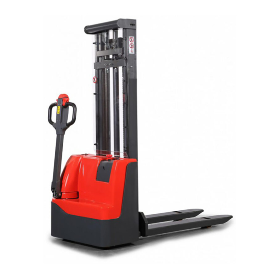
Electric Stacker ECL 10
WARNING
Do not use the electric truck before reading
and understanding these operating
instructions.
NOTE:
Please check the designation of your
present type at the last page of this
document as well as on the ID-plate.
Keep for future reference.
Version 03/2014
ECL10‐SMS‐004_EN
Related Manuals for Noblelift ECL 10
Summary of Contents for Noblelift ECL 10
This manual is also suitable for:
Ecl 10m
-
Contents
-
Table of Contents
-
Troubleshooting
-
Bookmarks
Quick Links
INSTRUCTION HANDBOOK
Electric Stacker ECL 10
WARNING
Do not use the electric truck before reading
and understanding these operating
instructions.
NOTE:
Please check the designation of your
present type at the last page of this
document as well as on the ID-plate.
Keep for future reference.
Version 03/2014
ECL10‐SMS‐004_EN
Related Manuals for Noblelift ECL 10
Summary of Contents for Noblelift ECL 10
This manual is also suitable for:
Ecl 10m