|
Моечно-дезинфекционная машина MELAtherm 10 |
||||||
|
||||||
|
||||||
|
||||||
|
||||||
|
||||||
|
||||||
|
||||||
|
||||||
|
||||||
|
||||||
|
||||||
|
||||||
|
||||||
|
||||||
|
||||||
|
||||||
|
||||||
|
||||||
|
||||||
|
||||||
|
||||||
|
||||||
|
||||||
|
||||||
|
||||||
|
||||||
|
||||||
|
||||||
|
||||||
|
||||||
|
||||||
|
||||||
|
||||||
|
||||||
|
||||||
|
||||||
|
||||||
|
||||||
|
||||||
|




 но наверно интересно почитать


















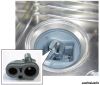 если он засорен — прочистить, если в плохом состоянии — заменить; проверьте, не протекает ли обратный клапан в системе сушки, для этого надо снять армированный шланг.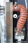
 ) поможет с чтением крокозябр… (использовать: либо через меню — открыть с помощью… , либо перетаскиванием файла на значек программы).
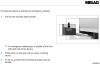
 ) При ТО должны меняться шланги на дозирующих насосах (чтобы была правильная дозировка реагентов и проверяется потом весами…), фильтры на сушку и уплотнительное кольцо (внутри камеры, там куда корзина стыкуется). Это то, что в наборе идет. А остальное — проверка всех соединений, контактов и визуальный осмотр на протечки.
Fault
Incident
F484
Consult the user manual
F484
F505
Salt storage empty
F509
Emergency overflow
F509 Stop water intake
F512
NOT disinfected! Power
outage F512. Warning!
Load NOT disinfected!
Possible cause
1.
The basis basket has
been inserted incor-
rectly or not at all.
2.
Strong foam genera-
tion: The instruments
are pre-cleaned in a
foam-generating solu-
tion or are dropped in
and subject to insuffi-
cient rinsing.
3.
Non-cleared process
agents (rinse aid or
cleaning agent) were
used / the metering
concentration has been
set incorrectly.
4.
Large receptacles are
to be placed in the bas-
ket with the opening fa-
cing upwards. Other-
wise, they take the wa-
ter from the rinse li-
quor.
5.
The blind cap on the in-
jector rail could have
leaks.
The salt storage has been
exhausted. No new
regeneration can be
performed.
Liquid in the floor trough.
A running program was
interrupted by a power
outage.
Remedy
1.
Check whether the basis basket
has been fitted correctly. The in-
jector rail should be located on the
right-hand side and dock with the
blind cap on the port of the rear
wall (see
Inserting the basis bas-
ket
[} page 24]).
2.
Re-start the program again. If a
malfunction message is displayed,
open the door.
– Check for foam in the washing
chamber.
– PLEASE NOTE: do not pre-
treat the instruments. Remove
any strongly encrusted soiling
manually.
3.
Check whether the connected pro-
cess agents have been approved
by MELAG.
Check the settings of the metering
concentration and if necessary, ar-
range for the technical service to
correct them.
4.
Setup the containers with their
opening facing downwards.
5.
Check the black plastic seal on
the fore-side of the injector rail for
its stability.
Re-fill the regenerating salt.
A program can then be started if the
salt has dissolved in the water. Do not
start the program until the
regenerating salt has been filled and
the signal tone has sounded.
▪ Switch off the device and close the
water inflow tap. Check whether ex-
ternal influence has enabled water
to enter the device. CAUTION!
Avoid contact with liquids in the
device floor trough; they can include
process agents.
▪ Contact your technical service pro-
vider and name the device serial
number and the malfunction number
displayed.
Acknowledge with the «4» key. The
program must be restarted as the
disinfection is not guaranteed.
Do not switch off the device at the
power switch whilst a program is
running.
13 Malfunctions
59
-
Contents
-
Table of Contents
-
Bookmarks
Quick Links
®
MELAtherm
10
Washer-Disinfector
Software version 1.309
Dear Dr.
We should like to extend our thanks for the expression of trust in our company which you have displayed through the
purchase of this MELAG product.
As an owner-run and operated family concern founded in 1951, we have a long history of successful specialization in
hygiene products for practice-based use. Our focus on innovation, quality and the highest standards of operational
reliability has established MELAG as the world’s leading manufacturer in the instrument treatment and hygiene field.
You, our customer are justified in your demand for the best products, quality and reliability. Providing «competence in
hygiene» and «Quality – made in Germany», we guarantee that these demands will be met. Our certified quality
management systems is subject to close monitoring: one instrument to this end is our annual multi-day audit conducted
in accordance with ISO 13485 and ISO 9001. This guarantees that all MELAG products are manufactured and tested in
accordance with strict quality criteria.
The MELAG management and team.
Summary of Contents for MELAG MELAtherm 10
-
Contents
-
Table of Contents
-
Bookmarks
Quick Links
®
MELAtherm
10
Washer-Disinfector
Software version 1.309
Dear Dr.
We should like to extend our thanks for the expression of trust in our company which you have displayed through the
purchase of this MELAG product.
As an owner-run and operated family concern founded in 1951, we have a long history of successful specialization in
hygiene products for practice-based use. Our focus on innovation, quality and the highest standards of operational
reliability has established MELAG as the world’s leading manufacturer in the instrument treatment and hygiene field.
You, our customer are justified in your demand for the best products, quality and reliability. Providing «competence in
hygiene» and «Quality – made in Germany», we guarantee that these demands will be met. Our certified quality
management systems is subject to close monitoring: one instrument to this end is our annual multi-day audit conducted
in accordance with ISO 13485 and ISO 9001. This guarantees that all MELAG products are manufactured and tested in
accordance with strict quality criteria.
The MELAG management and team.
Summary of Contents for MELAG MELAtherm 10
- Модель: MELAtherm 10DT B
- Способ управления: автоматический
- Объем: 85 л
- Количество программ: 5
- Диапазон задаваемых температур: 22–90 °C
- Карта памяти CF, два интерфейса RJ45 (Ethernet)
- Регистрационное удостоверение
Арт. 6616
Машина моюще-дезинфицирующая Melag MELAtherm 10
- Описание
- Характеристики
- Комплектация
- Данные для транспортировки
- Документация
- Машина моюще-дезинфицирующая Melag MELAtherm 10 (модель MELAtherm 10DT B) — это мойка-дезинфектор, предназначенная для машинной обработки медицинских инструментов
- Применяется в стоматологии, хирургии, офтальмологии, гинекологии, отоларингологии и других областях медицины
- Соответствует Европейскому стандарту EN 15883 MELAtherm 10 автоматически контролирует вращение промывочного коромысла, давление потоков воды и состояние сетчатых фильтров, таким образом предотвращаются ошибки в работе программы или устройства
- Эффективность очистки инструментов составляет 99,9–100%
- Стандартная ширина моюще-дезинфицирующей машины составляет всего 60 см и она может быть без проблем встроена в мебель под общую столешницу
- Мойка поставляется в комплекте с верхней панелью из нержавеющей стали (крышкой), если крышку снять, то можно встроить в мебель
- Оборудована основной корзиной с инжекторной рейкой, благодаря которой можно одновременно обрабатывать изнутри до 11 пустотелых инструментов: отсасывающие канюли или обычные и угловые стоматологические наконечники и т. д.
- Шкаф-подставка на колёсиках обеспечивает эргономичную рабочую высоту и создает дополнительное место для хранения
- Преимущества машины MELAtherm 10:
— подача чистящих веществ при помощи дозирующего устройства
— активная сушка в соответствии со стандартом
— документирование процесса через компьютерную сеть или на карту памяти
— машина автоматически контролирует вращение промывочного коромысла, давление потоков воды и состояние сетчатых фильтров, т.о. предотвращаются ошибки в работе программы или устройства
— документирование протоколов осуществляется через подключение MELAtherm 10 к Ethernet, пользовательской сети, ПК или принтера или посредством записи данных на флэш-карту через встроенный слот, полученной информацией можно управлять через программы Windows, например, Word, Excel или Text Editor - Программы:
— быстрая программа: 32 мин
— универсальная программа: 37 мин
— специальная программа: 42 мин
— ополаскивание: 4 мин
Программы плюс активная сушка, которые пользователь может прервать в любое время
Перед применением необходимо ознакомиться с инструкцией по применению (паспортом изделия) или получить консультацию специалиста
Размеры камеры (ШхГхВ), мм
465х448х405
Вес, не более, кг
79/85 с крышкой
Способ управления
автоматический
Диапазон задаваемых температур, °C
22–90
Эффективность очистки, %
99,9–100
Длина кабеля электропитания, м
2
Электропитание, В/Гц
220–240/50
Гарантия производителя, мес.
12
Машина моюще-дезинфицирующая Melag MELAtherm 10
Перед применением необходимо ознакомиться с инструкцией по применению (паспортом изделия) или получить консультацию специалиста
- Машина моющие-дезинфицирующая — 1 шт.
- Крышка из нержавеющей стали — 1 шт.
- Карта памяти — 1 шт.
- Базовая корзина с инжекторной рейкой (с 11 форсунками и пружинными зажимами) — 1 шт.
- Вставная корзина для 3-х лотков MELAstore — 1 шт.
- Стандартная корзина для вертикально стоящих инструментов — 1 шт.
- MelaStore 100 (силиконовые стержни для установки до 14 инструментов), размеры: 275х176х30 мм — 3 шт.
- Мягкая корзина для инструментов, лежащих плоско, внутренние размеры: 145х240х60 мм — 1 шт.
- Вставная стойка для 8-ми зубных оттискных лотков, ножниц и зажимов — 1 шт.
- Корзина для мелких инструментов, размеры: Ø760 мм, длина — 180 мм — 1 шт.
- Руководство по эксплуатации
Габариты в упаковке, м
1,10х0,80х1,20; 0,40х0,56х0,67
Количество изделий в упаковке
1
Упаковка
коробка из гофрокартона
Дополнительная упаковка
требуется
Мойка-дезинфектор MELAtherm 10
Производитель: MELAG (Германия)
Артикул 10021
MELAtherm 10 – это мойка-дезинфектор, соответствующая Европейскому стандарту EN 15883. Идеально подходит для машинной обработки инструмента. MELAtherm 10 автоматически контролирует вращение промывочного коромысла, давление потоков воды и состояние сетчатых фильтров. Таким образом предотвращаются ошибки в работе программы или устройства. Стандартная ширина
MELAtherm 10 составляет всего 60 см и он может быть без проблем встроен в мебель под общую столешницу. Если MELAtherm 10 устанавливается отдельно от мебели, MELAG предлагает использовать верхнюю панель из нержавеющей стали.
Имеющийся в ассортименте нижний шкаф-подставка на колёсиках обеспечивает эргономичную рабочую высоту и создает дополнительное место для хранения.
MELAtherm 10 оборудован основной корзиной, с инжекционной рейкой или без неё, по Вашему выбору. При наличии инжекционной рейки можно одновременно обрабатывать изнутри до 11 пустотелых инструментов, напр., отсасывающие канюли или обычные и угловые стоматологические наконечники и т. д.
Встроенная документация MELAtherm®10 позволяет без дополнительных расходов вести документирование процессов, используя встроенный разъём для карты формата CF или один из двух встроенных интерфейсов Ethernet сеть, ПК или принтер.
Активная сушка Очень важное преимущество MELAtherm®10 – встроенная функция активной сушки. Данная функция обеспечивает защиту ваших инструментов от повторного заражения, коррозии и повреждении.
Встроенный модуль подачи реагентов Встроенный измерительный модуль и устройство для подачи обрабатывающих средств размещены во встроенном выдвижном отсеке,что делает их легкодоступными и удобными для использования. Это способствует эргономичности и безопасности рабочего процесса
Камера дезинфекции, оптимизированная с учетом практических требований Изготовленная в соответствии с концепцией оптимизации пространства,моечно-дезинфекционная машина MELAtherm 10 обеспечивает экономичность, экологичность и рекордно низкое время обработки инструментов.
Систематическая обработка Процедура дезинфекции соответствует требованиям методики Институт Роберта Коха и ведущих специалистов в области гигиены. Данные требования полностью выполняются благодаря гигиенической системе компании MELAG.
Программы:
- Быстрая программа — 53 мин
- Универсальная программа — 59 мин.
- Интенсивная программа — 64 мин.
- Офтальмологическая программа — 59 мин.
- Ополаскивание — 3 мин.
Все программы включают активную сушку, которую можно прервать в любой момент.
Технические характеристики:
- Внутренние размеры — 465 × 405 × 450 мм
- Габариты (Ш×В×Г) — 598 × 124 × 678 мм
- Электропитание — 220-240 В, 50Гц, 1 × 16А
- Объем камеры — 85 л
- Вес — 106 кг
 |
Номер ошибки: | Ошибка 509 |
| Название ошибки: | Excel Error 509 | |
| Описание ошибки: | Ошибка 509: Возникла ошибка в приложении Microsoft Excel. Приложение будет закрыто. Приносим извинения за неудобства. | |
| Разработчик: | Microsoft Corporation | |
| Программное обеспечение: | Microsoft Excel | |
| Относится к: | Windows XP, Vista, 7, 8, 10, 11 |
Основы «Excel Error 509»
«Excel Error 509» часто называется ошибкой во время выполнения (ошибка). Разработчики программного обеспечения, такие как SoftwareDeveloper, обычно работают через несколько этапов отладки, чтобы предотвратить и исправить ошибки, обнаруженные в конечном продукте до выпуска программного обеспечения для общественности. К сожалению, многие ошибки могут быть пропущены, что приводит к проблемам, таким как те, с ошибкой 509.
После установки программного обеспечения может появиться сообщение об ошибке «Excel Error 509». Когда это происходит, конечные пользователи могут сообщить Microsoft Corporation о наличии ошибок «Excel Error 509». Затем Microsoft Corporation исправит ошибки и подготовит файл обновления для загрузки. Эта ситуация происходит из-за обновления программного обеспечения Microsoft Excel является одним из решений ошибок 509 ошибок и других проблем.
Почему возникает ошибка времени выполнения 509?
Наиболее распространенные вхождения «Excel Error 509» проблемы при загрузке Microsoft Excel. Рассмотрим распространенные причины ошибок ошибки 509 во время выполнения:
Ошибка 509 Crash — это типичная ошибка «Excel Error 509», которая приводит к полному завершению работы программы. Это возникает, когда Microsoft Excel не работает должным образом или не знает, какой вывод будет подходящим.
«Excel Error 509» Утечка памяти — Ошибка 509 утечка памяти происходит и предоставляет Microsoft Excel в качестве виновника, перетаскивая производительность вашего ПК. Возможные искры включают сбой освобождения, который произошел в программе, отличной от C ++, когда поврежденный код сборки неправильно выполняет бесконечный цикл.
Ошибка 509 Logic Error — Логическая ошибка вызывает неправильный вывод, даже если пользователь дал действительные входные данные. Это видно, когда исходный код Microsoft Corporation включает дефект в анализе входных данных.
В большинстве случаев проблемы с файлами Excel Error 509 связаны с отсутствием или повреждением файла связанного Microsoft Excel вредоносным ПО или вирусом. Основной способ решить эти проблемы вручную — заменить файл Microsoft Corporation новой копией. Мы также рекомендуем выполнить сканирование реестра, чтобы очистить все недействительные ссылки на Excel Error 509, которые могут являться причиной ошибки.
Ошибки Excel Error 509
Усложнения Microsoft Excel с Excel Error 509 состоят из:
- «Ошибка программы Excel Error 509. «
- «Excel Error 509 не является программой Win32. «
- «Возникла ошибка в приложении Excel Error 509. Приложение будет закрыто. Приносим извинения за неудобства.»
- «Файл Excel Error 509 не найден.»
- «Отсутствует файл Excel Error 509.»
- «Ошибка запуска программы: Excel Error 509.»
- «Не удается запустить Excel Error 509. «
- «Отказ Excel Error 509.»
- «Ошибка пути программного обеспечения: Excel Error 509. «
Проблемы Microsoft Excel Excel Error 509 возникают при установке, во время работы программного обеспечения, связанного с Excel Error 509, во время завершения работы или запуска или менее вероятно во время обновления операционной системы. Выделение при возникновении ошибок Excel Error 509 имеет первостепенное значение для поиска причины проблем Microsoft Excel и сообщения о них вMicrosoft Corporation за помощью.
Создатели Excel Error 509 Трудности
Заражение вредоносными программами, недопустимые записи реестра Microsoft Excel или отсутствующие или поврежденные файлы Excel Error 509 могут создать эти ошибки Excel Error 509.
Более конкретно, данные ошибки Excel Error 509 могут быть вызваны следующими причинами:
- Недопустимая или поврежденная запись Excel Error 509.
- Вредоносные программы заразили Excel Error 509, создавая повреждение.
- Вредоносное удаление (или ошибка) Excel Error 509 другим приложением (не Microsoft Excel).
- Excel Error 509 конфликтует с другой программой (общим файлом).
- Microsoft Excel/Excel Error 509 поврежден от неполной загрузки или установки.
Продукт Solvusoft
Загрузка
WinThruster 2022 — Проверьте свой компьютер на наличие ошибок.
Совместима с Windows 2000, XP, Vista, 7, 8, 10 и 11
Установить необязательные продукты — WinThruster (Solvusoft) | Лицензия | Политика защиты личных сведений | Условия | Удаление
User manual MELAtherm ® 10 Washer-Desinfector as of software version 1.309 EN Dear doctor, We thank you for your confidence demonstrated by the purchase of this MELAG product. As an owner-run and operated family concern founded in 1951, we have a long history of successful specialization in hygiene products for practice- based use. Our focus on innovation, quality and the highest standards of operational reliability has established MELAG as the world’s leading manufacturer in the instrument treatment and hygiene field. You, our customer are justified in your demand for the best products, quality and reliability. Providing "competence in hygiene" and "Quality – made in Germany", we guarantee that these demands will be met. Our certified quality management systems is subject to close monitoring: one instrument to this end is our annual multi-day audit conducted in accordance with ISO13485 and ISO9001. This guarantees that all MELAG products are manufactured and tested in accordance with strict quality criteria. The MELAG management and team. Contents Contents 1 General safety information..................................................................................................................................................5 2 Scope of delivery..................................................................................................................................................................7 3 General Guidelines...............................................................................................................................................................8 User group and validity ........................................................................................................................................................8 Intended use ........................................................................................................................................................................8 Symbols used.......................................................................................................................................................................8 Formatting rules ...................................................................................................................................................................8 Symbols on the device.........................................................................................................................................................9 Disposal ...............................................................................................................................................................................9 4 Performance specifications ..............................................................................................................................................10 User Benefits......................................................................................................................................................................10 Program sequence.............................................................................................................................................................11 Approved process agents ..................................................................................................................................................11 5 Description of the device...................................................................................................................................................13 Views of the device ............................................................................................................................................................13 Operating panel and acoustic signals ................................................................................................................................15 Menu structure ...................................................................................................................................................................16 Water softening unit ...........................................................................................................................................................17 6 Settings ...............................................................................................................................................................................18 SETUP menu .....................................................................................................................................................................18 Setting the water supply.....................................................................................................................................................18 Setting automatic logging...................................................................................................................................................18 Setting date and time .........................................................................................................................................................19 Setting the display contrast................................................................................................................................................20 Selecting the language.......................................................................................................................................................20 Setting the water hardness ................................................................................................................................................21 7 First steps ...........................................................................................................................................................................22 Setup and Installation.........................................................................................................................................................22 Testing in daily operation ...................................................................................................................................................22 Switching the device on and off .........................................................................................................................................22 Opening and closing the door ............................................................................................................................................22 Emergency release of the door..........................................................................................................................................23 Inserting the basis basket ..................................................................................................................................................24 Filling the regeneration salt................................................................................................................................................24 Regenerating the water softening unit ...............................................................................................................................25 Metering process agents....................................................................................................................................................26 Holding process agents ready............................................................................................................................................26 Bleeding the metering hoses..............................................................................................................................................28 8 Cleaning and Disinfection .................................................................................................................................................30 The nature of the load........................................................................................................................................................30 Arranging the load..............................................................................................................................................................30 Decontaminating hollow-bodied instruments .....................................................................................................................31 Decontaminating dental transfer instruments.....................................................................................................................32 Contents Decontaminating ophthalmological instruments.................................................................................................................32 Overview of programs........................................................................................................................................................33 Selecting, starting and following the program ....................................................................................................................34 Manual program abort........................................................................................................................................................36 Removing the load after program end................................................................................................................................37 9 Logging ...............................................................................................................................................................................38 Batch documentation .........................................................................................................................................................38 Output media......................................................................................................................................................................38 Outputting logs immediately and automatically..................................................................................................................40 Subsequent log output .......................................................................................................................................................41 Deleting the saved logs......................................................................................................................................................41 Determining the format for the program logs .....................................................................................................................41 Finding the logs..................................................................................................................................................................44 10 Function tests...................................................................................................................................................................45 Automatic and manual functional check.............................................................................................................................45 Measuring conductivity.......................................................................................................................................................45 11 Maintenance......................................................................................................................................................................46 Daily checks and cleaning..................................................................................................................................................46 Cleaning on demand..........................................................................................................................................................48 Avoiding staining................................................................................................................................................................48 Changing the filter in the drying fan ...................................................................................................................................48 Maintenance.......................................................................................................................................................................49 (Process) validation............................................................................................................................................................50 12 Pause times ......................................................................................................................................................................51 Decommissioning...............................................................................................................................................................51 Transport within the practice..............................................................................................................................................52 13 Malfunctions .....................................................................................................................................................................53 General events...................................................................................................................................................................53 Warnings............................................................................................................................................................................54 Malfunction messages .......................................................................................................................................................56 14 Technical Data ..................................................................................................................................................................62 15 Accessories and Spare Parts..........................................................................................................................................63 Accessories........................................................................................................................................................................63 16 Documentation and approval..........................................................................................................................................64 Glossary .................................................................................................................................................................................65 1 General safety information 5 1 General safety information When operating the device, comply with the following safety instructions as well as those contained in subsequent chapters. Use the device only for the purpose named in these instructions. Failure to comply with the set-up conditions can result in malfunctions or damage to the device and/or human injury. Power cable and power plug n Observe the legal regulations and supply conditions of your local electricity company. n Never operate the device if the mains cable or power plug are damaged. n The power cable and plug should only be replaced by authorized persons. n Never damage or alter the plug or mains cable. n Never unplug by pulling on the power cable. Always take a grip on the plug. n Make sure that the power cable is not clamped. n Never install the cable along a source of heat. n Never fix the power cable with sharp objects. Set-up installation and commissioning n Check the device for any damage suffered during transport after unpacking. n Only have the device set up, installed, and started up by people authorized by MELAG. n The connections for electrical provision and water supply and discharge must be set-up by trained per- sonnel. n In accordance with current VDE specifications, the device is unsuitable for operation in explosive at- mospheres. n The device is conceived for use outside patient surroundings. The device should be located at least 1.5 m away (radius) from the treatment area. n The documentation media (computer, CF card reader etc.) must be placed in such a way that they cannot come into contact with liquids. n Observe all the information contained in the technical manual during commissioning. Daily operation n Use only those instruments designed by their manufacturer for automatic treatment in a washer-disin- fector. Comply with the instructions issued by the instrument manufacturer in accordance with DINENISO17664. It is especially important to observe the manufacturer's information when treating newly purchased instruments for the first time. n Use only original MELAG accessories or those from other suppliers authorized for use by MELAG. n When using additional accessories to accept instruments, especially hollow-bodied instruments, it is necessary to observe the information contained in the manufacturer's operating instructions. n Observe the relevant standards and directives applicable to the treatment of instruments in your coun- try as well as the treatment information from the instrument manufacturer. n The personnel responsible for instrument treatment must be sufficiently trained and schooled. n The fore ventilation slits must not be covered. n Only operate the device with the basis basket provided for this purpose. Process agents n Handle all process agents with care. The cleaning, neutralization and rinsing aids contain irritants and even caustic substances. n Use only those process agents approved by MELAG for this device. Observe the operating and safety information from the process agent manufacturer. If, despite observation of the manufacturer's inform- 1 General safety information 6 ation, the process agents have a negative effect on the material of the instruments or the device, liabil- ity lies with the manufacturer of the process agents. n The use of process agents not approved by MELAG absolves MELAG of all liability whatsoever for any damage to the device or the instruments. n Should you have any questions concerning the compatibility of the process agents with the instru- ments, please consult the manufacturer. MELAG provides information for the application of the pro- cess agents in the device but does not take any responsibility for their effects on the instruments. n Any fluids in the drawer and the floor tank underneath can also contain process agents in case of damage. Ensure that you observe the information of the respective process agent manufacturer. Maintenance n Have the maintenance done only by authorized persons. n Maintain the specified servicing intervals. Transport and storage n Install and operate the device in a frost-free environment. n Store and transport the device in a generally frost-free environment. n Avoid strong vibrations. Malfunctions n Should the device issue the same malfunction message repeatedly, turn off the device and if necessary, inform your stockist. n Only have the device repaired by authorized persons. 2 Scope of delivery 7 2 Scope of delivery Please check the scope of delivery before setting up and connecting the device. Standard scope of delivery ▪ Washer disinfector MELAtherm ® 10 ▪ User manual ▪ Technical manual ▪ Record of installation and set-up ▪ Manufacturer's inspection report ▪ Certificate of Conformity ▪ Warranty certificate ▪ Instructions for the use and care of the accessories ▪ MELAflash CF card for documentation ▪ 1 L container for rinse aid ▪ 5 L container for cleaning agent ▪ Feed funnel for the regeneration salt ▪ Starter package of regeneration salt ▪ Open-end wrench for injector rail ▪ Transfer spigot for process agent containers ▪ Effluent hose with hose clamp Ø 16-25/9 mm Optionally ▪ Accessories according to the delivery note 3 General Guidelines 8 3 General Guidelines Please read this user manual carefully before commissioning the device. The operating manual includes important safety information. The functionality and value-retention of this device depend primarily on the care accorded to it. Make sure to keep the User Manual close to the device. It represents a component of the product. User group and validity This manual applies for the devices MELAtherm ® 10 DTA and MELAtherm ® 10 DTB. This manual is addressed to doctors, their assistants and service departments. Intended use In accordance with DIN EN ISO 15883-1 and -2, this device is designed for application in a medical context, e.g. clinics and medical and dental practices. You can subject thermo-stable medical instruments (i.e. instruments which are heat resistant to a temperature of 95°C) to automatic cleaning as long as they are suitable for this purpose. The cleaning is undertaken via the use of water and a chemical cleaning agent. Subsequent disinfection is performed by thermal disinfection. This device is NOT suitable for treatment of: ▪ Thermo-instable instruments, e.g. flexible endoscopes ▪ Wastes for disposal and in the lab area ▪ Dishes ▪ Bedpans Symbols used Symbol Explanation Indicates a dangerous situation, which if not avoided, could entail slight to life- threatening injuries. Draws your attention to a situation, which if not avoided, could result in damage to the instruments, the practice fittings or the device. Draws your attention to important information. Formatting rules Example Explanation see Chapter 2 Reference to another text section within this document Settings Words or phrases appearing on the display of the device are marked as display text. 3 General Guidelines 9 Symbols on the device Manufacturer of the medical product Date of manufacture of the medical product Medical product serial number from the manufacturer Article number of the medical product Refers to the lowest and highest water temperature to which the device can be safely subjected. Flow pressure on the water inflow connected from min. to max. Internal device fuse, rated in amperes [A] The operating manual includes important safety information. Failure to comply with these instructions can result in injury and material damage. Please read this user manual carefully before commissioning the device. In affixing this CE mark, the manufacturer declares that this medical product fulfils the basic requirements of the Medical products directive. The four-digit number confirms that this is monitored by an approved certification agency. The device may not be disposed as domestic waste. The vendor is responsible for appropriate disposal of the device - it must be delivered to the vendor to be disposed of. By the designation of an apparatus with this symbol, the manufacturer furthermore declares that he satisfies all requirements of the law concerning the release, redemption and environmentally sound disposal of electric and electronic appliances. Disposal MELAG devices are synonymous for long-term quality. When you eventually need to decommission your MELAG device, we offer a special disposal service. Simply contact your stockist. The packaging protects the device against transport damage. The packaging materials have been selected for their environmentally-friendly and recycling properties and can be recycled. Returning the packaging to the material flow reduces the amount of waste and saves raw materials. Dispose of all non- required packaging materials at the collection points of the dual system. Dispose of waste from process agents in accordance with the specifications from the manufacturer of the process agents. Information regarding this topic is provided by the safety data sheets or can be obtained directly from the manufacturer of the process agents. Dispose of accessories and consumption media which you no longer require (e.g. used filters) in the appropriate manner. Comply with all relevant disposal specification in terms of possibly contaminated waste. 4 Performance specifications 10 4 Performance specifications User Benefits Universal use The device cleans and disinfects. The disinfection phase is conceived so as to reach an A0-value of at least 3000. This eliminates vegetative bacteria and fungi/fungal spores and disables viruses (inc. HBV, HCV) thus reaching the effective range AB in according to the (German) RKI directive. Active drying The device has an active drying facility. This means that after cleaning and disinfection, the instruments are dried inside (interior lumen) and out via an integrated drying fan. The HEPA-Filter guarantees drying with contamination-free air. Automatic treatment of hollow-bodied instruments is also possible. This protects the instruments from stain accretion and rusting. The geometry of some hollow-bodied instruments such as turbines, requires additional drying. Automatic sieve recognition The device recognizes automatically before a program start whether the fine sieve has been inserted in the base of the washing chamber. Thus it avoids a situation in which instrument components enter the opening of the drain pump or the circulation pump and thus compromising the function of the pumps, rinse arms and the injector rail. Internal water softening The device has an internal softening plant. The water hardness of the local drinking water is set in the device. The internal water softening unit then automatically adjusts itself to the best solution. This ensures a optimal instrument decontamination result. Monitoring the rotation speed of the rinse arms The rotation speed of the rinse arms is subject to permanent monitoring during a program run. This ensures that the cleaning process proceeds properly and the rinse arms do not become blocked e.g. by protruding instruments in the washing chamber. Monitoring the cleaning pressure The cleaning pressure is monitored during a program run via a pressure sensor. This ensures effective cleaning. Excess foam generation results in the interruption of the program run. Metering monitoring The required amounts of cleaner and neutralizer are measured out using a hose measuring pump. A measurement turbine performs flow monitoring. The rinse aid is metered using a hose metering pump subject to monitoring for rotation speed. Drawer for process agents The drawer in the lower area of the device provides storage space for the process agents cleaning agent, neutralizer and rinse aid. Automatic conductivity measurement If the device is provided with DI water in the final rinse, the DI water is subject to automatic, internal conductivity measurement. Emergency opening of the door The door can be opened manually via the emergency release following a power outage or malfunction. 4 Performance specifications 11 Program sequence The program steps are indicated on the display during the program run: Pre-cleaning Pre-cleaning is performed with softened water and without process agents. It is temperature controlled. All proteins on the instruments must be removed entirely. It is necessary to avoid denaturation resulting from too a high water temperature. These and other coarse organic deposits are removed during pre-cleaning. Cleaning The actual cleaning is performed during the cleaning process. The washing chamber is heated until reaching the program-specific temperature. This is then held during the holding time. The cleaner is added automatically before the holding time begins. Neutralization The main cleaning is followed immediately by neutralization. Neutralization reduces alkalinity and frees the instruments from acid-soluble deposits such as lime scale and extraneous rust etc. During this process, a specified amount of cold process water is pumped into the washing chamber. This is followed by the addition / mixing of a measured amount of neutralizer. Intermediate rinsing Intermediate rinsing is a preparatory step to disinfection to reduce the residual concentration of the process agents. Disinfection Intermediate rinsing is followed by thermal disinfection at a temperature of over 90°C. Drying The instruments are then dried by the integrated drying fan from inside and out. This prevents rust accretion on the instruments. Displaying the batch counter The display shows the last batch number run and the total batch counter after a program end or the end of a program abort. Approved process agents NOTICE Observe the operating and safety information from the process agent manufacturer. Process agents from different manufacturers may not be mixed. Any change to another authorized combination may only be performed by trained service partners. The metering concentration must be adapted to local conditions. This is to be performed by the service technician during setup in accordance with the manufacturer's information. NOTICE Observe the operating and safety information from the process agent manufacturer. If, despite observation of the manufacturer's information, the process agents have a negative effect on the material of the instruments or the device, liability lies with the manufacturer of the process agents. The use of process agents not approved by MELAG absolves MELAG of all liability whatsoever for any damage to the device or the instruments. The following combinations of process agents were tested for suitability for use with MELAtherm 10, brought into circulation since 01-07-2012: 4 Performance specifications 12 Manufacturer Cleaner Neutralizer Rinse aid Alpro* TR-3 TR-Neutralizer TR-Clear B. Braun Helimatic cleaner alkaline Helimatic neutralizer C Helimatic rinse neutral Bode Dismoclean 21 clean Dismoclean 25 acid Dismoclean 64 neutra-dry Borer* deconex 28 ALKA ONE-x deconex 22 LIQ-x deconex 25 ORGANACID deconex 26 MINERALACID deconex 64 NEUTRADRY Dr. Schumacher Thermoton Cleaner Thermoton N Thermoton clear Dr. Weigert neodisher MediClean forte neodisher MediClean Dental neodisher N neodisher Z neodisher N dental neodisher Z dental neodisher MediKlar neodisher MediKlar dental neodisher MediKlar special Schülke + thermodent alka clean thermosept RKF forte thermosept alka clean forte thermodent neutralizer thermosept NKP thermosept NKZ thermodent clear thermosept BSK Henry Schein Eurosept Thermo Cleanser Eurosept Thermo Neutralizer Eurosept Thermo Rinse *When using process agents of manufacturers Alpro or Borer, it is absolutely essential and regardless of the maintenance message after twelve month to replace all hoses of the dosing unit during maintenance. Ensure that the process media selected are suitable for your instruments. Please address any questions to the manufacturer of the process agents. Please observe and comply with the notes specific to the process agents contained in the maintenance record. Preset metering concentrations 1) Program Cleaner Neutralizer Rinse aid Universal-Program 6 ml/l 1.5 ml/l 0.3 ml/l Quick-Program 6 ml/l 1.5 ml/l 0.3 ml/l Intensive Program 8 ml/l 1.5 ml/l 0.3 ml/l Ophthalmo-Program 6 ml/l 1.5 ml/l -------- 1) For using drinking water (hardness range medium - hard) we recommend the dosage concentrations specified above. The metering concentration must be adjusted individually depending on the local conditions. The pre-set metering quantities can be used for various combinations of process agents. Observe the operating and safety information of the process agent manufacturer. This information can be read-off from the canister in the units "ml/l" or on separate data sheets provided by the manufacturer. The process-relevant parameters must be adapted depending on the nature of the soiling, the quality of the tap water and other framework conditions. Please contact the manufacturer of the process agents regarding this question. 5 Description of the device 13 5 Description of the device Views of the device 2 1 3 5 6 4 7 10 8 9 Fig.1: Fore view 1 Operating and display field 2 Cover plate (optional) 3 Power switch 4 Cover for CF card slot and Ethernet data interface (for service) 5 Door grip 6 Hinged door, opens forwards 7 Drawer handle 8 Drawer for process agents 9 Ventilation slots (air outlet with active drying) 10 Device foot 13 14 11 12 Fig.2: Cover cap CF card slot open 11 Card slot 12 LED 13 Ejection button 14 Ethernet data connection 5 Description of the device 14 20 19 18 15 16 17 Fig.3: View from rear 15 Connection for de-ionised water (DI water) 16 Connection for cold water 17 Effluent connection 18 Transport rollers 19 Ethernet data connection for permanent network connection 20 Mains power cable 25 21 22 23 24 Fig.4: View inside 21 Connection tube for injector rails 22 Cold water inflow (CW) and deionised water (DI) 23 Salt container 24 Lower rinse arm 25 Coarse and fine sieve 5 Description of the device 15 31 27 30 29 28 26 Fig.5: Process agent drawer, open 26 Drying filter 27 Assignment of the process agents 28 Suction lance bracket 29 Container for rinse aid with suction lance 30 Container for neutralizer with suction lance 31 Container for cleaning agent with suction lance Operating panel and acoustic signals The control panel consists of a two-line LED display and four membrane keys. Key 1 2 3 4 MELAG MELAtherm 10 Fig.6: 2-row LED display Table1: Key functions Key Function/Explanation 1...2 or Navigation: BACKWARDS - FORWARDS to adjust a value: REDUCE, INCREASE 3 Unlocking door, BACKWARDS, CANCELLATION Leave menu 4 Confirming messages (ENTER, OK, YES, SELECTION). QUIT with warning or malfunction messages 1+2 and The system status is displayed with information relating to the device e.g. serial number, software version, daily and total batches etc. 1+3 and QUIT + DOOR, i.e. to acknowledge the program abort and unlock the door 3...4 or Deletes all logs located in the internal log memory 5 Description of the device 16 Acoustic Signals The device issues acoustic signals for information purposes. Table2: Acoustic Signals Signal / tone Meaning 1x Confirmation, warning or message 3x Refill with salt soon; program abort; end of the abort after drying abort reached 5x Program completed successfully 10x Malfunction Menu structure P01 Universal-Program P02 Quick-Program P03 Intensive-Program P04 Ophthalmo-Program Z01 Rinsing Z02 Emptying Z03 Conductivity measurement DI Z04 Air removal Z05 Regeneration Z06 Time metering 60s M01 DOCU MENU (Output of a saved log via the following output media) Select output medium: Automatic, CF card, MELAprint, PC 01 Log list 02 Last log 03 Logs of day 04 Logs of week 05 Logs of month 06 All logs 07 Last malfunction log 08 Malfunction logs Day 09 Malfunc. log Week 10 Malfunc. log Month 11 All malf. logs 12 Caption log 13 Status log 14 System log 15 Format CF card M02 SETUP-MENU 01 DI water 02 Automatic logging └ 03 Date 04 Time 05 Display contrast 06 Language 07 Water (hardness) °dH 08 DIAGNOSIS + SERVICE > AC outputs (AC-OUT) > DC outputs (DC-OUT) > Analogue inputs > Counter inputs > Digital inputs SERVICE MENU └ Maintenance Counter Date DEMO mode MAIN MENU ├ ├ ├ ├ ├ ├ ├ ├ ├ ├ └ ├ ├ ├ ├ ├ ├ ├ ├ ├ ├ ├ ├ ├ ├ └ ├ ├ ├ ├ ├ ├ ├ ├ └ ├ ├ ├ ├ ├ ├ ├ ├ └ + + 5 Description of the device 17 Water softening unit The tap water is processed in a water softening unit to produce optimal cleaning results. u Use coarse-grain regeneration salt (NaCl) to regenerate the water softening unit. NOTICE The fitted water softening unit has been optimized for a degree of hardness of 0–40°dH. For higher degrees of hardness than 40°dH, you will require a dedicated water softening unit. NOTICE An incorrectly set degree of hardness can result in a higher salt consumption or limes- cale deposits on the instruments. When using a dedicated water softening unit, the residual hardness of the dedicated water softening unit must also be set in the setup menu. Table3: Water hardness conversion table °dH mmol/l °f °e °dH mmol/l °f °e °dH mmol/l °f °e 1 0.2 2 2 15 2.7 27 19 28 5.0 50 36 2 0.4 4 3 16 2.9 29 20 29 5.2 52 37 3 0.5 5 4 17 3.1 31 22 30 5.4 54 38 4 0.7 7 5 18 3.2 32 23 31 5.6 56 39 5 0.9 9 7 19 3.4 34 24 32 5.8 58 41 6 1.1 11 8 20 3.6 36 25 33 5.9 59 42 7 1.3 13 9 21 3.8 38 27 34 6.1 61 43 8 1.4 14 10 22 4.0 40 28 35 6.3 63 44 9 1.6 16 12 23 4.1 41 29 36 6.5 65 46 10 1.8 18 13 24 4.3 43 31 37 6.7 67 47 11 2.0 20 14 25 4.5 45 32 38 6.8 68 48 12 2.2 22 15 26 4.7 47 33 39 7.0 70 49 13 2.3 23 17 27 4.9 49 34 40 7.2 72 51 14 2.5 25 18 6 Settings 18 6 Settings SETUP menu The setup menu contains settings for the date, time and display contrast. Navigate in the setup menu as follows: 1. Press to navigate in the main menu to M02->SETUP-MENU. 2. Press to open the setup menu. 3. Press to leave the setup menu. 4. Press to save changes or hold depressed to discard the changes. Setting the water supply If the device is connected to a DI water supply e.g. MELAdem 53/MELAdem 53 C or another water treatment unit, this must be set on the device. In its delivery state, the water supply has been set to DI water YES. To alter this setting proceed as follows: 1. Press to open the setup menu. Ê This display registers the option 01 DI-Water YES. 2. Press in order to change the option. Ê The value YES flashes. 3. Press or to switch between YES and NO. 4. Press to accept Yes o No. Ê The value no longer flashes. 5. Press to leave the setup menu. ÊThe selected value is automatically saved when leaving the setup menu. Setting automatic logging Settings relating to log output are made in Menu 02 Automatic logging. The settings made here are saved for the respective output medium. The display image shows whether the option for log issue is ACTIVE. Detailed information regarding logging is provided in chapter Logging [}page 38]. Determining the output medium You are able to output the logs of the completed programs on various media: Comply with the specifications of the manufacturer’s operating manual of the respective device. The example shows how to use the CF card as an output medium. Proceed in a similar manner to set a different output medium. Working in the SETUP menu [}page 18] set the output medium as follows: 1. Press to navigate to 02 Automatic logging. 6 Settings 19 2. Press to open the menu 02 Automatic logging. Ê The selectable output media are displayed consecutively. 3. Press repeatedly to navigate in the setup menu to 01 CF card YES . Ê The display of YES indicates that the log is to be saved on the CF card. 4. Press if this value is to be changed. Ê The value YES flashes. 5. Press or to switch between YES and NO. 6. Press to save the new value. Ê The value no longer flashes. 7. Press to leave setup menu 02 Automatic logging. Ê The selected value is automatically saved when leaving the setup menu. Determining the log format You can find more detailed information regarding the log formats 0001 and 0002 here: Determining the format for the program logs [}page 41]. Setting date and time Date and time of the device must be correctly set for proper batch documentation. PLEASE NOTICE The time is not set automatically. n The time setting to summer or winter time must be performed manually. Setting the date Working in the SETUP menu [}page 18] set the output medium as follows: 1. Press to navigate to 03 Date. 2. Press to change the date. Ê The display changes to 03 Change date. 3. Press repeatedly to choose between day, month and year. 4. Press to activate the selected parameters (day, year). Ê The current value flashes. 5. Press or to reduce or increase the value. 6. Press to save the new value. Ê The value no longer flashes. 7. Press to change the month next. Proceed in a similar fashion here. 8. Press to leave the setup menu. ÊThe selected value is automatically saved when leaving the setup menu. 6 Settings 20 Setting the time Working in the SETUP menu [}page 18] set the time as follows: 1. Press repeatedly to navigate to 04 Time. 2. Press in order to change the language. Ê The display changes to 04 Change date. 3. Press to activate the selected parameters. Ê The current value flashes. 4. Press or to reduce or increase the value. 5. Press to save the new value. Ê The value no longer flashes. 6. Press to leave the setup menu. ÊThe selected value is automatically saved when leaving the setup menu. Setting the display contrast Working in the SETUP menu [}page 18] set the display contrast as follows: 1. Press repeatedly to navigate to 05 Display contrast. 2. Press to activate the selected parameters. Ê The current value flashes. 3. Press or to reduce or increase the value. 4. Press to save the new value. Ê The value no longer flashes. 5. Press to leave the setup menu. ÊThe selected value is automatically saved when leaving the setup menu. Selecting the language You can choose between two languages. Language 0001 is usually the local language or English, Language 0002 is English or other required language Working in the SETUP menu [}page 18] set the language as follows: 1. Press repeatedly to navigate to 06 Language. 2. Press to activate the selected parameters. Ê The current value flashes. 3. Press to change to language 0002. 4. Press to save the new value. Ê The value no longer flashes. 5. Press to leave the setup menu. 6 Settings 21 ÊThe selected value is automatically saved when leaving the setup menu. Other languages can also be installed. To this end, the corresponding language update file must be downloaded on the device from the CF card. Please consult your MELAG customer services or stockist for this. Setting the water hardness Working in the SETUP menu [}page 18] set the water hardness as follows: 1. Press repeatedly to navigate to 07 Water °dH. 2. Press to activate the selected parameters. Ê The current value flashes. 3. Press or to reduce or increase the value. 4. Press to save the new value. Ê The value no longer flashes. 5. Press to leave the setup menu. ÊThe selected value is automatically saved when leaving the setup menu. You can find a water hardness conversion table in the chapter Description of the device [}page 13] under Water softening unit [}page 17]. 7 First steps 22 7 First steps Setup and Installation PLEASE NOTICE Comply with the specifications of the technical manual during set-up and installation. This contains all building-side requirements. Record of installation and set-up The responsible stockist is to complete the record of installation and setup as proof of the correct setup, installation and commissioning. A copy is to be sent to MELAG oHG and the stockist. This is a constituent part of any guarantee claim. Testing in daily operation Check the following items every day before work starts: ▪ The nozzles of the upper and lower rinse arms are accessible and clean. ▪ The rinse arms can be turned freely. ▪ The coarse and fine sieves are clean and have been rinsed. ▪ The washing chamber interior and the door seal are intact. Comply with the instructions regarding daily inspections and cleaning contained under Maintenance [}page 46]. Switching the device on and off } Switch the device on or off at the power switch. Opening and closing the door The door is automatically closed via a motor. For this reason, it is important that the device is connected to the power supply and is switched on. The door unlocks automatically after a successful program run. The door cannot be opened following a power outage. In such a case, activate the door emergency release [}page 23]. NOTICE The door can only be opened during a program run using a program abort. The door is unlocked after the program abort has been acknowledged and sufficient cooling has been performed. 7 First steps 23 Opening the door 1. Switch on the device at the power switch. 2. Press the key. Ê The door is unlocked. 3. Open the door forwards to open. Closing the door u Shut the door upwards and press it until the motorized lock sets in. Emergency release of the door CAUTION Danger of scalding from hot steam. Hot steam could be released upon opening the door. n Never operate the emergency release while a program is active. n Wear suitable protective clothing. DANGER Danger of contamination from insufficient disinfection A program aborted by emergency release is classed as not completed successfully. Process water can remain in the washing chamber; the instruments have not been disinfected completely. n The instruments must be subject to renewed treatment. Proceed as follows to activate the emergency release: 1. Pull out the process agent drawer. Ê An emergency release grip is located at the front left-hand side of the device. 2. Press down on the grip until you hear a clicking sound. 3. To do so, pull the door forwards strongly using its handle. 7 First steps 24 Inserting the basis basket A port for the connection of the injector rail is located on the right-hand rear side of the washing chamber of the washer-disinfector. } Slide the basis basket with the injector rail opening into the washing chamber until it connects to this port. Filling the regeneration salt CAUTION Danger of injury from insufficient protective measures! Performing work without first taking the corresponding protective measures can result in Injuries. n Comply with the working safety measures required by the respective tasks. NOTICE Malfunctions of the water softening unit from unsuitable regenerating salt. Fine grain regeneration salt can cause device malfunctions. We do not recommend the use of pellets, as the salt dissolves too slowly. n Use only special, coarse grain regeneration salt (additive-free NaCl). n Never use cooking salt, table salt, de-icing salt, cattle salt or road salt. These salts usually contain insoluble components. n Never pour cleaning agent or other process agents in the salt container. Filling the regenerating salt for the first time (by the service technician upon first installation) 1. Fill enough water in the salt container once until it overflows. This enables dissolution of the salt. Ê No further water is required for all subsequent salt fillings. 2. Fill the salt container with 1 kg of regenerating salt. Ê The device can only be operated if the salt container contains sufficient regenerating salt. Re-filling regenerating salt Insufficient regenerating salt will result in the display of the corresponding display notification. ▪ Display of Refill with salt soon means that you can perform up to ten washing runs depending on the program selected and the hardness of the water. ▪ Display of Salt exhausted. Please refill means that you should refill with regenerating salt im- mediately. Otherwise you will be unable to start a further program. 7 First steps 25 You can refill the regenerating salt at any time without the corresponding display notification. After filling, start the supplementary “Rinse” program to remove overflowing brine and salt residue from the washing chamber. In order to refill the regeneration salt, proceed as follows: 1. Acknowledge the notification Refill with salt soon with the key. 2. Open the door. 3. Remove the basis basket. 4. Open the lid of the salt container by turning it anti- clockwise. 5. Insert the filling funnel for the regenerating salt in the opening. 6. Fill the salt container with regenerating salt using the filling funnel. Regenerating salt 7. Clean the edge of the filling opening of salt residue. 8. Remove the filling funnel and screw on the lid of the salt container. 9. Insert the basis basket. 10. Wait three minutes and then start the rinsing pro- gram without (instrument) load. Regenerating the water softening unit The internal water softening unit regenerates automatically in certain intervals. The program run time is extended by a number of minutes. You can regenerate the water softening unit manually after e.g. having filled it with salt without a warning having previously been issued. u To do so, start the “Regeneration” program. 7 First steps 26 Metering process agents The concentration of the process agents is set once during the initial device setup performed by the customer services technician (see technical manual). During a program run, the preset concentration of the relevant process agents is metered automatically. Holding process agents ready DANGER Danger of acid burns by irritant substances! Improper handling of the process agents may cause caustic burns and health damage. n Protect your eyes, hands, clothing and all surfaces from contact with the process agents. n Comply with the information from the manufacturer of the process agents. n Every type of fluid (e.g. in the drawer, in the device floor tank or fluid emerging from the device) issued from the device as the result of damage could potentially contain aggressive process agents. NOTICE Damage to instruments and the device from unsuitable process agents! n Use only those process agents approved by MELAG for use in this device. n Comply with the information from the process agent manufacturer. An insufficient filling level of a certain process agent means will trigger the display of the corresponding display message. In this case, replace or refill the process agent container. Comply with the following provisions pertaining to the use of the process agents: ▪ When re-filling, please use the same process agents, set on the device during installation (see the tie-on label on the can in the drawer). ▪ Changing the combination of process agents may only be performed by a qualified and trained service technician. ▪ Every change of a process agent in a validated device necessitates revalidation. ▪ Use a a citric acid based neutralizer for the treatment of dental transfer instruments. ▪ Use a mild alkali cleaner wherever possible on technical, hygienic and ecological reasons. ▪ Check that your instruments are compatible for use with rinse aid. ▪ All air should be removed from the metering hoses before commissioning or after changing a container. See Bleeding the metering hoses [}page 28]. 7 First steps 27 Containers for process agents Every process agent has its own container and a suction lance with screw-on lid: ▪ Cleaning agent: 5 L container with a blue suction lance screw-on lid ▪ Neutralizer: 5 L container with a red suction lance screw-on lid ▪ Rinse aid: 1 L container with a black suction lance screw-on lid } Place the container in the drawer in accordance with with the process agent assignment. A container can only be closed correctly if the colour of the process agent matches that of the screw-on lid of the suction lance. Clean the container and change the neutralizer 1. Unscrew the suction lance from the container and place it the suction lance bracket. 2. Place the new container in the process agents drawer and screw on the suction lance. Ê The screw-on lid of the suction lance points for- wards. 3. Vent the metering hose (see Bleeding the metering hoses [}page 28]). 7 First steps 28 Refilling rinse aid PLEASE NOTICE When treating ophthalmologic instruments rinse aid may not be used. PLEASE NOTICE If the instrument surfaces are streaky this could be caused by too much rinse aid. Proceed as follows to fill an empty container with rinse aid: 1. Unscrew the suction lance from the container and place it in the bracket behind it. 2. Transfer the rinse aid from the original packaging into the MELAG container. Ê Use the drain tap included in the scope of deliv- ery for ease of filling. Ê Fill the container with rinse aid ¾ full, otherwise the rinse aid will overflow during insertion of the suction lance. 3. Screw the suction lance onto the container. 4. Vent the metering hose (see Bleeding the metering hoses [}page 28]). Bleeding the metering hoses The process agent hoses must be vented after filling the container, performing a product change or removing the suction lances. Air removal removes all air pockets from the metering hoses and permits good metering. ü Place the suction lances of non-used process agents (e.g. the rinse aid) in the suction lance bracket during the “Air removal” program. 7 First steps 29 ü The “Air removal” program must be started twice after initial filling of the container. 1. Insert the suction lance of the non-used process agent head-first in the suction lance bracket before the program start. 2. Press the key repeatedly to navigate to Z04 Air removal in the main menu. 3. Start the “Air removal” program by pressing the key. 8 Cleaning and Disinfection 30 8 Cleaning and Disinfection The nature of the load Comply with the specifications of the document Instructions for the use and care of accessories when loading the device. Only use the loading pattern specified and approved within the scope of the validation. This device can clean and disinfect max. 10 kg of the following type of load: ▪ Massive instruments ▪ Hollow-bodied instrument e.g. aspirator tips, which are fixed to injector nozzles or ▪ transfer instruments e.g. handpieces by using the adapter Further accessories may be required when reprocessing ophthalmological instruments (not available from MELAG). The operator is responsible for validating the procedure in combination with special load accessories It is especially important that feed lines to hollow-bodied instruments are maintained without kinking and as short as possible. Arranging the load DANGER Danger of injury from sharp and pointed instruments. Using inappropriate procedures to load the device with sharp and pointed instruments can result in injuries. Baskets and sieve cassettes with wire meshes or other openings do not provide any protection against penetration by sharp instruments. n Wear protective gloves. n Proceed with caution when sorting sharp and pointed instruments. n Arrange sharp and pointed instruments in such a way as to prevent the danger of injury. NOTICE Use only those instruments designed by their manufacturer for automatic treatment in a washer-disinfector. n Some brands are only authorized for thermal disinfection after a specific year of manufac- ture. n Comply with the information from the relevant instrument manufacturer. To arrange the load, the basis basket must be used as a minimum (see chapter First steps [}page 22], Inserting the basis basket [}page 24]). Instruments and other accessories such as insert racks, instrument baskets, wash trays are placed in the baskets. The basis basket with an injector rail is available for the treatment of hollow-bodied instruments. Further accessories and their user instructions such as insert racks for wash trays, sieve cassettes and instrument baskets etc. are listed in the document Instructions for the use and care of the accessories. Please comply with the following specifications when arranging the load: u Empty all residual liquids from containers before arranging them in the device. Rinse away any liquids (e.g. disinfectant solutions) thoroughly. u Never place any individual instruments directly in the basis basket. Use baskets or trays to this end. u Ensure that instruments do not protrude from the sides of the instrument basket or the basis basket. Protruding instruments can damage the seal and the surface of the door or the side walls of the wash- ing chamber. The instruments can break. u Place hollow-bodied instruments in the device in such a way as to ensure safe rinsing. If necessary, use the accessories developed especially for the treatment of hollow-bodied instruments such as in- jector nozzles, Luer connections, adapters etc. See the information for the use and care of the ac- cessories. 8 Cleaning and Disinfection 31 u Avoid blockages of the rinse arm from instruments protruding upwards or downwards. The rinse arms must be able to rotate freely. u Avoid spray shadow. A good cleaning outcome depends on the correct arrangement of the instru- ments. u Arrange all containers such as glasses, basins etc. with their opening pointing downwards. u Place components with openings or compressions at an angle, so that the water can run off them. u Only use thermostable instruments approved by their manufacturer for treatment. Decontaminating hollow-bodied instruments DANGER Danger of contamination from insufficient disinfection n Residue on the hollow-bodied instruments can impair disinfection. n Check the hollow-bodied instruments for free passage before treatment. PLEASE NOTICE All openings must be connected to an accessory piece when using a multiway terminal blocks or the injector rail. Only then can correct functioning be guaranteed. n Seal non-used openings with sealing screws. PLEASE NOTICE Use a filter insert for hollow-bodied instruments with an inside diameter ≤ 0.8 mm. n Do not use any reusable filter screen and central filters in the treatment of ophthalmological instruments. Comply with the following specifications before automatic treatment: u Flush all hollow-bodied instrument after use with patients / before automatic treatment. u Treat only those hollow-bodied instruments which guarantee sufficient and reproducible rinsing. Re- move instruments with a recognisably reduced throughflow. u Use only MELAG adapters (accessories list) for the injector rail to treat hollow-bodied instruments. The suitability of the hollow-bodied instruments for the respective adapter and the sufficient flushing of the instruments can only be proven by validation. u Check the connections between the adapter and the hollow-bodied instrument for stability both before and after treatment. Should a connection work loose after treatment, the instruments must be treated again. u Comply with the cleaning and replacement intervals when using filter inserts. The cleaning and re- placement intervals are listed in the separate document Instructions for the use and care of the ac- cessories. u When treating dental and ophthalmologic transfer instrument, observe and comply with the special treatment notes in the chapter Decontaminating ophthalmological instruments [}page 32]. Rule for use of filters or filter discs: Diameter of the inner lumen Insert of a filter ≤ 0.8 mm Filter required e.g. a triple distributor with a filter disc > 0.8 mm no filter necessary, direct connection of the adapter to the injector rail possible 8 Cleaning and Disinfection 32 Decontaminating dental transfer instruments Suitable program Treat turbines and handpieces in the Universal-Program or the Intensive-Program. The Quick-Program has not been approved for the treatment of dental transfer instruments, as it is impossible to verify the level of soiling in the instrument interior. Comply with the following specifications before automatic treatment: u The exterior surfaces of the handpieces should be free of all residue e.g. dental cement. u The air and spray channels must be entirely clear. u Avoid the drying-on of soiling, especially on the handpieces. u Use a a citric acid based neutralizer for the treatment of dental transfer instruments. Care of the instruments and adapters. Leading manufacturers recommend drying the spray / air / water channels immediately after cleaning and disinfection using clean (medical) compressed air and then maintenance with suitable maintenance and care products and oils. Please observe all relevant national specifications. The adapter for handpieces should be checked for dirt at regular intervals. Clean the individual adapter components under running water where necessary. The silicon inserts can be rubbed with a damp, non- fuzzing cloth. Decontaminating ophthalmological instruments Please comply with national recommendations for the cleaning of medical products under the aspect of decontamination of infectious prion proteins (vCJK). DANGER Danger of contamination from biological interactions. Devices used to treat ophthalmologic instruments may only be used exclusively for this purpose. n Do not treat any instruments which are used for operations of the posterior segment surgery (contact with retinal tissue, sub-retinal fluid and the optical nerve). n These devices should be fitted with a suitable filter system: Ophthalmological instruments may only be treated using the filter discs (MELAG art. no. 64375). NOTICE Use only those instruments designed by their manufacturer for automatic treatment in a washer-disinfector. n Some brands are only authorized for thermal disinfection after a specific year of manufac- ture. n Comply with the information from the relevant instrument manufacturer. NOTICE Do not use a rinse aid to treat ophthalmological instruments. n Remove the container for the rinse aid from the process agents drawer and hang the black suction lance in the suction lance bracket. PLEASE NOTICE Use demineralized water to treat ophthalmological instruments. n To this end, connect a mixed-bed resin cartridge. 8 Cleaning and Disinfection 33 Suitable program Treat ophthalmological instruments in the Ophthalmo-Program. Only this program enables monitoring of the conductivity during the disinfection phase; this ensures an uncritical residual conductivity. Comply with the following specifications before automatic treatment: u Cleaning should be undertaken with a mildly alkali cleaner. Neutralization should be effected with a cit- ric acid based neutralizer. u Flush all hollow-bodied instruments with DI water following patient use / before automatic treatment u Treat only those hollow-bodied instruments which guarantee sufficient and reproducible rinsing. Re- move instruments with a recognisably reduced throughflow. u All hollow-bodied instruments should be connected with the rinse bar designed for the purpose. u Ensure that plugs and / or cables from phaco handpieces are not able to slip through the basis basket, otherwise the rinse arm can become blocked. u Try to prevent dirt from drying or encrusting on and in the instruments. u Dry the hollow-bodied instrumts with clean (medical) compressed air after treatment in order to re- move any residual moisture. u When using the rinsing system, individual outlets which are not connected can be sealed with suitable accessories. Instrument care Comply with the manufacturer's instructions regarding the care and maintenance of the instruments / the load accessories. Routine controls Perform a routine check of the pH value after treatment of the hollow-bodied instruments. 1. Blow through the hollow-bodied instruments with medical compressed air onto indicator paper (e.g. From Macherey-Nagel: PEHANON pH 4.0-9.0). The ph-value should be 0.5 or even more exact. 2. Compare the value displayed on the indicator paper with the pH value of the final rinse water from the previous performance qualification. 3. Should you discover any deviations, contact the customer services. Overview of programs u Choose the program according to the level of soiling of the load. Comply with the specifications from the validation. u The Universal-Program is sufficient for every-day general cleaning and disinfection. The Quick-Pro- gram is designed for lightly-soiled instruments. 8 Cleaning and Disinfection 34 The following table lists the correct program for each load. Table4: Programs and operating times Program Nature of the instruments / degree of soiling Operating time* excl. drying time DTA DTB Universal-Program 90°C, 5 min. ▪ For normal-heavily soiled instruments. This complies with the general hygiene-related requirements of DIN EN ISO 15883-1. 36 min 53 min Quick-Program 90°C, 5 min. ▪ For unsoiled or only lightly-soiled instru- ments ▪ like the Universal-Program but without the pre-cleaning. ▪ Not suitable for hollow-bodied instruments (e.g. aspirator tips, handpieces, turbines, cannulas) 30 min 47 min Intensive-Program 90°C, 5 min. ▪ For particularly heavily soiled instruments ▪ like the Universal-Program, but with a longer cleaning time 40 min 57 min Ophthalmo Program 90°C, 5 min. ▪ For ophthalmological instruments ▪ like the Universal-Program, but with a longer cleaning time, double intermediate rinsing without rinse aid 42 min 59 min *The operating times represent average values and apply only for the recommended running water pressure at a cold water temperature of 15 °C. Table5: Additional programs Additional programs Application Operating time* Rinsing, 3 min. no disinfection, without process agents ▪ For rinsing strongly-soiled instruments (e.g. blood) A dis- infection program must then be started. ▪ To rinse out the washing chamber after adding salt; without process agents, no disinfection 3 min Emptying ▪ Pumping out residual water in the washing chamber 1 min Conductivity measurement DI ▪ For measuring the conductivity of the DI water 2 min Air-removal ▪ After filling / changing the process agents, i.e. product change etc. ▪ With decommissioning and commissioning 5 min Regeneration ▪ Regenerating the internal water softening unit 8 min Time metering ▪ Only for technicians -- *The operating times represent average values and apply only for the recommended running water pressure at a cold water temperature of 15 °C. Selecting, starting and following the program NOTICE Unsupervised operation of the device can result in damage to the device or your facility. In such a case, MELAG does not accept any liability. n Never operate the device unattended. Unattended operation is performed at the operator’s risk. 8 Cleaning and Disinfection 35 Ensure compliance with the following prerequisites in order to secure the optimal cleaning performance before every program start: u The process agents containers are sufficiently full. u The injector rail nozzles / adaptor are clean. u The rinse arms can be turned freely. u The load must be arranged correctly. u Baskets and inserts are inserted correctly. Selecting and starting a program: 1. Select a program in accordance with the Program overview [}page 33]. 2. Navigate to the desired program using . The display shows the program names, the temperature and the holding time. P01 DOOR 3 90°C 5 min Universal-Program 3. Start the selected program with . Following the program run on the computer You can follow the current progress of a program run on every computer in the practice network. To do so, an IP address must be issued for the device and it must be incorporated in the practice network. 1. Open a web browser window in the practice PC (we recommend Mozilla Firefox or Internet Explorer). 2. Enter the device IP address in the address bar of the web browser, e.g. 192.168.70.206 and confirm with [Enter]. Program run Adress bar of web server Ê The program run and the device information such as e.g. serial number, device software ver- sion will be shown. 8 Cleaning and Disinfection 36 Manual program abort NOTICE Cancellation of a current program by deactivation at the power switch may cause dam- age at the device. n Never abort a program by switching off at the power switch. Abort the program during drying CAUTION Danger of burns from hot instruments and surfaces. The instruments and chamber can remain hot even after the device has been switched off. n Allow the device to cool before removing the instruments. n Wear suitable protective gloves. WARNING Nucleation because of residual dampness. If a program is aborted during drying, residual dampness will remain on the instruments. n Only abort a current program in exceptional reasons. n Dry the instruments manually. If a program is aborted during drying the program is classed as having been ended successfully. Proceed as follows to abort the program during drying: 1. Wait until the display shows the message Universal-Program drying abort 4. 2. Press the key to abort the program. Confirm the abort with YES. 3. To open the door, press and simultaneously. Abort the program before the start of drying CAUTION Danger of burns from hot instruments and surfaces. The instruments and chamber can remain hot even after the device has been switched off. n Allow the device to cool before removing the instruments. n Wear suitable protective gloves. WARNING Danger of infection from program abort. If a program is interrupted before the start of a drying phase, the load is taken as not having been cleaned and disinfected. This endangers the health of the patient and the practice team. n Only abort a current program in exceptional reasons. n Never open the door after a program start. n Treat the instruments again after a program abort. 8 Cleaning and Disinfection 37 Press the key to abort a current program before drying begins and follow the information on the display. Removing the load after program end CAUTION Danger of burns from hot instruments and surfaces. The instruments and chamber can remain hot even after the device has been switched off. n Allow the device to cool before removing the instruments. n Wear suitable protective gloves. PLEASE NOTICE Open the door immediately after the end of the program to prevent the accretion of con- densation. PLEASE NOTICE Dry the hollow-bodied instruments with clean (medical) compressed air after treatment in order to remove any residual moisture. NOTICE Soiling can become encrusted even after a rinsing program; this could result in instru- ment corrosion. n Remove the instruments from the washing chamber after every program run. n Do not leave the instruments in the washing chamber overnight. The display message indicates when and whether a program has ended successfully. The display shows the last batch number run and the total batch counter after a program end or the end of a program abort. 1. Press and open the door. 2. Remove the load whilst complying with all the hygiene and working safety regulations. Ê Do not leave the instruments in the washing chamber overnight, otherwise this can result in corro- sion of the instruments. The load is only classed as having been cleaned and disinfected if all the following points have been satisfied. Otherwise, treat the load afresh. u The program has been performed without interruption or malfunction. u Instruments must be completely clean and dry. u Hollow-bodied instruments are fixed. u The interior of the hollow-bodied instruments are accessible. u The injector rail still sits snugly on the connection tube in the washing chamber. u The nozzles and connections to the basis basket are still connected. 9 Logging 38 9 Logging Batch documentation The batch documentation acts as proof of the successful conclusion of the sterilization process and represents an obligatory part of quality control. The data, such as type of program as well as batch and process parameters of the completed programs, are stored in an internal log memory of the device. To obtain the batch documentation, you can read out the internal log memory and transfer its data to various output media. This can be performed immediately at the end of every program or at a later point, such as at the end of the day. As delivered, the MELAflash CF card is set as the output medium. Setting a different output medium or activating the internal log memory is outlined under Settings [}page 18]. Capacity of the internal log memory The device is equipped with an internal log memory. This saves all the data regarding the sterilization program automatically. The capacity of the internal log memory is sufficient for 15-20 logs. If the internal log memory is full, the display will show the warning Internal program log memory full, do not output all logs. If this warning is issued, provide the specified output medium (see Settings [}page 18] menu → Logging) and output the affected log (→ Logging [}page 18] menu). If the program is continued, the logs are deleted automatically; the last ten saved logs remain in the log memory. We recommend outputting logs immediately. Outputting logs immediately and automatically u The text log is issued on the selected output medium after the end of the program run. At the same time, this text log is saved in the internal log memory and marked as “outputted”. u If multiple output media have been activated, all activated output media must be connected to the device. Otherwise, the text logs are saved in the internal memory and are classed as “not outputted”. u If the internal log memory is full, the device will register all the text logs which are classed as “not out- putted”. The warning 386 appears after the program start. You can acknowledge this warning with the key in order to continue the program run. u With warning 372, logs not yet outputted must be outputted manually. Only then is a program start possible. The log memory is deleted automatically after manual issue; the last ten logs remain in the log memory. The manual outputting of logs is outlines under Subsequent log output [}page 41]. Output media You can output the logs of the finished programs via the following output media: ▪ MELAflash CF card ▪ A computer via the practice network (LAN) ▪ MELAprint 42 log printer with network adaptor The output media can be combined in any fashion. Thus it is possible both to save logs on the CF card (included in the scope of delivery) and also to print them on the log printer. PLEASE NOTICE Further information about the log printer (e.g. the duration of the readability of the log print-out) is specified in the appendant operating manual. 9 Logging 39 Using the CF card as an output medium NOTICE When the CF card is pulled from the card slot prematurely or if it is treated improperly, data loss, damage to the CF card, the device and/or its software may occur! n Never push the CF card in the slot with force. n Never remove the CF card from the slot whilst it is being written or read. ð The red LED next to the card slot on the right will illuminate red in short irregular inter- vals during reading and writing access. n Hold the CF card cover cap closed during operation so that the CF card ejection button is not actuated by mistake. Inserting the CF card The card slot for the CF card is located behind the cover cap on the right, adjacent to the door below the power switch. When inserting the CF card in the slot, ensure that it is aligned correctly. 1. Open the CF card cover cap. 2. Insert the CF card in the slot with the contacts at the front. The MELAG logo on the CF card points towards the LED. 3. Slide the CF card in the card slot until it clicks. Do not use force. When the CF card has been placed correctly, the red LED will illuminate shortly. 4. Close the cover cap. Removing the CF card 1. Open the CF card cover cap. 2. Press the ejection button and remove the CF card. 3. Close the cover cap. Using the computer as an output medium You can either connect a computer directly to a device or via a network if the following conditions are fulfilled: u The computer is fitted with a network card with a RJ45 bushing (LAN). u An FTP server or an FTP service is installed on the computer (when the log is issued via FTP). u A suitable program, e.g. MELAtrace/MELAview, is installed (when the log is issued via TCP). 9 Logging 40 Outputting logs immediately and automatically As delivered, the MELAflash CF card is set as an output medium in the setup menu and thus the automatic log output at the end of a program (immediate output = YES) is thus activated. Log output on multiply activated media is performed successively. You can select or add an alternative output medium for automatic log output. Text logs The following requirements must be fulfilled in order to output text logs immediately after the end of a program. u In the setup menu → 02 Autom. logging → immediate output is set to YES. u In the setup menu → 02 Autom. logging → at least one output medium is selected and 02 Autom. log- ging is thus set to ACTIVE. u The activated output medium is available (e.g. The MELAprint 42 log printer or a CF card). Graphic Logs (optional) The following additional requirements must be fulfilled in order to record graphic logs: u In the SETUP MENU → 02 Autom. logging → Graphic logs, at least one output medium is set to YES. u At least one of the output media selected corresponds to an output medium for the text logs. This means that at least the computer or the CF card must be activated as an output medium for both log types. u The selected output medium has been connected. NOTICE Graphic logs cannot be saved in the internal log memory and cannot be outputted via the log printer MELAprint 42. n Save the graphic logs on the CF card or the computer. The following settings can be made to record graphic logs: Graphics & CFC One of the selected output media must conform with the selected output medium for text logs. 01 Graphic logs Graphic+CFC YES CFC interval CFC interval or PC interval indicates the time intervals in which the program curve is recorded on the CF card or computer. The smaller the time interval, the more exact the curve. In the example, the time interval is set at 1 second. 03 Graphic logs CFC-Interval 00001 PC backup PC backup indicates the time interval in which the graphic logs are to be saved on the computer by the device. In the example, the backup interval is set to 30 seconds. 9 Logging 41 03 Graphic logs PC-backup 00030 Subsequent log output The Docu menu provides the option of issuing logs subsequently and independently of the point of the program end. Proceed as follows: 1. Press or to navigate to the DOCU MENU. 2. Press to open the DOCU MENU. 3. Press repeatedly to select an output medium. If you want to assume the settings from the menu Automatic logging, select the option automatic. 4. Press to get to the option Log type. 5. Press to choose between the log types, e.g. last log, log of the day, etc. 6. Press the key in order to start the log output. Deleting the saved logs Save the logs on an output medium before deleting them. 1. Press or to navigate to the DOCU MENU. 2. Press to open the Docu menu. 3. Press to get to the option Log type. 4. Press to navigate to 06 All logs. 5. Hold and depressed to delete all logs. Determining the format for the program logs The log format enables you to determine which of the data saved is to be outputted. You can choose between the format (0001) and the more comprehensive format (0002). The log format (0002) is the standard format. Working in the setup menu, you can select the log format for the program log (see Logging [}page 38]). 9 Logging 42 Log types In addition to logs for successfully completed programs, there are many other types of log. These can be issued via the list in the Docu menu. You can identify the log type by the ending of its file name. Table6: Overview of log types Ending Stands for Explanation PRO Program log Log of a successfully completed program GPD Graphic log The log in which the process is recorded graphically STR Malfunction log Log of an aborted program STB Malfunction in standby Log with malfunctions without a program having run LOG System log List of all the malfunctions and changes to the system in order of time (log book) STA Status log Summary of all the important settings and system states (counter, measured values etc.) + a list of all procedure-relevant parameters (VRP) LEG Legend log Contains all step abbreviations used in the program log DEM Demo log Log of a successfully completed simulated program in DEMO mode (only for presentation purposes) DES Demo malfunction Log of a program simulated as interrupted (presentation) 9 Logging 43 Example of a program log for a successful finished Program ---------------------------------------- 10 MELAG MELAtherm 10-DTA ---------------------------------------- 15 Program: Ophthalmo-Program 20 TARGET °C min 21 Pre-clean: 22.0 01:30 23 Cleaning : 55.0 10:00 28 Disinfect: 90.0 05:00 30 Date : 17.02.2016 35 Batch : Day:10 Total:00010 ===== 40 Program successfully ended ====== 50 ACTUAL °C +/- K min 51 Pre-clean: 29.1 +0.2/-0.2 01:30 53 Cleaning: 57.2 +1.2/-0.3 10:00 58 Disinfect: 91.9 +0.2/-0.2 05:00 3962 ------ 60 Conductivity : 9.8 (12.6) µS/cm 65 Start time: 11:19:21 70 End time : 12:49:32 (90:11 min) ====== 80 SN:201610-DTA1288 ====== 81 Firmware : V1.309 01.03.2013 82 Parameter: V1.314 25.02.2015 83 UI : V1.305 25.01.2013 ---------------------------------------- Step Start End Time °C ml mbar --> Process start S1X01 0:00 0:00 0:00 52.3 ---- --- --> Pre-cleaning V1E01 0:00 0:03 0:03 52.3 ---- --- V1P01 0:03 0:09 0:06 52.2 ---- --- V1S12 0:09 0:13 0:04 52.2 350 --- ... --> Cleaning R1E02 4:19 4:19 0:00 35.1 ---- --- R1P01 4:19 4:25 0:06 35.3 ---- --- R1U03 4:25 4:54 0:29 35.4 ---- --- R1S02 4:25 5:16 0:51 25.2 5555 --- ... --> Neutralizing N1E02 16:14 16:14 0:00 56.8 ---- --- N1P01 16:14 16:20 0:06 56.8 ---- --- N1U01 16:20 16:48 0:28 56.3 ---- --- N1S03 16:20 17:05 0:45 35.9 5055 --- ... -.-> Intermediate rinsing Z1E02 18:03 18:04 0:01 35.1 ---- --- ... --> Disinfecting D1E02 19:47 19:48 0:01 24.3 ---- --- D1P01 19:48 19:53 0:05 24.5 ---- --- D1U03 19:53 20:29 0:36 25.5 ---- --- D1S05 19:53 20:52 0:59 25.8 5035 --- ... --> Drying T1E01 35:15 35:28 0:13 89.0 ---- --- T1T04 35:15 38:25 3:10 79.8 ---- --- T1K02 35:15 38:25 3:10 79.8 704 --- ... --> Process end E1Z01 60:52 61:00 0:08 61.0 ---- --- ---------------------------------------- >> Never change code in following row << 490000ED0077000A6DFB0209030004C200000000 >> Proof of authenticity batch log << ---------------------------------------- Voltage max/min: 241/217 KW:21.5 VE:5035 0.0 0.0 -0.00 0.0 -0.00 --et1---et2----eps----etu----epx---END-- 10 Header: Device name 15 Program name 21 23 28 Target values of the temperature and holding time of the partial cycles 30 Date 35 Daily and total batches 40 Control display 42 Program abort (appears if program unsuccessful) 51 53 ACTUAL-value Temperature (range) in C°, holding time of the partial cycles 58 ACTUAL-value Temperature conditions of the disinfection, A0 value 60 Conductivity of the DI water for the final rinse 65 Time upon program start 70 Time upon program end 80 Device serial number 81 Installed firmware version 82 Installed parameter version 83 Installed user interface Tim e min. Time (mm:ss), since the program start Duration (mm:ss), of a program step °C Temperature of the rinse liquor in the washing chamber in Celsius ml Volume of CW/DI water, the process agent consumed during a process step mb ar Rinse pressure 92 Up to 5 warnings as required 95 If necessary, malfunction numbers of the program aborts Proof of authenticity: Authenticity proof; should never be changed; permits inference that the data was created and not changed on an autoclave from MELAG. Sensor measurement values are displayed in the case of a malfunction. The values are helpful for a technician. 9 Logging 44 Finding the logs PLEASE NOTICE Do not rename the directory, otherwise logs will be stored in both the renamed directory as well as the new device directory generated automatically by the device. All storage media (CF card or computer) contain a directory with the encoded serial number of the device concerned following log output. The folder name consists of five characters identical with the first five characters of every log, e.g. CR0ZH. This directory contains a sub-directory with the month of log generation e.g. 01_2013 for January 2013. This contains all logs generated by the device this month. The device directory is entered in the main directory on the CF card. The device checks the storage medium after every type of log output (immediate output after a completed cycle or the transfer of multiple logs simultaneously). Should a directory not exist, it creates one of device and a month. If logs are issued on the same storage medium more than once, a “duplicated" directory will be created under the device directory in which these logs will be saved only once. Given direct log transfer to a computer, set the storage location in the program (FCP, FTP) used on your computer. 10 Function tests 45 10 Function tests Automatic and manual functional check Automatic The device components are monitored and checked automatically for their functionality and interplay. Should the parameter thresholds be exceeded, the device will issue warnings or malfunction messages. If necessary, it will abort a program with the relevant notification. The device will also display messages when a program has been completed. Manual You can follow the program run on the display and use the log recorded to check the success of a program. Further information is provided in chapter Logging [}page 38]. Measuring conductivity You can access the water quality of the DI wateron the device on the display at any time providing, that it is switched on. } Press to start the “Conductivity measurement DI” program. Z03 DOOR 3 MEASURE 4 Conductivity DI 11 Maintenance 46 11 Maintenance DANGER All servicing work, especially that performed in the washing chamber may only be per- formed after a successful disinfection program. n Comply with the working safety regulations. Daily checks and cleaning NOTICE Incorrect cleaning can damage the surfaces and sealing faces. Scratched or damaged surfaces and leaking sealing faces favour soiling deposits and corrosion in the washing chamber. n Comply with all information regarding cleaning of the parts affected. NOTICE When the coarse and fine sieves are missing, residue may enter the flushing circuit and impair the device function. n Ensure that the coarse and fine sieves are always in place before program start. Inspection of the sieves in the washing chamber A coarse and a fine sieves are fitted in the washing chamber. The sieves are designed to hold back dirt particles or soiling from the instruments. They can become blocked over time. 1. Inspect the coarse and the fine sieves for soiling. 2. Turn the coarse filter all the way to the right by the handle and remove upwards. 3. Turn the knurled nut on the fine sieve rightwards and pull the fine sieve upwards. 4. Inspect the coarse and the fine sieves for soiling. 11 Maintenance 47 5. Rinse the soiled sieve under running water. Do not use any dishwashing detergent. Remove deposits with a soft brush. Checking the rinse arms Dirt particles can block the nozzles of the rinse arms. Check both rinse arms regularly and rinse the nozzles if necessary. 1. Check that the coarse and the fine sieves are in- stalled. 2. Turn the knurled nut on the rinse arm rightwards and remove it. 3. Clean blocked nozzles with a thin pointed object. 4. Return the rinse arms and ensure their free move- ment. Checking the door seal Check the door seal for impurities, deposits or damage on a daily basis. If necessary, clean the door seal with a moist, non-fuzzing cloth and conventionally-available neutral liquid cleaning fluid. Inspection of passage of the nozzles of the injector rail To test whether the nozzles on the injector rails are blocked, the nozzles must be held upright under running water. If the water flows freely through the nozzles, they are not blocked. Checking the accessories Subject the accessories for damage, deposits and soiling on a monthly basis, unless the document Instructions for the use and care of the accessories indicates otherwise. 11 Maintenance 48 Cleaning on demand Operating unit and plastic front Comply with the following specifications for cleaning: u Use a soft, non-fuzzing cloth. u Use a chlorine- and vinegar-free cleaning fluid or a plastics cleaning agent. u Check the material compatibility before application! u Never use solvents or benzene. u Use surface disinfectants which are suitable for plastics. Observe the manufacturer's information on the respective surface disinfectant. Pump pit and non-return valve If the rinse water has not been removed entirely after a program, the non-return valve must be cleaned. 1. Remove the coarse and fine sieves and remove the residue and deposits from the pump pit. 2. Remove the non-return valve upwards by pulling on its grip and pull it out of the pump pit. 3. Clean the non-return valve under running water. Do not use any dishwashing detergent. 4. Replace the non-return valve and the fine and coarse sieve in the pump pit. 5. Start the “Rinse” program. Avoiding staining Stains on the instruments or the device can develop from poor water quality. In particular, heavy metals or chloride deposits can result in the development of stains and rust. To avoid the development of stains on the instruments or the washing chamber, we recommend a final rinse with deionised water (DI water). All water-conducting parts of the device are made of non-rusting materials. This excludes the formation of stains or rust caused by the device. Often a rust-producing instrument already suffices for third-party rust to form on the other instruments or in the device. Further information is provided in the document How to optimise cleaning and protect instruments. Changing the filter in the drying fan Exceeding the permissible level of blockage can result in a worsened drying outcome. For this reason, the device checks the degree of blockage automatically. Exceeding the tolerances results in the issue of the relevant display message. DANGER Careless touching of the HEPA filter may damage the lamellae. This may impair filter services and recontamination of the disinfected instruments. n Only touch the HEPA filter by the frame and do not damage the lamellae. 11 Maintenance 49 PLEASE NOTICE The pre-filter and HEPA filter must be changed yearly (e.g. during maintenance). 1. Pull the process agent drawer forwards. 2. Undo the screw on the cover cap of the drying fan by hand and lift up the cover cap. 3. Pull out the pre-filter upwards and replace it. 4. Take out the HEPA filter upwards and replace it. 5. Close the cover cap and turn the screw hand-tight. Maintenance NOTICE Continuing operation beyond the maintenance interval can result in malfunctions in the device. n Maintenance should only be performed by trained customer services technicians, or special- ist dealer technicians. Consult your specialist dealer or the nearest MELAG customer services point. n Maintain the specified servicing intervals. Regular maintenance is indispensable for the retention of value and the reliable practice operation of the device. All function and safety-relevant components and electrical units are checked during maintenance and replaced where necessary. Maintenance is carried out according to the maintenance instructions relevant for this device. 11 Maintenance 50 Maintenance is to be performed after every 1000 cycles or after 18 months at the latest. Please note any restrictions arising from the process agents used (see Approved process agents [}page 11]). (Process) validation A reproducible cleaning and disinfection outcome can only be ensured via correct operation (inc. use of suitable accessories). The practice operator is responsible for ensuring reproducibility through the use of batch, routine and / or periodic inspections (e.g. validation). This requirement is made (in Germany) by e.g. the Medizinprodukte-Betreiberverordnung (§ 4 Abs. 2 MPBetreibV); DGKH, DGSV and AKI directives and the recommendations from the Robert-Koch-Institut. This requirement is also made in international regulations. This is based on DIN EN ISO 15883, which is also valid in Germany. Please observe all valid national regulations and specifications. In case of doubt, please consult the relevant professional association. ▪ Only use the loading pattern specified and approved within the scope of the validation. ▪ We cannot provide a guarantee for non-MELAG accessories, even if they are in possession of valida- tion. 12 Pause times 51 12 Pause times Pause times between individual programs are not necessary. Instruments can be re-arranged and then cleaned and disinfected directly after a program run or interruption. Run the "Rinse" program twice before treatment following pause times longer than two days e.g. following a weekend. Given an ophthalmic application, run an empty batch (Ophthalmo-Program) twice before treatment following pause times longer than two days in order to flush the DI cartridge Long operating pauses (longer than two weeks) ▪ Decommission the device if you plan to have a pause of over two weeks (see ). Decommissioning Preparation for transport Decommissioning in preparation for transport outside the practice should only be undertaken by MELAG- authorized individuals. Following longer operating pauses DANGER Danger of acid burns by irritant substances! Improper handling of the process agents may cause caustic burns and health damage. n Protect your eyes, hands, clothing and all surfaces from contact with the process agents. n Comply with the information from the manufacturer of the process agents. n Every type of fluid (e.g. in the drawer, in the device floor tank or fluid emerging from the device) issued from the device as the result of damage could potentially contain aggressive process agents. When decommissioning the device for a long pause (e.g. due to holiday), proceed as follows: 1. Remove the suction lances from the container and place them in a canister of water. The suction lances should be immersed to a minimum of 80%. 2. Run the “air-removal“ program to free the metering system from process agents. 3. Return the suction lances to the process agents and screw them on tightly. 4. The interior of the washing chamber must be dry. 5. Switch off the device at the power switch. 6. Remove the mains plug from the socket after use. 7. Turn off the water inflow. Recommissioning NOTICE Run the Air removal program twice before running the first decontamination process. Then start the usual disinfection program with an unloaded basis basket. u Comply with the specifications in chapter First steps [}page 22] when performing the recommission- ing. 12 Pause times 52 Transport within the practice CAUTION Danger of injury from incorrect carrying. Lifting and carrying too heavy a load can result in spinal injury. Failure to observe these provisions can result in crushing. n Two people are necessary to carry the device. n Please ensure that you comply with the transport instructions. Comply with the following provisions pertaining to transport within the practice: u Empty the device entirely u Remove the inserts and the basis basket. u Seal the water inflow hose u Close the door before moving the device. u Avoid strong vibrations. Frost protection Operate, store and transport the device in a generally frost-free environment. Should any residual fluids freeze in the device, the device should be held at room temperature for a minimum of two hours so that they can thaw. Re-startup after change of locality When recommissioning after a move, proceed as with the first commissioning (see chapter First steps [}page 22]). 13 Malfunctions 53 13 Malfunctions Warnings are marked in the display with a W and malfunction messages with an F. Follow the operating procedures shown in connection with a warning text or an error message on the display of the device. General events It serves to inform and provides assistance in the operation of the device. Malfunction-free operation of the device is still possible. Warning A warning helps to ensure malfunction-free operation and recognition of undesirable situations. React to a warning quickly to prevent the resulting malfunction. Malfunction message Malfunction messages are issued when it is not possible to ensure safe operation or cleaning and disinfection. These can appear on the display shortly after switching on the device or while a program is running. If a malfunction occurs during a program run, the program will be discontinued. WARNING Danger of infection from program abort. If a program is interrupted before the start of a drying phase, the load is taken as not having been cleaned and disinfected. This endangers the health of the patient and the practice team. n Only abort a current program in exceptional reasons. n Never open the door after a program start. n Treat the instruments again after a program abort. General events CAUTION Danger of injury from insufficient protective measures! Performing work without first taking the corresponding protective measures can result in Injuries. n Comply with the working safety measures required by the respective tasks. The following table indicates possible causes for certain events and the corresponding operating information for their remedy. Should you be unable to find the relevant event, or your efforts do not redress the problem, you can contact your nearest stockist or authorized MELAG customer service provider. Please have your device serial number and a detailed description of the malfunction contained in the malfunction message to hand. Incident Possible cause Remedy Banging or rattling noise in the washing chamber during a program run. The rinse arm bangs against instruments or containers. The load moves in the washing chamber. Interrupt the program and re-arrange the load. Re-start the program again. 13 Malfunctions 54 Incident Possible cause Remedy White layer on the instruments 1. The internal water softening unit has not been programmed correctly. 2. Water-insoluble, hardened treatment residue (e.g. dental cement or root canal disinfectants) remain on the in- struments. The instruments can also be covered by residue of ultrasound gel. 1. Check the water hardness of the tap water and reset the internal wa- ter softening unit if necessary, see Description of the device [}page 13]. 2. Remove the residue manually im- mediately after instrument applica- tion. Poor cleaning outcome 1. The basis baskets / insert baskets / racks / are loaded incorrectly or overfull. 2. Load results in a spray shadow. 3. The cleaning agent is unsuitable for this type of soiling. 4. Encrusted soiling on the instruments. 5. Rinse arm nozzles or injector rail nozzles blocked. 6. Sieve in the pump pit soiled. 1. Ensure correct arrangement and avoid overloading. 2. Ensure the correct arrangement of the instruments. 3. Use a suitable cleaning agent for automatic cleaning 4. Do not allow soiling to dry on. Rinse off soiling immediately. 5. Rectify the blockage in accordance with the description provided in chapter Maintenance [}page 46]. 6. Clean the coarse and fine sieves in accordancewith the description provided in Maintenance [}page 46]. Empty display 1. The device is not switched on. 2. The fuse in domestic installation has tripped. This can be caused by oper- ating a number of electrical devices at the same time. 1. Check that the device is connected to the power supply and is switched on. 2. Check the house fuse (see type plate for the min. fuse). Display message: Salt store empty/Refill salt. Then wait for signal. There is almost no regeneration salt left. Fill the salt container with regenerating salt. The signal (a tone) informs the operator that the salt in the salt container has been recognized and that operation can be continued. Residual moisture on and/or in the instruments. 1. The basis baskets / insert baskets / racks / are loaded incorrectly or overfull. 2. The interior structure of the instru- ments is too complex / the volume is too low. 1. Ensure correct arrangement and avoid overloading. 2. Dry the instruments with clean (medical) compressed air. Warnings Warning Incident Possible cause Remedy W372 Internal program log memory is full, not all logs have been outputted! ▪ The log memory is full. ▪ The log memory contains c. 30 program logs which have not been issued. Further logs are in the memory and cannot be outputted because the memory is full. 1. Re-start the program. 2. Output all logs via the Docu menu. 3. Delete all logs if necessary. 13 Malfunctions 55 Warning Incident Possible cause Remedy W386 Progr. log memory almost full Not all logs issued. ▪ If the batch documenta- tion is activated, un-is- sued logs are stored in the memory. ▪ The program log memory is almost full. 1. Check the automatic logging set- tings after the program run. 2. Check whether the set output me- dium has been connected. 3. Output all logs via the Docu menu and restart the device. See Logging. W397 No connection to the computer The computer was selected as an output medium but the system is unable to register a computer. Check the network connection to the FTP server (user name / password). W414 Rinse aid just exhausted The rinse aid has been exhausted. Replace the rinse aid storage container, working in accordance with the working safety regulations. Alternatively, refill. NOTE No signal from neutralizer float switch W424 Neutralizer just exhausted The neutralizer has been exhausted. Replace the neutralizer storage container, working in accordance with the working safety regulations. Alternatively, refill. NOTE No signal from neutralizer float switch W425 Cleaner just exhausted The cleaning agent has been exhausted. Replace the cleaning agent storage container, working in accordance with the working safety regulations. Alternatively, refill. NOTE No signal from neutralizer float switch W428 Re-fill the salt soon There is almost no regeneration salt left Re-fill the regenerating salt. W501 Re-fill the salt soon There is almost no regeneration salt left Re-fill the regenerating salt. W502 Computer connection not recognized 1. The FTP server pro- gram has not started 2. An Ethernet cable is not connected 3. With a TCP connec- tion: MELAview/MELAtrace has not been started / there is no connection. Settings in MELAview incorrect. The settings on the device or com- puter are incorrect 1. Re-start the MELAview/MELAt- race program and connect. 2. Check the settings in MELAview/ MELAtrace. 3. Check the network settings on the device and computer Start the FTP server program. Connect an Ethernet cable. W533 Caution! Temp. high. Open door? DOOR *1+*3 NO *4 The temperature of the washing chamber is a minimum of min. 55°C when program is finished or is interrupted. Acknowledge with the 1+3 keys and open the door. CAUTION! The instruments are hot! W534 Temperature too high Please wait The temperature in the washing chamber is too high. The door cannot be unlocked - danger of scalding. Leave the washing chamber to cool. You can now open the door. CAUTION! The instruments are hot! 13 Malfunctions 56 Warning Incident Possible cause Remedy W549 Poor DI water quality The MELAdem cartridge is almost exhausted. The warning is issued above 15 µS. Start the additional program conductivity measurement. If the displayed value is under 15 µS, treatment can continue without any further measures. If the value is over 15 µS the cartridge must be replaced soon. No treatment is possible after a value of 60 µS. W622 Maintenance required The maintenance period / the permissible number of cycles has been reached since the first commissioning or the last maintenance. Arrange a maintenance appointment; the device can still be used. W671 Poor conductivity/Final rinse 1. The Ophthalmo-Pro- gram places higher re- quirements on the quality of final rinse wa- ter. Should thepump pit determine a conductiv- ity of >15 µS and <25 µS, the device issues a warning. 2. The MELAdem cart- ridge is almost ex- hausted. 3. Possible carry-over of process agents and / or deposits which lead to an increased conduct- ivity in the final rinse. 1. Ascertain the conductivity in the inflow via the “Conductivity meas- urement” program. Replace the MELAdem cartridge over a con- ductivity of 15 µS. Check the re- placement cartridge for its state. It may need to be regenerated quickly, in order to ensure prob- lem-free operation. 2. If a conductivity measurement of over 15µS is measured, replace the MELAdem cartridge. If the conductivity measurement returns a figure lower than 15µS, contact the technical service dept., spe- cifying the malfunction number. 3. Check the load: The opening of bowls, basins and receptacles must point downwards so that li- quor cannot collect in them. Check all hollow bodies for their free ac- cessibility and correct position be- fore treatment. Malfunction messages Fault Incident Possible cause Remedy F410 Rinse aid exhausted. The container for the rinse aid has been exhausted. Replace the rinse aid container, working in accordance with the working safety regulations. Alternatively, refill. NOTE No signal from neutralizer float switch Start the “Air removal” program. F411 Neutralizer exhausted The container for the neutralizer has been exhausted. Replace the neutralizer container, working in accordance with the working safety regulations. NOTE No signal from neutralizer float switch Start the “Air removal” program. F412 Cleaner exhausted The container for the cleaning agent has been exhausted. Replace the cleaning agent container, working in accordance with the working safety regulations. NOTE No signal from neutralizer float switch Start the “Air removal” program. 13 Malfunctions 57 Fault Incident Possible cause Remedy F426 Air-bubble formation R Start Air removal 1. The cleaning agent has been exhausted, air is being transported. 2. The hose to the suction lance is kinked (in the visible area) 3. Air bubbles can de- velop in the metering system after long im- mobilization times. 1. Replace the cleaning agent con- tainer, working in accordance with the working safety regulations. NOTE No signal from neutralizer float switch Start the “Air removal” program. 2. Replace any areas of kinking or crushing on the metering hose and start the “Air removal” pro- gram. 3. Start the “Air removal” program. F427 Air-bubble formation N Start air removal: if unsuccessful, please contact the Service department 1. The cleaning agent container has been ex- hausted, air is being transported. 2. The hose to the suction lance is kinked (in the visible area) 3. Air bubbles can de- velop in the metering system after long im- mobilization times. 1. Replace the neutralizer container, working in accordance with the working safety regulations. NOTE No signal from neutralizer float switch Start the “Air removal” program. 2. Replace any areas of kinking or crushing on the metering hose and start the “Air removal” pro- gram. 3. Start the “Air removal” program. F431 Min. rate of supply R not met. Please start Air removal 1. The container for the cleaning agent has been exhausted / is nearly empty. 2. The hose to the suction lance is kinked (in the visible area) 3. Air bubbles can de- velop in the metering system after long im- mobilization times. 1. Replace the cleaning agent con- tainer, working in accordance with the working safety regulations. NOTE No signal from neutralizer float switch Start the “Air removal” program. 2. Replace any areas of kinking or crushing on the metering hose and start the “Air removal” pro- gram. 3. Start the “Air removal” program. F432 Min. rate of supply N not met. Please start Air removal 1. The container for the neutralizer has been exhausted / is nearly empty. 2. The hose to the suction lance is kinked (in the visible area) 1. Replace the neutralizer container, working in accordance with the working safety regulations. NOTE No signal from neutralizer float switch Start the “Air removal” pro- gram. 2. Replace any areas of kinking or crushing on the metering hose and start the “Air removal” pro- gram. F433 Water in the chamber after pumping out 1. The coarse or fine sieve are blocked. 2. The water flows out of the effluent hose and back into the pump pit. 3. The non-return valve is missing or has been fit- ted incorrectly. 4. The non-return valve is blocked by foreign bod- ies. 1. Clean the coarse and the fine sieve. 2. Insert the non-return valve in the pump pit correctly. 3. Subject the non-return valve to a visual inspection for foreign bod- ies, remove them if necessary. 13 Malfunctions 58 Fault Incident Possible cause Remedy F451 Consult the user manual F451 One of the washing chamber temperature sensors measures an incorrect temperature. Check the load and re-sort it if necessary. Then re-start the program. F464 Check the inflow tap 1. The water inflow tap has not been opened completely. 2. The sieve in the water connection is blocked. 3. The cold water inflow hose is kinked. 1. Open the cold water inflow tap. 2. Remove the sieve in the cold wa- ter inflow connection and check for soiling. Clean the sieve if ne- cessary. 3. Check the installation of the cold water inflow hose; it must be free of kinks. F465 Consult the user manual F465 The MELAtherm was programmed for the connection of a water treatment unit. This has not been connected. Working in the Setup menu, set the DI connection to NO. F466 Check the inflow tap 1. The water inflow tap has not been opened completely. 2. The sieve in the aqua stop valve is blocked. 3. The DI inflow hoses are kinked. 1. Open the water inflow tap to the DI cartridge. Check the connec- tion / open the DI water supply. 2. Remove the sieve in the aqua stop valve and check it for soiling. Clean if necessary. 3. Check the installation of the DI in- flow hoses. F467 Check the inflow tap 1. The water inflow tap has not been opened completely. 2. The sieve in the water connection is blocked. 3. The cold water inflow hose is kinked. 4. The practice internal aqua stop does not open. 1. Open the cold water inflow tap. 2. Remove the sieve in the cold wa- ter inflow connection and check it for soiling. Clean if necessary. 3. Check the installation of the cold water inflow hose and remove any kinks. 4. Check the practice aqua stop for its function (if given). F476 The drying pressure has not been reached. The lid on the drying fan has not been closed correctly. Check whether the drying fan cover has been sealed correctly. 13 Malfunctions 59 Fault Incident Possible cause Remedy F484 Consult the user manual F484 1. The basis basket has been inserted incor- rectly or not at all. 2. Strong foam genera- tion: The instruments are pre-cleaned in a foam-generating solu- tion or are dropped in and subject to insuffi- cient rinsing. 3. Non-cleared process agents (rinse aid or cleaning agent) were used / the metering concentration has been set incorrectly. 4. Large receptacles are to be placed in the bas- ket with the opening fa- cing upwards. Other- wise, they take the wa- ter from the rinse li- quor. 5. The blind cap on the in- jector rail could have leaks. 1. Check whether the basis basket has been fitted correctly. The in- jector rail should be located on the right-hand side and dock with the blind cap on the port of the rear wall (see Inserting the basis bas- ket [}page 24]). 2. Re-start the program again. If a malfunction message is displayed, open the door. – Check for foam in the washing chamber. – PLEASE NOTE: do not pre- treat the instruments. Remove any strongly encrusted soiling manually. 3. Check whether the connected pro- cess agents have been approved by MELAG. Check the settings of the metering concentration and if necessary, ar- range for the technical service to correct them. 4. Setup the containers with their opening facing downwards. 5. Check the black plastic seal on the fore-side of the injector rail for its stability. F505 Salt storage empty The salt storage has been exhausted. No new regeneration can be performed. Re-fill the regenerating salt. A program can then be started if the salt has dissolved in the water. Do not start the program until the regenerating salt has been filled and the signal tone has sounded. F509 Emergency overflow F509 Stop water intake Liquid in the floor trough. ▪ Switch off the device and close the water inflow tap. Check whether ex- ternal influence has enabled water to enter the device. CAUTION! Avoid contact with liquids in the device floor trough; they can include process agents. ▪ Contact your technical service pro- vider and name the device serial number and the malfunction number displayed. F512 NOT disinfected! Power outage F512. Warning! Load NOT disinfected! A running program was interrupted by a power outage. Acknowledge with the “4” key. The program must be restarted as the disinfection is not guaranteed. Do not switch off the device at the power switch whilst a program is running. 13 Malfunctions 60 Fault Incident Possible cause Remedy F531 Emergency unlocking Emergency unlocking activated during a current program PLEASE NOTE The emergency release may only be actuated in an emergency. Clear with the key "4" and close the door. The program must be restarted as the disinfection is not guaranteed. F535 Fine sieve not found The fine sieve is missing or has been fitted incorrectly. Insert the fine sieve correctly. The arrow must point to the rear left-hand corner. F536 Cleanthe blockage of the upper rinse armBlockage upper rinse arm, Please clean 1. The upper rinse arm is mechanically blocked. 2. The drive nozzles of the rinse arms are blocked. 3. The basis basket has been inserted incor- rectly or not at all. 1. Check whether the load is block- ing the revolution of the rinse arms 2. Remove and clean the rinse arms. 3. Insert the basis basket correctly. The injector rail must be located on the right-hand side of the basis basket and dock onto the port on the washing chamber. Otherwise, the connection of the injector rail remains open and sufficient rinse pressure will not build up. F537 Blockage lower rinse arm 1. The lower rinse arm is mechanically blocked. 2. The drive nozzles of the rinse arms are blocked. 3. The basis basket has been inserted incor- rectly or not at all. 1. Check whether the load is block- ing the revolution of the rinse arms. 2. Remove and clean the rinse arms. 3. Insert the basis basket correctly. The injector rail must be located on the right-hand side of the basis basket and dock onto the port on the washing chamber. Otherwise, the connection of the injector rail remains open and sufficient rinse pressure will not build up. F538 F539 Min. speed upper rinse arm. clean the rinse arm. Please clean. 1. The basis basket has been inserted incor- rectly or not at all. As a result, the injector rail connections remain open and it is not pos- sible to establish suffi- cient rinse pressure. 2. The drive nozzles of the rinse arms are blocked. 3. Fine deposits have ac- crued on the rinse arm bearing / the white slide rail which inhibit the true run. 1. Insert the basis basket correctly. 2. Remove and clean the rinse arms. 3. Remove and rinse the rinse arms. Clean the rinse arm bracket and the white slide rail with a cloth and check them for deposits. F548 DI water quality sufficient The MELAdem cartridge is exhausted. Replace the MELAdem cartridge from a conductivity of 60 µS. 13 Malfunctions 61 Fault Incident Possible cause Remedy F549 Poor DI water quality The MELAdem 53 cartridge is almost exhausted. Warning from a conductivity of 15 µS. ▪ Start the additional program con- ductivity measurement. If the dis- played value is lower than 15 µS, treatment can continue without any further measures. ▪ If the value is over 15 µS the cart- ridge must be replaced soon. ▪ No treatment is possible after a value of 60 µS. F571 Brine in chamber Start regeneration The program cannot be started as brine is still in the water softening module or washing chamber. Start the “Regeneration” program. F583 Consult the user manual F583 The CW water inflow was interrupted during the program run. Check the water supply. The water supply must be fully-functional during the entire program run. F620 Foaming during circulating 1. The instruments are pre-cleaned in a foam- generating solution or are dropped in and subject to insufficient rinsing. 2. Non-cleared process agents (rinse aid or cleaning agent) were used / the metering concentration has been set incorrectly. 1. Place the instruments in the MELAtherm without pre-treatment. Encrusted residue must be re- moved by hand. 2. Check whether the connected pro- cess agents have been approved by MELAG. Check the settings of the metering concentration and if necessary, ar- range for the technical service to correct them. 14 Technical Data 62 14 Technical Data Table7: Device dimensions MELAtherm 10 DTA/DTB Device type Free standing Under-desk unit Cabinet device Dimensions (HxWxD) 1 83.6 x 59.8 x 67.83 cm 81.8 x 59.8 x 67.83 cm 124 x 59.8 x 67.83 cm Empty weight 85 kg 79 kg 106 kg Floor loading c. 2800 N/m² c. 2800 N/m² c. 4100 N/m² Max. set-up height 1500 m (it may be necessary to reduce the disinfection temperature depending on the installation height. Consult technical manual) Device type MELAtherm 10 DTA MELAtherm 10 DTB Electrical connection 3N AC 380-415V; 50/60 Hz; 3x16 A; 9.3 kW 2 3N AC 220-240V; 50/60 Hz; 3x16 A; 3.3 kW 3 Washing chamber (HxWxD) 29 x 45.5 x 42.3 cm Volume of the washing chamber 84 L Max. load of the door 15 kg Max. audibility (cleaning) 62 dBA Waste heat 0.75 kWh (2.7 MJ) Ambient temperature 5-40 °C (recommended max. 25 °C) Relative humidity max. 80% at 31 °C, decreasing in a linear fashion up to a relative humidity of 50% at 40 °C Installation category 2 Air pressure 75 kPa – 106 kPa Connection CW / DI water 3/4“ internal thread (for the connection to a standard 3/4“ connection with external thread) Effluent water connection DN21 Water quality Drinking water according to Drinking Water Ordinance (TrinkW2001) / observe local specifications Minimum flow pressure 150 kPa (1.5 bar) Recommended flow pressure 250 kPa (2.5 bar) Max. water pressure 1000 kPa (10 bar) Max effluent temperature 93 °C (<1 min, ca. 5,5 l) Cold water temperature 1 - 26 °C Amount of effluent water per hour ca. 30 L (in small intervals) Capacity of drain pump Max. 40 l/min. (Volume in effluent hose) Length of the inflow hoses and outlet hose each 1.80 m (extension optionally available) Length of power cable 2 m Degree of soiling Category 2 Degree of protection (following IEC 60529) IP20 CE mark CE 0197 1) Appropriate for a 60-cm deep working surface 2) Observe the maximum voltage range of 360-440V 3) Observe the maximum voltage range of 207-253V 15 Accessories and Spare Parts 63 15 Accessories and Spare Parts Accessories You can obtain the specified articles together with an overview of further accessories from your stockist. Information regarding the instrument decontamination accessories can be found in the current MELAG price list. Article Order no. Optionally available Floor unit (HxWxD 40 cm x 59.8 cm x 59.8 cm) Stainless steel cover plate (HxWxD 1.8 cm x 59.8 cm x 59.8 cm) 11020 65310 Water treatment MELAdem 53 MELAdem 53 C 01038 01036 For documentation: MELAflash CF card MELAflash card reader MELAprint 42 log printer Ethernet adapter for MELAprint 42 01043 01048 01042 40295 Process agents 5 l canister for process agents 1 l container for rinse aid 64010 60910 Others Pre-filter HEPA filter Feed funnel Outlet tap for rinse aid 68130 51240 68200 70100 16 Documentation and approval 64 16 Documentation and approval Treated on Partially yes no yes no yes no Program/ load Process successful? Process approval? Approval instruments? Remarks Signature Personal number Device number Batch number Treated on Partially yes no yes no yes no Treated on Partially yes no yes no yes no Treated on Partially yes no yes no yes no Treated on Partially yes no yes no yes no Treated on Partially yes no yes no yes no Treated on Partially yes no yes no yes no Treated on Partially yes no yes no yes no Treated on Partially yes no yes no yes no Glossary 65 Glossary A0-value The A0 value represents a standard for the elimin- ation of microorganisms and the deactivation of vir- uses in the disinfection procedure with damp heat. The A0 value depends on temperature and time. Authorized personnel An authorized personnel can be a medical stock- ists, depot technicians or MELAG-authorized cus- tomer services trained by MELAG. Batch Collection of sterilization material which has been processed together in the same sterilization pro- gram. Cleaner The cleaning agent serves the removal of organic material (e.g. blood). The maximum pH value of the working solution of a mildly-alkaline cleaning agent is 11. DI water Demineralized water, also known as de-ionized water or deionate. Water (H2O) which does not contain the minerals (salts, ions) found in source and tap water. Empty batch Program run without a load or accessories (only with a basis basket). Neutralizer In addition to neutralizing the cleaning agent, the neutralizer serves to protect the instruments and brightens their stainless steel surface. pH value The pH value is a measure of the strength of the acid or alkali effect of a watery solution. Rinse aid The rinse aid serves the subsequent rinsing of the instruments before drying. The rinse aid dries the load faster and without stain accretion. VDE German abbreviation "Verband der Elektrotechnik, Elektronik und Informationstechnik e.V." (Alliance of the Electronics, Electrotechnical and IT In- dustry). Your stockist MELAG Medizintechnik oHG Geneststraße 6-10 10829 Berlin Germany E-Mail: [email protected] Web: www.melag.com Responsible for content: MELAG Medizintechnik oHG We reserve the right to technical alterations BA_10DT_EN.pdf | 10 - 17/0199 | Modification date: 2017-02-02