Коды ошибок и сообщения бесперебойников

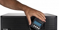
Источники бесперебойного питания нового поколения оснащены удобным ЖК-дисплеем для вывода информации о текущих параметрах энергосети и сообщений пользователю об ошибках, неисправностях и возможных неполадках с целью их оперативного устранения. Зная коды ошибок ИБП, владелец устройства сможет быстро среагировать на сообщение и предотвратить серьезные последствия любого сбоя.
Что такое события ИБП, и почему устройство пищит?
Интуитивно понятный интерфейс существенно упрощает «язык общения» бесперебойника с пользователем. Многие производители используют для типичных сообщений о состоянии ИБП не цифровые и буквенные коды, а условные обозначения. Нередко знаки на дисплее сопровождаются звуковыми сигналами бесперебойника. Если вы уже купили источник бесперебойного питания, инструкция по эксплуатации даст ответы на все вопросы о значении таких символов и кодов ошибок. Некоторые ситуации являются универсальными, встречающимися вне зависимости от марки производства устройства.
События – это фоновые условия, формой которых пользуются многие престижные марки ИБП (например, Eaton). Коды ошибок ИБП Eaton чередуются с регулярными сообщениями о событиях, которые регистрирует устройство как информацию о текущем состоянии. Такие уведомления сопровождаются звуковым сигналом, подаваемым с определенной периодичностью. Сигнал событий можно отключить – например, если вы поставили бесперебойник дома, и звук регулярных уведомлений мешает вашему досугу. Устройство будет сообщать о состоянии (работа от аккумулятора, переход на байпас, другие аспекты из журнала событий) через ЖК-дисплей. В отличие от кодов ошибок или предупреждений, события сообщают не о проблемах с бесперебойником, а о его исправной работе.

Что означают предупреждения ИБП?
Предупреждения, подаваемые при помощи символьных обозначений, мигания индикатора и звукового сигнала, свидетельствуют об определенной неисправности источника бесперебойного питания, или об угрозе.
-
Режим работы от батарей – сообщение, сопровождаемое непрерывной работой светодиодного индикатора и звуковым сигналом с промежутками времени в 5 секунд. Сообщает о сбое в энергосети, из-за чего ИБП перешел на питание от аккумулятора. Следует подготовить технику к выключению, сохранить все нужные документы – если это автоматически не предусмотрено используемым программным обеспечением.
-
Низкий заряд батареи – медленное мигание светодиода, посекундный звуковой сигнал. Это сообщение replace battery на бесперебойнике – о разряде батареи, оно может появляться на уровне заряда 25% и меньше.
-
Переход на байпас – горит индикатор-светодиод, каждые 5 секунд подается сигнал-звук. При переходе на байпас ИБП продолжает фильтровать энергию, но не защищает оборудование, так как батарейный режим работы недоступен. Причиной может служить перегрев, неисправность ИБП, перегрузка.
-
Если индикатор горит, но звукового сигнала нет – значит, ИБП перешел на байпас в высокоэффективном режиме работы. Оборудование находится под защитой, режим работы от АКБ доступен.
-
Сигнал отсоединения батарей сопровождается ежесекундным звуковым сообщением и продолжительным включением светодиода. Батареи действительно могут быть отсоединены – нужно проверить исправность подключения. Другой причиной может служить невозможность ИБП распознать батареи, что свидетельствует о неисправности ИБП, аккумуляторов, неправильного выбора аккумуляторов и других причинах ошибки.
-
Перегрузка, или overload на бесперебойнике – означает, что мощность ИБП меньше, чем возникшие требования к питанию. Необходимо отсоединить наименее приоритетную часть оборудования, иначе ИБП выключится от дальнейшего увеличения нагрузки, либо перейдет на байпас.
Во избежание перегрузки оборудование, которое не нуждается в постоянной защите (лазерные принтеры, плоттеры) рекомендуется подключать к выходам surge only на бесперебойнике. -
Перегрев – сигнал, подаваемый при чересчур высокой внутренней температуре источника. Возможно, отказал вентилятор. От момента подачи этого сообщения при повышении температуры еще на 10 градусов бесперейбоник переключается на режим байпаса, либо отключается, если работа на байпасе недоступна.
Чтобы устранить причины перегрева, следует очистить вентиляционные отверстия, перенести устройство подальше от источников тепла. Позаботьтесь об обеспечении беспрепятственного воздушного потока вокруг бесперебойника. Когда ИБП остынет, его можно перезапустить. Если проблема не решена, обращайтесь в сервисный центр. -
Слишком высокое напряжение АКБ – сигнал, сообщающий об отключении бесперебойником его зарядного устройства до запуска следующего цикла.
Некоторые значки на бесперебойнике просто сообщают о текущем состоянии устройства или о переходе из одного режима в другой, что не представляет собой сбоя или угрозы. Но если вы увидели сообщение об опасности, ошибке или неисправности ИБП, желательно обратиться к специалистам за сервисным обслуживанием устройства. Только профессионал сможет без негативных последствий устранить причины выхода из строя источника бесперебойного питания или отдельных его элементов.
Другие материалы по теме
18 мар. 2016
01 мар. 2016

02 дек. 2016

28 ноя. 2016

25 ноя. 2016

19 мар. 2016
Возврат к списку
Chapter 13
Typical Alarms and Conditions
Alarm or Condition
On Battery
LED is on.
1 beep every second.
Battery Low
LED is on.
Continuous beep for
10 seconds.
Battery Breaker
LED is on.
1 beep every second.
Overload
LED is on.
1 beep every second.
Overtemperature
LED is on.
1 beep every second.
Battery test failed
EATON Powerware
The Powerware 9355 is designed for durable, automatic operation and also alerts you
whenever potential operating problems may occur. Usually the alarms shown by the
control panel do not mean that the output power is affected. Instead, they are
preventive alarms intended to alert the user. Use the following troubleshooting chart
to determine the UPS alarm condition.
The following table describes typical alarms and conditions; check the Event Log
through the control panel for a list of active alarms. If an alarm appears with a service
code, please contact the Help Desk (see page 89).
Possible Cause
A utility failure has occurred and the UPS is in
Battery mode.
The battery is running low.
The UPS does not recognize the internal
batteries.
The power requirements exceed the UPS
capacity (greater than 100% of nominal; see
page 84 for specific output overload ranges).
The UPS internal temperature is too high or the
fan has failed.
The batteries need service.
®
9355 UPS (20/30 kVA) Installation and Operation Manual
Action
The UPS is powering the equipment with battery power. Prepare
your equipment for shutdown.
Five minutes or less of battery power remains (depending on load
configuration and battery charge). Save your work and turn off
your equipment.
When utility power is restored, the UPS restarts automatically,
provides power to the load, and charges the battery.
Verify the battery circuit breaker is in the ON position. If the
condition persists, contact your service representative.
Remove some of the equipment from the UPS. The UPS continues
to operate, but may switch to Bypass mode if the load increases.
The alarm resets when the condition becomes inactive.
Turn the maintenance bypass switch to the SERVICE position.
Otherwise, shut down the UPS.
Clear vents and remove any heat sources. Allow the UPS to cool.
Ensure the airflow around the UPS is not restricted.
If the alarm disappears, turn the maintenance bypass switch back
to the UPS position.
If the condition persists, contact your service representative.
Contact your service representative.
S
164201626 Rev B www.powerware.com
87
подробное описание кодов ошибок по Eaton
| Автор | Сообщение | |||||||||
|---|---|---|---|---|---|---|---|---|---|---|
|
Site Admin
Зарегистрирован: 06 апр 2005 08:14 |
Одно из самых полных описаний кодов неисправностей по различным комплектациям моторов, кпп и других компонентов. Данное издание подготовлено Eaton
|
|||||||||
| 22 июн 2012 17:04 |
|
|||||||||
|
Antart Ф@Н@Т
Зарегистрирован: 15 апр 2010 08:48 |
Ну и здесь на русском : http://tulatruck.ru/load/fajly_sajta/fa … 34-1-0-113 http://tulatruck.ru/load/fajly_sajta/fa … 34-1-0-114
|
|||||||||
| 22 июн 2012 18:45 |
|
|||||||||
|
Igor Site Admin
Зарегистрирован: 06 апр 2005 08:14 |
Что то я не найду куда там ткунть ??? Или надо регистрироваться ??? |
|||||||||
| 23 июн 2012 01:11 |
|
|||||||||
|
Lehers_rus Ф@Н@Т
Предупреждения: 1 Зарегистрирован: 09 дек 2011 12:36 |
можно ведь и сюда добавить. |
|||||||||
| 23 июн 2012 08:14 |
|
|||||||||
|
Миша Ф@Н@Т
Зарегистрирован: 27 окт 2006 19:31 |
Да походу надо регистрироватся, да ещё статус иметь, Андрей погорячился со ссылкой Добавлено спустя 8 минут 18 секунд: |
|||||||||
| 23 июн 2012 08:56 |
|
|||||||||
|
Antart Ф@Н@Т
Зарегистрирован: 15 апр 2010 08:48 |
Не подумал что будут проблемы с просмотром… http://files.mail.ru/BHOZQ9 |
|||||||||
| 24 июн 2012 09:46 |
|
|||||||||
| Показать сообщения за: Поле сортировки |


-
Contents
-
Table of Contents
-
Troubleshooting
-
Bookmarks
Quick Links
Eaton
9355 UPS
®
20/30 kVA
Installation and Operation Manual
Related Manuals for Eaton 9355
Summary of Contents for Eaton 9355
-
Page 1
Eaton 9355 UPS ® 20/30 kVA Installation and Operation Manual… -
Page 3
Eaton 9355 UPS ® 20/30 kVA Installation and Operation Manual… -
Page 4
Eaton, Powerware, ABM, LanSafe, Powerware Hot Sync, and X-Slot are registered trademarks of Eaton or its subsidiaries and affiliates. Greenlee is a registered trademark of Greenlee Textron. Modbus is a registered trademark of Schneider Automation. National Electrical Code and NEC are registered trademarks of National Fire Protection Association, Inc. -
Page 5
Class A EMC Statements FCC Part 15 This equipment has been tested and found to comply with the limits for a Class A digital device, pursuant to part 15 of the FCC Rules. These limits are designed to provide reasonable protection against harmful interference when the equipment is operated in a commercial environment. -
Page 6: Special Symbols
Special Symbols The following are examples of symbols used on the UPS or accessories to alert you to important information: RISK OF ELECTRIC SHOCK — Observe the warning associated with the risk of electric shock symbol. CAUTION: REFER TO OPERATOR’S MANUAL — Refer to your operator’s manual for additional information, such as important operating and maintenance instructions.
-
Page 7: Table Of Contents
PARALLEL COMMUNICATION…………….Eaton 9355 UPS (20/30kVA) Installation and Operation Manual 164201626—Rev F…
-
Page 8
Limited Factory Warranty …………..Eaton 9355 UPS (20/30kVA) Installation and Operation Manual 164201626—Rev F… -
Page 9: Introduction
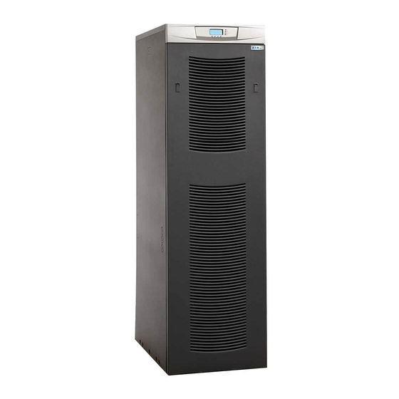
During brownouts, blackouts, and other power interruptions, batteries provide emergency power to safeguard operation. With the Eaton 9355 UPS, you can safely eliminate the effects of electrical line disturbances and guard the integrity of your systems and equipment. Figure 1 shows the Eaton 9355 UPS (20/30 kVA) with an optional Extended Battery Cabinet (EBC) and Options Cabinet.
-
Page 10
Introduction Providing outstanding performance and reliability, the Eaton 9355 UPS’s unique benefits including the following: Online UPS design with pure sine wave output. The UPS filters and regulates incoming AC power and provides consistent power to your equipment without draining the battery. -
Page 11
UPS from virtually any location within the facility. You can install multiple RMPs at remote locations to increase your monitoring capabilities. Seismic Kit The optional seismic kit secures the UPS and optional cabinets for Zone 4 seismic installations. Eaton 9355 UPS (20/30kVA) Installation and Operation Manual 164201626—Rev F www.eaton.com/powerquality… -
Page 12
Introduction This page intentionally left blank. Eaton 9355 UPS (20/30kVA) Installation and Operation Manual 164201626—Rev F www.eaton.com/powerquality… -
Page 13: Safety Warnings
Keep unauthorized personnel away from batteries. Proper disposal of batteries is required. Refer to your local codes for disposal requirements. Never dispose of batteries in a fire. Batteries may explode when exposed to flame. Eaton 9355 UPS (20/30kVA) Installation and Operation Manual 164201626—Rev F www.eaton.com/powerquality…
-
Page 14
Une mise au rebut réglementaire des batteries est obligatoire. Consulter les règlements en vigueur dans votre localité. Ne jamais jeter les batteries au feu. L’exposition aux flammes risque de les faire exploser. Eaton 9355 UPS (20/30kVA) Installation and Operation Manual 164201626—Rev F www.eaton.com/powerquality… -
Page 15
Es necesario desechar las baterías de un modo adecuado. Consulte las normas locales para conocer los requisitos pertinentes. Nunca deseche las baterías en el fuego. Las baterías pueden explotar si se las expone a la llama. Eaton 9355 UPS (20/30kVA) Installation and Operation Manual 164201626—Rev F www.eaton.com/powerquality… -
Page 16
Safety Warnings This page intentionally left blank. Eaton 9355 UPS (20/30kVA) Installation and Operation Manual 164201626—Rev F www.eaton.com/powerquality… -
Page 17: Ups Setup
Options Cabinet with MBS only 205 lb (93 kg) 51 lb/in (3.6 kg/cm Clearances The following clearances are recommended for the Eaton 9355 UPS: From Front of Cabinet 36″ (91.4 cm) working space From Back of Cabinet 6″ (15.2 cm) From Right of Cabinet Refer to local codes for right side service access [minimum 36″…
-
Page 18: Removing And Replacing The Front Doors
Lift the door up and off the cabinet. To replace the door: Insert the door notches into the slots on the bottom of the cabinet. Secure the door latches. Figure 2. Removing the UPS Front Door Eaton 9355 UPS (20/30kVA) Installation and Operation Manual 164201626—Rev F www.eaton.com/powerquality…
-
Page 19: Ebc Front Door
Lift the door up and off the cabinet. To replace the door: Place the door on the bottom hooks of the EBC. Replace the two door screws. Figure 3. Removing the EBC Front Door Eaton 9355 UPS (20/30kVA) Installation and Operation Manual 164201626—Rev F www.eaton.com/powerquality…
-
Page 20: Unloading The Cabinet(S)
Be sure to retain the rear shipping bracket and hardware for later re-assembly if you plan to permanently mount the cabinet. M10 Bolts M8 Screws Figure 4. Removing the Rear Shipping Bracket (UPS Shown) Eaton 9355 UPS (20/30kVA) Installation and Operation Manual 164201626—Rev F www.eaton.com/powerquality…
-
Page 21
Remove the three M10 bolts securing the rear shipping pad to the pallet and remove the shipping pad (see Figure 5). M10 Bolts Shipping Pad Figure 5. Removing the Shipping Pad (UPS Shown) Eaton 9355 UPS (20/30kVA) Installation and Operation Manual 164201626—Rev F www.eaton.com/powerquality… -
Page 22
Remove the two M10 bolts securing the front shipping bracket to the pallet and remove the bracket. M10 Bolts M8 Screws Figure 6. Removing the Front Shipping Bracket (UPS Shown) Eaton 9355 UPS (20/30kVA) Installation and Operation Manual 164201626—Rev F www.eaton.com/powerquality… -
Page 23
Slowly roll the cabinet toward the rear of the pallet. Once the pallet tilts, continue rolling the cabinet down the pallet until the cabinet touches the floor (see Figure 8). Figure 8. Unloading the Cabinet (UPS Shown) Eaton 9355 UPS (20/30kVA) Installation and Operation Manual 164201626—Rev F www.eaton.com/powerquality… -
Page 24
11. Roll the cabinet to the desired location. 12. If you are installing more than one cabinet, continue to “Joining the Cabinets” on page 17; otherwise, continue to “Electrical Installation” on page 21. Eaton 9355 UPS (20/30kVA) Installation and Operation Manual 164201626—Rev F www.eaton.com/powerquality… -
Page 25: Joining The Cabinets
If you have two Options Cabinets, remove the three circular knockouts on the left side of the first Options Cabinet. 10. Install three bushings (supplied) in the circular knockouts of the adjacent cabinet. Eaton 9355 UPS (20/30kVA) Installation and Operation Manual 164201626—Rev F www.eaton.com/powerquality…
-
Page 26
13. Install the other ground strap between the front panels of the adjacent cabinets as shown in Figure 11. 14. Repeat Steps 11 through 13 for each cabinet. 15. Replace the front door of all cabinets. 16. Continue to “Electrical Installation” on page 21. Eaton 9355 UPS (20/30kVA) Installation and Operation Manual 164201626—Rev F www.eaton.com/powerquality… -
Page 27
Joining the Cabinets Rear Ground Strap Front Ground Strap Figure 11. Ground Strap Installation Eaton 9355 UPS (20/30kVA) Installation and Operation Manual 164201626—Rev F www.eaton.com/powerquality… -
Page 28
Joining the Cabinets This page intentionally left blank. Eaton 9355 UPS (20/30kVA) Installation and Operation Manual 164201626—Rev F www.eaton.com/powerquality… -
Page 29: Electrical Installation
To accommodate the feature of easy system expandability, it is recommended that initial installation of the Eaton 9355 UPS contain wiring to support the maximum capacity of the UPS cabinet. Switch off utility power to the distribution point where the UPS or Options Cabinet will be connected. Be absolutely sure there is no power.
-
Page 30
Electrical Installation Input Circuit Output Circuit Battery Circuit Breaker Breaker (optional) Breaker Wiring Access Cover UPS Connection Insulator Figure 12. UPS Front View Eaton 9355 UPS (20/30kVA) Installation and Operation Manual 164201626—Rev F www.eaton.com/powerquality… -
Page 31: Wiring Installation
UPS with Options Cabinet that has an input transformer only – see “Options Cabinet with Dual-Feed Wiring” on page 31 UPS with Options Cabinet that has an output transformer only– see “Options Cabinet with Output Transformer Wiring” on 33 Eaton 9355 UPS (20/30kVA) Installation and Operation Manual 164201626—Rev F www.eaton.com/powerquality…
-
Page 32: Ups Only Wiring
Reinstall the UPS conduit landing box in the reversed position (see Figure 14). Replace the UPS front door (see page 10). Figure 14. Reversing the UPS Conduit Landing Box Eaton 9355 UPS (20/30kVA) Installation and Operation Manual 164201626—Rev F www.eaton.com/powerquality…
-
Page 33: Parallel Ups Wiring
From UPS 1 Output From UPS 2 Output From UPS 3 Output From UPS 4 Output Figure 15. Parallel Wiring Diagram – Version 1 and Version 2 without Maitenance Isolation Switch (MIS) Eaton 9355 UPS (20/30kVA) Installation and Operation Manual 164201626—Rev F www.eaton.com/powerquality…
-
Page 34
13. Reinstall the UPS wiring access cover. 14. Reinstall the UPS conduit landing box in the reversed position (see Figure 14 on page 24). 15. Replace the UPS front door (see page 10). Eaton 9355 UPS (20/30kVA) Installation and Operation Manual 164201626—Rev F www.eaton.com/powerquality… -
Page 35
Electrical Installation Maintenance Bypass Wiring to UPS TB4 Neutral Ground Line 1 Line 3 Line 2 Figure 17. Bypass AC Input Wiring (Eaton Tie Cabinet Version 1 Shown) Eaton 9355 UPS (20/30kVA) Installation and Operation Manual 164201626—Rev F www.eaton.com/powerquality… -
Page 36
Electrical Installation Neutral Ground Line 2 Line 3 Line 1 Maintenance Bypass Wiring to UPS TB4 Figure 18. Bypass AC Input Wiring (Eaton Tie Cabinet Version 2 with MIS Shown) Eaton 9355 UPS (20/30kVA) Installation and Operation Manual 164201626—Rev F www.eaton.com/powerquality… -
Page 37: Options Cabinet With Mbs Wiring
10. Reinstall the UPS connections insulator. 11. Reinstall the UPS wiring access cover. 12. Replace the UPS front door (see page 10). Figure 19. Reversing the Options Cabinet Conduit Landing Box Eaton 9355 UPS (20/30kVA) Installation and Operation Manual 164201626—Rev F www.eaton.com/powerquality…
-
Page 38
Options Cabinet with Bypass Auxiliary MBS and Input Isolation Contacts Transformer or with MBS and Input and Output Transformer L1 L1 Input Output Figure 20. Options Cabinet with MBS Wiring Eaton 9355 UPS (20/30kVA) Installation and Operation Manual 164201626—Rev F www.eaton.com/powerquality… -
Page 39: Options Cabinet With Dual-Feed Wiring
10. Replace both Options Cabinet front doors (see page 10). 11. Reinstall the UPS connections insulator. 12. Reinstall the UPS wiring access cover. 13. Replace the UPS front door (see page 10). Eaton 9355 UPS (20/30kVA) Installation and Operation Manual 164201626—Rev F www.eaton.com/powerquality…
-
Page 40
Second Options Cabinet First Options Cabinet with Rectifier Transformer with MBS Only L1 L1 L1 L1 Input Input Output Maintenance Bypass Auxiliary Contacts Figure 21. Options Cabinets with Dual-Feed Wiring Eaton 9355 UPS (20/30kVA) Installation and Operation Manual 164201626—Rev F www.eaton.com/powerquality… -
Page 41: Options Cabinet With Output Transformer Wiring
Replace both Options Cabinet front doors (see page 10). 10. Reinstall the UPS connections insulator. 11. Reinstall the UPS wiring access cover. 12. Replace the UPS front door (see page 10). Eaton 9355 UPS (20/30kVA) Installation and Operation Manual 164201626—Rev F www.eaton.com/powerquality…
-
Page 42
Second Options Cabinet First Options Cabinet with Output Transformer with MBS Only L1 L1 Input Output Output Maintenance Bypass Auxiliary Contacts Figure 22. Options Cabinets with Output Transformer Wiring Eaton 9355 UPS (20/30kVA) Installation and Operation Manual 164201626—Rev F www.eaton.com/powerquality… -
Page 43: Wiring Specifications And Diagrams
Cabinet with an input isolation transformer, the input neutral is supplied by the input isolation transformer. Note: The Eaton 9355 UPS is shipped as a single-feed UPS and can be converted to a dual-feed UPS in the field. Note: DO NOT overtighten the screws; be sure to use the specified tightening torque values shown in Table 1.
-
Page 44
The two input neutral terminals are jumpered together; use either one of these terminals to make the input neutral connection. Note: The two output neutral terminals are jumpered together; use either one of these terminals to make the output neutral connection. Eaton 9355 UPS (20/30kVA) Installation and Operation Manual 164201626—Rev F www.eaton.com/powerquality… -
Page 45
Electrical Installation Figure 24. UPS Wiring Diagram (Single-Feed, 208V or 220V Input : 208V or 220V Output) Eaton 9355 UPS (20/30kVA) Installation and Operation Manual 164201626—Rev F www.eaton.com/powerquality… -
Page 46
Electrical Installation Figure 25. UPS with EBCs Wiring Diagram (Single-Feed, 208V or 220V Input : 208V or 220V Output) Eaton 9355 UPS (20/30kVA) Installation and Operation Manual 164201626—Rev F www.eaton.com/powerquality… -
Page 47
Electrical Installation Figure 26. UPS and Options Cabinet with MBS Only (Single-Feed, 208V or 220V Input : 208V Output) Eaton 9355 UPS (20/30kVA) Installation and Operation Manual 164201626—Rev F www.eaton.com/powerquality… -
Page 48
Electrical Installation Figure 27. UPS and Options Cabinet with MBS/Input Isolation Transformer Wiring Diagram (Single-Feed, 208V, 480V, or 600V Input : 208V Output) Eaton 9355 UPS (20/30kVA) Installation and Operation Manual 164201626—Rev F www.eaton.com/powerquality… -
Page 49
Electrical Installation Figure 28. UPS and Dual-Feed Options Cabinets Wiring Diagram (Dual-Feed, 208V, 480V, or 600V Input : 208V Output) Eaton 9355 UPS (20/30kVA) Installation and Operation Manual 164201626—Rev F www.eaton.com/powerquality… -
Page 50
Electrical Installation Figure 29. UPS and Dual Options Cabinets with Input and Output Transformers Wiring Diagram (Single-Feed, 480V Input : 480V Output) Eaton 9355 UPS (20/30kVA) Installation and Operation Manual 164201626—Rev F www.eaton.com/powerquality… -
Page 51
Electrical Installation Figure 30. UPS and Single Options Cabinet with Input and Output Transformers Wiring Diagram (Single-Feed, 480V Input : 480V Output) Eaton 9355 UPS (20/30kVA) Installation and Operation Manual 164201626—Rev F www.eaton.com/powerquality… -
Page 52
Electrical Installation Figure 31. Parallel UPS System with Tie Cabinet Diagram (Single-Feed, 208V or 220V Input : 208V or 220V Output) Eaton 9355 UPS (20/30kVA) Installation and Operation Manual 164201626—Rev F www.eaton.com/powerquality… -
Page 53: Extended Battery Cabinet Installation
“Operation” on page 69 to start up the UPS. Note: After UPS startup, ensure maximum battery runtime by configuring the UPS for the correct number of EBCs (see page 75). Eaton 9355 UPS (20/30kVA) Installation and Operation Manual 164201626—Rev F www.eaton.com/powerquality…
-
Page 54
Extended Battery Cabinet Installation UPS Battery Connector EBC Battery Connector EBC Cable UPS Battery Circuit Breaker Figure 32. Typical EBC Installation Eaton 9355 UPS (20/30kVA) Installation and Operation Manual 164201626—Rev F www.eaton.com/powerquality… -
Page 55
Extended Battery Cabinet Installation EBC Cable Hooks Figure 33. Dual Transformer Options Cabinet EBC Cable Hooks Eaton 9355 UPS (20/30kVA) Installation and Operation Manual 164201626—Rev F www.eaton.com/powerquality… -
Page 56
Extended Battery Cabinet Installation This page intentionally left blank. Eaton 9355 UPS (20/30kVA) Installation and Operation Manual 164201626—Rev F www.eaton.com/powerquality… -
Page 57: Permanent Mounting Installation
“Operation” on page 69 to start up the UPS. Note: After UPS startup, ensure maximum battery runtime by configuring the UPS for the correct number of EBCs (see page 75). Eaton 9355 UPS (20/30kVA) Installation and Operation Manual 164201626—Rev F www.eaton.com/powerquality…
-
Page 58
Permanent Mounting Installation Figure 35. Permanent Mounting Eaton 9355 UPS (20/30kVA) Installation and Operation Manual 164201626—Rev F www.eaton.com/powerquality… -
Page 59: Communication
REPO (normally open) REPO (normally closed) Signal Input 2 Pull-Chain Output Signal Input 1 Contacts (parallel only) DB-9 Communication Port Relay Output Contacts Figure 36. Communication Options and Control Terminals Eaton 9355 UPS (20/30kVA) Installation and Operation Manual 164201626—Rev F www.eaton.com/powerquality…
-
Page 60: Installing Communication Options And Control Terminals
Route the control terminal cable(s) through the middle of the fan section and secure in the cable clips. Cable Clips for Control Terminal Wiring Figure 37. Installing Communication Cables Eaton 9355 UPS (20/30kVA) Installation and Operation Manual 164201626—Rev F www.eaton.com/powerquality…
-
Page 61
See “Communication Options” on page 54 or “Control Terminals” on page 60 for detailed information. Reinstall the communication wiring access plate. Replace the UPS front door. Continue to “Operation” on page 69 to start up the UPS. Eaton 9355 UPS (20/30kVA) Installation and Operation Manual 164201626—Rev F www.eaton.com/powerquality… -
Page 62: Communication Options
For information about the Powerware Hot Sync CAN Bridge Card, see ”Parallel Communication” on page 63. X-Slot cards allow the UPS to communicate in a variety of networking environments and with different types of devices. The Eaton 9355 UPS has two available communication bays for any X-Slot card, including: Power Xpert Gateway Card — provides a data gateway from the UPS to the Power Xpert Software;…
-
Page 63
USB Card — connects to a USB port on your computer. Note: The Eaton 9355 UPS does not detect plug-and-play hardware. Before installing the USB Card, set the UPS baud rate to 1200 through the front panel (see Table 7 on page 70). -
Page 64: Remote Monitor Panel
Figure 42 shows an RMP. Figure 43 shows the enclosure dimensions and cable exit openings. Cable Exit Opening for 1/2” Conduit or Provided Strain Relief Horn Silence Button Figure 42. Remote Monitor Panel Eaton 9355 UPS (20/30kVA) Installation and Operation Manual 164201626—Rev F www.eaton.com/powerquality…
-
Page 65
Connect the wiring between the RMP and the IRC plug-in terminal blocks using terminations shown in Table 3. See Figure 44 and Figure 45 for plug-in terminal block locations. Eaton 9355 UPS (20/30kVA) Installation and Operation Manual 164201626—Rev F www.eaton.com/powerquality… -
Page 66
NOTE Conduit and wiring supplied by the customer. The maximum distance between the RMP and the UPS is not to exceed 500 ft (152.4m). Figure 44. RMP Top Internal View Eaton 9355 UPS (20/30kVA) Installation and Operation Manual 164201626—Rev F www.eaton.com/powerquality… -
Page 67: Industrial Relay Card
J2-4 Bypass mode J2-5 J2-6 J2-7 Battery mode J2-8 J2-9 J2-10 Alarm mode J2-11 J2-12 NOTE Maximum contact rating: 250 Vac, 30 Vdc @ 5A; Wire range: 16–24 AWG Eaton 9355 UPS (20/30kVA) Installation and Operation Manual 164201626—Rev F www.eaton.com/powerquality…
-
Page 68: Lansafe Power Management Software
UPS or power information. If there is a power outage and the Eaton 9355 UPS battery power becomes low, LanSafe software can automatically shut down your computer system to protect your data before the UPS shutdown occurs.
-
Page 69: Remote Emergency Power-Off
The pins must be shorted with maximum resistance of 10 ohm to activate the specific input. Note: See Figure 46 on page 60 for the polarity and verify these connections if polarity control is required. Eaton 9355 UPS (20/30kVA) Installation and Operation Manual 164201626—Rev F www.eaton.com/powerquality…
-
Page 70
If active, the UPS knows that input is fed from the generator. Bypass is disabled; the automatic battery test is disabled. External Transformer Overtemperature This option is not used. Eaton 9355 UPS (20/30kVA) Installation and Operation Manual 164201626—Rev F www.eaton.com/powerquality… -
Page 71: Parallel Communication
Remove the communication wiring access plate from the UPS rear panel and punch a hole in it using a Greenlee punch or similar device (see Figure 48). Install conduit for the communication wiring. Communication Wiring Access Plate Figure 48. Communication Wiring Access Eaton 9355 UPS (20/30kVA) Installation and Operation Manual 164201626—Rev F www.eaton.com/powerquality…
-
Page 72
Route the wiring through the conduit from the communication wiring access plate to the opening between the two X-Slot communication bays on each UPS (see Figure 50). Figure 50. Routing the Cables Eaton 9355 UPS (20/30kVA) Installation and Operation Manual 164201626—Rev F www.eaton.com/powerquality… -
Page 73
10. Route the pull-chain wiring through the middle of the fan section and secure in the cable clips for each UPS (see Figure 51). Figure 51. Installing Communication Cables Eaton 9355 UPS (20/30kVA) Installation and Operation Manual 164201626—Rev F www.eaton.com/powerquality… -
Page 74
Signal Input 2 can still be used for building alarms; it is automatically rerouted to the CAN Bridge Card. 12. Reinstall the communication wiring access plate on each UPS. 13. Replace the UPS front door on each UPS. Eaton 9355 UPS (20/30kVA) Installation and Operation Manual 164201626—Rev F www.eaton.com/powerquality… -
Page 75
X52- — NC UPS #1 UPS #2 UPS #3 From UPS #1 To UPS #3 Signal Input 2 Pull-Chain Output Contacts Figure 52. CAN Bridge Card and Pull-Chain Wiring Eaton 9355 UPS (20/30kVA) Installation and Operation Manual 164201626—Rev F www.eaton.com/powerquality… -
Page 76
Parallel Communication This page intentionally left blank. Eaton 9355 UPS (20/30kVA) Installation and Operation Manual 164201626—Rev F www.eaton.com/powerquality… -
Page 77: Operation
Chapter 10 Operation This chapter contains information on how to use the Eaton 9355 UPS, including front panel operation, UPS startup and shutdown, and configuring the UPS for Extended Battery Cabinets (EBCs). Control Panel Functions The UPS has a four-button graphical LCD with backlight. It provides useful information about the UPS itself, load status, events, measurements, and settings (see Figure 53).
-
Page 78: User Settings
Alarm 1: empty Setup: [Battery Low] [On Battery] [On Bypass] [UPS ok] X-Slots (1 or 2) [custom] [empty] #1: UPS ok #2: On Bypass #3: Summary Alarm #4: On Battery Eaton 9355 UPS (20/30kVA) Installation and Operation Manual 164201626—Rev F www.eaton.com/powerquality…
-
Page 79
Control Commands from X-Slot1 Allowed/Disabled Allowed Control Commands from X-Slot2/ Allowed/Disabled Allowed Serv X-Slot Signal Input Activation Delay 0 through 65 seconds Input Signal Delayed Shutdown 1 through 65535 seconds 120s Delay Eaton 9355 UPS (20/30kVA) Installation and Operation Manual 164201626—Rev F www.eaton.com/powerquality… -
Page 80: Initial Startup
Disabled after initial startup Initial Startup Startup and operational checks must be performed by an authorized Eaton Customer Service Engineer, or the warranty terms as specified on page 89 become void. This service is offered as part of the sales contract for the UPS.
-
Page 81: Starting The Ups On Battery
Press any button on the front panel display to activate the menu options. Within three minutes, press the button on the front panel display and then press the button to select the TURN UPS ON/OFF menu. Eaton 9355 UPS (20/30kVA) Installation and Operation Manual 164201626—Rev F www.eaton.com/powerquality…
-
Page 82: Internal Bypass Startup
Switch on utility power where the UPS is connected. The load is now powered by utility power. To transfer the load to the UPS, see “Using the UPS Maintenance Bypass Switch” on page 80. Eaton 9355 UPS (20/30kVA) Installation and Operation Manual 164201626—Rev F www.eaton.com/powerquality…
-
Page 83: Configuring The Ups For Ebcs
If the optional UPS output circuit breaker is installed, switch the breaker to the OFF position. Replace the UPS front door. Switch off utility power where the UPS is connected. Eaton 9355 UPS (20/30kVA) Installation and Operation Manual 164201626—Rev F www.eaton.com/powerquality…
-
Page 84: Parallel Operation
Operation Parallel Operation Initial startup must be performed by an authorized Eaton Customer Service Engineer. This section describes shutting down and restarting UPSs in a parallel system. Parallel System Shutdown To remove power to the parallel UPS system output: Press any button on the front panel display to activate the menu options.
-
Page 85: Restarting The Parallel System
The UPS goes to Bypass mode for five seconds, and then the indicator illuminates. Each UPS should be in Normal mode. 14. Press the button until the Eaton logo or Mimic screen appears. Eaton 9355 UPS (20/30kVA) Installation and Operation Manual 164201626—Rev F www.eaton.com/powerquality…
-
Page 86
Operation This page intentionally left blank. Eaton 9355 UPS (20/30kVA) Installation and Operation Manual 164201626—Rev F www.eaton.com/powerquality… -
Page 87: Ups Maintenance
Change the batteries approximately every five years. Recycling the Used Battery or UPS Contact your local recycling or hazardous waste center for information on proper disposal of the used battery or UPS. Eaton 9355 UPS (20/30kVA) Installation and Operation Manual 164201626—Rev F www.eaton.com/powerquality…
-
Page 88: Using The Ups Maintenance Bypass Switch
The SERVICE position on the switch allows a service engineer to apply power to the UPS input and verify its operation while the load is powered through bypass. Figure 55. Maintenance Bypass Switch Eaton 9355 UPS (20/30kVA) Installation and Operation Manual 164201626—Rev F www.eaton.com/powerquality…
-
Page 89: Single Ups Bypass
Turn the maintenance bypass switch to the UPS position to return to Normal mode. Verify the rear fan is running. The UPS is now powering the load. Replace the UPS front door. Eaton 9355 UPS (20/30kVA) Installation and Operation Manual 164201626—Rev F www.eaton.com/powerquality…
-
Page 90: Parallel Ups Bypass
On the same UPS front panel, set the UPS to Normal mode: Press the button to select the Go to Normal Mode option. Each UPS should go to Normal mode. The UPS is now powering the load in Normal mode. Eaton 9355 UPS (20/30kVA) Installation and Operation Manual 164201626—Rev F www.eaton.com/powerquality…
-
Page 91: Specifications
<62 dBA Surge Suppression ANSI C62.41 Category B3 Safety Conformance NOM-019-SCFI, UL 1778, CSA C22.2, No. 107.3 Agency Markings cULus EMC (Class A) IEC 62040-2, FCC Part 15, ICES-003 Eaton 9355 UPS (20/30kVA) Installation and Operation Manual 164201626—Rev F www.eaton.com/powerquality…
-
Page 92
Output Frequency 50/60-Hz selectable or autoconfiguring Output Frequency Regulation Synchronization to line Output Overload 101–110% for 10 minutes 111–125% for 60 seconds 126–149% for 5 seconds >150% for 300 milliseconds Eaton 9355 UPS (20/30kVA) Installation and Operation Manual 164201626—Rev F www.eaton.com/powerquality… -
Page 93
100A 100A 100A Output Current Output kVA Output kW Efficiency (Minimum) Heat Rejection [BTU/hr (kg-cal/hr)] 9220 (2323) 13831 (3485) 13831 (3485) 9220 (2323) 13493 (3402) 18104 (4565) 18104 (4565) Eaton 9355 UPS (20/30kVA) Installation and Operation Manual 164201626—Rev F www.eaton.com/powerquality… -
Page 94
+(1) EBC 72 +(2) EBC 72 +(3) EBC 72 30 kVA/27 kW 20 kVA/18 kW NOTE Battery times are approximate and vary depending on the load configuration and battery charge. Eaton 9355 UPS (20/30kVA) Installation and Operation Manual 164201626—Rev F www.eaton.com/powerquality… -
Page 95: Troubleshooting
Chapter 13 Troubleshooting The Eaton 9355 is designed for durable, automatic operation and also alerts you whenever potential operating problems may occur. Usually the alarms shown by the control panel do not mean that the output power is affected. Instead, they are preventive alarms intended to alert the user. Use the following troubleshooting chart to determine the UPS alarm condition.
-
Page 96: Silencing The Alarm
Please have the following information ready when you call for service: Model number Serial number Firmware version number Date of failure or problem Symptoms of failure or problem Customer return address and contact information Eaton 9355 UPS (20/30kVA) Installation and Operation Manual 164201626—Rev F www.eaton.com/powerquality…
-
Page 97: Warranty
“Warranted Items”) are free from defects in material and workmanship. If, in the opinion of Eaton, a Warranted Item is defective and the defect is within the terms of this Warranty, Eaton’s sole obligation will be to repair or replace such defective item (including by providing service, parts, and labor, as applicable), at the option of Eaton.
-
Page 98
OTHER LIMITATIONS: Eaton’s obligations under this Warranty are expressly conditioned upon receipt by Eaton of all payments due to it (including interest charges, if any). During such time as Eaton has not received payment of any amount due to it for the Product, in accordance with the contract terms under which the Product is sold, Eaton shall have no obligation under this Warranty. -
Page 100
*164201626 D* 164201626 F…
-
Contents
-
Table of Contents
-
Troubleshooting
-
Bookmarks
Quick Links
Eaton
9355 UPS
®
20/30 kVA
Installation and Operation Manual
Related Manuals for Eaton 9355
Summary of Contents for Eaton 9355
-
Page 1
Eaton 9355 UPS ® 20/30 kVA Installation and Operation Manual… -
Page 3
Eaton 9355 UPS ® 20/30 kVA Installation and Operation Manual… -
Page 4
Eaton, Powerware, ABM, LanSafe, Powerware Hot Sync, and X-Slot are registered trademarks of Eaton or its subsidiaries and affiliates. Greenlee is a registered trademark of Greenlee Textron. Modbus is a registered trademark of Schneider Automation. National Electrical Code and NEC are registered trademarks of National Fire Protection Association, Inc. -
Page 5
Class A EMC Statements FCC Part 15 This equipment has been tested and found to comply with the limits for a Class A digital device, pursuant to part 15 of the FCC Rules. These limits are designed to provide reasonable protection against harmful interference when the equipment is operated in a commercial environment. -
Page 6: Special Symbols
Special Symbols The following are examples of symbols used on the UPS or accessories to alert you to important information: RISK OF ELECTRIC SHOCK — Observe the warning associated with the risk of electric shock symbol. CAUTION: REFER TO OPERATOR’S MANUAL — Refer to your operator’s manual for additional information, such as important operating and maintenance instructions.
-
Page 7: Table Of Contents
PARALLEL COMMUNICATION…………….Eaton 9355 UPS (20/30kVA) Installation and Operation Manual 164201626—Rev F…
-
Page 8
Limited Factory Warranty …………..Eaton 9355 UPS (20/30kVA) Installation and Operation Manual 164201626—Rev F… -
Page 9: Introduction
During brownouts, blackouts, and other power interruptions, batteries provide emergency power to safeguard operation. With the Eaton 9355 UPS, you can safely eliminate the effects of electrical line disturbances and guard the integrity of your systems and equipment. Figure 1 shows the Eaton 9355 UPS (20/30 kVA) with an optional Extended Battery Cabinet (EBC) and Options Cabinet.
-
Page 10
Introduction Providing outstanding performance and reliability, the Eaton 9355 UPS’s unique benefits including the following: Online UPS design with pure sine wave output. The UPS filters and regulates incoming AC power and provides consistent power to your equipment without draining the battery. -
Page 11
UPS from virtually any location within the facility. You can install multiple RMPs at remote locations to increase your monitoring capabilities. Seismic Kit The optional seismic kit secures the UPS and optional cabinets for Zone 4 seismic installations. Eaton 9355 UPS (20/30kVA) Installation and Operation Manual 164201626—Rev F www.eaton.com/powerquality… -
Page 12
Introduction This page intentionally left blank. Eaton 9355 UPS (20/30kVA) Installation and Operation Manual 164201626—Rev F www.eaton.com/powerquality… -
Page 13: Safety Warnings
Keep unauthorized personnel away from batteries. Proper disposal of batteries is required. Refer to your local codes for disposal requirements. Never dispose of batteries in a fire. Batteries may explode when exposed to flame. Eaton 9355 UPS (20/30kVA) Installation and Operation Manual 164201626—Rev F www.eaton.com/powerquality…
-
Page 14
Une mise au rebut réglementaire des batteries est obligatoire. Consulter les règlements en vigueur dans votre localité. Ne jamais jeter les batteries au feu. L’exposition aux flammes risque de les faire exploser. Eaton 9355 UPS (20/30kVA) Installation and Operation Manual 164201626—Rev F www.eaton.com/powerquality… -
Page 15
Es necesario desechar las baterías de un modo adecuado. Consulte las normas locales para conocer los requisitos pertinentes. Nunca deseche las baterías en el fuego. Las baterías pueden explotar si se las expone a la llama. Eaton 9355 UPS (20/30kVA) Installation and Operation Manual 164201626—Rev F www.eaton.com/powerquality… -
Page 16
Safety Warnings This page intentionally left blank. Eaton 9355 UPS (20/30kVA) Installation and Operation Manual 164201626—Rev F www.eaton.com/powerquality… -
Page 17: Ups Setup
Options Cabinet with MBS only 205 lb (93 kg) 51 lb/in (3.6 kg/cm Clearances The following clearances are recommended for the Eaton 9355 UPS: From Front of Cabinet 36″ (91.4 cm) working space From Back of Cabinet 6″ (15.2 cm) From Right of Cabinet Refer to local codes for right side service access [minimum 36″…
-
Page 18: Removing And Replacing The Front Doors
Lift the door up and off the cabinet. To replace the door: Insert the door notches into the slots on the bottom of the cabinet. Secure the door latches. Figure 2. Removing the UPS Front Door Eaton 9355 UPS (20/30kVA) Installation and Operation Manual 164201626—Rev F www.eaton.com/powerquality…
-
Page 19: Ebc Front Door
Lift the door up and off the cabinet. To replace the door: Place the door on the bottom hooks of the EBC. Replace the two door screws. Figure 3. Removing the EBC Front Door Eaton 9355 UPS (20/30kVA) Installation and Operation Manual 164201626—Rev F www.eaton.com/powerquality…
-
Page 20: Unloading The Cabinet(S)
Be sure to retain the rear shipping bracket and hardware for later re-assembly if you plan to permanently mount the cabinet. M10 Bolts M8 Screws Figure 4. Removing the Rear Shipping Bracket (UPS Shown) Eaton 9355 UPS (20/30kVA) Installation and Operation Manual 164201626—Rev F www.eaton.com/powerquality…
-
Page 21
Remove the three M10 bolts securing the rear shipping pad to the pallet and remove the shipping pad (see Figure 5). M10 Bolts Shipping Pad Figure 5. Removing the Shipping Pad (UPS Shown) Eaton 9355 UPS (20/30kVA) Installation and Operation Manual 164201626—Rev F www.eaton.com/powerquality… -
Page 22
Remove the two M10 bolts securing the front shipping bracket to the pallet and remove the bracket. M10 Bolts M8 Screws Figure 6. Removing the Front Shipping Bracket (UPS Shown) Eaton 9355 UPS (20/30kVA) Installation and Operation Manual 164201626—Rev F www.eaton.com/powerquality… -
Page 23
Slowly roll the cabinet toward the rear of the pallet. Once the pallet tilts, continue rolling the cabinet down the pallet until the cabinet touches the floor (see Figure 8). Figure 8. Unloading the Cabinet (UPS Shown) Eaton 9355 UPS (20/30kVA) Installation and Operation Manual 164201626—Rev F www.eaton.com/powerquality… -
Page 24
11. Roll the cabinet to the desired location. 12. If you are installing more than one cabinet, continue to “Joining the Cabinets” on page 17; otherwise, continue to “Electrical Installation” on page 21. Eaton 9355 UPS (20/30kVA) Installation and Operation Manual 164201626—Rev F www.eaton.com/powerquality… -
Page 25: Joining The Cabinets
If you have two Options Cabinets, remove the three circular knockouts on the left side of the first Options Cabinet. 10. Install three bushings (supplied) in the circular knockouts of the adjacent cabinet. Eaton 9355 UPS (20/30kVA) Installation and Operation Manual 164201626—Rev F www.eaton.com/powerquality…
-
Page 26
13. Install the other ground strap between the front panels of the adjacent cabinets as shown in Figure 11. 14. Repeat Steps 11 through 13 for each cabinet. 15. Replace the front door of all cabinets. 16. Continue to “Electrical Installation” on page 21. Eaton 9355 UPS (20/30kVA) Installation and Operation Manual 164201626—Rev F www.eaton.com/powerquality… -
Page 27
Joining the Cabinets Rear Ground Strap Front Ground Strap Figure 11. Ground Strap Installation Eaton 9355 UPS (20/30kVA) Installation and Operation Manual 164201626—Rev F www.eaton.com/powerquality… -
Page 28
Joining the Cabinets This page intentionally left blank. Eaton 9355 UPS (20/30kVA) Installation and Operation Manual 164201626—Rev F www.eaton.com/powerquality… -
Page 29: Electrical Installation
To accommodate the feature of easy system expandability, it is recommended that initial installation of the Eaton 9355 UPS contain wiring to support the maximum capacity of the UPS cabinet. Switch off utility power to the distribution point where the UPS or Options Cabinet will be connected. Be absolutely sure there is no power.
-
Page 30
Electrical Installation Input Circuit Output Circuit Battery Circuit Breaker Breaker (optional) Breaker Wiring Access Cover UPS Connection Insulator Figure 12. UPS Front View Eaton 9355 UPS (20/30kVA) Installation and Operation Manual 164201626—Rev F www.eaton.com/powerquality… -
Page 31: Wiring Installation
UPS with Options Cabinet that has an input transformer only – see “Options Cabinet with Dual-Feed Wiring” on page 31 UPS with Options Cabinet that has an output transformer only– see “Options Cabinet with Output Transformer Wiring” on 33 Eaton 9355 UPS (20/30kVA) Installation and Operation Manual 164201626—Rev F www.eaton.com/powerquality…
-
Page 32: Ups Only Wiring
Reinstall the UPS conduit landing box in the reversed position (see Figure 14). Replace the UPS front door (see page 10). Figure 14. Reversing the UPS Conduit Landing Box Eaton 9355 UPS (20/30kVA) Installation and Operation Manual 164201626—Rev F www.eaton.com/powerquality…
-
Page 33: Parallel Ups Wiring
From UPS 1 Output From UPS 2 Output From UPS 3 Output From UPS 4 Output Figure 15. Parallel Wiring Diagram – Version 1 and Version 2 without Maitenance Isolation Switch (MIS) Eaton 9355 UPS (20/30kVA) Installation and Operation Manual 164201626—Rev F www.eaton.com/powerquality…
-
Page 34
13. Reinstall the UPS wiring access cover. 14. Reinstall the UPS conduit landing box in the reversed position (see Figure 14 on page 24). 15. Replace the UPS front door (see page 10). Eaton 9355 UPS (20/30kVA) Installation and Operation Manual 164201626—Rev F www.eaton.com/powerquality… -
Page 35
Electrical Installation Maintenance Bypass Wiring to UPS TB4 Neutral Ground Line 1 Line 3 Line 2 Figure 17. Bypass AC Input Wiring (Eaton Tie Cabinet Version 1 Shown) Eaton 9355 UPS (20/30kVA) Installation and Operation Manual 164201626—Rev F www.eaton.com/powerquality… -
Page 36
Electrical Installation Neutral Ground Line 2 Line 3 Line 1 Maintenance Bypass Wiring to UPS TB4 Figure 18. Bypass AC Input Wiring (Eaton Tie Cabinet Version 2 with MIS Shown) Eaton 9355 UPS (20/30kVA) Installation and Operation Manual 164201626—Rev F www.eaton.com/powerquality… -
Page 37: Options Cabinet With Mbs Wiring
10. Reinstall the UPS connections insulator. 11. Reinstall the UPS wiring access cover. 12. Replace the UPS front door (see page 10). Figure 19. Reversing the Options Cabinet Conduit Landing Box Eaton 9355 UPS (20/30kVA) Installation and Operation Manual 164201626—Rev F www.eaton.com/powerquality…
-
Page 38
Options Cabinet with Bypass Auxiliary MBS and Input Isolation Contacts Transformer or with MBS and Input and Output Transformer L1 L1 Input Output Figure 20. Options Cabinet with MBS Wiring Eaton 9355 UPS (20/30kVA) Installation and Operation Manual 164201626—Rev F www.eaton.com/powerquality… -
Page 39: Options Cabinet With Dual-Feed Wiring
10. Replace both Options Cabinet front doors (see page 10). 11. Reinstall the UPS connections insulator. 12. Reinstall the UPS wiring access cover. 13. Replace the UPS front door (see page 10). Eaton 9355 UPS (20/30kVA) Installation and Operation Manual 164201626—Rev F www.eaton.com/powerquality…
-
Page 40
Second Options Cabinet First Options Cabinet with Rectifier Transformer with MBS Only L1 L1 L1 L1 Input Input Output Maintenance Bypass Auxiliary Contacts Figure 21. Options Cabinets with Dual-Feed Wiring Eaton 9355 UPS (20/30kVA) Installation and Operation Manual 164201626—Rev F www.eaton.com/powerquality… -
Page 41: Options Cabinet With Output Transformer Wiring
Replace both Options Cabinet front doors (see page 10). 10. Reinstall the UPS connections insulator. 11. Reinstall the UPS wiring access cover. 12. Replace the UPS front door (see page 10). Eaton 9355 UPS (20/30kVA) Installation and Operation Manual 164201626—Rev F www.eaton.com/powerquality…
-
Page 42
Second Options Cabinet First Options Cabinet with Output Transformer with MBS Only L1 L1 Input Output Output Maintenance Bypass Auxiliary Contacts Figure 22. Options Cabinets with Output Transformer Wiring Eaton 9355 UPS (20/30kVA) Installation and Operation Manual 164201626—Rev F www.eaton.com/powerquality… -
Page 43: Wiring Specifications And Diagrams
Cabinet with an input isolation transformer, the input neutral is supplied by the input isolation transformer. Note: The Eaton 9355 UPS is shipped as a single-feed UPS and can be converted to a dual-feed UPS in the field. Note: DO NOT overtighten the screws; be sure to use the specified tightening torque values shown in Table 1.
-
Page 44
The two input neutral terminals are jumpered together; use either one of these terminals to make the input neutral connection. Note: The two output neutral terminals are jumpered together; use either one of these terminals to make the output neutral connection. Eaton 9355 UPS (20/30kVA) Installation and Operation Manual 164201626—Rev F www.eaton.com/powerquality… -
Page 45
Electrical Installation Figure 24. UPS Wiring Diagram (Single-Feed, 208V or 220V Input : 208V or 220V Output) Eaton 9355 UPS (20/30kVA) Installation and Operation Manual 164201626—Rev F www.eaton.com/powerquality… -
Page 46
Electrical Installation Figure 25. UPS with EBCs Wiring Diagram (Single-Feed, 208V or 220V Input : 208V or 220V Output) Eaton 9355 UPS (20/30kVA) Installation and Operation Manual 164201626—Rev F www.eaton.com/powerquality… -
Page 47
Electrical Installation Figure 26. UPS and Options Cabinet with MBS Only (Single-Feed, 208V or 220V Input : 208V Output) Eaton 9355 UPS (20/30kVA) Installation and Operation Manual 164201626—Rev F www.eaton.com/powerquality… -
Page 48
Electrical Installation Figure 27. UPS and Options Cabinet with MBS/Input Isolation Transformer Wiring Diagram (Single-Feed, 208V, 480V, or 600V Input : 208V Output) Eaton 9355 UPS (20/30kVA) Installation and Operation Manual 164201626—Rev F www.eaton.com/powerquality… -
Page 49
Electrical Installation Figure 28. UPS and Dual-Feed Options Cabinets Wiring Diagram (Dual-Feed, 208V, 480V, or 600V Input : 208V Output) Eaton 9355 UPS (20/30kVA) Installation and Operation Manual 164201626—Rev F www.eaton.com/powerquality… -
Page 50
Electrical Installation Figure 29. UPS and Dual Options Cabinets with Input and Output Transformers Wiring Diagram (Single-Feed, 480V Input : 480V Output) Eaton 9355 UPS (20/30kVA) Installation and Operation Manual 164201626—Rev F www.eaton.com/powerquality… -
Page 51
Electrical Installation Figure 30. UPS and Single Options Cabinet with Input and Output Transformers Wiring Diagram (Single-Feed, 480V Input : 480V Output) Eaton 9355 UPS (20/30kVA) Installation and Operation Manual 164201626—Rev F www.eaton.com/powerquality… -
Page 52
Electrical Installation Figure 31. Parallel UPS System with Tie Cabinet Diagram (Single-Feed, 208V or 220V Input : 208V or 220V Output) Eaton 9355 UPS (20/30kVA) Installation and Operation Manual 164201626—Rev F www.eaton.com/powerquality… -
Page 53: Extended Battery Cabinet Installation
“Operation” on page 69 to start up the UPS. Note: After UPS startup, ensure maximum battery runtime by configuring the UPS for the correct number of EBCs (see page 75). Eaton 9355 UPS (20/30kVA) Installation and Operation Manual 164201626—Rev F www.eaton.com/powerquality…
-
Page 54
Extended Battery Cabinet Installation UPS Battery Connector EBC Battery Connector EBC Cable UPS Battery Circuit Breaker Figure 32. Typical EBC Installation Eaton 9355 UPS (20/30kVA) Installation and Operation Manual 164201626—Rev F www.eaton.com/powerquality… -
Page 55
Extended Battery Cabinet Installation EBC Cable Hooks Figure 33. Dual Transformer Options Cabinet EBC Cable Hooks Eaton 9355 UPS (20/30kVA) Installation and Operation Manual 164201626—Rev F www.eaton.com/powerquality… -
Page 56
Extended Battery Cabinet Installation This page intentionally left blank. Eaton 9355 UPS (20/30kVA) Installation and Operation Manual 164201626—Rev F www.eaton.com/powerquality… -
Page 57: Permanent Mounting Installation
“Operation” on page 69 to start up the UPS. Note: After UPS startup, ensure maximum battery runtime by configuring the UPS for the correct number of EBCs (see page 75). Eaton 9355 UPS (20/30kVA) Installation and Operation Manual 164201626—Rev F www.eaton.com/powerquality…
-
Page 58
Permanent Mounting Installation Figure 35. Permanent Mounting Eaton 9355 UPS (20/30kVA) Installation and Operation Manual 164201626—Rev F www.eaton.com/powerquality… -
Page 59: Communication
REPO (normally open) REPO (normally closed) Signal Input 2 Pull-Chain Output Signal Input 1 Contacts (parallel only) DB-9 Communication Port Relay Output Contacts Figure 36. Communication Options and Control Terminals Eaton 9355 UPS (20/30kVA) Installation and Operation Manual 164201626—Rev F www.eaton.com/powerquality…
-
Page 60: Installing Communication Options And Control Terminals
Route the control terminal cable(s) through the middle of the fan section and secure in the cable clips. Cable Clips for Control Terminal Wiring Figure 37. Installing Communication Cables Eaton 9355 UPS (20/30kVA) Installation and Operation Manual 164201626—Rev F www.eaton.com/powerquality…
-
Page 61
See “Communication Options” on page 54 or “Control Terminals” on page 60 for detailed information. Reinstall the communication wiring access plate. Replace the UPS front door. Continue to “Operation” on page 69 to start up the UPS. Eaton 9355 UPS (20/30kVA) Installation and Operation Manual 164201626—Rev F www.eaton.com/powerquality… -
Page 62: Communication Options
For information about the Powerware Hot Sync CAN Bridge Card, see ”Parallel Communication” on page 63. X-Slot cards allow the UPS to communicate in a variety of networking environments and with different types of devices. The Eaton 9355 UPS has two available communication bays for any X-Slot card, including: Power Xpert Gateway Card — provides a data gateway from the UPS to the Power Xpert Software;…
-
Page 63
USB Card — connects to a USB port on your computer. Note: The Eaton 9355 UPS does not detect plug-and-play hardware. Before installing the USB Card, set the UPS baud rate to 1200 through the front panel (see Table 7 on page 70). -
Page 64: Remote Monitor Panel
Figure 42 shows an RMP. Figure 43 shows the enclosure dimensions and cable exit openings. Cable Exit Opening for 1/2” Conduit or Provided Strain Relief Horn Silence Button Figure 42. Remote Monitor Panel Eaton 9355 UPS (20/30kVA) Installation and Operation Manual 164201626—Rev F www.eaton.com/powerquality…
-
Page 65
Connect the wiring between the RMP and the IRC plug-in terminal blocks using terminations shown in Table 3. See Figure 44 and Figure 45 for plug-in terminal block locations. Eaton 9355 UPS (20/30kVA) Installation and Operation Manual 164201626—Rev F www.eaton.com/powerquality… -
Page 66
NOTE Conduit and wiring supplied by the customer. The maximum distance between the RMP and the UPS is not to exceed 500 ft (152.4m). Figure 44. RMP Top Internal View Eaton 9355 UPS (20/30kVA) Installation and Operation Manual 164201626—Rev F www.eaton.com/powerquality… -
Page 67: Industrial Relay Card
J2-4 Bypass mode J2-5 J2-6 J2-7 Battery mode J2-8 J2-9 J2-10 Alarm mode J2-11 J2-12 NOTE Maximum contact rating: 250 Vac, 30 Vdc @ 5A; Wire range: 16–24 AWG Eaton 9355 UPS (20/30kVA) Installation and Operation Manual 164201626—Rev F www.eaton.com/powerquality…
-
Page 68: Lansafe Power Management Software
UPS or power information. If there is a power outage and the Eaton 9355 UPS battery power becomes low, LanSafe software can automatically shut down your computer system to protect your data before the UPS shutdown occurs.
-
Page 69: Remote Emergency Power-Off
The pins must be shorted with maximum resistance of 10 ohm to activate the specific input. Note: See Figure 46 on page 60 for the polarity and verify these connections if polarity control is required. Eaton 9355 UPS (20/30kVA) Installation and Operation Manual 164201626—Rev F www.eaton.com/powerquality…
-
Page 70
If active, the UPS knows that input is fed from the generator. Bypass is disabled; the automatic battery test is disabled. External Transformer Overtemperature This option is not used. Eaton 9355 UPS (20/30kVA) Installation and Operation Manual 164201626—Rev F www.eaton.com/powerquality… -
Page 71: Parallel Communication
Remove the communication wiring access plate from the UPS rear panel and punch a hole in it using a Greenlee punch or similar device (see Figure 48). Install conduit for the communication wiring. Communication Wiring Access Plate Figure 48. Communication Wiring Access Eaton 9355 UPS (20/30kVA) Installation and Operation Manual 164201626—Rev F www.eaton.com/powerquality…
-
Page 72
Route the wiring through the conduit from the communication wiring access plate to the opening between the two X-Slot communication bays on each UPS (see Figure 50). Figure 50. Routing the Cables Eaton 9355 UPS (20/30kVA) Installation and Operation Manual 164201626—Rev F www.eaton.com/powerquality… -
Page 73
10. Route the pull-chain wiring through the middle of the fan section and secure in the cable clips for each UPS (see Figure 51). Figure 51. Installing Communication Cables Eaton 9355 UPS (20/30kVA) Installation and Operation Manual 164201626—Rev F www.eaton.com/powerquality… -
Page 74
Signal Input 2 can still be used for building alarms; it is automatically rerouted to the CAN Bridge Card. 12. Reinstall the communication wiring access plate on each UPS. 13. Replace the UPS front door on each UPS. Eaton 9355 UPS (20/30kVA) Installation and Operation Manual 164201626—Rev F www.eaton.com/powerquality… -
Page 75
X52- — NC UPS #1 UPS #2 UPS #3 From UPS #1 To UPS #3 Signal Input 2 Pull-Chain Output Contacts Figure 52. CAN Bridge Card and Pull-Chain Wiring Eaton 9355 UPS (20/30kVA) Installation and Operation Manual 164201626—Rev F www.eaton.com/powerquality… -
Page 76
Parallel Communication This page intentionally left blank. Eaton 9355 UPS (20/30kVA) Installation and Operation Manual 164201626—Rev F www.eaton.com/powerquality… -
Page 77: Operation
Chapter 10 Operation This chapter contains information on how to use the Eaton 9355 UPS, including front panel operation, UPS startup and shutdown, and configuring the UPS for Extended Battery Cabinets (EBCs). Control Panel Functions The UPS has a four-button graphical LCD with backlight. It provides useful information about the UPS itself, load status, events, measurements, and settings (see Figure 53).
-
Page 78: User Settings
Alarm 1: empty Setup: [Battery Low] [On Battery] [On Bypass] [UPS ok] X-Slots (1 or 2) [custom] [empty] #1: UPS ok #2: On Bypass #3: Summary Alarm #4: On Battery Eaton 9355 UPS (20/30kVA) Installation and Operation Manual 164201626—Rev F www.eaton.com/powerquality…
-
Page 79
Control Commands from X-Slot1 Allowed/Disabled Allowed Control Commands from X-Slot2/ Allowed/Disabled Allowed Serv X-Slot Signal Input Activation Delay 0 through 65 seconds Input Signal Delayed Shutdown 1 through 65535 seconds 120s Delay Eaton 9355 UPS (20/30kVA) Installation and Operation Manual 164201626—Rev F www.eaton.com/powerquality… -
Page 80: Initial Startup
Disabled after initial startup Initial Startup Startup and operational checks must be performed by an authorized Eaton Customer Service Engineer, or the warranty terms as specified on page 89 become void. This service is offered as part of the sales contract for the UPS.
-
Page 81: Starting The Ups On Battery
Press any button on the front panel display to activate the menu options. Within three minutes, press the button on the front panel display and then press the button to select the TURN UPS ON/OFF menu. Eaton 9355 UPS (20/30kVA) Installation and Operation Manual 164201626—Rev F www.eaton.com/powerquality…
-
Page 82: Internal Bypass Startup
Switch on utility power where the UPS is connected. The load is now powered by utility power. To transfer the load to the UPS, see “Using the UPS Maintenance Bypass Switch” on page 80. Eaton 9355 UPS (20/30kVA) Installation and Operation Manual 164201626—Rev F www.eaton.com/powerquality…
-
Page 83: Configuring The Ups For Ebcs
If the optional UPS output circuit breaker is installed, switch the breaker to the OFF position. Replace the UPS front door. Switch off utility power where the UPS is connected. Eaton 9355 UPS (20/30kVA) Installation and Operation Manual 164201626—Rev F www.eaton.com/powerquality…
-
Page 84: Parallel Operation
Operation Parallel Operation Initial startup must be performed by an authorized Eaton Customer Service Engineer. This section describes shutting down and restarting UPSs in a parallel system. Parallel System Shutdown To remove power to the parallel UPS system output: Press any button on the front panel display to activate the menu options.
-
Page 85: Restarting The Parallel System
The UPS goes to Bypass mode for five seconds, and then the indicator illuminates. Each UPS should be in Normal mode. 14. Press the button until the Eaton logo or Mimic screen appears. Eaton 9355 UPS (20/30kVA) Installation and Operation Manual 164201626—Rev F www.eaton.com/powerquality…
-
Page 86
Operation This page intentionally left blank. Eaton 9355 UPS (20/30kVA) Installation and Operation Manual 164201626—Rev F www.eaton.com/powerquality… -
Page 87: Ups Maintenance
Change the batteries approximately every five years. Recycling the Used Battery or UPS Contact your local recycling or hazardous waste center for information on proper disposal of the used battery or UPS. Eaton 9355 UPS (20/30kVA) Installation and Operation Manual 164201626—Rev F www.eaton.com/powerquality…
-
Page 88: Using The Ups Maintenance Bypass Switch
The SERVICE position on the switch allows a service engineer to apply power to the UPS input and verify its operation while the load is powered through bypass. Figure 55. Maintenance Bypass Switch Eaton 9355 UPS (20/30kVA) Installation and Operation Manual 164201626—Rev F www.eaton.com/powerquality…
-
Page 89: Single Ups Bypass
Turn the maintenance bypass switch to the UPS position to return to Normal mode. Verify the rear fan is running. The UPS is now powering the load. Replace the UPS front door. Eaton 9355 UPS (20/30kVA) Installation and Operation Manual 164201626—Rev F www.eaton.com/powerquality…
-
Page 90: Parallel Ups Bypass
On the same UPS front panel, set the UPS to Normal mode: Press the button to select the Go to Normal Mode option. Each UPS should go to Normal mode. The UPS is now powering the load in Normal mode. Eaton 9355 UPS (20/30kVA) Installation and Operation Manual 164201626—Rev F www.eaton.com/powerquality…
-
Page 91: Specifications
<62 dBA Surge Suppression ANSI C62.41 Category B3 Safety Conformance NOM-019-SCFI, UL 1778, CSA C22.2, No. 107.3 Agency Markings cULus EMC (Class A) IEC 62040-2, FCC Part 15, ICES-003 Eaton 9355 UPS (20/30kVA) Installation and Operation Manual 164201626—Rev F www.eaton.com/powerquality…
-
Page 92
Output Frequency 50/60-Hz selectable or autoconfiguring Output Frequency Regulation Synchronization to line Output Overload 101–110% for 10 minutes 111–125% for 60 seconds 126–149% for 5 seconds >150% for 300 milliseconds Eaton 9355 UPS (20/30kVA) Installation and Operation Manual 164201626—Rev F www.eaton.com/powerquality… -
Page 93
100A 100A 100A Output Current Output kVA Output kW Efficiency (Minimum) Heat Rejection [BTU/hr (kg-cal/hr)] 9220 (2323) 13831 (3485) 13831 (3485) 9220 (2323) 13493 (3402) 18104 (4565) 18104 (4565) Eaton 9355 UPS (20/30kVA) Installation and Operation Manual 164201626—Rev F www.eaton.com/powerquality… -
Page 94
+(1) EBC 72 +(2) EBC 72 +(3) EBC 72 30 kVA/27 kW 20 kVA/18 kW NOTE Battery times are approximate and vary depending on the load configuration and battery charge. Eaton 9355 UPS (20/30kVA) Installation and Operation Manual 164201626—Rev F www.eaton.com/powerquality… -
Page 95: Troubleshooting
Chapter 13 Troubleshooting The Eaton 9355 is designed for durable, automatic operation and also alerts you whenever potential operating problems may occur. Usually the alarms shown by the control panel do not mean that the output power is affected. Instead, they are preventive alarms intended to alert the user. Use the following troubleshooting chart to determine the UPS alarm condition.
-
Page 96: Silencing The Alarm
Please have the following information ready when you call for service: Model number Serial number Firmware version number Date of failure or problem Symptoms of failure or problem Customer return address and contact information Eaton 9355 UPS (20/30kVA) Installation and Operation Manual 164201626—Rev F www.eaton.com/powerquality…
-
Page 97: Warranty
“Warranted Items”) are free from defects in material and workmanship. If, in the opinion of Eaton, a Warranted Item is defective and the defect is within the terms of this Warranty, Eaton’s sole obligation will be to repair or replace such defective item (including by providing service, parts, and labor, as applicable), at the option of Eaton.
-
Page 98
OTHER LIMITATIONS: Eaton’s obligations under this Warranty are expressly conditioned upon receipt by Eaton of all payments due to it (including interest charges, if any). During such time as Eaton has not received payment of any amount due to it for the Product, in accordance with the contract terms under which the Product is sold, Eaton shall have no obligation under this Warranty. -
Page 100
*164201626 D* 164201626 F…
-
Инструкции по эксплуатации
1

EATON 9355-8-N-33-64x9Ah (1023412) инструкция по эксплуатации
(52 страницы)
- Языки:Русский
-
Тип:
PDF -
Размер:
740.58 KB -
Описание:
Источник бесперебойного питания (ИБП)
Предпросмотр
На NoDevice можно скачать инструкцию по эксплуатации для EATON 9355-8-N-33-64x9Ah (1023412). Руководство пользователя необходимо для ознакомления с правилами установки и эксплуатации EATON 9355-8-N-33-64x9Ah (1023412). Инструкции по использованию помогут правильно настроить EATON 9355-8-N-33-64x9Ah (1023412), исправить ошибки и выявить неполадки.

Руководство пользователя ИБП 8 — 15 кВА,
выход 400 Вт 50/60 Гц
1023625
Версия
C
30
Информация и установки батарей
Отключение зацикливания зарядки ABM
[Включено], [Отключено]
Включено
Температурная компенсация при зарядке [Включено], [Отключено]
Включено
Установка размерности батареи
Шаг: 1 ватт на ячейку
24 ватта на ячейку
Число цепочек батарей из 32 элементов
0 (нет батарей), 1, 2, 3, 4…
1 цепочка
Уровень предупреждения о заряде
батареи
Шаг: 0,01 В на ячейку
1,88 В на ячейку
Автоматический тест емкости батарей
[Включено], [Отключено]
Включено
Максимальный ток зарядки
Шаг: 0,1 А [максимум 20 ампер]
3 А
Выход включен, время автоматической
задержки перед включением выхода
[Отключено], [Установка задержки,
шаг: 1 секунда]
0 секунд.
Выход выключен, время автоматической
задержки для батареи, после которой
выход отключается
[Отключено], [Установка задержки,
шаг: 1 секунда]
Отключено
Предпочтения пользователя
Приоритет операций во время
прерывания входа выпрямителя
[От батарей], [На байпасе]
От батарей
Ошибка полевого монтажа с
подключением нейтрали или плохой
нейтралью
[Включено], [Отключено]
Включено
Стратегия управления питанием
[Стандартная], [Высокая
эффективность]
Стандартная
Установки в режиме параллельной
работы
Номер параллельного блока
[Одиночный блок], [Блок № 1], [Блок №
2], [Блок № 3], [Блок № 4]
Одиночный блок
Режим параллельной работы
[Резервированный режим],
[Производительный режим]
Резервированный
режим
Синхронизация
[Включено], [Отключено]
Включено
Начальная автокалибровка
Протокол XCP при параллельной работе
[Система], [Блок]
Система
Минимальное количество блоков для
поддержки нагрузки
[0], [1], [2], [3], [4]
2
Таблица 29. Установки пользователя в меню на экране ЖКдисплея
Изменение конфигурации установок пользователя
Можно настраивать конфигурацию установок пользователя с передней панели.
Выберите в главном меню пункт Settings («Установки»), затем User settings («Установки
пользователя»).
Изменение языка интерфейса
Нажатие и удержание первой слева кнопки в течение 3 секунд позволяет выбрать
языковое меню. Попасть в него можно из любого состояния ЖК дисплея.
По умолчанию ИБП имеет четыре основных языка: английский, испанский,
французский и немецкий. Другие версии ПО меню ИБП имеют другие наборы
языков, включая китайский, греческий и русский. Эти версии ПО можно получить
бесплатно по запросу у местных представителей сервисной службы.
 Наша компания является официальным сервисным центром Eaton. Инженеры ООО «Масэнерго сервис» прошли обучение на заводе Eaton в Финляндии.
Выполняем регламентное техническое обслуживание с требуемой периодичностью в режиме 24x7x365 следующих ИБП Eaton и Powerware:
- ИБП Powerware 9150, 9305, 9315, 9370;
- Все однофазные ИБП Eaton;
- ИБП Eaton 9155, 9355, 91PS, 93PS, 9390, 9395, Power Xpert 9395P, 93E, 93PM, BladeUPS;
- ИБП Eaton 9E, DX (E-серия).
Работы выполняются по утвержденному регламенту завода-изготовителя с поэлементным контролем аккумуляторов с применением специализированного программного обеспечения и поверенных приборов Fluke, Актаком, Кулон. Анализируем логи и сервисные коды ошибок Вашего ИБП Eaton. Выполняем сброс ошибок, сервисных интервалов и счетчиков наработки.
По итогам обслуживания, клиент получает техническое заключение о состоянии ИБП и аккумуляторов с рекомендациями по дальнейшей эксплуатации, замене ресурсных компонентов и запасных частей, АКБ.
Заключенный сервисный договор позволяет быть уверенным, что в критической ситуации ИБП Eaton отработает в штатном режиме и избавит от проблем подключенное к нему оборудование.
Работаем во всех крупных городах (Москва, Санкт-Петербург, Волгоград, Воронеж, Екатеринбург, Казань, Краснодар, Красноярск, Нижний Новгород, Новосибирск, Омск, Пермь, Ростов-на-Дону, Самара, Тюмень, Уфа, Челябинск) и по всей России, а также в Казахстане, Беларуси, Армении и Узбекистане.
![]() ЗАЧЕМ НУЖНО ПРОВОДИТЬ ТЕХНИЧЕСКОЕ ОБСЛУЖИВАНИЕ ВАШЕГО ИБП
ЗАЧЕМ НУЖНО ПРОВОДИТЬ ТЕХНИЧЕСКОЕ ОБСЛУЖИВАНИЕ ВАШЕГО ИБП
Предлагаем услугу по увеличению мощности ИБП Eaton и Powerware для серий:
Powerware 9150-8/10/12/15кВА
Eaton 9155-8/10/12/15кВА и 9155-20/30кВА
Eaton 91PS-8/10/15/20/30кВА
Powerware 9305-7.5/10/15кВА, 9305-20/30кВА, 9305-25/30/45кВА и 9305-40/50/60кВА
Eaton 9355-20/30кВА
Eaton 9390-60/80/100/120/160кВА
Eaton 9395-225/275/450/550кВА
Eaton 93PS-8/10/15/20/30/40кВА
Eaton 93PM -30/40/50кВА