FAULT CODES
Unit (Node id)
2 = Power source
3 = Wire feed unit
4 = Remote control unit
This manual describes the error codes for the PEK. The error codes for other units are
described in the manuals for these units.
Code Description
1
Program memory error (EPROM)
The program memory is damaged. This fault does not disable any functions.
Action: Restart the equipment. If the fault persists, update the unit with new control
program software. If the fault still persists, replace circuit board 1AP1 that carries the
memory chip.
2
Microprocessor RAM error
The microprocessor is unable to read/write from/to a particular memory address in its
internal memory. This test is preformed only as part of initiation after power-up. This
fault does not disable any functions.
Action: Restart the equipment. If the fault persists, replace the welding data board
1AP1.
3
Error in the external RAM
Read/write test of the processor’s external RAM. This test is performed only on
initiation after power-up. The microprocessor is unable to read/write from/to a
particular memory address in its external memory. This fault does not disable any
functions.
Action: Restart the equipment. If the fault persists, replace the welding data board
1AP1.
4
+5V power supply too low
The unregulated power supply voltage for the processor is too low: the smoothing
capacitors cannot keep the voltage up enough for the processor to continue to
operate. The processor stops all normal activities, expecting to be shut down.
Action: Turn off the mains power supply to reset the unit. If the fault persists, check
the power supply to circuit board 1AP1.
6
High temperature
Error code from external source
Action: Check manual for connected units
7
Low current
Error code from external source. To low current detected during 0.3 sec and welding
is interrupted.
Action: Check if something obstruct the welding arc, check for faulty cables. Check
manual for connected units
0740 801 028
6 = Motor control board
8 = Welding data unit
— 48 —
© ESAB AB 2017
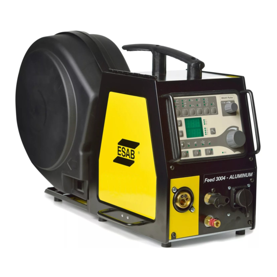
- Manuals
- Brands
- ESAB Manuals
- Welding System
- Aristo Origo Feed 3004
- Service manual
-
Contents
-
Table of Contents
-
Bookmarks
Quick Links
Aristo®, Origo™
Feed 3004, Feed 4804
Service manual
Valid for: serial no. 745-, 910-, 236-, 540-, 628-xxx-xxxx
0740 800 181 GB 20161005
Related Manuals for ESAB Aristo Origo Feed 3004
Summary of Contents for ESAB Aristo Origo Feed 3004
-
Page 1
Aristo®, Origo™ Feed 3004, Feed 4804 Service manual Valid for: serial no. 745-, 910-, 236-, 540-, 628-xxx-xxxx 0740 800 181 GB 20161005… -
Page 2: Table Of Contents
FAULT CODES ………………..24 Fault log………………….Summary of fault codes…………….Fault code description ……………… SERVICE INSTRUCTIONS…………….27 What is ESD? ………………..Service aid ………………… SPARE PARTS ………………..29 Rights reserved to alter specifications without notice. 0740 800 181 © ESAB AB 2016…
-
Page 3: Read This First
European standards IEC/EN 60974-5. On completion of service or repair work, it is the responsibility of the person(s) performing the work to ensure that the product still complies with the requirements of the above standard. 0740 800 181 — 3 — © ESAB AB 2016…
-
Page 4: Introduction
INTRODUCTION INTRODUCTION The Feed 3004 and Feed 4804 wire feed units are intended for use with power sources equipped with CAN bus communication. 0740 800 181 — 4 — © ESAB AB 2016…
-
Page 5: Wiring Diagram
Socket connectors. 13YV1 Solenoid valve. CAUTION! STATIC ELECTRICITY can damage circuit boards and electronic components. • Observe precautions for handling electrostatic sensitive devices. • Use proper static-proof bags and boxes. 0740 800 181 — 5 — © ESAB AB 2016…
-
Page 6: Feed 3004, Feed 4804
WIRING DIAGRAM Feed 3004, Feed 4804 0740 800 181 — 6 — © ESAB AB 2016…
-
Page 7
WIRING DIAGRAM 0740 800 181 — 7 — © ESAB AB 2016… -
Page 8: Technical Data
MIG/MAG welding MIG/MAG welding max pressure 0.5 MPa ( 5 bar) 0.5 MPa ( 5 bar) Coolant ESAB’s ready mixed coolant ESAB’s ready mixed coolant max pressure 0.5 MPa ( 5 bar) 0.5 MPa ( 5 bar) Maximum permissible load at…
-
Page 9: Description Of Operation
Control panel U6 The MA23 panel, with knobs for settings of voltage / wire feed speed / current. Other settings by push-buttons, with corresponding symbols on the display panel. Control panel MA23 0740 800 181 — 9 — © ESAB AB 2016…
-
Page 10: 13Ap1 Control Board
Non configured board, must be configured by ESAT. • Configured for Feed 3004 with machine ID 8 • Configured for Feed 3004 with machine ID 37 • Configured for Feed 4804 0740 800 181 — 10 — © ESAB AB 2016…
-
Page 11: 13Ap1:1 Power Supply
The +15 V is monitored by the processor and potential divider R152/R153. If the 15 V supply drops below 13 V or exceeds 17 V, the MMC panel displays fault code 8. This fault does not, however, disable any functions. 0740 800 181 — 11 — © ESAB AB 2016…
-
Page 12: 13Ap1:2 Start / Stop
13AP1:3 Gas valve The gas valve is controlled by the microprocessor. In normal operation the gas valve opens when the start signal is activated by the welding torch switch. 0740 800 181 — 12 — © ESAB AB 2016…
-
Page 13: 13Ap1:4 Motor Driving / Braking
Wire feed is stopped if the feed speed deviates from the set speed by more than 1.5 m/min for more than 5.1 seconds. The MMC panel displays fault code 11. 0740 800 181 — 13 — © ESAB AB 2016…
-
Page 14: 13Ap1:5 Pulse Generator Input
25 m/min. 13AP1:6 Monitoring the cooling water connection The wire feed unit with water connection is equipped with a detection system ELP (ESAB Logic Pump) which checks that the water hoses are connected. When connecting a water-cooled welding torch, the water pump starts.
-
Page 15: 13Ap1:7 Monitoring Wire And Gas
Although the welding power source supplies a +12 V power supply to the MMC panel, this is not used on circuit board 13AP1. 0 V on the circuit board is connected to 0 V in the MMC panel. 0740 800 181 — 15 — © ESAB AB 2016…
-
Page 16: 13Ap1:9 Arc Voltage Sensing
13AP1:9 Arc voltage sensing In order to avoid spurious volt drops when measuring the welding arc voltage, the power source senses the arc voltage via the filler wire and the feeder unit motor. 0740 800 181 — 16 — © ESAB AB 2016…
-
Page 17: 13Ap1:10 Push Pull & I/O
Terminals D, J, X and G and are used for the manual push pull, mechanized push pull, MiggyTrack and RailTrack options: see section «CAN adapter options». Terminal BA is for present not used for any standard options. 0740 800 181 — 17 — © ESAB AB 2016…
-
Page 18: 13Ap1 Component Positions
DESCRIPTION OF OPERATION 13AP1 Component positions Control board 0487 187 88x with print number 487186-001 0740 800 181 — 18 — © ESAB AB 2016…
-
Page 19
DESCRIPTION OF OPERATION Control board 0487 187 8xx with print number 487186-002 0740 800 181 — 19 — © ESAB AB 2016… -
Page 20: Can Adapter Option
In position A the control panel is active and the external controls inactive. If the wire feeder is controlled by an U8, switch 13S2 has to be in position B. Then external or internal control can be selected by the U8. 0740 800 181 — 20 — © ESAB AB 2016…
-
Page 21: Welding Gun With Pull Motor
Then external or internal control of the wire feed speed can be selected by the U8. Pull motor option without wire feed speed adjustment. 0459 020 883 This option includes connectors 13XS25, 13XS20 and wires 1389, 1390. Circuit board layout, CAN adapter and filter board 0740 800 181 — 21 — © ESAB AB 2016…
-
Page 22: Connection Instructions
DESCRIPTION OF OPERATION Connection instructions Wire feeder with built-in control panel Wire feeder controlled by U8, NOTE: the switch must be in position B. 0740 800 181 — 22 — © ESAB AB 2016…
-
Page 23: Remote Controls
REMOTE CONTROLS REMOTE CONTROLS A number of remote control units can be connected to the wire feeders, these are described in a separate service manual. 0740 800 181 — 23 — © ESAB AB 2016…
-
Page 24: Fault Codes
Lost contact with the wire feed unit Lost contact with the power source Memory error in data memory Memory allocation error Transmitter buffer overflow Receiver buffer overflow Program operating fault 0ut of wire 0740 800 181 — 24 — © ESAB AB 2016…
-
Page 25: Fault Code Description
The wire feed speed differs from the set value by more than 1.5 m/min for more than 3 seconds. This fault stops the wire feed. After a period of 5 seconds, restart is permitted. 0740 800 181 — 25 — © ESAB AB 2016…
-
Page 26
Stack overflow The program execution does not work. This fault should never occur in reality: the fault code is intended as an aid during development work. Contact ESAB if the fault does occur. No gas flow Gas flow is too low. -
Page 27: Service Instructions
Work surfaces, carts and containers must be conductive and grounded. Use only antistatic packaging materials. Overall, handling of ESD-sensitive devices should be minimized to prevent damage. 0740 800 181 — 27 — © ESAB AB 2016…
-
Page 28: Service Aid
The software update is made from a PC, it has to be managed by a trained serviceman. For this a PC program called ESAT, ESAB Software Administration Tool, is needed. The PC is connected to the welding equipment by a cable connector and a CAN reader. From the ESAT it is possible to update the software.
-
Page 29: Spare Parts
SPARE PARTS The spare parts list is published in a separate document that can be downloaded from the Internet: www.esab.com Filename Product 0459 839 017 Feed 3004 and Feed 4804 0740 800 181 — 29 — © ESAB AB 2016…
-
Page 30
ESAB subsidiaries and representative offices Europe THE NETHERLANDS North and South America SOUTH KOREA ESAB Nederland B.V. ESAB SeAH Corporation AUSTRIA Amersfoort ARGENTINA Kyungnam ESAB Ges.m.b.H Tel: +31 33 422 35 55 CONARCO Tel: +82 55 269 8170 Vienna-Liesing Fax: +31 33 422 35 44…
Подождите не меньше 5 минут после отключения питания и отсоединения шнура от сети перед тем, как открыть пластину блока управления. Прикосновение к деталям, находящимся под высоким напряжением, может привести к несчастному случаю.

Если произойдет нарушение работы машины, послышится жужжащий звук, и в окне дисплея появится код ошибки. Чтобы удалить причину нарушения работы, выполните указанную в таблице процедуру.
| Код | Причина | Способ устранения |
| Е-13 | Неправильно подсоединен коннектор машины | Отключите питание и проверьте, отсоединены ли коннекторы Р3. |
| Е-20 | Проблема с остановкой мотора машины или ошибка с подсоединением синхронизатора. | Отключите питание, а затем поверните шкив машины, чтобы проверить, запирается ли машина. Проверьте соединение синхронизатора. Убедитесь, что отсоединены коннекторы Р11, Р12 и Р13. |
| Е-21 | Ошибка в работе мотора машины. | Отключите питание и проверьте исправность соединения заземления. |
| Е-30 | Во время установки коэффициента увеличения произошел выход за пределы возможной области пошива. | Нажмите переключатель RESET, а затем снова установите коэффициент увеличения. |
| Е-31 | Рисунок стежков находит на область пошива, когда активно ограничение области. | Нажмите переключатель RESET, а затем переустановите переключатели памяти «30» и «31» или коэффициент увеличения. |
| Е-32 | Формат данных программы пользователя (% или мм) не соответствует установкам DIP-переключателя А-6. | После изменения установки DIP-переключателя А-6, удалите все данные из памяти. (См. «10-16. Удаление всех данных из памяти»). |
| Е-40 | Длина стежка превышает 10мм | Нажмите переключатель RESET, а затем снова установите коэффициент увеличения. |
| Е-41 | Ошибка в данных пошива. | При программировании новых данных пошива повторите всю процедуру сначала. |
| Е-42 | Указан неправильно номер программы. | Нажмите переключатель RESET и укажите правильный номер. |
| Е-50 | Иглодержатель не останавливается при подъеме иглы. | Поверните шкив так, чтобы указатель поравнялся с верхним положением иглы. (см. раздел «10-12. Настройка верхнего положения остановки иглы».) Проверьте натяжение клиновидного приводного ремня. (См. раздел «3-14. Установка клиновидного приводного ремня»). |
| Е-60 | Прижим не опустился. |
См. раздел «16. Устранение неисправностей». Отключите питание и проверьте соединение коннектора Р1 датчика прижима. |
| Е-61 | Прижим не может быть поднят. | |
| Е-62 | Прижим не поднят. | |
| Е-63 | Прижим не может быть опущен. | |
| Е-64* | Прижимная лапка не закрывается. | |
| Е-70 | Охлаждающий вентилятор не работает. | Отключите питание, а затем проверьте, не засорился ли вентилятор обрывками ниток. |
| Е-80 | Мотор PROM вставлен неправильно. | Отключите питание и проверьте. |
| Е-81 | Ножной переключатель нажат, когда было включено питание. | Отключите питание и проверьте. |
| Е-82 | Переключатель панели управления был нажат во время включения питания. | Отключите питание и проверьте панель управления. Проверьте шнуры панели. |
| Е-90 | Падение напряжения питания, или питание было включено снова сразу после выключения. | Отключите питание и проверьте напряжение на входе. После выключения питания подождите 3 секунды или больше перед тем, как снова его включить. (см. «10-15. Проверка напряжения на входе.) |
| Е-91 | Повышение напряжения питания. | Отключите питание и проверьте напряжение на входе. (См. «10-15. Проверка напряжения на входе»). |
| Код | Причина | Способ устранения |
| Е-А0 | Не может быть определено начальное положение (нарушение работы датчика начального положения), или нарушение в подключении питания. | Отключите питание и проверьте соединение коннектора Р1 датчика начального положения. |
| Е-b0 | Вы попытались изменить номер программы, когда DIP-переключатель А-8 был установлен на ON. | Нажмите переключатель RESET.
Установите DIP-переключатель А-8 на OFF перед тем как изменить номер программы. |
| Е-d0 | Теплоотвод цепи панели управления перегрелся. | Отключите питание и почистите отверстия для воздуха в блоке. |
| Е-E0 | Неправильная работа EEPROM (нарушение работы главной цепи). | Отключите питание, а затем снова включите. Если ошибка появится снова, обратитесь к квалифицированному специалисту по обслуживанию машины. |
| Е-E1 | Порча данных EEPROM, или была обновлена версия PROM. | Нажмите переключатель RESET, чтобы обнулить ошибку. Однако данные (переключатели памяти, дисплей и программы пользователя) будут обнулены или установлены в исходное состояние. |
| Е-E2 | Порча данных EEPROM управления информацией. | Нажмите переключатель RESET, чтобы обнулить ошибку. однако данные (переключатели памяти, дисплей и программы пользователя) будут установлены в исходное состояние. |
| Е-F0 | Короткое замыкание цепи соленоида (нарушение работы главной цепи), или не работает реле питания (нарушение подачи питания). | Отключите питание и вызовите квалифицированного специалиста по обслуживанию машин. |
| Е-F1 | Плохое соединения кабеля между цепью подачи питания и главной цепью. | Отключите питание и проверьте, отсоединены ли коннекторы Р16. |
| Е-F2 | Обнаружение неправильного тока в цепи подачи питания. | Отключите питание и вызовите квалифицированного специалиста по обслуживанию машины. |
Ошибки, появляющиеся при использовании дополнительного оборудования
| Код | Причина | Способ устранения |
| Е-10 | Был нажат переключатель аварийной остановки. | Поверните переключатель аварийной остановки EMERGENCY STOP по часовой стрелке, чтобы отменить запирание, а затем нажмите переключатель RESET, чтобы обнулить ошибку. |
| Е-11 | Во время шитья был нажат переключатель аварийной остановки. | Поверните переключатель аварийной остановки EMERGENCY STOP по часовой стрелке, чтобы отменить запирание, а затем нажмите переключатель RESET, чтобы обнулить ошибку. Вы можете нажать переключатель STEP BACK /шаг назад/, чтобы повторить пошив. |
| Е-12 | Переключатель аварийной остановки непрерывно нажат, или ошибка соединения переключателя аварийной остановки. | Отключите питание и проверьте. |
| Е-14 | Определен разрыв нити. | Поверните переключатель аварийной остановки EMERGENCY STOP по часовой стрелке, чтобы отменить запирание, а затем нажмите переключатель RESET, чтобы обнулить ошибку. Вы можете нажать переключатель STEP BACK /шаг назад/, чтобы повторить пошив. |

Указатель сегментный светодиодный алфавит