Управление
– это совокупность действий, направленных
на достижение объектом управления
(сварочный процесс) заданного состояния
(требуемых качества шва, скорости сварки,
глубины проплавления, размеров литого
ядра и т. п.). Формирование управляющего
воздействия и само воздействие на объект
управления осуществляется управляющим
устройством.
Система управления
(СУ) – это
совокупность объекта управления и
управляющего устройства, взаимодействующих
между собой.
Воздействие
управляющего устройства (УУ) на объект
управления осуществляется по каналу
прямой связи, а воздействие объекта
управления на управляющее устройство
– по каналу обратной связи.
X y Прямаясвязь

X
Обратная
связь
x
— управляемая величина,
y
— задающее воздействие.
СУ, в которой
присутствует только прямая связь
называется разомкнутой.


X
Y
Прямая связь

Обратная
связь
СУ, в которой наряду
с прямой связью существует обратная
связь называется замкнутой.
Под обратной
связью в
теории управления понимают передачу
сигнала (информации) с выхода объекта
управления (ОУ) на вход управляющего
устройства (УУ). Обратная связь передаёт
результат изменения выходной величины
на вход системы.
Эта выходная
величина представляет собой реальную
физич. величину (длина дуги, глубина
проплавления, ширина свароч. ванны,
длина и диаметр обратного валика),
подлежащую управлению.
Теория
автоматического управления
– это наука, которая изучает процессы
управления и основы проектирования
автоматич. систем, работающих по
замкнутому циклу в любой области науки
и техники. Иначе говоря, она изучает
процессы управления и задачи создания
любых систем управления с обратной
связью.
Главная обратная
связь – это
связь между выходом и входом системы
управления.
Местная обратная
связь – это
связь между входом и выходом каких-либо
элементов внутри системы управления.
Обобщённая функциональная схема сау
Эта блок-схема
является инвариантной (общей), для всех
систем автоматического управления.

Зу – задающее устройство — формирует сигнал задающего воздействия g(t) пропорциональный заданному значению управляемой величиныx(t).
СС – система
сравнения (схема сравнения),
ИУ – измерительное
устройство,
(T) – сигнал рассогласования (сигнал ошибки),
(t)
= g(t)
– y(t),
где у(t)=
k·x(t),
ε(t)
→ 0 – главная
идея ТАУ.
ОУ – объект
управления,
УПУ –
усилительно-преобразоват. устройство
(регулятор) – решает основную
интеллектуальную функцию СУ.
ИО – исполнительный
орган (привод подачи проволоки):
гидравлический, пневматический, зубчатые,
планетарные передачи. ИО может быть
источник питания.
X1(t)
– сигнал с
выхода регулятора (УПУ),
X2(t)
— управляющее
воздействие ИО на ОУ.
КУ – корректирующее
устройство
Z(t)
– выходной сигнал КУ (местн. обр. связь)
Если задающее
воздействие g(t)
= const,
то это соответствует случаю автоматич.
регулирования, основанному на поддержании
постоянного значения управляемой
величины. Такие системы называются
системами автоматического регулирования
САР.
Лекция №3 Основные элементы сау:
1) ИУ
– чувствительный элемент или датчик,
который измеряет текущие значения
управляемой величины Х
и преобразует их с коэффициентом усиления
k
к сигналу Y
удобному для дальнейшего использования
в системе;
2) ЗУ
– формирует сигнал задающего воздействия
g(t)
в удобном для сравнения с виде;
3) CC
– измеряет сигнал ошибки (t)
пропорциональный отклонению управляемой
величины X(t)
от заданного значения g(t);
4) УПУ
(регулятор)
– усиливает и преобразует в соответствии
с заданным законом управления сигнал
ошибки (t)
необходимый для управления исполнительным
органом ИО;
5) ИО
– преобразует сигнал x1(t)
в управляющее воздействие x2(t),
которое не обязательно может быть
электрич. природы;
6) КУ
(корректирующее устройство) – включаются
последовательно или параллельно ИО.
Назначение КУ: улучшить качество
процессов управления внутри системы с
помощью дополнительного воздействия
z(t).
Классификация
САУ по виду функциональных схем и
принципу действия системы:

Соседние файлы в предмете [НЕСОРТИРОВАННОЕ]
- #
- #
- #
- #
- #
- #
- #
- #
- #
- #
- #
From Wikipedia, the free encyclopedia
Mismatch loss in transmission line theory is the amount of power expressed in decibels that will not be available on the output due to impedance mismatches and signal reflections. A transmission line that is properly terminated, that is, terminated with the same impedance as that of the characteristic impedance of the transmission line, will have no reflections and therefore no mismatch loss. Mismatch loss represents the amount of power wasted in the system[dubious – discuss]. It can also be thought of as the amount of power gained if the system was perfectly matched[dubious – discuss]. Impedance matching is an important part of RF system design; however, in practice there will likely be some degree of mismatch loss.[1] In real systems, relatively little loss is due to mismatch loss and is often on the order of 1dB.
Calculation[edit]
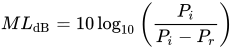
Mismatch loss (ML) is the ratio of incident power to the difference between incident and reflected power:

Figure 1. Simple circuit showing characteristic impedance Zo and the load impedance ZL. In a perfectly matched system ZL=Zo, and there is no mismatch loss.

where


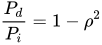
The fraction of incident power delivered to the load is

Figure 2. Simple circuit showing incident power, Pi, on a load. The reflected power will be the difference between Pi and the power delivered, Pd.
where

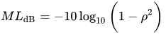
If the reflection coefficient is known, mismatch can be calculated by
In terms of the voltage standing wave ratio (VSWR):

[2]
Sources of mismatch loss[edit]
Any component of the transmission line that has an input and output will contribute to the overall mismatch loss of the system. For example, in mixers mismatch loss occurs when there is an impedance mismatch between the RF port and IF port of the mixer[dubious – discuss].[3] This is one of the principal reasons for losses in mixers. Likewise, a large amount of the loss in amplifiers comes from the mismatch between the input and output. Consequently, not all of the available power generated by the amplifier gets transferred to the load.[4] This is most important in antenna systems where mismatch loss in the transmitting and receiving antenna directly contributes to the losses the system—including the system noise figure. Other common RF system components such as filters, attenuators, splitters, and combiners will generate some amount of mismatch loss. While completely eliminating mismatch loss in these components is near impossible, mismatch loss contributions by each component can be minimized by selecting quality components for use in a well designed system.
Mismatch error[edit]
[5] If there are two or more components in cascade as is often the case, the resultant mismatch loss is not only due to the mismatches from the individual components, but also from how the reflections from each component combine with each other. The overall mismatch loss cannot be calculated by just adding up the individual loss contributions from each component. The difference between the sum of the mismatch loss in each component and total mismatch loss due to the interactions of the reflections is known as mismatch error. Depending on how the multiple reflections combine, the overall system loss may be lower or higher than the sum of the mismatch loss from each component. Mismatch error occurs in pairs as the signal reflects off of each mismatched component. So for the example in Figure 3, there are mismatch errors generated by each pair of components.[6] The mismatch uncertainty increases as the frequency increases, and in wide-band applications. The phasing of the reflections makes it particularly harder to model.
The general case for calculating mismatch error (ME) is:

Figure 3. Simple circuit showing multiple reflections due to more than 1 mismatched device.

where 
See also[edit]
- Insertion loss
References[edit]
- ^ Daniels, David J. (2004). Ground penetrating radar (2nd Edition). Institution of Engineering and Technology. ISBN 978-0-86341-360-5
- ^ Lo YT and Lee SW 1988 Antenna handbook: Theory, Applications, and Design
- ^ Carr, Joseph J. (2002). RF components and circuits. Oxford: Newnes. ISBN 0-7506-4844-9
- ^ Skolnik, Merrill I. (2001). Introduction to radar systems (3rd Edition). New York: McGraw-Hill. ISBN 0-07-288138-0
- ^ White, Joseph F. (2004). High frequency techniques: An introduction to RF and microwave engineering. Hoboken: Wiley. ISBN 0-471-45591-1
- ^ Briggs, John N. (2004). Target detection by marine radar. Institution of Engineering and Technology. ISBN 978-0-86341-359-9
From Wikipedia, the free encyclopedia
Mismatch loss in transmission line theory is the amount of power expressed in decibels that will not be available on the output due to impedance mismatches and signal reflections. A transmission line that is properly terminated, that is, terminated with the same impedance as that of the characteristic impedance of the transmission line, will have no reflections and therefore no mismatch loss. Mismatch loss represents the amount of power wasted in the system[dubious – discuss]. It can also be thought of as the amount of power gained if the system was perfectly matched[dubious – discuss]. Impedance matching is an important part of RF system design; however, in practice there will likely be some degree of mismatch loss.[1] In real systems, relatively little loss is due to mismatch loss and is often on the order of 1dB.
Calculation[edit]
Mismatch loss (ML) is the ratio of incident power to the difference between incident and reflected power:
Figure 1. Simple circuit showing characteristic impedance Zo and the load impedance ZL. In a perfectly matched system ZL=Zo, and there is no mismatch loss.
where
The fraction of incident power delivered to the load is
Figure 2. Simple circuit showing incident power, Pi, on a load. The reflected power will be the difference between Pi and the power delivered, Pd.
where
If the reflection coefficient is known, mismatch can be calculated by
In terms of the voltage standing wave ratio (VSWR):
[2]
Sources of mismatch loss[edit]
Any component of the transmission line that has an input and output will contribute to the overall mismatch loss of the system. For example, in mixers mismatch loss occurs when there is an impedance mismatch between the RF port and IF port of the mixer[dubious – discuss].[3] This is one of the principal reasons for losses in mixers. Likewise, a large amount of the loss in amplifiers comes from the mismatch between the input and output. Consequently, not all of the available power generated by the amplifier gets transferred to the load.[4] This is most important in antenna systems where mismatch loss in the transmitting and receiving antenna directly contributes to the losses the system—including the system noise figure. Other common RF system components such as filters, attenuators, splitters, and combiners will generate some amount of mismatch loss. While completely eliminating mismatch loss in these components is near impossible, mismatch loss contributions by each component can be minimized by selecting quality components for use in a well designed system.
Mismatch error[edit]
[5] If there are two or more components in cascade as is often the case, the resultant mismatch loss is not only due to the mismatches from the individual components, but also from how the reflections from each component combine with each other. The overall mismatch loss cannot be calculated by just adding up the individual loss contributions from each component. The difference between the sum of the mismatch loss in each component and total mismatch loss due to the interactions of the reflections is known as mismatch error. Depending on how the multiple reflections combine, the overall system loss may be lower or higher than the sum of the mismatch loss from each component. Mismatch error occurs in pairs as the signal reflects off of each mismatched component. So for the example in Figure 3, there are mismatch errors generated by each pair of components.[6] The mismatch uncertainty increases as the frequency increases, and in wide-band applications. The phasing of the reflections makes it particularly harder to model.
The general case for calculating mismatch error (ME) is:
Figure 3. Simple circuit showing multiple reflections due to more than 1 mismatched device.
where
See also[edit]
- Insertion loss
References[edit]
- ^ Daniels, David J. (2004). Ground penetrating radar (2nd Edition). Institution of Engineering and Technology. ISBN 978-0-86341-360-5
- ^ Lo YT and Lee SW 1988 Antenna handbook: Theory, Applications, and Design
- ^ Carr, Joseph J. (2002). RF components and circuits. Oxford: Newnes. ISBN 0-7506-4844-9
- ^ Skolnik, Merrill I. (2001). Introduction to radar systems (3rd Edition). New York: McGraw-Hill. ISBN 0-07-288138-0
- ^ White, Joseph F. (2004). High frequency techniques: An introduction to RF and microwave engineering. Hoboken: Wiley. ISBN 0-471-45591-1
- ^ Briggs, John N. (2004). Target detection by marine radar. Institution of Engineering and Technology. ISBN 978-0-86341-359-9