|
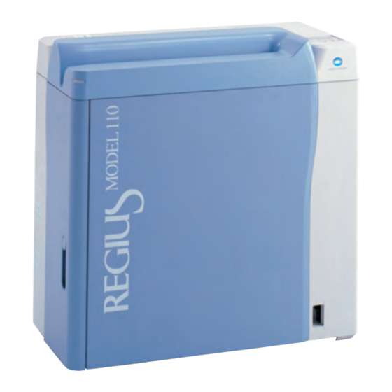
Дигитайзер Regius 110HQ ф.Konica Minolta |
||||||
|
||||||
|
||||||
|
||||||
|
||||||
|
||||||
|
||||||
|
||||||
|
||||||
|
||||||
|
||||||
|
||||||
|
||||||
|
||||||
|
||||||
|
||||||
|
||||||
|
||||||
|
||||||
|
||||||
|
||||||
|
||||||
|
||||||
|
||||||
|
||||||
|
||||||
|
||||||
|
||||||
|
||||||
|
||||||
|
||||||
|
||||||
|
||||||
|
||||||
|
||||||
|
||||||
|
||||||
|
||||||
|
||||||
|
||||||
|





















3.2.2
•
Error codes S column: Errors at the read operation/calibration.
•
Error codes E column: Errors during erase operation.
•
Error codes I column: Errors during initialization.
Error code
S
E
06050 06065 06080 Receiver HP sensor error
06051 06066 06081 Receiver motor control error
06052 06067 06082 Receiver HP sensor error
06053 06068 06083 Receiver motor control error
06054 06069 06084 Receiver motor control error
06055 06070 06085 Receiver motor control error
06056 06071 06086 Receiver motor control error
06057 06072 06087 Receiver HP sensor error
Description of the error
I
(when moving to HP)
Receiver HP sensor did not go
ON when the receiver was
moving to the home position.
(when moving to HP)
There was a trouble with the
motor control when the receiver
was moving to the home position.
(when moving to first falling
position)
Receiver HP sensor did not go
OFF when the receiver was
moving from the home position
to the first falling position.
(when moving to first falling
position)
There was a trouble with the motor
control when the receiver was
moving from the home position to
the first falling position.
(when moving to second falling
position)
There was a trouble with the motor
control when the receiver was
moving from the first falling position
to the second falling position.
(when moving slightly down
at the second falling position)
There was a trouble with the
motor control when the receiver
was moving down slightly at the
second falling position.
(when moving to first falling
position 2)
There was a trouble with the motor
control when the receiver was
moving from the second falling
position to the first falling position.
(when moving to HP 2)
Receiver HP sensor did not go
ON when the receiver was
moving from the first falling
position to the home position.
Chapter 3 Troubleshooting
Response
(References to replacement methods are
listed at the end of the table.)
Confirm following and replace the faulty parts.
•
Receiver HP sensor
•
Sensor wire: JP43 ~ MCN3 (MDU)
•
Receiver motor
•
Motor wire: JP51 ~ MCN5 (MDU)
•
MDU
Confirm following and replace the faulty parts.
•
Receiver motor
•
Motor wire: JP51 ~ MCN5 (MDU)
•
MDU
Confirm following and replace the faulty parts.
•
Receiver HP sensor
•
Sensor wire: JP43 ~ MCN3 (MDU)
•
Receiver motor
•
Motor wire: JP51 ~ MCN5 (MDU)
•
MDU
Confirm following and replace the faulty parts.
•
Receiver motor
•
Motor wire: JP51 ~ MCN5 (MDU)
•
MDU
Confirm following and replace the faulty parts.
•
Receiver HP sensor
•
Sensor wire: JP43 ~ MCN3 (MDU)
•
Receiver motor
•
Motor wire: JP51 ~ MCN5 (MDU)
•
MDU
3-7
-
Contents
-
Table of Contents
-
Troubleshooting
-
Bookmarks
Quick Links
DIRECT DIGITIZER
110
REGIUS MODEL
CODE NO.0902
Service Manual
0197
Manufacturer:
2970 Ishikawa-machi, Hachioji-shi Tokyo 192-8505 Japan
Related Manuals for Konica Minolta REGIUS 110
Summary of Contents for Konica Minolta REGIUS 110
-
Page 1
DIRECT DIGITIZER REGIUS MODEL CODE NO.0902 Service Manual 0197 Manufacturer: 2970 Ishikawa-machi, Hachioji-shi Tokyo 192-8505 Japan… -
Page 3
Introduction The Direct Digitizer REGIUS MODEL 110 is designed to read REGIUS Plates using a photostimulable luminescent material as an X-ray detector. This manual states the cautions and steps for the service engineers who will perform repair or maintenance of this equipment (or the system including this equipment). After reading through the manual, please keep it close so you can refer whenever needed. -
Page 4: How To Use This Manual
How to Use This Manual Configuration of This Manual Caution about the safety and operation of this equipment are described in following 8 chapters in this manual. Chapter 1: Warning and Caution Regarding Safety This chapter describes the caution regarding the safety before performing the repair/maintenance. Chapter 2: Before Repair This chapter describes the basic knowledge about the equipment before performing the repair/ maintenance.
-
Page 5: Alert Symbol Marks
Alert Symbol Marks Alert symbol marks are cautioning the interested person about the item or operation that might cause a danger to the operator or other people during the repair/maintenance of the equipment (and system including the equipment). Read these messages and follow instructions carefully. Also, read and understand the instructions and safety standards before performing repair/maintenance of the equipment.
-
Page 7: Table Of Contents
Table of Contents Table of Contents Introduction ………………i How to Use This Manual …………..ii Configuration of This Manual…………ii Alert Symbol Marks …………….iii Signal Words ………………iii Chapter 1 Safety Warnings and Cautions……..1-1 Warning Labels …………….1-2 1.1.1 Position and Type of Warning Label ……..1-2 Safety Caution…………….1-5 1.2.1 Caution Based on Ordinance ……….
-
Page 8
Table of Contents 3.2.1 06000 ~ 06037: Justifier Motor Errors ……..3-5 3.2.2 06050 ~ 06090: Receiver Motor Errors …….. 3-7 3.2.3 06100 ~ 06143: Transporter Motor Errors ……3-9 3.2.4 06150 ~ 06182: Subscan Motor Errors……. 3-13 3.2.5 06200 ~ 06231: Insertion ShutterMotor Errors ….3-15 3.2.6 06250 ~ 06282: Lock Release Motor Errors……. -
Page 9
Table of Contents 3.4.23 Duplex Image …………..3-47 3.4.24 Sensitivity Calibration Do Not Fit Within Specification ..3-47 3.4.25 All Processed Images are Generally High in Contrast ..3-47 3.4.26 All Processed Images are Generally Low in Contrast ..3-48 3.4.27 Image Out of Focus ………… -
Page 10
Table of Contents 5.4.10 Replacing the Receiver (Receiver Unit Assembly) ….. 5-55 5.4.11 Replacing the Justifier Guide Unit Assembly…… 5-57 5.4.12 Replacing the Receiver Belt ……….5-59 5.4.13 Replacing the Justifier Belt ……….5-62 Replacing the Parts on the Subscan Unit ……5-65 5.5.1 Replacing the Subscan HP Sensor …….. -
Page 11
Table of Contents 5.10.10 Replacing the Back Plate Detection Unit ……5-129 5.10.11 Replacing the Cleaning Unit ……….5-130 Chapter 6 Adjustment …………..6-1 Adjust Justifier Belt Tension ………….6-2 Adjust Receiver Belt Tension ………..6-4 Adjustment of Justifier Motor…………6-6 Adjust Wire Tension ……………6-10 Adjust Position of Detach Detection Roller/Sensor ….6-12 Adjustment of Pressing Amount……….6-15 Chapter 7 Periodic Maintenance ………….7-1… -
Page 13: Chapter 1 Safety Warnings And Cautions
Chapter Safety Warnings and Chapter 1 Cautions The caution regarding the safety before performing the repair/ maintenance is described here. Warning Labels ……….1-2 Safety Caution ………..1-5…
-
Page 14: Warning Labels
Chapter 1 Safety Warnings and Cautions Warning Labels Various warning labels are attached to REGIUS MODEL 110 as shown below. Understand the meaning of the warning labels, and handle with care on the parts with warning cables during the installation or repair/maintenance is performed. Do not peel off or smudge the affixed label to prevent accidents during the service.
-
Page 15
Chapter 1 Safety Warnings and Cautions Contents/Warning label Contents/Warning label Class 1 laser product Laser caution Do not sit Laser output Clearing a jam and lamp replacement High Temperature Caution procedures… -
Page 16
Chapter 1 Safety Warnings and Cautions Contents/Warning label Contents/Warning label Interlock Caution Magnetism Warning Magnet… -
Page 17: Safety Caution
Chapter 1 Safety Warnings and Cautions Safety Caution Read and follow all safety cautions thoroughly before using the product. Be sure to observe the cautions described here, since it is regarding about the safety. 1.2.1 Caution Based on Ordinance Caution regarding laser regulation To prevent danger, do not remove the external covers or touch inside the equipment except the service engineer with official training.
-
Page 18: General Caution
Chapter 1 Safety Warnings and Cautions 5. Note following items after operating the equipment. (1) Turn the power off by prescribed procedure after returning the operation switches and dials to the positions before usage. (2) Do not unplug the cables by pulling on cable part or apply unnecessary force. (3) Note following items for storing location.
-
Page 19: Caution For Handling The Equipment
Chapter 1 Safety Warnings and Cautions 1.2.3 Caution for Handling the Equipment Terminate the operation when abnormal noise or smell, or smoke arise from the equipment Terminate the operation immediately when abnormal noise or smell, or smoke arise from the equipment. It may result to electrification, fire, or damage to the equipment by running the equipment with abnormality.
-
Page 20: Caution During Service
Chapter 1 Safety Warnings and Cautions 1.2.5 Caution During Service Do not insert wire or metal pieces Do not insert foreign objects such as wire or metal pieces from the air holes or the gap of the body. There is a danger of electrification. Always turn OFF the power supply during service There is a risk of major incident when the PCB inside the equipment, connectors, or cables are pulled out with the power supply still ON.
-
Page 21
Chapter Before the Repair Chapter 2 The basic knowledge about the equipment before performing are described. the repair/maintenance Name of Parts …………2-2 Structure …………2-4 Principal Specifications ……..2-5 Block Diagram…………2-9 Position of Major Components……2-11 Operation …………2-20 Handling the Cassette……..2-31 Tools, Measuring Devices, Jigs, Etc., Necessary for Service……..2-32… -
Page 22: Chapter 2 Before The Repair
Chapter 2 Before the Repair Name of Parts Following are names of parts that is necessary to know when performing repair of the REGIUS MODEL 110. Exterior First front back side First front side Second front back side Second front side Name Function Air intake…
-
Page 23
Chapter 2 Before the Repair Vertical Positioning The front side (user’s access direction) of the equipment can be changed by switching the operation panel position. Horizontal Positioning (Factory Default) Vertical Positioning Operation Operation panel panel Access Access direction direction Horizontal positioning: First front side will be the front. (This is the factory default.) Vertical positioning: Second front side will be the front. -
Page 24: Structure
Chapter 2 Before the Repair Structure Following are the structure of the REGIUS MODEL 110. Name Function Insertion unit Constructed of slot to insert/eject the cassette, operation panel, barcode reader, shutter open and close mechanism. Exterior Unit to separate from outer environment, such as light shield, vibration blocker, etc.
-
Page 25: Principal Specifications
Chapter 2 Before the Repair Principal Specifications 2.3.1 Equipment Specification Dimensions 740 (W) x 365 (D) x 747 (H) mm Weight Approximately 100 kg Floor height adjustment range Up to 12 mm bump at the position of the foot adjuster Noise level During operation: 55 dB or less During idle: 42 dB or less…
-
Page 26: Read/Erase Of The Image
Chapter 2 Before the Repair 2.3.2 Read/Erase of the Image Processing Performance • Reading resolution Standard read mode: 175µm • High resolution read mode: 87.5µm Cassette feed load time 45 seconds or less (14 x 14 inches/standard read mode) • Time from the cassette is inserted until the cassette is ejected.
-
Page 27
Chapter 2 Before the Repair Optical Unit Laser scan unit Method Laser scan by polygon mirror Polygon face count 6 faces Laser wavelength 660 nm Laser intensity on the plate 35 mW or more surface Imaging beam diameter 100 µm or less (main and sub) Lens 2 group 2 lens Light condensing unit… -
Page 28: Control Unit Performance
Chapter 2 Before the Repair 2.3.3 Control Unit Performance Major performance of the control unit is following. • Image data generation function A function to generate image data by laser scan • Image data compensation/ Moire elimination calculation function • Gain offset •…
-
Page 29: Block Diagram
Block Diagram Insertion Unit Receiver Unit Subscan Unit Lock Motor (M2) LM Coil Unit (LM1) Operation Unit Mechanical Linkage Mechanical Linkage OPB (Operator’s Panel Circuit Board) Lock HP Sensor (S9) Subscan HP Sensor (S14) LCD Panel Mechanical Linkage «operation» Lamp Receiver Encoder (S13) «erase»…
-
Page 30
2-10… -
Page 31: Position Of Major Components
Chapter 2 Before the Repair Position of Major Components Position and function of the major components of each unit is described here. 2.5.1 Insertion Unit Name Function Reference on replacement method Insert slot detection Detects the insertion of the cassette. «5.3.7 Replacing the Insertion sensor 2 It is turned ON when the cassette…
-
Page 32: Receiver Unit
Chapter 2 Before the Repair 2.5.2 Receiver unit Name Function Reference on replacement method Justifier guide Fix the cassette by moving inward «5.4.11 Replacing the Justifier and push the cassette against the Guide Unit Assembly (Page 5- justifier standard block. 60)»…
-
Page 33: Transporter Unit
Chapter 2 Before the Repair Name Function Reference on replacement method Lock HP sensor Use to control the operation of «5.4.8 Replacing the Lock HP Lock Motor by the FPGA. Initial Sensor (Page 5-54)» position is ON. Lock/lock release Operate by Lock Motor, performing —…
-
Page 34: Subscan Unit
Chapter 2 Before the Repair 2.5.4 Subscan Unit Name Function Reference on replacement method Tumbler (bottom) Fix the push plate unit to read «5.5.4 Replacing the Tumbler position with a spring. (Lower) (Page 5-77)» Wire Used on the position control «5.5.3 Replacing the Encoder/ encoder.
-
Page 35: Optical Unit/Eraser Unit
Chapter 2 Before the Repair 2.5.5 Optical Unit/Eraser Unit Eraser unit Name Function Reference on replacement method • Erase lamp unit Halogen lamp is built-in, erasing Unit: Instruction manual the recording of the plate. • Halogen lamp only: «5.7.3 Replacing the Halogen Lamp (Page 5-88)»…
-
Page 36: Detach Detection Unit
Chapter 2 Before the Repair 2.5.6 Detach Detection Unit Name Function Reference on replacement method Detach detection roller When the back plate or the plate «5.8.3 Replacing the Detach on the back plate is detached more Detection Roller (Page 5-93)» than certain amount from the push Top detach detection «5.8.1 Replacing the Detach…
-
Page 37: Exterior
Chapter 2 Before the Repair 2.5.7 Exterior Name Function Reference on replacement method Interlock switch It turns ON when the second front «5.9.2 Replacing the Interlock door is open. Switch (Page 5-97)» All the power will be shut off, except for the electronic circuit board, when it is ON.
-
Page 38
Chapter 2 Before the Repair Name Function Reference on replacement method Interlock relay 1 A relay to cut power supply when «5.9.7 Replacing the the interlock is engaged. Transformer Unit Relay (Interlock Relay 1) (Page 5-105)» Analog power supply Supply the power supply (±5V, +24 «5.9.10 Replacing the Analog V) to the LMC (photomultiplier). -
Page 39: Framework
Chapter 2 Before the Repair 2.5.8 Framework Name Function Reference on replacement method • Cleaning brush Clean the light condenser of the Brush only: «5.10.8 Replacing optical unit. the Brush (Cleaning Unit) (Page 5-131)» • Whole cleaner: «5.10.11 Replacing the Cleaning Unit (Page 5-135)»…
-
Page 40: Operation
Chapter 2 Before the Repair Operation 2.6.1 Operation Transition Diagram Status Transition Diagram REGIUS MODEL 110 in in one of the following status. Power Supply Breaker ON Idling Press «operation» Switch Boot Shut down Press «operation» Press «operation» Switch for 3 Seconds Switch for 3 Seconds Sleep Mode Maintenance Mode…
-
Page 41
Chapter 2 Before the Repair Routine Mode Operation Transition Diagram Idling Press «operation» Intergradation Resulting Switch from Operation Automatic Intergradation Error Generated Initialization Process Close Door Finished Press «operation» Switch Open Door for 3 Seconds «READY» State Press «operation» Switch Press «erase»… -
Page 42: Normal Operation (Image Read Action)
Chapter 2 Before the Repair 2.6.2 Normal Operation (Image Read Action) Action from the insertion to the eject of the cassette is described here. Use the service tool to confirm operation. See «Chapter 4 Confirming Operation Using Service Tool (Page 4-1)».
-
Page 43
Chapter 2 Before the Repair Justifier guide will move toward the justifier standard, pressing the cassette to the justifier standard block. Justifier motor will rotate, according to the cassette size from the barcode, moving the justifier guide to the justifier standard side. Justifier Guide Justifier Sensor Justifier HP Sensor… -
Page 44
Chapter 2 Before the Repair Lock/lock release mechanism will release the lock on the cassette. Lock motor will rotate operating the lock/rock release mechanism, releasing the lock on the cassette. Lock/Lock Release Mechanism Lock HP Sensor The push plate unit that absorbed the back plate will move to the read position. -
Page 45
Chapter 2 Before the Repair Push plate unit will move to the press down position and press the back plate to the front plate. Transporter motor will rotate to move the push plate unit to the push down position. Lock/lock release mechanism will lock the cassette. -
Page 46
Chapter 2 Before the Repair Receiver will rise to the home position. Receiver motor will rotate and receiver will rise to the home position. Receiver HP Sensor Sensor at the insertion slot will detect ejection of the cassette. Ejecting of cassette is completed when the following sensors turns OFF. -
Page 47: Initialization Action
Chapter 2 Before the Repair 2.6.3 Initialization Action Initialization action will be performed according to the timing of each status transition. Description of initialization action per initialization operation timing Initialization timing Initialization action After power on » Initialization of the FPGA» «…
-
Page 48
Chapter 2 Before the Repair Initialization and operation check sequence of the mechanical unit Start With Cassette Check Cassette Detection Receiver at Sensor HP Position? Jam Evacuation Without Cassette Action Move Down Shutter Close? Wait for Door Receiver Minutely Open Move Receiver Initialization of Wait for Door… -
Page 49
Chapter 2 Before the Repair Initialization of the Mechanical Unit • Check if there is cassette inside the equipment and close the shutter. • Move the unit to the initial position. • Shutter: Closed • Receiver: Receiver home position • Justifier guide: Justifier home position •… -
Page 50: Erase Action
Chapter 2 Before the Repair 2.6.4 Erase Action Erase mode is composed of 2 modes. It will go into the erase mode (quick) by pressing the erase switch for more than 3 seconds when the equipment is in READY status. It will transit to the erase mode (slow) by pressing the erase switch in the erase mode (quick) status.
-
Page 51: Handling The Cassette
Chapter 2 Before the Repair Handling the Cassette Please be familiar with the following cautions when handling the REGIUS cassettes (RC-110 series). Maintaining the image quality • Be cautious no scratch or foreign object goes on the read surface of the plate. •…
-
Page 52: Tools, Measuring Devices, Jigs, Etc., Necessary For Service
Chapter 2 Before the Repair Tools, Measuring Devices, Jigs, Etc., Necessary for Service Following tools, measuring devices, and jigs are necessary when performing service on the REGIUS MODEL 110. Jigs/tools Note Phillips driver Standard tools Slotted tip driver Allen wrench Wrench Wire cutter Tray…
-
Page 53
Chapter 2 Before the Repair Supplied Products Jigs/tools Note Alcohol Used to clean the cassette absorption plate. Grease (for LM guide) AFC grease by THK Grease (all parts except LM guide) Plusguard No 2 by Kyodo Yushi Wiring band Snap ties 2-33… -
Page 55
Chapter Troubleshooting Chapter 3 How to respond to a trouble on the equipment is described here. Workflow …………3-2 Description of the Error Codes and How to Respond………….3-5 Response to the Problems Not Displaying Error …………..3-32 How to Respond on Image Defect ….3-38… -
Page 56: Chapter 3 Troubleshooting
Chapter 3 Troubleshooting Workflow Following describes the flow of response when there is a problem with the equipment. Type of trouble Flow of response Trouble that displays an error message 1. Check if there is a cassette inside the equipment and on the message display window restart the equipment.
-
Page 57: Restore Operation
Chapter 3 Troubleshooting 3.1.1 Restore Operation When the error occurs, confirm if the error recur after restarting the equipment. Hot to restart is described here. Open the second front door. Eject the cassette if it is possible to eject the cassette.
-
Page 58
Chapter 3 Troubleshooting Eject the cassette if the cassette is still in the equipment. When the push plate is not at the read position 1. See » Removal Procedures (Page 5-6)» of the «5.2.3 Removing/Installing the Exterior Panel and Insertion Unit», and remove the first font back panel. -
Page 59: Description Of The Error Codes And How To Respond
Chapter 3 Troubleshooting Description of the Error Codes and How to Respond 3.2.1 06000 ~ 06037: Justifier Motor Errors • Error codes S column: Errors at the read operation/calibration. • Error codes E column: Errors during erase operation. • Error codes I column: Errors during initialization. Error code Description of the error Response…
-
Page 60
Chapter 3 Troubleshooting Error code Description of the error Response (References to replacement methods are listed at the end of the table.) 06008 06023 06038 Justifier HP sensor error Confirm following and replace the faulty (when moving to HP 3) parts. -
Page 61: 06050 ~ 06090: Receiver Motor Errors
Chapter 3 Troubleshooting 3.2.2 06050 ~ 06090: Receiver Motor Errors • Error codes S column: Errors at the read operation/calibration. • Error codes E column: Errors during erase operation. • Error codes I column: Errors during initialization. Error code Description of the error Response (References to replacement methods are listed at the end of the table.)
-
Page 62
Chapter 3 Troubleshooting Error code Description of the error Response (References to replacement methods are listed at the end of the table.) 06058 06073 06088 Receiver motor control error Confirm following and replace the faulty parts. (when moving to HP 2) •… -
Page 63: 06100 ~ 06143: Transporter Motor Errors
Chapter 3 Troubleshooting 3.2.3 06100 ~ 06143: Transporter Motor Errors • Error codes S column: Errors at the read operation/calibration. • Error codes E column: Errors during erase operation. • Error codes I column: Errors during initialization. Error code Description of the error Response (References to replacement methods are listed at the end of the table.)
-
Page 64
Chapter 3 Troubleshooting Error code Description of the error Response (References to replacement methods are listed at the end of the table.) 06103 06118 06133 Transporter HP sensor error 1. Confirm that there are no foreign (when moving to HP) objects between the push plate and Transporter HP sensor did not the frame, and remove if there are any. -
Page 65
Chapter 3 Troubleshooting Error code Description of the error Response (References to replacement methods are listed at the end of the table.) 06106 06121 06136 Transporter motor control 1. Confirm the ground. (It may cause error (when moving to press noise) down position) 2. -
Page 66
Chapter 3 Troubleshooting Error code Description of the error Response (References to replacement methods are listed at the end of the table.) 06109 06124 06139 Transporter read sensor error 1. Confirm that there are no foreign (when moving to press down objects between the push plate and position 2) the frame, and remove if there are any. -
Page 67: 06150 ~ 06182: Subscan Motor Errors
Chapter 3 Troubleshooting Error code Description of the error Response (References to replacement methods are listed at the end of the table.) 06113 06128 06143 Transporter motor control 1. Confirm the ground. (It may cause error (when moving to HP 2) noise) There was a trouble with the 2.
-
Page 68
Chapter 3 Troubleshooting Error code Description of the error Response 06151 06166 06181 Subscan motor control error 1. Confirm that the fixing shaft of the (when moving to mechanical simple fixing lock is not lowered. 2. Confirm there are no foreign objects There was a trouble with the on the magnet shaft of the subscan motor control when the subscan… -
Page 69: 06200 ~ 06231: Insertion Shuttermotor Errors
Chapter 3 Troubleshooting 3.2.5 06200 ~ 06231: Insertion ShutterMotor Errors • Error codes S column: Errors at the read operation/calibration. • Error codes E column: Errors during erase operation. • Error codes I column: Errors during initialization. Error code Description of the error Response (References to replacement methods are listed at the end of the table.)
-
Page 70: 06250 ~ 06282: Lock Release Motor Errors
Chapter 3 Troubleshooting 3.2.6 06250 ~ 06282: Lock Release Motor Errors • Error codes S column: Errors at the read operation/calibration. • Error codes E column: Errors during erase operation. • Error codes I column: Errors during initialization. Error code Description of the error Response (References to replacement methods are…
-
Page 71: 06300 ~ 06333: Justifier Sensor Errors
Chapter 3 Troubleshooting 3.2.7 06300 ~ 06333: Justifier Sensor Errors • Error codes S column: Errors at the read operation/calibration. • Error codes E column: Errors during erase operation. • Error codes I column: Errors during initialization. Error code Description of the error Response (References to replacement methods are listed at the end of the table.)
-
Page 72
Chapter 3 Troubleshooting Error code Description of the error Response (References to replacement methods are listed at the end of the table.) 06302 Cassette during the startup 1. Confirm for foreign object inside the (justifier sensor) equipment, and remove it if there is Justifier sensor or justifier any. -
Page 73: 06350 ~ 06385: Receiver Sensor Errors
Chapter 3 Troubleshooting 3.2.8 06350 ~ 06385: Receiver Sensor Errors • Error codes S column: Errors at the read operation/calibration. • Error codes E column: Errors during erase operation. • Error codes I column: Errors during initialization. Error code Description of the error Response (References to replacement methods are listed at the end of the table.)
-
Page 74: 06400 ~ 06432: Back Plate Detection Sensor Errors
Chapter 3 Troubleshooting 3.2.9 06400 ~ 06432: Back Plate Detection Sensor Errors • Error codes S column: Errors at the read operation/calibration. • Error codes E column: Errors during erase operation. • Error codes I column: Errors during initialization. Error code Description of the error Response (References to replacement methods are…
-
Page 75: 06450 ~ 06483: Detach Detection Sensor Errors
Chapter 3 Troubleshooting 3.2.10 06450 ~ 06483: Detach Detection Sensor Errors • Error codes S column: Errors at the read operation/calibration. • Error codes E column: Errors during erase operation. • Error codes I column: Errors during initialization. Error code Description of the error Response (References to replacement methods are…
-
Page 76: 06500 ~ 06533: Insertion Slot Detection Sensor Errors
Chapter 3 Troubleshooting 3.2.11 06500 ~ 06534: Insertion Slot Detection Sensor Errors • Error codes S column: Errors at the read operation/calibration. • Error codes E column: Errors during erase operation. • Error codes I column: Errors during initialization. Error code Description of the error Response (References to replacement methods are…
-
Page 77
Chapter 3 Troubleshooting Error code Description of the error Response (References to replacement methods are listed at the end of the table.) 06503 06518 06533 Cassette back plate drop When the back plate is off detection 1. Check the cassette. Back plate drop detection sensor was OFF (drop detected) after •… -
Page 78: 06550 : Optical Unit/Eraser Unit Errors
Chapter 3 Troubleshooting 3.2.12 06550 : Optical Unit/Eraser Unit Errors • Error codes S column: Errors at the read operation/calibration. • Error codes E column: Errors during erase operation. • Error codes I column: Errors during initialization. Error code Description of the error Response (References to replacement methods are listed at the end of the table.)
-
Page 79: 06650 ~ 06683: Fpga Errors
Chapter 3 Troubleshooting 3.2.14 06650 ~ 06683: FPGA Errors • Error codes S column: Errors at the read operation/calibration. • Error codes E column: Errors during erase operation. • Error codes I column: Errors during initialization. Error code Description of the error Response (References to replacement methods are listed at the end of the table.)
-
Page 80: 14000 ~ 15000: Signal Process Errors
Chapter 3 Troubleshooting 3.2.15 14000 ~ 15000: Signal Process Errors Error Description of the error Response code (References to replacement methods are listed at the end of the table.) 14000 Signal process error Confirm the operation of the LMC with standard current read if it recur.
-
Page 81: 23000 ~ 23900: Program Errors
Chapter 3 Troubleshooting 3.2.16 23000 ~ 23900: Program Errors Error Description of the error Response code (References to replacement methods are listed at the end of the table.) 23000 Program error Confirm the following when it recur. − Main control 1.
-
Page 82: 26000 ~ 26900: Operation Errors
Chapter 3 Troubleshooting Error Description of the error Response code (References to replacement methods are listed at the end of the table.) 25000 Network error Confirm in following order: − Non-timeout 1. Confirm if the console in communication is operating Network control program has normally.
-
Page 83
Chapter 3 Troubleshooting Error Description of the error Response code (References to replacement methods are listed at the end of the table.) 26300 Operation error Operation will continue without any problems. Perform the operation on the console again after the −… -
Page 84: Confirm The H-Sync Signal
Chapter 3 Troubleshooting 3.2.19 Confirm the H-sync Signal (To be stated) 3-30…
-
Page 85: Confirm The Lmc Operation
Chapter 3 Troubleshooting 3.2.20 Confirm the LMC Operation (To be stated) 3-31…
-
Page 86: Response To The Problems Not Displaying Error
Chapter 3 Troubleshooting Response to the Problems Not Displaying Error The problems originated from electric regulation/communication are described below. • Network Related • Power ON/OFF Related • Signal processing related (control/error) 3.3.1 Network Related Phenomenon: «READY» is displayed, but the image is not transferred when it is registered and read is performed.
-
Page 87
Chapter 3 Troubleshooting Phenomenon Occurring by Setup Problem Following phenomenon will occur when there is incorrect setup (like same IP address) in the REGIUS MODEL 110, REGIUS console, and JM. Restart after setting up so the IP addresses and host names do not duplicate. Setup condition Phenomenon •… -
Page 88: Power On/Off Related
Chapter 3 Troubleshooting Setup condition Phenomenon • There are REGIUS console and JM with same When you set the IP address and host name of IP address and host name. the REGIUS console to the one used in the JM, REGIUS console will not startup.
-
Page 89
Chapter 3 Troubleshooting Analysis Procedure of Power Supply Problems (Cannot Turn ON the Power Supply) When the power does not go ON by pressing the «operation» switch, confirm from top of the next table, and respond accordingly. (See next page for the position of each parts.) Confirm Possible fault location for no output*… -
Page 90
Chapter 3 Troubleshooting First Front Side JP25 PCN2 Noise Filter Interlock Switch AC Inlet Standby Power JJ10 Digital Power Power Supply Supply Supply Breaker Transformer First Front Side Back MCN7 MCN2 3-36… -
Page 91: Signal Processing Related
Chapter 3 Troubleshooting 3.3.3 Signal Processing Related Troubles caused by the signal processing is described here. Phenomenon: Image transfer is very slow (cycle timeover even for single read) Cause Response There might be a 10BASE network hub Confirm the network hubs and cables. or cable used in the network system.
-
Page 92: How To Respond On Image Defect
Chapter 3 Troubleshooting How to Respond on Image Defect How to respond on image defect is described here. 3.4.1 Flow of Response Flow of response to image defect is described hereafter. Item Description Confirm the phenomenon Confirm the phenomenon of the image defect, and search if it is in table «…
-
Page 93
Chapter 3 Troubleshooting Phenomenon List Find the corresponding phenomenon from the list and respond according to the reference. Phenomenon Reference Image is dark or black in general (still with structure of the object) page 3-40 Image is bright or white in general (still with structure of the object) page 3-40 Horizontal streak in part of the image page 3-41… -
Page 94: Image Is Dark Or Black In General (Still With Structure Of The Object)
Chapter 3 Troubleshooting 3.4.2 Image is Dark or Black in General (Still With Structure of the Object) Cause Response Output density in the G process See the Image Process Adjustment Manual and set parameter is set high in general. the Density H/L in the G process parameter lower. X-ray dosage is too much (in case of fix Confirm the exposure condition if the X-ray dosage is the process or unprocessed image).
-
Page 95: Horizontal Streak In Part Of The Image
Chapter 3 Troubleshooting 3.4.4 Horizontal Streak in Part of the Image Always perform the image size adjustment, the image position adjustment, the unevenness calibration, and the sensitivity calibration after replacing the optical unit. Important Phenomenon: Streak appears in part of the image Cause External force was applied during the read.
-
Page 96: Horizontal Streak All Over The Image
Chapter 3 Troubleshooting Phenomenon: 1 to few lines of horizontal line looking digital Cause Response Connection failure Confirm the connection of the LMC connectors (CN8, J1, CN301, CN302, CN303, and CN304). H-sync signal detection problem. Confirm the H-sync signal using the oscilloscope and replace the optical unit if there is a fault.
-
Page 97: Vertical Streak
Chapter 3 Troubleshooting Phenomenon: Horizontal streaks of 20 ~ 60 steps in 4 ~ 5 line cycle all over the image Cause Response Under effect of the radiofrequency Confirm if the horizontal streaks disappear by turning treatment equipment. OFF the radiofrequency treatment equipment or point the antenna away from the equipment.
-
Page 98: Quasi-Contour In The Image
Chapter 3 Troubleshooting Phenomenon: Faint black steak Cause Response When there is no streak by reading Redo the unevenness calibration. without any correction Correction could of been made with a dust on the CY2 mirror. White steak is at the same position by Replace the optical unit.
-
Page 99: Image Size Is Different (Horizontally)
Chapter 3 Troubleshooting 3.4.10 Image Size is Different (Horizontally) Cause Response Image size setup value was replaced. Confirm and correct the image size setup value. 3.4.11 Top and Bottom of the Image is Trimmed Cause Response Aperture of the X-ray is not appropriate. Confirm the exposure field.
-
Page 100: S Value Fluctuation
Chapter 3 Troubleshooting 3.4.15 S Value Fluctuation Phenomenon Response Fluctuation within Fluctuate when the 87.5µm and 175 µm will not have identical S value due same equipment sampling pitch is to the difference in the read pitch, resulting as different difference in the luminance.
-
Page 101: Sandy Image
Chapter 3 Troubleshooting 3.4.19 Sandy Image Cause Response Not enough dosage from X-ray tube. Confirm the dosage of the X-ray tube. Perform the mR measurement and confirm if there is any X-ray. Wrong exposure conditions Confirm the exposure conditions referring to the recommended value in the medical notebook.
-
Page 102: All Processed Images Are Generally Low In Contrast
Chapter 3 Troubleshooting 3.4.26 All Processed Images are Generally Low in Contrast Cause Response • Output density in the process parameter Reset the rotate/shift parameter output density H is set low in contrast in general. higher. • Reset the rotate/shift parameter output density L lower.
-
Page 103: Chapter 4 Confirming Operation Using Service Tool
Chapter Confirming Operation Chapter 4 Using Service Tool Methods to confirm the operation of REGIUS MODEL 110 is described here. Before Confirming the Operation …….4-2 Display [Unit Test] Screen……..4-3 Confirming Operation for Each Unit ….4-6 Confirming by Step Operation……4-8 Confirming the Status of the Sensors ….4-17…
-
Page 104: Before Confirming The Operation
Chapter 4 Confirming Operation Using Service Tool Before Confirming the Operation 4.1.1 Outline of Confirming the Operation To confirm the operation of each unit of the REGIUS MODEL 110 or confirm the status of the sensors, operate the [Unit Test] screen in the service tool (only for the REGIUS MODEL 110) on the REGIUS console.
-
Page 105: Display [Unit Test] Screen
[Service Tool] screen (console) is displayed. Click the [Reader] button. [Service Tool] screen (reader) is displayed. Click the [Unit Test] button in the [REGIUS 110]. [Unit Test] screen is displayed. (REGIUS) service See the Installation/Service Manual for the REGIUS console on how to display the screen and [Service Tool] screen (console/reader).
-
Page 106: Function Outline Of The [Unit Test] Screen
Chapter 4 Confirming Operation Using Service Tool 4.2.2 Function Outline of the [Unit Test] Screen [Unit Test] is composed of 8 screens, and panels are switched using the tab. Contents of each panels are as following: Panel name Description Indicator Stand-alone operation for following units can be confirmed.
-
Page 107
Chapter 4 Confirming Operation Using Service Tool Panel name Description Adjustment Following adjustment can be performed. • Amount of Justification (Receiver Motor) • Pressing Amount (Transporter Motor) • Monitoring Confirmation of the operation by step operation of the mechanical can be performed. -
Page 108: Confirming Operation For Each Unit
Chapter 4 Confirming Operation Using Service Tool Confirming Operation for Each Unit Procedure to confirm the operation is explained here using stand-alone action of the receiver motor. Do not use the cassette for confirming operation for each unit (except for «Adjustment» and «Monitoring»…
-
Page 109
Chapter 4 Confirming Operation Using Service Tool Initialization of Justifier Motor The following operation is necessary only when performing an initialization of the justifier motor. It will stop with the message, [Uploading…] displayed when the [Initialization] button for justifier motor is clicked. -
Page 110: Confirming By Step Operation
Chapter 4 Confirming Operation Using Service Tool Confirming by Step Operation Procedure to confirm the operation by step operation is described here. You can not terminate the process half-way between the steps. Perform all the way to the last step. To stop half-way between the steps, perform following steps to force quit the process. Important 1.
-
Page 111
Chapter 4 Confirming Operation Using Service Tool Click the [Initialization] button. Initialization action will be performed, and [Next] button will be enabled one it is completed. Click the [ ] button. Next Step operation is performed. When using the cassette Click the [Next] button after setting the cassette in the insertion slot. -
Page 112
Chapter 4 Confirming Operation Using Service Tool Sequence SeqID Operation type* Move the push plate unit to the read position Slightly lower the receiver Read Erase Move the push plate unit to the press down position Lock Move the push plate unit to the passing point of the home position Move the push plate unit to the home position &… -
Page 113
Chapter 4 Confirming Operation Using Service Tool SeqID=51: Read barcode SeqID=52: Open shutter & wait cassette drop SeqID=53: Move receiver to first falling position SeqID=54: Fix cassette with justifier guide at first falling position 4-11… -
Page 114
Chapter 4 Confirming Operation Using Service Tool SeqID=55: Slightly release the fixing of cassette by the justifier guide Depending on the cassette type, Justifier S1 = ON and Justifier S2 = OFF, but both are correct as a sensor status. SeqID=56: Move the receiver to second falling position SeqID=57: Fix cassette with justifier guide at second falling position SeqID=58: Move the push plate unit to the press down position &… -
Page 115
Chapter 4 Confirming Operation Using Service Tool SeqID=59: Release lock SeqID=60: Move push plate to read position SeqID=61: Slightly lower the receiver SeqID=62: Read 4-13… -
Page 116
Chapter 4 Confirming Operation Using Service Tool SeqID=63: Erase SeqID=64: Move push plate unit to pressing position SeqID=65: Lock SeqID=66: Move push plate unit to the passing point of the home position 4-14… -
Page 117
Chapter 4 Confirming Operation Using Service Tool SeqID=67: Move push plate unit to home position & open shutter SeqID=68: Slightly release the fixing of the cassette with justifier guide Depending on the cassette type, it might show Justifier S1 = ON and Justifier S2 = OFF, but both are correct as a sensor status. -
Page 118
Chapter 4 Confirming Operation Using Service Tool SeqID=71: Move the receiver to home position Cassette Insertion S2 stays OFF when the cassette is 15 x 30 cm. SeqID=72: Detection of cassette ejection SeqID=73: Close shutter (finished) 4-16… -
Page 119: Confirming The Status Of The Sensors
Chapter 4 Confirming Operation Using Service Tool Confirming the Status of the Sensors Confirmation procedure of the sensor status is described here. Click the [Monitoring] tab in the [Unit Test] screen. [Monitoring] panel is displayed. Click the [Start] button. Monitoring of the sensor status of the REGIUS MODEL 110 will start.
-
Page 121: Chapter 5 Disassembly And Assembly
Chapter Disassembly and Chapter 5 Assembly This chapter describes the instructions on how to disassemble/ assemble the equipment. Before Disassembly ………..5-2 Basic Works …………5-3 Replacing the Parts on the Insertion Unit ..5-19 Replacing the Parts on the Receiver unit..5-40 Replacing the Parts on the Subscan Unit ..5-65 Replacing the Parts on the Optical Unit …5-78 Replacing the Parts on the Eraser Unit….5-83 Replacing the Parts on the Detach Detection…
-
Page 122: Before Disassembly
Chapter 5 Disassembly and Assembly Before Disassembly 5.1.1 Precautions during Disassembly/Assembly Be sure to turn off the power supply circuit breaker and unplug the power cable from the equipment whenever you disassemble/assemble the equipment. Failure to do so may lead to Caution malfunction, causing your fingers to be wedged between the sliding or rotating parts inside the equipment.
-
Page 123: Basic Works
Chapter 5 Disassembly and Assembly Basic Works This section describes the works including the basic instructions on how to remove/install the exterior panels that are required in disassembling/assembling the equipment. 5.2.1 Power OFF/ON This section describes the instructions on how to turn the power off/on on the equipment. Power OFF Turn the power supply circuit breaker OFF and unplug the power cable and the Ethernet cable.
-
Page 124
Chapter 5 Disassembly and Assembly Power ON Connect the Ethernet cable and power cable and turn ON the power. Connect the Ethernet cable to the equipment. Connect the power cable to the equipment and power outlet. Second Front Back Side Turn on the power supply circuit breaker. -
Page 125: Moving The Equipment
Chapter 5 Disassembly and Assembly 5.2.2 Moving the Equipment Move the equipment to a place available for servicing if it is hard to operate service at the installation site. Moving to the Maintenance Space Move the optical unit to the second front side and fix it using the simple fixing lock.
-
Page 126: Removing/Installing The Exterior Panel And Insertion Unit
Chapter 5 Disassembly and Assembly 5.2.3 Removing/Installing the Exterior Panel and Insertion Unit This section describes the instructions on how to remove and install the exterior panel and insertion unit. Be sure to turn off the power supply circuit breaker and unplug the power cable from the equipment whenever you disassemble/assemble the equipment.
-
Page 127
Chapter 5 Disassembly and Assembly Removing the First Front Panel Remove the first front panel. • 6 screws (M4 x 8) Remove the panel with both hands, holding on the bottom and pulling away from the equipment. First Front Side Removing the Insertion Unit Remove the circuit board cover. -
Page 128
Chapter 5 Disassembly and Assembly Remove the insertion unit. Place the removed insertion unit upside down to prevent any damage inside, on a stable location. Remove the unit carefully so the cables disconnected in Step 5 do not get caught. Caution Now, you have finished with the procedure to remove the exterior panels and the insertion unit. -
Page 129
Chapter 5 Disassembly and Assembly Install the circuit board cover. • 3 screws (M3 x 6) First Front Back Side Installing the First Front Panel Install the first front panel. • 6 screws (M4 x 8) Hold the bottom part of the first front panel with both hands, and install it by inserting the top part of panel into the panel. -
Page 130: Removing/Installing The Second Front Door
Chapter 5 Disassembly and Assembly 5.2.4 Removing/Installing the Second Front Door This section describes the instructions on how to remove and install the second front door. Be sure to turn off the power supply circuit breaker and unplug the power cable from the equipment whenever you disassemble/assemble the equipment.
-
Page 131: Removing/Installing The Optical Unit
Chapter 5 Disassembly and Assembly 5.2.5 Removing/Installing the Optical Unit This section describes the instructions on how to remove and install the optical unit. • Be sure to turn off the power supply circuit breaker and unplug the power cable from the equipment whenever you disassemble/assemble the equipment.
-
Page 132
Chapter 5 Disassembly and Assembly Fix the unit using a simple fixing lock. When the optical unit moves all the way toward the front, fixing shaft will Note automatically lower to lock. Second Front Side Remove the setscrews on the second front side of the optical unit. -
Page 133
Chapter 5 Disassembly and Assembly Remove the cables connected to the optical unit. • • CN1 (ACN1: cable) • CN2 (ACN2: cable) • CN4 (ACN4: cable) Second Front • CN5 (ACN5: cable) Back Side • CN9 (ACN9: cable) • • CN2 (LMCN2: cable) This connector may have been fixed very tightly. -
Page 134
Chapter 5 Disassembly and Assembly Remove the optical unit, holding the knob on top of the optical unit with the bottom surface. Knob Place the removed optical unit in a level and stable place. Second Front Back Side If you are going to lay it down, turn up the light condensing unit and cover it with a vinyl sheet in order Light Condensing Unit to screen out dust on it. -
Page 135
Chapter 5 Disassembly and Assembly Connect the cables to the circuit board on the optical unit. • • CN1 (ACN1: cable) • CN2 (ACN2: cable) Second Front • CN4 (ACN4: cable) Back Side • CN5 (ACN5: cable) • CN9 (ACN9: cable) •… -
Page 136
Chapter 5 Disassembly and Assembly Release the simple fixing lock and move the optical unit to the second front side. In the second front side, fix the optical unit using a simple fixing lock. Fully tighten the setscrews on the second front side. -
Page 137: Moving The Push Plate Unit
Chapter 5 Disassembly and Assembly 5.2.6 Moving the Push Plate Unit This section describes the instructions on how to move the push plate unit with the power off. • First, move the optical unit to the second front back side, then move the push plate unit. •…
-
Page 138: Binding The Grounding Strap
Chapter 5 Disassembly and Assembly 5.2.7 Binding the Grounding Strap You must bind the grounding strap when accessing the circuit board in order to prevent the circuit board being damaged by static discharge. Caution Bind the grounding strap around your wrist, then have the other clip nip the metallic portion of the main unit that is surely grounded.
-
Page 139: Replacing The Parts On The Insertion Unit
Chapter 5 Disassembly and Assembly Replacing the Parts on the Insertion Unit 5.3.1 Replacing the Operation Unit (Operation Panel) This section describes the instructions on how to replace the operation unit. Following are the procedures available for the unit with the horizontal positioning, though the same procedures can be used for the unit with the vertical positioning.
-
Page 140: Changing The Mounting Location Of The Operation Unit
Chapter 5 Disassembly and Assembly 5.3.2 Changing the Mounting Location of the Operation Unit This section describes the instructions on how to change the mounting location of the operation unit. Following are the procedures taking example for the case that the horizontal positioning will be changed to the vertical positioning, though the same procedures can be used for the unit with the vertical positioning.
-
Page 141
Chapter 5 Disassembly and Assembly Remove the operation unit. • 4 tapping screws (M4 x 10) Place the operation unit at the position where the dummy operation unit was placed. • 4 tapping screws (M4 x 10) Follow the figure to wire the cables to the operation unit. -
Page 142: Replacing The Eraser Cooling Fan
Chapter 5 Disassembly and Assembly 5.3.3 Replacing the Eraser Cooling Fan This section describes the instructions on how to replace the eraser cooling fan. Be sure to turn off the power supply circuit breaker and unplug the power cable from the equipment whenever you disassemble/assemble the equipment.
-
Page 143: Replacing The Indicator
Chapter 5 Disassembly and Assembly 5.3.4 Replacing the Indicator This section describes the instructions on how to replace the indicator. Be sure to turn off the power supply circuit breaker and unplug the power cable from the equipment whenever you disassemble/assemble the equipment. Caution Work outline Listed below are the number of people and the rough standard of work hours required for performing the…
-
Page 144: Replacing The Barcode Reader
Chapter 5 Disassembly and Assembly Install the insertion indicator unit assembly. • 1 tapping screw (M4 x 10) Move the insertion indicator in the direction of the arrow shown in the figure to fix it. » Installation Procedures (Page 5-8)» «5.2.3 Removing/Installing the Exterior Panel and Insertion Unit»…
-
Page 145
Chapter 5 Disassembly and Assembly Remove the connector (JJ38). When removing the connector, hold a notch JJ38 on the connector without pulling a cable. Caution Giving a strong pull to the cable may cause it to be broken. Remove the barcode reader. •… -
Page 146: Replacing The Back Plate Drop Detection Sensor
Chapter 5 Disassembly and Assembly 5.3.6 Replacing the Back Plate Drop Detection Sensor This section describes the instructions on how to replace the back plate drop detection sensor. Be sure to turn off the power supply circuit breaker and unplug the power cable from the equipment whenever you disassemble/assemble the equipment.
-
Page 147: Replacing The Insertion Slot Detection Sensors (Llb)
Chapter 5 Disassembly and Assembly 5.3.7 Replacing the Insertion Slot Detection Sensors (LLB) This section describes the instructions on how to replace the insertion slot detection sensors (LLB). Be sure to turn off the power supply circuit breaker and unplug the power cable from the equipment whenever you disassemble/assemble the equipment.
-
Page 148: Replacing The Insertion Slot Detection Sensors (Lpb)
Chapter 5 Disassembly and Assembly Install the light shield cover that was removed in Step • 1 tapping screw (M4 x 10) • 1 screw (M4 x 8) Attach the sponge to the right side of the light shield cover, and wrap the cable with it. «…
-
Page 149
Chapter 5 Disassembly and Assembly Remove the shutter unit assembly. • 5 tapping screws (M4 x 10) Remove the sensor cover. • 2 screws (M4 x 8) Remove the insertion slot detection sensors Sensor 2 (LPB1) (LPB). • Insertion slot detection sensor 1: 1 screw (M3 x 6) •… -
Page 150
Chapter 5 Disassembly and Assembly Install the shutter unit assembly that was removed in Step • 5 tapping screws (M4 x 10) Press it in a direction of the arrow shown in the figure to fix it. Use a 0.2 mm-spacer (film) to check the clearance between the lock cam and the stopper block. -
Page 151: Replacing The Shutter Open Detection Sensor
Chapter 5 Disassembly and Assembly 5.3.9 Replacing the Shutter Open Detection Sensor This section describes the instructions on how to replace the shutter open detection sensor. Be sure to turn off the power supply circuit breaker and unplug the power cable from the equipment whenever you disassemble/assemble the equipment.
-
Page 152
Chapter 5 Disassembly and Assembly Remove the bracket from the shutter open detection sensor. • 1 screw (M4 x 8) Remove the shutter open detection sensor. Install the new shutter open detection sensor on the bracket. Install the bracket that was removed in Step •… -
Page 153: Replacing The Shutter Close Detection Sensor
Chapter 5 Disassembly and Assembly Connect the cables that were unplugged in Step Grounding Cable to the shutter unit assembly. • Connector (JP20): shutter motor JP36 • Connector (JP35): shutter close detection sensor • Connector (JP36): shutter open detection sensor •…
-
Page 154
Chapter 5 Disassembly and Assembly Remove the bracket from the shutter close detection sensor. • 1 screw (M4 x 8) Remove the shutter close detection sensor. Install the new shutter close detection sensor on the bracket. Install the bracket that was removed in Step •… -
Page 155: Replacing The Shutter Motor
Chapter 5 Disassembly and Assembly 5.3.11 Replacing the Shutter Motor This section describes the instructions on how to replace the shutter motor. Be sure to turn off the power supply circuit breaker and unplug the power cable from the equipment whenever you disassemble/assemble the equipment. Caution Work outline Listed below are the number of people and the rough standard of work hours required for performing the…
-
Page 156: Replacing The Shutter Unit
Chapter 5 Disassembly and Assembly 5.3.12 Replacing the Shutter Unit This section describes the instructions on how to replace the shutter unit. Be sure to turn off the power supply circuit breaker and unplug the power cable from the equipment whenever you disassemble/assemble the equipment. Caution Work outline Listed below are the number of people and the rough standard of work hours required for performing the…
-
Page 157
Chapter 5 Disassembly and Assembly Replace the parts. Removing the Shutter Motor and Shutter Sensor Unit Assembly Removing the Shutter Motor and Shutter Plate unit Assembly and Cam Unit Assembly 5-37… -
Page 158
Chapter 5 Disassembly and Assembly Removing the Lock Unit Assembly Assembly Figure Watch for orientation Install the shutter unit assembly that was removed in Step • 5 tapping screws (M4 x 10) Press it in the direction of the arrow shown in the figure to fix it. -
Page 159
Chapter 5 Disassembly and Assembly Connect the cables that were unplugged in Step Grounding Cable to the shutter unit assembly. • Connector (JP20): shutter motor JP36 • Connector (JP36): shutter close detection sensor • Connector (JP35): shutter open detection sensor •… -
Page 160: Replacing The Parts On The Receiver Unit
Chapter 5 Disassembly and Assembly Replacing the Parts on the Receiver unit 5.4.1 Replacing the Justifier HP Sensor This section describes the instructions on how to replace the justifier HP sensor. Be sure to turn off the power supply circuit breaker and unplug the power cable from the equipment whenever you disassemble/assemble the equipment.
-
Page 161: Replacing The Justifier Sensor
Chapter 5 Disassembly and Assembly 5.4.2 Replacing the Justifier Sensor This section describes the instructions on how to replace the justifier sensor. Be sure to turn off the power supply circuit breaker and unplug the power cable from the equipment whenever you disassemble/assemble the equipment. Caution Work outline Listed below are the number of people and the rough standard of work hours required for performing the…
-
Page 162: Replacing The Justifier Motor
Chapter 5 Disassembly and Assembly 5.4.3 Replacing the Justifier Motor This section describes the instructions on how to replace the justifier motor. Be sure to turn off the power supply circuit breaker and unplug the power cable from the equipment whenever you disassemble/assemble the equipment. Caution Work outline Listed below are the number of people and the rough standard of work hours required for performing the…
-
Page 163
Chapter 5 Disassembly and Assembly Remove the justifier motor. • 4 screws (M4 x 12) Remove the gear. • 2 setscrews Install the gear on the new justifier motor. • 2 setscrews Fix the gear, fitting the edge surfaces of it and the motor shaft. -
Page 164: Replacing The Justifier Standard Sensor
Chapter 5 Disassembly and Assembly 5.4.4 Replacing the Justifier Standard Sensor This section describes the instructions on how to replace the justifier standard sensor. Be sure to turn off the power supply circuit breaker and unplug the power cable from the equipment whenever you disassemble/assemble the equipment.
-
Page 165
Chapter 5 Disassembly and Assembly Unplug the cable. • Connector (JP44) JP44 When removing the connector, hold a notch on the connector without pulling a cable. Caution Giving a strong pull to the cable may cause it to be broken. Remove the justifier detection mount board 2. -
Page 166: Replacing The Receiver Sensor
Chapter 5 Disassembly and Assembly 5.4.5 Replacing the Receiver Sensor This section describes the instructions on how to replace the justifier receiver sensor. Be sure to turn off the power supply circuit breaker and unplug the power cable from the equipment whenever you disassemble/assemble the equipment.
-
Page 167
Chapter 5 Disassembly and Assembly Remove the receiver detection mount board. • 1 screw (M3 x 6) Unplug the cable from the receiver sensor. • Connector (JP42) When removing the connector, hold a notch on the connector without pulling a cable. Caution Giving a strong pull to the cable may cause it to be broken. -
Page 168: Replacing The Receiver Hp Sensor
Chapter 5 Disassembly and Assembly 5.4.6 Replacing the Receiver HP Sensor This section describes the instructions on how to replace the receiver HP sensor. Be sure to turn off the power supply circuit breaker and unplug the power cable from the equipment whenever you disassemble/assemble the equipment.
-
Page 169
Chapter 5 Disassembly and Assembly Install the new receiver HP sensor on the receiver sensor mount board. • 1 screw (M4 x 15) Connect the cable to the receiver HP sensor. • Connector (JP43) Install the receiver sensor mount board that was removed in Step •… -
Page 170: Replacing The Receiver Motor
Chapter 5 Disassembly and Assembly 5.4.7 Replacing the Receiver Motor This section describes the instructions on how to replace the receiver motor. Be sure to turn off the power supply circuit breaker and unplug the power cable from the equipment whenever you disassemble/assemble the equipment. Caution Work outline Listed below are the number of people and the rough standard of work hours required for performing the…
-
Page 171
Chapter 5 Disassembly and Assembly Remove the receiver motor. • 4 hex/Phillips-head screws (M4 x 8) Remove the gear. • 2 setscrews (M4 x 5) Install the gear on the new receiver motor. • 2 setscrews (M4 x 5) When installing, make sure the clearance between the motor main unit and the gear is 1 mm. -
Page 172: Replacing The Lock Hp Sensor
Chapter 5 Disassembly and Assembly Connect the connector (JP51) that was removed Step Install the exterior frame (front) that was removed Step • 4 screws (M4 x 8) » Installation Procedures (Page 5-8)» «5.2.3 Removing/Installing the Exterior Panel and Insertion Unit» to install the insertion unit and exterior panel.
-
Page 173: Replacing The Lock Motor
Chapter 5 Disassembly and Assembly Connect the cable to the new lock HP sensor. • Connector (JP45) Install the lock HP sensor. » Installation Procedures (Page 5-8)» «5.2.3 Removing/Installing the Exterior Panel and Insertion Unit» to install the first front panel and the second front back panel. Now, you have finished with the procedures to replace the lock HP sensor.
-
Page 174
Chapter 5 Disassembly and Assembly Remove the cam unit assembly. • 2 setscrews Remove the Lock Motor. • 3 screws (M3 x 6) Install the new Lock Motor on the motor mount board. • 3 screws (M3 x 6) Install the cam unit assembly. •… -
Page 175: Replacing The Receiver (Receiver Unit Assembly)
Chapter 5 Disassembly and Assembly 5.4.10 Replacing the Receiver (Receiver Unit Assembly) This section describes the instructions on how to replace the receiver (receiver unit assembly). Be sure to turn off the power supply circuit breaker and unplug the power cable from the equipment whenever you disassemble/assemble the equipment.
-
Page 176
Chapter 5 Disassembly and Assembly Replace the parts. If the cable has been unplugged, align the white mark of the cable with the Hole A Important shown in the figure, then bind the cable with the wiring band to fix. Install the receiver. -
Page 177: Replacing The Justifier Guide Unit Assembly
Chapter 5 Disassembly and Assembly 5.4.11 Replacing the Justifier Guide Unit Assembly This section describes the instructions on how to replace the justifier guide unit assembly. Be sure to turn off the power supply circuit breaker and unplug the power cable from the equipment whenever you disassemble/assemble the equipment.
-
Page 178
Chapter 5 Disassembly and Assembly Eject the justifier guide unit assembly. Replace the parts. Checking the Justifier Guide Unit Assembly after Assembled Incline the justifier guide unit assembly to make sure that the guide can be moved by its own weight. If it cannot, the justifier shaft has not been assembled parallel to the guide.Adjust the justifier shaft by tightening or loosening the setscrew. -
Page 179: Replacing The Receiver Belt
Chapter 5 Disassembly and Assembly 5.4.12 Replacing the Receiver Belt This section describes the instructions on how to replace the receiver belt. Be sure to turn off the power supply circuit breaker and unplug the power cable from the equipment whenever you disassemble/assemble the equipment. Caution Work outline Listed below are the number of people and the rough standard of work hours required for performing the…
-
Page 180
Chapter 5 Disassembly and Assembly Loosen the receiver belt tension. 1. Loosen the setscrews on the receiver idler pulley unit assembly. • 3 hex/Phillips-head screws (M4 x 8) 2. Loosen the adjustable screws. • 1 hexagon socket head bolts (M4 x 20) •… -
Page 181
Chapter 5 Disassembly and Assembly Install the new timing belt. • 2 belt presser plates • 2 screws for each plate (M3 x 10) Wiring guide Perform installation so that two belt cogs are exposed for each receiver cog. «6.2 Adjust Receiver Belt Tension (Page 6- 4)»… -
Page 182: Replacing The Justifier Belt
Chapter 5 Disassembly and Assembly 5.4.13 Replacing the Justifier Belt This section describes the instructions on how to replace the justifier belt. Be sure to turn off the power supply circuit breaker and unplug the power cable from the equipment whenever you disassemble/assemble the equipment. Caution Work outline Listed below are the number of people and the rough standard of work hours required for performing the…
-
Page 183
Chapter 5 Disassembly and Assembly Remove the belt presser plate first, then the timing belt. • 1 tapping screw (M4 x 10) Incline the justifier guide unit assembly to remove the screw from the first front side. First Front Side Remove the justifier motor connector (JP50). -
Page 184
Chapter 5 Disassembly and Assembly Temporarily secure the motor mount board to the main unit. Setscrew • 3 hex/Phillips-head screws (M4 x 8) Setscrew Connect the connector (JP50) that was removed Step Step 5 to install the timing belt on the justifier guide. -
Page 185: Replacing The Parts On The Subscan Unit
Chapter 5 Disassembly and Assembly Replacing the Parts on the Subscan Unit 5.5.1 Replacing the Subscan HP Sensor This section describes the instructions on how to replace the subscan HP sensor. Be sure to turn off the power supply circuit breaker and unplug the power cable from the equipment whenever you disassemble/assemble the equipment.
-
Page 186
Chapter 5 Disassembly and Assembly Remove the photo sensor unit assembly. • 1 screw (M3 x 10) Second Front Back Side Remove the subscan HP sensor. • 2 screws (M3 x 6) Install the new subscan HP sensor on the sensor spacer. -
Page 187: Replacing The Simple Fixing Unit
Chapter 5 Disassembly and Assembly 5.5.2 Replacing the Simple Fixing Unit This section describes the instructions on how to replace the simple fixing unit. • Be sure to turn off the power supply circuit breaker and unplug the power cable from the equipment whenever you disassemble/assemble the equipment.
-
Page 188: Replacing The Encoder/Wires
Chapter 5 Disassembly and Assembly Install the fixing shaft knob that was removed in Step • 1 screw (M3 x 6) Install it with the textured surface down. » Installation Procedures (Page 5-14)» «5.2.5 Removing/Installing the Optical Unit» install the optical unit. Now, you have finished with the procedures to replace the simple fixing unit.
-
Page 189
Chapter 5 Disassembly and Assembly Rotate the shaft clockwise, and move the push plate unit slightly to the first front side. This work is intended to enable you to access the setscrews on the wire cover (that will be removed in Step First Front Back Side Fix the cable that was connected to the optical… -
Page 190
Chapter 5 Disassembly and Assembly Loosen the setscrew on the wire presser plate in the second front back side to remove the wire. • 1 screw (M4 x 8) Loosen the screw. Put down the removed wire without pulling at it or anything. -
Page 191
Chapter 5 Disassembly and Assembly Move the holding plate to the second front side. Remove the encoder unit assembly. • 2 hex/Phillips-head screws (M3 x 12) Move the holding plate on the subscan unit until the setscrews fixing the encoder bracket reaches the position A in the figure in order to remove the screws one by one. -
Page 192
Chapter 5 Disassembly and Assembly Give a single wrapping of the wire around the encoder. Follow the descriptions in the figure to wrap. Important Step 12 to fix the other front edge of the wire using the wire presser plate in the second front side. -
Page 193: Replacing The Tumbler (Lower)
Chapter 5 Disassembly and Assembly 5.5.4 Replacing the Tumbler (Lower) This section describes the instructions on how to replace the tumbler (lower). Be sure to turn off the power supply circuit breaker and unplug the power cable from the equipment whenever you disassemble/assemble the equipment. Caution Work outline Listed below are the number of people and the rough standard of work hours required for performing the…
-
Page 194: Replacing The Cable Bear
Chapter 5 Disassembly and Assembly 5.5.5 Replacing the Cable Bear This section describes the instructions on how to replace the cable bear. • Be sure to turn off the power supply circuit breaker and unplug the power cable from the equipment whenever you disassemble/assemble the equipment.
-
Page 195
Chapter 5 Disassembly and Assembly Remove the connector and the grounding cable from the optical unit. • • CN1 (ACN1: cable) • CN2 (ACN2: cable) • CN9 (ACN9: cable) • Second Eraser unit junction cable Grounding cable Front Back Side •… -
Page 196
Chapter 5 Disassembly and Assembly Remove the cable bear unit assembly from the holding plate. • 1 screw (M3 x 6) Remove the cable bear unit assembly from the subscan base. • 1 screw (M3 x 6) First Front Side Remove the tap plate and the tap plate B from the cable bear tie. -
Page 197
Chapter 5 Disassembly and Assembly Connect the serial cable connector to the CIU. • CN11 (CCN11: cable) CN11 First Front Back Side Step 3 to connect the cable bear side cables with the connectors (JP13, JJ14). Step 8 to install the cable bear unit assembly on the holding plate. -
Page 198: Replacing The Parts On The Optical Unit
Chapter 5 Disassembly and Assembly Replacing the Parts on the Optical Unit 5.6.1 Replacing the LMD This section describes the instructions on how to replace the LMD. • Be sure to turn off the power supply circuit breaker and unplug the power cable from the equipment whenever you disassemble/assemble the equipment.
-
Page 199: Replacing The Lmc
Chapter 5 Disassembly and Assembly Connect the cables removed in Step 3 to the LMD. • CN2 (LMCN2: cable) Release the simple fixing lock. Lock will be released by pulling up the blue knob. » Installation Procedures (Page 5-8)» «5.2.3 Removing/Installing the Exterior Panel and Insertion Unit»…
-
Page 200: Replacing The Inverter
Chapter 5 Disassembly and Assembly Connect the cables removed in Step 2 to the LMC. • CN1 (ACN1: cable) • CN2 (ACN2: cable) • CN301 (ACN301: cable) • CN302 (ACN302: cable) • CN303 (ACN303: cable) • CN304 (ACN304: cable) • CN4 (ACN4: cable) •…
-
Page 201: Replacing The Photomultiplier Tube Filter Assy
Chapter 5 Disassembly and Assembly Connect the cables removed in Step 2 to the inverter. • CN1 (ICN1: cable) • CN2 (ICN2: cable) » Installation Procedures (Page 5-14)» «5.2.5 Removing/Installing the Optical Unit» install the optical unit. Now, you have finished with the procedures to replace the inverter. 5.6.4 Replacing the Photomultiplier Tube Filter Assy This section describes the instructions on how to replace the photomultiplier tube filter assembly.
-
Page 202
Chapter 5 Disassembly and Assembly Remove the photomultiplier tube filter assembly. • 4 screws (M4 x 8) Install the new photomultiplier tube filter assembly. • 4 screws (M4 x 8) Connect the cables removed in Step 2 to the LMC. •… -
Page 203: Replacing The Parts On The Eraser Unit
Chapter 5 Disassembly and Assembly Replacing the Parts on the Eraser Unit 5.7.1 Replacing the Erase Lamp Unit (Halogen Lamp) See the section «6.2.5 Replacing the Erase Lamp (Halogen Lamp)» in the Operation Manual. 5.7.2 Replacing the Hot-Cathode Tube Lamp This section describes the instructions on how to replace the hot-cathode tube lamp.
-
Page 204: Replacing The Halogen Lamp
Chapter 5 Disassembly and Assembly 5.7.3 Replacing the Halogen Lamp This section described the instructions on how to replace the halogen lamp on the erase lamp unit. • Do not touch the erase lamp directly immediately after it is turned on so as not to burn yourself.
-
Page 205
Chapter 5 Disassembly and Assembly Slide the (five) filters to remove them. Remove the reflector guide. • 1 screw (M3 x 6) Remove the halogen lamp. Install the new halogen lamp. Install the reflector guide that was removed in Step •… -
Page 206: Replacing The Parts On The Detach Detection Unit
Chapter 5 Disassembly and Assembly Replacing the Parts on the Detach Detection Unit 5.8.1 Replacing the Detach Detection Sensor (Upper) This section describes the instructions on how to replace the detach detection sensor (upper). • Be sure to turn off the power supply circuit breaker and unplug the power cable from the equipment whenever you disassemble/assemble the equipment.
-
Page 207: Replacing The Detach Detection Sensor (Lower)
Chapter 5 Disassembly and Assembly 5.8.2 Replacing the Detach Detection Sensor (Lower) This section describes the instructions on how to replace the detach detection sensor (lower). • Be sure to turn off the power supply circuit breaker and unplug the power cable from the equipment whenever you disassemble/assemble the equipment.
-
Page 208
Chapter 5 Disassembly and Assembly Remove the roller retention lower unit assembly. • 2 screws (M3 x 6) To access the screws, slide the sensor mount board upward. Disconnect the spring connected to the sensor mount board, from one end of the spring. Remove the sensor mount board. -
Page 209: Replacing The Detach Detection Roller
Chapter 5 Disassembly and Assembly 5.8.3 Replacing the Detach Detection Roller This section describes the instructions on how to replace the detach detection roller. • Be sure to turn off the power supply circuit breaker and unplug the power cable from the equipment whenever you disassemble/assemble the equipment.
-
Page 210: Replacing The Parts On The Exterior
Chapter 5 Disassembly and Assembly Replacing the Parts on the Exterior 5.9.1 Replacing the Second Front Door Lock Mechanisms This section describes the instructions on how to replace the second front door lock mechanisms (the lock mechanism unit assembly in the door side and the locking pin unit assembly in the main unit side). Be sure to turn off the power supply circuit breaker and unplug the power cable from the equipment whenever you disassemble/assemble the equipment.
-
Page 211
Chapter 5 Disassembly and Assembly Main Unit Side (Locking Pin Unit Assembly) Work outline Listed below are the number of people and the rough standard of work hours required for performing the works described in this section. Personnel Work Hours (steps 2 to 11) Number Requirements The works in this section can be performed using only the standard tools. -
Page 212
Chapter 5 Disassembly and Assembly Replace the parts. Step 5 to install the locking pin unit assembly. • 2 hex/Phillips-head screws (M4 x 8) Close the second front door to adjust the locking pin position. Locking Lever • Make sure that the locking lever on the second front door is securely engaged to the locking shaft at the Sensor position A (two of upper and lower locations). -
Page 213: Replacing The Interlock Switch
Chapter 5 Disassembly and Assembly 5.9.2 Replacing the Interlock Switch This section describes the instructions on how to replace the interlock switch. Be sure to turn off the power supply circuit breaker and unplug the power cable from the equipment whenever you disassemble/assemble the equipment. Caution Work outline Listed below are the number of people and the rough standard of work hours required for performing the…
-
Page 214: Replacing The Noise Filter And The Circuit Protector Unit
Chapter 5 Disassembly and Assembly Connect the connector (JJ10) that was removed Step Install the electric component mount panel that was removed in Step • 8 hex/Phillips-head screws (M4 x 8) » Installation Procedures (Page 5-8)» «5.2.3 Removing/Installing the Exterior Panel and Insertion Unit»…
-
Page 215
Chapter 5 Disassembly and Assembly Remove the connector (JP1) from the first front side. When removing the connector, hold a notch on the connector without pulling a cable. Caution Giving a strong pull to the cable may cause it to be broken. Remove the grounding cable from the second front side. -
Page 216
Chapter 5 Disassembly and Assembly Step 7 to install the locking pin unit assembly. • Noise filter • 2 screws (M4 x 8) • Grounding cable: 1 screw (M4 x 8) • Circuit protector unit assembly • 2 screws (M4 x 8) Move the noise filter in the direction of the arrow in the figure and fix it. -
Page 217: Replacing The Condenser
Chapter 5 Disassembly and Assembly 5.9.4 Replacing the Condenser This section describes the instructions on how to replace the condenser. Be sure to turn off the power supply circuit breaker and unplug the power cable from the equipment whenever you disassemble/assemble the equipment. Caution Work outline Listed below are the number of people and the rough standard of work hours required for performing the…
-
Page 218
Chapter 5 Disassembly and Assembly Remove the halogen power supply unit assembly. • 1 hex/Phillips-head screw (M4 x 8) • 2 screws (M4 x 8) First Front Side Remove the bracket, then the condenser. • 1 screw (M3 x 6) Install the new condenser. -
Page 219: Replacing The Halogen Power Supply
Chapter 5 Disassembly and Assembly 5.9.5 Replacing the Halogen Power Supply This section describes the instructions on how to replace the halogen power supply. Be sure to turn off the power supply circuit breaker and unplug the power cable from the equipment whenever you disassemble/assemble the equipment.
-
Page 220: Replacing The Pcu
Chapter 5 Disassembly and Assembly » Installation Procedures (Page 5-8)» «5.2.3 Removing/Installing the Exterior Panel and Insertion Unit» to install the first front panel. Now, you have finished with the procedures to replace the halogen power supply. 5.9.6 Replacing the PCU This section describes the instructions on how to replace the PCU.
-
Page 221: Replacing The Transformer Unit Relay (Interlock Relay 1)
Chapter 5 Disassembly and Assembly Connect the cables unplugged in Step 3 to the PCU. • CN1 (PCN1: cable) • CN2 (PCN2: cable) • CN3 (PCN3: cable) Install the electric component mount panel that was removed in Step • 8 hex/Phillips-head screws (M4 x 8) «…
-
Page 222: Replacing The Standby Power Supply Unit Relay (Interlock Relay 2)
Chapter 5 Disassembly and Assembly Remove the interlock relay 1. • 2 screws (M4 x 6) Unplug the cable and connect it to the new interlock relay 1. (Brown) (Black) Analog Power Install the new interlock relay 1. Supply, etc. •…
-
Page 223
Chapter 5 Disassembly and Assembly Remove the electric component mount panel. • 8 hex/Phillips-head screws (M4 x 8) Loosen all screws. First Front Side Remove the interlock relay 2. • 2 screws (M4 x 6) First Front Side Unplug the cable and connect it to the new interlock relay 1. -
Page 224: Replacing The Standby Power Supply
Chapter 5 Disassembly and Assembly 5.9.9 Replacing the Standby Power Supply This section describes the instructions on how to replace the standby power supply. Be sure to turn off the power supply circuit breaker and unplug the power cable from the equipment whenever you disassemble/assemble the equipment.
-
Page 225
Chapter 5 Disassembly and Assembly Remove the circuit board mount bracket. • 2 hex/Phillips-head screws (M4 x 8) Remove the standby power supply. • 2 hex/Phillips-head screws (M3 x 6) Install the new standby power supply. • 2 hex/Phillips-head screws (M3 x 6) Step 6 to install the circuit board mount bracket. -
Page 226: Replacing The Analog Power Supply
Chapter 5 Disassembly and Assembly 5.9.10 Replacing the Analog Power Supply This section describes the instructions on how to replace the analog power supply. Be sure to turn off the power supply circuit breaker and unplug the power cable from the equipment whenever you disassemble/assemble the equipment.
-
Page 227: Replacing The Digital Power Supply
Chapter 5 Disassembly and Assembly Connect the cables removed in Step 3 to the analog power supply. • CN1 (JP24: cable) • CN2 (JP27: cable) Step 3 to install the bracket. • 2 hex/Phillips-head screws (M3 x 6) Install the electric component mount panel that was removed in Step •…
-
Page 228
Chapter 5 Disassembly and Assembly Unplug all the cables connected to the digital power supply. When removing the connector, hold a notch on the connector without pulling a cable. Caution Giving a strong pull to the cable may cause it to be broken. Remove the digital power supply. -
Page 229: Replacing The Transformer
Chapter 5 Disassembly and Assembly 5.9.12 Replacing the Transformer This section describes the instructions on how to replace the transformer. • Be sure to turn off the power supply circuit breaker and unplug the power cable from the equipment whenever you disassemble/assemble the equipment. Caution •…
-
Page 230
Chapter 5 Disassembly and Assembly Remove the connectors in the below figure to remove the cables secured to the transformer unit assembly with the wiring band and clamps. When removing the connector, hold a notch on the connector without pulling a cable. Giving a strong pull to the cable may cause it to be broken. -
Page 231
Chapter 5 Disassembly and Assembly Remove the transformer unit assembly. • 2 hex/Phillips-head screws (M4 x 8) First Front Side Remove the transformer. • 4 screws (M4 x 6) Install the new transformer. • 4 screws (M4 x 6) Press it in a direction of the arrow shown in the figure to fix it. -
Page 232: Replacing The Digital Power Supply Cooling Fan
Chapter 5 Disassembly and Assembly 5.9.13 Replacing the Digital Power Supply Cooling Fan This section describes the instructions on how to replace the digital power supply cooling fan. Be sure to turn off the power supply circuit breaker and unplug the power cable from the equipment whenever you disassemble/assemble the equipment.
-
Page 233: Replacing The Mdu Cooling Fan
Chapter 5 Disassembly and Assembly Step 4 to install the fan bracket. • 2 screws (M4 x 8) Connect the connector (JP49) that was removed Step After connecting, fix the cable using the clamp and wiring band. Install the electric component mount panel that was removed in Step •…
-
Page 234
Chapter 5 Disassembly and Assembly Remove the connector (JJ62). When removing the connector, hold a notch on the connector without pulling a cable. Caution Giving a strong pull to the cable may cause it to be broken. JJ62 First Front Back Side Remove the fan unit assembly. -
Page 235: Replacing The Parts On The Framework
Chapter 5 Disassembly and Assembly 5.10 Replacing the Parts on the Framework 5.10.1 Replacing the CIU This section describes the instructions on how to replace the CIU. • Be sure to turn off the power supply circuit breaker and unplug the power cable from the equipment whenever you disassemble/assemble the equipment.
-
Page 236: Replacing The Mdu
Chapter 5 Disassembly and Assembly Install the circuit board cover that was removed in Step • 3 screws (M3 x 6) » Installation Procedures (Page 5-8)» «5.2.3 Removing/Installing the Exterior Panel and Insertion Unit» to install the first front back panel. Now, you have finished with the procedures to replace the CIU.
-
Page 237
Chapter 5 Disassembly and Assembly Unplug all the cables connected to the MDU. When removing the connector, hold a notch on the connector without pulling a cable. Caution Giving a strong pull to the cable may cause it to be broken. Remove the MDU. -
Page 238: Replacing The Cf Card
Chapter 5 Disassembly and Assembly 5.10.3 Replacing the CF Card This section describes the instructions on how to replace the CF card. Before Replacing the CF Card Own various configuration data on the individual REGIUS MODEL 110 equipment is stored in each CF card.
-
Page 239
Chapter 5 Disassembly and Assembly CCU INFO screen • Host name: R170-0001 • Host name (on JobManager): r170-0001 • IP address: 192.168.20.170 PostgreSQL access tool • c_status: set to «CS#-0001» only • r_status: set to «r170-0001» only • relations: set to a single relation between «CS#-0001» and «r170-0001» only •… -
Page 240
Chapter 5 Disassembly and Assembly Disconnect the equipment and the REGIUS console from the network over the site to establish the peer-to-peer based connection. Turn both the REGIUS console and equipment powers on to get them started. In the «Network Configuration» screen of the service tool, re-set the settings to the values when network configuration was set up on the equipment (during operations at the site). -
Page 241: Replacing The Transporter Hp Sensor
Chapter 5 Disassembly and Assembly 5.10.4 Replacing the Transporter HP Sensor This section describes the instructions on how to replace the Transporter HP sensor. Be sure to turn off the power supply circuit breaker and unplug the power cable from the equipment whenever you disassemble/assemble the equipment.
-
Page 242: Replacing The Transporter Read Sensor
Chapter 5 Disassembly and Assembly 5.10.5 Replacing the Transporter Read Sensor This section describes the instructions on how to replace the transporter read sensor. Be sure to turn off the power supply circuit breaker and unplug the power cable from the equipment whenever you disassemble/assemble the equipment.
-
Page 243: Replacing The Transporter Motor
Chapter 5 Disassembly and Assembly If the first front back panel was removed, see » Installation Procedures (Page 5-8)» «5.2.3 Removing/Installing the Exterior Panel and Insertion Unit» to install it. Now, you have finished with the procedures to replace the transporter read sensor. 5.10.6 Replacing the Transporter Motor This section describes the instructions on how to replace the transporter motor.
-
Page 244
Chapter 5 Disassembly and Assembly Cut off the wiring band retaining the cable on the transporter motor unit assembly. Remove the right side tumbler (upper). • 2 screws (M4 x 8) Remove the connector (JP52). When removing the connector, hold a notch JP52 on the connector without pulling a cable. -
Page 245
Chapter 5 Disassembly and Assembly Remove the transporter motor. • 4 hex/Phillips-head screws (M4 x 12) • 1 hexagon nut • 1 washer Remove the gear. • 2 setscrews Secure temporarily the gear to the new transporter motor. • 2 setscrews Step 8 to install the transporter motor on the bracket. -
Page 246: Replacing The Back Plate Absorption Detection Sensor
Chapter 5 Disassembly and Assembly Apply grease to the transporter motor unit Transporter Motor assembly gear mechanism unit. Unit Assembly • Grease: Plusguard No. 2 by Kyodo Yushi Gear Mechanism Always use the specified grease. Important Apply grease on entire area by turning the transporter lead screw using a screw driver.
-
Page 247: Replacing The Brush (Cleaning Unit)
Chapter 5 Disassembly and Assembly Press the bracket assembly to lay it down. Remove the back plate absorption detection sensor. JP48 Unplug the cable from the back plate absorption detection sensor. • Connector (JP48) When removing the connector, hold a notch on the connector without pulling a cable.
-
Page 248: Replacing The Tumbler (Upper)
Chapter 5 Disassembly and Assembly 5.10.9 Replacing the Tumbler (Upper) This section describes the instructions on how to replace the tumbler (upper). Be sure to turn off the power supply circuit breaker and unplug the power cable from the equipment whenever you disassemble/assemble the equipment. Caution Work outline Listed below are the number of people and the rough standard of work hours required for performing the…
-
Page 249: Replacing The Back Plate Detection Unit
Chapter 5 Disassembly and Assembly 5.10.10Replacing the Back Plate Detection Unit This section describes the instructions on how to replace the back plate detection unit. Be sure to turn off the power supply circuit breaker and unplug the power cable from the equipment whenever you disassemble/assemble the equipment.
-
Page 250: Replacing The Cleaning Unit
Chapter 5 Disassembly and Assembly Replace the parts. The spring will be installed later in Step 9 after installed on the main unit. Step 5 to install the back plate detection unit. • 1 screw (M4 x 8) Install the back plate absorption detection sensor that was removed in Step Step 2…
-
Page 251
Chapter 5 Disassembly and Assembly » Removal Procedures (Page 5-10)» «5.2.4 Removing/Installing the Second Front Door» to remove the second front door. Remove the exterior frame (left). • A: 3 hex/Phillips-head screws (M4 x 8) • B: 13 screws (M4 x 8) Remove all screws. -
Page 252
Chapter 5 Disassembly and Assembly Left Side • C: screw (M3 x 6) • D: tapping screw (M4 x 10) Adjust the wire tension. Make sure that the clearance between the cushion rubber on the brush unit and the subscan base is a value from 0 to 0.5 mm as a result of a visual inspection. -
Page 253
Chapter Adjustment Chapter 6 How to adjust each units, which is necessary in repair/maintenance is described here. Adjust Justifier Belt Tension …….6-2 Adjust Receiver Belt Tension ……6-4 Adjustment of Justifier Motor ……6-6 Adjust Wire Tension ………6-10 Adjust Position of Detach Detection Roller/Sensor ………..6-12 Adjustment of Pressing Amount…….6-15… -
Page 254: Chapter 6 Adjustment
Chapter 6 Adjustment Adjust Justifier Belt Tension Adjust the tension of the timing belt for the justifier mechanism in the receiver unit. Work outline Listed below are the number of people and the rough standard of work hours required for performing the works described in this section.
-
Page 255
Chapter 6 Adjustment Loosen the fixing screws on the justifier motor unit assembly. Setscrew • 3 hex/Phillips-head screws (M4 x 8) Adjustable Screw Adjust by turning the adjustment screw so the tension is within the specified value. • 2 hexagon socket head bolts (M4 x 20) Adjustable Screw •… -
Page 256: Adjust Receiver Belt Tension
Chapter 6 Adjustment Adjust Receiver Belt Tension Adjust the tension of the timing belt for the receiver mechanism in the receiver unit. Work outline Listed below are the number of people and the rough standard of work hours required for performing the works described in this section.
-
Page 257
Chapter 6 Adjustment Measure the belt tension. Strike around the center of the belt, and measure the vibration noise toward the end of the belt. «8.5 Operation of the Acoustic Wave Tension Meter (Page 8-13)» for how to use the acoustic wave tension meter. -
Page 258: Adjustment Of Justifier Motor
Chapter 6 Adjustment Adjustment of Justifier Motor Adjust the justifier (distance justifier guide moves to fix the cassette) after replacing the justifier mechanism (justifier motor, justifier guide, justifier belt, etc.). Work outline Listed below are the number of people and the rough standard of work hours required for performing the works described in this section.
-
Page 259
Chapter 6 Adjustment Select «14 x 14 inch» for the «Cassette Type». Click the [Initialization] button for the [Adjustment of Justifier Motor]. Initialization process will be performed, and will wait for the cassette to be inserted. The message, «Uploading…» will continue to be displayed. Set the standard cassette (14 x 14 inches) into the insertion slot. -
Page 260
Chapter 6 Adjustment Confirm the step in the justifier guide 2 while the cassette is fixed with the justifier guide. If the left edge of the justifier guide 1 is between the position of the A and B of the justifier guide 2, it is justifier within the specification, and there is not need for adjustment of the current Go to Step 13 if you do not need to change the Amount of Justification. -
Page 261
Chapter 6 Adjustment Click the [Send] button once the step is within the specified value. Selected amount of justification will be set. Adjustment amount of the last justifier operation performed will be set. Always Important perform the justifier operation with the value to set before clicking on the [Send] button. -
Page 262: Adjust Wire Tension
Chapter 6 Adjustment Adjust Wire Tension Adjust the tension of the wire in the subscan unit. Work outline Listed below are the number of people and the rough standard of work hours required for performing the works described in this section. Personnel Work Hours (steps 2 to 7) Number…
-
Page 263
Chapter 6 Adjustment Measure the wire tension. Strike the wire around the center of the belt using ball of a finger, and measure the vibration noise toward the edge of the wire. Do not strike the wire with your fingernail. Caution «8.5 Operation of the Acoustic Wave Tension Meter (Page 8-13)»… -
Page 264: Adjust Position Of Detach Detection Roller/Sensor
Chapter 6 Adjustment Adjust Position of Detach Detection Roller/Sensor Adjust the positions of the detach detection roller and sensor when assembling the detach detection unit. Work outline Listed below are the number of people and the rough standard of work hours required for performing the works described in this section.
-
Page 265
Chapter 6 Adjustment Sensor status detection jig To USB Connector Detach Detection Sensor Top Detach Detection Sensor Bottom To Detach Detection Sensor Sensor status detection jig will display the status of the sensor with the lamp by directly connecting it to the detach detection sensor. -
Page 266
Chapter 6 Adjustment Adjust the roller position Adjustment Block Adjust the roller position by performing Step 4 Step 6 the top and bottom of the roller. Adjust the roller position by turning the adjustment screw (E in the figure) so it will touch B of the adjustment block. -
Page 267: Adjustment Of Pressing Amount
Chapter 6 Adjustment Adjustment of Pressing Amount Adjust the pressing amount (distance of the push plate unit moves to absorb the back plate of the cassette) when the transporter mechanism (transporter motor, etc.) is replaced. If the purpose is just to confirm the press down, it can be done by using the step operation (sequence of operation from insertion to eject of the cassette) in the service tool.
-
Page 268
Chapter 6 Adjustment Select «14 x 17 inch» for the «Cassette Type». Click the [Initialization] button for the [Adjustment of Pressing Amout]. Set the standard cassette facing toward the magnet (push plate) on the receiver. Set the direction of the front plate and the back plate of the cassette in reverse so the Important cassette will not be absorbed onto the… -
Page 269
Chapter 6 Adjustment Confirm if it is possible to slide in the press down Second Front Side adjustment jig in-between the push plate and the shaft. Slide in the jig along the indentation of the plate as shown in the figure. OK: Can insert. -
Page 270
Chapter 6 Adjustment Click the [Send] button once the distance is within the specified value. Selected pressing amount will be set. Adjustment amount of the last pressing operation performed will be set. Always Important perform the pressing operation with the value to set before clicking on the [Send] button. -
Page 271: Chapter 7 Periodic Maintenance
Chapter Periodic Maintenance Chapter 7 Method for the periodic maintenance of the equipment is described here. Maintenance Schedule ……..7-2 Maintenance Performed Annually……7-3…
-
Page 272: Maintenance Schedule
Chapter 7 Periodic Maintenance Maintenance Schedule Perform the maintenance according to the following schedule. Maintenance Performed by User Description of Maintenance Work Maintenance Period Cleaning REGIUS cassette 1 week Cleaning cassette insertion slot Cleaning exterior of the equipment 1 month Cleaning air intake 3 month Replacing erase lamp (halogen lamp)
-
Page 273: Maintenance Performed Annually
Chapter 7 Periodic Maintenance Maintenance Performed Annually Work outline Listed below are the number of people and the rough standard of work hours required for performing the works described in this section. Personnel Work Hours Number Requirements Following are the supplies and tools required in addition to the standard tools before performing the works in this section.
-
Page 274
Chapter 7 Periodic Maintenance Item Description Cleaning cassette Clean the surface of the magnet on the cassette absorption plate. absorption magnet «7.2.6 Cleaning Cassette Absorption Magnet (Page 7-10)» description. Greasing LM guide Grease the LM guide using a grease for metal. «7.2.7 Greasing LM Guide (Page 7-11)»… -
Page 275: Power Off
Chapter 7 Periodic Maintenance 7.2.2 Power OFF Turn the power supply circuit breaker OFF and unplug the power cable and the Ethernet cable. Confirm that REGIUS MODEL 110 is not operating. Press the «operation» switch for 3 seconds. Shutdown action will take place and «operation» lamp will turn off when completed.
-
Page 276: Secure The Maintenance Space
Chapter 7 Periodic Maintenance 7.2.3 Secure the Maintenance Space If the maintenance procedure is difficult to perform at the installation site, move the equipment to a place capable of performing the maintenance. Move the optical unit to the second front side and fix it using the simple fixing lock.
-
Page 277: Removal Of Exterior Panels And Insertion Unit
Chapter 7 Periodic Maintenance 7.2.4 Removal of Exterior Panels and Insertion Unit Remove the exterior panels and the insertion unit to access the maintenance area. Remove the second front back panel. • 6 screws (M4 x 8) • 1 spacer each (for 4 locations excluding the middle) Second Front Back Side Remove the first front back panel.
-
Page 278
Chapter 7 Periodic Maintenance Remove the connectors from the MDU. • CN1 (MCN1: cable) • CN2 (MCN2: cable) First Front Back Side Remove the screws from the insertion unit. • 5 hex/Phillips-head screws (M5 x 10) Remove the insertion unit. Place the removed insertion unit upside down to prevent any damage inside, on a stable location. -
Page 279: Cleaning Brush And Check For Fallen Foreign Objects
Chapter 7 Periodic Maintenance 7.2.5 Cleaning Brush and Check for Fallen Foreign Objects Clean the brush (cleaning unit, eraser unit, and toppling prevention block) and the magnet shaft. Also, confirm if any foreign object has fallen into the equipment. Be sure to turn OFF the power supply circuit breaker and unplug the power cable from the equipment whenever the maintenance is performed.
-
Page 280: Cleaning Cassette Absorption Magnet
Chapter 7 Periodic Maintenance 7.2.6 Cleaning Cassette Absorption Magnet Clean the surface of the magnet on the cassette absorption plate.Confirm that the surface of the cassette absorption plate is free of scratches and flat at the same time. Be sure to turn OFF the power supply circuit breaker and unplug the power cable from the equipment whenever the maintenance is performed.
-
Page 281: Greasing Lm Guide
Chapter 7 Periodic Maintenance 7.2.7 Greasing LM Guide Grease the LM guide using a grease for metal. Be sure to turn OFF the power supply circuit breaker and unplug the power cable from the equipment whenever the maintenance is performed. Caution Grease the LM guide using a grease gun.
-
Page 282: Greasing Transporter Lead Screw Unit And Transporter Motor Unit Assembly Gear Mechanism Unit
Chapter 7 Periodic Maintenance 7.2.8 Greasing Transporter Lead Screw Unit and Transporter Motor Unit Assembly Gear Mechanism Unit Apply grease to the transporter lead screw unit and the transporter motor unit assembly gear mechanism unit. Be sure to turn OFF the power supply circuit breaker and unplug the power cable from the equipment whenever the maintenance is performed.
-
Page 283: Greasing Of Release Shaft Holder
Chapter 7 Periodic Maintenance 7.2.9 Greasing of Release Shaft Holder Apply grease to the release shaft holder. Be sure to turn OFF the power supply circuit breaker and unplug the power cable from the equipment whenever the maintenance is performed. Caution Apply grease to the release shaft holder.
-
Page 284: Attachment Of Exterior Panels And Insertion Unit
Chapter 7 Periodic Maintenance This completes the greasing procedure for the justifier motor unit assembly gear mechanism unit. Go to «7.2.11 Attachment of Exterior Panels and Insertion Unit (Page 7-14)» and attach the removed exterior panels and insertion slot unit. 7.2.11 Attachment of Exterior Panels and Insertion Unit Attach the removed exterior panels and insertion slot unit after completion of the maintenance.
-
Page 285
Chapter 7 Periodic Maintenance Attach the first front panel. • 6 screws (M4 x 8) Hold the bottom part of the first front panel with both hand, and attach it by sliding the top part of panel in to the top panel. Close the second front door. -
Page 286: Move To The Installed Location
Chapter 7 Periodic Maintenance 7.2.12 Move to the Installed Location Move the equipment back to the installed location if it was moved. Move the optical unit to the second front side and fix it using the simple fixing lock. Move the equipment back to the installed location.
-
Page 287
Chapter Appendix Chapter 8 Technical information that can be referenced during repair/ maintenance is described here. Service Tool Screen (Unit Test)……8-2 Global Wiring Diagram……..8-9 Circuit Board Silk Screen Diagram ….8-11 Contents of Barcode ……..8-12 Operation of the Acoustic Wave Tension Meter…8-13… -
Page 288: Chapter 8 Appendix
Chapter 8 Appendix Service Tool Screen (Unit Test) [Unit Test] screen of the service tool to perform the maintenance features of the REGIUS MODEL 110 is described here. Display Procedure of the [Unit Test] Screen «4.2 Display [Unit Test] Screen (Page 4-3)» for the display procedure of [Unit Test] screen.
-
Page 289: Indicator] Panel
Chapter 8 Appendix 8.1.1 [Indicator] Panel Confirmation of the operation of the operation panel and the status lamp can be performed in the [Indicator] panel. Item/button Description [Operation LED] The «operation» lamp (green) will be turned on for 3 seconds. [Erase LED] The «erase»…
-
Page 290: Pulse Motor] Panel
Chapter 8 Appendix 8.1.3 [Pulse Motor] Panel Confirmation of the operation of the receiver and the transporter can be performed in the [Pulse Motor] panel. Item/button Description Cassette Type Specify the cassette size to be the standard when the receiver, the justifier guide, and the push plate is to be operated.
-
Page 291: Linear Motor] Panel
Chapter 8 Appendix 8.1.4 [Linear Motor] Panel Confirmation of the operation of the subscan unit can be performed in the [Linear Motor] panel. Item/button Description Cassette Type Specify the cassette size to be the standard when the subscan unit is to be operated. Read Mode Specify the mode of the subscan unit during the confirmation of the read action.
-
Page 292: Settings] Panel
Chapter 8 Appendix 8.1.6 [Settings] Panel Settings for the reader parameter such as display language and speaker volume, and confirmation of the LCD and speaker operation can be performed in the [Settings] panel. Item/button Description Language Select the language to display on the LCD. [Test Screen] Display the test screen on the LCD.The back light will be turned ON too.
-
Page 293: Adjustment] Panel
Chapter 8 Appendix Setup Procedure for Reader Parameter Change the values for the items that needs to be changed. Following items are reader parameter. • [LCD] — [Language] • [Speaker] — [Volume] Confirm the operation of the changed items. • Click the [Test Screen] button if you have changed the display language of the LCD.
-
Page 294: Monitoring] Panel
Chapter 8 Appendix Item/button Description Send When you click this button, the value for the «Amount of Justification» or «Pressing Amount» when the justification or pressing was performed last will be set as the reader parameter. Current values right after the «Adjustments» panel was displayed are in the «Amount of Justification»…
-
Page 295: Global Wiring Diagram
Name material, and 4% in steel material. Halogen lamp Note 1: This board may not include RoHS hazardous materials (Chromium 6+, Lead, Mercury, Cadmium, PBB, and PBDE). Revision date No. of revision slip Prepared KONICA MINOLTA MEDICAL & GRAPHIC, INC.
-
Page 296
8-10… -
Page 297: Circuit Board Silk Screen Diagram
Chapter 8 Appendix Circuit Board Silk Screen Diagram 8.3.1 MDU (Mechanism Control Circuit Board) (To be stated) 8.3.2 CIU (System Control Circuit Board) (To be stated) 8.3.3 LMC (Optical/Subscan Control Circuit Board) (To be stated) 8.3.4 LMD (Motor Drive Circuit Board) (To be stated) 8-11…
-
Page 298: Contents Of Barcode
Chapter 8 Appendix Contents of Barcode The number (14 digits) on the barcode label on the cassette is describing the following. 1 2 1 2 1 2 3 1 2 3 4 5 6 7 Cassette Size (2 Digits) 00 : 14 X 17 Inches 01 : 14 X 14 Inches 02 : 11 X 14 Inches 03 : 10 X 12 Inches…
-
Page 299: Operation Of The Acoustic Wave Tension Meter
Chapter 8 Appendix Operation of the Acoustic Wave Tension Meter Use the acoustic wave tension meter to adjust the belt tension and the wire tension. Manufacturer: Gates Unitta Asia Product name: Sonic Belt Tension Meter Model: U-505 or U-507 This section describes how to operate U-505 for measurement. ([WEIGHT] button will be [MASS] button in case of U-507.) Before using the acoustic wave tension meter, always read and understand the Operation Manual for the acoustic wave tension meter.
-
Page 302
0902YG220A Konica Minolta Medical Imaging U.S.A., Inc. Konica Minolta Business Solutions (Canada) Ltd. 411 Newark Pompton Turnpike, Wayne, NJ 07470, U.S.A. TEL. 973-633-1500 369 Britannia Road East, Mississauga, Ontario, L4Z 2H5, Canada TEL. 905-890-6600 EU Authorized Representative: Konica Minolta Medical & Graphic Konica Minolta Medical &…
This manual is also suitable for:
0902
-
Contents
-
Table of Contents
-
Troubleshooting
-
Bookmarks
Quick Links
DIRECT DIGITIZER
110
REGIUS MODEL
CODE NO.0902
Service Manual
0197
Manufacturer:
2970 Ishikawa-machi, Hachioji-shi Tokyo 192-8505 Japan
Related Manuals for Konica Minolta REGIUS 110
Summary of Contents for Konica Minolta REGIUS 110
-
Page 1
DIRECT DIGITIZER REGIUS MODEL CODE NO.0902 Service Manual 0197 Manufacturer: 2970 Ishikawa-machi, Hachioji-shi Tokyo 192-8505 Japan… -
Page 3
Introduction The Direct Digitizer REGIUS MODEL 110 is designed to read REGIUS Plates using a photostimulable luminescent material as an X-ray detector. This manual states the cautions and steps for the service engineers who will perform repair or maintenance of this equipment (or the system including this equipment). After reading through the manual, please keep it close so you can refer whenever needed. -
Page 4: How To Use This Manual
How to Use This Manual Configuration of This Manual Caution about the safety and operation of this equipment are described in following 8 chapters in this manual. Chapter 1: Warning and Caution Regarding Safety This chapter describes the caution regarding the safety before performing the repair/maintenance. Chapter 2: Before Repair This chapter describes the basic knowledge about the equipment before performing the repair/ maintenance.
-
Page 5: Alert Symbol Marks
Alert Symbol Marks Alert symbol marks are cautioning the interested person about the item or operation that might cause a danger to the operator or other people during the repair/maintenance of the equipment (and system including the equipment). Read these messages and follow instructions carefully. Also, read and understand the instructions and safety standards before performing repair/maintenance of the equipment.
-
Page 7: Table Of Contents
Table of Contents Table of Contents Introduction ………………i How to Use This Manual …………..ii Configuration of This Manual…………ii Alert Symbol Marks …………….iii Signal Words ………………iii Chapter 1 Safety Warnings and Cautions……..1-1 Warning Labels …………….1-2 1.1.1 Position and Type of Warning Label ……..1-2 Safety Caution…………….1-5 1.2.1 Caution Based on Ordinance ……….
-
Page 8
Table of Contents 3.2.1 06000 ~ 06037: Justifier Motor Errors ……..3-5 3.2.2 06050 ~ 06090: Receiver Motor Errors …….. 3-7 3.2.3 06100 ~ 06143: Transporter Motor Errors ……3-9 3.2.4 06150 ~ 06182: Subscan Motor Errors……. 3-13 3.2.5 06200 ~ 06231: Insertion ShutterMotor Errors ….3-15 3.2.6 06250 ~ 06282: Lock Release Motor Errors……. -
Page 9
Table of Contents 3.4.23 Duplex Image …………..3-47 3.4.24 Sensitivity Calibration Do Not Fit Within Specification ..3-47 3.4.25 All Processed Images are Generally High in Contrast ..3-47 3.4.26 All Processed Images are Generally Low in Contrast ..3-48 3.4.27 Image Out of Focus ………… -
Page 10
Table of Contents 5.4.10 Replacing the Receiver (Receiver Unit Assembly) ….. 5-55 5.4.11 Replacing the Justifier Guide Unit Assembly…… 5-57 5.4.12 Replacing the Receiver Belt ……….5-59 5.4.13 Replacing the Justifier Belt ……….5-62 Replacing the Parts on the Subscan Unit ……5-65 5.5.1 Replacing the Subscan HP Sensor …….. -
Page 11
Table of Contents 5.10.10 Replacing the Back Plate Detection Unit ……5-129 5.10.11 Replacing the Cleaning Unit ……….5-130 Chapter 6 Adjustment …………..6-1 Adjust Justifier Belt Tension ………….6-2 Adjust Receiver Belt Tension ………..6-4 Adjustment of Justifier Motor…………6-6 Adjust Wire Tension ……………6-10 Adjust Position of Detach Detection Roller/Sensor ….6-12 Adjustment of Pressing Amount……….6-15 Chapter 7 Periodic Maintenance ………….7-1… -
Page 13: Chapter 1 Safety Warnings And Cautions
Chapter Safety Warnings and Chapter 1 Cautions The caution regarding the safety before performing the repair/ maintenance is described here. Warning Labels ……….1-2 Safety Caution ………..1-5…
-
Page 14: Warning Labels
Chapter 1 Safety Warnings and Cautions Warning Labels Various warning labels are attached to REGIUS MODEL 110 as shown below. Understand the meaning of the warning labels, and handle with care on the parts with warning cables during the installation or repair/maintenance is performed. Do not peel off or smudge the affixed label to prevent accidents during the service.
-
Page 15
Chapter 1 Safety Warnings and Cautions Contents/Warning label Contents/Warning label Class 1 laser product Laser caution Do not sit Laser output Clearing a jam and lamp replacement High Temperature Caution procedures… -
Page 16
Chapter 1 Safety Warnings and Cautions Contents/Warning label Contents/Warning label Interlock Caution Magnetism Warning Magnet… -
Page 17: Safety Caution
Chapter 1 Safety Warnings and Cautions Safety Caution Read and follow all safety cautions thoroughly before using the product. Be sure to observe the cautions described here, since it is regarding about the safety. 1.2.1 Caution Based on Ordinance Caution regarding laser regulation To prevent danger, do not remove the external covers or touch inside the equipment except the service engineer with official training.
-
Page 18: General Caution
Chapter 1 Safety Warnings and Cautions 5. Note following items after operating the equipment. (1) Turn the power off by prescribed procedure after returning the operation switches and dials to the positions before usage. (2) Do not unplug the cables by pulling on cable part or apply unnecessary force. (3) Note following items for storing location.
-
Page 19: Caution For Handling The Equipment
Chapter 1 Safety Warnings and Cautions 1.2.3 Caution for Handling the Equipment Terminate the operation when abnormal noise or smell, or smoke arise from the equipment Terminate the operation immediately when abnormal noise or smell, or smoke arise from the equipment. It may result to electrification, fire, or damage to the equipment by running the equipment with abnormality.
-
Page 20: Caution During Service
Chapter 1 Safety Warnings and Cautions 1.2.5 Caution During Service Do not insert wire or metal pieces Do not insert foreign objects such as wire or metal pieces from the air holes or the gap of the body. There is a danger of electrification. Always turn OFF the power supply during service There is a risk of major incident when the PCB inside the equipment, connectors, or cables are pulled out with the power supply still ON.
-
Page 21
Chapter Before the Repair Chapter 2 The basic knowledge about the equipment before performing are described. the repair/maintenance Name of Parts …………2-2 Structure …………2-4 Principal Specifications ……..2-5 Block Diagram…………2-9 Position of Major Components……2-11 Operation …………2-20 Handling the Cassette……..2-31 Tools, Measuring Devices, Jigs, Etc., Necessary for Service……..2-32… -
Page 22: Chapter 2 Before The Repair
Chapter 2 Before the Repair Name of Parts Following are names of parts that is necessary to know when performing repair of the REGIUS MODEL 110. Exterior First front back side First front side Second front back side Second front side Name Function Air intake…
-
Page 23
Chapter 2 Before the Repair Vertical Positioning The front side (user’s access direction) of the equipment can be changed by switching the operation panel position. Horizontal Positioning (Factory Default) Vertical Positioning Operation Operation panel panel Access Access direction direction Horizontal positioning: First front side will be the front. (This is the factory default.) Vertical positioning: Second front side will be the front. -
Page 24: Structure
Chapter 2 Before the Repair Structure Following are the structure of the REGIUS MODEL 110. Name Function Insertion unit Constructed of slot to insert/eject the cassette, operation panel, barcode reader, shutter open and close mechanism. Exterior Unit to separate from outer environment, such as light shield, vibration blocker, etc.
-
Page 25: Principal Specifications
Chapter 2 Before the Repair Principal Specifications 2.3.1 Equipment Specification Dimensions 740 (W) x 365 (D) x 747 (H) mm Weight Approximately 100 kg Floor height adjustment range Up to 12 mm bump at the position of the foot adjuster Noise level During operation: 55 dB or less During idle: 42 dB or less…
-
Page 26: Read/Erase Of The Image
Chapter 2 Before the Repair 2.3.2 Read/Erase of the Image Processing Performance • Reading resolution Standard read mode: 175µm • High resolution read mode: 87.5µm Cassette feed load time 45 seconds or less (14 x 14 inches/standard read mode) • Time from the cassette is inserted until the cassette is ejected.
-
Page 27
Chapter 2 Before the Repair Optical Unit Laser scan unit Method Laser scan by polygon mirror Polygon face count 6 faces Laser wavelength 660 nm Laser intensity on the plate 35 mW or more surface Imaging beam diameter 100 µm or less (main and sub) Lens 2 group 2 lens Light condensing unit… -
Page 28: Control Unit Performance
Chapter 2 Before the Repair 2.3.3 Control Unit Performance Major performance of the control unit is following. • Image data generation function A function to generate image data by laser scan • Image data compensation/ Moire elimination calculation function • Gain offset •…
-
Page 29: Block Diagram
Block Diagram Insertion Unit Receiver Unit Subscan Unit Lock Motor (M2) LM Coil Unit (LM1) Operation Unit Mechanical Linkage Mechanical Linkage OPB (Operator’s Panel Circuit Board) Lock HP Sensor (S9) Subscan HP Sensor (S14) LCD Panel Mechanical Linkage «operation» Lamp Receiver Encoder (S13) «erase»…
-
Page 30
2-10… -
Page 31: Position Of Major Components
Chapter 2 Before the Repair Position of Major Components Position and function of the major components of each unit is described here. 2.5.1 Insertion Unit Name Function Reference on replacement method Insert slot detection Detects the insertion of the cassette. «5.3.7 Replacing the Insertion sensor 2 It is turned ON when the cassette…
-
Page 32: Receiver Unit
Chapter 2 Before the Repair 2.5.2 Receiver unit Name Function Reference on replacement method Justifier guide Fix the cassette by moving inward «5.4.11 Replacing the Justifier and push the cassette against the Guide Unit Assembly (Page 5- justifier standard block. 60)»…
-
Page 33: Transporter Unit
Chapter 2 Before the Repair Name Function Reference on replacement method Lock HP sensor Use to control the operation of «5.4.8 Replacing the Lock HP Lock Motor by the FPGA. Initial Sensor (Page 5-54)» position is ON. Lock/lock release Operate by Lock Motor, performing —…
-
Page 34: Subscan Unit
Chapter 2 Before the Repair 2.5.4 Subscan Unit Name Function Reference on replacement method Tumbler (bottom) Fix the push plate unit to read «5.5.4 Replacing the Tumbler position with a spring. (Lower) (Page 5-77)» Wire Used on the position control «5.5.3 Replacing the Encoder/ encoder.
-
Page 35: Optical Unit/Eraser Unit
Chapter 2 Before the Repair 2.5.5 Optical Unit/Eraser Unit Eraser unit Name Function Reference on replacement method • Erase lamp unit Halogen lamp is built-in, erasing Unit: Instruction manual the recording of the plate. • Halogen lamp only: «5.7.3 Replacing the Halogen Lamp (Page 5-88)»…
-
Page 36: Detach Detection Unit
Chapter 2 Before the Repair 2.5.6 Detach Detection Unit Name Function Reference on replacement method Detach detection roller When the back plate or the plate «5.8.3 Replacing the Detach on the back plate is detached more Detection Roller (Page 5-93)» than certain amount from the push Top detach detection «5.8.1 Replacing the Detach…
-
Page 37: Exterior
Chapter 2 Before the Repair 2.5.7 Exterior Name Function Reference on replacement method Interlock switch It turns ON when the second front «5.9.2 Replacing the Interlock door is open. Switch (Page 5-97)» All the power will be shut off, except for the electronic circuit board, when it is ON.
-
Page 38
Chapter 2 Before the Repair Name Function Reference on replacement method Interlock relay 1 A relay to cut power supply when «5.9.7 Replacing the the interlock is engaged. Transformer Unit Relay (Interlock Relay 1) (Page 5-105)» Analog power supply Supply the power supply (±5V, +24 «5.9.10 Replacing the Analog V) to the LMC (photomultiplier). -
Page 39: Framework
Chapter 2 Before the Repair 2.5.8 Framework Name Function Reference on replacement method • Cleaning brush Clean the light condenser of the Brush only: «5.10.8 Replacing optical unit. the Brush (Cleaning Unit) (Page 5-131)» • Whole cleaner: «5.10.11 Replacing the Cleaning Unit (Page 5-135)»…
-
Page 40: Operation
Chapter 2 Before the Repair Operation 2.6.1 Operation Transition Diagram Status Transition Diagram REGIUS MODEL 110 in in one of the following status. Power Supply Breaker ON Idling Press «operation» Switch Boot Shut down Press «operation» Press «operation» Switch for 3 Seconds Switch for 3 Seconds Sleep Mode Maintenance Mode…
-
Page 41
Chapter 2 Before the Repair Routine Mode Operation Transition Diagram Idling Press «operation» Intergradation Resulting Switch from Operation Automatic Intergradation Error Generated Initialization Process Close Door Finished Press «operation» Switch Open Door for 3 Seconds «READY» State Press «operation» Switch Press «erase»… -
Page 42: Normal Operation (Image Read Action)
Chapter 2 Before the Repair 2.6.2 Normal Operation (Image Read Action) Action from the insertion to the eject of the cassette is described here. Use the service tool to confirm operation. See «Chapter 4 Confirming Operation Using Service Tool (Page 4-1)».
-
Page 43
Chapter 2 Before the Repair Justifier guide will move toward the justifier standard, pressing the cassette to the justifier standard block. Justifier motor will rotate, according to the cassette size from the barcode, moving the justifier guide to the justifier standard side. Justifier Guide Justifier Sensor Justifier HP Sensor… -
Page 44
Chapter 2 Before the Repair Lock/lock release mechanism will release the lock on the cassette. Lock motor will rotate operating the lock/rock release mechanism, releasing the lock on the cassette. Lock/Lock Release Mechanism Lock HP Sensor The push plate unit that absorbed the back plate will move to the read position. -
Page 45
Chapter 2 Before the Repair Push plate unit will move to the press down position and press the back plate to the front plate. Transporter motor will rotate to move the push plate unit to the push down position. Lock/lock release mechanism will lock the cassette. -
Page 46
Chapter 2 Before the Repair Receiver will rise to the home position. Receiver motor will rotate and receiver will rise to the home position. Receiver HP Sensor Sensor at the insertion slot will detect ejection of the cassette. Ejecting of cassette is completed when the following sensors turns OFF. -
Page 47: Initialization Action
Chapter 2 Before the Repair 2.6.3 Initialization Action Initialization action will be performed according to the timing of each status transition. Description of initialization action per initialization operation timing Initialization timing Initialization action After power on » Initialization of the FPGA» «…
-
Page 48
Chapter 2 Before the Repair Initialization and operation check sequence of the mechanical unit Start With Cassette Check Cassette Detection Receiver at Sensor HP Position? Jam Evacuation Without Cassette Action Move Down Shutter Close? Wait for Door Receiver Minutely Open Move Receiver Initialization of Wait for Door… -
Page 49
Chapter 2 Before the Repair Initialization of the Mechanical Unit • Check if there is cassette inside the equipment and close the shutter. • Move the unit to the initial position. • Shutter: Closed • Receiver: Receiver home position • Justifier guide: Justifier home position •… -
Page 50: Erase Action
Chapter 2 Before the Repair 2.6.4 Erase Action Erase mode is composed of 2 modes. It will go into the erase mode (quick) by pressing the erase switch for more than 3 seconds when the equipment is in READY status. It will transit to the erase mode (slow) by pressing the erase switch in the erase mode (quick) status.
-
Page 51: Handling The Cassette
Chapter 2 Before the Repair Handling the Cassette Please be familiar with the following cautions when handling the REGIUS cassettes (RC-110 series). Maintaining the image quality • Be cautious no scratch or foreign object goes on the read surface of the plate. •…
-
Page 52: Tools, Measuring Devices, Jigs, Etc., Necessary For Service
Chapter 2 Before the Repair Tools, Measuring Devices, Jigs, Etc., Necessary for Service Following tools, measuring devices, and jigs are necessary when performing service on the REGIUS MODEL 110. Jigs/tools Note Phillips driver Standard tools Slotted tip driver Allen wrench Wrench Wire cutter Tray…
-
Page 53
Chapter 2 Before the Repair Supplied Products Jigs/tools Note Alcohol Used to clean the cassette absorption plate. Grease (for LM guide) AFC grease by THK Grease (all parts except LM guide) Plusguard No 2 by Kyodo Yushi Wiring band Snap ties 2-33… -
Page 55
Chapter Troubleshooting Chapter 3 How to respond to a trouble on the equipment is described here. Workflow …………3-2 Description of the Error Codes and How to Respond………….3-5 Response to the Problems Not Displaying Error …………..3-32 How to Respond on Image Defect ….3-38… -
Page 56: Chapter 3 Troubleshooting
Chapter 3 Troubleshooting Workflow Following describes the flow of response when there is a problem with the equipment. Type of trouble Flow of response Trouble that displays an error message 1. Check if there is a cassette inside the equipment and on the message display window restart the equipment.
-
Page 57: Restore Operation
Chapter 3 Troubleshooting 3.1.1 Restore Operation When the error occurs, confirm if the error recur after restarting the equipment. Hot to restart is described here. Open the second front door. Eject the cassette if it is possible to eject the cassette.
-
Page 58
Chapter 3 Troubleshooting Eject the cassette if the cassette is still in the equipment. When the push plate is not at the read position 1. See » Removal Procedures (Page 5-6)» of the «5.2.3 Removing/Installing the Exterior Panel and Insertion Unit», and remove the first font back panel. -
Page 59: Description Of The Error Codes And How To Respond
Chapter 3 Troubleshooting Description of the Error Codes and How to Respond 3.2.1 06000 ~ 06037: Justifier Motor Errors • Error codes S column: Errors at the read operation/calibration. • Error codes E column: Errors during erase operation. • Error codes I column: Errors during initialization. Error code Description of the error Response…
-
Page 60
Chapter 3 Troubleshooting Error code Description of the error Response (References to replacement methods are listed at the end of the table.) 06008 06023 06038 Justifier HP sensor error Confirm following and replace the faulty (when moving to HP 3) parts. -
Page 61: 06050 ~ 06090: Receiver Motor Errors
Chapter 3 Troubleshooting 3.2.2 06050 ~ 06090: Receiver Motor Errors • Error codes S column: Errors at the read operation/calibration. • Error codes E column: Errors during erase operation. • Error codes I column: Errors during initialization. Error code Description of the error Response (References to replacement methods are listed at the end of the table.)
-
Page 62
Chapter 3 Troubleshooting Error code Description of the error Response (References to replacement methods are listed at the end of the table.) 06058 06073 06088 Receiver motor control error Confirm following and replace the faulty parts. (when moving to HP 2) •… -
Page 63: 06100 ~ 06143: Transporter Motor Errors
Chapter 3 Troubleshooting 3.2.3 06100 ~ 06143: Transporter Motor Errors • Error codes S column: Errors at the read operation/calibration. • Error codes E column: Errors during erase operation. • Error codes I column: Errors during initialization. Error code Description of the error Response (References to replacement methods are listed at the end of the table.)
-
Page 64
Chapter 3 Troubleshooting Error code Description of the error Response (References to replacement methods are listed at the end of the table.) 06103 06118 06133 Transporter HP sensor error 1. Confirm that there are no foreign (when moving to HP) objects between the push plate and Transporter HP sensor did not the frame, and remove if there are any. -
Page 65
Chapter 3 Troubleshooting Error code Description of the error Response (References to replacement methods are listed at the end of the table.) 06106 06121 06136 Transporter motor control 1. Confirm the ground. (It may cause error (when moving to press noise) down position) 2. -
Page 66
Chapter 3 Troubleshooting Error code Description of the error Response (References to replacement methods are listed at the end of the table.) 06109 06124 06139 Transporter read sensor error 1. Confirm that there are no foreign (when moving to press down objects between the push plate and position 2) the frame, and remove if there are any. -
Page 67: 06150 ~ 06182: Subscan Motor Errors
Chapter 3 Troubleshooting Error code Description of the error Response (References to replacement methods are listed at the end of the table.) 06113 06128 06143 Transporter motor control 1. Confirm the ground. (It may cause error (when moving to HP 2) noise) There was a trouble with the 2.
-
Page 68
Chapter 3 Troubleshooting Error code Description of the error Response 06151 06166 06181 Subscan motor control error 1. Confirm that the fixing shaft of the (when moving to mechanical simple fixing lock is not lowered. 2. Confirm there are no foreign objects There was a trouble with the on the magnet shaft of the subscan motor control when the subscan… -
Page 69: 06200 ~ 06231: Insertion Shuttermotor Errors
Chapter 3 Troubleshooting 3.2.5 06200 ~ 06231: Insertion ShutterMotor Errors • Error codes S column: Errors at the read operation/calibration. • Error codes E column: Errors during erase operation. • Error codes I column: Errors during initialization. Error code Description of the error Response (References to replacement methods are listed at the end of the table.)
-
Page 70: 06250 ~ 06282: Lock Release Motor Errors
Chapter 3 Troubleshooting 3.2.6 06250 ~ 06282: Lock Release Motor Errors • Error codes S column: Errors at the read operation/calibration. • Error codes E column: Errors during erase operation. • Error codes I column: Errors during initialization. Error code Description of the error Response (References to replacement methods are…
-
Page 71: 06300 ~ 06333: Justifier Sensor Errors
Chapter 3 Troubleshooting 3.2.7 06300 ~ 06333: Justifier Sensor Errors • Error codes S column: Errors at the read operation/calibration. • Error codes E column: Errors during erase operation. • Error codes I column: Errors during initialization. Error code Description of the error Response (References to replacement methods are listed at the end of the table.)
-
Page 72
Chapter 3 Troubleshooting Error code Description of the error Response (References to replacement methods are listed at the end of the table.) 06302 Cassette during the startup 1. Confirm for foreign object inside the (justifier sensor) equipment, and remove it if there is Justifier sensor or justifier any. -
Page 73: 06350 ~ 06385: Receiver Sensor Errors
Chapter 3 Troubleshooting 3.2.8 06350 ~ 06385: Receiver Sensor Errors • Error codes S column: Errors at the read operation/calibration. • Error codes E column: Errors during erase operation. • Error codes I column: Errors during initialization. Error code Description of the error Response (References to replacement methods are listed at the end of the table.)
-
Page 74: 06400 ~ 06432: Back Plate Detection Sensor Errors
Chapter 3 Troubleshooting 3.2.9 06400 ~ 06432: Back Plate Detection Sensor Errors • Error codes S column: Errors at the read operation/calibration. • Error codes E column: Errors during erase operation. • Error codes I column: Errors during initialization. Error code Description of the error Response (References to replacement methods are…
-
Page 75: 06450 ~ 06483: Detach Detection Sensor Errors
Chapter 3 Troubleshooting 3.2.10 06450 ~ 06483: Detach Detection Sensor Errors • Error codes S column: Errors at the read operation/calibration. • Error codes E column: Errors during erase operation. • Error codes I column: Errors during initialization. Error code Description of the error Response (References to replacement methods are…
-
Page 76: 06500 ~ 06533: Insertion Slot Detection Sensor Errors
Chapter 3 Troubleshooting 3.2.11 06500 ~ 06534: Insertion Slot Detection Sensor Errors • Error codes S column: Errors at the read operation/calibration. • Error codes E column: Errors during erase operation. • Error codes I column: Errors during initialization. Error code Description of the error Response (References to replacement methods are…
-
Page 77
Chapter 3 Troubleshooting Error code Description of the error Response (References to replacement methods are listed at the end of the table.) 06503 06518 06533 Cassette back plate drop When the back plate is off detection 1. Check the cassette. Back plate drop detection sensor was OFF (drop detected) after •… -
Page 78: 06550 : Optical Unit/Eraser Unit Errors
Chapter 3 Troubleshooting 3.2.12 06550 : Optical Unit/Eraser Unit Errors • Error codes S column: Errors at the read operation/calibration. • Error codes E column: Errors during erase operation. • Error codes I column: Errors during initialization. Error code Description of the error Response (References to replacement methods are listed at the end of the table.)
-
Page 79: 06650 ~ 06683: Fpga Errors
Chapter 3 Troubleshooting 3.2.14 06650 ~ 06683: FPGA Errors • Error codes S column: Errors at the read operation/calibration. • Error codes E column: Errors during erase operation. • Error codes I column: Errors during initialization. Error code Description of the error Response (References to replacement methods are listed at the end of the table.)
-
Page 80: 14000 ~ 15000: Signal Process Errors
Chapter 3 Troubleshooting 3.2.15 14000 ~ 15000: Signal Process Errors Error Description of the error Response code (References to replacement methods are listed at the end of the table.) 14000 Signal process error Confirm the operation of the LMC with standard current read if it recur.
-
Page 81: 23000 ~ 23900: Program Errors
Chapter 3 Troubleshooting 3.2.16 23000 ~ 23900: Program Errors Error Description of the error Response code (References to replacement methods are listed at the end of the table.) 23000 Program error Confirm the following when it recur. − Main control 1.
-
Page 82: 26000 ~ 26900: Operation Errors
Chapter 3 Troubleshooting Error Description of the error Response code (References to replacement methods are listed at the end of the table.) 25000 Network error Confirm in following order: − Non-timeout 1. Confirm if the console in communication is operating Network control program has normally.
-
Page 83
Chapter 3 Troubleshooting Error Description of the error Response code (References to replacement methods are listed at the end of the table.) 26300 Operation error Operation will continue without any problems. Perform the operation on the console again after the −… -
Page 84: Confirm The H-Sync Signal
Chapter 3 Troubleshooting 3.2.19 Confirm the H-sync Signal (To be stated) 3-30…
-
Page 85: Confirm The Lmc Operation
Chapter 3 Troubleshooting 3.2.20 Confirm the LMC Operation (To be stated) 3-31…
-
Page 86: Response To The Problems Not Displaying Error
Chapter 3 Troubleshooting Response to the Problems Not Displaying Error The problems originated from electric regulation/communication are described below. • Network Related • Power ON/OFF Related • Signal processing related (control/error) 3.3.1 Network Related Phenomenon: «READY» is displayed, but the image is not transferred when it is registered and read is performed.
-
Page 87
Chapter 3 Troubleshooting Phenomenon Occurring by Setup Problem Following phenomenon will occur when there is incorrect setup (like same IP address) in the REGIUS MODEL 110, REGIUS console, and JM. Restart after setting up so the IP addresses and host names do not duplicate. Setup condition Phenomenon •… -
Page 88: Power On/Off Related
Chapter 3 Troubleshooting Setup condition Phenomenon • There are REGIUS console and JM with same When you set the IP address and host name of IP address and host name. the REGIUS console to the one used in the JM, REGIUS console will not startup.
-
Page 89
Chapter 3 Troubleshooting Analysis Procedure of Power Supply Problems (Cannot Turn ON the Power Supply) When the power does not go ON by pressing the «operation» switch, confirm from top of the next table, and respond accordingly. (See next page for the position of each parts.) Confirm Possible fault location for no output*… -
Page 90
Chapter 3 Troubleshooting First Front Side JP25 PCN2 Noise Filter Interlock Switch AC Inlet Standby Power JJ10 Digital Power Power Supply Supply Supply Breaker Transformer First Front Side Back MCN7 MCN2 3-36… -
Page 91: Signal Processing Related
Chapter 3 Troubleshooting 3.3.3 Signal Processing Related Troubles caused by the signal processing is described here. Phenomenon: Image transfer is very slow (cycle timeover even for single read) Cause Response There might be a 10BASE network hub Confirm the network hubs and cables. or cable used in the network system.
-
Page 92: How To Respond On Image Defect
Chapter 3 Troubleshooting How to Respond on Image Defect How to respond on image defect is described here. 3.4.1 Flow of Response Flow of response to image defect is described hereafter. Item Description Confirm the phenomenon Confirm the phenomenon of the image defect, and search if it is in table «…
-
Page 93
Chapter 3 Troubleshooting Phenomenon List Find the corresponding phenomenon from the list and respond according to the reference. Phenomenon Reference Image is dark or black in general (still with structure of the object) page 3-40 Image is bright or white in general (still with structure of the object) page 3-40 Horizontal streak in part of the image page 3-41… -
Page 94: Image Is Dark Or Black In General (Still With Structure Of The Object)
Chapter 3 Troubleshooting 3.4.2 Image is Dark or Black in General (Still With Structure of the Object) Cause Response Output density in the G process See the Image Process Adjustment Manual and set parameter is set high in general. the Density H/L in the G process parameter lower. X-ray dosage is too much (in case of fix Confirm the exposure condition if the X-ray dosage is the process or unprocessed image).
-
Page 95: Horizontal Streak In Part Of The Image
Chapter 3 Troubleshooting 3.4.4 Horizontal Streak in Part of the Image Always perform the image size adjustment, the image position adjustment, the unevenness calibration, and the sensitivity calibration after replacing the optical unit. Important Phenomenon: Streak appears in part of the image Cause External force was applied during the read.
-
Page 96: Horizontal Streak All Over The Image
Chapter 3 Troubleshooting Phenomenon: 1 to few lines of horizontal line looking digital Cause Response Connection failure Confirm the connection of the LMC connectors (CN8, J1, CN301, CN302, CN303, and CN304). H-sync signal detection problem. Confirm the H-sync signal using the oscilloscope and replace the optical unit if there is a fault.
-
Page 97: Vertical Streak
Chapter 3 Troubleshooting Phenomenon: Horizontal streaks of 20 ~ 60 steps in 4 ~ 5 line cycle all over the image Cause Response Under effect of the radiofrequency Confirm if the horizontal streaks disappear by turning treatment equipment. OFF the radiofrequency treatment equipment or point the antenna away from the equipment.
-
Page 98: Quasi-Contour In The Image
Chapter 3 Troubleshooting Phenomenon: Faint black steak Cause Response When there is no streak by reading Redo the unevenness calibration. without any correction Correction could of been made with a dust on the CY2 mirror. White steak is at the same position by Replace the optical unit.
-
Page 99: Image Size Is Different (Horizontally)
Chapter 3 Troubleshooting 3.4.10 Image Size is Different (Horizontally) Cause Response Image size setup value was replaced. Confirm and correct the image size setup value. 3.4.11 Top and Bottom of the Image is Trimmed Cause Response Aperture of the X-ray is not appropriate. Confirm the exposure field.
-
Page 100: S Value Fluctuation
Chapter 3 Troubleshooting 3.4.15 S Value Fluctuation Phenomenon Response Fluctuation within Fluctuate when the 87.5µm and 175 µm will not have identical S value due same equipment sampling pitch is to the difference in the read pitch, resulting as different difference in the luminance.
-
Page 101: Sandy Image
Chapter 3 Troubleshooting 3.4.19 Sandy Image Cause Response Not enough dosage from X-ray tube. Confirm the dosage of the X-ray tube. Perform the mR measurement and confirm if there is any X-ray. Wrong exposure conditions Confirm the exposure conditions referring to the recommended value in the medical notebook.
-
Page 102: All Processed Images Are Generally Low In Contrast
Chapter 3 Troubleshooting 3.4.26 All Processed Images are Generally Low in Contrast Cause Response • Output density in the process parameter Reset the rotate/shift parameter output density H is set low in contrast in general. higher. • Reset the rotate/shift parameter output density L lower.
-
Page 103: Chapter 4 Confirming Operation Using Service Tool
Chapter Confirming Operation Chapter 4 Using Service Tool Methods to confirm the operation of REGIUS MODEL 110 is described here. Before Confirming the Operation …….4-2 Display [Unit Test] Screen……..4-3 Confirming Operation for Each Unit ….4-6 Confirming by Step Operation……4-8 Confirming the Status of the Sensors ….4-17…
-
Page 104: Before Confirming The Operation
Chapter 4 Confirming Operation Using Service Tool Before Confirming the Operation 4.1.1 Outline of Confirming the Operation To confirm the operation of each unit of the REGIUS MODEL 110 or confirm the status of the sensors, operate the [Unit Test] screen in the service tool (only for the REGIUS MODEL 110) on the REGIUS console.
-
Page 105: Display [Unit Test] Screen
[Service Tool] screen (console) is displayed. Click the [Reader] button. [Service Tool] screen (reader) is displayed. Click the [Unit Test] button in the [REGIUS 110]. [Unit Test] screen is displayed. (REGIUS) service See the Installation/Service Manual for the REGIUS console on how to display the screen and [Service Tool] screen (console/reader).
-
Page 106: Function Outline Of The [Unit Test] Screen
Chapter 4 Confirming Operation Using Service Tool 4.2.2 Function Outline of the [Unit Test] Screen [Unit Test] is composed of 8 screens, and panels are switched using the tab. Contents of each panels are as following: Panel name Description Indicator Stand-alone operation for following units can be confirmed.
-
Page 107
Chapter 4 Confirming Operation Using Service Tool Panel name Description Adjustment Following adjustment can be performed. • Amount of Justification (Receiver Motor) • Pressing Amount (Transporter Motor) • Monitoring Confirmation of the operation by step operation of the mechanical can be performed. -
Page 108: Confirming Operation For Each Unit
Chapter 4 Confirming Operation Using Service Tool Confirming Operation for Each Unit Procedure to confirm the operation is explained here using stand-alone action of the receiver motor. Do not use the cassette for confirming operation for each unit (except for «Adjustment» and «Monitoring»…
-
Page 109
Chapter 4 Confirming Operation Using Service Tool Initialization of Justifier Motor The following operation is necessary only when performing an initialization of the justifier motor. It will stop with the message, [Uploading…] displayed when the [Initialization] button for justifier motor is clicked. -
Page 110: Confirming By Step Operation
Chapter 4 Confirming Operation Using Service Tool Confirming by Step Operation Procedure to confirm the operation by step operation is described here. You can not terminate the process half-way between the steps. Perform all the way to the last step. To stop half-way between the steps, perform following steps to force quit the process. Important 1.
-
Page 111
Chapter 4 Confirming Operation Using Service Tool Click the [Initialization] button. Initialization action will be performed, and [Next] button will be enabled one it is completed. Click the [ ] button. Next Step operation is performed. When using the cassette Click the [Next] button after setting the cassette in the insertion slot. -
Page 112
Chapter 4 Confirming Operation Using Service Tool Sequence SeqID Operation type* Move the push plate unit to the read position Slightly lower the receiver Read Erase Move the push plate unit to the press down position Lock Move the push plate unit to the passing point of the home position Move the push plate unit to the home position &… -
Page 113
Chapter 4 Confirming Operation Using Service Tool SeqID=51: Read barcode SeqID=52: Open shutter & wait cassette drop SeqID=53: Move receiver to first falling position SeqID=54: Fix cassette with justifier guide at first falling position 4-11… -
Page 114
Chapter 4 Confirming Operation Using Service Tool SeqID=55: Slightly release the fixing of cassette by the justifier guide Depending on the cassette type, Justifier S1 = ON and Justifier S2 = OFF, but both are correct as a sensor status. SeqID=56: Move the receiver to second falling position SeqID=57: Fix cassette with justifier guide at second falling position SeqID=58: Move the push plate unit to the press down position &… -
Page 115
Chapter 4 Confirming Operation Using Service Tool SeqID=59: Release lock SeqID=60: Move push plate to read position SeqID=61: Slightly lower the receiver SeqID=62: Read 4-13… -
Page 116
Chapter 4 Confirming Operation Using Service Tool SeqID=63: Erase SeqID=64: Move push plate unit to pressing position SeqID=65: Lock SeqID=66: Move push plate unit to the passing point of the home position 4-14… -
Page 117
Chapter 4 Confirming Operation Using Service Tool SeqID=67: Move push plate unit to home position & open shutter SeqID=68: Slightly release the fixing of the cassette with justifier guide Depending on the cassette type, it might show Justifier S1 = ON and Justifier S2 = OFF, but both are correct as a sensor status. -
Page 118
Chapter 4 Confirming Operation Using Service Tool SeqID=71: Move the receiver to home position Cassette Insertion S2 stays OFF when the cassette is 15 x 30 cm. SeqID=72: Detection of cassette ejection SeqID=73: Close shutter (finished) 4-16… -
Page 119: Confirming The Status Of The Sensors
Chapter 4 Confirming Operation Using Service Tool Confirming the Status of the Sensors Confirmation procedure of the sensor status is described here. Click the [Monitoring] tab in the [Unit Test] screen. [Monitoring] panel is displayed. Click the [Start] button. Monitoring of the sensor status of the REGIUS MODEL 110 will start.
-
Page 121: Chapter 5 Disassembly And Assembly
Chapter Disassembly and Chapter 5 Assembly This chapter describes the instructions on how to disassemble/ assemble the equipment. Before Disassembly ………..5-2 Basic Works …………5-3 Replacing the Parts on the Insertion Unit ..5-19 Replacing the Parts on the Receiver unit..5-40 Replacing the Parts on the Subscan Unit ..5-65 Replacing the Parts on the Optical Unit …5-78 Replacing the Parts on the Eraser Unit….5-83 Replacing the Parts on the Detach Detection…
-
Page 122: Before Disassembly
Chapter 5 Disassembly and Assembly Before Disassembly 5.1.1 Precautions during Disassembly/Assembly Be sure to turn off the power supply circuit breaker and unplug the power cable from the equipment whenever you disassemble/assemble the equipment. Failure to do so may lead to Caution malfunction, causing your fingers to be wedged between the sliding or rotating parts inside the equipment.
-
Page 123: Basic Works
Chapter 5 Disassembly and Assembly Basic Works This section describes the works including the basic instructions on how to remove/install the exterior panels that are required in disassembling/assembling the equipment. 5.2.1 Power OFF/ON This section describes the instructions on how to turn the power off/on on the equipment. Power OFF Turn the power supply circuit breaker OFF and unplug the power cable and the Ethernet cable.
-
Page 124
Chapter 5 Disassembly and Assembly Power ON Connect the Ethernet cable and power cable and turn ON the power. Connect the Ethernet cable to the equipment. Connect the power cable to the equipment and power outlet. Second Front Back Side Turn on the power supply circuit breaker. -
Page 125: Moving The Equipment
Chapter 5 Disassembly and Assembly 5.2.2 Moving the Equipment Move the equipment to a place available for servicing if it is hard to operate service at the installation site. Moving to the Maintenance Space Move the optical unit to the second front side and fix it using the simple fixing lock.
-
Page 126: Removing/Installing The Exterior Panel And Insertion Unit
Chapter 5 Disassembly and Assembly 5.2.3 Removing/Installing the Exterior Panel and Insertion Unit This section describes the instructions on how to remove and install the exterior panel and insertion unit. Be sure to turn off the power supply circuit breaker and unplug the power cable from the equipment whenever you disassemble/assemble the equipment.
-
Page 127
Chapter 5 Disassembly and Assembly Removing the First Front Panel Remove the first front panel. • 6 screws (M4 x 8) Remove the panel with both hands, holding on the bottom and pulling away from the equipment. First Front Side Removing the Insertion Unit Remove the circuit board cover. -
Page 128
Chapter 5 Disassembly and Assembly Remove the insertion unit. Place the removed insertion unit upside down to prevent any damage inside, on a stable location. Remove the unit carefully so the cables disconnected in Step 5 do not get caught. Caution Now, you have finished with the procedure to remove the exterior panels and the insertion unit. -
Page 129
Chapter 5 Disassembly and Assembly Install the circuit board cover. • 3 screws (M3 x 6) First Front Back Side Installing the First Front Panel Install the first front panel. • 6 screws (M4 x 8) Hold the bottom part of the first front panel with both hands, and install it by inserting the top part of panel into the panel. -
Page 130: Removing/Installing The Second Front Door
Chapter 5 Disassembly and Assembly 5.2.4 Removing/Installing the Second Front Door This section describes the instructions on how to remove and install the second front door. Be sure to turn off the power supply circuit breaker and unplug the power cable from the equipment whenever you disassemble/assemble the equipment.
-
Page 131: Removing/Installing The Optical Unit
Chapter 5 Disassembly and Assembly 5.2.5 Removing/Installing the Optical Unit This section describes the instructions on how to remove and install the optical unit. • Be sure to turn off the power supply circuit breaker and unplug the power cable from the equipment whenever you disassemble/assemble the equipment.
-
Page 132
Chapter 5 Disassembly and Assembly Fix the unit using a simple fixing lock. When the optical unit moves all the way toward the front, fixing shaft will Note automatically lower to lock. Second Front Side Remove the setscrews on the second front side of the optical unit. -
Page 133
Chapter 5 Disassembly and Assembly Remove the cables connected to the optical unit. • • CN1 (ACN1: cable) • CN2 (ACN2: cable) • CN4 (ACN4: cable) Second Front • CN5 (ACN5: cable) Back Side • CN9 (ACN9: cable) • • CN2 (LMCN2: cable) This connector may have been fixed very tightly. -
Page 134
Chapter 5 Disassembly and Assembly Remove the optical unit, holding the knob on top of the optical unit with the bottom surface. Knob Place the removed optical unit in a level and stable place. Second Front Back Side If you are going to lay it down, turn up the light condensing unit and cover it with a vinyl sheet in order Light Condensing Unit to screen out dust on it. -
Page 135
Chapter 5 Disassembly and Assembly Connect the cables to the circuit board on the optical unit. • • CN1 (ACN1: cable) • CN2 (ACN2: cable) Second Front • CN4 (ACN4: cable) Back Side • CN5 (ACN5: cable) • CN9 (ACN9: cable) •… -
Page 136
Chapter 5 Disassembly and Assembly Release the simple fixing lock and move the optical unit to the second front side. In the second front side, fix the optical unit using a simple fixing lock. Fully tighten the setscrews on the second front side. -
Page 137: Moving The Push Plate Unit
Chapter 5 Disassembly and Assembly 5.2.6 Moving the Push Plate Unit This section describes the instructions on how to move the push plate unit with the power off. • First, move the optical unit to the second front back side, then move the push plate unit. •…
-
Page 138: Binding The Grounding Strap
Chapter 5 Disassembly and Assembly 5.2.7 Binding the Grounding Strap You must bind the grounding strap when accessing the circuit board in order to prevent the circuit board being damaged by static discharge. Caution Bind the grounding strap around your wrist, then have the other clip nip the metallic portion of the main unit that is surely grounded.
-
Page 139: Replacing The Parts On The Insertion Unit
Chapter 5 Disassembly and Assembly Replacing the Parts on the Insertion Unit 5.3.1 Replacing the Operation Unit (Operation Panel) This section describes the instructions on how to replace the operation unit. Following are the procedures available for the unit with the horizontal positioning, though the same procedures can be used for the unit with the vertical positioning.
-
Page 140: Changing The Mounting Location Of The Operation Unit
Chapter 5 Disassembly and Assembly 5.3.2 Changing the Mounting Location of the Operation Unit This section describes the instructions on how to change the mounting location of the operation unit. Following are the procedures taking example for the case that the horizontal positioning will be changed to the vertical positioning, though the same procedures can be used for the unit with the vertical positioning.
-
Page 141
Chapter 5 Disassembly and Assembly Remove the operation unit. • 4 tapping screws (M4 x 10) Place the operation unit at the position where the dummy operation unit was placed. • 4 tapping screws (M4 x 10) Follow the figure to wire the cables to the operation unit. -
Page 142: Replacing The Eraser Cooling Fan
Chapter 5 Disassembly and Assembly 5.3.3 Replacing the Eraser Cooling Fan This section describes the instructions on how to replace the eraser cooling fan. Be sure to turn off the power supply circuit breaker and unplug the power cable from the equipment whenever you disassemble/assemble the equipment.
-
Page 143: Replacing The Indicator
Chapter 5 Disassembly and Assembly 5.3.4 Replacing the Indicator This section describes the instructions on how to replace the indicator. Be sure to turn off the power supply circuit breaker and unplug the power cable from the equipment whenever you disassemble/assemble the equipment. Caution Work outline Listed below are the number of people and the rough standard of work hours required for performing the…
-
Page 144: Replacing The Barcode Reader
Chapter 5 Disassembly and Assembly Install the insertion indicator unit assembly. • 1 tapping screw (M4 x 10) Move the insertion indicator in the direction of the arrow shown in the figure to fix it. » Installation Procedures (Page 5-8)» «5.2.3 Removing/Installing the Exterior Panel and Insertion Unit»…
-
Page 145
Chapter 5 Disassembly and Assembly Remove the connector (JJ38). When removing the connector, hold a notch JJ38 on the connector without pulling a cable. Caution Giving a strong pull to the cable may cause it to be broken. Remove the barcode reader. •… -
Page 146: Replacing The Back Plate Drop Detection Sensor
Chapter 5 Disassembly and Assembly 5.3.6 Replacing the Back Plate Drop Detection Sensor This section describes the instructions on how to replace the back plate drop detection sensor. Be sure to turn off the power supply circuit breaker and unplug the power cable from the equipment whenever you disassemble/assemble the equipment.
-
Page 147: Replacing The Insertion Slot Detection Sensors (Llb)
Chapter 5 Disassembly and Assembly 5.3.7 Replacing the Insertion Slot Detection Sensors (LLB) This section describes the instructions on how to replace the insertion slot detection sensors (LLB). Be sure to turn off the power supply circuit breaker and unplug the power cable from the equipment whenever you disassemble/assemble the equipment.
-
Page 148: Replacing The Insertion Slot Detection Sensors (Lpb)
Chapter 5 Disassembly and Assembly Install the light shield cover that was removed in Step • 1 tapping screw (M4 x 10) • 1 screw (M4 x 8) Attach the sponge to the right side of the light shield cover, and wrap the cable with it. «…
-
Page 149
Chapter 5 Disassembly and Assembly Remove the shutter unit assembly. • 5 tapping screws (M4 x 10) Remove the sensor cover. • 2 screws (M4 x 8) Remove the insertion slot detection sensors Sensor 2 (LPB1) (LPB). • Insertion slot detection sensor 1: 1 screw (M3 x 6) •… -
Page 150
Chapter 5 Disassembly and Assembly Install the shutter unit assembly that was removed in Step • 5 tapping screws (M4 x 10) Press it in a direction of the arrow shown in the figure to fix it. Use a 0.2 mm-spacer (film) to check the clearance between the lock cam and the stopper block. -
Page 151: Replacing The Shutter Open Detection Sensor
Chapter 5 Disassembly and Assembly 5.3.9 Replacing the Shutter Open Detection Sensor This section describes the instructions on how to replace the shutter open detection sensor. Be sure to turn off the power supply circuit breaker and unplug the power cable from the equipment whenever you disassemble/assemble the equipment.
-
Page 152
Chapter 5 Disassembly and Assembly Remove the bracket from the shutter open detection sensor. • 1 screw (M4 x 8) Remove the shutter open detection sensor. Install the new shutter open detection sensor on the bracket. Install the bracket that was removed in Step •… -
Page 153: Replacing The Shutter Close Detection Sensor
Chapter 5 Disassembly and Assembly Connect the cables that were unplugged in Step Grounding Cable to the shutter unit assembly. • Connector (JP20): shutter motor JP36 • Connector (JP35): shutter close detection sensor • Connector (JP36): shutter open detection sensor •…
-
Page 154
Chapter 5 Disassembly and Assembly Remove the bracket from the shutter close detection sensor. • 1 screw (M4 x 8) Remove the shutter close detection sensor. Install the new shutter close detection sensor on the bracket. Install the bracket that was removed in Step •… -
Page 155: Replacing The Shutter Motor
Chapter 5 Disassembly and Assembly 5.3.11 Replacing the Shutter Motor This section describes the instructions on how to replace the shutter motor. Be sure to turn off the power supply circuit breaker and unplug the power cable from the equipment whenever you disassemble/assemble the equipment. Caution Work outline Listed below are the number of people and the rough standard of work hours required for performing the…
-
Page 156: Replacing The Shutter Unit
Chapter 5 Disassembly and Assembly 5.3.12 Replacing the Shutter Unit This section describes the instructions on how to replace the shutter unit. Be sure to turn off the power supply circuit breaker and unplug the power cable from the equipment whenever you disassemble/assemble the equipment. Caution Work outline Listed below are the number of people and the rough standard of work hours required for performing the…
-
Page 157
Chapter 5 Disassembly and Assembly Replace the parts. Removing the Shutter Motor and Shutter Sensor Unit Assembly Removing the Shutter Motor and Shutter Plate unit Assembly and Cam Unit Assembly 5-37… -
Page 158
Chapter 5 Disassembly and Assembly Removing the Lock Unit Assembly Assembly Figure Watch for orientation Install the shutter unit assembly that was removed in Step • 5 tapping screws (M4 x 10) Press it in the direction of the arrow shown in the figure to fix it. -
Page 159
Chapter 5 Disassembly and Assembly Connect the cables that were unplugged in Step Grounding Cable to the shutter unit assembly. • Connector (JP20): shutter motor JP36 • Connector (JP36): shutter close detection sensor • Connector (JP35): shutter open detection sensor •… -
Page 160: Replacing The Parts On The Receiver Unit
Chapter 5 Disassembly and Assembly Replacing the Parts on the Receiver unit 5.4.1 Replacing the Justifier HP Sensor This section describes the instructions on how to replace the justifier HP sensor. Be sure to turn off the power supply circuit breaker and unplug the power cable from the equipment whenever you disassemble/assemble the equipment.
-
Page 161: Replacing The Justifier Sensor
Chapter 5 Disassembly and Assembly 5.4.2 Replacing the Justifier Sensor This section describes the instructions on how to replace the justifier sensor. Be sure to turn off the power supply circuit breaker and unplug the power cable from the equipment whenever you disassemble/assemble the equipment. Caution Work outline Listed below are the number of people and the rough standard of work hours required for performing the…
-
Page 162: Replacing The Justifier Motor
Chapter 5 Disassembly and Assembly 5.4.3 Replacing the Justifier Motor This section describes the instructions on how to replace the justifier motor. Be sure to turn off the power supply circuit breaker and unplug the power cable from the equipment whenever you disassemble/assemble the equipment. Caution Work outline Listed below are the number of people and the rough standard of work hours required for performing the…
-
Page 163
Chapter 5 Disassembly and Assembly Remove the justifier motor. • 4 screws (M4 x 12) Remove the gear. • 2 setscrews Install the gear on the new justifier motor. • 2 setscrews Fix the gear, fitting the edge surfaces of it and the motor shaft. -
Page 164: Replacing The Justifier Standard Sensor
Chapter 5 Disassembly and Assembly 5.4.4 Replacing the Justifier Standard Sensor This section describes the instructions on how to replace the justifier standard sensor. Be sure to turn off the power supply circuit breaker and unplug the power cable from the equipment whenever you disassemble/assemble the equipment.
-
Page 165
Chapter 5 Disassembly and Assembly Unplug the cable. • Connector (JP44) JP44 When removing the connector, hold a notch on the connector without pulling a cable. Caution Giving a strong pull to the cable may cause it to be broken. Remove the justifier detection mount board 2. -
Page 166: Replacing The Receiver Sensor
Chapter 5 Disassembly and Assembly 5.4.5 Replacing the Receiver Sensor This section describes the instructions on how to replace the justifier receiver sensor. Be sure to turn off the power supply circuit breaker and unplug the power cable from the equipment whenever you disassemble/assemble the equipment.
-
Page 167
Chapter 5 Disassembly and Assembly Remove the receiver detection mount board. • 1 screw (M3 x 6) Unplug the cable from the receiver sensor. • Connector (JP42) When removing the connector, hold a notch on the connector without pulling a cable. Caution Giving a strong pull to the cable may cause it to be broken. -
Page 168: Replacing The Receiver Hp Sensor
Chapter 5 Disassembly and Assembly 5.4.6 Replacing the Receiver HP Sensor This section describes the instructions on how to replace the receiver HP sensor. Be sure to turn off the power supply circuit breaker and unplug the power cable from the equipment whenever you disassemble/assemble the equipment.
-
Page 169
Chapter 5 Disassembly and Assembly Install the new receiver HP sensor on the receiver sensor mount board. • 1 screw (M4 x 15) Connect the cable to the receiver HP sensor. • Connector (JP43) Install the receiver sensor mount board that was removed in Step •… -
Page 170: Replacing The Receiver Motor
Chapter 5 Disassembly and Assembly 5.4.7 Replacing the Receiver Motor This section describes the instructions on how to replace the receiver motor. Be sure to turn off the power supply circuit breaker and unplug the power cable from the equipment whenever you disassemble/assemble the equipment. Caution Work outline Listed below are the number of people and the rough standard of work hours required for performing the…
-
Page 171
Chapter 5 Disassembly and Assembly Remove the receiver motor. • 4 hex/Phillips-head screws (M4 x 8) Remove the gear. • 2 setscrews (M4 x 5) Install the gear on the new receiver motor. • 2 setscrews (M4 x 5) When installing, make sure the clearance between the motor main unit and the gear is 1 mm. -
Page 172: Replacing The Lock Hp Sensor
Chapter 5 Disassembly and Assembly Connect the connector (JP51) that was removed Step Install the exterior frame (front) that was removed Step • 4 screws (M4 x 8) » Installation Procedures (Page 5-8)» «5.2.3 Removing/Installing the Exterior Panel and Insertion Unit» to install the insertion unit and exterior panel.
-
Page 173: Replacing The Lock Motor
Chapter 5 Disassembly and Assembly Connect the cable to the new lock HP sensor. • Connector (JP45) Install the lock HP sensor. » Installation Procedures (Page 5-8)» «5.2.3 Removing/Installing the Exterior Panel and Insertion Unit» to install the first front panel and the second front back panel. Now, you have finished with the procedures to replace the lock HP sensor.
-
Page 174
Chapter 5 Disassembly and Assembly Remove the cam unit assembly. • 2 setscrews Remove the Lock Motor. • 3 screws (M3 x 6) Install the new Lock Motor on the motor mount board. • 3 screws (M3 x 6) Install the cam unit assembly. •… -
Page 175: Replacing The Receiver (Receiver Unit Assembly)
Chapter 5 Disassembly and Assembly 5.4.10 Replacing the Receiver (Receiver Unit Assembly) This section describes the instructions on how to replace the receiver (receiver unit assembly). Be sure to turn off the power supply circuit breaker and unplug the power cable from the equipment whenever you disassemble/assemble the equipment.
-
Page 176
Chapter 5 Disassembly and Assembly Replace the parts. If the cable has been unplugged, align the white mark of the cable with the Hole A Important shown in the figure, then bind the cable with the wiring band to fix. Install the receiver. -
Page 177: Replacing The Justifier Guide Unit Assembly
Chapter 5 Disassembly and Assembly 5.4.11 Replacing the Justifier Guide Unit Assembly This section describes the instructions on how to replace the justifier guide unit assembly. Be sure to turn off the power supply circuit breaker and unplug the power cable from the equipment whenever you disassemble/assemble the equipment.
-
Page 178
Chapter 5 Disassembly and Assembly Eject the justifier guide unit assembly. Replace the parts. Checking the Justifier Guide Unit Assembly after Assembled Incline the justifier guide unit assembly to make sure that the guide can be moved by its own weight. If it cannot, the justifier shaft has not been assembled parallel to the guide.Adjust the justifier shaft by tightening or loosening the setscrew. -
Page 179: Replacing The Receiver Belt
Chapter 5 Disassembly and Assembly 5.4.12 Replacing the Receiver Belt This section describes the instructions on how to replace the receiver belt. Be sure to turn off the power supply circuit breaker and unplug the power cable from the equipment whenever you disassemble/assemble the equipment. Caution Work outline Listed below are the number of people and the rough standard of work hours required for performing the…
-
Page 180
Chapter 5 Disassembly and Assembly Loosen the receiver belt tension. 1. Loosen the setscrews on the receiver idler pulley unit assembly. • 3 hex/Phillips-head screws (M4 x 8) 2. Loosen the adjustable screws. • 1 hexagon socket head bolts (M4 x 20) •… -
Page 181
Chapter 5 Disassembly and Assembly Install the new timing belt. • 2 belt presser plates • 2 screws for each plate (M3 x 10) Wiring guide Perform installation so that two belt cogs are exposed for each receiver cog. «6.2 Adjust Receiver Belt Tension (Page 6- 4)»… -
Page 182: Replacing The Justifier Belt
Chapter 5 Disassembly and Assembly 5.4.13 Replacing the Justifier Belt This section describes the instructions on how to replace the justifier belt. Be sure to turn off the power supply circuit breaker and unplug the power cable from the equipment whenever you disassemble/assemble the equipment. Caution Work outline Listed below are the number of people and the rough standard of work hours required for performing the…
-
Page 183
Chapter 5 Disassembly and Assembly Remove the belt presser plate first, then the timing belt. • 1 tapping screw (M4 x 10) Incline the justifier guide unit assembly to remove the screw from the first front side. First Front Side Remove the justifier motor connector (JP50). -
Page 184
Chapter 5 Disassembly and Assembly Temporarily secure the motor mount board to the main unit. Setscrew • 3 hex/Phillips-head screws (M4 x 8) Setscrew Connect the connector (JP50) that was removed Step Step 5 to install the timing belt on the justifier guide. -
Page 185: Replacing The Parts On The Subscan Unit
Chapter 5 Disassembly and Assembly Replacing the Parts on the Subscan Unit 5.5.1 Replacing the Subscan HP Sensor This section describes the instructions on how to replace the subscan HP sensor. Be sure to turn off the power supply circuit breaker and unplug the power cable from the equipment whenever you disassemble/assemble the equipment.
-
Page 186
Chapter 5 Disassembly and Assembly Remove the photo sensor unit assembly. • 1 screw (M3 x 10) Second Front Back Side Remove the subscan HP sensor. • 2 screws (M3 x 6) Install the new subscan HP sensor on the sensor spacer. -
Page 187: Replacing The Simple Fixing Unit
Chapter 5 Disassembly and Assembly 5.5.2 Replacing the Simple Fixing Unit This section describes the instructions on how to replace the simple fixing unit. • Be sure to turn off the power supply circuit breaker and unplug the power cable from the equipment whenever you disassemble/assemble the equipment.
-
Page 188: Replacing The Encoder/Wires
Chapter 5 Disassembly and Assembly Install the fixing shaft knob that was removed in Step • 1 screw (M3 x 6) Install it with the textured surface down. » Installation Procedures (Page 5-14)» «5.2.5 Removing/Installing the Optical Unit» install the optical unit. Now, you have finished with the procedures to replace the simple fixing unit.
-
Page 189
Chapter 5 Disassembly and Assembly Rotate the shaft clockwise, and move the push plate unit slightly to the first front side. This work is intended to enable you to access the setscrews on the wire cover (that will be removed in Step First Front Back Side Fix the cable that was connected to the optical… -
Page 190
Chapter 5 Disassembly and Assembly Loosen the setscrew on the wire presser plate in the second front back side to remove the wire. • 1 screw (M4 x 8) Loosen the screw. Put down the removed wire without pulling at it or anything. -
Page 191
Chapter 5 Disassembly and Assembly Move the holding plate to the second front side. Remove the encoder unit assembly. • 2 hex/Phillips-head screws (M3 x 12) Move the holding plate on the subscan unit until the setscrews fixing the encoder bracket reaches the position A in the figure in order to remove the screws one by one. -
Page 192
Chapter 5 Disassembly and Assembly Give a single wrapping of the wire around the encoder. Follow the descriptions in the figure to wrap. Important Step 12 to fix the other front edge of the wire using the wire presser plate in the second front side. -
Page 193: Replacing The Tumbler (Lower)
Chapter 5 Disassembly and Assembly 5.5.4 Replacing the Tumbler (Lower) This section describes the instructions on how to replace the tumbler (lower). Be sure to turn off the power supply circuit breaker and unplug the power cable from the equipment whenever you disassemble/assemble the equipment. Caution Work outline Listed below are the number of people and the rough standard of work hours required for performing the…
-
Page 194: Replacing The Cable Bear
Chapter 5 Disassembly and Assembly 5.5.5 Replacing the Cable Bear This section describes the instructions on how to replace the cable bear. • Be sure to turn off the power supply circuit breaker and unplug the power cable from the equipment whenever you disassemble/assemble the equipment.
-
Page 195
Chapter 5 Disassembly and Assembly Remove the connector and the grounding cable from the optical unit. • • CN1 (ACN1: cable) • CN2 (ACN2: cable) • CN9 (ACN9: cable) • Second Eraser unit junction cable Grounding cable Front Back Side •… -
Page 196
Chapter 5 Disassembly and Assembly Remove the cable bear unit assembly from the holding plate. • 1 screw (M3 x 6) Remove the cable bear unit assembly from the subscan base. • 1 screw (M3 x 6) First Front Side Remove the tap plate and the tap plate B from the cable bear tie. -
Page 197
Chapter 5 Disassembly and Assembly Connect the serial cable connector to the CIU. • CN11 (CCN11: cable) CN11 First Front Back Side Step 3 to connect the cable bear side cables with the connectors (JP13, JJ14). Step 8 to install the cable bear unit assembly on the holding plate. -
Page 198: Replacing The Parts On The Optical Unit
Chapter 5 Disassembly and Assembly Replacing the Parts on the Optical Unit 5.6.1 Replacing the LMD This section describes the instructions on how to replace the LMD. • Be sure to turn off the power supply circuit breaker and unplug the power cable from the equipment whenever you disassemble/assemble the equipment.
-
Page 199: Replacing The Lmc
Chapter 5 Disassembly and Assembly Connect the cables removed in Step 3 to the LMD. • CN2 (LMCN2: cable) Release the simple fixing lock. Lock will be released by pulling up the blue knob. » Installation Procedures (Page 5-8)» «5.2.3 Removing/Installing the Exterior Panel and Insertion Unit»…
-
Page 200: Replacing The Inverter
Chapter 5 Disassembly and Assembly Connect the cables removed in Step 2 to the LMC. • CN1 (ACN1: cable) • CN2 (ACN2: cable) • CN301 (ACN301: cable) • CN302 (ACN302: cable) • CN303 (ACN303: cable) • CN304 (ACN304: cable) • CN4 (ACN4: cable) •…
-
Page 201: Replacing The Photomultiplier Tube Filter Assy
Chapter 5 Disassembly and Assembly Connect the cables removed in Step 2 to the inverter. • CN1 (ICN1: cable) • CN2 (ICN2: cable) » Installation Procedures (Page 5-14)» «5.2.5 Removing/Installing the Optical Unit» install the optical unit. Now, you have finished with the procedures to replace the inverter. 5.6.4 Replacing the Photomultiplier Tube Filter Assy This section describes the instructions on how to replace the photomultiplier tube filter assembly.
-
Page 202
Chapter 5 Disassembly and Assembly Remove the photomultiplier tube filter assembly. • 4 screws (M4 x 8) Install the new photomultiplier tube filter assembly. • 4 screws (M4 x 8) Connect the cables removed in Step 2 to the LMC. •… -
Page 203: Replacing The Parts On The Eraser Unit
Chapter 5 Disassembly and Assembly Replacing the Parts on the Eraser Unit 5.7.1 Replacing the Erase Lamp Unit (Halogen Lamp) See the section «6.2.5 Replacing the Erase Lamp (Halogen Lamp)» in the Operation Manual. 5.7.2 Replacing the Hot-Cathode Tube Lamp This section describes the instructions on how to replace the hot-cathode tube lamp.
-
Page 204: Replacing The Halogen Lamp
Chapter 5 Disassembly and Assembly 5.7.3 Replacing the Halogen Lamp This section described the instructions on how to replace the halogen lamp on the erase lamp unit. • Do not touch the erase lamp directly immediately after it is turned on so as not to burn yourself.
-
Page 205
Chapter 5 Disassembly and Assembly Slide the (five) filters to remove them. Remove the reflector guide. • 1 screw (M3 x 6) Remove the halogen lamp. Install the new halogen lamp. Install the reflector guide that was removed in Step •… -
Page 206: Replacing The Parts On The Detach Detection Unit
Chapter 5 Disassembly and Assembly Replacing the Parts on the Detach Detection Unit 5.8.1 Replacing the Detach Detection Sensor (Upper) This section describes the instructions on how to replace the detach detection sensor (upper). • Be sure to turn off the power supply circuit breaker and unplug the power cable from the equipment whenever you disassemble/assemble the equipment.
-
Page 207: Replacing The Detach Detection Sensor (Lower)
Chapter 5 Disassembly and Assembly 5.8.2 Replacing the Detach Detection Sensor (Lower) This section describes the instructions on how to replace the detach detection sensor (lower). • Be sure to turn off the power supply circuit breaker and unplug the power cable from the equipment whenever you disassemble/assemble the equipment.
-
Page 208
Chapter 5 Disassembly and Assembly Remove the roller retention lower unit assembly. • 2 screws (M3 x 6) To access the screws, slide the sensor mount board upward. Disconnect the spring connected to the sensor mount board, from one end of the spring. Remove the sensor mount board. -
Page 209: Replacing The Detach Detection Roller
Chapter 5 Disassembly and Assembly 5.8.3 Replacing the Detach Detection Roller This section describes the instructions on how to replace the detach detection roller. • Be sure to turn off the power supply circuit breaker and unplug the power cable from the equipment whenever you disassemble/assemble the equipment.
-
Page 210: Replacing The Parts On The Exterior
Chapter 5 Disassembly and Assembly Replacing the Parts on the Exterior 5.9.1 Replacing the Second Front Door Lock Mechanisms This section describes the instructions on how to replace the second front door lock mechanisms (the lock mechanism unit assembly in the door side and the locking pin unit assembly in the main unit side). Be sure to turn off the power supply circuit breaker and unplug the power cable from the equipment whenever you disassemble/assemble the equipment.
-
Page 211
Chapter 5 Disassembly and Assembly Main Unit Side (Locking Pin Unit Assembly) Work outline Listed below are the number of people and the rough standard of work hours required for performing the works described in this section. Personnel Work Hours (steps 2 to 11) Number Requirements The works in this section can be performed using only the standard tools. -
Page 212
Chapter 5 Disassembly and Assembly Replace the parts. Step 5 to install the locking pin unit assembly. • 2 hex/Phillips-head screws (M4 x 8) Close the second front door to adjust the locking pin position. Locking Lever • Make sure that the locking lever on the second front door is securely engaged to the locking shaft at the Sensor position A (two of upper and lower locations). -
Page 213: Replacing The Interlock Switch
Chapter 5 Disassembly and Assembly 5.9.2 Replacing the Interlock Switch This section describes the instructions on how to replace the interlock switch. Be sure to turn off the power supply circuit breaker and unplug the power cable from the equipment whenever you disassemble/assemble the equipment. Caution Work outline Listed below are the number of people and the rough standard of work hours required for performing the…
-
Page 214: Replacing The Noise Filter And The Circuit Protector Unit
Chapter 5 Disassembly and Assembly Connect the connector (JJ10) that was removed Step Install the electric component mount panel that was removed in Step • 8 hex/Phillips-head screws (M4 x 8) » Installation Procedures (Page 5-8)» «5.2.3 Removing/Installing the Exterior Panel and Insertion Unit»…
-
Page 215
Chapter 5 Disassembly and Assembly Remove the connector (JP1) from the first front side. When removing the connector, hold a notch on the connector without pulling a cable. Caution Giving a strong pull to the cable may cause it to be broken. Remove the grounding cable from the second front side. -
Page 216
Chapter 5 Disassembly and Assembly Step 7 to install the locking pin unit assembly. • Noise filter • 2 screws (M4 x 8) • Grounding cable: 1 screw (M4 x 8) • Circuit protector unit assembly • 2 screws (M4 x 8) Move the noise filter in the direction of the arrow in the figure and fix it. -
Page 217: Replacing The Condenser
Chapter 5 Disassembly and Assembly 5.9.4 Replacing the Condenser This section describes the instructions on how to replace the condenser. Be sure to turn off the power supply circuit breaker and unplug the power cable from the equipment whenever you disassemble/assemble the equipment. Caution Work outline Listed below are the number of people and the rough standard of work hours required for performing the…
-
Page 218
Chapter 5 Disassembly and Assembly Remove the halogen power supply unit assembly. • 1 hex/Phillips-head screw (M4 x 8) • 2 screws (M4 x 8) First Front Side Remove the bracket, then the condenser. • 1 screw (M3 x 6) Install the new condenser. -
Page 219: Replacing The Halogen Power Supply
Chapter 5 Disassembly and Assembly 5.9.5 Replacing the Halogen Power Supply This section describes the instructions on how to replace the halogen power supply. Be sure to turn off the power supply circuit breaker and unplug the power cable from the equipment whenever you disassemble/assemble the equipment.
-
Page 220: Replacing The Pcu
Chapter 5 Disassembly and Assembly » Installation Procedures (Page 5-8)» «5.2.3 Removing/Installing the Exterior Panel and Insertion Unit» to install the first front panel. Now, you have finished with the procedures to replace the halogen power supply. 5.9.6 Replacing the PCU This section describes the instructions on how to replace the PCU.
-
Page 221: Replacing The Transformer Unit Relay (Interlock Relay 1)
Chapter 5 Disassembly and Assembly Connect the cables unplugged in Step 3 to the PCU. • CN1 (PCN1: cable) • CN2 (PCN2: cable) • CN3 (PCN3: cable) Install the electric component mount panel that was removed in Step • 8 hex/Phillips-head screws (M4 x 8) «…
-
Page 222: Replacing The Standby Power Supply Unit Relay (Interlock Relay 2)
Chapter 5 Disassembly and Assembly Remove the interlock relay 1. • 2 screws (M4 x 6) Unplug the cable and connect it to the new interlock relay 1. (Brown) (Black) Analog Power Install the new interlock relay 1. Supply, etc. •…
-
Page 223
Chapter 5 Disassembly and Assembly Remove the electric component mount panel. • 8 hex/Phillips-head screws (M4 x 8) Loosen all screws. First Front Side Remove the interlock relay 2. • 2 screws (M4 x 6) First Front Side Unplug the cable and connect it to the new interlock relay 1. -
Page 224: Replacing The Standby Power Supply
Chapter 5 Disassembly and Assembly 5.9.9 Replacing the Standby Power Supply This section describes the instructions on how to replace the standby power supply. Be sure to turn off the power supply circuit breaker and unplug the power cable from the equipment whenever you disassemble/assemble the equipment.
-
Page 225
Chapter 5 Disassembly and Assembly Remove the circuit board mount bracket. • 2 hex/Phillips-head screws (M4 x 8) Remove the standby power supply. • 2 hex/Phillips-head screws (M3 x 6) Install the new standby power supply. • 2 hex/Phillips-head screws (M3 x 6) Step 6 to install the circuit board mount bracket. -
Page 226: Replacing The Analog Power Supply
Chapter 5 Disassembly and Assembly 5.9.10 Replacing the Analog Power Supply This section describes the instructions on how to replace the analog power supply. Be sure to turn off the power supply circuit breaker and unplug the power cable from the equipment whenever you disassemble/assemble the equipment.
-
Page 227: Replacing The Digital Power Supply
Chapter 5 Disassembly and Assembly Connect the cables removed in Step 3 to the analog power supply. • CN1 (JP24: cable) • CN2 (JP27: cable) Step 3 to install the bracket. • 2 hex/Phillips-head screws (M3 x 6) Install the electric component mount panel that was removed in Step •…
-
Page 228
Chapter 5 Disassembly and Assembly Unplug all the cables connected to the digital power supply. When removing the connector, hold a notch on the connector without pulling a cable. Caution Giving a strong pull to the cable may cause it to be broken. Remove the digital power supply. -
Page 229: Replacing The Transformer
Chapter 5 Disassembly and Assembly 5.9.12 Replacing the Transformer This section describes the instructions on how to replace the transformer. • Be sure to turn off the power supply circuit breaker and unplug the power cable from the equipment whenever you disassemble/assemble the equipment. Caution •…
-
Page 230
Chapter 5 Disassembly and Assembly Remove the connectors in the below figure to remove the cables secured to the transformer unit assembly with the wiring band and clamps. When removing the connector, hold a notch on the connector without pulling a cable. Giving a strong pull to the cable may cause it to be broken. -
Page 231
Chapter 5 Disassembly and Assembly Remove the transformer unit assembly. • 2 hex/Phillips-head screws (M4 x 8) First Front Side Remove the transformer. • 4 screws (M4 x 6) Install the new transformer. • 4 screws (M4 x 6) Press it in a direction of the arrow shown in the figure to fix it. -
Page 232: Replacing The Digital Power Supply Cooling Fan
Chapter 5 Disassembly and Assembly 5.9.13 Replacing the Digital Power Supply Cooling Fan This section describes the instructions on how to replace the digital power supply cooling fan. Be sure to turn off the power supply circuit breaker and unplug the power cable from the equipment whenever you disassemble/assemble the equipment.
-
Page 233: Replacing The Mdu Cooling Fan
Chapter 5 Disassembly and Assembly Step 4 to install the fan bracket. • 2 screws (M4 x 8) Connect the connector (JP49) that was removed Step After connecting, fix the cable using the clamp and wiring band. Install the electric component mount panel that was removed in Step •…
-
Page 234
Chapter 5 Disassembly and Assembly Remove the connector (JJ62). When removing the connector, hold a notch on the connector without pulling a cable. Caution Giving a strong pull to the cable may cause it to be broken. JJ62 First Front Back Side Remove the fan unit assembly. -
Page 235: Replacing The Parts On The Framework
Chapter 5 Disassembly and Assembly 5.10 Replacing the Parts on the Framework 5.10.1 Replacing the CIU This section describes the instructions on how to replace the CIU. • Be sure to turn off the power supply circuit breaker and unplug the power cable from the equipment whenever you disassemble/assemble the equipment.
-
Page 236: Replacing The Mdu
Chapter 5 Disassembly and Assembly Install the circuit board cover that was removed in Step • 3 screws (M3 x 6) » Installation Procedures (Page 5-8)» «5.2.3 Removing/Installing the Exterior Panel and Insertion Unit» to install the first front back panel. Now, you have finished with the procedures to replace the CIU.
-
Page 237
Chapter 5 Disassembly and Assembly Unplug all the cables connected to the MDU. When removing the connector, hold a notch on the connector without pulling a cable. Caution Giving a strong pull to the cable may cause it to be broken. Remove the MDU. -
Page 238: Replacing The Cf Card
Chapter 5 Disassembly and Assembly 5.10.3 Replacing the CF Card This section describes the instructions on how to replace the CF card. Before Replacing the CF Card Own various configuration data on the individual REGIUS MODEL 110 equipment is stored in each CF card.
-
Page 239
Chapter 5 Disassembly and Assembly CCU INFO screen • Host name: R170-0001 • Host name (on JobManager): r170-0001 • IP address: 192.168.20.170 PostgreSQL access tool • c_status: set to «CS#-0001» only • r_status: set to «r170-0001» only • relations: set to a single relation between «CS#-0001» and «r170-0001» only •… -
Page 240
Chapter 5 Disassembly and Assembly Disconnect the equipment and the REGIUS console from the network over the site to establish the peer-to-peer based connection. Turn both the REGIUS console and equipment powers on to get them started. In the «Network Configuration» screen of the service tool, re-set the settings to the values when network configuration was set up on the equipment (during operations at the site). -
Page 241: Replacing The Transporter Hp Sensor
Chapter 5 Disassembly and Assembly 5.10.4 Replacing the Transporter HP Sensor This section describes the instructions on how to replace the Transporter HP sensor. Be sure to turn off the power supply circuit breaker and unplug the power cable from the equipment whenever you disassemble/assemble the equipment.
-
Page 242: Replacing The Transporter Read Sensor
Chapter 5 Disassembly and Assembly 5.10.5 Replacing the Transporter Read Sensor This section describes the instructions on how to replace the transporter read sensor. Be sure to turn off the power supply circuit breaker and unplug the power cable from the equipment whenever you disassemble/assemble the equipment.
-
Page 243: Replacing The Transporter Motor
Chapter 5 Disassembly and Assembly If the first front back panel was removed, see » Installation Procedures (Page 5-8)» «5.2.3 Removing/Installing the Exterior Panel and Insertion Unit» to install it. Now, you have finished with the procedures to replace the transporter read sensor. 5.10.6 Replacing the Transporter Motor This section describes the instructions on how to replace the transporter motor.
-
Page 244
Chapter 5 Disassembly and Assembly Cut off the wiring band retaining the cable on the transporter motor unit assembly. Remove the right side tumbler (upper). • 2 screws (M4 x 8) Remove the connector (JP52). When removing the connector, hold a notch JP52 on the connector without pulling a cable. -
Page 245
Chapter 5 Disassembly and Assembly Remove the transporter motor. • 4 hex/Phillips-head screws (M4 x 12) • 1 hexagon nut • 1 washer Remove the gear. • 2 setscrews Secure temporarily the gear to the new transporter motor. • 2 setscrews Step 8 to install the transporter motor on the bracket. -
Page 246: Replacing The Back Plate Absorption Detection Sensor
Chapter 5 Disassembly and Assembly Apply grease to the transporter motor unit Transporter Motor assembly gear mechanism unit. Unit Assembly • Grease: Plusguard No. 2 by Kyodo Yushi Gear Mechanism Always use the specified grease. Important Apply grease on entire area by turning the transporter lead screw using a screw driver.
-
Page 247: Replacing The Brush (Cleaning Unit)
Chapter 5 Disassembly and Assembly Press the bracket assembly to lay it down. Remove the back plate absorption detection sensor. JP48 Unplug the cable from the back plate absorption detection sensor. • Connector (JP48) When removing the connector, hold a notch on the connector without pulling a cable.
-
Page 248: Replacing The Tumbler (Upper)
Chapter 5 Disassembly and Assembly 5.10.9 Replacing the Tumbler (Upper) This section describes the instructions on how to replace the tumbler (upper). Be sure to turn off the power supply circuit breaker and unplug the power cable from the equipment whenever you disassemble/assemble the equipment. Caution Work outline Listed below are the number of people and the rough standard of work hours required for performing the…
-
Page 249: Replacing The Back Plate Detection Unit
Chapter 5 Disassembly and Assembly 5.10.10Replacing the Back Plate Detection Unit This section describes the instructions on how to replace the back plate detection unit. Be sure to turn off the power supply circuit breaker and unplug the power cable from the equipment whenever you disassemble/assemble the equipment.
-
Page 250: Replacing The Cleaning Unit
Chapter 5 Disassembly and Assembly Replace the parts. The spring will be installed later in Step 9 after installed on the main unit. Step 5 to install the back plate detection unit. • 1 screw (M4 x 8) Install the back plate absorption detection sensor that was removed in Step Step 2…
-
Page 251
Chapter 5 Disassembly and Assembly » Removal Procedures (Page 5-10)» «5.2.4 Removing/Installing the Second Front Door» to remove the second front door. Remove the exterior frame (left). • A: 3 hex/Phillips-head screws (M4 x 8) • B: 13 screws (M4 x 8) Remove all screws. -
Page 252
Chapter 5 Disassembly and Assembly Left Side • C: screw (M3 x 6) • D: tapping screw (M4 x 10) Adjust the wire tension. Make sure that the clearance between the cushion rubber on the brush unit and the subscan base is a value from 0 to 0.5 mm as a result of a visual inspection. -
Page 253
Chapter Adjustment Chapter 6 How to adjust each units, which is necessary in repair/maintenance is described here. Adjust Justifier Belt Tension …….6-2 Adjust Receiver Belt Tension ……6-4 Adjustment of Justifier Motor ……6-6 Adjust Wire Tension ………6-10 Adjust Position of Detach Detection Roller/Sensor ………..6-12 Adjustment of Pressing Amount…….6-15… -
Page 254: Chapter 6 Adjustment
Chapter 6 Adjustment Adjust Justifier Belt Tension Adjust the tension of the timing belt for the justifier mechanism in the receiver unit. Work outline Listed below are the number of people and the rough standard of work hours required for performing the works described in this section.
-
Page 255
Chapter 6 Adjustment Loosen the fixing screws on the justifier motor unit assembly. Setscrew • 3 hex/Phillips-head screws (M4 x 8) Adjustable Screw Adjust by turning the adjustment screw so the tension is within the specified value. • 2 hexagon socket head bolts (M4 x 20) Adjustable Screw •… -
Page 256: Adjust Receiver Belt Tension
Chapter 6 Adjustment Adjust Receiver Belt Tension Adjust the tension of the timing belt for the receiver mechanism in the receiver unit. Work outline Listed below are the number of people and the rough standard of work hours required for performing the works described in this section.
-
Page 257
Chapter 6 Adjustment Measure the belt tension. Strike around the center of the belt, and measure the vibration noise toward the end of the belt. «8.5 Operation of the Acoustic Wave Tension Meter (Page 8-13)» for how to use the acoustic wave tension meter. -
Page 258: Adjustment Of Justifier Motor
Chapter 6 Adjustment Adjustment of Justifier Motor Adjust the justifier (distance justifier guide moves to fix the cassette) after replacing the justifier mechanism (justifier motor, justifier guide, justifier belt, etc.). Work outline Listed below are the number of people and the rough standard of work hours required for performing the works described in this section.
-
Page 259
Chapter 6 Adjustment Select «14 x 14 inch» for the «Cassette Type». Click the [Initialization] button for the [Adjustment of Justifier Motor]. Initialization process will be performed, and will wait for the cassette to be inserted. The message, «Uploading…» will continue to be displayed. Set the standard cassette (14 x 14 inches) into the insertion slot. -
Page 260
Chapter 6 Adjustment Confirm the step in the justifier guide 2 while the cassette is fixed with the justifier guide. If the left edge of the justifier guide 1 is between the position of the A and B of the justifier guide 2, it is justifier within the specification, and there is not need for adjustment of the current Go to Step 13 if you do not need to change the Amount of Justification. -
Page 261
Chapter 6 Adjustment Click the [Send] button once the step is within the specified value. Selected amount of justification will be set. Adjustment amount of the last justifier operation performed will be set. Always Important perform the justifier operation with the value to set before clicking on the [Send] button. -
Page 262: Adjust Wire Tension
Chapter 6 Adjustment Adjust Wire Tension Adjust the tension of the wire in the subscan unit. Work outline Listed below are the number of people and the rough standard of work hours required for performing the works described in this section. Personnel Work Hours (steps 2 to 7) Number…
-
Page 263
Chapter 6 Adjustment Measure the wire tension. Strike the wire around the center of the belt using ball of a finger, and measure the vibration noise toward the edge of the wire. Do not strike the wire with your fingernail. Caution «8.5 Operation of the Acoustic Wave Tension Meter (Page 8-13)»… -
Page 264: Adjust Position Of Detach Detection Roller/Sensor
Chapter 6 Adjustment Adjust Position of Detach Detection Roller/Sensor Adjust the positions of the detach detection roller and sensor when assembling the detach detection unit. Work outline Listed below are the number of people and the rough standard of work hours required for performing the works described in this section.
-
Page 265
Chapter 6 Adjustment Sensor status detection jig To USB Connector Detach Detection Sensor Top Detach Detection Sensor Bottom To Detach Detection Sensor Sensor status detection jig will display the status of the sensor with the lamp by directly connecting it to the detach detection sensor. -
Page 266
Chapter 6 Adjustment Adjust the roller position Adjustment Block Adjust the roller position by performing Step 4 Step 6 the top and bottom of the roller. Adjust the roller position by turning the adjustment screw (E in the figure) so it will touch B of the adjustment block. -
Page 267: Adjustment Of Pressing Amount
Chapter 6 Adjustment Adjustment of Pressing Amount Adjust the pressing amount (distance of the push plate unit moves to absorb the back plate of the cassette) when the transporter mechanism (transporter motor, etc.) is replaced. If the purpose is just to confirm the press down, it can be done by using the step operation (sequence of operation from insertion to eject of the cassette) in the service tool.
-
Page 268
Chapter 6 Adjustment Select «14 x 17 inch» for the «Cassette Type». Click the [Initialization] button for the [Adjustment of Pressing Amout]. Set the standard cassette facing toward the magnet (push plate) on the receiver. Set the direction of the front plate and the back plate of the cassette in reverse so the Important cassette will not be absorbed onto the… -
Page 269
Chapter 6 Adjustment Confirm if it is possible to slide in the press down Second Front Side adjustment jig in-between the push plate and the shaft. Slide in the jig along the indentation of the plate as shown in the figure. OK: Can insert. -
Page 270
Chapter 6 Adjustment Click the [Send] button once the distance is within the specified value. Selected pressing amount will be set. Adjustment amount of the last pressing operation performed will be set. Always Important perform the pressing operation with the value to set before clicking on the [Send] button. -
Page 271: Chapter 7 Periodic Maintenance
Chapter Periodic Maintenance Chapter 7 Method for the periodic maintenance of the equipment is described here. Maintenance Schedule ……..7-2 Maintenance Performed Annually……7-3…
-
Page 272: Maintenance Schedule
Chapter 7 Periodic Maintenance Maintenance Schedule Perform the maintenance according to the following schedule. Maintenance Performed by User Description of Maintenance Work Maintenance Period Cleaning REGIUS cassette 1 week Cleaning cassette insertion slot Cleaning exterior of the equipment 1 month Cleaning air intake 3 month Replacing erase lamp (halogen lamp)
-
Page 273: Maintenance Performed Annually
Chapter 7 Periodic Maintenance Maintenance Performed Annually Work outline Listed below are the number of people and the rough standard of work hours required for performing the works described in this section. Personnel Work Hours Number Requirements Following are the supplies and tools required in addition to the standard tools before performing the works in this section.
-
Page 274
Chapter 7 Periodic Maintenance Item Description Cleaning cassette Clean the surface of the magnet on the cassette absorption plate. absorption magnet «7.2.6 Cleaning Cassette Absorption Magnet (Page 7-10)» description. Greasing LM guide Grease the LM guide using a grease for metal. «7.2.7 Greasing LM Guide (Page 7-11)»… -
Page 275: Power Off
Chapter 7 Periodic Maintenance 7.2.2 Power OFF Turn the power supply circuit breaker OFF and unplug the power cable and the Ethernet cable. Confirm that REGIUS MODEL 110 is not operating. Press the «operation» switch for 3 seconds. Shutdown action will take place and «operation» lamp will turn off when completed.
-
Page 276: Secure The Maintenance Space
Chapter 7 Periodic Maintenance 7.2.3 Secure the Maintenance Space If the maintenance procedure is difficult to perform at the installation site, move the equipment to a place capable of performing the maintenance. Move the optical unit to the second front side and fix it using the simple fixing lock.
-
Page 277: Removal Of Exterior Panels And Insertion Unit
Chapter 7 Periodic Maintenance 7.2.4 Removal of Exterior Panels and Insertion Unit Remove the exterior panels and the insertion unit to access the maintenance area. Remove the second front back panel. • 6 screws (M4 x 8) • 1 spacer each (for 4 locations excluding the middle) Second Front Back Side Remove the first front back panel.
-
Page 278
Chapter 7 Periodic Maintenance Remove the connectors from the MDU. • CN1 (MCN1: cable) • CN2 (MCN2: cable) First Front Back Side Remove the screws from the insertion unit. • 5 hex/Phillips-head screws (M5 x 10) Remove the insertion unit. Place the removed insertion unit upside down to prevent any damage inside, on a stable location. -
Page 279: Cleaning Brush And Check For Fallen Foreign Objects
Chapter 7 Periodic Maintenance 7.2.5 Cleaning Brush and Check for Fallen Foreign Objects Clean the brush (cleaning unit, eraser unit, and toppling prevention block) and the magnet shaft. Also, confirm if any foreign object has fallen into the equipment. Be sure to turn OFF the power supply circuit breaker and unplug the power cable from the equipment whenever the maintenance is performed.
-
Page 280: Cleaning Cassette Absorption Magnet
Chapter 7 Periodic Maintenance 7.2.6 Cleaning Cassette Absorption Magnet Clean the surface of the magnet on the cassette absorption plate.Confirm that the surface of the cassette absorption plate is free of scratches and flat at the same time. Be sure to turn OFF the power supply circuit breaker and unplug the power cable from the equipment whenever the maintenance is performed.
-
Page 281: Greasing Lm Guide
Chapter 7 Periodic Maintenance 7.2.7 Greasing LM Guide Grease the LM guide using a grease for metal. Be sure to turn OFF the power supply circuit breaker and unplug the power cable from the equipment whenever the maintenance is performed. Caution Grease the LM guide using a grease gun.
-
Page 282: Greasing Transporter Lead Screw Unit And Transporter Motor Unit Assembly Gear Mechanism Unit
Chapter 7 Periodic Maintenance 7.2.8 Greasing Transporter Lead Screw Unit and Transporter Motor Unit Assembly Gear Mechanism Unit Apply grease to the transporter lead screw unit and the transporter motor unit assembly gear mechanism unit. Be sure to turn OFF the power supply circuit breaker and unplug the power cable from the equipment whenever the maintenance is performed.
-
Page 283: Greasing Of Release Shaft Holder
Chapter 7 Periodic Maintenance 7.2.9 Greasing of Release Shaft Holder Apply grease to the release shaft holder. Be sure to turn OFF the power supply circuit breaker and unplug the power cable from the equipment whenever the maintenance is performed. Caution Apply grease to the release shaft holder.
-
Page 284: Attachment Of Exterior Panels And Insertion Unit
Chapter 7 Periodic Maintenance This completes the greasing procedure for the justifier motor unit assembly gear mechanism unit. Go to «7.2.11 Attachment of Exterior Panels and Insertion Unit (Page 7-14)» and attach the removed exterior panels and insertion slot unit. 7.2.11 Attachment of Exterior Panels and Insertion Unit Attach the removed exterior panels and insertion slot unit after completion of the maintenance.
-
Page 285
Chapter 7 Periodic Maintenance Attach the first front panel. • 6 screws (M4 x 8) Hold the bottom part of the first front panel with both hand, and attach it by sliding the top part of panel in to the top panel. Close the second front door. -
Page 286: Move To The Installed Location
Chapter 7 Periodic Maintenance 7.2.12 Move to the Installed Location Move the equipment back to the installed location if it was moved. Move the optical unit to the second front side and fix it using the simple fixing lock. Move the equipment back to the installed location.
-
Page 287
Chapter Appendix Chapter 8 Technical information that can be referenced during repair/ maintenance is described here. Service Tool Screen (Unit Test)……8-2 Global Wiring Diagram……..8-9 Circuit Board Silk Screen Diagram ….8-11 Contents of Barcode ……..8-12 Operation of the Acoustic Wave Tension Meter…8-13… -
Page 288: Chapter 8 Appendix
Chapter 8 Appendix Service Tool Screen (Unit Test) [Unit Test] screen of the service tool to perform the maintenance features of the REGIUS MODEL 110 is described here. Display Procedure of the [Unit Test] Screen «4.2 Display [Unit Test] Screen (Page 4-3)» for the display procedure of [Unit Test] screen.
-
Page 289: Indicator] Panel
Chapter 8 Appendix 8.1.1 [Indicator] Panel Confirmation of the operation of the operation panel and the status lamp can be performed in the [Indicator] panel. Item/button Description [Operation LED] The «operation» lamp (green) will be turned on for 3 seconds. [Erase LED] The «erase»…
-
Page 290: Pulse Motor] Panel
Chapter 8 Appendix 8.1.3 [Pulse Motor] Panel Confirmation of the operation of the receiver and the transporter can be performed in the [Pulse Motor] panel. Item/button Description Cassette Type Specify the cassette size to be the standard when the receiver, the justifier guide, and the push plate is to be operated.
-
Page 291: Linear Motor] Panel
Chapter 8 Appendix 8.1.4 [Linear Motor] Panel Confirmation of the operation of the subscan unit can be performed in the [Linear Motor] panel. Item/button Description Cassette Type Specify the cassette size to be the standard when the subscan unit is to be operated. Read Mode Specify the mode of the subscan unit during the confirmation of the read action.
-
Page 292: Settings] Panel
Chapter 8 Appendix 8.1.6 [Settings] Panel Settings for the reader parameter such as display language and speaker volume, and confirmation of the LCD and speaker operation can be performed in the [Settings] panel. Item/button Description Language Select the language to display on the LCD. [Test Screen] Display the test screen on the LCD.The back light will be turned ON too.
-
Page 293: Adjustment] Panel
Chapter 8 Appendix Setup Procedure for Reader Parameter Change the values for the items that needs to be changed. Following items are reader parameter. • [LCD] — [Language] • [Speaker] — [Volume] Confirm the operation of the changed items. • Click the [Test Screen] button if you have changed the display language of the LCD.
-
Page 294: Monitoring] Panel
Chapter 8 Appendix Item/button Description Send When you click this button, the value for the «Amount of Justification» or «Pressing Amount» when the justification or pressing was performed last will be set as the reader parameter. Current values right after the «Adjustments» panel was displayed are in the «Amount of Justification»…
-
Page 295: Global Wiring Diagram
Name material, and 4% in steel material. Halogen lamp Note 1: This board may not include RoHS hazardous materials (Chromium 6+, Lead, Mercury, Cadmium, PBB, and PBDE). Revision date No. of revision slip Prepared KONICA MINOLTA MEDICAL & GRAPHIC, INC.
-
Page 296
8-10… -
Page 297: Circuit Board Silk Screen Diagram
Chapter 8 Appendix Circuit Board Silk Screen Diagram 8.3.1 MDU (Mechanism Control Circuit Board) (To be stated) 8.3.2 CIU (System Control Circuit Board) (To be stated) 8.3.3 LMC (Optical/Subscan Control Circuit Board) (To be stated) 8.3.4 LMD (Motor Drive Circuit Board) (To be stated) 8-11…
-
Page 298: Contents Of Barcode
Chapter 8 Appendix Contents of Barcode The number (14 digits) on the barcode label on the cassette is describing the following. 1 2 1 2 1 2 3 1 2 3 4 5 6 7 Cassette Size (2 Digits) 00 : 14 X 17 Inches 01 : 14 X 14 Inches 02 : 11 X 14 Inches 03 : 10 X 12 Inches…
-
Page 299: Operation Of The Acoustic Wave Tension Meter
Chapter 8 Appendix Operation of the Acoustic Wave Tension Meter Use the acoustic wave tension meter to adjust the belt tension and the wire tension. Manufacturer: Gates Unitta Asia Product name: Sonic Belt Tension Meter Model: U-505 or U-507 This section describes how to operate U-505 for measurement. ([WEIGHT] button will be [MASS] button in case of U-507.) Before using the acoustic wave tension meter, always read and understand the Operation Manual for the acoustic wave tension meter.
-
Page 302
0902YG220A Konica Minolta Medical Imaging U.S.A., Inc. Konica Minolta Business Solutions (Canada) Ltd. 411 Newark Pompton Turnpike, Wayne, NJ 07470, U.S.A. TEL. 973-633-1500 369 Britannia Road East, Mississauga, Ontario, L4Z 2H5, Canada TEL. 905-890-6600 EU Authorized Representative: Konica Minolta Medical & Graphic Konica Minolta Medical &…
This manual is also suitable for:
0902
Getting this network error message after power went out for a few seconds. I have resatrted the unit without success. What do I do?
RE: Computed Radiography Report Post
Sat Jun 04 2016Reply from tomcouts

This is a network error indicating that there is no communication between the reader and the control station. Make sure that if either one is connected to a network switch or hub that the switch is turned on. Otherwise power down both the reader and control station, then first powerup the control station until it gets to the logon screen then power on the reader. Also check all network connections to be sure that they are connected and secure. If this does not remedy the problem then you may have a corrupted job manager in which case it would have to be rebuilt, call the OEM for this if this is necessary.
Report Post
Sat Jun 04 2016Reply from FMC3626
I am getting this error message on the computer screen, not sure what it means: I am not getting the log on screen. Could you be kind to view this on a team Viewer with me? so you can see th error?
Report Post
Fri Jun 11 2021Reply from cchawinga2019_7624
please help me solve the same problem
Report Post
Service Manual
DIRECT DIGITIZER
CODE NO.0902
REGIUS MODEL
110
2970 Ishikawa-machi, Hachioji-shi Tokyo 192-8505 Japan
Manufacturer:
0197
i
Introduction
The Direct Digitizer REGIUS MODEL 110 is designed to read REGIUS Plates using a photostimulable
luminescent material as an X-ray detector.
This manual states the cautions and steps for the service engineers who will perform repair or
maintenance of this equipment (or the system including this equipment).
After reading through the manual, please keep it close so you can refer whenever needed.
Cautions
1. Unauthorized reproduction of any part of this manual is prohibited.
2. The contents of this manual are subject to change without notice.
3. Any discrepancies, errors or omissions noted should be communicated to the manufacturer.
4. Notwithstanding item 3. above, the manufacturer accepts no responsibility whatsoever for any loss
or decrease in profits arising from usage of the product.
Trademark
•
Microsoft and Windows are registered trademark or trademark of the Microsoft Corporation in USA
and other countries.
• Windows 2000/XP is abbreviation of Windows 2000/XP Professional operating system.
• All other company names and product names in this manual are trademarks or registered
trademarks of their respective owners.
ii
How to Use This Manual
Configuration of This Manual
Caution about the safety and operation of this equipment are described in following 8 chapters in this
manual.
Chapter 1: Warning and Caution Regarding Safety
This chapter describes the caution regarding the safety before performing the repair/maintenance.
Chapter 2: Before Repair
This chapter describes the basic knowledge about the equipment before performing the repair/
maintenance.
Chapter 3: Troubleshooting
This chapter describes how to handle when there is a trouble on the equipment.
Chapter 4: Confirm Operation Using the Service Tool
This chapter describes how to confirm the operation of the REGIUS MODEL 110.
Chapter 5: Disassemble and Assemble
This chapter describes how to disassemble and assemble the equipment.
Chapter 6: Adjustment
This chapter describes how to adjust each units, which is necessary in repair/maintenance.
Chapter 7: Periodic Maintenance
This chapter describes how to perform periodical maintenance of the equipment.
Chapter 8: Appendix
This chapter contains technical information that can be referenced during repair/maintenance.
Im
p
ortant
Service tool on the REGIUS console will be used for setting and operation confirmation of the
equipment. Please see the install/service manual of the REGIUS console for the operation of
service tool.
The reference point (title) to the REGIUS consol install/service manual listed in this manual is
as of May 21, 2007.
iii
Alert Symbol Marks
Alert symbol marks are cautioning the interested person about the item or operation that might cause a
danger to the operator or other people during the repair/maintenance of the equipment (and system
including the equipment).
Read these messages and follow instructions carefully.
Also, read and understand the instructions and safety standards before performing repair/maintenance of
the equipment.
Description of safety icon
•
Symbols indicating that caution (including danger and warning) should be taken
• Symbols indicating prohibited act
• Symbols indicating compulsory or required act
Signal Words
Signal words indicate the degree of potential hazards in the product.
There are three degrees of caution labels, and each is used depending on the level of risk and damage
caused by incorrect use and mishandling.
DANGER
This is used for a direct and urgent danger that can cause death or severe injury, major damage to the
property like complete destruction of the equipment, or fire, if not avoided.
WARNING
This is used for a indirect (potential) danger that can cause death or severe injury, major damage to the
property like complete destruction of the equipment, or fire, if not avoided.
CAUTION
This is used for a danger that can cause minor or mid-level injury, partial destruction of equipment, or loss
of data in the computer, if not avoided.
General
Caution
Fire
Caution
Electrical
Shocks
Caution
High
Temperature
Caution
Rotating
Object
Caution
Magnetism
Warning
Prohibited Do not
touch
Do not
disassemble
Do not
touch with
a wet hand
Do not
expose to
moisture
Mobile
phone
prohibited
Do not connect
multiple wires
Ground Remove plug from outlet
Probability of damage
High Low
Body injury
(or damage to property)
Death or severe injury
(serious damage)
DANGER WARNING
Mid-level or minor injury
(minor damage)
WARNING or
CAUTION
CAUTION
Damage to property only CAUTION
Table of Contents
1
Table of Contents
Introduction......................................................................................... i
How to Use This Manual ................................................................... ii
Configuration of This Manual...........................................................ii
Alert Symbol Marks .......................................................................... iii
Signal Words .................................................................................... iii
Chapter 1 Safety Warnings and Cautions........................................1-1
1.1 Warning Labels ........................................................................1-2
1.1.1 Position and Type of Warning Label ..................................... 1-2
1.2 Safety Caution..........................................................................1-5
1.2.1 Caution Based on Ordinance ............................................... 1-5
1.2.2 General Caution ................................................................... 1-6
1.2.3 Caution for Handling the Equipment..................................... 1-7
1.2.4 Caution for Handling the Cassette........................................ 1-7
1.2.5 Caution During Service......................................................... 1-8
1.2.6 Treatment of Disposed Parts ................................................ 1-8
Chapter 2 Before the Repair............................................................2-1
2.1 Name of Parts ..........................................................................2-2
2.2 Structure...................................................................................2-4
2.3 Principal Specifications ............................................................2-5
2.3.1 Equipment Specification ....................................................... 2-5
2.3.2 Read/Erase of the Image...................................................... 2-6
2.3.3 Control Unit Performance ..................................................... 2-8
2.4 Block Diagram..........................................................................2-9
2.5 Position of Major Components ............................................... 2-11
2.5.1 Insertion Unit ...................................................................... 2-11
2.5.2 Receiver unit....................................................................... 2-12
2.5.3 Transporter Unit.................................................................. 2-13
2.5.4 Subscan Unit ...................................................................... 2-14
2.5.5 Optical Unit/Eraser Unit ...................................................... 2-15
2.5.6 Detach Detection Unit......................................................... 2-16
2.5.7 Exterior ............................................................................... 2-17
2.5.8 Framework.......................................................................... 2-19
2.6 Operation ...............................................................................2-20
2.6.1 Operation Transition Diagram............................................. 2-20
2.6.2 Normal Operation (Image Read Action) ............................. 2-22
2.6.3 Initialization Action.............................................................. 2-27
2.6.4 Erase Action ....................................................................... 2-30
2.6.5 Optical Unit Maintenance Status......................................... 2-30
2.7 Handling the Cassette............................................................2-31
2.8
Tools, Measuring Devices, Jigs, Etc., Necessary for Service
.....2-32
Chapter 3 Troubleshooting ..............................................................3-1
3.1 Workflow ..................................................................................3-2
3.1.1 Restore Operation ................................................................ 3-3
3.2 Description of the Error Codes and How to Respond ..............3-5
Table of Contents
2
3.2.1 06000 ~ 06037: Justifier Motor Errors .................................. 3-5
3.2.2 06050 ~ 06090: Receiver Motor Errors ................................ 3-7
3.2.3 06100 ~ 06143: Transporter Motor Errors ............................ 3-9
3.2.4 06150 ~ 06182: Subscan Motor Errors............................... 3-13
3.2.5 06200 ~ 06231: Insertion ShutterMotor Errors ................... 3-15
3.2.6 06250 ~ 06282: Lock Release Motor Errors....................... 3-16
3.2.7 06300 ~ 06333: Justifier Sensor Errors .............................. 3-17
3.2.8 06350 ~ 06385: Receiver Sensor Errors ............................ 3-19
3.2.9 06400 ~ 06432: Back Plate Detection Sensor Errors ......... 3-20
3.2.10 06450 ~ 06483: Detach Detection Sensor Errors............... 3-21
3.2.11 06500 ~ 06533: Insertion Slot Detection Sensor Errors ..... 3-22
3.2.12 06550 : Optical Unit/Eraser Unit Errors .............................. 3-24
3.2.13 06600: Fan Error ................................................................ 3-24
3.2.14 06650 ~ 06683: FPGA Errors ............................................. 3-25
3.2.15 14000 ~ 15000: Signal Process Errors............................... 3-26
3.2.16 23000 ~ 23900: Program Errors ......................................... 3-27
3.2.17 24000 ~ 25200: Network Errors.......................................... 3-27
3.2.18 26000 ~ 26900: Operation Errors ....................................... 3-28
3.2.19 Confirm the H-sync Signal .................................................. 3-30
3.2.20 Confirm the LMC Operation................................................ 3-31
3.3 Response to the Problems Not Displaying Error....................3-32
3.3.1 Network Related ................................................................. 3-32
3.3.2 Power ON/OFF Related ..................................................... 3-34
3.3.3 Signal Processing Related ................................................. 3-37
3.4 How to Respond on Image Defect .........................................3-38
3.4.1 Flow of Response ............................................................... 3-38
3.4.2 Image is Dark or Black in General
(Still With Structure of the Object)....................................... 3-40
3.4.3 Image is Bright or White in General
(Still With Structure of the Object)....................................... 3-40
3.4.4 Horizontal Streak in Part of the Image................................ 3-41
3.4.5 Horizontal Streak All Over the Image.................................. 3-42
3.4.6 Vertical Streak..................................................................... 3-43
3.4.7 Quasi-Contour in the Image ............................................... 3-44
3.4.8 Jitter (Jagged Vertical Line) in the Image ........................... 3-44
3.4.9 Image Size is Different (Vertically)...................................... 3-44
3.4.10 Image Size is Different (Horizontally) ................................. 3-45
3.4.11 Top and Bottom of the Image is Trimmed........................... 3-45
3.4.12 Sides of the Image is Trimmed ........................................... 3-45
3.4.13 Unevenness is Not calibrated ............................................. 3-45
3.4.14 Unevenness Calibration Data is Too High
(MAX-MIN is Over 300 Steps) ............................................ 3-45
3.4.15 S Value Fluctuation............................................................. 3-46
3.4.16 Not Enough Contrast (Raw Data)....................................... 3-46
3.4.17 Different Density Left to Right............................................. 3-46
3.4.18 Dosage Problem (Compatibility Problem with mAs Value
and S Value, Etc.) ............................................................... 3-46
3.4.19 Sandy Image ...................................................................... 3-47
3.4.20 White Dot............................................................................ 3-47
3.4.21 Black Dot ............................................................................ 3-47
3.4.22 Monitor Display Problem (Film is OK)................................. 3-47
Table of Contents
3
3.4.23 Duplex Image ..................................................................... 3-47
3.4.24 Sensitivity Calibration Do Not Fit Within Specification........ 3-47
3.4.25 All Processed Images are Generally High in Contrast ....... 3-47
3.4.26 All Processed Images are Generally Low in Contrast ........ 3-48
3.4.27 Image Out of Focus ............................................................ 3-48
Chapter 4 Confirming Operation Using Service Tool .......................4-1
4.1 Before Confirming the Operation .............................................4-2
4.1.1 Outline of Confirming the Operation ..................................... 4-2
4.2 Display [Unit Test] Screen........................................................4-3
4.2.1 Display [Unit Test] Screen (In Case of CS-1/CS-2/CS-3) ..... 4-3
4.2.2 Function Outline of the [Unit Test] Screen ............................ 4-4
4.3 Confirming Operation for Each Unit .........................................4-6
4.4 Confirming by Step Operation..................................................4-8
4.5 Confirming the Status of the Sensors.....................................4-17
Chapter 5 Disassembly and Assembly ............................................5-1
5.1 Before Disassembly .................................................................5-2
5.1.1 Precautions during Disassembly/Assembly.......................... 5-2
5.2 Basic Works .............................................................................5-3
5.2.1 Power OFF/ON..................................................................... 5-3
5.2.2 Moving the Equipment.......................................................... 5-5
5.2.3 Removing/Installing the Exterior Panel and Insertion Unit.... 5-6
5.2.4 Removing/Installing the Second Front Door....................... 5-10
5.2.5 Removing/Installing the Optical Unit................................... 5-11
5.2.6 Moving the Push Plate Unit ................................................ 5-17
5.2.7 Binding the Grounding Strap .............................................. 5-18
5.3 Replacing the Parts on the Insertion Unit...............................5-19
5.3.1 Replacing the Operation Unit (Operation Panel) ................ 5-19
5.3.2 Changing the Mounting Location of the Operation Unit...... 5-20
5.3.3 Replacing the Eraser Cooling Fan...................................... 5-22
5.3.4 Replacing the Indicator ....................................................... 5-23
5.3.5 Replacing the Barcode Reader .......................................... 5-24
5.3.6 Replacing the Back Plate Drop Detection Sensor .............. 5-26
5.3.7 Replacing the Insertion Slot Detection Sensors (LLB) ....... 5-27
5.3.8 Replacing the Insertion Slot Detection Sensors (LPB) ....... 5-28
5.3.9 Replacing the Shutter Open Detection Sensor................... 5-31
5.3.10 Replacing the Shutter Close Detection Sensor .................. 5-33
5.3.11 Replacing the Shutter Motor............................................... 5-35
5.3.12 Replacing the Shutter Unit.................................................. 5-36
5.4 Replacing the Parts on the Receiver unit...............................5-40
5.4.1 Replacing the Justifier HP Sensor ...................................... 5-40
5.4.2 Replacing the Justifier Sensor ............................................ 5-41
5.4.3 Replacing the Justifier Motor .............................................. 5-42
5.4.4 Replacing the Justifier Standard Sensor............................. 5-44
5.4.5 Replacing the Receiver Sensor .......................................... 5-46
5.4.6 Replacing the Receiver HP Sensor .................................... 5-48
5.4.7 Replacing the Receiver Motor ............................................ 5-50
5.4.8 Replacing the Lock HP Sensor........................................... 5-52
5.4.9 Replacing the Lock Motor ................................................... 5-53
Table of Contents
4
5.4.10 Replacing the Receiver (Receiver Unit Assembly) ............. 5-55
5.4.11 Replacing the Justifier Guide Unit Assembly...................... 5-57
5.4.12 Replacing the Receiver Belt ............................................... 5-59
5.4.13 Replacing the Justifier Belt ................................................. 5-62
5.5 Replacing the Parts on the Subscan Unit ..............................5-65
5.5.1 Replacing the Subscan HP Sensor .................................... 5-65
5.5.2 Replacing the Simple Fixing Unit........................................ 5-67
5.5.3 Replacing the Encoder/Wires ............................................. 5-68
5.5.4 Replacing the Tumbler (Lower) .......................................... 5-73
5.5.5 Replacing the Cable Bear................................................... 5-74
5.6 Replacing the Parts on the Optical Unit .................................5-78
5.6.1 Replacing the LMD ............................................................. 5-78
5.6.2 Replacing the LMC ............................................................. 5-79
5.6.3 Replacing the Inverter ........................................................ 5-80
5.6.4 Replacing the Photomultiplier Tube Filter Assy .................. 5-81
5.7 Replacing the Parts on the Eraser Unit..................................5-83
5.7.1 Replacing the Erase Lamp Unit (Halogen Lamp) ............... 5-83
5.7.2 Replacing the Hot-Cathode Tube Lamp ............................. 5-83
5.7.3 Replacing the Halogen Lamp ............................................. 5-84
5.8 Replacing the Parts on the Detach Detection Unit.................5-86
5.8.1 Replacing the Detach Detection Sensor (Upper)................ 5-86
5.8.2 Replacing the Detach Detection Sensor (Lower)................ 5-87
5.8.3 Replacing the Detach Detection Roller............................... 5-89
5.9 Replacing the Parts on the Exterior .......................................5-90
5.9.1 Replacing the Second Front Door Lock Mechanisms ........ 5-90
5.9.2 Replacing the Interlock Switch ........................................... 5-93
5.9.3 Replacing the Noise Filter and the Circuit Protector Unit ... 5-94
5.9.4 Replacing the Condenser ................................................... 5-97
5.9.5 Replacing the Halogen Power Supply ................................ 5-99
5.9.6 Replacing the PCU ........................................................... 5-100
5.9.7 Replacing the Transformer Unit Relay
(Interlock Relay 1) ............................................................ 5-101
5.9.8 Replacing the Standby Power Supply Unit Relay
(Interlock Relay 2) ............................................................ 5-102
5.9.9 Replacing the Standby Power Supply............................... 5-104
5.9.10 Replacing the Analog Power Supply ................................ 5-106
5.9.11 Replacing the Digital Power Supply.................................. 5-107
5.9.12 Replacing the Transformer ............................................... 5-109
5.9.13 Replacing the Digital Power Supply Cooling Fan ............. 5-112
5.9.14 Replacing the MDU Cooling Fan ...................................... 5-113
5.10 Replacing the Parts on the Framework................................ 5-115
5.10.1 Replacing the CIU ............................................................ 5-115
5.10.2 Replacing the MDU .......................................................... 5-116
5.10.3 Replacing the CF Card ..................................................... 5-118
5.10.4 Replacing the Transporter HP Sensor.............................. 5-121
5.10.5 Replacing the Transporter Read Sensor .......................... 5-122
5.10.6 Replacing the Transporter Motor ...................................... 5-123
5.10.7 Replacing the Back Plate Absorption Detection Sensor... 5-126
5.10.8 Replacing the Brush (Cleaning Unit) ................................ 5-127
5.10.9 Replacing the Tumbler (Upper) ........................................ 5-128
Table of Contents
5
5.10.10 Replacing the Back Plate Detection Unit.......................... 5-129
5.10.11 Replacing the Cleaning Unit ............................................. 5-130
Chapter 6 Adjustment ......................................................................6-1
6.1 Adjust Justifier Belt Tension .....................................................6-2
6.2 Adjust Receiver Belt Tension ...................................................6-4
6.3 Adjustment of Justifier Motor....................................................6-6
6.4 Adjust Wire Tension ...............................................................6-10
6.5 Adjust Position of Detach Detection Roller/Sensor................6-12
6.6 Adjustment of Pressing Amount.............................................6-15
Chapter 7 Periodic Maintenance .....................................................7-1
7.1 Maintenance Schedule.............................................................7-2
7.2 Maintenance Performed Annually............................................7-3
7.2.1 Workflow............................................................................... 7-3
7.2.2 Power OFF ........................................................................... 7-5
7.2.3 Secure the Maintenance Space............................................ 7-6
7.2.4 Removal of Exterior Panels and Insertion Unit..................... 7-7
7.2.5 Cleaning Brush and Check for Fallen Foreign Objects......... 7-9
7.2.6 Cleaning Cassette Absorption Magnet ............................... 7-10
7.2.7 Greasing LM Guide ............................................................ 7-11
7.2.8 Greasing Transporter Lead Screw Unit and Transporter
Motor Unit Assembly Gear Mechanism Unit....................... 7-12
7.2.9 Greasing of Release Shaft Holder ...................................... 7-13
7.2.10
Greasing Justifier Motor Unit Assembly Gear Mechanism
...... 7-13
7.2.11 Attachment of Exterior Panels and Insertion Unit ............... 7-14
7.2.12 Move to the Installed Location ............................................ 7-16
7.2.13 Power ON ........................................................................... 7-16
Chapter 8 Appendix .........................................................................8-1
8.1 Service Tool Screen (Unit Test)................................................8-2
8.1.1 [Indicator] Panel.................................................................... 8-3
8.1.2 [DC Motor] Panel .................................................................. 8-3
8.1.3 [Pulse Motor] Panel .............................................................. 8-4
8.1.4 [Linear Motor] Panel ............................................................. 8-5
8.1.5 [Others] Panel....................................................................... 8-5
8.1.6 [Settings] Panel .................................................................... 8-6
8.1.7 [Adjustment] Panel ............................................................... 8-7
8.1.8 [Monitoring] Panel................................................................. 8-8
8.2 Global Wiring Diagram.............................................................8-9
8.3 Circuit Board Silk Screen Diagram......................................... 8-11
8.3.1 MDU (Mechanism Control Circuit Board) ........................... 8-11
8.3.2 CIU (System Control Circuit Board).................................... 8-11
8.3.3 LMC (Optical/Subscan Control Circuit Board) .................... 8-11
8.3.4 LMD (Motor Drive Circuit Board) ........................................ 8-11
8.4 Contents of Barcode ..............................................................8-12
8.5 Operation of the Acoustic Wave Tension Meter .....................8-13
Chapter
1
Chapter 1 Safety Warnings and
Cautions
The caution regarding the safety before performing the repair/
maintenance is described here.
1.1 Warning Labels ..................................................1-2
1.2 Safety Caution ...................................................1-5
Chapter 1 Safety Warnings and Cautions
1-2
1.1 Warning Labels
Various warning labels are attached to REGIUS MODEL 110 as shown below.
Understand the meaning of the warning labels, and handle with care on the parts with warning cables
during the installation or repair/maintenance is performed.
1.1.1 Position and Type of Warning Label
Exterior and optic unit
*: Position will differ depending on the operation panel position.
Inside second front door
Caution
Do not peel off or smudge the affixed label to prevent accidents during the service. Affix new
label if the label is peeled off or you cannot read the dirty label.
3*
3*
2
1
4
2
5
8
6 7
9
Chapter 1 Safety Warnings and Cautions
1-3
No. Contents/Warning label No. Contents/Warning label
1 Class 1 laser product 2 Laser caution
3 Do not sit 4 Laser output
5 Clearing a jam and lamp replacement
procedures
6 High Temperature Caution
Chapter 1 Safety Warnings and Cautions
1-4
7 Interlock Caution 8 Magnetism Warning
9 Magnet
No. Contents/Warning label No. Contents/Warning label
Chapter 1 Safety Warnings and Cautions
1-5
1.2 Safety Caution
Read and follow all safety cautions thoroughly before using the product.
Be sure to observe the cautions described here, since it is regarding about the safety.
1.2.1 Caution Based on Ordinance
Laser unit specification of the REGIUS MODEL 110
REGIUS MODEL 110 is laser class I product.
Notation According to Pharmaceutical Law
Following are text from "Caution regarding usage (safety and prevent danger) of the medical electric
equipment", required to attach by Notification Number 495 of Pharmaceutical Affairs Bureau, Ministry of
Health and Welfare (June 1, 1972). Read this caution closely and operate properly.
Caution regarding usage (safety and prevent danger) of the medical electric equipment
1. Equipment should only be operated by skilled operator.
2. Note following items when installing the equipment.
(1) Install in position where no water spills.
(2) Install in location where air pressure, temperature, ventilation, sun light, dust, salt, sulfur, etc.,
does not affect the equipment.
(3) Note the stability such as inclination, vibration, shock (including transport), etc.
(4) Do not install where the chemical is stored or where the gas is generated.
(5) Note the frequency and allowable current (or power consumption) of the power supply.
(6) Confirm the status (abandoned status, polarity, etc.) of the battery power supply.
(7) Connect to the ground correctly.
3. Note following items before using the equipment.
(1) Confirm that the equipment works properly by checking the contact of the switches, polarity
dial setting, meters, etc.
(2) Confirm that the ground is connected safely.
(3) Confirm that all the cords are connected properly and safely.
(4) Be careful that simultaneous use of the equipment might lead to wrong diagnostic or cause
danger.
(5) Confirm the battery power supply.
4. Note following items while operating the equipment.
(1) Be cautious that you do not go over the necessary time or amount needed for diagnostic or
treatment.
(2) Always monitor that there is no problem with the equipment and patient.
(3) Perform appropriate measure, such as stopping the equipment safely to patient, when a
problem is found with the equipment or patient.
(4) Be cautious that patient should not touch the equipment carelessly.
Caution regarding laser regulation
To prevent danger, do not remove the external covers or touch inside the equipment
except the service engineer with official training.
Item Specification
Class IIIb
Medium Semiconductor laser
Wavelength 660 nm
Maximum output 130 mW (CW)
Chapter 1 Safety Warnings and Cautions
1-6
5. Note following items after operating the equipment.
(1) Turn the power off by prescribed procedure after returning the operation switches and dials to
the positions before usage.
(2) Do not unplug the cables by pulling on cable part or apply unnecessary force.
(3) Note following items for storing location.
• Store in position where no water spills.
• Store in location where air pressure, temperature, ventilation, sun light, dust, salt, sulfur,
etc., does not affect the equipment.
• Note the stability such as inclination, vibration, shock (including transport), etc.
• Do not store where the chemical is stored or where the gas is generated.
(4) Organize the accessories, cables, electrodes, etc., after cleaning.
6. Clean the equipment so there is no interference on next use.
7. Do not tamper the equipment when it is malfunctioning, and let the professional perform the repair.
8. Do not modify the equipment.
9. Routine maintenance
(1) Always perform a routine maintenance on the equipment and parts.
(2) The equipment must be checked if it works normal and safely when operation is resumed after
it has not been used for an extended period.
10.Operate properly in accordance with the User Manual.
1.2.2 General Caution
Do not perform any operation that is not mentioned in this manual
There are hot spots and high voltage parts inside the equipment, and there is a possibility
of burn or electrification if operated wrongly.
Always follow the contents of the warning label
Always follow the cautions mentioned in this manual and the contents of the warning
label affixed to the equipment. Personal injury or destruction of the equipment may result
if it is not followed.
This equipment is equipped with a laser generating device (Class IIIb)
Major damage could happen when this laser ray is projected on skin or eyes.
Use the dedicated protection glasses when performing operation confirmation with the
power on.
This equipment can be considered as class I laser product only when the safety interlock
is not released.
Person with cardiac pacemaker should not get close to this equipment
There is a possibility of electromagnetic interference to a cardiac pacemaker
Removal of the external covers
To prevent danger, do not remove the external covers or touch inside the equipment
except the service engineer with official training.
Chapter 1 Safety Warnings and Cautions
1-7
1.2.3 Caution for Handling the Equipment
1.2.4 Caution for Handling the Cassette
Terminate the operation when abnormal noise or smell, or smoke arise
from the equipment
Terminate the operation immediately when abnormal noise or smell, or smoke arise from
the equipment. It may result to electrification, fire, or damage to the equipment by running
the equipment with abnormality.
Do not trip on or step on the power supply cable
Electrification, excess heat, or fire may result using damaged power supply cable.
Do not pull the power supply cable to unplug the power supply
This may result to breakage of wire inside, and could cause excess heat or fire.
Do not place drink or foreign object on top of the equipment
Do not place drinks, such as juice, or foreign objects, such as clips or pins, on top of the
equipment. It is possible that the internal circuit will short, and cause fire, when there is
water or metal foreign object inside the equipment.
Do not block the air intake or outlet of the equipment
It is possible that equipment to break or decrease the image read quality when the air
intake and outlet of the equipment is blocked.
Do not place object on top of equipment, or climb on the equipment
There is a risk of injury due to the fall, or damage to the equipment.
Do not use the equipment that will generate radio wave, such as mobile
phone
There is a risk of harmful influence to the equipment when you use the equipment that
will generate radio wave, such as mobile phone.
Do not disassemble the REGIUS plate.
Photostimulable phosphor that is toxic when entered the body is used on the plate.
Follow the procedure described below when the photostimulable phosphor (milky white)
is exposed due to breakage of the protection layer on the plate surface.
• Get a treatment by physician immediately when you swallowed it.
• Wash with clean water and then get a treatment by physician immediately when it got
in your eyes.
• Wash with clean water immediately when it got on your skin.
• Even if it did not get in your body, treat the plate so the photostimulable phosphor will
not contact anybody, and dispose it according to the regulation.
Chapter 1 Safety Warnings and Cautions
1-8
1.2.5 Caution During Service
1.2.6 Treatment of Disposed Parts
Do not insert wire or metal pieces
Do not insert foreign objects such as wire or metal pieces from the air holes or the gap of
the body. There is a danger of electrification.
Always turn OFF the power supply during service
There is a risk of major incident when the PCB inside the equipment, connectors, or
cables are pulled out with the power supply still ON.
Always perform these operation with the power supply switch in the OFF position.
Do not detach the lithium battery without discretion
A lithium battery is installed on the CIU PCB in the equipment. There is a risk of explosion
when the lithium battery is placed near the fire or place in the water.
Use the wrist band when handling the electronic parts inside the equipment
Use the anti-static wrist band when handling the electronic parts inside the equipment.
It is possible to damage the electronic part by touching it with static buildup.
Unplug the power supply or turn the power switch to OFF while cleaning
Always unplug the power supply or turn the power switch to OFF while cleaning the
equipment.
There is a risk of pinching your finger on the sliding or rotating parts.
This equipment, accessories, and packaging material are considered as
industrial waste.
Always request a licensed industrial waste disposal firm in accordance to local
regulations/rules to dispose them.
Chapter
2
Chapter 2 Before the Repair
The basic knowledge about the equipment before performing
the repair/maintenance are described.
2.1 Name of Parts ....................................................2-2
2.2 Structure ............................................................2-4
2.3 Principal Specifications ......................................2-5
2.4 Block Diagram....................................................2-9
2.5 Position of Major Components.........................2-11
2.6 Operation .........................................................2-20
2.7 Handling the Cassette......................................2-31
2.8 Tools, Measuring Devices, Jigs, Etc.,
Necessary for Service......................................2-32
Chapter 2 Before the Repair
2-2
2.1 Name of Parts
Following are names of parts that is necessary to know when performing repair of the REGIUS MODEL
110.
Exterior
*: Switch the position of dummy operating panel and operation panel when the equipment is placed
vertically.
No. Name Function
1 Air intake Intake the air to cool the interior.
2 Cassette insertion slot Slot to insert/eject the cassette to the REGIUS MODEL 110.
3 Status lamp Displays the status of the REGIUS MODEL 110 with LEDs.
• Off: Stopped, starting up, stopping
• Blue light on: Idling
• Orange light flashing: Transporting cassette
• Orange light flashing fast: Ejecting cassette
• Orange light on: Cassette ejected
• Blue/orange lights
flashing alternately: Malfunction
4* Dummy operation
panel
A cover on the side where the operation panel is not connected, out of 2
operation panel attachment locations.
5* Operation panel Message display window showing the status and errors of the REGIUS
MODEL 110 and switches to operate the equipment is located.
See " Operation Panel (Page 2-3)" for description.
6 Second front door A door user open to clear the cassette jam or replacing the erase lamp.
7 First front panel An exterior panel.
8 Power supply circuit
breaker
Turn ON/OFF power supply of the REGIUS MODEL 110.
9
Second front back panel
An exterior panel.
10 Power supply port Connect the power supply cable.
11 Ethernet connection
port
Connect the ethernet cable.
12 First front back panel An exterior panel.
5*
7 12
8
12
3
6
4*
10
9
11
First front side
Second front side
First front back side
Second front back side
Chapter 2 Before the Repair
2-3
Vertical Positioning
The front side (user's access direction) of the equipment can be changed by switching the operation
panel position.
Horizontal positioning: First front side will be the front. (This is the factory default.)
Vertical positioning: Second front side will be the front.
Position of the operation panel needs to be changed to install in vertical positioning.
Operation Panel
Horizontal Positioning (Factory Default) Vertical Positioning
Access
direction
Operation
panel
Access
direction
Operation
panel
operation erase
4 2
1
5 3
6
No. Name Function
1 Message display
window
Displays the status and errors of the REGIUS MODEL 110.
2 “operation” lamp Turns on when “operation” switch is turned ON.
• Off: Stopped
• Green light on: Starting up, running, idling
• Green light on: Stopping
• Green flashing slowly: Sleeping
3 “operation” switch Press to turn ON/OFF the REGIUS MODEL 110.
Also, by pressing simultaneously with “erase” switch, it goes into optical
unit maintenance (user maintenance) mode.
4 “erase” lamp Turns on during erase mode.
5 “erase” switch Press to erase the image information on the plate.
6 Speaker Alarm will beep according to the operation status.
• Beep: Going into or coming out of idling state
• Beepbeep Beepbeep...: Ejecting cassette
• Bong Bong...: Erasing
• Beepbeepbeep: Warning occurred
• Pingpong: Error occurred
Chapter 2 Before the Repair
2-4
2.2 Structure
Following are the structure of the REGIUS MODEL 110.
No. Name Function
1 Insertion unit Constructed of slot to insert/eject the cassette, operation panel, barcode
reader, shutter open and close mechanism.
2 Exterior Unit to separate from outer environment, such as light shield, vibration
blocker, etc. Power supplies to supply power to control unit is located in
the first front side.
3 Framework Unit to construct the equipment's frame along with the exterior. Sensors
and motors relating to the transporter is installed. Also, control unit is
installed in the first front back side.
4 Transporter unit Move only the back plate (including the plate) of the cassette, locked in
the receiver unit, will be moved to reading position (first front back side).
5 Receiver unit Take in the cassette into the equipment with the receiver mechanism
and fix the cassette with the justifier mechanism. Also, cassette will be
locked or unlocked with the lock/lock release mechanism.
6 Subscan unit Subscan (horizontal movement) the optical unit/eraser unit.
Reading will be done during the movement from the second front back side
to the second front side, and erasing will be done during the returning.
7 Optical unit Read the image information on the plate by laser scanning unit and light
condensing unit.
8 Eraser unit Image information left on the plate will be erased with hybrid 2 step
erase method using halogen lamp and hot-cathode tube.
9 Detach detection unit
Detect the warp or detachment of the plate in the back plate during read/erase.
4
3
5
7
8
9
1
2
6
Chapter 2 Before the Repair
2-5
2.3 Principal Specifications
2.3.1 Equipment Specification
Applicable cassette
Dimensions 740 (W) x 365 (D) x 747 (H) mm
Weight Approximately 100 kg
Floor height adjustment range Up to 12 mm bump at the position of the foot adjuster
Noise level During operation: 55 dB or less
During idle: 42 dB or less
(Excluding warning buzzer, user operating sound, etc.)
Power consumption 185 Wh or less (40 mR or less exposure, continuous processing of
14 x 17 inches)
Maximum power consumption 800 VA or less (100 V, 8 A or less)
Power supply In Japan AC 100 V ± 10% (50/60 Hz)
North America AC 110/115/120/220/230/240 V ± 10%
(60 Hz)
Europe AC 200/220/230/240 V ± 10% (50 Hz)
Environment condition
(Temperature/Humidity)
During operation: 15 ~ 30°C/35 ~ 80% RH (no condensation)
Not operating: -10 ~ 40°C/10 ~ 95% RH (no condensation)
Periodic replacement parts Erase lamp unit (erase count: About 30,000 shots)
Accessories Power supply cable, operation manual
Available accessories REGIUS cassette, REGIUS plate, JM, REGIUS console (CS-1/CS-
2/CS-3)
Cassette type Description
Readable cassette type RC-110, RC-110R, and cassette with equivalent open/close/
separation mechanism with RC-110
Readable cassette size 14 x 17 inches, 14 x 14 inches, 11 x 14 inches,
10 x 12 inches, 8 x 10 inches, 24 x 30 cm, 18 x 24 cm,
15 x 30 cm
Exposure only cassette type RC-110T (long length exposure), RC-110L (confirming therapy
positioning)
Exposure only cassette size RC-110T: 4 types (10 x 36 inches, 11 x 28 inches, 14 x 42 inches,
14 x 51 inches)
RC-110L: 3 types (14 x 17 inches, 14 x 14 inches, 10 x 12 inches)
Im
p
ortant
Cassettes produced before April 2004 can not be used.
Chapter 2 Before the Repair
2-6
2.3.2 Read/Erase of the Image
Processing Performance
Cutout image size
Reading resolution • Standard read mode: 175µm
• High resolution read mode: 87.5µm
Cassette feed load time 45 seconds or less (14 x 14 inches/standard read mode)
• Time from the cassette is inserted until the cassette is ejected.
Processing Performance 80 or more (14 x 14 inches/standard read mode)
• Number of cassettes process in 1 hour when the cassette is
continuously inserted.
QR value 3 settings possible between 125 ~ 500
• Low sensitivity (QR value: 125 ~ 249)
• Normal sensitivity (QR value: 250)
• High sensitivity (QR value: 251 ~ 500)
QR value definition: Define as QR = 200 when the output signal
value in 12 bit output is 1535 steps, with 2.58 x
10
-7
C/kg (= 1 mR is exposed with 80 kV tube
voltage
Reading dynamic range Normal D range (4.0 digits: PMT output current range = 100 nA ~
1 mA)
Digital tone steps 12 bit (4096 steps)
Cassette used Cutout image size
Cassette type Display size
(mm)
Normal mode
(pixel)
High resolution
mode
(pixel)
14 x 17 inches 352.0 x 428.5 2010 x 2446 4020 x 4892
14 x 14 inches 352.0 x 352.0 2010 x 2010 4020 x 4020
11 x 14 inches 275.0 x 352.0 1572 x 2010 3144 x 4020
10 x 12 inches 250.5 x 301.5 1430 x 1722 2860 x 3444
8 x 10 inches 199.5 x 250.5 1140 x 1430 2280 x 2860
24 x 30 cm 236.5 x 296.5 1350 x 1692 2700 x 3384
18 x 24 cm 176.4 x 236.3 1008 x 1350 2016 x 2700
15 x 30 cm 296.5 x 146.5 1694 x 836 3388 x 1672
Chapter 2 Before the Repair
2-7
Optical Unit
Laser scan unit
Light condensing unit
Eraser Unit
Subscan Unit
Method Laser scan by polygon mirror
Polygon face count 6 faces
Laser wavelength 660 nm
Laser intensity on the plate
surface
35 mW or more
Imaging beam diameter 100 µm or less (main and sub)
Lens 2 group 2 lens
Method Light condensing by light guide and light condensing mirror
Elimination of exciting light Elimination with exciting light cut filter
Method Using halogen lamp and hot-cathode tube
Method Drive: Linear motor drive method
Reading speed Normal read mode: 38.54 mm/s
High resolution read mode: 19.27 mm/s
Erase speed During read mode: Variable speed depending on signal value,
automatically select from 5 speeds
Chapter 2 Before the Repair
2-8
2.3.3 Control Unit Performance
Major performance of the control unit is following.
Image data generation function
• A function to generate image data by laser scan
Image data compensation/
calculation function
• Moire elimination
• Gain offset
• Shading compensation and polygon correction
• Erase speed calculation
Communication function
• A function to receive various commands
• A function to send the read image data to the specified
destination
• A function to notify the equipment status
Control functions
•
A function to perform sequence of controls, such as mechanical
control, optical unit control, signal processing control,
communication control, etc., triggered by cassette insertion
• A control to execute various commands received via network
Calibration function
(at maintenance/factory setup)
• A function for autogain/offset
• Unevenness calibration function
• Sensitivity calibration function
• A function for image position/size adjustment
2-9
2.4 Block Diagram
Insertion Unit
Operation Unit
OPB (Operator's Panel Circuit Board)
Speaker (SP1)
Insertion Unit
Status Lamp (INB)
ShutterMotor (M1)
Shutter Open Detection Sensor (S1)
Shutter Close Detection Sensor (S2)
Insertion Slot Detection Sensor Emitter 1(LLB1)
Insertion Slot Detection Sensor Receiver 1 (LPB1)
Insertion Slot Detection Sensor Emitter 2(LLB2)
Insertion Slot Detection Sensor Receiver 2 (LPB2)
Back Plate Drop Detection Sensor (S3)
Barcode Reader
Eraser Cooling Fan (FM1)
Receiver Unit
Receiver
Lock Motor (M2)
Lock HP Sensor (S9)
Justifier Mechanism
Justifier Motor (PM1)
Justifier HP Sensor (S5)
Justifier Standard Sensor (S8)
Justifier Sensor (S4)
Transporter Motor (PM3)
Transporter HP Sensor (S10)
Transporter Read Sensor (S11)
Back Plate Absorption Sensor (S12)
Fan (FM3)
Subscan Unit
LM Coil Unit (LM1)
Encoder (S13)
Optical Unit/Detach Detection Unit
Laser Unit
Polygon
H-sync
Photomultiplier
Detach Detection Sensor Top (S15)
Detach Detection Sensor Bottom (S16)
Halogen Lamp (HL1)
Hot-Cathode Tube Lamp
Receiver Sensor (S6)
Receiver HP Sensor (S7)
Receiver Motor (PM2)
Mechanical Linkage
Mechanical Linkage
Mechanical Linkage
Transporter Unit/Framework
Transporter Mechanism
Mechanical Linkage
Mechanical Linkage
Subscan HP Sensor (S14)
Optical Unit
Eraser Unit
Mechanical Linkage
Mechanical Linkage
Thermostat (OH_SW)
Halogen Power Supply (SUP4/AC 78 V)
Inverter (AC 70 V/AC 3.5 V)
LMD (Motor Drive Circuit Board)
LMC (Optical/Subscan Control Circuit Board)
CIU (System Control Circuit Board)
CF Card
MDU (Mechanism Control Circuit Board)
Interlock Switch (SW1)
Interlock Relay 2 (X2)
Digital Power Supply (SUP1/5 V/24 V)
Interlock Relay 1 (X1)
Fan (FM2)
PCU (Power Supply Control Unit)
Standby Power Supply (SUP2/5V)
Input Voltage Switch Tap
Transformer
Noise Filter (NF1)
Circuit Breaker (SW2)
AC IN
(AC100/110/120/150/200/220/230/240V)
LCD Panel
"operation" Lamp
"erase" Lamp
"operation" Switch
"erase" Switch
Analog Power Supply (SUP3/5 V/12 V)
Mechanical Linkage
Mechanical Linkage
air flow alarm
alarm
air flow
alarm
DC5V
AC110V-
AC120V
DC24VDC5V
DC24V
External I/F
DC5V/-5V/12V
2-10
Chapter 2 Before the Repair
2-11
2.5 Position of Major Components
Position and function of the major components of each unit is described here.
2.5.1 Insertion Unit
No. Name Function Reference on replacement
method
1 Insert slot detection
sensor 2
Detects the insertion of the cassette.
It is turned ON when the cassette
(except 15 x 30 cm) is inserted.
"5.3.7 Replacing the Insertion
Slot Detection Sensors (LLB)
(Page 5-28)"
"5.3.8 Replacing the Insertion
Slot Detection Sensors (LPB)
(Page 5-30)"
2 Insert slot detection
sensor 1
Detects the insertion of the
cassette. It goes ON when the
cassette (all sizes) is inserted.
3 Barcode reader Reads the barcode label on the
cassette.
"5.3.5 Replacing the Barcode
Reader (Page 5-25)"
4 Back plate drop
detection
sensor
Detects the presence of the back plate
during insert/eject of the cassette. It is
OFF when there is no back plate.
"5.3.6 Replacing the Back Plate
Drop Detection Sensor (Page 5-
27)"
5 Eraser cooling fan Intakes air to cool the eraser unit. "5.3.3 Replacing the Eraser
Cooling Fan (Page 5-23)"
6 Operation panel Constructed of switches, display
window, and speaker.
"5.3.1 Replacing the Operation Unit
(Operation Panel) (Page 5-19)"
7 Status lamp Displays mostly the process status
of the cassette.
"5.3.4 Replacing the Indicator
(Page 5-24)"
8 Shutter
It is normally closed, preventing any
foreign object to fall in, and opens only
during the insert/eject of the cassette.
"5.3.12 Replacing the Shutter
Unit (Page 5-38)"
9 ShutterMotor Open and close the shutter. "5.3.11 Replacing the Shutter
Motor (Page 5-37)"
10 Shutter open detection
sensor
It goes ON when the shutter is
open.
"5.3.9 Replacing the Shutter Open
Detection Sensor (Page 5-33)"
11 Shutter close detection
sensor
It goes ON when the shutter is
closed.
"5.3.10 Replacing the Shutter Close
Detection Sensor (Page 5-35)"
6
5
8
1
7
9
11
10
3
4
2
Chapter 2 Before the Repair
2-12
2.5.2 Receiver unit
No. Name Function Reference on replacement
method
1 Justifier guide Fix the cassette by moving inward
and push the cassette against the
justifier standard block.
"5.4.11 Replacing the Justifier
Guide Unit Assembly (Page 5-
60)"
2 Justifier sensor Detects the presence of cassette
when it is fixing the cassette. It
goes ON when there is a cassette.
"5.4.2 Replacing the Justifier
Sensor (Page 5-43)"
3 Justifier HP sensor It goes ON when the justifier guide
is at the home position.
"5.4.1 Replacing the Justifier HP
Sensor (Page 5-42)"
4 Justifier motor Justifier guide will move
horizontally.
"5.4.3 Replacing the Justifier
Motor (Page 5-44)"
5 Justifier standard sensor Detects the presence of cassette
when it is fixing the cassette. It
goes ON when there is a cassette.
"5.4.4 Replacing the Justifier
Standard Sensor (Page 5-46)"
6 Receiver motor Hoists the receiver. "5.4.7 Replacing the Receiver
Motor (Page 5-52)"
7 Receiver
A platform to place the cassette when
it is inserted into the equipment.
"5.4.10 Replacing the Receiver
(Receiver Unit Assembly) (Page
5-58)"
8 Receiver HP sensor It goes ON when the receiver is at
the home position.
"5.4.6 Replacing the Receiver
HP Sensor (Page 5-50)"
9 Receiver sensor It goes ON when there is a
cassette on the receiver.
"5.4.5 Replacing the Receiver
Sensor (Page 5-48)"
10 Lock Motor Move the lock/lock release shaft
holder, performing lock/lock
release of the cassette.
"5.4.9 Replacing the Lock Motor
(Page 5-55)"
5
10
11
12
9
7
1
2
3
6
8
4
Chapter 2 Before the Repair
2-13
2.5.3 Transporter Unit
*1: Parts attached to the framework.
*2: Parts attached to the subscan unit.
*3: Read position is the position to read/erase the plate, at the first front back side.
11 Lock HP sensor Use to control the operation of
Lock Motor by the FPGA. Initial
position is ON.
"5.4.8 Replacing the Lock HP
Sensor (Page 5-54)"
12 Lock/lock release
mechanism
Operate by Lock Motor, performing
lock/lock release of the cassette.
—
No. Name Function Reference on replacement
method
1 Transporter motor (*1) Move the push plate unit. "5.10.6 Replacing the
Transporter Motor (Page 5-127)"
2 Transporter read sensor
(*1)
It goes ON when the push plate is
at the read position (*3).
"5.10.5 Replacing the Transporter
Read Sensor (Page 5-126)"
3 Transporter HP sensor
(*1)
It goes ON when the push plate
unit is at the home position.
"5.10.4 Replacing the Transporter
HP Sensor (Page 5-125)"
4 Push plate unit
Absorb the back plate of the cassette.
Cannot replace on-site.
5 Back plate absorption
detection sensor (*1)
It goes ON when the push plate is
at the read position (*3) and back
plate is absorbed.
"5.10.7 Replacing the Back Plate
Absorption Detection Sensor
(Page 5-130)"
6 Tumbler (top) (*1) Fix the push plate unit to read
position (*3) with a spring.
"5.10.9 Replacing the Tumbler
(Upper) (Page 5-133)"
7 Tumbler (bottom) (*2) Fix the push plate unit to read
position (*3) with a spring.
"5.5.4 Replacing the Tumbler
(Lower) (Page 5-77)"
No. Name Function Reference on replacement
method
7
7
1
6
6
3
4
2
5
Chapter 2 Before the Repair
2-14
2.5.4 Subscan Unit
No. Name Function Reference on replacement
method
1 Tumbler (bottom) Fix the push plate unit to read
position with a spring.
"5.5.4 Replacing the Tumbler
(Lower) (Page 5-77)"
2 Wire Used on the position control
encoder.
"5.5.3 Replacing the Encoder/
Wires (Page 5-72)"
3 Magnet shaft A shaft for the subscan motor. Cannot replace on-site.
4 LM block A block running on top of the LM
guide. Use these grease nipples to
grease.
Cannot replace on-site.
5 Subscan motor
(LM coil unit)
Move the holding plate with the
optical unit.
Cannot replace on-site.
6 Subscan HP sensor It goes ON when the holding plate
is at the home position.
"5.5.1 Replacing the Subscan
HP Sensor (Page 5-68)"
7 Encoder Performs position control. "5.5.3 Replacing the Encoder/
Wires (Page 5-72)"
1
1
2
3
4
7
5
6
Chapter 2 Before the Repair
2-15
2.5.5 Optical Unit/Eraser Unit
Eraser unit
Optical unit
No. Name Function Reference on replacement
method
1 Erase lamp unit Halogen lamp is built-in, erasing
the recording of the plate.
• Unit: Instruction manual
• Halogen lamp only: "5.7.3
Replacing the Halogen
Lamp (Page 5-88)"
2 Hot-cathode tube lamp Erase the recording of the plate. "5.7.2 Replacing the Hot-
Cathode Tube Lamp (Page 5-
87)"
No. Name Function Reference on replacement
method
3 Inverter An inverter for the hot-cathode
tube lamp.
"5.6.3 Replacing the Inverter
(Page 5-84)"
4 LMC A circuit board to control the
subscan motors and sensors.
"5.6.2 Replacing the LMC (Page
5-83)"
5 LMD A drive circuit board for subscan
motor (LM coil unit).
"5.6.1 Replacing the LMD (Page
5-82)"
3
1
1
2
4
5
Chapter 2 Before the Repair
2-16
2.5.6 Detach Detection Unit
No. Name Function Reference on replacement
method
1 Detach detection roller When the back plate or the plate
on the back plate is detached more
than certain amount from the push
plate unit, it will touch the detach
detection roller during the read.
This movement will be detected by
the detach sensor (sensor goes
ON), and determined as an error.
"5.8.3 Replacing the Detach
Detection Roller (Page 5-93)"
2 Top detach detection
sensor
"5.8.1 Replacing the Detach
Detection Sensor (Upper) (Page
5-90)"
3 Bottom detach detection
sensor
"5.8.2 Replacing the Detach
Detection Sensor (Lower) (Page
5-91)"
1
2
3
Chapter 2 Before the Repair
2-17
2.5.7 Exterior
No. Name Function Reference on replacement
method
1 Interlock switch It turns ON when the second front
door is open.
All the power will be shut off,
except for the electronic circuit
board, when it is ON.
"5.9.2 Replacing the Interlock
Switch (Page 5-97)"
2PCU
A circuit board to control the ON/OFF
when the operation switch is pressed.
"5.9.6 Replacing the PCU (Page
5-104)"
3 Transformer — "5.9.12 Replacing the
Transformer (Page 5-113)"
4 Digital power supply Supplies the power supply (+5 V,
+24 V) for the digital components
of the LMC, CIU, and MDU.
"5.9.11 Replacing the Digital
Power Supply (Page 5-111)"
5 Digital power supply
cooling fan
Cools the digital power supply.
"5.9.13 Replacing the Digital Power
Supply Cooling Fan (Page 5-116)"
6 Tap switch
connector
A connector to switch the input voltage.
There are following 4 types, and switch
to appropriate connector overseas.
• Japan specification: AC 100 V
• Europe specification: AC 220/
230/240 V
• General overseas: AC 200 V
•
UL specification: AC 110/150/120 V
—
9
10
11
3
4
5
87
2
6
1
14
13
12
Chapter 2 Before the Repair
2-18
7 Interlock relay 1 A relay to cut power supply when
the interlock is engaged.
"5.9.7 Replacing the
Transformer Unit Relay
(Interlock Relay 1) (Page 5-105)"
8 Analog power supply Supply the power supply (±5V, +24
V) to the LMC (photomultiplier).
"5.9.10 Replacing the Analog
Power Supply (Page 5-110)"
9 Interlock relay 2 A relay to cut power supply when
the interlock is engaged.
"5.9.8 Replacing the Standby
Power Supply Unit Relay
(Interlock Relay 2) (Page 5-106)"
10 Standby power supply A power supply that is constantly
ON.
"5.9.9 Replacing the Standby
Power Supply (Page 5-108)"
11 Halogen power supply Supply the power supply to the
halogen lamp.
"5.9.5 Replacing the Halogen
Power Supply (Page 5-103)"
12 Condenser — "5.9.4 Replacing the Condenser
(Page 5-101)"
13 Circuit protector
(Power supply circuit
breaker)
Turn ON/OFF power supply of the
REGIUS MODEL 110.
"5.9.3 Replacing the Noise Filter
and the Circuit Protector Unit
(Page 5-98)"
14 Noise filter — "5.9.3 Replacing the Noise Filter
and the Circuit Protector Unit
(Page 5-98)"
No. Name Function Reference on replacement
method
Chapter 2 Before the Repair
2-19
2.5.8 Framework
No. Name Function Reference on replacement
method
1 Cleaning brush Clean the light condenser of the
optical unit.
•
Brush only: "5.10.8 Replacing
the Brush (Cleaning Unit)
(Page 5-131)"
• Whole cleaner: "5.10.11
Replacing the Cleaning Unit
(Page 5-135)"
2 MDU A circuit board to control the
motors excluding subscan motors,
sensors, LED, LCD, operation
switches, speaker, and cooling
fans.
"5.10.2 Replacing the MDU
(Page 5-120)"
3 CIU Controls the system with the
firmware.
"5.10.1 Replacing the CIU (Page
5-119)"
4 Tumbler (top) A circuit board to fix the push plate
unit to read position with a spring.
"5.10.9 Replacing the Tumbler
(Upper) (Page 5-133)"
5 Transporter motor Move the push plate unit. "5.10.6 Replacing the
Transporter Motor (Page 5-127)"
6 Transporter read sensor It goes ON when the push plate is
at the read position.
"5.10.5 Replacing the
Transporter Read Sensor (Page
5-126)"
7 Transporter HP sensor It goes ON when the push plate
unit is at the home position.
"5.10.4 Replacing the
Transporter HP Sensor (Page 5-
125)"
8 Back plate absorption
detection
sensor
It goes ON when the push plate is
at the read position and back plate
is absorbed.
"5.10.7 Replacing the Back Plate
Absorption Detection Sensor
(Page 5-130)"
3
2
8
7
1
6
4
4
5
Chapter 2 Before the Repair
2-20
2.6 Operation
2.6.1 Operation Transition Diagram
Status Transition Diagram
REGIUS MODEL 110 in in one of the following status.
Status name Description
Stopped Status where the OS is shut down.
operation switch is monitored by hardware.
Routine mode A main mode that does the read and erase of the cassette image.
See " Routine Mode Operation Transition Diagram (Page 2-21)" for
more description about the status transition.
Sleep mode A sleep status engaged with turning OFF the REGIUS console.
Maintenance mode A status performing operation confirmation with service tools.
Idling
Routine Mode
Maintenance ModeSleep Mode
Power Supply Breaker ON
Shut downBoot
WakeUp
Standby
Leave Maintenance
Enter Maintenance
Press "operation"
Switch for 3 Seconds
Press "operation"
Switch for 3 Seconds
Press "operation"
Switch for 3 Seconds
Press "operation"
Switch
Chapter 2 Before the Repair
2-21
Routine Mode Operation Transition Diagram
Insert Cassette
Error Generated
Eject Cassette
Finished
Finished
"READY" State
Idling
Image Read
Action
Insert Cassette Open Door
Open Door
Close Door
Replace Lamp/
Cleaning
Close Door
Press
"erase"
Switch
Eject Cassette
Finished
Finished
Timeout
Timeout
Image Erase Action
(Fast Erase)
Initialization
Process
Press "erase" Switch
for 3 Seconds
Press "operation"
Switch
Press "operation" Switch
for 3 Seconds
ERASE MODE QUICK Status
(Countdown)
Press "operation" Switch
+ "erase" Switch
for 3 Seconds
Optical Unit
Maintenance State
Insert Cassette
Eject Cassette
Finished
Image Erase Action
(Slow Erase)
ERASE MODE SLOW State
(Countdown)
Error State
(Jam)
Automatic
Intergradation
Intergradation Resulting
from Operation
Open Door
Clear Jam
Close Door
Press
"erase"
Switch
Initialization Process
Chapter 2 Before the Repair
2-22
2.6.2 Normal Operation (Image Read Action)
Action from the insertion to the eject of the cassette is described here.
Use the service tool to confirm operation. See "Chapter 4 Confirming Operation Using Service Tool (Page
4-1)".
Numbers for each step (50~73) is corresponding to the steps of SeqID of the confirming operation using
the service tool.
50Sensor at the insert slot detects the cassette.
It is determined if it is a cassette or not by the status of
the following sensors at the insertion slot when the
cassette is inserted.
• Insert slot detection sensor 1
• Insert slot detection sensor 2
• Back plate drop detection sensor
When the cassette is inserted correctly, insert slot
detection sensor 1 and back plate drop detection
sensor will both go ON. In all other cases, it will
generate an error as foreign object insertion or
cassette insertion position error.
51 Barcode reader reads the barcode.
Following check will be performed by barcode reader
reading the barcode.
• If the barcode is correctly read
• If the plate size is smaller than calibration size
• If there is no discrepancy between the inserted
cassette (status of the insert slot detection
sensor 1 and insert slot detection sensor 2) and
the cassette size from the barcode.
52 Shutter will open and cassette will rest on the
receiver.
Shutter will open by rotating the ShutterMotor.
Cassette will fall onto the receiver, and receiver sensor
will detect the cassette.
53 Receiver will lower to the first falling position.
Receiver motor will rotate, according to the cassette
size from the barcode, and receiver will lower to the
first falling position.
First falling position: The lowest position that the
cassette will not fall out, without
the support of the justifier
mechanism.
4123
3
Insertion Slot Detection Sensor 11:
Insertion Slot Detection Sensor 22:
Back Plate Drop Detection Sensor
3:
Barcode Reader4:
5
66 7
5
Shutter
5:
Receiver
6:
Receiver Sensor
7:
Shutter Open Detection Sensor
8:
Shutter Close Detection Sensor
9:
9
8
Chapter 2 Before the Repair
2-23
54 Justifier guide will move toward the justifier
standard, pressing the cassette to the justifier
standard block.
Justifier motor will rotate, according to the cassette size
from the barcode, moving the justifier guide to the
justifier standard side.
55Justifier guide will move to the slightly opened
position.
Justifier motor will rotate, moving the justifier guide
slightly (approximately 3 mm) to the home position side.
Slightly opened position:
A position slightly moved from
cassette fixing position toward the
home position to unfix the cassette.
56Receiver will lower to the second falling position.
Receiver will lower to the second falling position by
rotating the receiver motor for appropriate pulses
(depends on the cassette size) after the justifier guide
completes its move.
Second falling position:
Position of the lock/lock release
mechanism and open/close lock
of the cassette will match.
57 The justifier guide will move toward the justifier
standard and the cassette is fixed between the
justifier guide and the justifier standard block.
Justifier motor will rotate, moving the justifier guide
slightly (approximately 3 mm) toward the justifier
standard side.
58 Push plate unit will move to the press down
position. The shutter is close at the same time.
The transporter motor will rotate and move the push
plate unit to the press down position.
The shutter is closed by rotating the shutter motor.
10
12
14
13
11
10:
11:
12:
13:
14:
Justifier Guide
Justifier Sensor
Justifier HP Sensor
Justifier Standard
Justifier Standard Sensor
15
Push Plate Unit15:
Chapter 2 Before the Repair
2-24
59Lock/lock release mechanism will release the
lock on the cassette.
Lock motor will rotate operating the lock/rock release
mechanism, releasing the lock on the cassette.
60The push plate unit that absorbed the back plate
will move to the read position.
Transporter motor will rotate to move the push plate
unit to the read position.
The back plate absorption sensor will turn ON when
the back plate is absorbed correctly with the push plate
unit at the read position.
61 The receiver is lowered slightly.
The receiver will lower slightly (depends on the
cassette size, 1 mm or less) by rotating the receiver
motor at the end of movement of the push plate unit.
62 Optical unit will read the image on plate after
moving the subscan unit the holding plate toward
the second front side.
After waiting for the vibration to subside (1 second), the
holding plate with the optical unit and the eraser unit
will move to the second front side by the subscan
motor.
Optical unit will turn on the laser and read the image
from the plate.
If there is a warp or detach of the plate, this will contact
the detach detection roller, then detected by detach
detection sensor, and an error is generated.
Subscan unit will stop when the image read action is
completed, and prepare for the erase action.
63Eraser unit will erase the image on plate after
moving the subscan unit the holding plate toward
the second front back side.
The holding plate with the optical unit and the eraser
unit will move to the second front back side by the
subscan motor.
While the subscan unit is in action, eraser lamp (hybrid
2 step erase method using halogen lamp and hot-
cathode tube) on the eraser unit is turned on, erasing
the image on the plate.
When there is only 1 lamp
When the erase reference value (e value) is large, an
image might no be erased with only 1 pass. In such
case, subscan unit will move back and forth the
amount calculated from the erase reference value.
16
17
Lock/Lock Release Mechanism16:
Lock HP Sensor17:
18
19
20
Transporter Read Sensor18:
Transporter HP Sensor19:
Back Plate Absorption Detection Sensor
20:
2122
21
Optical Unit/Eraser Unit21:
Detach Detection Unit22:
Subscan HP Sensor23:
23
Chapter 2 Before the Repair
2-25
64 Push plate unit will move to the press down
position and press the back plate to the front
plate.
Transporter motor will rotate to move the push plate
unit to the push down position.
65Lock/lock release mechanism will lock the
cassette.
Lock motor will rotate operating the lock/rock release
mechanism, locking the cassette.
66Push plate unit will move to pass the home
position.
Transporter motor will rotate to move the push plate.
67 Push plate unit will move to the home position.
Shutter will also open.
Transporter motor will rotate in reverse direction to
move the push plate unit to the home position.
Shutter will also open by rotating the ShutterMotor.
68Justifier guide will move to the slightly opened
position.
Justifier motor will rotate, moving the justifier guide
slightly (approximately 3 mm) to the home position
side.
69Receiver will rise to the first falling position.
Receiver motor will rotate and receiver will rise to the
first falling position.
70 Justifier guide will move to the home position.
Transporter motor will rotate to move the justifier guide
to the home position.
Chapter 2 Before the Repair
2-26
71 Receiver will rise to the home position.
Receiver motor will rotate and receiver will rise to the
home position.
72 Sensor at the insertion slot will detect ejection of
the cassette.
Ejecting of cassette is completed when the following
sensors turns OFF.
• Insert slot detection sensor 1
• Insert slot detection sensor 2
• Back plate drop detection sensor
• Receiver sensor
73 The shutter is closed.
Shutter is closed by rotating the ShutterMotor when the
cassette eject is completed.
24
Receiver HP Sensor24:
Chapter 2 Before the Repair
2-27
2.6.3 Initialization Action
Initialization action will be performed according to the timing of each status transition.
Description of initialization action per initialization operation timing
Initialization of the FPGA
• Transmit the program in FPGA at the startup.
Set the Parameters of the FPGA
• Set the gain offset value, drive pattern of the motors, factory setting of the shading compensation,
and factory setting of the QRV table to the FPGA.
Initialization and Operation Check of the Mechanical Unit
• Check if there is cassette inside the equipment and close the shutter.
• Move the unit to the initial position.
• Shutter: Closed
• Receiver: Receiver home position
• Justifier guide: Justifier home position
• Push plate unit: Transporter home position
• Subscan unit: Subscan home position
• Perform warm-up action and operation check of all units.
(Warm-up action: Operate in a maximum operable range)
Initialization timing Initialization action
After power on " Initialization of the FPGA"
" Initialization and Operation Check of the
Mechanical Unit"
" Set the Parameters of the FPGA"
Transition from the stopped to the routine mode " Initialization and Operation Check of the
Mechanical Unit"
" Set the Parameters of the FPGA"
Transition from the sleep mode to the routine
mode
" Initialization and Operation Check of the
Mechanical Unit"
" Set the Parameters of the FPGA"
From the sleep mode to the maintenance mode " Initialization and Operation Check of the
Mechanical Unit"
Transition from the maintenance mode to the
routine mode
" Initialization of the Mechanical Unit"
Transition after detecting the
close of the second front door to the routine
mode
" Initialization of the Mechanical Unit"
Transition after detecting the
close of the second front door to the
maintenance mode
" Initialization of the Mechanical Unit"
Chapter 2 Before the Repair
2-28
Initialization and operation check sequence of the mechanical unit
Check Cassette Detection
Sensor
Shutter Open
End
Shutter Close
Shutter Open
Shutter Close
Inverter ON
Initialize
Subscan Unit
Move Justifier Minutely toward
Cassette Fixing Direction
Move Justifier
to Justifier HP
Move Subscan
Unit to
Mechanical HP
Move Receiver
to Second Falling
Position for 14 x 17
Move Justifier to
Cassette Fixing Position
for 15 cm x 30 cm
Move Subscan
Unit to Subscan
Mechanical Position
Transporter
at Read Position?
Move Subscan
Unit to
Mechanical HP
Shutter Close?
Jam Evacuation
Action
Wait for Door
Open
Wait for Door
Close
Move Down
Receiver Minutely
Move Receiver
to HP
Move Receiver
to HP
Receiver at
HP Position?
Justifier at
HP Position?
Move Justifier
to HP
Move Transporter
to HP
Move Transporter to
Press Down Position
Move Transporter
to Read Position
Move Transporter
to HP Pass Position
Move Transporter
to HP
Turn ON
Erase Lamp
Confirm
Illumination
Turn OFF
Erase Lamp
Lock Action
Start
With Cassette
Cassette Check in the
Equipment is Completed
Initialization of
Receiver is Completed
Justifier Warm-up
Action is Completed
Receiver Warm-up is Completed
Transporter
Warm-up is Completed
Lock Warm-up is Completed
Erase Lamp Illumination
Confirmation is Completed
Shutter Warm-up
Action is Completed
Initialization of
Subscan Unit is Completed
Subscan Unit
Warm-up Action is Completed
Initialization of
Justifier is Completed
Evacuation of
Transporter is Completed
No
Without Cassette
Yes
No
Yes
No
Yes
No
Yes
Chapter 2 Before the Repair
2-29
Initialization of the Mechanical Unit
• Check if there is cassette inside the equipment and close the shutter.
• Move the unit to the initial position.
• Shutter: Closed
• Receiver: Receiver home position
• Justifier guide: Justifier home position
• Push plate unit: Transporter home position
• Subscan unit: Subscan home position
Initialization sequence of the mechanical unit
Check Cassette Detection
Sensor
Shutter Open
End
Shutter Close
Move Justifier Minutely Toward
Cassette Fixing Direction
Move Justifier
to Justifier HP
Transporter
at Read Position?
Shutter Close?
Jam Evacuation
Action
Wait for Door
Open
Wait for Door
Close
Justifier at HP
Position?
Move Transporter
to Read Position
Move Transporter
to HP
Start
Synchronize
No
Yes
No
Yes
Move Down
Receiver Minutely
Move Receiver
to HP
Receiver at
HP Position?
No
Yes
With Cassette
No
Without Cassette
Yes
Subscan Unit
at Mechanical HP
Position?
No
Yes
Move Subscan
Unit to
Mechanical HP
Chapter 2 Before the Repair
2-30
2.6.4 Erase Action
Erase mode is composed of 2 modes.
It will go into the erase mode (quick) by pressing the erase switch for more than 3 seconds when the
equipment is in READY status. It will transit to the erase mode (slow) by pressing the erase switch in the
erase mode (quick) status.
This erase action will perform the same action as normal image read/erase action, but only the read
action will not be performed.
2.6.5 Optical Unit Maintenance Status
A mode user use to perform the following maintenance.
• Replacing erase lamp unit (halogen lamp)
• Cleaning reading unit
It will go into the optical unit maintenance mode by pressing the operation switch and the erase switch
simultaneously for more than 3 seconds when the equipment is in READY status.
Optical unit maintenance flow
Clean up ScanUnit?
㨅㧦㨛㨜㨑㨞㨍㨠㨕㨛㨚 㧺㧦㨑㨞㨍㨟㨑
Change Halogen Lamp?
㨅㧦㨛㨜㨑㨞㨍㨠㨕㨛㨚 㧺㧦㨑㨞㨍㨟㨑
Door Open
Perform Optical
Unit Cleaning
Door Close
Door Open
Perform Lamp
Replacement
Door Close
Press "operation"
Switch
Press "erase"
Switch
Press "operation"
Switch
Press "erase"
Switch
To clean the optical unit To replace the lamp
To replace the lamp To cancel
Did you change lamp?
㨅㧦㨛㨜㨑㨞㨍㨠㨕㨛㨚 㧺㧦㨑㨞㨍㨟㨑
Press "operation"
Switch
Press "erase"
Switch
When the lamp was replaced
When the lamp was not replaced
ScanUnit MAINTENANCE
PREPARATION FINISH
ScanUnit MAINTENANCE
PREPARING
㧵㧺㧵㨀㧵㧭㧸㧵㨆㧵㧺㧳
عععععغغغغغ
㧾㧱㧭㧰㨅
(Reset the counter)
(Optical unit moves to second front side)
Chapter 2 Before the Repair
2-31
2.7 Handling the Cassette
Please be familiar with the following cautions when handling the REGIUS cassettes (RC-110 series).
Maintaining the image quality
•
Be cautious no scratch or foreign object goes on the read surface of the plate.
• If you find any foreign object on the plate read surface, immediately clean it.
• Use a glove when handling a plate, just as handling the film.
• Do not expose the plate to the sun light.
• When you work on the plate under a fluorescent light in situation like cleaning, do it as fast as
possible, and return it to the cassette as soon as it is completed.
• Do not scratch or smudge the front plate.
Transportation/storage
•
Please follow following specification for temperature and humidity.
• Temperature: Before opening the plate: 10 ~ 40°C
After opening the plate: 10 ~ 30°C
• Humidity: 80% RH or less (no condensation)
• Do not expose to radiation such as X-ray, γ-ray, etc.
• Place it so the cassette will be horizontal when transporting or storing in the original box. The back
plate may distort when the cassette is placed vertically for long period or in high temperature.
• Always tore the opened plate in the cassette.
• Do not store with back plate and front plate separated. Especially, the back plate might warp when it
is stored diagonally by itself.
• Do not drop or bump the cassette.
• Store the operational cassettes vertically in the rack as conventional cassettes.
Confirmation before inserting
Confirm following before inserting the cassette to prevent the trouble of cassette transportation action in
the REGIUS MODEL 110.
• Confirm that the lock mechanism is normal, and there is no distortion or breakage. Do not insert the
cassette with abnormality into the REGIUS MODEL 110.
• Confirm that there is no foreign object, such as a paper, wedged on the memo clip on the back
plate.
• Confirm that there is no foreign object, such as clips, between the front plate and the back plate.
• Confirm that there is no tape affixed on the back plate to ensure good absorption of the back plate to
the absorption plate.
• Confirm that barcode is not dirty.
• Confirm that it is locked.
Disposal
•
Request a disposal to an authorized industrial waste disposal service when disposing.
Follow the local regulations/rules regarding the disposal methods.
Chapter 2 Before the Repair
2-32
2.8 Tools, Measuring Devices, Jigs, Etc., Necessary for Service
Following tools, measuring devices, and jigs are necessary when performing service on the REGIUS
MODEL 110.
Jigs/tools Note
Phillips driver Standard tools
Slotted tip driver
Allen wrench
Wrench
Wire cutter
Tray Place the removed screws and
parts.
Anti-static wrist band (grounding strap)
Detach detection unit adjusting jig
• Adjustment block
• Sensor status detection jig
Use to adjust the position of the detach detection roller/
sensor.
Power for the sensor status detection jig is coming from
the USB connector. Prepare power outlet to USB adapter
when getting the power from the power outlet.
Press down size adjusting jig Used to adjust the press down size of the push plate unit.
0.2 mm spacer (film) Used to adjust the position after installing the shutter unit
assembly.
Interlock release key
Laser protection glasses Compatible to laser light of 660 nm wavelength
Acoustic wave tension meter Manufacturer: Gates Unitta Asia
Product name: Sonic Belt Tension Meter
Model: U-505 or U-507
Oscilloscope
Ethernet cable Used to temporary connect the REGIUS console and the
REGIUS MODEL 110 when replacing the CF card. Use
category 5e or above cable.
Cross cable can also be used.
Interface specification: RJ-45 connector
100Base-TX/1000Base-T
Network hub
Grease gun Used to grease up the LM guide.
Model name: MG70
Glove Used to replace the halogen lamp.
Vacuum cleaner (portable) Used to clean the brush.
Rag
• Used to clean the magnet shaft.
• Used to clean the cassette absorption plate.
• Used to apply grease on the parts except the LM
guide.
• Used to clean the exterior of the equipment upon
completion of the service.
Plastic sheet Cover the light condenser unit, so no dust will collect, when
the optical unit is taken off.
Rag, cardboard, etc. Cover the LM guide and magnet shaft when performing the
replacement inside the equipment.
Maintenance PC
Chapter 2 Before the Repair
2-33
Supplied Products
Jigs/tools Note
Alcohol Used to clean the cassette absorption plate.
Grease (for LM guide) AFC grease by THK
Grease (all parts except LM guide) Plusguard No 2 by Kyodo Yushi
Wiring band
Snap ties
Chapter
3
Chapter 3 Troubleshooting
How to respond to a trouble on the equipment is described
here.
3.1 Workflow ............................................................3-2
3.2 Description of the Error Codes and How to
Respond.............................................................3-5
3.3 Response to the Problems Not Displaying
Error.................................................................3-32
3.4 How to Respond on Image Defect...................3-38
Chapter 3 Troubleshooting
3-2
3.1 Workflow
Following describes the flow of response when there is a problem with the equipment.
Information to Communicate
Communicate following information, as precise as possible, when communicating the status of trouble to
the contact.
Type of trouble Flow of response
Trouble that displays an error message
on the message display window
1. Check if there is a cassette inside the equipment and
restart the equipment. See
"3.1.1 Restore Operation (Page 3-3)".
2. Confirm if the error occurs again.
3. See "3.2 Description of the Error Codes and How to
Respond (Page 3-5)" and perform the response.
When you can not respond
Communicate the description of the condition (see
" Information to Communicate") to the contact person.
Trouble that does not display an error
message on the message display
window
See "3.3 Response to the Problems Not Displaying Error
(Page 3-32)" and perform the response.
• Eject the cassette as first priority if the cassette is still in
the equipment.
When you can not respond
Communicate the description of the condition (see
" Information to Communicate") to the contact person.
Defect in the read image See "3.4 How to Respond on Image Defect (Page 3-38)"
and perform the response.
Logs Collect the logs of the equipment from the REGIUS console for the equipment
trouble.
Connection
configuration of the
site
JM internal/external
n : m
If any dedicated equipment such as 350 is connected
IP address/subnet mask
• REGIUS MODEL 110
• JM
• REGIUS console
Restore information Has it restored by opening and closing the second front door
Did it need to turn OFF/ON the circuit breaker
Other, description
Chapter 3 Troubleshooting
3-3
3.1.1 Restore Operation
When the error occurs, confirm if the error recur after restarting the equipment. Hot to restart is described
here.
1 Open the second front door.
2 Eject the cassette if it is possible to eject the
cassette.
See the instruction manual on how to eject the
cassette.
When the push plate unit is not at the read position due
to operational error in the transporter, eject the
cassette by Step 6.
3 Close the second front door.
Initialization will be performed.
Initialization will be canceled if there is a fault in the
sensors or if the cassette is not ejected, and an error
will be displayed.
If the error was resolved, it will be in "READY" status.
4 Shutdown the equipment by pressing "operation"
switch for more than 3 seconds.
5 Turn OFF the power supply circuit breaker.
operation erase
"operation" Switch
Chapter 3 Troubleshooting
3-4
6 Eject the cassette if the cassette is still in the
equipment.
When the push plate is not at the read
position
1. See " Removal Procedures (Page 5-6)" of the
"5.2.3 Removing/Installing the Exterior Panel and
Insertion Unit", and remove the first font back panel.
2. Move the push plate to the read position by rotating A
in the image (drive shaft holder).
3. Eject the cassette.
See the instruction manual on how to eject the
cassette.
4. See " Installation Procedures (Page 5-8)" of the
"5.2.3 Removing/Installing the Exterior Panel and
Insertion Unit", and attach the first font back panel.
7 Turn ON the power supply circuit breaker.
8 Press the "operation" switch.
Equipment will start up and initialization will be
performed.
First Front Back Side
A
Chapter 3 Troubleshooting
3-5
3.2 Description of the Error Codes and How to Respond
3.2.1 06000 ~ 06037: Justifier Motor Errors
• Error codes S column: Errors at the read operation/calibration.
• Error codes E column: Errors during erase operation.
• Error codes I column: Errors during initialization.
Error code Description of the error Response
(References to replacement methods are
listed at the end of the table.)
S E I
06000 06015 06030 Justifier HP sensor error
(when moving to HP)
Justifier HP sensor did not go
ON when the justifier guide was
moving to the home position.
Confirm following and replace the faulty parts.
• Justifier HP sensor
• Sensor wire: JP41 ~ MCN3 (MDU)
• Justifier motor
• Motor wire: JJ50 ~ MCN5 (MDU)
• MDU
06001 06016 06031
Justifier motor control error
(when moving to HP)
There was a trouble with the motor
control when the justifier guide
was moving to the home position.
Confirm following and replace the faulty parts.
• Justifier motor
• Motor wire: JJ50 ~ MCN5 (MDU)
• MDU
06002 06017 06032 Justifier HP sensor error
(when moving to cassette
fixing position)
Justifier HP sensor did not go
OFF when the justifier guide
was moving to the cassette
fixing position.
Confirm following and replace the faulty parts.
• Justifier HP sensor
• Sensor wire: JP41 ~ MCN3 (MDU)
• Justifier motor
• Motor wire: JJ50 ~ MCN5 (MDU)
• MDU
06003 06018 06033
Justifier motor control error
(when moving to cassette
fixing position)
There was a trouble with the motor
control when the justifier guide was
moving to the cassette fixing position.
Confirm following and replace the faulty parts.
• Justifier motor
• Motor wire: JJ50 ~ MCN5 (MDU)
• MDU
06004 06019 06034
Justifier motor control error
(when moving to minute
opening position)
There was a trouble with the motor
control when the justifier guide was
moving to the minute opening position.
06005 06020 06035
Justifier motor control error
(when moving to cassette fixing
position 2)
There was a trouble with the motor
control when the justifier guide was
moving to the minute opening position.
06006 06021 06036 Justifier HP sensor error
(when moving to HP 2)
Justifier HP sensor did not go
ON when the justifier guide was
moving from the cassette fixing
position to the home position.
Confirm following and replace the faulty parts.
• Justifier HP sensor
• Sensor wire: JP41 ~ MCN3 (MDU)
• Justifier motor
• Motor wire: JJ50 ~ MCN5 (MDU)
• MDU
06007 06022 06037
Justifier motor control error
(when moving to HP 2)
There was a trouble with the motor
control when the justifier guide was
moving from the cassette fixing
position to the home position.
Confirm following and replace the faulty parts.
• Justifier motor
• Motor wire: JJ50 ~ MCN5 (MDU)
• MDU
Chapter 3 Troubleshooting
3-6
References for response method
•
See "2.5.2 Receiver unit (Page 2-12)" for the position of the justifier motor and the justifier HP
sensor.
• See "2.5.8 Framework (Page 2-19)" for the position of the MDU.
• See "5.4.1 Replacing the Justifier HP Sensor (Page 5-40)" for the procedure to replace the justifier
HP sensor.
• See "5.4.3 Replacing the Justifier Motor (Page 5-42)" for the procedure to replace the justifier motor.
• See "5.10.2 Replacing the MDU (Page 5-116)" for the procedure to replace the MDU.
06008 06023 06038 Justifier HP sensor error
(when moving to HP 3)
Justifier HP sensor did not go
ON when the justifier guide was
moving from the minute opening
position to the home position.
Confirm following and replace the faulty
parts.
• Justifier HP sensor
• Sensor wire: JP41 ~ MCN3 (MDU)
• Justifier motor
• Motor wire: JJ50 ~ MCN5 (MDU)
• MDU
06009 06024 06039 Justifier motor control error
(when moving to HP 3)
There was a trouble with the
motor control when the justifier
guide was moving from the
minute opening position to the
home position.
Confirm following and replace the faulty
parts.
• Justifier motor
• Motor wire: JJ50 ~ MCN5 (MDU)
• MDU
06010 06025 06040 Justifier HP sensor error
(when moving to minute
opening position)
Justifier HP sensor did not go
OFF when the justifier guide
was moving from the home
position to the minute opening
position.
Confirm following and replace the faulty
parts.
• Justifier HP sensor
• Sensor wire: JP41 ~ MCN3 (MDU)
• Justifier motor
• Motor wire: JJ50 ~ MCN5 (MDU)
• MDU
06011 06026 06041 Justifier motor control error
(when moving to minute
opening position 2)
There was a trouble with the
motor control when the justifier
guide was moving from the
home position to the minute
opening position.
Confirm following and replace the faulty
parts.
• Justifier motor
• Motor wire: JJ50 ~ MCN5 (MDU)
• MDU
Error code Description of the error Response
(References to replacement methods are
listed at the end of the table.)
S E I
Chapter 3 Troubleshooting
3-7
3.2.2 06050 ~ 06090: Receiver Motor Errors
• Error codes S column: Errors at the read operation/calibration.
• Error codes E column: Errors during erase operation.
• Error codes I column: Errors during initialization.
Error code Description of the error Response
(References to replacement methods are
listed at the end of the table.)
S E I
06050 06065 06080 Receiver HP sensor error
(when moving to HP)
Receiver HP sensor did not go
ON when the receiver was
moving to the home position.
Confirm following and replace the faulty parts.
• Receiver HP sensor
• Sensor wire: JP43 ~ MCN3 (MDU)
• Receiver motor
• Motor wire: JP51 ~ MCN5 (MDU)
• MDU
06051 06066 06081
Receiver motor control error
(when moving to HP)
There was a trouble with the
motor control when the receiver
was moving to the home position.
Confirm following and replace the faulty parts.
• Receiver motor
• Motor wire: JP51 ~ MCN5 (MDU)
• MDU
06052 06067 06082 Receiver HP sensor error
(when moving to first falling
position)
Receiver HP sensor did not go
OFF when the receiver was
moving from the home position
to the first falling position.
Confirm following and replace the faulty parts.
• Receiver HP sensor
• Sensor wire: JP43 ~ MCN3 (MDU)
• Receiver motor
• Motor wire: JP51 ~ MCN5 (MDU)
• MDU
06053 06068 06083
Receiver motor control error
(when moving to first falling
position)
There was a trouble with the motor
control when the receiver was
moving from the home position to
the first falling position.
Confirm following and replace the faulty parts.
• Receiver motor
• Motor wire: JP51 ~ MCN5 (MDU)
• MDU
06054 06069 06084
Receiver motor control error
(when moving to second falling
position)
There was a trouble with the motor
control when the receiver was
moving from the first falling position
to the second falling position.
06055 06070 06085 Receiver motor control error
(when moving slightly down
at the second falling position)
There was a trouble with the
motor control when the receiver
was moving down slightly at the
second falling position.
06056 06071 06086
Receiver motor control error
(when moving to first falling
position 2)
There was a trouble with the motor
control when the receiver was
moving from the second falling
position to the first falling position.
06057 06072 06087 Receiver HP sensor error
(when moving to HP 2)
Receiver HP sensor did not go
ON when the receiver was
moving from the first falling
position to the home position.
Confirm following and replace the faulty parts.
• Receiver HP sensor
• Sensor wire: JP43 ~ MCN3 (MDU)
• Receiver motor
• Motor wire: JP51 ~ MCN5 (MDU)
• MDU
Chapter 3 Troubleshooting
3-8
References for response method
•
See "2.5.2 Receiver unit (Page 2-12)" for the position of the receiver motor and the receiver HP
sensor.
• See "2.5.8 Framework (Page 2-19)" for the position of the MDU.
• See "5.4.6 Replacing the Receiver HP Sensor (Page 5-48)" for the procedure to replace the
receiver HP sensor.
• See "5.4.7 Replacing the Receiver Motor (Page 5-50)" for the procedure to replace the receiver
motor.
• See "5.10.2 Replacing the MDU (Page 5-116)" for the procedure to replace the MDU.
06058 06073 06088 Receiver motor control error
(when moving to HP 2)
There was a trouble with the
motor control when the receiver
was moving from the first falling
position to the home position.
Confirm following and replace the faulty parts.
• Receiver motor
• Motor wire: JP51 ~ MCN5 (MDU)
• MDU
06059 06074 06089 Receiver HP sensor error
(when moving to HP 3)
Receiver HP sensor did not go
ON when the receiver was
moving from the second falling
position to the home position.
Confirm following and replace the faulty parts.
• Receiver HP sensor
• Sensor wire: JP43 ~ MCN3 (MDU)
• Receiver motor
• Motor wire: JP51 ~ MCN5 (MDU)
• MDU
06060 06075 06090 Receiver motor control error
(when moving to HP 3)
There was a trouble with the
motor control when the receiver
was moving from the second
falling position to the home
position.
Confirm following and replace the faulty parts.
• Receiver motor
• Motor wire: JP51 ~ MCN5 (MDU)
• MDU
06061 06076 06091 Receiver HP sensor error
(when moving to second
falling position)
Receiver HP sensor did not go
OFF when the receiver was
moving from the home position
to the second falling position.
Confirm following and replace the faulty
parts.
• Receiver HP sensor
• Sensor wire: JP43 ~ MCN3 (MDU)
• Receiver motor
• Motor wire: JJ51 ~ MCN5 (MDU)
• MDU
06062 06077 06092 Receiver motor control error
(when moving to second
falling position 2)
There was a trouble with the
motor control when the receiver
was moving from the home
position to the second falling
position.
Confirm following and replace the faulty
parts.
• Receiver motor
• Motor wire: JJ51 ~ MCN5 (MDU)
• MDU
Error code Description of the error Response
(References to replacement methods are
listed at the end of the table.)
S E I
Chapter 3 Troubleshooting
3-9
3.2.3 06100 ~ 06143: Transporter Motor Errors
• Error codes S column: Errors at the read operation/calibration.
• Error codes E column: Errors during erase operation.
• Error codes I column: Errors during initialization.
Error code Description of the error Response
(References to replacement methods are
listed at the end of the table.)
S E I
06100 06115 06130 Transporter read sensor error
(when moving to read
position)
Transporter read sensor did not
go ON when the push plate unit
was moving to the read position.
1. Confirm that there are no foreign
objects between the push plate and
the frame, and remove if there are any.
2. Confirm if there is enough grease on
the drive shaft, nut, or transporter
motor unit, and apply grease if it is not
enough.
3. Confirm following and replace the
faulty parts.
• Tumbler
(if the spring is not broken)
• Transporter read sensor
• Sensor wire:
JP47 ~ MCN4 (MDU)
• Transporter motor
• Motor wire:
JP52 ~ MCN6 (MDU)
• MDU
06101 06116 06131 Transporter motor control
error (when moving to read
position)
There was a trouble with the
motor control when the push
plate unit was moving to the
read position.
1. Confirm the ground. (It may cause
noise)
2. Confirm that the antistatic brush right
under the insertion slot has not fallen off.
3. Confirm following and replace the
faulty parts.
• Ground wire of transporter unit
(if it is not broken)
• Transporter motor
• Motor wire:
JP52 ~ MCN6 (MDU)
• MDU
06102 06117 06132 Transporter read sensor error
(when moving to HP)
Transporter read sensor did not
go OFF when the push plate
unit was moving to the home
position.
1. Confirm that there are no foreign
objects between the push plate and
the frame, and remove if there are any.
2. Confirm if there is enough grease on
the drive shaft, nut, or transporter
motor unit, and apply grease if it is not
enough.
3. Confirm following and replace the
faulty parts.
• Transporter read sensor
• Sensor wire:
JP47 ~ MCN4 (MDU)
• Transporter motor
• Motor wire:
JP52 ~ MCN6 (MDU)
• MDU
Chapter 3 Troubleshooting
3-10
06103 06118 06133 Transporter HP sensor error
(when moving to HP)
Transporter HP sensor did not
go ON when the push plate unit
was moving from the read
position to the home position.
1. Confirm that there are no foreign
objects between the push plate and
the frame, and remove if there are any.
2. Confirm if there is enough grease on
the drive shaft, nut, or transporter
motor unit, and apply grease if it is not
enough.
3. Confirm following and replace the
faulty parts.
• Transporter HP Sensor
• Sensor wire:
JP46 ~ MCN4 (MDU)
• Transporter motor
• Motor wire:
JP52 ~ MCN6 (MDU)
• MDU
06104 06119 06134 Transporter motor control
error (when moving to HP)
There was a trouble with the
motor control when the push
plate unit was moving from the
read position to the home
position.
1. Confirm the ground. (It may cause
noise)
2. Confirm that the antistatic brush right
under the insertion slot has not fallen off.
3. Confirm following, and replace faulty
parts:
• Ground wire of transporter unit
(if it is not broken)
• Transporter motor
• Motor wire:
JP52 ~ MCN6 (MDU)
• MDU
06105 06120 06135 Transporter HP sensor error
(when moving to press down
position)
Transporter HP sensor did not
go OFF when the push plate
unit was moving from the home
position to the press down
position.
1. Confirm that there are no foreign
objects between the push plate and
the frame, and remove if there are any.
2. Confirm if there is enough grease on
the drive shaft, nut, or transporter
motor unit, and apply grease if it is not
enough.
3. Confirm following and replace the
faulty parts.
• Transporter HP sensor
• Sensor wire:
JP46 ~ MCN4 (MDU)
• Transporter motor
• Motor wire:
JP52 ~ MCN6 (MDU)
• MDU
Error code Description of the error Response
(References to replacement methods are
listed at the end of the table.)
S E I
Chapter 3 Troubleshooting
3-11
06106 06121 06136 Transporter motor control
error (when moving to press
down position)
There was a trouble with the
motor control when the push
plate unit was moving from the
home position to the press
down position.
1. Confirm the ground. (It may cause
noise)
2. Confirm that the antistatic brush right
under the insertion slot has not fallen off.
3. Confirm following and replace the
faulty parts.
• Ground wire of transporter unit
(if it is not broken)
• Transporter motor
• Motor wire:
JP52 ~ MCN6 (MDU)
• MDU
06107 06122 06137 Transporter read sensor error
(when moving to read
position 2)
Transporter read sensor did not
go ON when the push plate unit
was moving from the press down
position to the read position.
1. Confirm that there are no foreign
objects between the push plate and
the frame, and remove if there are any.
2. Confirm if there is enough grease on
the drive shaft, nut, or transporter
motor unit, and apply grease if it is not
enough.
3. Confirm following and replace the
faulty parts.
• Transporter read sensor
• Sensor wire:
JP47 ~ MCN4 (MDU)
• Transporter motor
• Motor wire:
JP52 ~ MCN6 (MDU)
• MDU
06108 06123 06138 Transporter motor control
error (when moving to read
position 2)
There was a trouble with the
motor control when the push plate
unit was moving from the press
down position to the read position.
1. Confirm the ground. (It may cause
noise)
2. Confirm that the antistatic brush right
under the insertion slot has not fallen off.
3. Confirm following and replace the
faulty parts.
• Ground wire of transporter unit
(if it is not broken)
• Transporter motor
• Motor wire:
JP52 ~ MCN6 (MDU)
• MDU
Error code Description of the error Response
(References to replacement methods are
listed at the end of the table.)
S E I
Chapter 3 Troubleshooting
3-12
06109 06124 06139
Transporter read sensor error
(when moving to press down
position 2)
Transporter read sensor did not
go OFF when the push plate unit
was moving from the read position
to the press down position.
1. Confirm that there are no foreign
objects between the push plate and
the frame, and remove if there are any.
2. Confirm if there is enough grease on
the drive shaft, nut, or transporter
motor unit, and apply grease if it is not
enough.
3. Confirm following and replace the
faulty parts.
• Transporter read sensor
• Sensor wire:
JP47 ~ MCN4 (MDU)
• Transporter motor
• Motor wire:
JP52 ~ MCN6 (MDU)
• MDU
06110 06125 06140
Transporter motor control error
(when moving to press down
position 2)
There was a trouble with the motor
control when the push plate unit
was moving from the read position
to the press down position.
1. Confirm the ground. (It may cause
noise)
2. Confirm that the antistatic brush right
under the insertion slot has not fallen off.
3. Confirm following and replace the
faulty parts.
• Ground wire of transporter unit
(if it is not broken)
• Transporter motor
• Motor wire:
JP52 ~ MCN6 (MDU)
• MDU
06111 06126 06141
Transporter motor control error
(when moving to HP pass
position)
There was a trouble with the
motor control when the push plate
unit was moving from the read
position to the HP pass position.
06112 06127 06142 Transporter HP sensor error
(when moving to HP 2)
Transporter HP sensor did not
go ON when the push plate unit
was moving from the HP pass
position to the home position,
when it was trying to move from
the press down position to the
home position.
1. Confirm that there are no foreign
objects between the push plate and
the frame, and remove if there are any.
2. Confirm if there is enough grease on
the drive shaft, nut, or transporter
motor unit, and apply grease if it is not
enough.
3. Confirm following and replace the
faulty parts.
• Transporter HP sensor
• Sensor wire:
JP46 - MCN4 (MDU)
• Transporter motor
• Motor wire:
JP52 - MCN6 (MDU)
• MDU
Error code Description of the error Response
(References to replacement methods are
listed at the end of the table.)
S E I
Chapter 3 Troubleshooting
3-13
References for response method
•
See "2.5.3 Transporter Unit (Page 2-13)" for the positions of push plate and tumbler.
• See "2.5.8 Framework (Page 2-19)" for the position of the transporter motor, the transporter read
sensor, the transporter HP sensor, and the MDU.
• See "7.2.8 Greasing Transporter Lead Screw Unit and Transporter Motor Unit Assembly Gear
Mechanism Unit (Page 7-12)" for applying grease to the transporter motor unit.
• See "5.10.5 Replacing the Transporter Read Sensor (Page 5-122)" for the procedure to replace the
transporter read sensor.
• See "5.10.4 Replacing the Transporter HP Sensor (Page 5-121)" for the procedure to replace the
transporter HP sensor.
• See "5.10.6 Replacing the Transporter Motor (Page 5-123)" for the procedure to replace the
transporter motor.
• See "5.10.2 Replacing the MDU (Page 5-116)" for the procedure to replace the MDU.
3.2.4 06150 ~ 06182: Subscan Motor Errors
• Error codes S column: Errors at the read operation/calibration.
• Error codes E column: Errors during erase operation.
• Error codes I column: Errors during initialization.
06113 06128 06143 Transporter motor control
error (when moving to HP 2)
There was a trouble with the
motor control when the push
plate unit was moving from the
HP pass position to the home
position, when it was trying to
move from the press down
position to the home position.
1. Confirm the ground. (It may cause
noise)
2. Confirm that the antistatic brush right
under the insertion slot has not fallen off.
3. Confirm following and replace the
faulty parts.
• Ground wire of transporter unit
(if it is not broken)
• Transporter motor
• Motor wire:
JP52 ~ MCN6 (MDU)
• MDU
Error code Description of the error Response
S E I
06150 06165 06180 Encoder initialization error
Initialization of the encoder has
failed.
1. Confirm that the fixing shaft of the
simple fixing lock is not lowered.
2. Confirm there are no foreign objects
on the magnet shaft of the subscan
unit, and remove it if there are any.
3. Confirm that it is installed horizontally.
4. Confirm following and replace the
faulty parts.
• Encoder
• Encoder wire: CN4 (LMC)
• LMC
Error code Description of the error Response
(References to replacement methods are
listed at the end of the table.)
S E I
Chapter 3 Troubleshooting
3-14
References for response method
•
See "2.5.4 Subscan Unit (Page 2-14)" for the position of the encoder and the subscan motor.
• See "2.5.5 Optical Unit/Eraser Unit (Page 2-15)" for the position of the LMD and the LMC.
• See "5.5.3 Replacing the Encoder/Wires (Page 5-68)" for the procedure to replace the encoder.
• See "5.6.1 Replacing the LMD (Page 5-78)" for the procedure to replace the LMD.
• See "5.6.2 Replacing the LMC (Page 5-79)" for the procedure to replace the LMC.
06151 06166 06181 Subscan motor control error
(when moving to mechanical
HP)
There was a trouble with the
motor control when the subscan
was moving from the home
position to the mechanical home
position.
1. Confirm that the fixing shaft of the
simple fixing lock is not lowered.
2. Confirm there are no foreign objects
on the magnet shaft of the subscan
unit, and remove it if there are any.
3. Confirm that it is installed horizontally.
4. Confirm following and replace the
faulty parts.
• Subscan motor (cannot replace
on-site)
• Motor wire: CN2 (LMD)
• LMD
• LMC
06152 06167 06182 Transporter motor control
error (when moving to read
end position)
There was a trouble with the
motor control when the subscan
was moving from the
mechanical home position to the
read end position.
06153 06168 06183 Subscan motor control error
(when moving to mechanical
home position 2)
There was a trouble with the
motor control when the subscan
was moving from the read end
position to the mechanical home
position.
Error code Description of the error Response
S E I
Chapter 3 Troubleshooting
3-15
3.2.5 06200 ~ 06231: Insertion ShutterMotor Errors
• Error codes S column: Errors at the read operation/calibration.
• Error codes E column: Errors during erase operation.
• Error codes I column: Errors during initialization.
References for response method
•
See "2.5.1 Insertion Unit (Page 2-11)" for the position of the ShutterMotor, the shutter open
detection sensor, and the shutter close detection sensor.
• See "2.5.8 Framework (Page 2-19)" for the position of the MDU.
• See "5.3.12 Replacing the Shutter Unit (Page 5-36)" for the method to replace the shutter unit.
• See "5.3.9 Replacing the Shutter Open Detection Sensor (Page 5-31)" for the procedure to replace
the shutter open detection sensor.
• See "5.3.10 Replacing the Shutter Close Detection Sensor (Page 5-33)" for the procedure to
replace the shutter close detection sensor.
•
See "5.3.11 Replacing the Shutter Motor (Page 5-35)" for the procedure to replace the ShutterMotor.
• See "5.10.2 Replacing the MDU (Page 5-116)" for the procedure to replace the MDU.
Error code Description of the error Response
(References to replacement methods are
listed at the end of the table.)
S E I
06200 06215 06230 Insertion shutter open error
There was a trouble with the
motor control for the opening
action of the insertion shutter.
1. Confirm there are no foreign objects in
the shutter unit, and remove it if there
are any.
2. Confirm following and replace the
faulty parts.
• Shutter unit
(if it is not deformed)
• Shutter open detection sensor
• Sensor wire:
JP35 ~ MCN1 (MDU)
• Shutter close detection sensor
• Sensor wire:
JP36 ~ MCN1 (MDU)
• ShutterMotor
• Motor wire:
JP20 ~ MCN1 (MDU)
• MDU
06201 06216 06231 Insertion shutter close error
There was a trouble with the
motor control for the closing
action of the insertion shutter.
Chapter 3 Troubleshooting
3-16
3.2.6 06250 ~ 06282: Lock Release Motor Errors
• Error codes S column: Errors at the read operation/calibration.
• Error codes E column: Errors during erase operation.
• Error codes I column: Errors during initialization.
References for response method
•
See "2.5.2 Receiver unit (Page 2-12)" for the position of the Lock Motor and the lock HP sensor.
• See "2.5.8 Framework (Page 2-19)" for the position of the MDU.
• See "5.4.8 Replacing the Lock HP Sensor (Page 5-52)" for the procedure to replace the lock HP
sensor.
• See "5.4.9 Replacing the Lock Motor (Page 5-53)" for the procedure to replace the Lock Motor.
• See "5.10.2 Replacing the MDU (Page 5-116)" for the procedure to replace the MDU.
Error code Description of the error Response
(References to replacement methods are
listed at the end of the table.)
S E I
06250 06265 06280 Lock release motor error
(when initializing)
There was a trouble with the
motor control for the
initialization action of the lock
unit.
1. Check the sliding of the release rod
(plunger pin), and replace the release
pin unit assembly when it does not
slide smoothly.
2. Confirm following and replace the
faulty parts.
• Lock HP sensor
• Sensor wire:
JP45 ~ MCN3 (MDU)
• Lock Motor
• Motor wire:
JP16 ~ MCN3 (MDU)
• MDU
06251 06266 06281 Lock release motor error
(when locking)
There was a trouble with the
motor control for the lock action
of the lock unit.
1. Confirm the status of how the cassette
is set.
(is the cassette set in correct
orientation)
2. Check the sliding of the release rod
(plunger pin), and replace the release
pin unit assembly when it does not
slide smoothly.
3. Confirm following and replace the
faulty parts.
• Lock HP sensor
• Sensor wire:
JP45 ~ MCN3 (MDU)
• Lock Motor
• Motor wire:
JP16 ~ MCN3 (MDU)
• MDU
06252 06267 06282 Lock release motor error
(when releasing)
There was a trouble with the
motor control for the lock
release action of the lock unit.
Chapter 3 Troubleshooting
3-17
3.2.7 06300 ~ 06333: Justifier Sensor Errors
• Error codes S column: Errors at the read operation/calibration.
• Error codes E column: Errors during erase operation.
• Error codes I column: Errors during initialization.
Error code Description of the error Response
(References to replacement methods are
listed at the end of the table.)
S E I
06300 06315 06330 Justifier sensor error (during
fixing action)
Both justifier sensor and justifier
standard sensor did not go ON
right after the cassette fixing
action.
1. Confirm that there are no scratches or
foreign objects on the cassette, the
receiver, and the justifier guide. Replace
with new parts if there are any scratches,
or remove any foreign objects.
2. Confirm if the adjustment of the
justifier motor is appropriate, and
adjust it if it is out of range.
3. Confirm that there is no rattling or
loosening in the pulley or the gear unit
of the justifier motor unit, and remount
the unit if there is any rattling or
loosening.
A: Confirm that there is rattling
(backlash) on the timing belt by
moving it left and right.
B: Confirm that the fixing screw of
the pulley is not loose.
C: Confirm that the shaft does not
move left and right. (should be
less than 0.2 mm)
4. Confirm following and replace the
faulty parts.
• Justifier standard sensor
• Sensor wire:
JP44 ~ MCN3 (MDU)
• Justifier sensor
• Sensor wire:
JP40 ~ JJ18/JP18 ~ MCN3 (MDU)
• MDU
06301 06316 06331 Justifier sensor error (during
fixing action)
Justifier sensor or justifier
standard sensor went OFF
during the fixing of the cassette.
Confirm following and replace the faulty
parts.
• Justifier standard sensor
• Sensor wire: JP44 ~ MCN3 (MDU)
• Justifier sensor
• Sensor wire:
JP40 ~ JJ18/JP18 ~ MCN3 (MDU)
• MDU
B
Justifier
Motor
A
C
Chapter 3 Troubleshooting
3-18
References for response method
•
See "2.5.2 Receiver unit (Page 2-12)" for the position of the receiver, the justifier guide, the justifier
motor, the justifier standard sensor, and the justifier sensor.
• See "2.5.8 Framework (Page 2-19)" for the position of the MDU.
• See "6.3 Adjustment of Justifier Motor (Page 6-6)" for the confirmation and adjustment methods for
the amount of justification.
• See "5.4.13 Replacing the Justifier Belt (Page 5-62)" for the method to mount the pulley and the
gear unit for the justifier motor.
• See "5.4.4 Replacing the Justifier Standard Sensor (Page 5-44)" for the procedure to replace the
justifier standard sensor.
• See "5.4.2 Replacing the Justifier Sensor (Page 5-41)" for the procedure to replace the justifier
sensor.
• See "5.10.2 Replacing the MDU (Page 5-116)" for the procedure to replace the MDU.
06302 Cassette during the startup
(justifier sensor)
Justifier sensor or justifier
standard sensor was ON during
the initialization by PowerON.
1. Confirm for foreign object inside the
equipment, and remove it if there is
any.
2. Confirm following and replace the
faulty parts.
• Justifier standard sensor
• Sensor wire:
JP44 ~ MCN3 (MDU)
• Justifier sensor
• Sensor wire: JP40 ~ JJ18/JP18 ~
MCN3 (MDU)
• MDU
06303 06318 06333 Cassette during the
initialization (justifier sensor)
Justifier sensor or justifier
standard sensor was ON during
the initialization after closing the
second front door.
Confirm following and replace the faulty parts.
• Justifier standard sensor
• Sensor wire: JP44 ~ MCN3 (MDU)
• Justifier sensor
• Sensor wire:
JP40 ~ JJ18/JP18 ~ MCN3 (MDU)
• MDU
Error code Description of the error Response
(References to replacement methods are
listed at the end of the table.)
S E I
Chapter 3 Troubleshooting
3-19
3.2.8 06350 ~ 06385: Receiver Sensor Errors
• Error codes S column: Errors at the read operation/calibration.
• Error codes E column: Errors during erase operation.
• Error codes I column: Errors during initialization.
References for response method
•
See "2.5.2 Receiver unit (Page 2-12)" for the position of the receiver, the justifier guide, and the
receiver sensor.
• See "2.5.8 Framework (Page 2-19)" for the position of the MDU.
• See "5.4.10 Replacing the Receiver (Receiver Unit Assembly) (Page 5-55)" for the method to
replace the receiver.
• See "5.4.11 Replacing the Justifier Guide Unit Assembly (Page 5-57)" for the method to replace the
justifier guide.
• See "5.4.5 Replacing the Receiver Sensor (Page 5-46)" for the procedure to replace the receiver
sensor.
• See "5.10.2 Replacing the MDU (Page 5-116)" for the procedure to replace the MDU.
Error code Description of the error Response
(References to replacement methods are
listed at the end of the table.)
S E I
06350 06365 06380 Receiver sensor error (when
receiving cassette)
Receiver sensor did not go ON
when receiving the cassette.
1. Confirm that there are no scratches or
foreign objects on the cassette, the
receiver, and the justifier guide.
Replace with new parts if there are any
scratches, or remove any foreign
objects.
2. Confirm that the sensor dog on the
receiver sensor is not deformed, and
replace it if there is any deformafion.
3. Confirm following and replace the
faulty parts.
• Receiver sensor
• Sensor wire:
JP42 ~ JJ17/JP17 ~ MCN3 (MDU)
• MDU
06351 06366 06381 Receiver sensor error (when
moving cassette)
Receiver sensor went OFF
when moving the cassette.
06352 06367 06382 Receiver sensor error (when
ejecting cassette)
Receiver sensor went OFF
when ejecting the cassette.
06353 06368 06383 Receiver sensor error (when
removing cassette)
Receiver sensor did not go OFF
after removing the
cassette.(Insertion slot
detection sensor is OFF)
06354 Cassette during the startup
(receiver)
Receiver sensor was ON during
the initialization by PowerON.
1. Confirm for foreign object inside the
equipment, and remove it if there is
any.
2. Confirm following and replace the
faulty parts.
• Receiver sensor
• Sensor wire: JP42 ~ JJ17/JP17 ~
MCN3 (MDU)
• MDU
06355 06370 06385 Cassette during the
initialization (receiver)
Receiver sensor was ON during
the initialization after closing the
second front door.
Chapter 3 Troubleshooting
3-20
3.2.9 06400 ~ 06432: Back Plate Detection Sensor Errors
• Error codes S column: Errors at the read operation/calibration.
• Error codes E column: Errors during erase operation.
• Error codes I column: Errors during initialization.
References for response method
•
See "2.5.8 Framework (Page 2-19)" for the position of the back plate absorption detection sensor
and the MDU.
• See "5.10.7 Replacing the Back Plate Absorption Detection Sensor (Page 5-126)" for the procedure
to replace the back plate absorption detection sensor.
• See "5.10.2 Replacing the MDU (Page 5-116)" for the procedure to replace the MDU.
Error code Description of the error Response
(References to replacement methods are
listed at the end of the table.)
S E I
06400 06415 06430 Back plate detection sensor
error (before moving to read
position)
Back plate absorption detection
sensor was ON before moving
the push plate to the read
position after separating the
cassette.
Confirm following and replace the faulty parts.
• Back plate absorption detection
sensor
• Sensor wire: JP48 ~ MCN4 (MDU)
• MDU
06401 06416 06431 Back plate detection sensor
error (when stopped at read
position)
Back plate absorption detection
sensor was OFF when the push
plate is at the read position after
separating the cassette.
06402 06417 06432 Back plate detection sensor
error (after moving to press
down position)
Back plate absorption detection
sensor was ON after moving the
push plate to the press down
position after separating the
cassette.
Chapter 3 Troubleshooting
3-21
3.2.10 06450 ~ 06483: Detach Detection Sensor Errors
• Error codes S column: Errors at the read operation/calibration.
• Error codes E column: Errors during erase operation.
• Error codes I column: Errors during initialization.
References for response method
•
See "2.5.6 Detach Detection Unit (Page 2-16)" for the position of the detach detection sensors.
• See "2.5.8 Framework (Page 2-19)" for the position of the MDU.
• See "5.8.1 Replacing the Detach Detection Sensor (Upper) (Page 5-86)" or "5.8.2 Replacing the
Detach Detection Sensor (Lower) (Page 5-87)"for the procedure to replace the detach detection
sensors.
• See "5.8.3 Replacing the Detach Detection Roller (Page 5-89)" for the procedure to replace the
detach detection roller.
• See "5.6.2 Replacing the LMC (Page 5-79)" for the procedure to replace the LMC.
Error code Description of the error Response
(References to replacement methods are
listed at the end of the table.)
S E I
06450 06465 06480 Plate detach detection (when
reading or erasing)
Detach detection sensor went
ON during the read action or the
erase action.
• Stop using the cassette with an error,
and request a repair at the factory.
• If same error occurs with multiple
cassettes, adjust the position of the
detach detection roller and the detach
detection sensor.
06451 06466 06481 Detach detection sensor error
(when not operating)
Detach detection sensor went
ON when the read action or the
erase action is not performing.
Confirm following and replace the faulty parts.
• Detach detection sensor
• Sensor wire (top):
JP54 ~ ACN6 (LMC)
• Sensor wire (bottom):
JP55 ~ ACN6 (LMC)
• LMC
06452 Detach detection sensor error
(during startup)
Detach detection sensor was
ON during the initialization by
PowerON.
1. Confirm for foreign object inside the
equipment, and remove it if there is
any.
2. Confirm following and replace the
faulty parts.
• Detach detection sensor
• Sensor wire (top):
JP54 ~ ACN6 (LMC)
• Sensor wire (bottom):
JP55 ~ ACN6 (LMC)
• LMC
06453 06468 06483 Detach detection sensor error
(during initialization)
Detach detection sensor was
ON during the initialization after
closing the second front door.
Chapter 3 Troubleshooting
3-22
3.2.11 06500 ~ 06534: Insertion Slot Detection Sensor Errors
• Error codes S column: Errors at the read operation/calibration.
• Error codes E column: Errors during erase operation.
• Error codes I column: Errors during initialization.
Error code Description of the error Response
(References to replacement methods are
listed at the end of the table.)
S E I
06500 06515 06530 Insertion slot detection
sensor error (when
initializing)
One or more of the insertion slot
detection sensor 1, the insertion
slot detection sensor 2, or the
back plate drop detection
sensor was not OFF when
initializing the cassette (before
opening the shutter).
1. Confirm there are no foreign objects in
the sensor hole of the insertion slot,
and remove it if there are any.
2. Confirm following and replace the
faulty parts.
(sensor may be soiled)
• Insert slot detection sensor 1
• Sensor wire (LLB2):
JP32 ~ MCN1 (MDU)
• Sensor wire (LPB2):
JP34 ~ MCN1 (MDU)
• Insert slot detection sensor 2
• Sensor wire (LLB1):
JP31 ~ MCN1 (MDU)
• Sensor wire (LPB1):
JP33 ~ MCN1 (MDU)
• Back plate drop detection sensor
• Sensor wire:
JP37 ~ MCN1 (MDU)
• MDU
06501 06516 06531 Insertion slot detection
sensor error (when loading
cassette)
One or more of the insertion slot
detection sensor 1 or the
insertion detection sensor 2 was
not OFF when loading the
cassette (from dropping to the
second falling position to shutter
close).
Confirm the following, and replace faulty
parts:
• Insertion slot detection sensor 1
• Sensor wire (LLB2):
JP32 ~ MCN1 (MDU)
• Sensor wire (LPB2):
JP34 ~ MCN1 (MDU)
• Insertion slot detection sensor 2
• Sensor wire (LLB1):
JP31 ~ MCN1 (MDU)
• Sensor wire (LPB1):
JP33 ~ MCN1 (MDU)
• Back plate drop detection sensor
• Sensor wire:
JP37 ~ MCN1 (MDU)
• MDU
06502 06517 06532 Insertion slot detection
sensor error (when ejecting
cassette)
One or more of the insertion slot
detection sensor 1, the insertion
detection sensor 2, or the back
plate drop detection sensor was
not OFF when ejecting the
cassette (after opening shutter).
Chapter 3 Troubleshooting
3-23
References for response method
•
See "2.5.1 Insertion Unit (Page 2-11)" for the position of the insertion detection sensor 1, the
insertion detection sensor 2, and the back plate drop detection sensor.
• See "2.5.8 Framework (Page 2-19)" for the position of the MDU.
• See "5.3.7 Replacing the Insertion Slot Detection Sensors (LLB) (Page 5-27)" and "5.3.7 Replacing
the Insertion Slot Detection Sensors (LLB) (Page 5-27)" for the procedure to replace the insertion
detection sensor 1, the insertion detection sensor 2, and the back plate drop detection sensor.
• See "5.3.6 Replacing the Back Plate Drop Detection Sensor (Page 5-26)" for the procedure to
replace the back plate drop detection sensor.
• See "5.10.2 Replacing the MDU (Page 5-116)" for the procedure to replace the MDU.
• See "6.6 Adjustment of Pressing Amount (Page 6-15)" for the confirmation and adjustment method
of the pressing amount of the push plate unit.
06503 06518 06533 Cassette back plate drop
detection
Back plate drop detection sensor
was OFF (drop detected) after
the insertion slot detection
sensor went ON during the eject.
When the back plate is off
1. Check the cassette.
• Are there any clicks when lock
unit is pushed?
• Is the manufacturing date of the
cassette correct? (You can not
use the ones before April 2004.)
2. If there was no problem with the
cassette, check the operation of the
equipment and determine the reason
that it could not lock and respond
accordingly.
(Confirm the pressing amount of the
push plate unit too)
When the back plate is not off
Confirm following and replace the faulty parts.
• Roller on the insertion slot
(if it is not deformed)
• Back plate drop detection sensor
• Sensor wire: JP37 ~ MCN1 (MDU)
• MDU
06504 06519 06534 Insertion slot detection
sensor error (when ejecting
cassette 2)
Insertion slot detection sensor 1
and insertion slot detection
sensor 2 were both OFF when
ejecting the cassette.
Confirm following and replace the faulty parts.
• Insert slot detection sensor 1
• Sensor wire (LLB2):
JP32 ~ MCN1 (MDU)
• Sensor wire (LPB2):
JP34 ~ MCN1 (MDU)
• Insert slot detection sensor 2
• Sensor wire (LLB1):
JP31 ~ MCN1 (MDU)
• Sensor wire (LPB1):
JP33 ~ MCN1 (MDU)
• MDU
Error code Description of the error Response
(References to replacement methods are
listed at the end of the table.)
S E I
Chapter 3 Troubleshooting
3-24
3.2.12 06550 : Optical Unit/Eraser Unit Errors
• Error codes S column: Errors at the read operation/calibration.
• Error codes E column: Errors during erase operation.
• Error codes I column: Errors during initialization.
References for response method
•
See "5.2.5 Removing/Installing the Optical Unit (Page 5-11)" for the procedure to replace the optical
unit.
3.2.13 06600: Fan Error
References for response method
•
See "2.5.7 Exterior (Page 2-17)" for the position of the digital power supply cooling fan.
• See "2.5.8 Framework (Page 2-19)" for the position of the MDU.
• See "5.9.13 Replacing the Digital Power Supply Cooling Fan (Page 5-112)" for the procedure to
replace the digital power supply cooling fan.
• See "5.10.2 Replacing the MDU (Page 5-116)" for the procedure to replace the MDU.
Error code Description of the error Response
(References to replacement methods are
listed at the end of the table.)
S E I
06550 - - Polygon rotation error
Rotation of the polygon was not
stable when the push plate unit
moved to the read position.
Replace the optical unit.
Error
code
Description of the error Response
(References to replacement methods are listed at the end
of the table.)
06600 Digital power supply cooling
fan blowout
Fan blowout was detected when
the digital power supply cooling
fan tried to turn.
Confirm following and replace the faulty parts.
• Digital power supply cooling fan
• Fan wire: JJ49 ~ JP11/JJ11 ~ MCN9 (MDU)
• MDU
Chapter 3 Troubleshooting
3-25
3.2.14 06650 ~ 06683: FPGA Errors
• Error codes S column: Errors at the read operation/calibration.
• Error codes E column: Errors during erase operation.
• Error codes I column: Errors during initialization.
References for response method
•
•
•
•
•
Error code Description of the error Response
(References to replacement methods are
listed at the end of the table.)
S E I
06650 FPGA error (failure on event
driver access)
Failed on event driver access
during the initialization after the
PowerON.
06651 FPGA error (failure on access
to MDU)
Failed to access the MDU
during the initialization after the
PowerON.
06652 FPGA error (failure on access
to LMC)
Failed to access the LMC during
the initialization after the
PowerON.
06653 06668 06683 FPGA error (failed on I/O
control)
Failed on IOCTL (I/O control)
during access to the FPGA.
06654 - - FPGA error (failed to open
image driver)
Failed to open the image driver
when transferring the image.
Chapter 3 Troubleshooting
3-26
3.2.15 14000 ~ 15000: Signal Process Errors
References for response method
•
See "2.5.5 Optical Unit/Eraser Unit (Page 2-15)" for the position of the LMC.
• See "3.2.20 Confirm the LMC Operation (Page 3-31)" for the procedure to confirm the LMC.
• See "5.10.3 Replacing the CF Card (Page 5-118)" for the procedure to replace the CF card.
Error
code
Description of the error Response
(References to replacement methods are listed at the end
of the table.)
14000 Signal process error
− Gain Overflow
Gain value has overflowed in
the gain/offset compensation
process during the PowerON/
Wakeup.
Confirm the operation of the LMC with standard current
read if it recur.
14001 Signal process error
− Gain Underflow
Gain value has underflowed in
the gain/offset compensation
process during the PowerON/
Wakeup.
14002 Signal process error
− Offset Overflow
Offset value has overflowed in
the gain/offset compensation
process during the PowerON/
Wakeup.
14003 Signal process error
− Offset Underflow
Offset value has underflowed in
the gain/offset compensation
process during the PowerON/
Wakeup.
14010 Signal process error
− QRV Overflow
PMT high voltage setup value
has exceeded the operation
guarantee voltage during the
sensitivity calibration.
Confirm the following when it recur.
1. Confirm that there is no mistake in exposure X-ray
condition and the service tool input dosage. (There is a
possibility that the exposure dosage is too small)
2. Replace the cassette and confirm the operation.
3. Confirm the connectors around the PMT and the LMC.
14011 Signal process error
− QRV Underflow
PMT high voltage setup value is
lower than the operation
guarantee voltage during the
sensitivity calibration.
Confirm the following when it recur.
1. Confirm that the high voltage ON/OFF switch is ON on
the LMC. (It is ON if the image is displayed on the
console upon reading any image)
2. Confirm that there is no mistake in exposure X-ray
condition and the service tool input dosage. (There is a
possibility that the exposure dosage is too large)
3. Replace the cassette and confirm the operation.
4. Confirm the connectors around the PMU and the LMC.
Chapter 3 Troubleshooting
3-27
3.2.16 23000 ~ 23900: Program Errors
References for response method
•
See "2.5.8 Framework (Page 2-19)" for the position of the MDU.
• See "5.10.3 Replacing the CF Card (Page 5-118)" for the procedure to replace the CF card.
• See "5.10.2 Replacing the MDU (Page 5-116)" for the procedure to replace the MDU.
3.2.17 24000 ~ 25200: Network Errors
Error
code
Description of the error Response
(References to replacement methods are listed at the end
of the table.)
23000 Program error
− Main control
Network control program has
detected a problem in the
system call including the device
I/O.
Confirm the following when it recur.
1. Replace only the CIU and confirm the operation.
2. Replace both CIU and CF card, restore the circuit data,
and confirm the operation.
23200 Program error
− Data file size
In the operation of the
maintenance mode, the size of
the data that was sent from the
console was different from the
prescribed size.
Confirm the following when it recur.
1. If there is a backup from before the problem, restore
the circuit board data, after confirming normal startup
after replacing the CF card.
23900 Program error
− Firmware update
Problem in data included in the
Update-Kit for updating the
reader firm.
(This error is displayed only on
the console.)
Confirm that the Update-Kit is for the REGIUS MODEL 110
and it is not corrupted, then perform the update again after
replacing the CF card.
Error
code
Description of the error Response
(References to replacement methods are listed at the end
of the table.)
24000 Network error
− JM connection
1. The connection between
the equipment and the JM
was not established
because the JM has not
started.
2. The connection between
the equipment and the JM
was not established
because there was problem
with the network
environment such as
malfunction of the cable or
the HUB.
3. The connection between
the equipment and the JM
was not established
because there was a
problem with the network
setup of the console or the
reader.
Confirm in following order:
1. Confirm the startup of the JM (internal/external
console).
2. Confirm malfunction or power outage of the network
hubs or disconnection of the Ethernet cables.
3. Confirm the network settings of the console, the reader,
and the JM (see Install and Maintenance Manual for
the console).
Chapter 3 Troubleshooting
3-28
References for response method
•
See "2.5.8 Framework (Page 2-19)" for the position of the CIU.
• See "5.10.3 Replacing the CF Card (Page 5-118)" for the procedure to replace the CF card.
• See "5.10.1 Replacing the CIU (Page 5-115)" for the procedure to replace the CIU.
3.2.18 26000 ~ 26900: Operation Errors
25000 Network error
− Non-timeout
Network control program has
detected a problem in the system
call related to the network I/F.
Confirm in following order:
1. Confirm if the console in communication is operating
normally.
2. Confirm that there is no malfunction of the network hub
between the equipment and the console, power
outage, or disconnection of the Ethernet cable.
3. Confirm the network setup on the console, reader, and
JM (see Install/Maintenance Manual for the console).
4. Replace only the CIU and confirm the operation.
5. Replace both CIU and CF card, restore the circuit data,
and confirm the operation.
25100 Network error
− Timeout (during normal
communication)
Data transmission to the
console, mainly during
operation of the maintenance
mode, has timed out.
25200 Network error
− Timeout (during image
transfer)
Image transmission to the
console, mainly during the
image read operation in routine
mode, has timed out.
Error
code
Description of the error Response
(References to replacement methods are listed at the end
of the table.)
26000 Operation error
− Invalid job
There was an unsupported command
in the job searched from JM.
(This error is displayed on the
console only)
Install the most current reader firm and console application
with matching versions.
26010 Operation error
− Invalid job parameter
The job searched from JM
included a command parameter
that is not compatible.
(This error is displayed on the
console only)
26100 Operation error
− Out of mode job
The job searched from the JM was
not executable with any of the
operation mode of the equipment.
(This error is displayed on the
console only)
If this error occurred on the startup after powering OFF the
reader while it was sleeping, it should operate without any
problem.
In any other cases, confirm that the settings of the JM are
correct (see Install/Maintenance Manual for the console).
26200 Operation error
− Invalid console
During the maintenance mode,
there was an operation request
from a console that is not
performing the maintenance.
(This error is displayed on the
console only)
It will operate without any problems.
When the reader is under maintenance, it will not accept
the operation request from other consoles.
Error
code
Description of the error Response
(References to replacement methods are listed at the end
of the table.)
Chapter 3 Troubleshooting
3-29
26300 Operation error
− Reader Busy
The operation request from the
console was not executable
because the cassette was
inserted at the same time as the
operation request from the
console was received.
(This error is displayed only on
the console.)
Operation will continue without any problems.
Perform the operation on the console again after the
cassette is ejected.
26900 Operation error
− PowerOFF during job
execution
PowerOFF was executed by
pressing the "operation" switch
right after the job search from
the JM.
(This error is displayed only on
the console.)
Operation will continue without any problems.
Perform the operation on the console again after starting up
the reader that was powered OFF.
Error
code
Description of the error Response
(References to replacement methods are listed at the end
of the table.)
Chapter 3 Troubleshooting
3-30
3.2.19 Confirm the H-sync Signal
(To be stated)
Chapter 3 Troubleshooting
3-31
3.2.20 Confirm the LMC Operation
(To be stated)
Chapter 3 Troubleshooting
3-32
3.3 Response to the Problems Not Displaying Error
The problems originated from electric regulation/communication are described below.
• Network Related
• Power ON/OFF Related
• Signal processing related (control/error)
3.3.1 Network Related
Phenomenon: "READY" is displayed, but the image is not transferred when it is
registered and read is performed.
Phenomenon: Ethernet cable came off while operating.
No. Cause Response
1 The equipment was not restarted after
changing the settings for network and
host name of REGIUS console.
Restart the equipment.
Generation status Response
Connection to the JM was disconnected in
"READY" state.
• Nothing can be done on the equipment if no
operation was performed. Restart of the REGIUS
console is necessary if the registration action is
not possible on the REGIUS console.
• Restart of the equipment and the REGIUS
console is necessary if the error is displayed on
the equipment when some operation is performed.
Connection to the JM was disconnected
immediately after pre-registering the cassette.
When the registered cassette is inserted during
disconnection.
• The cassette stops at the insertion slot, no read
action, and error 04214 is displayed. Restart is
necessary for all, restart of the equipment by
power ON/OFF. Restart of both REGIUS console
and JM is necessary.
When the JM is restarted without any operation after
the disconnection, making it able to read again
• Possible to read the registered image. But, new
cassette can not be registered to the REGIUS
console, so restart is necessary.
Connection to the JM was disconnected
before the cassette was inserted in the erase
mode.
It will return to "READY" status after the erase mode is
completed. Take same action as above disconnection
during the "READY" as above if disconnection continues.
Network connection on the equipment was
disconnected for 5 minutes after pre-
registering the cassette.
Possible to read normally even after 5 minutes.
Network connection on the equipment was
disconnected for 5 minutes after post-
registering the cassette.
Possible to read normally even after 5 minutes.
Network connection on the equipment was
disconnected for 5 minutes when it is in
"READY" status.
Possible to read normally even after 5 minutes.
Network connection on the equipment was
disconnected for 5 minutes during the shutdown.
Power supply can be turned OFF even if it was
disconnected any time during the shutdown.
Network connection of the equipment was
disconnected when only 1 symbol is displayed
during the initialization after the power ON.
(Same action for 1 to 10 symbols)
Error (24000) occurred in the equipment. Connect the
network cable, and if it makes the network connection
with the JM, it will resume to "READY" status and work
without any problem.
Chapter 3 Troubleshooting
3-33
Phenomenon Occurring by Setup Problem
Following phenomenon will occur when there is incorrect setup (like same IP address) in the REGIUS
MODEL 110, REGIUS console, and JM.
Restart after setting up so the IP addresses and host names do not duplicate.
Setup condition Phenomenon
There are 2 REGIUS MODEL 110 with same
IP address and host name.
• Both will startup normally from power ON to
"READY" status.
• When the second REGIUS MODEL 11 starts the
read action after first REGIUS MODEL 110
performed the read action, error (04214) will occur
when the cassette is inserted, and error (04214)
will occur after that on the first equipment too.
• When the cassette is inserted simultaneously on
both equipment, error (13031) will occur.
There are 2 REGIUS MODEL 110 with same
IP address.
Read action on the first equipment will be normal, but
when the read action starts on the second equipment,
action will stop after displaying "BUSY" on the
message display window and have error (04202).
There are 2 REGIUS consoles with same host
name.
Warning saying there are duplicate host name is
displayed in the Windows, and REGIUS console will
startup, but cannot read the image. REGIUS MODEL
110 will operate normally.
There are 2 JM with same IP address and host
name.
It will operate with the JM that has started up first.
Warning saying there are duplicate host name will be
displayed in the Windows, but the read action is
possible. It will take longer to insert the cassette after
detecting the barcode only on the first read.
Attempt to operate from the JM that started up later
will cause a registration error.
There are 2 REGIUS consoles with same IP
address.
REGIUS console that changed the IP address will not
startup. Warning will be displayed in the Windows.
There are 2 JMs with same IP address. It will operate with the JM that has started up first. It
will take longer to insert the cassette after detecting
the barcode only on the first read.
There are 2 REGIUS MODEL 110s with same
host name.
There is no problem, and it will read normally.
There are 2 JMs with same host name. It will operate with the JM that has started up first.
Warning will be displayed in the Windows saying there
are duplicate host name.
There are REGIUS MODEL 110 and REGIUS
console with same IP address and host name.
• If you change the IP address and host name of the
REGIUS MODEL 110 to the one used in the
REGIUS console, REGIUS MODEL 110 will
startup, but it will not read.Error (04214) occurs.
• When you change the IP address and host name
of the REGIUS console to the one used in the
REGIUS MODEL 110, REGIUS console will
startup, but there will be error (04214) on the
REGIUS MODEL 110 when the cassette is
inserted, and application error will occur on the
REGIUS console too.
There are REGIUS MODEL 110 and JM with
same IP address and host name.
• When you change the IP address and host for the
REGIUS MODEL 110 to the one used in the JM,
error (24000) will occur.
• When you change the IP address and host name
of the JM to the one used in the REGIUS MODEL
110, both REGIUS MODEL 110 and application
will not startup.
Chapter 3 Troubleshooting
3-34
3.3.2 Power ON/OFF Related
Phenomenon that might occur when the power is turned ON/OFF is described here.
There are REGIUS console and JM with same
IP address and host name.
• When you set the IP address and host name of
the REGIUS console to the one used in the JM,
REGIUS console will not startup.
• When you set the IP address and host name of
the JM to the one used in the REGIUS console, it
will read normally.
There are REGIUS MODEL 110 and REGIUS
console with same host name.
• Even if you set the host name of the REGIUS
console as same as the REGIUS MODEL 110, it
will read as normal.
• Even if you set the host name of the REGIUS
console as same as the REGIUS MODEL 110, it
will read as normal.
There are REGIUS MODEL 110 and JM with
same host name.
Either way, it will read normally.
Phenomenon Response
Nothing operates when "operation"
switch is pressed.
("operation" lamp does not turn on)
See " Analysis Procedure of Power Supply Problems
(Cannot Turn ON the Power Supply) (Page 3-35)".
When the "operation" switch is pressed
for 3 seconds to shutdown during the
"READY" state, message display
window turns off but the blinking of the
LED does not stop.
Turn OFF the power supply circuit breaker of the equipment.
"operation" switch was pressed before
the JM started up.
Error (24000) will occur, but it will connect automatically as
soon as the JM starts up, and read will be possible.
"operation" switch was pressed when
there was an error, but it did not start the
power OFF action.
Turn OFF the power supply circuit breaker of the equipment.
Pressed the "operation" switch during
the read.
• Image getting read will be sent to REGIUS console.
• Equipment will shutdown automatically after the transfer
of the image. Startup the equipment when the
"operation" switch was pressed by mistake.
Sleep action does not function properly. Confirm the Relation setting in the JM.
Equipment does not startup after starting
up the REGIUS console.
Confirm if the "operation" lamp is on (sleep mode).
• If the "operation" lamp is off, power supply is OFF
(circuit breaker OFF) or stopped, so turn ON the power
supply circuit breaker and startup by pressing the
"operation" switch.
• If the "operation" lamp is on, shutdown once by pressing
the "operation" switch and restart the equipment.
Setup condition Phenomenon
Chapter 3 Troubleshooting
3-35
Analysis Procedure of Power Supply Problems (Cannot Turn ON the
Power Supply)
When the power does not go ON by pressing the "operation" switch, confirm from top of the next table,
and respond accordingly. (See next page for the position of each parts.)
*: Only circuit board and power supply is described for faulty parts. Confirm the wiring too.
No. Confirm Possible fault location
for no output*
1 Connect the power cable to the outlet, and confirm that there
are specified voltage on the plug on other side.
Power cable
2 Confirm that second front door is closed. Close the second front door.
3 Confirm that the position of the interlock switch (SW1) is
adjusted.
Adjust the position.
4 If above is normal, confirm that the resistance between the
contacts is open on the interlock switch (SW1) when the
second front door is closed.
Measuring point: JJ10-1 pin ~ 2 pin
Interlock switch (SW1)
5 Confirm that the resistance between the contacts is open on
the "operation" switch while the "operation" switch is pressed.
Measuring point: MCN2-1 pin ~ 10 pin
OPB
6 Confirm that AC 110 - 120 V is output on the secondary
connector of the transformer (JJ2 and JJ3) after turning ON
the power supply circuit breaker.
Measuring point: JJ2-1 pin ~ 2 pin
JJ3-1 pin ~ 2 pin
• AC inlet
• Power supply circuit breaker
(SW2)
• Noise filter (NF1)
• Transformer (PT1)
• Wrong tap connected to the
transformer
7 Confirm that standby power supply is supplied to the MDU
power supply connector after turning ON the power supply
circuit breaker.
Measuring point: MCN7 - 1 pin = 5 V ~ 2 pin = 0 V
Standby Power supply (SUP2)
8 Confirm the power supply control output from the MDU while
pressing the "operation" switch after turning ON the power
supply circuit breaker.
Measuring point: CN3 -1 pin ≒ 0 V
MDU if it is 5 V
9 Confirm the output from the PCU while pressing the
"operation" switch after turning ON the power supply circuit
breaker.
Measuring point: PCN2 - 1 pin ~ 5 pin = AC 110 - 120 V
PCU
10 Confirm the that there is normal output from the SUP1 (JP25)
while pressing the "operation" switch after turning ON the
power supply circuit breaker.
Measuring point: JP25-
3 pin = 24 V ~ 2 pin = 0 V
4 pin = 24 V ~ 2 pin = 0 V
7 pin = 5 V ~ 6 pin = 0 V
8 pin = 5 V ~ 6 pin = 0 V
Digital power supply (SUP1)
11 When all above are normal
• MDU
• CIU
Chapter 3 Troubleshooting
3-36
First Front Side
First Front Side Back
JJ2
JP25
JJ3
Transformer
JJ10 Tap
Digital Power
Supply
Standby Power
Supply
Power Supply
Breaker
Noise Filter
PCN2
Interlock
Switch
PCU
AC Inlet
MCN2
MCN7
MDU
CIU
CN3
Chapter 3 Troubleshooting
3-37
3.3.3 Signal Processing Related
Troubles caused by the signal processing is described here.
Phenomenon: Image transfer is very slow (cycle timeover even for single read)
Phenomenon: White (only compensation data) image is output
No. Cause Response
1 There might be a 10BASE network hub
or cable used in the network system.
Confirm the network hubs and cables.
No. Cause Response
1 Settings of the SW on LMC is wrong. 1. Confirm that HVSW (SW3) is ON on the LMC.
2. Confirm the high voltage supply cable on the LMC
is connected firmly.
3. Confirm that DIP-SW (SW2, SW4) is set to Auto
on the LMC.
Chapter 3 Troubleshooting
3-38
3.4 How to Respond on Image Defect
How to respond on image defect is described here.
3.4.1 Flow of Response
Flow of response to image defect is described hereafter.
Information to Communicate
Communicate following information, as precise as possible, when communicating the status of image
defect to the contact.
Item Description
Confirm the phenomenon Confirm the phenomenon of the image defect, and search if
it is in table " Phenomenon List (Page 3-39)".
Phenomenon in
the table
Phenomenon not
in the table
Unable to respond
(contact)
Communicate the description of the condition (see
" Information to Communicate") to the contact person.
Investigate the cause and respond See the reference in the table " Phenomenon List (Page
3-39)" that corresponds to the phenomenon, investigate the
cause and respond.
Improved No improvement
Unable to respond
(contact)
Communicate the description of the condition (see
" Information to Communicate") to the contact person.
Respond process finished
Log Collect various logs from the REGIUS console.
• Application log
• System log
• Reader log
• JM log
System information
Image data Backup the defect image from the REGIUS console.
Other, description
Chapter 3 Troubleshooting
3-39
Phenomenon List
Find the corresponding phenomenon from the list and respond according to the reference.
No. Phenomenon Reference
1 Image is dark or black in general (still with structure of the object) page 3-40
2 Image is bright or white in general (still with structure of the object) page 3-40
3 Horizontal streak in part of the image page 3-41
4 Horizontal streak all over the image page 3-42
5 Vertical streak page 3-43
6 Quasi-contour in the image page 3-44
7 Jitter (jagged vertical line) in the image page 3-44
8 Image size is different (vertically) page 3-44
9 Image size is different (horizontally) page 3-45
10 Top and bottom of the image is trimmed page 3-45
11 Sides of the image is trimmed page 3-45
12 Unevenness is not calibrated page 3-45
13 Unevenness calibration data is too high (MAX-MIN is over 300 steps) page 3-45
14 S value fluctuation page 3-46
15 Not enough contrast (raw data) page 3-46
16 Different density left to right page 3-46
17 Dosage problem (compatibility problem with mAs value and S value, etc.) page 3-46
18 Sandy image page 3-47
19 White dot page 3-47
20 Black dot page 3-47
21 Monitor display problem (film is OK) page 3-47
22 Duplex image page 3-47
23 Sensitivity calibration do not fit within specification page 3-47
24 All processed images are generally high in contrast page 3-47
25 All processed images are generally low in contrast page 3-48
26 Image out of focus page 3-48
Chapter 3 Troubleshooting
3-40
3.4.2 Image is Dark or Black in General (Still With Structure of the Object)
3.4.3 Image is Bright or White in General (Still With Structure of the
Object)
No. Cause Response
1 Output density in the G process
parameter is set high in general.
See the Image Process Adjustment Manual and set
the Density H/L in the G process parameter lower.
2 X-ray dosage is too much (in case of fix
the process or unprocessed image).
Confirm the exposure condition if the X-ray dosage is
not too much.
3
S value (gain) set in the REGIUS console
is too large (in case of fix
the
process or
unprocessed image).
Set the S value to the appropriate value.
4 Sensitivity calibration problem (in case of
fix the process and unprocessed image).
Redo the sensitivity calibration.
5 The ROI recognized for process was not
setup correctly for some reason.
Set the ROI to the correct position.
No. Cause Response
1 Output density in the G process
parameter is set low in general.
See the Image Process Adjustment Manual and set
the Density H/L in the G process parameter higher.
2 X-ray dosage is extremely low or not
generated at all.
• Confirm the exposure condition.Confirm that the
exposure switch is not released during the X-ray
exposure.
• Confirm the X-ray dosage using the dosimeter.
3 S value (gain) set in the REGIUS
console is too small (in case of fix the
process or unprocessed image).
Set the S value to the appropriate value.
4 The ROI recognized for process was not
setup correctly for some reason.
Set the ROI to the correct position.
5 Photomultiplier switch on the LMC is
turned OFF.
Turn it ON.
6 Problem with the LMC. Replace the LMC.
See "5.6.2 Replacing the LMC (Page 5-79)" for the
procedure to replace the LMC.
7 Failure of the photomultiplier. Replace the photo multiplier filter assy.
See "5.6.4 Replacing the Photomultiplier Tube Filter
Assy (Page 5-81)" for the procedure to replace the
photomultiplier filter or assy.
Chapter 3 Troubleshooting
3-41
3.4.4 Horizontal Streak in Part of the Image
Phenomenon: Streak appears in part of the image
Phenomenon: Streak reaching sideways from a shielding material such as lead
Phenomenon: Density jump occur at about 30 mm from the top of image.
Phenomenon: Cyclic slanted streaks
Im
p
ortant
Always perform the image size adjustment, the image position adjustment, the unevenness
calibration, and the sensitivity calibration after replacing the optical unit.
No. Cause
1 External force was applied during the read.
No. Response
1 Perform read again making sure no shock is applied
to the equipment.
No. Cause
1 It could happen when there are shielding material is
located at the white area.
No. Response
1
• Cause is so limited, ask the user to respond by
methods such as moving the shielding material
away from the object as much as possible or
decrease the exposure field.
• Communicate the contact if it recur.
No. Cause
1 Plate is in contact with the detach detection roller
due to warp or detach of the plate.
No. Response
1
• Return the plate with the warp or detach to the
contact.
• Adjust the detach detection roller when it occurs
in multiple plates.
No. Cause Response
1 There is a possibility that light is entering
from outside.
Confirm by reading solid image after reattaching the
exteriors, or darkening the room.
Chapter 3 Troubleshooting
3-42
Phenomenon: 1 to few lines of horizontal line looking digital
3.4.5 Horizontal Streak All Over the Image
Phenomenon: Horizontal streak in 7 line cycle
Phenomenon: Irregular horizontal streaks all over the left side of the image
Phenomenon: White streaks starting in the midway going all the way to the right edge of
the image
Phenomenon: Horizontal streak in 6 ~ 7 mm cycle
No. Cause Response
1 Connection failure Confirm the connection of the LMC connectors (CN8,
J1, CN301, CN302, CN303, and CN304).
2 H-sync signal detection problem. Confirm the H-sync signal using the oscilloscope and
replace the optical unit if there is a fault.
• See "3.2.19 Confirm the H-sync Signal (Page 3-
30)" for the procedure to confirm the H-sync.
• See "5.2.5 Removing/Installing the Optical Unit
(Page 5-11)" for the procedure to replace the
optical unit.
3 When there is any other digitalization
(include density change)
Confirm after replacing LMC or CIU.
• Replace the LMC.
See "5.6.2 Replacing the LMC (Page 5-79)" for
the procedure to replace the LMC.
• Replace the CIU.
See "5.10.1 Replacing the CIU (Page 5-115)" for
the procedure to replace the CIU.
Im
p
ortant
Always perform the image size adjustment, the image position adjustment, the unevenness
calibration, and the sensitivity calibration after replacing the optical unit.
No. Cause Response
1 Polygon correction Redo the unevenness calibration.
2 There is a possibility that vignetting is
occurring to the laser ray in the optical
unit
Replace the optical unit.
See "5.2.5 Removing/Installing the Optical Unit (Page
5-11)" for the procedure to replace the optical unit.
No. Cause Response
1 Fluctuation of laser intensity Replace the optical unit.
See "5.2.5 Removing/Installing the Optical Unit (Page
5-11)" for the procedure to replace the optical unit.
No. Cause Response
1 Fluctuation of laser intensity Replace the optical unit.
See "5.2.5 Removing/Installing the Optical Unit (Page
5-11)" for the procedure to replace the optical unit.
No. Cause Response
1 Problem in subscan action due to the
rust on the LM guide
Lubricate the LM guide.
See "7.2.7 Greasing LM Guide (Page 7-11)" for the
procedure to lubricate the LM guide.
Chapter 3 Troubleshooting
3-43
Phenomenon: Horizontal streaks of 20 ~ 60 steps in 4 ~ 5 line cycle all over the image
3.4.6 Vertical Streak
Phenomenon: Sharp white streak (width of 5 ~ 10 pixels)
Phenomenon: Sharp black streak (width of 5 ~ 10 pixels)
Phenomenon: Faint white streak (width of 20 ~ 100 pixels)
No. Cause Response
1 Under effect of the radiofrequency
treatment equipment.
Confirm if the horizontal streaks disappear by turning
OFF the radiofrequency treatment equipment or point
the antenna away from the equipment.
Increase the distance between the equipment and the
radiofrequency treatment equipment or point the
antenna of the radiofrequency treatment equipment
away from the equipment if the streaks disappear.
Im
p
ortant
Always perform the image size adjustment, the image position adjustment, the unevenness
calibration, and the sensitivity calibration after replacing the optical unit.
No. Cause Response
1 There is vertical scratch on the plate. Replace the plate.
2 Vignetting might be happening to the
laser by the dust stuck on the tip of the
condensing unit of the optical unit.
Clean the light condenser of the optical unit using a
cleaning brush.
No. Cause Response
1 Unevenness calibration was performed
with a plate with scratch or dust on the
tip of the condensing unit in the optical
unit.
Redo the unevenness calibration with a plate without
any scratch.
2 If there is a partial black steak with low
dosage image like shown below, and not
in the high dosage image, exciting light
leakage.
Replace the optical unit.
See "5.2.5 Removing/Installing the Optical Unit (Page
5-11)" for the procedure to replace the optical unit.
No. Cause Response
1 Could be a dust inside the optical unit. Replace the optical unit.
See "5.2.5 Removing/Installing the Optical Unit (Page
5-11)" for the procedure to replace the optical unit.
2 Vignetting of the laser ray could be
happening if there are several streaks all
over the image.
Chapter 3 Troubleshooting
3-44
Phenomenon: Faint black steak
3.4.7 Quasi-Contour in the Image
3.4.8 Jitter (Jagged Vertical Line) in the Image
3.4.9 Image Size is Different (Vertically)
No. Cause Response
1 When there is no streak by reading
without any correction
Correction could of been made with a
dust on the CY2 mirror.
Redo the unevenness calibration.
2 White steak is at the same position by
reading without any correction
Could be a dust inside the optical unit.
Replace the optical unit.
See "5.2.5 Removing/Installing the Optical Unit (Page
5-11)" for the procedure to replace the optical unit.
3 There is a possibility of vignetting of the
laser or a ghost.
Phenomenon Cause/Response
Only occur on the film output. Confirm the imager.
Quasi-contour is visible even when image data
is confirmed on the service tool.
Bit fallout in the image data after LMC.
• Replace the LMC.
See "5.6.2 Replacing the LMC (Page 5-79)" for
the procedure to replace the LMC.
• Replace the CIU.
See "5.10.1 Replacing the CIU (Page 5-115)" for
the procedure to replace the CIU.
Im
p
ortant
Always perform the image size adjustment, the image position adjustment, the unevenness
calibration, and the sensitivity calibration after replacing the optical unit.
No. Cause Response
1 Rotation failure of the polygon if it is in 6
line cycle.
Replace the optical unit.
See "5.2.5 Removing/Installing the Optical Unit (Page
5-11)" for the procedure to replace the optical unit.
2 Synchronization to the H-sync signal is
not correct.
Confirm the input timing of the H-sync signal is not
changed, and the pulse wave is not blunt.
Replace the optical unit if you find any problem.
• See "3.2.19 Confirm the H-sync Signal (Page 3-
30)" for the procedure to confirm the H-sync.
• See "5.2.5 Removing/Installing the Optical Unit
(Page 5-11)" for the procedure to replace the
optical unit.
No. Cause Response
1 Pixel size of the printer (40 µm) is not
setup correctly.
Confirm the setup and correct.
2 Set the wrong printer type by mistake. Confirm the setup and correct.
Chapter 3 Troubleshooting
3-45
3.4.10 Image Size is Different (Horizontally)
3.4.11 Top and Bottom of the Image is Trimmed
3.4.12 Sides of the Image is Trimmed
• Communicate the contact if it recur after the response.
3.4.13 Unevenness is Not calibrated
• Confirm if the image can be acquired without correction.
• Confirm if the high voltage switch on LMC is ON.
3.4.14 Unevenness Calibration Data is Too High (MAX-MIN is Over 300
Steps)
No. Cause Response
1 Image size setup value was replaced. Confirm and correct the image size setup value.
No. Cause Response
1 Aperture of the X-ray is not appropriate. Confirm the exposure field.
No. Cause Response
1 Aperture of the X-ray is not appropriate. Confirm the exposure field.
2 Horizontal start point is not appropriate. Confirm and change the horizontal start point.
No. Cause Response
1 Image data used for unevenness
calibration was faulty.
Redo the unevenness calibration with a plate without
any scratch or smudge.
2 (Does not improve after performing the
above action)
• Replace the CF card.
See "5.10.3 Replacing the CF Card (Page 5-118)"
for the procedure to replace the CF card.
• Replace the CIU.
See "5.10.1 Replacing the CIU (Page 5-115)" for
the procedure to replace the CIU.
Im
p
ortant
Always perform the image size adjustment, the image position adjustment, the unevenness
calibration, and the sensitivity calibration after replacing the optical unit.
No. Cause Response
1 Exposure condition of the image used in
the unevenness calibration is not
appropriate.
Redo the exposure with appropriate exposure
condition.
2 Plate or the light condensing unit in the
optical unit is dirty.
Clean the plate and the light condensing unit in the
optical unit.
3 Object was exposed on the image that
was used for the unevenness calibration.
Redo the exposure without any object getting
exposed.
4 Polygon correction data is too large
(over 300 steps)
Replace the optical unit if it is still large after redoing
the unevenness calibration.
See "5.2.5 Removing/Installing the Optical Unit (Page
5-11)" for the procedure to replace the optical unit.
Chapter 3 Troubleshooting
3-46
3.4.15 S Value Fluctuation
3.4.16 Not Enough Contrast (Raw Data)
3.4.17 Different Density Left to Right
• Expose solid image and compare with the solid image taken at the installation.
If there is a difference in the density left to right, cause 2.
3.4.18 Dosage Problem (Compatibility Problem with mAs Value and S
Value, Etc.)
Phenomenon Response
Fluctuation within
same equipment
Fluctuate when the
sampling pitch is
different
87.5µm and 175 µm will not have identical S value due
to the difference in the read pitch, resulting as
difference in the luminance.
Fluctuate with identical
sampling pitch
Confirm if the exposure conditions (X-ray quality,
distance, exposure area) and the process (condition
key, etc.) are identical on both exposures. S value will
fluctuate if there is any difference in them. S value also
will fluctuate if the ROI for the process is different.
Fluctuate compared with other REGIUS
MODEL 110
Redo the sensitivity calibration if the S value is
different even after confirming the exposure conditions
(X-ray tube, grid, X-ray quality (tube voltage), distance,
exposure range) were identical.
Fluctuate
compared with
different model
Compare with 150 S value will be different if the x-ray tube, grid, or
exposure condition are not equivalent.
Compare with 170 (To be stated)
Compare with 190 (To be stated)
Compare with 330 S value will be different if the x-ray tube, grid, or
exposure condition are not equivalent.
Compare with 350 or
550
S value will be different if the x-ray tube, grid, or
exposure condition (beware of focal distance) are not
equivalent.
No. Cause Response
1 — Confirm the presence of the aperture.
2 — Confirm the X-ray tube voltage referring to the
recommended value in the medical notebook.
3 — Confirm the process parameters (E, F, H).
No. Cause Response
1 Alignment of the grid is not appropriate. Redo the exposure after adjusting the alignment.
2 The condensing unit in the optical unit is
dirty.
Clean the condensing unit in the optical unit and redo
the unevenness calibration.
No. Cause Response
1
Sensitivity
calibration
is not appropriate.
Redo the sensitivity calibration.
2 X-ray tube failure
(After measuring the mAs value and the
mR, there was no linearity comparing the
MR for 1 mA, 10 mAs, and 100 mAs
against the log-log.)
Request the X-ray tube manufacturer to take
response.
Chapter 3 Troubleshooting
3-47
3.4.19 Sandy Image
3.4.20 White Dot
3.4.21 Black Dot
3.4.22 Monitor Display Problem (Film is OK)
3.4.23 Duplex Image
3.4.24 Sensitivity Calibration Do Not Fit Within Specification
3.4.25 All Processed Images are Generally High in Contrast
No. Cause Response
1 Not enough dosage from X-ray tube. Confirm the dosage of the X-ray tube.
Perform the mR measurement and confirm if there is
any X-ray.
2 Wrong exposure conditions Confirm the exposure conditions referring to the
recommended value in the medical notebook.
No. Cause Response
1 There is a dust on the plate. Clean the plate and confirm the solid image.
2 Plate fault (missing pixel) Replace the plate.
No. Cause Response
1 Exposed on the plate that was not
erased.
Erase the image on the plate and redo the exposure.
No. Cause Response
1 Density does not match the light box. Regenerate the display LUT.
No. Cause Response
1 Exposed on the plate that was not
erased.
Confirm that the erase lamp is on for certain when
erasing.
2 Plate fault (plate might been damaged
by X-ray exposure above allowable)
Confirm the plate right after the erase action without
any compensation.
Replace the plate if any image appears.
No. Cause Response
1 Exposure condition and input value used
for the sensitivity calibration was
incorrect.
Confirm the exposure condition and input value for the
image is correct.
No. Cause Response
1 Output density in the process parameter
is set high in contrast in general.
• Reset the rotate/shift parameter output density H
lower.
• Reset the rotate/shift parameter output density L
higher.
See the Image Process Adjustment Manual for details.
Chapter 3 Troubleshooting
3-48
3.4.26 All Processed Images are Generally Low in Contrast
3.4.27 Image Out of Focus
No. Cause Response
1 Output density in the process parameter
is set low in contrast in general.
• Reset the rotate/shift parameter output density H
higher.
• Reset the rotate/shift parameter output density L
lower.
See the Image Process Adjustment Manual for details.
Im
p
ortant
Always perform the image size adjustment, the image position adjustment, the unevenness
calibration, and the sensitivity calibration after replacing the optical unit.
No. Cause Response
1 X-ray exposure time is too long.
Organs will move when the time is
longer.
• Confirm the exposure time to the site. Also
confirm that the display S value is less than 50
and abnormally small.
• Confirm there is no problem with the photo timer.
2 Fault in the beam diameter
• Measure the chart method MTF.
• Replace the optical unit if the value of 2 cycles/
mm is 22% or less.
See "5.2.5 Removing/Installing the Optical Unit
(Page 5-11)" for the procedure to replace the
optical unit.
Chapter
4
Chapter 4 Confirming Operation
Using Service Tool
Methods to confirm the operation of REGIUS MODEL 110 is
described here.
4.1 Before Confirming the Operation .......................4-2
4.2 Display [Unit Test] Screen..................................4-3
4.3 Confirming Operation for Each Unit...................4-6
4.4 Confirming by Step Operation............................4-8
4.5 Confirming the Status of the Sensors ..............4-17
Chapter 4 Confirming Operation Using Service Tool
4-2
4.1 Before Confirming the Operation
4.1.1 Outline of Confirming the Operation
To confirm the operation of each unit of the REGIUS MODEL 110 or confirm the status of the sensors,
operate the [Unit Test] screen in the service tool (only for the REGIUS MODEL 110) on the REGIUS
console.
The equipment will go into maintenance mode once the [Unit Test] screen is displayed, and only the
commands from the REGIUS console displaying the [Unit Test] will be accepted (same status as
performing the calibration).
Following operation can be performed on the [Unit Test] screen:
• Stand-alone operation of each unit
• Step operation (perform each step in order of read sequence, and display OK/NG of each operation)
• Display status of the sensors
• Setup of the reader parameter such as volume
• Setup of compensation value such as justifier (operation for the setup is possible too)
Network Hub
REGIUS
Console
REGIUS
MODEL 110
[Unit Test] screen
Chapter 4 Confirming Operation Using Service Tool
4-3
4.2 Display [Unit Test] Screen
How to display and outline of the function of the [Unit Test] screen, a service tool to perform the
confirmation of operation of the REGIUS MODEL 110, is described here.
4.2.1 Display [Unit Test] Screen (In Case of CS-1/CS-2/CS-3)
1 Start up the service tool from the (REGIUS) service screen of the REGIUS console.
[Service Tool] screen (console) is displayed.
2 Click the [Reader] button.
[Service Tool] screen (reader) is displayed.
3 Click the [Unit Test] button in the [REGIUS 110].
[Unit Test] screen is displayed.
See the Installation/Service Manual for the REGIUS console on how to display the
(REGIUS) service
screen and [Service Tool] screen (console/reader).
• CS-1: See "Chapter 13 Service Tool Screen"
• CS-2: See "Chapter 12 Service Tool Screen"
• CS-3: See "Chapter 14 Service Tool Screen"
Chapter 4 Confirming Operation Using Service Tool
4-4
4.2.2 Function Outline of the [Unit Test] Screen
[Unit Test] is composed of 8 screens, and panels are switched using the tab.
Contents of each panels are as following:
Panel name Description
Indicator Stand-alone operation for following units can be confirmed.
• Lamps on the operation panel
• Status lamp
DC Motor Stand-alone operation for following units can be confirmed.
• Shutter Motor
• Lock Motor
Pulse Motor Stand-alone operation for following units can be confirmed.
• Receive Motor
• Justifier Motor
• Transporter Motor
Linear Motor Stand-alone operation for following units can be confirmed.
• Subscan Motor
Others Stand-alone operation for following units can be confirmed.
• Barcode reader
• Polygon Mirror
• Halogen Lamp
• Fluorescent Lamp
Settings Following setups can be performed.
• Display language
• Speaker volume
Also, stand-alone operation for following units can be confirmed.
• LCD
• Speaker
Chapter 4 Confirming Operation Using Service Tool
4-5
Stand-alone operation confirmation of the unit and operation confirmation by step operation is described
in this chapter.
• See "4.3 Confirming Operation for Each Unit (Page 4-6)" for the procedure to perform stand-alone
confirmation the unit.
• See "4.4 Confirming by Step Operation (Page 4-8)" for the procedure to perform the operation
confirmation by step operation.
• See "8.1 Service Tool Screen (Unit Test) (Page 8-2)" for the description of [Unit Test] screen.
Adjustment Following adjustment can be performed.
• Amount of Justification (Receiver Motor)
• Pressing Amount (Transporter Motor)
Monitoring
• Confirmation of the operation by step operation of the mechanical can be
performed.
• Monitor of the sensor can be performed.
Panel name Description
Chapter 4 Confirming Operation Using Service Tool
4-6
4.3 Confirming Operation for Each Unit
Procedure to confirm the operation is explained here using stand-alone action of the receiver motor.
1 Click the [Pulse Motor] in the [Unit Test] screen.
[Pulse Motor] panel is displayed.
2 Select the cassette size to be emulated from the
[Cassette Type].
3 Click the [Initialization] button for the receiver
motor.
Initialization of the receiver mechanism is performed.
Initialization here is to move other mechanism so it will
be possible to operate the receiver.
Once the initialization is completed, [Move to HP]
button is enabled. Also, a message [Initialization ... OK]
is displayed in the [Information] area saying that the
initialization has finished without any problem.
Caution
Do not use the cassette for confirming operation for each unit (except for "Adjustment" and
"Monitoring" panels).
To perform confirmation using the cassette, perform the confirming by step operation. See "4.4
Confirming by Step Operation (Page 4-8)" for confirming by step operation.
Note
Only the [Initialization] button is available for each motor in the [Pulse Motor] panel when it is
first displayed.
Buttons to move to available positions will be enabled once the initialization is performed for
each motor. Every time the motor is moved, available position will change, and only applicable
buttons will be enabled. [Initialization] button will be enabled regardless of the position.
Note
When the [Cassette Type] is changed, only
[Initialization] button will be enabled like
when the panel was switched.
Chapter 4 Confirming Operation Using Service Tool
4-7
Initialization of Justifier Motor
The following operation is necessary only when
performing an initialization of the justifier motor.
It will stop with the message, [Uploading...] displayed
when the [Initialization] button for justifier motor is
clicked.
Block the light of the insertion slot detection sensor 1
using your hands.
4 Click the [Move To HP] button.
Receiver will move to the home position.
Once the move is completed without any problem, a
message [Move To HP ... OK] is displayed in the
[Information] area and [Position 1] button is enabled.
5 Click the [Position 1] button.
Receiver will move to the home position.
Once the move is completed without any problem, a
message [Position 1 ... OK] is displayed in the
[Information] area, and [Move to HP] button and
[Position 2] button are enabled.
Likely, the [Move To HP] button and [Transportation
Position] button will be enabled after it moved to the
second falling position by clicking the [Position 2]
button.
Also, the [Move To HP] button and [Position 1] button
will be enabled after it moved to the transportation
position by clicking the [Transportation Position] button.
Insertion Slot Detection Sensor 1
Note
Justifier motor will perform the same
operation as Adjustment of Justifier Motor
in "Adjustment" panel, therefore stops and
waits for the detection of the cassette. That
is the reason for the need of this operation.
Chapter 4 Confirming Operation Using Service Tool
4-8
4.4 Confirming by Step Operation
Procedure to confirm the operation by step operation is described here.
1 Click the [Monitoring] tab in the [Unit Test] screen.
[Monitoring] panel is displayed.
2 Select the cassette used to perform the step
operation in the [Cassette Type].
Select [Cassette] when the actual cassette is to be
used.
Select the cassette size to be emulated if the actual
cassette is not used.
Im
p
ortant
You can not terminate the process half-way between the steps. Perform all the way to the last
step. To stop half-way between the steps, perform following steps to force quit the process.
1. Open the second front door.
(Remove the key if you are using the interlock release key.)
2. Remove the cassette if it is still in the equipment.
3. Close the second front door.
(Insert the key if you are using the interlock release key.)
4. Click the [Return] button on the "Unit Testî screen.
Note
Step operation is different from normal read action in the following points.
• Vibration halt delay action will not be performed.
• Laser does not come on, and PMT high voltage value is 0 V.
• Subscan speed for reading direction is fixed to 175µm read.
• Reading and transmission of image will not be performed.
• Subscan speed for erasing direction is fixed to quick erase.
• Erase lamp will not come on.
Chapter 4 Confirming Operation Using Service Tool
4-9
3 Click the [Initialization] button.
Initialization action will be performed, and [Next] button
will be enabled one it is completed.
4 Click the [Next] button.
Step operation is performed.
When using the cassette
Click the [Next] button after setting the cassette in the
insertion slot.
Operation check is performed for each step operation,
and the step operation sequence ID and its result will
be displayed in the [Information] area.
See " Step Operation Sequence" for the step
operation and the sequence ID.
As an example, if the cassette detection operation was
OK, it will display [Next [50] ... OK].
5 Click the [Next] button again to move to next step.
Ejecting a Cassette
If you are using a cassette, the cassette will be ejected
from the insertion slot in sequence ID 71. To move to
next step, click [Next] button after removing the
cassette.
Once the last step (sequence ID 73) is completed,
"Next [All]... OK" is displayed in the [Information] field,
and [Initialization] button becomes available.
Step Operation Sequence
Step operation sequence will differ depending on the use/no use of the cassette. (Perform the operation
with a )
Sequence
type*
SeqID Operation
A B
50 Detection of the cassette
51 Reading the barcode
52 Shutter open &wait for cassette to drop
53 Move the receiver to the first falling position
54 Fix the cassette with the justifier guide at the first falling position
55 Slightly release the cassette fixation by the justifier guide
56 Move the receiver to the second falling position
57 Fix the cassette with the justifier guide at the second falling position
58 Move the push plate unit to the press down position & shutter close
59 Release the lock
Chapter 4 Confirming Operation Using Service Tool
4-10
*: Sequence type
A: Using the cassette
B: Not using the cassette
Sensor Status for Each Step
Shows the status of the sensors after each step has completed its operation when the step action is
performed with the cassette. (Areas boxed are the sensors that have changed its status from the previous
step.)
After Initialization
SeqID=50: Detect cassette
"Cassette Insertion S2" stays OFF when the cassette is 15 x 30 cm.
60 Move the push plate unit to the read position
61 Slightly lower the receiver
62 Read
63 Erase
64 Move the push plate unit to the press down position
65 Lock
66 Move the push plate unit to the passing point of the home position
67 Move the push plate unit to the home position & shutter open
68 Slightly release the cassette fixation by the justifier guide
69 Move the receiver to the first falling position
70 Move the justifier guide to the home position
71 Move the receiver to the home position
72 Detect the eject of cassette
73 Shutter close
Sequence
type*
SeqID Operation
A B
Chapter 4 Confirming Operation Using Service Tool
4-11
SeqID=51: Read barcode
SeqID=52: Open shutter & wait cassette drop
SeqID=53: Move receiver to first falling position
SeqID=54: Fix cassette with justifier guide at first falling position
Chapter 4 Confirming Operation Using Service Tool
4-12
SeqID=55: Slightly release the fixing of cassette by the justifier guide
Depending on the cassette type, Justifier S1 = ON and Justifier S2 = OFF, but both are correct as a
sensor status.
SeqID=56: Move the receiver to second falling position
SeqID=57: Fix cassette with justifier guide at second falling position
SeqID=58: Move the push plate unit to the press down position & close shutter
Chapter 4 Confirming Operation Using Service Tool
4-13
SeqID=59: Release lock
SeqID=60: Move push plate to read position
SeqID=61: Slightly lower the receiver
SeqID=62: Read
Chapter 4 Confirming Operation Using Service Tool
4-14
SeqID=63: Erase
SeqID=64: Move push plate unit to pressing position
SeqID=65: Lock
SeqID=66: Move push plate unit to the passing point of the home position
Chapter 4 Confirming Operation Using Service Tool
4-15
SeqID=67: Move push plate unit to home position & open shutter
SeqID=68: Slightly release the fixing of the cassette with justifier guide
Depending on the cassette type, it might show Justifier S1 = ON and Justifier S2 = OFF, but both are
correct as a sensor status.
SeqID=69: Move the receiver to the first falling position
SeqID=70: Move the justifier guide to the home position
Chapter 4 Confirming Operation Using Service Tool
4-16
SeqID=71: Move the receiver to home position
Cassette Insertion S2 stays OFF when the cassette is 15 x 30 cm.
SeqID=72: Detection of cassette ejection
SeqID=73: Close shutter (finished)
Chapter 4 Confirming Operation Using Service Tool
4-17
4.5 Confirming the Status of the Sensors
Confirmation procedure of the sensor status is described here.
1 Click the [Monitoring] tab in the [Unit Test] screen.
[Monitoring] panel is displayed.
2 Click the [Start] button.
Monitoring of the sensor status of the REGIUS MODEL
110 will start.
Most current sensor status will be displayed in the
"Sensor Status" every 3 seconds once the monitor is
started.
3 Confirm the status of the sensors.
4 Click the [Stop] once the confirmation is
completed.
Monitoring of the sensor status will finish.
Chapter
5
Chapter 5 Disassembly and
Assembly
This chapter describes the instructions on how to disassemble/
assemble the equipment.
5.1 Before Disassembly...........................................5-2
5.2 Basic Works.......................................................5-3
5.3 Replacing the Parts on the Insertion Unit ........5-19
5.4 Replacing the Parts on the Receiver unit.........5-40
5.5 Replacing the Parts on the Subscan Unit ........5-65
5.6 Replacing the Parts on the Optical Unit ...........5-78
5.7 Replacing the Parts on the Eraser Unit............5-83
5.8 Replacing the Parts on the Detach Detection
Unit...................................................................5-86
5.9 Replacing the Parts on the Exterior .................5-90
5.10 Replacing the Parts on the Framework.......... 5-115
Chapter 5 Disassembly and Assembly
5-2
5.1 Before Disassembly
5.1.1 Precautions during Disassembly/Assembly
Caution
Be sure to turn off the power supply circuit breaker and unplug the power cable from the
equipment whenever you disassemble/assemble the equipment. Failure to do so may lead to
malfunction, causing your fingers to be wedged between the sliding or rotating parts inside the
equipment.
Caution
Use the anti-static wristband when handling the electronic parts inside the equipment. It is
possible to damage the electronic part by touching it with static buildup.
Caution
Do not touch inside the equipment with your bare hand. Otherwise, the equipment may be
rusted by stain or sebum on your hand, leading to malfunction in the sliding or rotating parts.
Caution
When assembling the equipment, restore the wiring layouts to their original positions and
make sure no wire is wedged between or stuck with the attaching parts. A wire wedged
between or stuck with the attaching parts will cause malfunction in the equipment.
Caution
Never loosen the setscrew painted white. Loosing it may make the equipment unable to be
restored in the service site.
Chapter 5 Disassembly and Assembly
5-3
5.2 Basic Works
This section describes the works including the basic instructions on how to remove/install the exterior
panels that are required in disassembling/assembling the equipment.
5.2.1 Power OFF/ON
This section describes the instructions on how to turn the power off/on on the equipment.
Power OFF
Turn the power supply circuit breaker OFF and unplug the power cable and the Ethernet cable.
1 Press and hold the "operation" switch for 3
seconds or longer.
Shutdown action will take place and the "operation"
lamp will go off when completed.
2 Turn off the power supply circuit breaker.
3 Unplug the power cable from the equipment and
the power outlet.
4 Unplug the Ethernet cable.
Now, you have finished with the procedures to turn the power off.
operation erase
4'#&;
"operation" Switch
Second Front Back Side
Im
p
ortant
Place the unplugged power cable and
Ethernet cable in a place where they will not
be stepped on while servicing.
Chapter 5 Disassembly and Assembly
5-4
Power ON
Connect the Ethernet cable and power cable and turn ON the power.
1 Connect the Ethernet cable to the equipment.
2 Connect the power cable to the equipment and
power outlet.
3 Turn on the power supply circuit breaker.
4 Press the "operation" switch.
Equipment will start up and initialization will be
performed. When the initialization is completed,
"READY" will be shown on the message display
window.
Now, you have finished with the procedures to turn the power on.
Second Front Back Side
operation erase
"operation" Switch
Chapter 5 Disassembly and Assembly
5-5
5.2.2 Moving the Equipment
Move the equipment to a place available for servicing if it is hard to operate service at the installation site.
Moving to the Maintenance Space
1 Move the optical unit to the second front side and
fix it using the simple fixing lock.
2 Loosen the adjusters (4 locations).
3 Move the equipment to a place capable of
operation.
Secure a space of 600 mm or more in four directions.
4 Fix the equipment so that it will not move using
the adjusters (4 locations) after moving it.
5 Release the simple fixing lock.
Lock will be released by pulling up the blue knob.
Now, you have finished with the procedures for moving the equipment to the maintenance space.
Note
•
When the optical unit moves all the way
toward the front, fixing shaft will
automatically lower to lock.
• The second front door that is locked with
the simple fixing lock cannot be fully
closed. (for the purpose of preventing
the unit from being left locked).
Over 600 mm Over 600 mm
Over 600 mm
Over 600 mm
Im
p
ortant
Push the optical unit slightly towards the
back when pulling up the knob. Fixing shaft
might move down, and get locked again if
the optical unit is at its hithermost position.
Also, move the optical unit to confirm that
the fixing shaft is not lowered after
unlocking.
Chapter 5 Disassembly and Assembly
5-6
5.2.3 Removing/Installing the Exterior Panel and Insertion Unit
This section describes the instructions on how to remove and install the exterior panel and insertion unit.
Requirements
The works in this section can be performed using only the standard tools.
Removal Procedures
Work outline
Listed below are the personnel number and the rough standard of work hours required for performing the
works described in this section.
The exterior panels (first front, first front back and second front back panels) can be removed in any order.
Removing the Second Front Back Panel
1 Remove the second front back panel.
•
6 screws (M4 x 8)
• 1 spacer each (for 4 locations excluding the middle
stage)
Removing the First Front Back Panel
2 Remove the first front back panel.
•
7 screws (M4 x 8)
Remove the panel with both hands, holding on the
bottom and pulling away from the equipment.
Caution
Be sure to turn off the power supply circuit breaker and unplug the power cable from the
equipment whenever you disassemble/assemble the equipment.
Personnel
Number
Work Hours
1
Second Front Back Side
First Front Back Side
Chapter 5 Disassembly and Assembly
5-7
Removing the First Front Panel
3 Remove the first front panel.
•
6 screws (M4 x 8)
Remove the panel with both hands, holding on the
bottom and pulling away from the equipment.
Removing the Insertion Unit
4 Remove the circuit board cover.
•
3 screws (M3 x 6)
Loosen all.
5 Remove the connectors from the MDU.
•
CN1 (MCN1: cable)
• CN2 (MCN2: cable)
6 Remove the screws from the insertion unit.
•
5 hex/Phillips-head screws (M4 x 8)
If the push plate unit is not located at the
read position, then the optical unit cannot be
moved:
You cannot access one of the screws retaining the
insertion unit, if the optical unit is located at the second
front backside.
See " If the insertion unit has not been removed:
(Page 5-17)" in "5.2.6 Moving the Push Plate Unit" to
move the push plate unit to the read position, then
move the optical unit to the second front side.
First Front Side
First Front Back Side
CN1
CN2
First Front Back Side
MDU
First Front Side
Chapter 5 Disassembly and Assembly
5-8
7 Remove the insertion unit.
Place the removed insertion unit upside down to
prevent any damage inside, on a stable location.
Now, you have finished with the procedure to remove the exterior panels and the insertion unit.
Installation Procedures
Work outline
Listed below are the number of people and the rough standard of work hours required for performing the
works described in this section.
Installing the Insertion Unit
1 Install the insertion unit on the equipment.
•
5 hex/Phillips-head screws (M4 x 8)
2 Connect the cables on the insertion unit to the
MDU.
•
MCN1 → CN1 (MDU)
• MCN2 → CN2 (MDU)
Caution
Remove the unit carefully so the cables
disconnected in Step 5 do not get caught.
Personnel
Number
Work Hours
1
First Front Side
Caution
Take care of the cable routing and not to
pinch the cable.
CN1
CN2
First Front Back Side
MDU
Chapter 5 Disassembly and Assembly
5-9
3 Install the circuit board cover.
•
3 screws (M3 x 6)
Installing the First Front Panel
4 Install the first front panel.
•
6 screws (M4 x 8)
Hold the bottom part of the first front panel with both
hands, and install it by inserting the top part of panel
into the panel.
5 Close the second front door.
Installing the First Front Back Panel
6 Install the first front panel.
•
7 screws (M4 x 8)
Hold the bottom part of the first front back panel with
both hands, and install it by inserting the top part of
panel into the panel.
Installing the First Front Back Panel
7 Install the first front back panel.
•
6 screws (M4 x 8)
• 1 spacer for each screw (for 4 locations excluding the
middle one)
Now, you have finished with the procedures to install the exterior panels and the insertion unit.
First Front Back Side
First Front Side
Fir
st
Fr
o
n
t
B
ac
k
S
i
de
Second Front Back Side
Chapter 5 Disassembly and Assembly
5-10
5.2.4 Removing/Installing the Second Front Door
This section describes the instructions on how to remove and install the second front door.
Requirements
The works in this section can be performed using only the standard tools.
Removal Procedures
Work outline
Listed below are the number of people and the rough standard of work hours required for performing the
works described in this section.
1 See " Removal Procedures (Page 5-6)" in "5.2.3 Removing/Installing the Exterior Panel and
Insertion Unit" to remove the exterior panel and insertion unit.
2 Remove the fulcrum bracket assembly, while
supporting the second front door.
•
1 hex/Phillips-head screw (M4 x 8)
3 Remove the second front door from the lower pin.
Now, you have finished with the procedures to remove the second front door.
Installation Procedures
Work outline
Listed below are the number of people and the rough standard of work hours required for performing the
works described in this section.
1 Insert the second front door into the lower pin.
2 Install the fulcrum bracket assembly.
•
1 hex/Phillips-head screw (M4 x 8)
3 See " Installation Procedures (Page 5-8)" in "5.2.3 Removing/Installing the Exterior Panel
and Insertion Unit" to remove the exterior panel and insertion unit.
Now, you have finished with the procedures to install the second front door.
Caution
Be sure to turn off the power supply circuit breaker and unplug the power cable from the
equipment whenever you disassemble/assemble the equipment.
Personnel
Number
Work Hours (steps 2 to 3)
1
Second Front Side
Personnel
Number
Work Hours (steps 1 to 2)
1
Chapter 5 Disassembly and Assembly
5-11
5.2.5 Removing/Installing the Optical Unit
This section describes the instructions on how to remove and install the optical unit.
Requirements
Shown below is the tool requiring to be prepared in addition to the standard tools before performing the
works in this section.
Positions of the Setscrews on the Optical Unit
The optical unit is secured to the holding plate unit assembly on the subscan unit with 6 screws.
Remove 2 setscrews on the second front side after moving the optical unit to the second front side.
Remove a total of 4 setscrews on the first and second front sides after moving the optical unit to the
second front back side.
Removal Procedures
Work outline
Listed below are the number of people and the rough standard of work hours required for performing the
works described in this section.
1 See " Removal Procedures (Page 5-6)" in "5.2.3 Removing/Installing the Exterior Panel and
Insertion Unit" to remove the exterior panel and insertion unit.
2 Move the optical unit to the second front side.
Caution
• Be sure to turn off the power supply circuit breaker and unplug the power cable from the
equipment whenever you disassemble/assemble the equipment.
• Be careful when handling the optical unit not to send a shock wave to it, that is composed
of precision parts.
No. Tool
1 Vinyl sheet (used for covering the light condensing unit
to screen out dust on it)
Personnel
Number
Work Hours (steps 2 to 12)
1
Second Front Side Second Front Back Side
Second Front Side
Chapter 5 Disassembly and Assembly
5-12
3 Fix the unit using a simple fixing lock.
4 Remove the setscrews on the second front side
of the optical unit.
•
2 hex/Phillips-head screws (M4 x 12)
5 Release the simple fixing lock.
Lock will be released by pulling up the blue knob.
6 Move the optical unit to the second front back
side.
7 Fix the unit using a simple fixing lock.
Push the blue fixing shaft lever to lower the fixing shaft
and have the unit locked.
Second Front Side
Note
When the optical unit moves all the way
toward the front, fixing shaft will
automatically lower to lock.
Second Front Side
Im
p
ortan
t
Push the optical unit slightly towards the
back when pulling up the knob. Fixing shaft
might move down, and get locked again if
the optical unit is at its hithermost position.
Fixing Shaft Lever
Second Front
Back Side
Chapter 5 Disassembly and Assembly
5-13
8 Remove the cables connected to the optical unit.
•
LMC
• CN1 (ACN1: cable)
• CN2 (ACN2: cable)
• CN4 (ACN4: cable)
• CN5 (ACN5: cable)
• CN9 (ACN9: cable)
• LMD
• CN2 (LMCN2: cable)
This connector may have been fixed very tightly.
• Eraser unit junction cable
• JJ61 (JP61: cable)
9 Remove the snap ties and other parts.
•
Snap ties at 3 locations
• Tie fixtures at 3 locations
You do not have to cut off the ties coming with the tie
fixtures.
10 Remove the setscrews on the first front back side
of the optical unit.
•
2 hex/Phillips-head screws (M4 x 12)
11 Remove the setscrews on the second front back
side of the optical unit.
•
2 hex/Phillips-head screws (M4 x 12)
JP61
CN2
CN9
CN4
CN5
CN2
CN1
Second Front
Back Side
Caution
When removing the connector, hold a notch
on the connector without pulling a cable.
Giving a strong pull to the cable may cause
it to be broken.
First Front Back Side
Second Front Back Side
Chapter 5 Disassembly and Assembly
5-14
12 Remove the optical unit, holding the knob on top
of the optical unit with the bottom surface.
Place the removed optical unit in a level and stable
place.
If you are going to lay it down, turn up the light
condensing unit and cover it with a vinyl sheet in order
to screen out dust on it.
Now, you have finished with the procedures to remove the optical unit.
Installation Procedures
Work outline
Listed below are the number of people and the rough standard of work hours required for performing the
works described in this section.
1 Move the holding plate on the subscan unit to the
second front back side to fix it using a simple
fixing lock.
2 Place the optical unit on the holding plate.
3 Temporarily fix the setscrews on the second front
back side.
•
2 hex/Phillips-head screws (M4 x 12)
Knob
Second Front Back Side
Light Condensing Unit
Vinyl sheet
Personnel
Number
Work Hours (steps 1 to 18)
1
Knob
Second Front Back Side
Second Front Back Side
Chapter 5 Disassembly and Assembly
5-15
4 Connect the cables to the circuit board on the
optical unit.
•
LMC
• CN1 (ACN1: cable)
• CN2 (ACN2: cable)
• CN4 (ACN4: cable)
• CN5 (ACN5: cable)
• CN9 (ACN9: cable)
• LMD
• CN2 (LMCN2: cable)
• Eraser unit junction cable
• JJ61 (JP61: cable)
5 Install the snap ties and other parts.
•
Snap ties at 3 locations
• Tie fixtures at 3 locations
6 Release the simple fixing lock and move the
optical unit to the second front side.
7 In the second front side, fix the optical unit using
a simple fixing lock.
8 Temporarily fix the setscrews on the second front
side.
•
2 hex/Phillips-head screws (M4 x 12)
9 Release the simple fixing lock and move the
optical unit to the second front back side.
10 In the second front back side, fix the optical unit
using a simple fixing lock.
11 Install the setscrews on the first front back side.
•
2 hex/Phillips-head screws (M4 x 12)
JP61
CN2
CN9
CN4
CN5
CN2
CN1
Second Front
Back Side
Second Front Side
Im
p
ortant
Push the optical unit slightly towards the
back when pulling up the knob. Fixing shaft
might move down, and get locked again if
the optical unit is at its hithermost position.
First Front Back Side
Chapter 5 Disassembly and Assembly
5-16
12 Release the simple fixing lock and move the
optical unit to the second front side.
13 In the second front side, fix the optical unit using
a simple fixing lock.
14 Fully tighten the setscrews on the second front
side.
•
2 hex/Phillips-head screws (M4 x 12)
15 Release the simple fixing lock and move the
optical unit to the second front back side.
16 In the second front back side, fix the optical unit
using a simple fixing lock.
17 Fully tighten the setscrews on the second front
back side.
•
2 hex/Phillips-head screws (M4 x 12)
18 Release the simple fixing lock.
19 See " Installation Procedures (Page 5-8)" in "5.2.3 Removing/Installing the Exterior Panel
and Insertion Unit" to install the exterior panel and insertion unit.
Now, you have finished with the procedures to install the optical unit.
Second Front Side
Second Front Back Side
Chapter 5 Disassembly and Assembly
5-17
5.2.6 Moving the Push Plate Unit
This section describes the instructions on how to move the push plate unit with the power off.
Requirements
The works in this section can be performed using only the standard tools.
If the insertion unit has not been removed:
1 See " Removal Procedures (Page 5-6)" of the
"5.2.3 Removing/Installing the Exterior Panel and
Insertion Unit", and remove the first font back
panel.
2 Move the optical unit to the second front back
side.
3 Turn A (drive shaft presser) in the figure to move
the push plate unit.
Relationship between the rotating direction of A in the
figure (drive shaft holder) and the movement direction
of the push plate is as shown below.
If the insertion unit has been removed:
1 Move the optical unit to the second front back
side.
2 Turn the shaft to move the push plate unit.
Relationship between the rotating direction of the shaft
and the movement direction of the push plate is as
shown below.
Caution
• First, move the optical unit to the second front back side, then move the push plate unit.
• When moving the push plate unit into the vicinity of the press down position, be careful so
that it will not contact the receiver.
First Front Back Side
A
Rotating Direction Seen
From Above
Movement Direction
Clockwise First Front Side
Counter Clockwise First Front Back Side
Rotating Direction Movement Direction
Clockwise First Front Side
Counter Clockwise First Front Back Side
Chapter 5 Disassembly and Assembly
5-18
5.2.7 Binding the Grounding Strap
1 Bind the grounding strap around your wrist, then
have the other clip nip the metallic portion of the
main unit that is surely grounded.
Caution
You must bind the grounding strap when accessing the circuit board in order to prevent the
circuit board being damaged by static discharge.
Chapter 5 Disassembly and Assembly
5-19
5.3 Replacing the Parts on the Insertion Unit
5.3.1 Replacing the Operation Unit (Operation Panel)
This section describes the instructions on how to replace the operation unit. Following are the procedures
available for the unit with the horizontal positioning, though the same procedures can be used for the unit
with the vertical positioning.
Work outline
Listed below are the number of people and the rough standard of work hours required for performing the
works described in this section.
Requirements
The works in this section can be performed using only the standard tools.
1 See " Removal Procedures (Page 5-6)" in "5.2.3 Removing/Installing the Exterior Panel and
Insertion Unit" to remove the insertion unit.
Reverse the removed insertion unit and place it in a stable place in order to perform the replacing work.
2 Remove the operation unit.
•
4 tapping screws (M4 x 10)
3 Unplug a cable from the operation unit.
•
Connector (OCN1)
4 Connect the cable to the new operation unit.
5 See Step 2 to install the operation unit.
•
4 tapping screws (M4 x 10)
6 See " Installation Procedures (Page 5-8)" in "5.2.3 Removing/Installing the Exterior Panel
and Insertion Unit" to install the insertion unit and exterior panel.
Now, you have finished with the procedures to replace the operation unit.
Caution
Be sure to turn off the power supply circuit breaker and unplug the power cable from the
equipment whenever you disassemble/assemble the equipment.
Personnel
Number
Work Hours (steps 2 to 5)
1
OCN1
Caution
When removing the connector, hold a notch
on the connector without pulling a cable.
Giving a strong pull to the cable may cause
it to be broken.
Chapter 5 Disassembly and Assembly
5-20
5.3.2 Changing the Mounting Location of the Operation Unit
This section describes the instructions on how to change the mounting location of the operation unit.
Following are the procedures taking example for the case that the horizontal positioning will be changed
to the vertical positioning, though the same procedures can be used for the unit with the vertical
positioning.
Work outline
Listed below are the number of people and the rough standard of work hours required for performing the
works described in this section.
Requirements
The works in this section can be performed using only the standard tools.
Attachment Position of the Operation Panel
1 See " Removal Procedures (Page 5-6)" in "5.2.3 Removing/Installing the Exterior Panel and
Insertion Unit" to remove the insertion unit.
Reverse the removed insertion unit and place it in a stable place in order to perform the replacing work.
2 Remove the dummy operation panel.
•
4 tapping screws (M4 x 10)
3 Unplug the cable to the operation unit at the
clamps.
•
Clamps for 2 locations
Caution
Be sure to turn off the power supply circuit breaker and unplug the power cable from the
equipment whenever you disassemble/assemble the equipment.
Personnel
Number
Work Hours (steps 2 to 7)
1
Horizontal Positioning (Factory Default)
Operation
Unit
Vertical Positioning
Chapter 5 Disassembly and Assembly
5-21
4 Remove the operation unit.
•
4 tapping screws (M4 x 10)
5 Place the operation unit at the position where the
dummy operation unit was placed.
•
4 tapping screws (M4 x 10)
6 Follow the figure to wire the cables to the
operation unit.
•
Clamps for 4 locations
7 Install the dummy operation unit.
•
4 tapping screws (M4 x 10)
8 See " Installation Procedures (Page 5-8)" in "5.2.3 Removing/Installing the Exterior Panel
and Insertion Unit" to install the insertion unit and exterior panel.
Now, you have finished with the procedures to change the mounting location of the operation unit.
Im
p
ortant
Install the unit in a direction so that the
bottom of the "Cassette loaded/Do not sit
on" label is the operation side.
Chapter 5 Disassembly and Assembly
5-22
5.3.3 Replacing the Eraser Cooling Fan
This section describes the instructions on how to replace the eraser cooling fan.
Work outline
Listed below are the number of people and the rough standard of work hours required for performing the
works described in this section.
Requirements
The works in this section can be performed using only the standard tools.
1 See " Removal Procedures (Page 5-6)" in "5.2.3 Removing/Installing the Exterior Panel and
Insertion Unit" to remove the insertion unit.
Reverse the removed insertion unit and place it in a stable place in order to perform the replacing work.
2 Remove the connector (JJ19).
3 Remove the eraser cooling fan.
•
2 tapping screws (M4 x 25)
4 Install the new eraser cooling fan.
•
2 tapping screws (M4 x 25)
5 Connect the connector (JJ19) that was removed
in Step 2.
6 See " Installation Procedures (Page 5-8)" in "5.2.3 Removing/Installing the Exterior Panel
and Insertion Unit" to install the insertion unit and exterior panel.
Now, you have finished with the procedures to replace the eraser cooling fan.
Caution
Be sure to turn off the power supply circuit breaker and unplug the power cable from the
equipment whenever you disassemble/assemble the equipment.
Personnel
Number
Work Hours (steps 2 to 5)
1
JJ19
Caution
When removing the connector, hold a notch
on the connector without pulling a cable.
Giving a strong pull to the cable may cause
it to be broken.
Chapter 5 Disassembly and Assembly
5-23
5.3.4 Replacing the Indicator
This section describes the instructions on how to replace the indicator.
Work outline
Listed below are the number of people and the rough standard of work hours required for performing the
works described in this section.
Requirements
The works in this section can be performed using only the standard tools.
1 See " Removal Procedures (Page 5-6)" in "5.2.3 Removing/Installing the Exterior Panel and
Insertion Unit" to remove the insertion unit.
Reverse the removed insertion unit and place it in a stable place in order to perform the replacing work.
2 Remove the insertion indicator unit assembly.
•
1 tapping screw (M4 x 10)
3 Unplug a cable from the indicator.
•
Connector (J39)
4 Remove the indicator.
•
2 tapping screws (M3 x 8)
5 Install the new indicator.
•
2 tapping screws (M3 x 8)
6 Connect the cable to the indicator.
•
Connector (J39)
Caution
Be sure to turn off the power supply circuit breaker and unplug the power cable from the
equipment whenever you disassemble/assemble the equipment.
Personnel
Number
Work Hours (steps 2 to 7)
1
J39
Caution
When removing the connector, hold a notch
on the connector without pulling a cable.
Giving a strong pull to the cable may cause
it to be broken.
Chapter 5 Disassembly and Assembly
5-24
7 Install the insertion indicator unit assembly.
•
1 tapping screw (M4 x 10)
Move the insertion indicator in the direction of the
arrow shown in the figure to fix it.
8 See " Installation Procedures (Page 5-8)" in "5.2.3 Removing/Installing the Exterior Panel
and Insertion Unit" to install the insertion unit and exterior panel.
Now, you have finished with the procedures to replace the indicator.
5.3.5 Replacing the Barcode Reader
This section describes the instructions on how to replace the barcode reader.
Work outline
Listed below are the number of people and the rough standard of work hours required for performing the
works described in this section.
Requirements
The works in this section can be performed using only the standard tools.
1 See " Removal Procedures (Page 5-6)" in "5.2.3 Removing/Installing the Exterior Panel and
Insertion Unit" to remove the insertion unit.
Reverse the removed insertion unit and place it in a stable place in order to perform the replacing work.
2 Remove the light shield cover.
•
A: 1 tapping screw (M4 x 10)
• B: 1 screw (M4 x 8)
Remove the sponge protecting the cable at the right
side of the light shield cover too.
Caution
Be sure to turn off the power supply circuit breaker and unplug the power cable from the
equipment whenever you disassemble/assemble the equipment.
Personnel
Number
Work Hours (steps 2 to 7)
1
A
B
Chapter 5 Disassembly and Assembly
5-25
3 Remove the connector (JJ38).
4 Remove the barcode reader.
•
2 screws (M2 x 6)
• 1 washer for each screw
5 Install the new barcode reader.
•
2 screws (M2 x 6)
• 1 washer for each screw
Move the barcode reader in the direction of the arrow
shown in the figure to fix it.
6 Connect the connector (JJ38) that was removed
in Step 3.
7 Install the light shield cover that was removed in
Step 2.
•
1 tapping screw (M4 x 10)
• 1 screw (M4 x 8)
Attach the sponge to the right side of the light shield
cover, and wrap the cable with it.
8 See " Installation Procedures (Page 5-8)" in "5.2.3 Removing/Installing the Exterior Panel
and Insertion Unit" to install the insertion unit and exterior panel.
Now, you have finished with the procedures to replace the barcode reader.
JJ38
Caution
When removing the connector, hold a notch
on the connector without pulling a cable.
Giving a strong pull to the cable may cause
it to be broken.
Chapter 5 Disassembly and Assembly
5-26
5.3.6 Replacing the Back Plate Drop Detection Sensor
This section describes the instructions on how to replace the back plate drop detection sensor.
Work outline
Listed below are the number of people and the rough standard of work hours required for performing the
works described in this section.
Requirements
The works in this section can be performed using only the standard tools.
1 See " Removal Procedures (Page 5-6)" in "5.2.3 Removing/Installing the Exterior Panel and
Insertion Unit" to remove the insertion unit.
Reverse the removed insertion unit and place it in a stable place in order to perform the replacing work.
2 Remove the light shield cover.
•
A: 1 tapping screw (M4 x 10)
• B: 1 screw (M4 x 8)
Remove the sponge protecting the cable at the right
side of the light shield cover too.
3 Remove the back plate drop detection sensor.
4 Unplug the cable from the back plate drop
detection sensor.
•
Connector (J37)
5 Connect the cable to the new back plate drop
detection sensor.
6 Install the back plate drop detection sensor.
7
Install the light shield cover that was removed in Step 2.
• 1 tapping screw (M4 x 10)
• 1 screw (M4 x 8)
Attach the sponge to the right side of the light shield
cover, and wrap the cable with it.
8 See " Installation Procedures (Page 5-8)" in "5.2.3 Removing/Installing the Exterior Panel
and Insertion Unit" to install the insertion unit and exterior panel.
Now, you have finished with the procedures to replace the back plate drop detection sensor.
Caution
Be sure to turn off the power supply circuit breaker and unplug the power cable from the
equipment whenever you disassemble/assemble the equipment.
Personnel
Number
Work Hours (steps 2 to 7)
1
A
B
J37
Caution
When removing the connector, hold a notch
on the connector without pulling a cable.
Giving a strong pull to the cable may cause
it to be broken.
Chapter 5 Disassembly and Assembly
5-27
5.3.7 Replacing the Insertion Slot Detection Sensors (LLB)
This section describes the instructions on how to replace the insertion slot detection sensors (LLB).
Work outline
Listed below are the number of people and the rough standard of work hours required for performing the
works described in this section.
Requirements
The works in this section can be performed using only the standard tools.
1 See " Removal Procedures (Page 5-6)" in "5.2.3 Removing/Installing the Exterior Panel and
Insertion Unit" to remove the insertion unit.
Reverse the removed insertion unit and place it in a stable place in order to perform the replacing work.
2 Remove the light shield cover.
•
A: 1 tapping screw (M4 x 10)
• B: 1 screw (M4 x 8)
Remove the sponge protecting the cable at the right
side of the light shield cover too.
3 Remove the insertion slot detection sensors
(LLB).
•
Insertion slot detection sensor 1: 1 screw (M3 x 6)
• Insertion slot detection sensor 2: 1 screw (M3 x 6)
4 Unplug the cables from the insertion slot
detection sensors (LLB).
•
Insertion slot detection sensor 1: connector (J32)
• Insertion slot detection sensor 2: connector (J31)
5 Connect the cables to the new insertion slot
detection sensors (LLB).
6 Install the insertion slot detection sensors (LLB).
•
Insertion slot detection sensor 1: 1 screw (M3 x 6)
• Insertion slot detection sensor 2: 1 screw (M3 x 6)
Caution
Be sure to turn off the power supply circuit breaker and unplug the power cable from the
equipment whenever you disassemble/assemble the equipment.
Personnel
Number
Work Hours (steps 2 to 7)
1
A
B
J32
J31
Sensor 2 (LLB1)
Sensor 1 (LLB2)
Caution
When removing the connector, hold a notch
on the connector without pulling a cable.
Giving a strong pull to the cable may cause
it to be broken.
Chapter 5 Disassembly and Assembly
5-28
7 Install the light shield cover that was removed in
Step 2.
•
1 tapping screw (M4 x 10)
• 1 screw (M4 x 8)
Attach the sponge to the right side of the light shield
cover, and wrap the cable with it.
8 See " Installation Procedures (Page 5-8)" in "5.2.3 Removing/Installing the Exterior Panel
and Insertion Unit" to install the insertion unit and exterior panel.
Now, you have finished with the procedures to replace the insertion slot detection sensor (LLB).
5.3.8 Replacing the Insertion Slot Detection Sensors (LPB)
This section describes the instructions on how to replace the insertion slot detection sensors (LPB).
Work outline
Listed below are the number of people and the rough standard of work hours required for performing the
works described in this section.
Requirements
Shown below are the tools requiring to be prepared in addition to the standard tools before performing the
works in this section.
1 See " Removal Procedures (Page 5-6)" in "5.2.3 Removing/Installing the Exterior Panel and
Insertion Unit" to remove the insertion unit.
Reverse the removed insertion unit and place it in a stable place in order to perform the replacing work.
2 Unplug the cables connected to the shutter unit
assembly.
•
Connector (JP20): shutter motor
• Connector (JP36): shutter close detection sensor
• Connector (JP35): shutter open detection sensor
• Grounding cable: 1 hex/Phillips-head screw (M5 x 10)
Caution
Be sure to turn off the power supply circuit breaker and unplug the power cable from the
equipment whenever you disassemble/assemble the equipment.
Personnel
Number
Work Hours (steps 2 to 12)
1
No. Tool
1 0.2 mm spacer (film, etc.)
A piece of film has about 0.2 mm in thickness.
JP20
JP35
JP36
Grounding Cable
Caution
When removing the connector, hold a notch
on the connector without pulling a cable.
Giving a strong pull to the cable may cause
it to be broken.
Chapter 5 Disassembly and Assembly
5-29
3 Remove the shutter unit assembly.
•
5 tapping screws (M4 x 10)
4 Remove the sensor cover.
•
2 screws (M4 x 8)
5 Remove the insertion slot detection sensors
(LPB).
•
Insertion slot detection sensor 1: 1 screw (M3 x 6)
• Insertion slot detection sensor 2: 1 screw (M3 x 6)
6 Unplug the cables from the insertion slot
detection sensors (LPB).
•
Insertion slot detection sensor 1: connector (J34)
• Insertion slot detection sensor 2: connector (J35)
7 Connect the cables to the new insertion slot
detection sensors (LPB).
8 Install the insertion slot detection sensors (LPB).
•
Insertion slot detection sensor 1: 1 screw (M3 x 6)
• Insertion slot detection sensor 2: 1 screw (M3 x 6)
9 Install the sensor cover that was removed in Step
4.
•
2 screws (M4 x 8)
J34
Sensor 2 (LPB1)
Sensor 1 (LPB2)
J33
Caution
When removing the connector, hold a notch
on the connector without pulling a cable.
Giving a strong pull to the cable may cause
it to be broken.
Chapter 5 Disassembly and Assembly
5-30
10 Install the shutter unit assembly that was
removed in Step 3.
•
5 tapping screws (M4 x 10)
Press it in a direction of the arrow shown in the figure
to fix it.
11
Use a 0.2 mm-spacer (film) to check the clearance
between the lock cam and the stopper block.
If the clearance is any other value than 0.2 mm, adjust
the position of the stopper block.
12 Connect the cables that were unplugged in Step
2 to the shutter unit assembly.
•
Connector (JP20): shutter motor
• Connector (JP35): shutter close detection sensor
• Connector (JP36): shutter open detection sensor
• Grounding cable: 1 hex/Phillips-head screw (M5 x 10)
13 See " Installation Procedures (Page 5-8)" in "5.2.3 Removing/Installing the Exterior Panel
and Insertion Unit" to install the insertion unit and exterior panel.
Now, you have finished with the procedures to replace the insertion slot detection sensor (LPB).
0.2mm
JP20
JP35
JP36
Grounding Cable
Caution
Always attach the grounding cable in the
direction shown in the figure.
Chapter 5 Disassembly and Assembly
5-31
5.3.9 Replacing the Shutter Open Detection Sensor
This section describes the instructions on how to replace the shutter open detection sensor.
Work outline
Listed below are the number of people and the rough standard of work hours required for performing the
works described in this section.
Requirements
Shown below are the tools requiring to be prepared in addition to the standard tools before performing the
works in this section.
1 See " Removal Procedures (Page 5-6)" in "5.2.3 Removing/Installing the Exterior Panel and
Insertion Unit" to remove the insertion unit.
Reverse the removed insertion unit and place it in a stable place in order to perform the replacing work.
2 Unplug the cables connected to the shutter unit
assembly.
•
Connector (JP20): shutter motor
• Connector (JP36): shutter close detection sensor
• Connector (JP35): shutter open detection sensor
• Grounding cable: 1 hex/Phillips-head screw (M5 x 10)
3 Remove the shutter unit assembly.
•
5 tapping screws (M4 x 10)
Caution
Be sure to turn off the power supply circuit breaker and unplug the power cable from the
equipment whenever you disassemble/assemble the equipment.
Personnel
Number
Work Hours (steps 2 to 10)
1
No. Tool
1 0.2 mm spacer (film, etc.)
A piece of film has about 0.2 mm in thickness.
JP20
JP35
JP36
Grounding Cable
Caution
When removing the connector, hold a notch
on the connector without pulling a cable.
Giving a strong pull to the cable may cause
it to be broken.
Chapter 5 Disassembly and Assembly
5-32
4 Remove the bracket from the shutter open
detection sensor.
•
1 screw (M4 x 8)
5 Remove the shutter open detection sensor.
6 Install the new shutter open detection sensor on
the bracket.
7 Install the bracket that was removed in Step 4.
•
1 screw (M4 x 8)
8 Install the shutter unit assembly that was
removed in Step 3.
•
5 tapping screws (M4 x 10)
Press it in a direction of the arrow shown in the figure
to fix it.
9
Use a 0.2 mm-spacer (film) to check the clearance
between the lock cam and the stopper block.
If the clearance is any other value than 0.2 mm, adjust
the position of the stopper block.
0.2mm
Chapter 5 Disassembly and Assembly
5-33
10 Connect the cables that were unplugged in Step
2 to the shutter unit assembly.
•
Connector (JP20): shutter motor
• Connector (JP35): shutter close detection sensor
• Connector (JP36): shutter open detection sensor
• Grounding cable: 1 hex/Phillips-head screw (M5 x 10)
11 See " Installation Procedures (Page 5-8)" in "5.2.3 Removing/Installing the Exterior Panel
and Insertion Unit" to install the insertion unit and exterior panel.
Now, you have finished with the procedures to replace the shutter open detection sensor.
5.3.10 Replacing the Shutter Close Detection Sensor
This section describes the instructions on how to replace the shutter close detection sensor.
Work outline
Listed below are the number of people and the rough standard of work hours required for performing the
works described in this section.
Requirements
The works in this section can be performed using only the standard tools.
1 See " Removal Procedures (Page 5-6)" in "5.2.3 Removing/Installing the Exterior Panel and
Insertion Unit" to remove the insertion unit.
Reverse the removed insertion unit and place it in a stable place in order to perform the replacing work.
2 Unplug the cable from the shutter close detection
sensor.
•
Connector (JP36)
JP20
JP35
JP36
Grounding Cable
Caution
Always attach the grounding cable in the
direction shown in the figure.
Caution
Be sure to turn off the power supply circuit breaker and unplug the power cable from the
equipment whenever you disassemble/assemble the equipment.
Personnel
Number
Work Hours (steps 2 to 7)
1
JP36
Caution
When removing the connector, hold a notch
on the connector without pulling a cable.
Giving a strong pull to the cable may cause
it to be broken.
Chapter 5 Disassembly and Assembly
5-34
3 Remove the bracket from the shutter close
detection sensor.
•
1 screw (M4 x 8)
4 Remove the shutter close detection sensor.
5 Install the new shutter close detection sensor on
the bracket.
6 Install the bracket that was removed in Step 3.
•
1 screw (M4 x 8)
7 Connect the cables that were unplugged in Step
2 to the shutter close detection sensor.
•
Connector (JP36)
8 See " Installation Procedures (Page 5-8)" in "5.2.3 Removing/Installing the Exterior Panel
and Insertion Unit" to install the insertion unit and exterior panel.
Now, you have finished with the procedures to replace the shutter close detection sensor.
Chapter 5 Disassembly and Assembly
5-35
5.3.11 Replacing the Shutter Motor
This section describes the instructions on how to replace the shutter motor.
Work outline
Listed below are the number of people and the rough standard of work hours required for performing the
works described in this section.
Requirements
The works in this section can be performed using only the standard tools.
1 See " Removal Procedures (Page 5-6)" in "5.2.3 Removing/Installing the Exterior Panel and
Insertion Unit" to remove the insertion unit.
Reverse the removed insertion unit and place it in a stable place in order to perform the replacing work.
2 Remove the connector (JP20).
3 Remove the shutter motor.
•
3 screws (M3 x 6)
4 Install the new shutter motor.
•
3 screws (M3 x 6)
5 Connect the connector (JP20) that was removed
in Step 2.
6 See " Installation Procedures (Page 5-8)" in "5.2.3 Removing/Installing the Exterior Panel
and Insertion Unit" to install the insertion unit and exterior panel.
Now, you have finished with the procedures to replace the shutter motor.
Caution
Be sure to turn off the power supply circuit breaker and unplug the power cable from the
equipment whenever you disassemble/assemble the equipment.
Personnel
Number
Work Hours (steps 2 to 5)
1
JP20
Caution
When removing the connector, hold a notch
on the connector without pulling a cable.
Giving a strong pull to the cable may cause
it to be broken.
Chapter 5 Disassembly and Assembly
5-36
5.3.12 Replacing the Shutter Unit
This section describes the instructions on how to replace the shutter unit.
Work outline
Listed below are the number of people and the rough standard of work hours required for performing the
works described in this section.
Requirements
Shown below are the tools requiring to be prepared in addition to the standard tools before performing the
works in this section.
1 See " Removal Procedures (Page 5-6)" in "5.2.3 Removing/Installing the Exterior Panel and
Insertion Unit" to remove the insertion unit.
Reverse the removed insertion unit and place it in a stable place in order to perform the replacing work.
2 Unplug the cables connected to the shutter unit
assembly.
•
Connector (JP20): shutter motor
• Connector (JP36): shutter close detection sensor
• Connector (JP35): shutter open detection sensor
• Grounding cable: 1 hex/Phillips-head screw (M5 x 10)
3 Remove the shutter unit assembly.
•
5 tapping screws (M4 x 10)
Caution
Be sure to turn off the power supply circuit breaker and unplug the power cable from the
equipment whenever you disassemble/assemble the equipment.
Personnel
Number
Work Hours (steps 2 to 7)
1
No. Tool
1 0.2 mm spacer (film, etc.)
A piece of film has about 0.2 mm in thickness.
JP20
JP35
JP36
Grounding Cable
Caution
When removing the connector, hold a notch
on the connector without pulling a cable.
Giving a strong pull to the cable may cause
it to be broken.
Chapter 5 Disassembly and Assembly
5-37
4 Replace the parts.
Removing the Shutter Motor and Shutter Sensor Unit Assembly
Removing the Shutter Motor and Shutter Plate unit Assembly and Cam Unit Assembly
Chapter 5 Disassembly and Assembly
5-38
Removing the Lock Unit Assembly
Assembly Figure
5 Install the shutter unit assembly that was
removed in Step 3.
•
5 tapping screws (M4 x 10)
Press it in the direction of the arrow shown in the figure
to fix it.
6
Use a 0.2 mm-spacer (film) to check the clearance
between the lock cam and the stopper block.
If the clearance is any other value than 0.2 mm, adjust
the position of the stopper block.
Watch for orientation
0.2mm
Chapter 5 Disassembly and Assembly
5-39
7 Connect the cables that were unplugged in Step
2 to the shutter unit assembly.
•
Connector (JP20): shutter motor
• Connector (JP36): shutter close detection sensor
• Connector (JP35): shutter open detection sensor
• Grounding cable: 1 hex/Phillips-head screw (M5 x 10)
8 See " Installation Procedures (Page 5-8)" in "5.2.3 Removing/Installing the Exterior Panel
and Insertion Unit" to install the insertion unit and exterior panel.
Now, you have finished with the procedures to replace the shutter unit.
JP20
JP35
JP36
Grounding Cable
Caution
Always attach the grounding cable in the
direction shown in the figure.
Chapter 5 Disassembly and Assembly
5-40
5.4 Replacing the Parts on the Receiver unit
5.4.1 Replacing the Justifier HP Sensor
This section describes the instructions on how to replace the justifier HP sensor.
Work outline
Listed below are the number of people and the rough standard of work hours required for performing the
works described in this section.
Requirements
The works in this section can be performed using only the standard tools.
1 See " Removal Procedures (Page 5-6)" in "5.2.3 Removing/Installing the Exterior Panel and
Insertion Unit" to remove the first front panel.
2 While the justifier guide is located upon the
justifier HP sensor, turn A (thrust collar) to move
the justifier guide.
3 Remove the justifier HP sensor.
•
1 screw (M4 x 15)
4 Unplug the cable from the justifier HP sensor.
•
Connector (JP41)
5 Connect the cable to the justifier HP sensor.
6 Install the justifier HP sensor.
•
1 screw (M4 x 15)
7 See " Installation Procedures (Page 5-8)" in "5.2.3 Removing/Installing the Exterior Panel
and Insertion Unit" to install the first front panel.
Now, you have finished with the procedures to replace the justifier HP sensor.
Caution
Be sure to turn off the power supply circuit breaker and unplug the power cable from the
equipment whenever you disassemble/assemble the equipment.
Personnel
Number
Work Hours (steps 2 to 6)
1
A
Justifier Guide
First Front Side
Note
You can hold the justifier guide knob (green
portion) to move the guide in the second
front side.
JP41
First Front Side
Caution
When removing the connector, hold a notch
on the connector without pulling a cable.
Giving a strong pull to the cable may cause
it to be broken.
Chapter 5 Disassembly and Assembly
5-41
5.4.2 Replacing the Justifier Sensor
This section describes the instructions on how to replace the justifier sensor.
Work outline
Listed below are the number of people and the rough standard of work hours required for performing the
works described in this section.
Requirements
The works in this section can be performed using only the standard tools.
1 Open the second front door.
2 Remove the justifier detection mount board.
•
1 screw (M4 x 8)
If the justifier guide is not located in the
home position (second front) side:
Hold the justifier guide knob (green portion) to move it
toward you.
3 Unplug the cable from the justifier sensor.
•
Connector (JP40)
4 Remove the justifier sensor.
5 Install the new justifier sensor on the positioning
detection mount board.
6 Connect the cable to the justifier sensor.
•
Connector (JP40)
7 Install the justifier detection mount board.
•
1 screw (M4 x 8)
Press it in a direction of the arrow shown in the figure
to fix it.
Now, you have finished with the procedures to replace the justifier sensor.
Caution
Be sure to turn off the power supply circuit breaker and unplug the power cable from the
equipment whenever you disassemble/assemble the equipment.
Personnel
Number
Work Hours
1
Knob
Second Front Side
JP40
Caution
When removing the connector, hold a notch
on the connector without pulling a cable.
Giving a strong pull to the cable may cause
it to be broken.
Second Front Side
Chapter 5 Disassembly and Assembly
5-42
5.4.3 Replacing the Justifier Motor
This section describes the instructions on how to replace the justifier motor.
Work outline
Listed below are the number of people and the rough standard of work hours required for performing the
works described in this section.
Requirements
Shown below are the tools requiring to be prepared in addition to the standard tools before performing the
works in this section.
1 See " Removal Procedures (Page 5-6)" in "5.2.3 Removing/Installing the Exterior Panel and
Insertion Unit" to remove the exterior panel and insertion unit.
2 Remove the exterior frame (front).
•
4 screws (M4 x 8)
Loosen all screws.
3 Remove the connector (JP50).
4 Remove the motor mount board.
1. Loosen the adjustable screws.
• 2 hexagon socket head bolts (M4 x 20)
2. Remove the setscrews.
• 3 hex/Phillips-head screws (M4 x 8)
3. Remove the motor mount board.
Caution
Be sure to turn off the power supply circuit breaker and unplug the power cable from the
equipment whenever you disassemble/assemble the equipment.
Personnel
Number
Work Hours (steps 2 to 12)
1
No. Tool
1 Acoustic wave tension meter
First Front Side
JP50
First Front Side
Caution
When removing the connector, hold a notch
on the connector without pulling a cable.
Giving a strong pull to the cable may cause
it to be broken.
Setscrew
Setscrew
Adjustable screw
Adjustable Screw
Chapter 5 Disassembly and Assembly
5-43
5 Remove the justifier motor.
•
4 screws (M4 x 12)
6 Remove the gear.
•
2 setscrews
7 Install the gear on the new justifier motor.
•
2 setscrews
Fix the gear, fitting the edge surfaces of it and the
motor shaft.
8 See Step 5 to install the justifier motor on the
motor mount board.
•
4 screws (M4 x 12)
9 Temporarily secure the motor mount board to the
main unit.
•
3 hex/Phillips-head screws (M4 x 8)
10 See "6.1 Adjust Justifier Belt Tension (Page 6-2)"
to adjust the belt tension.
11 Connect the connector (JP50) that was removed
in Step 3.
12 Install the exterior frame (front) that was removed
in Step 2.
•
4 screws (M4 x 8)
13 See " Installation Procedures (Page 5-8)" in "5.2.3 Removing/Installing the Exterior Panel
and Insertion Unit" to install the insertion unit and exterior panel.
Now, you have finished with the procedures to replace the justifier motor.
Im
p
ortant
Make sure the connector is in the right
direction when installing the motor.
Setscrew
Setscrew
Chapter 5 Disassembly and Assembly
5-44
5.4.4 Replacing the Justifier Standard Sensor
This section describes the instructions on how to replace the justifier standard sensor.
Work outline
Listed below are the number of people and the rough standard of work hours required for performing the
works described in this section.
Requirements
The works in this section can be performed using only the standard tools.
1 See " Removal Procedures (Page 5-6)" in "5.2.3 Removing/Installing the Exterior Panel and
Insertion Unit" to remove the second front back panel and first front panel.
2 Move the optical unit to the second front side.
If the push plate unit is not located at the
read position, then the optical unit cannot be
moved:
See " If the insertion unit has not been removed:
(Page 5-17)" in "5.2.6 Moving the Push Plate Unit" to
move the push plate unit to the read position, then
move the optical unit to the second front side.
3 Remove the setscrew from the cassette detection
unit assembly.
•
1 hex/Phillips-head screw (M4 x 8)
4 Eject the cassette detection unit assembly from
the second front back side.
Caution
Be sure to turn off the power supply circuit breaker and unplug the power cable from the
equipment whenever you disassemble/assemble the equipment.
Personnel
Number
Work Hours (steps 2 to 11)
1
Second Front Side
First Front Side
Second Front Back Side
Chapter 5 Disassembly and Assembly
5-45
5 Unplug the cable.
•
Connector (JP44)
6 Remove the justifier detection mount board 2.
•
1 screw (M4 x 10)
7 Remove the justifier standard sensor.
8 Install the new justifier standard sensor on the
justifier detection mount board 2.
9 See Step 6 to install the justifier detection mount
board 2.
•
1 screw (M4 x 10)
10 Connect the cable that was unplugged in Step 5
to the justifier standard sensor.
•
Connector (JP44)
11 See Step 3 and Step 4 to install the cassette
detection unit assembly.
•
1 hex/Phillips-head screw (M4 x 8)
12 See " Installation Procedures (Page 5-8)" in "5.2.3 Removing/Installing the Exterior Panel
and Insertion Unit" to install the removed exterior panel.
Now, you have finished with the procedures to replace the justifier standard sensor.
JP44
Caution
When removing the connector, hold a notch
on the connector without pulling a cable.
Giving a strong pull to the cable may cause
it to be broken.
Chapter 5 Disassembly and Assembly
5-46
5.4.5 Replacing the Receiver Sensor
This section describes the instructions on how to replace the justifier receiver sensor.
Work outline
Listed below are the number of people and the rough standard of work hours required for performing the
works described in this section.
Requirements
The works in this section can be performed using only the standard tools.
1 See " Removal Procedures (Page 5-6)" in "5.2.3 Removing/Installing the Exterior Panel and
Insertion Unit" to remove the exterior panel and insertion unit.
2 Move the optical unit to the second front side.
3 Turn the gear shown in the figure to move the
receiver toward the uppermost part.
4 Remove the receiver cover unit assembly.
•
1 screw (M4 x 8)
Access from the first front back side, using a long
screw driver.
Caution
Be sure to turn off the power supply circuit breaker and unplug the power cable from the
equipment whenever you disassemble/assemble the equipment.
Personnel
Number
Work Hours (steps 2 to 11)
1
Second Front Side
First Front Side
Im
p
ortant
When holding directly the receiver to move it
up and down, be sure to hold it at the
position approximate to the belt.
First Front Back Side
Chapter 5 Disassembly and Assembly
5-47
5 Remove the receiver detection mount board.
•
1 screw (M3 x 6)
6 Unplug the cable from the receiver sensor.
•
Connector (JP42)
7 Remove the receiver sensor.
8 Install the new receiver sensor on the receiver
detection mount board.
9 Connect the cable to the receiver sensor.
•
Connector (JP42)
Lower the receiver to the position easy to make the
connection, as needed.
10 Install the receiver detection mount board that was removed in Step 5.
•
1 screw (M4 x 8)
11 Install the receiver cover unit assembly that was removed in Step 4.
•
1 screw (M4 x 8)
12 See " Installation Procedures (Page 5-8)" in "5.2.3 Removing/Installing the Exterior Panel
and Insertion Unit" to install the insertion unit and exterior panel.
Now, you have finished with the procedures to replace the receiver sensor.
JP42
Caution
When removing the connector, hold a notch
on the connector without pulling a cable.
Giving a strong pull to the cable may cause
it to be broken.
Chapter 5 Disassembly and Assembly
5-48
5.4.6 Replacing the Receiver HP Sensor
This section describes the instructions on how to replace the receiver HP sensor.
Work outline
Listed below are the number of people and the rough standard of work hours required for performing the
works described in this section.
Requirements
The works in this section can be performed using only the standard tools.
1 See " Removal Procedures (Page 5-6)" in "5.2.3 Removing/Installing the Exterior Panel and
Insertion Unit" to remove the exterior panel and insertion unit.
2 Remove the exterior frame (front).
•
4 screws (M4 x 8)
Loosen all screws.
3 Remove the receiver unit.
•
1 hex/Phillips-head screw (M4 x 8)
4 Unplug the cable from the receiver HP sensor.
•
Connector (JP43)
5 Remove the receiver HP sensor.
•
1 screw (M4 x 15)
Caution
Be sure to turn off the power supply circuit breaker and unplug the power cable from the
equipment whenever you disassemble/assemble the equipment.
Personnel
Number
Work Hours (steps 2 to 9)
1
First Front Side
First Front Side
JP43
Caution
When removing the connector, hold a notch
on the connector without pulling a cable.
Giving a strong pull to the cable may cause
it to be broken.
Chapter 5 Disassembly and Assembly
5-49
6 Install the new receiver HP sensor on the receiver
sensor mount board.
•
1 screw (M4 x 15)
7 Connect the cable to the receiver HP sensor.
•
Connector (JP43)
8 Install the receiver sensor mount board that was
removed in Step 3.
•
1 hex/Phillips-head screws (M4 x 8)
9 Install the exterior frame (front) that was removed
in Step 2.
•
4 screws (M4 x 8)
10 See " Installation Procedures (Page 5-8)" in "5.2.3 Removing/Installing the Exterior Panel
and Insertion Unit" to install the insertion unit and exterior panel.
Now, you have finished with the procedures to replace the receiver HP sensor.
Chapter 5 Disassembly and Assembly
5-50
5.4.7 Replacing the Receiver Motor
This section describes the instructions on how to replace the receiver motor.
Work outline
Listed below are the number of people and the rough standard of work hours required for performing the
works described in this section.
Requirements
The works in this section can be performed using only the standard tools.
1 See " Removal Procedures (Page 5-6)" in "5.2.3 Removing/Installing the Exterior Panel and
Insertion Unit" to remove the exterior panel and insertion unit.
2 Remove the exterior frame (front).
•
4 screws (M4 x 8)
Loosen all screws.
3 Remove the connector (JP51).
4 Remove the receiver motor mount board.
•
2 hex/Phillips-head screws (M4 x 8)
Loosen only the upper screw.
Caution
Be sure to turn off the power supply circuit breaker and unplug the power cable from the
equipment whenever you disassemble/assemble the equipment.
Personnel
Number
Work Hours (steps 2 to 11)
1
First Front Side
JP51
First Front Side
Caution
When removing the connector, hold a notch
on the connector without pulling a cable.
Giving a strong pull to the cable may cause
it to be broken.
Loosen
Chapter 5 Disassembly and Assembly
5-51
5 Remove the receiver motor.
•
4 hex/Phillips-head screws (M4 x 8)
6 Remove the gear.
•
2 setscrews (M4 x 5)
7 Install the gear on the new receiver motor.
•
2 setscrews (M4 x 5)
When installing, make sure the clearance between the
motor main unit and the gear is 1 mm.
8 See Step 5 to install the receiver motor on the
receiver motor mount board.
•
4 hex/Phillips-head screws (M4 x 8)
9 Install the receiver motor mount board.
•
2 hex/Phillips-head screws (M4 x 8)
Press the board rightward until it reaches the dowel,
then fix it by pressing upward so as not to form any
clearance at A (between the edge of the motor and the
pulley) shown in the figure.
1mm
Im
p
ortant
Make sure the connector is in the right
direction when installing the motor.
A
Dowel
Dowel
Chapter 5 Disassembly and Assembly
5-52
10 Connect the connector (JP51) that was removed
in Step 3.
11 Install the exterior frame (front) that was removed
in Step 2.
•
4 screws (M4 x 8)
12 See " Installation Procedures (Page 5-8)" in "5.2.3 Removing/Installing the Exterior Panel
and Insertion Unit" to install the insertion unit and exterior panel.
Now, you have finished with the procedures to replace the receiver motor.
5.4.8 Replacing the Lock HP Sensor
This section describes the instructions on how to replace the lock HP sensor.
Work outline
Listed below are the number of people and the rough standard of work hours required for performing the
works described in this section.
Requirements
The works in this section can be performed using only the standard tools.
1 See " Removal Procedures (Page 5-6)" in "5.2.3 Removing/Installing the Exterior Panel and
Insertion Unit" to remove the second front back panel and first front panel.
2 Move the optical unit to the second front side.
If the push plate unit is not located at the
read position, then the optical unit cannot be
moved:
See " If the insertion unit has not been removed:
(Page 5-17)" in "5.2.6 Moving the Push Plate Unit" to
move the push plate unit to the read position, then
move the optical unit to the second front side.
3 Remove the lock HP sensor.
Leave the pin unit assembly moved leftward, then
release the notch of the lock HP sensor to remove the
sensor from the second front back side.
4 Unplug the cable from the lock HP sensor.
•
Connector (JP45)
Caution
Be sure to turn off the power supply circuit breaker and unplug the power cable from the
equipment whenever you disassemble/assemble the equipment.
Personnel
Number
Work Hours (steps 2 to 6)
1
Second Front Side
JP45
Second Front Back Side
Pin Assembly
Caution
When removing the connector, hold a notch
on the connector without pulling a cable.
Giving a strong pull to the cable may cause
it to be broken.
Chapter 5 Disassembly and Assembly
5-53
5 Connect the cable to the new lock HP sensor.
•
Connector (JP45)
6 Install the lock HP sensor.
7 See " Installation Procedures (Page 5-8)" in "5.2.3 Removing/Installing the Exterior Panel
and Insertion Unit" to install the first front panel and the second front back panel.
Now, you have finished with the procedures to replace the lock HP sensor.
5.4.9 Replacing the Lock Motor
This section describes the instructions on how to replace the Lock Motor.
Work outline
Listed below are the number of people and the rough standard of work hours required for performing the
works described in this section.
Requirements
The works in this section can be performed using only the standard tools.
1 See " Removal Procedures (Page 5-6)" in "5.2.3 Removing/Installing the Exterior Panel and
Insertion Unit" to remove the first front panel.
2 Remove the connector (JP16).
3 Remove the lock release motor unit assembly.
•
2 screws (M4 x 8)
Caution
Be sure to turn off the power supply circuit breaker and unplug the power cable from the
equipment whenever you disassemble/assemble the equipment.
Personnel
Number
Work Hours (steps 2 to 9)
1
JP16
First Front Side
Caution
When removing the connector, hold a notch
on the connector without pulling a cable.
Giving a strong pull to the cable may cause
it to be broken.
Chapter 5 Disassembly and Assembly
5-54
4 Remove the cam unit assembly.
•
2 setscrews
5 Remove the Lock Motor.
•
3 screws (M3 x 6)
6 Install the new Lock Motor on the motor mount
board.
•
3 screws (M3 x 6)
7 Install the cam unit assembly.
•
2 setscrews
Fix the gear, aligning the Surface A in the figure.
8 Install the lock release motor that was removed in
Step 3.
•
2 screws (M4 x 8)
9 Connect the connector (JP16) that was removed
in Step 2.
10 See " Installation Procedures (Page 5-8)" in "5.2.3 Removing/Installing the Exterior Panel
and Insertion Unit" to install the first front panel.
Now, you have finished with the procedures to replace the Lock Motor.
A
Chapter 5 Disassembly and Assembly
5-55
5.4.10 Replacing the Receiver (Receiver Unit Assembly)
This section describes the instructions on how to replace the receiver (receiver unit assembly).
Work outline
Listed below are the number of people and the rough standard of work hours required for performing the
works described in this section.
Requirements
Shown below are the tools requiring to be prepared in addition to the standard tools before performing the
works in this section.
1 See Step 1 to Step 6 in "5.4.12 Replacing the Receiver Belt (Page 5-59)" to remove the
receiver belt.
2 Remove the connector (JP17) from the relay
cable on the receiver sensor.
3 Cut off the wiring band (at 2 locations) to lead the
cable inside the equipment.
4 Remove the receiver.
•
4 screws (M4 x 6)
Caution
Be sure to turn off the power supply circuit breaker and unplug the power cable from the
equipment whenever you disassemble/assemble the equipment.
Personnel
Number
Work Hours (steps 2 to 7)
1
No. Tool
1 Wiring band
JP17
First Front Side
Caution
When removing the connector, hold a notch
on the connector without pulling a cable.
Giving a strong pull to the cable may cause
it to be broken.
Caution
The receiver is secured to the guide. Work
must be performed, supporting or setting
down the guide so as to keep it up.
Chapter 5 Disassembly and Assembly
5-56
5 Replace the parts.
6 Install the receiver.
•
4 screws (M4 x 6)
Press the receiver in the direction of the arrow shown
in the figure to secure it to the guide on the slide pack.
7 Connect the connector (JP17), that was removed
in Step 2, to the original position to secure the
cable to the guide with the
wiring band.
8 See the descriptions following Step 7 in "5.4.12 Replacing the Receiver Belt (Page 5-59)" to
install the receiver belt.
Now, you have finished with the procedures to replace the receiver (receiver unit assembly).
A
Im
p
ortant
If the cable has been unplugged, align the
white mark of the cable with the Hole A
shown in the figure, then bind the cable with
the wiring band to fix.
First Front Side
JP17
B
Im
p
ortant
Make sure that no twisted part is found in
the cable, then align the white mark of it with
the fixing position (B in the figure) to fix it.
Chapter 5 Disassembly and Assembly
5-57
5.4.11 Replacing the Justifier Guide Unit Assembly
This section describes the instructions on how to replace the justifier guide unit assembly.
Work outline
Listed below are the number of people and the rough standard of work hours required for performing the
works described in this section.
Requirements
Shown below are the tools requiring to be prepared in addition to the standard tools before performing the
works in this section.
1 See " Removal Procedures (Page 5-6)" in "5.2.3 Removing/Installing the Exterior Panel and
Insertion Unit" to remove the first front panel.
2 Remove the connector (JJ18) and cut off the
wiring band.
3 Move the justifier guide to the center of the shaft.
4 Remove the setscrews from the justifier base
(justifier guide unit assembly).
•
2 screws (M4 x 8)
Do not remove the justifier guide unit assembly at this
time because the justifier guide and the timing belt are
left attached on the assembly.
5 Remove the belt presser plate from the justifier
guide.
•
1 tapping screw (M4 x 10)
Incline the justifier guide unit assembly to remove the
screw from the first front side.
Caution
Be sure to turn off the power supply circuit breaker and unplug the power cable from the
equipment whenever you disassemble/assemble the equipment.
Personnel
Number
Work Hours (steps 2 to 9)
1
No. Tool
1 Wiring band
JJ18
First Front Side
Second Front Side
First Front Side
Chapter 5 Disassembly and Assembly
5-58
6 Eject the justifier guide unit assembly.
7 Replace the parts.
Checking the Justifier Guide Unit Assembly
after Assembled
Incline the justifier guide unit assembly to make sure
that the guide can be moved by its own weight.
If it cannot, the justifier shaft has not been assembled
parallel to the guide.Adjust the justifier shaft by
tightening or loosening the setscrew.
Fixing the Cable
8 See Step 5 and Step 4 to install the justifier guide
unit assembly.
•
Belt presser plate: 1 tapping screw (M4 x 10)
• Justifier base: 2 screws (M4 x 8)
Press the justifier guide unit assembly upward to fix it.
9 See Step 2 to install the connector (JJ18) and the
wiring band.
10 See "6.1 Adjust Justifier Belt Tension (Page 6-2)"
to adjust the belt tension.
11 See " Installation Procedures (Page 5-8)" in "5.2.3 Removing/Installing the Exterior Panel
and Insertion Unit" to install the first front panel.
Now, you have finished with the procedures to replace the justifier guide unit assembly.
Im
p
ortant
If the cable has been unplugged from the
justifier guide, align the white mark with the
fixing position, then fix the cable using the
wiring band.
Second Front Side
Im
p
ortant
Align the white mark on the cable with the
fixing position, then fix the cable using the
wiring band.
Chapter 5 Disassembly and Assembly
5-59
5.4.12 Replacing the Receiver Belt
This section describes the instructions on how to replace the receiver belt.
Work outline
Listed below are the number of people and the rough standard of work hours required for performing the
works described in this section.
Requirements
The works in this section can be performed using only the standard tools.
1 See " Removal Procedures (Page 5-6)" in "5.2.3 Removing/Installing the Exterior Panel and
Insertion Unit" to remove the exterior panel and insertion unit.
2 Turn the gear shown in the figure to move the
receiver to the top.
3 Remove the electric component mount panel.
•
8 hex/Phillips-head screws (M4 x 8)
Loosen all screws.
Caution
Be sure to turn off the power supply circuit breaker and unplug the power cable from the
equipment whenever you disassemble/assemble the equipment.
Personnel
Number
Work Hours (steps 2 to 9)
1
First Front Side
Im
p
ortant
When holding directly the receiver to move it
up and down, be sure to hold it at the
position approximate to the belt.
First Front Side
Chapter 5 Disassembly and Assembly
5-60
4 Loosen the receiver belt tension.
1. Loosen the setscrews on the receiver idler pulley unit
assembly.
• 3 hex/Phillips-head screws (M4 x 8)
2. Loosen the adjustable screws.
• 1 hexagon socket head bolts (M4 x 20)
• 1 hexagon nut
3. Raise the receiver idler pulley unit assembly fully,
then loosen the setscrews to fix the assembly.
• 3 hex/Phillips-head screws (M4 x 8)
5 Cover the LM guide and the magnet shaft on the
subscan unit using a rag or cardboard.
6 Remove the belt presser plates (2 pieces) first,
then the timing belt.
•
2 screws for each plate (M3 x 10)
Remove the lower belt presser plate first.
Setscrew
Adjustable
screw
Setscrew
First Front Side
First Front Back Side
Caution
Falling down or banging the parts onto the
LM guide or the magnet shaft may affect
performance of the equipment. Cover the
LM guide and the magnet shaft using a
shock-absorbing object before removing/
installing the parts inside the equipment.
First Front Back Side
Caution
Remove the upper belt presser plate to
automatically release the timing belt from
the receiver and drop the receiver. Be sure
to support the receiver when removing the
upper belt presser plate.
Chapter 5 Disassembly and Assembly
5-61
7 Install the new timing belt.
•
2 belt presser plates
• 2 screws for each plate (M3 x 10)
Perform installation so that two belt cogs are exposed
for each receiver cog.
8 See "6.2 Adjust Receiver Belt Tension (Page 6-
4)" to adjust the belt tension.
9 Install the electric component mount panel that
was removed in Step 3.
•
8 hex/Phillips-head screws (M4 x 8)
10 See " Installation Procedures (Page 5-8)" in "5.2.3 Removing/Installing the Exterior Panel
and Insertion Unit" to install the insertion unit and exterior panel.
Now, you have finished with the procedures to replace the receiver belt.
㈩✢
㈩✢
ࠟࠗ࠼
ࠟࠗ࠼
Wiring
guide
Chapter 5 Disassembly and Assembly
5-62
5.4.13 Replacing the Justifier Belt
This section describes the instructions on how to replace the justifier belt.
Work outline
Listed below are the number of people and the rough standard of work hours required for performing the
works described in this section.
Requirements
Shown below are the tools requiring to be prepared in addition to the standard tools before performing the
works in this section.
1 See " Removal Procedures (Page 5-6)" in "5.2.3 Removing/Installing the Exterior Panel and
Insertion Unit" to remove the exterior panel and insertion unit.
2 Remove the exterior frame (front).
•
4 screws (M4 x 8)
Loosen all screws.
3 Move the justifier guide to the center of the shaft.
4 Remove the setscrews of the justifier base
(justifier guide unit assembly).
•
2 screws (M4 x 8)
Caution
Be sure to turn off the power supply circuit breaker and unplug the power cable from the
equipment whenever you disassemble/assemble the equipment.
Personnel
Number
Work Hours (steps 2 to 16)
1
No. To o l No. Tool
1 Acoustic wave tension meter 2 Grease (Plusguard No. 2 by Kyodo Yushi)
3 Waste cloth (used for greasing)
First Front Side
First Front Side
Chapter 5 Disassembly and Assembly
5-63
5 Remove the belt presser plate first, then the
timing belt.
•
1 tapping screw (M4 x 10)
Incline the justifier guide unit assembly to remove the
screw from the first front side.
6 Remove the justifier motor connector (JP50).
7 Remove the motor mount board.
1. Loosen the adjustable screws.
• 2 hexagon socket head bolts (M4 x 20)
2. Remove the setscrews.
• 3 hex/Phillips-head screws (M4 x 8)
3. Remove the motor mount board.
8 Remove the gear first, then the timing belt.
•
Gear: 1 screw (M4 x 8)
• Thrust collars: 2 setscrews for each one
9 Lead the new timing belt and install the gear.
•
Gear: 1 screw (M4 x 8)
• Thrust collars: 2 setscrews for each one
Fix the thrust collar placed far from you, mating the
surfaces of it and the shaft end.Fix the thrust collar
placed toward you, pressing it lightly to the shaft so as
not to have the shaft misaligned after the collar is fixed.
First Front Side
JP50
First Front Side
Caution
When removing the connector, hold a notch
on the connector without pulling a cable.
Giving a strong pull to the cable may cause
it to be broken.
Setscrew
Setscrew
Adjustable screw
Adjustable Screw
Note
For the upper gear, install it, mating the
surfaces of the thrust collar and the shaft
end for the left side, while pressing lightly for
the right side.
Chapter 5 Disassembly and Assembly
5-64
10 Temporarily secure the motor mount board to the
main unit.
•
3 hex/Phillips-head screws (M4 x 8)
11 Connect the connector (JP50) that was removed
in Step 6.
12 See Step 5 to install the timing belt on the justifier
guide.
•
Belt presser plate
• 1 tapping screw (M4 x 10)
13 Install the justifier base.
•
2 screws (M4 x 8)
Press the base upward to fix it.
14 See "6.1 Adjust Justifier Belt Tension (Page 6-2)"
to adjust the belt tension.
15 Apply grease to the justifier motor unit assembly
gear mechanism unit.
•
Grease: Plusguard No. 2 by Kyodo Yushi
Apply grease on entire area by turning A.
16 Install the exterior frame (front) that was removed
in Step 2.
•
4 screws (M4 x 8)
17 See " Installation Procedures (Page 5-8)" in "5.2.3 Removing/Installing the Exterior Panel
and Insertion Unit" to install the insertion unit and exterior panel.
Now, you have finished with the procedures to replace the justifier belt.
Setscrew
Setscrew
Second Front Side
A
First Front Side
Im
p
ortant
Always use the specified grease.
Chapter 5 Disassembly and Assembly
5-65
5.5 Replacing the Parts on the Subscan Unit
5.5.1 Replacing the Subscan HP Sensor
This section describes the instructions on how to replace the subscan HP sensor.
Work outline
Listed below are the number of people and the rough standard of work hours required for performing the
works described in this section.
Requirements
Shown below are the tools requiring to be prepared in addition to the standard tools before performing the
works in this section.
1 See " Removal Procedures (Page 5-6)" of the "5.2.3 Removing/Installing the Exterior Panel
and Insertion Unit", and remove the second font back panel.
2 Move the optical unit to the second front back
side.
3 Unplug the subscan HP sensor cable from LMC.
•
CN5 (ACN5: subscan HP sensor cable)
4 Cut off the wiring band binding other cables (at 3
locations).
Caution
Be sure to turn off the power supply circuit breaker and unplug the power cable from the
equipment whenever you disassemble/assemble the equipment.
Personnel
Number
Work Hours (steps 2 to 10)
1
No. Tool
1 Wiring band
Second Front Back Side
CN5
Second Front
Back Side
Caution
When removing the connector, hold a notch
on the connector without pulling a cable.
Giving a strong pull to the cable may cause
it to be broken.
Chapter 5 Disassembly and Assembly
5-66
5 Remove the photo sensor unit assembly.
•
1 screw (M3 x 10)
6 Remove the subscan HP sensor.
•
2 screws (M3 x 6)
7 Install the new subscan HP sensor on the sensor
spacer.
•
2 screws (M3 x 6)
8 Install the photo sensor unit assembly.
•
1 screw (M3 x 10)
Press the photo sensor unit assembly upward to fix it
so that the setscrew on the subscan HP sensor is led
into the screw relief hole in the holding plate.
9 Connect the subscan HP sensor cable that was
unplugged in Step 3 to LMC.
•
CN5 (ACN5: subscan HP sensor cable)
10 See Step 4 to fix the cable using the wiring band.
11 See " Installation Procedures (Page 5-8)" in "5.2.3 Removing/Installing the Exterior Panel
and Insertion Unit" to install the second front back panel.
Now, you have finished with the procedures to replace the subscan HP sensor.
Second Front Back Side
Second Front Back Side
Chapter 5 Disassembly and Assembly
5-67
5.5.2 Replacing the Simple Fixing Unit
This section describes the instructions on how to replace the simple fixing unit.
Work outline
Listed below are the number of people and the rough standard of work hours required for performing the
works described in this section.
Requirements
Shown below are the tools requiring to be prepared in addition to the standard tools before performing the
works in this section.
1 See " Removal Procedures (Page 5-11)" in "5.2.5 Removing/Installing the Optical Unit" to
remove the optical unit.
Place the removed optical unit in a level and stable place with the light condensing unit up.
2 Fix the cable that was connected to the optical unit to the holding plate using tape.
3 Move the holding plate on the subscan unit to the second front side.
4 Remove the fixing shaft knob.
•
1 screw (M3 x 6)
5 Remove the simple fixing unit assembly.
•
2 tapping screws (M4 x 10)
Eject the anchor bearing (A in the figure) with it held
pressed down using a precision screw driver or other
tool.
6 Replace the parts.
7 See Step 5 to install the simple fixing unit.
•
2 tapping screws (M4 x 10)
Caution
• Be sure to turn off the power supply circuit breaker and unplug the power cable from the
equipment whenever you disassemble/assemble the equipment.
• Be careful when handling the optical unit not to send a shock wave to it, that is composed
of precision parts.
Personnel
Number
Work Hours (steps 2 to 8)
1
No. Tool
1 Vinyl sheet (used for covering the light condensing unit
to screen out dust on it)
Second Front Side
A
A
Second Front Side
Chapter 5 Disassembly and Assembly
5-68
8 Install the fixing shaft knob that was removed in
Step 4.
•
1 screw (M3 x 6)
Install it with the textured surface down.
9 See " Installation Procedures (Page 5-14)" in "5.2.5 Removing/Installing the Optical Unit" to
install the optical unit.
Now, you have finished with the procedures to replace the simple fixing unit.
5.5.3 Replacing the Encoder/Wires
This section describes the instructions on how to replace the encoder.
The same procedures as below can be used to replace the wire, excluding the items on installing and
removing the encoder.
Work outline
Listed below are the number of people and the rough standard of work hours required for performing the
works described in this section.
Requirements
Shown below are the tools requiring to be prepared in addition to the standard tools before performing the
works in this section.
1 See " Removal Procedures (Page 5-11)" in "5.2.5 Removing/Installing the Optical Unit" to
remove the optical unit.
Place the removed optical unit in a level and stable place with the light condensing unit up.
2 See " Removal Procedures (Page 5-10)" in "5.2.4 Removing/Installing the Second Front
Door" to remove the second font door.
Caution
• Be sure to turn off the power supply circuit breaker and unplug the power cable from the
equipment whenever you disassemble/assemble the equipment.
• Be careful when handling the optical unit not to send a shock wave to it, that is composed
of precision parts.
First Front Back Side
Caution
Cover the LM guide and the magnet
shaft of the subscan unit using a rag
or cardboard
Performance of the equipment might be
affected if the parts are hit or dropped on
the LM guide or the magnet shaft. Cover
the LM guide and magnet shaft with
something that will absorb the shock when
disassembling or assembling the parts
inside the equipment.
Personnel
Number
Work Hours (steps 3 to 29)
1
No. To o l No. Tool
1 Vinyl sheet (used for covering the light
condensing unit to screen out dust on it)
2 Acoustic wave tension meter
Chapter 5 Disassembly and Assembly
5-69
3 Rotate the shaft clockwise, and move the push
plate unit slightly to the first front side.
This work is intended to enable you to access the
setscrews on the wire cover (that will be removed in
Step 6).
4 Fix the cable that was connected to the optical
unit to the holding plate using tape.
5 Move the holding plate to the second front back
side.
6 Remove the wire cover.
•
2 screws (M4 x 8)
7 Move the push plate unit to the read position.
8 To replace the encoder, see "5.5.2 Replacing the
Simple Fixing Unit (Page 5-67)" to remove the
simple fixing unit.
To replace the wire only, the simple fixing unit does not
need to be removed.
9 Loosen the setscrew on the wire holding
assembly in the second front back side.
•
1 hex/Phillips-head screw (M4 x 12)
10 Loosen the adjustable screw to loosen the wire
tension.
•
1 screw (M4 x 12)
First Front Back Side
First Front Back Side
Caution
• Remove the screws, supporting the wire
cover to keep it from falling down on the
wire.
• Keep the wire cover away from the
magnet shaft.
Adjustable screw
Setscrew
Second Front Back Side
Chapter 5 Disassembly and Assembly
5-70
11 Loosen the setscrew on the wire presser plate in
the second front back side to remove the wire.
•
1 screw (M4 x 8)
Loosen the screw.
Put down the removed wire without pulling at it or
anything.
12 Loosen the setscrew on the wire presser plate in
the second from side to remove the wire.
•
1 screw (M4 x 8)
Loosen the screw.
13 Disconnect the wire from the encoder.
•
If the encoder is not replaced, skip to Step 21.
• If the encoder is replaced, stick the removed wire to
the cassette absorption plate, making sure the wire is
not folded back.
14 Cut off the wiring band binding the encoder cable
(connector: ACN4) and the other cables.
The wired optical unit is shown in the figure for
reference, though the optical unit has been already
removed.
Caution
Handle the wire carefully so as not to
damage or fold it.
Second Front Side
ACN4
Chapter 5 Disassembly and Assembly
5-71
15 Move the holding plate to the second front side.
16 Remove the encoder unit assembly.
•
2 hex/Phillips-head screws (M3 x 12)
Move the holding plate on the subscan unit until the
setscrews fixing the encoder bracket reaches the
position A in the figure in order to remove the screws
one by one.
17 Remove the encoder.
•
3 screws (M3 x 12)
18 Install the new encoder.
•
3 screws (M3 x 12)
19 See Step 16 to install the encoder unit assembly.
•
2 hex/Phillips-head screws (M3 x 12)
Fix the encoder unit assembly by pressing in the
direction of the arrow in the figure.
20 See "5.5.2 Replacing the Simple Fixing Unit
(Page 5-67)" to install the simple fixing unit
assembly.
21 Pull the wire into the equipment carefully so as
not to fold it.
Stick one front edge the wire to the cassette absorption
plate magnet from the second front side, then pull out
the stuck the front edge from the second front back
side.
22 Fix one front edge the wire using the wire presser
plate in the second front back side.
•
1 screw (M4 x 8)
Install the wire with the level surface in the installation
part down. Install other wire in this way for the second
front side.
A
First Front Back Side
Note
It will be easier to install if you temporarily
attach the encoder unit assembly using
screws, and then pressing it in the direction
of the arrow in the figure.
Chapter 5 Disassembly and Assembly
5-72
23 Give a single wrapping of the wire around the
encoder.
24 See Step 12 to fix the other front edge of the wire
using the wire presser plate in the second front
side.
•
1 screw (M4 x 8)
25 See Step 10 to slightly tighten the tension in the
wire.
26 Move the holding plate back and forth three times
or more to warm up the wire wrapping.
27 See "6.4 Adjust Wire Tension (Page 6-10)" to
adjust the wire tension.
28 Rotate the shaft clockwise and move the push
plate unit slightly toward the first front side
following the instruction in Step 3.
29 Install the wire cover that was removed in Step 6.
•
2 screws (M4 x 8)
30 Move the push plate unit to the read position.
31 See " Installation Procedures (Page 5-10)" in "5.2.4 Removing/Installing the Second Front
Door" to install the second front door.
32 See " Installation Procedures (Page 5-14)" in "5.2.5 Removing/Installing the Optical Unit" to
install the optical unit.
Now, you have finished with the procedures to replace the encoder or wires.
Second Front Back Side
Im
p
ortant
Follow the descriptions in the figure to wrap.
Note
If the tension in the wire is left loosen, the
wire may be disconnected from the encoder
while warming up the wrapping (
Step 26).
Caution
• Do not drop the wire cover on the wire.
• Keep the wire cover away from the
magnet shaft.
Chapter 5 Disassembly and Assembly
5-73
5.5.4 Replacing the Tumbler (Lower)
This section describes the instructions on how to replace the tumbler (lower).
Work outline
Listed below are the number of people and the rough standard of work hours required for performing the
works described in this section.
Requirements
The works in this section can be performed using only the standard tools.
1 See " Removal Procedures (Page 5-6)" of the "5.2.3 Removing/Installing the Exterior Panel
and Insertion Unit", and remove the first font back panel.
2 Move the push plate unit into the vicinity of the
transporter home position.
This work is intended for the case that the push plate is
at the read position.
1. Move the optical unit to the second front back side.
2. Turn the A in the figure (drive shaft presser) to move it
to the press down position side.
3 Remove the tumbler (lower).
•
2 screws for each plate (M4 x 8)
4 Install the new tumbler (lower).
•
2 screws for each plate (M4 x 8)
5 See " Installation Procedures (Page 5-8)" in "5.2.3 Removing/Installing the Exterior Panel
and Insertion Unit" to install the first front back panel.
Now, you have finished with the procedures to replace the tumbler (lower).
Caution
Be sure to turn off the power supply circuit breaker and unplug the power cable from the
equipment whenever you disassemble/assemble the equipment.
Personnel
Number
Work Hours (steps 2 to 4)
1
First Front Back Side
A
First Front Back Side
Im
p
ortant
Make sure that it is able to receive the push
plate unit (as shown in the figure) after
installing it.
Chapter 5 Disassembly and Assembly
5-74
5.5.5 Replacing the Cable Bear
This section describes the instructions on how to replace the cable bear.
Work outline
Listed below are the number of people and the rough standard of work hours required for performing the
works described in this section.
Requirements
Shown below are the tools requiring to be prepared in addition to the standard tools before performing the
works in this section.
1 See " Removal Procedures (Page 5-6)" in "5.2.3 Removing/Installing the Exterior Panel and
Insertion Unit" to remove the exterior panel and insertion unit.
2 Remove the electric component mount panel.
•
8 hex/Phillips-head screws (M4 x 8)
Loosen all screws.
3 Remove the connectors (JP13, JJ14).
Caution
• Be sure to turn off the power supply circuit breaker and unplug the power cable from the
equipment whenever you disassemble/assemble the equipment.
• Be careful when handling the optical unit not to send a shock wave to it, that is composed
of precision parts.
Personnel
Number
Work Hours (steps 2 to 20)
1
No. To o l No. Tool
1 Wiring band 2 Snap ties
Note
It is recommended the insertion unit be removed to let in light in order to work with the inner
part of the equipment, though the insertion unit can be replaced without removing it.
First Front Side
First Front Side
JP13
JJ14
Caution
When removing the connector, hold a notch
on the connector without pulling a cable.
Giving a strong pull to the cable may cause
it to be broken.
Chapter 5 Disassembly and Assembly
5-75
4 Remove the connector and the grounding cable
from the optical unit.
•
LMC
• CN1 (ACN1: cable)
• CN2 (ACN2: cable)
• CN9 (ACN9: cable)
• Eraser unit junction cable
• JJ61 (JP61: cable)
• Grounding cable
5 Remove the snap ties and other parts.
•
Snap ties at 3 locations
• A: wiring band at a location (cut it off)
6 Remove the connector (CN11) from the CIU.
•
CN11 (CCN11: cable)
7 Cut off the wiring band (5 locations) retaining the
cable removed in Step 6.
When installing, position the white mark on the cable to
the position A in the figure. In addition, when fixing,
make sure that the cable is located outside at the
positions A, B, D and E.
Grounding cable
JP61
A
CN2
CN1
CN9
Second
Front Back Side
Caution
When removing the connector, hold a notch
on the connector without pulling a cable.
Giving a strong pull to the cable may cause
it to be broken.
First Front Back Side
CN11
Caution
When removing the connector, hold a notch
on the connector without pulling a cable.
Giving a strong pull to the cable may cause
it to be broken.
Second Front Back Side
Chapter 5 Disassembly and Assembly
5-76
8 Remove the cable bear unit assembly from the
holding plate.
•
1 screw (M3 x 6)
9 Remove the cable bear unit assembly from the
subscan base.
•
1 screw (M3 x 6)
10 Remove the tap plate and the tap plate B from the
cable bear tie.
•
Tap plate (subscan base mount side)
• 1 screw (M3 x 6)
• Snap tie (remove it)
•
Grounding cable: 1 hex/Phillips-head screw
(M4 x 8)
• Tap plate B (holding plate mount side)
• 1 screw (M3 x 6)
11 Install the tap plate and the tap plate B on the
new cable bear tie.
•
Tap plate (subscan base mount side)
• 1 screw (M3 x 6)
• Snap tie (remove it)
•
Grounding cable: 1 hex/Phillips-head screw
(M4 x 8)
• Tap plate B (holding plate mount side)
• 1 screw (M3 x 6)
When installing the grounding cable, incline it as shown
in the figure.
12 Fix the cables excluding a serial cable using the
snap ties.
13 See Step 9 to install the cable bear unit assembly
on the subscan base.
•
1 screw (M3 x 6)
14 Wire the serial cable (connector: CCN11) and fix
it using the wiring band.
Position the white mark on the cable to the position A in
the figure. In addition, when fixing, make sure that the
cable is located outside at the positions A, B, D and E.
First Front Side
Tie
Grounding Cable
AB
C
E
D
Second Front Back Side
Chapter 5 Disassembly and Assembly
5-77
15 Connect the serial cable connector to the CIU.
•
CN11 (CCN11: cable)
16 See Step 3 to connect the cable bear side cables
with the connectors (JP13, JJ14).
17 See Step 8 to install the cable bear unit assembly
on the holding plate.
•
1 screw (M3 x 6)
18 Make sure that the cable bear unit assembly has
been mounted appropriately.
Move the holding plate with the receiver fully down to
make sure that the cable bear does not contact the
receiver and the receiver base.
19 See Step 4 and Step 5 to connect the cable to the
optical unit and fix it using the snap ties and the
wiring band.
•
LMC
• CN1 (ACN1: cable)
• CN2 (ACN2: cable)
• CN9 (ACN9: cable)
• Eraser unit junction cable
• JJ61 (JP61: cable)
• Grounding cable
20 Install the electric component mount panel that
was removed in Step 2.
•
8 hex/Phillips-head screws (M4 x 8)
21 See " Installation Procedures (Page 5-8)" in "5.2.3 Removing/Installing the Exterior Panel
and Insertion Unit" to install the insertion unit and exterior panel.
Now, you have finished with the procedures to replace the cable bear.
First Front Back Side
CN11
Chapter 5 Disassembly and Assembly
5-78
5.6 Replacing the Parts on the Optical Unit
5.6.1 Replacing the LMD
This section describes the instructions on how to replace the LMD.
Work outline
Listed below are the number of people and the rough standard of work hours required for performing the
works described in this section.
Requirements
The works in this section can be performed using only the standard tools.
1 See " Removal Procedures (Page 5-6)" of the "5.2.3 Removing/Installing the Exterior Panel
and Insertion Unit", and remove the second font back panel.
2 Move the optical unit to the second front back
side and fix it using the simple fixing lock.
Push the blue fixing shaft lever to lower the fixing shaft
and have the unit locked.
3 Unplug all the cables connected to the LMD.
Each connector may have been fixed very tightly.
4 Remove the LMD.
•
4 screws (M3 x 6)
Be careful, when removing the LMD, so as not to
damage the connector in the backside that connects it
to the LMC.
5 Install the new LMD.
•
4 screws (M3 x 6)
Caution
• Be sure to turn off the power supply circuit breaker and unplug the power cable from the
equipment whenever you disassemble/assemble the equipment.
• See "5.2.7 Binding the Grounding Strap (Page 5-18)" to bind a grounding strap in order to
protect the circuit board from damage due to static discharge.
Personnel
Number
Work Hours (steps 2 to 7)
1
Fixing Shaft Lever
Second Front
Back Side
CN2
LMC
LMD
Second Front
Back Side
Caution
When removing the connector, hold a notch
on the connector without pulling a cable.
Giving a strong pull to the cable may cause
it to be broken.
Chapter 5 Disassembly and Assembly
5-79
6 Connect the cables removed in Step 3 to the
LMD.
•
CN2 (LMCN2: cable)
7 Release the simple fixing lock.
Lock will be released by pulling up the blue knob.
8 See " Installation Procedures (Page 5-8)" in "5.2.3 Removing/Installing the Exterior Panel
and Insertion Unit" to install the second front back panel.
Now, you have finished with the procedures to replace the LMD.
5.6.2 Replacing the LMC
This section describes the instructions on how to replace the LMC.
Work outline
Listed below are the number of people and the rough standard of work hours required for performing the
works described in this section.
Requirements
The works in this section can be performed using only the standard tools.
1 See "5.6.1 Replacing the LMD (Page 5-78)" to remove the LMD.
2 Unplug all the cables connected to the LMC.
3 Remove the LMC.
•
4 screws (M3 x 6)
4 Install the new LMC.
•
4 screws (M3 x 6)
Caution
• Be sure to turn off the power supply circuit breaker and unplug the power cable from the
equipment whenever you disassemble/assemble the equipment.
• See "5.2.7 Binding the Grounding Strap (Page 5-18)" to bind a grounding strap in order to
protect the circuit board from damage due to static discharge.
Personnel
Number
Work Hours (steps 2 to 5)
1
Second Front
Back Side
LMC
LMD
CN9
CN7
CN304
CN303
CN5
CN4
CN6
CN2
CN8
J1
CN1
CN301
CN302
Caution
When removing the connector, hold a notch
on the connector without pulling a cable.
Giving a strong pull to the cable may cause
it to be broken.
Chapter 5 Disassembly and Assembly
5-80
5 Connect the cables removed in Step 2 to the
LMC.
•
CN1 (ACN1: cable)
• CN2 (ACN2: cable)
• CN301 (ACN301: cable)
• CN302 (ACN302: cable)
• CN303 (ACN303: cable)
• CN304 (ACN304: cable)
• CN4 (ACN4: cable)
• CN5 (ACN5: cable)
• CN6 (ACN6: cable)
• CN7 (ACN7: cable)
• CN8 (ACN8: cable)
• CN9 (ACN9: cable)
• J1 (AJ1: cable)
6 See "5.6.1 Replacing the LMD (Page 5-78)" to install the LMD.
Now, you have finished with the procedures to replace the LMC.
5.6.3 Replacing the Inverter
This section describes the instructions on how to replace the inverter.
Work outline
Listed below are the number of people and the rough standard of work hours required for performing the
works described in this section.
Requirements
The works in this section can be performed using only the standard tools.
1 See " Removal Procedures (Page 5-11)" in "5.2.5 Removing/Installing the Optical Unit" to
remove the optical unit.
Place the removed optical unit in a level and stable place with it kept stood.
2 Unplug all cables from the inverter.
3 Remove the inverter.
•
1 screw (M3 x 12)
• 1 collar for each (3 locations excluding A in the figure)
4 Install the new inverter.
•
1 screw (M3 x 12)
• 1 collar for each (3 locations excluding A in the figure)
Caution
• Be sure to turn off the power supply circuit breaker and unplug the power cable from the
equipment whenever you disassemble/assemble the equipment.
• Be careful when handling the optical unit not to send a shock wave to it, that is composed
of precision parts.
Personnel
Number
Work Hours (steps 2 to 5)
1
CN1 CN2
A
Caution
When removing the connector, hold a notch
on the connector without pulling a cable.
Giving a strong pull to the cable may cause
it to be broken.
Chapter 5 Disassembly and Assembly
5-81
5 Connect the cables removed in Step 2 to the
inverter.
•
CN1 (ICN1: cable)
• CN2 (ICN2: cable)
6 See " Installation Procedures (Page 5-14)" in "5.2.5 Removing/Installing the Optical Unit" to
install the optical unit.
Now, you have finished with the procedures to replace the inverter.
5.6.4 Replacing the Photomultiplier Tube Filter Assy
This section describes the instructions on how to replace the photomultiplier tube filter assembly.
Work outline
Listed below are the number of people and the rough standard of work hours required for performing the
works described in this section.
Requirements
Shown below are the tools requiring to be prepared in addition to the standard tools before performing the
works in this section.
1 See " Removal Procedures (Page 5-11)" in "5.2.5 Removing/Installing the Optical Unit" to
remove the optical unit.
Place the removed optical unit in a level and stable place with the light condensing unit up.
2 Unplug the photomultiplier tube filter assembly
cables from the LMC.
•
CN301 (ACN301: cable)
• CN302 (ACN302: cable)
• CN303 (ACN303: cable)
• CN304 (ACN304: cable)
• J1 (AJ1: cable)
Caution
• Be sure to turn off the power supply circuit breaker and unplug the power cable from the
equipment whenever you disassemble/assemble the equipment.
• Be careful when handling the optical unit not to send a shock wave to it, that is composed
of precision parts.
Personnel
Number
Work Hours (steps 2 to 5)
1
No. Tool
1 Vinyl sheet (used for covering the light condensing unit
to screen out dust on it)
CN302
CN301 J1
CN304
CN303
Caution
When removing the connector, hold a notch
on the connector without pulling a cable.
Giving a strong pull to the cable may cause
it to be broken.
Chapter 5 Disassembly and Assembly
5-82
3 Remove the photomultiplier tube filter assembly.
•
4 screws (M4 x 8)
4 Install the new photomultiplier tube filter
assembly.
•
4 screws (M4 x 8)
5 Connect the cables removed in Step 2 to the
LMC.
•
CN301 (ACN301: cable)
• CN302 (ACN302: cable)
• CN303 (ACN303: cable)
• CN304 (ACN304: cable)
• J1 (AJ1: cable)
6 See " Installation Procedures (Page 5-14)" in "5.2.5 Removing/Installing the Optical Unit" to
install the optical unit.
Now, you have finished with the procedures to replace the photomultiplier tube filter assembly.
Chapter 5 Disassembly and Assembly
5-83
5.7 Replacing the Parts on the Eraser Unit
5.7.1 Replacing the Erase Lamp Unit (Halogen Lamp)
See the section "6.2.5 Replacing the Erase Lamp (Halogen Lamp)" in the Operation Manual.
5.7.2 Replacing the Hot-Cathode Tube Lamp
This section describes the instructions on how to replace the hot-cathode tube lamp.
Work outline
Listed below are the number of people and the rough standard of work hours required for performing the
works described in this section.
Requirements
The works in this section can be performed using only the standard tools.
1 See " Removal Procedures (Page 5-11)" in "5.2.5 Removing/Installing the Optical Unit" to
remove the optical unit.
Place the removed optical unit in a level and stable place with the light condensing unit up.
2 Remove the hot-cathode tube lamp.
3 Install the new hot-cathode tube lamp.
Install it so the transparent face will be on the surface.
4 See " Installation Procedures (Page 5-14)" in "5.2.5 Removing/Installing the Optical Unit" to
install the optical unit.
Now, you have finished with the procedures to replace the hot-cathode tube lamp.
Caution
• Be sure to turn off the power supply circuit breaker and unplug the power cable from the
equipment whenever you disassemble/assemble the equipment.
• Be careful when handling the optical unit not to send a shock wave to it, that is composed
of precision parts.
Personnel
Number
Work Hours (steps 2 to 3)
1
Chapter 5 Disassembly and Assembly
5-84
5.7.3 Replacing the Halogen Lamp
This section described the instructions on how to replace the halogen lamp on the erase lamp unit.
Work outline
Listed below are the number of people and the rough standard of work hours required for performing the
works described in this section.
Requirements
Shown below is the tool requiring to be prepared in addition to the standard tools before performing the
works in this section.
1 See the section "6.2.5 Replacing the Erase Lamp
(Halogen Lamp)" in the Operation Manual to
remove the erase lamp unit.
2 Remove the halogen lamp cable connector
(JP57).
3 Remove the fixing board.
•
1 screw (M3 x 6)
Caution
• Do not touch the erase lamp directly immediately after it is turned on so as not to burn
yourself.
• Wear glove when working with the lamp. The halogen lamp soiled with dirt or smear of your
hand could be blown out in use.
Personnel
Number
Work Hours
1
No. Tool
1Glove
JP57
Caution
When removing the connector, hold a notch
on the connector without pulling a cable.
Giving a strong pull to the cable may cause
it to be broken.
Chapter 5 Disassembly and Assembly
5-85
4 Slide the (five) filters to remove them.
5 Remove the reflector guide.
•
1 screw (M3 x 6)
6 Remove the halogen lamp.
7 Install the new halogen lamp.
8 Install the reflector guide that was removed in
Step 5.
•
1 screw (M3 x 6)
9
Install the (five) filters that were removed in Step 4.
10
Install the fixing board that was removed in Step 3.
• 1 screw (M3 x 6)
11 Connect the connector (JP57) that was removed
in Step 2.
12 See the section "6.2.5 Replacing the Erase Lamp
(Halogen Lamp)" in the Operation Manual" to
install the erase lamp unit.
Now, you have finished with the procedures to replace the halogen Lamp.
Chapter 5 Disassembly and Assembly
5-86
5.8 Replacing the Parts on the Detach Detection Unit
5.8.1 Replacing the Detach Detection Sensor (Upper)
This section describes the instructions on how to replace the detach detection sensor (upper).
Work outline
Listed below are the number of people and the rough standard of work hours required for performing the
works described in this section.
Requirements
Shown below are the tools requiring to be prepared in addition to the standard tools before performing the
works in this section.
1 See " Removal Procedures (Page 5-11)" in "5.2.5 Removing/Installing the Optical Unit" to
remove the optical unit.
Place the removed optical unit in a level and stable place with the light condensing unit up.
2 Remove the detach detection sensor (upper).
•
1 screw (M3 x 6)
3 Unplug the cable from the detach detection
sensor (upper).
•
Connector (JP54)
4 Connect the cable to the new detach detection
sensor (upper).
5 Install the detach detection sensor (upper).
•
1 screw (M3 x 6)
6 See "6.5 Adjust Position of Detach Detection Roller/Sensor (Page 6-12)" to adjust the sensor
position.
7 See " Installation Procedures (Page 5-14)" in "5.2.5 Removing/Installing the Optical Unit" to
install the optical unit.
Now, you have finished with the procedures to replace the detach detection sensor (upper).
Caution
• Be sure to turn off the power supply circuit breaker and unplug the power cable from the
equipment whenever you disassemble/assemble the equipment.
• Be careful when handling the optical unit not to send a shock wave to it, that is composed
of precision parts.
Personnel
Number
Work Hours (steps 2 to 5)
1
No. To o l No. Tool
1 Detach detection unit adjusting jig
(Adjustment block, sensor status detection
jig)
2 Vinyl sheet (used for covering the light
condensing unit to screen out dust on it)
JP54
Caution
The screw cannot be accessed straight. Be
careful so as not to break down its screw
hole.
Chapter 5 Disassembly and Assembly
5-87
5.8.2 Replacing the Detach Detection Sensor (Lower)
This section describes the instructions on how to replace the detach detection sensor (lower).
Work outline
Listed below are the number of people and the rough standard of work hours required for performing the
works described in this section.
Requirements
Shown below are the tools requiring to be prepared in addition to the standard tools before performing the
works in this section.
1 See " Removal Procedures (Page 5-11)" in "5.2.5 Removing/Installing the Optical Unit" to
remove the optical unit.
Place the removed optical unit in a level and stable place with the light condensing unit up.
2 Open the number 2 eraser cover.
•
1 screw
3 See "5.8.3 Replacing the Detach Detection
Roller" to remove the detach detection roller.
4 Cover the optical unit with a vinyl sheet to screen
out dust on it.
5 Unplug the cable from the detach detection
sensor (lower).
•
Connector (JP55)
6 Remove the setscrew from the sensor mount
board.
•
1 hex/Phillips-head screw (M3 x 10)
Caution
• Be sure to turn off the power supply circuit breaker and unplug the power cable from the
equipment whenever you disassemble/assemble the equipment.
• Be careful when handling the optical unit not to send a shock wave to it, that is composed
of precision parts.
Personnel
Number
Work Hours (steps 2 to 14)
1
No. To o l No. Tool
1 Detach detection unit adjusting jig
(Adjustment block, sensor status detection
jig)
2 Vinyl sheet (used for covering the light
condensing unit to screen out dust on it)
JP55
Sensor Mount Board
Chapter 5 Disassembly and Assembly
5-88
7 Remove the roller retention lower unit assembly.
•
2 screws (M3 x 6)
To access the screws, slide the sensor mount board
upward.
8 Disconnect the spring connected to the sensor
mount board, from one end of the spring.
9 Remove the sensor mount board.
•
2 screws (M3 x 6)
• 1 guide spacer for each
10 Remove the detach detection sensor (lower).
•
1 screw (M3 x 6)
11 Install the new detach detection sensor (lower).
12 See Step 9 and Step 8 to install the sensor mount
board.
•
2 screws (M3 x 6)
• 1 guide spacer for each
• Spring
The setscrew removed in Step 6 will be installed later
when the sensor position will be adjusted (Step 15).
13 Install the roller retention unit lower assembly that
was removed in Step 7.
•
2 screws (M3 x 6)
14 Install the detach detection roller that was
removed in Step 3.
15 See "6.5 Adjust Position of Detach Detection Roller/Sensor (Page 6-12)" to adjust the roller
and sensor positions.
16 See " Installation Procedures (Page 5-14)" in "5.2.5 Removing/Installing the Optical Unit" to
install the optical unit.
Now, you have finished with the procedures to replace the detach detection sensor (lower).
Chapter 5 Disassembly and Assembly
5-89
5.8.3 Replacing the Detach Detection Roller
This section describes the instructions on how to replace the detach detection roller.
Work outline
Listed below are the number of people and the rough standard of work hours required for performing the
works described in this section.
Requirements
Shown below are the tools requiring to be prepared in addition to the standard tools before performing the
works in this section.
1 See " Removal Procedures (Page 5-11)" in "5.2.5 Removing/Installing the Optical Unit" to
remove the optical unit.
Place the removed optical unit in a level and stable place with the light condensing unit up.
2 Remove the E-rings to remove the detach
detection roller.
•
2 E-rings
• 2 bearings
3 Install the new detach detection roller.
•
2 E-rings
• 2 bearings
4 See "6.5 Adjust Position of Detach Detection Roller/Sensor (Page 6-12)" to adjust the roller
position.
5 See " Installation Procedures (Page 5-14)" in "5.2.5 Removing/Installing the Optical Unit" to
install the optical unit.
Now, you have finished with the procedures to replace the detach detection roller.
Caution
• Be sure to turn off the power supply circuit breaker and unplug the power cable from the
equipment whenever you disassemble/assemble the equipment.
• Be careful when handling the optical unit not to send a shock wave to it, that is composed
of precision parts.
Personnel
Number
Work Hours (steps 2 to 3)
1
No. Tool
1 Detach detection unit adjusting jig
(Adjustment block, sensor status detection
jig)
Chapter 5 Disassembly and Assembly
5-90
5.9 Replacing the Parts on the Exterior
5.9.1 Replacing the Second Front Door Lock Mechanisms
This section describes the instructions on how to replace the second front door lock mechanisms (the lock
mechanism unit assembly in the door side and the locking pin unit assembly in the main unit side).
Door Side (Lock Mechanism Unit Assembly)
Work outline
Listed below are the number of people and the rough standard of work hours required for performing the
works described in this section.
Requirements
The works in this section can be performed using only the standard tools.
1 Open the second front door.
2 Remove the lock mechanism unit assembly.
•
4 tapping screws (M4 x 10)
3 Install the new lock mechanism unit assembly.
•
4 tapping screws (M4 x 10)
Press it in a direction of the arrow shown in the figure
to fix it.
4 Close the second front door.
Now, you have finished with the procedures to replace the lock mechanism unit assembly.
Caution
Be sure to turn off the power supply circuit breaker and unplug the power cable from the
equipment whenever you disassemble/assemble the equipment.
Personnel
Number
Work Hours
1
Chapter 5 Disassembly and Assembly
5-91
Main Unit Side (Locking Pin Unit Assembly)
Work outline
Listed below are the number of people and the rough standard of work hours required for performing the
works described in this section.
Requirements
The works in this section can be performed using only the standard tools.
1 See " Removal Procedures (Page 5-6)" in "5.2.3 Removing/Installing the Exterior Panel and
Insertion Unit" to remove the first front panel.
2 Remove the electric component mount panel.
•
8 hex/Phillips-head screws (M4 x 8)
Loosen all screws.
3 Remove all connectors from the PCU.
•
CN1 (PCN1: cable)
• CN2 (PCN2: cable)
• CN3 (PCN3: cable)
4 Remove the interlock switch cable connector
(JJ10).
5 Remove the locking pin unit assembly.
•
2 hex/Phillips-head screws (M4 x 8)
Personnel
Number
Work Hours (steps 2 to 11)
1
First Front Side
JJ10
CN3
CN1
CN2
Caution
When removing the connector, hold a notch
on the connector without pulling a cable.
Giving a strong pull to the cable may cause
it to be broken.
First Front Side
Chapter 5 Disassembly and Assembly
5-92
6 Replace the parts.
7 See Step 5 to install the locking pin unit
assembly.
•
2 hex/Phillips-head screws (M4 x 8)
8 Close the second front door to adjust the locking
pin position.
•
Make sure that the locking lever on the second front
door is securely engaged to the locking shaft at the
position A (two of upper and lower locations). If it is
not, loosen the screws B to adjust the right and left
sides, then fix the lever.
• B: 2 hex/Phillips-head screws (M4 x 8)
• Make sure that the sensor dog on the second front
door is set in the almost center of the slit in the switch
mount bracket at the position C. If it is not, loosen the
screws D to adjust the up and down sides, then fix the
dog.
• D: 2 hex/Phillips-head screws (M4 x 8)
9 Press the open/close button on the second front
door to make sure that the door can be opened
by spring force.
10 Connect the connectors removed in Step 3 and
Step 4.
•
PCU
• CN1 (PCN1: cable)
• CN2 (PCN2: cable)
• CN3 (PCN3: cable)
• Interlock switch cable (JJ10)
11 Install the electric component mount panel that
was removed in Step 2.
•
8 hex/Phillips-head screws (M4 x 8)
12 See " Installation Procedures (Page 5-8)" in "5.2.3 Removing/Installing the Exterior Panel
and Insertion Unit" to install the first front panel.
Now, you have finished with the procedures to replace the locking pin unit assembly.
Locking Lever
Locking Lever
Sensor
Dog
B
B
D
A
D
C
A
Chapter 5 Disassembly and Assembly
5-93
5.9.2 Replacing the Interlock Switch
This section describes the instructions on how to replace the interlock switch.
Work outline
Listed below are the number of people and the rough standard of work hours required for performing the
works described in this section.
Requirements
The works in this section can be performed using only the standard tools.
1 See " Removal Procedures (Page 5-6)" in "5.2.3 Removing/Installing the Exterior Panel and
Insertion Unit" to remove the first front panel.
2 Remove the electric component mount panel.
•
8 hex/Phillips-head screws (M4 x 8)
Loosen all screws.
3 Remove the connector (JJ10).
4 Remove the interlock switch.
•
2 hex/Phillips-head screws (M3 x 15)
5 Disconnect the cable and connect it to the
interlock switch.
6 Install the new interlock switch.
•
2 hex/Phillips-head screws (M3 x 15)
Caution
Be sure to turn off the power supply circuit breaker and unplug the power cable from the
equipment whenever you disassemble/assemble the equipment.
Personnel
Number
Work Hours (steps 2 to 8)
1
First Front Side
JJ10
Caution
When removing the connector, hold a notch
on the connector without pulling a cable.
Giving a strong pull to the cable may cause
it to be broken.
Brown
Blue
Chapter 5 Disassembly and Assembly
5-94
7 Connect the connector (JJ10) that was removed
in Step 3.
8 Install the electric component mount panel that
was removed in Step 2.
•
8 hex/Phillips-head screws (M4 x 8)
9 See " Installation Procedures (Page 5-8)" in "5.2.3 Removing/Installing the Exterior Panel
and Insertion Unit" to install the first front panel.
Now, you have finished with the procedures to replace the interlock switch.
5.9.3 Replacing the Noise Filter and the Circuit Protector Unit
This section describes the instructions on how to replace the noise filter and the circuit protector unit
Work outline
Listed below are the number of people and the rough standard of work hours required for performing the
works described in this section.
Requirements
Shown below are the tools requiring to be prepared in addition to the standard tools before performing the
works in this section.
1 See " Removal Procedures (Page 5-6)" in "5.2.3 Removing/Installing the Exterior Panel and
Insertion Unit" to remove the exterior panel and insertion unit.
2 Remove the cooling fan connector (JJ62) from
the first front back side.
3 Remove the CIU connector (CN5).
•
CN5 (CCN5: cable)
Caution
Be sure to turn off the power supply circuit breaker and unplug the power cable from the
equipment whenever you disassemble/assemble the equipment.
Personnel
Number
Work Hours (steps 2 to 14)
1
No. Tool
1 Wiring band
CN5
CIU
JJ62
First Front Back Side
Caution
When removing the connector, hold a notch
on the connector without pulling a cable.
Giving a strong pull to the cable may cause
it to be broken.
Chapter 5 Disassembly and Assembly
5-95
4 Remove the connector (JP1) from the first front
side.
5 Remove the grounding cable from the second
front side.
•
1 hex/Phillips-head screw (M5 x 10)
6 Remove the exterior frame (right).
•
A: 3 hex/Phillips-head screws (M4 x 8)
• B: 14 screws (M4 x 8)
Remove all screws.
7 Remove the noise filter and the circuit protector
unit assembly.
•
Noise filter
• 2 screws (M4 x 8)
• Grounding cable: 1 screw (M4 x 8)
• Circuit protector unit assembly
• 2 screws (M4 x 8)
8 Replace the parts.
•
Circuit breaker cover
• 1 screw (M4 x 8)
• Inlet
• 2 screws (M3 x 6)
Install the circuit protector (power supply circuit
breaker) with the ON side up.
Install the inlet with the ground side facing to the left.
JP1
First Front Side
Second Front
Back Side
Caution
When removing the connector, hold a notch
on the connector without pulling a cable.
Giving a strong pull to the cable may cause
it to be broken.
B
B
B
B
A
B
Second Front Back Side
Black White
Yellow
Blue
Black
White
Chapter 5 Disassembly and Assembly
5-96
9 See Step 7 to install the locking pin unit
assembly.
•
Noise filter
• 2 screws (M4 x 8)
• Grounding cable: 1 screw (M4 x 8)
• Circuit protector unit assembly
• 2 screws (M4 x 8)
Move the noise filter in the direction of the arrow in the
figure and fix it.
10 See Step 6 to install the exterior frame (right).
•
A: 4 hex/Phillips-head screws (M4 x 8)
• B: 12 screws (M4 x 8)
11 See Step 5 to connect the grounding cable of the
inlet to the frame.
•
1 hex/Phillips-head screw (M5 x 10)
12 Connect the connector (JP1) that was removed in
Step 4.
13 Connect the CIU connector (CN5) that was
removed in Step 3.
•
CN5 (CCN5: cable)
14 Connect the cooling fan connector (JJ62) that
was removed in Step 2.
15 See " Installation Procedures (Page 5-8)" in "5.2.3 Removing/Installing the Exterior Panel
and Insertion Unit" to install the insertion unit and exterior panel.
Now, you have finished with the procedures to replace the noise filter and the circuit protector unit.
Caution
After installing, make sure that circuit
protector has been switched to OFF.
Chapter 5 Disassembly and Assembly
5-97
5.9.4 Replacing the Condenser
This section describes the instructions on how to replace the condenser.
Work outline
Listed below are the number of people and the rough standard of work hours required for performing the
works described in this section.
Requirements
The works in this section can be performed using only the standard tools.
1 See " Removal Procedures (Page 5-6)" in "5.2.3 Removing/Installing the Exterior Panel and
Insertion Unit" to remove the first front panel.
2 Remove the electric component mount panel.
•
8 hex/Phillips-head screws (M4 x 8)
Loosen all screws.
3 Remove the connectors in the figure to remove
the cables secured to the halogen power supply
unit assembly with the snap ties and the clamps.
•
Ties
• A: Snap ties (remove them)
• Interlock relay 2
• 4 pieces
• Standby power supply
• CN1 (JP23: cable)
• CN2 (JP26: cable)
• Halogen power supply
• CN1 (HCN1: cable)
• CN2 (HCN2: cable)
• CN3 (HCN3: cable)
• Condenser
• JJ1A (JP1: cable)
• JP1A (JJ1: cable)
Caution
Be sure to turn off the power supply circuit breaker and unplug the power cable from the
equipment whenever you disassemble/assemble the equipment.
Personnel
Number
Work Hours (steps 2 to 9)
1
First Front Side
JJ1
CN2/HCN2
JP1
CN1/HCN1
A
A
A
CN3/HCN3
CN1/JP23
CN2/JP26
4 Interlock
Relay 2 Lines
First Front Side
Caution
When removing the connector, hold a notch
on the connector without pulling a cable.
Giving a strong pull to the cable may cause
it to be broken.
Chapter 5 Disassembly and Assembly
5-98
4 Remove the halogen power supply unit assembly.
•
1 hex/Phillips-head screw (M4 x 8)
• 2 screws (M4 x 8)
5 Remove the bracket, then the condenser.
•
1 screw (M3 x 6)
6 Install the new condenser.
•
Bracket
• 1 screw (M3 x 6)
7 Install the halogen power supply unit assembly
that was removed in Step 4.
•
1 hex/Phillips-head screw (M4 x 8)
• 2 screws (M4 x 8)
8 Connect the connectors removed in Step 3 and
fix them using the snap ties and clamps.
•
Ties
• Snap ties at 3 locations
• Interlock relay 2
• 4 pieces (see the figure)
• Standby power supply
• CN1 (JP23: cable)
• CN2 (JP26: cable)
• Halogen power supply
• CN1 (HCN1: cable)
• CN2 (HCN2: cable)
• CN3 (HCN3: cable)
• Condenser
• JJ1A (JP1: cable)
• JP1A (JJ1: cable)
9 Install the electric component mount panel that
was removed in Step 2.
•
8 hex/Phillips-head screws (M4 x 8)
10 See " Installation Procedures (Page 5-8)" in "5.2.3 Removing/Installing the Exterior Panel
and Insertion Unit" to install the first front panel.
Now, you have finished with the procedures to replace the condenser.
First Front Side
(Black)
Interlock
Relay 1, etc.
(Brown)
Interlock Switch
Interlock Relay 2
(Brown)
MDU, etc.
(Blue)
Digital Power Supply
Chapter 5 Disassembly and Assembly
5-99
5.9.5 Replacing the Halogen Power Supply
This section describes the instructions on how to replace the halogen power supply.
Work outline
Listed below are the number of people and the rough standard of work hours required for performing the
works described in this section.
Requirements
The works in this section can be performed using only the standard tools.
1 See " Removal Procedures (Page 5-6)" in "5.2.3 Removing/Installing the Exterior Panel and
Insertion Unit" to remove the first front panel.
2 Remove the electric component mount panel.
•
8 hex/Phillips-head screws (M4 x 8)
Loosen all screws.
3 Unplug all the cables connected to the halogen
power supply.
4 Remove the halogen power supply.
•
6 hex/Phillips-head screws (M3 x 15)
• 1 collar for each one (excluding the position A)
5 Install the new halogen power supply.
•
6 hex/Phillips-head screws (M3 x 15)
• 1 collar for each one (excluding the position A)
6 Connect the cables unplugged in Step 3 to the
halogen power supply.
•
CN1 (HCN1: cable)
• CN2 (HCN2: cable)
• CN3 (HCN3: cable)
7 Install the electric component mount panel that
was removed in Step 2.
•
8 hex/Phillips-head screws (M4 x 8)
Caution
Be sure to turn off the power supply circuit breaker and unplug the power cable from the
equipment whenever you disassemble/assemble the equipment.
Personnel
Number
Work Hours (steps 2 to 7)
1
First Front Side
CN3
CN2
CN1
A
First Front Side
Caution
When removing the connector, hold a notch
on the connector without pulling a cable.
Giving a strong pull to the cable may cause
it to be broken.
Chapter 5 Disassembly and Assembly
5-100
8 See " Installation Procedures (Page 5-8)" in "5.2.3 Removing/Installing the Exterior Panel
and Insertion Unit" to install the first front panel.
Now, you have finished with the procedures to replace the halogen power supply.
5.9.6 Replacing the PCU
This section describes the instructions on how to replace the PCU.
Work outline
Listed below are the number of people and the rough standard of work hours required for performing the
works described in this section.
Requirements
The works in this section can be performed using only the standard tools.
1 See " Removal Procedures (Page 5-6)" in "5.2.3 Removing/Installing the Exterior Panel and
Insertion Unit" to remove the first front panel.
2 Remove the electric component mount panel.
•
8 hex/Phillips-head screws (M4 x 8)
Loosen all screws.
3 Unplug all the cables connected to the PCU.
4 Remove the PCU.
•
5 hex/Phillips-head screws (M3 x 15)
• 1 collar for each one
5 Install the new PCU.
•
5 hex/Phillips-head screws (M3 x 15)
• 1 collar for each one
Caution
Be sure to turn off the power supply circuit breaker and unplug the power cable from the
equipment whenever you disassemble/assemble the equipment.
Personnel
Number
Work Hours (steps 2 to 7)
1
First Front Side
CN3
CN1
CN2
Caution
When removing the connector, hold a notch
on the connector without pulling a cable.
Giving a strong pull to the cable may cause
it to be broken.
Im
p
ortant
Be careful not to drop and lose the collar.
Chapter 5 Disassembly and Assembly
5-101
6 Connect the cables unplugged in Step 3 to the
PCU.
•
CN1 (PCN1: cable)
• CN2 (PCN2: cable)
• CN3 (PCN3: cable)
7 Install the electric component mount panel that
was removed in Step 2.
•
8 hex/Phillips-head screws (M4 x 8)
8 See " Installation Procedures (Page 5-8)" in "5.2.3 Removing/Installing the Exterior Panel
and Insertion Unit" to install the first front panel.
Now, you have finished with the procedures to replace the PCU.
5.9.7 Replacing the Transformer Unit Relay (Interlock Relay 1)
This section describes the instructions on how to replace the interlock relay 1.
Work outline
Listed below are the number of people and the rough standard of work hours required for performing the
works described in this section.
Requirements
The works in this section can be performed using only the standard tools.
1 See " Removal Procedures (Page 5-6)" in "5.2.3 Removing/Installing the Exterior Panel and
Insertion Unit" to remove the first front panel.
2 Remove the electric component mount panel.
•
8 hex/Phillips-head screws (M4 x 8)
Loosen all screws.
Caution
Be sure to turn off the power supply circuit breaker and unplug the power cable from the
equipment whenever you disassemble/assemble the equipment.
Personnel
Number
Work Hours (steps 2 to 6)
1
First Front Side
Chapter 5 Disassembly and Assembly
5-102
3 Remove the interlock relay 1.
•
2 screws (M4 x 6)
4 Unplug the cable and connect it to the new
interlock relay 1.
5 Install the new interlock relay 1.
•
2 screws (M4 x 6)
6 Install the electric component mount panel that
was removed in Step 2.
•
8 hex/Phillips-head screws (M4 x 8)
7 See " Installation Procedures (Page 5-8)" in "5.2.3 Removing/Installing the Exterior Panel
and Insertion Unit" to install the first front panel.
Now, you have finished with the procedures to replace the interlock relay 1.
5.9.8 Replacing the Standby Power Supply Unit Relay (Interlock Relay 2)
This section describes the instructions on how to replace the interlock relay 2.
Work outline
Listed below are the number of people and the rough standard of work hours required for performing the
works described in this section.
Requirements
The works in this section can be performed using only the standard tools.
1 See " Removal Procedures (Page 5-6)" in "5.2.3 Removing/Installing the Exterior Panel and
Insertion Unit" to remove the first front panel.
(Brown)
Analog Power
Supply, etc.
(Brown)
Interlock Switch
(Black)
Digital Power
Supply, etc.
(Black)
PCU
Caution
Be sure to turn off the power supply circuit breaker and unplug the power cable from the
equipment whenever you disassemble/assemble the equipment.
Personnel
Number
Work Hours (steps 2 to 6)
1
Chapter 5 Disassembly and Assembly
5-103
2 Remove the electric component mount panel.
•
8 hex/Phillips-head screws (M4 x 8)
Loosen all screws.
3 Remove the interlock relay 2.
•
2 screws (M4 x 6)
4 Unplug the cable and connect it to the new
interlock relay 1.
5 Install the new interlock relay 2.
•
2 screws (M4 x 6)
6 Install the electric component mount panel that
was removed in Step 2.
•
8 hex/Phillips-head screws (M4 x 8)
7 See " Installation Procedures (Page 5-8)" in "5.2.3 Removing/Installing the Exterior Panel
and Insertion Unit" to install the first front panel.
Now, you have finished with the procedures to replace the interlock relay 2.
First Front Side
First Front Side
(Black)
Interlock
Relay 1, etc.
(Brown)
Interlock
Switch
(Brwon)
MDU, etc.
(Blue)
Digital Power Supply
Chapter 5 Disassembly and Assembly
5-104
5.9.9 Replacing the Standby Power Supply
This section describes the instructions on how to replace the standby power supply.
Work outline
Listed below are the number of people and the rough standard of work hours required for performing the
works described in this section.
Requirements
The works in this section can be performed using only the standard tools.
1 See " Removal Procedures (Page 5-6)" in "5.2.3 Removing/Installing the Exterior Panel and
Insertion Unit" to remove the first front panel.
2 Remove the electric component mount panel.
•
8 hex/Phillips-head screws (M4 x 8)
Loosen all screws.
3 Remove the snap tie (at 1 location) in the figure.
The tie does not to be cut off.
4 Remove the interlock relay 2.
•
2 screws (M4 x 6)
5 Unplug all the cables connected to the standby
power supply.
•
CN1 (JP23: cable)
• CN2 (JP26: cable)
Caution
Be sure to turn off the power supply circuit breaker and unplug the power cable from the
equipment whenever you disassemble/assemble the equipment.
Personnel
Number
Work Hours (steps 2 to 13)
1
First Front Side
First Front Side
CN1
CN2
Chapter 5 Disassembly and Assembly
5-105
6 Remove the circuit board mount bracket.
•
2 hex/Phillips-head screws (M4 x 8)
7 Remove the standby power supply.
•
2 hex/Phillips-head screws (M3 x 6)
8 Install the new standby power supply.
•
2 hex/Phillips-head screws (M3 x 6)
9 See Step 6 to install the circuit board mount
bracket.
•
2 hex/Phillips-head screws (M4 x 8)
10 Connect the cables removed in Step 5 to the
standby power supply.
•
CN1 (JP23: cable)
• CN2 (JP26: cable)
11 Install the interlock relay 2 that was removed in
Step 4.
•
2 screws (M4 x 6)
12 Install the snap ties that was removed in Step 3.
13 Install the electric component mount panel that
was removed in Step 2.
•
8 hex/Phillips-head screws (M4 x 8)
14 See " Installation Procedures (Page 5-8)" in "5.2.3 Removing/Installing the Exterior Panel
and Insertion Unit" to install the first front panel.
Now, you have finished with the procedures to replace the standby power supply.
Chapter 5 Disassembly and Assembly
5-106
5.9.10 Replacing the Analog Power Supply
This section describes the instructions on how to replace the analog power supply.
Work outline
Listed below are the number of people and the rough standard of work hours required for performing the
works described in this section.
Requirements
The works in this section can be performed using only the standard tools.
1 See " Removal Procedures (Page 5-6)" in "5.2.3 Removing/Installing the Exterior Panel and
Insertion Unit" to remove the first front panel.
2 Remove the electric component mount panel.
•
8 hex/Phillips-head screws (M4 x 8)
Loosen all screws.
3 Eject the analog power supply together with the
bracket.
•
2 hex/Phillips-head screws (M3 x 6)
While ejecting the analog power supply as above,
unplug the cables from it.
• CN1 (JP24: cable)
• CN2 (JP27: cable)
4 Remove the analog power supply.
•
2 screws (M3 x 6)
5 Install the bracket on the new analog power
supply.
•
2 screws (M3 x 6)
Fix the bracket by moving it upward to the analog
power supply.
Caution
Be sure to turn off the power supply circuit breaker and unplug the power cable from the
equipment whenever you disassemble/assemble the equipment.
Personnel
Number
Work Hours (steps 2 to 8)
1
First Front Side
CN1
CN2
Caution
When removing the connector, hold a notch
on the connector without pulling a cable.
Giving a strong pull to the cable may cause
it to be broken.
Chapter 5 Disassembly and Assembly
5-107
6 Connect the cables removed in Step 3 to the
analog power supply.
•
CN1 (JP24: cable)
• CN2 (JP27: cable)
7 See Step 3 to install the bracket.
•
2 hex/Phillips-head screws (M3 x 6)
8 Install the electric component mount panel that
was removed in Step 2.
•
8 hex/Phillips-head screws (M4 x 8)
9 See " Installation Procedures (Page 5-8)" in "5.2.3 Removing/Installing the Exterior Panel
and Insertion Unit" to install the first front panel.
Now, you have finished with the procedures to replace the analog power supply.
5.9.11 Replacing the Digital Power Supply
This section describes the instructions on how to replace the digital power supply.
Work outline
Listed below are the number of people and the rough standard of work hours required for performing the
works described in this section.
Requirements
The works in this section can be performed using only the standard tools.
1 See " Removal Procedures (Page 5-6)" in "5.2.3 Removing/Installing the Exterior Panel and
Insertion Unit" to remove the first front panel.
2 Remove the electric component mount panel.
•
8 hex/Phillips-head screws (M4 x 8)
Loosen all screws.
Caution
Be sure to turn off the power supply circuit breaker and unplug the power cable from the
equipment whenever you disassemble/assemble the equipment.
Personnel
Number
Work Hours (steps 2 to 7)
1
First Front Side
Chapter 5 Disassembly and Assembly
5-108
3 Unplug all the cables connected to the digital
power supply.
4 Remove the digital power supply.
•
5 hex/Phillips-head screws (M3 x 15)
• 1 circuit board spacer for each one (excluding the
position A)
5 Install the new digital power supply.
•
5 hex/Phillips-head screws (M3 x 15)
• 1 circuit board spacer for each one (excluding the
position A)
6 Connect the cables removed in Step 3 to the
digital power supply.
•
CN1 (JP22: cable)
• CN2 (JP25: cable)
7 Install the electric component mount panel that
was removed in Step 2.
•
8 hex/Phillips-head screws (M4 x 8)
8 See " Installation Procedures (Page 5-8)" in "5.2.3 Removing/Installing the Exterior Panel
and Insertion Unit" to install the first front panel.
Now, you have finished with the procedures to replace the digital power supply.
CN1
CN2
A
Caution
When removing the connector, hold a notch
on the connector without pulling a cable.
Giving a strong pull to the cable may cause
it to be broken.
Chapter 5 Disassembly and Assembly
5-109
5.9.12 Replacing the Transformer
This section describes the instructions on how to replace the transformer.
Work outline
Listed below are the number of people and the rough standard of work hours required for performing the
works described in this section.
Requirements
Shown below are the tools requiring to be prepared in addition to the standard tools before performing the
works in this section.
1 See " Removal Procedures (Page 5-6)" in "5.2.3 Removing/Installing the Exterior Panel and
Insertion Unit" to remove the first front panel.
2 Remove the electric component mount panel.
•
8 hex/Phillips-head screws (M4 x 8)
Loosen all screws.
Caution
• Be sure to turn off the power supply circuit breaker and unplug the power cable from the
equipment whenever you disassemble/assemble the equipment.
• A transformer weighs about ??kg. When removing or installing the transformer or
transformer unit assembly, be sure to hold it securely so as not to drop it.
Personnel
Number
Work Hours (steps 2 to 9)
1
No. Tool
1 Wiring band
First Front Side
Chapter 5 Disassembly and Assembly
5-110
3 Remove the connectors in the below figure to remove the cables secured to the transformer
unit assembly with the wiring band and clamps.
Removing the transformer unit assembly will remove the cables expressed with heavy lines in the figure,
which are kept attached to the unit. Remove any other cable than the above, which is attached to the unit.
• Ties
• A: wiring band (cut them off)
• B: snap ties (cut them off)
• C: snap ties (remove them)
Caution
When removing the connector, hold a notch on the connector without pulling a cable. Giving a
strong pull to the cable may cause it to be broken.
• Transformer cables
• JJ1 (JP1A: cable)
• JP2 (CN2: cable)
• JJ3 (JP3: cable)
• JJ21 (tap switching connector)
JJ21 must be removed from the clasp.
• PCU
• CN2 (PCN2: cable)
• Interlock switch
• JJ10 (JP10: cable)
• Interlock relay 1
• 2 pieces in the lower side (left: brown,
right: black)
• Digital power supply
• CN2 (JP25: cable)
• Digital power supply cooling fan cable
• JP49 (JJ49: cable)
• Analog power supply
• CN2 (JP27: cable)
• Halogen power supply
• CN1 (HCN1: cable)
CN2/JP27
JJ2
JJ1 CN1/HCN1
JP10
CN2/JP25
JJ3
2 Wires at Bottom
of Interlock Relay 1
Tap Switching
Connector
JJ21
JP49
CN2/PCN2
A B
B
C
A
A
A
A
First Front Side
Chapter 5 Disassembly and Assembly
5-111
4 Remove the transformer unit assembly.
•
2 hex/Phillips-head screws (M4 x 8)
5 Remove the transformer.
•
4 screws (M4 x 6)
6 Install the new transformer.
•
4 screws (M4 x 6)
Press it in a direction of the arrow shown in the figure
to fix it.
7 See Step 4 to install the transformer unit
assembly.
•
2 hex/Phillips-head screws (M4 x 8)
8 Connect the connectors removed in Step 3 and
fix them using the wiring band and clamps.
•
Connectors at 10 locations
• 2 cables to the interlock relay 1
9 Install the electric component mount panel that
was removed in Step 2.
•
8 hex/Phillips-head screws (M4 x 8)
10 See " Installation Procedures (Page 5-8)" in "5.2.3 Removing/Installing the Exterior Panel
and Insertion Unit" to install the first front panel.
Now, you have finished with the procedures to replace the transformer.
First Front Side
Chapter 5 Disassembly and Assembly
5-112
5.9.13 Replacing the Digital Power Supply Cooling Fan
This section describes the instructions on how to replace the digital power supply cooling fan.
Work outline
Listed below are the number of people and the rough standard of work hours required for performing the
works described in this section.
Requirements
The works in this section can be performed using only the standard tools.
1 See " Removal Procedures (Page 5-6)" in "5.2.3 Removing/Installing the Exterior Panel and
Insertion Unit" to remove the first front panel.
2 Remove the electric component mount panel.
•
8 hex/Phillips-head screws (M4 x 8)
Loosen all screws.
3 Remove the digital power supply cooling fan
cable connector (JP49).
4 Remove the fan bracket.
•
2 screws (M4 x 8)
5 Remove the fan motor.
•
2 screws (M4 x 8)
6 Install the new fan motor.
•
2 screws (M4 x 8)
Caution
Be sure to turn off the power supply circuit breaker and unplug the power cable from the
equipment whenever you disassemble/assemble the equipment.
Personnel
Number
Work Hours (steps 2 to 9)
1
First Front Side
JP49
First Front Side
Caution
When removing the connector, hold a notch
on the connector without pulling a cable.
Giving a strong pull to the cable may cause
it to be broken.
Chapter 5 Disassembly and Assembly
5-113
7 See Step 4 to install the fan bracket.
•
2 screws (M4 x 8)
8 Connect the connector (JP49) that was removed
in Step 3.
After connecting, fix the cable using the clamp and
wiring band.
9 Install the electric component mount panel that
was removed in Step 2.
•
8 hex/Phillips-head screws (M4 x 8)
10 See " Installation Procedures (Page 5-8)" in "5.2.3 Removing/Installing the Exterior Panel
and Insertion Unit" to install the first front panel.
Now, you have finished with the procedures to replace the power supply cooling fan.
5.9.14 Replacing the MDU Cooling Fan
This section describes the instructions on how to replace the MDU cooling fan.
Work outline
Listed below are the number of people and the rough standard of work hours required for performing the
works described in this section.
Requirements
The works in this section can be performed using only the standard tools.
1 See " Removal Procedures (Page 5-6)" of the "5.2.3 Removing/Installing the Exterior Panel
and Insertion Unit", and remove the first font back panel.
2 Remove the circuit board cover.
•
3 screws (M3 x 6)
Loosen all.
Caution
Be sure to turn off the power supply circuit breaker and unplug the power cable from the
equipment whenever you disassemble/assemble the equipment.
Personnel
Number
Work Hours (steps 2 to 9)
1
First Front Back Side
Chapter 5 Disassembly and Assembly
5-114
3 Remove the connector (JJ62).
4 Remove the fan unit assembly.
•
1 screw (M4 x 8)
5 Remove the cooling fan.
•
1 hex/Phillips-head screw (M3 x 20)
6 Install the new cooling fan.
•
1 hex/Phillips-head screw (M3 x 20)
7 See Step 4 to install the fan unit assembly.
•
1 screw (M4 x 8)
8 Connect the connector (JJ62) that was removed
in Step 3.
9 Install the circuit board cover that was removed in
Step 2.
•
3 screws (M3 x 6)
10 See " Installation Procedures (Page 5-8)" in "5.2.3 Removing/Installing the Exterior Panel
and Insertion Unit" to install the first front back panel.
Now, you have finished with the procedures to replace the cooling fan.
JJ62
First Front Back Side
Caution
When removing the connector, hold a notch
on the connector without pulling a cable.
Giving a strong pull to the cable may cause
it to be broken.
Chapter 5 Disassembly and Assembly
5-115
5.10 Replacing the Parts on the Framework
5.10.1 Replacing the CIU
This section describes the instructions on how to replace the CIU.
Work outline
Listed below are the number of people and the rough standard of work hours required for performing the
works described in this section.
Requirements
The works in this section can be performed using only the standard tools.
1 See " Removal Procedures (Page 5-6)" of the "5.2.3 Removing/Installing the Exterior Panel
and Insertion Unit", and remove the first font back panel.
2 Remove the circuit board cover.
•
3 screws (M3 x 6)
Loosen all.
3 Unplug all the cables connected to the CIU.
4 Remove the CIU.
•
4 hex/Phillips-head screws (M3 x 6)
5 Remove the CF card to install it on the new CIU.
6 Install the new CIU.
•
4 hex/Phillips-head screws (M3 x 6)
7 Connect the cables removed in Step 3 to the CIU.
•
CN1 (CCN1: cable)
• CN5 (CCN5: cable)
• CN11 (OCN11: cable)
• CN13 (CCN13: cable)
Caution
• Be sure to turn off the power supply circuit breaker and unplug the power cable from the
equipment whenever you disassemble/assemble the equipment.
• See "5.2.7 Binding the Grounding Strap (Page 5-18)" to bind a grounding strap in order to
protect the circuit board from damage due to static discharge.
Personnel
Number
Work Hours (steps 2 to 8)
1
First Front Back Side
CN13
CN5
CF
Card
CN1 CN11
First Front Back Side
Caution
When removing the connector, hold a notch
on the connector without pulling a cable.
Giving a strong pull to the cable may cause
it to be broken.
Chapter 5 Disassembly and Assembly
5-116
8 Install the circuit board cover that was removed in
Step 2.
•
3 screws (M3 x 6)
9 See " Installation Procedures (Page 5-8)" in "5.2.3 Removing/Installing the Exterior Panel
and Insertion Unit" to install the first front back panel.
Now, you have finished with the procedures to replace the CIU.
5.10.2 Replacing the MDU
This section describes the instructions on how to replace the MDU.
Work outline
Listed below are the number of people and the rough standard of work hours required for performing the
works described in this section.
Requirements
The works in this section can be performed using only the standard tools.
1 See " Removal Procedures (Page 5-6)" of the "5.2.3 Removing/Installing the Exterior Panel
and Insertion Unit", and remove the first font back panel.
2 Remove the circuit board cover.
•
3 screws (M3 x 6)
Loosen all.
Caution
• Be sure to turn off the power supply circuit breaker and unplug the power cable from the
equipment whenever you disassemble/assemble the equipment.
• See "5.2.7 Binding the Grounding Strap (Page 5-18)" to bind a grounding strap in order to
protect the circuit board from damage due to static discharge.
Personnel
Number
Work Hours (steps 2 to 7)
1
First Front Back Side
Chapter 5 Disassembly and Assembly
5-117
3 Unplug all the cables connected to the MDU.
4 Remove the MDU.
•
6 hex/Phillips-head screws (M3 x 6)
5 Install the new MDU.
•
6 hex/Phillips-head screws (M3 x 6)
6 Connect the cables removed in Step 3 to the
MDU.
•
CN1 (MCN1: cable)
• CN2 (MCN2: cable)
• CN3 (MCN3: cable)
• CN4 (MCN4: cable)
• CN5 (MCN5: cable)
• CN6 (MCN6: cable)
• CN7 (MCN7: cable)
• CN8 (MCN8: cable)
• CN9 (MCN9: cable)
• CN11 (MCN11: cable)
7 Install the circuit board cover that was removed in
Step 2.
•
3 screws (M3 x 6)
8 See " Installation Procedures (Page 5-8)" in "5.2.3 Removing/Installing the Exterior Panel
and Insertion Unit" to install the first front back panel.
Now, you have finished with the procedures to replace the MDU.
CN7
CN3
CN4
CN9
CN11
CN8
CN5
CN6
CN1
CN2
First Front Back Side
Caution
When removing the connector, hold a notch
on the connector without pulling a cable.
Giving a strong pull to the cable may cause
it to be broken.
Chapter 5 Disassembly and Assembly
5-118
5.10.3 Replacing the CF Card
This section describes the instructions on how to replace the CF card.
Before Replacing the CF Card
Own various configuration data on the individual REGIUS MODEL 110 equipment is stored in each CF
card. Therefore, data within the card must be backed up before replaced, then it must be restored in the
new card after replaced. The service tools can be used to perform these works as above on the REGIUS
console that is connected to the REGIUS MODEL 110 through networking.
Work Procedures
This section describes the procedures for the works required in order to replace the CF card.
For operating the service tools, see the Installation/Service Manual for REGIUS console.
Work outline
Listed below are the number of people and the rough standard of work hours required for performing the
works described in this section.
Requirements
Shown below are the tools requiring to be prepared in addition to the standard tools before performing the
works in this section.
*: Cross cable can also be used.
1 If the equipment can communicate with the REGIUS console, back up data in the CF card and
store it in the console in the "Change Circuit Board" screen of a service tool.
2 Back up the own configuration data (system or JM information) on the REGIUS on the console
on which backup of the CF card data has been performed.
Subsequently, use this REGIUS console to restore the CF card data or configure the equipment (REGIUS
MODEL 110).
3 Reset the settings in the REGIUS console to default (1:1 connect, post-register)
Network address setting screen
•
IP address: 192.168.20.90
• Subnet mask: 255.255.255.0
JOBINFO screen
•
Select "JobManager internal, post-register"
Im
p
ortant
Replace the CF card when it is possibly malfunctioning. In most cases, a malfunction in the CF
card will disable the REGIUS MODEL 110 to establish network connection, resulting in
impossibility to perform data backup at this time. The CF card backup is one of the work items
required when installing the equipment, however, backup must be performed whenever any
setting is changed in the REGIUS MODEL 110 for the purpose of servicing or other purpose.
Caution
• Be sure to turn off the power supply circuit breaker and unplug the power cable from the
equipment whenever you disassemble/assemble the equipment.
• See "5.2.7 Binding the Grounding Strap (Page 5-18)" to bind a grounding strap in order to
protect the circuit board from damage due to static discharge.
Personnel
Number
Work Hours
1
No. To o l No. Tool
1* Ethernet cable
(Category 5e or higher)
2* Network hub
Chapter 5 Disassembly and Assembly
5-119
CCU INFO screen
•
Host name: R170-0001
• Host name (on JobManager): r170-0001
• IP address: 192.168.20.170
PostgreSQL access tool
•
c_status: set to "CS#-0001" only
• r_status: set to "r170-0001" only
• relations: set to a single relation between "CS#-0001" and "r170-0001" only
• sys_config: set to "1"
(CS#: "CS1" for CS-1 or CS-3; "CS2" for CS2)
Alternatively you can also initialize the JM settings using a service tool.
4 Exit the REGIUS console and the equipment and turn each power off.
5 Replace the CF card.
1. See " Removal Procedures (Page 5-6)" in "5.2.3 Removing/Installing the Exterior Panel and
Insertion Unit" to remove the first front back panel.
2. Remove the circuit board cover.
• 3 screws (M3 x 6)
Loosen all.
3. Replace the CF card.
4. Install the circuit board cover.
• 3 screws (M3 x 6)
5. See " Installation Procedures (Page 5-8)" in "5.2.3 Removing/Installing the Exterior Panel and
Insertion Unit" to install the first front back panel.
First Front Back Side
CF
Card
First Front Back Side
Chapter 5 Disassembly and Assembly
5-120
6 Disconnect the equipment and the REGIUS console from the network over the site to establish
the peer-to-peer based connection.
7 Turn both the REGIUS console and equipment powers on to get them started.
8 In the "Network Configuration" screen of the service tool, re-set the settings to the values when
network configuration was set up on the equipment (during operations at the site).
9 Restore the settings in the REGIUS console that were backed up in Step 2.
10 Connect the REGIUS console and the equipment to the network over the site.
11 Make sure that all data was reset to the settings that were made during operations, excluding
each compensation and Config data.
12 In the "Change Circuit Board" screen of the service tool, restore the data backed up in Step 1
(or during installation/servicing) in the CF card.
No Data to Restore
If data in the CF card cannot be backed up and there is no data backed up during installation/servicing,
perform the rechecking/readjustment procedures as described below:
• Checking the number of read pixels and the read position
• Adjusting the image size and position
• Unevenness calibration
• Sensitivity calibration
For performing each work, see the Installation/Service Manual for REGIUS console.
13 Restart the equipment.
Now, you have finished with the procedures to replace the CF card.
Im
p
ortant
After configuration is completed, perform backup of the CF card data.
Chapter 5 Disassembly and Assembly
5-121
5.10.4 Replacing the Transporter HP Sensor
This section describes the instructions on how to replace the Transporter HP sensor.
Work outline
Listed below are the number of people and the rough standard of work hours required for performing the
works described in this section.
Requirements
The works in this section can be performed using only the standard tools.
1 Open the second front door.
2 Check the position of the push plate unit.
When the push plate is in vicinity to the read
home position:
See " If the insertion unit has not been removed:
(Page 5-17)" in "5.2.6 Moving the Push Plate Unit" to
move the push plate unit to the read position (first front
back side).
3 Remove the transporter HP sensor.
•
1 screw (M4 x 15)
4 Unplug the cable from the transporter HP sensor.
•
Connector (JP46)
5 Connect the cable to the new transporter HP
sensor.
6 Install the transporter HP sensor.
•
1 screw (M4 x 15)
7 If the first front back panel was removed, see
" Installation Procedures (Page 5-8)" in "5.2.3
Removing/Installing the Exterior Panel and
Insertion Unit" to install it.
Now, you have finished with the procedures to replace the transporter HP sensor.
Caution
Be sure to turn off the power supply circuit breaker and unplug the power cable from the
equipment whenever you disassemble/assemble the equipment.
Personnel
Number
Work Hours
1
Second Front Side
JP46
Caution
When removing the connector, hold a notch
on the connector without pulling a cable.
Giving a strong pull to the cable may cause
it to be broken.
Chapter 5 Disassembly and Assembly
5-122
5.10.5 Replacing the Transporter Read Sensor
This section describes the instructions on how to replace the transporter read sensor.
Work outline
Listed below are the number of people and the rough standard of work hours required for performing the
works described in this section.
Requirements
The works in this section can be performed using only the standard tools.
1 Open the second front door.
2 Check the position of the push plate unit.
When the push plate is at the read position:
See " If the insertion unit has not been removed:
(Page 5-17)" in "5.2.6 Moving the Push Plate Unit" to
move the push plate unit in the vicinity of the read
home position.
3 Remove the read position detection unit
assembly.
•
1 hex/Phillips-head screw (M4 x 8)
4 Remove the connector (JP47).
5 Remove the transporter read sensor.
•
1 screw (M4 x 15)
6 Install the new transporter read sensor on the
sensor bracket.
•
1 screw (M4 x 15)
7 Connect the connector (JP47).
8 Install the read position detection unit assembly
that was removed in Step 3.
•
1 hex/Phillips-head screw (M4 x 8)
Caution
Be sure to turn off the power supply circuit breaker and unplug the power cable from the
equipment whenever you disassemble/assemble the equipment.
Personnel
Number
Work Hours
1
JP47
Caution
When removing the connector, hold a notch
on the connector without pulling a cable.
Giving a strong pull to the cable may cause
it to be broken.
Chapter 5 Disassembly and Assembly
5-123
9 If the first front back panel was removed, see "
Installation Procedures (Page 5-8)" in "5.2.3
Removing/Installing the Exterior Panel and
Insertion Unit" to install it.
Now, you have finished with the procedures to replace the transporter read sensor.
5.10.6 Replacing the Transporter Motor
This section describes the instructions on how to replace the transporter motor.
Work outline
Listed below are the number of people and the rough standard of work hours required for performing the
works described in this section.
Requirements
Shown below are the tools requiring to be prepared in addition to the standard tools before performing the
works in this section.
1 See " Removal Procedures (Page 5-6)" in "5.2.3 Removing/Installing the Exterior Panel and
Insertion Unit" to remove the exterior panel and insertion unit.
2 Remove the exterior frame (back).
•
9 screws (M4 x 8)
3 Rotate the shaft clockwise and move the push
plate unit to the vicinity of the transporter home
position.
This work is intended for the case that the push plate is
at the read position.
1. Move the optical unit to the second front back side.
2. Rotate the shaft clockwise and move to the vicinity of
the transporter home position.
Caution
Be sure to turn off the power supply circuit breaker and unplug the power cable from the
equipment whenever you disassemble/assemble the equipment.
Personnel
Number
Work Hours (steps 2 to 18)
1
No. To o l No. Tool
1 Grease (Plusguard No. 2 by Kyodo Yushi) 2 Waste cloth (used for greasing)
3 Wiring band
First Front Back Side
First Front Back Side
Chapter 5 Disassembly and Assembly
5-124
4 Cut off the wiring band retaining the cable on the
transporter motor unit assembly.
5 Remove the right side tumbler (upper).
•
2 screws (M4 x 8)
6 Remove the connector (JP52).
7 Remove the transporter unit assembly.
•
4 screws (M4 x 8)
JP52
Caution
When removing the connector, hold a notch
on the connector without pulling a cable.
Giving a strong pull to the cable may cause
it to be broken.
First Front Back Side
Chapter 5 Disassembly and Assembly
5-125
8 Remove the transporter motor.
•
4 hex/Phillips-head screws (M4 x 12)
• 1 hexagon nut
• 1 washer
9 Remove the gear.
•
2 setscrews
10 Secure temporarily the gear to the new
transporter motor.
•
2 setscrews
11 See Step 8 to install the transporter motor on the
bracket.
•
4 hex/Phillips-head screws (M4 x 12)
12 Adjust the position of the gear and fix it.
Fix the gear, positioning the Surface A shown in the
figure.
13 See Step 7 to install the transporter motor unit
assembly.
•
4 screws (M4 x 8)
14 Connect the connector (JP52) that was removed
in Step 6.
15 Install the right side tumbler (upper) that was
removed in Step 5.
•
2 screws (M4 x 8)
16 See Step 4 to secure the cable to the transporter
unit assembly with the wiring band.
Im
p
ortant
Make sure the connector is in the right
direction when installing the motor.
A
Chapter 5 Disassembly and Assembly
5-126
17 Apply grease to the transporter motor unit
assembly gear mechanism unit.
•
Grease: Plusguard No. 2 by Kyodo Yushi
Apply grease on entire area by turning the transporter
lead screw using a screw driver.
18 Install the exterior frame (back) that was removed
in Step 2.
•
9 screws (M4 x 8)
19 See " Installation Procedures (Page 5-8)" in "5.2.3 Removing/Installing the Exterior Panel
and Insertion Unit" to install the insertion unit and exterior panel.
Now, you have finished with the procedures to replace the transporter motor.
5.10.7 Replacing the Back Plate Absorption Detection Sensor
This section describes the instructions on how to replace the back plate absorption detection sensor.
Work outline
Listed below are the number of people and the rough standard of work hours required for performing the
works described in this section.
Requirements
The works in this section can be performed using only the standard tools.
1 See " Removal Procedures (Page 5-6)" of the "5.2.3 Removing/Installing the Exterior Panel
and Insertion Unit", and remove the first font back panel.
2 Remove the spring from the bracket assembly on
the back plate detection unit.
Transporter Motor
Unit Assembly
Gear Mechanism
Im
p
ortant
Always use the specified grease.
Caution
Be sure to turn off the power supply circuit breaker and unplug the power cable from the
equipment whenever you disassemble/assemble the equipment.
Personnel
Number
Work Hours (steps 2 to 8)
1
First Front Back Side
Chapter 5 Disassembly and Assembly
5-127
3 Press the bracket assembly to lay it down.
4 Remove the back plate absorption detection
sensor.
5 Unplug the cable from the back plate absorption
detection sensor.
•
Connector (JP48)
6 Connect the cable to the new back plate
absorption detection sensor.
7 Install the back plate absorption detection sensor.
8 Install the spring that was removed in Step 2 on
the bracket assembly.
9 See " Installation Procedures (Page 5-8)" in "5.2.3 Removing/Installing the Exterior Panel
and Insertion Unit" to install the first front back panel.
Now, you have finished with the procedures to replace the back plate absorption detection sensor.
5.10.8 Replacing the Brush (Cleaning Unit)
This section describes the instructions on how to replace the brush (cleaning unit).
Work outline
Listed below are the number of people and the rough standard of work hours required for performing the
works described in this section.
Requirements
The works in this section can be performed using only the standard tools.
1 Open the second front door.
2 Remove the brush assembly.
•
3 tapping screws (M4 x 10)
3 Install the new brush assembly.
•
3 tapping screws (M4 x 10)
4 Close the second front door.
Now, you have finished with the procedures to replace the brush (cleaning unit).
First Front Back Side
JP48
Caution
When removing the connector, hold a notch
on the connector without pulling a cable.
Giving a strong pull to the cable may cause
it to be broken.
Caution
Be sure to turn off the power supply circuit breaker and unplug the power cable from the
equipment whenever you disassemble/assemble the equipment.
Personnel
Number
Work Hours
1
Second Front Side
Chapter 5 Disassembly and Assembly
5-128
5.10.9 Replacing the Tumbler (Upper)
This section describes the instructions on how to replace the tumbler (upper).
Work outline
Listed below are the number of people and the rough standard of work hours required for performing the
works described in this section.
Requirements
The works in this section can be performed using only the standard tools.
1 See " Removal Procedures (Page 5-6)" in "5.2.3 Removing/Installing the Exterior Panel and
Insertion Unit" to remove the exterior panel and insertion unit.
2 Rotate the shaft clockwise and move the push
plate unit to the vicinity of the transporter home
position.
This work is intended for the case that the push plate is
at the read position.
1. Move the optical unit to the second front back side.
2. Rotate the shaft clockwise and move to the vicinity of
the transporter home position.
3 Remove the tumbler (upper).
•
2 screws for each one (M4 x 8)
4 Install the new tumbler (upper).
•
2 screws for each one (M4 x 8)
5 See " Installation Procedures (Page 5-8)" in "5.2.3 Removing/Installing the Exterior Panel
and Insertion Unit" to install the insertion unit and exterior panel.
Now, you have finished with the procedures to replace the tumbler (upper).
Caution
Be sure to turn off the power supply circuit breaker and unplug the power cable from the
equipment whenever you disassemble/assemble the equipment.
Personnel
Number
Work Hours (steps 2 to 4)
1
First Front Back Side Top
Im
p
ortant
Make sure that it is able to receive the push
plate unit (as shown in the figure) after
installing it.
Chapter 5 Disassembly and Assembly
5-129
5.10.10Replacing the Back Plate Detection Unit
This section describes the instructions on how to replace the back plate detection unit.
Work outline
Listed below are the number of people and the rough standard of work hours required for performing the
works described in this section.
Requirements
The works in this section can be performed using only the standard tools.
1 See " Removal Procedures (Page 5-6)" of the "5.2.3 Removing/Installing the Exterior Panel
and Insertion Unit", and remove the first font back panel.
2 Remove the spring from the bracket assembly on
the back plate detection unit.
3 Press the bracket assembly to lay it down.
4 Remove the back plate absorption detection
sensor.
5 Remove the back plate detection unit assembly.
•
1 screw (M4 x 8)
Caution
Be sure to turn off the power supply circuit breaker and unplug the power cable from the
equipment whenever you disassemble/assemble the equipment.
Personnel
Number
Work Hours (steps 2 to 9)
1
First Front Back Side
Chapter 5 Disassembly and Assembly
5-130
6 Replace the parts.
The spring will be installed later in Step 9 after installed
on the main unit.
7 See Step 5 to install the back plate detection unit.
•
1 screw (M4 x 8)
8 Install the back plate absorption detection sensor
that was removed in Step 4.
9 See Step 2 to install the spring on the back plate
detection unit.
10 See " Installation Procedures (Page 5-8)" in "5.2.3 Removing/Installing the Exterior Panel
and Insertion Unit" to install the first front back panel.
Now, you have finished with the procedures to replace the back plate detection unit.
5.10.11Replacing the Cleaning Unit
This section describes the instructions on how to replace the cleaning unit.
Work outline
Listed below are the number of people and the rough standard of work hours required for performing the
works described in this section.
Requirements
The works in this section can be performed using only the standard tools.
1 See " Removal Procedures (Page 5-6)" in "5.2.3 Removing/Installing the Exterior Panel and
Insertion Unit" to remove the exterior panel and insertion unit.
2 Remove the exterior frame (front).
•
4 screws (M4 x 8)
Loosen all screws.
Caution
Be sure to turn off the power supply circuit breaker and unplug the power cable from the
equipment whenever you disassemble/assemble the equipment.
Personnel
Number
Work Hours (steps 2 to 8)
1
First Front Side
Chapter 5 Disassembly and Assembly
5-131
3 See " Removal Procedures (Page 5-10)" in
"5.2.4 Removing/Installing the Second Front
Door" to remove the second front door.
4 Remove the exterior frame (left).
•
A: 3 hex/Phillips-head screws (M4 x 8)
• B: 13 screws (M4 x 8)
Remove all screws.
5 Replace the cleaning unit assembly.
Upper Part
•
A: tapping screw (M4 x 10)
• B: tapping screw (M3 x 8)
B
B
B
A
B
Second
Front Side
B
B
B
A
Chapter 5 Disassembly and Assembly
5-132
Left Side
•
C: screw (M3 x 6)
• D: tapping screw (M4 x 10)
6 Adjust the wire tension.
Make sure that the clearance between the cushion
rubber on the brush unit and the subscan base is a
value from 0 to 0.5 mm as a result of a visual
inspection.
Loosen the setscrew on the roller in the upper right
side and move it upward and downward to adjust the
tension.
After adjustment, move the knob to check the brush
unit for normal operation.
7 See Step 4 to install the exterior frame (left).
•
A: 3 hex/Phillips-head screws (M4 x 8)
• B: 13 screws (M4 x 8)
8 See " Installation Procedures (Page 5-10)" in
"5.2.4 Removing/Installing the Second Front
Door" to install the second front panel.
9 Install the exterior frame (front) that was removed
in Step 2.
•
4 screws (M4 x 8)
10 See " Installation Procedures (Page 5-8)" in "5.2.3 Removing/Installing the Exterior Panel
and Insertion Unit" to install the insertion unit and exterior panel.
Now, you have finished with the procedures to replace the cleaning unit.
C
C
C
D
C
0㨪0.5mm
Second Front Side
Chapter
6
Chapter 6 Adjustment
How to adjust each units, which is necessary in repair/maintenance is
described here.
6.1 Adjust Justifier Belt Tension...............................6-2
6.2 Adjust Receiver Belt Tension .............................6-4
6.3 Adjustment of Justifier Motor .............................6-6
6.4 Adjust Wire Tension .........................................6-10
6.5 Adjust Position of Detach Detection
Roller/Sensor ...................................................6-12
6.6 Adjustment of Pressing Amount.......................6-15
Chapter 6 Adjustment
6-2
6.1 Adjust Justifier Belt Tension
Adjust the tension of the timing belt for the justifier mechanism in the receiver unit.
Work outline
Listed below are the number of people and the rough standard of work hours required for performing the
works described in this section.
Requirements
Shown below are the tools requiring to be prepared in addition to the standard tools before performing the
works in this section.
Positioning and adjustment parts for timing belt
Adjustment method
1 See " Removal Procedures (Page 5-6)" in "5.2.3 Removing/Installing the Exterior Panel and
Insertion Unit" to remove the first front panel.
2 Measure the belt tension.
Strike around the center of the belt, and measure the
vibration noise toward the end of the belt.
See "8.5 Operation of the Acoustic Wave Tension Meter
(Page 8-13)" for how to use the acoustic wave tension meter.
Specified value is following. Perform the adjustment
according to Step 3 - Step 5 if it is out of range.
Personnel
Number
Work Hours (steps 2 to 5)
1
No. Tool
1 Acoustic wave tension meter
Caution
Be sure to turn off the power supply circuit breaker and unplug the power cable from the
equipment whenever you adjust the unit position of the equipment.
Justifier Motor Unit Assembly
Timing Belt
First Front Side
Specified
value
Tension: 15.8 ± 2 N
Confirmation
method
Acoustic wave tension meter
Input data
• Weight (MASS): 1.3g/m
• Width: 6.0mm
• Span: 418mm
Chapter 6 Adjustment
6-3
3 Loosen the fixing screws on the justifier motor
unit assembly.
•
3 hex/Phillips-head screws (M4 x 8)
4 Adjust by turning the adjustment screw so the
tension is within the specified value.
•
2 hexagon socket head bolts (M4 x 20)
• 1 hexagon nut each
5 Fix the justifier motor unit assembly by tightening
the fixing screws.
•
3 hex/Phillips-head screws (M4 x 8)
6 See " Installation Procedures (Page 5-8)" in "5.2.3 Removing/Installing the Exterior Panel
and Insertion Unit" to install the first front panel.
Setscrew
Setscrew
Adjustable Screw
Adjustable Screw
Chapter 6 Adjustment
6-4
6.2 Adjust Receiver Belt Tension
Adjust the tension of the timing belt for the receiver mechanism in the receiver unit.
Work outline
Listed below are the number of people and the rough standard of work hours required for performing the
works described in this section.
Requirements
Shown below are the tools requiring to be prepared in addition to the standard tools before performing the
works in this section.
Positioning and adjustment parts for timing belt
Adjustment method
1 See " Removal Procedures (Page 5-6)" in "5.2.3 Removing/Installing the Exterior Panel and
Insertion Unit" to remove the first front panel.
2 Remove the electric component mount panel.
•
8 hex/Phillips-head screws (M4 x 8)
Loosen all screws.
Personnel
Number
Work Hours (steps 2 to 7)
1
No. Tool
1 Acoustic wave tension meter
Caution
Be sure to turn off the power supply circuit breaker and unplug the power cable from the
equipment whenever you adjust the unit position of the equipment.
Timing Belt
Receiver Idler Pulley Unit Assembly
First Front Side
Chapter 6 Adjustment
6-5
3 Measure the belt tension.
Strike around the center of the belt, and measure the
vibration noise toward the end of the belt.
See "8.5 Operation of the Acoustic Wave Tension
Meter (Page 8-13)" for how to use the acoustic wave
tension meter.
Specified value is following. Perform the adjustment
according to Step 4 - Step 6 if it is out of range.
4 Loosen the fixing screws of the receiver idler
pulley unit assembly.
•
3 hex/Phillips-head screws (M4 x 8)
5 Adjust by turning the adjustment screw so the
tension is within the specified value.
•
1hexagon socket head bolt (M4 x 20)
• 1 hexagon nut
6 Fix the receiver idler pulley unit assembly by
tightening the fixing screws.
•
3 hex/Phillips-head screws (M4 x 8)
7 Attach the electric component mount panel that
was removed in Step 2.
•
8 hex/Phillips-head screws (M4 x 8)
8 See " Installation Procedures (Page 5-8)" in "5.2.3 Removing/Installing the Exterior Panel
and Insertion Unit" to install the first front panel.
Specified
value
Tension: 44 ± 4 N
Confirmation
method
Acoustic wave tension meter
Input data
• Weight (MASS): 2.5g/m
• Width: 9.0mm
• Span: 507mm
Setscrew
Adjustable
Screw
Setscrew
Chapter 6 Adjustment
6-6
6.3 Adjustment of Justifier Motor
Adjust the justifier (distance justifier guide moves to fix the cassette) after replacing the justifier
mechanism (justifier motor, justifier guide, justifier belt, etc.).
Work outline
Listed below are the number of people and the rough standard of work hours required for performing the
works described in this section.
Requirements
Shown below are the tools requiring to be prepared in addition to the standard tools before performing the
works in this section.
Adjustment method
1 See " Removal Procedures (Page 5-6)" in "5.2.3 Removing/Installing the Exterior Panel and
Insertion Unit" to remove the first front panel.
2 Insert the interlock release key into the interlock
switch.
3 Turn the power ON.
4 Start the service tool and display the [Adjustment]
panel in [Unit Test] screen.
Personnel
Number
Work Hours (steps 2 to 11)
1
No. To o l No. Tool
1 Standard cassette (14 x 14 inches) 2 Interlock release key
Caution
• Be sure to turn off the power supply circuit breaker and unplug the power cable from the
equipment whenever you disassemble/assemble the equipment.
• When operating inside the equipment with interlock released and power ON, be aware
against the electrification and pinching.
Second Front Side
Note
Current value right after the "Adjustment"
panel was displayed is in the "Amount of
Justification".
Chapter 6 Adjustment
6-7
5 Select "14 x 14 inch" for the "Cassette Type".
6 Click the [Initialization] button for the [Adjustment
of Justifier Motor].
Initialization process will be performed, and will wait for
the cassette to be inserted. The message,
"Uploading..." will continue to be displayed.
7 Set the standard cassette (14 x 14 inches) into
the insertion slot.
Shutter will open and the cassette will be loaded.
8 Click the [Move To HP] button.
9 Click the [Position of Justification] button.
The standard cassette is fixed by the justifier guide.
Caution
Do not do anything that is not described
until you take out the cassette in Step 13.
Equipment may be damaged by the drive
unit and cassette contacting each other
when wrong operation is performed.
Chapter 6 Adjustment
6-8
10 Confirm the step in the justifier guide 2 while the cassette is fixed with the justifier guide.
If the left edge of the justifier guide 1 is between the position of the A and B of the justifier guide 2, it is
within the specification, and there is not need for adjustment of the current justifier.
Go to Step 13 if you do not need to change the Amount of Justification.
11 Change the justifier value if the step is not within
specification, and reconfirm.
1. Click the [Move To HP] button.
2. Change the amount of justification.
3. Click the [Position of Justification] button.
4. Confirm the step of the justifier guide 2 again.
Repeat until the step come within the specified value.
Measurement Step between the justifier guide 2
and the justifier guide 1 when the
standard cassette is fixed by
justifier mechanism
Specified
value
2 ± 0.3 mm
2.3mm
1.7mm
2.0mm
Justifier Guide 2
A B
Justifier Guide 1
Chapter 6 Adjustment
6-9
12 Click the [Send] button once the step is within the
specified value.
Selected amount of justification will be set.
13 Eject the cassette.
1. Click the [Move to HP] button.
The cassette will be released from the fixing by the
justifier guide.
2. Eject the cassette from the insertion slot.
The cassette cannot be ejected automatically, so push
up the cassette with your hand from the second front
side.
14 End the service tool.
15 Turn the power OFF.
16 Pull out the interlock release key.
17 See " Installation Procedures (Page 5-8)" in "5.2.3 Removing/Installing the Exterior Panel
and Insertion Unit" to install the first front panel.
Im
p
ortant
Adjustment amount of the last justifier
operation performed will be set. Always
perform the justifier operation with the value
to set before clicking on the [Send] button.
Chapter 6 Adjustment
6-10
6.4 Adjust Wire Tension
Adjust the tension of the wire in the subscan unit.
Work outline
Listed below are the number of people and the rough standard of work hours required for performing the
works described in this section.
Requirements
Shown below are the tools requiring to be prepared in addition to the standard tools before performing the
works in this section.
Positioning and adjustment parts for wire
Adjustment method
1 See " Removal Procedures (Page 5-6)" of the "5.2.3 Removing/Installing the Exterior Panel
and Insertion Unit", and remove the second font back panel.
2 Move the optical unit to the second front side and
fix it using the simple fixing lock.
Personnel
Number
Work Hours (steps 2 to 7)
1
No. Tool
1 Acoustic wave tension meter
Caution
Be sure to turn off the power supply circuit breaker and unplug the power cable from the
equipment whenever you adjust the unit position of the equipment.
Wire
Wire
Retaining Plate
Note
When the optical unit moves all the way
toward the front, fixing shaft will
automatically lower to lock.
Chapter 6 Adjustment
6-11
3 Measure the wire tension.
Strike the wire around the center of the belt using ball
of a finger, and measure the vibration noise toward the
edge of the wire.
See "8.5 Operation of the Acoustic Wave Tension Meter
(Page 8-13)" for how to use the acoustic wave tension
meter.
Specified value is following.Perform the adjustment
according to Step 4 - Step 6 if it is out of range.
4 Loosen the fixing screws of the wire holding
assembly.
•
1 hex/Phillips-head screw (M4 x 12)
5 Adjust by turning the adjustment screw so the
tension is within the specified value.
•
1 screw (M4 x 12)
6 Fix the wire holding assembly by tightening the
fixing screw.
•
1 hex/Phillips-head screw (M4 x 12)
7 Release the simple fixing lock.
Lock will be released by pulling up the blue knob.
8 See " Installation Procedures (Page 5-8)" in "5.2.3 Removing/Installing the Exterior Panel
and Insertion Unit" to install the second front back panel.
Second Front Back Side
Caution
Do not strike the wire with your fingernail.
Specified
value
Tension: 30 ± 5 N
Confirmation
method
Acoustic wave tension meter
Input data
• Weight (MASS): 1.4 g/m
• Width: 1.0 mm
• Span: 555 mm
Setscrew
Adjustable Screw
Im
p
ortant
Push the optical unit slightly towards the
back when pulling up the knob. Fixing shaft
might move down, and get locked again if
the optical unit is at its hithermost position.
Also, move the optical unit to confirm that
the fixing shaft is not lowered after
unlocking.
Chapter 6 Adjustment
6-12
6.5 Adjust Position of Detach Detection Roller/Sensor
Adjust the positions of the detach detection roller and sensor when assembling the detach detection unit.
Work outline
Listed below are the number of people and the rough standard of work hours required for performing the
works described in this section.
Requirements
Shown below are the tools requiring to be prepared in addition to the standard tools before performing the
works in this section.
Position and adjustment parts for the detach detection roller/sensor
Adjustment block
There are 4 steps in the adjustment block:
A: Plane where roller should not touch
B: Plane where roller touch (sensor is OFF)
C: Plane where sensor goes ON
D: Plane to place on the standard plane
Standard plane is the 3 locations at the side of the hot-cathode tube lamp attachment unit. Adjust at the
top and bottom locations, and confirm at the center area with the roller rotating.
Personnel
Number
Work Hours (steps 2 to 12)
1
No. To ol No. Tool
1 Detach the detection unit adjusting jig
(Adjustment block, sensor status detection
jig)
2 Maintenance PC
Or power outlet to USB adapter
It will be used as power supply for the sensor
status detection jig.
Top Roller Support Plate
Detach Detection Roller
Bottom Roller Support
Plate
Sensor Fixing Plate
Sensor Fixing Plate
Top Detach
Detection Sensor
Bottom Detach
Detection Sensor
Reference Plane
AB C D
Chapter 6 Adjustment
6-13
Sensor status detection jig
Sensor status detection jig will display the status of the sensor with the lamp by directly connecting it to
the detach detection sensor.
Adjustment method
1 See " Removal Procedures (Page 5-11)" in "5.2.5 Removing/Installing the Optical Unit" to
remove the optical unit.
2 Remove the hot-cathode tube lamp.
3 Open the number 2 eraser cover.
•
- 1 screw (M4 x 12)
No. Function
1 Display the status of the connected detach detection sensor.
• Light on: ON (transparent)
• Light off: OFF (opaque)
2 It will light up on power ON.
Note
It has a buzzer that will go on when ON is detected on both sensors.
It will be in same condition and the buzzer will sound when the sensors are not connected, so
if you do want it to buzz when connecting the cables, connect the sensor cables before
connecting the USB cable.
1
2
Detach Detection
Sensor Bottom
Detach Detection
Sensor Top
To USB Connector
To Detach Detection Sensor
Chapter 6 Adjustment
6-14
Adjust the roller position
Adjust the roller position by performing Step 4 - Step 6 at
the top and bottom of the roller.
4 Adjust the roller position by turning the
adjustment screw (E in the figure) so it will touch
B of the adjustment block.
•
1 each hex/Phillips-head screw (M3 x 20)
• 1 hexagon nut each
5 Confirm that it is not touching A of the adjustment
block.
6 Fix it by tighten the hex nut of the adjustment
screw (E in the figure).
7 Turn the roller and confirm that the roller does not
touch A of the adjustment block in the center part.
Continue with the adjustment of the sensor position.
Adjust the sensor position
8 Loosen the fixing screw (F in the figure) for the
sensor mount board.
•
1 each hex/Phillips-head screw (M3 x 10)
9 Remove the cables from the sensor, and connect
the sensor status detection jig.
10 Connect the USB cable from the sensor status
detection jig.
11 Adjust the position of the sensor mount board by
turning the adjustment screw (G in the figure) so
the sensor will come ON when C of the
adjustment block is touching the roller.
•
1 each hex/Phillips-head screw (M3 x 10)
• 1 hexagon nut each
Also confirm that the sensor is OFF with B of the
adjustment block.
12 Fix each sensor mount board by tightening the
fixing screw (F in the figure) after adjusting the
sensor position.
13 Close the number 2 eraser cover once the
adjustments are finished.
•
- 1 screw (M4 x 12)
14 Install the hot-cathode tube lamp that was
removed in Step 2.
Attach it so the transparent face will be on the surface.
15 See " Installation Procedures (Page 5-14)" in "5.2.5 Removing/Installing the Optical Unit" to
install the optical unit.
Top Side
Adjustment Block
Bottom Side
E
F
G
G
F
E
AB C D
Im
p
ortant
Be careful that the adjustment screw do not
turn when tightening the hex nut.
Im
p
ortant
Be careful not to shift the adjusted position
while fixing.
Chapter 6 Adjustment
6-15
6.6 Adjustment of Pressing Amount
Adjust the pressing amount (distance of the push plate unit moves to absorb the back plate of the
cassette) when the transporter mechanism (transporter motor, etc.) is replaced.
Work outline
Listed below are the number of people and the rough standard of work hours required for performing the
works described in this section.
Requirements
Shown below are the tools requiring to be prepared in addition to the standard tools before performing the
works in this section.
Adjustment method
1 Insert the interlock release key into the interlock
switch.
2 Start the service tool and display the [Adjustment]
panel in [Unit Test] screen.
Note
If the purpose is just to confirm the press down, it can be done by using the step operation
(sequence of operation from insertion to eject of the cassette) in the service tool. See "4.4
Confirming by Step Operation (Page 4-8)" for the procedure to operate the step operation.
Personnel
Number
Work Hours
1
No. Too l No. Tool
1 Press down size adjusting jig 2 Standard cassette (14 x 17 inches)
3 Interlock release key
Caution
When operating inside the equipment with interlock released and power ON, be aware against
the electrification and pinching.
Second Front Side
Note
Current value right after the "Adjustment"
panel was displayed is in the "Pressing
Amount".
Chapter 6 Adjustment
6-16
3 Select "14 x 17 inch" for the "Cassette Type".
4 Click the [Initialization] button for the [Adjustment
of Pressing Amout].
5 Set the standard cassette facing toward the
magnet (push plate) on the receiver.
6 Click the [Move To HP] button.
7 Click the [Pressing Position] button.
Second Front Side
Front Plate
Im
p
ortant
Set the direction of the front plate and the
back plate of the cassette in reverse so the
cassette will not be absorbed onto the
magnet absorption plate.
Cautio
n
Do not do anything that is not described until
you take out the cassette in Step 11.
Equipment may be damaged by the drive
unit and cassette contacting each other
when wrong operation is performed.
Note
Cassette may tilt toward the push plate unit
by vibration. Cassette will be straightened
by the press down operation, so there is no
need to reset the cassette.
Chapter 6 Adjustment
6-17
8 Confirm if it is possible to slide in the press down
adjustment jig in-between the push plate and the
shaft.
Slide in the jig along the indentation of the plate as
shown in the figure.
It is in following specified value if it is appropriate.
Go to Step 11 if you do not need to change the
Pressing Amount.
9 Change the value for the press down if the
distance between the push plate and the shaft is
not within the specified value, and reconfirm.
1. Click the [Move To HP] button.
2. Change the pressing amount.
3. Click the [Pressing Position] button.
4. Confirm if the press down adjustment jig can be
inserted again.
Repeat until the distance come within the specified value.
5㨪5.5mm
Second Front Side
OK: Can insert. NG: Cannot insert.
Insertion direction Status of press down
Thin Thick
OK OK Press down is weak
OK NG Appropriate
NG NG Press down is strong
Measurement Distance between the push plate
and the shaft when the press down
is performed on the 14 x 17 inch
cassette
Specified
value
5 - 5.5 mm
Note
There are around 0.15 mm error in the push
down.
Chapter 6 Adjustment
6-18
10 Click the [Send] button once the distance is within
the specified value.
Selected pressing amount will be set.
11 Eject the cassette.
1. Click the [Move to HP] button.
2. Eject the cassette.
12 End the service tool.
13 Pull out the interlock release key.
Im
p
ortant
Adjustment amount of the last pressing
operation performed will be set. Always
perform the pressing operation with the
value to set before clicking on the [Send]
button.
Second Front Side
Chapter
7
Chapter 7 Periodic Maintenance
Method for the periodic maintenance of the equipment is
described here.
7.1 Maintenance Schedule ......................................7-2
7.2 Maintenance Performed Annually......................7-3
Chapter 7 Periodic Maintenance
7-2
7.1 Maintenance Schedule
Perform the maintenance according to the following schedule.
Maintenance Performed by User
See the Instruction Manual for detail.
Maintenance by the Maintenance Service Person
See "7.2 Maintenance Performed Annually (Page 7-3)" for the maintenance procedure.
Description of Maintenance Work Maintenance Period
Cleaning REGIUS cassette
1 week
Cleaning cassette insertion slot
Cleaning exterior of the equipment 1 month
Cleaning air intake 3 month
Replacing erase lamp (halogen lamp) Every 30,000 shots
Cleaning dust from optical unit When vertical streak occur
Description of Maintenance Work Maintenance Period
Cleaning of the brushes (3 locations)
1 year
Cleaning cassette absorption magnet
Greasing LM guide
Greasing transporter lead screw unit
Greasing transporter motor unit assembly gear mechanism
Greasing of release shaft holder
Greasing justifier motor unit assembly gear mechanism
Check for fallen foreign objects
Chapter 7 Periodic Maintenance
7-3
7.2 Maintenance Performed Annually
Work outline
Listed below are the number of people and the rough standard of work hours required for performing the
works described in this section.
Requirements
Following are the supplies and tools required in addition to the standard tools before performing the works
in this section.
7.2.1 Workflow
Following are the flow of the maintenance performed annually.
Personnel
Number
Work Hours
1
No. Supplies, tools Note
1 Alcohol For cleaning the cassette absorption plate
2Grease
(For LM guide)
AFC grease by THK
3Grease
(For all parts except LM guide)
Plusguard No. 2 by Kyodo Yushi
4 Grease gun Model name: MG70
5 Glove Use when handing the erase lamp unit.
6 Rag For cleaning the magnet shaft
7 Rag For cleaning the cassette absorption plate
8 Rag For applying grease
9 Vacuum cleaner (portable) For cleaning the brush
Item Description
Power OFF Turn the power supply circuit breaker OFF and unplug the power cable
and the Ethernet cable.
See "7.2.2 Power OFF (Page 7-5)" for description.
Secure the maintenance
space
Move the equipment to a place capable of performing the maintenance.
See "7.2.3 Secure the Maintenance Space (Page 7-6)" for description.
Attachment of exterior
panels and the insertion
unit
Remove the exterior panels and the insertion unit to access the
maintenance area.
See "7.2.4 Removal of Exterior Panels and Insertion Unit (Page 7-7)" for
description.
Cleaning brush Clean the brush (cleaning unit, eraser unit, and toppling prevention block)
and the magnet shaft.
Also, confirm if any foreign object has fallen into the equipment.
See "7.2.5 Cleaning Brush and Check for Fallen Foreign Objects (Page
7-9)" for description.
Check for fallen foreign
objects
Chapter 7 Periodic Maintenance
7-4
Cleaning cassette
absorption magnet
Clean the surface of the magnet on the cassette absorption plate.
See "7.2.6 Cleaning Cassette Absorption Magnet (Page 7-10)" for
description.
Greasing LM guide Grease the LM guide using a grease for metal.
See "7.2.7 Greasing LM Guide (Page 7-11)" for description.
Greasing transporter lead
screw unit
Apply grease to the transporter lead screw unit and the transporter motor
unit assembly gear mechanism unit.
See "7.2.8 Greasing Transporter Lead Screw Unit and Transporter Motor
Unit Assembly Gear Mechanism Unit (Page 7-12)" for description.
Greasing transporter motor
unit assembly gear
mechanism
Greasing of release shaft
holder
Apply grease to the release shaft holder.
See "7.2.9 Greasing of Release Shaft Holder (Page 7-13)" for
description.
Greasing justifier motor unit
assembly gear mechanism
Apply grease to the justifier motor unit assembly gear mechanism unit.
See "7.2.10 Greasing Justifier Motor Unit Assembly Gear Mechanism
(Page 7-13)" for description.
Attachment of exterior
panels and the insertion
unit
Attach the removed exterior panels and insertion slot unit.
See "7.2.11 Attachment of Exterior Panels and Insertion Unit (Page 7-
14)" for description.
Move to the installed
location
Move the equipment back to the installed location if it was moved.
See "7.2.12 Move to the Installed Location (Page 7-16)" for description.
Power ON Connect the Ethernet cable and power cable and turn ON the power.
See "7.2.13 Power ON (Page 7-16)" for description.
Maintenance finished
Item Description
Chapter 7 Periodic Maintenance
7-5
7.2.2 Power OFF
Turn the power supply circuit breaker OFF and unplug the power cable and the Ethernet cable.
1 Confirm that REGIUS MODEL 110 is not
operating.
2 Press the "operation" switch for 3 seconds.
Shutdown action will take place and "operation" lamp
will turn off when completed.
3 Turn OFF the power supply circuit breaker.
4 Unplug the power cable from the equipment and
the power outlet.
5 Unplug the Ethernet cable.
This completes the Power OFF procedure.
Go to "7.2.3 Secure the Maintenance Space (Page 7-6)" and secure the maintenance space.
operation erase
4'#&;
"operation" Switch
Second Front Back Side
Im
p
ortant
Place the unplugged power cable and
Ethernet cable in a place where they will not
be stepped on while servicing.
Chapter 7 Periodic Maintenance
7-6
7.2.3 Secure the Maintenance Space
If the maintenance procedure is difficult to perform at the installation site, move the equipment to a place
capable of performing the maintenance.
1 Move the optical unit to the second front side and
fix it using the simple fixing lock.
2 Loosen the adjuster (4 locations).
3 Move the equipment to a place capable of
operation.
Secure a space of 600 mm around each side of the
equipment.
4 Fix the equipment so it will not move using the
adjuster (4 location) after moving it.
5 Release the simple fixing lock.
Lock will be released by pulling up the blue knob.
This completes the securing of the maintenance space.
Go to "7.2.4 Removal of Exterior Panels and Insertion Unit (Page 7-7)" to remove the exterior panels and
the insertion unit.
Note
•
When the optical unit moves all the way
toward the front, fixing shaft will
automatically lower to lock.
• The second front door that is locked with
the simple fixing lock cannot be fully
closed. (for the purpose of preventing
the unit from being left locked).
Over 600 mm Over 600 mm
Over 600 mm
Over 600 mm
Im
p
ortant
Push the optical unit slightly towards the
back when pulling up the knob. Fixing shaft
might move down, and get locked again if
the optical unit is at its hithermost position.
Also, move the optical unit to confirm that
the fixing shaft is not lowered after
unlocking.
Chapter 7 Periodic Maintenance
7-7
7.2.4 Removal of Exterior Panels and Insertion Unit
Remove the exterior panels and the insertion unit to access the maintenance area.
1 Remove the second front back panel.
•
6 screws (M4 x 8)
• 1 spacer each (for 4 locations excluding the middle)
2 Remove the first front back panel.
•
7 screws (M4 x 8)
Remove the panel with both hands, holding on the
bottom and pulling away from the equipment.
3 Remove the first front panel.
•
6 screws (M4 x 8)
Remove the panel with both hands, holding on the
bottom and pulling away from the equipment.
4 Remove the circuit board cover.
•
3 screws (M3 x 6)
Loosen all.
Second Front Back Side
First Front Back Side
First Front Side
First Front Back Side
Chapter 7 Periodic Maintenance
7-8
5 Remove the connectors from the MDU.
•
CN1 (MCN1: cable)
• CN2 (MCN2: cable)
6 Remove the screws from the insertion unit.
•
5 hex/Phillips-head screws (M5 x 10)
7 Remove the insertion unit.
Place the removed insertion unit upside down to
prevent any damage inside, on a stable location.
This completes the procedure to remove the exterior panels and the insertion unit.
Go to "7.2.5 Cleaning Brush and Check for Fallen Foreign Objects (Page 7-9)" and clean the brush.
CN1
CN2
First Front Back Side
MDU
Caution
Remove the unit carefully so the cables
disconnected in Step 5 do not get caught.
Chapter 7 Periodic Maintenance
7-9
7.2.5 Cleaning Brush and Check for Fallen Foreign Objects
Clean the brush (cleaning unit, eraser unit, and toppling prevention block) and the magnet shaft.
Also, confirm if any foreign object has fallen into the equipment.
1 Open the second front door.
2 Remove dust on the brush in the cleaning unit
using a vacuum cleaner.
3 Remove dust on the toppling prevention block
using a vacuum cleaner.
4 Remove dust on the dust removal brush in the
eraser unit using a vacuum cleaner.
1. See the section "6.2.5 Replacing the Erase Lamp
(Halogen Lamp)" in the Operation Manual" to remove
the erase lamp unit.
2. Remove dust on the dust removal brush using a
vacuum cleaner.
3. Attach the eraser lamp unit.
5 Confirm there is no foreign object in the
equipment.
Remove it if there is any. If possible, give client an
advice to be alert.
6 Clean the magnet shaft of the subscan unit.
Wipe off the grim from the magnet shaft using a rag
dampened with a water and squeezed tightly.
This completes the cleaning of the brush and confirmation of the foreign objects.
Go to "7.2.6 Cleaning Cassette Absorption Magnet (Page 7-10)" and clean the surface of the magnet
surface of the cassette absorption plate.
Caution
Be sure to turn OFF the power supply circuit breaker and unplug the power cable from the
equipment whenever the maintenance is performed.
Caution
Use the glove while working so there will be
no oil from hand contaminating the filters on
the eraser lamp unit.
Chapter 7 Periodic Maintenance
7-10
7.2.6 Cleaning Cassette Absorption Magnet
Clean the surface of the magnet on the cassette absorption plate.Confirm that the surface of the cassette
absorption plate is free of scratches and flat at the same time.
1 Open the second front door.
2 Wipe the surface (magnet face) of the cassette
absorption plate lightly with alcohol.
Confirm that it is free of scratches and flat at the
same time.
This completes the cleaning of the cassette absorption magnet.
Go to "7.2.7 Greasing LM Guide (Page 7-11)" and grease the LM guide.
Caution
Be sure to turn OFF the power supply circuit breaker and unplug the power cable from the
equipment whenever the maintenance is performed.
Caution
Be careful not to distort the cassette
absorption plate with too much force.
Im
p
ortant
Replacement of the transporter unit (at the
factory) will be necessary if there is a
scratch on the surface of the cassette
absorption plate or if it is not flat.
Chapter 7 Periodic Maintenance
7-11
7.2.7 Greasing LM Guide
Grease the LM guide using a grease for metal.
1 Grease the LM guide using a grease gun.
There are grease nipples at the front and back of the
holding plate of the subscan unit. Grease by moving
the subscan unit (optical unit).
• Grease: AFC grease by THK
• Grease gun model name: MG70
• Grease gun discharge rate: ca 60 cc/stroke
Pull the lever on grease gun twice per each location.
This completes the greasing procedure for the LM guide.
Go to "7.2.8 Greasing Transporter Lead Screw Unit and Transporter Motor Unit Assembly Gear
Mechanism Unit (Page 7-12)" and apply grease to the transporter lead screw unit and the transporter
motor unit assembly gear mechanism unit.
Caution
Be sure to turn OFF the power supply circuit breaker and unplug the power cable from the
equipment whenever the maintenance is performed.
Second Front Back Side
Second Front Side
Im
p
ortant
Always use the specified grease.
Im
p
ortant
Wipe off the rust if you find any rust on the
LM guide.
Chapter 7 Periodic Maintenance
7-12
7.2.8 Greasing Transporter Lead Screw Unit and Transporter Motor Unit
Assembly Gear Mechanism Unit
Apply grease to the transporter lead screw unit and the transporter motor unit assembly gear mechanism
unit.
1 Move the optical unit to the second front back
side.
2 Remove the exterior frame (back).
•
9 screws (M4 x 8)
3 Apply grease to the transporter lead screw unit
and the transporter motor unit assembly gear
mechanism unit.
•
Grease: Plusguard No. 2 by Kyodo Yushi
Apply grease on entire area by turning the transporter
lead screw by a screw driver.
4 Attach the exterior frame (back).
•
9 screws (M4 x 8)
This completes the greasing the transporter lead screw unit and the transporter motor unit assembly fear
mechanism unit.
Go to "7.2.9 Greasing of Release Shaft Holder (Page 7-13)" and apply grease to the release shaft holder.
Caution
Be sure to turn OFF the power supply circuit breaker and unplug the power cable from the
equipment whenever the maintenance is performed.
Note
It is necessary to move the optical unit to the
second front back side when moving the push
plate unit of the transporter unit (procedure to
turn the transporter lead screw).
First Front Back Side
Transporter Lead
Screw Unit
Im
p
ortant
Always use the specified grease.
Transporter Motor
Unit Assembly
Gear Mechanism
Chapter 7 Periodic Maintenance
7-13
7.2.9 Greasing of Release Shaft Holder
Apply grease to the release shaft holder.
1 Apply grease to the release shaft holder.
•
Grease: Plusguard No. 2 by Kyodo Yushi
This completes the greasing procedure for the release shaft holder.
Go to "7.2.10 Greasing Justifier Motor Unit Assembly Gear Mechanism (Page 7-13)" and apply grease to
the justifier motor unit assembly gear mechanism.
7.2.10 Greasing Justifier Motor Unit Assembly Gear Mechanism
Apply grease to the justifier motor unit assembly gear mechanism unit.
1 Remove the exterior frame (front).
•
4 screws (M4 x 8)
Loosen all screws.
2 Apply grease to the justifier motor unit assembly
gear mechanism unit.
•
Grease: Plusguard No. 2 by Kyodo Yushi
Apply grease on entire area by turning A.
3 Attach the exterior frame (front) that was
removed in Step 1.
•
4 screws (M4 x 8)
Caution
Be sure to turn OFF the power supply circuit breaker and unplug the power cable from the
equipment whenever the maintenance is performed.
Application Point
Im
p
ortant
Always use the specified grease.
Caution
Be sure to turn OFF the power supply circuit breaker and unplug the power cable from the
equipment whenever the maintenance is performed.
First Front Side
A
First Front Side
Im
p
ortant
Always use the specified grease.
Chapter 7 Periodic Maintenance
7-14
This completes the greasing procedure for the justifier motor unit assembly gear mechanism unit.
Go to "7.2.11 Attachment of Exterior Panels and Insertion Unit (Page 7-14)" and attach the removed
exterior panels and insertion slot unit.
7.2.11 Attachment of Exterior Panels and Insertion Unit
Attach the removed exterior panels and insertion slot unit after completion of the maintenance.
1 Attach the insertion unit to the equipment.
•
5 hex/Phillips-head screws (M4 x 8)
2 Connect the cables on the insertion unit to the
MDU.
•
MCN1 → CN1 (MDU)
• MCN2 → CN2 (MDU)
3 Attach the circuit board cover.
•
3 screws (M3 x 6)
First Front Side
Caution
Take care of the cable routing and not to
pinch the cable.
CN1
CN2
First Front Back Side
MDU
First Front Back Side
Chapter 7 Periodic Maintenance
7-15
4 Attach the first front panel.
•
6 screws (M4 x 8)
Hold the bottom part of the first front panel with both
hand, and attach it by sliding the top part of panel in to
the top panel.
5 Close the second front door.
6 Attach the first front panel.
•
7 screws (M4 x 8)
Hold the bottom part of the first front back panel with
both hand, and attach it by sliding the top part of panel
in to the top panel.
7 Install the first front back panel.
•
6 screws (M4 x 8)
• 1 spacer each (for 4 locations excluding the middle)
This completes the attachment procedure of the exterior panels and the insertion unit.
Go to "7.2.12 Move to the Installed Location (Page 7-16)" and move the equipment back to the installed
location.
First Front Side
Fir
st
Fr
o
n
t
B
ac
k
S
i
de
Second Front Back Side
Chapter 7 Periodic Maintenance
7-16
7.2.12 Move to the Installed Location
Move the equipment back to the installed location if it was moved.
1 Move the optical unit to the second front side and
fix it using the simple fixing lock.
2 Move the equipment back to the installed
location.
3 Release the lock on the optical unit.
4
Fix the equipment using the adjuster (4 locations).
Check the level inside the second front door and make
sure the bubble is inside the circle.
5 Gently push the equipment to confirm that it is
fixed firmly.
This completes the movement to the installed location.
Go to "7.2.13 Power ON (Page 7-16)" and turn the power ON on the equipment.
7.2.13 Power ON
Connect the Ethernet cable and power cable to the equipment and turn ON the power.
1 Connect the Ethernet cable and the power supply cable.
2 Turn ON the power supply circuit breaker.
3 Press the "operation" switch.
Operation is possible once "READY" is displayed in the message display window.
This completes the maintenance operation performed annually.
Im
p
ortant
Push the optical unit slightly towards the
back when pulling up the knob. Fixing shaft
might move down, and get locked again if
the optical unit is at its hithermost position.
Also, move the optical unit to confirm that
the fixing shaft is not lowered after
unlocking.
Level
Chapter
8
Chapter 8 Appendix
Technical information that can be referenced during repair/
maintenance is described here.
8.1 Service Tool Screen (Unit Test)..........................8-2
8.2 Global Wiring Diagram.......................................8-9
8.3 Circuit Board Silk Screen Diagram ..................8-11
8.4 Contents of Barcode ........................................8-12
8.5
Operation of the Acoustic Wave Tension Meter
...8-13
Chapter 8 Appendix
8-2
8.1 Service Tool Screen (Unit Test)
[Unit Test] screen of the service tool to perform the maintenance features of the REGIUS MODEL 110 is
described here.
Display Procedure of the [Unit Test] Screen
See "4.2 Display [Unit Test] Screen (Page 4-3)" for the display procedure of [Unit Test] screen.
[Unit Test] Screen
No. Item/button Description
1 Command operation panel [Unit Test] screen is composed of 8 panels with group of command
operation keys. Switch the panel using the tab.
See following for the contents of each panel.
• Indicator: "8.1.1 [Indicator] Panel (Page 8-3)"
• DC Motor: "8.1.2 [DC Motor] Panel (Page 8-3)"
• Pulse Motor: "8.1.3 [Pulse Motor] Panel (Page 8-4)"
• Linear Motor: "8.1.4 [Linear Motor] Panel (Page 8-5)"
• Others: "8.1.5 [Others] Panel (Page 8-5)"
• Settings: "8.1.6 [Settings] Panel (Page 8-6)"
• Adjustment: "8.1.7 [Adjustment] Panel (Page 8-7)"
• Monitoring: "8.1.8 [Monitoring] Panel (Page 8-8)"
2 Sensor Status Displays the status of each sensor (OFF/ON), when the operation by
a button is completed, for each operation panel.
Right after the activation of the reader, the sensor status will be
displayed in black if the status is at its default, and in red if it is not.
3 Information Contents and the result of the executed action is displayed.
4 [Back] Return to the [Service Tool] screen (reader).
1
2
4
3
Chapter 8 Appendix
8-3
8.1.1 [Indicator] Panel
Confirmation of the operation of the operation panel and the status lamp can be performed in the
[Indicator] panel.
8.1.2 [DC Motor] Panel
Confirmation of the operation of the shutter and lock/lock release mechanism can be performed in the
[DC Motor] panel.
No. Item/button Description
1 LED [Operation LED] The "operation" lamp (green) will be turned on for
3 seconds.
[Erase LED] The "erase" lamp (orange) will be turned on for
3 seconds.
[Status LED (B)] The status lamp (blue) will be turned on for 3 seconds.
[Status LED (U)] The status lamp (orange) will be turned on for
3 seconds.
No. Item/button Description
1 Shutter
Motor
[Open] Open the shutter at the insertion slot.
[Close] Close the shutter at the insertion slot.
2 Lock Motor [Initialization] Cassette lock is pushed once.
1
2
1
Chapter 8 Appendix
8-4
8.1.3 [Pulse Motor] Panel
Confirmation of the operation of the receiver and the transporter can be performed in the [Pulse Motor]
panel.
No. Item/button Description
1 Cassette Type Specify the cassette size to be the standard when the
receiver, the justifier guide, and the push plate is to be
operated.
2 Receiver Motor [Initialization] Move other mechanism away before starting the
operation of the receiver.
[Move To HP] Move the receiver to the home position.
[Position 1] Move the receiver to the position 1.
[Position 2] Move the receiver to the position 2.
[Transportation
Position]
Move the receiver to the transportation position (height
when transporting the cassette).
3 Justifier Motor [Initialization] Move other mechanism away before starting the
operation of the justifier guide.
See the "Important: Initialization of the Justifier Motor"
regarding the operation.
[Move To HP] Move the justifier guide to the home position.
[Cassette Fixed
Position]
Move the justifier guide to the cassette fixing position.
[Cassette Support
Position]
Slightly release the justifier guide from the cassette
fixation position.
4 Transporter
Motor
[Initialization] Move other mechanism away before starting the
operation of the transporter unit.
[Move To HP] Move the push plate unit to the home position.
[Pressing Position] Move the push plate unit to the pressing position
(position to absorb the cassette back plate).
[Reading Position] Move the push plate to the reading position (position to
read/erase the image).
Im
p
ortant
Initialization of the Justifier Motor
It will stop with message, "Uploading..." when the [Initialization] button for justifier motor is
clicked. Block the light of the insertion slot detection sensor 1 using your hands.
2
1
3
4
Chapter 8 Appendix
8-5
8.1.4 [Linear Motor] Panel
Confirmation of the operation of the subscan unit can be performed in the [Linear Motor] panel.
8.1.5 [Others] Panel
Confirmation of the barcode reader and the optical unit actions can be performed in the [Others] panel.
No. Item/button Description
1 Cassette Type Specify the cassette size to be the standard when the
subscan unit is to be operated.
2 Read Mode Specify the mode of the subscan unit during the
confirmation of the read action.
3 Erase Mode Specify the operating speed during the confirmation of
the erase action.
4 Subscan Motor [Initialization] Move other mechanism away before starting the
operation of the subscan unit.
[Move To HP]
Move the holding plate (optical unit) to the home position.
[Read Action]
Move the
holding plate
to the second front side as in the read action.
[Erase Action]
Move the holding plate to the home position with erase action.
No. Item/button Description
1 Barcode [Start Reading] Instruct the barcode reader to start the read.
Barcode The barcode that was read is displayed.
2 Optics System [Polygon Mirror] Confirm that the polygon mirror rotates properly.
[Halogen Lamp] Confirm that the halogen lamp turns on properly.
[Fluorescent Lamp] Confirm that the fluorescent lamp (hot-cathode tube
lamp) turns on properly.
1
2
3
4
1
2
Chapter 8 Appendix
8-6
8.1.6 [Settings] Panel
Settings for the reader parameter such as display language and speaker volume, and confirmation of the
LCD and speaker operation can be performed in the [Settings] panel.
No. Item/button Description
1 LCD Language Select the language to display on the LCD.
[Test Screen]
Display the test screen on the LCD.The back light will
be turned ON too.
2 Speaker Volume Select the volume of the error and warning sound on the
speaker.
• [Low]
• [Normal]
• [High]
Pattern Select the type of sound played on the speaker.
• Pattern 1: Sound 1 (pingpong) is played.
• Pattern 2: Sound 2 (beepbeep beepbeep) is
played.
• Pattern 3: Sound 3 (beep) is played.
• Pattern 4: Sound 4 (beepbeepbeep) is played.
• Pattern 5: Sound 5 is played.
[Start] Play the sound selected in [Volume] and [Pattern].
3 [Send] Contents of the following items during the confirmation
will be set as the reader parameter when the button is
clicked.
• [LCD] - [Language]
• [Speaker] - [Volume]
Note
Current values right after the "Others" panel was displayed are in the "Language" and
"Volume".
3
1
2
Chapter 8 Appendix
8-7
Setup Procedure for Reader Parameter
1 Change the values for the items that needs to be changed.
Following items are reader parameter.
• [LCD] - [Language]
• [Speaker] - [Volume]
2 Confirm the operation of the changed items.
•
Click the [Test Screen] button if you have changed the display language of the LCD.
• Click the [Start] button if you have changed the volume of the speaker.
3 Click the [Send] button.
Value will be registered.
8.1.7 [Adjustment] Panel
Adjustment of the justifier mechanism and the transporter mechanism can be performed in the
[Adjustment] panel.
Im
p
ortant
The value of the last confirmation performed will be set as a parameter. Always perform the
confirmation when changing the setting.
No. Item/button Description
1 Cassette
Selection
Cassette Type Specify the cassette size to be the standard when the
justifier guide and the push plate is to be operated.
2 Adjustment of
Justifier Motor
Amount of
Justification
Setup the compensation value for the cassette fixing position
(distance the justifier guide moves to fix the cassette).
[Initialization] Move other mechanism away before starting the
operation of the justifier mechanism.
[Move To HP] Move the justifier guide to the home position.
[Position of Justification]
Move the justifier guide to the cassette fixing position.
3 Adjustment of
Pressing
Amount
[Pressing Amount] Setup the compensation value for the press down
position (distance the push plate unit moves to absorb
the back plate of the cassette).
[Initialization] Move other mechanism away before starting the
operation of the transporter unit.
[Move To HP] Move the push plate unit to the home position.
[Pressing Position] Move the push plate unit to the press down position
(position to absorb the cassette back plate).
1
2
3
4
Chapter 8 Appendix
8-8
Adjustment Procedure
• See "6.3 Adjustment of Justifier Motor (Page 6-6)" for the Amount of Justification procedure for the
justification.
• See "6.6 Adjustment of Pressing Amount (Page 6-15)" for the Pressing Amount procedure for the
pressing.
8.1.8 [Monitoring] Panel
Confirmation of the operation can be performed by step operation in accordance to the read action in the
[Monitoring] panel.
Operation Procedure
• See "4.4 Confirming by Step Operation (Page 4-8)" for the operation procedure of the [Mechanical
Sequence].
• See "4.5 Confirming the Status of the Sensors (Page 4-17)" for the operation procedure of the
[Sensors].
4 Send When you click this button, the value for the "Amount of
Justification" or "Pressing Amount" when the
justification or pressing was performed last will be set as
the reader parameter.
Note
Current values right after the "Adjustments" panel was displayed are in the "Amount of
Justification" and "Pressing Amount".
No. Item/button Description
1 Sequential Test Cassette Type Select the cassette used to perform the step operation.
Select [Cassette] when the actual cassette is to be
used.
Select the cassette size to be emulated if actual
cassette is not used.
[Initialization] Perform the initialization operation.
[Next] Perform the operation step by step according to the
read sequence every time it is clicked.
2 Sensor
Monitoring
[Start] Start the monitoring of the sensor status.
[Stop] Stop the monitoring of the sensor status.
No. Item/button Description
1
2
8-9
8.2 Global Wiring Diagram
(Digital power supply
+5V and +24V)
Interlock relay 2
Digital power supply
cooling fan
Cooling fan
Shutter
motor
Eraser cooling fan
Insertion sensor
(Left LED)
Insertion sensor
(Center LED)
Insertion sensor
(Left PD)
Insertion sensor
(Center PD)
Shutter open
detection S
Sutter close
detection S
Back board drop
detection S
Barcode reader
Indicator
Left side plate
Shutter mount plate
Shutter assembly
Operation unit
Speaker
Standby power supply
Interlock relay 1
Interlock SW
(Analog power supply
+12V and +/- 5V)
Ethernet
shielded cable
Ethernet
shielded cable
Ethernet
shielded cable
Lock motor
Justifier S
Justifier standard S Justifier HP-S Receiver S Receiver HP-S
Lock HP
Transporter
read sensor
Transporter
HP sensor
Back plate
absorption
detection sensor
Receiver motor Justifier motor
Transporter motor
(Halogen power supply)
Tap switch connector
Input voltage
Input voltage
Input voltage
Input voltage
Transformer
(Europe specification)
(General overseas)
Condenser
(UL specification)
(Japan specification)
Inlet
Breaker
Noise filter
Bottom plate Subscan base
Bottom plate
Exterior frame_3
Ethernet
shielded cable
Subscan base
Optical base
Cable Bear
Overheat SW
Detach detection
sensor (Upper)
Detach detection
sensor (Lower)
Inverter
Polygon driver
Holder
Encoder
Subscan HP-S
LM coil unit
Hot-cathode tube lamp
Halogen lamp
Approved by:
Designed by:
Drawn by:
Checked by:
Scale
Part No.
Drawing No.
Name
Prepared
by:
Revision date
No. of revision slip
Note 2: The weight percentage of lead in an alloy content shall be less than 0.35% in copper material, 0.4% in aluminum
material, and 4% in steel material.
Note 1: This board may not include RoHS hazardous materials (Chromium 6+, Lead, Mercury, Cadmium, PBB, and PBDE).
Larger than 500
and less than 1000
1000 or larger
50 or less
Larger than 50
and less than 500
Tolerance of wiring dimension (Finished dimension of diameter)
KONICA MINOLTA MEDICAL & GRAPHIC, INC.
8-10
Chapter 8 Appendix
8-11
8.3 Circuit Board Silk Screen Diagram
8.3.1 MDU (Mechanism Control Circuit Board)
(To be stated)
8.3.2 CIU (System Control Circuit Board)
(To be stated)
8.3.3 LMC (Optical/Subscan Control Circuit Board)
(To be stated)
8.3.4 LMD (Motor Drive Circuit Board)
(To be stated)
Chapter 8 Appendix
8-12
8.4 Contents of Barcode
The number (14 digits) on the barcode label on the cassette is describing the following.
Im
p
ortant
Cassette sizes that can be used on the equipment are 00 - 06 and 09.
Note
The sensitivity calibration data (3 digits) are not used.
1 2 1 2 1 2 3 1 2 3 4 5 6 7
Cassette Size (2 Digits)
00 : 14 X 17 Inches
01 : 14 X 14 Inches
02 : 11 X 14 Inches
03 : 10 X 12 Inches
04 : 8 X 10 Inches
05 : 24 X 30 cm
06 : 18 X 24 cm
07 : 24 X 30 cm (Mammo)
08 : 18 X 24 cm (Mammo)
09 : 15 X 30 cm
40 : PCM 14 X 17 Inches
Other : Spare
Plate Version Number (2 Digits)
00 ~ 19 : For General Imaging
20 ~ 49 : Spare For General Imaging
50 ~ 69 : For Mammography
70 : For PCM Mammography
71 ~ 99 : Spare for Mammography
Plate Serial Number (7 Digits)
Sensitivity Calibration Data
(3 Digits)
XXXXXXXXXXXxxxxx
Barcode
Chapter 8 Appendix
8-13
8.5 Operation of the Acoustic Wave Tension Meter
Use the acoustic wave tension meter to adjust the belt tension and the wire tension.
This section describes how to operate U-505 for measurement.
([WEIGHT] button will be [MASS] button in case of U-507.)
1 Attach the microphone to the body of the tension
meter.
2 Turn ON by pressing the [POWER] button.
3 Select the [Input No.].
Select in one of following method.
• Press the [SELECT] button multiple times.(Number
will change in sequence.)
• Press the number on the numeric keypad.
4 Input the M (unit mass value).
Input the value from numeric keypad after pressing the
[WEIGHT] button.
Press the buttons in following order to input "1.3".
[WEIGHT]
→ [0] → [0] → [1] → [3]
5 Input the W (belt width value).
Input the value from numeric keypad after pressing the
[WIDTH] button.
6 Input the S (span length value).
Input the value from numeric keypad after pressing the
[SPAN] button.
7 Place the microphone close to the center of the
span of the object to measure, but not touching.
8 Press [MEASURE] button.
9 Vibrate the object by tapping it with the finger.
The result is displayed when the vibration sound is
detected and the measurement is performed.
Manufacturer: Gates Unitta Asia
Product name: Sonic Belt Tension Meter
Model: U-505 or U-507
Caution
Before using the acoustic wave tension meter, always read and understand the Operation
Manual for the acoustic wave tension meter.
POWER
WEIGHT
WIDTH SPAN
Hz
SELECT
MEASURE
0
1
4
7
2
5
8
3
6
9
Konica Minolta Business Solutions
(Canada) Ltd.
369 Britannia Road East, Mississauga,
Ontario, L4Z 2H5, Canada
TEL. 905-890-6600
Konica Minolta Medical & Graphic
(Shanghai) Co., Ltd.
11F-C1 Junyao International Plaza, No.789
ZhaojiabangRoad, Shanghai, China Postcode 200032
TEL. 021-6422-2626
Konica Minolta Medical Imaging U.S.A., Inc.
411 Newark Pompton Turnpike, Wayne, NJ 07470, U.S.A.
TEL. 973-633-1500
EU Authorized Representative:
Konica Minolta Medical & Graphic Imaging
Europe B.V.
Frankfurtstraat 40, 1175 RH Lijnden,
The Netherlands
TEL. 31-20659-0260
070821YM
0902YG220A
DIRECT DIGITIZER
REGIUS MODEL 110 CODE NO. 0902 (110) CODE NO. 1616 (110S)
Six Edition
Service Manual 0197 Manufacturer:
1 Sakura-machi, Hino-shi, Tokyo 191-8511, Japan
Introduction The Direct Digitizer REGIUS MODEL 110 is designed to read REGIUS Plates using a p hotostimulable hotostimulable luminescent material as an X-ray detector. This manual states the cautions and steps for the service engineers who will perform repair or maintenance of this equipment (or the system including this equipment). After reading through the manual, manual, please keep itit close so you you can refer whenever whenever needed.
Cautions 1. Unauthorized reproduction reproduction of any part part of this manual manual is prohibited. prohibited. 2. The contents contents of this manual manual are subject to change without notice. 3. Any discrepancies, discrepancies, errors or omissions noted should be communicated communicated to the manufacturer. manufacturer. 4. Notwithstanding Notwithstanding item 3. above, the manufacturer accepts no responsibility responsibility whatsoever whatsoever for any loss or decrease in profits arising from usage of the product.
Trademark Company names and product names in this manual are trademarks or registered trademarks of their respective owners.
i
How to Use This Manual Configuration of This Manual Caution about the safety and operation of this equipment are described in following 8 chapters in this manual.
Chapter 1: Warning and Caution Regarding Safety This chapter describes the caution regarding the safety before p erforming the repair/maintenance.
Chapter 2: Before Repair This chapter describes the basic knowledge about the equipment before performing the repair/ maintenance.
Chapter 3: Troubleshooting This chapter describes how to handle when there is a trouble on the equipment.
Chapter 4: Confirm Operation Using the Service Tool This chapter describes how to confirm the operation of the REGIUS MODEL 110. 110.
Chapter 5: Disassemble and Assemble This chapter describes how to disassemble and assemble the equipment.
Chapter 6: Adjustment This chapter describes how to adjust each units, which is necessary in repair/maintenance.
Chapter 7: Periodic Maintenance This chapter describes how to perform periodical maintenance of the equipment.
Chapter 8: Appendix This chapter contains technical information that can be referenced during repair/maintenance.
Important
Service tool on the REGIUS console will be used for setting and operation confirmation of the equipment. Please see the install/service install/service manual of the REGIUS console for the operation of service tool. The reference point (title) to the REGIUS consol install/service install/service manual listed in this manual is as of May 21, 2007.
ii
Alert Symbol Marks Alert symbol symbol marks are cautioning cautioning the interested interested person about the item or operation operation that might cause a danger to the operator or other people during the repair/maintenance repair/maintenance of the equipment (and system including the equipment). Read these messages and follow instructions carefully. carefully. Also, read and understand understand the instructions and safety standards before performing performing repair/maintenance repair/maintenance of the equipment.
Description of safety icon • Symbols indicating indicating that caution (including danger and warning) should be taken
General Caution
Fire Caution
Electrical Shocks Caution
High Temperature Caution
Rotating Object Caution
Magnetism Warning
Do not touch with a wet hand
Do not expose to moisture
Mobile phone prohibited
• Symbols indicating prohibited act
Prohibited
Do no not touch
Do not disassemble
Do not connect multiple wires
• Symbols indicating compulsory or required act
Ground
Remove pl plug fr from ou outlet
Signal Words Signal words indicate the degree of potential hazards in the product. There are three degrees of caution labels, and each is used depending on the level of risk and damage caused by incorrect use and mishandling.
DANGER This is used for a direct and urgent danger that can cause death or severe injury, major damage to the property like complete destruction of the equipment, or fire, if not avoided.
WARNING This is used for a indirect (potential) danger that can cause death or severe injury, injury, major damage to the property like complete destruction of the equipment, or fire, if not avoided.
CAUTION This is used for a danger that can cause minor or mid-level injury, injury, partial destruction of equipment, or loss of data in the computer, if not avoided. Probability of damage
Body injury (or damage to property)
High
Low
Death or severe injury (serious damage)
DANGER
WARNING
Mid-level or minor injury (minor damage)
WARNING or CAUTION
CAUTION
Damage to property only
CAUTION
iii
Table of Contents
Table of Contents Introduction…………………………………………………………………………….. i How to Use This Manual …………………………………………………………. ii Configuration of This Manual ………………………………………………………………ii
Alert Symbol Marks ……………………………………………………………….. iii Signal Words ………………………………………………………………………… iii
Chapter 1 Safety Warnings and Cautions………………………………….1-1 1.1
Warning Labels ………………………………………………………………1-2 1.1.1
1.2
Position and Type of Warning Label………………………………. 1-2
Safety Caution………………………………………………………………..1-5 1.2.1 1.2.2 1.2.3 1.2.4
Caution Based on Ordinance ……………………………………….. 1-5 General Caution …………………………………………………………. 1-6 Caution for Handling the Equipment………………………………. 1-7 Caution for Handling the Cassette…………………………………. 1-7
1.2.5 1.2.6
Caution During Service………………………………………………… 1-8 Treatment of Disposed Parts………………………………………… 1-8
Chapter 2 Before the Repair……………………………………………………2-1 2.1 2.2 2.3
Name of Parts ………………………………………………………………..2-2 Structure………………………………………………………………………..2-4 Principal Specifications ……………………………………………………2-5 2.3.1 2.3.2 2.3.3
2.4 2.5
2.6
2.7 2.8
Equipment Specification ………………………………………………. 2-5 Read/Erase of the Image……………………………………………… 2-6 Control Unit Performance …………………………………………….. 2-8
Block Diagram………………………………………………………………..2-9 Position of Major Components ………………………………………..2-11 2.5.1
Insertion Unit ……………………………………………………………. 2-11
2.5.2 2.5.3
Receiver unit…………………………………………………………….. 2-12 Transporter Unit………………………………………………………… 2-13
2.5.4 2.5.5 2.5.6 2.5.7
Subscan Unit ……………………………………………………………. 2-14 Optical Unit/Eraser Unit ……………………………………………… 2-15 Detach Detection Unit………………………………………………… 2-16 Exterior ……………………………………………………………………. 2-17
2.5.8
Framework……………………………………………………………….. 2-19
Operation …………………………………………………………………….2-20 2.6.1 2.6.2
Operation Transition Diagram……………………………………… 2-20 Normal Operation (Image Read Action) ……………………….. 2-22
2.6.3 2.6.4 2.6.5
Initialization Action…………………………………………………….. 2-27 Erase Action …………………………………………………………….. 2-30 Optical Unit Maintenance Status………………………………….. 2-30
Handling the Cassette……………………………………………………2-31 Tools, Measuring Devices, Jigs, Etc., Necessary for Service ……………………………………………………2-32
1
Table of Contents
Chapter 3 Troubleshooting ……………………………………………………..3-1 3.1
Workflow ……………………………………………………………………….3-2 3.1.1
3.2
Restore Operation ………………………………………………………. 3-3
Description of the Error Codes and How to Respond …………..3-5 3.2.1 3.2.2
06000 ~ 06037: Justifier Motor Errors ……………………………. 3-5 06050 ~ 06090: Receiver Motor Errors ………………………….. 3-7
3.2.3 3.2.4
06100 ~ 06143: Transporter Motor Errors ………………………. 3-9 06150 ~ 06182: Subscan Motor Errors…………………………. 3-13
3.2.5 3.2.6 3.2.7 3.2.8
06200 ~ 06231: Insertion ShutterMotor Errors ………………. 3-15 06250 ~ 06282: Lock Release Motor Errors………………….. 3-16 06300 ~ 06333: Justifier Sensor Errors ………………………… 3-17 06350 ~ 06385: Receiver Sensor Errors ………………………. 3-19
3.2.9 06400 ~ 06432: Back Plate Detection Sensor Errors ……… 3-20 3.2.10 06450 ~ 06483: Detach Detection Sensor Errors…………… 3-21 3.2.11 3.2.12 3.2.13 3.2.14
06500 ~ 06534: Insertion Slot Detection Sensor Errors ….. 3-22 06550 : Optical Unit/Eraser Unit Errors ………………………… 3-24 06601 ~ 06603: Fan Error ………………………………………….. 3-24 06650 ~ 06683: FPGA Errors ……………………………………… 3-25
3.2.15 14000 ~ 15000: Signal Process Errors…………………………. 3-27 3.2.16 23000 ~ 23900: Program Errors………………………………….. 3-28 3.2.17 24000 ~ 25200: Network Errors…………………………………… 3-28 3.2.18 26000 ~ 26900: Operation Errors………………………………… 3-29 3.2.19 Confirm the H-sync Signal………………………………………….. 3-31
3.3
3.4
Response to the Problems Not Displaying Error………………..3-32 3.3.1 3.3.2 3.3.3 3.3.4
Network Related ……………………………………………………….. 3-32 Power ON/OFF Related …………………………………………….. 3-32 Signal Processing Related …………………………………………. 3-35 A strange noise from the device ………………………………….. 3-35
3.3.5
Faulty operation by users …………………………………………… 3-35
How to Respond on Image Defect …………………………………..3-36 3.4.1 3.4.2
Flow of Response……………………………………………………… 3-36 Image is Dark or Black in General
3.4.3
(Still With Structure of the Object)………………………………… 3-38 Image is Bright or White in General
3.4.4
(Still With Structure of the Object)………………………………… 3-38 Horizontal Streak in Part of the Image………………………….. 3-39
3.4.5 3.4.6
Horizontal Streak All Over the Image……………………………. 3-40 Vertical Streak…………………………………………………………… 3-41
3.4.7 3.4.8 3.4.9 3.4.10
Quasi-Contour in the Image ……………………………………….. 3-42 Jitter (Jagged Vertical Line) in the Image ……………………… 3-43 Image Size is Different (Vertically)……………………………….. 3-43 Image Size is Different (Horizontally) …………………………… 3-43
3.4.11 Top and Bottom of the Image is Trimmed……………………… 3-43 3.4.12 Sides of the Image is Trimmed ……………………………………. 3-43 3.4.13 Unevenness is Not calibrated……………………………………… 3-44 3.4.14 Unevenness Calibration Data is Too High (MAX-MIN is Over 300 Steps) …………………………………….. 3-44 3.4.15 S Value Fluctuation……………………………………………………. 3-45 3.4.16 Not Enough Contrast (Raw Data) ………………………………… 3-45 3.4.17 Different Density Left to Right……………………………………… 3-45
2
Table of Contents
3.4.18 Dosage Problem (Compatibility Problem with mAs 3.4.19 3.4.20 3.4.21 3.4.22
Value and S Value, Etc.) …………………………………………….. 3-45 Sandy Image ……………………………………………………………. 3-46 White Dot…………………………………………………………………. 3-46 Black Dot …………………………………………………………………. 3-46 Monitor Display Problem (Film is OK)…………………………… 3-46
3.4.23 3.4.24 3.4.25 3.4.26 3.4.27 3.4.28
Duplex Image …………………………………………………………… 3-46 Sensitivity Calibration Do Not Fit Within Specification …….. 3-46 All Processed Images are Generally High in Contrast ……. 3-46 All Processed Images are Generally Low in Contrast …….. 3-47 Image Out of Focus …………………………………………………… 3-47 A White Image (Corrected Data Only) is Output…………….. 3-47
3.4.29 An Image is Slanted ………………………………………………….. 3-47
Chapter 4 Confirming Operation Using Service Tool …………………..4-1 4.1
Before Confirming the Operation ………………………………………4-2 4.1.1
4.2
4.3 4.4 4.5
Outline of Confirming the Operation………………………………. 4-2
Display [Unit Test] Screen………………………………………………..4-3 4.2.1 4.2.2
Display [Unit Test] Screen (In Case of REGIUS Unitea)……. 4-3 Display [Unit Test] Screen (In Case of CS-1/CS-2/CS-3) ….. 4-3
4.2.3
Function Outline of the [Unit Test] Screen ………………………. 4-4
Confirming Operation for Each Unit …………………………………..4-6 Confirming by Step Operation …………………………………………..4-8 Confirming the Status of the Sensors……………………………….4-17
Chapter 5 Disassembly and Assembly ……………………………………..5-1 5.1
Before Disassembly ………………………………………………………..5-2 5.1.1
5.2
5.3
Precautions during Disassembly/Assembly…………………….. 5-2
Basic Works …………………………………………………………………..5-3 5.2.1 5.2.2 5.2.3 5.2.4
Power OFF/ON…………………………………………………………… 5-3 Moving the Equipment…………………………………………………. 5-5 Removing/Installing the Exterior Panel and Insertion Unit…. 5-6 Removing/Installing the Second Front Door………………….. 5-10
5.2.5 5.2.6 5.2.7
Removing/Installing the Optical Unit…………………………….. 5-11 Moving the Push Plate Unit ………………………………………… 5-17 Binding the Grounding Strap ………………………………………. 5-18
Replacing the Parts on the Insertion Unit………………………….5-19 5.3.1 5.3.2 5.3.3 5.3.4
Replacing the Operation Unit (Operation Panel) ……………. 5-19 Changing the Mounting Location of the Operation Unit…… 5-20 Replacing the Eraser Cooling Fan……………………………….. 5-22 Replacing the Indicator………………………………………………. 5-23
5.3.5 5.3.6
Replacing the Barcode Reader …………………………………… 5-24 Replacing the Back Plate Drop Detection Sensor ………….. 5-26
5.3.7 5.3.8 5.3.9 5.3.10
Replacing the Insertion Slot Detection Sensors (LLB) ……. 5-27 Replacing the Insertion Slot Detection Sensors (LPB) ……. 5-28 Replacing the Shutter Open Detection Sensor………………. 5-31 Replacing the Shutter Close Detection Sensor ……………… 5-33
5.3.11 Replacing the Shutter Motor……………………………………….. 5-34 5.3.12 Replacing the Shutter Unit………………………………………….. 5-35
3
Table of Contents
5.4
5.5
5.6
5.7
5.8
5.9
Replacing the Parts on the Receiver unit………………………….5-39 5.4.1
Replacing the Justifier HP Sensor……………………………….. 5-39
5.4.2 5.4.3
Replacing the Justifier Sensor…………………………………….. 5-40 Replacing the Justifier Motor ………………………………………. 5-41
5.4.4 5.4.5 5.4.6 5.4.7
Replacing the Justifier Standard Sensor……………………….. 5-43 Replacing the Receiver Sensor …………………………………… 5-45 Replacing the Receiver HP Sensor ……………………………… 5-47 Replacing the Receiver Motor …………………………………….. 5-48
5.4.8 5.4.9
Replacing the Lock HP Sensor……………………………………. 5-51 Replacing the Lock Motor…………………………………………… 5-52
5.4.10 5.4.11 5.4.12 5.4.13
Replacing the Receiver (Receiver Unit Assembly) …………. 5-53 Replacing the Justifier Guide Unit Assembly…………………. 5-55 Replacing the Receiver Belt ……………………………………….. 5-58 Replacing the Justifier Belt …………………………………………. 5-60
Replacing the Parts on the Subscan Unit …………………………5-64 5.5.1 5.5.2 5.5.3
Replacing the Subscan HP Sensor ……………………………… 5-64 Replacing the Simple Fixing Unit…………………………………. 5-66 Replacing the Encoder/Wires ……………………………………… 5-67
5.5.4 5.5.5
Replacing the Tumbler (Lower) …………………………………… 5-72 Replacing the Cable Bear…………………………………………… 5-73
Replacing the Parts on the Optical Unit ……………………………5-78 5.6.1
Replacing the LMD ……………………………………………………. 5-78
5.6.2 5.6.3
Replacing the LMC ……………………………………………………. 5-79 Replacing the Inverter ……………………………………………….. 5-80
5.6.4
Replacing the Photomultiplier Tube Filter Assy……………… 5-81
Replacing the Parts on the Eraser Unit…………………………….5-85 5.7.1 5.7.2
Replacing the Erase Lamp Unit (Halogen Lamp) …………… 5-85 Replacing the Hot-Cathode Tube Lamp ……………………….. 5-85
5.7.3
Replacing the Halogen Lamp ……………………………………… 5-86
Replacing the Parts on the Detach Detection Unit……………..5-88 5.8.1 5.8.2
Replacing the Detach Detection Sensor (Upper)……………. 5-88 Replacing the Detach Detection Sensor (Lower)……………. 5-89
5.8.3
Replacing the Detach Detection Roller…………………………. 5-91
Replacing the Parts on the Exterior …………………………………5-92 5.9.1 5.9.2 5.9.3 5.9.4
Replacing the Second Front Door Lock Mechanisms …….. 5-92 Replacing the Interlock Switch ……………………………………. 5-95 Replacing the Noise Filter and the Circuit Protector Unit … 5-96 Replacing the Capacitor …………………………………………….. 5-99
5.9.5 5.9.6
Replacing Resistant Assy…………………………………………. 5-101 Replacing the Halogen Power Supply ………………………… 5-103
5.9.7 5.9.8
Replacing the PCU ………………………………………………….. 5-105 Replacing the Transformer Unit Relay (Interlock Relay 1) …………………………………………………… 5-106 Replacing the Standby Power Supply Unit Relay
5.9.9
(Interlock Relay 2) …………………………………………………… 5-107 5.9.10 Replacing the Standby Power Supply…………………………. 5-109 5.9.11 5.9.12 5.9.13 5.9.14
4
Replacing the Analog Power Supply ……………………………5-111 Replacing the Digital Power Supply……………………………. 5-112 Replacing the Transformer ……………………………………….. 5-114 Replacing the Digital Power Supply Cooling Fan …………. 5-117
Table of Contents
5.9.15 Replacing the MDU Cooling Fan ……………………………….. 5-118
5.10 Replacing the Parts on the Framework…………………………..5-121 5.10.1 Replacing the CIU …………………………………………………… 5-121 5.10.2 Replacing the MDU …………………………………………………. 5-122 5.10.3 5.10.4 5.10.5 5.10.6
Replacing the CF Card …………………………………………….. 5-124 Replacing the Transporter HP Sensor………………………… 5-127 Replacing the Transporter Read Sensor …………………….. 5-128 Replacing the Transporter Motor ……………………………….. 5-129
5.10.7 Replacing the Back Plate Absorption Detection Sensor… 5-132 5.10.8 Replacing the Brush (Cleaning Unit) ………………………….. 5-133 5.10.9 Replacing the Tumbler (Upper) …………………………………. 5-134 5.10.10 Replacing the Back Plate Detection Unit…………………….. 5-135 5.10.11 Replacing the Cleaning Unit ……………………………………… 5-137
Chapter 6 Adjustment …………………………………………………………….6-1 6.1 6.2 6.3 6.4 6.5 6.6
Adjust Justifier Belt Tension ……………………………………………..6-2 Adjust Receiver Belt Tension ……………………………………………6-4 Adjustment of Justifier Motor…………………………………………….6-6 Adjust Wire Tension ………………………………………………………6-10 Adjust Position of Detach Detection Roller/Sensor …………….6-12 Adjustment of Pressing Amount………………………………………6-15
Chapter 7 Periodic Maintenance ……………………………………………..7-1 7.1 7.2
Maintenance Schedule…………………………………………………….7-2 Maintenance Performed Annually……………………………………..7-3 7.2.1 7.2.2 7.2.3 7.2.4
Workflow……………………………………………………………………. 7-3 Power OFF ………………………………………………………………… 7-5 Secure the Maintenance Space…………………………………….. 7-6 Removal of Exterior Panels and Insertion Unit………………… 7-7
7.2.5 7.2.6
Cleaning Brush and Check for Fallen Foreign Objects……… 7-9 Cleaning Cassette Absorption Magnet …………………………. 7-10
7.2.7 7.2.8
Greasing LM Guide …………………………………………………… 7-11 Greasing Transporter Lead Screw Unit and Transporter Motor Unit Assembly Gear Mechanism Unit………………….. 7-12 Greasing of Release Shaft Holder ……………………………….. 7-13
7.2.9
7.2.10 Greasing Justifier Motor Unit Assembly Gear Mechanism ………………………………………………………………. 7-13 7.2.11 Attachment of Exterior Panels and Insertion Unit…………… 7-14 7.2.12 Move to the Installed Location …………………………………….. 7-16 7.2.13 Power ON ………………………………………………………………… 7-16
5
Table of Contents
Chapter 8 Appendix ……………………………………………………………….8-1 8.1
8.2 8.3
Service Tool Screen (Unit Test)…………………………………………8-2 8.1.1 8.1.2
[Indicator] Panel………………………………………………………….. 8-3 [DC Motor] Panel ………………………………………………………… 8-3
8.1.3 8.1.4 8.1.5 8.1.6
[Pulse Motor] Panel …………………………………………………….. 8-4 [Linear Motor] Panel ……………………………………………………. 8-5 [Others] Panel…………………………………………………………….. 8-5 [Settings] Panel ………………………………………………………….. 8-6
8.1.7 8.1.8
[Adjustment] Panel ……………………………………………………… 8-7 [Monitoring] Panel……………………………………………………….. 8-8
Global Wiring Diagram…………………………………………………….8-9 Circuit Board Silk Screen Diagram………………………………….. 8-11 8.3.1 8.3.2 8.3.3 8.3.4
8.4 8.5
6
MDU (Mechanism Control Circuit Board) ……………………… 8-11 CIU (System Control Circuit Board)……………………………… 8-12 LMC (Optical/Subscan Control Circuit Board) ……………….. 8-13 LMD (Motor Drive Circuit Board) …………………………………. 8-14
Contents of Barcode ……………………………………………………..8-15 Operation of the Acoustic Wave Tension Meter …………………8-16
Chapter Chapter 1
1
Safety Warnings and Cautions The caution regarding the safety before performing the repair/ maintenance is described here.
1.1 1.2
Warning Labels …………………………………………..1-2 Safety Caution ……………………………………………1-5
Chapter 1 Safety Warnings and Cautions
1.1
Warning Labels Various warning labels are attached to REGIUS MODEL 110 as shown below. Understand the meaning of the warning labels, and handle with care on the parts with warning cables during the installation or r epair/maintenance is performed.
Caution
1.1.1
Do not peel off or smudge the affixed label to prevent accidents during the service. Affix new label if the label is peeled off or you cannot read the dirty label.
Position and Type of Warning Label Exterior and optic unit 3* 3*
4
1 2 2
*: Position will differ depending on the operation panel position.
Inside second front door
5
6
7
9 8
12
Chapter 1 Safety Warnings and Cautions
No.
Contents/Warning label
No.
Contents/Warning label
1
Class 1 laser product
2
Laser caution
3
Do not sit
4
Laser output
5
Clearing a jam and lamp replacement procedures
6
High Temperature Caution
1-3
Chapter 1 Safety Warnings and Cautions
No.
14
Contents/Warning label
7
Interlock Caution
9
Magnet
No. 8
Contents/Warning label Magnetism Warning
Chapter 1 Safety Warnings and Cautions
1.2
Safety Caution Read and follow all safety cautions thoroughly before using the product. Be sure to observe the cautions described here, since it is regarding about the safety.
1.2.1
Caution Based on Ordinance
Caution regarding laser regulation To prevent danger, do not remove the external covers or touch inside the equipment except the service engineer with official training.
Laser unit specification of the REGIUS MODEL 110 Item Class Medium Wavelength Maximum output
Specification IIIb Semiconductor laser 660 nm 130 mW (CW) REGIUS MODEL 110 is laser class I product.
Notation According to Pharmaceutical Law Following are text from «Caution regarding usage (safety and prevent danger) of the medical electric equipment», required to attach by Notification Number 495 of Pharmaceutical Affairs Bureau, Ministry of Health and Welfare (June 1, 1972). Read this caution closely and operate properly.
Caution regarding usage (safety and prevent danger) of the medical electric equipment 1. Equipment should only be operated by skilled operator. 2. Note following items when installing the equipment. (1) Install in position where no water spills. (2) Install in location where air pressure, temperature, ventilation, sun light, dust, salt, sulfur, etc., does not affect the equipment. (3) Note the stability such as inclination, vibration, shock (including transport), etc. (4) Do not install where the chemical is stored or where the gas is generated. (5) Note the frequency and allowable current (or power consumption) of the power supply. (6) Confirm the status (abandoned status, polarity, etc.) of the battery power supply. (7) Connect to the ground correctly. 3. Note following items before using the equipment. (1) Confirm that the equipment works properly by checking the contact of the switches, polarity dial setting, meters, etc. (2) Confirm that the ground is connected safely. (3) Confirm that all the cords are connected properly and safely. (4) Be careful that simultaneous use of the equipment might lead to wrong diagnostic or cause danger. (5) Confirm the battery power supply. 4. Note following items while operating the equipment. (1) Be cautious that you do not go over the necessary time or amount needed for diagnostic or treatment. (2) Always monitor that there is no problem with the equipment and patient. (3) Perform appropriate measure, such as stopping the equipment safely to patient, when a problem is found with the equipment or patient. (4) Be cautious that patient should not touch the equipment carelessly.
1-5
Chapter 1 Safety Warnings and Cautions
5. Note following items after operating the equipment. (1) Turn the power off by prescribed procedure after returning the operation switches and dials to the positions before usage. (2) Do not unplug the cables by pulling on cable part or apply unnecessary force. (3) Note following items for storing location.
• Store in position where no water spills. • Store in location where air pressure, temperature, ventilation, sun light, dust, salt, sulfur, etc., does not a ffect the equipment.
• Note the stability such as inclination, vibration, shock (including transport), etc. • Do not store where the chemical is stored or where the gas is generated. (4) Organize the accessories, cables, electrodes, etc., after cleaning. 6. Clean the equipment so there is no interference on next use. 7. Do not tamper the equipment when it is malfunctioning, and let the professional perform the repair. 8. Do not modify the equipment. 9. Routine maintenance (1) Always perform a routine maintenance on the equipment and parts. (2) The equipment must be checked if it works normal and safely when operation is resumed after it has not been used for an extended period. 10.Operate properly in accordance with the User Manual.
1.2.2
General Caution
Do not perform any operation that is not mentioned in this manual There are hot spots and high voltage parts inside the equipment, and there is a possibility of burn or electrification if operated wrongly.
Always follow the contents of the warning label Always follow the cautions mentioned in this manual and the contents of the warning label affixed to the equipment. Personal injury or destruction of the equipment may result if it is not followed.
This equipment is equipped with a laser generating device (Class IIIb) Major damage could happen when this laser ray is projected on skin or eyes. Use the dedicated protection glasses when performing operation confirmation with the power on. This equipment can be considered as class I laser product only when the safety interlock is not released.
Person with cardiac pacemaker should not get close to this equipment There is a possibility of electromagnetic interference to a cardiac pacemaker
Removal of the external covers To prevent danger, do not remove the external covers or touch inside the equipment except the service engineer with official training.
16
Chapter 1 Safety Warnings and Cautions
1.2.3
Caution for Handling the Equipment
Terminate the operation when abnormal noise or smell, or smoke arise from the equipment Terminate the operation immediately when abnormal noise or smell, or smoke arise from the equipment. It may result to electrification, fire, or damage to the equipment by running the equipment with abnormality.
Do not trip on or step on the power supply cable Electrification, excess heat, or fire may result using damaged power supply cable.
Do not pull the power supply cable to unplug the power supply This may result to breakage of wire inside, and could cause excess heat or fire.
Do not place drink or foreign object on top of the equipment Do not place drinks, such as juice, or foreign objects, such as clips or pins, on top of the equipment. It is possible that the internal circuit will short, and cause fire, when there is water or metal foreign object inside the equipment.
Do not block the air intake or outlet of the equipment It is possible that equipment to break or decrease the image read quality when the air intake and outlet of the equipment is blocked.
Do not place object on top of equipment, or climb on the equipment There is a risk of injury due to the fall, or damage to the equipment.
Do not use the equipment that will generate radio wave, such as mobile phone There is a risk o f harmful influence to the equipment when you use the equipment that will generate radio wave, such as mobile phone.
1.2.4
Caution for Handling the Cassette
Do not disassemble the REGIUS plate. Photostimulable phosphor that is toxic when entered the body is used on the plate. Follow the procedure described below when the photostimulable phosphor (milky white) is exposed due to breakage of the protection layer on the plate surface.
• Get a treatment by physician immediately when you swallowed it. • Wash with clean water and then get a treatment by physician immediately when it got in your eyes.
• Wash with clean water immediately when it got on your skin. • Even if it did not get in your b ody, treat the plate so the photostimulable phosphor will not contact anybody, and dispose it according to the regulation.
1-7
Chapter 1 Safety Warnings and Cautions
1.2.5
Caution During Service
Do not insert wire or metal pieces Do not insert foreign objects such as wire o r metal pieces from the air holes or the gap of the body. There is a danger of electrification.
Always turn OFF the power supply during service There is a risk of major incident when the PCB inside the equipment, connectors, or cables are pulled out with the power supply still ON. Always perform these operation with the power supply switch in the OFF position.
Do not detach the lithium battery without discretion A lithium battery is installed on the CIU PCB in the equipment. There is a risk of explosion when the lithium battery is placed near the fire or place in the water.
Use the wrist band when handling the electronic parts inside the equipment Use the anti-static wrist band when handling the electronic parts inside the equipment. It is possible to damage the electronic part by touching it with static buildup.
Unplug the power supply or turn the power switch to OFF while cleaning Always unplug the power supply or turn the power switch to OFF while cleaning the equipment. There is a risk of pinching your finger on the sliding or rotating parts.
1.2.6
Treatment of Disposed Parts
This equipment, accessories, and packaging material are considered as industrial waste. Always request a licensed industrial waste disposal firm in accordance to local regulations/rules to dispose them.
18
Chapter Chapter 2
2
Before the Repair The basic knowledge about the equipment before performing the repair/maintenance are described.
2.1 2.2 2.3 2.4 2.5 2.6 2.7 2.8
Name of Parts …………………………………………….2-2 Structure ……………………………………………………2-4 Principal Specifications ………………………………..2-5 Block Diagram…………………………………………….2-9 Position of Major Components……………………. 2-11 Operation …………………………………………………2-20 Handling the Cassette………………………………..2-31 Tools, Measuring Devices, Jigs, Etc., Necessary for Service………………………………..2-32
Chapter 2 Before the Repair
2.1
Name of Parts Following are names of parts that is necessary to know when performing repair of the REGIUS MODEL 110.
Exterior 2
1
3 5* 4*
7
12 9
6 8
10
First front side 11 Second front back side
Second front side No.
Name
First front back side
Function
1
Air intake
Intake the air to cool the interior.
2
Cassette insertion slot
Slot to insert/eject the cassette to the REGIUS MODEL 110.
3
Status lamp
Displays the status of the REGIUS MODEL 110 with LEDs.
• • • • • •
Off: Stopped, starting up, stopping Blue light on: Idling Orange light flashing: Transporting cassette Orange light flashing fast: Ejecting cassette Orange light on: Cassette ejected Blue/orange lights flashing alternately: Malfunction
4*
Dummy operation panel
A cover on the side where the operation panel is not connected, out of 2 operation panel attachment locations.
5*
Operation panel
Message display window showing the status and errors of the REGIUS MODEL 110 and switches to operate the equipment is located. See « Operation Panel (page 2-3)» for description.
6
Second front door
A door user open to clear the cassette jam or replacing the erase lamp.
7
First front panel
An exterior panel.
8
Power supply circuit breaker
Turn ON/OFF power supply of the REGIUS MODEL 110.
9
Second front back panel An exterior panel.
10
Power supply port
Connect the power supply cable.
11
Ethernet connection port
Connect the ethernet cable.
12
First front back panel
An exterior panel.
*: Switch the position of dummy operating panel and operation panel when the equipment is placed vertically.
22
Chapter 2 Before the Repair
Vertical Positioning The front side (user’s access direction) of the equipment can be changed by switching the operation panel position. Horizontal Positioning (Factory Default)
Vertical Positioning
Operation panel
Operation panel
Access direction
Access direction
Horizontal positioning: First front side will be the front. (This is the factory default.) Vertical positioning: Second front side will be the front. Position of the operation panel needs to be changed to install in vertical positioning.
Operation Panel
1 operation
2
erase
4
3
5 6
No.
Name
Function
1
Message display window
Displays the status and errors of the REGIUS MODEL 110.
2
“operation” lamp
Turns on when “operation” switch is turned ON.
• • • •
Off:
Stopped
Green light on:
Starting up, running, idling
Green light on:
Stopping
Green flashing slowly:
Sleeping
3
“operation” switch
Press to turn ON/OFF the REGIUS MODEL 110. Also, by pressing simultaneously with “erase” switch, it goes into optical unit maintenance (user maintenance) mode.
4
“erase” lamp
Turns on during erase mode.
5
“erase” switch
Press to erase the image information on the plate.
6
Speaker
Alarm will beep according to the operation status.
• • • • •
Beep:
Going into or coming out of idling state
Beepbeep Beepbeep…: Ejecting cassette Bong Bong…:
Erasing
Beepbeepbeep:
Warning occurred
Pingpong:
Error occurred
2-3
Chapter 2 Before the Repair
2.2
Structure Following are the structure of the REGIUS MODEL 110.
1
9 3
2
8 7 4
6
5 No.
24
Name
Function
1
Insertion unit
Constructed of slot to insert/eject the cassette, operation panel, barcode reader, shutter open and close mechanism.
2
Exterior
Unit to separate from outer environment, such as light shield, vibration blocker, etc. Power supplies to supply power to control unit is located in the first front side.
3
Framework
Unit to construct the equipment’s frame along with the exterior. Sensors and motors relating to the transporter is installed. Also, control unit is installed in the first front back side.
4
Transporter unit
Move only the back plate (including the plate) of the cassette, locked in the receiver unit, will be moved to reading position (first front back side).
5
Receiver unit
Take in the cassette into the equipment with the receiver mechanism and fix the cassette with the justifier mechanism. Also, cassette will be locked or unlocked with the lock/lock release mechanism.
6
Subscan unit
Subscan (horizontal movement) the optical unit/eraser unit. Reading will be done during the movement from the second front back side to the second front side, and erasing will be done during the returning.
7
Optical unit
Read the image information on the plate by laser scanning unit and light condensing unit.
8
Eraser unit
Image information left on the plate will be erased with hybrid 2 step erase method using halogen lamp and hot-cathode tube.
9
Detach detection unit
Detect the warp or detachment of the plate in the back plate during read/erase.
Chapter 2 Before the Repair
2.3
Principal Specifications 2.3.1
Equipment Specification Dimensions
740 (W) x 365 (D) x 747 (H) mm
Weight
Approximately 100 kg
Floor height adjustment range
Up to 12 mm bump at the position of the foot adjuster
Noise level
During operation: 55 dB or less During idle: 42 dB or less (Excluding warning buzzer, user operating sound, etc.)
Power consumption
185 Wh or less (40 mR or less exposure, continuous processing of 14 x 17 inches)
Maximum power consumption
800 VA or less (100 V, 8 A or less)
Power supply
In Japan
AC 100 V ± 10% (50/60 Hz)
North America
AC 110/115/120/220/230/240 V ± 10% (60 Hz)
Europe
AC 200/220/230/240 V ± 10% (50 Hz)
Environment condition (Temperature/Humidity)
During operation: 15 ~ 30°C/35 ~ 80% RH (no condensation) Not operating: -10 ~ 40°C/10 ~ 95% RH (no condensation)
Periodic replacement parts
Erase lamp unit (erase count: About 30,000 shots)
Accessories
Power supply cable, operation manual
Available accessories
REGIUS cassette, REGIUS plate, JM, REGIUS console (CS-1/CS2/CS-3/REGIUS Unitea)
Applicable cassette Cassette type
Description
Readable cassette type
RC-110, RC-110R, and cassette with equivalent open/close/ separation mechanism with RC-110
Readable cassette size
14 x 17 inches, 14 x 14 inches, 11 x 14 inches, 10 x 12 inches, 8 x 10 inches, 24 x 30 cm, 18 x 24 cm, 15 x 30 cm
Exposure only cassette type
RC-110T (long length exposure), RC-110L (confirming therapy positioning)
Exposure only cassette size
RC-110T: 4 types (10 x 36 inches, 11 x 28 inches, 14 x 42 inches, 14 x 51 inches) RC-110L: 3 types (14 x 17 inches, 14 x 14 inches, 10 x 12 inches)
Cassettes produced before April 2004 can not be used.
Important
2-5
Chapter 2 Before the Repair
2.3.2
Read/Erase of the Image Processing Performance Reading resolution Cassette feed load time
• Standard read mode: 175µm • High resolution read mode: 87.5µm 45 seconds or less (14 x 14 inches/standard read mode)
• Time from the cassette is inserted until the cassette is ejected. Processing Performance
80 or more (14 x 14 inches/standard read mode)
• Number of cassettes process in 1 hour when the cassette is continuously inserted. QR value
3 settings possible between 125 ~ 500
• Low sensitivity (QR value: 125 ~ 249) • Normal sensitivity (QR value: 250) • High sensitivity (QR value: 251 ~ 500) QR value definition: Define as QR = 200 when the output signal value in 12 bit output is 1535 steps, with 2.58 x 10 -7 C/kg (= 1 mR is exposed with 80 kV tube voltage Reading dynamic range
Normal D range (4.0 digits: PMT output current range = 100 nA ~ 1 mA)
Digital tone steps
12 bit (4096 steps)
Cutout image size Cassette used Cassette type
26
Cutout image size Display size (mm)
Normal mode (pixel)
High resolution mode (pixel)
14 x 17 inches
352.0 x 428.5
2010 x 2446
4020 x 4892
14 x 14 inches
352.0 x 352.0
2010 x 2010
4020 x 4020
11 x 14 inches
275.0 x 352.0
1572 x 2010
3144 x 4020
10 x 12 inches
250.5 x 301.5
1430 x 1722
2860 x 3444
8 x 10 inches
199.5 x 250.5
1140 x 1430
2280 x 2860
24 x 30 cm
236.5 x 296.5
1350 x 1692
2700 x 3384
18 x 24 cm
176.4 x 236.3
1008 x 1350
2016 x 2700
15 x 30 cm
296.5 x 146.5
1694 x 836
3388 x 1672
Chapter 2 Before the Repair
Optical Unit Laser scan unit Method
Laser scan by polygon mirror
Polygon face count
6 faces
Laser wavelength
660 nm
Laser intensity on the plate surface
35 mW or more
Imaging beam diameter
100 µm or less (main and sub)
Lens
2 group 2 lens
Light condensing unit Method
Light condensing by light guide and light condensing mirror
Elim Elimin inat atio ion n of of exci exciti ting ng ligh lightt
Elim Elimin inat atio ion n wit with h exc excit itin ing g lig light ht cut cut fil filte ter r
Eraser Unit Method
Using halogen lamp and hot-cathode tube
Subscan Unit Method
Drive: Linear motor drive method
Reading speed
Normal read mode: 38.54 mm/s High resolution read mode: 19.27 mm/s
Erase speed
During read mode: Variable speed depending on signal value, automatically select from 5 speeds
2-7
Chapter 2 Before the Repair
2.3. 2.3.3 3
Cont Contro roll Unit Unit Per Perfo form rman ance ce Major performance of the control unit is following. Image data generation function
• A function to generate generate image data data by laser scan scan
Image data compensation/ calculation function
• • • •
Communication Communication function
Moire elimination Gain offset Shading compensation and polygon correction Erase speed calculation
• A function to receive receive various commands • A function to send send the read image data to the specified specified destination
• A function to notify notify the equipment equipment status status
28
Control functions
sequen ce of controls, such as mechan ical • A function to perfo rm sequence control, optical unit control, signal processing control, communication control, etc., triggered by cassette insertion • A control to execute execute various commands received received via network
Calibration function (at maintenance/factory setup)
• • • •
A function for autogain/offs autogain/offset et Unevenness calibration function Sensitivity calibration function A function for image image position/size position/size adjustment adjustment
9 2
) d r a o B t i u c r i C e v i r D r o t o M (
V 6 / V 6 C D
) d r a o B t i u c r i C l o r t n o C n a c s b u S / l a c i t p O ( C M L
D M L
)
e 4 e g 1 g a a k S k n ( n i i r L ) L l o l s 1 a n a c c M i e i n L n a S a ) ( h h t c P c 3 1 i n e H e S U M n M ( r
l t i i n o U C n M a L c s b u S
a c s b u S
e g a k n ) i L 9 l S a ( ) i c r 2 n o a s M n ( h e r c e o t M S o
t i M n U k r c o e L v i e c e R
P H k c o L
e d o c n E
) 6 S ( r o s n e S r e r i e v v i e e c e c R e R
t i n U n o i t c e t e D h c a t e D t / t i i n n U t U l r i n a e c s U i a l t a p L c O i t p O
) e 7 g a S ) ( k n 2 r i L o l M s a P n i ( e c r o S n a t P h c o H e M r M r e e v i v i e e c c e e R R
n c o n g y y s l o P H
r e i l p i t l u m o t o h P
e g ) a k 5 n S ) i 1 L ( r l a o s m M c P s ( i i n n e n r a S o a h c P h t o e c e M M H
M r e r i f e i t i f i t s u s J u J
r e i f i t s u J
) 5 1 S ( p o T r o s n e S n o i t c e t e D h c a t e D
) 8 S ( r o s n e S d r a d n a t S r e i f i t s u J
) 6 1 S ( m o t t o B r o s n e S n o i t c e t e D h c a t e D
) 1 L H ( p m a t i L n n U e g r l e o s a a r H E
) V 5 . 3 C A / V 0 7 C A ( r e t r e v n I
p m a L e b u T e d o h t a C t o H
)
) 4 S ( r o s n e S r e i f i t s u J
) 2 1 S ( r o s n e S n o i t p r o s b A e t a l P k c a B
m r a l a
) d r a o
t i n U
B t i u c r i C l p h c e t n m i a a p w h P c L S i t ‘ » m » w t s r l i e a n n o n t n o L o S i » t i » a a t U r a a n e r e p P r e s o e i O D a e s a
) 1 P S ( r e k
) B N I ( p t i m n a U L n s
) ) 2 1 S S ( ( r r e o e o g s g s a n a n k e k e n S i n S i L n L n o ) l o l i i t t a c 1 a c c i c i e n e M t n ( a e a t r h D h e o c n c D t e s o e e e o M p M l M O C r r e r
) 1 B L L ( 1 r e t t i m E r o s n e S n o i t c e t e D t o l S
) 1 B P L ( 1 r e v i e c e R r o s n e S n o i t c e t e D t o l S
) 2 B L L ( 2 r e t t i m E r o s n e S n o i t c e t e D t o l S
) 2 B P L ( 2 r e v i e c e R r o s n e S n o i t c e t e D t o l S
) 3 S ( r o s n e S n o i t c e t e D p o r D e t a l P
r e d a e R e d o
) C D / C D ( U D D
) 1 M F ( n a F g n i l o o C r e
F / I l a n r e t x E
d r a C F C
r o t s i s e r r e d e e l B
V 5 C D
V 2 1 / V 5 / V 5 C D
) V 8 7 C A / 4 P U S ( y l p p u S r e w o P n e g o l a H
) W S _ H O ( t a t s o m r e h T
1 ) 0 1 1 S ( S ) e ( e g r 3 g a r a o k o k s k n s i n n r m M P i o i L n L e s ( S e l w n r l a a d e a t o i c S i c h m c o n P n a a e M a H a e r h R c r c r F M r h / t r t e e t e e t e i r r M M r n e o o o U t r p p p r o s s s e p n n n t r s a a a r r r o n T T T p a r s T n a r T
V 2 1 C D
) d r a o B t i u c r i C l o r t n o C m e t s y S ( U I C
) V 2 1 / V 5 / V 5 / 3 P U S ( y l p p u S r e w o P g o l a n A
V 4 2 C D
) 1 W S ( h c t i w S k c o l r e t n I
m r a l a
) 3 M F ( n a F w o l f r i a
) d r a o B t i u c r i C l o r t n o C m s i n a h c e M ( U D M
V 4 2 C D
) 2 X ( 2 y a l e R k c o l r e t n I
V 5 C D
) 1 X ( 1 y a l e R k c o l r e t n I
w o l f r i a
) 2 M F ( n a F
m r a l a
V 5 C D
) V 0 4 2 / 0 3 2 / 0 2
) V 4 2 / V 5 / 1 P U S ( y l p p u S r e w o P l a t i g i D
) V 5 / 2 P U S ( y l p p u S r e
w o P y b d n a t S
) t i n U l o r t n o C y l p p u S r e w o P ( U C P
— V V 0 0 2 1 1 1 C C A A
Chapter 2 Before the Repair
2.5
Position of of Ma Major Co Components Position and function of the major components of each unit is described here.
2.5.1 5.1
Insertion Un Unit 5
6 11
10
3 4
9
2 8 1 7 No.
Name
Function
Reference on replacement method
1
Inse Insert rt slot slot dete detect ctio ion n sensor 2
Detects the insertion of the cassette. It is turned ON when the cassette (except 20.3 x 25.4 cm, 18 x 24 cm and 15 x 30 cm) is inserted.
2
Inse Insert rt slot slot dete detect ctio ion n sensor 1
Detects the insertion of the cassette. It goes ON when the cassette (all sizes) is inserted.
3
Barcode reader
Reads the barcode label on the cassette.
«5.3.5 Replacing the Barcode Reader (Page 5-24)»
4
Back pl plate dr drop detection sensor
Detects the presence of the back plate during insert/eject of the cassette. It is OFF when there is no back plate.
«5.3.6 Replacing the Back Plate Drop Detection Sensor (Page 526)»
5
Eraser cooling fan
Intakes air to cool the eraser unit.
«5.3.3 Replacing the Eraser Cooling Fan (Page 5-22)»
6
Operation panel
Constructed of switches, display window, and speaker.
«5.3.1 Replacing the Operation Unit (Operation Panel) (Page 5-19)»
7
Status lamp
Displays mostly the process status of the cassette.
«5.3.4 Replacing the Indicator (Page 5-23)»
8
Shutter
It is normally closed, preventing any foreign object to fall in, and opens only during the insert/eject of the cassette.
«5.3.12 Replacing the Shutter Unit (Page 5-35)»
9
ShutterMotor
Open and close the shutter.
«5.3.11 Replacing the Shutter Motor (Page 5-34)»
10
Shut Shutte terr ope open n det detec ecti tion on sensor
It goes ON when the shutter is open.
«5.3.9 Replacing the Shutter Open Detection Sensor (Page 5-31)»
11
Shut Shutte terr clo close se dete detect ctio ion n sensor
It goes ON when the shutter is closed.
«5.3.10 Replacing the Shutter Close Detection Sensor (Page 5-33)»
«5.3.7 Replacing the Insertion Slot Detection Sensors (LLB) (Page 5-27)» «5.3.8 Replacing the Insertion Slot Detection Sensors (LPB) (Page 5-28)»
2-11
Chapter 2 Before the Repair
2.5.2 5.2
Receiver unit
7 9 6 8
4 5 2
1
10 11 1 1 12
3 No.
2 12
Name
Function
Reference on replacement method
1
Justifier guide
Fix the cassette by moving inward and push the cassette against the justifier standard standard block.
«5.4.11 Replacing the Justifier «5.4.11 Guide Unit Assembly (Page 555)»
2
Justifier sensor
Detects the presence of cassette when it is fixing the cassette. It goes ON when there is a cassette.
«5.4.2 Replacing the Justifier Sensor (Page 5-40)»
3
Justifier HP HP sensor
It goes ON wh when the ju justifier gu guide is at the home position.
«5.4.1 Replacing the Justifier HP Sensor (Page 5-39)»
4
Justifier motor
Justifier guide will move horizontally.
«5.4.3 Replacing the Justifier Motor (Page 5-41)»
5
Just Justif ifie ierr stan standa dard rd sen senso sorr
Dete Detect cts s the the pres presen ence ce of of cass casset ette te when it is fixing the cassette. It goes ON when there is a cassette.
«5.4.4 Replacing the Justifier Standard St andard Sensor (Page 5-43)»
6
Receiver motor
Hoists the receiver.
«5.4.7 Replacing the Receiver Motor (Page 5-48)»
7
Receiver
A platform platform to place the cassette when «5.4.10 Replacing the Receiver it is inserted into the equipment. (Receiver Unit Assembly) (Page 5-53)»
8
Receiv eiver HP sens ensor
It goes ON when the rec receiver is at the home position.
«5.4.6 Replacing the Receiver HP Sensor (Page 5-47)»
9
Receiver sensor
It goes ON when there is a cassette on the receiver.
«5.4.5 Replacing the Receiver Sensor (Page 5-45)»
10
Lock Motor
Move the lock/lock release shaft holder, performing lock/lock release of the cassette.
«5.4.9 Replacing the Lock Motor (Page 5-52)»
Chapter 2 Before the Repair
2.5.3
No.
Name
Function
11
Lock HP sensor
Use to control the operation of Lock Motor by the FPGA. Initial position is ON.
12
Lock/lock release mechanism
Operate by Lock Motor, performing lock/lock release of the cassette.
Reference on replacement method «5.4.8 Replacing the Lock HP Sensor (Page 5-51)» —
Transporter Unit 6 1 6
2 3
4
7 5 7
No.
Name
Function
Reference on replacement method
1
Transporter motor (*1)
Move the push plate unit.
«5.10.6 Replacing the Transporter Motor (Page 5-129)»
2
Transporter read sensor (*1)
It goes ON when the push plate is at the read position (*3).
«5.10.5 Replacing the Transporter Read Sensor (Page 5-128)»
3
Transporter HP sensor (*1)
It goes ON when the push plate unit is at the home position.
«5.10.4 Replacing the Transporter HP Sensor (Page 5-127)»
4
Push plate unit
Absorb the back plate of the cassette. Cannot replace on-site.
5
Back plate absorption detection sensor (*1)
It goes ON when the push plate is at the read position (*3) and back plate is absorbed.
6
Tumbler (top) (*1)
Fix the push plate unit to read position (*3) with a spring.
«5.10.9 Replacing the Tumbler (Upper) (Page 5-134)»
7
Tumbler (bottom) (*2)
Fix the push plate unit to read position (*3) with a spring.
«5.5.4 Replacing the Tumbler (Lower) (Page 5-72)»
«5.10.7 Replacing the Back Plate Absorption Detection Sensor (Page 5-132)»
*1: Parts attached to the framework. *2: Parts attached to the subscan unit. *3: Read position is the position to read/erase the plate, at the first front back side.
2-13
Chapter 2 Before the Repair
2.5.4
Subscan Unit
7
6
1 2 1
5
4 3 No.
2 14
Name
Function
Reference on replacement method
1
Tumbler (bottom)
Fix the push plate unit to read position with a spring.
«5.5.4 Replacing the Tumbler (Lower) (Page 5-72)»
2
Wire
Used on the position control encoder.
«5.5.3 Replacing the Encoder/ Wires (Page 5-67)»
3
Magnet shaft
A shaft for the subscan motor.
Cannot replace on-site.
4
LM block
A block running on top of the LM guide. Use these grease nipples to grease.
Cannot replace on-site.
5
Subscan motor (LM coil unit)
Move the holding plate with the optical unit.
Cannot replace on-site.
6
Subscan HP sensor
It goes ON when the holding plate is at the home position.
«5.5.1 Replacing the Subscan HP Sensor (Page 5-64)»
7
Encoder
Performs position control.
«5.5.3 Replacing the Encoder/ Wires (Page 5-67)»
Chapter 2 Before the Repair
2.5.5
Optical Unit/Eraser Unit
1
1
4 3
2 5
Eraser unit No. 1
Name Erase lamp unit
Function Halogen lamp is built-in, erasing the recording of the plate.
Reference on replacement method
• Unit: Instruction manual • Halogen lamp only: «5.7.3 Replacing the Halogen Lamp (Page 5-86)»
2
Hot-cathode tube lamp
Erase the recording of the plate.
«5.7.2 Replacing the HotCathode Tube Lamp (Page 585)»
Optical unit No.
Name
Function
Reference on replacement method
3
Inverter
An inverter for the hot-cathode tube lamp.
«5.6.3 Replacing the Inverter (Page 5-80)»
4
LMC
A circuit board to control the subscan motors and sensors.
«5.6.2 Replacing the LMC (Page 5-79)»
5
LMD
A drive circuit board for subscan motor (LM coil unit).
«5.6.1 Replacing the LMD (Page 5-78)»
2-15
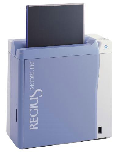
Поставщики и цены:
Дигитайзер REGIUS 110
Дигитайзер REGIUS 110 — Новая, комфортная и простая работа с CR системами.
Компактные размеры допускают различные варианты установки
Различные варианты размещения оборудования
Панель управления устанавливается в зависимости от способа размещения оборудования:
При ограниченном рабочем пространстве
При достаточном рабочем пространстве
Дигитайзер REGIUS 110 отличает удивительно компактный дизайн. Площадь основания составляет всего 0.27 м?, а различные способы установки позволят организовать рабочее пространство по Вашему усмотрению, с учетом эргономических требований.
Простота и удобство использования
Новая модель REGIUS проста и удобна в использовании. Высота кассетоприемника — 710 мм, установка экспонированных кассет не требует никаких усилий. Кассеты, используемые в REGIUS модели 110, полностью совместимы с кассетами систем REGIUS моделей 170/190, имеют жесткую структуру подложки и большой ресурс эксплуатации.
Компактный, технологичный и высокопроизводительный REGIUS 110 обладает уникальной производительностью и может обрабатывать до 80 кассет в час, при этом время обработки одной кассеты составляет всего 45 секунд.
Это самая компактная CR система REGIUS с усовершенствованным дизайном и впечатляющими техническими характеристиками.
Назначение оборудования — Дигитайзер REGIUS 110
Похожее оборудование
Отзывы и комментарии:
Оцифровщик рентгеновских снимков – это высокотехнологичный прибор, выполняющий перевод в цифровой формат рентген-снимков. Он применяется в общей рентгенографии. С его помощью получают радиографические снимки конечностей и позвоночника. В качестве сверхкомпактных CR-систем рентгеновский оцифровщик устанавливается в медицинском транспорте и мобильных кабинетах. Выступающий важным звеном комплекта компьютерной радиографии, он упрощает процедуру получения рентген-снимков, снижает риск проведения повторных исследований, делает возможным хранение результатов рентгенографии в системе лечебного учреждения.
Оцифровщик Konica Regius 110 с возможностью использования новых пластин для снижения уровня зернистости на снимке. Больше нет необходимости в проявлении пленки и ручной замене реактивов. Больше не нужно чистить проявочные банки. Оцифровщик Konica Regius 110 – это высокая эргономика и расширенные возможности.
Компактная система обработки изображений Regius 110 имеет ширину всего 36,5 сантиметров и может располагаться различными способами.
Панель управления устанавливается соответственно расположению аппарата. Аппарат имеет высокую производительность — до 80 кассет в час, одна кассета обрабатывается 45 секунд. Используемые кассеты совместимы с кассетами Regius 170/190, выпущенными позже апреля 2004 года. Большой ресурс эксплуатации кассет, жёсткая подложка. Разрешение по шкале серого при пересылке изображения 12 бит, при считывании — 3 диапазона по 12 бит. Шаг сканирования 87,5 мкм и 175 мкм. Лёгкая установка кассет.
Особенности
- Компактный дизайн с минимальным поперечным размером 36,5 см. Regius модель 110 отличает удивительно компактный дизайн. Площадь основания составляет всего 0.27 м², а различные способы установки позволят организовать рабочее пространство по Вашему усмотрению, с учетом эргономических требований;
- Простота и удобство использования. Новая модель Regius проста и удобна в использовании. Высота кассетоприемника — 710 мм, установка экспонированных кассет не требует никаких усилий. Кассеты, используемые в Regius модели 110, полностью совместимы с кассетами систем Regius моделей 170/190, имеют жесткую структуру подложки и большой ресурс эксплуатации;
- Технологичный и высокопроизводительный. Regius 110 обладает уникальной производительностью и может обрабатывать до 80 кассет в час, при этом время обработки одной кассеты составляет всего 45 секунд. Это самая компактная CR система Regius с усовершенствованным дизайном и впечатляющими техническими характеристиками.
Система компьютерной радиографии REGIUS 110 с принадлежностями
I. Система компьютерной радиографии REGIUS, исполнения: 110 (DIRECT DIGITIZER REGIUS MODEL 110), REGIUS 110 S (DIRECT DIGITIZER REGIUS MODEL 110 S), REGIUS 110 HQ (DIRECT DIGITIZER REGIUS MODEL 110 HQ):
II. Система компьютерной радиографии REGIUS, состав:
1. Базовый блок — 1 шт.
2. Кабель сетевой — 1 шт.
III. Принадлежности:
1. Документация эксплуатационная — 1 шт.
2. Проводные перемычки с разъемами — 3 шт.
3. Кассеты REGIUS в сборе с пластинами (REGIUS CASSETTE/PLATE) системы компьютерной радиографии следующих форматов: 8х10 дюймов, 10×12 дюймов, 11×14 дюймов, 14×14 дюймов, 14×17 дюймов, 18×24 см, 24×30 см, 15×30 см — до 4 шт. каждого формата на одну систему
4. Кассеты маммографические REGIUS в сборе с пластинами (REGIUS CASSETTE/PLATE for Mammography) системы компьютерной радиографии следующих форматов: 18х24 см, 24х30 см — до 8 шт. каждого формата на одну систему
5. Кассеты REGIUS (REGIUS CASSETTE) системы компьютерной радиографии следующих форматов: 10×24 дюймов, 10×36 дюймов, 11×28 дюймов, 14×34 дюймов, 14×42 дюймов, 14×51 дюймов — до 2 шт. каждого формата на одну систему
6. Пластины REGIUS (REGIUS PLATE) системы компьютерной радиографии следующих форматов: 8х10 дюймов, 10×12 дюймов, 11×14 дюймов, 14×14 дюймов, 14×17 дюймов, 18×24 см, 24×30 см, 15×30 см — до 6 шт. каждого формата на одну систему
7. Консоль CS-1 системы компьютерной радиографии — до 4 шт. на одну систему: блок основной с комплектом интерфейсных кабелей — 1 шт. мониторы медицинские жидкокристаллические системы компьютерной радиографии — до 4 шт. на одну консоль клавиатура — 1 шт. мышь — 1 шт. кабель сетевой — 1 шт. считыватель штрих кода — до 1 шт. на одну консоль документация эксплуатационная в электронном виде на CD/DVD носителях и/или в печатном виде — 1 шт.
8. Консоль CS-2 системы компьютерной радиографии — до 4 шт. на одну систему: блок основной с комплектом интерфейсных кабелей — 1 шт. мониторы медицинские жидкокристаллические системы компьютерной радиографии — до 4 шт. на одну консоль клавиатура — 1 шт. мышь — 1 шт. кабель сетевой — 1 шт. считыватель штрих кода — до 1 шт. на одну консоль документация эксплуатационная в электронном виде на CD/DVD носителях и/или в печатном виде — 1 шт.
9. Консоль CS-3 системы компьютерной радиографии — до 4 шт. на одну систему: блок основной с комплектом интерфейсных кабелей — 1 шт. мониторы медицинские жидкокристаллические системы компьютерной радиографии — до 4 шт. на одну консоль клавиатура — 1 шт. мышь — 1 шт. кабель сетевой — 1 шт. считыватель штрих кода — до 1 шт. на одну консоль документация эксплуатационная в электронном виде на CD/DVD носителях и/или в печатном виде — 1 шт.
10. Консоль CS-4 системы компьютерной радиографии — до 4 шт. на одну систему: блок основной с комплектом интерфейсных кабелей — 1 шт. мониторы медицинские жидкокристаллические системы компьютерной радиографии ? до 4 шт. на одну консоль клавиатура — 1 шт. мышь — 1 шт. кабель сетевой — 1 шт. считыватель штрих кода — до 1 шт. на одну консоль документация эксплуатационная в электронном виде на CD/DVD носителях и/или в печатном виде — 1 шт.
11. Консоль портативная (PDA) системы компьютерной радиографии — до 4 шт. на одну систему
12. Фантом тестовый системы компьютерной радиографии — 1 шт.
13. Крепления фигурные металлические разноформенные для установки и фиксации системы компьютерной радиографии в кузовах медицинских автомобилей -не более 15 шт.
14. Шок абсорберы для установки и фиксации системы компьютерной радиографии в кузовах медицинских автомобилей — не более 15 шт.
15. Обеспечение программное системы компьютерной радиографии на жестких дисках устройств, CD/DVD дисках, картах памяти — 1 шт.