
КАТЕГОРИИ
Коды ошибки котла E.C.A
- Confeo
- Код Т6 — ошибка датчика дымовых газов (короткое замыкание)
- Код Т2 — Чрезмерный поток воздуха для дымовых газов
- Код E4 — Предупреждение о дифференциальном реле давления воздуха (короткое замыкание)
- Код E5 — Предупреждение о дифференциальном реле давления воздуха (разомкнутый контур)
- Код E3 — Блокировка перегрева (предельный термостат)
- Код Т1 — Чрезмерное предупреждение о нагреве (электронный предел)
- Код Т3 — ошибка датчика центрального датчика температуры (разомкнутый контур)
- Код T5 — Ошибка датчика температуры воды (разомкнутый контур)
- Код T7 — Ошибка датчика наружной температуры (короткое замыкание)
- Код E1 / E2 — отсутствие пламени
- Код D1 — ошибка при взрыве
- Код C1 — Прерванная связь с материнской картой
- Код A1 — предупреждение о низком напряжении на основной плате
- Код P1 — Предупреждение о низком давлении воды
- Код Y1 — Авария в цепи газового клапана
Citius Premix
- A00 Ошибка — программного обеспечения электронной карты
- A01 Ошибка -зажигания
- A02 Ошибка — Ложный сигнал пламени
- A03 Ошибка — Предупреждение о перегреве
- A04 Ошибка — Может быть из-за неисправности датчиков температуры.
- A05 Ошибка — Отсутствие обратной связи от вентилятора более 1 минуты
- A08 Ошибка — Неисправность цепи пламени
- A09 Ошибка — Клапан не дает обратной связи
- A12 Ошибка — проверки EEPROM
- A15 Ошибка — отклонения измерения датчиков температуры
- A16 Ошибка — датчика температуры подачи
- A17 Ошибка — датчика температуры обратки
- A18 Ошибка — датчика температуры
- A21 Ошибка — аналого-цифрового преобразователя (АЦП)
- A33 Ошибка — датчика температуры обратки
- A35 Ошибка — датчика температуры подачи
- A80 Ошибка — разности температур между датчиками температуры обратки и подачи
- A82 Ошибка — пропадания пламени (более 3 пропаданий пламени за 4 минуты)
- C07 Ошибка — превышения температуры дымовых газов
- C13 Ошибка — перезапуска
- C25 Ошибка — Отказ электронной платы
- C34 Ошибка — Низкое напряжение питания
- C37 Ошибка — низкого давления воды
- C39 Ошибка — датчика наружного воздуха
- C40 Ошибка — высокого давления воды
- C47 Ошибка -датчика давления воды
- C50 Ошибка — датчика котла
- C51 Ошибка — солнечного датчика PT1000
- C52 Ошибка — датчика температуры ГВС
- C53 Ошибка — датчика температуры дымовых газов
- C81 Ошибка — Режим ожидания теста дрейфа датчика температуры
Калора
- Если все светодиоды быстро мигают, связь с материнской платой потеряна.
- Если горит L2, а L1, L3 и L4 нет, то в горелке нет пламени.
- Если L1 быстро мигает, L2 горит, L3 и L4 не горят, проблема с датчиком нагрева.
- Если L3 быстро мигает, L2 горит, L1 и L4 не горят, проблема с датчиком горячей воды.
- Ошибка перегрева, если L2 быстро мигает, L1, L3 и L4 не горят
- Если L4 быстро мигает, L2 горит, L1 и L3 не горят, неисправность дымохода.
- L3 и L4 быстро мигают, L2 горит, L1 не горит Давление воды низкое
- Если L2 быстро мигает, L1, L3 и L4 горят Внешняя неисправность. Обычно возникает проблема с электронной картой.
(Calora Digital)
- E1 ошибка — Сбой зажигания.
- E2 Ошибка — неправильное формирование пламени
- E3 Ошибка — проблема с блокировкой при перегреве
- E4 Ошибка — Проблема короткого замыкания реле дифференциального давления воздуха
- E5 Ошибка — проблема с замкнутой цепью дифференциального реле давления воздуха
- T1 Ошибка — проблема перегрева
- T3 Ошибка — неисправность датчика нагрева
- T5 Ошибка — ошибка датчика горячей воды
- T7 Ошибка — неисправность датчика наружного воздуха
- D1 Ошибка — ошибка цепи пламени
- C1 Ошибка — проблема связи с материнской платой
- A1 Ошибка — ошибка низкого напряжения
- P1 Ошибка — Ошибка низкого давления воды
- Y1 Ошибка — ошибка газового клапана
Калора Премих
- E01 ошибка — нет пламени
- Е02 ошибка — не провилное пламия
- E05 ошибка — Нет обратной связи от вентилятора в течение длительного времени
- E08 ошибка — цепи пламени
- E09 ошибка — проблема с газовым клапан
- E12 ошибка — проверки EEPROM
- E15 ошибка — сбой определения датчика температуры
- E16 ошибка — датчика температуры подачи отопительного контура
- E17 ошибка — датчика температуры обратной воды отопительного контура
- E18 ошибка — датчика воды для бытового потребления
- E21 ошибка — аналого-цифрового преобразователя
- Е33 ошибка — датчика температуры обратной воды отопления
- E35 ошибка — Ошибка датчика температуры подающей линии отопления
- E54 ошибка — возможно, забит сифон для конденсата.
- E80 ошибка — Разница температур между температурой обратной линии отопления и температурой подающей воды
- E82 ошибка — нет пламени
- F07 ошибка — проблема с температурой дымовых газов
- F13 ошибка — чрезмерная ошибка сброса
- F34 ошибка — проблема с низким энергопотребление
- F37 ошибка — предупреждение о низком давлении воды
- F39 Ошибка — наружного датчика
- F40 ошибка — предупреждение о высоком давлении воды
- F47 ошибка — неисправность датчика давления воды
- F50 ошибка — неисправность датчика котла
- F51 ошибка — неисправность солнечного датчика PT1000
- F52 ошибка — Неисправность датчика температуры воды для бытового потребления
- F53 ошибка — Предупреждение датчика температуры дымовых газов
- F81 ошибка — Предупреждение об ожидании теста доения датчика температура
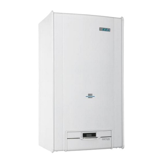
- ЭCА Протеус
Если Led1, Led2, Led3 и Led4 быстро мигают: Материнская плата отключена. Это означает, что если перед этим была заменена электронная карта или видеокарта, подключение может быть неправильным. Если не принять никаких мер, возможно, электронная карта неисправна. - Если Led1, Led3 и Led4 не загораются Если Led2 загорается: Нет зажигания. Газовый клапан, электронная карта, означает неисправность ионов или электродов.
- Если светодиод 1 часто мигает, светодиод 2 загорается, а светодиоды 3 и 4 не горят: неисправность датчика радиатора.
- Светодиод 1 и светодиод 4 не горят, светодиод 2 горит, а светодиод 3 часто мигает: ошибка датчика горячей воды, датчик может быть влажным
- Светодиод 1, светодиод 3 и светодиод 4 горят, светодиод 2 часто мигает: Перегрев Блокировка безопасности. Засор радиатора, засор Esenjor, проблема с трехходовым клапаном
- Если светодиоды 1 и 3 не горят, загорается светодиод 2, а светодиод 4 часто мигает: Ошибка давления воздуха. Возможна ошибка вентилятора и материнской платы
- Светодиод 1 не горит, светодиод 2 горит, светодиоды 3 и 4 часто мигают: Давление воды упало. Должно быть 1,5 бар.
- Светодиод 1, светодиод 3 и светодиод 4 горят, если светодиод 2 часто мигает: ошибка электронной карты
ECA Proteus Premix
- Код E01-проблема с зажиганием
Код E02- Зажигание не идет. Неисправность вентилятора, иона, газового клапана или материнской платы
Код E03- Перегрев
Код E05- Проблема с вентилятором. От болельщика нет обратной связи более 1 минуты.
Код E08- Ошибка циркуляции пламени Повторить несколько раз. Если это не исправлено, это может быть электронная карта
Код E09- Проблема с газовым клапаном
Код E12 — ошибка EEPROM (материнская плата)
Код E15 — ошибка измерения датчика горячей воды или ошибка электронной карты
Код E16- Ошибка датчика температуры воды на выходе.
Код E17 — ошибка датчика воды на входе
Код E18 — Указывает на то, что датчик температуры выше 30 C.
Код E21- Ошибка аналого-цифрового преобразователя
Код E33- Ошибка датчика нагрева воды на входе
Код E35- Ошибка датчика температуры воды на выходе
Код E54- Ошибка засорения сифона
Код E80- Ошибка разницы температур между датчиками температуры обратки и подачи
Код E82 — ошибка потери пламени
Код F07- Ошибка чрезмерной температуры дымовых газов. Сообщается 95 C
Код F13 — проблема многократного сброса
Код F34 — Сообщается об ошибке напряжения ниже 170 В.
Код F37- Падение давления (должно быть 1,5 бар)
Код F39- Ошибка внешнего датчика воздуха
Код F40- Высокое давление воды
Код F47- Датчик давления воды
Код F50- Ошибка датчика котла
Код F51- Ошибка солнечного датчика PT1000
Код F52- Ошибка датчика температуры использованной воды
Код F53- Ошибка сверления дымохода
Код F81- проверка датчика тепла
Если вы не можете решить проблему с кодами ошибок, обратитесь в нашу Службу Сервиса.- контакт(012) 374 92 02(055) 555 92 02(070) 355 92 02
-
Contents
-
Table of Contents
-
Bookmarks
Quick Links
PLUS
23,3 kW Room Sealed Fan Assisted Gas Combination Boiler (monothermic type)
INSTALLATION AND USER’S OPERATING
INSTRUCTIONS
Related Manuals for E.C.A. Proteus Plus
-

-

-
-

-

-

-

Boiler E.C.A. Fortius Service Manual
24 kw open flued gas combination boiler (bithermic type)
24 kw room sealed fan assisted gas combination boiler (bithermic type)
24 kw room sealed fan assisted gas combination boiler (monothermic type)
28 kw room sealed fan assisted gas combination boil (42 pages)


Summary of Contents for E.C.A. Proteus Plus
-
Page 1
PLUS 23,3 kW Room Sealed Fan Assisted Gas Combination Boiler (monothermic type) INSTALLATION AND USER’S OPERATING INSTRUCTIONS… -
Page 2: Table Of Contents
…— .I CONTENTS PREFACE GUARANTEE SERVICE & SYMBOLS’ DEFINITIONS SAFETY INSTRUCTIONS AND WARNINGS PRODUCT General Specifications Product Notation Technical Data BOILER PACKAGING INSTALLATION Selection Of The Boiler Location Mounting The Boiler CONNECTIONS Flue Connection Gas Supply Water Systems & Electricity Supply BOILER START-UP Final Checks And Operations Before Boiler Start-up Control Panel…
-
Page 3: Guarantee & Service
PREFACE Proteus Plus 23,3 kW room sealed fan assisted gas combination boilers have been designed for providing efficient, safe and comfortable central heating (CH) and domestic hot water (DHW). The boilers are supplied for use with either natural gas or LPG.
-
Page 4
SAFETY INSTRUCTIONS AND PRECAUTIONS This appliance is not intended for use by persons (including children) with reduced physical, sensory or mental capabilities, or lack of experience and knowledge, unless they have been given supervision or instruction concerning use of the appliance by a person responsible for their safety. -
Page 5: Product
Boiler Start-up Boiler start-up must be performed certainly by qualified person. Gas type (natural gas/LPG), gas supply pressure (mbar), maximum DHW operating water presure (bar) and electricity supply voltage (V) data which are detailed on the information plate must be suitable with mains supply conditions.
-
Page 6: Product Notation
(monothermic type) Technical Data Proteus Plus 23,3 kW room sealed fan assisted gas combination boiler is a C type boiler (EN 483). C type boilers have a sealed combustion chamber. Required fresh air for combustion is provided independently from the installation room by concentric air/flue ducts and products of combustion can be also discharged by the same air/flue ducts.
-
Page 7
Table 2.2 PRP 24 HM Unit Gas Category * 2H 3B/P Boiler Type Natural gas Type of gas Performances , Min. Heat Output , Max. Heat Output 23,3 maks , Heat Output 18,7 , Min. Thermal Load , Max. Thermal Load 25,6 maks , Thermal Load… -
Page 8: Wiring Diagram
Wiring Diagram PRP 24HM • ==-;Kj — : _ ® E::::::::l c::::::::J 27 . 2 MA IN BOARD SUPPLY CABLE 9 OUTS DE TEMPERATURE SENSOR (Optional TERM INAL ELECTR VALVE DHW FLOW SENSOR GAS VALVE MODULATOR GASVALVE TEMPERATURE SENSOR ROOM THERMOSTAT (Optional) IFFERENTIAL A R PRESSURE SWITCH…
-
Page 9: Boiler Packaging
fig. 1 BOILER PACKAGING CAUTION: The instructions on the boiler package should be considered during transportation and storage. — The product is covered with a cardboard box of which dimensions are 867x 470×400 mm (HxWxL) and supported by upper and lower styrofoams (fig. 2a). fig.
-
Page 10
— For room sealed fan assisted operation, apart from the boiler package, concentric air/flue kit ( 60/100) is given with a cardboard box. Air/flue kit consists of the following parts: a) Flat sealing ring b) Flange c) 90 Concentric elbow d) Screws e) Fixing Collar f) Sealing ring, EPDM… -
Page 11: Installation
INSTALLATION Selection Of The Boiler Location The boiler must be installed in accordance with gas safety regulations and relevant standards. Additionally, the clearances around the boiler should be as shown in fig. 4 in order to make service, maintenance and usage easier. …
-
Page 12: Mounting The Boiler
Room Sealed Fan Assisted Operation WARNING: For room sealed fan assisted appliance, the boiler location and air/flue terminal position must obey national and local requirements, gas safety regulations and relevant standarts. The room sealed fan assisted boiler is not suitable for external installation. It should be within in the building.
-
Page 13: Connections
fig. 7 CONNECTIONS Flue Connection 3 different types of air/flue system can be designed for 23,3 kW room sealed fanned boilers: assisted a) The air/flue system is designed by horizontal concentric ducts. b) The air/flue system is designed by two separate ducts. c) The air/flue system is designed by vertical concentric ducts.
-
Page 14
fig. 9 Room Sealed Fan Assisted Operation fig. 10 should be ordered through If the air/flue kit length is insufficient, additional flue accessories qualified service. Do not use any other type / brand name of flue parts. — Horizontal air/flue kit accessories (fig 11): a) Concentric extension, L=500 mm, 60/100 mm Concentric extension, L=1000 mm, 60/100 mm Concentric elbow, 60/100 mm… -
Page 15
Room Sealed Fan Assisted Operation The total length of horizontal air/flue system must not exceed 3 m. Furthermore, each extra concentric elbow or two pieces of 45 concentric elbow decreases the maximum length 1m (fig. 12). The maximum number of 90 elbow to be used is 3. -
Page 16
Room Sealed Fan Assisted Operation Mounting the restrictor: The restrictor should be mounted on the fan outlet according to the length of the air/flue connection to provide efficient combustion and suitable combustion products. Table 3 restrictor Product Elbow L (m) (mm) … -
Page 17
Room Sealed Fan Assisted Operation Connection by two separate ducts Maximum length of the air ducts and flue ducts are seen in Table 4. The air ducts and flue ducts must be parallel (fig. 15). — The twin air/flue kit and its accessories (fig. 14): a) The twin air/flue kit b) Extension, L=500 mm, 80 mm Extension, L=1000 mm, 80 mm… -
Page 18: Table 4
Room Sealed Fan Assisted Operation Table 4 restrictor Product Elbow (mm) 42 1×90 PRP 24 HM 42 2×90 Connection by vertical concentric ducts Vertical flue connection can be designed by 60/100 mm or 80/125 mm concentric ducts. The total length is 3 m for 60/100 mm vertical air/flue system and 8 m for 80/125 mm vertical air/flue system.
-
Page 19: Product Elbow L (M) L (M) Restrictor (Mm) 1X90
Room Sealed Fan Assisted Operation Table 5 The restrictors for 60/100 mm concentric ducts restrictor Product Elbow L (m) (mm) 47 ≤ 1 1×90 49 1< ≤ 2 1×90 2< ≤ 3 1×90 PRP 24 HM 49 ≤…
-
Page 20: Gas Supply & Water Systems
& Gas Supply Water Systems (Optional) — Water & gas connections between the boiler and the mounting bracket can be fixed with the optional pipes and the nipples as shown in fig. 18. 1!Iounting Bracket Nipp le (3/4″ fig. 18 a) CH flow 3/4″…
-
Page 21: Electricity Supply
Electricity Supply Electrical installation should be made according to the national and local instructions. The boiler must be earthed and a standard 230 V AC — 50 Hz supply is required. WARNING: Disconnect power supply to prevent electrical shock before connecting the electricity supply.
-
Page 22: Boiler Start-Up
BOILER START-UP Final Checks And Operations : Having completed the installation and connections (flue, electricity supply, gas supply and water circuits) of the boiler according to the authorized gas company regulations and relevant standards, the final checks and operations must be carried out by qualified person. Filling the boiler and central heating circuit with water.
-
Page 23: Control Panel
The filling tap is not available in some models based on national and local regulations. Control Panel The control panel shown in fig. 20 consists of the following parts as detailed below. Fault & Error LED Manometer Status Potentiometer Domestic Hot Water Temperature Potentiometer Central Heating Potentiometer fig.20…
-
Page 24: Operating The Boiler
Error Reset Mode — Error code and error led will be flashing countinusly If the errors cause a lock out condition, tum to Status (Pl) to Reset» «position and hold it for sec. to get to the normal operation (winter or summer) mode again.
-
Page 25
— In case of failed ignition, automatic ignition sequence is repeated 5 times. If all ignition trials are failed, flame failure lockout happens. Error LED (red) will turn ON and blink to indicate this error condition (fig.22). Turn Status ’s knob to the reset “ ”… -
Page 26
— Rotate the CH to minumum position. The summer mode will be active and the system will go back to stand-by mode again. Frost Protection The appliance goes on and off automatically depending on actual water temperature values measured by the sensors for protecting water circuits against freezing. This function protects both CH and DHW systems. -
Page 27: Gas Type Conversion
fig. 21 Programming the Unit — Set the right sliding button to P. — See the program number that you want to set while pressing P button. (If the program to be set is startup program, sign will appear. 1,3,5,7,9,11,13,15 are startup programs; 2,4,6,8,10,12,14,16 are shutdown programs) — Set the day of startup or shutdown program by pressing button.
-
Page 28: Gas Pressure Adjustments
The heat output directly depends on the operating pressure. When the operating gas pressure range is adjusted, minimum and maximum heat output is also adjusted (mechanically). Proteus Plus 23,3 kW Table 7 Max. operating gas pressure (mbar)
-
Page 29: Replacement Of The Burner Injectors
fig. 22 Replacement Of The Burner Injectors WARNING:Keep the gas valve on the boiler and electricity supply closed during replacement of the burner injectors. — Shut off the boiler by turning the status to OFF-Reset position and turn off the gas valve on the boiler.
-
Page 30: Gas Leak Test
.. GAS LEAK TEST );- Apply a rich soap and water solution to the surface of all pipe connections. Bubbles indicate a gas leak In case of gas leak, tighten the pipe connection. Check the pipe connection again for gas leak. Replace the part/parts if gas leak can not be stopped.
-
Page 31
Table 11 Fault/Error Cause Solution 1- The boiler does not start up — Lack of electricity. -Check the electricity connections. by turning Status to “winter or summer” position. — No flame in burner after 3 ignition — Turn the Status Konb (P1) to Off/Reset 2- Flame failure lockout: trials. -
Page 32: Maintenance
MAINTENANCE — The boiler should be checked and serviced for general maintenance once a year. Maintenance and service operations must be carried out only by qualified person. — Only a damp cloth should be used for cleaning the outer space of the boiler and then the surfaces should be dried completely.
-
Page 33
23,3 kW gas combination boilers’ capacity & operating gas pressure diagrams for (LPG) Propan ALL RIGHTS RESERVED Product specifications are subject to change without notice. Manufacturer : EMAS MAKİNA SANAYI A.Ş. Organize Sanayi Bölgesi Mustafa Kemal Bulvarı No:13 MANİSA Pbx: +90 236 213 00 21 Fax: +90 236 213 08 59 www.emas.com.tr…
-
Contents
-
Table of Contents
-
Bookmarks
Quick Links
PLUS
23,3 kW Room Sealed Fan Assisted Gas Combination Boiler (monothermic type)
INSTALLATION AND USER’S OPERATING
INSTRUCTIONS
Related Manuals for E.C.A. Proteus Plus
-
-
-
-
-
-
-
Boiler E.C.A. Fortius Service Manual
24 kw open flued gas combination boiler (bithermic type)
24 kw room sealed fan assisted gas combination boiler (bithermic type)
24 kw room sealed fan assisted gas combination boiler (monothermic type)
28 kw room sealed fan assisted gas combination boil (42 pages)
Summary of Contents for E.C.A. Proteus Plus
-
Page 1
PLUS 23,3 kW Room Sealed Fan Assisted Gas Combination Boiler (monothermic type) INSTALLATION AND USER’S OPERATING INSTRUCTIONS… -
Page 2: Table Of Contents
…— .I CONTENTS PREFACE GUARANTEE SERVICE & SYMBOLS’ DEFINITIONS SAFETY INSTRUCTIONS AND WARNINGS PRODUCT General Specifications Product Notation Technical Data BOILER PACKAGING INSTALLATION Selection Of The Boiler Location Mounting The Boiler CONNECTIONS Flue Connection Gas Supply Water Systems & Electricity Supply BOILER START-UP Final Checks And Operations Before Boiler Start-up Control Panel…
-
Page 3: Guarantee & Service
PREFACE Proteus Plus 23,3 kW room sealed fan assisted gas combination boilers have been designed for providing efficient, safe and comfortable central heating (CH) and domestic hot water (DHW). The boilers are supplied for use with either natural gas or LPG.
-
Page 4
SAFETY INSTRUCTIONS AND PRECAUTIONS This appliance is not intended for use by persons (including children) with reduced physical, sensory or mental capabilities, or lack of experience and knowledge, unless they have been given supervision or instruction concerning use of the appliance by a person responsible for their safety. -
Page 5: Product
Boiler Start-up Boiler start-up must be performed certainly by qualified person. Gas type (natural gas/LPG), gas supply pressure (mbar), maximum DHW operating water presure (bar) and electricity supply voltage (V) data which are detailed on the information plate must be suitable with mains supply conditions.
-
Page 6: Product Notation
(monothermic type) Technical Data Proteus Plus 23,3 kW room sealed fan assisted gas combination boiler is a C type boiler (EN 483). C type boilers have a sealed combustion chamber. Required fresh air for combustion is provided independently from the installation room by concentric air/flue ducts and products of combustion can be also discharged by the same air/flue ducts.
-
Page 7
Table 2.2 PRP 24 HM Unit Gas Category * 2H 3B/P Boiler Type Natural gas Type of gas Performances , Min. Heat Output , Max. Heat Output 23,3 maks , Heat Output 18,7 , Min. Thermal Load , Max. Thermal Load 25,6 maks , Thermal Load… -
Page 8: Wiring Diagram
Wiring Diagram PRP 24HM • ==-;Kj — : _ ® E::::::::l c::::::::J 27 . 2 MA IN BOARD SUPPLY CABLE 9 OUTS DE TEMPERATURE SENSOR (Optional TERM INAL ELECTR VALVE DHW FLOW SENSOR GAS VALVE MODULATOR GASVALVE TEMPERATURE SENSOR ROOM THERMOSTAT (Optional) IFFERENTIAL A R PRESSURE SWITCH…
-
Page 9: Boiler Packaging
fig. 1 BOILER PACKAGING CAUTION: The instructions on the boiler package should be considered during transportation and storage. — The product is covered with a cardboard box of which dimensions are 867x 470×400 mm (HxWxL) and supported by upper and lower styrofoams (fig. 2a). fig.
-
Page 10
— For room sealed fan assisted operation, apart from the boiler package, concentric air/flue kit ( 60/100) is given with a cardboard box. Air/flue kit consists of the following parts: a) Flat sealing ring b) Flange c) 90 Concentric elbow d) Screws e) Fixing Collar f) Sealing ring, EPDM… -
Page 11: Installation
INSTALLATION Selection Of The Boiler Location The boiler must be installed in accordance with gas safety regulations and relevant standards. Additionally, the clearances around the boiler should be as shown in fig. 4 in order to make service, maintenance and usage easier. …
-
Page 12: Mounting The Boiler
Room Sealed Fan Assisted Operation WARNING: For room sealed fan assisted appliance, the boiler location and air/flue terminal position must obey national and local requirements, gas safety regulations and relevant standarts. The room sealed fan assisted boiler is not suitable for external installation. It should be within in the building.
-
Page 13: Connections
fig. 7 CONNECTIONS Flue Connection 3 different types of air/flue system can be designed for 23,3 kW room sealed fanned boilers: assisted a) The air/flue system is designed by horizontal concentric ducts. b) The air/flue system is designed by two separate ducts. c) The air/flue system is designed by vertical concentric ducts.
-
Page 14
fig. 9 Room Sealed Fan Assisted Operation fig. 10 should be ordered through If the air/flue kit length is insufficient, additional flue accessories qualified service. Do not use any other type / brand name of flue parts. — Horizontal air/flue kit accessories (fig 11): a) Concentric extension, L=500 mm, 60/100 mm Concentric extension, L=1000 mm, 60/100 mm Concentric elbow, 60/100 mm… -
Page 15
Room Sealed Fan Assisted Operation The total length of horizontal air/flue system must not exceed 3 m. Furthermore, each extra concentric elbow or two pieces of 45 concentric elbow decreases the maximum length 1m (fig. 12). The maximum number of 90 elbow to be used is 3. -
Page 16
Room Sealed Fan Assisted Operation Mounting the restrictor: The restrictor should be mounted on the fan outlet according to the length of the air/flue connection to provide efficient combustion and suitable combustion products. Table 3 restrictor Product Elbow L (m) (mm) … -
Page 17
Room Sealed Fan Assisted Operation Connection by two separate ducts Maximum length of the air ducts and flue ducts are seen in Table 4. The air ducts and flue ducts must be parallel (fig. 15). — The twin air/flue kit and its accessories (fig. 14): a) The twin air/flue kit b) Extension, L=500 mm, 80 mm Extension, L=1000 mm, 80 mm… -
Page 18: Table 4
Room Sealed Fan Assisted Operation Table 4 restrictor Product Elbow (mm) 42 1×90 PRP 24 HM 42 2×90 Connection by vertical concentric ducts Vertical flue connection can be designed by 60/100 mm or 80/125 mm concentric ducts. The total length is 3 m for 60/100 mm vertical air/flue system and 8 m for 80/125 mm vertical air/flue system.
-
Page 19: Product Elbow L (M) L (M) Restrictor (Mm) 1X90
Room Sealed Fan Assisted Operation Table 5 The restrictors for 60/100 mm concentric ducts restrictor Product Elbow L (m) (mm) 47 ≤ 1 1×90 49 1< ≤ 2 1×90 2< ≤ 3 1×90 PRP 24 HM 49 ≤…
-
Page 20: Gas Supply & Water Systems
& Gas Supply Water Systems (Optional) — Water & gas connections between the boiler and the mounting bracket can be fixed with the optional pipes and the nipples as shown in fig. 18. 1!Iounting Bracket Nipp le (3/4″ fig. 18 a) CH flow 3/4″…
-
Page 21: Electricity Supply
Electricity Supply Electrical installation should be made according to the national and local instructions. The boiler must be earthed and a standard 230 V AC — 50 Hz supply is required. WARNING: Disconnect power supply to prevent electrical shock before connecting the electricity supply.
-
Page 22: Boiler Start-Up
BOILER START-UP Final Checks And Operations : Having completed the installation and connections (flue, electricity supply, gas supply and water circuits) of the boiler according to the authorized gas company regulations and relevant standards, the final checks and operations must be carried out by qualified person. Filling the boiler and central heating circuit with water.
-
Page 23: Control Panel
The filling tap is not available in some models based on national and local regulations. Control Panel The control panel shown in fig. 20 consists of the following parts as detailed below. Fault & Error LED Manometer Status Potentiometer Domestic Hot Water Temperature Potentiometer Central Heating Potentiometer fig.20…
-
Page 24: Operating The Boiler
Error Reset Mode — Error code and error led will be flashing countinusly If the errors cause a lock out condition, tum to Status (Pl) to Reset» «position and hold it for sec. to get to the normal operation (winter or summer) mode again.
-
Page 25
— In case of failed ignition, automatic ignition sequence is repeated 5 times. If all ignition trials are failed, flame failure lockout happens. Error LED (red) will turn ON and blink to indicate this error condition (fig.22). Turn Status ’s knob to the reset “ ”… -
Page 26
— Rotate the CH to minumum position. The summer mode will be active and the system will go back to stand-by mode again. Frost Protection The appliance goes on and off automatically depending on actual water temperature values measured by the sensors for protecting water circuits against freezing. This function protects both CH and DHW systems. -
Page 27: Gas Type Conversion
fig. 21 Programming the Unit — Set the right sliding button to P. — See the program number that you want to set while pressing P button. (If the program to be set is startup program, sign will appear. 1,3,5,7,9,11,13,15 are startup programs; 2,4,6,8,10,12,14,16 are shutdown programs) — Set the day of startup or shutdown program by pressing button.
-
Page 28: Gas Pressure Adjustments
The heat output directly depends on the operating pressure. When the operating gas pressure range is adjusted, minimum and maximum heat output is also adjusted (mechanically). Proteus Plus 23,3 kW Table 7 Max. operating gas pressure (mbar)
-
Page 29: Replacement Of The Burner Injectors
fig. 22 Replacement Of The Burner Injectors WARNING:Keep the gas valve on the boiler and electricity supply closed during replacement of the burner injectors. — Shut off the boiler by turning the status to OFF-Reset position and turn off the gas valve on the boiler.
-
Page 30: Gas Leak Test
.. GAS LEAK TEST );- Apply a rich soap and water solution to the surface of all pipe connections. Bubbles indicate a gas leak In case of gas leak, tighten the pipe connection. Check the pipe connection again for gas leak. Replace the part/parts if gas leak can not be stopped.
-
Page 31
Table 11 Fault/Error Cause Solution 1- The boiler does not start up — Lack of electricity. -Check the electricity connections. by turning Status to “winter or summer” position. — No flame in burner after 3 ignition — Turn the Status Konb (P1) to Off/Reset 2- Flame failure lockout: trials. -
Page 32: Maintenance
MAINTENANCE — The boiler should be checked and serviced for general maintenance once a year. Maintenance and service operations must be carried out only by qualified person. — Only a damp cloth should be used for cleaning the outer space of the boiler and then the surfaces should be dried completely.
-
Page 33
23,3 kW gas combination boilers’ capacity & operating gas pressure diagrams for (LPG) Propan ALL RIGHTS RESERVED Product specifications are subject to change without notice. Manufacturer : EMAS MAKİNA SANAYI A.Ş. Organize Sanayi Bölgesi Mustafa Kemal Bulvarı No:13 MANİSA Pbx: +90 236 213 00 21 Fax: +90 236 213 08 59 www.emas.com.tr…
Table 11
Fault/Error
1- The boiler does not start up
by turning Status to «winter or
summer» position.
2- Flame failure lockout:
When turning the Status
«winter or summer position, F4
error code appears on LCD and
error (red) led turns ON by
flashing
to indicate the lockout
position
(F4)
3- CH NTC error:
F3 error code appears on LCD
and
error (red) led turns ON by
flashing
to indicate the lockout
position
(F3)
4- DHW NTC error:
F2 error code appears on LCD
and
error (red) led turns ON by
flashing
to indicate the lockout
position
(F2)
5- High limit lockout:
F1 error code appears on LCD
and error (red) led turns ON by
flashing to indicate the lockout
position
(F1)
6- APS Error:
F5 error code appears on LCD
and error (red) led turns ON by
flashing to indicate the lockout
position
(F5)
7- Low water pressure:
F7 error code appears on LCD
and error (red) led turns ON by
flashing to indicate the lockout
position
(F7)
8- Low voltage :
F8 error code appears on LCD
and error (red) led turns ON by
flashing to indicate the lockout
position
(F8)
9- OTC Exthernal Probe Fault:
F6 error code appears on LCD
(F6)
CC: When the power supply is switched On «
Sensor correctly disconnected and the function enabled.
OC: When the power supply is switched On «
Sensor correctly connected and the function enabled.
Cause
— Lack of electricity.
— No flame in burner after 3 ignition
trials.
to
— CH sensor is out of operating
range and this condition lasted for
more than 10 seconds.
— DHW sensor is out of operating
range and this condition lasted for
more than 10 seconds.
— If limit thermostat is open, error
will be generated.
— Insufficient flue draught.
— Operating water pressure is not
suitable for your appliance.
— The main voltage is not suitable
for your appliance.
— Check to the OTC terminal
connections and cabels.
-Check the electricity connections.
— Turn the Status Konb (P1) to Off/Reset
position and waith for 5 seconds. — If the
lockout condition continues after the reset,
check the gas inlet and supply valves.
— Having all tries expired, consult qualified
service.
— Check the CH inlet valve and radiator valves
whether it is open or not.
— The system stays in blocking condition until
CH sensor is in operating range. If repeated,
consult qualified service.
— Check the CH inlet valve and radiator valves
whether it is open or not.
— The system stays in blocking condition until
DHW sensor is in operating range. If repeated,
consult qualified service.
— Check the flue connections / chimney.
— Reset the boiler, turn the Status (P1) to Off-
Reset position and waith for 5 seconds.- If the
lockout condition continues after the reset,
consult qualified service.
— Check the flue connections.
— Reset the boiler, turn the Status Potentiometer
(P1) to Off-Reset position and waith for 5
seconds.- If the lockout condition continues
after the reset, consult qualified service.
— The system stays in blocking condition until
water pressure is back to nominal value.
Check the valves whether is open or not.
— Check circuits for leaks.
— The system stays in blocking condition until
main voltage is back to nominal value.
— The Boiler can work without OTC (outside
temp. Sensor)
— Consult qualified service for the solution.
» showed on LCD display means Outside temp.
» showed on LCD display means Outside temp.
Solution
—
—
30
- 25 Дек 2020
котёл включается, насос, турбина крутят, нет искры и пламени. Газ с горелки не идёт. кран открыт. сопротивление на модуляционной катушке — 71,4Ом, на запирающей 1-3-5,84 Ом, 1-4 — 7.25
- 25 Дек 2020
проверьте сопротивление контактов реле давления воздуха при работающей турбине
- 25 Дек 2020
Здесь принято маркировку платы указывать или фото
На одном и том же котле могут быть разные платы
- 25 Дек 2020
Это тот же ферроли диватеч, точнее наоборот, эка под маркой ферроли. Их лаборатория отопления напродавала. Прессостат их больное место.
- 26 Дек 2020
егорий68 сказал(а):
Это тот же ферроли диватеч
Значит sitовская плата
- 26 Дек 2020
EZZY сказал(а):
проверьте сопротивление контактов реле давления воздуха при работающей турбине
EZZY сказал(а):
проверьте сопротивление контактов реле давления воздуха при работающей турбине
при работающей турбине по нулям, при моргающей F4 — 11, 77 кОм.
xas.alik сказал(а):
Здесь принято маркировку платы указывать или фото
На одном и том же котле могут быть разные платы
- 26 Дек 2020
при работающей должно быть около 1 Ом (с погрешностью на щуп),при отключенном вентиляторе — бесконечность(разомкнут контакт)
пробуйте перемкнуть контакты реле при включении вентилятора,если розжиг начнется, делайте выводы (проверить на загрязненность турбину или замена реле давления воздуха)
- 26 Дек 2020
EZZY, А что ошибку тяги для этой платы запретили ?
- 26 Дек 2020
Konstantin_18 сказал(а):
EZZY, А что ошибку тяги для этой платы запретили
к производителю вопрос, я не компетентен. из практики довольно часто.
- 27 Дек 2020
Konstantin_18 сказал(а):
EZZY, А что ошибку тяги для этой платы запретили ?
Есть у него ошибка по тяге F05
- 29 Дек 2020
EZZY сказал(а):
при работающей должно быть около 1 Ом (с погрешностью на щуп),при отключенном вентиляторе — бесконечность(разомкнут контакт)
пробуйте перемкнуть контакты реле при включении вентилятора,если розжиг начнется, делайте выводы (проверить на загрязненность турбину или замена реле давления воздуха)
— пробовал, безрезультатно
- 30 Дек 2020
На котле плата делается или на столе? На отопление работает?
- 30 Дек 2020
Ф 4 это отсуствие пламени
- 30 Дек 2020
Автор уже замерз наверно, столько времени делает.
- 30 Дек 2020
NIKOLAY KOVAL сказал(а):
EZZY сказал(а):
при работающей должно быть около 1 Ом (с погрешностью на щуп),при отключенном вентиляторе — бесконечность(разомкнут контакт)
пробуйте перемкнуть контакты реле при включении вентилятора,если розжиг начнется, делайте выводы (проверить на загрязненность турбину или замена реле давления воздуха)— пробовал, безрезультатно
Поподробнее. Что и как именно пробовал. Этот котелок, как кореястар, тестирует включение турбины, а потом уже начинает отрабатывать на запуск цикла отопления. Т.е. он должен включить турбу, дождаться сигнала прессостата, выключить, увидеть размыкание. Только потом запускается на отопление.
- 2 Янв 2021
егорий68 сказал(а):
NIKOLAY KOVAL сказал(а):
EZZY сказал(а):
при работающей должно быть около 1 Ом (с погрешностью на щуп),при отключенном вентиляторе — бесконечность(разомкнут контакт)
пробуйте перемкнуть контакты реле при включении вентилятора,если розжиг начнется, делайте выводы (проверить на загрязненность турбину или замена реле давления воздуха)— пробовал, безрезультатно
Поподробнее. Что и как именно пробовал. Этот котелок, как кореястар, тестирует включение турбины, а потом уже начинает отрабатывать на запуск цикла отопления. Т.е. он должен включить турбу, дождаться сигнала прессостата, выключить, увидеть размыкание. Только потом запускается на отопление.
струсил ошибку и на запуске коротнул концы идущие на пресостат.
Virviglas сказал(а):
На котле плата делается или на столе? На отопление работает?
котёл собран. Ф4 и на лето и на зиму
- 2 Янв 2021
NIKOLAY KOVAL, То есть так неделю без котла и живете ??? !!!
- 3 Янв 2021
Цепи контроля контактов реле турбины в этой модели судя по фото, похоже нет. Тогда полезно проверить цепь, по которой контроллер «видит» сам факт замыкания контактов прессостата.
Котел «eca proteus plus 24 hm» был куплен за 7-8 месяцев до его установки, поэтому после первого пуска сервисники не поставили его на гарантию, типа надо было установить до полугода или провести сервисное обслуживание (500грн) — отказался.
Проработал котел почти год, появилась ошибка F4 (нет пламени). Начал разбираться сам. Открываю воду (отопление еще не включил) пошла искра, пламя горит, искра не прекращяется, несколько секунд и газ перекрывается. Так делает три пуска и F4. Как по инструкции. Присмотрелся через окошко, пламя на всех горелках кроме той, где стоит датчик пламени! Снял переднюю и боковые панели, переднюю крышку камеры сгорания, открутил блок горелок. Все жиклеры чистые, а вот из не работающей горелки палочкой вытащил, вытрусил, плотную паутину, муху и два сушенных комара. Вот вся проблемка, как они туда попали и почему именно туда где датчик?
Вопрос, паукам газ жить не мешает? Его я там не нашел. Если это не паутина, а пыль сбилась, как туда попали насекомые? Вообще то весь котел внутри, можно сказать чистый, паутины нет, очень легкий налет пыли, камера сгорания вообще как новая.
И еще не понял как работает датчик пламени, такой же кусок медной проволоки, как и на розжиге, провод к нему — одинарный, ожидал увидеть термопару.
Вот такой ремонт, жаль не сфоткал, извените шо многа букфф
Страница 1 из 4
-

- Регистрация:
- 01.08.12
- Сообщения:
-
413
- Благодарности:
- 178
Alex250962
Живу здесь
- Регистрация:
- 01.08.12
- Сообщения:
- 413
- Благодарности:
- 178
- Адрес:
- Москва
Котел Е. C. A. Proteus PremixКто сталкивался с таким?
Документация только для чайников. Как войти в сервисное меню не нашел, а хотелось бы посмотреть некоторые параметры, например выбег насоса.
И вообще как котел? -

- Регистрация:
- 12.11.18
- Сообщения:
-
570
- Благодарности:
- 186
Mironov4
Живу здесь
- Регистрация:
- 12.11.18
- Сообщения:
- 570
- Благодарности:
- 186
Их сейчас возит компания Vessen Russia. На будущее задавайте вопросы туда — там достаточно грамотный руководитель технической поддержки.
Хороший турецкий котёл из европейских компонентов.
Ранее он завозился другой конторой под брендом Hi-Therm. На него мануал прикладываю — в нём есть и про сервисные параметры.Вложения:
-
- Регистрация:
- 01.08.12
- Сообщения:
-
413
- Благодарности:
- 178
Alex250962
Живу здесь
- Регистрация:
- 01.08.12
- Сообщения:
- 413
- Благодарности:
- 178
- Адрес:
- Москва
-

- Регистрация:
- 21.01.10
- Сообщения:
-
31.898
- Благодарности:
- 14.192
Ortodox
Живу здесь
- Регистрация:
- 21.01.10
- Сообщения:
- 31.898
- Благодарности:
- 14.192
- Адрес:
- Москва
Турецкий котёл под итальянским новоявленным брендом.
Точно. Там турок какой-то рулит.
-
- Регистрация:
- 09.03.13
- Сообщения:
-
1.926
- Благодарности:
- 296
Сергей2403
Живу здесь
- Регистрация:
- 09.03.13
- Сообщения:
- 1.926
- Благодарности:
- 296
- Адрес:
- Домодедово
Всем привет, взял такой котёл на 24 кВт, и их боллер на 100 л,
Дом 180 кв
Планирую все на зонт повесить,
Взял одно одноконтурный чисто на отопление -
- Регистрация:
- 21.01.10
- Сообщения:
-
31.898
- Благодарности:
- 14.192
Ortodox
Живу здесь
- Регистрация:
- 21.01.10
- Сообщения:
- 31.898
- Благодарности:
- 14.192
- Адрес:
- Москва
А это
тогда зачем, если чисто на отопление?
-
- Регистрация:
- 09.03.13
- Сообщения:
-
1.926
- Благодарности:
- 296
Сергей2403
Живу здесь
- Регистрация:
- 09.03.13
- Сообщения:
- 1.926
- Благодарности:
- 296
- Адрес:
- Домодедово
Планировал так, газовый котёл, резервный электрический и гребёнка на 3 выхода (радиаторы, тп и выход на боллер) управление с зонта,
А что не так ? -
- Регистрация:
- 09.03.13
- Сообщения:
-
1.926
- Благодарности:
- 296
Сергей2403
Живу здесь
- Регистрация:
- 09.03.13
- Сообщения:
- 1.926
- Благодарности:
- 296
- Адрес:
- Домодедово
Я имел ввиду что без треходового, загрузка Боллера с колектора
-
- Регистрация:
- 21.01.10
- Сообщения:
-
31.898
- Благодарности:
- 14.192
Ortodox
Живу здесь
- Регистрация:
- 21.01.10
- Сообщения:
- 31.898
- Благодарности:
- 14.192
- Адрес:
- Москва
Ничего, кроме этого
И тут же противоречие самому себе
Зачем вам бойлер, если сами пишите, что вам котёл нужен чисто на отопления?
Или это вы так витиевато выражаете свои желания?Что без трёхходового? Котёл одноконтурный без встроенного трёхходового?
Или вы схему решили смонтировать без трёхходового?Понятно, то есть схема работы без приоритета по ГВС. Непонятно на хрена, но хозяин-барин.Последнее редактирование: 02.11.22
-
- Регистрация:
- 09.03.13
- Сообщения:
-
1.926
- Благодарности:
- 296
Сергей2403
Живу здесь
- Регистрация:
- 09.03.13
- Сообщения:
- 1.926
- Благодарности:
- 296
- Адрес:
- Домодедово
Да котёл без трёх ходового, приоритет гвс включу через зонт, с отключением насосов и закрытием трёх ходовых, причём можно кстати полы не выключать думаю их трёх ходовой сам подожмёт как увидет повышенную температуру ,
-
- Регистрация:
- 21.01.10
- Сообщения:
-
31.898
- Благодарности:
- 14.192
Ortodox
Живу здесь
- Регистрация:
- 21.01.10
- Сообщения:
- 31.898
- Благодарности:
- 14.192
- Адрес:
- Москва
Каких трёхходовых, если вы пишите
и будет
Наверно не гребёнка и гидроколлектор.
Что-то вы перемудрили. Ладно, это ваше дело.
-
- Регистрация:
- 09.03.13
- Сообщения:
-
1.926
- Благодарности:
- 296
Сергей2403
Живу здесь
- Регистрация:
- 09.03.13
- Сообщения:
- 1.926
- Благодарности:
- 296
- Адрес:
- Домодедово
Ну да, два котла приходят на гидроколектор с 3 выходами и там 2 сервопривода, и один прямой на бкн
-
- Регистрация:
- 21.01.10
- Сообщения:
-
31.898
- Благодарности:
- 14.192
Ortodox
Живу здесь
- Регистрация:
- 21.01.10
- Сообщения:
- 31.898
- Благодарности:
- 14.192
- Адрес:
- Москва
К котлу схема монтажа уже не имеет отношение. Делайте как хотите.
-
- Регистрация:
- 14.03.21
- Сообщения:
-
9
- Благодарности:
- 0
Василий-77
Участник
- Регистрация:
- 14.03.21
- Сообщения:
- 9
- Благодарности:
- 0
Нет нигде информации, поддерживает ли контроллер котла протокол OpenTherm?
Есть ли конкретный опыт и информация? -
- Регистрация:
- 12.11.18
- Сообщения:
-
570
- Благодарности:
- 186
Mironov4
Живу здесь
- Регистрация:
- 12.11.18
- Сообщения:
- 570
- Благодарности:
- 186
Заявляют, что поддерживает и опыт есть. Более подробно тут расскажут.
ООО «Вессен»
Адрес 115230, г. Москва, Электролитный проезд, д. 3, стр. 23
Phone +7 (499) 290 5171
+7 (800) 500 5171
Страница 1 из 4