Сажевый фильтр (DPF) на дизельном авто обычно служит не менее 150 000 км пробега, после чего обычно требуется его замена либо проведение процедуры профессиональной очистки.
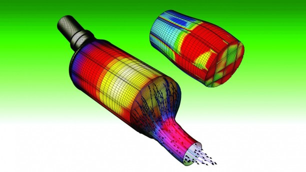
Однако, из-за технической неисправности автомобиля блок управления (ECU) может не инициировать включение автоматической регенерации сажевого фильтра. Это становится причиной преждевременного загрязнения DPF до критического состояния и влечет за собой блокировку выхлопной системы. В таком случае замена или очистка DPF не решат проблему надолго и сажевый фильтр будет снова сильно загрязнен после короткой эксплуатации.
По истории ECU всегда можно проверить, проводил ли автомобиль регенерации сажевого фильтра, являлись ли они успешными и насколько часто происходили.
Эти моменты очень важны, так как на основании такой информации можно определить наиболее вероятные неисправности авто.
Причинами преждевременной блокировки DPF могут стать проблемы с топливной системой, свечами накаливания, системой рециркуляции отработавших газов (EGR), вопросы, связанные с воздухозабором и неисправным турбокомпрессором.
Регенерация не проводится, если есть какие-либо ошибки, связанные с датчиком дифференциального давления DPF, датчиком температуры выхлопных газов и даже с пробкой заливной горловины топливного бака.
Ниже приведены коды неисправностей DPF с кратким описанием:
Typical DPF fault codes
P1471 Diesel particulate filter (bank 1) regeneration not completed
P2002 Diesel particulate filter (bank 1) efficiency below threshold
P2003 Diesel particulate filter (bank 1) particulate mass too high
P242F Diesel particulate filter (bank 1) regeneration not active
P244A Particulate filter differential pressure too low
P224B Particulate filter differential pressure too high
P2452 Particulate filter differential pressure sensor malfunction
P2453 Diesel particulate filter differential pressure — sensor malfunction
P2454 Diesel particulate filter differential pressure — sensor voltage too low
P2455 Diesel particulate filter differential pressure — sensor malfunction
P2458 Particulate filter regeneration maximum regeneration time exceeded
P2459 Particulate filter regeneration, regeneration frequency implausible
Рассмотрим некоторые моменты на которые следует обратить внимание, чтобы регенерация сажевого фильтра прошла успешно:
1) В баке должно быть достаточное количество топлива, по меньшей мере четверть бака, или около двадцати литров топлива.
2) Для пассивной регенерации содержание сажи в фильтре не должно превышать 45% от максимума.
3) При большом количестве неуспешных регенераций, моторное масло часто оказывается сильно разжижено дизельным топливом. И если этот параметр контролируется ECU, то регенерация с большой вероятностью не будет запускаться до тех пор, пока моторное масло и масляный фильтр не будут заменены, а контрольный параметр не будет сброшен с помощью диагностического аппарата.
Напомним, что в авто, оборудованных сажевым фильтром следует использовать моторное масло с низким содержанием SAPS (сульфатной золы, фосфора и серы).
4) Любая неисправность в системе управления двигателем не даст произойти процессу регенерации сажевого фильтра. Все недостатки должны быть устранены, иначе сажевый фильтр будет заблокирован после короткого интервала работы двигателя.
5) Некоторые производители автомобилей ограничивают время работы DPF пробегом. И если «вшитый» предел достигнут, то ECU автомобиля не позволит DPF пройти через процесс регенерации. При замене сажевого фильтра на новый или восстановленный все значения DPF в ECU требуется сбросить с помощью диагностического аппарата.
6) Если DPF критически заблокирован сажей и золой, то потребуется либо его замена либо проведение процедуры профессиональной очистки.
Принудительная регенерация
Принудительная регенерация требуется, если диагностическим прибором определяется код неисправности P1471 — DPF регенерация не завершена. Причиной возникновения этой ошибки является то, что активная регенерация не была успешной при нормальных условиях движения транспортного средства. В таком случае следует попытаться запустить принудительную регенерацию сажевого фильтра.
Существует два типа принудительной регенерации: статическая и динамическая.
Статическая регенерация проводится на открытом воздухе на ровной и пожаробезопасной поверхности. Ее запуск производится с помощью диагностического прибора, который управляет процессом регенерации от начала до конца. Весь процесс должен находится под контролем техника-оператора. Цикл регенерации может длиться до часа в зависимости от целого ряда факторов. Как правило, это тип транспортного средства, содержание сажи в фильтре, зольность и т.д.
Динамическая регенерация происходит во время движения авто. Техник должен вести транспортное средство с умеренной скоростью, как правило, менее 60 км в час, а процесс управляется диагностическим прибором, подключенным через порт OBD автомобиля.
Регенерация в движении занимает приблизительно от двадцати до тридцати минут. Из соображений безопасности второму технику рекомендуется сидеть в автомобиле и следить за сообщениями и указаниями, появляющимися на экране диагностического прибора.
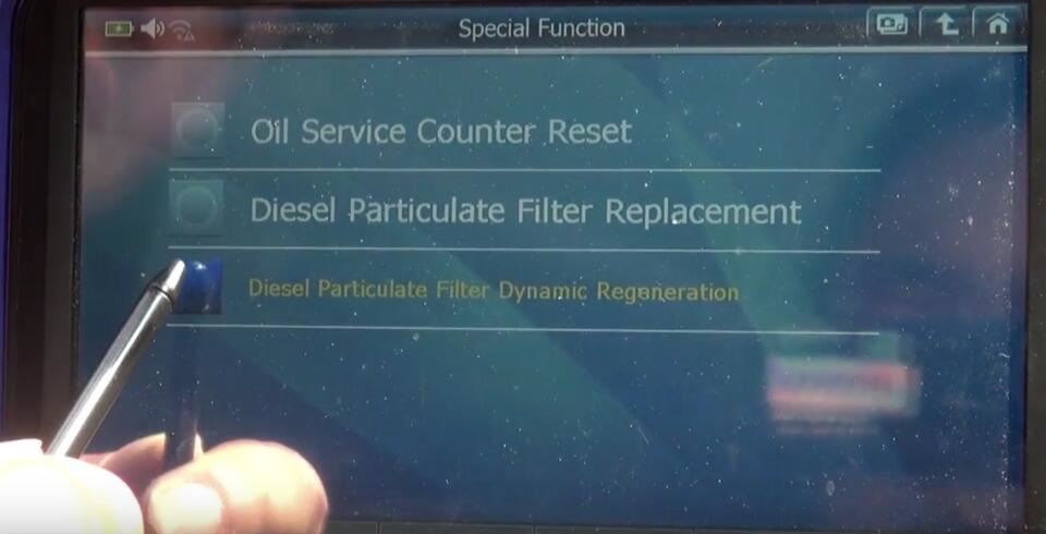
Отдельно следует отметить, что большое количество транспортных средств, оборудованных сажевым фильтром, требует для процедуры регенерации использования специальной добавки (EOLYS). В таких авто нужно контролировать наличие достаточного количества этой добавки в отдельном предназначенном для нее баке, и следить за отсутствием ошибок в системе управления ее впрыском в топливо.
OBD-II PIDs (On-board diagnostics Parameter IDs) are codes used to request data from a vehicle, used as a diagnostic tool.
SAE standard J1979 defines many OBD-II PIDs. All on-road vehicles and trucks sold in North America are required to support a subset of these codes, primarily for state mandated emissions inspections. Manufacturers also define additional PIDs specific to their vehicles. Though not mandated, many motorcycles also support OBD-II PIDs.
In 1996, light duty vehicles (less than 8,500 lb or 3,900 kg) were the first to be mandated followed by medium duty vehicles (8,500–14,000 lb or 3,900–6,400 kg) in 2005.[1] They are both required to be accessed through a standardized data link connector defined by SAE J1962.
Heavy duty vehicles (greater than 14,000 lb or 6,400 kg) made after 2010,[1] for sale in the US are allowed to support OBD-II diagnostics through SAE standard J1939-13 (a round diagnostic connector) according to CARB in title 13 CCR 1971.1. Some heavy duty trucks in North America use the SAE J1962 OBD-II diagnostic connector that is common with passenger cars, notably Mack and Volvo Trucks, however they use 29 bit CAN identifiers (unlike 11 bit headers used by passenger cars).
Services / ModesEdit
There are 10 diagnostic services described in the latest OBD-II standard SAE J1979. Before 2002, J1979 referred to these services as «modes». They are as follows:
| Service / Mode (hex) | Description |
|---|---|
| 01 | Show current data |
| 02 | Show freeze frame data |
| 03 | Show stored Diagnostic Trouble Codes |
| 04 | Clear Diagnostic Trouble Codes and stored values |
| 05 | Test results, oxygen sensor monitoring (non CAN only) |
| 06 | Test results, other component/system monitoring (Test results, oxygen sensor monitoring for CAN only) |
| 07 | Show pending Diagnostic Trouble Codes (detected during current or last driving cycle) |
| 08 | Control operation of on-board component/system |
| 09 | Request vehicle information |
| 0A | Permanent Diagnostic Trouble Codes (DTCs) (Cleared DTCs) |
Vehicle manufacturers are not required to support all services. Each manufacturer may define additional services above #9 (e.g.: service 22 as defined by SAE J2190 for Ford/GM, service 21 for Toyota) for other information e.g. the voltage of the traction battery in a hybrid electric vehicle (HEV).[2]
The nonOBD UDS services start at 0x10 to avoid overlap of ID-range.
Standard PIDsEdit
The table below shows the standard OBD-II PIDs as defined by SAE J1979. The expected response for each PID is given, along with information on how to translate the response into meaningful data. Again, not all vehicles will support all PIDs and there can be manufacturer-defined custom PIDs that are not defined in the OBD-II standard.
Note that services 01 and 02 are basically identical, except that service 01 provides current information, whereas service 02 provides a snapshot of the same data taken at the point when the last diagnostic trouble code was set. The exceptions are PID 01, which is only available in service 01, and PID 02, which is only available in service 02. If service 02 PID 02 returns zero, then there is no snapshot and all other service 02 data is meaningless.
When using Bit-Encoded-Notation, quantities like C4 means bit 4 from data byte C. Each bit is numbered from 0 to 7, so 7 is the most significant bit and 0 is the least significant bit (See below).
| A | B | C | D | ||||||||||||||||||||||||||||
| A7 | A6 | A5 | A4 | A3 | A2 | A1 | A0 | B7 | B6 | B5 | B4 | B3 | B2 | B1 | B0 | C7 | C6 | C5 | C4 | C3 | C2 | C1 | C0 | D7 | D6 | D5 | D4 | D3 | D2 | D1 | D0 |
Service 01 — Show current dataEdit
| PIDs (hex) |
PID (Dec) |
Data bytes returned | Description | Min value | Max value | Units | Formula[a] |
|---|---|---|---|---|---|---|---|
| 00 | 0 | 4 | PIDs supported [01 — 20] | Bit encoded [A7..D0] == [PID $01..PID $20] See below | |||
| 01 | 1 | 4 | Monitor status since DTCs cleared. (Includes malfunction indicator lamp (MIL), status and number of DTCs, components tests, DTC readiness checks) | Bit encoded. See below | |||
| 02 | 2 | 2 | Freeze DTC | ||||
| 03 | 3 | 2 | Fuel system status | Bit encoded. See below | |||
| 04 | 4 | 1 | Calculated engine load | 0 | 100 | % | (or ) |
| 05 | 5 | 1 | Engine coolant temperature | -40 | 215 | °C | |
| 06 | 6 | 1 | Short term fuel trim—Bank 1 | -100 (Reduce Fuel: Too Rich) | 99.2 (Add Fuel: Too Lean) | % | (or ) |
| 07 | 7 | 1 | Long term fuel trim—Bank 1 | ||||
| 08 | 8 | 1 | Short term fuel trim—Bank 2 | ||||
| 09 | 9 | 1 | Long term fuel trim—Bank 2 | ||||
| 0A | 10 | 1 | Fuel pressure (gauge pressure) | 0 | 765 | kPa | |
| 0B | 11 | 1 | Intake manifold absolute pressure | 0 | 255 | kPa | |
| 0C | 12 | 2 | Engine speed | 0 | 16,383.75 | rpm | |
| 0D | 13 | 1 | Vehicle speed | 0 | 255 | km/h | |
| 0E | 14 | 1 | Timing advance | -64 | 63.5 | ° before TDC | |
| 0F | 15 | 1 | Intake air temperature | -40 | 215 | °C | |
| 10 | 16 | 2 | Mass air flow sensor (MAF) air flow rate | 0 | 655.35 | g/s | |
| 11 | 17 | 1 | Throttle position | 0 | 100 | % | |
| 12 | 18 | 1 | Commanded secondary air status | Bit encoded. See below | |||
| 13 | 19 | 1 | Oxygen sensors present (in 2 banks) | [A0..A3] == Bank 1, Sensors 1-4. [A4..A7] == Bank 2… | |||
| 14 | 20 | 2 | Oxygen Sensor 1 A: Voltage B: Short term fuel trim |
0 -100 |
1.275 99.2 |
V
% |
(if B==$FF, sensor is not used in trim calculation) |
| 15 | 21 | 2 | Oxygen Sensor 2 A: Voltage B: Short term fuel trim |
||||
| 16 | 22 | 2 | Oxygen Sensor 3 A: Voltage B: Short term fuel trim |
||||
| 17 | 23 | 2 | Oxygen Sensor 4 A: Voltage B: Short term fuel trim |
||||
| 18 | 24 | 2 | Oxygen Sensor 5 A: Voltage B: Short term fuel trim |
||||
| 19 | 25 | 2 | Oxygen Sensor 6 A: Voltage B: Short term fuel trim |
||||
| 1A | 26 | 2 | Oxygen Sensor 7 A: Voltage B: Short term fuel trim |
||||
| 1B | 27 | 2 | Oxygen Sensor 8 A: Voltage B: Short term fuel trim |
||||
| 1C | 28 | 1 | OBD standards this vehicle conforms to | 1 | 250 | — | enumerated. See below |
| 1D | 29 | 1 | Oxygen sensors present (in 4 banks) | Similar to PID 13, but [A0..A7] == [B1S1, B1S2, B2S1, B2S2, B3S1, B3S2, B4S1, B4S2] | |||
| 1E | 30 | 1 | Auxiliary input status | A0 == Power Take Off (PTO) status (1 == active) [A1..A7] not used |
|||
| 1F | 31 | 2 | Run time since engine start | 0 | 65,535 | s | |
| 20 | 32 | 4 | PIDs supported [21 — 40] | Bit encoded [A7..D0] == [PID $21..PID $40] See below | |||
| 21 | 33 | 2 | Distance traveled with malfunction indicator lamp (MIL) on | 0 | 65,535 | km | |
| 22 | 34 | 2 | Fuel Rail Pressure (relative to manifold vacuum) | 0 | 5177.265 | kPa | |
| 23 | 35 | 2 | Fuel Rail Gauge Pressure (diesel, or gasoline direct injection) | 0 | 655,350 | kPa | |
| 24 | 36 | 4 | Oxygen Sensor 1 AB: Air-Fuel Equivalence Ratio (lambda,λ) CD: Voltage |
0 0 |
< 2 < 8 |
ratio V |
|
| 25 | 37 | 4 | Oxygen Sensor 2 AB: Air-Fuel Equivalence Ratio (lambda,λ) CD: Voltage |
||||
| 26 | 38 | 4 | Oxygen Sensor 3 AB: Air-Fuel Equivalence Ratio (lambda,λ) CD: Voltage |
||||
| 27 | 39 | 4 | Oxygen Sensor 4 AB: Air-Fuel Equivalence Ratio (lambda,λ) CD: Voltage |
||||
| 28 | 40 | 4 | Oxygen Sensor 5 AB: Air-Fuel Equivalence Ratio (lambda,λ) CD: Voltage |
||||
| 29 | 41 | 4 | Oxygen Sensor 6 AB: Air-Fuel Equivalence Ratio (lambda,λ) CD: Voltage |
||||
| 2A | 42 | 4 | Oxygen Sensor 7 AB: Air-Fuel Equivalence Ratio (lambda,λ) CD: Voltage |
||||
| 2B | 43 | 4 | Oxygen Sensor 8 AB: Air-Fuel Equivalence Ratio (lambda,λ) CD: Voltage |
||||
| 2C | 44 | 1 | Commanded EGR | 0 | 100 | % | |
| 2D | 45 | 1 | EGR Error | -100 | 99.2 | % | |
| 2E | 46 | 1 | Commanded evaporative purge | 0 | 100 | % | |
| 2F | 47 | 1 | Fuel Tank Level Input | 0 | 100 | % | |
| 30 | 48 | 1 | Warm-ups since codes cleared | 0 | 255 | count | |
| 31 | 49 | 2 | Distance traveled since codes cleared | 0 | 65,535 | km | |
| 32 | 50 | 2 | Evap. System Vapor Pressure | -8,192 | 8191.75 | Pa |
(AB is two’s complement signed)[3] |
| 33 | 51 | 1 | Absolute Barometric Pressure | 0 | 255 | kPa | |
| 34 | 52 | 4 | Oxygen Sensor 1 AB: Air-Fuel Equivalence Ratio (lambda,λ) CD: Current |
0 -128 |
< 2 <128 |
ratio mA |
|
| 35 | 53 | 4 | Oxygen Sensor 2 AB: Air-Fuel Equivalence Ratio (lambda,λ) CD: Current |
||||
| 36 | 54 | 4 | Oxygen Sensor 3 AB: Air-Fuel Equivalence Ratio (lambda,λ) CD: Current |
||||
| 37 | 55 | 4 | Oxygen Sensor 4 AB: Air-Fuel Equivalence Ratio (lambda,λ) CD: Current |
||||
| 38 | 56 | 4 | Oxygen Sensor 5 AB: Air-Fuel Equivalence Ratio (lambda,λ) CD: Current |
||||
| 39 | 57 | 4 | Oxygen Sensor 6 AB: Air-Fuel Equivalence Ratio (lambda,λ) CD: Current |
||||
| 3A | 58 | 4 | Oxygen Sensor 7 AB: Air-Fuel Equivalence Ratio (lambda,λ) CD: Current |
||||
| 3B | 59 | 4 | Oxygen Sensor 8 AB: Air-Fuel Equivalence Ratio (lambda,λ) CD: Current |
||||
| 3C | 60 | 2 | Catalyst Temperature: Bank 1, Sensor 1 | -40 | 6,513.5 | °C | |
| 3D | 61 | 2 | Catalyst Temperature: Bank 2, Sensor 1 | ||||
| 3E | 62 | 2 | Catalyst Temperature: Bank 1, Sensor 2 | ||||
| 3F | 63 | 2 | Catalyst Temperature: Bank 2, Sensor 2 | ||||
| 40 | 64 | 4 | PIDs supported [41 — 60] | Bit encoded [A7..D0] == [PID $41..PID $60] See below | |||
| 41 | 65 | 4 | Monitor status this drive cycle | Bit encoded. See below | |||
| 42 | 66 | 2 | Control module voltage | 0 | 65.535 | V | |
| 43 | 67 | 2 | Absolute load value | 0 | 25,700 | % | |
| 44 | 68 | 2 | Commanded Air-Fuel Equivalence Ratio (lambda,λ) | 0 | < 2 | ratio | |
| 45 | 69 | 1 | Relative throttle position | 0 | 100 | % | |
| 46 | 70 | 1 | Ambient air temperature | -40 | 215 | °C | |
| 47 | 71 | 1 | Absolute throttle position B | 0 | 100 | % | |
| 48 | 72 | 1 | Absolute throttle position C | ||||
| 49 | 73 | 1 | Accelerator pedal position D | ||||
| 4A | 74 | 1 | Accelerator pedal position E | ||||
| 4B | 75 | 1 | Accelerator pedal position F | ||||
| 4C | 76 | 1 | Commanded throttle actuator | ||||
| 4D | 77 | 2 | Time run with MIL on | 0 | 65,535 | min | |
| 4E | 78 | 2 | Time since trouble codes cleared | ||||
| 4F | 79 | 4 | Maximum value for Fuel–Air equivalence ratio, oxygen sensor voltage, oxygen sensor current, and intake manifold absolute pressure | 0, 0, 0, 0 | 255, 255, 255, 2550 | ratio, V, mA, kPa | , , , |
| 50 | 80 | 4 | Maximum value for air flow rate from mass air flow sensor | 0 | 2550 | g/s | ; , , and are reserved for future use |
| 51 | 81 | 1 | Fuel Type | From fuel type table see below | |||
| 52 | 82 | 1 | Ethanol fuel % | 0 | 100 | % | |
| 53 | 83 | 2 | Absolute Evap system Vapor Pressure | 0 | 327.675 | kPa | |
| 54 | 84 | 2 | Evap system vapor pressure | -32,768 | 32,767 | Pa | (AB is two’s complement signed)[3] |
| 55 | 85 | 2 | Short term secondary oxygen sensor trim, A: bank 1, B: bank 3 | -100 | 99.2 | % | |
| 56 | 86 | 2 | Long term secondary oxygen sensor trim, A: bank 1, B: bank 3 | ||||
| 57 | 87 | 2 | Short term secondary oxygen sensor trim, A: bank 2, B: bank 4 | ||||
| 58 | 88 | 2 | Long term secondary oxygen sensor trim, A: bank 2, B: bank 4 | ||||
| 59 | 89 | 2 | Fuel rail absolute pressure | 0 | 655,350 | kPa | |
| 5A | 90 | 1 | Relative accelerator pedal position | 0 | 100 | % | |
| 5B | 91 | 1 | Hybrid battery pack remaining life | 0 | 100 | % | |
| 5C | 92 | 1 | Engine oil temperature | -40 | 210 | °C | |
| 5D | 93 | 2 | Fuel injection timing | -210.00 | 301.992 | ° | |
| 5E | 94 | 2 | Engine fuel rate | 0 | 3212.75 | L/h | |
| 5F | 95 | 1 | Emission requirements to which vehicle is designed | Bit Encoded | |||
| 60 | 96 | 4 | PIDs supported [61 — 80] | Bit encoded [A7..D0] == [PID $61..PID $80] See below | |||
| 61 | 97 | 1 | Driver’s demand engine — percent torque | -125 | 130 | % | |
| 62 | 98 | 1 | Actual engine — percent torque | -125 | 130 | % | |
| 63 | 99 | 2 | Engine reference torque | 0 | 65,535 | N⋅m | |
| 64 | 100 | 5 | Engine percent torque data | -125 | 130 | % | Idle Engine point 1 Engine point 2 Engine point 3 Engine point 4 |
| 65 | 101 | 2 | Auxiliary input / output supported | Bit Encoded | |||
| 66 | 102 | 5 | Mass air flow sensor | 0 | 2047.96875 | g/s | [A0]== Sensor A Supported [A1]== Sensor B Supported Sensor A: Sensor B: |
| 67 | 103 | 3 | Engine coolant temperature | -40 | 215 | °C | [A0]== Sensor 1 Supported [A1]== Sensor 2 Supported Sensor 1: Sensor 2: |
| 68 | 104 | 3 | Intake air temperature sensor | -40 | 215 | °C | [A0]== Sensor 1 Supported [A1]== Sensor 2 Supported Sensor 1: Sensor 2: |
| 69 | 105 | 7 | Actual EGR, Commanded EGR, and EGR Error | ||||
| 6A | 106 | 5 | Commanded Diesel intake air flow control and relative intake air flow position | ||||
| 6B | 107 | 5 | Exhaust gas recirculation temperature | ||||
| 6C | 108 | 5 | Commanded throttle actuator control and relative throttle position | ||||
| 6D | 109 | 11 | Fuel pressure control system | ||||
| 6E | 110 | 9 | Injection pressure control system | ||||
| 6F | 111 | 3 | Turbocharger compressor inlet pressure | ||||
| 70 | 112 | 10 | Boost pressure control | ||||
| 71 | 113 | 6 | Variable Geometry turbo (VGT) control | ||||
| 72 | 114 | 5 | Wastegate control | ||||
| 73 | 115 | 5 | Exhaust pressure | ||||
| 74 | 116 | 5 | Turbocharger RPM | ||||
| 75 | 117 | 7 | Turbocharger temperature | ||||
| 76 | 118 | 7 | Turbocharger temperature | ||||
| 77 | 119 | 5 | Charge air cooler temperature (CACT) | ||||
| 78 | 120 | 9 | Exhaust Gas temperature (EGT) Bank 1 | Special PID. See below | |||
| 79 | 121 | 9 | Exhaust Gas temperature (EGT) Bank 2 | Special PID. See below | |||
| 7A | 122 | 7 | Diesel particulate filter (DPF)
differential pressure |
||||
| 7B | 123 | 7 | Diesel particulate filter (DPF) | ||||
| 7C | 124 | 9 | Diesel Particulate filter (DPF) temperature | °C | |||
| 7D | 125 | 1 | NOx NTE (Not-To-Exceed) control area status | ||||
| 7E | 126 | 1 | PM NTE (Not-To-Exceed) control area status | ||||
| 7F | 127 | 13 | Engine run time [b] | s | |||
| 80 | 128 | 4 | PIDs supported [81 — A0] | Bit encoded [A7..D0] == [PID $81..PID $A0] See below | |||
| 81 | 129 | 41 | Engine run time for Auxiliary Emissions Control Device(AECD) | ||||
| 82 | 130 | 41 | Engine run time for Auxiliary Emissions Control Device(AECD) | ||||
| 83 | 131 | 9 | NOx sensor | ||||
| 84 | 132 | 1 | Manifold surface temperature | ||||
| 85 | 133 | 10 | NOx reagent system | ||||
| 86 | 134 | 5 | Particulate matter (PM) sensor | ||||
| 87 | 135 | 5 | Intake manifold absolute pressure | ||||
| 88 | 136 | 13 | SCR Induce System | ||||
| 89 | 137 | 41 | Run Time for AECD #11-#15 | ||||
| 8A | 138 | 41 | Run Time for AECD #16-#20 | ||||
| 8B | 139 | 7 | Diesel Aftertreatment | ||||
| 8C | 140 | 17 | O2 Sensor (Wide Range) | ||||
| 8D | 141 | 1 | Throttle Position G | 0 | 100 | % | |
| 8E | 142 | 1 | Engine Friction — Percent Torque | -125 | 130 | % | |
| 8F | 143 | 7 | PM Sensor Bank 1 & 2 | ||||
| 90 | 144 | 3 | WWH-OBD Vehicle OBD System Information | h | |||
| 91 | 145 | 5 | WWH-OBD Vehicle OBD System Information | h | |||
| 92 | 146 | 2 | Fuel System Control | ||||
| 93 | 147 | 3 | WWH-OBD Vehicle OBD Counters support | h | |||
| 94 | 148 | 12 | NOx Warning And Inducement System | ||||
| 98 | 152 | 9 | Exhaust Gas Temperature Sensor | ||||
| 99 | 153 | 9 | Exhaust Gas Temperature Sensor | ||||
| 9A | 154 | 6 | Hybrid/EV Vehicle System Data, Battery, Voltage | ||||
| 9B | 155 | 4 | Diesel Exhaust Fluid Sensor Data | ||||
| 9C | 156 | 17 | O2 Sensor Data | ||||
| 9D | 157 | 4 | Engine Fuel Rate | g/s | |||
| 9E | 158 | 2 | Engine Exhaust Flow Rate | kg/h | |||
| 9F | 159 | 9 | Fuel System Percentage Use | ||||
| A0 | 160 | 4 | PIDs supported [A1 — C0] | Bit encoded [A7..D0] == [PID $A1..PID $C0] See below | |||
| A1 | 161 | 9 | NOx Sensor Corrected Data | ppm | |||
| A2 | 162 | 2 | Cylinder Fuel Rate | 0 | 2047.96875 | mg/stroke | |
| A3 | 163 | 9 | Evap System Vapor Pressure | Pa | |||
| A4 | 164 | 4 | Transmission Actual Gear | 0 | 65.535 | ratio | [A1]==Supported
|
| A5 | 165 | 4 | Commanded Diesel Exhaust Fluid Dosing | 0 | 127.5 | % | [A0]= 1:Supported; 0:Unsupported |
| A6 | 166 | 4 | Odometer [c] | 0 | 429,496,729.5 | km | |
| A7 | 167 | 4 | NOx Sensor Concentration Sensors 3 and 4 | ||||
| A8 | 168 | 4 | NOx Sensor Corrected Concentration Sensors 3 and 4 | ||||
| A9 | 169 | 4 | ABS Disable Switch State | [A0]= 1:Supported; 0:Unsupported
[B0]= 1:Yes;0:No |
|||
| C0 | 192 | 4 | PIDs supported [C1 — E0] | 0x0 | 0xffffffff | Bit encoded [A7..D0] == [PID $C1..PID $E0] See below | |
| C3 | 195 | ? | ? | ? | ? | ? | Returns numerous data, including Drive Condition ID and Engine Speed* |
| C4 | 196 | ? | ? | ? | ? | ? | B5 is Engine Idle Request B6 is Engine Stop Request* |
| PID (hex) |
PID (Dec) |
Data bytes returned | Description | Min value | Max value | Units | Formula[a] |
Service 02 — Show freeze frame dataEdit
Service 02 accepts the same PIDs as service 01, with the same meaning,[5] but information given is from when the freeze frame[6] was created.
You have to send the frame number in the data section of the message.
| PID (hex) |
Data bytes returned | Description | Min value | Max value | Units | Formula[a] |
|---|---|---|---|---|---|---|
| 02 | 2 | DTC that caused freeze frame to be stored. | BCD encoded. Decoded as in service 3 |
Service 03 — Show stored Diagnostic Trouble Codes (DTCs)Edit
| PID (hex) |
Data bytes returned | Description | Min value | Max value | Units | Formula[a] |
|---|---|---|---|---|---|---|
| N/A | n*6 | Request trouble codes | 3 codes per message frame. See below |
Service 04 — Clear Diagnostic Trouble Codes and stored valuesEdit
| PID (hex) |
Data bytes returned | Description | Min value | Max value | Units | Formula[a] |
|---|---|---|---|---|---|---|
| N/A | 0 | Clear trouble codes / Malfunction indicator lamp (MIL) / Check engine light | Clears all stored trouble codes and turns the MIL off. |
Service 05 — Test results, oxygen sensor monitoring (non CAN only)Edit
| PID (hex) |
Data bytes returned | Description | Min value | Max value | Units | Formula[a] |
|---|---|---|---|---|---|---|
| 0100 | 4 | OBD Monitor IDs supported ($01 – $20) | 0x0 | 0xffffffff | ||
| 0101 | 2 | O2 Sensor Monitor Bank 1 Sensor 1 | 0.00 | 1.275 | V | 0.005 Rich to lean sensor threshold voltage |
| 0102 | O2 Sensor Monitor Bank 1 Sensor 2 | 0.00 | 1.275 | V | 0.005 Rich to lean sensor threshold voltage | |
| 0103 | O2 Sensor Monitor Bank 1 Sensor 3 | 0.00 | 1.275 | V | 0.005 Rich to lean sensor threshold voltage | |
| 0104 | O2 Sensor Monitor Bank 1 Sensor 4 | 0.00 | 1.275 | V | 0.005 Rich to lean sensor threshold voltage | |
| 0105 | O2 Sensor Monitor Bank 2 Sensor 1 | 0.00 | 1.275 | V | 0.005 Rich to lean sensor threshold voltage | |
| 0106 | O2 Sensor Monitor Bank 2 Sensor 2 | 0.00 | 1.275 | V | 0.005 Rich to lean sensor threshold voltage | |
| 0107 | O2 Sensor Monitor Bank 2 Sensor 3 | 0.00 | 1.275 | V | 0.005 Rich to lean sensor threshold voltage | |
| 0108 | O2 Sensor Monitor Bank 2 Sensor 4 | 0.00 | 1.275 | V | 0.005 Rich to lean sensor threshold voltage | |
| 0109 | O2 Sensor Monitor Bank 3 Sensor 1 | 0.00 | 1.275 | V | 0.005 Rich to lean sensor threshold voltage | |
| 010A | O2 Sensor Monitor Bank 3 Sensor 2 | 0.00 | 1.275 | V | 0.005 Rich to lean sensor threshold voltage | |
| 010B | O2 Sensor Monitor Bank 3 Sensor 3 | 0.00 | 1.275 | V | 0.005 Rich to lean sensor threshold voltage | |
| 010C | O2 Sensor Monitor Bank 3 Sensor 4 | 0.00 | 1.275 | V | 0.005 Rich to lean sensor threshold voltage | |
| 010D | O2 Sensor Monitor Bank 4 Sensor 1 | 0.00 | 1.275 | V | 0.005 Rich to lean sensor threshold voltage | |
| 010E | O2 Sensor Monitor Bank 4 Sensor 2 | 0.00 | 1.275 | V | 0.005 Rich to lean sensor threshold voltage | |
| 010F | O2 Sensor Monitor Bank 4 Sensor 3 | 0.00 | 1.275 | V | 0.005 Rich to lean sensor threshold voltage | |
| 0110 | O2 Sensor Monitor Bank 4 Sensor 4 | 0.00 | 1.275 | V | 0.005 Rich to lean sensor threshold voltage | |
| 0201 | O2 Sensor Monitor Bank 1 Sensor 1 | 0.00 | 1.275 | V | 0.005 Lean to Rich sensor threshold voltage | |
| 0202 | O2 Sensor Monitor Bank 1 Sensor 2 | 0.00 | 1.275 | V | 0.005 Lean to Rich sensor threshold voltage | |
| 0203 | O2 Sensor Monitor Bank 1 Sensor 3 | 0.00 | 1.275 | V | 0.005 Lean to Rich sensor threshold voltage | |
| 0204 | O2 Sensor Monitor Bank 1 Sensor 4 | 0.00 | 1.275 | V | 0.005 Lean to Rich sensor threshold voltage | |
| 0205 | O2 Sensor Monitor Bank 2 Sensor 1 | 0.00 | 1.275 | V | 0.005 Lean to Rich sensor threshold voltage | |
| 0206 | O2 Sensor Monitor Bank 2 Sensor 2 | 0.00 | 1.275 | V | 0.005 Lean to Rich sensor threshold voltage | |
| 0207 | O2 Sensor Monitor Bank 2 Sensor 3 | 0.00 | 1.275 | V | 0.005 Lean to Rich sensor threshold voltage | |
| 0208 | O2 Sensor Monitor Bank 2 Sensor 4 | 0.00 | 1.275 | V | 0.005 Lean to Rich sensor threshold voltage | |
| 0209 | O2 Sensor Monitor Bank 3 Sensor 1 | 0.00 | 1.275 | V | 0.005 Lean to Rich sensor threshold voltage | |
| 020A | O2 Sensor Monitor Bank 3 Sensor 2 | 0.00 | 1.275 | V | 0.005 Lean to Rich sensor threshold voltage | |
| 020B | O2 Sensor Monitor Bank 3 Sensor 3 | 0.00 | 1.275 | V | 0.005 Lean to Rich sensor threshold voltage | |
| 020C | O2 Sensor Monitor Bank 3 Sensor 4 | 0.00 | 1.275 | V | 0.005 Lean to Rich sensor threshold voltage | |
| 020D | O2 Sensor Monitor Bank 4 Sensor 1 | 0.00 | 1.275 | V | 0.005 Lean to Rich sensor threshold voltage | |
| 020E | O2 Sensor Monitor Bank 4 Sensor 2 | 0.00 | 1.275 | V | 0.005 Lean to Rich sensor threshold voltage | |
| 020F | O2 Sensor Monitor Bank 4 Sensor 3 | 0.00 | 1.275 | V | 0.005 Lean to Rich sensor threshold voltage | |
| 0210 | O2 Sensor Monitor Bank 4 Sensor 4 | 0.00 | 1.275 | V | 0.005 Lean to Rich sensor threshold voltage | |
| PID (hex) |
Data bytes returned | Description | Min value | Max value | Units | Formula[a] |
Service 09 — Request vehicle informationEdit
| PID<581>(hex) | Data bytes returned | Description | Min value | Max value | Units | Formula[a] |
|---|---|---|---|---|---|---|
| 00 | 4 | Service 9 supported PIDs (01 to 20) | Bit encoded. [A7..D0] = [PID $01..PID $20] See below | |||
| 01 | 1 | VIN Message Count in PID 02. Only for ISO 9141-2, ISO 14230-4 and SAE J1850. | Usually the value will be 5. | |||
| 02 | 17 | Vehicle Identification Number (VIN) | 17-char VIN, ASCII-encoded and left-padded with null chars (0x00) if needed to. | |||
| 03 | 1 | Calibration ID message count for PID 04. Only for ISO 9141-2, ISO 14230-4 and SAE J1850. | It will be a multiple of 4 (4 messages are needed for each ID). | |||
| 04 | 16,32,48,64.. | Calibration ID | Up to 16 ASCII chars. Data bytes not used will be reported as null bytes (0x00). Several CALID can be outputed (16 bytes each) | |||
| 05 | 1 | Calibration verification numbers (CVN) message count for PID 06. Only for ISO 9141-2, ISO 14230-4 and SAE J1850. | ||||
| 06 | 4,8,12,16 | Calibration Verification Numbers (CVN) Several CVN can be output (4 bytes each) the number of CVN and CALID must match | Raw data left-padded with null characters (0x00). Usually displayed as hex string. | |||
| 07 | 1 | In-use performance tracking message count for PID 08 and 0B. Only for ISO 9141-2, ISO 14230-4 and SAE J1850. | 8 | 10 | 8 if sixteen values are required to be reported, 9 if eighteen values are required to be reported, and 10 if twenty values are required to be reported (one message reports two values, each one consisting in two bytes). | |
| 08 | 4 | In-use performance tracking for spark ignition vehicles | 4 or 5 messages, each one containing 4 bytes (two values). See below | |||
| 09 | 1 | ECU name message count for PID 0A | ||||
| 0A | 20 | ECU name | ASCII-coded. Right-padded with null chars (0x00). | |||
| 0B | 4 | In-use performance tracking for compression ignition vehicles | 5 messages, each one containing 4 bytes (two values). See below | |||
| PID (hex) |
Data bytes returned | Description | Min value | Max value | Units | Formula[a] |
- ^ a b c d e f g h i In the formula column, letters A, B, C, etc. represent the first, second, third, etc. byte of the data. For example, for two data bytes
0F 19,A = 0FandB = 19. Where a (?) appears, contradictory or incomplete information was available. - ^ Starting with MY 2010 the California Air Resources Board mandated that all diesel vehicles must supply total engine hours [4]
- ^ Starting with MY 2019 the California Air Resources Board mandated that all vehicles must supply odometer[4]
Bitwise encoded PIDsEdit
Some of the PIDs in the above table cannot be explained with a simple formula. A more elaborate explanation of these data is provided here:
Service 01 PID 00 — Show PIDs supportedEdit
A request for this PID returns 4 bytes of data (Big-endian). Each bit, from MSB to LSB, represents one of the next 32 PIDs and specifies whether that PID is supported.
For example, if the car response is BE1FA813, it can be decoded like this:
| Hexadecimal | B | E | 1 | F | A | 8 | 1 | 3 | ||||||||||||||||||||||||
|---|---|---|---|---|---|---|---|---|---|---|---|---|---|---|---|---|---|---|---|---|---|---|---|---|---|---|---|---|---|---|---|---|
| Binary | 1 | 0 | 1 | 1 | 1 | 1 | 1 | 0 | 0 | 0 | 0 | 1 | 1 | 1 | 1 | 1 | 1 | 0 | 1 | 0 | 1 | 0 | 0 | 0 | 0 | 0 | 0 | 1 | 0 | 0 | 1 | 1 |
| Supported? | Yes | No | Yes | Yes | Yes | Yes | Yes | No | No | No | No | Yes | Yes | Yes | Yes | Yes | Yes | No | Yes | No | Yes | No | No | No | No | No | No | Yes | No | No | Yes | Yes |
| PID number | 01 | 02 | 03 | 04 | 05 | 06 | 07 | 08 | 09 | 0A | 0B | 0C | 0D | 0E | 0F | 10 | 11 | 12 | 13 | 14 | 15 | 16 | 17 | 18 | 19 | 1A | 1B | 1C | 1D | 1E | 1F | 20 |
So, supported PIDs are: 01, 03, 04, 05, 06, 07, 0C, 0D, 0E, 0F, 10, 11, 13, 15, 1C, 1F and 20
Service 01 PID 01 — Monitor status since DTCs clearedEdit
A request for this PID returns 4 bytes of data, labeled A B C and D.
The first byte(A) contains two pieces of information. Bit A7 (MSB of byte A, the first byte) indicates whether or not the MIL (check engine light) is illuminated. Bits A6 through A0 represent the number of diagnostic trouble codes currently flagged in the ECU.
The second, third, and fourth bytes(B, C and D) give information about the availability and completeness of certain on-board tests («OBD readiness checks»). Note that test availability is indicated by set (1) bit and completeness is indicated by reset (0) bit.
| Bit | Name | Definition |
|---|---|---|
| A7 | MIL | Off or On, indicates if the CEL/MIL is on (or should be on) |
| A6—A0 | DTC_CNT | Number of confirmed emissions-related DTCs available for display. |
| B7 | RESERVED | Reserved (should be 0) |
| B3 | NO NAME | 0 = Spark ignition monitors supported (e.g. Otto or Wankel engines) 1 = Compression ignition monitors supported (e.g. Diesel engines) |
Here are the common bit B definitions, they are test based.
| Test available | Test incomplete | |
|---|---|---|
| Components | B2 | B6 |
| Fuel System | B1 | B5 |
| Misfire | B0 | B4 |
The third and fourth bytes are to be interpreted differently depending on if the engine is spark ignition (e.g. Otto or Wankel engines) or compression ignition (e.g. Diesel engines). In the second (B) byte, bit 3 indicates how to interpret the C and D bytes, with 0 being spark (Otto or Wankel) and 1 (set) being compression (Diesel).
The bytes C and D for spark ignition monitors (e.g. Otto or Wankel engines):
| Test available | Test incomplete | |
|---|---|---|
| EGR and/or VVT System | C7 | D7 |
| Oxygen Sensor Heater | C6 | D6 |
| Oxygen Sensor | C5 | D5 |
| A/C Refrigerant | C4 | D4 |
| Secondary Air System | C3 | D3 |
| Evaporative System | C2 | D2 |
| Heated Catalyst | C1 | D1 |
| Catalyst | C0 | D0 |
And the bytes C and D for compression ignition monitors (Diesel engines):
| Test available | Test incomplete | |
|---|---|---|
| EGR and/or VVT System | C7 | D7 |
| PM filter monitoring | C6 | D6 |
| Exhaust Gas Sensor | C5 | D5 |
| — Reserved — | C4 | D4 |
| Boost Pressure | C3 | D3 |
| — Reserved — | C2 | D2 |
| NOx/SCR Monitor | C1 | D1 |
| NMHC Catalyst[a] | C0 | D0 |
- ^ NMHC may stand for Non-Methane HydroCarbons, but J1979 does not enlighten us. The translation would be the ammonia sensor in the SCR catalyst.
Service 01 PID 41 — Monitor status this drive cycleEdit
A request for this PID returns 4 bytes of data.
The first byte is always zero. The second, third, and fourth bytes give information about the availability and completeness of certain on-board tests. As with PID 01, the third and fourth bytes are to be interpreted differently depending on the ignition type (B3) – with 0 being spark and 1 (set) being compression. Note again that test availability is represented by a set (1) bit and completeness is represented by a reset (0) bit.
Here are the common bit B definitions, they are test based.
| Test available | Test incomplete | |
|---|---|---|
| Components | B2 | B6 |
| Fuel System | B1 | B5 |
| Misfire | B0 | B4 |
The bytes C and D for spark ignition monitors (e.g. Otto or Wankel engines):
| Test available | Test incomplete | |
|---|---|---|
| EGR and/or VVT System | C7 | D7 |
| Oxygen Sensor Heater | C6 | D6 |
| Oxygen Sensor | C5 | D5 |
| A/C Refrigerant | C4 | D4 |
| Secondary Air System | C3 | D3 |
| Evaporative System | C2 | D2 |
| Heated Catalyst | C1 | D1 |
| Catalyst | C0 | D0 |
And the bytes C and D for compression ignition monitors (Diesel engines):
| Test available | Test incomplete | |
|---|---|---|
| EGR and/or VVT System | C7 | D7 |
| PM filter monitoring | C6 | D6 |
| Exhaust Gas Sensor | C5 | D5 |
| — Reserved — | C4 | D4 |
| Boost Pressure | C3 | D3 |
| — Reserved — | C2 | D2 |
| NOx/SCR Monitor | C1 | D1 |
| NMHC Catalyst[a] | C0 | D0 |
- ^ NMHC may stand for Non-Methane HydroCarbons, but J1979 does not enlighten us. The translation would be the ammonia sensor in the SCR catalyst.
Service 01 PID 78 and 79 — Exhaust Gas temperature (EGT) Bank 1 and Bank 2Edit
A request for this PID will return 9 bytes of data.
The first byte is a bit encoded field indicating which EGT sensors are supported:
| Byte | Description |
|---|---|
| A | Supported EGT sensors |
| B—C | Temperature read by EGT11 |
| D—E | Temperature read by EGT12 |
| F—G | Temperature read by EGT13 |
| H—I | Temperature read by EGT14 |
The first byte is bit-encoded as follows:
| Bit | Description |
|---|---|
| A7—A4 | Reserved |
| A3 | EGT bank 1, sensor 4 Supported? |
| A2 | EGT bank 1, sensor 3 Supported? |
| A1 | EGT bank 1, sensor 2 Supported? |
| A0 | EGT bank 1, sensor 1 Supported? |
The remaining bytes are 16 bit integers indicating the temperature in degrees Celsius in the range -40 to 6513.5 (scale 0.1), using the usual formula (MSB is A, LSB is B). Only values for which the corresponding sensor is supported are meaningful.
The same structure applies to PID 79, but values are for sensors of bank 2.
Service 03 (no PID required) — Show stored Diagnostic Trouble CodesEdit
A request for this service returns a list of the DTCs that have been set. The list is encapsulated using the ISO 15765-2 protocol.
If there are two or fewer DTCs (4 bytes) they are returned in an ISO-TP Single Frame (SF). Three or more DTCs in the list are reported in multiple frames, with the exact count of frames dependent on the communication type and addressing details.
Each trouble code requires 2 bytes to describe. The five-character code of a trouble code (like «U0158«) may be decoded as follows from bits. The first character in the trouble code is determined by the first two bits in the first byte:
| A7—A6 | First DTC character |
|---|---|
| 00 | P — Powertrain |
| 01 | C — Chassis |
| 10 | B — Body |
| 11 | U — Network |
The two following digits are encoded as 2 bits. The second character in the DTC is a number defined by the following table:
| A5—A4 | Second DTC character |
|---|---|
| 00 | 0 |
| 01 | 1 |
| 10 | 2 |
| 11 | 3 |
The third character in the DTC is a number defined by
| A3—A0 | Third DTC character |
|---|---|
| 0000 | 0 |
| 0001 | 1 |
| 0010 | 2 |
| 0011 | 3 |
| 0100 | 4 |
| 0101 | 5 |
| 0110 | 6 |
| 0111 | 7 |
| 1000 | 8 |
| 1001 | 9 |
| 1010 | A |
| 1011 | B |
| 1100 | C |
| 1101 | D |
| 1110 | E |
| 1111 | F |
The fourth and fifth characters are defined in the same way as the third, but using bits B7—B4 and B3—B0. The resulting five-character code should look something like «U0158» and can be looked up in a table of OBD-II DTCs to get an actual DTC text. Hexadecimal characters (0-9, A-F), while relatively rare, are allowed in the last 3 positions of the code itself.
Service 09 PID 08 — In-use performance tracking for spark ignition enginesEdit
It provides information about track in-use performance for catalyst banks, oxygen sensor banks, evaporative leak detection systems, EGR systems and secondary air system.
The numerator for each component or system tracks the number of times that all conditions necessary for a specific monitor to detect a malfunction have been encountered.
The denominator for each component or system tracks the number of times that the vehicle has been operated in the specified conditions.
The count of data items should be reported at the beginning (the first byte).
All data items of the In-use Performance Tracking record consist of two bytes and are reported in this order (each message contains two items, hence the message length is 4).
| Mnemonic | Description |
|---|---|
| OBDCOND | OBD Monitoring Conditions Encountered Counts |
| IGNCNTR | Ignition Counter |
| CATCOMP1 | Catalyst Monitor Completion Counts Bank 1 |
| CATCOND1 | Catalyst Monitor Conditions Encountered Counts Bank 1 |
| CATCOMP2 | Catalyst Monitor Completion Counts Bank 2 |
| CATCOND2 | Catalyst Monitor Conditions Encountered Counts Bank 2 |
| O2SCOMP1 | O2 Sensor Monitor Completion Counts Bank 1 |
| O2SCOND1 | O2 Sensor Monitor Conditions Encountered Counts Bank 1 |
| O2SCOMP2 | O2 Sensor Monitor Completion Counts Bank 2 |
| O2SCOND2 | O2 Sensor Monitor Conditions Encountered Counts Bank 2 |
| EGRCOMP | EGR Monitor Completion Condition Counts |
| EGRCOND | EGR Monitor Conditions Encountered Counts |
| AIRCOMP | AIR Monitor Completion Condition Counts (Secondary Air) |
| AIRCOND | AIR Monitor Conditions Encountered Counts (Secondary Air) |
| EVAPCOMP | EVAP Monitor Completion Condition Counts |
| EVAPCOND | EVAP Monitor Conditions Encountered Counts |
| SO2SCOMP1 | Secondary O2 Sensor Monitor Completion Counts Bank 1 |
| SO2SCOND1 | Secondary O2 Sensor Monitor Conditions Encountered Counts Bank 1 |
| SO2SCOMP2 | Secondary O2 Sensor Monitor Completion Counts Bank 2 |
| SO2SCOND2 | Secondary O2 Sensor Monitor Conditions Encountered Counts Bank 2 |
Service 09 PID 0B — In-use performance tracking for compression ignition enginesEdit
It provides information about track in-use performance for NMHC catalyst, NOx catalyst monitor, NOx adsorber monitor, PM filter monitor, exhaust gas sensor monitor, EGR/ VVT monitor, boost pressure monitor and fuel system monitor.
All data items consist of two bytes and are reported in this order (each message contains two items, hence message length is 4):
| Mnemonic | Description |
|---|---|
| OBDCOND | OBD Monitoring Conditions Encountered Counts |
| IGNCNTR | Ignition Counter |
| HCCATCOMP | NMHC Catalyst Monitor Completion Condition Counts |
| HCCATCOND | NMHC Catalyst Monitor Conditions Encountered Counts |
| NCATCOMP | NOx/SCR Catalyst Monitor Completion Condition Counts |
| NCATCOND | NOx/SCR Catalyst Monitor Conditions Encountered Counts |
| NADSCOMP | NOx Adsorber Monitor Completion Condition Counts |
| NADSCOND | NOx Adsorber Monitor Conditions Encountered Counts |
| PMCOMP | PM Filter Monitor Completion Condition Counts |
| PMCOND | PM Filter Monitor Conditions Encountered Counts |
| EGSCOMP | Exhaust Gas Sensor Monitor Completion Condition Counts |
| EGSCOND | Exhaust Gas Sensor Monitor Conditions Encountered Counts |
| EGRCOMP | EGR and/or VVT Monitor Completion Condition Counts |
| EGRCOND | EGR and/or VVT Monitor Conditions Encountered Counts |
| BPCOMP | Boost Pressure Monitor Completion Condition Counts |
| BPCOND | Boost Pressure Monitor Conditions Encountered Counts |
| FUELCOMP | Fuel Monitor Completion Condition Counts |
| FUELCOND | Fuel Monitor Conditions Encountered Counts |
Enumerated PIDsEdit
Some PIDs are to be interpreted specially, and aren’t necessarily exactly bitwise encoded, or in any scale.
The values for these PIDs are enumerated.
Service 01 PID 03 — Fuel system statusEdit
A request for this PID returns 2 bytes of data.
The first byte describes fuel system #1.
| Value | Description |
|---|---|
| 0 | The motor is off |
| 1 | Open loop due to insufficient engine temperature |
| 2 | Closed loop, using oxygen sensor feedback to determine fuel mix |
| 4 | Open loop due to engine load OR fuel cut due to deceleration |
| 8 | Open loop due to system failure |
| 16 | Closed loop, using at least one oxygen sensor but there is a fault in the feedback system |
Any other value is an invalid response.
The second byte describes fuel system #2 (if it exists) and is encoded identically to the first byte.
Service 01 PID 12 — Commanded secondary air statusEdit
A request for this PID returns a single byte of data which describes the secondary air status.
| Value | Description |
|---|---|
| 1 | Upstream |
| 2 | Downstream of catalytic converter |
| 4 | From the outside atmosphere or off |
| 8 | Pump commanded on for diagnostics |
Any other value is an invalid response.
Service 01 PID 1C — OBD standards this vehicle conforms toEdit
A request for this PID returns a single byte of data which describes which OBD standards this ECU was designed to comply with. The different values the data byte can hold are shown below, next to what they mean:
| Value | Description |
|---|---|
| 1 | OBD-II as defined by the CARB |
| 2 | OBD as defined by the EPA |
| 3 | OBD and OBD-II |
| 4 | OBD-I |
| 5 | Not OBD compliant |
| 6 | EOBD (Europe) |
| 7 | EOBD and OBD-II |
| 8 | EOBD and OBD |
| 9 | EOBD, OBD and OBD II |
| 10 | JOBD (Japan) |
| 11 | JOBD and OBD II |
| 12 | JOBD and EOBD |
| 13 | JOBD, EOBD, and OBD II |
| 14 | Reserved |
| 15 | Reserved |
| 16 | Reserved |
| 17 | Engine Manufacturer Diagnostics (EMD) |
| 18 | Engine Manufacturer Diagnostics Enhanced (EMD+) |
| 19 | Heavy Duty On-Board Diagnostics (Child/Partial) (HD OBD-C) |
| 20 | Heavy Duty On-Board Diagnostics (HD OBD) |
| 21 | World Wide Harmonized OBD (WWH OBD) |
| 22 | Reserved |
| 23 | Heavy Duty Euro OBD Stage I without NOx control (HD EOBD-I) |
| 24 | Heavy Duty Euro OBD Stage I with NOx control (HD EOBD-I N) |
| 25 | Heavy Duty Euro OBD Stage II without NOx control (HD EOBD-II) |
| 26 | Heavy Duty Euro OBD Stage II with NOx control (HD EOBD-II N) |
| 27 | Reserved |
| 28 | Brazil OBD Phase 1 (OBDBr-1) |
| 29 | Brazil OBD Phase 2 (OBDBr-2) |
| 30 | Korean OBD (KOBD) |
| 31 | India OBD I (IOBD I) |
| 32 | India OBD II (IOBD II) |
| 33 | Heavy Duty Euro OBD Stage VI (HD EOBD-IV) |
| 34-250 | Reserved |
| 251-255 | Not available for assignment (SAE J1939 special meaning) |
Service 01 PID 51 — Fuel Type CodingEdit
Service 01 PID 51 returns a value from an enumerated list giving the fuel type of the vehicle. The fuel type is returned as a single byte, and the value is given by the following table:
| Value | Description |
|---|---|
| 0 | Not available |
| 1 | Gasoline |
| 2 | Methanol |
| 3 | Ethanol |
| 4 | Diesel |
| 5 | LPG |
| 6 | CNG |
| 7 | Propane |
| 8 | Electric |
| 9 | Bifuel running Gasoline |
| 10 | Bifuel running Methanol |
| 11 | Bifuel running Ethanol |
| 12 | Bifuel running LPG |
| 13 | Bifuel running CNG |
| 14 | Bifuel running Propane |
| 15 | Bifuel running Electricity |
| 16 | Bifuel running electric and combustion engine |
| 17 | Hybrid gasoline |
| 18 | Hybrid Ethanol |
| 19 | Hybrid Diesel |
| 20 | Hybrid Electric |
| 21 | Hybrid running electric and combustion engine |
| 22 | Hybrid Regenerative |
| 23 | Bifuel running diesel |
Any other value is reserved by ISO/SAE. There are currently no definitions for flexible-fuel vehicle.
Non-standard PIDsEdit
The majority of all OBD-II PIDs in use are non-standard. For most modern vehicles, there are many more functions supported on the OBD-II interface than are covered by the standard PIDs, and there is relatively minor overlap between vehicle manufacturers for these non-standard PIDs.
There is very limited information available in the public domain for non-standard PIDs. The primary source of information on non-standard PIDs across different manufacturers is maintained by the US-based Equipment and Tool Institute and only available to members. The price of ETI membership for access to scan codes varies based on company size defined by annual sales of automotive tools and equipment in North America:
| Annual Sales in North America | Annual Dues |
|---|---|
| Under $10,000,000 | $5,000 |
| $10,000,000 — $50,000,000 | $7,500 |
| Greater than $50,000,000 | $10,000 |
However, even ETI membership will not provide full documentation for non-standard PIDs. ETI state:[7][8]
Some OEMs refuse to use ETI as a one-stop source of scan tool information. They prefer to do business with each tool company separately. These companies also require that you enter into a contract with them. The charges vary but here is a snapshot as of April 13th, 2015 of the per year charges:
GM $50,000 Honda $5,000 Suzuki $1,000 BMW $25,500 plus $2,000 per update. Updates occur annually.
CAN (11-bit) bus formatEdit
The PID query and response occurs on the vehicle’s CAN bus. Standard OBD requests and responses use functional addresses. The diagnostic reader initiates a query using CAN ID 7DFh[clarification needed], which acts as a broadcast address, and accepts responses from any ID in the range 7E8h to 7EFh. ECUs that can respond to OBD queries listen both to the functional broadcast ID of 7DFh and one assigned ID in the range 7E0h to 7E7h. Their response has an ID of their assigned ID plus 8 e.g. 7E8h through 7EFh.
This approach allows up to eight ECUs, each independently responding to OBD queries. The diagnostic reader can use the ID in the ECU response frame to continue communication with a specific ECU. In particular, multi-frame communication requires a response to the specific ECU ID rather than to ID 7DFh.
CAN bus may also be used for communication beyond the standard OBD messages. Physical addressing uses particular CAN IDs for specific modules (e.g., 720h for the instrument cluster in Fords) with proprietary frame payloads.
QueryEdit
The functional PID query is sent to the vehicle on the CAN bus at ID 7DFh, using 8 data bytes. The bytes are:
| Byte | ||||||||
|---|---|---|---|---|---|---|---|---|
| PID Type | 0 | 1 | 2 | 3 | 4 | 5 | 6 | 7 |
| SAE Standard | Number of additional data bytes: 2 |
Service 01 = show current data; 02 = freeze frame; etc. |
PID code (e.g.: 05 = Engine coolant temperature) |
not used (ISO 15765-2 suggests CCh) |
||||
| Vehicle specific | Number of additional data bytes: 3 |
Custom service: (e.g.: 22 = enhanced data) | PID code (e.g.: 4980h) |
not used (ISO 15765-2 suggests CCh) |
ResponseEdit
The vehicle responds to the PID query on the CAN bus with message IDs that depend on which module responded. Typically the engine or main ECU responds at ID 7E8h. Other modules, like the hybrid controller or battery controller in a Prius, respond at 07E9h, 07EAh, 07EBh, etc. These are 8h higher than the physical address the module responds to. Even though the number of bytes in the returned value is variable, the message uses 8 data bytes regardless (CAN bus protocol form Frameformat with 8 data bytes).
The bytes are:
| Byte | ||||||||
|---|---|---|---|---|---|---|---|---|
| CAN Address | 0 | 1 | 2 | 3 | 4 | 5 | 6 | 7 |
| SAE Standard 7E8h, 7E9h, 7EAh, etc. |
Number of additional data bytes: 3 to 6 |
Custom service Same as query, except that 40h is added to the service value. So: 41h = show current data; 42h = freeze frame; etc. |
PID code (e.g.: 05 = Engine coolant temperature) |
value of the specified parameter, byte 0 | value, byte 1 (optional) | value, byte 2 (optional) | value, byte 3 (optional) | not used (may be 00h or 55h) |
| Vehicle specific 7E8h, or 8h + physical ID of module. |
Number of additional data bytes: 4to 7 |
Custom service: same as query, except that 40h is added to the service value.(e.g.: 62h = response to service 22h request) | PID code (e.g.: 4980h) |
value of the specified parameter, byte 0 | value, byte 1 (optional) | value, byte 2 (optional) | value, byte 3 (optional) | |
| Vehicle specific 7E8h, or 8h + physical ID of module. |
Number of additional data bytes: 3 |
7Fh this a general response usually indicating the module doesn’t recognize the request. | Custom service: (e.g.: 22h = enhanced diagnostic data by PID, 21h = enhanced data by offset) | 31h | not used (may be 00h) |
See alsoEdit
- Engine control unit
- ELM327, a very common microcontroller (silicon chip) and multi-protocol interpreter used in OBD-II vehicle communication interfaces
ReferencesEdit
- ^ a b «Basic Information | On-Board Diagnostics (OBD)». US EPA. 16 March 2015. Retrieved 24 June 2015.
- ^ «Escape PHEV TechInfo — PIDs». Electric Auto Association — Plug in Hybrid Electric Vehicle. Retrieved 11 December 2013.
- ^ a b «Extended PID’s — Signed Variables». Torque-BHP. Retrieved 17 March 2016.
- ^ a b «Final Regulation Order» (PDF). US: California Air Resources Board. 2015. Retrieved 4 September 2021.
- ^ «OBD2 Codes and Meanings». Lithuania: Baltic Automotive Diagnostic Systems. Retrieved 11 June 2020.
- ^ «OBD2 Freeze Frame Data: What is It? How To Read It?». OBD Advisor. 2018-02-28. Retrieved 2020-03-14.
- ^
«ETI Full Membership FAQ». The Equipment and Tool Institute. Retrieved 29 November 2013.
showing cost of access to OBD-II PID documentation - ^ «Special OEM License Requirements». The Equipment and Tool Institute. Retrieved 13 April 2015.
Further readingEdit
- «E/E Diagnostic Test Modes». Vehicle E E System Diagnostic Standards Committee. SAE J1979. SAE International. 2017-02-16. doi:10.4271/J1979_201702.
- «Digital Annex of E/E Diagnostic Test Modes». Vehicle E E System Diagnostic Standards Committee. SAE J1979-Da. SAE International. 2017-02-16. doi:10.4271/J1979DA_201702.
- Wagner, Bernhard. «The Lifecycle of a Diagnostic Trouble Code (DTC)». KPIT. Germany. Retrieved 2020-08-29.
Particulate Matter Filter Monitor — PM Monitor
Used only on diesel engine the particulate matter (PM) filter removes particulate matter from the exhaust stream by filtration. The filter has a honeycomb structure similar to a catalyst substrate, but with the channels blocked at alternate ends.
This forces the exhaust gas to flow through the walls between the channels, filtering the particulate matter out. The filters are self-cleaning by periodic modification of the exhaust gas concentration in order to burn off the trapped particles (oxidizing the particles to form CO2 and water).
The computer monitors the efficiency of the filter in trapping particulate matter, as well as the ability of the filter to regenerate (self-clean).
The PM Filter Monitor is a “Two-Trip” Monitor. If a fault is found on the first trip, the computer temporarily saves the fault in its memory as a Pending Code. The computer does not command the MIL on at this time. If the fault is sensed again on the second trip, the computer commands
the MIL “On,” and saves the code in its long-term memory.
Posted on November 14, 2022 by Rick Muscoplat
Tags
- Particulate Matter Filter Monitor — PM Monitor
Filter-based PM monitors
Collecting particulate matter (PM) on a filter for analysis is the oldest and best understood method of measuring particle pollution. Filter-based PM monitors form the basis of US-based PM regulations, and filter based samplers are written directly into the US Code of Federal Regulations.
How filter measurements work
PM is expressed as a mass concentration; that is, the mass of particles in a given volume of air, usually in micrograms (millionths of a gram) per cubic meter of air (μg/m3). All expressions of PM mass concentration refer back to filter-based PM measurements, and PM monitors that aren’t filter-based usually apply a correction factor to bring their readings in line with Federal Reference Methods. Some optical monitors also have a filter-based system in-line to generate a more accurate correction.
How measurements are calculated
To determine mass concentrations, a known volume of air is pumped through a filter of a known mass for a specific time period, after which point the filter is weighed. The mass concentration mass equals the mass of filter after sampling minus the mass of the filter before sampling divided by the total volume of air. This process is referred to by the jargon term ’gravimetric analysis.’
What are particles made of?
Further analysis of collected PM may be conducted to identify the makeup of the PM, a process called ‘speciation.’ Usually, the filter is dissolved and the remaining material analyzed with X-ray spectrometry or mass spectrometry.
Questions
Components of a Filter-based PM monitor
A contemporary filter-based PM monitor consists of three components, an impactor, a filter, and a precise pump. The impactor sorts particles by size so only the desired fraction of airborne particles are collected, the filter collects the sorted particles, and the pump draws a precise volume of air at a consistent speed.

Sorting particle sizes with impactors
An impactor is a momentum-based particle sorter— the airstream makes a turn, and large particles’ momentum prevents them from making the turn, and so they impact a collection surface. Small particles stay «entrained» in the airstream and get caught in the filter. Often the impaction plate is coated in oil to capture particles and prevent them from bouncing and passing beyond the plate.

While impactor-sorted particles are often described as being of a specific diameter or smaller (i.e. PM10, 10um or smaller particles), impactors sort particles based on their ‘mass-mean aerodynamic diameter,’ not their actual diameter. The particles that pass by an impactor fly through the air as if they were idealized spheres of an assumed density derived from the mean density of airborne particles.
An impactor does not provide a hard cutoff at a specific particle size. The particles passing through a PM10 impactor have a median size of 10um. 50% of particles are below 10um and 50% above. The cutoff is usually fairly sharp above 10um, and an impactor is described as having a specific ‘sharpness.’ An impactor’s cutoff is dependent on the speed of the air flowing through it, and precise flow control at the pump is vital to proper impactor function.

There are a variety of impactor designs based on this principle, from the plate-based system illustrated here to cyclone impactors similar to those found in bagless vacuum cleaners to ‘dichotomous virtual impactors’ that provide two different size-sorted particle ranges, but they all work on the same momentum-based sorting principles, and can be described and compared based on their sharpness.
Filters
A variety of filter media are used depending on the analysis method applied to the filter. For instance, while fiberglass filters are often used in gravimetrically calibrated measurements, often PVC filters are used when the filter must be dissolved for speciation analysis.
Pumps
For an impactor to work properly air must be pulled through it at a consistent speed, measured in volume per unit time, usually liters per minute, or L/m. Keeping a consistent pumping speed can be challenging. Air pressure, humidity and variations in power can all effect pump performance as can the temperature of both the air and of the pump components. Pressure can change rapidly outside as wind speed changes. Pumps are coupled with control systems that actively monitor some or all of these factors, often in parallel with the airspeed through the pump, and adjust accordingly. The details of most pumps’ control systems are proprietary.
Common filter-based PM-monitoring systems
At present there are no open hardware designs for filter-based systems. Several proprietary systems are available.
EPA Federal Reference Methods
EPA Federal Reference Methods (FRMs) for PM10 and PM2.5 are filter-based. They draw one cubic meter of air per hour through their filters. Read more in PM Monitoring Regulations. FRMs cost between $20-60,000.
MiniVol
The MiniVol costs around $2000, and is a lower volume (mini Volume) and more portable filter-based system manufactured by Airmetrics. While not a federal reference method, several states recognize data from the MiniVol. It comes with interchangable impactors for PM2.5 and PM10, and can be used to produce 24-hour averages by gravimetric methods. Public Lab has two MiniVols available for loan.
Global Community Monitor has had limited success in using the MiniVol. Read more about Global Community Monitor’s experience
Learn More about the MiniVol and how to deploy it
Hybrid Filter/Optical systems
Dusttrak and Dusttrak II by TSI, and the PDR-1500 by Thermofisher are filter-based systems with the addition of an optical PM monitoring system.
They provide real-time readings that are calibrated against a gravimetrically analyzed 24-hour average from their filters. The Dustrak II and PDR-1500 are Federal Equivalent Methods used by the EPA to read momentary spikes in PM. Since optical monitors measure water droplets and ‘wet’ particles rather than a ‘dry’ particulate matter on the filter, filter-based calibrations are crucial to improving their accuracy.
- Remove From My Forums
-
Question
-
I am trying to use the Monitoring Filter Changes sample code in
http://msdn.microsoft.com/en-us/library/windows/desktop/bb427379(v=VS.85).aspx.I managed to add a _getch() call at the end of the wmain such that I can see the
FilterChangeCallback being triggered, and changed the layer to monitor.I have another application running to add a filter to the layer specified in the code.
It was found that everytime when a filter is added, the changeType and filterId is displayed (which is nice!), but the sample code crashes after. An access violation error pointing at ntdll.dll!778215ee is shown
in the Call Stack.It is working fine if the sample code is terminated without any filter changes.
Would someone nicely pointed out to me what went wrong?
Thank you.
Answers
-
I finally have it working. The keyword CALLBACK, or WINAPI is missing in the definition of FilterChangeCallback function.
This is the fix:
void CALLBACK FilterChangeCallback(IN void* context, IN const FWPM_FILTER_CHANGE0* change)
-
Marked as answer by
Wednesday, October 19, 2011 10:01 PM
-
Marked as answer by