Основные Qcode / Q-code / Post коды для плат ASUS
Если на дисплее вашей платы отобразился Q-Code, вы можете обратиться к таблице ниже и ознакомиться с описанием Qcode и статуса системы.
Таблица также представлена в руководстве пользователя.
|
QCode / Q-code |
Описание |
|
00 |
Не используется |
|
01 |
Включено. Обнаружен сброс параметров (программный/аппаратный). |
|
02 |
AP инициализация перед загрузкой микрокода |
|
03 |
Инициализация системного агента перед загрузкой микрокода |
|
04 |
PCH инициализация перед загрузкой микрокода |
|
06 |
Загрузка микрокода |
|
07 |
AP инициализация после загрузки микрокода |
|
08 |
Инициализация системного агента после загрузки микрокода |
|
09 |
PCH инициализация после загрузки микрокода |
|
0A |
Инициализация после загрузки микрокода |
|
0B |
Инициализация Кэша |
|
0C-0D |
Зарезервировано для будущих кодов ошибок AMI SEC. |
|
0E |
Микрокод не найден |
|
0F |
Микрокод не загружен |
|
10 |
PEI Core запущен |
|
11-14 |
Запущена инициализация CPU до памяти |
|
15-18 |
Предварительная инициализация системного агента памяти запущена |
|
19-1C |
Запущена инициализация PCH памяти |
|
2B-2F |
Инициализация памяти запущена |
|
29 |
Тренинг памяти (только на серии плат X299) |
|
30 |
Зарезервировано для ASL |
|
31 |
Установлена память |
|
32-36 |
CPU инициализация памяти |
|
37-3A |
Запущена инициализация системного агента после памяти |
|
3B-3E |
Инициализация PCH после запуска памяти |
|
4F |
Запущена DXE IPL |
|
50-53 |
Ошибка инициализации памяти. Неверный тип памяти или несовместимая скорость памяти |
|
54 |
Неопределенная ошибка инициализации памяти |
|
55 |
Память не установлена |
|
56 |
Неверный тип процессора или скорость |
|
57 |
Несоответствие процессора |
|
58 |
Сбой самопроверки процессора или возможная ошибка кэша |
|
59 |
Микрокод ЦП не найден или обновление микрокода не выполнено |
|
5A |
Ошибка встроенного процессора |
|
5B |
Сброс PPI недоступен |
|
5C-5F |
Зарезервировано для будущих кодов ошибок AMI |
|
E0 |
S3 возобновление запуска (S3 возобновление PPI вызывается DUX IPL) |
|
E1 |
S3 выполнение загрузочного скрипта |
|
E2 |
Видео репост |
|
E3 |
OS S3 вектор вызова |
|
E4-E7 |
Зарезервировано для будущих кодов прогресса AMI |
|
E8 |
S3 ошибка резюме |
|
E9 |
S3 резюме PPI не найдено |
|
EA |
S3 ошибка загрузочного скрипта |
|
EB |
S3 OS Wake ошибка |
|
EC-EF |
Зарезервировано для будущих кодов ошибок AMI |
|
F0 |
Состояние восстановления вызвано прошивкой (Авто восстановление) |
|
F1 |
Состояние восстановления, вызванное пользователем (принудительное восстановление) |
|
F2 |
Процесс восстановления начался |
|
F3 |
Образ прошивки восстановления найден |
|
F4 |
Загружен образ восстановления |
|
F5-F7 |
Зарезервировано для будущих кодов прогресса AMI |
|
F8 |
Восстановление PPI недоступно |
|
F9 |
Капсула восстановления не найдена |
|
FA |
Неверная капсула восстановления |
|
FB-FF |
Зарезервировано для будущих кодов ошибок AMI |
|
60 |
DXE Core запущен |
|
61 |
NVRAM инициализация |
|
62 |
Установка PCH Runtime Services |
|
63-67 |
Процесс инициализации DXE запущен |
|
68 |
Инициализация моста хоста PCI |
|
69 |
Инициализация DXE системного агента запущена |
|
6A |
Инициализация системного агента DXE SMM запущена |
|
6B-6F |
Инициализация DXE системного агента (зависит от модуля системного агента) |
|
70 |
Начата инициализация PCH DXE |
|
71 |
Инициализация PCH DXE SMM запущена |
|
72 |
Инициализация устройств PCH |
|
73-77 |
Инициализация PCH DXE (PCH модуль) |
|
78 |
Инициализация модуля ACPI |
|
79 |
CSM инициализация |
|
7A-7F |
Зарезервировано для будущих кодов AMI DXE |
|
90 |
Начата фаза выбора загрузочного устройства (BDS) |
|
91 |
Подключение драйвера запущено |
|
92 |
Инициализация шины PCI начата |
|
93 |
Инициализация контроллера горячей замены шины PCI |
|
94 |
Перечисление шины PCI |
|
95 |
Ресурсы для запроса шины PCI |
|
96 |
Ресурсы шины PCI |
|
97 |
Устройства консольного вывода подключаются |
|
98 |
Подключите консольные устройства ввода |
|
99 |
Инициализация Super IO |
|
9A |
USB запуск инициализации |
|
9B |
USB сброс |
|
9C |
USB обнаружен |
|
9D |
USB Вкл |
|
9E-9F |
Зарезервировано для будущих кодов AMI |
|
A0 |
IDE запуск инициализации |
|
A1 |
IDE сброс |
|
A2 |
IDE обнаружен |
|
A3 |
IDE Вкл |
|
A4 |
SCSI запуск инициализации |
|
A5 |
SCSI сброс |
|
A6 |
SCSI обнаружен |
|
A7 |
SCSI Вкл |
|
A8 |
Настройка Проверочного пароля |
|
A9 |
Начало настройки |
|
AA |
Зарезервировано для ASL |
|
AB |
Настройка входа ожидания |
|
AC |
Зарезервировано для ASL |
|
AD |
Готов к загрузке |
|
AE |
Событие Legacy Boot |
|
AF |
Событие Exit Boot Services |
|
B0 |
Запуск настройки виртуального адреса MAP начат |
|
B1 |
Запуск настройки виртуального адреса MAP завершено |
|
B2 |
Инициализация устаревшего дополнительного ПЗУ |
|
B3 |
Сброс системы |
|
B4 |
USB горячее подключение |
|
B5 |
замена шины PCI |
|
B6 |
Очистка NVRAM |
|
B7 |
Сброс конфигурации (сброс настроек NVRAM) |
|
B8-BF |
Зарезервировано для будущих кодов AMI |
|
D0 |
CPU ошибка инициализации |
|
D1 |
Ошибка инициализации системного агента |
|
D2 |
PCH ошибка инициализации |
|
D3 |
Некоторые из архитектурных протоколов недоступны |
|
D4 |
Ошибка выделения ресурсов PCI. Вне ресурсов |
|
D5 |
Нет места для устаревшего дополнительного ПЗУ |
|
D6 |
Устройства консольного вывода не найдены |
|
D7 |
Устройства консольного ввода не найдены |
|
D8 |
Неверный пароль |
|
D9 |
Ошибка загрузки Boot Option (ошибка возврата LoadImage) |
|
DA |
Не удалось запустить загрузочное устройство |
|
DB |
Не удалось обновить Flash |
|
DC |
Сброс протокола недоступен |
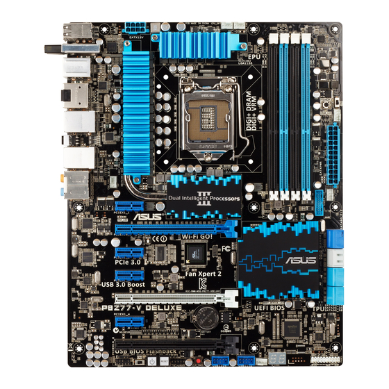
-
Contents
-
Table of Contents
-
Bookmarks
Quick Links
Related Manuals for Asus P8Z77-V DELUXE


-

-
-

-

-
-

Motherboard Asus P8Z77-M Manual
Your next micro atx z77 build with precise digital power design, independent fan control and up to 60% hybrid graphics boost (74 pages)
-

-
Summary of Contents for Asus P8Z77-V DELUXE
-
Page 1
P8Z77-V DELUXE… -
Page 2
Product warranty or service will not be extended if: (1) the product is repaired, modified or altered, unless such repair, modification of alteration is authorized in writing by ASUS; or (2) the serial number of the product is defaced or missing. -
Page 3: Table Of Contents
Contents Safety information … vii About this guide … viii P8Z77-V DELUXE specifications summary … x Chapter 1: Product introduction Welcome! … 1-1 Package contents… 1-1 Special features… 1-2 1.3.1 Product highlights… 1-2 1.3.2 Dual Intelligent Processors 3.1 with New DIGI+ Power Control . 1-4 1.3.3…
-
Page 4
3.5.8 Network Stack … 3-30 Monitor menu … 3-31 Boot menu … 3-35 Tools menu … 3-37 3.8.1 ASUS EZ Flash 2 Utility … 3-37 3.8.2. ASUS O.C. Profile … 3-37 3.8.3. ASUS SPD Information … 3-38 3.8.4. ASUS Drive Xpert … 3-39 Exit menu … -
Page 5
DIGI+ Power Control … 4-8 4.3.4 EPU … 4-12 4.3.5 USB 3.0 Boost… 4-13 4.3.6 USB BIOS Flashback Wizard… 4-14 4.3.7 ASUS SSD Caching … 4-16 4.3.8 Probe II… 4-17 4.3.9 Sensor Recorder … 4-18 4.3.10 ASUS Update … 4-19 4.3.11 MyLogo2 … -
Page 6
LucidLogix Virtu MVP … 5-8 5.3.1 Installing LucidLogix Virtu MVP … 5-8 5.3.2 Setting up your display … 5-9 5.3.3 Configuring LucidLogix Virtu MVP … 5-10 Appendices Notices … A-1 RF Equipment Notices … A-3… -
Page 7: Safety Information
Safety information Electrical safety • To prevent electrical shock hazard, disconnect the power cable from the electrical outlet before relocating the system. • When adding or removing devices to or from the system, ensure that the power cables for the devices are unplugged before the signal cables are connected. If possible, disconnect all power cables from the existing system before you add a device.
-
Page 8: About This Guide
Where to find more information Refer to the following sources for additional information and for product and software updates. ASUS websites The ASUS website provides updated information on ASUS hardware and software products. Refer to the ASUS contact information. Optional documentation Your product package may include optional documentation, such as warranty flyers, that may have been added by your dealer.
-
Page 9: Conventions Used In This Guide
Conventions used in this guide To ensure that you perform certain tasks properly, take note of the following symbols used throughout this manual. DANGER/WARNING: Information to prevent injury to yourself when trying to complete a task. CAUTION: Information to prevent damage to the components when trying to complete a task.
-
Page 10: P8Z77-V Deluxe Specifications Summary
® * The Intel Turbo Boost Technology 2.0 support depends on the CPU types. ** Refer to www.asus.com for Intel CPU support list Intel ® Z77 Express Chipset 4 x DIMM, max. 32GB, DDR3 2600 (O.C.)* / 2400 (O.C.)* / 2200(O.C.)* / 2133(O.C.) / 1866(O.C.) / 1600 / 1333 / 1066 MHz,…
-
Page 11
8111F Gigabit LAN controller ALC898 8-channel high definition audio CODEC ® jack-retasking ® USB 3.0 controllers — supports ASUS USB 3.0 ® Z77 Express Chipset — supports ASUS USB 3.0 Boost ® Z77 Express Chipset panel) ® ® Rapid Start ®… -
Page 12
P8Z77-V DELUXE specifications summary ASUS unique features ASUS Dual Intelligent Processors 3 — SMART DIGI+ Power Control Smart DIGI+: — Smart DIGI+ Key — quickly delivers a higher VRM frequency, voltage, and current for superior CPU/iGPU/ DRAM overclocking performance with one switch. -
Page 13
— ASUS C.P.R.(CPU Parameter Recall) Back Panel I/O Ports 1 x DisplayPort 1 x HDMI port 1 x BT4 connector for ASUS Wi-Fi GO! cad (Wi-Fi 802.11 a/b/g/n and Bluetooth v4.0/3.0+HS) 1 x Optical S/PDIF Out port 2 x eSATA ports 2 x LAN (RJ-45) ports (1 x Intel 6 x USB 3.0/2.0 ports (blue, 1 supports USB BIOS Flashback) -
Page 14
64 Mb Flash ROM, UEFI AMI BIOS, PnP, DMI 2.0, WfM 2.0, SM BIOS 2.5, ACPI 2.0a, Multi-language BIOS, ASUS EZ Flash 2, ASUS CrashFree BIOS 3, F12 PrintScreen function, F3 Shortcut function, and ASUS DRAM SPD (Serial Presence Detect) memory information WfM 2.0, DMI 2.0, WOL by PME, PXE… -
Page 16: Chapter 1: Product Introduction
Thank you for buying an ASUS The motherboard delivers a host of new features and latest technologies, making it another standout in the long line of ASUS quality motherboards! Before you start installing the motherboard, and hardware devices on it, check the items in your package with the list below.
-
Page 17: Special Features
Special features 1.3.1 Product highlights LGA1155 socket for Intel i5 / Core™ i3 / Pentium This motherboard supports the Intel processors in the LGA1155 package, with iGPU, memory, and PCI Express controllers integrated to support onboard graphics out with dedicated chipsets, 2-channel (4 DIMMs) DDR3 memory, and 16 PCI Express 3.0/2.0 lanes.
-
Page 18: Intel Rapid Start Technology
Complete USB 3.0 Integration ASUS facilitates the strategic USB 3.0 accessibility for both the front and rear panel – 8 USB 3.0 ports in total. Experience the latest plug & play connectivity at speeds up to 10 times faster than USB 2.0.
-
Page 19: Dual Intelligent Processors 3.1 With New Digi+ Power Control
12.5 power design, ASUS once again leaps to the future of innovation. Unleash your performance with ASUS’ simple onboard switch or AI Suite II utility. The TPU chip offers precise voltage control and advanced monitoring through Auto Tuning and TurboV functions.
-
Page 20: Asus Exclusive Features
DLNA streaming so you can enjoy a home theater PC, while providing remote access to your PC with a smart device. ASUS Wi-Fi GO! leads the market by integrating Wi-Fi connectivity, DLNA access, and all smart devices with a one-stop utility for a futuristic connected lifestyle.
-
Page 21: Usb Charger
ASUS SSD Caching SSD Caching from ASUS is easier than ever. At 3X faster, this feature boosts system performance by using an installed SSD with no capacity limitations as a cache for frequently accessed data. Harness a combination of SSD-like performance and response, and hard drive capacity with just one click, no rebooting needed, and instant activation for complete ease of use, and even prevent data loss with included backup functionality.
-
Page 22: Asus Quiet Thermal Solution
1.3.4 ASUS Quiet Thermal Solution ASUS Fan Xpert 2 — featuring Fan Auto Tuning mode for the Ultimate Cool and Quiet Hardware-level ASUS Fan Xpert 2 provides the most customizable settings for an even cooler and quieter computing environment. Upgraded with the Fan Auto Tuning mode, it…
-
Page 23: Other Special Features
ASUS EZ-Flash 2 ASUS EZ Flash 2 is a user-friendly utility that allows you to update the BIOS without using a bootable floppy disk or an OS-based utility.
-
Page 24: Dts Connect
The motherboard is European Union’s Energy-related Products (ErP) ready, and ErP requires products to meet certain energy efficiency requirement in regards to energy consumptions. This is in line with ASUS vision of creating environment-friendly and energy-efficient products through product design and innovation to reduce carbon footprint of the product and thus mitigate environmental impacts.
-
Page 25
1-10 Chapter 1: Product Introduction… -
Page 26: Chapter 2: Hardware Information
Before you install or remove any component, ensure that the ATX power supply is switched off or the power cord is detached from the power supply. Failure to do so may cause severe damage to the motherboard, peripherals, or components. ASUS P8Z77-V DELUXE Chapter 2 Hardware information…
-
Page 27: Motherboard Overview
Motherboard overview 2.2.1 Motherboard layout Refer to 2.2.7 Internal connectors and 2.3.10 Rear panel connection for more information about rear panel connectors and internal connectors. Chapter 2: Hardware information…
-
Page 28: Layout Contents
Q-Code LED (LED1, LED2) USB 2.0 connectors (10-1 pin USB1314, USB1112) Clear CMOS button Reset switch Power-on switch EPU switch Front panel audio connector (10-1 pin AAFP) Digital audio connector (4-1 pin SPDIF_OUT) ASUS P8Z77-V DELUXE Page 2-34 2-32 2-17 2-18 2-30 2-29…
-
Page 29: Central Processing Unit (Cpu)
Contact your retailer immediately if the PnP cap is missing, or if you see any damage to the PnP cap/socket contacts/motherboard components. ASUS will shoulder the cost of repair only if the damage is shipment/ transit-related.
-
Page 30: System Memory
The motherboard comes with four Double Data Rate 3 (DDR3) Dual Inline Memory Modules (DIMM) slots. A DDR3 module is notched differently from a DDR or DDR2 module. DO NOT install a DDR or DDR2 memory module to the DDR3 slot. Recommended memory configurations ASUS P8Z77-V DELUXE…
-
Page 31: Memory Configurations
3.4 Ai Tweaker menu for manual memory frequency adjustment. • For system stability, use a more efficient memory cooling system to support a full memory load (4 DIMMs) or overclocking condition. P8Z77-V DELUXE Motherboard Qualified Vendors Lists (QVL) DDR3 2600(O.C.) MHz capability Vendors Part No. G.skill…
-
Page 32
P8Z77-V DELUXE Motherboard Qualified Vendors Lists (QVL) DDR3 2500(O.C.) MHz capability Vendors Part No. Size G.Skill F3-20000CL10Q-16GBZHD(XMP) 16GB(4x4GB) DS — * The 2500MHz memory modules above are supported on Intel motherboard; however, the actual frequency support varied depending on the O.C. margin of the installed CPU. -
Page 33
P8Z77-V DELUXE Motherboard Qualified Vendors Lists (QVL) DDR3 2133(O.C.) MHz capability Vendors Part No. A-DATA 8154A 1044(XMP) A-DATA AX3U2133C2G9B(XMP) A-DATA AX3U2133GC2G9B(XMP) Apacer 78.BAGE4.AFD0C(XMP) CORSAIR CMT4GX3M2A2133C9(XMP) CORSAIR CMT4GX3M2B2133C9(Ver7.1)(XMP) 4GB(2x2GB) CORSAIR CMT4GX3M2B2133C9(XMP) G.SKILL F3-17000CL9Q-16GBXLD(XMP) G.SKILL F3-17066CL9Q-16GBTDD(XMP) G.SKILL F3-17066CL9D-8GBPID(XMP) GEIL GE34GB2133C9DC(XMP) KINGSTON KHX2133C9AD3T1K2/4GX(XMP) -
Page 34
P8Z77-V DELUXE Motherboard Qualified Vendors Lists (QVL) DDR3 1866(O.C.) MHz capability Vendors Part No. Size A-DATA AX3U1866GC2G9B(XMP) A-DATA AX3U1866GC4G9B(XMP) CORSAIR CMZ8GX3M2A1866C9(XMP) 8GB(2x4GB) G.SKILL F3-14900CL9Q-16GBXL(XMP) 16GB(4x4GB) DS G.SKILL F3-15000CL9D-4GBTD(XMP) 4GB(2x2GB) G.SKILL F3-14900CL9D-8GBSR(XMP) 8GB(2x4GB) G.SKILL F3-14900CL9Q-8GBFLD(XMP) 8GB(2x4GB) KINGSTON KHX1866C9D3T1K3/3GX(XMP) 3GB(3x1GB) Patriot PXD34G1866ELK(XMP) -
Page 35
P8Z77-V DELUXE Motherboard Qualified Vendors Lists (QVL) DDR3 1600 MHz capability (continued) Vendors Part No. KINGSTON KHX1600C9D3K3/12GX(XMP) KINGSTON KHX1600C9D3T1BK3/12GX(XMP) 12GB(3x4GB) DS KINGSTON KHX1600C9D3K3/12GX(XMP) KINGSTON KHX1600C9D3K6/24GX(XMP) KINGSTON KHX1600C8D3K2/4GX(XMP) KINGSTON KHX1600C9D3K2/4GX(XMP) KINGSTON KHX1600C9D3LK2/4GX(XMP) KINGSTON KHX1600C9D3X2K2/4GX(XMP) KINGSTON KHX1600C9D3K3/6GX(XMP) KINGSTON KHX1600C9D3K3/6GX(XMP) KINGSTON KHX1600C9D3T1K3/6GX(XMP) KINGSTON… -
Page 36
P8Z77-V DELUXE Motherboard Qualified Vendors Lists (QVL) DDR3 1333 MHz capability Vendors Part No. Size A-DATA AD63I1B0823EV A-DATA AXDU1333GC2G9(XMP) A-DATA AD63I1C1624EV A-DATA SU3U1333W8G9(XMP) Apacer 78.01GC6.9L0 Apacer 78.A1GC6.9L1 Apacer 78.B1GDE.9L10C CORSAIR TW3X4G1333C9A 4GB ( 2x 2GB ) DS CORSAIR CMX8GX3M2A1333C9(XMP) 8GB ( 2x 4GB ) DS… -
Page 37
P8Z77-V DELUXE Motherboard Qualified Vendors Lists (QVL) DDR3 1333 MHz capability (continued) Vendors Part No. Size SAMSUNG M378B5673FH0-CH9 SAMSUNG M378B5273BH1-CH9 SAMSUNG M378B5273CH0-CH9 SAMSUNG M378B5273DH0-CH9 SAMSUNG M378B1G73AH0-CH9 Transcend JM1333KLN-2G Transcend TS256MLK64V3N ( 585541 ) Transcend TS256MLK64V3N (566577) Transcend TS256MLK64V3N (574206) Transcend… -
Page 38
• Hyper DIMM support is subject to the physical characteristics of individual CPUs. Load the X.M.P. or D.O.C.P. settings in the BIOS for the hyper DIMM support. • Visit the ASUS website for the latest QVL. ASUS P8Z77-V DELUXE 2-13… -
Page 39: Expansion Slots
2.2.4 Expansion slots Ensure to unplug the power cord before adding or removing expansion cards. Failure to do so may cause you physical injury and damage motherboard components. Slot No. Slot Description PCIe 2.0 x1_1 slot PCIe 3.0/2.0 x16_1 slot (single at x16 or dual at x8/x8 mode) PCIe 2.0 x1_2 slot PCIe 2.0 x1_3 slot PCIe 3.0/2.0 x16_2 slot (at x8 mode)
-
Page 40: Irq Assignments For This Motherboard
ASMedia USB 3.0 #1 – Intel 82579V LAN – PEX 8608 PCIE Bridge – ASMedia SATA shared Controller Marvell 9128 Hardware – shared RAID Controller ASUS P8Z77-V DELUXE ® 3rd generation Core™ processors. – – shared – – – – shared – –…
-
Page 41: Onboard Switches
2.2.5 Onboard switches Onboard switches allow you to fine-tune performance when working on a bare or open- case system. This is ideal for overclockers and gamers who continually change settings to enhance system performance. Power-on switch The motherboard comes with a power-on switch that allows you to power up or wake up the system.
-
Page 42: Memok! Switch
BIOS default settings. A messgae will appear during POST reminding you that the BIOS has been restored to its default settings. • We recommend that you download and update to the latest BIOS version from the ASUS website at www.asus.com after using the MemOK! function. ASUS P8Z77-V DELUXE 2-17…
-
Page 43
TPU switch Turning this switch to Enable will automatically optimize the system for fast, yet stable clock speeds. For ensuring the system performance, turn the switch setting to Enable when the system is powered off. • The TPU LED (O2LED2) near the TPU switch lights when the switch setting is turned to Enable. -
Page 44
• You may change the EPU settings in the software application or BIOS setup program, and enable the EPU function at the same time. However, the system will use the last setting you have made. ASUS P8Z77-V DELUXE 2-19… -
Page 45
Clear CMOS switch Turning this switch to clear the BIOS setup information, only when the systems hangs due to overclocking. 2-20 Chapter 2: Hardware information… -
Page 46: Onboard Leds
This user-friendly design provides an intuitional way to locate the root problem within a second. ID LEDs The ID LEDs provide an elegant embellishment to the motherboard design. ASUS P8Z77-V DELUXE 2-21…
-
Page 47
TPU LED The TPU LED lights when the TPU switch is turned to Enable. EPU LED The EPU LED lights when the EPU switch is turned to Enable. 2-22 Chapter 2: Hardware information… -
Page 48
Pre-memory PCH initialization is started 19 – 1C Memory initialization 2B – 2F Reserved for ASL (see ASL Status Codes section below) Memory Installed CPU post-memory initialization 32 – 36 Post-Memory System Agent initialization is started 37 – 3A ASUS P8Z77-V DELUXE 2-23… -
Page 49
Q-Code table (continued) Code Description Post-Memory PCH initialization is started 3B – 3E DXE IPL is started Memory initialization error. Invalid memory type or incompatible memory 50 – 53 speed Unspecified memory initialization error Memory not installed Invalid CPU type or Speed CPU mismatch CPU self test failed or possible CPU cache error CPU micro-code is not found or micro-code update is failed… -
Page 50
Reserved for ASL (see ASL Status Codes section below) Setup Input Wait Reserved for ASL (see ASL Status Codes section below) Ready To Boot event Legacy Boot event Exit Boot Services event Runtime Set Virtual Address MAP Begin ASUS P8Z77-V DELUXE 2-25… -
Page 51
Q-Code table (continued) Code Description Runtime Set Virtual Address MAP End Legacy Option ROM Initialization System Reset USB hot plug PCI bus hot plug Clean-up of NVRAM Configuration Reset (reset of NVRAM settings) B8– BF Reserved for future AMI codes CPU initialization error System Agent initialization error PCH initialization error… -
Page 52: Internal Connectors
You must install Windows ATA hard disk drives. The Serial ATA RAID feature is available only if you are using ® Windows XP SP3 or later versions. ASUS P8Z77-V DELUXE ® XP Service Pack 3 or later versions before using Serial ® 2-27…
-
Page 53
® Intel Z77 Serial ATA 3.0 Gb/s connectors (7-pin SATA3G_3–6 [blue]) These connectors connect to Serial ATA 3.0 Gb/s hard disk drives and optical disc drives via Serial ATA 3.0 Gb/s signal cables. If you installed Serial ATA hard disk drives, you can create a RAID 0, 1, 5, and 10 configuration with the Intel chipset. -
Page 54
91xx SATA Controller Driver. For Windows Vista / Windows 7 OS, load only the Marvell 91xx SATA Controller Driver. • Connect one HDD and one SSD to Marvell performance of ASUS SSD Caching. • The SATA6G_E1/E2 connectors are recommended for regular use. ASUS P8Z77-V DELUXE ®… -
Page 55
Never connect a 1394 cable to the USB connectors. Doing so will damage the motherboard! You can connect the front panel USB cable to the ASUS Q-Connector (USB, blue) first, and then install the Q-Connector (USB) to the USB connector onboard if your chassis supports front panel USB ports. -
Page 56
This connector is for an additional Sony/Philips Digital Interface (S/PDIF) port(s). Connect the S/PDIF Out module cable to this connector, then install the module to a slot opening at the back of the system chassis. The S/PDIF module is purchased separately. ASUS P8Z77-V DELUXE 2-31… -
Page 57
• The CPU_FAN connector supports the CPU fan of maximum 1A (12 W) fan power. • Only the CPU_FAN, CHA_FAN 1/2/3/4 connectors support the ASUS FAN Xpert 2 feature. • If you install two VGA cards, we recommend that you plug the rear chassis fan cable to the motherboard connector labeled CHA_FAN1 or CHA_FAN2 for better thermal environment. -
Page 58
ATX power connectors (24-pin EATXPWR; 8-pin EATX12V) These connectors are for ATX power supply plugs. The power supply plugs are designed to fit these connectors in only one orientation. Find the proper orientation and push down firmly until the connectors completely fit. ASUS P8Z77-V DELUXE 2-33… -
Page 59
1000W power or above to ensure the system stability. • If you are uncertain about the minimum power supply requirement for your system, refer to the Recommended Power Supply Wattage Calculator at http://support.asus. com/PowerSupplyCalculator/PSCalculator.aspx?SLanguage=en-us for details. 2-34 Chapter 2: Hardware information… -
Page 60: System Panel Connector
Pressing the power switch for more than four seconds while the system is ON turns the system OFF. • Reset button (2-pin RESET) This 2-pin connector is for the chassis-mounted reset button for system reboot without turning off the system power. ASUS P8Z77-V DELUXE 2-35…
-
Page 61: Building Your Computer System
Building your computer system 2.3.1 Additional tools and components to build a PC system 1 bag of screws PC chassis Intel LGA 1155 CPU DIMM SATA optical disc drive (optional) The tools and components in the table above are not included in the motherboard package. 2-36 Philips (cross) screwdriver Power supply unit…
-
Page 62: Cpu Installation
2.3.2 CPU installation The LGA1156 CPU is incompatible with the LGA1155 socket. DO NOT install a LGA1156 CPU on the LGA1155 socket. ASUS P8Z77-V DELUXE 2-37…
-
Page 63
2-38 Chapter 2: Hardware information… -
Page 64: Cpu Heatsink And Fan Assembly Installation
2.3.3 CPU heatsink and fan assembly installation To install the CPU heatsink and fan assembly ASUS P8Z77-V DELUXE Apply the Thermal Interface Material to the CPU heatsink and CPU before you install the heatsink and fan if necessary. 2-39…
-
Page 65
To uninstall the CPU heatsink and fan assembly 2-40 Chapter 2: Hardware information… -
Page 66: Dimm Installation
2.3.4 DIMM installation To remove a DIMM ASUS P8Z77-V DELUXE 2-41…
-
Page 67: Motherboard Installation
2.3.5 Motherboard installation The diagrams in this section are for reference only. The motherboard layout may vary with models, but the installation steps remain the same. 2-42 Chapter 2: Hardware information…
-
Page 68
DO NOT overtighten the screws! Doing so can damage the motherboard. 2-43 ASUS P8Z77-V DELUXE… -
Page 69: Atx Power Connection
2.3.6 ATX Power connection 2-44 Chapter 2: Hardware information…
-
Page 70: Sata Device Connection
2.3.7 SATA device connection ASUS P8Z77-V DELUXE 2-45…
-
Page 71: Front I/O Connector
2.3.8 Front I/O Connector To install ASUS Q-Connector To install USB 2.0 Connector USB 2.0 To install USB 3.0 Connector USB 3.0 2-46 To install front panel audio connector AAFP Chapter 2: Hardware information…
-
Page 72: Expansion Card Installation
2.3.9 Expansion Card installation To install PCIe x16 cards To install PCIe x1 cards 2-47 ASUS P8Z77-V DELUXE…
-
Page 73: Wireless And Bluetooth Module Installation
2.3.10 Wireless and Bluetooth Module Installation Wi-Fi 802.11a/b/g/n, Bluetooth v4.0/3.0 + HS Ensure to disconnect the power supply unit from the motherboard before installing/ uninstalling the Wireless and Bluetooth Module. Unfasten screw B from the Wireless & Bluetooth Module. Align the Module to the BT4 connector (the second item at the motherboard’s back IO area).
-
Page 74
Wi-Fi Bluetooth Ring Moving Antenna. When you hear the clicking sound, the antenna connectors are properly inserted. Give a slight pull to determine that the installation is complete. Be sure to install the BT4 driver before installing the Wi-Fi GO! software. ASUS P8Z77-V DELUXE IO Shield 2-49… -
Page 75: Usb Bios Flashback
BIOS is automatically flashed using standby power. Worry-free overclocking for the ultimate convenience! Download the BIOS Flashback program from the ASUS service website (www.asus.com). Save it to a USB portable disk, and place it in the root directory. Plug the USB flash drive to the bottom port LAN1_USB3_34 connector in the back I/O.
-
Page 76: Rear Panel Connection
® LAN (RJ-45) port** (Recommended for single LAN usage) 6. ASUS Wi-Fi GO! card (Wi-Fi 802.11 and Bluetooth v4.0/30.+HS)* 7. External SATA ports 1 and 2 *, ** and ***: Refer to the tables on the next page for LAN port LED, and audio port definitions.
-
Page 77
* Bluetooth module LED indications Status Description No link Blue Linked Blinking Data activity ASUS Wi-Fi GO! card automatically sets itself to the country’s available Wi-Fi channels, ** LAN ports LED indications Activity Link LED Status Description No link ORANGE Linked… -
Page 78: Audio I/O Connections
2.3.13 Audio I/O connections Audio I/O ports Connect to Headphone and Mic Connect to Stereo Speakers Connect to 2.1 channel Speakers 2-53 ASUS P8Z77-V DELUXE…
-
Page 79
Connect to 4.1 channel Speakers Connect to 5.1 channel Speakers Connect to 7.1 channel Speakers When the DTS UltraPC II function is enabled, ensure to connect the rear speaker to the gray port. 2-54 Chapter 2: Hardware information… -
Page 80: Starting Up For The First Time
BIOS setting. Pressing the power switch for more than four seconds lets the system enter the soft-off mode regardless of the BIOS setting. ASUS P8Z77-V DELUXE Description VGA detected Quick boot set to disabled…
-
Page 81
2-56 Chapter 2: Hardware information… -
Page 82: Chapter 3: Bios Setup
Chapter 3: Knowing BIOS The new ASUS UEFI BIOS is a Unified Extensible Interface that complies with UEFI architecture, offering a user-friendly interface that goes beyond the traditional keyboard- only BIOS controls to enable a more flexible and convenient mouse input. Users can easily navigate the new UEFI BIOS with the same smoothness as their operating system.
-
Page 83: Ez Mode
Displays the CPU/motherboard temperature, CPU/5V/3.3V/12V voltage output, CPU/chassis/power fan speed UEFI BIOS Utility — EZ Mode P8Z77-V Deluxe BIOS Version : 0306 CPU Type : Genuine Intel(R) CPU 0 @ 3.10GHz Total Memory : 1024 MB (DDR3 1333MHz) Monday [12/01/2012]…
-
Page 84: Advanced Mode
For changing the system boot configuration Boot For configuring options for special functions Tool Exit For selecting the exit options and loading default settings ASUS P8Z77-V DELUXE Configuration fields General help Monitor Boot Enabled/Disabled Bluetooth Controller Enabled SPDIF…
-
Page 85: Menu Items
Menu items The highlighted item on the menu bar displays the specific items for that menu. For example, selecting Main shows the Main menu items. The other items (Ai Tweaker, Advanced, Monitor, Boot, Tool, and Exit) on the menu bar have their respective menu items.
-
Page 86: Main Menu
RTC RAM. • The Administrator or User Password items on top of the screen show the default Not Installed. After you set a password, these items show Installed. ASUS P8Z77-V DELUXE Monitor Boot Choose the system default language…
-
Page 87: Administrator Password
Administrator Password If you have set an administrator password, we recommend that you enter the administrator password for accessing the system. Otherwise, you might be able to see or change only selected fields in the BIOS setup program. To set an administrator password: Select the Administrator Password item and press <Enter>.
-
Page 88: Ai Tweaker Menu
DRAM DATA REF Voltage on CHB DRAM CTRL REF Voltage on CHB CPU Spread Spectrum Version 2.10.1208. Copyright (C) 2012 American Megatrends, Inc. ASUS P8Z77-V DELUXE Monitor Boot [X.M.P.] When XMP is enabled BLCK [X.M.P.] When XMP is enabled BLCK…
-
Page 89
Ai Overclock Tuner [Auto] Allows you to select the CPU overclocking options to achieve the desired CPU internal frequency. Select any of these preset overclocking configuration options: [Auto] Loads the optimal settings for the system. [Manual] Allows you to individually set overclocking parameters. [X.M.P.] If you install memory modules supporting the eXtreme Memory Profile (X.M.P.) Technology, choose this item to set the profiles supported by your… -
Page 90
Configuration options: [Auto] [Light Power Saving Mode] [Medium Power Saving Mode] [Max Power Saving Mode] OC Tuner OC Tuner automatically overclocks the frequency and voltage of CPU and DRAM for enhancing the system performance. Configuration options: [OK] [Cancel] ASUS P8Z77-V DELUXE… -
Page 91: Dram Timing Control
DRAM Timing Control The sub-items in this menu allow you to set the DRAM timing control features. Use the <+> and <-> keys to adjust the value. To restore the default setting, type [auto] using the keyboard and press the <Enter> key. Changing the values in this menu may cause the system to become unstable! If this happens, revert to the default settings.
-
Page 92
Configuration options: [Auto] [1 DRAM Clock] – [15 DRAM Clock] DRAM RTL (CHB) [Auto] Configuration options: [Auto] [1 DRAM Clock] – [15 DRAM Clock] Third Timings tWRDR (DD) [Auto] Configuration options: [Auto] [0 DRAM Clock] – [7 DRAM Clock] ASUS P8Z77-V DELUXE 3-11… -
Page 93: Mrc Fast Boot
tRWDR (DD) [Auto] Configuration options: [Auto] [0 DRAM Clock] – [15 DRAM Clock] tRWSR [Auto] Configuration options: [Auto] [0 DRAM Clock] – [15 DRAM Clock] tRR (DD) [Auto] Configuration options: [Auto] [0 DRAM Clock] – [7 DRAM Clock] tRR (DR) [Auto] Configuration options: [Auto] [0 DRAM Clock] –…
-
Page 94
This item appears only when you set the VRM Frequency item to [Manual] and allows you to set a fixed VRM frequency. Use the <+> and <-> keys to adjust the value. The values range from 300k Hz to 500k Hz with a 10k Hz interval. ASUS P8Z77-V DELUXE 3-13… -
Page 95
CPU Power Phase Control [Auto] Allows you to control the power phase based on the CPU’s demands. Configuration options: [Auto] [Standard] [Optimized] [Extreme] [Manual Adjustment] DO NOT remove the thermal module when switching to Extreme and Manual Mode. The thermal conditions should be monitored. CPU Power Duty Control [T.Probe] DIGI + VRM Duty control adjusts the current and thermal conditions of every component’s phase. -
Page 96: Offset Mode Sign
DRAM Power Phase Control [Auto] [Auto] Allows you to set the Auto mode. [Optimized] Allows you to set the ASUS optimized phase tuning profile. [Extreme] Allows you to set the full phase mode. DRAM Power Thermal Control [110] A higher temperature brings a wider DRAM power thermal range, and extends the overclocking tolerance to enlarge the O.C.
-
Page 97
CPU Manual Voltage [Auto] This item appears only when you set the CPU Voltage item to [Manual Mode] and allows you to set a fixed CPU voltage. The values range from 0.800V to 1.990V with a 0.005V interval. Refer to the CPU documentation before setting the CPU voltage. Setting a high voltage may damage the CPU permanently, and setting a low voltage may make the system unstable. -
Page 98
0.395x to 0.630x with a 0.005x interval. Different ratio might enhance DRAM overclocking ability. CPU Spread Spectrum [Auto] [Auto] Automatic configuration. [Disabled] Enhances the BCLK overclocking ability. [Enabled] Sets to [Enabled] for EMI control. ASUS P8Z77-V DELUXE Yellow Pink 1.045V–1.09V 1.095V–1.14V 1.145V–1.99V 0.155V– 0.055V–0.1V 0.105V–0.15V 0.635V… -
Page 99: Advanced Menu
Advanced menu The Advanced menu items allow you to change the settings for the CPU and other system devices. Be cautious when changing the settings of the Advanced menu items. Incorrect field values can cause the system to malfunction. UEFI BIOS Utility — Advanced Mode Main Ai Tweaker >…
-
Page 100: Cpu Configuration
Allows legacy operating systems to boot even without support for CPUs with extended CPUID functions. [Disabled] Disables this function. Execute Disable Bit [Enabled] [Enabled] Enables the No-Execution Page Protection Technology. ASUS P8Z77-V DELUXE Monitor Boot Adjust Non-Turbo Ratio Supported 3300 MHz 306a8…
-
Page 101: Cpu Power Management Configuration
[Disabled] Forces the XD feature flag to always return to zero (0). Intel® Virtualization Technology [Disabled] [Enabled] Allows a hardware platform to run multiple operating systems separately and simultaneously, enabling one system to virtually function as several systems. [Disabled] Disables this function. Hardware Prefetcher [Enabled] [Enabled] Allows a hardware platform to run multiple operating systems separately…
-
Page 102: Pch Configuration
Allow you to enable or disable Intel Smart Connect Technology. Configuration options: [Enabled] [Disabled] Intel Rapid Start Technology [Disabled] Allows you to enable or disable Intel Rapid Start Technology. Configuration options: [Enabled] [Disabled] ASUS P8Z77-V DELUXE Monitor Boot Tool Enabled/Disabled the High Precision Event Timer.
-
Page 103: Sata Configuration
3.5.3 SATA Configuration While entering Setup, the BIOS automatically detects the presence of SATA devices. The SATA Port items show Not Present if no SATA device is installed to the corresponding SATA port. UEFI BIOS Utility — Advanced Mode Main Ai Tweaker SATA Configuration >…
-
Page 104: System Agent Configuration
Allows you to select the amount of system memory allocated to DVMT 5.0 used by the iGPU. Render Standby [Enabled] Allows you to enable the Intel Graphics Render Standby support to reduce the iGPU power use when idle. Configuration options: [Disabled] [Enabled] ASUS P8Z77-V DELUXE Monitor Boot Tool IvyBridge…
-
Page 105: Nb Pcie Configuration
iGPU Multi-Monitor [Disabled] Allows you to enable the iGPU Multi-Monitor. For Lucid Virtu MVP function supports, set this item to [Enabled] to empower both integrated and discrete graphics. iGPU shared system memory size is fixed in 64MB. Configuration options: [Disabled] [Enabled] NB PCIe Configuration Allows you to configure the NB PCI Express settings.
-
Page 106: Usb Configuration
EHCI Hand-off [Disabled] [Enabled] Enables the support for operating systems without an EHCI hand-off feature. [Disabled] Disables the function. ASUS P8Z77-V DELUXE Monitor Boot Tool Enables Legacy USB support. AUTO option disables legacy support if no USB devices are connected. DISABLE option will keep USB devices available only for EFI applications.
-
Page 107: Onboard Devices Configuration
3.5.6 Onboard Devices Configuration UEFI BIOS Utility — Advanced Mode Main Ai Tweaker Onboard Devices Configuration > Back Advanced HD Audio controller Front Panel Type SPDIF Out Type Bluetooth Controller PCI Express X1_2 Slot (Blue) bandwidth ASM1061 Storage Controller (Front) ASM1061 Storage OPROM ASM1061 Storage Controller (Rear) ASM1061 Storage OPROM…
-
Page 108
Enables the controller. ASM1061 Storage OPROM [Enabled] This item appears only when you set the previous item to [Enabled] and allows you to enable or disable the OptionRom of the ASM1061storage controller. Configuration options: [Enabled] [Disabled] ASUS P8Z77-V DELUXE 3-27… -
Page 109
Realtek LAN Controller [Enabled] [Enabled] Enables the Realtek LAN controller. [Disabled] Disables the controller. Realtek PXE OPROM [Disabled] This item appears only when you set the previous item to [Enabled] and allows you to enable or disable the PXE OptionRom of the Realtek LAN controller. Configuration options: [Enabled] [Disabled] ASmedia USB 3.0 Controller (USB3_E12) [Enabled] [Enabled]… -
Page 110: Apm
Disables RTC to generate a wake event. [Enabled] When set to [Enabled], the items RTC Alarm Date (Days) and Hour/ Minute/Second will become user-configurable with set values. ASUS P8Z77-V DELUXE Monitor Boot Disabled Allow BIOS to switch off some power…
-
Page 111: Network Stack
3.5.8 Network Stack UEFI BIOS Utility — Advanced Mode Main Ai Tweaker Back Advanced Network Stack > Network Stack Network Stack [Disable Link] This item allows user to disable or enable the UEFI network stack. Configuration options: [Disable Link] [Enable] 3-30 Advanced Monitor…
-
Page 112: Monitor Menu
Chassis4 Fan Speed Low Limit Chassis4 Fan Profile CPU Voltage 3.3V Voltage 5V Voltage 12V Voltage Anti Surge Support Version 2.00.1208. Copyright (C) 2012 American Megatrends, Inc. ASUS P8Z77-V DELUXE Monitor Boot +73ºC / +163ºF +73ºC / +163ºF +31ºC / +87ºF 4192 RPM Enabled →←: Select Screen…
-
Page 113
CPU Temperature / MB Temperature [xxx�C/xxx�F] The onboard hardware monitor automatically detects and displays the CPU and motherboard temperatures. Select Ignore if you do not wish to display the detected temperatures. CPU Fan Speed [xxxx RPM] or [Ignore] / [N/A] CPU OPT Speed [xxxx RPM] or [Ignore] / [N/A] Chassis Fan 1/4 Speed [xxxx RPM] or [Ignore] / [N/A] The onboard hardware monitor automatically detects and displays the CPU, chassis,… -
Page 114
Use the <+> and <-> keys to adjust the minimum chassis fan duty cycle. The values range from 0% to 100%. When the chassis temperature is under 40ºC, the chassis fan will operate at the minimum duty cycle. ASUS P8Z77-V DELUXE minimum CPU fan duty cycle. The values range from 0% The values range from 0%… -
Page 115
CPU Voltage, 3.3V Voltage, 5V Voltage, 12V Voltage The onboard hardware monitor automatically detects the voltage output through the onboard voltage regulators. Select Ignore if you do not want to detect this item. Anti Surge Support [Enabled] This item allows you to enable or disable the Anti Surge function. Configuration options: [Disabled] [Enabled] 3-34 Chapter 3: BIOS setup… -
Page 116: Boot Menu
Full Screen Logo [Enabled] [Enabled] Enables the full screen logo display feature. [Disabled] Disables the full screen logo display feature. Set this item to [Enabled] to use the ASUS MyLogo 2™ feature. Wait For ‘F1’ If Error [Enabled] [Disabled] Disables this function. [Enabled] The system waits for the <F1>…
-
Page 117: Boot Option Priorities
• To select the boot device during system startup, press <F8> when ASUS Logo appears. • To access Windows OS in Safe Mode, do any of the following: — Press <F5>…
-
Page 118: Tools Menu
3.8.1 ASUS EZ Flash 2 Utility Allows you to run ASUS EZ Flash 2. When you press <Enter>, a confirmation message appears. Use the left/right arrow key to select between [Yes] or [No], then press <Enter> to confirm your choice.
-
Page 119: Asus Spd Information
ASUS SPD Information Allows you to view the DRAM SPD information. UEFI BIOS Utility — Advanced Mode Ai Tweaker Main Back Tool ASUS SPD Information > DIMM Slot # Manufacturer Module Size Maximum Bandwidth Part Number Serial Number Product Week/Year SPD Ext.
-
Page 120: Asus Drive Xpert
ASUS Drive Xpert UEFI BIOS Utility — Advanced Mode Main Ai Tweaker Advanced Back Tool ASUS Drive Xpert > Drive Xpert Setup Utility Drive Xpert Mode Drive Xpert Device(s) List : > SATA 6G E1 (Gray) > SATA 6G E2 (Gray) •…
-
Page 121: Exit Menu
Load Optimized Defaults Save Changes & Reset Discard Changes & Exit ASUS EZ Mode Launch EFI Shell from filesystem device Load Optimized Defaults This option allows you to load the default values for each of the parameters on the Setup menus.
-
Page 122: Updating Bios
BIOS in the future. Copy the original motherboard BIOS using the ASUS Update or BIOS Updater utilities. 3.10.1 ASUS Update utility The ASUS Update is a utility that allows you to manage, save, and update the motherboard ® BIOS in Windows environment. The ASUS Update utility allows you to: •…
-
Page 123: Updating The Bios Through The Internet
Updating the BIOS through the Internet To update the BIOS through the Internet: From the ASUS Update screen, select Update BIOS from Internet, and then click Next. Select the ASUS FTP site nearest you to avoid network traffic. If you want to enable the BIOS…
-
Page 124: Updating The Bios Through A Bios File
The screenshots in this section are for reference only. The actual BIOS information vary by models. • Refer to the software manual in the support DVD or visit the ASUS website at www.asus.com for detailed software configuration. ASUS P8Z77-V DELUXE…
-
Page 125: Asus Ez Flash 2 Utility
3.10.2 ASUS EZ Flash 2 utility The ASUS EZ Flash 2 feature allows you to update the BIOS without having to use a bootable floppy disk or an OS-based utility. Before you start using this utility, download the latest BIOS from the ASUS website at www.asus.com.
-
Page 126: Asus Crashfree Bios 3 Utility
The BIOS file in the motherboard support DVD may be older than the BIOS file published on the ASUS official website. If you want to use the newer BIOS file, download the file at support.asus.com and save it to a USB flash drive.
-
Page 127: Asus Bios Updater
3.10.4 ASUS BIOS Updater The ASUS BIOS Updater allows you to update BIOS in DOS environment. This utility also allows you to copy the current BIOS file that you can use as a backup when the BIOS fails or gets corrupted during the updating process.
-
Page 128: Updating The Bios File
Select the Load Optimized Defaults item under the Exit BIOS menu. See Chaper 3 of your motherboard user manual for details. • Ensure to connect all SATA hard disk drives after updating the BIOS file if you have disconnected them. ASUS P8Z77-V DELUXE Update ROM BOARD: Unknown VER:…
-
Page 129
3-48 Chapter 3: BIOS setup… -
Page 130: Chapter 4: Software Support
The contents of the support DVD are subject to change at any time without notice. Visit the ASUS website at www.asus.com for updates. 4.2.1 Running the support DVD Place the support DVD into the optical drive.
-
Page 131: Obtaining The Software Manuals
The software manual files are in Portable Document Format (PDF). Install the Adobe Reader from the Utilities menu before opening the files. ® Acrobat Click the Manual tab. Click ASUS Motherboard Utility Guide from the manual list on the left. The Manual folder of the support DVD appears.
-
Page 132: Software Information
4.3.1 AI Suite II AI Suite II is an all-in-one interface that integrates several ASUS utilities and allows users to launch and operate these utilities simultaneously. Installing AI Suite II To install AI Suite II on your computer Place the support DVD to the optical drive.
-
Page 133: Turbov Evo
After installing AI Suite II from the motherboard support DVD, launch TurboV EVO by clicking Tool > TurboV EVO on the AI Suite II main menu bar. Refer to the software manual in the support DVD or visit the ASUS website at www.asus.com for detailed software configuration.
-
Page 134
TurboV. Refer to Chapter 3 of your motherboard user manual for details. • The CPU Ratio bars show the status of the CPU cores, which vary with your CPU model. ASUS P8Z77-V DELUXE Voltage Adjustment bars Undoes all changes… -
Page 135: Auto Tuning
Current values Click to restore all start-up settings Auto Tuning ASUS TurboV EVO includes two auto tuning modes, providing the most flexible auto-tuning options. • The overclocking result varies with the CPU model and the system configuration. • To prevent overheating from damaging the motherboard, a better thermal environment is strongly recommended.
-
Page 136
Click Stop if you want to cancel the Overclocking process. TurboV automatically adjusts and saves BIOS settings and restarts the system. After re-entering Windows, a message appears indicating auto tuning success. Click OK to exit. ASUS P8Z77-V DELUXE… -
Page 137: Digi+ Power Control
4.3.3 DIGI+ Power Control DIGI+ PowerControl allows you to adjust the VRM voltage and frequency modulation to enhance reliability and stability. It also provides profile settings to achieve the highest power efficiency, generating less heat to prolong component lifespan, and minimize power loss. After installing AI Suite II from the motherboard support DVD, launch DIGI+ Power Control by clicking Tool >…
-
Page 138
A higher value setting gets higher VRM power consumption delivery. CPU Voltage Frequency Switching frequency will affect the VRM transient response and component thermal. Higher frequency gets quicker transient response. ASUS P8Z77-V DELUXE Application aids Apply all changes immediately Undo all changes… -
Page 139
Function no. Function description iGPU Load-line Calibration Load-line is defined by Intel VRM specifications, and affects the iGPU voltage. The iGPU working voltage decreases proportionally to integrated graphics loading. A higher value can get a higher iGPU voltage, and a good performance, but decreases the CPU and VRM thermal conditions. -
Page 140
OC Range. DRAM Power Phase Control Select Extreme for full phase mode to increase system performance or select Optimized for ASUS optimized phase tuning profile to increase DRAM power efficiency. DRAM Power Thermal Control A higher temperature brings a wider DRAM power thermal range, and extends the overclocking tolerance to enlarge overclocking potential. -
Page 141: Epu
Select From the Last Reset to show the total CO2 that has been reduced since you click the Clear button • Refer to the software manual in the support DVD or visit the ASUS website at www.asus.com for detailed software configuration. 4-12…
-
Page 142: Usb 3.0 Boost
4.3.5 USB 3.0 Boost The ASUS exclusive USB 3.0 Boost provides speed boost for USB 3.0 devices and the up-to-date support of USB Attached SCSI Protocol (UASP). With USB 3.0 Boost, you can accelerate the transfer speed of your USB 3.0 devices with ease.
-
Page 143: Usb Bios Flashback Wizard
USB BIOS Flashback Wizard This utility allows you to check and save the latest BIOS version to a USB storage device. With ASUS USB BIOS Flashback hardware feature, the system BIOS is conveniently updated without booting your system. Sets the schedule…
-
Page 144
USB flashdrive, and click Download. After the download is complete, click OK. After you download the BIOS file to your flash drive, you can update the motherboard’s BIOS. Refer to 2.3.11 USB BIOS Flashback for details. ASUS P8Z77-V DELUXE 4-15… -
Page 145: Asus Ssd Caching
Launching ASUS SSD Caching After installing AI Suite II from the motherboard support DVD, launch ASUS SSD Caching by clicking Tool > ASUS SSD Caching on the AI Suite II main menu bar. Configuring ASUS SSD Caching Connect one HDD and one SSD to the the Marvell ®…
-
Page 146: Probe Ii
Loads the default Loads your saved configuration threshold values for each sensor Refer to the software manual in the support DVD or visit the ASUS website at www.asus.com for detailed software configuration. ASUS P8Z77-V DELUXE Applies your changes 4-17…
-
Page 147: Sensor Recorder
4.3.9 Sensor Recorder Sensor Recorder monitors the changes in the system voltage, temperature, and fan speed on a timeline. The History Record function allows you to designate specific time spans on record to keep track of the three system statuses for certain purposes. Launching Sensor Recorder After installing AI Suite II from the motherboard support DVD, launch Sensor Recorder by clicking Tool >…
-
Page 148: Asus Update
4.3.10 ASUS Update ASUS Update lays out the options for updating BIOS on your system. Update BIOS utility on your system or simply save the utility for later use just by following the directions on this convenient updating feature. Launching ASUS Update After installing AI Suite II from the motherboard support DVD, launch ASUS Update by clicking Update>…
-
Page 149: Mylogo2
Power-On-Self-Tests (POST). Personalize your computer from the very beginning! Launching ASUS Update After installing AI Suite II from the motherboard support DVD, launch MyLogo by clicking Update> MyLogo on the AI Suite II main menu bar.
-
Page 150
Then at Picture File, Browse to select the desired image for boot logo. Click Next. Follow steps 2-5 in Change the BIOS boot logo of my motherboard to complete logo update. The fullscreen logo application in BIOS utility must be enabled for MyLogo to take effect. ASUS P8Z77-V DELUXE 4-21… -
Page 151: Audio Configurations
Configuration options Control settings window Information button • Refer to the software manual in the support DVD or visit the ASUS website at www.asus.com for detailed software configuration. • Due to Intel ® Z77 platform does not support Windows driver is only supported by Windows •…
-
Page 152: Raid Configurations
With the RAID 10 configuration you get all the benefits of both RAID 0 and RAID 1 configurations. Use four new hard disk drives or use an existing drive and three new drives for this setup. ASUS P8Z77-V DELUXE ® XP Service Pack 3 or later versions before using Serial ®…
-
Page 153: Installing Serial Ata Hard Disks
4.4.2 Installing Serial ATA hard disks The motherboard supports Serial ATA hard disk drives. For optimal performance, install identical drives of the same model and capacity when creating a disk array. To install the SATA hard disks for a RAID configuration: Install the SATA hard disks into the drive bays.
-
Page 154: Creating A Raid Set
9LS0HJA4 ST3160812AS 9LS0F4HL ST3160812AS 3LS0JYL8 ST3160812AS 9LS0BJ5H Select 2 to 6 disks to use in creating the volume. [ ↑↓ ]-Prev/Next [SPACE]-SelectDisk [ENTER]-Done ASUS P8Z77-V DELUXE All Rights Reserved. CREATE VOLUME MENU Name: Volume0 RAID0(Stripe) Disks: Select Disks 128KB Sync:…
-
Page 155
Use the up/down arrow key to select a drive, and then press <Space> to select. A small triangle marks the selected drive. Press <Enter> after completing your selection. Use the up/down arrow key to select the stripe size for the RAID array (for RAID 0, 10 and 5 only),and then press <Enter>. -
Page 156: Deleting A Raid Set
From the utility main menu, select 5. Exit, and then press <Enter>. The following warning message appears: CONFIRM EXIT Are you sure you want to exit? (Y/N): Press <Y> to exit or press <N> to return to the utility main menu. ASUS P8Z77-V DELUXE All Rights Reserved. DELETE VOLUME MENU Drives Capacity Status 298.0GB…
-
Page 157: Marvell Raid Utility
4.4.5 Marvell RAID utility The onboard Marvell SATA 6.0 Gb/s controller allows you to create a RAID 0 or RAID 1 array using two SATA hard disk drives. Refer to Chapter 2 of your motherboard user manual for the exact location of the Marvell SATA 6.0 Gb/s connector. To enter the Marvell utility, press <Ctrl>…
-
Page 158
Do you want to create this virtual disk ? Press <Y> to create the RAID array, or press <N> to cancel. The new RAID array appears under Virtual Disks, as shown in the image below. ASUS P8Z77-V DELUXE : RAID 0 : 305253… -
Page 159: Delete An Existing Raid Array
Marvell BIOS Setup (c) 2009 Marvell Technology Group Ltd. Topology HBA 0: Marvell 0 ├ Virtual Disks │ └ VD 0: New_VD │ ├ PD 0: ST3160812AS │ └ PD 8: ST3160812AS └ Free Physical Disks Help Marvell RAID on chip controller. ENTER: Operation F10: Exit/Save Press <F10>.
-
Page 160
Press <Y> to delete the Master Boot Record (MBR) from the selected RAID array. Press <F10>. The following warning message appears: Exit Do you want to exit from Marvell BIOS Setup? Press <Y> to save the RAID setting and exit the Marvell RAID utility. ASUS P8Z77-V DELUXE 4-31… -
Page 161: Introduction To Intel 2012 Desktop Responsiveness Technologies
4.4.6 Introduction to Intel technologies This document details the overview of the installation and configuration procedures of the Intel 2012 Desktop responsiveness technologies. ® Intel 2012 Desktop responsiveness technologies feature the three technologies: ® • Intel Smart Response Technology ® •…
-
Page 162
® • Only Intel internal SATA ports (gray and blue) support Intel responsiveness technologies. • The performance of Intel Technology vary by the installed SSD. ASUS P8Z77-V DELUXE System DRAM 20GB 20GB Separate 20GB Separate and 2GB 20GB and 4GB… -
Page 163: Intel Smart Response Technology
® Intel Smart Response Technology ® Intel Smart Response Technology boosts overall system performance. It uses an installed fast SSD (min. 20GB available) as a cache for frequently accessed operations, speeding up hard drive/main memory interaction. Key benefits are expedited hard drive speeds, reduced load and wait times, and maximized storage utilization.
-
Page 164
Adjusting the DRAM to a high frequency will result to unstable system performance. Go to Start, right-click Computer > Manage > Disk Management. Select the SSD that you want to create the partition. ASUS P8Z77-V DELUXE ® Smart Response Technology. -
Page 165
Right click the New Volume that you want to shrink from, and select Shrink Volume. If your SSD is not initialized and unformatted: a. Right click the disk that you want to create the partition, and select Initialize. b. Right click the unallocated volume, select New Simple Volume, and follow the remaining steps. -
Page 166
(x = number), and press Enter to store the Intel ® Rapid Start partition. • The value “x” refers to a disk number where you want to create the store partition. ASUS P8Z77-V DELUXE 4-37… -
Page 167
Type set id=84 override, press Enter, and wait for the “shrinking process” until the Disk Management utility identifies a new partition called Hibernation Partition. The Hibernation Partition does not appear when you choose “GPT (GUID Partition Table store type”. Ensure the “Unallocated” disappears from the volume, and a new partition is identified. -
Page 168: Recovering The Partition
(x = number), and press Enter. The value “x” refers to a disk number where you want to delete the store partition. ASUS P8Z77-V DELUXE Select and click to enable or disable the function Click to save the Click to cancel the settings made.
-
Page 169
Type list partition, press Enter, and select the ® partition where the Intel Rapid Start Technology is installed by typing select partition x (x = number), and press Enter. The value “x” refers to a disk number where you want to delete the store partition. Type delete partition override, and press Enter. -
Page 170: Intel Smart Connect Technology
Place the support DVD to the optical drive. Go to Utilities, and click Intel ® As the setup wizard appears, click Next to begin the setup. Tick I accept the terms in the License Agreement, and click Next. ASUS P8Z77-V DELUXE ® Rapid Start Technology. ® ®…
-
Page 171: Using The Intel Smart Connect Technology
Select all and click Next for Custom Setup. Click Install to proceed the installation. Click Yes to restart your system, and for the newly installed Intel Technology to take effect. ® Using the Intel Smart Connect Technology • Before the system goes to sleep mode, ensure to keep your applications on the desktop, and enter the applications, passwords.
-
Page 172
This setting only applies to the assigned time period. In the Help tab, click About to view the feature’s version. Click Topics to learn more Smart Connect Technology and its configuration. about the Intel ® ASUS P8Z77-V DELUXE 4-43… -
Page 173: Creating A Raid Driver Disk
Creating a RAID driver disk A floppy disk with the RAID driver is required when installing a Windows on a hard disk drive that is included in a RAID set. The motherboard does not provide a floppy drive connector. You have to use a •…
-
Page 174: Installing The Raid Driver During Windows Os Installation
Follow the succeeding screen instructions to complete the installation. Before loading the RAID driver from a USB flash drive, you have to use another computer to copy the RAID driver from the support DVD to the USB flash drive. ASUS P8Z77-V DELUXE ® OS installation ®…
-
Page 175: Using A Usb Floppy Disk Drive
4.5.4 Using a USB floppy disk drive Due to OS limitation, Windows install the RAID driver from a floppy disk during the OS installation. To solve this issue, add the USB floppy disk drive’s Vendor ID (VID) and Product ID (PID) to the floppy disk containing the RAID driver.
-
Page 176
= “USBVID_xxxx&PID_xxxx”, “usbstor” [HardwareIds.scsi.iaAHCI_DesktopWorkstationServer] id= “PCIVEN_8086&DEV_1C02&CC_0106”,”iaStor” id= “USBVID_03EE&PID_6901”, “usbstor” [HardwareIds.scsi.iaStor_DesktopWorkstationServer] id= “PCIVEN_8086&DEV_2822&CC_0104”,”iaStor” id= “USBVID_03EE&PID_6901”, “usbstor” Add the same line to both sections. The VID and PID vary with different vendors. Save and exit the file. ASUS P8Z77-V DELUXE 4-47… -
Page 177
4-48 Chapter 4: Software support… -
Page 178: Chapter 5: Multiple Gpu Technology Support
For Windows Vista, go to Control Panel > Programs and Features. Select your current graphics card driver/s. For Windows XP, select Add/Remove. For Windows Vista, select Uninstall. Turn off your computer. ASUS P8Z77-V DELUXE Chapter 5 Multiple GPU technology support ® CrossFireX™ technology that allows you to install See Chapter 2 for details.
-
Page 179: Installing Two Crossfirex™ Graphics Cards
5.1.3 Installing two CrossFireX™ graphics cards The following pictures are for reference only. The graphics cards and the motherboard layout may vary with models, but the installation steps remain the same. Prepare two CrossFireX-ready graphics cards. Insert the two graphics card into the PCIEX16 slots.
-
Page 180: Installing The Device Drivers
Graphics Settings > CrossFireX > Configure. From the Graphics Adapter list, select the graphics card to act as the display GPU. Select Enable CrossFireX. Click Apply, and then click OK to exit the window. ASUS P8Z77-V DELUXE ® CrossFireX™ CrossFireX™ technology…
-
Page 181: Nvidia ® Sli™ Technology
NVIDIA ® The motherboard supports the NVIDIA allows you to install multi-graphics processing units (GPU) graphics cards. Follow the installation procedures in this section. 5.2.1 Requirements • In SLI mode, you should have two identical SLI-ready graphics cards that are NVIDIA certified.
-
Page 182: Installing The Device Drivers
You can launch the NVIDIA Control Panel by the following two methods. Right click on the empty space of the Windows and select NVIDIA Control Panel. The NVIDIA Control Panel window appears (See Step B5). ASUS P8Z77-V DELUXE ® ® SLI™ technology ®…
-
Page 183
If you cannot see the NVIDIA Control Panel item in step (A), select Personalize. From the Personalization window, select Display Settings. From the Display Settings dialog box, click Advanced Settings. Chapter 5: Multiple GPU technology support… -
Page 184
Start the NVIDIA Control Panel. The NVIDIA Control Panel window appears. Enabling SLI settings From the NVIDIA Control Panel window, select Set SLI Configuration. Click Enable SLI and set the display for viewing SLI rendered content. When done, click Apply. ASUS P8Z77-V DELUXE… -
Page 185: Lucidlogix Virtu Mvp
Installing LucidLogix Virtu MVP To install LucidLogix Virtu MVP: Insert the support DVD in the optical drive. The ASUS Support Wizard appears if your computer has enabled the Autorun feature. Click the Utilites tab, then click LucidLogix Virtu MVP Software.
-
Page 186: Setting Up Your Display
3D gaming performance. i-Mode (VGA output from motherboard) The motherboard’s IO ports and discrete graphic card is for reference only and may vary in different models. ASUS P8Z77-V DELUXE d-Mode (VGA output from discrete graphics card)
-
Page 187: Configuring Lucidlogix Virtu Mvp
5.3.3 Configuring LucidLogix Virtu MVP Launch the Virtu MVP Control Panel to allow you to configure the main features, adjust the performance settings and select applications for graphical virtualization. To open the control panel, right-click LucidLogix Virtu MVP icon in the notification area and select Open Virtu MVP Control Panel.
-
Page 188
Performance ® Allows you to turn ON/OFF the Hyperformance or Virtual Vsync function. Click to turn Hyperformance® ON or OFF Click to turn Virtual Vsync ON or OFF ASUS P8Z77-V DELUXE 5-11… -
Page 189
Applications Allows you to select applications for graphic virtualization. Click to select a program to run by discrete card, iGPU, or Hyperformance Click to add, edit, or remove programs See the descriptions of these columns below: • D column allows you to run applications with the discrete graphic card. Select D to enable 3D graphical performance for that application. -
Page 190: Appendices
: (1) cet appareil ne doit pas provoquer d’interférences et (2) cet appareil doit accepter toute interférence, y compris celles susceptibles de provoquer un fonctionnement non souhaité de l’appareil. ASUS P8Z77-V DELUXE Appendices…
-
Page 191: Canadian Department Of Communications Statement
ASUS Recycling/Takeback Services ASUS recycling and takeback programs come from our commitment to the highest standards for protecting our environment. We believe in providing solutions for you to be able to responsibly recycle our products, batteries, other components as well as the packaging materials. Please go to http://csr.asus.com/english/Takeback.htm for detailed recycling information in different…
-
Page 192: Rf Equipment Notices
This Class B device meets all requirements of the Canadian interference-causing equipment regulations. Cet appareil numérique de la Class B respecte toutes les exigences du Règlement sur le matériel brouilleur du Canada. BSMI: Taiwan Wireless Statement Japan RF Equipment Statement KC (RF Equipment) ASUS P8Z77-V DELUXE…
-
Page 193
Appendices… -
Page 194: Asus Contact Information
+1-812-282-3777 +1-510-608-4555 Web site usa.asus.com Technical Support Telephone +1-812-282-2787 Support fax +1-812-284-0883 Online support support.asus.com ASUS COMPUTER GmbH (Germany and Austria) Address Harkort Str. 21-23, D-40880 Ratingen, Germany +49-2102-959911 Web site www.asus.de Online contact www.asus.de/sales Technical Support Telephone +49-1805-010923* Support Fax…
-
Contents
-
Table of Contents
-
Bookmarks
Quick Links
Related Manuals for Asus P8Z77-V DELUXE
-
-
-
-
-
-
Motherboard Asus P8Z77-M Manual
Your next micro atx z77 build with precise digital power design, independent fan control and up to 60% hybrid graphics boost (74 pages)
-
-
Summary of Contents for Asus P8Z77-V DELUXE
-
Page 1
P8Z77-V DELUXE… -
Page 2
Product warranty or service will not be extended if: (1) the product is repaired, modified or altered, unless such repair, modification of alteration is authorized in writing by ASUS; or (2) the serial number of the product is defaced or missing. -
Page 3: Table Of Contents
Contents Safety information … vii About this guide … viii P8Z77-V DELUXE specifications summary … x Chapter 1: Product introduction Welcome! … 1-1 Package contents… 1-1 Special features… 1-2 1.3.1 Product highlights… 1-2 1.3.2 Dual Intelligent Processors 3.1 with New DIGI+ Power Control . 1-4 1.3.3…
-
Page 4
3.5.8 Network Stack … 3-30 Monitor menu … 3-31 Boot menu … 3-35 Tools menu … 3-37 3.8.1 ASUS EZ Flash 2 Utility … 3-37 3.8.2. ASUS O.C. Profile … 3-37 3.8.3. ASUS SPD Information … 3-38 3.8.4. ASUS Drive Xpert … 3-39 Exit menu … -
Page 5
DIGI+ Power Control … 4-8 4.3.4 EPU … 4-12 4.3.5 USB 3.0 Boost… 4-13 4.3.6 USB BIOS Flashback Wizard… 4-14 4.3.7 ASUS SSD Caching … 4-16 4.3.8 Probe II… 4-17 4.3.9 Sensor Recorder … 4-18 4.3.10 ASUS Update … 4-19 4.3.11 MyLogo2 … -
Page 6
LucidLogix Virtu MVP … 5-8 5.3.1 Installing LucidLogix Virtu MVP … 5-8 5.3.2 Setting up your display … 5-9 5.3.3 Configuring LucidLogix Virtu MVP … 5-10 Appendices Notices … A-1 RF Equipment Notices … A-3… -
Page 7: Safety Information
Safety information Electrical safety • To prevent electrical shock hazard, disconnect the power cable from the electrical outlet before relocating the system. • When adding or removing devices to or from the system, ensure that the power cables for the devices are unplugged before the signal cables are connected. If possible, disconnect all power cables from the existing system before you add a device.
-
Page 8: About This Guide
Where to find more information Refer to the following sources for additional information and for product and software updates. ASUS websites The ASUS website provides updated information on ASUS hardware and software products. Refer to the ASUS contact information. Optional documentation Your product package may include optional documentation, such as warranty flyers, that may have been added by your dealer.
-
Page 9: Conventions Used In This Guide
Conventions used in this guide To ensure that you perform certain tasks properly, take note of the following symbols used throughout this manual. DANGER/WARNING: Information to prevent injury to yourself when trying to complete a task. CAUTION: Information to prevent damage to the components when trying to complete a task.
-
Page 10: P8Z77-V Deluxe Specifications Summary
® * The Intel Turbo Boost Technology 2.0 support depends on the CPU types. ** Refer to www.asus.com for Intel CPU support list Intel ® Z77 Express Chipset 4 x DIMM, max. 32GB, DDR3 2600 (O.C.)* / 2400 (O.C.)* / 2200(O.C.)* / 2133(O.C.) / 1866(O.C.) / 1600 / 1333 / 1066 MHz,…
-
Page 11
8111F Gigabit LAN controller ALC898 8-channel high definition audio CODEC ® jack-retasking ® USB 3.0 controllers — supports ASUS USB 3.0 ® Z77 Express Chipset — supports ASUS USB 3.0 Boost ® Z77 Express Chipset panel) ® ® Rapid Start ®… -
Page 12
P8Z77-V DELUXE specifications summary ASUS unique features ASUS Dual Intelligent Processors 3 — SMART DIGI+ Power Control Smart DIGI+: — Smart DIGI+ Key — quickly delivers a higher VRM frequency, voltage, and current for superior CPU/iGPU/ DRAM overclocking performance with one switch. -
Page 13
— ASUS C.P.R.(CPU Parameter Recall) Back Panel I/O Ports 1 x DisplayPort 1 x HDMI port 1 x BT4 connector for ASUS Wi-Fi GO! cad (Wi-Fi 802.11 a/b/g/n and Bluetooth v4.0/3.0+HS) 1 x Optical S/PDIF Out port 2 x eSATA ports 2 x LAN (RJ-45) ports (1 x Intel 6 x USB 3.0/2.0 ports (blue, 1 supports USB BIOS Flashback) -
Page 14
64 Mb Flash ROM, UEFI AMI BIOS, PnP, DMI 2.0, WfM 2.0, SM BIOS 2.5, ACPI 2.0a, Multi-language BIOS, ASUS EZ Flash 2, ASUS CrashFree BIOS 3, F12 PrintScreen function, F3 Shortcut function, and ASUS DRAM SPD (Serial Presence Detect) memory information WfM 2.0, DMI 2.0, WOL by PME, PXE… -
Page 16: Chapter 1: Product Introduction
Thank you for buying an ASUS The motherboard delivers a host of new features and latest technologies, making it another standout in the long line of ASUS quality motherboards! Before you start installing the motherboard, and hardware devices on it, check the items in your package with the list below.
-
Page 17: Special Features
Special features 1.3.1 Product highlights LGA1155 socket for Intel i5 / Core™ i3 / Pentium This motherboard supports the Intel processors in the LGA1155 package, with iGPU, memory, and PCI Express controllers integrated to support onboard graphics out with dedicated chipsets, 2-channel (4 DIMMs) DDR3 memory, and 16 PCI Express 3.0/2.0 lanes.
-
Page 18: Intel Rapid Start Technology
Complete USB 3.0 Integration ASUS facilitates the strategic USB 3.0 accessibility for both the front and rear panel – 8 USB 3.0 ports in total. Experience the latest plug & play connectivity at speeds up to 10 times faster than USB 2.0.
-
Page 19: Dual Intelligent Processors 3.1 With New Digi+ Power Control
12.5 power design, ASUS once again leaps to the future of innovation. Unleash your performance with ASUS’ simple onboard switch or AI Suite II utility. The TPU chip offers precise voltage control and advanced monitoring through Auto Tuning and TurboV functions.
-
Page 20: Asus Exclusive Features
DLNA streaming so you can enjoy a home theater PC, while providing remote access to your PC with a smart device. ASUS Wi-Fi GO! leads the market by integrating Wi-Fi connectivity, DLNA access, and all smart devices with a one-stop utility for a futuristic connected lifestyle.
-
Page 21: Usb Charger
ASUS SSD Caching SSD Caching from ASUS is easier than ever. At 3X faster, this feature boosts system performance by using an installed SSD with no capacity limitations as a cache for frequently accessed data. Harness a combination of SSD-like performance and response, and hard drive capacity with just one click, no rebooting needed, and instant activation for complete ease of use, and even prevent data loss with included backup functionality.
-
Page 22: Asus Quiet Thermal Solution
1.3.4 ASUS Quiet Thermal Solution ASUS Fan Xpert 2 — featuring Fan Auto Tuning mode for the Ultimate Cool and Quiet Hardware-level ASUS Fan Xpert 2 provides the most customizable settings for an even cooler and quieter computing environment. Upgraded with the Fan Auto Tuning mode, it…
-
Page 23: Other Special Features
ASUS EZ-Flash 2 ASUS EZ Flash 2 is a user-friendly utility that allows you to update the BIOS without using a bootable floppy disk or an OS-based utility.
-
Page 24: Dts Connect
The motherboard is European Union’s Energy-related Products (ErP) ready, and ErP requires products to meet certain energy efficiency requirement in regards to energy consumptions. This is in line with ASUS vision of creating environment-friendly and energy-efficient products through product design and innovation to reduce carbon footprint of the product and thus mitigate environmental impacts.
-
Page 25
1-10 Chapter 1: Product Introduction… -
Page 26: Chapter 2: Hardware Information
Before you install or remove any component, ensure that the ATX power supply is switched off or the power cord is detached from the power supply. Failure to do so may cause severe damage to the motherboard, peripherals, or components. ASUS P8Z77-V DELUXE Chapter 2 Hardware information…
-
Page 27: Motherboard Overview
Motherboard overview 2.2.1 Motherboard layout Refer to 2.2.7 Internal connectors and 2.3.10 Rear panel connection for more information about rear panel connectors and internal connectors. Chapter 2: Hardware information…
-
Page 28: Layout Contents
Q-Code LED (LED1, LED2) USB 2.0 connectors (10-1 pin USB1314, USB1112) Clear CMOS button Reset switch Power-on switch EPU switch Front panel audio connector (10-1 pin AAFP) Digital audio connector (4-1 pin SPDIF_OUT) ASUS P8Z77-V DELUXE Page 2-34 2-32 2-17 2-18 2-30 2-29…
-
Page 29: Central Processing Unit (Cpu)
Contact your retailer immediately if the PnP cap is missing, or if you see any damage to the PnP cap/socket contacts/motherboard components. ASUS will shoulder the cost of repair only if the damage is shipment/ transit-related.
-
Page 30: System Memory
The motherboard comes with four Double Data Rate 3 (DDR3) Dual Inline Memory Modules (DIMM) slots. A DDR3 module is notched differently from a DDR or DDR2 module. DO NOT install a DDR or DDR2 memory module to the DDR3 slot. Recommended memory configurations ASUS P8Z77-V DELUXE…
-
Page 31: Memory Configurations
3.4 Ai Tweaker menu for manual memory frequency adjustment. • For system stability, use a more efficient memory cooling system to support a full memory load (4 DIMMs) or overclocking condition. P8Z77-V DELUXE Motherboard Qualified Vendors Lists (QVL) DDR3 2600(O.C.) MHz capability Vendors Part No. G.skill…
-
Page 32
P8Z77-V DELUXE Motherboard Qualified Vendors Lists (QVL) DDR3 2500(O.C.) MHz capability Vendors Part No. Size G.Skill F3-20000CL10Q-16GBZHD(XMP) 16GB(4x4GB) DS — * The 2500MHz memory modules above are supported on Intel motherboard; however, the actual frequency support varied depending on the O.C. margin of the installed CPU. -
Page 33
P8Z77-V DELUXE Motherboard Qualified Vendors Lists (QVL) DDR3 2133(O.C.) MHz capability Vendors Part No. A-DATA 8154A 1044(XMP) A-DATA AX3U2133C2G9B(XMP) A-DATA AX3U2133GC2G9B(XMP) Apacer 78.BAGE4.AFD0C(XMP) CORSAIR CMT4GX3M2A2133C9(XMP) CORSAIR CMT4GX3M2B2133C9(Ver7.1)(XMP) 4GB(2x2GB) CORSAIR CMT4GX3M2B2133C9(XMP) G.SKILL F3-17000CL9Q-16GBXLD(XMP) G.SKILL F3-17066CL9Q-16GBTDD(XMP) G.SKILL F3-17066CL9D-8GBPID(XMP) GEIL GE34GB2133C9DC(XMP) KINGSTON KHX2133C9AD3T1K2/4GX(XMP) -
Page 34
P8Z77-V DELUXE Motherboard Qualified Vendors Lists (QVL) DDR3 1866(O.C.) MHz capability Vendors Part No. Size A-DATA AX3U1866GC2G9B(XMP) A-DATA AX3U1866GC4G9B(XMP) CORSAIR CMZ8GX3M2A1866C9(XMP) 8GB(2x4GB) G.SKILL F3-14900CL9Q-16GBXL(XMP) 16GB(4x4GB) DS G.SKILL F3-15000CL9D-4GBTD(XMP) 4GB(2x2GB) G.SKILL F3-14900CL9D-8GBSR(XMP) 8GB(2x4GB) G.SKILL F3-14900CL9Q-8GBFLD(XMP) 8GB(2x4GB) KINGSTON KHX1866C9D3T1K3/3GX(XMP) 3GB(3x1GB) Patriot PXD34G1866ELK(XMP) -
Page 35
P8Z77-V DELUXE Motherboard Qualified Vendors Lists (QVL) DDR3 1600 MHz capability (continued) Vendors Part No. KINGSTON KHX1600C9D3K3/12GX(XMP) KINGSTON KHX1600C9D3T1BK3/12GX(XMP) 12GB(3x4GB) DS KINGSTON KHX1600C9D3K3/12GX(XMP) KINGSTON KHX1600C9D3K6/24GX(XMP) KINGSTON KHX1600C8D3K2/4GX(XMP) KINGSTON KHX1600C9D3K2/4GX(XMP) KINGSTON KHX1600C9D3LK2/4GX(XMP) KINGSTON KHX1600C9D3X2K2/4GX(XMP) KINGSTON KHX1600C9D3K3/6GX(XMP) KINGSTON KHX1600C9D3K3/6GX(XMP) KINGSTON KHX1600C9D3T1K3/6GX(XMP) KINGSTON… -
Page 36
P8Z77-V DELUXE Motherboard Qualified Vendors Lists (QVL) DDR3 1333 MHz capability Vendors Part No. Size A-DATA AD63I1B0823EV A-DATA AXDU1333GC2G9(XMP) A-DATA AD63I1C1624EV A-DATA SU3U1333W8G9(XMP) Apacer 78.01GC6.9L0 Apacer 78.A1GC6.9L1 Apacer 78.B1GDE.9L10C CORSAIR TW3X4G1333C9A 4GB ( 2x 2GB ) DS CORSAIR CMX8GX3M2A1333C9(XMP) 8GB ( 2x 4GB ) DS… -
Page 37
P8Z77-V DELUXE Motherboard Qualified Vendors Lists (QVL) DDR3 1333 MHz capability (continued) Vendors Part No. Size SAMSUNG M378B5673FH0-CH9 SAMSUNG M378B5273BH1-CH9 SAMSUNG M378B5273CH0-CH9 SAMSUNG M378B5273DH0-CH9 SAMSUNG M378B1G73AH0-CH9 Transcend JM1333KLN-2G Transcend TS256MLK64V3N ( 585541 ) Transcend TS256MLK64V3N (566577) Transcend TS256MLK64V3N (574206) Transcend… -
Page 38
• Hyper DIMM support is subject to the physical characteristics of individual CPUs. Load the X.M.P. or D.O.C.P. settings in the BIOS for the hyper DIMM support. • Visit the ASUS website for the latest QVL. ASUS P8Z77-V DELUXE 2-13… -
Page 39: Expansion Slots
2.2.4 Expansion slots Ensure to unplug the power cord before adding or removing expansion cards. Failure to do so may cause you physical injury and damage motherboard components. Slot No. Slot Description PCIe 2.0 x1_1 slot PCIe 3.0/2.0 x16_1 slot (single at x16 or dual at x8/x8 mode) PCIe 2.0 x1_2 slot PCIe 2.0 x1_3 slot PCIe 3.0/2.0 x16_2 slot (at x8 mode)
-
Page 40: Irq Assignments For This Motherboard
ASMedia USB 3.0 #1 – Intel 82579V LAN – PEX 8608 PCIE Bridge – ASMedia SATA shared Controller Marvell 9128 Hardware – shared RAID Controller ASUS P8Z77-V DELUXE ® 3rd generation Core™ processors. – – shared – – – – shared – –…
-
Page 41: Onboard Switches
2.2.5 Onboard switches Onboard switches allow you to fine-tune performance when working on a bare or open- case system. This is ideal for overclockers and gamers who continually change settings to enhance system performance. Power-on switch The motherboard comes with a power-on switch that allows you to power up or wake up the system.
-
Page 42: Memok! Switch
BIOS default settings. A messgae will appear during POST reminding you that the BIOS has been restored to its default settings. • We recommend that you download and update to the latest BIOS version from the ASUS website at www.asus.com after using the MemOK! function. ASUS P8Z77-V DELUXE 2-17…
-
Page 43
TPU switch Turning this switch to Enable will automatically optimize the system for fast, yet stable clock speeds. For ensuring the system performance, turn the switch setting to Enable when the system is powered off. • The TPU LED (O2LED2) near the TPU switch lights when the switch setting is turned to Enable. -
Page 44
• You may change the EPU settings in the software application or BIOS setup program, and enable the EPU function at the same time. However, the system will use the last setting you have made. ASUS P8Z77-V DELUXE 2-19… -
Page 45
Clear CMOS switch Turning this switch to clear the BIOS setup information, only when the systems hangs due to overclocking. 2-20 Chapter 2: Hardware information… -
Page 46: Onboard Leds
This user-friendly design provides an intuitional way to locate the root problem within a second. ID LEDs The ID LEDs provide an elegant embellishment to the motherboard design. ASUS P8Z77-V DELUXE 2-21…
-
Page 47
TPU LED The TPU LED lights when the TPU switch is turned to Enable. EPU LED The EPU LED lights when the EPU switch is turned to Enable. 2-22 Chapter 2: Hardware information… -
Page 48
Pre-memory PCH initialization is started 19 – 1C Memory initialization 2B – 2F Reserved for ASL (see ASL Status Codes section below) Memory Installed CPU post-memory initialization 32 – 36 Post-Memory System Agent initialization is started 37 – 3A ASUS P8Z77-V DELUXE 2-23… -
Page 49
Q-Code table (continued) Code Description Post-Memory PCH initialization is started 3B – 3E DXE IPL is started Memory initialization error. Invalid memory type or incompatible memory 50 – 53 speed Unspecified memory initialization error Memory not installed Invalid CPU type or Speed CPU mismatch CPU self test failed or possible CPU cache error CPU micro-code is not found or micro-code update is failed… -
Page 50
Reserved for ASL (see ASL Status Codes section below) Setup Input Wait Reserved for ASL (see ASL Status Codes section below) Ready To Boot event Legacy Boot event Exit Boot Services event Runtime Set Virtual Address MAP Begin ASUS P8Z77-V DELUXE 2-25… -
Page 51
Q-Code table (continued) Code Description Runtime Set Virtual Address MAP End Legacy Option ROM Initialization System Reset USB hot plug PCI bus hot plug Clean-up of NVRAM Configuration Reset (reset of NVRAM settings) B8– BF Reserved for future AMI codes CPU initialization error System Agent initialization error PCH initialization error… -
Page 52: Internal Connectors
You must install Windows ATA hard disk drives. The Serial ATA RAID feature is available only if you are using ® Windows XP SP3 or later versions. ASUS P8Z77-V DELUXE ® XP Service Pack 3 or later versions before using Serial ® 2-27…
-
Page 53
® Intel Z77 Serial ATA 3.0 Gb/s connectors (7-pin SATA3G_3–6 [blue]) These connectors connect to Serial ATA 3.0 Gb/s hard disk drives and optical disc drives via Serial ATA 3.0 Gb/s signal cables. If you installed Serial ATA hard disk drives, you can create a RAID 0, 1, 5, and 10 configuration with the Intel chipset. -
Page 54
91xx SATA Controller Driver. For Windows Vista / Windows 7 OS, load only the Marvell 91xx SATA Controller Driver. • Connect one HDD and one SSD to Marvell performance of ASUS SSD Caching. • The SATA6G_E1/E2 connectors are recommended for regular use. ASUS P8Z77-V DELUXE ®… -
Page 55
Never connect a 1394 cable to the USB connectors. Doing so will damage the motherboard! You can connect the front panel USB cable to the ASUS Q-Connector (USB, blue) first, and then install the Q-Connector (USB) to the USB connector onboard if your chassis supports front panel USB ports. -
Page 56
This connector is for an additional Sony/Philips Digital Interface (S/PDIF) port(s). Connect the S/PDIF Out module cable to this connector, then install the module to a slot opening at the back of the system chassis. The S/PDIF module is purchased separately. ASUS P8Z77-V DELUXE 2-31… -
Page 57
• The CPU_FAN connector supports the CPU fan of maximum 1A (12 W) fan power. • Only the CPU_FAN, CHA_FAN 1/2/3/4 connectors support the ASUS FAN Xpert 2 feature. • If you install two VGA cards, we recommend that you plug the rear chassis fan cable to the motherboard connector labeled CHA_FAN1 or CHA_FAN2 for better thermal environment. -
Page 58
ATX power connectors (24-pin EATXPWR; 8-pin EATX12V) These connectors are for ATX power supply plugs. The power supply plugs are designed to fit these connectors in only one orientation. Find the proper orientation and push down firmly until the connectors completely fit. ASUS P8Z77-V DELUXE 2-33… -
Page 59
1000W power or above to ensure the system stability. • If you are uncertain about the minimum power supply requirement for your system, refer to the Recommended Power Supply Wattage Calculator at http://support.asus. com/PowerSupplyCalculator/PSCalculator.aspx?SLanguage=en-us for details. 2-34 Chapter 2: Hardware information… -
Page 60: System Panel Connector
Pressing the power switch for more than four seconds while the system is ON turns the system OFF. • Reset button (2-pin RESET) This 2-pin connector is for the chassis-mounted reset button for system reboot without turning off the system power. ASUS P8Z77-V DELUXE 2-35…
-
Page 61: Building Your Computer System
Building your computer system 2.3.1 Additional tools and components to build a PC system 1 bag of screws PC chassis Intel LGA 1155 CPU DIMM SATA optical disc drive (optional) The tools and components in the table above are not included in the motherboard package. 2-36 Philips (cross) screwdriver Power supply unit…
-
Page 62: Cpu Installation
2.3.2 CPU installation The LGA1156 CPU is incompatible with the LGA1155 socket. DO NOT install a LGA1156 CPU on the LGA1155 socket. ASUS P8Z77-V DELUXE 2-37…
-
Page 63
2-38 Chapter 2: Hardware information… -
Page 64: Cpu Heatsink And Fan Assembly Installation
2.3.3 CPU heatsink and fan assembly installation To install the CPU heatsink and fan assembly ASUS P8Z77-V DELUXE Apply the Thermal Interface Material to the CPU heatsink and CPU before you install the heatsink and fan if necessary. 2-39…
-
Page 65
To uninstall the CPU heatsink and fan assembly 2-40 Chapter 2: Hardware information… -
Page 66: Dimm Installation
2.3.4 DIMM installation To remove a DIMM ASUS P8Z77-V DELUXE 2-41…
-
Page 67: Motherboard Installation
2.3.5 Motherboard installation The diagrams in this section are for reference only. The motherboard layout may vary with models, but the installation steps remain the same. 2-42 Chapter 2: Hardware information…
-
Page 68
DO NOT overtighten the screws! Doing so can damage the motherboard. 2-43 ASUS P8Z77-V DELUXE… -
Page 69: Atx Power Connection
2.3.6 ATX Power connection 2-44 Chapter 2: Hardware information…
-
Page 70: Sata Device Connection
2.3.7 SATA device connection ASUS P8Z77-V DELUXE 2-45…
-
Page 71: Front I/O Connector
2.3.8 Front I/O Connector To install ASUS Q-Connector To install USB 2.0 Connector USB 2.0 To install USB 3.0 Connector USB 3.0 2-46 To install front panel audio connector AAFP Chapter 2: Hardware information…
-
Page 72: Expansion Card Installation
2.3.9 Expansion Card installation To install PCIe x16 cards To install PCIe x1 cards 2-47 ASUS P8Z77-V DELUXE…
-
Page 73: Wireless And Bluetooth Module Installation
2.3.10 Wireless and Bluetooth Module Installation Wi-Fi 802.11a/b/g/n, Bluetooth v4.0/3.0 + HS Ensure to disconnect the power supply unit from the motherboard before installing/ uninstalling the Wireless and Bluetooth Module. Unfasten screw B from the Wireless & Bluetooth Module. Align the Module to the BT4 connector (the second item at the motherboard’s back IO area).
-
Page 74
Wi-Fi Bluetooth Ring Moving Antenna. When you hear the clicking sound, the antenna connectors are properly inserted. Give a slight pull to determine that the installation is complete. Be sure to install the BT4 driver before installing the Wi-Fi GO! software. ASUS P8Z77-V DELUXE IO Shield 2-49… -
Page 75: Usb Bios Flashback
BIOS is automatically flashed using standby power. Worry-free overclocking for the ultimate convenience! Download the BIOS Flashback program from the ASUS service website (www.asus.com). Save it to a USB portable disk, and place it in the root directory. Plug the USB flash drive to the bottom port LAN1_USB3_34 connector in the back I/O.
-
Page 76: Rear Panel Connection
® LAN (RJ-45) port** (Recommended for single LAN usage) 6. ASUS Wi-Fi GO! card (Wi-Fi 802.11 and Bluetooth v4.0/30.+HS)* 7. External SATA ports 1 and 2 *, ** and ***: Refer to the tables on the next page for LAN port LED, and audio port definitions.
-
Page 77
* Bluetooth module LED indications Status Description No link Blue Linked Blinking Data activity ASUS Wi-Fi GO! card automatically sets itself to the country’s available Wi-Fi channels, ** LAN ports LED indications Activity Link LED Status Description No link ORANGE Linked… -
Page 78: Audio I/O Connections
2.3.13 Audio I/O connections Audio I/O ports Connect to Headphone and Mic Connect to Stereo Speakers Connect to 2.1 channel Speakers 2-53 ASUS P8Z77-V DELUXE…
-
Page 79
Connect to 4.1 channel Speakers Connect to 5.1 channel Speakers Connect to 7.1 channel Speakers When the DTS UltraPC II function is enabled, ensure to connect the rear speaker to the gray port. 2-54 Chapter 2: Hardware information… -
Page 80: Starting Up For The First Time
BIOS setting. Pressing the power switch for more than four seconds lets the system enter the soft-off mode regardless of the BIOS setting. ASUS P8Z77-V DELUXE Description VGA detected Quick boot set to disabled…
-
Page 81
2-56 Chapter 2: Hardware information… -
Page 82: Chapter 3: Bios Setup
Chapter 3: Knowing BIOS The new ASUS UEFI BIOS is a Unified Extensible Interface that complies with UEFI architecture, offering a user-friendly interface that goes beyond the traditional keyboard- only BIOS controls to enable a more flexible and convenient mouse input. Users can easily navigate the new UEFI BIOS with the same smoothness as their operating system.
-
Page 83: Ez Mode
Displays the CPU/motherboard temperature, CPU/5V/3.3V/12V voltage output, CPU/chassis/power fan speed UEFI BIOS Utility — EZ Mode P8Z77-V Deluxe BIOS Version : 0306 CPU Type : Genuine Intel(R) CPU 0 @ 3.10GHz Total Memory : 1024 MB (DDR3 1333MHz) Monday [12/01/2012]…
-
Page 84: Advanced Mode
For changing the system boot configuration Boot For configuring options for special functions Tool Exit For selecting the exit options and loading default settings ASUS P8Z77-V DELUXE Configuration fields General help Monitor Boot Enabled/Disabled Bluetooth Controller Enabled SPDIF…
-
Page 85: Menu Items
Menu items The highlighted item on the menu bar displays the specific items for that menu. For example, selecting Main shows the Main menu items. The other items (Ai Tweaker, Advanced, Monitor, Boot, Tool, and Exit) on the menu bar have their respective menu items.
-
Page 86: Main Menu
RTC RAM. • The Administrator or User Password items on top of the screen show the default Not Installed. After you set a password, these items show Installed. ASUS P8Z77-V DELUXE Monitor Boot Choose the system default language…
-
Page 87: Administrator Password
Administrator Password If you have set an administrator password, we recommend that you enter the administrator password for accessing the system. Otherwise, you might be able to see or change only selected fields in the BIOS setup program. To set an administrator password: Select the Administrator Password item and press <Enter>.
-
Page 88: Ai Tweaker Menu
DRAM DATA REF Voltage on CHB DRAM CTRL REF Voltage on CHB CPU Spread Spectrum Version 2.10.1208. Copyright (C) 2012 American Megatrends, Inc. ASUS P8Z77-V DELUXE Monitor Boot [X.M.P.] When XMP is enabled BLCK [X.M.P.] When XMP is enabled BLCK…
-
Page 89
Ai Overclock Tuner [Auto] Allows you to select the CPU overclocking options to achieve the desired CPU internal frequency. Select any of these preset overclocking configuration options: [Auto] Loads the optimal settings for the system. [Manual] Allows you to individually set overclocking parameters. [X.M.P.] If you install memory modules supporting the eXtreme Memory Profile (X.M.P.) Technology, choose this item to set the profiles supported by your… -
Page 90
Configuration options: [Auto] [Light Power Saving Mode] [Medium Power Saving Mode] [Max Power Saving Mode] OC Tuner OC Tuner automatically overclocks the frequency and voltage of CPU and DRAM for enhancing the system performance. Configuration options: [OK] [Cancel] ASUS P8Z77-V DELUXE… -
Page 91: Dram Timing Control
DRAM Timing Control The sub-items in this menu allow you to set the DRAM timing control features. Use the <+> and <-> keys to adjust the value. To restore the default setting, type [auto] using the keyboard and press the <Enter> key. Changing the values in this menu may cause the system to become unstable! If this happens, revert to the default settings.
-
Page 92
Configuration options: [Auto] [1 DRAM Clock] – [15 DRAM Clock] DRAM RTL (CHB) [Auto] Configuration options: [Auto] [1 DRAM Clock] – [15 DRAM Clock] Third Timings tWRDR (DD) [Auto] Configuration options: [Auto] [0 DRAM Clock] – [7 DRAM Clock] ASUS P8Z77-V DELUXE 3-11… -
Page 93: Mrc Fast Boot
tRWDR (DD) [Auto] Configuration options: [Auto] [0 DRAM Clock] – [15 DRAM Clock] tRWSR [Auto] Configuration options: [Auto] [0 DRAM Clock] – [15 DRAM Clock] tRR (DD) [Auto] Configuration options: [Auto] [0 DRAM Clock] – [7 DRAM Clock] tRR (DR) [Auto] Configuration options: [Auto] [0 DRAM Clock] –…
-
Page 94
This item appears only when you set the VRM Frequency item to [Manual] and allows you to set a fixed VRM frequency. Use the <+> and <-> keys to adjust the value. The values range from 300k Hz to 500k Hz with a 10k Hz interval. ASUS P8Z77-V DELUXE 3-13… -
Page 95
CPU Power Phase Control [Auto] Allows you to control the power phase based on the CPU’s demands. Configuration options: [Auto] [Standard] [Optimized] [Extreme] [Manual Adjustment] DO NOT remove the thermal module when switching to Extreme and Manual Mode. The thermal conditions should be monitored. CPU Power Duty Control [T.Probe] DIGI + VRM Duty control adjusts the current and thermal conditions of every component’s phase. -
Page 96: Offset Mode Sign
DRAM Power Phase Control [Auto] [Auto] Allows you to set the Auto mode. [Optimized] Allows you to set the ASUS optimized phase tuning profile. [Extreme] Allows you to set the full phase mode. DRAM Power Thermal Control [110] A higher temperature brings a wider DRAM power thermal range, and extends the overclocking tolerance to enlarge the O.C.
-
Page 97
CPU Manual Voltage [Auto] This item appears only when you set the CPU Voltage item to [Manual Mode] and allows you to set a fixed CPU voltage. The values range from 0.800V to 1.990V with a 0.005V interval. Refer to the CPU documentation before setting the CPU voltage. Setting a high voltage may damage the CPU permanently, and setting a low voltage may make the system unstable. -
Page 98
0.395x to 0.630x with a 0.005x interval. Different ratio might enhance DRAM overclocking ability. CPU Spread Spectrum [Auto] [Auto] Automatic configuration. [Disabled] Enhances the BCLK overclocking ability. [Enabled] Sets to [Enabled] for EMI control. ASUS P8Z77-V DELUXE Yellow Pink 1.045V–1.09V 1.095V–1.14V 1.145V–1.99V 0.155V– 0.055V–0.1V 0.105V–0.15V 0.635V… -
Page 99: Advanced Menu
Advanced menu The Advanced menu items allow you to change the settings for the CPU and other system devices. Be cautious when changing the settings of the Advanced menu items. Incorrect field values can cause the system to malfunction. UEFI BIOS Utility — Advanced Mode Main Ai Tweaker >…
-
Page 100: Cpu Configuration
Allows legacy operating systems to boot even without support for CPUs with extended CPUID functions. [Disabled] Disables this function. Execute Disable Bit [Enabled] [Enabled] Enables the No-Execution Page Protection Technology. ASUS P8Z77-V DELUXE Monitor Boot Adjust Non-Turbo Ratio Supported 3300 MHz 306a8…
-
Page 101: Cpu Power Management Configuration
[Disabled] Forces the XD feature flag to always return to zero (0). Intel® Virtualization Technology [Disabled] [Enabled] Allows a hardware platform to run multiple operating systems separately and simultaneously, enabling one system to virtually function as several systems. [Disabled] Disables this function. Hardware Prefetcher [Enabled] [Enabled] Allows a hardware platform to run multiple operating systems separately…
-
Page 102: Pch Configuration
Allow you to enable or disable Intel Smart Connect Technology. Configuration options: [Enabled] [Disabled] Intel Rapid Start Technology [Disabled] Allows you to enable or disable Intel Rapid Start Technology. Configuration options: [Enabled] [Disabled] ASUS P8Z77-V DELUXE Monitor Boot Tool Enabled/Disabled the High Precision Event Timer.
-
Page 103: Sata Configuration
3.5.3 SATA Configuration While entering Setup, the BIOS automatically detects the presence of SATA devices. The SATA Port items show Not Present if no SATA device is installed to the corresponding SATA port. UEFI BIOS Utility — Advanced Mode Main Ai Tweaker SATA Configuration >…
-
Page 104: System Agent Configuration
Allows you to select the amount of system memory allocated to DVMT 5.0 used by the iGPU. Render Standby [Enabled] Allows you to enable the Intel Graphics Render Standby support to reduce the iGPU power use when idle. Configuration options: [Disabled] [Enabled] ASUS P8Z77-V DELUXE Monitor Boot Tool IvyBridge…
-
Page 105: Nb Pcie Configuration
iGPU Multi-Monitor [Disabled] Allows you to enable the iGPU Multi-Monitor. For Lucid Virtu MVP function supports, set this item to [Enabled] to empower both integrated and discrete graphics. iGPU shared system memory size is fixed in 64MB. Configuration options: [Disabled] [Enabled] NB PCIe Configuration Allows you to configure the NB PCI Express settings.
-
Page 106: Usb Configuration
EHCI Hand-off [Disabled] [Enabled] Enables the support for operating systems without an EHCI hand-off feature. [Disabled] Disables the function. ASUS P8Z77-V DELUXE Monitor Boot Tool Enables Legacy USB support. AUTO option disables legacy support if no USB devices are connected. DISABLE option will keep USB devices available only for EFI applications.
-
Page 107: Onboard Devices Configuration
3.5.6 Onboard Devices Configuration UEFI BIOS Utility — Advanced Mode Main Ai Tweaker Onboard Devices Configuration > Back Advanced HD Audio controller Front Panel Type SPDIF Out Type Bluetooth Controller PCI Express X1_2 Slot (Blue) bandwidth ASM1061 Storage Controller (Front) ASM1061 Storage OPROM ASM1061 Storage Controller (Rear) ASM1061 Storage OPROM…
-
Page 108
Enables the controller. ASM1061 Storage OPROM [Enabled] This item appears only when you set the previous item to [Enabled] and allows you to enable or disable the OptionRom of the ASM1061storage controller. Configuration options: [Enabled] [Disabled] ASUS P8Z77-V DELUXE 3-27… -
Page 109
Realtek LAN Controller [Enabled] [Enabled] Enables the Realtek LAN controller. [Disabled] Disables the controller. Realtek PXE OPROM [Disabled] This item appears only when you set the previous item to [Enabled] and allows you to enable or disable the PXE OptionRom of the Realtek LAN controller. Configuration options: [Enabled] [Disabled] ASmedia USB 3.0 Controller (USB3_E12) [Enabled] [Enabled]… -
Page 110: Apm
Disables RTC to generate a wake event. [Enabled] When set to [Enabled], the items RTC Alarm Date (Days) and Hour/ Minute/Second will become user-configurable with set values. ASUS P8Z77-V DELUXE Monitor Boot Disabled Allow BIOS to switch off some power…
-
Page 111: Network Stack
3.5.8 Network Stack UEFI BIOS Utility — Advanced Mode Main Ai Tweaker Back Advanced Network Stack > Network Stack Network Stack [Disable Link] This item allows user to disable or enable the UEFI network stack. Configuration options: [Disable Link] [Enable] 3-30 Advanced Monitor…
-
Page 112: Monitor Menu
Chassis4 Fan Speed Low Limit Chassis4 Fan Profile CPU Voltage 3.3V Voltage 5V Voltage 12V Voltage Anti Surge Support Version 2.00.1208. Copyright (C) 2012 American Megatrends, Inc. ASUS P8Z77-V DELUXE Monitor Boot +73ºC / +163ºF +73ºC / +163ºF +31ºC / +87ºF 4192 RPM Enabled →←: Select Screen…
-
Page 113
CPU Temperature / MB Temperature [xxx�C/xxx�F] The onboard hardware monitor automatically detects and displays the CPU and motherboard temperatures. Select Ignore if you do not wish to display the detected temperatures. CPU Fan Speed [xxxx RPM] or [Ignore] / [N/A] CPU OPT Speed [xxxx RPM] or [Ignore] / [N/A] Chassis Fan 1/4 Speed [xxxx RPM] or [Ignore] / [N/A] The onboard hardware monitor automatically detects and displays the CPU, chassis,… -
Page 114
Use the <+> and <-> keys to adjust the minimum chassis fan duty cycle. The values range from 0% to 100%. When the chassis temperature is under 40ºC, the chassis fan will operate at the minimum duty cycle. ASUS P8Z77-V DELUXE minimum CPU fan duty cycle. The values range from 0% The values range from 0%… -
Page 115
CPU Voltage, 3.3V Voltage, 5V Voltage, 12V Voltage The onboard hardware monitor automatically detects the voltage output through the onboard voltage regulators. Select Ignore if you do not want to detect this item. Anti Surge Support [Enabled] This item allows you to enable or disable the Anti Surge function. Configuration options: [Disabled] [Enabled] 3-34 Chapter 3: BIOS setup… -
Page 116: Boot Menu
Full Screen Logo [Enabled] [Enabled] Enables the full screen logo display feature. [Disabled] Disables the full screen logo display feature. Set this item to [Enabled] to use the ASUS MyLogo 2™ feature. Wait For ‘F1’ If Error [Enabled] [Disabled] Disables this function. [Enabled] The system waits for the <F1>…
-
Page 117: Boot Option Priorities
• To select the boot device during system startup, press <F8> when ASUS Logo appears. • To access Windows OS in Safe Mode, do any of the following: — Press <F5>…
-
Page 118: Tools Menu
3.8.1 ASUS EZ Flash 2 Utility Allows you to run ASUS EZ Flash 2. When you press <Enter>, a confirmation message appears. Use the left/right arrow key to select between [Yes] or [No], then press <Enter> to confirm your choice.
-
Page 119: Asus Spd Information
ASUS SPD Information Allows you to view the DRAM SPD information. UEFI BIOS Utility — Advanced Mode Ai Tweaker Main Back Tool ASUS SPD Information > DIMM Slot # Manufacturer Module Size Maximum Bandwidth Part Number Serial Number Product Week/Year SPD Ext.
-
Page 120: Asus Drive Xpert
ASUS Drive Xpert UEFI BIOS Utility — Advanced Mode Main Ai Tweaker Advanced Back Tool ASUS Drive Xpert > Drive Xpert Setup Utility Drive Xpert Mode Drive Xpert Device(s) List : > SATA 6G E1 (Gray) > SATA 6G E2 (Gray) •…
-
Page 121: Exit Menu
Load Optimized Defaults Save Changes & Reset Discard Changes & Exit ASUS EZ Mode Launch EFI Shell from filesystem device Load Optimized Defaults This option allows you to load the default values for each of the parameters on the Setup menus.
-
Page 122: Updating Bios
BIOS in the future. Copy the original motherboard BIOS using the ASUS Update or BIOS Updater utilities. 3.10.1 ASUS Update utility The ASUS Update is a utility that allows you to manage, save, and update the motherboard ® BIOS in Windows environment. The ASUS Update utility allows you to: •…
-
Page 123: Updating The Bios Through The Internet
Updating the BIOS through the Internet To update the BIOS through the Internet: From the ASUS Update screen, select Update BIOS from Internet, and then click Next. Select the ASUS FTP site nearest you to avoid network traffic. If you want to enable the BIOS…
-
Page 124: Updating The Bios Through A Bios File
The screenshots in this section are for reference only. The actual BIOS information vary by models. • Refer to the software manual in the support DVD or visit the ASUS website at www.asus.com for detailed software configuration. ASUS P8Z77-V DELUXE…
-
Page 125: Asus Ez Flash 2 Utility
3.10.2 ASUS EZ Flash 2 utility The ASUS EZ Flash 2 feature allows you to update the BIOS without having to use a bootable floppy disk or an OS-based utility. Before you start using this utility, download the latest BIOS from the ASUS website at www.asus.com.
-
Page 126: Asus Crashfree Bios 3 Utility
The BIOS file in the motherboard support DVD may be older than the BIOS file published on the ASUS official website. If you want to use the newer BIOS file, download the file at support.asus.com and save it to a USB flash drive.
-
Page 127: Asus Bios Updater
3.10.4 ASUS BIOS Updater The ASUS BIOS Updater allows you to update BIOS in DOS environment. This utility also allows you to copy the current BIOS file that you can use as a backup when the BIOS fails or gets corrupted during the updating process.
-
Page 128: Updating The Bios File
Select the Load Optimized Defaults item under the Exit BIOS menu. See Chaper 3 of your motherboard user manual for details. • Ensure to connect all SATA hard disk drives after updating the BIOS file if you have disconnected them. ASUS P8Z77-V DELUXE Update ROM BOARD: Unknown VER:…
-
Page 129
3-48 Chapter 3: BIOS setup… -
Page 130: Chapter 4: Software Support
The contents of the support DVD are subject to change at any time without notice. Visit the ASUS website at www.asus.com for updates. 4.2.1 Running the support DVD Place the support DVD into the optical drive.
-
Page 131: Obtaining The Software Manuals
The software manual files are in Portable Document Format (PDF). Install the Adobe Reader from the Utilities menu before opening the files. ® Acrobat Click the Manual tab. Click ASUS Motherboard Utility Guide from the manual list on the left. The Manual folder of the support DVD appears.
-
Page 132: Software Information
4.3.1 AI Suite II AI Suite II is an all-in-one interface that integrates several ASUS utilities and allows users to launch and operate these utilities simultaneously. Installing AI Suite II To install AI Suite II on your computer Place the support DVD to the optical drive.
-
Page 133: Turbov Evo
After installing AI Suite II from the motherboard support DVD, launch TurboV EVO by clicking Tool > TurboV EVO on the AI Suite II main menu bar. Refer to the software manual in the support DVD or visit the ASUS website at www.asus.com for detailed software configuration.
-
Page 134
TurboV. Refer to Chapter 3 of your motherboard user manual for details. • The CPU Ratio bars show the status of the CPU cores, which vary with your CPU model. ASUS P8Z77-V DELUXE Voltage Adjustment bars Undoes all changes… -
Page 135: Auto Tuning
Current values Click to restore all start-up settings Auto Tuning ASUS TurboV EVO includes two auto tuning modes, providing the most flexible auto-tuning options. • The overclocking result varies with the CPU model and the system configuration. • To prevent overheating from damaging the motherboard, a better thermal environment is strongly recommended.
-
Page 136
Click Stop if you want to cancel the Overclocking process. TurboV automatically adjusts and saves BIOS settings and restarts the system. After re-entering Windows, a message appears indicating auto tuning success. Click OK to exit. ASUS P8Z77-V DELUXE… -
Page 137: Digi+ Power Control
4.3.3 DIGI+ Power Control DIGI+ PowerControl allows you to adjust the VRM voltage and frequency modulation to enhance reliability and stability. It also provides profile settings to achieve the highest power efficiency, generating less heat to prolong component lifespan, and minimize power loss. After installing AI Suite II from the motherboard support DVD, launch DIGI+ Power Control by clicking Tool >…
-
Page 138
A higher value setting gets higher VRM power consumption delivery. CPU Voltage Frequency Switching frequency will affect the VRM transient response and component thermal. Higher frequency gets quicker transient response. ASUS P8Z77-V DELUXE Application aids Apply all changes immediately Undo all changes… -
Page 139
Function no. Function description iGPU Load-line Calibration Load-line is defined by Intel VRM specifications, and affects the iGPU voltage. The iGPU working voltage decreases proportionally to integrated graphics loading. A higher value can get a higher iGPU voltage, and a good performance, but decreases the CPU and VRM thermal conditions. -
Page 140
OC Range. DRAM Power Phase Control Select Extreme for full phase mode to increase system performance or select Optimized for ASUS optimized phase tuning profile to increase DRAM power efficiency. DRAM Power Thermal Control A higher temperature brings a wider DRAM power thermal range, and extends the overclocking tolerance to enlarge overclocking potential. -
Page 141: Epu
Select From the Last Reset to show the total CO2 that has been reduced since you click the Clear button • Refer to the software manual in the support DVD or visit the ASUS website at www.asus.com for detailed software configuration. 4-12…
-
Page 142: Usb 3.0 Boost
4.3.5 USB 3.0 Boost The ASUS exclusive USB 3.0 Boost provides speed boost for USB 3.0 devices and the up-to-date support of USB Attached SCSI Protocol (UASP). With USB 3.0 Boost, you can accelerate the transfer speed of your USB 3.0 devices with ease.
-
Page 143: Usb Bios Flashback Wizard
USB BIOS Flashback Wizard This utility allows you to check and save the latest BIOS version to a USB storage device. With ASUS USB BIOS Flashback hardware feature, the system BIOS is conveniently updated without booting your system. Sets the schedule…
-
Page 144
USB flashdrive, and click Download. After the download is complete, click OK. After you download the BIOS file to your flash drive, you can update the motherboard’s BIOS. Refer to 2.3.11 USB BIOS Flashback for details. ASUS P8Z77-V DELUXE 4-15… -
Page 145: Asus Ssd Caching
Launching ASUS SSD Caching After installing AI Suite II from the motherboard support DVD, launch ASUS SSD Caching by clicking Tool > ASUS SSD Caching on the AI Suite II main menu bar. Configuring ASUS SSD Caching Connect one HDD and one SSD to the the Marvell ®…
-
Page 146: Probe Ii
Loads the default Loads your saved configuration threshold values for each sensor Refer to the software manual in the support DVD or visit the ASUS website at www.asus.com for detailed software configuration. ASUS P8Z77-V DELUXE Applies your changes 4-17…
-
Page 147: Sensor Recorder
4.3.9 Sensor Recorder Sensor Recorder monitors the changes in the system voltage, temperature, and fan speed on a timeline. The History Record function allows you to designate specific time spans on record to keep track of the three system statuses for certain purposes. Launching Sensor Recorder After installing AI Suite II from the motherboard support DVD, launch Sensor Recorder by clicking Tool >…
-
Page 148: Asus Update
4.3.10 ASUS Update ASUS Update lays out the options for updating BIOS on your system. Update BIOS utility on your system or simply save the utility for later use just by following the directions on this convenient updating feature. Launching ASUS Update After installing AI Suite II from the motherboard support DVD, launch ASUS Update by clicking Update>…
-
Page 149: Mylogo2
Power-On-Self-Tests (POST). Personalize your computer from the very beginning! Launching ASUS Update After installing AI Suite II from the motherboard support DVD, launch MyLogo by clicking Update> MyLogo on the AI Suite II main menu bar.
-
Page 150
Then at Picture File, Browse to select the desired image for boot logo. Click Next. Follow steps 2-5 in Change the BIOS boot logo of my motherboard to complete logo update. The fullscreen logo application in BIOS utility must be enabled for MyLogo to take effect. ASUS P8Z77-V DELUXE 4-21… -
Page 151: Audio Configurations
Configuration options Control settings window Information button • Refer to the software manual in the support DVD or visit the ASUS website at www.asus.com for detailed software configuration. • Due to Intel ® Z77 platform does not support Windows driver is only supported by Windows •…
-
Page 152: Raid Configurations
With the RAID 10 configuration you get all the benefits of both RAID 0 and RAID 1 configurations. Use four new hard disk drives or use an existing drive and three new drives for this setup. ASUS P8Z77-V DELUXE ® XP Service Pack 3 or later versions before using Serial ®…
-
Page 153: Installing Serial Ata Hard Disks
4.4.2 Installing Serial ATA hard disks The motherboard supports Serial ATA hard disk drives. For optimal performance, install identical drives of the same model and capacity when creating a disk array. To install the SATA hard disks for a RAID configuration: Install the SATA hard disks into the drive bays.
-
Page 154: Creating A Raid Set
9LS0HJA4 ST3160812AS 9LS0F4HL ST3160812AS 3LS0JYL8 ST3160812AS 9LS0BJ5H Select 2 to 6 disks to use in creating the volume. [ ↑↓ ]-Prev/Next [SPACE]-SelectDisk [ENTER]-Done ASUS P8Z77-V DELUXE All Rights Reserved. CREATE VOLUME MENU Name: Volume0 RAID0(Stripe) Disks: Select Disks 128KB Sync:…
-
Page 155
Use the up/down arrow key to select a drive, and then press <Space> to select. A small triangle marks the selected drive. Press <Enter> after completing your selection. Use the up/down arrow key to select the stripe size for the RAID array (for RAID 0, 10 and 5 only),and then press <Enter>. -
Page 156: Deleting A Raid Set
From the utility main menu, select 5. Exit, and then press <Enter>. The following warning message appears: CONFIRM EXIT Are you sure you want to exit? (Y/N): Press <Y> to exit or press <N> to return to the utility main menu. ASUS P8Z77-V DELUXE All Rights Reserved. DELETE VOLUME MENU Drives Capacity Status 298.0GB…
-
Page 157: Marvell Raid Utility
4.4.5 Marvell RAID utility The onboard Marvell SATA 6.0 Gb/s controller allows you to create a RAID 0 or RAID 1 array using two SATA hard disk drives. Refer to Chapter 2 of your motherboard user manual for the exact location of the Marvell SATA 6.0 Gb/s connector. To enter the Marvell utility, press <Ctrl>…
-
Page 158
Do you want to create this virtual disk ? Press <Y> to create the RAID array, or press <N> to cancel. The new RAID array appears under Virtual Disks, as shown in the image below. ASUS P8Z77-V DELUXE : RAID 0 : 305253… -
Page 159: Delete An Existing Raid Array
Marvell BIOS Setup (c) 2009 Marvell Technology Group Ltd. Topology HBA 0: Marvell 0 ├ Virtual Disks │ └ VD 0: New_VD │ ├ PD 0: ST3160812AS │ └ PD 8: ST3160812AS └ Free Physical Disks Help Marvell RAID on chip controller. ENTER: Operation F10: Exit/Save Press <F10>.
-
Page 160
Press <Y> to delete the Master Boot Record (MBR) from the selected RAID array. Press <F10>. The following warning message appears: Exit Do you want to exit from Marvell BIOS Setup? Press <Y> to save the RAID setting and exit the Marvell RAID utility. ASUS P8Z77-V DELUXE 4-31… -
Page 161: Introduction To Intel 2012 Desktop Responsiveness Technologies
4.4.6 Introduction to Intel technologies This document details the overview of the installation and configuration procedures of the Intel 2012 Desktop responsiveness technologies. ® Intel 2012 Desktop responsiveness technologies feature the three technologies: ® • Intel Smart Response Technology ® •…
-
Page 162
® • Only Intel internal SATA ports (gray and blue) support Intel responsiveness technologies. • The performance of Intel Technology vary by the installed SSD. ASUS P8Z77-V DELUXE System DRAM 20GB 20GB Separate 20GB Separate and 2GB 20GB and 4GB… -
Page 163: Intel Smart Response Technology
® Intel Smart Response Technology ® Intel Smart Response Technology boosts overall system performance. It uses an installed fast SSD (min. 20GB available) as a cache for frequently accessed operations, speeding up hard drive/main memory interaction. Key benefits are expedited hard drive speeds, reduced load and wait times, and maximized storage utilization.
-
Page 164
Adjusting the DRAM to a high frequency will result to unstable system performance. Go to Start, right-click Computer > Manage > Disk Management. Select the SSD that you want to create the partition. ASUS P8Z77-V DELUXE ® Smart Response Technology. -
Page 165
Right click the New Volume that you want to shrink from, and select Shrink Volume. If your SSD is not initialized and unformatted: a. Right click the disk that you want to create the partition, and select Initialize. b. Right click the unallocated volume, select New Simple Volume, and follow the remaining steps. -
Page 166
(x = number), and press Enter to store the Intel ® Rapid Start partition. • The value “x” refers to a disk number where you want to create the store partition. ASUS P8Z77-V DELUXE 4-37… -
Page 167
Type set id=84 override, press Enter, and wait for the “shrinking process” until the Disk Management utility identifies a new partition called Hibernation Partition. The Hibernation Partition does not appear when you choose “GPT (GUID Partition Table store type”. Ensure the “Unallocated” disappears from the volume, and a new partition is identified. -
Page 168: Recovering The Partition
(x = number), and press Enter. The value “x” refers to a disk number where you want to delete the store partition. ASUS P8Z77-V DELUXE Select and click to enable or disable the function Click to save the Click to cancel the settings made.
-
Page 169
Type list partition, press Enter, and select the ® partition where the Intel Rapid Start Technology is installed by typing select partition x (x = number), and press Enter. The value “x” refers to a disk number where you want to delete the store partition. Type delete partition override, and press Enter. -
Page 170: Intel Smart Connect Technology
Place the support DVD to the optical drive. Go to Utilities, and click Intel ® As the setup wizard appears, click Next to begin the setup. Tick I accept the terms in the License Agreement, and click Next. ASUS P8Z77-V DELUXE ® Rapid Start Technology. ® ®…
-
Page 171: Using The Intel Smart Connect Technology
Select all and click Next for Custom Setup. Click Install to proceed the installation. Click Yes to restart your system, and for the newly installed Intel Technology to take effect. ® Using the Intel Smart Connect Technology • Before the system goes to sleep mode, ensure to keep your applications on the desktop, and enter the applications, passwords.
-
Page 172
This setting only applies to the assigned time period. In the Help tab, click About to view the feature’s version. Click Topics to learn more Smart Connect Technology and its configuration. about the Intel ® ASUS P8Z77-V DELUXE 4-43… -
Page 173: Creating A Raid Driver Disk
Creating a RAID driver disk A floppy disk with the RAID driver is required when installing a Windows on a hard disk drive that is included in a RAID set. The motherboard does not provide a floppy drive connector. You have to use a •…
-
Page 174: Installing The Raid Driver During Windows Os Installation
Follow the succeeding screen instructions to complete the installation. Before loading the RAID driver from a USB flash drive, you have to use another computer to copy the RAID driver from the support DVD to the USB flash drive. ASUS P8Z77-V DELUXE ® OS installation ®…
-
Page 175: Using A Usb Floppy Disk Drive
4.5.4 Using a USB floppy disk drive Due to OS limitation, Windows install the RAID driver from a floppy disk during the OS installation. To solve this issue, add the USB floppy disk drive’s Vendor ID (VID) and Product ID (PID) to the floppy disk containing the RAID driver.
-
Page 176
= “USBVID_xxxx&PID_xxxx”, “usbstor” [HardwareIds.scsi.iaAHCI_DesktopWorkstationServer] id= “PCIVEN_8086&DEV_1C02&CC_0106”,”iaStor” id= “USBVID_03EE&PID_6901”, “usbstor” [HardwareIds.scsi.iaStor_DesktopWorkstationServer] id= “PCIVEN_8086&DEV_2822&CC_0104”,”iaStor” id= “USBVID_03EE&PID_6901”, “usbstor” Add the same line to both sections. The VID and PID vary with different vendors. Save and exit the file. ASUS P8Z77-V DELUXE 4-47… -
Page 177
4-48 Chapter 4: Software support… -
Page 178: Chapter 5: Multiple Gpu Technology Support
For Windows Vista, go to Control Panel > Programs and Features. Select your current graphics card driver/s. For Windows XP, select Add/Remove. For Windows Vista, select Uninstall. Turn off your computer. ASUS P8Z77-V DELUXE Chapter 5 Multiple GPU technology support ® CrossFireX™ technology that allows you to install See Chapter 2 for details.
-
Page 179: Installing Two Crossfirex™ Graphics Cards
5.1.3 Installing two CrossFireX™ graphics cards The following pictures are for reference only. The graphics cards and the motherboard layout may vary with models, but the installation steps remain the same. Prepare two CrossFireX-ready graphics cards. Insert the two graphics card into the PCIEX16 slots.
-
Page 180: Installing The Device Drivers
Graphics Settings > CrossFireX > Configure. From the Graphics Adapter list, select the graphics card to act as the display GPU. Select Enable CrossFireX. Click Apply, and then click OK to exit the window. ASUS P8Z77-V DELUXE ® CrossFireX™ CrossFireX™ technology…
-
Page 181: Nvidia ® Sli™ Technology
NVIDIA ® The motherboard supports the NVIDIA allows you to install multi-graphics processing units (GPU) graphics cards. Follow the installation procedures in this section. 5.2.1 Requirements • In SLI mode, you should have two identical SLI-ready graphics cards that are NVIDIA certified.
-
Page 182: Installing The Device Drivers
You can launch the NVIDIA Control Panel by the following two methods. Right click on the empty space of the Windows and select NVIDIA Control Panel. The NVIDIA Control Panel window appears (See Step B5). ASUS P8Z77-V DELUXE ® ® SLI™ technology ®…
-
Page 183
If you cannot see the NVIDIA Control Panel item in step (A), select Personalize. From the Personalization window, select Display Settings. From the Display Settings dialog box, click Advanced Settings. Chapter 5: Multiple GPU technology support… -
Page 184
Start the NVIDIA Control Panel. The NVIDIA Control Panel window appears. Enabling SLI settings From the NVIDIA Control Panel window, select Set SLI Configuration. Click Enable SLI and set the display for viewing SLI rendered content. When done, click Apply. ASUS P8Z77-V DELUXE… -
Page 185: Lucidlogix Virtu Mvp
Installing LucidLogix Virtu MVP To install LucidLogix Virtu MVP: Insert the support DVD in the optical drive. The ASUS Support Wizard appears if your computer has enabled the Autorun feature. Click the Utilites tab, then click LucidLogix Virtu MVP Software.
-
Page 186: Setting Up Your Display
3D gaming performance. i-Mode (VGA output from motherboard) The motherboard’s IO ports and discrete graphic card is for reference only and may vary in different models. ASUS P8Z77-V DELUXE d-Mode (VGA output from discrete graphics card)
-
Page 187: Configuring Lucidlogix Virtu Mvp
5.3.3 Configuring LucidLogix Virtu MVP Launch the Virtu MVP Control Panel to allow you to configure the main features, adjust the performance settings and select applications for graphical virtualization. To open the control panel, right-click LucidLogix Virtu MVP icon in the notification area and select Open Virtu MVP Control Panel.
-
Page 188
Performance ® Allows you to turn ON/OFF the Hyperformance or Virtual Vsync function. Click to turn Hyperformance® ON or OFF Click to turn Virtual Vsync ON or OFF ASUS P8Z77-V DELUXE 5-11… -
Page 189
Applications Allows you to select applications for graphic virtualization. Click to select a program to run by discrete card, iGPU, or Hyperformance Click to add, edit, or remove programs See the descriptions of these columns below: • D column allows you to run applications with the discrete graphic card. Select D to enable 3D graphical performance for that application. -
Page 190: Appendices
: (1) cet appareil ne doit pas provoquer d’interférences et (2) cet appareil doit accepter toute interférence, y compris celles susceptibles de provoquer un fonctionnement non souhaité de l’appareil. ASUS P8Z77-V DELUXE Appendices…
-
Page 191: Canadian Department Of Communications Statement
ASUS Recycling/Takeback Services ASUS recycling and takeback programs come from our commitment to the highest standards for protecting our environment. We believe in providing solutions for you to be able to responsibly recycle our products, batteries, other components as well as the packaging materials. Please go to http://csr.asus.com/english/Takeback.htm for detailed recycling information in different…
-
Page 192: Rf Equipment Notices
This Class B device meets all requirements of the Canadian interference-causing equipment regulations. Cet appareil numérique de la Class B respecte toutes les exigences du Règlement sur le matériel brouilleur du Canada. BSMI: Taiwan Wireless Statement Japan RF Equipment Statement KC (RF Equipment) ASUS P8Z77-V DELUXE…
-
Page 193
Appendices… -
Page 194: Asus Contact Information
+1-812-282-3777 +1-510-608-4555 Web site usa.asus.com Technical Support Telephone +1-812-282-2787 Support fax +1-812-284-0883 Online support support.asus.com ASUS COMPUTER GmbH (Germany and Austria) Address Harkort Str. 21-23, D-40880 Ratingen, Germany +49-2102-959911 Web site www.asus.de Online contact www.asus.de/sales Technical Support Telephone +49-1805-010923* Support Fax…
| Автор |
|
|||
|---|---|---|---|---|
|
[ТС] |
Заголовок сообщения: Asus P8Z77-v Deluxe запускается и зависает с Q-code 15.
|
|||
Сообщения: 7 |
Одним прекрасным днём включил комп, а он не загрузился. Накануне всё было в порядке. Asus P8Z77-v Deluxe Rev. 1.02 запускается и зависает с горящим CPU_LED и c Q-code 15: Pre-memory System Agent initialization is started. Для диагностики используются заведомо исправные: Видимые повреждения платы и элементов не обнаружены. Схему на эту плату в Интернете не нашёл (подскажите где взять, если знаете). В чём может быть причина?
У вас нет доступа для просмотра вложений:
|
|||
|
|
|
|||
 |
 Добавлено: 31 мар 2017, 23:08



|
N Stanislav |
Заголовок сообщения: Re: Asus P8Z77-v Deluxe запускается и зависает с Q-code 15.
|
|
Сообщения: 139 |
На подобной плате P8Z77-V с пост-кодом 15 и горящим CPU Led проблема у меня решилась заменой хаба Z77. |
|
|
|
|
|
username |
Заголовок сообщения: Re: Asus P8Z77-v Deluxe запускается и зависает с Q-code 15.
|
|
Сообщения: 7 |
На всякий случай прогрел SLJC7 — изменений нет. Как можно однозначно определить в хабе ли дело? Есть ли ещё какие-нибудь предположения? |
|
|
|
|
|
Pauls_Al |
Заголовок сообщения: Re: Asus P8Z77-v Deluxe запускается и зависает с Q-code 15.
|
|
Сообщения: 3 |
|
|
|
|
|
|
Eskariot |
Заголовок сообщения: Re: Asus P8Z77-v Deluxe запускается и зависает с Q-code 15.
|
|
Сообщения: 131 |
напряжение терминации памяти не увидел, озвучьте пожалуйста |
|
|
|
|
|
username |
Заголовок сообщения: Re: Asus P8Z77-v Deluxe запускается и зависает с Q-code 15.
|
|
Сообщения: 7 |
Напряжение терминации DDR3 VTT = 0,76 В. Измерено на 120-м и 240-м контактах разъёма DIMM. Заодно и другие напряжения: |
|
|
|
|
|
HeXakep |
Заголовок сообщения: Re: Asus P8Z77-v Deluxe запускается и зависает с Q-code 15.
|
|
Сообщения: 466 |
Ну если действительно с прошивками м/схем bios всё в порядке, то вариант с хабом — один из основных.
|
|
|
|
|
|
valendorn |
Заголовок сообщения: Re: Asus P8Z77-v Deluxe запускается и зависает с Q-code 15.
|
|
Сообщения: 11 |
Один прекрасный день пришел и ко мне. |
|
|
|
|
|
username |
Заголовок сообщения: Re: Asus P8Z77-v Deluxe запускается и зависает с Q-code 15.
|
|
Сообщения: 7 |
Купил микросхему SLJC7 за 15 USD. Буду перепаивать, как только её доставят. |
|
|
|
|
|
valendorn |
Заголовок сообщения: Re: Asus P8Z77-v Deluxe запускается и зависает с Q-code 15.
|
|
Сообщения: 11 |
А новый чип с шарами уже или без? |
|
|
|
|
|
fraud72 |
Заголовок сообщения: Re: Asus P8Z77-v Deluxe запускается и зависает с Q-code 15.
|
|
Сообщения: 127 |
может и не в хабе дело всё таки.
10 Power-on initialization of the host processor (Boot Strap Processor) пока едет z77 из поднебесной, — можно повертеть/поковырять плату (заглядывая в бордвью) в районе smbus сигнала. |
|
|
|
|
|
valendorn |
Заголовок сообщения: Re: Asus P8Z77-v Deluxe запускается и зависает с Q-code 15.
|
|
Сообщения: 11 |
Для меня это всё пока темный лес… |
|
|
|
|
|
ivaning |
Заголовок сообщения: Re: Asus P8Z77-v Deluxe запускается и зависает с Q-code 15.
|
|
Сообщения: 367 |
valendorn писал(а): А новый чип с шарами уже или без? Чип меняется только на инфрокрасной паяльной станцией, низ шириной на всю плату и верх размером под участок пайки. Феном перегреете новый чип что его только на выброс, да и старый снимать будете оторвете пятаки под чипом. Лучше отдать в сервис или кто возьметься на форуме с гарантией. А проще готовую плату на авито купить, с проверкой. |
|
|
|
|
|
Takulya2 |
Заголовок сообщения: Re: Asus P8Z77-v Deluxe запускается и зависает с Q-code 15.
|
|
Сообщения: 15 |
эти платы уже дешевые чем их давать на ремонт лучше купить бу. |
|
|
|
|
|
valendorn |
Заголовок сообщения: Re: Asus P8Z77-v Deluxe запускается и зависает с Q-code 15.
|
|
Сообщения: 11 |
Авито мне недоступен, на Али эта плата б/у а то и рефаблиш за 200$, кстати мне так до конца и не понятно какой именно смысл китайцы вкладывают в это слово. |
|
|
|
|
|
ivaning |
Заголовок сообщения: Re: Asus P8Z77-v Deluxe запускается и зависает с Q-code 15.
|
|
Сообщения: 367 |
valendorn писал(а): Авито мне недоступен, на Али эта плата б/у а то и рефаблиш за 200$, кстати мне так до конца и не понятно какой именно смысл китайцы вкладывают в это слово. Ну если есть инфрокрасная паяльная станция, то меняйте. Термовоздушным феном советую не пытаться, убьете все и плату и чип. |
|
|
|
|
|
valendorn |
Заголовок сообщения: Re: Asus P8Z77-v Deluxe запускается и зависает с Q-code 15.
|
|
Сообщения: 11 |
fraud72 писал(а): может и не в хабе дело всё таки в книжке от материнки написано: Последний раз редактировалось valendorn 28 апр 2017, 11:20, всего редактировалось 1 раз. |
|
|
|
|
|
Eskariot |
Заголовок сообщения: Re: Asus P8Z77-v Deluxe запускается и зависает с Q-code 15.
|
|
Сообщения: 131 |
инициализация памяти, контроллер памяти в проце, у тебя все ноги на сокете целые? |
|
|
|
|
|
valendorn |
Заголовок сообщения: Re: Asus P8Z77-v Deluxe запускается и зависает с Q-code 15.
|
|
Сообщения: 11 |
Eskariot писал(а): у тебя все ноги на сокете целые? извините, на форуме ограничения по сообщениям, 1-но в час…((( https://cloud.mail.ru/public/Cz5s/CnSYevDa2 процессор стоит i7 2600k http://hardlock.org.ua/viewtopic.php?f=18&t=6 как думаете, получится ли с его помощью перепрошить? https://goo.gl/7i9668 эх, ладно, наверное всё это бесполезный треп… буду искать мастерскую |
|
|
|
|
|
Eskariot |
Заголовок сообщения: Re: Asus P8Z77-v Deluxe запускается и зависает с Q-code 15.
|
|
Сообщения: 131 |
последний вариант — перепрошить биос |
|
|
|
|
|
sasha_y_06 |
Заголовок сообщения: Re: Asus P8Z77-v Deluxe запускается и зависает с Q-code 15.
|
|
Сообщения: 40 |
Поделитесь пожалуйста дампами |
|
|
|
|
|
ivaning |
Заголовок сообщения: Re: Asus P8Z77-v Deluxe запускается и зависает с Q-code 15.
|
|
Сообщения: 367 |
sasha_y_06 писал(а): Поделитесь пожалуйста дампами Прошивку можно взять на сайте, обрезать первые 2кб и сверить со слитым дампом на вашем программаторе, если объем побитно совпадает, то шейте программатором. В каждой второй теме asus об этом пишут на форуме. |
|
|
|
|
|
sasha_y_06 |
Заголовок сообщения: Re: Asus P8Z77-v Deluxe запускается и зависает с Q-code 15.
|
|
Сообщения: 40 |
ivaning писал(а): sasha_y_06 писал(а): Поделитесь пожалуйста дампами Прошивку можно взять на сайте, обрезать первые 2кб и сверить со слитым дампом на вашем программаторе, если объем побитно совпадает, то шейте программатором. В каждой второй теме asus об этом пишут на форуме. Прошил но результат не изменился |
|
|
|
|
|
username |
Заголовок сообщения: Re: Asus P8Z77-v Deluxe запускается и зависает с Q-code 15.
|
|
Сообщения: 7 |
Новые чипы продаются с шарами из бессвинцового припоя. Трафарет пригодится, если захотите перекатать шары на оловяно-свинцовые и если неудачно припаяете чипсет с первого раза. System Agent (SA, Системный Агент) — контроллер, интегрированный в процессор и объединяющий в себе контроллеры внешних интерфейсов процессора: PCI Express, DMI, памяти и дисплейные интерфейсы, блок управления питанием (PCU). Функционально аналогичен северному мосту s775. Схема Asus P8Z77-V Deluxe больше похожа на схему Asus P8Z77-V Premium. По бордвью Asus P8Z77-V Premium определено:
Делюсь имеющейся информацией по платам Asus P8Z77 (описания, руководства, фото, бордвью, схемы, даташиты, BIOS). |
|
|
|
|
|
sasha_y_06 |
Заголовок сообщения: Re: Asus P8Z77-v Deluxe запускается и зависает с Q-code 15.
|
|
Сообщения: 40 |
Заменой хаба BD82Z77 SLJC7 проблема не решилась( |
|
|
|
|
|
valendorn |
Заголовок сообщения: Re: Asus P8Z77-v Deluxe запускается и зависает с Q-code 15.
|
|
Сообщения: 11 |
Аяяй, как печально, тоже заказал микросхему, ещё в пути… На положительный исход тоже мало надежд, но кто знает, а вдруг… |
|
|
|
|
|
practicezerg |
Заголовок сообщения: Re: Asus P8Z77-v Deluxe запускается и зависает с Q-code 15.
|
|
Сообщения: 277 |
valendorn писал(а): Авито мне недоступен, на Али эта плата б/у а то и рефаблиш за 200$, кстати мне так до конца и не понятно какой именно смысл китайцы вкладывают в это слово. Изначально — китайцы вкладывали в это слово -в отремонченное (но товар не был продан — он был возвращен на завод либо от вендор ivaning писал(а): зависает с Q-code 15 была такая проблема оказалась в хабе.
|
|
|
|
|

|
vovanek |
Заголовок сообщения: Re: Asus P8Z77-v Deluxe запускается и зависает с Q-code 15.
|
|
Сообщения: 25 |
при посте 15 виноват либо хаб либо плашка памяти |
|
|
|
|
|
sasha_y_06 |
Заголовок сообщения: Re: Asus P8Z77-v Deluxe запускается и зависает с Q-code 15.
|
|
Сообщения: 40 |
vovanek писал(а): при посте 15 виноват либо хаб либо плашка памяти проц и память заведомо рабочие подкидались. Хаб менял новый. Биос тоже шил. После прошивки биос пробегает пост код 10 и останавливается на 15( на родном сразу пост 15 |
|
|
|
|
|
username |
Заголовок сообщения: Re: Asus P8Z77-v Deluxe запускается и зависает с Q-code 15.
|
|
Сообщения: 7 |
Поискали сигналы SMBus и вот результаты: жёлтый: S_SMBDATA_MAIN (DIMM, Pin 238) жёлтый: S_SMBCLK_PCI (PCIEX16_1, Pin SMCLK) жёлтый: O2 SMB1 DATA (OU1, Nuvoton NCT6779D, Pin 76) O2 SMB2 DATA (O2U1, EPF036(CA3) EXPLORE TPU, Pin 41) Это все изменения измеренных сигналов за время работы платы. Сигналы, кроме O2 SMB2 DATA и O2 SMB2 CLK, есть, но пока не понятно, всё ли с ними в порядке. Дополнительно некторые напряжения с микросхемы O2U1 (EPF036(CA3) EXPLORE TPU) после запуска платы |
|
|
|
|
Статьи » Расшифровка кодов ошибок POST (ПОСТ) карты
Расшифровка кодов ошибок POST (ПОСТ) карты
Award BIOS 6.0: полная загрузка
Данная таблица содержит POST-коды, которые отображаются при полной процедуре POST.
- CF Определяется тип процессора и тестируется чтение/запись CMOS
- C0 Предварительно инициализируется чипсет и L1-, L2-кэш, программируется контроллер прерываний, DMA, таймер
- C1 Детектируется тип и объем оперативной памяти
- C3 Код BIOS распаковывается во временную область оперативной памяти
- 0С Проверяются контрольные суммы BIOS
- C5 Код BIOS копируется в теневую память и управление передается модулю Boot Block
- 01 Модуль XGROUP распаковывается по физическому адресу 1000:0000h
- 02 Инициализация процессора. Устанавливаются регистры CR и MSR
- 03 Определяются ресурсы ввода/вывода (Super I/O)
- 05 Очищается экран и флаг состояния CMOS
- 06 Проверяется сопроцессор
- 07 Определяется и тестируется контроллер клавиатуры
- 08 Определяется интерфейс клавиатуры
- 09 Инициализация контроллера Serial ATA
- OA Определяется клавиатура и мышь, которые подключены к портам PS/2
- 0B Устанавливаются ресурсы звукового контроллера AC97
- OE Тестируется сегмент памяти F000h
- 10 Определяется тип flash-памяти
- 12 Тестируется CMOS
- 14 Устанавливаются значения для регистров чипсета
- 16 Первично инициализируется тактовый генератор
- 18 Определяется тип процессора, его параметры и объемы кэша L1 и L2
- 1B Инициализируется таблица векторов прерываний
- 1С Проверяются контрольные суммы CMOS и напряжение питания аккумулятора
- 1D Определяется система управления питанием Power Management
- 1F Загружается матрица клавиатуры (для ноутбуков)
- 21 Инициализируется система Hardware Power Management (для ноутбуков)
- 23 Тестируется математический сопроцессор, дисковод, инициализация чипсета
- 24 Обновляется микрокод процессора. Создается карта распределения ресурсов устройств Plug and Play
- 25 Начальная инициализация PCI: перечисляются устройства, поиск адаптера VGA, запись VGA BIOS по адресу C000:0
- 26 Устанавливается тактовая частота по CMOS Setup. Отключается синхронизация неиспользуемых слотов DIMM и PCI. Инициализируется система мониторинга (H/W Monitor)
- 27 Разрешается прерывание INT 09h. Снова инициализируется контроллер клавиатуры
- 29 Программируются регистры MTRR, инициализируется APIC. Программируется контроллер IDE. Измеряется частота процессора. Вызывается расширение BIOS видеосистемы
- 2B Поиск BIOS видеоадаптера
- 2D Отображается заставка Award, информация о типе процессора и его скорости
- 33 Сбрасывается клавиатура
- 35 Тестируется первый канал DMA
- 37 Тестируется второй канал DMA
- 39 Тестируются страничные регистры DMA
- 3C Настраивается контроллер 8254 (таймер)
- 3E Проверка контроллера прерываний 8259
- 43 Проверяется контроллер прерываний
- 47 Тестируются шины ISA/EISA
- 49 Вычисляется объем оперативной памяти. Настраиваются регистры для процессора AMD K5
- 4E Программируются регистры MTRR для процессоров Syrix. Инициализируются кэш L2 и APIC
- 50 Определяется шина USB
- 52 Тестируется ОЗУ с отображением результатов. Очищается расширенная память
- 53 Если выполнена очистка CMOS, то сбрасывается пароль на вход в систему
- 55 Отображается количество процессоров (для многопроцессорных платформ)
- 57 Отображается логотип EPA. Начальная инициализация устройств ISA PnP
- 59 Определяется система защиты от вирусов
- 5B Вывод подсказки для запуска обновления BIOS с дискеты
- 5D Запускается контроллер Super I/O и интегрированный аудиоконтроллер
- 60 Вход в CMOS Setup, если была нажата клавиша Delete
- 65 Инициализируется мышь PS/2
- 69 Включается кэш L2
- 6B Настраиваются регистры чипсета согласно BIOS Setup
- 6D Назначаются ресурсы для устройств ISA PnP и COM-порты для интегрированных устройств
- 6F Инициализируется и настраивается контроллер гибких дисков
- 75 Детектируются и устанавливаются IDE-устройства: жесткие диски, CD/DVD, LS-120, ZIP и др.
- 76 Выводится информация об обнаруженных IDE-устройствах
- 77 Инициализируются последовательные и параллельные порты
- 7A Сбрасывается и готовится к работе математический сопроцессор
- 7C Определяется защита от несанкционированной записи на жесткие диски
- 7F При наличии ошибок выводится сообщение и ожидается нажатие клавиш Delete и F1
- 82 Выделяется память для управления питанием и заносятся изменения в таблицу ESCD.
- Убирается заставка с логотипом EPA. Запрашивается пароль, если нужен
- 83 Все данные сохраняются из временного стека в CMOS
- 84 Вывод на экран сообщения Initializing Plug and Play Cards
- 85 Завершается инициализация USB
- 87 Создаются таблицы SYSID в области DMI
- 89 Устанавливаются таблицы ACPI. Назначаются прерывания для PCI-устройств
- 8B Вызывается BIOS дополнительных ISA- или PCI-контроллеров, за исключением видеоадаптера
- 8D Устанавливаются параметры контроля четности ОЗУ по CMOS Setup. Инициализируется APM
- 8F IRQ 12 разрешается для «горячего» подключения мыши PS/2
- 94 Завершение инициализации чипсета. Отображение таблицы распределения ресурсов. Включение кэша L2. Установка режима перехода на летнее/зимнее время
- 95 Устанавливается частота автоповтора клавиатуры и состояния Num Lock
- 96 Для многопроцессорных систем настраиваются регистры (для процессоров Cyrix). Создается таблица ESCD. Устанавливается таймер DOS Time по показаниям часов RTC CMOS. Сохраняются разделы загрузочных устройств для использования встроенным антивирусом. Динамик оповещает об окончании POST. Создается таблица MSIRQ FF Выполняется прерывание BIOS INT 19h. Поиск загрузчика в первом секторе загрузочного устройства
Award BIOS 6.0: сокращенная загрузка
Сокращенная процедура выполняется при установке в BIOS параметра Quick Power On Self Test.
- 65 Сбрасывается видеоадаптер. Инициализируются звуковой контроллер, устройства ввода/вывода,тестируется клавиатура и мышь. Проверяется целостность BIOS
- 66 Инициализируется кэш-память. Создается таблица векторов прерываний. Инициализируется система управления питанием
- 67 Проверяется контрольная сумма CMOS и тестируется батарейка питания. Настраивается чипсет на основе параметров CMOS
- 68 Инициализируется видеоадаптер
- 69 Настраивается контроллер прерываний
- 6A Тестируется оперативная память (ускоренно)
- 6B Отображается логотип EPA, результаты тестов процессора и памяти
- 70 Отображается подсказка для входа в BIOS Setup. Инициализируется мышь, подключенная к PS/2 или USB
- 71 Инициализируется контроллер кэш-памяти
- 72 Настраиваются регистры чипсета. Создается список устройств Plug and Play.& Инициализируется контроллер дисковода
- 73 Инициализируется контроллер жестких дисков
- 74 Инициализируется сопроцессор
- 75 Если нужно, жесткий диск защищается от записи
- 77 Если нужно, запрашивается пароль и выводятся сообщения Press F1 to continue, DEL to enter Setup
- 78 Инициализируются платы расширения с собственной BIOS
- 79 Инициализируются ресурсы платформы
- 7A Генерируются корневая таблица RSDT, таблицы устройств DSDT, FADT и т. п.
- 7D Собирается информациия о разделах загрузочных устройств
- 7E BIOS готовится к загрузке операционной системы
- 7F Состояние индикатора NumLock устанавливается в соответствии с настройками
- BIOS Setup
- 80 Вызывается INT 19 и запускается операционная система
- FF Загрузка операционной системы
AMIBIOS 8.0
- D0 Инициализация процессора и чипсета. Проверка контрольных сумм загрузочного блока BIOS
- D1 Начальная инициализация портов ввода/вывода. Контроллеру клавиатуры передается команда для самотестирования BAT
- D2 Запрет кэш-памяти L1/L2. Определяется объем установленной ОЗУ
- D3 Настраиваются схемы регенерации памяти. Разрешается использовать кэш-память
- D4 Тест 512 Кбайт памяти. Устанавливается стек и назначается протокол обмена с кэш-памятью
- D5 Код BIOS распаковывается и копируется в теневую память
- D6 Проверяются контрольные суммы BIOS и нажатие клавиш Ctrl+Home (восстановление BIOS)
- D7 Управление передается интерфейсному модулю, распаковывающему код в область Run-Time
- D8 Выполняемый код распаковывается из flash-памяти в оперативную. Сохраняется информация CPUID
- D9 Распакованный код переносится из области временного хранения в сегменты 0E000h и 0F000h ОЗУ
- DA Восстанавливаются регистры CPUID. Выполнение POST переносится в оперативную память
- E1–E8, EC–EE Ошибки, связанные с конфигурацией системной памяти
- 03 Запрещается обработка NMI, ошибок четности, выдача сигналов на монитор. Резервируется область для журнала событий GPNV, устанавливаются начальные значения переменных из BIOS
- 04 Проверяется работоспособность батареи и подсчитывается контрольная сумма CMOS
- 05 Инициализируется контроллер прерываний и строится таблица векторов
- 06 Тестируется и готовится к работе таймер
- 08 Тестируется клавиатура (мигают индикаторы клавиатуры)
- C0 Начальная инициализация процессора. Запрещается использовать кэш-память. Определяется APIC
- C1 Для многопроцессорных систем определяется процессор, отвечающий за запуск системы
- C2 Завершается назначение процессора для запуска системы. Идентификация с помощью CPUID
- C5 Определяется количество процессоров, настраиваются их параметры
- C6 Инициализируется кэш-память для более быстрого прохождения POST
- C7 Завершается начальная инициализация процессора
- 0A Определяется контроллер клавиатуры
- 0B Поиск мыши, подключенной к порту PS/2
- 0C Проверяется наличие клавиатуры
- 0E Детектируются и инициализируются различные устройства ввода
- 13 Начальная инициализация регистров чипсета
- 24 Распаковываются и инициализируются модули BIOS, специфические для платформы.
- Создается таблица векторов прерываний и инициализируется обработка прерываний
- 2A С помощью механизма DIM определяются устройства на локальных шинах. Готовится к инициализации видеоадаптер, строится таблица распределения ресурсов
- 2C Обнаружение и инициализация видеоадаптера, видеоадаптер вызывается BIOS
- 2E Поиск и инициализация дополнительных устройств ввода/вывода
- 30 Готовится к обработке SMI
- 31 Инициализируется и активизируется модуль ADM
- 33 Инициализируется модуль упрощенной загрузки
- 37 Отображается логотип AMI, версия BIOS, процессора, подсказка клавиши для входа в BIOS
- 38 С помощью DIM инициализируются различные устройства на локальных шинах
- 39 Инициализируется контроллер DMA
- 3A Устанавливается системное время в соответствии с показаниями часов RTC
- 3B Тестируется оперативная память и отображаются результаты
- 3C Настраиваются регистры чипсета
- 40 Инициализируются последовательные и параллельные порты, математический сопроцессор и др.
- 52 По результатам теста памяти обновляются данные об ОЗУ в CMOS
- 60 По BIOS Setup устанавливается состояние NumLock и настраиваются параметры автоповтора
- 75 Запускается процедура для работы с дисковыми устройствами (прерывание INT 13h)
- 78 Создается список устройств IPL (с которых возможна загрузка операционной системы)
- 7C Создаются и записываются в NVRAM таблицы расширенной системной конфигурации ESCD
- 84 Регистрация ошибок, обнаруженных при выполнении POST
- 85 Выводятся сообщения об обнаруженных некритических ошибках.
- 87 Если нужно, запускается BIOS Setup, которая предварительно распаковывается в ОЗУ
- 8C В соответствии с BIOS Setup настраиваются регистры чипсета
- 8D Строятся таблицы ACPI
- 8E Настраивается обслуживание немаскируемых прерываний (NMI)
- 90 Окончательно инициализируется SMI
- A1 Очистка данных, которые не нужны при загрузке операционной системы
- A2 Для взаимодействия с операционной системой готовятся модули EFI
- A4 В соответствии с BIOS Setup инициализируется языковой модуль
- A7 Выводится итоговая таблица процедуры POST
- A8 Устанавливается состояние регистров MTRR
- A9 Если нужно, выполняется ожидание ввода команд с клавиатуры
- AA Удаляются векторы прерываний POST (INT 1Ch и INT 09h)
- AB Определяются устройства для загрузки операционной системы
- AC Завершающие этапы настройки чипсета в соответствии с BIOS Setup
- B1 Настраивается интерфейс ACPI
- 00 Вызывается обработка прерывания INT 19h (поиск загрузочного сектора, загрузка ОС)
PhoenixBIOS 4.0
- 02 Verify Real Mode
- 03 Disable Non-Maskable Interrupt (NMI)
- 04 Get CPU type
- 06 Initialize system hardware
- 08 Initialize chipset with initial POST values
- 09 Set IN POST flag
- 0A Initialize CPU registers
- 0B Enable CPU cache
- 0C Initialize caches to initial POST values
- 0E Initialize I/O component
- 0F Initialize the local bus IDE
- 10 Initialize Power Management
- 11 Load alternate registers with initial POST values
- 12 Restore CPU control word during warm boot
- 13 Initialize PCI Bus Mastering devices
- 14 Initialize keyboard controller
- 16 (1-2-2-3) BIOS ROM checksum
- 17 Initialize cache before memory autosize
- 18 8254 timer initialization
- 1A 8237 DMA controller initialization
- 1C Reset Programmable Interrupt Controller
- 20 (1-3-1-1) Test DRAM refresh
- 22 (1-3-1-3) Test 8742 Keyboard Controller
- 24 Set ES segment register to 4 GB
- 26 Enable A20 line
- 28 Autosize DRAM
- 29 Initialize POST Memory Manager
- 2A Clear 512 KB base RAM
- 2C (1-3-4-1) RAM failure on address line xxxx
- 2E (1-3-4-3) RAM failure on data bits xxxx of low byte of memory bus
- 2F Enable cache before system BIOS shadow
- 30 (1-4-1-1) RAM failure on data bits xxxx of high byte of memory bus
- 32 Test CPU bus-clock frequency
- 33 Initialize Phoenix Dispatch Manager
- 34 Disable Power Button during POST
- 35 Re-initialize registers
- 36 Warm start shut down
- 37 Re-initialize chipset
- 38 Shadow system BIOS ROM
- 39 Re-initialize cache
- 3A Autosize cache
- 3C Advanced configuration of chipset registers
- 3D Load alternate registers with CMOS values
- 40 CPU speed detection
- 42 Initialize interrupt vectors
- 45 POST device initialization
- 46 (2-1-2-3) Check ROM copyright notice
- 48 Check video configuration against CMOS
- 49 Initialize PCI bus and devices
- 4A Initialize all video adapters in system
- 4B QuietBoot start (optional)
- 4C Shadow video BIOS ROM
- 4E Display BIOS copyright notice
- 50 Display CPU type and speed
- 51 Initialize EISA board
- 52 Test keyboard Тестируется клавиатура
- 54 Set key click if enabled
- 55 Initialize USB bus
- 58 (2-2-3-1) Test for unexpected interrupts
- 59 Initialize POST display service
- 5A Display prompt “Press F2 to enter SETUP”
- 5B Disable CPU cache
- 5C Test RAM between 512 and 640 KB
- 60 Test extended memory
- 62 Test extended memory address lines
- 64 Jump to UserPatch1
- 66 Configure advanced cache registers
- 67 Initialize Multi Processor APIC
- 68 Enable external and CPU caches
- 69 Setup System Management Mode (SMM) area
- 6A Display external L2 cache size
- 6B Load custom defaults (optional)
- 6C Display shadow-area message
- 6E Display possible high address for UMB recovery
- 70 Display error messages Выводятся сообщения об ошибках
- 72 Check for configuration errors
- 76 Check for keyboard errors
- 7C Set up hardware interrupt vectors
- 7D Initialize hardware monitoring
- 7E Initialize coprocessor if present
- 80 Disable onboard Super I/O ports and IRQs
- 81 Late POST device initialization
- 82 Detect and install external RS232 ports
- 83 Configure non-MCD IDE controllers
- 84 Detect and install external parallel ports
- 85 Initialize PC-compatible PnP ISA devices
- 86 Re-initialize onboard I/O ports
- 87 Configure Motheboard Configurable Devices (optional)
- 88 Initialize BIOS Data Area
- 89 Enable Non-Maskable Interrupts (NMIs)
- 8A Initialize Extended BIOS Data Area
- 8B Test and initialize PS/2 mouse
- 8C Initialize floppy controller
- 8F Determine number of ATA drives (optional)
- 90 Initialize hard-disk controllers
- 91 Initialize local-bus harddisk controllers
- 92 Jump to UserPatch2
- 93 Build MPTABLE for multi-processor boards
- 95 Install CD ROM for boot
- 96 Clear huge ES segment register
- 97 Fixup Multi Processor table
- 98 (1-2) Search for option ROMs. One long, two short beeps on checksum failure
- 99 Check for SMART Drive (optional)
- 9A Shadow option ROMs
- 9C Set up Power Management
- 9D Initialize security engine (optional)
- 9E Enable hardware interrupts
- 9F Determine number of ATA and SCSI drives
- A0 Set time of day
- A2 Check key lock
- A4 Initialize Typematic rate
- A8 Erase F2 prompt
- AA Scan for F2 key stroke
- AC Enter SETUP
- AE Clear Boot flag
- B0 Check for errors
- B2 POST done – prepare to boot operating system
- B4 (1) One short beep before boot
- B5 Terminate QuietBoot (optional)
- B6 Check password (optional)
- B9 Prepare Boot
- BA Initialize DMI parameters
- BB Initialize PnP Option ROMs
- BC Clear parity checkers
- BD Display MultiBoot menu
- BE Clear screen (optional)
- BF Check virus and backup reminders
- C0 Try to boot with INT 19
- C1 Initialize POST Error Manager (PEM)
- C2 Initialize error logging
- C3 Initialize error display function
- C4 Initialize system error handler
- C5 PnPnd dual CMOS (optional)
- C6 Initialize notebook docking (optional)
- C7 Initialize notebook docking late
- D2 Unknown interrupt
- E0 Initialize the chipset
- E1 Initialize the bridge
- E2 Initialize the CPU
- E3 Initialize system timer
- E4 Initialize system I/O
- E5 Check force recovery boot
- E6 Checksum BIOS ROM
- E7 Go to BIOS
- E8 Set Huge Segment
- E9 Initialize Multi Processor
- EA Initialize OEM special code
- EB Initialize PIC and DMA
- EC Initialize Memory type
- ED Initialize Memory size
- EE Shadow Boot Block
- EF System memory test
- F0 Initialize interrupt vectors
- F1 Initialize Real Time Clock
- F2 Initialize video
- F3 Initialize System Management Mode
- F4 (1) Output one beep before boot
- F5 Boot to Mini DOS
- F6 Clear Huge Segment
- F7 Boot to Full DOS