- Печать
Страницы: 1 … 35 36 [37] 38 39 Вниз

Тема: OTIS 2000R (Прочитано 137000 раз)
0 Пользователей и 2 Гостей просматривают эту тему.
Вверх на большой тоже не ехал, но с этим разобрались.
В статусе всё нормально.

Записан
А что было, какая причина?
Записан
Переключили нижний переключатель на плате.
Автоматическое объединение сообщений.
Первым делом смотрим меню статуса М-1-1-1…
Пишет NOR потом меняется наIDL
« Последнее редактирование: Август 26, 2019, 06:16:17 от Evgeniy »
Записан
спасибо
добрый день . можете скинуть расшифровку ошибок . лифт 2000R на разных этажах начинает закрывать двери и переключается на открытие ( как при реверсе ) так несколько раз и вырубается. механику проверили заеданий нет , фотобарьера тоже нет . пробовали с другого лифта привод ставить .. тоже самое
Записан
Состояние какое на сервистуле?
Записан
Ленивые всё делают быстро. Чтобы поскорее отделаться от работы.
И делают качественно. Чтобы потом не переделывать.
у нас расшифровок нет поэтому пока не смотрели
Записан
Всем здравствуйте . Опять проблема с платой LCB-2C . После монтажа привод ( OVF_20 ) прошел обучение шахты, а вот дверной тест лифт не может пройти . На 1 этаже откроет-закроет дверь , SVT пишет движение на следующий этаж- но привод молчит и никакого движения нет . В приводе ошибок нет , в LCB-2C единственная ошибка — 0043 Bad Params . Программировал согласно документации, менял ППЗУ с соседнего ( пока тоже не запущенного лифта ) , результата ноль .Подскажите что еще посмотреть , у меня идеи кончились . В статусе пишет активен дверной тест .
Записан
добрый день . можете скинуть расшифровку ошибок . лифт 2000R на разных этажах начинает закрывать двери и переключается на открытие ( как при реверсе ) так несколько раз и вырубается. механику проверили заеданий нет , фотобарьера тоже нет . пробовали с другого лифта привод ставить .. тоже самое
Аналогично, электронщики с прибором ничего не нашли, вроде поставили большее усилие на закрытие — не помогло, переключают лифтёры уже год, но всё реже и реже сейчас почти без проблем — само как то наладилось. Заметили эта проблема на приводе с маленьким двигателем такие же лифты с большим двигателем с монтажа без проблем.
Записан
лифт 2000R на разных этажах начинает закрывать двери и переключается на открытие ( как при реверсе ) так несколько раз и вырубается.
электронщики с прибором ничего не нашли
 походу эти люди с предметом не знакомы. В частотнике следует смотреть текущий статус (M-3-1-1) когда он перестал работать и ошибки (M-3-2-1) актуальную и сохраненные.
Если это на самом деле реверс — увеличить:
Px: CloseTorque — Крутящий момент во время главного профиля закрывания
Px: PassProt Limit — Чувствительность застопоренных дверей
Stop Distance — Расстояние стоп реверса в мм.
Записан

разобрались . на разъеме в rs-14 контакт терялся
Записан
Здравствуйте. В продолжение о плате LCB2C. Сбросил все параметры на заводские по умолчанию , затем заново запрограммировал согласно лифтовой документации . 43 ошибка ( BAD params ) пропала . Сейчас нет ни одной ошибки , но результат тот же — дверной тест отрабатывает 1 этаж, а дальше кабина не идет .
Записан
Здравствуйте . Как оказалось прислали плату LCB2C с не той версией ПО : GP130782GAF , а нужна GAA30782GAG — нашел в городе рабочий лифт и сравнил .
Записан
спасибо
Подскажите пожалуйста какой подвесной кабель подойдет для лифта Otis 2000, ранее стоял кабель DYNOFIL FH-D/T DAETWYLER CH TYP 8587-F 40*1/0 + 8*2*0.5 + 3*4*0.34 MM2, в настоящий момент данный кабель снят с производство. Посоветуйте пожалуйста какой аналог подойдет, либо может двумя другими кабелями его можно заменить.?
Записан
Ребята привет. Висит у меня на лифте уже месяц одна проблема:
Отис 2000R
> 5 эт
>1 м/с
>с МП
>Двухскоростной без ЧП
>1000 кг.
Раз в день вылетает ошибка NAV DP. Изначально я забраковал пускатели и поменял их. Поменял все силовые (уже пора было), так как помогало постукивание по ним, а так же заодно пускатель C1 и UD. Но проблема не ушла и лифт может встать на любом этаже.
Из наблюдений:
1. по прибытии на лифт, он всегда стоял в ТО пустой, ни разу не стоял между этажами. Только один раз встал беременный, но там человек сам затупил и не нажал на открытие дверей.
2. Один раз сам застрял в нем, зашел в кабину, двери закрылась, но лифт не поехал. Нажал на открытие и открыл дверь, приказ немного еще погорел и перестал в принципе подсвечиваться после повторных нажатий.
3. Наблюдал в МП такую картину: ничего не происходило после остановки лифта. Он просто стоит в ожидании и через какое-то время светодиод NOR перестает гореть, при этом ни один пускатель не пытался включаться или дергаться.
4. Несколько раз он так же не шел и от ревизии, помогало постукивание по пускателям направления и скорости.
Что проверял:
1. Блок датчиков ТО и направляющие, все норм.
2. Контакт ДК, тоже все норм.
3. Все провода на пускателях заново зачищал
4. Кабину не зажимает в шахте.
Вопрос:
Проблема все же с пускателями или надо в шахте искать?
Записан
Проблема с пускателями, в том числе с С2,С3.
Нужно не стучать по пускателям, а брать в руки мультиметр и замерять напряжение и прозванивать согласно схеме.
Записан
- Печать
Страницы: 1 … 35 36 [37] 38 39 Вверх
| Автор | Сообщение | ||
|---|---|---|---|
|
Заголовок сообщения: MCS220RX2 GEN2
|
|||
|
Нужна помощь. лифт недавно сдали и он работал. Был отключен до открытия торгового центра. При пуске убежал на верхний этаж.Вверх при нажатии направления идет,а вниз без движения. Опустили на первый этаж,а он опять убежал на верх.Показывает ошибку 043,типа плохие параметры(кодов ошибок нет,попробовали перевести переводчиком). Проверили параметры с паспортными-совпадают. |
||
| Вернуться к началу |
|
||
 |
 Добавлено: Ср, 31 мар 2021, 19:22


|
Alex1807 |
Заголовок сообщения: Re: MCS220RX2 GEN2
|
|
|
Так,а чего на верх то убегает?Что Стульчик пишет? |
| Вернуться к началу |
|
|
|
artlist |
Заголовок сообщения: Re: MCS220RX2 GEN2
|
||
|
|||
| Вернуться к началу |
|
||
|
|
Alex1807 |
Заголовок сообщения: Re: MCS220RX2 GEN2
|
|
|
Я не про ошибки.В статусе,что пишет? |
| Вернуться к началу |
|
|
|
el_neon |
Заголовок сообщения: Re: MCS220RX2 GEN2
|
||
|
artlist писал(а): 043 BAD PARAMS и все. Так что пишет? Вопрос решился? Тоже беспокоит данная ошибка. И как с ней бороться и искать причину возникновения??? |
||
| Вернуться к началу |
|
||
|
|
Alex1807 |
Заголовок сообщения: Re: MCS220RX2 GEN2
|
|
|
М-3-2 и соглашаешься со всем. |
| Вернуться к началу |
|
|
|
Naladchik2006 |
Заголовок сообщения: Re: MCS220RX2 GEN2
|
|
Реальное имя: Евгений
|
ну не совсем так, можно тупо всю таблицу заново забить. там такое ощущение что при заливки параметров какой то сбой возникает и появляются значения вне пределов или просто -вроде все правильно, а перезабьёшь теже значения и нет ошибок. |
| Вернуться к началу |
|
|
0100Opmode OCSS не может работать из-за сбоя драйвера (сбой драйвера BR NR)
0101EPOshutd Автомобиль не может работать в режиме аварийного питания.
0102OpMmode DTC Дверь не может быть закрыта в течение установленного времени (без сигналов DCL, DFC или DW).
0103-DTO Дверь не может быть полностью открыта в течение установленного времени (нет сигнала DOL).
0104-DCP Автомобиль не может ответить на командный сигнал в автомобиле в течение установленного времени (например, дверь вынуждена открываться).
0105DBSS fault Ошибка драйвера
0200pos.Count Когда система работает, область шлюза и количество IP-адресов не совпадают. Система также может быть слишком короткой, чтобы обнаружить сигнал области затвора.
0201 Корректная операция коррекции
0202 / DFC в EFR Сигнал ES активируется, когда лифт работает быстро.
0203 / DFC в ESR Сигнал ES активируется, когда лифт работает на низкой скорости
0204TCI / ERO вкл. Переключатель активирован
0205 Лифт не может быть запущен из-за потери сигнала SE (проверьте обход двери), и проверьте, работает ли фотоэлектрический датчик плоского слоя: проверьте, все ли переключатели SW6, SW7 и SW8 цепи плоского слоя платы GECB все установлены в положении ON; Проверьте, находится ли фотоэлектрическое расстояние плоского слоя 1LV и 2LV в пределах 30 мм.
0207DDP в FR Во время быстрой работы лифта в течение установленного времени (DDP) отсутствует сигнал обнаружения на вал (потерянный сигнал DZ).
0208 DDP в элеваторе SR на низкой скорости, работающей в установленное время (3P), отсутствие излучения для сигнала скважины.
0209 DDP в RS Во время спасательной операции лифта в течение установленного времени (3P) не было обнаружено сигналов со стороны скважины.
0210 / DZ в сигнале NST DZ не обнаруживается при остановке лифта (DY-TYP установлен на 0, что может вызвать эту ошибку)
0211 // DFC в FR Цепь безопасности отключается во время быстрой работы лифта
0212 / DFC в SR Цепь безопасности лифта отключена на низких скоростях
0218 Преобразователь частоты вышел из строя
0219 Эта ошибка обычно возникает, когда включена функция ADO / RLV, а для TLD-DW-D (M1-3-1-5) установлено значение больше 0, обычно равное 10. Эта ошибка не возникает, если ADO / RLV выключено.
Реле 02241 — LCB-2 Это недостающая фаза. Плата TCBC или GECB для инвертора не работает
0225 11OVAC dead F 110VAC Прерывание длится 5 секунд
0226 Ошибка LS 1LS.2LS сигнал является ненормальным.
02281LS. + 2LS для сигналов 1LS.2LS работают одновременно.
0230RSL ADR CHK Неправильные адреса некоторых специальных удаленных станций
0231 LSVF_: сбой привода DR
0232 LSVF_: SC Скорость лифта слишком высокая во время замедления. ADO или RLV не могут быть завершены, чтобы открыть заранее.
0300DBP: dfc_SE Когда дверь открыта или дверь полностью открыта, DFC или SE (ADO) не двигаются; Когда дверь открывается или полностью открывается, обход двери прерывается.
0301 not dcl —– d Когда дверь полностью открыта, сигнал DCL не перемещается.
0302DCS: DW err В режиме работы DCS, когда дверь открыта, сигнал DW действителен или дверь автомобиля полностью закрыта, сигнал DW недействителен.
0304 Dol.alw.on F Когда дверь полностью закрыта, активируется сигнал DOL .
0306 HwyAccess F Петля блокировки двери замкнута, но петля двери холла все еще отсоединена.
0400 четность RSL Две удаленные станции подключены к одной последовательной линии с использованием одного и того же адреса.
0401 Синхронизация RSL Сигнал синхронизации потерян на удаленной последовательной линии.
0500 RNG 1 msg Ошибка данных на двух или трех последовательных линиях лифта.
0501 RNG 1 раз В течение определенного времени не поступил сигнал от другой группы управления лифтом, ошибка управления группой.
0502 RNG 1 sio Ошибка формата последовательных данных.
0503 RNG 1 tx Тайм-аут последовательной передачи данных.
|
|
Ремонт частотных преобразователей OTIS
 Ремонт частотного преобразователя OTIS, впрочем, как и ремонт частотников других производителей имеет ряд особенностей в силу своего конструктива. Частотные преобразователи, точнее их начинка делятся на две части:
- Аппаратная часть,
- Программная часть.
Частотники данного производителя не являются исключением из правил, именно поэтому ремонт частотного преобразователя OTIS имеет точно такой же ряд особенностей, как и у других преобразователей.
Диагностировать ту или иную неисправность помогают коды ошибок частотного преобразователя, которые отображаются на небольшом дисплее, расположенном на лицевой панели привода либо на дистанционном пульте. Ремонт частотных преобразователей OTIS в , как и любых других преобразователей, выпущенных под другими брендами, всегда начинается с аппаратной части, после успешного ремонта аппаратной части наступает очередь программной.
Настройка частотного преобразователя OTIS также прописана в инструкции завода производителя и выполняется силами персонала отвечающих за работоспособность лифтового оборудования, для каждой серии частотных преобразователей настройка будет индивидуальной, так как каждая линейка преобразователей решает свои собственные задачи, этим обусловливается широкая номенклатура данного промышленного оборудования.
Ремонт частотных преобразователей OTIS в сервисном центре
 Компания «Кернел» производит ремонт частотных преобразователей OTIS в с 2002 года. За время существования компании наши сотрудники накопили колоссальный опыт в ремонте преобразователей частоты такого известного производителя как OTIS. Ремонт подобного промышленного оборудования ответственное и сложное занятие, требующие максимальной отдачи, профессионализма, а также максимально полной материальной базе.
Специалисты нашего сервисного центра максимальное внимание уделяют качеству исполнения ремонта, промышленных преобразователей частоты, не зависимо от производителя данного промышленного оборудования. Именно поэтому мы смело даем гарантию на ремонт частотных преобразователей OTIS и на запасные части, замененные в процессе ремонта шесть месяцев.
Ремонт частотных преобразователей OTIS в производится исключительно с использованием оригинальных запасных частей, на компонентном уровне с применением высокотехнологичного диагностического оборудования, квалифицированным персоналом с инженерным образованием.
В случае выхода из строя преобразователя частоты на вашем оборудовании либо появились проблемы с приводом, которые вы не можете решить самостоятельно, мы всегда рады вам помочь. Специалисты нашего сервисного центра в минимальные сроки проведут глубокую диагностику и последующий ремонт частотного преобразователя OTIS.
Инженеры сервисного центра выполняют качественный ремонт частотных преобразователей OTIS в всех серий, когда-либо выпускаемых компанией.
|
OTIS OVF20 |
GAA21344C1, GCA21342F2, GCA21150CL1 |
|
OTIS OVF20 CR |
GCA21150D1, GDA21150D1, GAA21343C1, GBA21343J100, GAA21344C20, GAA21344B20, GAA21344A20, GAA21343C20, GCA21150C10 |
|
OTIS OVF20CR |
GCA21342C1, GBA21342J100, GCA21342B1, GCA21342B1, GCA21150BL1, CAA21344C1 |
|
OTIS OVF30 |
GCA21305KY60, GAA21380B, ACA21290BM1, ACA21290BA4, ACA21290BJ2, ACA21290BA2, ADA21290AK2 |
|
OTIS OVFR03B-402 |
KAA21310ABF1, KBA21310ABF2 |
|
OTIS OVFR03B-403 |
KBA21310ABG1, KBA21310ABG5 |
|
OTIS OVFR03B-401 |
KAA21310ABD1, KBA21310ABD2 |
|
OTIS OVFR03B-404 |
KDA21310ABL1 |
|
OTIS OVFR2B-402 |
KDA21310AAT1, KCA21310AAT1, KCA21310AAN1 |
|
OTIS OVFR2B-403 , OVFR02B-403 |
KCA21310AAN1 |
|
OTIS OVFR2B-403 , OVFR02B-403 |
KCA21310AAN1 |
|
OTIS OVFR2B-404 |
KCA21310AAV1 |
|
OTIS OVF10 |
GCA21342F2 |
|
OTIS MSVF |
GAA21340A1, GAA21340B1 |
|
OTIS OVFWW 403N |
GAA21382G1 |
|
OTIS OVFWW 405N GEN2 |
GAA21382H1 |
|
OTIS UD403B |
В данной таблице присутствуют далеко не все частотные преобразователи OTIS ремонт которых предлагает наш сервисный центр.
Ошибки и неисправности OTIS 2000
 В процессе работы выходит из строя даже самое надежное промышленное оборудование. В данной статье мы приведем ошибки OTIS 2000. Частотники в наше время, нашли широкое применение абсолютно во всех сферах промышленности, управляя как мини моторами в оргтехнике, так и гигантскими двигателями в горнодобывающей промышленности.
В данном случае речь идет о лифтовом оборудовании как гражданского назначения, так и в сферах промышленности известного во всем мире производителя лифтового оборудования OTIS.
В этой статье мы рассмотрим одного из самых известных производителей промышленной электроники имеющему уважение во всем мире, OTIS.
Существует несколько видов ошибок, некоторые из них можно устранить автоматически, а некоторые возможно исправить только, обратившись в специализированный сервисный центр. В таблицах ниже приведены ошибки и неисправности OTIS 2000.
Обязательно должны соблюдаться все рекомендации, изложенные в инструкции по монтажу и эксплуатации лифтового оборудования, в особенности требования по технике безопасности!
Неисправности OTIS 2000
|
Наименование неисправностей, внешние проявления, дополнительные признаки |
Вероятная причина |
Метод устранения |
|
При нажатии на кнопки приказа и вызова кабина остается неподвижной, не открываются двери от кнопки вызова этажа, где находится кабина. |
Отсутствует напряжение питания |
Проверить наличие напряжения на фазах вводного устройства, предохранителей всех цепей управления и сигнализации. Выяснить причины отсутствия напряжения и при необходимости заменить соответствующий предохранитель. |
|
При движении кабина остановилась. Остановка возможна в любом месте шахты. |
Опустилась до срабатывания выключателя подвижная часть натяжного устройства каната ограничителя скорости. Сработал один из выключателей безопасности. |
Укоротить канат ограничителя скорости перепасовкой ветви, подходящей к рычагу механизма включения ловителей сверху. По индикации в контроллере установить срабатывание выключателя и устранить неисправность. |
|
При нажатии на любую кнопку приказа двери кабины и шахты не закрываются (не включается привод дверей). |
Отключился автоматический выключатель привода дверей. |
Включить автоматический выключатель. |
|
При нажатии кнопки приказа двери закрываются, но кабина остается неподвижной. |
Нет электрического контакта в замке шахтной двери. |
Устранить неисправность. |
|
Двери не открываются при нажатии на кнопку «двери». |
Обрыв электрической цепи кнопки открытия двери. |
Восстановить электрическую цепь. |
|
Самореверсирование дверей. Двери непрерывно открываются и закрываются. Кабина остается неподвижной. |
Между створками дверей попал посторонний предмет. Неправильно установлено устройство инфракрасного контроля проема. |
Очистить пороги дверей кабины и шахты. Отрегулировать установку устройства. |
|
При принудительной задержке створок в процессе закрывания, двери не реверсируются. |
Неправильно установлено устройство инфракрасного контроля проема. |
Отрегулировать установку устройства. |
|
После остановки кабины и открытия двери, их закрытие происходит без выдержки времени. |
Неисправность электронной платы. |
Заменить электронную плату. |
|
Кабина останавливается, но двери кабины и шахты не открываются. |
Неисправность электронной платы. |
Заменить электронную плату. |
|
Кабина, не замедляясь, проходит заданную остановку. |
Неисправность датчика замедления. |
Заменить датчик. |
|
Кабина на малой скорости проходит мимо заданного этажа. |
Неправильно установлены магниты точной остановки соответствующего этажа. |
Отрегулировать установку магнитов. |
|
Кабина самопроизвольно «садится» на ловители. |
1. Ослабло крепление башмаков кабины; 2. Большой износ. |
Подтянуть крепления; Сменить вкладыши. |
|
При пуске электродвигатель гудит, кабина остается неподвижной, срабатывает реле контроля фаз. |
Отсутствие напряжения на одной из фаз электродвигателя, длительное падение напряжения в сети более чем на 10% от номинального. |
Замерить напряжение на фазах вводного устройства. Величина напряжения между каждыми двумя фазами должна быть в пределах 380 В ± 10%. |
|
При прикосновении к металлическим частям лифта «бьет» электрическим током. |
Пробой изоляции на корпус или нарушение изоляции проводов при неудовлетворительном заземлении. |
Проверить сопротивление изоляции и устранить пробой; проверить заземление, повреждение устранить. |

При возникновении проблем, проведите диагностику в соответствии с приведённой выше таблицей. Если требуется замена деталей или проблему нельзя решить одним из описанных здесь способов, обратитесь в сервисный центр.
Преобразователь частоты OTIS управляющий движением кабины лифта разработан таким образом, что он пытается избежать аварийных отключений путем ограничения момента, перенапряжения и т.п.
Появление сбоев при вводе в эксплуатацию или вскоре после него обычно свидетельствует о неверной настройке или неправильном подключении.
Возникновение неисправностей или проблем после длительного режима бесперебойной работы обычно происходит по причине изменений в системе или ее окружении (например, в результате износа).
Дополнительную информацию по частотным преобразователям OTIS можно посмотреть и скачать в файлах ниже.
Частотный преобразователь OTIS, скачать инструкции по эксплуатации
Ниже вы можете скачать руководства по эксплуатации частотных преобразователей OTIS для всех серий, когда-либо выпущенных данным производителем.
|
Частотный преобразователь OTIS OVF20 инструкция, руководство пользователя. |
 Скачать PDF Скачать PDF |
|
Частотный преобразователь OTIS OVF20 CR инструкция, руководство пользователя. |
Скачать PDF |
|
Частотный преобразователь OTIS OVF40 инструкция, руководство пользователя. |
Скачать PDF |
Схемы частотного преобразователя OTIS OVF20
|
Схема проводки цепи безопасности на MCB II OTIS OVF20 |
Схема обычной проводки цепи безопасности OTIS OVF20 |
|
|

|
|
Схема основной проводки OTIS OVF20 |
|
|
|


Другие схемы частотных преобразователей OTIS вы найдете в руководстве пользователя.
Оставьте заявку на ремонт промышленного оборудования, используя форму на сайте, либо свяжетесь с нашими менеджерами, сделать это очень просто.
Оставить заявку на ремонт частотных преобразователей OTIS
У вас вышел из строя частотник? Вам необходим срочный ремонт частотных преобразователей OTIS в ? Оставьте заявку на ремонт нажав на одноименную кнопку в верхней правой части экрана либо свяжитесь с нашими менеджерами. Связаться с ними можно несколькими способами:

- Заказав обратный звонок (кнопка в правом нижнем углу сайта)
- Посредством чата (кнопка расположена с левой стороны сайта)
- Позвонив по номеру телефона: +7(8482) 79-78-54; +7(917) 121-53-01
- Написав на электронную почту: 89171215301@mail.ru
Далеко не полный список производителей промышленной электроники и оборудования, ремонтируемой в нашей компании.
- В начало статьи
0100Opmode OCSS can not operate due to driver failure (driver failure BR NR)
0101EPOshutd The car can not operate in emergency power mode.
0102OpMmode DTC The door cannot be closed within a set time (without DCL, DFC or DW signals).
0103-DTO The door can not be fully opened within the set time (no DOL signal).
0104-DCP The car can not respond to the command signal in the car within a set time (e.g. the door is forced to open).
0105DBSS fault Driver failure
0200pos.Count When the system is running, the gate area and IP counts do not match. It may also be too short for the system to detect the gate area signal.
0201correct Correction operation
0202/DFC in EFR The ES signal is activated when the elevator is running fast.
0203/DFC in ESR The ES signal is activated when the elevator is running at low speed
0204TCI/ERO on The switch has been activated
0205 The elevator cannot be started due to the loss of SE signal (check the door bypass), and check whether the photoelectric of flat layer works normally: check whether SW6, SW7 and SW8 switches of the flat layer circuit of GECB board are all set in the position of ON; Check whether the photoelectric distance of 1LV and 2LV flat layer is within 30mm.
0207DDP in FR During the rapid operation of the elevator, there is no detection signal to the shaft (lost DZ signal) within the set time (DDP).
0208 DDP in SR Elevator at low speed running in the set time (3P) no radiance to the well signal.
0209 DDP in RS During the rescue operation of the elevator, no signals were detected to the well side within the set time (3P).
0210/DZ in NST DZ signal is not detected when the elevator stops (DY-TYP is set to 0, which may cause this fault)
0211//DFC in FR The safety loop is disconnected during rapid operation of the elevator
0212 /DFC in SR The elevator’s safety loop is disconnected at low speeds
0218 The frequency converter is out of order Shutdown
0219 This fault usually occurs when ADO/RLV function is enabled and TLD-DW-D(M1-3-1-5) is set to be greater than 0, usually set to 10. This failure will not occur when ADO/RLV is turned off.
02241-Relay—LCB-2 It’s the missing phase. The TCBC or GECB board for inverter does not end up running
0225 11OVAC dead F 110VAC The interrupt lasts 5 seconds
0226 LS-fault 1LS.2LS signal is abnormal.
02281LS.+2LS on 1LS.2LS signals operate simultaneously.
0230RSL ADR CHK Some special remote station addresses are not correct
0231 LSVF_:DR Drive failure
0232 LSVF_:SC The speed of the elevator is too high during deceleration. ADO or RLV cannot be completed to open ahead of time.
0300DBP:dfc_SE When the door is open or the door has been fully opened, DFC or SE(ADO) do not move; When the door is opening or fully open, the door bypass is interrupted.
0301 not dcl—–d When the door is fully open, the DCL signal does not move.
0302DCS:DW err In DCS operation mode, when the door is open, the DW signal is valid or the car door is completely closed, the DW signal is invalid.
0304 Dol.alw.on F When the door is completely closed, the DOL signal is activated.
0306 HwyAccess F The door lock loop is closed, but the hall door loop is still disconnected.
0400 RSL parity Two remote stations are connected to the same serial line using the same address.
0401 RSL sync Synchronization signal lost on remote serial line.
0500 RNG 1 msg Data error on two or three elevator serial lines.
0501 RNG 1 time In a certain time did not receive from the other elevator group control signal, group control failure.
0502 RNG 1 sio Serial data format fault.
0503 RNG 1 tx Serial data transfer timeout.
Posted in Technology and tagged Driver Failure, Elevator Accessories Maintenance, Elevator Failure Code, Elevator Motherboard Failure Code, Elevator Motherboard Maintenance, GECB Motherboard Failure, Inverter Failure, LCB-2 Motherboard Failure, OTIS Elevator, OTIS Elevator Accessories, OTIS Elevator Motherboard Failure, TCBC Motherboard Failure.
-
Contents
-
Table of Contents
-
Bookmarks
Quick Links
Model OI-7032
32-Channel
_____________________________________
Operation Manual
Revision 2.5w
_______________________________________________________________________________________
___________________________________________________________
Summary of Contents for OTIS GEN2 OI-7032
-
Page 1
Model OI-7032 32-Channel _____________________________________ Operation Manual Revision 2.5w _______________________________________________________________________________________ ___________________________________________________________… -
Page 2: Product Overview
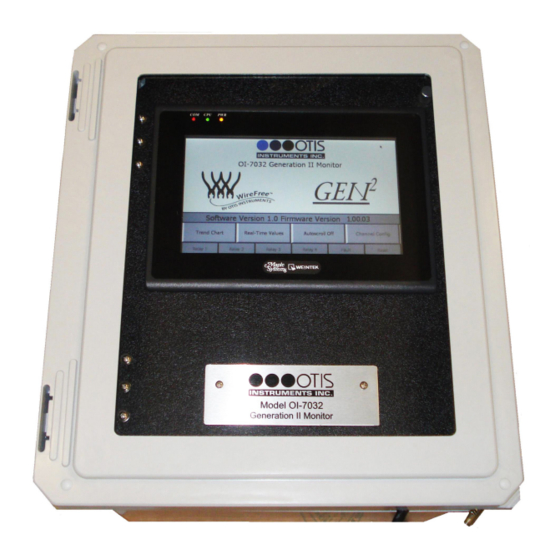
Product Overview The Otis Instruments, Inc. GenII OI-7032 (32-Channel) is a Hybrid Monitor that supports up to 32 WireFree sensor units, and up to four 4-20mA input sensors (when only 28 channels are setup as WireFree). The OI-7032 is backward compatible with GenI WireFree sensor units, and also supports GenII Wirefree sensor units (configurable).
-
Page 3: Table Of Contents
Table of Contents Product Overview……………………….2 Introduction…………………………5 Warnings…………………………6 Complete System Diagrams……………………7 Front Panel…………………………….7 Internal Diagram…………………………..8 Terminal Board……………………………..9 Touchscreen (Front)……………………………10 Touchscreen (Back)…………………………..10 AC (Delta) Power Supply…………………………11 Internal Diagram – As Wired from the Factory………………….12 Internal Diagram – Completely Wired……………………..13 Wiring Configurations……………………..14 DC Power-in (24 Volts DC (nominal;…
-
Page 4
VIEW Modbus Output Settings: Baud Rate……………………71 VIEW Radio Settings: Radio Timeout……………………..72 VIEW Gen II Radio Settings: Network ID……………………72 VIEW Gen II Radio Settings: Primary or Secondary Monitor………………73 VIEW OI-7032 Reset to Factory Default……………………73 VIEW Relay Settings: Relays 1-4 (Failsafe)……………………74 VIEW Relay Settings: Fault Terminal……………………..74 VIEW Relay Settings: Fault Relay Assign…………………… -
Page 5: Introduction
Introduction This document is an Operation Manual containing diagrams and step-by-step instruction for proper operation of the Otis Instruments, Inc. GenII OI-7032. This document should be read before initial operation of the product. Should a question arise during the use of the product, this document will serve as a first reference for consultation.
-
Page 6: Warnings
-20 to 122 degrees Fahrenheit. If the OI-7032 is at risk of being exposed to temperatures that are outside the previously stated range, DO NOT install the device in that location. For applications in areas with the potential of reaching extreme temperatures, Otis Instruments recommends using the OI-7032 indoors only (in a temperature-controlled environment).
-
Page 7: Complete System Diagrams
Complete System Diagrams The following diagrams should be consulted for identification of Panels, Boards, and any other system component that may be referred to in this Operation Manual. Front Panel…
-
Page 8: Internal Diagram
Internal Diagram…
-
Page 9: Terminal Board
Terminal Board…
-
Page 10: Touchscreen (Front)
Touchscreen (Front) Touchscreen (Back)
-
Page 11: Ac (Delta) Power Supply
AC (Delta) Power Supply…
-
Page 12: Internal Diagram — As Wired From The Factory
Internal Diagram – As Wired from the Factory…
-
Page 13: Internal Diagram — Completely Wired
Internal Diagram – Completely Wired…
-
Page 14: Wiring Configurations
Please consult a solar panel manufacture for specific details. Otis Instruments, Inc. may also be contacted to provide guidance and recommendations.
-
Page 15
DC Power-in (24 Volts DC (nominal; 22-26 Volts DC)) cont… 1. Open the enclosure box to expose the Front Panel. 2. Unscrew the two thumb-screws on the Front Panel. 3. Open the Front Panel so that the Terminal Board is exposed. -
Page 16
DC Power-in (24 Volts DC (nominal; 22-26 Volts DC)) cont… 4. Locate the Power Terminal (on the lower right side of the Terminal Board). 5. Connect the DC Power Supply live wire (red) to the terminal marked “+12-35 VDC”. 6. Connect the DC Power Supply Ground wire (black) to the terminal marked “GND”. 7. -
Page 17: Ac Power Supply Connection
For AC Power applications, the Delta Power Supply located below the Terminal Board should be used. NOTE: The unit will be wired for the power-type that is requested by the purchaser when shipped from Otis Instruments, Inc. 1. Open the enclosure box to expose the Front Panel.
-
Page 18
AC Power Supply Connection cont… 4. Connect a positive (red) wire to the Power Terminal terminal labeled “+12-35 VDC” on the Terminal Board. 5. Connect the other end of that same positive (red) wire from the Terminal Board to the terminal labeled “+V”… -
Page 19: Touchscreen Power Connection
Touchscreen Power Connection NOTE: The Touchscreen power connection will be pre-wired for use when the unit is shipped from Otis Instruments, Inc. 1. Open the enclosure box to expose the Front Panel. 2. Unscrew the two thumb-screws on the Front Panel.
-
Page 20
Touchscreen Power Connection cont… 4. Locate the Touchscreen’s Power Terminal. 5. Connect the positive DC Supply wire (red) to the terminal labeled “+”. 6. Connect the negative DC Supply wire (black) to the terminal labeled “-” 7. Connect an earth ground wire (green) to the ground terminal. 8. -
Page 21
Touchscreen Power Connection cont… 9. Connect the positive DC Supply wire (red) to the terminal labeled “12-32 VDC” on the Power Supply Terminal Block. 10.Connect the negative DC Supply wire (black) to the terminal labeled “GND” on the Power Supply Terminal Block. -
Page 22: Touchscreen Connection
Touchscreen Connection NOTE: The OI-7032 Touchscreen will be pre-wired when the unit is shipped from Otis Instruments, Inc. 1. Open the enclosure box to expose the Front Panel. 2. Unscrew the two thumb-screws on the Front Panel. 3. Open the Front Panel so that the back of the Touchscreen is exposed.
-
Page 23
Touchscreen Connection cont… 4. Locate the COM Port and the Control Screen Terminal Block. 5. Plug the DB-9 connector into the COM1 Port. -
Page 24
Touchscreen Connection cont… 6. Connect the yellow wire from the DB-9 connector to the terminal labeled “A” on the Control Screen Terminal Block. 7. Connect the white wire from the DB-9 connector to the terminal labeled “GND” on the Control Screen Terminal Block. -
Page 25: Memory Installation
NOTE: The maximum memory card capacity is 2GB. NOTE: The OI-7032 memory card will be pre-installed in the touch- screen when the unit is shipped from Otis Instruments, Inc. 1. Open the enclosure box to expose the Front Panel. 2. Unscrew the two thumb-screws on the Front Panel.
-
Page 26
Memory Installation cont… 4. Locate the USB Port on the back of the Touchscreen. 5. Insert a USB-compatible memory card into the USB Port. 6. Close the Front Panel. 7. Screw in the thumb-screws. 8. Close the enclosure box. -
Page 27: Connecting Sensors
Connecting Sensors The OI-7032 is capable of monitoring up to four wired (4-20mA) sensors. Sensor connection should be completed according to the following instructions. Connecting Sensor 1 1. Locate the Sensor 1 Terminal Block on the Terminal Board.
-
Page 28
Connecting Sensor 1 cont… 2. Connect the positive (red) wire to the terminal labeled “+VDC”. 3. Connect the signal (green) wire to the terminal labeled “4-20mA”. 4. Connect the neutral (black) wire to the terminal labeled “GND”. -
Page 29: Connecting Sensor 2
Connecting Sensor 2 1. Locate the Sensor 2 Terminal Block on the Terminal Board.
-
Page 30
Connecting Sensor 2 cont… 2. Connect the positive (red) wire to the terminal labeled “+VDC”. 3. Connect the signal (green) wire to the terminal labeled “4-20mA”. 4. Connect the neutral (black) wire to the terminal labeled “GND”. -
Page 31: Connecting Sensor 3
Connecting Sensor 3 1. Locate the Sensor 3 Terminal Block on the Terminal Board.
-
Page 32
Connecting Sensor 3 cont… 2. Connect the positive (red) wire to the terminal labeled “+VDC”. 3. Connect the signal (green) wire to the terminal labeled “4-20mA”. 4. Connect the neutral (black) wire to the terminal labeled “GND”. -
Page 33: Connecting Sensor 4
Connecting Sensor 4 1. Locate the Sensor 4 Terminal Block on the Terminal Board.
-
Page 34
Connecting Sensor 4 cont… 2. Connect the positive (red) wire to the terminal labeled “+VDC”. 3. Connect the signal (green) wire to the terminal labeled “4-20mA”. 4. Connect the neutral (black) wire to the terminal labeled “GND”. -
Page 35: Relay Configurations
Relay Configurations The OI-7032 offers four relays to be setup. Each of the four relays may be setup as Normal Open (NO) or Normally Closed (NC). Connecting Relay 1 1. Locate the Relay 1 Terminal Block on the Terminal Board.
-
Page 36
Connecting Relay 1 cont… 2. Connect the live wire (red) from the Relay 1 Alarm (light/horn) to the terminal labeled “NO” (or “NC”) on the Relay 1 Terminal Block. 3. Connect the neutral wire (black) from the Relay 1 Alarm (light/horn) to the terminal labeled “GND”… -
Page 37: Connecting Relay 2
Connecting Relay 2 1. Locate the Relay 2 Terminal Block on the Terminal Board.
-
Page 38
Connecting Relay 2 cont… 2. Connect the live wire (red) from the Relay 2 Alarm (light/horn) to the terminal labeled “NO” (or “NC”) on the Relay 2 Terminal Block. 3. Connect the neutral wire (black) from the Relay 2 Alarm (light/horn) to the terminal labeled “GND”… -
Page 39: Connecting Relay 3
Connecting Relay 3 1. Locate the Relay 3 Terminal Block on the Terminal Board.
-
Page 40
Connecting Relay 3 cont… 2. Connect the live wire (red) from the Relay 3 Alarm (light/horn) to the terminal labeled “NO” (or “NC”) on the Relay 3 Terminal Block. 3. Connect the neutral wire (black) from the Relay 3 Alarm (light/horn) to the terminal labeled “GND”… -
Page 41: Connecting Relay 4
Connecting Relay 4 1. Locate the Relay 4 Terminal Block on the Terminal Board.
-
Page 42
Connecting Relay 4 cont… 2. Connect the live wire (red) from the Relay 4 Alarm (light/horn) to the terminal labeled “NO” (or “NC”) on the Relay 3 Terminal Block. 3. Connect the neutral wire (black) from the Relay 4 Alarm (light/horn) to the terminal labeled “GND”… -
Page 43: Power On/Off
Power On/Off Powering on the device activates its functions. When powered on, the device is fully functional and access to system and settings menus is allowed. Once power is supplied to the OI-7032—by being plugged into an AC outlet or by being wired to a DC power supply—the Touchscreen will illuminate.
-
Page 44: Basic Operation — Home Screen Navigation
Basic Operation — Home Screen Navigation The Home Screen is the Main Menu of the OI-7032, and should be used view indicators, as well as to enter the sub-menus. NOTE: To return to the Home Screen at any time, press “HOME”…
-
Page 45: Trend Chart
Trend Chart The Trend Chart allows the user to view logged data for each channel. The Trend Chart menu allows the user to select a group of eight channels, and then view the trends for the selected set. The trend chart will show data that was recorded over the past week. To view additional data (up to 2 months prior), use the USB that’s connected to the back of the Touchscreen.
-
Page 46
Trend Chart cont… The Touchscreen will show the following: 3. Select a channel group to view. The Touchscreen will show the following (in this example, the group of “Channels 1-8” was chosen): 4. Select a range to view. -
Page 47
Trend Chart cont… The Touchscreen will show the following (in this example, the range selection of 0-10 was chosen): NOTE: Load-time will depend on the amount of recorded data. Please wait until all data has loaded before using the navigation arrows. 5. -
Page 48: Real-Time Values
Real-Time Values The Real-Time Values Screen allows the user to view the current status of each sensor. Status readings include: Sensor Location ▪ Reading ▪ Address ▪ Mode ▪ Battery ▪ TSLM ▪ Relays ▪ The Real-Time Values Screen should be entered from the Home Screen. 1.
-
Page 49
Real-Time Values cont… The Touchscreen will show the following: 3. Select a channel group to view. The Touchscreen will show the following (in this example, the group of “Channels 25-32” was selected):… -
Page 50
Real-Time Value cont… 4. Real-Time Value Data may be viewed from this screen. To view data for additional channels, press either of the “Channels xx – xx” buttons on the lower left/right side of the Touch Screen. 5. Press “Home” to return to the Home Screen when finished viewing the data. -
Page 51: Time Since Last Calibration And Null
Time Since Last Calibration and Null The Time Since Last Calibration and Null Screen allows the user to view the last time each sensor assembly was calibrated or nulled. The Time Since Last Calibration and Null Screen should be entered from the Real-Time Values Screen via the Home Screen.
-
Page 52
Times Since Last Calibration and Null cont… The Touchscreen will show the following: 3. Press “Calibration and Null Values”. The Touchscreen will show the following: 4. Press “Home” to return to the Home Screen when finished viewing the data. -
Page 53: Autoscroll On/Off
Autoscroll On/Off Autoscroll may be used to continuously scroll through the current state of each channel. To turn this feature On/Off, simply press “Autoscroll On/Off”. NOTE: The unit will automatically Autoscroll after 20 seconds of Home Screen inactivity. In this example, Autoscroll is Off.
-
Page 54: Channel Configuration
Channel Configuration The following instructions should be consulted when configuring the channels for their corresponding sensor assemblies. Once one channel is setup, these settings may be duplicated for all channels by pressing “Duplicate Setting” on the lower right side of the Touchscreen. Remember, though, that the duplicate settings feature will duplicate the settings for ALL successive channels.
-
Page 55
Channel Configuration cont… 2. Press “Channel Config” to enter Channel Configuration Mode. The Touchscreen will show the following: 3. Choose a group of channels to configure. The Touchscreen will show the following (in this example, “Channel 1-8” was selected):… -
Page 56
Channel Configuration cont… 4. Choose a channel to configure. The Touchscreen will show the following (in this example, “Channel 1” was selected): 5. Touch the desired button on the Touchscreen to setup that specific aspect of the sensor assembly. For options that require numbers be typed, a numeric keypad will appear when that … -
Page 57: Set As Wired Or Wirefree (Channels 29-32 Only)
Set as Wired or WireFree (Channels 29-32 ONLY) To begin configuring the channel, set the channel-type to Wired or WireFree. Processing When operations are confirmed, the Touchscreen may display that the operation is being processed. When the following is displayed, please wait until processing is complete (and the green box disappears) before pressing another button.
-
Page 58: Relay Configuration
Relay Configuration To setup the relays for Channel 1, complete the following steps. 1. Press “Relay 1” to turn Relay 1 On/Off. In this example, Relay 1 is On. 2. Press “Alarm On Rising” (or “Alarm On Falling”) to set Relay 1 as Rising or Falling. In the image above, Relay 1 is set as “Alarm On Rising”.
-
Page 59: Setting Radio Address (Wirefree)
Setting Radio Address (WireFree) 1. To set the radio address, touch the value next to “Radio Address” and wait for the numeric keypad to appear. 2. Type the desired address on the keypad, then press “ENT”. NOTE: The range of available addresses is 1-255. If a value that falls outside this range is entered, the previously set value will •…
-
Page 60: Setting Scale (Wired)
Setting Scale (Wired) 1. To set the scale, touch the value next to “Scale” and wait for the numeric keypad to appear. 2. Type the desired scale on the keypad, then press “ENT”. NOTE: The range of available scales is 1 – 65000. If a value that falls outside this range is entered, the previously set value will be used.
-
Page 61: Setting Sensor Location
Setting Sensor Location 1. To specify the sensor location, touch the space to the right of “Sensor Location” and wait for the on-screen keyboard to appear. 2. Type the desired sensor location name—up to ten characters—on the keypad, then press “ENT”. NOTE: To enter lower-case letters, press “Shift”.
-
Page 62: Duplicate Settings
Duplicate Settings Each channel may be setup individually, or one channel may be setup and then duplicated to all other channels. The “duplicate” feature will set all channels the same way as the one channel that was manually setup. When the duplicate feature is used: The address value is incremented ▪…
-
Page 63
Duplicate Settings cont… 3. Press “Yes” to confirm, or “No” to decline, the Duplicate Settings operation. -
Page 64: Channel Off
Channel Off 1. To turn the channel off, press “Channel On”. 2. The button will then say “Channel Off”, as illustrated here: NOTE: The Channel On/Off state can be duplicated to all successive channels by pressing the “Duplicate Settings” button.
-
Page 65: Configuration Menu Navigation
Configuration Menu Navigation The Configuration Menu should be used to view/modify any of the following: Monitor Serial # • Date Manufactured • Calibration Mode • Relay Tests • OI-7032 Restart • Modbus Output Settings (Address; Baud Rate) • Radio Settings (Radio Timeout) •…
-
Page 66: Entering Configuration Menu
Entering Configuration Menu To enter the Configuration Menu: Touch the WireFree logo, then ▪ Press and hold the GEN II logo until the Touchscreen shows the Configuration Menu. ▪ The Touchscreen will show the following:…
-
Page 67: View Monitor Serial
View Monitor Serial # The Monitor Serial # can be viewed on the upper left side of the Touchscreen while in the Configuration Menu. View Date Manufactured The Date Manufactured can be viewed on the upper right side of the Touchscreen while in the Configuration Menu.
-
Page 68: Calibration Mode
Calibration Mode While in the Configuration Menu, press “Enter Calibration Mode” to put the OI-7032 in Calibration Mode. While in Calibration Mode, the Touchscreen will show the following:…
-
Page 69: Relay Tests
Calibration Mode cont… To exit Calibration Mode, touch “Calibration Mode Active” or “Reset”. Relay Tests While in the Configuration Menu, press “Test Relays”.
-
Page 70: Oi-7032 Restart
Relay Test cont… When in Relay Test Mode, the Touchscreen will consecutively light each Relay (in red) every 5 seconds. To cancel the Relay Test, press “Testing Relays” or “Reset”. When all 4 relays have been tested (and passed), the Touchscreen will look like the following illustration (before automatically returning to the regular Configuration Menu view): OI-7032 Restart While in the Configuration Menu, press “Restart OI-7032”…
-
Page 71: View Modbus Output Settings: Address
VIEW Modbus Output Settings: Address While in the Configuration Menu, the address can be viewed in the Modbus Output Settings box. To modify the Address, consult the next section of this Operation Manual “Second-Level Modifications – Configuration Menu”. VIEW Modbus Output Settings: Baud Rate While in the Configuration Menu, the Baud Rate can be viewed in the Modbus Output Settings box.
-
Page 72: View Radio Settings: Radio Timeout
VIEW Radio Settings: Radio Timeout While in the Configuration Menu, the Radio Timeout can be viewed in the Radio Settings box. To modify the Radio Settings, consult the next section of this Operation Manual “Second-Level Modifications – Configuration Menu”. VIEW Gen II Radio Settings: Network ID While in the Configuration Menu, the Network ID can be viewed in the Gen II Radio Settings box.
-
Page 73: View Gen Ii Radio Settings: Primary Or Secondary Monitor
VIEW Gen II Radio Settings: Primary or Secondary Monitor While in the Configuration Menu, the monitor can view the “Primary/Secondary Monitor” setting in the Gen II Radio Settings box. To modify the Gen II Radio Settings, consult the next section of this Operation Manual “Second-Level Modifications –…
-
Page 74: View Relay Settings: Relays 1-4 (Failsafe)
VIEW Relay Settings: Relays 1-4 (Failsafe) While in the Configuration Menu, the user can view the Relay Failsafe (1-4) setting next to the corresponding relay number in the Relay 1, 2, 3 or 4 box. To modify the Relay Failsafe settings, consult the next section of this Operation Manual “Second-Level Modifications –…
-
Page 75: View Relay Settings: Fault Relay Assign
VIEW Relay Settings: Fault Relay Assign While in the Configuration Menu, the user can view the Relay 4 Fault Relay setting in the “Relay 4 is Fault Relay” box. To modify the Relay 4 fault relay assignment, consult the next section of this Operation Manual “Second-Level Modifications –…
-
Page 76: Configuration Menu Modifications (Second-Level Configuration Menu)
Configuration Menu Modifications (Second-Level Configuration Menu) To modify certain items in the Configuration Menu, the OI-7032 Terminal Board must be reset (while in the Configuration Menu). To reset the board, copmlete the following steps. 1. Press “Restart OI-7032”. The Touchscreen will show the following: 2.
-
Page 77: Modify Modbus Output Settings: Address
MODIFY Modbus Output Settings: Address While in the Second-Level Configuration Menu, modify the address by touching the number next to the word “Address”. When the numeric keypad appears, type the desired address number and then press “ENT”. NOTE: The acceptable values for this setting are 1-247. If a value that falls outside this range is entered, the previously entered value will be used.
-
Page 78: Modify Modbus Output Settings: Baud Rate
MODIFY Modbus Output Settings: Baud Rate While in the Second-Level Configuration Menu, modify the Baud Rate by pressing the arrow next to the current Baud Rate setting, and then choosing the desired option from the drop-down list. MODIFY Radio Settings: Radio Timeout While in the Second-Level Configuration Menu, adjust the Radio Timeout by touching the number next to “Radio Timeout (Minutes)”.
-
Page 79: Modify Gen Ii Radio Settings: Network Id
MODIFY Gen II Radio Settings: Network ID While in the Second-Level Configuration Menu, adjust the Network ID by touching the number under “Network ID”. When the numeric keypad appears, type the desired ID number and then press “ENT”. NOTE: The values allowed for “Network ID” are 1-78. If a value that falls outside this range is entered, the previously entered value will be used.
-
Page 80: Modify Oi-7032 Reset To Factory Default
MODIFY OI-7032 Reset to Factory Default While in the Second-Level Configuration Menu, the user can reset the OI-7032 to the factory default settings by completing the following steps. 1. Press the “Yes” button in the “Reset OI-7032 to Factory Defaults?” box. 2.
-
Page 81: Modify Relay Settings: Fault Terminal
MODIFY Relay Settings: Fault Terminal While in the Second-Level Configuration Menu, set the relays and fault terminal to be failsafe (or not failsafe) by pressing the “Failsafe” (or “Not Failsafe”) button in the Relay Settings box. MODIFY Relay Settings: Fault Relay Assign While in the Second-Level Configuration Menu, set relay 4 as the fault relay (or not the fault relay) by pressing the “Yes/No”…
-
Page 82: Relay Indicator
Relay Indicator Indicators for all four relays remain along the bottom of the Touchscreen at all times. When a relay has been triggered, that relay indicator will turn red. In the illustration below, all four relays are in alarm (in Relay Test Mode):…
-
Page 83: Fault Indicator
Fault Indicator A button for fault indication remains along the bottom of the Touchscreen at all times. When a fault occurs, the fault button will turn orange. Fault Status To view the Fault Status, press the “Fault” button. The screen will show orange buttons for the channels that are in fault, as well as a description of the fault.
-
Page 84: Channel On Without Wired Sensor Connected (Fault)
Fault Status cont… Channel On Without Wired Sensor Connected (Fault) F1: Check Sensor Cable…
-
Page 85: F4: Check Sensor Board
Fault Status cont… F4: Check Sensor Board…
-
Page 86: Error Messages
Error Messages The following section contains explanations, and corresponding illustrations, for error messages that may appear while using the OI-7032. Double-Primary Error Problem: There are two primary monitors in the network, which is not allowed. NOTE: The Primary/Secondary setting ONLY applies to a GEN II network. Reason 1: The OI-7032 was setup to be the primary monitor and it was turned off or reset, the secondary monitor became the primary monitor.
-
Page 87: Autoscroll Error
Autoscroll Error Problem: Autoscroll is turned on, but all channels are turned off. Solution: Return to the Home Screen and activate all channels that are needed.
-
Page 88: Appendix A: Software Installation
APPENDIX A: Software Installation…
-
Page 89: Installation
Installation This section will detail how to set up the OI-7032 software. HMI Software Insert the provided CD into the CDROM drive of a computer. The following screen should automatically appear: Select the top button “Install Ezware-5000”. The following window will appear:…
-
Page 90
HMI Software cont… Select the top option again. The following notification will appear: Press OK. On the following screen, press “Next”. Press “Next” again. -
Page 91
HMI Software cont… Press “Next” again. Press “Next” again to begin installation. -
Page 92
HMI Software cont… After the installation is complete, the following window will appear: Fill in the appropriate fields. The serial number can be found on the back of the plastic case that contained the CD. If a viable Internet connection is available, press the “Register via Internet” button now. If a viable Internet connection is not available, press “Print Faxable Form”… -
Page 93: Appendix B: Reading Usb Drive
APPENDIX B: Reading USB Drive…
-
Page 94: Usb Drive
USB Drive The following instructions will advise the user on how to remove and read the USB Drive information. Removing the USB Drive Remove the USB drive from the OI-7032. Plug the USB drive into your computer. Reading the USB Drive When looking at the contents of the USB drive, you will see the following: Opening the Datalog Files Each folder is labeled.
-
Page 95
Opening the Easy Converter Software cont… Open the folder within labeled “Ezware-5000”. Open the shortcut called “Easy Converter”. Once Easy Converter is opened, click the “open” button to locate the datalog file desired to convert. Once the file has been selected and “OK” is pressed, the following window will appear:… -
Page 96
Opening the Easy Converter Software cont… Press “OK” to proceed to the next window. Press “OK” again. The following window will appear. The data may then be converted into an .xls (spreadsheet file). -
Page 97: Converting The Datalog File To An .Xls (Spreadsheet) File
Converting the Datalog File to an .xls (spreadsheet) File In order to convert the file to an .xls or spreadsheet file, complete the following instructions. Press the “spreadsheet” button as seen in the diagram above. The software will convert the file and save it in the same location as the datalog file. To view the file, complete the instructions in the following section.
-
Page 98: Appendix C: 4-20Ma Loop Current Introduction
APPENDIX C: 4-20mA Loop Current Introduction…
-
Page 99: 4-20Ma Current Loop Introduction
Overview 4-20mA («four to twenty”), is an analog electrical transmission standard used by Otis Instruments for some of its ambient gas sensors and monitors. The signal is a current loop where 4mA represents zero percent signal, and 20mA represents 100 percent signal (full scale of the sensor assembly).
-
Page 100: Measuring Current
Measuring Current If the value measured is 0mA, then: the loop wires are broken, the sensor assembly is not powered up, the sensor assembly is malfunctioning, or the monitor is malfunctioning. A DMM (digital multi meter) or Current Meter may be used to test a 4-20mA signal. Place the DMM or Current Meter in line with the loop and measure current.
-
Page 101: Specifications
Specifications Operating Voltage: 24 Volts DC (nominal; 22-26 Volts DC), 120/240 Volts AC Compatibility: Otis WireFree and wired (4-20mA input) sensor units Channels: Gases: all that are supported by the sensor assemblies Wired Output: RS-485 Modbus Relays: four Dry-Contact (5 Amp) w/ 4 Amp Fuses…
-
Page 102
Warranty Statement for WireFree Touchscreen Monitor OI-7032 Hardware Otis Instruments, Inc. (Manufacturer) warrants its products to be free of defects in workmanship and materials—under normal use and service—from the date of purchase from the manufacturer or from the product’s authorized reseller. The hardware for this device is under a one-year limited warranty. -
Page 103
Otis Instruments, Inc. Corporate Office 2200 E. Villa Maria Dr. Bryan, TX 77802 979.776.7700 www.otisinstruments.com…
-
Contents
-
Table of Contents
-
Bookmarks
Quick Links
Model OI-7032
32-Channel
_____________________________________
Operation Manual
Revision 2.5w
_______________________________________________________________________________________
___________________________________________________________
Summary of Contents for OTIS GEN2 OI-7032
-
Page 1
Model OI-7032 32-Channel _____________________________________ Operation Manual Revision 2.5w _______________________________________________________________________________________ ___________________________________________________________… -
Page 2: Product Overview
Product Overview The Otis Instruments, Inc. GenII OI-7032 (32-Channel) is a Hybrid Monitor that supports up to 32 WireFree sensor units, and up to four 4-20mA input sensors (when only 28 channels are setup as WireFree). The OI-7032 is backward compatible with GenI WireFree sensor units, and also supports GenII Wirefree sensor units (configurable).
-
Page 3: Table Of Contents
Table of Contents Product Overview……………………….2 Introduction…………………………5 Warnings…………………………6 Complete System Diagrams……………………7 Front Panel…………………………….7 Internal Diagram…………………………..8 Terminal Board……………………………..9 Touchscreen (Front)……………………………10 Touchscreen (Back)…………………………..10 AC (Delta) Power Supply…………………………11 Internal Diagram – As Wired from the Factory………………….12 Internal Diagram – Completely Wired……………………..13 Wiring Configurations……………………..14 DC Power-in (24 Volts DC (nominal;…
-
Page 4
VIEW Modbus Output Settings: Baud Rate……………………71 VIEW Radio Settings: Radio Timeout……………………..72 VIEW Gen II Radio Settings: Network ID……………………72 VIEW Gen II Radio Settings: Primary or Secondary Monitor………………73 VIEW OI-7032 Reset to Factory Default……………………73 VIEW Relay Settings: Relays 1-4 (Failsafe)……………………74 VIEW Relay Settings: Fault Terminal……………………..74 VIEW Relay Settings: Fault Relay Assign…………………… -
Page 5: Introduction
Introduction This document is an Operation Manual containing diagrams and step-by-step instruction for proper operation of the Otis Instruments, Inc. GenII OI-7032. This document should be read before initial operation of the product. Should a question arise during the use of the product, this document will serve as a first reference for consultation.
-
Page 6: Warnings
-20 to 122 degrees Fahrenheit. If the OI-7032 is at risk of being exposed to temperatures that are outside the previously stated range, DO NOT install the device in that location. For applications in areas with the potential of reaching extreme temperatures, Otis Instruments recommends using the OI-7032 indoors only (in a temperature-controlled environment).
-
Page 7: Complete System Diagrams
Complete System Diagrams The following diagrams should be consulted for identification of Panels, Boards, and any other system component that may be referred to in this Operation Manual. Front Panel…
-
Page 8: Internal Diagram
Internal Diagram…
-
Page 9: Terminal Board
Terminal Board…
-
Page 10: Touchscreen (Front)
Touchscreen (Front) Touchscreen (Back)
-
Page 11: Ac (Delta) Power Supply
AC (Delta) Power Supply…
-
Page 12: Internal Diagram — As Wired From The Factory
Internal Diagram – As Wired from the Factory…
-
Page 13: Internal Diagram — Completely Wired
Internal Diagram – Completely Wired…
-
Page 14: Wiring Configurations
Please consult a solar panel manufacture for specific details. Otis Instruments, Inc. may also be contacted to provide guidance and recommendations.
-
Page 15
DC Power-in (24 Volts DC (nominal; 22-26 Volts DC)) cont… 1. Open the enclosure box to expose the Front Panel. 2. Unscrew the two thumb-screws on the Front Panel. 3. Open the Front Panel so that the Terminal Board is exposed. -
Page 16
DC Power-in (24 Volts DC (nominal; 22-26 Volts DC)) cont… 4. Locate the Power Terminal (on the lower right side of the Terminal Board). 5. Connect the DC Power Supply live wire (red) to the terminal marked “+12-35 VDC”. 6. Connect the DC Power Supply Ground wire (black) to the terminal marked “GND”. 7. -
Page 17: Ac Power Supply Connection
For AC Power applications, the Delta Power Supply located below the Terminal Board should be used. NOTE: The unit will be wired for the power-type that is requested by the purchaser when shipped from Otis Instruments, Inc. 1. Open the enclosure box to expose the Front Panel.
-
Page 18
AC Power Supply Connection cont… 4. Connect a positive (red) wire to the Power Terminal terminal labeled “+12-35 VDC” on the Terminal Board. 5. Connect the other end of that same positive (red) wire from the Terminal Board to the terminal labeled “+V”… -
Page 19: Touchscreen Power Connection
Touchscreen Power Connection NOTE: The Touchscreen power connection will be pre-wired for use when the unit is shipped from Otis Instruments, Inc. 1. Open the enclosure box to expose the Front Panel. 2. Unscrew the two thumb-screws on the Front Panel.
-
Page 20
Touchscreen Power Connection cont… 4. Locate the Touchscreen’s Power Terminal. 5. Connect the positive DC Supply wire (red) to the terminal labeled “+”. 6. Connect the negative DC Supply wire (black) to the terminal labeled “-” 7. Connect an earth ground wire (green) to the ground terminal. 8. -
Page 21
Touchscreen Power Connection cont… 9. Connect the positive DC Supply wire (red) to the terminal labeled “12-32 VDC” on the Power Supply Terminal Block. 10.Connect the negative DC Supply wire (black) to the terminal labeled “GND” on the Power Supply Terminal Block. -
Page 22: Touchscreen Connection
Touchscreen Connection NOTE: The OI-7032 Touchscreen will be pre-wired when the unit is shipped from Otis Instruments, Inc. 1. Open the enclosure box to expose the Front Panel. 2. Unscrew the two thumb-screws on the Front Panel. 3. Open the Front Panel so that the back of the Touchscreen is exposed.
-
Page 23
Touchscreen Connection cont… 4. Locate the COM Port and the Control Screen Terminal Block. 5. Plug the DB-9 connector into the COM1 Port. -
Page 24
Touchscreen Connection cont… 6. Connect the yellow wire from the DB-9 connector to the terminal labeled “A” on the Control Screen Terminal Block. 7. Connect the white wire from the DB-9 connector to the terminal labeled “GND” on the Control Screen Terminal Block. -
Page 25: Memory Installation
NOTE: The maximum memory card capacity is 2GB. NOTE: The OI-7032 memory card will be pre-installed in the touch- screen when the unit is shipped from Otis Instruments, Inc. 1. Open the enclosure box to expose the Front Panel. 2. Unscrew the two thumb-screws on the Front Panel.
-
Page 26
Memory Installation cont… 4. Locate the USB Port on the back of the Touchscreen. 5. Insert a USB-compatible memory card into the USB Port. 6. Close the Front Panel. 7. Screw in the thumb-screws. 8. Close the enclosure box. -
Page 27: Connecting Sensors
Connecting Sensors The OI-7032 is capable of monitoring up to four wired (4-20mA) sensors. Sensor connection should be completed according to the following instructions. Connecting Sensor 1 1. Locate the Sensor 1 Terminal Block on the Terminal Board.
-
Page 28
Connecting Sensor 1 cont… 2. Connect the positive (red) wire to the terminal labeled “+VDC”. 3. Connect the signal (green) wire to the terminal labeled “4-20mA”. 4. Connect the neutral (black) wire to the terminal labeled “GND”. -
Page 29: Connecting Sensor 2
Connecting Sensor 2 1. Locate the Sensor 2 Terminal Block on the Terminal Board.
-
Page 30
Connecting Sensor 2 cont… 2. Connect the positive (red) wire to the terminal labeled “+VDC”. 3. Connect the signal (green) wire to the terminal labeled “4-20mA”. 4. Connect the neutral (black) wire to the terminal labeled “GND”. -
Page 31: Connecting Sensor 3
Connecting Sensor 3 1. Locate the Sensor 3 Terminal Block on the Terminal Board.
-
Page 32
Connecting Sensor 3 cont… 2. Connect the positive (red) wire to the terminal labeled “+VDC”. 3. Connect the signal (green) wire to the terminal labeled “4-20mA”. 4. Connect the neutral (black) wire to the terminal labeled “GND”. -
Page 33: Connecting Sensor 4
Connecting Sensor 4 1. Locate the Sensor 4 Terminal Block on the Terminal Board.
-
Page 34
Connecting Sensor 4 cont… 2. Connect the positive (red) wire to the terminal labeled “+VDC”. 3. Connect the signal (green) wire to the terminal labeled “4-20mA”. 4. Connect the neutral (black) wire to the terminal labeled “GND”. -
Page 35: Relay Configurations
Relay Configurations The OI-7032 offers four relays to be setup. Each of the four relays may be setup as Normal Open (NO) or Normally Closed (NC). Connecting Relay 1 1. Locate the Relay 1 Terminal Block on the Terminal Board.
-
Page 36
Connecting Relay 1 cont… 2. Connect the live wire (red) from the Relay 1 Alarm (light/horn) to the terminal labeled “NO” (or “NC”) on the Relay 1 Terminal Block. 3. Connect the neutral wire (black) from the Relay 1 Alarm (light/horn) to the terminal labeled “GND”… -
Page 37: Connecting Relay 2
Connecting Relay 2 1. Locate the Relay 2 Terminal Block on the Terminal Board.
-
Page 38
Connecting Relay 2 cont… 2. Connect the live wire (red) from the Relay 2 Alarm (light/horn) to the terminal labeled “NO” (or “NC”) on the Relay 2 Terminal Block. 3. Connect the neutral wire (black) from the Relay 2 Alarm (light/horn) to the terminal labeled “GND”… -
Page 39: Connecting Relay 3
Connecting Relay 3 1. Locate the Relay 3 Terminal Block on the Terminal Board.
-
Page 40
Connecting Relay 3 cont… 2. Connect the live wire (red) from the Relay 3 Alarm (light/horn) to the terminal labeled “NO” (or “NC”) on the Relay 3 Terminal Block. 3. Connect the neutral wire (black) from the Relay 3 Alarm (light/horn) to the terminal labeled “GND”… -
Page 41: Connecting Relay 4
Connecting Relay 4 1. Locate the Relay 4 Terminal Block on the Terminal Board.
-
Page 42
Connecting Relay 4 cont… 2. Connect the live wire (red) from the Relay 4 Alarm (light/horn) to the terminal labeled “NO” (or “NC”) on the Relay 3 Terminal Block. 3. Connect the neutral wire (black) from the Relay 4 Alarm (light/horn) to the terminal labeled “GND”… -
Page 43: Power On/Off
Power On/Off Powering on the device activates its functions. When powered on, the device is fully functional and access to system and settings menus is allowed. Once power is supplied to the OI-7032—by being plugged into an AC outlet or by being wired to a DC power supply—the Touchscreen will illuminate.
-
Page 44: Basic Operation — Home Screen Navigation
Basic Operation — Home Screen Navigation The Home Screen is the Main Menu of the OI-7032, and should be used view indicators, as well as to enter the sub-menus. NOTE: To return to the Home Screen at any time, press “HOME”…
-
Page 45: Trend Chart
Trend Chart The Trend Chart allows the user to view logged data for each channel. The Trend Chart menu allows the user to select a group of eight channels, and then view the trends for the selected set. The trend chart will show data that was recorded over the past week. To view additional data (up to 2 months prior), use the USB that’s connected to the back of the Touchscreen.
-
Page 46
Trend Chart cont… The Touchscreen will show the following: 3. Select a channel group to view. The Touchscreen will show the following (in this example, the group of “Channels 1-8” was chosen): 4. Select a range to view. -
Page 47
Trend Chart cont… The Touchscreen will show the following (in this example, the range selection of 0-10 was chosen): NOTE: Load-time will depend on the amount of recorded data. Please wait until all data has loaded before using the navigation arrows. 5. -
Page 48: Real-Time Values
Real-Time Values The Real-Time Values Screen allows the user to view the current status of each sensor. Status readings include: Sensor Location ▪ Reading ▪ Address ▪ Mode ▪ Battery ▪ TSLM ▪ Relays ▪ The Real-Time Values Screen should be entered from the Home Screen. 1.
-
Page 49
Real-Time Values cont… The Touchscreen will show the following: 3. Select a channel group to view. The Touchscreen will show the following (in this example, the group of “Channels 25-32” was selected):… -
Page 50
Real-Time Value cont… 4. Real-Time Value Data may be viewed from this screen. To view data for additional channels, press either of the “Channels xx – xx” buttons on the lower left/right side of the Touch Screen. 5. Press “Home” to return to the Home Screen when finished viewing the data. -
Page 51: Time Since Last Calibration And Null
Time Since Last Calibration and Null The Time Since Last Calibration and Null Screen allows the user to view the last time each sensor assembly was calibrated or nulled. The Time Since Last Calibration and Null Screen should be entered from the Real-Time Values Screen via the Home Screen.
-
Page 52
Times Since Last Calibration and Null cont… The Touchscreen will show the following: 3. Press “Calibration and Null Values”. The Touchscreen will show the following: 4. Press “Home” to return to the Home Screen when finished viewing the data. -
Page 53: Autoscroll On/Off
Autoscroll On/Off Autoscroll may be used to continuously scroll through the current state of each channel. To turn this feature On/Off, simply press “Autoscroll On/Off”. NOTE: The unit will automatically Autoscroll after 20 seconds of Home Screen inactivity. In this example, Autoscroll is Off.
-
Page 54: Channel Configuration
Channel Configuration The following instructions should be consulted when configuring the channels for their corresponding sensor assemblies. Once one channel is setup, these settings may be duplicated for all channels by pressing “Duplicate Setting” on the lower right side of the Touchscreen. Remember, though, that the duplicate settings feature will duplicate the settings for ALL successive channels.
-
Page 55
Channel Configuration cont… 2. Press “Channel Config” to enter Channel Configuration Mode. The Touchscreen will show the following: 3. Choose a group of channels to configure. The Touchscreen will show the following (in this example, “Channel 1-8” was selected):… -
Page 56
Channel Configuration cont… 4. Choose a channel to configure. The Touchscreen will show the following (in this example, “Channel 1” was selected): 5. Touch the desired button on the Touchscreen to setup that specific aspect of the sensor assembly. For options that require numbers be typed, a numeric keypad will appear when that … -
Page 57: Set As Wired Or Wirefree (Channels 29-32 Only)
Set as Wired or WireFree (Channels 29-32 ONLY) To begin configuring the channel, set the channel-type to Wired or WireFree. Processing When operations are confirmed, the Touchscreen may display that the operation is being processed. When the following is displayed, please wait until processing is complete (and the green box disappears) before pressing another button.
-
Page 58: Relay Configuration
Relay Configuration To setup the relays for Channel 1, complete the following steps. 1. Press “Relay 1” to turn Relay 1 On/Off. In this example, Relay 1 is On. 2. Press “Alarm On Rising” (or “Alarm On Falling”) to set Relay 1 as Rising or Falling. In the image above, Relay 1 is set as “Alarm On Rising”.
-
Page 59: Setting Radio Address (Wirefree)
Setting Radio Address (WireFree) 1. To set the radio address, touch the value next to “Radio Address” and wait for the numeric keypad to appear. 2. Type the desired address on the keypad, then press “ENT”. NOTE: The range of available addresses is 1-255. If a value that falls outside this range is entered, the previously set value will •…
-
Page 60: Setting Scale (Wired)
Setting Scale (Wired) 1. To set the scale, touch the value next to “Scale” and wait for the numeric keypad to appear. 2. Type the desired scale on the keypad, then press “ENT”. NOTE: The range of available scales is 1 – 65000. If a value that falls outside this range is entered, the previously set value will be used.
-
Page 61: Setting Sensor Location
Setting Sensor Location 1. To specify the sensor location, touch the space to the right of “Sensor Location” and wait for the on-screen keyboard to appear. 2. Type the desired sensor location name—up to ten characters—on the keypad, then press “ENT”. NOTE: To enter lower-case letters, press “Shift”.
-
Page 62: Duplicate Settings
Duplicate Settings Each channel may be setup individually, or one channel may be setup and then duplicated to all other channels. The “duplicate” feature will set all channels the same way as the one channel that was manually setup. When the duplicate feature is used: The address value is incremented ▪…
-
Page 63
Duplicate Settings cont… 3. Press “Yes” to confirm, or “No” to decline, the Duplicate Settings operation. -
Page 64: Channel Off
Channel Off 1. To turn the channel off, press “Channel On”. 2. The button will then say “Channel Off”, as illustrated here: NOTE: The Channel On/Off state can be duplicated to all successive channels by pressing the “Duplicate Settings” button.
-
Page 65: Configuration Menu Navigation
Configuration Menu Navigation The Configuration Menu should be used to view/modify any of the following: Monitor Serial # • Date Manufactured • Calibration Mode • Relay Tests • OI-7032 Restart • Modbus Output Settings (Address; Baud Rate) • Radio Settings (Radio Timeout) •…
-
Page 66: Entering Configuration Menu
Entering Configuration Menu To enter the Configuration Menu: Touch the WireFree logo, then ▪ Press and hold the GEN II logo until the Touchscreen shows the Configuration Menu. ▪ The Touchscreen will show the following:…
-
Page 67: View Monitor Serial
View Monitor Serial # The Monitor Serial # can be viewed on the upper left side of the Touchscreen while in the Configuration Menu. View Date Manufactured The Date Manufactured can be viewed on the upper right side of the Touchscreen while in the Configuration Menu.
-
Page 68: Calibration Mode
Calibration Mode While in the Configuration Menu, press “Enter Calibration Mode” to put the OI-7032 in Calibration Mode. While in Calibration Mode, the Touchscreen will show the following:…
-
Page 69: Relay Tests
Calibration Mode cont… To exit Calibration Mode, touch “Calibration Mode Active” or “Reset”. Relay Tests While in the Configuration Menu, press “Test Relays”.
-
Page 70: Oi-7032 Restart
Relay Test cont… When in Relay Test Mode, the Touchscreen will consecutively light each Relay (in red) every 5 seconds. To cancel the Relay Test, press “Testing Relays” or “Reset”. When all 4 relays have been tested (and passed), the Touchscreen will look like the following illustration (before automatically returning to the regular Configuration Menu view): OI-7032 Restart While in the Configuration Menu, press “Restart OI-7032”…
-
Page 71: View Modbus Output Settings: Address
VIEW Modbus Output Settings: Address While in the Configuration Menu, the address can be viewed in the Modbus Output Settings box. To modify the Address, consult the next section of this Operation Manual “Second-Level Modifications – Configuration Menu”. VIEW Modbus Output Settings: Baud Rate While in the Configuration Menu, the Baud Rate can be viewed in the Modbus Output Settings box.
-
Page 72: View Radio Settings: Radio Timeout
VIEW Radio Settings: Radio Timeout While in the Configuration Menu, the Radio Timeout can be viewed in the Radio Settings box. To modify the Radio Settings, consult the next section of this Operation Manual “Second-Level Modifications – Configuration Menu”. VIEW Gen II Radio Settings: Network ID While in the Configuration Menu, the Network ID can be viewed in the Gen II Radio Settings box.
-
Page 73: View Gen Ii Radio Settings: Primary Or Secondary Monitor
VIEW Gen II Radio Settings: Primary or Secondary Monitor While in the Configuration Menu, the monitor can view the “Primary/Secondary Monitor” setting in the Gen II Radio Settings box. To modify the Gen II Radio Settings, consult the next section of this Operation Manual “Second-Level Modifications –…
-
Page 74: View Relay Settings: Relays 1-4 (Failsafe)
VIEW Relay Settings: Relays 1-4 (Failsafe) While in the Configuration Menu, the user can view the Relay Failsafe (1-4) setting next to the corresponding relay number in the Relay 1, 2, 3 or 4 box. To modify the Relay Failsafe settings, consult the next section of this Operation Manual “Second-Level Modifications –…
-
Page 75: View Relay Settings: Fault Relay Assign
VIEW Relay Settings: Fault Relay Assign While in the Configuration Menu, the user can view the Relay 4 Fault Relay setting in the “Relay 4 is Fault Relay” box. To modify the Relay 4 fault relay assignment, consult the next section of this Operation Manual “Second-Level Modifications –…
-
Page 76: Configuration Menu Modifications (Second-Level Configuration Menu)
Configuration Menu Modifications (Second-Level Configuration Menu) To modify certain items in the Configuration Menu, the OI-7032 Terminal Board must be reset (while in the Configuration Menu). To reset the board, copmlete the following steps. 1. Press “Restart OI-7032”. The Touchscreen will show the following: 2.
-
Page 77: Modify Modbus Output Settings: Address
MODIFY Modbus Output Settings: Address While in the Second-Level Configuration Menu, modify the address by touching the number next to the word “Address”. When the numeric keypad appears, type the desired address number and then press “ENT”. NOTE: The acceptable values for this setting are 1-247. If a value that falls outside this range is entered, the previously entered value will be used.
-
Page 78: Modify Modbus Output Settings: Baud Rate
MODIFY Modbus Output Settings: Baud Rate While in the Second-Level Configuration Menu, modify the Baud Rate by pressing the arrow next to the current Baud Rate setting, and then choosing the desired option from the drop-down list. MODIFY Radio Settings: Radio Timeout While in the Second-Level Configuration Menu, adjust the Radio Timeout by touching the number next to “Radio Timeout (Minutes)”.
-
Page 79: Modify Gen Ii Radio Settings: Network Id
MODIFY Gen II Radio Settings: Network ID While in the Second-Level Configuration Menu, adjust the Network ID by touching the number under “Network ID”. When the numeric keypad appears, type the desired ID number and then press “ENT”. NOTE: The values allowed for “Network ID” are 1-78. If a value that falls outside this range is entered, the previously entered value will be used.
-
Page 80: Modify Oi-7032 Reset To Factory Default
MODIFY OI-7032 Reset to Factory Default While in the Second-Level Configuration Menu, the user can reset the OI-7032 to the factory default settings by completing the following steps. 1. Press the “Yes” button in the “Reset OI-7032 to Factory Defaults?” box. 2.
-
Page 81: Modify Relay Settings: Fault Terminal
MODIFY Relay Settings: Fault Terminal While in the Second-Level Configuration Menu, set the relays and fault terminal to be failsafe (or not failsafe) by pressing the “Failsafe” (or “Not Failsafe”) button in the Relay Settings box. MODIFY Relay Settings: Fault Relay Assign While in the Second-Level Configuration Menu, set relay 4 as the fault relay (or not the fault relay) by pressing the “Yes/No”…
-
Page 82: Relay Indicator
Relay Indicator Indicators for all four relays remain along the bottom of the Touchscreen at all times. When a relay has been triggered, that relay indicator will turn red. In the illustration below, all four relays are in alarm (in Relay Test Mode):…
-
Page 83: Fault Indicator
Fault Indicator A button for fault indication remains along the bottom of the Touchscreen at all times. When a fault occurs, the fault button will turn orange. Fault Status To view the Fault Status, press the “Fault” button. The screen will show orange buttons for the channels that are in fault, as well as a description of the fault.
-
Page 84: Channel On Without Wired Sensor Connected (Fault)
Fault Status cont… Channel On Without Wired Sensor Connected (Fault) F1: Check Sensor Cable…
-
Page 85: F4: Check Sensor Board
Fault Status cont… F4: Check Sensor Board…
-
Page 86: Error Messages
Error Messages The following section contains explanations, and corresponding illustrations, for error messages that may appear while using the OI-7032. Double-Primary Error Problem: There are two primary monitors in the network, which is not allowed. NOTE: The Primary/Secondary setting ONLY applies to a GEN II network. Reason 1: The OI-7032 was setup to be the primary monitor and it was turned off or reset, the secondary monitor became the primary monitor.
-
Page 87: Autoscroll Error
Autoscroll Error Problem: Autoscroll is turned on, but all channels are turned off. Solution: Return to the Home Screen and activate all channels that are needed.
-
Page 88: Appendix A: Software Installation
APPENDIX A: Software Installation…
-
Page 89: Installation
Installation This section will detail how to set up the OI-7032 software. HMI Software Insert the provided CD into the CDROM drive of a computer. The following screen should automatically appear: Select the top button “Install Ezware-5000”. The following window will appear:…
-
Page 90
HMI Software cont… Select the top option again. The following notification will appear: Press OK. On the following screen, press “Next”. Press “Next” again. -
Page 91
HMI Software cont… Press “Next” again. Press “Next” again to begin installation. -
Page 92
HMI Software cont… After the installation is complete, the following window will appear: Fill in the appropriate fields. The serial number can be found on the back of the plastic case that contained the CD. If a viable Internet connection is available, press the “Register via Internet” button now. If a viable Internet connection is not available, press “Print Faxable Form”… -
Page 93: Appendix B: Reading Usb Drive
APPENDIX B: Reading USB Drive…
-
Page 94: Usb Drive
USB Drive The following instructions will advise the user on how to remove and read the USB Drive information. Removing the USB Drive Remove the USB drive from the OI-7032. Plug the USB drive into your computer. Reading the USB Drive When looking at the contents of the USB drive, you will see the following: Opening the Datalog Files Each folder is labeled.
-
Page 95
Opening the Easy Converter Software cont… Open the folder within labeled “Ezware-5000”. Open the shortcut called “Easy Converter”. Once Easy Converter is opened, click the “open” button to locate the datalog file desired to convert. Once the file has been selected and “OK” is pressed, the following window will appear:… -
Page 96
Opening the Easy Converter Software cont… Press “OK” to proceed to the next window. Press “OK” again. The following window will appear. The data may then be converted into an .xls (spreadsheet file). -
Page 97: Converting The Datalog File To An .Xls (Spreadsheet) File
Converting the Datalog File to an .xls (spreadsheet) File In order to convert the file to an .xls or spreadsheet file, complete the following instructions. Press the “spreadsheet” button as seen in the diagram above. The software will convert the file and save it in the same location as the datalog file. To view the file, complete the instructions in the following section.
-
Page 98: Appendix C: 4-20Ma Loop Current Introduction
APPENDIX C: 4-20mA Loop Current Introduction…
-
Page 99: 4-20Ma Current Loop Introduction
Overview 4-20mA («four to twenty”), is an analog electrical transmission standard used by Otis Instruments for some of its ambient gas sensors and monitors. The signal is a current loop where 4mA represents zero percent signal, and 20mA represents 100 percent signal (full scale of the sensor assembly).
-
Page 100: Measuring Current
Measuring Current If the value measured is 0mA, then: the loop wires are broken, the sensor assembly is not powered up, the sensor assembly is malfunctioning, or the monitor is malfunctioning. A DMM (digital multi meter) or Current Meter may be used to test a 4-20mA signal. Place the DMM or Current Meter in line with the loop and measure current.
-
Page 101: Specifications
Specifications Operating Voltage: 24 Volts DC (nominal; 22-26 Volts DC), 120/240 Volts AC Compatibility: Otis WireFree and wired (4-20mA input) sensor units Channels: Gases: all that are supported by the sensor assemblies Wired Output: RS-485 Modbus Relays: four Dry-Contact (5 Amp) w/ 4 Amp Fuses…
-
Page 102
Warranty Statement for WireFree Touchscreen Monitor OI-7032 Hardware Otis Instruments, Inc. (Manufacturer) warrants its products to be free of defects in workmanship and materials—under normal use and service—from the date of purchase from the manufacturer or from the product’s authorized reseller. The hardware for this device is under a one-year limited warranty. -
Page 103
Otis Instruments, Inc. Corporate Office 2200 E. Villa Maria Dr. Bryan, TX 77802 979.776.7700 www.otisinstruments.com…
Предложите, как улучшить StudyLib
(Для жалоб на нарушения авторских прав, используйте
другую форму
)
Ваш е-мэйл
Заполните, если хотите получить ответ
Оцените наш проект
1
2
3
4
5