-
#1
Полдня откатали нормально, не топили. Постоял, завел, поехал, вылез чек, IBR ушел в верхнее положение, мотор в аварийный режим. IBR не насиловал, ошибок не было.
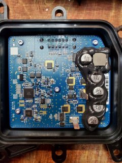
Разъемы сухие, проводку от ECM до IBR прозвонил, ок! Блок снял, вскрыл, чистый, сухой!
Разъем в блоке пропаял, проводку еще раз проверил, проблема осталась…
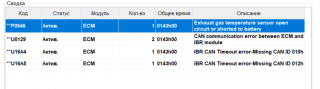
Три ошибки, все по CAN шине. Скрины и вскрытый блок во вложении.
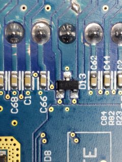
На плате разъема, белыми точками, отмечены CAN дата, по дорожкам далее, 3х ногая смд tan33 (что это?), далее разводка в многослойку…
Новый блок только под заказ и жаба…
Есть мысли куда копать, ну или может кто ремонтировал уже?
-
109,5 KB
Просмотры: 170 -
222,8 KB
Просмотры: 169 -
168,5 KB
Просмотры: 150
-
#2
Привет, проверьте напряжение которое выходит на мотор IBR. по этношению к земле на 1-2 ношке должно быть по 6 вольт.
ЕСЛИ НЕТУ напряжения — выбиты ключи. ОНИ НАХОДИТСЯ под платой на 2- плате .
проверьте и напишите ответ. чтобы я мог вам дальше помоччь.
-
#3
Всем здравствуйте!Такая же проблема вылезла только я чуть подтопил гидрик Воду слили стал заводить загорелся ibr и чек.Снял полностью ibr когда вскрыл вытекло немного воды где плата стоит,просушил сильно- присильно)Сгорел предохранитель возле Акума на 30А поменял,ставлю на место сразу ibr пищит на панели а в плате что то щёлкает и ничего не работает (
-
#4
Проверь CAN шину от IBR до мозгов
-
#6
Хорошо сегодня попробую.Отпишусь

104
ДОСТУПНЫЙ РЕЖИМ
СООБЩЕНИЕ IBR-OVR MODE
5. Нажмите кнопку SET, для входа в ре-
жим IBR-OVR и появления надписи
OVR OFF.
ОТОБРАЖАЕТСЯ СООБЩЕНИЕ
OVR OFF
6. Нажмите кнопку UP (вверх)/DOWN
(вниз) (правая рукоятка руля) для по-
явления сообщения OVR ON.
ОТОБРАЖАЕТСЯ СООБЩЕНИЕ
OVR ON
7. Нажмите кнопку SET для подтверж-
дения выбора OVR ON (включение
ручного режима). Дисплей вернётся
к прежним показаниям.
8. Нажимайте кнопки управления системы
VTS UP (вверх) или DOWN (вниз) для
перемещения отражателя системы iBR.
Модели, не оборудованные кнопками
системы VTS
ПРИМЕЧАНИЕ: На моделях, не обору-
дованных кнопками управления систе-
мы VTS, используйте кнопки UP (ВВЕРХ)/
DOWN(ВНИЗ), расположенные на правой
стороне руля, чтобы переместить отража-
тель iBR в необходимое положение, когда
активирован ручной режим iBR в соответ-
ствии с приведённым выше описанием.
Все модели
9. Снимите колпачок шнура безопасности
с выключателя двигателя.
!
ПРЕДОСТЕРЕЖЕНИЕ
Если необходимо удалить захвачен-
ный отражателем, соплом водомёта
или рычажным механизмом предмет,
перед выполнением этого строго сле-
дуйте следующим указаниям:
– Снимите ключ DESS с выключателя.
– Подождите, по меньшей мере, 5 минут.
– Не нажимайте кнопку запуска/оста-
новки двигателя. Если кнопка была
нажата, после нажатия подождите
ещё 5 минут.
Отключение ручного режима
системы iBR
Предусмотрено три способа отключения
ручного режима системы iBR:
– Повторите предыдущие шаги и, при
появ лении надписи OVR OFF (выклю-
чение ручного режима), подтвердите
выбор нажатием кнопки SET.
– Подождите, пока электрическая систе-
ма не обесточится.
– Запустите двигатель.
ПРИМЕЧАНИЕ: При запуске двигателя
произойдёт отключение ручного режима
системы iBR и отражатель переместится
в нейтральное положение.
СПЕЦИАЛЬНЫЕ ПРОЦЕДУРЫ
-
03-25-2013, 06:09 PM
#1


IBR Module Error and codes—found my problem
-
03-25-2013, 10:39 PM
#2

Great find. Thanks for the info.
-
+1 by:
-
03-25-2013, 10:39 PM
#3

Sea Doo with IBR are very picky when it comes to AMPs.
A bad battery with bad connection can trigger false alarm when using IBR/Neutral ect…Friend had issue whenever pulling IBR.
Battery and corroded connection was the issuesThanks for sharing!
-
04-03-2013, 09:44 AM
#4
I replaced the plastic support bracket and noticed that my 30 amp fuse for the IBR is looser then all the other ones. I tried to make the pins tighter but no luck. I wonder if anyone else has the same issue and maybe that is part of the IBR failures we see?? I used some aluminum foil to tighten the gap. Tested on land fine— but will test on water-should be okay it tight now.
-
04-03-2013, 01:52 PM
#5

The IBR ghost strikes again …
I had issues with my RXTX and IBR changed out … Been good so far …
-
04-03-2013, 01:59 PM
#6
Yeah mine was replaced too, but wondering if this is an issue with others.
-
04-03-2013, 03:00 PM
#7

my rxtx 260 also have a problem with ibr,,, have a error code,, C2146 ,C0042 and p1661,, im try to replacea fuse and clean fuse box from corrode,, also check all connector from ibr ,ecu, display meter and lever sensor,,, start back a engine and still have a problem,,,ibr error and same error code,,,
any suggestion from other sifu,,,,
-
04-03-2013, 04:14 PM
#8
is your fuse tight in the fuse box? Is the IBR wire touching the exhaust? Did you try IBR over-ride to see if it actually works?
-
04-04-2013, 06:52 AM
#9
The 2010 rxtx have the Version 1 IBR …
There is now a Version 6 IBR , so there must of been some changes and improvements …
-
+1 by:
-
04-04-2013, 03:49 PM
#10
They said mine was an updated part when they put it in, but no specifics.
Thread Information
Users Browsing this Thread
There are currently 1 users browsing this thread. (0 members and 1 guests)
Similar Threads
-
Replies: 6
Last Post: 12-30-2009, 11:18 AM
-
Replies: 47
Last Post: 09-09-2006, 10:29 AM
-
Replies: 4
Last Post: 09-08-2006, 10:29 PM
-
Replies: 6
Last Post: 04-20-2006, 08:52 PM
-
Replies: 5
Last Post: 06-20-2005, 03:12 PM

Posting Permissions
- You may not post new threads
- You may not post replies
- You may not post attachments
- You may not edit your posts
- BB code is On
- Smilies are On
- [IMG] code is On
- [VIDEO] code is On
- HTML code is Off
Forum Rules

151
ПОИСК И УСТРАНЕНИЕ НЕИСПРАВНОСТЕЙ
ОТРАЖАТЕЛЬ СИСТЕМЫ iBR НЕ ВОЗВРАЩАЕТСЯ В НЕЙТРАЛЬНОЕ ПОЛОЖЕ-
НИЕ (ГОРИТ ЛАМПА IBR)
1. Отражатель системы iBR заклинен инородными предметами.
– Очистите и проверьте отражатель iBR и сопло на наличие повреждений.
2. Неисправность системы iBR.
– Снимите ключ DESS, подождите несколько минут, установите ключ DESS и убе-
дитесь, что лампа iBR не горит, что свидетельствует о сбросе кода ошибки.
– Обратитесь к авторизованному дилеру Sea-Doo, если ошибка присутствует или
часто повторяется.
ОТРАЖАТЕЛЬ СИСТЕМЫ IBR НЕ ВОЗВРАЩАЕТСЯ В НЕЙТРАЛЬНОЕ ПОЛОЖЕ-
НИЕ (ЛАМПА IBR НЕ ГОРИТ)
1. Рычаг дросселя отпущен не полностью.
– Полностью отпустите рычаг дросселя, чтобы отражатель iBR вернулся в ней-
тральное положение.
2. Рычаг дросселя не возвращается в начальное положение, когда он полностью от-
пущен.
– Обратитесь к авторизованному дилеру Sea-Doo.
РАБОТА ВОДОМЁТНОГО ДВИЖИТЕЛЯ СОПРОВОЖДАЕТСЯ НЕНОРМАЛЬНЫМ
ШУМОМ
1. Наматывание травы или водорослей на импеллер.
– Очистить. См. «ОЧИСТКА ВХОДНОГО ОТВЕРСТИЯ ВОДОМЁТА И ИМПЕЛЛЕРА»
в разделе «СПЕЦИАЛЬНЫЕ ПРОЦЕДУРЫ».
– Убедитесь в отсутствии повреждений.
2. Повреждение вала импеллера или приводного вала.
– Обратитесь к авторизованному дилеру Sea-Doo.
3. Заедание подшипника вследствие попадания воды.
– Обратитесь к авторизованному дилеру Sea-Doo.
ВОДА ВО ВНУТРЕННЕЙ ПОЛОСТИ ГИДРОЦИКЛА
1. Неисправность системы откачки воды.
– Обратитесь к авторизованному дилеру Sea-Doo для проверки системы откачки
воды.
2. Неисправность в системе выпуска.
– Обратитесь к авторизованному дилеру Sea-Doo.
3. Изношено карбоновое кольцо на приводном валу.
– Обратитесь к авторизованному дилеру Sea-Doo.

I have been working and repairing Sea-doo jet skis for the last 20 years. They are very reliable machines but occasionally things go wrong and like all smart vehicles that just display a fault code, it can be confusing. That’s why with the help of a few different Sea-doo workshop manuals I will be showing the full Sea-doo fault code list.
I have split the sections up into areas such as Cluster, iBR, Intelligent Suspension, VTS, and Engine Control Management to make codes simple to read.
As this is a very large document you can either scroll in alphabetic/numeric order or use the browser search function to find a specific Sea-doo fault code to fix it yourself.
Having access to the BRP BUDS or Candoo Pro scanning software is beneficial in tracking down faults but not necessary. I have used both and they work very well. I would recommend the BRP BUDS2 scanner when working on newer 4-Tec Sea-doos. It comes with an ALL-DEALER license to help fix your jet-ski and your friends.
Table of Contents
- 1 Mega Sea-doo fault code list
- 2 Sea doo fault codes for iBR
- 3 Sea-doo “iS” Faults (Stands for Intelligent Suspension)
- 4 Sea-doo ECM Fault codes
- 5 Sea-doo Electrical Fault Codes Continued
- 6 Sea-doo Throttle, CAN-BUS, and VTS Fault Codes List
- 7 Seadoo Code Reader – Candoo Pro and BRP BUDS.
- 7.1 BRP Sea-doo code reader specs
- 8 How to get a list of stored codes from your Sea-doo for 4TEC skis up to 2003
- 9 How to read Sea-doo fault codes on 2004 to 2021 models without a scanner.
- 10 Sea-doo warning lights messages and display meaning
- 11 Conclusion
| SEA-DOO FAULT CODES |
REPORTING MODULE |
DESCRIPTION | POSSIBLE CAUSE | REPAIR ACTION |
| B2210 | CLUSTER | Left keypad fault (Switch kept activated more than 60 seconds) |
Problem with left keypad. |
The switch may be defective, verify the functionality of the switch or the wires. Refer to the shop manual for switch diagnosis/testing procedure. |
| B2211 | CLUSTER | Suspension UP/DOWN switches shorted to ground fault |
Problem with left keypad. |
Look for pin B if shorted to ground or pin C. |
| B2212 | CLUSTER | Suspension UP/DOWN switches disconnected fault |
Problem with left keypad. |
Look for pin B if disconnected to pin 14 on the cluster. Look for pin C if disconnected to pin 15 on the cluster. |
| B2213 | CLUSTER | VTS UP/DOWN switches shorted to ground fault |
Problem with left keypad. |
Look for pin A if shorted to ground or if pin C is grounded. |
| B2214 | CLUSTER | VTS UP/DOWN switches disconnected fault |
Problem with left keypad. |
Look for pin A if disconnected to pin 13 on the cluster. Look for pin C if disconnected to pin 15 on the cluster. |
| B2220 | CLUSTER | Right keypad fault (Switch kept activated more than 60 seconds) |
Problem with the right keypad. |
The switch may be defective, verify the functionality of the switch or the wires. Refer to the shop manual for switch diagnosis/testing procedure. |
| B2221 | CLUSTER | MODE/SET switches shorted to ground fault |
Problem with the right keypad. |
Look for pin B if shorted to ground or pin C. |
| B2222 | CLUSTER | MODE/SET switches disconnected fault |
Problem with the right keypad. |
Look for pin B if disconnected to pin 17 on the cluster. Look for pin C if disconnected to pin 18 on the cluster. |
| B2223 | CLUSTER | UP/DOWN switches shorted to ground fault |
Problem with the right keypad. |
Look for pin A if shorted to ground or pin C. |
| B2224 | CLUSTER | UP/DOWN switches disconnected fault |
Problem with the right keypad. |
Look for pin A if disconnected to pin 16 on the cluster. Look for pin C if disconnected to pin 18 on the cluster. |
Sea doo fault codes for iBR
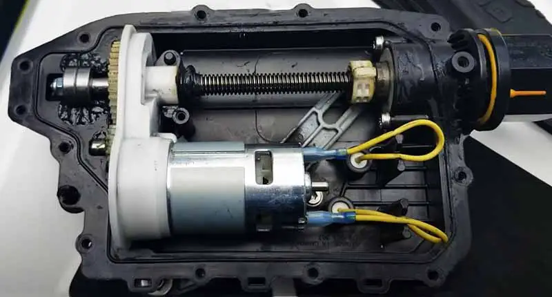
The Intelligent brake and reverse (iBR) helps the jetski stop sooner, improves safety, and gives you the ability to engage forward, neutral, and reverse. This is important for stable, easy maneuvers at low speeds. But occasionally things go wrong when the iBR gets jammed with sticks or debris.
| SEA-DOO FAULT CODE LIST | REPORTING MODULE | DESCRIPTION | POSSIBLE CAUSE | REPAIR ACTION |
| C0042 | iBR | Brake Lever Sensor (BRLS) signals A open/shorted to ground |
Damaged sensor, damaged circuit wires, damaged connector, or damaged iBR pins. Fault detected when the engine is running or stopped. |
Check for 0.5 to 3 V on pin F. and 0.25 to 1.5V on pin C. |
| C0043 | iBR | Brake Lever Sensor (BRLS) signals B open/shorted to ground |
Damaged sensor, damaged circuit wires, damaged connector or damaged iBR pins. Fault detected when the engine is running or stopped. |
Check for 0.5 to 3 V on pin F and 0.25 to 1.5 on pin C. |
| C0073 | iBR | Torque request failure | ECM software failure. CPS wires shorted. | Perform ECM software updates if available or replace ECM. Verify CPS connection. |
| C2100 | iBR | Sensors calibration is corrupted | Incompatible firmware or memory failure. | Replace the iBR unit. Refer to the Service Manual for more details. |
| C2101 | iBR | Actuator movement warning | The reverse gate cannot move to the desired position within the expected time. | Clean and check for damage in the reverse gate and nozzle area. Refer to the Service Manual for more details. |
| C2100 There are a few with the same code. |
iBR | Actuator movement | The reverse gate cannot move to the desired position. | Clean and check for damage in the reverse gate and nozzle area. Refer to the Service Manual for more details. |
| C2110 | iBR | Reverse gate position sensor error | iBR malfunction. | Check for correct movement of iBR.Replace the iBR unit. Refer to the Service Manual for more details. |
| C2110 | iBR | Angle position sensor warning | iBR malfunction. | Replace the iBR unit. Refer to the Service Manual for more details. |
| C2110 | iBR | iBR overheat | iBR cooling system failure. iBR unit failure. |
Check the iBR cooling circuit. Replace the iBR unit. Refer to the Service Manual for more details. |
| C2110 | iBR | Monitoring CPU message timeout or validity | iBR malfunction. | Perform an iBR software update if available. Replace the iBR unit. Refer to the Service Manual for more details. |
| C2110 | iBR | Monitoring CPU limp force | iBR malfunction. | Perform an iBR software update if available. Replace the iBR unit. Refer to the Service Manual for more details. |
| C2111 | iBR | ECM erratic RPM signal | RPM signal received from engine ECM not plausible | Check CPS sensor connection |
| C2120 | iBR | Application calibration is corrupted | Incompatible firmware or memory failure. | Perform an iBR software update if available. Replace the iBR unit. Refer to the Service Manual for more details. |
| C2121 | iBR | Application parameters corrupted (backup #1 or #2) | Battery power loss or memory failure. | Perform an electrical system shut download to clear the fault. Verify starting and charging system circuits. Refer to the Service Manual for more details. |
| 02122 | iBR | The last session interrupted |
Unexpected battery power lost. | Perform an electrical system shut down and clear fault. Verify starting and charging system circuits. Refer to the Service Manual for more details. |
| C2130 | iBR | Motor current software breaker | Motor current too high. | Clean and check for damage in the reverse gate and nozzle area. Refer to the Service Manual for more details. |
| C2130 | iBR | Internal motor drive failure | Motor voltage feedback not fitting with the command. | Check that the power cable to the motor is connected |
| C2131 | iBR | iBR DC motor shorted to ground or 12 V | iBR motor failure. iBR motor wires damaged or moisture detected |
Check iBR circuits A and B. Refer to the Service Manual for more details. |
| C2132 | iBR | Motor Open | No current while activated. | Check the power cables are connected. |
| C2142 | iBR | Brake Lever Sensor (BRLS) signals A shorted to battery | Damaged sensor, damaged circuit wires, damaged connector, or damaged iBR pins. Fault detected when the engine is running or stopped. |
Check for 0.5 to 3 V on pin F and 0.25 to 1.5 on pin C. |
| C2143 | iBR | Brake Lever Sensor (BRLS) signals B shorted to battery | Damaged sensor, damaged circuit wires, damaged connector, or damaged iBR pins. Fault detected when the engine is running or stopped. |
Check for 0.5 to 3 Von pin F and 0.25 to 1.5 on pin C. |
| C2144 | iBR | Brake Lever Sensor (BRLS) power shorted to battery | Damaged sensor, damaged circuit wires, damaged connector, or damaged iBR pins. Fault detected when the engine is running or stopped. |
Check for 4.5 to 5 volts on sensor connector pin A & D. Refer to the Service Manual for more details. |
| C2145 | iBR | Brake Lever Sensor (BRLS) power shorted to ground | Damaged sensor, damaged circuit wires, damaged connector, or damaged iBR pins. Fault detected when the engine is running or stopped. |
Check for 4.5 to 5 volts on sensor connector pin A & D. Refer to the Service Manual for more details. |
| C2146 | iBR | Brake Lever Sensor (BRLS) signals A/B reading difference | Damaged sensor, damaged circuit wires, damaged connector, or damaged iBR pins. Fault detected when the engine is running or stopped. |
Check for 0.5 to 3 V on pin F and 0.25 to 1.5 on pin C. |
| C2150 | iBR | System current software breaker | iBR input current too high. | Clean and check for damage in the reverse gate and nozzle area. Refer to the Service Manual for more details. |
| C2151 | iBR | System disabled and need activation | The system is locked. Need activation. | Use B.U.D.S. iBR unlock function. Refer to the Service Manual for more details. |
| C2155 | iBR | Water temperature sensor overheat | iBR cooling system failure. iBR unit failure. |
Check the iBR cooling circuit. Sea-Doo coolant flush procedure. Replace the iBR unit. Refer to the Service Manual for more details. |
| C2161 | iBR | Low voltage detected | Battery failure, rectifier failure, damaged circuit wires, battery terminal connection, damaged AC generator or damaged connectors. |
Check fuses #6 (refer to WIRING DIAGRAM). Check ground continuity to the engine block. Refer to the Service Manual for more details. |
Sea-doo “iS” Faults (Stands for Intelligent Suspension)
Sea-Doo discontinued its Intelligent Suspension system in 2017 possibly due to costs, weight and for me, it just didn’t work very well. But there are a number of Jet-skis out there with this feature so below are the fault codes that can occur with Intelligent Suspension.
| SEA-DOO FAULT CODES | REPORTING MODULE |
DESCRIPTION | POSSIBLE CAUSE | REPAIR ACTION |
| C2200 | iS | Sensors calibration is corrupted | Incompatible firmware or memory failure (Internal memory failure, return to supplier). | Defective iS module, replace the module and return to supplier. |
| C2210 | iS | Bridge/CPU temperature sensor overheat |
Hardware failure or external heat source. | Check for overutilization/heat. |
| C2220 | iS | Application calibration is corrupted | Incompatible firmware or memory failure (B.U.D.S. should repair that). | Program calibration with B.U.D.S. software. |
| C2221 | iS | Application parameters corrupted (backup #1 or #2) | Battery power lost or memory failure (Reset after power-down-up, clear fault. If happens often, verify supply voltage). |
Check power wiring and fuse. |
| C2222 | iS | Last session interrupted |
Unexpected battery power lost. | Check power wiring and fuse. |
| C2230 | iS | Internal motor drive failure | Motor voltage feedback not fitting with the command. | Defective iS module, replace the module and return to supplier. |
| C2231 | iS | Motor shorted to ground/battery | Motor shorted to ground/battery | Check suspension actuator pump wiring. |
| C2232 | iS | Motor open | No current while activated. | Check suspension actuator pump and/or wiring. |
| C2233 | iS | Motor current software breaker | Motor current too high. | Check suspension actuator pump. |
| C2240 | iS | Seat position sensor error Open, Shorted to Ground | Sensor not connected | Check system circuit at iS module, (refer to WIRING DIAGRAM) |
| C2250 | iS | System current software breaker | Battery input current too high. | Check suspension actuator pump. |
| C2251 | iS | System disabled and need activation | The system is locked for safety. Need activation. | Activate iS using BRP B.U.D.S. fault scanner activation function. |
| C2252 | iS | TOPS active Tip-over protection |
Warning only! TOPS detected by the system, the suspension is disabled while the TOPS is “ON’. | Refer to the Service Manual for more details. |
| C2260 | iS | System under voltage | The system has an under-voltage warning. | Check battery and charging system. Replace Seadoo battery. |
Sea-doo ECM Fault codes
The Engine Control Module (ECM), also called the Engine Control Unit (ECU), ensures that your Sea-doo jetski operates at optimal performance. The ECM is looking at hundreds of parameters every second and will throw up a fault code if something is wrong to protect the engine.
| SEA-DOO FAULT CODE LIST |
REPORTING MODULE |
DESCRIPTION | POSSIBLE CAUSE | REPAIR ACTION |
| P0008 | ECM | Engine phase-detection fault | ||
| P0030 | ECM | Heater Power Stage fault for lambda sensor upstreams of catalyst |
||
| P0031 | ECM | Heater Power Stage fault for lambda sensor upstreams of catalyst short circuit to GNI) |
It can have several problems, but wiring being damaged by excessive heat from the exhaust is most common. Make certain the wiring is good and has proper voltage and ground to the sensor before replacing the sensor. Check if the ground wire on the HO2 sensor circuit is corroded |
|
| P0032 | ECM | Heater Power Stage fault for lambda sensor upstreams of catalyst short circuit to V+ |
It can have several problems, but wiring being damaged by excessive heat from the exhaust is most common. Make certain the wiring is in good condition and has proper voltage and ground to the sensor before replacing the sensor. Check if the ground wire on the HO2 sensor circuit is corroded |
|
| P0036 | ECM | Heater Power Stage fault for lambda sensor downstream of the catalyst |
This can mean that the specified sensor is not sending the right data to the PCM (powertrain control module). | |
| P0037 | ECM | Heater Power Stage fault for lambda sensor downstream of catalyst – short circuit to GND |
||
| P0038 | ECM | Heater Power Stage fault for lambda sensor downstream of catalyst – short circuit to V+ |
||
| P0106 | ECM | Intake pressure sensor out of range | Sensing port dirty or blocked. Sensor failure or unexpected reading at idle. The sensor has fallen out of housing or leaking inlet. |
Check system circuits A-64, A-G4, A-H2. Make sure that the sensor housing is correctly inserted into the manifold. Check sensor connector for: a)5 volts on pin 1. b)0 volt on pin 2. c)0 volt on pin 3. Refer to the Service Manual for more details |
| P0107 | ECM | Manifold absolute pressure sensor shorted to ground or not connected. |
Sensing port dirty or blocked. Sensor failure or unexpected reading at idle. The sensor has fallen out of housing or leaking inlet. Connector disconnected |
Check system circuits A-B4, A-G4, A-H2. Make sure that the sensor housing is correctly inserted into the manifold. Check sensor connector for: a)5 volts on pin 1. b)0 volt on pin 2. c)0 volt on pin 3. Refer to the Service Manual for more details. |
| P0108 | ECM | Manifold absolute pressure sensor open circuit or shorted to battery | Sensing port dirty or blocked. A sensor failure or unexpected reading at idle. The sensor has fallen out of housing or leaking inlet. |
Check system circuits A-B4, A-G4, A-H2. Make sure that the sensor housing is correctly inserted into the manifold. Check sensor connector for: a)5 volts on pin 1. b)0 volt on pin 2. c)0 volt on pin 3. Refer to the Service Manual for more details. |
| P0112 | ECM | Intake manifold temperature sensor shorted to ground | Damaged sensor, damaged circuit wires, damaged connector, or damaged ECM pins. | Check the sensor for approximately 2280 to 2736 ohms at 19 to 21°C (66 to 70°F). Check for approximately 2280 to 2736 ohms at 19 to 21°C (66 to 70°F) between ECM connector pins A-H3 and A-J3. Refer to the Service Manual for more details. |
| P0113 | ECM | Intake manifold temperature sensor open circuit or shorted to battery | Damaged sensor, damaged circuit wires, damaged connector, or damaged ECM pins. | heck the sensor for approximately 2280 to 2736 ohms at 19 to 21°C (66 to 70°F). Check for approximately 2280 to 2736 ohms at 19 to 21°C (66 to 70°F) between ECM connector pins A-H3 and A-J3. Refer to the Service Manual for more details. |
| P0116 | ECM | Engine coolant temperature signal not plausible | Damaged sensor, damaged circuit wires, damaged connector, or damaged ECM pins. | Check for debris Dr blockage in the cooling system. Check the sensor for approximately 2280 to 2736 ohms at 19 to 21°C (66 to 70°F). Check for approximately 2280 to 2736 Ohms at 19 to 21°C (66 to 70°F) between ECM connector pins A-Al and A-J2. Refer to the Service Manual for more details. |
| P0117 | ECM | Engine coolant temperature sensor fault – Short circuit to GND | Damaged sensor, damaged circuit wires, damaged connector, or damaged ECM pins. | Check for debris or blockage in the cooling system. Check the sensor for approximately 2280 to 2736 ohms at 19 to 21°C (66 to 70°F). Check for approximately 2280 to 2736 Ohms at 19 to 21°C (66 to 70°F) between ECM connector pins A-Al and A-J2. Refer to the Service Manual for more details. |
| P0118 | ECM | Engine coolant temperature sensor fault – Short circuit to V+ or connector disconnected. | Engine overheated or damaged sensor. Connector disconnected. | Check for debris or blockage in the cooling system. Check the sensor for approximately 2280 to 2736 ohms at 19 to 21°C (66 to 70°F). Check for approximately 2280 to 2736 ohms at 19 to 21°C (66 to 70°F) between ECM connector pins A-A1 and A-J2. Refer to the Service Manual for more details. |
| P0122 | ECM | TAS (Throttle Accelerator sensor) 1 fault (short circuit to GND) | Damaged sensor, damaged circuit wires, damaged connector or damaged ECM pins, | Check system circuits B-E1, B-K1, B-K3. Check for 0 volts on sensor connector pin E. Check for 5 volts on sensor connector pin D. Check for 0.5 to 3 volts on sensor connector pin F. Refer to the Service Manual for more details. |
| P0123 | ECM | TAS (Throttle Accelerator sensor) 1 fault (short circuit to the battery) | Damaged sensor, damaged circuit wires, damaged connector, or damaged ECM pins. | Check system circuits B-E1, B-K1, B-K3. Check for 0 volts on sensor connector pin E. Check for 5 volts on sensor connector pin D. Check for 0.5 to 3 volts on sensor connector pin F. Refer to the Service Manual for more details. |
| P0127 | ECM | Intercooler system fault | High air intake temperature detected. Fault detected when the engine is running and stopped. Blocked intercooler water circuit. | Clean intercooler water circuit system. Refer to the Service Manual for more details. |
| P0130 | ECM | Lambda Sensor fault upstreams of catalyst signal not plausible | ||
| P0131 | ECM | Lambda Sensor fault upstreams of catalyst short circuit to GND | Replace oxygen sensor find ground fault | |
| P0132 | ECM | Lambda Sensor fault upstreams of catalyst short circuit to V+ | Replace oxygen sensor | |
| P0133 | ECM | Oxygen sensor upstreams of catalyst react too slow —› contaminated | Clean replace the oxygen sensor | |
| P0134 | ECM | Oxygen sensor upstreams of catalyst react too slow —> defective | Clean replace the oxygen sensor | |
| P0135 | ECM | Lambda Sensor heating fault upstreams of catalyst | It can have several problems, but wiring being damaged by excessive heat from the exhaust is most common. Make certain the wiring is good and has proper voltage and ground to the sensor before replacing the sensor. Check if the ground wire on the HO2 sensor circuit is corroded |
|
| P0136 | ECM | Lambda Sensor fault downstream of catalyst – signal not plausible | It can have several problems, but wiring being damaged by excessive heat from the exhaust is most common. Make certain the wiring is good and has proper voltage and ground to the sensor before replacing the sensor. Check if the ground wire on the O2 sensor circuit is corroded |
|
| P0137 | ECM | Lambda Sensor fault downstream of catalyst – short circuit to GROUND | It can have several problems, but wiring being damaged by excessive heat from the exhaust is most common. Make certain the wiring is good and has proper voltage and ground to the sensor before replacing the sensor. Check if the ground wire on the O2 sensor circuit is corroded |
|
| P0138 | ECM | Lambda Sensor fault downstream of catalyst – short circuit to V+ | It can have several problems, but wiring being damaged by excessive heat from the exhaust is most common. Make certain the wiring is good and has proper voltage and ground to the sensor before replacing the sensor. Check if the ground wire on the O2 sensor circuit is corroded |
|
| P0141 | ECM | Lambda Sensor heating fault downstream of the catalyst | It can have several problems, but wiring being damaged by excessive heat from the exhaust is most common. Make certain the wiring is good and has proper voltage and ground to the sensor before replacing the sensor. Check if the ground wire on the O2 sensor circuit is corroded |
|
| P0171 | ECM | Multiplicative mixture adaptation exceeds the upper limit—> mixture too lean | ||
| P0172 | ECM | Multiplicative mixture adaptation below lower limit—> mixture too rich | ||
| P0201 | ECM | Injection Power Stage fault – open line/Cylinder 1 | Damaged injector, damaged circuit wires, damaged connector, or damaged ECM Output pins. | Check for 11.4 to 12.6 ohms between engine connector pin 2 and ECM connector pin A-B3. Check for 12 volts on pin 2 of injector connector. Check fuse #13 (refer to WIRING DIAGRAM). Check for damaged circuit wires. Refer to the Service Manual for more details. |
| P0202 | ECM | Injection Power Stage fault – Open line/Cylinder 2 | Damaged injector, damaged circuit wires, damaged connector, or damaged ECM output pins. | Check for 11.4 to 12.6 ohms between engine connector pin 2 and ECM connector pin A-K1. Check for 12 volts on pin 2 of the injector connector. Check fuse #14 (refer to WIRING DIAGRAM). Check for damaged circuit wires Refer to the Service Manual for more details. |
| P0203 | ECM | Injection Power Stage fault – open line/Cylinder 3 | Damaged injector, damaged circuit wires, damaged connector, or damaged ECM output pins. | Check for 11.4 to 12.6 ohms between engine connector pin 3 and ECM connector pin A-J1, Check for 12 volts on pin 2 of the injector connector. Check fuse #15 (refer to WIRING DIAGRAM). . Check for damaged circuit wires. Refer to the Service Manual for more details. |
| P0217 | ECM | High engine coolant temperature detected | High engine coolant temperature detected caused by a blockage in coolant ride plate, cooling system, or low coolant.
This Sea-doo fault code comes up often when seaweed is blocking the intake grate. |
Check for debris or blockage in the cooling system. Check the sensor for approximately 2280 to 2736 ohms at 19 to 21°C (66 to 70°F). Check for approximately 2280 to 2736 ohms at 19 to 21°C (66 to 70°F) between ECM connector pins A-Al and A-J2. Refer to the Service Manual for more details. |
| P0222 | ECM | TAS (Throttle Accelerator sensor) 2 fault (short circuit to GND) | Damaged sensor, damaged circuit wires, damaged connector, or damaged ECM pins. | Check system circuits B-A3, B-B3, B-J3. Check for 0 volts on sensor connector pin B. Check for 5 volts on sensor connector pin A. Check for 0.25 to 1.5 volts on sensor connector pin C, Refer to the Service Manual for more details. |
| P0223 | ECM | TAS (Throttle Accelerator sensor) 2 fault (short circuit to the battery) | Damaged sensor, damaged circuit wires, damaged connector, or damaged ECM pins. | Check system circuits B-A3, B-B3, 8-J3. Check for 0 volt Dn sensor connector pin B. Check for 5 volts on sensor connector pin A. Check for 0.25 to 1.5 volts on sensor connector pin C. Refer to the Service Manual for more details. |
| P0231 | ECM | Fuel pump open circuit or short to ground | Damaged pump, damaged circuit wires, damaged connector, or damaged ECM output pins. | Check for approximately 1 ohm between pins A and B of the fuel pump connector. Check fuse #18 (refer to WIRING DIAGRAM). Check for damaged circuit wires. Check for damaged connector, damaged ECM Output pins or ECM failure. Refer to the Service Manual for more details. |
| P0232 | ECM | Fuel pump short circuit to battery | Damaged pump, damaged circuit wires, damaged connector, or damaged ECM Output pins. | Check for approximately 1 ohm between pins A and B of the fuel pump connector. Check fuse #16 (refer to WIRING DIAGRAM). Check for damaged circuit wires. Check for damaged connector, damaged ECM output pins or ECM failure. Refer to the Service Manual for more details. |
| P0261 | ECM | Injector 1 open circuit or shorted to ground |
Damaged injector, damaged circuit wires, damaged connector, or damaged ECM output pins. | Check for 11.4 to 12.6 ohms between engine connector pin 1 and ECM connector pin A-B3. Check for 12 volts on pin 2 of the injector connectors. Check fuse #13 (refer to WIRING DIAGRAM), Check for damaged circuit wires. Refer to the Service Manual for more details. |
| P0262 | ECM | Injector 1 shorted to battery | Damaged injector, damaged circuit wires, damaged connector, or damaged ECM output pins. | Check for 11.4 to 12.6 ohms between engine connector pin 1 and ECM connector pin A-83. Check for 12 volts on pin 2 of the injector connector. Check fuse #13 (refer to WIRING DIAGRAM). Check for damaged circuit wires. Refer to the Service Manual for more details. |
| P0264 | ECM | Injector 2 open circuit or shorted to ground | Damaged injector, damaged circuit wires, damaged connector, or damaged ECM output pins. | Check for 11.4 to 12.6 ohms between engine connector pin 2 and ECM connector pin A-K1. Check for 12 volts on pin 2 of the injector connectors. Check fuse #14 (refer to WIRING DIAGRAM). Check for damaged circuit wires. Refer to the Service Manual for more details. |
| P0265 | ECM | Injector 2 shorted to battery | Damaged injector, damaged circuit wires, damaged connector, or damaged ECM output pins. | Check for 11.4 to 12.6 ohms between engine connector pin 2 and ECM connector pin A-KI. Check for 12 volts on pin 2 of the injector connector. Check fuse #14 (refer to WIRING DIAGRAM). Check for damaged circuit wires. Refer to the Service Manual for more details. |
| P0267 | ECM | Injector 3 open circuit or shorted to ground | Damaged injector, damaged circuit wires, damaged connector, or damaged ECM Output pins. | Check for 11.4 to 12.6 ohms between engine connector pin 3 and ECM connector pin A-.11. Check for 12 volts on pin 2 of the injector connector. Check fuse #15 (refer to WIRING DIAGRAM). Check for damaged circuit wires. Refer to the Service Manual for more details. |
| P0268 | ECM | Injector 3 shorted to battery | Damaged injector, damaged circuit wires, damaged connector, or damaged ECM output pins. | Check for 11.4 to 12.6 ohms between engine connector pin 3 and ECM connector pin A-J1. Check for 12 volts on pin 2 of the injector connector. Check fuse #15 (refer to WIRING DIAGRAM). Check for damaged circuit wires. Refer to the Service Manual for more details. |
| P0300 | ECM | Multiple misfires detected | Check coil and spark plugs. | |
| P0301 | ECM | Misfire cylinder 2 (physical cylinder 1) | Check coil and spark plugs. | Replace Sea-doo spark plugs and coil |
| P0302 | ECM | Misfire cylinder 2 (physical cylinder 1) | Check coil and spark plugs. Water ingress into the electrical system. | Replace spark plugs and coil |
| P0303 | ECM | Misfire cylinder 1 (physical cylinder 3) | Check coil and spark plugs. Water ingress. | Replace spark plugs and coil |
| P0325 | ECM | Knock sensor 1 fault | Damaged sensor, damaged circuit wires, damaged connector, or damaged ECM output pins. Open circuit. | Bring the engine to 5000 RPM. If fault code appears then check for approximately 5 M ohms between system circuits A-C3 and A-G2. Refer to the Service Manual for more details. |
| P0330 | ECM | Knock sensor 2 fault | Damaged sensor, damaged circuit wires, damaged connector, or damaged ECM output pins. Open circuit. | Bring the engine to 5000 RPM. If fault code appears then check for approximately 5 Mohms between system circuits A-C3 and A-G2. Refer to the Service Manual for more details. |
Sea-doo Electrical Fault Codes Continued
| SEA-DOO FAULT CODES | REPORTING MODULE |
DESCRIPTION | POSSIBLE CAUSE |
REPAIR ACTION |
| P0335 | ECM | Crankshaft signal error | Damaged sensor, damaged circuit wires, damaged connector, damaged ECM pins, or damaged tooth wheel. Connector disconnected. | For the CPS, check for 700 to 900 ohms between terminals A-H1 and A-K2 of the ECM connector. Refer to the Service Manual for more details. |
| P0340 | ECM | Camshaft 1 signal error | Damaged sensor, damaged circuit wires, damaged connector, damaged ECM pins, or damaged tooth wheel. Connector disconnected. | For the CAPS, check for 12 volts on sensor connector pin 3. Check continuity for circuits A-D4, A-E2, and terminal 4 on engine connector. Check fuse #12 (refer to WIRING DIAGRAM). Engine must run to erase the corrected fault. Refer to the Service Manual for more details. |
| P0351 | ECM | Ignition coil 1 open circuit or shorted to ground or to battery |
Damaged coil, damaged circuit wires, damaged connector, or damaged ECM output pins. | Check for 0.85 to 1.15 Ohms between engine connector pin 1 and ECM connector pin A-M4. Check for 12 volts on pin 2 of the coil connector. Check fuse #13 (refer to WIRING DIAGRAM). Refer to the Service Manual for more details. |
| P0352 | ECM | Ignition coil 2 open circuit or shorted to ground or to battery |
Damaged coil, damaged circuit wires, damaged connector, or damaged ECM output pins. | Check for 0.85 to 1.15 ohms between engine connector pin 1 and ECM connector pin A-M2. Check for 12 volts on pin 2 of the coil connector. Check fuse #14 (refer to WIRING DIAGRAM). Refer to the Service Manual for more details. |
| P0353 | ECM | Ignition coil 3 open circuit or shorted to ground or to battery |
Damaged coil, damaged circuit wires, damaged connector, or damaged ECM output pins. | Check for 0.85 to 1.15 ohms between engine connector pin 3 and ECM connector pin A-M1. Check for 12 volts on pin 2 of the coil connector. Check fuse #15 (refer to WIRING DIAGRAM). Refer to the Service Manual for more details. |
| P0354 | ECM | Ignition Power Stage fault – short circuit to GND/Cylinder 1 | Damaged coil, damaged circuit wires, damaged connector, or damaged ECM output pins. | Check for 0.85 to 1.15 ohms between engine connector pin 1 and ECM connector pin A-M4. Check for 12 volts on pin 2 of the coil connector. Check fuse #13 (refer to WIRING DIAGRAM). Refer to the Service Manual for more details. |
| P0355 | ECM | Ignition Power Stage fault – short circuit to GND/Cylinder 2 | Damaged coil, damaged circuit wires, damaged connector, or damaged ECM output pins. | Check for 0.85 to 1.15 ohms between engine connector pin 1 and ECM connector pin A-M2. Check for 12 volts on pin 2 of the coil connector. Check fuse #14 (refer to WIRING DIAGRAM). Refer to the Service Manual for more details. |
| P0356 | ECM | Ignition Power Stage fault – short circuit to GND/Cylinder 3 | Damaged coil, damaged circuit wires, damaged connector, or damaged ECM output pins. | Check for 0.85 to 1,15 ohms between engine connector pin 3 and ECM connector pin A-M1. Check for 12 volts on pin 2 of the coil connector. Check fuse #15 (refer to WIRING DIAGRAM). Refer to the Service Manual for more details. |
| P0357 | ECM | Ignition Power Stage fault – short circuit to V+/Cylinder 1 | Damaged coil, damaged circuit wires, damaged connector Dr damaged ECM output pins. | Check for 0.85 to 1,15 ohms between engine connector pin 1 and ECM connector pin A-M4. Check for 12 volts on pin 2 of the coil connector. Check fuse #13 (refer to WIRING DIAGRAM). Refer to the Service Manual for more details. |
| P0358 | ECM | Ignition Power Stage fault – short circuit to V+/Cylinder 2 | Damaged coil, damaged circuit wires, damaged connector, or damaged ECM output pins. | Check for 0.85 to 1.15 ohms between engine connector pin 1 and ECM connector pin A-M2. Check for 12 volts Dn pin 2 of coil connector. Check fuse #14 (refer to WIRING DIAGRAM). Refer to the Service Manual for more details. |
| P0359 | ECM | Ignition Power Stage fault – short circuit to V+/Cylinder 3 | Damaged coil, damaged circuit wires, damaged connector Dr damaged ECM output pins. | Check for 0.85 to 1.15 ohms between engine connector pin 3 and ECM connector pin A-M1. Check for 12 volts on pin 2 of the coil connector. Check fuse #15 (refer to WIRING DIAGRAM). Refer to the Service Manual for more details. |
| P0360 | ECM | Ignition Power stage max error & false detection of low battery voltage/Cylinder 1 | Signal not plausible, verify battery voltage too low during ignition. | Check for 0.85 to 1.15 Ohms between engine connector pin 1 and ECM connector pin A-M4. Check for 12 volts on pin 2 of the coil connector. Check fuse #13 (refer to WIRING DIAGRAM). Refer to the Service Manual for more details. |
| P0361 | ECM | Ignition Power stage max error & false detection of low battery voltage/Cylinder 2 | Signal not plausible, verify battery voltage too low during ignition. | Check for 0.85 to 1.15 ohms between engine connector pin 1 and ECM connector pin A-M2. Check for 12 volts on pin 2 of the coil connector. Check fuse #14 (refer to WIRING DIAGRAM). Refer to the Service Manual for more details. |
| P0362 | ECM | Ignition Power stage max error & false detection of low battery voltage/Cylinder 3 | Signal not plausible, verify battery voltage too low during ignition. | Check for 0.86 to 1.15 ohms between engine connector pin 3 and ECM connector pin A-M1. Check for 12 volts on pin 2 of the coil connector. Check fuse #15 (refer to WIRING DIAGRAM). Refer to the Service Manual for more details. |
| P0365 | ECM | Camshaft 2 signal error | Replacement of the sensor, along with a repair of the oil leak responsible for contaminating the sensor. Wiring damage and corroded connectors and earth are also often common problems. |
|
| P0500 | ECM | Vehicle speed signal fault | Cluster fault detected by ECM C.A.N. circuit failure, Instrument cluster, or ECM failure | Check C.A.N. circuits wires. Replace instrument Cluster. Verify Outside of the building if the GPS LED becomes active after 1 minute and stays steady Refer to the Service Manual for more details. |
| P0501 | ECM | Vehicle speed not plausible | Cluster or iBR fault detected by ECM. C.A.N. circuit failure, Instrument cluster, iBR, or ECM failure. | Check C.A.N. circuits wires. Replace instrument Cluster. Verify outside of the building if the GPS LED becomes active after 1 minute and stays steady Refer to the Service Manual for more details. |
| P0504 | ECM | Vehicle speed not plausible | iBR fault detected by ECM. C.A.N. circuit failure, ECM software failure. |
Check C.A.N. circuits wires. Replace iBR. Refer to the Service Manual for more details. |
| P0512 | ECM | The starter power stage detects high current | Damaged solenoid, damaged circuit wires, damaged connector, or damaged ECM. | Verify fuse #16 (5AIVIP). Check for 12 volts on pin 2 of the starter relay. Check earth. Refer to the Service Manual for more details. |
| P0513 | ECM | Invalid D.E.S.S. Key detected | Key not programmed in ECU. | Replace or program a good key. |
| P0520 | ECM | Oil pressure switch functional problem | Engine leak, oil pump failure, damaged sensor, damaged circuit wires, damaged connector, or damaged ECM pins | Check resistance at 0 RPM and above 3500 RPM, Switch is normally closed, ECM connector pin A-E3 When blow-by pressure exceeds 40 kPa (6 PSI), the resistance is infinitely high. Refer to the Service Manual for more details. |
| P0523 | ECM | Oil pressure sensor fault | Engine leak, oil pump failure, damaged sensor, damaged circuit wires, damaged connector, or damaged ECM pins. Fault detected when the engine is running or stopped. | Check resistance at 0 RPM and above 3500 RPM. When blow-by pressure exceeds 40 kPa (6 PSI), the resistance is infinitely high. Refer to the Service Manual for more details. |
| P0524 | ECM | Low oil pressure condition | Low Oil level, engine leak, oil pump fault. | Check the oil level in the engine. Blocked oil filter. How to do an easy Oil Change on a Sea-doo PWC. Check impedance of the sensor. Refer to the Service Manual for more details. |
| P0544 | ECM | Exhaust gas temperature sensor functional problem | Damaged sensor, damaged circuit wires, damaged connecter, or damaged ECM output pins. | Check for approximately 2280 to 2736 ohms at a temperature of 19 to 21°C (66 to 70°F) between system circuits A-H4 and A-J4. Refer to the Shop Manual for more details. |
| P0545 | ECM | Exhaust gas temperature sensor shorted to ground |
Damaged sensor, damaged circuit wires, damaged connecter, or damaged ECM output pins. | Check for approximately 2280 to 2736 ohms at a temperature of 19 to 21°C (66 to 70°F) between system circuits A-H4 and A-J4. Refer to the Service Manual for more details |
| P0546 | ECM | Exhaust gas temperature sensor open circuit or shorted to battery | Damaged sensor, damaged circuit wires, damaged connector, or damaged ECM output pins. | Check for approximately 2280 to 2736 ohms at a temperature of 19 to 21°C (86 to 70°F) between system circuits A-H4 and A-J4. Refer to the Service Manual for more details. |
| P0560 | ECM | Battery voltage is not plausible | Battery failure, rectifier failure, damaged circuit wires, battery terminal connection, damaged AC generator or damaged connectors. | Check fuses #6 (refer to WIRING DIAGRAM). Check ground continuity to the engine block. Refer to the Service Manual for more details |
| P0562 | ECM | Battery voltage too low | Battery failure, rectifier failure, damaged circuit wires, battery terminal connection, damaged AC generator, or damaged connectors. |
Check fuses #6 (refer to WIRING DIAGRAM). Check ground continuity to the engine block. Charge the battery with a smart charger. Refer to the Service Manual for more details |
| P0563 | ECM | Battery voltage too high | Battery failure, rectifier failure, or battery terminal connection. | Check for regulator-rectifier failure. Make sure if jump-starting the battery that you are connected in parallel and not series. Refer to the Service Manual for more details. |
| P0564 | CLUSTER | Cruise switch fault | The cruise switch is shorted or activated for more than 60 seconds. | Verify the cruise switch if it is normally open and close when activated. Sticky switch replace. |
| P0606 | ECM | ECM ADC fault | Damaged ECM. | Replace damaged ECM. |
| P060D | ECM | TAS (Throttle Accelerator sensor) synchronization error | Damaged sensor, damaged circuit wires, damaged connector, or damaged ECM pins. | Check system circuits B-El, B-K1, B-K3, B-A3, B-B3, B-J3. Check for 0 volts on sensor connector pin B and E. Check for 5 volts on sensor connector pin A and D. Check for 0.5 to 3 volts on sensor connector pin F and 0.25 to 1.5 volts on C Refer to the Service Manual for more details. |
| P060E | ECM | Throttle Actuator – Controller Fault-digital position control exceeds the limit. | ||
| P0610 | ECM | Variant coding fault | ||
| P0629 | CLUSTER | Fuel sensor disconnected fault |
Damaged sensor, damaged circuit wires, damaged connector Dr damaged ECM output pins. | Check for 2.6 ohms (full tank) to 93.6 ohms (empty tank) between pin C and pin D at the fuel pump connector. Check the system circuit at the gauge Pin 19 and 20. (refer to WIRING DIAGRAM). |
| P062C | ECM | Cluster CAN error – Loss of vehicle speed information from the cluster | Cluster fault detected by ECM. C.A.N. circuit failure, Instrument cluster, or ECM failure. | Check C.A.N. circuits wires. Replace instrument Cluster. Verify outside of the building if the GPS LED becomes active after 1 minute and stays steady Refer to the Service Manual for more details. |
| P062F | ECM | ECM EEPROM fault – exchange ECM | Damaged ECM. | Replace damaged ECM. |
| P06B6 | ECM | ECM Fast ADC fault (knock detection line) | ||
| P1030 P1036 |
ECM | Heater Power Stage | ||
| P1106 | ECM | Altitude correction | ||
| P1120 | ECM | Throttle positions calculated from TPS 1 and TPS 2 not corresponding | Damaged throttle actuator, damaged circuit wires, damaged connector, or damaged ECM. | Check system circuit, perform closed throttle with B.U.D.S code scanner. Replace throttle actuator, replace ECM. |
| P1130 P1136 |
ECM | Lambda Sensor fault | Lambda Sensor fault upstream of the catalyst, replace the sensor. | |
| P1171 | ECM | Additive mixture too lean | An open signal on the coolant temperature sensor (CTS) can trigger this fault. | |
| P1172 | ECM | Additive mixture too rich | An open signal on the coolant temperature sensor (CTS) can trigger this fault. | |
| P1264 | ECM | Ignition Power stage overload | Damaged coil, replace. Damaged circuit wires, damaged connector, or damaged ECM output pins. |
|
| P1502 | ECM | T.O.P.S functional problem | Boat, Jet-ski, or sensor upside down, damaged circuit wires, damaged connector, or damaged ECM output pins. | Check continuity for circuits A-C4, A-G1, A-F4. Refer to the Service Manual for more details. |
| P1503 | ECM | T.O.P.S switch short circuit to 12 V | Boat or sensor upside down, damaged circuit wires, damaged connector, or damaged ECM output pins. | Check continuity circuits A-C4, A-G1, A-F4. Refer to the Service Manual for more details. |
| P1504 | ECM | T.O.P.S switch short circuit ground | Boat or sensor upside down, damaged circuit wires, damaged connector, or damaged ECM output pins. | Check continuity circuits A-C4, A-G1, A-F4. Refer to the Service Manual for more details. |
| P1505 | ECM | T.O.P.S switch fault non-plausible state | Boat or sensor upside down, damaged circuit wires, damaged connector, or damaged ECM output pins. Open circuit. | Check continuity for circuits A-C4, A-G1, A-F4. Refer to the Service Manual for more details. |
| P1506 | ECM | T.O.P.S switch open circuit | Boat or sensor upside down, damaged circuit wires, damaged connector, or damaged ECM output pins. Open circuit. | Check continuity for circuits A-C4, A-G1, A-F4. Refer to the Service Manual for more details. |
| P1509 | ECM | Lake Water Temperature sensor fault |
Clean or replace the sensor |
Sea-doo Throttle, CAN-BUS, and VTS Fault Codes List
| SEA-DOO FAULT CODES | REPORTING MODULE |
DESCRIPTION | POSSIBLE CAUSE | REAPIR ACTION |
| P1550 | ECM | O.T.A.S sensor voltage not plausible | Sensor or a magnet out of place | Check for rust on the magnet or sensor. Clean. Replace magnet or sensor. See this post on P1550 OTAS fix for more information. |
| P1590 | ECM | VTS position sensor circuit out of range | ||
| P1591 | ECM | VTS position sensor circuit voltage low | ||
| P1592 | ECM | VTS position sensor circuit voltage high | ||
| P1593 | ECM | VTS malfunction | ||
| P1606 | ECM | ECM ADC fault – exchange ECM | Damaged ECM. | No service action is available for fault P1606. |
| P160E | ECM | Throttle Actuator – Controller Fault – digital position control below the limit | Damaged throttle actuator, damaged circuit wires, damaged connector, or damaged ECM. | Check system circuit, perform closed throttle with BRP B.U.D.S Diagnostic Scanner. Replace throttle actuator, replace ECM module. |
| P1610 | ECM | Throttle Actuator – Power Stage fault | Damaged throttle actuator, damaged circuit wires, damaged connector, or damaged ECM. | Check system circuit, perform closed throttle with B.U.D.S. Replace throttle actuator, replace ECM. |
| P1611 | ECM | Throttle Actuator – Power Stage fault | Damaged throttle actuator, damaged circuit wires, damaged connector or damaged ECM, | Check system circuit, perform closed throttle with B.U.D.S. Replace throttle actuator, replace ECM. |
| P1612 | ECM | Throttle Actuator – Power Stage fault | Damaged throttle actuator, damaged circuit wires, damaged connector, or damaged ECM. | Check system circuit, perform closed throttle with B.U.D.S. Replace throttle actuator, replace ECM. |
| P1613 | ECM | Throttle Actuator – Power Stage fault | Damaged throttle actuator, damaged circuit wires, damaged connector, or damaged ECM. | Check system circuit, perform closed throttle with B.U.D.S. Replace throttle actuator, replace ECM. |
| P1614 | ECM | Throttle Actuator – Return-Spring check not passed/Spring does not close | Damaged throttle actuator, damaged circuit wires, damaged connector, or damaged ECM. | Check system circuit, perform closed throttle with B.U.D.S. Replace throttle actuator, cable, replace ECM. |
| P1615 | ECM | Throttle Actuator – Position monitoring fault | Damaged throttle actuator, damaged circuit wires, damaged connector, or damaged ECM. | Check system circuit, perform closed throttle with B.U.D.S. Replace throttle actuator, replace ECM. |
| P1616 | ECM | Throttle Actuator – Default position check or learning fault | Damaged throttle actuator, damaged circuit wires, damaged connector, or damaged ECM. | Check system circuit, perform closed throttle with B.U.D.S. Replace throttle actuator, replace ECM. |
| P1619 | ECM | Throttle Actuator – Adaptation of upper mechanical limit failed | Damaged throttle actuator, damaged circuit wires, damaged connector, or damaged ECM. | Check system circuit, perform closed throttle with B.U.D.S. Replace throttle actuator, replace ECM. |
| P1619 | ECM | Throttle Actuator – Adaptation of upper mechanical limit failed | Damaged throttle actuator, damaged circuit wires, damaged connector, or damaged ECM. | Check system circuit, perform closed throttle with B.U.D.S. Replace throttle actuator, replace ECM. |
| P1620 | ECM | Throttle Actuator – Adaptation of lower mechanical limit failed | Damaged throttle actuator, damaged circuit wires, damaged connector, or damaged ECM. | Check system circuit, perform closed throttle with B.U.D.S. Replace throttle actuator, replace ECM. |
| P1621 | ECM | Throttle Actuator – Abortion of adaptation | Damaged throttle actuator, damaged circuit wires, damaged connector, or damaged ECM. | Check system circuit, perform closed throttle with B.U.D.S. Replace throttle actuator, replace ECM. |
| P1622 | ECM | Throttle Actuator – Repeated abortion of adaptation | Damaged throttle actuator, damaged circuit wires, damaged connector, or damaged ECM. | Check system circuit, perform closed throttle with B.U.D.S. Replace throttle actuator, replace ECM. |
| P1654 | ECM | The voltage of D.E.S.S, key switch out of range. DESS stands for ‘digital encoded security system’. |
Damaged D.E.S.S. key switch, damaged circuit wires, damaged connector, or damaged ECM output pins. | Remove the D.E.S.S. key and check system circuit B-B2. Refer to the Service Manual for more details. |
| P1657 | ECM | Electrical- fault of D.E.S.S. key communication line |
Damaged D.E.S.S. key switch, damaged circuit wires, damaged connector, or damaged ECM output pins. | Remove the D.E.S.S. key and check system circuit B-B2. Refer to the Service Manual for more details. |
| P1658 | ECM | Faulty D.E.S.S. key communication | Damaged D.E.S.S. key switch, damaged circuit wires, damaged connector, or damaged ECM output pins. | Remove the D.E.S.S. key and check system circuit B-B2. Refer to the Service Manual for more details. |
| P1661 | ECM | iBR malfunction | iBR fault detected by ECM. | Remove D.E.S.S. key Perform an electrical system shut down. Clear fault. |
| P1662 | ECM | iBR torque request is not plausible | iBR fault detected by ECM. | Perform iBR software update if available or replace iBR. |
| P1679 | ECM | Main Relay Sticking | Permanent 12 V is present on ECM Pin B-M4. | ECU pin B-M4 is permanently supplied thru a 15 amp fuse and it should be accessory 12 Vdc. |
| P1690 | ECM | VTS control up circuit open circuit or shorted to ground | ||
| P1691 | ECM | VTS control up circuit shorted to battery | ||
| P1692 | ECM | VTS control down circuit open circuit or shorted to ground | ||
| P1693 | ECM | VTS control down circuit shorted to battery |
||
| P1694 | ECM | VTS Power stage fault | ||
| P1695 | ECM | VTS Power stage fault | ||
| P1686 | ECM | ECU Fast ADC fault (knock detection line) | ||
| P1687 P1688 P16B7 P16B8 |
ECM | ECU Fast ADC fault (knock detection line) | ||
| P16C0 P16C1 |
ECM | The fault of ECM ADC | ||
| P16C2 | ECM | The fault of ECM monitoring module | ||
| P16C3 | ECM | Monitoring fault due to Accelerator Sensor check | ||
| P16C4 | ECM | Monitoring fault due to engine speed check | ||
| P16C5 | ECM | Safety fuel cut off active – Monitoring level 1 | ||
| P16C6 | ECM | Safety fuel cut off active – Monitoring level 2 | ||
| P1607 | ECM | Monitoring fault due to throttle valve plausibility check | Damaged throttle actuator, damaged circuit wires, damaged connector, or damaged ECM. | Check system circuit, perform closed throttle with B.U.D.S. Replace throttle actuator, replace ECM. |
| P1608 | ECM | Monitoring fault due to exceeding permitted throttle valve position | Damaged throttle actuator, damaged circuit wires, damaged connector, or damaged ECM. | Check system circuit, perform closed throttle with B.U.D.S. Replace throttle actuator, replace ECM. |
| P1609 | ECM | Monitoring detected non-plausible D.E.S.S. key state | Damaged D.E.S.S. key switch, damaged circuit wires, damaged connector, or damaged. | Remove D.E.S.S. key and check system circuit B-B2. Refer to the Service Manual for more details. |
| P16CA | ECM | ECU detected faulty watchdog line ECU defect | Damaged ECM. | Replace Damaged ECM. |
| P160B | ECM | ECU switch off through watchdog line (hardware fault) ECU defect | Damaged ECM. | Replace Damaged ECM. |
| P2080 | ECM | Exhaust temperature not plausible | Damaged sensor, damaged circuit wires, damaged connector Dr damaged ECM output pins. | Check for approximately 2280 to 2736 ohms at a temperature of 19 to 21°C (66 to 70°F) between system circuits A-H4 and A-J4. Refer to the Service Manual for more details. |
| P2081 | ECM | Exhaust temperature sensor fault | Intermittent connection. Damaged sensor, damaged circuit wires, damaged connector, or damaged ECM output pins. | Check for approximately 2280 to 2736 ohms at a temperature of 19 to 21°C (66 to 70°F) between system circuits A-H4 and A-J4. Refer to the Service Manual for more details. |
| P212C | ECM | Electrical lower-range violation TPS 2 | Damaged throttle actuator, damaged circuit wires, damaged connector, or damaged ECM. | Check system circuit, perform closed throttle with B.U.D.S. Replace throttle actuator, replace ECM |
| P212D | ECM | Electrical upper-range violation TPS 2 | Damaged throttle actuator, damaged circuit wires, damaged connector, or damaged ECM. | Check system circuit, perform closed throttle with B.U.D.S. Replace throttle actuator, replace ECM |
| P2159 | ECM | TAS (Throttle Accelerator sensor) signal not plausible | ||
| P2245 | ECM | Lambda Sensor aging fault downstream of catalyst Sensor Voltage too low | Replace sensor | |
| P2246 | ECM | Lambda Sensor aging fault downstream of catalyst Sensor Voltage too high | Replace sennsor | |
| P2428 | ECM | High exhaust temperature detected |
Exhaust system overheating, damaged sensor, or damaged circuit wires. | Check the cooling system for blockage. Check if the exhaust injection valve is properly calibrated. Refer to the Service Manual for more details. |
| P2620 | ECM | TPS value not plausible | Damaged throttle actuator, damaged circuit wires, damaged connector, or damaged ECM. | Check system circuit, perform closed throttle with B.U.D.S. Replace throttle actuator, replace ECM. |
| P2621 | ECM | Electrical lower-range violation TPS 1 | Damaged throttle actuator, damaged circuit wires, damaged connector, or damaged ECM. | Check system circuit, perform closed throttle with B.U.D.S. Replace throttle actuator, replace ECM. |
| P2622 | ECM | Electrical upper-range violation TPS 1 | Damaged throttle actuator, damaged circuit wires, damaged connector, or damaged ECM. | Check system circuit, perform closed throttle with B.U.D.S. Replace throttle actuator, replace ECM. |
| U0129 | ECM | CAN-BUS communication error between ECM and iBR module | iBR fault detected by ECM. C.A.N. circuit failure, iBR, or ECM failure. Disconnected connector. |
Check C.A.N. circuits wires. Replace iBR. Refer to the Service Manual for more details. |
| U0129 | iS | IBR CAN messages timeout or validity | Warning only: the iS module lost communication with the iBR. | If fault ACTIVE, verify CAN connection between iBR and iS. |
| U016A | ECM | Loss of vehicle speed | Instrument cluster fault detected by ECM. C.A.N. circuit failure, instrument Cluster, or ECM failure. | Check C.A.N. circuits wires, replace instrument Cluster. Refer to the Service Manual for more details. |
| U0300 | ECM | Exchange security – Wrong ECM | Incorrect ECM or cluster for the engine. | Install proper recommended ECM or cluster for the vehicle. |
| U0401 | iBR | ECM CAN messages timeout or validity | C.A.N. circuit failure, ECM software failure. | Check C.A.N. circuits wires. Replace ECM. Refer to the Service Manual for more details. |
| U0401 | iS | ECM CAN messages timeout or validity | Warning only: the iS module lost communication with the engine ECU. | If fault ACTIVE, verify CAN connection between ECM and iS. |
| U0457 | iBR | Cluster CAN messages timeout or validity | C.A.N. circuit failure, Cluster software failure. | Check C.A.N. circuits wires. Replace instrument Cluster. Refer to the Service Manual for more details. |
| U0457 | iS | Cluster CAN messages timeout Dr validity | Warning only: the iS module lost communication with the Cluster. | If fault ACTIVE, verify CAN connection between Cluster and iS. |
| U16A1 | ECM | Cluster CAN Timeout error-Missing CAN ID 514h | Cluster fault detected by ECM. C.A.N. circuit failure, Instrument cluster, or ECM failure. | Check C.A.N. circuits wires. Replace instrument Cluster. Refer to the Service Manual for more details. |
| U16A2 | ECM | Cluster CAN Timeout error-Missing CAN ID 230h | Cluster fault detected by ECM. C.A.N. circuit failure, Instrument cluster, or ECM failure | Check C.A.N. circuits wires. Replace instrument Cluster. Refer to the Service Manual for more details. |
| U16A3 | ECM | Cluster CAN Timeout error-Missing CAN ID 40Bh | Cluster fault detected by ECM. C.A.N. circuit failure, Instrument cluster, or ECM failure. | Check C.A.N. circuits wires. Replace instrument Cluster. Refer to the Service Manual for more details. |
| U16A4 | ECM | iBR CAN Timeout error-Missing CAN ID 010h | iBR fault detected by ECM. C.A.N. circuit failure, iBR, or ECM failure. Disconnected connector. |
Check C.A.N. circuits wires. Replace iBR. Refer to the Service Manual for more details. |
| U16A5 | ECM | iBR CAN Timeout error-Missing CAN ID 012h | iBR fault detected by ECM. C.A.N. circuit failure, iBR, or ECM failure. Disconnected connector. |
Check C.A.N. circuits wires. Replace instrument iBR. Refer to the Service Manual for more details. |
| U16A6 | ECM | Cluster checksum error – CAN ID230h | Cluster fault detected by ECM. C.A.N. circuit failure, Instrument cluster, or ECM failure. | Check C.A.N BUS circuits wires. Replace instrument Cluster. Refer to the Service Manual for more details. |
| U16A7 | ECM | Cluster checksum error – CAN ID408h | Cluster fault detected by ECM. C.A.N. circuit failure, Instrument cluster, or ECM failure | Check C.A.N. circuits wires. Replace instrument Cluster. Refer to the Service Manual for more details. |
| U16A8 | ECM | 1131-i checksum error – CAN ID010h | iBR fault detected by ECM. C.A.N. circuit failure, ECM software failure. |
Check C.A.N. circuits wires. Replace iBR. Refer to the Service Manual for more details. |
| U16A9 | ECM | 1131-i checksum error – CAN ID020h | iBR fault detected by ECM. C.A.N. circuit failure, ECM software failure. |
Check C.A.N. circuits wires. Replace iBR. Refer to the Service Manual for more details. |
| U16AA | ECM | Cluster CAN Timeout Error missing CAN 1D 410h |
||
| U16AB | ECM | Cluster checksum error – CAN ID410h |
Seadoo Code Reader – Candoo Pro and BRP BUDS.
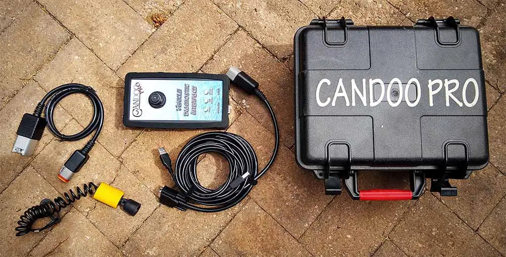
There are two great Sea-doo code readers on the market.
- BRP BUDS / BUDS2 MPI-3 Diagnostic Scanner 4TEC/ETEC for Sea-doo, Ski-doo, Canam, Lynx
- Candoo Pro for all BRP Seadoo model Jetki and Ski-doos.
In the past, you could only get public access to the Candoo Pro code reader. Lately, BRP has made their dealer and technician Seadoo code reader available to the public. They are both slightly pricey but you will save on dealer workshop fees. I can work on my own Sea-doo now and after a few Sea-doo oil changes, my costs are only oil, filters, and spark plugs.
I have the Candoo Pro but my mate has the BRP BUDS2 and they are very similar in features. I even changed my spare learners DESS key and turned it into a full-speed key.
BRP Sea-doo code reader specs
- BRP MPI-3 Interface (main unit, is used for diagnosis of all BRP vehicles)
- Diagnostic Cable (for connection of MPI-3 Interface to 4-TEC/E-TEC vehicles
- BRP B.U.D.S. Diagnostic software with ALL-DEALER license (supports BRP vehicle till 2016)
- BRP B.U.D.S.2 Diagnostic software with DEALER TECHNICIAN license (supports BRP vehicle from 2016 and after)
How to get a list of stored codes from your Sea-doo for 4TEC skis up to 2003
With the engine, off, plug in your lanyard and hit SET 5 times. You will be able to cycle through these codes. You will see a list of codes on the display. If nothing comes up you need a dealer to read the codes.
How to read Sea-doo fault codes on 2004 to 2021 models without a scanner.
- Press the MODE button repetadly untill the Fault Code funtion is displayed on the console.
- Press the SET buttor and the UP/DOWN buttons to cycle through any stores or active fault codes to select them.
- Contrinnue to press the UP/Down buttons to scroll to the next fault code.
- If there is no faults active then the console will display NO ACTIVE FAULT CODES.
- To exit out of the Fault code section press MODE or SET once.
Sea-doo warning lights messages and display meaning
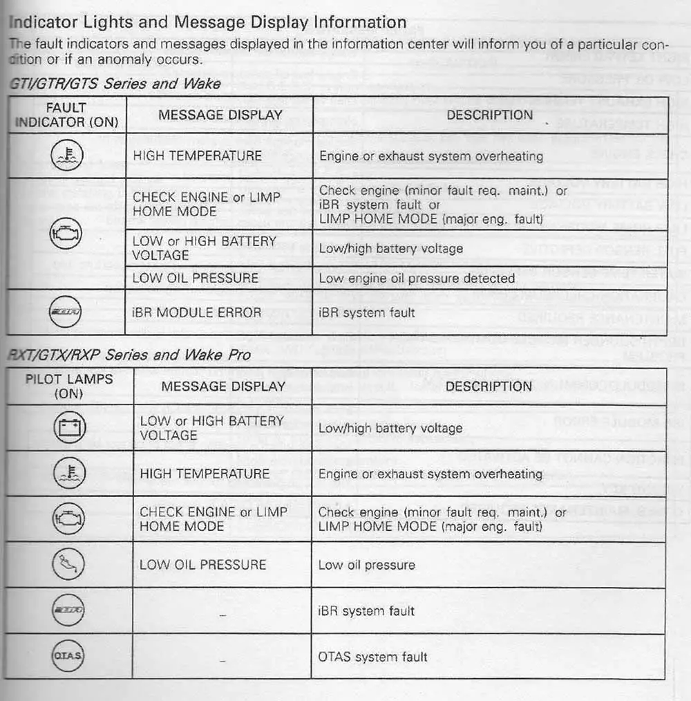
If you see the following pictures pop up on your Sea-doo GTI, GTR, GTS, RXT, GTX, or RXP display you will need to rectify the problem.
- High temperature
- Check Engine or Limp mode
- Low/High battery voltage
- iBR module error
- Low oil pressure
Conclusion
There are over 230 Sea-doo fault codes listed here and even though the solution is basic it will give you a good starting point to repair your Sea-doo jet-ski. Often the fix will be simple such as why your Jetski turns over but won’t start.
These alarm codes give you a very good indication of where to start. Most of the faults that I have come across are because of people not taking care of their Jes-ski. Remember to winterize your Sea-doo so it will be ready for next season.
Let me know in the comments below if I have missed any Sea doo fault codes and I will add them to the list.

I am a qualified Industrial Electrician for the past 20 years and I love to share my knowledge on home repair jobs.
I love fast toys like Motorcycles, Cars, Jetskis, and Boats so writing about them is easy.
To keeps costs down I do all my own mods, repairs, and servicing. These skills I want to share with everyone. DIY is a skill everyone can learn.