Error codes
11 Error codes
Errors in operation
Warnings
Fatal error code
E1 – Fig. 80
Rim dimensions were entered incorrectly, or
incompletely.
When the error code is read out, enter data once
again.
E2 – Fig. 81
Wheel guard is not closed.
E3 – Fig. 82
Distance gauge arm is not in home position.
E5 – Fig. 83
Range of electrical compensation exceeded
(wheel adaptor has unacceptable unbalance).
Press STOP key.
Check wheel adaptor, repeat compensation run.
E6 – Fig. 84
The calibration weight was not fitted for readjustment.
Press STOP key.
Repeat readjustment.
E7 – Fig. 85
With this Vehicle type it is not possible to choose a
balancing mode.
If possible, choose another Vehicle type.
E8 – Fig. 86
Valve position was not entered in electronic unit
(error code only in optimisation or minimisation
programs).
Position valve exactly perpendicular to and above
main shaft and press the OP key.
Operation manual
geodyna 4500-2/p – ZEEWB727B03
–
Error code E
–
Error code H
–
300 or C10
Codes d’erreur
11 Codes d’erreur
Erreur de manipulation –
Remarque
Message d’erreur
E1 – Fig. 80
Entrée incomplète ou fausse des dimensions de
jante.
Quand le code d’erreur est affiché, répéter l’entrée
correctement.
E2 – Fig. 81
Le carter de roue n’est pas fermé.
E3 – Fig. 82
La pige de mesure pour écart n’est pas en position
de repos.
E5 – Fig. 83
La gamme de compensation électrique est dépassée
(balourd inadmissible du moyen de serrage).
Appuyer sur la touche STOP.
Contrôler le moyen de serrage, répéter la lancée
de compensation.
E6 – Fig. 84
La masse d’étalonnage n’a pas été fixée pour
l’étalonnage.
Appuyer sur la touche STOP.
Répéter l’étalonnage.
E7 – Fig. 85
Pour ce type de véhicule, il n’est pas possible de
choisir un mode d’equilibrage.
Si nécessaire, choisir un autre type de véhicule.
E8 – Fig. 86
La position de la valve n’a pas été entrée (code
d’erreur seulement en programmes d’optimisation/
minimisation).
Positionner la valve exactement perpendiculaire
sur et au-dessus de l’arbre principal et appuyer
sur la touche OP.
Mode d’emploi
geodyna 4500-2/p – ZEEWB727B03
Message E
–
Message H
–
300 ou C10
85
- Manuals
- Brands
- Hofmann Manuals
- Wheel Balancers
- geodyna optima
- Additional instructions
-
Contents
-
Table of Contents
-
Bookmarks
Quick Links
geodyna optima
Additional instructions
Wheel balancer
Related Manuals for Hofmann geodyna optima
Summary of Contents for Hofmann geodyna optima
-
Page 1
Additional instructions Wheel balancer… -
Page 3
All Information in this manual has been supplied by the producer of the equipment: Snap-on Equipment GmbH Geschäftsbereich Hofmann Werkstatt-Technik Postfach 1202 D-64311 Pfungstadt Tel. +49 6157 12-482 Fax +49 6157 12-484 E-mail: service @hofmann-ge.com Internet www.hofmann-ge.com geodyna optima… -
Page 4: Table Of Contents
Contents Safety ……………………6 Typographic style ………………….. 6 Scope of application ………………..6 General safety rules ………………..7 Description of function ………………..8 1.4.1 Switching operating modes ………………9 1.4.2 TDI Tread Depth Indication ………………10 1.4.3 Print functions ………………….10 Layout ……………………
-
Page 5: Safety
1.0 Safety All safety information relative to the unit is described in the Safety Manual (fig. 1-1) supplied alongside this operator’s manual. The safety precautions must be completely understood and observed by every operator. We recommend keeping a copy of the Safety Manual next to the unit within easy reach of the operator.
-
Page 6: General Safety Rules
In case of calibration defects there is an internal diagnostic that prompts contacting service. geodyna optima Operator’s Manual…
-
Page 7: Description Of Function
1) radial (on the radius); 2) lateral (on the lateral shift). The geodyna optima balancer also has the TDI (Tread Depth Indication) system, which provides a general indication of tread wear. This function is only active in OPTIMA mode.
-
Page 8: Switching Operating Modes
Keep the F6 key pressed to switch from Profiling to 1.4-3 Optima and vice versa. Note: refer to the geodyna 6800 basic manual for the navigation procedure through the function menus and personal data entry modalities. geodyna optima Operator’s Manual…
-
Page 9: Tdi Tread Depth Indication
1.4.2 TDI Tread Depth Indication When run in OPTIMA mode, the machine always automatically detects the depth of the tread groove at the centre of the tire and over its whole circumference. According to the mean value detected and the limit value set, the program displays one of the following Tread Groove indications on screen (Fig.
-
Page 10
Power Clamp device. Entry of wheel type, balancing mode and wheel size In Profiling and Optima mode the wheel data entry is automatic (see later instructions). For Manual mode functioning see geodyna 6800 basic model instructions. geodyna optima Operator’s Manual… -
Page 11: Layout
Layout The geodyna optima balancer is fitted with a laser scanner (fig. 8-1, details 1, 2 and 3) for the automatic measurement of the wheel data. The internal laser scanner (detail 1) carries out the following measurements: a) detects the internal profile of the rim to identify the optimum position of the weight to apply on the left part or internal part of the rim;…
-
Page 12: Balancing
Operational Selections 9.0 Optima BALANCING The geodyna optima balancer is fitted with 3 laser scanners with integrated CCD that guarantee an accurate detection of the characteristics of any type of wheel. The laser scanners carry out a series of geometric measurements on the rim, the tread, the flange and the profile of the rim and of the whole wheel with a single measuring run of a few seconds.
-
Page 13
Note: The change in the position of the weight is saved by the machine, then automatically suggested for all subsequent wheels with the same dimensions. The selection is deleted when the machine is switched off. F2: the top part of the key is described in the geodyna 6800 basic model instructions. -
Page 14: Wheel Measuring Run In Optima Mode
(ALU or adhesive): the balancer will automatically recalculate the value and position of the corresponding weights. The wheel measuring run may have detected the number of spokes: in this case press F5 to determine the position of the hidden weights. geodyna optima Operator’s Manual…
-
Page 15: Optima Entry Screen
9.2 OPTIMA ENTRY Screen (fig. 9.2-0) Press F6 in the balancing screen to access. The control software automatically displays this screen whenever, at the end of the wheel measuring run, the measuring values exceed the preset limits. The overall wheel (rim + tire) measuring run is displayed. To move the cursor on the wheel graph, rotate the wheel by hand in both directions.
-
Page 16: Warning Messages In Optima Entry Screen
Warning Message (Fig. 9.2.1-2): Possible issue with wheel, but no possibility of improving by matching. Check rim and tire for defects. If matching is recommended: Potential problem on the wheel. Check rim and tire for defects. geodyna optima Operator’s Manual…
-
Page 17
Rim problems messages appear when: 1) rim radial runout is high 2) rim lateral runout is high 3) wheel 1-harmonic runout is high and the proportion of runout between rim and tire is greater than 60 per cent (high rim 1-harmonic runout). -
Page 18: Optima Diagnosis
“Rim radial and lateral runout” section). Rim radial and lateral runout (fig. 9.3-2) The screen page shows the rim radial and lateral runout graphs. 9.3-1 F3: to change from this screen to the previous one. 9.3-2 geodyna optima Operator’s Manual…
-
Page 19: Optima Matching
9.4 OPTIMA MATCHING There are two ways to access the Matching procedure: 1) Manually, • Press F5 in the «OPTIMA ENTRY» screen (fig. 9.4-1) to go to the «Optima Matching» screen (fig. 9.4-2). • From «OPTIMA MATCHING» continue by pressing — F2 Continues the interrupted Matching.
-
Page 20: Geometric Matching With Only The Rim
Right bead recess — Red triangle Mean of the entire rim — Grey triangle When the rim is turned, it will be stopped by the brake in each peak position, to facilitate rim marking. The 9.5-3 geodyna optima Operator’s Manual…
-
Page 21: Behind-The-Spokes Placement
peak markings on the rim can then be suitably combined with the minimum reference present on the tyre. • press F2 for further information about the rim Runout (Fig. 9.5-4). These graphs also show the first harmonic peak markers, combined with the Position Brake. The «RIM ONLY»…
-
Page 22: Optima Parameters
“0” (preset) it doesn’t print, if the value is “1” it prints. m) Allows selection of RIM ONLY advanced diagnosis. Select «1» = Enables RIM ONLY advanced diagnosis and opens the screen shown in fig. 9.6-2. geodyna optima Operator’s Manual…
-
Page 23: Print Report
Select «0» = Enables automatic switching to the MATCHING procedure if the machine detects the presence of the rim only (fig. 9.6-2). m1)Limit (threshold) for RIM ONLY peak to peak radial Runout. Preset value: 0.7 mm. m2)Limit (threshold) for RIM ONLY first harmonic radial Runout.
-
Page 24: Changing Modes Of Operation
Rim (left and right) lateral runout peak to peak values. 9.9-2 w1) Graph of rim left lateral runout (blue curve). x1) Graph of rim right lateral runout (dashed green curve). 10.0 Changing modes of operation See geodyna 6800 basic model instructions. geodyna optima Operator’s Manual…
-
Page 25: Optional Functions
11.0 Optional functions The wheel balancer has additional functions, which can be enabled individually after purchasing the machine. They are enabled by plugging a software key (fig. 11.0- 1) into one of the USB ports on the back of the machine (fig.
-
Page 26: Opti Line Mode
Press F6 to switch on the Set of Wheels procedure. Note: When the «Set of Wheels» procedure is on, the status bar shows the relative icon (Fig. 11.1-1) and key F6 shows the OPTIMA icon again for exiting and returning to OPTIMA mode. geodyna optima Operator’s Manual…
-
Page 27
WHEEL No. 1 • Mount the wheel on the balancer shaft. • Perform the run. The balancer completes the optima program readings, then the rear laser scanner scans the tread to acquire the conicity indices. 11.1-2 Note: The overall cycle time is increased by this operation. -
Page 28
3) Wheel assigned only to right side of vehicle. To continue, • Apply the appropriate identification tag to the wheel valve, with the same number and colour as the last wheel shown (Fig. 11.1-8). 11.1-7 11.1-8 geodyna optima Operator’s Manual… -
Page 29
WHEEL No. 2 • Mount the wheel on the balancer shaft. • Perform the run. • Balance the planes and make any corrections suggested by optima. • Remove the wheel from the balancer. The screen page shows the wheel with the number after the previous one and a different colour (Fig. -
Page 30
Note: No further wheels can be entered in the Set. If you try to enter another wheel the machine starts the procedure for a new Set of Wheels and all of the data relative to the previous Set will be deleted. 11.1-15 geodyna optima Operator’s Manual… -
Page 31
Start a new Set of Wheels After entry of WHEEL No. 5 in a Set, you can start a new Set, without exiting the Set of Wheels mode. Proceed as follows: • Perform the procedure as described for wheel No. 1. The machine deletes the data relative to the previous wheels and shows the current wheel as the first wheel in a new Set. -
Page 32: Pull Calibration
OK appears. If not, error E400 is signalled (see «Error Messages» 11.1.1-3 section). • Remove the calibration tool. Note: For an on-line description of the procedure select the HELP key in the OPTIMA PARAMETERS screen page. geodyna optima Operator’s Manual…
-
Page 33: Error Codes
12.0 Error codes Note: E Prefix = Errors in operation H Prefix = Warnings The error codes are displayed for ca. 3 seconds on the left of the screen above the F1 menu key with an E followed by the numerical code (e.g. E10). Use the HELP key to call up a help text (installed as of version 1.34 of the software).
-
Page 34
Corrective actions: • check the camera controller board • check the connections • re-install the camera controller board software. geodyna optima Operator’s Manual… -
Page 35
E362 Main camera board power on self test failure Possible causes: • there is a fault in the camera controller board • the flat cable connecting the keyboard, the balancer controller board and the camera controller board is partially unplugged or damaged •… -
Page 36
E369 Main shaft encoder zero mark detection failure or missing cable Possible causes: • there is a fault in the camera controller board • there is a fault in the encoder geodyna optima Operator’s Manual… -
Page 37
• the cable connecting the camera controller board and the encoder board is unplugged, missing or damaged Corrective actions: • check the camera controller board • check the encoder • check the connections. E370 Inner CCD signals failure Possible causes: •… -
Page 38
• there is a fault in the inner scanner motor • there is a fault in the camera controller board motor drivers Corrective actions: • check all items above. geodyna optima Operator’s Manual… -
Page 39
E376 Inner motor missing steps Possible causes: • the inner scanner movement is not smooth or it is striking the frame • the motor power supply is not configured properly • there is a fault in the motor power supply board •… -
Page 40
CCD board Corrective actions: • check the connections • check the outer scanner CCD board • switch power off and on again; should the problem not go away please call service. geodyna optima Operator’s Manual… -
Page 41
E383 Outer scanner not calibrated Possible causes: • the outer scanner has not been factory calibrated Corrective actions: • please call service and replace the outer scanner. E384 Outer motor current sink or power supply failure Possible causes: • the cable connecting the camera controller board and the outer scanner motor is unplugged, damaged or missing •… -
Page 42
• there is a fault in the camera controller board laser drivers Corrective actions: • check all items above. geodyna optima Operator’s Manual… -
Page 43
E390 Rear CCD signals failure Possible causes: • the flat cable connecting the camera controller board and the rear scanner CCD board is unplugged, missing or damaged • there is a fault in the rear scanner CCD board • there is a fault in the camera controller board •… -
Page 44
• there is a fault in the rear scanner motor • there is a fault in the camera controller board motor drivers Corrective actions: • check all items above. geodyna optima Operator’s Manual… -
Page 45
E396 Rear motor missing steps Possible causes: • the rear scanner movement is not smooth or it is striking the frame • the motor power supply is not configured properly • there is a fault in the motor power supply board •… -
Page 46
• there is a fault in the rear shift scanner motor • there is a fault in the camera controller board motor drivers. Corrective actions: • check all items above. geodyna optima Operator’s Manual… -
Page 47
E405 Rear shift scanner zero mark not detected Possible causes: • the flat cable connecting the camera controller board and the rear shift scanner CCD board is unplugged, missing or damaged • there is a fault in the rear shift scanner CCD board •… -
Page 48
The distance of the left virtual compensation plane from the reference plane in the measuring system is incorrect. One of the unbalance sensors may have been mounted with inverted polarity. • Check and correct if connection is wrong. geodyna optima Operator’s Manual… -
Page 49: Optimisation / Weight Minimisation
13.0 Optimisation / Weight minimisation See geodyna 6800 basic model instructions (function can only be carried out in Manual mode). 14.0 Readjustment by the operator See geodyna 6800 basic model instructions.
-
Page 50: Maintenance
Only use a clean, dry and soft cloth as shown in figure 16.1-2, so as not to make scratches to the glass surface. In case of oil or grease stains, add an ordinary detergent product for glass. 15.1-2 geodyna optima Operator’s Manual…
-
Page 51: Technical Data
16.0 Technical data Power supply (v): 230 volt 1 Ph 50-60 hertz Series of concentric cones: 3 cones 43 — 115 mm Shaft length: 7.5 “ 190 mm Shaft diameter: 1.57 “ 40 mm Measuring speed: 200 rpm Balancing precision: 0.035 ounces 1 gr Scanning device precision: 0,039″…
-
Page 52: Accessories
FUNCTION screen. The operation of the geodyna optima depends a lot on the power clamp in order to have the information addressed to the software during some procedures. In…
-
Page 53: Tapered Ring
17.6 Tapered ring A centring cone with a 5° taper, to achieve a higher degree of wheel centring precision when fitting the wheel on the balancer. 17.7 Wheel weight removal tool Special tool in wear resistant plastic material, essential for the removal of adhesive weights from alloy wheels. Ensures that the rim surfaces are not damaged.
-
Page 54: Printer Installation Instructions (Optional)
18.0 Mise en place de la Imprimante (disponible en option) Printer Installation Instructions (optional) (8×20) (Ø 8) (6×20) (Ø 6) MONITOR VELCRO geodyna optima — Operator’s Manual / Manuel d’Utilisation…
-
Page 55
Note page Note La página de la nota geodyna optima — Operator’s Manual / Manuel d’Utilisation… -
Page 56
Electrical diagram… -
Page 57
Electrical diagram… -
Page 58
Electrical diagram… -
Page 59
Electrical diagram… -
Page 60
Note page MODIFIED / CHANGED PARTS Regarding Revision 02.05 (B) List of new chapter from this revision: At page 16-17 1.4.2 TDI Tread Dept Indication At page 16-17 1.4.3 Print functions At page 28-29 9.2.1 Warning Messages in Optima Entry Screen MODIFIED / CHANGED PARTS Regarding Revision 07.05 (C) List of new chapter from this revision: Information added:… -
Page 61
Note page… -
Page 62
„Scope of application” of this operation manual, or if any modifications or changes whatsoever are made to the machine without prior approval from our end. ppa. Hans-J. Rupp Director Sales & Service ZEEWB716B01 12.06 cullum ENG geodyna optima.. copyright 2006 Snap-on Equipment All rights reserved…
- Manuals
- Brands
- Hofmann Manuals
- Wheel Balancers
- geodyna optima
- Additional instructions
-
Contents
-
Table of Contents
-
Bookmarks
Quick Links
geodyna optima
Additional instructions
Wheel balancer
Related Manuals for Hofmann geodyna optima
Summary of Contents for Hofmann geodyna optima
-
Page 1
Additional instructions Wheel balancer… -
Page 3
All Information in this manual has been supplied by the producer of the equipment: Snap-on Equipment GmbH Geschäftsbereich Hofmann Werkstatt-Technik Postfach 1202 D-64311 Pfungstadt Tel. +49 6157 12-482 Fax +49 6157 12-484 E-mail: service @hofmann-ge.com Internet www.hofmann-ge.com geodyna optima… -
Page 4: Table Of Contents
Contents Safety ……………………6 Typographic style ………………….. 6 Scope of application ………………..6 General safety rules ………………..7 Description of function ………………..8 1.4.1 Switching operating modes ………………9 1.4.2 TDI Tread Depth Indication ………………10 1.4.3 Print functions ………………….10 Layout ……………………
-
Page 5: Safety
1.0 Safety All safety information relative to the unit is described in the Safety Manual (fig. 1-1) supplied alongside this operator’s manual. The safety precautions must be completely understood and observed by every operator. We recommend keeping a copy of the Safety Manual next to the unit within easy reach of the operator.
-
Page 6: General Safety Rules
In case of calibration defects there is an internal diagnostic that prompts contacting service. geodyna optima Operator’s Manual…
-
Page 7: Description Of Function
1) radial (on the radius); 2) lateral (on the lateral shift). The geodyna optima balancer also has the TDI (Tread Depth Indication) system, which provides a general indication of tread wear. This function is only active in OPTIMA mode.
-
Page 8: Switching Operating Modes
Keep the F6 key pressed to switch from Profiling to 1.4-3 Optima and vice versa. Note: refer to the geodyna 6800 basic manual for the navigation procedure through the function menus and personal data entry modalities. geodyna optima Operator’s Manual…
-
Page 9: Tdi Tread Depth Indication
1.4.2 TDI Tread Depth Indication When run in OPTIMA mode, the machine always automatically detects the depth of the tread groove at the centre of the tire and over its whole circumference. According to the mean value detected and the limit value set, the program displays one of the following Tread Groove indications on screen (Fig.
-
Page 10
Power Clamp device. Entry of wheel type, balancing mode and wheel size In Profiling and Optima mode the wheel data entry is automatic (see later instructions). For Manual mode functioning see geodyna 6800 basic model instructions. geodyna optima Operator’s Manual… -
Page 11: Layout
Layout The geodyna optima balancer is fitted with a laser scanner (fig. 8-1, details 1, 2 and 3) for the automatic measurement of the wheel data. The internal laser scanner (detail 1) carries out the following measurements: a) detects the internal profile of the rim to identify the optimum position of the weight to apply on the left part or internal part of the rim;…
-
Page 12: Balancing
Operational Selections 9.0 Optima BALANCING The geodyna optima balancer is fitted with 3 laser scanners with integrated CCD that guarantee an accurate detection of the characteristics of any type of wheel. The laser scanners carry out a series of geometric measurements on the rim, the tread, the flange and the profile of the rim and of the whole wheel with a single measuring run of a few seconds.
-
Page 13
Note: The change in the position of the weight is saved by the machine, then automatically suggested for all subsequent wheels with the same dimensions. The selection is deleted when the machine is switched off. F2: the top part of the key is described in the geodyna 6800 basic model instructions. -
Page 14: Wheel Measuring Run In Optima Mode
(ALU or adhesive): the balancer will automatically recalculate the value and position of the corresponding weights. The wheel measuring run may have detected the number of spokes: in this case press F5 to determine the position of the hidden weights. geodyna optima Operator’s Manual…
-
Page 15: Optima Entry Screen
9.2 OPTIMA ENTRY Screen (fig. 9.2-0) Press F6 in the balancing screen to access. The control software automatically displays this screen whenever, at the end of the wheel measuring run, the measuring values exceed the preset limits. The overall wheel (rim + tire) measuring run is displayed. To move the cursor on the wheel graph, rotate the wheel by hand in both directions.
-
Page 16: Warning Messages In Optima Entry Screen
Warning Message (Fig. 9.2.1-2): Possible issue with wheel, but no possibility of improving by matching. Check rim and tire for defects. If matching is recommended: Potential problem on the wheel. Check rim and tire for defects. geodyna optima Operator’s Manual…
-
Page 17
Rim problems messages appear when: 1) rim radial runout is high 2) rim lateral runout is high 3) wheel 1-harmonic runout is high and the proportion of runout between rim and tire is greater than 60 per cent (high rim 1-harmonic runout). -
Page 18: Optima Diagnosis
“Rim radial and lateral runout” section). Rim radial and lateral runout (fig. 9.3-2) The screen page shows the rim radial and lateral runout graphs. 9.3-1 F3: to change from this screen to the previous one. 9.3-2 geodyna optima Operator’s Manual…
-
Page 19: Optima Matching
9.4 OPTIMA MATCHING There are two ways to access the Matching procedure: 1) Manually, • Press F5 in the «OPTIMA ENTRY» screen (fig. 9.4-1) to go to the «Optima Matching» screen (fig. 9.4-2). • From «OPTIMA MATCHING» continue by pressing — F2 Continues the interrupted Matching.
-
Page 20: Geometric Matching With Only The Rim
Right bead recess — Red triangle Mean of the entire rim — Grey triangle When the rim is turned, it will be stopped by the brake in each peak position, to facilitate rim marking. The 9.5-3 geodyna optima Operator’s Manual…
-
Page 21: Behind-The-Spokes Placement
peak markings on the rim can then be suitably combined with the minimum reference present on the tyre. • press F2 for further information about the rim Runout (Fig. 9.5-4). These graphs also show the first harmonic peak markers, combined with the Position Brake. The «RIM ONLY»…
-
Page 22: Optima Parameters
“0” (preset) it doesn’t print, if the value is “1” it prints. m) Allows selection of RIM ONLY advanced diagnosis. Select «1» = Enables RIM ONLY advanced diagnosis and opens the screen shown in fig. 9.6-2. geodyna optima Operator’s Manual…
-
Page 23: Print Report
Select «0» = Enables automatic switching to the MATCHING procedure if the machine detects the presence of the rim only (fig. 9.6-2). m1)Limit (threshold) for RIM ONLY peak to peak radial Runout. Preset value: 0.7 mm. m2)Limit (threshold) for RIM ONLY first harmonic radial Runout.
-
Page 24: Changing Modes Of Operation
Rim (left and right) lateral runout peak to peak values. 9.9-2 w1) Graph of rim left lateral runout (blue curve). x1) Graph of rim right lateral runout (dashed green curve). 10.0 Changing modes of operation See geodyna 6800 basic model instructions. geodyna optima Operator’s Manual…
-
Page 25: Optional Functions
11.0 Optional functions The wheel balancer has additional functions, which can be enabled individually after purchasing the machine. They are enabled by plugging a software key (fig. 11.0- 1) into one of the USB ports on the back of the machine (fig.
-
Page 26: Opti Line Mode
Press F6 to switch on the Set of Wheels procedure. Note: When the «Set of Wheels» procedure is on, the status bar shows the relative icon (Fig. 11.1-1) and key F6 shows the OPTIMA icon again for exiting and returning to OPTIMA mode. geodyna optima Operator’s Manual…
-
Page 27
WHEEL No. 1 • Mount the wheel on the balancer shaft. • Perform the run. The balancer completes the optima program readings, then the rear laser scanner scans the tread to acquire the conicity indices. 11.1-2 Note: The overall cycle time is increased by this operation. -
Page 28
3) Wheel assigned only to right side of vehicle. To continue, • Apply the appropriate identification tag to the wheel valve, with the same number and colour as the last wheel shown (Fig. 11.1-8). 11.1-7 11.1-8 geodyna optima Operator’s Manual… -
Page 29
WHEEL No. 2 • Mount the wheel on the balancer shaft. • Perform the run. • Balance the planes and make any corrections suggested by optima. • Remove the wheel from the balancer. The screen page shows the wheel with the number after the previous one and a different colour (Fig. -
Page 30
Note: No further wheels can be entered in the Set. If you try to enter another wheel the machine starts the procedure for a new Set of Wheels and all of the data relative to the previous Set will be deleted. 11.1-15 geodyna optima Operator’s Manual… -
Page 31
Start a new Set of Wheels After entry of WHEEL No. 5 in a Set, you can start a new Set, without exiting the Set of Wheels mode. Proceed as follows: • Perform the procedure as described for wheel No. 1. The machine deletes the data relative to the previous wheels and shows the current wheel as the first wheel in a new Set. -
Page 32: Pull Calibration
OK appears. If not, error E400 is signalled (see «Error Messages» 11.1.1-3 section). • Remove the calibration tool. Note: For an on-line description of the procedure select the HELP key in the OPTIMA PARAMETERS screen page. geodyna optima Operator’s Manual…
-
Page 33: Error Codes
12.0 Error codes Note: E Prefix = Errors in operation H Prefix = Warnings The error codes are displayed for ca. 3 seconds on the left of the screen above the F1 menu key with an E followed by the numerical code (e.g. E10). Use the HELP key to call up a help text (installed as of version 1.34 of the software).
-
Page 34
Corrective actions: • check the camera controller board • check the connections • re-install the camera controller board software. geodyna optima Operator’s Manual… -
Page 35
E362 Main camera board power on self test failure Possible causes: • there is a fault in the camera controller board • the flat cable connecting the keyboard, the balancer controller board and the camera controller board is partially unplugged or damaged •… -
Page 36
E369 Main shaft encoder zero mark detection failure or missing cable Possible causes: • there is a fault in the camera controller board • there is a fault in the encoder geodyna optima Operator’s Manual… -
Page 37
• the cable connecting the camera controller board and the encoder board is unplugged, missing or damaged Corrective actions: • check the camera controller board • check the encoder • check the connections. E370 Inner CCD signals failure Possible causes: •… -
Page 38
• there is a fault in the inner scanner motor • there is a fault in the camera controller board motor drivers Corrective actions: • check all items above. geodyna optima Operator’s Manual… -
Page 39
E376 Inner motor missing steps Possible causes: • the inner scanner movement is not smooth or it is striking the frame • the motor power supply is not configured properly • there is a fault in the motor power supply board •… -
Page 40
CCD board Corrective actions: • check the connections • check the outer scanner CCD board • switch power off and on again; should the problem not go away please call service. geodyna optima Operator’s Manual… -
Page 41
E383 Outer scanner not calibrated Possible causes: • the outer scanner has not been factory calibrated Corrective actions: • please call service and replace the outer scanner. E384 Outer motor current sink or power supply failure Possible causes: • the cable connecting the camera controller board and the outer scanner motor is unplugged, damaged or missing •… -
Page 42
• there is a fault in the camera controller board laser drivers Corrective actions: • check all items above. geodyna optima Operator’s Manual… -
Page 43
E390 Rear CCD signals failure Possible causes: • the flat cable connecting the camera controller board and the rear scanner CCD board is unplugged, missing or damaged • there is a fault in the rear scanner CCD board • there is a fault in the camera controller board •… -
Page 44
• there is a fault in the rear scanner motor • there is a fault in the camera controller board motor drivers Corrective actions: • check all items above. geodyna optima Operator’s Manual… -
Page 45
E396 Rear motor missing steps Possible causes: • the rear scanner movement is not smooth or it is striking the frame • the motor power supply is not configured properly • there is a fault in the motor power supply board •… -
Page 46
• there is a fault in the rear shift scanner motor • there is a fault in the camera controller board motor drivers. Corrective actions: • check all items above. geodyna optima Operator’s Manual… -
Page 47
E405 Rear shift scanner zero mark not detected Possible causes: • the flat cable connecting the camera controller board and the rear shift scanner CCD board is unplugged, missing or damaged • there is a fault in the rear shift scanner CCD board •… -
Page 48
The distance of the left virtual compensation plane from the reference plane in the measuring system is incorrect. One of the unbalance sensors may have been mounted with inverted polarity. • Check and correct if connection is wrong. geodyna optima Operator’s Manual… -
Page 49: Optimisation / Weight Minimisation
13.0 Optimisation / Weight minimisation See geodyna 6800 basic model instructions (function can only be carried out in Manual mode). 14.0 Readjustment by the operator See geodyna 6800 basic model instructions.
-
Page 50: Maintenance
Only use a clean, dry and soft cloth as shown in figure 16.1-2, so as not to make scratches to the glass surface. In case of oil or grease stains, add an ordinary detergent product for glass. 15.1-2 geodyna optima Operator’s Manual…
-
Page 51: Technical Data
16.0 Technical data Power supply (v): 230 volt 1 Ph 50-60 hertz Series of concentric cones: 3 cones 43 — 115 mm Shaft length: 7.5 “ 190 mm Shaft diameter: 1.57 “ 40 mm Measuring speed: 200 rpm Balancing precision: 0.035 ounces 1 gr Scanning device precision: 0,039″…
-
Page 52: Accessories
FUNCTION screen. The operation of the geodyna optima depends a lot on the power clamp in order to have the information addressed to the software during some procedures. In…
-
Page 53: Tapered Ring
17.6 Tapered ring A centring cone with a 5° taper, to achieve a higher degree of wheel centring precision when fitting the wheel on the balancer. 17.7 Wheel weight removal tool Special tool in wear resistant plastic material, essential for the removal of adhesive weights from alloy wheels. Ensures that the rim surfaces are not damaged.
-
Page 54: Printer Installation Instructions (Optional)
18.0 Mise en place de la Imprimante (disponible en option) Printer Installation Instructions (optional) (8×20) (Ø 8) (6×20) (Ø 6) MONITOR VELCRO geodyna optima — Operator’s Manual / Manuel d’Utilisation…
-
Page 55
Note page Note La página de la nota geodyna optima — Operator’s Manual / Manuel d’Utilisation… -
Page 56
Electrical diagram… -
Page 57
Electrical diagram… -
Page 58
Electrical diagram… -
Page 59
Electrical diagram… -
Page 60
Note page MODIFIED / CHANGED PARTS Regarding Revision 02.05 (B) List of new chapter from this revision: At page 16-17 1.4.2 TDI Tread Dept Indication At page 16-17 1.4.3 Print functions At page 28-29 9.2.1 Warning Messages in Optima Entry Screen MODIFIED / CHANGED PARTS Regarding Revision 07.05 (C) List of new chapter from this revision: Information added:… -
Page 61
Note page… -
Page 62
„Scope of application” of this operation manual, or if any modifications or changes whatsoever are made to the machine without prior approval from our end. ppa. Hans-J. Rupp Director Sales & Service ZEEWB716B01 12.06 cullum ENG geodyna optima.. copyright 2006 Snap-on Equipment All rights reserved…
Балансировочный стенд Hofmann Geodyna 4500-2 со встроенным ЖК-дисплеем для небольших мастерских и СТО с малым и средним объемом работ. Автоматическим вводом расстояния от стенда до колеса, диаметром обода и ширины обода (3D SAPE), а также автоматическим
вводом места установки грузов в режиме easyALU.
Обслуживаемая техника:
Легковые, лёгкие грузовые, микроавтобусы, внедорожники, мотоциклы (требуются адаптеры).
- Виртуальные плоскости измерений (техника VPM, патент)
- Автоматический ввод расстояния от колеса до станка, ширины и диаметра обода (3 D)
- Обзорный ЖК дисплей
- Автоматический предварительный выбор положения грузов (режим «easy ALU»)
- Программа установки грузов за спицами
- Программа для РАХ-колес
- Автоматическое торможение колеса после измерения
- Педальный стопорный тормоз
- Программа оптимизации плавности хода (патент)
- Измерительный рычаг с зажимом для грузов и устройством позиционирования грузов (патент)
- Удобная крышка с ячейками для грузов
- 4 профиля оператора
Цветовой вариант исполнения:
Патенты реализованные в балансировочном станке.
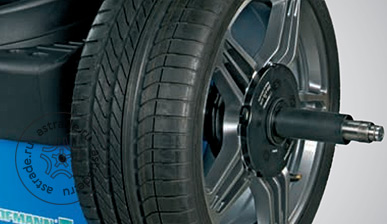
Power clamp
Электромеханический зажим Power СlampTM (патент) зажимает колесо аккуратно и с постоянной силой, обеспечивая точность определения массы груза.
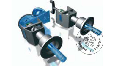
Техника измерений VPM
Все станки оснащены системой виртуальных плоскостей измерений (патент). Система обеспечивает большую точность балансировки и устойчива к внешним воздействиям.
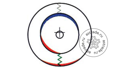
Оптимизация плавности хода
Эта функция позволяет компенсировать возможную ошибку формы обода определением положения тяжелого места шины перед тем, как выполняется обычная операция устранения дисбаланса.
Технические характеристики
| Частота вращения | 200 об/м |
| Ширина обода | 1-20 дюймов |
| Диаметр обода | 8-25 дюймов авт. / 8-30 дюймов ручн. |
| Отображение данных | ЖК-дисплей |
| Зажим колеса | Быстрозажимная гайка |
| Макс.ширина колеса | 530 мм |
| Макс.диаметр колеса | 950 мм |
| Макс.масса колеса, кг | 70 |
| Ввод размеров | Автоматический |
| Электропитание | 230 В, 1 фазн. 50 Гц |
| Габаритные размеры | 1285 x 1130 x 1765 мм |
| Масса | 130 кг |
Видео


Доставка в г. Москва через транспортные компании подробнее »

Балансировочный стенд Hofmann Geodyna 4500-2p для профессиональной балансировки колес легковых и небольших грузовых автомобилей, весом до 70 кг и диаметром не более 950 мм. Используется в шиномонтажных центрах, станциях технического обслуживания и на автозаправочных станциях.
Программа оптимизации плавности хода (патент), позволяющая компенсировать возможную ошибку формы обвода определением положения тяжелого места шины перед тем, как выполняется обычная операция устранения дисбаланса (HOS).
Программа минимизации массы груза. Программы для установки грузов за спицами внутри ободьев из легких сплавов. Программа балансировки PAX колес. Программа HSP скрытой установеи клеевых грузов за спицами внутри ободьев из легких сплавов.
Техника измерения повышенной точности VPM — виртуальные плоскости измерения (патент) — сверхточный балансировочный узел с повышенной устойчивостью к внешним воздействиям.
Измерительный рычаг с зажимом для грузов и системой позиционирования ALU (патент), обеспечивающий поиск выбранной оператором плоскости.
Дисбаланс для обеих плоскостей балансировки индицируется раздельно в двух окнах. Точная установка на выбранное место груза, закрепленного в зажиме устройства. Небольшая частота вращения диагностируемого колеса, обеспечивающая безопасность работы. Электропривод и клиноременная передача, обеспечивающие постоянную частоту вращения при измерении.
Конструктивные особенности:
- Усиленная стальная конструкция;
- Большой ЖК-монитор;
- Простота управления благодаря автоматическому вводу расстояния и диаметра обода (2D SAPE);
- Ручной ввод ширины обода;
- Приводной двигатель;
- Ввод дополнительных параметров вращением колеса при нажатой клавише (патент);
- Различные профили операторов с функцией сохранение данных;
- Сохранение «профилей» пользователя;
- Стопорный педальный тормоз колеса;
- Автоматическое торможение колеса после проведения диагностики;
- Большой защитный кожух колеса в комплекте;
- Удобный стол с ячейками для конусов, грузов и инструмента;
- Широкий ассортимент дополнительных опций;
- Электромеханическое зажимное устройство power clamp.
Комплектация:
- Устройство зажима колеса на балансировочном валу MZV-4 с быстрозажимной гайкой;
- Проставочное кольцо: 20 мм;
- Кронциркуль: 1 шт;
- Балансировочные клещи для снятия и установки грузиков: 1 шт;
- Руководство по эксплуатации: 1 шт.
Производитель: Hofmann, Германия
Модель: Geodyna 4500-2p
Технические характеристики:
|
Диаметр диска, дюймы |
8-25 |
|
Ширина диска, дюймы |
1-20 |
|
Максимальный диаметр колеса, мм |
950 |
|
Максимальная масса колеса, кг |
70 |
|
Диаметр центрального отверстия диска, мм |
43-116 |
|
Диаметр вала, мм |
40 |
|
Частота вращения вала, об/мин |
200 |
|
Электропитание |
1 ф., 220В, 50 Гц |
|
Масса, кг |
70 |
|
Габаритные размеры, мм |
1265×1130×1765 |
|
Вес, кг |
130/135 |
- Каталог — Балансировочные станки (стенды) для легковых автомобилей
- Прайс-лист на Балансировочные станки (стенды) для легковых автомобилей
- Прайс-лист на оборудование HOFMANN
Балансировочный стенд Hofmann Geodyna 4500-2p в наличии и под заказ в Москве с возможностью купить в кредит и лизинг. Каталог, технические характеристики, фото, видео, инструкция по эксплуатации и отзывы клиентов помогут выбрать оборудование под ваши задачи. Чтобы оформить заказ на сайте нажмите в карточке товар на кнопку «В корзину» или позвоните нам по бесплатному телефону 8-804-333-33-48.
Компания «Трейдимпорт» специализируется на поставках профессионального оборудования и инструмента. Наши специалисты помогут подобрать качественное и надежное оборудование и инструмент в соответствии с вашими требованиями. Компания «Трейдимпорт», является официальным дилером ведущих компаний производителей, поэтому на все товары действует гарантия до 36 месяцев.
На некоторое оборудование и инструмент действует система скидок, поэтому вы можете приобрести товар по выгодной цене.
Закажите обратный звонок и наш менеджер позвонит и проконсультирует по любым вопросам. Купите Балансировочный стенд Hofmann Geodyna 4500-2p за 256 885 руб. — хороший товар, выгодная цена. Товар имеет все необходимые сертификаты и инструкции. Доставку в г. Москва мы осуществляем транспортными компаниями ПЭК, Деловые линии, Ратэк, СДЭК и другими.
Время работы:
- с 9-00 до 18-00 по Москве с понедельника по пятницу
- Сб — Вс с 10-00 до 17-00
- Приём заявок круглосуточно в любой день.
Компания Трейдимпорт предлагает взять Балансировочный стенд Hofmann Geodyna 4500-2p в кредит или лизинг на выгодных для вас условиях. Цена может быть ниже указанной на сайте для торгующих организаций и при покупке оптом.

- Задать вопрос
- Отзывы
Вы можете задать любой интересующий вас вопрос по товару или работе магазина.
Наши квалифицированные специалисты обязательно вам помогут.
Отзывов пока никто не оставил. Вы будете первым.

ОФИЦИАЛЬНЫЙ ДИЛЕР
HOFMANN и JOHN BEAN
В РОССИИ


ВАША КОРЗИНА
корзина пуста

Балансировочный станок (стенд) Hofmann Geodyna 4500-2, арт. 6028752
- Простота управления благодаря автоматическому вводу расстояния от обода до станка и диаметру обода (2D SAPE)
- Ширина обода вводится вращением колеса при нажатой функциональной клавише (патент).
- С помощью измерительного рычага оператор устанавливает груз в плоскости балансировки (программа ALU2P и ALU3P).
- Программа (HSP) скрытной установки клеевых грузов за спицами внутри ободьев литых дисков
- Зажим для установки клеевых грузов
- Программа оптимизации плавности хода.
- Программа для PAX-колес
- Дисбаланс для обеих плоскостей балансировки указываетя раздельно в двух окнах.
- Программа минимизации массы груза
- Автоматический выбор плоскости размещения груза для литых дисков
- Педальный стопорный тормоз
- Сохранение данных для 4-х различных профилей пользователя
- Измерение запускается при нажатии кнопки ПУСК или при опускании защитного кожуха колеса
- Электропривод и клиноременная передача обеспечивают постоянную частоту вращения при измерении.
- Автоматическая остановка колеса после измерения
- Станок можно дооснастить зажимным устройством для колес мотоциклов.

4 223 €
Технические данные:
| Артикул: |
6028752 |
| диаметр диска: |
8-25″ |
| ширина диска: |
1-20″ |
| диаметр диска ручной ввод: |
8-30″ |
| ширина диска ручной ввод: |
1-20″ |
| макс. диаметр колеса: |
950 мм |
| ширина колеса: |
до 530 мм |
| макс. масса колеса: |
70 кг |
| тип зажима: |
быстросъемная гайка |
| защитный кожух: |
стандартный |
| дисплей: |
ЖКИ, встроенный в крышку |
| ввод диаметра и расстояния: |
автомат, рычаг |
| ввод ширины: |
автолинейка |
| установка грузиков за спицами: |
+ |
| программа минимизации: |
+ |
| программа оптимизации: |
+ |
| стопорный тормоз: |
механический |
| самокалибровка: |
+ |
| запуск цикла: |
автоматический |
| частота вращения колеса: |
< 200 об/мин |
| точность балансировки: |
1 г |
| диаметр вала: |
40 мм |
| длина: |
1265 мм |
| ширина: |
1130 мм |
| высота: |
1765 мм |
| электропитание: |
220 В, 1 ф, 50 Гц |
| масса: |
130 кг |