Добрый день форумчанам! Чувствую что меня скоро забанят наверное за частые вопросы, но все же нужна ваша помощь. Сегодня утром пришел на работу, сделал утренний тест, вышел с оттенками красного (из прошлых опытов знаю что это красный АОМ), решил поменять местами ближний и средний АОМы тест вышел бирюзовым, но до черного, в итоге машина настроилась (через пару минут полз в зеленый), соответственно зная что на том месте стоит АОМ с красного цвета, сделал вывод что это таки АОМ. Но думаю пока еще чуть держит цвет по быстрому отпечатать 1 заказ (60 штук), утром успел взять срочку. Отпечатал заказ 10 на 15, вышел немного желтовато-зеленоватым, но фотки с мообильного телефона так что в целом подоли, заменил бумагу для печати 20 на 30, запустил фотку на печать машина отрезала бумагу и выскочила ошибка 6073 Synchronous sensor error (без дополнительных индексов), лист вышел белым, а лазер начал нагрев (5минут). После нагрева решил запустить еще раз 20 на 30, вышло также более менее нормально как и весь заказ. Через 2 минуты запустил еще 1-ну 20 на 30 она вышла фиолетовым оттенком, запустил дейли сетап вышел в зеленом оттенке с поолосками. Все изобюражения прилагаю. Реши сделать фото, все по порядку, утренняя настройка 1-й тест, затем 2 теста после смены ближнего и среднего АОМов, затем фото после ошибки (но второе, первое вышло нормальным), и затем тест после отпечатка в фиолетовом цвете. На фото в фиолетовом цвете есть пару тонких желтых полосок. они увеличены на 2-м фото.
Here is not original laser driver. It is made in China.
Original laser driver has not any paper stickers. You have sticker with text in Chinese.
Original driver has CN4. Your driver doesn’t have it.
Above holes with screws should be black stamp with laser driver serial number. You do not have it.
Above transistor pins should be black stamp with date, when laser driver was made. It is missing on your driver.
Beside power supply should be black stamp with rhombus and letter «I» inside it. Have not it also.
A little higher should be black stamp with rhombus and some Japanese text inside it. It is not on your driver.
Original driver pcb has part number J391231-00. Your driver J391231-01.
J391231-00 pcb should be marked TP-30553E-RoHS. Your board is marked TP-30553D. They copied text from older laser driver — J390929-01.
Doesn’t matter, where 0.1 resistor is soldered — on position R54, or R55. These positions are connected. On original driver resistor always mounted on position R54. On Chinese resistor sometimes mounted on position R55.
If your laser driver is not original then laser head will be not original also. That is the reason why it works at very low current ( 73 mA ) .
Yes, on your picture original head and head made in China.
Laser test is only for original laser, which can start properly. You have laser head made in China. Your laser head sometimes doesn’t start ( you told, that saw 0 mV on resistor ) . Take two multimeters. If G laser is ON, between laser driver CN3 pin 2 and ground you see about 0 V , but on resistor R54 will be 0 V then need replace laser head, laser driver, or both of them. Laser head is not original. Only laser head maker can comment what should be there and why it sometimes doesn’t start.
Probable Cause 1: Faulty AOM driver.
Probable Cause 2: Faulty AOM crystal.
Probable Cause 3: Damaged coaxial cable between AOM driver and AOM crystal.
Probable Cause 4: Damaged cable between Laser control PCB and AOM driver.
Probable Cause 5: Poor contact of synchro-sensor inside the laser unit.
Probable Cause 6: Faulty synchro-sensor inside the laser unit.
Probable Cause 7: Faulty laser module.
Probable Cause 8: Faulty laser driver.
Probable Cause 9: Misplaced AOM Drivers’ BNC connectors.
In other words:
The sync signal is not received within the specified time period at the sync sensor PCB detector. Over time, the light from the laser diode becomes dimmer: eventually, the laser beam becomes not bright enough for the synchronous sensor to reliably detect it, which causes the 6073 # error message.
The purpose of AOM is to make the laser beam diffract (onto the print) by injecting sound waves of different frequencies. Usually, the blue laser module fails first, then the green one, and then the red one.
If the output sensor does not detect the laser beam, this error will be generated.
To rule out the worst, do the following – determine the cause of this error.
On the qss30 series:
If you have suffix 0001 – you need to check the red AOM (R) driver.
If you have suffix 0002, you need to check the green AOM (G) driver.
If you have suffix 0003 – you need to check the blue AOM (B) driver.
Replace it with the following AOM driver and run the lab.
If the error code changed, the problem was there.
A more detailed description of the exchange procedure can be found here.
Note 1:
The QSS 31/32/33 series does not have a suffix at the end of the error code.
Note 2:
Only the AOM drivers need to be changed, not the wires!
Note 3:
Sometimes you may have multiple AOM drivers faulty at the same time.
If the error persists, the following suspicious parts are:
– AOM crystal (inside the laser unit). In this case, laser repair will be required.
– Laser input/output of the PCB.
– Laser control board
Also:
– Disconnect and reconnect all connectors to all laser printed circuit boards.
– Check all test points for incorrect voltage.
– Check the quality of all connections of each AOM driver. No result – move on. Double-check if the AOM driver is connected properly.
For example, if an engineer swaps the BNC connector of the blue AOM driver for the green AOM driver, they can spend a lot of time searching for the cause of error 6073. It is recommended that all cables be tagged before replacing them.
– Check the power supply of the laser driver. If the power supply is normal, but the error persists, send us the laser unit.
– Check the quality and condition of the cables mentioned above …
We recommend using the Laser Self-Diagnosis Utility to understand the status of the entire circuit:
AOM driver + AOM crystal + laser module.
You can download it here.
Be sure to download and read the installation guide for this software.
Resume: Laser repair is required (if AOM driver works well)


Новости:
Ты можешь поставить плюсик в карму юзеру, если его пост или комментарий тебе понравился. Но материальная помощь лучше 🙂
Просмотр сообщений
В этом разделе можно просмотреть все сообщения, сделанные этим пользователем.
Темы — maxitol
Минилабы Noritsu / Noritsu qss-3001, БП системного блока.
Минилабы Noritsu / Noritsu QSS-3001, проблемы с лазерной частью.
Добрый день.
Имеется Noritsu QSS-3001, тип лазера А.
Три дня назад пошли ошибки по лазеру.
Выскакивают сразу по три.
при включении появляются: 6073-0001, 6075-0004, 6074-0004.
после того как их сбросишь, лазер греется пару минут, и появляются в такой комбинации: 6073-0002, 6075-0004, 6074-0004,
и дальше после сброса опять прогрев лазера с минуту, и опять 6073-0002, 6075-0004, 6074-0004.
Т.е. при включении сперва ошибка синхронизации на красный (6073-0001), а ошибки B и G лазер-контрол на синий и зеленый(6075-0004, 6074-0004),
а после первого сброса, ошибка синхронизации уже на зеленый (6073-0002), а лазер-контрол остаются прежними (6075-0004, 6074-0004).
И дальше сколько не сбрасывай, 6075-0004, 6074-0004 идут в сочетании с 6073-0002.
Менял местами АОМы зеленый с красным, и синий с зеленым — ситуация никак не меняется.
Каков приговор? Лазер опять сдох? Какой именно? И почему сразу после загрузки ошибка синхронизации на красный, а после сброса, все время на зеленый?
Минилабы Noritsu / QSS-3001 — не удается провести зигзагинг.
Еще раз всем доброго времени суток. Помогите пожалуйста дельными советами:
1. Для начала вопрос к специалистам:
Есть ли какая-нибудь методология, как правильно натягивать ремешки, которые приводят в движение лапку, подающую отпечаток от ножа к юниту экспозиции? А то провисли со временем, причем неравномерно, перетянуть боязно, и недотяг, я так понимаю, тоже не есть хорошо. Пока натянули «на глазок», но хотелось бы «по науке»  .
.
2. Собственно сама проблема:
При отправке на печать, тестового отпечатка для зигзагинга, машина подает бумагу, отпечаток заходит в юнит экспозиции, она его обрезает, пару секунд думает, и выдает
6017-0004 — Paper has jammed in the printer section. Причем тестовый отпечаток, если я правильно помню, должен быть ощутимо длинее, чем тот, который остается застрявшим в машине.
Аналогичная ситуация при попытке печати панорамных снимков.
Проблема с невозможностью печатать панораму, по словам хозяина машины, всплыла еще как минимум 2 года назад, но поскольку без панорамы можно было легко обойтись, на ней просто поставили крест и забыли, а вот теперь при попытке провести зигзагинг, проблема вновь всплыла.
Т.е. фактически машина почему-то не способна печатать длинные отпечатки, и соответственно невозможно провести зигзагинг.
Может есть у кого, какие-нибудь идеи по этому поводу?
Минилабы Noritsu / QSS-3001 — Printer system error 6056-0026
Минилабы Noritsu / QSS-3001 — нож не дорезает 20х30
Добрый день.
Помогите пожалуйста:
Проблема такая, при печати 20х30 на глянцевой бумаге, нож не дорезает 2-3мм бумаги, которые ближе к оператору. При печати 20х30 на матовой бумаге — все обрезается нормально.
Глянцевая — кодак роял профото. Матовая — фуджи.
Вынимал нож — лезвия смыкаются на всю ширину, т.е. по идее должно обрезать.
Пробовал вставлять глянцевую бумагу, в магазин из под матовой — проблема осталась.
По моим субъективным ощущениям, фуджи тоньше, чем кодак, но по ощущениям хозяина машины — разницы нет.
Где грабли? Сточился нож? Но лезвия то смыкаются, и матовая то режется! 
Вобщем ситуация: «стою на асфальте я в лыжи обутый. »
Фото на документы и нестандартные носители — кружки, майки и тд. / Принтеры для фото на документы
Народ, поделитесь опытом — кто на чем печатает?
Несколько лет сидели на эпсонах, но что-то уж больно хлипкие они стали, многие полосить начинают еще до истечения срока гарантии, хотя картриджи только оригинальные используем. Кроме того в последних моделях замут со сбросом памперса.
Вобщем поглядываю в сторону Canon — кто что плохого/хорошего может сказать?
В жизни всякое бывает. / чем тупее клиент — тем правее он себя считает
частенько копаясь в очередной машине, или просто по делам зайдя в один из наших магазинов, наблюдаю забавные случаи из серии: клиент продавец:
как-то залетает в магазин мужик (весь такой торопится) и спрашивает: мол где можно отснятую пленку посмотреть, ну продавцы ему на световой столик и указали, он пулей туда, достает из кармана касету с непроявленной пленкой, и прежде чем девченки успели открыть рот, одним махом вытягивает всю пленку из касеты, и положив на столик пытается что-нибуть там увидеть 
. он потом еще долго возмущался, что по вине продавцов испортил пленку (не предупредили что ее сначало проявить надо)
Файлы / Нужен Recovery CD для Noritsu QSS-3001
Цифровые рамки E-filming / Сохранение настроек в ПО версии 2.4.1.5
Вот систему надо переставить и соответственно сохранить настройки рамы. Делаю экспорт настроек — получаю файлик весом меньше мегабайта. Чтобы сохранить данные юниформы, я так понимаю надо еще сохранить папки Soft и Hard.
Подскажите пожалуйста, а чтобы сохранить настройки гаммы, каналов и т.д., больше ничего сохранять не нужно?
Минилабы Noritsu / QSS-3001 Машина гуляет по цветам
Вводные:
QSS-3001, тип лазера Б
синий и зеленый лазеры уже ремонтировались.
Где-то 2-3 месяца назад(хотя возможно и больше) оператор пожаловался, что машина в течении дня, иногда, плавно уползает по цвету.
Примерно месяц назад машина начала гулять по цвету очень сильно — т.е. в при печатти одного заказа часть фотографий могла выйти нормальными, а часть уйти в какой-нибудь цвет. Причем гуляла машина не между какими-то двумя цветами, а как угодно. Проблема стала быстро нарастать — в течении одного заказа нормальные фотографии могли чередоваться с ушедшими по цвету.
В логах присутствовала лишь одна ошибка 6073-0001 — в единичном экземпляре.
Когда машина начинала сильно гулять по цветам — ее стали выключать на час-два — как правило это помогало. Так же машину стали полностью отключать на ночь — после этого как правило первую половину дня она работала нормально, а потом опять начинала «цветопредставление».
Примерно 10 дней назад во время Daily setup вновь вылезла ошибка 6073-0001, и не дала провести сетапю Машину вырубили и после 2-3 часового отдыха она весь день работала нормально.
Хотя машина гуляла не между двумя цветами, а как придется, все-же была мысль что это красный АОМ-драйвер. Раздобыл заведомо рабочий АОМ-драйвер и поставил вместо родного красного. Провел сетап, довел до нормального серого (примерно за 3-4 прохода). Дело было вечером, поэтому специально не стал машину вырубать, а поставил на таймер.
Утром оператор запустил дейли-сетап и отпечаток вышел дикого коричнево-малинового цвета. Машина ругнулась, что коррекции больше 3 ступеней (а там было что-то в районе 10 ступеней), но поскольку оператор не понял чего она пишет, то нажимать YES он не рискнул и оставил машину дожидаться меня.
Поскольку, несмотря на замену красного АОМ-драйвера, машина за ночь очень сильно ушла по цветам, то я решил, что дело не в АОМ-драйвере, по крайней мере не в красном. Но я решил на всякий случай провериь подобным образом все АОМ-драйверы.
Итак, приехав вечером, я вернул родной красный АОМ, а новый поставил вместо зеленого. Провел сетап, довел до серого, и оставил машину на ночь на таймере.
Утром при попытке провести сетап вылезала ошибка 6073-0001 и не дала провести сетап. Вырубание машины на 2, а затем и на 3 часа, эффекта не дало. По-прежнему вылезала ошибка 6073-0001
Вечером я вернул родной зеленый АОМ и вновь поставил запасной вместо красного. Машина заработала, я провел сетап, и подождал пару часиков пока оператор спечатает скопившиеся заказы. К концу печати, на некоторых фотках стали появляться синие полосы (скрин сейчас выложу).
После печати я еще раз провел дейли сетап — отпечаток вышел серым, поэтому я его даже вводить не стал. На ночь машину вырубил полностью. (Это было уже вчера).
Сегодня утром, после включения, по словам оператора, сетап сразу вышел нормального серого цвета. Весь день машина печатала нормально, а после обеда на большом заказе вновь стали появляться синие полосы, а последние фотографии вышли синими полностью.
Я ему сказал пока вырубить машину на пару часов.
Минилабы Noritsu / QSS-3001 не устанавливается ПО
Доброго всем времени суток.
Такая проблема:
QSS-3001
Слетела винда. Решил установить все с нуля, с последующим подсовыванием бэкапа.
Рекавери диск развернулся. Ставлю норицевское системное ПО (версия К001). Процесс запускается, в строке Processor прогресс доходит до 57% после чего, напротив этой строки высвечивается сообщение Abnormal Termination и на этом процесс останавливается.
На всякий случай почистил контакты оперативки на норицевской плате — эффекта ноль.
В чем может быть проблема?
Минилабы Noritsu / QSS-3001 — ошибка 6017-0004
Добрый день.
Такая проблема: периодически застревают отпечатки на входе в Exposure Advance Unit. Отпечаток втыкается на 2-3мм в первую пару валов и все. Проблема присутствует уже примерно пару месяцев с постепенным нарастанием. После нескольких попыток (от 2 до 15) запустить очередь на печать — отпечатки наконец начинают проходить и иногда машина дает работать весь день.
Застревания почти всегда происходят после смены магазина. Причем на 10х15 запустить печать легче чем на др. форматах. Можно было бы объяснить это тем, что чем больше формат, тем больше нагрузка на двигатель, приводящий в движение валы, но парадокс в том, что если 20х30 с большим трудом, с *надцатой попытки, все же удается запустить, то 15х20 почему-то никак.
В output check пытался запускать двигатель приводящий в движение первую пару валиков (Exposure advance motor 1) иногда удается его заставить крутиться, но чаще нет.
Снимал Exposure Advance Unit — визуально никакого криминала нет, валики вращаются легко, ремень цел.
Осмотрел плату Printer I/O PCB 1 — пм-драйверы визуально в норме.
Основное подозрение все-таки на двигатель.
Но параллельно присутствует еще одна проблема, которая как мне кажется может влиять на процесс печати в целом — проблема с аркнетом. Дело в том, что когда глючит аркнет, машина начмнает сильно тормозить и тупить, вплоть до того, что ошибки (после устранения их причины) сбарываются лишб с 3-5 попытки. Т.е. допустим открыл дверцу — машина просит закрыть, закрываешь — машина по прежнему орет что дверца открыта, 3-5 раз сбросишь сообщение, и только тогда до машины доходит, что дверца действительно закрыта.
Вот собственно и возникла мысль — может машина просто не получает вовремя сигнал с кагого-либо датчика или с опозданием подает сигнал на запуск двигателя — вобщем как версия.
Собственно хотелось бы услышать мение гуру — может ли влиять аркнет на застревание отпечатков. Если нет, то можно ли как-нибудь проверить действительно ли двигатель сдох.
Ну и если дело в двигателе, то есть ли у кого в наличии такой и сколько стоит (W407811-01 — MOTOR UNIT) .
Минилабы Noritsu / QSS-3001 — ARCNET/LVDS communication error.
Доброго всем времени суток.
Имеются две машины QSS-3001. У обоих, почти одновременно появились схожие проблемы:
Итак машина №1:
еще около полугода назад машина переодически матюгалась на ARCNET/LVDS communication error — прочитска оптоволокна и предергивание кабеля от сканера к машине результатов не давало — тогда предернул все разЪемы на «бутерброде» Printer control PCB / Laser control PCB , включая платки Clock PCB.
Проблема ушла, плюс машина стала работать ощутимо быстрее (до этого долго думала над каждой фоткой).
Сейчас проблема повторяется — примерно через каждые 20-30 фоток(по словам хозяина машины) вываливаются:
6901-0010 ARCNET communication error. scanner AFC
6901-0008 ARCNET communication error. Processor
6901-0080 ARCNET communication error. Image processing PCB
6902-0280 LVDS communication error. Image processing PCB
6056-0026 Printer system error.
6820-16393 Image Processing PCB operation error
плюс машина снова начала подтупливать.
теперь машина №2:
если у машины №1 глюк нарастали постепенно и машина продолжает печатать, то у машины №2 в один «прекрасный» день утром, после отправки первых фотографий, вывалились ошибки (до этого подобых проблем небыло):
6901-0080
6902-0280
6313-0083 CCD check error
6056-0018
6310-0072 Scanner area registration error
и в итоге выходят белые листы вместо фотографий (печать идет с цифры, а не со сканера)
до машины №1 я еще не добрался, а вот на машине №2 почистил оптоволокно, передернул все разъемы на «бутерброде» Printer control PCB / Laser control PCB, плюс на плате Processor control PCB .
машина начала матюгаться теми же ошибками но с новыми индексами:
6901-0006
6901-0016
6902-00E1
плюс еще 6900-0040 — Main control system error.
передернул разъемы еще раз!
В результате машина стала дико тупить, т.е. подгружает фотку минут 15, а потом ждал минут 40 пока она отправит ее на печать но так и не дождался. Вобщем сделал все еще хуже :-/
На машине №1 проблема вероятнее всего все-таки в контактах — завтра собираюсь съездить к ней, а вот на машине №2 есть подозрение что сдохла какая-то из плат — все-таки печать прекратилазь внезапно, без всяких предварительных подглючиваний.
Вобщем может подскажете чего дергать более прицельно?
Как проверить работоспособность плат, и на какую обратить внимание в первую очередь?
Взаимозаменяемы ли платы Printer control PCB и Laser control PCB на машинах с типом лазера А и В ?
Источник
 Loading…

CNC SYSTEM
OSP-P300S/P300L
ALARM & ERROR LIST
(1st Edition)
Pub No. 5921-E (LE37-006-R1) Nov. 2011

5921-E P-(i)
SAFETY PRECAUTIONS
SAFETY PRECAUTIONS
The machine is equipped with safety devices which serve to protect personnel and the machine itself from hazards arising from unforeseen accidents. However, operators must not rely exclusively on these safety devices: they must also become fully familiar with the safety guidelines presented below to ensure accidentfree operation.
This instruction manual and the warning signs attached to the machine cover only those hazards which Okuma can predict. Be aware that they do not cover all possible hazards.
1.Precautions Relating to Installation
(1)Please be noted about a primary power supply as follows.
Do not draw the primary power supply from a distribution panel that also supplies a major noise source (for example, an electric welder or electric discharge machine) since this could cause malfunction of the CNC unit.
If possible, connect the machine to a ground not used by any other equipment. If there is no choice but to use a common ground, the other equipment must not generate a large amount of noise (such as an electric welder or electric discharge machine).
(2)Installation Environment
Observe the following points when installing the control enclosure.
Make sure that the CNC unit will not be subject to direct sunlight.
Make sure that the control enclosure will not be splashed with chips, water, or oil.
Make sure that the control enclosure and operation panel are not subject to excessive vibrations or shock.
The permissible ambient temperature range for the control enclosure is 5 to 40°C (41 to 104°F).
The permissible ambient humidity range for the control enclosure is relative humidity 50% or less at 40°C (104°F) (no condensation).
The maximum altitude at which the control enclosure can be used is 1000 m (3281ft.).
2.Points to Check before Turning on the Power
(1)Close all the doors of the control enclosure and operation panel to prevent the entry of water, chips, and dust.
(2)Make absolutely sure that there is nobody near the moving parts of the machine, and that there are no obstacles around the machine, before starting machine operation.
(3)When turning on the power, turn on the main power disconnect switch first, then the CONTROL ON switch on the operation panel.

5921-E P-(ii)
SAFETY PRECAUTIONS
3.Precautions Relating to Manual/Continuous Operation
(1)Follow the instruction manual during operation.
(2)Do not operate the machine with the front cover, chuck cover, or another protective cover removed.
(3)Close the front cover before starting the machine.
(4)When machining the initial workpiece, check for machine operations, run the machine under no load to check for interference among components, cut the workpiece in the single block mode, and then start continuous operation.
(5)Ensure your safety before rotating the spindle or moving a machine part.
(6)Do not touch chips or workpiece while the spindle is rotating.
(7)Do not stop a rotating part with hand or another means.
(8)Check that the condition of hydraulic chuck jaws as mounted, operating pressure, and maximum permissible revolving speed.
(9)Check the condition and location of the cutting tool as mounted.
(10)Check the tool offset value.
(11)Check the zero offset value.
(12)Check that the SPINDLE OVERRIDE and FEEDRATE OVERRIDE dials on the NC operation panel are set to 100%.
(13)When moving the turret, check the software limits for X- and Z-axes or the locations of limit switch dogs to prevent interference with the chuck and tailstock.
(14)Check the location of the turret.
(15)Check the location of the tailstock.
(16)Cut workpieces with a transmitted power and torque within the permissible range.
(17)Chuck each workpiece firmly.
(18)Check that the coolant nozzle is properly located.
4.On Finishing Work
(1)On finishing work, clean the vicinity of the machine.
(2)Return the ATC, APC and other equipment to the predetermined retraction position.
(3)Always turn off the power to the machine before leaving it.
(4)To turn off the power, turn off the CONTROL ON switch on the operation panel first, then the main power disconnect switch.

5921-E P-(iii)
SAFETY PRECAUTIONS
5.Precautions during Maintenance Inspection and When Trouble Occurs
In order to prevent unforeseen accidents, damage to the machine, etc., it is essential to observe the following points when performing maitenance inspections or during checking when trouble has occurred.
(1)When trouble occurs, press the emergency stop button on the operation panel to stop the machine.
(2)Consult the person responsible for maintenance to determine what corrective measures need to be taken.
(3)If two or more persons must work together, establish signals so that they can communicate to confirm safety before proceeding to each new step.
(4)Use only the specified replacement parts and fuses.
(5)Always turn the power off before starting inspection or changing parts.
(6)When parts are removed during inspection or repair work, always replace them as they were and secure them properly with their screws, etc.
(7)When carrying out inspections in which measuring instruments are used — for example voltage checks — make sure the instrument is properly calibrated.
(8)Do not keep combustible materials or metals inside the control enclosure or terminal box.
(9)Check that cables and wires are free of damage: damaged cables and wires will cause current leakage and electric shocks.
(10)Maintenance inside the Control Enclosure
a.Switch the main power disconnect switch OFF before opening the control enclosure door.
b.Even when the main power disconnect switch is OFF, there may some residual charge in the MCS drive unit (servo/spindle), and for this reason only service personnel are permitted to perform any work on this unit. Even then, they must observe the following precautions.
MCS drive unit (servo/spindle)
The residual voltage discharges two minutes after the main switch is turned OFF.
c.The control enclosure contains the NC unit, and the NC unit has a printed circuit board whose memory stores the machining programs, parameters, etc. In order to ensure that the contents of this memory will be retained even when the power is switched off, the memory is supplied with power by a battery. Depending on how the printed circuit boards are handled, the contents of the memory may be destroyed and for this reason only service personnel should handle these boards.

5921-E P-(iv)
SAFETY PRECAUTIONS
(11)Periodic Inspection of the Control Enclosure
a.Cleaning the cooling unit
The cooling unit in the door of the control enclosure serves to prevent excessive temperature rise inside the control enclosure and increase the reliability of the NC unit. Inspect the following points every three months.
Is the fan motor inside the cooling unit working?
The motor is normal if there is a strong draft from the unit.
Is the external air inlet blocked?
If it is blocked, clean it with compressed air.
6.General Precautions
(1)Keep the vicinity of the machine clean and tidy.
(2)Wear appropriate clothing while working, and follow the instructions of someone with sufficient training.
(3)Make sure that your clothes and hair cannot become entangled in the machine. Machine operators must wear safety equipment such as safety shoes and goggles.
(4)Machine operators must read the instruction manual carefully and make sure of the correct procedure before operating the machine.
(5)Memorize the position of the emergency stop button so that you can press it immediately at any time and from any position.
(6)Do not access the inside of the control panel, transformer, motor, etc., since they contain highvoltage terminals and other components which are extremely dangerous.
(7)If two or more persons must work together, establish signals so that they can communicate to confirm safety before proceeding to each new step.
5921-E P-(v)
SAFETY PRECAUTIONS
7.Symbols Used in This Manual
The following warning indications are used in this manual to draw attention to information of particular importance. Read the instructions marked with these symbols carefully and follow them.

5921-E P-(i)
INTRODUCTION
INTRODUCTION
Before using this NC unit, read this manual thoroughly in order to ensure correct use.
This manual explains how to use and maintain the control so that it will deliver its full performance and maintain accuracy over the long term.
You must pay particular attention to the cautions given in this manual; read them carefully and make sure you fully understand them before operating the NC.
|
5921-E P-(i) |
|||
TABLE OF CONTENTS |
|||
|
TABLE OF CONTENTS |
|||
|
SECTION 1 CLASSIFICATION OF ALARMS ………………………………………………….. |
1 |
||
|
1-1. |
Alarm Classifications …………………………………………………………………………………………… |
1 |
|
|
1-2. |
Object Number and Object Message …………………………………………………………………….. |
2 |
|
|
1-2-1. |
Alarm Codes………………………………………………………………………………………….. |
3 |
|
|
1-2-2. |
Bit conversion method…………………………………………………………………………….. |
3 |
|
|
1-2-3. |
How to check alarm contents …………………………………………………………………… |
4 |
|
SECTION 2 |
ALARM P………………………………………………………………………………….. |
5 |
|
SECTION 3 |
ALARM A………………………………………………………………………………… |
74 |
|
SECTION 4 |
ALARM B………………………………………………………………………………. |
249 |
|
SECTION 5 |
ALARM C………………………………………………………………………………. |
464 |
|
SECTION 6 |
ALARM D………………………………………………………………………………. |
544 |
|
SECTION 7 |
ERROR…………………………………………………………………………………. |
645 |
|
SECTION 8 |
APPENDIX ……………………………………………………………………………. |
754 |
|
8-1. Factor Classification Code/Factor Parameter………………………………………………………. |
754 |
|
|
8-1-1. Factor Classification Code/Factor Parameter (for Machine) ……………………… |
754 |

5921-E P-1
SECTION 1 CLASSIFICATION OF ALARMS
SECTION 1 CLASSIFICATION OF ALARMS
Alarms related with the OSP are classified into five types such as Alarm P, A, B, C and D.
1-1. Alarm Classifications
|
Alarm |
Machine Conditions When ALARM Lamp |
Operative NC Functions Thereafter |
||
|
Comes ON |
||||
|
P |
Stops NC operation. |
All NC functions are inoperative. |
||
|
Concerning the control, cancel the alarm |
||||
|
axis feed |
||||
|
by turning power on again after turning it |
||||
|
Stops; |
spindle rotation |
|||
|
off once. |
||||
|
coolant supply |
||||
|
Shuts off power supply |
to X- and Z-axis |
|||
|
servo drives. |
||||
|
Alarm display is displayed on the operation |
||||
|
panel. |
||||
|
A |
axis feed |
Operations for display are possible. |
||
|
Stops; |
The machine remains inoperative until |
|||
|
spindle rotation |
||||
|
the control is reset and the alarm |
||||
|
coolant supply |
||||
|
canceled. |
||||
|
Shuts off power supply to X- and Z-axis |
||||
|
servo drives. |
||||
|
Alarm display is given on the operation |
||||
|
panel. |
||||
|
B |
The commands in the active block are |
Operations for display are possible. |
||
|
completed. |
The machine remains inoperative until |
|||
|
the control is reset and the alarm |
||||
|
Spindle rotation and coolant supply do not |
||||
|
stop. |
canceled. |
|||
|
Power supply to X- and Z-axis servo drives |
||||
|
is not shut off. |
||||
|
Alarm display is given on the operation |
||||
|
panel. |
||||
|
C |
The part program being run is executed to |
Operations for display are possible. |
||
|
the end (up to M02 command). |
No new program can be run until the |
|||
|
control is reset and the alarm is |
||||
|
Spindle rotation and coolant supply do not |
||||
|
stop. |
canceled. |
|||
|
Power supply to X- and Z-axis servo drives |
||||
|
is not shut off. |
||||
|
Alarm display is given on the operation |
||||
|
panel. |
||||
|
D |
This alarm does not have any influence on |
Operations on the operation panel are all |
||
|
the machine operation. |
operative. Alarm cannot be canceled |
|||
|
Alarm display is given on the operation |
unless the cause of the alarm is |
|||
|
panel. |
removed. |
|||
5921-E P-2
SECTION 1 CLASSIFICATION OF ALARMS
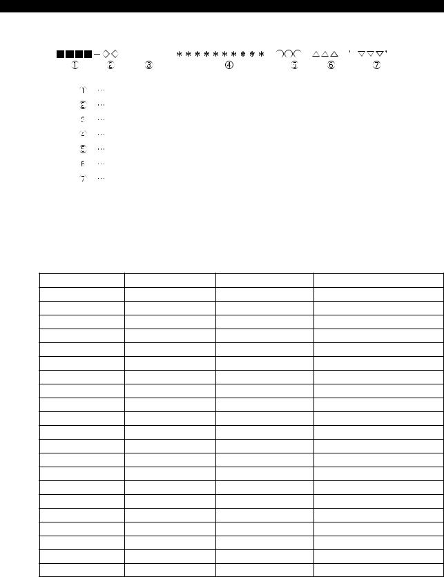
Display Format of Alarm P, A, B, C and D
ALARM-A
Alarm number
Object number
Alarm level
Alarm message
Object message
Alarm code
Alarm character-string
LE37006R0100300020001
1-2. Object Number and Object Message
The object number and the object message show the programming system and the control axis where the alarm has occurred by the number and message as shown in the table blow:
|
Object No. |
Meaning |
Object message |
Notes |
|
|
None |
No classification |
None |
||
|
01 |
System 1 |
“A side” or “1-A sd” |
1st spindle and turret A |
|
|
02 |
System 2 |
“B side” or “1-B sd” |
1st spindle and turret B |
|
|
03 |
System 3 |
“2-A sd” |
2d spindle and turret A |
|
|
04 |
System 4 |
“2-B sd” |
2d spindle and turret B |
|
|
11 |
1st X-axis |
“XAaxis” or “X-axis” |
||
|
12 |
1st Y-axis |
“YAaxis” or “Y-axis” |
||
|
13 |
1st Z-axis |
“ZAaxis” or “Z-axis” |
||
|
16 |
1st W-axis |
“W-axis” |
||
|
19 |
1st C-axis |
“C-axis” or “Caxis1” |
||
|
20 |
1st S-axis |
“SPDL” or “SPDL-1” |
||
|
21 |
1st T-axis |
“TAaxis” or “T-axis” |
||
|
22 |
1st M-axis |
“MAaxis” or “M-axis” |
||
|
31 |
2d |
X-axis |
“XBaxis” |
|
|
32 |
2d |
Y-axis |
“YBaxis” |
|
|
33 |
2d |
Z-axis |
“ZBaxis” |
|
|
39 |
2d |
C-axis |
“Caxis2” |
|
|
40 |
2d |
S-axis |
“SPDL-2” |
Sub spindle, pick-off spindle |
|
41 |
2d |
T-axis |
“TBaxis” |
|
|
42 |
2d |
M-axis |
“MBaxis” |
|
|
53 |
3d |
Z-axis |
“ZCaxis” |
LT series |
As indicated above, the object numbers and messages to be used are determined by the machine specifications.

5921-E P-3
SECTION 1 CLASSIFICATION OF ALARMS
1-2-1. Alarm Codes
In this manual, alarm codes are explained using such as «X», «XX», and «XXYY».
Explanation is given in the following methods:
(1)The alarm code indicated in this text can be used directly as the key to find the contents of error.
(2)The alarm code indicated in this text should first be converted into bit expression (pattern), which is then used as the key to find the contents of error.
In the case of 2), the procedure to convert the alarm code into bit pattern is shown below.
1-2-2. Bit conversion method
|
Alarm Code |
Alarm Code |
||||||||
|
(Expressed in |
Bit Pattern |
(Expressed in |
Bit Pattern |
||||||
|
hexadecimal) |
hexadecimal) |
||||||||
|
0 |
0 |
0 |
0 |
0 |
8 |
1 |
0 |
0 |
0 |
|
1 |
0 |
0 |
0 |
1 |
9 |
1 |
0 |
0 |
1 |
|
2 |
0 |
0 |
1 |
0 |
A |
1 |
0 |
1 |
0 |
|
3 |
0 |
0 |
1 |
1 |
B |
1 |
0 |
1 |
1 |
|
4 |
0 |
1 |
0 |
0 |
C |
1 |
1 |
0 |
0 |
|
5 |
0 |
1 |
0 |
1 |
D |
1 |
1 |
0 |
1 |
|
6 |
0 |
1 |
1 |
0 |
E |
1 |
1 |
1 |
0 |
|
7 |
0 |
1 |
1 |
1 |
F |
1 |
1 |
1 |
1 |
5921-E P-4
SECTION 1 CLASSIFICATION OF ALARMS
1-2-3. How to check alarm contents
The method to find the details of the alarm indicated by the bit pattern is explained below using an example.
Example:
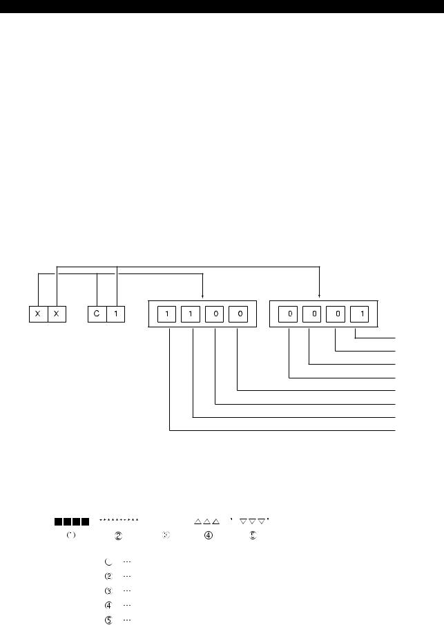
[Code] XX
XX bit0->Battery error
bit1->EC I/O power shut off error
bit2->ECC error
bit3->Not used
bit4->Not used
bit5->EDRQ INT signal
bit6->ECP INT signal
bit7->ECP RUN signal
If an alarm occurs, a hexadecimal number is displayed.
If «$C1» is displayed, for example, first convert this «$C1» into bits.
bit 0 bit 1 bit 2 bit 3 bit 4 bit 5 bit 6 bit 7
After the conversion, it is known that Bit0, Bit6, and Bit7 are ON. See the information above and you will find that these error codes
correspond to «battery error», «ECP INT signal», and «ECP RUN signal», respectively.
Error Display Format
ERROR
Error number
Error message
Indication of ERROR
Error code
Error character-string
LE37006R0100300060001
5921-E P-5
SECTION 2 ALARM P |
|||
|
SECTION 2 |
ALARM P |
||
|
0700 |
NC start-up error ………………………………………………………………………………. |
10 |
|
|
0701 |
P100-Menu initialization failure …………………………………………………………… |
10 |
|
|
0702 |
Power failure upon start-up ………………………………………………………………… |
11 |
|
|
0703 |
Load information file not found …………………………………………………………… |
11 |
|
|
0704 |
File load error …………………………………………………………………………………… |
11 |
|
|
0705 |
Default scheduling table error …………………………………………………………….. |
12 |
|
|
0706 |
Backup data file error ………………………………………………………………………… |
12 |
|
|
0707 |
DTL link/unlink error …………………………………………………………………………. |
12 |
|
|
0708 |
RT thread stack overflow …………………………………………………………………… |
13 |
|
|
0709 |
Hardware exception ………………………………………………………………………….. |
13 |
|
|
0710 |
System call error ………………………………………………………………………………. |
13 |
|
|
0711 |
AlarmService library error ………………………………………………………………….. |
14 |
|
|
0712 |
AlarmService internal error (exception) ……………………………………………….. |
14 |
|
|
0713 |
AlarmService error ……………………………………………………………………………. |
14 |
|
|
0714 |
Blue screen ……………………………………………………………………………………… |
14 |
|
|
0715 |
P100-Menu error ………………………………………………………………………………. |
15 |
|
|
0716 |
Floating point exception …………………………………………………………………….. |
15 |
|
|
0717 |
PLC control error ……………………………………………………………………………… |
15 |
|
|
0718 |
Real time thread time over …………………………………………………………………. |
15 |
|
|
0719 |
HXCP thread error ……………………………………………………………………………. |
15 |
|
|
0720 |
AlarmService internal error ………………………………………………………………… |
16 |
|
|
0721 |
DeviceNet error ………………………………………………………………………………… |
16 |
|
|
0723 |
DeviceNet I/O data link file read …………………………………………………………. |
17 |
|
|
0725 |
M code data file ……………………………………………………………………………….. |
17 |
|
|
0726 |
Safety speed data error …………………………………………………………………….. |
17 |
|
|
0727 |
MCS firmware doesn’t support POS2 unit ……………………………………………. |
17 |
|
|
0728 |
FL-net error ……………………………………………………………………………………… |
18 |
|
|
0729 |
Non-responsive software detected. …………………………………………………….. |
18 |
|
|
0731 |
R Spec. error …………………………………………………………………………………… |
18 |
|
|
0732 |
Unable to execute lost motion compensation ……………………………………….. |
18 |
|
|
0735 |
MCS DD encoder link error ………………………………………………………………… |
18 |
|
|
0736 |
MCS DD encoder error ……………………………………………………………………… |
19 |
|
|
0737 |
MCS DD encoder (slave sensor) detected error ……………………………………. |
19 |
|
|
0738 |
MCS DD encoder initialization failure ………………………………………………….. |
20 |
|
|
0739 |
MCS DD encoder (slave sensor) initialization failure ……………………………… |
21 |
|
|
0741 |
MCS firmware version error ……………………………………………………………….. |
22 |
|
|
0742 |
Relocation detection error ………………………………………………………………….. |
22 |
|
|
0744 |
MCS power supply unit overload ………………………………………………………… |
22 |
5921-E P-6
|
SECTION 2 ALARM P |
||
|
0750 |
The spec.-code or select-soft. was wrong |
……………………………………………. 22 |
|
0752 |
VDU communication error …………………………………………………………………. |
23 |
|
0753 |
VDU detected error …………………………………………………………………………… |
23 |
|
0754 |
VDU initialization failure …………………………………………………………………….. |
24 |
|
0755 |
SIO link error ……………………………………………………………………………………. |
24 |
|
0756 |
PSC optical scale encoder error …………………………………………………………. |
25 |
|
0757 MF-SAFETY Error ……………………………………………………………………………. |
25 |
|
|
0758 |
Safety I/O Error ………………………………………………………………………………… |
26 |
|
0759 |
Safety Servo Link Error ……………………………………………………………………… |
28 |
|
0782 |
Magnetic encoder speed detection error ……………………………………………… |
29 |
|
0783 |
MCS Rotary encoder 5 initialization failure …………………………………………… |
29 |
|
0784 |
MCS Rotary encoder 5 error ………………………………………………………………. |
30 |
|
0785 |
MCS Rotary encoder 4 initialization failure …………………………………………… |
30 |
|
0786 |
MCS Rotary encoder 4 error ………………………………………………………………. |
30 |
|
0787 |
MCS Rotary encoder 3 initialization failure …………………………………………… |
30 |
|
0788 |
MCS Rotary encoder 3 error ………………………………………………………………. |
30 |
|
0789 |
MCS Rotary encoder 2 error ………………………………………………………………. |
31 |
|
0790 |
MCS Rotary encoder 1 initialization failure …………………………………………… |
31 |
|
0791 |
MCS Rotary encoder 1 error ………………………………………………………………. |
31 |
|
0792 |
MCS Linear scale 4 initialization failure ……………………………………………….. |
32 |
|
0793 |
MCS Linear scale 4 error …………………………………………………………………… |
32 |
|
0794 |
MCS Linear scale 3 initialization failure ……………………………………………….. |
32 |
|
0795 |
MCS Linear scale 3 error …………………………………………………………………… |
33 |
|
0796 |
MCS Linear scale 2 initialization failure ……………………………………………….. |
33 |
|
0797 |
MCS Linear scale 2 error …………………………………………………………………… |
33 |
|
0798 |
MCS Linear scale 1 initialization failure ……………………………………………….. |
33 |
|
0799 |
MCS Linear scale 1 error …………………………………………………………………… |
33 |
|
0800 |
Spindle D/A control data file read ……………………………………………………….. |
34 |
|
0801 |
TCP/IP board detected error ………………………………………………………………. |
34 |
|
0802 |
Load information file not found …………………………………………………………… |
35 |
|
0803 |
File load error …………………………………………………………………………………… |
35 |
|
0804 |
MSB file mismatch ……………………………………………………………………………. |
35 |
|
0805 |
MOP-Tool parameter PBU load ………………………………………………………….. |
35 |
|
0806 |
MOP-Tool tool data PBU load ……………………………………………………………. |
35 |
|
0807 |
ACP panel status receipt error ……………………………………………………………. |
36 |
|
0808 |
Speed change ratio failure …………………………………………………………………. |
36 |
|
0810 |
NC I/O data file read …………………………………………………………………………. |
36 |
|
0812 |
MCS initialization error ………………………………………………………………………. |
36 |
|
0813 |
MCS Communication error ………………………………………………………………… |
38 |
|
0814 |
MCS data file corrupt ………………………………………………………………………… |
39 |
5921-E P-7
|
SECTION 2 ALARM P |
||
|
0815 |
PLC real-time task loop error ……………………………………………………………… |
40 |
|
0816 |
PLC initialization error ……………………………………………………………………….. |
40 |
|
0817 |
MCS error ……………………………………………………………………………………….. |
41 |
|
0818 |
ADP initialization failure …………………………………………………………………….. |
41 |
|
0820 |
Machine data file read ………………………………………………………………………. |
41 |
|
0821 |
Spindle gear ratio ……………………………………………………………………………… |
42 |
|
0822 |
Wheel data file read ………………………………………………………………………….. |
42 |
|
0823 AXIS CONSTRUCTION DATA setting error …………………………………………. |
42 |
|
|
0824 |
Unit connection mistake …………………………………………………………………….. |
43 |
|
0825 AXIS CONSTRUCTION name not set …………………………………………………. |
43 |
|
|
0826 AXIS CONSTRUCTION DATA file read ………………………………………………. |
43 |
|
|
0827 |
Control axis not found ……………………………………………………………………….. |
43 |
|
0828 |
Wire feed axis No. error …………………………………………………………………….. |
43 |
|
0833 |
MCS option program file not sent ……………………………………………………….. |
44 |
|
0834 |
MCS servo data error ……………………………………………………………………….. |
44 |
|
0835 |
MCS communication error …………………………………………………………………. |
44 |
|
0836 |
Program request illegal ……………………………………………………………………… |
45 |
|
0837 |
Loader spec. code data error ……………………………………………………………… |
45 |
|
0838 |
Loader backup data file read error ………………………………………………………. |
45 |
|
0839 |
Specification conditions failure …………………………………………………………… |
45 |
|
0840 |
SuperHi-NC specification mismatch ……………………………………………………. |
46 |
|
0841 |
FCP4 board detected error ………………………………………………………………… |
46 |
|
0842 |
Safety monitor spec. error …………………………………………………………………. |
46 |
|
0845 |
Specification code setting failure ………………………………………………………… |
46 |
|
0846 |
Thermal deviation comp. backup data file read …………………………………….. |
47 |
|
0847 |
DNC-DT preload task start error …………………………………………………………. |
47 |
|
0848 |
PSCB error ……………………………………………………………………………………… |
47 |
|
0849 |
Synchronous axis tandem control initialization failure ……………………………. |
47 |
|
0850 |
MCS Undefined alarm number …………………………………………………………… |
48 |
|
0851 |
MCS Inverter unit fault ………………………………………………………………………. |
48 |
|
0852 |
Mistake in data from MCS to NC ………………………………………………………… |
49 |
|
0853 MCS CON APA deviation ………………………………………………………………….. |
50 |
|
|
0854 |
MCS Power supply unit error ……………………………………………………………… |
50 |
|
0855 |
MCS Converter link error …………………………………………………………………… |
51 |
|
0856 |
MCS DC-bus voltage alarm ……………………………………………………………….. |
51 |
|
0857 |
MCS Motor overcurrent …………………………………………………………………….. |
51 |
|
0858 |
MCS Power unit overheat ………………………………………………………………….. |
51 |
|
0859 |
MCS Power unit overload ………………………………………………………………….. |
52 |
|
0860 |
MCS Supply voltage flutter ………………………………………………………………… |
52 |
|
0861 |
MCS Inverter capacity differs from spec. ……………………………………………… |
52 |
5921-E P-8
|
SECTION 2 ALARM P |
||
|
0862 |
MCS Winding change failure ……………………………………………………………… |
52 |
|
0863 |
MCS Encoder link error …………………………………………………………………….. |
53 |
|
0864 |
MCS Encoder detected error ……………………………………………………………… |
53 |
|
0865 |
MCS Encoder initialization failure ……………………………………………………….. |
54 |
|
0866 |
MCS Encoder with shaft detected error ……………………………………………….. |
54 |
|
0867 |
MCS Encoder with shaft initialization failure …………………………………………. |
54 |
|
0868 MCS ABSO SCALE error ………………………………………………………………….. |
55 |
|
|
0869 |
MCS ABSO SCALE initialization failure ……………………………………………….. |
55 |
|
0870 |
MCS Magnetic encoder alarm ……………………………………………………………. |
55 |
|
0871 |
MCS Resolver alarm …………………………………………………………………………. |
55 |
|
0872 |
MCS Pulse generator count over ………………………………………………………… |
56 |
|
0873 |
MCS Motor overheat …………………………………………………………………………. |
56 |
|
0874 |
MCS Servo link error ………………………………………………………………………… |
56 |
|
0875 |
MCS Servo link disconnection ……………………………………………………………. |
57 |
|
0876 |
Mistake in data from NC to MCS ………………………………………………………… |
57 |
|
0877 |
MCS Servo data error ……………………………………………………………………….. |
57 |
|
0878 |
MCS Illegal command ……………………………………………………………………….. |
58 |
|
0879 MCS CON speed over ………………………………………………………………………. |
58 |
|
|
0880 MCS Speed command over ……………………………………………………………….. |
59 |
|
|
0881 MCS DIFF over ………………………………………………………………………………… |
59 |
|
|
0882 MCS APA speed over ……………………………………………………………………….. |
59 |
|
|
0883 |
MCS Full-closed APA error ………………………………………………………………… |
59 |
|
0884 MCS Over speed ……………………………………………………………………………… |
60 |
|
|
0885 |
MCS Speed deviation over ………………………………………………………………… |
60 |
|
0886 |
MCS Collision detected …………………………………………………………………….. |
60 |
|
0887 |
MCS Urgent-stop time over ……………………………………………………………….. |
61 |
|
0888 |
MCS Belt is broken …………………………………………………………………………… |
61 |
|
0889 |
MCS Axis change control error …………………………………………………………… |
61 |
|
0890 |
MCS Independent encoder initialization failure …………………………………….. |
61 |
|
0891 |
MCS Calculated current position lies outside range ………………………………. |
62 |
|
0892 |
MCS Motor overload …………………………………………………………………………. |
62 |
|
0893 |
MCS Safety speed monitor E-Link error ………………………………………………. |
62 |
|
0894 |
MCS ABSO SCALE sub-slider detected error ………………………………………. |
62 |
|
0895 |
MCS Tandem control communication error ………………………………………….. |
63 |
|
0896 |
MCS Full abso scale link error ……………………………………………………………. |
63 |
|
0897 |
MCS Full abso scale error …………………………………………………………………. |
64 |
|
0898 |
MCS Full abso scale initialization failure ……………………………………………… |
64 |
|
0899 |
MCS Axis stop signal error ………………………………………………………………… |
65 |
|
0940 |
Time sharing task control …………………………………………………………………… |
65 |
|
0941 |
Real-time task control ……………………………………………………………………….. |
65 |
5921-E P-9
|
SECTION 2 ALARM P |
||
|
0942 |
Real-time task loop error …………………………………………………………………… |
65 |
|
0943 |
Main processor name incorrect ………………………………………………………….. |
66 |
|
0944 |
Slave processor name incorrect …………………………………………………………. |
66 |
|
0945 |
Memory board/battery life ………………………………………………………………….. |
66 |
|
0951 |
SMP error ……………………………………………………………………………………….. |
66 |
|
0952 |
Not equipped with processor board …………………………………………………….. |
67 |
|
0954 |
Peripheral processor start ………………………………………………………………….. |
67 |
|
0955 |
Spec. code: data file …………………………………………………………………………. |
67 |
|
0956 |
Backup data file read ………………………………………………………………………… |
68 |
|
0957 |
Graphic backup data file read …………………………………………………………….. |
68 |
|
0958 |
Pitch compensation data file read ……………………………………………………….. |
68 |
|
0965 |
Configuration file format error …………………………………………………………….. |
69 |
|
0971 |
Cache data: Initialization error ……………………………………………………………. |
69 |
|
0988 |
Cache data: Operation error ………………………………………………………………. |
69 |
|
0989 |
CPU information table data incorrect …………………………………………………… |
69 |
|
0990 |
TASK generate error …………………………………………………………………………. |
70 |
|
0991 |
TASK information table data incorrect …………………………………………………. |
70 |
|
0992 |
PLC backup data file read …………………………………………………………………. |
70 |
|
0993 |
TCP/IP board illegal ………………………………………………………………………….. |
71 |
|
0994 |
TCP/IP configuration file ……………………………………………………………………. |
71 |
|
0995 |
Machine axis data file ……………………………………………………………………….. |
71 |
|
0996 |
PLC axis data file ……………………………………………………………………………… |
71 |
|
0997 |
PLC monitor backup data file read ……………………………………………………… |
72 |
|
0998 |
PLC sequence program load ……………………………………………………………… |
72 |
|
0999 |
Synchronous tap data file read …………………………………………………………… |
73 |

5921-E P-10
SECTION 2 ALARM P
0700 NC start-up error
An error occurred when NC started up.
[Object] None
[Character-string] None
[Code]
0x10000000: NC Configuration read error 0x10003000: Spec code read error 0x20000000: ServoLink board initializing error 0x3XXX00YY: NC data file read error
XXX:
0x002: HD backup status file 0x004: Parameter data file 0x008: Machine data file 0x010: PLC backup data file 0x020: PLC-HMI data file 0x040: Alarm History data file 0x080: PLC AXIS data pbu file
0x100: POT TOOL data pbu file (M/C only) 0x200: MOP TOOL Tool data file (M/C only) 0x400: MOP TOOL Parameter file (M/C only) 0x800: Thermal deviation compensation data file
YY:
0x01: File read open error 0x02: File read error 0x03: Version check error 0x04: Check sum error
0x05: Double check sum error 0x06: Backupped Memory error 0x07: File write open error 0x08: File write error
0x40000000: Axis information initializing error -More than 8 axis
0x50000000: PLC data file read error -Read failed M code data file
0x60000000: I/O Initializing error -PLC variable backup file read error -I/O forced data file read error
0x70000000: ServoLink Initializing error 0x80000000: Operation buffer get error 0x90000000: PBU data file read error 0xA0000000: Shared memory size definition error 0xA1XXXXXX: AlarmService start error
XXXXXX: Error code of AlarmService library function 0xA2400002: Alarm History read error 0xA3000000: Thread monitor initializing error
0xA9000000: Initialization processing of the safety logic was not completed within 20 seconds 0xA9000001: Axis construction definition file open error
0xA9000002: Axis construction definition file read error 0xA9000003: Axis construction definition file mismatch 0xFFFFFFFF: Debug information file read error
0701 P100-Menu initialization failure
An error occurred in P100-Menu while system startup.
[Object] None
[Character-string] None
[Code]
1:NC Control file was not found.
2:PLC Control file was not found.
3:NC-HMI was not found

5921-E P-11
SECTION 2 ALARM P
4:3D real sim file was not found.
5:MacMan file was not found.
6:Version mismatch between P100-Menu and PLC Control
7:Version mismatch between P100-Menu and MacMan
8:Version mismatch between P100-Menu and NC Control
11:Conf-P100-menu read error
12:An error occurred at RTOS
13:An error occurred at UPS Service
21:NC Control start failure
22:Error in obtaining shared objects
23:PLC Control start failure
24:NC-HMI start failure
25:3D real sim start failure
26:MacMan start failure
101:Startup sequence 0x10 receive failure
200:Startup sequence 0x10 send failure
201:Startup sequence 0x20 receive failure
300:Startup sequence 0x20 send failure
301:Startup sequence 0x30 receive failure
400:Startup sequence 0x30 send failure
401:Startup sequence 0x60 receive failure
500:Startup sequence 0x60 send failure
501:Startup sequence 0x70 receive failure
600:Startup sequence 0x70 send failure
601:Startup sequence 0x7C receive failure
700:Startup sequence 0x7C send failure
701:AlarmService start failure
702:Activation sequence 0x80 receive failure
[Probable Faulty Locations]
1.Execution file name failure 2.Data file name failure 3.RTOS failure
4.UPS function failure 5.Software failure 6.Software Version failure
0702 Power failure upon start-up
[Object] None
[Character-string] None
[Code] None
[Probable Faulty Locations]
1.Power failure during while system startup 2.Power shutoff during while system startup
0703 Load information file not found
A load information file was not found.
[Object] None
[Character-string] None
[Code] None
0704 File load error
An object file was not loaded correctly.
[Object] None
[Character-string]

5921-E P-12
SECTION 2 ALARM P
None
[Code]
1:A file was not found
2:The attribute of file was not correct.
3:The load address information of file was not correct 4:An error occurred when file was loaded
FFFFFFFF:The details of alarm was displayed by message from OS
0705 Default scheduling table error
A default scheduling table error was detected.
[Object] None
[Character-string] None
[Code]
0x00010001: RTIN default scheduling table error (element number) 0x00010002: RTIN default scheduling table error (end element) 0x00020001: TSMN default scheduling table error (element number) 0x00020002: TSMN default scheduling table error (initial attribute)
[Probable Faulty Locations] 1.NC software failure
0706 Backup data file error
Error occurred when load/save the backup file.
[Object] None
[Character-string] None
[Code] XXXXYYYY
XXXX
0x0002:HD backup status file 0x0004:Low speed NC backup data file 0x0008:High speed NC backup data file 0x0010:PLC backup data file 0x0020:PLC-HMI data file 0x0040:Alarm history data file 0x0080:PLC axis data file
0x0100:POT TOOL data file
0x0200:MOP TOOL Tool data file (M/C only) 0x0400:MOP TOOL Parameter data file (M/C only) 0x0800:Thermal deviation compensation data file
YYYY
1:File read open error 2:File read error 3:Version check error 4:Check sum error 5:Double check sum error
6:Backup memory check error 7:File write open error
8:File write error
0707 DTL link/unlink error
An error occurred in DTL link or unlink.
[Object] None
[Character-string] None
[Code]
1:RTIN refresh error

5921-E P-13
SECTION 2 ALARM P
2:TSMN refresh error
[Probable Faulty Locations]
1.Hardware failure 2.Software failure
0708 RT thread stack overflow
Stack overflow of RT thread was detected.
[Object] None
[Character-string]
Occurred RT thread name
[Code] None
[Probable Faulty Locations] 1.NC software failure
0709 Hardware exception
Hardware exception was occurred.
[Object] None
[Character-string]
Occurred RT thread name
[Code]
Hardware exception code 0x5555: CPU Diagnose error 0x8100:Divide by 0 error
0x8101:Unexpected Single Step Interrupt 0x8102:Unexpected NMI 0x8103:Unexpected Debug Interrupt 0x8104:Overflow error
0x8105:Array Bounds error 0x8106:Invalid Opcode error 0x8107:NPX Device not present 0x8108:Double Fault error 0x8109:Unknown Device error 0x810A:Invalid TSS error 0x810B:Segment not Present error 0x810C:Stack Fault error 0x810D:General Protection error 0x810E:Page Fault error 0x8110:Unknown Device error 1 0x8111:Alignment error
[Probable Faulty Locations] 1.Hardware failure 2.Software failure
[Note]
Alarm information is also displayed also in the console window.
0710 System call error
An error occurred in the INtime system call.
[Object] None
[Character-string]
Occurred RT thread name
[Code] XXXXYYYY
XXXX:INtime system call code
YYYY:Return value or status of INtime system call [Probable Faulty Locations]

5921-E P-14
SECTION 2 ALARM P
NC software failure
[Note]
Alarm information is also displayed also in the console window.
0711 AlarmService library error
An error occurred in the AlarmService library function.
[Object] None
[Character-string] Occurred thread name
[Code]
XXYYYYYY
XX:AlarmService library function code YYYYYY:AlarmService library function error code
[Probable Faulty Locations] NC software failure
[Note]
Alarm information is also displayed also in the console window.
0712 AlarmService internal error (exception)
An error occurred inside of AlarmService.
[Object] None
[Character-string] «ALMS»
[Code]
AlarmService internal error code
[Probable Faulty Locations] NC software failure
[Note]
Alarm information is also displayed also in the console window.
0713 AlarmService error
P100-Menu detected AlarmService error.
[Object] None
[Character-string] None
[Code] None
[Probable Faulty Locations] 1.NC software failure
0714 Blue screen
Blue screen (kernel stop error) occurred.
[Object] None
[Character-string] None
[Code] None
[Probable Faulty Locations] 1.Win32 application failure 2.Windows failure 3.Windows driver failure

5921-E P-15
SECTION 2 ALARM P
0715 P100-Menu error
An abnormal condition of P100-Menu was detected.
[Object] None
[Character-string] None
[Code] None
[Probable Faulty Locations] 1.P100-Menu failure
0716 Floating point exception
Floating point exception was occurred.
[Object] None
[Character-string]
Occurred RT thread name
[Code] XXXXYYZZ
XXXX:Exception code YY:Not used (0 fixed) ZZ:FPU status word
bit5:PE (Precision Exception Flag) bit4:UE (Underflow Exception Flag) bit3:OE (Overflow Exception Flag) bit2:ZE (Zero Divide Exception Flag)
bit1:DE (Denormalized Operand Exception Flag) bit0:IE (Invalid Operation Exception Flag)
[Probable Faulty Locations] NC software failure
0717 PLC control error
Error occurred on PLC Control.
[Object] None
[Character-string] None
[Code] XXXXYYYY
XXXX:PLC Control status YYYY:PLC Control error code
[Probable Faulty Locations] 1.PLC software failure
0718 Real time thread time over
Real time-type thread did not finish within the stated time
[Object] None
[Character-string]
RT thread name that was exceeded the stated time
[Code] None
[Probable Faulty Locations] 1.NC software failure
0719 HXCP thread error

5921-E P-16
SECTION 2 ALARM P
An abnormal condition of HXCP thread was detected.
[Object] None
[Character-string] None
[Code] None
[Probable Faulty Locations] 1.NC software failure
0720 AlarmService internal error
An error occurred inside of AlarmService.
[Object] None
[Character-string] «ALMS»
[Code]
AlarmService internal error code
[Probable Faulty Locations]
1.NC software failure 2.P100-Menu failure
0721 DeviceNet error
Error occurred on DeviceNet.
[Index] None
[Character-string] CH* SC$
* : Channel number where the error occurred. S : Sequence counter
[Code] XXYYZZZZ
XXSlave station MacID where the error occurred
YYSlave station
0x00 Normal or nonexistent slave station
0x46 Duplicate MacID error
0x48 Communication stop
0x49 Discrimination information was not compatible with scan list 0x4D Data size was not compatible with scan list
0x4E No response in the connection check.
0x4F Other slave stations are nonexistence on network 0x50 Idle condition
0x53 Error received in the connection check
0x54 Timeout occurred in the connection check
0x56 Turn into the idle mode 0x5B Bus off
0x5C Network power supply off
( XXXX became 0xFFFF,if its not caused by slave station, such as communication delay.) ZZZZ Scanner error status
bit 0 Memory check error bit 1 Scan list initialize error
bit 2 Scan list mismatch error(MacID) bit 3 Scan list mismatch error(Input data)
bit 4 Scan list mismatch error(Output data) bit 5 Duplicate MacID error
bit 6 Network power supply status error bit 7 Memory parity error
bit 8 Input data reception error(single) bit 9 Input data reception error(dowble)
bit10 Output data transmission error(single) bit11 Output data transmission error(dowble)

5921-E P-17
SECTION 2 ALARM P
bit12 Slave station communication delay error(single) bit13 Slave station communication delay error(dowble) bit14 Bus off
bit15 Diagnostic information access error
[Probable Faulty Locations]
1)Hardware failure 2)Software failure
0723 DeviceNet I/O data link file read
The NC failed to read DeviceNet IO data link file.
[Code]
I/O data file load status (in hexadecimal) 2 ->File open error (no file)
3 ->File read error (no data)
4 ->File attribute error (not «PBU1»)
5 ->File close error
6 ->File size error (too small)
7 ->File size error (too large)
100->Wrong PLC machine type
200->Wrong PLC class
300->Wrong file version
1002 ->DN SCAN LIST CHANGE FILE OPEN ERROR
1003 ->DN SCAN LIST CHANGE FILE READ ERROR (NO DATA)
1004 ->DN SCAN LIST CHANGE FILE ATTRIBUTE ERROR (NO ‘PBU1’) 1005 ->DN SCAN LIST CHANGE FILE CLOSE ERROR
1006 ->DN SCAN LIST CHANGE FILE SIZE ERROR (SIZE SMALL)
0725 M code data file
Establishment data of reading M-code file is bad.
[Code]
1->The denial data is bad.
[Character string]
The number is M-code which is established bad data.
[Measures to Take]
Please correct the bad data of M-code.
0726 Safety speed data error
The safety speed data was in abnormal state in the machine without the CE marking safety speed monitor.
[Index]
Axis name or none (spindle)
[Character-string] None
[Code]
X
X=1:The guard number of the safety speed data was outside the range from -0 to 9.
[Measures to Take]
Change the safety speed monitor data file for axis control. Relevant specifications:Without CE mark safety speed monitor type
[Related Specifications]
Without CE mark safety speed monitor type
0727 MCS firmware doesn’t support POS2 unit
This alarm occurs when the firmware ROM version of the NC axis/ machine(PLC) axis MIV unit is not 511 or later when the new POS unit is installed.
[Character-string] None
[Code] None

5921-E P-18
SECTION 2 ALARM P
0728 FL-net error
An error occurred during startup of the FL-net card.
[Object] None
[Character-string] None
[Code]
Y000XXX
Y:0
XXXX: 7F00:System error
7F01:Flash memory error 7F02:DRAM test error 7F03:NICE test error 7F04:EEPROM sum check error 7F05:CPU BUS error 7F06:illegal Instruction
Y:1
XXXX:
0004:Timeout error for 4 sec or longer Y:F
XXXX:
FFFF: FL-net card is not mounted
[Probable Faulty Locations] FL-net card is defective.
0729 Non-responsive software detected.
Non-answered software was detected.
[Object] None
[Character-string] None
[Code]
NT Process name
[Probable Faulty Locations] NC software failure
0731 R Spec. error
It is the illegal of «R SPEC».
[Index] None
[Code]
1:»NON R SPEC» of NC is OFF, and «R-SPEC» of SVDN-ID is OFF. 2:»NON R SPEC» of NC is ON, and «R-SPEC» of SVDN-ID is ON.
3:When there are 2 SVDN-boards in the machine, «R-SPEC» of one board is ON, other is OFF. 4X:»NON R SPEC» of NC is OFF, and «R-SPEC» of SVDN-ID is ON, and Restriction-Spec is ON.
0732 Unable to execute lost motion compensation
0735 MCS DD encoder link error
An error occurred in the encoder communication link.
[Object]
Axis name or none (spindle)
[Character-string] None
[Code] XXYYZZZZ

5921-E P-19
SECTION 2 ALARM P
XX= $FF (fixed)
YY= $00: Error is detected at the DD encoder.
$01: Error is detected at the DD encoder(slave sensor). ZZZZ = Encoder link error status at the time of error detection
bit15: Undefined bit14: Undefined
bit13: Error in communication with the DD encoder (slave sensor) bit12: Error in communication with the DD encoder
bit11: MT buffer error
bit10: Transmission loop error in AT mode
bit9 : Data over error in data receiving part of interface bit8 : Undefined
bit7 : Undefined
bit6 : Modulation code error bit5 : CRC error
bit4 : Format error
bit3 : Double transmission error bit2 : Double reception error bit1 : Parity error
bit0 : Time-out error
This alarm occurs only at ICB-H.
[Probable Faulty Locations]
DD encoder of DD encoder (slave sensor) of the pertinent axis Encoder link cables or connectors Inverter unit control board
0736 MCS DD encoder error
The DD encoder has become undetectable.
[Object]
Axis name or none (spindle)
[Character-string] None
[Code] XXYYZZZZ
XX= Positional data status bit7 : Error bit (1:error)
bit6 : Absolute position sensor margin error.(0:Normal, 1:Warning) bit5 : Gap-Warning (1:Gap-small,Toggle:Gap-big)
bit4 : Inclination-Warning (1:CCW-big, Toggle:CW-big) bit3 : Auto set mode (0:Normal, 1:Auto mode)
bit2 : Communication error (Toggle by detecting)
bit1,0: Error bit number of absolute position code.(It is indicated by 2bits.)
YY= Alarm code
01: Stop command has stopped. 02: Control parameter error
04: Absolutization error
05: Initialization speed too high 08: Auto-set-data error
0D: Speed too high
0E: Synchronization error
20:Absolutization mismatch (Only Format-5)
21:Communication-error of Master-sensor (Only Format-5) 3E: Code-error by Absolute-position-sensor
3F: Check-errotr by Absolute-position-code
40:Inclination-error (for plus)
41:Inclination-error (for minus)
42:Gap is narrow
43:Gap is wide
ZZZZ= 0000 fixed
This alarm occurs only at ICB-H.
[Probable Faulty Locations] DD encoder
0737 MCS DD encoder (slave sensor) detected error
The DD encoder (slave sensor) has become undetectable.

5921-E P-20
SECTION 2 ALARM P
[Object]
Axis name or none (spindle)
[Character-string] None
[Code] XXYYZZZZ
XX= Positional data status bit7 : Error bit (1:error)
bit6 : Absolute position sensor margin error.(0:Normal, 1:Warning) bit5 : Gap-Warning (1:Gap-small,Toggle:Gap-big)
bit4 : Inclination-Warning (1:CCW-big, Toggle:CW-big) bit3 : Auto set mode (0:Normal, 1:Auto mode)
bit2 : Communication error (Toggle by detecting)
bit1,0: Error bit number of absolute position code.(It is indicated by 2bits.)
YY= Alarm code
01: Stop command has stopped. 02: Control parameter error
04: Absolutization error
05: Initialization speed too high 08: Auto-set-data error
0D: Speed too high
0E: Synchronization error
20:Absolutization mismatch (Only Format-5)
21:Communication-error of Master-sensor (Only Format-5) 3E: Code-error by Absolute-position-sensor
3F: Check-errotr by Absolute-position-code
40:Inclination-error (for plus)
41:Inclination-error (for minus)
42:Gap is narrow
43:Gap is wide
ZZZZ= 0000 fixed
This alarm occurs only at ICB-H.
[Probable Faulty Locations] DD encoder (slave sensor)
0738 MCS DD encoder initialization failure
An error occurred in the initialization of the DD encoder.
[Object]
Axis name or none (spindle)
[Character-string] None
[Code] XXYYZZZZ
XX= Encoder link initialization sequence number (1B) at the time of the error detection
0:Reset
1:Network address setting
2:Request to send the basic information for communication
3:Change of communication software version
4:Acquisition of device information
5:Parameter change
6:Position detection start
7:AT mode start
YY= Error content (1B)
0:Communication error
1:Transmission start time over
2:Transmission finish time over
3:Reception finish time over
4:Abnormal response address
5:Abnormal response code
6:Parameter error
ZZZZ = Data (2B)
If YY = 0,
The encoder link error status C2ERR at the time of error detection appears.
If YY = 1, 2 or 3,

5921-E P-21
SECTION 2 ALARM P
The transmitted frame information QC2MTINF appears.
If YY = 4,
The network address of the responding device appears.
If YY = 5,
Alarm code + positional data status
Refer to MCS DD Encoder error (alarm 1136).
If YY = 6,
Parameter number at which the error is detected
1:Reception of insufficient number of parameters
2:Basic information for communication being incompatible
3:Multi-turn detection range over
4:Communication protocol version being incompatible
5:Positional data format being incompatible
6:Abbreviated data mode being incompatible
However, when abnormal voltage is detected at the encoder fuse XXYY = $FFFF fixed
ZZZZ = Detected voltage value of the encoder fuse (12[V] = $9980) Normal range: 10.6[V] to 13.8[V]
Allowable range: $8800 to $B000 This alarm occurs only at ICB-H.
[Probable Faulty Locations] DD encoder
Encoder link cables and connectors Inverter unit control board
0739 MCS DD encoder (slave sensor) initialization failure
An error occurred in the initialization of the DD encoder (slave sensor).
[Index]
Axis name or none (spindle)
[Character-string] None
[Code] XXYYZZZZ
XX= Encoder link initialization sequence number (1B) at the time of the error detection
0:Reset
1:Network address setting
2:Request to send the basic information for communication
3:Change of communication software version
4:Acquisition of device information
5:Parameter change
6:Position detection start
7:AT mode start
YY= Error content (1B)
0:Communication error
1:Transmission start time over
2:Transmission finish time over
3:Reception finish time over
4:Abnormal response address
5:Abnormal response code
6:Parameter error
ZZZZ = Data (2B)
If YY = 0,
The encoder link error status C2ERR at the time of error detection appears.
If YY = 1, 2 or 3,
The transmitted frame information QC2MTINF appears.
If YY = 4,
The network address of the responding device appears.
If YY = 5,
Alarm code + positional data status
Refer to MCS DD Encoder error (alarm 1136).
If YY = 6,
Parameter number at which the error is detected
1:Reception of insufficient number of parameters
2:Basic information for communication being incompatible
3:Multi-turn detection range over

5921-E P-22
SECTION 2 ALARM P
4:Communication protocol version being incompatible
5:Positional data format being incompatible
6:Abbreviated data mode being incompatible
However, when abnormal voltage is detected at the encoder fuse XXYY = $FFFF fixed
ZZZZ = Detected voltage value of the encoder fuse (12[V] = $9980) Normal range: 10.6[V] to 13.8[V]
Allowable range: $8800 to $B000 This alarm occurs only at ICB-H.
[Probable Faulty Locations] DD encoder (slave sensor)
Encoder link cables and connectors Inverter unit control board
0741 MCS firmware version error
The MCS software version was not correct.
[Object] None
[Code]
1-> The MCS software version of the XA axis is not since ICBH590 in the premium thread cutting function spec.
[Probable Faulty Locations] Specification code error MCS software version error
[Measures to Take]
Reinstall the software or reissue the install disk. MCS software Upgrade
0742 Relocation detection error
Relocation detection error occurred [Character-string]
|
ComErr |
:Communication error |
|
PBU |
:PBU data error |
|
PJ |
:PJ discord |
|
PwdTout |
:Password application timeout |
|
PwdChk |
:Password check error |
PwdTerm:Password application terminate
[Code]
ComErr:
bit2 Atmega error bit1 RTC error
bit0 Relocation detection module error PwdChk:
Password check error code
0744 MCS power supply unit overload
Power Supply Unit over load
[Object]
Axis name or none (spindle)
[Character-string] None
[Code]
1(fixed)
[Probable Faulty Locations] Power unit
Overload operation
0750 The spec.-code or select-soft. was wrong
The combination of NC-software and PLC-software was wrong. Or, the combination of specification-code was wrong.

5921-E P-23
SECTION 2 ALARM P
[Object] None
[Character-string] None
[Code]
1:PLC-software is not effective for the specification of «TOOL OFFSET 999» 4:It can’t be combined with spindle command unit 0.1.
5:Overlapped PLC axis number
[Probable Faulty Locations]
(1)Mistake of select for specification-code (2)Mistake of select for PLC-software-version
0752 VDU communication error
An error occurred in the VDU(Vibration Detect Unit) communication link, disabling the VDU from detecting acceleration.
[Object]
Axis name or none (spindle)
[Character-string] None
[Code] XXYYZZZZ
XX= FF [HEX] (fixed)
YY= 00 [HEX] (fixed)
ZZZZ = VDU link error status at the time of error detection. (Each bit represents the kind of communication error.)
bit 15 Undefined bit 14 Undefined bit 13 Undefined
bit 12 1: Error in communication with VDU(AT mode) bit 11 1: Error in communication with VDU(MT mode) bit 10 1: Transmission loop error in AT (auto) mode
bit 9 1: Data over error in data receiving part of interface bit 8 Undefined
bit 7 Undefined
bit 6 1: Modulation code error bit 5 1: CRC error
bit 4 1: Format error
bit 3 1: Double transmission error bit 2 1: Double reception error bit 1 1: Modulation code error
bit 0 1: Time-out error [Probable Faulty Locations]
—VDU
—Encoder link cables
—VFA unit
0753 VDU detected error
The VDU(Vibration Detect Unit) has become unable to detect acceleration data.
[Object]
Axis name or none (spindle)
[Character-string] None
[Code]
XXYYZZZZ
XX = VDU error status
|
bit7 |
1: Error bit (1 is error) |
|
bit6 |
1: Empty bit |
|
bit5 |
1: Latest acceleration data is overflow(Y axis) |
|
bit4 |
1: Latest acceleration data is overflow(X axis) |
|
bit3 |
1: Empty bit |
|
bit2 |
1: Error in communication (toggled detecting each error) |
|
bit1 |
1: Previous acceleration data is overflow(Y axis) |

5921-E P-24
SECTION 2 ALARM P
|
bit0 |
1: Previous acceleration data is overflow(X axis) |
YY= VDU alarm code
01:Stop command halt
02: Control parameter error
07: User parameter check sum error 0E: Synchronous miss error
15:Acceleration sensor signal error (X axis)
16:Acceleration sensor signal error (Y axis)
17:Acceleration sensor signal error (X and Y axis) ZZZZ= 0 (fixed)
[Probable Faulty Locations]
— VDU
0754 VDU initialization failure
An error occurred in initialization of VDU(Vibration Detect Unit).
[Object]
Axis name or none (spindle)
[Character-string] None
[Code] XXYYZZZZ
XX= Encoder link sequence number at the time of error detection
0:Reset
1:Network address setting
2:Request of basic information on communication
3:Change of communication version
4:Acquisition of device information
5:Parameter change
6:AT (auto) mode start
YY= Error content
0:Communication error
1:Transmission start time over
2:Transmission finishes time over
3:Reception finishes time over
4:Abnormal response address
5:Abnormal response code
6:Parameter error
ZZZZ = Additional data If YY=0,
the encoder link error status C2ERR at the time of error detection appears. If YY=1, 2, or 3,
the transferred frame information C2MTINF appears. If YY=4,
the network address of the responding device appears. If YY=5,
the received frame information C2RXINF appears. If YY=6,
the number of parameter that caused the alarm appears. 1 = Not all the necessary parameters are received.
2 = Basic information on communication is incompatible.
4 = Protocol version on communication is incompatible. [Probable Faulty Locations]
—VDU
—Encoder link cables
—VFA unit
0755 SIO link error
An error occurred in the SIO link.
[Object] None
[Character-string] None

5921-E P-25
SECTION 2 ALARM P
[Code]
During steady processing FFFFFFFF:
Recieved the same data from MFU twice XXXXYYYY:
XXXX: command & data length 0303: recieved error with frame 0
YYYY:The second byte of reception data 1303: recieved error with frame 1
YYYY:The second byte of reception data 05FF: Error status besides 0
YYYY:Error status During setup processing XXYYZZZZ:
XX:frame
YY:command 00: reset
01: intelligence
02: time-out time setting 05: file-transfer
ZZZZ:error cause
0007: Data reception response is not sent within 0.15 second after data transmission. 0008: Data transmission does not end within 0.15 second.
0009: Communication error occurred after reception of data.
000A: Communication error occurred while the NC was waiting for data reception. 000B: Communication error occurred while the NC was waiting for data transmission. 000C: Data transmission was attempted during data transmission.
000D: Data transmission was attempted in the state of communication error. 000E: An error command was received.
000F: Transmission command and reception command were not same.
[Probable Faulty Locations]
1.SSIO card 2.Safety module 3.I/O slave
0756 PSC optical scale encoder error
An error was detected by the position encoder of optical scale.
[Character-string] None
[Code] XXYYZZ
XX:Value of the J-type endoder and value of the optical scale are too different. bit1:It is too different by a negative sign.
bit0:It is too different by a positive sign. YY:Pulse count value of optical scale
bit0:A-phase pulse and B-phase pulse have changed at the same time. ZZ:The amplitude of the optical scale signal is wrong.
bit1:The amplitude of B-phase is wrong. bit0:The amplitude of A-phase is wrong.
[Probable Faulty Locations]
—Breakdown of optical scale
—Breakdown of optical scale cable
[Measures to Take]
—Exchange of optical scale
—Exchange of optical scale cables
0757 MF-SAFETY Error
An error was detected by the MF-SAFETY.
[Object] None
[Character-string] None

5921-E P-26
SECTION 2 ALARM P
[Code]
0x1000XXXX->CPU Exception was occurred in the MF-SAFETY XXXX->Exception number
0x1100XXXX->NMI was occurred in the MF-SAFETY XXXX->NMI code
bit15->An error was occurred bit9 ->Voltage drop for CPU1
bit8 ->Watchdog timer overflow in CPU0 bit1 ->Voltage drop for CPU0
bit0 ->Watchdog timer overflow in CPU1 0x1200XXXX->CPU bus error was occurred in the MF-SAFETY
XXXX->CPUID
bit15->CPUID (0:CPU0, 1:CPU1) 0x130000XX->No response in CPU1 request
XX->CPU1 request number
0x170000XX->Normal process in the MF-SAFETY did not end within a specific period. XX->End time of normal process (1bit=62.5us)
0x1800XXXX->An Error was detected by the MF-SAFETY XXXX->Error Code
bit15->MFU I/O unit error bit14->MFU I/O Bus parity error bit12->Synchronization error
bit11->Wrongly set synchronous signal timing 0x19000000->Stack overflow in the MF-SAFETY CPU 0x1A00XXXX->Illegal address is in the label table
XXXX->Index of label table
0x1B000000->NC starts up with software update mode in the MF-SAFETY 0x1C0000XX->Mode setting is mismatch between NC and MF-SAFETY
XX->Mismatch location 01->MF-SAFETY mode setting is wrong 02->NC mode setting is wrong
[Probable Faulty Locations] MF-SAFETY MF-SAFETY mode setting NC mode setting
I/O unit in MFU
[Measures to Take]
Replace the MF-SAFETY unit Replace the I/O unit in MFU
Switch(SW1) of the MF-SAFETY turns off Update the MF-SAFETY software (safety logic)
0758 Safety I/O Error
An error occurred in Safety IO link (SIO link) or in safety I/O unit.
[Object] None
[Character-string] None
[Code]
0x20000000->Safety transmission data was mismatch between CPU0 and CPU1while initialization of SIO link 0x21XX0000->Command was not received while initialization of SIO link
XX->Expecting command 00->Reset Command
01->Information gathering Command
02->Time-out time setting Command
0x22XXYYYY->Communication error was occurred while initialization of SIO link XX->Expecting command
00->Reset Command
01->Information gathering Command
02->Time-out time setting Command YYYY->SIO controller error status
bit15->An error was occurred bit10->Reception buffer size setting was too big bit9 ->Disconnection error

5921-E P-27
SECTION 2 ALARM P
bit8 ->Modulation code error bit7 ->CRC error
bit6 ->Format error
bit5 ->Double transmission error bit4 ->Double reception error
bit3 ->Parity error was occurred when SIO controller read transmission buffer bit2 ->Parity error was occurred when CPU read transmission buffer
bit1 ->Parity error was occurred when CPU read reception buffer bit0 ->Time-out error
0x23XXYYYY->Error command was received while initialization of SIO link XX->SIO link slave address which error was detected
YYYY->Error status
bit15->An error was occurred bit10->Reception buffer size setting was too big bit9 ->Disconnection error
bit8 ->Modulation code error bit7 ->CRC error
bit6 ->Format error
bit4 ->Double reception error
bit3 ->Parity error was occurred when SIO controller read transmission buffer bit2 ->Parity error was occurred when CPU read transmission buffer
bit1 ->Parity error was occurred when CPU read reception buffer bit0 ->Time-out error
0x24XX00YY->Illegal command was received while initialization of SIO link XX->Expecting command
XX->Reception command
0x25XX0000->Safety IO slave information did not match the scan file list XX->Mismatch frame offset
0x2F000000->SIO link was disconnected
0x31000000->The command was not received within a specific period 0x3200XXXX->Communication error was detected by the MF-SAFETY
XXXX->SIO controller error status bit15->An error was occurred
bit10->Reception buffer size setting was too big bit9 ->Disconnection error
bit8 ->Modulation code error bit7 ->CRC error
bit6 ->Format error
bit5 ->Double transmission error bit4 ->Double reception error
bit3 ->Parity error was occurred when SIO controller read transmission buffer bit2 ->Parity error was occurred when CPU read transmission buffer
bit1 ->Parity error was occurred when CPU read reception buffer bit0 ->Time-out error
0x33XXYYYY->Error command was received in SIO link safety frame XX->SIO link slave address which error was detected YYYY->Error status
bit15->An error was occurred bit10->Reception buffer size setting was too big bit9 ->Disconnection error
bit8 ->Modulation code error bit7 ->CRC error
bit6 ->Format error
bit4 ->Double reception error
bit3 ->Parity error was occurred when SIO controller read transmission buffer bit2 ->Parity error was occurred when CPU read transmission buffer
bit1 ->Parity error was occurred when CPU read reception buffer bit0 ->Time-out error
0x34XX0000->Safety protocol could not be established on the SIO link XX->slave address
0x35XXYYZZ->Could not communicate safety SIO frame, after established safety protocol XX->slave address
YY->
00->Reset command was received
01->Unexpected command was received
02->Undefined command was received
03->Connection ID was in err
04->CRC error

5921-E P-28
SECTION 2 ALARM P
08->FailSafeData command was received ZZ->Reception safety data
0x36000000->Safety transmission data was mismatch between CPU0 and CPU1 0x37XX0000->Safety frame was not renewal
XX->slave address
0x3FXXYYZZ->Safety physical output data was mismatch between CPU0 and CPU1 XX->Index of physical output
YY->Output data in CPU0 ZZ->Output data in CPU1
0x41X000YY->An error was occurred in MFU I/O unit X->Slot number
YY->I/O unit error status <MF-EC1>
bit7->Overcurrent Protection circuit was worked in output circuit bit6->Overcurrent protection was occurred in input circuit bit4->I/O bus check error
bit2->Data was mismatched between order and monitor bit1->A parity error was occurred when I/O bus1 was written bit0->A parity error was occurred when I/O bus0 was written <MF-P2A16S>
bit6->Overcurrent protection was occurred in input circuit bit5->Self-check error
bit4->I/O bus check error <MF-P2M2S>
bit7->Overcurrent Protection circuit was worked in output circuit bit6->Overcurrent protection was occurred in input circuit bit4->I/O bus check error
bit2->Data was mismatched between order and monitor bit1->A parity error was occurred when I/O bus1 was written bit0->A parity error was occurred when I/O bus0 was written
0x42XYZZWW->MFU I/O unit input of CPU0 and CPU1 was mismatched longer than a specific period X->Slot number
Y->I/O unit safety input number (1-4) ZZ->Input data in CPU0
WW->Input data in CPU1
0x43XYZZWW->MFU I/O unit written data was mismatch between CPU0 and CPU1 X->Slot number
Y->I/O unit safety output number (1-4) ZZ->Output data in CPU0 WW->Output data in CPU1
[Probable Faulty Locations]
SIO link cables I/O unit in MFU MF-SAFETY I/O data file SIO slave unit
[Measures to Take]
Replace the SIO link cables Replace the MFU I/O unit Replace the MF-SAFETY unit Update the I/O data file Replace the SIO link slave unit
0759 Safety Servo Link Error
An error occurred in Safety Servo Link.
[Object] None
[Character-string] None
[Code]
0x50000000->Safety transmission data was mismatch between CPU0 and CPU1 in initialization of Servo link 0x51XX0000->Frame from slave was not received in initialization of Servo link
XX->axis ID
0x520XYYYY->Communication error was occurred in initialization of Servo link X->Servo link channel number

5921-E P-29
SECTION 2 ALARM P
YYYY->Servo controller error status bit15->An error was occurred bit11->Protect error
bit9 ->Disconnection error bit8 ->Modulation code error bit7 ->CRC error
bit6 ->Format error
bit4 ->Double reception error
bit3 ->Parity error was occurred when Servo controller read transmission buffer bit2 ->Parity error was occurred when CPU read transmission buffer
bit1 ->Parity error was occurred when CPU read reception buffer bit0 ->Time-out error
0x53XX0000->The response was not received within a specific period XX-axis ID
0x54XX0000->Safety protocol could not be established on the Servo link XX->axis ID
0x55XXYYZZ->Could not communicate safety Servo frame, after established safety protocol XX->slave address
YY->
00->Reset command was received
01->Unexpected command was received
02->Undefined command was received
03->Connection ID was in err
04->CRC error
08->FailSafeData command was received ZZ->Reception safety data
0x56000000->Safety Servo transmission data was mismatch between CPU0 and CPU1 0xFFFFXXXX
XXXX->world clock after the put a safety protocol
[Probable Faulty Locations] Servo link cables MF-SAFETY
Servo link slave unit
Axis construction definition file
[Measures to Take]
Replace the Servo link cables Replace the MF-SAFETY unit Replace the Servo link slave unit
Update the axis construction definition file
0782 Magnetic encoder speed detection error
The difference between speed feed back value and current frequency of Magnetic encoder was always observed, and there was a difference in excessive.
[Object] Axis
[Character-string] None
[Code] XXXXYYYY
XXXX=speed reference value(2B) YYYY=speed detect value(2B)
[Probable Faulty Locations] Magnetic encoder
[Corrective Action]
Change Magnetic encoder
0783 MCS Rotary encoder 5 initialization failure
It failed in initialization of Rotary encoder 5(Others).
[Object] Axis
[Character-string] None

5921-E P-30
SECTION 2 ALARM P
[Probable Faulty Locations]
Rotary encoder 5(Others).
[Corrective Action]
Change Rotary encoder 5(Others).
0784 MCS Rotary encoder 5 error
Illegal data was detected in Rotary encoder 5(Others).
[Object] Axis
[Character-string] None
[Probable Faulty Locations] Rotary encoder 5(Others).
[Corrective Action]
Change Rotary encoder 5(Others).
0785 MCS Rotary encoder 4 initialization failure
It failed in initialization of Rotary encoder 4(HEIDENHAIN).
[Object] Axis
[Character-string] None
[Probable Faulty Locations]
Rotary encoder 4(HEIDENHAIN).
[Corrective Action]
Change Rotary encoder 4(HEIDENHAIN).
0786 MCS Rotary encoder 4 error
Illegal data was detected in Rotary encoder 4(HEIDENHAIN).
[Object] Axis
[Character-string] None
[Probable Faulty Locations]
Rotary encoder 4(HEIDENHAIN).
[Corrective Action]
Change Rotary encoder 4(HEIDENHAIN).
0787 MCS Rotary encoder 3 initialization failure
It failed in initialization of Rotary encoder 3(HEIDENHAIN).
[Object] Axis
[Character-string] None
[Probable Faulty Locations]
Rotary encoder 3(HEIDENHAIN).
[Corrective Action]
Change Rotary encoder 3(HEIDENHAIN).
0788 MCS Rotary encoder 3 error
Illegal data was detected in Rotary encoder 3(HEIDENHAIN).
[Object] Axis
[Character-string]

5921-E P-31
SECTION 2 ALARM P
None
[Probable Faulty Locations]
Rotary encoder 3(HEIDENHAIN).
[Corrective Action]
Change Rotary encoder 3(HEIDENHAIN).
0789 MCS Rotary encoder 2 error
Illegal data was detected in Rotary encoder 2(INA-BEARING).
[Object] Axis
[Character-string] None
[Code]
XXXXYYYY
XXXX= Content of illegal data
000A[HEX] : illegal data of A aspect voltage 000B[HEX] : illegal data of B aspect voltage
YYYY= Illegal data
XXXX=000A[HEX] : A aspect voltage value XXXX=000B[HEX] : B aspect voltage value
[Probable Faulty Locations]
Rotary encoder 2(INA-BEARING).
[Corrective Action]
Change Rotary encoder 2(INA-BEARING).
0790 MCS Rotary encoder 1 initialization failure
It failed in initialization of Rotary encoder 1.
[Object] Axis
[Character-string] None
[Code]
XXYYZZZZ
Same with the alarm No. 0865 «MCS Encoder initialize failed»
[Probable Faulty Locations] Rotary encoder 1 Motor encoder
Encoder link cable & connector Control base of Inverter Unit
[Corrective Action]
Exchange & check on thing Above Unit
0791 MCS Rotary encoder 1 error
Illegal data was detected in Rotary encoder 1.
[Object] Axis
[Character-string] None
[Code] XXYYZZZZ
XX= Rotary encoder status bit7 alarm
bit6 communication error
8X The output amplitude is normal.
9X Output amplitude smallness AX Output amplitude bigness BX Output amplitude too small YY= Rotary encoder alarm code

5921-E P-32
SECTION 2 ALARM P
00 Unstart
01 Stop command stop
02 The control parameter is illegal.
0E Synchronous mistake
0F The excitation output is illegal.
11B face Ad offset Voltage decrease
12A face AD offset voltage decrease
13A and B face AD offset voltage decrease
15B face AD offset voltage decrease
16A face Ad offset voltage rise
17A and B face AD offset voltage rise
25B face signal amplitude is excessive
26A face signal amplitude is excessive
27A and B face signal amplitude is excessive.
29The signal amplitude is underestimates. 2D B face signal amplitude is underestimates. 2E A and signal amplitude is underestimates.
2F A and B face signal amplitude is underestimates.
80-FF CPU illegal
ZZZZ= Rotary encoder position data Positional data of each pitch
[Probable Faulty Locations] Rotary encoder 1
[Corrective Action]
Change Rotary encoder 1
0792 MCS Linear scale 4 initialization failure
It failed in initialization of Linear scale 4(Others).
[Object] Axis
[Character-string] None
[Probable Faulty Locations] Linear scale 4(Others).
[Corrective Action]
Change Linear scale 4(Others).
0793 MCS Linear scale 4 error
Illegal data was detected in Liner scale 4(Others).
[Object] Axis
[Character-string] None
[Probable Faulty Locations] Linear scale 4(Others).
[Corrective Action]
Change Linear scale 4(Others).
0794 MCS Linear scale 3 initialization failure
It failed in initialization of Linear scale 3(HEIDENHAIN).
[Object] Axis
[Character-string] None
[Probable Faulty Locations] Linear scale 3(HEIDENHAIN).
[Corrective Action]
Change Linear scale 3(HEIDENHAIN).

5921-E P-33
SECTION 2 ALARM P
0795 MCS Linear scale 3 error
Illegal data was detected in Liner scale 3(HEIDENHAIN).
[Object] Axis
[Character-string] None
[Probable Faulty Locations] Linear scale 3(HEIDENHAIN).
[Corrective Action]
Change Linear scale 3(HEIDENHAIN).
0796 MCS Linear scale 2 initialization failure
It failed in initialization of Linear scale 2(HEIDENHAIN).
[Object] Axis
[Character-string] None
[Probable Faulty Locations] Linear scale 2(HEIDENHAIN).
[Corrective Action]
Change Linear scale 2(HEIDENHAIN).
0797 MCS Linear scale 2 error
Illegal data was detected in Liner scale 2(HEIDENHAIN).
[Object] Axis
[Character-string] None
[Probable Faulty Locations] Linear scale 2(HEIDENHAIN).
[Corrective Action]
Change Linear scale 2(HEIDENHAIN).
0798 MCS Linear scale 1 initialization failure
It failed in initialization of Linear scale 1(MITUTOYO).
[Object] Axis
[Character-string] None
[Code] XXYYZZZZ
Same with the alarm No. 0865 «MCS Encoder initialize failed»
[Probable Faulty Locations]
Rotary encoder 1 Motor encoder
Encoder link cable & connector Control base of Inverter Unit
[Corrective Action]
Exchange & check on thing Above Unit
0799 MCS Linear scale 1 error
Illegal data was detected in Liner scale 1(MITUTOYO).
[Object] Axis
[Character-string]

5921-E P-34
SECTION 2 ALARM P
None
[Code]
XXYYZZZZ
XX= Liner scale 1 status bit7: alarm
bit6: communication error
bit2: communication error(every detection)
bit0: alarm code distinction bit (bit0=1: An alarm occurred in MITUTOYO scale.) YY=Liner scale 1
case of XX=88 bit7: over speed
bit6: communication error bit5: EEPROM error bit4: CPU error
bit3: electric capacity error bit2: photo electron error bit1: digit match error bit0: initialize error
case of XX=80
43:MITUTOYO scale no response
44:MITUTOYO scale ID error case of XX=C0
00-3F: Gateway receive error
46:REQ time over error
ZZZZ= Liner scale 1 position data position data of every 2mm pitch
[Probable Faulty Locations] Linear scale 1
[Corrective Action] Change Linear scale 1
0800 Spindle D/A control data file read
The NC failed to read the spindle D/A control data file.
[Code] XY
X: Gear set number (The number where the error occurred first.X does not appear if Y = 1 to 6.) Y=1 -> No data file
Y=2 -> Data file type is not PBU1. Y=3 -> Larger data file size
Y=4 -> Improper data file size
Y=5 -> Gear set number does not match the data file size. Y=6 -> Gear set number is not any of 1 to 4.
Y=7 -> Motor speed limit or spindle speed limit is 0. Y=8 -> Max spindle speed is 0.
[Probable Faulty Locations]
Spindle D/A control data file creation error
[Measures to Take]
Create a correct spindle D/A control data file.
0801 TCP/IP board detected error
During activation of DNC-T1, T2, T3,or DT function, a CPU error occurred on TCP/IP board
[Index] None
[Character-string] None
[Code] XXYYZZ
XX…Board status in hexadecimal
bit7 bit6 bit5 bit4 bit3 bit2 bit1 bit0
RUN HALT CPUOFF 0 SNMI 0 0 0 YY…Bus error status in hexadecimal
bit7 bit6 bit5 bit4 bit3 bit2 bit1 bit0

5921-E P-35
SECTION 2 ALARM P
0 0 0 0 PROT DAI LOOP ECC ZZ…Always 0
[Probable Faulty Locations] 1.Hardware error on TCP/IP board
2.Software error on TCP/IP firmware
0802 Load information file not found
The custom software production system failed to find the load information file that matches the specification codes. Or, the file described in the load information file is not found.
[Character-string] Problem file name
[Probable Faulty Locations]
Installation error Software production error Specification code error
[Measures to Take]
Reinstall the software or reissue the install floppy disk.
0803 File load error
The custom software production system failed to find the software that matches the specification codes.
[Character-string]
Problem software file name
[Code]
1->The file ended without loading any character.
3->The file ended during file loading.
9->Wrong device name
10->Wrong file name
11->No file exists.
11 or FFFFFFFF
[Probable Faulty Locations] Installation error Software production error Specification code error
[Measures to Take]
Reinstall the software or reissue the install floppy disk.
0804 MSB file mismatch
The MSB file used for IMAPB and interactive programming B does not satisfy the NC software requirements.
[Code]
1->The MSB file for IMAPB and interactive programming B is not compatible with the NC software.
[Measures to Take]
Use an MSB file of revision B or later to run the IMAPB or interactive programming B.
0805 MOP-Tool parameter PBU load
The backup file (MMTUBuu.PBU) is not found, or its type or size is wrong.
[Code]
1-> Parameter PBU file (MMTUBuu.PBU) is not in MD0:.
2-> Parameter PBU file (MMTUBuu.PBU) does not start from «PBU1» or has an improper file length (not $18 sectors).
[Probable Faulty Locations]
1)If the alarm occurred during NC operation, the PBU file has been deleted or its data has been destroyed.
2)If the alarm occurred without NC operation after installation of control floppy disk, the PBU file type was wrong or no PBU file was stored in the memory.
[Measures to Take]
1)If the alarm occurred during NC operation, reinstall the control floppy disk. 2)If the alarm occurred before NC operation, create a correct control floppy.
0806 MOP-Tool tool data PBU load

5921-E P-36
SECTION 2 ALARM P
The backup file (MMTUAuu.PBU) is not found, or its type or size is wrong.
[Code]
3->The tool data PBU file (MMTUAuu.PBU) is not found in MD0:.
4->The tool data PBU file (MMTUAuu.PBU) does not start from «PBU1» or has an improper file length (not $125 sectors).
[Probable Faulty Locations]
1)If the alarm occurred during NC operation, the PBU file has been deleted or its data has been destroyed.
2)If the alarm occurred without NC operation after installation of control floppy disk, the PBU file type was wrong or no PBU file was stored in the memory.
[Measures to Take]
1)If the alarm occurred during NC operation, reinstall the control floppy disk. 2)If the alarm occurred before NC operation, create a correct control floppy.
0807 ACP panel status receipt error
The ACP board received an abnormal operation panel status.
[Code]
XX (operation panel status data) bit7->Invalid panel status bit6->Operation panel CPU error
bit3 to 5->Software version applied to operation panel firmware bit0 to 2->Operation panel type
0808 Speed change ratio failure
On the machine with high speed profiling function,an improper speed change ratio is set on X, Y, Z, or Caxis or a wrong type of position encoder is used.
[Code]
1->Xaxis speed change ratio is set with a code. 2->Yaxis speed change ratio is set with a code. 3->Zaxis speed change ratio is set with a code. 4->Caxis speed change ratio is set with a code.
5->Xaxis speed change ratio exceeds the setting range. 6->Yaxis speed change ratio exceeds the setting range. 7->Zaxis speed change ratio exceeds the setting range. 8->Caxis speed change ratio exceeds the setting range. 9->A wrong type of position encoder is used.
[Probable Faulty Locations]
Speed change ratio data in the servo data PBU file,or encoder type
[Measures to Take]
Correct the servo data PBU file.
0810 NC I/O data file read
The NC failed to read I/O data file.
[Code]
I/O data file load status (in hexadecimal) 2->File open error (no file)
3->File read error (no data)
4->File attribute error (not «PBU1»)
5->File close error
6->File size error (too small)
7->File size error (too large)
100->Wrong PLC machine type
200->Wrong PLC class
300->Wrong file version
0812 MCS initialization error
An error occurred in initialization of MCS when the power was supplied.
[Index]
None or axis name
[Character-string] Varies with the code.

5921-E P-37
SECTION 2 ALARM P
[Code] XXXXYYYY
XXXX:Kind of generated alarm
YYYY:Further information on the alarm (Varies with XXXX.)
XXXX
FFFF…YYYY is 00UV. Where, U: Faulty channel number — 1 0= Channel 1
1= Channel 2 2= Channel 3
V: Cause of alarm (V=1 indicates that servo link mode has not been established.) FF01…Memory error occurred in read/write test of the servolink I/O buffer.
YYYY= 0 (always)
Character-string shows the address where the error occurred.
FF00…Communication LSI caused an error in read/write test of the servo link I/O buffer. YYYY= Error status
Character-string shows the address where the error occurred. F000…
YYYY=bit 7:Same ID number used bit 6:Improper ID number bit 5:Missing ID number
bit 4:Too many CH4 controllers bit 3:Too many CH3 controllers bit 2:Too many CH2 controllers bit 1:Too many CH1 controllers bit 0:
With this error, connection data appears in the screen center.
EF00…The servo link does not connect with all the required axes or connects with an improper axis. YYYY= ID number of required axis controller
Character-string shows the problem axis name.
With this alarm, connection data appears in the screen center. EE00…An error occurred in downloading an optional file.
High-order digit of
YYYY shows the cause while low-order part is an error code.
If high-order digit=
1:File is not in OSP format.
2:File attribute is not contiguous.
3:File opening error. Low-order part is an error code.
4:Error in initial data reading. Low-order part is an error code.
5:File does not start with «MCS1».
6:File name is not followed by «OPFS».
7:The number of file sets is 0.
8:Data reading error. Low-order part is an error code.
9:File data has a sector length of 0.
A:The number of bytes transferred is 0.
B:File data has a sector length smaller than the number of bytes transferred.
C:Data reading error. Low-order part is an error code.
ED00…An error occurred when manual mode is switched to auto mode. High-order digit of
YYYY shows the cause while low-order part is an error code. High order digit=1: World clock does not start. EC01…Time difference occurred in setting CH1 timer.
YYYY is the difference.
EC02…Time difference occurred in setting CH2 timer. YYYY is the difference.
EC03…Time difference occurred in setting CH3 timer. YYYY is the difference.
D001…In buffering the initial data in AT (auto) receive mode, the software synchronization bit does not come on within 3 seconds.
YYYY is always 0.
D002…In buffering the initial data in AT (auto) receive mode, the buffer A received a wrong format code. Two low-order characters of
YYYY are the received format code.
D003…In buffering the initial data in AT (auto) receive mode, the buffer B received a wrong format code in the first block. YYYY is the received format code.
D004…In buffering the initial data in AT (auto) receive mode, the buffer B received a wrong format code in the second block. YYYY is the received format code.
D005…In buffering the initial data in AT (auto) receive mode, the buffer B received a wrong format code in the third block. YYYY is the received format code.
D006…In buffering the initial data in AT (auto) receive mode, the buffer B received a wrong format code in the fourth block. YYYY is the received format code.

5921-E P-38
SECTION 2 ALARM P
D007…In buffering the initial data in AT (auto) receive mode, the buffer B received a wrong format code in the fifth block. YYYY is the received format code.
D008…In buffering the initial data in AT (auto) receive mode, the buffer B received a wrong format code in the sixth block. YYYY is the received format code.
D009…In buffering the initial data in AT (auto) receive mode, the buffer B received a wrong format code in the seventh block. YYYY is the received format code.
D00A…In buffering the initial data in AT (auto) receive mode, the buffer B received a wrong format code in the eighth block. YYYY is the received format code.
D010…In buffering the initial data in AT (auto) receive mode, the received self-diagnostic data is not $55. YYYY is the received diagnostic data.
D011…In buffering the initial data in AT (auto) receive mode, the buffer A received the bit data which is wrong at bit No. 0 and No. 1.
YYYY is the received data.
D012…In buffering the initial data in AT (auto) receive mode, the buffer A received the bit data which is wrong at bit No. 2 and No. 3.
YYYY is the received data.
D013…In buffering the initial data in AT (auto) receive mode, the buffer A received the bit data which is wrong at bit No. 4 and No. 5.
YYYY is the received data.
D080…Initial data buffered in AT (auto) receive mode includes wrong data at ID data No. 441C. YYYY is the received data.
D081…Initial data buffered in AT (auto) receive mode includes wrong data at ID data No. 2428. D090…Initial data buffered in AT (auto) receive mode includes wrong data at ID data No. 4405.
YYYY is the received data.
D091…Initial data buffered in AT (auto) receive mode includes wrong data at ID data No. 4404. YYYY is the received data.
D092…Initial data buffered in AT (auto) receive mode includes wrong offset data for compensating positioning points. YYYY is the received data.
[Probable Faulty Locations]
—Inverter unit (Check the LED of the inverter unit.)
—Improper ID number set in MCS
—Specification code setting error
—Erroneous connection with MCS
0813 MCS Communication error
When the power was supplied, an error occurred in communication with MCS.
If servo link information is displayed at the center of the screen, judge the cause by taking into consideration the message in the servo link information.
[Index] None
[Character-string]
[command name]-[channel No.]-network address (controller No.)
[Code] XXXXYYYY XXXX:
1…The NC received the data that the NC had broadcasted. YYYY: information of the received frame
2…Data is received from a station other than the slave station that broadcasted the data. YYYY: information of the received frame
3…The received data size is 2 bytes or less. YYYY: always 0
4…Data is received from a station other than the slave station that sent the date. YYYY: information of the received frame
5…The NC received the data that the NC had transmitted in a way other than broadcasting. YYYY: information of the received frame
6…Data is received from a the station of which network address is 0. YYYY: information of the received frame
7…Data reception response is not sent within 1 or 0.1 second after data transmission. YYYY: Always 0
‘SI’ command is specified before at least one MCS is normally activated in the link or before the power is supplied. Open the box and check the LEDs of all the MCS units connected to the error-caused channel.
Normal units are indicated with ’22’.
8…Data transmission does not end within 0.1 second. YYYY: Always 0
9…Communication error occurred after reception of data.

5921-E P-39
SECTION 2 ALARM P
YYYY: Error status
A…Communication error occurred while the NC was waiting for data reception or immediately after data transmission. YYYY: Error status
B…Communication error occurred while the NC was waiting for data transmission. YYYY: Error status
C…Data transmission was attempted during data transmission. YYYY: NC operation status
D…Data transmission was attempted in the state of communication error. YYYY: Error status
E…An error command was received.
Two high-order digits of YYYY are a code (45: exception; 41: alarm; 57: warning; 54: error) while low-order digits are the number.
[Refer to the shake-hand communication error list (5-10) in external specification for MCS controller function.] 100…The received first 2 bytes are improper as a response to the transmitted data.
YYYY: Received first 2 bytes
101…The received data size is improper as a response to the transmitted data.High-order digits of YYYY is the received data size while the low-order half is a normal value.
102…Data No. 1 attached to the received data is improper. YYYY: Two high-order bytes of the data judged to be improper SI command: slave station connection No.
AS command: slave station connection No.
ID command: communication code + auxiliary code 103…Data No. 2 attached to the received data is improper.
YYYY: Two high-order bytes of the data judged to be improper SI command: cumulative relay time
ID command: data ID
104…Data No. 3 attached to the received data is improper. YYYY: two high-order bytes of the data judged to be improper ID command: reserved
105…Data No. 4 attached to the received data is improper. YYYY: Two high-order bytes of the data judged to be improper ID command: ID data (4 bytes or less)
106…Data No. 5 attached to the received data is improper. YYYY: Two high-order bytes of the data judged to be improper SI command: The number of controllers
ID command: ID data (8 bytes)
200…Data sizes differ from those specified with ID numbers. Faulty software
[Probable Faulty Locations]
—Inverter unit (Check the LED of the inverter unit.)
—FCP board
—MCS connection error
—MCS connection cable is faulty
—Faulty software
0814 MCS data file corrupt
When the power was supplied, an error occurred in reading or transferring the servo link data file. Or, the data file includes abnormal data.
[Character-string]
[axis name] [device name] [file name] or none
[Code]
XYZZAAAA
X: Axis kind; Y: Rough classification; ZZ: Minute classification; AAAA: Data X:1= NC-controlled axis
2= spindle
3= PLC-controlled axis
Y:0= Error in reading servo data file ZZ:
01= Error occurred in retrieval of the file. AAAA=error code
AAAA indicates that the data file does not exist at 000B: or the required axis data does not exists in the file. 02= File attribute is not contiguous.
03= File is not in OSP format.
04= File opening error. AAAA=error code 05= File data reading error. AAAA=error code 06= File does not start with «PBU1».

5921-E P-40
SECTION 2 ALARM P
07= File name is not followed by «M1».
08= The relevant axis data has exceeded the maximum number of data sets stored in the file before the specified number of data sets are transferred.
09= File closing error. AAAA=error code
0A= A set of data size is larger than 8 sectors. AAAA=number of data sectors 0B= Data reading error. AAAA=error code
0C= The data file does not contain the previously specified number of data sets. 0D= The data serial number does not match.
0E= The data type does not match.
0F= The whole number of data sets does not match. 10= File closing error. AAAA=error code
11= Servo data does not exist in the file where NC axis data exists. Y:1= Error in checking servo data file
ZZ:
01= The NC axis data file of NC axis control for heavy workpiece specification is not found.
02= Axis specification (rotary or limited) or unit system does not match. AAAA=axis specification data 03= Acceleration/deceleration method does not match.
04= Inductosyn is not provided.
05= The number of data sets is abnormal (the number of spindle data sets is not within 1 to 32). AAA=the number of data sets
06= The speed-time constant characteristic data includes faulty data with reversed inequality. AAAA=Two high-order digits show the axis number while low-order digits are the error content. High-order AA:
00-> X-axis
01-> Y-axis
02-> Z-axis
03-> 4th axis
04-> 5th axis Low-order AA:
11-> FT1max=0
12-> FT1max<FT1min
13-> FT1max=FT1min and T1max<T1min
14-> FT1max>FT1min and T1max<T1min
21-> FT2max=0 (FT2max is determined by internal calculation.) 22-> FT2max<FT2min
23-> FT2max=FT2min and T2max<T2min
24-> FT2max>FT2min and T2max<T2min
07= The servo data to be used with the NC axis data for heavy workpiece specification is not found. 08= Abnormality is found in data for the premium thread cutting mode.
AAAA=00-> The servo data for the premium thread cutting mode is not found.
=01-> The operation result of the round-up acceleration exceeded the permissible value. 09= The number of slave axis of the spindle tandem control is not found.
The number of slave axis is four or more.
AABB: Set values of number of slave axis of the spindle tandem control in the axis data file.
[Probable Faulty Locations] — Axis data file
0815 PLC real-time task loop error
The real time task indicated by the character-string failed to end within the preset processing time.
[Object] None
[Character-string] AAAABB
AAAA-> Task name being processed when the loop error was detected. BB-> Program module number being executed (hexadecimal)
[Code]
XXXXXXXX-> Program counter value (hexadecimal) at the time of error detection [Probable Faulty Locations]
—Level 2 or level 3 task in the PLC sequence program failed to end processing within the preset time.
—Timing error of synchronous signal
—Wrongly set synchronous signal frequency
0816 PLC initialization error

5921-E P-41
SECTION 2 ALARM P
An error was detected in the checking process for activating the PLC.
[Index] None
[Character-string] None
[Code]
XX
=1…NC-PLC synchronous parameter is not found.
[Measures to Take]
Consult the machine maker.
0817 MCS error
An error occurred under the control by MCS.
[Index]
Axis name or none
[Character-string] None
[Code] XXZZAAAA XYZZ: 0 AAAA:
1= Processing does not end within 5 seconds after MCS reset 1. 2= Processing does not end within 5 seconds after MCS reset 2.
3= Processing does not end within 5 seconds after PLC reset processing 1. 4= Processing does not end within 5 seconds after PLC reset processing 2. X: 1 to 3
X: Channel number
YZZAAAA: Communication error status [Probable Faulty Locations]
—Faulty MCS controller
—Faulty servo link on FCP board
—Faulty software
0818 ADP initialization failure
An alarm occurred while the AD conversion processor board was initialized after power ON.
[Object] None
[Character-string] None
[Code]
X
X=1:Synchronous counter value remains 1.
X=2:A system alarm occurred when the synchronous counter value was 1. X=3:Synchronous counter value remains 3.
X=4:A system alarm occurred when the synchronous counter value was 3.
[Probable Faulty Locations]
1 ADP(AD conversion processor board)
[Measures to Take]
Replace the ADP(AD conversion processor board).
[Related Specifications]
Thermal deviation compensation
0820 Machine data file read
At power on, the machine data file (GNCUB*.PBU) cannot be read from memory (sector device MD0A:) correctly.
[Object] None
[Character-string] None

5921-E P-42
SECTION 2 ALARM P
[Code]
1 -> The file is not stored in memory, or file name is different. 2 -> The file type is not «PBU2».
3 -> File DB size is too large.
4 -> File DB side is too small. [Probable Faulty Locations]
1)The machine data PBU file is not stored in the floppy disk shipped with the NC.
2)Operation procedure for loading the PBU file from the floppy disk to the NC memory is incorrect. (A COPY command must not be used.)
3)Memory error
[Measures to Take]
1)Check the control floppy disk if the machine data file (GNCUB*.PBU) is stored on it.
2)Load the control floppy disk again.
3)Replace the memory.
0821 Spindle gear ratio
For the spindle speed control, the gear ratio data set in the servo data PBU file (SVGU*.PBU) is incorrect.
1)If the gear ratio data is set by the gear ratio code, the gear ratio code is not $2F — $3F.
2)If the gear ratio data is specified directly, the data is not 0 — 2048 (or 7200).
3)For the high-speed cam grinding specifications, the gear ratio data is set by the gear ratio code.
4)For the high-speed cam grinding specifications, the data is not 0 — 2048 (or 7200).
[Object] None
[Character-string] None
[Code]
1 -> Setting of gear ratio data by gear ratio code 2 -> Direct setting of gear ratio data
3 -> X-axis gear ratio data is set by the code. 4 -> C-axis gear ratio data is set by the code.
5 -> X-axis gear ratio data is outside the setting range. 6 -> C-axis gear ratio data is outside the setting range.
[Probable Faulty Locations]
Gear ratio data in the servo data PBU file (SVGU*.PBU)
[Measures to Take]
Correct the gear ratio data in the servo data PBU file.
0822 Wheel data file read
At power on, the wheel data pair number extension file (GNCUD*.PBU) cannot be read from memory (sector device MD0A:) correctly.
[Object] None
[Character-string] None
[Code]
1 ->The file is not stored in memory, or file name is different. 2 ->The file type is not «PBU3».
3 ->File DB size is too large.
4 ->File DB side is too small.
[Probable Faulty Locations]
1 The wheel data pair number extension file is not stored in the floppy disk shipped with the NC. 2)Operation procedure for loading the PBU file from the floppy disk to the NC memory is incorrect.
(A COPY command must not be used.) 3)Memory error
[Measures to Take]
1)Check the control floppy disk if the wheel data pair number extension file (GNCUD*.PBU) is stored on it. 2)Load the control floppy disk again.
3)Replace the memory.