T
r
o
u
b
l
e
S
h
o
o
t
i
n
g
T
r
o
u
b
l
e
S
h
o
o
t
i
n
g
•w Error code 10h ~ 2Fh
•w
Error display
Err.
Cover Open
10
Card Empty
11
20
Rbn Empty
25
21
Rbn Wind
24
22
Rbn Type
23
No Ribbon
26
28
S e r v i c e C .
2F
•w Error Code 30h ~ 4Fh
•w
Error display
Err.
F e e d M i s s
30
31
40
41
42
Card JAM.
43
44
4D
4E
4F
•x Cover open / Card empty / Ribbon related / Up•E Down of print
•x
head / Path switching
Add.
01
Front access cover open
01
Card empty
01
End mark detected (when printing)
02
End mark detected (when initializing)
11
Ribbon end Cartridge is installed.
03, 04
Abnormal clock of ribbon take up spool
05
Abnormal clock of ribbon feed spool
**
Abnormal ribbon insert sensor
01
Abnormal unique/end mark position
02
Abnormal black panel
03, 04
Abnormal panel space (short)
05
Abnormal panel space (long)
06
Unique mark not detected (front of yellow panel)
07
Unique mark not detected (front of cyan panel)
08
Abnormal cycle of unique mark
**
Ribbon transport time out
11,12
Cartridge
Ink Ribbon
**
Abnormal up/down of thermal head
**
Abnormal move of path switch part
•x
Card jam related errors
•x
Add.
**
Card feed failure
**
Card jam at card feeder
**
Card transport failure jam in printing part
**
Card transport failure jam in printing part
**
Card transport failure jam in printing part
**
Card transport failure jam in printing part
**
Card transport failure jam in printing part
**
Card transport failure jam in printing part (ejection failure)
**
Card transport failure jam in printing part (ejection failure, double transport)
**
Abnormal card position control in card control part
Description
not detected
Description
36
CONTENTS
1. Over view of the Device
?Over view of the Device
Basic Specification
? Description of Mechanism
? Description of electric functions
Composition of electric parts
List of actuators
2. Operation of Operation Panel
?Over view
? Explanation of the operation panel
? Mode of the operation panel
Normal mode
User Mode
Service Mode
Operation of Service Mode
? Composition of Service Mode menu
? Explanation of Function of Service Mode
3. Replacement and adjustment
?Over view
? Replacement of Main PCB
? Various Settings after Replacement of Main PCB
? Replacement of print head
? Applied Energy Adjustment
? Print Position Adjustment
? Print Uniformity Adjustment
4. Trouble Shooting
? Explanation of Trouble shooting by LCD display
? LCD Display and recovery method
Display of normal condition
Display to request manual recovery operation
Error display at ordinary use
Error display of card jam
Ink ribbon related error display
Magnetic encode error display
4. Trouble Shooting
Display of error by printer system
? Checking and repairing of hardware related troubles
? List of error messages
Error code 10h ~ 2Fh
Error code 30h ~ 4Fh
Error code 50h ~ 5Eh
Error code 60h ~ 6Fh
Error code 70h ~ 7Fh
Error code 80h ~ AFh
Error code B0h ~ BFh
Error code C0h ~ C7h
Error code C8h ~ CFh
Front access cover open
Card empty
Ribbon empty
Ribbon roll up error
Ribbon type setting error
Abnormal ribbon in/out
Abnormal up/down of print head
Abnormal motion of path switching part
Card jam error in printing part
Card jam error at card feed part
Card jam at print part
Trouble in magnetic encoder
Abnormal write/read of magnetic encoder
Print part hardware error
Firmware control error
Download related error
Other errors of hardware
? Trouble which can not be check on LCD
5. Appendix
? Parts list
? Exploded view
?Layout plan of electric parts
? Wiring diagram
O
O
v
v
e
e
r
r
v
v
i
i
e
e
w
w
o
o
f
f
t
t
h
h
e
e
D
D
e
e
v
v
i
i
c
c
e
e 1
?
?
Overview of the Device
Basic Specification
Please refer to “PR-C101/PR-C101M Operation Guide”
?
?
Description of Mechanism
This device is composed of Card feeding part, Path switching mechanism, Printing part,
Card ejection part, Magnetic encoder, Contactless card reader/writer
Card feeding part
Cards are loaded with face up. 100pcs of 0.76mm cards can be loaded.
By incorporating the multi-function card cassette, the cards can be loaded without
removing the cassette. Card separation can be made without adjusting the card
thickness. Card can be manually inserted from manual feed slot.
Cleaning part
Cleaning part consists of cleaning roller and cleaning assist roller. Dirt and dust on the
card is cleaned by the cleaning roller and, at the same time, dirt and dust on the
cleaning roller is cleaned by the cleaning assist roller.
.Path switching part
When the card is fed, the path switching part is kept in horizontal direction. When
discharging the card to the card ejection part 1, the direction is changed in the slanting
direction and transports the card.
.Printing part
The printing part has a thermal head of 300dpi which is positioned above the face of
the card. Printing is made in the heat transfer system, transferring the ink from the
ribbon while the card is moving.
..
..
..
..
..
..
.
O
O
v
v
e
e
r
r
v
v
i
i
e
e
w
w
o
o
f
f
t
t
h
h
e
e
D
D
e
e
v
v
i
i
c
c
e
e
2
Card ejection part
There are two card ejection parts. Card ejection part 1 is located below the card
feeding part and card ejection part 2 is located at the opposite side. The card exit can
be optionally set to separate the normally printed card and error card.
.Magnetic encoder (PR-C101M only) Contactless IC reader/writer mounting area
Magnetic encoder is mounted in PR-C101M. Consequently, contactless IC reader/writer
can not be mounted on this model. The contactless IC reader/writer can be mounted to
PR-C101.
?Description of electric functions
Composition of electric parts
Block diagram of the printer unit
The printer unit is controlled and driven by the following parts:
.Main PCB
Main PCB receives the command and data from the host computer and controls the
whole printer unit. It has the connector for USB2.0 and the connector for optional units.
.PCB of operation panel
This is composed of LCD, LED and push button switches, and controlled by the main PCB.
.Power supply unit
The unit supplies DC24V and DC5V to the printer and optional units.
P
P
r
r
i
i
n
n
t
t head
The print head supplies heat energy for printing the image, characters and protective layer.
.Mechanical part
Mechanical part is composed with motors and sensors to transport and print the card.
.
.
.
.
.
.
.
.
.
.
O
O
v
v
e
e
r
r
v
v
i
i
e
e
w
w
o
o
f
f
t
t
h
h
e
e
D
D
e
e
v
v
i
i
c
c
e
e
3
List of actuators
Mechanical parts of input system
Symbol Composition Function
SN1 Optical sensor Detection of card empty
SN2 Optical sensor Detection of the card (feed and discharge)
SN3 Optical sensor Detection of switching of transportation
SN4 Optical sensor Detection of the edge of the card (printing part)
SN5 Optical sensor
Detection of the ribbon transport length
(supply axis)
SN6 Optical sensor
Detection of the ribbon transport length
(take up axis)
SN7 Optical sensor Detection of the beginning of the ribbon
SN8 Optical sensor Detection of existence of the ribbon cartridge
SN10 Optical sensor Detection of print head position
MS1 Micro swicth
Detection of open/close of the front access cover
(interlocking function)
Mechanical part of output syste
Symbol Composition Function
DM1 DC motor Drives the head elevation mechanism
DM2 DC motor Drives the ribbon take up mechanism
PM1 Pulse motor Drives paper supply motor.
PM2 Pulse motor Drives card transport switching mechanism
PM3 Pulse motor Drives the print cart transport mechanism
FAN1 Fan motor Cooling of the power supply PCB
FAN2 Fan motor Cooling of the print head
FAN3 Fan motor Cooling of the whole printer unit
SOL1 Solenoid
Switching and holding of the cleaning tape
mechanism.
O
O
v
v
e
e
r
r
v
v
i
i
e
e
w
w
o
o
f
f
t
t
h
h
e
e
D
D
e
e
v
v
i
i
c
c
e
e
4
O
O
p
p
e
e
r
r
a
a
t
t
i
i
o
o
n
n
o
o
f
f
O
O
p
p
e
e
r
r
a
a
t
t
i
i
o
o
n
n
P
P
a
a
n
n
e
e
l
l
5
?
?
Overview
Printer status is displayed on the operation panel on the top of the printer. Settings of
the printer, such as card re-issuance, adjustment of the printer and checking of the operation
can be made from the operation panel.
? Explanation of the operation panel
Please refer to the “PR-C101/PR-C101M Operation Guide”.
? Mode of the operation panel
Operation panel of this printer has 3 types of operation modes.
Normal mode
Status of the printer such as “error” is displayed while printing. When the printer is started,
it becomes this mode automatically.
Regarding the function and the operation, please refer to the “PR-C101/PR-C101M
Operation Guide”
User mode
Set the function of the printer such as reissuing of the card. Also, displays the information
such as the version of the firmware etc.
Regarding the function and the operation, please refer to the “PR-C101/PR-C101M
Operation Guide”
Service mode
Individual printer adjustment such as print density etc is made in this mode. This mode is
also used for display of the sensor status and analysis of the troubles such as driving
of the actuators.
This paragraph describes the details of this mode.
O
O
p
p
e
e
r
r
a
a
t
t
i
i
o
o
n
n
o
o
f
f
O
O
p
p
e
e
r
r
a
a
t
t
i
i
o
o
n
n
P
P
a
a
n
n
e
e
l
l
6
Operation of Service Mode
Service mode is composed of plural number of menus and various functions are allocated
to each menu such as the change and display of adjustment values of the printer, individual
action of the actuator and test pattern printing and display of the error history etc.
To perform the function of each menu, switch to the Service Mode and to the desired menu
by the steps described below.
1
.
. Entering into Service Mode
Operate the key of the operation panel in the following steps:
1) Finish the other mode and switch to the Normal Mode.
2) Press and keep the MENU key while the printer is in waiting or error stop. The display
will change to “Input Command”.
3) Holding the MENU key pressed, press CLEAR key and EXE key alternately at least
8 times. Release the MENU key when the display changes to “Service Mode”.
The moving mark to the lower layer “>>” is shown at the right end of the LCD.
Display “Service Mode >>”
4) Press EXE key to display first menu.
2. Switching the menu
Service Mode is composed of the tree structure of menus of categorized functions. Switching
of the menus in the same layer and moving to the other layer is made by operation of the key.
Please refer to “Composition of the menu of Service Mode” regarding the composition
and categorization of the menu.
1) Switching menu in the same layer
Every time the MENU key is pressed, the menu changes. Pressing at the last menu
will come back to the first menu in loop.
2) Moving to the lower layer
Press the EXE key when the menu with >> mark at the right end to move to the
lower layer.
3) Moving to upper layer
To move one layer up from the present layer, press EXE key at the “Parent Menu
<<” in the same layer.
4) Finishing the Service Mode (to return to Normal Mode
Select the “Normal Mode <<” in the uppermost layer and press EXE key to finish
Service Mode and return to Normal Mode.
Service Mode can also be finished by pressing CLEAR key at “Parent Menu <<”
at each lower layer.
3
3
.
.Execution of Menu
Regarding the function and operation of each menu, please refer to “Explanation of Functions
of Service Mode”.
O
O
p
p
e
e
r
r
a
a
t
t
i
i
o
o
n
n
o
o
f
f
O
O
p
p
e
e
r
r
a
a
t
t
i
i
o
o
n
n
P
P
a
a
n
n
e
e
l
l
7
?
?
Composition of Service Mode menu
Composition of the menu of Service Mode is shown below. The menu shown with broken line
is for PR-C101M only.
O
O
p
p
e
e
r
r
a
a
t
t
i
i
o
o
n
n
o
o
f
f
O
O
p
p
e
e
r
r
a
a
t
t
i
i
o
o
n
n
P
P
a
a
n
n
e
e
l
l
8
O
O
p
p
e
e
r
r
a
a
t
t
i
i
o
o
n
n
o
o
f
f
O
O
p
p
e
e
r
r
a
a
t
t
i
i
o
o
n
n
P
P
a
a
n
n
e
e
l
l
9
O
O
p
p
e
e
r
r
a
a
t
t
i
i
o
o
n
n
o
o
f
f
O
O
p
p
e
e
r
r
a
a
t
t
i
i
o
o
n
n
P
P
a
a
n
n
e
e
l
l
10
?
?
Explanation of Functions of Service Mode
Adjustment printer adjustment related menus
This menu is for adjustment of print conditions such as maximum density and print position etc.
Note: Do not change the adjustment values excessively as it may cause troubles.
1
1
.
. Applied Energy Adjustment Menu
(
(
A
A
d
d
j
j
u
u
s
s
t
t
m
m
e
e
n
n
t
t
>
>
>
>
D
D
e
e
n
n
s
s
i
i
t
t
y
y
>
>
>
>
)
)
OD Color XXX Applied energy adjustment for color dye printing.
OD Black XXX Applied energy adjustment for melt black printing.
OD Clear XXX Applied energy adjustment for protective layer printing.
CLEAR Decreasing value reduce applied energy/lower limit -14
EXE Increasing value increase applied energy/upper limit +14
2. Preheat Energy Adjustment Menu
(
(
A
A
d
d
j
j
u
u
s
s
t
t
m
m
e
e
n
n
t
t
>
>
>
>
D
D
e
e
n
n
s
s
i
i
t
t
y
y
>
>
>
>
)
)
Zero Color XXX Adjustment of preheat energy for color dye printing.
Zero Black XXX Adjustment of preheat energy for melt black printing.
Zero Clear XXX Adjustment of preheat energy for protective layer printing.
CLEAR Decrease value reduce preheat energy/lower limit -14
EXE Increase value increase preheat energy/upper limit +14
Note: This adjustment is made in such case as color is printed on the area where there is
no effective data (white color) or insufficient coloring where gradation is low due
to the improper material of the card.
3. Test Pattern J Printing Menu
(
(
A
A
d
d
j
j
u
u
s
s
t
t
m
m
e
e
n
n
t
t
>
>
>
>
D
D
e
e
n
n
s
s
i
i
t
t
y
y
>
>
>
>
)
)
TestPrintJ [EXE] Printing of test pattern to check applied energy for color printing.
CLEAR Printer error release (when error only)
EXE Start of test pattern printing
Print the black/white pattern to check print condition of maximum density (RGB=O/O/O)
Black part is printed in color printing (YMC overlap printing).
If print defective of circular arc appears in the print result, decrease the applied energy for
color printing (OD Color) using the “Applied Energy Adjustment Menu” in the same layer.
4. Test Pattern K Printing Menu
(
(
A
A
d
d
j
j
u
u
s
s
t
t
m
m
e
e
n
n
t
t
>
>
>
>
D
D
e
e
n
n
s
s
i
i
t
t
y
y
>
>
>
>
)
)
TestPrintK [EXE] Printing of test pattern to check preheating energy for color printing.
CLEAR Printer error release (when error only)
EXE Start of the test pattern
Print the gradation pattern to check the low gradation and white color (0 gradation).
Gradation part is printed in color printing.
If insufficient color in low gradation or color appears in the area of white (0 gradation) in the
print result, adjust the preheat energy for color printing (Zero Color) using Preheat
Energy Adjustment Menu in the same layer.
O
O
p
p
e
e
r
r
a
a
t
t
i
i
o
o
n
n
o
o
f
f
O
O
p
p
e
e
r
r
a
a
t
t
i
i
o
o
n
n
P
P
a
a
n
n
e
e
l
l
11
5.Test Pattern E Print Menu
(
(
A
A
d
d
j
j
u
u
s
s
t
t
m
m
e
e
n
n
t
t
>
>
>
>
D
D
e
e
n
n
s
s
i
i
t
t
y
y
>
>
>
>
)
)
TestPrintE [EXE] Prints checking pattern of applied energy for black printing.
CLEAR Release printer error (when error only)
EXE Start printing of test pattern
The printer prints the tile pattern to check the printing condition of melt black. Black
part is printed with the melt black.
In the result of the test print, if some part of the line is scratched or the space between the
lines is bridged, adjust the applied energy (OD Black) for the melt black printing using the
applied energy adjustment menu in the same layer.
6. Print position (horizontal) adjustment value
(
(
A
A
d
d
j
j
u
u
s
s
t
t
m
m
e
e
n
n
t
t
>
>
>
>
P
P
o
o
s
s
i
i
t
t
i
i
o
o
n
n
>
>
>
>
)
)
Horizontal XXX Adjustment of horizontal print position (1 adjustment value = 0.085mm)
CLEAR Decrease value move the print position to left/lower limit –50
EXE Increase value move the print position to right/upper limit +50
7
7
.
. Print position (Vertical) adjustment value
(
(
A
A
d
d
j
j
u
u
s
s
t
t
m
m
e
e
n
n
t
t
>
>
>
>
P
P
o
o
s
s
i
i
t
t
i
i
o
o
n
n
>
>
>
>
)
)
Vertical XXX Adjustment of vertical print position (Adjustment value 1=0.085mm)
CLEAR Decrease value move print position upward / lower limit –16
EXE Increase value move print position downward / upper limit +16
8
8
.
. Print Position of Image and Character Adjustment Menu
(
(
A
A
d
d
j
j
u
u
s
s
t
t
m
m
e
e
n
n
t
t
>
>
>
>
P
P
o
o
s
s
i
i
t
t
i
i
o
o
n
n
>
>
>
>
)
)
BK Shift XXX Adjustment of transport amount to the print start position
(Adjustment value 1 = 0.1%)
CLEAR Decrease value Reduce transport amount to the print start position /
lower limit –50
EXE Increase of value Increase transport amount to the print start position /
upper limit +50
Note) This adjustment is used if there is a position shift in overlay printing of color image
and black character when printing the data which has different print area
(print start positions) between color image and black characters.
It is not for adjustment of the print start position itself.
9. Test Pattern H Print Menu
(
(
A
A
d
d
j
j
u
u
s
s
t
t
m
m
e
e
n
n
t
t
>
>
>
>
P
P
o
o
s
s
i
i
t
t
i
i
o
o
n
n
>
>
>
>
)
)
TestPrintH [EXE] Printing of print position checking pattern
CLEAR Release printer error (when error only)
EXE Start test pattern printing
The printer prints the pattern in pink color to check the relative print position of the image
data to the card. The part in blue and pink are color printing. The pattern is common with
the density uniformity checking. There are gaps (white color) of 0.5mm between each edges of
the printed card and the each edges of the printed images area, if the position is correct.
If the position is deviated, adjust the print position with the Print Position Adjustment
Menu (Horizontal/Vertical) in the same layer.
O
O
p
p
e
e
r
r
a
a
t
t
i
i
o
o
n
n
o
o
f
f
O
O
p
p
e
e
r
r
a
a
t
t
i
i
o
o
n
n
P
P
a
a
n
n
e
e
l
l
12
1
1
0
0
.
. Test Pattern M Print Menu
(
(
A
A
d
d
j
j
u
u
s
s
t
t
m
m
e
e
n
n
t
t
>
>
>
>
P
P
o
o
s
s
i
i
t
t
i
i
o
o
n
n
>
>
>
>
)
)
TestPrintM [EXE] Printing the pattern to check the shift of image and character print postion.
CLEAR Release of printer error (when error only)
EXE Start printing test pattern
Pattern is printed in whole area in gray color to check the shift of image and character
overlay printing. Gray area is in color print and the black vertical line is in melt black print.
With the correct print condition, the black vertical line must be within the limit of the
vertical white line at about 6mm from the right edge of the printed card. If there is shift, adjust
the position of the black line with the Image and Character Print Position Adjustment Menu
(BK shift) in the same layer.
Note) The shape of the right edge of the test pattern is not used for this adjustment.
Note) Amount of the shift is affected by the pattern to be printed. If there is a shift in the
actually issued card, adjust the position with the actual card.
Density Uniformity Adjustment Menu
(
(
A
A
d
d
j
j
u
u
s
s
t
t
m
m
e
e
n
n
t
t
>
>
>
>
U
U
n
n
i
i
f
f
o
o
r
r
m
m
i
i
t
t
y
y
>
>
>
>
)
)
Lower XXX Density adjustment of upper part of the card
Center XXX Density adjustment of center part of the card
Upper XXX Density adjustment of lower part of the card
CLEAR Decrease of value Increase of density of selected part / Lower limit ±0
EXE Increase of value Decrease of density of selected part / Upper limit +9
Note) The higher value makes the printed color lighter.
Note) Density unevenness in the card transport direction (left and right) can not be adjusted
with this method.
Test Pattern H Printing Menu
(
(
A
A
d
d
j
j
u
u
s
s
t
t
m
m
e
e
n
n
t
t
>
>
>
>
U
U
n
n
i
i
f
f
o
o
r
r
m
m
i
i
t
t
y
y
>
>
>
>
)
)
TestPrintH [EXE] Printing the test pattern to check density uniformity in vertical direction
CLEAR Release of printer error (when error only)
EXE Start printing the test pattern
Pattern is printed in pink color to check the uniformity of print density in vertical direction.
The part printed in blue and pink is color printing. It is same pattern as the print position
checking. Adjust by the Density Uniformity Adjustment Menu in the same layer so that the
density of upper, center and lower part in the same column of the printed card become
uniform.
1
1
3
3
.
. Card Tail edge Print Designation Menu
(
(
A
A
d
d
j
j
u
u
s
s
t
t
m
m
e
e
n
n
t
t
>
>
>
>
E
E
x
x
p
p
a
a
n
n
d
d
e
e
d
d
D
D
a
a
t
t
a
a
>
>
>
>
)
)
Data Cut XXX
CLEAR No function
EXE Switching of setting (Stop data output Permit (ON) / Prohibit (OFF))
Note) There is a case that the image is expanded and the print area may protrude from
the end of the card (right edge). Ribbon may be broken if printing is continued in
such condition. Therefore, set to ON (permit to stop output of data) if there
is no inconvenience.
O
O
p
p
e
e
r
r
a
a
t
t
i
i
o
o
n
n
o
o
f
f
O
O
p
p
e
e
r
r
a
a
t
t
i
i
o
o
n
n
P
P
a
a
n
n
e
e
l
l
13
1
1
4
4
.
. Card End Position Adjustment Menu
(
(
A
A
d
d
j
j
u
u
s
s
t
t
m
m
e
e
n
n
t
t
>
>
>
>
E
E
x
x
p
p
a
a
n
n
d
d
e
e
d
d
D
D
a
a
t
t
a
a
>
>
>
>
)
)
Cut Size XXX Adjustment of cutting position of data
(Adjustment value 1 = 0.085mm)
CLEAR Decrease of value Move cutting position to left / Lower limit –10
EXE Increase of value Move cutting position to right / Upper limit +10
Note) Amount of expansion of the image may be different by the print data. Set the
value with some margin to frontward (minus side).
Note) There is no test pattern for this adjustment. Make adjustment according to the
printing of actual layout.
15. Ribbon Start Position Adjustment Menu
(
(
A
A
d
d
j
j
u
u
s
s
t
t
m
m
e
e
n
n
t
t
>
>
>
>
R
R
i
i
b
b
b
b
o
o
n
n
P
P
o
o
s
s
i
i
>
>
>
>
)
)
Ribbon Posi XXX Adjustment of ribbon panel use position
(Adjustment value 1 = 0.1mm)
CLEAR Decrease of value Move use position of ribbon panel to left /
Lower limit –50
EXE Increase of value Move use position of ribbon panel to right /
Upper limit +50
Note) Adjust the position if the ribbon use position extends off the panel and adversely
affect the printing.
Note) There is no test pattern for this adjustment. Adjust according to the condition
of the trouble.
16. Path Change Angle Adjustment Menu
(
(
A
A
d
d
j
j
u
u
s
s
t
t
m
m
e
e
n
n
t
t
>
>
>
>
P
P
a
a
s
s
s
s
C
C
h
h
a
a
n
n
g
g
e
e
>
>
>
>
)
)
PC Angle XXX Adjustment of path change angle (Adjustment value 1 = 0.3)
CLEAR Decrease of value Move stop angle of PC to lower right / Adjustment
value 1 = –3
EXE Increase of value Move stop angle of PC to upper right / Adjustment
value 1 = +3
Note) Incorrect adjustment may cause card jam trouble.
O
O
p
p
e
e
r
r
a
a
t
t
i
i
o
o
n
n
o
o
f
f
O
O
p
p
e
e
r
r
a
a
t
t
i
i
o
o
n
n
P
P
a
a
n
n
e
e
l
l
14
17. Path Change Angle Check Menu
(
(
A
A
d
d
j
j
u
u
s
s
t
t
m
m
e
e
n
n
t
t
>
>
>
>
P
P
a
a
s
s
s
s
C
C
h
h
a
a
n
n
g
g
e
e
>
>
>
>
)
)
PC Entry [EXE] Move path change to entry position (horizontal).
PC Eject [EXE] Move path change to eject position (lower right).
CLEAR Interrupt operation
EXE Start operation (move to the designated position)
Move the path change to designated position. Use this as a rough indicator for
adjustment of path change angle in the same layer.
18. LCD Display Adjustment Menu
(
(
A
A
d
d
j
j
u
u
s
s
t
t
m
m
e
e
n
n
t
t
>
>
>
>
)
)
LCD XXX Adjustment of brightness of LCD
CLEAR Decrease of value Darken the LCD / Lower limit –3
EXE Increase of value Brighten the LCD / Upper limit +3
Sensor Check Checking the sensor status adjustment related menus
Check the level (ON/OFF) of each sensor and adjust the sensitivity of ribbon sensor
19. Sensor Level Display Menu
(
(
S
S
e
e
n
n
s
s
o
o
r
r
C
C
h
h
e
e
c
c
k
k
>
>
>
>
)
)
SN01-08 XXXXXXXX Display level of sensor 01 ~ 08
SN09-15 XXXXXXX Display level of sensor 09 ~ 15
ENCODE H:- C:-
Display the level of magnetic encoder
(Head position detection (H) / Card position detection (C))
CLEAR No function
EXE No function
Note) “1” is displayed if light blocking material (card or clock plate) exists on the sensor,
and “0” is displayed if not.
20. Ribbon Sensor Analog Display Manu
(
(
S
S
e
e
n
n
s
s
o
o
r
r
C
C
h
h
e
e
c
c
k
k
>
>
>
>
)
)
SN07 aaa/bbbb:c Display of amount of light emission /reception of the ribbon mark
detection sensor SN07.
aaa D/A value of the light emitting element (Higher value => larger amount)
bbbb A/D value of light receiving element (difference from standard value /higher
value => smaller amount)
c Binary level of sensor SN07 (1: Block light / 0: Transmit)
CLEAR Decrease of D/A value aaa ( Decrease of light emission )
EXE Increase of D/A value aaa ( Increase of light emission )
Note) Changed emission amount by key operation is valid in this menu only. (The value
will be returned to the original value when coming out of the menu.) Please use
this menu for checking the sensor status when analyzing the trouble etc.
O
O
p
p
e
e
r
r
a
a
t
t
i
i
o
o
n
n
o
o
f
f
O
O
p
p
e
e
r
r
a
a
t
t
i
i
o
o
n
n
P
P
a
a
n
n
e
e
l
l
15
21. Ribbon Sensor Automatic Adjustment Display
(
(
S
S
e
e
n
n
s
s
o
o
r
r
C
C
h
h
e
e
c
c
k
k
>
>
>
>
)
)
SN07 Adj [EXE] Execution of automatic adjustment of ribbon mark detection sensor
CLEAR No function
EXE Execute automatic adjustment
Note) Pull out the ribbon cassette from the printer before execution.
Note) When sensor or main PCB is exchanged, execute this menu without fail.
Note) Check the result of automatic adjustment on the “Ribbon Sensor Analog Display Manu”.
Actuator(Individual actuator operation related menu)
Used for checking each actuator when analyzing troubles.
Note) Remove all remaining cards from the printer in advance. It may cause a trouble
of the printer.
22. Card Feeding at Card Feeder Menu
(
(
A
A
c
c
t
t
u
u
a
a
t
t
o
o
r
r
>
>
>
>
P
P
M
M
1
1
:
:
C
C
a
a
r
r
d
d
F
F
e
e
e
e
d
d
>
>
>
>
)
)
PM1 Feed [EXE] Drives card feed roller
PM1 Eject [EXE] Drives card eject roller
CLEAR Interruption
EXE Start operation (Drives for set time period)
23. Path Change Actuation Menu
(
(
A
A
c
c
t
t
u
u
a
a
t
t
o
o
r
r
>
>
>
>
P
P
M
M
2
2
:
:
P
P
.
.
C
C
h
h
a
a
n
n
g
g
e
e
>
>
>
>
)
)
PM2 Entry [EXE] Move path change to entry position(Horizontal).
PM2 Eject [EXE] Move path change to eject position(Right down).
CLEAR Interruption
EXE Start operation (Move to designated position)
24. Printing Part Card Transport Menu
(
(
A
A
c
c
t
t
u
u
a
a
t
t
o
o
r
r
>
>
>
>
P
P
M
M
3
3
:
:
C
C
a
a
r
r
d
d
M
M
o
o
v
v
e
e
>
>
>
>
)
)
PM3 Forward[EXE] Drives card transport roller to transport direction
PM1 Reverse[EXE] Drives card transport roller to reverse direction
CLEAR Interruption
EXE Start operation (Drives for set time period)
25. Print Head Up/Down Menu
(
(
A
A
c
c
t
t
u
u
a
a
t
t
o
o
r
r
>
>
>
>
D
D
M
M
1
1
:
:
H
H
e
e
a
a
d
d
>
>
>
>
)
)
DM1 Home [EXE] Move print head to home position (Up)
DM1 Down [EXE] Move print head to print position (Down)
CLEAR Interruption
EXE Start operation (Move to designated position)
26. Ink Ribbon Transport Menu
(
(
A
A
c
c
t
t
u
u
a
a
t
t
o
o
r
r
>
>
>
>
D
D
M
M
2
2
:
:
R
R
i
i
b
b
b
b
o
o
n
n
>
>
>
>
)
)
DM2 Fast [EXE] High speed transport of ink ribbon
DM2 Slow [EXE] Low speed transport of ink ribbon
CLEAR Interruption
EXE Start operation (Transport a set amount)
O
O
p
p
e
e
r
r
a
a
t
t
i
i
o
o
n
n
o
o
f
f
O
O
p
p
e
e
r
r
a
a
t
t
i
i
o
o
n
n
P
P
a
a
n
n
e
e
l
l
16
27. Cleaning Roller Up/Down Menu
(
(
A
A
c
c
t
t
u
u
a
a
t
t
o
o
r
r
>
>
>
>
S
S
O
O
L
L
:
:
C
C
l
l
e
e
a
a
n
n
i
i
n
n
g
g
>
>
>
>
)
)
SOL ON/OFF [EXE] Up/Down the cleaning roller
CLEAR Interruption
EXE Start operation (Up: Home position, Down: Cleaning position)
28. Card Transport Designation Menu
(
(
A
A
c
c
t
t
u
u
a
a
t
t
o
o
r
r
>
>
>
>
C
C
a
a
r
r
d
d
P
P
a
a
s
s
s
s
>
>
>
>
)
)
Action XXXXXXX Selection of card transport pattern
EXIT-1 Transport card from card feeder to card ejection 1
EXIT-2 Transport card from card feeder to card ejection 2
CLEAR No function
EXE Selection of operation pattern
29. Frequency of Card Transport Action Setting Menu
(
(
A
A
c
c
t
t
u
u
a
a
t
t
o
o
r
r
>
>
>
>
C
C
a
a
r
r
d
d
P
P
a
a
s
s
s
s
>
>
>
>
)
)
Count XXX Set frequency of card transport
CLEAR Decrease of frequency ( Lower limit 1)
EXE Increase of frequency (Upper limit 100)
30. Card Transport Execution Menu
(
(
A
A
c
c
t
t
u
u
a
a
t
t
o
o
r
r
>
>
>
>
C
C
a
a
r
r
d
d
P
P
a
a
s
s
s
s
>
>
>
>
)
)
Card Pass [EXE] Execution of card transportation
CLEAR Interruption of the action/Release printer error (when error only)
EXE Start of operation
Encoder Check Magnetic encoder related menu
The menu is used to check operation of magnetic encoder.
O
O
p
p
e
e
r
r
a
a
t
t
i
i
o
o
n
n
o
o
f
f
O
O
p
p
e
e
r
r
a
a
t
t
i
i
o
o
n
n
P
P
a
a
n
n
e
e
l
l
17
31. Magnetic Encoder Writing Execution Menu
(
(
E
E
n
n
c
c
o
o
d
d
e
e
r
r
C
C
h
h
e
e
c
c
k
k
>
>
>
>
)
)
ISO Track1 [EXE] Write data on ISO Track 1
ISO Track2 [EXE] Write data on ISO Track 2
ISO Track3 [EXE] Write data on ISO Track 3
JIS2 [EXE] Write data on JIS II
CLEAR Release printer error (when error only)
EXE Start operation
Write the data on designated track.
According to the specification of connected magnetic unit (ISO/JIS II), menu
of corresponding track is displayed.
Writing data are as following:
At the end of the character string (********), total number of the issued cards is displayed
in ASCII code.
Blank (space) code is recorded for ‘ _ ‘ of the character string.
ISO Track1
ISO_TRACK_1_ENCODE_TEST._CARD_PRINTER_PRC-101_TOTAL NO._____
********
ISO Track2 12345678901234567890123456789********
ISO Track3
12345678901234567890123456789012345678901234567890
1234567890123456789012345678901234567890123456********
JIS II JIS2_ ._Card_Printer_PRC-101_TOTAL NO. =********
Custom Setup(Printer custom set up related menu)
This menu is used for setting the printer for special application.
32. Memory Mode Activation Menu
(
(
C
C
u
u
s
s
t
t
o
o
m
m
S
S
e
e
t
t
u
u
p
p
>
>
>
>
)
)
Mem Select XXX Setting memory mode
CLEAR No function
EXE Switching of OFF (Not effective: Default) / ON (Effective)
This menu is used to designate the control method (memory mode) of the print data
which is received from the PC.
Select OFF if attached driver is used.
If you are using the driver for old models and, at the same time, the driver is supporting
old memory mode only, switch this setting to ON and select the memory mode in
“Memory Mode Selection Menu”.
33. Memory Mode Setting Menu
(
(
C
C
u
u
s
s
t
t
o
o
m
m
S
S
e
e
t
t
u
u
p
p
>
>
>
>
)
)
Mem Mode XXXXXXX Setting memory mode
CLEAR No function
EXE Switching memory mode
Designate the control method (memory Mode) of the print data which is received form PC.
This menu is displayed only when the “Memory Mode Activation Menu” is switched to
ON. Select the proper memory mode according to the driver.
O
O
p
p
e
e
r
r
a
a
t
t
i
i
o
o
n
n
o
o
f
f
O
O
p
p
e
e
r
r
a
a
t
t
i
i
o
o
n
n
P
P
a
a
n
n
e
e
l
l
18
34. Resin Black Correction Activation Menu
(
(
C
C
u
u
s
s
t
t
o
o
m
m
S
S
e
e
t
t
u
u
p
p
>
>
>
>
)
)
Text Correct XXX Setting the resin black correction
CLEAR No function
EXE Switching of ON (Effective: Default) / OFF (Not effective)
If characters are printed on the color image, the character tends to be printed thicker
as compared to direct printing on the card surface. PRC-101 printer is designed to reduce
the print energy for printing the resin characters in the area where the resin black is
overlay printed on the color image to correct the thickness of characters to make it
uniform. However, there are cases in which the correction may affect adversely, such as
to print characters on the stripes or geometric patterns. In such case, set this menu to OFF.
35. USB-ID Setting Menu
(
(
C
C
u
u
s
s
t
t
o
o
m
m
S
S
e
e
t
t
u
u
p
p
>
>
>
>
I
I
n
n
t
t
e
e
r
r
f
f
a
a
c
c
e
e
>
>
>
>
)
)
USB ID X Setting of device identification number
CLEAR Decrement of USB ID (Lower limit 0 (Default) / Loop to upper limit)
EXE Increment of USB ID (Upper limit 7 / Loop to lower limit)
Set the ID number to each printer for recognition when connecting multiple printers to
a PC. Do not set the same number to plural numbers of printers.
If only one printer is used, this setting is not necessary.
36. USB Class Information Setting Menu
(
(
C
C
u
u
s
s
t
t
o
o
m
m
S
S
e
e
t
t
u
u
p
p
>
>
>
>
I
I
n
n
t
t
e
e
r
r
f
f
a
a
c
c
e
e
>
>
>
>
)
)
Class XXXXXXXX Setting of USB class information
CLEAR No function
EXE Switching of class information (PRINTER(Default)/VENDER)
This is the information to identify the class of USB device which is defined by the
USB specification.
Set this setting to PRINTER if the included driver is used. (No setting operation is
necessary because this is default factory setting.) If driver for old model is used, set
this to VENDER. Reboot of the printer is necessary to activate this setting.
Error Display (Error history related menu)
Display the history of error that has occurred to the printer in the past.
Maximum 99 errors can be memorized in the printer. If error exceeds 99, the older errors
will be overwritten in order. Total number of errors are counted and memorized at
occurrence of every 10 errors.
37. Error Occurrence Rate Display menu
E
E
r
r
r
r
o
o
r
r
D
D
i
i
s
s
p
p
l
l
a
a
y
y
>
>
>
>
)
)
Rate aa/bbbbbbb Display of error rate
aa Number of errors that occurred in the past
bbbbbbb Number of the cards (Total count) that has been printed till the above error
(max. 99) occurred.
CLEAR No function
EXE No function
O
O
p
p
e
e
r
r
a
a
t
t
i
i
o
o
n
n
o
o
f
f
O
O
p
p
e
e
r
r
a
a
t
t
i
i
o
o
n
n
P
P
a
a
n
n
e
e
l
l
19
38. Order of Error Occurrence Display Menu
(
(
E
E
r
r
r
r
o
o
r
r
D
D
i
i
s
s
p
p
l
l
a
a
y
y
>
>
>
>
)
)
Histry aa(bb) cc Display of type of error and order of occurrence
Histry C:ddddddd Display total count at the occurrence of error (every 10)
aa Error code (Upper 2 digits of the code at the right end of the error message)
bb Detail code (Lower 2 digits of the code at the right end of the
error message)
cc Serial number (Oldest error is 01 and increment in order)
ddddddd Total count at the time of error occurrence (Indicator of error frequency)
CLEAR Switching of error display (Decrease dd : New =>Old)
EXE Switching of error display (Increase dd : Old =>New)
39. Error Code Display Menu
(
(
E
E
r
r
r
r
o
o
r
r
D
D
i
i
s
s
p
p
l
l
a
a
y
y
>
>
>
>
)
)
Err.aa(--) yy/xx Display of [Number of occurrence/Total error] for each error code
Add.aa(bb) zz/yy Display of [Number of occurrence/Total number of error code] for
each detail code
aa Error code (Upper 2 digits of the code at the right end of error message)
bb Detail code (Lower 2 digits of the code at the right end of error message)
xx Number of the errors recorded in the printer (max. 99)
yy Number of occurrence of displayed error code (aa)
zz Number of occurrence of displayed detail code (bb)
CLEAR Switching of display type (Error code / detail code)
EXE Switching of error display (aa or bb in increment / loop)
40. Error History Initialization Menu
(
(
E
E
r
r
r
r
o
o
r
r
D
D
i
i
s
s
p
p
l
l
a
a
y
y
>
>
>
>
)
)
Log Reset [C+E] Clear the recorded errors information in the printer
CLEAR Clear error information (Press with EXE key)
EXE Clear error information (Press with CLEAR key)
O
O
p
p
e
e
r
r
a
a
t
t
i
i
o
o
n
n
o
o
f
f
O
O
p
p
e
e
r
r
a
a
t
t
i
i
o
o
n
n
P
P
a
a
n
n
e
e
l
l
20
R
R
e
e
p
p
l
l
a
a
c
c
e
e
m
m
e
e
n
n
t
t
a
a
n
n
d
d
a
a
d
d
j
j
u
u
s
s
t
t
m
m
e
e
n
n
t
t
21
?
?
Overview
In this paragraph, method of replacement and various adjustments are explained which
are necessary when replacing thermal head or main PCB.
? Replacement of Main PCB
Steps to replace main PCB is described below.
Setting of various items of the printer is memorized in the nonvolatile memory on the main
PCB. Reading and recording these settings before the replacement work will make the setting
work of items after the replacement easier. For the details, please refer to the next item
(Various Setting after Replacement of Main PCB) below.
1. Turn OFF the power switch and remove USB cable and power cord from the printer.
2. Remove the parts in the order of Card Eject Exit Cover, Rear Cover, Operation Panel Cover.
3. Disconnect all connectors connected to the main PCB and remove the main PCB.
4. Mount new main PCB and connect all connectors.
5. Assemble the parts in the order of Operation Panel Cover, Rear Cover, Card Eject Exit Cover.
6. Connect the power cord and turn ON the power switch and set various settings of the
printer which have been memorized in the printer.
?Various Settings after Replacement of Main PCB
1. Download of files
Download of main firmware
Obtain the latest firmware from WEB site etc and download to the printer.
Download resistance value of the head
Obtain the resistance value of thermal head which is mounted on the printer and
download to the printer.
Serial number is printed on each individual thermal head. Check this serial number and
obtain the resistance value data for the same serial number.
2. Setting the items of User Mode
Set the items to be set at the User Mode.
PR-C101 PR-C101M
R
R
e
e
p
p
l
l
a
a
c
c
e
e
m
m
e
e
n
n
t
t
a
a
n
n
d
d
a
a
d
d
j
j
u
u
s
s
t
t
m
m
e
e
n
n
t
t
22
3. Setting of items of Service Mode and Adjustment
Set and adjust the items at Service Mode.
For the details of each item, refer to “2. Operation of the Operation Panel”.
Applied energy adjustment
Preheating energy adjustment
Print position (Horizontal) adjustment
Print position (Vertical) adjustment
Print position shift of image and characters adjustment
Density uniformity adjustment
Card trailing edge print setting
Card trailing edge position setting
Ribbon start position adjustment
Path change angle adjustment
LCD adjustment
Ribbon sensor automatic adjustment
Memory mode activation
Memory mode setting
Resin black correction activation
USB-ID setting
USB class information setting
R
R
e
e
p
p
l
l
a
a
c
c
e
e
m
m
e
e
n
n
t
t
a
a
n
n
d
d
a
a
d
d
j
j
u
u
s
s
t
t
m
m
e
e
n
n
t
t
23
R
R
e
e
p
p
l
l
a
a
c
c
e
e
m
m
e
e
n
n
t
t
a
a
n
n
d
d
a
a
d
d
j
j
u
u
s
s
t
t
m
m
e
e
n
n
t
t
24
? Replacement of Print Head
C
C
a
a
u
u
t
t
i
i
o
o
n
n
D
D
o
o
n
n
o
o
t
t
t
t
o
o
u
u
c
c
h
h
t
t
h
h
e
e
e
e
d
d
g
g
e
e
o
o
f
f
t
t
h
h
e
e
p
p
r
r
i
i
n
n
t
t
h
h
e
e
a
a
d
d
.
.
I
I
t
t
m
m
a
a
y
y
c
c
a
a
u
u
s
s
e
e
a
a
b
b
r
r
e
e
a
a
k
k
a
a
g
g
e
e
o
o
f
f
h
h
e
e
a
a
d
d
o
o
r
r
d
d
e
e
f
f
e
e
c
c
t
t
i
i
v
v
e
e
p
p
r
r
i
i
n
n
t
t
i
i
n
n
g
g
.
.
W
W
h
h
e
e
n
n
h
h
a
a
n
n
d
d
l
l
i
i
n
n
g
g
t
t
h
h
e
e
p
p
r
r
i
i
n
n
t
t
h
h
e
e
a
a
d
d
,
,
h
h
o
o
l
l
d
d
i
i
t
t
b
b
y
y
t
t
h
h
e
e
f
f
r
r
a
a
m
m
e
e
.
.
Following is the steps to replace the print head.
1. Turn OFF the power switch and disconnect USB cable and power cord etc
from the printer.
2. Open the front access cover, remove upper two screws fixing the top cover
and remove the top cover.
3. Pull up the tip of the Ink Ribbon Cartridge Set Lever and pull toward you.
Turn the Ink Ribbon Cartridge Set Lever to the left and push in. Then,
pull out the Print Head upward.
See Fig 1
4. Pull off the cable from the Print Head and insert new Print Head.
5. Remove the earth lead which is connecting the Print Head and the
printer body, and fix the a ground wire to the new Print Head. See Fig 2
6. Insert the Print Head to the printer and push down the Ink Ribbon
Cartridge Set Lever. See Fig 2
7. Fix the ground wire to the printer frame.
8. Attach the top cover.
9
9
.
.
Connect the power cord and turn ON the power switch. Download the
resistance-value data which is supplied with the Print Head.
10. Set the following settings in Service Mode as needed.
Regarding the details of each items, please read “2. Operation of Operation Panel”.
Applied energy adjustment
Print position (horizontal) adjustment
Print position (vertical) adjustment
Density uniformity adjustment
R
R
e
e
p
p
l
l
a
a
c
c
e
e
m
m
e
e
n
n
t
t
a
a
n
n
d
d
a
a
d
d
j
j
u
u
s
s
t
t
m
m
e
e
n
n
t
t
25
Fig 1
Fig
R
R
e
e
p
p
l
l
a
a
c
c
e
e
m
m
e
e
n
n
t
t
a
a
n
n
d
d
a
a
d
d
j
j
u
u
s
s
t
t
m
m
e
e
n
n
t
t
26
?
?
Applied Energy Adjustment
Adjust the print density with Applied Energy Adjustment
For the operation, refer to “Operation of Operation Panel”.
Step 1. Print the test pattern with Adjustment>>Density>>TestPrintJ.
Step 2. Change the setting value of Adjustment>>Density>>OD Color so that there is
no color drop in the image and average density of A, B, C, below
becomes 1.75±0.025.
Step 3. Print test pattern again with Adjustment>>Density>>TestPrintJ and repeat
the adjustment if necessary.
Note 1) For the comparison of density, use instrument such as Density Meter. If instrument
is not available, use sample card and compare visually.
Note 2) Larger setting value of color makes image density heavier and smaller value
makes it lighter.
Note 3) When replacing the thermal head, retain the old settings as is, and start adjustment
from the retained value.
TestPrintJ
R
R
e
e
p
p
l
l
a
a
c
c
e
e
m
m
e
e
n
n
t
t
a
a
n
n
d
d
a
a
d
d
j
j
u
u
s
s
t
t
m
m
e
e
n
n
t
t
27
?
?
Print Position Adjustment
Adjust horizontal and vertical print position
For the operation, refer to “2. Operation of Operation Panel”.
Step 1. Print test pattern with Adjustment>>Position>>TestPrintH.
Step 2. Adjust the values of Adjustment>>Position>>Horizontal
and Adjustment>>Position>>Vertical so that the dimensions h, v of the test pattern
(dimension from the edge of the card to the frame of the image) become
0.5±0.2mm as shown in the fig below.
Step 3. Print the test pattern with Adjustment>>Position>>TestPrintH again and
repeat adjustment if necessary.
Note 1) If dimensions h, v are small, increase the value and if it is large, decrease the value.
Note 2) Setting value can be obtained by the formula below.
H(new) = H(old) + ( 0.5 – h ) / 12
H(new) New set value of Horizontal
H(old) Present value of Horizontal
h Measured value of Horizontal (mm)
Value for vertical can be obtained by same formula.
Note 3) When replacing thermal head, start adjustment from the retained value of the old head.
TestPrintH
R
R
e
e
p
p
l
l
a
a
c
c
e
e
m
m
e
e
n
n
t
t
a
a
n
n
d
d
a
a
d
d
j
j
u
u
s
s
t
t
m
m
e
e
n
n
t
t
28
<mm – dot conversion table>
Thermal head has the resolution of 300dpi. Print position adjustment is made in the unit
of the dot.
Measured dimension can be converted into the dots by the table below.
New setting value=Present value + (0.5 – dimension from the card edge)
Convert into dots by the table below.
If dimension is (-), the dot is also (-).
Dot Dimension(mm)
Dot Dimension(mm)
0 0.00 26 2.20
1 0.08 27 2.29
2 0.17 28 2.37
3 0.25 29 2.46
4 0.34 30 2.54
5 0.42 31 2.62
6 0.51 32 2.71
7 0.59 33 2.79
8 0.68 34 2.88
9 0.76 35 2.96
10 0.85 36 3.05
11 0.93 37 3.13
12 1.02 38 3.22
13 1.10 39 3.30
14 1.19 40 3.39
15 1.27 41 3.47
16 1.35 42 3.56
17 1.44 43 3.64
18 1.52 44 3.73
19 1.61 45 3.81
20 1.69 46 3.89
21 1.78 47 3.98
22 1.86 48 4.06
23 1.95 49 4.15
24 2.03 50 4.23
25 2.12
R
R
e
e
p
p
l
l
a
a
c
c
e
e
m
m
e
e
n
n
t
t
a
a
n
n
d
d
a
a
d
d
j
j
u
u
s
s
t
t
m
m
e
e
n
n
t
t
29
? Print Uniformity Adjustment
Step 1. Print test pattern with Adjustment>>Uniformity>>TestPrintH.
Step 2. Compare the density of area A, B, C and take the area where the density is lowest as
a standard. Decrease the value of other two areas to the same density as standard.
Step 3. Print test pattern again with Adjustment>>Uniformity>>TestPrintH and repeat
adjustment if necessary.
Note 1) Use instrument such as density meter for comparison of density.
If instrument is not available, use sample card and compare visually.
Note 2) Area A, B, C corresponds with the following, and the density becomes lower by
decreasing the set value.
A
A
A
d
d
j
j
u
u
s
s
t
t
m
m
e
e
n
n
t
t
>
>
>
>
U
U
n
n
i
i
f
f
o
o
r
r
m
m
i
i
t
t
y
y
>
>
>
>
Upper
B
A
A
d
d
j
j
u
u
s
s
t
t
m
m
e
e
n
n
t
t
>
>
>
>
U
U
n
n
i
i
f
f
o
o
r
r
m
m
i
i
t
t
y
y
>
>
>
>
Center
C
A
A
d
d
j
j
u
u
s
s
t
t
m
m
e
e
n
n
t
t
>
>
>
>
U
U
n
n
i
i
f
f
o
o
r
r
m
m
i
i
t
t
y
y
>
>
>
>
Lower
Note 3) When replacing thermal head, start adjustment from the retained values of old setting.
TestPrintH
R
R
e
e
p
p
l
l
a
a
c
c
e
e
m
m
e
e
n
n
t
t
a
a
n
n
d
d
a
a
d
d
j
j
u
u
s
s
t
t
m
m
e
e
n
n
t
t
30
T
T
r
r
o
o
u
u
b
b
l
l
e
e
S
S
h
h
o
o
o
o
t
t
i
i
n
n
g
g 31
?Explanation of Trouble shooting by LCD display
If trouble is detected, error LED on the operation panel lights up and type of trouble is
displayed on LCD.
This paragraph describes the cause of trouble and the method of recovery based on the display
on the LCD.
Types of errors are controlled by combination of 2 digits of error code (Er) and 2 digits of
detail code (Ad).
On the LCD, from the left to the right, error message and 4 digits of numerals (2 digits of
error code and 2 digits of detail code) are displayed.
Example of LCD Display Description
Cover Open 10-01 Error code (Er) : 10
Detail code (Ad) : 01
In the explanation in this paragraph, error code and detail code on the error message
may be indicated as wildcard “* *”.
User is required to perform recovery operation according to the description of error message
on the LCD. Most of the error can be recovered by user. However, if it is impossible to recover
to normal condition by user, or error occurs repeatedly, service call is necessary.
When service call is received from user, ask the details of symptom, and confirm error code
and detail code.
T
T
r
r
o
o
u
u
b
b
l
l
e
e
S
S
h
h
o
o
o
o
t
t
i
i
n
n
g
g
32
? LCD Display and Recovery Method
Display of normal condition
Following shows the LCD display in the normal condition of the printer.
Error LED does not light up to indicate the printer is normal. Error code and detail code are
not shown.
LCD
Ready to print.
Printer is in waiting mode.
Possible to transmit data from host computer and start printing.
Initializing..
Printer is being initialized.
Now Printing..
Printer is in printing operation. Data for next printing may
be transmitted.
Ready to D.Load
Safety mode is activated due to main program damage.
Download the main program. For downloading,
refer to paragraph 3.
Data Writing..
Program is being downloaded.
Now Cleaning..
Roller cleaning operation is being executed.
Display to ask manual recovery operation
Display the manual operation to recover from printer error.
After the printer stops by error, the printer will perform recovery operation by
pressing [Clear-key] if condition of error recovery is satisfied. If not satisfied, one of the
following messages will be shown.
LCD Display Description Recovery method
Push CLEAR Key
Error recovery condition is
satisfied.
Press [Clear_Key].
Check Ink Ribbon
Check condition of the Ink
Ribbon.
Set the ribbon correctly, close the front access
cover and press [Clear_Key].
Card Empty
No card in the card
cassette.
Set cards in the card cassette and press
[Clear_Key].
Cover Open
Front access cover is open.
Close front access cover and press
[Clear_Key].
Remove Card
Un-ejected card is staying
in the printer.
Remove the remaining card manually from the
printer following the operation guide. Turn ON
the power after the operation.
Load ResistData
No resistance data. Download the corresponding resistance d
ata of
the serial No. of the print head. For
downloading, refer to para 7.
Can not Recover
Un-recoverable error
occurred.
Turn OFF and ON the power switch.
T
T
r
r
o
o
u
u
b
b
l
l
e
e
S
S
h
h
o
o
o
o
t
t
i
i
n
n
g
g
33
Error display at ordinary use
These are the errors that occur in the ordinary use of the printer. These errors are easily
recovered by user.
However, these errors may occur due to malfunction of the means of detection (sensor etc).
In such case, it is necessary to check and repair by service engineer.
LCD Display Description Recovery method
Card Empty
11-01
Card is empty Set cards at card feeder and press [Clear_Key]
Cover Open
10- 01
Front access cover is open.
Check that the front access cover is closed and
press [Clear_Key]
Rbn Empty 20-**
27-**
Ink ribbon is finished.
Rbn Empty 25-**
Ribbon end is detected
Set new ink ribbon cassette and press
[Clear_Key].
Card jam related error display
In case the card is not transported according to the sequence, card jam error occurs.
Basic recovery methods are described here for the card jam errors. There may be the case that
the card itself is causing the error. In such case, check whether there is any problem with the
card such as card specification (dimension and thickness), curling, surface finishing
(special finish such as anti static agent etc).
LCD Display Description Recovery method
Feed Miss
30-**
Card was not fed from the
card cassette normally.
Check that the cards are correctly set in the card
cassette and press [Clear_Key].
Card JAM.
31-**
41-**
42-**
43-**
44-**
Card was not transported
normally.
Press [Clear_Key].
If the card is not ejected automatically, remove
the card in the printer manually.
Card JAM.
4D-**
4F-**
More than one cards exist
in the printer.
Remove the cards in the printer manually and
press [Clear_Key].
Card JAM.
4E-**
Double feed of card
occurred.
Remove the double fed cards manually and
press [Clear_Key].
T
T
r
r
o
o
u
u
b
b
l
l
e
e
S
S
h
h
o
o
o
o
t
t
i
i
n
n
g
g
34
Ink ribbon related error display
Recovery methods for ink ribbon related errors are described below.
LCD Display Description Recovery method
Rbn Wind 21- **
24- **
Abnormal wind up of ink
ribbon
Check breakage of ribbon and insert ink ribbon
cartridge. Close front access cover and press
[Clear_Key].
Rbn Type 22-**
23- **
Ribbon is not same as the
ribbon type recognized by
printer.
Pull out the ribbon cartridge.
Check if there is breakage of ribbon or IC, and
insert the cartridge.
Clo
se front access cover and press [Clear_Key].
No Ribbon 26- **
Ink Ribbon Cartridge is not
installed.
Install Ink Ribbon Cartridge in the correct position.
Close front access cover and press [Clear_Key].
Magnetic encode error display
Recovery method for magnetic encode error is described below.
LCD Display Description Recovery method
MG Write 58-**
MG Read 59-**
Failed to write or read
magnetic data.
Press [Clear_Key]
Display of error by printer system
Errors caused by system factor of the printer are shown below. These errors must be checked
and repaired by service engineer.
LCD Display Description Recovery method
Service C. **-**
Unrecoverable error
occurred in the printer.
Turn OFF and ON the power switch.
T
T
r
r
o
o
u
u
b
b
l
l
e
e
S
S
h
h
o
o
o
o
t
t
i
i
n
n
g
g
35
? Checking and repairing of hardware related troubles
If troubles are unrecoverable by user, service engineer is required to check and repair in
the following steps.
<Caution> Read before trouble shooting without fail.
1. Each error is shown with error message, error code (Er) and detail code (Ad).
2. When performing the following work, do not fail to turn OFF the power switch and pull off
the cord from wall outlet.
Remove housing
Replace print head
Check connection of harness
Replace parts such as PCB, sensor, motor etc.
Mount/dismount magnetic encoder to/from the printer
3. Type of card jam error is detected by the sensors attached on the card transport path
and categorized as following.
Un arrival jam:Card is not detected within specified time while the card is transported.
Clog jam: Card is stopped and stays at where it should not stop.
Double feed jam: Card double feed is detected.
Plural card jam: Multiple cards are detected in the printer.
4. If ribbon position control error (Rbn Type **-**) occurs frequently, improper adjustment
of ribbon sensor sensitivity is considered. Readjust the ribbon sensor sensitivity
following paragraph 3, “Operation of Operation Panel”.
5.When checking various actuators, perform the work after checking that no card exists in
the printer. It may cause other trouble.
6. Card transport roller cleaning must be performed following the Operation Guide.
To check the type of error, search by the combination of error message and error
code.
T
T
r
r
o
o
u
u
b
b
l
l
e
e
S
S
h
h
o
o
o
o
t
t
i
i
n
n
g
g
36
? List of error messages
Error code 10h ~ 2Fh
Cover open / Card empty / Ribbon related / Up Down of print
head / Path switching
Error display Err. Add. Description
Cover Open 10 01 Front access cover open
Card Empty 11 01 Card empty
01 End mark detected (when printing)
20
02 End mark detected (when initializing) Rbn Empty
25 11
Ribbon end Cartridge is installed.
03, 04 Abnormal clock of ribbon take up spool
21
05 Abnormal clock of ribbon feed spool
Rbn Wind
24 ** Abnormal ribbon insert sensor
01 Abnormal unique/end mark position
02 Abnormal black panel
03, 04 Abnormal panel space (short)
05 Abnormal panel space (long)
06 Unique mark not detected (front of yellow panel)
07 Unique mark not detected (front of cyan panel)
22
08 Abnormal cycle of unique mark
Rbn Type
23 ** Ribbon transport time out
No Ribbon 26 11,12
Ink Ribbon Cartridge not detected
28 ** Abnormal up/down of thermal head
Service C.
2F ** Abnormal move of path switch part
Error Code 30h ~ 4Fh
Card jam related errors
Error display Err. Add. Description
Feed Miss 30 ** Card feed failure
31 ** Card jam at card feeder
40 ** Card transport failure jam in printing part
41 ** Card transport failure jam in printing part
42 ** Card transport failure jam in printing part
43 ** Card transport failure jam in printing part
44 ** Card transport failure jam in printing part
4D ** Card transport failure jam in printing part (ejection failure)
4E ** Card transport failure jam in printing part (ejection failure, double transport)
Card JAM.
4F ** Abnormal card position control in card control part
T
T
r
r
o
o
u
u
b
b
l
l
e
e
S
S
h
h
o
o
o
o
t
t
i
i
n
n
g
g
37
Error code 50h ~ 5Eh
Magnetic encoder related errors
Error display Err. Add. Description
50 01 Program error in communication of magnetic encoder
50 02,03 Communication error with magnetic encoder
11 Error of un-arrival to target position of magnetic head
12 Magnetic head clock not detected
51
13 Communication error in control of transport speed to magnetic head
Service C.
52 ** Magnetic encoder parameter set error
MG Write 58 ** Magnetic encoder writing error
MG Read 59 ** Magnetic encoder reading error
Error coder 60h ~ 6Fh
Hardware related errors (Main program process only)
Error display Err. Add. Description
60 ** DSP writing time out
61 ** DSP reading time out
62 ** Abnormal DSP sequence (NAK response)
63 ** Abnormal DSP sequence (response other than ACK,NAK)
64 ** DMA transmit complete time out (line 1)
65 ** DMA transmit complete time out (line 2)
66 ** Abnormal test pattern format
01 Power source fan alarm signal detected
02 Thermal head fan alarm signal detected 67
03 Exhaust fan alarm signal detected
01 Ribbon sensor adjust error (rough: output overflow)
02 Ribbon sensor adjust error (fine: output overflow)
68
03 Ribbon sensor adjust error (fine: output underflow)
01 Thermal head thermistor temperature low
02 Thermal head thermistor temperature high
11 Cabinet thermistor temperature low
69
12 Cabinet thermistor temperature high
01 Abnormal communication of ink ribbon cartridge IC
02 Abnormal verification of ink ribbon cartridge IC (data)
03 Abnormal verification of ink ribbon cartridge IC (address)
04 Ink ribbon cartridge IC program authentication failure
6A
11 Abnormal format of ink ribbon cartridge IC
01 DSP program not exist
6D
02 Abnormal format of DSP program
01 Thermal head resistance data not exist
Service C.
6E
02 Abnormal format of thermal head resistance data
T
T
r
r
o
o
u
u
b
b
l
l
e
e
S
S
h
h
o
o
o
o
t
t
i
i
n
n
g
g
38
Error code 70h ~ 7Fh
Design related errors
Error display Err. Add. Description
70 ** Card feed part/card eject part 1 motion time out
72 ** Print part motion time out
74 ** Card feed card/card eject part 1 motion program error
76 ** Print part program construction error
77 ** Magnetic control part program construction error
78 ** Card ejection part 2 program construction error
79 ** Image processing part program construction error
7A ** Card processing part program error
01 Surface test pattern designation error (Designation of undefined pattern)
7D
02 Back side test pattern designation error (Designation of undefined pattern)
7E ** DSP process request error (Designation of undefined request)
Service C.
7F ** Watchdog timer time expiration error (elapse of 200msec)
Error code 80h ~ AFh
USB communication related errors
(Omitted: Described in command specification)
Error code B0h ~ BFh
Command related errors while downloading
Error display Err. Add. Description
B0 ** Disaccord of rank information of module
B1 ** Improper parameter size of command
B2 ** Improper address control of module
B3 ** Disaccord of SUM value of module
B4 ** Disaccord of LRC value of module
B5 ** Disaccord of number of block transfer of module
B6 ** Disaccord of control name of module
B7 ** Improper index number of block transfer
B8 ** Improper address control of block transfer
B9 ** Disaccord of SUM value of block transfer
Download
BF 01 Download interrupt command (USB command) is received
Error code C0h ~ C7h
Hardware related (specific process for base program)
Error display Err. Add. Description
01,02 HW
03,04 FW
11~13 HW
14~16 FW
31 DRAM
41 DRAM DRAM
51 DRAM DRAM
Service C. C0
61,62
T
T
r
r
o
o
u
u
b
b
l
l
e
e
S
S
h
h
o
o
o
o
t
t
i
i
n
n
g
g
39
Error code C8h ~ CFh
Hardware related
(Common process of main program/base program)
Error display Err. Add. Description
C8 01 Time out of FPGA program writing
01 Abnormal verification of EEPROM function check data
02 Time out of EEPROM function check data writing
03 Broken data of EEPROM
04 Time out of EEPROM data writing
Service C.
C9
05 Improper data format of EEPROM
Front access cover open
Cover Open Er-Ad
Er Ad
Status of occurrence Check/Repair method
10 01
Front access cover of the printer is
open.
If the error occurs in spite of the
cover is closed, check the methods
in the right side this table.
1. Check reaction of SN11 for open/close of the
front access cover in sensor check mode.
2. If the sensor does not respond normally, check
connection and conduction of harness.
3. If the harness is normal, replace the following:
SN11 (MS1)
PBA-MAIN
Card Empty
Card Empty Er-Ad
Er Ad
Status of occurrence Check/Repair method
11 01
Card is not set at card cassette.
If the error occurs in spite of the
card, check the method in the
right side of this table.
1. Check reaction of SN1 in sensor check mode.
2. If the sensor does not react normally, check
connection and conduction of harness.
ASM-SENSOR1
ASM-SN1
3. In the harness is normal, replace the following:
SN1
PBA-MAIN
T
T
r
r
o
o
u
u
b
b
l
l
e
e
S
S
h
h
o
o
o
o
t
t
i
i
n
n
g
g
40
Ribbon Empty
Rbn Empty Er-Ad
Er Ad
Status of occurrence Check/Repair method
20 01
02
Ribbon empty mark is detected.
If the error occurs in spite of the
ribbon is set normally and is not
reached to ribbon empty mark,
check the method in the right side
of this table.
1. Adjust sensitivity of sensor SN7 in the sensor
check mode. If impossible to adjust, check
connection and conduction of harness.
2. If the harness connection is normal replace the
following:
SN7 (LD/PT)
PBA-MAIN
Ribbon winding error
Rbn Wind Er-Ad
Er Ad
Status of occurrence Check/Repair method
3
4
Winding speed of ribbon is too
slow.
Check whether the ribbon is set
correctly.
This occurs if ribbon sticks to the
card. Check whether the card is
incorrectly used, such as already
printed card is used again. Also,
card material may be the cause of
trouble.
If, the above is not the case,
check the method in the right side
of this table.
1.
Check reaction of SN6 in the sensor check
mode. If the se
nsor does not react normally,
check item b below.
2a. If the sensor is normal, motor may have problem.
Check connection and conduction of harness of
DM2.
ASM-DMOT
3a. If the harness is normal, replace the following:
Ink ribbon cartridge
DM2
PBA-MAIN
2b. Check connection and conduction of harness of
SN6.
ASM-SENSOR2
3b. If the harness connection is normal, replace the
following:
SN6
PBA-MAIN
21
5
Ribbon feed spindle is not
rotating.
If the trouble occurs in spite of
the ribbon is set correctly and
there is no breakage, check the
method in the right side of this
table.
1. Check reaction of SN5 in the sensor check mode.
2. Check connection and conduction of the harness
of SN5.
ASM-SENSOR2
3. If the harness connection is normal, replace the
following:
Ink ribbon cartridge
SN5
PBA-MAIN
T
T
r
r
o
o
u
u
b
b
l
l
e
e
S
S
h
h
o
o
o
o
t
t
i
i
n
n
g
g
41
Ribbon type setting error
Rbn Type Er-Ad
Er Ad
Status of occurrence Check / Repair method
01
02
Ribbon type is not same as the
type that printer recognized.
03
04
05
Distance of ribbon edges is
different from the set ribbon.
06
07
Unique mark (ribbon type) was
not detected.
22
08
Distance of unique mark (ribbon
type) is different from the set
ribbon.
23 **
Failed to transport to target panel
in the set time period.
1.
Check if the type of ribbon is same as the type
shown on the operation panel. If different, IC of
the ink ribbon cartridge may be brok
en. Replace
the following:
Ink ribbon cartridge
2. Check whether there is breakage of ribbon.
3. Adjust the sensitivity of sensor SN7 in the sensor
check mode. If impossible to adjust, check
connection and conduction of harness:
SN7 (LD/PT)
PBA-MAIN
27 10
Ribbon type is not set.
Check that the ribbon cartridge is
inserted. If error occurs, check the
method in the right side of this
table.
1. Breakage of ink ribbon cartridge IC is considered.
Replace the following:
Ink ribbon cartridge
2. If the above replacement does not solve the
problem, check connection and conduction of
harness.
ASM-CONTACT
3. If harness is normal, replace the following:
PBA-CONTACT
PBA-MAIN
Abnormal ribbon in/out
Service C. Er-Ad
Er Ad
Status of occurrence Check / Repair method
24 **
Insert/pull out of ribbon cartridge
is not normal.
Pull out the ink ribbon cartridge
and insert correctly. If the error
occurs in spite of the cartridge is
normally inserted, check the
method in the right side of this
table.
1. Check reaction of SN8 in the sensor check mode.
2. Check connection and conduction of harness of
SN8.
ASM-SENSOR
3. If the connection and conduction of harness is
normal, replace the following:
Ink ribbon cartridge
SN8
PBA-MAIN
T
T
r
r
o
o
u
u
b
b
l
l
e
e
S
S
h
h
o
o
o
o
t
t
i
i
n
n
g
g
42
Abnormal up/down of print head
Service C. Er-Ad
Er Ad
Status of occurrence Check / Repair method
28 **
Abnormal motion of path
switching part
1. Check reaction of SN10 in the sensor check mode.
If the sensor does not react normally, check items
b.
2a. If the sensor is normal, problem with the motor
is considered. Check connection and conduction
of DM1 harness.
ASM-MAIN
3a. If the harness is normal, replace the following:
DM1
PBA-MAIN
2b. Check connection and conduction of SN10
harness.
ASM-SENSOR2
3b. If the harness is normal, replace the following:
SN10
PBA-MAIN
Abnormal motion of path switching part
Service C. Er-Ad
Er Ad
Status of occurrence Check / Repair method
2F **
Abnormal motion of path
switching part
1. Check reaction of SN3 in the sensor check mode.
If sensor does not react normally, check items b.
(2a) If sensor is normal, problem with motor is
considered. Check connection and conduction
of harness of PM2.
ASM-PMOT
(3a) If the connection of harness is normal, replace
the following:
PM2
PBA-MAIN
(2b) Check connection and conduction of harne
ss of
SN3.
ASM-SN3
ASM-SENSOR1
(3b) If connection of harness is normal, replace the
following:
SN3
PBA-MAIN
T
T
r
r
o
o
u
u
b
b
l
l
e
e
S
S
h
h
o
o
o
o
t
t
i
i
n
n
g
g
43
Card feed error at card feed part
Feed Miss Er-Ad
Er Ad
Status of occurrence Check / Repair method
30 **
Card did not arrive at SN2. 1.
Check that the card did not arrive at SN2. If the
card arrives at or pass through, check items b.
2a. Check motion of PM1 in the actuator motion
check mode. If moves normally, perform
cleaning of card feed rollers.
3a. If it does
not move at all, check connection of the
harness.
ASM-PMOT
4a. If the harness is normal, replace the following:
PM1
PBA-MAIN
2b. Check reaction of SN2 in the sensor check mode.
3b. If SN2 does not react, check connection of
harness.
ASM-SENSOR3
ASM-SN2
4b. If connection of harness is normal, replace the
following:
SN2 (LD/DP)
PBA-MAIN
T
T
r
r
o
o
u
u
b
b
l
l
e
e
S
S
h
h
o
o
o
o
t
t
i
i
n
n
g
g
44
Card jam error at card feed part
Card JAM. Er-Ad
Er Ad
Status of occurrence Check / Repair method
31 **
Card jam error occurred at SN2. 1. Check that the card is staying at the designated
position. If the card is not at designated position,
check items b. If card has arrived at cleaning
roller, trouble of print card transportation motor is
considered. Refer to error code 40 also.
2a. Check the action of PM1 in the actuator motion
check mode. If normal, perform cleaning of card
feed roller.
3a. If it does not move at all, check connection of
harness.
ASM-PMOT
4a. If the harness is normal, replace the following:
PM1
PBA-MAIN
2b. Check reaction of SN2 in th
e sensor check mode.
3b. If SN2 does not react, check connection of
harness.
ASM-SENSOR3
ASM-SN2
4b. If connection of harness is normal, replace the
following:
SN2 (LD/PT)
PBA-MAIN
T
T
r
r
o
o
u
u
b
b
l
l
e
e
S
S
h
h
o
o
o
o
t
t
i
i
n
n
g
g
45
Card jam error in printing part
Card JAM. Er-Ad
Er Ad
Status of occurrence Check / Repair method
40 **
Card jam error at SN2
1. Check that the card stays at designated position. If
card is not at the designated position, check items
b.
2a. After removing the staying card, check motion of
PM3 in the actuator motion check mode. If it is
normal, perform cleaning of card transport
roller.
3a. If PM3 does not move normally, check
connection and conduction of harness.
ASM-PM3
4a. If the harness is normal, replace the following:
PM3
PBA-MAIN
2b. Check reaction of SN2 in the sensor check mode.
3b. If SN2 does not react, check connection and
conduction of harness.
ASM-SENSOR3
ASM-SN2
4b. If harness connection is normal, replace the
following:
SN2 (LD/PT)
PBA-MAIN
41 **
Card jam error at SN4 while card
transportation
44 **
Card jam error after SN4 while
card transportation
1. Check that the card stays at designated position. If
there is no card, check items b.
2a. After removing the staying card, check motion of
PM3 in actuator motion check mode. If it is
normal, perform cleaning of card transport
roller.
3a. If PM3 does not move normally, check
connection and conduction of harness.
ASM-PM3
4a. If the harness is normal, replace the following:
PM3
PBA-MAIN
2b. Check reaction of SN4 in sensor check mode.
3b. If SN4 does not react, check connection and
conduction of the harness.
ASM-SENSOR3
ASM-SN4-7
4b. If the harness connection is normal, replace the
following:
SN4
PBA-MAIN
T
T
r
r
o
o
u
u
b
b
l
l
e
e
S
S
h
h
o
o
o
o
t
t
i
i
n
n
g
g
46
Er Ad
Status of occurrence Check / Repair method
42 **
Card jam error in between SN2 –
SN4 while transportation
1.Check that card is staying at the designated
position. If card is not, check items b.
2a. After removing the staying card, check motion of
PM3 in actuator motion check mode. If it moves
normally, perform cleaning of card transport
roller.
3a. If PM3 does not move normally, check
connection and conduction of harness.
ASM-PM3
4a. If harness is normal, replace the following:
PM3
PBA-MAIN
2b. Check reaction of SN2/SN4 in the sensor check
mode.
3b. If SN2/SN4 does not react, check connection and
conduction of harness.
ASM-SENSOR
ASM-SN2
ASM-SN4-7
4b. If connection of the harness is normal, replace
the following:
SN2 (LD/PT)
SN4
PBA-MAIN
43 **
Card jam error at OP_SN1 while
card transport
* OP_SN1 is card position sensor
in magnetic encoder unit.
1. Check that a card is staying at designated positi
on.
If no card, check items b.
2a. After removing the staying card, check motion of
PM3 in actuator motion check mode. If normal,
perform cleaning of card transport roller.
3a. If PM3 does not move normally, check
connection and conduction of the harness.
ASM-PM3
4a. If the harness is normal, replace the following:
PM3
PBA-MAIN
2b. Check reaction of OP_SN1 in sensor check
mode.
3b. If OP_SN1 does not react, check connection and
conduction of harness.
ASM-MG-PWR-M
ASM-MG-IF-M
ASM-MG-PWR-OP
ASM-MG-IF-OP
ASM-MG-SN
4b. If connection of harness is normal, replace the
following:
OP_SN1
PBA-MG-HEAD
PBA-MAIN
T
T
r
r
o
o
u
u
b
b
l
l
e
e
S
S
h
h
o
o
o
o
t
t
i
i
n
n
g
g
47
Er Ad
Status of occurrence Check / Repair method
4E **
Double feed is detected (at SN2)
when feeding
1. Remove staying card.
2. Check reaction of SN2 in the sensor check mode.
3. If SN2 does not react, check connection and
conduction of harness.
ASM-SENSOR3
ASM-SN2
4. If connection of harness is normal, replace the
following:
SN-2 (LD/PT)
PBA-MAIN
4D
4F
**
Card is detected at SN2, SN4
while transportation.
Multiple cards is considered to
exist in the printer.
1. Remove staying card.
2. Check reaction of SN2, SN4 in sensor check
mode.
3. If SN2/SN4 does not react, check connection and
conduction of harness.
ASM-SENSOR3
ASM-SN2
ASM-SN4-7
4. If connection of harness is normal, replace the
following:
SN2 (LD/PT)
SN4
PBA-MAIN
T
T
r
r
o
o
u
u
b
b
l
l
e
e
S
S
h
h
o
o
o
o
t
t
i
i
n
n
g
g
48
Trouble in magnetic encoder
Service C. Er-Ad
Er Ad
Status of occurrence Check / Repair method
50 01
Program error 1. Turn power switch OFF and ON
2. If the trouble repeats, contact to the factory.
50
02
03
Communication error between
printer and magnetic encoder
52 **
Parameter of the magnetic
encoder is different from the
parameter set by the printer.
1. Check connection and conduction of harness.
ASM-MG-PWR-M
ASM-MG-IF-M
ASM-MG-PWR-OP
ASM-MG-IF-OP
2. If connection of harness is normal, replace the
following:
PBA-MG-HEAD
PBA-MAIN
11
Error occurred when transporting
the magnetic head to the target
position.
*OP_SN2 is magnetic head
position sensor of magnetic
encoder.
1. Check connection and conduction of harness.
ASM-MG-PWR-M
ASM-MG-IF-M
ASM-MG-PWR-OP
ASM-MG-IF-OP
ASM-MG-SN
2. If connection of harness is normal, replace the
following:
OP_SN2
PBA-MG-HEAD
PBA-MAIN
51
12
Clock of motor for magnetic head
transport was not detected.
1. Check connection and conduction of harness.
ASM-MG-PWR-M
ASM-MG-IF-M
ASM-MG-PWR-OP
ASM-MG-IF-OP
ASM-ENCODER
2. If connection of harness is normal, replace the
following:
MOT-MG-HEAD
3. If the trouble is not solved by above replacement,
replace the following:
PBA-ENCODER
PBA-MG-HEAD
PBA-MAIN
51 13
Communication error has
occurred between printer and
magnetic encoder in the magnetic
head speed control.
1. Check connection and conduction of harness.
ASM-MG-PWR-M
ASM-MG-IF-M
2. If connection of harness is normal, replace the
following:
PBA-MG-HEAD
PBA-MAIN
ASM-MG-PWR-OP
ASM-MG-IF-OP
T
T
r
r
o
o
u
u
b
b
l
l
e
e
S
S
h
h
o
o
o
o
t
t
i
i
n
n
g
g
49
Abnormal writ/read of magnetic encoder
MG Write Er-Ad MG Read Er-Ad
Er Ad
Status of occurrence Check / Repair method
58
01
Written data and read data are not
same (Verify error)
02
03
04
05
06
Written data or read data is not
correct.
07
Size of written data or rea
d data is
too big.
58
59
08
09
Size of written data or read data is
too small.
1. Check whether the magnetic stripe and format of
the card is correct or not. In case of ISO
supporting magnetic stripe, check on the operation
panel whether the setting of HICO/LOCO is same
as the card.
2. Check connection and conduction of harness.
ASM-MG-PWR-M
ASM-MG-IF-M
ASM-MG-PWR-OP
ASM-MG-IF-OP
CBP-MG-HEAD
3. If harness connection is normal, replace the
following:
MG-HEAD
PBA-MG-HEAD
PBA-MAIN
Printing part hardware error
Service C. Er-Ad
Er
Ad
Status of occurrence Check / Repair method
60
61
62
63
**
Communication of DSP and CPU
ended abnormally.
1. Download the main program.
2. If the error repeats, replace the following:
PBA-MAIN
64
65
**
Time out of DMA transfer has
occurred.
Replace the following:
PBA-MAIN
66
**
Failed to generate test pattern. Please contact the factory.
01
Abnormal operation of power
source fan was detected.
1. Check connection and conduction of harness.
ASM-FAN
2. If connection of harness is normal, replace the
following:
FAN1
PBA-MAIN
02
Abnormal operation of print head
fan was detected.
1. Check connection and conduction of harness.
ASM-FAN
2. If connection of harness is normal, replace the
following:
FAN2
PBA-MAIN
67
03
Abnormal operation of air intake
fan was detected.
1. Check connection and conduction of harness.
ASM-FAN
2. If connection of harness is normal, replace the
following:
FAN3
PBA-MAIN
T
T
r
r
o
o
u
u
b
b
l
l
e
e
S
S
h
h
o
o
o
o
t
t
i
i
n
n
g
g
50
Er Ad
Status of occurrence Check / Repair method
68 01
02
03
Failed to adjust sensitivity of
ribbon position sensor SN7.
1.Check connection and conduction of harness.
ASM-SENSOR3
ASM-SN4-7
2. If connection of harness is normal, replace the
following:
SN7 (LD/PT)
PBA-MAIN
01
02
Print head temperature sensor
detected temperature of out of
control range.
1. Check connection and conduction of harness.
CBP HEAD
2. If connection of harness is normal, replace the
following:
Print head
PBA-MAIN
69
11
12
Printer ambient temperature
sensor detected temperature of
out of control range.
1. Check that the temperature of the printer ambient
is within the range specified in the Operation
Guide.
2. If the temperature is within the range, check
connection and conduction of harness.
ASM-THRM
3. If connection of harness is normal, replace the
following:
PBA-MAIN
01
02
03
04
Failed to communicate with
ribbon cartridge IC.
1. Check fitting of ribbon cartridge.
2. Check connection and conduction of harness.
ASM-CONTACT
3. If connection of harness is normal, replace the
following:
PBA-CONTACT
PBA-MAIN
6A
11
Incorrect format of ribbon
cartridge IC.
Please contact factory.
01
DPS information is not registered.
6D
02
DPS information is broken.
1. Download the main program.
2. If error repeats, replace the following:
PBA-MAIN
01
Resistance information is not
registered.
6E
02
Resistance information is broken.
1. Download resistance data of the same serial
number as the print head.
2. If error repeats, replace the following:
PBA-MAIN
T
T
r
r
o
o
u
u
b
b
l
l
e
e
S
S
h
h
o
o
o
o
t
t
i
i
n
n
g
g
51
Firmware control error
Service C. Er-Ad
Er Ad
Status of occurrence Check / Repair method
70
72
74
76
77
78
79
7A
7D
7E
7F
**
Program error occurred. Please contact the factory.
Download related errors
Download Er-Ad
Er Ad
Status of occurrence Check / Repair method
B0
|
BF
**
Failed to download. 1. Reboot PC and printer, and try to download again.
2. If error repeats, replace the following:
PBA-MAIN
Other errors of hardware
Service C. Er-Ad
Er Ad
Status of occurrence Check / Repair method
C0
**
Error was detected while writing
the downloaded program.
C8
01
Error was detected while writing
the FPGA program.
C9
01
|
05
Error was detected while
accessing the EEPROM.
1. Turn OFF and ON the power switch.
2. If error repeats, main PCB is considered to have
problem. Replace the main PCB.
PBA-MAIN
T
T
r
r
o
o
u
u
b
b
l
l
e
e
S
S
h
h
o
o
o
o
t
t
i
i
n
n
g
g
52
? Trouble which can not be checked on LCD
The following describes the method to recover from the trouble which can not be checked on LCD.
<Caution> Do not fail to read before performing troubleshooting.
1. When performing the following, turn OFF the power switch and pull out the cord without fail.
Replace print head
Remove front access cover or printer housing
Check connection of harness
Replace electric parts such as PCB, sensor, motor
Mount or dismount magnetic encoder unit to and from the printer
Phenomenon Status of occurrence Check / Repair method
AC current is not supplied.
1. Check whether the specified voltage(AC
voltage) is supplied from wall outlet.
2. Check whether the power cable is correctly
connected.
Defective connection of
harness
Check connection of harness.
ASM-AC-POWER
ASM-DC-POWER
ASM-OPEPANE
After SW is turned
ON, nothing is shown
on LCD of operation
panel. LED does not
light.
Defect of PCB
Defect of Operation panel
Replace the following and check the operation.
PBA-MAIN
PBA-OPEPANE
Following error occur
when printing image
or characters:
White line in
Longitudinal
direction.
Longitudinal color
unevenness.
Defect of print head 1. Turn OFF the power switch, replace the
following, and check again.
Print head
2. Download the print head resistance data of
the new print head to the printer.
Print head resistance data
Defective connection of
harness
1. Check connection of harness.
CBP-HEAD
Defect of print head 1. Turn OFF the power, replace the following
and check again.
Print head
Download the resistance data of the new print
head to the printer.
Print head resistance data
Image and characters
are not printed at all.
Defect of PCB
Defect of power unit
1. Turn OFF the power, replace the following
and check again.
PBA-MAIN
Power unit
Defective connection of
cable.
1. Check connection of interface cable. Printer does not react
to the data transmitted
from host computer.
Defect of PCB 1. Turn OFF the power, replace the following
and check again.
PBA-MAIN
T
T
r
r
o
o
u
u
b
b
l
l
e
e
S
S
h
h
o
o
o
o
t
t
i
i
n
n
g
g
53
Phenomenon Status of occurrence Check / Repair method
Magnetic encoder is
not recognized.
Defective connection of
harness or defective PCB
1.
Turn OFF the power and check connection
of harness.
ASM-MG-PWR-M
ASM-MG-IF-M
ASM-MG-PWR-OP
ASM-MG-IF-OP
2. Turn OFF the power, replace the following
and check again.
PBA-MG-HEAD
PBA-MAIN
T
T
r
r
o
o
u
u
b
b
l
l
e
e
S
S
h
h
o
o
o
o
t
t
i
i
n
n
g
g
54
? Layout plan of electric parts
? Wiring diagram
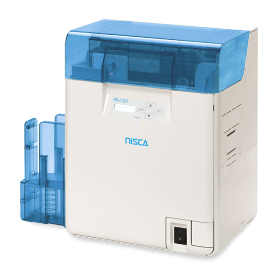
- Manuals
- Brands
- Nisca Manuals
- Printer
- PR-C201
- Operation manual
-
Contents
-
Table of Contents
-
Troubleshooting
-
Bookmarks
Quick Links
Related Manuals for Nisca PR-C201
Summary of Contents for Nisca PR-C201
-
Page 1
Operation Guide… -
Page 2: Easy Operation
Features of the card printer PR-C201 Easy Card Loading Thanks to the Multifunctional Card Case, it is possible to feed cards without detaching the Card Case. (→ p10) Strengthened Security • You can anchor the printer with a cable using the Security Cable Slot. (→ p53) •…
-
Page 3: Table Of Contents
Contents Contents Operating the Printer Safely ………………1 Regulations for this product FCC Regulations………….. 3 Part Names and Descriptions………………4 Front Side of the Printer………………..4 Inside the Top Cover ………………… 5 Rear Side of the Printer ………………..6 Front Cover ……………………7 Operation Panel ………………….
-
Page 4
Full Color Card Printer Adjusting the contour level …………….37 Adjusting the hue ………………38 Setting the Type of Ink Ribbon or Transfer Film to Use……….39 Notification of Time for Ink Ribbon and Transfer Film Replacement ……41 Setting the Types of Card to Use …………….42 Adjusting the Feed Gate Depending on Card Thickness…… -
Page 5: Operating The Printer Safely
Operating the Printer Safely Operating the Printer Safely The following precautions must be observed to assure safe operation of the printer. Also, do not do anything that is not described in this manual. Doing so may cause an unexpected accident. Failure to observe the following items while using the printer may cause fire, electric shock or other unexpected accident.
-
Page 6
Full Color Card Printer The lower part of the Top Cover, the printer internal heat roller section, High Temperature and the thermal head section get Warning Label very hot. Ensure you do not touch these three locations. Heat Roller Section Thermal Head Section Failure to observe the following items while using the printer may cause injury or a malfunction. -
Page 7: Regulations For This Product Fcc Regulations
Operating the Printer Safely Under the following conditions images on cards may deteriorate or cards may warp after printing. The surface of the card is in contact for an extended period of time with a vinyl card holder or synthetic leather or other material that contains plasticizer.
-
Page 8: Part Names And Descriptions
Full Color Card Printer Part Names and Descriptions Front Side of the Printer a Top Cover e Power Switch Open when loading cards or cleaning the Turns the power on and off. feeding roller. →See «Turning On and Off the Printer» on page 9 for instructions on turning the power on and off.
-
Page 9: Inside The Top Cover
Part Names and Descriptions Inside the Top Cover Interior of the Top Cover. a Card Case c Top Cover Up to 250 cards can be loaded at one time. Open when cards are jammed or similar. You can adjust the gate gap to match the →See «When a Card is Jammed…»…
-
Page 10: Rear Side Of The Printer
Full Color Card Printer Rear Side of the Printer (OPTION) (PC) (10/100) RS-232C(PC) RS-232C(OPTION) a Card Ejection Slot (Right) e Security Cable Slot Ejects correctly printed cards and cards with Use the Security Cable Slot to prevent theft of errors. the printer.
-
Page 11: Front Cover
Part Names and Descriptions Front Cover Interior of the Front Cover. a Card Feeding Knob e Reverse Knob Rotating the dial to the left or right ejects cards Rotate the knob to the left to change the jammed in the secondary transfer section from direction of the cards in the reverse section.
-
Page 12: Operation Panel
Full Color Card Printer Operation Panel Ready to Print a MENU Key d LED Indicator Switches between Normal Mode and User This indicator is lit blue depending on the status Mode. In User Mode, it is used to go up one of the printer.
-
Page 13: Basic Card Printing Methods
Basic Card Printing Methods Basic Card Printing Methods This section explains the basic flow of operations, from turning on the power through printing a card. Turning On and Off the Printer Turn on the printer before starting to print. Before turning on the power, make sure the following preparations are complete: •…
-
Page 14: Loading Cards
Full Color Card Printer Loading Cards Cards can be loaded in two ways: using the card retainer, and using the card feeding slot. The Card Retainer can be loaded with a large quantity of cards, making it useful for mass printing. Use the Card Feeding Slot to manually load cards when you want to print only 1 particular card or to print many types of cards.
-
Page 15
Basic Card Printing Methods Pull the card retainer, and load cards. • Hold the card retainer lever with your fingers, and pull it right out. • Load the card case with the printing side (front surface) to the left. • When loading the cards, be sure to hold their edges, and never touch the front or rear printing sides. Return the card retainer, and close the Card Case cover. -
Page 16: Manually Loading Cards One By One
Full Color Card Printer Manually Loading Cards One by One Open the Top Cover. Open the Card Case, and insert cards into the Card Feeding Slot. • Pull the lock, and open the Card Case lid. • Insert cards with the printing side to the left into the Card Feeding Card Feeding Slot.
-
Page 17: Loading Magnetic/Ic Cards
Basic Card Printing Methods Loading Magnetic/IC Cards The factory default for magnetic cards/IC cards is to be loaded as below. →See «Loading Cards into the Card Case» on page 10 for the procedure on loading cards into the Card Case. If using cards with JIS2 magnetic strips Card Case Rear •…
-
Page 18: Printing
• Open the printer driver settings screen. Specify various settings for printing if necessary. • Select [NISCA PR-C201] if it is not already selected. • Click [Preferences] (or [Properties]), and set the card size and the number of cards to be printed.
-
Page 19: Removing Cards
Basic Card Printing Methods Click [Print]. • Printing starts. • Cards are pulled into the printer and the LED Indicator blinks blue. [Now Printing] appears on the LCD Panel. • If the cards are not loaded, [Card Empty] appears on the LCD Panel.
-
Page 20: Changing The Ink Ribbon And Transfer Film
Full Color Card Printer Changing the Ink Ribbon and Transfer Film Change the Ink Ribbon and Transfer Film when these run out. →See «Ink Ribbon/Transfer Film» on page 81 for details about Ink Ribbon and Transfer Film. You can check the amount of Ink Ribbon and Transfer Film remaining. Note →See «Correcting image and text misalignment»…
-
Page 21: Changing The Ink Ribbon
Basic Card Printing Methods Changing the Ink Ribbon Use the following procedure when replacing the Ink Ribbon. Remove the Ink Ribbon Cassette. • Pull out the handle of the ink ribbon cassette with the handle turned up. Note When placing the Ink Ribbon Cassette down, prevent contamination adhering by placing it with the handle on the bottom.
-
Page 22
Full Color Card Printer Take up the Ink Ribbon slack. • Turn the knob as in the diagram at right, and take up the ribbon slack. • If the slack is not taken up properly, then the Ink Ribbon may jam. Insert the Ink Ribbon Cassette. -
Page 23: Transfer Film Replacement
Basic Card Printing Methods Transfer Film Replacement Use the following procedure when replacing the Transfer Film. Remove the Transfer Film Cassette. • Pull out the handle of the transfer film cassette with the handle turned up. When placing the Transfer Film down, Note prevent contamination adhering by placing it with the handle on the bottom.
-
Page 24
Full Color Card Printer Load new Transfer Film in the Cassette. • Insert the spool spindle into the feed side (white) holder. As in the diagram at right, unwind and load onto the shaft. Finally, insert the spool spindle into the winding side holder. -
Page 25
Basic Card Printing Methods Insert the Transfer Film Cassette. • Insert the Transfer Film Cassette until a «click» is heard. →For replacing Cleaning Tape, See «Cleaning Tape Replacement» on page 22. When inserting the Transfer Film, insert Note while turning the knob in order to prevent slack. -
Page 26: Cleaning Tape Replacement
Full Color Card Printer Cleaning Tape Replacement Remove the Cleaning Tape Cassette. • Hold the Cleaning Tape Cassette handle, lift it, and pull. Lift up the tape spindle. • As in the diagram at right, lift the tape spindle by hand. Remove the used Cleaning Tape, insert the new tape, and return the tape spindle.
-
Page 27: Normal Mode And User Mode
Normal Mode and User Mode Normal Mode and User Mode You can switch the printer from Normal Mode to User Mode while it is operating. This section provides an outline of both modes, explains how to change modes and explains the basic operations of the User Mode. Normal Mode and User Mode …
-
Page 28: User Mode
Full Color Card Printer User Mode User Mode is used to set operations and check the status of the printer. Menu names such as [Card Count] and [Ribbon Type] appear on the LCD Panel. Switching to User Mode This section explains how to switch from Normal Mode to User Mode. →See «Switching to Normal Mode (Exiting User Mode)»…
-
Page 29: Basic User Mode Operations
Normal Mode and User Mode Basic User Mode Operations The User Mode has multiple menus in a hierarchical tree organized according to function. This section explains how to switch menus in the User Mode hierarchy tree and how to switch from User Mode to Normal Mode.
-
Page 30: Returning To The Main Menu (Switching To Menus On A Higher Level)
Full Color Card Printer Returning to the Main Menu (Switching to Menus on a Higher Level) You can return to a higher level by pressing the Printer Setup Printer Setup Buzzer Buzzer MENU Key. You can return to the main menu by SET:>>…
-
Page 31: Printer Settings
Printer Settings Printer Settings This section explains how to check the printer’s status and change the printer’s settings. Counting the Number of Cards that Are Printed You can count the number of cards that are printed. You can also count the number of cards that have been printed in a specified period of time by resetting the count with the SET Key.
-
Page 32: Displaying The Total Number Of Sides That Are Printed
Full Color Card Printer Press the SET key. • The display changes to [Reset ?]. Card Count Card Count Reset ? Reset ? Change the setting to [YES] by using Reset ? the / Keys then press the SET key. •…
-
Page 33: Checking The Type And Remaining Quantity Of The Ink Ribbon Or Transfer Film
Printer Settings Press the Key until [Total Count] is Card Count Card Count displayed. • The total number of sides is displayed. Total Count Total Count The count cannot be reset. Checking the type and remaining quantity of the Ink Ribbon or Transfer Film You can check the type and remaining quantity of the Ink Ribbon or Transfer Film.
-
Page 34: Checking The Program Version And Serial Number
Full Color Card Printer Checking the Program Version and Serial Number You can check the version of the program and the printer’s serial number. You can also display the status on the printer driver (→See «Opening the Printer Note Driver Settings Screen»…
-
Page 35: Turning The Error Alarm On Or Off
Printer Settings Turning the Error Alarm On or Off The initial setting is for the buzzer to sound when an error occurs. You can set the buzzer so that it does not sound. You can also change the settings by using the printer driver (→See «Opening the Note Printer Driver Settings Screen»…
-
Page 36: Reduce Printer Power Consumption
Full Color Card Printer Reduce Printer Power Consumption Select the power-saving mode for when the printer is not being used. You can also change the settings by using the printer driver (→ See «Opening the Note Printer Driver Settings Screen» on page 87). Switch from Normal Mode to User Normal Mode User Mode…
-
Page 37: Adjusting The Print Results
Printer Settings The factory default setting is [MAIN POWER OFF]. Note If the printer is off ([MAIN POWER OFF]), turn it on by pressing the Power Switch to use it (→See «Turning On and Off the Printer» on page 9). Adjusting the Print Results You can adjust the print results by changing the hue and the strength of the edge.
-
Page 38
Full Color Card Printer Change the settings by using the / Print Vertical Keys, then press the SET key. • If you increase the setting value of [Print Vertical] , the printing position will move downwards. (Setting values Print Vertical are by increments/decrements of approximately 0.04 mm) •… -
Page 39: Quality Printing/Quick Printing
Printer Settings Quality printing/Quick printing You can change the printing speed of color images. Quick printing is set as a factory default. You can perform quality printing by changing the settings. Switch from Normal Mode to User Normal Mode User Mode MENU Mode.
-
Page 40: Correcting Image And Text Misalignment
Full Color Card Printer Correcting image and text misalignment You can correct the misalignment (horizontal) of the color image and black text printing position. Switch from Normal Mode to User Normal Mode User Mode MENU Mode. Ready to Print Ready to Print Printer Info.
-
Page 41: Adjusting The Contour Level
Printer Settings Adjusting the contour level You can adjust the sharpness of edges such as facial contour. Switch from Normal Mode to User Normal Mode User Mode MENU Mode. Ready to Print Ready to Print Printer Info. Printer Info. SET:>>…
-
Page 42: Adjusting The Hue
Full Color Card Printer Adjusting the hue You can adjust the level of each hue (Yellow, Magenta, Cyan, Black). Adjusting the levels changes the hues of Yellow, Magenta, and Cyan for color images, and the thickness of black text for Black printing. Switch from Normal Mode to User Normal Mode User Mode…
-
Page 43: Setting The Type Of Ink Ribbon Or Transfer Film To Use
Printer Settings Setting the Type of Ink Ribbon or Transfer Film to Use Set the type of Ink Ribbon or Transfer Film to use. →See «Changing the Ink Ribbon and Transfer Film» on page 16 for details about changing the Ink Ribbon and Transfer Film.
-
Page 44
Full Color Card Printer Change the settings by using the / Ribbon Type OOOOO Keys, then press the SET Key. Ribbon Type xxxxx If the Ink Ribbon type set in the printer and the [Ribbon Type] setting are different, an Note Ink Ribbon error or a transfer problem occurs. -
Page 45: Notification Of Time For Ink Ribbon And Transfer Film Replacement
Printer Settings Notification of Time for Ink Ribbon and Transfer Film Replacement If there is little remaining Ink Ribbon or Transfer Film, the LCD Panel will display the remaining quantity to notify you that it should be replaced soon. You can also change the settings from the printer driver (→See «Opening the Printer Note Driver Settings Screen»…
-
Page 46: Setting The Types Of Card To Use
Full Color Card Printer As time approaches for replacement of the Ink Ribbon or Transfer Film, a remaining quantity notification for these is displayed. • In Normal Mode, if the Ink Ribbon and Transfer Film remaining quantity drops below the settings value (%), then the remaining quantity notification will appear at a set frequency (approximately 4 seconds).
-
Page 47: Optimizing Transfer Conditions
Printer Settings Rotate the dial on the lower surface of Align the Card Case and adjust the gate gap. Knob with Marks • The figures on the knob indicate the size of the gate gap. • If cards do not pass through the gate, turn the knob to the right.
-
Page 48
Full Color Card Printer Change the settings by using the / Card Type Card Type PVC (0.76mm) PVC (0.76mm) Keys, then press the SET Key. • Settings values that can be changed are as below. • If CARD1-3 are selected, then go to Step 5. If other Card Type Card Type settings values are selected, then you have finished. -
Page 49: Correcting Card Curl
Printer Settings Correcting Card Curl Depending on the cards you use, even given optimum secondary transfer conditions (speed and temperature), cards may curl. After secondary transfer, by correcting card curl (decurl), you can reduce the amount of curl. You can also change the settings by using the printer driver (→See «Opening the Note Printer Driver Settings Screen»…
-
Page 50: Switching The Card Ejection Slot
Full Color Card Printer Switching the Card Ejection Slot You can switch the slot from which printed cards are output to Card Ejection Slot (Left) and (Right). The factory default is set so that correctly printed cards are output from the Card Ejection Slot (Left), and cards with errors are output from Card Ejection Slot (Right).
-
Page 51: Set The Orientation Of Magnetic Cards/Ic Cards To Load
Printer Settings Change the settings by using the / Normal Exit Normal Exit LEFT SIDE LEFT SIDE Keys, then press the SET Key. • Use the / Keys to switch between [LEFT SIDE]/ [RIGHT SIDE]. Normal Exit Normal Exit • Set it to [LEFT SIDE] to output cards from Card RIGHT SIDE RIGHT SIDE Ejection Slot (Left), or [RIGHT SIDE] to do from Card…
-
Page 52
Full Color Card Printer Press the Key until [Set Face] is Card Type displayed, then press the SET Key. Set Face Set Face STANDARD STANDARD STANDARD Change the settings by using the / Set Face Set Face STANDARD STANDARD Keys, then press the SET Key. -
Page 53: Set The Orientation Of Cards To Eject
Printer Settings Set the Orientation of Cards to Eject Set the orientation of correctly printed cards. You can also change the settings by using the printer driver (→See «Opening the Note Printer Driver Settings Screen» on page 87). Switch from Normal Mode to User Normal Mode User Mode MENU…
-
Page 54
Full Color Card Printer Change the settings by using the / Eject Face Eject Face NOT SPECIFY NOT SPECIFY Keys, then press the SET Key. • Settings values that can be changed are as below. Eject Face Eject Face Eject Face Eject Face DOWN DOWN… -
Page 55: Changing Network Connection Settings
Printer Settings Changing Network Connection Settings You can configure Internet communications settings such as the individual printer ID and TCP/ IP-related settings. You can also change the settings by using the printer driver (→See «2. Print over a Note network»…
-
Page 56
Full Color Card Printer Change the settings by using the / Keys, then press the SET Key. • When setting numerical values, change each digit using the / Keys. Fix changes using the SET Key then progresses to the next digit. Pressing the SET Key after the final digit fixes the changes. -
Page 57: Preventing Theft And Unauthorized Usage
Printer Settings Preventing Theft and Unauthorized Usage Preventing Theft of the Printer (Security Cable Slot) You can prevent theft of the printer by locking it with a wire cable. Use a wire cable that fits the Security Cable Slot (0.12″…
-
Page 58: Cleaning
Full Color Card Printer Cleaning The rollers need to be cleaned to maintain good print quality. This section explains which rollers need to be cleaned and how to clean them. Before Cleaning Note the following cautions when cleaning the rollers. …
-
Page 59: Open The Top Cover
Cleaning Press the Key until [Cleaning] is Printer Info. Printer Info. SET:>> SET:>> displayed, then press the SET Key. Cleaning Cleaning Cleaning Cleaning SET:>> SET:>> Remove Cards Remove Cards When [Cool Down —] is displayed, wait Cleaning Cleaning Cool Down 75 Cool Down 70 until the figure drops to 70 or lower.
-
Page 60
Full Color Card Printer When [Set Cleaning Crd] is displayed, load the Cleaning Card in the Card Feeding Slot. Card • When the Cleaning Card is loaded, close the Card Feeding Case cover and the Top Cover. Slot • Align the adhesive side of the Cleaning Card to the right. -
Page 61: Cleaning The Cleaning Roller
Cleaning Cleaning the Cleaning Roller Clean the Cleaning Roller if cards are printed with missing colors or if there are foreign objects on them. Be sure to turn off the printer before cleaning the rollers. Read the cautions in «Before Cleaning» on page 54. Turn off the power.
-
Page 62
Full Color Card Printer Wipe the roller clean. • Use a soft cloth fully moistened with water and wrung out to wipe the roller clean. Load the Cleaning Roller and Cleaning Tape Cassette in order, and close the Front Cover. -
Page 63: Cleaning The Feeding Roller
Cleaning Cleaning the Feeding Roller Clean the Feeding Roller under the Card Case if cards do not feed smoothly into the printer. Be sure to turn off the printer before cleaning the rollers. Read the cautions in «Before Cleaning» on page 54. Turn off the power.
-
Page 64: Cleaning The Feeding Roller
Full Color Card Printer Cleaning the Feeding Roller If the printing location on printed cards is out of adjustment, or there is white space at the edge of printed areas, then clean the secondary transfer section feeding roller at the bottom of the top cover.
-
Page 65
Cleaning Wipe the roller clean. • Use a soft cloth fully moistened with water and wrung out to wipe the roller clean. • As you turn the card feeding knob, fully clean the roller. • Clean the card feeding roller (5 locations). Card Feeding Roller … -
Page 66: Cleaning The Reverse Roller
Full Color Card Printer Cleaning the Reverse Roller If card delivery from the reverse section to the secondary transfer feeding roller is not possible, then clean the Reverse Roller. Be sure to turn off the printer before cleaning the rollers. …
-
Page 67
Cleaning Wipe the roller clean. • Use a soft cloth fully moistened with water and wrung out to wipe the roller clean. • Rotate the reverse feeding knob, and fully clean the roller. • Turn the reverse knob to rotate the reverse section one Reverse Roller turn, and clean the other side of the Reverse Roller. -
Page 68: Primary Transfer Feeding Roller Cleaning
Full Color Card Printer Primary Transfer Feeding Roller Cleaning If a film-related error occurs such as [Film Wind up], or there is color bleed or image distortion, then clean the primary transfer feeding roller. Be sure to turn off the printer before cleaning the rollers. …
-
Page 69
Cleaning Insert a flat screwdriver or coin into the groove on the end of the feeding roller. Flat Screwdriver Feeding Roller • Ensure you have a flat screwdriver or coin that can fit into the groove on the end of the feeding roller. Wipe the roller clean. -
Page 70: Filter Cleaning
Full Color Card Printer Filter Cleaning If the filter becomes clogged, then dirt may enter the printer. It is recommended that the filter be cleaned monthly. Be sure to turn off the printer before cleaning the rollers. Read the cautions in «Before Cleaning» on page 54. Turn off the power.
-
Page 71: Troubleshooting
Troubleshooting Troubleshooting This section explains what to do when an error message appears, a card is jammed, or there is a problem with the printed side of a card. When an Error Message Appears The LED Indicator is lit orange or blinks, and a description of the error appears on the LCD Panel when an error occurs.
-
Page 72
Full Color Card Printer Error message Cause and solution The Ink Ribbon has been used up. Replace the Ink Ribbon. Ribbon Empty → See «Changing the Ink Ribbon and Transfer Film» on page 16 for details about changing the Ink Ribbon. The Ink Ribbon could not be detected correctly. -
Page 73
Troubleshooting Error message Cause and solution The Transfer Film could not be detected correctly. Reload the Transfer Film. Film Type →See «Changing the Ink Ribbon and Transfer Film» on page 16 for details about changing the Transfer Film. The Transfer Film set in the printer and printer settings may be different. -
Page 74
Full Color Card Printer Error message Cause and solution Cards cannot be fed into printer. Press the SET Key. Card Jam Feeder Frequent occurrences of this error may mean the following: Is the Card Case loaded correctly? Correctly load the Card Case. Confirm that the Card Case card retainer is loaded properly. -
Page 75: Service Call
Troubleshooting Error message Cause and solution An error that requires repair may occur. Service Call The cause of the error differs depending on the error code. Turn off and on the power. Repairs are necessary if the error reoccurs. Program version update was interrupted. Turn off and on the power, then start version update again.
-
Page 76: Cover Is Open
Full Color Card Printer If the following messages appear after pressing the SET key, resolve the problem according to the instructions below. Message Solution Press the SET Key. Push SET key Load the card in the Card Case. Card Empty Correctly close the cover.
-
Page 77: When A Card Is Jammed
Troubleshooting When a Card is Jammed… Use the following procedure to remove cards jammed during printing or when the jammed card is unable to be removed despite the SET Key being pressed. Ejection Dials are at 3 locations within the printer. …
-
Page 78
Full Color Card Printer (If cards can be seen in the feed slot) Rotate the reverse feeding knob. Reverse Feeding Knob • Remove cards jammed in the cleaning section from the feed slot. • Cards jammed in the reverse section can also be output. -
Page 79
Troubleshooting (If the card is in other than the reverse section) Rotate the feeding knob. • Jammed cards are ejected from Card Ejection Slot Secondary Transfer Section (left). • If the jam is cleared, then go to Step 8. Feeding Knob Close the Top Cover and Front Cover. -
Page 80: If The Ink Ribbon Or Transfer Film Are Cut
Full Color Card Printer If the Ink Ribbon or Transfer Film are Cut If the Ink Ribbon or Transfer Film are cut for any reason, then repair these using the method below. Remove the Ink Ribbon Cassette or Transfer Film Cassette. →See «Changing the Ink Ribbon and Transfer Film»…
-
Page 81
Troubleshooting Rotate the winding side knob. Ink Ribbon Transfer Film • Rotate the knob until the joined section of the Ink Cassette Cassette Ribbon or Transfer Film is fully inside the winding side spool spindle. Return the Ink Ribbon Cassette or Transfer Film Cassette to their original positions. -
Page 82: When Cards Are Not Printed Correctly
Full Color Card Printer When Cards are Not Printed Correctly… If missing or incorrect colors are printed on a card or cards are incorrectly printed, resolve the problem according to the following instructions. Problem Cause and solution There are missing or Is there dirt on the card surface? Do not use dirty cards.
-
Page 83
Troubleshooting Problem Cause and solution White cards (unprinted Only color image data was received with the Black Ink Ribbon cards) are output. loaded. Use the Overcoating Color Ink Ribbon when printing in color. →See «Changing the Ink Ribbon and Transfer Film» on page 16 for details about changing the Ink Ribbon. -
Page 84: Other Troubles
Full Color Card Printer Problem Cause and solution Some or all of the printed Is the Transfer Film running between the two pins on top of the area are cloudy. Transfer Film Cassette? Make sure that the Transfer Film is correctly loaded. →See «Transfer Film Replacement»…
-
Page 85: Appendix
Appendix Appendix Consumables Ink Ribbon/Transfer Film The 2 types of Ink Ribbon that can be used in this printer are as follows. Number of Name Type Product no Remarks Printable Sides Retransfer Color Ink R-YMCK PR5002-R4C 500 screens/spool – Ribbon Retransfer Reverse R-YMCKK…
-
Page 86: Cards
Full Color Card Printer Cards Use only cards that conform to the CR-80 standard. Size: 3.4″ × 2.1″ (86 mm × 54 mm) Thickness: 0.03″-0.04″ (0.76 mm-1.00 mm) Material: PVC, PET, PET-G Do not use cards that do not conform to the CR-80 standard. Such cards may not be printed properly.
-
Page 87: Updating The Printer’s Software
Appendix Updating the Printer’s Software Please contact your reseller for upgrades to printer firmware and drivers.
-
Page 88: Menu Route Map (User Mode)
Full Color Card Printer Menu Route Map (User Mode) Normal Mode User Mode Main Menu Settings Menu MENU Ready to Print Printer Info. Card Count [User Mode] SET:>> MENU Total Count MENU Exit Menu ? Ribbon Remainder Film Remainder Exit Menu ? Version Info.
-
Page 89
Appendix User Mode Settings Menu To Main Menu To [Image Setup] Menu (Previous Page) Ribbon Setup Ribbon Type SET:>> MENU Film Type Ribbon Notice(%) MENU Film Notice(%) Card Setup Card Type SET:>> MENU Decurl Time(s) Normal Exit Error Exit Set Face Eject Face Interface Setup Printer ID… -
Page 90: Main Specifications
Full Color Card Printer Main Specifications PR-C201 Function Double-sided printing (full color) Print system Indirect transfer system Print media Material: PVC, PET, PET-G Thickness: 0.76-1.00 mm Size: according to CR-80 standards Print quality 600 dpi Print tones Input tones: RGB, 256 tones/color, K2 tones…
-
Page 91: Opening The Printer Driver Settings Screen
If you are using Windows Server 2008 R2, open the printer driver’s setting screen as follows. [Start] → [Control Panel] → [View devices and printers] → [NISCA PR-C201] → [Printing preferences] If you are using Windows 7, open the printer driver’s setting screen as follows.
-
Page 92
4Y5-8399-010…
- Manuals
- Brands
- Nisca Manuals
- Printer
- PR-C201
- Operation manual
-
Contents
-
Table of Contents
-
Troubleshooting
-
Bookmarks
Quick Links
Related Manuals for Nisca PR-C201
Summary of Contents for Nisca PR-C201
-
Page 1
Operation Guide… -
Page 2: Easy Operation
Features of the card printer PR-C201 Easy Card Loading Thanks to the Multifunctional Card Case, it is possible to feed cards without detaching the Card Case. (→ p10) Strengthened Security • You can anchor the printer with a cable using the Security Cable Slot. (→ p53) •…
-
Page 3: Table Of Contents
Contents Contents Operating the Printer Safely ………………1 Regulations for this product FCC Regulations………….. 3 Part Names and Descriptions………………4 Front Side of the Printer………………..4 Inside the Top Cover ………………… 5 Rear Side of the Printer ………………..6 Front Cover ……………………7 Operation Panel ………………….
-
Page 4
Full Color Card Printer Adjusting the contour level …………….37 Adjusting the hue ………………38 Setting the Type of Ink Ribbon or Transfer Film to Use……….39 Notification of Time for Ink Ribbon and Transfer Film Replacement ……41 Setting the Types of Card to Use …………….42 Adjusting the Feed Gate Depending on Card Thickness…… -
Page 5: Operating The Printer Safely
Operating the Printer Safely Operating the Printer Safely The following precautions must be observed to assure safe operation of the printer. Also, do not do anything that is not described in this manual. Doing so may cause an unexpected accident. Failure to observe the following items while using the printer may cause fire, electric shock or other unexpected accident.
-
Page 6
Full Color Card Printer The lower part of the Top Cover, the printer internal heat roller section, High Temperature and the thermal head section get Warning Label very hot. Ensure you do not touch these three locations. Heat Roller Section Thermal Head Section Failure to observe the following items while using the printer may cause injury or a malfunction. -
Page 7: Regulations For This Product Fcc Regulations
Operating the Printer Safely Under the following conditions images on cards may deteriorate or cards may warp after printing. The surface of the card is in contact for an extended period of time with a vinyl card holder or synthetic leather or other material that contains plasticizer.
-
Page 8: Part Names And Descriptions
Full Color Card Printer Part Names and Descriptions Front Side of the Printer a Top Cover e Power Switch Open when loading cards or cleaning the Turns the power on and off. feeding roller. →See «Turning On and Off the Printer» on page 9 for instructions on turning the power on and off.
-
Page 9: Inside The Top Cover
Part Names and Descriptions Inside the Top Cover Interior of the Top Cover. a Card Case c Top Cover Up to 250 cards can be loaded at one time. Open when cards are jammed or similar. You can adjust the gate gap to match the →See «When a Card is Jammed…»…
-
Page 10: Rear Side Of The Printer
Full Color Card Printer Rear Side of the Printer (OPTION) (PC) (10/100) RS-232C(PC) RS-232C(OPTION) a Card Ejection Slot (Right) e Security Cable Slot Ejects correctly printed cards and cards with Use the Security Cable Slot to prevent theft of errors. the printer.
-
Page 11: Front Cover
Part Names and Descriptions Front Cover Interior of the Front Cover. a Card Feeding Knob e Reverse Knob Rotating the dial to the left or right ejects cards Rotate the knob to the left to change the jammed in the secondary transfer section from direction of the cards in the reverse section.
-
Page 12: Operation Panel
Full Color Card Printer Operation Panel Ready to Print a MENU Key d LED Indicator Switches between Normal Mode and User This indicator is lit blue depending on the status Mode. In User Mode, it is used to go up one of the printer.
-
Page 13: Basic Card Printing Methods
Basic Card Printing Methods Basic Card Printing Methods This section explains the basic flow of operations, from turning on the power through printing a card. Turning On and Off the Printer Turn on the printer before starting to print. Before turning on the power, make sure the following preparations are complete: •…
-
Page 14: Loading Cards
Full Color Card Printer Loading Cards Cards can be loaded in two ways: using the card retainer, and using the card feeding slot. The Card Retainer can be loaded with a large quantity of cards, making it useful for mass printing. Use the Card Feeding Slot to manually load cards when you want to print only 1 particular card or to print many types of cards.
-
Page 15
Basic Card Printing Methods Pull the card retainer, and load cards. • Hold the card retainer lever with your fingers, and pull it right out. • Load the card case with the printing side (front surface) to the left. • When loading the cards, be sure to hold their edges, and never touch the front or rear printing sides. Return the card retainer, and close the Card Case cover. -
Page 16: Manually Loading Cards One By One
Full Color Card Printer Manually Loading Cards One by One Open the Top Cover. Open the Card Case, and insert cards into the Card Feeding Slot. • Pull the lock, and open the Card Case lid. • Insert cards with the printing side to the left into the Card Feeding Card Feeding Slot.
-
Page 17: Loading Magnetic/Ic Cards
Basic Card Printing Methods Loading Magnetic/IC Cards The factory default for magnetic cards/IC cards is to be loaded as below. →See «Loading Cards into the Card Case» on page 10 for the procedure on loading cards into the Card Case. If using cards with JIS2 magnetic strips Card Case Rear •…
-
Page 18: Printing
• Open the printer driver settings screen. Specify various settings for printing if necessary. • Select [NISCA PR-C201] if it is not already selected. • Click [Preferences] (or [Properties]), and set the card size and the number of cards to be printed.
-
Page 19: Removing Cards
Basic Card Printing Methods Click [Print]. • Printing starts. • Cards are pulled into the printer and the LED Indicator blinks blue. [Now Printing] appears on the LCD Panel. • If the cards are not loaded, [Card Empty] appears on the LCD Panel.
-
Page 20: Changing The Ink Ribbon And Transfer Film
Full Color Card Printer Changing the Ink Ribbon and Transfer Film Change the Ink Ribbon and Transfer Film when these run out. →See «Ink Ribbon/Transfer Film» on page 81 for details about Ink Ribbon and Transfer Film. You can check the amount of Ink Ribbon and Transfer Film remaining. Note →See «Correcting image and text misalignment»…
-
Page 21: Changing The Ink Ribbon
Basic Card Printing Methods Changing the Ink Ribbon Use the following procedure when replacing the Ink Ribbon. Remove the Ink Ribbon Cassette. • Pull out the handle of the ink ribbon cassette with the handle turned up. Note When placing the Ink Ribbon Cassette down, prevent contamination adhering by placing it with the handle on the bottom.
-
Page 22
Full Color Card Printer Take up the Ink Ribbon slack. • Turn the knob as in the diagram at right, and take up the ribbon slack. • If the slack is not taken up properly, then the Ink Ribbon may jam. Insert the Ink Ribbon Cassette. -
Page 23: Transfer Film Replacement
Basic Card Printing Methods Transfer Film Replacement Use the following procedure when replacing the Transfer Film. Remove the Transfer Film Cassette. • Pull out the handle of the transfer film cassette with the handle turned up. When placing the Transfer Film down, Note prevent contamination adhering by placing it with the handle on the bottom.
-
Page 24
Full Color Card Printer Load new Transfer Film in the Cassette. • Insert the spool spindle into the feed side (white) holder. As in the diagram at right, unwind and load onto the shaft. Finally, insert the spool spindle into the winding side holder. -
Page 25
Basic Card Printing Methods Insert the Transfer Film Cassette. • Insert the Transfer Film Cassette until a «click» is heard. →For replacing Cleaning Tape, See «Cleaning Tape Replacement» on page 22. When inserting the Transfer Film, insert Note while turning the knob in order to prevent slack. -
Page 26: Cleaning Tape Replacement
Full Color Card Printer Cleaning Tape Replacement Remove the Cleaning Tape Cassette. • Hold the Cleaning Tape Cassette handle, lift it, and pull. Lift up the tape spindle. • As in the diagram at right, lift the tape spindle by hand. Remove the used Cleaning Tape, insert the new tape, and return the tape spindle.
-
Page 27: Normal Mode And User Mode
Normal Mode and User Mode Normal Mode and User Mode You can switch the printer from Normal Mode to User Mode while it is operating. This section provides an outline of both modes, explains how to change modes and explains the basic operations of the User Mode. Normal Mode and User Mode …
-
Page 28: User Mode
Full Color Card Printer User Mode User Mode is used to set operations and check the status of the printer. Menu names such as [Card Count] and [Ribbon Type] appear on the LCD Panel. Switching to User Mode This section explains how to switch from Normal Mode to User Mode. →See «Switching to Normal Mode (Exiting User Mode)»…
-
Page 29: Basic User Mode Operations
Normal Mode and User Mode Basic User Mode Operations The User Mode has multiple menus in a hierarchical tree organized according to function. This section explains how to switch menus in the User Mode hierarchy tree and how to switch from User Mode to Normal Mode.
-
Page 30: Returning To The Main Menu (Switching To Menus On A Higher Level)
Full Color Card Printer Returning to the Main Menu (Switching to Menus on a Higher Level) You can return to a higher level by pressing the Printer Setup Printer Setup Buzzer Buzzer MENU Key. You can return to the main menu by SET:>>…
-
Page 31: Printer Settings
Printer Settings Printer Settings This section explains how to check the printer’s status and change the printer’s settings. Counting the Number of Cards that Are Printed You can count the number of cards that are printed. You can also count the number of cards that have been printed in a specified period of time by resetting the count with the SET Key.
-
Page 32: Displaying The Total Number Of Sides That Are Printed
Full Color Card Printer Press the SET key. • The display changes to [Reset ?]. Card Count Card Count Reset ? Reset ? Change the setting to [YES] by using Reset ? the / Keys then press the SET key. •…
-
Page 33: Checking The Type And Remaining Quantity Of The Ink Ribbon Or Transfer Film
Printer Settings Press the Key until [Total Count] is Card Count Card Count displayed. • The total number of sides is displayed. Total Count Total Count The count cannot be reset. Checking the type and remaining quantity of the Ink Ribbon or Transfer Film You can check the type and remaining quantity of the Ink Ribbon or Transfer Film.
-
Page 34: Checking The Program Version And Serial Number
Full Color Card Printer Checking the Program Version and Serial Number You can check the version of the program and the printer’s serial number. You can also display the status on the printer driver (→See «Opening the Printer Note Driver Settings Screen»…
-
Page 35: Turning The Error Alarm On Or Off
Printer Settings Turning the Error Alarm On or Off The initial setting is for the buzzer to sound when an error occurs. You can set the buzzer so that it does not sound. You can also change the settings by using the printer driver (→See «Opening the Note Printer Driver Settings Screen»…
-
Page 36: Reduce Printer Power Consumption
Full Color Card Printer Reduce Printer Power Consumption Select the power-saving mode for when the printer is not being used. You can also change the settings by using the printer driver (→ See «Opening the Note Printer Driver Settings Screen» on page 87). Switch from Normal Mode to User Normal Mode User Mode…
-
Page 37: Adjusting The Print Results
Printer Settings The factory default setting is [MAIN POWER OFF]. Note If the printer is off ([MAIN POWER OFF]), turn it on by pressing the Power Switch to use it (→See «Turning On and Off the Printer» on page 9). Adjusting the Print Results You can adjust the print results by changing the hue and the strength of the edge.
-
Page 38
Full Color Card Printer Change the settings by using the / Print Vertical Keys, then press the SET key. • If you increase the setting value of [Print Vertical] , the printing position will move downwards. (Setting values Print Vertical are by increments/decrements of approximately 0.04 mm) •… -
Page 39: Quality Printing/Quick Printing
Printer Settings Quality printing/Quick printing You can change the printing speed of color images. Quick printing is set as a factory default. You can perform quality printing by changing the settings. Switch from Normal Mode to User Normal Mode User Mode MENU Mode.
-
Page 40: Correcting Image And Text Misalignment
Full Color Card Printer Correcting image and text misalignment You can correct the misalignment (horizontal) of the color image and black text printing position. Switch from Normal Mode to User Normal Mode User Mode MENU Mode. Ready to Print Ready to Print Printer Info.
-
Page 41: Adjusting The Contour Level
Printer Settings Adjusting the contour level You can adjust the sharpness of edges such as facial contour. Switch from Normal Mode to User Normal Mode User Mode MENU Mode. Ready to Print Ready to Print Printer Info. Printer Info. SET:>>…
-
Page 42: Adjusting The Hue
Full Color Card Printer Adjusting the hue You can adjust the level of each hue (Yellow, Magenta, Cyan, Black). Adjusting the levels changes the hues of Yellow, Magenta, and Cyan for color images, and the thickness of black text for Black printing. Switch from Normal Mode to User Normal Mode User Mode…
-
Page 43: Setting The Type Of Ink Ribbon Or Transfer Film To Use
Printer Settings Setting the Type of Ink Ribbon or Transfer Film to Use Set the type of Ink Ribbon or Transfer Film to use. →See «Changing the Ink Ribbon and Transfer Film» on page 16 for details about changing the Ink Ribbon and Transfer Film.
-
Page 44
Full Color Card Printer Change the settings by using the / Ribbon Type OOOOO Keys, then press the SET Key. Ribbon Type xxxxx If the Ink Ribbon type set in the printer and the [Ribbon Type] setting are different, an Note Ink Ribbon error or a transfer problem occurs. -
Page 45: Notification Of Time For Ink Ribbon And Transfer Film Replacement
Printer Settings Notification of Time for Ink Ribbon and Transfer Film Replacement If there is little remaining Ink Ribbon or Transfer Film, the LCD Panel will display the remaining quantity to notify you that it should be replaced soon. You can also change the settings from the printer driver (→See «Opening the Printer Note Driver Settings Screen»…
-
Page 46: Setting The Types Of Card To Use
Full Color Card Printer As time approaches for replacement of the Ink Ribbon or Transfer Film, a remaining quantity notification for these is displayed. • In Normal Mode, if the Ink Ribbon and Transfer Film remaining quantity drops below the settings value (%), then the remaining quantity notification will appear at a set frequency (approximately 4 seconds).
-
Page 47: Optimizing Transfer Conditions
Printer Settings Rotate the dial on the lower surface of Align the Card Case and adjust the gate gap. Knob with Marks • The figures on the knob indicate the size of the gate gap. • If cards do not pass through the gate, turn the knob to the right.
-
Page 48
Full Color Card Printer Change the settings by using the / Card Type Card Type PVC (0.76mm) PVC (0.76mm) Keys, then press the SET Key. • Settings values that can be changed are as below. • If CARD1-3 are selected, then go to Step 5. If other Card Type Card Type settings values are selected, then you have finished. -
Page 49: Correcting Card Curl
Printer Settings Correcting Card Curl Depending on the cards you use, even given optimum secondary transfer conditions (speed and temperature), cards may curl. After secondary transfer, by correcting card curl (decurl), you can reduce the amount of curl. You can also change the settings by using the printer driver (→See «Opening the Note Printer Driver Settings Screen»…
-
Page 50: Switching The Card Ejection Slot
Full Color Card Printer Switching the Card Ejection Slot You can switch the slot from which printed cards are output to Card Ejection Slot (Left) and (Right). The factory default is set so that correctly printed cards are output from the Card Ejection Slot (Left), and cards with errors are output from Card Ejection Slot (Right).
-
Page 51: Set The Orientation Of Magnetic Cards/Ic Cards To Load
Printer Settings Change the settings by using the / Normal Exit Normal Exit LEFT SIDE LEFT SIDE Keys, then press the SET Key. • Use the / Keys to switch between [LEFT SIDE]/ [RIGHT SIDE]. Normal Exit Normal Exit • Set it to [LEFT SIDE] to output cards from Card RIGHT SIDE RIGHT SIDE Ejection Slot (Left), or [RIGHT SIDE] to do from Card…
-
Page 52
Full Color Card Printer Press the Key until [Set Face] is Card Type displayed, then press the SET Key. Set Face Set Face STANDARD STANDARD STANDARD Change the settings by using the / Set Face Set Face STANDARD STANDARD Keys, then press the SET Key. -
Page 53: Set The Orientation Of Cards To Eject
Printer Settings Set the Orientation of Cards to Eject Set the orientation of correctly printed cards. You can also change the settings by using the printer driver (→See «Opening the Note Printer Driver Settings Screen» on page 87). Switch from Normal Mode to User Normal Mode User Mode MENU…
-
Page 54
Full Color Card Printer Change the settings by using the / Eject Face Eject Face NOT SPECIFY NOT SPECIFY Keys, then press the SET Key. • Settings values that can be changed are as below. Eject Face Eject Face Eject Face Eject Face DOWN DOWN… -
Page 55: Changing Network Connection Settings
Printer Settings Changing Network Connection Settings You can configure Internet communications settings such as the individual printer ID and TCP/ IP-related settings. You can also change the settings by using the printer driver (→See «2. Print over a Note network»…
-
Page 56
Full Color Card Printer Change the settings by using the / Keys, then press the SET Key. • When setting numerical values, change each digit using the / Keys. Fix changes using the SET Key then progresses to the next digit. Pressing the SET Key after the final digit fixes the changes. -
Page 57: Preventing Theft And Unauthorized Usage
Printer Settings Preventing Theft and Unauthorized Usage Preventing Theft of the Printer (Security Cable Slot) You can prevent theft of the printer by locking it with a wire cable. Use a wire cable that fits the Security Cable Slot (0.12″…
-
Page 58: Cleaning
Full Color Card Printer Cleaning The rollers need to be cleaned to maintain good print quality. This section explains which rollers need to be cleaned and how to clean them. Before Cleaning Note the following cautions when cleaning the rollers. …
-
Page 59: Open The Top Cover
Cleaning Press the Key until [Cleaning] is Printer Info. Printer Info. SET:>> SET:>> displayed, then press the SET Key. Cleaning Cleaning Cleaning Cleaning SET:>> SET:>> Remove Cards Remove Cards When [Cool Down —] is displayed, wait Cleaning Cleaning Cool Down 75 Cool Down 70 until the figure drops to 70 or lower.
-
Page 60
Full Color Card Printer When [Set Cleaning Crd] is displayed, load the Cleaning Card in the Card Feeding Slot. Card • When the Cleaning Card is loaded, close the Card Feeding Case cover and the Top Cover. Slot • Align the adhesive side of the Cleaning Card to the right. -
Page 61: Cleaning The Cleaning Roller
Cleaning Cleaning the Cleaning Roller Clean the Cleaning Roller if cards are printed with missing colors or if there are foreign objects on them. Be sure to turn off the printer before cleaning the rollers. Read the cautions in «Before Cleaning» on page 54. Turn off the power.
-
Page 62
Full Color Card Printer Wipe the roller clean. • Use a soft cloth fully moistened with water and wrung out to wipe the roller clean. Load the Cleaning Roller and Cleaning Tape Cassette in order, and close the Front Cover. -
Page 63: Cleaning The Feeding Roller
Cleaning Cleaning the Feeding Roller Clean the Feeding Roller under the Card Case if cards do not feed smoothly into the printer. Be sure to turn off the printer before cleaning the rollers. Read the cautions in «Before Cleaning» on page 54. Turn off the power.
-
Page 64: Cleaning The Feeding Roller
Full Color Card Printer Cleaning the Feeding Roller If the printing location on printed cards is out of adjustment, or there is white space at the edge of printed areas, then clean the secondary transfer section feeding roller at the bottom of the top cover.
-
Page 65
Cleaning Wipe the roller clean. • Use a soft cloth fully moistened with water and wrung out to wipe the roller clean. • As you turn the card feeding knob, fully clean the roller. • Clean the card feeding roller (5 locations). Card Feeding Roller … -
Page 66: Cleaning The Reverse Roller
Full Color Card Printer Cleaning the Reverse Roller If card delivery from the reverse section to the secondary transfer feeding roller is not possible, then clean the Reverse Roller. Be sure to turn off the printer before cleaning the rollers. …
-
Page 67
Cleaning Wipe the roller clean. • Use a soft cloth fully moistened with water and wrung out to wipe the roller clean. • Rotate the reverse feeding knob, and fully clean the roller. • Turn the reverse knob to rotate the reverse section one Reverse Roller turn, and clean the other side of the Reverse Roller. -
Page 68: Primary Transfer Feeding Roller Cleaning
Full Color Card Printer Primary Transfer Feeding Roller Cleaning If a film-related error occurs such as [Film Wind up], or there is color bleed or image distortion, then clean the primary transfer feeding roller. Be sure to turn off the printer before cleaning the rollers. …
-
Page 69
Cleaning Insert a flat screwdriver or coin into the groove on the end of the feeding roller. Flat Screwdriver Feeding Roller • Ensure you have a flat screwdriver or coin that can fit into the groove on the end of the feeding roller. Wipe the roller clean. -
Page 70: Filter Cleaning
Full Color Card Printer Filter Cleaning If the filter becomes clogged, then dirt may enter the printer. It is recommended that the filter be cleaned monthly. Be sure to turn off the printer before cleaning the rollers. Read the cautions in «Before Cleaning» on page 54. Turn off the power.
-
Page 71: Troubleshooting
Troubleshooting Troubleshooting This section explains what to do when an error message appears, a card is jammed, or there is a problem with the printed side of a card. When an Error Message Appears The LED Indicator is lit orange or blinks, and a description of the error appears on the LCD Panel when an error occurs.
-
Page 72
Full Color Card Printer Error message Cause and solution The Ink Ribbon has been used up. Replace the Ink Ribbon. Ribbon Empty → See «Changing the Ink Ribbon and Transfer Film» on page 16 for details about changing the Ink Ribbon. The Ink Ribbon could not be detected correctly. -
Page 73
Troubleshooting Error message Cause and solution The Transfer Film could not be detected correctly. Reload the Transfer Film. Film Type →See «Changing the Ink Ribbon and Transfer Film» on page 16 for details about changing the Transfer Film. The Transfer Film set in the printer and printer settings may be different. -
Page 74
Full Color Card Printer Error message Cause and solution Cards cannot be fed into printer. Press the SET Key. Card Jam Feeder Frequent occurrences of this error may mean the following: Is the Card Case loaded correctly? Correctly load the Card Case. Confirm that the Card Case card retainer is loaded properly. -
Page 75: Service Call
Troubleshooting Error message Cause and solution An error that requires repair may occur. Service Call The cause of the error differs depending on the error code. Turn off and on the power. Repairs are necessary if the error reoccurs. Program version update was interrupted. Turn off and on the power, then start version update again.
-
Page 76: Cover Is Open
Full Color Card Printer If the following messages appear after pressing the SET key, resolve the problem according to the instructions below. Message Solution Press the SET Key. Push SET key Load the card in the Card Case. Card Empty Correctly close the cover.
-
Page 77: When A Card Is Jammed
Troubleshooting When a Card is Jammed… Use the following procedure to remove cards jammed during printing or when the jammed card is unable to be removed despite the SET Key being pressed. Ejection Dials are at 3 locations within the printer. …
-
Page 78
Full Color Card Printer (If cards can be seen in the feed slot) Rotate the reverse feeding knob. Reverse Feeding Knob • Remove cards jammed in the cleaning section from the feed slot. • Cards jammed in the reverse section can also be output. -
Page 79
Troubleshooting (If the card is in other than the reverse section) Rotate the feeding knob. • Jammed cards are ejected from Card Ejection Slot Secondary Transfer Section (left). • If the jam is cleared, then go to Step 8. Feeding Knob Close the Top Cover and Front Cover. -
Page 80: If The Ink Ribbon Or Transfer Film Are Cut
Full Color Card Printer If the Ink Ribbon or Transfer Film are Cut If the Ink Ribbon or Transfer Film are cut for any reason, then repair these using the method below. Remove the Ink Ribbon Cassette or Transfer Film Cassette. →See «Changing the Ink Ribbon and Transfer Film»…
-
Page 81
Troubleshooting Rotate the winding side knob. Ink Ribbon Transfer Film • Rotate the knob until the joined section of the Ink Cassette Cassette Ribbon or Transfer Film is fully inside the winding side spool spindle. Return the Ink Ribbon Cassette or Transfer Film Cassette to their original positions. -
Page 82: When Cards Are Not Printed Correctly
Full Color Card Printer When Cards are Not Printed Correctly… If missing or incorrect colors are printed on a card or cards are incorrectly printed, resolve the problem according to the following instructions. Problem Cause and solution There are missing or Is there dirt on the card surface? Do not use dirty cards.
-
Page 83
Troubleshooting Problem Cause and solution White cards (unprinted Only color image data was received with the Black Ink Ribbon cards) are output. loaded. Use the Overcoating Color Ink Ribbon when printing in color. →See «Changing the Ink Ribbon and Transfer Film» on page 16 for details about changing the Ink Ribbon. -
Page 84: Other Troubles
Full Color Card Printer Problem Cause and solution Some or all of the printed Is the Transfer Film running between the two pins on top of the area are cloudy. Transfer Film Cassette? Make sure that the Transfer Film is correctly loaded. →See «Transfer Film Replacement»…
-
Page 85: Appendix
Appendix Appendix Consumables Ink Ribbon/Transfer Film The 2 types of Ink Ribbon that can be used in this printer are as follows. Number of Name Type Product no Remarks Printable Sides Retransfer Color Ink R-YMCK PR5002-R4C 500 screens/spool – Ribbon Retransfer Reverse R-YMCKK…
-
Page 86: Cards
Full Color Card Printer Cards Use only cards that conform to the CR-80 standard. Size: 3.4″ × 2.1″ (86 mm × 54 mm) Thickness: 0.03″-0.04″ (0.76 mm-1.00 mm) Material: PVC, PET, PET-G Do not use cards that do not conform to the CR-80 standard. Such cards may not be printed properly.
-
Page 87: Updating The Printer’s Software
Appendix Updating the Printer’s Software Please contact your reseller for upgrades to printer firmware and drivers.
-
Page 88: Menu Route Map (User Mode)
Full Color Card Printer Menu Route Map (User Mode) Normal Mode User Mode Main Menu Settings Menu MENU Ready to Print Printer Info. Card Count [User Mode] SET:>> MENU Total Count MENU Exit Menu ? Ribbon Remainder Film Remainder Exit Menu ? Version Info.
-
Page 89
Appendix User Mode Settings Menu To Main Menu To [Image Setup] Menu (Previous Page) Ribbon Setup Ribbon Type SET:>> MENU Film Type Ribbon Notice(%) MENU Film Notice(%) Card Setup Card Type SET:>> MENU Decurl Time(s) Normal Exit Error Exit Set Face Eject Face Interface Setup Printer ID… -
Page 90: Main Specifications
Full Color Card Printer Main Specifications PR-C201 Function Double-sided printing (full color) Print system Indirect transfer system Print media Material: PVC, PET, PET-G Thickness: 0.76-1.00 mm Size: according to CR-80 standards Print quality 600 dpi Print tones Input tones: RGB, 256 tones/color, K2 tones…
-
Page 91: Opening The Printer Driver Settings Screen
If you are using Windows Server 2008 R2, open the printer driver’s setting screen as follows. [Start] → [Control Panel] → [View devices and printers] → [NISCA PR-C201] → [Printing preferences] If you are using Windows 7, open the printer driver’s setting screen as follows.
-
Page 92
4Y5-8399-010…
Nisca 7710001C101 принтер пластиковых карт PR-C101

173 296
Оптовая цена по запросу
Арт.: Nisca 7710001C101
Под заказ
Лягаева Татьяна
+7 (495) 229-45-15 доб. 26
Сереброва Арина
+7 (495) 229-45-15, доб. 17
- Характеристики
- Описание
- Расходные материалы
- Дополнительные опции
- Видеообзоры
| Тип устройства | Принтер пластиковых карт |
| Страна | США |
| Операционные системы |
Windows XP Windows 10 Windows 8 Windows 7 Windows Vista |
| Емкость загрузочного лотка, карт | 100 |
| Начало производства, год | 2007 |
| Интерфейсы подключения | USB |
| Модель | PR-C101 |
| Ламинирование | Нет |
| Емкость выгрузочного лотка, карт | 30 |
| Бренд | Nisca |
| Разрешение, dpi | 300 |
| Допустимые материалы карт | PVC |
| Стороны печати | Односторонний |
| Рабочая влажность, % | 20-80 |
| Скорость печати |
5.6 секунд на карту К (643 карты/час) 25 секунд на карту YMCKO (150 карт/час) |
| Частота, Гц | 50/60 |
| Допустимые типы карт |
Чистые карты Бесконтактные Smart-карты |
| Метод печати | Сублимационный |
| Размеры без упаковки (ШхГхВ), мм | 180 х 329 х 222 |
| Рабочая температура, С | От 10 до 35 |
| Напряжение, В | 100/240 |
| Гарантия, месяцев | Принтер — 24 |
| Вес без упаковки, кг | 6.5 |
| Комплектация | Принтер пластиковых карт |
| Цвета | Полноцветный |
| Допустимый размер карт | CR-80 |
| Область печати | В края карты |
| Допустимая толщина карт, mil | 30 |
| Дисплей | Поворотная ЖК-панель с подсветкой |
| Память, МБ | 16 |
Купить принтер Nisca PR-C101 – это значит приобрести устройство настоящего японского качества. Оригинальные технологии печати позволяют выводить полноцветное глубиной в 24 бита изображение на карты любой площади и толщины. Nisca PR-C101 поддерживает так называемую печать в край, что актуально для многих компаний и предприятий.
Бейджи, визитки, дисконтные карты, пропуска, членские билеты… и это далеко не полный перечень того, что под силу принтеру Nisca PR-C101. Несмотря на то, что данная модель относится к начальному уровню, она обеспечивает потрясающую скорость печати:
• 150 карт в час в полноцветном режиме;
• 643 карты в час в монохромном режиме.
Цена на Nisca PR-C101 невелика, отчасти и из-за того, что базовый вариант можно в любое время нарастить до полноценного комплекса. При этом станут доступны возможности кодирования, ламинрования, а также наличие собственного принт-сервера.
Чистящие комплекты (Совместимые)
Монохромные ленты (Совместимые)
Полноцветные ленты (Совместимые)
|
Фотография |
Артикул | Описание |
Цена |
|---|