
9441073990 Rev B1
IEM-2020
Коды ошибок MTU
C-1
ПРИЛОЖЕНИЕ C • КОДЫ ОШИБОК MTU
Введение
Коды ошибок MTU IEM-2020 отображены в таблице С-1.
Таблица C-1. Коды ошибок MTU
Номер
кода
ошибки
Строка
Описание
3
HI T FUEL
Температура топлива выше допустимой (Значение 1).
4
SS T FUEL
Температура топлива выше допустимой (Значение 2).
5
HI T CHRG AIR
Температура воздуха выше допустимой (Значение 1).
6
SS T CHRG AIR
Температура воздуха выше допустимой (Значение 2).
9
HI T INTERCOOLER
Температура охладителя выше допустимой (Значение 1).
10
SS T INTERCOOLER
Температура охладителя выше допустимой (Значение 2).
15
LO P LUBE OIL
Давление масла выше допустимого (Значение 1).
16
SS P LUBE OIL
Давление масла выше допустимого (Значение 2).
19
HI T EXHAUST A
Температура выходящих газов (сторона А) выше допустимой
(предел 1).
20
SS T EXHAUST A
Температура выходящих газов (сторона А) выше допустимой
(предел 2).
21
HIT T EXHAUST B
Температура выходящих газов (сторона В) выше допустимой
(предел 1).
22
SS T EXHAUST B
Температура выходящих газов (сторона В) выше допустимой
(предел 2).
23
LO COOLANT LEVEL
Низкий уровень охладителя (Значение 1)
24
SS COOLANT LEVEL
Низкий уровень охладителя (Значение 2)
25
HI P DIFF LUBE OIL
Высокое магистральное давление в фильтре (Значение 1)
26
SS P DIFF LUBE OIL
Высокое магистральное давление в фильтре (Значение 2)
27
HI LEVEL LEAKAGE FUEL
Сильная утечка топлива (Значение 1)
29
HI ETC IDLE SPD TOO HI
Высокое число оборотов холостого хода генератора
30
SS ENGINE OVERSPEED
Заброс оборотов двигателя (Значение 2).
31
HI ETC1 OVERSPEED
Скорость вращения генератора выше допустимой (Значение 1).
32
SS ETC1 OVERSPEED
Скорость вращения генератора выше допустимой (Значение 2).
33
L1 P FUELFLT DIF
Высокий перепад давления в топливном фильтре (Значение 1).
36
HI ETC2 OVERSPEED
Высокое число оборотов генератора 1 (Значение 1).
37
SS ETC2 OVERSPEED
Высокое число оборотов генератора 1 (Значение 2).
38
AL ETC SPEED DEVIATION
Отклонение частоты вращения турбогенератора и одного из
генераторов
39
AL ETC2 CUTIN FAIL
Ошибка протокола ETC генератора.
44
LO LEVEL INTRCLR
Низкий уровень охладителя (Значение 1).
45
FAULT L2 LEVEL INTRCLR
Низкий уровень охладителя (Значение 2).
51
HI T LUBE OIL
Высокая температура масла (Значение 1).
52
SS T LUBE OIL
Высокая температура масла (Значение 2).
57
LO P COOLANT
Низкая температура масла (Значение 1).
58
SS P COOLANT
Низкая температура масла (Значение 2).
59
SS T COOLANT L3
Высокая/низкая температура масла (Значение 3).
60
SS T COOLANT L4
Высокая/низкая температура масла (Значение 4).
63
HI P CRANKCASE
Высокое давление газов в картере двигателя (Значение 1)
64
SS P CRANK CASE
Высокое давление газов в картере двигателя (Значение 2)
65
LO P FUEL
Низкое давление потребляемого топлива (Значение 1).
66
SS P FUEL
Низкое давление потребляемого топлива (Значение 2).
307 страниц подробных инструкций и пользовательских руководств по эксплуатации
 38:20
38:20
SC2 — Hurricane vs. Clem — IEM Katowice 2020 — Group C
 06:04
06:04
IEM Katowice 2020 OFFICIAL AFTERMOVIE
 47:29
47:29
SC2 — Zest vs. Rogue — IEM Katowice 2020 — Grand Finals
 01:16
01:16
SC2 — Serral vs. Zest — IEM Katowice 2020 — Semifinals
 42:46
42:46
SC2 — INnoVation vs. Serral — IEM Katowice 2020 — Quarter Finals
 08:20
08:20
ТИМСПИК NAVI vs LIQUID и КЛАТЧИ S1MPLE на IEM Katowice 2020
 13:36
13:36
SC2 — HeRoMaRinE vs. ShoWTimE — IEM Katowice 2020 — Group A
 33:35
33:35
SC2 — Elazer vs. INnoVation — IEM Katowice 2020 — Group C
Ce совместимость, Знак еас (соответствие евразийским нормам), Вес и габариты, Система зажигания -9, Окружающая среда -9, Ul нормативы -9, Csa сертиф
- Изображение
- Текст
- Содержание
9441073990 Rev B1
IEM-2020
Общая информация
1-9
указанными выше параметрами (HALT испытаний) не рекомендуется. Рабочие параметры указаны
в 1-м разделе данного руководства.
Система зажигания
Проверена в незащищенных условиях. Система зажигания Altronic DISN 800.
Окружающая среда
Температура
Рабочая:
–40 to +70
°C (–40 to +158°F)
Хранение:
–40 to +85
°C (–40 to +185°F)
Влажность:
IEC 68-2-38
Соляной туман:
ASTM B 17-73, IEC 68-2-11
Защита от проникновения:
для передней панели IECIP54
UL
нормативы
IEM-2020
одобрено канадскими и американскими стандартами безопасности и нормативами UL.
Используемые стандарты:
•
UL 508
•
CSA C22.2 No. 14
ВНИМАНИЕ
В соответствии с нормативами UL, замена резервной батареи часов
реального времени должна производиться квалифицированным
специалистом.
CSA
сертификация
IEM-2020
был протестирован и соответствует требованиям сертификатов для электрических и/или
механических изделий.
Используемые стандарты:
•
CSA C22.2 No. 14
CE
совместимость
Этот продукт был оценен и отвечает соответствующим основным требованиям, установленным
законодательством ЕU.
Директива EC:
•
Приборы низкого напряжения (LVD) – 2006/95/EC
•
Электромагнитная совместимость (EMC) – 2004/108/EC
Стандарты используемы для оценки:
• EN 50178:1997 – Электронное оборудование используемое в силовых установках
• EN 61000-6-4:2001 –Электромагнитная совместимость (EMC), Базовые стандарты,
Стандарт излучения в условиях промышленности
• EN 61000-6-2:2001 — Электромагнитная совместимость (EMC), Базовые стандарты,
Стойкость в условиях промышленности
Знак ЕАС (соответствие евразийским нормам)
• TP TC 004/2011
• TP TC 020/2011
Данный продукт рассчитан на 20 лет эксплуатации и хранения при условии соблюдения
инструкций настоящего руководства.
Вес и габариты
Вес:
4.40
фунта (1.99кг)
Габариты:
Смотрите 6-й раздел, Установка.

1-10
IEM-2020
Общая информация
9441073990 Rev B1


ii
IEM-2020
Человеко-машинный интерфейс
9441073990 Rev B1

Введение, Передняя панель, Раздел 2 • человеко-машинный интерфейс (чми) -1
Введение -1, Передняя панель -1, Рисунок 2-1. чми передней панели -1, Раздел 2 • человеко-машинный интерфейс (чми)
- Изображение
- Текст
9441073990 Rev B1
IEM-2020
Человеко-машинный интерфейс
2-1
РАЗДЕЛ 2 • ЧЕЛОВЕКО-МАШИННЫЙ
ИНТЕРФЕЙС (ЧМИ)
Введение
В разделе описывается человеко-машинный интерфейс (ЧМИ) IEM-2020. ЧМИ IEM-2020
расположен на передней панели (управление и индикация) и на задней панели (клеммы и
разъемы).
Передняя панель
Рисунок 2-1 отображает ЧМИ передней панели IEM-2020. Таблица 2-1 представляет собой
экспликацию рисунка 2-1 с описанием каждой позиции.
Рисунок 2-1. ЧМИ передней панели

Работа с дисплеем, Работа с дисплеем -2, Таблица 2-1. описание чми передней панели -2
Страница 26
- Изображение
- Текст
2-2
IEM-2020
Человеко-машинный интерфейс
9441073990 Rev B1
Таблица 2-1. Описание ЧМИ передней панели
Обозначение
Описание
A
Жидкокристаллический индикатор. ЖКИ размером 64х128 пикселей с
подсветкой служит для отображения измеренных величин, аварийной и
предупредительной сигнализации, защитных функций. ЖКИ может работать с
температурой до −40°C.
B
Индикатор неавтоматического режима. Красный светодиод, который
подсвечивается при работе в неавтоматическом режиме работы IEM-2020.
C
Индикатор аварийной сигнализации. Красный светодиод, который постоянно
горит при активной аварийной сигнализации и мигает при активной
предупредительной сигнализации.
D
Кнопка сброса звуковой сигнализации. Нажатие на кнопку будет разрывать
контакты выходного реле, которые питают звуковую сигнализацию.
E
Кнопка проверки ламп. Нажатие на кнопку позволяет проверить индикаторы
IEM-2020
путем подсветки всех пикселей ЖКИ и всех светодиодов.
F
Кнопка автоматического режима и индикации текущего режима. Нажатие на
кнопку позволяет перевести IEM-2020 в автоматический режим. Зеленый
светодиод на кнопке подсвечен при автоматическом режиме.
G
Кнопка отключения и индикации текущего режима. Нажатие кнопки приводит к
отключению IEM-2020. Красный светодиод на кнопке подсвечен при
отключенном IEM-2020.
H
Кнопка включения и индикатор текущего режима. Нажатие кнопки приводит к
включению IEM-2020. Зеленый светодиод на кнопке подсвечен при включенном
IEM-2020.
I
Кнопка сброса. Кнопка используется для отмены вносимых изменений. Кнопка
сбрасывает предупредительную сигнализацию. При мгновенном нажатии кнопки
отключается сигнализация ECU7. При удерживании кнопки в течении 10 секунд
сбрасывается интервал срабатывания предварительного сигнала
J
Навигационные кнопки. Четыре навигационные кнопки используются для
навигации по меню передней панели, и производить настройку параметров.
Левая и правая кнопки используются для навигации по уровням меню. Правая
кнопка используется для спуска по меню, левая кнопка для подъема по меню.
Находясь в определенном меню с помощью верхней и нижней кнопки можно
перемещаться между подпунктами меню. Нижняя кнопка передвигает указатель
к находящемуся ниже подпункту меню. Верхняя кнопка перемещает указатель к
расположенному выше подпункту меню.
При редактировании параметра, верхняя и нижняя кнопки используются для
изменения величины параметра.
K
Кнопка редактирования. Нажатие на кнопку приводит к переходу в режим
редактирования, в котором производятся изменения выбранного параметра
IEM-2020.
После окончания редактирования повторное нажатие приводит к
сохранению измененных параметров.
Работа с дисплеем
Дисплей на панели позволяет внести изменения в настройки и просмотреть измеренные
параметры. Смотрите обозначения I, J и K в таблице 2-1 для получения информации по порядку
работы при внесении изменений в настройки и просмотру измеренных значений.

Вход в систему и уровень доступа, Сводный экран и настройка измерений, Вход в систему и уровень доступа -3
Сводный экран и настройка измерений -3
- Изображение
- Текст
9441073990 Rev B1
IEM-2020
Человеко-машинный интерфейс
2-3
Вход в систему и уровень доступа
Вход в систему
Для входа в систему, необходимо зайти на экран УСТАНОВКИ (SETTINGS), ВВОД ПАРОЛЯ
(ENTER PASSWORD)
и нажать кнопку Редактирование (Edit). Используя кнопки Вверх/Вниз
(Up/Down)
можно набрать необходимую комбинацию символов. Используя кнопки (Влево/Вправо)
Left/Right
можно переходить на новый регистр символа. После того как пароль введен необходимо
нажать кнопку Редактирование (Edit). В меню УСТАНОВКИ (SETTINGS) появится пункт (ВЫХОД)
LOGOUT.
Для выхода, необходимо перейти к пункту УСТАНОВКИ (SETTINGS), ВЫХОД (LOGOUT)
и нажать кнопку Редактирование (Edit). Пункт ВЫХОД (LOGOUT) исчезнет из меню УСТАНОВКИ
(SETTINGS).
Уровень доступа
Если активно одно из соединений: модем или USB порт, на дисплее будет отображаться надпись
УДАЛЕННОЕ ПОДКЛЮЧЕНИЕ (REMOTE COMMS), ПЕРЕДНЯЯ ПАНЕЛЬ ТОЛЬКО ДЛЯ ЧТЕНИЯ
(FRONT PANEL IS READ ONLY).
Надписи информируют пользователя о том, что панель
используется только для отображения измеренных величин и настроек. Удаленный доступ должен
быть закрыт, перед тем как производить изменение настроек с панели.
Сводный экран и настройка измерений
Сводный экран может быть настроен для стандартного отображения и прокрутки. Для настройки
сводного экрана необходимо зайти в меню УСТАНОВКИ (SETTINGS), ОБЩИЕ НАСТРОЙКИ
(GENERAL SETTINGS
), ЧМИ ПЕРЕДНЕЙ ПАНЕЛИ (FRONT PANEL HMI)
Если выбраны стандартные настройки, отображается следующее меню: МАСЛО (OIL), ТОПЛИВО
(FUEL),
ТЕМПЕРАТУРА (TEMP),БАТАРЕЯ (BATT), ЧАСТОТА ПРОКРУТКИ (RPM). Сводный экран
также отображает заданные параметры с определенной частотой прокрутки (PRM TOG DELAY),
настраиваемой пользователем. См рис 2-2. Чтобы включить данные функции, выберите меню
SETTINGS, GENERAL SETTINGS, FRONT PANEL HMI, OVERVIEW PRM SELECT.
Следующие
величины могут быть выбраны для сводного экрана:
•
ENGINE STATUS(
состояние двигателя)
•
RUN HRS(
время работы)
•
ALG VOLT(
аналоговый вход напряжения)
•
ALG CUR(
аналоговый вход тока)
•
RPM SETPT(
задание скорости)
•
PARAM SETPT(
установка параметров)
•
RPM SRC
•
COOLANT LEVL(
уровень охладителя)
•
ALG IN X (X = 1 to 8) (
с AEM-2020)
•
RTD IN X (X = 1 to 8) (
с AEM-2020)
•
THRM CPL X (X = 1 to 2) (
с AEM-2020)
•
FUEL DELV P
•
INJ RAIL RPS
•
TOTAL FUEL USED(
расход топлива)
•
FUEL TEMP(
температура топлива)
•
ENG OIL TEMP
9температура масла)
•
ENG INTCLR TEMP
•
COOLANT PRESS(
давление охладителя)
•
FUEL RATE(
уровень топлива)
•
BOOST PRESS(
давление наддува)
•
INTAK MNFLD TEMP
•
CHRG AIR TMP(
температура воздуха)
Рисунок 2-2. Стандартный режим (показан с включенной функцией ENGINE STATUS)
Если сводный экран настроен для прокрутки, то можно определить тип отображаемых на дисплее
измеренных величин. На экране может быть отображено до 20-ти величин, которые
P
0
0
6
6
—
6
0
Необходимые параметры
отображаются здесь

Спящий режим, Изменение настроек, Структура меню передней панели
Спящий режим -4, Изменение настроек -4, Структура меню передней панели -4, Рисунок 2-3. режим прокрутки -4
- Изображение
- Текст
2-4
IEM-2020
Человеко-машинный интерфейс
9441073990 Rev B1
прокручиваются с заданной выдержкой времени. и отредактировать СВОДНЫЙ ЭКРАН
(SUMMARY VIEW).
Выдержку времени можно изменить, редактируя ВЫДЕРЖКУ ПРОКРУТКИ
(SCROLL DELAY).
См рис 2-3
Для выбора прокручиваемых величин, необходимо зайти в пункт меню УСТАНОВКИ (SETTINGS),
ОБЩИЕ НАСТРОЙКИ (GENERAL SETTINGS), ЧМИ ПЕРЕДНЕЙ ПАНЕЛИ (FRONT PANEL HMI) и
отредактировать НАСТРОЙКА ИЗМЕРЕНИЙ (CONFIGURABLE METERING). Следующие величины
могут быть выбраны для сводного экрана:
•
NONE (
удаляет весь список прокрутки)
•
BLANK (
очищает одну линию
•
OIL P(
давление масла)
•
TEMP(
температура)
•
BATT V(
напряжение батареи)
•
RPM(
скорость)
•
FUEL(
топливо)
•
RUN HRS(
время работы)
•
ALG IN X (X = 1 to 8) (
с AEM-2020)
•
RTD IN X (X = 1 to 8) (
с AEM-2020)
•
THRM CPL X (X = 1 to 2) (
с AEM-2020)
•
FUEL DELV P
•
INJ RAIL PRS
•
TOTAL FUEL USED(
расход топлива)
•
FUEL TEMP(
температура топлива)
•
ENGINE OIL TEMP(
температура масла)
•
ENGINE INTCLR TEMP
(
температура охладителя)
•
COOLANT PRESS (
давление охладителя)
•
FUEL RATE(
уровень топлива)
•
BOOST PRESS(
давление наддува)
•
INTAK MNFLD TMP
•
CHRG AIR TMP(
температура воздуха)
•
ENGINE % LOAD(
загруженность двигателя)
•
RPM SRC
•
ALG VOLT(
аналоговый вход напряжения)
•
ALG CUR(
аналоговый вход тока)
•
PARAM SETPT(
установка параметров)
•
RPM SETPT(
задание скорости)
Рисунок 2-3. Режим прокрутки
Спящий режим
Спящий режим позволяет переводить модуль в энергосберегающий режим. Если IEM-2020
находится в отключенном состоянии или в автоматическом режиме (двигатель не работает), и
манипуляция кнопками не производится более 15 минут, то происходит отключение ЖКИ
подсветки и ЖКИ подогрева. Модуль IEM-2020 возвращается в нормальный режим при нажатии на
любую из кнопок панели или удаленном пуске двигателя посредством подачи сигнала на вход
Автопуск (Auto Start). При активной сигнализации IEM-2020 не переходит в спящий режим. Если
необходимо, спящий режим может быть отключен с помощью BESTCOMSPlus или передней
панели.
Изменение настроек
Для изменения настроек, необходимо перейти к параметру, который необходимо изменить и
нажать кнопку Редактирование (Edit). Если до этого не был выполнен вход в систему, будет
предложено ввести пароль. Необходимо использовать кнопки Вверх/Вниз (Up/Down) для
повышения или понижения значения. Повторное нажатие кнопки Редактирование (Edit) сохранит
изменения.
Структура меню передней панели
Начальным экраном на передней панели является СВОДНЫЙ ЭКРАН (SUMMARY SCREEN).
Нажав кнопку Вправо (Right) будет открыто ГЛАВНОЕ МЕНЮ (MAIN MENU), которое состоит из
экранов ИЗМЕРЕНИЕ (METERING) и УСТАНОВКИ (SETTINGS). На рисунке 2-2 представлена
ветвь подменю ИЗМЕРЕНИЕ (METERING). Подробное описание экрана ИЗМЕРЕНИЕ (METERING)
представлено после рисунка 2-2. На рисунке 2-3 представлена ветвь подменю УСТАНОВКИ
(SETTINGS).
Подробное описание экрана УСТАНОВКИ (SETTINGS) представлено на рис. 2-4.

9441073990 Rev B1
IEM-2020
Человеко-машинный интерфейс
2-5
Рисунок 2-4 Меню экрана измерений
ДВИГАТЕЛЬ
•
ДАВЛЕНИЕ МАСЛА (OIL PRESSURE)
•
ТЕМПЕРАТУРА ОКРУЖАЮЩЕЙ ЖИДКОСТИ (COOLAND TMP)
•
НАПРЯЖЕНИЕ БАТАРЕИ (BATTERY VOLT)
•
ЗАДАНИЕ СКОРОСТИ(RPM SETPT)
•
ОБОРОТОВ В МИНУТУ (RPM)
•
СКОРОСТЬ (SPEED SRC)
•
УРОВЕНЬ ТОПЛИВА (FUEL LEVEL)
•
УРОВЕНЬ ОХЛАЖДАЮЩЕЙ ЖИДКОСТИ (COOLANT LEVL) (видимо при включенном CANBUS)
•
ОБЩЕЕ ВРЕМЯ РАБОТЫ (TOTAL RUN TM)
•
ЧАСОВ ДО ТЕХНИЧЕСКОГО ОБСЛУЖИВАНИЯ (HRS TO MAINT)
• DEF –
УРОВЕНЬ ЕМКОСТИ1 % (видимо при включенном CANBUS)
• DEF –
УРОВЕНЬ ЕМКОСТИ2 % (видимо при включенном CANBUS)
СТАТИСТИКА РАБОТЫ (RUN STATISTICS)
•
СУММАРНАЯ (CUMULATIVE)
—
СУММАРНАЯ (CUMULATIVE)
o
ПУСК (START)
o
№ ПУСКА (# STARTS)
o
ЧАСОВ ДО ТЕХНИЧЕСКОГО ОБСЛУЖИВАНИЯ (HRS TO MAINT)
—
ОБЩЕЕ ВРЕМЯ РАБОТЫ (TOTAL RUN TIME)
o
ЧАСОВ (HOURS)
o
МИНУТ (MINUTES)
•
СЕСИЯ (SESSION)
—
СЕСИЯ (SESSION)
o
ПУСК (START)
—
ОБЩЕЕ ВРЕМЯ РАБОТЫ (TOTAL RUN TIME)
o
ЧАСЫ (HOURS)
o
МИНУТЫ (MINUTES)
СОСТОЯНИЕ СИГНАЛИЗАЦИИ (ALARMS-STATUS)
•
АВАРИЙНЫЕ СИГНАЛЫ (ALARMS)
•
АВАРИЙНЫЕ ПРЕДУПРЕДИТЕЛЬНЫЕ СИГНАЛЫ (PRE-ALARMS)
•
КОДЫ ОШИБОК MTU (видимо, если ECU настроен для работы по протоколу MTU MDEC, MTU
ADEC, MTU ECU7/ECU
8 или or MTU Smart Connect.)
•
СОСТОЯНИЕ MTU (MTU STATUS) (видимо, если ECU настроен для работы по протоколу MTU
MDEC, MTU ADEC
или MTU ECU7/ECU8)
•
•
ПРЕДУПРЕДИТЕЛЬНЫЕ СИГНАЛЫ (PRE-ALARMS)
•
КОДЫ ОШИБОК MTU (MTU FAULT CODES) (видимо, если ECU настроен для работы по
протоколу MTU MDEC, MTU ADEC или MTU ECU7.)
○
NMT-ALIVE STATUS(
Видимо, если ECU настроен для работы по протоколу MTU MDEC or MTU
ECU7/ECU8.)
■
SPS NODE
■
SW TYP
■
SW VAR
P
0066
—
50
ENGINE
(ДВИГАТЕЛЬ)
RUN STATISTICS
(СТАТИСТИКА) РАБОТЫ)
ALARMS — STATUS
(СОСТОЯНИЕ СИГНАЛИЗАЦИИ)
DIAGNOSTICS
(ДИАГНОСТИКА)
METERING
(ИЗМЕРЕНИЯ)

2-6
IEM-2020
Человеко-машинный интерфейс
9441073990 Rev B1
■
SW ED1
■
SW ED2
■
REV
■
SW MOD
○
TRIP FUEL (
видимо, если ECU настроен для работы по протоколу MTU ECU7/ECU8.)
■
TRIP HRS
■
TRIP IDLE HRS
■
FUEL RATE
■
TRIP FL RATE
■
TOTAL RUN TM
■
DAILY FUEL
■
TOTAL FUEL
○
FUEL (
Видимо, если ECU настроен для работы по протоколу MTU ADEC.)
■
DAY TANK LVL
■
STORE TANK LVL
○
ENGINE STATUS (
Видимо, если ECU настроен для работы по протоколу MTU MDEC, MTU ADEC,
MTU ECU7/ECU8 или MTU Smart Connect.)
■
MTU FAULT CODES(
ОШИБКА КОДА MTU)
■
ENG RUNNING(
РАБОТА ДВИГАТЕЛЯ)
■
CYL CUTOUT (
ОТКЛЮЧЕНИЕ ЦИЛИНДРА)
■
ENG OPTIMIZED (
Видимо, если ECU настроен для работы по протоколу MTU
ECU7/ECU8.)
■
PREHT NT RCHD (
Видимо, если ECU настроен для работы по протоколу MTU
ECU7/ECU8.)
■
SPEC TORQUE (
Видимо, если ECU настроен для работы по протоколу MTU
ECU7/ECU8.)
■
SPD DMD FL MD (
Видимо, если ECU настроен для работы по протоколу MTU ADEC.)
■
CURR P DEGREE (
Видимо, если ECU настроен для работы по протоколу MTU ADEC.)
■
LOAD GEN ON (
Видимо, если ECU настроен для работы по протоколу MTU MDEC, MTU
ADEC, MTU ECU7/ECU
8 или or MTU Smart Connect.)
■
PRIME PUMP ON (
Видимо, если ECU настроен для работы по протоколу MTU ADEC.)
■
RUNUP SPD LO (
Видимо, если ECU настроен для работы по протоколу MTU ADEC.)
■
IDLE SPD LO (
Видимо, если ECU настроен для работы по протоколу MTU ADEC.)
■
CYL CUTOUT CD (
Видимо, если ECU настроен для работы по протоколу MTU
ECU7/ECU8.)
■
RPM (
Видимо, если ECU настроен для работы по протоколу MTU ECU7/ECU8.)
■
DROOP % (
Видимо, если ECU настроен для работы по протоколу MTU ECU7/ECU8 or
MTU Smart Connect.)
■
ENG COOL TEMP (
Видимо, если ECU настроен для работы по протоколу MTU
ECU7/ECU8.)
■
CHRG AIR TMP (
Видимо, если ECU настроен для работы по протоколу MTU
ECU7/ECU8.)
■
INTRCOOLR TEMP (
Видимо, если ECU настроен для работы по протоколу MTU
ECU7/ECU8.)
■
ENG OIL TEMP (
Видимо, если ECU настроен для работы по протоколу MTU
ECU7/ECU8.)
■
FUEL TEMP (
Видимо, если ECU настроен для работы по протоколу MTU ECU7/ECU8.)
■
ECU TEMP (
Видимо, если ECU настроен для работы по протоколу MTU ECU7/ECU8.)
■
OIL PRESSURE (
Видимо, если ECU настроен для работы по протоколу MTU
ECU7/ECU8.)
■
CHG AIR P (
Видимо, если ECU настроен для работы по протоколу MTU ECU7/ECU8.)
■
FUEL DELV P (
Видимо, если ECU настроен для работы по протоколу MTU ECU7/ECU8.)
■
FL RAIL P (
Видимо, если ECU настроен для работы по протоколу MTU ECU7/ECU8.)
■
CAMSHAFT RPM (
Видимо, если ECU настроен для работы по протоколу MTU
ECU7/ECU8.)
■
IDLE RPM (
Видимо, если ECU настроен для работы по протоколу MTU ECU7/ECU8.)
■
ECU SHUTDOWN (
Видимо, если ECU настроен для работы по протоколу MTU
ECU7/ECU8.)
■
TOTAL RUN TM (
Видимо, если ECU настроен для работы по протоколу MTU
ECU7/ECU8.)
■
ECU SUPP VOLTS (
Видимо, если ECU настроен для работы по протоколу MTU
ECU7/ECU8.)
■
INJCT DBR % (
Видимо, если ECU настроен для работы по протоколу MTU ECU7/ECU8.)
■
RATED RPM (
Видимо, если ECU настроен для работы по протоколу MTU ECU7/ECU8.)
■
INJCT QTY (
Видимо, если ECU настроен для работы по протоколу MTU ECU7/ECU8.)
■
RATED KW (
Видимо, если ECU настроен для работы по протоколу MTU ECU7/ECU8.)
■
RESRV PWR % (
Видимо, если ECU настроен для работы по протоколу MTU
ECU7/ECU8.)

Комментарии
ПРИЛОЖЕНИЕ D • КОДЫ ОШИБОК MTU
Введение
Коды ошибок MTU отображаемые DGC-2020 представлены в таблице D-1
Таблица D-2 Коды ошибок MTU
Номер кода ошибки
Строка
Описание 3
HI T FUEL
Температура топлива слишком высокая (предел 1) 4
SS T FUEL
Температура топлива слишком высокая (предел 2) 5
HI T CHRG AIR
Температура входящего воздуха в цилиндр двигателя слишком высокая (предел 1) 6
SS T CHRG AIR
Температура входящего воздуха в цилиндр двигателя слишком высокая (предел 2) 9
HI T INTERCOOLER
Температура охлаждающей жидкости в интеркулере слишком высокая (предел 1) 10
SS T INTERCOOLER
Температура охлаждающей жидкости в интеркулере слишком высокая (предел 2) 15
LO P LUBE OIL
Давление смазочного масла слишком низкое (предел 1) 16
SS P LUBE OIL
Давление смазочного масла слишком низкое (предел 2) 19
HI T EXHAUST A
Температура выхлопных газов (сторона A) слишком высокая (предел 1) 20
SS T EXHAUST A
Температура выхлопных газов (сторона A) слишком высокая (предел 2) 21
HIT T EXHAUST B
Температура выхлопных газов (сторона B) слишком высокая (предел 1) 22
SS T EXHAUST B
Температура выхлопных газов (сторона B) слишком высокая (предел 2) 23
LO COOLANT LEVEL
Уровень охлаждающей жидкости слишком низкий (предел 1) 24
SS COOLANT LEVEL
Уровень охлаждающей жидкости слишком низкий (предел 1) 25
HI P DIFF LUBE OIL
Разность давления на масляном фильтре слишком высокая (предел 1) 26
SS P DIFF LUBE OIL
Разность давления на масляном фильтре слишком высокая (предел 2) 27
HI LEVEL LEAKAGE FUEL
Уровень протечки топлива слишком высокий (предел 1) 29
HI ETC IDLE SPD TOO HI
Скорость холостого хода на одном из переключаемых зарядных слишком высокая 30
SS ENGINE OVERSPEED
Превышение скорости двигателя (предел 2) 31
HI ETC1 OVERSPEED
Скорость основного зарядного слишком высокая (предел 1) 32
SS ETC1 OVERSPEED
Скорость основного зарядного слишком высокая (предел 1) 33
L1 P FUELFLT DIF
Разность давления на топливном фильтре слишком высокая (предел 1) 36
HI ETC2 OVERSPEED
Скорость первого переключаемого зарядного слишком высокая (предел 1) 37
SS ETC2 OVERSPEED
Скорость первого переключаемого зарядного слишком высокая (предел 2) 38
AL ETC SPEED DEVIATION
Разность скорости между основным турбозарядным и одним из переключаемых зарядных 39
AL ETC2 CUTIN FAIL
Переключение зарядного ETC2 неуспешное 44
LO LEVEL INTRCLR
Уровень охлаждающей жидкости интеркулера слишком низкий (предел 1) 45
FAULT L2 LEVEL INTRCLR
Уровень охлаждающей жидкости интеркулера слишком низкий (предел 2) 51
HI T LUBE OIL
Температура смазочного масла слишком высокая (предел 1) 52
SS T LUBE OIL
Температура смазочного масла слишком высокая (предел 2) 9400273990 Bep X19400273990 Bep X1DGC-
2020 Коды ошибок MTU
D-1
-
Contents
-
Table of Contents
-
Bookmarks
Quick Links
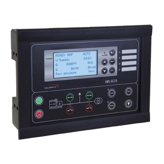
Genset Controller Unit
Model EMS -GC10
Operator’s Manual
00-02-0878
Section 75
2013-03-07
Related Manuals for Murphy EMS-GC10
Summary of Contents for Murphy EMS-GC10
-
Page 1
Genset Controller Unit Model EMS -GC10 Operator’s Manual 00-02-0878 Section 75 2013-03-07… -
Page 2
BEFORE BEGINNING INSTALLATION OF THIS MURPHY PRODUCT: • Read and follow all installation instructions. • Please contact your Murphy Master Distributor immediately if you have any questions. • A visual inspection of this product for damage during shipping is recommended before installation. -
Page 3: Table Of Contents
Table of Contents About This Document ………………….. 1 General Purpose ………………….1 Intended Users ………………….1 Address, Menu, Setting, Parameter …………….1 Warnings and Legal Information ………………… 2 Legal Information and Responsibility …………..2 Disclaimer ……………………2 Electrostatic Discharge Awareness ……………..2 Safety Issues ………………….2 Factory Settings ………………….2 Warnings and Notes ………………..3 Introduction ……………………..
-
Page 4
Sequences …………………… 37 Display and Menu Structure ………………..47 Passwords and Parameter Access …………….. 47 Engine Communication………………….49 Additional Functions ………………….. 50 Start Functions ………………….50 Mains Voltage Unbalance Detection …………… 54 Phase Sequence Error ………………… 54 Breaker Types and Feedback ……………… 54 Breaker Spring Load Time ……………… -
Page 5
Differential Measurement ………………106 Protections ……………………..107 General ……………………107 Appendix I —Can Bus Engine Interface Communication ……….109 Terminal Description for EMS-GC10 …………..109 Modbus Communication ………………109 Terminals …………………… 109 Principle Diagram ………………..109 Functional Description ………………….110 Electronic Control Module (ECM) …………….. -
Page 6
Scania EMS (J1939) ………………..135 Scania EMS 2 S6 (J1939) ………………135 Volvo Penta EMS (J1939) ………………138 Volvo Penta EMS 2 (J1939) ………………139 Modbus Communication …………………. 140 Additional Information ………………. 140 Readings ……………………. 140 Alarms ……………………….. 147 Caterpillar/Perkins ………………..147 Cummins …………………. -
Page 7: About This Document
You will need to purchase the TTL to USB cable (75000277) in order to use the Utility Software (USW). Intended Users The document is intended for the person responsible for setup and operating the EMS-GC10 unit. Address, Menu, Setting, Parameter…
-
Page 8: Warnings And Legal Information
Warnings and Legal Information Legal Information and Responsibility FW Murphy takes no responsibility for installation or operation of the generator set. If there is any doubt about how to install or operate the engine/generator controlled by the EMS-GC10 unit, the company responsible for the installation or the operation of the set must be contacted.
-
Page 9: Warnings And Notes
Warnings and Notes Throughout this document, a number of notes and warnings will be presented. To ensure that these are noticed, they will be highlighted in order to separate them from the general text. Notes NOTE: The notes provide general information which will be helpful for the reader to bear in mind.
-
Page 10: Introduction
Modbus® RTU protocol on the RS485 port. Product Description The EMS-GC10 Genset Controller provides flexible control and monitoring for industrial genset applications. Typical applications include backup power, power supply for remote locations without a connection to power grid, and mobile power for remote locations.
-
Page 11: Push-Buttons
Push-Buttons Normal display: Scrolls the display down once. Programming: Decreases setpoint value. Normal display: Scrolls the display up once. Programming: Increases setpoint value. Resets horn relay. Extra function: Press and hold button 2 seconds to see alarm list Enter menus/enter value/acknowledges alarm. Jumps from parameter settings to display.
-
Page 12: Led Indicators
LED Indicators Power OK indicator. Alarm LED: Flashing: active, non-acknowledged alarm(s) present. Steady: active, acknowledged alarm(s) present. Additional alarm indication LEDs: Flashing: active, non-acknowledged alarm(s) where output A or B is configured to LED 1, 2, 3 or 4. Steady: active, acknowledged alarm(s) where output A or B is configured to LED 1, 2, 3 or 4.
-
Page 13: Menu
Menu The Menu can be viewed without password entry. View Menu The measured values are displayed from this view. Log Menu This menu displays the Event, Alarm, and Battery Logs. Used for setting up the unit, and detailed information. Setup Menu Changing of parameter settings is password-protected.
-
Page 14
Menu Structure Diagram Section 75 00-02-0878 2013-03-07 — 8 -… -
Page 15: Display
Display The display indicates readings and alarms. Below are some examples of the display views. Display View Description and Notes View Menu The software version can be found in the Service Menu Status of Generator P, Generator Q, Generator S, and Run Hours Status of Service Timer 1, Service Timer 2, and Run Hours…
-
Page 16: Status Line Text
ENTER button NOTE: The available parameters depend on the set options. Some parameters can only be changed using the PC utility software (USW) for EMS-GC10. Status Line Text Below is a list of standard conditions with comments. Condition…
-
Page 17
Condition Comment Note GB Trip Externally An external trip is Some external equipment has tripped logged in the event MB Trip Externally the breaker The «Idle run» function is active. The Idle Run genset will not stop until a timer has expired The timer in the «Idle run»’… -
Page 18: Running Modes
Running Modes The unit has four different running modes and one block mode. The different running modes are four to three via the display or the PC utility software. In auto mode, the unit will operate automatically, and the operator cannot Auto initiate any sequences manually.
-
Page 19: Log List
52 historical battery tests. Parameters—Only Available With USW Parameters need to be configured through the Utility Software (USW) and not locally available to be configured from EMS-GC10 unit. Parameter Description 1340 Busbar voltage trip.
-
Page 20
Parameter Description 5010 Relay 21. 5020 Relay 22. 5030 Relay 23. 5040 Relay 24. 5060 Relay 45. 5070 Relay 47. 6200 Shutdown override. 7000 Mains power. 7010 Daytime period. 7020 Start Generator. (peak shaving) 7030 Stop Generator. (peak shaving) 7530 Internal communication ID. -
Page 21: General Product Information
General Product Information Functional Descriptions Standard Functions This chapter includes functional descriptions of standard functions as well as illustrations of the relevant application types. Flowcharts and single-line diagrams will be used in order to simplify the information. The standard functions are listed in the following paragraphs. Operation Modes Automatic Mains Failure (AMF) Island operation (Island)
-
Page 22: Terminal Strip Overview
«Installation Instructions», which is located on FW Murphy website under documentation for EMS-GC10. Measurement Systems EMS-GC10 unit is designed for measurement of voltages between 100 and 690Vpp AC. For further reference, the AC wiring diagrams are shown in the Installation Instructions. In parameters 9130, 9131 the measurement principle can be changed between three-phase, single phase and split phase.
-
Page 23
Split Phase System When EMS-GC10 unit is delivered from the factory, the three-phase system is selected. When this principle is used, all three phases must be connected to the EMS-GC10 controller unit. The following adjustments must be made to make the system ready for the three-phase… -
Page 24: Applications
Applications Applications and Genset Modes NOTE: This section about applications is to be used for reference using the particular Genset mode as starting point. It is not suitable for reading from beginning to end. The unit can be used for the applications listed in the table below. Application Engine Control Automatic Mains Failure (no back sync.)
-
Page 25
When the mains returns, the unit will switch back to mains supply and cool down and stop the genset. The switching back to mains supply is done when the adjusted «Mains OK delay” has expired. NOTE: For a general description of the available running modes, please refer to the chapter «Running mode description». -
Page 26: Running Mode Description
2. Digital inputs are used 3. Modbus command at service port or RS 485 NOTE: The standard EMS-GC10 is only equipped with a limited number of digital inputs, please see «Digital inputs» in this document for additional information about availability.
-
Page 27: Test Mode
NOTE: Test mode is not available in an island application Simple Test EMS-GC10 controller unit will go through the start sequence and run the engine for the time set in parameter 7041 without any breaker operation. This sequence is initiated by a digital input or the TEST push-button on the front.
-
Page 28
Block Mode Block mode can be enabled by pressing the MAN button on the EMS-GC10 twice and hold for 2 seconds, with M-Logic or a digital input. When block mode is selected, the controller unit will be locked for certain actions. This means that it cannot start the genset or perform any breaker operations from the buttons. -
Page 29: Single-Line Diagrams
WARNING: You should take care to follow OSHA equipment lockout requirements and any other company safety regulations, procedures, or requirements by authorities with local jurisdiction. IMPORTANT: The genset will shut down if block mode is selected while the genset is running. Single-Line Diagrams Application Illustration In the following, the various applications are illustrated in single-line diagrams.
-
Page 30
Island Operation Island Mode without breaker is possible. Load Takeover NOTE: Synchronization is not supported by EMS-GC10 Section 75 00-02-0878 2013-03-07 — 24 -… -
Page 31: Flowcharts
Flowcharts Using flowcharts, the principles of the most important functions will be illustrated in the next sections. The functions included are: • Mode shift • MB open sequence • GB open sequence • Stop sequence • Start sequence • MB close sequence •…
-
Page 32
Mode Shift NOTE: To enable mode shift, a digital input has to be set up. Section 75 00-02-0878 2013-03-07 — 26 -… -
Page 33
MB Open Sequence Section 75 00-02-0878 2013-03-07 — 27 -… -
Page 34
GB Open Sequence Section 75 00-02-0878 2013-03-07 — 28 -… -
Page 35
Stop Sequence Section 75 00-02-0878 2013-03-07 — 29 -… -
Page 36
Start Sequence Section 75 00-02-0878 2013-03-07 — 30 -… -
Page 37
MB Close Sequence Section 75 00-02-0878 2013-03-07 — 31 -… -
Page 38
GB Close Sequence Section 75 00-02-0878 2013-03-07 — 32 -… -
Page 39
Load Takeover (LTO) Section 75 00-02-0878 2013-03-07 — 33 -… -
Page 40
Island Operation Section 75 00-02-0878 2013-03-07 — 34 -… -
Page 41
Automatic Mains Failure (AMF) Section 75 00-02-0878 2013-03-07 — 35 -… -
Page 42
Test Sequence Section 75 00-02-0878 2013-03-07 — 36 -… -
Page 43: Sequences
Sequences The following contains information about the sequences of the engine, the generator breaker, and the mains breaker. In the manual or semi-auto mode, the selected sequence is the only sequence initiated (e.g. press the START push-button: the engine will start, but not close the breaker). The following sequences will be illustrated below: •…
-
Page 44
Start Sequence NOTE: Run coil can be activated from 1…600 sec. before crank (starter) will be executed. In the above example, the timer is set to 1 sec. (parameter 6151). Section 75 00-02-0878 2013-03-07 — 38 -… -
Page 45
Start Sequence Conditions The start sequence initiation can be controlled by the following conditions: • (oil pressure) • (water temperature) • (fuel level) This means that if, for example, the oil pressure is not primed to the sufficient value, then the crank relay will not engage the starter motor. The selection is made in parameter 6185. -
Page 46
Running Feedback Different types of running feedback can be used to detect if the motor is running. Refer to parameters 6170, 6171, 6175 for selection of the running feedback type. The running detection is made with a built-in safety routine. The running feedback selected is the primary feedback. -
Page 47
Running feedback Oil pressure setpoint (parameter 6175). Running feedback EIC (engine communication). Emergency stop Alarm Alarms with shutdown» or «trip and stop» fail class. Stop push-button on display Manual mode. Modbus stop command Manual mode. Binary stop input Manual mode. Auto mode in the following genset modes: Island operation or load Deactivate the «auto start/stop»… -
Page 48
Stop Sequence The drawings illustrate the stop sequence. Section 75 00-02-0878 2013-03-07 — 42 -… -
Page 49
The stop sequence will be activated if a stop command is given. The stop sequence includes the cooling down time if the stop is a normal or controlled stop. Description Cooling Down Stop Comment Auto mode stop Trip and stop alarm Stop button on display Manual. -
Page 50
Setpoints Related To MB Control Parameter 7080 MB control. Parameter 7081 Mode shift: When enabled, the EMS-GC10 will perform the AMF sequence in case of a mains failure in load takeover or TEST mode Parameter 7082 MB close delay: The time from GB OFF to MB ON Parameter 7085 Load time: After opening of the breaker, the MB ON sequence will not be initiated before this delay has expired. -
Page 51
AMF MB Opening (Parameters 7060–7066 U Mains Failure) It is possible to select the functionality of the mains breaker closing function. This is necessary if the unit operates in Automatic Mains Failure (AMF). The possibilities are: Selection Description Start engine and open When a mains failure occurs, the mains breaker opens, and the engine starts at mains breaker the same time. -
Page 52
Example 2: Parameter 7065 Mains fail control: Start engine NOTE: The Terms: F/U (Frequency / Voltage) and V/F (Voltage / Frequency) represent the same value. Conditions for Breaker Operations The breaker sequences react depending on the breaker positions and the voltage/frequency measurements. -
Page 53: Display And Menu Structure
Display and Menu Structure Passwords and Parameter Access Passwords The unit includes three password levels. All levels can be adjusted in the PC software. Available password levels: Password level Factory setting Access Customer Service Master Customer 2000 Service 2001 Master 2002 A parameter cannot be entered with a password that is ranking too low.
-
Page 54
Example of pop-up window in USW for parameter 1000. The password level can also be changed from the parameter view in the column «Level». This is a snapshot of part of the USW parameters list. Section 75 00-02-0878 2013-03-07 — 48 -… -
Page 55: Engine Communication
Engine Communication EMS-GC10 Unit and Engine Controller The EMS-GC10 unit is able to communicate with an engine controller through the CAN bus (CAN A). NOTE: Information about engine communication can be found in this manual Appendix I.
-
Page 56: Additional Functions
Additional Functions Start Functions The controller unit will start the genset when the start command is given. The start sequence is deactivated when the remove starter event occurs or when the running feedback is present. The reason for having two possibilities to deactivate the start relay is to be able to delay the alarms with run status.
-
Page 57
Digital Feedbacks If an external running relay is installed, the digital control inputs for running detection or remove starter can be used. Running Feedback When the digital running feedback is active, the start relay is deactivated, and the starter motor will be disengaged. The diagram illustrates how the digital running feedback is activated when the engine has reached its firing speed. -
Page 58
Analog Tach Feedback When a magnetic pick-up (MPU) is being used, the specific level of revolutions for deactivation of the start relay can be adjusted Running Feedback The diagram below shows how the running feedback is detected at the firing speed level. -
Page 59
Oil Pressure The multi-inputs on terminals 6, 7 and 8 can be used for the detection of running feedback. The terminal in question must be configured as an analog input for oil pressure measurement. When the oil pressure increases above the adjusted value, (parameter 6175 Pressure level), the running feedback is detected, and the start sequence is ended. -
Page 60: Mains Voltage Unbalance Detection
This type of signal is most often used combined with circuit breaker. With the setting pulse, EMS-GC10 unit will use the close command and the open command relay. The close breaker relay will close for a short time for closing of the circuit breaker. The open breaker relay will close for a short time for opening of the breaker.
-
Page 61: Breaker Spring Load Time
Breaker Feedback Whether breaker feedbacks are necessary or not depends on which type of breaker is selected in the application configuration of the utility software (USW) . Continuous NE and Continuous ND This type of breaker does not require feedback. Pulse Because of the pulse signal, it is required that at least one feedback is configured for each breaker.
-
Page 62
Different breaker types are used, and therefore there are two available solutions: Timer-Controlled A load time setpoint for the GB and MB control for breakers with no feedback indicating that the spring is loaded. After the breaker has been opened it will not be allowed to close again before the delay has expired. -
Page 63
However, the EMS-GC10 unit waits a while before it issues the close signal again, because the spring load time must expire (or the digital input must be activated — not shown in this example). Then EMS-GC10 unit issues the close signal. -
Page 64: Alarm Inhibit
Alarm Inhibit In order to select when the alarms are to be active, a configurable inhibit setting for each alarm has been made. The inhibit functionality is only available via the PC utility software (USW). For each alarm, there is a drop-down window where it is possible to select which signals have to be present in order to inhibit the alarm.
-
Page 65
Selections for Alarm Inhibit: Function Description Inhibit 1 M-Logic outputs: Conditions are programmed in M-Logic Inhibit 2 Inhibit 3 GB ON ( ON) The generator breaker is closed GB OFF ( ON) The generator breaker is open Run status Running detected and the timer in parameter 6160 expired Not run status Running not detected or the timer in parameter 6160 not expired Generator voltage >… -
Page 66
Inhibit of the alarm is active as long as one of the selected inhibit functions is active. Example of the USW parameter 1000. In this example, inhibit is set to Not run status and GB ON. Here, the alarm will be active when the generator has started and disabled again when the GB is closed. -
Page 67
Run Status (parameter 6160) Alarms can be adjusted to activate only when the running feedback is active and a specific time delay has expired. The diagram below illustrates that after activation of the running feedback, a run status delay will expire. When the delay expires, alarms with Run status will be activated. NOTE: The timer is ignored if binary running feedback is used. -
Page 68: Digital Mains Breaker Control
Digital Mains Breaker Control The unit will normally execute the Automatic Mains Failure (AMF) sequence based on the settings adjusted in the system setup. Besides these settings it is possible to configure a digital input that can be used to control the mains return sequence. This input is the «Mains Okay»…
-
Page 69: Command Timers
Command Timers The purpose of the command timers is to be able to (for example) start and stop the genset automatically at specific times each weekday or certain weekdays. If auto mode is activated, this function is available in Island Operation and Load Takeover operation. Up to four command timers can be used (for example) for start and stop.
-
Page 70: Running Output
Running Output Parameter 6160 Run status can be adjusted to give a digital output when the genset is running. Example of the USW parameter 6160 setup window. Select the correct relay number in output A and output B and enable the function. Change the relay function to limit in the I/O menu.
-
Page 71: Idle Running
Idle Running The purpose of the idle run function is to change the start and stop sequences to allow the genset to operate under low temperature conditions. It is possible to use the idle run function with or without timers. Two timers are available.
-
Page 72
NOTE: Turbo chargers not originally prepared for operating in the low speed area can be damaged if the genset is running in «idle run» for too long. Examples Idle Speed During Starting And Stopping In this example both the start and the stop timers are activated. The start and stop sequences are changed in order to let the genset stay at the idle level before speeding up. -
Page 73
Idle Speed, No Stopping In this example both timers are deactivated. If the genset is to be prevented from stopping, then the digital input «temp control» must be left ON at all times. In that case the characteristic looks like this. NOTE: The oil pressure alarm (analog input for oil) will be enabled during idle run if set to «ON». -
Page 74
Start Section 75 00-02-0878 2013-03-07 — 68 -… -
Page 75
Stop Section 75 00-02-0878 2013-03-07 — 69 -… -
Page 76
Engine Heater This function is used to control the temperature of the engine. A sensor measuring the cooling water temperature is used to activate an external heating system to keep the engine at a minimum temperature. The setpoints adjusted in parameter 6320–6324, 6330 are: This setpoint +/- the hysteresis is the start and stop points Parameter 6321 setpoint for the engine heater. -
Page 77: Battery Test
Battery Test This function gives the possibility to test the condition of the battery. The battery test can be initiated with a digital input and is available when the genset is in auto mode. If a mains failure occurs during the battery test sequence, the test will automatically be interrupted, and the automatic mains failure start up sequence will be activated.
-
Page 78
The drawing below shows that when the test is started, the start relay activates making the engine turn. Input Configuration If this function is to be used, it is necessary to configure a digital input that initiates the function. Using the PC software (USW), this is done in the `dialogue box below: If AUTO mode is selected, the mains failure sequence will be initiated if a mains failure occurs during the battery test. -
Page 79
Ventilation This function can be used to control the cooling of the engine. The purpose is to use a multi-input for measuring the cooling water temperature and that way activate an external ventilation system to keep the engine below a maximum temperature. The functionality is shown in the below diagram. -
Page 80: Fuel Pump Logic
Fuel Pump Logic The fuel pump logic is used to start and stop the fuel supply pump to maintain the fuel level in the service tank at predefined levels. The start and stop limits are detected from one of the three multi-inputs. Set points available in parameter 6550–6554: Setpoint 1: Start level.
-
Page 81: Fail Class
Full to Fuel Fill Check The fuel pump logic includes a Fuel fill check function. When the fuel pump is running, the fuel level must increase by 2% within the fuel fill check timer set in parameter 6553. If the fuel level does not increase by 2% within the adjusted delay time, then the fuel pump relay deactivates and a Fuel Fill Alarm occurs.
-
Page 82
Engine Running Alarm Horn Alarm Trip Of Gen. Trip Of Mains Cooling- Stop Fail Class Action Relay Display Breaker Breaker Down Genset Genset 1 Block 2 Warning 3 Trip GB 4 Trip + stop 5 Shutdown 6 Trip MB 7 Trip MB/GB The table illustrates the action of the fail classes. -
Page 83
Fail Class Configuration The fail class can be selected for each alarm function either via the display or the PC software. To change the fail class via the PC software (USW), the alarm function to be configured must be selected. Select the desired fail class in the fail class roll-down panel. Example of pop-up window in USW for parameter 1000. -
Page 84: Service Timers
Service Timers The unit is able to monitor the maintenance intervals. Two service timers are available to cover different intervals. The service timers are set up in parameters 6110, 6113, 6114, 6116, and 6120, 6121, 6123, 6126. The function is based on running hours. When the adjusted time expires, the unit will display an alarm.
-
Page 85: Wire Fail Detection
Wire Fail Detection If it is necessary to supervise the sensors/wires connected to the multi-inputs and analog inputs, then it is possible to enable the wire break function for each input. If the measured value on the input is outside the normal dynamic area of the input, it will be detected as if the wire has made a short-circuit or a break.
-
Page 86: Digital Inputs
Digital Inputs The unit has a number of binary inputs, some are configurable and some are not. Input Function Auto Semi Test Block Configurable Input Type Shutdown override Configurable Constant Access lock Configurable Constant Binary running detection Configurable Constant Remote start Configurable Pulse Remote stop…
-
Page 87
Functional Description—Input 1. Shutdown override This input deactivates all protections except the over speed protection and the emergency stop input. The number of start attempts is seven by default, but it can be configured in parameter 6201. Also a special cool down timer is used in the stop sequence after an activation of this input. -
Page 88
12. Remote MB ON The mains breaker ON sequence will be initiated. 13. Remote MB OFF The mains breaker OFF sequence will be initiated. 14. Remote alarm acknowledge Acknowledges all present alarms, and the alarm LED on the display stops flashing. 15. -
Page 89
When this input is activated, then the mains breaker cannot close. 28. Enable mode shift The input activates the mode shift function, and the EMS-GC10 will perform the AMF sequence in case of a mains failure. When the input is configured, the setting in parameter 7081 (mode shift ON/OFF) is disregarded. -
Page 90: Outputs
34. MB spring loaded EMS-GC10 genset controller unit will not send a close signal before this feedback is present. 35. D+ (digital running feedback) This input is used as a running indication of the engine. When the input is activated, the start relay is deactivated.
-
Page 91
Functional Description—Output 1. Status OK 2. Run Coil The relay configured to Run coil will be closed the entire time the engine is supposed to run. 3. Stop Coil This relay will close to stop the engine, and when no running feedback is present, it will stay closed in the external stop time (parameter 6212). -
Page 92: Multi-Inputs
Multi-Inputs The EMS-GC10 unit has three multi-inputs which can be configured to be used as the following input types: 1. 4-20 mA 2. RMI oil 3. RMI water 4. RMI fuel 5. Binary NOTE: The function of the multi-inputs can only be configured in the PC utility software (USW).
-
Page 93
RMI Oil This RMI input is used for measuring the lubricating oil pressure. RMI Sensor Type Pressure Type 1 Type 2 Type 3 Ω Ω Ω 10.0 10.0 27.2 44.9 31.3 62.9 81.0 51.5 99.2 117.1 71.0 134.7 151.9 89.6 168.3 184.0 107.3… -
Page 94
RMI Water This RMI input is used for measuring the cooling water temperature. RMI Sensor Type Temperature Type 1 Type 2 Type 3 Type 4 Ω Ω Ω Ω °C °F 291.5 480.7 69.3 197.3 323.6 134.0 222.5 36.0 97.1 157.1 70.1 113.2… -
Page 95
RMI Fuel This RMI input is used for the fuel level sensor. RMI Sensor Type Type 1 Value Resistance 78.8 Ω 1.6 Ω 100% RMI Sensor Type Type 2 Value Resistance 3 Ω 180 Ω 100% NOTE: If the RMI input is used as a level switch, then be aware that no voltage must be connected to the input. -
Page 96
Illustration of Configurable Inputs Configuration The eight curve settings (data point or pairs) for the configurable RMI inputs cannot be changed in the display, but only in the PC utility software (USW). In the USW the configurable inputs are adjusted in this dialogue box: Adjust the resistance of the RMI sensor at the specific measuring value. -
Page 97
Scaling Of 4-20 Ma Inputs The scaling of the analog inputs is made to ensure that the readout of the inputs is made with a resolution that fits the connected sensor. It is recommended to follow the guide below when changing the scaling of the analog inputs. Scaling Example: 1. -
Page 98
4. Adjust the input as required, for example, 0-5 bar. The display will then show 0 at 4 5. If needed, it is possible to scale the input to fit the sensor (Parameter 11010). NOTE: Multi input 7 (parameter 11020) and Multi input 8 (parameter 11030) NOTE: Analog Units listed as 1/1 = xxx units, 1/10 = xx.x units, 1/100 = x.xx units. -
Page 99
Save The Parameter File: After having set up the 4-20 mA inputs (hardware, wiring, and transducer/transmitter as well as alarms), the parameter file should be uploaded from the device to the PC and then saved. In this way the settings will not be modified again if the parameters are reloaded to the device. -
Page 100: Text In Status Line
Text in Status Line This table explains the different messages in the status line text. Condition Comment Note BLOCK Block mode is activated SIMPLE TEST Test mode is activated FULL TEST SIMPLE TEST ###.#min Test mode activated and test timer counting down FULL TEST ###.#min ISLAND MAN Genset stopped or running and no other action taking…
-
Page 101
Quick setup of the application failed MOUNT CAN Connect the power management CAN line CONNECTOR The EMS-GC10 is receiving the application that it has ADAPT IN PROGRESS just been connected to The new EMS-GC10 is being added to the existing… -
Page 102: Counters
Counters Counters for various values are included, and some of these can be adjusted if necessary, for instance if the unit is installed on an existing genset or a new circuit breaker has been installed. The table shows the adjustable values and their function in parameter 6100: Parameter and Function Comment…
-
Page 103: Buzzer
PC Utility Software (USW). Buzzer EMS-GC10 unit has a built-in buzzer. The buzzer is configured in M-Logic. This means that if the buzzer is going to be used as a horn annunciator, the input must be set to «Horn»…
-
Page 104: Usw Remote Communication
Basic Parameter Settings Parameter Name Function Set To 10320 GSM PIN code Set PIN code for GSM modem None 10330 12345678901 Set phone no. for SMS to cellular phone 1 None 10340 12345678901 Set phone no. for SMS to cellular phone 2 None 10350 12345678901…
-
Page 105: Nominal Settings
Nominal Settings How to Change the Nominal Settings The nominal settings can be changed to match different voltages and frequencies. The EMS-GC10 has four sets of nominal values for the generator, and they are adjusted in parameters. EMS-GC10 Nominal Settings Parameters 6001–6005…
-
Page 106: Ac Voltage Scaling
Parameter Settings In parameter 6006 the switching is made between settings 1 to 4, for the generator, simply by choosing the desired nominal setting, just as it is for the Busbar group choice in parameter 6054. AC Voltage Scaling Default AC voltage scaling is set to range 100 V-25000 V (parameter 9030). To be able to handle applications above 25000 V and below 100 V, it is necessary to adjust the input range so it matches the actual value of the primary voltage transformer.
-
Page 107: Fan Logic
Fan Logic EMS-GC10 is able to control four different fans. This could for example, be air supply fans for supplying air to a genset in a closed enclosure, or radiator fans for switching on and off cooling fans for air coolers.
-
Page 108
M-logic: Input for Fan Control The fan control requires a temperature input in order to start and stop the fans based on a temperature measurement. Fan temperature input is set up in parameter 6561, and this input can be selected between the multi-configurable inputs: Multi-input 6, 7, 8. -
Page 109
The following start/stop curve will be generated if a bow setting is used: Fan Output At parameter 6581 to 6584, the output relays for fans A to D are selected. The purpose of these relays is to issue a signal to the fan starter cabinet. The relay must be energized for the fan to run. -
Page 110
M-Logic setup: If the fan unit is raising a signal that is led to a digital input on the EMS-GC10 unit when it is running, then the following M-Logic must be programmed: When it is not possible to get a running feedback from the fan unit, the internal relay of the genset controller unit must be used to indicate that the fan is running. -
Page 111
The running hour can be reset by entering parameter 6585 and then selecting the desired fan hours to be reset. NOTE: Only reset is possible. It is not possible to add an offset to the run hour counter. Fan Priority Update In parameter 6562 the priority update rate (hours between priority rearrange) is selected: If the fan priority update is set to 0 hours, the order of priority will be fixed at: Fan A, fan… -
Page 112: Differential Measurement
Differential Measurement Differential measurements between two sensors can be configured in parameters 4600- 4606. The sensors can be selected from the input list shown, the list also contains various EIC measurements: Two levels of alarms can be made of each differential measurement between sensor A and B.
-
Page 113: Protections
Protections General The protections are all of the definite time type, meaning, a setpoint and time is selected. If the function is, for example, Overvoltage, the timer will be activated if the setpoint is exceeded. If the voltage value falls below the setpoint value before the timer runs out, then the timer will be stopped and reset.
-
Page 114
The table shows the actual measurements at a 10% under voltage situation in a 400/230 volt system. Phase-Neutral Phase-Phase Nominal Voltage 400/230 400/230 Voltage, 10% Error 380/207 360/185 The alarm will occur at two different voltage levels, even though the alarm setpoint is 10% in both cases. -
Page 115: Appendix I —Can Bus Engine Interface Communication
CAN-H CAN A CAN-GND CAN-L Modbus Communication If option H2 is present in the EMS-GC10 unit, it is possible to read engine data over the Modbus. Terminals NOTE: For terminal details, please refer to the document “Installation Manual”. Principle Diagram…
-
Page 116: Functional Description
ECM module with CANbus interface. The values can be used as display values, alarms/shutdown alarms and values to be transmitted through Modbus. Engine Types Data can be transmitted between the EMS-GC10 units and the following engine controllers/types: Engine…
-
Page 117: Communication System
Communication System All these protocols are based on a CANbus communication system. Except for the MDEC and ADEC communication, all are based on the J1939. The MDEC and ADEC protocols are MTU- designed protocols based on CANopen. The Baud rate is fixed by the engine manufacturer at: Caterpillar, Cummins, Detroit Diesel, Deutz, Iveco, John Deere, Perkins, MDEC, ADEC MTU J1939 Smart Connect, Scania and Volvo Penta…
-
Page 118: Error Messages
Error Messages The following error messages can occur: Message Description Engine I. value N.A. The view is not selectable for the present engine type. The value cannot be read due to the sensor error, sub-system or Value selected error module error. The value is not supported by the engine, or due to a communication “N.A.”…
-
Page 119
Start Posi- Pri- Tion Length Object PGN No. Unit J1939-71 Scaling Ority Of 1 (Bytes) Data Byte EIC % load, c. 61443 1%/bit, offset 0 speed EIC air inlet 65270 2 kpa/bit, offset 0 pressure EIC exhaust gas 65270 °C 0.03125°C/bit, offset -273°C temp. -
Page 120: Showing Engine Values In Display
Showing Engine Values in Display It is possible to parameterise the EMS-GC10 so all values from the engine CAN bus is shown in the display unit. This is an example where speed, coolant and air inlet temperature is shown.
-
Page 121: Verification Of J1939 Objects
To verify the communication, various CAN PC tools can be used. Common for these are that they must be connected to the CANbus between the EMS-GC10 unit and the engine controller. When the tool is connected, it is possible to monitor the communication between the two units.
-
Page 122: Displaying Alarms — J1939 Dm1/Dm2, Scania Kwp2000, Caterpillar/Perkins
Normally in SAE J1939, only priority 3 and 6 are used. Hereafter the data can be read (PGN 61444): 0xcf00400 xD ff 7d 7d e0 15 ff f0 ff Engine torque (Data byte 1) Not available Driver demand torque (Data byte 2) Actual engine torque (Data byte 3) Engine speed…
-
Page 123
CLRALL: By pressing ENTER, the entire alarm log list will be cleared. For safety reasons this requires the master password. Refer to “Passwords and Parameter Access” for details. NOTE: If the controller has no translation text of an SPN diagnostic number, “Text N/A.”… -
Page 124: Displaying Alarms — Ems-Gc10
Displaying Alarms — EMS-GC10 J1939 Use the up buttons until the DM1 or DM2 is shown in the display and press Enter. The alarm log will be shown in the display. Example: DM1 LOG DDEC Oil pressure Low level warning The alarm log in DM1 shows the active alarms, the DM2 shows the historical alarms.
-
Page 125: Control Commands Sent To The Engine
NOTE: The display of Caterpillar/Perkins secondary DM 1 log only applies to EMS-GC10 100 and GC-1F/2. Control Commands Sent to the Engine Engine types with the possibility to send commands to the ECM via the CANbus…
-
Page 126
EIC 50 Hz – 60 Hz Switch If the set point f nominal is changed in the EMS-GC10 between 50 and 60 Hz then the change is made with a frequency ramp of 2 Hz per second. This frequency ramp is used when switching between nominal settings 1-4 or if the parameter of the nominal frequency is changed between 50 and 60 Hz. -
Page 127
• EIC malfunction • EIC protection EIC Idle The “Idle” function of the EMS-GC10 is activated in parameter 6290. If this is used with engines with speed control from CANbus communication, the speed is defined to be 700 rpm. Section 75… -
Page 128: Specific Engine Type Descriptions
Specific Engine Type Descriptions About Type Descriptions NOTE: The J1939 warnings/shutdowns with corresponding SPN and FMI numbers in this chapter refer to those that will automatically appear in the alarm list. The alarms can be acknowledged from the display. NOTE: The available alarms vary from engine type to engine type. Besides these, the entire log list can be read in the engine controller by holding the “LOG”…
-
Page 129: Cummins Cm850-Cm570 (J1939)
Write Commands to Engine Controller ●Engine controls All the write commands to the engine controller (ex: speed, start/stop, etc.) are enabled in parameter 7563 (EIC Controls). ●Engine speed CANbus ID for speed control: 0x0c000000. J1939 TSC1. ●M-Logic commands are available to enable/disable start/stop and speed controls. ●EIC start/stop enable ●EIC speed control inhibit NOTE: The speed regulation is enabled in parameter 2781 (Reg.
-
Page 130
• • Engine Speed CANbus ID for speed control: 0x00FF69DC. For Cummins proprietary “Engine governing” EG telegram, the source address of the EMS-GC10 controller is 0xDC/220 dec). • Frequency Selection Nominal frequency is written automatically based on the frequency nominal parameter. -
Page 131
ECU then indicators from the treatment system can be read over the J1939 link and some regeneration can be controlled. The table shows lamps and status indicators from the after treatment. The states can be reached through M-logic and can be shown on a FW Murphy display unit. Diesel Status indicator… -
Page 132: Detroit Diesel Ddec (J1939)
Detroit Diesel DDEC (J1939) Warnings and Shutdowns J1939 codes Warning/shutdown list FMI warning FMI shutdown EIC yellow lamp EIC red lamp EIC malfunction EIC protection NOTE: FMI indication “-“ means that the alarm in question is not supported. Write Commands to Engine Controller •…
-
Page 133: Generic J1939 (J1939)
7563 (EIC Controls). • Engine Speed CANbus ID for speed control: 0x0c000003. For J1939 TSC1, the source address of the EMS-GC10 controller is 3. • EIC Speed Control Inhibit NOTE: The speed regulation is enabled in parameter 2781 (Reg. output) and 7563 (EIC Controls).
-
Page 134: Iveco (J1939)
• Engine Speed CANbus ID for speed control: 0x0c000003. For J1939 TSC1, the source address of the EMS-GC10 controller is 3. For the Iveco Vector 8 type only: CANbus ID for speed control: 0xcFF0027. M-Logic commands are available to enable/disable start/stop and speed controls: •…
-
Page 135: John Deere Jdec (1939)
John Deere JDEC (1939) Warnings and Shutdowns J1939 codes Warning/shutdown list FMI warning FMI shutdown Low oil pressure Intake manifold Coolant temperature Fuel injection pump 1076 Fuel temperature ECU failure 2000 EIC yellow lamp EIC red lamp EIC malfunction EIC protection NOTE: FMI indication “-“…
-
Page 136: Mtu J1939 Smart Connect
MTU J1939 Smart Connect Smart Connect This protocol is available with MTU series 1600 With ECU8/Smart Connect. Warnings and Shutdowns J1939 codes Warning/shutdown list FMI warning FMI shutdown EIC yellow lamp EIC red lamp EIC malfunction EIC protection NOTE: FMI indication “-“ means that the alarm in question is not supported.
-
Page 137: Mtu Adec (Canopen)
• Intermittent Oil Priming Engage the pre-lubrication oil pump if installed. The command is activated through M- Logic. • Engine Operating Mode Switches the operating mode of the engine. The command is activated through M- Logic (EIC Engine opr mode command). •…
-
Page 138
Warning Below is a list of warnings that can be shown on the display. The warnings will be shown as an alarm in the alarm window. The alarms can be acknowledged from the display, but they will be visible until the alarm disappears in the ECM module. Warning Warning list… -
Page 139
Shutdown Below is a shutdown value that can be shown on the display. It is possible to configure “EIC Shutdown” in the system setup to put the unit in a shutdown state and/or to activate relay outputs if necessary. The shutdown state is present, until it disappears in the ECM module. Shutdown List AL Com. -
Page 140: Mtu Mdec Module 302/303 (Mtu)
MTU MDEC Module 302/303 (MTU) NOTE: The MTU MDEC is not a part of the J1939, therefore the reading of values, alarms and shutdowns are different. Object EIC speed EIC coolant temp. EIC oil pressure EIC faults EIC oil temp. EIC fuel temp.
-
Page 141: Scania Ems (J1939)
Write Commands to Engine Controller None. Scania EMS (J1939) Warning/Shutdown None. Write Commands to Engine Controller None. Scania EMS 2 S6 (J1939) Scania EMS 2 S6 (J1939) NOTE: Scania EMS 2 S6 does not use the J1939 SPN/FMI (Suspect parameter Number/Failure Mode Indicator) system for alarm handling. Instead the DNL2 system is used.
-
Page 142
The alarms available are the same alarms which can be read by the flash combination of the diagnostics lamp on the EMS S6 (please refer to the engine documentation). NOTE: The EMS S6 software version and engine number is automatically retrieved when CANbus communication is established. Flash EMS-GC10 Description Code Displayed Text Overreving… -
Page 143
Flash EMS-GC10 Description Code Displayed Text Coola. l. prot. Low engine coolant level HW watchdog Hardware watchdog The EMS has detected that the fault code memory is not Fault in RAM functioning correctly Seal The programme in the EMS has been altered in a prohibited manner Coola. -
Page 144: Volvo Penta Ems (J1939)
Volvo Penta EMS (J1939) Warnings and Shutdowns J1939 codes Warning/shutdown list FMI warning FMI shutdown Low oil pressure Intake manifold #1 P Coolant temperature High inlet air temp. Fuel temperature Fuel pressure Oil level Overspeed Coolant level low EIC yellow lamp EIC red lamp EIC malfunction EIC protection…
-
Page 145: Volvo Penta Ems 2 (J1939)
Volvo Penta EMS 2 (J1939) EMS 2 and EDCIII/D6, D7, D9, D12 and D16 (GE and AUX variants only). Warnings and Shutdowns J1939 codes Warning/shutdown list FMI warning FMI shutdown Low oil pressure Intake manifold #1 P Coolant temperature High inlet air temp. Fuel temperature Fuel pressure Oil level…
-
Page 146: Modbus Communication
Modbus Communication Additional Information This is to be considered as additional information for Modbus RS 485 RTU. Please refer to the ECM (Engine Communication Module) user manuals for more information about the ECM protocol technical description and the details of each communication value. The data can be transmitted to a PLC, a computer, the alarm-and-monitoring system or a Scada system.
-
Page 147
The data refers to the common J1939 display reading list as well as the overview of readings in the MTU ADEC (CANopen) and MTU MDEC (MTU protocol). Measurement Table (Read Only) Function Code 04h. Scaling Addr Content Unit Description J1939 ADEC MDEC EIC speed… -
Page 148
Measurement Table (Read Only) Function Code 04h. Scaling Addr Content Unit Description J1939 ADEC MDEC EIC trap inlet [bar] [psi] 1/100 Trap inlet 1/100 EIC Air filter diff press [bar] [psi] Air filter diff press EIC Cool filter diff press [bar] [psi] 1/100 Cool filter diff press… -
Page 149
Diagnostic Codes To interpret an SPN and/or FMI number, refer to the documentation of the engine manufacturer. SPN means «Suspect Parameter Number», for example, if the coolant water temperature becomes too high, the SPN code «110» will be shown. FMI means «Failure Mode Indicator», for example, if the temperature in the above example is at shutdown level, the FMI code «0»… -
Page 150
Active Fail Mode Identifier (DM1/FMI) Addr. Content Description 1402 FMI diagnostic no. 1 1403 FMI diagnostic no. 2 1404 FMI diagnostic no. 3 1405 FMI diagnostic no. 4 1406 FMI diagnostic no. 5 1407 FMI diagnostic no. 6 1408 FMI diagnostic no. 7 1409 FMI diagnostic no. -
Page 151
Active Diagnostic Codes (DM2/SPN) Addr. Content Description 1434 SPN diagnostic no. 1 Lo word 1435 SPN diagnostic no. 2 Lo word 1436 SPN diagnostic no. 3 Lo word 1437 SPN diagnostic no. 4 Lo word 1438 SPN diagnostic no. 5 Lo word 1439 SPN diagnostic no. -
Page 152
Active Fail Mode Identifier (DM2/FMI) Addr. Content Description 1466 FMI diagnostic no. 1 1467 FMI diagnostic no. 2 1468 FMI diagnostic no. 3 1469 FMI diagnostic no. 4 1470 FMI diagnostic no. 5 1471 FMI diagnostic no. 6 1472 FMI diagnostic no. 7 1473 FMI diagnostic no. -
Page 153: Alarms
Alarms Caterpillar/Perkins Alarm, status and measurement table (read only) function code 04h. Addr. Content Type 1020 EIC alarms Bit 0 7570 EIC communication error Bit 1 7580 EIC warning Bit 2 7590 EIC shutdown Bit 3 7600 EIC overspeed Bit 4 7610 EIC coolant water temperature 1 Bit 5 7620 EIC coolant water temperature 2 Bit 6 7630 EIC oil pressure 1 Bit 7 7640 EIC oil pressure 2…
-
Page 154: Cummins
Cummins Alarm, status and measurement table (read only) function code 04h. Addr. Content Type 1020 EIC alarms Bit 0 7570 EIC communication error Bit 1 7580 EIC warning Bit 2 7590 EIC shutdown Bit 3 7600 EIC overspeed Bit 4 7610 EIC coolant water temperature 1 Bit 5 7620 EIC coolant water temperature 2 Bit 6 7630 EIC oil pressure 1 Bit 7 7640 EIC oil pressure 2…
-
Page 155: Ddec – Detroit Engines
DDEC – Detroit Engines Alarm, status and measurement table (read only) function code 04h. Addr. Content Type 1020 EIC alarms Bit 0 7570 EIC communication error Bit 1 7580 EIC warning Bit 2 7590 EIC shutdown Bit 3 7600 EIC overspeed Bit 4 7610 EIC coolant water temperature 1 Bit 5 7620 EIC coolant water temperature 2 Bit 6 7630 EIC oil pressure 1…
-
Page 156: Emr 2 – Emr 3 — Deutz Engines
EMR 2 – EMR 3 — Deutz Engines Alarm, status and measurement table (read only) function code 04h. Addr. Content Type 1020 EIC alarms Bit 0 7570 EIC communication error Bit 1 7580 EIC warning Bit 2 7590 EIC shutdown Bit 3 7600 EIC overspeed Bit 4 7610 EIC coolant water temperature 1 Bit 5 7620 EIC coolant water temperature 2…
-
Page 157: Generic J1939
Generic J1939 Alarm, status and measurement table (read only) function code 04h. Addr. Content Type 1020 EIC alarms Bit 0 7570 EIC communication error Bit 1 7580 EIC warning Bit 2 7590 EIC shutdown Bit 3 7600 EIC overspeed Bit 4 7610 EIC coolant water temperature 1 Bit 5 7620 EIC coolant water temperature 2 Bit 6 7630 EIC oil pressure 1 Bit 7 7640 EIC oil pressure 2…
-
Page 158: Iveco
Iveco Alarm, status and measurement table (read only) function code 04h. Addr. Content Type 1020 EIC alarms Bit 0 7570 EIC communication error Bit 1 7580 EIC warning Bit 2 7590 EIC shutdown Bit 3 7600 EIC overspeed Bit 4 7610 EIC coolant water temperature 1 Bit 5 7620 EIC coolant water temperature 2 Bit 6 7630 EIC oil pressure 1 Bit 7 7640 EIC oil pressure 2…
-
Page 159
JDEC – John Deere Engines Alarm, status and measurement table (read-only) function code 04h. Addr. Content Type Bit 0 7570 EIC communication error Bit 1 7580 EIC warning Bit 2 7590 EIC shutdown Bit 3 7600 EIC overspeed Bit 4 7610 EIC coolant water temperature 1 Bit 5 7620 EIC coolant water temperature 2 1020 EIC alarms… -
Page 160: Mtu Smart Connect
Mtu Smart Connect Alarms, status and measurement table (read only) function code 04h. Addr. Content Type Bit 0 7570 EIC communication error Bit 1 7580 EIC warning Bit 2 7590 EIC shutdown Bit 3 7600 EIC overspeed Bit 4 7610 EIC coolant water temp. 1 Bit 5 7620 EIC coolant water temp.
-
Page 161: Mtu Adec
MTU ADEC Alarm, status and measurement table (read only) function code 04h. Addr. Content Type Bit 0 EIC 7570 communication error Bit 2 EIC 7590 shutdown Bit 3 EIC 7600 overspeed Bit 4 EIC 7610 coolant water temperature 1 Bit 5 EIC 7620 coolant water temperature 2 1020 EIC alarms Bit 6 EIC oil pressure 1…
-
Page 162
Addr. Content Type Bit 0 EIC Common alarm red Bit 1 EIC Overspeed Bit 2 EIC Lube oil press LowLow Bit 3 EIC Coolant temperature HiHi Bit 4 EIC Lube oil temp HiHi Bit 5 EIC Charge air temp HiHi Bit 6 EIC ECU power supp voltage HiHi Bit 7 EIC Generator temp high warning 1023… -
Page 163: Mtu Mdec Series — 2000/4000 — Module 302 & 303
MTU MDEC Series — 2000/4000 — Module 302 & 303 Alarm, status and measurement table (read-only) function code 04h. Addr. Content Type Bit 0 EIC communication error Bit 2 EIC shutdown Bit 3 EIC overspeed 1020 EIC alarms Bit 4 EIC coolant water temperature 1 Bit 5 EIC coolant water temperature 2 Bit 6 EIC oil pressure 1 Bit 7 EIC oil pressure 2…
-
Page 164: Scania
Scania Alarm, status and measurement table (read-only) function code 04h. Addr. Content Type Bit 0 EIC overreving Bit 1 EIC speed sensor 1 Bit 2 EIC speed sensor 2 Bit 3 EIC water temp. sensor Bit 4 EIC charge air temp. sensor Bit 5 EIC charge air pressure sensor Bit 6 EIC oil temp.
-
Page 165
Addr. Content Type Bit 0 EIC seal Bit 1 EIC coola. shut OFF Bit 2 EIC overheat prot. Bit 3 Fault in TPU Bit 4 Not used Bit 5 Not used 1028 EIC alarms (KWP 2000) Bit 6 Not used Bit 7 Not used Bit 8 Not used Bit 9 Not used… -
Page 166: Volvo Penta
Volvo Penta Alarm, status and measurement table (read-only) function code 04h. Addr. Content Type Bit 0 7570 EIC communication error Bit 1 7580 EIC warning Bit 2 7590 EIC shutdown Bit 3 7600 EIC overspeed Bit 4 7610 EIC coolant water temperature 1 Bit 5 7620 EIC coolant water temperature 2 1020 EIC alarms…
-
Page 167: Appendix Ii —M-Logic
Appendix II —M-Logic Introduction to M-Logic The M-Logic is a small logic controller incorporated in the EMS-GC10 unit. Even though it is a logic controller, it must not be confused with a PLC. The M-Logic can be compared with a PLC limited in functionality and can only be used for uncomplicated tasks.
-
Page 168: Configuration
Configuration Starting the M-Logic Once the USW has been started, there will be an icon on the lower left-hand side to activate M-Logic Section 75 00-02-0878 2013-03-07 — 162 -…
-
Page 169
Click the icon, and the following screen appears: Read/Write and Save/Open When the M-Logic screen is shown, the M-Logic toolbar appears at the top of the screen. The toolbar has two buttons which are used to write and read the M-Logic configuration to and from the unit. -
Page 170: Basic Functions
The M-Logic configuration can also be saved/opened to/from a file using the default save/open buttons. Save: Activating this button makes it possible to save the M-Logic configuration to file (part of the general EMS-GC10 configuration file “.USW”). Open: Activating this button makes it possible to open a previously saved logics file.
-
Page 171
Events A, B, and C Note: For each event, the function “NOT” can be selected to get an inverted function. When opening the roll-down window of the events, this window appears. Alarm Use an alarm to activate. Limits Same as alarms, only with no time delay on binary inputs. Events Events that are not alarms, for example, «Engine Running». -
Page 172
This is the selection of the reaction of the system upon activation of the function. Note that the output has a delay function. If set to 0 s (default), there is no delay. Command to the EMS-GC10 unit, for example,, select AUTO running Commands mode. -
Page 173: Definitions
NOTE: If a relay output is chosen, the relay in question must be set up to be a limit relay output. This is done in the parameter list under «OUTPUTS». NOTE: If a relay output is chosen, the relay in question must be set up to be an alarm/limit output (input/output settings, icon in the top of the USW).
-
Page 174: Examples
Examples By using the events, rules can be made for the use of the M-Logic. Virtual Events Virtual events are used to expand the number of events in a logic sequence. The following shows how the output of Logic 1 is used to continue the sequence in Logic 2.
-
Page 175
Power Up In a Specific Mode In the above example, the unit will always power up in manual mode. The timer in Logic 1 sets the output for 5 s, and this is used to set manual mode in event 2. When the timer expires, you can freely select any mode since the virtual event 1 turns ON and the Logic 2 says NOT virtual event 1. -
Page 176: List Of Events And Commands
List of Events and Commands Events Description Notes All alarms are available as events in the alarm category. Note that the list will show all alarms, also Alarms those that are not available in the present configuration of basic unit and options. If the outputs A and B of the alarm in question (e.g.
-
Page 177
Events Description Notes Mode shift deactivated AMF (Automatic Mains Failure). 3-phase system Split L1L3-phase system AC configuration. Split L1L2-phase system Single phase system Emulation with engine and breaker relay Test application selected with output cmd enabled Events reaction. Emulation without engine and breaker relay Test application selected with output cmd disabled reactions. -
Page 178
In the following section, EMS-GC10 Genset Controller Unit module CANbus addresses. These are divided into: DG (diesel generator unit): Address 1-16 Mains (Mains breaker unit with or without tie breaker):Address 17-32 BTB (bus tie breaker unit): Address 33-40 Event Description… -
Page 179
Event Description Notes DPF Lamp OFF Particulate filter is OK. DPF Lamp ON (solid) Indicates initial need for regeneration. DPF Lamp ON (blink) Regeneration is necessary (after regeneration the lamp turns OFF). DPF Active Regeneration not activated Regeneration status. (status) DPF Active Regeneration activated Regeneration status. -
Page 180
Output Description Notes Set parameter 2 Set parameter 3 Set parameter 4 Select test type to simple Test sequence selection. Select test type to full Block GB sequence Block the operation of the genset breaker. Select application 1 Power management: Four different applications can be stored at the same time in the units. -
Page 181
Output Description Notes Activate relay on AOP-2 ID5 Activate buzzer on Single AOP-2 buzzer. AOP-2 ID1 Activate buzzer on AOP-2 ID2 Activate buzzer on AOP-2 ID3 Activate buzzer on AOP-2 ID4 Activate buzzer on AOP-2 ID5 Fan A running Running feedback for cooling fans. Fan B running Fan C running Fan D running… -
Page 182
Output Description Notes CAN command 01-16 active Command Alarm Ind. LED X Red + blink Leds LED X Red LED X Yellow X = ID number (01-04). +blink LED X Yellow LED X Green + blink LED X Green Activate view 1-20 on display 1 Activate a specific view on display 1. -
Page 183
Section 75 00-02-0878 2013-03-07 — 177 -…
-
Contents
-
Table of Contents
-
Bookmarks
Quick Links
Genset Controller Unit
Model EMS -GC10
Operator’s Manual
00-02-0878
Section 75
2013-03-07
Related Manuals for Murphy EMS-GC10
Summary of Contents for Murphy EMS-GC10
-
Page 1
Genset Controller Unit Model EMS -GC10 Operator’s Manual 00-02-0878 Section 75 2013-03-07… -
Page 2
BEFORE BEGINNING INSTALLATION OF THIS MURPHY PRODUCT: • Read and follow all installation instructions. • Please contact your Murphy Master Distributor immediately if you have any questions. • A visual inspection of this product for damage during shipping is recommended before installation. -
Page 3: Table Of Contents
Table of Contents About This Document ………………….. 1 General Purpose ………………….1 Intended Users ………………….1 Address, Menu, Setting, Parameter …………….1 Warnings and Legal Information ………………… 2 Legal Information and Responsibility …………..2 Disclaimer ……………………2 Electrostatic Discharge Awareness ……………..2 Safety Issues ………………….2 Factory Settings ………………….2 Warnings and Notes ………………..3 Introduction ……………………..
-
Page 4
Sequences …………………… 37 Display and Menu Structure ………………..47 Passwords and Parameter Access …………….. 47 Engine Communication………………….49 Additional Functions ………………….. 50 Start Functions ………………….50 Mains Voltage Unbalance Detection …………… 54 Phase Sequence Error ………………… 54 Breaker Types and Feedback ……………… 54 Breaker Spring Load Time ……………… -
Page 5
Differential Measurement ………………106 Protections ……………………..107 General ……………………107 Appendix I —Can Bus Engine Interface Communication ……….109 Terminal Description for EMS-GC10 …………..109 Modbus Communication ………………109 Terminals …………………… 109 Principle Diagram ………………..109 Functional Description ………………….110 Electronic Control Module (ECM) …………….. -
Page 6
Scania EMS (J1939) ………………..135 Scania EMS 2 S6 (J1939) ………………135 Volvo Penta EMS (J1939) ………………138 Volvo Penta EMS 2 (J1939) ………………139 Modbus Communication …………………. 140 Additional Information ………………. 140 Readings ……………………. 140 Alarms ……………………….. 147 Caterpillar/Perkins ………………..147 Cummins …………………. -
Page 7: About This Document
You will need to purchase the TTL to USB cable (75000277) in order to use the Utility Software (USW). Intended Users The document is intended for the person responsible for setup and operating the EMS-GC10 unit. Address, Menu, Setting, Parameter…
-
Page 8: Warnings And Legal Information
Warnings and Legal Information Legal Information and Responsibility FW Murphy takes no responsibility for installation or operation of the generator set. If there is any doubt about how to install or operate the engine/generator controlled by the EMS-GC10 unit, the company responsible for the installation or the operation of the set must be contacted.
-
Page 9: Warnings And Notes
Warnings and Notes Throughout this document, a number of notes and warnings will be presented. To ensure that these are noticed, they will be highlighted in order to separate them from the general text. Notes NOTE: The notes provide general information which will be helpful for the reader to bear in mind.
-
Page 10: Introduction
Modbus® RTU protocol on the RS485 port. Product Description The EMS-GC10 Genset Controller provides flexible control and monitoring for industrial genset applications. Typical applications include backup power, power supply for remote locations without a connection to power grid, and mobile power for remote locations.
-
Page 11: Push-Buttons
Push-Buttons Normal display: Scrolls the display down once. Programming: Decreases setpoint value. Normal display: Scrolls the display up once. Programming: Increases setpoint value. Resets horn relay. Extra function: Press and hold button 2 seconds to see alarm list Enter menus/enter value/acknowledges alarm. Jumps from parameter settings to display.
-
Page 12: Led Indicators
LED Indicators Power OK indicator. Alarm LED: Flashing: active, non-acknowledged alarm(s) present. Steady: active, acknowledged alarm(s) present. Additional alarm indication LEDs: Flashing: active, non-acknowledged alarm(s) where output A or B is configured to LED 1, 2, 3 or 4. Steady: active, acknowledged alarm(s) where output A or B is configured to LED 1, 2, 3 or 4.
-
Page 13: Menu
Menu The Menu can be viewed without password entry. View Menu The measured values are displayed from this view. Log Menu This menu displays the Event, Alarm, and Battery Logs. Used for setting up the unit, and detailed information. Setup Menu Changing of parameter settings is password-protected.
-
Page 14
Menu Structure Diagram Section 75 00-02-0878 2013-03-07 — 8 -… -
Page 15: Display
Display The display indicates readings and alarms. Below are some examples of the display views. Display View Description and Notes View Menu The software version can be found in the Service Menu Status of Generator P, Generator Q, Generator S, and Run Hours Status of Service Timer 1, Service Timer 2, and Run Hours…
-
Page 16: Status Line Text
ENTER button NOTE: The available parameters depend on the set options. Some parameters can only be changed using the PC utility software (USW) for EMS-GC10. Status Line Text Below is a list of standard conditions with comments. Condition…
-
Page 17
Condition Comment Note GB Trip Externally An external trip is Some external equipment has tripped logged in the event MB Trip Externally the breaker The «Idle run» function is active. The Idle Run genset will not stop until a timer has expired The timer in the «Idle run»’… -
Page 18: Running Modes
Running Modes The unit has four different running modes and one block mode. The different running modes are four to three via the display or the PC utility software. In auto mode, the unit will operate automatically, and the operator cannot Auto initiate any sequences manually.
-
Page 19: Log List
52 historical battery tests. Parameters—Only Available With USW Parameters need to be configured through the Utility Software (USW) and not locally available to be configured from EMS-GC10 unit. Parameter Description 1340 Busbar voltage trip.
-
Page 20
Parameter Description 5010 Relay 21. 5020 Relay 22. 5030 Relay 23. 5040 Relay 24. 5060 Relay 45. 5070 Relay 47. 6200 Shutdown override. 7000 Mains power. 7010 Daytime period. 7020 Start Generator. (peak shaving) 7030 Stop Generator. (peak shaving) 7530 Internal communication ID. -
Page 21: General Product Information
General Product Information Functional Descriptions Standard Functions This chapter includes functional descriptions of standard functions as well as illustrations of the relevant application types. Flowcharts and single-line diagrams will be used in order to simplify the information. The standard functions are listed in the following paragraphs. Operation Modes Automatic Mains Failure (AMF) Island operation (Island)
-
Page 22: Terminal Strip Overview
«Installation Instructions», which is located on FW Murphy website under documentation for EMS-GC10. Measurement Systems EMS-GC10 unit is designed for measurement of voltages between 100 and 690Vpp AC. For further reference, the AC wiring diagrams are shown in the Installation Instructions. In parameters 9130, 9131 the measurement principle can be changed between three-phase, single phase and split phase.
-
Page 23
Split Phase System When EMS-GC10 unit is delivered from the factory, the three-phase system is selected. When this principle is used, all three phases must be connected to the EMS-GC10 controller unit. The following adjustments must be made to make the system ready for the three-phase… -
Page 24: Applications
Applications Applications and Genset Modes NOTE: This section about applications is to be used for reference using the particular Genset mode as starting point. It is not suitable for reading from beginning to end. The unit can be used for the applications listed in the table below. Application Engine Control Automatic Mains Failure (no back sync.)
-
Page 25
When the mains returns, the unit will switch back to mains supply and cool down and stop the genset. The switching back to mains supply is done when the adjusted «Mains OK delay” has expired. NOTE: For a general description of the available running modes, please refer to the chapter «Running mode description». -
Page 26: Running Mode Description
2. Digital inputs are used 3. Modbus command at service port or RS 485 NOTE: The standard EMS-GC10 is only equipped with a limited number of digital inputs, please see «Digital inputs» in this document for additional information about availability.
-
Page 27: Test Mode
NOTE: Test mode is not available in an island application Simple Test EMS-GC10 controller unit will go through the start sequence and run the engine for the time set in parameter 7041 without any breaker operation. This sequence is initiated by a digital input or the TEST push-button on the front.
-
Page 28
Block Mode Block mode can be enabled by pressing the MAN button on the EMS-GC10 twice and hold for 2 seconds, with M-Logic or a digital input. When block mode is selected, the controller unit will be locked for certain actions. This means that it cannot start the genset or perform any breaker operations from the buttons. -
Page 29: Single-Line Diagrams
WARNING: You should take care to follow OSHA equipment lockout requirements and any other company safety regulations, procedures, or requirements by authorities with local jurisdiction. IMPORTANT: The genset will shut down if block mode is selected while the genset is running. Single-Line Diagrams Application Illustration In the following, the various applications are illustrated in single-line diagrams.
-
Page 30
Island Operation Island Mode without breaker is possible. Load Takeover NOTE: Synchronization is not supported by EMS-GC10 Section 75 00-02-0878 2013-03-07 — 24 -… -
Page 31: Flowcharts
Flowcharts Using flowcharts, the principles of the most important functions will be illustrated in the next sections. The functions included are: • Mode shift • MB open sequence • GB open sequence • Stop sequence • Start sequence • MB close sequence •…
-
Page 32
Mode Shift NOTE: To enable mode shift, a digital input has to be set up. Section 75 00-02-0878 2013-03-07 — 26 -… -
Page 33
MB Open Sequence Section 75 00-02-0878 2013-03-07 — 27 -… -
Page 34
GB Open Sequence Section 75 00-02-0878 2013-03-07 — 28 -… -
Page 35
Stop Sequence Section 75 00-02-0878 2013-03-07 — 29 -… -
Page 36
Start Sequence Section 75 00-02-0878 2013-03-07 — 30 -… -
Page 37
MB Close Sequence Section 75 00-02-0878 2013-03-07 — 31 -… -
Page 38
GB Close Sequence Section 75 00-02-0878 2013-03-07 — 32 -… -
Page 39
Load Takeover (LTO) Section 75 00-02-0878 2013-03-07 — 33 -… -
Page 40
Island Operation Section 75 00-02-0878 2013-03-07 — 34 -… -
Page 41
Automatic Mains Failure (AMF) Section 75 00-02-0878 2013-03-07 — 35 -… -
Page 42
Test Sequence Section 75 00-02-0878 2013-03-07 — 36 -… -
Page 43: Sequences
Sequences The following contains information about the sequences of the engine, the generator breaker, and the mains breaker. In the manual or semi-auto mode, the selected sequence is the only sequence initiated (e.g. press the START push-button: the engine will start, but not close the breaker). The following sequences will be illustrated below: •…
-
Page 44
Start Sequence NOTE: Run coil can be activated from 1…600 sec. before crank (starter) will be executed. In the above example, the timer is set to 1 sec. (parameter 6151). Section 75 00-02-0878 2013-03-07 — 38 -… -
Page 45
Start Sequence Conditions The start sequence initiation can be controlled by the following conditions: • (oil pressure) • (water temperature) • (fuel level) This means that if, for example, the oil pressure is not primed to the sufficient value, then the crank relay will not engage the starter motor. The selection is made in parameter 6185. -
Page 46
Running Feedback Different types of running feedback can be used to detect if the motor is running. Refer to parameters 6170, 6171, 6175 for selection of the running feedback type. The running detection is made with a built-in safety routine. The running feedback selected is the primary feedback. -
Page 47
Running feedback Oil pressure setpoint (parameter 6175). Running feedback EIC (engine communication). Emergency stop Alarm Alarms with shutdown» or «trip and stop» fail class. Stop push-button on display Manual mode. Modbus stop command Manual mode. Binary stop input Manual mode. Auto mode in the following genset modes: Island operation or load Deactivate the «auto start/stop»… -
Page 48
Stop Sequence The drawings illustrate the stop sequence. Section 75 00-02-0878 2013-03-07 — 42 -… -
Page 49
The stop sequence will be activated if a stop command is given. The stop sequence includes the cooling down time if the stop is a normal or controlled stop. Description Cooling Down Stop Comment Auto mode stop Trip and stop alarm Stop button on display Manual. -
Page 50
Setpoints Related To MB Control Parameter 7080 MB control. Parameter 7081 Mode shift: When enabled, the EMS-GC10 will perform the AMF sequence in case of a mains failure in load takeover or TEST mode Parameter 7082 MB close delay: The time from GB OFF to MB ON Parameter 7085 Load time: After opening of the breaker, the MB ON sequence will not be initiated before this delay has expired. -
Page 51
AMF MB Opening (Parameters 7060–7066 U Mains Failure) It is possible to select the functionality of the mains breaker closing function. This is necessary if the unit operates in Automatic Mains Failure (AMF). The possibilities are: Selection Description Start engine and open When a mains failure occurs, the mains breaker opens, and the engine starts at mains breaker the same time. -
Page 52
Example 2: Parameter 7065 Mains fail control: Start engine NOTE: The Terms: F/U (Frequency / Voltage) and V/F (Voltage / Frequency) represent the same value. Conditions for Breaker Operations The breaker sequences react depending on the breaker positions and the voltage/frequency measurements. -
Page 53: Display And Menu Structure
Display and Menu Structure Passwords and Parameter Access Passwords The unit includes three password levels. All levels can be adjusted in the PC software. Available password levels: Password level Factory setting Access Customer Service Master Customer 2000 Service 2001 Master 2002 A parameter cannot be entered with a password that is ranking too low.
-
Page 54
Example of pop-up window in USW for parameter 1000. The password level can also be changed from the parameter view in the column «Level». This is a snapshot of part of the USW parameters list. Section 75 00-02-0878 2013-03-07 — 48 -… -
Page 55: Engine Communication
Engine Communication EMS-GC10 Unit and Engine Controller The EMS-GC10 unit is able to communicate with an engine controller through the CAN bus (CAN A). NOTE: Information about engine communication can be found in this manual Appendix I.
-
Page 56: Additional Functions
Additional Functions Start Functions The controller unit will start the genset when the start command is given. The start sequence is deactivated when the remove starter event occurs or when the running feedback is present. The reason for having two possibilities to deactivate the start relay is to be able to delay the alarms with run status.
-
Page 57
Digital Feedbacks If an external running relay is installed, the digital control inputs for running detection or remove starter can be used. Running Feedback When the digital running feedback is active, the start relay is deactivated, and the starter motor will be disengaged. The diagram illustrates how the digital running feedback is activated when the engine has reached its firing speed. -
Page 58
Analog Tach Feedback When a magnetic pick-up (MPU) is being used, the specific level of revolutions for deactivation of the start relay can be adjusted Running Feedback The diagram below shows how the running feedback is detected at the firing speed level. -
Page 59
Oil Pressure The multi-inputs on terminals 6, 7 and 8 can be used for the detection of running feedback. The terminal in question must be configured as an analog input for oil pressure measurement. When the oil pressure increases above the adjusted value, (parameter 6175 Pressure level), the running feedback is detected, and the start sequence is ended. -
Page 60: Mains Voltage Unbalance Detection
This type of signal is most often used combined with circuit breaker. With the setting pulse, EMS-GC10 unit will use the close command and the open command relay. The close breaker relay will close for a short time for closing of the circuit breaker. The open breaker relay will close for a short time for opening of the breaker.
-
Page 61: Breaker Spring Load Time
Breaker Feedback Whether breaker feedbacks are necessary or not depends on which type of breaker is selected in the application configuration of the utility software (USW) . Continuous NE and Continuous ND This type of breaker does not require feedback. Pulse Because of the pulse signal, it is required that at least one feedback is configured for each breaker.
-
Page 62
Different breaker types are used, and therefore there are two available solutions: Timer-Controlled A load time setpoint for the GB and MB control for breakers with no feedback indicating that the spring is loaded. After the breaker has been opened it will not be allowed to close again before the delay has expired. -
Page 63
However, the EMS-GC10 unit waits a while before it issues the close signal again, because the spring load time must expire (or the digital input must be activated — not shown in this example). Then EMS-GC10 unit issues the close signal. -
Page 64: Alarm Inhibit
Alarm Inhibit In order to select when the alarms are to be active, a configurable inhibit setting for each alarm has been made. The inhibit functionality is only available via the PC utility software (USW). For each alarm, there is a drop-down window where it is possible to select which signals have to be present in order to inhibit the alarm.
-
Page 65
Selections for Alarm Inhibit: Function Description Inhibit 1 M-Logic outputs: Conditions are programmed in M-Logic Inhibit 2 Inhibit 3 GB ON ( ON) The generator breaker is closed GB OFF ( ON) The generator breaker is open Run status Running detected and the timer in parameter 6160 expired Not run status Running not detected or the timer in parameter 6160 not expired Generator voltage >… -
Page 66
Inhibit of the alarm is active as long as one of the selected inhibit functions is active. Example of the USW parameter 1000. In this example, inhibit is set to Not run status and GB ON. Here, the alarm will be active when the generator has started and disabled again when the GB is closed. -
Page 67
Run Status (parameter 6160) Alarms can be adjusted to activate only when the running feedback is active and a specific time delay has expired. The diagram below illustrates that after activation of the running feedback, a run status delay will expire. When the delay expires, alarms with Run status will be activated. NOTE: The timer is ignored if binary running feedback is used. -
Page 68: Digital Mains Breaker Control
Digital Mains Breaker Control The unit will normally execute the Automatic Mains Failure (AMF) sequence based on the settings adjusted in the system setup. Besides these settings it is possible to configure a digital input that can be used to control the mains return sequence. This input is the «Mains Okay»…
-
Page 69: Command Timers
Command Timers The purpose of the command timers is to be able to (for example) start and stop the genset automatically at specific times each weekday or certain weekdays. If auto mode is activated, this function is available in Island Operation and Load Takeover operation. Up to four command timers can be used (for example) for start and stop.
-
Page 70: Running Output
Running Output Parameter 6160 Run status can be adjusted to give a digital output when the genset is running. Example of the USW parameter 6160 setup window. Select the correct relay number in output A and output B and enable the function. Change the relay function to limit in the I/O menu.
-
Page 71: Idle Running
Idle Running The purpose of the idle run function is to change the start and stop sequences to allow the genset to operate under low temperature conditions. It is possible to use the idle run function with or without timers. Two timers are available.
-
Page 72
NOTE: Turbo chargers not originally prepared for operating in the low speed area can be damaged if the genset is running in «idle run» for too long. Examples Idle Speed During Starting And Stopping In this example both the start and the stop timers are activated. The start and stop sequences are changed in order to let the genset stay at the idle level before speeding up. -
Page 73
Idle Speed, No Stopping In this example both timers are deactivated. If the genset is to be prevented from stopping, then the digital input «temp control» must be left ON at all times. In that case the characteristic looks like this. NOTE: The oil pressure alarm (analog input for oil) will be enabled during idle run if set to «ON». -
Page 74
Start Section 75 00-02-0878 2013-03-07 — 68 -… -
Page 75
Stop Section 75 00-02-0878 2013-03-07 — 69 -… -
Page 76
Engine Heater This function is used to control the temperature of the engine. A sensor measuring the cooling water temperature is used to activate an external heating system to keep the engine at a minimum temperature. The setpoints adjusted in parameter 6320–6324, 6330 are: This setpoint +/- the hysteresis is the start and stop points Parameter 6321 setpoint for the engine heater. -
Page 77: Battery Test
Battery Test This function gives the possibility to test the condition of the battery. The battery test can be initiated with a digital input and is available when the genset is in auto mode. If a mains failure occurs during the battery test sequence, the test will automatically be interrupted, and the automatic mains failure start up sequence will be activated.
-
Page 78
The drawing below shows that when the test is started, the start relay activates making the engine turn. Input Configuration If this function is to be used, it is necessary to configure a digital input that initiates the function. Using the PC software (USW), this is done in the `dialogue box below: If AUTO mode is selected, the mains failure sequence will be initiated if a mains failure occurs during the battery test. -
Page 79
Ventilation This function can be used to control the cooling of the engine. The purpose is to use a multi-input for measuring the cooling water temperature and that way activate an external ventilation system to keep the engine below a maximum temperature. The functionality is shown in the below diagram. -
Page 80: Fuel Pump Logic
Fuel Pump Logic The fuel pump logic is used to start and stop the fuel supply pump to maintain the fuel level in the service tank at predefined levels. The start and stop limits are detected from one of the three multi-inputs. Set points available in parameter 6550–6554: Setpoint 1: Start level.
-
Page 81: Fail Class
Full to Fuel Fill Check The fuel pump logic includes a Fuel fill check function. When the fuel pump is running, the fuel level must increase by 2% within the fuel fill check timer set in parameter 6553. If the fuel level does not increase by 2% within the adjusted delay time, then the fuel pump relay deactivates and a Fuel Fill Alarm occurs.
-
Page 82
Engine Running Alarm Horn Alarm Trip Of Gen. Trip Of Mains Cooling- Stop Fail Class Action Relay Display Breaker Breaker Down Genset Genset 1 Block 2 Warning 3 Trip GB 4 Trip + stop 5 Shutdown 6 Trip MB 7 Trip MB/GB The table illustrates the action of the fail classes. -
Page 83
Fail Class Configuration The fail class can be selected for each alarm function either via the display or the PC software. To change the fail class via the PC software (USW), the alarm function to be configured must be selected. Select the desired fail class in the fail class roll-down panel. Example of pop-up window in USW for parameter 1000. -
Page 84: Service Timers
Service Timers The unit is able to monitor the maintenance intervals. Two service timers are available to cover different intervals. The service timers are set up in parameters 6110, 6113, 6114, 6116, and 6120, 6121, 6123, 6126. The function is based on running hours. When the adjusted time expires, the unit will display an alarm.
-
Page 85: Wire Fail Detection
Wire Fail Detection If it is necessary to supervise the sensors/wires connected to the multi-inputs and analog inputs, then it is possible to enable the wire break function for each input. If the measured value on the input is outside the normal dynamic area of the input, it will be detected as if the wire has made a short-circuit or a break.
-
Page 86: Digital Inputs
Digital Inputs The unit has a number of binary inputs, some are configurable and some are not. Input Function Auto Semi Test Block Configurable Input Type Shutdown override Configurable Constant Access lock Configurable Constant Binary running detection Configurable Constant Remote start Configurable Pulse Remote stop…
-
Page 87
Functional Description—Input 1. Shutdown override This input deactivates all protections except the over speed protection and the emergency stop input. The number of start attempts is seven by default, but it can be configured in parameter 6201. Also a special cool down timer is used in the stop sequence after an activation of this input. -
Page 88
12. Remote MB ON The mains breaker ON sequence will be initiated. 13. Remote MB OFF The mains breaker OFF sequence will be initiated. 14. Remote alarm acknowledge Acknowledges all present alarms, and the alarm LED on the display stops flashing. 15. -
Page 89
When this input is activated, then the mains breaker cannot close. 28. Enable mode shift The input activates the mode shift function, and the EMS-GC10 will perform the AMF sequence in case of a mains failure. When the input is configured, the setting in parameter 7081 (mode shift ON/OFF) is disregarded. -
Page 90: Outputs
34. MB spring loaded EMS-GC10 genset controller unit will not send a close signal before this feedback is present. 35. D+ (digital running feedback) This input is used as a running indication of the engine. When the input is activated, the start relay is deactivated.
-
Page 91
Functional Description—Output 1. Status OK 2. Run Coil The relay configured to Run coil will be closed the entire time the engine is supposed to run. 3. Stop Coil This relay will close to stop the engine, and when no running feedback is present, it will stay closed in the external stop time (parameter 6212). -
Page 92: Multi-Inputs
Multi-Inputs The EMS-GC10 unit has three multi-inputs which can be configured to be used as the following input types: 1. 4-20 mA 2. RMI oil 3. RMI water 4. RMI fuel 5. Binary NOTE: The function of the multi-inputs can only be configured in the PC utility software (USW).
-
Page 93
RMI Oil This RMI input is used for measuring the lubricating oil pressure. RMI Sensor Type Pressure Type 1 Type 2 Type 3 Ω Ω Ω 10.0 10.0 27.2 44.9 31.3 62.9 81.0 51.5 99.2 117.1 71.0 134.7 151.9 89.6 168.3 184.0 107.3… -
Page 94
RMI Water This RMI input is used for measuring the cooling water temperature. RMI Sensor Type Temperature Type 1 Type 2 Type 3 Type 4 Ω Ω Ω Ω °C °F 291.5 480.7 69.3 197.3 323.6 134.0 222.5 36.0 97.1 157.1 70.1 113.2… -
Page 95
RMI Fuel This RMI input is used for the fuel level sensor. RMI Sensor Type Type 1 Value Resistance 78.8 Ω 1.6 Ω 100% RMI Sensor Type Type 2 Value Resistance 3 Ω 180 Ω 100% NOTE: If the RMI input is used as a level switch, then be aware that no voltage must be connected to the input. -
Page 96
Illustration of Configurable Inputs Configuration The eight curve settings (data point or pairs) for the configurable RMI inputs cannot be changed in the display, but only in the PC utility software (USW). In the USW the configurable inputs are adjusted in this dialogue box: Adjust the resistance of the RMI sensor at the specific measuring value. -
Page 97
Scaling Of 4-20 Ma Inputs The scaling of the analog inputs is made to ensure that the readout of the inputs is made with a resolution that fits the connected sensor. It is recommended to follow the guide below when changing the scaling of the analog inputs. Scaling Example: 1. -
Page 98
4. Adjust the input as required, for example, 0-5 bar. The display will then show 0 at 4 5. If needed, it is possible to scale the input to fit the sensor (Parameter 11010). NOTE: Multi input 7 (parameter 11020) and Multi input 8 (parameter 11030) NOTE: Analog Units listed as 1/1 = xxx units, 1/10 = xx.x units, 1/100 = x.xx units. -
Page 99
Save The Parameter File: After having set up the 4-20 mA inputs (hardware, wiring, and transducer/transmitter as well as alarms), the parameter file should be uploaded from the device to the PC and then saved. In this way the settings will not be modified again if the parameters are reloaded to the device. -
Page 100: Text In Status Line
Text in Status Line This table explains the different messages in the status line text. Condition Comment Note BLOCK Block mode is activated SIMPLE TEST Test mode is activated FULL TEST SIMPLE TEST ###.#min Test mode activated and test timer counting down FULL TEST ###.#min ISLAND MAN Genset stopped or running and no other action taking…
-
Page 101
Quick setup of the application failed MOUNT CAN Connect the power management CAN line CONNECTOR The EMS-GC10 is receiving the application that it has ADAPT IN PROGRESS just been connected to The new EMS-GC10 is being added to the existing… -
Page 102: Counters
Counters Counters for various values are included, and some of these can be adjusted if necessary, for instance if the unit is installed on an existing genset or a new circuit breaker has been installed. The table shows the adjustable values and their function in parameter 6100: Parameter and Function Comment…
-
Page 103: Buzzer
PC Utility Software (USW). Buzzer EMS-GC10 unit has a built-in buzzer. The buzzer is configured in M-Logic. This means that if the buzzer is going to be used as a horn annunciator, the input must be set to «Horn»…
-
Page 104: Usw Remote Communication
Basic Parameter Settings Parameter Name Function Set To 10320 GSM PIN code Set PIN code for GSM modem None 10330 12345678901 Set phone no. for SMS to cellular phone 1 None 10340 12345678901 Set phone no. for SMS to cellular phone 2 None 10350 12345678901…
-
Page 105: Nominal Settings
Nominal Settings How to Change the Nominal Settings The nominal settings can be changed to match different voltages and frequencies. The EMS-GC10 has four sets of nominal values for the generator, and they are adjusted in parameters. EMS-GC10 Nominal Settings Parameters 6001–6005…
-
Page 106: Ac Voltage Scaling
Parameter Settings In parameter 6006 the switching is made between settings 1 to 4, for the generator, simply by choosing the desired nominal setting, just as it is for the Busbar group choice in parameter 6054. AC Voltage Scaling Default AC voltage scaling is set to range 100 V-25000 V (parameter 9030). To be able to handle applications above 25000 V and below 100 V, it is necessary to adjust the input range so it matches the actual value of the primary voltage transformer.
-
Page 107: Fan Logic
Fan Logic EMS-GC10 is able to control four different fans. This could for example, be air supply fans for supplying air to a genset in a closed enclosure, or radiator fans for switching on and off cooling fans for air coolers.
-
Page 108
M-logic: Input for Fan Control The fan control requires a temperature input in order to start and stop the fans based on a temperature measurement. Fan temperature input is set up in parameter 6561, and this input can be selected between the multi-configurable inputs: Multi-input 6, 7, 8. -
Page 109
The following start/stop curve will be generated if a bow setting is used: Fan Output At parameter 6581 to 6584, the output relays for fans A to D are selected. The purpose of these relays is to issue a signal to the fan starter cabinet. The relay must be energized for the fan to run. -
Page 110
M-Logic setup: If the fan unit is raising a signal that is led to a digital input on the EMS-GC10 unit when it is running, then the following M-Logic must be programmed: When it is not possible to get a running feedback from the fan unit, the internal relay of the genset controller unit must be used to indicate that the fan is running. -
Page 111
The running hour can be reset by entering parameter 6585 and then selecting the desired fan hours to be reset. NOTE: Only reset is possible. It is not possible to add an offset to the run hour counter. Fan Priority Update In parameter 6562 the priority update rate (hours between priority rearrange) is selected: If the fan priority update is set to 0 hours, the order of priority will be fixed at: Fan A, fan… -
Page 112: Differential Measurement
Differential Measurement Differential measurements between two sensors can be configured in parameters 4600- 4606. The sensors can be selected from the input list shown, the list also contains various EIC measurements: Two levels of alarms can be made of each differential measurement between sensor A and B.
-
Page 113: Protections
Protections General The protections are all of the definite time type, meaning, a setpoint and time is selected. If the function is, for example, Overvoltage, the timer will be activated if the setpoint is exceeded. If the voltage value falls below the setpoint value before the timer runs out, then the timer will be stopped and reset.
-
Page 114
The table shows the actual measurements at a 10% under voltage situation in a 400/230 volt system. Phase-Neutral Phase-Phase Nominal Voltage 400/230 400/230 Voltage, 10% Error 380/207 360/185 The alarm will occur at two different voltage levels, even though the alarm setpoint is 10% in both cases. -
Page 115: Appendix I —Can Bus Engine Interface Communication
CAN-H CAN A CAN-GND CAN-L Modbus Communication If option H2 is present in the EMS-GC10 unit, it is possible to read engine data over the Modbus. Terminals NOTE: For terminal details, please refer to the document “Installation Manual”. Principle Diagram…
-
Page 116: Functional Description
ECM module with CANbus interface. The values can be used as display values, alarms/shutdown alarms and values to be transmitted through Modbus. Engine Types Data can be transmitted between the EMS-GC10 units and the following engine controllers/types: Engine…
-
Page 117: Communication System
Communication System All these protocols are based on a CANbus communication system. Except for the MDEC and ADEC communication, all are based on the J1939. The MDEC and ADEC protocols are MTU- designed protocols based on CANopen. The Baud rate is fixed by the engine manufacturer at: Caterpillar, Cummins, Detroit Diesel, Deutz, Iveco, John Deere, Perkins, MDEC, ADEC MTU J1939 Smart Connect, Scania and Volvo Penta…
-
Page 118: Error Messages
Error Messages The following error messages can occur: Message Description Engine I. value N.A. The view is not selectable for the present engine type. The value cannot be read due to the sensor error, sub-system or Value selected error module error. The value is not supported by the engine, or due to a communication “N.A.”…
-
Page 119
Start Posi- Pri- Tion Length Object PGN No. Unit J1939-71 Scaling Ority Of 1 (Bytes) Data Byte EIC % load, c. 61443 1%/bit, offset 0 speed EIC air inlet 65270 2 kpa/bit, offset 0 pressure EIC exhaust gas 65270 °C 0.03125°C/bit, offset -273°C temp. -
Page 120: Showing Engine Values In Display
Showing Engine Values in Display It is possible to parameterise the EMS-GC10 so all values from the engine CAN bus is shown in the display unit. This is an example where speed, coolant and air inlet temperature is shown.
-
Page 121: Verification Of J1939 Objects
To verify the communication, various CAN PC tools can be used. Common for these are that they must be connected to the CANbus between the EMS-GC10 unit and the engine controller. When the tool is connected, it is possible to monitor the communication between the two units.
-
Page 122: Displaying Alarms — J1939 Dm1/Dm2, Scania Kwp2000, Caterpillar/Perkins
Normally in SAE J1939, only priority 3 and 6 are used. Hereafter the data can be read (PGN 61444): 0xcf00400 xD ff 7d 7d e0 15 ff f0 ff Engine torque (Data byte 1) Not available Driver demand torque (Data byte 2) Actual engine torque (Data byte 3) Engine speed…
-
Page 123
CLRALL: By pressing ENTER, the entire alarm log list will be cleared. For safety reasons this requires the master password. Refer to “Passwords and Parameter Access” for details. NOTE: If the controller has no translation text of an SPN diagnostic number, “Text N/A.”… -
Page 124: Displaying Alarms — Ems-Gc10
Displaying Alarms — EMS-GC10 J1939 Use the up buttons until the DM1 or DM2 is shown in the display and press Enter. The alarm log will be shown in the display. Example: DM1 LOG DDEC Oil pressure Low level warning The alarm log in DM1 shows the active alarms, the DM2 shows the historical alarms.
-
Page 125: Control Commands Sent To The Engine
NOTE: The display of Caterpillar/Perkins secondary DM 1 log only applies to EMS-GC10 100 and GC-1F/2. Control Commands Sent to the Engine Engine types with the possibility to send commands to the ECM via the CANbus…
-
Page 126
EIC 50 Hz – 60 Hz Switch If the set point f nominal is changed in the EMS-GC10 between 50 and 60 Hz then the change is made with a frequency ramp of 2 Hz per second. This frequency ramp is used when switching between nominal settings 1-4 or if the parameter of the nominal frequency is changed between 50 and 60 Hz. -
Page 127
• EIC malfunction • EIC protection EIC Idle The “Idle” function of the EMS-GC10 is activated in parameter 6290. If this is used with engines with speed control from CANbus communication, the speed is defined to be 700 rpm. Section 75… -
Page 128: Specific Engine Type Descriptions
Specific Engine Type Descriptions About Type Descriptions NOTE: The J1939 warnings/shutdowns with corresponding SPN and FMI numbers in this chapter refer to those that will automatically appear in the alarm list. The alarms can be acknowledged from the display. NOTE: The available alarms vary from engine type to engine type. Besides these, the entire log list can be read in the engine controller by holding the “LOG”…
-
Page 129: Cummins Cm850-Cm570 (J1939)
Write Commands to Engine Controller ●Engine controls All the write commands to the engine controller (ex: speed, start/stop, etc.) are enabled in parameter 7563 (EIC Controls). ●Engine speed CANbus ID for speed control: 0x0c000000. J1939 TSC1. ●M-Logic commands are available to enable/disable start/stop and speed controls. ●EIC start/stop enable ●EIC speed control inhibit NOTE: The speed regulation is enabled in parameter 2781 (Reg.
-
Page 130
• • Engine Speed CANbus ID for speed control: 0x00FF69DC. For Cummins proprietary “Engine governing” EG telegram, the source address of the EMS-GC10 controller is 0xDC/220 dec). • Frequency Selection Nominal frequency is written automatically based on the frequency nominal parameter. -
Page 131
ECU then indicators from the treatment system can be read over the J1939 link and some regeneration can be controlled. The table shows lamps and status indicators from the after treatment. The states can be reached through M-logic and can be shown on a FW Murphy display unit. Diesel Status indicator… -
Page 132: Detroit Diesel Ddec (J1939)
Detroit Diesel DDEC (J1939) Warnings and Shutdowns J1939 codes Warning/shutdown list FMI warning FMI shutdown EIC yellow lamp EIC red lamp EIC malfunction EIC protection NOTE: FMI indication “-“ means that the alarm in question is not supported. Write Commands to Engine Controller •…
-
Page 133: Generic J1939 (J1939)
7563 (EIC Controls). • Engine Speed CANbus ID for speed control: 0x0c000003. For J1939 TSC1, the source address of the EMS-GC10 controller is 3. • EIC Speed Control Inhibit NOTE: The speed regulation is enabled in parameter 2781 (Reg. output) and 7563 (EIC Controls).
-
Page 134: Iveco (J1939)
• Engine Speed CANbus ID for speed control: 0x0c000003. For J1939 TSC1, the source address of the EMS-GC10 controller is 3. For the Iveco Vector 8 type only: CANbus ID for speed control: 0xcFF0027. M-Logic commands are available to enable/disable start/stop and speed controls: •…
-
Page 135: John Deere Jdec (1939)
John Deere JDEC (1939) Warnings and Shutdowns J1939 codes Warning/shutdown list FMI warning FMI shutdown Low oil pressure Intake manifold Coolant temperature Fuel injection pump 1076 Fuel temperature ECU failure 2000 EIC yellow lamp EIC red lamp EIC malfunction EIC protection NOTE: FMI indication “-“…
-
Page 136: Mtu J1939 Smart Connect
MTU J1939 Smart Connect Smart Connect This protocol is available with MTU series 1600 With ECU8/Smart Connect. Warnings and Shutdowns J1939 codes Warning/shutdown list FMI warning FMI shutdown EIC yellow lamp EIC red lamp EIC malfunction EIC protection NOTE: FMI indication “-“ means that the alarm in question is not supported.
-
Page 137: Mtu Adec (Canopen)
• Intermittent Oil Priming Engage the pre-lubrication oil pump if installed. The command is activated through M- Logic. • Engine Operating Mode Switches the operating mode of the engine. The command is activated through M- Logic (EIC Engine opr mode command). •…
-
Page 138
Warning Below is a list of warnings that can be shown on the display. The warnings will be shown as an alarm in the alarm window. The alarms can be acknowledged from the display, but they will be visible until the alarm disappears in the ECM module. Warning Warning list… -
Page 139
Shutdown Below is a shutdown value that can be shown on the display. It is possible to configure “EIC Shutdown” in the system setup to put the unit in a shutdown state and/or to activate relay outputs if necessary. The shutdown state is present, until it disappears in the ECM module. Shutdown List AL Com. -
Page 140: Mtu Mdec Module 302/303 (Mtu)
MTU MDEC Module 302/303 (MTU) NOTE: The MTU MDEC is not a part of the J1939, therefore the reading of values, alarms and shutdowns are different. Object EIC speed EIC coolant temp. EIC oil pressure EIC faults EIC oil temp. EIC fuel temp.
-
Page 141: Scania Ems (J1939)
Write Commands to Engine Controller None. Scania EMS (J1939) Warning/Shutdown None. Write Commands to Engine Controller None. Scania EMS 2 S6 (J1939) Scania EMS 2 S6 (J1939) NOTE: Scania EMS 2 S6 does not use the J1939 SPN/FMI (Suspect parameter Number/Failure Mode Indicator) system for alarm handling. Instead the DNL2 system is used.
-
Page 142
The alarms available are the same alarms which can be read by the flash combination of the diagnostics lamp on the EMS S6 (please refer to the engine documentation). NOTE: The EMS S6 software version and engine number is automatically retrieved when CANbus communication is established. Flash EMS-GC10 Description Code Displayed Text Overreving… -
Page 143
Flash EMS-GC10 Description Code Displayed Text Coola. l. prot. Low engine coolant level HW watchdog Hardware watchdog The EMS has detected that the fault code memory is not Fault in RAM functioning correctly Seal The programme in the EMS has been altered in a prohibited manner Coola. -
Page 144: Volvo Penta Ems (J1939)
Volvo Penta EMS (J1939) Warnings and Shutdowns J1939 codes Warning/shutdown list FMI warning FMI shutdown Low oil pressure Intake manifold #1 P Coolant temperature High inlet air temp. Fuel temperature Fuel pressure Oil level Overspeed Coolant level low EIC yellow lamp EIC red lamp EIC malfunction EIC protection…
-
Page 145: Volvo Penta Ems 2 (J1939)
Volvo Penta EMS 2 (J1939) EMS 2 and EDCIII/D6, D7, D9, D12 and D16 (GE and AUX variants only). Warnings and Shutdowns J1939 codes Warning/shutdown list FMI warning FMI shutdown Low oil pressure Intake manifold #1 P Coolant temperature High inlet air temp. Fuel temperature Fuel pressure Oil level…
-
Page 146: Modbus Communication
Modbus Communication Additional Information This is to be considered as additional information for Modbus RS 485 RTU. Please refer to the ECM (Engine Communication Module) user manuals for more information about the ECM protocol technical description and the details of each communication value. The data can be transmitted to a PLC, a computer, the alarm-and-monitoring system or a Scada system.
-
Page 147
The data refers to the common J1939 display reading list as well as the overview of readings in the MTU ADEC (CANopen) and MTU MDEC (MTU protocol). Measurement Table (Read Only) Function Code 04h. Scaling Addr Content Unit Description J1939 ADEC MDEC EIC speed… -
Page 148
Measurement Table (Read Only) Function Code 04h. Scaling Addr Content Unit Description J1939 ADEC MDEC EIC trap inlet [bar] [psi] 1/100 Trap inlet 1/100 EIC Air filter diff press [bar] [psi] Air filter diff press EIC Cool filter diff press [bar] [psi] 1/100 Cool filter diff press… -
Page 149
Diagnostic Codes To interpret an SPN and/or FMI number, refer to the documentation of the engine manufacturer. SPN means «Suspect Parameter Number», for example, if the coolant water temperature becomes too high, the SPN code «110» will be shown. FMI means «Failure Mode Indicator», for example, if the temperature in the above example is at shutdown level, the FMI code «0»… -
Page 150
Active Fail Mode Identifier (DM1/FMI) Addr. Content Description 1402 FMI diagnostic no. 1 1403 FMI diagnostic no. 2 1404 FMI diagnostic no. 3 1405 FMI diagnostic no. 4 1406 FMI diagnostic no. 5 1407 FMI diagnostic no. 6 1408 FMI diagnostic no. 7 1409 FMI diagnostic no. -
Page 151
Active Diagnostic Codes (DM2/SPN) Addr. Content Description 1434 SPN diagnostic no. 1 Lo word 1435 SPN diagnostic no. 2 Lo word 1436 SPN diagnostic no. 3 Lo word 1437 SPN diagnostic no. 4 Lo word 1438 SPN diagnostic no. 5 Lo word 1439 SPN diagnostic no. -
Page 152
Active Fail Mode Identifier (DM2/FMI) Addr. Content Description 1466 FMI diagnostic no. 1 1467 FMI diagnostic no. 2 1468 FMI diagnostic no. 3 1469 FMI diagnostic no. 4 1470 FMI diagnostic no. 5 1471 FMI diagnostic no. 6 1472 FMI diagnostic no. 7 1473 FMI diagnostic no. -
Page 153: Alarms
Alarms Caterpillar/Perkins Alarm, status and measurement table (read only) function code 04h. Addr. Content Type 1020 EIC alarms Bit 0 7570 EIC communication error Bit 1 7580 EIC warning Bit 2 7590 EIC shutdown Bit 3 7600 EIC overspeed Bit 4 7610 EIC coolant water temperature 1 Bit 5 7620 EIC coolant water temperature 2 Bit 6 7630 EIC oil pressure 1 Bit 7 7640 EIC oil pressure 2…
-
Page 154: Cummins
Cummins Alarm, status and measurement table (read only) function code 04h. Addr. Content Type 1020 EIC alarms Bit 0 7570 EIC communication error Bit 1 7580 EIC warning Bit 2 7590 EIC shutdown Bit 3 7600 EIC overspeed Bit 4 7610 EIC coolant water temperature 1 Bit 5 7620 EIC coolant water temperature 2 Bit 6 7630 EIC oil pressure 1 Bit 7 7640 EIC oil pressure 2…
-
Page 155: Ddec – Detroit Engines
DDEC – Detroit Engines Alarm, status and measurement table (read only) function code 04h. Addr. Content Type 1020 EIC alarms Bit 0 7570 EIC communication error Bit 1 7580 EIC warning Bit 2 7590 EIC shutdown Bit 3 7600 EIC overspeed Bit 4 7610 EIC coolant water temperature 1 Bit 5 7620 EIC coolant water temperature 2 Bit 6 7630 EIC oil pressure 1…
-
Page 156: Emr 2 – Emr 3 — Deutz Engines
EMR 2 – EMR 3 — Deutz Engines Alarm, status and measurement table (read only) function code 04h. Addr. Content Type 1020 EIC alarms Bit 0 7570 EIC communication error Bit 1 7580 EIC warning Bit 2 7590 EIC shutdown Bit 3 7600 EIC overspeed Bit 4 7610 EIC coolant water temperature 1 Bit 5 7620 EIC coolant water temperature 2…
-
Page 157: Generic J1939
Generic J1939 Alarm, status and measurement table (read only) function code 04h. Addr. Content Type 1020 EIC alarms Bit 0 7570 EIC communication error Bit 1 7580 EIC warning Bit 2 7590 EIC shutdown Bit 3 7600 EIC overspeed Bit 4 7610 EIC coolant water temperature 1 Bit 5 7620 EIC coolant water temperature 2 Bit 6 7630 EIC oil pressure 1 Bit 7 7640 EIC oil pressure 2…
-
Page 158: Iveco
Iveco Alarm, status and measurement table (read only) function code 04h. Addr. Content Type 1020 EIC alarms Bit 0 7570 EIC communication error Bit 1 7580 EIC warning Bit 2 7590 EIC shutdown Bit 3 7600 EIC overspeed Bit 4 7610 EIC coolant water temperature 1 Bit 5 7620 EIC coolant water temperature 2 Bit 6 7630 EIC oil pressure 1 Bit 7 7640 EIC oil pressure 2…
-
Page 159
JDEC – John Deere Engines Alarm, status and measurement table (read-only) function code 04h. Addr. Content Type Bit 0 7570 EIC communication error Bit 1 7580 EIC warning Bit 2 7590 EIC shutdown Bit 3 7600 EIC overspeed Bit 4 7610 EIC coolant water temperature 1 Bit 5 7620 EIC coolant water temperature 2 1020 EIC alarms… -
Page 160: Mtu Smart Connect
Mtu Smart Connect Alarms, status and measurement table (read only) function code 04h. Addr. Content Type Bit 0 7570 EIC communication error Bit 1 7580 EIC warning Bit 2 7590 EIC shutdown Bit 3 7600 EIC overspeed Bit 4 7610 EIC coolant water temp. 1 Bit 5 7620 EIC coolant water temp.
-
Page 161: Mtu Adec
MTU ADEC Alarm, status and measurement table (read only) function code 04h. Addr. Content Type Bit 0 EIC 7570 communication error Bit 2 EIC 7590 shutdown Bit 3 EIC 7600 overspeed Bit 4 EIC 7610 coolant water temperature 1 Bit 5 EIC 7620 coolant water temperature 2 1020 EIC alarms Bit 6 EIC oil pressure 1…
-
Page 162
Addr. Content Type Bit 0 EIC Common alarm red Bit 1 EIC Overspeed Bit 2 EIC Lube oil press LowLow Bit 3 EIC Coolant temperature HiHi Bit 4 EIC Lube oil temp HiHi Bit 5 EIC Charge air temp HiHi Bit 6 EIC ECU power supp voltage HiHi Bit 7 EIC Generator temp high warning 1023… -
Page 163: Mtu Mdec Series — 2000/4000 — Module 302 & 303
MTU MDEC Series — 2000/4000 — Module 302 & 303 Alarm, status and measurement table (read-only) function code 04h. Addr. Content Type Bit 0 EIC communication error Bit 2 EIC shutdown Bit 3 EIC overspeed 1020 EIC alarms Bit 4 EIC coolant water temperature 1 Bit 5 EIC coolant water temperature 2 Bit 6 EIC oil pressure 1 Bit 7 EIC oil pressure 2…
-
Page 164: Scania
Scania Alarm, status and measurement table (read-only) function code 04h. Addr. Content Type Bit 0 EIC overreving Bit 1 EIC speed sensor 1 Bit 2 EIC speed sensor 2 Bit 3 EIC water temp. sensor Bit 4 EIC charge air temp. sensor Bit 5 EIC charge air pressure sensor Bit 6 EIC oil temp.
-
Page 165
Addr. Content Type Bit 0 EIC seal Bit 1 EIC coola. shut OFF Bit 2 EIC overheat prot. Bit 3 Fault in TPU Bit 4 Not used Bit 5 Not used 1028 EIC alarms (KWP 2000) Bit 6 Not used Bit 7 Not used Bit 8 Not used Bit 9 Not used… -
Page 166: Volvo Penta
Volvo Penta Alarm, status and measurement table (read-only) function code 04h. Addr. Content Type Bit 0 7570 EIC communication error Bit 1 7580 EIC warning Bit 2 7590 EIC shutdown Bit 3 7600 EIC overspeed Bit 4 7610 EIC coolant water temperature 1 Bit 5 7620 EIC coolant water temperature 2 1020 EIC alarms…
-
Page 167: Appendix Ii —M-Logic
Appendix II —M-Logic Introduction to M-Logic The M-Logic is a small logic controller incorporated in the EMS-GC10 unit. Even though it is a logic controller, it must not be confused with a PLC. The M-Logic can be compared with a PLC limited in functionality and can only be used for uncomplicated tasks.
-
Page 168: Configuration
Configuration Starting the M-Logic Once the USW has been started, there will be an icon on the lower left-hand side to activate M-Logic Section 75 00-02-0878 2013-03-07 — 162 -…
-
Page 169
Click the icon, and the following screen appears: Read/Write and Save/Open When the M-Logic screen is shown, the M-Logic toolbar appears at the top of the screen. The toolbar has two buttons which are used to write and read the M-Logic configuration to and from the unit. -
Page 170: Basic Functions
The M-Logic configuration can also be saved/opened to/from a file using the default save/open buttons. Save: Activating this button makes it possible to save the M-Logic configuration to file (part of the general EMS-GC10 configuration file “.USW”). Open: Activating this button makes it possible to open a previously saved logics file.
-
Page 171
Events A, B, and C Note: For each event, the function “NOT” can be selected to get an inverted function. When opening the roll-down window of the events, this window appears. Alarm Use an alarm to activate. Limits Same as alarms, only with no time delay on binary inputs. Events Events that are not alarms, for example, «Engine Running». -
Page 172
This is the selection of the reaction of the system upon activation of the function. Note that the output has a delay function. If set to 0 s (default), there is no delay. Command to the EMS-GC10 unit, for example,, select AUTO running Commands mode. -
Page 173: Definitions
NOTE: If a relay output is chosen, the relay in question must be set up to be a limit relay output. This is done in the parameter list under «OUTPUTS». NOTE: If a relay output is chosen, the relay in question must be set up to be an alarm/limit output (input/output settings, icon in the top of the USW).
-
Page 174: Examples
Examples By using the events, rules can be made for the use of the M-Logic. Virtual Events Virtual events are used to expand the number of events in a logic sequence. The following shows how the output of Logic 1 is used to continue the sequence in Logic 2.
-
Page 175
Power Up In a Specific Mode In the above example, the unit will always power up in manual mode. The timer in Logic 1 sets the output for 5 s, and this is used to set manual mode in event 2. When the timer expires, you can freely select any mode since the virtual event 1 turns ON and the Logic 2 says NOT virtual event 1. -
Page 176: List Of Events And Commands
List of Events and Commands Events Description Notes All alarms are available as events in the alarm category. Note that the list will show all alarms, also Alarms those that are not available in the present configuration of basic unit and options. If the outputs A and B of the alarm in question (e.g.
-
Page 177
Events Description Notes Mode shift deactivated AMF (Automatic Mains Failure). 3-phase system Split L1L3-phase system AC configuration. Split L1L2-phase system Single phase system Emulation with engine and breaker relay Test application selected with output cmd enabled Events reaction. Emulation without engine and breaker relay Test application selected with output cmd disabled reactions. -
Page 178
In the following section, EMS-GC10 Genset Controller Unit module CANbus addresses. These are divided into: DG (diesel generator unit): Address 1-16 Mains (Mains breaker unit with or without tie breaker):Address 17-32 BTB (bus tie breaker unit): Address 33-40 Event Description… -
Page 179
Event Description Notes DPF Lamp OFF Particulate filter is OK. DPF Lamp ON (solid) Indicates initial need for regeneration. DPF Lamp ON (blink) Regeneration is necessary (after regeneration the lamp turns OFF). DPF Active Regeneration not activated Regeneration status. (status) DPF Active Regeneration activated Regeneration status. -
Page 180
Output Description Notes Set parameter 2 Set parameter 3 Set parameter 4 Select test type to simple Test sequence selection. Select test type to full Block GB sequence Block the operation of the genset breaker. Select application 1 Power management: Four different applications can be stored at the same time in the units. -
Page 181
Output Description Notes Activate relay on AOP-2 ID5 Activate buzzer on Single AOP-2 buzzer. AOP-2 ID1 Activate buzzer on AOP-2 ID2 Activate buzzer on AOP-2 ID3 Activate buzzer on AOP-2 ID4 Activate buzzer on AOP-2 ID5 Fan A running Running feedback for cooling fans. Fan B running Fan C running Fan D running… -
Page 182
Output Description Notes CAN command 01-16 active Command Alarm Ind. LED X Red + blink Leds LED X Red LED X Yellow X = ID number (01-04). +blink LED X Yellow LED X Green + blink LED X Green Activate view 1-20 on display 1 Activate a specific view on display 1. -
Page 183
Section 75 00-02-0878 2013-03-07 — 177 -…

ПРИЛОЖЕНИЕ D • КОДЫ ОШИБОК MTU
Введение
Коды ошибок MTU отображаемые DGC-2020 представлены в таблице D-1.
Таблица D—2. Коды ошибок MTU
Номер
кода
ошибки
Строка
Описание
3
HI T FUEL
Температура топлива слишком высокая (предел 1).
4
SS T FUEL
Температура топлива слишком высокая (предел 2).
5
HI T CHRG AIR
Температура входящего воздуха в цилиндр двигателя слишком
высокая (предел 1).
6
SS T CHRG AIR
Температура входящего воздуха в цилиндр двигателя слишком
высокая (предел 2).
9
HI T INTERCOOLER
Температура охлаждающей жидкости в интеркулере слишком
высокая (предел 1).
10
SS T INTERCOOLER
Температура охлаждающей жидкости в интеркулере слишком
высокая (предел 2).
15
LO P LUBE OIL
Давление смазочного масла слишком низкое (предел 1).
16
SS P LUBE OIL
Давление смазочного масла слишком низкое (предел 2).
19
HI T EXHAUST A
Температура выхлопных газов (сторона A) слишком высокая
(предел 1).
20
SS T EXHAUST A
Температура выхлопных газов (сторона A) слишком высокая
(предел 2).
21
HIT T EXHAUST B
Температура выхлопных газов (сторона B) слишком высокая
(предел 1).
22
SS T EXHAUST B
Температура выхлопных газов (сторона B) слишком высокая
(предел 2).
23
LO COOLANT LEVEL
Уровень охлаждающей жидкости слишком низкий (предел 1).
24
SS COOLANT LEVEL
Уровень охлаждающей жидкости слишком низкий (предел 1).
25
HI P DIFF LUBE OIL
Разность давления на масляном фильтре слишком высокая
(предел 1).
26
SS P DIFF LUBE OIL
Разность давления на масляном фильтре слишком высокая
(предел 2).
27
HI LEVEL LEAKAGE FUEL
Уровень протечки топлива слишком высокий (предел 1).
29
HI ETC IDLE SPD TOO HI
Скорость холостого хода на одном из переключаемых зарядных
слишком высокая.
30
SS ENGINE OVERSPEED
Превышение скорости двигателя (предел 2).
31
HI ETC1 OVERSPEED
Скорость основного зарядного слишком высокая (предел 1).
32
SS ETC1 OVERSPEED
Скорость основного зарядного слишком высокая (предел 1).
33
L1 P FUELFLT DIF
Разность давления на топливном фильтре слишком высокая
(предел 1).
36
HI ETC2 OVERSPEED
Скорость первого переключаемого зарядного слишком высокая
(предел 1).
37
SS ETC2 OVERSPEED
Скорость первого переключаемого зарядного слишком высокая
(предел 2).
38
AL ETC SPEED DEVIATION
Разность скорости между основным турбозарядным и одним из
переключаемых зарядных.
39
AL ETC2 CUTIN FAIL
Переключение зарядного ETC2 неуспешное.
44
LO LEVEL INTRCLR
Уровень охлаждающей жидкости интеркулера слишком низкий
(предел 1).
45
FAULT L2 LEVEL INTRCLR
Уровень охлаждающей жидкости интеркулера слишком низкий
(предел 2).
51
HI T LUBE OIL
Температура смазочного масла слишком высокая (предел 1).
52
SS T LUBE OIL
Температура смазочного масла слишком высокая (предел 2).
9400273990 Bep. X19400273990 Bep. X1DGC-
2020 Коды ошибок MTU
D-1

9400200990 Rev K
DGC-2020 Functional Description
3-7
Table 3-3. Diagnostic Information Obtained Over the CANbus Interface
Parameter
Transmission
Repetition Rate
Active diagnostic trouble code
1 s
Lamp status
1 s
Previously active diagnostic trouble code
On request
Request to clear active DTCs
On request
Request to clear previously active DTCs
On request
MTU Fault Codes
A DGC-2020 connected to a genset equipped with an MTU engine ECU tracks and displays the active
fault codes issued by the MTU engine ECU. Active MTU fault codes can be viewed through
BESTCOMSPlus by using the Metering Explorer to expand the MTU tree or through the front panel
display by navigating to METERING, ALARMS-STATUS, MTU FAULT CODES.
Each fault code is displayed with a fault description and the fault number. If the DGC-2020 does not have
descriptive information about a fault number that was received, the fault description will display as “NO
TEXT AVAILABLE”. For more detailed information, refer to your MTU documentation.
3, L1 T-FUEL
4, L2 T-FUEL
5, L1 T-CHRG AIR
6, L2 T-CHRG AIR
8, RAIL PRES LOW
9, L1 T-INTERCOOLER
10, L2 T-INTERCOOLER
15, L1 P-LUBE OIL
16, L2 P-LUBE OIL
19, L1 T-EXHAUST A
21, L1 T-EXHAUST B
23, L1 COOLANT LEVEL
24, L2 COOLANT LEVEL
30, ENGINE OVERSPEED
31, CHRGR1 OVERSPD 1
32, CHRGR1 OVERSPD 2
33, L1 P-FUELFLT DIF
44, L1 LEVEL INTRCLR
45, L2 LEVEL INTRCLR
51, L1 T-LUBE OIL
52, L2 T-LUBE OIL
57, L1 P-COOLANT
58, L2 P-COOLANT
63, L1 P-CRANKCASE
65, L1 P-FUEL
66, L2 P-FUEL
67, L1 T-COOLANT
68, L2 T-COOLANT
69, L1 T-EXTERN 1
70, L2 T-EXTERN 1
71, L1 T-EXTERN 2
72, L2 T-EXTERN 2
73, L1 P-EXTERN 1
74, L2 P-EXTERN 1
75, L1 P-EXTERN 2
76, L2 P-EXTERN 2
77, LIN EXT CLNT LEV
78, LIN INTERCLR LEV
79, L BIN-EXTERN 3
80, L BIN-EXTERN 4
81, RAIL LEAKAGE
82, RAIL PRES HI
89, ENG SPEED LOW
90, IDLE SPEED LOW
91, RUNUP SPEED LOW
92, START SPEED LOW
93, PREHT TMP. LIM 2
94, PREHT TMP. LIM 1
95, PRIMING FAULT
99, DUMMY FAULT
100, EDM NOT VALID
101, IDM NOT VALID
102, INVLD FUEL CNS 1
103, INVLD FUEL CNS 2
104, OP HRS1 INVALID
105, OP HRS2 INVALID
106, ERR REC1 INVALID
107, ERR REC2 INVALID
118, L1 SPPLY VOLT LO
119, L2 SPPLY VOLT LO
120, L1 SPPLY VOLT HI
121, L2 SPPLY VOLT HI
122, L1 T-ELECTRONIC
134, 15V POSECU DEFCT
136, 15V NEGECU DEFCT
137, L1 5V BUFFR TEST
138, SENSOR PWR DEFCT
139, L1 TE BUFFR TEST
140, TE BUF ECU DEFCT
142, BANK1ECU DEFECT
144, BANK2ECU DEFECT
145, 15V GOODECU DFCT
147, AD-TST1ECU DEFCT
149, AD-TST2ECU DEFCT
151, AD-TST3ECU DEFCT
163, SD AUX 2
170, MI MODULE FAIL
171, MI NOT ACTIVE
172, TBO EXPIRED
173, MODL WRITE LIMIT
176, AL LIFEDATA NA
177, AL LIFEDATA RI
180, CAN1 NODE LOST
181, CAN2 NODE LOST
182, CAN WRONG PARAMS
183, CAN NO PU-DATA
184, CAN PUDATA EE-FL
185, CAN LESS MAILBXS
186, CAN1 BUS OFF
187, CAN1 ERROR PASSV
188, CAN2 BUS OFF
189, CAN2 ERROR PASSV
201, SD T-COOLANT
202, SD T-FUEL
203, SD T-CHARGE AIR
205, SD T-CLNT INTERC
208, SD P-CHARGE AIR
211, SD P-LUBE OIL
214, SD P-CRANKCASE
215, SD P-RAIL FUEL
216, SD T-LUBE OIL
219, SD T-INTAKE AIR
220, SD COOLANT LEVEL
222, SD LVL LKG FUEL
223, SD LVL INTERCLR
229, SD ENG SPD SNSRS
230, SD CRANKSHFT SPD
231, SD CAMSHAFT SPD
240, SD P-FUEL
245, SD POWER SUPPLY
246, SD T-ELECTRONIC
249, SD CAN STOP
250, SD CAN SPD DEMND
251, SD CAN UP/DOWN
252, SD CAN NOTCH POS
253, SD CAN OVERRIDE
254, SD CAN TST OVRSP
260, SD 15V POS SPPLY
261, SD 15V NEG SPPLY
262, SD 5V BUFFR TEST
263, SD TE BUFFR TEST
264, SD BANK 1 TEST