Любой кондиционер Mitsubishi имеет функцию самодиагностики. При включении и во время работы микропроцессор через множество датчиков проверяет ошибки кондиционера Mitsubishi Heavy, чтобы вовремя остановить его работу при нарушении параметров. Все ошибки Митсубиси Хэви делятся на 2 вида:
— аварийные, например, неисправность компрессора;
— информационные, например, сообщение о загрязнённом фильтре.
Большинство ошибок можно сбросить переключением электропитания, но при 3-5 кратном повторе в течение часа кондиционер может остановиться полностью, до устранения неисправности сервисным специалистом.
Кондиционер Mitsubishi коды ошибок сообщает пользователю световой индикацией, а при использовании проводного пульта также текстом на экране.
В бытовых сериях используются только ИК-пульты, поэтому коды ошибок кондиционера Митсубиси можно определить по количеству миганий двух индикаторов: «Run» зелёного цвета и «Timer» жёлтого цвета. Для инверторных и On/Off моделей разных лет выпуска одна и та же ошибка может высвечиваться по-разному.
В полупромышленных и мультизональных сериях преимущественно устанавливают проводные пульты, где коды ошибок Митсубиси Хэви можно прочитать с ЖК-экрана пульта, RC-E5 или RC-EX1.
Ошибки кондиционера Митсубиси Хеви обозначаются буквой Е (error) и двузначным числом. Все коды ошибок кондиционеров Mitsubishi Heavy являются универсальными для бытовых, полупромышленных и мультизональных серий. Т.е. код Е5, например, будет означать «Отсутствие связи между внутренним и наружным блоком» для любого кондиционера MHI.
Ошибки Mitsubishi Heavy бытовых серий
| Run | Timer | Ошибка кондиционера Митсубиси |
| 1-кратное мигание | Постоянно светится | E6 |
| 2-кратное мигание | Постоянно светится | E7 |
| 3-кратное мигание | Постоянно светится | E6 |
| 4-кратное мигание | Постоянно светится | E9 |
| 5-кратное мигание | Постоянно светится | E47 |
| 6-кратное мигание | Постоянно светится | E16 |
| 7-кратное мигание | Постоянно светится | E57 |
| Постоянно мигает | 1-кратное мигание | E38 |
| Постоянно мигает | 2-кратное мигание | E37 |
| Постоянно мигает | 4-кратное мигание | E39 |
| Постоянно светится | 1-кратное мигание | E42 |
| Постоянно светится | 2-кратное мигание | E59 |
| Постоянно светится | 3-кратное мигание | E58 |
| Постоянно светится | 4-кратное мигание | E51 |
| Постоянно светится | 5-кратное мигание | E36 |
| Постоянно светится | 6-кратное мигание | E5 |
| Постоянно светится | 7-кратное мигание | E48 |
| Постоянно светится | Постоянно мигает | E35 |
| 2-кратное мигание | 2-кратное мигание | E60 |
| Не светится | 5-кратное мигание | E5 |
| 3-кратное мигание | 5-кратное мигание | E35 |
| 3-кратное мигание | 6-кратное мигание | E36 |
| 3-кратное мигание | 7-кратное мигание | E37 |
| 3-кратное мигание | 8-кратное мигание | E38 |
| 3-кратное мигание | 9-кратное мигание | E39 |
| 4-кратное мигание | 2-кратное мигание | E42 |
| 4-кратное мигание | 7-кратное мигание | E47 |
| 4-кратное мигание | 8-кратное мигание | E48 |
| 5-кратное мигание | 1-кратное мигание | E51 |
| 5-кратное мигание | 3-кратное мигание | E53 |
| 5-кратное мигание | 7-кратное мигание | E57 |
| 5-кратное мигание | 8-кратное мигание | E58 |
| 5-кратное мигание | 9-кратное мигание | E59 |
| 6-кратное мигание | Не светится | E60 |
| 6-кратное мигание | 1-кратное мигание | E61 |
| 6-кратное мигание | 2-кратное мигание | E62 |
| 7-кратное мигание | 1-кратное мигание | E40 |
| 8-кратное мигание | Не светится | E80 |
| 8-кратное мигание | 2-кратное мигание | E82 |
| 8-кратное мигание | 4-кратное мигание | E84 |
| 8-кратное мигание | 5-кратное мигание | E85 |
| 8-кратное мигание | 6-кратное мигание | E86 |
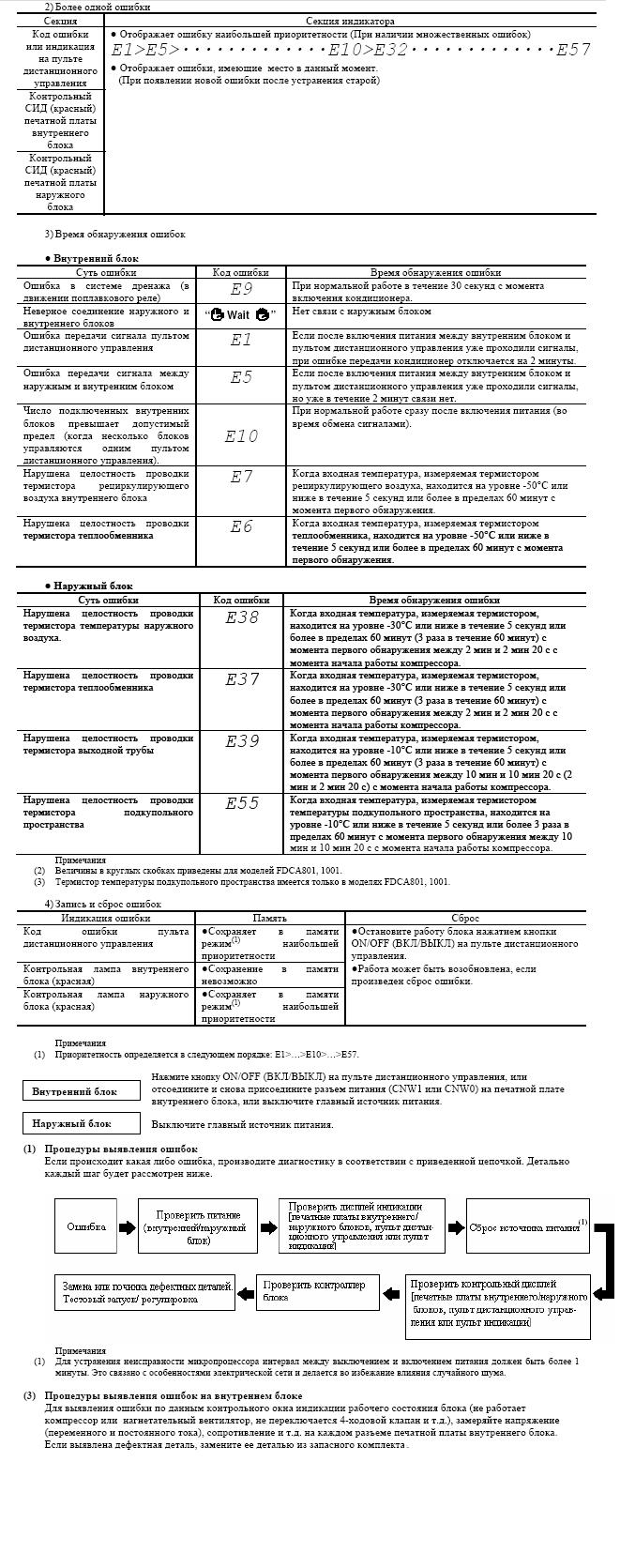
В полупромышленном и мультизональном оборудовании коды ошибки Mitsubishi Heavy с E1 до E31 относятся к внутренним блокам и высвечиваются только на пульте проблемного блока. Коды ошибок Митсубиси Хеви с номерами E32 — E75 относятся к наружным блокам и показываются на всех проводных пультах данного фреонового контура.
Кондиционеры Mitsubishi Heavy ошибки
| Коды ошибок Mitsubishi | Описание ошибок Митсубиси | Возможные причины ошибки Митсубиси Хеви |
| E1 | Ошибка соединения пульта управления | • Плохой контакт или обрыв сигнального провода • Электромагнитные наводки на кабель • Неисправность PCB внутреннего блока или пульта ДУ |
| E2 | Двойной адрес внутреннего блока | • Количество подключенных блоков превышает лимит. • Двойной адрес внутреннего блока. • Дефект PCB управления внутреннего блока. |
| E3 | Ошибка сигнальной линии | Возникает при полном отсутствии связи между всеми внутренними и внешними блоками. Если появляется соединение между внутренними и внешними блоками, ошибка меняется на E5. В обоих случаях проверьте предохранители и провода сигнальной линии. Проверить заданный номер наружного блока. |
| E5 | Ошибка межблочной связи | Если соединение между внутренним и внешним блоками отсутствует более 2 минут. • Сбой питания внешнего блока • Смена полярности А и B после подачи питания. |
| E6 | Неисправен датчик 1 (2) теплообменника внутреннего блока | • Дефект соединителя датчика теплообменника внутреннего блока • Дефект датчика теплообменника внутреннего блока • Неисправность PCB управления внутреннего блока |
| E7 | Неисправен датчик температуры комнатного воздуха | • Дефект соединителя датчика температуры входящего воздуха • Дефект датчика температуры входящего воздуха • Неисправность PCB управления внутреннего блока |
| E8 | Защита от перегрузки в режиме обогрева | • Загрязнение воздушного фильтра • Неисправность термодатчика на теплообменнике внутреннего блока (короткое замыкание) • Неисправность PCB внутреннего блока |
| E9 | Неисправность дренажа | • Неисправность дренажной помпы, повреждение кабеля, отключен разъем, забита дренажная труба • Неправильная работа поплавкового реле • Неисправность PCB внутреннего блока |
| E10 | Превышение числа внутренних блоков (более 16), контролируемых с одного пульта управления | |
| E11 | Неверное подключение адресации между master и slave блоками | • Для RC-EX1: «Меню» — «Настройка внутренних блоков» — «Выбор В/Б» |
| E12 | В одной сети SL смешаны автоматическая адресация (с пульта управления) и ручная адресация. | |
| E14 | Ошибка связи между между master и slave блоками | • Не указан Master-блок • Неверное подключение кабеля ПДУ, повреждение кабеля ПДУ между master и slave блоками |
| E16 | Неисправность двигателя вентилятора внутреннего блока | • Неисправность электродвигателя • Неисправность PCB внутреннего блока (в случае блоков FDTC и FDT проверить предохранитель F202). |
| E18 | Неверное подключение адресации между master и slave блоками | • Не задан номер ведущего внутреннего блока. • Адрес ведомого внутреннего блока совпадает с адресом ведущего внутреннего блока. • Нет питания на master-блоке |
| E19 | Ошибка помпы из-за неотключения SW7-1 после проверки работоспособности внутреннего блока | |
| E20 | Завышенная скорость вентилятора внутреннего блока | |
| E21 | Не защёлкнута панель фильтра внутреннего блока (только FDT) | |
| E22 | Ошибка подключения к наружному блоку | Внутренние блоки 1,5kW возможно подключить к наружным блокам KX6: • FDC224-335KXE6 c кодом A и выше • FDC400-1360KXE6 c кодом F и выше |
| E28 | Неисправность термодатчика проводного ПДУ | Через 10 секунд после выключения датчика пульта управления, E28 не будет отображаться, даже если провод датчика отсоединен. В это время происходит переключение от датчика пульта управления к датчику температуры входящего воздуха внутреннего блока. |
| E30 | Отсутствие соединения внутреннего и внешнего блоков | • Неисправность PCB управления внутреннего блока • Неисправность PCB управления внешнего блока |
| E31 | Двойной адрес внешнего блока | • Ошибка адресации внешних блоков • Подключено более 128 внутренних блоков • Не установлен переключатель master/slave для комбинированных наружных блоков * Адресация не будет подтверждена, если не перезагрузить питание. **В случае комбинирования блоков установите одинаковые адреса для главного и подчиненного блоков. Главные и подчиненные блоки можно назначить с помощью SW4-7. |
| E32 | Открытая L3 фаза электропитания на первичной стороне | Когда напряжение между L1-N и L2-N равно 0 V, и/или ток L3 уменьшается (0 ампер). |
| E36 | Повышенная температура трубы нагнетания (Tho-D1) | • Неисправность температурного датчика выпускной трубы • Неисправность датчика высокого давления • Недостаточное количество хладагента • Неисправность EEV внутреннего блока • Неисправность температурного датчика теплообменника внутреннего блока • Неисправность EEVH внешнего блока • Неисправность датчика температуры трубы всасывания или неисправность датчика низкого давления • Неисправность EEVSC внешнего блока • Неисправность температурного датчика Tho-H |
| E37 | Неисправен датчик теплообменника наружного блока | Красный LED-индикатор дополнительно указывает на проблемный термистор: • Tho-R1: мигает 1 раз (E37-1) • Tho-R2: мигает 2 раза (E37-2) • Tho-R3: мигает 3 раза (E37-3) • Tho-R4: мигает 4 раза (E37-4) • Tho-SC: мигает 5 раз (E37-5) • Tho-H: мигает 6 раз (E37-6) |
| E38 | Неисправен датчик наружной температуры | • Неисправность PCB управления наружного блока • Разрыв жгута проводов термистора или секции температурного датчика • Разрыв проводного соединения (разъема) |
| E39 | Неисправен датчик температуры трубы нагнетания | • Неисправность PCB управления наружного блока • Разрыв жгута проводов термистора или секции температурного датчика • Разрыв проводного соединения (разъема) |
| E40 | Ошибка высокого давления (активирован 63Н1) | • Короткое замыкание в цепи воздушного потока, сбой воздушного потока, загрязнение наружного теплообменника/неисправность мотора вентилятора • Неисправность PCB управления наружного блока • Неисправность разъема 63H1 • Неисправность разъема электронного клапана • Закрыт сервисный порт • Смесь неконденсируемого газа (азота и т.д.) |
| E41 | Перегрев силового транзистора | • Неисправность инверторной PCB • Неисправность мотора наружного вентилятора • Неправильно закреплено ребро радиатора силового транзистора • Неисправность температурного термистора силового транзистора • Недостаточное пространство установки для наружного блока |
| E42 | Токовая отсечка | • Закрыты порты • Неисправность подачи питания • Избыточное количество хладагента • Неисправность компрессора • Неисправность модуля силового транзистора |
| E43 | Превышение числа подключенных внутренних блоков, превышение допустимой суммарной мощности | • Ошибка адресации внутреннего/внешнего блока • Ошибка соединения сигнальных проводов |
| E44 | Влажный ход | • Несоответствие трубопроводов и сигнальной линии • Перезаправка хладагента • Циркуляция хладагента через байпасный клапан • Ошибка контроля перегрева хладагента |
| E45 | Ошибка связи инвертора | • Неисправность PCB инвертора • Неисправность разъема между PCB управления наружного блока и PCB инвертора • Неисправность PCB управления наружного блока |
| E46 | Смешивание ручной и автоматической адресации в одной сети SL | |
| E47 | Ошибка перегрузки инвертора по току | • Неисправность PCB управления наружного блока • Пыль на PCB управления • Перегорел предохранитель F2 |
| E48 | Неисправность двигателя вентилятора внешнего блока | • Неисправность PCB управления внешнего блока • Попадание посторонних предметов в область вращения вентилятора • Неисправность мотора вентилятора |
| E49 | Ошибка низкого давления или неисправность датчика низкого давления | • Датчик низкого давления (дефект PSL) • Рабочий клапан закрыт • EEV закрыт (неправильная работа) • Недостаточный объем хладагента • Засорение (EEV, фильтр) |
| E51 | Перегрев силового транзистора в течение 15 минут | • Неисправность силового транзистора • Неисправность инвертора и мотора вентилятора |
| E53 | Неисправность датчика температуры трубы всасывания | • Отсоединение провода термистора или внутреннего провода считывающей части (проверьте запрессованную часть) • Отсоединение разъема термистора • Дефект PCB управления внешнего блока |
| E54 | Неисправность датчика высокого давления/ датчика низкого давления | Красный LED-индикатор дополнительно указывает на проблемный термистор: • E54-1/мигает 1 раз: аномалия датчика низкого давления • E54-2/мигает 2 раза: аномалия датчика высокого давления |
| E55 | Неисправность датчика температуры компрессора (Tho-C1) | • Отсоединение провода термистора или внутреннего провода считывающей части (проверьте запрессованную часть) • Отсоединение разъема термистора • Дефект PCB управления внешнего блока |
| E56 | Перегрев силивого модуля (IGBT) (Tho-P1, Tho-P2) | Красный LED-индикатор дополнительно указывает на проблемный термистор: • E56-1/мигает 1 раз: аномалия Tho-P1 • E56-2/мигает 2 раза: аномалия Tho-P2 |
| E57 | • Недостаток хладагента • Закрыт клапан |
|
| E58 | Аварийное прекращение подачи тока | • Избыточное количество хладагента • Не соблюдено пространство установки внутреннего, наружного блоков • Неисправность компрессора • Неисправность датчика температуры наружного воздуха • Неисправность PCB управления наружного блока |
| E59 | Ошибка запуска компрессора | • Неисправность мотора наружного вентилятора • Неисправность PCB инвертора • Ненормальное напряжение питания • Ненадлежащее количество хладагента и неисправность холодильного контура • Неисправный компрессор (подшипник мотора) |
| E60 | Ошибка определения положения ротора компрессора (рассинхронизация) | • Неисправность мотора наружного вентилятора • Неисправность PCB управления наружного блока • Неисправность PCB инвертора • Ненормальное напряжение питания • Ненадлежащее количество хладагента и неисправность холодильного контура • Неисправность компрессора (мотор, подшипник) |
| E61 | Ошибка связи между master / slave наружными блоками | |
| E63 | Аварийная остановка | |
| E75 | Ошибка связи при работе с центральным пультом | |
| E82 | Неисправен датчик теплообменника внутреннего блока | • Неисправен термодатчик (дефект чувствительного элемента, повреждение кабеля, короткое замыкание) • Отсоединение разъема термодатчика |
| E84 | Высокая влажность | |
| E85 | Защита от обмерзания | • Упала скорость вентилятора внутреннего блока • Неисправность датчика теплообменника внутреннего блока |
| E86 | Высокое давление в режиме обогрева | • Перегрузка системы • Упала скорость вентилятора внутреннего блока • Неисправность датчика теплообменника внутреннего блока |
E1-сбой печатной платы внутреннего блока, неправильно подключён пульт дистанционного управления или неисправен.
E2 -дублирование адресов внутренних блоков
E3 — некорректный адрес наружного блока
E5 -неисправна плата управления наружного блока
E6 — термодатчик испарителя замкнут/оборван
E7 —сенсор внутреннего блока замкнут/оборван
E8 — перегрузка испарителя или неисправен датчик
E9 — ошибка дренажного насоса или поплавкового датчика
E10 —больше 16 внутренних блоков соединяются с пультом управления
E11 -больше одного блока соединяются с пультом управления,когда адрес занят
E12 -ошибка настройки адресов
E14 -неправильные настройки соединения master-slave (ведущий-ведомый)
E16 -неисправен вентилятор внутреннего блока
E28 -неисправен датчик пульта управления
E30 —ошибка соединения наружного/внутреннего блоков
E31 -дублирование, неправильные настройки адресов
E32 — неправильная последовательность фаз или обрыв провода
E33 — обрыв обмотки компрессора
E34 — разомкнута фаза L3 обмотки 52C
E35 —высокая температура конденсера или неисправен термодатчик
E36 —недопустимое отклонение температуры выходного воздуха
E37 -неисправен термодатчик конденсера
E38 — неисправен термодатчик наружного воздуха
E39 — неисправен термодтчик нагнетательной трубы
E40 — сработала реле высокого давления 63Н1
E49 -система остановилась, низкое давление или недостаточно хладагента
E52 — сбой в 52С
E53 —неисправен термистор всасывающей трубы
E54 -отсоединён датчик низкого давления
E55 — неисправен термистор температуры внутреннего пространства компрессора
E56 -термодатчик силового транзистора неисправен или оборван
E57-недостаточно хладагента
E59 -не запускается компрессор
E60 -ошибка позиционирования компрессора
E63 -аварийное отключение внутреннего блока
Полная версия кодов ошибок в формате .pdf
Скачать 
Коды ошибок для моделей
FDTA28KXE4 FDTWA28KXE4 FDTQA22KXE4
FDRA22KXE4 FDQMA22KXE4/28/36/45/56/71/90/112/140
FDTSA22KXE4
FDUMA36KXE4 FDURA45KXE4 FDEA36KXE4
FDKA22KXE4 FDFLA28KXE4
FDE321HKXE2 401HKXE2 501/631/801/1001/1251HKXE2
FDKY251HKXE2,321HKXE2,401HKXE2,501HKEXE2,631HKXE2
FDFL251HKXE2,401HKXE2,631HKXE2
FDFUA28KXE4 SRK20ZD-S SRK501CENF-L
SRK561CENF-F SCM328CENF-L1 SCM338CENF-L1
SRK25GZ-L1/35/502Z-L
FDC508HES3 808HES3 1008HES3
FDT208-A 258A 308A 408-A 508-A
FDR208-A 258A 308A 408-A 508-A
SCM60ZD-S SCM80ZD-S
SKM2ZD-S SKM25ZD-S
SKM28ZD-S SKM35ZD-S
FDC2001HKXRE2,2501HKXRE2
и др.
Функция самодиагностики
■
Мы стремимся к постоянному совершенствованию изделий путем установки индикаторов, указывающих на появление каждой из описанных ниже
неисправностей:
Горит лампочка TIMER
Лампочка RUN продолжает
мигать
Горит лампочка RUN
Лампочка RUN мигает два раза
Лампочка RUN
Oшибкa дaтчикa 1 тeплообмeнникa
Мигает 1 раз
Ошибка датчика температуры в
Мигает 2 раза
помещении
Oшибкa дaтчикa 3 тeплообмeнникa
Мигает 3 раз
Oшибкa нaпpяжeния aктивного
Мигает 5 раз
фильтpa
Ошибка двигателя внутреннего
Мигает 6 раз
вентилятора
Недостаточное количество
хладагента
Рабочий клапан закрыт
Мигает 7 раз
Ошибка датчика 1 теплообменника
Лампочка TIMER
Ошибка датчика наружной
Мигает 1 раз
температуры
Ошибка датчика жидкостной трубы
Мигает 2 раза
наружного теплообменника
Ошибка датчика нагнетательного
Мигает 4 раза
трубопровода
Мигает 5 раза
Сбой датчика всасывающей трубки
Мигает 1 раз
Отсутствие тока
Мигает 2 раза
Неисправность наружного блока
Чрезмерный ток
Мигает 3 раза
Ошибка транзистора
Мигает 4 раза
Перегрев компрессора
Мигает 5 раз
Мигает 6 раз
Ошибка передачи сигнала
Ошибка
Мигает 7 раз
вентилятора
Зaщитa cиcтeмы оxлaждeния от
Пpодолжaeт мигaть
выcокого дaвлeния
Мигает 2 раз
Заблокирован ротор
Описание неисправности
• Поpвaн пpовод дaтчикa 1 тeплообмeнникa, плоxо подключeн
paзъeм
• Обрыв провода датчика температуры в помещении, плохой
контакт в соединении
• Поpвaн пpовод дaтчикa 3 тeплообмeнникa, плоxо подключeн
paзъeм
• Подaeтcя нeвepноe питaниe
• Неисправен двигатель вентилятора, плохой контакт в
соединении
• Недостаточное количество хладагента, утечка
• Рабочий клапан закрыт
• Порван провод датчика 1 теплообменника, плохо подключен
разъем
• Обрыв провода датчика наружной температуры, плохой
контакт в соединении
• Обрыв провода датчика жидкостной трубы теплообменника,
плохой контакт в соединении
• Поврежден провод датчика нагнетательного трубопровода.
Слабый контакт соединителя
• Порван провод датчика всасывающей трубки, плохо
подключен разъем
• Блокировка компрессора, размыкание фазы на выходе
компрессора, короткое замыкание транзистора в сети
питания, закрывание рабочего клапана
• Неисправен транзистор в сети питания, неисправна магистраль компрессора
• Обрыв провода датчика выпускной трубы, плохой контакт в соединении
• Засорение компрессора
• Перегрузка, избыток хладагента в системе
• Транзистор поврежден
• Недостаток хладагента, неисправный датчик выпускной
трубы, закрыт рабочий клапан
• Неисправность в системе электропитания. Обрыв
сигнального провода, неисправность платы внутреннего/
наружного блока
двигателя
внешнего
• Дефектный двигатель вентилятора, плохое соединение
разъема
• Избыток гaзa, коpоткоe зaмыкaниe нapyжного модyля
• Неисправен компрессор
• Размыкание фазы компрессора
• Неисправны платы наружного блока
– 198 –
Причина

Полный список ошибок кондиционеров Mitsubishi Heavy с расшифровкой.
Е1 – произошел сбой в печатной плате внутреннего блока или возникли
неисправности в пульте управления;
Е2 – произошло дублирование адресов внутренних блоков;
Е3 – адрес наружного блока является некорректным;
Е5 – возникли неисправности в плате управления наружного бока;
Е6 – произошел обрыв (замыкание) датчика испарителя;
Е7 – произошел обрыв (замыкание) сенсора внутреннего блока;
Е8 – произошла перегрузка испарителя;
Е9 – ошибка в работе дренажного насоса;
Е10 – с пультом управления соединены более 16-ти блоков;
Е11 – с пультом управления соединены более 1-го блока при занятом адресе;
Е12 – ошибки в настройках адресов;
Е14 – совершены неправильные настройки ведущих и ведомых соединений;
Е16 – возникли неисправности в работе вентилятора внутреннего блока;
Е28 – возникли неисправности в датчике пульта управления;
Е30 – возникла ошибка в соединении наружного и внутреннего блоков;
Е31 – осуществление неверной настройки адресов;
Е32 – возник обрыв провода или неверно выполнена последовательность фаз;
Е33 – произошел обрыв обмотки провода;
Е34 – произошло размыкание фазы обмотки;
Е35 – неисправности в работе датчика или повышение температуры в конденсаторе;
Е36 – произошло отклонение температуры выходного воздуха выше нормы;
Е37 – возникли неисправности в температурном датчике конденсера;
Е38 – возникли неисправности в температурном датчике наружного воздуха;
Е39 – возникли неисправности в температурном датчике нагнетательной трубы;
Е40 – произошло повышение давления в системе;
Е49 – произошло понижение давления или хладагента является недостаточно;
Е53 – возникли неисправности в термисторе всасывающей трубы;
Е54 – отсоединился датчик низкого давления;
Е55 – возникли неисправности в термисторе температуры внутри компрессора;
Е56 – возникли неисправности или обрыв температурного датчика силового транзистора;
Е57 – недостаточное число охлаждающей жидкости;
Е59 – не осуществляется запуск компрессора;
Е60 – возникла ошибка в позиционировании компрессора;
Е63 – произошло аварийное отключение внутреннего блока.
Комментарии:
Коды ошибок марки кондиционеров Mitsubishi Heavy для моделей;
- FDTA28KXE4
- FDTWA28KXE4
- FDTQA22KXE4
- FDRA22KXE4
- FDQMA22KXE4/28/36/45/56/71/90/112/140
- FDTSA22KXE4
- FDUMA36KXE4
- FDURA45KXE4
- FDEA36KXE4
- FDKA22KXE4
- FDFLA28KXE4
- FDE321HKXE2
- 401HKXE2 501/631/801/1001/1251HKXE2
- 631HKXE2
- 501HKEXE2
- FDFL251HKXE2
- FDFUA28KXE4
- SRK20ZD-S
- SRK501CENF-L
- SRK561CENF-F
- SCM328CENF-L1
- SCM338CENF-L1
- SRK25GZ-L1/35/502Z-L
- FDC508HES3
- 808HES3
- 1008HES3
- FDT208-A 258A 308A 408-A 508-A
- FDR208-A 258A 308A 408-A 508-A
- SCM60ZD-S
- SCM80ZD-S
- SKM25ZD-S
- SKM2ZD-S
- SKM28ZD-S
- SKM35ZD-S
- FDC2001HKXRE2
- 2501HKXRE2
- и др.
| Ошибка | Неисправность |
|---|---|
| E1 | Сбой печатной платы внутреннего блока, неправильно подключён пульт дистанционного управления или неисправен |
| E2 | Дублирование адресов внутренних блоков |
| E3 | Некорректный адрес наружного блока |
| E5 | Неисправна плата управления наружного блока |
| E6 | Термодатчик испарителя замкнут/оборван |
| E7 | Сенсор внутреннего блока замкнут/оборван |
| E8 | Перегрузка испарителя или неисправен датчик |
| E9 | Ошибка дренажного насоса или поплавкового датчика |
| E10 | Больше 16 внутренних блоков соединяются с пультом управления |
| E11 | Больше одного блока соединяются с пультом управления,когда адрес занят |
| E12 | Ошибка настройки адресов |
| E14 | Неправильные настройки соединения master-slave (ведущий-ведомый) |
| E16 | Неисправен вентилятор внутреннего блока |
| E28 | Неисправен датчик пульта управления |
| E30 | Ошибка соединения наружного/внутреннего блоков |
| E31 | Дублирование, неправильные настройки адресов |
| E32 | Неправильная последовательность фаз или обрыв провода |
| E33 | Обрыв обмотки компрессора |
| E34 | Разомкнута фаза L3 обмотки 52C |
| E35 | Высокая температура конденсера или неисправен термодатчик |
| E36 | Недопустимое отклонение температуры выходного воздуха |
| E37 | Неисправен термодатчик конденсера |
| E38 | Неисправен термодатчик наружного воздуха |
| E39 | Неисправен термодтчик нагнетательной трубы |
| E40 | Сработала реле высокого давления 63Н1 |
| E49 | Система остановилась, низкое давление или недостаточно хладагента |
| E52 | Сбой в 52С |
| E53 | Неисправен термистор всасывающей трубы |
| E54 | Отсоединён датчик низкого давления |
| E55 | Неисправен термистор температуры внутреннего пространства компрессора |
| E56 | Термодатчик силового транзистора неисправен или оборван |
| E57 | Недостаточно хладагента |
| E59 | Не запускается компрессор |
| E60 | Ошибка позиционирования компрессора |
| E63 | Аварийное отключение внутреннего блока |
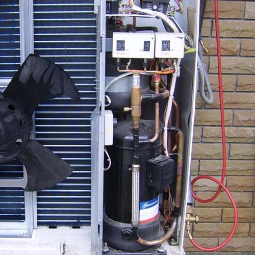
Black = All R410A
Red = FD Split 1, 2 Series R410A
Blue = KX4 & KXR4 Series R410A
| Код ошибки | Внутренняя плата | Наружная плата | Подробная информация о неисправности | ||
|---|---|---|---|---|---|
| Красный светодиод | Зеленый светодиод | Красный светодиод | Зеленый светодиод | ||
| Нет признаков | Не горит | Мигание | Не горит | Мигание | • Нормальная работа |
| Не горит | Не горит | Не горит | Не горит | • Нет электросети [выключеное питание или отказ источника питания]. • L фазный провод разомкнут |
|
| Мигает 3 раза | Мигание | Не горит | Мигание | • Провода пульта дистанционного управления — X & Y перепутаны. • Провода пульта дистанционного управления — Y & Z перепутаны. • Проводка пульта дистанционного управления является разомкнутой. (X провод сломан — звуковой сигнал вырабатывается и указание. Z сломанный провод — нет звукового сигнала и нет индикации) |
|
| LCD мигает непрерывно потихоньку или выкл. | Не горит | Мигание | Мигает 2 раза | Мигание | • Открытая цепь или плохая внутренняя / наружная соединительная проводка |
| E1 | Не горит | Выкл. Или Вкл. Непрерывно | Не горит | Мигание | • Внутренняя плата или отказ CPU |
| Выкл. Или Вкл. Непрерывно | Выкл. Или Вкл. Непрерывно | Не горит | Мигание | • Внутренняя плата или отказ CPU | |
| Не горит | Мигание | Не горит | Мигание | • В контрольной группе электроснабжения, подача питания по меньшей мере на один внутренний блок выключена • Провод дистанционного управления Y разомкнут • Проводки X и Y пульта дистанционного управления поменять местами • Неисправная плата внутреннего или удаленного пульта • Электрические помехи |
|
| Не горит | Мигание | Не горит | Мигание | • Проводка пульта дистанционного управления, подключенна к A и B • Проводка A и B соединена в замкнутом контуре • Процессор внутреннего блока печатной платы отсутствует |
|
| Мигает 3 раза | Мигание | Не горит | Мигание | • Разомкнутая цепь подключения пульта дистанционного управления | |
| E2 | Мигает один раз | Мигание | Не горит | Мигание | • Дублирование адресов внутренних блоков. • В сеть подключено более 49 внутренних блоков |
| E3 | Мигает 2 раза | Мигание | Не горит | Не горит | • Нет сетевого питания на наружном блоке [выключение питания или сбой питания] |
| Мигает 2 раза | Не горит | Не горит | Мигает 2 раза | • Неправильная настройка адреса наружного блока | |
| Мигает 2 раза | Мигание | Выкл. Или Вкл. Непрерывно | Неопределен | • Нет сетевого питания на наружном блоке [выключение питания или сбой питания] | |
| E5 | Мигает 2 раза | Мигание | Мигает 2 раза | Мигание | • Ошибка связи с наружнем/внутренним блоком |
| Мигает 2 раза | Мигание | Не горит | Не горит | • Нарушение работы ППБ блока управления наружным блоком • Неисправен инвертор |
|
| Мигает 2 раза | Мигание | Не горит | Не горит | • Отказ внешнего блока питания (где внутренние / наружные источники питания разделены) • Ошибка внутренней / наружной связи • Поменяйте местами проводку А и Б затем включите |
|
| Мигает 2 раза | Мигание | Не горит | Не регулярное мигание | Отказ микрокомпьютера наружного блока | |
| E6 | Мигает один раз | Мигание | Не горит | Мигание | • Неисправен датчик теплообменника внутреннего блока [THIR] (сопротивление разомкнутая цепь или замкнутая цепь) • Плохое соединение разъема датчика в помещении ПЕЧАТНАЯ ПЛАТА |
| E7 | Мигает один раз | Мигание | Не горит | Мигание | • Неисправен датчик возврата внутреннего блока [Thia] (сопротивление разомкнуто или замкнуто) • Плохое соединение разъема датчика в помещении ПЕЧАТНАЯ ПЛАТА |
| E8 | Мигает один раз | Мигание | Не горит | Мигание | • Перегрузка при нагревании (необычайно высокая температура в помещении температура теплообменника). • Отказ датчика теплообменника внутреннего блока [THIR] (сопротивление датчика замкнутая цепь). |
| E9 | Мигает один раз | Мигание | Не горит | Мигание | • Ошибка дренажного насоса или поплавкового датчика. • Обнаружен конденсат в сливном лотке. |
| E10 | Не горит | Мигание | Не горит | Мигание | • 17 или более внутренних блоков, подключенные к одному пульту дистанционного управления (максимально допустимо: 16) |
| E11 | Не горит | Мигание | Не горит | Мигание | • Больше одного блока соединяются с пультом управления,когда адрес занят |
Коды ошибок неисправностей кондиционеров Mitsubishi Heavy Industries приведены в таблице 2, 3, 4.
В целях правильной диагностики перед тем, как предпринять меры по устранению возникшей неисправности, убедитесь в том, что симптомы, подтверждающие возникновение неисправности, проявились повторно.
Нахождение и устранение неисправностей в холодильном контуре
Диагностика состояния работы по рабочему давлению и разнице температур
Точная диагностика требует навыков, которые приобретаются в результате многолетней практики: одна неисправность может повлечь за собой другую, иногда одновременно могут иметь место несколько неисправностей из разных источников. Выявить источники неисправностей легче, если ежедневно наблюдать за рабочим состоянием кондиционера. Полезным признаком является рабочее давление и разность температур между всасываемым и распределяемым воздухом. В таблице 1 приведены некоторые указания.
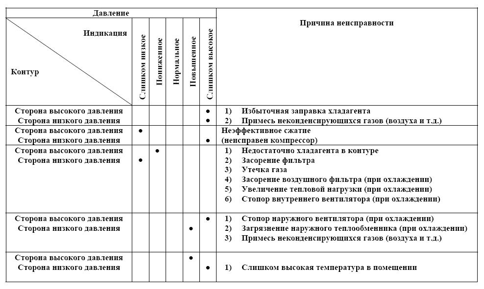
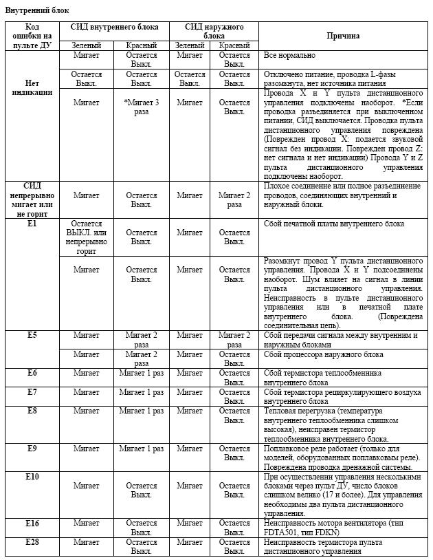
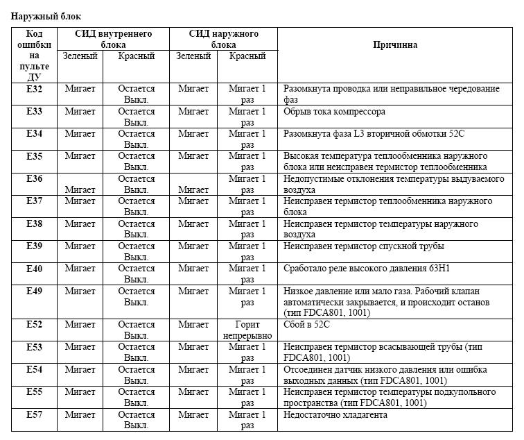
Информация приведена для полупромышленных кондиционеров СЕРИИ V-MULTI (Сплит-система с тепловым насосом):
(НАРУЖНЫЙ БЛОК) FDCA301HEN 301HES 401HEN 401HES 501HES 601HES 801HES 1001HES
(ВНУТРЕННИЙ БЛОК) FDTA151 201 251 301 401 501, FDENA151 201 251 301 401 501, FDKNA151 201 251 301, FDURA201 251 301 401 501
Продажа и монтаж. Ремонт и обслуживание (Пн.-пт.: 09.00—19.00, сб-вс: 10.00-17.00):
+7(495) 146-65-64
sale@service-climate.ru
E1 — сбой печатной платы внутреннего блока, неправильно подключён пульт дистанционного управления или неисправен.
E2 — дублирование адресов внутренних блоков
E3 — некорректный адрес наружного блока
E5 — неисправна плата управления наружного блока
E6 — термодатчик испарителя замкнут/оборван
E7 — сенсор внутреннего блока замкнут/оборван
E8 — перегрузка испарителя или неисправен датчик
E9 — ошибка дренажного насоса или поплавкового датчика
E10 — больше 16 внутренних блоков соединяются с пультом управления
E11 — больше одного блока соединяются с пультом управления,когда адрес занят
E12 — ошибка настройки адресов
E14 — неправильные настройки соединения master-slave (ведущий-ведомый)
E16 — неисправен вентилятор внутреннего блока
E28 — неисправен датчик пульта управления
E30 — ошибка соединения наружного/внутреннего блоков
E31 — дублирование, неправильные настройки адресов
E32 — неправильная последовательность фаз или обрыв провода
E33 — обрыв обмотки компрессора
E34 — разомкнута фаза L3 обмотки 52C
E35 — высокая температура конденсера или неисправен термодатчик
E36 — недопустимое отклонение температуры выходного воздуха
E37 — неисправен термодатчик конденсера
E38 — неисправен термодатчик наружного воздуха
E39 — неисправен термодтчик нагнетательной трубы
E40 — сработала реле высокого давления 63Н1
E49 — система остановилась, низкое давление или недостаточно хладагента
E52 — сбой в 52С
E53 — неисправен термистор всасывающей трубы
E54 — отсоединён датчик низкого давления
E55 — неисправен термистор температуры внутреннего пространства компрессора
E56 — термодатчик силового транзистора неисправен или оборван
E57— недостаточно хладагента
E59 — не запускается компрессор
E60 — ошибка позиционирования компрессора
E63 — аварийное отключение внутреннего блока
Полная версия кодов ошибок в формате .pdf
|
Скачать |
Коды ошибок для моделей
FDTA28KXE4 FDTWA28KXE4 FDTQA22KXE4
FDRA22KXE4 FDQMA22KXE4/28/36/45/56/71/90/112/140
FDTSA22KXE4
FDUMA36KXE4 FDURA45KXE4 FDEA36KXE4
FDKA22KXE4 FDFLA28KXE4
FDE321HKXE2 401HKXE2 501/631/801/1001/1251HKXE2
FDKY251HKXE2,321HKXE2,401HKXE2,501HKEXE2,631HKXE2
FDFL251HKXE2,401HKXE2,631HKXE2
FDFUA28KXE4 SRK20ZD-S SRK501CENF-L
SRK561CENF-F SCM328CENF-L1 SCM338CENF-L1
SRK25GZ-L1/35/502Z-L
FDC508HES3 808HES3 1008HES3
FDT208-A 258A 308A 408-A 508-A
FDR208-A 258A 308A 408-A 508-A
SCM60ZD-S SCM80ZD-S
SKM2ZD-S SKM25ZD-S
SKM28ZD-S SKM35ZD-S
FDC2001HKXRE2,2501HKXRE2
и др.
СПЕЦПРЕДЛОЖЕНИЕ!
Для владельцев коммерческих объектов и корпоративных заказчиков выполняем диагностику и составляем план ремонтно-восстановительных мероприятий для вашего инженерного оборудования индивидуально, учитывая Ваши пожелания и рекомендации заводов-изготовителей техники. Подробнее.
-
Contents
-
Table of Contents
-
Troubleshooting
-
Bookmarks
Quick Links
DATA BOOK
INVERTER WALL MOUNTED TYPE
ROOM AIR-CONDITIONERS
(Split system, air to air heat pump type)
SRK20ZJ-S
25ZJ-S
35ZJ-S
DRAFT
Manual No.’09•SRK-DB-087D
Related Manuals for Mitsubishi Heavy Industries SRK20ZJ-S
Summary of Contents for Mitsubishi Heavy Industries SRK20ZJ-S
-
Page 1
DRAFT Manual No.’09•SRK-DB-087D DATA BOOK INVERTER WALL MOUNTED TYPE ROOM AIR-CONDITIONERS (Split system, air to air heat pump type) SRK20ZJ-S 25ZJ-S 35ZJ-S… -
Page 2: Table Of Contents
’09•SRK-DB-087D CONTENTS 1 SPECIFICATIONS ………………2 2 EXTERIOR DIMENSIONS …………….5 3 ELECTRICAL WIRING …………….7 4 NOISE LEVEL ………………9 5 PIPING SYSTEM ………………12 6 APPLICATION DATA …………….13 (1) Installation of indoor unit …………..13 (2) Installation of outdoor unit …………..17 7 RANGE OF USAGE & LIMITATIONS …………24 8 CAPACITY TABLES…………….26 REFERENCE 1 OUTLINE OF OPERATION CONTROL BY MICROCOMPUTER ..27…
-
Page 3: Specifications
’09•SRK-DB-087D 1 SPECIFICATIONS Adapted to RoHS directive SRK20ZJ-S Model Item Indoor unit SRK20ZJ-S Outdoor unit SRC20ZJ-S Cooling capacity (1) 2000 (1000 (Min.) ~ 2700 (Max.)) Heating capacity (1) 2700 (1200 (Min.) ~ 3900 (Max.)) Power supply 1 Phase, 220 ~ 240 V, 50Hz Cooling 0.44 (0.21 ~ 0.77)
-
Page 4
’09•SRK-DB-087D Adapted to RoHS directive SRK25ZJ-S Model Item SRK25ZJ-S SRC25ZJ-S Indoor unit Outdoor unit Cooling capacity (1) 2500 (1000 (Min.) ~ 2900 (Max.)) Heating capacity (1) 3200 (1200 (Min.) ~ 4200 (Max.)) Power supply 1 Phase, 220 ~ 240 V, 50Hz Cooling 0.62 (0.21 ~ 0.88) Power… -
Page 5
’09•SRK-DB-087D Adapted to RoHS directive SRK35ZJ-S Model Item SRK35ZJ-S SRC35ZJ-S Indoor unit Outdoor unit Cooling capacity (1) 3500 (1000 (Min.) ~ 3800 (Max.)) Heating capacity (1) 4000 (1300 (Min.) ~ 4800 (Max.)) Power supply 1 Phase, 220 ~ 240 V, 50Hz Cooling 1.01 (0.21 ~ 1.24) Power… -
Page 6
Symbol Content 14.5 Gas piping φ9.52(3/8″) (Flare) Liquid piping φ6.35(1/4″) (Flare) (φ65) Hole on wall for right rear piping (φ65) Hole on wall for left rear piping Drain hose VP16 Outlet for wiring Outlet for piping(on both side) Wireless remote controller Outlet for down piping 17.3 (Refer to the above view) -
Page 7
Notes 50.6 (1) It must not be surrounded by walls on the four sides. (2) The unit must be fixed with anchor bolts. An anchor bolt must not 390.6 protrude more than 15mm. (3) Where the unit is subject to strong winds, lay it in such a direction that the blower outlet faces perpendicularly to the dominant wind direction. -
Page 8: Electrical Wiring
Description Item CNE-CNY Connector Fan motor Flap motor Louver motor Humidity sensor Room temp. sensor Heat exch. sensor Diode stack Fuse PRINTED Terminal block CIRCUIT Varistor BOARD HEAT EXCHANGER Mark Color 250V 3.15A Black Blue White Yellow Yellow/Green HEAT EXCHANGER DISPLAY WIRELESS R-AMP…
-
Page 9: Specifications
TO INDOOR UNIT POWER WIRES SIGNAL WIRE PWB ASSY POWER SOURCE T1 T2 POWER TRANSISTOR 1〜220-240V 50Hz/1〜220V 60Hz t° 250V 15A (BK) R.IN (RD) + + NOISE (WH) 250V 20A FILTER 3~ (BK) (WH) S.IN F3 250V 1A (Y/G) (RD) CIRCUIT (Y/G) CNFAN…
-
Page 10: Noise Level
’09•SRK-DB-087D 4 NOISE LEVEL Condition ISO-T1, JIS C9612 Model SRK20ZJ-S (Indoor Unit) Model SRK20ZJ-S Cooling 33 dB(A) Noise Level Heating 36 dB(A) × ..Cooling Heating Mid Octave Band frequency(Hz) (Outdoor Unit) Model SRC20ZJ-S Cooling 47 dB(A) Noise Level Heating 46 dB(A) ×…
-
Page 11
’09•SRK-DB-087D Model SRK25ZJ-S Condition ISO-T1, JIS C9612 (Indoor Unit) Model SRK25ZJ-S 34 dB(A) Cooling Noise Level Heating 39 dB(A) × ..Cooling Heating Mid Octave Band frequency(Hz) (Outdoor Unit) Model SRC25ZJ-S Cooling 48 dB(A) Noise Level 49 dB(A) Heating × ..Cooling Heating Mid Octave Band Frequency(Hz) -
Page 12
’09•SRK-DB-087D Model SRK35ZJ-S Condition ISO-T1, JIS C9612 (Indoor Unit) Model SRK35ZJ-S 42 dB(A) Cooling Noise Level Heating 43 dB(A) × ..Cooling Heating Mid Octave Band frequency(Hz) (Outdoor Unit) Model SRC35ZJ-S Cooling 50 dB(A) Noise Level 51 dB(A) Heating × ..Cooling Heating Mid Octave Band Frequency(Hz) -
Page 13: Piping System
’09•SRK-DB-087D 5 PIPING SYSTEM Models SRK20ZJ-S, 25ZJ-S Cooling cycle Heating cycle Indoor unit Outdoor unit Outdoor air Flare temp. sensor connection Service valve (TH2) (Gas) Discharge pipe temp. sensor Gas pipie Check joint Heat Muf fler (TH3) (φ9.52) Room temp.
-
Page 14: Application Data
6 APPLICATION DATA RLA012A012 WARNING • Do not vent R410A into the atmosphere : R410A is a fluorinated • Do not perform any change of protective device itself or its setup (1) Installation of indoor unit greenhouse gas, covered by the Kyoto Protocol with Global condition.
-
Page 15: Selection Of Installation Location
Poisonous gases will flow into the room through drainage pipe and This may cause fire or electric shock due to defecting contact, defecting set or radio receiver is placed within 1m). system is in operation. seriously affect the user’s health and safety. insulation and over-current etc.
-
Page 16
Fixing of indoor unit Since this air conditioner has been designed to collect dew drops on the rear Gutter surface to the drain pan, do not attach the power cord above the gutter. • How to remove the indoor unit from the installation board Latch (2 locations) Installation Steps Wall… -
Page 17
illustration, hold the panel at both ends of lower Tighten the 2 set screws. part, lower it downward slowly, then push it Fit the air filter. slightly until the latch works. Fit the air inlet panel. Set screws ELECTRICAL WIRING WORK Installing the air-cleaning filters Screw Preparation of indoor unit… -
Page 18: Installation Of Outdoor Unit
RWC012A030A Model 20 · 25 · 35 (2) Installation of outdoor unit R410A REFRIGERANT USED • This installation manual deals with outdoor units and general installation specifications only. For indoor units, refer to page 13. • When install the unit, be sure to check whether the selection of installation place, power supply specifications, usage limitation (piping length, height differences between indoor and outdoor units, power supply voltage and etc.) and installation spaces.
-
Page 19
• Do not processing, splice the power cord, or share a socket Touching rotating equipments, hot surfaces or high voltage parts can component can cause fire or burst. with other power plugs. cause personal injury due to entrapment, burn or electric shocks. This may cause fire or electric shock due to defecting contact, defecting insulation and over-current etc. -
Page 20
Notabilia as a unit designed for R410A Do not use any refrigerant other than R410A. R410A will rise to pressure about 1.6 times higher than that of a conventional refrigerant. A cylinder containing R410A has a pink indication mark on the top. A unit designed for R410A has adopted a different size indoor unit operation valve charge port and a different size check joint provided in the unit to prevent the charging of a wrong refrigerant by mistake. -
Page 21
ying 2. REFRIGERANT PIPING WORK rate 2. REFRIGERANT PIPING WORK rate 1) Restrictions on unit installation and use 1) Restrictions on unit installation and use Check the following points in light of the indoor unit specifications and the installation site. Observe the following restrictions on unit installation and use. -
Page 22
flare nut onto it. Flare dimensions for R410A are different from those for conventional R407C. Copper In the case of a rigid (clutch) type Although we recommend the use of flaring tools designed specifically for R410A, conventional Screw pipe outer With an R410A tool With a conventional tool diameter flaring tools can also be used by adjusting the measurement of protrusion B with a protrusion… -
Page 23: Drain Piping Work
Wrap indoor units’ flare joints with heat insulating parts (pipe cover) for heat insulation (both gas and liquid pipes). and outdoor units Give heat insulation to both gas and liquid side pipes. Bundle a heat insulating material and a pipe tightly together so that no gaps may be left between them and wrap them Gas piping together with a connecting cable by a dressing tape.
-
Page 24: After Installation
Polychloroprene rubber conductors insulation Do not lay electronic control cables (remote control and signaling wires) and other cables together outside the unit. Laying them together can result Stranded core in the malfunctioning or a failure of the unit due to electric noises. 4or5 Number of conductors Fasten cables so that may not touch the piping, etc.
-
Page 25: Selection Chart
’09•SRK-DB-087D 7 RANGE OF USAGE & LIMITATIONS Models Item Cooling operation : Approximately 18 to 32℃ D.B. Indoor return air temperature Heating operation : Approximately 10 to 27℃ D.B. (Upper, lower limits) (Refer to the selection chart) Cooling operation : Approximately -15 to 46℃ D.B. Outdoor air temperature Heating operation : Approximately -15 to 21℃…
-
Page 26
’09•SRK-DB-087D (2) Correction of cooling and heating capacity in relation to one way length of refrigerant piping It is necessary to correct the cooling and heating capacity in relation to the one way piping length between the indoor and outdoor units. -
Page 27: Capacity Tables
’09•SRK-DB-087D 8 CAPACITY TABLES Model SRK20ZJ-S Cool Mode Heat Mode Indoor air temp Indoor air temp outdoor 21˚CDB 23˚CDB 26˚CDB 27˚CDB 28˚CDB 31˚CDB 33˚CDB Outdoor Air flow air temp. Air flow air temp. 14˚CWB 16˚CWB 18˚CWB 19˚CWB 20˚CWB 22˚CWB 24˚CWB 16˚CDB…
-
Page 28: Reference
’09•SRK-DB-087D Reference 1 OUTLINE OF OPERATION CONTROL BY MICROCOMPUTER 1. Operation control function by remote controller Operation section FAN SPEED button OPERATION MODE select button Each time the button is pressed, the Each time the button pressed, the display is switched over in turn. display is switched over in turn.
-
Page 29: Auto Restart Function
’09•SRK-DB-087D 2. Unit ON/OFF button When the remote controller batteries become weak, or if the remote controller is lost or malfunctioning, this button may be used to turn the unit on and off. (1) Operation Push the button once to place the unit in the automatic mode. Push it once more to turn the unit off. (2) Details of operation The unit will go into the automatic mode in which it automatically determines, from indoor temperature (as detected by sensor), whether to go into the cooling, thermal dry or heating modes.
-
Page 30: Flap And Louver Control
’09•SRK-DB-087D 5. Flap and louver control Control the flap and louver by AIR FLOW (UP/DOWN) and (LEFT/RIGHT) button on the wireless remote controller. (1) Flap Each time when you press the AIR FLOW (UP/DOWN) button the mode changes as follows. (Flap stopped) (Swing) Angle of Flap from Horizontal…
-
Page 31: D Auto Operation
’09•SRK-DB-087D 6. 3D auto operation Control the flap and louver by D AUTO button on the wireless remote controller. Air f low selection and air flow direction are automatically controlled, allowing the entire indoor to efficiently conditioned. (1) During Cooling and Heating (Including auto cooling and heating) (a) Air f low selection is determined according to indoor temperature and setting temperature.
-
Page 32: Timer Operation
’09•SRK-DB-087D 7. Timer operation (1) Comfortable timer setting (ON timer) If the timer is set at ON when the operation select switch is set at the cooling or heating, or the cooling or heating in auto mode operation is selected, the comfortable timer starts and determines the starting time of next operation based on the initial value of minutes and the relationship between the indoor temperature at the setting time (temperature of room temperature sensor) and the setting temperature.
-
Page 33: Outline Of Heating Operation
(a) Fuzzy operation Deviation between the indoor temperature setting correction temperature and the return air temperature is calculated in accordance with the fuzzy rule, and used for control of the air capacity and the compressor speed. Model SRK20ZJ-S SRK25ZJ-S SRK35ZJ-S Fan speed…
-
Page 34: Outline Of Cooling Operation
(a) Fuzzy operation During the fuzzy operation, the air f low and the compressor speed are controlled by calculating the difference between the indoor temperature setting correction temperature and the return air temperature. Model SRK20ZJ-S SRK25ZJ-S SRK35ZJ-S Fan speed 20~66rps…
-
Page 35: Protective Control Function
’09•SRK-DB-087D 12. Protective control function (1) Frost prevention control (During cooling or dehumidifying) (a) Operating conditions Indoor heat exchanger temperature (Th) is lower than ºC. compressor command minutes after reaching the compressor command speed except 0 rps. speed (b) Detail of anti-frost operation Lower Indoor heat exchanger limit…
-
Page 36
’09•SRK-DB-087D (4) Cooling low outdoor air temperature protective control (a) Operating conditions: When the outdoor air temperature (TH) is ºC or lower continues for 0 seconds while the compressor command speed is other than 0 rps. (b) Detail of operation: The lower limit of the compressor command speed is set to 0 <>… -
Page 37
’09•SRK-DB-087D (6) Heating overload protective control (a) Indoor unit side 1) Operating conditions : When the outdoor air temperature (TH) is ºC or higher continues for 0 seconds while the compressor command speed other than 0 rps. The indoor fan is stepped up by speed step. (Upper limit th speed) 2) Detail of operation : The outdoor air temperature (TH) is lower than ºC. -
Page 38
’09•SRK-DB-087D (8) Compressor overheat protection (a) Purpose: It is designed to prevent deterioration of oil, burnout of motor coil and other trouble resulting from the compressor overheat. (b) Detail of operation 1) Speeds are controlled with temperature detected by the sensor (TH) mounted on the discharge pipe. (Example) Fuzzy rps After lapse of 0 second or over… -
Page 39
’09•SRK-DB-087D (13) Serial signal transmission error protection (a) Purpose: Prevents malfunction resulting from error on the indoor ↔ outdoor signals. (b) Detail of operation: If the compressor is operating and a serial signal cannot be received from the indoor control with outdoor control having serial signals continues for minute and seconds, the compressor is stopped. -
Page 40: Troubleshooting Procedures For Electrical Equipment
’09•SRK-DB-087D Reference Reference 2 TROUBLESHOOTING PROCEDURES FOR ELECTRICAL EQUIPMENT (1) Cautions (a) If you are disassembling and checking an air conditioner, be sure to turn off the power before beginning. When working on indoor units, let the unit sit for about minute after turning off the power before you begin work. When working on an outdoor unit, there may be an electrical charge applied to the main circuit (electrolytic condenser), so begin work only after discharging this electrical charge (to DC 10 V or lower).
-
Page 41
’09•SRK-DB-087D (4) Troubleshooting procedure (If the air conditioner runs) Conf irm the contents of the customer complaint. The cause of the trouble can be specifically identified. Eliminate the cause of the trouble and perform an Check the self-diagnosis display. operation check. See page . -
Page 42
’09•SRK-DB-087D (5) Self-diagnosis table When this air conditioner performs an emergency stop, the reason why the emergency stop occurred is displayed by the flashing of display lights. If the air conditioner is operated using the remote controller minutes or more after the emergency stop, the trouble display stops and the air conditioner resumes operation. -
Page 43
’09•SRK-DB-087D (6) Service mode (Trouble mode access function) This air conditioner is capable of recording error displays and protective stops (service data) which have occurred in the past. If self-diagnosis displays cannot be confirmed, it is possible to get a grasp of the conditions at the time trouble occurred by checking these service data. -
Page 44
’09•SRK-DB-087D *3: To count the number of flashes in the service mode, count the number of flashes after the light lights up for 1.5 second initially (start signal). (The time that the light lights up for . second (start signal) is not counted in the number of flashes.) In the case of current cut (example: stop code 42’’) The RUN light (10’… -
Page 45: Remote Controller Setting
’09•SRK-DB-087D (Example) Remote controller setting Operation Displayed data Temperature Fan speed switching switching setting Cooling Displays the reason for the stop (error code) the previous time an error was displayed. 21ºC 22ºC Displays the reason for the stop (error code) 2 times previous when an error was displayed. Displays the reason for the stop (error code) 3 times previous when an error was displayed.
-
Page 46
’09•SRK-DB-087D (c) Error code, stop code table (Assignment of error codes and stop codes is done in common for all models.) Number of flashes when in service mode Stop coad Error Auto TIMER Error content Cause Occurrence conditions display recovery light light Error coad… -
Page 47
’09•SRK-DB-087D Note (1) The number of flashes when in the Service Mode do not include the 1.5 second period when the lights light up at f irst (starting signal). (See the example shown below.) In the case of current cut (example: stop code 42’’) The RUN light (10’… -
Page 48
’09•SRK-DB-087D (e) Room temperature sensor, indoor heat exchanger sensor, outdoor air temperature sensor, outdoor heat exchanger sensor table Units: °C TIMER light (1’s digit) RUN light (10’s digit) Buzzer sound (sounds for 0.1 second) (does not sound) * If no data are recorded (error code is normal), the display for each sensor becomes as shown below. Sensor value displayed when the error code is normal Sensor name -64ºC… -
Page 49
’09•SRK-DB-087D Discharge pipe sensor table Units: °C TIMER light (1’s digit) RUN light (10’s digit) Buzzer sound (sounds for 0.1 second) (does not sound) * If no data are recorded (error code is normal), the display for each sensor becomes as shown below. Sensor value displayed when the error code is normal Sensor name -64ºC… -
Page 50
’09•SRK-DB-087D Service data record form Model Customer Date of investigation Machine name Content of complaint Remote controller settings Display results Display content Content of displayed data Temperature setting Operation switching Fan speed switching Buzzer (Yes/No.) RUN light (Times) TIMER light (Times) Error code on previous occasion. -
Page 51
’09•SRK-DB-087D (7) Inspection procedures corresponding to detail of trouble Sensor error Broken sensor wire, connector poor connection Is connector connection good? Correct connection. Is sensor resistance value good? Replace sensor. Replace PCB. ◆ Sensor temperature characteristics (Room ◆ Discharge pipe sensor temperature characteristics temp., indoor heat exchanger temp., out- door heat exchanger temp., outdoor air temp.) -
Page 52: Current Cut
’09•SRK-DB-087D Current cut Compressor lock, Compressor wiring short circuit, Compressor output is open phase, Outdoor PCB is faulty, Service valve is closed, EEV is faulty, Compressor faulty. In the service valves of the outdoor Open the service valves unit open? Secure space for inlet and Is there any shortcircuit? outlet.
-
Page 53: Over Heat Of Compressor
’09•SRK-DB-087D Over heat of compressor Gas shortage, defective discharge pipe sensor Connector connection check, resistance Is discharge pipe sensor value check, replacement of discharge pipe resistance value good? sensor (page 0) Check if there are any Does trouble persist after Is sufficient quantity of refrigerant places where gas is leaking.
-
Page 54
’09•SRK-DB-087D Trouble of outdoor unit Insufficient refregerant amount, Faulty power transistor, Broken compressor wire Service valve close, Defective EEV, Defective outdoor PCB Check power supply. Is the power supply voltage OK? Proper power supply voltages are as follows. (At the power supply outlet) 220V : 198~242V 230V : 207~253V 240V : 216~264V… -
Page 55
’09•SRK-DB-087D Outdoor fan motor error Defective fan motor, connector poor connection, defective outdoor PCB Is connector connection good? Correct connector connection Is fan motor resistance value good? * Disconnect the fan motor connector, then investigate the fan motor and outdoor PCB separately. -
Page 56
’09•SRK-DB-087D (b) Outdoor unit Phenomenon Operation Sensor mode Shortcircuit Disconnected wire System can be operated normally. Compressor stop. Cooling Heat exchanger sensor Defrosting is not performed. Defrosting is performed for 0 minutes at approx. minutes. Heating System can be operated normally. Compressor stop. -
Page 57
’09•SRK-DB-087D (C) Power transistor inspection procedure [Use a tester with a needle indicator for the inspection. (Do not use a digital tester. Check in the AC 300 volt range.)] (1) If there is a self-diagnosis display, inspect the compressor system (burns, wiring mistakes, etc.) If no problems are found, check the output of the power transistor. -
Page 58
CAUTION- HIGH VOLTAGE High voltage is produced in the control box. Don’t touch electrical parts in the control box for 5 minutes after the unit is stopped. Color symbol Inspection power transistor Black Remove the fasten terminal and test output voltage Orange Indoor unit White… -
Page 59
’09•SRK-DB-087D (a) Inspection of electronic expansion valve Electronic expansion valve operates for approx. 0 seconds after the power on, in order to determine its aperture. Check the operating sound and voltage during the period of time. (Voltage cannot be checked during operation in which only the aperture change occurs.) … -
Page 60
ROOM AIR-CONDITIONERS Air-Conditioning & Refrigeration Systems Headquarters 16-5, 2-chome, Kounan, Minato-ku, Tokyo, 108-8215, Japan Fax : (03) 6716-5926 Because of our policy of continuous improvement, we reserve the right to make changes in all specifications without notice. Copyright MITSUBISHI HEAVY INDUSTRIES.LTD…
-
Contents
-
Table of Contents
-
Troubleshooting
-
Bookmarks
Quick Links
DATA BOOK
INVERTER WALL MOUNTED TYPE
ROOM AIR-CONDITIONERS
(Split system, air to air heat pump type)
SRK20ZJ-S
25ZJ-S
35ZJ-S
DRAFT
Manual No.’09•SRK-DB-087D
Related Manuals for Mitsubishi Heavy Industries SRK20ZJ-S
Summary of Contents for Mitsubishi Heavy Industries SRK20ZJ-S
-
Page 1
DRAFT Manual No.’09•SRK-DB-087D DATA BOOK INVERTER WALL MOUNTED TYPE ROOM AIR-CONDITIONERS (Split system, air to air heat pump type) SRK20ZJ-S 25ZJ-S 35ZJ-S… -
Page 2: Table Of Contents
’09•SRK-DB-087D CONTENTS 1 SPECIFICATIONS ………………2 2 EXTERIOR DIMENSIONS …………….5 3 ELECTRICAL WIRING …………….7 4 NOISE LEVEL ………………9 5 PIPING SYSTEM ………………12 6 APPLICATION DATA …………….13 (1) Installation of indoor unit …………..13 (2) Installation of outdoor unit …………..17 7 RANGE OF USAGE & LIMITATIONS …………24 8 CAPACITY TABLES…………….26 REFERENCE 1 OUTLINE OF OPERATION CONTROL BY MICROCOMPUTER ..27…
-
Page 3: Specifications
’09•SRK-DB-087D 1 SPECIFICATIONS Adapted to RoHS directive SRK20ZJ-S Model Item Indoor unit SRK20ZJ-S Outdoor unit SRC20ZJ-S Cooling capacity (1) 2000 (1000 (Min.) ~ 2700 (Max.)) Heating capacity (1) 2700 (1200 (Min.) ~ 3900 (Max.)) Power supply 1 Phase, 220 ~ 240 V, 50Hz Cooling 0.44 (0.21 ~ 0.77)
-
Page 4
’09•SRK-DB-087D Adapted to RoHS directive SRK25ZJ-S Model Item SRK25ZJ-S SRC25ZJ-S Indoor unit Outdoor unit Cooling capacity (1) 2500 (1000 (Min.) ~ 2900 (Max.)) Heating capacity (1) 3200 (1200 (Min.) ~ 4200 (Max.)) Power supply 1 Phase, 220 ~ 240 V, 50Hz Cooling 0.62 (0.21 ~ 0.88) Power… -
Page 5
’09•SRK-DB-087D Adapted to RoHS directive SRK35ZJ-S Model Item SRK35ZJ-S SRC35ZJ-S Indoor unit Outdoor unit Cooling capacity (1) 3500 (1000 (Min.) ~ 3800 (Max.)) Heating capacity (1) 4000 (1300 (Min.) ~ 4800 (Max.)) Power supply 1 Phase, 220 ~ 240 V, 50Hz Cooling 1.01 (0.21 ~ 1.24) Power… -
Page 6
Symbol Content 14.5 Gas piping φ9.52(3/8″) (Flare) Liquid piping φ6.35(1/4″) (Flare) (φ65) Hole on wall for right rear piping (φ65) Hole on wall for left rear piping Drain hose VP16 Outlet for wiring Outlet for piping(on both side) Wireless remote controller Outlet for down piping 17.3 (Refer to the above view) -
Page 7
Notes 50.6 (1) It must not be surrounded by walls on the four sides. (2) The unit must be fixed with anchor bolts. An anchor bolt must not 390.6 protrude more than 15mm. (3) Where the unit is subject to strong winds, lay it in such a direction that the blower outlet faces perpendicularly to the dominant wind direction. -
Page 8: Electrical Wiring
Description Item CNE-CNY Connector Fan motor Flap motor Louver motor Humidity sensor Room temp. sensor Heat exch. sensor Diode stack Fuse PRINTED Terminal block CIRCUIT Varistor BOARD HEAT EXCHANGER Mark Color 250V 3.15A Black Blue White Yellow Yellow/Green HEAT EXCHANGER DISPLAY WIRELESS R-AMP…
-
Page 9: Specifications
TO INDOOR UNIT POWER WIRES SIGNAL WIRE PWB ASSY POWER SOURCE T1 T2 POWER TRANSISTOR 1〜220-240V 50Hz/1〜220V 60Hz t° 250V 15A (BK) R.IN (RD) + + NOISE (WH) 250V 20A FILTER 3~ (BK) (WH) S.IN F3 250V 1A (Y/G) (RD) CIRCUIT (Y/G) CNFAN…
-
Page 10: Noise Level
’09•SRK-DB-087D 4 NOISE LEVEL Condition ISO-T1, JIS C9612 Model SRK20ZJ-S (Indoor Unit) Model SRK20ZJ-S Cooling 33 dB(A) Noise Level Heating 36 dB(A) × ..Cooling Heating Mid Octave Band frequency(Hz) (Outdoor Unit) Model SRC20ZJ-S Cooling 47 dB(A) Noise Level Heating 46 dB(A) ×…
-
Page 11
’09•SRK-DB-087D Model SRK25ZJ-S Condition ISO-T1, JIS C9612 (Indoor Unit) Model SRK25ZJ-S 34 dB(A) Cooling Noise Level Heating 39 dB(A) × ..Cooling Heating Mid Octave Band frequency(Hz) (Outdoor Unit) Model SRC25ZJ-S Cooling 48 dB(A) Noise Level 49 dB(A) Heating × ..Cooling Heating Mid Octave Band Frequency(Hz) -
Page 12
’09•SRK-DB-087D Model SRK35ZJ-S Condition ISO-T1, JIS C9612 (Indoor Unit) Model SRK35ZJ-S 42 dB(A) Cooling Noise Level Heating 43 dB(A) × ..Cooling Heating Mid Octave Band frequency(Hz) (Outdoor Unit) Model SRC35ZJ-S Cooling 50 dB(A) Noise Level 51 dB(A) Heating × ..Cooling Heating Mid Octave Band Frequency(Hz) -
Page 13: Piping System
’09•SRK-DB-087D 5 PIPING SYSTEM Models SRK20ZJ-S, 25ZJ-S Cooling cycle Heating cycle Indoor unit Outdoor unit Outdoor air Flare temp. sensor connection Service valve (TH2) (Gas) Discharge pipe temp. sensor Gas pipie Check joint Heat Muf fler (TH3) (φ9.52) Room temp.
-
Page 14: Application Data
6 APPLICATION DATA RLA012A012 WARNING • Do not vent R410A into the atmosphere : R410A is a fluorinated • Do not perform any change of protective device itself or its setup (1) Installation of indoor unit greenhouse gas, covered by the Kyoto Protocol with Global condition.
-
Page 15: Selection Of Installation Location
Poisonous gases will flow into the room through drainage pipe and This may cause fire or electric shock due to defecting contact, defecting set or radio receiver is placed within 1m). system is in operation. seriously affect the user’s health and safety. insulation and over-current etc.
-
Page 16
Fixing of indoor unit Since this air conditioner has been designed to collect dew drops on the rear Gutter surface to the drain pan, do not attach the power cord above the gutter. • How to remove the indoor unit from the installation board Latch (2 locations) Installation Steps Wall… -
Page 17
illustration, hold the panel at both ends of lower Tighten the 2 set screws. part, lower it downward slowly, then push it Fit the air filter. slightly until the latch works. Fit the air inlet panel. Set screws ELECTRICAL WIRING WORK Installing the air-cleaning filters Screw Preparation of indoor unit… -
Page 18: Installation Of Outdoor Unit
RWC012A030A Model 20 · 25 · 35 (2) Installation of outdoor unit R410A REFRIGERANT USED • This installation manual deals with outdoor units and general installation specifications only. For indoor units, refer to page 13. • When install the unit, be sure to check whether the selection of installation place, power supply specifications, usage limitation (piping length, height differences between indoor and outdoor units, power supply voltage and etc.) and installation spaces.
-
Page 19
• Do not processing, splice the power cord, or share a socket Touching rotating equipments, hot surfaces or high voltage parts can component can cause fire or burst. with other power plugs. cause personal injury due to entrapment, burn or electric shocks. This may cause fire or electric shock due to defecting contact, defecting insulation and over-current etc. -
Page 20
Notabilia as a unit designed for R410A Do not use any refrigerant other than R410A. R410A will rise to pressure about 1.6 times higher than that of a conventional refrigerant. A cylinder containing R410A has a pink indication mark on the top. A unit designed for R410A has adopted a different size indoor unit operation valve charge port and a different size check joint provided in the unit to prevent the charging of a wrong refrigerant by mistake. -
Page 21
ying 2. REFRIGERANT PIPING WORK rate 2. REFRIGERANT PIPING WORK rate 1) Restrictions on unit installation and use 1) Restrictions on unit installation and use Check the following points in light of the indoor unit specifications and the installation site. Observe the following restrictions on unit installation and use. -
Page 22
flare nut onto it. Flare dimensions for R410A are different from those for conventional R407C. Copper In the case of a rigid (clutch) type Although we recommend the use of flaring tools designed specifically for R410A, conventional Screw pipe outer With an R410A tool With a conventional tool diameter flaring tools can also be used by adjusting the measurement of protrusion B with a protrusion… -
Page 23: Drain Piping Work
Wrap indoor units’ flare joints with heat insulating parts (pipe cover) for heat insulation (both gas and liquid pipes). and outdoor units Give heat insulation to both gas and liquid side pipes. Bundle a heat insulating material and a pipe tightly together so that no gaps may be left between them and wrap them Gas piping together with a connecting cable by a dressing tape.
-
Page 24: After Installation
Polychloroprene rubber conductors insulation Do not lay electronic control cables (remote control and signaling wires) and other cables together outside the unit. Laying them together can result Stranded core in the malfunctioning or a failure of the unit due to electric noises. 4or5 Number of conductors Fasten cables so that may not touch the piping, etc.
-
Page 25: Selection Chart
’09•SRK-DB-087D 7 RANGE OF USAGE & LIMITATIONS Models Item Cooling operation : Approximately 18 to 32℃ D.B. Indoor return air temperature Heating operation : Approximately 10 to 27℃ D.B. (Upper, lower limits) (Refer to the selection chart) Cooling operation : Approximately -15 to 46℃ D.B. Outdoor air temperature Heating operation : Approximately -15 to 21℃…
-
Page 26
’09•SRK-DB-087D (2) Correction of cooling and heating capacity in relation to one way length of refrigerant piping It is necessary to correct the cooling and heating capacity in relation to the one way piping length between the indoor and outdoor units. -
Page 27: Capacity Tables
’09•SRK-DB-087D 8 CAPACITY TABLES Model SRK20ZJ-S Cool Mode Heat Mode Indoor air temp Indoor air temp outdoor 21˚CDB 23˚CDB 26˚CDB 27˚CDB 28˚CDB 31˚CDB 33˚CDB Outdoor Air flow air temp. Air flow air temp. 14˚CWB 16˚CWB 18˚CWB 19˚CWB 20˚CWB 22˚CWB 24˚CWB 16˚CDB…
-
Page 28: Reference
’09•SRK-DB-087D Reference 1 OUTLINE OF OPERATION CONTROL BY MICROCOMPUTER 1. Operation control function by remote controller Operation section FAN SPEED button OPERATION MODE select button Each time the button is pressed, the Each time the button pressed, the display is switched over in turn. display is switched over in turn.
-
Page 29: Auto Restart Function
’09•SRK-DB-087D 2. Unit ON/OFF button When the remote controller batteries become weak, or if the remote controller is lost or malfunctioning, this button may be used to turn the unit on and off. (1) Operation Push the button once to place the unit in the automatic mode. Push it once more to turn the unit off. (2) Details of operation The unit will go into the automatic mode in which it automatically determines, from indoor temperature (as detected by sensor), whether to go into the cooling, thermal dry or heating modes.
-
Page 30: Flap And Louver Control
’09•SRK-DB-087D 5. Flap and louver control Control the flap and louver by AIR FLOW (UP/DOWN) and (LEFT/RIGHT) button on the wireless remote controller. (1) Flap Each time when you press the AIR FLOW (UP/DOWN) button the mode changes as follows. (Flap stopped) (Swing) Angle of Flap from Horizontal…
-
Page 31: D Auto Operation
’09•SRK-DB-087D 6. 3D auto operation Control the flap and louver by D AUTO button on the wireless remote controller. Air f low selection and air flow direction are automatically controlled, allowing the entire indoor to efficiently conditioned. (1) During Cooling and Heating (Including auto cooling and heating) (a) Air f low selection is determined according to indoor temperature and setting temperature.
-
Page 32: Timer Operation
’09•SRK-DB-087D 7. Timer operation (1) Comfortable timer setting (ON timer) If the timer is set at ON when the operation select switch is set at the cooling or heating, or the cooling or heating in auto mode operation is selected, the comfortable timer starts and determines the starting time of next operation based on the initial value of minutes and the relationship between the indoor temperature at the setting time (temperature of room temperature sensor) and the setting temperature.
-
Page 33: Outline Of Heating Operation
(a) Fuzzy operation Deviation between the indoor temperature setting correction temperature and the return air temperature is calculated in accordance with the fuzzy rule, and used for control of the air capacity and the compressor speed. Model SRK20ZJ-S SRK25ZJ-S SRK35ZJ-S Fan speed…
-
Page 34: Outline Of Cooling Operation
(a) Fuzzy operation During the fuzzy operation, the air f low and the compressor speed are controlled by calculating the difference between the indoor temperature setting correction temperature and the return air temperature. Model SRK20ZJ-S SRK25ZJ-S SRK35ZJ-S Fan speed 20~66rps…
-
Page 35: Protective Control Function
’09•SRK-DB-087D 12. Protective control function (1) Frost prevention control (During cooling or dehumidifying) (a) Operating conditions Indoor heat exchanger temperature (Th) is lower than ºC. compressor command minutes after reaching the compressor command speed except 0 rps. speed (b) Detail of anti-frost operation Lower Indoor heat exchanger limit…
-
Page 36
’09•SRK-DB-087D (4) Cooling low outdoor air temperature protective control (a) Operating conditions: When the outdoor air temperature (TH) is ºC or lower continues for 0 seconds while the compressor command speed is other than 0 rps. (b) Detail of operation: The lower limit of the compressor command speed is set to 0 <>… -
Page 37
’09•SRK-DB-087D (6) Heating overload protective control (a) Indoor unit side 1) Operating conditions : When the outdoor air temperature (TH) is ºC or higher continues for 0 seconds while the compressor command speed other than 0 rps. The indoor fan is stepped up by speed step. (Upper limit th speed) 2) Detail of operation : The outdoor air temperature (TH) is lower than ºC. -
Page 38
’09•SRK-DB-087D (8) Compressor overheat protection (a) Purpose: It is designed to prevent deterioration of oil, burnout of motor coil and other trouble resulting from the compressor overheat. (b) Detail of operation 1) Speeds are controlled with temperature detected by the sensor (TH) mounted on the discharge pipe. (Example) Fuzzy rps After lapse of 0 second or over… -
Page 39
’09•SRK-DB-087D (13) Serial signal transmission error protection (a) Purpose: Prevents malfunction resulting from error on the indoor ↔ outdoor signals. (b) Detail of operation: If the compressor is operating and a serial signal cannot be received from the indoor control with outdoor control having serial signals continues for minute and seconds, the compressor is stopped. -
Page 40: Troubleshooting Procedures For Electrical Equipment
’09•SRK-DB-087D Reference Reference 2 TROUBLESHOOTING PROCEDURES FOR ELECTRICAL EQUIPMENT (1) Cautions (a) If you are disassembling and checking an air conditioner, be sure to turn off the power before beginning. When working on indoor units, let the unit sit for about minute after turning off the power before you begin work. When working on an outdoor unit, there may be an electrical charge applied to the main circuit (electrolytic condenser), so begin work only after discharging this electrical charge (to DC 10 V or lower).
-
Page 41
’09•SRK-DB-087D (4) Troubleshooting procedure (If the air conditioner runs) Conf irm the contents of the customer complaint. The cause of the trouble can be specifically identified. Eliminate the cause of the trouble and perform an Check the self-diagnosis display. operation check. See page . -
Page 42
’09•SRK-DB-087D (5) Self-diagnosis table When this air conditioner performs an emergency stop, the reason why the emergency stop occurred is displayed by the flashing of display lights. If the air conditioner is operated using the remote controller minutes or more after the emergency stop, the trouble display stops and the air conditioner resumes operation. -
Page 43
’09•SRK-DB-087D (6) Service mode (Trouble mode access function) This air conditioner is capable of recording error displays and protective stops (service data) which have occurred in the past. If self-diagnosis displays cannot be confirmed, it is possible to get a grasp of the conditions at the time trouble occurred by checking these service data. -
Page 44
’09•SRK-DB-087D *3: To count the number of flashes in the service mode, count the number of flashes after the light lights up for 1.5 second initially (start signal). (The time that the light lights up for . second (start signal) is not counted in the number of flashes.) In the case of current cut (example: stop code 42’’) The RUN light (10’… -
Page 45: Remote Controller Setting
’09•SRK-DB-087D (Example) Remote controller setting Operation Displayed data Temperature Fan speed switching switching setting Cooling Displays the reason for the stop (error code) the previous time an error was displayed. 21ºC 22ºC Displays the reason for the stop (error code) 2 times previous when an error was displayed. Displays the reason for the stop (error code) 3 times previous when an error was displayed.
-
Page 46
’09•SRK-DB-087D (c) Error code, stop code table (Assignment of error codes and stop codes is done in common for all models.) Number of flashes when in service mode Stop coad Error Auto TIMER Error content Cause Occurrence conditions display recovery light light Error coad… -
Page 47
’09•SRK-DB-087D Note (1) The number of flashes when in the Service Mode do not include the 1.5 second period when the lights light up at f irst (starting signal). (See the example shown below.) In the case of current cut (example: stop code 42’’) The RUN light (10’… -
Page 48
’09•SRK-DB-087D (e) Room temperature sensor, indoor heat exchanger sensor, outdoor air temperature sensor, outdoor heat exchanger sensor table Units: °C TIMER light (1’s digit) RUN light (10’s digit) Buzzer sound (sounds for 0.1 second) (does not sound) * If no data are recorded (error code is normal), the display for each sensor becomes as shown below. Sensor value displayed when the error code is normal Sensor name -64ºC… -
Page 49
’09•SRK-DB-087D Discharge pipe sensor table Units: °C TIMER light (1’s digit) RUN light (10’s digit) Buzzer sound (sounds for 0.1 second) (does not sound) * If no data are recorded (error code is normal), the display for each sensor becomes as shown below. Sensor value displayed when the error code is normal Sensor name -64ºC… -
Page 50
’09•SRK-DB-087D Service data record form Model Customer Date of investigation Machine name Content of complaint Remote controller settings Display results Display content Content of displayed data Temperature setting Operation switching Fan speed switching Buzzer (Yes/No.) RUN light (Times) TIMER light (Times) Error code on previous occasion. -
Page 51
’09•SRK-DB-087D (7) Inspection procedures corresponding to detail of trouble Sensor error Broken sensor wire, connector poor connection Is connector connection good? Correct connection. Is sensor resistance value good? Replace sensor. Replace PCB. ◆ Sensor temperature characteristics (Room ◆ Discharge pipe sensor temperature characteristics temp., indoor heat exchanger temp., out- door heat exchanger temp., outdoor air temp.) -
Page 52: Current Cut
’09•SRK-DB-087D Current cut Compressor lock, Compressor wiring short circuit, Compressor output is open phase, Outdoor PCB is faulty, Service valve is closed, EEV is faulty, Compressor faulty. In the service valves of the outdoor Open the service valves unit open? Secure space for inlet and Is there any shortcircuit? outlet.
-
Page 53: Over Heat Of Compressor
’09•SRK-DB-087D Over heat of compressor Gas shortage, defective discharge pipe sensor Connector connection check, resistance Is discharge pipe sensor value check, replacement of discharge pipe resistance value good? sensor (page 0) Check if there are any Does trouble persist after Is sufficient quantity of refrigerant places where gas is leaking.
-
Page 54
’09•SRK-DB-087D Trouble of outdoor unit Insufficient refregerant amount, Faulty power transistor, Broken compressor wire Service valve close, Defective EEV, Defective outdoor PCB Check power supply. Is the power supply voltage OK? Proper power supply voltages are as follows. (At the power supply outlet) 220V : 198~242V 230V : 207~253V 240V : 216~264V… -
Page 55
’09•SRK-DB-087D Outdoor fan motor error Defective fan motor, connector poor connection, defective outdoor PCB Is connector connection good? Correct connector connection Is fan motor resistance value good? * Disconnect the fan motor connector, then investigate the fan motor and outdoor PCB separately. -
Page 56
’09•SRK-DB-087D (b) Outdoor unit Phenomenon Operation Sensor mode Shortcircuit Disconnected wire System can be operated normally. Compressor stop. Cooling Heat exchanger sensor Defrosting is not performed. Defrosting is performed for 0 minutes at approx. minutes. Heating System can be operated normally. Compressor stop. -
Page 57
’09•SRK-DB-087D (C) Power transistor inspection procedure [Use a tester with a needle indicator for the inspection. (Do not use a digital tester. Check in the AC 300 volt range.)] (1) If there is a self-diagnosis display, inspect the compressor system (burns, wiring mistakes, etc.) If no problems are found, check the output of the power transistor. -
Page 58
CAUTION- HIGH VOLTAGE High voltage is produced in the control box. Don’t touch electrical parts in the control box for 5 minutes after the unit is stopped. Color symbol Inspection power transistor Black Remove the fasten terminal and test output voltage Orange Indoor unit White… -
Page 59
’09•SRK-DB-087D (a) Inspection of electronic expansion valve Electronic expansion valve operates for approx. 0 seconds after the power on, in order to determine its aperture. Check the operating sound and voltage during the period of time. (Voltage cannot be checked during operation in which only the aperture change occurs.) … -
Page 60
ROOM AIR-CONDITIONERS Air-Conditioning & Refrigeration Systems Headquarters 16-5, 2-chome, Kounan, Minato-ku, Tokyo, 108-8215, Japan Fax : (03) 6716-5926 Because of our policy of continuous improvement, we reserve the right to make changes in all specifications without notice. Copyright MITSUBISHI HEAVY INDUSTRIES.LTD…