1. TROUBLESHOOTING FOR SERVO AMPLIFIER (DRIVE UNIT)
No.
Name
10
Undervoltage
11
Switch setting error
Memory error 1
12
(RAM)
13
Clock error
Control process
14
error
Memory error 2
15
(EEP-ROM)
Encoder initial
16
communication
error 1
Detail
Detail name
No.
Voltage drop in the control
10.1
circuit power
Voltage drop in the main circuit
10.2
power
Axis number setting error/
11.1
Station number setting error
Disabling control axis setting
11.2
error
12.1
RAM error 1
12.2
RAM error 2
12.3
RAM error 3
12.4
RAM error 4
12.5
RAM error 5
12.6
RAM error 6
13.1
Clock error 1
13.2
Clock error 2
14.1
Control process error 1
14.2
Control process error 2
14.3
Control process error 3
14.4
Control process error 4
14.5
Control process error 5
14.6
Control process error 6
14.7
Control process error 7
14.8
Control process error 8
14.9
Control process error 9
14.A
Control process error 10
14.B
Control process error 11
15.1
EEP-ROM error at power on
EEP-ROM error during
15.2
operation
Home position information read
15.4
error
Encoder initial communication —
16.1
Receive data error 1
Encoder initial communication —
16.2
Receive data error 2
Encoder initial communication —
16.3
Receive data error 3
Encoder initial communication —
16.5
Transmission data error 1
Encoder initial communication —
16.6
Transmission data error 2
Encoder initial communication —
16.7
Transmission data error 3
Encoder initial communication —
16.A
Process error 1
Encoder initial communication —
16.B
Process error 2
Encoder initial communication —
16.C
Process error 3
Encoder initial communication —
16.D
Process error 4
Encoder initial communication —
16.E
Process error 5
Encoder initial communication —
16.F
Process error 6
Alarm deactivation
Stop
method
Cycling
Alarm
CPU
(Note
the
reset
reset
2, 3)
power
EDB
SD
DB
DB
DB
DB
DB
DB
DB
DB
DB
DB
DB
DB
DB
DB
DB
DB
DB
DB
DB
DB
DB
DB
DB
DB
DB
DB
DB
DB
DB
DB
DB
DB
DB
DB
DB
DB
1 — 3
Alarm code (Note 8)
Process-
Stop
ing
system
ACD3
ACD2
system
(Note 9)
(Bit 3)
(Bit 2)
(Note 9)
Common All axes
0
0
Common All axes
Common All axes
Common All axes
Common All axes
Common All axes
Common All axes
0
0
Common All axes
Common All axes
Common All axes
0
0
Common All axes
Common All axes
Common All axes
Common All axes
Common All axes
Common All axes
0
0
Common All axes
Common All axes
Common All axes
Common All axes
Common All axes
Common All axes
Common All axes
0
0
Each
Each
axis
axis
Each
Each
axis
axis
Each
Each
axis
axis
Each
Each
axis
axis
Each
Each
axis
axis
Each
Each
axis
axis
0
1
Each
Each
axis
axis
Each
Each
axis
axis
Each
Each
axis
axis
Each
Each
axis
axis
Each
Each
axis
axis
Each
Each
axis
axis
ACD1
ACD0
(Bit 1)
(Bit 0)
1
0
0
0
0
0
0
0
0
0
1
0
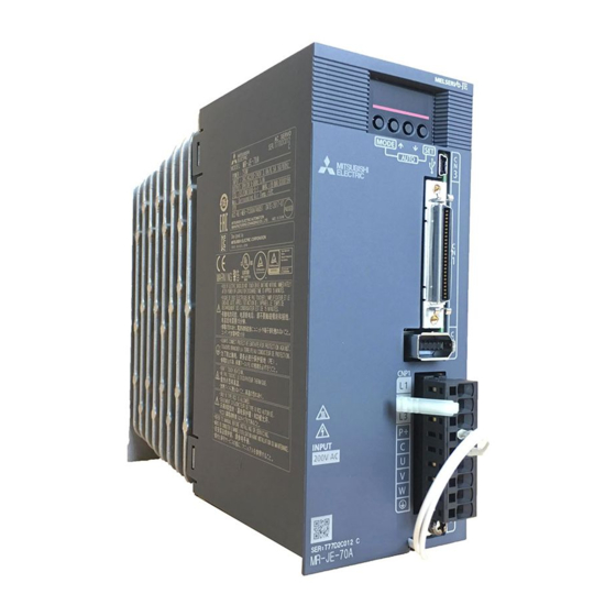
-
Contents
-
Table of Contents
-
Troubleshooting
-
Bookmarks
Quick Links
General-Purpose AC Servo
General-Purpose Interface AC Servo
MODEL
MR-JE-_A
SERVO AMPLIFIER
INSTRUCTION MANUAL
B
Related Manuals for Mitsubishi Electric MELSERVO-JE MR-JE-70A
Summary of Contents for Mitsubishi Electric MELSERVO-JE MR-JE-70A
-
Page 1
General-Purpose AC Servo General-Purpose Interface AC Servo MODEL MR-JE-_A SERVO AMPLIFIER INSTRUCTION MANUAL… -
Page 2: Safety Instructions
Safety Instructions Please read the instructions carefully before using the equipment. To use the equipment correctly, do not attempt to install, operate, maintain, or inspect the equipment until you have read through this Instruction Manual, Installation guide, and appended documents carefully. Do not use the equipment until you have a full knowledge of the equipment, safety information and instructions.
-
Page 3
1. To prevent electric shock, note the following WARNING Before wiring and inspections, turn off the power and wait for 15 minutes or more until the charge lamp turns off. Otherwise, an electric shock may occur. In addition, when confirming whether the charge lamp is off or not, always confirm it from the front of the servo amplifier. -
Page 4
4. Additional instructions The following instructions should also be fully noted. Incorrect handling may cause a malfunction, injury, electric shock, etc. (1) Transportation and installation CAUTION Transport the products correctly according to their mass. Stacking in excess of the specified number of product packages is not allowed. Do not hold the lead wire of the regenerative resistor when transporting the servo amplifier. -
Page 5
(2) Wiring CAUTION Before removing the CNP1 connector of MR-JE-40A to MR-JE-100A, disconnect the lead wires of the regenerative resistor from the CNP1 connector. Wire the equipment correctly and securely. Otherwise, the servo motor may operate unexpectedly. Do not install a power capacitor, surge killer, or radio noise filter (optional FR-BIF) on the servo amplifier output side. -
Page 6
(4) Usage CAUTION When it is assumed that a hazardous condition may occur due to a power failure or product malfunction, use a servo motor with an external brake to prevent the condition. Do not disassemble, repair, or modify the equipment. Before resetting an alarm, make sure that the run signal of the servo amplifier is off in order to prevent a sudden restart. -
Page 7
(7) General instruction To illustrate details, the equipment in the diagrams of this Instruction Manual may have been drawn without covers and safety guards. When the equipment is operated, the covers and safety guards must be installed as specified. Operation must be performed in accordance with this Instruction Manual. DISPOSAL OF WASTE Please dispose a servo amplifier and other options according to your local laws and regulations. -
Page 8: Table Of Contents
CONTENTS 1. FUNCTIONS AND CONFIGURATION 1- 1 to 1-12 1.1 Summary……………………….1- 1 1.2 Function block diagram……………………1- 2 1.3 Servo amplifier standard specifications ……………….. 1- 4 1.4 Combinations of servo amplifiers and servo motors ……………. 1- 5 1.5 Function list……………………….1- 5 1.6 Model designation……………………..
-
Page 9
3.9 Interfaces ……………………….3-50 3.9.1 Internal connection diagram…………………. 3-50 3.9.2 Detailed explanation of interfaces………………… 3-52 3.9.3 Source I/O interfaces …………………… 3-56 3.10 Servo motor with an electromagnetic brake ……………… 3-57 3.10.1 Safety precautions ……………………3-57 3.10.2 Timing chart ……………………..3-58 3.11 Grounding ………………………. -
Page 10
5.1.2 Gain/filter setting parameters ([Pr. PB_ _ ]) …………….5- 2 5.1.3 Extension setting parameters ([Pr. PC_ _ ]) …………….5- 3 5.1.4 I/O setting parameters ([Pr. PD_ _ ]) ………………5- 5 5.1.5 Extension setting 2 parameters ([Pr. PE_ _ ])…………….5- 6 5.1.6 Extension setting 3 parameters ([Pr. -
Page 11
8.2 Remedies for alarms……………………. 8- 6 8.3 Remedies for warnings ……………………8-24 9. DIMENSIONS 9- 1 to 9- 6 9.1 Servo amplifier ……………………..9- 1 9.2 Connector ……………………….9- 4 10. CHARACTERISTICS 10- 1 to 10- 8 10.1 Overload protection characteristics ………………..10- 1 10.2 Power supply capacity and generated loss ……………… -
Page 12: Functions And Configuration
1. FUNCTIONS AND CONFIGURATION 1. FUNCTIONS AND CONFIGURATION 1.1 Summary The Mitsubishi general-purpose AC servo MELSERVO-JE series have limited functions with keeping high performance based on MELSERVO-J4 series. The servo amplifier has position, speed, and torque control modes. In the position control mode, the maximum pulse train of 4 Mpulses/s is supported.
-
Page 13: Function Block Diagram
1. FUNCTIONS AND CONFIGURATION 1.2 Function block diagram The function block diagram of this servo is shown below. (1) MR-JE-100A or less Regenerative option Servo motor Diode Dynamic stack Relay brake circuit (Note 1) MCCB (Note 2) Current Power Regene- encoder supply rative…
-
Page 14
1. FUNCTIONS AND CONFIGURATION (2) MR-JE-200A or more Regenerative option Servo motor N- (Note 2) Diode Dynamic stack brake circuit Relay MCCB (Note 1) Current Power encoder Regene- supply rative CHARGE lamp Cooling fan Electromagnetic 24 V DC brake Control circuit Base Voltage… -
Page 15: Servo Amplifier Standard Specifications
1. FUNCTIONS AND CONFIGURATION 1.3 Servo amplifier standard specifications Model: MR-JE- 100A 200A 300A Rated voltage 3-phase 170 V AC Output Rated current 11.0 11.0 3-phase or 1-phase 200 V AC to 240 V AC, 50 3-phase 200 V AC to 240 V AC, 50 Voltage/Frequency Hz/60 Hz Hz/60 Hz…
-
Page 16: Combinations Of Servo Amplifiers And Servo Motors
1. FUNCTIONS AND CONFIGURATION 1.4 Combinations of servo amplifiers and servo motors Servo amplifier Servo motor MR-JE-10A HF-KN13 MR-JE-20A HF-KN23 MR-JE-40A HF-KN43 MR-JE-70A HF-KN73 HF-SN52 MR-JE-100A HF-SN102 MR-JE-200A HF-SN152, HF-SN202 MR-JE-300A HF-SN302 1.5 Function list The following table lists the functions of this servo. For details of the functions, refer to each section indicated in the detailed explanation field.
-
Page 17
1. FUNCTIONS AND CONFIGURATION Detailed Function Description explanation Alarm history clear Alarm history is cleared. [Pr. PC18] Output signal selection ST1 (Forward rotation start), ST2 (Reverse rotation start), and SON (Servo-on) and [Pr. PD03] to (device settings) other input device can be assigned to any pins. [Pr. -
Page 18: Model Designation
1. FUNCTIONS AND CONFIGURATION 1.6 Model designation (1) Rating plate The following shows an example of rating prate for explanation of each item. Serial number AC SERVO SER. S33001001 Model MR-JE-10A Capacity POWER : 100W Applicable power supply INPUT : 3AC/AC200-240V 0.9A/1.5A 50/60Hz Rated output current OUTPUT : 3PH170V 0-360Hz 1.1A…
-
Page 19: Structure
1. FUNCTIONS AND CONFIGURATION 1.7 Structure 1.7.1 Parts identification (1) MR-JE-100A or less Detailed Name/Application explanati Display Section The 5-digit, 7-segment LED shows the servo status and the alarm number. Operation section Used to perform status display, diagnostic, alarm, and parameter setting operations. Push the «MODE» and «SET»…
-
Page 20
1. FUNCTIONS AND CONFIGURATION (2) MR-JE-200A or more Detailed Name/Application explanati Display Section The 5-digit, 7-segment LED shows the servo status and the alarm number. Operation section Used to perform status display, diagnostic, alarm, and parameter setting operations. Push the «MODE» and «SET»… -
Page 21: Configuration Including Peripheral Equipment
1. FUNCTIONS AND CONFIGURATION 1.8 Configuration including peripheral equipment Connecting a servo motor of the wrong axis to U, V, W, or CN2 of the servo CAUTION amplifier may cause a malfunction. POINT Equipment other than the servo amplifier and servo motor are optional or recommended products.
-
Page 22
1. FUNCTIONS AND CONFIGURATION (2) MR-JE-200A or more The diagram shows MR-JE-200A. R S T (Note 1) Power supply Molded-case circuit breaker Personal computer MR Configurator2 (Note 2) Magnetic contactor (MC) Power factor improving AC reactor (FR-HAL) Line noise filter (FR-BSF01) Junction terminal block Servo motor… -
Page 23
1. FUNCTIONS AND CONFIGURATION MEMO 1 — 12… -
Page 24: Installation
2. INSTALLATION 2. INSTALLATION WARNING To prevent electric shock, ground each equipment securely. Stacking in excess of the specified number of product packages is not allowed. Do not hold the lead wire of the regenerative resistor when transporting the servo amplifier.
-
Page 25: Installation Direction And Clearances
2. INSTALLATION 2.1 Installation direction and clearances The equipment must be installed in the specified direction. Otherwise, it may cause a malfunction. CAUTION Leave specified clearances between the servo amplifier and the cabinet walls or other equipment. Otherwise, it may cause a malfunction. MR-JE-40A to MR-JE-100A have a regenerative resistor on their back face.
-
Page 26: Keep Out Foreign Materials
2. INSTALLATION (b) Installation of two or more servo amplifiers POINT Close mounting is possible for all capacity type of MR-JE servo amplifiers. Leave a large clearance between the top of the servo amplifier and the cabinet walls, and install a cooling fan to prevent the internal temperature of the cabinet from exceeding the environment.
-
Page 27: Encoder Cable Stress
2. INSTALLATION 2.3 Encoder cable stress (1) The way of clamping the cable must be fully examined so that bending stress and cable’s own weight stress are not applied to the cable connection. (2) For use in any application where the servo motor moves, fix the cables (encoder, power supply, and brake) with having some slack from the connector connection part of the servo motor to avoid putting stress on the connector connection part.
-
Page 28: Parts Having Service Lives
2. INSTALLATION 2.5 Parts having service lives Service lives of the following parts are listed below. However, the service life vary depending or operating methods and environment. If any fault is found in the parts, they must be replaced immediately regardless of their service lives.
-
Page 29
2. INSTALLATION MEMO 2 — 6… -
Page 30: Signals And Wiring
3. SIGNALS AND WIRING 3. SIGNALS AND WIRING Any person who is involved in wiring should be fully competent to do the work. Before wiring, turn off the power and wait for 15 minutes or more until the charge lamp turns off. Otherwise, an electric shock may occur. In addition, when confirming whether the charge lamp is off or not, always confirm it from the front of the servo amplifier.
-
Page 31: Input Power Supply Circuit
3. SIGNALS AND WIRING 3.1 Input power supply circuit Always connect a magnetic contactor between the power supply and the power supply (L1, L2, and L3) of the servo amplifier, in order to configure a circuit that shuts down the power supply on the side of the servo amplifier’s power supply. If a magnetic contactor is not connected, continuous flow of a large current may cause a fire when the servo amplifier malfunctions.
-
Page 32
3. SIGNALS AND WIRING (1) For 3-phase 200 V AC to 240 V AC power supply of MR-JE-10A to MR-JE-100A EMG stop switch Malfunction Servo amplifier Servo motor (Note 5) MCCB CNP1 3-phase (Note 4, 7) Built-in 200 V AC to Motor regenerative 240 V AC… -
Page 33
3. SIGNALS AND WIRING (2) For 1-phase 200 V AC to 240 V AC power supply of MR-JE-10A to MR-JE-70A POINT Connect the 1-phase 200 V AC to 240 V AC power supply to L1 and L3. One of the connecting destinations is different from MR-E Super Series Servo Amplifier’s. -
Page 34
3. SIGNALS AND WIRING (3) MR-JE-200A/MR-JE-300A EMG stop switch Malfunction Servo amplifier Servo motor (Note 5) MCCB CNP1 3-phase CNP2 (Note 4, 7) 200 V AC to Motor 240 V AC (Note 1) (Note 7) (Note 2) Encoder Encoder cable (Note 6) Power supply… -
Page 35: I/O Signal Connection Example
3. SIGNALS AND WIRING 3.2 I/O signal connection example 3.2.1 Position control mode (1) When you use a positioning module LD75D/QD75D (a) For sink I/O interface Servo amplifier 24 V DC (Note 4) (Note 7) Positioning module 24 V DC (Note 4) LD75D/QD75D (Note 7) DOCOM…
-
Page 36
3. SIGNALS AND WIRING Note 1. To prevent an electric shock, always connect the protective earth (PE) terminal (marked ) of the servo amplifier to the protective earth (PE) of the cabinet. 2. Connect the diode in the correct direction. If it is connected reversely, the servo amplifier will malfunction and will not output signals, disabling EM2 (Forced stop 2) and other protective circuits. -
Page 37
3. SIGNALS AND WIRING (b) For source I/O interface POINT For notes, refer to (1) (a) in this section. Servo amplifier 24 V DC (Note 4, 12) (Note 7) Positioning module 24 V DC (Note 4, 12) LD75D/QD75D (Note 7) DOCOM (Note 2) (Note 14) -
Page 38
3. SIGNALS AND WIRING (2) When you use a positioning module FX -_ _MT/ES (For sink I/O interface) 2 m or less (Note 8) Programmable controller -_ _MT/ES (Note 11) (Note 15) 24 V Servo amplifier (Note 7) (Note 7) 24 V DC 24 V DC (Note 4) Programmable… -
Page 39
3. SIGNALS AND WIRING Note 1. To prevent an electric shock, always connect the protective earth (PE) terminal (marked ) of the servo amplifier to the protective earth (PE) of the cabinet. 2. Connect the diode in the correct direction. If it is connected reversely, the servo amplifier will malfunction and will not output signals, disabling EM2 (Forced stop 2) and other protective circuits. -
Page 40: Speed Control Mode
3. SIGNALS AND WIRING 3.2.2 Speed control mode (1) For sink I/O interface Servo amplifier (Note 7) 24 V DC (Note 4) DOCOM DOCOM (Note 2) 10 m or less Malfunction (Note 6) (Note 7) (Note 11) Power supply Zero speed detection (Note 3, 5) Forced stop 2 Servo-on…
-
Page 41
3. SIGNALS AND WIRING (2) For source I/O interface POINT For notes, refer to (1) in this section. Servo amplifier (Note 7) 24 V DC (Note 4, 12) DOCOM DOCOM (Note 2) 10 m or less Malfunction (Note 6) (Note 7) (Note 11) Power supply Zero speed detection… -
Page 42: Torque Control Mode
3. SIGNALS AND WIRING 3.2.3 Torque control mode POINT EM2 has the same function as EM1 in the torque control mode. (1) For sink I/O interface Servo amplifier (Note 6) 24 V DC (Note 4) DOCOM DOCOM (Note 2) 10 m or less Malfunction (Note 6) (Note 6) (Note 9)
-
Page 43
3. SIGNALS AND WIRING (2) For source I/O interface POINT For notes, refer to (1) in this section. Servo amplifier (Note 6) 24 V DC (Note 4, 10) DOCOM DOCOM (Note 2) 10 m or less Malfunction (Note 5) (Note 6) (Note 9) Power supply Zero speed detection… -
Page 44: Explanation Of Power Supply System
3. SIGNALS AND WIRING 3.3 Explanation of power supply system 3.3.1 Signal explanations POINT For the layout of connector and terminal block, refer to chapter 9 DIMENSIONS. Connection target Symbol Description (application) Supply the following power to L1, L2, and L3. For 1-phase 200 V AC to 240 V AC, connect the power supply to L1 and L3.
-
Page 45: Power-On Sequence
3. SIGNALS AND WIRING 3.3.2 Power-on sequence POINT The voltage of analog monitor output, output signal, etc. may be unstable at power-on. (1) Power-on procedure 1) Always wire the power supply as shown in above section 3.1 using the magnetic contactor with the power supply (3-phase: L1, L2, and L3, 1-phase: L1 and L3).
-
Page 46: Wiring Cnp1 And Cnp2
3. SIGNALS AND WIRING 3.3.3 Wiring CNP1 and CNP2 POINT For the wire sizes used for wiring, refer to section 11.5. To wire to CNP1 and CNP2, use servo amplifier power connectors packed with the amplifier or optional connectors (refer to section 11.1.1). (1) Connector (a) MR-JE-10A to MR-JE-100A Servo amplifier…
-
Page 47
3. SIGNALS AND WIRING (2) Cable connection procedure (a) Fabrication on cable insulator Refer to table 3.1 and 3.2 for stripped length of cable insulator. The appropriate stripped length of cables depends on their type, etc. Set the length considering their status. Insulator Core Stripped length… -
Page 48: Connectors And Pin Assignment
3. SIGNALS AND WIRING 3.4 Connectors and pin assignment POINT The pin assignment of the connectors are as viewed from the cable connector wiring section. For the CN1 connector, securely connect the external conductor of the shielded cable to the ground plate and fix it to the connector shell. Screw Cable Screw…
-
Page 49
3. SIGNALS AND WIRING The device assignment of CN1 connector pins changes depending on the control mode. For the pins which are given parameters in the related parameter column, their devices will be changed using those parameters. (Note 2) I/O signals in control modes (Note 1) Pin No. -
Page 50: Signal (Device) Explanations
3. SIGNALS AND WIRING (Note 2) I/O signals in control modes (Note 1) Pin No. Related parameter DOCOM DOCOM DOCOM DOCOM DOCOM DOCOM DOCOM DOCOM DOCOM DOCOM DOCOM DOCOM Pr. PD28 Note 1. I: input signal, O: output signal 2. P: position control mode, S: speed control mode, T: torque control mode, P/S: position/speed control switching mode, S/T: speed/torque control switching mode, T/P: torque/position control switching mode 3.
-
Page 51
3. SIGNALS AND WIRING Control Connector Device Symbol Function and application mode pin No. division Reset CN1-19 Turn on RES for more than 50 ms to reset the alarm. DI-1 Some alarms cannot be deactivated by RES (Reset). Refer to section 8.1. Turning RES on in an alarm-free status shuts off the base circuit. -
Page 52
3. SIGNALS AND WIRING Control Connector Device Symbol Function and application mode pin No. division Forward rotation This is used to select a servo motor torque generation directions. DI-1 selection The following shows the torque generation directions. (Note) Input device Torque generation direction Torque is not generated. -
Page 53
3. SIGNALS AND WIRING Control Connector Device Symbol Function and application mode pin No. division Proportion Turn PC on to switch the speed amplifier from the proportional integral type DI-1 control to the proportional type. If the servo motor at a stop is rotated even one pulse due to any external factor, it generates torque to compensate for a position shift. -
Page 54
3. SIGNALS AND WIRING Control Connector Device Symbol Function and application mode pin No. division Control switching «Position/speed control switching mode» DI-1 Refer to Function This is used to select the control mode in the position/speed control switching mode. application. (Note) Control mode… -
Page 55
3. SIGNALS AND WIRING (b) Output device Control Connector Device Symbol Function and application mode pin No. division Malfunction CN1-48 When an alarm occurs, ALM will turn off. DO-1 When an alarm does not occur, ALM will turn on after 2.5 s to 3.5 s after power-on. -
Page 56
3. SIGNALS AND WIRING Control Connector Device Symbol Function and application mode pin No. division Alarm code ACD0 (CN1-24) To use these signals, set » _ _ _ 1″ in [Pr. PD34]. DI-1 This signal is outputted when an alarm occurs. ACD1 (CN1-23) When an alarm is not occurring, respective ordinary signals are outputted. -
Page 57
3. SIGNALS AND WIRING (3) Output signal Control Connector Device Symbol Function and application mode pin No. division Encoder A- CN1-4 These devices output pulses of encoder output pulse set in [Pr. PA15] in DO-2 phase pulse the differential line driver type. CN1-5 (differential line In CCW rotation of the servo motor, the encoder B-phase pulse lags the… -
Page 58: Detailed Explanation Of Signals
3. SIGNALS AND WIRING 3.6 Detailed explanation of signals 3.6.1 Position control mode POINT Adjust the logic of a positioning module and command pulse as follows. Q series/L series positioning module Command pulse logic setting Signal type MR-JE-_A servo amplifier Q series/L series positioning module Pr.
-
Page 59
3. SIGNALS AND WIRING The following section explains about the case where the negative logic and the forward/reverse rotation pulse trains are set to «_ _ 1 0» in [Pr. PA13]. (ON) (ON) (ON) (OFF) (OFF) (OFF) Forward rotation pulse train (transistor) Reverse rotation pulse train (OFF) -
Page 60
3. SIGNALS AND WIRING (2) INP (In-position) INP turns on when the number of droop pulses in the deviation counter falls within the preset in-position range ([Pr. PA10]). INP may turn on continuously during a low-speed operation with a large value set as the in-position range. -
Page 61
3. SIGNALS AND WIRING (5) Torque limit If the torque limit is canceled during servo-lock, the servo motor may suddenly CAUTION rotate according to position deviation in respect to the command position. (a) Torque limit and torque By setting [Pr. PA11 Forward rotation torque limit] or [Pr. PA12 Reverse rotation torque limit], torque is always limited to the maximum value during operation. -
Page 62
3. SIGNALS AND WIRING (Note) Input device Enabled torque limit value Limit value status CCW power running/CW CW power running/CCW regeneration regeneration Pr. PA11 Pr .PA12 Pr. PA11 > Pr. PA11 Pr. PA12 Pr. PA12 Pr. PA11 < Pr. PA12 Pr. -
Page 63: Speed Control Mode
3. SIGNALS AND WIRING 3.6.2 Speed control mode (1) Speed setting (a) Speed command and speed The servo motor is run at the speeds set in the parameters or at the speed set in the applied voltage of VC (Analog speed command). A relation between VC (Analog speed command) applied voltage and the servo motor speed is as follows.
-
Page 64
3. SIGNALS AND WIRING (b) Speed command value selection To select VC (Analog speed command) and a speed command value of internal speed commands 1 to 7, enable SP1 (Speed selection 1), SP2 (Speed selection 2), and SP3 (Speed selection 3) with [Pr. -
Page 65: Torque Control Mode
3. SIGNALS AND WIRING 3.6.3 Torque control mode (1) Torque limit (a) Torque command and torque The following shows a relation between the applied voltage of TC (Analog torque command) and the torque by the servo motor. The maximum torque is generated at ±8 V. The speed at ±8 V can be changed with [Pr. PC13]. CCW direction Forward rotation Maximum torque…
-
Page 66
3. SIGNALS AND WIRING (b) Analog torque command offset Using [Pr. PC38], the offset voltage of -9999 mV to 9999 mV can be added to the TC applied voltage as follows. Maximum torque Torque [Pr. PC38] offset range -9999 mV to 9999 mV 8 (-8) TC applied voltage [V] (2) Torque limit… -
Page 67
3. SIGNALS AND WIRING Normally, connect as follows. Servo amplifier -10 V to +10 V (b) Speed limit value selection To select VLA (Analog speed limit) and a speed limit value of internal speed limit 1 to 7, enable SP1 (Speed selection 1), SP2 (Speed selection 2), and SP3 (Speed selection 3) with [Pr. -
Page 68: Position/Speed Control Switching Mode
3. SIGNALS AND WIRING 3.6.4 Position/speed control switching mode Set » _ _ _ 1″ in [Pr. PA01] to switch to the position/speed control switching mode. (1) LOP (control switching) Use LOP (Control switching) to switch between the position control mode and the speed control mode with an external contact.
-
Page 69
3. SIGNALS AND WIRING (3) Speed setting in speed control mode (a) Speed command and speed The servo motor is run at the speeds set in the parameters or at the speed set in the applied voltage of VC (Analog speed command). The relation between an applied voltage of VC (Analog speed command) and servo motor speed, and the rotation direction with turning on ST1/ST2 are the same as section 3.6.2 (1) (a). -
Page 70: Speed/Torque Control Switching Mode
3. SIGNALS AND WIRING 3.6.5 Speed/torque control switching mode Set » _ _ _ 3″ in [Pr. PA01] to switch to the speed/torque control switching mode. (1) LOP (control switching) Use LOP (Control switching) to switch between the speed control mode and the torque control mode with an external contact.
-
Page 71
3. SIGNALS AND WIRING Normally, connect as follows. Servo amplifier -10 V to +10 V (b) Speed limit value selection To select VLA (Analog speed limit) and a speed limit value of internal speed limit 1 to 7, enable SP1 (Speed selection 1), SP2 (Speed selection 2), and SP3 (Speed selection 3) with [Pr. -
Page 72: Torque/Position Control Switching Mode
3. SIGNALS AND WIRING 3.6.6 Torque/position control switching mode Set » _ _ _ 5″ in [Pr. PA01] to switch to the torque/position control switching mode. (1) LOP (control switching) Use LOP (Control switching) to switch between the torque control mode and the position control mode with an external contact.
-
Page 73: Forced Stop Deceleration Function
3. SIGNALS AND WIRING 3.7 Forced stop deceleration function POINT When alarms not related to the forced stop function occur, control of motor deceleration can not be guaranteed. (Refer to chapter 8.) In the torque control mode, the forced stop deceleration function is not available. 3.7.1 Forced stop deceleration function When EM2 is turned off, dynamic brake will start to stop the servo motor after forced stop deceleration.
-
Page 74
3. SIGNALS AND WIRING (2) Timing chart POINT When LSP/LSN is turned on during a forced stop deceleration, the motor will stop depending on the setting of [Pr. PD30] as follows. [Pr. PD30] Stop system _ _ _ 0 Switching to sudden stop _ _ _ 1 Continuing forced stop deceleration When EM2 (Forced stop 2) turns off, the motor will decelerate according to [Pr. -
Page 75: Base Circuit Shut-Off Delay Time Function
3. SIGNALS AND WIRING 3.7.2 Base circuit shut-off delay time function The base circuit shut-off delay time function is used to prevent vertical axis from dropping at a forced stop (EM2 goes off) or alarm occurrence due to delay time of the electromagnetic brake. Use [Pr. PC16] to set the delay time between completion of EM2 (Forced stop 2) or activation of MBR (Electromagnetic brake interlock) due to an alarm occurrence, and shut-off of the base circuit.
-
Page 76: Vertical Axis Freefall Prevention Function
3. SIGNALS AND WIRING 3.7.3 Vertical axis freefall prevention function The vertical axis freefall prevention function avoids machine damage by pulling up the shaft slightly like the following case. When the servo motor is used for operating vertical axis, the servo motor electromagnetic brake and the base circuit shut-off delay time function avoid dropping axis at forced stop.
-
Page 77: Alarm Occurrence Timing Chart
3. SIGNALS AND WIRING 3.8 Alarm occurrence timing chart When an alarm has occurred, remove its cause, make sure that the operation CAUTION signal is not being input, ensure safety, and reset the alarm before restarting operation. POINT In the torque control mode, the forced stop deceleration function is not available. To deactivate an alarm, cycle the power, push the «SET»…
-
Page 78: When You Do Not Use The Forced Stop Deceleration Function
3. SIGNALS AND WIRING (2) When the forced stop deceleration function is not enabled Alarm occurrence Braking by the dynamic brake Dynamic brake + Braking by the electromagnetic brake Servo motor speed 0 r/min Base circuit (Energy supply to the servo motor) Servo amplifier No alarm Alarm No.
-
Page 79: Interfaces
3. SIGNALS AND WIRING 3.9 Interfaces 3.9.1 Internal connection diagram The following diagram is for sink I/O interface when command pulse train input is differential line driver type. Servo amplifier (Note 1) (Note 4) 24 V DC (Note 1) DOCOM Approx.
-
Page 80
3. SIGNALS AND WIRING Note 1. P: position control mode, S: speed control mode, T: torque control mode 2. This is for the differential line driver pulse train input. For the open-collector pulse train input, connect as follows. DOCOM 24 V DC DICOM DOCOM 3. -
Page 81: Detailed Explanation Of Interfaces
3. SIGNALS AND WIRING 3.9.2 Detailed explanation of interfaces This section provides the details of the I/O signal interfaces (refer to the I/O division in the table) given in section 3.5. Refer to this section and make connection with the external device. (1) Digital input interface DI-1 This is an input circuit whose photocoupler cathode side is input terminal.
-
Page 82
3. SIGNALS AND WIRING (3) Pulse train input interface DI-2 Give a pulse train signal in the differential line driver type or open-collector type. (a) Differential line driver type 1) Interface Servo amplifier Max. input pulse frequency 4 Mpulses/s (Note 2) 10 m or less PP (NP) Approximalely… -
Page 83
3. SIGNALS AND WIRING 2) Input pulse condition tLH = tHL < 0.2 µs tc > 2 µs tF > 3 µs (4) Encoder output pulse DO-2 (a) Open-collector type Interface Maximum sink current: 35 mA 5 V DC to 24 V DC Servo amplifier Servo amplifier Photocoupler… -
Page 84
3. SIGNALS AND WIRING 2) Output pulse Servo motor CCW rotation Time cycle (T) is determined by the settings of [Pr. PA15] and [Pr. PC19]. 400 s or more (5) Analog input Input impedance 10 k to 12 k Servo amplifier VC etc. -
Page 85: Source I/O Interfaces
3. SIGNALS AND WIRING 3.9.3 Source I/O interfaces In this servo amplifier, source type I/O interfaces can be used. (1) Digital input interface DI-1 This is an input circuit whose photocoupler anode side is the input terminal. Transmit signals from source (open-collector) type transistor output, relay switch, etc.
-
Page 86: Servo Motor With An Electromagnetic Brake
3. SIGNALS AND WIRING 3.10 Servo motor with an electromagnetic brake 3.10.1 Safety precautions Configure an electromagnetic brake circuit so that it is activated also by an external EMG stop switch. Contacts must be opened when ALM (Malfunction) Contacts must be opened with the or MBR (Electromagnetic brake interlock) turns off.
-
Page 87: Timing Chart
3. SIGNALS AND WIRING (2) Setting (a) Enable MBR (Electromagnetic brake interlock) with [Pr. PD03] to [Pr. PD20]. (b) In [Pr. PC16 Electromagnetic brake sequence output], set the time delay (Tb) from electromagnetic brake operation to base circuit shut-off at a servo-off as in the timing chart in section 3.10.2 (1). 3.10.2 Timing chart (1) When you use the forced stop deceleration function POINT…
-
Page 88
3. SIGNALS AND WIRING (b) Forced stop 2 on/off POINT In the torque control mode, the forced stop deceleration function is not available. (Note 2) Model speed command 0 and equal to or less than zero speed Servo motor speed 0 r/min Base circuit (Energy supply to… -
Page 89
3. SIGNALS AND WIRING (2) When you do not use the forced stop deceleration function POINT To disable the function, set «0 _ _ _» in [Pr. PA04]. (a) SON (Servo-on) on/off It is the same as (1) (a) in this section. (b) EM1 (Forced stop 1) on/off Dynamic brake Dynamic brake… -
Page 90: Grounding
3. SIGNALS AND WIRING 3.11 Grounding Ground the servo amplifier and servo motor securely. WARNING To prevent an electric shock, always connect the protective earth (PE) terminal (marked ) of the servo amplifier to the protective earth (PE) of the cabinet. The servo amplifier switches the power transistor on-off to supply power to the servo motor.
-
Page 91
3. SIGNALS AND WIRING MEMO 3 — 62… -
Page 92: Startup
4. STARTUP 4. STARTUP Do not operate the switches with wet hands. Otherwise, it may cause an electric WARNING shock. Before starting operation, check the parameters. Improper settings may cause some machines to operate unexpectedly. The servo amplifier heat sink, regenerative resistor, servo motor, etc. may be hot CAUTION while power is on or for some time after power-off.
-
Page 93: Wiring Check
4. STARTUP 4.1.2 Wiring check (1) Power supply system wiring Before switching on the power supply, check the following items. (a) Power supply system wiring The power supplied to the power input terminals (L1, L2, and L3) of the servo amplifier should satisfy the defined specifications.
-
Page 94: Surrounding Environment
4. STARTUP (2) I/O signal wiring (a) The I/O signals should be connected correctly. Use DO forced output to forcibly turn on/off the pins of the CN1 connector. This function can be used to perform a wiring check. Switch off SON (Servo-on) to enable the function. Refer to section 3.2 for details of I/O signal connection.
-
Page 95: Startup In Position Control Mode
4. STARTUP 4.2 Startup in position control mode Make a startup in accordance with section 4.1. This section provides descriptions specific to the position control mode. 4.2.1 Power on and off procedures (1) Power-on Switch power on in the following procedure. Always follow this procedure at power-on. 1) Switch off SON (Servo-on).
-
Page 96: Test Operation
4. STARTUP 4.2.3 Test operation Before starting actual operation, perform test operation to make sure that the machine operates normally. Refer to section 4.2.1 for how to power on and off the servo amplifier. Test operation of the servo motor In this step, confirm that the servo amplifier and servo motor operate alone in JOG operation of test normally.
-
Page 97: Parameter Setting
4. STARTUP 4.2.4 Parameter setting POINT The following encoder cables are of four-wire type. When using any of these encoder cables, set [Pr. PC22] to «1 _ _ _» to select the four-wire type. Incorrect setting will result in [AL. 16 Encoder initial communication error 1]. MR-EKCBL30M-L MR-EKCBL30M-H MR-EKCBL40M-H…
-
Page 98: Trouble At Start-Up
4. STARTUP 4.2.6 Trouble at start-up Never make a drastic adjustment or change to the parameter values as doing so CAUTION will make the operation unstable. POINT Using the optional MR Configurator2, you can refer to reason for rotation failure, etc.
-
Page 99
4. STARTUP (2) How to find the cause of position shift Controller Servo amplifier Machine (a) Output pulse Servo motor counter Electronic gear [Pr.PA05], [Pr.PA06], (d) Machine stop position M [Pr.PA07], [Pr.PA21] (b) Cumulative command pulses Cause B Cause A SON (Servo-on) input LSP/LSN (Stroke end) input Encoder… -
Page 100: Startup In Speed Control Mode
4. STARTUP 2) When P • During operation, SON (Servo-on), LSP (Forward rotation stroke end), or LSN (Reverse rotation stroke end) was switched off; or CR (Clear) or RES (Reset) was switched on. (Cause C) 3) When C • Mechanical slip occurred between the servo motor and machine. (Cause B) 4.3 Startup in speed control mode Make a startup in accordance with section 4.1.
-
Page 101: Test Operation
4. STARTUP 4.3.3 Test operation Before starting actual operation, perform test operation to make sure that the machine operates normally. Refer to section 4.3.1 for how to power on and off the servo amplifier. Test operation of the servo motor In this step, confirm that the servo amplifier and servo motor operate alone in JOG operation of test normally.
-
Page 102: Parameter Setting
4. STARTUP 4.3.4 Parameter setting POINT The following encoder cables are of four-wire type. When using any of these encoder cables, set [Pr. PC22] to «1 _ _ _» to select the four-wire type. Incorrect setting will result in [AL. 16 Encoder initial communication error 1]. MR-EKCBL30M-L MR-EKCBL30M-H MR-EKCBL40M-H…
-
Page 103: Actual Operation
4. STARTUP 4.3.5 Actual operation Start actual operation after confirmation of normal operation by test operation and completion of the corresponding parameter settings. 4.3.6 Trouble at start-up Never make a drastic adjustment or change to the parameter values as doing so CAUTION will make the operation unstable.
-
Page 104: Startup In Torque Control Mode
4. STARTUP Start-up sequence Fault Investigation Possible cause Reference Gain adjustment Rotation ripples (speed Make gain adjustment in the Gain adjustment fault Chapter fluctuations) are large following procedure. at low speed. 1. Increase the auto tuning response level. 2. Repeat acceleration and deceleration several times to complete auto tuning.
-
Page 105: Test Operation
4. STARTUP 4.4.3 Test operation Before starting actual operation, perform test operation to make sure that the machine operates normally. Refer to section 4.4.1 for how to power on and off the servo amplifier. Test operation of the servo motor In this step, confirm that the servo amplifier and servo motor operate alone in JOG operation of test normally.
-
Page 106: Parameter Setting
4. STARTUP 4.4.4 Parameter setting POINT The following encoder cables are of four-wire type. When using any of these encoder cables, set [Pr. PC22] to «1 _ _ _» to select the four-wire type. Incorrect setting will result in [AL. 16 Encoder initial communication error 1]. MR-EKCBL30M-L MR-EKCBL30M-H MR-EKCBL40M-H…
-
Page 107: Trouble At Start-Up
4. STARTUP 4.4.6 Trouble at start-up Never make a drastic adjustment or change to the parameter values as doing so CAUTION will make the motion unstable. POINT Using the optional MR Configurator2, you can refer to reason for rotation failure, etc.
-
Page 108: Display And Operation Sections
4. STARTUP 4.5 Display and operation sections 4.5.1 Summary The MR-JE-A servo amplifier has the display section (5-digit, 7-segment LED) and operation section (4 pushbuttons) for servo amplifier status display, alarm display, parameter setting, etc. Push the «MODE» and «SET» buttons at the same time for 3 s or more to switch to the one-touch tuning mode. The operation section and display data are described below.
-
Page 109: Display Flowchart
4. STARTUP 4.5.2 Display flowchart Press the «MODE» button once to shift to the next display mode. Refer to section 4.5.3 and later for the description of the corresponding display mode. To refer to and set the gain/filter parameters, extension setting parameters and I/O setting parameters, enable them with [Pr.
-
Page 110: Status Display Mode
4. STARTUP 4.5.3 Status display mode The servo status during operation is shown on the 5-digit, 7-segment LED display. Press the «UP» or «DOWN» button to change display data as desired. When the required data is selected, the corresponding symbol is displayed. Press the «SET» button to display that data. At only power-on, however, data appears after the symbol of the status display selected in [Pr.
-
Page 111
4. STARTUP (2) Display examples The following table shows the display examples. Displayed data Item Status Servo amplifier display Forward rotation at 2500 r/min Servo motor speed Reverse rotation at 3000 r/min Reverse rotation is indicated by «- «. Load to motor inertia ratio 7.00 times 11252 pulses Cumulative feedback pulses… -
Page 112
4. STARTUP (3) Status display list The following table lists the servo statuses that may be shown. Refer to appendix 4 for the measurement point. Status display Symbol Unit Description Feedback pulses from the servo motor encoder are counted and displayed. The values in excess of ±99999 can be counted. -
Page 113
4. STARTUP Status display Symbol Unit Description Bus voltage The voltage of main circuit converter (between P+ and N-) is displayed. Encoder inside temperature °C Inside temperature of encoder detected by the encoder is displayed. Settling time Settling time is displayed. When it exceeds 1000 ms, «1000» will be displayed. Oscillation detection Frequency at the time of oscillation detection is displayed. -
Page 114: Diagnostic Mode
4. STARTUP 4.5.4 Diagnostic mode Name Display Description Not ready Indicates that the servo amplifier is being initialized or an alarm has occurred. Sequence Ready Indicates that the servo was switched on after completion of initialization and the servo amplifier is ready to operate. Drive recorder enabled When an alarm occurs in the status, the drive recorder will operate and write the status of…
-
Page 115
4. STARTUP Name Display Description Indicates the version of the software. Software version — Lower Indicates the system number of the software. Software version — Upper If offset voltages in the analog circuits inside and outside the servo amplifier cause the servo motor to rotate slowly at VC (Analog speed command) or VLA (Analog speed limit) of 0… -
Page 116: Alarm Mode
4. STARTUP 4.5.5 Alarm mode The current alarm, past alarm history and parameter error are displayed. The lower 2 digits on the display indicate the alarm number that has occurred or the parameter number in error. Name Display Description Indicates no occurrence of an alarm. Current alarm Indicates the occurrence of [AL.
-
Page 117: Parameter Mode
4. STARTUP Functions at occurrence of an alarm (1) Any mode screen displays the current alarm. (2) Even during alarm occurrence, the other screen can be viewed by pressing the button in the operation area. At this time, the decimal point in the fourth digit remains flickering. (3) For any alarm, remove its cause and clear it in any of the following methods.
-
Page 118
4. STARTUP (2) Operation example (a) Parameters of 5 or less digits The following example shows the operation procedure performed after power-on to change the control mode to the speed control mode with [Pr. PA01 Operation mode]. Press «MODE» to switch to the basic setting parameter screen. -
Page 119: External I/O Signal Display
4. STARTUP 4.5.7 External I/O signal display POINT The I/O signal settings can be changed using the I/O setting parameters [Pr. PD03] to [Pr. PD28]. The on/off states of the digital I/O signals connected to the servo amplifier can be confirmed. (1) Operation The display screen at power-on.
-
Page 120
4. STARTUP (a) Control modes and I/O signals Signal (Note 2) Symbols of I/O signals in control modes Connector Pin No. input/output Related parameter (Note 1) I/O Pr. PD03/Pr. PD04 RES/ST1 ST1/RS2 RS2/RES Pr. PD11/Pr. PD12 Pr. PD24 INP/SA SA/- -/INP Pr. -
Page 121
4. STARTUP (3) Display data at initial values (a) Position control mode CR (CN1-41) RES (CN1-19) SON (CN1-15) LSN (CN1-44) EM2 (CN1-42) LSP (CN1-43) Input signal Light on: on Output signals Light off: off OP (CN1-33) RD (CN1-49) ALM (CN1-48) INP (CN1-24) ZSP (CN1-23) (b) Speed control mode… -
Page 122: Output Signal (Do) Forced Output
4. STARTUP 4.5.8 Output signal (DO) forced output POINT When the servo system is used in a vertical lift application, turning on MBR (Electromagnetic brake interlock) by the DO forced output after assigning it to connector CN1 will release the electromagnetic brake, causing a drop. Take drop preventive measures on the machine side.
-
Page 123: Test Operation Mode
4. STARTUP 4.5.9 Test operation mode The test operation mode is designed for checking servo operation. Do not use it CAUTION for actual operation. If the servo motor operates unexpectedly, use EM2 (Forced stop 2) to stop it. POINT MR Configurator2 is required to perform positioning operation. Test operation cannot be performed if SON (Servo-on) is not turned off.
-
Page 124
4. STARTUP (2) JOG operation POINT When performing JOG operation, turn on EM2, LSP and LSN. LSP and LSN can be set to automatic on by setting [Pr. PD01] to » _ C _ _ «. JOG operation can be performed when there is no command from the controller. (a) Operation The servo motor rotates while holding down the «UP»… -
Page 125
4. STARTUP (3) Positioning operation POINT MR Configurator2 is required to perform positioning operation. Turn on EM2 (forced stop 2) when performing positioning operation. Positioning operation can be performed when there is no command from the controller. (a) Operation a) Motor speed [r/min] Enter the servo motor speed into the «Motor speed»… -
Page 126
4. STARTUP f) Travel distance unit selection Select with the option buttons whether the travel distance set in c) is in the command pulse unit or in the encoder pulse unit. When the command input pulse unit is selected, the value, which is the set travel distance multiplied by the electronic gear, will be the command value. -
Page 127
4. STARTUP (4) Motor-less operation Without connecting the servo motor, output signals or status display can be provided in response to the input device as if the servo motor is actually running. This operation can be used to check the sequence of a controller or the like. -
Page 128: Parameters
5. PARAMETERS 5. PARAMETERS Never make a drastic adjustment or change to the parameter values as doing so will make the operation unstable. CAUTION If fixed values are written in the digits of a parameter, do not change these values. Do not change parameters for manufacturer setting.
-
Page 129
5. PARAMETERS Control mode Initial Symbol Name Unit value PA29 For manufacturer setting 0000h PA30 0000h PA31 0000h PA32 0000h 5.1.2 Gain/filter setting parameters ([Pr. PB_ _ ]) Initial Control mode Symbol Name Unit value PB01 FILT Adaptive tuning mode (adaptive filter II) 0000h VRFT Vibration suppression control tuning mode (advanced vibration… -
Page 130
5. PARAMETERS Control mode Initial Symbol Name Unit value PB41 For manufacturer setting 0000h PB42 0000h PB43 0000h PB44 0.00 PB45 CNHF Command notch filter 0000h PB46 Machine resonance suppression filter 3 4500 [Hz] PB47 NHQ3 Notch shape selection 3 0000h PB48 Machine resonance suppression filter 4… -
Page 131
5. PARAMETERS Control mode Initial Symbol Name Unit value PC16 Electromagnetic brake sequence output [ms] PC17 Zero speed [r/min] PC18 *BPS Alarm history clear 0000h PC19 *ENRS Encoder output pulse selection 0000h PC20 For manufacturer setting PC21 0000h PC22 *COP1 Function selection C-1 0020h PC23… -
Page 132
5. PARAMETERS Control mode Initial Symbol Name Unit value PC69 For manufacturer setting 0000h PC70 0000h PC71 0000h PC72 0000h PC73 0000h PC74 0000h PC75 0000h PC76 0000h PC77 0000h PC78 0000h PC79 0000h PC80 0000h 5.1.4 I/O setting parameters ([Pr. PD_ _ ]) Initial Control mode Symbol… -
Page 133: Extension Setting 2 Parameters ([Pr. Pe_ _ ])
5. PARAMETERS Control mode Initial Symbol Name Unit value PD39 For manufacturer setting PD40 PD41 0000h PD42 0000h PD43 0000h PD44 0000h PD45 0000h PD46 0000h PD47 0000h PD48 0000h 5.1.5 Extension setting 2 parameters ([Pr. PE_ _ ]) Initial Control mode Symbol Name…
-
Page 134
5. PARAMETERS Control mode Initial Symbol Name Unit value PE41 EOP3 Function selection E-3 0000h PE42 For manufacturer setting PE43 PE44 0000h PE45 0000h PE46 0000h PE47 0000h PE48 0000h PE49 0000h PE50 0000h PE51 0000h PE52 0000h PE53 0000h PE54 0000h PE55… -
Page 135: Basic Setting Parameters ([Pr. Pa
5. PARAMETERS Control mode Initial Symbol Name Unit value PF26 For manufacturer setting PF27 PF28 PF29 0000h PF30 PF31 FRIC Machine diagnosis function — Friction judgement speed [r/min] PF32 For manufacturer setting PF33 0000h PF34 0000h PF35 0000h PF36 0000h PF37 0000h PF38…
-
Page 136
5. PARAMETERS Initial Control mode No./ Setting Function value symbol/name digit [unit] PA02 _ _ x x Regenerative option *REG Used to select the regenerative option. Regenerative Incorrect setting may cause the regenerative option to burn. option If a selected regenerative option is not for use with the servo amplifier, [AL. 37 Parameter error] occurs. -
Page 137
5. PARAMETERS Initial Control mode No./ Setting Function value symbol/name digit [unit] PA06 Set the numerator of the electronic gear. To enable the parameter, select «Electronic gear (0 _ _ _)» of «Electronic gear selection» in [Pr. PA21]. Electronic gear The following shows a standard of the setting range of the electronic gear. -
Page 138
5. PARAMETERS Initial Control mode No./ Setting Function value symbol/name digit [unit] PA08 _ _ _ x Gain adjustment mode selection Select the gain adjustment mode. Auto tuning 0: 2 gain adjustment mode 1 (interpolation mode) mode 1: Auto tuning mode 1 2: Auto tuning mode 2 3: Manual mode 4: 2 gain adjustment mode 2… -
Page 139
5. PARAMETERS Initial Control mode No./ Setting Function value symbol/name digit [unit] PA09 Set a response of the auto tuning. Machine characteristic Machine characteristic Auto tuning Guideline for Guideline for response Setting Setting machine machine value value Response Response resonance resonance frequency [Hz] frequency [Hz]… -
Page 140
5. PARAMETERS Initial Control mode No./ Setting Function value symbol/name digit [unit] PA13 _ _ _ x Command input pulse train form selection *PLSS 0: Forward/reverse rotation pulse train Command 1: Signed pulse train pulse input 2: A-phase/B-phase pulse train (The servo amplifier imports input pulses after form multiplying by four.) Refer to table 5.3 for settings. -
Page 141
5. PARAMETERS Initial Control mode No./ Setting Function value symbol/name digit [unit] PA14 Select servo motor rotation direction relative to the input pulse train. *POL Servo motor rotation direction Rotation Setting When forward rotation When reverse rotation direction value pulse is input pulse is input selection The following shows the servo motor rotation directions. -
Page 142
5. PARAMETERS Initial Control mode No./ Setting Function value symbol/name digit [unit] PA19 Select a reference range and writing range of the parameter. 00AAh *BLK Refer to table 5.4 for settings. Parameter writing inhibit Table 5.4 [Pr. PA19] setting value and reading/writing range Setting PA19 operation… -
Page 143
5. PARAMETERS Initial Control mode No./ Setting Function value symbol/name digit [unit] PA21 _ _ _ x One-touch tuning function selection *AOP3 0: Disabled Function 1: Enabled selection A-3 When the digit is «0», the one-touch tuning is not available. _ _ x _ For manufacturer setting _ x _ _ x _ _ _ Electronic gear selection… -
Page 144: Gain/Filter Setting Parameters ([Pr. Pb
5. PARAMETERS 5.2.2 Gain/filter setting parameters ([Pr. PB_ _ ]) Initial Control mode No./ Setting Function value symbol/name digit [unit] PB01 _ _ _ x Filter tuning mode selection FILT Set the adaptive filter tuning. Adaptive Select the adjustment mode of the machine resonance suppression filter 1. Refer to tuning mode section 7.1.2 for details.
-
Page 145
5. PARAMETERS Initial Control mode No./ Setting Function value symbol/name digit [unit] PB04 Set the feed forward gain. When the setting is 100%, the droop pulses during operation at constant speed are nearly zero. However, sudden acceleration/deceleration will increase the overshoot. Feed forward As a guideline, when the feed forward gain setting is 100%, set 1 s or more as the gain… -
Page 146
5. PARAMETERS Initial Control mode No./ Setting Function value symbol/name digit [unit] PB09 This is used to set the gain of the speed loop. [rad/s] Set this parameter when vibration occurs on machines of low rigidity or large backlash. Increasing the setting value will also increase the response level but will Speed loop be liable to generate vibration and/or noise. -
Page 147
5. PARAMETERS Initial Control mode No./ Setting Function value symbol/name digit [unit] PB16 Set the shape of the machine resonance suppression filter 2. NHQ2 _ _ _ x Machine resonance suppression filter 2 selection Notch shape 0: Disabled selection 2 1: Enabled _ _ x _ Notch depth selection 0: -40 dB… -
Page 148
5. PARAMETERS Initial Control mode No./ Setting Function value symbol/name digit [unit] PB18 Set the low-pass filter. 3141 [rad/s] The following shows a relation of a required parameter to this parameter. Low-pass filter setting Setting range: 100 to 18000 [Pr. PB23] [Pr. -
Page 149
5. PARAMETERS Initial Control mode No./ Setting Function value symbol/name digit [unit] PB24 _ _ _ x Slight vibration suppression control selection *MVS Select the slight vibration suppression control. Slight 0: Disabled vibration 1: Enabled suppression To enable the slight vibration suppression control, select «Manual mode (_ _ _ 3)» of control «Gain adjustment mode selection»… -
Page 150
5. PARAMETERS Initial Control mode No./ Setting Function value symbol/name digit [unit] PB31 Set the speed loop gain when the gain switching is enabled. [rad/s] VG2B When you set a value less than 20 rad/s, the value will be the same as [Pr. PB09]. Gain This parameter is enabled only when you select «Manual mode (_ _ _ 3)»… -
Page 151
5. PARAMETERS Initial Control mode No./ Setting Function value symbol/name digit [unit] PB45 Set the command notch filter. CNHF _ _ x x Command notch filter setting frequency selection Command Refer to table 5.6 for the relation of setting values to frequency. notch filter _ x _ _ Notch depth selection Refer to table 5.7 for details. -
Page 152
5. PARAMETERS Initial Control mode No./ Setting Function value symbol/name digit [unit] PB46 Set the notch frequency of the machine resonance suppression filter 3. 4500 [Hz] To enable the setting value, select «Enabled (_ _ _ 1)» of «Machine resonance suppression filter 3 selection»… -
Page 153
5. PARAMETERS Initial Control mode No./ Setting Function value symbol/name digit [unit] PB51 Set the shape of the machine resonance suppression filter 5. NHQ5 When you select «Enabled (_ _ _ 1)» of «Robust filter selection» in [Pr. PE41], the machine resonance suppression filter 5 is not available. -
Page 154
5. PARAMETERS Initial Control mode No./ Setting Function value symbol/name digit [unit] PB56 Set the vibration frequency for vibration suppression control 2 when the gain switching is enabled. [Hz] VRF21B When you set a value less than 0.1 Hz, the value will be the same as [Pr. PB52]. Vibration suppression This parameter will be enabled only when the following conditions are fulfilled. -
Page 155: Extension Setting Parameters ([Pr. Pc
5. PARAMETERS Initial Control mode No./ Setting Function value symbol/name digit [unit] PB60 Set the model loop gain when the gain switching is enabled. [rad/s] PG1B When you set a value less than 1.0 rad/s, the value will be the same as [Pr. PB07]. Model loop This parameter will be enabled only when the following conditions are fulfilled.
-
Page 156
5. PARAMETERS Initial Control mode No./ Setting Function value symbol/name digit [unit] PC03 This is used to smooth start/stop of the servo motor. [ms] Set the time of the arc part for S-pattern acceleration/deceleration. S-pattern acceleration/d Speed eceleration command time constant 0 r/min Time STA: Acceleration time constant ([Pr. -
Page 157
5. PARAMETERS Initial Control mode No./ Setting Function value symbol/name digit [unit] PC05 This is used to set speed 1 of internal speed commands. [r/min] Internal Setting range: 0 to permissible instantaneous speed speed This is used to set speed 1 of internal speed limits. command 1/internal Setting range: 0 to permissible instantaneous speed… -
Page 158
5. PARAMETERS Initial Control mode No./ Setting Function value symbol/name digit [unit] PC12 This is used to set the speed at the maximum input voltage (10 V) of VC (Analog speed command). [r/min] When «0» is set, the analog speed command maximum speed would be the rated Analog speed speed of the servo motor connected. -
Page 159
5. PARAMETERS Initial Control mode No./ Setting Function value symbol/name digit [unit] PC15 _ _ x x Analog monitor 2 output selection MOD2 Select a signal to output to MO2 (Analog monitor 2). Refer to appendix 4 (3) for detection point of output selection. Analog monitor 2 Refer to [Pr. -
Page 160
5. PARAMETERS Initial Control mode No./ Setting Function value symbol/name digit [unit] PC22 _ _ _ x For manufacturer setting *COP1 _ _ x _ Function _ x _ _ selection C-1 x _ _ _ Encoder cable communication method selection Select the encoder cable communication method. -
Page 161
5. PARAMETERS Initial Control mode No./ Setting Function value symbol/name digit [unit] PC26 _ _ _ x [AL. 99 Stroke limit warning] selection *COP5 Select [AL. 99 Stroke limit warning]. Function 0: Enabled selection C-5 1: Disabled _ _ x _ For manufacturer setting _ x _ _ x _ _ _ PC30… -
Page 162
5. PARAMETERS Initial Control mode No./ Setting Function value symbol/name digit [unit] PC36 _ _ x x Status display selection at power-on *DMD This is used to select a status display shown at power-on. Status display 00: Cumulative feedback pulses selection 01: Servo motor speed 02: Droop pulses… -
Page 163
5. PARAMETERS Initial Control mode No./ Setting Function value symbol/name digit [unit] PC37 This is used to set the offset voltage of VC (Analog speed command). value For example, if CCW rotation is provided by switching on ST1 (Forward rotation differs start) with applying 0 V to VC, set a negative value. -
Page 164
5. PARAMETERS Initial Control mode No./ Setting Function value symbol/name digit [unit] PC51 This is used to set deceleration time constant when you use the forced stop deceleration function. [ms] RSBR Set the time per ms from the rated speed to 0 r/min. Forced stop deceleration time constant… -
Page 165
5. PARAMETERS 5.2.4 I/O setting parameters ([Pr. PD_ _ ]) Initial Control mode No./ Setting Function value symbol/name digit [unit] PD01 Select input devices to turn on them automatically. *DIA1 _ _ _ x _ _ _ x (BIN): For manufacturer setting Input signal (HEX) _ _ x _ (BIN): For manufacturer setting… -
Page 166
5. PARAMETERS Initial Control mode No./ Setting Function value symbol/name digit [unit] PD03 Any input device can be assigned to the CN1-15 pin. *DI1L _ _ x x Position control mode — Device selection Input device Refer to table 5.9 for settings. selection 1L x x _ _ Speed control mode — Device selection… -
Page 167
5. PARAMETERS Initial Control mode No./ Setting Function value symbol/name digit [unit] PD14 Any input device can be assigned to the CN1-41 pin. *DI6H _ _ x x Torque control mode — Device selection Input device Refer to table 5.9 in [Pr. PD03] for settings. selection 6H _ x _ _ For manufacturer setting x _ _ _… -
Page 168
5. PARAMETERS Initial Control mode No./ Setting Function value symbol/name digit [unit] PD25 _ _ x x Device selection *DO3 Any output device can be assigned to the CN1-24 pin. Output device Refer to table 5.10 in [Pr. PD24] for settings. selection 3 _ x _ _ For manufacturer setting… -
Page 169: Extension Setting 2 Parameters ([Pr. Pe
5. PARAMETERS Initial Control mode No./ Setting Function value symbol/name digit [unit] PD34 _ _ _ x Alarm code output *DOP5 This is used to select if output alarm codes. Function Alarm codes are outputted to pins CN1-23, CN1-24, and CN1-49. selection D-5 0: Disabled 1: Enabled…
-
Page 170: Extension Setting 3 Parameters ([Pr. Pf
5. PARAMETERS 5.2.6 Extension setting 3 parameters ([Pr. PF_ _ ]) Initial Control mode No./ Setting Function value symbol/name digit [unit] PF21 This is used to set a drive recorder switching time. When a USB communication is cut during using a graph function or a graph function is terminated, the function will be changed to the drive recorder function after the Drive setting time of this parameter.
-
Page 171
5. PARAMETERS MEMO 5 — 44… -
Page 172: Normal Gain Adjustment
6. NORMAL GAIN ADJUSTMENT 6. NORMAL GAIN ADJUSTMENT POINT In the torque control mode, you do not need to make gain adjustment. Before making gain adjustment, check that your machine is not being operated at maximum torque of the servo motor. If operated over maximum torque, the machine may vibrate and may operate unexpectedly.
-
Page 173: Adjustment Using Mr Configurator2
6. NORMAL GAIN ADJUSTMENT (2) Adjustment sequence and mode usage Start Interpolation 2 gain adjustment mode 1 made for 2 or more (interpolation mode) axes? The load fluctuation is large during driving? One-touch tuning Handle the error Error handling Finished normally? Auto tuning mode 1 is possible? Adjustment OK?
-
Page 174: One-Touch Tuning
6. NORMAL GAIN ADJUSTMENT 6.2 One-touch tuning You can execute the one-touch tuning with MR Configurator2 or push buttons. The following parameters are set automatically with one-touch tuning. Table 6.1 List of parameters automatically set with one-touch tuning Parameter Symbol Name Parameter Symbol…
-
Page 175
6. NORMAL GAIN ADJUSTMENT (2) When you use push buttons Make one-touch tuning as follows. Start Startup a system referring to chapter 4. Startup of the system Rotate the servo motor by an external controller, etc. (The one-touch tuning cannot be performed if the Operation servo motor is not operating.) Select the initial screen («AUTO») of the one-touch tuning with the «MODE»… -
Page 176: Display Transition And Operation Procedure Of One-Touch Tuning
6. NORMAL GAIN ADJUSTMENT 6.2.2 Display transition and operation procedure of one-touch tuning (1) When you use MR Configurator2 (a) Response mode selection Select a response mode from three modes in the one-touch tuning window of MR Configurator2. Response mode Explanation High mode This mode is for high rigid system.
-
Page 177
6. NORMAL GAIN ADJUSTMENT Response mode Machine characteristic Response Low mode Basic mode High mode Guideline of corresponding machine Low response Arm robot General machine tool conveyor Precision working machine Inserter Mounter Bonder High response 6 — 6… -
Page 178
6. NORMAL GAIN ADJUSTMENT (b) One-touch tuning execution POINT For equipment in which overshoot during one-touch tuning is in the permissible level of the in-position range, changing the value of [Pr. PA25 One-touch tuning — Overshoot permissible level] will shorten the settling time and improve the response. -
Page 179
6. NORMAL GAIN ADJUSTMENT (c) Stop of one-touch tuning During one-touch tuning, pushing the stop button stops one-touch tuning. If the one-touch tuning is stopped, «C 0 0 0» will be displayed at status in error code. (d) Error occurrence If a tuning error occurs during tuning, one-touch tuning will be forcibly terminated. -
Page 180
6. NORMAL GAIN ADJUSTMENT (g) Clearing one-touch tuning You can clear the parameter values set with one-touch tuning. Refer to table 6.1 for the parameters which you can clear. Pushing «Return to value before tuning» in the one-touch tuning window of MR Configurator2 enables to rewrite the parameter to the value before pushing the start button. -
Page 181
6. NORMAL GAIN ADJUSTMENT (2) When you use push buttons POINT Push the «MODE» and «SET» buttons at the same time for 3 s or more to switch to the response mode selection («AUTO.») without going through the initial screen of the one-touch tuning («AUTO»). (a) Response mode selection Select a response mode of the one-touch tuning from 3 modes with «UP»… -
Page 182
6. NORMAL GAIN ADJUSTMENT (b) One-touch tuning execution POINT For equipment in which overshoot during one-touch tuning is in the permissible level of the in-position range, changing the value of [Pr. PA25 One-touch tuning — Overshoot permissible level] will shorten the settling time and improve the response. -
Page 183
6. NORMAL GAIN ADJUSTMENT (d) If an error occurs Stop symbol If an error occurs during the one-touch tuning, the tuning will be forcibly terminated and the stop symbol and error code from «C 001» to «C 00F» will be displayed by turns with 2 s interval. -
Page 184: Caution For One-Touch Tuning
6. NORMAL GAIN ADJUSTMENT (g) Clearing one-touch tuning Refer to table 6.1 for the parameters which you can clear. You can initialize the parameters changed by the one-touch tuning with the clear mode. You can reset the parameters to before tuning with the back mode. 1) Push the «MODE»…
-
Page 185: Auto Tuning
6. NORMAL GAIN ADJUSTMENT 6.3 Auto tuning 6.3.1 Auto tuning mode The servo amplifier has a real-time auto tuning function which estimates the machine characteristic (load to motor inertia ratio) in real time and automatically sets the optimum gains according to that value. This function permits ease of gain adjustment of the servo amplifier.
-
Page 186: Auto Tuning Mode Basis
6. NORMAL GAIN ADJUSTMENT 6.3.2 Auto tuning mode basis The block diagram of real-time auto tuning is shown below. Load moment Automatic setting of inertia Encoder Loop gain Command Current PG1, PG2, control VG2, VIC Servo motor Current feedback Real-time Position/speed Set 0 or 1 to turn on.
-
Page 187: Adjustment Procedure By Auto Tuning
6. NORMAL GAIN ADJUSTMENT 6.3.3 Adjustment procedure by auto tuning Since auto tuning is enabled before shipment from the factory, simply running the servo motor automatically sets the optimum gains that match the machine. Merely changing the response level setting value as required completes the adjustment.
-
Page 188: Response Level Setting In Auto Tuning Mode
6. NORMAL GAIN ADJUSTMENT 6.3.4 Response level setting in auto tuning mode Set the response of the whole servo system by [Pr. PA09]. As the response level setting is increased, the track ability and settling time for a command decreases, but a too high response level will generate vibration. Hence, make setting until desired response is obtained within the vibration-free range.
-
Page 189: Manual Mode
6. NORMAL GAIN ADJUSTMENT 6.4 Manual mode If you are not satisfied with the adjustment of auto tuning, you can make simple manual adjustment with three parameters. POINT If machine resonance occurs, filter tuning mode selection in [Pr. PB01] or machine resonance suppression filter in [Pr.
-
Page 190
6. NORMAL GAIN ADJUSTMENT (c) Parameter adjustment 1) [Pr. PB09 Speed loop gain] This parameter determines the response level of the speed control loop. Increasing the setting increases the response level, but the mechanical system is liable to vibrate. The actual response frequency of the speed loop is as indicated in the following expression. -
Page 191
6. NORMAL GAIN ADJUSTMENT (b) Adjustment procedure Step Operation Description Brief-adjust with auto tuning. Refer to section 6.3.3. Change the setting of auto tuning to the manual mode ([Pr. PA08]: _ _ _ 3). Set an estimated value to the load to motor inertia ratio. (If the estimate value with auto tuning is correct, setting change is not required.) Set a slightly smaller value to the model loop gain and the… -
Page 192
6. NORMAL GAIN ADJUSTMENT 3) [Pr. PB08 Position loop gain] This parameter determines the response level to a disturbance to the position control loop. Increasing the position loop gain increases the response level to a disturbance, but the mechanical system is liable to vibrate. Speed loop gain Position loop gain guideline ×… -
Page 193: Gain Adjustment Mode
6. NORMAL GAIN ADJUSTMENT 6.5 2 gain adjustment mode The 2 gain adjustment mode is used to match the position loop gains of the axes when performing the interpolation operation of servo motors of two or more axes for an X-Y table or the like. In this mode, manually set the model loop gain that determines command track ability.
-
Page 194
6. NORMAL GAIN ADJUSTMENT (3) Adjustment procedure of 2 gain adjustment mode POINT Set the same value in [Pr. PB07 Model loop gain] for the axis used in 2 gain adjustment mode. Step Operation Description Set to the auto tuning mode. Select the auto tuning mode 1. -
Page 195
6. NORMAL GAIN ADJUSTMENT MEMO 6 — 24… -
Page 196: Special Adjustment Functions
7. SPECIAL ADJUSTMENT FUNCTIONS 7. SPECIAL ADJUSTMENT FUNCTIONS POINT The functions given in this chapter need not be used normally. Use them if you are not satisfied with the machine status after making adjustment in the methods in chapter 6. 7.1 Filter setting The following filters are available with MR-JE servo amplifiers.
-
Page 197
7. SPECIAL ADJUSTMENT FUNCTIONS (1) Function The machine resonance suppression filter is a filter function (notch filter) which decreases the gain of the specific frequency to suppress the resonance of the mechanical system. You can set the gain decreasing frequency (notch frequency), gain decreasing depth and width. Machine resonance point Frequency Notch width… -
Page 198
7. SPECIAL ADJUSTMENT FUNCTIONS (2) Parameter (a) Machine resonance suppression filter 1 ([Pr. PB13] and [Pr. PB14]) Set the notch frequency, notch depth and notch width of the machine resonance suppression filter 1 ([Pr. PB13] and [Pr. PB14]) When you select «Manual setting (_ _ _ 2)» of «Filter tuning mode selection» in [Pr. PB01], the setting of the machine resonance suppression filter 1 is enabled. -
Page 199: Adaptive Filter Ii
7. SPECIAL ADJUSTMENT FUNCTIONS 7.1.2 Adaptive filter II POINT The machine resonance frequency which adaptive filter II (adaptive tuning) can respond to is about 100 Hz to 2.25 kHz. As for the resonance frequency out of the range, set manually. When adaptive tuning is executed, vibration sound increases as an excitation signal is forcibly applied for several seconds.
-
Page 200
7. SPECIAL ADJUSTMENT FUNCTIONS (3) Adaptive tuning mode procedure Adaptive tuning Operation Is the target response reached? Increase the response setting. Has vibration or unusual noise occurred? Execute or re-execute adaptive tuning. (Set [Pr. PB01] to «_ _ _ 1».) Tuning ends automatically after the If assumption fails after tuning is executed at a large vibration or predetermined period of time. -
Page 201: Shaft Resonance Suppression Filter
7. SPECIAL ADJUSTMENT FUNCTIONS 7.1.3 Shaft resonance suppression filter (1) Function When a load is mounted to the servo motor shaft, resonance by shaft torsion during driving may generate a mechanical vibration at high frequency. The shaft resonance suppression filter suppresses the vibration.
-
Page 202: Low-Pass Filter
7. SPECIAL ADJUSTMENT FUNCTIONS 7.1.4 Low-pass filter (1) Function When a ball screw or the like is used, resonance of high frequency may occur as the response level of the servo system is increased. To prevent this, the low-pass filter is enabled for a torque command as the initial value.
-
Page 203
7. SPECIAL ADJUSTMENT FUNCTIONS (1) Function Vibration suppression control is used to further suppress load-side vibration, such as work-side vibration and base shake. The servo motor-side operation is adjusted for positioning so that the machine does not vibrate. Servo motor side Servo motor side Load side Load side… -
Page 204
7. SPECIAL ADJUSTMENT FUNCTIONS (3) Vibration suppression control tuning procedure The following flow chart is for the vibration suppression control 1. For the vibration suppression control 2, set «_ _ 1 _» in [Pr. PB02] to execute the vibration suppression control tuning. Vibration suppression control tuning Operation Is the target response… -
Page 205
7. SPECIAL ADJUSTMENT FUNCTIONS (4) Vibration suppression control manual mode POINT When load-side vibration does not show up in servo motor-side vibration, the setting of the servo motor-side vibration frequency does not produce an effect. When the anti-resonance frequency and resonance frequency can be confirmed using the machine analyzer or external equipment, do not set the same value but set different values to improve the vibration suppression performance. -
Page 206
7. SPECIAL ADJUSTMENT FUNCTIONS Step 2. Set «Vibration suppression control — Vibration frequency» and «Vibration suppression control — Resonance frequency» as follows. (a) When a vibration peak can be confirmed with machine analyzer using MR Configurator2, or external equipment. Vibration suppression control 2 — Vibration frequency (anti-resonance frequency) [Pr. -
Page 207: Command Notch Filter
7. SPECIAL ADJUSTMENT FUNCTIONS 7.1.6 Command notch filter POINT By using the advanced vibration suppression control II and the command notch filter, the load-side vibration of three frequencies can be suppressed. The frequency range of machine vibration, which can be supported by the command notch filter, is between 4.5 Hz and 2250 Hz.
-
Page 208: Gain Switching Function
7. SPECIAL ADJUSTMENT FUNCTIONS (2) Parameter Set [Pr. PB45 Command notch filter] as shown below. For the command notch filter setting frequency, set the closest value to the vibration frequency [Hz] at the load side. [Pr. PB45] Notch depth Command notch filter setting frequency Depth Setting Setting…
-
Page 209: Function Block Diagram
7. SPECIAL ADJUSTMENT FUNCTIONS 7.2.2 Function block diagram The control gains, load to motor inertia ratio, and vibration suppression control settings are changed according to the conditions selected by [Pr. PB26 Gain switching function] and [Pr. PB27 Gain switching condition]. [Pr.
-
Page 210: Parameter
7. SPECIAL ADJUSTMENT FUNCTIONS 7.2.3 Parameter When using the gain switching function, always select «Manual mode (_ _ _ 3)» of «Gain adjustment mode selection» in [Pr. PA08 Auto tuning mode]. The gain switching function cannot be used in the auto tuning mode.
-
Page 211
7. SPECIAL ADJUSTMENT FUNCTIONS (2) Switchable gain parameter Before switching After switching Loop gain Parameter Symbol Name Parameter Symbol Name Load to motor inertia ratio PB06 Load to motor inertia ratio PB29 GD2B Gain switching Load to motor inertia ratio Model loop gain PB07 Model loop gain… -
Page 212: Gain Switching Procedure
7. SPECIAL ADJUSTMENT FUNCTIONS (c) [Pr. PB29 Load to motor inertia ratio after gain switching] Set the load to motor inertia ratio after gain switching. If the load to motor inertia ratio does not change, set it to the same value as [Pr. PB06 Load to motor inertia ratio]. (d) [Pr.
-
Page 213
7. SPECIAL ADJUSTMENT FUNCTIONS Parameter Symbol Name Setting value Unit PB28 Gain switching time constant [ms] PB33 VRF11B Vibration suppression control 1 — [Hz] Vibration frequency after gain switching PB34 VRF12B Vibration suppression control 1 — [Hz] Resonance frequency after gain switching PB35 VRF13B Vibration suppression control 1 -… -
Page 214
7. SPECIAL ADJUSTMENT FUNCTIONS (2) When you choose switching by droop pulses In this case, the vibration suppression control after gain switching and model loop gain after gain switching cannot be used. (a) Setting Parameter Symbol Name Setting value Unit PB06 Load to motor inertia ratio 4.00… -
Page 215: Tough Drive Function
7. SPECIAL ADJUSTMENT FUNCTIONS 7.3 Tough drive function POINT Set enable/disable of the tough drive function with [Pr. PA20 Tough drive setting]. (Refer to section 5.2.1.) This function makes the equipment continue operating even under the condition that an alarm occurs. 7.3.1 Vibration tough drive function This function prevents vibration by resetting a filter instantaneously when machine resonance occurs due to varied vibration frequency caused by machine aging.
-
Page 216
7. SPECIAL ADJUSTMENT FUNCTIONS The following shows the function block diagram of the vibration tough drive function. The function detects machine resonance frequency and compare it with [Pr. PB13] and [Pr. PB15], and reset a machine resonance frequency of a parameter whose set value is closer. Parameter that is Filter Setting parameter… -
Page 217: Instantaneous Power Failure Tough Drive Function
7. SPECIAL ADJUSTMENT FUNCTIONS 7.3.2 Instantaneous power failure tough drive function The immunity to instantaneous power failures is increased by the instantaneous CAUTION power failure tough drive function. However, it is not guarantee to comply with the SEMI-F47 standard. The instantaneous power failure tough drive function avoids [AL. 10 Undervoltage] even when an instantaneous power failure occurs during operation.
-
Page 218
7. SPECIAL ADJUSTMENT FUNCTIONS (1) Instantaneous power failure time > [Pr. PF25 SEMI-F47 function — Instantaneous power failure detection time (instantaneous power failure tough drive — detection time)] The alarm occurs when the instantaneous power failure time exceeds [Pr. PF25 SEMI-F47 function — Instantaneous power failure detection time (instantaneous power failure tough drive — detection time)]. -
Page 219
7. SPECIAL ADJUSTMENT FUNCTIONS (2) Instantaneous power failure time < [Pr. PF25 SEMI-F47 function — Instantaneous power failure detection time (instantaneous power failure tough drive — detection time)] Operation status differs depending on how bus voltage decrease. (a) When the bus voltage decreases lower than 158 V DC within the instantaneous power failure time [AL. -
Page 220
7. SPECIAL ADJUSTMENT FUNCTIONS (b) When the bus voltage does not decrease lower than 158 V DC within the instantaneous power failure time The operation continues without alarming. Instantaneous power failure time Power supply [Pr. PF25] Bus voltage Undervoltage level (158 V DC) (Malfunction) (Warning) -
Page 221
7. SPECIAL ADJUSTMENT FUNCTIONS MEMO 7 — 26… -
Page 222: Troubleshooting
8. TROUBLESHOOTING 8. TROUBLESHOOTING POINT As soon as an alarm occurs, turn SON (Servo-on) off and interrupt the power. 8.1 Alarm and warning list When an error occurs during operation, the corresponding alarm or warning is displayed. If any alarm or warning has occurred, refer to section 8.2 or 8.3 and take the appropriate action.
-
Page 223
8. TROUBLESHOOTING Alarm code Alarm deactivation Press Stop Power «SET» Detailed method Alarm Name Detail name off to button display (Note 2, reset on the (RES) current (Bit 2) (Bit 1) (Bit 0) (Note 4) alarm screen. Encoder initial communication — Receive 16.1 data error 1 Encoder initial communication — Receive… -
Page 224
8. TROUBLESHOOTING Alarm code Alarm deactivation Press Stop Power «SET» Detailed method Alarm Name Detail name off to button display (Note 2, reset on the (RES) current (Bit 2) (Bit 1) (Bit 0) (Note 4) alarm screen. Ground fault detected by hardware 24.1 detection circuit Main circuit error… -
Page 225
8. TROUBLESHOOTING Alarm code Alarm deactivation Press Stop Power «SET» Detailed method Alarm Name Detail name off to button display (Note 2, reset on the (RES) current (Bit 2) (Bit 1) (Bit 0) (Note 4) alarm screen. USB communication time- 8A.1 USB communication time-out error out error… -
Page 226
8. TROUBLESHOOTING Table 8.2 Warning list Stop Detailed method Name Detail name display (Note 2, Servo amplifier overheat 91.1 Main circuit device overheat warning warning (Note 1) 99.1 Forward rotation stroke end off (Note 4) Stroke limit warning 99.2 Reverse rotation stroke end off (Note 4) Excessive regeneration E0.1… -
Page 227: Remedies For Alarms
8. TROUBLESHOOTING 8.2 Remedies for alarms When any alarm has occurred, eliminate its cause, ensure safety, and deactivate CAUTION the alarm before restarting operation. Otherwise, it may cause injury. As soon as an alarm occurs, make the Servo-off status and interrupt the power. POINT When any of the following alarms has occurred, do not cycle the power repeatedly to restart.
-
Page 228
8. TROUBLESHOOTING Alarm No.: 12 Name: Memory error 1 (RAM) Alarm content A part (RAM) in the servo amplifier is failure. Display Detail name Cause Check method Check result Action 12.1 RAM error 1 (1) A part in the servo Disconnect the cables It is repeatable. -
Page 229
8. TROUBLESHOOTING Alarm No.: 15 Name: Memory error 2 (EEP-ROM) Alarm content A part (EEP-ROM) in the servo amplifier is failure. Display Detail name Cause Check method Check result Action 15.1 EEP-ROM error EEP-ROM is Disconnect the cables It is repeatable. Replace the servo at power on malfunctioning at power… -
Page 230
8. TROUBLESHOOTING Alarm No.: 16 Name: Encoder initial communication error 1 Alarm content An error occurred in the communication between an encoder and servo amplifier. Display Detail name Cause Check method Check result Action 16.3 Encoder initial An encoder cable was Check if the encoder It is not connected. -
Page 231
8. TROUBLESHOOTING Alarm No.: 17 Name: Board error Alarm content A part in the servo amplifier is malfunctioning. Display Detail name Cause Check method Check result Action 17.1 Board error 1 (1) A current detection Check if the alarm It occurs. Replace the servo circuit is malfunctioning. -
Page 232
8. TROUBLESHOOTING Alarm No.: 1F Name: Encoder initial communication error 3 Alarm content The connected encoder is not compatible with the servo amplifier. Display Detail name Cause Check method Check result Action 1F.1 Incompatible A servo motor, which is Check the model of the It is not compatible with Replace it with the servo encoder… -
Page 233
8. TROUBLESHOOTING Alarm No.: 21 Name: Encoder normal communication error 2 Alarm content The encoder detected an error signal. Display Detail name Cause Check method Check result Action 21.1 Encoder data The encoder detected a Decrease the loop gain, It is not repeatable. Use the encoder with low error 1 high speed/acceleration… -
Page 234
8. TROUBLESHOOTING Alarm No.: 30 Name: Regenerative error Permissible regenerative power of the built-in regenerative resistor or regenerative option is exceeded. Alarm content A regenerative transistor in the servo amplifier is malfunctioning. Display Detail name Cause Check method Check result Action 30.1 Regeneration… -
Page 235
8. TROUBLESHOOTING Alarm No.: 32 Name: Overcurrent Alarm content A current higher than the permissible current was applied to the servo amplifier. Display Detail name Cause Check method Check result Action 32.1 Overcurrent (1) The servo amplifier is Disconnect the servo It occurs. -
Page 236
8. TROUBLESHOOTING Alarm No.: 33 Name: Overvoltage Alarm content The value of the bus voltage exceeded 400 V DC. Display Detail name Cause Check method Check result Action 33.1 Main circuit The setting of the Check the regenerative The setting value is Set it correctly. -
Page 237
8. TROUBLESHOOTING Alarm No.: 45 Name: Main circuit device overheat Alarm content Inside of the servo amplifier overheated. Display Detail name Cause Check method Check result Action 45.1 Main circuit (1) Ambient temperature has Check the ambient It is over 55 ˚C. Lower the ambient device exceeded 55 ˚C. -
Page 238
8. TROUBLESHOOTING Alarm No.: 47 Name: Cooling fan error The speed of the servo amplifier cooling fan decreased. Alarm content Or the cooling fan speed decreased to the alarm occurrence level or less. Display Detail name Cause Check method Check result Action 47.2 Cooling fan… -
Page 239
8. TROUBLESHOOTING Alarm No.: 50 Name: Overload 1 Alarm content Load exceeded overload protection characteristic of servo amplifier. Display Detail name Cause Check method Check result Action 50.4 Thermal A moving part collided Check if it collided. It collided. Check operation pattern. overload error 1 against the machine. -
Page 240
8. TROUBLESHOOTING Alarm No.: 51 Name: Overload 2 Alarm content Maximum output current flowed continuously due to machine collision or the like. Display Detail name Cause Check method Check result Action 51.1 Thermal (1) The servo motor power Check the servo motor It is disconnected. -
Page 241
8. TROUBLESHOOTING Alarm No.: 52 Name: Error excessive Alarm content Droop pulses have exceeded the alarm occurrence level. Display Detail name Cause Check method Check result Action 52.1 Excess droop (1) The servo motor power Check the servo motor It is disconnected. Repair or replace the pulse 1 cable was disconnected. -
Page 242
8. TROUBLESHOOTING Alarm No.: 54 Name: Oscillation detection Alarm content An oscillation of the servo motor was detected. Display Detail name Cause Check method Check result Action 54.1 Oscillation (1) The servo system is Check if the servo motor The torque ripple is Adjust the servo gain detection error unstable and oscillating. -
Page 243
8. TROUBLESHOOTING Alarm No.: 8A Name: USB communication time-out error Communication between the servo amplifier and a personal computer, etc. stopped for the specified time Alarm content or longer. Display Detail name Cause Check method Check result Action 8A.1 Communication Check if a command It was not transmitted. -
Page 244
8. TROUBLESHOOTING Alarm No.: 8E Name: USB communication error Alarm content A communication error occurred between servo amplifier and a personal computer, etc. Display Detail name Cause Check method Check result Action 8E.5 (1) The transmitted data Check the data number The transmitted data Correct the transmission communication… -
Page 245: Remedies For Warnings
8. TROUBLESHOOTING 8.3 Remedies for warnings POINT When any of the following alarms has occurred, do not cycle the power of the servo amplifier repeatedly to restart. Doing so will cause a malfunction of the servo amplifier and servo motor. If the power of the servo amplifier is switched off/on during the alarms, allow more than 30 minutes for cooling before resuming operation.
-
Page 246
8. TROUBLESHOOTING Alarm No.: E1 Name: Overload warning 1 Alarm content [AL.50 Overload 1] or [AL.51 Overload 2] may occur. Display Detail name Cause Check method Check result Action E1.1 Thermal (1) The load was over 85% Check it with the check method for [AL. 50.1]. overload to the alarm level of [AL. -
Page 247
8. TROUBLESHOOTING Alarm No.: E9 Name: Main circuit off warning The servo-on command was inputted with power supply off. Alarm content The bus voltage dropped during the servo motor driving under 50 r/min. Display Detail name Cause Check method Check result Action E9.1 Servo-on signal… -
Page 248
8. TROUBLESHOOTING Alarm No.: F2 Name: Drive recorder — Miswriting warning Alarm content A waveform measured by the drive recorder function was not recorded. Display Detail name Cause Check method Check result Action F2.1 Drive recorder — (1) The Flash-ROM is Disconnect the cables It is repeatable. -
Page 249
8. TROUBLESHOOTING MEMO 8 — 28… -
Page 250: Dimensions
9. DIMENSIONS 9. DIMENSIONS 9.1 Servo amplifier (1) MR-JE-10A to MR-JE-40A [Unit: mm] 6 mounting hole Approx. 80 CNP1 The built-in regenerative resistor (lead wire) is mounted only in MR-JE-40A. Mass: 0.8 [kg] Mounting screw Terminal Screw size: M5 Tightening torque: 3.24 [N•m] CNP1 Approx.
-
Page 251
9. DIMENSIONS (2) MR-JE-70A/MR-JE-100A [Unit: mm] 6 mounting hole Approx. 80 CNP1 Mass: 1.5 [kg] Mounting screw Terminal Screw size: M5 Tightening torque: 3.24 [N•m] CNP1 Approx. 70 3-M5 screw Screw size: M4 Tightening torque: 1.2 [N•m] 42 ± 0.3 Approx. -
Page 252
9. DIMENSIONS (3) MR-JE-200A/MR-JE-300A [Unit: mm] 6 mounting hole Approx. 80 Exhaust CNP1 CNP2 Cooling fan air intake Mass: 2.1 [kg] Mounting screw Terminal Screw size: M5 Tightening torque: 3.24 [N•m] CNP1 Approx. 90 CNP2 3-M5 screw Screw size: M4 Tightening torque: 1.2 [N•m] Approx. -
Page 253: Connector
9. DIMENSIONS 9.2 Connector (1) Miniature delta ribbon (MDR) system (3M) (a) One-touch lock type [Unit: mm] Logo etc, are indicated here. 12.7 Variable dimensions Connector Shell kit 10150-3000PE 10350-52F0-008 41.1 52.4 18.0 14.0 17.0 (b) Jack screw M2.6 type This is not available as option.
-
Page 254
9. DIMENSIONS (2) SCR connector system (3M) Receptacle: 36210-0100PL Shell kit: 36310-3200-008 [Unit: mm] 39.5 34.8 9 — 5… -
Page 255
9. DIMENSIONS MEMO 9 — 6… -
Page 256: Characteristics
10. CHARACTERISTICS 10. CHARACTERISTICS 10.1 Overload protection characteristics An electronic thermal is built in the servo amplifier to protect the servo motor, servo amplifier and servo motor power wires from overloads. [AL. 50 Overload 1] occurs if overload operation performed is above the electronic thermal protection curve shown in fig.
-
Page 257
10. CHARACTERISTICS 1000 1000 Operating Operating Servo-lock Servo-lock (Note) Load ratio [%] (Note) Load ratio [%] HF-KN13, HF-KN23, HF-KN43 HF-SN152, HF-SN202, HF-SN302 HF-KN73, HF-SN52, HF-SN102 Note. If operation that generates torque more than 100% of the rating is performed with an abnormally high frequency in a servo motor stop status (servo-lock status) or in a 30 r/min or less low-speed operation status, the servo amplifier may malfunction regardless of the electronic thermal protection. -
Page 258: Power Supply Capacity And Generated Loss
10. CHARACTERISTICS 10.2 Power supply capacity and generated loss (1) Amount of heat generated by the servo amplifier Table 10.1 indicates servo amplifiers’ power supply capacities and losses generated under rated load. For thermal design of an enclosed type cabinet, use the values in the table in consideration for the worst operating conditions.
-
Page 259
10. CHARACTERISTICS (2) Heat dissipation area for an enclosed type cabinet The enclosed type cabinet (hereafter called the cabinet) which will contain the servo amplifier should be designed to ensure that its temperature rise is within +10 ˚C at the ambient temperature of 40 ˚C. (With an approximately 5 ˚C safety margin, the system should operate within a maximum 55 ˚C limit.) The necessary cabinet heat dissipation area can be calculated by equation 10.1. -
Page 260: Dynamic Brake Characteristics
10. CHARACTERISTICS 10.3 Dynamic brake characteristics POINT Do not use dynamic brake to stop in a normal operation as it is the function to stop in emergency. For a machine operating at the recommended load to motor inertia ratio or less, the estimated number of usage times of the dynamic brake is 1000 times while the machine decelerates from the rated speed to a stop once in 10 minutes.
-
Page 261: Permissible Load To Motor Inertia When The Dynamic Brake Is Used
10. CHARACTERISTICS (2) Dynamic brake time constant The following shows necessary dynamic brake time constant for equation 10.2. 0 500 1500 2500 3500 4500 500 1000 1500 2000 2500 3000 1000 2000 3000 4000 Speed [r/min] Speed [r/min] HF-KN series HF-SN series 10.3.2 Permissible load to motor inertia when the dynamic brake is used Use the dynamic brake under the load to motor inertia ratio indicated in the following table.
-
Page 262: Cable Bending Life
10. CHARACTERISTICS 10.4 Cable bending life The bending life of the cables is shown below. This graph calculated values. Since they are not guaranteed values, provide a little allowance for these values. 1 × 10 5 × 10 1 × 10 Long bending life encoder cable 5 ×…
-
Page 263
10. CHARACTERISTICS MEMO 10 — 8… -
Page 264: Options And Peripheral Equipment
11. OPTIONS AND PERIPHERAL EQUIPMENT 11. OPTIONS AND PERIPHERAL EQUIPMENT Before connecting options and peripheral equipment, turn off the power and wait for 15 minutes or more until the charge lamp turns off. Otherwise, an electric WARNING shock may occur. In addition, when confirming whether the charge lamp is off or not, always confirm it from the front of the servo amplifier.
-
Page 265: Combinations Of Cable/Connector Sets
11. OPTIONS AND PERIPHERAL EQUIPMENT 11.1.1 Combinations of cable/connector sets Operation panel Servo amplifier Personal computer Controller 1) (Packed with the servo amplifier) (Note) CNP1 Refer to «HF-KN/HF-SN Servo Motor Instruction Manual» for options for servo motor power supply, electromagnetic brake, and encoder. To 24 V DC power supply for electromagnetic brake Servo motor…
-
Page 266
11. OPTIONS AND PERIPHERAL EQUIPMENT Product name Model Description Application Servo amplifier MR-JECNP1-01 Supplied with servo CNP1 power amplifiers connector of 1 kW or less CNP1 Connector: 09JFAT-SAXGDK-H5.0 (JST) Applicable wire size: AWG 18 to 14 Insulator OD: to 3.9 mm Open tool J-FAT-OT (JST) -
Page 267: Regenerative Option
11. OPTIONS AND PERIPHERAL EQUIPMENT 11.2 Regenerative option Do not use servo amplifiers with regenerative options other than the combinations CAUTION specified below. Otherwise, it may cause a fire. 11.2.1 Combination and regenerative power The power values in the table are resistor-generated powers and not rated powers. Regenerative power [W] Servo (Note)
-
Page 268: Selection Of Regenerative Option
11. OPTIONS AND PERIPHERAL EQUIPMENT 11.2.2 Selection of regenerative option Use the following method when regeneration occurs continuously in vertical motion applications or when it is desired to make an in-depth selection of the regenerative option. (1) Regenerative energy calculation tf (1 cycle) Time Down…
-
Page 269
11. OPTIONS AND PERIPHERAL EQUIPMENT (2) Losses of servo motor and servo amplifier in regenerative mode The following table lists the efficiencies and other data of the servo motor and servo amplifier in the regenerative mode. Inverse Capacitor Inverse Capacitor Servo amplifier Servo amplifier efficiency [%]… -
Page 270: Selection Of Regenerative Option
11. OPTIONS AND PERIPHERAL EQUIPMENT 11.2.4 Selection of regenerative option POINT When you use a regenerative option with an MR-JE-40A to MR-JE-100A, remove the built-in regenerative resistor and wiring from the servo amplifier. When MR-RB50 is used, a cooling fan is required to cool it. The cooling fan should be prepared by the customer.
-
Page 271
11. OPTIONS AND PERIPHERAL EQUIPMENT To remove the built-in regenerative resistor mounted on the back of MR-JE-40A to MR-JE-100A, follow the procedures 1) to 3) with referring the illustration. 1) Disconnect the wirings of the built-in regenerative resistor from the power connector (CNP1). (Refer to (3) (b) of 3.3.2.) 2) Remove the wirings of the built-in regenerative resistor from the closest position to the power connector (CNP1) in order. -
Page 272
11. OPTIONS AND PERIPHERAL EQUIPMENT (2) MR-JE-200A or more Always remove the wiring from across P+ to D and fit the regenerative option across P+ to C. G3 and G4 are terminals for thermal sensor. Between G3 and G4 is opened when the regenerative option overheats abnormally. -
Page 273: Dimensions
11. OPTIONS AND PERIPHERAL EQUIPMENT 11.2.5 Dimensions (1) MR-RB12 [Unit: mm] TE1 terminal block 6 mounting hole Applicable wire size: 0.2 mm to 2.5 mm (AWG 24 to Tightening torque: 0.5 to 0.6 [N•m] Mounting screw Screw size: M5 Tightening torque: 3.24 [N•m] Mass: 1.1 [kg] Approx.
-
Page 274
11. OPTIONS AND PERIPHERAL EQUIPMENT (3) MR-RB50 [Unit: mm] Terminal block Cooling fan mounting screw (2-M3 screw) On opposite side 7 × 14 82.5 slotted hole Terminal screw size: M4 Tightening torque: 1.2 [N•m] Mounting screw Screw size: M6 intake Tightening torque: 5.4 [N•m] Mass: 5.6 [kg] Approx. -
Page 275: Junction Terminal Block Mr-Tb50
11. OPTIONS AND PERIPHERAL EQUIPMENT 11.3 Junction terminal block MR-TB50 (1) Usage Always use the junction terminal block (MR-TB50) with the option cable (MR-J2M-CN1TBL_M) as a set. Servo amplifier Junction terminal block MR-TB50 Cable clamp Junction terminal block cable (MR-J2M-CN1TBL_M) Install the junction terminal block cable on the junction terminal block side with the supplied cable clamp fitting (AERSBAN-ESET).
-
Page 276
11. OPTIONS AND PERIPHERAL EQUIPMENT (4) Junction terminal block cable MR-J2M-CN1TBL_M (a) Model explanations Model: Symbol Cable length [m] (b) Connection diagram 10150-6000EL D7650-B500FL (Servo amplifier side) (Junction terminal side) Signal symbol Pin No. Pin No. Position Speed Torque DICOM DICOM DICOM DICOM… -
Page 277: Mr Configurator2
11. OPTIONS AND PERIPHERAL EQUIPMENT 11.4 MR Configurator2 POINT For the MR-JE servo amplifier, use MR Configurator2 with software version 1.19V or later. MR Configurator2 (SW1DNC-MRC2-E) uses the communication function of the servo amplifier to perform parameter setting changes, graph display, test operation, etc. on a personal computer. (1) Specifications Item Description…
-
Page 278
11. OPTIONS AND PERIPHERAL EQUIPMENT Note 1. Microsoft, Windows, Internet Explorer and Windows Vista are registered trademarks of Microsoft Corporation in the United States and other countries. Celeron and Pentium are the registered trademarks of Intel Corporation. 2. On some personal computers, MR Configurator2 may not run properly. ®… -
Page 279: Selection Example Of Wires
11. OPTIONS AND PERIPHERAL EQUIPMENT 11.5 Selection example of wires POINT To comply with the UL/CSA standard, use the wires shown in appendix 2 for wiring. To comply with other standards, use a wire that is complied with each standard. Selection conditions of wire size is as follows.
-
Page 280: Molded-Case Circuit Breakers, Fuses, Magnetic Contactors (Recommended)
11. OPTIONS AND PERIPHERAL EQUIPMENT 11.6 Molded-case circuit breakers, fuses, magnetic contactors (recommended) Always use one molded-case circuit breaker and one magnetic contactor with one servo amplifier. When using a fuse instead of the molded-case circuit breaker, use the one having the specifications given in this section.
-
Page 281: Relay (Recommended)
11. OPTIONS AND PERIPHERAL EQUIPMENT (2) Dimensions Terminal layout S Y T 4-d mounting hole (Varnish is removed from front right mounting hole (face and back side).) (Note 1) D or less Max. W (Note 2) Fig. 11.1 Power factor Dimensions [mm] Mass Dimens…
-
Page 282: Noise Reduction Techniques
11. OPTIONS AND PERIPHERAL EQUIPMENT 11.9 Noise reduction techniques Noises are classified into external noises which enter the servo amplifier to cause it to malfunction and those radiated by the servo amplifier to cause peripheral equipment to malfunction. Since the servo amplifier is an electronic device which handles small signals, the following general noise reduction techniques are required.
-
Page 283
11. OPTIONS AND PERIPHERAL EQUIPMENT Sensor power supply Servo amplifier Instrument Receiver Sensor Servo motor Noise transmission Suppression techniques route When measuring instruments, receivers, sensors, etc. which handle weak signals and may malfunction due to noise and/or their signal cables are contained in a cabinet together with the servo amplifier or run near the servo amplifier, such devices may malfunction due to noises transmitted through the air. -
Page 284
11. OPTIONS AND PERIPHERAL EQUIPMENT (2) Noise reduction techniques (a) Data line filter (recommended) Noise can be prevented by installing a data line filter onto the encoder cable, etc. For example, ZCAT3035-1330 by TDK, ESD-SR-250 by NEC TOKIN, and GRFC-13 by Kitagawa Industries are available as data line filters. -
Page 285
11. OPTIONS AND PERIPHERAL EQUIPMENT (c) Cable clamp fitting AERSBAN-_SET Generally, the grounding of the shielded wire may only be connected to the connector’s SD terminal. However, the effect can be increased by directly connecting the cable to an grounding plate as shown below. -
Page 286
11. OPTIONS AND PERIPHERAL EQUIPMENT (d) Line noise filter (FR-BSF01) This filter is effective in suppressing noises radiated from the power supply side and output side of the servo amplifier and also in suppressing high-frequency leakage current (0-phase current). It especially affects the noises between 0.5 MHz and 5 MHz band. -
Page 287
11. OPTIONS AND PERIPHERAL EQUIPMENT (e) Radio noise filter (FR-BIF) This filter is effective in suppressing noises radiated from the power supply side of the servo amplifier especially in 10 MHz and lower radio frequency bands. The FR-BIF is designed for the input only. -
Page 288: Earth-Leakage Current Breaker
11. OPTIONS AND PERIPHERAL EQUIPMENT 11.10 Earth-leakage current breaker (1) Selection method High-frequency chopper currents controlled by pulse width modulation flow in the AC servo circuits. Leakage currents containing harmonic contents are larger than those of the motor which is run with a commercial power supply.
-
Page 289
11. OPTIONS AND PERIPHERAL EQUIPMENT Table 11.2 Servo motor leakage current example (lgm) Servo motor power [kW] Leakage current [mA] 0.1 to 1 Table 11.3 Servo amplifier leakage current example (Iga) Servo amplifier capacity [kW] Leakage current [mA] 0.1 to 0.6 0.75 to 3 0.15 Table 11.4 Earth-leakage current breaker selection example… -
Page 290: Emc Filter (Recommended)
11. OPTIONS AND PERIPHERAL EQUIPMENT 11.11 EMC filter (recommended) It is recommended that one of the following filters be used to comply with EN EMC directive. Some EMC filters have large in leakage current. (1) Combination with the servo amplifier Recommended filter (Soshin Electric) Servo amplifier Mass [kg]…
-
Page 291
11. OPTIONS AND PERIPHERAL EQUIPMENT (3) Dimensions (a) EMC filter HF3010A-UN [Unit: mm] 3-M4 4-5.5 × 7 3-M4 Approx. 41 258 ± 4 65 ± 4 273 ± 2 288 ± 4 300 ± 5 HF3030A-UN [Unit: mm] 6-R3.25 length:8 3-M5 3-M5 70 ±… -
Page 292
11. OPTIONS AND PERIPHERAL EQUIPMENT (b) Surge protector RSPD-250-U4 [Unit: mm] 4.2 ± 0.5 Resin Lead Case 41 ± 1 11 — 29… -
Page 293
11. OPTIONS AND PERIPHERAL EQUIPMENT MEMO 11 — 30… -
Page 294: Appendix
Always use the MR-JE servo amplifiers within specifications (voltage, temperature, etc. Refer to section 1.3 for details.). Mitsubishi Electric Co. accepts no claims for liability if the equipment is used in any other way or if modifications are made to the device, even in the context of mounting and installation.
-
Page 295
APPENDIX (1) Peripheral device and power wiring (a) Local wiring Use only copper wires rated at 75 ˚C for wiring. The following table shows wires [AWG] rated at 75 ˚C. Wire [AWG] Servo amplifier (Note 2) (Note 1, 2) P+/C U/V/W/ L1/L2/L3/ MR-JE-10A/MR-JE-20A/MR-JE-40A/MR-JE-70A/MR-JE-100A/… -
Page 296
(b) For Declaration of Conformity (DoC) Hereby, MITSUBISHI ELECTRIC EUROPE B.V., declares that the servo amplifiers are in compliance with the necessary requirements and standards (2004/108/EC and 2006/95/EC). For the copy of Declaration of Conformity, contact your local sales office. -
Page 297
APPENDIX (f) Branch circuit protection For installation in United States, branch circuit protection must be provided, in accordance with the National Electrical Code and any applicable local codes. For installation in Canada, branch circuit protection must be provided, in accordance with the Canada Electrical Code and any applicable provincial codes. -
Page 298
Machine side Servo motor Encoder The control circuit connectors described by rectangles are safely separated from the main circuits described by circles. The connected motors will be limited as follows. HF-KN/HF-SN series servo motors (Mfg.: Mitsubishi Electric) App. — 5… -
Page 299
APPENDIX App. 2.4 Signal App. 2.4.1 Signal The following shows CN1 connector signals as a typical example. Refer to section 3.4 for other connectors. DICOM DICOM DOCOM DOCOM This is in position control mode. App. 2.4.2 Input/output device The following shows typical I/O devices. Refer to section 3.5 for other devices. Input device Symbol Device… -
Page 300
APPENDIX Output device Symbol Device Connector Pin No. Zero speed detection In-position Malfunction Ready Power supply Symbol Device Connector Pin No. DICOM Digital I/F power supply input 20, 21 DOCOM Digital I/F common 46, 47 Shield Plate App. 2.5 Maintenance and service To avoid an electric shock, only qualified personnel should attempt inspections. -
Page 301
APPENDIX App. 2.5.2 Parts having service lives Service lives of the following parts are listed below. However, the service life vary depending or operating methods and environment. If any fault is found in the parts, they must be replaced immediately regardless of their service lives. -
Page 302
APPENDIX App. 2.7 Technical data App. 2.7.1 MR-JE servo amplifier MR-JE-10A/MR-JE-20A/MR-JE-40A/ Item MR-JE-100A/MR-JE-200A/MR-JE-300A MR-JE-70A 3-phase or 1-phase 200 V AC to 240 V AC, 50 Power Line voltage 3-phase 200 V AC to 240 V AC, 50 Hz/60 Hz Hz/60 Hz supply Interface (SELV) 24 V DC, (required current capacity: 300 mA) -
Page 303: App. 3 Analog Monitor
APPENDIX App. 3 Analog monitor POINT A voltage of analog monitor output may be irregular at power-on. The servo status can be outputted to two channels in terms of voltage. (1) Setting Change the following digits of [Pr. PC14] and [Pr. PC15]. [Pr.
-
Page 304
APPENDIX (2) Setting The servo amplifier is factory-set to output the servo motor speed to MO1 (Analog monitor 1) and the torque to MO2 (Analog monitor 2). The setting can be changed as listed below by setting the [Pr. PC14] and [Pr. -
Page 305
APPENDIX Note 1. Encoder pulse unit 2. This cannot be used in the torque control mode. 3. This cannot be used in the speed control mode. (3) Analog monitor block diagram Speed Speed Current Droop pulses Bus voltage command command 2 command Current encoder… -
Page 306: App. 4 Low-Voltage Directive
APPENDIX App. 4 Low-voltage directive MR-JE series servo amplifiers are certificated in compliance with Low-voltage directive. The following shows a certificate by the Certification Body. Supplementation: Refer to section 1.6 (2) for the models shown in «(see Appendix 1)». App. — 13…
-
Page 307
This manual confers no industrial property rights or any rights of any other kind, nor does it confer any patent licenses. Mitsubishi Electric Corporation cannot be held responsible for any problems involving industrial property rights which may occur as a result of using the contents noted in this manual. -
Page 308
Mitsubishi Electric Automation Inc. : +1-847-478-2100 500 Corporate Woods Parkway, Vernon Hills, IL 60061, USA : +1-847-478-0327 Germany Mitsubishi Electric Europe B.V. German Branch : +49-2102-486-0 Gothaer Strasse 8, D-40880 Ratingen, Germany : +49-2102-486-1120 Italy Mitsubishi Electric Europe B.V. Italian Branch… -
Page 309
Warranty 1. Warranty period and coverage We will repair any failure or defect hereinafter referred to as «failure» in our FA equipment hereinafter referred to as the «Product» arisen during warranty period at no charge due to causes for which we are responsible through the distributor from which you purchased the Product or our service provider. -
Page 310
MR-JE-A SERVOAMPLIFIER MODEL INSTRUCTIONMANUAL MODEL 1CW706 CODE HEAD OFFICE : TOKYO BLDG MARUNOUCHI TOKYO 100-8310 This Instruction Manual uses recycled paper. SH (NA) 030128-B (1307) MEE Printed in Japan Specifications are subject to change without notice.
-
Contents
-
Table of Contents
-
Troubleshooting
-
Bookmarks
Quick Links
General-Purpose AC Servo
General-Purpose Interface AC Servo
MODEL
MR-JE-_A
SERVO AMPLIFIER
INSTRUCTION MANUAL
B
Related Manuals for Mitsubishi Electric MELSERVO-JE MR-JE-70A
Summary of Contents for Mitsubishi Electric MELSERVO-JE MR-JE-70A
-
Page 1
General-Purpose AC Servo General-Purpose Interface AC Servo MODEL MR-JE-_A SERVO AMPLIFIER INSTRUCTION MANUAL… -
Page 2: Safety Instructions
Safety Instructions Please read the instructions carefully before using the equipment. To use the equipment correctly, do not attempt to install, operate, maintain, or inspect the equipment until you have read through this Instruction Manual, Installation guide, and appended documents carefully. Do not use the equipment until you have a full knowledge of the equipment, safety information and instructions.
-
Page 3
1. To prevent electric shock, note the following WARNING Before wiring and inspections, turn off the power and wait for 15 minutes or more until the charge lamp turns off. Otherwise, an electric shock may occur. In addition, when confirming whether the charge lamp is off or not, always confirm it from the front of the servo amplifier. -
Page 4
4. Additional instructions The following instructions should also be fully noted. Incorrect handling may cause a malfunction, injury, electric shock, etc. (1) Transportation and installation CAUTION Transport the products correctly according to their mass. Stacking in excess of the specified number of product packages is not allowed. Do not hold the lead wire of the regenerative resistor when transporting the servo amplifier. -
Page 5
(2) Wiring CAUTION Before removing the CNP1 connector of MR-JE-40A to MR-JE-100A, disconnect the lead wires of the regenerative resistor from the CNP1 connector. Wire the equipment correctly and securely. Otherwise, the servo motor may operate unexpectedly. Do not install a power capacitor, surge killer, or radio noise filter (optional FR-BIF) on the servo amplifier output side. -
Page 6
(4) Usage CAUTION When it is assumed that a hazardous condition may occur due to a power failure or product malfunction, use a servo motor with an external brake to prevent the condition. Do not disassemble, repair, or modify the equipment. Before resetting an alarm, make sure that the run signal of the servo amplifier is off in order to prevent a sudden restart. -
Page 7
(7) General instruction To illustrate details, the equipment in the diagrams of this Instruction Manual may have been drawn without covers and safety guards. When the equipment is operated, the covers and safety guards must be installed as specified. Operation must be performed in accordance with this Instruction Manual. DISPOSAL OF WASTE Please dispose a servo amplifier and other options according to your local laws and regulations. -
Page 8: Table Of Contents
CONTENTS 1. FUNCTIONS AND CONFIGURATION 1- 1 to 1-12 1.1 Summary……………………….1- 1 1.2 Function block diagram……………………1- 2 1.3 Servo amplifier standard specifications ……………….. 1- 4 1.4 Combinations of servo amplifiers and servo motors ……………. 1- 5 1.5 Function list……………………….1- 5 1.6 Model designation……………………..
-
Page 9
3.9 Interfaces ……………………….3-50 3.9.1 Internal connection diagram…………………. 3-50 3.9.2 Detailed explanation of interfaces………………… 3-52 3.9.3 Source I/O interfaces …………………… 3-56 3.10 Servo motor with an electromagnetic brake ……………… 3-57 3.10.1 Safety precautions ……………………3-57 3.10.2 Timing chart ……………………..3-58 3.11 Grounding ………………………. -
Page 10
5.1.2 Gain/filter setting parameters ([Pr. PB_ _ ]) …………….5- 2 5.1.3 Extension setting parameters ([Pr. PC_ _ ]) …………….5- 3 5.1.4 I/O setting parameters ([Pr. PD_ _ ]) ………………5- 5 5.1.5 Extension setting 2 parameters ([Pr. PE_ _ ])…………….5- 6 5.1.6 Extension setting 3 parameters ([Pr. -
Page 11
8.2 Remedies for alarms……………………. 8- 6 8.3 Remedies for warnings ……………………8-24 9. DIMENSIONS 9- 1 to 9- 6 9.1 Servo amplifier ……………………..9- 1 9.2 Connector ……………………….9- 4 10. CHARACTERISTICS 10- 1 to 10- 8 10.1 Overload protection characteristics ………………..10- 1 10.2 Power supply capacity and generated loss ……………… -
Page 12: Functions And Configuration
1. FUNCTIONS AND CONFIGURATION 1. FUNCTIONS AND CONFIGURATION 1.1 Summary The Mitsubishi general-purpose AC servo MELSERVO-JE series have limited functions with keeping high performance based on MELSERVO-J4 series. The servo amplifier has position, speed, and torque control modes. In the position control mode, the maximum pulse train of 4 Mpulses/s is supported.
-
Page 13: Function Block Diagram
1. FUNCTIONS AND CONFIGURATION 1.2 Function block diagram The function block diagram of this servo is shown below. (1) MR-JE-100A or less Regenerative option Servo motor Diode Dynamic stack Relay brake circuit (Note 1) MCCB (Note 2) Current Power Regene- encoder supply rative…
-
Page 14
1. FUNCTIONS AND CONFIGURATION (2) MR-JE-200A or more Regenerative option Servo motor N- (Note 2) Diode Dynamic stack brake circuit Relay MCCB (Note 1) Current Power encoder Regene- supply rative CHARGE lamp Cooling fan Electromagnetic 24 V DC brake Control circuit Base Voltage… -
Page 15: Servo Amplifier Standard Specifications
1. FUNCTIONS AND CONFIGURATION 1.3 Servo amplifier standard specifications Model: MR-JE- 100A 200A 300A Rated voltage 3-phase 170 V AC Output Rated current 11.0 11.0 3-phase or 1-phase 200 V AC to 240 V AC, 50 3-phase 200 V AC to 240 V AC, 50 Voltage/Frequency Hz/60 Hz Hz/60 Hz…
-
Page 16: Combinations Of Servo Amplifiers And Servo Motors
1. FUNCTIONS AND CONFIGURATION 1.4 Combinations of servo amplifiers and servo motors Servo amplifier Servo motor MR-JE-10A HF-KN13 MR-JE-20A HF-KN23 MR-JE-40A HF-KN43 MR-JE-70A HF-KN73 HF-SN52 MR-JE-100A HF-SN102 MR-JE-200A HF-SN152, HF-SN202 MR-JE-300A HF-SN302 1.5 Function list The following table lists the functions of this servo. For details of the functions, refer to each section indicated in the detailed explanation field.
-
Page 17
1. FUNCTIONS AND CONFIGURATION Detailed Function Description explanation Alarm history clear Alarm history is cleared. [Pr. PC18] Output signal selection ST1 (Forward rotation start), ST2 (Reverse rotation start), and SON (Servo-on) and [Pr. PD03] to (device settings) other input device can be assigned to any pins. [Pr. -
Page 18: Model Designation
1. FUNCTIONS AND CONFIGURATION 1.6 Model designation (1) Rating plate The following shows an example of rating prate for explanation of each item. Serial number AC SERVO SER. S33001001 Model MR-JE-10A Capacity POWER : 100W Applicable power supply INPUT : 3AC/AC200-240V 0.9A/1.5A 50/60Hz Rated output current OUTPUT : 3PH170V 0-360Hz 1.1A…
-
Page 19: Structure
1. FUNCTIONS AND CONFIGURATION 1.7 Structure 1.7.1 Parts identification (1) MR-JE-100A or less Detailed Name/Application explanati Display Section The 5-digit, 7-segment LED shows the servo status and the alarm number. Operation section Used to perform status display, diagnostic, alarm, and parameter setting operations. Push the «MODE» and «SET»…
-
Page 20
1. FUNCTIONS AND CONFIGURATION (2) MR-JE-200A or more Detailed Name/Application explanati Display Section The 5-digit, 7-segment LED shows the servo status and the alarm number. Operation section Used to perform status display, diagnostic, alarm, and parameter setting operations. Push the «MODE» and «SET»… -
Page 21: Configuration Including Peripheral Equipment
1. FUNCTIONS AND CONFIGURATION 1.8 Configuration including peripheral equipment Connecting a servo motor of the wrong axis to U, V, W, or CN2 of the servo CAUTION amplifier may cause a malfunction. POINT Equipment other than the servo amplifier and servo motor are optional or recommended products.
-
Page 22
1. FUNCTIONS AND CONFIGURATION (2) MR-JE-200A or more The diagram shows MR-JE-200A. R S T (Note 1) Power supply Molded-case circuit breaker Personal computer MR Configurator2 (Note 2) Magnetic contactor (MC) Power factor improving AC reactor (FR-HAL) Line noise filter (FR-BSF01) Junction terminal block Servo motor… -
Page 23
1. FUNCTIONS AND CONFIGURATION MEMO 1 — 12… -
Page 24: Installation
2. INSTALLATION 2. INSTALLATION WARNING To prevent electric shock, ground each equipment securely. Stacking in excess of the specified number of product packages is not allowed. Do not hold the lead wire of the regenerative resistor when transporting the servo amplifier.
-
Page 25: Installation Direction And Clearances
2. INSTALLATION 2.1 Installation direction and clearances The equipment must be installed in the specified direction. Otherwise, it may cause a malfunction. CAUTION Leave specified clearances between the servo amplifier and the cabinet walls or other equipment. Otherwise, it may cause a malfunction. MR-JE-40A to MR-JE-100A have a regenerative resistor on their back face.
-
Page 26: Keep Out Foreign Materials
2. INSTALLATION (b) Installation of two or more servo amplifiers POINT Close mounting is possible for all capacity type of MR-JE servo amplifiers. Leave a large clearance between the top of the servo amplifier and the cabinet walls, and install a cooling fan to prevent the internal temperature of the cabinet from exceeding the environment.
-
Page 27: Encoder Cable Stress
2. INSTALLATION 2.3 Encoder cable stress (1) The way of clamping the cable must be fully examined so that bending stress and cable’s own weight stress are not applied to the cable connection. (2) For use in any application where the servo motor moves, fix the cables (encoder, power supply, and brake) with having some slack from the connector connection part of the servo motor to avoid putting stress on the connector connection part.
-
Page 28: Parts Having Service Lives
2. INSTALLATION 2.5 Parts having service lives Service lives of the following parts are listed below. However, the service life vary depending or operating methods and environment. If any fault is found in the parts, they must be replaced immediately regardless of their service lives.
-
Page 29
2. INSTALLATION MEMO 2 — 6… -
Page 30: Signals And Wiring
3. SIGNALS AND WIRING 3. SIGNALS AND WIRING Any person who is involved in wiring should be fully competent to do the work. Before wiring, turn off the power and wait for 15 minutes or more until the charge lamp turns off. Otherwise, an electric shock may occur. In addition, when confirming whether the charge lamp is off or not, always confirm it from the front of the servo amplifier.
-
Page 31: Input Power Supply Circuit
3. SIGNALS AND WIRING 3.1 Input power supply circuit Always connect a magnetic contactor between the power supply and the power supply (L1, L2, and L3) of the servo amplifier, in order to configure a circuit that shuts down the power supply on the side of the servo amplifier’s power supply. If a magnetic contactor is not connected, continuous flow of a large current may cause a fire when the servo amplifier malfunctions.
-
Page 32
3. SIGNALS AND WIRING (1) For 3-phase 200 V AC to 240 V AC power supply of MR-JE-10A to MR-JE-100A EMG stop switch Malfunction Servo amplifier Servo motor (Note 5) MCCB CNP1 3-phase (Note 4, 7) Built-in 200 V AC to Motor regenerative 240 V AC… -
Page 33
3. SIGNALS AND WIRING (2) For 1-phase 200 V AC to 240 V AC power supply of MR-JE-10A to MR-JE-70A POINT Connect the 1-phase 200 V AC to 240 V AC power supply to L1 and L3. One of the connecting destinations is different from MR-E Super Series Servo Amplifier’s. -
Page 34
3. SIGNALS AND WIRING (3) MR-JE-200A/MR-JE-300A EMG stop switch Malfunction Servo amplifier Servo motor (Note 5) MCCB CNP1 3-phase CNP2 (Note 4, 7) 200 V AC to Motor 240 V AC (Note 1) (Note 7) (Note 2) Encoder Encoder cable (Note 6) Power supply… -
Page 35: I/O Signal Connection Example
3. SIGNALS AND WIRING 3.2 I/O signal connection example 3.2.1 Position control mode (1) When you use a positioning module LD75D/QD75D (a) For sink I/O interface Servo amplifier 24 V DC (Note 4) (Note 7) Positioning module 24 V DC (Note 4) LD75D/QD75D (Note 7) DOCOM…
-
Page 36
3. SIGNALS AND WIRING Note 1. To prevent an electric shock, always connect the protective earth (PE) terminal (marked ) of the servo amplifier to the protective earth (PE) of the cabinet. 2. Connect the diode in the correct direction. If it is connected reversely, the servo amplifier will malfunction and will not output signals, disabling EM2 (Forced stop 2) and other protective circuits. -
Page 37
3. SIGNALS AND WIRING (b) For source I/O interface POINT For notes, refer to (1) (a) in this section. Servo amplifier 24 V DC (Note 4, 12) (Note 7) Positioning module 24 V DC (Note 4, 12) LD75D/QD75D (Note 7) DOCOM (Note 2) (Note 14) -
Page 38
3. SIGNALS AND WIRING (2) When you use a positioning module FX -_ _MT/ES (For sink I/O interface) 2 m or less (Note 8) Programmable controller -_ _MT/ES (Note 11) (Note 15) 24 V Servo amplifier (Note 7) (Note 7) 24 V DC 24 V DC (Note 4) Programmable… -
Page 39
3. SIGNALS AND WIRING Note 1. To prevent an electric shock, always connect the protective earth (PE) terminal (marked ) of the servo amplifier to the protective earth (PE) of the cabinet. 2. Connect the diode in the correct direction. If it is connected reversely, the servo amplifier will malfunction and will not output signals, disabling EM2 (Forced stop 2) and other protective circuits. -
Page 40: Speed Control Mode
3. SIGNALS AND WIRING 3.2.2 Speed control mode (1) For sink I/O interface Servo amplifier (Note 7) 24 V DC (Note 4) DOCOM DOCOM (Note 2) 10 m or less Malfunction (Note 6) (Note 7) (Note 11) Power supply Zero speed detection (Note 3, 5) Forced stop 2 Servo-on…
-
Page 41
3. SIGNALS AND WIRING (2) For source I/O interface POINT For notes, refer to (1) in this section. Servo amplifier (Note 7) 24 V DC (Note 4, 12) DOCOM DOCOM (Note 2) 10 m or less Malfunction (Note 6) (Note 7) (Note 11) Power supply Zero speed detection… -
Page 42: Torque Control Mode
3. SIGNALS AND WIRING 3.2.3 Torque control mode POINT EM2 has the same function as EM1 in the torque control mode. (1) For sink I/O interface Servo amplifier (Note 6) 24 V DC (Note 4) DOCOM DOCOM (Note 2) 10 m or less Malfunction (Note 6) (Note 6) (Note 9)
-
Page 43
3. SIGNALS AND WIRING (2) For source I/O interface POINT For notes, refer to (1) in this section. Servo amplifier (Note 6) 24 V DC (Note 4, 10) DOCOM DOCOM (Note 2) 10 m or less Malfunction (Note 5) (Note 6) (Note 9) Power supply Zero speed detection… -
Page 44: Explanation Of Power Supply System
3. SIGNALS AND WIRING 3.3 Explanation of power supply system 3.3.1 Signal explanations POINT For the layout of connector and terminal block, refer to chapter 9 DIMENSIONS. Connection target Symbol Description (application) Supply the following power to L1, L2, and L3. For 1-phase 200 V AC to 240 V AC, connect the power supply to L1 and L3.
-
Page 45: Power-On Sequence
3. SIGNALS AND WIRING 3.3.2 Power-on sequence POINT The voltage of analog monitor output, output signal, etc. may be unstable at power-on. (1) Power-on procedure 1) Always wire the power supply as shown in above section 3.1 using the magnetic contactor with the power supply (3-phase: L1, L2, and L3, 1-phase: L1 and L3).
-
Page 46: Wiring Cnp1 And Cnp2
3. SIGNALS AND WIRING 3.3.3 Wiring CNP1 and CNP2 POINT For the wire sizes used for wiring, refer to section 11.5. To wire to CNP1 and CNP2, use servo amplifier power connectors packed with the amplifier or optional connectors (refer to section 11.1.1). (1) Connector (a) MR-JE-10A to MR-JE-100A Servo amplifier…
-
Page 47
3. SIGNALS AND WIRING (2) Cable connection procedure (a) Fabrication on cable insulator Refer to table 3.1 and 3.2 for stripped length of cable insulator. The appropriate stripped length of cables depends on their type, etc. Set the length considering their status. Insulator Core Stripped length… -
Page 48: Connectors And Pin Assignment
3. SIGNALS AND WIRING 3.4 Connectors and pin assignment POINT The pin assignment of the connectors are as viewed from the cable connector wiring section. For the CN1 connector, securely connect the external conductor of the shielded cable to the ground plate and fix it to the connector shell. Screw Cable Screw…
-
Page 49
3. SIGNALS AND WIRING The device assignment of CN1 connector pins changes depending on the control mode. For the pins which are given parameters in the related parameter column, their devices will be changed using those parameters. (Note 2) I/O signals in control modes (Note 1) Pin No. -
Page 50: Signal (Device) Explanations
3. SIGNALS AND WIRING (Note 2) I/O signals in control modes (Note 1) Pin No. Related parameter DOCOM DOCOM DOCOM DOCOM DOCOM DOCOM DOCOM DOCOM DOCOM DOCOM DOCOM DOCOM Pr. PD28 Note 1. I: input signal, O: output signal 2. P: position control mode, S: speed control mode, T: torque control mode, P/S: position/speed control switching mode, S/T: speed/torque control switching mode, T/P: torque/position control switching mode 3.
-
Page 51
3. SIGNALS AND WIRING Control Connector Device Symbol Function and application mode pin No. division Reset CN1-19 Turn on RES for more than 50 ms to reset the alarm. DI-1 Some alarms cannot be deactivated by RES (Reset). Refer to section 8.1. Turning RES on in an alarm-free status shuts off the base circuit. -
Page 52
3. SIGNALS AND WIRING Control Connector Device Symbol Function and application mode pin No. division Forward rotation This is used to select a servo motor torque generation directions. DI-1 selection The following shows the torque generation directions. (Note) Input device Torque generation direction Torque is not generated. -
Page 53
3. SIGNALS AND WIRING Control Connector Device Symbol Function and application mode pin No. division Proportion Turn PC on to switch the speed amplifier from the proportional integral type DI-1 control to the proportional type. If the servo motor at a stop is rotated even one pulse due to any external factor, it generates torque to compensate for a position shift. -
Page 54
3. SIGNALS AND WIRING Control Connector Device Symbol Function and application mode pin No. division Control switching «Position/speed control switching mode» DI-1 Refer to Function This is used to select the control mode in the position/speed control switching mode. application. (Note) Control mode… -
Page 55
3. SIGNALS AND WIRING (b) Output device Control Connector Device Symbol Function and application mode pin No. division Malfunction CN1-48 When an alarm occurs, ALM will turn off. DO-1 When an alarm does not occur, ALM will turn on after 2.5 s to 3.5 s after power-on. -
Page 56
3. SIGNALS AND WIRING Control Connector Device Symbol Function and application mode pin No. division Alarm code ACD0 (CN1-24) To use these signals, set » _ _ _ 1″ in [Pr. PD34]. DI-1 This signal is outputted when an alarm occurs. ACD1 (CN1-23) When an alarm is not occurring, respective ordinary signals are outputted. -
Page 57
3. SIGNALS AND WIRING (3) Output signal Control Connector Device Symbol Function and application mode pin No. division Encoder A- CN1-4 These devices output pulses of encoder output pulse set in [Pr. PA15] in DO-2 phase pulse the differential line driver type. CN1-5 (differential line In CCW rotation of the servo motor, the encoder B-phase pulse lags the… -
Page 58: Detailed Explanation Of Signals
3. SIGNALS AND WIRING 3.6 Detailed explanation of signals 3.6.1 Position control mode POINT Adjust the logic of a positioning module and command pulse as follows. Q series/L series positioning module Command pulse logic setting Signal type MR-JE-_A servo amplifier Q series/L series positioning module Pr.
-
Page 59
3. SIGNALS AND WIRING The following section explains about the case where the negative logic and the forward/reverse rotation pulse trains are set to «_ _ 1 0» in [Pr. PA13]. (ON) (ON) (ON) (OFF) (OFF) (OFF) Forward rotation pulse train (transistor) Reverse rotation pulse train (OFF) -
Page 60
3. SIGNALS AND WIRING (2) INP (In-position) INP turns on when the number of droop pulses in the deviation counter falls within the preset in-position range ([Pr. PA10]). INP may turn on continuously during a low-speed operation with a large value set as the in-position range. -
Page 61
3. SIGNALS AND WIRING (5) Torque limit If the torque limit is canceled during servo-lock, the servo motor may suddenly CAUTION rotate according to position deviation in respect to the command position. (a) Torque limit and torque By setting [Pr. PA11 Forward rotation torque limit] or [Pr. PA12 Reverse rotation torque limit], torque is always limited to the maximum value during operation. -
Page 62
3. SIGNALS AND WIRING (Note) Input device Enabled torque limit value Limit value status CCW power running/CW CW power running/CCW regeneration regeneration Pr. PA11 Pr .PA12 Pr. PA11 > Pr. PA11 Pr. PA12 Pr. PA12 Pr. PA11 < Pr. PA12 Pr. -
Page 63: Speed Control Mode
3. SIGNALS AND WIRING 3.6.2 Speed control mode (1) Speed setting (a) Speed command and speed The servo motor is run at the speeds set in the parameters or at the speed set in the applied voltage of VC (Analog speed command). A relation between VC (Analog speed command) applied voltage and the servo motor speed is as follows.
-
Page 64
3. SIGNALS AND WIRING (b) Speed command value selection To select VC (Analog speed command) and a speed command value of internal speed commands 1 to 7, enable SP1 (Speed selection 1), SP2 (Speed selection 2), and SP3 (Speed selection 3) with [Pr. -
Page 65: Torque Control Mode
3. SIGNALS AND WIRING 3.6.3 Torque control mode (1) Torque limit (a) Torque command and torque The following shows a relation between the applied voltage of TC (Analog torque command) and the torque by the servo motor. The maximum torque is generated at ±8 V. The speed at ±8 V can be changed with [Pr. PC13]. CCW direction Forward rotation Maximum torque…
-
Page 66
3. SIGNALS AND WIRING (b) Analog torque command offset Using [Pr. PC38], the offset voltage of -9999 mV to 9999 mV can be added to the TC applied voltage as follows. Maximum torque Torque [Pr. PC38] offset range -9999 mV to 9999 mV 8 (-8) TC applied voltage [V] (2) Torque limit… -
Page 67
3. SIGNALS AND WIRING Normally, connect as follows. Servo amplifier -10 V to +10 V (b) Speed limit value selection To select VLA (Analog speed limit) and a speed limit value of internal speed limit 1 to 7, enable SP1 (Speed selection 1), SP2 (Speed selection 2), and SP3 (Speed selection 3) with [Pr. -
Page 68: Position/Speed Control Switching Mode
3. SIGNALS AND WIRING 3.6.4 Position/speed control switching mode Set » _ _ _ 1″ in [Pr. PA01] to switch to the position/speed control switching mode. (1) LOP (control switching) Use LOP (Control switching) to switch between the position control mode and the speed control mode with an external contact.
-
Page 69
3. SIGNALS AND WIRING (3) Speed setting in speed control mode (a) Speed command and speed The servo motor is run at the speeds set in the parameters or at the speed set in the applied voltage of VC (Analog speed command). The relation between an applied voltage of VC (Analog speed command) and servo motor speed, and the rotation direction with turning on ST1/ST2 are the same as section 3.6.2 (1) (a). -
Page 70: Speed/Torque Control Switching Mode
3. SIGNALS AND WIRING 3.6.5 Speed/torque control switching mode Set » _ _ _ 3″ in [Pr. PA01] to switch to the speed/torque control switching mode. (1) LOP (control switching) Use LOP (Control switching) to switch between the speed control mode and the torque control mode with an external contact.
-
Page 71
3. SIGNALS AND WIRING Normally, connect as follows. Servo amplifier -10 V to +10 V (b) Speed limit value selection To select VLA (Analog speed limit) and a speed limit value of internal speed limit 1 to 7, enable SP1 (Speed selection 1), SP2 (Speed selection 2), and SP3 (Speed selection 3) with [Pr. -
Page 72: Torque/Position Control Switching Mode
3. SIGNALS AND WIRING 3.6.6 Torque/position control switching mode Set » _ _ _ 5″ in [Pr. PA01] to switch to the torque/position control switching mode. (1) LOP (control switching) Use LOP (Control switching) to switch between the torque control mode and the position control mode with an external contact.
-
Page 73: Forced Stop Deceleration Function
3. SIGNALS AND WIRING 3.7 Forced stop deceleration function POINT When alarms not related to the forced stop function occur, control of motor deceleration can not be guaranteed. (Refer to chapter 8.) In the torque control mode, the forced stop deceleration function is not available. 3.7.1 Forced stop deceleration function When EM2 is turned off, dynamic brake will start to stop the servo motor after forced stop deceleration.
-
Page 74
3. SIGNALS AND WIRING (2) Timing chart POINT When LSP/LSN is turned on during a forced stop deceleration, the motor will stop depending on the setting of [Pr. PD30] as follows. [Pr. PD30] Stop system _ _ _ 0 Switching to sudden stop _ _ _ 1 Continuing forced stop deceleration When EM2 (Forced stop 2) turns off, the motor will decelerate according to [Pr. -
Page 75: Base Circuit Shut-Off Delay Time Function
3. SIGNALS AND WIRING 3.7.2 Base circuit shut-off delay time function The base circuit shut-off delay time function is used to prevent vertical axis from dropping at a forced stop (EM2 goes off) or alarm occurrence due to delay time of the electromagnetic brake. Use [Pr. PC16] to set the delay time between completion of EM2 (Forced stop 2) or activation of MBR (Electromagnetic brake interlock) due to an alarm occurrence, and shut-off of the base circuit.
-
Page 76: Vertical Axis Freefall Prevention Function
3. SIGNALS AND WIRING 3.7.3 Vertical axis freefall prevention function The vertical axis freefall prevention function avoids machine damage by pulling up the shaft slightly like the following case. When the servo motor is used for operating vertical axis, the servo motor electromagnetic brake and the base circuit shut-off delay time function avoid dropping axis at forced stop.
-
Page 77: Alarm Occurrence Timing Chart
3. SIGNALS AND WIRING 3.8 Alarm occurrence timing chart When an alarm has occurred, remove its cause, make sure that the operation CAUTION signal is not being input, ensure safety, and reset the alarm before restarting operation. POINT In the torque control mode, the forced stop deceleration function is not available. To deactivate an alarm, cycle the power, push the «SET»…
-
Page 78: When You Do Not Use The Forced Stop Deceleration Function
3. SIGNALS AND WIRING (2) When the forced stop deceleration function is not enabled Alarm occurrence Braking by the dynamic brake Dynamic brake + Braking by the electromagnetic brake Servo motor speed 0 r/min Base circuit (Energy supply to the servo motor) Servo amplifier No alarm Alarm No.
-
Page 79: Interfaces
3. SIGNALS AND WIRING 3.9 Interfaces 3.9.1 Internal connection diagram The following diagram is for sink I/O interface when command pulse train input is differential line driver type. Servo amplifier (Note 1) (Note 4) 24 V DC (Note 1) DOCOM Approx.
-
Page 80
3. SIGNALS AND WIRING Note 1. P: position control mode, S: speed control mode, T: torque control mode 2. This is for the differential line driver pulse train input. For the open-collector pulse train input, connect as follows. DOCOM 24 V DC DICOM DOCOM 3. -
Page 81: Detailed Explanation Of Interfaces
3. SIGNALS AND WIRING 3.9.2 Detailed explanation of interfaces This section provides the details of the I/O signal interfaces (refer to the I/O division in the table) given in section 3.5. Refer to this section and make connection with the external device. (1) Digital input interface DI-1 This is an input circuit whose photocoupler cathode side is input terminal.
-
Page 82
3. SIGNALS AND WIRING (3) Pulse train input interface DI-2 Give a pulse train signal in the differential line driver type or open-collector type. (a) Differential line driver type 1) Interface Servo amplifier Max. input pulse frequency 4 Mpulses/s (Note 2) 10 m or less PP (NP) Approximalely… -
Page 83
3. SIGNALS AND WIRING 2) Input pulse condition tLH = tHL < 0.2 µs tc > 2 µs tF > 3 µs (4) Encoder output pulse DO-2 (a) Open-collector type Interface Maximum sink current: 35 mA 5 V DC to 24 V DC Servo amplifier Servo amplifier Photocoupler… -
Page 84
3. SIGNALS AND WIRING 2) Output pulse Servo motor CCW rotation Time cycle (T) is determined by the settings of [Pr. PA15] and [Pr. PC19]. 400 s or more (5) Analog input Input impedance 10 k to 12 k Servo amplifier VC etc. -
Page 85: Source I/O Interfaces
3. SIGNALS AND WIRING 3.9.3 Source I/O interfaces In this servo amplifier, source type I/O interfaces can be used. (1) Digital input interface DI-1 This is an input circuit whose photocoupler anode side is the input terminal. Transmit signals from source (open-collector) type transistor output, relay switch, etc.
-
Page 86: Servo Motor With An Electromagnetic Brake
3. SIGNALS AND WIRING 3.10 Servo motor with an electromagnetic brake 3.10.1 Safety precautions Configure an electromagnetic brake circuit so that it is activated also by an external EMG stop switch. Contacts must be opened when ALM (Malfunction) Contacts must be opened with the or MBR (Electromagnetic brake interlock) turns off.
-
Page 87: Timing Chart
3. SIGNALS AND WIRING (2) Setting (a) Enable MBR (Electromagnetic brake interlock) with [Pr. PD03] to [Pr. PD20]. (b) In [Pr. PC16 Electromagnetic brake sequence output], set the time delay (Tb) from electromagnetic brake operation to base circuit shut-off at a servo-off as in the timing chart in section 3.10.2 (1). 3.10.2 Timing chart (1) When you use the forced stop deceleration function POINT…
-
Page 88
3. SIGNALS AND WIRING (b) Forced stop 2 on/off POINT In the torque control mode, the forced stop deceleration function is not available. (Note 2) Model speed command 0 and equal to or less than zero speed Servo motor speed 0 r/min Base circuit (Energy supply to… -
Page 89
3. SIGNALS AND WIRING (2) When you do not use the forced stop deceleration function POINT To disable the function, set «0 _ _ _» in [Pr. PA04]. (a) SON (Servo-on) on/off It is the same as (1) (a) in this section. (b) EM1 (Forced stop 1) on/off Dynamic brake Dynamic brake… -
Page 90: Grounding
3. SIGNALS AND WIRING 3.11 Grounding Ground the servo amplifier and servo motor securely. WARNING To prevent an electric shock, always connect the protective earth (PE) terminal (marked ) of the servo amplifier to the protective earth (PE) of the cabinet. The servo amplifier switches the power transistor on-off to supply power to the servo motor.
-
Page 91
3. SIGNALS AND WIRING MEMO 3 — 62… -
Page 92: Startup
4. STARTUP 4. STARTUP Do not operate the switches with wet hands. Otherwise, it may cause an electric WARNING shock. Before starting operation, check the parameters. Improper settings may cause some machines to operate unexpectedly. The servo amplifier heat sink, regenerative resistor, servo motor, etc. may be hot CAUTION while power is on or for some time after power-off.
-
Page 93: Wiring Check
4. STARTUP 4.1.2 Wiring check (1) Power supply system wiring Before switching on the power supply, check the following items. (a) Power supply system wiring The power supplied to the power input terminals (L1, L2, and L3) of the servo amplifier should satisfy the defined specifications.
-
Page 94: Surrounding Environment
4. STARTUP (2) I/O signal wiring (a) The I/O signals should be connected correctly. Use DO forced output to forcibly turn on/off the pins of the CN1 connector. This function can be used to perform a wiring check. Switch off SON (Servo-on) to enable the function. Refer to section 3.2 for details of I/O signal connection.
-
Page 95: Startup In Position Control Mode
4. STARTUP 4.2 Startup in position control mode Make a startup in accordance with section 4.1. This section provides descriptions specific to the position control mode. 4.2.1 Power on and off procedures (1) Power-on Switch power on in the following procedure. Always follow this procedure at power-on. 1) Switch off SON (Servo-on).
-
Page 96: Test Operation
4. STARTUP 4.2.3 Test operation Before starting actual operation, perform test operation to make sure that the machine operates normally. Refer to section 4.2.1 for how to power on and off the servo amplifier. Test operation of the servo motor In this step, confirm that the servo amplifier and servo motor operate alone in JOG operation of test normally.
-
Page 97: Parameter Setting
4. STARTUP 4.2.4 Parameter setting POINT The following encoder cables are of four-wire type. When using any of these encoder cables, set [Pr. PC22] to «1 _ _ _» to select the four-wire type. Incorrect setting will result in [AL. 16 Encoder initial communication error 1]. MR-EKCBL30M-L MR-EKCBL30M-H MR-EKCBL40M-H…
-
Page 98: Trouble At Start-Up
4. STARTUP 4.2.6 Trouble at start-up Never make a drastic adjustment or change to the parameter values as doing so CAUTION will make the operation unstable. POINT Using the optional MR Configurator2, you can refer to reason for rotation failure, etc.
-
Page 99
4. STARTUP (2) How to find the cause of position shift Controller Servo amplifier Machine (a) Output pulse Servo motor counter Electronic gear [Pr.PA05], [Pr.PA06], (d) Machine stop position M [Pr.PA07], [Pr.PA21] (b) Cumulative command pulses Cause B Cause A SON (Servo-on) input LSP/LSN (Stroke end) input Encoder… -
Page 100: Startup In Speed Control Mode
4. STARTUP 2) When P • During operation, SON (Servo-on), LSP (Forward rotation stroke end), or LSN (Reverse rotation stroke end) was switched off; or CR (Clear) or RES (Reset) was switched on. (Cause C) 3) When C • Mechanical slip occurred between the servo motor and machine. (Cause B) 4.3 Startup in speed control mode Make a startup in accordance with section 4.1.
-
Page 101: Test Operation
4. STARTUP 4.3.3 Test operation Before starting actual operation, perform test operation to make sure that the machine operates normally. Refer to section 4.3.1 for how to power on and off the servo amplifier. Test operation of the servo motor In this step, confirm that the servo amplifier and servo motor operate alone in JOG operation of test normally.
-
Page 102: Parameter Setting
4. STARTUP 4.3.4 Parameter setting POINT The following encoder cables are of four-wire type. When using any of these encoder cables, set [Pr. PC22] to «1 _ _ _» to select the four-wire type. Incorrect setting will result in [AL. 16 Encoder initial communication error 1]. MR-EKCBL30M-L MR-EKCBL30M-H MR-EKCBL40M-H…
-
Page 103: Actual Operation
4. STARTUP 4.3.5 Actual operation Start actual operation after confirmation of normal operation by test operation and completion of the corresponding parameter settings. 4.3.6 Trouble at start-up Never make a drastic adjustment or change to the parameter values as doing so CAUTION will make the operation unstable.
-
Page 104: Startup In Torque Control Mode
4. STARTUP Start-up sequence Fault Investigation Possible cause Reference Gain adjustment Rotation ripples (speed Make gain adjustment in the Gain adjustment fault Chapter fluctuations) are large following procedure. at low speed. 1. Increase the auto tuning response level. 2. Repeat acceleration and deceleration several times to complete auto tuning.
-
Page 105: Test Operation
4. STARTUP 4.4.3 Test operation Before starting actual operation, perform test operation to make sure that the machine operates normally. Refer to section 4.4.1 for how to power on and off the servo amplifier. Test operation of the servo motor In this step, confirm that the servo amplifier and servo motor operate alone in JOG operation of test normally.
-
Page 106: Parameter Setting
4. STARTUP 4.4.4 Parameter setting POINT The following encoder cables are of four-wire type. When using any of these encoder cables, set [Pr. PC22] to «1 _ _ _» to select the four-wire type. Incorrect setting will result in [AL. 16 Encoder initial communication error 1]. MR-EKCBL30M-L MR-EKCBL30M-H MR-EKCBL40M-H…
-
Page 107: Trouble At Start-Up
4. STARTUP 4.4.6 Trouble at start-up Never make a drastic adjustment or change to the parameter values as doing so CAUTION will make the motion unstable. POINT Using the optional MR Configurator2, you can refer to reason for rotation failure, etc.
-
Page 108: Display And Operation Sections
4. STARTUP 4.5 Display and operation sections 4.5.1 Summary The MR-JE-A servo amplifier has the display section (5-digit, 7-segment LED) and operation section (4 pushbuttons) for servo amplifier status display, alarm display, parameter setting, etc. Push the «MODE» and «SET» buttons at the same time for 3 s or more to switch to the one-touch tuning mode. The operation section and display data are described below.
-
Page 109: Display Flowchart
4. STARTUP 4.5.2 Display flowchart Press the «MODE» button once to shift to the next display mode. Refer to section 4.5.3 and later for the description of the corresponding display mode. To refer to and set the gain/filter parameters, extension setting parameters and I/O setting parameters, enable them with [Pr.
-
Page 110: Status Display Mode
4. STARTUP 4.5.3 Status display mode The servo status during operation is shown on the 5-digit, 7-segment LED display. Press the «UP» or «DOWN» button to change display data as desired. When the required data is selected, the corresponding symbol is displayed. Press the «SET» button to display that data. At only power-on, however, data appears after the symbol of the status display selected in [Pr.
-
Page 111
4. STARTUP (2) Display examples The following table shows the display examples. Displayed data Item Status Servo amplifier display Forward rotation at 2500 r/min Servo motor speed Reverse rotation at 3000 r/min Reverse rotation is indicated by «- «. Load to motor inertia ratio 7.00 times 11252 pulses Cumulative feedback pulses… -
Page 112
4. STARTUP (3) Status display list The following table lists the servo statuses that may be shown. Refer to appendix 4 for the measurement point. Status display Symbol Unit Description Feedback pulses from the servo motor encoder are counted and displayed. The values in excess of ±99999 can be counted. -
Page 113
4. STARTUP Status display Symbol Unit Description Bus voltage The voltage of main circuit converter (between P+ and N-) is displayed. Encoder inside temperature °C Inside temperature of encoder detected by the encoder is displayed. Settling time Settling time is displayed. When it exceeds 1000 ms, «1000» will be displayed. Oscillation detection Frequency at the time of oscillation detection is displayed. -
Page 114: Diagnostic Mode
4. STARTUP 4.5.4 Diagnostic mode Name Display Description Not ready Indicates that the servo amplifier is being initialized or an alarm has occurred. Sequence Ready Indicates that the servo was switched on after completion of initialization and the servo amplifier is ready to operate. Drive recorder enabled When an alarm occurs in the status, the drive recorder will operate and write the status of…
-
Page 115
4. STARTUP Name Display Description Indicates the version of the software. Software version — Lower Indicates the system number of the software. Software version — Upper If offset voltages in the analog circuits inside and outside the servo amplifier cause the servo motor to rotate slowly at VC (Analog speed command) or VLA (Analog speed limit) of 0… -
Page 116: Alarm Mode
4. STARTUP 4.5.5 Alarm mode The current alarm, past alarm history and parameter error are displayed. The lower 2 digits on the display indicate the alarm number that has occurred or the parameter number in error. Name Display Description Indicates no occurrence of an alarm. Current alarm Indicates the occurrence of [AL.
-
Page 117: Parameter Mode
4. STARTUP Functions at occurrence of an alarm (1) Any mode screen displays the current alarm. (2) Even during alarm occurrence, the other screen can be viewed by pressing the button in the operation area. At this time, the decimal point in the fourth digit remains flickering. (3) For any alarm, remove its cause and clear it in any of the following methods.
-
Page 118
4. STARTUP (2) Operation example (a) Parameters of 5 or less digits The following example shows the operation procedure performed after power-on to change the control mode to the speed control mode with [Pr. PA01 Operation mode]. Press «MODE» to switch to the basic setting parameter screen. -
Page 119: External I/O Signal Display
4. STARTUP 4.5.7 External I/O signal display POINT The I/O signal settings can be changed using the I/O setting parameters [Pr. PD03] to [Pr. PD28]. The on/off states of the digital I/O signals connected to the servo amplifier can be confirmed. (1) Operation The display screen at power-on.
-
Page 120
4. STARTUP (a) Control modes and I/O signals Signal (Note 2) Symbols of I/O signals in control modes Connector Pin No. input/output Related parameter (Note 1) I/O Pr. PD03/Pr. PD04 RES/ST1 ST1/RS2 RS2/RES Pr. PD11/Pr. PD12 Pr. PD24 INP/SA SA/- -/INP Pr. -
Page 121
4. STARTUP (3) Display data at initial values (a) Position control mode CR (CN1-41) RES (CN1-19) SON (CN1-15) LSN (CN1-44) EM2 (CN1-42) LSP (CN1-43) Input signal Light on: on Output signals Light off: off OP (CN1-33) RD (CN1-49) ALM (CN1-48) INP (CN1-24) ZSP (CN1-23) (b) Speed control mode… -
Page 122: Output Signal (Do) Forced Output
4. STARTUP 4.5.8 Output signal (DO) forced output POINT When the servo system is used in a vertical lift application, turning on MBR (Electromagnetic brake interlock) by the DO forced output after assigning it to connector CN1 will release the electromagnetic brake, causing a drop. Take drop preventive measures on the machine side.
-
Page 123: Test Operation Mode
4. STARTUP 4.5.9 Test operation mode The test operation mode is designed for checking servo operation. Do not use it CAUTION for actual operation. If the servo motor operates unexpectedly, use EM2 (Forced stop 2) to stop it. POINT MR Configurator2 is required to perform positioning operation. Test operation cannot be performed if SON (Servo-on) is not turned off.
-
Page 124
4. STARTUP (2) JOG operation POINT When performing JOG operation, turn on EM2, LSP and LSN. LSP and LSN can be set to automatic on by setting [Pr. PD01] to » _ C _ _ «. JOG operation can be performed when there is no command from the controller. (a) Operation The servo motor rotates while holding down the «UP»… -
Page 125
4. STARTUP (3) Positioning operation POINT MR Configurator2 is required to perform positioning operation. Turn on EM2 (forced stop 2) when performing positioning operation. Positioning operation can be performed when there is no command from the controller. (a) Operation a) Motor speed [r/min] Enter the servo motor speed into the «Motor speed»… -
Page 126
4. STARTUP f) Travel distance unit selection Select with the option buttons whether the travel distance set in c) is in the command pulse unit or in the encoder pulse unit. When the command input pulse unit is selected, the value, which is the set travel distance multiplied by the electronic gear, will be the command value. -
Page 127
4. STARTUP (4) Motor-less operation Without connecting the servo motor, output signals or status display can be provided in response to the input device as if the servo motor is actually running. This operation can be used to check the sequence of a controller or the like. -
Page 128: Parameters
5. PARAMETERS 5. PARAMETERS Never make a drastic adjustment or change to the parameter values as doing so will make the operation unstable. CAUTION If fixed values are written in the digits of a parameter, do not change these values. Do not change parameters for manufacturer setting.
-
Page 129
5. PARAMETERS Control mode Initial Symbol Name Unit value PA29 For manufacturer setting 0000h PA30 0000h PA31 0000h PA32 0000h 5.1.2 Gain/filter setting parameters ([Pr. PB_ _ ]) Initial Control mode Symbol Name Unit value PB01 FILT Adaptive tuning mode (adaptive filter II) 0000h VRFT Vibration suppression control tuning mode (advanced vibration… -
Page 130
5. PARAMETERS Control mode Initial Symbol Name Unit value PB41 For manufacturer setting 0000h PB42 0000h PB43 0000h PB44 0.00 PB45 CNHF Command notch filter 0000h PB46 Machine resonance suppression filter 3 4500 [Hz] PB47 NHQ3 Notch shape selection 3 0000h PB48 Machine resonance suppression filter 4… -
Page 131
5. PARAMETERS Control mode Initial Symbol Name Unit value PC16 Electromagnetic brake sequence output [ms] PC17 Zero speed [r/min] PC18 *BPS Alarm history clear 0000h PC19 *ENRS Encoder output pulse selection 0000h PC20 For manufacturer setting PC21 0000h PC22 *COP1 Function selection C-1 0020h PC23… -
Page 132
5. PARAMETERS Control mode Initial Symbol Name Unit value PC69 For manufacturer setting 0000h PC70 0000h PC71 0000h PC72 0000h PC73 0000h PC74 0000h PC75 0000h PC76 0000h PC77 0000h PC78 0000h PC79 0000h PC80 0000h 5.1.4 I/O setting parameters ([Pr. PD_ _ ]) Initial Control mode Symbol… -
Page 133: Extension Setting 2 Parameters ([Pr. Pe_ _ ])
5. PARAMETERS Control mode Initial Symbol Name Unit value PD39 For manufacturer setting PD40 PD41 0000h PD42 0000h PD43 0000h PD44 0000h PD45 0000h PD46 0000h PD47 0000h PD48 0000h 5.1.5 Extension setting 2 parameters ([Pr. PE_ _ ]) Initial Control mode Symbol Name…
-
Page 134
5. PARAMETERS Control mode Initial Symbol Name Unit value PE41 EOP3 Function selection E-3 0000h PE42 For manufacturer setting PE43 PE44 0000h PE45 0000h PE46 0000h PE47 0000h PE48 0000h PE49 0000h PE50 0000h PE51 0000h PE52 0000h PE53 0000h PE54 0000h PE55… -
Page 135: Basic Setting Parameters ([Pr. Pa
5. PARAMETERS Control mode Initial Symbol Name Unit value PF26 For manufacturer setting PF27 PF28 PF29 0000h PF30 PF31 FRIC Machine diagnosis function — Friction judgement speed [r/min] PF32 For manufacturer setting PF33 0000h PF34 0000h PF35 0000h PF36 0000h PF37 0000h PF38…
-
Page 136
5. PARAMETERS Initial Control mode No./ Setting Function value symbol/name digit [unit] PA02 _ _ x x Regenerative option *REG Used to select the regenerative option. Regenerative Incorrect setting may cause the regenerative option to burn. option If a selected regenerative option is not for use with the servo amplifier, [AL. 37 Parameter error] occurs. -
Page 137
5. PARAMETERS Initial Control mode No./ Setting Function value symbol/name digit [unit] PA06 Set the numerator of the electronic gear. To enable the parameter, select «Electronic gear (0 _ _ _)» of «Electronic gear selection» in [Pr. PA21]. Electronic gear The following shows a standard of the setting range of the electronic gear. -
Page 138
5. PARAMETERS Initial Control mode No./ Setting Function value symbol/name digit [unit] PA08 _ _ _ x Gain adjustment mode selection Select the gain adjustment mode. Auto tuning 0: 2 gain adjustment mode 1 (interpolation mode) mode 1: Auto tuning mode 1 2: Auto tuning mode 2 3: Manual mode 4: 2 gain adjustment mode 2… -
Page 139
5. PARAMETERS Initial Control mode No./ Setting Function value symbol/name digit [unit] PA09 Set a response of the auto tuning. Machine characteristic Machine characteristic Auto tuning Guideline for Guideline for response Setting Setting machine machine value value Response Response resonance resonance frequency [Hz] frequency [Hz]… -
Page 140
5. PARAMETERS Initial Control mode No./ Setting Function value symbol/name digit [unit] PA13 _ _ _ x Command input pulse train form selection *PLSS 0: Forward/reverse rotation pulse train Command 1: Signed pulse train pulse input 2: A-phase/B-phase pulse train (The servo amplifier imports input pulses after form multiplying by four.) Refer to table 5.3 for settings. -
Page 141
5. PARAMETERS Initial Control mode No./ Setting Function value symbol/name digit [unit] PA14 Select servo motor rotation direction relative to the input pulse train. *POL Servo motor rotation direction Rotation Setting When forward rotation When reverse rotation direction value pulse is input pulse is input selection The following shows the servo motor rotation directions. -
Page 142
5. PARAMETERS Initial Control mode No./ Setting Function value symbol/name digit [unit] PA19 Select a reference range and writing range of the parameter. 00AAh *BLK Refer to table 5.4 for settings. Parameter writing inhibit Table 5.4 [Pr. PA19] setting value and reading/writing range Setting PA19 operation… -
Page 143
5. PARAMETERS Initial Control mode No./ Setting Function value symbol/name digit [unit] PA21 _ _ _ x One-touch tuning function selection *AOP3 0: Disabled Function 1: Enabled selection A-3 When the digit is «0», the one-touch tuning is not available. _ _ x _ For manufacturer setting _ x _ _ x _ _ _ Electronic gear selection… -
Page 144: Gain/Filter Setting Parameters ([Pr. Pb
5. PARAMETERS 5.2.2 Gain/filter setting parameters ([Pr. PB_ _ ]) Initial Control mode No./ Setting Function value symbol/name digit [unit] PB01 _ _ _ x Filter tuning mode selection FILT Set the adaptive filter tuning. Adaptive Select the adjustment mode of the machine resonance suppression filter 1. Refer to tuning mode section 7.1.2 for details.
-
Page 145
5. PARAMETERS Initial Control mode No./ Setting Function value symbol/name digit [unit] PB04 Set the feed forward gain. When the setting is 100%, the droop pulses during operation at constant speed are nearly zero. However, sudden acceleration/deceleration will increase the overshoot. Feed forward As a guideline, when the feed forward gain setting is 100%, set 1 s or more as the gain… -
Page 146
5. PARAMETERS Initial Control mode No./ Setting Function value symbol/name digit [unit] PB09 This is used to set the gain of the speed loop. [rad/s] Set this parameter when vibration occurs on machines of low rigidity or large backlash. Increasing the setting value will also increase the response level but will Speed loop be liable to generate vibration and/or noise. -
Page 147
5. PARAMETERS Initial Control mode No./ Setting Function value symbol/name digit [unit] PB16 Set the shape of the machine resonance suppression filter 2. NHQ2 _ _ _ x Machine resonance suppression filter 2 selection Notch shape 0: Disabled selection 2 1: Enabled _ _ x _ Notch depth selection 0: -40 dB… -
Page 148
5. PARAMETERS Initial Control mode No./ Setting Function value symbol/name digit [unit] PB18 Set the low-pass filter. 3141 [rad/s] The following shows a relation of a required parameter to this parameter. Low-pass filter setting Setting range: 100 to 18000 [Pr. PB23] [Pr. -
Page 149
5. PARAMETERS Initial Control mode No./ Setting Function value symbol/name digit [unit] PB24 _ _ _ x Slight vibration suppression control selection *MVS Select the slight vibration suppression control. Slight 0: Disabled vibration 1: Enabled suppression To enable the slight vibration suppression control, select «Manual mode (_ _ _ 3)» of control «Gain adjustment mode selection»… -
Page 150
5. PARAMETERS Initial Control mode No./ Setting Function value symbol/name digit [unit] PB31 Set the speed loop gain when the gain switching is enabled. [rad/s] VG2B When you set a value less than 20 rad/s, the value will be the same as [Pr. PB09]. Gain This parameter is enabled only when you select «Manual mode (_ _ _ 3)»… -
Page 151
5. PARAMETERS Initial Control mode No./ Setting Function value symbol/name digit [unit] PB45 Set the command notch filter. CNHF _ _ x x Command notch filter setting frequency selection Command Refer to table 5.6 for the relation of setting values to frequency. notch filter _ x _ _ Notch depth selection Refer to table 5.7 for details. -
Page 152
5. PARAMETERS Initial Control mode No./ Setting Function value symbol/name digit [unit] PB46 Set the notch frequency of the machine resonance suppression filter 3. 4500 [Hz] To enable the setting value, select «Enabled (_ _ _ 1)» of «Machine resonance suppression filter 3 selection»… -
Page 153
5. PARAMETERS Initial Control mode No./ Setting Function value symbol/name digit [unit] PB51 Set the shape of the machine resonance suppression filter 5. NHQ5 When you select «Enabled (_ _ _ 1)» of «Robust filter selection» in [Pr. PE41], the machine resonance suppression filter 5 is not available. -
Page 154
5. PARAMETERS Initial Control mode No./ Setting Function value symbol/name digit [unit] PB56 Set the vibration frequency for vibration suppression control 2 when the gain switching is enabled. [Hz] VRF21B When you set a value less than 0.1 Hz, the value will be the same as [Pr. PB52]. Vibration suppression This parameter will be enabled only when the following conditions are fulfilled. -
Page 155: Extension Setting Parameters ([Pr. Pc
5. PARAMETERS Initial Control mode No./ Setting Function value symbol/name digit [unit] PB60 Set the model loop gain when the gain switching is enabled. [rad/s] PG1B When you set a value less than 1.0 rad/s, the value will be the same as [Pr. PB07]. Model loop This parameter will be enabled only when the following conditions are fulfilled.
-
Page 156
5. PARAMETERS Initial Control mode No./ Setting Function value symbol/name digit [unit] PC03 This is used to smooth start/stop of the servo motor. [ms] Set the time of the arc part for S-pattern acceleration/deceleration. S-pattern acceleration/d Speed eceleration command time constant 0 r/min Time STA: Acceleration time constant ([Pr. -
Page 157
5. PARAMETERS Initial Control mode No./ Setting Function value symbol/name digit [unit] PC05 This is used to set speed 1 of internal speed commands. [r/min] Internal Setting range: 0 to permissible instantaneous speed speed This is used to set speed 1 of internal speed limits. command 1/internal Setting range: 0 to permissible instantaneous speed… -
Page 158
5. PARAMETERS Initial Control mode No./ Setting Function value symbol/name digit [unit] PC12 This is used to set the speed at the maximum input voltage (10 V) of VC (Analog speed command). [r/min] When «0» is set, the analog speed command maximum speed would be the rated Analog speed speed of the servo motor connected. -
Page 159
5. PARAMETERS Initial Control mode No./ Setting Function value symbol/name digit [unit] PC15 _ _ x x Analog monitor 2 output selection MOD2 Select a signal to output to MO2 (Analog monitor 2). Refer to appendix 4 (3) for detection point of output selection. Analog monitor 2 Refer to [Pr. -
Page 160
5. PARAMETERS Initial Control mode No./ Setting Function value symbol/name digit [unit] PC22 _ _ _ x For manufacturer setting *COP1 _ _ x _ Function _ x _ _ selection C-1 x _ _ _ Encoder cable communication method selection Select the encoder cable communication method. -
Page 161
5. PARAMETERS Initial Control mode No./ Setting Function value symbol/name digit [unit] PC26 _ _ _ x [AL. 99 Stroke limit warning] selection *COP5 Select [AL. 99 Stroke limit warning]. Function 0: Enabled selection C-5 1: Disabled _ _ x _ For manufacturer setting _ x _ _ x _ _ _ PC30… -
Page 162
5. PARAMETERS Initial Control mode No./ Setting Function value symbol/name digit [unit] PC36 _ _ x x Status display selection at power-on *DMD This is used to select a status display shown at power-on. Status display 00: Cumulative feedback pulses selection 01: Servo motor speed 02: Droop pulses… -
Page 163
5. PARAMETERS Initial Control mode No./ Setting Function value symbol/name digit [unit] PC37 This is used to set the offset voltage of VC (Analog speed command). value For example, if CCW rotation is provided by switching on ST1 (Forward rotation differs start) with applying 0 V to VC, set a negative value. -
Page 164
5. PARAMETERS Initial Control mode No./ Setting Function value symbol/name digit [unit] PC51 This is used to set deceleration time constant when you use the forced stop deceleration function. [ms] RSBR Set the time per ms from the rated speed to 0 r/min. Forced stop deceleration time constant… -
Page 165
5. PARAMETERS 5.2.4 I/O setting parameters ([Pr. PD_ _ ]) Initial Control mode No./ Setting Function value symbol/name digit [unit] PD01 Select input devices to turn on them automatically. *DIA1 _ _ _ x _ _ _ x (BIN): For manufacturer setting Input signal (HEX) _ _ x _ (BIN): For manufacturer setting… -
Page 166
5. PARAMETERS Initial Control mode No./ Setting Function value symbol/name digit [unit] PD03 Any input device can be assigned to the CN1-15 pin. *DI1L _ _ x x Position control mode — Device selection Input device Refer to table 5.9 for settings. selection 1L x x _ _ Speed control mode — Device selection… -
Page 167
5. PARAMETERS Initial Control mode No./ Setting Function value symbol/name digit [unit] PD14 Any input device can be assigned to the CN1-41 pin. *DI6H _ _ x x Torque control mode — Device selection Input device Refer to table 5.9 in [Pr. PD03] for settings. selection 6H _ x _ _ For manufacturer setting x _ _ _… -
Page 168
5. PARAMETERS Initial Control mode No./ Setting Function value symbol/name digit [unit] PD25 _ _ x x Device selection *DO3 Any output device can be assigned to the CN1-24 pin. Output device Refer to table 5.10 in [Pr. PD24] for settings. selection 3 _ x _ _ For manufacturer setting… -
Page 169: Extension Setting 2 Parameters ([Pr. Pe
5. PARAMETERS Initial Control mode No./ Setting Function value symbol/name digit [unit] PD34 _ _ _ x Alarm code output *DOP5 This is used to select if output alarm codes. Function Alarm codes are outputted to pins CN1-23, CN1-24, and CN1-49. selection D-5 0: Disabled 1: Enabled…
-
Page 170: Extension Setting 3 Parameters ([Pr. Pf
5. PARAMETERS 5.2.6 Extension setting 3 parameters ([Pr. PF_ _ ]) Initial Control mode No./ Setting Function value symbol/name digit [unit] PF21 This is used to set a drive recorder switching time. When a USB communication is cut during using a graph function or a graph function is terminated, the function will be changed to the drive recorder function after the Drive setting time of this parameter.
-
Page 171
5. PARAMETERS MEMO 5 — 44… -
Page 172: Normal Gain Adjustment
6. NORMAL GAIN ADJUSTMENT 6. NORMAL GAIN ADJUSTMENT POINT In the torque control mode, you do not need to make gain adjustment. Before making gain adjustment, check that your machine is not being operated at maximum torque of the servo motor. If operated over maximum torque, the machine may vibrate and may operate unexpectedly.
-
Page 173: Adjustment Using Mr Configurator2
6. NORMAL GAIN ADJUSTMENT (2) Adjustment sequence and mode usage Start Interpolation 2 gain adjustment mode 1 made for 2 or more (interpolation mode) axes? The load fluctuation is large during driving? One-touch tuning Handle the error Error handling Finished normally? Auto tuning mode 1 is possible? Adjustment OK?
-
Page 174: One-Touch Tuning
6. NORMAL GAIN ADJUSTMENT 6.2 One-touch tuning You can execute the one-touch tuning with MR Configurator2 or push buttons. The following parameters are set automatically with one-touch tuning. Table 6.1 List of parameters automatically set with one-touch tuning Parameter Symbol Name Parameter Symbol…
-
Page 175
6. NORMAL GAIN ADJUSTMENT (2) When you use push buttons Make one-touch tuning as follows. Start Startup a system referring to chapter 4. Startup of the system Rotate the servo motor by an external controller, etc. (The one-touch tuning cannot be performed if the Operation servo motor is not operating.) Select the initial screen («AUTO») of the one-touch tuning with the «MODE»… -
Page 176: Display Transition And Operation Procedure Of One-Touch Tuning
6. NORMAL GAIN ADJUSTMENT 6.2.2 Display transition and operation procedure of one-touch tuning (1) When you use MR Configurator2 (a) Response mode selection Select a response mode from three modes in the one-touch tuning window of MR Configurator2. Response mode Explanation High mode This mode is for high rigid system.
-
Page 177
6. NORMAL GAIN ADJUSTMENT Response mode Machine characteristic Response Low mode Basic mode High mode Guideline of corresponding machine Low response Arm robot General machine tool conveyor Precision working machine Inserter Mounter Bonder High response 6 — 6… -
Page 178
6. NORMAL GAIN ADJUSTMENT (b) One-touch tuning execution POINT For equipment in which overshoot during one-touch tuning is in the permissible level of the in-position range, changing the value of [Pr. PA25 One-touch tuning — Overshoot permissible level] will shorten the settling time and improve the response. -
Page 179
6. NORMAL GAIN ADJUSTMENT (c) Stop of one-touch tuning During one-touch tuning, pushing the stop button stops one-touch tuning. If the one-touch tuning is stopped, «C 0 0 0» will be displayed at status in error code. (d) Error occurrence If a tuning error occurs during tuning, one-touch tuning will be forcibly terminated. -
Page 180
6. NORMAL GAIN ADJUSTMENT (g) Clearing one-touch tuning You can clear the parameter values set with one-touch tuning. Refer to table 6.1 for the parameters which you can clear. Pushing «Return to value before tuning» in the one-touch tuning window of MR Configurator2 enables to rewrite the parameter to the value before pushing the start button. -
Page 181
6. NORMAL GAIN ADJUSTMENT (2) When you use push buttons POINT Push the «MODE» and «SET» buttons at the same time for 3 s or more to switch to the response mode selection («AUTO.») without going through the initial screen of the one-touch tuning («AUTO»). (a) Response mode selection Select a response mode of the one-touch tuning from 3 modes with «UP»… -
Page 182
6. NORMAL GAIN ADJUSTMENT (b) One-touch tuning execution POINT For equipment in which overshoot during one-touch tuning is in the permissible level of the in-position range, changing the value of [Pr. PA25 One-touch tuning — Overshoot permissible level] will shorten the settling time and improve the response. -
Page 183
6. NORMAL GAIN ADJUSTMENT (d) If an error occurs Stop symbol If an error occurs during the one-touch tuning, the tuning will be forcibly terminated and the stop symbol and error code from «C 001» to «C 00F» will be displayed by turns with 2 s interval. -
Page 184: Caution For One-Touch Tuning
6. NORMAL GAIN ADJUSTMENT (g) Clearing one-touch tuning Refer to table 6.1 for the parameters which you can clear. You can initialize the parameters changed by the one-touch tuning with the clear mode. You can reset the parameters to before tuning with the back mode. 1) Push the «MODE»…
-
Page 185: Auto Tuning
6. NORMAL GAIN ADJUSTMENT 6.3 Auto tuning 6.3.1 Auto tuning mode The servo amplifier has a real-time auto tuning function which estimates the machine characteristic (load to motor inertia ratio) in real time and automatically sets the optimum gains according to that value. This function permits ease of gain adjustment of the servo amplifier.
-
Page 186: Auto Tuning Mode Basis
6. NORMAL GAIN ADJUSTMENT 6.3.2 Auto tuning mode basis The block diagram of real-time auto tuning is shown below. Load moment Automatic setting of inertia Encoder Loop gain Command Current PG1, PG2, control VG2, VIC Servo motor Current feedback Real-time Position/speed Set 0 or 1 to turn on.
-
Page 187: Adjustment Procedure By Auto Tuning
6. NORMAL GAIN ADJUSTMENT 6.3.3 Adjustment procedure by auto tuning Since auto tuning is enabled before shipment from the factory, simply running the servo motor automatically sets the optimum gains that match the machine. Merely changing the response level setting value as required completes the adjustment.
-
Page 188: Response Level Setting In Auto Tuning Mode
6. NORMAL GAIN ADJUSTMENT 6.3.4 Response level setting in auto tuning mode Set the response of the whole servo system by [Pr. PA09]. As the response level setting is increased, the track ability and settling time for a command decreases, but a too high response level will generate vibration. Hence, make setting until desired response is obtained within the vibration-free range.
-
Page 189: Manual Mode
6. NORMAL GAIN ADJUSTMENT 6.4 Manual mode If you are not satisfied with the adjustment of auto tuning, you can make simple manual adjustment with three parameters. POINT If machine resonance occurs, filter tuning mode selection in [Pr. PB01] or machine resonance suppression filter in [Pr.
-
Page 190
6. NORMAL GAIN ADJUSTMENT (c) Parameter adjustment 1) [Pr. PB09 Speed loop gain] This parameter determines the response level of the speed control loop. Increasing the setting increases the response level, but the mechanical system is liable to vibrate. The actual response frequency of the speed loop is as indicated in the following expression. -
Page 191
6. NORMAL GAIN ADJUSTMENT (b) Adjustment procedure Step Operation Description Brief-adjust with auto tuning. Refer to section 6.3.3. Change the setting of auto tuning to the manual mode ([Pr. PA08]: _ _ _ 3). Set an estimated value to the load to motor inertia ratio. (If the estimate value with auto tuning is correct, setting change is not required.) Set a slightly smaller value to the model loop gain and the… -
Page 192
6. NORMAL GAIN ADJUSTMENT 3) [Pr. PB08 Position loop gain] This parameter determines the response level to a disturbance to the position control loop. Increasing the position loop gain increases the response level to a disturbance, but the mechanical system is liable to vibrate. Speed loop gain Position loop gain guideline ×… -
Page 193: Gain Adjustment Mode
6. NORMAL GAIN ADJUSTMENT 6.5 2 gain adjustment mode The 2 gain adjustment mode is used to match the position loop gains of the axes when performing the interpolation operation of servo motors of two or more axes for an X-Y table or the like. In this mode, manually set the model loop gain that determines command track ability.
-
Page 194
6. NORMAL GAIN ADJUSTMENT (3) Adjustment procedure of 2 gain adjustment mode POINT Set the same value in [Pr. PB07 Model loop gain] for the axis used in 2 gain adjustment mode. Step Operation Description Set to the auto tuning mode. Select the auto tuning mode 1. -
Page 195
6. NORMAL GAIN ADJUSTMENT MEMO 6 — 24… -
Page 196: Special Adjustment Functions
7. SPECIAL ADJUSTMENT FUNCTIONS 7. SPECIAL ADJUSTMENT FUNCTIONS POINT The functions given in this chapter need not be used normally. Use them if you are not satisfied with the machine status after making adjustment in the methods in chapter 6. 7.1 Filter setting The following filters are available with MR-JE servo amplifiers.
-
Page 197
7. SPECIAL ADJUSTMENT FUNCTIONS (1) Function The machine resonance suppression filter is a filter function (notch filter) which decreases the gain of the specific frequency to suppress the resonance of the mechanical system. You can set the gain decreasing frequency (notch frequency), gain decreasing depth and width. Machine resonance point Frequency Notch width… -
Page 198
7. SPECIAL ADJUSTMENT FUNCTIONS (2) Parameter (a) Machine resonance suppression filter 1 ([Pr. PB13] and [Pr. PB14]) Set the notch frequency, notch depth and notch width of the machine resonance suppression filter 1 ([Pr. PB13] and [Pr. PB14]) When you select «Manual setting (_ _ _ 2)» of «Filter tuning mode selection» in [Pr. PB01], the setting of the machine resonance suppression filter 1 is enabled. -
Page 199: Adaptive Filter Ii
7. SPECIAL ADJUSTMENT FUNCTIONS 7.1.2 Adaptive filter II POINT The machine resonance frequency which adaptive filter II (adaptive tuning) can respond to is about 100 Hz to 2.25 kHz. As for the resonance frequency out of the range, set manually. When adaptive tuning is executed, vibration sound increases as an excitation signal is forcibly applied for several seconds.
-
Page 200
7. SPECIAL ADJUSTMENT FUNCTIONS (3) Adaptive tuning mode procedure Adaptive tuning Operation Is the target response reached? Increase the response setting. Has vibration or unusual noise occurred? Execute or re-execute adaptive tuning. (Set [Pr. PB01] to «_ _ _ 1».) Tuning ends automatically after the If assumption fails after tuning is executed at a large vibration or predetermined period of time. -
Page 201: Shaft Resonance Suppression Filter
7. SPECIAL ADJUSTMENT FUNCTIONS 7.1.3 Shaft resonance suppression filter (1) Function When a load is mounted to the servo motor shaft, resonance by shaft torsion during driving may generate a mechanical vibration at high frequency. The shaft resonance suppression filter suppresses the vibration.
-
Page 202: Low-Pass Filter
7. SPECIAL ADJUSTMENT FUNCTIONS 7.1.4 Low-pass filter (1) Function When a ball screw or the like is used, resonance of high frequency may occur as the response level of the servo system is increased. To prevent this, the low-pass filter is enabled for a torque command as the initial value.
-
Page 203
7. SPECIAL ADJUSTMENT FUNCTIONS (1) Function Vibration suppression control is used to further suppress load-side vibration, such as work-side vibration and base shake. The servo motor-side operation is adjusted for positioning so that the machine does not vibrate. Servo motor side Servo motor side Load side Load side… -
Page 204
7. SPECIAL ADJUSTMENT FUNCTIONS (3) Vibration suppression control tuning procedure The following flow chart is for the vibration suppression control 1. For the vibration suppression control 2, set «_ _ 1 _» in [Pr. PB02] to execute the vibration suppression control tuning. Vibration suppression control tuning Operation Is the target response… -
Page 205
7. SPECIAL ADJUSTMENT FUNCTIONS (4) Vibration suppression control manual mode POINT When load-side vibration does not show up in servo motor-side vibration, the setting of the servo motor-side vibration frequency does not produce an effect. When the anti-resonance frequency and resonance frequency can be confirmed using the machine analyzer or external equipment, do not set the same value but set different values to improve the vibration suppression performance. -
Page 206
7. SPECIAL ADJUSTMENT FUNCTIONS Step 2. Set «Vibration suppression control — Vibration frequency» and «Vibration suppression control — Resonance frequency» as follows. (a) When a vibration peak can be confirmed with machine analyzer using MR Configurator2, or external equipment. Vibration suppression control 2 — Vibration frequency (anti-resonance frequency) [Pr. -
Page 207: Command Notch Filter
7. SPECIAL ADJUSTMENT FUNCTIONS 7.1.6 Command notch filter POINT By using the advanced vibration suppression control II and the command notch filter, the load-side vibration of three frequencies can be suppressed. The frequency range of machine vibration, which can be supported by the command notch filter, is between 4.5 Hz and 2250 Hz.
-
Page 208: Gain Switching Function
7. SPECIAL ADJUSTMENT FUNCTIONS (2) Parameter Set [Pr. PB45 Command notch filter] as shown below. For the command notch filter setting frequency, set the closest value to the vibration frequency [Hz] at the load side. [Pr. PB45] Notch depth Command notch filter setting frequency Depth Setting Setting…
-
Page 209: Function Block Diagram
7. SPECIAL ADJUSTMENT FUNCTIONS 7.2.2 Function block diagram The control gains, load to motor inertia ratio, and vibration suppression control settings are changed according to the conditions selected by [Pr. PB26 Gain switching function] and [Pr. PB27 Gain switching condition]. [Pr.
-
Page 210: Parameter
7. SPECIAL ADJUSTMENT FUNCTIONS 7.2.3 Parameter When using the gain switching function, always select «Manual mode (_ _ _ 3)» of «Gain adjustment mode selection» in [Pr. PA08 Auto tuning mode]. The gain switching function cannot be used in the auto tuning mode.
-
Page 211
7. SPECIAL ADJUSTMENT FUNCTIONS (2) Switchable gain parameter Before switching After switching Loop gain Parameter Symbol Name Parameter Symbol Name Load to motor inertia ratio PB06 Load to motor inertia ratio PB29 GD2B Gain switching Load to motor inertia ratio Model loop gain PB07 Model loop gain… -
Page 212: Gain Switching Procedure
7. SPECIAL ADJUSTMENT FUNCTIONS (c) [Pr. PB29 Load to motor inertia ratio after gain switching] Set the load to motor inertia ratio after gain switching. If the load to motor inertia ratio does not change, set it to the same value as [Pr. PB06 Load to motor inertia ratio]. (d) [Pr.
-
Page 213
7. SPECIAL ADJUSTMENT FUNCTIONS Parameter Symbol Name Setting value Unit PB28 Gain switching time constant [ms] PB33 VRF11B Vibration suppression control 1 — [Hz] Vibration frequency after gain switching PB34 VRF12B Vibration suppression control 1 — [Hz] Resonance frequency after gain switching PB35 VRF13B Vibration suppression control 1 -… -
Page 214
7. SPECIAL ADJUSTMENT FUNCTIONS (2) When you choose switching by droop pulses In this case, the vibration suppression control after gain switching and model loop gain after gain switching cannot be used. (a) Setting Parameter Symbol Name Setting value Unit PB06 Load to motor inertia ratio 4.00… -
Page 215: Tough Drive Function
7. SPECIAL ADJUSTMENT FUNCTIONS 7.3 Tough drive function POINT Set enable/disable of the tough drive function with [Pr. PA20 Tough drive setting]. (Refer to section 5.2.1.) This function makes the equipment continue operating even under the condition that an alarm occurs. 7.3.1 Vibration tough drive function This function prevents vibration by resetting a filter instantaneously when machine resonance occurs due to varied vibration frequency caused by machine aging.
-
Page 216
7. SPECIAL ADJUSTMENT FUNCTIONS The following shows the function block diagram of the vibration tough drive function. The function detects machine resonance frequency and compare it with [Pr. PB13] and [Pr. PB15], and reset a machine resonance frequency of a parameter whose set value is closer. Parameter that is Filter Setting parameter… -
Page 217: Instantaneous Power Failure Tough Drive Function
7. SPECIAL ADJUSTMENT FUNCTIONS 7.3.2 Instantaneous power failure tough drive function The immunity to instantaneous power failures is increased by the instantaneous CAUTION power failure tough drive function. However, it is not guarantee to comply with the SEMI-F47 standard. The instantaneous power failure tough drive function avoids [AL. 10 Undervoltage] even when an instantaneous power failure occurs during operation.
-
Page 218
7. SPECIAL ADJUSTMENT FUNCTIONS (1) Instantaneous power failure time > [Pr. PF25 SEMI-F47 function — Instantaneous power failure detection time (instantaneous power failure tough drive — detection time)] The alarm occurs when the instantaneous power failure time exceeds [Pr. PF25 SEMI-F47 function — Instantaneous power failure detection time (instantaneous power failure tough drive — detection time)]. -
Page 219
7. SPECIAL ADJUSTMENT FUNCTIONS (2) Instantaneous power failure time < [Pr. PF25 SEMI-F47 function — Instantaneous power failure detection time (instantaneous power failure tough drive — detection time)] Operation status differs depending on how bus voltage decrease. (a) When the bus voltage decreases lower than 158 V DC within the instantaneous power failure time [AL. -
Page 220
7. SPECIAL ADJUSTMENT FUNCTIONS (b) When the bus voltage does not decrease lower than 158 V DC within the instantaneous power failure time The operation continues without alarming. Instantaneous power failure time Power supply [Pr. PF25] Bus voltage Undervoltage level (158 V DC) (Malfunction) (Warning) -
Page 221
7. SPECIAL ADJUSTMENT FUNCTIONS MEMO 7 — 26… -
Page 222: Troubleshooting
8. TROUBLESHOOTING 8. TROUBLESHOOTING POINT As soon as an alarm occurs, turn SON (Servo-on) off and interrupt the power. 8.1 Alarm and warning list When an error occurs during operation, the corresponding alarm or warning is displayed. If any alarm or warning has occurred, refer to section 8.2 or 8.3 and take the appropriate action.
-
Page 223
8. TROUBLESHOOTING Alarm code Alarm deactivation Press Stop Power «SET» Detailed method Alarm Name Detail name off to button display (Note 2, reset on the (RES) current (Bit 2) (Bit 1) (Bit 0) (Note 4) alarm screen. Encoder initial communication — Receive 16.1 data error 1 Encoder initial communication — Receive… -
Page 224
8. TROUBLESHOOTING Alarm code Alarm deactivation Press Stop Power «SET» Detailed method Alarm Name Detail name off to button display (Note 2, reset on the (RES) current (Bit 2) (Bit 1) (Bit 0) (Note 4) alarm screen. Ground fault detected by hardware 24.1 detection circuit Main circuit error… -
Page 225
8. TROUBLESHOOTING Alarm code Alarm deactivation Press Stop Power «SET» Detailed method Alarm Name Detail name off to button display (Note 2, reset on the (RES) current (Bit 2) (Bit 1) (Bit 0) (Note 4) alarm screen. USB communication time- 8A.1 USB communication time-out error out error… -
Page 226
8. TROUBLESHOOTING Table 8.2 Warning list Stop Detailed method Name Detail name display (Note 2, Servo amplifier overheat 91.1 Main circuit device overheat warning warning (Note 1) 99.1 Forward rotation stroke end off (Note 4) Stroke limit warning 99.2 Reverse rotation stroke end off (Note 4) Excessive regeneration E0.1… -
Page 227: Remedies For Alarms
8. TROUBLESHOOTING 8.2 Remedies for alarms When any alarm has occurred, eliminate its cause, ensure safety, and deactivate CAUTION the alarm before restarting operation. Otherwise, it may cause injury. As soon as an alarm occurs, make the Servo-off status and interrupt the power. POINT When any of the following alarms has occurred, do not cycle the power repeatedly to restart.
-
Page 228
8. TROUBLESHOOTING Alarm No.: 12 Name: Memory error 1 (RAM) Alarm content A part (RAM) in the servo amplifier is failure. Display Detail name Cause Check method Check result Action 12.1 RAM error 1 (1) A part in the servo Disconnect the cables It is repeatable. -
Page 229
8. TROUBLESHOOTING Alarm No.: 15 Name: Memory error 2 (EEP-ROM) Alarm content A part (EEP-ROM) in the servo amplifier is failure. Display Detail name Cause Check method Check result Action 15.1 EEP-ROM error EEP-ROM is Disconnect the cables It is repeatable. Replace the servo at power on malfunctioning at power… -
Page 230
8. TROUBLESHOOTING Alarm No.: 16 Name: Encoder initial communication error 1 Alarm content An error occurred in the communication between an encoder and servo amplifier. Display Detail name Cause Check method Check result Action 16.3 Encoder initial An encoder cable was Check if the encoder It is not connected. -
Page 231
8. TROUBLESHOOTING Alarm No.: 17 Name: Board error Alarm content A part in the servo amplifier is malfunctioning. Display Detail name Cause Check method Check result Action 17.1 Board error 1 (1) A current detection Check if the alarm It occurs. Replace the servo circuit is malfunctioning. -
Page 232
8. TROUBLESHOOTING Alarm No.: 1F Name: Encoder initial communication error 3 Alarm content The connected encoder is not compatible with the servo amplifier. Display Detail name Cause Check method Check result Action 1F.1 Incompatible A servo motor, which is Check the model of the It is not compatible with Replace it with the servo encoder… -
Page 233
8. TROUBLESHOOTING Alarm No.: 21 Name: Encoder normal communication error 2 Alarm content The encoder detected an error signal. Display Detail name Cause Check method Check result Action 21.1 Encoder data The encoder detected a Decrease the loop gain, It is not repeatable. Use the encoder with low error 1 high speed/acceleration… -
Page 234
8. TROUBLESHOOTING Alarm No.: 30 Name: Regenerative error Permissible regenerative power of the built-in regenerative resistor or regenerative option is exceeded. Alarm content A regenerative transistor in the servo amplifier is malfunctioning. Display Detail name Cause Check method Check result Action 30.1 Regeneration… -
Page 235
8. TROUBLESHOOTING Alarm No.: 32 Name: Overcurrent Alarm content A current higher than the permissible current was applied to the servo amplifier. Display Detail name Cause Check method Check result Action 32.1 Overcurrent (1) The servo amplifier is Disconnect the servo It occurs. -
Page 236
8. TROUBLESHOOTING Alarm No.: 33 Name: Overvoltage Alarm content The value of the bus voltage exceeded 400 V DC. Display Detail name Cause Check method Check result Action 33.1 Main circuit The setting of the Check the regenerative The setting value is Set it correctly. -
Page 237
8. TROUBLESHOOTING Alarm No.: 45 Name: Main circuit device overheat Alarm content Inside of the servo amplifier overheated. Display Detail name Cause Check method Check result Action 45.1 Main circuit (1) Ambient temperature has Check the ambient It is over 55 ˚C. Lower the ambient device exceeded 55 ˚C. -
Page 238
8. TROUBLESHOOTING Alarm No.: 47 Name: Cooling fan error The speed of the servo amplifier cooling fan decreased. Alarm content Or the cooling fan speed decreased to the alarm occurrence level or less. Display Detail name Cause Check method Check result Action 47.2 Cooling fan… -
Page 239
8. TROUBLESHOOTING Alarm No.: 50 Name: Overload 1 Alarm content Load exceeded overload protection characteristic of servo amplifier. Display Detail name Cause Check method Check result Action 50.4 Thermal A moving part collided Check if it collided. It collided. Check operation pattern. overload error 1 against the machine. -
Page 240
8. TROUBLESHOOTING Alarm No.: 51 Name: Overload 2 Alarm content Maximum output current flowed continuously due to machine collision or the like. Display Detail name Cause Check method Check result Action 51.1 Thermal (1) The servo motor power Check the servo motor It is disconnected. -
Page 241
8. TROUBLESHOOTING Alarm No.: 52 Name: Error excessive Alarm content Droop pulses have exceeded the alarm occurrence level. Display Detail name Cause Check method Check result Action 52.1 Excess droop (1) The servo motor power Check the servo motor It is disconnected. Repair or replace the pulse 1 cable was disconnected. -
Page 242
8. TROUBLESHOOTING Alarm No.: 54 Name: Oscillation detection Alarm content An oscillation of the servo motor was detected. Display Detail name Cause Check method Check result Action 54.1 Oscillation (1) The servo system is Check if the servo motor The torque ripple is Adjust the servo gain detection error unstable and oscillating. -
Page 243
8. TROUBLESHOOTING Alarm No.: 8A Name: USB communication time-out error Communication between the servo amplifier and a personal computer, etc. stopped for the specified time Alarm content or longer. Display Detail name Cause Check method Check result Action 8A.1 Communication Check if a command It was not transmitted. -
Page 244
8. TROUBLESHOOTING Alarm No.: 8E Name: USB communication error Alarm content A communication error occurred between servo amplifier and a personal computer, etc. Display Detail name Cause Check method Check result Action 8E.5 (1) The transmitted data Check the data number The transmitted data Correct the transmission communication… -
Page 245: Remedies For Warnings
8. TROUBLESHOOTING 8.3 Remedies for warnings POINT When any of the following alarms has occurred, do not cycle the power of the servo amplifier repeatedly to restart. Doing so will cause a malfunction of the servo amplifier and servo motor. If the power of the servo amplifier is switched off/on during the alarms, allow more than 30 minutes for cooling before resuming operation.
-
Page 246
8. TROUBLESHOOTING Alarm No.: E1 Name: Overload warning 1 Alarm content [AL.50 Overload 1] or [AL.51 Overload 2] may occur. Display Detail name Cause Check method Check result Action E1.1 Thermal (1) The load was over 85% Check it with the check method for [AL. 50.1]. overload to the alarm level of [AL. -
Page 247
8. TROUBLESHOOTING Alarm No.: E9 Name: Main circuit off warning The servo-on command was inputted with power supply off. Alarm content The bus voltage dropped during the servo motor driving under 50 r/min. Display Detail name Cause Check method Check result Action E9.1 Servo-on signal… -
Page 248
8. TROUBLESHOOTING Alarm No.: F2 Name: Drive recorder — Miswriting warning Alarm content A waveform measured by the drive recorder function was not recorded. Display Detail name Cause Check method Check result Action F2.1 Drive recorder — (1) The Flash-ROM is Disconnect the cables It is repeatable. -
Page 249
8. TROUBLESHOOTING MEMO 8 — 28… -
Page 250: Dimensions
9. DIMENSIONS 9. DIMENSIONS 9.1 Servo amplifier (1) MR-JE-10A to MR-JE-40A [Unit: mm] 6 mounting hole Approx. 80 CNP1 The built-in regenerative resistor (lead wire) is mounted only in MR-JE-40A. Mass: 0.8 [kg] Mounting screw Terminal Screw size: M5 Tightening torque: 3.24 [N•m] CNP1 Approx.
-
Page 251
9. DIMENSIONS (2) MR-JE-70A/MR-JE-100A [Unit: mm] 6 mounting hole Approx. 80 CNP1 Mass: 1.5 [kg] Mounting screw Terminal Screw size: M5 Tightening torque: 3.24 [N•m] CNP1 Approx. 70 3-M5 screw Screw size: M4 Tightening torque: 1.2 [N•m] 42 ± 0.3 Approx. -
Page 252
9. DIMENSIONS (3) MR-JE-200A/MR-JE-300A [Unit: mm] 6 mounting hole Approx. 80 Exhaust CNP1 CNP2 Cooling fan air intake Mass: 2.1 [kg] Mounting screw Terminal Screw size: M5 Tightening torque: 3.24 [N•m] CNP1 Approx. 90 CNP2 3-M5 screw Screw size: M4 Tightening torque: 1.2 [N•m] Approx. -
Page 253: Connector
9. DIMENSIONS 9.2 Connector (1) Miniature delta ribbon (MDR) system (3M) (a) One-touch lock type [Unit: mm] Logo etc, are indicated here. 12.7 Variable dimensions Connector Shell kit 10150-3000PE 10350-52F0-008 41.1 52.4 18.0 14.0 17.0 (b) Jack screw M2.6 type This is not available as option.
-
Page 254
9. DIMENSIONS (2) SCR connector system (3M) Receptacle: 36210-0100PL Shell kit: 36310-3200-008 [Unit: mm] 39.5 34.8 9 — 5… -
Page 255
9. DIMENSIONS MEMO 9 — 6… -
Page 256: Characteristics
10. CHARACTERISTICS 10. CHARACTERISTICS 10.1 Overload protection characteristics An electronic thermal is built in the servo amplifier to protect the servo motor, servo amplifier and servo motor power wires from overloads. [AL. 50 Overload 1] occurs if overload operation performed is above the electronic thermal protection curve shown in fig.
-
Page 257
10. CHARACTERISTICS 1000 1000 Operating Operating Servo-lock Servo-lock (Note) Load ratio [%] (Note) Load ratio [%] HF-KN13, HF-KN23, HF-KN43 HF-SN152, HF-SN202, HF-SN302 HF-KN73, HF-SN52, HF-SN102 Note. If operation that generates torque more than 100% of the rating is performed with an abnormally high frequency in a servo motor stop status (servo-lock status) or in a 30 r/min or less low-speed operation status, the servo amplifier may malfunction regardless of the electronic thermal protection. -
Page 258: Power Supply Capacity And Generated Loss
10. CHARACTERISTICS 10.2 Power supply capacity and generated loss (1) Amount of heat generated by the servo amplifier Table 10.1 indicates servo amplifiers’ power supply capacities and losses generated under rated load. For thermal design of an enclosed type cabinet, use the values in the table in consideration for the worst operating conditions.
-
Page 259
10. CHARACTERISTICS (2) Heat dissipation area for an enclosed type cabinet The enclosed type cabinet (hereafter called the cabinet) which will contain the servo amplifier should be designed to ensure that its temperature rise is within +10 ˚C at the ambient temperature of 40 ˚C. (With an approximately 5 ˚C safety margin, the system should operate within a maximum 55 ˚C limit.) The necessary cabinet heat dissipation area can be calculated by equation 10.1. -
Page 260: Dynamic Brake Characteristics
10. CHARACTERISTICS 10.3 Dynamic brake characteristics POINT Do not use dynamic brake to stop in a normal operation as it is the function to stop in emergency. For a machine operating at the recommended load to motor inertia ratio or less, the estimated number of usage times of the dynamic brake is 1000 times while the machine decelerates from the rated speed to a stop once in 10 minutes.
-
Page 261: Permissible Load To Motor Inertia When The Dynamic Brake Is Used
10. CHARACTERISTICS (2) Dynamic brake time constant The following shows necessary dynamic brake time constant for equation 10.2. 0 500 1500 2500 3500 4500 500 1000 1500 2000 2500 3000 1000 2000 3000 4000 Speed [r/min] Speed [r/min] HF-KN series HF-SN series 10.3.2 Permissible load to motor inertia when the dynamic brake is used Use the dynamic brake under the load to motor inertia ratio indicated in the following table.
-
Page 262: Cable Bending Life
10. CHARACTERISTICS 10.4 Cable bending life The bending life of the cables is shown below. This graph calculated values. Since they are not guaranteed values, provide a little allowance for these values. 1 × 10 5 × 10 1 × 10 Long bending life encoder cable 5 ×…
-
Page 263
10. CHARACTERISTICS MEMO 10 — 8… -
Page 264: Options And Peripheral Equipment
11. OPTIONS AND PERIPHERAL EQUIPMENT 11. OPTIONS AND PERIPHERAL EQUIPMENT Before connecting options and peripheral equipment, turn off the power and wait for 15 minutes or more until the charge lamp turns off. Otherwise, an electric WARNING shock may occur. In addition, when confirming whether the charge lamp is off or not, always confirm it from the front of the servo amplifier.
-
Page 265: Combinations Of Cable/Connector Sets
11. OPTIONS AND PERIPHERAL EQUIPMENT 11.1.1 Combinations of cable/connector sets Operation panel Servo amplifier Personal computer Controller 1) (Packed with the servo amplifier) (Note) CNP1 Refer to «HF-KN/HF-SN Servo Motor Instruction Manual» for options for servo motor power supply, electromagnetic brake, and encoder. To 24 V DC power supply for electromagnetic brake Servo motor…
-
Page 266
11. OPTIONS AND PERIPHERAL EQUIPMENT Product name Model Description Application Servo amplifier MR-JECNP1-01 Supplied with servo CNP1 power amplifiers connector of 1 kW or less CNP1 Connector: 09JFAT-SAXGDK-H5.0 (JST) Applicable wire size: AWG 18 to 14 Insulator OD: to 3.9 mm Open tool J-FAT-OT (JST) -
Page 267: Regenerative Option
11. OPTIONS AND PERIPHERAL EQUIPMENT 11.2 Regenerative option Do not use servo amplifiers with regenerative options other than the combinations CAUTION specified below. Otherwise, it may cause a fire. 11.2.1 Combination and regenerative power The power values in the table are resistor-generated powers and not rated powers. Regenerative power [W] Servo (Note)
-
Page 268: Selection Of Regenerative Option
11. OPTIONS AND PERIPHERAL EQUIPMENT 11.2.2 Selection of regenerative option Use the following method when regeneration occurs continuously in vertical motion applications or when it is desired to make an in-depth selection of the regenerative option. (1) Regenerative energy calculation tf (1 cycle) Time Down…
-
Page 269
11. OPTIONS AND PERIPHERAL EQUIPMENT (2) Losses of servo motor and servo amplifier in regenerative mode The following table lists the efficiencies and other data of the servo motor and servo amplifier in the regenerative mode. Inverse Capacitor Inverse Capacitor Servo amplifier Servo amplifier efficiency [%]… -
Page 270: Selection Of Regenerative Option
11. OPTIONS AND PERIPHERAL EQUIPMENT 11.2.4 Selection of regenerative option POINT When you use a regenerative option with an MR-JE-40A to MR-JE-100A, remove the built-in regenerative resistor and wiring from the servo amplifier. When MR-RB50 is used, a cooling fan is required to cool it. The cooling fan should be prepared by the customer.
-
Page 271
11. OPTIONS AND PERIPHERAL EQUIPMENT To remove the built-in regenerative resistor mounted on the back of MR-JE-40A to MR-JE-100A, follow the procedures 1) to 3) with referring the illustration. 1) Disconnect the wirings of the built-in regenerative resistor from the power connector (CNP1). (Refer to (3) (b) of 3.3.2.) 2) Remove the wirings of the built-in regenerative resistor from the closest position to the power connector (CNP1) in order. -
Page 272
11. OPTIONS AND PERIPHERAL EQUIPMENT (2) MR-JE-200A or more Always remove the wiring from across P+ to D and fit the regenerative option across P+ to C. G3 and G4 are terminals for thermal sensor. Between G3 and G4 is opened when the regenerative option overheats abnormally. -
Page 273: Dimensions
11. OPTIONS AND PERIPHERAL EQUIPMENT 11.2.5 Dimensions (1) MR-RB12 [Unit: mm] TE1 terminal block 6 mounting hole Applicable wire size: 0.2 mm to 2.5 mm (AWG 24 to Tightening torque: 0.5 to 0.6 [N•m] Mounting screw Screw size: M5 Tightening torque: 3.24 [N•m] Mass: 1.1 [kg] Approx.
-
Page 274
11. OPTIONS AND PERIPHERAL EQUIPMENT (3) MR-RB50 [Unit: mm] Terminal block Cooling fan mounting screw (2-M3 screw) On opposite side 7 × 14 82.5 slotted hole Terminal screw size: M4 Tightening torque: 1.2 [N•m] Mounting screw Screw size: M6 intake Tightening torque: 5.4 [N•m] Mass: 5.6 [kg] Approx. -
Page 275: Junction Terminal Block Mr-Tb50
11. OPTIONS AND PERIPHERAL EQUIPMENT 11.3 Junction terminal block MR-TB50 (1) Usage Always use the junction terminal block (MR-TB50) with the option cable (MR-J2M-CN1TBL_M) as a set. Servo amplifier Junction terminal block MR-TB50 Cable clamp Junction terminal block cable (MR-J2M-CN1TBL_M) Install the junction terminal block cable on the junction terminal block side with the supplied cable clamp fitting (AERSBAN-ESET).
-
Page 276
11. OPTIONS AND PERIPHERAL EQUIPMENT (4) Junction terminal block cable MR-J2M-CN1TBL_M (a) Model explanations Model: Symbol Cable length [m] (b) Connection diagram 10150-6000EL D7650-B500FL (Servo amplifier side) (Junction terminal side) Signal symbol Pin No. Pin No. Position Speed Torque DICOM DICOM DICOM DICOM… -
Page 277: Mr Configurator2
11. OPTIONS AND PERIPHERAL EQUIPMENT 11.4 MR Configurator2 POINT For the MR-JE servo amplifier, use MR Configurator2 with software version 1.19V or later. MR Configurator2 (SW1DNC-MRC2-E) uses the communication function of the servo amplifier to perform parameter setting changes, graph display, test operation, etc. on a personal computer. (1) Specifications Item Description…
-
Page 278
11. OPTIONS AND PERIPHERAL EQUIPMENT Note 1. Microsoft, Windows, Internet Explorer and Windows Vista are registered trademarks of Microsoft Corporation in the United States and other countries. Celeron and Pentium are the registered trademarks of Intel Corporation. 2. On some personal computers, MR Configurator2 may not run properly. ®… -
Page 279: Selection Example Of Wires
11. OPTIONS AND PERIPHERAL EQUIPMENT 11.5 Selection example of wires POINT To comply with the UL/CSA standard, use the wires shown in appendix 2 for wiring. To comply with other standards, use a wire that is complied with each standard. Selection conditions of wire size is as follows.
-
Page 280: Molded-Case Circuit Breakers, Fuses, Magnetic Contactors (Recommended)
11. OPTIONS AND PERIPHERAL EQUIPMENT 11.6 Molded-case circuit breakers, fuses, magnetic contactors (recommended) Always use one molded-case circuit breaker and one magnetic contactor with one servo amplifier. When using a fuse instead of the molded-case circuit breaker, use the one having the specifications given in this section.
-
Page 281: Relay (Recommended)
11. OPTIONS AND PERIPHERAL EQUIPMENT (2) Dimensions Terminal layout S Y T 4-d mounting hole (Varnish is removed from front right mounting hole (face and back side).) (Note 1) D or less Max. W (Note 2) Fig. 11.1 Power factor Dimensions [mm] Mass Dimens…
-
Page 282: Noise Reduction Techniques
11. OPTIONS AND PERIPHERAL EQUIPMENT 11.9 Noise reduction techniques Noises are classified into external noises which enter the servo amplifier to cause it to malfunction and those radiated by the servo amplifier to cause peripheral equipment to malfunction. Since the servo amplifier is an electronic device which handles small signals, the following general noise reduction techniques are required.
-
Page 283
11. OPTIONS AND PERIPHERAL EQUIPMENT Sensor power supply Servo amplifier Instrument Receiver Sensor Servo motor Noise transmission Suppression techniques route When measuring instruments, receivers, sensors, etc. which handle weak signals and may malfunction due to noise and/or their signal cables are contained in a cabinet together with the servo amplifier or run near the servo amplifier, such devices may malfunction due to noises transmitted through the air. -
Page 284
11. OPTIONS AND PERIPHERAL EQUIPMENT (2) Noise reduction techniques (a) Data line filter (recommended) Noise can be prevented by installing a data line filter onto the encoder cable, etc. For example, ZCAT3035-1330 by TDK, ESD-SR-250 by NEC TOKIN, and GRFC-13 by Kitagawa Industries are available as data line filters. -
Page 285
11. OPTIONS AND PERIPHERAL EQUIPMENT (c) Cable clamp fitting AERSBAN-_SET Generally, the grounding of the shielded wire may only be connected to the connector’s SD terminal. However, the effect can be increased by directly connecting the cable to an grounding plate as shown below. -
Page 286
11. OPTIONS AND PERIPHERAL EQUIPMENT (d) Line noise filter (FR-BSF01) This filter is effective in suppressing noises radiated from the power supply side and output side of the servo amplifier and also in suppressing high-frequency leakage current (0-phase current). It especially affects the noises between 0.5 MHz and 5 MHz band. -
Page 287
11. OPTIONS AND PERIPHERAL EQUIPMENT (e) Radio noise filter (FR-BIF) This filter is effective in suppressing noises radiated from the power supply side of the servo amplifier especially in 10 MHz and lower radio frequency bands. The FR-BIF is designed for the input only. -
Page 288: Earth-Leakage Current Breaker
11. OPTIONS AND PERIPHERAL EQUIPMENT 11.10 Earth-leakage current breaker (1) Selection method High-frequency chopper currents controlled by pulse width modulation flow in the AC servo circuits. Leakage currents containing harmonic contents are larger than those of the motor which is run with a commercial power supply.
-
Page 289
11. OPTIONS AND PERIPHERAL EQUIPMENT Table 11.2 Servo motor leakage current example (lgm) Servo motor power [kW] Leakage current [mA] 0.1 to 1 Table 11.3 Servo amplifier leakage current example (Iga) Servo amplifier capacity [kW] Leakage current [mA] 0.1 to 0.6 0.75 to 3 0.15 Table 11.4 Earth-leakage current breaker selection example… -
Page 290: Emc Filter (Recommended)
11. OPTIONS AND PERIPHERAL EQUIPMENT 11.11 EMC filter (recommended) It is recommended that one of the following filters be used to comply with EN EMC directive. Some EMC filters have large in leakage current. (1) Combination with the servo amplifier Recommended filter (Soshin Electric) Servo amplifier Mass [kg]…
-
Page 291
11. OPTIONS AND PERIPHERAL EQUIPMENT (3) Dimensions (a) EMC filter HF3010A-UN [Unit: mm] 3-M4 4-5.5 × 7 3-M4 Approx. 41 258 ± 4 65 ± 4 273 ± 2 288 ± 4 300 ± 5 HF3030A-UN [Unit: mm] 6-R3.25 length:8 3-M5 3-M5 70 ±… -
Page 292
11. OPTIONS AND PERIPHERAL EQUIPMENT (b) Surge protector RSPD-250-U4 [Unit: mm] 4.2 ± 0.5 Resin Lead Case 41 ± 1 11 — 29… -
Page 293
11. OPTIONS AND PERIPHERAL EQUIPMENT MEMO 11 — 30… -
Page 294: Appendix
Always use the MR-JE servo amplifiers within specifications (voltage, temperature, etc. Refer to section 1.3 for details.). Mitsubishi Electric Co. accepts no claims for liability if the equipment is used in any other way or if modifications are made to the device, even in the context of mounting and installation.
-
Page 295
APPENDIX (1) Peripheral device and power wiring (a) Local wiring Use only copper wires rated at 75 ˚C for wiring. The following table shows wires [AWG] rated at 75 ˚C. Wire [AWG] Servo amplifier (Note 2) (Note 1, 2) P+/C U/V/W/ L1/L2/L3/ MR-JE-10A/MR-JE-20A/MR-JE-40A/MR-JE-70A/MR-JE-100A/… -
Page 296
(b) For Declaration of Conformity (DoC) Hereby, MITSUBISHI ELECTRIC EUROPE B.V., declares that the servo amplifiers are in compliance with the necessary requirements and standards (2004/108/EC and 2006/95/EC). For the copy of Declaration of Conformity, contact your local sales office. -
Page 297
APPENDIX (f) Branch circuit protection For installation in United States, branch circuit protection must be provided, in accordance with the National Electrical Code and any applicable local codes. For installation in Canada, branch circuit protection must be provided, in accordance with the Canada Electrical Code and any applicable provincial codes. -
Page 298
Machine side Servo motor Encoder The control circuit connectors described by rectangles are safely separated from the main circuits described by circles. The connected motors will be limited as follows. HF-KN/HF-SN series servo motors (Mfg.: Mitsubishi Electric) App. — 5… -
Page 299
APPENDIX App. 2.4 Signal App. 2.4.1 Signal The following shows CN1 connector signals as a typical example. Refer to section 3.4 for other connectors. DICOM DICOM DOCOM DOCOM This is in position control mode. App. 2.4.2 Input/output device The following shows typical I/O devices. Refer to section 3.5 for other devices. Input device Symbol Device… -
Page 300
APPENDIX Output device Symbol Device Connector Pin No. Zero speed detection In-position Malfunction Ready Power supply Symbol Device Connector Pin No. DICOM Digital I/F power supply input 20, 21 DOCOM Digital I/F common 46, 47 Shield Plate App. 2.5 Maintenance and service To avoid an electric shock, only qualified personnel should attempt inspections. -
Page 301
APPENDIX App. 2.5.2 Parts having service lives Service lives of the following parts are listed below. However, the service life vary depending or operating methods and environment. If any fault is found in the parts, they must be replaced immediately regardless of their service lives. -
Page 302
APPENDIX App. 2.7 Technical data App. 2.7.1 MR-JE servo amplifier MR-JE-10A/MR-JE-20A/MR-JE-40A/ Item MR-JE-100A/MR-JE-200A/MR-JE-300A MR-JE-70A 3-phase or 1-phase 200 V AC to 240 V AC, 50 Power Line voltage 3-phase 200 V AC to 240 V AC, 50 Hz/60 Hz Hz/60 Hz supply Interface (SELV) 24 V DC, (required current capacity: 300 mA) -
Page 303: App. 3 Analog Monitor
APPENDIX App. 3 Analog monitor POINT A voltage of analog monitor output may be irregular at power-on. The servo status can be outputted to two channels in terms of voltage. (1) Setting Change the following digits of [Pr. PC14] and [Pr. PC15]. [Pr.
-
Page 304
APPENDIX (2) Setting The servo amplifier is factory-set to output the servo motor speed to MO1 (Analog monitor 1) and the torque to MO2 (Analog monitor 2). The setting can be changed as listed below by setting the [Pr. PC14] and [Pr. -
Page 305
APPENDIX Note 1. Encoder pulse unit 2. This cannot be used in the torque control mode. 3. This cannot be used in the speed control mode. (3) Analog monitor block diagram Speed Speed Current Droop pulses Bus voltage command command 2 command Current encoder… -
Page 306: App. 4 Low-Voltage Directive
APPENDIX App. 4 Low-voltage directive MR-JE series servo amplifiers are certificated in compliance with Low-voltage directive. The following shows a certificate by the Certification Body. Supplementation: Refer to section 1.6 (2) for the models shown in «(see Appendix 1)». App. — 13…
-
Page 307
This manual confers no industrial property rights or any rights of any other kind, nor does it confer any patent licenses. Mitsubishi Electric Corporation cannot be held responsible for any problems involving industrial property rights which may occur as a result of using the contents noted in this manual. -
Page 308
Mitsubishi Electric Automation Inc. : +1-847-478-2100 500 Corporate Woods Parkway, Vernon Hills, IL 60061, USA : +1-847-478-0327 Germany Mitsubishi Electric Europe B.V. German Branch : +49-2102-486-0 Gothaer Strasse 8, D-40880 Ratingen, Germany : +49-2102-486-1120 Italy Mitsubishi Electric Europe B.V. Italian Branch… -
Page 309
Warranty 1. Warranty period and coverage We will repair any failure or defect hereinafter referred to as «failure» in our FA equipment hereinafter referred to as the «Product» arisen during warranty period at no charge due to causes for which we are responsible through the distributor from which you purchased the Product or our service provider. -
Page 310
MR-JE-A SERVOAMPLIFIER MODEL INSTRUCTIONMANUAL MODEL 1CW706 CODE HEAD OFFICE : TOKYO BLDG MARUNOUCHI TOKYO 100-8310 This Instruction Manual uses recycled paper. SH (NA) 030128-B (1307) MEE Printed in Japan Specifications are subject to change without notice.
|
|
Ремонт сервоусилителя Mitsubishi
 Сервисный центр «Кернел» предлагает выполнить качественный ремонт сервоусилителя Mitsubishi в на компонентном уровне в максимально сжатые сроки. Сервоусилители относятся к сложной промышленной электронике именно поэтому ремонтом сервоусилителей Mitsubishi, впрочем, как и других производителей должны заниматься специалисты, имеющие не только высшее техническое образование, но и солидный опыт в ремонте подобной промышленной электроники.
Также для восстановления подобного промышленного оборудования понадобится хорошая материально-техническая база. При выполнении всех выше перечисленных условий, шансы на успешный ремонт сервоусилителя Mitsubishi возрастают в геометрической прогрессии.
Именно поэтому за ремонтом сервоусилителей, независимо от производителя лучше всего обращаться в специализированный сервисный центр, который отвечает всем техническим требованиям, такой как Кернел. Наш цент имеет отличную материально-техническую базу, а за время существования с 2002 года специалисты компании накопили бесценный опыт в том числе опыт в ремонте сервоусилителей Mitsubishi.
Особенности ремонта сервоусилителя Mitsubishi
 Ремонт сервоусилителей Mitsubishi имеет ряд индивидуальных особенностей, это связано с конструктивными особенностями данного промышленного оборудования. По аналогии с частотными преобразователями они состоят из двух взаимосвязанных частей, это:
- Аппаратная часть;
- Программная часть.
В первую очередь ремонтируется аппаратная часть промышленного сервоусилителя. После глубокой диагностики неисправного блока выявляются все неисправные компоненты, которые в последствии заменяются на оригинальные запасные части (по возможности), в случае если сервопривод уже давно снят с производства и найти оригинальные запчасти просто невозможно они заменяются на аналоги.
Данный вид ремонта называется компонентным. От других видов его отличает две немаловажные детали.
- Значительное удешевление ремонта;
- Существенное сокращение времени ремонта.
По завершении ремонта аппаратной части сервоусилителя наступает очередь программной. В зависимости от серии выбирается программный продукт и зашивается в блок.
Заключительный этап ремонта сервоусилителя Mitsubishi это проверка на специализированном стенде. Все блоки проверяются без нагрузки и с нагрузкой не менее двух часов.
Коды предупреждений и ошибок сервоусилителя Mitsubishi
При обнаружении неисправности при работе сервоусилителя будет активирована соответствующая защита и выведено предупреждающее сообщение на индикатор сервоусилителя или цифрового пульта.
Коды аварийной сигнализации выводятся при возникновении соответствующей сигнализации. При нормальной работе (отсутствие неполадок) через контакты CN1-10, CN1-11 и CN1-12 выводятся стандартные сигналы состояния (к примеру частота или направление вращения). При возникновении аварийной сигнализации, установите сигнал состояния «Серво выкл.» и прервите питание силового контура.
Коды неисправностей и предупреждений сервоусилителя Mitsubishi MR-E приведены в файле PDF который доступен по ссылке ниже. Дополнительно в файле указаны способы устранения неисправностей и их сброс.
Посмотреть все коды ошибок сервоусилителя Mitsubishi MR-E
Схемы
В некоторых случает может понадобится схема подключения сервоусилителей, ниже мы показаны схемы сервоусилителя Mitsubishi.
Базовые схемы конфигурации сервоусилителей Mitsubishi
|
Конфигурация системы MR-E-100AG-QW003 |
Конфигурация системы MR-E-200AG-QW003 |
|
|

|

Схемы типовых подключений сервоусилителей Mitsubishi
|
Сервопривод Mitsubishi Схема регулировки частоты вращения |
Сервопривод Mitsubishi Схема регулировки крутящего момента |
|
|
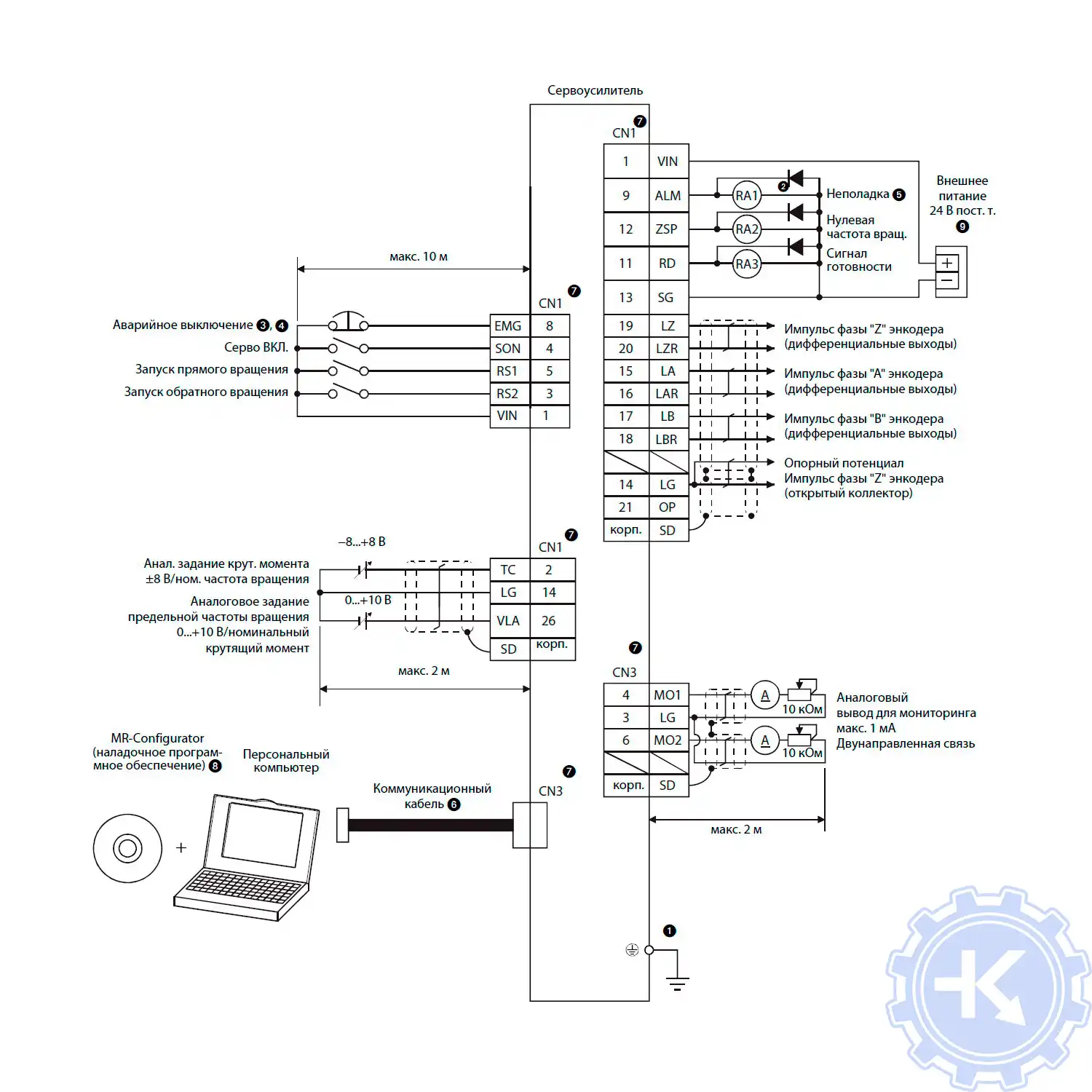
|

Блок схема сервоусилителя Mitsubishi
|
Mitsubishi MR-E-Super с аналоговым входом |

|
Преимущество ремонта сервоусилителя Mitsubishi в нашем сервисном центре
Во время эксплуатации электроприводов Mitsubishi может возникнуть проблема, далеко не всегда возникшую проблему можно исправить на месте своими силами, наш сервисный центр готов вам в этом помочь, выполнив качественный ремонт сервоусилителей Mitsubishi в сжатые сроки с полугодовой гарантией.
Мы не только восстановим неисправный блок, но и подскажем как действовать в той или иной ситуации для максимально долгой и безаварийной работы сервоусилителя.
Работы, проводимые при ремонте сервоусилителя Mitsubishi в :

- Предварительный осмотр на возможность восстановления бесплатный;
- Мы производим ремонт сервоусилителя Mitsubishi на компонентном уровне (экономия бюджета и времени)
- При ремонте сервоусилителей ни каких конструктивных изменений не вносим;
- Ремонт блоков с применением оригинальных запасных частей (по возможности).
- Вы платите исключительно за результат — работающий сервопривод;
- Гарантия на ремонт сервоусилителя Mitsubishi и на запасные части замененные в процессе ремонта 6 месяцев;
- Сроки ремонта варьируются от 5 до 15 рабочих дней;
За два десятилетия существования сервисного центра нашими специалистами были успешно проведены тысячи подобных ремонтов с каждым разом поднимая квалификацию наших инженеров. Ниже представлен далеко не полный список сервоусилителей Mitsubishi серии MR-E ремонтируемые в нашем сервисном центре.
|
MR-E Super Сервоусилитель 1(3) x 200-230В/50-60Гц (управление импульсной последовательностью) |
|
|
MR-E-10A-QW003 |
Ремонт сервоусилителя MR-E-A для двигателей до 100 Вт |
|
MR-E-20A-QW003 |
Ремонт сервоусилителя MR-E-A для двигателей до 200 Вт |
|
MR-E-40A-QW003 |
Ремонт сервоусилителя MR-E-A для двигателей до 400 Вт |
|
MR-E-70A-QW003 |
Ремонт сервоусилителя MR-E-A для двигателей до 750 Вт |
|
MR-E Super Сервоусилитель 3 x 200-230В/50-60Гц (управление импульсной последовательностью) |
|
|
MR-E-100A-QW003 |
Ремонт сервоусилителя MR-E-A для двигателей до 1кВт |
|
MR-E-200A-QW003 |
Ремонт сервоусилителя MR-E-A для двигателей до 2кВт |
|
MR-E Super Сервоусилитель 1(3) x 200-230В/50-60Гц (управление аналоговым сигналом) |
|
|
MR-E-10AG-QW003 |
Ремонт сервоусилителя MR-E-AG для двигателей до 100 Вт |
|
MR-E-20AG-QW003 |
Ремонт сервоусилителя MR-E-AG для двигателей до 200 Вт |
|
MR-E-40AG-QW003 |
Ремонт сервоусилителя MR-E-AG для двигателей до 400 Вт |
|
MR-E-70AG-QW003 |
Ремонт сервоусилителя MR-E-AG для двигателей до 750 Вт |
|
MR-E Super Сервоусилитель 3 x 200-230В/50-60Гц (управление аналоговым сигналом) |
|
|
MR-E-100AG-QW003 |
Ремонт сервоусилителя MR-E-AG для двигателей до 1кВт |
|
MR-E-200AG-QW003 |
Ремонт сервоусилителя MR-E-AG для двигателей до 2кВт |
В таблице представлены исключительно сервоусилители Mitsubishi серии MR-E ремонт которых мы вам предлагаем, также специалисты нашей компании ремонтируют сервоусилители не зависимо от серии и под каким брендом они были выпущены.
Оставить заявку на ремонт сервоусилителя Mitsubishi
У вас остались вопросы, связанные с ремонтом или сбросом ошибок, а также программированием и настройкой сервоусилителей Mitsubishi? Оставьте заявку на ремонт сервоусилителя Mitsubishi в нашим менеджерам. Связаться с ними можно несколькими способами:

- Заказав обратный звонок (кнопка в правом нижнем углу сайта)
- Посредством чата (кнопка расположена с левой стороны сайта)
- Позвонив по номеру телефона: +7(8482) 79-78-54; +7(917) 121-53-01
- Написав на электронную почту: 89171215301@mail.ru
За время существования сервисного центра нашими специалистами были отремонтированы десятки и сотни тысяч единиц промышленной электроники. Вот далеко не полный список производителей промышленной электроники и оборудования, ремонтируемой в нашей компании.
Все ошибки Mitsubishi AIRTREK, ASX, CARISMA,COLT, DELICA, DIAMANTE, DION, ECLIPSE, ENDEAVOR, GALANT, GRANDIS, GTO, i-MiEV, IO, L200, LANCER, LANCER CLASSIC, LANCER EVO, MINICA, MIRAGE, MONTERO, OUTLANDER, PAJERO, PAJERO SPORT, SPACE STAR, SPACE WAGON, TOWN BOX
FUSO, FUSO Canter, FUSO Fighter, FUSO Super Great
Ошибки Mitsubishi по протоколу OBDI. Самодиагностика.
11 – Датчик кислорода – неисправность
12 – Датчик массового расхода воздуха – неисправность
13 – Датчик температуры впускного воздуха – неисправность
14 – Датчик положения дроссельной заслонки (TPS) – неисправность
15 – Датчик положения двигателя на холостом ходу – неисправность
21 – Датчик температуры охлаждающей жидкости – неисправность
22 – Датчик положения коленчатого вала – неисправность
23 – Датчик положения распределительного вала – неисправность
24 – Датчик скорости автомобиля – неисправность
25 – Датчик барометрического давления – неисправность
31 – Датчик детонации – неисправность
32 – Датчик абсолютного давления – неисправность
36 – Неисправность сигнала регулировки времени зажигания
39 – Датчик кислорода – неисправность
41 – Неисправность форсунки / форсунок
42 – Топливный насос – неисправность
43 – Система отработавших газов (EGR) – неисправность
44 – Катушка зажигания (цилиндры № 1 и № 4) – неисправность
52 – Катушка зажигания (цилиндры № 2 и № 5) – неисправность
53 – Катушка зажигания (цилиндры № 3 и № 6) – неисправность
55 – Управление холостым ходом (IAC) – неисправность датчика положения клапана
59 – Кислородный датчик (задний) – неисправность
61 – Модуль управления трансмиссией – снижение мощности – некорректный сигнал
62 – Система VIC – неисправность датчика положения клапана
71 – Неисправность электромагнитного вакуумного клапана управления тягой (Traction Control)
72 – Неисправность соленоида вентиляционного клапана системы управления тягой (Traction Control)
Ошибки Mitsubishi по протоколу OBDII
Топливная система и воздухоподача
P0000-P0099, P0100-P0199, P0200-P0299
P0001 – Управление регулятором подачи топлива — обрыв цепи
P0002 – Управление регулятором подачи топлива — параметры цепи
P0003 – Управление регулятором подачи топлива — низкое напряжение
P0004 – Управление регулятором подачи топлива — высокое напряжение
P0005 – Клапан отсечки подачи топлива — обрыв цепи
P0006 – Клапан отсечки подачи топлива — низкий уровень сигнала
P0007 – Клапан отсечки подачи топлива — высокий уровень сигнала
P0008 – Система синхронизации фаз, банк 1 — характеристика двигателя
P0009 – Система синхронизации фаз, банк 2 — характеристика двигателя
P0010 – Привод системы изменения фаз газораспределения, впуск/левый/передний, банк 1 — неисправность электрической цепи
P0011 – Положение распределительного вала, впуск/левый/передний, банк 1 — слишком ранний угол открывания клапанов / нарушение функционирования системы
P0012 – Положение распределительного вала, впуск/левый/передний, банк 1 — слишком поздний угол открывания клапанов
P0013 – Привод системы изменения фаз газораспределения, впуск/левый/передний, банк 1 — неисправность электрической цепи
P0014 – Привод системы изменения фаз газораспределения, выпуск/правый/задний, банк 1 — слишком ранний угол открывания / функционирование системы
P0015 – Привод системы изменения фаз газораспределения, выпуск/правый/задний, банк 1 — слишком поздний угол открывания
P0016 – Положение коленчатого и распределительного валов, банк 1, датчик А — нет соответствия
P0017 – Положение коленчатого и распределительного валов, банк 1, датчик В — корреляция
P0018 – Положение коленчатого и распределительного валов, банк 2, датчик А — корреляция
P0019 – Положение коленчатого и распределительного валов, банк 2, датчик B — корреляция
P0020 – Привод системы изменения фаз газораспределения, впуск/левый/передний, банк 2 — неисправность электрической цепи
P0021 – Положение распределительного вала, впуск/левый/передний, банк 2 — слишком ранний угол открывания клапанов / нарушение функционирования системы
P0022 – Положение распределительного вала, впуск/левый/передний, банк 2 — слишком поздний угол открывания клапанов
P0023 – Привод системы изменения фаз газораспределения, выпуск/правый/задний, банк 2 — неисправность электрической цепи
P0024 – Положение распределительного вала, выпуск/правый/задний, банк 2 — слишком ранний угол открывания / функционирование системы
P0025 – Положение распределительного вала, выпуск/правый/задний, банк 2 — слишком поздний угол открывания
P0030 – Подогреваемый кислородный датчик 1, банк 1, управление нагревателем — неисправность электрической цепи
P0031 – Подогреваемый кислородный датчик 1, банк 1, управление нагревателем — низкое напряжение цепи
P0032 – Подогреваемый кислородный датчик 1, банк 1, управление нагревателем — высокое напряжение цепи
P0033 – Перепускной клапан турбокомпрессора — неисправность электрической цепи
P0034 – Перепускной клапан турбокомпрессора — низкий уровень сигнала
P0035 – Перепускной клапан турбокомпрессора — высокий уровень сигнала
P0036 – Подогреваемый кислородный датчик 2, банк 1, управление нагревателем — неисправность электрической цепи
P0037 – Подогреваемый кислородный датчик 2, банк 1, управление нагревателем — низкое напряжение цепи
P0038 – Подогреваемый кислородный датчик 2, банк 1, управление нагревателем — высокое напряжение цепи
P0039 – Перепускной клапан турбокомпрессора/перепускной клапан приводного нагнетателя, управление — диапазон/функционирование
P0040 – Перепутано подключение кислородных датчиков 1, банка 1 и банка 2
P0041 – Перепутано подключение кислородных датчиков 2, банка 1 и банка 2
P0045 – Э/м клапан управления давлением турбонаддува/ клапан управления давлением наддува приводного нагнетателя — обрыв цепи
P0046 – Э/м клапан управления давлением турбонаддува / давлением наддува приводного нагнетателя — диапазон/функционирование
P0047 – Э/м клапан управления давлением турбонаддува / давлением наддува приводного нагнетателя — низкий уровень сигнала
P0048 – Э/м клапан управления давлением турбонаддува / давлением наддува приводного нагнетателя — высокий уровень сигнала
P0049 – Турбина турбокомпрессора / нагнетателя — превышение скорости
P0050 – Подогреваемый кислородный датчик 1, банк 2, управление нагревателем — неисправность электрической цепи
P0051 – Подогреваемый кислородный датчик 1, банк 2, управление нагревателем — низкий уровень сигнала
P0052 – Подогреваемый кислородный датчик 1, банк 2, управление нагревателем — высокий уровень сигнала
P0053 – Подогреваемый кислородный датчик 1, банк 1 — сопротивление нагревателя
P0054 – Подогреваемый кислородный датчик 1, банк 2 — сопротивление нагревателя
P0055 – Подогреваемый кислородный, банк 1, датчик 3 — сопротивление нагревателя
P0056 – Подогреваемый кислородный датчик 2, банк 2, управление нагревателем — неисправность электрической цепи
P0057 – Подогреваемый кислородный датчик 2, банк 2, управление нагревателем — низкое напряжение цепи нагревателя
P0058 – Подогреваемый кислородный датчик 2, банк 2, управление нагревателем — высокий уровень сигнала
P0059 – Подогреваемый кислородный датчик 1, банк 2 — сопротивление нагревателя
P0060 – Подогреваемый кислородный датчик, банк 2, датчик 2 — сопротивление нагревателя
P0061 – Подогреваемый кислородный датчик, банк 2, датчик 3 — сопротивление нагревателя
P0065 – Форсунка с дополнительным воздушным каналом — диапазон/функционирование
P0066 – Форсунка с дополнительным воздушным каналом — неисправность электрической цепи / низкое напряжение
P0067 – Форсунка с дополнительным воздушным каналом — высоко напряжение цепи
P0068 – Датчик абсолютного давления во впускном коллекторе/датчик расхода воздуха (MAF) — несоответствие положению дроссельной заслонки
P0069 – Датчик абсолютного давления во впускном коллекторе / датчик атмосферного давления — корреляция
P0070 – Датчик температуры окружающего воздуха — неисправность электрической цепи
P0071 – Датчик температуры окружающего воздуха — диапазон/функционирование
P0072 – Датчик температуры окружающего воздуха — низкий уровень сигнала
P0073 – Датчик температуры окружающего воздуха — высокий уровень выходного сигнала
P0074 – Датчик температуры окружающего воздуха — ненадежный контакт электрической цепи
P0087 – Давление в системе / в топливном коллекторе — слишком низкое
P0088 – Давление в системе / в топливном коллекторе — слишком высокое
P0089 – Регулятор давления топлива 1 — функционирование
P0090 – Регулятор давления топлива 1 — обрыв цепи
P0091 – Регулятор давления топлива 1 — короткое замыкание на массу
P0092 – Регулятор давления топлива 1 — короткое замыкание на «+»
P0093 – Значительная утечка в топливной системе
P0094 – Незначительная утечка в топливной системе
P0100 – Датчик расхода воздуха (массового — MAF) / (объемного — VAF) — неисправность электрической цепи
P0101 – Датчик расхода воздуха (MAF) / (VAF) — диапазон/функционирование
P0102 – Датчик расхода воздуха (MAF) / (VAF) — низкий уровень входного сигнала
P0103 – Датчик расхода воздуха (MAF) / (VAF) — высокий уровень входного сигнала
P0104 – Датчик расхода воздуха (MAF) / (VAF) — ненадежный контакт электрической цепи
P0105 – Датчик абсолютного давления во впускном коллекторе (МАР) / датчик атмосферного давления — неисправность электрической цепи
P0106 – Датчик абсолютного давления во впускном коллекторе/датчик атмосферного давления — диапазон/функционирование
P0107 – Датчик абсолютного давления во впускном коллекторе/датчик атмосферного давления — низкий уровень сигнала
P0108 – Датчик абсолютного давления во впускном коллекторе/датчик атмосферного давления — высокий уровень сигнала
P0109 – Датчик абсолютного давления во впускном коллекторе (МАР) / датчик атмосферного давления — ненадежный контакт электрической цепи
P0110 – Датчик температуры воздуха на впуске — неисправность электрической цепи
P0111 – Датчик температуры воздуха на впуске — диапазон/функционирование
P0112 – Датчик температуры воздуха на впуске — низкий уровень сигнала
P0113 – Датчик температуры воздуха на впуске — высокий уровень входного сигнала
P0114 – Датчик температуры воздуха на впуске — ненадежный контакт электрической цепи
P0115 – Датчик температуры охлаждающей жидкости — неисправность электрической цепи
P0116 – Датчик температуры охлаждающей жидкости — диапазон/функционирование
P0117 – Датчик температуры охлаждающей жидкости — низкий уровень сигнала
P0118 – Датчик температуры охлаждающей жидкости — высокий уровень входного сигнала
P0119 – Датчик температуры охлаждающей жидкости — ненадежный контакт электрической цепи
P0120 – Датчик А положения дроссельной заслонки / датчик А положения педали акселератора — неисправность электрической цепи
P0121 – Датчик А положения дроссельной заслонки / датчик А положения педали акселератора — диапазон/функционирование
P0122 – Датчик «А» положения дроссельной заслонки / датчик «А» положения педали акселератора — низкий уровень сигнала
P0123 – Датчик А положения дроссельной заслонки / датчик А положения педали акселератора — высокий уровень сигнала
P0124 – Датчик А положения дроссельной заслонки / датчик А положения педали акселератора — ненадежный контакт электрической цепи
P0125 – Температура охлаждающей жидкости недостаточна для управления топливоподачей с обратной связью
P0126 – Температура охлаждающей жидкости недостаточна для стабильной работы
P0127 – Слишком высокая температура воздуха на впуске
P0128 – Термостат системы охлаждения — температура охлаждающей жидкости ниже температуры открывания термостата
P0129 – Слишком низкое атмосферное давление
P0130 – Кислородный датчик 1, банк 1 — неисправность электрической цепи
P0131 – Кислородный датчик 1, банк 1 — низкое напряжение
P0132 – Кислородный датчик 1, банк 1 — высокое напряжение
P0133 – Кислородный датчик 1, банк 1 — малое быстродействие
P0134 – Кислородный датчик 1, банк 1 — нет отклика
P0135 – Подогреваемый кислородный датчик 1, банк 1, управление нагревателем — неисправность электрической цепи
P0136 – Кислородный датчик 2, банк 1 — неисправность электрической цепи
P0137 – Кислородный датчик 2, банк 1 — низкое напряжение
P0138 – Кислородный датчик 2, банк 1 — высокое напряжение
P0139 – Кислородный датчик 2, банк 1 — малое быстродействие
P0140 – Кислородный датчик 2, банк 1 — нет отклика
P0141 – Подогреваемый кислородный датчик 2, банк 1, управление нагревателем — неисправность электрической цепи
P0148 – Неправильная подача топлива
P0149 – Неправильный угол опережения впрыска
P0150 – Кислородный датчик 1, банк 2 — неисправность электрической цепи
P0151 – Кислородный датчик 1, банк 2 — низкое напряжение
P0152 – Кислородный датчик 1, банк 2 — высокое напряжение
P0153 – Кислородный датчик 1, банк 2 — малое быстродействие
P0154 – Кислородный датчик 1, банк 2 — нет отклика
P0155 – Кислородный датчик 1, банк 2, управление нагревателем — неисправность электрической цепи
P0156 – Кислородный датчик 2, банк 2 — неисправность электрической цепи
P0157 – Кислородный датчик 2, банк 2 — низкое напряжение
P0158 – Кислородный датчик 2, банк 2 — высокое напряжение
P0159 – Кислородный датчик 2, банк 2 — малое быстродействие
P0160 – Кислородный датчик 2, банк 2 — нет отклика
P0161 – Подогреваемый кислородный датчик 2, банк 2, управление нагревателем — неисправность электрической цепи
P0168 – Слишком высокая температура топлива
P0169 – Несоответствующий состав топлива
P0170 – Топливный баланс, банк 1 — неисправность
P0171 – Слишком бедная топливовоздушная смесь, банк 1
P0172 – Слишком богатая топливовоздушная смесь, банк 1
P0173 – Топливный баланс, банк 2 — неисправность
P0174 – Слишком бедная топливовоздушная смесь, банк 2
P0175 – Слишком богатая топливовоздушная смесь, банк 2
P0176 – Датчик состава смеси — неисправность электрической цепи
P0177 – Датчик состава смеси — диапазон/функционирование
P0178 – Датчик состава смеси — низкий уровень сигнала
P0179 – Датчик состава смеси — высокий уровень сигнала
P0180 – Датчик температуры топлива A — неисправность электрической цепи
P0181 – Датчик температуры топлива A — диапазон/функционирование
P0182 – Датчик температуры топлива A — низкий уровень сигнала
P0183 – Датчик температуры топлива A — высокий уровень входного сигнала
P0184 – Датчик температуры топлива A — ненадежный контакт электрической цепи
P0185 – Датчик температуры топлива B — неисправность электрической цепи
P0186 – Датчик температуры топлива B — диапазон/функционирование
P0187 – Датчик температуры топлива B — низкий уровень входного сигнала
P0188 – Датчик температуры топлива B — высокий уровень входного сигнала
P0189 – Датчик температуры топлива B — ненадежный контакт электрической цепи
P0190 – Датчик давления в топливном коллекторе — неисправность электрической цепи
P0191 – Датчик давления в топливном коллекторе — диапазон/функционирование
P0192 – Датчик давления в топливном коллекторе — низкий уровень сигнала
P0193 – Датчик давления в топливном коллекторе — высокий уровень входного сигнала
P0194 – Датчик давления в топливном коллекторе — ненадежный контакт электрической цепи
P0195 – Датчик температуры моторного масла — неисправность электрической цепи
P0196 – Датчик температуры моторного масла — диапазон/функционирование
P0197 – Датчик температуры моторного масла — низкий уровень сигнала
P0198 – Датчик температуры моторного масла — высокий уровень входного сигнала
P0199 – Датчик температуры моторного масла — ненадежный контакт электрической цепи
P0200 – Форсунка — неисправность электрической цепи
P0201 – Форсунка 1 — неисправность электрической цепи
P0202 – Форсунка 2 — неисправность электрической цепи
P0203 – Форсунка 3 — неисправность электрической цепи
P0204 – Форсунка 4 — неисправность электрической цепи
P0205 – Форсунка 5 — неисправность электрической цепи
P0206 – Форсунка 6 — неисправность электрической цепи
P0207 – Форсунка 7 — неисправность электрической цепи
P0208 – Форсунка 8 — неисправность электрической цепи
P0213 – Форсунка холодного пуска 1 — неисправность электрической цепи
P0214 – Форсунка холодного пуска 2 — неисправность электрической цепи
P0215 – Э/м клапан отсечки подачи топлива — неисправность электрической цепи
P0216 – Управление углом опережения впрыска топлива — неисправность электрической цепи
P0217 – Перегрев двигателя
P0218 – Перегрев коробки передач
P0219 – Превышение допустимой частоты вращения коленчатого вала
P0220 – Датчик В положения дроссельной заслонки / датчик В положения педали акселератора — неисправность электрической цепи
P0221 – Датчик В положения дроссельной заслонки / датчик В положения педали акселератора — диапазон/функционирование
P0222 – Датчик В положения дроссельной заслонки / датчик В положения педали акселератора — низкий уровень входного сигнала
P0223 – Датчик В положения дроссельной заслонки / датчик В положения педали акселератора — высокий уровень входного сигнала
P0224 – Датчик В положения дроссельной заслонки / датчик В положения педали акселератора — ненадежный контакт электрической цепи
P0230 – Реле топливного насоса — неисправность электрической цепи
P0231 – Реле топливного насоса — низкое напряжение цепи
P0232 – Реле топливного насоса — высокое напряжение цепи
P0233 – Реле топливного насоса — ненадежный контакт электрической цепи
P0234 – Давление турбонаддува — превышен верхний предел
P0235 – Датчик давления наддува A турбокомпрессора/приводного нагнетателя — неисправность электрической цепи
P0236 – Датчик давления наддува A турбокомпрессора/приводного нагнетателя — диапазон/функционирование
P0237 – Датчик давления наддува A турбокомпрессора/приводного нагнетателя — низкий уровень входного сигнала
P0238 – Датчик давления наддува A турбокомпрессора/приводного нагнетателя — высокий уровень входного сигнала
P0239 – Датчик давления наддува B турбокомпрессора/приводного нагнетателя — неисправность электрической цепи
P0240 – Датчик давления наддува B турбокомпрессора/приводного нагнетателя — диапазон/функционирование
P0241 – Датчик давления наддува B турбокомпрессора/приводного нагнетателя — низкий уровень входного сигнала
P0242 – Датчик давления наддува B турбокомпрессора/приводного нагнетателя — высокий уровень входного сигнала
P0243 – Клапан А управления перепуском газов мимо турбины — неисправность цепи
P0244 – Клапан А управления перепуском газов мимо турбины — диапазон/функционирование
P0245 – Клапан А управления перепуском газов мимо турбины — низкое напряжение цепи
P0246 – Клапан А управления перепуском газов мимо турбины — высокое напряжение цепи
P0247 – Клапан управления перепуском газов мимо турбины B — неисправность цепи
P0248 – Клапан В управления перепуском газов мимо турбины — диапазон/функционирование
P0249 – Клапан управления перепуском газов мимо турбины B — низкий уровень сигнала
P0250 – Клапан управления перепуском газов мимо турбины B — высокий уровень сигнала
P0251 – Дозатор топлива А, ротор/кулачок/форсунка — неисправность электрической цепи
P0252 – Дозатор топлива А, ротор/кулачок/форсунка — диапазон/функционирование
P0253 – Дозатор топлива А, ротор/кулачок/форсунка — низкий уровень сигнала
P0254 – Дозатор топлива А, ротор/кулачок/форсунка — высокий уровень сигнала
P0255 – Дозатор топлива А, ротор/кулачок/форсунка — ненадежный контакт электрической цепи
P0256 – Дозатор топлива B, ротор/кулачок/форсунка — неисправность электрической цепи
P0257 – Дозатор топлива B, ротор/кулачок/форсунка — диапазон/функционирование
P0258 – Дозатор топлива B, ротор/кулачок/форсунка — низкий уровень сигнала
P0259 – Дозатор топлива B, ротор/кулачок/форсунка — высокий уровень сигнала
P0260 – Дозатор топлива B, ротор/кулачок/форсунка — ненадежный контакт электрической цепи
P0261 – Форсунка 1 — низкий уровень сигнала
P0262 – Форсунка 1 — высокий уровень сигнала
P0263 – Цилиндр 1 — неправильный баланс мощности
P0264 – Форсунка 2 — низкий уровень сигнала
P0265 – Форсунка 2 — высокий уровень сигнала
P0266 – Цилиндр 2 — неправильный баланс мощности
P0267 – Форсунка 3 — низкий уровень сигнала
P0268 – Форсунка 3 — высокий уровень сигнала
P0269 – Цилиндр 3 — неправильный баланс мощности
P0270 – Форсунка 4 — низкий уровень сигнала
P0271 – Форсунка 4 — высокий уровень сигнала
P0272 – Цилиндр 4 — неправильный баланс мощности
P0273 – Форсунка 5 — низкий уровень сигнала
P0274 – Форсунка 5 — высокий уровень сигнала
P0275 – Цилиндр 5 — неправильный баланс мощности
P0276 – Форсунка 6 — низкий уровень сигнала
P0277 – Форсунка 6 — высокий уровень сигнала
P0278 – Цилиндр 6 — неправильный баланс мощности
P0279 – Форсунка 7 — низкий уровень сигнала
P0280 – Форсунка 7 — высокий уровень сигнала
P0281 – Цилиндр 7 — неправильный баланс мощности
P0282 – Форсунка 8 — низкий уровень сигнала
P0283 – Форсунка 8 — высокий уровень сигнала
P0284 – Цилиндр 8 — неправильный баланс мощности
P0297 – Превышение допустимой скорости автомобиля
P0298 – Слишком высокая температура моторного масла
P0299 – Турбокомпрессор / приводной нагнетатель — низкое давление наддува
Система зажигания
P0300-P0399
P0300 – Случайные / множественные пропуски зажигания (воспламенения)
P0301 – Цилиндр 1 — пропуски зажигания (воспламенения)
P0302 – Цилиндр 2 — пропуски зажигания (воспламенения)
P0303 – Цилиндр 3 — пропуски зажигания (воспламенения)
P0304 – Цилиндр 4 — пропуски зажигания (воспламенения)
P0305 – Цилиндр 5 — пропуски зажигания (воспламенения)
P0306 – Цилиндр 6 — пропуски зажигания (воспламенения)
P0307 – Цилиндр 7 — пропуски зажигания (воспламенения)
P0308 – Цилиндр 8 — пропуски зажигания (воспламенения)
P0313 – Пропуски зажигания (воспламенения) — низкий уровень топлива
P0314 – Пропуск зажигания (воспламенения) в одном цилиндре — номер цилиндра не распознается
P0315 – Коленчатый вал — отсутствие изменения положения
P0316 – Пропуски зажигания (воспламенения) при запуске — первые 1000 оборотов
P0317 – Нет данных по характеристикам неровностей дорожного покрытия
P0318 – Датчик состояния дорожного покрытия A — неисправность электрической цепи
P0319 – Датчик состояния дорожного покрытия B — неисправность электрической цепи
P0320 – Датчик положения коленчатого вала / датчик частоты вращения коленчатого вала — неисправность электрической цепи
P0321 – Датчик положения коленчатого вала / датчик частоты вращения коленчатого вала — диапазон/функционирование
P0322 – Датчик положения коленчатого вала/датчик частоты вращения коленчатого вала — нет сигнала
P0323 – Датчик положения коленчатого вала / датчик частоты вращения коленчатого вала — ненадежный контакт электрической цепи
P0324 – Ошибка в системе управления по детонации
P0325 – Датчик детонации 1, банк 1 — неисправность электрической цепи
P0326 – Датчик детонации 1, банк 1 — диапазон/функционирование
P0327 – Датчик детонации 1, банк 1 — низкий уровень сигнала
P0328 – Датчик детонации 1, банк 1 — высокий уровень входного сигнала
P0329 – Датчик детонации 1, банк 1 — ненадежный контакт электрической цепи
P0330 – Датчик детонации 2, банк 2 — неисправность электрической цепи
P0331 – Датчик детонации 2, банк 2 — диапазон/функционирование
P0332 – Датчик детонации 2, банк 2 — низкий уровень сигнала
P0333 – Датчик детонации 2, банк 2 — высокий уровень входного сигнала
P0334 – Датчик детонации 2, банк 2 — ненадежный контакт электрической цепи
P0335 – Датчик положения коленчатого вала — неисправность электрической цепи
P0336 – Датчик положения коленчатого вала — диапазон/функционирование
P0337 – Датчик положения коленчатого вала — низкий уровень сигнала
P0338 – Датчик положения коленчатого вала — высокий уровень сигнала
P0339 – Датчик положения коленчатого вала — ненадежный контакт электрической цепи
P0340 – Датчик положения распределительного вала A, банк 1 — неисправность электрической цепи
P0341 – Датчик положения распределительного вала A, банк 1 — диапазон/функционирование
P0342 – Датчик положения распределительного вала A, банк 1 — низкий уровень сигнала
P0343 – Датчик положения распределительного вала A, банк 1 — высокий уровень входного сигнала
P0344 – Датчик положения распределительного вала A, банк 1 — ненадежный контакт электрической цепи
P0345 – Датчик положения распределительного вала A, банк 2 — неисправность электрической цепи
P0346 – Датчик положения распределительного вала A, банк 2 — диапазон/функционирование
P0347 – Датчик положения распределительного вала A, банк 2 — низкий уровень сигнала
P0348 – Датчик положения распределительного вала A, банк 2 — высокий уровень сигнала
P0349 – Датчик положения распределительного вала A, банк 2 — ненадежный контакт электрической цепи
P0350 – Катушка зажигания, первичная/вторичная обмотки — неисправность электрической цепи
P0351 – Катушка зажигания A, первичная/вторичная обмотки — неисправность электрической цепи
P0352 – Катушка зажигания В, первичная/вторичная обмотки — неисправность электрической цепи
P0353 – Катушка зажигания С, первичная/вторичная обмотки — неисправность электрической цепи
P0354 – Катушка зажигания D, первичная/вторичная обмотки — неисправность электрической цепи
P0355 – Катушка зажигания Е, первичная/вторичная обмотки — неисправность электрической цепи
P0356 – Катушка зажигания F, первичная/вторичная обмотки — неисправность электрической цепи
P0357 – Катушка зажигания G, первичная/вторичная обмотки — неисправность электрической цепи
P0358 – Катушка зажигания H, первичная/вторичная обмотки — неисправность электрической цепи
P0363 – Пропуск зажигания (воспламенения) — отсутствие подачи топлива
P0364 – Зарезервировано (ISO/SAE)
P0365 – Датчик В положения распределительного вала, банк 1 — неисправность электрической цепи
P0366 – Датчик В положения распределительного вала, банк 1 — диапазон/функционирование
P0367 – Датчик В положения распределительного вала, банк 1 — низкий уровень сигнала
P0368 – Датчик В положения распределительного вала, банк 1 — высокий уровень сигнала
P0369 – Датчик В положения распределительного вала, банк 1 — ненадежный контакт электрической цепи
P0370 – Опорная точка синхронизации фаз, сигнал А высокого разрешения — неисправность
P0371 – Опорная точка синхронизации фаз, сигнал А высокого разрешения — слишком много импульсов
P0372 – Опорная точка синхронизации фаз, сигнал А высокого разрешения — слишком мало импульсов
P0373 – Опорная точка синхронизации фаз, сигнал А высокого разрешения — хаотичные/пропадающие импульсы
P0374 – Опорная точка синхронизации фаз, сигнал А высокого разрешения — нет импульсов
P0375 – Опорная точка синхронизации фаз, сигнал В высокого разрешения — неисправность
P0376 – Опорная точка синхронизации фаз, сигнал В высокого разрешения — слишком много импульсов
P0377 – Опорная точка синхронизации фаз, сигнал В высокого разрешения — слишком мало импульсов
P0378 – Опорная точка синхронизации фаз, сигнал B высокого разрешения — хаотичные/пропадающие импульсы
P0379 – Опорная точка синхронизации фаз, сигнал В высокого разрешения — нет импульсов
P0380 – Свечи накаливания, цепь А — неисправность
P0381 – Индикатор свечей накаливания — неисправность электрической цепи
P0382 – Свечи накаливания, цепь В — неисправность
P0383 – Блок управления свечами накаливания — низкий уровень сигнала
P0384 – Блок управления свечами накаливания — высокий уровень сигнала
P0385 – Датчик положения коленчатого вала B — неисправность электрической цепи
P0386 – Датчик положения коленчатого вала B — диапазон/функционирование
P0387 – Датчик положения коленчатого вала B — низкий уровень входного сигнала
P0388 – Датчик положения коленчатого вала B — высокий уровень входного сигнала
P0389 – Датчик положения коленчатого вала B — ненадежный контакт электрической цепи
P0390 – Датчик «А» положения распределительного вала B, банк 2 — неисправность электрической цепи
P0391 – Датчик В положения распределительного вала, банк 2 — диапазон/функционирование
P0392 – Датчик В положения распределительного вала, банк 2 — низкий уровень входного сигнала
P0393 – Датчик В положения распределительного вала, банк 2 — высокий уровень входного сигнала
P0394 – Датчик B положения распределительного вала, банк 2 — ненадежный контакт электрической цепи
P0395 – Датчик давления в цилиндре, цилиндр 1 — неисправность электрической цепи
P0396 – Датчик давления в цилиндре, цилиндр 1 — диапазон/функционирование
P0397 – Датчик давления в цилиндре, цилиндр 1 — низкий уровень сигнала
P0398 – Датчик давления в цилиндре, цилиндр 1 — высокий уровень сигнала
P0399 – Датчик давления в цилиндре, цилиндр 1 — ненадежный/пропадающий контакт электрической цепи
Контроль выбросов
P0400-P0499
P0400 – Система рециркуляции отработавших газов (EGR) — неисправность каналов системы
P0401 – Система рециркуляции отработавших газов (EGR) — недостаточный уровень рециркуляции
P0402 – Система рециркуляции отработавших газов (EGR) — чрезмерный уровень рециркуляции
P0403 – Система рециркуляции отработавших газов (EGR) — неисправность электрической цепи
P0404 – Система рециркуляции отработавших газов (EGR) — диапазон/функционирование
P0405 – Датчик положения клапана А системы рециркуляции ОГ (EGR) — низкий уровень сигнала
P0406 – Датчик положения клапана А системы рециркуляции ОГ (EGR) — высокий уровень сигнала
P0407 – Датчик положения клапана B системы рециркуляции ОГ (EGR) — низкий уровень входного сигнала
P0408 – Датчик положения клапана B системы рециркуляции ОГ (EGR) — высокий уровень входного сигнала
P0409 – Датчик А системы рециркуляции отработавших газов (EGR) — неисправность электрической цепи
P0410 – Система подачи воздуха на выпуск — неисправность
P0411 – Система подачи воздуха на выпуск — некорректный расход
P0412 – Э/м клапан А подачи воздуха на выпуск — неисправность электрической цепи
P0413 – Э/м клапан А подачи воздуха на выпуск — обрыв цепи
P0414 – Э/м клапан А подачи воздуха на выпуск — короткое замыкание
P0415 – Э/м клапан B подачи воздуха на выпуск — неисправность электрической цепи
P0416 – Э/м клапан B подачи воздуха на выпуск — обрыв цепи
P0417 – Э/м клапан B подачи воздуха на выпуск — короткое замыкание в цепи
P0418 – Реле насоса А подачи воздуха на выпуск — неисправность электрической цепи
P0419 – Реле B насоса системы подачи воздуха на выпуск — неисправность электрической цепи
P0420 – Каталитический нейтрализатор, банк 1 — эффективность ниже требуемой
P0421 – Прогрев каталитического нейтрализатора, банк 1 — эффективность ниже требуемой
P0422 – Основной каталитический нейтрализатор, банк 1 — эффективность ниже требуемой
P0423 – Подогреваемый каталитический нейтрализатор, банк 1 — эффективность ниже требуемой
P0424 – Подогреваемый каталитический нейтрализатор, банк 1 — эффективность ниже требуемой
P0425 – Датчик температуры каталитического нейтрализатора, банк 1
P0426 – Датчик температуры каталитического нейтрализатора, банк 1 — диапазон/функционирование
P0427 – Датчик температуры каталитического нейтрализатора, банк 1 — низкий уровень сигнала
P0428 – Датчик температуры каталитического нейтрализатора, банк 1 — высокий уровень входного сигнала
P0429 – Нагреватель каталитического нейтрализатора, банк 1 — неисправность электрической цепи
P0430 – Каталитический нейтрализатор, банк 2 — эффективность ниже требуемой
P0431 – Прогрев каталитического нейтрализатора, банк 2 — эффективность ниже требуемой
P0432 – Основной каталитический нейтрализатор, банк 2 — эффективность ниже требуемой
P0433 – Подогреваемый каталитический нейтрализатор, банк 2 — эффективность ниже требуемой
P0434 – Подогреваемый каталитический нейтрализатор, банк 2 — температура ниже требуемой
P0435 – Датчик температуры каталитического нейтрализатора, банк 2
P0436 – Датчик температуры каталитического нейтрализатора, банк 2 — диапазон/функционирование
P0437 – Датчик температуры каталитического нейтрализатора, банк 2 — низкий уровень входного сигнала
P0438 – Датчик температуры каталитического нейтрализатора, банк 2 — высокий уровень входного сигнала
P0439 – Нагреватель каталитического нейтрализатора, банк 2 — неисправность электрической цепи
P0440 – Система улавливания паров топлива — неисправность
P0441 – Система улавливания паров топлива — некорректный расход
P0442 – Система улавливания паров топлива — незначительная утечка
P0443 – Э/м клапан аккумулятора паров топлива — неисправность электрической цепи
P0444 – Э/м клапан аккумулятора паров топлива — обрыв цепи
P0445 – Э/м клапан аккумулятора паров топлива — короткое замыкание
P0446 – Система улавливания паров топлива, управление продувкой — неисправность электрической цепи
P0447 – Система улавливания паров топлива, управление продувкой — обрыв цепи
P0448 – Система улавливания паров топлива, управление продувкой — короткое замыкание
P0449 – Система улавливания паров топлива, клапан управления продувкой — неисправность электрической цепи
P0450 – Датчик давления системы улавливания паров топлива — неисправность электрической цепи
P0451 – Датчик давления системы улавливания паров топлива — диапазон/функционирование
P0452 – Датчик давления системы улавливания паров топлива — низкий уровень сигнала
P0453 – Датчик давления системы улавливания паров топлива — высокий уровень сигнала
P0454 – Датчик давления системы улавливания паров топлива — ненадежный контакт электрической цепи
P0455 – Система улавливания паров топлива — значительная утечка
P0456 – Система улавливания паров топлива — крайне незначительная утечка
P0457 – Система улавливания паров топлива — утечка (ослабла или открыта крышка топливозаливной горловины)
P0458 – Система улавливания паров топлива, клапан аккумулятора паров топлива — низкий уровень сигнала
P0459 – Система улавливания паров топлива, клапан аккумулятора паров топлива — высокий уровень сигнала
P0460 – Датчик уровня топлива — неисправность электрической цепи
P0461 – Датчик уровня топлива — диапазон/функционирование
P0462 – Датчик уровня топлива — низкий уровень сигнала
P0463 – Датчик уровня топлива — высокий уровень входного сигнала
P0464 – Датчик уровня топлива — ненадежный контакт электрической цепи
P0465 – Датчик расхода через аккумулятор паров топлива — неисправность электрической цепи
P0466 – Датчик расхода через аккумулятор паров топлива — диапазон/функционирование
P0467 – Датчик расхода через аккумулятор паров топлива — низкий уровень сигнала
P0468 – Датчик расхода через аккумулятор паров топлива — высокий уровень сигнала
P0469 – Датчик расхода через аккумулятор паров топлива — ненадежный контакт электрической цепи
P0470 – Датчик давления отработавших газов — неисправность электрической цепи
P0471 – Датчик давления отработавших газов — диапазон/функционирование
P0472 – Датчик давления отработавших газов — низкий уровень сигнала
P0473 – Датчик давления отработавших газов — высокий уровень входного сигнала
P0474 – Датчик давления отработавших газов — ненадежный контакт электрической цепи
P0475 – Клапан управления давлением отработавших газов — неисправность электрической цепи
P0476 – Клапан управления давлением отработавших газов — диапазон/функционирование
P0477 – Клапан управления давлением отработавших газов — низкий уровень сигнала
P0478 – Клапан управления давлением отработавших газов — высокий уровень входного сигнала
P0479 – Клапан управления давлением отработавших газов — ненадежный контакт электрической цепи
P0480 – Электродвигатель вентилятора 1 системы охлаждения — неисправность электрической цепи
P0481 – Электродвигатель вентилятора 2 системы охлаждения — неисправность электрической цепи
P0482 – Электродвигатель вентилятора системы охлаждения 3 — неисправность электрической цепи
P0483 – Электродвигатель вентилятора системы охлаждения, нормальная проверка — неисправность
P0484 – Электродвигатель вентилятора системы охлаждения — превышение допустимой силы тока в цепи
P0485 – Электродвигатель вентилятора системы охлаждения, питание / масса — неисправность электрической цепи
P0486 – Датчик положения клапана В системы рециркуляции ОГ (EGR) — неисправность электрической цепи
P0487 – Система рециркуляции отработавших газов (EGR), управление положением дроссельной заслонки — неисправность электрической цепи
P0488 – Система рециркуляции отработавших газов (EGR), управление положением заслонки — проблемы диапазона / функционирования
P0489 – Система рециркуляции отработавших газов (EGR) — низкое напряжение цепи
P0490 – Система рециркуляции отработавших газов (EGR) — высокое напряжение цепи
P0491 – Система подачи воздуха на выпуск, банк 1 — неисправность
P0492 – Система подачи воздуха на выпуск, банк 2 — неисправность
P0493 – Превышение частоты вращения электродвигателя вентилятора системы охлаждения (блокировка муфты)
P0494 – Электродвигатель вентилятора системы охлаждения — низкая скорость
P0495 – Электродвигатель вентилятора системы охлаждения — высокая скорость
P0496 – Система улавливания паров топлива — высокий расход при продувке
P0497 – Система улавливания паров топлива — низкий расход при продувке
P0498 – Система улавливания паров топлива, управление продувкой — низкий уровень сигнала
P0499 – Система улавливания паров топлива, управление продувкой — высокий уровень сигнала
Контроль скорости и холостого хода
P0500-P0599
P0500 – Датчик скорости автомобиля — неисправность электрической цепи
P0501 – Датчик скорости автомобиля — диапазон/функционирование
P0502 – Датчик скорости автомобиля — низкий уровень сигнала
P0503 – Датчик скорости автомобиля — сигналы хаотичные / пропадающие / высокого уровня
P0504 – Выключатель А/В стоп-сигналов (датчик положения педали тормоза) — корреляция
P0505 – Система управления частотой вращения холостого хода — неисправность
P0506 – Система управления частотой вращения холостого хода — частота вращения ниже допустимой
P0507 – Система управления частотой вращения холостого хода — частота вращения выше допустимой
P0508 – Управление перепуском воздуха на холостом ходу — низкий уровень сигнала
P0509 – Управление перепуском воздуха на холостом ходу — высокий уровень сигнала
P0510 – Датчик полностью закрытого положения дроссельной заслонки — неисправность электрической цепи
P0511 – Управление перепуском воздуха на холостом ходу — неисправность электрической цепи
P0512 – Цепь управления стартером — неисправность
P0513 – Некорректный ключ иммобилайзера (неправильный код)
P0514 – Датчик температуры аккумуляторной батареи — диапазон/функционирование
P0515 – Датчик температуры аккумуляторной батареи — диапазон/функционирование
P0516 – Датчик температуры аккумуляторной батареи — низкое напряжение цепи
P0517 – Датчик температуры аккумуляторной батареи — высокое напряжение цепи
P0518 – Управление перепуском воздуха на холостом ходу — ненадежный контакт электрической цепи
P0519 – Управление перепуском воздуха на холостом ходу — функционирование
P0520 – Датчик давления моторного масла — неисправность электрической цепи
P0521 – Датчик давления моторного масла — диапазон/функционирование
P0522 – Датчик давления моторного масла — низкое напряжение
P0523 – Датчик давления моторного масла — высокое напряжение
P0524 – Давление моторного масла слишком низкое
P0525 – Система поддержания скорости (круиз-контроль), управление приводом — диапазон/функционирование
P0526 – Электродвигатель вентилятора системы охлаждения, датчик скорости — неисправность электрической цепи
P0527 – Электродвигатель вентилятора системы охлаждения, датчик скорости — диапазон/функционирование
P0528 – Электродвигатель вентилятора системы охлаждения, датчик скорости — нет сигнала
P0529 – Электродвигатель вентилятора системы охлаждения, датчик скорости — ненадежный контакт электрической цепи
P0530 – Датчик давления хладагента системы кондиционирования — неисправность электрической цепи
P0531 – Датчик давления хладагента системы кондиционирования — диапазон/функционирование
P0532 – Датчик давления хладагента системы кондиционирования — низкий уровень сигнала
P0533 – Датчик давления хладагента системы кондиционирования — высокий уровень входного сигнала
P0534 – Недостаток хладагента в системе кондиционирования
P0535 – Датчик температуры за испарителем (кондиционер) — неисправность электрической цепи
P0536 – Датчик температуры за испарителем (кондиционер) — диапазон/функционирование
P0537 – Датчик температуры за испарителем системы кондиционирования — низкий уровень сигнала
P0538 – Датчик температуры за испарителем системы кондиционирования — высокий уровень сигнала
P0539 – Датчик температуры за испарителем системы кондиционирования — ненадежный контакт электрической цепи
P0550 – Датчик/выключатель по давлению усилителя рулевого управления — неисправность электрической цепи
P0551 – Датчик-выключатель по давлению усилителя рулевого управления — диапазон/функционирование
P0552 – Датчик/выключатель по давлению усилителя рулевого управления — низкий уровень сигнала
P0553 – Датчик/выключатель по давлению усилителя рулевого управления — высокий уровень сигнала
P0554 – Датчик/выключатель по давлению усилителя рулевого управления — ненадежный контакт электрической цепи
P0555 – Датчик давления в системе усилителя тормозной системы — неисправность электрической цепи
P0556 – Датчик давления в системе усилителя тормозной системы — диапазон/функционирование
P0557 – Датчик давления в системе усилителя тормозной системы — низкий уровень сигнала
P0558 – Датчик давления в системе усилителя тормозной системы — высокий уровень входного сигнала
P0559 – Датчик давления в системе усилителя тормозной системы — ненадежный контакт электрической цепи
P0564 – Система поддержания скорости (круиз-контроль), многофункциональный переключатель (входной сигнал А) — неисправность электрической цепи
P0565 – Главный выключатель системы поддержания скорости (круиз-контроля), сигнал «ON» — неисправность
P0566 – Главный выключатель системы поддержания скорости (круиз-контроля), сигнал «OFF» — неисправность
P0567 – Переключатель выбора режима работы системы поддержания скорости (круиз-контроля), сигнал «RESUME» — неисправность
P0568 – Главный выключатель системы поддержания скорости (круиз-контроля), сигнал «SET» — неисправность
P0569 – Переключатель выбора режима работы системы поддержания скорости (круиз-контроля), сигнал «COAST» — неисправность
P0570 – Система поддержания скорости (круиз-контроль), сигнал датчика положения педали акселератора — неисправность
P0571 – Выключатель педали тормоза A (система поддержания скорости) — неисправность электрической цепи
P0572 – Концевой выключатель А педали тормоза (система поддержания скорости) — низкий уровень сигнала
P0573 – Концевой выключатель А педали тормоза (система поддержания скорости) — высокий уровень сигнала
P0574 – Система поддержания скорости (круиз-контроль) — слишком высокая скорость автомобиля
P0575 – Система поддержания скорости (круиз-контроль) — неисправность цепи входного сигнала
P0576 – Система поддержания скорости (круиз-контроль) — низкий уровень входного сигнала
P0577 – Система поддержания скорости (круиз-контроль) — высокий уровень входного сигнала
P0578 – Система поддержания скорости (круиз-контроль), многофункциональный переключатель (входной сигнал А) — цепь блокирована
P0579 – Система поддержания скорости (круиз-контроль), многофункциональный переключатель (входной сигнал А) — диапазон/функционирование
P0580 – Система поддержания скорости (круиз-контроль), многофункциональный переключатель (входной сигнал А) — низкий уровень сигнала
P0581 – Система поддержания скорости (круиз-контроль), многофункциональный переключатель (входной сигнал А) — высокий уровень сигнала
P0582 – Система поддержания скорости (круиз-контроль), управление разрежением — обрыв цепи
P0583 – Система поддержания скорости (круиз-контроль), управление разрежением — низкое напряжение цепи
P0584 – Система поддержания скорости (круиз-контроль), управление разрежением — высокое напряжение цепи
P0585 – Система поддержания скорости (круиз-контроль), многофункциональный переключатель (входной сигнал А/В) — корреляция
P0597 – Система управления нагревателем термостата — обрыв цепи
P0598 – Система управления нагревателем термостата — низкое напряжение цепи
P0599 – Система управления нагревателем термостата — высокое напряжение цепи
Электронный блок управления (ЭБУ) и его подсистемы
P0600-P0699
P0600 – Шина данных CAN — неисправность
P0601 – Электронный блок управления двигателем — ошибка контрольной суммы памяти
P0602 – Электронный блок управления двигателем — ошибка программирования
P0603 – Электронный блок управления двигателем — ошибка памяти КАМ
P0604 – Электронный блок управления двигателем — ошибка памяти RAM
P0605 – Электронный блок управления двигателем — ошибка памяти ROM
P0606 – Электронный блок управления двигателем (ECM) / блок управления силовым агрегатом (PCM) — неисправность процессора
P0607 – Электронный блок управления двигателем — функционирование
P0608 – Электронный блок управления двигателем, датчик скорости автомобиля (выходной сигнал А) — неисправность
P0609 – Электронный блок управления двигателем, датчик скорости автомобиля (выходной сигнал В) — неисправность
P0610 – Электронный блок управления двигателем — ошибка опции автомобиля
P0611 – Блок управления топливными форсунками — функционирование
P0612 – Блок управления топливными форсунками — цепь управления реле
P0613 – Электронный блок управления КПП (TCM) — ошибка процессора
P0614 – Электронный блок управления двигателем (ECM) / электронный блок управления КПП (TCM) — несоответствие
P0615 – Реле стартера — неисправность электрической цепи
P0616 – Реле стартера — низкий уровень сигнала
P0617 – Реле стартера — высокий уровень сигнала
P0618 – Блок управления подачей альтернативного топлива — ошибка памяти KAM
P0619 – Блок управления подачей альтернативного топлива — ошибка памяти RAM/ROM
P0620 – Управление генератором — неисправность электрической цепи
P0621 – Индикатор зарядки — неисправность электрической цепи
P0622 – Генератор, управление обмоткой возбуждения — неисправность электрической цепи
P0623 – Индикатор зарядки, управление — неисправность электрической цепи
P0624 – Индикатор незакрытой крышки заливной горловины, управление — неисправность электрической цепи
P0625 – Вывод обмотки возбуждения генератора — низкий уровень сигнала
P0626 – Вывод обмотки возбуждения генератора — высокий уровень сигнала
P0627 – Управление топливным насосом — обрыв цепи
P0628 – Управление топливным насосом — низкий уровень сигнала
P0629 – Управление топливным насосом — высокий уровень сигнала
P0630 – VIN не запрограммирован или не подходит — ECM/PCM
P0631 – Не запрограммирован электронный блок управления АКПП или не соответствует идентификационному номеру автомобиля
P0632 – Не запрограммирован одометр — ECM/PCM
P0633 – Не запрограммирован ключ иммобилайзера — ECM/PCM
P0634 – Электронный блок управления силовым агрегатом/двигателем/КПП (PCM/ECM/TCM) — высокая внутренняя температура
P0635 – Управление усилителем рулевого управления — неисправность электрической цепи
P0636 – Управление усилителем рулевого управления — низкий уровень сигнала
P0637 – Управление усилителем рулевого управления — высокий уровень сигнала
P0638 – Управление приводом дроссельной заслонки, банк 1 — диапазон/функционирование
P0639 – Управление приводом дроссельной заслонки, банк 2 — диапазон/функционирование
P0640 – Управление подогревом воздуха на впуске — неисправность электрической цепи
P0641 – Опорное напряжение датчика A — обрыв цепи
P0642 – Опорное напряжение датчика A — низкий уровень сигнала
P0643 – Опорное напряжение датчика A — высокий уровень сигнала
P0644 – Дисплей водителя, обмен данными (последовательный) — неисправность электрической цепи
P0645 – Реле электромагнитной муфты компрессора кондиционера — неисправность электрической цепи
P0646 – Реле электромагнитной муфты компрессора кондиционера — низкий уровень сигнала
P0647 – Реле электромагнитной муфты компрессора кондиционера — высокий уровень сигнала
P0648 – Индикатор иммобилайзера, управление — неисправность электрической цепи
P0649 – Индикатор системы поддержания скорости (круиз-контроля), управление — неисправность цепи
P0650 – Индикатор неисправности (MIL), управление — неисправность электрической цепи
P0651 – Опорное напряжение датчика B — обрыв цепи
P0652 – Опорное напряжение датчика B — низкий уровень
P0653 – Опорное напряжение датчика B — высокое напряжение цепи
P0654 – Частота вращения коленчатого вала, выходной сигнал — неисправность электрической цепи
P0655 – Индикатор перегрева двигателя — неисправность электрической цепи
P0656 – Индикация уровня топлива — неисправность электрической цепи
P0666 – Датчик внутренней температуры электронного блока управления двигателем/КПП/силового агрегата (ECM/PCM/TCM) — неисправность электрической цепи
P0667 – Датчик внутренней температуры электронного блока управления двигателем/КПП/силового агрегата (ECM/PCM/TCM) — диапазон/функционирование
P0668 – Датчик внутренней температуры электронного блока управления двигателем/КПП/силового агрегата (ECM/PCM/TCM) — низкий уровень сигнала
P0669 – Датчик внутренней температуры электронного блока управления двигателем/КПП/силового агрегата (ECM/PCM/TCM) — высокий уровень сигнала
P0670 – Блок управления свечами накаливания — неисправность электрической цепи
P0671 – Свеча накаливания, цилиндр 1 — неисправность электрической цепи
P0672 – Свеча накаливания, цилиндр 2 — неисправность электрической цепи
P0673 – Свеча накаливания, цилиндр 3 — неисправность электрической цепи
P0674 – Свеча накаливания, цилиндр 4 — неисправность электрической цепи
P0675 – Свеча накаливания, цилиндр 5 — неисправность электрической цепи
P0676 – Свеча накаливания, цилиндр 6 — неисправность электрической цепи
P0677 – Свеча накаливания, цилиндр 7 — неисправность электрической цепи
P0678 – Свеча накаливания, цилиндр 8 — неисправность электрической цепи
P0683 – Связь блока управления свечами накаливания с ECM/PCM
P0684 – Связь блока управления свечами накаливания с ECM/PCM, ошибка связи — диапазон/функционирование
P0685 – Реле системы управления двигателем — обрыв цепи
P0686 – Реле системы управления двигателем — низкий уровень сигнала
P0687 – Реле системы управления двигателем — короткое замыкание на массу
P0688 – Реле системы управления двигателем — короткое замыкание на «+»
P0689 – Реле системы управления двигателем — низкий уровень сигнала в контрольной цепи
P0690 – Реле системы управления двигателем — высокий уровень сигнала в контрольной цепи
P0691 – Электродвигатель вентилятора 1 системы охлаждения — низкий уровень сигнала
P0692 – Электродвигатель вентилятора 1 системы охлаждения — высокий уровень сигнала
P0693 – Электродвигатель вентилятора 2 системы охлаждения — низкий уровень сигнала
P0694 – Электродвигатель вентилятора 2 системы охлаждения — высокий уровень сигнала
P0695 – Электродвигатель вентилятора 3 системы охлаждения — низкий уровень сигнала
P0696 – Электродвигатель вентилятора 3 системы охлаждения — высокий уровень сигнала
Трансмиссия
P0700-P0799, P0800-P0899, P0900-P0999
P0700 – Управление АКПП, запрос неисправностей (MIL) — неисправность электрической цепи
P0701 – Система управления АКПП — диапазон/функционирование
P0702 – Система управления АКПП — электрическая неисправность
P0703 – Выключатель стоп-сигналов B — неисправность электрической цепи
P0704 – Концевой выключатель (датчик положения) педали сцепления — неисправность электрической цепи
P0705 – Датчик положения селектора АКПП, входной сигнал PRNDL — неисправность электрической цепи
P0706 – Датчик положения селектора КПП — диапазон/функционирование
P0707 – Датчик положения селектора АКПП — низкий уровень сигнала
P0708 – Датчик положения селектора АКПП — высокий уровень входного сигнала
P0709 – Датчик положения селектора АКПП — ненадежный контакт электрической цепи
P0710 – Датчик температуры рабочей жидкости АКПП — неисправность электрической цепи
P0711 – Датчик температуры рабочей жидкости КПП — диапазон/функционирование
P0712 – Датчик температуры рабочей жидкости КПП — низкий уровень сигнала
P0713 – Датчик температуры рабочей жидкости КПП — высокий уровень входного сигнала
P0714 – Датчик температуры рабочей жидкости КПП — ненадежный контакт электрической цепи
P0715 – Датчик частоты вращения входного вала АКПП (турбины гидротрансформатора) — неисправность электрической цепи
P0716 – Датчик частоты вращения входного вала АКПП (турбины гидротрансформатора) — диапазон/функционирование
P0717 – Датчик частоты вращения входного вала АКПП (турбины гидротрансформатора) — нет сигнала
P0718 – Датчик частоты вращения входного вала АКПП (турбины гидротрансформатора) — ненадежный контакт электрической цепи
P0719 – Выключатель стоп-сигналов B — низкий уровень сигнала
P0720 – Датчик частоты вращения выходного вала — неисправность электрической цепи
P0721 – Датчик частоты вращения выходного вала — диапазон/функционирование
P0722 – Датчик частоты вращения выходного вала — нет сигнала
P0723 – Датчик частоты вращения выходного вала — ненадежный контакт электрической цепи
P0724 – Выключатель стоп-сигналов B — высокий уровень сигнала
P0725 – Частота вращения коленчатого вала, входной сигнал — неисправность электрической цепи
P0726 – Частота вращения коленчатого вала, входной сигнал — диапазон/функционирование
P0727 – Частота вращения коленчатого вала, входной сигнал — нет сигнала
P0728 – Частота вращения коленчатого вала, входной сигнал — ненадежный контакт электрической цепи
P0729 – 6-я передача — некорректное передаточное отношение
P0730 – Некорректное передаточное отношение
P0731 – 1-я передача — некорректное передаточное отношение
P0732 – 2-я передача — некорректное передаточное отношение
P0733 – 3-я передача — некорректное передаточное отношение
P0734 – 4-я передача — некорректное передаточное отношение
P0735 – 5-я передача — некорректное передаточное отношение
P0736 – Передача заднего хода — некорректное передаточное отношение
P0737 – Электронный блок управления АКПП, частота вращения — выходная цепь
P0738 – Электронный блок управления АКПП, частота вращения — низкий уровень выходного сигнала
P0739 – Электронный блок управления АКПП, частота вращения — высокий уровень выходного сигнала
P0740 – Электромагнитный клапан муфты блокировки гидротрансформатора — неисправность электрической цепи
P0741 – Электромагнитный клапан муфты блокировки гидротрансформатора — функционирование или «залипание» в закрытом состоянии
P0742 – Электромагнитный клапан муфты блокировки гидротрансформатора — «залипание» в открытом состоянии
P0743 – Электромагнитный клапан муфты блокировки гидротрансформатора — электрическая неисправность
P0744 – Электромагнитный клапан муфты блокировки гидротрансформатора — ненадежный контакт электрической цепи
P0745 – Электромагнитный клапан управления давлением рабочей жидкости КПП — неисправность электрической цепи
P0746 – Электромагнитный клапан управления давлением рабочей жидкости КПП — функционирование или «залипание» в закрытом состоянии
P0747 – Электромагнитный клапан управления давлением рабочей жидкости КПП — «залипание» в открытом состоянии
P0748 – Электромагнитный клапан управления давлением рабочей жидкости КПП — электрическая неисправность
P0749 – Электромагнитный клапан управления давлением рабочей жидкости КПП — ненадежный контакт электрической цепи
P0750 – Э/м клапан А переключения передач — неисправность электрической цепи
P0751 – Э/м клапан А переключения передач — функционирование или «залипание» в закрытом состоянии
P0752 – Э/м клапан А переключения передач — «залипание» в открытом состоянии
P0753 – Э/м клапан А переключения передач — электрическая неисправность
P0754 – Э/м клапан А переключения передач — ненадежный контакт электрической цепи
P0755 – Э/м клапан В переключения передач — неисправность электрической цепи
P0756 – Э/м клапан В переключения передач — функционирование или «залипание» в закрытом состоянии
P0757 – Э/м клапан В переключения передач — «залипание» в открытом состоянии
P0758 – Э/м клапан В переключения передач — электрическая неисправность
P0759 – Э/м клапан B переключения передач — ненадежный контакт электрической цепи
P0760 – Э/м клапан С переключения передач — неисправность электрической цепи
P0761 – Э/м клапан С переключения передач — функционирование или «залипание» в закрытом состоянии
P0762 – Э/м клапан С переключения передач — «залипание» в открытом состоянии
P0763 – Э/м клапан С переключения передач — электрическая неисправность
P0764 – Э/м клапан C переключения передач — ненадежный контакт электрической цепи
P0765 – Э/м клапан D переключения передач — неисправность электрической цепи
P0766 – Э/м клапан D переключения передач — функционирование или «залипание» в закрытом состоянии
P0767 – Э/м клапан D переключения передач — «залипание» в открытом состоянии
P0768 – Э/м клапан D переключения передач — электрическая неисправность
P0769 – Э/м клапан D переключения передач — ненадежный контакт электрической цепи
P0770 – Э/м клапан E переключения передач — неисправность электрической цепи
P0771 – Э/м клапан E переключения передач — функционирование или «залипание» в закрытом состоянии
P0772 – Э/м клапан E переключения передач — «залипание» в открытом состоянии
P0773 – Э/м клапан E переключения передач — электрическая неисправность
P0774 – Э/м клапан E переключения передач — ненадежный контакт электрической цепи
P0775 – Э/м клапан В управления давлением — неисправность
P0776 – Э/м клапан B управления давлением — функционирование или «залипание» в закрытом состоянии
P0777 – Э/м клапан В управления давлением — «залипание» в открытом состоянии
P0778 – Э/м клапан В управления давлением — электрическая неисправность
P0779 – Э/м клапан В управления давлением — ненадежный контакт электрической цепи
P0780 – Выбор передачи — неисправность переключения
P0781 – Выбор передачи, 1-2 — неисправность переключения
P0782 – Выбор передачи, 2-3 — неисправность переключения
P0783 – Выбор передачи, 3-4 — неисправность переключения
P0784 – Выбор передачи, 4-5 — неисправность переключения
P0785 – Электромагнитный клапан переключения / синхронизации передач — неисправность электрической цепи
P0786 – Электромагнитный клапан переключения / синхронизации передач — диапазон/функционирование
P0787 – Электромагнитный клапан синхронизации переключения передач — низкий уровень
P0788 – Электромагнитный клапан синхронизации переключения передач — высокий уровень
P0789 – Электромагнитный клапан синхронизации переключения передач — ненадежный контакт электрической цепи
P0790 – Переключатель выбора режима работы АКПП — неисправность электрической цепи
P0791 – Датчик частоты вращения промежуточного вала КПП — неисправность электрической цепи
P0792 – Датчик частоты вращения промежуточного вала КПП — диапазон/функционирование
P0793 – Датчик частоты вращения промежуточного вала КПП — нет сигнала
P0794 – Датчик частоты вращения промежуточного вала КПП — ненадежный контакт электрической цепи
P0795 – Э/м клапан С управления давлением рабочей жидкости КПП — неисправность электрической цепи
P0796 – Э/м клапан C управления давлением рабочей жидкости КПП — функционирование или «залипание» в закрытом состоянии
P0797 – Э/м клапан C управления давлением рабочей жидкости КПП — «залипание» в открытом состоянии
P0798 – Э/м клапан С управления давлением рабочей жидкости КПП — электрическая неисправность
P0799 – Э/м клапан C управления давлением рабочей жидкости КПП — ненадежный контакт электрической цепи
P0800 – Управление раздаточной коробкой, запрос неисправностей (MIL) — неисправность электрической цепи
P0801 – Цепь блокировки включения передачи заднего хода — неисправность электрической цепи
P0802 – Управление АКПП, запрос неисправностей (MIL) — обрыв цепи
P0803 – Электромагнитный клапан цепи повышения передачи (1-4 передача), пропуски при переключении — неисправность электрической цепи
P0804 – Индикатор пропуска переключения в цепи повышения передачи (1-4 передача) — неисправность электрической цепи
P0805 – Датчик положения сцепления (муфты) — неисправность электрической цепи
P0806 – Датчик положения сцепления (муфты) — диапазон/функционирование
P0807 – Датчик положения сцепления (муфты) — низкий уровень сигнала
P0808 – Датчик положения сцепления (муфты) — высокий уровень сигнала
P0809 – Датчик положения сцепления (муфты) — ненадежный контакт электрической цепи
P0810 – Ошибка в управлении сцеплением (муфтой)
P0811 – Повышенное проскальзывание сцепления (муфты)
P0812 – Передача заднего хода — неисправность входной цепи
P0813 – Передача заднего хода — неисправность выходной цепи
P0814 – Индикатор положения селектора — неисправность электрической цепи
P0815 – Переключатель выбора передач КПП, повышение передачи — неисправность электрической цепи
P0816 – Переключатель выбора передач КПП, понижение передачи — неисправность электрической цепи
P0817 – Цепь блокировки стартера — неисправность
P0818 – Датчик-выключатель разъединения потока мощности — неисправность электрической цепи
P0819 – Переключатель выбора передач КПП, повышение/понижение передачи — корреляция с диапазоном
P0820 – Датчик положения X-Y рычага переключения — неисправность электрической цепи
P0821 – Датчик положения X рычага переключения — неисправность электрической цепи
P0822 – Датчик положения Y рычага переключения — неисправность электрической цепи
P0823 – Датчик положения X рычага переключения — ненадежный контакт электрической цепи
P0824 – Датчик положения Y рычага переключения — ненадежный контакт электрической цепи
P0825 – Переключатель положения (рычаг переключения качающегося типа) — неисправность электрической цепи
P0826 – Переключатель выбора передач КПП, повышение/понижение передачи — неисправность электрической цепи
P0827 – Переключатель выбора передач КПП, повышение/понижение передачи — низкий уровень сигнала
P0828 – Переключатель выбора передач КПП, повышение/понижение передачи — высокий уровень сигнала
P0829 – Переключение с 5-й на 6-ю передачу
P0830 – Концевой выключатель (датчик положения) А педали сцепления — неисправность электрической цепи
P0831 – Концевой выключатель (датчик положения) А педали сцепления — низкий уровень сигнала
P0832 – Концевой выключатель (датчик положения) А педали сцепления — высокий уровень сигнала
P0833 – Концевой выключатель (датчик положения) B педали сцепления — неисправность электрической цепи
P0834 – Концевой выключатель (датчик положения) B педали сцепления — низкий уровень входного сигнала
P0835 – Концевой выключатель (датчик положения) В педали сцепления — высокий уровень входного сигнала
P0836 – Выключатель режима 4WD — неисправность электрической цепи
P0837 – Выключатель режима 4WD — диапазон/функционирование
P0838 – Выключатель режима 4WD — низкий уровень сигнала
P0839 – Выключатель режима 4WD — высокий уровень входного сигнала
P0840 – Датчик А давления рабочей жидкости КПП — неисправность электрической цепи
P0841 – Датчик А давления рабочей жидкости КПП — диапазон/функционирование
P0842 – Датчик А давления рабочей жидкости КПП — низкий уровень сигнала
P0843 – Датчик А давления рабочей жидкости КПП — высокий уровень сигнала
P0844 – Датчик А давления рабочей жидкости АКПП — ненадежный контакт электрической цепи
P0845 – Датчик B давления рабочей жидкости КПП — неисправность электрической цепи
P0846 – Датчик В давления рабочей жидкости КПП — диапазон/функционирование
P0847 – Датчик B давления рабочей жидкости КПП — низкий уровень входного сигнала
P0848 – Датчик В давления рабочей жидкости КПП — высокий уровень входного сигнала
P0849 – Датчик B давления рабочей жидкости КПП — ненадежный контакт электрической цепи
P0850 – Выключатель запрещения запуска («P»/»N») — неисправность цепи входного сигнала
P0851 – Выключатель запрещения запуска («P»/»N») — низкий уровень входного сигнала
P0852 – Выключатель запрещения запуска («P»/»N») — высокий уровень входного сигнала
P0853 – Выключатель режима движения — неисправность цепи входного сигнала
P0854 – Выключатель режима движения — низкий уровень входного сигнала
P0855 – Выключатель режима движения — высокий уровень входного сигнала
P0856 – Входной сигнал противобуксовочной системы — неисправность
P0857 – Входной сигнал противобуксовочной системы — диапазон/функционирование
P0858 – Входной сигнал противобуксовочной системы — низкий уровень
P0859 – Входной сигнал противобуксовочной системы — высокий уровень
P0860 – Линия связи блока управления переключением — неисправность
P0861 – Линия связи блока управления переключением — низкий уровень сигнала
P0862 – Линия связи блока управления переключением — высокий уровень входного сигнала
P0863 – Электронный блок управления КПП (TCM), связь — неисправность электрической цепи
P0864 – Электронный блок управления КПП (TCM), связь — диапазон/функционирование
P0865 – Электронный блок управления КПП (TCM), связь — низкий уровень входного сигнала
P0866 – Электронный блок управления КПП (TCM), связь — высокий уровень входного сигнала
P0867 – Датчик давления рабочей жидкости АКПП
P0868 – Датчик давления рабочей жидкости АКПП — низкое
P0869 – Датчик давления рабочей жидкости АКПП — высокое
P0870 – Датчик C давления рабочей жидкости КПП — неисправность электрической цепи
P0871 – Датчик С давления рабочей жидкости КПП — диапазон/функционирование
P0872 – Датчик C давления рабочей жидкости КПП — низкий уровень сигнала
P0873 – Датчик C давления рабочей жидкости КПП — высокий уровень сигнала
P0874 – Датчик C давления рабочей жидкости КПП — ненадежный контакт электрической цепи
P0875 – Датчик D давления рабочей жидкости АКПП — неисправность электрической цепи
P0876 – Датчик D давления рабочей жидкости КПП — диапазон/функционирование
P0877 – Датчик D давления рабочей жидкости АКПП — низкое напряжение цепи
P0878 – Датчик D давления рабочей жидкости АКПП — высокое напряжение цепи
P0879 – Датчик D давления рабочей жидкости КПП — ненадежный контакт электрической цепи
P0880 – Электронный блок управления АКПП — неисправность цепи питания
P0881 – Электронный блок управления АКПП — неисправность цепи питания (диапазон / функционирование)
P0882 – Электронный блок управления АКПП — низкое напряжение цепи питания
P0883 – Электронный блок управления АКПП — высокое напряжение цепи питания
P0884 – Электронный блок управления КПП (TCM), входной сигнал питания — ненадежный контакт электрической цепи
P0885 – Реле питания электронного блока управления КПП (TCM), управление — обрыв цепи
P0886 – Реле питания электронного блока управления КПП (TCM), управление — низкий уровень сигнала
P0887 – Реле питания электронного блока управления КПП (TCM), управление — высокий уровень сигнала
P0888 – Реле питания электронного блока управления КПП (TCM) — неисправность контрольной цепи
P0889 – Реле питания электронного блока управления КПП (TCM) — диапазон/функционирование контрольной цепи
P0890 – Реле питания электронного блока управления КПП (TCM) — низкий уровень сигнала в контрольной цепи
P0891 – Реле питания электронного блока управления КПП (TCM) — высокий уровень сигнала в контрольной цепи
P0892 – Реле питания электронного блока управления КПП (TCM) — ненадежный контакт контрольной цепи
P0893 – Одновременное включение нескольких передач
P0894 – Проскальзывание компонентов АКПП
P0895 – Слишком малое время переключения
P0896 – Слишком большое время переключения
P0897 – Ухудшение качества рабочей жидкости
P0898 – Управление АКПП, запрос неисправностей (MIL) — низкое напряжение цепи
P0899 – Управление АКПП, запрос неисправностей (MIL) — высокое напряжение цепи
P0900 – Привод сцепления — обрыв цепи
P0901 – Привод сцепления — диапазон/функционирование
P0902 – Привод сцепления — низкое напряжение цепи
P0903 – Привод сцепления — высокое напряжение цепи
P0904 – Цепь выбора диапазона коробки передач — неисправность
P0905 – Цепь выбора диапазона коробки передач — диапазон/функционирование
P0906 – Цепь выбора диапазона коробки передач — низкое напряжение
P0907 – Цепь выбора диапазона коробки передач — высокое напряжение
P0908 – Цепь выбора диапазона коробки передач — ненадежный контакт электрической цепи
P0909 – Ошибка выбора диапазона коробки передач
P0910 – Привод выбора диапазона коробки передач — обрыв цепи
P0911 – Привод выбора диапазона коробки передач — диапазон/функционирование
P0912 – Привод выбора диапазона коробки передач — низкое напряжение цепи
P0913 – Привод выбора диапазона коробки передач — высокое напряжение цепи
P0914 – Цепь определения включенной передачи — неисправность
P0915 – Цепь определения включенной передачи — диапазон/функционирование
P0916 – Цепь определения включенной передачи — низкое напряжение цепи
P0917 – Цепь определения включенной передачи — высокое напряжение цепи
P0918 – Цепь определения включенной передачи — ненадежный контакт электрической цепи
P0919 – Контроль включенной передачи — ошибка
P0920 – Привод включения передач переднего хода — обрыв цепи
P0921 – Привод включения передач переднего хода — диапазон/функционирование
P0922 – Привод включения передач переднего хода — низкое напряжение цепи
P0923 – Привод включения передач переднего хода — высокое напряжение цепи
P0924 – Привод включения передачи заднего хода — обрыв цепи
P0925 – Привод включения передачи заднего хода — диапазон/функционирование
P0926 – Привод включения передачи заднего хода — низкое напряжение цепи
P0927 – Привод включения передачи заднего хода — высокое напряжение цепи
P0928 – Электромагнитный клапан блокировки переключения передач — обрыв цепи
P0929 – Электромагнитный клапан блокировки переключения передач — диапазон/функционирование
P0930 – Электромагнитный клапан блокировки переключения передач — низкое напряжение цепи
P0931 – Электромагнитный клапан блокировки переключения передач — высокое напряжение цепи
P0932 – Датчик давления в гидросистеме — неисправность электрической цепи
P0933 – Датчик давления в гидросистеме — диапазон/функционирование
P0934 – Датчик давления в гидросистеме — низкий уровень сигнала
P0935 – Датчик давления в гидросистеме — высокий уровень входного сигнала
P0936 – Датчик давления в гидросистеме — ненадежный контакт электрической цепи
P0937 – Датчик температуры рабочей жидкости в гидросистеме — неисправность электрической цепи
P0938 – Датчик температуры рабочей жидкости в гидросистеме — диапазон/функционирование
P0939 – Датчик температуры рабочей жидкости в гидросистеме — низкий уровень сигнала
P0940 – Датчик температуры рабочей жидкости в гидросистеме — высокий уровень входного сигнала
P0941 – Датчик температуры рабочей жидкости в гидросистеме — ненадежный контакт электрической цепи
P0942 – Блок создания давления в гидросистеме
P0943 – Блок создания давления в гидросистеме — цикл работы слишком короткий
P0944 – Блок создания давления в гидросистеме — потеря давления
P0945 – Реле насоса гидросистемы — обрыв цепи
P0946 – Реле насоса гидросистемы — диапазон/функционирование
P0947 – Реле насоса гидросистемы — низкое напряжение цепи
P0948 – Реле насоса гидросистемы — высокое напряжение цепи
P0949 – Коробка передач с автоматизированным переключением (ASM) — не проведено адаптивное обучение
P0950 – Коробка передач с автоматизированным переключением (ASM), управление — неисправность электрической цепи
P0951 – Коробка передач с автоматизированным переключением (ASM), управление — диапазон/функционирование
P0952 – Коробка передач с автоматизированным переключением (ASM), управление — низкий уровень сигнала
P0953 – Коробка передач с автоматизированным переключением (ASM), управление — высокий уровень сигнала
P0954 – Коробка передач с автоматизированным переключением (ASM), управление — ненадежный контакт электрической цепи
P0955 – Коробка передач с автоматизированным переключением (ASM), режим — неисправность электрической цепи
P0956 – Коробка передач с автоматизированным переключением (ASM), режим — диапазон/функционирование
P0957 – Коробка передач с автоматизированным переключением (ASM), режим — низкий уровень сигнала
P0958 – Коробка передач с автоматизированным переключением (ASM), режим — высокий уровень сигнала
P0959 – Коробка передач с автоматизированным переключением (ASM), режим — ненадежный контакт электрической цепи
P0960 – Э/м клапан А управления давлением — обрыв цепи
P0961 – Э/м клапан А управления давлением — диапазон/функционирование
P0962 – Э/м клапан А управления давлением — низкий уровень сигнала
P0963 – Э/м клапан А управления давлением — высокий уровень сигнала
P0964 – Э/м клапан B управления давлением — обрыв цепи
P0965 – Э/м клапан B управления давлением — диапазон/функционирование
P0966 – Э/м клапан B управления давлением — низкий уровень сигнала
P0967 – Э/м клапан B управления давлением — высокий уровень сигнала
P0968 – Э/м клапан C управления давлением — обрыв цепи
P0969 – Э/м клапан C управления давлением — диапазон/функционирование
P0970 – Э/м клапан C управления давлением — низкий уровень сигнала
P0971 – Э/м клапан C управления давлением — высокий уровень сигнала
P0972 – Э/м клапан A переключения передач — диапазон/функционирование
P0973 – Э/м клапан А переключения передач — низкий уровень сигнала
P0974 – Э/м клапан А переключения передач — высокий уровень сигнала
P0975 – Э/м клапан В переключения передач — диапазон/функционирование
P0976 – Э/м клапан B переключения передач — низкий уровень сигнала
P0977 – Э/м клапан B переключения передач — высокий уровень сигнала
P0978 – Э/м клапан C переключения передач — диапазон/функционирование
P0979 – Э/м клапан С переключения передач — низкий уровень сигнала
P0980 – Э/м клапан C переключения передач — высокий уровень сигнала
P0981 – Э/м клапан D переключения передач — диапазон/функционирование
P0982 – Э/м клапан D переключения передач — низкий уровень сигнала
P0983 – Э/м клапан D переключения передач — высокий уровень сигнала
P0984 – Э/м клапан E переключения передач — диапазон/функционирование
P0985 – Э/м клапан E переключения передач — низкий уровень сигнала
P0986 – Э/м клапан E переключения передач — высокий уровень сигнала
P0987 – Датчик Е давления рабочей жидкости АКПП — неисправность электрической цепи
P0988 – Датчик E давления рабочей жидкости КПП — диапазон/функционирование
P0989 – Датчик Е давления рабочей жидкости АКПП — низкое напряжение цепи
P0990 – Датчик Е давления рабочей жидкости АКПП — высокое напряжение цепи
P0991 – Датчик Е давления рабочей жидкости АКПП — ненадежный контакт электрической цепи
P0992 – Датчик F давления рабочей жидкости АКПП — неисправность электрической цепи
P0993 – Датчик E давления рабочей жидкости КПП — диапазон/функционирование
P0994 – Датчик F давления рабочей жидкости АКПП — низкое напряжение цепи
P0995 – Датчик F давления рабочей жидкости АКПП — высокое напряжение цепи
P0996 – Датчик F давления рабочей жидкости АКПП — ненадежный контакт электрической цепи
P0997 – Э/м клапан F переключения передач — диапазон/функционирование
P0998 – Э/м клапан F переключения передач — низкий уровень сигнала
P0999 – Э/м клапан F переключения передач — высокий уровень сигнала
SH (NA) 030128-B (1307) MEE Printed in Japan Specifications are subject to change without notice.
This Instruction Manual uses recycled paper.
MODEL
MODEL
CODE
General-Purpose AC Servo
MR-JE-_A SERVO AMPLIFIER INSTRUCTION MANUAL
HEAD OFFICE : TOKYO BLDG MARUNOUCHI TOKYO 100-8310
MODEL
MR-JE-_A
SERVO AMPLIFIER
INSTRUCTION MANUAL
General-Purpose Interface AC Servo
1CW706
MR-JE-A SERVOAMPLIFIER
INSTRUCTIONMANUAL
B
B
A - 1
Safety Instructions
Please read the instructions carefully before using the equipment.
To use the equipment correctly, do not attempt to install, operate, maintain, or inspect the equipment until
you have read through this Instruction Manual, Installation guide, and appended documents carefully. Do not
use the equipment until you have a full knowledge of the equipment, safety information and instructions.
In this Instruction Manual, the safety instruction levels are classified into "WARNING" and "CAUTION".
WARNING
Indicates that incorrect handling may cause hazardous conditions,
resulting in death or severe injury.
CAUTION
Indicates that incorrect handling may cause hazardous conditions,
resulting in medium or slight injury to personnel or may cause physical
damage.
Note that the CAUTION level may lead to a serious consequence according to conditions.
Please follow the instructions of both levels because they are important to personnel safety.
What must not be done and what must be done are indicated by the following diagrammatic symbols.
Indicates what must not be done. For example, "No Fire" is indicated by .
Indicates what must be done. For example, grounding is indicated by .
In this Instruction Manual, instructions at a lower level than the above, instructions for other functions, and so
on are classified into "POINT".
After reading this Instruction Manual, keep it accessible to the operator.
A - 2
1. To prevent electric shock, note the following
WARNING
Before wiring and inspections, turn off the power and wait for 15 minutes or more until the charge lamp
turns off. Otherwise, an electric shock may occur. In addition, when confirming whether the charge lamp
is off or not, always confirm it from the front of the servo amplifier.
Ground the servo amplifier and servo motor securely.
Any person who is involved in wiring and inspection should be fully competent to do the work.
Do not attempt to wire the servo amplifier and servo motor until they have been installed. Otherwise, it
may cause an electric shock.
Do not operate switches with wet hands. Otherwise, it may cause an electric shock.
The cables should not be damaged, stressed, loaded, or pinched. Otherwise, it may cause an electric
shock.
To prevent an electric shock, always connect the protective earth (PE) terminal (marked ) of the servo
amplifier to the protective earth (PE) of the cabinet.
When using an earth-leakage current breaker (RCD), select the type B.
To avoid an electric shock, insulate the connections of the power supply terminals.
2. To prevent fire, note the following
CAUTION
Install the servo amplifier, servo motor, and regenerative resistor on incombustible material. Installing
them directly or close to combustibles will lead to a fire.
Always connect a magnetic contactor between the power supply and the power supply (L1, L2, and L3)
of the servo amplifier, in order to configure a circuit that shuts down the power supply on the side of the
servo amplifier’s power supply. If a magnetic contactor is not connected, continuous flow of a large
current may cause a fire when the servo amplifier malfunctions.
When using the regenerative resistor, switch power off with the alarm signal. Not doing so may cause a
fire when a regenerative transistor malfunctions or the like may overheat the regenerative resistor.
When you use a regenerative option with an MR-JE-40A to MR-JE-100A, remove the built-in
regenerative resistor and wiring from the servo amplifier.
Provide adequate protection to prevent screws and other conductive matter, oil and other combustible
matter from entering the servo amplifier and servo motor.
Always connect a molded-case circuit breaker to the power supply of the servo amplifier.
3. To prevent injury, note the following
CAUTION
Only the voltage specified in the Instruction Manual should be applied to each terminal. Otherwise, a
burst, damage, etc. may occur.
Connect cables to the correct terminals. Otherwise, a burst, damage, etc. may occur.
Ensure that polarity (+/-) is correct. Otherwise, a burst, damage, etc. may occur.
The servo amplifier heat sink, regenerative resistor, servo motor, etc. may be hot while power is on or for
some time after power-off. Take safety measures, e.g. provide covers, to avoid accidentally touching the
parts (cables, etc.) by hand.
A - 3
4. Additional instructions
The following instructions should also be fully noted. Incorrect handling may cause a malfunction, injury,
electric shock, etc.
(1) Transportation and installation
CAUTION
Transport the products correctly according to their mass.
Stacking in excess of the specified number of product packages is not allowed.
Do not hold the lead wire of the regenerative resistor when transporting the servo amplifier.
Install the servo amplifier and the servo motor in a load-bearing place in accordance with the Instruction
Manual.
Do not get on or put heavy load on the equipment.
The equipment must be installed in the specified direction.
Leave specified clearances between the servo amplifier and the cabinet walls or other equipment.
Do not install or operate the servo amplifier and servo motor which have been damaged or have any
parts missing.
Do not block the intake and exhaust areas of the servo amplifier. Otherwise, it may cause a malfunction.
Do not drop or strike the servo amplifier and servo motor. Isolate them from all impact loads.
When you keep or use the equipment, please fulfill the following environment.
Item Environment
Operation 0 ˚C to 55 ˚C (non-freezing)
Ambient
temperature
Storage -20 ˚C to 65 ˚C (non-freezing)
Operation
Ambient
humidity
Storage
90 %RH or less (non-condensing)
Ambience Indoors (no direct sunlight), free from corrosive gas, flammable gas, oil mist, dust, and dirt
Altitude 1000 m or less above sea level
Vibration resistance 5.9 m/s
2
, at 10 Hz to 55 Hz (directions of X, Y and Z axes)
When the product has been stored for an extended period of time, contact your local sales office.
When handling the servo amplifier, be careful about the edged parts such as corners of the servo
amplifier.
The servo amplifier must be installed in a metal cabinet.
When fumigants that contain halogen materials such as fluorine, chlorine, bromine, and iodine are used
for disinfecting and protecting wooden packaging from insects, they cause malfunction when entering our
products. Please take necessary precautions to ensure that remaining materials from fumigant do not
enter our products, or treat packaging with methods other than fumigation (heat method). Additionally,
disinfect and protect wood from insects before packing products.
A - 4
(2) Wiring
CAUTION
Before removing the CNP1 connector of MR-JE-40A to MR-JE-100A, disconnect the lead wires of the
regenerative resistor from the CNP1 connector.
Wire the equipment correctly and securely. Otherwise, the servo motor may operate unexpectedly.
Do not install a power capacitor, surge killer, or radio noise filter (optional FR-BIF) on the servo amplifier
output side.
To avoid a malfunction, connect the wires to the correct phase terminals (U, V, and W) of the servo
amplifier and servo motor.
Connect the servo amplifier power output (U, V, and W) to the servo motor power input (U, V, and W)
directly. Do not let a magnetic contactor, etc. intervene. Otherwise, it may cause a malfunction.
U
Servo motor
M
V
W
U
V
W
U
M
V
W
U
V
W
Servo amplifier
Servo motorServo amplifier
The connection diagrams in this instruction manual are shown for sink interfaces, unless stated
otherwise.
The surge absorbing diode installed to the DC relay for control output should be fitted in the specified
direction. Otherwise, the emergency stop and other protective circuits may not operate.
DOCOM
Control output
signal
Servo amplifier
RA
For sink output interface
24 V DC
DOCOM
Control output
signal
24 V DC
Servo amplifie
r
RA
For source output interface
When the cable is not tightened enough to the terminal block, the cable or terminal block may generate
heat because of the poor contact. Be sure to tighten the cable with specified torque.
Connecting a servo motor of the wrong axis to U, V, W, or CN2 of the servo amplifier may cause a
malfunction.
(3) Test run and adjustment
CAUTION
Before operation, check the parameter settings. Improper settings may cause some machines to operate
unexpectedly.
Never make a drastic adjustment or change to the parameter values as doing so will make the operation
unstable.
Do not get close to moving parts during the servo-on status.
A - 5
(4) Usage
CAUTION
When it is assumed that a hazardous condition may occur due to a power failure or product malfunction,
use a servo motor with an external brake to prevent the condition.
Do not disassemble, repair, or modify the equipment.
Before resetting an alarm, make sure that the run signal of the servo amplifier is off in order to prevent a
sudden restart. Otherwise, it may cause an accident.
Use a noise filter, etc. to minimize the influence of electromagnetic interference. Electromagnetic
interference may be given to the electronic equipment used near the servo amplifier.
Burning or breaking a servo amplifier may cause a toxic gas. Do not burn or break it.
Use the servo amplifier with the specified servo motor.
The electromagnetic brake on the servo motor is designed to hold the motor shaft and should not be
used for ordinary braking.
For such reasons as service life and mechanical structure (e.g. where a ball screw and the servo motor
are coupled via a timing belt), the electromagnetic brake may not hold the motor shaft. To ensure safety,
install a stopper on the machine side.
(5) Corrective actions
CAUTION
When it is assumed that a hazardous condition may occur due to a power failure or product malfunction,
use a servo motor with an electromagnetic brake or external brake to prevent the condition.
Configure an electromagnetic brake circuit so that it is activated also by an external EMG stop switch.
Servo motor
Electromagnetic brake
B
RA
Contacts must be opened
with the EMG stop switch.
Contacts must be opened when ALM
(Malfunction) or MBR (Electromagnetic
brake interlock) turns off.
24 V DC
When any alarm has occurred, eliminate its cause, ensure safety, and deactivate the alarm before
restarting operation.
Provide an adequate protection to prevent unexpected restart after an instantaneous power failure.
(6) Maintenance, inspection and parts replacement
CAUTION
With age, the electrolytic capacitor of the servo amplifier will deteriorate. To prevent a secondary
accident due to a malfunction, it is recommend that the electrolytic capacitor be replaced every 10 years
when it is used in general environment. For replacement, please contact your local sales office.
A - 6
(7) General instruction
To illustrate details, the equipment in the diagrams of this Instruction Manual may have been drawn
without covers and safety guards. When the equipment is operated, the covers and safety guards must
be installed as specified. Operation must be performed in accordance with this Instruction Manual.
DISPOSAL OF WASTE
Please dispose a servo amplifier and other options according to your local laws and regulations.
EEP-ROM life
The number of write times to the EEP-ROM, which stores parameter settings, etc., is limited to 100,000. If
the total number of the following operations exceeds 100,000, the servo amplifier may malfunction when the
EEP-ROM reaches the end of its useful life.
Write to the EEP-ROM due to parameter setting changes
Write to the EEP-ROM due to device changes
Compliance with global standards
Refer to appendix 2 for the compliance with global standard.
«About the manual»
You must have this Instruction Manual and the following manuals to use this servo. Ensure to prepare
them to use the servo safely.
Relevant manuals
Manual name Manual No.
MELSERVO-JE Series Instructions and Cautions for Safe Use of AC Servos (packed with the
servo amplifier)
IB(NA)0300194
MELSERVO HF-KN/HF-SN Servo Motor Instruction Manual SH(NA)030123
EMC Installation Guidelines IB(NA)67310
«Cables used for wiring»
Wires mentioned in this Instruction Manual are selected based on the ambient temperature of 40 ˚C.
1
CONTENTS
1. FUNCTIONS AND CONFIGURATION 1- 1 to 1-12
1.1 Summary........................................................................................................................................... 1- 1
1.2 Function block diagram..................................................................................................................... 1- 2
1.3 Servo amplifier standard specifications ............................................................................................ 1- 4
1.4 Combinations of servo amplifiers and servo motors ........................................................................ 1- 5
1.5 Function list....................................................................................................................................... 1- 5
1.6 Model designation............................................................................................................................. 1- 7
1.7 Structure ........................................................................................................................................... 1- 8
1.7.1 Parts identification...................................................................................................................... 1- 8
1.8 Configuration including peripheral equipment ................................................................................. 1-10
2. INSTALLATION 2- 1 to 2- 6
2.1 Installation direction and clearances ................................................................................................ 2- 2
2.2 Keep out foreign materials................................................................................................................ 2- 3
2.3 Encoder cable stress ........................................................................................................................ 2- 4
2.4 Inspection items ................................................................................................................................ 2- 4
2.5 Parts having service lives ................................................................................................................. 2- 5
3. SIGNALS AND WIRING 3- 1 to 3-62
3.1 Input power supply circuit ................................................................................................................. 3- 2
3.2 I/O signal connection example.......................................................................................................... 3- 6
3.2.1 Position control mode................................................................................................................. 3- 6
3.2.2 Speed control mode .................................................................................................................. 3-11
3.2.3 Torque control mode ................................................................................................................. 3-13
3.3 Explanation of power supply system ............................................................................................... 3-15
3.3.1 Signal explanations ................................................................................................................... 3-15
3.3.2 Power-on sequence.................................................................................................................. 3-16
3.3.3 Wiring CNP1 and CNP2............................................................................................................ 3-17
3.4 Connectors and pin assignment ...................................................................................................... 3-19
3.5 Signal (device) explanations............................................................................................................ 3-21
3.6 Detailed explanation of signals........................................................................................................ 3-29
3.6.1 Position control mode................................................................................................................ 3-29
3.6.2 Speed control mode .................................................................................................................. 3-34
3.6.3 Torque control mode ................................................................................................................. 3-36
3.6.4 Position/speed control switching mode.....................................................................................3-39
3.6.5 Speed/torque control switching mode.......................................................................................3-41
3.6.6 Torque/position control switching mode....................................................................................3-43
3.7 Forced stop deceleration function ................................................................................................... 3-44
3.7.1 Forced stop deceleration function............................................................................................. 3-44
3.7.2 Base circuit shut-off delay time function ................................................................................... 3-46
3.7.3 Vertical axis freefall prevention function ................................................................................... 3-47
3.7.4 Residual risks of the forced stop function (EM2) ...................................................................... 3-47
3.8 Alarm occurrence timing chart......................................................................................................... 3-48
3.8.1 When you use the forced stop deceleration function................................................................ 3-48
3.8.2 When you do not use the forced stop deceleration function..................................................... 3-49
2
3.9 Interfaces ......................................................................................................................................... 3-50
3.9.1 Internal connection diagram...................................................................................................... 3-50
3.9.2 Detailed explanation of interfaces............................................................................................. 3-52
3.9.3 Source I/O interfaces ................................................................................................................ 3-56
3.10 Servo motor with an electromagnetic brake ..................................................................................3-57
3.10.1 Safety precautions .................................................................................................................. 3-57
3.10.2 Timing chart............................................................................................................................ 3-58
3.11 Grounding ...................................................................................................................................... 3-61
4. STARTUP 4- 1 to 4-36
4.1 Switching power on for the first time................................................................................................. 4- 1
4.1.1 Startup procedure ...................................................................................................................... 4- 1
4.1.2 Wiring check............................................................................................................................... 4- 2
4.1.3 Surrounding environment........................................................................................................... 4- 3
4.2 Startup in position control mode ....................................................................................................... 4- 4
4.2.1 Power on and off procedures..................................................................................................... 4- 4
4.2.2 Stop ............................................................................................................................................ 4- 4
4.2.3 Test operation............................................................................................................................ 4- 5
4.2.4 Parameter setting....................................................................................................................... 4- 6
4.2.5 Actual operation ......................................................................................................................... 4- 6
4.2.6 Trouble at start-up...................................................................................................................... 4- 7
4.3 Startup in speed control mode.......................................................................................................... 4- 9
4.3.1 Power on and off procedures..................................................................................................... 4- 9
4.3.2 Stop ............................................................................................................................................ 4- 9
4.3.3 Test operation........................................................................................................................... 4-10
4.3.4 Parameter setting...................................................................................................................... 4-11
4.3.5 Actual operation ........................................................................................................................ 4-12
4.3.6 Trouble at start-up..................................................................................................................... 4-12
4.4 Startup in torque control mode ........................................................................................................ 4-13
4.4.1 Power on and off procedures.................................................................................................... 4-13
4.4.2 Stop ........................................................................................................................................... 4-13
4.4.3 Test operation........................................................................................................................... 4-14
4.4.4 Parameter setting...................................................................................................................... 4-15
4.4.5 Actual operation ........................................................................................................................ 4-15
4.4.6 Trouble at start-up..................................................................................................................... 4-16
4.5 Display and operation sections........................................................................................................ 4-17
4.5.1 Summary ................................................................................................................................... 4-17
4.5.2 Display flowchart ....................................................................................................................... 4-18
4.5.3 Status display mode .................................................................................................................. 4-19
4.5.4 Diagnostic mode ....................................................................................................................... 4-23
4.5.5 Alarm mode ............................................................................................................................... 4-25
4.5.6 Parameter mode ....................................................................................................................... 4-26
4.5.7 External I/O signal display......................................................................................................... 4-28
4.5.8 Output signal (DO) forced output .............................................................................................. 4-31
4.5.9 Test operation mode ................................................................................................................. 4-32
5. PARAMETERS 5- 1 to 5-44
5.1 Parameter list.................................................................................................................................... 5- 1
5.1.1 Basic setting parameters ([Pr. PA_ _ ])...................................................................................... 5- 1
3
5.1.2 Gain/filter setting parameters ([Pr. PB_ _ ]) ............................................................................... 5- 2
5.1.3 Extension setting parameters ([Pr. PC_ _ ]) .............................................................................. 5- 3
5.1.4 I/O setting parameters ([Pr. PD_ _ ]) ......................................................................................... 5- 5
5.1.5 Extension setting 2 parameters ([Pr. PE_ _ ])............................................................................ 5- 6
5.1.6 Extension setting 3 parameters ([Pr. PF_ _ ])............................................................................ 5- 7
5.2 Detailed list of parameters ................................................................................................................ 5- 8
5.2.1 Basic setting parameters ([Pr. PA_ _ ])...................................................................................... 5- 8
5.2.2 Gain/filter setting parameters ([Pr. PB_ _ ]) .............................................................................. 5-17
5.2.3 Extension setting parameters ([Pr. PC_ _ ]) ............................................................................. 5-28
5.2.4 I/O setting parameters ([Pr. PD_ _ ]) ........................................................................................ 5-38
5.2.5 Extension setting 2 parameters ([Pr. PE_ _ ])........................................................................... 5-42
5.2.6 Extension setting 3 parameters ([Pr. PF_ _ ])........................................................................... 5-43
6. NORMAL GAIN ADJUSTMENT 6- 1 to 6-24
6.1 Different adjustment methods........................................................................................................... 6- 1
6.1.1 Adjustment on a single servo amplifier ...................................................................................... 6- 1
6.1.2 Adjustment using MR Configurator2 .......................................................................................... 6- 2
6.2 One-touch tuning .............................................................................................................................. 6- 3
6.2.1 One-touch tuning flowchart ........................................................................................................ 6- 3
6.2.2 Display transition and operation procedure of one-touch tuning ............................................... 6- 5
6.2.3 Caution for one-touch tuning..................................................................................................... 6-13
6.3 Auto tuning....................................................................................................................................... 6-14
6.3.1 Auto tuning mode ...................................................................................................................... 6-14
6.3.2 Auto tuning mode basis............................................................................................................. 6-15
6.3.3 Adjustment procedure by auto tuning .......................................................................................6-16
6.3.4 Response level setting in auto tuning mode ............................................................................. 6-17
6.4 Manual mode ................................................................................................................................... 6-18
6.5 2 gain adjustment mode .................................................................................................................. 6-22
7. SPECIAL ADJUSTMENT FUNCTIONS 7- 1 to 7-26
7.1 Filter setting ...................................................................................................................................... 7- 1
7.1.1 Machine resonance suppression filter ....................................................................................... 7- 1
7.1.2 Adaptive filter II........................................................................................................................... 7- 4
7.1.3 Shaft resonance suppression filter............................................................................................. 7- 6
7.1.4 Low-pass filter ............................................................................................................................ 7- 7
7.1.5 Advanced vibration suppression control II .................................................................................7- 7
7.1.6 Command notch filter ................................................................................................................ 7-12
7.2 Gain switching function.................................................................................................................... 7-13
7.2.1 Applications ............................................................................................................................... 7-13
7.2.2 Function block diagram ............................................................................................................. 7-14
7.2.3 Parameter.................................................................................................................................. 7-15
7.2.4 Gain switching procedure ......................................................................................................... 7-17
7.3 Tough drive function ........................................................................................................................ 7-20
7.3.1 Vibration tough drive function.................................................................................................... 7-20
7.3.2 Instantaneous power failure tough drive function ..................................................................... 7-22
8. TROUBLESHOOTING 8- 1 to 8-28
8.1 Alarm and warning list ...................................................................................................................... 8- 1
4
8.2 Remedies for alarms......................................................................................................................... 8- 6
8.3 Remedies for warnings .................................................................................................................... 8-24
9. DIMENSIONS 9- 1 to 9- 6
9.1 Servo amplifier .................................................................................................................................. 9- 1
9.2 Connector ......................................................................................................................................... 9- 4
10. CHARACTERISTICS 10- 1 to 10- 8
10.1 Overload protection characteristics .............................................................................................. 10- 1
10.2 Power supply capacity and generated loss .................................................................................. 10- 3
10.3 Dynamic brake characteristics...................................................................................................... 10- 5
10.3.1 Dynamic brake operation ....................................................................................................... 10- 5
10.3.2 Permissible load to motor inertia when the dynamic brake is used....................................... 10- 6
10.4 Cable bending life......................................................................................................................... 10- 7
10.5 Inrush current at power-on ........................................................................................................... 10- 7
11. OPTIONS AND PERIPHERAL EQUIPMENT 11- 1 to 11-30
11.1 Cable/connector sets .................................................................................................................... 11- 1
11.1.1 Combinations of cable/connector sets................................................................................... 11- 2
11.2 Regenerative option...................................................................................................................... 11- 4
11.2.1 Combination and regenerative power.................................................................................... 11- 4
11.2.2 Selection of regenerative option ............................................................................................ 11- 5
11.2.3 Parameter setting................................................................................................................... 11- 6
11.2.4 Selection of regenerative option ............................................................................................ 11- 7
11.2.5 Dimensions ........................................................................................................................... 11-10
11.3 Junction terminal block MR-TB50................................................................................................ 11-12
11.4 MR Configurator2 ........................................................................................................................ 11-14
11.5 Selection example of wires .......................................................................................................... 11-16
11.6 Molded-case circuit breakers, fuses, magnetic contactors (recommended)............................... 11-17
11.7 Power factor improving AC reactor.............................................................................................. 11-17
11.8 Relay (recommended) ................................................................................................................. 11-18
11.9 Noise reduction techniques ......................................................................................................... 11-19
11.10 Earth-leakage current breaker................................................................................................... 11-25
11.11 EMC filter (recommended) ........................................................................................................ 11-27
APPENDIX App. - 1 to App. -13
App. 1 Peripheral equipment manufacturer (for reference).............................................................. App.- 1
App. 2 Compliance with global standards ........................................................................................ App.- 1
App. 3 Analog monitor .....................................................................................................................App.-10
App. 4 Low-voltage directive ...........................................................................................................App.-13
1. FUNCTIONS AND CONFIGURATION
1 - 1
1. FUNCTIONS AND CONFIGURATION
1.1 Summary
The Mitsubishi general-purpose AC servo MELSERVO-JE series have limited functions with keeping high
performance based on MELSERVO-J4 series.
The servo amplifier has position, speed, and torque control modes. In the position control mode, the
maximum pulse train of 4 Mpulses/s is supported. Further, it can perform operation with the control modes
switched, e.g. position/speed control, speed/torque control and torque/position control. Hence, it is
applicable to a wide range of fields, not only precision positioning and smooth speed control of machine tools
and general industrial machines but also line control and tension control.
With one-touch tuning and real-time auto tuning, you can automatically adjust the servo gains according to
the machine.
The tough drive function, drive recorder function, and preventive maintenance support function strongly
support machine maintenance.
The servo amplifier has a USB communication interface. Therefore, you can connect the servo amplifier to
the personal computer with MR Configurator2 installed to perform the parameter setting, test operation, gain
adjustment, and others.
The MELSERVO-JE series servo motor equipped with an incremental encoder whose resolution is 131072
pulses/rev will enable a high-accuracy positioning.
1. FUNCTIONS AND CONFIGURATION
1 - 2
1.2 Function block diagram
The function block diagram of this servo is shown below.
(1) MR-JE-100A or less
Model position
Current
control
Actual
position
control
Actual
speed
control
Virtual
motor
Virtual
encoder
Encoder
(Note 2)
Power
supply
MCMCCB
Position
command
input
Model speed Model torque
CN2
Model
position
control
Model
speed
control
Servo motor
CN3
Analog monitor
(two channel)
I/F
USBA/D D/A
USB
Personal
computer
Analog
(two channel)
CN1
U U
U
C
L3
L2
L1
Dynamic
brake circuit
Current
detection
Overcurrent
protection
Voltage
detection
Base
amplifier
U
V
W
U
V
W
Diode
stack
Relay
P+
(Note 1)
+
B
RA
24 V DC
B1
B2
M
Control
circuit
power
CHARGE
lamp
Regene-
rative
TR
Current
encoder
Regenerative
option
Electromagnetic
brake
DI/O control
Servo-on
Input command pulse.
Start
Malfunction, etc
Note 1. The built-in regenerative resistor is not provided for MR-JE-10A and MR-JE-20A.
2. For 1-phase 200 V AC to 240 V AC, connect the power supply to L1 and L3. Leave L2 open.
For the power supply specifications, refer to section 1.3.
1. FUNCTIONS AND CONFIGURATION
1 - 3
(2) MR-JE-200A or more
MCMCCB
Servo motor
CN3
I/F
USBA/D D/A
USB
CN1
U U
U
L3
L2
L1
U
V
W
U
V
W
B
RA
24 V DC
B1
B2
M
CN2
N- (Note 2)CDP+
+
Cooling fan
(Note 1)
Power
supply
Dynamic
brake circuit
Diode
stack
Relay
CHARGE
lamp
Regene-
rative
TR
Current
encoder
Regenerative
option
Encoder
Current
detection
Overcurrent
protection
Voltage
detection
Base
amplifier
Control
circuit
power
Electromagnetic
brake
Model position
Current
control
Actual
position
control
Actual
speed
control
Virtual
motor
Virtual
encoder
Position
command
input
Model speed Model torque
Model
position
control
Model
speed
control
Analog monitor
(two channel)
Personal
computer
Analog
(two channel)
DI/O control
Servo-on
Input command pulse.
Start
Malfunction, etc
Note 1. For the power supply specifications, refer to section 1.3.
2. This is for manufacturer adjustment. Leave this open.
1. FUNCTIONS AND CONFIGURATION
1 - 4
1.3 Servo amplifier standard specifications
Model: MR-JE- 10A 20A 40A 70A 100A 200A 300A
Rated voltage 3-phase 170 V AC
Output
Rated current [A] 1.1 1.5 2.8 5.8 6.0 11.0 11.0
Voltage/Frequency
3-phase or 1-phase 200 V AC to 240 V AC, 50
Hz/60 Hz
3-phase 200 V AC to 240 V AC, 50
Hz/60 Hz
Rated current [A] 0.9 1.5 2.6 3.8 5.0 10.5 14.0
Permissible voltage
fluctuation
3-phase or 1-phase 170 V AC to 264 V AC 3-phase 170 V AC to 264 V AC
Permissible frequency
fluctuation
Within ±5%
Power supply capacity
[kVA]
Refer to section 10.2.
Power supply
input
Inrush current [A] Refer to section 10.5.
Voltage 24 V DC ± 10%
Interface
power supply
Current capacity [A] (Note 1) 0.3
Control method Sine-wave PWM control, current control method
Dynamic brake Built-in
Communication function USB: Connection to a personal computer or others (MR Configurator2-compatible)
Encoder output pulses Compatible (A/B/Z-phase pulse)
Analog monitor Two channels
Max. input pulse
frequency
4 Mpulses/s (for differential receiver) (Note 3), 200 kpulses/s (for open collector)
Positioning feedback
pulse
Encoder resolution (resolution per servo motor revolution): 131072 pulses/rev
Command pulse
multiplying factor
Electronic gear A:1 to 16777215, B:1 to 16777215, 1/10 < A/B < 4000
In-position range
setting
0 pulse to ±65535 pulses (command pulse unit)
Error excessive ±3 revolutions
Position
control mode
Torque limit Set by parameter setting or external analog input (0 V DC to +10 V DC/maximum torque)
Speed control range Analog speed command 1: 2000, internal speed command 1: 5000
Analog speed
command input
0 to ±10 V DC/rated speed (The speed at 10 V is changeable with [Pr. PC12].)
Speed fluctuation ratio
±0.01% or less (load fluctuation 0% to 100%), 0% (power fluctuation ±10%), ±0.2% or less
(ambient temperature 25 °C ± 10 °C) when using analog speed command
Speed control
mode
Torque limit Set by parameter setting or external analog input (0 V DC to +10 V DC/maximum torque)
Analog torque
command input
0 V DC to ±8 V DC/maximum torque (input impedance 10 k to 12 k)
Torque
control mode
Speed limit Set by parameter setting or external analog input (0 V DC to 10 V DC/rated speed)
Protective functions
Overcurrent shut-off, regenerative overvoltage shut-off, overload shut-off (electronic thermal),
servo motor overheat protection, encoder error protection, regenerative error protection,
undervoltage protection, instantaneous power failure protection, overspeed protection, and
error excessive protection
CE marking
LVD: EN 61800-5-1
EMC: EN 61800-3
MD: EN ISO 13849-1, EN 61800-5-2, EN 62061
Compliance
to global
standards
UL standard UL 508C
Structure (IP rating) Natural cooling, open (IP20)
Force cooling, open
(IP20)
Close mounting (Note 2) Possible
Operation 0 ˚C to 55 ˚C (non-freezing)
Ambient
temperature
Storage -20 ˚C to 65 ˚C (non-freezing)
Operation
Ambient
humidity
Storage
90 %RH or less (non-condensing)
Ambience
Indoors (no direct sunlight),
free from corrosive gas, flammable gas, oil mist, dust, and dirt
Altitude 1000 m or less above sea level
Environment
Vibration resistance 5.9 m/s
2
, at 10 Hz to 55 Hz (directions of X, Y and Z axes)
Mass [kg] 0.8 1.5 2.1
Note 1. 0.3 A is the value applicable when all I/O signals are used. The current capacity can be decreased by reducing the number of
I/O points.
2. When closely mounting the servo amplifier of 3.5 kW or less, operate them at the ambient temperatures of 0 ˚C to 45 ˚C or at
75% or smaller effective load ratio.
3. 1 Mpulse/s or lower commands are supported in the initial setting. When inputting commands over 1 Mpulse/s and 4 Mpulses/
s or lower, change the setting in [Pr. PA13].
1. FUNCTIONS AND CONFIGURATION
1 - 5
1.4 Combinations of servo amplifiers and servo motors
Servo amplifier Servo motor
MR-JE-10A HF-KN13
MR-JE-20A HF-KN23
MR-JE-40A HF-KN43
MR-JE-70A HF-KN73
HF-SN52
MR-JE-100A HF-SN102
MR-JE-200A HF-SN152, HF-SN202
MR-JE-300A HF-SN302
1.5 Function list
The following table lists the functions of this servo. For details of the functions, refer to each section
indicated in the detailed explanation field.
Function Description
Detailed
explanation
Position control mode This servo is used as a position control servo.
Section 3.2.1
Section 3.6.1
Section 4.2
Speed control mode This servo is used as a speed control servo.
Section 3.2.2
Section 3.6.2
Section 4.3
Torque control mode This servo is used as a torque control servo.
Section 3.2.3
Section 3.6.3
Section 4.4
Position/speed control switch
mode
Using an input device, control can be switched between position control and speed
control.
Section 3.6.4
Speed/torque control switch
mode
Using an input device, control can be switched between speed control and torque
control.
Section 3.6.5
Torque/position control switch
mode
Using an input device, control can be switched between torque control and position
control.
Section 3.6.6
High-resolution encoder
High-resolution encoder of 131072 pulses/rev is used for the encoder of the servo
motor compatible with the MELSERVO-JE series.
Gain switching function
You can switch gains during rotation and during stop, and can use an input device to
switch gains during operation.
Section 7.2
Advanced vibration
suppression control II
This function suppresses vibration at the arm end or residual vibration. Section 7.1.5
Adaptive filter II
Servo amplifier detects mechanical resonance and sets filter characteristics
automatically to suppress mechanical vibration.
Section 7.1.2
Low-pass filter
Suppresses high-frequency resonance which occurs as servo system response is
increased.
Section 7.1.4
Machine analyzer function
Analyzes the frequency characteristic of the mechanical system by simply connecting
an MR Configurator2 installed personal computer and servo amplifier.
MR Configurator2 is necessary for this function.
Robust filter
This function provides better disturbance response in case low response level that
load to motor inertia ratio is high for such as roll send axes.
[Pr. PE41]
Slight vibration suppression
control
Suppresses vibration of ±1 pulse produced at a servo motor stop. [Pr. PB24]
Electronic gear Input pulses can be multiplied by 1/10 to 4000.
[Pr. PA06]
[Pr. PA07]
S-pattern
acceleration/deceleration time
constant
Speed can be increased and decreased smoothly. [Pr. PC03]
Auto tuning
Automatically adjusts the gain to optimum value if load applied to the servo motor
shaft varies.
Section 6.3
Regenerative option
Used when the built-in regenerative resistor of the servo amplifier does not have
sufficient regenerative capability for the regenerative power generated.
Section 11.2
1. FUNCTIONS AND CONFIGURATION
1 - 6
Function Description
Detailed
explanation
Alarm history clear Alarm history is cleared. [Pr. PC18]
Output signal selection
(device settings)
ST1 (Forward rotation start), ST2 (Reverse rotation start), and SON (Servo-on) and
other input device can be assigned to any pins.
[Pr. PD03] to
[Pr. PD20]
Output signal selection
(device settings)
The output devices including MBR (Electromagnetic brake interlock) can be assigned
to certain pins of the CN1 connector.
[Pr. PD24] to
[Pr. PD28]
Output signal (DO) forced
output
Output signal can be forced on/off independently of the servo status.
Use this function for checking output signal wiring, etc.
Section 4.5.8
Command pulse selection Command pulse train form can be selected from among three different types. [Pr. PA13]
Torque limit Servo motor torque can be limited to any value.
Section 3.6.1
(5)
[Pr. PA11]
[Pr. PA12]
Speed limit Servo motor speed can be limited to any value.
Section 3.6.3
(3)
[Pr. PC05] to
[Pr. PC11]
Status display Servo status is shown on the 5-digit, 7-segment LED display. Section 4.5.3
External I/O signal display On/off statuses of external I/O signals are shown on the display. Section 4.5.7
Automatic VC offset
Voltage is automatically offset to stop the servo motor if it does not come to a stop
when VC (Analog speed command) or VLA (Analog speed limit is 0 V.
Section 4.5.4
Alarm code output If an alarm has occurred, the corresponding alarm number is outputted in 3-bit code. Chapter 8
Test operation mode
Jog operation, positioning operation, motor-less operation, DO forced output, and
program operation
MR Configurator2 is required for the positioning operation and program operation.
Section 4.5.9
Analog monitor output Servo status is outputted in terms of voltage in real time.
[Pr. PC14],
[Pr. PC15]
MR Configurator2
Using a personal computer, you can perform the parameter setting, test operation,
monitoring, and others.
Section 11.4
One-touch tuning
Gain adjustment is performed just by one click on a certain button on MR
Configurator2 or operation section.
Section 6.2
Tough drive function
This function makes the equipment continue operating even under the condition that
an alarm occurs.
The tough drive function includes two types: the vibration tough drive and the
instantaneous power failure tough drive.
Section 7.3
Drive recorder function
This function continuously monitors the servo status and records the status transition
before and after an alarm for a fixed period of time. You can check the recorded data
on the drive recorder window on MR Configurator2 by clicking the "Graph" button.
However, the drive recorder will not operate on the following conditions.
1. You are using the graph function of MR Configurator2.
2. You are using the machine analyzer function.
3. [Pr. PF21] is set to "-1".
[Pr. PA23]
Servo amplifier life diagnosis
function
You can check the cumulative energization time and the number of on/off times of the
inrush relay. This function gives an indication of the replacement time for parts of the
servo amplifier including a capacitor and a relay before they malfunction.
MR Configurator2 is necessary for this function.
Power monitoring function
This function calculates the power running energy and the regenerative power from
the data in the servo amplifier such as speed and current. Power consumption and
others are displayed on MR Configurator2.
Machine diagnosis function
From the data in the servo amplifier, this function estimates the friction and vibrational
component of the drive system in the equipment and recognizes an error in the
machine parts, including a ball screw and bearing.
MR Configurator2 is necessary for this function.
1. FUNCTIONS AND CONFIGURATION
1 - 7
1.6 Model designation
(1) Rating plate
The following shows an example of rating prate for explanation of each item.
Serial numbe
r
Model
Capacity
Applicable power supply
Rated output current
Standard, Manual number
Ambient temperature
IP rating
KC certification number,
The year and month of manufacture
Country of origin
KCC-REI-MEK-TC300A745G51 DATE: 2013-05
MR-JE-10A
AC SERVO
SER. S33001001
POWER
INPUT
OUTPUT
STD.: IEC/EN61800-5-1 MAN. : IB(NA)0300194
Max. Surrounding Air Temp. : 55°C
IP20
: 100W
: 3AC/AC200-240V 0.9A/1.5A 50/60Hz
: 3PH170V 0-360Hz 1.1A
TOKYO 100-8310, JAPAN MADE IN JAPAN
(2) Model
The following describes what each block of a model name indicates.
Series
Rated output
General-purpose interface
Symbol Rated output [kW]
10 0.1
20 0.2
40 0.4
70 0.75
100 1
200 2
300 3
1. FUNCTIONS AND CONFIGURATION
1 - 8
1.7 Structure
1.7.1 Parts identification
(1) MR-JE-100A or less
No. Name/Application
Detailed
explanati
on
(1)
Display
The 5-digit, 7-segment LED shows the servo status
and the alarm number.
Section
4.5
(2)
Operation section
Used to perform status display, diagnostic, alarm,
and parameter setting operations. Push the "MODE"
and "SET" buttons at the same time for 3 s or more
to switch to the one-touch tuning mode.
Used to change the mode.
Used to change the
display or data in each
mode.
Used to set data.
To the one-touch tuning
mode
Section
4.5
Section
6.2
(3)
USB communication connector (CN3)
Connect with the personal computer.
Section
11.4
(4)
I/O signal connector (CN1)
Digital I/O signal, analog input signal, and analog
monitor output are connected.
Section
3.2
Section
3.4
(5)
Encoder connector (CN2)
Used to connect the servo motor encoder.
Section
3.4
(6)
Power connector (CNP1)
Input power supply, built-in regenerative resistor,
regenerative option, and servo motor are connected.
Section
3.1
Section
3.3
Rating plate Section
1.6
(8)
Charge lamp
When the main circuit is charged, this will light up.
While this lamp is lit, do not reconnect the cables.
(1)
(2)
(7)
(3)
(4)
(5)
(8)
(6)
(9)
Bottom
Side
(9)
Protective earth (PE) terminal
Grounding terminal
Section
3.1
Section
3.3
1. FUNCTIONS AND CONFIGURATION
1 - 9
(2) MR-JE-200A or more
No. Name/Application
Detailed
explanati
on
(1)
Display
The 5-digit, 7-segment LED shows the servo status
and the alarm number.
Section
4.5
(2)
Operation section
Used to perform status display, diagnostic, alarm,
and parameter setting operations. Push the "MODE"
and "SET" buttons at the same time for 3 s or more
to switch to the one-touch tuning mode.
Used to change the mode.
Used to change the
display or data in each
mode.
Used to set data.
To the one-touch tuning
mode
Section
4.5
Section
6.2
(3)
USB communication connector (CN3)
Connect with the personal computer.
Section
11.4
(4)
I/O signal connector (CN1)
Digital I/O signal, analog input signal, and analog
monitor output are connected.
Section
3.2
Section
3.4
(5)
Encoder connector (CN2)
Used to connect the servo motor encoder.
Section
3.4
(6)
Power connector (CNP1)
Input power supply and regenerative option are
connected.
Section
3.1
Section
3.3
(7)
Rating plate Section
1.6
(8)
Servo motor power connector (CNP2)
Connect the servo motor.
Section
3.1
Section
3.3
(9)
Charge lamp
When the main circuit is charged, this will light up.
While this lamp is lit, do not reconnect the cables.
(1)
(2)
(6)
(7)
(8)
(9)
(10)
Bottom
Side
(4)
(5)
(3)
(10)
Protective earth (PE) terminal
Grounding terminal
Section
3.1
Section
3.3
1. FUNCTIONS AND CONFIGURATION
1 - 10
1.8 Configuration including peripheral equipment
CAUTION
Connecting a servo motor of the wrong axis to U, V, W, or CN2 of the servo
amplifier may cause a malfunction.
POINT
Equipment other than the servo amplifier and servo motor are optional or
recommended products.
(1) MR-JE-100A or less
The diagram shows MR-JE-10A.
Power factor
improving AC
reactor
(FR-HAL)
Line noise
filter
(FR-BSF01)
CN3
Servo motor
Personal
computer
MR Configurator2
CN1
CN2
W
V
U
L1
L2
L3
(Note 2)
Magnetic
contactor
(MC)
Molded-case
circuit breaker
RST
Junction terminal block
(Note 1)
Power
supply
Note 1. A 1-phase 200 V AC to 240 V AC power supply may be used with the servo amplifier of MR-JE-70A or less. For 1-phase 200 V
AC to 240 V AC, connect the power supply to L1 and L3. Leave L2 open. For the power supply specifications, refer to section
1.3.
2. Depending on the power supply voltage and operation pattern, bus voltage can decrease. This can shift the mode to the
dynamic brake deceleration during forced stop deceleration. When dynamic brake deceleration is not required, slow the time to
turn off the magnetic contactor.
1. FUNCTIONS AND CONFIGURATION
1 - 11
(2) MR-JE-200A or more
The diagram shows MR-JE-200A.
Power factor
improving AC
reactor
(FR-HAL)
Line noise
filter
(FR-BSF01)
CN3
Personal
computer
MR Configurator2
CN1
CN2
W
V
U
L1
L2
L3
(Note 2)
Magnetic
contactor
(MC)
Molded-case
circuit breaker
RS T
Junction terminal block
(Note 1)
Power
supply
Servo motor
Note 1. For the power supply specifications, refer to section 1.3.
2. Depending on the power supply voltage and operation pattern, bus voltage can decrease. This can shift the mode to the
dynamic brake deceleration during forced stop deceleration. When dynamic brake deceleration is not required, slow the time to
turn off the magnetic contactor.
1. FUNCTIONS AND CONFIGURATION
1 - 12
MEMO
2. INSTALLATION
2 - 1
2. INSTALLATION
WARNING
To prevent electric shock, ground each equipment securely.
CAUTION
Stacking in excess of the specified number of product packages is not allowed.
Do not hold the lead wire of the regenerative resistor when transporting the servo
amplifier.
Install the equipment on incombustible material. Installing them directly or close to
combustibles will lead to a fire.
Install the servo amplifier and the servo motor in a load-bearing place in
accordance with the Instruction Manual.
Do not get on or put heavy load on the equipment. Otherwise, it may cause injury.
Use the equipment within the specified environment. For the environment, refer to
section 1.3.
Provide an adequate protection to prevent screws and other conductive matter, oil
and other combustible matter from entering the servo amplifier.
Do not block the intake and exhaust areas of the servo amplifier. Otherwise, it
may cause a malfunction.
Do not drop or strike the servo amplifier. Isolate it from all impact loads.
Do not install or operate the servo amplifier which has been damaged or has any
parts missing.
When the product has been stored for an extended period of time, contact your
local sales office.
When handling the servo amplifier, be careful about the edged parts such as
corners of the servo amplifier.
The servo amplifier must be installed in a metal cabinet.
When fumigants that contain halogen materials such as fluorine, chlorine,
bromine, and iodine are used for disinfecting and protecting wooden packaging
from insects, they cause malfunction when entering our products. Please take
necessary precautions to ensure that remaining materials from fumigant do not
enter our products, or treat packaging with methods other than fumigation (heat
method). Additionally, disinfect and protect wood from insects before packing
products.
2. INSTALLATION
2 - 2
2.1 Installation direction and clearances
CAUTION
The equipment must be installed in the specified direction. Otherwise, it may
cause a malfunction.
Leave specified clearances between the servo amplifier and the cabinet walls or
other equipment. Otherwise, it may cause a malfunction.
MR-JE-40A to MR-JE-100A have a regenerative resistor on their back face. The regenerative resistor
generates heat of 100 ˚C higher than the ambient temperature. Please fully consider heat dissipation,
installation position, etc. when mounting it.
(1) Installation clearances of the servo amplifier
(a) Installation of one servo amplifier
40 mm
or more
10 mm
or more
10 mm
or more
40 mm
or more
Servo
amplifier
Cabinet Cabinet
Wiring allowance
80 mm
or more
Top
Bottom
2. INSTALLATION
2 - 3
(b) Installation of two or more servo amplifiers
POINT
Close mounting is possible for all capacity type of MR-JE servo amplifiers.
Leave a large clearance between the top of the servo amplifier and the cabinet walls, and install a
cooling fan to prevent the internal temperature of the cabinet from exceeding the environment.
When mounting the servo amplifiers closely, leave a clearance of 1 mm between the adjacent servo
amplifiers in consideration of mounting tolerances. In this case, keep the ambient temperature within
0 ˚C to 45 ˚C or use the servo amplifier with 75% or less of the effective load ratio.
100 mm or more
10 mm or more
30 mm
or more
30 mm
or more
40 mm or more
Cabinet
Top
Bottom
100 mm or more
1 mm
30 mm
or more
40 mm or more
Cabinet
1 mm
Leaving clearance Mounting closely
(2) Others
When using heat generating equipment such as the regenerative option, install them with full
consideration of heat generation so that the servo amplifier is not affected.
Install the servo amplifier on a perpendicular wall in the correct vertical direction.
2.2 Keep out foreign materials
(1) When drilling in the cabinet, prevent drill chips and wire fragments from entering the servo amplifier.
(2) Prevent oil, water, metallic dust, etc. from entering the servo amplifier through openings in the cabinet or
a cooling fan installed on the ceiling.
(3) When installing the cabinet in a place where toxic gas, dirt and dust exist, conduct an air purge (force
clean air into the cabinet from outside to make the internal pressure higher than the external pressure) to
prevent such materials from entering the cabinet.
2. INSTALLATION
2 - 4
2.3 Encoder cable stress
(1) The way of clamping the cable must be fully examined so that bending stress and cable's own weight
stress are not applied to the cable connection.
(2) For use in any application where the servo motor moves, fix the cables (encoder, power supply, and
brake) with having some slack from the connector connection part of the servo motor to avoid putting
stress on the connector connection part. Use the optional encoder cable within the bending life range.
Use the power supply and brake wiring cables within the bending life of the cables.
(3) Avoid any probability that the cable sheath might be cut by sharp chips, rubbed by a machine corner or
stamped by workers or vehicles.
(4) For installation on a machine where the servo motor moves, the flexing radius should be made as large
as possible. Refer to section 10.4 for the bending life.
2.4 Inspection items
WARNING
Before starting maintenance and/or inspection, turn off the power and wait for 15
minutes or more until the charge lamp turns off. Otherwise, an electric shock may
occur. In addition, when confirming whether the charge lamp is off or not, always
confirm it from the front of the servo amplifier.
To avoid an electric shock, only qualified personnel should attempt inspections.
For repair and parts replacement, contact your local sales office.
CAUTION
Do not perform insulation resistance test on the servo amplifier. Otherwise, it may
cause a malfunction.
Do not disassemble and/or repair the equipment on customer side.
It is recommended that the following points periodically be checked.
(1) Check for loose terminal block screws. Retighten any loose screws.
(2) Check the cables and the like for scratches or cracks. Inspect them periodically according to operating
conditions especially when the servo motor is movable.
(3) Check that the connector is securely connected to the servo amplifier.
(4) Check that the wires are not coming out from the connector.
(5) Check for dust accumulation on the servo amplifier.
(6) Check for unusual noise generated from the servo amplifier.
2. INSTALLATION
2 - 5
2.5 Parts having service lives
Service lives of the following parts are listed below. However, the service life vary depending or operating
methods and environment. If any fault is found in the parts, they must be replaced immediately regardless of
their service lives. For parts replacement, please contact your local sales office.
Part name Life guideline
Smoothing capacitor 10 years
Relay
Number of power-on and forced stop times
by EM1 (Forced stop 1): 100,000 times
Cooling fan
50,000 hours to 70,000 hours (7 years to 8
years)
(1) Smoothing capacitor
The characteristic of smoothing capacitor is deteriorated due to ripple currents, etc. The life of the
capacitor greatly depends on ambient temperature and operating conditions. The capacitor will reach
the end of its life in 10 years of continuous operation in normal air-conditioned environment (40 ˚C
surrounding air temperature or less).
(2) Relays
Contact faults will occur due to contact wear arisen from switching currents. Relays will reach the end of
their lives depending on their power supply capacity when the number of power-on times and number of
forced stop times by EM1 (Forced stop 1) are 100,000 times in total.
(3) Servo amplifier cooling fan
The cooling fan bearings reach the end of their life in 50,000 hours to 70,000 hours. Normally, therefore,
the cooling fan must be replaced in seven to eight years of continuous operation as a guideline. It must
also be changed if unusual noise or vibration is found during inspection.
The life indicates under the yearly average ambient temperature of 40 ˚C, free from corrosive gas,
flammable gas, oil mist, dust and dirt.
2. INSTALLATION
2 - 6
MEMO
3. SIGNALS AND WIRING
3 - 1
3. SIGNALS AND WIRING
WARNING
Any person who is involved in wiring should be fully competent to do the work.
Before wiring, turn off the power and wait for 15 minutes or more until the charge
lamp turns off. Otherwise, an electric shock may occur. In addition, when
confirming whether the charge lamp is off or not, always confirm it from the front
of the servo amplifier.
Ground the servo amplifier and servo motor securely.
Do not attempt to wire the servo amplifier and servo motor until they have been
installed. Otherwise, it may cause an electric shock.
The cables should not be damaged, stressed, loaded, or pinched. Otherwise, it
may cause an electric shock.
To avoid an electric shock, insulate the connections of the power supply
terminals.
CAUTION
Before removing the CNP1 connector from MR-JE-40A to MR-JE-100A,
disconnect the lead wires of the regenerative resistor from the CNP1 connector.
Wire the equipment correctly and securely. Otherwise, the servo motor may
operate unexpectedly, resulting in injury.
Connect cables to the correct terminals. Otherwise, a burst, damage, etc. may
occur.
Ensure that polarity (+/-) is correct. Otherwise, a burst, damage, etc. may occur.
The surge absorbing diode installed to the DC relay for control output should be
fitted in the specified direction. Otherwise, the emergency stop and other
protective circuits may not operate.
DOCOM
Control output
signal
Servo amplifier
RA
For sink output interface
24 V DC
DOCOM
Control output
signal
24 V DC
Servo amplifie
r
RA
For source output interface
Use a noise filter, etc. to minimize the influence of electromagnetic interference.
Electromagnetic interference may be given to the electronic equipment used near
the servo amplifier.
Do not install a power capacitor, surge killer or radio noise filter (optional FR-BIF)
with the power line of the servo motor.
When using the regenerative resistor, switch power off with the alarm signal.
Otherwise, a transistor fault or the like may overheat the regenerative resistor,
causing a fire.
Do not modify the equipment.
Connect the servo amplifier power output (U, V, and W) to the servo motor power
input (U, V, and W) directly. Do not let a magnetic contactor, etc. intervene.
Otherwise, it may cause a malfunction.
U
Servo motor
M
V
W
U
V
W
U
M
V
W
U
V
W
Servo amplifier
Servo motorServo amplifier
Connecting a servo motor of the wrong axis to U, V, W, or CN2 of the servo
amplifier may cause a malfunction.
3. SIGNALS AND WIRING
3 - 2
3.1 Input power supply circuit
CAUTION
Always connect a magnetic contactor between the power supply and the power
supply (L1, L2, and L3) of the servo amplifier, in order to configure a circuit that
shuts down the power supply on the side of the servo amplifier’s power supply. If
a magnetic contactor is not connected, continuous flow of a large current may
cause a fire when the servo amplifier malfunctions.
Use ALM (Malfunction) to switch power off. Not doing so may cause a fire when a
regenerative transistor malfunctions or the like may overheat the regenerative
resistor.
Before removing the CNP1 connector from MR-JE-40A to MR-JE-100A,
disconnect the lead wires of the regenerative resistor from the CNP1 connector.
Not doing so may break the lead wires of the regenerative resistor.
Check the servo amplifier model, and then input proper voltage to the servo
amplifier power supply. If input voltage exceeds the upper limit of the
specification, the servo amplifier will break down.
The servo amplifier has a built-in surge absorber (varistor) to reduce noise and to
suppress lightning surge. The varistor can break down due to its aged
deterioration. To prevent a fire, use a molded-case circuit breaker or fuse for input
power supply.
Connecting a servo motor of the wrong axis to U, V, W, or CN2 of the servo
amplifier may cause a malfunction.
POINT
EM2 has the same function as EM1 in the torque control mode.
Connect the 1-phase 200 V AC to 240 V AC power supply to L1 and L3. One of
the connecting destinations is different from MR-E Super Series Servo
Amplifier's. When using MR-JE as a replacement for MR-E Super, be careful not
to connect the power to L2.
Configure the wirings so that the power supply is shut off and SON (Servo-on) is turned off after deceleration
to a stop due to an alarm occurring, enabled servo forced stop, etc. A molded-case circuit breaker (MCCB)
must be used with the input cables of the main circuit power supply.
3. SIGNALS AND WIRING
3 - 3
(1) For 3-phase 200 V AC to 240 V AC power supply of MR-JE-10A to MR-JE-100A
(Note 5)
MC
ALM
DOCOM
CN1
(Note 3)
24 V DC (Note 8)
24 V DC (Note 8)
Malfunction
RA1
L1
L2
L3
3-phase
200 V AC to
240 V AC
Servo amplifier
U
V
W
(Note 1)
CNP1
Servo motor
U
V
W
M
Motor
Encoder
CN2
(Note 2)
Encoder cable
(Note 4, 7)
RA1
Malfunction
OFF
MC
ON
MC
SK
EMG stop switch
CN1
Forced stop 2
Servo-on
(Note 3)
EM2
SON
DICOM
(Note 6)
Power
supply
MCCB
(Note 7)
C
P+
Built-in
regenerative
resistor
Note 1. MR-JE-40A to MR-JE-100A have a built-in regenerative resistor. (factory-wired) When using the regenerative option,
refer to section 11.2.
2. For the encoder cable, use of the option cable is recommended. For selecting cables, refer to "HF-KN/HF-SN Servo
Motor Instruction Manual".
3. This diagram shows sink I/O interface. For source I/O interface, refer to section 3.9.3.
4. For connecting servo motor power wires, refer to "HF-KN/HF-SN Servo Motor Instruction Manual".
5. Use a magnetic contactor with an operation delay time (interval between current being applied to the coil until closure of
contacts) of 80 ms or less. Depending on the power supply voltage and operation pattern, bus voltage can decrease.
This can shift the mode to the dynamic brake deceleration during forced stop deceleration. When dynamic brake
deceleration is not required, slow the time to turn off the magnetic contactor.
6. Configure a circuit to turn off EM2 when the power is turned off to prevent an unexpected restart of the servo amplifier.
7. Connecting a servo motor of the wrong axis to U, V, W, or CN2 of the servo amplifier may cause a malfunction.
8. The illustration of the 24 V DC power supply is divided between input signal and output signal for convenience. However,
they can be configured by one.
3. SIGNALS AND WIRING
3 - 4
(2) For 1-phase 200 V AC to 240 V AC power supply of MR-JE-10A to MR-JE-70A
POINT
Connect the 1-phase 200 V AC to 240 V AC power supply to L1 and L3. One of
the connecting destinations is different from MR-E Super Series Servo
Amplifier's. When using MR-JE as a replacement for MR-E Super, be careful not
to connect the power to L2.
(Note 5)
MC
ALM
DOCOM
CN1
(Note 3)
24 V DC (Note 8)
24 V DC (Note 8)
Malfunction
RA1
L1
L2
L3
1-phase
200 V AC to
240 V AC
Servo amplifier
U
V
W
(Note 1)
CNP1
Servo motor
U
V
W
M
Motor
Encoder
CN2
(Note 2)
Encoder cable
(Note 4, 7)
CN1
Forced stop 2
Servo-on
(Note 3)
EM2
SON
DICOM
(Note 6)
Power
supply
MCCB
(Note 7)
C
P+
Built-in
regenerative
resistor
RA1
OFF
MC
ON
MC
SK
EMG stop switch
Malfunction
Note 1. MR-JE-40A and MR-JE-70A have a built-in regenerative resistor. (factory-wired) When using the regenerative option,
refer to section 11.2.
2. For the encoder cable, use of the option cable is recommended. For selecting cables, refer to "HF-KN/HF-SN Servo
Motor Instruction Manual".
3. This diagram shows sink I/O interface. For source I/O interface, refer to section 3.9.3.
4. For connecting servo motor power wires, refer to "HF-KN/HF-SN Servo Motor Instruction Manual".
5. Use a magnetic contactor with an operation delay time (interval between current being applied to the coil until closure of
contacts) of 80 ms or less. Depending on the power supply voltage and operation pattern, bus voltage can decrease.
This can shift the mode to the dynamic brake deceleration during forced stop deceleration. When dynamic brake
deceleration is not required, slow the time to turn off the magnetic contactor.
6. Configure a circuit to turn off EM2 when the power is turned off to prevent an unexpected restart of the servo amplifier.
7. Connecting a servo motor of the wrong axis to U, V, W, or CN2 of the servo amplifier may cause a malfunction.
8. The illustration of the 24 V DC power supply is divided between input signal and output signal for convenience. However,
they can be configured by one.
3. SIGNALS AND WIRING
3 - 5
(3) MR-JE-200A/MR-JE-300A
(Note 5)
MC
ALM
DOCOM
CN1
(Note 3)
24 V DC (Note 8)
24 V DC (Note 8)
Malfunction
RA1
3-phase
200 V AC to
240 V AC
Servo amplifier
Servo motor
U
V
W
M
Motor
Encoder
CN2
(Note 2)
Encoder cable
(Note 4, 7)
CN1
Forced stop 2
Servo-on
(Note 3)
EM2
SON
DICOM
(Note 6)
Power
supply
MCCB
(Note 7)
L1
L2
L3
P+
N-
D
C
U
V
W
(Note 1)
CNP1
CNP2
RA1
OFF
MC
ON
MC
SK
EMG stop switch
Malfunction
Note 1. Always connect between P+ and D terminals. (factory-wired) When using the regenerative option, refer to section 11.2.
2. For the encoder cable, use of the option cable is recommended. For selecting cables, refer to "HF-KN/HF-SN Servo
Motor Instruction Manual".
3. This diagram shows sink I/O interface. For source I/O interface, refer to section 3.9.3.
4. For connecting servo motor power wires, refer to "HF-KN/HF-SN Servo Motor Instruction Manual".
5. Use a magnetic contactor with an operation delay time (interval between current being applied to the coil until closure of
contacts) of 80 ms or less. Depending on the power supply voltage and operation pattern, bus voltage can decrease.
This can shift the mode to the dynamic brake deceleration during forced stop deceleration. When dynamic brake
deceleration is not required, slow the time to turn off the magnetic contactor.
6. Configure a circuit to turn off EM2 when the power is turned off to prevent an unexpected restart of the servo amplifier.
7. Connecting a servo motor of the wrong axis to U, V, W, or CN2 of the servo amplifier may cause a malfunction.
8. The illustration of the 24 V DC power supply is divided between input signal and output signal for convenience. However,
they can be configured by one.
3. SIGNALS AND WIRING
3 - 6
3.2 I/O signal connection example
3.2.1 Position control mode
(1) When you use a positioning module LD75D/QD75D
(a) For sink I/O interface
Servo amplifie
r
2 m or less
26
MO1
30 LG
29
MO2
(Note 7)
CN1
± 10 V DC
± 10 V DC
Analog monitor 1
(Note 2)
Malfunction (Note 6)
Zero speed detection
Encoder A-phase pulse
(differential line driver)
47 DOCOM
48 ALM
23 ZSP
24 INP
4
LA
5
LAR
6 LB
7
LBR
34 LG
33
OP
SD
10 m or less
2 m or less
Encoder B-phase pulse
(differential line driver)
Control common
Encoder Z-phase pulse
(open collector)
(Note 7)
CN1
LG
DICOM
10 m or less (Note 8)
41
20
46
49
10
11
35
9
3
36
CLEARCOM
12
15
16
14
13
11
CLEAR
RDYCOM
READY
PULSE F+
PULSE F-
PG0
PG0 COM
PULSE R+
PULSE R-
18
10
17
9
DOCOM
CR
RD
PP
PG
NP
NG
LZ
LZR
8
(Note 10)
(Note 7)
CN1
Positioning module
LD75D/QD75D
(Note 14)
In-position
Control common
SD
RA1
RA2
RA3
24 V DC (Note 4)
24 V DC (Note 4)
24 V DC (Note 4)
Plate
(Note 1)
2 m or less
10 m or less
0 V to +10 V
42
15
19
43
44
21
27
SD
Plate
Plate
Plate
SD
EM2
SON
RES
LSP
LSN
DICOM
TLA
LG 28
(Note 7)
CN1
Forced stop 2
Servo-on
Reset
Forward rotation
stroke end
Reverse rotation
stroke end
(Note 3, 5)
(Note 5)
+
USB cable (option)
(Note 9)
MR Configurator2
CN3
Analog torque limit
+10 V/maximum torque
Personal
computer
(Note 11)
Power supply
Analog monitor 2
3. SIGNALS AND WIRING
3 - 7
Note 1. To prevent an electric shock, always connect the protective earth (PE) terminal (marked ) of the servo amplifier to the
protective earth (PE) of the cabinet.
2. Connect the diode in the correct direction. If it is connected reversely, the servo amplifier will malfunction and will not output
signals, disabling EM2 (Forced stop 2) and other protective circuits.
3. The forced stop switch (normally closed contact) must be installed.
4. Supply 24 V DC ± 10% to interfaces from outside. The total current capacity is up to 300 mA. 300 mA is the value applicable
when all I/O signals are used. The current capacity can be decreased by reducing the number of I/O points. Refer to section
3.9.2 (1) that gives the current value necessary for the interface. The illustration of the 24 V DC power supply is divided
between input signal and output signal for convenience. However, they can be configured by one.
5. When starting operation, always turn on EM2 (Forced stop 2), LSP (Forward rotation stroke end) and LSN (Reverse rotation
stroke end) (normally closed contact).
6. ALM (Malfunction) turns on in normal alarm-free condition (normally closed contact). When this signal is switched off (at
occurrence of an alarm), the output of the programmable controller should be stopped by the sequence program.
7. The pins with the same signal name are connected in the servo amplifier.
8. This length applies to the command pulse train input in the differential line driver type. It is 2 m or less in the open-collector
type.
9. Use SW1DNC-MRC2-E. (Refer to section 11.4.)
10. This connection is not necessary for LD75D and QD75D. However, to enhance noise immunity, it is recommended to connect
LG of servo amplifier and control common depending on the positioning module.
11. Configure a circuit to turn off EM2 when the power is turned off to prevent an unexpected restart of the servo amplifier.
12. Plus and minus of the power of source interface are the opposite of those of sink interface.
13. CLEAR and CLEARCOM of source interface are interchanged to sink interface.
14. When a command cable malfunctions due to disconnection or noise, a position mismatch can occur. To avoid position
mismatch, it is recommended that Encoder A-phase pulse and Encoder B-phase pulse be checked.
3. SIGNALS AND WIRING
3 - 8
(b) For source I/O interface
POINT
For notes, refer to (1) (a) in this section.
2 m or less
26 MO1
30 LG
29
MO2
± 10 V DC
± 10 V DC
SD
Servo amplifie
r
(Note 2)
Malfunction (Note 6)
Zero speed detection
47 DOCOM
48 ALM
23 ZSP
24 INP
4
LA
5
LAR
6 LB
7
LBR
34 LG
33
OP
SD
10 m or less
2 m or less
(Note 7)
CN1
LG
DICOM
10 m or less (Note 8)
41
20
46
49
10
11
35
9
3
36
CLEARCOM
12
15
16
14
13
11
CLEAR
RDYCOM
READY
PULSE F+
PULSE F-
PG0
PG0 COM
PULSE R+
PULSE R-
18
10
17
9
DOCOM
CR
RD
PP
PG
NP
NG
LZ
LZR
8
(Note 10)
(Note 13)
(Note 7)
CN1
Positioning module
LD75D/QD75D
24 V DC (Note 4, 12)
In-position
SD
RA1
RA2
RA3
24 V DC (Note 4, 12)
24 V DC (Note 4, 12)
(Note 1)
2 m or less
10 m or less
42
15
19
43
44
21
27
SD
EM2
SON
RES
LSP
LSN
DICOM
TLA
LG 28
(Note 7)
CN1
+
(Note 9)
MR Configurator2
(Note 7)
CN1
CN3
(Note 11)
Power supply
(Note 14)
0 V to +10 V
Encoder A-phase pulse
(differential line driver)
Encoder B-phase pulse
(differential line driver)
Control common
Encoder Z-phase pulse
(open collector)
Control common
Forced stop 2
Servo-on
Reset
Forward rotation
stroke end
Reverse rotation
stroke end
(Note 3, 5)
(Note 5)
Analog torque limit
+10 V/maximum torque
Plate
Plate
Plate
Plate
USB cable (option)
Personal
computer
Analog monitor 1
Analog monitor 2
3. SIGNALS AND WIRING
3 - 9
(2) When you use a positioning module FX
3U
-_ _MT/ES (For sink I/O interface)
Servo amplifier
(Note 1)
2 m or less
10 m or less
42
15
19
43
44
21
27
SD
EM2
SON
RES
LSP
LSN
DICOM
TLA
LG 28
(Note 7)
CN1
+
(Note 9)
MR Configurator2
CN3
(Note 10)
Power supply
(Note 2)
(Note 7)
CN1
47 DOCOM
48 ALM
23 ZSP
4 LA
5 LAR
6 LB
7 LBR
34 LG
SD
8 LZ
9 LZR
RA1
RA2
10 m or less
(Note 7)
CN1
COM3
X _ _ _
X000
RD
3
49
33
10
12
35
41
20
L
N
COM2
Y000
COM1
Y004
Y010
OP
LG
PP
OPC
NP
DICOM
DOCOM
CR
46
Programmable controller
FX
3U
-_ _MT/ES (Note 11)
S/S
24 V
0 V
Programmable
controller
power supply
2 m or less (Note 8)
24 V DC
(Note 4)
24 V DC (Note 4)
24 V DC (Note 4)
(Note 15)
(Note 12)
(Note 13)
(Note 14)
X _ _ _
INP 24
SD
2 m or less
26
MO1
30 LG
29 MO2
± 10 V DC
± 10 V DC
SD
(Note 7)
CN1
0 V to +10 V
Malfunction (Note 6)
Zero speed detection
Encoder A-phase pulse
(differential line driver)
Encoder Z-phase pulse
(differential line driver)
Encoder B-phase pulse
(differential line driver)
Control common
Plate
Plate
Plate
Plate
Forced stop 2
Servo-on
Reset
Forward rotation
stroke end
Reverse rotation
stroke end
(Note 3, 5)
(Note 5)
Analog torque limit
+10 V/maximum torque
USB cable (option)
Personal
computer
Analog monitor 1
Analog monitor 2
3. SIGNALS AND WIRING
3 - 10
Note 1. To prevent an electric shock, always connect the protective earth (PE) terminal (marked ) of the servo amplifier to the
protective earth (PE) of the cabinet.
2. Connect the diode in the correct direction. If it is connected reversely, the servo amplifier will malfunction and will not output
signals, disabling EM2 (Forced stop 2) and other protective circuits.
3. The forced stop switch (normally closed contact) must be installed.
4. Supply 24 V DC ± 10% to interfaces from outside. The total current capacity is up to 300 mA. 300 mA is the value applicable
when all I/O signals are used. The current capacity can be decreased by reducing the number of I/O points. Refer to section
3.9.2 (1) that gives the current value necessary for the interface. The illustration of the 24 V DC power supply is divided
between input signal and output signal for convenience. However, they can be configured by one.
5. When starting operation, always turn on EM2 (Forced stop 2), LSP (Forward rotation stroke end) and LSN (Reverse rotation
stroke end) (normally closed contact).
6. ALM (Malfunction) turns on in normal alarm-free condition (normally closed contact). When this signal is switched off (at
occurrence of an alarm), the output of the programmable controller should be stopped by the sequence program.
7. The pins with the same signal name are connected in the servo amplifier.
8. Connect them within 2 m because of open-collector type.
9. Use SW1DNC-MRC2-E. (Refer to section 11.4.)
10. Configure a circuit to turn off EM2 when the power is turned off to prevent an unexpected restart of the servo amplifier.
11. Select the number of I/O points of the programmable controller depending on your system.
12. It will be COM0 for FX
3U
-16MT/ES.
13. It will be COM4 for FX
3U
-16MT/ES.
14. Select it within X000 to X007.
15. When a command cable malfunctions due to disconnection or noise, a position mismatch can occur. To avoid position
mismatch, it is recommended that Encoder A-phase pulse and Encoder B-phase pulse be checked.
3. SIGNALS AND WIRING
3 - 11
3.2.2 Speed control mode
(1) For sink I/O interface
(Note 11)
Power supply
(Note 1)
(Note 2)
(Note 7)
CN1
(Note 7)
CN1
Servo amplifier
(Note 7)
CN1
47 DOCOM
46 DOCOM
48
ALM
23 ZSP
24
SA
49
RD
4 LA
5 LAR
6 LB
7 LBR
34
LG
33 OP
SD
2 m or less
8 LZ
9 LZR
20
DICOM
21DICOM
10 m or less
2
2 m or less
28
27
VC
SD
TLA
LG
+
CN3
(Note 10) Analog speed command
±10 V/rated speed
(Note 8) Analog torque limit
+10 V/maximum torque
(Note 9)
MR Configurator2
RA1
RA2
RA3
RA4
24 V DC (Note 4)
24 V DC (Note 4)
42
15
19
41
43
44
EM2
SON
ST1
ST2
LSP
LSN
Forward rotation start
Reverse rotation start
Encoder Z-phase pulse
(open collector)
Speed reached
Ready
10 m or less
2 m or less
26 MO1
30
LG
29
MO2
± 10 V DC
± 10 V DC
SD
-10 V to +10 V
0 V to +10 V
Forced stop 2
Servo-on
Forward rotation
stroke end
Reverse rotation
stroke end
(Note 3, 5)
(Note 5)
Plate
Plate
Plate
USB cable (option)
Personal
computer
Analog monitor 1
Analog monitor 2
Malfunction (Note 6)
Zero speed detection
Encoder A-phase pulse
(differential line driver)
Encoder Z-phase pulse
(differential line driver)
Encoder B-phase pulse
(differential line driver)
Control common
Note 1. To prevent an electric shock, always connect the protective earth (PE) terminal (marked ) of the servo amplifier to the
protective earth (PE) of the cabinet.
2. Connect the diode in the correct direction. If it is connected reversely, the servo amplifier will malfunction and will not output
signals, disabling EM2 (Forced stop 2) and other protective circuits.
3. The forced stop switch (normally closed contact) must be installed.
4. Supply 24 V DC ± 10% to interfaces from outside. The total current capacity is up to 300 mA. 300 mA is the value applicable
when all I/O signals are used. The current capacity can be decreased by reducing the number of I/O points. Refer to section
3.9.2 (1) that gives the current value necessary for the interface. The illustration of the 24 V DC power supply is divided
between input signal and output signal for convenience. However, they can be configured by one.
5. When starting operation, always turn on EM2 (Forced stop 2), LSP (Forward rotation stroke end) and LSN (Reverse rotation
stroke end) (normally closed contact).
6. ALM (Malfunction) turns on in normal alarm-free condition (normally closed contact).
7. The pins with the same signal name are connected in the servo amplifier.
8. TLA will be available when TL (External torque limit selection) is enabled with [Pr. PD03], [Pr. PD11], [Pr. PD13], [Pr. PD17],
and [Pr. PD19]. (Refer to section 3.6.1 (5).)
9. Use SW1DNC-MRC2-E. (Refer to section 11.4.)
10. Use an external power supply when inputting a negative voltage.
11. Configure a circuit to turn off EM2 when the power is turned off to prevent an unexpected restart of the servo amplifier.
12. Plus and minus of the power of source interface are the opposite of those of sink interface.
3. SIGNALS AND WIRING
3 - 12
(2) For source I/O interface
POINT
For notes, refer to (1) in this section.
(Note 1)
(Note 2)
(Note 7)
CN1
(Note 7)
CN1
(Note 7)
CN1
47 DOCOM
46 DOCOM
48
ALM
23 ZSP
24 SA
49 RD
4 LA
5 LAR
6 LB
7 LBR
34 LG
33 OP
SD
2 m or less
8 LZ
9 LZR
20
DICOM
21DICOM
2
2 m or less
28
27
VC
SD
TLA
LG
+
CN3
(Note 9)
MR Configurator2
RA1
RA2
RA3
RA4
42
15
19
41
43
44
EM2
SON
ST1
ST2
LSP
LSN
10 m or less
2 m or less
26 MO1
30
LG
29
MO2
± 10 V DC
± 10 V DC
SD
24 V DC (Note 4, 12)
10 m or less
24 V DC (Note 4, 12)
-10 V to +10 V
0 V to +10 V
Forward rotation start
Reverse rotation start
Forced stop 2
Servo-on
Forward rotation
stroke end
Reverse rotation
stroke end
(Note 3, 5)
(Note 5)
Servo amplifie
r
Plate
Plate
Plate
(Note 11)
Power supply
Speed reached
Ready
Malfunction (Note 6)
Zero speed detection
Encoder A-phase pulse
(differential line driver)
Encoder Z-phase pulse
(differential line driver)
Encoder B-phase pulse
(differential line driver)
Control common
Encoder Z-phase pulse
(open collector)
Analog monitor 1
Analog monitor 2
USB cable (option)
Personal
computer
(Note 10) Analog speed command
±10 V/rated speed
(Note 8) Analog torque limit
+10 V/maximum torque
3. SIGNALS AND WIRING
3 - 13
3.2.3 Torque control mode
POINT
EM2 has the same function as EM1 in the torque control mode.
(1) For sink I/O interface
Servo amplifie
r
(Note 6)
CN1
(Note 1)
9
(Note 2)
47 DOCOM
46 DOCOM
48 ALM
23 ZSP
4 LA
5 LAR
6 LB
7 LBR
34 LG
33 OP
SD
10 m or less
2 m or less
(Note 6)
CN1
49 RD
8 LZ
LZR
(Note 6)
CN1
20DICOM
21DICOM
+
CN3
27
2 m or less
28
2
TC
SD
VLA
LG
Analog torque command
±8 V/maximum torque
(Note 8) Analog speed limit
0 to ±10 V/rated speed
(Note 7)
MR Configurator2
42
15
19
41
EM2
SON
RS1
RS2
RA1
RA2
RA3
2 m or less
26 MO1
30
LG
29
MO2
± 10 V DC
± 10 V DC
SD
24 V DC (Note 4)
10 m or less
24 V DC (Note 4)
-8 V to +8 V
-10 V to +10 V
Forward rotation start
Reverse rotation start
Forced stop 2
Servo-on
(Note 3)
(Note 9)
Power supply
Plate
Plate
Plate
Ready
Malfunction (Note 6)
Zero speed detection
Encoder A-phase pulse
(differential line driver)
Encoder Z-phase pulse
(differential line driver)
Encoder B-phase pulse
(differential line driver)
Control common
Encoder Z-phase pulse
(open collector)
Analog monitor 1
Analog monitor 2
USB cable (option)
Personal
computer
Note 1. To prevent an electric shock, always connect the protective earth (PE) terminal (marked ) of the servo amplifier to the
protective earth (PE) of the cabinet.
2. Connect the diode in the correct direction. If it is connected reversely, the servo amplifier will malfunction and will not output
signals, disabling EM2 (Forced stop 2) and other protective circuits.
3. The forced stop switch (normally closed contact) must be installed.
4. Supply 24 V DC ± 10% to interfaces from outside. The total current capacity is up to 300 mA. 300 mA is the value applicable
when all I/O signals are used. The current capacity can be decreased by reducing the number of I/O points. Refer to section
3.9.2 (1) that gives the current value necessary for the interface. The illustration of the 24 V DC power supply is divided
between input signal and output signal for convenience. However, they can be configured by one.
5. ALM (Malfunction) turns on in normal alarm-free condition (normally closed contact).
6. The pins with the same signal name are connected in the servo amplifier.
7. Use SW1DNC-MRC2-E. (Refer to section 11.4.)
8. Use an external power supply when inputting a negative voltage.
9. Configure a circuit to turn off EM2 when the power is turned off to prevent an unexpected restart of the servo amplifier.
10. Plus and minus of the power of source interface are the opposite of those of sink interface.
3. SIGNALS AND WIRING
3 - 14
(2) For source I/O interface
POINT
For notes, refer to (1) in this section.
-8 V to +8 V
-10 V to +10 V
24 V DC (Note 4, 10)
Servo amplifie
r
(Note 6)
CN1
(Note 1)
9
(Note 2)
47 DOCOM
DICOM
DICOM
46 DOCOM
48 ALM
23 ZSP
4 LA
5 LAR
6 LB
7 LBR
34 LG
33 OP
SD
10 m or less
2 m or less
(Note 6)
CN1
49 RD
8 LZ
LZR
(Note 6)
CN1
+
CN3
27
2 m or less
28
2
TC
SD
VLA
LG
(Note 7)
MR Configurator2
42
15
41
19
20
21
EM2
SON
RS1
RS2
RA1
RA2
RA3
2 m or less
26
MO1
30 LG
29 MO2
± 10 V DC
± 10 V DC
SD
10 m or less
24 V DC (Note 4, 10)
Forward rotation start
Reverse rotation start
Forced stop 2
Servo-on
(Note 3)
(Note 9)
Power supply
Plate
Plate
Plate
Ready
Malfunction (Note 5)
Zero speed detection
Encoder A-phase pulse
(differential line driver)
Encoder Z-phase pulse
(differential line driver)
Encoder B-phase pulse
(differential line driver)
Control common
Encoder Z-phase pulse
(open collector)
Analog monitor 1
Analog monitor 2
USB cable (option)
Personal
computer
Analog torque command
±8 V/maximum torque
(Note 8) Analog speed limit
0 to ±10 V/rated speed
3. SIGNALS AND WIRING
3 - 15
3.3 Explanation of power supply system
3.3.1 Signal explanations
POINT
For the layout of connector and terminal block, refer to chapter 9 DIMENSIONS.
Symbol
Connection target
(application)
Description
Supply the following power to L1, L2, and L3. For 1-phase 200 V AC to 240 V AC,
connect the power supply to L1 and L3. Leave L2 open.
Servo amplifier
Power supply
MR-JE-10A to
MR-JE-70A
MR-JE-100A to
MR-JE-300A
3-phase 200 V AC to 240 V AC, 50
Hz/60 Hz
L1/L2/L3
1-phase 200 V AC to 240 V AC, 50
Hz/60 Hz
L1/L3
L1/L2/L3 Power supply
P+/C/D
Regenerative
option
1) MR-JE-100A or less
MR-JE-10A to MR-JE-100A do not have D.
When using a servo amplifier built-in regenerative resistor, connect P+ and C.
(factory-wired)
MR-JE-10A and MR-JE-20A do not have a built-in regenerative resistor.
When using a regenerative option, disconnect wires of P+ and C for the built-in
regenerative resistor. And then connect wires of the regenerative option to P+
and C.
2) MR-JE-200A or more
When using a servo amplifier built-in regenerative resistor, connect P+ and D.
(factory-wired)
When using a regenerative option, disconnect P+ and D, and connect the
regenerative option to P+ and C.
Refer to section 11.2 for details.
U/V/W
Servo motor
power output
Connect them to the servo motor power supply (U, V, and W). Connect the servo
amplifier power output (U, V, and W) to the servo motor power input (U, V, and W)
directly. Do not let a magnetic contactor, etc. intervene. Otherwise, it may cause a
malfunction.
N-
This is for manufacturer adjustment.
Leave this open.
MR-JE-10A to MR-JE-100A do not have N-.
Protective earth
(PE)
Connect it to the grounding terminal of the servo motor and to the protective earth
(PE) of the cabinet for grounding.
3. SIGNALS AND WIRING
3 - 16
3.3.2 Power-on sequence
POINT
The voltage of analog monitor output, output signal, etc. may be unstable at
power-on.
(1) Power-on procedure
1) Always wire the power supply as shown in above section 3.1 using the magnetic contactor with
the power supply (3-phase: L1, L2, and L3, 1-phase: L1 and L3). Configure an external sequence
to switch off the magnetic contactor as soon as an alarm occurs.
2) The servo amplifier receives the SON (Servo-on) 2.5 s to 3.5 s after the power supply is switched
on. Therefore, when SON (Servo-on) is switched on simultaneously with the power supply, the
base circuit will switch on in about 2.5 s to 3.5 s, and the RD (Ready) will switch on in further
about 5 ms, making the servo amplifier ready to operate. (Refer to (2) of this section.)
3) When RES (Reset) is switched on, the base circuit is shut off and the servo motor shaft coasts.
(2) Timing chart
95 ms
95 ms
RD (Ready)
RES (Reset)
SON (Servo-on)
OFF
ON
OFF
ON
ON
OFF
Base circuit
OFF
ON
Power supply
OFF
ON
10 ms5 ms
10 ms
10 ms5 ms
10 ms
5 ms 10 ms
(2.5 s to 3.5 s)
SON (Servo-on) accepted
Alarm (OFF)
No alarm (ON)
ALM No alarm
(Malfunction)
2.5 s to 3.5 s
3. SIGNALS AND WIRING
3 - 17
3.3.3 Wiring CNP1 and CNP2
POINT
For the wire sizes used for wiring, refer to section 11.5.
To wire to CNP1 and CNP2, use servo amplifier power connectors packed with the amplifier or optional
connectors (refer to section 11.1.1).
(1) Connector
(a) MR-JE-10A to MR-JE-100A
CNP1
Servo amplifie
r
Table 3.1 Connector and applicable wire
Applicable wire
Connector
Receptacle
assembly
Size Insulator OD
Stripped
length [mm]
Open tool
Manu-
facturer
CNP1 09JFAT-SAXGDK-H5.0 AWG 18 to 14 3.9 mm or shorter 9 J-FAT-OT JST
(b) MR-JE-200A/MR-JE-300A
CNP1
CNP2
Servo amplifier
Table 3.2 Connector and applicable wire
Applicable wire
Connector
Receptacle
assembly
Size Insulator OD
Stripped
length [mm]
Open tool
Manu-
facturer
CNP1 07JFAT-SAXGFK-XL
CNP2 03JFAT-SAXGFK-XL
AWG 16 to 10 4.7 mm or shorter 11.5 J-FAT-OT-EXL JST
3. SIGNALS AND WIRING
3 - 18
(2) Cable connection procedure
(a) Fabrication on cable insulator
Refer to table 3.1 and 3.2 for stripped length of cable insulator. The appropriate stripped length of
cables depends on their type, etc. Set the length considering their status.
Insulato
r
Core
Stripped length
Twist strands lightly and straighten them as follows.
Loose and bent strands Twist and straighten
the strands.
You can also use a ferrule to connect with the connectors. The following shows references to select
ferrules according to wire sizes.
Ferrule model (Phoenix Contact)
Servo amplifier Wire size
For one For two
Crimp terminal
(Phoenix Contact)
AWG 16 AI1.5-10BK AI-TWIN2×1.5-10BK
MR-JE-10A to
MR-JE-100A
AWG 14 AI2.5-10BU
AWG 16 AI1.5-10BK AI-TWIN2×1.5-10BK
AWG 14 AI2.5-10BU AI-TWIN2×2.5-10BU
MR-JE-200A to
MR-JE-300A
AWG 12 AI4-10GY
CRIMPFOX-ZA3
(b) Inserting wire
Insert the open tool as follows and push down it to open the spring. While the open tool is pushed
down, insert the stripped wire into the wire insertion hole. Check the insertion depth so that the wire
insulator does not get caught by the spring.
Release the open tool to fix the wire. Pull the wire lightly to confirm that the wire is surely connected.
The following shows a connection example of the CNP2 connector for 2 kW and 3 kW.
1) Push down the open tool.
3) Release the open tool to fix the wire.
2) Insert the wire.
3. SIGNALS AND WIRING
3 - 19
3.4 Connectors and pin assignment
POINT
The pin assignment of the connectors are as viewed from the cable connector
wiring section.
For the CN1 connector, securely connect the external conductor of the shielded
cable to the ground plate and fix it to the connector shell.
Screw
Screw
Ground plate
Cable
The servo amplifier front view shown is that of the MR-JE-40A or less. Refer to chapter 9 DIMENSIONS for
the appearances and connector layouts of the other servo amplifiers.
CN1
The frames of the CN1 connector
are connected to the protective earth
terminal in the servo amplifier.
CN3 (USB connector)
Refer to section 11.4
This is a connector of 3M.
4
MRR
2
LG 8
6
1
P5
5
10
3
MR
7
9
CN2
MDR
MD
2
4
6
8
10
12
14
16
18
20
22
24
1
3
5
7
9
11
13
15
17
19
21
23
27
29
31
33
35
37
39
41
43
45
47
49
26
28
30
32
34
36
38
40
42
44
46
48
25 50
3. SIGNALS AND WIRING
3 - 20
The device assignment of CN1 connector pins changes depending on the control mode. For the pins
which are given parameters in the related parameter column, their devices will be changed using those
parameters.
(Note 2) I/O signals in control modes
Pin No.
(Note 1)
I/O
P P/S S S/T T T/P
Related parameter
1
2 I -/VC VC VC/VLA VLA VLA/-
3 LG LG LG LG LG LG
4 O LA LA LA LA LA LA
5 O LAR LAR LAR LAR LAR LAR
6 O LB LB LB LB LB LB
7 O LBR LBR LBR LBR LBR LBR
8 O LZ LZ LZ LZ LZ LZ
9 O LZR LZR LZR LZR LZR LZR
10 I PP PP/- -/PP
11 I PG PG/- -/PG
12 OPC OPC/- -/OPC
13
14
15 I SON SON SON SON SON SON Pr. PD03/Pr. PD04
16
17
18
19 I RES RES/ST1 ST1 ST1/RS2 RS2 RS2/RES Pr. PD11/Pr. PD12
20 DICOM DICOM DICOM DICOM DICOM DICOM
21 DICOM DICOM DICOM DICOM DICOM DICOM
22
23 O ZSP ZSP ZSP ZSP ZSP ZSP Pr. PD24
24 O INP INP/SA SA SA/- -/INP Pr. PD25
25
26 O MO1 MO1 MO1 MO1 MO1 MO1 Pr. PC14
27 I TLA
(Note 3)
TLA
(Note 3)
TLA
(Note 3)
TLA/TC
TC
(Note 3)
TC/TLA
28 LG LG LG LG LG LG
29 O MO2 MO2 MO2 MO2 MO2 MO2 Pr. PC15
30 LG LG LG LG LG LG
31
32
33 O OP OP OP OP OP OP
34 LG LG LG LG LG LG
35 I NP NP/- -/NP
36 I NG NG/- -/NG
37
38
39
40
41 I CR CR/ST2 ST2 ST2/RS1 RS1 RS1/CR Pr. PD13/Pr. PD14
42 I EM2 EM2 EM2 EM2 EM2 EM2
43 I LSP LSP LSP LSP/- -/LSP Pr. PD17/Pr. PD18
44 I LSN LSN LSN LSN/- -/LSN Pr. PD19/Pr. PD20
45
3. SIGNALS AND WIRING
3 - 21
(Note 2) I/O signals in control modes
Pin No.
(Note 1)
I/O
P P/S S S/T T T/P
Related parameter
46 DOCOM DOCOM DOCOM DOCOM DOCOM DOCOM
47 DOCOM DOCOM DOCOM DOCOM DOCOM DOCOM
48 O ALM ALM ALM ALM ALM ALM
49 O RD RD RD RD RD RD Pr. PD28
50
Note 1. I: input signal, O: output signal
2. P: position control mode, S: speed control mode, T: torque control mode, P/S: position/speed control switching
mode, S/T: speed/torque control switching mode, T/P: torque/position control switching mode
3. TLA will be available when TL (External torque limit selection) is enabled with [Pr. PD03], [Pr. PD11], [Pr. PD13],
[Pr. PD17], and [Pr. PD19].
3.5 Signal (device) explanations
For the I/O interfaces (symbols in I/O division column in the table), refer to section 3.9.2. In the control mode
field of the table
P: position control mode, S: speed control mode, T: torque control mode Torque control mode
: devices used with initial setting status, : devices used by setting [Pr. PA04] and [Pr. PD03] to [Pr.
PD28]
The pin numbers in the connector pin No. column are those in the initial status.
(1) I/O device
(a) Input device
Control
mode
Device Symbol
Connector
pin No.
Function and application
I/O
division
P S T
Turn off EM2 (open between commons) to decelerate the servo motor to a
stop with commands.
Turn EM2 on (short between commons) in the forced stop state to reset
that state.
The following shows the setting of [Pr. PA04].
Deceleration method
[Pr. PA04]
setting
EM2/EM1
EM2 or EM1 is off Alarm occurred
0 _ _ _ EM1
MBR (Electromagnetic
brake interlock) turns
off without the forced
stop deceleration.
MBR (Electromagnetic
brake interlock) turns
off without the forced
stop deceleration.
2 _ _ _ EM2
MBR (Electromagnetic
brake interlock) turns
off after the forced
stop deceleration.
MBR (Electromagnetic
brake interlock) turns
off after the forced
stop deceleration.
Forced stop 2 EM2 CN1-42
EM2 and EM1 are mutually exclusive.
EM2 has the same function as EM1 in the torque control mode.
DI-1
Forced stop 1 EM1 (CN1-42) When using EM1, set [Pr. PA04] to "0 _ _ _" to enable EM1.
Turn EM1 off (open between commons) to bring the motor to a forced stop
state. The base circuit is shut off, the dynamic brake is operated and
decelerate the servo motor to a stop.
Turn EM1 on (short between commons) in the forced stop state to reset
that state.
DI-1
Servo-on SON CN1-15 Turn SON on to power on the base circuit and make the servo amplifier
ready to operate. (servo-on status)
Turn it off to shut off the base circuit and coast the servo motor.
Set "_ _ _ 4" in [Pr. PD01] to switch this signal on (keep terminals
connected) automatically in the servo amplifier.
DI-1
3. SIGNALS AND WIRING
3 - 22
Control
mode
Device Symbol
Connector
pin No.
Function and application
I/O
division
PST
Reset RES CN1-19 Turn on RES for more than 50 ms to reset the alarm.
Some alarms cannot be deactivated by RES (Reset). Refer to section 8.1.
Turning RES on in an alarm-free status shuts off the base circuit. The base
circuit is not shut off when " _ _ 1 _ " is set in [Pr. PD30].
This device is not designed to make a stop. Do not turn it on during
operation.
DI-1
Forward rotation
stroke
end
LSP CN1-43 To start operation, turn on LSP and LSN. Turn it off to bring the motor to a
sudden stop and make it servo-locked.
Setting [Pr. PD30] to " _ _ _ 1" will enable a slow stop.
DI-1
LSN CN1-44 (Note) Input device Operation Reverse rotation
stroke end
LSP LSN
CCW
direction
CW
direction
1 1
0 1
1 0
0 0
Note. 0: Off
1: On
Set [Pr. PD01] as indicated below to switch on the signals (keep terminals
connected) automatically in the servo amplifier.
Status
[Pr. PD01]
LSP LSN
_ 4 _ _
Automatic
on
_ 8 _ _
Automatic
on
_ C _ _
Automatic
on
Automatic
on
When LSP or LSN turns off, [AL. 99 Stroke limit warning] occurs, and WNG
(Warning) turns on. When using WNG, enable it by setting [Pr. PD24], [Pr.
PD25] and [Pr. PD28].
External torque
limit selection
TL Turning off TL will enable [Pr. PA11 Forward torque limit] and [Pr. PA12
Reverse torque limit], and turning on it will enable TLA (Analog torque
limit). For details, refer to section 3.6.1 (5).
DI-1
Internal torque
limit selection
TL1 To select [Pr. PC35 Internal torque limit 2], enable TL1 with [Pr. PD03] to
[Pr. PD20]. For details, refer to section 3.6.1 (5).
DI-1
Forward rotation
start
ST1 This is used to start the servo motor.
The following shows the directions.
DI-1
(Note) Input device
ST2 ST1
Servo motor starting direction
0 0 Stop (servo-lock)
0 1 CCW
1 0 CW
1 1 Stop (servo-lock)
Note. 0: Off
1: On
Reverse rotation
start
ST2 If both ST1 and ST2 are switched on or off during operation, the servo
motor will be decelerated to a stop according to the [Pr. PC02] setting and
servo-locked.
When " _ _ _1" is set in [Pr. PC23], the servo motor is not servo-locked
after deceleration to a stop.
3. SIGNALS AND WIRING
3 - 23
Control
mode
Device Symbol
Connector
pin No.
Function and application
I/O
division
PST
Forward rotation
selection
RS1 This is used to select a servo motor torque generation directions.
The following shows the torque generation directions.
DI-1
(Note) Input device
RS2 RS1
Torque generation direction
0 0 Torque is not generated.
Reverse rotation
selection
RS2
0 1
Forward rotation in power
running mode/reverse rotation
in regenerative mode
1 0
Reverse rotation in power
running mode/forward rotation
in regenerative mode
1 1 Torque is not generated.
Note. 0: Off
1: On
Speed selection
1
SP1 1. For speed control mode
This is used to select the command speed for operation.
DI-1
SP2 (Note) Input device DI-1 Speed selection
2
SP3 SP2 SP1
Speed command
SP3 0 0 0 VC (Analog speed command) DI-1 Speed selection
3
0 0 1
Pr. PC05 Internal speed
command 1
0 1 0
Pr. PC06 Internal speed
command 2
0 1 1
Pr. PC07 Internal speed
command 3
1 0 0
Pr. PC08 Internal speed
command 4
1 0 1
Pr. PC09 Internal speed
command 5
1 1 0
Pr. PC10 Internal speed
command 6
1 1 1
Pr. PC11 Internal speed
command 7
Note. 0: Off
1: On
2. For the torque control mode
This is used to select the limited speed for operation.
(Note) Input device
SP3 SP2 SP1
Speed limit
0 0 0 VLA (Analog speed limit)
0 0 1 Pr. PC05 Internal speed limit 1
0 1 0 Pr. PC06 Internal speed limit 2
0 1 1 Pr. PC07 Internal speed limit 3
1 0 0 Pr. PC08 Internal speed limit 4
1 0 1 Pr. PC09 Internal speed limit 5
1 1 0 Pr. PC10 Internal speed limit 6
1 1 1 Pr. PC11 Internal speed limit 7
Note. 0: Off
1: On
3. SIGNALS AND WIRING
3 - 24
Control
mode
Device Symbol
Connector
pin No.
Function and application
I/O
division
PST
Proportion
control
PC Turn PC on to switch the speed amplifier from the proportional integral type
to the proportional type.
If the servo motor at a stop is rotated even one pulse due to any external
factor, it generates torque to compensate for a position shift. When the
servo motor shaft is to be locked mechanically after positioning completion
(stop), switching on the PC (Proportion control) upon positioning
completion will suppress the unnecessary torque generated to compensate
for a position shift.
When the shaft is to be locked for a long time, switch on the PC
(Proportion control) and TL (External torque limit selection) at the same
time to make the torque less than the rated by TLA (Analog torque limit).
DI-1
Clear CR CN1-41 Turn CR on to clear the position control counter droop pulse on its leading
edge. The pulse width should be 10 ms or longer.
The delay amount set in [Pr. PB03 Position command
acceleration/deceleration time constant] is also cleared. When " _ _ _1 " is
set to [Pr. PD32], the pulses are always cleared while CR is on.
DI-1
Electronic gear
selection 1
CM1 The combination of CM1 and CM2 enables you to select four different
electronic gear numerators set in the parameters.
DI-1
(Note) Input device
CM2 CM1
Electronic gear numerator
0 0 Pr. PA06
CM2 0 1 Pr. PC32 DI-1 Electronic gear
selection 2
1 0 Pr. PC33
1 1 Pr. PC34
Note. 0: Off
1: On
Gain switching CDP Turn on CDP to use the values of [Pr. PB29] to [Pr. PB36] and [Pr. PB56]
to [Pr. PB60] as the load to motor inertia ratio and gain values.
DI-1
3. SIGNALS AND WIRING
3 - 25
Control
mode
Device Symbol
Connector
pin No.
Function and application
I/O
division
PST
Control switching LOP «Position/speed control switching mode»
This is used to select the control mode in the position/speed control
switching mode.
DI-1
(Note)
LOP
Control
mode
Refer to
Function
and
application.
0 Position
1 Speed
Note. 0: Off
1: On
«Speed/torque control switch mode»
This is used to select the control mode in the speed/torque control
switching mode.
(Note)
LOP
Control
mode
0 Speed
1 Torque
Note. 0: Off
1: On
«Torque/position control switch mode»
This is used to select the control mode in the torque/position control
switching mode.
(Note)
LOP
Control
mode
0 Torque
1 Position
Note. 0: Off
1: On
Second
acceleration/
deceleration
selection
STAB2 The device allows selection of the acceleration/deceleration time constant
at servo motor rotation in the speed control mode or torque control mode.
The s-pattern acceleration/deceleration time constant is always uniform.
DI-1
(Note)
STAB2
Acceleration/deceleration time
constant
0 Pr. PC01 Acceleration time
constant
Pr. PC02 Deceleration time
constant
1 Pr. PC30 Acceleration time
constant 2
Pr. PC31 Deceleration time
constant 2
Note. 0: Off
1: On
3. SIGNALS AND WIRING
3 - 26
(b) Output device
Control
mode
Device Symbol
Connector
pin No.
Function and application
I/O
division
PST
Malfunction ALM CN1-48 When an alarm occurs, ALM will turn off.
When an alarm does not occur, ALM will turn on after 2.5 s to 3.5 s after
power-on.
When [Pr. PD34] is "_ _ 1 _", an alarming or warning will turn off ALM.
DO-1
Ready RD CN1-49 Enabling servo-on to make the servo amplifier ready to operate will turn on
RD.
DO-1
In-position INP CN1-24 When the number of droop pulses is in the preset in-position range, INP
will turn on. The in-position range can be changed using [Pr. PA10]. When
the in-position range is increased, INP may be on during low-speed
rotation.
INP turns on when servo-on turns on.
DO-1
Speed reached SA When the servo motor speed reaches the following range, SA will turn on.
Set speed ± ((Set speed × 0.05) + 20) r/min
When the preset speed is 20 r/min or less, SA always turns on.
SA does not turn on even when the SON (Servo-on) is turned off or the
servo motor speed by the external force reaches the preset speed while
both ST1 (Forward rotation start) and ST2 (reverse rotation start) are off.
DO-1
Limiting speed VLC VLC turns on when speed reaches a value limited with any of [Pr. PC05
Internal speed limit 1] to [Pr. PC11 Internal speed limit 7] or VLA (Analog
speed limit).
This turns off when SON (Servo-on) turns off.
DO-1
Limiting torque TLC
TLC turns on when a generated torque reaches a value set with any of [Pr.
PA11 Forward torque limit], [Pr. PA12 Reverse torque limit], or TLA
(Analog torque limit).
DO-1
Zero speed
detection
ZSP CN1-23 ZSP turns on when the servo motor speed is zero speed (50r/min) or less.
Zero speed can be changed with [Pr. PC17].
OFF
ON
Servo motor
speed
20 r/min
(Hysteresis width)
[Pr. PC17]
20 r/min
(Hysteresis width)
OFF level
-70 r/min
ON level
-50 r/min
ON level
50 r/min
OFF level
70 r/min
0 r/min
[Pr. PC17]
ZSP
(Zero speed
detection)
1)
3)
2)
4)
Forward
rotation
direction
Reverse
rotation
direction
ZSP will turn on when the servo motor is decelerated to 50 r/min (at 1)),
and will turn off when the servo motor is accelerated to 70 r/min again (at
2)).
ZSP will turn on when the servo motor is decelerated again to 50 r/min (at
3)), and will turn off when the servo motor speed has reached -70 r/min (at
4)).
The range from the point when the servo motor speed has reached on
level, and ZSP turns on, to the point when it is accelerated again and has
reached off level is called hysteresis width.
Hysteresis width is 20 r/min for this servo amplifier.
DO-1
Electromagnetic
brake interlock
MBR When using the device, set operation delay time of the electromagnetic
brake in [Pr. PC16].
When a servo-off status or alarm occurs, MBR will turn off.
DO-1
Warning WNG When warning has occurred, WNG turns on. When a warning is not
occurring, turning on the power will turn off WNG after 2.5 s to 3.5 s.
DO-1
3. SIGNALS AND WIRING
3 - 27
Control
mode
Device Symbol
Connector
pin No.
Function and application
I/O
division
PST
Alarm code ACD0 (CN1-24) DI-1
ACD1 (CN1-23)
ACD2 (CN1-49)
To use these signals, set " _ _ _ 1" in [Pr. PD34].
This signal is outputted when an alarm occurs.
When an alarm is not occurring, respective ordinary signals are outputted.
For details of the alarm codes, refer to chapter 8.
When you select alarm code output while MBR or ALM is selected for
CN1-23, CN1-24, or CN1-49 pin, [AL. 37 Parameter error] will occur.
Variable gain
selection
CDPS CDPS turns on during gain switching. DO-1
During tough
drive
MTTR When a tough drive is enabled in [Pr. PA20], activating the instantaneous
power failure tough drive will turn on MTTR.
DO-1
(2) Input signal
Control
mode
Device Symbol
Connector
pin No.
Function and application
I/O
division
PST
Analog torque
limit
TLA CN1-27 To use the signal, enable TL (External torque limit selection) with [Pr.
PD03] to [Pr. PD20].
When TLA is enabled, torque is limited in the full servo motor output torque
range. Apply 0 V to +10 V DC between TLA and LG. Connect the positive
terminal of the power supply to TLA. The maximum torque is generated at
+10 V. (Refer to section 3.6.1 (5).)
If a value equal to or larger than the maximum torque is inputted to TLA,
the value is clamped at the maximum torque.
Resolution: 10 bits
Analog
input
Analog torque
command
TC This is used to control torque in the full servo motor output torque range.
Apply 0 V to ±8 V DC between TC and LG. The maximum torque is
generated at ±8 V. (Refer to section 3.6.3 (1).) The speed at ±8 V can be
changed with [Pr. PC13].
If a value equal to or larger than the maximum torque is inputted to TC, the
value is clamped at the maximum torque.
Analog
input
Analog speed
command
VC CN1-2 Apply 0 V to ±10 V DC between VC and LG. Speed set in [Pr. PC12] is
provided at ±10 V. (Refer to section 3.6.2 (1).)
If a value equal to or larger than the permissible speed is inputted to VC,
the value is clamped at the permissible speed.
Resolution: 14 bits or equivalent
Analog
input
Analog speed
limit
VLA Apply 0 V to ±10 V DC between VLA and LG. Speed set in [Pr. PC12] is
provided at ±10 V. (Refer to section 3.6.3 (3).)
If a limited value equal to or larger than the permissible speed is inputted
to VLA, the value is clamped at the permissible speed.
Analog
input
Forward rotation
pulse train
Reverse rotation
pulse train
PP
NP
PG
NG
CN1-10
CN1-35
CN1-11
CN1-36
This is used to enter a command pulse train.
The command input pulse train form, pulse train logic, and command input
pulse train filter are changed in [Pr. PA13].
For open-collector type, set [Pr. PA13] to "_ 3 _ _".
For differential receiver type, set [Pr. PA13] depending on the maximum
input frequency.
For open-collector type (sink input interface)
The maximum input frequency is 200 kpulses/s. For A-phase/B-phase
pulse train, 200 kpulses/s will be the frequency after multiplication by
four.
Input the forward rotation pulse train between PP and DOCOM.
Input the reverse rotation pulse train between NP and DOCOM.
For differential receiver type
The maximum input frequency is 4 Mpulses/s. For A-phase/B-phase
pulse train, 4 Mpulses/s will be the frequency after multiplication by four.
Input the forward rotation pulse train between PG and PP.
Input the reverse rotation pulse train between NG and NP.
DI-2
3. SIGNALS AND WIRING
3 - 28
(3) Output signal
Control
mode
Device Symbol
Connector
pin No.
Function and application
I/O
division
PST
Encoder A-
phase pulse
(differential line
driver)
LA
LAR
CN1-4
CN1-5
DO-2
Encoder B-
phase pulse
(differential line
driver)
LB
LBR
CN1-6
CN1-7
These devices output pulses of encoder output pulse set in [Pr. PA15] in
the differential line driver type.
In CCW rotation of the servo motor, the encoder B-phase pulse lags the
encoder A-phase pulse by a phase angle of /2.
The relation between rotation direction and phase difference of the A-
phase and B-phase pulses can be changed with [Pr. PC19].
Encoder Z-
phase pulse
(differential line
driver)
LZ
LZR
CN1-8
CN1-9
The encoder zero-point signal is outputted in the differential line driver
type. One pulse is outputted per servo motor revolution. This turns on
when the zero-point position is reached. (negative logic)
The minimum pulse width is about 400 s. For home position return using
this pulse, set the creep speed to 100 r/min. or less.
DO-2
Encoder Z-
phase pulse
(open-collector)
OP CN1-33 The encoder zero-point signal is outputted in the open-collector type. DO-2
Analog monitor 1 MO1 CN1-26 This is used to output the data set in [Pr. PC14] to between MO1 and LG in
terms of voltage.
Resolution: 10 bits or equivalent
Analog
output
Analog monitor 2 MO2 CN1-29 This signal outputs the data set in [Pr. PC15] to between MO2 and LG in
terms of voltage.
Resolution: 10 bits or equivalent
Analog
output
(4) Power supply
Control
mode
Device Symbol
Connector
pin No.
Function and application
I/O
division
PST
Digital I/F power
supply input
DICOM CN1-20
CN1-21
Input 24 V DC (24 V DC ± 10% 300 mA) for I/O interface. The power
supply capacity changes depending on the number of I/O interface points
to be used.
For sink interface, connect + of 24 V DC external power supply.
For source interface, connect - of 24 V DC external power supply.
Open-collector
sink interface
power supply
input
OPC CN1-12 When inputting a pulse train in the open-collector type with sink interface,
supply this terminal with the positive (+) power of 24 V DC.
Digital I/F
common
DOCOM CN1-46
CN1-47
Common terminal of input signal such as EM2 of the servo amplifier. This
is separated from LG.
For sink interface, connect - of 24 V DC external power supply.
For source interface, connect + of 24 V DC external power supply.
Control common LG CN1-3
CN1-28
CN1-30
CN1-34
This is a common terminal for TLA, TC, VC, VLA, OP, MO1, and MO2.
Pins are connected internally.
Shield SD Plate Connect the external conductor of the shielded wire.
3. SIGNALS AND WIRING
3 - 29
3.6 Detailed explanation of signals
3.6.1 Position control mode
POINT
Adjust the logic of a positioning module and command pulse as follows.
Q series/L series positioning module
Command pulse logic setting
Signal type
Q series/L series positioning
module Pr. 23 setting
MR-JE-_A servo amplifier
[Pr. PA13] setting
Positive logic Positive logic (_ _ 0 _)
Open-collector type
Negative logic Negative logic (_ _ 1 _)
Positive logic (Note) Negative logic (_ _ 1 _)
Differential line driver type
Negative logic (Note) Positive logic (_ _ 0 _)
Note.
For Q series and L series, the logic means N-side waveform. Therefore, reverse the input
pulse logic of the servo amplifier.
F series positioning module
Command pulse logic setting
Signal type
F series positioning module
(fixed)
MR-JE-_A servo amplifier [Pr.
PA13] setting
Open-collector type
Differential line driver type
Negative logic Negative logic (_ _ 1 _)
(1) Pulse train input
(a) Input pulse waveform selection
You can input command pulses in any of three different forms, and can choose positive or negative
logic. Set the command pulse train form in [Pr. PA13]. Refer to section 5.2.1 for details.
(b) Connection and waveform
1) Open-collector type
Connect as follows.
1.2 k
Approx.
1.2 k
Approx.
SD
Servo amplifie
r
OPC
PP
NP
DOCOM
24 V DC
(Note)
Note. Pulse train input interface is comprised of a photocoupler.
If a resistor is connected to the pulse train signal line, it may malfunction due to
reduction in current.
3. SIGNALS AND WIRING
3 - 30
The following section explains about the case where the negative logic and the forward/reverse
rotation pulse trains are set to "_ _ 1 0" in [Pr. PA13].
Reverse rotation commandForward rotation command
(OFF)
(OFF) (OFF)(ON) (ON)
(ON) (OFF) (ON) (OFF) (ON)
(OFF)
Forward rotation pulse train
(transistor)
Reverse rotation pulse train
(transistor)
(ON)
2) Differential line driver type
Connect as follows.
PP
NP
Servo amplifie
r
PG
NG
SD
Approximately
100
Approximately
100
(Note)
Note. Pulse train input interface is comprised of a photocoupler.
If a resistor is connected to the pulse train signal line, it may malfunction due to
reduction in current.
The following example shows that an input waveform has been set to the negative logic and
forward/reverse rotation pulse trains by setting "_ _ 1 0" in [Pr. PA13]. The waveforms of PP, PG,
NP, and NG are based on LG.
Reverse rotation
PP
PG
NP
NG
Reverse rotation
pulse train
Forward rotation
pulse train
Forward rotation
3. SIGNALS AND WIRING
3 - 31
(2) INP (In-position)
INP turns on when the number of droop pulses in the deviation counter falls within the preset in-position
range ([Pr. PA10]). INP may turn on continuously during a low-speed operation with a large value set as
the in-position range.
In-position range
INP (In-position)
ON
OFF
ON
OFF
Alarm
No alarm
SON (Servo-on)
Alarm
Droop pulses
(3) RD (Ready)
RD (Ready)
ON
OFF
ON
OFF
Alarm
No alarm
SON (Servo-on)
Alarm
100 ms
or shorter
10 ms or shorter
10 ms or shorter
(4) Electronic gear switching
The combination of CM1 and CM2 enables you to select four different electronic gear numerators set in
the parameters.
As soon as CM1/CM2 is turned on or off, the numerator of the electronic gear changes. Therefore, if a
shock occurs at switching, use the position smoothing ([Pr. PB03]) to relieve the shock.
(Note) Input device
CM2 CM1
Electronic gear numerator
0 0 Pr. PA06
0 1 Pr. PC32
1 0 Pr. PC33
1 1 Pr. PC34
Note. 0: Off
1: On
3. SIGNALS AND WIRING
3 - 32
(5) Torque limit
CAUTION
If the torque limit is canceled during servo-lock, the servo motor may suddenly
rotate according to position deviation in respect to the command position.
(a) Torque limit and torque
By setting [Pr. PA11 Forward rotation torque limit] or [Pr. PA12 Reverse rotation torque limit], torque
is always limited to the maximum value during operation. A relation between the limit value and
servo motor torque is as follows.
Torque limit value
in [Pr. PA11]
Maximum
torque
Torque
0 100 [%]
Torque limit value
in [Pr. PA12]
100
CCW directionCW direction
A relation between the applied voltage of TLA (Analog torque limit) and the torque limit value of the
servo motor is as follows. Torque limit values will vary about 5% relative to the voltage depending on
products. At the voltage of less than 0.05 V, torque may vary as it may not be limited sufficiently.
Therefore, use this function at the voltage of 0.05 V or more.
±5%
Connection exampleTLA applied voltage vs. torque limit value
TLA applied voltage [V]
Maximum
torque
Torque
0
0
0.05
Servo amplifier
24 V DC
(Note)
TL
DICOM
TLA
LG
SD
0 V to +10 V
Note. This diagram shows sink I/O interface. For source I/O interface, refer to section 3.9.3.
(b) Torque limit value selection
The following shows how to select a torque limit using TL (External torque limit selection) from [Pr.
PA11 Forward torque limit] or [Pr. PA12 Reverse torque limit] and TLA (Analog torque limit).
When TL1 (Internal torque limit selection) is enabled with [Pr. PD03] to [Pr. PD22], you can select
[Pr. PC35 Internal torque limit 2].
However, if [Pr. PA11] and [Pr. PA12] value is less than the limit value selected by TL/TL1, [Pr.
PA11] and [Pr. PA12] value will be enabled.
3. SIGNALS AND WIRING
3 - 33
(Note) Input device Enabled torque limit value
TL1 TL
Limit value status
CCW power running/CW
regeneration
CW power running/CCW
regeneration
0 0 Pr. PA11 Pr .PA12
TLA >
Pr. PA11
Pr. PA12
Pr. PA11 Pr. PA12
0 1
TLA <
Pr. PA11
Pr. PA12
TLA TLA
Pr. PC35 >
Pr. PA11
Pr. PA12
Pr. PA11 Pr. PA12
1 0
Pr. PC35 <
Pr. PA11
Pr. PA12
Pr. PC35 Pr. PC35
TLA > Pr. PC35 Pr. PC35 Pr. PC35
1 1
TLA < Pr. PC35 TLA TLA
Note. 0: Off
1: On
(c) TLC (Limiting torque)
TLC turns on when the servo motor torque reaches the torque limited using the forward rotation
torque limit, reverse rotation torque limit or analog torque limit.
3. SIGNALS AND WIRING
3 - 34
3.6.2 Speed control mode
(1) Speed setting
(a) Speed command and speed
The servo motor is run at the speeds set in the parameters or at the speed set in the applied voltage
of VC (Analog speed command). A relation between VC (Analog speed command) applied voltage
and the servo motor speed is as follows.
Rated speed is achieved at ±10 V with initial setting. The speed at ±10 V can be changed with [Pr.
PC12].
Speed
[r/min]
CW
direction
Rated speed [r/min]
Rated speed [r/min]
0
CCW direction
+10
-10
VC applied voltage [V]
Forward rotation
(CCW)
Reverse rotation
(CW)
The following table indicates the rotation direction according to ST1 (Forward rotation start) and ST2
(Reverse rotation start) combination.
(Note 1) Input device (Note 2) Rotation direction
VC (Analog speed command)
ST2 ST1
Polarity: + 0 V Polarity: -
Internal speed command
0 0
Stop
(servo-lock)
Stop
(servo-lock)
Stop
(servo-lock)
Stop
(servo-lock)
0 1 CCW CW CCW
1 0 CW
Stop
(no servo-lock)
CCW CW
1 1
Stop
(servo-lock)
Stop
(servo-lock)
Stop
(servo-lock)
Stop
(servo-lock)
Note 1. 0: Off
1: On
2. If the torque limit is canceled during servo-lock, the servo motor may suddenly rotate according to position deviation in respect
to the command position.
Normally, connect as follows.
(Note)
ST1
ST2
DICOM
VC
LG
SD
Servo amplifie
r
24 V DC
-10 V to +10 V
Note. This diagram shows sink I/O interface. For source I/O interface, refer to section 3.9.3.
3. SIGNALS AND WIRING
3 - 35
(b) Speed command value selection
To select VC (Analog speed command) and a speed command value of internal speed commands 1
to 7, enable SP1 (Speed selection 1), SP2 (Speed selection 2), and SP3 (Speed selection 3) with
[Pr. PD03] to [Pr. PD20].
(Note) Input device
SP3 SP2 SP1
Speed command value
0 0 0 VC (Analog speed command)
0 0 1 Pr. PC05 Internal speed command 1
0 1 0 Pr. PC06 Internal speed command 2
0 1 1 Pr. PC07 Internal speed command 3
1 0 0 Pr. PC08 Internal speed command 4
1 0 1 Pr. PC09 Internal speed command 5
1 1 0 Pr. PC10 Internal speed command 6
1 1 1 Pr. PC11 Internal speed command 7
Note. 0: Off
1: On
You can change the speed during rotation. To accelerate/decelerate, set acceleration/deceleration
time constant in [Pr. PC01] or [Pr. PC02].
When the internal speed commands are used to command a speed, the speed does not vary with
the ambient temperature.
(2) SA (Speed reached)
SA turns on when the servo motor speed has nearly reached the speed set to the internal speed
command or analog speed command.
Internal speed
command 1
Internal speed
command 2
Set speed selection
ST1 or ST2
ON
OFF
Servo motor speed
SA (Speed reached)
ON
OFF
(3) Torque limit
As in section 3.6.1 (5)
3. SIGNALS AND WIRING
3 - 36
3.6.3 Torque control mode
(1) Torque limit
(a) Torque command and torque
The following shows a relation between the applied voltage of TC (Analog torque command) and the
torque by the servo motor.
The maximum torque is generated at ±8 V. The speed at ±8 V can be changed with [Pr. PC13].
Forward rotation
(CCW)
Reverse rotation
(CW)
Maximum torque
Torque
CCW direction
TC applied voltage [V]
CW direction
Maximum torque
-8
+8
-0.05
+0.05
Generated torque command values will vary about 5% relative to the voltage depending on products.
The torque may vary if the voltage is low (-0.05 V to 0.05 V) and the actual speed is close to the limit
value. In such a case, increase the speed limit value.
The following table indicates the torque generation directions determined by RS1 (Forward rotation
selection) and RS2 (Reverse rotation selection) when TC (Analog torque command) is used.
(Note) Input device Rotation direction
TC (Analog torque command)
RS2 RS1
Polarity: + 0 V Polarity: -
0 0 Torque is not generated. Torque is not generated.
0 1
CCW
(Forward rotation in
power running
mode/reverse rotation in
regenerative mode)
CW
(Reverse rotation in
power running
mode/forward rotation in
regenerative mode)
1 0
CW
(Reverse rotation in
power running
mode/forward rotation in
regenerative mode)
CCW
(Forward rotation in
power running
mode/reverse rotation in
regenerative mode)
1 1 Torque is not generated.
Torque is not generated.
Torque is not generated.
Note. 0: Off
1: On
Normally, connect as follows.
RS2
24 V DC
DICOM
TC
LG
SD
RS1
-8 V to 8 V
Servo amplifier
(Note)
Note. This diagram shows sink I/O interface. For source I/O interface, refer to section 3.9.3.
3. SIGNALS AND WIRING
3 - 37
(b) Analog torque command offset
Using [Pr. PC38], the offset voltage of -9999 mV to 9999 mV can be added to the TC applied voltage
as follows.
TC applied voltage [V]
Maximum torque
Torque
0 8 (-8)
[Pr. PC38]
offset range
-9999 mV to 9999 mV
(2) Torque limit
By setting [Pr. PA11 Forward rotation torque limit] or [Pr. PA12 Reverse rotation torque limit], torque is
always limited to the maximum value during operation. A relation between limit value and servo motor
torque is as in section 3.6.1 (5).
Note that TLA (Analog torque limit) is unavailable.
(3) Speed limit
(a) Speed limit value and speed
The speed is limited to the values set with [Pr. PC05 Internal speed limit 0] to [Pr. PC11 Internal
speed limit 7] or the value set in the applied voltage of VLA (Analog speed limit). A relation between
VLA (Analog speed limit) applied voltage and the servo motor speed is as follows.
When the servo motor speed reaches the speed limit value, torque control may become unstable.
Make the set value more than 100 r/min greater than the desired speed limit value.
Speed
[r/min]
CW
direction
0
CCW direction
+10
-10
VLA applied voltage [V]
Forward rotation
(CCW)
Reverse rotation
(CW)
Rated speed [r/min]
Rated speed [r/min]
The following table indicates the limit direction according to RS1 (Forward rotation selection) and
RS2 (Reverse rotation selection) combination.
(Note) Input device Speed limit direction
VLA (Analog speed limit)
RS1 RS2
Polarity: + Polarity: -
Internal speed command
1 0 CCW CW CCW
0 1 CW CCW CW
Note. 0: Off
1: On
3. SIGNALS AND WIRING
3 - 38
Normally, connect as follows.
-10 V to +10 V
VLA
LG
SD
Servo amplifie
r
(b) Speed limit value selection
To select VLA (Analog speed limit) and a speed limit value of internal speed limit 1 to 7, enable SP1
(Speed selection 1), SP2 (Speed selection 2), and SP3 (Speed selection 3) with [Pr. PD03] to [Pr.
PD20].
(Note) Input device
SP3 SP2 SP1
Speed limit
0 0 0 VLA (Analog speed limit)
0 0 1 Pr. PC05 Internal speed limit 1
0 1 0 Pr. PC06 Internal speed limit 2
0 1 1 Pr. PC07 Internal speed limit 3
1 0 0 Pr. PC08 Internal speed limit 4
1 0 1 Pr. PC09 Internal speed limit 5
1 1 0 Pr. PC10 Internal speed limit 6
1 1 1 Pr. PC11 Internal speed limit 7
Note. 0: Off
1: On
When the internal speed limits 1 to 7 are used to limit a speed, the speed does not vary with the
ambient temperature.
(c) VLC (Limiting speed)
VLC turns on when the servo motor speed reaches a speed limited with internal speed limits 1 to 7
or analog speed limit.
3. SIGNALS AND WIRING
3 - 39
3.6.4 Position/speed control switching mode
Set " _ _ _ 1" in [Pr. PA01] to switch to the position/speed control switching mode.
(1) LOP (control switching)
Use LOP (Control switching) to switch between the position control mode and the speed control mode
with an external contact. The following shows a relation between LOP and control modes.
(Note)
LOP
Control mode
0 Position control mode
1 Speed control mode
Note. 0: Off
1: On
You can switch the control mode in the zero speed status. To ensure safety, switch modes after the
servo motor has stopped. When position control mode is switched to speed control mode, droop pulses
will be reset.
If LOP is switched on/off at the speed higher than the zero speed, the control mode cannot be changed
regardless of the speed. The following shows a switching timing chart.
Zero speed
level
Position control
mode
ON
OFF
ON
OFF
LOP
(Control switching)
ZSP
(Zero speed detection)
Servo motor speed
Speed control
mode
Position control
mode
(Note)(Note)
Note. When ZSP is not turned on, the control mode is not switched even if LOP is turned
on/off. After LOP is turned on/off, even if ZSP is turned on, the control mode is not
switched.
(2) Torque limit in position control mode
As in section 3.6.1 (5)
3. SIGNALS AND WIRING
3 - 40
(3) Speed setting in speed control mode
(a) Speed command and speed
The servo motor is run at the speeds set in the parameters or at the speed set in the applied voltage
of VC (Analog speed command). The relation between an applied voltage of VC (Analog speed
command) and servo motor speed, and the rotation direction with turning on ST1/ST2 are the same
as section 3.6.2 (1) (a).
Normally, connect as follows.
(Note)
ST1
ST2
DICOM
VC
LG
SD
Servo amplifie
r
24 V DC
-10 V to +10 V
Note. This diagram shows sink I/O interface. For source I/O interface, refer to section 3.9.3.
(b) Speed command value selection
To select VC (Analog speed command) and a speed command value of internal speed commands 1
to 7, enable SP1 (Speed selection 1), SP2 (Speed selection 2), and SP3 (Speed selection 3) with
[Pr. PD03] to [Pr. PD20].
(Note) Input device
SP3 SP2 SP1
Speed command value
0 0 0 VC (Analog speed command)
0 0 1 Pr. PC05 Internal speed command 1
0 1 0 Pr. PC06 Internal speed command 2
0 1 1 Pr. PC07 Internal speed command 3
1 0 0 Pr. PC08 Internal speed command 4
1 0 1 Pr. PC09 Internal speed command 5
1 1 0 Pr. PC10 Internal speed command 6
1 1 1 Pr. PC11 Internal speed command 7
Note. 0: Off
1: On
You can change the speed during rotation. Acceleration/deceleration is performed with the setting
values of [Pr. PC01] and [Pr. PC02].
When the internal speed commands 1 to 7 are used to command a speed, the speed does not vary
with the ambient temperature.
(c) SA (Speed reached)
As in section 3.6.2 (2)
3. SIGNALS AND WIRING
3 - 41
3.6.5 Speed/torque control switching mode
Set " _ _ _ 3" in [Pr. PA01] to switch to the speed/torque control switching mode.
(1) LOP (control switching)
Use LOP (Control switching) to switch between the speed control mode and the torque control mode
with an external contact. The following shows a relation between LOP and control modes.
(Note)
LOP
Control mode
0 Speed control mode
1 Torque control mode
Note. 0: Off
1: On
The control mode may be switched at any time. The following shows a switching timing chart.
LOP
(Control switching)
Servo motor speed
TC
(Analog torque command)
ON
OFF
10V
0
(Note)
Load torque
Speed control
mode
Torque control
mode
Speed control
mode
Forward rotation
in driving mode
Note. When ST1 (Forward rotation start) and ST2 (Reverse rotation start) are switched off
as soon as a mode is switched to the speed control, the servo motor comes to a stop
according to the deceleration time constant. A shock may occur at switching control
modes.
(2) Speed setting in speed control mode
As in section 3.6.2 (1)
(3) Torque limit in speed control mode
As in section 3.6.1 (5)
(4) Speed limit in torque control mode
(a) Speed limit value and speed
The speed is limited to the limit value of the parameter or the value set in the applied voltage of VLA
(Analog speed limit).
A relation between the VLA (Analog speed limit) applied voltage and the limit value is as in section
3.6.3 (3) (a).
3. SIGNALS AND WIRING
3 - 42
Normally, connect as follows.
-10 V to +10 V
VLA
LG
SD
Servo amplifie
r
(b) Speed limit value selection
To select VLA (Analog speed limit) and a speed limit value of internal speed limit 1 to 7, enable SP1
(Speed selection 1), SP2 (Speed selection 2), and SP3 (Speed selection 3) with [Pr. PD03] to [Pr.
PD20].
(Note) Input device
SP3 SP2 SP1
Speed limit
0 0 0 VLA (Analog speed limit)
0 0 1 Pr. PC05 Internal speed limit 1
0 1 0 Pr. PC06 Internal speed limit 2
0 1 1 Pr. PC07 Internal speed limit 3
1 0 0 Pr. PC08 Internal speed limit 4
1 0 1 Pr. PC09 Internal speed limit 5
1 1 0 Pr. PC10 Internal speed limit 6
1 1 1 Pr. PC11 Internal speed limit 7
Note. 0: Off
1: On
When the internal speed command 1 is used to command a speed, the speed does not vary with the
ambient temperature.
(c) VLC (Limiting speed)
As in section 3.6.3 (3) (c)
(5) Torque control in torque control mode
As in section 3.6.3 (1)
(6) Torque limit in torque control mode
As in section 3.6.3 (2)
3. SIGNALS AND WIRING
3 - 43
3.6.6 Torque/position control switching mode
Set " _ _ _ 5" in [Pr. PA01] to switch to the torque/position control switching mode.
(1) LOP (control switching)
Use LOP (Control switching) to switch between the torque control mode and the position control mode
with an external contact. The following shows a relation between LOP and control modes.
(Note)
LOP
Control mode
0 Torque control mode
1 Position control mode
Note. 0: Off
1: On
You can switch the control mode in the zero speed status. To ensure safety, switch modes after the
servo motor has stopped. When position control mode is switched to torque control mode, droop pulses
will be reset.
If LOP is switched on/off at the speed higher than the zero speed, the control mode cannot be changed
regardless of the speed. The following shows a switching timing chart.
Zero speed
level
Torque control
mode
Position control
mode
Position control
mode
Servo motor
speed
TC (Analog
torque command)
ZSP (Zero
speed detection)
LOP
(Control switching)
0 V
OFF
(Note) (Note)
ON
OFF
ON
10 V
Note. When ZSP is not turned on, the control mode is not switched even if LOP is turned
on/off. After LOP is turned on/off, even if ZSP is turned on, the control mode is not
switched.
(2) Speed limit in torque control mode
As in section 3.6.3 (3)
(3) Torque control in torque control mode
As in section 3.6.3 (1)
(4) Torque limit in torque control mode
As in section 3.6.3 (2)
(5) Torque limit in position control mode
As in section 3.6.1 (5)
3. SIGNALS AND WIRING
3 - 44
3.7 Forced stop deceleration function
POINT
When alarms not related to the forced stop function occur, control of motor
deceleration can not be guaranteed. (Refer to chapter 8.)
In the torque control mode, the forced stop deceleration function is not available.
3.7.1 Forced stop deceleration function
When EM2 is turned off, dynamic brake will start to stop the servo motor after forced stop deceleration.
During this sequence, the display shows [AL. E6 Servo forced stop warning].
During normal operation, do not use EM2 (Forced stop 2) to alternate stop and drive. The the servo amplifier
life may be shortened.
(1) Connection diagram
Servo amplifie
r
Forced stop 2
DICOM
EM2
24 V DC
(Note)
Note. This diagram shows sink I/O interface. For source I/O interface, refer to section
3.9.3.
3. SIGNALS AND WIRING
3 - 45
(2) Timing chart
POINT
When LSP/LSN is turned on during a forced stop deceleration, the motor will
stop depending on the setting of [Pr. PD30] as follows.
[Pr. PD30] Stop system
_ _ _ 0 Switching to sudden stop
_ _ _ 1 Continuing forced stop deceleration
When EM2 (Forced stop 2) turns off, the motor will decelerate according to [Pr. PC51 Forced stop
deceleration time constant]. Once the motor speed is below [Pr. PC17 Zero speed] after completion of
the deceleration command, base power is cut and the dynamic brake activates.
Base circuit
(Energy supply to
t
he servo motor)
0 r/min
Servo motor speed
MBR
(Electromagnetic
brake interlock)
ON
OFF (Enabled)
ON
OFF
Deceleration time
Command
Rated speed
Ordinary
operation
Forced stop
deceleration
Dynamic brake
+
Electromagnetic brake
ON
OFF (Enabled)
EM2 (Forced stop 2)
Zero speed
([Pr. PC17])
[Pr. PC51]
3. SIGNALS AND WIRING
3 - 46
3.7.2 Base circuit shut-off delay time function
The base circuit shut-off delay time function is used to prevent vertical axis from dropping at a forced stop
(EM2 goes off) or alarm occurrence due to delay time of the electromagnetic brake. Use [Pr. PC16] to set
the delay time between completion of EM2 (Forced stop 2) or activation of MBR (Electromagnetic brake
interlock) due to an alarm occurrence, and shut-off of the base circuit.
(1) Timing chart
MBR
(Electromagnetic
brake interlock)
ON
OFF (Enabled)
Base circuit
(Energy supply to
t
he servo motor)
0 r/min
Servo motor speed
ON
OFF (Enabled)
EM2 (Forced stop 2)
ON
OFF
[Pr. PC16]
When EM2 (Forced stop 2) turns off or an
alarm occurs during driving, the servo motor
will decelerate based on the deceleration
time constant. MBR (Electromagnetic brake
interlock) will turn off, and then after the
delay time set in [Pr. PC16], the servo
amplifier will be base circuit shut-off status.
(2) Adjustment
While the servo motor is stopped, turn off EM2 (Forced stop 2), adjust the base circuit shut-off delay
time in [Pr. PC16], and set the value to approximately 1.5 times of the smallest delay time in which the
servo motor shaft does not freefall.
3. SIGNALS AND WIRING
3 - 47
3.7.3 Vertical axis freefall prevention function
The vertical axis freefall prevention function avoids machine damage by pulling up the shaft slightly like the
following case.
When the servo motor is used for operating vertical axis, the servo motor electromagnetic brake and the
base circuit shut-off delay time function avoid dropping axis at forced stop. However, the functions may not
avoid dropping axis a few m due to the backlash of the servo motor electromagnetic brake.
The vertical axis freefall prevention function is enabled with the following conditions.
Other than "0" is set to [Pr. PC54 Vertical axis freefall prevention compensation amount].
The servo motor speed decelerates lower than the value of zero speed by turning off EM2 (Forced stop
2) or by an alarm occurrence.
The base circuit shut-off delay time function is enabled.
EM2 (Forced stop 2) turned off or an alarm occurred while the servo motor speed is zero speed or less.
(1) Timing chart
MBR
(Electromagnetic
brake interlock)
ON
OFF (Enabled)
Base circuit
(Energy supply to
the servo motor)
ON
OFF
A
ctual operation of
electromagnetic brake
Disabled
Enabled
Position
Travel distance
ON
OFF (Enabled)
EM2 (Forced stop 2)
Set the base circuit shut-off delay time. ([Pr. PC16])
(2) Adjustment
Set the freefall prevention compensation amount in [Pr. PC54].
While the servo motor is stopped, turn off the EM2 (Forced stop 2). Adjust the base circuit shut-off
delay time in [Pr. PC16] in accordance with the travel distance ([Pr. PC54). Adjust it considering the
freefall prevention compensation amount by checking the servo motor speed, torque ripple, etc.
3.7.4 Residual risks of the forced stop function (EM2)
(1) The forced stop function is not available for alarms that activate the dynamic brake when the alarms
occur.
(2) When an alarm that activates the dynamic brake during forced stop deceleration occurs, the braking
distance until the servo motor stops will be longer than that of normal forced stop deceleration without
the dynamic brake.
3. SIGNALS AND WIRING
3 - 48
3.8 Alarm occurrence timing chart
CAUTION
When an alarm has occurred, remove its cause, make sure that the operation
signal is not being input, ensure safety, and reset the alarm before restarting
operation.
POINT
In the torque control mode, the forced stop deceleration function is not available.
To deactivate an alarm, cycle the power, push the "SET" button in the current alarm window, or cycle the
RES (Reset) However, the alarm cannot be deactivated unless its cause is removed.
3.8.1 When you use the forced stop deceleration function
POINT
To enable the function, set "2 _ _ _ (initial value)" in [Pr. PA04].
(1) When the forced stop deceleration function is enabled
Controller command is ignored.
Alarm occurrence
Alarm No.No alarm
(Note)
Model speed command 0
and equal to or less than
zero speed
MBR
(Electromagnetic
brake interlock)
ON
OFF
ON (no alarm)
OFF (alarm)
Base circuit
(Energy supply to
the servo motor)
ON
OFF
Servo amplifier
display
0 r/min
Servo motor speed
ALM (Malfunction)
Note. The model speed command is a speed command generated in the servo amplifier for forced stop deceleration
of the servo motor.
3. SIGNALS AND WIRING
3 - 49
(2) When the forced stop deceleration function is not enabled
MBR
(Electromagnetic
brake interlock)
ON
OFF
ON (no alarm)
OFF (alarm)
Base circuit
(Energy supply to
the servo motor)
ON
OFF
Servo amplifier
display
0 r/min
Servo motor speed
ALM (Malfunction)
No alarm Alarm No.
Braking by the dynamic brake
Dynamic brake
+ Braking by the electromagnetic brake
Operation delay time of the electromagnetic brake
Alarm occurrence
3.8.2 When you do not use the forced stop deceleration function
POINT
To disable the function, set "0 _ _ _" in [Pr. PA04].
The operation status during an alarm is the same as section 3.8.1 (2).
3. SIGNALS AND WIRING
3 - 50
3.9 Interfaces
3.9.1 Internal connection diagram
The following diagram is for sink I/O interface when command pulse train input is differential line driver type.
3
SON SON SON
CN1
15
RES ST1
19
CR ST2 41
EM2
42
LSN 44
OPC
12
20
21
LSN
LSP 43LSP
DICOM
DICOM
RS2
RS1
PST
CN1
47
23
24
48
49
DOCOM
46 DOCOM
ZSP
INP
RD
ZSP
ALM
RD
ZSP
RD
SA
P
ST
CN1
P
ST
4
5
6
7
8
9
33
34
LA
LAR
LB
LBR
LZ
LZR
OP
LG
CN1
P
ST
MO1
MO2
LG
26
29
30
Differential line
driver output
(35 mA or less)
Open-collector
output
CN1PST
2VC VLA
27
TLA TLA TC
3LG
28LG
Case
SD
(Note 2)
Approx.
6.2 k
Approx.
6.2 k
Analog monitor
Servo amplifie
r
(Note 4)
24 V DC
CN2
P
ST
2
4
7
8
MR
MRR
MD
MDR
LG
Encoder
E
Servo motor
(Note 3)
(Note 3)
USB
PST
D+
GND
D-
2
3
5
CN3
(Note 1)
(Note 1)
(Note 1)
(Note 1)
(Note 1)
(Note 1)
(Note 1)
± 10 V DC
± 10 V DC
(Note 4) 24 V DC
RA
RA
M
Isolated
PP
10
PG 11
NP 35
NG
36
Approx.
100
Approx.
100
Approx.
1.2 k
Approx.
1.2 k
3. SIGNALS AND WIRING
3 - 51
Note 1. P: position control mode, S: speed control mode, T: torque control mode
2. This is for the differential line driver pulse train input. For the open-collector pulse train input, connect as follows.
DOCOM 46
OPC 12
20
47
PP 10
PG 11
NP 35
NG 36
DICOM
DOCOM
24 V DC
3. This diagram shows sink I/O interface. For source I/O interface, refer to section 3.9.3.
4. The illustration of the 24 V DC power supply is divided between input signal and output signal for convenience. However, they
can be configured by one.
3. SIGNALS AND WIRING
3 - 52
3.9.2 Detailed explanation of interfaces
This section provides the details of the I/O signal interfaces (refer to the I/O division in the table) given in
section 3.5. Refer to this section and make connection with the external device.
(1) Digital input interface DI-1
This is an input circuit whose photocoupler cathode side is input terminal. Transmit signals from sink
(open-collector) type transistor output, relay switch, etc. The following is a connection diagram for sink
input. Refer to section 3.9.3 for source input.
Approximately
6.2 k
Approximately
5 mA
TR
24 V DC ± 10%
300 mA
Switch
For transisto
r
EM2
etc.
Servo amplifie
r
DICOM
V
CES
1.0 V
I
CEO
100 A
(2) Digital output interface DO-1
This is a circuit in which the collector side of the output transistor is the output terminal. When the output
transistor is turned on, the current flows from the collector terminal.
A lamp, relay or photocoupler can be driven. Install a diode (D) for an inductive load, or install an inrush
current suppressing resistor (R) for a lamp load.
(Rated current: 40 mA or less, maximum current: 50 mA or less, inrush current: 100 mA or less) A
maximum of 2.6 V voltage drop occurs in the servo amplifier.
The following shows a connection diagram for sink output. Refer to section 3.9.3 for source output.
(Note) 24 V DC 10%
300 mA
If polarity of diode is
reversed, servo amplifier
will malfunction.
Servo amplifier
ALM
etc.
Load
DOCOM
Note. If the voltage drop (maximum of 2.6 V) interferes with the relay operation, apply high
voltage (maximum of 26.4 V) from external source.
3. SIGNALS AND WIRING
3 - 53
(3) Pulse train input interface DI-2
Give a pulse train signal in the differential line driver type or open-collector type.
(a) Differential line driver type
1) Interface
SD
PG (NG)
PP (NP)
Max. input pulse
frequency 4 Mpulses/s
(Note 2)
Servo amplifie
r
Am26LS31 or equivalent
Approximalely
100
V
OH
: 2.5 V
V
OL
: 0.5 VV
(Note 1)
10 m or less
Note 1. Pulse train input interface is comprised of a photocoupler.
If a resistor is connected to the pulse train signal line, it may malfunction due to
reduction in current.
2. When the input pulse frequency is 4 Mpulses/s, set [Pr. PA13] to "_ 0 _ _".
2) Input pulse condition
0.9
0.1
tc tLH
tc tHL
tF
PP PG
NP NG
tLH = tHL < 50 ns
tc > 75 ns
tF > 3 µs
(b) Open-collector type
1) Interface
Approximately
1.2 k
Servo amplifie
r
24 V DC
OPC
PP, NP
DOCOM
SD
Max. input pulse
frequency 200 kpulses/s
2 m or less
(Note)
Note. Pulse train input interface is comprised of a photocoupler.
If a resistor is connected to the pulse train signal line, it may malfunction due to
reduction in current.
3. SIGNALS AND WIRING
3 - 54
2) Input pulse condition
0.9
0.1
tc tLH
tc tHL
tF
PP
NP
tLH = tHL < 0.2 µs
tc > 2 µs
tF > 3 µs
(4) Encoder output pulse DO-2
(a) Open-collector type
Interface
Maximum sink current: 35 mA
Photocoupler
Servo amplifier
OP
LG
SD
Servo amplifier
OP
LG
SD
5 V DC to 24 V DC
(b) Differential line driver type
1) Interface
Maximum output current: 35 mA
150
100
Am26LS32 or equivalent
Servo amplifie
r
LA
(LB, LZ)
LAR
(LBR, LZR)
SD
LG
High-speed photocoupler
Servo amplifie
r
LAR
(LBR, LZR)
SD
LA
(LB, LZ)
3. SIGNALS AND WIRING
3 - 55
2) Output pulse
/2
T
400
s or more
Time cycle (T) is determined by the settings of
[Pr. PA15] and [Pr. PC19].
LA
LAR
LB
LBR
LZ
LZR
OP
Servo motor CCW rotation
(5) Analog input
Input impedance
10 k to 12 k
VC etc.
LG
SD
Approx.
10 k
Servo amplifie
r
(6) Analog output
Output voltage: ±10 V (Note)
Maximum output current: 1 mA
Resolution: 10 bits or equivalent
LG
MO1
(MO2)
Servo amplifie
r
Note. Output voltage range varies depending on the monitored signal.
3. SIGNALS AND WIRING
3 - 56
3.9.3 Source I/O interfaces
In this servo amplifier, source type I/O interfaces can be used.
(1) Digital input interface DI-1
This is an input circuit whose photocoupler anode side is the input terminal. Transmit signals from
source (open-collector) type transistor output, relay switch, etc.
Approximately
6.2 k
DC 24 V ± 10
300 mA
Switch
For transistor
EM2
etc.
Servo amplifie
r
DICOM
Approximately
5 mA
V
CES
1.0 V
I
CEO
100 A
TR
(2) Digital output interface DO-1
This is a circuit in which the emitter side of the output transistor is the output terminal. When the output
transistor is turned on, the current flows from the output terminal to a load.
A maximum of 2.6 V voltage drop occurs in the servo amplifier.
(Note) 24 V DC ± 10%
300 mA
Servo amplifie
r
ALM
etc.
DOCOM
Load
If polarity of diode is
reversed, servo amplifier
will malfunction.
Note. If the voltage drop (maximum of 2.6 V) interferes with the relay operation, apply high
voltage (maximum of 26.4 V) from external source.
3. SIGNALS AND WIRING
3 - 57
3.10 Servo motor with an electromagnetic brake
3.10.1 Safety precautions
CAUTION
Configure an electromagnetic brake circuit so that it is activated also by an
external EMG stop switch.
Servo motor
Electromagnetic brake
B
U
RA
Contacts must be opened when ALM (Malfunction)
or MBR (Electromagnetic brake interlock) turns off.
24 V DC
Contacts must be opened with the
EMG stop switch.
The electromagnetic brake is provided for holding purpose and must not be used
for ordinary braking.
Before operating the servo motor, be sure to confirm that the electromagnetic
brake operates properly.
Do not use the 24 V DC interface power supply for the electromagnetic brake.
Always use the power supply designed exclusively for the electromagnetic brake.
Otherwise, it may cause a malfunction.
POINT
Refer to "HF-KN/HF-SN Servo Motor Instruction Manual" for specifications such
as the power supply capacity and operation delay time of the electromagnetic
brake.
Refer to "HF-KN/HF-SN Servo Motor Instruction Manual" for the selection of a
surge absorber for the electromagnetic brake.
Note the following when the servo motor with an electromagnetic brake is used.
1) The brake will operate when the power (24 V DC) turns off.
2) The status is base circuit shut-off during RES (Reset) on. When you use the motor in vertical axis
system, use MBR (Electromagnetic brake interlock).
3) Turn off SON (Servo-on) after the servo motor stopped.
(1) Connection diagram
B2
B1
MBR
DOCOM
RA1
U
B
Servo motor
24 V DC
ALM
(Malfaunction)
Servo amplifie
r
MBR
RA1
(Note 1)
(Note 2)
24 V DC
Note 1. Create the circuit in order to shut off by interlocking with the emergency stop switch.
2. Do not use the 24 V DC interface power supply for the electromagnetic brake.
3. SIGNALS AND WIRING
3 - 58
(2) Setting
(a) Enable MBR (Electromagnetic brake interlock) with [Pr. PD03] to [Pr. PD20].
(b) In [Pr. PC16 Electromagnetic brake sequence output], set the time delay (Tb) from electromagnetic
brake operation to base circuit shut-off at a servo-off as in the timing chart in section 3.10.2 (1).
3.10.2 Timing chart
(1) When you use the forced stop deceleration function
POINT
To enable the function, set "2 _ _ _ (initial value)" in [Pr. PA04].
(a) SON (Servo-on) on/off
When SON (Servo-on) is turned off, the servo lock will be released after Tb [ms], and the servo
motor will coast. If the electromagnetic brake is enabled during servo-lock, the brake life may be
shorter. Therefore, set Tb about 1.5 times of the minimum delay time where the moving part will not
drop down for a vertical axis system, etc.
Approx. 95 ms
Approx. 95 ms
MBR
(Electromagnetic
brake interlock)
(Note 1)
ON
OFF
ON
OFF
0 r/min
Base circuit
Servo motor speed
SON (Servo-on)
ON
OFF
Coasting
Tb
Operation delay time of
the electromagnetic brake
Release
Activate
Position command
(Note 4)
Electromagnetic
brake
Release delay time and external relay, etc. (Note 2)
(Note 3)
0 r/min
Note 1. ON: Electromagnetic brake is not activated.
OFF: Electromagnetic brake has been activated.
2. Electromagnetic brake is released after the release delay time of electromagnetic brake and operation time of external circuit
relay, etc. For the release delay time of electromagnetic brake, refer to "HF-KN/HF-SN Servo Motor Instruction Manual".
3. Give a position command after the electromagnetic brake is released.
4. This is in position control mode.
3. SIGNALS AND WIRING
3 - 59
(b) Forced stop 2 on/off
POINT
In the torque control mode, the forced stop deceleration function is not available.
ON
ON
OFF
(Note 2)
Model speed command 0
and equal to or less than
zero speed
ON
OFF
OFF
EM2 (Forced stop 2)
MBR
(Electromagnetic
brake interlock)
ON (no alarm)
OFF (alarm)
Base circuit
(Energy supply to
the servo motor)
0 r/min
Servo motor speed
A
LM (Malfunction)
(Note 1)
Note 1. ON: Electromagnetic brake is not activated.
OFF: Electromagnetic brake has been activated.
2. The model speed command is a speed command generated in the servo amplifier for forced stop
deceleration of the servo motor.
(c) Alarm occurrence
The operation status during an alarm is the same as section 3.8.
(d) Power off
MBR
(Electromagnetic
brake interlock)
(Note 2)
ON
OFF
Base circuit
ON
OFF
A
larm
[AL.10 Undervoltage]
No alarm
Alarm
Approx. 10 ms
Dynamic brake
Dynamic brake
+ Electromagnetic brake
Electromagnetic brake
(Note 1)
Operation delay time of
the electromagnetic brake
Servo motor speed
ON
OFF
Power supply
0 r/min
Note 1. Variable according to the operation status.
2. ON: Electromagnetic brake is not activated.
OFF: Electromagnetic brake has been activated.
3. SIGNALS AND WIRING
3 - 60
(2) When you do not use the forced stop deceleration function
POINT
To disable the function, set "0 _ _ _" in [Pr. PA04].
(a) SON (Servo-on) on/off
It is the same as (1) (a) in this section.
(b) EM1 (Forced stop 1) on/off
Dynamic brake
Dynamic brake
+ Electromagnetic brake
Electromagnetic brake
MBR
(Electromagnetic
brake interlock)
Operation delay time
of the electromagnetic
brake
Approx. 210 ms
Approx. 210 ms
Electromagnetic brake
has released.
(Note)
ON
OFF
Base circuit
ON
OFF
Servo motor speed
EM1 (Forced stop)
Disabled (ON)
Enabled (OFF)
0 r/min
Approx. 10 ms
Note. ON: Electromagnetic brake is not activated.
OFF: Electromagnetic brake has been activated.
(c) Alarm occurrence
The operation status during an alarm is the same as section 3.8.
(d) Power off
It is the same as (1) (d) of this section.
3. SIGNALS AND WIRING
3 - 61
3.11 Grounding
WARNING
Ground the servo amplifier and servo motor securely.
To prevent an electric shock, always connect the protective earth (PE) terminal
(marked
) of the servo amplifier to the protective earth (PE) of the cabinet.
The servo amplifier switches the power transistor on-off to supply power to the servo motor. Depending on
the wiring and ground cable routing, the servo amplifier may be affected by the switching noise (due to di/dt
and dv/dt) of the transistor. To prevent such a fault, refer to the following diagram and always ground.
To conform to the EMC Directive, refer to the EMC Installation Guidelines (IB(NA)67310).
Ensure to connect the
wire to the PE terminal
of the servo amplifier.
Do not connect the wire
directly to the grounding
of the cabinet.
Line filter
(Note)
Power
supply
V
U
Cabinet
Servo motor
M
U
V
W
W
Encoder
CN2
Servo amplifier
L1
L2
L3
CN1
Protective earth (PE)
Outer
box
MC
MCCB
Programmable
controller
Note. For 1-phase 200 V AC to 240 V AC, connect the power supply to L1 and L3. Leave L2 open. For the power
supply specifications, refer to section 1.3.
3. SIGNALS AND WIRING
3 - 62
MEMO
4. STARTUP
4 - 1
4. STARTUP
WARNING
Do not operate the switches with wet hands. Otherwise, it may cause an electric
shock.
CAUTION
Before starting operation, check the parameters. Improper settings may cause
some machines to operate unexpectedly.
The servo amplifier heat sink, regenerative resistor, servo motor, etc. may be hot
while power is on or for some time after power-off. Take safety measures, e.g.
provide covers, to avoid accidentally touching the parts (cables, etc.) by hand.
During operation, never touch the rotor of the servo motor. Otherwise, it may
cause injury.
4.1 Switching power on for the first time
When switching power on for the first time, follow this section to make a startup.
4.1.1 Startup procedure
Wiring check
Parameter setting
Test operation of the servo motor
alone in test operation mode
Test operation of the servo motor
alone by commands
Test operation with the servo motor
and machine connected
Gain adjustment
Actual operation
Stop
Surrounding environment check
Check whether the servo amplifier and servo motor are wired correctly using
visual inspection, DO forced output function (section 4.5.8), etc. (Refer to
section 4.1.2.)
Check the surrounding environment of the servo amplifier and servo motor.
(Refer to section 4.1.3.)
Set the parameters as necessary, such as the used operation mode and
regenerative option selection. (Refer to chapter 5, and sections 4.2.4, 4.3.4,
and 4.4.4.)
For the test operation, with the servo motor disconnected from the machine
and operated at the speed as low as possible, check whether the servo
motor rotates correctly. (Refer to sections 4.2.3, 4.3.3, and 4.4.3.)
For the test operation with the servo motor disconnected from the machine
and operated at the speed as low as possible, give commands to the servo
amplifier and check whether the servo motor rotates correctly.
After connecting the servo motor with the machine, check machine motions
with sending operation commands from the controller.
Make gain adjustment to optimize the machine motions. (Refer to chapter 6.)
Stop giving commands and stop operation. Other conditions that stop the
servo motor are mentioned in sections 4.2.2, 4.3.2, and 4.4.2.
4. STARTUP
4 - 2
4.1.2 Wiring check
(1) Power supply system wiring
Before switching on the power supply, check the following items.
(a) Power supply system wiring
The power supplied to the power input terminals (L1, L2, and L3) of the servo amplifier should satisfy
the defined specifications. (Refer to section 1.3.)
(b) Connection of servo amplifier and servo motor
1) The servo amplifier power output (U, V, and W) should match in phase with the servo motor
power input terminals (U, V, and W).
Servo amplifie
r
Servo moto
r
M
U
V
W
U
V
W
2) The power supplied to the servo amplifier should not be connected to the power outputs (U, V,
and W). Doing so will fail the connected servo amplifier and servo motor.
Servo amplifier Servo motor
M
U
V
W
U
V
W
L1
L2
L3
3) The grounding terminal of the servo motor is connected to the PE terminal of the servo amplifier.
Servo amplifie
r
Servo moto
r
M
4) The CN2 connector of the servo amplifier should be connected to the encoder of the servo motor
securely using the encoder cable.
(c) When you use an option and peripheral equipment
1) When you use a regenerative option for 1 kW or less servo amplifiers
The built-in regenerative resistor and wirings should be removed from the servo amplifier.
The lead wire of built-in regenerative resistor connected to P+ terminal and C terminal should
not be connected.
The regenerative option should be connected to P+ terminal and C terminal.
A twisted cable should be used. (Refer to section 11.2.4.)
2) When you use a regenerative option for 2 kW or more servo amplifiers
The lead wire between P+ terminal and D terminal should not be connected.
The regenerative option should be connected to P+ terminal and C terminal.
A twisted cable should be used. (Refer to section 11.2.4.)
4. STARTUP
4 - 3
(2) I/O signal wiring
(a) The I/O signals should be connected correctly.
Use DO forced output to forcibly turn on/off the pins of the CN1 connector. This function can be used
to perform a wiring check. Switch off SON (Servo-on) to enable the function.
Refer to section 3.2 for details of I/O signal connection.
(b) A voltage exceeding 24 V DC is not applied to the pins of the CN1 connector.
(c) Between SD and DOCOM of the CN1 connector should not be shorted.
Servo amplifie
r
DOCOM
SD
CN1
4.1.3 Surrounding environment
(1) Cable routing
(a) The wiring cables should not be stressed.
(b) The encoder cable should not be used in excess of its bending life. (Refer to section 10.4.)
(c) The connector of the servo motor should not be stressed.
(2) Environment
Signal cables and power cables are not shorted by wire offcuts, metallic dust or the like.
4. STARTUP
4 - 4
4.2 Startup in position control mode
Make a startup in accordance with section 4.1. This section provides descriptions specific to the position
control mode.
4.2.1 Power on and off procedures
(1) Power-on
Switch power on in the following procedure. Always follow this procedure at power-on.
1) Switch off SON (Servo-on).
2) Make sure that a command pulse train is not input.
3) Turn on the power.
When main circuit power/control circuit power is switched on, the display shows "C (Cumulative
feedback pulses)", and in 2 s later, shows data.
(2) Power-off
1) Make sure that a command pulse train is not input.
2) Switch off SON (Servo-on).
3) Shut off the power.
4.2.2 Stop
If any of the following situations occurs, the servo amplifier suspends the running of the servo motor and
brings it to a stop. Refer to section 3.10 for the servo motor with an electromagnetic brake.
Operation/command Stopping condition
Switch off SON (Servo-on). The base circuit is shut off and the servo motor coasts.
Alarm occurrence The servo motor decelerates to a stop with the command. With some alarms,
however, the dynamic brake operates to bring the servo motor to a stop. (Refer to
chapter 8.)
EM2 (Forced stop 2) off The servo motor decelerates to a stop with the command. [AL. E6 Servo forced stop
warning] occurs. EM2 has the same function as EM1 in the torque control mode.
Refer to section 3.5 for EM1.
LSP (Forward rotation stroke end) off, LSN
(Reverse rotation stroke end) off
It will bring the motor to a sudden stop and make it servo-locked. It can be run in the
opposite direction.
4. STARTUP
4 - 5
4.2.3 Test operation
Before starting actual operation, perform test operation to make sure that the machine operates normally.
Refer to section 4.2.1 for how to power on and off the servo amplifier.
Test operation of the servo motor
alone in JOG operation of test
operation mode
Test operation of the servo motor
alone by commands
Test operation with the servo motor
and machine connected
In this step, confirm that the servo amplifier and servo motor operate
normally.
With the servo motor disconnected from the machine, use the test operation
mode and check whether the servo motor correctly rotates at the slowest
speed. Refer to section 4.5.9 for the test operation mode.
In this step, confirm that the servo motor correctly rotates at the slowest
speed under the commands from the controller.
Make sure that the servo motor rotates in the following procedure.
1) Switch on EM2 (Forced stop 2) and SON (Servo-on). When the servo
amplifier is put in a servo-on status, RD (Ready) switches on.
2) Switch on LSP (Forward rotation stroke end) and LSN (Reverse rotation
stroke end).
3) When a pulse train is input from the controller, the servo motor starts
rotating. Give a low speed command at first and check the rotation
direction, etc. of the servo motor. If the machine does not operate in the
intended direction, check the input signal.
In this step, connect the servo motor with the machine and confirm that the
machine operates normally under the commands from the controller.
Make sure that the servo motor rotates in the following procedure.
1) Switch on EM2 (Forced stop 2) and SON (Servo-on). When the servo
amplifier is put in a servo-on status, RD (Ready) switches on.
2) Switch on LSP (Forward rotation stroke end) and LSN (Reverse rotation
stroke end).
3) When a pulse train is input from the controller, the servo motor starts
rotating. Give a low speed command at first and check the operation
direction, etc. of the machine. If the machine does not operate in the
intended direction, check the input signal. In the status display, check for
any problems of the servo motor speed, command pulse frequency, load
ratio, etc.
4) Then, check automatic operation with the program of the controller.
4. STARTUP
4 - 6
4.2.4 Parameter setting
POINT
The following encoder cables are of four-wire type. When using any of these
encoder cables, set [Pr. PC22] to "1 _ _ _" to select the four-wire type. Incorrect
setting will result in [AL. 16 Encoder initial communication error 1].
MR-EKCBL30M-L
MR-EKCBL30M-H
MR-EKCBL40M-H
MR-EKCBL50M-H
In the position control mode, the servo amplifier can be used by merely changing the basic setting
parameters ([Pr. PA _ _ ]) mainly.
As necessary, set other parameters.
4.2.5 Actual operation
Start actual operation after confirmation of normal operation by test operation and completion of the
corresponding parameter settings. Perform a home position return as necessary.
4. STARTUP
4 - 7
4.2.6 Trouble at start-up
CAUTION
Never make a drastic adjustment or change to the parameter values as doing so
will make the operation unstable.
POINT
Using the optional MR Configurator2, you can refer to reason for rotation failure,
etc.
The following faults may occur at start-up. If any of such faults occurs, take the corresponding action.
(1) Troubleshooting
No. Start-up sequence Fault Investigation Possible cause Reference
Not improved even if CN1 and
CN2 connectors are disconnected.
1. Power supply voltage fault
2. The servo amplifier is
malfunctioning.
Improved when CN1 connector is
disconnected.
Power supply of CN1 cabling is
shorted.
1 Power on LED is not lit.
LED flickers.
Improved when CN2 connector is
disconnected.
1. Power supply of encoder
cabling is shorted.
2. Encoder is malfunctioning.
Alarm occurs. Refer to chapter 8 and remove cause. Chapter 8
2 Alarm occurs. Refer to chapter 8 and remove cause. Chapter 8
Switch on SON
(Servo-on).
Servo motor shaft is
not servo-locked.
(Servo motor shaft is
free.)
1. Check the display to see if the
servo amplifier is ready to
operate.
2. Check the external I/O signal
indication (section 4.5.7) to see
if SON (Servo-on) is on.
1. SON (Servo-on) is not input.
(wiring mistake)
2. 24 V DC power is not
supplied to DICOM.
Section
4.5.7
1. Wiring mistake
(a) For open collector pulse
train input, 24 V DC power
is not supplied to OPC.
(b) LSP and LSN are not on.
2. Pulse is not input from the
controller.
Section
4.5.3
Servo motor does not
rotate.
Mistake in setting of [Pr. PA13].
3 Input command
pulse (test
operation).
Servo motor run in
reverse direction.
Check the cumulative command
pulse on the status display
(section 4.5.3).
1. Mistake in wiring to controller.
2. Mistake in setting of [Pr.
PA14].
Chapter
5
Rotation ripples (speed
fluctuations) are large
at low speed.
Make gain adjustment in the
following procedure.
1. Increase the auto tuning
response level.
2. Repeat acceleration and
deceleration several times to
complete auto tuning.
Gain adjustment fault Chapter
6
4 Gain adjustment
Large load inertia
moment causes the
servo motor shaft to
oscillate side to side.
If the servo motor may be driven
with safety, repeat acceleration
and deceleration several times to
complete auto tuning.
Gain adjustment fault Chapter
6
5 Cyclic operation Position shift occurs Confirm the cumulative command
pulses, cumulative feedback
pulses and actual servo motor
position.
Pulse counting error, etc. due to
noise.
(2) of
this
section
4. STARTUP
4 - 8
(2) How to find the cause of position shift
Encoder
Q
P
C
M
L
(b) Cumulative command pulses
(c) Cumulative feedback pulses
(d) Machine stop position M
Cause B
(a) Output pulse
counter
Cause A
SON (Servo-on) input
LSP/LSN (Stroke end) input
Servo amplifierControlle
r
Servo motor
Machine
Electronic gear
[Pr.PA05], [Pr.PA06],
[Pr.PA07], [Pr.PA21]
Cause C
When a position shift occurs, check (a) output pulse counter Q, (b) cumulative command pulse P, (c)
cumulative feedback pulse C, and (d) machine stop position M in the above diagram.
Also, Causes A, B, and C indicate the causes of position mismatch. For example, Cause A indicates that
noise entered the wiring between the controller and servo amplifier, causing command input pulses to be
miscounted.
In a normal status without position shift, there are the following relationships.
1) Q = P (Output counter = Cumulative command pulses)
2) When [Pr. PA21] is "0 _ _ _"
P •
CMX [Pr. PA06]
CDV [Pr. PA07]
= C (Cumulative command pulses × Electronic gear = Cumulative feedback
pulses)
3) When [Pr. PA21] is "1 _ _ _"
P •
131072
FBP [Pr. PA05]
= C
4) C • = M (Cumulative feedback pulses × Travel distance per pulse = Machine position)
Check for a position mismatch in the following sequence.
1) When Q P
Noise entered the pulse train signal wiring between the controller and servo amplifier, causing
command input pulses to be miscounted. (Cause A)
Make the following check or take the following measures.
Check how the shielding is done.
Change the open collector type to the differential line driver type.
Run wiring away from the power circuit.
Install a data line filter. (Refer to section 11.9 (2) (a).)
Change the [Pr. PA13 Command pulse input form] setting.
4. STARTUP
4 - 9
2) When P •
CMX
CDV
C
During operation, SON (Servo-on), LSP (Forward rotation stroke end), or LSN (Reverse rotation
stroke end) was switched off; or CR (Clear) or RES (Reset) was switched on. (Cause C)
3) When C • M
Mechanical slip occurred between the servo motor and machine. (Cause B)
4.3 Startup in speed control mode
Make a startup in accordance with section 4.1. This section provides the methods specific to the speed
control mode.
4.3.1 Power on and off procedures
(1) Power-on
Switch power on in the following procedure. Always follow this procedure at power-on.
1) Switch off SON (Servo-on).
2) Make sure that ST1 (Forward rotation start) and ST2 (Reverse rotation start) are off.
3) Turn on the power.
When main circuit power/control circuit power is switched on, the display shows "r (Servo motor
speed)", and in 2 s later, shows data.
(2) Power-off
1) Switch off ST1 (Forward rotation start) and ST2 (Reverse rotation start).
2) Switch off SON (Servo-on).
3) Shut off the power.
4.3.2 Stop
If any of the following situations occurs, the servo amplifier suspends the running of the servo motor and
brings it to a stop.
Refer to section 3.10 for the servo motor with an electromagnetic brake.
Operation/command Stopping condition
Switch off SON (Servo-on). The base circuit is shut off and the servo motor coasts.
Alarm occurrence The servo motor decelerates to a stop with the command. With some alarms,
however, the dynamic brake operates to bring the servo motor to a stop. (Refer to
chapter 8.)
EM2 (Forced stop 2) off The servo motor decelerates to a stop with the command. [AL. E6 Servo forced stop
warning] occurs. EM2 has the same function as EM1 in the torque control mode.
Refer to section 3.5 for EM1.
LSP (Forward rotation stroke end) off, LSN
(Reverse rotation stroke end) off
It will bring the motor to a sudden stop and make it servo-locked. It can be run in the
opposite direction.
Simultaneous on or off of ST1 (Forward
rotation start) and ST2 (Reverse rotation
start)
The servo motor is decelerated to a stop.
4. STARTUP
4 - 10
4.3.3 Test operation
Before starting actual operation, perform test operation to make sure that the machine operates normally.
Refer to section 4.3.1 for how to power on and off the servo amplifier.
Test operation of the servo motor
alone in JOG operation of test
operation mode
Test operation of the servo motor
alone by commands
Test operation with the servo
motor and machine connected
In this step, confirm that the servo amplifier and servo motor operate
normally.
With the servo motor disconnected from the machine, use the test operation
mode and check whether the servo motor correctly rotates at the slowest
speed. Refer to section 4.5.9 for the test operation mode.
In this step, confirm that the servo motor correctly rotates at the slowest
speed under the commands from the controller.
Make sure that the servo motor rotates in the following procedure.
1) Switch on EM2 (Forced stop 2) and SON (Servo-on). When the servo
amplifier is put in a servo-on status, RD (Ready) switches on.
2) Switch on LSP (Forward rotation stroke end) and LSN (Reverse rotation
stroke end).
3) When VC (Analog speed command) is input from the controller and ST1
(Forward rotation start) or ST2 (Reverse rotation start) is switched on,
the servo motor starts rotating. Give a low speed command at first and
check the rotation direction, etc. of the servo motor. If the machine does
not operate in the intended direction, check the input signal.
In this step, connect the servo motor with the machine and confirm that the
machine operates normally under the commands from the controller.
Make sure that the servo motor rotates in the following procedure.
1) Switch on EM2 (Forced stop 2) and SON (Servo-on). When the servo
amplifier is put in a servo-on status, RD (Ready) switches on.
2) Switch on LSP (Forward rotation stroke end) and LSN (Reverse rotation
stroke end).
3) When VC (Analog speed command) is input from the controller and ST1
(Forward rotation start) or ST2 (Reverse rotation start) is switched on,
the servo motor starts rotating. Give a low speed command at first and
check the operation direction, etc. of the machine. If the machine does
not operate in the intended direction, check the input signal. In the status
display, check for any problems of the servo motor speed, load ratio, etc.
4) Then, check automatic operation with the program of the controller.
4. STARTUP
4 - 11
4.3.4 Parameter setting
POINT
The following encoder cables are of four-wire type. When using any of these
encoder cables, set [Pr. PC22] to "1 _ _ _" to select the four-wire type. Incorrect
setting will result in [AL. 16 Encoder initial communication error 1].
MR-EKCBL30M-L
MR-EKCBL30M-H
MR-EKCBL40M-H
MR-EKCBL50M-H
When using this servo in the speed control mode, change [Pr. PA01] setting to select the speed control
mode. In the speed control mode, the servo can be used by merely changing the basic setting parameters
([Pr. PA _ _ ]) and extension setting parameters ([Pr. PC _ _ ]) mainly.
As necessary, set other parameters.
4. STARTUP
4 - 12
4.3.5 Actual operation
Start actual operation after confirmation of normal operation by test operation and completion of the
corresponding parameter settings.
4.3.6 Trouble at start-up
CAUTION
Never make a drastic adjustment or change to the parameter values as doing so
will make the operation unstable.
POINT
Using the optional MR Configurator2, you can refer to reason for rotation failure,
etc.
The following faults may occur at start-up. If any of such faults occurs, take the corresponding action.
No. Start-up sequence Fault Investigation Possible cause Reference
Not improved even if CN1 and
CN2 connectors are
disconnected.
1. Power supply voltage fault
2. The servo amplifier is
malfunctioning.
Improved when CN1 connector is
disconnected.
Power supply of CN1 cabling is
shorted.
1 Power on LED is not lit.
LED flickers.
Improved when CN2 connector is
disconnected.
1. Power supply of encoder
cabling is shorted.
2. Encoder is malfunctioning.
Alarm occurs. Refer to chapter 8 and remove cause. Chapter 8
2 Alarm occurs. Refer to chapter 8 and remove cause. Chapter 8
Switch on SON
(Servo-on).
Servo motor shaft is
not servo-locked.
(Servo motor shaft is
free.)
1. Check the display to see if the
servo amplifier is ready to
operate.
2. Check the external I/O signal
indication (section 4.5.7) to
see if SON (Servo-on) is on.
1. SON (Servo-on) is not input.
(wiring mistake)
2. 24 V DC power is not supplied
to DICOM.
Section
4.5.7
Call the status display (section
4.5.3) and check the input
voltage of VC (Analog speed
command).
Analog speed command is 0 V. Section
4.5.3
Call the external I/O signal
display (section 4.5.7) and check
the on/off status of the input
signal.
LSP, LSN, ST1, and ST2 are off. Section
4.5.7
Check the internal speed
commands 1 to 7 ([Pr. PC05] to
[Pr. PC11]).
Set value is 0. Section
5.2.3
Check the forward rotation
torque limit ([Pr. PA11]) and the
reverse rotation torque limit ([Pr.
PA12]).
Torque limit level is too low as
compared to the load torque.
Section
5.2.1
3 Switch on ST1
(Forward rotation
start) or ST2
(Reverse rotation
start).
Servo motor does not
rotate.
When TLA (Analog torque limit)
is usable, check the input voltage
on the status display.
Torque limit level is too low as
compared to the load torque.
Section
4.5.3
4. STARTUP
4 - 13
No. Start-up sequence Fault Investigation Possible cause Reference
Rotation ripples (speed
fluctuations) are large
at low speed.
Make gain adjustment in the
following procedure.
1. Increase the auto tuning
response level.
2. Repeat acceleration and
deceleration several times to
complete auto tuning.
Gain adjustment fault Chapter
6
4 Gain adjustment
Large load inertia
moment causes the
servo motor shaft to
oscillate side to side.
If the servo motor may be driven
with safety, repeat acceleration
and deceleration several times to
complete auto tuning.
Gain adjustment fault Chapter
6
4.4 Startup in torque control mode
Make a startup in accordance with section 4.1. This section provides the methods specific to the torque
control mode.
4.4.1 Power on and off procedures
(1) Power-on
Switch power on in the following procedure. Always follow this procedure at power-on.
1) Switch off SON (Servo-on).
2) Make sure that RS1 (Forward rotation selection) and RS2 (Reverse rotation selection) are off.
3) Turn on the power.
Data is displayed in 2 s after "U" (Analog torque command) is displayed.
(2) Power-off
1) Switch off RS1 (Forward rotation selection) or RS2 (Reverse rotation selection).
2) Switch off SON (Servo-on).
3) Shut off the power.
4.4.2 Stop
If any of the following situations occurs, the servo amplifier suspends the running of the servo motor and
brings it to a stop. Refer to section 3.10 for the servo motor with an electromagnetic brake.
Operation/command Stopping condition
Switch off SON (Servo-on). The base circuit is shut off and the servo motor coasts.
Alarm occurrence The servo motor decelerates to a stop with the command. With some alarms,
however, the dynamic brake operates to bring the servo motor to a stop. (Refer to
chapter 8.)
EM2 (Forced stop 2) off This stops the servo motor with the dynamic brake. [AL. E6 Servo forced stop
warning] occurs. EM2 has the same function as EM1 in the torque control mode.
Refer to section 3.5 for EM1.
Simultaneous on or off of RS1 (Forward
rotation selection) and RS2 (Reverse rotation
selection)
The servo motor coasts.
4. STARTUP
4 - 14
4.4.3 Test operation
Before starting actual operation, perform test operation to make sure that the machine operates normally.
Refer to section 4.4.1 for how to power on and off the servo amplifier.
Test operation of the servo motor
alone in JOG operation of test
operation mode
Test operation of the servo
motor alone by commands
Test operation with the servo
motor and machine connected
In this step, confirm that the servo amplifier and servo motor operate
normally.
With the servo motor disconnected from the machine, use the test operation
mode and check whether the servo motor correctly rotates at the slowest
speed. Refer to section 4.5.9 for the test operation mode.
In this step, confirm that the servo motor correctly rotates at the slowest
speed under the commands from the controller.
Make sure that the servo motor rotates in the following procedure.
1) Switch on SON (Servo-on). When the servo amplifier is put in a servo-on
status, RD (Ready) switches on.
2) When TC (Analog speed command) is input from the controller and RS1
(Forward rotation start) or RS2 (Reverse rotation start) is switched on,
the servo motor starts rotating. Give a low torque command at first and
check the rotation direction, etc. of the servo motor. If the machine does
not operate in the intended direction, check the input signal.
In this step, connect the servo motor with the machine and confirm that the
machine operates normally under the commands from the controller.
Make sure that the servo motor rotates in the following procedure.
1) Switch on SON (Servo-on). When the servo amplifier is put in a servo-on
status, RD (Ready) switches on.
2) When TC (Analog speed command) is input from the controller and RS1
(Forward rotation start) or RS2 (Reverse rotation start) is switched on,
the servo motor starts rotating. Give a low torque command at first and
check the operation direction, etc. of the machine. If the machine does
not operate in the intended direction, check the input signal. In the status
display, check for any problems of the servo motor speed, load ratio, etc.
3) Then, check automatic operation with the program of the controller.
4. STARTUP
4 - 15
4.4.4 Parameter setting
POINT
The following encoder cables are of four-wire type. When using any of these
encoder cables, set [Pr. PC22] to "1 _ _ _" to select the four-wire type. Incorrect
setting will result in [AL. 16 Encoder initial communication error 1].
MR-EKCBL30M-L
MR-EKCBL30M-H
MR-EKCBL40M-H
MR-EKCBL50M-H
When using this servo in the torque control mode, change [Pr. PA01] setting to select the torque control
mode. In the torque control mode, the servo can be used by merely changing the basic setting parameters
([Pr. PA _ _ ]) and extension setting parameters ([Pr. PC _ _ ]) mainly.
As necessary, set other parameters.
4.4.5 Actual operation
Start actual operation after confirmation of normal operation by test operation and completion of the
corresponding parameter settings.
4. STARTUP
4 - 16
4.4.6 Trouble at start-up
CAUTION
Never make a drastic adjustment or change to the parameter values as doing so
will make the motion unstable.
POINT
Using the optional MR Configurator2, you can refer to reason for rotation failure,
etc.
The following faults may occur at start-up. If any of such faults occurs, take the corresponding action.
No.
Start-up sequence Fault Investigation Possible cause Reference
Not improved even if CN1 and
CN2 connectors are
disconnected.
1. Power supply voltage fault
2. The servo amplifier is
malfunctioning.
Improved when CN1 connector is
disconnected.
Power supply of CN1 cabling is
shorted.
1
Power on
LED is not lit.
LED flickers.
Improved when CN2 connector is
disconnected.
1. Power supply of encoder
cabling is shorted.
2. Encoder is malfunctioning.
Alarm occurs. Refer to chapter 8 and remove cause. Chapter 8
2
Alarm occurs. Refer to chapter 8 and remove cause. Chapter 8
Switch on SON
(Servo-on).
Servo motor shaft is
free.
Call the external I/O signal
display (section 4.5.7) and check
the on/off status of the input
signal.
1. SON (Servo-on) is not input.
(wiring mistake)
2. 24 V DC power is not supplied
to DICOM.
Section
4.5.7
Call the status display (section
4.5.3) and check the input
voltage of TC (Analog torque
command).
Analog torque command is 0 V. Section
4.5.3
Call the external I/O signal
display (section 4.5.7) and check
the on/off status of the input
signal.
RS1 and RS2 are off. Section
4.5.7
Check the internal speed limit 1
to 7 ([Pr. PC05] to [Pr. PC11]).
Set value is 0. Section
5.2.3
Check the analog torque
command maximum output ([Pr.
PC13]) value.
Torque command level is too low
as compared to the load torque.
Section
5.2.3
3
Switch on RS1
(Forward rotation
start) or RS2
(Reverse rotation
start).
Servo motor does not
rotate.
Check the forward rotation
torque limit ([Pr. PA11]) and the
reverse rotation torque limit ([Pr.
PA12]).
Set value is 0. Section
5.2.1
4. STARTUP
4 - 17
4.5 Display and operation sections
4.5.1 Summary
The MR-JE-A servo amplifier has the display section (5-digit, 7-segment LED) and operation section (4
pushbuttons) for servo amplifier status display, alarm display, parameter setting, etc. Push the "MODE" and
"SET" buttons at the same time for 3 s or more to switch to the one-touch tuning mode.
The operation section and display data are described below.
Display mode change
Low/High switching
Decimal LED Displays the decimal points, alarm presence/absence, etc.
Lit to indicate the decimal point.
Decimal
Lit to indicate a negative when "-"
(negative) cannot be displayed.
Flickers to indicate alarm occurrence.
Flickers to indicate the test operation
mode.
5-digit, 7-segment LED Displays data.
MODE
SET
AUTO
Display/data scrolling (UP)
Display/data scrolling (DOWN)
Display/data determination
Data clear
To the one-touch tuning mode
4. STARTUP
4 - 18
4.5.2 Display flowchart
Press the "MODE" button once to shift to the next display mode. Refer to section 4.5.3 and later for the
description of the corresponding display mode.
To refer to and set the gain/filter parameters, extension setting parameters and I/O setting parameters,
enable them with [Pr. PA19 Parameter writing inhibit].
Display mode transition Initial screen Function Reference
Servo status display.
appears at power-on.
(Note)
Section
4.5.3
One-touch tuning
Select this when performing the one-touch
tuning.
Section 6.2
Sequence display, external signal display,
output signal (DO) forced output, test
operation, software version display, VC
automatic offset, servo motor series ID
display, servo motor type ID display, servo
motor encoder ID display, drive recorder
enabled/disabled display.
Section
4.5.4
Current alarm display, alarm history display,
parameter error number display.
Section
4.5.5
Display and setting of basic setting
parameters.
Section
4.5.6
Display and setting of gain/filter parameters.
Display and setting of extension setting
parameters.
Display and setting of I/O setting parameters.
Display and setting of extension setting 2
parameters.
Status display
Diagnosis
Alarms
Basic setting
parameters
Gain/filter
parameters
Extension setting
parameters
Extension setting 2
parameters
Extension setting 3
parameters
I/O setting
parameters
Button
MODE
One-touch tuning
Display and setting of extension setting 3
parameters.
Note. When the axis name is set to the servo amplifier using MR Configurator2, the axis name is displayed and the servo status is then
displayed.
4. STARTUP
4 - 19
4.5.3 Status display mode
The servo status during operation is shown on the 5-digit, 7-segment LED display. Press the "UP" or
"DOWN" button to change display data as desired. When the required data is selected, the corresponding
symbol is displayed. Press the "SET" button to display that data. At only power-on, however, data appears
after the symbol of the status display selected in [Pr. PC36] has been shown for 2 s.
(1) Display transition
After selecting the status display mode with the "MODE" button, pressing the "UP" or "DOWN" button
changes the display as shown below.
Regenerative load ratio
Cumulative feedback
pulses
Effective load ratio
Peak load ratio
Instantaneous torque
Within one-revolution
position (1 pulse unit)
Servo motor speed
Within one-revolution position
(1000 pulse unit)
Droop pulses
Cumulative command
pulses
Load to motor inertia ratio
ABS counter (Note)
Command pulse frequency
Bus voltage
Encoder inside temperature
Settling time
Oscillation detection frequency
Number of tough drives
Unit power consumption 1
(increment of 1 W)
Unit total power consumption 1
(increment of 1 Wh)
Unit power consumption 2
(increment of 1 kW)
Unit total power consumption 2
(increment of 100 kWh)
Unit total power
consumption 2
(increment of 100 kWh)
Cumulative feedback pulses
Analog torque limit
voltage
Analog torque command
voltage
Analog speed command
voltage
Analog speed limit
voltage
DOWN
UP
Note. Travel distance from power on is displayed by counter value.
4. STARTUP
4 - 20
(2) Display examples
The following table shows the display examples.
Displayed data
Item Status
Servo amplifier display
Forward rotation at 2500
r/min
Servo motor speed
Reverse rotation at 3000
r/min
Reverse rotation is indicated by "- ".
Load to motor inertia ratio 7.00 times
11252 pulses
Cumulative feedback
pulses
-12566 pulses
Lit
Negative value is indicated by the lit decimal
points in the upper four digits.
4. STARTUP
4 - 21
(3) Status display list
The following table lists the servo statuses that may be shown. Refer to appendix 4 for the measurement
point.
Status display Symbol Unit Description
Cumulative feedback pulses C pulse
Feedback pulses from the servo motor encoder are counted and displayed.
The values in excess of ±99999 can be counted. However, the counter shows
only the lower five digits of the actual value since the servo amplifier display is
five digits.
Press the "SET" button to reset the display value to zero.
The value of minus is indicated by the lit decimal points in the upper four digits.
Servo motor speed r r/min
The servo motor speed is displayed.
It is displayed rounding off 0.1 r/min unit.
Droop pulses E pulse
The number of droop pulses in the deviation counter are displayed.
The decimal points in the upper four digits are lit for reverse rotation pulses.
The values in excess of ±99999 can be counted. However, the counter shows
only the lower five digits of the actual value since the servo amplifier display is
five digits.
The number of pulses displayed is in the encoder pulse unit.
Cumulative command pulses P pulse
Position command input pulses are counted and displayed.
As the value displayed is not yet multiplied by the electronic gear (CMX/CDV), it
may not match the indication of the cumulative feedback pulses.
The values in excess of ±99999 can be counted. However, the counter shows
only the lower five digits of the actual value since the servo amplifier display is
five digits.
Press the "SET" button to reset the display value to zero.
When the servo motor is rotating in the reverse direction, the decimal points in
the upper four digits are lit.
Command pulse frequency n kpulse/s
The frequency of position command input pulses is counted and displayed.
The value displayed is not multiplied by the electronic gear (CMX/CDV).
1) Torque control mode
Input voltage of VLA (Analog speed limit) voltage is displayed.
Analog speed command
voltage
Analog speed limit voltage
F V
2) Speed control mode
Input voltage of VC (Analog speed command) voltage is displayed
1) Position control mode and speed control mode
Voltage of TLA (Analog torque limit) voltage is displayed.
Analog torque command
voltage
Analog torque limit voltage
U V
2) Torque control mode
Voltage of TC (Analog torque command) voltage is displayed.
Regenerative load ratio L %
The ratio of regenerative power to permissible regenerative power is displayed in
%.
Effective load ratio J %
The continuous effective load current is displayed.
The effective value in the past 15 s is displayed relative to the rated current of
100 %.
Peak load ratio b %
The maximum occurrence torque is displayed.
The highest value in the past 15 s is displayed relative to the rated current of 100
%.
Instantaneous torque T %
The instantaneous occurrence torque is displayed.
The value of torque being occurred is displayed in real time considering a rated
torque as 100%.
Within one-revolution position
(1 pulse unit)
Cy1 pulse
Position within one revolution is displayed in encoder pulses.
The values in excess of ±99999 can be counted. However, the counter shows
only the lower five digits of the actual value since the servo amplifier display is
five digits.
When the servo motor rotates in the CCW direction, the value is added.
Within one-revolution position
(1000 pulses unit)
Cy2
1000
pulses
The within one-revolution position is displayed in 1000 pulse increments of the
encoder.
When the servo motor rotates in the CCW direction, the value is added.
ABS counter LS rev Travel distance from power on is displayed by counter value.
Load to motor inertia ratio dC Multiplier
The estimated ratio of the load inertia moment to the servo motor shaft inertia
moment is displayed.
4. STARTUP
4 - 22
Status display Symbol Unit Description
Bus voltage Pn V The voltage of main circuit converter (between P+ and N-) is displayed.
Encoder inside temperature ETh °C Inside temperature of encoder detected by the encoder is displayed.
Settling time ST ms Settling time is displayed. When it exceeds 1000 ms, "1000" will be displayed.
Oscillation detection
frequency
oF Hz Frequency at the time of oscillation detection is displayed.
Number of tough drive
operations
Td times The number of tough drive functions activated is displayed.
Unit power consumption 1
(increment of 1 W)
PC1 W
Unit power consumption is displayed by increment of 1 W. Positive value indicate
power running, and negative value indicate regeneration. The values in excess of
±99999 can be counted. However, the counter shows only the lower five digits of
the actual value since the servo amplifier display is five digits.
Unit power consumption 2
(increment of 1 kW)
PC2 kW
Unit power consumption is displayed by increment of 1 kW. Positive value
indicate power running, and negative value indicate regeneration.
Unit total power consumption
1 (increment of 1 Wh)
TPC1 Wh
Unit total power consumption is displayed by increment of 1 Wh. Positive value is
cumulated during power running and negative value during regeneration. The
values in excess of ±99999 can be counted. However, the counter shows only
the lower five digits of the actual value since the servo amplifier display is five
digits.
Unit total power consumption
2 (increment of 100 kWh)
TPC2 100 kWh
Unit total power consumption is displayed by increment of 100 kWh. Positive
value is cumulated during power running and negative value during regeneration.
(4) Changing the status display screen
The status display item of the servo amplifier display shown at power-on can be changed by changing
[Pr. PC36] settings. The item displayed in the initial status changes with the control mode as follows.
Control mode Status display
Position Cumulative feedback pulses
Position/speed Cumulative feedback pulses/servo motor speed
Speed Servo motor speed
Speed/torque Servo motor speed/analog torque command voltage
Torque Analog torque command voltage
Torque/position Analog torque command voltage/cumulative feedback
pulses
4. STARTUP
4 - 23
4.5.4 Diagnostic mode
Name Display Description
Not ready
Indicates that the servo amplifier is being
initialized or an alarm has occurred.
Sequence
Ready
Indicates that the servo was switched on after
completion of initialization and the servo
amplifier is ready to operate.
Drive recorder enabled
When an alarm occurs in the status, the drive
recorder will operate and write the status of
occurrence.
Drive recorder enabled/disabled display
Drive recorder disabled
The drive recorder will not operate on the
following conditions.
1. You are using the graph function of MR
Configurator2.
2. You are using the machine analyzer
function.
3. [Pr. PF21] is set to "-1".
External I/O signal display Refer to section 4.5.7.
This Indicates the on/off status of external I/O
signal.
The upper segments correspond to the input
signals and the lower segments to the output
signals.
Output signal (DO) forced output
This allows digital output signal to be
switched on/off forcibly.
For details, refer to section 4.5.8.
JOG operation
JOG operation can be performed when there
is no command from an external controller.
For details, refer to section 4.5.9 (2).
Positioning operation
Positioning operation can be performed when
there is no command from an external
controller.
MR Configurator2 is required to perform
positioning operation.
For details, refer to section 4.5.9 (3).
Motor-less operation
Without connecting the servo motor, output
signals or status display monitoring can be
provided in response to the input device as if
the servo motor is actually running.
For details, refer to section 4.5.9 (4).
Machine analyzer
operation
Merely connecting the servo amplifier allows
the resonance point of the mechanical system
to be measured.
MR Configurator2 is required to perform
machine analyzer operation.
Refer to section 11.4 for details.
Test operation
mode
For manufacturer
adjustment
This is for manufacturer adjustment.
4. STARTUP
4 - 24
Name Display Description
Software version - Lower
Indicates the version of the software.
Software version - Upper
Indicates the system number of the software.
Automatic VC offset
If offset voltages in the analog circuits inside
and outside the servo amplifier cause the
servo motor to rotate slowly at VC (Analog
speed
command) or VLA (Analog speed limit) of 0
V, this function automatically makes zero-
adjustment of offset voltages.
When using this function, enable the function
in the following procedure. When it is
enabled, [Pr. PC37] value changes to the
automatically adjusted offset voltage.
1) Push "SET" once.
2) Set the number in the first digit to 1 with
"UP"/"DOWN".
3) Push "SET".
This function cannot be used if the input
voltage of VC or VLA is - +0.4 V or less, or +
0.4 V or more. (Note)
Servo motor series ID
Push the "SET" button to show the series ID
of the servo motor currently connected.
For indication details, refer to appendix 1 of
"HF-KN/HF-SN servo Motor Instruction
Manual".
Servo motor type ID
Push the "SET" button to show the type ID of
the servo motor currently connected.
For indication details, refer to appendix 1 of
"HF-KN/HF-SN servo Motor Instruction
Manual".
Servo motor encoder ID
Push the "SET" button to show the encoder
ID of the servo motor currently connected.
For indication details, refer to appendix 1 of
"HF-KN/HF-SN servo Motor Instruction
Manual".
For manufacturer adjustment
This is for manufacturer adjustment.
For manufacturer adjustment
This is for manufacturer adjustment.
Note. Even if Automatic VC offset is performed and 0 V is input, the servo motor may not completely stop due to an internal error. To
completely stop the servo motor, switch off ST1 or ST2.
4. STARTUP
4 - 25
4.5.5 Alarm mode
The current alarm, past alarm history and parameter error are displayed. The lower 2 digits on the display
indicate the alarm number that has occurred or the parameter number in error.
Name Display Description
Indicates no occurrence of an alarm.
Current alarm
Indicates the occurrence of [AL. 33.1 Main
circuit voltage error].
Flickers at alarm occurrence.
Indicates that the last alarm is [AL. 50.1
Thermal overload error 1 during operation].
Indicates the second last alarm is [AL. 33.1
Main circuit voltage error].
Indicates the third last alarm is [AL. 10.1
Voltage drop in the power].
Indicates that there is no tenth alarm in the
past.
Indicates that there is no eleventh alarm in
the past.
Indicates that there is no twelfth alarm in the
past.
Alarm history
Indicates that there is no sixteenth alarm in
the past.
This indicates no occurrence of [AL. 37
Parameter error].
Parameter error No.
The data content error of [Pr. PA12 Reverse
rotation torque limit].
4. STARTUP
4 - 26
Functions at occurrence of an alarm
(1) Any mode screen displays the current alarm.
(2) Even during alarm occurrence, the other screen can be viewed by pressing the button in the operation
area. At this time, the decimal point in the fourth digit remains flickering.
(3) For any alarm, remove its cause and clear it in any of the following methods. (Refer to chapter 8 for the
alarms that can be cleared.)
(a) Switch power off, then on.
(b) Push the "SET" button on the current alarm screen.
(c) Turn on RES (Reset).
(4) Use [Pr. PC18] to clear the alarm history.
(5) Push "UP" or "DOWN" to move to the next history.
4.5.6 Parameter mode
(1) Parameter mode transition
After selecting the corresponding parameter mode with the "MODE" button, pushing the "UP" or
"DOWN" button changes the display as shown below.
[Pr. PB01]
[Pr. PA02]
[Pr. PA01]
I/O setting
parameters
[Pr. PD01]
[Pr. PD02]
[Pr. PD47]
[Pr. PD48]
[Pr. PC01]
[Pr. PC02]
[Pr. PC79]
Extension setting
parameters
[Pr. PC80]
[Pr. PB02]
[Pr. PB63]
[Pr. PB64]
To status display mode
[Pr. PA31]
Basic setting
parameters
[Pr. PA32]
Extension setting 2
parameters
[Pr. PE01]
[Pr. PE02]
[Pr. PE63]
[Pr. PE64]
Extension setting 3
parameters
[Pr. PF01]
[Pr. PF02]
[Pr. PF47]
[Pr. PF48]
Gain/filter
parameters
MODE
UP
DOWN
From an alarm
mode
4. STARTUP
4 - 27
(2) Operation example
(a) Parameters of 5 or less digits
The following example shows the operation procedure performed after power-on to change the
control mode to the speed control mode with [Pr. PA01 Operation mode]. Press "MODE" to switch to
the basic setting parameter screen.
The parameter number is displayed.
Press "UP" or "DOWN" to change the number.
The set value of the specified parameter number flickers.
Press "SET" twice.
Press "SET" to enter.
Press "UP" twice.
During flickering, the set value can be changed.
Use "UP" or "DOWN".
(_ _ _ 2: Speed control mode)
……
……
……
To shift to the next parameter, press the "UP" or "DOWN" button.
When changing the [Pr. PA01] setting, change its set value, then switch power off once and switch it
on again to enable the new value.
(b) Parameters of 6 or more digits
The following example gives the operation procedure to change the electronic gear numerator to
"123456" with [Pr. PA06 Electronic gear numerator].
The screen flickers.
Press "MODE" to switch to the basic setting parameter screen.
Press "UP" or "DOWN" to select [Pr. PA06].
Press "SET" once.
Press "SET" once.
Setting of upper 1 digit
Press "UP" or "DOWN" to
change the setting.
Press "SET" once.
Enter the setting.
Press "MODE" once.
Press "MODE" once.
Setting of lower 4 digits
…… ……
…… …
4. STARTUP
4 - 28
4.5.7 External I/O signal display
POINT
The I/O signal settings can be changed using the I/O setting parameters [Pr.
PD03] to [Pr. PD28].
The on/off states of the digital I/O signals connected to the servo amplifier can be confirmed.
(1) Operation
The display screen at power-on. Using the "MODE" button, display the diagnostic screen.
Press "UP" twice.
……
External I/O signal display screen
(2) Display definition
The 7-segment LED segments and CN1 connector pins correspond as shown below.
Input signal
Output signals
Always lit
CN1
42
CN1
41
CN1
48
CN1
19
CN1
15
CN1
23
CN1
49
CN1
24
Light on: on
Light off: off
CN1
33
CN1
44
CN1
43
The LED segment corresponding to the pin is lit to indicate on, and is extinguished to indicate off.
The signals corresponding to the pins in the respective control modes are indicated below.
4. STARTUP
4 - 29
(a) Control modes and I/O signals
(Note 2) Symbols of I/O signals in control modes
Connecto
r
Pin No.
Signal
input/output
(Note 1) I/O
P P/S S S/T T T/P
Related parameter
15 I SON SON SON SON SON SON Pr. PD03/Pr. PD04
16
17
18
19 I RES RES/ST1 ST1 ST1/RS2 RS2 RS2/RES Pr. PD11/Pr. PD12
22
23 O ZSP ZSP ZSP ZSP ZSP ZSP Pr. PD24
24 O INP INP/SA SA SA/- -/INP Pr. PD25
CN1 25
33 O OP OP OP OP OP OP
41 I CR CR/ST2 ST2 ST2/RS1 RS1 RS1/CR Pr. PD13/Pr. PD14
42 I EM2 EM2 EM2 EM2 EM2 EM2
43 I LSP LSP LSP LSP/- -/LSP Pr. PD17/Pr. PD18
44 I LSN LSN LSN LSN/- -/LSN Pr. PD19/Pr. PD20
45
48 O ALM ALM ALM ALM ALM ALM
49 O RD RD RD RD RD RD Pr. PD28
Note 1. I: input signal, O: output signal
2. P: position control mode, S: speed control mode, T: torque control mode
P/S: position/speed control switching mode, S/T: speed/torque control switching mode, T/P: torque/position switching mode
(b) Symbol and signal names
Symbol Signal name Symbol Signal name
SON Servo-on RES Reset
LSP Forward rotation stroke end EM2 Forced stop 2
LSN Reverse rotation stroke end LOP Control switching
CR Clear TLC Limiting torque
SP1 Speed selection 1 VLC Limiting speed
SP2 Speed selection 2 RD Ready
PC Proportion control ZSP Zero speed detection
ST1 Forward rotation start INP In-position
ST2 Reverse rotation start SA Speed reached
RS1 Forward rotation selection ALM Malfunction
RS2 Reverse rotation selection OP Encoder Z-phase pulse (open collector)
TL External torque limit selection
4. STARTUP
4 - 30
(3) Display data at initial values
(a) Position control mode
Light on: on
Light off: off
EM2 (CN1-42)
Input signal
Output signals
OP (CN1-33)
ALM (CN1-48)
CR (CN1-41)
RES (CN1-19)
SON (CN1-15)
LSN (CN1-44)
LSP (CN1-43)
RD (CN1-49)
INP (CN1-24)
ZSP (CN1-23)
(b) Speed control mode
Light on: on
Light off: off
EM2 (CN1-42)
Input signal
Output signals
OP (CN1-33)
ALM (CN1-48)
ST2 (CN1-41)
ST1 (CN1-19)
SON (CN1-15)
LSN (CN1-44)
LSP (CN1-43)
RD (CN1-49)
SA (CN1-24)
ZSP (CN1-23)
(c) Torque control mode
Light on: on
Light off: off
EM2 (CN1-42)
Input signal
Output signals
OP (CN1-33)
ALM (CN1-48)
RS1 (CN1-41)
RS2 (CN1-19)
SON (CN1-15)
RD (CN1-49)
ZSP (CN1-23)
4. STARTUP
4 - 31
4.5.8 Output signal (DO) forced output
POINT
When the servo system is used in a vertical lift application, turning on MBR
(Electromagnetic brake interlock) by the DO forced output after assigning it to
connector CN1 will release the electromagnetic brake, causing a drop. Take
drop preventive measures on the machine side.
Output signals can be switched on/off forcibly independently of the servo status. This function is used for
output signal wiring check, etc. This operation must be performed in the servo off state by turning off SON
(Servo-on).
Operation
The display screen at power-on. Using the "MODE" button, display the diagnostic screen.
……
……
……
……
……
Switch on/off the signal below the lit segment.
Indicates on/off of output signal. Definitions of on/off
are the same as those for the external I/O signals.
(Light on: on, light off: off)
Press "UP" three times.
Press "SET" for longer than 2 s.
CN1
33
CN1
48
CN1
23
CN1
24
CN1
49
Press "MODE" once.
Press "UP" once.
CN1-24 switches on.
(Between CN1-24 and DOCOM are connected.)
The lit LED moves to the upper LED of CN1-24.
Press "DOWN" once.
CN1-24 switches off.
Press "SET" for longer than 2 s.
Always lit.
4. STARTUP
4 - 32
4.5.9 Test operation mode
CAUTION
The test operation mode is designed for checking servo operation. Do not use it
for actual operation.
If the servo motor operates unexpectedly, use EM2 (Forced stop 2) to stop it.
POINT
MR Configurator2 is required to perform positioning operation.
Test operation cannot be performed if SON (Servo-on) is not turned off.
(1) Mode switching
The display screen at power-on. Select JOG operation or motor-less operation in the following
procedure. Using the "MODE" button, display the diagnostic screen.
Press "UP" four times.
Press "SET" for longer than 2 s.
When this screen appears,
JOG operation can be performed.
Flickers in the test operation mode.
……
4. STARTUP
4 - 33
(2) JOG operation
POINT
When performing JOG operation, turn on EM2, LSP and LSN. LSP and LSN can
be set to automatic on by setting [Pr. PD01] to " _ C _ _ ".
JOG operation can be performed when there is no command from the controller.
(a) Operation
The servo motor rotates while holding down the "UP" or the "DOWN" button. The servo motor stops
rotating by releasing the button. The operation condition can be changed using MR Configurator2.
The initial operation condition and setting range for operation are listed below.
Item Initial setting Setting range
Speed [r/min] 200
0 to permissible instantaneous
speed
Acceleration/deceleration
time constant [ms]
1000 0 to 50000
The following table shows how to use the buttons.
Button Description
"UP"
Press to start CCW rotation.
Release to stop.
"DOWN"
Press to start CW rotation.
Release to stop.
If the USB cable is disconnected during JOG operation using the MR Configurator2, the servo motor
decelerates to a stop.
(b) Status display
Press the "MODE" button in the JOG operation-ready status to call the status display screen. When
the JOG operation is performed using the "UP" or "DOWN" button, the servo status is displayed
during the JOG operation. Every time the "MODE" button is pressed, the next status display screen
appears. When one cycle of the screen display is complete, it returns to the JOG operation-ready
status screen. Refer to section 4.5.3 for details of status display. Note that the status display screen
cannot be changed by the "UP" or "DOWN" button during the JOG operation.
(c) Termination of JOG operation
To end the JOG operation, shut the power off once, or press the "MODE" button to switch to the next
screen, and then hold down the "SET" button for 2 s or longer.
4. STARTUP
4 - 34
(3) Positioning operation
POINT
MR Configurator2 is required to perform positioning operation.
Turn on EM2 (forced stop 2) when performing positioning operation.
Positioning operation can be performed when there is no command from the controller.
(a) Operation
a)
m)
b)
n)
g)
l)
k)j)
c)
d)
e)
f)
h)
i)
a) Motor speed [r/min]
Enter the servo motor speed into the "Motor speed" input field.
b) Acceleration/deceleration time constant [ms]
Enter the acceleration/deceleration time constant into the "Accel/decel time" input field.
c) Travel distance [pulse]
Enter the travel distance into the "Travel distance" input field.
d) LSP/LSN are automatically turned on
When setting the external stroke signal to automatic on, click the check box to enable it. When
it is not selected, turn on LSP and LSN externally.
e) Move till Z-phase signal
Travel is made until the travel distance is reached and the first Z-phase signal in the travelling
direction turns on.
4. STARTUP
4 - 35
f) Travel distance unit selection
Select with the option buttons whether the travel distance set in c) is in the command pulse
unit or in the encoder pulse unit.
When the command input pulse unit is selected, the value, which is the set travel distance
multiplied by the electronic gear, will be the command value. When the encoder pulse unit is
selected, the travel distance is not multiplied by the electronic gear.
g) Enable repeat operation
To perform repeat operation, click the check. The initial setting and setting range for the repeat
operation are listed below.
Item Initial setting Setting range
Repeat pattern
Fwd. rot. (CCW) to rev. rot.
(CW)
Fwd. rot. (CCW) to rev. rot.
(CW)
Fwd. rot. (CCW) to fwd. rot.
(CCW)
Rev. rot. (CW) to fwd. rot.
(CCW)
Rev. rot. (CW) to rev. rot.
(CW)
Dwell time [s] 2.0 0.1 to 50.0
Number of operations
[times]
1 1 to 9999
To perform continuous operation with the repeat pattern and dwell time settings, which are set
by referring to the above table, click the check box of "Make the aging function enabled".
h) Forward/reverse the servo motor
Click the "Forward CCW" button to rotate the servo motor in the forward rotation direction.
Click the "Reverse CW" button to rotate the servo motor in the reverse rotation direction.
i) Pause the servo motor
Click the "Pause" button during servo motor rotation to temporarily stop the servo motor.
This button is enabled during servo motor rotation.
h) Stop the servo motor
Click the "Stop" button during servo motor rotation to stop the servo motor.
k) Forced stop
Click the "Forced stop" button during servo motor rotation to make a sudden stop.
This button is enabled during servo motor rotation.
l) Operation status
The operation status during the repeat operation, and the number of operations are displayed
m) Axis No.
Axis No. in operation is displayed.
n) Termination of positioning operation window
Click the close button to cancel the positioning operation mode and close the window.
(b) Status display
The status display can be monitored during positioning operation.
4. STARTUP
4 - 36
(4) Motor-less operation
Without connecting the servo motor, output signals or status display can be provided in response to the
input device as if the servo motor is actually running. This operation can be used to check the sequence
of a controller or the like.
(a) Start of motor-less operation
After setting "_ _ _ 1" in [Pr. PC60], cycle the power. After that, perform external operation as in
ordinary operation.
(b) Termination of motor-less operation
To terminate the motor-less operation, set [Pr. PC60] to "_ _ _ 0" and then turn the power off.
(5) Program operation
Positioning operation can be performed in two or more operation patterns combined, without using a
controller. Use this operation with the forced stop reset. This operation may be used independently of
whether servo-on or servo-off and whether a controller is connected or not.
Exercise control on the program operation screen of MR Configurator2. For full information, refer to the
MR Configurator2 Installation Guide.
Operation Screen control
Start Click the "Operation start" button.
Stop Click the "Stop" button.
Forced stop Click the "Forced Stop" button.
(6) Output signal (DO) forced output
Output signals can be switched on/off forcibly independently of the servo status. This function is used for
output signal wiring check, etc. Exercise control on the DO forced output screen of MR Configurator2.
5. PARAMETERS
5 - 1
5. PARAMETERS
CAUTION
Never make a drastic adjustment or change to the parameter values as doing so
will make the operation unstable.
If fixed values are written in the digits of a parameter, do not change these values.
Do not change parameters for manufacturer setting.
Do not set a value other than the described values to each parameter.
5.1 Parameter list
POINT
To enable a parameter whose symbol is preceded by *, turn off the power for 1 s
or more after setting and turn it on again. However, the time will be longer
depending on a setting value of [Pr. PF25 SEMI-F47 function - Instantaneous
power failure detection time (instantaneous power failure tough drive - detection
time)] when "SEMI-F47 function selection (instantaneous power failure tough
drive selection)" is enabled in [Pr. PA20].
The symbols in the control mode column mean as follows.
P: Position control mode
S: Speed control mode
T: Torque control mode
5.1.1 Basic setting parameters ([Pr. PA_ _ ])
Control mode
No. Symbol Name
Initial
value
Unit
P S T
PA01 *STY Operation mode 1000h
PA02 *REG Regenerative option 0000h
PA03 For manufacturer setting 0000h
PA04 *AOP1 Function selection A-1 2000h
PA05 *FBP Number of command input pulses per revolution 10000
PA06 CMX Electronic gear numerator (command pulse multiplication numerator) 1
PA07 CDV Electronic gear denominator (command pulse multiplication denominator) 1
PA08 ATU Auto tuning mode 0001h
PA09 RSP Auto tuning response 16
PA10 INP In-position range 100 [pulse]
PA11 TLP Forward rotation torque limit 100.0 [%]
PA12 TLN Reverse rotation torque limit 100.0 [%]
PA13 *PLSS Command pulse input form 0100h
PA14 *POL Rotation direction selection 0
PA15 *ENR Encoder output pulses 4000 [pulse/rev]
PA16 *ENR2 Encoder output pulses 2 1
PA17 For manufacturer setting 0000h
PA18
0000h
PA19 *BLK Parameter writing inhibit 00AAh
PA20 *TDS Tough drive setting 0000h
PA21 *AOP3 Function selection A-3 0001h
PA22 For manufacturer setting 0000h
PA23 DRAT Drive recorder arbitrary alarm trigger setting 0000h
PA24 AOP4 Function selection A-4 0000h
PA25 OTHOV One-touch tuning - Overshoot permissible level 0 [%]
PA26 *AOP5 Function selection A-5 0000h
PA27 For manufacturer setting 0000h
PA28
0000h
5. PARAMETERS
5 - 2
Control mode
No. Symbol Name
Initial
value
Unit
P S T
PA29 For manufacturer setting 0000h
PA30 0000h
PA31 0000h
PA32
0000h
5.1.2 Gain/filter setting parameters ([Pr. PB_ _ ])
Control mode
No. Symbol Name
Initial
value
Unit
P S T
PB01 FILT Adaptive tuning mode (adaptive filter II) 0000h
PB02
VRFT Vibration suppression control tuning mode (advanced vibration
suppression control II)
0000h
PB03
PST Position command acceleration/deceleration time constant (position
smoothing)
0 [ms]
PB04 FFC Feed forward gain 0 [%]
PB05 For manufacturer setting 500
PB06 GD2 Load to motor inertia ratio 7.00 [Multiplier]
PB07 PG1 Model loop gain 15.0 [rad/s]
PB08 PG2 Position loop gain 37.0 [rad/s]
PB09 VG2 Speed loop gain 823 [rad/s]
PB10 VIC Speed integral compensation 33.7 [ms]
PB11 VDC Speed differential compensation 980
PB12 OVA Overshoot amount compensation 0 [%]
PB13 NH1 Machine resonance suppression filter 1 4500 [Hz]
PB14 NHQ1 Notch shape selection 1 0000h
PB15 NH2 Machine resonance suppression filter 2 4500 [Hz]
PB16 NHQ2 Notch shape selection 2 0000h
PB17 NHF Shaft resonance suppression filter 0000h
PB18 LPF Low-pass filter setting 3141 [rad/s]
PB19 VRF11 Vibration suppression control 1 - Vibration frequency 100.0 [Hz]
PB20 VRF12 Vibration suppression control 1 - Resonance frequency 100.0 [Hz]
PB21 VRF13 Vibration suppression control 1 - Vibration frequency damping 0.00
PB22 VRF14 Vibration suppression control 1 - Resonance frequency damping 0.00
PB23 VFBF Low-pass filter selection 0100h
PB24 *MVS Slight vibration suppression control 0000h
PB25 *BOP1 Function selection B-1 0000h
PB26 *CDP Gain switching function 0000h
PB27 CDL Gain switching condition 10 [kpulse/s]/
[pulse]/
[r/min]
PB28 CDT Gain switching time constant 1 [ms]
PB29 GD2B Load to motor inertia ratio after gain switching 7.00 [Multiplier]
PB30 PG2B Gain switching position loop gain 0.0 [rad/s]
PB31 VG2B Gain switching speed loop gain 0 [rad/s]
PB32 VICB Speed integral compensation after gain switching 0.0 [ms]
PB33 VRF1B Vibration suppression control 1 - Vibration frequency after gain switching 0.0 [Hz]
PB34 VRF2B Vibration suppression control 1 - Resonance frequency after gain
switching
0.0 [Hz]
PB35 VRF3B Vibration suppression control 1 - Vibration frequency damping after gain
switching
0.00
PB36 VRF4B Vibration suppression control 1 - Resonance frequency damping after
gain switching
0.00
PB37 For manufacturer setting 1600
PB38 0.00
PB39 0.00
PB40
0.00
5. PARAMETERS
5 - 3
Control mode
No. Symbol Name
Initial
value
Unit
P S T
PB41 For manufacturer setting 0000h
PB42 0000h
PB43 0000h
PB44
0.00
PB45 CNHF Command notch filter 0000h
PB46 NH3 Machine resonance suppression filter 3 4500 [Hz]
PB47 NHQ3 Notch shape selection 3 0000h
PB48 NH4 Machine resonance suppression filter 4 4500 [Hz]
PB49 NHQ4 Notch shape selection 4 0000h
PB50 NH5 Machine resonance suppression filter 5 4500 [Hz]
PB51 NHQ5 Notch shape selection 5 0000h
PB52 VRF21 Vibration suppression control 2 - Vibration frequency 100.0 [Hz]
PB53 VRF22 Vibration suppression control 2 - Resonance frequency 100.0 [Hz]
PB54 VRF23 Vibration suppression control 2 - Vibration frequency damping 0.00
PB55 VRF24 Vibration suppression control 2 - Resonance frequency damping 0.00
PB56 VRF21B Vibration suppression control 2 - Vibration frequency after gain switching 0.0 [Hz]
PB57 VRF22B Vibration suppression control 2 - Resonance frequency after gain
switching
0.0 [Hz]
PB58 VRF23B Vibration suppression control 2 - Vibration frequency damping after gain
switching
0.00
PB59 VRF24B Vibration suppression control 2 - Resonance frequency damping after
gain switching
0.00
PB60 PG1B Model loop gain after gain switching 0.0 [rad/s]
PB61 For manufacturer setting 0.0
PB62 0000h
PB63 0000h
PB64
0000h
5.1.3 Extension setting parameters ([Pr. PC_ _ ])
Control mode
No. Symbol Name
Initial
value
Unit
P S T
PC01 STA Acceleration time constant 0 [ms]
PC02 STB Deceleration time constant 0 [ms]
PC03 STC S-pattern acceleration/deceleration time constant 0 [ms]
PC04 TQC Torque command time constant 0 [ms]
Internal speed command 1 PC05 SC1
Internal speed limit 1
100 [r/min]
Internal speed command 2 PC06 SC2
Internal speed limit 2
500 [r/min]
Internal speed command 3 PC07 SC3
Internal speed limit 3
1000 [r/min]
Internal speed command 4 PC08 SC4
Internal speed limit 4
200 [r/min]
Internal speed command 5 PC09 SC5
Internal speed limit 5
300 [r/min]
Internal speed command 6 PC10 SC6
Internal speed limit 6
500 [r/min]
Internal speed command 7 PC11 SC7
Internal speed limit 7
800 [r/min]
Analog speed command - Maximum speed PC12 VCM
Analog speed limit - Maximum speed
0 [r/min]
PC13 TLC Analog torque command maximum output 100.0 [%]
PC14 MOD1 Analog monitor 1 output 0000h
PC15 MOD2 Analog monitor 2 output 0001h
5. PARAMETERS
5 - 4
Control mode
No. Symbol Name
Initial
value
Unit
P S T
PC16 MBR Electromagnetic brake sequence output 0 [ms]
PC17 ZSP Zero speed 50 [r/min]
PC18 *BPS Alarm history clear 0000h
PC19 *ENRS Encoder output pulse selection 0000h
PC20 For manufacturer setting 0
PC21
0000h
PC22 *COP1 Function selection C-1 0020h
PC23 *COP2 Function selection C-2 0000h
PC24 *COP3 Function selection C-3 0000h
PC25 For manufacturer setting 0000h
PC26 *COP5 Function selection C-5 0000h
PC27 For manufacturer setting 0000h
PC28 For manufacturer setting 0000h
PC29
0000h
PC30 STA2 Acceleration time constant 2 0 [ms]
PC31 STB2 Deceleration time constant 2 0 [ms]
PC32 CMX2 Command input pulse multiplication numerator 2 1
PC33 CMX3 Command input pulse multiplication numerator 3 1
PC34 CMX4 Command input pulse multiplication numerator 4 1
PC35 TL2 Internal torque limit 2 100.0 [%]
PC36 *DMD Status display selection 0000h
Analog speed command offset PC37 VCO
Analog speed limit offset
0 [mV]
Analog torque command offset PC38 TPO
Analog torque limit offset
0 [mV]
PC39 MO1 Analog monitor 1 offset 0 [mV]
PC40 MO2 Analog monitor 2 offset 0 [mV]
PC41 For manufacturer setting 0
PC42
0
PC43 ERZ Error excessive alarm level 0 [rev]
PC44 For manufacturer setting 0000h
PC45 0000h
PC46 0
PC47 0
PC48 0
PC49 0
PC50
0000h
PC51 RSBR Forced stop deceleration time constant 100 [ms]
PC52 For manufacturer setting 0
PC53
0
PC54 RSUP1 Vertical axis freefall prevention compensation amount 0 [0.0001rev]
PC55 For manufacturer setting 0
PC56 100
PC57 0000h
PC58 0
PC59
0000h
PC60 *COPD Function selection C-D 0000h
PC61 For manufacturer setting 0000h
PC62 0000h
PC63 0000h
PC64 0000h
PC65 0000h
PC66 0000h
PC67 0000h
PC68
0000h
5. PARAMETERS
5 - 5
Control mode
No. Symbol Name
Initial
value
Unit
P S T
PC69 For manufacturer setting 0000h
PC70 0000h
PC71 0000h
PC72 0000h
PC73 0000h
PC74 0000h
PC75 0000h
PC76 0000h
PC77 0000h
PC78 0000h
PC79 0000h
PC80
0000h
5.1.4 I/O setting parameters ([Pr. PD_ _ ])
Control mode
No. Symbol Name
Initial
value
Unit
P S T
PD01 *DIA1 Input signal automatic on selection 1 0000h
PD02 For manufacturer setting 0000h
PD03 *DI1L Input device selection 1L 0202h
PD04 *DI1H Input device selection 1H 0002h
PD05 For manufacturer setting 2100h
PD06 0021h
PD07 0704h
PD08 0007h
PD09 0805h
PD10
0008h
PD11 *DI5L Input device selection 5L 0703h
PD12 *DI5H Input device selection 5H 0007h
PD13 *DI6L Input device selection 6L 0806h
PD14 *DI6H Input device selection 6H 0008h
PD15 For manufacturer setting 0000h
PD16
0000h
PD17 *DI8L Input device selection 8L 0A0Ah
PD18 *DI8H Input device selection 8H 0000h
PD19 *DI9L Input device selection 9L 0B0Bh
PD20 *DI9H Input device selection 9H 0000h
PD21 For manufacturer setting 2323h
PD22 0023h
PD23
0004h
PD24 *DO2 Output device selection 2 000Ch
PD25 *DO3 Output device selection 3 0004h
PD26 For manufacturer setting 0007h
PD27
0003h
PD28 *DO6 Output device selection 6 0002h
PD29 *DIF Input filter setting 0004h
PD30 *DOP1 Function selection D-1 0000h
PD31 For manufacturer setting 0000h
PD32 *DOP3 Function selection D-3 0000h
PD33 For manufacturer setting 0000h
PD34 DOP5 Function selection D-5 0000h
PD35 For manufacturer setting 0000h
PD36 0000h
PD37 0000h
PD38
0
5. PARAMETERS
5 - 6
Control mode
No. Symbol Name
Initial
value
Unit
P S T
PD39 For manufacturer setting 0
PD40 0
PD41 0000h
PD42 0000h
PD43 0000h
PD44 0000h
PD45 0000h
PD46 0000h
PD47 0000h
PD48
0000h
5.1.5 Extension setting 2 parameters ([Pr. PE_ _ ])
Control mode
No. Symbol Name
Initial
value
Unit
P S T
PE01 For manufacturer setting 0000h
PE02 0000h
PE03 0003h
PE04 1
PE05 1
PE06 400
PE07 100
PE08 10
PE09 0000h
PE10 0000h
PE11 0000h
PE12 0000h
PE13 0000h
PE14 0111h
PE15 20
PE16 0000h
PE17 0000h
PE18 0000h
PE19 0000h
PE20 0000h
PE21 0000h
PE22 0000h
PE23 0000h
PE24 0000h
PE25 0000h
PE26 0000h
PE27 0000h
PE28 0000h
PE29 0000h
PE30 0000h
PE31 0000h
PE32 0000h
PE33 0000h
PE34 1
PE35 1
PE36 0.0
PE37 0.00
PE38 0.00
PE39 20
PE40
0000h
5. PARAMETERS
5 - 7
Control mode
No. Symbol Name
Initial
value
Unit
P S T
PE41 EOP3 Function selection E-3 0000h
PE42 For manufacturer setting 0
PE43 0.0
PE44 0000h
PE45 0000h
PE46 0000h
PE47 0000h
PE48 0000h
PE49 0000h
PE50 0000h
PE51 0000h
PE52 0000h
PE53 0000h
PE54 0000h
PE55 0000h
PE56 0000h
PE57 0000h
PE58 0000h
PE59 0000h
PE60 0000h
PE61 0.00
PE62 0.00
PE63 0.00
PE64
0.00
5.1.6 Extension setting 3 parameters ([Pr. PF_ _ ])
Control mode
No. Symbol Name
Initial
value
Unit
P S T
PF01 For manufacturer setting 0000h
PF02 0000h
PF03 0000h
PF04 0
PF05 0
PF06 0000h
PF07 1
PF08 1
PF09 0000h
PF10 0000h
PF11 0000h
PF12 10000
PF13 100
PF14 100
PF15 2000
PF16 0000h
PF17 10
PF18 0000h
PF19 0000h
PF20
0000h
PF21 DRT Drive recorder switching time setting 0 [s]
PF22 For manufacturer setting 200
PF23 OSCL1 Vibration tough drive - Oscillation detection level 50 [%]
PF24 *OSCL2 Vibration tough drive function selection 0000h
PF25 CVAT
SEMI-F47 function - Instantaneous power failure detection time
(instantaneous power failure tough drive - detection time)
200 [ms]
5. PARAMETERS
5 - 8
Control mode
No. Symbol Name
Initial
value
Unit
P S T
PF26 For manufacturer setting 0
PF27 0
PF28 0
PF29 0000h
PF30
0
PF31 FRIC Machine diagnosis function - Friction judgement speed 0 [r/min]
PF32 For manufacturer setting 50
PF33 0000h
PF34 0000h
PF35 0000h
PF36 0000h
PF37 0000h
PF38 0000h
PF39 0000h
PF40 0000h
PF41 0000h
PF42 0000h
PF43 0000h
PF44 0000h
PF45 0000h
PF46 0000h
PF47 0000h
PF48
0000h
5.2 Detailed list of parameters
POINT
Set a value to each "x" in the "Setting digit" columns.
5.2.1 Basic setting parameters ([Pr. PA_ _ ])
Control mode
No./
symbol/name
Setting
digit
Function
Initial
value
[unit]
P S T
PA01
*STY
Operation
mode
_ _ _ x Control mode selection
Select a control mode.
0: Position control mode
1: Position control mode and speed control mode
2: Speed control mode
3: Speed control mode and torque control mode
4: Torque control mode
5: Torque control mode and position control mode
0h
_ _ x _ For manufacturer setting 0h
_ x _ _ 0h
x _ _ _ 1h
5. PARAMETERS
5 - 9
Control mode
No./
symbol/name
Setting
digit
Function
Initial
value
[unit]
P S T
PA02
*REG
Regenerative
option
_ _ x x Regenerative option
Used to select the regenerative option.
Incorrect setting may cause the regenerative option to burn.
If a selected regenerative option is not for use with the servo amplifier, [AL. 37
Parameter error] occurs.
00: Regenerative option is not used.
For servo amplifier of 200 W or less, regenerative resistor is not used.
For servo amplifier of 0.4 kW to 3 kW, built-in regenerative resistor is used.
02: MR-RB032
03: MR-RB12
04: MR-RB32
05: MR-RB30
06: MR-RB50 (Cooling fan is required.)
00h
_ x _ _ For manufacturer setting 0h
x _ _ _ 0h
PA04 _ _ _ x For manufacturer setting 0h
*AOP1 _ _ x _ 0h
Function
selection A-1
_ x _ _ 0h
x _ _ _ Forced stop deceleration function selection
0: Forced stop deceleration function disabled (EM1)
2: Forced stop deceleration function enabled (EM2)
Refer to table 5.1 for details.
2h
Table 5.1 Deceleration method
Deceleration method
Setting
value
EM2/EM1
EM2 or EM1 is off Alarm occurred
0 _ _ _ EM1 MBR (Electromagnetic
brake interlock) turns off
without the forced stop
deceleration.
MBR (Electromagnetic
brake interlock) turns off
without the forced stop
deceleration.
2 _ _ _ EM2 MBR (Electromagnetic
brake interlock) turns off
after the forced stop
deceleration.
MBR (Electromagnetic
brake interlock) turns off
after the forced stop
deceleration.
PA05
*FBP
Number of
command
input pulses
per revolution
The servo motor rotates based on set command input pulses.
To enable the parameter value, select "Number of command input pulses per
revolution (1 _ _ _)" of "Electronic gear selection" in [Pr. PA21].
Setting range: 1000 to 1000000
10000
5. PARAMETERS
5 - 10
Control mode
No./
symbol/name
Setting
digit
Function
Initial
value
[unit]
P S T
PA06
CMX
Electronic
gear
numerator
(command
pulse
multiplication
numerator)
Set the numerator of the electronic gear.
To enable the parameter, select "Electronic gear (0 _ _ _)" of "Electronic gear
selection" in [Pr. PA21].
The following shows a standard of the setting range of the electronic gear.
1
10
CMX
CDV
4000
If the set value is outside this range, noise may be generated during
acceleration/deceleration or operation may not be performed at the preset speed
and/or acceleration/deceleration time constants.
CDV
FBP
Command
pulse train
Pt
"0" (initial value)
CMX
Deviation
counter
+
-
Electronic gear
([Pr. PA06] [Pr. PA07])
Number of command input pulses per revolutio
n
([Pr. PA05] "1000" to "1000000")
Servo motor
Encoder
M
"1"
Electronic gear selection
(x _ _ _ ) ([Pr. PA21])
Pt (servo motor resolution): 131072 pulses/rev
Always set the electronic gear with servo-off state to prevent unexpected operation
due to improper setting.
Setting range: 1 to 16777215
1
PA07
CDV
Electronic
gear
denominator
(command
pulse
multiplication
denominator)
Set the denominator of the electronic gear.
To enable the parameter, select "Electronic gear (0 _ _ _)" of "Electronic gear
selection" in [Pr. PA21].
Setting range: 1 to 16777215
1
5. PARAMETERS
5 - 11
Control mode
No./
symbol/name
Setting
digit
Function
Initial
value
[unit]
P S T
PA08
ATU
Auto tuning
mode
_ _ _ x Gain adjustment mode selection
Select the gain adjustment mode.
0: 2 gain adjustment mode 1 (interpolation mode)
1: Auto tuning mode 1
2: Auto tuning mode 2
3: Manual mode
4: 2 gain adjustment mode 2
Refer to table 5.2 for details.
1h
_ _ x _ For manufacturer setting 0h
_ x _ _ 0h
x _ _ _ 0h
Table 5.2 Gain adjustment mode selection
Setting
value
Gain adjustment
mode
Automatically adjusted parameter
_ _ _ 0 2 gain adjustment
mode 1 (interpolation
mode)
[Pr. PB06 Load to motor inertia ratio]
[Pr. PB08 Position loop gain]
[Pr. PB09 Speed loop gain]
[Pr. PB10 Speed integral compensation]
_ _ _ 1 Auto tuning mode 1 [Pr. PB06 Load to motor inertia ratio]
[Pr. PB07 Model loop gain]
[Pr. PB08 Position loop gain]
[Pr. PB09 Speed loop gain]
[Pr. PB10 Speed integral compensation]
_ _ _ 2 Auto tuning mode 2 [Pr. PB07 Model loop gain]
[Pr. PB08 Position loop gain]
[Pr. PB09 Speed loop gain]
[Pr. PB10 Speed integral compensation]
_ _ _ 3 Manual mode
_ _ _ 4 2 gain adjustment
mode 2
[Pr. PB08 Position loop gain]
[Pr. PB09 Speed loop gain]
[Pr. PB10 Speed integral compensation]
5. PARAMETERS
5 - 12
Control mode
No./
symbol/name
Setting
digit
Function
Initial
value
[unit]
P S T
Set a response of the auto tuning.
16
Machine characteristic Machine characteristic
PA09
RSP
Auto tuning
response
Setting
value
Response
Guideline for
machine
resonance
frequency [Hz]
Setting
value
Response
Guideline for
machine
resonance
frequency [Hz]
1
Low
respon
se
2.7
21
Middle
respon
se
67.1
2 3.6 22 75.6
3 4.9 23 85.2
4 6.6 24 95.9
5 10.0 25 108.0
6 11.3 26 121.7
7 12.7 27 137.1
8 14.3 28 154.4
9 16.1 29 173.9
10 18.1 30 195.9
11 20.4 31 220.6
12 23.0 32 248.5
13 25.9 33 279.9
14 29.2 34 315.3
15 32.9 35 355.1
16 37.0 36 400.0
17 41.7 37 446.6
18 47.0 38 501.2
19
52.9 39
571.5
20
Middle
respon
se
59.6
40
High
respon
se
642.7
Setting range: 1 to 40
PA10
INP
In-position
range
Set an in-position range per command pulse.
To change it to the servo motor encoder pulse unit, set [Pr. PC24].
Setting range: 0 to 65535
100
[pulse]
PA11
TLP
Forward
rotation
torque limit
You can limit the torque generated by the servo motor. Set the parameter referring
section 3.6.1 (5).
The larger value of [Pr. PA11 Forward rotation torque limit] or [Pr. PA12 Reverse
rotation torque limit] will be the maximum output voltage (8 V).
Set the parameter on the assumption that the maximum torque is 100 [%]. The
parameter is for limiting the torque of the servo motor in the CCW power running or
CW regeneration. Set this parameter to "0.0" to generate no torque.
Setting range: 0.0 to 100.0
100.0
[%]
PA12
TLN
Reverse
rotation
torque limit
You can limit the torque generated by the servo motor. Set the parameter referring
section 3.6.1 (5).
The larger value of [Pr. PA11 Forward rotation torque limit] or [Pr. PA12 Reverse
rotation torque limit] will be the maximum output voltage (8 V).
Set the parameter on the assumption that the maximum torque is 100 [%]. The
parameter is for limiting the torque of the servo motor in the CW power running or
CCW regeneration. Set this parameter to "0.0" to generate no torque.
Setting range: 0.0 to 100.0
100.0
[%]
5. PARAMETERS
5 - 13
Control mode
No./
symbol/name
Setting
digit
Function
Initial
value
[unit]
P S T
PA13
*PLSS
Command
pulse input
form
_ _ _ x Command input pulse train form selection
0: Forward/reverse rotation pulse train
1: Signed pulse train
2: A-phase/B-phase pulse train (The servo amplifier imports input pulses after
multiplying by four.)
Refer to table 5.3 for settings.
0h
_ _ x _ Pulse train logic selection
0: Positive logic
1: Negative logic
Refer to table 5.3 for settings.
0h
_ x _ _ Command input pulse train filter selection
Selecting proper filter enables to enhance noise immunity.
0: Command input pulse train is 4 Mpulses/s or less.
1: Command input pulse train is 1 Mpulse/s or less.
2: Command input pulse train is 500 kpulses/s or less.
3: Command input pulse train is 200 kpulses/s or less.
1 Mpulse/s or lower commands are supported by "1". When inputting commands
over 1 Mpulse/s and 4 Mpulses/s or lower, set "0".
Setting a value not according to the command pulse frequency may cause the
following malfunctions.
Setting a value higher than actual command will lower noise immunity.
Setting a value lower than actual command will cause a position mismatch.
1h
x _ _ _ For manufacturer setting 0h
Table 5.3 Command input pulse train form selection
Setting
value
Pulse train form
Forward rotation
command
Reverse rotation
command
_ _ 1 0h
Forward rotation
pulse train
Reverse rotation
pulse train
NP
PP
_ _ 1 1h
Negative logic
Signed pulse train
PP
L
H
NP
_ _ 1 2h
A-phase pulse
train
B-phase pulse
train
PP
NP
_ _ 0 0h
Forward rotation
pulse train
Reverse rotation
pulse train
NP
PP
_ _ 0 1h
Positive logic
Signed pulse train
L
H
PP
NP
_ _ 0 2h
A-phase pulse
train
B-phase pulse
train
PP
NP
Arrows in the table indicate the timing of importing pulse trains. A-phase pulse train and B-phase pulse train are
imported after they have been multiplied by 4.
5. PARAMETERS
5 - 14
Control mode
No./
symbol/name
Setting
digit
Function
Initial
value
[unit]
P S T
Select servo motor rotation direction relative to the input pulse train.
0
Servo motor rotation direction
PA14
*POL
Rotation
direction
selection
Setting
value
When forward rotation
pulse is input
When reverse rotation
pulse is input
0 CCW CW
1 CW CCW
The following shows the servo motor rotation directions.
Forward rotation (CCW)
Reverse rotation (CW)
Setting range: 0, 1
PA15
*ENR
Encoder
output pulses
Set the encoder output pulses from the servo amplifier by using the number of
output pulses per revolution, dividing ratio, or electronic gear ratio. (after
multiplication by 4)
To set a numerator of the electronic gear, select "A-phase/B-phase pulse electronic
gear setting (_ _ 3 _)" of "Encoder output pulse setting selection" in [Pr. PC19].
The maximum output frequency is 4.6 Mpulses/s. Set the parameter within this
range.
Setting range: 1 to 4194304
4000
[pulse/
rev]
PA16
*ENR2
Encoder
output pulses
2
Set a denominator of the electronic gear for the A/B-phase pulse output.
To set a denominator of the electronic gear, select "A-phase/B-phase pulse
electronic gear setting (_ _ 3 _)" of "Encoder output pulse setting selection" in [Pr.
PC19].
Setting range: 1 to 4194304
1
5. PARAMETERS
5 - 15
Control mode
No./
symbol/name
Setting
digit
Function
Initial
value
[unit]
P S T
Select a reference range and writing range of the parameter.
Refer to table 5.4 for settings.
00AAh
Table 5.4 [Pr. PA19] setting value and reading/writing range
PA19
*BLK
Parameter
writing inhibit
PA19
Setting
operation
PA PB PC PD PE PF
Reading
Other
than
below
Writing
Reading Only 19
000Ah
Writing Only 19
Reading
000Bh
Writing
Reading
000Ch
Writing
Reading
00AAh
(initial
value)
Writing
Reading
100Bh
Writing Only 19
Reading
100Ch
Writing Only 19
Reading
10AAh
Writing Only 19
Alarms may not be avoided with the tough drive function depending on the situations of the power supply and load
fluctuation.
You can assign MTTR (During tough drive) to pins CN1-23, CN1-24, and CN1-49 with [Pr. PD24], [Pr. PD25], and [Pr.
PD28].
PA20
*TDS
Tough drive
setting
_ _ _ x For manufacturer setting 0h
_ _ x _ Vibration tough drive selection
0: Disabled
1: Enabled
Selecting "1" enables to suppress vibrations by automatically changing setting
values of [Pr. PB13 Machine resonance suppression filter 1] and [Pr. PB15 Machine
resonance suppression filter 2] in case that the vibration exceed the value of the
oscillation level set in [Pr. PF23].
To output the oscillation detection alarm as a warning, set [Pr. PF24 Vibration tough
drive function selection].
Refer to section 7.3 for details.
0h
_ x _ _ SEMI-F47 function selection (instantaneous power failure tough drive selection)
0: Disabled
1: Enabled
Selecting "1" enables to avoid occurring [AL. 10 Undervoltage] using the electrical
energy charged in the capacitor in the servo amplifier in case that an instantaneous
power failure occurs during operation. In [Pr. PF25 SEMI-F47 function -
Instantaneous power failure detection time (instantaneous power failure tough drive -
detection time)], set the time until the occurrence of [AL. 10.1 Voltage drop in the
power].
When the parameter is enabled, the power should be off for the setting value of [Pr.
PF25] + 1.5 s or more before cycling the power to enable a parameter whose symbol
is preceded by "*".
0h
x _ _ _ For manufacturer setting 0h
5. PARAMETERS
5 - 16
Control mode
No./
symbol/name
Setting
digit
Function
Initial
value
[unit]
P S T
PA21
*AOP3
Function
selection A-3
_ _ _ x One-touch tuning function selection
0: Disabled
1: Enabled
When the digit is "0", the one-touch tuning is not available.
1h
_ _ x _ For manufacturer setting 0h
_ x _ _ 0h
x _ _ _ Electronic gear selection
0: Electronic gear ([Pr. PA06] and [Pr. PA07])
1: Number of command input pulses per revolution ([Pr. PA05])
0h
_ _ x x Alarm detail No. setting
Set the digits when you execute the trigger with arbitrary alarm detail No. for the
drive recorder function.
When these digits are "0 0", only the arbitrary alarm No. setting will be enabled.
00h PA23
DRAT
Drive
recorder
arbitrary
alarm trigger
setting
x x _ _ Alarm No. setting
Set the digits when you execute the trigger with arbitrary alarm No. for the drive
recorder function.
When "0 0" are set, arbitrary alarm trigger of the drive recorder will be disabled.
00h
Setting example:
To activate the drive recorder when [AL. 50 Overload 1] occurs, set "5 0 0 0".
To activate the drive recorder when [AL. 50.3 Thermal overload error 4 during operation] occurs, set "5 0 0 3".
PA24
AOP4
Function
selection A-4
_ _ _ x Vibration suppression mode selection
0: Standard mode
1: 3 inertia mode
2: Low response mode
When you select the standard mode or low response mode, "Vibration suppression
control 2" is not available.
When you select the 3 inertia mode, the feed forward gain is not available.
Before changing the control mode during the 3 inertia mode or low response mode,
stop the motor.
0h
_ _ x _ For manufacturer setting 0h
_ x _ _ 0h
x _ _ _ 0h
PA25
OTHOV
One-touch
tuning -
Overshoot
permissible
level
Set a permissible value of overshoot amount for one-touch tuning as a percentage of
the in-position range.
However, setting "0" will be 50%.
0
[%]
PA26
*AOP5
Function
selection A-5
_ _ _ x Torque limit function selection at instantaneous power failure
0: Disabled
1: Enabled
Selecting "1" for this digit will limit torques to save electric energy when an
instantaneous power failure occurs during operation and will make [AL. 10
Undervoltage] less likely to occur.
The torque limit function at instantaneous power failure is enabled when "SEMI-F47
function selection (instantaneous power failure tough drive selection)" in [Pr. PA20]
is "Enabled (_ 1 _ _)".
0h
_ _ x _ For manufacturer setting 0h
_ x _ _ 0h
x _ _ _ 0h
5. PARAMETERS
5 - 17
5.2.2 Gain/filter setting parameters ([Pr. PB_ _ ])
Control mode
No./
symbol/name
Setting
digit
Function
Initial
value
[unit]
P S T
PB01
FILT
Adaptive
tuning mode
(adaptive
filter II)
_ _ _ x Filter tuning mode selection
Set the adaptive filter tuning.
Select the adjustment mode of the machine resonance suppression filter 1. Refer to
section 7.1.2 for details.
0: Disabled
1: Automatic setting (Do not use this in the torque control mode.)
2: Manual setting
0h
_ _ x _ For manufacturer setting 0h
_ x _ _ 0h
x _ _ _ 0h
_ _ _ x Vibration suppression control 1 tuning mode selection
Select the tuning mode of the vibration suppression control 1. Refer to section 7.1.5
for details.
0: Disabled
1: Automatic setting
2: Manual setting
0h
PB02
VRFT
Vibration
suppression
control tuning
mode
(advanced
vibration
suppression
control II)
_ _ x _ Vibration suppression control 2 tuning mode selection
Select the tuning mode of the vibration suppression control 2. To enable the digit,
select "3 inertia mode (_ _ _ 1)" of "Vibration suppression mode selection" in [Pr.
PA24]. Refer to section 7.1.5 for details.
0: Disabled
1: Automatic setting
2: Manual setting
0h
_ x _ _ For manufacturer setting 0h
x _ _ _ 0h
PB03
PST
Position
command
acceleration/d
eceleration
time constant
(position
smoothing)
This is used to set the constant of a primary delay to the position command.
You can select a control method from "Primary delay" or "Linear
acceleration/deceleration" in [Pr. PB25 Function selection B-1]. The setting range of
"Linear acceleration/deceleration" is 0 ms to 10 ms. Setting of longer than 10 ms will
be recognized as 10 ms.
When the linear acceleration/deceleration is selected, do not set the "Control mode
selection" ([Pr. PA01]) to the setting other than "_ _ _ 0". Doing so will cause the
servo motor to make a sudden stop at the time of position control mode switching.
(Example) When a command is given from a synchronizing encoder, synchronous
operation will start smoothly even if it start during line operation.
Synchronizing
encoder
Start
Servo motor
Servo amplifier
ON
OFF
With time
constant setting
Without time
constant setting
Servo motor
speed
Start
t
Setting range: 0 to 65535
0
[ms]
5. PARAMETERS
5 - 18
Control mode
No./
symbol/name
Setting
digit
Function
Initial
value
[unit]
P S T
PB04
FFC
Feed forward
gain
Set the feed forward gain.
When the setting is 100%, the droop pulses during operation at constant speed are
nearly zero. However, sudden acceleration/deceleration will increase the overshoot.
As a guideline, when the feed forward gain setting is 100%, set 1 s or more as the
acceleration time constant up to the rated speed.
Setting range: 0 to 100
0
[%]
PB06
GD2
Load to motor
inertia ratio
This is used to set the load to motor inertia ratio.
The setting of the parameter will be the automatic setting or manual setting
depending on the [Pr. PA08] setting. Refer to the following table for details. When
the parameter is automatic setting, the value will vary between 0.00 and 100.00.
Setting range: 0.00 to 300.00
7.00
[Multiplier]
Pr. PA08 This parameter
_ _ _ 0 (2 gain adjustment mode 1
(interpolation mode)
Automatic setting
_ _ _ 1: (Auto tuning mode 1)
_ _ _ 2: (Auto tuning mode 2) Manual setting
_ _ _ 3: (Manual mode)
_ _ _ 4: (2 gain adjustment mode 2)
PB07
PG1
Model loop
gain
Set the response gain up to the target position.
Increasing the setting value will also increase the response level to the position
command but will be liable to generate vibration and/or noise.
The setting of the parameter will be the automatic setting or manual setting
depending on the [Pr. PA08] setting. Refer to the following table for details.
Setting range: 1.0 to 2000.0
15.0
[rad/s]
Pr. PA08 This parameter
_ _ _ 0 (2 gain adjustment mode 1
(interpolation mode)
Manual setting
_ _ _ 1: (Auto tuning mode 1) Automatic setting
_ _ _ 2: (Auto tuning mode 2)
_ _ _ 3: (Manual mode) Manual setting
_ _ _ 4: (2 gain adjustment mode 2)
PB08
PG2
Position loop
gain
This is used to set the gain of the position loop.
Set this parameter to increase the position response to level load disturbance.
Increasing the setting value will also increase the response level to the load
disturbance but will be liable to generate vibration and/or noise.
The setting of the parameter will be the automatic setting or manual setting
depending on the [Pr. PA08] setting. Refer to the following table for details.
Setting range: 1.0 to 2000.0
37.0
[rad/s]
Pr. PA08 This parameter
_ _ _ 0 (2 gain adjustment mode 1
(interpolation mode)
Automatic setting
_ _ _ 1: (Auto tuning mode 1)
_ _ _ 2: (Auto tuning mode 2)
_ _ _ 3: (Manual mode) Manual setting
_ _ _ 4: (2 gain adjustment mode 2) Automatic setting
5. PARAMETERS
5 - 19
Control mode
No./
symbol/name
Setting
digit
Function
Initial
value
[unit]
P S T
PB09
VG2
Speed loop
gain
This is used to set the gain of the speed loop.
Set this parameter when vibration occurs on machines of low rigidity or large
backlash. Increasing the setting value will also increase the response level but will
be liable to generate vibration and/or noise.
The setting of the parameter will be the automatic setting or manual setting
depending on the [Pr. PA08] setting. Refer to the table of [Pr. PB08] for details.
Setting range: 20 to 65535
823
[rad/s]
PB10
VIC
Speed
integral
compensation
This is used to set the integral time constant of the speed loop.
Decreasing the setting value will increase the response level but will be liable to
generate vibration and/or noise.
The setting of the parameter will be the automatic setting or manual setting
depending on the [Pr. PA08] setting. Refer to the table of [Pr. PB08] for details.
Setting range: 0.1 to 1000.0
33.7
[ms]
PB11
VDC
Speed
differential
compensation
This is used to set the differential compensation.
To enable the setting value, turn on PC (proportional control).
Setting range: 0 to 1000
980
PB12
OVA
Overshoot
amount
compensation
Set a viscous friction torque per percent to the servo motor rated speed.
When the response level is low, or when the torque is limited, the efficiency of the
parameter can be lower.
Setting range: 0 to 100
0
[%]
PB13
NH1
Machine
resonance
suppression
filter 1
Machine resonance suppression filter 1
Set the notch frequency of the machine resonance suppression filter 1.
When "Automatic setting (_ _ _ 1)" of "Filter tuning mode selection" is selected in
[Pr. PB01], this parameter will be adjusted automatically.
When you select "Manual setting (_ _ _ 2)" of "Filter tuning mode selection" in [Pr.
PB01], the setting value will be enabled.
Setting range: 10 to 4500
4500
[Hz]
Set the shape of the machine resonance suppression filter 1.
When you select "Automatic setting (_ _ _ 1)" of "Filter tuning mode selection" in [Pr. PB01], this parameter will be
adjusted automatically.
Set manually for the manual setting.
PB14
NHQ1
Notch shape
selection 1
_ _ _ x For manufacturer setting 0h
_ _ x _ Notch depth selection
0: -40 dB
1: -14 dB
2: -8 dB
3: -4 dB
0h
_ x _ _ Notch width selection
0: = 2
1: = 3
2: = 4
3: = 5
0h
x _ _ _ For manufacturer setting 0h
PB15
NH2
Machine
resonance
suppression
filter 2
Set the notch frequency of the machine resonance suppression filter 2.
To enable the setting value, select "Enabled (_ _ _ 1)" of "Machine resonance
suppression filter 2 selection" in [Pr. PB16].
Setting range: 10 to 4500
4500
[Hz]
5. PARAMETERS
5 - 20
Control mode
No./
symbol/name
Setting
digit
Function
Initial
value
[unit]
P S T
Set the shape of the machine resonance suppression filter 2. PB16
NHQ2
Notch shape
selection 2
_ _ _ x Machine resonance suppression filter 2 selection
0: Disabled
1: Enabled
0h
_ _ x _ Notch depth selection
0: -40 dB
1: -14 dB
2: -8 dB
3: -4 dB
0h
_ x _ _ Notch width selection
0: = 2
1: = 3
2: = 4
3: = 5
0h
x _ _ _ For manufacturer setting 0h
PB17
NHF
Shaft
resonance
suppression
filter
Set the shaft resonance suppression filter.
This is used to suppress a low-frequency machine vibration.
When you select "Automatic setting (_ _ _ 0)" of "Shaft resonance suppression filter selection" in [Pr. PB23], the value
will be calculated automatically from the servo motor you use and load to motor inertia ratio. Set manually for "Manual
setting (_ _ _ 1)".
When "Shaft resonance suppression filter selection" is "Disabled (_ _ _ 2)" in [Pr. PB23], the setting value of this
parameter will be disabled.
When you select "Enabled (_ _ _ 1)" of "Machine resonance suppression filter 4 selection" in [Pr. PB49], the shaft
resonance suppression filter is not available.
_ _ x x Shaft resonance suppression filter setting frequency selection
Refer to table 5.5 for settings.
Set the value closest to the frequency you need.
00h
_ x _ _ Notch depth selection
0: -40 dB
1: -14 dB
2: -8 dB
3: -4 dB
0h
x _ _ _ For manufacturer setting 0h
Table 5.5 Shaft resonance suppression filter
setting frequency selection
Setting
value
Frequency [Hz]
Setting
value
Frequency [Hz]
00 Disabled 10 562
01 Disabled 11 529
02 4500 12 500
03 3000 13 473
04 2250 14 450
05 1800 15 428
06 1500 16 409
07 1285 17 391
08 1125 18 375
09 1000 19 360
0A 900 1A 346
0B 818 1B 333
0C 750 1C 321
0D 692 1D 310
0E 642 1E 300
0F 600 1F 290
5. PARAMETERS
5 - 21
Control mode
No./
symbol/name
Setting
digit
Function
Initial
value
[unit]
P S T
PB18
LPF
Low-pass
filter setting
Set the low-pass filter.
The following shows a relation of a required parameter to this parameter.
Setting range: 100 to 18000
3141
[rad/s]
[Pr. PB23] [Pr. PB18]
_ _ 0 _ (Initial value) Automatic setting
_ _ 1 _ Setting value
enabled
_ _ 2 _ Setting value
disabled
PB19
VRF11
Vibration
suppression
control 1 -
Vibration
frequency
Set the vibration frequency for vibration suppression control 1 to suppress low-
frequency machine vibration.
When "Vibration suppression control 1 tuning mode selection" is "Automatic setting
(_ _ _ 1)" in [Pr. PB02], this parameter will be set automatically. Set manually for
"Manual setting (_ _ _ 2)". Refer to section 7.1.5 for details.
Setting range: 0.1 to 300.0
100.0
[Hz]
PB20
VRF12
Vibration
suppression
control 1 -
Resonance
frequency
Set the resonance frequency for vibration suppression control 1 to suppress low-
frequency machine vibration.
When "Vibration suppression control 1 tuning mode selection" is "Automatic setting
(_ _ _ 1)" in [Pr. PB02], this parameter will be set automatically. Set manually for
"Manual setting (_ _ _ 2)". Refer to section 7.1.5 for details.
Setting range: 0.1 to 300.0
100.0
[Hz]
PB21
VRF13
Vibration
suppression
control 1 -
Vibration
frequency
damping
Set a damping of the vibration frequency for vibration suppression control 1 to
suppress low-frequency machine vibration.
When "Vibration suppression control 1 tuning mode selection" is "Automatic setting
(_ _ _ 1)" in [Pr. PB02], this parameter will be set automatically. Set manually for
"Manual setting (_ _ _ 2)". Refer to section 7.1.5 for details.
Setting range: 0.00 to 0.30
0.00
PB22
VRF14
Vibration
suppression
control 1 -
Resonance
frequency
damping
Set a damping of the resonance frequency for vibration suppression control 1 to
suppress low-frequency machine vibration.
When "Vibration suppression control 1 tuning mode selection" is "Automatic setting
(_ _ _ 1)" in [Pr. PB02], this parameter will be set automatically. Set manually for
"Manual setting (_ _ _ 2)". Refer to section 7.1.5 for details.
Setting range: 0.00 to 0.30
0.00
PB23
VFBF
Low-pass
filter selection
_ _ _ x Shaft resonance suppression filter selection
Select the shaft resonance suppression filter.
0: Automatic setting
1: Manual setting
2: Disabled
When you select "Enabled (_ _ _ 1)" of "Machine resonance suppression filter 4
selection" in [Pr. PB49], the shaft resonance suppression filter is not available.
0h
_ _ x _ Low-pass filter selection
Select the low-pass filter.
0: Automatic setting
1: Manual setting
2: Disabled
0h
_ x _ _ For manufacturer setting 1h
x _ _ _ 0h
5. PARAMETERS
5 - 22
Control mode
No./
symbol/name
Setting
digit
Function
Initial
value
[unit]
P S T
PB24
*MVS
Slight
vibration
suppression
control
_ _ _ x Slight vibration suppression control selection
Select the slight vibration suppression control.
0: Disabled
1: Enabled
To enable the slight vibration suppression control, select "Manual mode (_ _ _ 3)" of
"Gain adjustment mode selection" in [Pr. PA08]. Slight vibration suppression control
cannot be used in the speed control mode.
0h
_ _ x _ For manufacturer setting 0h
_ x _ _ 0h
x _ _ _ 0h
_ _ _ x For manufacturer setting 0h PB25
*BOP1
Function
selection B-1
_ _ x _ Position acceleration/deceleration filter type selection
Select the position acceleration/deceleration filter type.
0: Primary delay
1: Linear acceleration/deceleration
When you select "Linear acceleration/deceleration", do not switch the control mode.
Doing so will cause the servo motor to make a sudden stop at the time of control
mode switching.
0h
_ x _ _ For manufacturer setting 0h
x _ _ _ 0h
Select the gain switching condition.
Set conditions to enable the gain switching values set in [Pr. PB29] to [Pr. PB36] and [Pr. PB56] to [Pr. PB60].
PB26
*CDP
Gain
switching
function
_ _ _ x Gain switching selection
0: Disabled
1: Input device (gain switching (CDP))
2: Command frequency
3: Droop pulses
4: Servo motor speed
0h
_ _ x _ Gain switching condition selection
0: Gain after switching is enabled with gain switching condition or more
1: Gain after switching is enabled with gain switching condition or less
0h
_ x _ _ For manufacturer setting 0h
x _ _ _ 0h
PB27
CDL
Gain
switching
condition
This is used to set the value of gain switching (command frequency, droop pulses,
and servo motor speed) selected in [Pr. PB26].
The set value unit differs depending on the switching condition item. (Refer to
section 7.2.3.)
Setting range: 0 to 9999
10
[kpulse/s]
/[pulse]
/[r/min]
PB28
CDT
Gain
switching
time constant
This is used to set the time constant at which the gains will change in response to
the conditions set in [Pr. PB26] and [Pr. PB27].
Setting range: 0 to 100
1
[ms]
PB29
GD2B
Load to motor
inertia ratio
after gain
switching
This is used to set the load to motor inertia ratio when gain switching is enabled.
This parameter is enabled only when you select "Manual mode (_ _ _ 3)" of "Gain
adjustment mode selection" in [Pr. PA08].
Setting range: 0.00 to 300.00
7.00
[Multipli
er]
PB30
PG2B
Gain
switching
position loop
gain
Set the position loop gain when the gain switching is enabled.
When you set a value less than 1.0 rad/s, the value will be the same as [Pr. PB08].
This parameter is enabled only when you select "Manual mode (_ _ _ 3)" of "Gain
adjustment mode selection" in [Pr. PA08].
Setting range: 0.0 to 2000.0
0.0
[rad/s]
5. PARAMETERS
5 - 23
Control mode
No./
symbol/name
Setting
digit
Function
Initial
value
[unit]
P S T
PB31
VG2B
Gain
switching
speed loop
gain
Set the speed loop gain when the gain switching is enabled.
When you set a value less than 20 rad/s, the value will be the same as [Pr. PB09].
This parameter is enabled only when you select "Manual mode (_ _ _ 3)" of "Gain
adjustment mode selection" in [Pr. PA08].
Setting range: 0 to 65535
0
[rad/s]
PB32
VICB
Speed
integral
compensation
after gain
switching
Set the speed integral compensation when the gain changing is enabled.
When you set a value less than 0.1 ms, the value will be the same as [Pr. PB10].
This parameter is enabled only when you select "Manual mode (_ _ _ 3)" of "Gain
adjustment mode selection" in [Pr. PA08].
Setting range: 0.0 to 5000.0
0.0
[ms]
PB33
VRF1B
Vibration
suppression
control 1 -
Vibration
frequency
after gain
switching
Set the vibration frequency for vibration suppression control 1 when the gain
switching is enabled.
When you set a value less than 0.1 Hz, the value will be the same as [Pr. PB19].
This parameter will be enabled only when the following conditions are fulfilled.
"Gain adjustment mode selection" in [Pr. PA08] is "Manual mode (_ _ _ 3)".
"Vibration suppression control 1 tuning mode selection" in [Pr. PB02] is "Manual
setting (_ _ _ 2)".
"Gain switching selection" in [Pr. PB26] is "Input device (gain switching (CDP)) (_
_ _ 1)".
Switching during driving may cause a shock. Be sure to switch them after the servo
motor stops.
Setting range: 0.0 to 300.0
0.0
[Hz]
PB34
VRF2B
Vibration
suppression
control 1 -
Resonance
frequency
after gain
switching
Set the resonance frequency for vibration suppression control 1 when the gain
switching is enabled.
When you set a value less than 0.1 Hz, the value will be the same as [Pr. PB20].
This parameter will be enabled only when the following conditions are fulfilled.
"Gain adjustment mode selection" in [Pr. PA08] is "Manual mode (_ _ _ 3)".
"Vibration suppression control 1 tuning mode selection" in [Pr. PB02] is "Manual
setting (_ _ _ 2)".
"Gain switching selection" in [Pr. PB26] is "Input device (gain switching (CDP)) (_
_ _ 1)".
Switching during driving may cause a shock. Be sure to switch them after the servo
motor stops.
Setting range: 0.0 to 300.0
0.0
[Hz]
PB35
VRF3B
Vibration
suppression
control 1 -
Vibration
frequency
damping after
gain
switching
Set a damping of the vibration frequency for vibration suppression control 1 when
the gain switching is enabled.
This parameter will be enabled only when the following conditions are fulfilled.
"Gain adjustment mode selection" in [Pr. PA08] is "Manual mode (_ _ _ 3)".
"Vibration suppression control 1 tuning mode selection" in [Pr. PB02] is "Manual
setting (_ _ _ 2)".
"Gain switching selection" in [Pr. PB26] is "Input device (gain switching (CDP)) (_
_ _ 1)".
Switching during driving may cause a shock. Be sure to switch them after the servo
motor stops.
Setting range: 0.00 to 0.30
0.00
PB36
VRF4B
Vibration
suppression
control 1 -
Resonance
frequency
damping after
gain
switching
Set a damping of the resonance frequency for vibration suppression control 1 when
the gain switching is enabled.
This parameter will be enabled only when the following conditions are fulfilled.
"Gain adjustment mode selection" in [Pr. PA08] is "Manual mode (_ _ _ 3)".
"Vibration suppression control 1 tuning mode selection" in [Pr. PB02] is "Manual
setting (_ _ _ 2)".
"Gain switching selection" in [Pr. PB26] is "Input device (gain switching (CDP)) (_
_ _ 1)".
Switching during driving may cause a shock. Be sure to switch them after the servo
motor stops.
Setting range: 0.00 to 0.30
0.00
5. PARAMETERS
5 - 24
Control mode
No./
symbol/name
Setting
digit
Function
Initial
value
[unit]
P S T
Set the command notch filter.
_ _ x x Command notch filter setting frequency selection
Refer to table 5.6 for the relation of setting values to frequency.
00h
PB45
CNHF
Command
notch filter
_ x _ _ Notch depth selection
Refer to table 5.7 for details.
0h
x _ _ _ For manufacturer setting 0h
Table 5.6 Command notch filter setting frequency selection
Setting
value
Frequency
[Hz]
Setting
value
Frequency
[Hz]
Setting
value
Frequency
[Hz]
00 Disabled 20 70 40 17.6
01 2250 21 66 41 16.5
02 1125 22 62 42 15.6
03 750 23 59 43 14.8
04 562 24 56 44 14.1
05 450 25 53 45 13.4
06 375 26 51 46 12.8
07 321 27 48 47 12.2
08 281 28 46 48 11.7
09 250 29 45 49 11.3
0A 225 2A 43 4A 10.8
0B 204 2B 41 4B 10.4
0C 187 2C 40 4C 10
0D 173 2D 38 4D 9.7
0E 160 2E 37 4E 9.4
0F 150 2F 36 4F 9.1
10 140 30 35.2 50 8.8
11 132 31 33.1 51 8.3
12 125 32 31.3 52 7.8
13 118 33 29.6 53 7.4
14 112 34 28.1 54 7.0
15 107 35 26.8 55 6.7
16 102 36 25.6 56 6.4
17 97 37 24.5 57 6.1
18 93 38 23.4 58 5.9
19 90 39 22.5 59 5.6
1A 86 3A 21.6 5A 5.4
1B 83 3B 20.8 5B 5.2
1C 80 3C 20.1 5C 5.0
1D 77 3D 19.4 5D 4.9
1E 75 3E 18.8 5E 4.7
1F 72 3F 18.2 5F 4.5
Table 5.7 Notch depth selection
Setting
value
Depth [dB]
Setting
value
Depth [dB]
0 -40.0 8 -6.0
1 -24.1 9 -5.0
2 -18.1 A -4.1
3 -14.5 B -3.3
4 -12.0 C -2.5
5 -10.1 D -1.8
6 -8.5 E -1.2
7 -7.2 F -0.6
5. PARAMETERS
5 - 25
Control mode
No./
symbol/name
Setting
digit
Function
Initial
value
[unit]
P S T
PB46
NH3
Machine
resonance
suppression
filter 3
Set the notch frequency of the machine resonance suppression filter 3.
To enable the setting value, select "Enabled (_ _ _ 1)" of "Machine resonance
suppression filter 3 selection" in [Pr. PB47].
Setting range: 10 to 4500
4500
[Hz]
Set the shape of the machine resonance suppression filter 3. PB47
NHQ3
Notch shape
selection 3
_ _ _ x Machine resonance suppression filter 3 selection
0: Disabled
1: Enabled
0h
_ _ x _ Notch depth selection
0: -40 dB
1: -14 dB
2: -8 dB
3: -4 dB
0h
_ x _ _ Notch width selection
0: = 2
1: = 3
2: = 4
3: = 5
0h
x _ _ _ For manufacturer setting 0h
PB48
NH4
Machine
resonance
suppression
filter 4
Set the notch frequency of the machine resonance suppression filter 4.
To enable the setting value, select "Enabled (_ _ _ 1)" of "Machine resonance
suppression filter 4 selection" in [Pr. PB49].
Setting range: 10 to 4500
4500
[Hz]
Set the shape of the machine resonance suppression filter 4. PB49
NHQ4
Notch shape
selection 4
_ _ _ x Machine resonance suppression filter 4 selection
0: Disabled
1: Enabled
When you select "Enabled" of this digit, [Pr. PB17 Shaft resonance suppression
filter] is not available.
0h
_ _ x _ Notch depth selection
0: -40 dB
1: -14 dB
2: -8 dB
3: -4 dB
0h
_ x _ _ Notch width selection
0: = 2
1: = 3
2: = 4
3: = 5
0h
x _ _ _ For manufacturer setting 0h
PB50
NH5
Machine
resonance
suppression
filter 5
Set the notch frequency of the machine resonance suppression filter 5.
To enable the setting value, select "Enabled (_ _ _ 1)" of "Machine resonance
suppression filter 5 selection" in [Pr. PB51].
Setting range: 10 to 4500
4500
[Hz]
5. PARAMETERS
5 - 26
Control mode
No./
symbol/name
Setting
digit
Function
Initial
value
[unit]
P S T
Set the shape of the machine resonance suppression filter 5.
When you select "Enabled (_ _ _ 1)" of "Robust filter selection" in [Pr. PE41], the machine resonance suppression
filter 5 is not available.
PB51
NHQ5
Notch shape
selection 5
_ _ _ x Machine resonance suppression filter 5 selection
0: Disabled
1: Enabled
0h
_ _ x _ Notch depth selection
0: -40 dB
1: -14 dB
2: -8 dB
3: -4 dB
0h
_ x _ _ Notch width selection
0: = 2
1: = 3
2: = 4
3: = 5
0h
x _ _ _ For manufacturer setting 0h
PB52
VRF21
Vibration
suppression
control 2 -
Vibration
frequency
Set the vibration frequency for vibration suppression control 2 to suppress low-
frequency machine vibration.
When "Vibration suppression control 2 tuning mode selection" is "Automatic setting
(_ _ 1 _)" in [Pr. PB02], this parameter will be set automatically. Set manually for
"Manual setting (_ _ 2 _)".
To enable the digit, select "3 inertia mode (_ _ _ 1)" of "Vibration suppression mode
selection" in [Pr. PA24].
Setting range: 0.1 to 300.0
100.0
[Hz]
PB53
VRF22
Vibration
suppression
control 2 -
Resonance
frequency
Set the resonance frequency for vibration suppression control 2 to suppress low-
frequency machine vibration.
When "Vibration suppression control 2 tuning mode selection" is "Automatic setting
(_ _ 1 _)" in [Pr. PB02], this parameter will be set automatically. Set manually for
"Manual setting (_ _ 2 _)".
To enable the digit, select "3 inertia mode (_ _ _ 1)" of "Vibration suppression mode
selection" in [Pr. PA24].
Setting range: 0.1 to 300.0
100.0
[Hz]
PB54
VRF23
Vibration
suppression
control 2 -
Vibration
frequency
damping
Set a damping of the vibration frequency for vibration suppression control 2 to
suppress low-frequency machine vibration.
When "Vibration suppression control 2 tuning mode selection" is "Automatic setting
(_ _ 1 _)" in [Pr. PB02], this parameter will be set automatically. Set manually for
"Manual setting (_ _ 2 _)".
To enable the digit, select "3 inertia mode (_ _ _ 1)" of "Vibration suppression mode
selection" in [Pr. PA24].
Setting range: 0.00 to 0.30
0.00
PB55
VRF24
Vibration
suppression
control 2 -
Resonance
frequency
damping
Set a damping of the resonance frequency for vibration suppression control 2 to
suppress low-frequency machine vibration.
When "Vibration suppression control 2 tuning mode selection" is "Automatic setting
(_ _ 1 _)" in [Pr. PB02], this parameter will be set automatically. Set manually for
"Manual setting (_ _ 2 _)".
To enable the digit, select "3 inertia mode (_ _ _ 1)" of "Vibration suppression mode
selection" in [Pr. PA24].
Setting range: 0.00 to 0.30
0.00
5. PARAMETERS
5 - 27
Control mode
No./
symbol/name
Setting
digit
Function
Initial
value
[unit]
P S T
PB56
VRF21B
Vibration
suppression
control 2 -
Vibration
frequency
after gain
switching
Set the vibration frequency for vibration suppression control 2 when the gain
switching is enabled.
When you set a value less than 0.1 Hz, the value will be the same as [Pr. PB52].
This parameter will be enabled only when the following conditions are fulfilled.
"Gain adjustment mode selection" in [Pr. PA08] is "Manual mode (_ _ _ 3)".
"Vibration suppression mode selection" in [Pr. PA24] is "3 inertia mode (_ _ _ 1)".
"Vibration suppression control 2 tuning mode selection" in [Pr. PB02] is "Manual
setting (_ _ 2 _)".
"Gain switching selection" in [Pr. PB26] is "Input device (gain switching (CDP)) (_
_ _ 1)".
Switching during driving may cause a shock. Be sure to switch them after the servo
motor stops.
Setting range: 0.0 to 300.0
0.0
[Hz]
PB57
VRF22B
Vibration
suppression
control 2 -
Resonance
frequency
after gain
switching
Set the resonance frequency for vibration suppression control 2 when the gain
switching is enabled.
When you set a value less than 0.1 Hz, the value will be the same as [Pr. PB53].
This parameter will be enabled only when the following conditions are fulfilled.
"Gain adjustment mode selection" in [Pr. PA08] is "Manual mode (_ _ _ 3)".
"Vibration suppression mode selection" in [Pr. PA24] is "3 inertia mode (_ _ _ 1)".
"Vibration suppression control 2 tuning mode selection" in [Pr. PB02] is "Manual
setting (_ _ 2 _)".
"Gain switching selection" in [Pr. PB26] is "Input device (gain switching (CDP)) (_
_ _ 1)".
Switching during driving may cause a shock. Be sure to switch them after the servo
motor stops.
Setting range: 0.0 to 300.0
0.0
[Hz]
PB58
VRF23B
Vibration
suppression
control 2 -
Vibration
frequency
damping after
gain
switching
Set a damping of the vibration frequency for vibration suppression control 2 when
the gain switching is enabled.
This parameter will be enabled only when the following conditions are fulfilled.
"Gain adjustment mode selection" in [Pr. PA08] is "Manual mode (_ _ _ 3)".
"Vibration suppression mode selection" in [Pr. PA24] is "3 inertia mode (_ _ _ 1)".
"Vibration suppression control 2 tuning mode selection" in [Pr. PB02] is "Manual
setting (_ _ 2 _)".
"Gain switching selection" in [Pr. PB26] is "Input device (gain switching (CDP)) (_
_ _ 1)".
Switching during driving may cause a shock. Be sure to switch them after the servo
motor stops.
Setting range: 0.00 to 0.30
0.00
PB59
VRF24B
Vibration
suppression
control 2 -
Resonance
frequency
damping after
gain
switching
Set a damping of the resonance frequency for vibration suppression control 2 when
the gain switching is enabled.
This parameter will be enabled only when the following conditions are fulfilled.
"Gain adjustment mode selection" in [Pr. PA08] is "Manual mode (_ _ _ 3)".
"Vibration suppression mode selection" in [Pr. PA24] is "3 inertia mode (_ _ _ 1)".
"Vibration suppression control 2 tuning mode selection" in [Pr. PB02] is "Manual
setting (_ _ 2 _)".
"Gain switching selection" in [Pr. PB26] is "Input device (gain switching (CDP)) (_
_ _ 1)".
Switching during driving may cause a shock. Be sure to switch them after the servo
motor stops.
Setting range: 0.00 to 0.30
0.00
5. PARAMETERS
5 - 28
Control mode
No./
symbol/name
Setting
digit
Function
Initial
value
[unit]
P S T
PB60
PG1B
Model loop
gain after
gain
switching
Set the model loop gain when the gain switching is enabled.
When you set a value less than 1.0 rad/s, the value will be the same as [Pr. PB07].
This parameter will be enabled only when the following conditions are fulfilled.
"Gain adjustment mode selection" in [Pr. PA08] is "Manual mode (_ _ _ 3)".
"Gain switching selection" in [Pr. PB26] is "Input device (gain switching (CDP)) (_
_ _ 1)".
Switching during driving may cause a shock. Be sure to switch them after the servo
motor stops.
Setting range: 0.0 to 2000.0
0.0
[rad/s]
5.2.3 Extension setting parameters ([Pr. PC_ _ ])
Control mode
No./
symbol/name
Setting
digit
Function
Initial
value
[unit]
P S T
PC01
STA
Acceleration
time constant
This is used to set the acceleration time required to reach the rated speed from 0
r/min in response to VC (Analog speed command) and [Pr. PC05 Internal speed
command 1] to [Pr. PC11 Internal speed command 7].
If the preset speed command is lowe
r
than the rated speed, acceleration/
deceleration time will be shorter.
Time
[Pr. PC02] setting
0 r/min
Rated
speed
Speed
[Pr. PC01] setting
For example for the servo motor of 3000 r/min rated speed, set 3000 (3s) to increase
speed from 0 r/min to 1000 r/min in 1 second.
Setting range: 0 to 50000
0
[ms]
PC02
STB
Deceleration
time constant
This is used to set the deceleration time required to reach 0 r/min from the rated
speed in response to VC (Analog speed command) and [Pr. PC05 Internal speed
command 1] to [Pr. PC11 Internal speed command 7].
Setting range: 0 to 50000
0
[ms]
5. PARAMETERS
5 - 29
Control mode
No./
symbol/name
Setting
digit
Function
Initial
value
[unit]
P S T
PC03
STC
S-pattern
acceleration/d
eceleration
time constant
This is used to smooth start/stop of the servo motor.
Set the time of the arc part for S-pattern acceleration/deceleration.
Speed
command
Servo motor
speed
0 r/min
STA
STC
Time
STC
STB
STC STC
STA: Acceleration time constant ([Pr. PC01])
STB: Deceleration time constant ([Pr. PC02])
STC: S-pattern acceleration/deceleration time constant ([Pr. PC03])
Long setting of STA (acceleration time constant) or STB (deceleration time constant)
may produce an error in the time of the arc part for the setting of the S-pattern
acceleration/deceleration time constant.
The upper limit value of the actual arc part time is limited by
2000000
STA
for acceleration or by
2000000
STB
for deceleration.
(Example) At the setting of STA 20000, STB 5000 and STC 200, the actual arc part
times are as follows.
During acceleration: 100 ms
2000000
20000
= 100 [ms]
200 [ms]
Therefore, it will be limited to 100 [ms].
During deceleration: 200 ms
2000000
5000
= 400 [ms]
200 [ms]
Therefore, it will be 200 [ms] as you set.
Setting range: 0 to 5000
0
[ms]
PC04
TQC
Torque
command
time constant
This is used to set the constant of a primary delay to the torque command.
TQC TQC
Time
Torque
Torque command
After filtering
TQC: Torque command time constant
Setting range: 0 to 50000
0
[ms]
5. PARAMETERS
5 - 30
Control mode
No./
symbol/name
Setting
digit
Function
Initial
value
[unit]
P S T
This is used to set speed 1 of internal speed commands.
Setting range: 0 to permissible instantaneous speed
100
[r/min]
PC05
SC1
Internal
speed
command
1/internal
speed limit 1
This is used to set speed 1 of internal speed limits.
Setting range: 0 to permissible instantaneous speed
This is used to set speed 2 of internal speed commands.
Setting range: 0 to permissible instantaneous speed
500
[r/min]
PC06
SC2
Internal
speed
command 2
Internal
speed limit 2
This is used to set speed 2 of internal speed limits.
Setting range: 0 to permissible instantaneous speed
This is used to set speed 3 of internal speed commands.
Setting range: 0 to permissible instantaneous speed
1000
[r/min]
PC07
SC3
Internal
speed
command 3
Internal
speed limit 3
This is used to set speed 3 of internal speed limits.
Setting range: 0 to permissible instantaneous speed
This is used to set speed 4 of internal speed commands.
Setting range: 0 to permissible instantaneous speed
200
[r/min]
PC08
SC4
Internal
speed
command 4
Internal
speed limit 4
This is used to set speed 4 of internal speed limits.
Setting range: 0 to permissible instantaneous speed
This is used to set speed 5 of internal speed commands.
Setting range: 0 to permissible instantaneous speed
300
[r/min]
PC09
SC5
Internal
speed
command 5
Internal
speed limit 5
This is used to set speed 5 of internal speed limits.
Setting range: 0 to permissible instantaneous speed
This is used to set speed 6 of internal speed commands.
Setting range: 0 to permissible instantaneous speed
500
[r/min]
PC10
SC6
Internal
speed
command 6
Internal
speed limit 6
This is used to set speed 6 of internal speed limits.
Setting range: 0 to permissible instantaneous speed
This is used to set speed 7 of internal speed commands.
Setting range: 0 to permissible instantaneous speed
800
[r/min]
PC11
SC7
Internal
speed
command 7
Internal
speed limit 7
This is used to set speed 7 of internal speed limits.
Setting range: 0 to permissible instantaneous speed
5. PARAMETERS
5 - 31
Control mode
No./
symbol/name
Setting
digit
Function
Initial
value
[unit]
P S T
This is used to set the speed at the maximum input voltage (10 V) of VC (Analog
speed command).
When "0" is set, the analog speed command maximum speed would be the rated
speed of the servo motor connected.
If a value equal to or larger than the permissible speed is inputted to VC, the value is
clamped at the permissible speed.
Setting range: 0 to 50000
0
[r/min]
PC12
VCM
Analog speed
command -
Maximum
speed
Analog speed
limit -
Maximum
speed
This is used to set the speed at the maximum input voltage (10 V) of VLA (Analog
speed limit).
When "0" is set, the analog speed command maximum speed would be the rated
speed of the servo motor connected.
If a limited value equal to or larger than the permissible speed is inputted to VLA, the
value is clamped at the permissible speed.
Setting range: 0 to 50000
PC13
TLC
Analog torque
command
maximum
output
This is used to set the output torque at the analog torque command voltage (TC = ±8
V) of +8 V on the assumption that the maximum torque is 100.0%.
For example, set 50.0.
The maximum torque ×
50.0
100.0
is outputted.
If a value equal to or larger than the maximum torque is inputted to TC, the value is
clamped at the maximum torque.
Setting range: 0.0 to 1000.0
100.0
[%]
_ _ x x Analog monitor 1 output selection
Select a signal to output to MO1 (Analog monitor 1). Refer to appendix 4 (3) for
detection point of output selection.
Refer to table 5.8 for settings.
00h PC14
MOD1
Analog
monitor 1
output
_ x _ _ For manufacturer setting 0h
x _ _ _ 0h
Table 5.8 Analog monitor setting value
Setting
value
Item
00 Servo motor speed (±8 V/max. speed)
01 Torque (±8 V/max. torque) (Note 2)
02 Servo motor speed (+8 V/max. speed)
03 Torque (+8 V/max. torque) (Note 2)
04 Current command (±8 V/max. current command)
05 The command pulse frequency (±10 V/4 Mpulses/s)
06 Servo motor-side droop pulses (±10 V/100 pulses) (Note 1)
07 Servo motor-side droop pulses (±10 V/1000 pulses) (Note 1)
08 Servo motor-side droop pulses (±10 V/10000 pulses) (Note 1)
09 Servo motor-side droop pulses (±10 V/100000 pulses) (Note 1)
0D Bus voltage (+8 V/400 V)
0E Speed command 2 (±8 V/max. speed)
17 Encoder inside temperature (±10 V/±128 ˚C)
Note 1. Encoder pulse unit
2. 8 V is outputted at the maximum torque. However, when [Pr. PA11] and [Pr. PA12] are set to limit
torque, 8 V is outputted at the torque highly limited.
5. PARAMETERS
5 - 32
Control mode
No./
symbol/name
Setting
digit
Function
Initial
value
[unit]
P S T
PC15
MOD2
Analog
monitor 2
output
_ _ x x Analog monitor 2 output selection
Select a signal to output to MO2 (Analog monitor 2). Refer to appendix 4 (3) for
detection point of output selection.
Refer to [Pr. PC14] for settings.
01h
_ x _ _ For manufacturer setting 0h
x _ _ _ 0h
PC16
MBR
Electromagne
tic brake
sequence
output
This is used to set the delay time between MBR (Electromagnetic brake interlock)
and the base drive circuit is shut-off.
Setting range: 0 to 1000
0
[ms]
PC17
ZSP
Zero speed
Used to set the output range of ZSP (Zero speed detection).
ZSP (Zero speed detection) has hysteresis of 20 r/min.
Setting range: 0 to 10000
50
[r/min]
PC18
*BPS
Alarm history
clear
_ _ _ x Alarm history clear selection
Used to clear the alarm history.
0: Disabled
1: Enabled
When you select "Enabled", the alarm history will be cleared at next power-on. After
the alarm history is cleared, the setting is automatically disabled.
0h
_ _ x _ For manufacturer setting 0h
_ x _ _ 0h
x _ _ _ 0h
PC19
*ENRS
Encoder
output pulse
selection
_ _ _ x Encoder output pulse phase selection
Select the encoder pulse direction.
0: Increasing A-phase 90° in CCW
1: Increasing A-phase 90° in CW
0h
Servo motor rotation direction
Setting
value
CCW CW
0
A
-phase
B-phase
A
-phase
B-phase
1
A
-phase
B-phase
A
-phase
B-phase
_ _ x _ Encoder output pulse setting selection
0: Output pulse setting
1: Dividing ratio setting
2: The same output pulse setting as the command pulse
3: A-phase/B-phase pulse electronic gear setting
When you select "1", the settings of [Pr. PA16 Encoder output pulses 2] will be
disabled.
When you select "2", the settings of [Pr. PA15 Encoder output pulses] and [Pr. PA16
Encoder output pulses 2] will be disabled. When you select the setting, do not
change the settings in [Pr. PA06] and [Pr. PA07] after the power-on.
0h
_ x _ _ For manufacturer setting 0h
x _ _ _ 0h
5. PARAMETERS
5 - 33
Control mode
No./
symbol/name
Setting
digit
Function
Initial
value
[unit]
P S T
_ _ _ x For manufacturer setting 0h
_ _ x _ 0h
_ x _ _ 2h
PC22
*COP1
Function
selection C-1
x _ _ _ Encoder cable communication method selection
Select the encoder cable communication method.
0: Two-wire type
1: Four-wire type
If the setting is incorrect, [AL. 16 Encoder initial communication error 1] or [AL. 20
Encoder normal communication error 1] occurs.
0h
PC23
*COP2
Function
selection C-2
_ _ _ x Servo-lock selection at speed control stop
Select the servo-lock selection at speed control stop.
In the speed control mode, the servo motor shaft can be locked to prevent the shaft
from being moved by an external force.
0: Enabled (servo-lock)
The operation to maintain the stop position is performed.
1: Disabled (no servo-lock)
The stop position is not maintained.
The control to make the speed 0 r/min is performed.
0h
_ _ x _ For manufacturer setting 0h
_ x _ _ VC/VLA voltage averaging selection
Select the VC/VLA voltage average.
This is used to set the filtering time when VC (Analog speed command) or VLA
(Analog speed limit) is imported.
Set 0 to vary the speed to voltage fluctuation in real time. Increase the set value to
vary the speed slower to voltage fluctuation.
0h
Setting
value
Filtering time [ms]
0 0
1 0.444
2 0.888
3 1.777
4 3.555
5 7.111
x _ _ _ Speed limit selection at torque control
Select the speed limit selection at torque control.
0: Enabled
1: Disabled
Do not use this function except when configuring an external speed loop.
0h
PC24
*COP3
Function
selection C-3
_ _ _ x In-position range unit selection
Select a unit of in-position range.
0: Command input pulse unit
1: Servo motor encoder pulse unit
0h
_ _ x _ For manufacturer setting 0h
_ x _ _ 0h
x _ _ _ Error excessive alarm level unit selection
Select a setting unit of the error excessive alarm level set in [Pr. PC43].
0: 1 rev unit
1: 0.1 rev unit
2: 0.01 rev unit
3: 0.001 rev unit
0h
5. PARAMETERS
5 - 34
Control mode
No./
symbol/name
Setting
digit
Function
Initial
value
[unit]
P S T
PC26
*COP5
Function
selection C-5
_ _ _ x [AL. 99 Stroke limit warning] selection
Select [AL. 99 Stroke limit warning].
0: Enabled
1: Disabled
0h
_ _ x _ For manufacturer setting 0h
_ x _ _ 0h
x _ _ _ 0h
PC30
STA2
Acceleration
time constant
2
To enable the parameter, turn on STAB2 (Speed acceleration/deceleration
selection).
This is used to set the acceleration time required to reach the rated speed from 0
r/min in response to VC (Analog speed command) and [Pr. PC05 Internal speed
command 1] to [Pr. PC11 Internal speed command 7].
Setting range: 0 to 50000
0
[ms]
PC31
STB2
Deceleration
time constant
2
To enable the parameter, turn on STAB2 (Speed acceleration/deceleration
selection).
This is used to set the deceleration time required to reach 0 r/min from the rated
speed in response to VC (Analog speed command) and [Pr. PC05 Internal speed
command 1] to [Pr. PC11 Internal speed command 7].
Setting range: 0 to 50000
0
[ms]
PC32
CMX2
Commanded
pulse
multiplication
numerator 2
To enable the parameter, select "Electronic gear (0 _ _ _)" of "Electronic gear
selection" in [Pr. PA21].
Setting range: 1 to 16777215
1
PC33
CMX3
Commanded
pulse
multiplication
numerator 3
To enable the parameter, select "Electronic gear (0 _ _ _)" of "Electronic gear
selection" in [Pr. PA21].
Setting range: 1 to 16777215
1
PC34
CMX4
Commanded
pulse
multiplication
numerator 4
To enable the parameter, select "Electronic gear (0 _ _ _)" of "Electronic gear
selection" in [Pr. PA21].
Setting range: 1 to 16777215
1
PC35
TL2
Internal
torque limit 2
Set the parameter on the assumption that the maximum torque is 100 %. The
parameter is for limiting the torque of the servo motor.
No torquet is generated when this parameter is set to "0.0".
When TL1 (Internal torque limit selection) is turned on, Internal torque limits 1 and 2
are compared and the lower value will be enabled.
Setting range: 0.0 to 100.0
100.0
[%]
5. PARAMETERS
5 - 35
Control mode
No./
symbol/name
Setting
digit
Function
Initial
value
[unit]
P S T
PC36
*DMD
Status display
selection
_ _ x x Status display selection at power-on
This is used to select a status display shown at power-on.
00: Cumulative feedback pulses
01: Servo motor speed
02: Droop pulses
03: Cumulative command pulses
04: Command pulse frequency
05: Analog speed command voltage (Note 1)
06: Analog torque command voltage (Note 2)
07: Regenerative load ratio
08: Effective load ratio
09: Peak load ratio
0A: Instantaneous torque
0B: Within one-revolution position (1 pulse unit)
0C: Within one-revolution position (100 pulses unit)
0D: ABS counter (Note 3)
0E: Load to motor inertia ratio
0F: Bus voltage
10: Encoder inside temperature
11: Settling time
12: Oscillation detection frequency
13: Number of tough operations
14: Unit power consumption (increment of 1 W)
15: Unit power consumption (increment of 1 kW)
16: Unit total power consumption (increment of 1 Wh)
17: Unit total power consumption (increment of 100 kWh)
00h
Note 1. It is for the speed control mode. It will be the analog speed limit voltage in
the torque control mode.
2.It is for the torque control mode. It will be the analog torque limit voltage in
the speed control mode and position control mode.
3.Travel distance from power on is displayed by counter value.
_ x _ _ Status display at power-on in corresponding control mode
0: Depends on the control mode
0h
Control mode Status display at power-on
Position Cumulative feedback pulses
Position/speed Cumulative feedback pulses/servo motor speed
Speed Servo motor speed
Speed/torque Servo motor speed/analog torque command
voltage
Torque Analog torque command voltage
Torque/position Analog torque command voltage/cumulative
feedback pulses
1: Depends on the last two digit setting of the parameter
x _ _ _ For manufacturer setting 0h
5. PARAMETERS
5 - 36
Control mode
No./
symbol/name
Setting
digit
Function
Initial
value
[unit]
P S T
PC37
VCO
Analog speed
command
offset/Analog
speed limit
offset
This is used to set the offset voltage of VC (Analog speed command).
For example, if CCW rotation is provided by switching on ST1 (Forward rotation
start) with applying 0 V to VC, set a negative value.
When automatic VC offset is used, the automatically offset value is set to this
parameter. (Refer to section 4.5.4.)
The initial value is provided before shipment by the automatic VC offset function on
condition that the voltage between VC and LG is 0 V.
Setting range: -9999 to 9999
The
value
differs
depend
ing on
the
servo
amplifi
ers.
[mV]
This is used to set the offset voltage of VLA (Analog speed limit).
For example, if CCW rotation is provided by switching on RS1 (Forward rotation
selection) with applying 0 V to VLA, set a negative value.
When automatic VC offset is used, the automatically offset value is set to this
parameter. (Refer to section 4.5.4.)
The initial value is provided before shipment by the automatic VC offset function on
condition that the voltage between VLA and LG is 0 V.
Setting range: -9999 to 9999
This is used to set the offset voltage of TC (Analog torque command).
Setting range: -9999 to 9999
PC38
TPO
Analog torque
command
offset/Analog
torque limit
offset
This is used to set the offset voltage of TLA (Analog torque limit).
Setting range: -9999 to 9999
0
[mV]
PC39
MO1
Analog
monitor 1
offset
This is used to set the offset voltage of MO1 (Analog monitor 1).
Setting range: -9999 to 9999
0
[mV]
PC40
MO2
Analog
monitor 2
offset
This is used to set the offset voltage of MO2 (Analog monitor 2).
Setting range: -9999 to 9999
0
[mV]
PC43
ERZ
Error
excessive
alarm level
Set an error excessive alarm level.
You can change the setting unit with "Error excessive alarm level" in [Pr. PC24].
However, setting "0" will be 3 rev. Setting over 200 rev will be clamped with 200 rev.
Setting range: 0 to 1000
0
[rev]
5. PARAMETERS
5 - 37
Control mode
No./
symbol/name
Setting
digit
Function
Initial
value
[unit]
P S T
PC51
RSBR
Forced stop
deceleration
time constant
This is used to set deceleration time constant when you use the forced stop
deceleration function.
Set the time per ms from the rated speed to 0 r/min.
Forced stop deceleration
[Pr. PC51]
0 r/min
Servo motor speed
Rated speed
Dynamic brake
deceleration
[Precautions]
If the servo motor torque is saturated at the maximum torque during forced stop
deceleration because the set time is too short, the time to stop will be longer than
the set time constant.
[AL. 50 Overload alarm 1] or [AL. 51 Overload alarm 2] may occur during forced
stop deceleration, depending on the set value.
After an alarm that leads to a forced stop deceleration, if an alarm that does not
lead to a forced stop deceleration occurs or if the power supply is cut, dynamic
braking will start regardless of the deceleration time constant setting.
Setting range: 0 to 20000
100
[ms]
PC54
RSUP1
Vertical axis
freefall
prevention
compensation
amount
Set the compensation amount of the vertical axis freefall prevention function.
Set it per servo motor rotation amount.
The function will pull up an shaft per rotation amount to the servo motor rotation
direction at the time of inputting forward rotation pulse for a positive number, and at
the time of inputting reverse rotation pulse for a negative number.
For example, if a positive compensation amount is set when the [Pr. PA14 Rotation
direction selection] setting is "1", compensation will be performed to the CW
direction.
The vertical axis freefall prevention function is performed when all of the following
conditions are met.
1) Position control mode
2) The value of the parameter is other than "0".
3) The forced stop deceleration function is enabled.
4) Alarm occurs or EM2 turns off when the servo motor speed is zero speed or less.
5) MBR (Electromagnetic brake interlock) was enabled in [Pr. PD24], [Pr. PD25],
and [Pr. PD28], and the base circuit shut-off delay time was set in [Pr. PC16].
Setting range: -25000 to 25000
0
[0.0001
rev]
_ _ _ x Motor-less operation selection
This is used to select the motor-less operation.
0: Disabled
1: Enabled
0h
_ _ x _ For manufacturer setting 0h
_ x _ _ 0h
PC60
*COPD
Function
selection C-D
x _ _ _ 0h
5. PARAMETERS
5 - 38
5.2.4 I/O setting parameters ([Pr. PD_ _ ])
Control mode
No./
symbol/name
Setting
digit
Function
Initial
value
[unit]
P S T
Select input devices to turn on them automatically.
_ _ _ x (BIN): For manufacturer setting 0h
_ _ x _ (BIN): For manufacturer setting
PD01
*DIA1
Input signal
automatic on
selection 1
_ x _ _ (BIN): SON (Servo-on)
0: Disabled (Use for an external input signal.)
1: Enabled (automatic on)
_ _ _ x
(HEX)
x _ _ _ (BIN): For manufacturer setting
_ _ _ x (BIN): PC (Proportional control) 0h
0: Disabled (Use for an external input signal.)
1: Enabled (automatic on)
_ _ x _ (BIN): TL (External torque limit selection)
0: Disabled (Use for an external input signal.)
1: Enabled (automatic on)
_ x _ _ (BIN): For manufacturer setting
_ _ x _
(HEX)
x _ _ _ (BIN): For manufacturer setting
_ _ _ x (BIN): For manufacturer setting 0h
_ _ x _ (BIN): For manufacturer setting
_ x _ _ (BIN): LSP (Forward rotation stroke end)
0: Disabled (Use for an external input signal.)
1: Enabled (automatic on)
x _ _ _ (BIN): LSN (Reverse rotation stroke end)
0: Disabled (Use for an external input signal.)
_ x _ _
(HEX)
1: Enabled (automatic on)
x _ _ _ For manufacturer setting 0h
Convert the setting value into hexadecimal as follows.
0
Initial value
BIN HEX
Signal name
0
0
0
0
0
SON (Servo-on)
0
Initial value
BIN HEX
Signal name
0
0
0
0
PC (Proportional control)
TL (External torque limit selection)
0
BIN 0: Use for an external input signal.
BIN 1: Automatic on
Initial value
BIN HEX
Signal name
0
0
0
0
LSP (Forward rotation stroke end)
LSN (Reverse rotation stroke end)
5. PARAMETERS
5 - 39
Control mode
No./
symbol/name
Setting
digit
Function
Initial
value
[unit]
P S T
Any input device can be assigned to the CN1-15 pin.
_ _ x x Position control mode - Device selection
Refer to table 5.9 for settings.
02h
PD03
*DI1L
Input device
selection 1L
x x _ _ Speed control mode - Device selection
Refer to table 5.9 for settings.
02h
Table 5.9 Selectable input devices
Input device (Note 1)
Setting
value
P S T
02 SON SON SON
03 RES RES RES
04 PC PC
05 TL TL
06 CR
07 ST1 RS2
08 ST2 RS1
09 TL1 TL1
0A LSP LSP
0B LSN LSN
0D CDP CDP
20 SP1 SP1
21 SP2 SP2
22 SP3 SP3
23 LOP (Note 2) LOP (Note 2) LOP (Note 2)
24 CM1
25 CM2
26 STAB2 STAB2
Note 1. P: position control mode, S: speed control mode, T: torque control mode
The diagonal lines indicate manufacturer settings. Never change the setting.
2.
When assigning LOP (Control switching), assign it to the same pin in all control modes.
Any input device can be assigned to the CN1-15 pin.
_ _ x x Torque control mode - Device selection
Refer to table 5.9 in [Pr. PD03] for settings.
02h
PD04
*DI1H
Input device
selection 1H
_ x _ _ For manufacturer setting 0h
x _ _ _ 0h
Any input device can be assigned to the CN1-19 pin.
_ _ x x Position control mode - Device selection
Refer to table 5.9 in [Pr. PD03] for settings.
03h
PD11
*DI5L
Input device
selection 5L
x x _ _ Speed control mode - Device selection
Refer to table 5.9 in [Pr. PD03] for settings.
07h
Any input device can be assigned to the CN1-19 pin.
_ _ x x Torque control mode - Device selection
Refer to table 5.9 in [Pr. PD03] for settings.
07h
PD12
*DI5H
Input device
selection 5H
_ x _ _ For manufacturer setting 0h
x _ _ _ 0h
Any input device can be assigned to the CN1-41 pin.
_ _ x x Position control mode - Device selection
Refer to table 5.9 in [Pr. PD03] for settings.
06h
PD13
*DI6L
Input device
selection 6L
x x _ _ Speed control mode - Device selection
Refer to table 5.9 in [Pr. PD03] for settings.
08h
5. PARAMETERS
5 - 40
Control mode
No./
symbol/name
Setting
digit
Function
Initial
value
[unit]
P S T
Any input device can be assigned to the CN1-41 pin.
_ _ x x Torque control mode - Device selection
Refer to table 5.9 in [Pr. PD03] for settings.
08h
PD14
*DI6H
Input device
selection 6H
_ x _ _ For manufacturer setting 0h
x _ _ _ 0h
Any input device can be assigned to the CN1-43 pin.
_ _ x x Position control mode - Device selection
Refer to table 5.9 in [Pr. PD03] for settings.
0Ah
PD17
*DI8L
Input device
selection 8L
x x _ _ Speed control mode - Device selection
Refer to table 5.9 in [Pr. PD03] for settings.
0Ah
Any input device can be assigned to the CN1-43 pin.
_ _ x x Torque control mode - Device selection
Refer to table 5.9 in [Pr. PD03] for settings.
00h
PD18
*DI8H
Input device
selection 8H
_ x _ _ For manufacturer setting 0h
x _ _ _ 0h
Any input device can be assigned to the CN1-44 pin.
_ _ x x Position control mode - Device selection
Refer to table 5.9 in [Pr. PD03] for settings.
0Bh
PD19
*DI9L
Input device
selection 9L
x x _ _ Speed control mode - Device selection
Refer to table 5.9 in [Pr. PD03] for settings.
0Bh
Any input device can be assigned to the CN1-44 pin.
_ _ x x Torque control mode - Device selection
Refer to table 5.9 in [Pr. PD03] for settings.
00h
PD20
*DI9H
Input device
selection 9H
_ x _ _ For manufacturer setting 0h
x _ _ _ 0h
_ _ x x Device selection
Any output device can be assigned to the CN1-23 pin.
Refer to table 5.10 for settings.
0Ch
PD24
*DO2
Output device
selection 2
_ x _ _ For manufacturer setting 0h
x _ _ _ 0h
Table 5.10 Selectable output devices
Output device (Note)
Setting
value
P S T
00 Always off Always off Always off
02 RD RD RD
03 ALM ALM ALM
04 INP SA Always off
05 MBR MBR MBR
07 TLC TLC VLC
08 WNG WNG WNG
0A Always off SA Always off
0B Always off Always off VLC
0C ZSP ZSP ZSP
0D MTTR MTTR MTTR
0F CDPS Always off Always off
Note. P: position control mode, S: speed control mode, T: torque control mode
5. PARAMETERS
5 - 41
Control mode
No./
symbol/name
Setting
digit
Function
Initial
value
[unit]
P S T
_ _ x x Device selection
Any output device can be assigned to the CN1-24 pin.
Refer to table 5.10 in [Pr. PD24] for settings.
04h
PD25
*DO3
Output device
selection 3
_ x _ _ For manufacturer setting 0h
x _ _ _ 0h
_ _ x x Device selection
Any output device can be assigned to the CN1-49 pin.
Refer to table 5.10 in [Pr. PD24] for settings.
02h
PD28
*DO6
Output device
selection 6
_ x _ _ For manufacturer setting 0h
x _ _ _ 0h
Select a filter for the input signal. PD29
*DIF
Input filter
setting
_ _ _ x Input signal filter selection
If external input signal causes chattering due to noise, etc., input filter is used to
suppress it.
0: None
1: 0.888 [ms]
2: 1.777 [ms]
3: 2.666 [ms]
4: 3.555 [ms]
4h
_ _ x _ RES (Reset) dedicated filter selection
0: Disabled
1: Enabled (50 [ms])
0h
_ x _ _ CR (Clear) dedicated filter selection
0: Disabled
1: Enabled (50 [ms])
0h
x _ _ _ For manufacturer setting 0h
PD30
*DOP1
Function
selection D-1
_ _ _ x Stop method selection for LSP (Forward rotation stroke end) off and LSN (Reverse
rotation stroke end) off
Select a stop method for LSP (Forward rotation stroke end) off and LSN (Reverse
rotation stroke end) off
0: Quick stop
1: Slow stop
0h
_ _ x _ Base circuit status selection for RES (Reset) on
0: Base circuit shut-off
1: No base circuit shut-off
0h
_ x _ _ For manufacturer setting 0h
x _ _ _ 0h
PD32
*DOP3
Function
selection D-3
_ _ _ x CR (Clear) selection
This is used to set CR (Clear).
0: Deleting droop pulses at the leading edge of turning on of CR
1: Continuous deleting of droop pulses while CR is on
0h
_ _ x _ For manufacturer setting 0h
_ x _ _ 0h
x _ _ _ 0h
5. PARAMETERS
5 - 42
Control mode
No./
symbol/name
Setting
digit
Function
Initial
value
[unit]
P S T
PD34
*DOP5
Function
selection D-5
_ _ _ x Alarm code output
This is used to select if output alarm codes.
Alarm codes are outputted to pins CN1-23, CN1-24, and CN1-49.
0: Disabled
1: Enabled
For details of the alarm codes, refer to chapter 8.
When you select alarm code output while MBR or ALM is selected for CN1-23, CN1-
24, or CN1-49 pin, [AL. 37 Parameter error] will occur.
0h
_ _ x _ Selection of output device at warning occurrence
Select ALM (Malfunction) output status at warning occurrence.
0h
Setting
value
Device status
0
OFF
ON
OFF
ON
WNG
A
LM
Warning occurrence
1
OFF
ON
OFF
ON
WNG
A
LM
Warning occurrence
_ x _ _ For manufacturer setting 0h
x _ _ _ 0h
5.2.5 Extension setting 2 parameters ([Pr. PE_ _ ])
Control mode
No./
symbol/name
Setting
digit
Function
Initial
value
[unit]
P S T
PE41
EOP3
Function
selection E-3
_ _ _ x Robust filter selection
0: Disabled
1: Enabled
When you select "Enabled" of this digit, the machine resonance suppression filter 5
set in [Pr. PB51] is not available.
0h
_ _ x _ For manufacturer setting 0h
_ x _ _ 0h
x _ _ _ 0h
5. PARAMETERS
5 - 43
5.2.6 Extension setting 3 parameters ([Pr. PF_ _ ])
Control mode
No./
symbol/name
Setting
digit
Function
Initial
value
[unit]
P S T
PF21
DRT
Drive
recorder
switching
time setting
This is used to set a drive recorder switching time.
When a USB communication is cut during using a graph function or a graph function
is terminated, the function will be changed to the drive recorder function after the
setting time of this parameter.
When a value from "1" to "32767" is set, it will switch after the setting value.
When "0" is set, it will switch after 600 s.
When "-1" is set, the drive recorder function is disabled.
Setting range: -1 to 32767
0
[s]
PF23
OSCL1
Vibration
tough drive -
Oscillation
detection
level
This is used to set a filter readjustment sensitivity of [Pr. PB13 Machine resonance
suppression filter 1] and [Pr. PB15 Machine resonance suppression filter 2] while the
vibration tough drive is enabled.
Example: When you set "50" to the parameter, the filter will be readjusted at the
time of 50% or more oscillation level.
Setting range: 0 to 100
50
[%]
PF24
*OSCL2
Vibration
tough drive
function
selection
_ _ _ x Oscillation detection alarm selection
Select alarm or warning when an oscillation continues at a filter readjustment
sensitivity level of [Pr. PF23].
The digit is continuously enabled regardless of the vibration tough drive in [Pr.
PA20].
0: [AL. 54 Oscillation detection] will occur at oscillation detection.
1: [AL. F3.1 Oscillation detection warning] will occur at oscillation detection.
2: Oscillation detection function disabled
0h
_ _ x _ For manufacturer setting 0h
_ x _ _ 0h
x _ _ _ 0h
PF25
CVAT
SEMI-F47
function -
Instantaneous
power failure
detection time
(instantaneous
power failure
tough drive -
detection time)
Set the time of the [AL. 10.1 Voltage drop in the power] occurrence.
To disable the parameter, select "Disabled (_ 0 _ _)" of "SEMI-F47 function selection
(instantaneous power failure tough drive selection)" in [Pr. PA20].
When "Enabled (_ 1 _ _)" is selected of "SEMI-F47 function selection (instantaneous
power failure tough drive selection)" in [Pr. PA20], the power should be off for the
setting value of this parameter + 1.5 s or more before cycling the power to enable a
parameter whose symbol is preceded by "*".
Setting range: 30 to 2000
200
[ms]
PF31
FRIC
Machine
diagnosis
function -
Friction
judgement
speed
Set a servo motor speed to divide a friction estimation area into high and low for the
friction estimation process of the machine diagnosis.
However, setting "0" will be the value half of the rated speed.
When your operation pattern is under rated speed, we recommend that you set half
value to the maximum speed with this.
Maximum speed in operation
[Pr. PF31] setting
Operation pattern
0 r/min
Servo motor
speed
Forward rotation
direction
Reverse rotation
direction
Setting range: 0 to
permissible speed
0
[r/min]
5. PARAMETERS
5 - 44
MEMO
6. NORMAL GAIN ADJUSTMENT
6 - 1
6. NORMAL GAIN ADJUSTMENT
POINT
In the torque control mode, you do not need to make gain adjustment.
Before making gain adjustment, check that your machine is not being operated
at maximum torque of the servo motor. If operated over maximum torque, the
machine may vibrate and may operate unexpectedly. In addition, make gain
adjustment with a safety margin considering characteristic differences of each
machine. It is recommended that generated torque during operation is under
90% of the maximum torque of the servo motor.
6.1 Different adjustment methods
6.1.1 Adjustment on a single servo amplifier
The following table shows the gain adjustment modes that can be set on a single servo amplifier. For gain
adjustment, first execute "Auto tuning mode 1". If you are not satisfied with the result of the adjustment,
execute "Auto tuning mode 2" and "Manual mode" in this order.
(1) Gain adjustment mode explanation
Gain adjustment mode [Pr. PA08] setting
Estimation of load to motor
inertia ratio
Automatically set
parameters
Manually set
parameters
Auto tuning mode 1
(initial value)
_ _ _ 1 Always estimated GD2 ([Pr. PB06])
PG1 ([Pr. PB07])
PG2 ([Pr. PB08])
VG2 ([Pr. PB09])
VIC ([Pr. PB10])
RSP ([Pr. PA09])
Auto tuning mode 2 _ _ _ 2 PG1 ([Pr. PB07])
PG2 ([Pr. PB08])
VG2 ([Pr. PB09])
VIC ([Pr. PB10])
GD2 ([Pr. PB06])
RSP ([Pr. PA09])
Manual mode _ _ _ 3
Fixed to [Pr. PB06] value
GD2 ([Pr. PB06])
PG1 ([Pr. PB07])
PG2 ([Pr. PB08])
VG2 ([Pr. PB09])
VIC ([Pr. PB10])
2 gain adjustment mode 1
(interpolation mode)
_ _ _ 0 Always estimated GD2 ([Pr. PB06])
PG2 ([Pr. PB08])
VG2 ([Pr. PB09])
VIC ([Pr. PB10])
PG1 ([Pr. PB07])
RSP ([Pr. PA09])
2 gain adjustment mode 2 _ _ _ 4 Fixed to [Pr. PB06] value PG2 ([Pr. PB08])
VG2 ([Pr. PB09])
VIC ([Pr. PB10])
GD2 ([Pr. PB06])
PG1 ([Pr. PB07])
RSP ([Pr. PA09])
6. NORMAL GAIN ADJUSTMENT
6 - 2
(2) Adjustment sequence and mode usage
2 gain adjustment mode 1
(interpolation mode)
Interpolation
made for 2 or more
axes?
The load fluctuation
is large during driving?
Start
End
Yes
No
Yes
No
Yes
No
No
Yes
One-touch tuning
Yes
Yes
Yes
Error handling
is possible?
Handle the error
Adjustment OK?
Finished normally?
2 gain adjustment mode 2
Manual mode
Auto tuning mode 1
Yes
Adjustment OK?
Auto tuning mode 2
No
No
No
Adjustment OK?
Adjustment OK?
No
6.1.2 Adjustment using MR Configurator2
This section explains the functions and adjustment using the servo amplifier with MR Configurator2.
Function Description Adjustment
Machine analyzer With the machine and servo motor coupled,
the characteristic of the mechanical system
can be measured by giving a random
vibration command from a personal
computer to the servo and measuring the
machine response.
You can grasp the machine resonance
frequency and determine the notch
frequency of the machine resonance
suppression filter.
6. NORMAL GAIN ADJUSTMENT
6 - 3
6.2 One-touch tuning
You can execute the one-touch tuning with MR Configurator2 or push buttons. The following parameters are
set automatically with one-touch tuning.
Table 6.1 List of parameters automatically set with one-touch tuning
Parameter Symbol Name Parameter Symbol Name
PA08 ATU Auto tuning mode PB14 NHQ1 Notch shape selection 1
PA09 RSP Auto tuning response
PB15 NH2
Machine resonance suppression filter
2
PB16 NHQ2 Notch shape selection 2
PB01 FILT
Adaptive tuning mode (adaptive filter
II)
PB18 LPF Low-pass filter setting
PB19 VRF11
Vibration suppression control 1 -
Vibration frequency
PB02 VRFT
Vibration suppression control tuning
mode (advanced vibration suppression
control II)
PB20 VRF12
Vibration suppression control 1 -
Resonance frequency
PB21 VRF13
Vibration suppression control 1 -
Vibration frequency damping
PB03 PST
Position command
acceleration/deceleration time
constant (position smoothing)
PB22 VRF14
Vibration suppression control 1 -
Resonance frequency damping
PB06 GD2 Load to motor inertia ratio PB23 VFBF Low-pass filter selection
PB07 PG1 Model loop gain PB47 NHQ3 Notch shape selection 3
PB08 PG2 Position loop gain
PB48 NH4
Machine resonance suppression filter
4
PB09 VG2 Speed loop gain PB49 NHQ4 Notch shape selection 4
PB10 VIC Speed integral compensation PB51 NHQ5 Notch shape selection 5
PB12 OVA Overshoot amount compensation PE41 EOP3 Function selection E-3
PB13 NH1
Machine resonance suppression filter
1
6.2.1 One-touch tuning flowchart
(1) When you use MR Configurator2
Make one-touch tuning as follows.
Startup a system referring to chapter 4.
Rotate the servo motor by an external controller, etc. (The one-touch tuning cannot be performed if the
servo motor is not operating.)
Start one-touch tuning of MR Configurator2.
Select a response mode (high mode, basic mode, and low mode) in the one-touch tuning window of
MR Configurator2.
Start
Startup of the system
Operation
One-touch tuning start
Response mode selection
One-touch tuning execution
End
Push the start button to start one-touch tuning. Push it during motor driving.
When one-touch tuning is completed normally, the parameters described in table 6.1 will be set
automatically.
6. NORMAL GAIN ADJUSTMENT
6 - 4
(2) When you use push buttons
Make one-touch tuning as follows.
Startup a system referring to chapter 4.
Rotate the servo motor by an external controller, etc. (The one-touch tuning cannot be performed if the
servo motor is not operating.)
Select the initial screen ("AUTO") of the one-touch tuning with the "MODE" button during motor
driving. Push the "SET" button for 2 s or more during displaying "AUTO" to switch to the response
mode selection ("AUTO."). Push the "MODE" and "SET" buttons at the same time for 3 s or more to
switch to the response mode selection ("AUTO.") without going through the initial screen of the one-
touch tuning ("AUTO").
The initial value of response mode is "AUTO." (basic mode). As necessary, push the "UP" or "DOWN"
button to select "AUTO.H" (high mode) or "AUTO.L" (low mode).
Start
Startup of the system
Operation
One-touch tuning start
Response mode selection
One-touch tuning execution
End
Push the "SET" button to start one-touch tuning. Push the "SET" button during servo motor driving.
When one-touch tuning is completed normally, the parameters described in table 6.1 will be set
automatically.
6. NORMAL GAIN ADJUSTMENT
6 - 5
6.2.2 Display transition and operation procedure of one-touch tuning
(1) When you use MR Configurator2
(a) Response mode selection
Select a response mode from three modes in the one-touch tuning window of MR Configurator2.
Response mode Explanation
High mode This mode is for high rigid system.
Basic mode This mode is for standard system.
Low mode This mode is for low rigid system.
Refer to the following table for selecting a response mode.
6. NORMAL GAIN ADJUSTMENT
6 - 6
Response mode Machine characteristic
Low mode Basic mode High mode
Response
Guideline of corresponding machine
Low response
High response
General machine
tool conveyor
Arm robot
Precision working
machine
Inserter
Mounter
Bonder
6. NORMAL GAIN ADJUSTMENT
6 - 7
(b) One-touch tuning execution
POINT
For equipment in which overshoot during one-touch tuning is in the permissible
level of the in-position range, changing the value of [Pr. PA25 One-touch tuning
- Overshoot permissible level] will shorten the settling time and improve the
response.
After the response mode is selected in (a), pushing the start button during driving will start one-touch
tuning. If the start button is pushed while the motor stops, "C 0 0 2" or "C 0 0 4" will be displayed at
status in error code. (Refer to table 6.2 of (1) (d) of this section for error codes.)
During processing of one-touch tuning, the status will be displayed in the progress window as
follows. One-touch tuning will be finished at 100%.
Completing the one-touch tuning starts writing tuning parameters to the servo amplifier. "0 0 0 0" is
displayed at status in error code. In addition, settling time and overshoot amount will be displayed in
"Adjustment result" after adjustment.
6. NORMAL GAIN ADJUSTMENT
6 - 8
(c) Stop of one-touch tuning
During one-touch tuning, pushing the stop button stops one-touch tuning.
If the one-touch tuning is stopped, "C 0 0 0" will be displayed at status in error code.
(d) Error occurrence
If a tuning error occurs during tuning, one-touch tuning will be forcibly terminated. With that, the
following error code will be displayed in status. Check the cause of tuning error.
Table 6.2 Error code list during one-touch tuning
Error code Name Description Action
C000 Tuning canceled The stop button or "SET" of the push button
was pushed.
C001 Overshoot exceeded The overshoot amount is lager than the value
set in [Pr. PA10 In-position range].
Increase the in-position range.
C002 Servo-off during tuning The one-touch tuning was attempted during
servo-off.
Perform the one-touch tuning after servo-on.
C003 Control mode error The one-touch tuning was attempted while the
torque control mode was selected in the
control modes.
Select the position control mode or speed
control mode for the control mode from the
controller, and then make one-touch tuning.
C004 Time-out 1. One cycle time during the operation has
been over 30 s.
Set the one cycle time during the operation to
30 s or less.
2. The command speed is low. Set the servo motor speed to100 r/min or
higher.
3. The operation interval of the continuous
operation is short.
Maintain the operation interval during motor
driving about 200 ms.
C005 Load to motor inertia
ratio misestimated
1. The estimation of the load to motor inertia
ratio at one-touch tuning was a failure.
Drive the motor with meeting conditions as
follows.
Time to reach 2000 r/min is the
acceleration/deceleration time constant of 5
s or less.
Speed is 150 r/min or higher.
The load to motor inertia ratio is 100 times
or less.
The acceleration/deceleration torque is
10% or more of the rated torque.
2. The load to motor inertia ratio was not
estimated due to such as an oscillation.
Set to the auto tuning mode that does not
estimate the load to motor inertia ratio as
follows, and then execute the one-touch
tuning.
Select "Auto tuning mode 2 (_ _ _ 2)",
"Manual mode (_ _ _ 3)", or "2 gain
adjustment mode 2 (_ _ _ 4)" of "Gain
adjustment mode selection" in [Pr. PA08].
Set [Pr. PB06 Load to motor inertia ratio]
properly with manual setting.
C00F One-touch tuning
disabled
"One-touch tuning function selection" in [Pr.
PA21] is "Disabled (_ _ _ 0)".
Select "Enabled (_ _ _ 1)".
(e) If an alarm occurs
If an alarm occurs during tuning, one-touch tuning will be forcibly terminated.
Remove the cause of the alarm and execute one-touch tuning again.
(f) If a warning occurs
If a warning which continue the motor driving occurs during the tuning, one-touch tuning will be
continued.
If a warning which does not continue the motor driving occurs during the tuning, one-touch tuning will
be stopped.
6. NORMAL GAIN ADJUSTMENT
6 - 9
(g) Clearing one-touch tuning
You can clear the parameter values set with one-touch tuning.
Refer to table 6.1 for the parameters which you can clear.
Pushing "Return to value before tuning" in the one-touch tuning window of MR Configurator2
enables to rewrite the parameter to the value before pushing the start button.
In addition, pushing "Return to initial value" in the one-touch tuning window enables to rewrite the
parameter to the initial value.
When clearing one-touch tuning is completed, the following window will be displayed. (returning to
initial value)
6. NORMAL GAIN ADJUSTMENT
6 - 10
(2) When you use push buttons
POINT
Push the "MODE" and "SET" buttons at the same time for 3 s or more to switch
to the response mode selection ("AUTO.") without going through the initial
screen of the one-touch tuning ("AUTO").
(a) Response mode selection
Select a response mode of the one-touch tuning from 3 modes with "UP" or "DOWN". Refer to (1) (a)
of this section for a guideline of response mode.
Response mode selection display
Low mode: This mode is for low rigid system.
Basic mode: This mode is for standard system.
High mode: This mode is for high rigid system.
DOWNUP
6. NORMAL GAIN ADJUSTMENT
6 - 11
(b) One-touch tuning execution
POINT
For equipment in which overshoot during one-touch tuning is in the permissible
level of the in-position range, changing the value of [Pr. PA25 One-touch tuning
- Overshoot permissible level] will shorten the settling time and improve the
response.
After the response mode is selected in (a), pushing the "SET" button will start one-touch tuning.
Completing the one-touch tuning will start writing the auto-tuned parameters to the servo
amplifier.
The one-touch tuning progress is displayed with 0% to 100%.
The decimal point moves left to right in rotation during the tuning.
To switch the display to the status display during the tuning, push the "MODE" button.
One-touch tuning in
progress
Complete
(c) Stop of one-touch tuning
The stop symbol and error code "C 000" (cancel during tuning) will be displayed by turns
with 2 s interval.
2 s interval
Error code
The one-touch tuning mode can be stopped by pushing the "SET" button regardless of
displayed item.
Stop symbol
Initial screen
Pushing the "SET" button will switch to the initial screen.
6. NORMAL GAIN ADJUSTMENT
6 - 12
(d) If an error occurs
Check the error cause referring table 6.2 of (1) (d) of this section.
2 s interval
Error code
If an error occurs during the one-touch tuning, the tuning will be forcibly terminated and the
stop symbol and error code from "C 001" to "C 00F" will be displayed by turns with 2 s
interval.
Stop symbol
Initial screen
Pushing the "SET" button will switch to the initial screen.
(e) If an alarm occurs
If an alarm occurs during tuning, one-touch tuning will be forcibly terminated and the alarm
No. will be displayed.
One-touch tuning in progress
Alarm display
(f) If a warning occurs
If a warning occurs during tuning, the alarm No. of the warning will be displayed.
When the warning is one which continue the motor driving, the one-touch tuning will be
continued.
One-touch tuning in progress
Alarm display (warning)
6. NORMAL GAIN ADJUSTMENT
6 - 13
(g) Clearing one-touch tuning
Refer to table 6.1 for the parameters which you can clear.
You can initialize the parameters changed by the one-touch tuning with the clear mode. You can
reset the parameters to before tuning with the back mode.
1) Push the "MODE" button to switch to the initial screen "AUTO" of the one-touch tuning.
2) Select the clear mode or back mode with the "UP" or "DOWN" button.
One-touch tuning clear mode selection
DOWNUP
To clear the one-touch tuning, push the "SET" button for 2 s.
The one-touch tuning clear mode is in progress.
The clear mode symbol flickers for 3 s.
Clearing one-touch tuning is completed, the initial screen will be displayed.
One-touch tuning clear mode display (initializing)
Initial screen
Auto mode
Clear mode
Back mode
6.2.3 Caution for one-touch tuning
(1) The tuning is not available in the torque control mode.
(2) The one-touch tuning cannot be executed while an alarm or warning which withholds the motor driving is
occurring.
(3) You can execute the one-touch tuning during the following test operation modes marked by "".
Test operation mode
How to one-touch tuning
Output signal (DO) forced
output
JOG operation
Positioning
operation
Motor-less
operation
Program
operation
MR Configurator2
Push buttons
6. NORMAL GAIN ADJUSTMENT
6 - 14
6.3 Auto tuning
6.3.1 Auto tuning mode
The servo amplifier has a real-time auto tuning function which estimates the machine characteristic (load to
motor inertia ratio) in real time and automatically sets the optimum gains according to that value. This
function permits ease of gain adjustment of the servo amplifier.
(1) Auto tuning mode 1
The servo amplifier is factory-set to the auto tuning mode 1.
In this mode, the load to motor inertia ratio of a machine is always estimated to set the optimum gains
automatically.
The following parameters are automatically adjusted in the auto tuning mode 1.
Parameter Symbol Name
PB06 GD2 Load to motor inertia ratio
PB07 PG1 Model loop gain
PB08 PG2 Position loop gain
PB09 VG2 Speed loop gain
PB10 VIC Speed integral compensation
POINT
The auto tuning mode 1 may not be performed properly if all of the following
conditions are not satisfied.
Time to reach 2000 r/min is the acceleration/deceleration time constant of 5 s
or less.
Speed is 150 r/min or higher.
The load to motor inertia ratio is 100 times or less.
The acceleration/deceleration torque is 10% or more of the rated torque.
Under operating conditions which will impose sudden disturbance torque during
acceleration/deceleration or on a machine which is extremely loose, auto tuning
may not function properly, either. In such cases, use the auto tuning mode 2 or
manual mode to make gain adjustment.
(2) Auto tuning mode 2
Use the auto tuning mode 2 when proper gain adjustment cannot be made by auto tuning mode 1. Since
the load to motor inertia ratio is not estimated in this mode, set the value of a correct load to motor
inertia ratio in [Pr. PB06].
The following parameters are automatically adjusted in the auto tuning mode 2.
Parameter Symbol Name
PB07 PG1 Model loop gain
PB08 PG2 Position loop gain
PB09 VG2 Speed loop gain
PB10 VIC Speed integral compensation
6. NORMAL GAIN ADJUSTMENT
6 - 15
6.3.2 Auto tuning mode basis
The block diagram of real-time auto tuning is shown below.
Loop gain
PG1, PG2,
VG2, VIC
Current
control
Load to motor
inertia ratio
estimation section
Gain table
[Pr. PB06 Load to
motor inertia ratio]
Response
level setting
Gain adjustment mode selection
[Pr. PA08]
+
-
+
-
Real-time
auto tuning section
Set 0 or 1 to turn on.
Switch
Current feedback
Position/speed
feedback
Speed feedback
Load moment
of inertia
Encoder
Command
Automatic setting
[Pr. PA09]
M
Servo motor
000
When a servo motor is accelerated/decelerated, the load to motor inertia ratio estimation section always
estimates the load to motor inertia ratio from the current and speed of the servo motor. The results of
estimation are written to [Pr. PB06 Load to motor inertia ratio]. These results can be confirmed on the status
display screen of the MR Configurator2.
If you have already known the value of the load to motor inertia ratio or failed to estimate, set "Gain
adjustment mode selection" to "Auto tuning mode 2 (_ _ _ 2)" in [Pr. PA08] to stop the estimation (turning off
the switch in above diagram), and set the load to motor inertia ratio ([Pr. PB06]) manually.
From the preset load to motor inertia ratio ([Pr. PB06]) value and response ([Pr. PA09]), the optimum loop
gains are automatically set on the basis of the internal gain table.
The auto tuning results are saved in the EEP-ROM of the servo amplifier every 60 minutes since power-on.
At power-on, auto tuning is performed with the value of each loop gain saved in the EEP-ROM being used
as an initial value.
POINT
If sudden disturbance torque is imposed during operation, the load to motor
inertia ratio may be misestimated temporarily. In such a case, set "Gain
adjustment mode selection" to "Auto tuning mode 2 (_ _ _ 2)" in [Pr. PA08] and
then set the correct load to motor inertia ratio in [Pr. PB06].
When any of the auto tuning mode 1 and auto tuning mode settings is changed
to the manual mode 2 setting, the current loop gains and load to motor inertia
ratio estimation value are saved in the EEP-ROM.
6. NORMAL GAIN ADJUSTMENT
6 - 16
6.3.3 Adjustment procedure by auto tuning
Since auto tuning is enabled before shipment from the factory, simply running the servo motor automatically
sets the optimum gains that match the machine. Merely changing the response level setting value as
required completes the adjustment. The adjustment procedure is as follows.
Auto tuning adjustment
Acceleration/deceleration repeated
Auto tuning conditions
are not satisfied? (Estimation of
load to motor inertia ratio is
difficult.)
Load to motor inertia ratio
estimation value stable?
Set [Pr. PA08] to "_ _ _ 2" and set
[Pr. PB06 Load to motor inertia ratio]
manually.
Adjust response level setting so
that desired response is achieved
on vibration-free level.
To 2 gain adjustment
mode 2
Requested performance
satisfied?
End
Yes
No
Yes
No
No
Yes
Acceleration/deceleration repeated
6. NORMAL GAIN ADJUSTMENT
6 - 17
6.3.4 Response level setting in auto tuning mode
Set the response of the whole servo system by [Pr. PA09]. As the response level setting is increased, the
track ability and settling time for a command decreases, but a too high response level will generate vibration.
Hence, make setting until desired response is obtained within the vibration-free range.
If the response level setting cannot be increased up to the desired response because of machine resonance
beyond 100 Hz, filter tuning mode selection in [Pr. PB01] or machine resonance suppression filter in [Pr.
PB13] to [Pr. PB16], and [Pr. PB46] to [Pr. PB51] may be used to suppress machine resonance.
Suppressing machine resonance may allow the response level setting to increase. Refer to section 7.1.1 and
7.1.2 for settings of the adaptive tuning mode and machine resonance suppression filter.
[Pr. PA09]
Machine characteristic Machine characteristic
Setting value
Response
Guideline for
machine resonance
frequency [Hz]
Setting value
Response
Guideline for
machine resonance
frequency [Hz]
1 Low response 2.7 21 Middle response 67.1
2 3.6 22 75.6
3 4.9 23 85.2
4 6.6 24 95.9
5 10.0 25 108.0
6 11.3 26 121.7
7 12.7 27 137.1
8 14.3 28 154.4
9 16.1 29 173.9
10 18.1 30 195.9
11 20.4 31 220.6
12 23.0 32 248.5
13 25.9 33 279.9
14 29.2 34 315.3
15 32.9 35 355.1
16 37.0 36 400.0
17 41.7 37 446.6
18 47.0 38 501.2
19
52.9 39
571.5
20 Middle response 59.6 40 High response 642.7
6. NORMAL GAIN ADJUSTMENT
6 - 18
6.4 Manual mode
If you are not satisfied with the adjustment of auto tuning, you can make simple manual adjustment with
three parameters.
POINT
If machine resonance occurs, filter tuning mode selection in [Pr. PB01] or
machine resonance suppression filter in [Pr. PB13] to [Pr. PB16] and [Pr. PB46]
to [Pr. PB51] may be used to suppress machine resonance. (Section 7.1.1,
7.1.2)
(1) For speed control
(a) Parameter
The following parameters are used for gain adjustment.
Parameter Symbol Name
PB06 GD2 Load to motor inertia ratio
PB07 PG1 Model loop gain
PB09 VG2 Speed loop gain
PB10 VIC Speed integral compensation
(b) Adjustment procedure
Step Operation Description
1 Brief-adjust with auto tuning. Refer to section 6.3.3.
2
Change the setting of auto tuning to the manual mode ([Pr.
PA08]: _ _ _ 3).
3
Set an estimated value to the load to motor inertia ratio. (If the
estimate value with auto tuning is correct, setting change is not
required.)
4
Set a slightly smaller value to the model loop gain
Set a slightly larger value to the speed integral compensation.
5
Increase the speed loop gain within the vibration- and unusual
noise-free range, and return slightly if vibration takes place.
Increase the speed loop
gain.
6
Decrease the speed integral compensation within the vibration-
free range, and return slightly if vibration takes place.
Decrease the time
constant of the speed
integral compensation.
7
Increase the model loop gain, and return slightly if overshoot
takes place.
Increase the model loop
gain.
8
If the gains cannot be increased due to mechanical system
resonance or the like and the desired response cannot be
achieved, response may be increased by suppressing resonance
with the adaptive tuning mode or machine resonance
suppression filter and then executing steps 3 to 7.
Suppression of machine
resonance
Refer to section 7.1.1 and
7.1.2.
9 While checking the motor status, fine-adjust each gain. Fine adjustment
6. NORMAL GAIN ADJUSTMENT
6 - 19
(c) Parameter adjustment
1) [Pr. PB09 Speed loop gain]
This parameter determines the response level of the speed control loop. Increasing the setting
increases the response level, but the mechanical system is liable to vibrate. The actual response
frequency of the speed loop is as indicated in the following expression.
Speed loop response frequency [Hz] =
(1 + Load to motor inertia ratio) × 2
Speed loop gain
2) [Pr. PB10 Speed integral compensation]
To eliminate stationary deviation against a command, the speed control loop is under proportional
integral control. For the speed integral compensation, set the time constant of this integral
control. Increasing the setting lowers the response level. However, if the load to motor inertia
ratio is large or the mechanical system has any vibratory element, the mechanical system is liable
to vibrate unless the setting is increased to some degree. The guideline is as indicated in the
following expression.
Speed integral compensation setting [ms]
2000 to 3000
Speed loop gain/(1 + Load to motor inertia ratio)
3) [Pr. PB07 Model loop gain]
This parameter determines the response level to a speed command. Increasing the value
improves track ability to a speed command, but a too high value will make overshoot liable to
occur at settling.
Estimated model loop gain
(1 + Load to motor inertia ratio)
Speed loop gain
×
8
1
4
1
to
(2) For position control
(a) Parameter
The following parameters are used for gain adjustment.
Parameter Symbol Name
PB06 GD2 Load to motor inertia ratio
PB07 PG1 Model loop gain
PB08 PG2 Position loop gain
PB09 VG2 Speed loop gain
PB10 VIC Speed integral compensation
6. NORMAL GAIN ADJUSTMENT
6 - 20
(b) Adjustment procedure
Step Operation Description
1 Brief-adjust with auto tuning. Refer to section 6.3.3.
2
Change the setting of auto tuning to the manual mode ([Pr.
PA08]: _ _ _ 3).
3
Set an estimated value to the load to motor inertia ratio. (If the
estimate value with auto tuning is correct, setting change is not
required.)
4
Set a slightly smaller value to the model loop gain and the
position loop gain.
Set a slightly larger value to the speed integral compensation.
5
Increase the speed loop gain within the vibration- and unusual
noise-free range, and return slightly if vibration takes place.
Increase the speed loop
gain.
6
Decrease the speed integral compensation within the vibration-
free range, and return slightly if vibration takes place.
Decrease the time
constant of the speed
integral compensation.
7
Increase the position loop gain, and return slightly if vibration
takes place.
Increase the position loop
gain.
8
Increase the model loop gain, and return slightly if overshoot
takes place.
Increase the model loop
gain.
9
If the gains cannot be increased due to mechanical system
resonance or the like and the desired response cannot be
achieved, response may be increased by suppressing resonance
with the adaptive tuning mode or machine resonance
suppression filter and then executing steps 3 to 8.
Suppression of machine
resonance
Section 7.1.1 and 7.1.2
10
While checking the settling characteristic and motor status, fine-
adjust each gain.
Fine adjustment
(c) Parameter adjustment
1) [Pr. PB09 Speed loop gain]
This parameter determines the response level of the speed control loop. Increasing the setting
increases the response level, but the mechanical system is liable to vibrate. The actual response
frequency of the speed loop is as indicated in the following expression.
Speed loop response frequency [Hz] =
(1 + Load to motor inertia ratio) × 2
Speed loop gain
2) [Pr. PB10 Speed integral compensation]
To eliminate stationary deviation against a command, the speed control loop is under proportional
integral control. For the speed integral compensation, set the time constant of this integral
control. Increasing the setting lowers the response level. However, if the load to motor inertia
ratio is large or the mechanical system has any vibratory element, the mechanical system is liable
to vibrate unless the setting is increased to some degree. The guideline is as indicated in the
following expression.
Speed integral compensation setting [ms]
2000 to 3000
Speed loop gain/(1 + Load to motor inertia ratio)
6. NORMAL GAIN ADJUSTMENT
6 - 21
3) [Pr. PB08 Position loop gain]
This parameter determines the response level to a disturbance to the position control loop.
Increasing the position loop gain increases the response level to a disturbance, but the
mechanical system is liable to vibrate.
Position loop gain guideline
(1 + Load to motor inertia ratio)
Speed loop gain
×
8
1
4
1
to
4) [Pr. PB07 Model loop gain]
This parameter determines the response level to a position command. Increasing the value
improves track ability to a position command, but a too high value will make overshoot liable to
occur at settling.
Estimated model loop gain
(1 + Load to motor inertia ratio)
Speed loop gain
×
8
1
4
1
to
6. NORMAL GAIN ADJUSTMENT
6 - 22
6.5 2 gain adjustment mode
The 2 gain adjustment mode is used to match the position loop gains of the axes when performing the
interpolation operation of servo motors of two or more axes for an X-Y table or the like. In this mode,
manually set the model loop gain that determines command track ability. Other parameters for gain
adjustment are set automatically.
(1) 2 gain adjustment mode 1
For the 2 gain adjustment mode 1, manually set the model loop gain that determines command track
ability. The mode constantly estimates the load to motor inertia ratio, and automatically set other
parameters for gain adjustment to optimum gains using auto tuning response.
The following parameters are used for 2 gain adjustment mode 1.
(a) Automatically adjusted parameter
The following parameters are automatically adjusted by auto tuning.
Parameter Symbol Name
PB06 GD2 Load to motor inertia ratio
PB08 PG2 Position loop gain
PB09 VG2 Speed loop gain
PB10 VIC Speed integral compensation
(b) Manually adjusted parameter
The following parameters are adjustable manually.
Parameter Symbol Name
PA09 RSP Auto tuning response
PB07 PG1 Model loop gain
(2) 2 gain adjustment mode 2
Use 2 gain adjustment mode 2 when proper gain adjustment cannot be made with 2 gain adjustment
mode 1. Since the load to motor inertia ratio is not estimated in this mode, set the value of a proper load
to motor inertia ratio in [Pr. PB06].
The following parameters are used for 2 gain adjustment mode 2.
(a) Automatically adjusted parameter
The following parameters are automatically adjusted by auto tuning.
Parameter Symbol Name
PB08 PG2 Position loop gain
PB09 VG2 Speed loop gain
PB10 VIC Speed integral compensation
(b) Manually adjusted parameter
The following parameters are adjustable manually.
Parameter Symbol Name
PA09 RSP Auto tuning response
PB06 GD2 Load to motor inertia ratio
PB07 PG1 Model loop gain
6. NORMAL GAIN ADJUSTMENT
6 - 23
(3) Adjustment procedure of 2 gain adjustment mode
POINT
Set the same value in [Pr. PB07 Model loop gain] for the axis used in 2 gain
adjustment mode.
Step Operation Description
1
Set to the auto tuning mode. Select the auto tuning
mode 1.
2
During operation, increase the response level setting value in [Pr.
PA09], and return the setting if vibration occurs.
Adjustment in auto tuning
mode 1
3
Check value of the model loop gain and the load to motor inertia
ratio in advance.
Check the upper setting
limits.
4
Set the 2 gain adjustment mode 1 ([Pr. PA08]: _ _ _ 0). Select the 2 gain
adjustment mode 1
(interpolation mode).
5
When the load to motor inertia ratio is different from the design
value, select the 2 gain adjustment mode 2 ([Pr. PA08]: _ _ _ 4)
and then set the load to motor inertia ratio manually in [Pr. PB06].
Check the load to motor
inertia ratio.
6
Set the model loop gain of all the axes to be interpolated to the
same value. At that time, adjust to the setting value of the axis,
which has the smallest model loop gain.
Set position loop gain.
7
Considering the interpolation characteristic and motor status,
fine-adjust the model loop gain and response level setting.
Fine adjustment
(4) Parameter adjustment
[Pr. PB07 Model loop gain]
This parameter determines the response level of the position control loop. Increasing the value improves
track ability to a position command, but a too high value will make overshoot liable to occur at settling.
The droop pulse value is determined by the following expression.
Number of droop pulses [pulse] =
Model loop gain setting
Position command frequency [pulse/s]
Position command frequency =
Speed [r/min]
60
× Encoder resolution (number of pulses per servo motor
revolution)
6. NORMAL GAIN ADJUSTMENT
6 - 24
MEMO
7. SPECIAL ADJUSTMENT FUNCTIONS
7 - 1
7. SPECIAL ADJUSTMENT FUNCTIONS
POINT
The functions given in this chapter need not be used normally. Use them if you
are not satisfied with the machine status after making adjustment in the methods
in chapter 6.
7.1 Filter setting
The following filters are available with MR-JE servo amplifiers.
Command
pulse train
Command
filter
Low-pass
filter
setting
Encoder
Servo motor
PWM
M
Load
[Pr. PB18]
+
-
Machine
resonance
suppression
filter 1
[Pr. PB13] [Pr. PB15] [Pr. PB46]
Machine
resonance
suppression
filter 2
Machine
resonance
suppression
filter 3
Machine
resonance
suppression
filter 4
Machine
resonance
suppression
filter 5
Shaft
resonance
suppression
filter
Robust filter
[Pr. PB48]
[Pr. PB50]
[Pr. PB17]
Speed
control
[Pr. PB49] [Pr. PE41]
7.1.1 Machine resonance suppression filter
POINT
The machine resonance suppression filter is a delay factor for the servo system.
Therefore, vibration may increase if you set an incorrect resonance frequency or
set notch characteristics too deep or too wide.
If the frequency of machine resonance is unknown, decrease the notch
frequency from higher to lower ones in order. The optimum notch frequency is
set at the point where vibration is minimal.
A deeper notch has a higher effect on machine resonance suppression but
increases a phase delay and may increase vibration.
A deeper notch has a higher effect on machine resonance suppression but
increases a phase delay and may increase vibration.
The machine characteristic can be grasped beforehand by the machine analyzer
on MR Configurator2. This allows the required notch frequency and notch
characteristics to be determined.
If a mechanical system has a natural resonance point, increasing the servo system response level may
cause the mechanical system to produce resonance (vibration or unusual noise) at that resonance
frequency. Using the machine resonance suppression filter and adaptive tuning can suppress the resonance
of the mechanical system. The setting range is 10 Hz to 4500 Hz.
7. SPECIAL ADJUSTMENT FUNCTIONS
7 - 2
(1) Function
The machine resonance suppression filter is a filter function (notch filter) which decreases the gain of
the specific frequency to suppress the resonance of the mechanical system. You can set the gain
decreasing frequency (notch frequency), gain decreasing depth and width.
Response of
mechanical system
Notch
characteristics
Machine resonance point
Notch frequency
Frequency
Frequency
Notch width
Notch depth
You can set five machine resonance suppression filters at most.
Filter Setting parameter Precaution
Parameter that is
reset with vibration
tough drive function
Parameter
automatically
adjusted with one-
touch tuning
Machine resonance
suppression filter 1
PB01/PB13/PB14 The filter can be set automatically with
"Filter tuning mode selection" in [Pr.
PB01].
PB13 PB01/PB13/PB14
Machine resonance
suppression filter 2
PB15/PB16 PB15 PB15/PB16
Machine resonance
suppression filter 3
PB46/PB47 PB47
Machine resonance
suppression filter 4
PB48/PB49 Enabling the filter disables the shaft
resonance suppression filter.
The shaft resonance suppression filter is
enabled for the initial setting.
PB48/PB49
Machine resonance
suppression filter 5
PB50/PB51 The setting of this filter is disabled while
you use the robust filter.
The robust filter is disabled for the initial
setting.
PB51
7. SPECIAL ADJUSTMENT FUNCTIONS
7 - 3
(2) Parameter
(a) Machine resonance suppression filter 1 ([Pr. PB13] and [Pr. PB14])
Set the notch frequency, notch depth and notch width of the machine resonance suppression filter 1
([Pr. PB13] and [Pr. PB14])
When you select "Manual setting (_ _ _ 2)" of "Filter tuning mode selection" in [Pr. PB01], the setting
of the machine resonance suppression filter 1 is enabled.
(b) Machine resonance suppression filter 2 ([Pr. PB15] and [Pr. PB16])
To use this filter, select "Enabled (_ _ _ 1)" of "Machine resonance suppression filter 2 selection" in
[Pr. PB16].
How to set the machine resonance suppression filter 2 ([Pr. PB15] and [Pr. PB16]) is the same as for
the machine resonance suppression filter 1 ([Pr. PB13] and [Pr. PB14]).
(c) Machine resonance suppression filter 3 ([Pr. PB46] and [Pr. PB47])
To use this filter, select "Enabled (_ _ _ 1)" of "Machine resonance suppression filter 3 selection" in
[Pr. PB47].
How to set the machine resonance suppression filter 3 ([Pr. PB46] and [Pr. PB47]) is the same as for
the machine resonance suppression filter 1 ([Pr. PB13] and [Pr. PB14]).
(d) Machine resonance suppression filter 4 ([Pr. PB48] and [Pr. PB49])
To use this filter, select "Enabled (_ _ _ 1)" of "Machine resonance suppression filter 4 selection" in
[Pr. PB49]. However, enabling the machine resonance suppression filter 4 disables the shaft
resonance suppression filter.
How to set the machine resonance suppression filter 4 ([Pr. PB48] and [Pr. PB49]) is the same as for
the machine resonance suppression filter 1 ([Pr. PB13] and [Pr. PB14]).
(e) Machine resonance suppression filter 5 ([Pr. PB50] and [Pr. PB51])
To use this filter, select "Enabled (_ _ _ 1)" of "Machine resonance suppression filter 5 selection" in
[Pr. PB51]. However, enabling the robust filter ([Pr. PE41: _ _ _ 1]) disables the machine resonance
suppression filter 5.
How to set the machine resonance suppression filter 5 ([Pr. PB50] and [Pr. PB51]) is the same as for
the machine resonance suppression filter 1 ([Pr. PB13] and [Pr. PB14]).
7. SPECIAL ADJUSTMENT FUNCTIONS
7 - 4
7.1.2 Adaptive filter II
POINT
The machine resonance frequency which adaptive filter II (adaptive tuning) can
respond to is about 100 Hz to 2.25 kHz. As for the resonance frequency out of
the range, set manually.
When adaptive tuning is executed, vibration sound increases as an excitation
signal is forcibly applied for several seconds.
When adaptive tuning is executed, machine resonance is detected for a
maximum of 10 s and a filter is generated. After filter generation, the adaptive
tuning mode automatically shifts to the manual setting.
Adaptive tuning generates the optimum filter with the currently set control gains.
If vibration occurs when the response setting is increased, execute adaptive
tuning again.
During adaptive tuning, a filter having the best notch depth at the set control
gain is generated. To allow a filter margin against machine resonance, increase
the notch depth in the manual setting.
Adaptive vibration suppression control may provide no effect on a mechanical
system which has complex resonance characteristics.
(1) Function
Adaptive filter II (adaptive tuning) is a function in which the servo amplifier detects machine vibration for
a predetermined period of time and sets the filter characteristics automatically to suppress mechanical
system vibration. Since the filter characteristics (frequency, depth) are set automatically, you need not
be conscious of the resonance frequency of a mechanical system.
Response of
mechanical systemNotch depth
Machine resonance point
Notch frequency
Frequency
Frequency
Response of
mechanical systemNotch depth
Machine resonance point
Notch frequency
Frequency
Frequency
When machine resonance is large and
frequency is low
When machine resonance is small and
frequency is high
(2) Parameter
Select how to set the filter tuning in [Pr. PB01 Adaptive tuning mode (adaptive filter II)].
[Pr. PB01]
Filter tuning mode selection
000
0
1
2
Setting
value
Filter tuning mode selection
Disabled
Automatic setting
Manual setting
PB13/PB14
Automatically set parameter
7. SPECIAL ADJUSTMENT FUNCTIONS
7 - 5
(3) Adaptive tuning mode procedure
Tuning ends automatically after the
predetermined period of time.
([Pr. PB01] will be "_ _ _ 2" or
"_ _ _ 0".)
Adaptive tuning
Operation
Is the target response
reached?
Decrease the response until vibration
or unusual noise is resolved.
End
Yes
No
No
Yes
Increase the response setting.
Has vibration or unusual
noise occurred?
Has vibration or unusual
noise been resolved?
Using the machine analyzer, set the
filter manually.
Yes
No
Execute or re-execute adaptive
tuning. (Set [Pr. PB01] to "_ _ _ 1".)
Factor
The response has increased to the machine limit.
The machine is too complicated to provide the
optimum filter.
If assumption fails after tuning is executed at a large vibration o
r
oscillation, decrease the response setting temporarily down to
the vibration level and execute again.
7. SPECIAL ADJUSTMENT FUNCTIONS
7 - 6
7.1.3 Shaft resonance suppression filter
(1) Function
When a load is mounted to the servo motor shaft, resonance by shaft torsion during driving may
generate a mechanical vibration at high frequency. The shaft resonance suppression filter suppresses
the vibration.
When you select "Automatic setting", the filter will be set automatically on the basis of the motor you use
and the load to motor inertia ratio. The disabled setting increases the response of the servo amplifier for
high resonance frequency.
(2) Parameter
Set "Shaft resonance suppression filter selection" in [Pr. PB23].
[Pr. PB23]
Shaft resonance suppression filter selection
0: Automatic setting
1: Manual setting
2: Disabled
010
To set [Pr. PB17 Shaft resonance suppression filter] automatically, select "Automatic setting".
To set [Pr. PB17 Shaft resonance suppression filter] manually, select "Manual setting". The setting
values are as follows.
Shaft resonance suppression filter setting frequency selection
Setting value Frequency [Hz] Setting value Frequency [Hz]
_ _ 0 0 Disabled _ _ 1 0 562
_ _ 0 1 Disabled _ _ 1 1 529
_ _ 0 2 4500 _ _ 1 2 500
_ _ 0 3 3000 _ _ 1 3 473
_ _ 0 4 2250 _ _ 1 4 450
_ _ 0 5 1800 _ _ 1 5 428
_ _ 0 6 1500 _ _ 1 6 409
_ _ 0 7 1285 _ _ 1 7 391
_ _ 0 8 1125 _ _ 1 8 375
_ _ 0 9 1000 _ _ 1 9 360
_ _ 0 A 900 _ _ 1 A 346
_ _ 0 B 818 _ _ 1 B 333
_ _ 0 C 750 _ _ 1 C 321
_ _ 0 D 692 _ _ 1 D 310
_ _ 0 E 642 _ _ 1 E 300
_ _ 0 F 600 _ _ 1 F 290
7. SPECIAL ADJUSTMENT FUNCTIONS
7 - 7
7.1.4 Low-pass filter
(1) Function
When a ball screw or the like is used, resonance of high frequency may occur as the response level of
the servo system is increased. To prevent this, the low-pass filter is enabled for a torque command as
the initial value. The filter frequency of the low-pass filter is automatically adjusted to the value in the
following equation.
Filter frequency ([rad/s]) =
1 + GD2
VG2
× 10
To set [Pr. PB18] manually, select "Manual setting (_ _ 1 _)" of "Low-pass filter selection" in [Pr. PB23].
(2) Parameter
Set "Low-pass filter selection" in [Pr. PB23].
[Pr. PB23]
Low-pass filter selection
0: Automatic setting
1: Manual setting
2: Disabled
01 0
7.1.5 Advanced vibration suppression control II
POINT
The function is enabled when "Gain adjustment mode selection" in [Pr. PA08] is
"Auto tuning mode 2 (_ _ _ 2)", "Manual mode (_ _ _ 3)", or "2 gain adjustment
mode 2 (_ _ _ 4)".
The machine resonance frequency supported in the vibration suppression
control tuning mode is 1.0 Hz to 100.0 Hz. As for the vibration out of the range,
set manually.
Stop the servo motor before changing the vibration suppression control-related
parameters. Otherwise, it may cause an unexpected operation.
For positioning operation during execution of vibration suppression control
tuning, provide a stop time to ensure a stop after vibration damping.
Vibration suppression control tuning may not make normal estimation if the
residual vibration at the servo motor side is small.
Vibration suppression control tuning sets the optimum parameter with the
currently set control gains. When the response setting is increased, set vibration
suppression control tuning again.
When using the vibration suppression control 2, set "_ _ _ 1" in [Pr. PA24].
7. SPECIAL ADJUSTMENT FUNCTIONS
7 - 8
(1) Function
Vibration suppression control is used to further suppress load-side vibration, such as work-side vibration
and base shake. The servo motor-side operation is adjusted for positioning so that the machine does not
vibrate.
Vibration suppression: off (normal)
Servo motor side
Load side
t
Position
Vibration suppression control: on
Servo motor side
Load side
Position
t
When the advanced vibration suppression control II ([Pr. PB02 Vibration suppression control tuning
mode]) is executed, the vibration frequency at load side is automatically estimated to suppress machine
side vibration two times at most.
In the vibration suppression control tuning mode, this mode shifts to the manual setting after the
positioning operation is performed the predetermined number of times. For manual setting, adjust the
vibration suppression control 1 with [Pr. PB19] to [Pr. PB22] and vibration suppression control 2 with [Pr.
PB52] to [Pr. PB55].
(2) Parameter
Set [Pr. PB02 Vibration suppression control tuning mode (advanced vibration suppression control II)].
When you use a vibration suppression control, set "Vibration suppression control 1 tuning mode
selection". When you use two vibration suppression controls, set "Vibration suppression control 2 tuning
mode selection" in addition.
[Pr. PB02]
Vibration suppression control 1 tuning mode
00
_ _ _ 0
_ _ _ 1
_ _ _ 2
Setting
value
Vibration suppression control 1
tuning mode selection
Disabled
Automatic setting
Manual setting
PB19/PB20/PB21/PB22
Automatically set parameter
Vibration suppression control 2 tuning mode
_ _ 0 _
_ _ 1 _
_ _ 2 _
Setting
value
Vibration suppression control 2
tuning mode selection
Disabled
Automatic setting
Manual setting
PB52/PB53/PB54/PB55
Automatically set parameter
7. SPECIAL ADJUSTMENT FUNCTIONS
7 - 9
(3) Vibration suppression control tuning procedure
The following flow chart is for the vibration suppression control 1. For the vibration suppression control 2,
set "_ _ 1 _" in [Pr. PB02] to execute the vibration suppression control tuning.
No
Vibration suppression control tuning
Operation
Is the target response
reached?
Execute or re-execute vibration
suppression control tuning.
(Set [Pr. PB02] to "_ _ _ 1".)
Decrease the response until vibration
of workpiece end/device is resolved.
End
Yes
No
No
Yes
Increase the response setting.
Has vibration of workpiece
end/device increased?
Has vibration
of workpiece end/device
been resolved?
Using a machine analyzer or
considering load-side vibration
waveform, set the vibration
suppression control manually.
Factor
Estimation cannot be made as load-side vibration
has not been transmitted to the servo motor side.
The response of the model loop gain has
increased to the load-side vibration frequency
(vibration suppression control limit).
Yes
Tuning ends automatically after
positioning operation is performed
the predetermined number of times.
([Pr. PB02] will be "_ _ _ 2" or
"_ _ _ 0".)
Stop operation.
Resume operation.
7. SPECIAL ADJUSTMENT FUNCTIONS
7 - 10
(4) Vibration suppression control manual mode
POINT
When load-side vibration does not show up in servo motor-side vibration, the
setting of the servo motor-side vibration frequency does not produce an effect.
When the anti-resonance frequency and resonance frequency can be confirmed
using the machine analyzer or external equipment, do not set the same value
but set different values to improve the vibration suppression performance.
A vibration suppression control effect is not produced if the relation between the
[Pr. PB07 Model loop gain] value and vibration frequency is as follows.
Vibration suppression control 1:
[Pr. PB19] <
2
1
(0.9 × [Pr. PB07])
[Pr. PB20] <
2
1
(0.9 × [Pr. PB07])
Vibration suppression control 2:
[Pr. PB19] < [Pr. PB52]
[Pr. PB52] < 5.0 + 0.1 × [Pr. PB07]
[Pr. PB53] < 5.0 + 0.1 × [Pr. PB07]
[Pr. PB07] < 2 (0.3 × [Pr. PB19] +
8
1
× [Pr. PB52])
1.1 < [Pr. PB52] / [Pr. PB19] < 5.5
Measure work-side vibration and device shake with the machine analyzer or external measuring
instrument, and set the following parameters to adjust vibration suppression control manually.
Setting item
Vibration suppression
control 1
Vibration suppression
control 2
Vibration suppression control - Vibration
frequency
[Pr. PB19] [Pr. PB52]
Vibration suppression control - Resonance
frequency
[Pr. PB20] [Pr. PB53]
Vibration suppression control - Vibration
frequency damping
[Pr. PB21] [Pr. PB54]
Vibration suppression control - Resonance
frequency damping
[Pr. PB22] [Pr. PB55]
Step 1. Select "Manual setting (_ _ _ 2)" of "Vibration suppression control 1 tuning mode selection" or
"Manual setting (_ _ 2 _)" of "Vibration suppression control 2 tuning mode selection" in [Pr.
PB02].
7. SPECIAL ADJUSTMENT FUNCTIONS
7 - 11
Step 2. Set "Vibration suppression control - Vibration frequency" and "Vibration suppression control -
Resonance frequency" as follows.
(a) When a vibration peak can be confirmed with machine analyzer using MR Configurator2, or external
equipment.
1 Hz
Gain characteristics
Phase
-90 deg.
300 Hz
Vibration suppression control 1 -
Vibration frequency
(anti-resonance frequency)
[Pr. PB19]
Vibration suppression control 1 -
Resonance frequency
[Pr. PB20]
Vibration suppression control 2 -
Vibration frequency
(anti-resonance frequency)
[Pr. PB52]
Vibration suppression control 2 -
Resonance frequency
[Pr. PB53]
Resonance of more than
300 Hz is not the target of control.
(b) When vibration can be confirmed using monitor signal or external sensor
t
Motor-side vibration
(droop pulses)
Position command frequency
t
External acceleration pickup signal, etc.
Vibration suppression control -
Vibration frequency
Vibration suppression control -
Resonance frequency
Set the same value.
Vibration cycle [Hz] Vibration cycle [Hz]
Step 3. Fine-adjust "Vibration suppression control - Vibration frequency damping" and "Vibration
suppression control - Resonance frequency damping".
7. SPECIAL ADJUSTMENT FUNCTIONS
7 - 12
7.1.6 Command notch filter
POINT
By using the advanced vibration suppression control II and the command notch
filter, the load-side vibration of three frequencies can be suppressed.
The frequency range of machine vibration, which can be supported by the
command notch filter, is between 4.5 Hz and 2250 Hz. Set a frequency close to
the machine vibration frequency and within the range.
When [Pr. PB45 Command notch filter] is changed during the positioning
operation, the changed setting is not reflected. The setting is reflected
approximately 150 ms after the servo motor stops (after servo-lock).
(1) Function
Command notch filter has a function that lowers the gain of the specified frequency contained in a
position command. By lowering the gain, load-side vibration, such as work-side vibration and base
shake, can be suppressed. Which frequency to lower the gain and how deep to lower the gain can be
set.
Position
Load side
t
Command notch filter: disabled
Load side
t
Position
Command notch filter: enabled
7. SPECIAL ADJUSTMENT FUNCTIONS
7 - 13
(2) Parameter
Set [Pr. PB45 Command notch filter] as shown below. For the command notch filter setting frequency,
set the closest value to the vibration frequency [Hz] at the load side.
Setting
value
Command notch filter setting frequency
Setting
value
Frequency
[Hz]
00
01
02
03
0
Frequency
[Hz]
Setting
value
Frequency
[Hz]
04
05
06
07
08
09
0A
0B
0C
0D
0E
0F
10
11
12
13
14
15
16
17
18
19
1A
1B
1C
1D
1E
1F
20
21
22
23
24
25
26
27
28
29
2A
2B
2C
2D
2E
2F
30
31
32
33
34
35
36
37
38
39
3A
3B
3C
3D
3E
3F
40
41
42
43
44
45
46
47
48
49
4A
4B
4C
4D
4E
4F
50
51
52
53
54
55
56
57
58
59
5A
5B
5C
5D
5E
5F
Disabled
2250
1125
750
562
450
375
321
281
250
225
204
187
173
160
150
140
132
125
118
112
107
102
97
93
90
86
83
80
77
75
72
70
66
62
59
56
53
51
48
46
45
43
41
40
38
37
36
35.2
33.1
31.3
29.6
28.1
26.8
25.6
24.5
23.4
22.5
21.6
20.8
20.1
19.4
18.8
18.2
17.6
16.5
15.6
14.8
14.1
13.4
12.8
12.2
11.7
11.3
10.8
10.4
10.0
9.7
9.4
9.1
8.8
8.3
7.8
7.4
7.0
6.7
6.4
6.1
5.9
5.6
5.4
5.2
5.0
4.9
4.7
4.5
Notch depth
0
1
2
3
4
5
6
7
8
9
A
B
C
D
E
F
Setting
value
Depth
[dB]
[Pr. PB45]
-40.0
-24.1
-18.1
-14.5
-12.0
-10.1
-8.5
-7.2
-6.0
-5.0
-4.1
-3.3
-2.5
-1.8
-1.2
-0.6
7.2 Gain switching function
You can switch gains with the function. You can switch gains during rotation and during stop, and can use an
input device to switch gains during operation.
7.2.1 Applications
The following shows when you use the function.
(1) You want to increase the gains during servo-lock but decrease the gains to reduce noise during rotation.
(2) You want to increase the gains during settling to shorten the stop settling time.
(3) You want to change the gains using an input device to ensure stability of the servo system since the
load to motor inertia ratio varies greatly during a stop (e.g. a large load is mounted on a carrier).
7. SPECIAL ADJUSTMENT FUNCTIONS
7 - 14
7.2.2 Function block diagram
The control gains, load to motor inertia ratio, and vibration suppression control settings are changed
according to the conditions selected by [Pr. PB26 Gain switching function] and [Pr. PB27 Gain switching
condition].
Command pulse
frequency
+
-
Droop pulses
Model speed
Input device (CDP)
Comparator
Changing
CDP
[Pr. PB26]
+
-
+
-
GD2
[Pr. PB06]
GD2B
[Pr. PB29]
Enabled
GD2 value
PG1
[Pr. PB07]
PG1B
[Pr. PB60]
Enabled
PG1 value
PG2
[Pr. PB08]
PG2B
[Pr. PB30]
Enabled
PG2 value
VG2
[Pr. PB09]
VG2B
[Pr. PB31]
Enabled
VG2 value
VIC
[Pr. PB10]
VICB
[Pr. PB32]
Enabled
VIC value
VRF11
[Pr. PB19]
VRF11B
[Pr. PB33]
Enabled
VRF11 value
VRF12
[Pr. PB20]
VRF12B
[Pr. PB34]
Enabled
VRF12 value
CDL
[Pr. PB27]
VRF13
[Pr. PB21]
VRF13B
[Pr. PB35]
Enabled
VRF13 value
VRF14
[Pr. PB22]
VRF14B
[Pr. PB36]
Enabled
VRF14 value
VRF21
[Pr. PB52]
VRF21B
[Pr. PB56]
Enabled
VRF21 value
VRF22
[Pr. PB53]
VRF22B
[Pr. PB57]
Enabled
VRF22 value
VRF23
[Pr. PB54]
VRF23B
[Pr. PB58]
Enabled
VRF23 value
VRF24
[Pr. PB55]
VRF24B
[Pr. PB59]
Enabled
VRF24 value
7. SPECIAL ADJUSTMENT FUNCTIONS
7 - 15
7.2.3 Parameter
When using the gain switching function, always select "Manual mode (_ _ _ 3)" of "Gain adjustment mode
selection" in [Pr. PA08 Auto tuning mode]. The gain switching function cannot be used in the auto tuning
mode.
(1) Variable gain operation setting parameter
Parameter Symbol Name Unit Description
PB26 CDP Gain switching selection Used to select the changing condition.
PB27 CDL Gain switching condition [kpulse/s]
/[pulse]
/[r/min]
Used to set the changing condition values.
PB28 CDT Gain switching time constant [ms] You can set the filter time constant for a gain change at
changing.
(a) [Pr. PB26 Gain switching function]
Used to set the gain switching condition. Select the switching condition in the first digit and second
digit.
Gain switching selection
0: Disabled
1: Input device ((CDP) gain switching )
2: Command frequency
3: Droop pulses
4: Servo motor speed
00
Gain switching condition
0: Gain after switching is enabled with gain switching condition or more
1: Gain after switching is enabled with gain switching condition or less
[Pr. PB26]
(b) [Pr. PB27 Gain switching condition]
Set a level to switch gains after you select "Command frequency", "Droop pulses", or "Servo motor
speed" in [Pr. PB26 Gain switching function].
The setting unit is as follows.
Gain switching condition Unit
Command frequency [kpulse/s]
Droop pulses [pulse]
Servo motor speed [r/min]
(c) [Pr. PB28 Gain switching time constant]
You can set the primary delay filter to each gain at gain switching. This parameter is used to
suppress shock given to the machine if the gain difference is large at gain switching, for example.
7. SPECIAL ADJUSTMENT FUNCTIONS
7 - 16
(2) Switchable gain parameter
Before switching After switching
Loop gain
Parameter Symbol Name Parameter Symbol Name
Load to motor inertia ratio PB06 GD2 Load to motor inertia ratio PB29 GD2B Gain switching
Load to motor inertia ratio
Model loop gain PB07 PG1 Model loop gain PB60 PG1B Gain switching
Model loop gain
Position loop gain PB08 PG2 Position loop gain PB30 PG2B Gain switching
Position loop gain
Speed loop gain PB09 VG2 Speed loop gain PB31 VG2B Gain switching
Speed loop gain
Speed integral
compensation
PB10 VIC Speed integral
compensation
PB32 VICB Gain switching
Speed integral
compensation
Vibration suppression
control 1
Used to set the value of the
after-changing vibration
suppression control
vibration frequency setting.
PB19 VRF11 Vibration suppression
control 1
Used to set the value of the
after-changing vibration
suppression control
vibration frequency setting.
PB33 VRF11B Vibration suppression
control 1 - Vibration
frequency after gain
switching
Vibration suppression
control 1 - Resonance
frequency
PB20 VRF12 Vibration suppression
control 1 - Resonance
frequency
PB34 VRF12B Vibration suppression
control 1 - Resonance
frequency after gain
switching
Vibration suppression
control 1 - Vibration
frequency damping
PB21 VRF13 Vibration suppression
control 1 - Vibration
frequency damping
PB35 VRF13B Vibration suppression
control 1 - Vibration
frequency damping after
gain switching
Vibration suppression
control 1 - Resonance
frequency damping
PB22 VRF14 Vibration suppression
control 1 - Resonance
frequency damping
PB36 VRF14B Vibration suppression
control 1 - Resonance
frequency damping after
gain switching
Vibration suppression
control 2 - Vibration
frequency
PB52 VRF21 Vibration suppression
control 2 - Vibration
frequency
PB56 VRF21B Vibration suppression
control 2 - Vibration
frequency after gain
switching
Vibration suppression
control 2 - Resonance
frequency
PB53 VRF22 Vibration suppression
control 2 - Resonance
frequency
PB57 VRF22B Vibration suppression
control 2 - Resonance
frequency after gain
switching
Vibration suppression
control 2 - Vibration
frequency damping
PB54 VRF23 Vibration suppression
control 2 - Vibration
frequency damping
PB58 VRF23B Vibration suppression
control 2 - Vibration
frequency damping after
gain switching
Vibration suppression
control 2 - Resonance
frequency damping
PB55 VRF24 Vibration suppression
control 2 - Resonance
frequency damping
PB59 VRF24B Vibration suppression
control 2 - Resonance
frequency damping after
gain switching
(a) [Pr. PB06] to [Pr. PB10]
These parameters are the same as in ordinary manual adjustment. Gain switching allows the values
of load to motor inertia ratio, position loop gain, speed loop gain, and speed integral compensation to
be switched.
(b) [Pr.PB19] to [Pr.PB22]/[Pr.PB52] to [Pr.PB55]
These parameters are the same as in ordinary manual adjustment. You can switch the vibration
frequency, resonance frequency, vibration frequency damping, and resonance frequency damping
by switching gain during motor stop.
7. SPECIAL ADJUSTMENT FUNCTIONS
7 - 17
(c) [Pr. PB29 Load to motor inertia ratio after gain switching]
Set the load to motor inertia ratio after gain switching. If the load to motor inertia ratio does not
change, set it to the same value as [Pr. PB06 Load to motor inertia ratio].
(d) [Pr. PB30 Position loop gain after gain switching], [Pr. PB31 Speed loop gain after gain switching],
and [Pr. PB32 Speed integral compensation after gain switching]
Set the values of after switching position loop gain, speed loop gain and speed integral
compensation.
(e) Vibration suppression control after gain switching ([Pr. PB33] to [Pr. PB36]/[Pr. PB56] to [Pr.
PB59])/[Pr. PB60 Model loop gain after gain switching]
The gain switching vibration suppression control and model loop gain are used only with input device
(CDP) on/off.
You can switch the vibration frequency, resonance frequency, vibration frequency damping,
resonance frequency damping, and model loop gain of the vibration suppression control 1 and
vibration suppression control 2.
7.2.4 Gain switching procedure
This operation will be described by way of setting examples.
(1) When you choose switching by input device (CDP)
(a) Setting
Parameter Symbol Name Setting value Unit
PB06 GD2 Load to motor inertia ratio 4.00 [Multiplier]
PB07 PG1 Model loop gain 100 [rad/s]
PB08 PG2 Position loop gain 120 [rad/s]
PB09 VG2 Speed loop gain 3000 [rad/s]
PB10 VIC Speed integral compensation 20 [ms]
PB19 VRF11 Vibration suppression control 1 -
Vibration frequency
50 [Hz]
PB20 VRF12 Vibration suppression control 1 -
Resonance frequency
50 [Hz]
PB21 VRF13 Vibration suppression control 1 -
Vibration frequency damping
0.20
PB22 VRF14 Vibration suppression control 1 -
Resonance frequency damping
0.20
PB52 VRF21 Vibration suppression control 2 -
Vibration frequency
20 [Hz]
PB53 VRF22 Vibration suppression control 2 -
Resonance frequency
20 [Hz]
PB54 VRF23 Vibration suppression control 2 -
Vibration frequency damping
0.10
PB55 VRF24 Vibration suppression control 2 -
Resonance frequency damping
0.10
PB29 GD2B Gain switching
Load to motor inertia ratio
10.00 [Multiplier]
PB60 PG1B Model loop gain after gain
switching
50 [rad/s]
PB30 PG2B Gain switching position loop gain 84 [rad/s]
PB31 VG2B Gain switching speed loop gain 4000 [rad/s]
PB32 VICB Speed integral compensation after
gain switching
50 [ms]
PB26 CDP Gain switching function 0001
(Switch by input device
(CDP) on/off.)
7. SPECIAL ADJUSTMENT FUNCTIONS
7 - 18
Parameter Symbol Name Setting value Unit
PB28 CDT Gain switching time constant 100 [ms]
PB33 VRF11B Vibration suppression control 1 -
Vibration frequency after gain
switching
60 [Hz]
PB34 VRF12B Vibration suppression control 1 -
Resonance frequency after gain
switching
60 [Hz]
PB35 VRF13B Vibration suppression control 1 -
Vibration frequency damping after
gain switching
0.15
PB36 VRF14B Vibration suppression control 1 -
Resonance frequency damping
after gain switching
0.15
PB56 VRF21B Vibration suppression control 2 -
Vibration frequency after gain
switching
30 [Hz]
PB57 VRF22B Vibration suppression control 2 -
Resonance frequency after gain
switching
30 [Hz]
PB58 VRF23B Vibration suppression control 2 -
Vibration frequency damping after
gain switching
0.05
PB59 VRF24B Vibration suppression control 2 -
Resonance frequency damping
after gain switching
0.05
(b) Switching timing chart
After-switching gain
63.4%
CDT = 100 ms
Before-switching gain
Gain switching
CDP (gain switching)
OFF
ON
OFF
Model loop gain 100 50 100
Load to motor inertia ratio 4.00 10.00 4.00
Position loop gain 120 84 120
Speed loop gain 3000 4000 3000
Speed integral compensation 20 50 20
Vibration suppression control 1 - Vibration
frequency
50 60 50
Vibration suppression control 1 -
Resonance frequency
50 60 50
Vibration suppression control 1 - Vibration
frequency damping
0.20 0.15 0.20
Vibration suppression control 1 -
Resonance frequency damping
0.20 0.15 0.20
Vibration suppression control 2 - Vibration
frequency
20 30 20
Vibration suppression control 2 -
Resonance frequency
20 30 20
Vibration suppression control 2 - Vibration
frequency damping
0.10 0.05 0.10
Vibration suppression control 2 -
Resonance frequency damping
0.10 0.05 0.10
7. SPECIAL ADJUSTMENT FUNCTIONS
7 - 19
(2) When you choose switching by droop pulses
In this case, the vibration suppression control after gain switching and model loop gain after gain
switching cannot be used.
(a) Setting
Parameter Symbol Name Setting value Unit
PB06 GD2 Load to motor inertia ratio 4.00 [Multiplier]
PB08 PG2 Position loop gain 120 [rad/s]
PB09 VG2 Speed loop gain 3000 [rad/s]
PB10 VIC Speed integral compensation 20 [ms]
PB29 GD2B Load to motor inertia ratio after
gain switching
10.00 [Multiplier]
PB30 PG2B Gain switching position loop gain 84 [rad/s]
PB31 VG2B Gain switching speed loop gain 4000 [rad/s]
PB32 VICB Speed integral compensation after
gain switching
50 [ms]
PB26 CDP Gain switching selection 0003
(switching by droop pulses)
PB27 CDL Gain switching condition 50 [pulse]
PB28 CDT Gain switching time constant 100 [ms]
(b) Switching timing chart
After-switching gain
63.4%
CDT = 100 ms
Before-switching gain
Gain switching
Droop pulses
[pulse]
+CDL
-CDL
0
Command pulses
Droop pulses
Command pulses
Load to motor inertia ratio 4.00 10.00 4.00 10.00
Position loop gain 120 84 120 84
Speed loop gain 3000 4000 3000 4000
Speed integral compensation 20 50 20 50
7. SPECIAL ADJUSTMENT FUNCTIONS
7 - 20
7.3 Tough drive function
POINT
Set enable/disable of the tough drive function with [Pr. PA20 Tough drive
setting]. (Refer to section 5.2.1.)
This function makes the equipment continue operating even under the condition that an alarm occurs.
7.3.1 Vibration tough drive function
This function prevents vibration by resetting a filter instantaneously when machine resonance occurs due to
varied vibration frequency caused by machine aging.
To reset the machine resonance suppression filters with the function, [Pr. PB13 Machine resonance
suppression filter 1] and [Pr. PB15 Machine resonance suppression filter 2] should be set in advance.
Set [Pr. PB13] and [Pr. PB15] as follows.
(1) One-touch tuning execution (section 6.2)
(2) Manual setting (section 5.2.2)
The vibration tough drive function operates when a detected machine resonance frequency is within ±30%
for a value set in [Pr. PB13 Machine resonance suppression filter 1] or [Pr. PB15 Machine resonance
suppression filter 2].
To set a detection level of the function, set sensitivity in [Pr. PF23 Vibration tough drive - Oscillation
detection level].
POINT
Resetting [Pr. PB13] and [Pr. PB15] by the vibration tough drive function is
performed constantly. However, the number of write times to the EEPROM is
limited to once per hour.
The vibration tough drive function does not reset [Pr. PB46 Machine resonance
suppression filter 3], [Pr. PB48 Machine resonance suppression filter 4], and [Pr.
PB50 Machine resonance suppression filter 5].
The vibration tough drive function does not detect a vibration of 100 Hz or less.
7. SPECIAL ADJUSTMENT FUNCTIONS
7 - 21
The following shows the function block diagram of the vibration tough drive function.
The function detects machine resonance frequency and compare it with [Pr. PB13] and [Pr. PB15], and reset
a machine resonance frequency of a parameter whose set value is closer.
Filter Setting parameter Precaution
Parameter that is
reset with vibration
tough drive function
Machine resonance
suppression filter 1
PB01/PB13/PB14 The filter can be set automatically with
"Filter tuning mode selection" in [Pr.
PB01].
PB13
Machine resonance
suppression filter 2
PB15/PB16 PB15
Machine resonance
suppression filter 3
PB46/PB47
Machine resonance
suppression filter 4
PB48/PB49 Enabling the filter disables the shaft
resonance suppression filter.
The shaft resonance suppression filter is
enabled for the initial setting.
Machine resonance
suppression filter 5
PB50/PB51 The setting of this filter is disabled while
you use the robust filter.
The robust filter is disabled for the initial
setting.
Command
pulse train
Command
filter
Encoder
Servo motor
PWM
M
Load
+
-
Machine
resonance
suppression
filter 1
[Pr. PB13] [Pr. PB15] [Pr. PB46]
Machine
resonance
suppression
filter 2
Machine
resonance
suppression
filter 3
Machine
resonance
suppression
filter 4
Machine
resonance
suppression
filter 5
Shaft
resonance
suppression
filter
Robust filter
[Pr. PB48]
[Pr. PB50]
[Pr. PB17]
[Pr. PB49] [Pr. PE41]
Updates the parameter
whose setting is the
closest to the machine
resonance frequency.
Vibration tough drive
Torque
ALM
(Malfunction)
WNG
(Warning)
MTTR
(During tough drive)
ON
OFF
[Pr. PF23 Vibration tough drive - Oscillation detection level]
Detects the machine resonance and reconfigures the filter automatically.
During tough drive (MTTR) is not turned on in the vibration tough drive function.
ON
OFF
ON
OFF
5 s
7. SPECIAL ADJUSTMENT FUNCTIONS
7 - 22
7.3.2 Instantaneous power failure tough drive function
CAUTION
The immunity to instantaneous power failures is increased by the instantaneous
power failure tough drive function. However, it is not guarantee to comply with the
SEMI-F47 standard.
The instantaneous power failure tough drive function avoids [AL. 10 Undervoltage] even when an
instantaneous power failure occurs during operation. When the instantaneous power failure tough drive
activates, the function will increase the immunity to instantaneous power failures using the electrical energy
charged in the capacitor in the servo amplifier and will change an alarm level of [AL. 10 Undervoltage]
simultaneously. The [AL. 10.1 Voltage drop in the power] detection time for the power supply can be
changed by [Pr. PF25 SEMI-F47 function - Instantaneous power failure detection time (instantaneous power
failure tough drive - detection time)]. In addition, [AL.10.2 Bus voltage drop] detection level for the bus
voltage is changed automatically.
POINT
MBR (Electromagnetic brake interlock) will not turn off during the instantaneous
power failure tough drive.
Selecting "Enabled (_ _ _ 1)" for "Torque limit function selection at
instantaneous power failure" in [Pr. PA26] will limit torques to save electric
energy when an instantaneous power failure occurs during operation and will
make [AL. 10 Undervoltage] less likely to occur.
When the load of instantaneous power failure is large, the undervoltage alarm
([AL. 10.2]) caused by the bus voltage drop may occur regardless of the set
value of [Pr. PF25 SEMI-F47 function - Instantaneous power failure detection
time (instantaneous power failure tough drive - detection time)].
7. SPECIAL ADJUSTMENT FUNCTIONS
7 - 23
(1) Instantaneous power failure time > [Pr. PF25 SEMI-F47 function - Instantaneous power failure detection
time (instantaneous power failure tough drive - detection time)]
The alarm occurs when the instantaneous power failure time exceeds [Pr. PF25 SEMI-F47 function -
Instantaneous power failure detection time (instantaneous power failure tough drive - detection time)].
MTTR (During tough drive) turns on after the instantaneous power failure is detected.
MBR (Electromagnetic brake interlock) turns off when the alarm occurs.
Power supply
Bus voltage
Undervoltage level
(158 V DC)
A
LM
(Malfunction)
[Pr. PF25]
Instantaneous power failure time
MTTR
(During tough drive)
MBR
(Electromagnetic
brake interlock)
Base circuit
ON
OFF
ON
OFF
ON
OFF
WNG
(Warning)
ON
OFF
ON
OFF
ON
OFF
7. SPECIAL ADJUSTMENT FUNCTIONS
7 - 24
(2) Instantaneous power failure time < [Pr. PF25 SEMI-F47 function - Instantaneous power failure detection
time (instantaneous power failure tough drive - detection time)]
Operation status differs depending on how bus voltage decrease.
(a) When the bus voltage decreases lower than 158 V DC within the instantaneous power failure time
[AL. 10 Undervoltage] occurs when the bus voltage decrease lower than 158 V DC regardless of the
enabled instantaneous power failure tough drive.
Power supply
Bus voltage
Undervoltage level
(158 V DC)
A
LM
(Malfunction)
[Pr. PF25]
Instantaneous power failure time
MTTR
(During tough drive)
MBR
(Electromagnetic
brake interlock)
Base circuit
ON
OFF
ON
OFF
ON
OFF
WNG
(Warning)
ON
OFF
ON
OFF
ON
OFF
7. SPECIAL ADJUSTMENT FUNCTIONS
7 - 25
(b) When the bus voltage does not decrease lower than 158 V DC within the instantaneous power
failure time
The operation continues without alarming.
Power supply
Bus voltage
Undervoltage level
(158 V DC)
A
LM
(Malfunction)
[Pr. PF25]
Instantaneous power failure time
MTTR
(During tough drive)
MBR
(Electromagnetic
brake interlock)
Base circuit
ON
OFF
ON
OFF
ON
OFF
ON
OFF
ON
OFF
WNG
(Warning)
ON
OFF
7. SPECIAL ADJUSTMENT FUNCTIONS
7 - 26
MEMO
8. TROUBLESHOOTING
8 - 1
8. TROUBLESHOOTING
POINT
As soon as an alarm occurs, turn SON (Servo-on) off and interrupt the power.
8.1 Alarm and warning list
When an error occurs during operation, the corresponding alarm or warning is displayed. If any alarm or
warning has occurred, refer to section 8.2 or 8.3 and take the appropriate action. When an alarm occurs,
ALM will turn off.
To output alarm codes, set [Pr. PD34] to "_ _ _ 1". Alarm codes are outputted by on/off of bit 0 to bit 2.
Warnings ([AL. 91] to [AL. F3]) do not have alarm codes. The alarm codes in the following table will be
outputted when they occur. The alarm codes will not be outputted in normal condition.
After its cause has been removed, the alarm can be deactivated in any of the methods marked in the
alarm deactivation column. Warnings are automatically canceled after the cause of occurrence is removed.
For the alarms and warnings in which "SD" is written in the stop method column, the servo motor stops with
the dynamic brake after forced stop deceleration. For the alarms and warnings written "DB" in the stop
method column, the servo motor stops with the dynamic brake without forced stop deceleration.
Table 8.1 Alarm list
Alarm code Alarm deactivation
No.
CN1
49
(Bit 2)
CN1
23
(Bit 1)
CN1
24
(Bit 0)
Name
Detailed
display
Detail name
Stop
method
(Note 2,
3)
Alarm
reset
(RES)
Press
the
"SET"
button
on the
current
alarm
screen.
Power
off to
On
(Note 4)
10.1 Voltage drop in the power DB
10 0 1 0 Undervoltage
10.2 Bus voltage drop SD
12.1 RAM error 1 DB
Alarm
12.2 RAM error 2 DB
12 0 0 0 Memory error 1 (RAM)
12.4 RAM error 4 DB
12.5 RAM error 5 DB
13.1 Clock error 1 DB
13 0 0 0 Clock error
13.2 Clock error 2 DB
14.1 Control process error 1 DB
14.2 Control process error 2 DB
14.3 Control process error 3 DB
14.4 Control process error 4 DB
14.5 Control process error 5 DB
14 0 0 0 Control process error
14.6 Control process error 6 DB
14.7 Control process error 7 DB
14.8 Control process error 8 DB
14.9 Control process error 9 DB
14.A Control process error 10 DB
15.1 EEP-ROM error at power on DB
15 0 0 0
Memory error 2
(EEP-ROM)
15.2 EEP-ROM error during operation DB
8. TROUBLESHOOTING
8 - 2
Alarm code Alarm deactivation
No.
CN1
49
(Bit 2)
CN1
23
(Bit 1)
CN1
24
(Bit 0)
Name
Detailed
display
Detail name
Stop
method
(Note 2,
3)
Alarm
reset
(RES)
Press
the
"SET"
button
on the
current
alarm
screen.
Power
off to
On
(Note 4)
16.1
Encoder initial communication - Receive
data error 1
DB
16.2
Encoder initial communication - Receive
data error 2
DB
16.3
Encoder initial communication - Receive
data error 3
DB
Alarm
16.5
Encoder initial communication -
Transmission data error 1
DB
16.6
Encoder initial communication -
Transmission data error 2
DB
16.7
Encoder initial communication -
Transmission data error 3
DB
16 1 1 0
Encoder initial
communication error 1
16.A
Encoder initial communication - Process
error 1
DB
16.B
Encoder initial communication - Process
error 2
DB
16.C
Encoder initial communication - Process
error 3
DB
16.D
Encoder initial communication - Process
error 4
DB
16.E
Encoder initial communication - Process
error 5
DB
16.F
Encoder initial communication - Process
error 6
DB
17.1 Board error 1 DB
17 0 0 0 Board error 17.3 Board error 2 DB
17.4 Board error 3 DB
19.1 FLASH-ROM error 1 DB
19 0 0 0
Memory error 3
(FLASH-ROM)
19.2 FLASH-ROM error 2 DB
1A 1 1 0
Servo motor combination
error
1A.1 Servo motor combination error DB
1E 1 1 0
Encoder initial
communication error 2
1E.1 Encoder malfunction DB
1F 1 1 0
Encoder initial
communication error 3
1F.1 Incompatible encoder DB
20.1
Encoder normal communication - Receive
data error 1
DB
20.2
Encoder normal communication - Receive
data error 2
DB
20.3
Encoder normal communication - Receive
data error 3
DB
20.5
Encoder normal communication -
Transmission data error 1
DB
20 1 1 0
Encoder normal
communication error 1
20.6
Encoder normal communication -
Transmission data error 2
DB
20.7
Encoder normal communication -
Transmission data error 3
DB
20.9
Encoder normal communication - Receive
data error 4
DB
20.A
Encoder normal communication - Receive
data error 5
DB
21.1 Encoder data error 1 DB
21.2 Encoder data update error DB
21.3 Encoder data waveform error DB
21 1 1 0
Encoder normal
communication error 2
21.5 Encoder hardware error 1 DB
21.6 Encoder hardware error 2 DB
21.9 Encoder data error 2 DB
8. TROUBLESHOOTING
8 - 3
Alarm code Alarm deactivation
No.
CN1
49
(Bit 2)
CN1
23
(Bit 1)
CN1
24
(Bit 0)
Name
Detailed
display
Detail name
Stop
method
(Note 2,
3)
Alarm
reset
(RES)
Press
the
"SET"
button
on the
current
alarm
screen.
Power
off to
On
(Note 4)
24.1
Ground fault detected by hardware
detection circuit
DB
Alarm
24 1 0 0 Main circuit error
24.2
Ground fault detected by software
detection function
DB
30.1 Regeneration heat error DB
(Note 1)
(Note 1)
(Note 1)
30 0 0 1
Regenerative error
(Note 1)
30.2 Regeneration signal error DB
(Note 1)
(Note 1)
(Note 1)
30.3 Regeneration feedback signal error DB
(Note 1)
(Note 1)
(Note 1)
31 1 0 1 Overspeed 31.1 Abnormal motor speed SD
32.1
Overcurrent detected at hardware
detection circuit (during operation)
DB
32.2
Overcurrent detected at software detection
function (during operation)
DB
32 1 0 0 Overcurrent
32.3
Overcurrent detected at hardware
detection circuit (during a stop)
DB
32.4
Overcurrent detected at software detection
function (during a stop)
DB
33 0 0 1 Overvoltage 33.1 Main circuit voltage error DB
35 1 0 1 Command frequency error 35.1 Command frequency error SD
37.1 Parameter setting range error DB
37 0 0 0 Parameter error
37.2 Parameter combination error DB
45 0 1 1
Main circuit device
overheat (Note 1)
45.1 Main circuit device overheat error SD
(Note 1)
(Note 1)
(Note 1)
46.1 Abnormal temperature of servo motor 1 SD
(Note 1)
(Note 1)
(Note 1)
46 0 1 1
Servo motor overheat
(Note 1)
46.5 Abnormal temperature of servo motor 3 DB
(Note 1)
(Note 1)
(Note 1)
46.6 Abnormal temperature of servo motor 4 DB
(Note 1)
(Note 1)
(Note 1)
47 0 1 1 Cooling fan error 47.2 Cooling fan speed reduction error SD
50.1 Thermal overload error 1 during operation SD
(Note 1)
(Note 1)
(Note 1)
50.2 Thermal overload error 2 during operation SD
(Note 1)
(Note 1)
(Note 1)
50.3 Thermal overload error 4 during operation SD
(Note 1)
(Note 1)
(Note 1)
50 0 1 1 Overload 1 (Note 1)
50.4 Thermal overload error 1 during a stop SD
(Note 1)
(Note 1)
(Note 1)
50.5 Thermal overload error 2 during a stop SD
(Note 1)
(Note 1)
(Note 1)
50.6 Thermal overload error 4 during a stop SD
(Note 1)
(Note 1)
(Note 1)
51.1 Thermal overload error 3 during operation DB
(Note 1)
(Note 1)
(Note 1)
51 0 1 1 Overload 2 (Note 1)
51.2 Thermal overload error 3 during a stop DB
(Note 1)
(Note 1)
(Note 1)
52.1 Excess droop pulse 1 SD
52.3 Excess droop pulse 2 SD
52 1 0 1 Error excessive
52.4 Error excessive during 0 torque limit SD
52.5 Excess droop pulse 3 DB
54 0 1 1 Oscillation detection 54.1 Oscillation detection error DB
56.2 Over speed during forced stop DB
56 1 1 0 Forced stop error
56.3 Estimated distance over during forced stop DB
8. TROUBLESHOOTING
8 - 4
Alarm code Alarm deactivation
No.
CN1
49
(Bit 2)
CN1
23
(Bit 1)
CN1
24
(Bit 0)
Name
Detailed
display
Detail name
Stop
method
(Note 2,
3)
Alarm
reset
(RES)
Press
the
"SET"
button
on the
current
alarm
screen.
Power
off to
On
(Note 4)
8A 0 0 0
USB communication time-
out error
8A.1 USB communication time-out error SD
Alarm
8E.1 USB communication receive error SD
8E.2 USB communication checksum error SD
8E 0 0 0 USB communication error 8E.3 USB communication character error SD
8E.4 USB communication command error SD
8E.5 USB communication data number error SD
88888 Watchdog 8888._Watchdog SD
Note 1. Leave for about 30 minutes of cooling time after removing the cause of occurrence.
2. Stop method indicates as follows:
DB: Stop with dynamic brake
SD: Forced stop deceleration
3. This is applicable when [Pr. PA04] is set to the initial value. The stop system of SD can be changed to DB using [Pr. PA04].
4. To cancel the alarm, turn off the power and check that the 5-digit, 7-segment LED display is off, and then turn on the power.
8. TROUBLESHOOTING
8 - 5
Table 8.2 Warning list
No. Name
Detailed
display
Detail name
Stop
method
(Note 2,
3)
91
Servo amplifier overheat
warning (Note 1)
91.1 Main circuit device overheat warning
99.1 Forward rotation stroke end off (Note 4)
Warning
99 Stroke limit warning
99.2 Reverse rotation stroke end off (Note 4)
E0
Excessive regeneration
warning (Note 1)
E0.1 Excessive regeneration warning
E1.1
Thermal overload warning 1 during
operation
E1.2
Thermal overload warning 2 during
operation
E1.3
Thermal overload warning 3 during
operation
E1
Overload warning 1
(Note 1)
E1.4
Thermal overload warning 4 during
operation
E1.5 Thermal overload error 1 during a stop
E1.6 Thermal overload error 2 during a stop
E1.7 Thermal overload error 3 during a stop
E1.8 Thermal overload error 4 during a stop
E6 Servo forced stop warning E6.1 Forced stop warning SD
E8
Cooling fan speed
reduction warning
E8.1 Decreased cooling fan speed warning
E9.1 Servo-on signal on during main circuit off DB
E9 Main circuit off warning
E9.2
Bus voltage drop during low speed
operation
DB
EC
Overload warning 2
(Note 1)
EC.1 Overload warning 2
ED
Output watt excess
warning
ED.1 Output watt excess warning
F0.1
Instantaneous power failure tough drive
warning
F0 Tough drive warning
F0.3 Vibration tough drive warning
F2.1
Drive recorder - Area writing time-out
warning
F2
Drive recorder - Miswriting
warning
F2.2 Drive recorder - Data miswriting warning
F3
Oscillation detection
warning
F3.1 Oscillation detection warning
Note 1. Leave for about 30 minutes of cooling time after removing the cause of occurrence.
2. Stop method indicates as follows:
DB: Stop with dynamic brake
SD: Forced stop deceleration
3. This is applicable when [Pr. PA04] is set to the initial value. The stop system of SD can be changed to DB using [Pr. PA04].
4. Quick stop or slow stop can be selected using [Pr. PD30].
8. TROUBLESHOOTING
8 - 6
8.2 Remedies for alarms
CAUTION
When any alarm has occurred, eliminate its cause, ensure safety, and deactivate
the alarm before restarting operation. Otherwise, it may cause injury.
As soon as an alarm occurs, make the Servo-off status and interrupt the power.
POINT
When any of the following alarms has occurred, do not cycle the power
repeatedly to restart. Doing so will cause a malfunction of the servo amplifier
and servo motor. Remove its cause and allow about 30 minutes for cooling
before resuming the operation.
[AL. 30 Regenerative error] [AL. 45 Main circuit device overheat]
[AL. 46 Servo motor overheat] [AL. 50 Overload 1]
[AL. 51 Overload 2]
Remove the cause of the alarm in accordance with this section. Use MR Configurator2 to refer to the cause
of alarm occurrence.
Alarm No.: 10 or less Name: Undervoltage
Alarm content
The power supply voltage dropped.
The bus voltage dropped.
Display Detail name Cause Check method Check result Action
10.1 Voltage drop in
the power
(1) Check the power
connector.
It has a failure. Connect it correctly.
The connection of the
power connector has a
failure.
It has no failure. Check (2).
(2) Power supply voltage is
low.
The voltage is lower than
160 V AC.
Review the voltage of
the power supply.
Check if the voltage of
the power supply is 160
V AC or lower.
The voltage is higher
than 160 V AC.
Check (3).
(3) An instantaneous power
failure has occurred for
longer time than the
specified time. The time
will be 60 ms when [Pr.
PA20] is "_ 0 _ _". The
time will be the value set
in [Pr. PF25] when [Pr.
PA20] is "_ 1 _ _".
Check if the power has a
problem.
It has a problem. Review the power.
10.2 (1) It has a failure. Connect it correctly.
Bus voltage
drop
The connection of the
power connector has a
failure.
Check the power
connector.
It has no failure. Check (2).
(2) Power supply voltage is
low.
The voltage is lower than
160 V AC.
Increase the power
supply voltage.
Check if the voltage of
the power supply is 160
V AC or lower.
The voltage is higher
than 160 V AC.
Check (3).
(3) The alarm has occurred
during acceleration.
Check that the bus
voltage during
acceleration is 200 V DC
or more.
The voltage is less than
200 V DC.
Increase the acceleration
time constant. Or
increase the power
supply capacity.
The voltage is 200 V DC
or more.
Check (4).
(4) The servo amplifier is
malfunctioning.
Check the bus voltage
value.
The voltage of the power
supply is 160 V AC or
more, and the bus
voltage is less than 200
V DC.
Replace the servo
amplifier.
8. TROUBLESHOOTING
8 - 7
Alarm No.: 12 Name: Memory error 1 (RAM)
Alarm content A part (RAM) in the servo amplifier is failure.
Display Detail name Cause Check method Check result Action
12.1 RAM error 1 (1) A part in the servo
amplifier is failure.
It is repeatable. Replace the servo
amplifier.
Disconnect the cables
except the power supply,
and then check the
repeatability.
It is not repeatable. Check (2).
(2) Something near the
device caused it.
Check the power supply
for noise.
It has a failure. Take countermeasures
against its cause.
12.2 RAM error 2 Check it with the check method for [AL. 12.1].
12.4 RAM error 4
12.5 RAM error 5
Alarm No.: 13 Name: Clock error
Alarm content A part in the servo amplifier is failure.
Display Detail name Cause Check method Check result Action
13.1 Clock error 1 (1) A part in the servo
amplifier is failure.
It is repeatable. Replace the servo
amplifier.
Disconnect the cables
except the power supply,
and then check the
repeatability.
It is not repeatable. Check (2).
(2) Something near the
device caused it.
Check the power supply
for noise.
Check if the connector is
shorted.
It has a failure. Take countermeasures
against its cause.
13.2 Clock error 2 Check it with the check method for [AL. 13.1].
Alarm No.: 14 Name: Control process error
Alarm content The process did not complete within the specified time.
Display Detail name Cause Check method Check result Action
14.1 (1) It is incorrect. Set it correctly.
Control process
error 1
The parameter setting is
incorrect.
Check if the parameter
setting is incorrect.
It is correct. Check (2).
(2) Something near the
device caused it.
It has a failure. Take countermeasures
against its cause.
Check the power supply
for noise. Check if the
connector is shorted.
It has no failure. Check (3).
(3) The servo amplifier is
malfunctioning.
Replace the servo
amplifier, and then check
the repeatability.
It is not repeatable. Replace the servo
amplifier.
14.2 (1) It is incorrect. Set it correctly.
Control process
error 2
The parameter setting is
incorrect.
Check if the parameter
setting is incorrect.
It is correct. Check (2).
(2) Something near the
device caused it.
It has a failure. Take countermeasures
against its cause.
Check the power supply
for noise. Check if the
connector is shorted.
It has no failure. Check (3).
(3) The servo amplifier is
malfunctioning.
Replace the servo
amplifier, and then check
the repeatability.
It is not repeatable. Replace the servo
amplifier.
14.3 Control process
error 3
Check it with the check method for [AL. 14.1].
14.4 Control process
error 4
14.5 Control process
error 5
14.6 Control process
error 6
14.7 Control process
error 7
14.8 Control process
error 8
14.9 Control process
error 9
14.A Control process
error 10
8. TROUBLESHOOTING
8 - 8
Alarm No.: 15 Name: Memory error 2 (EEP-ROM)
Alarm content A part (EEP-ROM) in the servo amplifier is failure.
Display Detail name Cause Check method Check result Action
15.1 EEP-ROM error
at power on
(1) It is repeatable. Replace the servo
amplifier.
EEP-ROM is
malfunctioning at power
on.
Disconnect the cables
except the power supply,
and then check the
repeatability.
It is not repeatable. Check (2).
(2) Something near the
device caused it.
It has a failure. Take countermeasures
against its cause.
Check the power supply
for noise. Check if the
connector is shorted.
It has no failure. Check (3).
(3) The number of write
times exceeded 100,000.
Check if parameters has
been used very
frequently.
It has a failure. Replace the servo
amplifier. Change the
process to use
parameters less
frequently after
replacement.
15.2 EEP-ROM error
during operation
(1) It occurs. Replace the servo
amplifier.
EEP-ROM is
malfunctioning during
normal operation.
Check if the error occurs
when you change
parameters during
normal operation.
It does not occur. Check (2).
(2) It takes an hour or more. Replace the servo
amplifier.
A write error occurred
while tuning results was
processed.
Check if the alarm
occurs after an hour from
power on.
It takes less than an
hour.
Check (3).
(3) Something near the
device caused it.
Check the power supply
for noise. Check if the
connector is shorted.
It has a failure. Take countermeasures
against its cause.
Alarm No.: 16 Name: Encoder initial communication error 1
Alarm content An error occurred in the communication between an encoder and servo amplifier.
Display Detail name Cause Check method Check result Action
16.1 (1) An encoder cable is
malfunctioning.
It has a failure. Replace or repair the
cable.
Check if the encoder
cable is disconnected or
shorted.
It has no failure. Check (2).
Encoder initial
communication
- Receive data
error 1
(2) The servo amplifier is
malfunctioning.
It is not repeatable. Replace the servo
amplifier.
Replace the servo
amplifier, and then check
the repeatability.
It is repeatable. Check (3).
(3) It is not repeatable. Replace the servo motor.
An encoder is
malfunctioning.
Replace the servo motor,
and then check the
repeatability.
It is repeatable. Check (4).
(4) Something near the
device caused it.
Check the noise,
ambient temperature,
vibration, etc.
It has a failure. Take countermeasures
against its cause.
16.2 Encoder initial
communication -
Receive data
error 2
Check it with the check method for [AL. 16.1].
8. TROUBLESHOOTING
8 - 9
Alarm No.: 16 Name: Encoder initial communication error 1
Alarm content An error occurred in the communication between an encoder and servo amplifier.
Display Detail name Cause Check method Check result Action
16.3 (1) It is not connected. Connect it correctly.
An encoder cable was
disconnected.
Check if the encoder
cable is connected
correctly.
It is connected. Check (2).
Encoder initial
communication -
Receive data
error 3
(2) The setting is incorrect. Set it correctly.
The parameter setting of
two-wire type/four-wire
type is incorrect.
Check the [Pr. PC22]
setting.
The setting is correct. Check (3).
(3) An encoder cable is
malfunctioning.
It has a failure. Replace or repair the
cable.
Check if the encoder
cable is disconnected or
shorted.
It has no failure. Check (4).
(4) The power voltage has
been unstable.
Check the power
voltage.
It is an instantaneous
power failure.
Review the power and
related parts.
It has no failure. Check (5).
(5) The servo amplifier is
malfunctioning.
It is not repeatable. Replace the servo
amplifier.
Replace the servo
amplifier, and then check
the repeatability.
It is repeatable. Check (6).
(6) An encoder is
malfunctioning.
It is not repeatable. Replace the servo motor.
Replace the servo motor,
and then check the
repeatability.
It is repeatable. Check (7).
(7) Something near the
device caused it.
Check the noise,
ambient temperature,
vibration, etc.
It has a failure. Take countermeasures
against its cause.
16.5 Encoder initial
communication -
Transmission
data error 1
Check it with the check method for [AL. 16.1].
16.6 Encoder initial
communication -
Transmission
data error 2
16.7 Encoder initial
communication -
Transmission
data error 3
16.A (1) The servo amplifier is
malfunctioning.
It is not repeatable. Replace the servo
amplifier.
Encoder initial
communication -
Process error 1
Replace the servo
amplifier, and then check
the repeatability.
It is repeatable. Check (2).
(2) It is not repeatable. Replace the servo motor.
An encoder is
malfunctioning.
Replace the servo motor,
and then check the
repeatability.
It is repeatable. Check (3).
(3) Something near the
device caused it.
Check the noise,
ambient temperature,
vibration, etc.
It has a failure. Take countermeasures
against its cause.
16.B Encoder initial
communication -
Process error 2
Check it with the check method for [AL. 16.A].
16.C Encoder initial
communication -
Process error 3
16.D Encoder initial
communication -
Process error 4
16.E Encoder initial
communication -
Process error 5
16.F Encoder initial
communication -
Process error 6
8. TROUBLESHOOTING
8 - 10
Alarm No.: 17 Name: Board error
Alarm content A part in the servo amplifier is malfunctioning.
Display Detail name Cause Check method Check result Action
17.1 Board error 1 (1) A current detection
circuit is malfunctioning.
It occurs. Replace the servo
amplifier.
Check if the alarm
occurs during the servo-
on status.
It does not occur. Check (2).
(2) Something near the
device caused it.
Check the noise,
ambient temperature,
etc.
It has a failure. Take countermeasures
against its cause.
17.3 Board error 2 Check it with the check method for [AL. 17.1].
17.4 Board error 3 (1) It is repeatable. Replace the servo
amplifier.
The servo amplifier
recognition signal was
not read properly.
Disconnect the cables
except the power supply,
and then check the
repeatability.
It is not repeatable. Check (2).
(2) Something near the
device caused it.
Check the noise,
ambient temperature,
etc.
It has a failure. Take countermeasures
against its cause.
Alarm No.: 19 Name: Memory error 3 (FLASH-ROM)
Alarm content A part (Flash-ROM) in the servo amplifier is failure.
Display Detail name Cause Check method Check result Action
19.1 FLASH-ROM
error 1
(1) The Flash-ROM is
malfunctioning.
It is repeatable. Replace the servo
amplifier.
Disconnect the cables
except the power supply,
and then check the
repeatability.
It is not repeatable. Check (2).
(2) Something near the
device caused it.
Check the noise,
ambient temperature,
etc.
It has a failure. Take countermeasures
against its cause.
19.2 FLASH-ROM
error 2
Check it with the check method for [AL. 19.1].
Alarm No.: 1A Name: Servo motor combination error
Alarm content The combination of servo amplifier and servo motor is incorrect.
Display Detail name Cause Check method Check result Action
1A.1 (1) The combination is
incorrect.
Use them in the correct
combination.
Servo motor
combination
error
The servo amplifier and
the servo motor was
connected incorrectly.
Check the model name
of the servo motor and
corresponding servo
amplifier.
The combination is
correct.
Check (2).
(2) An encoder is
malfunctioning.
Replace the servo motor,
and then check the
repeatability.
It is not repeatable. Replace the servo motor.
Alarm No.: 1E Name: Encoder initial communication error 2
Alarm content An encoder is malfunctioning.
Display Detail name Cause Check method Check result Action
1E.1 (1) It is not repeatable. Replace the servo motor.
Encoder
malfunction
An encoder is
malfunctioning.
Replace the servo motor,
and then check the
repeatability.
It is repeatable. Check (2).
(2) Something near the
device caused it.
Check the noise,
ambient temperature,
vibration, etc.
It has a failure. Take countermeasures
against its cause.
8. TROUBLESHOOTING
8 - 11
Alarm No.: 1F Name: Encoder initial communication error 3
Alarm content The connected encoder is not compatible with the servo amplifier.
Display Detail name Cause Check method Check result Action
1F.1 Incompatible
encoder
(1) Check the model of the
servo motor.
It is not compatible with
the amplifier.
Replace it with the servo
motor which is
compatible.
A servo motor, which is
not compatible with the
servo amplifier, was
connected.
It is compatible with the
amplifier.
Check (2).
(2) The software version of
the servo amplifier does
not support the servo
motor.
Check if the software
version supports the
servo motor.
It is not supported. Replace the servo
amplifier to one which
software version
supports the servo
motor.
It is supported. Check (3).
(3) It is not repeatable. Replace the servo motor.
An encoder is
malfunctioning.
Replace the servo motor,
and then check the
repeatability.
It is repeatable. Replace the servo
amplifier.
Alarm No.: 20 Name: Encoder normal communication error 1
Alarm content An error occurred in the communication between an encoder and servo amplifier.
Display Detail name Cause Check method Check result Action
20.1 (1) An encoder cable is
malfunctioning.
It has a failure. Repair or replace the
cable.
Check if the encoder
cable is disconnected or
shorted.
It has no failure. Check (2).
Encoder normal
communication -
Receive data
error 1
(2) The servo amplifier is
malfunctioning.
It is not repeatable. Replace the servo
amplifier.
Replace the servo
amplifier, and then check
the repeatability.
It is repeatable. Check (3).
(3) It is not repeatable. Replace the servo motor.
An encoder is
malfunctioning.
Replace the servo motor,
and then check the
repeatability.
It is repeatable. Check (4).
(4) Something near the
device caused it.
Check the noise,
ambient temperature,
vibration, etc.
It has a failure. Take countermeasures
against its cause.
20.2 Encoder normal
communication -
Receive data
error 2
Check it with the check method for [AL. 20.1].
20.3 Encoder normal
communication -
Receive data
error 3
20.5 Encoder normal
communication -
Transmission
data error 1
20.6 Encoder normal
communication -
Transmission
data error 2
20.7 Encoder normal
communication -
Transmission
data error 3
20.9 Encoder normal
communication -
Receive data
error 4
20.A Encoder normal
communication -
Receive data
error 5
8. TROUBLESHOOTING
8 - 12
Alarm No.: 21 Name: Encoder normal communication error 2
Alarm content The encoder detected an error signal.
Display Detail name Cause Check method Check result Action
21.1 Encoder data
error 1
(1) It is not repeatable. Use the encoder with low
loop gain.
The encoder detected a
high speed/acceleration
rate due to an oscillation
or other factors.
Decrease the loop gain,
and then check the
repeatability.
It is repeatable. Check (2).
(2) It is not repeatable. Replace the servo motor.
An encoder is
malfunctioning.
Replace the servo motor,
and then check the
repeatability.
It is repeatable. Check (3).
(3) Something near the
device caused it.
Check the noise,
ambient temperature,
vibration, etc.
It has a failure. Take countermeasures
against its cause.
21.2 (1) It is not repeatable. Replace the servo motor.
Encoder data
update error
An encoder is
malfunctioning.
Replace the servo motor,
and then check the
repeatability.
It is repeatable. Check (2).
(2) Something near the
device caused it.
Check the noise,
ambient temperature,
etc.
It has a failure. Take countermeasures
against its cause.
21.3 Encoder data
waveform error
Check it with the check method for [AL. 21.2].
21.5 Encoder
hardware error
1
Check it with the check method for [AL. 21.2].
21.6 Encoder
hardware error
2
21.9 Encoder data
error 2
Check it with the check method for [AL. 21.1].
Alarm No.: 24 Name: Main circuit error
Alarm content
A ground fault occurred on the servo motor power lines.
A ground fault occurred at the servo motor.
Display Detail name Cause Check method Check result Action
24.1 (1) The servo amplifier is
malfunctioning.
It occurs. Replace the servo
amplifier.
Ground fault
detected by
hardware
detection circuit
Disconnect the servo
motor power cables (U,
V, and W) and check if
the alarm occurs.
It does not occur. Check (2).
(2) It is shorted. Replace the servo motor
power cable.
A ground fault or short
occurred at the servo
motor power cable.
Check if only the servo
motor power cable is
shorted.
It is not shorted. Check (3).
(3) A ground fault occurred
at the servo motor.
It is shorted. Replace the servo motor.
Disconnect the servo
motor power cables on
motor side, and check
insulation of the motor
(between U, V, W, and
).
It is not shorted. Check (4).
(4) They are in contact. Correct the wiring.
The servo amplifier
power input cable and
servo motor power input
cable were shorted.
Shut off the power, and
check if the servo
amplifier power input
cable and servo motor
power input cable are in
contact.
They are not in contact. Check (5).
(5) Something near the
device caused it.
Check the noise,
ambient temperature,
etc.
It has a failure. Take countermeasures
against its cause.
24.2 Ground fault
detected by
software
detection
function
Check it with the check method for [AL. 24.1].
8. TROUBLESHOOTING
8 - 13
Alarm No.: 30 Name: Regenerative error
Alarm content
Permissible regenerative power of the built-in regenerative resistor or regenerative option is exceeded.
A regenerative transistor in the servo amplifier is malfunctioning.
Display Detail name Cause Check method Check result Action
30.1 Regeneration
heat error
(1) The setting value is
incorrect.
Set it correctly.
The setting of the
regenerative resistor
(regenerative option) is
incorrect.
Check the regenerative
resistor (regenerative
option) and [Pr. PA02]
setting.
It is set correctly. Check (2).
(2) It is not connected
correctly.
Connect it correctly.
The regenerative resistor
(regenerative option) is
not connected.
Check if the regenerative
resistor (regenerative
option) is connected
correctly.
It is connected correctly. Check (3).
(3) Power supply voltage
high.
Check the input power
supply voltage.
It is over 240 V AC. Reduce the power
supply voltage.
It is 240 V AC or less. Check (4).
(4) The regenerative load
ratio has been over
100%.
Check the regenerative
load ratio when alarm
occurs.
It is 100% or more. Reduce the frequency of
positioning. Reduce the
load. Use a regenerative
option if it is not being
used. Review the
regenerative option
capacity.
30.2 Regeneration
signal error
(1) A detection circuit of the
servo amplifier is
malfunctioning.
Check if the regenerative
resistor (regenerative
option) is overheating.
It is overheating
abnormally.
Replace the servo
amplifier.
30.3 (1) The alarm occurs. Replace the servo
amplifier.
Regeneration
feedback signal
error
A detection circuit of the
servo amplifier is
malfunctioning.
Remove the regenerative
option or built-in
regenerative resistor and
then check if the alarm
occur at power on.
The alarm does not
occur.
Check (2).
(2) Something near the
device caused it.
Check the noise, ground
fault, ambient
temperature, etc.
It has a failure. Take countermeasures
against its cause.
Alarm No.: 31 Name: Overspeed
Alarm content The servo motor seed has exceeded the permissible instantaneous speed.
Display Detail name Cause Check method Check result Action
31.1 (1) The command pulse
frequency is high.
Check the command
pulse frequency.
The command pulse
frequency is high.
Check operation pattern.
Abnormal
motor speed
The command pulse
frequency is low.
Check (2).
(2) The servo motor was at
the maximum torque at
the time of acceleration.
It is the maximum torque. Increase the
acceleration/deceleration
time constant. Or reduce
the load.
Check if the torque at the
time of acceleration is
the maximum torque.
It is lower than the
maximum torque.
Check (3).
(3) The servo system is
unstable and oscillating.
Check if the servo motor
is oscillating.
It is oscillating. Adjust the servo gain. Or
reduce the load.
It is not oscillating. Check (4).
(4) The velocity waveform
has overshot.
It is overshooting. Increase the
acceleration/deceleration
time constant.
Check if it is
overshooting because
the acceleration time
constant is too short.
It is not overshooting. Check (5).
(5) An encoder is
malfunctioning.
Check if the alarm is
occurring during less
than permissible
instantaneous speed.
It is occurring during less
than permissible
instantaneous speed.
Replace the servo motor.
8. TROUBLESHOOTING
8 - 14
Alarm No.: 32 Name: Overcurrent
Alarm content A current higher than the permissible current was applied to the servo amplifier.
Display Detail name Cause Check method Check result Action
32.1 (1) The servo amplifier is
malfunctioning.
It occurs. Replace the servo
amplifier.
Disconnect the servo
motor power cables (U,
V, and W) and check if
the alarm occurs.
It does not occur. Check (2).
Overcurrent
detected at
hardware
detection circuit
(during
operation)
(2) It is shorted. Replace the servo motor
power cable.
A ground fault or short
occurred at the servo
motor power cable.
Check if only the servo
motor power cable is
shorted.
It is not shorted. Check (3).
(3) The servo motor is
malfunctioning.
A ground fault is
occurring.
Replace the servo motor.
Disconnect the servo
motor power cables on
motor side, and check
insulation of the motor
(between U, V, W, and
).
A ground fault is not
occurring.
Check (4).
(4) The dynamic brake is
malfunctioning.
It occurs. Replace the servo
amplifier.
Check if the error occurs
when you turn on the
servo-on command.
It does not occur. Check (5).
(5) It is not correct. Wire it correctly.
The connection
destination of the
encoder cable is
incorrect.
Check if the encoder
cable is connected
correctly.
It is correct. Check (6).
(6) Something near the
device caused it.
Check the noise,
ambient temperature,
etc.
It has a failure. Take countermeasures
against its cause.
32.2 (1) The servo gain is high. Check if an oscillation is
occurring.
An oscillation is
occurring.
Reduce the speed loop
gain ([Pr. PB09]).
An oscillation is not
occurring.
Check (2).
Overcurrent
detected at
software
detection
function (during
operation)
(2) The servo amplifier is
malfunctioning.
It occurs. Replace the servo
amplifier.
Disconnect the servo
motor power cables (U,
V, and W) and check if
the alarm occurs.
It does not occur. Check (3).
(3) It is shorted. Replace the servo motor
power cable.
A ground fault or short
occurred at the servo
motor power cable.
Check if only the servo
motor power cable is
shorted.
It is not shorted. Check (4).
(4) The servo motor is
malfunctioning.
A ground fault is
occurring.
Replace the servo motor.
Disconnect the servo
motor power cables on
motor side, and check
insulation of the motor
(between U, V, W, and
).
A ground fault is not
occurring.
Check (5).
(5) It is not correct. Connect it correctly.
The connection
destination of the
encoder cable is
incorrect.
Check if the encoder
cable is connected
correctly.
It is correct. Check (6).
(6) Something near the
device caused it.
Check the noise,
ambient temperature,
etc.
It has a failure. Take countermeasures
against its cause.
32.3 Overcurrent
detected at
hardware
detection circuit
(during a stop)
Check it with the check method for [AL. 32.1].
32.4 Overcurrent
detected at
software
detection
function (during
a stop)
Check it with the check method for [AL. 32.2].
8. TROUBLESHOOTING
8 - 15
Alarm No.: 33 Name: Overvoltage
Alarm content The value of the bus voltage exceeded 400 V DC.
Display Detail name Cause Check method Check result Action
33.1 Main circuit
voltage error
(1) The setting value is
incorrect.
Set it correctly.
The setting of the
regenerative resistor
(regenerative option) is
incorrect.
Check the regenerative
resistor (regenerative
option) and [Pr. PA02]
setting.
It is set correctly. Check (2).
(2) It is not connected
correctly.
Connect it correctly.
The regenerative resistor
(regenerative option) is
not connected.
Check if the regenerative
resistor (regenerative
option) is connected
correctly.
It is connected correctly. Check (3).
(3) Wire breakage of built-in
regenerative resistor or
regenerative option
Measure the resistance
of the built-in
regenerative resistor or
regenerative option.
The resistance is
abnormal.
When using a built-in
regenerative resistor,
replace the servo
amplifier. When using a
regenerative option,
replace the regenerative
option.
The resistance is normal. Check (4).
(4) The regeneration
capacity is insufficient.
Set a longer deceleration
time constant, and then
check the repeatability.
It is not repeatable. When using a built-in
regenerative resistor,
use a regenerative
option. When using a
regenerative option, use
a larger capacity one.
It is repeatable. Check (5).
(5) Power supply voltage
high.
Check the input voltage. It is over 264 V AC. Reduce the input
voltage.
It is 264 V AC or less. Check (6).
(6) Something near the
device caused it.
Check the noise,
ambient temperature,
etc.
It has a failure. Take countermeasures
against its cause.
Alarm No.: 35 Name: Command frequency error
Alarm content Input pulse frequency of command pulse is too high.
Display Detail name Cause Check method Check result Action
35.1 Command
frequency error
(1) The command pulse
frequency is high.
Check the command
pulse frequency.
The command pulse
frequency is high.
Check operation pattern.
The command pulse
frequency is low.
Check (2).
(2) Something near the
device caused it.
Check the noise,
ambient temperature,
etc.
It has a failure. Take countermeasures
against its cause.
Alarm No.: 37 Name: Parameter error
Alarm content Parameter setting is incorrect.
Display Detail name Cause Check method Check result Action
37.1 (1) It is out of setting range. Set it within the range.
Parameter
setting range
error
A parameter was set out
of setting range.
Check the parameter
error No. and setting
value.
It is within the setting
range.
Check (2).
(2) The parameter setting
has changed due to a
servo amplifier
malfunction.
Replace the servo
amplifier, and then check
the repeatability.
It is not repeatable. Replace the servo
amplifier.
37.2 Parameter
combination
error
(1) A parameter setting
contradicts another.
Check the parameter
error No. and setting
value.
A setting value is
incorrect.
Correct the setting value.
8. TROUBLESHOOTING
8 - 16
Alarm No.: 45 Name: Main circuit device overheat
Alarm content Inside of the servo amplifier overheated.
Display Detail name Cause Check method Check result Action
45.1 (1) Ambient temperature has
exceeded 55 ˚C.
Check the ambient
temperature.
It is over 55 ˚C. Lower the ambient
temperature.
Main circuit
device
overheat error
It is less than 55 ˚C. Check (2).
(2) The close mounting is
out of specifications.
Check the specifications
of close mounting.
It is out of specifications. Use within the range of
specifications.
It is within specifications. Check (3).
(3) It occurred. Check operation pattern.
Turning on and off were
repeated under the
overload status.
Check if the overload
status occurred many
times.
It did not occur. Check (4).
(4) It is not repeatable. Clean it periodically.
A cooling fan, heat sink,
or openings is clogged
with foreign matter.
Clean the cooling fan,
heat sink, or openings,
and then check the
repeatability.
It is repeatable. Check (5).
(5) The servo amplifier is
malfunctioning.
Replace the servo
amplifier, and then check
the repeatability.
It is not repeatable. Replace the servo
amplifier.
Alarm No.: 46 Name: Servo motor overheat
Alarm content The servo motor overheated.
Display Detail name Cause Check method Check result Action
46.1 (1) It is over 40 ˚C. Lower the ambient
temperature.
Abnormal
temperature of
servo motor 1
Ambient temperature of
the servo motor has
exceeded 40 ˚C.
Check the ambient
temperature of the servo
motor.
It is less than 40 ˚C. Check (2).
(2) Servo motor is
overloaded.
Check the effective load
ratio.
The effective load ratio is
high.
Reduce the load or
review the operation
pattern.
The effective load ratio is
small.
Check (3).
(3) The thermal sensor in
the encoder is
malfunctioning.
Check the servo motor
temperature when the
alarm occurs.
The servo motor
temperature is low.
Replace the servo motor.
46.5 Abnormal
temperature of
servo motor 3
Check it with the check method for [AL. 46.1].
46.6 Abnormal
temperature of
servo motor 4
(1) A current was applied to
the servo amplifier in
excess of its continuous
output current.
Check the effective load
ratio.
The effective load ratio is
high.
Reduce the load or
review the operation
pattern. Or use a larger
capacity motor.
8. TROUBLESHOOTING
8 - 17
Alarm No.: 47 Name: Cooling fan error
Alarm content
The speed of the servo amplifier cooling fan decreased.
Or the cooling fan speed decreased to the alarm occurrence level or less.
Display Detail name Cause Check method Check result Action
47.2 (1) Foreign matter was
caught in the cooling fan.
Something has been
caught.
Remove the foreign
matter.
Cooling fan
speed
reduction error
Check if a foreign matter
is caught in the cooling
fan.
Nothing has been
caught.
Check (2).
(2) Cooling fan life expired. Check the cooling fan
speed.
The fan speed is less
than the alarm
occurrence level.
Replace the servo
amplifier.
Alarm No.: 50 Name: Overload 1
Alarm content Load exceeded overload protection characteristic of servo amplifier.
Display Detail name Cause Check method Check result Action
50.1 Thermal
overload error 1
during operation
(1) The servo motor power
cable was disconnected.
Check the servo motor
power cable.
It is disconnected. Repair or replace the
servo motor power
cable.
It is not disconnected. Check (2).
(2) It is incorrect. Connect it correctly.
The connection of the
servo motor is incorrect.
Check the wiring of U, V,
and W.
It is correct. Check (3).
(3) It is not released. Release the
electromagnetic brake.
The electromagnetic
brake has not released.
(The electromagnetic
brake has been
activated.)
Check if the
electromagnetic brake is
released during
operation.
It is released. Check (4).
(4) Check the effective load
ratio.
The effective load ratio is
high.
Reduce the load. Or use
a larger capacity motor.
A current was applied to
the servo amplifier in
excess of its continuous
output current.
The effective load ratio is
small.
Check (5).
(5) It is not correct. Connect it correctly.
The connection
destination of the
encoder cable is
incorrect.
Check if the encoder
cable is connected
correctly.
It is correct. Check (6).
(6) Check if it is resonating. It is resonating. Adjust gains.
The servo system is
unstable and resonating.
It is not resonating. Check (7).
(7) The servo amplifier is
malfunctioning.
It is not repeatable. Replace the servo
amplifier.
Replace the servo
amplifier, and then check
the repeatability.
It is repeatable. Check (8).
(8) An encoder is
malfunctioning.
Replace the servo motor,
and then check the
repeatability.
It is not repeatable. Replace the servo motor.
50.2 Thermal
overload error 2
during operation
Check it with the check method for [AL. 50.1].
50.3 Thermal
overload error 4
during operation
8. TROUBLESHOOTING
8 - 18
Alarm No.: 50 Name: Overload 1
Alarm content Load exceeded overload protection characteristic of servo amplifier.
Display Detail name Cause Check method Check result Action
50.4 (1) Check if it collided. It collided. Check operation pattern.
A moving part collided
against the machine.
It did not collide. Check (2).
Thermal
overload error 1
during a stop
(2) The servo motor power
cable was disconnected.
Check the servo motor
power cable.
It is disconnected. Repair or replace the
servo motor power
cable.
It is not disconnected. Check (3).
(3) The hunting is occurring. Adjust gains.
Hunting occurs during
servo-lock.
Check if the hunting is
occurring.
The hunting is not
occurring.
Check (4).
(4) It is not released. Release the
electromagnetic brake.
The electromagnetic
brake has not released.
(The electromagnetic
brake has been
activated.)
Check if the
electromagnetic brake is
released.
It is released. Check (5).
(5) Check the effective load
ratio.
The effective load ratio is
high.
Reduce the load. Or use
a larger capacity motor.
A current was applied to
the servo amplifier in
excess of its continuous
output current.
The effective load ratio is
small.
Check (6).
(6) It is not correct. Connect it correctly.
The connection
destination of the
encoder cable is
incorrect.
Check if the encoder
cable is connected
correctly.
It is correct. Check (7).
(7) Check if it is resonating. It is resonating. Adjust gains.
The servo system is
unstable and resonating.
It is not resonating. Check (8).
(8) The servo amplifier is
malfunctioning.
It is not repeatable. Replace the servo
amplifier.
Replace the servo
amplifier, and then check
the repeatability.
It is repeatable. Check (9).
(9) An encoder is
malfunctioning.
Replace the servo motor,
and then check the
repeatability.
It is not repeatable. Replace the servo motor.
50.5 Thermal
overload error 2
during a stop
Check it with the check method for [AL. 50.4].
50.6 Thermal
overload error 4
during a stop
8. TROUBLESHOOTING
8 - 19
Alarm No.: 51 Name: Overload 2
Alarm content Maximum output current flowed continuously due to machine collision or the like.
Display Detail name Cause Check method Check result Action
51.1 Thermal
overload error 3
during operation
(1) The servo motor power
cable was disconnected.
Check the servo motor
power cable.
It is disconnected. Repair or replace the
servo motor power
cable.
It is not disconnected. Check (2).
(2) It is incorrect. Connect it correctly.
The connection of the
servo motor is incorrect.
Check the wiring of U, V,
and W.
It is correct. Check (3).
(3) It is incorrect. Connect it correctly.
The connection of the
encoder cable is
incorrect.
Check if the encoder
cable is connected
correctly.
It is correct. Check (4).
(4) The torque is insufficient.Check the peak load
ratio.
The torque is saturated. Reduce the load or
review the operation
pattern. Or use a larger
capacity motor.
The torque is not
saturated.
Check (5).
(5) The servo amplifier is
malfunctioning.
It is not repeatable. Replace the servo
amplifier.
Replace the servo
amplifier, and then check
the repeatability.
It is repeatable. Check (6).
(6) An encoder is
malfunctioning.
Replace the servo motor,
and then check the
repeatability.
It is not repeatable. Replace the servo motor.
51.2 (1) Check if it collided. It collided. Check operation pattern.
A moving part collided
against the machine.
It did not collide. Refer to (2).
Thermal
overload error 3
during a stop
(2) The servo motor power
cable was disconnected.
Check it with the check method for [AL. 51.1].
(3) The connection of the
servo motor is incorrect.
(4) The connection of the
encoder cable is
incorrect.
(5) The torque is saturated.
(6) The servo amplifier is
malfunctioning.
(7) An encoder is
malfunctioning.
8. TROUBLESHOOTING
8 - 20
Alarm No.: 52 Name: Error excessive
Alarm content Droop pulses have exceeded the alarm occurrence level.
Display Detail name Cause Check method Check result Action
52.1 Excess droop
pulse 1
(1) The servo motor power
cable was disconnected.
Check the servo motor
power cable.
It is disconnected. Repair or replace the
servo motor power
cable.
It is not disconnected. Check (2).
(2) It is incorrect. Connect it correctly.
The connection of the
servo motor is incorrect.
Check the wiring of U, V,
and W.
It is correct. Check (3).
(3) It is incorrect. Connect it correctly.
The connection of the
encoder cable is
incorrect.
Check if the encoder
cable is connected
correctly.
It is correct. Check (4).
(4) The torque limit has
been enabled.
The limiting torque is in
progress.
Increase the torque limit
value.
Check if the limiting
torque is in progress.
The limiting torque is not
in progress.
Check (5).
(5) Check if it collided. It collided. Check operation pattern.
A moving part collided
against the machine.
It did not collide. Check (6).
(6) The torque is insufficient.Check the peak load
ratio.
The torque is saturated. Reduce the load or
review the operation
pattern. Or use a larger
capacity motor.
The torque is not
saturated.
Check (7).
(7) Power supply voltage
dropped.
Check the bus voltage
value.
The bus voltage is low. Check the power supply
voltage and power
supply capacity.
The bus voltage is high. Check (8).
(8) Acceleration/deceleration
time constant is too
short.
Set a longer deceleration
time constant, and then
check the repeatability.
It is not repeatable. Increase the
acceleration/deceleration
time constant.
It is repeatable. Check (9).
(9) The position loop gain is
small.
It is not repeatable. Increase the position
loop gain ([Pr. PB08]).
Increase the position
loop gain, and then
check the repeatability.
It is repeatable. Check (10).
(10) It is rotated by external
force.
Review the machine.
Servo motor shaft was
rotated by external force.
Measure the actual
position under the servo-
lock status.
It is not rotated by
external force.
Check (11).
(11) An encoder is
malfunctioning.
Replace the servo motor,
and then check the
repeatability.
It is not repeatable. Replace the servo motor.
52.3 Excess droop
pulse 2
Check it with the check method for [AL. 52.1].
52.4 Error excessive
during 0 torque
limit
(1) The torque limit has
been 0.
Check the torque limit
value.
The torque limit has
been 0.
Do not input a command
while the torque limit
value is 0.
52.5 Excess droop
pulse 3
Check it with the check method for [AL. 52.1].
8. TROUBLESHOOTING
8 - 21
Alarm No.: 54 Name: Oscillation detection
Alarm content An oscillation of the servo motor was detected.
Display Detail name Cause Check method Check result Action
54.1 Oscillation
detection error
(1) The servo system is
unstable and oscillating.
Check if the servo motor
is oscillating.
Check the torque ripple
with MR Configurator2.
The torque ripple is
vibrating.
Adjust the servo gain
with the auto tuning. Set
the machine resonance
suppression filter.
The torque ripple is not
vibrating.
Check (2).
(2) The resonance
frequency has changed
due to deterioration.
The resonance
frequency of the
equipment is different
from the filter setting
value.
Change the setting value
of the machine
resonance suppression
filter.
Measure the resonance
frequency of the
equipment and compare
it with the setting value o
f
the machine resonance
suppression filter.
The resonance
frequency of the
equipment is the same
as the filter setting value.
Check (3).
(3) An encoder is
malfunctioning.
Replace the servo motor,
and then check the
repeatability.
It is not repeatable. Replace the servo motor.
Alarm No.: 56 Name: Forced stop error
Alarm content The servo motor does not decelerate normally during forced stop deceleration.
Display Detail name Cause Check method Check result Action
56.2 (1) It is not repeatable. Adjust the deceleration
time constant.
Over speed
during forced
stop
The forced stop
deceleration time
constant is short.
Increase the parameter
setting value of [Pr.
PC51], and then check
the repeatability.
It is repeatable. Check (2).
(2) The torque limit has
been enabled.
The limiting torque is in
progress.
Review the torque limit
value.
Check if the limiting
torque is in progress.
The limiting torque is not
in progress.
Check (3).
(3) The servo system is
unstable and oscillating.
Check if the servo motor
is oscillating.
Check the torque ripple
with MR Configurator2.
The torque ripple is
vibrating.
Adjust the servo gain.
Set the machine
resonance suppression
filter.
The torque ripple is not
vibrating.
Check (4).
(4) An encoder is
malfunctioning.
Replace the servo motor,
and then check the
repeatability.
It is not repeatable. Replace the servo motor.
56.3 (1) It is not repeatable. Adjust the deceleration
time constant.
Estimated
distance over
during forced
stop
The forced stop
deceleration time
constant is short.
Increase the parameter
setting value of [Pr.
PC51], and then check
the repeatability.
It is repeatable. Check (2).
(2) The torque limit has
been enabled.
The limiting torque is in
progress.
Review the torque limit
value.
Check if the limiting
torque is in progress.
The limiting torque is not
in progress.
Check (3).
(3) An encoder is
malfunctioning.
Replace the servo motor,
and then check the
repeatability.
It is not repeatable. Replace the servo motor.
8. TROUBLESHOOTING
8 - 22
Alarm No.: 8A Name: USB communication time-out error
Alarm content
Communication between the servo amplifier and a personal computer, etc. stopped for the specified time
or longer.
Display Detail name Cause Check method Check result Action
8A.1 (1) It was not transmitted. Transmit a command.
Communication
commands have not
been transmitted.
Check if a command
was transmitted from
the personal computer,
etc.
It was transmitted. Check (2).
USB
communication
time-out error
(2) It is not repeatable. Replace the USB cable.
A USB cable was
disconnected.
Replace the USB cable,
and then check the
repeatability.
It is repeatable. Check (3).
(3) The servo amplifier is
malfunctioning.
Replace the servo
amplifier, and then
check the repeatability.
It is not repeatable. Replace the servo
amplifier.
Alarm No.: 8E Name: USB communication error
Alarm content A communication error occurred between servo amplifier and a personal computer, etc.
Display Detail name Cause Check method Check result Action
8E.1 (1) It is not repeatable. Replace the USB cable.
USB
communication
receive error
A USB cable is
malfunctioning.
Check the USB cable,
and then check the
repeatability.
It is repeatable. Check (2).
(2) It is incorrect. Review the settings.
The setting of the
personal computer, etc.
is incorrect.
Check the setting of the
personal computer, etc.
It is correct. Check (3).
(3) The servo amplifier is
malfunctioning.
Replace the servo
amplifier, and then check
the repeatability.
It is not repeatable. Replace the servo
amplifier.
8E.2 USB
communication
checksum error
(1) The setting of the
personal computer, etc.
is incorrect.
Check the setting of the
personal computer, etc.
It is incorrect. Review the settings.
8E.3 (1) The transmitted
character is out of
specifications.
Check the character
code at the time of
transmission.
The transmitted
character is out of
specifications.
Correct the transmission
data.
USB
communication
character error
The transmitted
character is within
specifications.
Check (2).
(2) The communication
protocol is failure.
It is not conforming. Modify the transmission
data according to the
communication protocol.
Check if transmission
data conforms the
communication protocol.
It is conforming. Check (3).
(3) The setting of the
personal computer, etc.
is incorrect.
Check the setting of the
personal computer, etc.
It is incorrect. Review the settings.
8E.4 (1) The transmitted
command is out of
specifications.
Check the command at
the time of transmission.
The transmitted
command is out of
specifications.
Correct the transmission
data.
USB
communication
command error
The transmitted
command is within
specifications.
Check (2).
(2) The communication
protocol is failure.
It is not conforming. Modify the transmission
data according to the
communication protocol.
Check if transmission
data conforms the
communication protocol.
It is conforming. Check (3).
(3) The setting of the
personal computer, etc.
is incorrect.
Check the setting of the
personal computer, etc.
It is incorrect. Review the settings.
8. TROUBLESHOOTING
8 - 23
Alarm No.: 8E Name: USB communication error
Alarm content A communication error occurred between servo amplifier and a personal computer, etc.
Display Detail name Cause Check method Check result Action
8E.5 (1) The transmitted data
number is out of
specifications.
Check the data number
at the time of
transmission.
The transmitted data
number is out of
specifications.
Correct the transmission
data.
USB
communication
data number
error
The transmitted data
number is within
specifications.
Check (2).
(2) The communication
protocol is failure.
It is not conforming. Modify the transmission
data according to the
communication protocol.
Check if transmission
data conforms the
communication protocol.
It is conforming. Check (3).
(3) The setting of the
personal computer, etc.
is incorrect.
Check the setting of the
personal computer, etc.
It is incorrect. Review the settings.
Alarm No.: 88888 Name: Watchdog
Alarm content A part such as CPU is malfunctioning.
Display Detail name Cause Check method Check result Action
8888._ Watchdog (1) A part in the servo
amplifier is failure.
Replace the servo
amplifier, and then check
the repeatability.
It is not repeatable. Replace the servo
amplifier.
8. TROUBLESHOOTING
8 - 24
8.3 Remedies for warnings
POINT
When any of the following alarms has occurred, do not cycle the power of the
servo amplifier repeatedly to restart. Doing so will cause a malfunction of the
servo amplifier and servo motor. If the power of the servo amplifier is switched
off/on during the alarms, allow more than 30 minutes for cooling before
resuming operation.
[AL. 91 Servo amplifier overheat warning] [AL. E0 Excessive regeneration
warning]
[AL.E1 Overload warning 1] [AL.EC Overload warning 2]
If [AL. E6] or [AL. E9] occurs, the amplifier will be the servo-off status. If any other warning occurs, operation
can be continued but an alarm may take place or proper operation may not be performed.
Remove the cause of warning according to this section. Use MR Configurator2 to refer to the cause of
warning occurrence.
Alarm No.: 91 Name: Servo amplifier overheat warning
Alarm content The temperature inside of the servo amplifier reached a warning level.
Display Detail name Cause Check method Check result Action
91.1 (1) Check the ambient
temperature.
It is over 55 ˚C. Lower the ambient
temperature.
Ambient temperature of
the servo amplifier has
exceeded 55 ˚C.
It is less than 55 ˚C. Check (2).
Main circuit
device overheat
warning
(2) The close mounting is
out of specifications.
Check the specifications
of close mounting.
It is out of specifications. Use within the range of
specifications.
Alarm No.: 99 Name: Stroke limit warning
Alarm content The stroke limit signal is off.
Display Detail name Cause Check method Check result Action
99.1 (1) It is not connected. Connect it correctly.
Forward rotation
stroke end off
The forward rotation
stroke limit switch has
not connected.
Check if the limit switch
is connected correctly.
It is connected. Check (2).
(2) The forward rotation
stroke limit was
exceeded during driving.
Check if the forward
rotation stroke limit
switch turned off.
It turned off. Check operation pattern.
99.2 (1) It is not connected. Connect it correctly.
Reverse rotation
stroke end off
The reverse rotation
stroke limit switch has
not connected.
Check if the limit switch
is connected correctly.
It is connected. Check (2).
(2) The reverse rotation
stroke limit was
exceeded during driving.
Check if the reverse
rotation stroke limit
switch turned off.
It turned off. Check operation pattern.
Alarm No.: E0 Name: Excessive regeneration warning
Alarm content
There is a possibility that regenerative power may exceed permissible regenerative power of built-in
regenerative resistor or regenerative option.
Display Detail name Cause Check method Check result Action
E0.1 Excessive
regeneration
warning
(1) The regenerative power
exceeded 85% of the
permissible regenerative
power of the built-in
regenerative resistor or
regenerative option.
Check the effective load
ratio.
It is 85% or more. Reduce the frequency of
positioning.
Increase the
deceleration time
constant.
Reduce the load.
Use a regenerative
option if it is not being
used.
8. TROUBLESHOOTING
8 - 25
Alarm No.: E1 Name: Overload warning 1
Alarm content [AL.50 Overload 1] or [AL.51 Overload 2] may occur.
Display Detail name Cause Check method Check result Action
E1.1 Thermal
overload
warning 1
during operation
(1) The load was over 85%
to the alarm level of [AL.
50.1 Thermal overload
error 1 during operation].
Check it with the check method for [AL. 50.1].
E1.2 Thermal
overload
warning 2
during operation
(1) The load was over 85%
to the alarm level of [AL.
50.2 Thermal overload
error 2 during operation].
Check it with the check method for [AL. 50.2].
E1.3 Thermal
overload
warning 3
during operation
(1) The load was over 85%
to the alarm level of [AL.
51.1 Thermal overload
error 3 during operation].
Check it with the check method for [AL. 51.1].
E1.4 Thermal
overload
warning 4
during operation
(1) The load was over 85%
to the alarm level of [AL.
50.3 Thermal overload
error 4 during operation].
Check it with the check method for [AL. 50.3].
E1.5 Thermal
overload error 1
during a stop
(1) The load was over 85%
to the alarm level of [AL.
50.4 Thermal overload
error 1 during a stop].
Check it with the check method for [AL. 50.4].
E1.6 Thermal
overload error 2
during a stop
(1) The load was over 85%
to the alarm level of [AL.
50.5 Thermal overload
error 2 during a stop].
Check it with the check method for [AL. 50.5].
E1.7 Thermal
overload error 3
during a stop
(1) The load was over 85%
to the alarm level of [AL.
51.2 Thermal overload
error 3 during operation].
Check it with the check method for [AL. 51.2].
E1.8 Thermal
overload error 4
during a stop
(1) The load was over 85%
to the alarm level of [AL.
50.6 Thermal overload
error 4 during a stop].
Check it with the check method for [AL. 50.6].
Alarm No.: E6 Name: Servo forced stop warning
Alarm content EM2/EM1 (Forced stop) turned off.
Display Detail name Cause Check method Check result Action
E6.1 Forced stop
warning
(1) EM2/EM1 (Forced stop)
turned off.
Check the status of
EM2/EM1.
It is off. Ensure safety and turn
on EM2/EM1 (Forced
stop).
It is on. Check (2).
(2) It is not inputted. Input the 24 V DC power
supply.
An external 24 V DC
power supply have not
inputted.
Check if the external 24
V DC power supply is
inputted.
It is inputted. Check (3).
(3) The servo amplifier is
malfunctioning.
Replace the servo
amplifier, and then check
the repeatability.
It is not repeatable. Replace the servo
amplifier.
Alarm No.: E8 Name: Cooling fan speed reduction warning
Alarm content The cooling fan speed decreased to the warning occurrence level or less.
Display Detail name Cause Check method Check result Action
E8.1 (1) Something has been
caught.
Remove the foreign
matter.
Decreased
cooling fan
speed warning
Foreign matter was
caught in the cooling fan.
Check if a foreign matter
is caught in the cooling
fan.
Nothing has been
caught.
Check (2).
(2) Cooling fan life expired. Check the total of power
on time of the servo
amplifier.
It exceed the cooling fan
life.
Replace the servo
amplifier.
8. TROUBLESHOOTING
8 - 26
Alarm No.: E9 Name: Main circuit off warning
Alarm content
The servo-on command was inputted with power supply off.
The bus voltage dropped during the servo motor driving under 50 r/min.
Display Detail name Cause Check method Check result Action
E9.1 Servo-on signal
on during main
circuit off
(1) The bus voltage is less
than 215 V DC.
Check the bus voltage. It is less than 215 V DC. Review the wiring.
Check the power supply
capacity.
(2) The servo amplifier is
malfunctioning.
Check the bus voltage
value.
The voltage of the
power supply is 160 V
AC or more, and the bus
voltage is less than 200
V DC.
Replace the servo
amplifier.
E9.2 Bus voltage
drop during low
speed operation
(1) The bus voltage dropped
during the servo motor
driving under 50 r/min.
Check the bus voltage. It is less than 200 V DC. Review the power supply
capacity. Increase the
acceleration time
constant.
Alarm No.: EC Name: Overload warning 2
Alarm content Operations over rated output were repeated while the servo motor shaft was not rotated.
Display Detail name Cause Check method Check result Action
EC.1 Overload
warning 2
(1) The load is too large or
the capacity is not
enough.
Check the effective load
ratio.
The effective load ratio is
high.
Reduce the load.
Replace the servo motor
with the one of larger
capacity.
Alarm No.: ED Name: Output watt excess warning
Alarm content
The status, in which the output wattage (speed × torque) of the servo motor exceeded the rated output,
continued steadily.
Display Detail name Cause Check method Check result Action
ED.1 Output watt
excess warning
(1) The status, in which the
output wattage (speed ×
torque) of the servo
motor exceeded 150% of
the rated output,
continued steadily.
Check the servo motor
speed and torque.
The output wattage is
150% of rating.
Reduce the servo motor
speed. Reduce the load.
Alarm No.: F0 Name: Tough drive warning
Alarm content Tough drive function was activated.
Display Detail name Cause Check method Check result Action
F0.1 Instantaneous
power failure
tough drive
warning
(1) The power supply
voltage dropped.
Check it with the check method for [AL. 10.1].
F0.3 Vibration tough
drive warning
(1) The setting value of the
machine resonance
suppression filter was
changed due to a
machine resonance.
Check if it was changed
frequently.
It was changed
frequently.
Set the machine
resonance suppression
filter. Check the machine
status if screws are
loose or the like.
8. TROUBLESHOOTING
8 - 27
Alarm No.: F2 Name: Drive recorder - Miswriting warning
Alarm content A waveform measured by the drive recorder function was not recorded.
Display Detail name Cause Check method Check result Action
F2.1 Drive recorder -
Area writing
time-out
warning
(1) The Flash-ROM is
malfunctioning.
Disconnect the cables
except the power supply,
and then check the
repeatability.
It is repeatable. Replace the servo
amplifier.
F2.2 Drive recorder -
Data miswriting
warning
(1) Data were not written to
the drive recorder area.
Check if the records
have all written.
They have all written. Delete the records in the
drive recorder window of
MR Configurator2.
If records cannot be
written after deletion,
replace the servo
amplifier.
Alarm No.: F3 Name: Oscillation detection warning
Alarm content [AL. 54 Oscillation detection] may occur.
Display Detail name Cause Check method Check result Action
F3.1 Oscillation
detection
warning
Check it with the check method for [AL. 54.1].
8. TROUBLESHOOTING
8 - 28
MEMO
9. DIMENSIONS
9 - 1
9. DIMENSIONS
9.1 Servo amplifier
(1) MR-JE-10A to MR-JE-40A
[Unit: mm]
Approx. 80 135
50
168
6
6
15666
2.9
6 mounting hole
The built-in regenerative
resistor (lead wire) is mounted
only in MR-JE-40A.
6
PE
CNP1
CN1
CN2
CN3
Mass: 0.8 [kg]
L2
L3
P+
C
U
V
W
L1
PE
Terminal
CNP1
Screw size: M4
Tightening torque: 1.2 [N•m]
Mounting screw
Screw size: M5
Tightening torque: 3.24 [N•m]
A
pprox. 6
Approx. 50
156 ± 0.5
Approx.
6
Approx.
6
Approx. 168
2-M5 screw
Mounting hole process drawing
9. DIMENSIONS
9 - 2
(2) MR-JE-70A/MR-JE-100A
[Unit: mm]
70
Approx. 80 185
3.3
168
4222
22
15666
6 mounting hole
6
PE
CNP1
CN1
CN2
CN3
Mass: 1.5 [kg]
L2
L3
P+
C
U
V
W
L1
PE
Terminal
CNP1
Screw size: M4
Tightening torque: 1.2 [N•m]
Mounting screw
Screw size: M5
Tightening torque: 3.24 [N•m]
Approx.
6
Approx.
6
Approx. 168
156 ± 0.5
Approx. 70
42 ± 0.3
Approx. 22
Approx. 6
3-M5 screw
Mounting hole process drawing
9. DIMENSIONS
9 - 3
(3) MR-JE-200A/MR-JE-300A
[Unit: mm]
6
6
6 78
168
6
156
45
90
85
Approx. 80
195
161
6
CNP1
6 mounting hole
CNP2
PE
Cooling fan
air intake
Exhaust
CN1
CN2
CN3
Mass: 2.1 [kg]
L2
L3
N-
C
D
P+
U
V
W
L1
CNP2
Terminal
CNP1
Screw size: M4
Tightening torque: 1.2 [N•m]
PE
Mounting screw
Screw size: M5
Tightening torque: 3.24 [N•m]
Approx. 90
78 ± 0.3
A
pprox. 6
Approx. 6
Approx. 168
156 ± 0.5
Approx.
6
Approx.
6
Mounting hole process drawing
3-M5 screw
9. DIMENSIONS
9 - 4
9.2 Connector
(1) Miniature delta ribbon (MDR) system (3M)
(a) One-touch lock type
[Unit: mm]
E
B
A
23.8
39.0
12.7
C
Logo etc, are indicated here.
D
Variable dimensions
Connector Shell kit
A B C D E
10150-3000PE 10350-52F0-008 41.1 52.4 18.0 14.0 17.0
(b) Jack screw M2.6 type
This is not available as option.
[Unit: mm]
E
B
A
23.8
39.0
12.7
C
Logo etc, are indicated here.
5.2
F
D
Variable dimensions
Connector Shell kit
A B C D E F
10150-3000PE 10350-52A0-008 41.1 52.4 18.0 14.0 17.0 46.5
9. DIMENSIONS
9 - 5
(2) SCR connector system (3M)
Receptacle: 36210-0100PL
Shell kit: 36310-3200-008
[Unit: mm]
34.8
39.5
22.4 11.0
9. DIMENSIONS
9 - 6
MEMO
10. CHARACTERISTICS
10 - 1
10. CHARACTERISTICS
10.1 Overload protection characteristics
An electronic thermal is built in the servo amplifier to protect the servo motor, servo amplifier and servo
motor power wires from overloads.
[AL. 50 Overload 1] occurs if overload operation performed is above the electronic thermal protection curve
shown in fig. 10.1. [AL. 51 Overload 2] occurs if the maximum current is applied continuously for several
seconds due to machine collision, etc. Use the equipment on the left-side area of the continuous or broken
line in the graph.
For the system where the unbalanced torque occurs, such as a vertical axis system, it is recommended that
the unbalanced torque of the machine be kept at 70% or less of the motor's rated torque.
This servo amplifier has servo motor overload protective function. (The servo motor overload current (full
load current) is set on the basis of 120% rated current of the servo amplifier.)
10. CHARACTERISTICS
10 - 2
Operation time [s]
1000
100
10
1
0.1
100 200 300
0
Servo-lock
Operating
50 150 250
(Note) Load ratio [%]
320
1000
100
10
1
0.1
100 200 3000 50 150 250 320
Operation time [s]
Servo-lock
Operating
(Note) Load ratio [%]
HF-KN13, HF-KN23, HF-KN43
HF-KN73, HF-SN52, HF-SN102
HF-SN152, HF-SN202, HF-SN302
Note. If operation that generates torque more than 100% of the rating is performed with an abnormally high frequency in a servo motor
stop status (servo-lock status) or in a 30 r/min or less low-speed operation status, the servo amplifier may malfunction regardless
of the electronic thermal protection.
Fig. 10.1 Electronic thermal protection characteristics
10. CHARACTERISTICS
10 - 3
10.2 Power supply capacity and generated loss
(1) Amount of heat generated by the servo amplifier
Table 10.1 indicates servo amplifiers' power supply capacities and losses generated under rated load.
For thermal design of an enclosed type cabinet, use the values in the table in consideration for the worst
operating conditions. The actual amount of generated heat will be intermediate between values at rated
torque and servo-off according to the duty used during operation. When the servo motor is run at less
than the rated speed, the power supply capacity will be smaller than the value in the table, but the servo
amplifier's generated heat will not change.
Table 10.1 Power supply capacity and generated loss per servo motor at rated output
(Note 2) Servo amplifier-
generated heat [W]
Servo amplifier Servo motor
(Note 1)
Power supply
capacity [kVA]
At rated output With servo-off
Area required
for heat
dissipation [m
2
]
MR-JE-10A HF-KN13 0.3 25 15 0.5
MR-JE-20A HF-KN23 0.5 25 15 0.5
MR-JE-40A HF-KN43 0.9 35 15 0.7
HF-KN73 1.3 50 15 1.0
MR-JE-70A
HF-SN52 1.0 40 15 0.8
MR-JE-100A HF-SN102 1.7 50 15 1.0
HF-SN152 2.5
MR-JE-200A
HF-SN202 3.5
90 20 1.8
MR-JE-300A HF-SN302 4.8 120 20 2.4
Note 1. Note that the power supply capacity will vary according to the power supply impedance. This value is
applicable when the power factor improving AC reactor is not used.
2. Heat generated during regeneration is not included in the servo amplifier-generated heat. To calculate
heat generated by the regenerative option, refer to section 11.2.
10. CHARACTERISTICS
10 - 4
(2) Heat dissipation area for an enclosed type cabinet
The enclosed type cabinet (hereafter called the cabinet) which will contain the servo amplifier should be
designed to ensure that its temperature rise is within +10 ˚C at the ambient temperature of 40 ˚C. (With
an approximately 5 ˚C safety margin, the system should operate within a maximum 55 ˚C limit.) The
necessary cabinet heat dissipation area can be calculated by equation 10.1.
A =
K • T
P
·········································································································································· (10.1)
A
P
T
K
: Heat dissipation area [m
2
]
: Loss generated in the cabinet [W]
: Difference between internal and ambient temperatures [˚C]
: Heat dissipation coefficient [5 to 6]
When calculating the heat dissipation area with equation 10.1, assume that P is the sum of all losses
generated in the cabinet. Refer to table 10.1 for heat generated by the servo amplifier. "A" indicates the
effective area for heat dissipation, but if the cabinet is directly installed on an insulated wall, that extra
amount must be added to the cabinet's surface area. The required heat dissipation area will vary with
the conditions in the cabinet. If convection in the cabinet is poor and heat builds up, effective heat
dissipation will not be possible. Therefore, arrangement of the equipment in the cabinet and the use of a
cooling fan should be considered. Table 10.1 lists the cabinet dissipation area for each servo amplifier
(guideline) when the servo amplifier is operated at the ambient temperature of 40 ˚C under rated load.
Fig. 10.2 Temperature distribution in an enclosed type cabinet
When air flows along the outer wall of the cabinet, effective heat exchange will be possible, because the
temperature slope inside and outside the cabinet will be steeper.
10. CHARACTERISTICS
10 - 5
10.3 Dynamic brake characteristics
POINT
Do not use dynamic brake to stop in a normal operation as it is the function to
stop in emergency.
For a machine operating at the recommended load to motor inertia ratio or less,
the estimated number of usage times of the dynamic brake is 1000 times while
the machine decelerates from the rated speed to a stop once in 10 minutes.
Be sure to enable EM1 (Forced stop 1) after servo motor stops when using EM1
(Forced stop 1) frequently in other than emergency.
10.3.1 Dynamic brake operation
(1) Calculation of coasting distance
Fig. 10.3 shows the pattern in which the servo motor comes to a stop when the dynamic brake is
operated. Use equation 10.2 to calculate an approximate coasting distance to a stop. The dynamic
brake time constant varies with the servo motor and machine operation speeds. (Refer to (2) of this
section.)
A working part generally has a friction force. Therefore, actual coasting distance will be shorter than a
maximum coasting distance calculated with the following equation.
V
0
OFF
ON
Machine speed
t
e
Time
EM1 (Forced stop 1)
Dynamic brake
time constant
Fig. 10.3 Dynamic brake operation diagram
L
max
=
60
V
0
•
J
M
t
e
+1 +
J
L
··············································································································· (10.2)
L
max
: Maximum coasting distance ·········································································································[mm]
V
0
: Machine's fast feed speed ······································································································· [mm/min]
J
M
: Moment of inertia of the servo motor ··············································································· [× 10
-4
kg•m
2
]
J
L
: Load moment of inertia converted into equivalent value on servo motor shaft·················[× 10
-4
kg•m
2
]
: Dynamic brake time constant ················································································································ [s]
t
e
: Delay time of control section ················································································································ [s]
There is internal relay delay time of about 10 ms.
10. CHARACTERISTICS
10 - 6
(2) Dynamic brake time constant
The following shows necessary dynamic brake time constant for equation 10.2.
0
5
10
15
20
25
0 500
1000
1500
2000
2500
3000
3500 4500
4000
73
43
23
13
Dynamic brake time
constant [ms]
Speed [r/min]
0
20
40
60
80
100
0 500 1000 1500 2000 2500 3000
102
52
202
302
152
Dynamic brake time
constant [ms]
Speed [r/min]
HF-KN series HF-SN series
10.3.2 Permissible load to motor inertia when the dynamic brake is used
Use the dynamic brake under the load to motor inertia ratio indicated in the following table. If the ratio is
higher than this value, the dynamic brake may burn. If there is a possibility that the ratio may exceed the
value, contact your local sales office.
The values of the permissible load to motor inertia ratio in the table are the values at the maximum rotation
speed of the servo motor.
Servo motor
Permissible load to
motor inertia ratio [multiplier]
HF-KN13
HF-KN23
HF-KN43
HF-KN73
HF-SN52
30
HF-SN102
HF-SN152
HF-SN202
HF-SN302 16
10. CHARACTERISTICS
10 - 7
10.4 Cable bending life
The bending life of the cables is shown below. This graph calculated values. Since they are not guaranteed
values, provide a little allowance for these values.
a:
b: Standard encoder cable
Standard motor power cable
Standard electromagnetic brake cable
Long bending life encoder cable
Long bending life motor power cable
Long bending life electromagnetic brake cable
Number of bending times
1 × 10
8
5 × 10
7
1 × 10
7
5 × 10
6
1 × 10
6
5 × 10
5
1 × 10
5
5 × 10
4
1 × 10
4
5 × 10
3
1 × 10
3
4 7 10 20 40 70 100 200
Bend radius [mm]
a
b
10.5 Inrush current at power-on
The following table indicates the inrush currents (reference data) that will flow when 240 V AC is applied at
the power supply capacity of 2500 kVA and the wiring length of 1 m. Even when you use a 1-phase 200 V
AC power supply with MR-JE-10A to MR-JE-70A, the inrush currents will be the same.
Servo amplifier Inrush currents (A
0-P
)
MR-JE-10A, MR-JE-20A,
MR-JE-40A
32 A
(attenuated to approx. 3 A in 20 ms)
MR-JE-70A, MR-JE-100A
36 A
(attenuated to approx. 7 A in 20 ms)
MR-JE-200A, MR-JE-300A
102 A
(attenuated to approx. 12 A in 20 ms)
Since large inrush currents flow in the power supplies, always use molded-case circuit breakers and
magnetic contactors. (Refer to section 11.6.)
When circuit protectors are used, it is recommended that the inertia delay type, which is not tripped by an
inrush current, be used.
10. CHARACTERISTICS
10 - 8
MEMO
11. OPTIONS AND PERIPHERAL EQUIPMENT
11 - 1
11. OPTIONS AND PERIPHERAL EQUIPMENT
WARNING
Before connecting options and peripheral equipment, turn off the power and wait
for 15 minutes or more until the charge lamp turns off. Otherwise, an electric
shock may occur. In addition, when confirming whether the charge lamp is off or
not, always confirm it from the front of the servo amplifier.
CAUTION
Use the specified peripheral equipment and options to prevent a malfunction or a
fire.
POINT
We recommend using HIV wires to wire the servo amplifiers, options, and
peripheral equipment. Therefore, the recommended wire sizes may differ from
those used for the previous servo amplifiers.
11.1 Cable/connector sets
POINT
The IP rating indicated for cables and connectors is their protection against
ingress of dust and raindrops when they are connected to a servo amplifier or
servo motor. If the IP rating of the cable, connector, servo amplifier and servo
motor vary, the overall IP rating depends on the lowest IP rating of all
components.
Please purchase the cable and connector options indicated in this section.
11. OPTIONS AND PERIPHERAL EQUIPMENT
11 - 2
11.1.1 Combinations of cable/connector sets
Refer to "HF-KN/HF-SN Servo Motor Instruction Manual" for options for
servo motor power supply, electromagnetic brake, and encoder.
(Note)
Personal computer
5)
1) (Packed with the
servo amplifier)
To 24 V DC power supply
for electromagnetic brake
Servo motor
Encoder
connector
Servo amplifier
Operation
panel
Controller
2)
3)
4)
CN3
CN1
CN2
Power
connector
Brake
connector
CNP1
Note. Connectors for 1 kW or less. Refer to section 3.3.3 (1) (b) for 2 kW or more.
11. OPTIONS AND PERIPHERAL EQUIPMENT
11 - 3
No. Product name Model Description Application
1) Servo amplifier
CNP1 power
connector
MR-JECNP1-01
CNP1 Connector:
09JFAT-SAXGDK-H5.0
(JST)
Supplied
with servo
amplifiers
of 1 kW or
less
Applicable wire size: AWG 18 to 14
Insulator OD: to 3.9 mm
Open tool
J-FAT-OT
(JST)
MR-JECNP1-02
Supplied
with servo
amplifiers
of 2 kW
and 3 kW
CNP1 Connector:
07JFAT-SAXGFK-XL
(JST)
Applicable wire size: AWG 16 to 10
Insulator OD: to 4.7 mm
Open tool
J-FAT-OT-EXL
(JST)
MR-JECNP2-02
Servo amplifier
power connector
CNP2 Connector:
03JFAT-SAXGFK-XL
(JST)
Applicable wire size: AWG 16 to 10
Insulator OD: to 4.7 mm
2) Junction terminal
block cable
Junction terminal block connector
Connector: D7950-B500FL
(3M)
CN1 connector
Connector: 10150-6000EL
Shell kit: 10350-3210-000
(3M or equivalent)
For
junction
terminal
block
connection
MR-J2M-
CN1TBL_M
Cable length:
0.5 m, 1 m
(Refer to section
11.3.)
3) CN1 connector
set
MR-J3CN1 Connector: 10150-3000PE
Shell kit: 10350-52F0-008
(3M or equivalent)
4) Junction terminal
block
MR-TB50 Refer to section 11.3.
5) USB cable MR-J3USBCBL3M
Cable length: 3 m
CN5 connector
mini-B connector (5 pins)
Personal computer connector
A connector
For
connection
with PC-AT
compatible
personal
computer
11. OPTIONS AND PERIPHERAL EQUIPMENT
11 - 4
11.2 Regenerative option
CAUTION
Do not use servo amplifiers with regenerative options other than the combinations
specified below.
Otherwise, it may cause a fire.
11.2.1 Combination and regenerative power
The power values in the table are resistor-generated powers and not rated powers.
Regenerative power [W]
Servo
amplifier
Built-in
regenerative
resistor
MR-RB032
[40 ]
MR-RB12
[40 ]
MR-RB30
[13 ]
MR-RB32
[40 ]
(Note)
MR-RB50
[13 ]
MR-JE-10A 30
MR-JE-20A 30 100
MR-JE-40A 10 30 100
MR-JE-70A 20 30 100 300
MR-JE-100A 20 30 100 300
MR-JE-200A 100 300 500
MR-JE-300A 100 300 500
Note. Always install a cooling fan.
11. OPTIONS AND PERIPHERAL EQUIPMENT
11 - 5
11.2.2 Selection of regenerative option
Use the following method when regeneration occurs continuously in vertical motion applications or when it is
desired to make an in-depth selection of the regenerative option.
(1) Regenerative energy calculation
M
Friction
torque
Unbalance torque
TF
TU
Servo motor speedGenerated torque
Time
Up
V
tf (1 cycle)
Down
(+)
(-)
(Power running)
(Regenerative)
tpsd2
t2 t3 t4t1
tpsa2tpsd1
tpsa1
1)
2)
3)
4)
5)
6)
7)
8)
Formulas for calculating torque and energy in operation
Regenerative
power
Torque applied to servo motor [N•m] Energy E [J]
1)
T
1
=
9.55 • 10
4
(J
L
/ + J
M
) • V
•
t
psa1
1
+ T
U
+ T
F
E
1
=
2
0.1047
• V • T
1
• t
psa1
2) T
2
= T
U
+ T
F
E
2
= 0.1047 • V • T
2
• t
1
3)
T
3
=
9.55 • 10
4
-(J
L
• + J
M
) • V
•
t
psa2
1
+ T
U
+ T
F
E
3
=
2
0.1047
• V • T
3
• t
psa2
4), 8) T
4
, T
8
= T
U
E
4
, E
8
0 (No regeneration)
5)
T
5
=
9.55 • 10
4
(J
L
/ + J
M
) • V
•
t
psd2
1
- T
U
+ T
F
E
5
=
2
0.1047
• V • T
5
• t
psd2
6) T
6
= -T
U
+ T
F
E
6
= 0.1047 • V • T
6
• t
3
7)
T
7
=
9.55 • 10
4
-(J
L
• + J
M
) • V
•
t
psd2
1
- T
U
+ T
F
E
7
=
2
0.1047
• V • T
7
• t
psd2
From the calculation results in 1) to 8), find the absolute value (Es) of the sum total of negative energies.
11. OPTIONS AND PERIPHERAL EQUIPMENT
11 - 6
(2) Losses of servo motor and servo amplifier in regenerative mode
The following table lists the efficiencies and other data of the servo motor and servo amplifier in the
regenerative mode.
Servo amplifier
Inverse
efficiency [%]
Capacitor
charging [J]
Servo amplifier
Inverse
efficiency [%]
Capacitor
charging [J]
MR-JE-10A 55 11 MR-JE-100A 85 25
MR-JE-20A 75 11 MR-JE-200A 85 42
MR-JE-40A 85 14 MR-JE-300A 85 42
MR-JE-70A 85 25
Inverse efficiency (): Efficiency including some efficiencies of the servo motor and servo amplifier
when rated (regenerative) torque is generated at rated speed. Since the
efficiency varies with the speed and generated torque, allow for about 10%.
Capacitor charging (Ec): Energy charged into the electrolytic capacitor in the servo amplifier
Subtract the capacitor charging from the result of multiplying the sum total of regenerative energies
by the inverse efficiency to calculate the energy consumed by the regenerative option.
ER [J] = • Es - Ec
Calculate the power consumption of the regenerative option on the basis of one-cycle operation
period tf [s] to select the necessary regenerative option.
PR [W] = ER/tf
11.2.3 Parameter setting
Set [Pr. PA02] according to the option to be used.
Regenerative option selection
00: Regenerative option is not used.
For servo amplifier of 200 W, regenerative resistor is not used.
For servo amplifier of 0.4 kW to 3 kW, built-in regenerative resistor is used.
02: MR-RB032
03: MR-RB12
04: MR-RB32
05: MR-RB30
06: MR-RB50 (Cooling fan is required)
00
[Pr. PA02]
11. OPTIONS AND PERIPHERAL EQUIPMENT
11 - 7
11.2.4 Selection of regenerative option
POINT
When you use a regenerative option with an MR-JE-40A to MR-JE-100A,
remove the built-in regenerative resistor and wiring from the servo amplifier.
When MR-RB50 is used, a cooling fan is required to cool it. The cooling fan
should be prepared by the customer.
For the wire sizes used for wiring, refer to section 11.5.
A built-in regenerative resistor should not be mounted/removed frequently.
When you remount a built-in regenerative resistor, check the lead wires of the
built-in regenerative resistor for scratches or cracks.
The regenerative option generates heat of 100 ˚C higher than the ambient temperature. Fully consider heat
dissipation, installation position, wires used, etc. before installing the option. For wiring, use flame-resistant
wires or make the wires flame-resistant and keep them away from the regenerative option. Always use
twisted cables of max. 5 m length for connection with the servo amplifier.
(1) MR-JE-100A or less
When you use a regenerative option for MR-JE-40A to MR-JE-100A, remove wirings of P+ and C,
remove the built-in regenerative resistor, and then connect the regenerative option between P+ and C.
G3 and G4 are terminals for thermal sensor. Between G3 and G4 is opened when the regenerative
option overheats abnormally.
Always remove the wiring (across P+ to C) of th
e
servo amplifier built-in regenerative resistor.
P+
C
G4
G3
C
P
Regenerative option
5 m or less
Servo amplifier
(Note 2)
(Note 1)
Note 1. The built-in regenerative resistor is not provided for MR-JE-10A and MR-JE-20A.
2. Make up a sequence which will switch off the magnetic contactor when abnormal
heating occurs.
G3-G4 contact specifications
Maximum voltage: 120 V AC/DC
Maximum current: 0.5 A/4.8 V DC
Maximum capacity: 2.4 VA
11. OPTIONS AND PERIPHERAL EQUIPMENT
11 - 8
To remove the built-in regenerative resistor mounted on the back of MR-JE-40A to MR-JE-100A, follow
the procedures 1) to 3) with referring the illustration.
1) Disconnect the wirings of the built-in regenerative resistor from the power connector (CNP1).
(Refer to (3) (b) of 3.3.2.)
2) Remove the wirings of the built-in regenerative resistor from the closest position to the power
connector (CNP1) in order. Please pay full attention not to break the wirings.
3) Remove the screw fixing the built-in regenerative resistor and dismount the built-in regenerative
resistor.
(Note)
3)
1)
2)
Note. Screw size: M3
Tightening torque: 0.72 [N•m]
11. OPTIONS AND PERIPHERAL EQUIPMENT
11 - 9
(2) MR-JE-200A or more
Always remove the wiring from across P+ to D and fit the regenerative option across P+ to C. G3 and
G4 are terminals for thermal sensor. Between G3 and G4 is opened when the regenerative option
overheats abnormally.
D
P+
C
G4
G3
C
P
Regenerative option
5 m or less
Servo amplifier
Always remove the lead from across P+ to D.
(Note 3)
Cooling fan
(Note 1, 2)
Note 1. When using the MR-RB50, forcibly cool it with a cooling fan (1.0 m
3
/min or more,
92 mm × 92 mm).
2. When the ambient temperature is more than 55 °C and the regenerative load ratio
is more than 60% in MR-RB30 and MR-RB32, forcefully cool the air with a cooling
fan (1.0 m
3
/min or more, 92 mm × 92 mm). A cooling fan is not required if the
ambient temperature is 35 °C or less. (A cooling fan is required for the shaded
area in the following graph.)
100
60
0
0
Ambient temperature [°C]
35 55
A cooling fan is
not required.
A cooling fan is required.
Load ratio [%]
3. Make up a sequence which will switch off the magnetic contactor when abnormal
heating occurs.
G3-G4 contact specifications
Maximum voltage: 120 V AC/DC
Maximum current: 0.5 A/4.8 V DC
Maximum capacity: 2.4 VA
11. OPTIONS AND PERIPHERAL EQUIPMENT
11 - 10
11.2.5 Dimensions
(1) MR-RB12
[Unit: mm]
5
144
Approx. 20
169
168
1566
12
6
36
40
6 mounting hole
T
E1
15
Approx. 6
149
2
TE1 terminal block
G3
G4
P
C
Applicable wire size: 0.2 mm
2
to 2.5 mm
2
(AWG 24 to
12)
Tightening torque: 0.5 to 0.6 [N•m]
Mounting screw
Screw size: M5
Tightening torque: 3.24 [N•m]
Mass: 1.1 [kg]
(2) MR-RB30/MR-RB32
[Unit: mm]
8.5125
150
Approx. 30
142
79
82.530
8.5
10
90
101.5 82.5
318
17
335
Air intake
7
100
Cooling fan mounting
screw (2-M4 screw)
Terminal block
P
C
G3
G4
Terminal screw size: M4
Tightening torque: 1.2 [N•m]
Mounting screw
Screw size: M6
Tightening torque: 5.4 [N•m]
Mass: 2.9 [kg]
11. OPTIONS AND PERIPHERAL EQUIPMENT
11 - 11
(3) MR-RB50
[Unit: mm]
2.3
133 82.5
49 82.5
Cooling fan mounting
screw (2-M3 screw)
On opposite side
200 17
217 8120
108
12
12.5
162.5
350
162.5
12.5
7
Approx. 30
7 × 14
slotted hole
Air
intake
Terminal block
P
C
G3
G4
Terminal screw size: M4
Tightening torque: 1.2 [N•m]
Mounting screw
Screw size: M6
Tightening torque: 5.4 [N•m]
Mass: 5.6 [kg]
(4) MR-RB032
[Unit: mm]
T
E1
30
15
99
1.6
119
14412
156
168
6
6
5
Approx. 6
Approx. 12
Approx. 20
6 mounting hole
TE1 terminal block
G3
G4
P
C
Applicable wire size: 0.2 mm
2
to 2.5 mm
2
(AWG 24 to
12)
Tightening torque: 0.5 to 0.6 [N•m]
Mounting screw
Screw size: M5
Tightening torque: 3.24 [N•m]
Mass: 0.5 [kg]
11. OPTIONS AND PERIPHERAL EQUIPMENT
11 - 12
11.3 Junction terminal block MR-TB50
(1) Usage
Always use the junction terminal block (MR-TB50) with the option cable (MR-J2M-CN1TBL_M) as a set.
Servo amplifier
CN1
Junction terminal block
MR-TB50
Junction terminal
block cable
(MR-J2M-CN1TBL_M)
Cable clamp
Install the junction terminal block cable on the junction terminal block side with the supplied cable clamp
fitting (AERSBAN-ESET). For the use of the cable clamp fitting, refer to section 11.9, (2) (c).
(2) Terminal block label
Use the following for the terminal label. For the input/output pin assignment in the control mode, refer to
(4) (b) of this section.
1
2
3
4
5
6
7
8
9
10
11
12
13
14
15
16
17
18
19
20
21
22
23
24
25
26
27
28
29
30
31
32
33
34
35
36
37
38
39
40
41
42
43
44
45
46
47
48
49
50
(3) Dimensions
[Unit: mm]
235
50
25
Approx.
25
9
2
1
50
49
MITSUBISHI
MR-TB50
4.5
244
2.5
46.5
1 3 5 7 9 1113 15 17 19 21 23 25 27 29 3133
2 4 6 8 10 12 14 16 18 20 22 24 26 28 30 32
35 37 39 41 43 45 47 49
34 36 3840 42 4446 48 50
2-
Terminal screw: M3.5
Applicable wire: 2 mm
2
Crimp terminal width: 7.2 mm or shorter
11. OPTIONS AND PERIPHERAL EQUIPMENT
11 - 13
(4) Junction terminal block cable MR-J2M-CN1TBL_M
(a) Model explanations
Model:
05
1
Symbol
Cable length [m]
0.5
1
(b) Connection diagram
10150-6000EL
(Servo amplifier side)
D7650-B500FL
(Junction terminal side)
Position
LG
LA
LAR
LB
LBR
LZ
LZR
PP
PG
OPC
SON
RES
DICOM
DICOM
ZSP
INP
MO1
TLA
LG
MO2
LG
OP
LG
NP
NG
CR
EM2
LSP
LSN
DOCOM
DOCOM
ALM
RD
SD
Speed
VC
LG
LA
LAR
LB
LBR
LZ
LZR
SON
ST1
DICOM
DICOM
ZSP
SA
MO1
TLA
LG
MO2
LG
OP
LG
ST2
EM2
LSP
LSN
DOCOM
DOCOM
ALM
RD
SD
Torque
VLA
LG
LA
LAR
LB
LBR
LZ
LZR
SON
RS2
DICOM
DICOM
ZSP
MO1
TC
LG
MO2
LG
OP
LG
RS1
EM2
DOCOM
DOCOM
ALM
RD
SD
1
2
3
4
5
6
7
8
9
10
11
12
13
14
15
16
17
18
19
20
21
22
23
24
25
26
27
28
29
30
31
32
33
34
35
36
37
38
39
40
41
42
43
44
45
46
47
48
49
50
Plate
1
2
3
4
5
6
7
8
9
10
11
12
13
14
15
16
17
18
19
20
21
22
23
24
25
26
27
28
29
30
31
32
33
34
35
36
37
38
39
40
41
42
43
44
45
46
47
48
49
50
Signal symbol
Pin No. Pin No.
11. OPTIONS AND PERIPHERAL EQUIPMENT
11 - 14
11.4 MR Configurator2
POINT
For the MR-JE servo amplifier, use MR Configurator2 with software version
1.19V or later.
MR Configurator2 (SW1DNC-MRC2-E) uses the communication function of the servo amplifier to perform
parameter setting changes, graph display, test operation, etc. on a personal computer.
(1) Specifications
Item Description
Project Create/read/save/delete project, system setting, and print
Parameter Parameter setting, axis name setting
Monitor Display all, I/O monitor, and graph
Diagnosis
Alarm display, alarm onset data, drive recorder, no motor rotation, system configuration, life
diagnosis, machine diagnosis
Test operation
Jog operation, positioning operation, motor-less operation, DO forced output, and program
operation, test mode information
Adjustment One-touch tuning, tuning, and machine analyzer
Others
Servo assistant, parameter setting range update, machine unit conversion setting, and help
display
(2) System requirements
(a) Components
To use this software, the following components are required in addition to the servo amplifier and
servo motor.
Equipment (Note 1) Description
OS
Microsoft
®
Windows
®
7 Enterprise [Service Pack none/1]
Microsoft
®
Windows
®
7 Ultimate [Service Pack none/1]
Microsoft
®
Windows
®
7 Professional [Service Pack none/1]
Microsoft
®
Windows
®
7 Home Premium [Service Pack none/1]
Microsoft
®
Windows
®
7 Starter [Service Pack none/1]
Microsoft
®
Windows Vista
®
Enterprise [Service Pack none /1/2]
Microsoft
®
Windows Vista
®
Ultimate [Service Pack none/1/2]
Microsoft
®
Windows Vista
®
Business [Service Pack none/1/2]
Microsoft
®
Windows Vista
®
Home Premium [Service Pack none/1/2]
Microsoft
®
Windows Vista
®
Home Basic [Service Pack none/1/2]
Microsoft
®
Windows
®
XP Professional [Service Pack 2/3]
Microsoft
®
Windows
®
XP Home Edition [Service Pack 2/3]
Microsoft
®
Windows
®
2000 Professional [Service Pack 4]
CPU
Desktop personal computer: Intel
®
Celeron
®
processor 2.8GHz or more is
recommended.
Laptop personal computer: Intel
®
Pentium
®
M processor 1.7GHz or more is
recommended.
Memory 512 MB or more (for 32-bit OS) and 1 GB or more (for 64-bit OS)
Hard Disk 1GB or more of free space
(Note 2, 3, 4, 5)
Personal computer
Communication
interface
USB port
Browser Windows
®
Internet Explorer
®
4.0 or more (Note 1)
Display
One whose resolution is 1024 × 768 or more and that can provide a high color (16 bit) display.
Connectable with the above personal computer.
Keyboard Connectable with the above personal computer.
Mouse Connectable with the above personal computer.
Printer Connectable with the above personal computer.
USB cable MR-J3USBCBL3M
11. OPTIONS AND PERIPHERAL EQUIPMENT
11 - 15
Note 1. Microsoft, Windows, Internet Explorer and Windows Vista are registered trademarks of Microsoft Corporation in the United
States and other countries.
Celeron and Pentium are the registered trademarks of Intel Corporation.
2. On some personal computers, MR Configurator2 may not run properly.
3. When Microsoft
®
Windows
®
7, Microsoft
®
Windows Vista
®
, or Microsoft
®
Windows
®
XP is used, the following functions cannot
be used.
Windows Program Compatibility mode
Fast User Switching
Remote Desktop
Large Fonts Mode (Display property)
DPI settings other than 96 DPI (Display property)
For 64-bit operating system, this software is compatible with Windows
®
7.
4. When Windows
®
7 is used, the following functions cannot be used.
Windows XP Mode
Windows touch
5. When using this software with Windows Vista
®
and Windows
®
7, log in as a user having USER authority or higher.
(b) Connection with servo amplifier
To USB
connector
USB cable
MR-J3USBCBL3M
(Option)
Personal compute
r
Servo amplifier
CN3
11. OPTIONS AND PERIPHERAL EQUIPMENT
11 - 16
11.5 Selection example of wires
POINT
To comply with the UL/CSA standard, use the wires shown in appendix 2 for
wiring. To comply with other standards, use a wire that is complied with each
standard.
Selection conditions of wire size is as follows.
Construction condition: One wire is constructed in the air.
Wiring length: 30 m or shorter
The following diagram shows the wires used for wiring. Use the wires given in this section or equivalent.
3) Regenerative option lead
Regenerative option
C
P+
L1
L2
L3
1) Power lead
Power supply
Servo amplifier
U
V
W
2) Servo motor power supply lead
M
Table 11.1 shows examples for using the 600 V Grade heat-resistant polyvinyl chloride insulated wire (HIV
wire).
Table 11.1 Wire size selection example (HIV wire)
Wire [mm
2
]
Servo amplifier
1) L1/L2/L3/
3) P+•C
2) U/V/W/
(Note 1)
MR-JE-10A
MR-JE-20A
MR-JE-40A
MR-JE-70A
2 (AWG 14)
2 (AWG 14)
AWG 18 to 14
(Note 2)
MR-JE-100A
MR-JE-200A
MR-JE-300A 3.5 (AWG 12)
AWG 16 to 10
Note 1. The wire size shows applicable size of the servo amplifier connector. For wires
connecting to the servo motor, refer to "HF-KN/HF-SN Servo Motor Instruction
Manual".
2. Be sure to use the size of 2 mm
2
when corresponding to UL/CSA standard.
11. OPTIONS AND PERIPHERAL EQUIPMENT
11 - 17
11.6 Molded-case circuit breakers, fuses, magnetic contactors (recommended)
Always use one molded-case circuit breaker and one magnetic contactor with one servo amplifier. When
using a fuse instead of the molded-case circuit breaker, use the one having the specifications given in this
section.
Molded-case circuit breaker (Note 1) Fuse
Servo amplifier
Frame, rated current
Voltage
AC [V]
Class
Current
[A]
Voltage
AC [V]
Magnetic
contactor
(Note 2)
MR-JE-10A
MR-JE-20A
30 A frame 5 A 10
MR-JE-40A 30 A frame 10 A 15
MR-JE-70A
MR-JE-100A
30 A frame 15 A 20
S-N10
S-T10
MR-JE-200A 30 A frame 20 A 40
S-N20 (Note 3)
S-T21
MR-JE-300A 30 A frame 30 A
240 T
70
300
S-N20
S-T21
Note 1. When having the servo amplifier comply with the UL/CSA standard, refer to appendix 2.
2.Use a magnetic contactor with an operation delay time (interval between current being applied to
the coil until closure of contacts) of 80 ms or less.
3.S-N18 can be used when auxiliary contact is not required.
11.7 Power factor improving AC reactor
The following shows the advantages of using power factor improving AC reactor.
It improves the power factor by increasing the form factor of the servo amplifier's input current.
It decreases the power supply capacity.
The input power factor is improved to about 80%.
When using power factor improving reactors for two servo amplifiers or more, be sure to connect a power
factor improving reactor to each servo amplifier. If using only one power factor improving reactor, enough
improvement effect of phase factor cannot be obtained unless all servo amplifiers are operated.
(1) Connection example
Y
Z
S
T
Y
Z
S
T
MCMCCB
MCMCCB
FR-HAL
Servo amplifie
r
3-phase 200 V class
XR
L1
L2
L3
3-phase
200 V AC to
240 V AC
FR-HAL
Servo amplifier
1-phase 200 V class
XR
L1
L2
(Note)
1-phase
200 V AC to
240 V AC
L3
Note. For 1-phase 200 V AC to 240 V AC, connect the power supply to L1 and L3. Leave
L2 open.
11. OPTIONS AND PERIPHERAL EQUIPMENT
11 - 18
(2) Dimensions
4-d mounting hole
(Varnish is removed from front right mounting
hole (face and back side).) (Note 1)
Terminal layout
RX ZSYT
Max. W (Note 2)
W1
D1
D2
H
D or less
Fig. 11.1
Dimensions [mm]
Servo amplifier
Power factor
improving AC
reactor
Dimens
ions
W W1 H
D
(Note 3)
D1 D2 d
Terminal
size
Mass
[kg]
MR-JE-10A,
MR-JE-20A
FR-HAL-0.4K 104 84 99 72 51 40 M5 M4 0.6
MR-JE-40A FR-HAL-0.75K 104 84 99 74 56 44 M5 M4 0.8
MR-JE-70A FR-HAL-1.5K 104 84 99 77 61 50 M5 M4 1.1
MR-JE-100A FR-HAL-2.2K
Fig.
11.1
115
(Note 3)
40 115 77 71 57 M6 M4 1.5
MR-JE-200A FR-HAL-3.7K
115
(Note 3)
40 115 83 81 67 M6 M4 2.2
MR-JE-300A FR-HAL-5.5K
115
(Note 3)
40 115 83 81 67 M6 M4 2.3
Note 1. Use this for grounding.
2. W ± 2 is applicable for FR-HAL-0.4K to FR-HAL-1.5K.
3. Maximum dimensions. The dimension varies depending on the input/output lines.
11.8 Relay (recommended)
The following relays should be used with the interfaces.
Interface Selection example
Digital input (interface DI-1)
Relay used for digital input command signals
To prevent defective contacts, use a relay for
small signal (twin contacts).
(Ex.) Omron: type G2A, type MY
Digital output (interface DO-1)
Relay used for digital output signals
Small relay with 12 V DC or 24 V DC of rated
current 40 mA or less
(Ex.) Omron: type MY
11. OPTIONS AND PERIPHERAL EQUIPMENT
11 - 19
11.9 Noise reduction techniques
Noises are classified into external noises which enter the servo amplifier to cause it to malfunction and those
radiated by the servo amplifier to cause peripheral equipment to malfunction. Since the servo amplifier is an
electronic device which handles small signals, the following general noise reduction techniques are required.
Also, the servo amplifier can be a source of noise as its outputs are chopped by high carrier frequencies. If
peripheral equipment malfunction due to noises produced by the servo amplifier, noise suppression
measures must be taken. The measures will vary slightly with the routes of noise transmission.
(1) Noise reduction techniques
(a) General reduction techniques
Avoid bundling power lines (input/output) and signal cables together or running them in parallel to
each other. Separate the power lines from the signal cables.
Use a shielded twisted pair cable for connection with the encoder and for control signal
transmission, and connect the external conductor of the cable to the SD terminal.
Ground the servo amplifier, servo motor, etc. together at one point. (Refer to section 3.11.)
(b) Reduction techniques for external noises that cause the servo amplifier to malfunction
If there are noise sources (such as a magnetic contactor, an electromagnetic brake, and many
relays which make a large amount of noise) near the servo amplifier and the servo amplifier may
malfunction, the following countermeasures are required.
Provide surge absorbers on the noise sources to suppress noises.
Attach data line filters to the signal cables.
Ground the shields of the encoder connecting cable and the control signal cables with cable clamp
fittings.
Although a surge absorber is built into the servo amplifier, to protect the servo amplifier and other
equipment against large exogenous noise and lightning surge, attaching a varistor to the power
input section of the equipment is recommended.
(c) Techniques for noises radiated by the servo amplifier that cause peripheral equipment to malfunction
Noises produced by the servo amplifier are classified into those radiated from the cables connected
to the servo amplifier and its main circuits (input and output circuits), those induced
electromagnetically or statically by the signal cables of the peripheral equipment located near the
main circuit cables, and those transmitted through the power supply cables.
Noises produced
by servo amplifier
Noises transmitted in the air Noise radiated directly from servo amplifier
Noise radiated from the power supply cable
Noise radiated from servo motor cable
Magnetic induction noise
Static induction noise
Noises transmitted through
electric channels
Noise transmitted through power supply cable
Noise sneaking from grounding cable due to leakage current
Routes 4) and 5)
Route 1)
Route 2)
Route 3)
Route 7)
Route 8)
Route 6)
11. OPTIONS AND PERIPHERAL EQUIPMENT
11 - 20
Instrument Receiver
Servo
amplifier
Servo motor M
2)
2)
8)
1)
7)
7) 7)
5)
3)
4)
6)
3)
Sensor
power
supply
Sensor
Noise transmission
route
Suppression techniques
1) 2) 3)
When measuring instruments, receivers, sensors, etc. which handle weak signals and may
malfunction due to noise and/or their signal cables are contained in a cabinet together with the servo
amplifier or run near the servo amplifier, such devices may malfunction due to noises transmitted
through the air. The following techniques are required.
1. Provide maximum clearance between easily affected devices and the servo amplifier.
2. Provide maximum clearance between easily affected signal cables and the I/O cables of the servo
amplifier.
3. Avoid wiring the power lines (input/output lines of the servo amplifier) and signal lines side by side
or bundling them together.
4. Insert a line noise filter to the I/O cables or a radio noise filter on the input line.
5. Use shielded wires for the signal and power lines, or put the lines in separate metal conduits.
4) 5) 6)
When the power lines and the signal lines are laid side by side or bundled together, magnetic
induction noise and static induction noise will be transmitted through the signal cables and
malfunction may occur. The following techniques are required.
1. Provide maximum clearance between easily affected devices and the servo amplifier.
2. Provide maximum clearance between easily affected signal cables and the I/O cables of the servo
amplifier.
3. Avoid wiring the power lines (input/output lines of the servo amplifier) and signal lines side by side
or bundling them together.
4. Use shielded wires for the signal and power lines, or put the lines in separate metal conduits.
7)
When the power supply of peripheral equipment is connected to the power supply of the servo
amplifier system, noises produced by the servo amplifier may be transmitted back through the power
supply cable and the devices may malfunction. The following techniques are required.
1. Install the radio noise filter (FR-BIF) on the power lines (Input lines) of the servo amplifier.
2. Install the line noise filter (FR-BSF01) on the power lines of the servo amplifier.
8)
When the cables of peripheral equipment are connected to the servo amplifier to make a closed loop
circuit, leakage current may flow to malfunction the peripheral equipment. If so, malfunction may be
prevented by disconnecting the grounding cable of the peripheral device.
11. OPTIONS AND PERIPHERAL EQUIPMENT
11 - 21
(2) Noise reduction techniques
(a) Data line filter (recommended)
Noise can be prevented by installing a data line filter onto the encoder cable, etc.
For example, ZCAT3035-1330 by TDK, ESD-SR-250 by NEC TOKIN, and GRFC-13 by Kitagawa
Industries are available as data line filters.
As a reference example, the impedance specifications of the ZCAT3035-1330 (TDK) are indicated
below. This impedances are reference values and not guaranteed values.
Impedance []
10 MHz to 100 MHz 100 MHz to 500 MHz
80 150
[Unit: mm]
Outline drawing (ZCAT3035-1330)
Loop for fixing the
cable band
Lot number
Product name
TDK
39 ± 1
34 ± 1
13 ± 1
30 ± 1
(b) Surge killer (recommended)
Use of a surge killer is recommended for AC relay, magnetic contactor or the like near the servo
amplifier. Use the following surge killer or equivalent.
MC
SK
Surge killer
Relay
Surge killer
MC
ON
OFF
This distance should be short
(within 20 cm).
(Ex.) CR-50500 Okaya Electric Industries)
Dimensions [Unit: mm]
Rated
voltage
AC [V]
C
[µF ± 20%]
R
[ ± 30%]
Test voltage
250 0.5
50
(1/2 W)
Between terminals:
625 V AC, 50/60 Hz 60 s
Between terminal and case:
2000 V AC, 50/60 Hz 60 s
6 ± 1
300 min. 300 min.
Soldered
Band (clear) AWG 18 Twisted wire
15 ± 1
48 ± 1.5
CR-50500
6 ± 1
16 ± 1
(18.5 + 5) max.
3.6
(18.5 + 2) ± 1
Note that a diode should be installed to a DC relay or the like.
Maximum voltage: not less than four times the drive voltage of the relay or
the like
Maximum current: not less than two times the drive current of the relay or
the like
-+
Diode
RA
11. OPTIONS AND PERIPHERAL EQUIPMENT
11 - 22
(c) Cable clamp fitting AERSBAN-_SET
Generally, the grounding of the shielded wire may only be connected to the connector's SD terminal.
However, the effect can be increased by directly connecting the cable to an grounding plate as
shown below.
Install the grounding plate near the servo amplifier for the encoder cable. Peel part of the cable
sheath to expose the external conductor, and press that part against the grounding plate with the
cable clamp. If the cable is thin, clamp several cables in a bunch.
The cable clamp comes as a set with the grounding plate.
[Unit: mm]
Cable clamp
(A, B)
Cable
Earth plate
External conductor
Clamp section diagram
40
Strip the cable sheath o
f
the clamped area.
cutter
cable
Dimensions
[Unit: mm]
Earth plate
(Note) M4 screw
11
3
6
C
A
6 22
17.5
35
35
7
24
0
-0.2
B ± 0.3
2-
5 hole
installation hole
[Unit: mm]
Clamp section diagram
L or less 10
30
24
+ 0.3
0
Note. Screw hole for grounding. Connect it to the grounding plate of the cabinet.
Model A B C Accessory fittings Clamp fitting L
AERSBAN-DSET 100 86 30 Clamp A: 2pcs. A 70
AERSBAN-ESET 70 56 Clamp B: 1pc. B 45
11. OPTIONS AND PERIPHERAL EQUIPMENT
11 - 23
(d) Line noise filter (FR-BSF01)
This filter is effective in suppressing noises radiated from the power supply side and output side of
the servo amplifier and also in suppressing high-frequency leakage current (0-phase current). It
especially affects the noises between 0.5 MHz and 5 MHz band.
Connection diagram Dimensions [Unit: mm]
FR-BSF01 (for wire size 3.5 mm
2
(AWG 12) or less)
33
4.5
Approx. 110
95 ± 0.5
Approx. 22.5
Approx. 65
Approx. 65
2-
5
11.25 ± 0.5
Use the line noise filters for lines of the power supply (L1, L2, and
L3) and of the servo motor power (U, V, and W). Pass each of the
wires through the line noise filter an equal number of times in the
same direction. For the power supply, the effect of the filter rises
as the number of passes increases, but generally four passes
would be appropriate. For the servo motor power lines, passes
must be four times or less. Do not pass the grounding wire
through the filter. or the effect of the filter will drop.
Wind the wires by passing through the filter to satisfy the required
number of passes as shown in Example 1. If the wires are too
thick to wind, use two or more filters to have the required number
of passes as shown in Example 2.
Place the line noise filters as close to the servo amplifier as
possible for their best performance.
MCMCCB
Example 1
Power
supply
Power
supply
Servo amplifier
Line noise
filter
L1
L2
L3
(Number of passes: 4)
MCMCCB
Line noise
filter
Example 2
Servo amplifier
L1
L2
L3
Two filters are used
(Total number of passes: 4)
11. OPTIONS AND PERIPHERAL EQUIPMENT
11 - 24
(e) Radio noise filter (FR-BIF)
This filter is effective in suppressing noises radiated from the power supply side of the servo
amplifier especially in 10 MHz and lower radio frequency bands. The FR-BIF is designed for the
input only.
200 V class: FR-BIF
Connection diagram Dimensions [Unit: mm]
Make the connection cables as short as possible. Grounding is
always required.
When using the FR-BIF with a single-phase power supply, always
insulate the lead wires that are not used for wiring.
Radio noise
filter
Servo amplifier
Power
supply
MC
MCCB
L3
L2
L1
Terminal
block
hole
Leakage current: 4 m
A
29
58
42
4
Red BlueWhite Green
44
29
7
5
Approx. 300
(f) Varistor for input power supply (recommended)
Varistors are effective to prevent exogenous noise and lightning surge from entering the servo
amplifier. When using a varistor, connect it between each phase of the input power supply of the
equipment. For varistors, the TND20V-431K and TND20V-471K, manufactured by NIPPON CHEMI-
CON, are recommended. For detailed specification and usage of the varistors, refer to the
manufacturer catalog.
Maximum rating
Maximum
limit voltage
Permissible circuit
voltage
Surge
current
immunity
Energy
immunity
Rated pulse
power
Static
capacity
(reference
value)
Varistor voltage rating
(range)
V1 mA
Power
supply
voltage
Varistor
AC [Vrms] DC [V] 8/20 µs [A] 2 ms [J] [W]
[A] [V]
[pF] [V]
TND20V-431K 275 350
10000/1
times
195 710 1300 430 (387 to 473)
200 V
class
TND20V-471K 300 385
7000/2
times
215
1.0 100
775 1200 470 (423 to 517)
[Unit: mm]
Model
D
Max.
H
Max.
T
Max.
E
±1.0
(Note)
L
min.
d
±0.05
W
±1.0
TND20V-431K 6.4 3.3
TND20V-471K
21.5 24.5
6.6 3.5
20 0.8 10.0
Note. For special purpose items for lead length (L), contact the manufacturer.
WE
H
D
L
T
d
11. OPTIONS AND PERIPHERAL EQUIPMENT
11 - 25
11.10 Earth-leakage current breaker
(1) Selection method
High-frequency chopper currents controlled by pulse width modulation flow in the AC servo circuits.
Leakage currents containing harmonic contents are larger than those of the motor which is run with a
commercial power supply.
Select an earth-leakage current breaker according to the following formula, and ground the servo
amplifier, servo motor, etc. securely.
To minimize leakage currents, make the input and output cables as short as possible, and make the
grounding cable longer than 30 cm.
Rated sensitivity current 10 • {Ig1 + Ign + Iga + K • (Ig2 + Igm)} [mA]············································· (11.1)
Earth-leakage current breaker
Type
Mitsubishi
products
K
Models provided with
harmonic and surge
reduction techniques
NV-SP
NV-SW
NV-CP
NV-CW
NV-HW
1
Ign
Noise filter
Cable
Ig1 Iga Ig2 Igm
M
Servo
amplifier
NV
Cable
General models
BV-C1
NFB
NV-L
3
Ig1: Leakage current on the electric channel from the earth-leakage current breaker to the input
terminals of the servo amplifier (Found from Fig. 11.2.)
Ig2: Leakage current on the electric channel from the output terminals of the servo amplifier to the servo
motor (found from Fig. 11.2.)
Ign: Leakage current when a filter is connected to the input side (4.4 mA per one FR-BIF)
Iga: Leakage current of the servo amplifier (Found from table 11.3.)
Igm: Leakage current of the servo motor (Found from table 11.2.)
Leakage current [mA]
Cable size [mm
2
]
120
100
80
60
40
20
0
2 5.5 14
3.5 8
38100
22
30
60150
80
Fig. 11.2 Example of leakage current per km (lg1, lg2) for CV cable run in metal conduit
11. OPTIONS AND PERIPHERAL EQUIPMENT
11 - 26
Table 11.2 Servo motor leakage current example (lgm)
Servo motor power [kW] Leakage current [mA]
0.1 to 1 0.1
2 0.2
3 0.3
Table 11.3 Servo amplifier leakage current example (Iga)
Servo amplifier capacity [kW] Leakage current [mA]
0.1 to 0.6 0.1
0.75 to 3 0.15
Table 11.4 Earth-leakage current breaker selection example
Servo amplifier capacity [kW]
Rated sensitivity current of earth-
leakage current breaker [mA]
MR-JE-10A to MR-JE-300A 15
(2) Selection example
Indicated below is an example of selecting an earth-leakage current breaker under the following
conditions.
Servo motor
HF-KN43
2 mm
2
× 5 m 2 mm
2
× 5 m
M
NV
Ig1 Iga Ig2 Igm
Servo amplifier
MR-JE-40A
Use an earth-leakage current breaker designed for suppressing harmonics/surges.
Find the terms of equation (11.1) from the diagram.
Ig1 = 20 •
5
1000
= 0.1 [mA]
Ig2 = 20 •
5
1000
= 0.1 [mA]
Ign = 0 (not used)
Iga = 0.1 [mA]
Igm = 0.1 [mA]
Insert these values in equation (11.1).
Ig 10 • {0.1 + 0 + 0.1 + 1 • (0.1 + 0.1)}
4 [mA]
According to the result of calculation, use an earth-leakage current breaker having the rated sensitivity
current (Ig) of 4.0 mA or more.
An earth-leakage current breaker having Ig of 15 mA is used with the NV-SP/SW/CP/CW/HW series.
11. OPTIONS AND PERIPHERAL EQUIPMENT
11 - 27
11.11 EMC filter (recommended)
It is recommended that one of the following filters be used to comply with EN EMC directive. Some EMC
filters have large in leakage current.
(1) Combination with the servo amplifier
Recommended filter (Soshin Electric)
Servo amplifier
Model
Rated current
[A]
Rated voltage
[V AC]
Leakage current
[mA]
Mass [kg]
MR-JE-10A to
MR-JE-100A
(Note)
HF3010A-UN
10 3.5
MR-JE-200A,
MR-JE-300A
(Note)
HF3030A-UN
30
250 5
5.5
Note. A surge protector is separately required to use any of these EMC filters.
(2) Connection example
MCCB
Servo amplifier
1
2
3
(Note 2)
Surge protector
(RSPD-250-U4)
(OKAYA Electric Industries Co., Ltd.)
(Note 1)
Power supply
123
MC
EMC filter
L1
L2
L3
4
5
6
E
Note 1. For 1-phase 200 V AC to 240 V AC, connect the power supply to L1 and L3.
Leave L2 open.
2. The example is when a surge protector is connected.
11. OPTIONS AND PERIPHERAL EQUIPMENT
11 - 28
(3) Dimensions
(a) EMC filter
HF3010A-UN
[Unit: mm]
32 ± 2
85 ± 2
110 ± 4
258 ± 4
273 ± 2
288 ± 4
300 ± 5
M4
IN
3-M4
65 ± 4
Approx. 41
4-5.5 × 73-M4
HF3030A-UN
[Unit: mm]
125 ± 2
44 ± 1
260 ± 5
140 ± 2
70 ± 2
140 ± 1
155 ± 2
3-M5
6-R3.25 length:8
3-M5
M4
85 ± 1
210 ± 2
85 ± 1
11. OPTIONS AND PERIPHERAL EQUIPMENT
11 - 29
(b) Surge protector
RSPD-250-U4
41 ± 1
28.5 ± 1 28 ± 1
4.2 ± 0.5
5.5 ± 1
11 ± 1
+30
0
200
4.5 ± 0.5
132
Lead
Case
Resin
[Unit: mm]
123
11. OPTIONS AND PERIPHERAL EQUIPMENT
11 - 30
MEMO
APPENDIX
App. - 1
App. 1 Peripheral equipment manufacturer (for reference)
Names given in the table are as of July 2013.
Manufacturer Contact information
JST J.S.T. Mfg. Co., Ltd.
3M 3M
Soshin Electric Soshin Electric Co., Ltd.
App. 2 Compliance with global standards
App. 2.1 About safety
This section explains safety of users and machine operators. Please read the section carefully before
mounting the equipment.
App. 2.1.1 Professional engineer
Only professional engineers should mount MR-JE servo amplifiers.
Here, professional engineers are persons who have taken proper engineering training qualified persons who
are engaged in electrical equipment.
Please note if you can take a proper engineering training at your local Mitsubishi Electric office. Contact your
local sales office for schedules and locations.
App. 2.1.2 Applications of the devices
MR-JE servo amplifiers comply with the following safety standards.
IEC/EN 61800-5-1, IEC/EN 61800-3
App. 2.1.3 Correct use
Always use the MR-JE servo amplifiers within specifications (voltage, temperature, etc. Refer to section 1.3
for details.). Mitsubishi Electric Co. accepts no claims for liability if the equipment is used in any other way or
if modifications are made to the device, even in the context of mounting and installation.
WARNING
It takes 15 minutes for capacitor discharging. Do not touch the unit and terminals
immediately after power off.
APPENDIX
App. - 2
(1) Peripheral device and power wiring
(a) Local wiring
Use only copper wires rated at 75 ˚C for wiring. The following table shows wires [AWG] rated at 75
˚C.
Wire [AWG]
Servo amplifier
(Note 2)
L1/L2/L3/
P+/C
(Note 1, 2)
U/V/W/
MR-JE-10A/MR-JE-20A/MR-JE-40A/MR-JE-70A/MR-JE-100A/
MR-JE-200A/MR-JE-300A
14 14 14
Note 1. Select wire sizes depending on the rated output of the servo motors. The values in the table are sizes based on rated output of
the servo amplifiers.
2. The following shows the PE terminal specifications of the servo amplifier.
Screw size: M4
Tightening torque: 1.2 [N•m]
Recommended crimp terminals: R2-4 (JST)
Crimping tool: YPT-60-21 (JST)
(b) Selection example of MCCB and fuse
When a servo amplifier is protected by T class fuses or circuit breaker having an interrupting rating
not less than 300 A effective value and 240 V maximum, use T class fuses or molded-case circuit
breaker (UL489 Listed MCCB) as the following table. The T class fuses and molded-case circuit
breakers in the table are selected examples based on rated I/O of the servo amplifiers. When you
select a smaller capacity servo motor to connect it to the servo amplifier, you can also use smaller
capacity T class fuses or molded-case circuit breaker than ones in the table. For selecting ones
other than Class T fuses and molded-case circuit breakers below, refer to section 11.6.
Servo amplifier Molded-case circuit breaker (240 V AC) Fuse (300 V)
MR-JE-10A/MR-JE-20A/MR-JE-40A/MR-JE-70A NF50-SWU-5A (50 A frame 5 A) 10 A
MR-JE-70A (Note)/MR-JE-100A NF50-SWU-10A (50 A frame 10 A) 15 A
MR-JE-200A/MR-JE-300A NF50-SWU-15A (50 A frame 15 A) 30 A
Note. For 1-phase 200 V AC power input
(c) Power supply
This servo amplifier can be supplied from star-connected supply with grounded neutral point of
overvoltage category III set forth in IEC/EN 60664-1. However, when you use the neutral point for
single phase supply, a reinforced insulating transformer is required in the power input section. For
the interface power supply, use an external 24 V DC power supply with reinforced insulation on I/O
terminals.
(d) Grounding
To prevent an electric shock, always connect the protective earth (PE) terminal (marked
) of the
servo amplifier to the protective earth (PE) of the cabinet. Do not connect two grounding cables to
the same protective earth (PE) terminal. Always connect cables to the terminals one-to-one.
If using an earth-leakage current breaker, always ground the protective earth (PE) terminal of the
servo amplifier to prevent an electric shock. Only an RCD (earth-leakage current breaker) of type B
can be used for the power supply side of the product.
PE terminals
PE terminals
APPENDIX
App. - 3
(2) EU compliance
The MR-JE servo amplifiers are designed to comply with the following directions to meet requirements
for mounting, using, and periodic technical inspections: EMC directive (2004/108/EC) and Low-voltage
directive (2006/95/EC).
(a) EMC requirement
MR-JE servo amplifiers comply with category C3 in accordance with IEC/EN 61800-3. Use a EMC
filter and surge protector on the primary side. As for I/O signal wires (max. length 10 m) and encoder
cables (max. length 50 m), connect them to a shielded grounding. However, when the encoder cable
length is longer than 30 m for MR-JE-70A and MR-JE-100A, set a radio noise filter (FR-BIF) to the
input power supply side of the servo amplifier. The following shows recommended products.
EMC filter: Soshin Electric HF3000A-UN series
Surge protector: Okaya Electric Industries RSPD-250-U4 series
Radio noise filter: Mitsubishi Electric FR-BIF
- MR-JE Series are not intended to be used on a low-voltage public network which supplies domestic
premises;
- radio frequency interference is expected if used on such a network.
The installer shall provide a guide for Installation and use, including recommended mitigation
devices.
(b) For Declaration of Conformity (DoC)
Hereby, MITSUBISHI ELECTRIC EUROPE B.V., declares that the servo amplifiers are in
compliance with the necessary requirements and standards (2004/108/EC and 2006/95/EC). For the
copy of Declaration of Conformity, contact your local sales office.
(3) USA/Canada compliance
This servo amplifier is designed in compliance with UL 508C and CSA C22.2 No.14.
(a) Installation
The minimum cabinet size is 150% of MR-JE servo amplifier's volume. Also, design the cabinet so
that the ambient temperature in the cabinet is 55 °C or less. The servo amplifier must be installed in
the metal cabinet. For environment, the units should be used in open type (UL 50) and overvoltage
category III or lower. The servo amplifier needs to be installed at or below of pollution degree 2. For
connection, use copper wires.
(b) Short-circuit current rating (SCCR)
Suitable For Use On A Circuit Capable Of Delivering Not More Than 100 kA rms Symmetrical
Amperes, 500 Volts Maximum.
(c) Overload protection characteristics
The MR-JE servo amplifiers have servo motor overload protective function. (It is set on the basis (full
load current) of 120% rated current of the servo amplifier.)
(d) Over-temperature protection for motor
Motor Over temperature sensing is not provided by the drive.
(e) Capacitor discharge
It takes 15 minutes for capacitor discharging. Do not touch the unit and terminals immediately after
power off.
APPENDIX
App. - 4
(f) Branch circuit protection
For installation in United States, branch circuit protection must be provided, in accordance with the
National Electrical Code and any applicable local codes.
For installation in Canada, branch circuit protection must be provided, in accordance with the
Canada Electrical Code and any applicable provincial codes.
(4) South Korea compliance
This product complies with the Radio Wave Law (KC mark). Please note the following to use the
product.
(A
)
.
(The product is for business use (Class A) and meets the electromagnetic compatibility requirements.
The seller and the user must note the above point, and use the product in a place except for home.)
App. 2.1.4 General cautions for safety protection and protective measures
Observe the following items to ensure proper use of the MELSERVO MR-JE servo amplifiers.
(1) Only qualified personnel and professional engineers should perform system installation.
(2) When mounting, installing, and using the MELSERVO MR-JE servo amplifier, always observe standards
and directives applicable in the country.
App. 2.1.5 Disposal
Disposal of unusable or irreparable devices should always occur in accordance with the applicable country-
specific waste disposal regulations. (Example: European Waste 16 02 14)
App. 2.2 Mounting/dismounting
Installation direction and clearances
CAUTION
The devices must be installed in the specified direction. Not doing so may cause
a malfunction.
Mount the servo amplifier on a cabinet which meets IP54 in the correct vertical
direction to maintain pollution degree 2.
10 mm
or more
80 mm or longer
for wiring
10 mm
or more
Top
Bottom
40 mm
or more
40 mm
or more
Cabinet
Servo amplifier
Servo amplifier
Cabinet
APPENDIX
App. - 5
App. 2.3 Electrical Installation and configuration diagram
WARNING
Turn off the molded-case circuit breaker (MCCB) to avoid electrical shocks or
damages to the product before starting the installation or wiring.
CAUTION
Connecting a servo motor of the wrong axis to U, V, W, or CN2 of the servo
amplifier may cause a malfunction.
The following shows representative configuration examples to conform to the IEC/EN/UL/CSA standards.
(1) 3-phase input
MCCB
or fuse
Controller
Encoder cable
(3-phase
230 V AC)
Powe
r
suppl
y
(3-phase
4
00 V AC)
Transformer
(star-connected)
PE
MC
Servo amplifier
Cabinet side
Machine side
Encoder
Servo motor
L1
U/V/W/PE
CN2
CN1
L2 L3
(2) 1-phase input
MCCB
or fuse
Controller
Encoder cable
(3-phase
230 V AC)
Power
supply
(3-phase
400 V AC)
Transformer
(star-connected)
PE
MC
Servo amplifier
Cabinet side
Machine side
Encoder
Servo motor
L1
U/V/W/PE
CN2
CN1
L2 L3
The control circuit connectors described by rectangles are safely separated from the main circuits described
by circles.
The connected motors will be limited as follows.
HF-KN/HF-SN series servo motors (Mfg.: Mitsubishi Electric)
APPENDIX
App. - 6
App. 2.4 Signal
App. 2.4.1 Signal
The following shows CN1 connector signals as a typical example. Refer to section 3.4 for other connectors.
1
3
5
7
9
11
13
15
17
19
21
23
25
2
4
6
8
10
12
14
16
18
20
22
24
TLA
MO1
MO2
27
29
31
33
35
37
39
41
43
45
47
49
26
28
30
32
34
36
38
40
42
44
46
48
50
LG
LA
LG
LAR
LB
LG
LBR
LZ OP
LZR LG
EM2
DICOM
DICOM
DOCOM
DOCOM
ALM
CN1
PP
OPC
PG
SON
CR
LSP
RES
ZSP
RDINP
LSN
NP
NG
This is in position control mode.
App. 2.4.2 Input/output device
The following shows typical I/O devices. Refer to section 3.5 for other devices.
Input device
Symbol Device Connector Pin No.
SON Servo-on 15
RES Reset 19
CR Clear 41
EM2 Forced stop 2
CN1
42
LSP Forward rotation stroke end 43
LSN Reverse rotation stroke end 44
APPENDIX
App. - 7
Output device
Symbol Device Connector Pin No.
ZSP Zero speed detection 23
INP In-position 24
ALM Malfunction
CN1
48
RD Ready 49
Power supply
Symbol Device Connector Pin No.
DICOM Digital I/F power supply input 20, 21
DOCOM Digital I/F common CN1 46, 47
SD Shield Plate
App. 2.5 Maintenance and service
WARNING
To avoid an electric shock, only qualified personnel should attempt inspections.
For repair and parts replacement, contact your local sales office.
CAUTION
Do not perform insulation resistance test on the servo amplifier. Otherwise, it may
cause a malfunction.
Do not disassemble and/or repair the equipment on customer side.
App. 2.5.1 Inspection items
It is recommended that the following points periodically be checked.
(1) Check for loose protective earth (PE) terminal screws of the servo amplifier. Retighten any loose screws.
(Tightening torque: 1.2 N•m)
(2) Check servo motor bearings, brake section, etc. for unusual noise.
(3) Check the cables and the like for scratches or cracks. Perform periodic inspection according to
operating conditions.
(4) Check that the connectors are securely connected to the servo motor.
(5) Check that the wires are not coming out from the connector.
(6) Check for dust accumulation on the servo amplifier.
(7) Check for unusual noise generated from the servo amplifier.
(8) Check the servo motor shaft and coupling for connection.
APPENDIX
App. - 8
App. 2.5.2 Parts having service lives
Service lives of the following parts are listed below. However, the service life vary depending or operating
methods and environment. If any fault is found in the parts, they must be replaced immediately regardless of
their service lives. For parts replacement, please contact your local sales office.
Part name Life guideline
Smoothing capacitor (Note) 10 years
Relay
Number of power-on times and forced stop times:
100,000 in total
Cooling fan 50,000 hours to 70,000 hours (7 years to 8 years)
Note. The characteristic of smoothing capacitor is deteriorated due to ripple currents, etc. The life of the capacitor greatly depends on
ambient temperature and operating conditions.
The capacitor will reach the end of its life in 10 years of continuous operation in normal air-conditioned environment (40 ˚C
surrounding air temperature or less).
App. 2.6 Transportation and storage
CAUTION
Transport the products correctly according to their mass.
Stacking in excess of the limited number of product packages is not allowed.
Install the servo amplifier and servo motor in a load-bearing place in accordance
with "MR-JE-_A Servo Amplifier Instruction Manual".
Do not get on or put heavy load on the equipment.
Do not hold the lead wire of the regenerative resistor when transporting the servo
amplifier.
When you keep or use it, please fulfill the following environment.
Item Environment
Operation [°C] 0 to 55 Class 3K3 (IEC/EN 60721-3-3)
Transportation (Note) [°C] -20 to 65 Class 2K4 (IEC/EN 60721-3-2)
Ambient
temperature
Storage (Note) [°C] -20 to 65 Class 1K4 (IEC/EN 60721-3-1)
Ambient
humidity
Operation, transportation,
storage
5% to 90 %RH
Test values
10 Hz to 57 Hz with constant deviation of 0.075 mm
57 Hz to 150 Hz with constant acceleration of 9.8 m/s
2
(1 g) to IEC/EN 61800-5-1
(Test Fc of IEC 60068-2-6)
Operation 5.9 m/s
2
(0.6 g)
Transportation (Note) Class 2M3 (IEC/EN 60721-3-2)
Vibration
load
Storage Class 1M2 (IEC/EN 60721-3-2)
Pollution degree 2
IP20 (IEC/EN 60529)
IP rating
Open type (UL 50)
Operation, storage 1000 m or less above sea level
Altitude
Transportation 10000 m or less above sea level
Note. In regular transport packaging
APPENDIX
App. - 9
App. 2.7 Technical data
App. 2.7.1 MR-JE servo amplifier
Item
MR-JE-10A/MR-JE-20A/MR-JE-40A/
MR-JE-70A
MR-JE-100A/MR-JE-200A/MR-JE-300A
Line voltage
3-phase or 1-phase 200 V AC to 240 V AC, 50
Hz/60 Hz
3-phase 200 V AC to 240 V AC, 50 Hz/60 Hz
Power
supply
Interface (SELV) 24 V DC, (required current capacity: 300 mA)
Control method Sine-wave PWM control, current control method
Pollution degree 2 (IEC/EN 60664-1)
Overvoltage category III (IEC/EN 60664-1)
Protection class I (IEC/EN 61800-5-1)
Short-circuit current rating (SCCR) 100 kA
App. 2.7.2 Servo amplifier dimensions
Variable dimension table [mm]
Servo amplifier
W H D
Mass [kg]
MR-JE-10A/MR-JE-20A/MR-JE-40A 50 168 135 0.8
MR-JE-70A/MR-JE-100A 70 168 185 1.5
MR-JE-200A/MR-JE-300A 90 168 195 2.1
WD
H Front Side
App. 2.7.3 Mounting hole
Variable dimensions [mm]
Servo amplifier
a a1 b c d
Screw size
e
MR-JE-10A/MR-JE-20A/MR-JE-40A 6 6 156 ± 0.5 6 M5
MR-JE-70A/MR-JE-100A 22 22 156 ± 0.5 6 42 ± 0.3 M5
MR-JE-200A/MR-JE-300A 6 45 156 ± 0.5 6 78 ± 0.3 M5
da
c
b
c
a1
e
APPENDIX
App. - 10
App. 3 Analog monitor
POINT
A voltage of analog monitor output may be irregular at power-on.
The servo status can be outputted to two channels in terms of voltage.
(1) Setting
Change the following digits of [Pr. PC14] and [Pr. PC15].
Analog monitor 1 output selection
(the signal provided to the output across MO1 and LG)
00
[Pr. PC14]
Analog monitor 2 output selection
(the signal provided to the output across MO2 and LG)
00
[Pr. PC15]
[Pr. PC39] and [Pr. PC40] can be used to set the offset voltages to the analog output voltages. Setting
value is -9999 mV to 9999 mV.
Parameter Description Setting range [mV]
PC39
This is used to set the offset voltage of MO1
(Analog monitor 1).
PC40
This is used to set the offset voltage of MO2
(Analog monitor 2).
-9999 to 9999
APPENDIX
App. - 11
(2) Setting
The servo amplifier is factory-set to output the servo motor speed to MO1 (Analog monitor 1) and the
torque to MO2 (Analog monitor 2). The setting can be changed as listed below by setting the [Pr. PC14]
and [Pr. PC15] value.
Refer to (3) for the detection point.
Setting
value
Output item Description
Setting
value
Output item Description
00 Servo motor speed
Maximum speed
CW direction
CCW direction
Maximum speed
0
8 [V]
-8 [V]
01 Torque
Maximum torque
Power running in
CW direction
Power running in
CCW direction
Maximum torque
0
8 [V]
-8 [V]
02 Servo motor speed
Maximum speed
CW direction CCW direction
Maximum speed 0
8 [V]
03 Torque
Maximum torque
Power running in
CW direction
Power running in
CCW direction
Maximum torque 0
8 [V]
04 Current command
Maximum current
command
(Maximum torque
command)
CW direction
CCW direction
Maximum current
command
(Maximum torqu
e
command)
0
8 [V]
-8 [V]
05 The command pulse
frequency (±10 V/±4
Mpulses/s)
4 [Mpulse/s]
CW direction
CCW direction
4
[Mpulse/s]
0
10 [V]
-10 [V]
06 Servo motor-side droop
pulses
(Note 1, 2, 3)
(±10 V/100 pulses)
100 [pulse]
CW direction
CCW direction
100 [pulse]
0
10 [V]
-10 [V]
07 Servo motor-side droop
pulses
(Note 1, 2, 3)
(±10 V/1000 pulses)
1000 [pulse]
CW direction
CCW direction
1000 [pulse]
0
10 [V]
-10 [V]
08 Servo motor-side droop
pulses
(Note 1, 2, 3)
(±10 V/10000 pulses)
10000 [pulse]
CW direction
CCW direction
10000 [pulse]
0
10 [V]
-10 [V]
09 Servo motor-side droop
pulses
(Note 1, 2, 3)
(±10 V/100000 pulses)
100000 [pulse]
CW direction
CCW direction
100000 [pulse]
0
10 [V]
-10 [V]
0D Bus voltage
400 [V]
0
8 [V]
0E Speed command 2
(Note 2)
Maximum speed
CW direction
CCW direction
Maximum speed
0
8 [V]
-8 [V]
17 Encoder inside
temperature (±10
V/±128 ˚C)
128 [°C]
-128 [°C]
0
10 [V]
-10 [V]
APPENDIX
App. - 12
Note 1. Encoder pulse unit
2. This cannot be used in the torque control mode.
3. This cannot be used in the speed control mode.
(3) Analog monitor block diagram
Droop pulses
Speed
command
Position
control
Speed
control
PWM
Current
control
Current
command
Bus voltage
Speed
command
Current
encoder
+
Servo motor
Encoder
Current feedback
Position feedback
M
Command
pulse
Differen-
tiation
Encoder inside
temperature
Servo motor
speed
Torque
+
+
-
-
+
-
Speed
command 2
APPENDIX
App. - 13
App. 4 Low-voltage directive
MR-JE series servo amplifiers are certificated in compliance with Low-voltage directive. The following shows
a certificate by the Certification Body.
Supplementation: Refer to section 1.6 (2) for the models shown in "(see Appendix 1)".
REVISIONS
*The manual number is given on the bottom left of the back cover.
Print Data *Manual Number Revision
May. 2013 SH(NA)030128-A First edition
Jul. 2013 SH(NA)030128-B 4. Additional instructions
(3) Transportation and
installation
Section 1.3
Section 1.6
Chapter 2
Chapter 3
Section 3.2.1
Section 3.4
Section 3.5
Section 3.6.1
Section 3.9.1
Section 3.9.2
Section 3.9.3
Section 5.2.1
Section 11.3
Section 11.6
App. 2
Partially changed.
Partially changed.
Partially changed.
CAUTION is partially changed.
CAUTION is partially changed.
Partially changed.
Partially changed.
Partially changed.
Partially changed.
Partially changed.
Partially changed.
Partially deleted.
Partially added and partially changed in Pr. PA13.
Partially changed.
Partially changed.
Partially changed.
This manual confers no industrial property rights or any rights of any other kind, nor does it confer any patent licenses.
Mitsubishi Electric Corporation cannot be held responsible for any problems involving industrial property rights which
may occur as a result of using the contents noted in this manual.
2013 MITSUBISHI ELECTRIC CORPORATION
Country/Region Sales office Tel/Fax
USA
Germany
Italy
China
Taiwan
Korea
Singapore
Mitsubishi Electric Automation Inc.
500 Corporate Woods Parkway, Vernon Hills, IL 60061, USA
Mitsubishi Electric Europe B.V. German Branch
Gothaer Strasse 8, D-40880 Ratingen, Germany
Mitsubishi Electric Europe B.V. Italian Branch
Viale Colleoni 7
1-20041 Agrate Brianza (Milano), Italy
Mitsubishi Electric Automation (China) Ltd.
4F Zhi Fu Plazz, No. 80 Xin Chang Road
Shanghai 200003, China
Setsuyo Enterprise Co., Ltd.
6F, No.105 Wu-Kung 3rd Rd, Wu-Ku Hsiang, Taipei Hsine, Taiwan
Mitsubishi Electric Automation Korea Co., Ltd.
3F, 1480-6, Gayang-dong, Gangseo-gu, Seoul
157-200, Korea
Mitsubishi Electric Asia Pte, Ltd.
307 Alexandra Road #05-01/02,
Mitsubishi Electric Building Singapore 159943
Tel
Fax
Tel
Fax
Tel
Fax
Tel
Fax
Tel
Fax
Tel
Fax
Tel
Fax
: +1-847-478-2100
: +1-847-478-0327
: +49-2102-486-0
: +49-2102-486-1120
: +39-39-60531
: +39-39-6053312
: +86-21-6120-0808
: +86-21-6121-2444
: +886-2-2299-2499
: +886-2-2299-2509
: +82-2-3660-9552
: +82-2-3664-8372
: +65-6470-2460
: +65-6476-7439
Warranty
1. Warranty period and coverage
We will repair any failure or defect hereinafter referred to as "failure" in our FA equipment hereinafter referred to as the "Product"
arisen during warranty period at no charge due to causes for which we are responsible through the distributor from which you
purchased the Product or our service provider. However, we will charge the actual cost of dispatching our engineer for an on-site
repair work on request by customer in Japan or overseas countries. We are not responsible for any on-site readjustment and/or trial
run that may be required after a defective unit are repaired or replaced.
[Term]
The term of warranty for Product is twelve (12) months after your purchase or delivery of the Product to a place designated by you or
eighteen (18) months from the date of manufacture whichever comes first (“Warranty Period”). Warranty period for repaired Product
cannot exceed beyond the original warranty period before any repair work.
[Limitations]
(1) You are requested to conduct an initial failure diagnosis by yourself, as a general rule.
It can also be carried out by us or our service company upon your request and the actual cost will be charged. However, it will not
be charged if we are responsible for the cause of the failure.
(2) This limited warranty applies only when the condition, method, environment, etc. of use are in compliance with the terms and
conditions and instructions that are set forth in the instruction manual and user manual for the Product and the caution label
affixed to the Product.
(3) Even during the term of warranty, the repair cost will be charged on you in the following cases;
(i) a failure caused by your improper storing or handling, carelessness or negligence, etc., and a failure caused by your
hardware or software problem
(ii) a failure caused by any alteration, etc. to the Product made on your side without our approval
(iii) a failure which may be regarded as avoidable, if your equipment in which the Product is incorporated is equipped with a
safety device required by applicable laws and has any function or structure considered to be indispensable according to a
common sense in the industry
(iv) a failure which may be regarded as avoidable if consumable parts designated in the instruction manual, etc. are duly
maintained and replaced
(v) any replacement of consumable parts (battery, fan, smoothing capacitor, etc.)
(vi) a failure caused by external factors such as inevitable accidents, including without limitation fire and abnormal fluctuation of
voltage, and acts of God, including without limitation earthquake, lightning and natural disasters
(vii) a failure generated by an unforeseeable cause with a scientific technology that was not available at the time of the shipment
of the Product from our company
(viii) any other failures which we are not responsible for or which you acknowledge we are not responsible for
2. Term of warranty after the stop of production
(1) We may accept the repair at charge for another seven (7) years after the production of the product is discontinued. The
announcement of the stop of production for each model can be seen in our Sales and Service, etc.
(2) Please note that the Product (including its spare parts) cannot be ordered after its stop of production.
3. Service in overseas countries
Our regional FA Center in overseas countries will accept the repair work of the Product. However, the terms and conditions of the
repair work may differ depending on each FA Center. Please ask your local FA center for details.
4. Exclusion of responsibility for compensation against loss of opportunity, secondary loss, etc.
Whether under or after the term of warranty, we assume no responsibility for any damages arisen from causes for which we are not
responsible, any losses of opportunity and/or profit incurred by you due to a failure of the Product, any damages, secondary
damages or compensation for accidents arisen under a specific circumstance that are foreseen or unforeseen by our company,
any damages to products other than the Product, and also compensation for any replacement work, readjustment, start-up test run
of local machines and the Product and any other operations conducted by you.
5. Change of Product specifications
Specifications listed in our catalogs, manuals or technical documents may be changed without notice.
6. Application and use of the Product
(1) For the use of our General-Purpose AC Servo, its applications should be those that may not result in a serious damage even if any
failure or malfunction occurs in General-Purpose AC Servo, and a backup or fail-safe function should operate on an external
system to General-Purpose AC Servo when any failure or malfunction occurs.
(2) Our General-Purpose AC Servo is designed and manufactured as a general purpose product for use at general industries.
Therefore, applications substantially influential on the public interest for such as atomic power plants and other power plants of
electric power companies, and also which require a special quality assurance system, including applications for railway companies
and government or public offices are not recommended, and we assume no responsibility for any failure caused by these
applications when used
In addition, applications which may be substantially influential to human lives or properties for such as airlines, medical treatments,
railway service, incineration and fuel systems, man-operated material handling equipment, entertainment machines, safety
machines, etc. are not recommended, and we assume no responsibility for any failure caused by these applications when used.
We will review the acceptability of the abovementioned applications, if you agree not to require a specific quality for a specific
application. Please contact us for consultation.
SH(NA)030128-B
SH (NA) 030128-B (1307) MEE Printed in Japan Specifications are subject to change without notice.
This Instruction Manual uses recycled paper.
MODEL
MODEL
CODE
General-Purpose AC Servo
MR-JE-_A SERVO AMPLIFIER INSTRUCTION MANUAL
HEAD OFFICE : TOKYO BLDG MARUNOUCHI TOKYO 100-8310
MODEL
MR-JE-_A
SERVO AMPLIFIER
INSTRUCTION MANUAL
General-Purpose Interface AC Servo
1CW706
MR-JE-A SERVOAMPLIFIER
INSTRUCTIONMANUAL
B
B

- Назад
- 1
- 2
- Далее
- Страница 1 из 2
Рекомендуемые сообщения
-
#1
Серва Melservo MR-J2S-70A, ошибка AL24. Может кто может помочь?
Изменено 10.03.2013 09:03 пользователем n-a-v
Поделиться сообщением
Ссылка на сообщение
-
#2
AL-24 короткое на одной из фаз на землю, проверить отходящие провода на двигатель, двигатель, разъем двигателя внутренности привода, силовой модуль.
Поделиться сообщением
Ссылка на сообщение
-
#3
Все проверил. Еще в мануале пишут, что если ошибка повторяется при отключенных uvw, то заменить блок. Похоже внутреннее кз между v и w.
Поделиться сообщением
Ссылка на сообщение
-
#4
Поделиться сообщением
Ссылка на сообщение
-
#5
Да, присматриваю уже на ибее (
Поделиться сообщением
Ссылка на сообщение
-
#6
Модуль то можно заказать, только долго идти будет, и выпаивать геморно. Модуль то проверили на короткое?
Поделиться сообщением
Ссылка на сообщение
-
#7
Сам модуль не коротит но сопротивление между w и v в нем 560 ом. Схему бы или даташит на него. Может есть где схема всего усилителя?
Поделиться сообщением
Ссылка на сообщение
-
#8
схема — вряд ли доступна… конспираторы они все..
я задал вопросы знакомому, который ремонтом усилков занимается — может подскажет чего
Поделиться сообщением
Ссылка на сообщение
-
#9
говорит, что ему известны 2 причины:
> I know the following reasons can cause this problem:
> 1. IGBT module
> 2. A7860 IC.
Поделиться сообщением
Ссылка на сообщение
-
#10
<b>Merkwurdigliebe</b>, спасибо.
Теперь бы разобраться как их проверить….
Изменено 08.03.2013 09:30 пользователем literide
Поделиться сообщением
Ссылка на сообщение
-
#11
Похоже что-то нашел. Кажется есть пробой между W и GWP.

Поделиться сообщением
Ссылка на сообщение
-
#12
Ну похоже всё же, можуль дохлый и опторазвязка тоже, даташит то вообще то я думаю, можно найти в инете. GWP — это минусовое плечо модуля.Фаза W.
Изменено 08.03.2013 15:41 пользователем Pavel47
Поделиться сообщением
Ссылка на сообщение
-
#13
Выпаял модуль, снял крышку, один транзистор точно пробит.
По дорожкам схема понятна вроде.
Оптоизоляторы как будто живые, но я точно не знаю как их проверить, они хитрые какие-то) Вот даташит на них http://www.avagotech.com/docs/AV02-0409EN
Поделиться сообщением
Ссылка на сообщение
-
#14
Поделиться сообщением
Ссылка на сообщение
-
#15
По ссылке модуль J2-Q04A-D, а у меня J2-Q24A-A, не знаю взаимозаменяемы ли они…
Поделиться сообщением
Ссылка на сообщение
-
#16
По опторазвязкам, по моему не то вы смотрели, 7860 обычно используются для измерения напряжения и тока в цепях обратной связи, а на силовые модули идет обычно 3120 или 3150 и их клоны.Опторазвязка обычно тоже сгорает, надо проверить сопротивления на выходе опторазвязки, они обычно сгорают.
Поделиться сообщением
Ссылка на сообщение
-
#17
Да, вы правы, опторазвязки там TLP351, но они, насколько я могу судить, живые, как и сопротивления на выходе.
Поделиться сообщением
Ссылка на сообщение
-
#18
Пришел мне наконец Igbt, поменял. Вхолостую работает нормально, но при нагрузке вылетает с AL32-Overcurrent 🙁
Поделиться сообщением
Ссылка на сообщение
-
#19
но при нагрузке вылетает с AL32-Overcurrent
Если резистор(ы) токовой измерительной цепи находится внутри сборки — такое возможно (если сборка не точно такая, как была).
Изменено 29.03.2013 19:00 пользователем Одессит
Поделиться сообщением
Ссылка на сообщение
-
#20
Модель один в один, может отличия от экземпляра к экземпляру…
Но, я думаю, может это все-таки A7860? Она вроде как ток меряет.
Поделиться сообщением
Ссылка на сообщение
-
#21
Но, я думаю, может это все-таки A7860? Она вроде как ток меряет.
-Меряет с шунта, кодирует в последовательный код-передает по оптоканалу и гонит далее +/-200мВ с шунта в последовательном коде
Поделиться сообщением
Ссылка на сообщение
-
#22
A7860? Она вроде как ток меряет.
Самое простое, что приходит в голову — поключится к драйверу стандартным мицубишевским софтом и таки посмотреть текущие параметры нагрузки на холостом ходу и при изменении нагрузки. Ну и… Иди знай, от чего у вас драйвер крякнул. Может мотор подбитый?
Поделиться сообщением
Ссылка на сообщение
-
#23
Подскажите пожалуйста, как исправить ошибку AL E6 на MR-J2S-70A? понял, что дело в EMG — экстренное выключение, но как это исправить не знаю, новичок в серво…
Поделиться сообщением
Ссылка на сообщение
-
#24
соединить контакты 10 и 15 на CN1B
Поделиться сообщением
Ссылка на сообщение
-
#25
соеденил, но почему то ошибка не пропала, может еще что-то нужно сделать?
Изменено 18.05.2013 11:35 пользователем alex998
Поделиться сообщением
Ссылка на сообщение
- Назад
- 1
- 2
- Далее
- Страница 1 из 2
Для публикации сообщений создайте учётную запись или авторизуйтесь
Вы должны быть пользователем, чтобы оставить комментарий
Войти
Уже есть аккаунт? Войти в систему.
Войти
-
Последние посетители
0 пользователей онлайн
Ни одного зарегистрированного пользователя не просматривает данную страницу