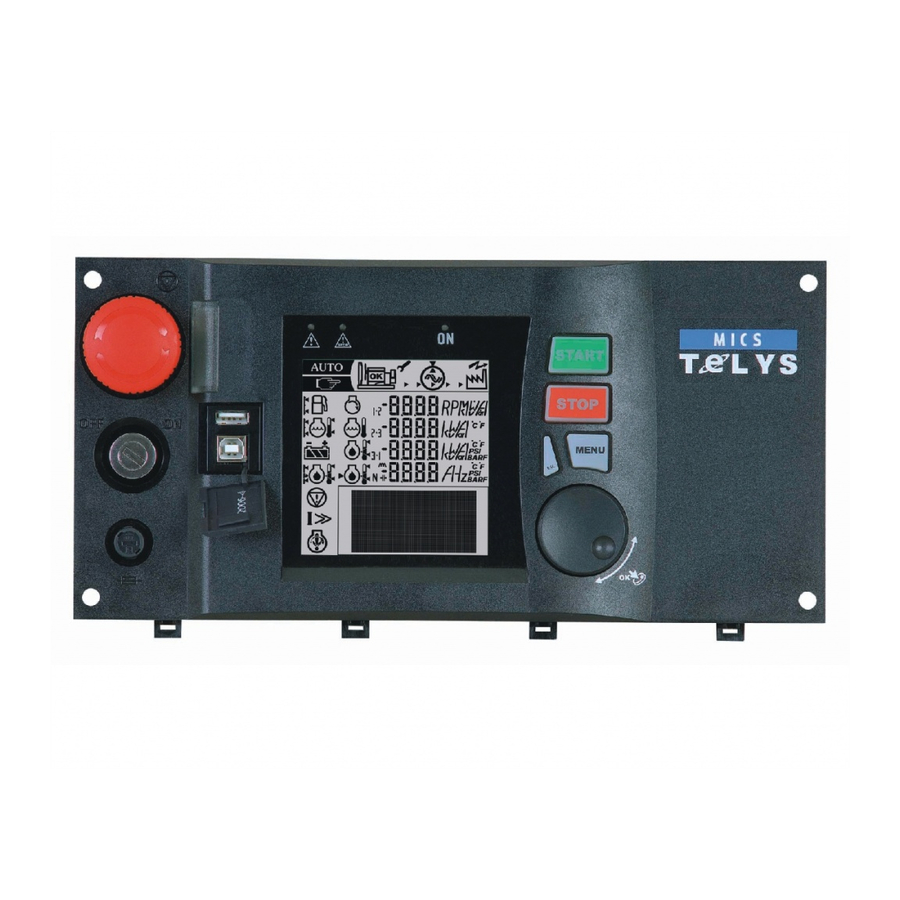
- Manuals
- Brands
- SDMO Manuals
- Control Unit
- MICS Telys
- Instructions for use manual
-
Contents
-
Table of Contents
-
Bookmarks
Quick Links
Instructions for use
Telys level 1
1.06 F
Réf. constructeur :
Réf. GPAO : 33502012701 ind1
Summary of Contents for SDMO MICS Telys
-
Page 1
Instructions for use Telys level 1 1.06 F Réf. constructeur : Réf. GPAO : 33502012701 ind1… -
Page 2
S S A A F F E E T T Y Y S S Y Y M M B B O O L L S S C C O O N N T T E E N N T T S S ENGLISH 10/01… -
Page 3
SAFETY S S YMBOLS Caution : danger Caution, refer to the publications supplied with the Genset Protective clothing required. Caution : risk of electric shock Eye and hearings protection necessary Caution : toxic substances Periodic maintenance required Caution : pressuried fluids Check battery charge Caution : high temperature (risk of burning) Recommended Lifting point… -
Page 4
_____________________________________________________________________________________________________________________________________________________ 10/01… -
Page 5
PRESENTATION K K e e y y E E N N G G L L I I S S H H C C o o n n t t r r o o l l u u n n i i t t Generating set programmable control- P P a a n n e e l l l l i i g g h h t t i i n n d d i i c c a a t t o o r r Lighting for wall mounted or free stan-… -
Page 6
USER MANUAL Level 1 CONTROL UNIT Due t t o o o ur o o n-g g oing r r esearch p p rogram a a nd t t he c c ontinual i i mprovements t t o o o ur p p roducts, w w e r r eserve t t he r r ight t t o m m ake a a ll c c hanges d d eemed n n ecessary w w ithout p p rior n n otice. All r r ights r r eserved a a s c c oncerns c c hanges t t o t t hese m m anuals. -
Page 7
Warning Changes to the front panel of the MICS Telys The MICS Telys front panel has been modified. Leaving aside the colour and design of the keys, the modifications are as follows: the «I» key has been changed to the «I/P» key (output measurements) the «F/ «… -
Page 8: Foreword
— Display the status of the alarm and fault LEDs on the front panel of the display or retro- information concerning the position of the Normal/Backup switch. In addition, with software version 1.01B, the MICS Telys is automatically reset when the generating set is configured from a remote location.
-
Page 9: Table Of Contents
Strating up the MICS TELYS ……..
-
Page 10
PRESENTATION A A ND T T ECHNICALS C C HARACTERISTICS 1. Oil pressure fault/shutdown (red LED on). 2. Water Tº fault/shutdown (red LED on). 3. Overcranking fault/shutdown (red LED on). 4. Overspeed fault/shutdown (red LED on). 5. Genset on load or ready to take the load (green LED on). 6. -
Page 11
1 1 — F F e e a a t t u u r r e e s s Display module (DM) Interface board available in 2 versions (CB, CB12) depending on customer optional equipment. Option 3 module, option 4 module and option 5 module (OPT 3 3 4) Block building system enabling multiple combinations. -
Page 12
5 5 — O O p p t t i i o o n n 3 3 , , 4 4 a a n n d d 5 5 m m o o d d u u l l e e s s ( ( O O P P T T 3 3 4 4 ) ) Modular case, dimensions : 160x90x58 Programming specific to each module (dip-switch) 8 allocated inputs and 10 programmable outputs on option 3 for remote volt free contacts… -
Page 13
1 1 6 6 — O O p p t t i i o o n n s s c c o o n n n n e e c c t t e e d d t t o o t t h h e e i i n n t t e e r r f f a a c c e e Option description CB12 external start-up command… -
Page 14: Power Connection
1. F F OREWORD 1 1 . . 1 1 . . P P r r e e c c a a u u t t i i o o n n s s The control unit is connected to various AC voltage sources (alternator, mains, …). While the generating set is idle, any work inside the control equipment is strictly forbidden as some parts of the electric and elec- tronic equipment stay live (mains voltage available).
-
Page 15: Welcome Screens
The language selection screen is then displayed. The cursor flashes by default on «international». If no LANGUAGE SELECTION action is taken while the four squares are displayed in the small overlaid window, the MICS Telys is auto- V: Valid Esc: Exit matically positioned on the international language.
-
Page 16: Overview » Screen
If neither V nor Esc is pressed, the » overview » screen appears after three minutes. There, the time and date will be those of the previous screen (before going automatically to the » overview » screen). Note : Not until the appearance of the » overview » screen will it be possible to start the generating set, however all engine protection shut- downs stay active (example: appearance of a fault).
-
Page 17: Manu Mode
In this operating mode, any event appearance (alarm, fault, external command, …) is signalled on screen. However, the generating set is stopped and automatic start-up is not possible. When the generating set is running and whatever the current mode (Auto, T T est, M M anu), press the Stop Ph./ph.
-
Page 18: Sleep Mode
Press Test button again to confirm the mode, the associated red LED comes on continuously and the Fuel Lev(%) generating set then enters into an automatic start-up phase (see paragraph 17). When the red LED flashes (waiting for confirmation), the mode can be changed by selecting Stop E.Speed(RPM) mode or Auto mode.
-
Page 19: Voltages
4. V V IEWING T T HE E E LECTRICAL V V ALUES 4 4 . . 1 1 . . V V o o l l t t a a g g e e s s You can view the various AC voltages by pressing the U/V button successively. Their values are expressed in true root mean square Volts. Depending on the client’s needs (type of electrical installation), several screens are possible: 3 phase with neutral (3ph+N) 3 phase without neutral (3ph)
-
Page 20: Currents
4 4 . . 2 2 . . C C u u r r r r e e n n t t s s To view the various AC currents, press the I button successively. The values are expressed in true root mean square Amps. Depending on the client’s needs (type of electrical installation), several screens are possible: 3 phase with neutral (3ph+N) 3 phase without neutral (3ph)
-
Page 21
5. V V IEWING T T HE E E NGINE P P ARAMETERS To view the engine parameters, press the Engine button successively. Three different screens can be viewed. The values that can be displayed on these three screens are indications only. Screen 1 1 : : Press the Engine button to get the following screen. -
Page 22
All these LEDs are identified by an ISO symbol. The last two LEDs are flashing lights. The » general fault » LED flashes on appearance of any fault and the » general alarm » LED flashes on appearance of any alarm. Each blue coloured function button (Stop, M M anu, A A uto, T T est) is associated with a LED. -
Page 23
If a fault appears on screen 3, the message on the second line disappears from the screen, the message on the first line slides down to the second line and the fault message takes the first line. If a third fault appears on screen 4, the message on the second line disappears from the screen, the message on the first line slides down to the second line and the third fault message takes the first line. -
Page 24
— ATS toggle delay: Mains Stand-by and Stand-by Mains, and closure confirmation of the Mains and Stand-by contactors- Motorised C/B opening and closure — Engine cooling down time in Auto mode — Operating time in Test mode — Delayed shutdown on water temperature fault or overload/short-circuit fault — Appearance of commands ;… -
Page 25
In cases where the generating set is equipped with a differential protection (with communication) or with a constant insulation checking device (with communication), this menu is used to view the settings, fault current or insulation resistor. Note: Press the M button for three seconds to bring up that same GENERAL screen, followed by the first welcome screen (see paragraph 1.6), where the language, date and time can be changed at any time. -
Page 26
— High battery voltage — Overcranking (fail to start) — Overspeed — Charge alternator 12. » » S S TATUS » » M M ENU After validation using the V button, when the cursor flashes over the o sign next to Status, the STATUS screen appears as follows. This screen is used to view the list of the date and time stamped generating set status. -
Page 27: Inputs » Menu
Main b b oard ( ( CB) Logical status display of the inputs on interface board CB, i.e. the eleven inputs described in Section » MAIN BOARD (CB) Technical characteristies «. Esc: Exit Note: the eleven inputs are also available on interface boards CB12. 123456789 10 11 * * * * * * * * * * * Input 1:…
-
Page 28
By setting parameter 903 to 1, the inputs of the option 5 module are displayed, programmed with John Deere OPTION 5 MODULE 6081HF engine. Esc: Exit Display of logical status of inputs of option 5 module. For the John Deere 6081HF engine., only inputs 1, 2 12345678 and 3 are used. -
Page 29
14. » » O O UTPUTS » » M M ENU After validation using the V button, when the cursor flashes over the o sign next to Outputs, the OUTPUTS screen appears as follows. 5 lines can be displayed at the same time on the screen. INPUTS The cursor flashes on the o sign of the first line. -
Page 30
Option 3 3 M M odule Logical status display of the ten outputs on option 3 module. OPTION 3 MODULE As these outputs can be programmed, the wording on each line varies according to the programming Esc: Exit performed. For that reason, the wording does not appear on the screen opposite. 123456789 10 * * * * * * * * * * Output 1:… -
Page 31: Differential Protection
Viewing the outputs on an option not available (see note) or on an option module not available (factory configuration) on the cabled sys- tem will result in the following superimposed message to be displayed. Example: a system is configured with interface board CB12 and Option 3 module. Press V, when the OUTPUTS cursor is next to Option 4 4 M M odule, to display the superimposed message opposite.
-
Page 32
— The delay setting can be displayed between 0 and 10 seconds, with: — a display in milliseconds between 0 and 100ms — a display in seconds above 100ms — The fault current percentage displayed varies according to the relay initial setting. Example: relay set to 300mA, fault current=150mA, the screen display will be of 50%. -
Page 33
1 1 7 7 . . 4 4 . . S S t t a a r r t t e e r r c c o o n n t t r r o o l l On appearance of the external command (immediate or associated with the end of the power failure delay) or at the end of the engine preglow period, the starter is cranked for an adjustable time (factory programmed). -
Page 34: Generating Set Operation
In Auto mode, when one of the three start-up conditions changes (see paragraph 2.3), the Stand-by contactor opens automatically, the Mains contac- tor closes after the S¢M toggle delay and the engine enters into a cooling down phase. At the end of the cooling down period, the engine stops and the generating set is on stand-by again.
-
Page 35: Ats Operation
1 1 — I I n n t t r r o o d d u u c c t t i i o o n n Software version 1.05E used with interface boards CB and CB12 enable you to use the MICS Telys in a language which is different from the four stan- dard languages already implemented.
-
Page 36
3 3 — M M o o d d i i f f y y i i n n g g d d i i s s p p l l a a y y w w i i t t h h i i n n t t e e r r n n a a t t i i o o n n a a l l l l a a n n g g u u a a g g e e When the international language is selected on power up or during use: — The time and date are no longer displayed on the screen. -
Page 37
5 5 — D D i i s s p p l l a a y y o o f f m m e e c c h h a a n n i i c c a a l l v v a a l l u u e e s s By pressing the Engine button successively, the following is displayed: oil pressure, water temperature, oil temperature, battery voltage, engine speed and fuel remaining in daily tank. -
Page 38
Return of system voltage (symbol 10) Return of the system voltage (or mains voltage) is represented on the screen by a transformer. The mains return time delay (para- meter 104 of Timing menu) is displayed next to this symbol and decrements automatically from the adjustment setting to 0. Example of screen showing system voltage is again available. -
Page 39
Fault takes priority over alarm Faults are reset in order of appearance For more details, refer to paragraph 8. All the alarms and faults which can appear on the MICS Telys screen are listed in the table below.a. Wording Alarm… -
Page 40
Wording Alarm Fault Generated on MTU engine oil pressure impossible 48-1 module 5 MTU engine HV water temperature impossible 49-1 module 5 MTU engine overspeed impossible 50-1 module 5 MTU engine general fault impossible 51-1 module 5 MTU engine gener al alarm 52-0 impossible module 5…
Instructions for use
Telys level 1
1.06 F
Réf. constructeur : Réf. GPAO : 33502012701 ind1
GB
ENGLISH
SSAAFFEETTYY SSYYMMBBOOLLSS 44
CCOONNTTEENNTTSS 11
10/01
3
4
10/01
SAFETY SSYMBOLS
Protective clothing required.
Eye and hearings protection necessary
Periodic maintenance required
Check battery charge
Recommended Lifting point
Fork lift stacking point
Naked flame and non protected lightining
forbidden, no smoking
Do not use water based fire extinguishers
Caution : danger
Caution : toxic substances
Caution : risk of electric shock
Caution : pressuried fluids
Caution : high temperature (risk of burning)
Caution : rotating or moving parts (risk of
entanglement)
Caution : risk of corrosion
Caution : risk of explosion
Caution, refer to the publications supplied with
the Genset
Authorised personnel only
MMAACCHHIINNEERRYY DDIIRREECCTTIIVVEE 9988//3377//CCEE IINNSSTTRRUUCCTTIIOONN FFOORR GGEENNEERRAATTIINNGG SSEETTSS
- Access prohibited to unauthorized personnel
- Live installation, potencial automatic starting.
Power
Earth
Trailer : link up the earth before starting the
generator
Emergency stop
Safety symbols_________________________________________________________________________________________________________________________________________
10/01
5
_____________________________________________________________________________________________________________________________________________________
6
10/01
6
10/01
EENNGGLLIISSHH
A
A
B
B
KKeeyy
PPaanneell lliigghhtt iinnddiiccaattoorr
Lighting for wall mounted or free stan-
ding panel
EEmmeerrggeennccyy SSttoopp
The genset shuts down immediately
and the control unit goes into STOP
mode
CCoonnttrrooll uunniitt
Generating set programmable control-
ler
MMIICCSS AAMMPPGG
Device for electrical value display
PPootteennttiioommeetteerr vvoollttss
Adjusts the alternator voltage
DDuuaall ffrrééqquueennccyy sswwiittcchh 5500//6600 HHzz
to select the frequency
PPootteennttiioommeetteerr sswwiittcchh
to select the voltage
PRESENTATION
Présentation___________________________________________________________________________________________________________________________________________
USER MANUAL
Due tto oour oon-ggoing rresearch pprogram aand tthe ccontinual iimprovements tto oour pproducts, wwe rreserve tthe rright tto mmake aall cchanges ddeemed nnecessary wwithout pprior nnotice.
All rrights rreserved aas cconcerns cchanges tto tthese mmanuals.
Reproduction oor ttranslation iin wwhole oor ppart sstrictly pprohibited wwithout pprior wwritten aauthorization.
Design aand pproduction: SSee ddocumentation:
Manufacturers ddocumentation bbase ffor ppower ggenerating ssets ++ EElec. EEng. DDept. DDocumentation
Level 1
CONTROL UNIT
Warning
Changes to the front panel of the MICS Telys
The MICS Telys front panel has been modified.
Leaving aside the colour and design of the keys, the modifications are as follows:
n the "I" key has been changed to the "I/P" key (output measurements)
o the "F/" key has been changed to the "F/H" key
p the "Manu" key has been changed to the "Start" key
previous design
new design
n The output measurement function will not be available initially, as software version 1.07G
will not be marketed until October 2003. Therefore, repeatedly pressing the "I/P" key will
only display the voltages.
o The change from the "F/" key to the "F/H" key does not affect the information displayed
on the screen.
p The most significant change is that from
the "Manu" key to the "Start" key. When the
generating set is started up in Manu mode, the
message shown opposite appears.
Fuel Lev(%)
E.Speed(RPM)
Batt.(Volts)
MANUAL mode selected
press MANU to confirm
24.2
50
0
As the "Manu" key is no longer present, one press on the "Start" key will trigger the starter
motor or the spark plug preheating (depending on configuration).
These modifications will be introduced to the technical documentation during
the next update (software update from version 1.06 F to version 1.07 G).
8
10/01
FOREWORD
CCoonnttrrooll uunniitt uuppggrraaddee::
The software compatibility is ensured with the old interface boards, meaning it is possible to reprogram, on site, an interface board having
a software index 1.01B with a software having an index 1.04D and 1.05E. However, a display defined for software version 1.2 and higher
is required to use a software version 1.05E.
Software upgrade 1.04D comprises the following:
- Addition of functions and parameters
- Modification of standard value of certain parameters
- Modification of utilization limits of certain parameters
- Supervision and remote management
- Control/command of engines MTU 2000 and 4000
- Control/command compatible with standards NFPA110 and CSA C282
- Control/command compatible with French standards NF S 61-940 and NF E 37-312
- Control/command for Cummins engines type QST30
- Control/command for Nevada engines
- Generating sets with "multi-voltage" option
- Generating sets with "bi-frequency/bi-voltage" option
- Option 5 module (this module is only used with applications on MTU 2000/4000 engines and CUMMINS engines QST30).
The software version 1.06F used with the CB and CB12 I/O cards extends the functionality and working range of the Telys MICS. A sum-
mary of the developments and changes incorporated into the new software is shown below. Each development is then described in detail
in the subsequent paragraphs.
Compatibility with earlier I/O cards has been provided, and it is therefore possible to reprogram I/O cards originally using software ver-
sions 1.01B, 1.04D or 1.05E with version 1.06F, without having to remove the card.
Software version 1.06F includes the following features:
- Command and control of the JDEC electronics used with the John Deere 6081HF engines using the optional module 5.
- Command and control of the EDC III electronics used with Volvo D12 engines using the optional module 5.
- Changing the number of working hours for the generator (clear or preset) by entering a single access code.
- Option 4 of module 4, allowing operation at three different voltages (480V, 208V and 240V), may be fine tuned to reflect the customer's
actual usage.
- The "low coolant level" LED of the optional module 6 comes on when either the 'low coolant level' or 'air cooling inadequate ' inputs are
enabled (only for NFPA110 applications).
- For gas-powered generators, the "low gas pressure" fault condition now has a five-second fixed timer. This timer prevents the engine
being switched off by sudden load changes. In practice, the gas pressure has a tendency to drop when the load increases sharply, before
returning to its normal value.
SSuuppeerrvviissiioonn aanndd rreemmoottee mmaannaaggeemmeenntt::
Supervision and remote management is possible using the "wintelys" software on a PC computer under a Windows 95, 98; NT or 2000 envi-
ronment.
A complete document describing the supervision and remote management features can
be obtained from the "products and development" department.
Supervision and remote management are operational on software version 1.01B with a
few restrictions as concerns the various data acquisition and display features. In this res-
pect, with software version 1.01B, it will not be possible to:
- Control the generator set from a remote location
- Display the status of the alarm and fault LEDs on the front panel of the display or retro-
information concerning the position of the Normal/Backup switch.
In addition, with software version 1.01B, the MICS Telys is automatically reset when the
generating set is configured from a remote location.
For optimum use of the supervision/remote management function, we recommend that
you use software version 1.04D.
MMoodduullee 55::
Module 5 is simply module OPT34 configured as module 5.
This module is programmed specifically for the applications with engines using an inte-
grated control electronics (MTU and Cummins engines).
The selection parameter for this module already exists in software version 1.01B.
However, a line has been added in the INPUTS and OUTPUTS screens to display the logi-
cal state of the inputs and outputs of the module according to its programming.
Supervision
Remote management
10/01
1
_______________________________________________________________________________________________________________________________________________Contents
CONTENTS
Presentation and technicals characteristics
1. Foreword . . . . . . . . . . . . . . . . . . . . . . . . . . . . . . . . . . . . . . . . . . . . . . . . . . . . . . . . . . . . . . . . . . . . . . . . . . . . . . . . . . 40
1.1. Precautions . . . . . . . . . . . . . . . . . . . . . . . . . . . . . . . . . . . . . . . . . . . . . . . . . . . . . . . . . . . . . . . . . . . . . . . . . . . . . . . . 40
1.2. Power connection . . . . . . . . . . . . . . . . . . . . . . . . . . . . . . . . . . . . . . . . . . . . . . . . . . . . . . . . . . . . . . . . . . . . . . . . . . . 40
1.3. Electric connections (control) . . . . . . . . . . . . . . . . . . . . . . . . . . . . . . . . . . . . . . . . . . . . . . . . . . . . . . . . . . . . . . . . . . . . 40
1.4. Battery preliminary inspection and commissioning . . . . . . . . . . . . . . . . . . . . . . . . . . . . . . . . . . . . . . . . . . . . . . . . . . . . . 40
1.5. Control unit first power-up . . . . . . . . . . . . . . . . . . . . . . . . . . . . . . . . . . . . . . . . . . . . . . . . . . . . . . . . . . . . . . . . . . . . . 41
1.6. Welcome screens . . . . . . . . . . . . . . . . . . . . . . . . . . . . . . . . . . . . . . . . . . . . . . . . . . . . . . . . . . . . . . . . . . . . . . . . . . . . 41
1.7. " Overview " screen . . . . . . . . . . . . . . . . . . . . . . . . . . . . . . . . . . . . . . . . . . . . . . . . . . . . . . . . . . . . . . . . . . . . . . . . . . 42
2. Operating Modes . . . . . . . . . . . . . . . . . . . . . . . . . . . . . . . . . . . . . . . . . . . . . . . . . . . . . . . . . . . . . . . . . . . . . . . . . . . . 42
2.1. Stop Mode . . . . . . . . . . . . . . . . . . . . . . . . . . . . . . . . . . . . . . . . . . . . . . . . . . . . . . . . . . . . . . . . . . . . . . . . . . . . . . . . 42
2.2. Manu Mode . . . . . . . . . . . . . . . . . . . . . . . . . . . . . . . . . . . . . . . . . . . . . . . . . . . . . . . . . . . . . . . . . . . . . . . . . . . . . . . 43
2.3. Auto Mode . . . . . . . . . . . . . . . . . . . . . . . . . . . . . . . . . . . . . . . . . . . . . . . . . . . . . . . . . . . . . . . . . . . . . . . . . . . . . . . . 43
2.4. Test Mode . . . . . . . . . . . . . . . . . . . . . . . . . . . . . . . . . . . . . . . . . . . . . . . . . . . . . . . . . . . . . . . . . . . . . . . . . . . . . . . . 43
3. Sleep mode and automatic shutdown . . . . . . . . . . . . . . . . . . . . . . . . . . . . . . . . . . . . . . . . . . . . . . . . . . . . . . . . . . . . . . 44
3.1. Sleep mode . . . . . . . . . . . . . . . . . . . . . . . . . . . . . . . . . . . . . . . . . . . . . . . . . . . . . . . . . . . . . . . . . . . . . . . . . . . . . . . 44
3.2. Automatic shutdown . . . . . . . . . . . . . . . . . . . . . . . . . . . . . . . . . . . . . . . . . . . . . . . . . . . . . . . . . . . . . . . . . . . . . . . . . . 44
3.3 Special Case . . . . . . . . . . . . . . . . . . . . . . . . . . . . . . . . . . . . . . . . . . . . . . . . . . . . . . . . . . . . . . . . . . . . . . . . . . . . . . . 44
4. Viewing the electrical values . . . . . . . . . . . . . . . . . . . . . . . . . . . . . . . . . . . . . . . . . . . . . . . . . . . . . . . . . . . . . . . . . . . . . 45
4.1. Voltages . . . . . . . . . . . . . . . . . . . . . . . . . . . . . . . . . . . . . . . . . . . . . . . . . . . . . . . . . . . . . . . . . . . . . . . . . . . . . . . . . . 45
4.2. Currents . . . . . . . . . . . . . . . . . . . . . . . . . . . . . . . . . . . . . . . . . . . . . . . . . . . . . . . . . . . . . . . . . . . . . . . . . . . . . . . . . . 46
4.3. Frequency and hours counter . . . . . . . . . . . . . . . . . . . . . . . . . . . . . . . . . . . . . . . . . . . . . . . . . . . . . . . . . . . . . . . . . . . 46
5. Viewing the engine parameters . . . . . . . . . . . . . . . . . . . . . . . . . . . . . . . . . . . . . . . . . . . . . . . . . . . . . . . . . . . . . . . . . . . 47
6. Display LEDs and lamp test . . . . . . . . . . . . . . . . . . . . . . . . . . . . . . . . . . . . . . . . . . . . . . . . . . . . . . . . . . . . . . . . . . . . . 47
7. Screen contrast . . . . . . . . . . . . . . . . . . . . . . . . . . . . . . . . . . . . . . . . . . . . . . . . . . . . . . . . . . . . . . . . . . . . . . . . . . . . . 48
8. Displaying the alarm and fault messages . . . . . . . . . . . . . . . . . . . . . . . . . . . . . . . . . . . . . . . . . . . . . . . . . . . . . . . . . . . . 48
8.1. Appearance of messages on screen . . . . . . . . . . . . . . . . . . . . . . . . . . . . . . . . . . . . . . . . . . . . . . . . . . . . . . . . . . . . . . . 48
8.2. Removing messages on screen . . . . . . . . . . . . . . . . . . . . . . . . . . . . . . . . . . . . . . . . . . . . . . . . . . . . . . . . . . . . . . . . . . 49
9. Displaying the status messages . . . . . . . . . . . . . . . . . . . . . . . . . . . . . . . . . . . . . . . . . . . . . . . . . . . . . . . . . . . . . . . . . . . 49
10. Accessing the level 1 display . . . . . . . . . . . . . . . . . . . . . . . . . . . . . . . . . . . . . . . . . . . . . . . . . . . . . . . . . . . . . . . . . . . . 50
11. " Alarm/Flt " menu . . . . . . . . . . . . . . . . . . . . . . . . . . . . . . . . . . . . . . . . . . . . . . . . . . . . . . . . . . . . . . . . . . . . . . . . . . . 51
11.1. Special features for a fault . . . . . . . . . . . . . . . . . . . . . . . . . . . . . . . . . . . . . . . . . . . . . . . . . . . . . . . . . . . . . . . . . . . . . 51
11.2. Special features for an alarm . . . . . . . . . . . . . . . . . . . . . . . . . . . . . . . . . . . . . . . . . . . . . . . . . . . . . . . . . . . . . . . . . . . 51
11.3. Other special cases . . . . . . . . . . . . . . . . . . . . . . . . . . . . . . . . . . . . . . . . . . . . . . . . . . . . . . . . . . . . . . . . . . . . . . . . . . 51
12. " Status " Menu . . . . . . . . . . . . . . . . . . . . . . . . . . . . . . . . . . . . . . . . . . . . . . . . . . . . . . . . . . . . . . . . . . . . . . . . . . . . . . 52
13. " Inputs " Menu . . . . . . . . . . . . . . . . . . . . . . . . . . . . . . . . . . . . . . . . . . . . . . . . . . . . . . . . . . . . . . . . . . . . . . . . . . . . . . 52
14. " Outputs " Menu . . . . . . . . . . . . . . . . . . . . . . . . . . . . . . . . . . . . . . . . . . . . . . . . . . . . . . . . . . . . . . . . . . . . . . . . . . . . 55
15. " Contrast " Menu . . . . . . . . . . . . . . . . . . . . . . . . . . . . . . . . . . . . . . . . . . . . . . . . . . . . . . . . . . . . . . . . . . . . . . . . . . . . 57
16. " Protect " Menu . . . . . . . . . . . . . . . . . . . . . . . . . . . . . . . . . . . . . . . . . . . . . . . . . . . . . . . . . . . . . . . . . . . . . . . . . . . . . 57
16.1. Differential protection . . . . . . . . . . . . . . . . . . . . . . . . . . . . . . . . . . . . . . . . . . . . . . . . . . . . . . . . . . . . . . . . . . . . . . . . . 57
16.2. Protection via CIC . . . . . . . . . . . . . . . . . . . . . . . . . . . . . . . . . . . . . . . . . . . . . . . . . . . . . . . . . . . . . . . . . . . . . . . . . . . 58
16.3. Special case . . . . . . . . . . . . . . . . . . . . . . . . . . . . . . . . . . . . . . . . . . . . . . . . . . . . . . . . . . . . . . . . . . . . . . . . . . . . . . . 58
17. Generating set operation . . . . . . . . . . . . . . . . . . . . . . . . . . . . . . . . . . . . . . . . . . . . . . . . . . . . . . . . . . . . . . . . . . . . . . . 58
17.1. Water heater . . . . . . . . . . . . . . . . . . . . . . . . . . . . . . . . . . . . . . . . . . . . . . . . . . . . . . . . . . . . . . . . . . . . . . . . . . . . . . . 58
17.2. Engine preglow . . . . . . . . . . . . . . . . . . . . . . . . . . . . . . . . . . . . . . . . . . . . . . . . . . . . . . . . . . . . . . . . . . . . . . . . . . . . . 58
17.3. Fuel solenoid control . . . . . . . . . . . . . . . . . . . . . . . . . . . . . . . . . . . . . . . . . . . . . . . . . . . . . . . . . . . . . . . . . . . . . . . . . 58
17.4. Starter control . . . . . . . . . . . . . . . . . . . . . . . . . . . . . . . . . . . . . . . . . . . . . . . . . . . . . . . . . . . . . . . . . . . . . . . . . . . . . . 59
17.5. Starter tripping . . . . . . . . . . . . . . . . . . . . . . . . . . . . . . . . . . . . . . . . . . . . . . . . . . . . . . . . . . . . . . . . . . . . . . . . . . . . . 59
17.6. RPM and Volts stabilisation . . . . . . . . . . . . . . . . . . . . . . . . . . . . . . . . . . . . . . . . . . . . . . . . . . . . . . . . . . . . . . . . . . . . . 59
17.7. Generating set output . . . . . . . . . . . . . . . . . . . . . . . . . . . . . . . . . . . . . . . . . . . . . . . . . . . . . . . . . . . . . . . . . . . . . . . . 59
17.8. Engine cooling down and shutdown . . . . . . . . . . . . . . . . . . . . . . . . . . . . . . . . . . . . . . . . . . . . . . . . . . . . . . . . . . . . . . . 59
18. Operation of GES . . . . . . . . . . . . . . . . . . . . . . . . . . . . . . . . . . . . . . . . . . . . . . . . . . . . . . . . . . . . . . . . . . . . . . . . . . 60
19. ATS operation . . . . . . . . . . . . . . . . . . . . . . . . . . . . . . . . . . . . . . . . . . . . . . . . . . . . . . . . . . . . . . . . . . . . . . . . . . . . . . 60
19.1. In Stop mode . . . . . . . . . . . . . . . . . . . . . . . . . . . . . . . . . . . . . . . . . . . . . . . . . . . . . . . . . . . . . . . . . . . . . . . . . . . . . . 60
19.2. In automatic mode . . . . . . . . . . . . . . . . . . . . . . . . . . . . . . . . . . . . . . . . . . . . . . . . . . . . . . . . . . . . . . . . . . . . . . . . . . 60
19.3. In manual mode . . . . . . . . . . . . . . . . . . . . . . . . . . . . . . . . . . . . . . . . . . . . . . . . . . . . . . . . . . . . . . . . . . . . . . . . . . . . 61
Appendix -software version 1.05E: "international" language . . . . . . . . . . . . . . . . . . . . . . . . . . . . . . . . . . . . . . . . . . . . . . . . . . . 61
1 Introduction . . . . . . . . . . . . . . . . . . . . . . . . . . . . . . . . . . . . . . . . . . . . . . . . . . . . . . . . . . . . . . . . . . . . . . . . . . . . . . . . 61
2 Strating up the MICS TELYS . . . . . . . . . . . . . . . . . . . . . . . . . . . . . . . . . . . . . . . . . . . . . . . . . . . . . . . . . . . . . . . . . . . . . 61
3 Modifying display with International language . . . . . . . . . . . . . . . . . . . . . . . . . . . . . . . . . . . . . . . . . . . . . . . . . . . . . . . . . 62
4 Display of electrical values . . . . . . . . . . . . . . . . . . . . . . . . . . . . . . . . . . . . . . . . . . . . . . . . . . . . . . . . . . . . . . . . . . . . . . 62
5 Display of mechanical values . . . . . . . . . . . . . . . . . . . . . . . . . . . . . . . . . . . . . . . . . . . . . . . . . . . . . . . . . . . . . . . . . . . . 62
6 Others symbols . . . . . . . . . . . . . . . . . . . . . . . . . . . . . . . . . . . . . . . . . . . . . . . . . . . . . . . . . . . . . . . . . . . . . . . . . . . . . 63
7 Alarms and fault codes . . . . . . . . . . . . . . . . . . . . . . . . . . . . . . . . . . . . . . . . . . . . . . . . . . . . . . . . . . . . . . . . . . . . . . . . 64
8 Access to programming and language change functions . . . . . . . . . . . . . . . . . . . . . . . . . . . . . . . . . . . . . . . . . . . . . . . . . 66
2
10/01
Presentation and technicals characteristics_____________________________________________________________________________________________________
Power on after automatic shutdown
(with LED).
Button to access the main menu (pro-
gramming/display)
Button to validate a selection.
Button to exit a selection Button to display the engine parame-
ters
Buttons to browse through menus and
adjust contrast
Button to select Auto mode (with LED).
Button to select Test mode (with LED).
Number pad
Button reset a fault.
Button to select Manu mode (with
LED).
Button to open genset breaker (with
LED).
Button to select Manu mode (with
LED).
Button to close genset breaker (with
LED).
Button to test the LEDs (except ON
button LED).
1. Oil pressure fault/shutdown (red LED on).
2. Water Tº fault/shutdown (red LED on).
3. Overcranking fault/shutdown (red LED on).
4. Overspeed fault/shutdown (red LED on).
5. Genset on load or ready to take the load (green LED on).
6. Charge alternator fault/shtdwn (red LED on).
7. General alarm/warning (yellow LED flashing).
8. General fault/shutdown (red LED flashing).
Button to display the voltages.
Button to display the currents
Button to display the frequency and
hours counter
1
2
3
4
5
6
7
8
PRESENTATION AAND TTECHNICALS CCHARACTERISTICS
10/01
3
__________________________________________________________________________________________________________________Technicals characteristics
11 - FFeeaattuurreess
Display module (
DM
)
Interface board available in 2 versions (
CB
,
CB12
) depending on customer optional equipment.
Option 3 module, option 4 module and option 5 module
(OPT 334)
Block building system enabling multiple combinations.
Note:
DM
required in all combinations
22 - DDiissppllaayy mmoodduullee
(Fig. 2)
LCD screen, 8 lines 21 characters, built-in back-light and keyboard adjustable contrast
28 momentary push buttons (two types; 10 and 13 dia.)
15 display LEDs (alarms/warnings, faults/shutdowns, status, operating modes)
UL approved polycarbonate case supplied with cable and connector for connection to the interface board
Dimensions 192x144x70
Quick installation using brackets and nuts screws
IP65 on panel face with seal (not supplied), IP20 inside
Extremely user friendly man-machine interface: multiple-message screens, diagnostic, genset status, ...
33 - IInntteerrffaaccee bbooaarrdd ((FFiigg.. 11))
CB = Main board
CB12 = Main board with option 1 and option 2 built in
Electronics in a sheet steel case (base + lid)
Dimensions : 435x263x31
Voltage bus; alternator, mains and DC built into the printed circuit board (see paragraphs 7, 8, 9 and 13)
16 bit microcontroller, (Flash, RAM and EEPROM) memories, real-time clock, battery backup for time and date
Supply from 9 to 33Volts DC and from 6Volts DC, for voltage drop at start-up
All connections are built into the printed circuit board on both sides with full screen printing
44 - LLooggiiccaall//aannaalloogg II//OO
All inputs and outputs are allocated to a specific use
(see tables below).
Note: Alarm or Fault selection via programming
Key:
A=Alarm, F=Fault, ana.=analog, C=Control
T=Transistor, R=Relay, Ω=resistive
Fig. 11 - CCB12 bboard
Fig. 22 - DDisplay mmodule
* : France only
Type
Logical output description
CB
CB12
F
oil pressure
x
x
F
water temperature
x
x
A or F
day tank low fuel level
x
x
F
emergency stop
x
x
A or F
overload or short-circuit
x
x
C
water heater thermostat
x
x
C
external start-up command
x
x
F
radiator low water level
x
x
C
Mains
contactor home position
x
x
C
Stand-by
contactor home position
x
x
F
external emergency stop
x
x
F
oil temperature
x
F
low oil level
x
A or F
water heater failure
x
A or F
battery charger failure
x
A or F
differential or CIC trip
x
F
differential relay available
x
F
Constant Insulation Check available
x
F
air cooler disconnection
x
F
air cooler low water level
x
A or F
fuel pump 1 disconnection
x
A or F
retention
bund
x
C
bulk tank CF80
x
A or F
bulk tank low fuel level
x
C
EJP switch (*)
x
C
EJP start-up (*)
x
C
EJP advanced warning (*)
x
Type
Logical output description
CB
T
fuel solenoid control
x
T
starter 1 contr ol
x
T
engine
preglow control
x
T
water heater control
x
T
hooter control (general fault)
x
R
Mains
contactor control
x
R
Stand-by
contactor control
x
T
air damper control
T
starter 2 control
R
electro-flaps control
T
fuel pump 1 control
R
CIC remote contact
Type
Analogue input description
CB
Ω
oil pressure indication
x
Ω
water temperature indication
x
4
10/01
Technicals characteristics _________________________________________________________________________________________________________________________________
55 - OOppttiioonn 33,, 44 aanndd 55 mmoodduulleess ((OOPPTT3344))
Modular case, dimensions : 160x90x58
Programming specific to each module (dip-switch)
8 allocated inputs and 10 programmable outputs on option 3 for remote volt free contacts
8 programmable inputs and 10 programmable outputs on option 4 , with 24 preprogrammed options
Specific programming of some entries
66 - AAlltteerrnnaattoorr ccuurrrreenntt iinnppuutt
4-wire, unisolated, on current transformer with 5A secondary (not built into the electronics)
Measurements in true root mean square values
Measurement range: 60A to 5000A
77 - AAlltteerrnnaattoorr vvoollttaaggee iinnppuutt
4-wire (3ph + neutral), unisolated, with 12.5A-500Vac built in power bus in 50 and 60Hz
Measurements in true root mean square values
Frequency measurement on phase 1 for screen display and engine overspeed sensing
88 - MMaaiinnss vvoollttaaggee mmaaiinnss 11
4-wire (3ph + neutral), unisolated, with 15A-600Vac built in power bus in 50 and 60Hz
No voltage and frequency measurements
99 - MMaaiinnss vvoollttaaggee mmaaiinnss 22
2-wire (1ph + neutral), unisolated, with 10A-240Vac built in power bus in 50 and 60Hz
No voltage and frequency measurements
1100 - CChhaarrggee aalltteerrnnaattoorr iinnppuutt
Charge alternator excitation and fault
Starter hardware fail safe on software failure
1111 - CCoommmmuunniiccaattiioonn
RS485 serial port with J-Bus protocol (Mod bus RTD)
9-pin SUB-D connector
Monitoring possible in local mode (≤ 1000meters)
Remote management possible with 2 modems (>1000m)
Optional monitoring/remote management software
1122 - CCAANN LLiinnkk
Link between interface board and option module(s)
Standard CAN bus version 2.0b, 9-pin SUB-D connector for CC supply to module
1 connector on CB and CB1, 2 connectors on CB12
1133 - FFuussee pprrootteeccttiioonn
Fn, F1, F2, F3, 12.5A-500V fuses for alternator bus
Mains bus protected by circuit breaker in the ATS
F5, 10A fuse for the DC bus
F7, 2.5A delayed action fuse for the interface board
F6, 1A delayed action fuse for option 3 Module
F8, 1A delayed action fuse for option 4, 5 Module (CB12 only)
1144 - CCoonnnneeccttiioonnss
Multi-pin (2 to 15 pins) connectors with polarizer
Number of connectors varies with interface board
Each connector has a specific use
1155 - PPrrooggrraammmmiinngg ooppttiioonnss
Multiple programming possibilities
Access code required to read/program
10/01
5
_________________________________________________________________________________________________________________________________ Technicals characteristics
1166 - OOppttiioonnss ccoonnnneecctteedd ttoo tthhee iinntteerrffaaccee
(*)indication and fault/shutdown for oil temperature, low oil level, water heater failure and alarm/warning for, oil pressure, water tempera-
ture, oil temperature, air damper control, starter 2 control.
1177 - SSoorrttiieess rreellaaiiss
Max switching voltage: 250Vac (277Vac for *)
Mains and Stand-by contactor control outputs: 4.9A, 1500VA breaking capacity at cosϕ=0.7
Electro-flaps outputs: 500mA & CIC remote contact:1A
MX coil control output (*): 4.9A (optional relay on baseplate)
1188 - TTrraannssiissttoorr oouuttppuuttss
Protected against short-circuit
Output for fuel solenoid/panel lighting: 700mA
Other outputs: 300mA
1199 - HHaarrddwwaarree ccoonnffiigguurraattiioonn
C14/C15 connector, auxiliaries voltage selection
C7 dip-switch, RS485 terminator
P3 dip-switch, CAN bus terminator
Dip-switch selection for VDE option
2200 - EEnnvviirroonnmmeenntt aanndd ssttaannddaarrddss
Operating temperature: -15°C to +60°C
Storage temperature: -20°C to +70°C
Resistance to shocks: IK01, vibration: to CEI68-2-6
Salt mist resistance : 96 hours according to EN68011-2-11
Humidity : 95 % of humidity at 45°C.
EMC :
- Generic standards EN50081-2 and EN50082-2
- Emissions EN55011 Class A
- Immunity EN61000-4.2, EN6100-4.3, EN61000-4.4, EN61000-4.6, EN61000-4.8, ENV50201
CE mark, UL listed, CSA certified
Option description
CB
CB12
external start-up command
x
x
auto predisposition + external command
x
x
3ph+neutral or 1ph+N mains connection
x
x
battery charger (3 possible ratings)
x
x
water heater (3 poss. depending on supply V)
x
x
hooter
x
x
RS485 for monitoring or remote
management
x
x
option 3 module / CAN bus connection
x
x
additional engine kit (9 options) (*)
x
electro-flaps (DC or AC)
x
anti-condensation heater
x
EJP (switch, adv. warning and start -up)
x
1ph or 3ph fuel pump (control & power)
x
Air cooler (low level, disconnection)
x
differential protection and MX coil contr ol
x
CIC protection with remote contact and MX
coil control
x
bulk tank fuel pump (CF80, low level,
retention bund)
x
AMPG with optional RS485
x
option 4 module / CAN bus connection
x
three-alarm (OP,WT,OT) and module 4 kit
x
French only
6
10/01
Foreword _______________________________________________________________________________________________________________________________
1. FFOREWORD
11..11.. PPrreeccaauuttiioonnss
The control unit is connected to various AC voltage sources (alternator, mains, ...).
If work inside the control panel is required, it must be performed by staff authorised to work live.
These fuses must be replaced when the generating set is in complete shutdown. For any voltage measurement on these four fuses, please
use suitable equipment.
The generating set can be equipped with a remote start-up (simple contact) or with an automatic starting system [mains failure + ATS
(Mains/Stand-by changeover switch)] .
11..22.. PPoowweerr ccoonnnneeccttiioonn
For power connection, make sure that flexible cables of suitable cross section are used to avoid overheating and a major in-line voltage drop.
Depending on laying method, ambient temperature and proximity of other cables, the conductor's cross section may vary.
11..33.. EElleeccttrriicc ccoonnnneeccttiioonnss ((ccoonnttrrooll))
Generating sset wwith mmanual sstart oonly
(from the control unit keyboard)
No external connection to make.
Generating sset wwith rremote ((without mmains) oor aautomatic ((with mmains) sstart-uup
For proper operation, make the connections on the user terminal block as per the diagram below.
For DC signals, we recommend the use of a 5-core (5x1.5mm²) flexible cable between the ATS and the user terminal block.
For AC signals, we recommend the use of a 12-core (12G1.5mm²) flexible cable between the ATS and the user terminal block.
(G means cable with a Green/Yellow conductor)
Note: for a remote start only, a 2x1.5mm² flexible cable is sufficient (see overleaf)
N
S
C16-UTIL
C13-UTIL
C35-UTIL
AC
DC
DC
DC
AC
AC
6
1
2
3
4
5
1
2
3
4
5
1
2
3
4
1
2
3
4
5
6
7
8
9
10
11
12
1
2
3
V/J
N
30
31
1
2
1
2
3
4
5
6
7
8
9
10
11
12
External command (mains sensing or client contact) Output C/B fault auxiliary signal contact
Mains and Stand-by contactors home position Stand-by contactor control
Mains contactor control 1 or 3 phase water heater
If the user does not connect an ATS from our range, it is imperative to observe the board relay characteristics given below and to check
that the coils power requirements are within these parameters.
Rated ccurrent=5A Rated vvoltage=250Vac
Maximum bbreaking ccapacity uunder aa 00.7 ccos ϕϕ: 11500VA
11..44.. BBaatttteerryy pprreelliimmiinnaarryy iinnssppeeccttiioonn aanndd ccoommmmiissssiioonniinngg
The battery must be connected for the control unit to operate and the generating set to start, hence the need to check its connection:
Red wire, positive polarity (
+
),
Black wire, negative polarity (
-
).
Some generating sets are equipped with a battery isolator enabling the electric circuit to be isolated. Check that it is in the position enabling
the operation.
Beware of possible electric shock by contact with any live part, during the generating set start up.
While the generating set is idle, any work inside the control equipment is strictly forbidden as some parts of the electric and elec-
tronic equipment stay live (mains voltage available).
When the generating set is running, the fuses marked
Fn
,
F1
,
F2
,
F3
are at a dangerous potential which can lead to electric shock
when touched.
The cross sections above are given as a guide as they can vary depending on the current to be drawn, length, temperature and
control cable laying method.
Not observing the above characteristics will damage or even destroy the board control relays.
The battery is supplied without electrolyte. Fill the battery with electrolyte at least 20 minutes before any start-up attempt (see main-
tenance manual).
10/01
7
_______________________________________________________________________________________________________________________________Foreword
11..55.. CCoonnttrrooll uunniitt ffiirrsstt ppoowweerr-uupp
If the battery is connected and the electrolyte level correct, control unit powers up automatically and the initialisation screen below appears.
This screen is visible for eight seconds. All LEDs are lit and will go out after 3 seconds except the
ON
button LED. When initialisation is complete, the
Stop
button LED comes on again.
If other LEDs are lit or flashing, refer to paragraph 6.
Note 1: The
0
button LED can also be lit (see paragraph 18).
Note 2: During initialisation, the display module software version appears on screen.
11..66.. WWeellccoommee ssccrreeeennss
Screen 11
After the initialisation phase, the screen below appears. The operator is then able to choose in which language he wants the messages to be
displayed on the control unit screen. Four languages are available: French, English, Spanish and Portuguese.
The language selection screen is then displayed. The cursor flashes by default on "international". If no
action is taken while the four squares are displayed in the small overlaid window, the MICS Telys is auto-
matically positioned on the international language. You then have around 6 seconds to change the lan-
guage by pressing the button then the
V
or
Esc
button (*).
(*) By pressing the
V
button, you store the selected language in memory meaning that the next time you
power up the unit, the cursor will automatically go to the previously selected language. In addition,
when you press the
V
button, the system goes to the next screen for modification of the date and time.
LANGUAGE SELECTION
V:
Valid
Esc: Exit
o International
o English
o
Spanish
o
Portugues
o French
(*) If you press the
Esc
button, the selected language is not stored in memory. The next time the unit is powered up, the cursor will automa-
tically be positioned on the international language.
By pressing or , the operator places the cursor over the required language. Note : Depending on the cursor position, the text of the
two upper lines changes to enable the operator to know where he is.
Press
Esc
to go directly to the " overview " screen (see paragraph 1.7).
There, the language used will be the one where the cursor was positioned.
Example : Cursor positioned over
English
. Pressing
Esc
configures the control unit in English. Any messages will appear be in English.
If neither
V
nor
Esc
is pressed, the " overview " screen (see paragraph 1.7) appears automatically after three minutes. There, the language used
will be the one where the cursor was positioned.
Not until the appearance of the " overview " screen will it be possible to start the generating set, however all inputs stay active (example:
appearance of a fault).
Press
V
to go to the second welcome screen, in the language where the cursor was before pressing
V
.
Note: If the "international" language is selected, refer to the "international language" appendix.
Screen 22
Screen 2 will allow the date and time to be modified. This is only required when the clocks change because the internal clock is kept active
by a lithium battery while control unit is powered off.
The cursor flashes over the
o
sign of the first line.
Press to move the cursor to the next line, except if it flashes next to
Minute
.
Press to move the cursor to the previous line, except if it flashes next to Day.
By pressing or , the operator places the cursor on the line to be changed.
DATE / TIME
V: Valid Esc: Exit
o Day : 12
o Month : 01
o Year : 2000
o Hour : 16
o Minute : 30
By following the instructions below, it is possible to change, line after line, the day, month, year, hours and minutes.
Press
V
to take the cursor to the first digit after the : sign. By pressing one of the ten buttons
0
to
9
, the first digit is modified and the cur-
sor is automatically moved to the second digit.
The cursor can be moved to the second digit by pressing instead of one of the ten digits
0
to
9
. Afterwards, it can be moved back to
the first digit by pressing .
Note: the year has four digits.
Press
V
again to take the cursor back to
o
and to validate the entry made.
When the cursor is positioned over one of the digits, press
Esc
to bring it back to
o
, without saving the entry made or without changing the
previous value if there was no entry.
Press
Esc
without any entry to go to the " overview " screen (see paragraph 1.7). There, the date and time taken into account will be the
ones appearing on the screen before
Esc
was pressed.
Press
Esc
after changing one of more parameters (hour, minute,...) to go to the " overview " screen (see paragraph 1.7). There, the time
and date taken into account will be those which were modified on screen before
Esc
was pressed.
When the clocks change, if you press
Esc
without changing the date and time, the generating set alarms, faults and status will not
be correctly date and time stamped.
Version 1.2
8
10/01
Foreword_______________________________________________________________________________________________________________________________________________
If neither
V
nor
Esc
is pressed, the " overview " screen appears after three minutes. There, the time and date will be those of the previous
screen (before going automatically to the " overview " screen).
Note : Not until the appearance of the " overview " screen will it be possible to start the generating set, however all engine protection shut-
downs stay active (example: appearance of a fault).
11..77.. "" OOvveerrvviieeww "" ssccrreeeenn
The " overview " screen is the screen which appears systematically by default.
Using the four buttons:
U/V
,
I
,
F/
,
Engine
, you can access all " overview " type screens (see paragraphs 4 and 5) which give details on:
- Electrical values and engine parameters
- Generating set alarms and faults
- Status of the generating set and its auxiliaries, date and time
Normal ooperation
Following the language selection screen and/or possible date and time modification screen, the " overview " screen below appears during
normal operating conditions.
The first line indicates the fuel level, in %, in the day tank.
The second line indicates the engine speed in RPM.
The third line indicates the battery voltage in Volts.
The fourth and fifth lines indicate the generating set status, the time, date and various other messages
(see paragraph 9).
Fuel Lev(%)
E.Speed(RPM)
Batt. (Volts)
ext command=0 16:45
gen stopped 12/01/00
24
.
2
50
0
If the cabling of the fuel level analogue input is faulty or if the sensor itself is faulty, there will be no digital indication on screen. However,
the wording
Fuel LLev(%)
will appear (see also paragraph 5). This particular display is used to perform a quick diagnostic on the physical
status of the input (sensor and cabling).
If the fuel level analogue sensor is not available on the day tank, there will be no display on screen (see paragraph 5). This is the case for
the Pacific range generating sets where the fuel level is read directly from a mechanical gauge.
Nota 1 : Press successively one of the four buttons previously mentioned to modify the screen above (see paragraphs 4 and 5).
Nota 2 : the date is given in day/month/year
Abnormal ooperation
During abnormal operating conditions (presence of an alarm or fault, several alarms or faults or a mixture of both), the previous screen is
replaced by the following one:
Two extra lines are inserted to display the malfunctions (alarms and/or faults).
Engine parameters and electric values appear on screen in a shortened form.
The two lower lines stay unchanged.
Fuel Lev(%) 10
E.Speed(RPM) 0
Batt. (Volts) 24.2
Alarm Low fuel level
ext command=0 17:25
gen stopped 12/01/00
The display of the generating set alarms and faults is detailed in paragraph 8.
2. OOPERATING MMODES
The control unit has four operating modes which can be accessed via the four blue coloured buttons on the display module:
Mode
Stop
Mode
Manu
Mode
Auto
Mode
Test
22..11.. SSttoopp MMooddee
After powering up (initialization, language selection and/or possible time and date update), the control unit automatically goes into
Stop
mode. The red LED associated with the button comes on and the "overview screen" appears.
Auto
Stop
Test
Manu
Example of " overview " screen in
Stop
mode.
Fuel Lev(%)
E.Speed(RPM)
Batt. (Volts)
ext command=0 16:45
gen stopped
12/01/00
24
.
2
50
0
10/01
9
________________________________________________________________________________________________________________________________________Operating Modes
In this operating mode, any event appearance (alarm, fault, external command, ...) is signalled on screen. However, the generating set is
stopped and automatic start-up is not possible.
When the generating set is running and whatever the current mode (
Auto, TTest, MManu
), press the
Stop
button to stop it instantly without any cooling down. A message appears on screen for two seconds
to signal that the button has been taken into account (see screen opposite).
Note: if the engine is equipped with a water heater, the latter is not powered in
Stop
mode.
Ph./ph. U12
voltages U23
(Volts) U31
STOP mode selected
395
396
390
22..22.. MMaannuu MMooddee
The
Local
mode provides local control from the keyboard, ie, the operator is wholly in control of the start procedure.
-This mode may be accessed from the
Stop
or
AUTO
modes. Two alternative programmed solutions are available :
- 1 press on the key
- 2 presses on thse key
a) SSingle kkey ppress ::
The generator starts in
Local
mode after a single press on the
Local
key. Using this function:
- The red LED usually associated with the
Local
key does not flash,
- The message confirming the selection of
Local
mode does not appear.
b) DDual kkey ppresses ::
Pressing the
Local
key once, briefly, selects the mode and displays the screen below. The key's associated red LED also flashes.
Pressing the
Local
key, briefly, a second time confirms the mode selection. The red LED comes on permanently and the generator set then
enters its automatic start procedure phase (see paragraph 17).
Whilst the red LED is flashing (awaiting confirmation), the mode may still be changed by selecting
either
Stop
or
Auto
mode.
If the first pressure on the
Local
key is not confirmed within two minutes, one of two things may hap-
pen s:
-
Stop
mode will be selected automatically if this was the previous mode, or,
-
Auto
mode will be selected automatically if that were the previous mode.
In
Local
mode, switching between Normal and Emergency is enabled by pressing the 0 or 1 keys, but only if the green LED is ON (see
paragraph 18). The operator still has control over the Normal/EmergencyY switch and the generator set.
If an external Start command appears on the screen, the control unit remains in
Local
mode. The operator then has to change from the
Local
to
AUTO
mode.
Fuel Lev(%)
E.Speed(RPM)
Batt. (Volts)
MANU mode selected
press MANU to confirm
24
.
2
50
0
Fuel Lev(%)
E.Speed(RPM)
Batt. (Volts)
AUTO mode selected
24
.
2
50
0
Fuel
Lev(%)
E.Speed(RPM)
Batt. (Volts)
ext command=0 16:50
gen stand-by
12/01/00
24
.
2
50
0
From the waiting screen, the generating set start-up is conditioned by:
Logical status change of the 'external command' input
Logical status change of the 'EJP advance warning' or 'EJP start-up' inputs (France only)
Activation of the clock mode built into (if the mode is programmed).
Example: the right-hand side screen above informs of the logical status of the external start-up command (abbreviation ext
command=0
or
ext
command=1
):
- External command = 0, no start-up
- External command = 1, imminent start-up possible
When one of the three start-up conditions changes from 0 to 1 (for and ) or from inactive to active (for ), a new message informs
the operator, then the generating set enters into an automatic start-up phase (see paragraph 17).
When one of the three start-up conditions changes from 1 to 0 (for and ) or from active to inactive (for ), a new message informs
the operator, then the generating set enters into an automatic shutdown phase (see paragraph 17).
In
Auto
mode, the ATS toggle is completely automatic (see paragraph 18).
22..44.. TTeesstt MMooddee
Test
mode can only be accessed from
Auto
mode. If one of the inputs ; external command, EJP advance warning, EJP start-up, is in logical
status 1 or if the clock is active,
Test
mode cannot be selected.
If the inputs; external command, EJP advance warning, EJP start-up, are in logical status 0 or if the clock is inactive, press
Test
button to
select the mode and to bring up the screen below. The red LED associated with the button flashes.
22..33.. AAuuttoo MMooddee
Auto
mode can be accessed from
Stop
,
Manu
or
Test
mode. Press the
Auto
button to select the mode and to display the left-hand side screen
below for two seconds. The red LED associated with the button comes on, then the right-hand screen appears. This screen corresponds to
the standby state of the generating set.
10
10/01
Operating Modes________________________________________________________________________________________________________________________________________
Press
Test
button again to confirm the mode, the associated red LED comes on continuously and the
generating set then enters into an automatic start-up phase (see paragraph 17).
When the red LED flashes (waiting for confirmation), the mode can be changed by selecting
Stop
mode or
Auto
mode.
Fuel Lev(%)
E.Speed(RPM)
Batt. (Volts)
TEST mode selected
press TEST to confirm
24
.
2
50
0
If you do not press
Test
to confirm,
Auto
mode is automatically selected after two minutes.
In
Test
mode, the ATS cannot be toggled, this is a no-load operation. The generating set operating time is indicated on screen by a time
displayed in minutes and seconds which counts down automatically. When the delay elapses, the generating set shuts down without cooling
and automatically goes into
Auto
mode.
Example of " overview " screen in
Test
mode
There are two minutes and thirty seconds of operation left before the generating set stops and the
control unit goes into
Auto
mode.
Fuel Level(%)
E.Speed(RPM)
Batt. (Volts)
TEST mode
eng. stops in: 02’ 30’’
24
.
2
50
0
During operation, if one of the inputs ; external command, EJP advance warning, EJP start-up, changes logical status (from 0 to 1) or if
internal clock is activated, a screen message is displayed to indicate the status change or the clock activation. The
Test
mode timer is bypas-
sed, automatically goes into
Auto
mode, the ATS toggles and you are then back in normal
Auto
mode operation.
3. SSLEEP MMODE AAND AAUTOMATIC SSHUTDOWN
Is equipped with a sleep mode and an automatic shutdown.
33..11.. SSlleeeepp mmooddee
Sleep mode is possible when is in
Stop
mode or
Auto
mode with the generating set on stand-by (*). The sleep mode starts automatically
after an adjustable time if there is no status change on one of the system logical inputs, no communication with a PC or no keystroke.
In this case, the back-light switches off and goes into a minimum consumption mode.
Example of a " overview " screen in sleep mode, the various indications stay visible on screen.
(*) Genset stopped with no external command, no EJP start-up and no clock activation.
If one the system logical inputs changes status (alarm, fault, thermostat, external command, ...), the
messages appear and the back-light switches back on.
On the appearance of an alarm or a fault not generated by the change of state of an entry, the back-
lighting does not come on again.
Note : if a low/high battery voltage alarm or fault or a CAN bus fault appears, the back-light will not
switch itself back on.
Fuel Lev(%)
E.Speed(RPM)
Batt. (Volts)
ext command=0 16:48
gen stopped 12/01/00
24
.
2
50
0
33..22.. AAuuttoommaattiicc sshhuuttddoowwnn
Automatic shutdown is only possible when is in
Stop
mode. In
Stop
mode, even if the back-light is switched off, the battery discharges slowly
(electronics consumption) in cases where the generating set is not equipped with a battery charger.
To avoid the battery from discharging and thus the generating set from not being able to start, will shut down automatically after a delay.
After shutdown, the internal clock stays active. The generating set alarm, fault and status event log is kept unchanged.
After powering up via the
ON
button, automatically goes into
Stop
mode and brings up the " overview " screen (see paragraph 1.7) in the
language used before the automatic shutdown. This way, the operator does not need to reselect the language and press
Esc
to return to the
" overview " screen.
Following an automatic shutdown, can be powered up again by simply pressing the
ON
button. Initialisation is carried out in the
same conditions as with a first power-up.
33..33.. SSppeecciiaall ccaassee
- On the appearance of any fault condition whatsoever, the Telys MICS automatically sets itself into the STOP mode but, at the end of the
'auto cut-off' timer (setting 108 in the Timer menu), the Telys MICS remains switched on. This function is particularly useful for those appli-
cations fitted with :
- An OPT34 module, programmed for Option 3
- An optional module 6
- The Wintelys supervision and remote management software.
This feature ensures that the signals provided by these modules (free potential contact, remote module 6 control) and the monitoring soft-
ware will remain available for remote operating.
10/01
11
_______________________________________________________________________________________________________________________________Viewing the electrical values
4. VVIEWING TTHE EELECTRICAL VVALUES
44..11.. VVoollttaaggeess
You can view the various AC voltages by pressing the
U/V
button successively. Their values are expressed in true root mean square Volts.
Depending on the client's needs (type of electrical installation), several screens are possible:
3 phase with neutral (3ph+N)
3 phase without neutral (3ph)
2 phase (2ph+N)
1 phase (1ph+N)
Note: one of the four choices above has been factory programmed as per the client's specification.
3 pphase wwith nneutral ((3ph+N)
Press
U/V
to get the three phase-to-phase voltages:
U12
= voltage across phase 1 and phase 2
U23
= voltage across phase 2 and phase 3
U31
= voltage across phase 3 and phase 1
Ph./ph. U12
voltages U23
(Volts) U31
ext command=1 17:05
gen running
12/01/00
398
399
400
Press
U/V
again to get the three phase-to-neutral voltages:
V1
= voltage across phase 1 and neutral
V2
= voltage across phase 2 and neutral
V3
= voltage across phase 3 and neutral
Press
U/V
again to bring up the first screen and so on...
Ph./neutr. V1
voltages V2
(Volts) V3
ext command=1 17:05
gen running
12/01/00
230
230
230
3 pphase wwithout nneutral ((3ph)
Press
U/V
to get the three phase-to-phase voltages:
U12
= voltage across phase 1 and phase 2
U23
= voltage across phase 2 and phase 3
U31
= voltage across phase 3 and phase 1
If you press
U/V
nothing changes.
Ph./ph. U12
voltages U23
(Volts) U31
ext command=1 17:05
gen running 12/01/00
398
399
400
Press
U/V
to get the two half voltages:
U1n
= voltage across phase 1 and neutral
U2n
= voltage across phase 2 and neutral
Half U1n
voltage U2n
(Volts)
ext command=1 17:05
gen running 12/01/00
120
122
2 pphase ((2ph+N)
Press
U/V
again to get the voltage across the two phases:
U12
= voltage across phase 1 and phase 2
Press
U/V
again to bring up the first screen and so on ...
Phase U12
voltage
(Volts)
ext command=1 17:05
gen running 12/01/00
242
1 pphase ((1ph+N)
Press
U/V
button to get the voltage across phase and neutral:
V1
= voltage across phase 1 and neutral
If you press
U/V
again, nothing changes.
Ph./neutr. V1
voltage
(Volts)
ext command=1 17:05
gen running
12/01/00
230
12
10/01
Viewing the electrical values_______________________________________________________________________________________________________________________________
44..22.. CCuurrrreennttss
To view the various AC currents, press the
I
button successively. The values are expressed in true root mean square Amps. Depending on the
client's needs (type of electrical installation), several screens are possible:
3 phase with neutral (3ph+N)
3 phase without neutral (3ph)
2 phase (2ph+N)
1 phase (1ph+N)
Note: one of the four choices above has been factory programmed as per the client's specification.
3 pphase wwith nneutral ((3ph+N)
Press
I
to get the three phase currents:
I1
= current in phase 1
I2
= current in phase 2
I3
= current in phase 3
Phase I1
current I2
(Amps) I3
ext command=1 17:10
gen running 12/01/00
536
542
543
Press
I
again to get the neutral current:
In
= current in the neutral
Note : the neutral current is calculated by vector summation of the three phase currents..
Press
I
again to bring up the first screen and so on ...
Neutral
current In
(Amps)
ext command=1 17:10
gen running 12/01/00
23
3 pphase wwithout nneutral ((3ph)
Press
I
to get the three phase currents:
I1
= current in phase 1
I2
= current in phase 2
I3
= current in phase 3
If you press
I
again, nothing changes.
Phase I1
current I2
(Amps) I3
ext command=1 17:10
gen running 12/01/00
536
542
543
Press
I
to get the two phase currents:
I1
= current in phase 1
I2
= current in phase 2
If you press
I
again, nothing changes.
Phase I1
current I2
(Amps)
ext command=1 17:10
gen running 12/01/00
246
238
2 pphase ((2ph+N)
1 pphase ((1ph+N)
Press
I
to get the 1 phase current :
I1
= 1 phase current
If you press
I
again, nothing changes.
Phase I1
current
(Amps)
ext command=1 17:10
gen running 12/01/00
95
44..33.. FFrreeqquueennccyy aanndd hhoouurrss ccoouunntteerr
To view the generating set frequency and number of running hours, press the
F/
button. Values are expressed in Hertz (Hz) and in hours res-
pectively.
The minutes are counted from 0 to 59 minutes; on the 60th minute, the number of hours is incremen-
ted and the number of minutes goes to 0.
Example of "overview" screen showing frequency and number of generator running hours and minutes.
Note: a maximum of 32767 running hours can be displayed. The display is in whole hours.
Frequency (Hz)
No hours
ext command=1 17:10
gen running 12/01/00
5500
.
2
664433
4455
No minutes
10/01
13
_____________________________________________________________________________________________________________________________Viewing the engine parameters
5. VVIEWING TTHE EENGINE PPARAMETERS
To view the engine parameters, press the
Engine
button successively. Three different screens can be viewed.
The values that can be displayed on these three screens are indications only.
Screen 11 ::
Press the
Engine
button to get the following screen.
The first line indicates the fuel level, expressed in %, in the day tank.
The second line indicates the engine speed expressed in RPM.
The third line indicates the battery voltage expressed in Volts.
Fuel Lev(%)
E.Speed(RPM)
Batt. (Volts)
ext command= 17:15
gen running 12/01/00
GE t d b
12
.
3
65
1502
Screen 22 ::
Press
Engine
a second time to get the following screen.
The first line indicates the oil pressure expressed in Bar.
The second line indicates the oil temperature expressed in degrees Celsius (°C).
The third line indicates the water temperature expressed in degrees Celsius (°C).
Oil Pr.(Bar)
Oil T.(°C)
WaterT.(°C)
ext command=1 17:15
gen running 12/01/00
75
6
90
The first line indicates the oil pressure expressed in PSI (pound per square inch).
The second line indicates the oil temperature expressed in degrees Fahrenheit (°F).
The third line indicates the water temperature expressed in degrees Fahrenheit (°F).
Oil Pr. (PSI)
Oil T.(°F)
WaterT. (°F)
ext command=1 17:15
gen running 12/01/00
167
90
1194
Screen 33 ::
Press
Engine
a third time to get the following screen.
Press
Engine
again to bring up the first screen and so on ...
The first screen is the one which appears by default after the has powered up (see paragraph 1.7) or after pressing
Esc
to exit the display
mode.
If one of the sensors is not declared available (optional sensor and/or factory programming), there will be no display on screen on the line
corresponding to the undeclared sensor (see screen 1).
If the cabling of one the analogue inputs is faulty or if a sensor is faulty, there will be no digital indication on screen on the line of the cor-
responding sensor (see screen 2).
Oil Pr. (Bar)
WaterT. (°C)
ext command=1 17:15
gen running 12/01/00
75
6
Oil Pr. (Bar)
Oil T.(°C)
WaterT.(°C)
ext command= 17:15
gen running 12/01/00
75
990
screen 1
screen 2
6. DDISPLAY LLEDS AAND LLAMP TTEST
On the display module panel face, fifteen LEDs are used to display various generating set status, alarms and faults.
A set of eight LEDs are used to display the following alarms, faults and statuses:
Oil pressure fault/shutdown (red) Genset ready to take load (green)
Water temperature fault/shutdown (red) Charge alternator fault/shutdown (red)
Overspeed fault/shutdown (red) General fault (red)
Overcranking/Fail to start shutdown (red) General alarm (yellow)
14
10/01
Viewing the engine parameters____________________________________________________________________________________________________________________________
All these LEDs are identified by an ISO symbol. The last two LEDs are flashing lights. The " general fault " LED flashes on appearance of any
fault and the " general alarm " LED flashes on appearance of any alarm.
Each blue coloured function button (
Stop, MManu, AAuto, TTest
) is associated with a LED. The operation of these four LEDs is described in
paragraph 2.
The
0
and
1
buttons are each associated with a LED. The operation of these two LEDs is described in paragraph 18.
The
ON
button is associated with a LED. This LED is used to display the powering up (see paragraphs 1.5 and 3.2).
Press the button to light all the LEDs for six seconds. This is only possible on the " overview " type screens.
7. SSCREEN CCONTRAST
On the various " overview " type screens, the contrast of the characters displayed on screen can be adjusted via the and buttons:
- Press to increase the contrast on screen
- Press to reduce the contrast on screen.
Note: le The contrast obtained after using the and button is not saved when if powered down. The only way the contrast value, modi-
fied by the and buttons, can be saved is via the
Contrast
menu (see paragraph 15).
Contrast adjustment is especially useful when is used in severe conditions (-15°C or +60°C).
When temperature is above +60°C, the screen is very dark. It is therefore necessary to reduce the contrast by pressing .
When temperature is below -15°C, the screen is very light. It is therefore necessary to increase the contrast by pressing .
8. DDISPLAYING TTHE AALARM AAND FFAULT MMESSAGES
All alarms and faults are clearly viewed on screen. Two lines are dedicated for their display (see screens below).
88..11.. AAppppeeaarraannccee ooff mmeessssaaggeess oonn ssccrreeeenn
As soon as an alarm or fault appears, the electrical values and engine parameters are displayed on screen in a shortened form.
The first alarm is displayed on screen over the first of the two lines (screen 1).
The first fault is displayed on screen over the first of the two lines (screen 2).
Ph./ph. U12 400
voltages U23 401
(Volts) U31 398
Alarm Low Fuel Level
ext command=1 17:30
gen stopped 12/01/00
Ph./ph. U12 0
voltages U23 0
(Volts) U31 0
Fault Emergency Stop
ext command=1 17:32
gen stopped 12/01/00
screen 1
screen 2
screen 3
As soon as another alarm appears on screen 1, the first alarm message slides down to the second line
and the message of the new alarm positions itself on the first line (see screen opposite).
(example :
Alarm RRetention BBund
)
Ph./ph. U12 400
voltages U23 401
(Volts) U31 398
Alarm Retention Bund
Alarm Low Fuel Level
ext command=1 17:35
gen stopped
12/01/00
screen 4
As soon as another fault appears on screen 2, the first fault message slides down to the second line
and the message of the new fault positions itself on the first line (see screen opposite).
(example :
Fault LLow FFuel LLevel
)
Ph./ph. U12 0
voltages U23 0
(Volts) U31 0
Fault Low Fuel Level
Fault Emergency Stop
ext command=1 17:38
gen stopped
12/01/00
Ph./ph. U12 0
voltages U23 0
(Volts) U31 0
Fault Emergency Stop
Alarm Low Fuel Level
ext command=1 17:35
gen stopped
12/01/00
screen 5
If an alarm appears on screen 2, the fault message stays on the first line and the alarm message is dis-
played on the second line (see screen opposite).
(example :
Alarm LLow FFuel LLevel
)
Priority is given to fault messages.
10/01
15
____________________________________________________________________________________________________________________Displaying the alarm and fault messages
If a fault appears on screen 3, the message on the second line disappears from the screen, the message on the first line slides down to
the second line and the fault message takes the first line.
If a third fault appears on screen 4, the message on the second line disappears from the screen, the message on the first line slides down
to the second line and the third fault message takes the first line.
If an alarm appears on screen 4, the message relating to that alarm will not appear.
If a new alarm appears on screen 5, the message relating to that alarm will replace the alarm message on the second line.
88..22.. RReemmoovviinngg mmeessssaaggeess oonn ssccrreeeenn
If all the faults, displayed on screen or not, are no longer active (circuit-breaker pressed in, emergency stop unlocked, logical input inac-
tive, connection restored, ...), press the
Reset
button to reset the last fault present on screen or in other words, the last recorded fault. This
way, the previous fault(s) is/are moved forward one line.
The example below shows the screen changes with two faults displayed on screen and one fault not displayed but recorded. In order of
appearance, the following faults are:
- Module 3 CAN
- Emergency stop
- Day tank low fuel level
The three faults are considered as no longer active (fuel level above low level, emergency stop unlocked, CAN connection restored on the
option 3 module).
Messages
Fault LLow FFuel LLevel
and
Fault EEmergency sstop
are then displayed. Press
Reset
to reset the
low fuel level fault (the message disappears).
Ph./ph. U12 0
voltages U23 0
(Volts) U31 0
Fault Low Fuel Level
Fault Emergency Stop
ext command=1 17:45
gen stopped
12/01/00
The message
Fault mmodule 33 CCAN
then appears on the second line (see screen opposite).
Press
Reset
to reset the emergency stop fault (the message disappears).
Ph./ph. U12 0
voltages U23 0
(Volts) U31 0
Fault Emergency Stop
Fault module 3 CAN
ext command=1 17:46
gen stopped 12/01/00
The message
Fault mmodule 33 CCAN
then appears on the second line (see screen opposite).
Press
Reset
to reset the emergency stop fault (the message disappears).
Ph./ph. U12 0
voltages U23 0
(Volts) U31 0
Fault module 3 CAN
ext command=1 17:47
gen stopped
12/01/00
There are no more faults but is still in
Stop
mode. As the external command is still available, the ope-
rator must select the
Auto
mode for the generating set to restart automatically.
Ph./
ph. U12
voltages U23
(Volts)
U31
ext command=1 17:48
gen
stopped
12/01/00
0
0
0
An alarm message will automatically disappear when the alarm input is no longer in logical status 1.
9. DDISPLAYING TTHE SSTATUS MMESSAGES
All status relating to the operation of the generating set and its auxiliaries are clearly viewed on the two lower lines.
As well as the date and time, the operator will be able to view:
- Operating mode selected (
Stop
,
Manu
,
Auto
,
Test
)
- Water heater control logical status (active or inactive)
- External command logical status (0 or 1)
- built-in mains failure and mains return delays
- Generating set status (genset on stand-by, stopped or running)
- Engine preglow period
- Cranking period (with attempt number and starter number)
- Starter rest period between two starting attempts, with possible indication of engine preglow
- Starter tripping (indicating starter number)
- RPM and Volts stabilising period
- Authorisation to close the Stand-by contactor in
Manu
mode
16
10/01
Displaying the status messages____________________________________________________________________________________________________________________________
- ATS toggle delay: MainsStand-by and Stand-byMains, and closure confirmation of the Mains and Stand-by contactors- Motorised
C/B opening and closure
- Engine cooling down time in
Auto
mode
- Operating time in
Test
mode
- Delayed shutdown on water temperature fault or overload/short-circuit fault
- Appearance of commands ; EJP J-1, EJP advance warning, EJP start-up
- Clock activated operation indicating time range number
- Shutdown bypass via switch (complying with French standard NFC 61940))
The three screens below show three examples of status messages displayed over the two last lines.
Starting period: attempt 1 on starter 1
Fuel Lev(%)
E.Speed(RPM)
Batt. (Volts)
starting
attempt1 starter1
24
.
2
45
326
SN toggle: Toggle from Stand-by contactor to Mains contactor in 5 seconds
Fuel Lev(%)
E.Speed(RPM)
Batt. (Volts)
toggle
delay
stand-by->mains 05’’
24
.
2
40
1502
Engine cooling down: Engine to stop in 3 minutes and 42 seconds in
Auto
mode
Fuel Lev(%)
E.Speed(RPM)
Batt. (Volts)
cooling
down
eng. stops in: 03’ 42’’
24
.
2
39
1502
10. AACCESSING TTHE LLEVEL 11 DDISPLAY
Level 1 display enables the operator to view various data and to do a quick diagnostic on any generating set operating problem.
Press the
M
button to bring up the
GENERAL
screen indicating the software version implemented on the interface board CB or CB12.
The cursor flashes over the
o
sign on the first line.
Press to move the cursor to the next sign on the right hand side, if possible, or to the next line.
Press to move the cursor to the previous sign, if possible, or to the previous line.
By pressing or , the operator places the cursor over the required menu.
Press
V
to access the selected menu (example:
Outputs
menu).
GENERAL (
vers. 1.01A)
V: Valid Esc: Exit
o Control
o
Config
o Alarm/ Flt
o Status
o Inputs
o Outputs
o Contrast
o Protect
o Ges
Menus
Control
and
Config
can only be accessed after entering a code on the keyboard
Press
Esc
to return to the " overview " screen (see paragraph 1.7).
If neither
V
nor
Esc
is pressed, the " overview " screen (see paragraph 1.7) appears after three minutes.
From the
GENERAL
screen, there is a selection of six menus. Their description is detailed below.
Alarm/Flt
(see paragraph 11)
This menu is used to view the list of time and date stamped generating set alarms and faults.
Status
(see paragraph 12)
This menu is used to view the list of time and date stamped generating set status.
Inputs
(see paragraph 13)
This menu is used to view the logical status of all inputs on the mounted interface board (CB or CB12) and on option (3,4 and 5) modules
if these are declared available.
Outputs
(see paragraph 14)
This menu is used to view the logical status of all outputs on the mounted interface board (CB or CB12) and on option (3,4 and 5) modules
if these are declared available.
Contrast
(see paragraph 15)
This menu is used to change characters contrast on screen and to save the changes.
Protect
(see paragraph 16)
Ges
(see paragraph 17).
This menu is used to display the generating set "Operating report". This function is only effective for the generating sets satisfying French
standards NFS61-940 and NFE 37-312.
10/01
17
_______________________________________________________________________________________________________________________________Accessing the level 1 display
In cases where the generating set is equipped with a differential protection (with communication) or with a constant insulation checking device (with
communication), this menu is used to view the settings, fault current or insulation resistor
.
Note: Press the
M
button for three seconds to bring up that same
GENERAL
screen, followed by the first welcome screen (see paragraph 1.6), where
the language, date and time can be changed at any time.
This can only be done when the generating set is running. All engine protection shutdowns stay active while these two welcome screens are accessed.
Generally, in all menus and submenus offered, if neither V or Esc is pressed the " overview " screen (see paragraph 1.7) appears after three minutes.
11. "" AALARM/FLT "" MMENU
After validation using the
V
button, when the cursor flashes over the
o
sign next to
Alarm/Flt
, the
ALARMS/FAULTS
screen appears as follows.
This screen is used to view the list of the time and date stamped alarms and faults.
Any one screen can have up to two alarm and/or fault messages.
Each message on two lines comprises:
- One chronological number (from 1 to 50)
- Time (hour/minute/second) and date (day/month/year)
- Nature of the fault or alarm
- One asterisk (
*
) or dash (
-
) (see paragraph 11.1)
ALARMS/FAULTS
Esc: Exit
1 18h40m25s 12/01/00
fault water temp.
2 18h28m40s 12/01/00
alarm water temp.
Fifty alarm and fault messages can be recorded into the interface board CB or CB12 memory.
These messages cannot be erased. When the list is full (fifty messages), the fifty first message will make the first recorded message disappear
and so on.
On screen, alarms and faults are displayed in real time. If the cursor flashes next to number
1
(top of list), the appearance of an alarm or
fault is viewed straight away. If the cursor flashes next to a number other than 1, the new alarm or fault can be viewed after pressing , once
or several time depending on the cursor position.
Press to view the list in ascending order (from number
1
to number
x
,
x
being the biggest number) or in other words, from the newest
to the oldest message.
Press to view the list in descending order (from number
x
to number
1
,
x
being the biggest number) or in other words, from the oldest
to the newest message.
The messages are always displayed two at a time (see the two screens below). The left-hand side screen shows messages number
5
and
6
. The right-hand side screen shows messages number
6
and
7
, after button was pressed.
ALARMS/FAULTS
Esc: Exit
5 18h40m25s 12/01/00
fault water temp.
6 18h28m40s
12/01/00
alarm water temp.
ALARMS/FAULTS
Esc: Exit
6 18h28m40s 12/01/00
alarm water temp.
7 17h25m35s
12/01/00
alarm low fuel level
1111..11.. SSppeecciiaall ffeeaattuurreess ffoorr aa ffaauulltt
Just to the right of the chronological number of a fault (number
x
), appears an asterisk or a dash alternately with the cursor.
The asterisk (
*
) systematically appears as long as the fault is active (emergency stop not unlocked, breaker not reset, CAN bus disconnec-
ted, etc ...). This asterisk disappears as soon as the logical input associated with the fault is no longer active (logical status 0).
A dash (
-
) will then replace the asterisk to inform the operator that the fault has not been reset via the
Reset
button (see also paragraph
8.2).
A fault not reset which gets to the end of the list (x=50), is repositioned to the top of the list (x=1) as soon as another event appears (alarm
or fault). In this case, it will be time stamped again while repositioning itself to the top.
1111..22.. SSppeecciiaall ffeeaattuurreess ffoorr aann aallaarrmm
If an alarm always changes status (going from 0 to 1, then from 1 to 0, etc ...) with a frequency of less than two minutes, it is then only recor-
ded on the first occurrence and this for two minutes. After this period, the alarm is recorded again if it continues to change. However, keeps
the alarm displayed on screen even if the alarm keeps on appearing and disappearing. If another alarm or fault appears between two acti-
vations of the alarm previously mentioned, the recording will be made twice.
1111..33.. OOtthheerr ssppeecciiaall ccaasseess
For all faults which are not linked to the status change of a logical input, it will not be possible to see the asterisk change into a dash.
Physically acknowledging the fault will not make the asterisk disappear and the dash appear. Press
Reset
to remove the asterisk and to ack-
nowledge the fault.
The faults concerned by this specific management are:
- Module 3CAN
- Module 4CAN
- Low alternator frequency
- High alternator frequency
- Low alternator voltage
- High alternator voltage
- Low battery voltage
18
10/01
5 lines can be displayed at the same time on the screen.
The cursor flashes on the
o
sign of the first line.
Press to move the cursor to the next line, unless the cursor is on the
Option 55 mmodule
.
Press to move the cursor to the previous line, unless the cursor is on the
Main bboard ((CB)
.
Press or to place the cursor on the desired display.
Press
V
when the cursor flashes on the
o
sign of one of the 6 lines to display the logical status of
the inputs on interface board CB or CB12, and the inputs on both option 3, 4 and 5 modules, as
described below:
The inputs are numbered on the first line and the flashes on input 1.
- The next two lines indicate the logical status (0 or 1), symbolized by an asterisk (*).
- The last two lines indicate the cursor position and input wording.
- This simple principle is used to display, in real time, how the system inputs change.
The option 5 module is simply module OPT34 configured as module 5. This module is programmed specifically for applications with engines using
integrated control electronics (MTU and Cummins engines).
The selection parameter for this module already exists in software version 1.01B. However, a line has been added in the INPUTS and OUTPUTS screens
to display the logical status of the inputs and outputs of the module in accordance with its programming.
" Alarm/Flt " menu_______________________________________________________________________________________________________________________________________
- High battery voltage
- Overcranking (fail to start)
- Overspeed
- Charge alternator
12. "" SSTATUS "" MMENU
After validation using the
V
button, when the cursor flashes over the
o
sign next to
Status
, the
STATUS
screen appears as follows.
This screen is used to view the list of the date and time stamped generating set status.
Any one screen can have up to two generating set status messages.
Any stroke on the following buttons is considered as a status:
- Mode selection (
Stop
,
Manu
,
Auto
,
Test
)
- ATS (Mains/Stand-by changeover) control (
0
and
1
) in
Manu
mode only
-
ON
button.
Also, the automatic power-up, automatic shutdown and logical status of option No 20 input on option
4 module (shutdown bypass, French standard NFC 61940) are considered as statuses.
STATUS
Esc: Exit
1 16h50m54s 12/01/00
STOP Mode activated
2 16h45m20s
12/01/00
AUTO Mode activated
Note: For the Test and Manu buttons, only the second stroke is taken into account (i.e. confirmation of the operating mode).
Each message comprises of:
- One chronological number (from 1 to 25)
- Time (hour/minute/second) and date (day/month/year)
- Nature of the status.
Up to twenty-five status messages can be recorded into the interface board CB or CB12 memory.
These messages cannot be erased. When the list is full (twenty-five messages), the twenty sixth message will make the first recorded message
disappear and so on.
Press to view the list in ascending order (from number
1
to number
x
,
x
being the biggest number) or in other terms from the newest to
the oldest message.
Press to view the list in descending order (from number
x
to number
1
,
x
being the biggest number) or in other terms from the oldest to
the newest message.
The messages are always displayed two at a time (see the two screens below). The left-hand side screen shows messages number
1
and
2
. The right-hand side screen shows messages number
2
and
3
, after button was pressed.
STATUS
Esc: Exit
1 16h50m54s 12/01/00
STOP Mode activated
2 16h45m20s
12/01/00
AUTO Mode activated
STATUS
Esc: Exit
2 16h45m40s 12/01/00
AUTO Mode activated
3 16h40m30s
12/01/00
MANU Mode
activated
13. "" IINPUTS "" MMENU
After validation using the
V
button, when the cursor flashes over the
o
sign next to
Inputs
, the
INPUTS
screen appears as follows.
INPUTS
V:
Valid
Esc: Exit
o Main
board
(CB12)
o Option 1 (CB12)
o Option 3 Module
o Option 4 Module
o Option 5 Module
Composition oof tthe iinterface bboards ((logical iinputs)
CB board
(11 inputs)
CB12 board = CB board + option 1 + option 2
(11 inputs + 4 inputs + 12 inputs)
CB12 BOARD
CB BOARD
INPUTS
V:
Valid
Esc: Exit
o Main
board (CB)
o Option 1 (CB1/CB12)
o Option 2 (CB12)
o Option 3 Module
o Option 4 Module
10/01
19
__________________________________________________________________________________________________________________________________________" Inputs " Menu
Main bboard ((CB)
Logical status display of the inputs on interface board CB, i.e. the eleven inputs described in Section "
Technical characteristies ".
Note: the eleven inputs are also available on interface boards CB12.
MAIN BOARD (CB)
Esc: Exit
123456789 10 11
0:
********* * *
1:
Input 1:
Oil Pressure
Shutdown
Option 11 ((CB1/CB12)
Logical status display of the inputs on option 1 part of interface board CB12, i.e. the four inputs des-
cribed in Section " Technical characteristies ".
Note: the four inputs are also available on interface board CB12.
OPTION 1 (CB1/CB12)
Esc: Exit
1234
0:
****
1:
Input 1:
Oil Temp. Shutdown
Option 22 ((CB12)
Logical status display of the inputs on option 2 part of interface board CB12, i.e. the twelve inputs des-
cribed in Section " Technical characteristies ".
OPTION 2 (CB12)
Esc: Exit
123456789 10 11 12
0:
********* * * *
1:
Input 1:
Diff. or C.I.C.
trip
Option 33 MModule
Logical status display of the inputs on option 3 module, i.e. the eight inputs described in Section " Tech-
nical characteristies ".
OPTION 3 MODULE
Esc: Exit
12345678
0:
1:
Input 1:
EJP J-1
********
Option 44 MModule
Option 55 MModule
Logical status display of the eight inputs on option 4 module. As these inputs can be programmed, the
wording of each input varies according to the programming performed. For that reason, the wording
does not appear on the screen opposite.
By setting parameter
901
to 1, the inputs of the option 5 module are displayed programmed with an MTU
engine.
Display of logical status of inputs of option 5 module. For the MTU engine, only inputs 1, 2, 3, 4 and 5 are
used.
By setting parameter
902
to 1, the inputs of the option 5 module are displayed, programmed with Cummins
engine QST30.
Display of logical status of inputs of option 5 module. For the QST30 engine, only inputs 1, 2 and 3 are used.
OPTION 4 MODULE
Esc: Exit
12345678
0:
********
1:
Input 1:
OPTION 5 MODULE
Esc: Exit
12345678
0:
********
Input 1:
MTU oil pressure fault
OPTION 5 MODULE
Esc: Exit
12345678
0:
********
Input 1:
QST30 overspeed fault
20
10/01
Viewing the inputs on an option not available (see note) or on an option module not available (factory configuration) will result in the fol-
lowing superimposed message to be displayed.
Example : a system is configured with interface board CB12 and Option 3 module. Press
V
, when the
cursor is next to
Option 44 MModule
, to display the superimposed message opposite.
INPUTS
V:
Valid
Esc: Exit
o Main
Board (CB)
o
o
o
o Option 4 Module
Module
Not
Avail.
Esc: Exit
OPTION 5 MODULE
Esc: Exit
12345678
0:
********
Input 1:
Oil pressure Shutdown
By setting parameter
904
to 1, the inputs of the option 5 module are displayed, programmed with Volvo D12
engine.
Display of logical status of inputs of option 5 module. For the Volvo D12 engine, only inputs 1, 2 and 3 are
used.
Note: The availability of option 1 and option 2 (interface board CB12) parts is detected automatically as soon as is powered up.
Example: a system comprises of interface board CB. Press
V
, when the cursor is in front of
Option 22 ((CB12)
, to make the previous screen appear.
OPTION 5 MODULE
Esc: Exit
12345678
0:
********
Input 1:
General Alarm JDEC
By setting parameter
903
to 1, the inputs of the option 5 module are displayed, programmed with John Deere
6081HF engine.
Display of logical status of inputs of option 5 module. For the John Deere 6081HF engine., only inputs 1, 2
and 3 are used.
10/01
21
14. "" OOUTPUTS "" MMENU
After validation using the
V
button, when the cursor flashes over the
o
sign next to Outputs, the OUTPUTS screen appears as follows.
5 lines can be displayed at the same time on the screen.
The cursor flashes on the
o
sign of the first line.
Press to move the cursor to the next line, unless the cursor is on the
Option 55 mmodule
.
Press to move the cursor to the previous line, unless the cursor is on the
Main bboard ((CB)
.
Press or to place the cursor on the desired display.
Press
V
when the cursor flashes on the
o
sign of one of the 6 lines to display the logical status
of the outputs on interface board CB or CB12, and the outputs on both option 3, 4 and 5 modules,
as described below:
- The outputs are numbered on the first line and the flashes on output 1.
- The next two lines indicate the logical status (0 or 1), symbolized by an asterisk (*).
- The last two lines indicate the cursor position and output wording.
This simple principle is used to display, in real time, how the system inputs change.
The option 5 module is simply module OPT34 configured as module 5. This module is program-
med specifically for applications with engines using integrated control electronics (MTU and Cummins engines).
The selection parameter for this module already exists in software version 1.01B. However, a line has been added in the INPUTS and OUTPUTS screens
to display the logical status of the inputs and outputs of the module in accordance with its programming.
Composition oof tthe iinterface bboards ((logical ooutputs)
CB board
(7 outputs)
CB12 board = CB board + option 1 + option 2
(7 outputs + 3 outputs + 2 outputs)
CB12 BOARD
CB BOARD
Main bboard ((CB)
Logical status display of the outputs on interface board CB, i.e. the seven outputs described in Section
" Technical characteristies ".
Note: the seven outputs are also available on interface boards CB12.
MAIN BOARD (CB)
Esc: Exit
1234567
0:
*******
1:
Output 1:
Fuel
Solenoid
Control
Option 11 ((CB1/CB12)
Logical status display of the outputs on option 1 part of interface board CB12, i.e. the three outputs
described in Section " Technical characteristies ".
Note: the three outputs are also available on interface board CB12.
OPTION 1 (CB1/CB12)
Esc: Exit
123
0:
***
1:
Output 1:
Air
Damper
Control
sc: Exit
CB12)
o Option 4 Module
o Option 5 Module
INPUTS
V:
Valid
Esc: Exit
o Main
board
(CB)
o Option 1 (CB12)
o Option 2 (CB12)
o Option 3 Module
o Option 4 Module
Option 22 ((CB12)
Logical status display of the outputs on option 2 part of interface board CB12, i.e. the two outputs des-
cribed in Section " Technical characteristies ".
OPTION 2 (CB12)
Esc: Exit
12
0: **
1:
Output 1:
Fuel
Pump
Control
Option 33 MModule
Logical status display of the ten outputs on option 3 module.
As these outputs can be programmed, the wording on each line varies according to the programming
performed. For that reason, the wording does not appear on the screen opposite.
OPTION 3 MODULE
Esc: Exit
123456789 10
0:
********* *
1:
Output 1:
22
10/01
Option 44 MModule
Option 55 MModule
Logical status display of the ten outputs on option 4 module.
As these outputs can be programmed, the wording on each line varies according to the programming
performed. For that reason, the wording does not appear on the screen opposite.
By setting parameter
901
to 1, the inputs of the option 5 module are displayed, programmed with an MTU engine.
By setting parameter
902
to 1, the outputs of the option 5 module are displayed, programmed with Cummins engine QST30.
OPTION 4 MODULE
Esc: Exit
123456789 10
0:
********* *
1:
Output 1:
OPTION 5 MODULE
Esc: Exit
12345678910
0:
********* *
Input 1:
Start order GE
OPTION 5 MODULE
Esc: Exit
12345678910
0:
********* *
Input 1:
Reset ECM
OPTION 5 MODULE
Esc: Exit
12345678910
0:
********* *
1
Input 1:
Start Order GE
" Inputs " Menu__________________________________________________________________________________________________________________________________________
Option 33 MModule
Logical status display of the ten outputs on option 3 module.
As these outputs can be programmed, the wording on each line varies according to the programming
performed. For that reason, the wording does not appear on the screen opposite.
OPTION 3 MODULE
Esc: Exit
123456789 10
0:
********* *
1:
Output 1:
Display of logical status of outputs of option 5 module. For the MTU engine, only outputs 1, 2, 3, 4 and 5 are
used.
Display of logical status of outputs of option 5 module. For the QST30 engine, only output1 is used.
By setting parameter
903
to 1, the outputs of the option 5 module are displayed, programmed with John Deere 6081HF engine.
Display of logical status of outputs of option 5 module. For the John Deere engine, only output 9 is used.
(*) If there is a problem with current consumption, use output relay #9 as this supports more than 2.5A. The
'Diagnostic' input on the JDEC electronics card needs a more current than 1A.
By setting parameter
904
to 1, the outputs of the option 5 module are displayed, programmed with Volvo D12 engine.
OPTION 5 MODULE
Esc: Exit
12345678910
0:
********* *
1
Input 9:
Diagnostic J D
Display of logical status of outputs of option 5 module. For the Volvo D12 engine, only ioutputs 1, 2, 3 and 4
are used.
10/01
23
This screen is used to adjust the contrast of the characters displayed. Also, when the contrast value has been
changed, only through this screen can the new value be saved in case is powered down.
Press to increase the contrast
Press to reduce the contrast
The contrast is increased or decreased in steps of 1 (..., 140, 141, 142, ...).
The contrast value which is modified by the and buttons changes on screen, thus enabling you to effi-
ciently locate the contrast area. This area varies according to ambient temperature.
Press
Esc
to exit this screen, the contrast is then saved into memory, the
GENERAL
screen appears and the
cursor flashes over the
o
sign next to
Contrast
.
________________________________________________________________________________________________________________________________________" Outputs " Menu
Viewing the outputs on an option not available (see note) or on an option module not available (factory configuration) on the cabled sys-
tem will result in the following superimposed message to be displayed.
Example: a system is configured with interface board CB12 and Option 3 module. Press
V
, when the
cursor is next to
Option 44 MModule
, to display the superimposed message opposite.
OUTPUTS
V:
Valid
Esc: Exit
o Main
board (CB)
o
o
o
o Option 4 Module
Module
Not
Avail.
Esc: Exit
15. "" CCONTRAST "" MMENU
After validation using the
V
button, when the cursor flashes over the o sign next to
Contrast
, the
CONTRAST
screen appears as follows.
CONTRAST
Esc: Exit
<- down up ->
Current Value: 148
Adjust contrast
Min Value : 1
Max Value : 250
16. "" PPROTECT "" MMENU
If a protection of differential type (differential relay) or via constant insulation check (C.I.C.) is cabled to interface board CB12, this menu is
used to view the parameters inherent in each protection. These parameters can only be viewed if the relays (differential or insulation check)
are equipped with a specific communication.
After validation using the
V
button, when the cursor flashes over the
o
sign next to
Protect
, one of the two screens below appears, depen-
ding on the protection selected (factory configuration).
1166..11.. DDiiffffeerreennttiiaall pprrootteeccttiioonn
The " Resys M " type relay will do this function. Differential protection is used in TT neutral systems (neutral linked to earth). When the cursor
flashes over the
o
sign next to
Protect
, the
DIFF. PPROTECTION
screen below then appears.
Delay SSetting
indicates the trip time on a differential fault.
Alarm RRelay SStatus
takes two values 0 or 1 and indicates the alarm relay physical status.
Toroid CConnection
takes two values 0 or 1 and indicates the connection status of the core balance
transformer.
Fault CCurrent
indicates the % value of the fault current.
DIFF. PROTECTION
Esc: Exit
Delay
Setting: 000ms
Alarm
Relay
Status: 0
Toroid
Connection : 0
Fault
Current: 000,0%
Note: The availability of option 1 and option 2 (interface board CB12) parts is detected automatically as soon as is powered up.
Example : a system comprises of interface board CB. Press
V
, when the cursor is in front of
Option 22 ((CB12)
, to make the previous screen
appear.
24
10/01
" Protect " Menu_________________________________________________________________________________________________________________________________________
17. GGENERATING SSET OOPERATION
1177..11.. WWaatteerr hheeaatteerr
If the engine is equipped with a water heater, will need to be in
Auto
mode for the water heater to operate. The water heater can be stop-
ped in two ways:
- via the thermostat mounted on the engine
- via the fuel stop solenoid when energised.
A message appears on the screen opposite when the water heater is activated. This message is dis-
played alternately with message
ext ccommand=0
.
As soon as the generating set starts, the message
water hheater
will no longer appear.
Fuel
Lev(%)
E.Speed(RPM)
Batt. (Volts)
water
heater 17:20
gen stand-by 12/01/00
24
.
2
65
0
1177..22.. EEnnggiinnee pprreeggllooww
Some engines are equipped with an air intake heating glow plug enabling easier start-up in cold weather. As factory programming was car-
ried out, the engine preglow output will be activated at the beginning of any start-up sequence (see screen 1). This preglow period can be
adjusted (factory programmed). Engine preglow is also active between two start-up attempts. However, the operating time is equal to the
interval between two attempts (see screen 2).
1177..33.. FFuueell ssoolleennooiidd ccoonnttrrooll
The fuel solenoid control activation is interlocked with the engine preglow control or starter control activation. The fuel solenoid supply is
then permanent. It is interrupted when the engine shutdown is requested (
Stop
button pressed, normal shutdown in
Auto
mode, emergency
stop pressed, shutdown on any fault).
Fuel Lev(%)
E.Speed(RPM)
Batt. (Volts)
engine
preglow
24
.
2
65
0
Fuel Lev(%)
E.Speed(RPM)
Batt. (Volts)
engine
preglow
rest
between
attempts
24
.
2
65
0
screen 1
screen 2
1166..33.. SSppeecciiaall ccaassee
In cases where the user installs a differential protection relay or a constant insulation checking device different from those offered, will not
be able to display the feedback data from these various relays. Therefore, access to
Protect
menu will not be possible.
- The delay setting can be displayed between 0 and 10 seconds, with:
- a display in milliseconds between 0 and 100ms
- a display in seconds above 100ms
- The fault current percentage displayed varies according to the relay initial setting.
Example: relay set to 300mA, fault current=150mA, the screen display will be of 50%.
1166..22.. PPrrootteeccttiioonn vviiaa CCIICC
The " Isom AS " type relay will do this function. Protection via permanent insulation check is used in IT neutral systems (impedant or insula-
ted neutral). When the cursor flashes over the
o
sign next to
Protect
, the
CONSTANT IINSUL CCHECK
screen below is displayed.
Insulation RResistor
indicates the real time insulation level in the circuit.
CONSTANT
INSUL.CHECK
Esc: Exit
Insulation
Resistor :
000
kOhms
10/01
25
_________________________________________________________________________________________________________________________________Generating set operation
1177..44.. SSttaarrtteerr ccoonnttrrooll
On appearance of the external command (immediate or associated with the end of the power failure delay) or at the end of the engine
preglow period, the starter is cranked for an adjustable time (factory programmed). The following can happen:
The engine cranks sufficiently to start
The whole attempt is not sufficient to start the engine
In the first instance, the starter trips (see paragraph 17.5). In the second instance, the starter automatically trips at the end of the starting
attempt and for an adjustable time (factory programmed). At the end of the preset number of attempts, if the engine has not started, the over-
cranking fault appears on screen.
Several choices are possible at the start-up level (factory programmed) :
- One electrical starter (simple start)
- Two electrical starters (twin start)
- One electrical starter and one pneumatic starter (twin start)
- Consecutive start (1)
- Alternated start (2)
In case (1), activates x times starter 1 output, then activates y times starter 2 output (x is starter 1 number of attempts and y is starter 2 num-
ber of attempts).
In case (2), alternately activates the two starter outputs up to the biggest of the two values entered in memory (x or y).
x = starter 1 number of attempts
y = starter 2 number of attempts
Below, two screen examples showing the starters activation.
Fuel Lev(%)
E.Speed(RPM)
Batt.(Volts)
starting
attempt 1 starter 1
24
.
2
65
0
Fuel Lev(%)
E.Speed(RPM)
Batt. (Volts)
starting
attempt 3 starter 2
24
.
2
65
0
screen 1
screen 2
1177..55.. SSttaarrtteerr ttrriippppiinngg
If the engine starts, the starter control output is automatically tripped when the engine reaches the set threshold (factory programmed):
- For an electrical starter
- For a pneumatic starter
1177..66.. RRPPMM aanndd VVoollttss ssttaabbiilliissaattiioonn
Stabilisation is a normal physical phenomenon in any regulation system. When the engine reaches the (electrical or pneumatic) starter trip-
ping threshold, the engine speed and alternator voltage stabilisation process is launched. When the delay elapses (factory programmed)
and if the low frequency and low alternator voltage thresholds are reached, the green LED comes on. This light tells the operator that the
Stand-by contactor or motorised C/B can be manually controlled. In the case of an
Auto
mode operation, the LED coming on activates
the Stand-by contactor delayed closure (see paragraph 18).
If the green LED does not come on, an alarm or fault will be signalled at the end of one of the four following delays: low frequency, high
frequency, low alternator voltage, high alternator voltage.
During operation, if the green LED goes out, this means that the generating set no longer operates within one of the two intervals:
- Low/high frequency
- Low/high alternator voltage
The appearance of an alarm or fault (depending on the configuration) will be displayed on screen.
1177..77.. GGeenneerraattiinngg sseett oouuttppuutt
In
Auto
mode, when the Stand-by contactor is closed, the generating set delivers the installation.
In
Manu
mode and without ATS, as soon as the green LED comes on, the generating set can deliver the installation. The operator must
then manually close the output circuit breaker mounted on the generating set.
When the generating set delivers the installation, the screen below appears.
The message on the last line indicates that the genset delivers the installation. The output is easily
checked by viewing the currents in each phase.
Phase I1
current I2
(Amps) I3
ext command=1 17:10
gen running
12/01/00
436
425
420
1177..88.. EEnnggiinnee ccoooolliinngg ddoowwnn aanndd sshhuuttddoowwnn
Engine cooling down and shutdown are triggered in three different ways; in
Manu
mode, in
Auto
mode, in
Test
mode.
In
Manu
mode, the operator opens the Stand-by contactor by pressing the
0
button (if there is an ATS) or cuts off the load by manually
opening the generating output circuit-breaker. The operator must then let the engine run for a few minutes to let it cool down, before pres-
sing
Stop
.
The cooling down phase is required in
Manu
mode
26
10/01
Generating set operation _________________________________________________________________________________________________________________________________
In
Auto
mode, when one of the three start-up conditions changes (see paragraph 2.3), the Stand-by contactor opens automatically, the Mains contac-
tor closes after the S¢M toggle delay and the engine enters into a cooling down phase. At the end of the cooling down period, the engine stops and
the generating set is on stand-by again.
In
Test
mode, at the end of the
Test
mode operation delay (screen display), the generating set stops instantly without any cooling down period as the
Test
mode is a no-load operation.
Note: when a fault appears, the engine shutdown is immediate or delayed depending on the nature of the fault and the factory programming.
18 GGES OOPERATION
By selecting the
GES
menu using the key, the
GES
unit screen is displayed:
The first line indicates the generating set running time in normal operation.
The second line indicates the generating set running time with safety features inhibited.
Press
Esc
to return to the
GENERAL
screen.
19. AATS OOPERATION
The ATS (or Mains/Stand-by changeover switch) is used to perform the automatic switching of energy sources when the main source (the mains) fails.
In the factory standard configuration, the operator is informed of the Mains and Stand-by contactors position on the display module panel face (LEDs
for
0
and
1
buttons):
- Stand-by contactor closed
- Mains contactor closed
However, if the user does not cable the Mains and Stand-by contactors auxiliary contacts, the LEDs for buttons
0
and
1
will never come on and the
following messages will continuously appear:
Alarm MMains oopen
Alarm SStand-bby oopen
If the user does not want to cable the contactors feed back data, the setups will have to be changed (consult the agent or technical sup-
port team).
The operations described below are valid with an ATS from our range and with the factory standard configuration.
1199..11.. IInn SSttoopp mmooddee
When is positioned in
Stop
mode, the Mains contactor is closed (mains available) and the
0
button
LED is lit. The Mains contactor control on interface board CB or CB12 is idle (contact closed).
If the mains disappears, the Mains contactor opens, its auxiliary contact opens too, the screen oppo-
site appears and the general alarm LED flashes.
The message
ext ccommand=1
appears on screen as soon as the external command input is active.
The operator must select the
Auto
mode for the generating set to be able to start.
Fuel Lev(%)
E.Speed(RPM)
Batt. (Volts)
ext command=1 17:06
gen
stopped 12/01/00
24
.
2
65
0
1199..22.. IInn aauuttoommaattiicc mmooddee
When is positioned in
Auto
mode, the Mains contactor is closed (mains available), the
0
button LED is lit. The Mains contactor control on
interface board CB or CB12 is idle (contact closed).
If the mains disappears, the Mains contactor opens, its auxiliary contact opens too, the external command input is activated and one of the
two screens below appears.
Fuel Lev(%) 65
E.Speed(RPM) 0
Batt. (Volts) 24.2
Alarm mains open
starting
attempt 1
starter 1
Fuel Lev(%) 65
E.Speed(RPM) 0
Batt. (Volts) 24.2
Alarm mains open
ext command=1
mains failure:
05’’
screen 1
screen 2
Screen 1 means that the mains failure delay is set to 0 or that type 1 starting mode has been selected ( built-in mains failure delay is ignored). The
generating set begins its automatic starting phase.
Screen 2 means that the generating set is going to start after the built-in mains failure delay (type 2 starting mode).
Whatever the screen (1 or 2), the message
Alarm MMains oopen
is displayed and the
0
button LED flashes, telling the operator that the Mains contactor
is in a transitional status. The LED stops flashing and the message disappears as soon as the green LED comes on.
Note: The Mains contactor opening control is activated, thus avoiding it from closing if the mains returned.
In this case, all messages associated with the Mains/Stand-by changeover operation will be displayed.
GES unit
Esc
:
Exit
Nbr hours/normal:
5 hours 39
Min.
Nbr hours/fault:
0 hours 41
10/01
27
___________________________________________________________________________________________________________________________________________ATS operation
The screen opposite indicates the delay for the Mains contactor to toggle to the Stand-by contactor.
When the delay elapses, the Stand-by contactor closure is requested, the message
Stand-bby cclosed
appears, the
1
button LED comes on and the genset then delivers the installation (see paragraph
17.7).
Ph./ph. U12
voltages U23
(Volts) U31
toggle delay
mains->stand-by: 05’’
398
399
400
When the external command disappears, the mains return delay begins (if type 2 selected) and the
screen opposite appears.
When the mains return delay elapses, the Stand-by contactor opens and the
1
button LED goes out.
Phase I1
current I2
(Amps) I3
ext command=0
mains return: 00’ 60’’
436
425
420
The message on the screen opposite appears to indicate that the Mains contactor will close in x
seconds.
When the delay elapses, the Mains contactor closure is requested, the message
Mains cclosed
appears, the
0
button LED comes on and the mains delivers the installation again.
Note 1: in cases where the contactors feed back data is ignored, the toggling messages from one contactor
to the other (MS and SM) do not appear.
Note 2: in cases of a type 1 start (the control unit built-in mains return delay ignored), the message
mains
return: 000' 660''
on the previous screen does not appear.
Phase I1
current I2
(
Amps) I3
toggle
delay
stand-by->mains: 05’’
0
0
0
1199..33.. IInn mmaannuuaall mmooddee
The ATS can only operate in
Manu
mode when the green LED is lit.
Press button
1
to close the Stand-by contactor. Before the Stand-by contactor closes, the Mains contactor opens, the
0
button LED goes out and the
message of toggling from Mains to Stand-by appears. When the delay elapses, the Stand-by contactor closure is effective, the message
Stand-bby
closed
appears and the
1
button LED comes on.
Press button
0
to open (instantly) the Stand-by contactor, the
1
button LED goes out and the message of toggling from Stand-by to Mains appears.
When the delay elapses, the Mains contactor closes automatically, the message
Mains cclosed
appears and the
0
button LED comes on.
APPENDIX - SOFTWARE VERSION 1.05E: "INTERNATIONAL" LANGUAGE
11 - IInnttrroodduuccttiioonn
Software version 1.05E used with interface boards CB and CB12 enable you to use the MICS Telys in a language which is different from the four stan-
dard languages already implemented. This language is based on the use of pictograms. Compatibility is ensured with the old interface boards. This
means it is possible to reprogram, on site, an interface board having software index 1.01B or 1.04D with a software having an index 1.05E. Howe-
ver, use of a software version 1.05E requires a display defined for software version 1.2 (see paragraph 2).
22 - SSttaarrttiinngg uupp tthhee MMIICCSS TTeellyyss
When the MICS Telys is powered up, the initialization screen indicates the display software version.
The initialization phase takes no more than 5 seconds.
Note: A display flashed to version 1.2 can be used with no problem with an interface board version 2.01B or
1.04D.
Next, the language selection screen is displayed. The cursor flashes by default on "International". If no action is taken while the four squares are dis-
played in the small overlaid window, the MICS Telys automatically goes to the international language.
You then have around 6 seconds to change the language by pressing the button then the
V
or
Esc
(*) but-
tons.
(*) By pressing the
V
button, the selected language is stored, meaning that the next time the unit is powe-
red up, the cursor will automatically go to the previously selected language. In addition, by pressing the
V
but-
ton, the system goes to the next screen to modify the date and time.
(*) If you press the
Esc
key, the selected language is not stored in memory. The next time the unit is powered up, the cursor will automatically be posi-
tioned on the international language.
Version 1.2
LANGUAGE SELECTION
V:
Valid
Esc: Exit
o International
o English
o
Spanish
o
Portugues
o French
28
10/01
Appendix - software version 1.05e: "international" language_____________________________________________________________________________________________________
33 - MMooddiiffyyiinngg ddiissppllaayy wwiitthh iinntteerrnnaattiioonnaall llaanngguuaaggee
When the international language is selected on power up or during use:
- The time and date are no longer displayed on the screen. The time-stamped record of alarms, faults and statuses is however preserved.
- The comfort messages described in paragraph 9 of the user instructions manual, levels 1, 2 or 3, disappear. These messages are displayed
on the last two lines of the screen.
- The alarms and/or faults are no longer displayed in plain language on the screen on the two lines located directly above the comfort mes-
sages, but are displayed in the form of codes in place of the time and date (see list of codes in paragraph 6).
- When an alarm or fault appears, the size of the electrical and mechanical value displays are not compressed.
- The programming display screens are accessed in the same way, the only difference is that all the screens are systematically in English.
44 - DDiissppllaayy ooff eelleeccttrriiccaall vvaalluueess
To facilitate understanding, the electrical values are not represented by pictograms.
Press the
U/V
button to display the line voltages and the single voltages by pressing the button successively.
The notations such as
U12
,
U23
,
U31
, etc. are preserved. For more information concerning the meaning of the notations, refer to the user
paragraph 4.1. The Volt is the unit of measurement for the electrical voltages at the alternator terminals (screen display:
Volts
).
Press the
I
button to display the phase currents and the neutral current by pressing the button suc-
cessively.
The notations such as
I1
,
I2
,
I3
, In, etc. are preserved. For more information concerning the meaning of the notations, refer to the user para-
graph 4.2.
The Ampere is the unit if measurement of the currents output by the alternator (screen display:
Amps
).
Press the
F/
key to display the generating set frequency and running hours and minutes.
Hz
is the abbreviation for
Hertz
. Symbols 1 and 2 are represented in the table below.
(Volts) U12
(Volts) U23
(Volts) U31
398
399
400
(Amps) I1
(Amps) I2
(Amps) I3
275
250
264
(Amps) In
22
(Symbol 1) (Hz)
(Symbol 2)
(Symbol 2)
45
50.2
643
Symbol number
Description
Symbol 1
(sinewave)
frequency of voltage output
by alternator
Symbol 2
(hourglass)
number of generating set
running hours and minutes
Pictogram
10/01
29
66 - OOtthheerr ssyymmbboollss
Loss of system voltage (symbol 9)
Loss of the system voltage (or loss of mains) is represented on the screen by a crossed-out transformer.
The micro-cutout time-delay (parameter 103 of
Timing
menu) is displayed next to this symbol and decrements automati-
cally from the adjustment setting to 0.
Example of screen showing system voltage is no longer available. 12 seconds remain prior to startup
of the generating set (micro-cutout time delay).
55 - DDiissppllaayy ooff mmeecchhaanniiccaall vvaalluueess
By pressing the Engine button successively, the following is displayed: oil pressure, water temperature, oil temperature, battery voltage, engine
speed and fuel remaining in daily tank.
The notations: %, RPM and Volts are preserved. For more information on the meaning of the notations,
refer to the user paragraph 5.
The notations: Bars and C° are preserved. For more information on the meaning of the notations, refer
to the user paragraph 5.
A third screen can be accessed using the
Engine
button with Anglo-Saxon notations for the oil pressure (PSI), the water temperature (°F) and
the oil temperature (°F).
Note: if the oil temperature is not selected (Sensors menu) or if the analog pack has not been selected, the symbol(s) will not appear on the
screen.
All the symbols related to the engine parameters are represented in the table below.
_____________________________________________________________________________________________________Appendix - software version 1.05e: "international" language
(symbol 3) (%)
(symbol 4) (RPM)
(symbol 5) (Volts)
24.2
50
1500
(symbol 6) (Bars)
(symbol 7) (°C)
(symbol 8) (°C)
75
6
90
Symbol number
Pictogram
Description
Symbol 3
(fuel pump)
Fuel level in daily tank
Symbol 4
(galvanometer)
Engine speed
Symbol 5
(generating set battery)
Battery voltage
Symbol 6
(oil can)
Engine oil pressure
Symbol 7
(thermometer with oil drop)
Engine oil temperature
Symbol 8
(thermometer with cooling fluid level)
Cooling fluid temperature
(symbol 3) (%)
(symbol 4) (RPM)
(symbol 5) (Volts)
(symbol 9) : 12''
24.2
50
0
30
10/01
Appendix - software version 1.05e: "international" language_____________________________________________________________________________________________________
Return of system voltage (symbol 10)
Return of the system voltage (or mains voltage) is represented on the screen by a transformer. The mains return time delay (para-
meter 104 of Timing menu) is displayed next to this symbol and decrements automatically from the adjustment setting to 0.
Example of screen showing system voltage is again available. Two minutes and fifteen seconds remain prior to automatic switchover from the
generating set to the system (mains return time delay).
Note: The two previous symbols can only be displayed provided the type 2 control parameter is at 1
(see user paragraph 2.1.1).
Spark plug preheating (symbol 11)
If the generating set is ready to be started on an external command and if the "spark plug preheating"
parameter is set to 1 (Factory menu), a symbol representing a solenoid appears on the screen during the spark plug preheating period prior
to the first startup and also between two startup attempts.
Example of screen showing that spark plug preheating is in operation; generating set will start in a few seconds.
Engine cooling (symbol 12)
When the mains return time delay is completed, the emergency contactor opens, the normal contactor
closes and the engine begins its cooling period which is displayed by the symbol shown opposite. The
cooling time delay (parameter 10 of timing menu) is displayed next to the symbol and decrements automatically from the adjustment setting
to 0.
Example of screen showing that three minutes and ten seconds remain for cooling of the generating set prior to complete shut-
down.
77 - AAllaarrmmss aanndd ffaauulltt ccooddeess
The alarms and faults are displayed on the right hand side of the two lower lines. As a general rule, a fault or alarm is displayed on the
screen as follows:
XX-YY XX
is a number between 00 and 99
Y
takes two values: 0 to indicate an alarm, 1 to indicate a fault (same method used in
Options mmenu
).
Special case 1: for a single number, it is possible to display: XX-0 or XX-1. This means that the
Options
menu must be programmed to have
one or the other on the screen.
Special case 2: if the alarm or fault are possible at the same time (two different sensors used on engine), the XX numbers are different
(example: engine oil pressure fault = 02-1, engine oil pressure alarm = 64-0).
Note: When the word "impossible" appears in the table on the following page, this means that the alarm or fault does not exist (example:
generating set emergency stop only managed for fault and not for alarm).
Example of screen showing "overload or short-circuit" fault designated 06-1.
Example of screen showing "alternator min voltage " alarm designated
12-00
.
(symbol 3) (%)
(symbol 4) (RPM)
(symbol 5) (Volts)
(symbol 11)
24.2
50
0
(Amps) 11
(Amps) 12
(Amps) 13
(symbol 10) : 2" 15"
653
645
680
(symbol 3) (%)
(symbol 4) (RPM)
(symbol 5) (Volts)
06-1
24.2
50
0
(Volts) U12
(Volts) U23
(Volts) U31
12-0
381
380
382
(Volts) U12
(Volts) U23
(Volts) U31
(symbol 12) : 3" 10"
398
399
400
10/01
31
Example of screen showing "max. battery voltage" alarm designated
08-00
and "emergency stop" fault
designated
00-11
.
The alarms and faults are displayed in the same way as for versions 0.01B and 1.04D:
- Up to two codes (max.) displayed on screen
- Fault takes priority over alarm
- Faults are reset in order of appearance
For more details, refer to paragraph 8.
All the alarms and faults which can appear on the MICS Telys screen are listed in the table below.a.
_____________________________________________________________________________________________________Appendix - software version 1.05e: "international" language
(símbolos 3) %
(símbolos 4) RPM
(símbolos 5) Volts
00-1
08-0
24.2
50
0
Wording
Alarm
Fault
Generated on
Generator set emergency stop
impossible
00-1
CB, CB12
External emergency stop
impossible
01-1
CB, CB12
Engine oil pressure
impossible
02-1
CB, CB12
Engine water temperature
impossible
03-1
CB, CB12
Daily fuel tank leve l low
04-0
04-1
CB, CB12
Radiator water level low
impossible
05-1
CB, CB12
Alternator overload or short -circuit
06-0
06-1
CB, CB12
Engine overspeed
impossible
07-1
CB, CB12
Min. battery voltage
08-0
08-1
CB, CB12
Max. battery voltage
09-0
09-1
CB, CB12
Lithium battery absent
10-0
impossible
CB, CB12
Generator set no start
impossible
11-1
CB, CB12
Min. alternator voltage
12-0
12-1
CB, CB12
Max. alternator voltage
13-0
13-1
CB, CB12
Min. alternator frequency
14-0
14-1
CB, CB12
Max. alternator frequ ency
15-0
15-1
CB, CB12
Option 3 module CAN bus
impossible
16-1
CB, CB12
Option 4 module CAN bus
impossible
17-1
CB12
Option 5 module CAN bus
impossible
18-1
CB12
Option 6 module CAN bus
impossible
19-1
CB12
Spare
RS485 communication
21-1
impossible
CB, CB12
Hardware watchdog
impossible
22-1
CB, CB12
Spare
Spare
Normal contactor open (system side)
25-0
impossible
CB, CB12
Emergency contactor open (generating set side)
26-0
impossible
CB, CB12
Oil temperature
impossible
27-1
CB, CB12
Oil level low
impossible
28-1
CB12
No water preheating
29-0
29-1
CB12
Differential trigger
30-0
30-1
CB12
Permanent insulation monitor trigger
31-0
31-1
CB12
Differential relay connection
impossible
32-1
CB12
Permanent insulation monitor connection
impossible
33-1
CB12
Battery charger fault
34-0
34-1
CB12
Air cooler trip
impossible
35-1
CB12
Air cooler low level
impossible
36-1
CB12
Fuel pump 1 trip
37-0
37-1
CB12
Retention tank
38-0
38-1
CB12
Fuel tank low level
39-0
39-1
CB12
Water flow
impossible
40-1
module 3
Fire detection
impossible
41-1
module 3
Oil leak
impossible
42-1
module 3
Fuel leak
impossible
43-1
module 3
Air cooler compartment door open
impossible
44-1
module 3
MCPS door open
impossible
45-1
module 3
Main circuit breaker open
46-0
46-1
module 3
Overload
47-0
impossible
CB12
32
10/01
(*) Special case: the "engine oil high level" indication is possible as an alarm and as a fault with two different numbers (56-0 and 57-1).
88 - AAcccceessss ttoo pprrooggrraammmmiinngg aanndd llaanngguuaaggee cchhaannggee ffuunnccttiioonnss
The programming/browsing functions are always accessed using the
M
button. However, the various menus and parameters are always dis-
played in English only (when international language is selected).
The software version number appears on the first line next to
GENERAL
. All the texts are in English.
By pressing the
M
button for at least three seconds, the first screen is displayed to allow you to change the language, and possibly the time
and date.
Appendix - software version 1.05e: "international" language_____________________________________________________________________________________________________
Wording
Alarm
Fault
Generated on
MTU engine oil pressure
impossible
48-1
module 5
MTU engine HV water temperature
impossible
49-1
module 5
MTU engine overspeed
impossible
50-1
module 5
MTU engine general fault
impossible
51-1
module 5
MTU engine gener al alarm
52-0
impossible
module 5
QST30 engine overspeed
impossible
53-1
module 5
QST30 engine general fault
impossible
54-1
module 5
QST30 engine general alarm
55-0
impossible
module 5
Engine oil high level
56-0
impossible
module 4
Engine oil high le vel
impossible
57-1
module 4
Startup battery min. voltage
58-0
impossible
module 4
Startup battery charger
59-0
impossible
module 4
MX coil
impossible
60-1
module 4
Damping valve
impossible
61-1
module 4
Starter air pressure
62-0
impossible
module 4
Magneto-thermal relay
63-0
impossible
module 4
Engine oil pressure
64-0
impossible
module 4
Engine water temperature
65-0
impossible
module 4
Engine oil temperature
66-0
impossible
module 4
Fuel low level (combined in option No. 16)
67-0
impossible
module 4
Fuel high level
68-0
impossible
module 4
Fuel very low level
impossible
69-1
module 4
Fuel very high level
impossible
70-1
module 4
Oil low level
71-0
impossible
module 4
Cylinder head temperature
impossible
72-1
module 4
Thermostat water inlet temperature
impossible
73-1
module 4
No water circulation
impossible
74-1
module 4
Bearing temperature
75-0
impossible
module 4
Bearing temperature
impossible
76-1
module 4
Stator temperature
77-0
impossible
module 4
Stator temperature
impossible
78-1
module 4
Fuel pump 2 trip
79-0
79-1
module 4
GENERAL (vers. 1.05E)
V : Valida Esc : Exit
Control o Config
o Alarm/Flt o Status
o Inputs o Outputs
o Contrast o Protect
o GES
Table of Contents:
-
Instructions for use Telys level 1 1.06 F Réf. constructeur : Réf. GPAO : 33502012701 ind1
-
GB ENGLISH SSAAFFEETTYY SSYYMMBBOOLLSS 44 CCOONNTTEENNTTSS 11 10/01 3
-
4 10/01 SAFETY SSYMBOLS Protective clothing required. Eye and hearings protection necessary Periodic maintenance required Check battery charge Recommended Lifting point Fork lift stacking point Naked flame and non protected lightining forbidden, no smoking Do not use water based fire extinguishers Caution : danger Caution : toxic substances Caution : risk of electric shock Caution : pressuried fluids Caution : high temperature (risk
-
10/01 5 _____________________________________________________________________________________________________________________________________________________
- Описание
- Опции
Для одиночных ДГУ как в ручном, так и в автоматическом режимах с возможностью синхронизации до 3 ДГУ.
Все характеристики
Информация о доставке по умолчанию
Описание
Пульт управления TELYS 2 генераторными установками SDMO включает в себя основные функции предыдущей модели, а так же ряд новых преимуществ и дополнений. Имеет простой, интуитивно понятный интерфейс с расширенными возможностями по удаленному мониторингу и контролю.
Имеет встроенные USB-порты, RS485 и RJ45.
Модуль может быть установлен в следующие консоли управления ДГУ:
— N 2500 ≤ 125 A
— N 3500 ≤ 250 A
— N 4500 ≥ 250 A
В случае специального применения TELYS может быть смонтирован в шкаф отдельно от генераторной установки (максимальная длина системы проводов между шкафом управления и установкой: 40 метров).
Больше 630 A, выключатель не встроен в пульт управления.
Измерения
-
Мощность (активная, реактивная)
стандарт -
Линейные напряжения, В
опция -
Фазные напряжения, В
стандарт / сообщение на дисплее -
Фазные токи, А
стандарт / сообщение на дисплее -
Ток в нейтрали
стандарт / сообщение на дисплее -
Частота, Гц
стандарт / сообщение на дисплее -
Все состояния генераторной установки, фаза запуска
стандарт / сообщение на дисплее -
Аналоговые величины
опция -
Ток заряда АКБ
опция
Параметры двигателя
-
Отображение частоты вращения
стандарт / сообщение на дисплее -
Отображение напряжения АКБ
стандарт / сообщение на дисплее -
Счётчик времени наработки
стандарт / сообщение на дисплее
Управление
-
Регулировка частоты вращения двигателя / напряжение генератора
опция -
Управление клапаном открытия топливоподачи
стандарт -
Управление стартером
стандарт -
Управление предпусковым подогревателем воздуха
опция -
Управление подогревателем ОЖ
опция -
Управление сетевым контактором
опция / сноска 1
Функциональная и предупредительная светоиндикация
-
Низкое давление масла
стандарт -
Высокая температура ОЖ
стандарт -
Неудачный запуск
стандарт -
Повышение частоты вращения
стандарт -
ДГУ готова принять нагрузку
стандарт -
Неисправность зарядного генератора
стандарт -
Общее предупреждение
стандарт -
Общая авария
стандарт -
Подсветка
стандарт -
Режимы: Стоп, Ручной, Авто, Тест
стандарт -
Положение контактора ГУ
опция / сноска 1 -
Положение контактора основной сети
опция / сноска 1 -
Все аварийные и/или предупредительные сообщения
стандарт / сообщение на дисплее
Защитные функции
-
Перегрузка или короткое замыкание
стандарт -
Повышение частоты вращения (разнос)
стандарт -
Утечка тока
опция -
Низкое давление масла
стандарт -
Высокая температура ОЖ
стандарт -
Экстренный аварийный останов
стандарт -
Низкое/Выокое напряжение АКБ
стандарт / сноска 2 -
Низкое/Высокое напряжение генератора
cтандарт / сноска 2 -
Низкая/Высокая частота тока
стандарт / сноска 2
Автоматические функции
-
Переход в режим ожидания
стандарт -
Автоматическое выключение
стандарт -
Переход в фазу охлаждения двигателя
стандарт -
Стабилизация по напряжению и частоте
стандарт -
Предпусковой подогрев воздуха
опция -
Информация о положении контакторов АВР
опция -
Переключение питания ДГУ-Сеть
опция -
Переключение питания Сеть-ДГУ
опция -
Запуск по таймеру
опция -
Запуск по внешней команде
опция -
Контроль 3-фазной сети
опция
Прочее
-
Тест светоиндикаторов
стандарт -
Сброс аварийных сообщений
стандарт -
Колодка подключения устройств автоматического запуска
опция -
Комплект автоматики (зарядное устройство + реле включения подогревателя АКБ)
опция -
Дифференцированная защита с регулируемой задержкой и порогом срабатывания
опция -
Звуковая сигнализация
опция
Сноски
-
сноска 1
Требуется установка доп. контрольных кабелей и доп. конфигурация пульта. -
сноска 2
Выбор категории сообщения (авария или предупреждение) может быть выполнено с пульта управления.
ОПИСАНИЕ
TELYS 2 может работать в ручном и автоматическом режимах.
Ручной режим:
запуск и остановка выполняются вручную пользователем.
Автоматический режим:
запуск и остановка выполняются автоматически по внешней команде.
Стандартная конфигурация TELYS.

НОВЫЕ ВОЗМОЖНОСТИ
• Встроенное программное обеспечение для поиска возможных причин при появлении аварийных или предупредительных сообщений;
• Готовность мониторинга с удаленного компьютера напрямую или через Сеть (используется кабель Ethernet);
• Возможность мониторинга через проводную телефонную сеть или без проводов — по сетям GSM;
• Встроенная функция для отправки SMS или факс-сообщений, в случае появления аварии или предупреждения;
• Обновление конфигурации (upgrade) с обычной USB-Flash;
• Тропическая пропитка платы для эксплуатации в условиях повышенной влажности (дополнительная опция);
• Контрастность ЖК-дисплея автоматически изменяется в зависимости от условий освещенности;
• Соответствие всем действующим европейским стандартам и нормам (CE, UL и т.д.)
ОПЦИЯ СИНХРОНИЗАЦИИ
Потребности в энергии растут, к
ак и системы генераторного оборудования. Следовательно необходимы функции синхронизации.
Компания SDMO предлагает опцию синхронизации для генераторных установок мощностью от 130 кВА до 700 кВА.
Существует 2 вида синхронизаций:
• A651 TELYS — Аварийная ГУ с кратковременной синхронизаций
• A631 TELYS — ГУ синхронизированные друг с другом (до 3 шт.)
УСЛОВИЯ РАБОТЫ.
Органы контроля и управления с индексом защиты IP54 на передней панели. Электроника защищена от влаги и пыли лаком для тропического исполнения. Разработано, испытано и сертифицировано по нормативам ЕС для промышленного применения в тяжёлых условиях.
Рабочая температура: -20/+60°С.
Температура хранения: -20/+70°С.
Относительная влажность:
95% при 45°С
70% при 50°С
50% при 60°С