Добро пожаловать!
Войдите или зарегистрируйтесь сейчас!
Войти
Страница 1 из 2
-

- Регистрация:
- 26 май 2017
- Сообщения:
- 1
- Симпатии:
- 0
Нужно выгрузить координаты, и сегодня вылетает вот такая ошибка
Можно ли выгрузить из него координаты, и как?
Вложения:
#1
-

Форумчанин
Можно попробовать открыть этот проект в Magnet Tools на компьютере. Там можно сделать импорт проекта с контроллера.
#2
-

Форумчанин
- Регистрация:
- 27 ноя 2012
- Сообщения:
- 56
- Симпатии:
- 5
- Адрес:
-
Якутск
vova443, или попробуй открыть бэковский файл
#3
-

Форумчанин
- Регистрация:
- 29 июл 2011
- Сообщения:
- 1.246
- Симпатии:
- 700
Возникла и у меня похожая ситуация. Magnet Field версии 5.1. Отработал в поле, закрыл программу, позже пытаюсь открыть проект — пишет «Ошибка открытия проекта».
У знакомых геодезистов какая-то из четвёртых версий Magnet Tools. Испорченный проект импортировался в виде готовых координат, т.е. без сырых данных, которые мне тоже были нужны.
Техподдержка ГСИ (отдельное спасибо им — московские специалисты были на выездах, и мне перезвонил Роман из Санкт-Петербурга) разъяснила, что порча проекта происходит, как правило, в том случае, если MF закрывается обычным образом, но пользователь, не дождавшись полного закрытия, что-то делает с контроллером — например, вводит его в спящий режим.
Дальше полезли в папку Backups — архивов нет. Сошлись на том, что надо попробовать импортировать проект в пятую версию Magnet Tools, тогда появятся сырые данные.
И только после разговора я обратил внимание на то, что в настройках архивации («Настройка»-«Архив») указана особая папка для архива. Открыл её и обнаружил там нужный архив. Так что, если не находите ничего в Jobs»название проекта»Backups, проверяйте настройки архивации.#4
Enot, Valang, KUG и 3 другим нравится это.
-

Форумчанин
- Регистрация:
- 9 фев 2012
- Сообщения:
- 2.699
- Симпатии:
- 2.152
- Адрес:
-
г.Магадан
Мало информации, но думаю, что памяти у вашего контроллера не хватило.
Если работаете такими приборами, вы должны:
1. Данные с контроллера периодически сливать на компьютер. Бывает и так, что спустя 2-3 года они вам пригодятся.
2. Следить за памятью контроллера: если память у него переполнена, он к, большому сожалению, ничего сохранить не сможет.#5
-

Форумчанин
День добрый.
Возникла тоже ошибка с открытием файла. Есть архив в папке проекта с расширением mjf. Как теперь от туда вытащить данные? Координаты съемки нужны.#6
-
Форумчанин
- Регистрация:
- 8 ноя 2017
- Сообщения:
- 101
- Симпатии:
- 32
Вложения:
#7
Maximus1983 нравится это.
-
Форумчанин
Файлы выделеные нужны, но они с не понятным расширением. Их как-то можно открыть? У меня не получается.
— Сообщения объединены, 1 май 2020, Оригинальное время сообщения: 1 май 2020 —
Вот этот файл проекта который не могу открыть. Может у кого откроет.
Вложения:
-

-
GRO.rar
- Размер файла:
- 31,7 КБ
- Просмотров:
- 5
#8
-
-

Форумчанин
- Регистрация:
- 3 мар 2011
- Сообщения:
- 31
- Симпатии:
- 12
- Адрес:
-
Севера’
Возможно, что проект создан в более поздней версии Магнет.
…
Можешь скинуть на меня… у меня есть какой то магнет… вдруг и откроет#9
-
Форумчанин
У меня на контролере одна версия программы. Работаю только в ней
#10
-
Форумчанин
- Регистрация:
- 29 июл 2011
- Сообщения:
- 1.246
- Симпатии:
- 700
Можно. Сотрите в названии одного — самого большого по объёму — файла всё, что после «mjf». Он откроется как обычный проект. Но лучше — если это возможно, конечно — открыть последний по времени баковский файл (у которого в имени есть «1453»). Принцип тот же — убираете окончание «.bak». В этих файлах содержится одинаковая информация, что видно из идентичности контрольных сумм.
#11
-
Форумчанин
- Регистрация:
- 29 июл 2011
- Сообщения:
- 1.246
- Симпатии:
- 700
Подразумевается самый большой по объёму файл из выделенных на картинке.
#12
-
Форумчанин
Пробовал, не получается. Такая же ошибка(
#13
-
Форумчанин
- Регистрация:
- 29 июл 2011
- Сообщения:
- 1.246
- Симпатии:
- 700
Это весьма необычно, учитывая, что архивный файл генерируется из фактически рабочего проекта и в дальнейшем не просто обновляется, а перезаписывается (заменяется). Пробуйте открыть в Magnet Tools соответствующей версии. Или выложите здесь резервные копии проектов, может, у кого-то получится открыть.
Также резервные копии с окончанием «*.bak» открываются непосредственно из MF (для этого не обязательно менять расширение, как в случае с mirror-файлами): «Проект» — «Открыть» — «Обзор» — в раскрывающемся списке «Тип» выбрать «Архивы проектов MAGNET Field (*.mjf.bak)».
Для удобства можно поставить PC-версию MF и открывать проекты в ней (даже в деморежиме). Только будьте внимательны: если на контроллере номер версии более ранний, чем на ПК, при открытии на всякий случай соглашайтесь на сохранение оригинального файла.#14
Maximus1983 нравится это.
-
Форумчанин
Бэкап есть на старые даты, а на 30 апреля, момент съёмки, нет. Только миррор файлы.
— Сообщения объединены, 2 май 2020, Оригинальное время сообщения: 2 май 2020 —
Сам проект я выкладывал выше. Зеркала завтра закину.
#15
-
Форумчанин
Полный бэкап. Проект GRO
— Сообщения объединены, 3 май 2020, Оригинальное время сообщения: 3 май 2020 —
файл
Вложения:
-
GRO.rar
- Размер файла:
- 835,8 КБ
- Просмотров:
- 2
#16
-
-
- Регистрация:
- 30 мар 2013
- Сообщения:
- 7
- Симпатии:
- 0
В папке Jods должен быть файлик GRO.mif Нету?
— Сообщения объединены, 3 май 2020, Оригинальное время сообщения: 3 май 2020 —
Ой. Jobs
#17
-
Форумчанин
есть, но он не открывается. Ошибка и все на этом(
#18
-
- Регистрация:
- 30 мар 2013
- Сообщения:
- 7
- Симпатии:
- 0
У меня магнет 3.2 и когда я папки bak, закидываю в папку Jobs файл GRO!2020-03-09_1453!.mjf , предварительно поменяв его имя на просто GRO.mjf мой магнет пишет несовместимая версия. Мож у кого-то поновее есть, пусть попробует так его восстановить. У себя я так иногда восстанавливаю данные. И на будущее — Взять за правило — сделал какую то сёмочку, сразу в обмен файлов=>экспорт файла и в 2 формата топкон и акад. Так надёжней.
#19
-
Форумчанин
03-09 это файл от 9 марта. Он у меня открывается. У меня не открывается файл GRO, он от 30 апреля. И в бэкапе нет файла от 30 апреля. Есть только миррор от этой даты
#20

Страница 1 из 2
Поделиться этой страницей
Добро пожаловать!
Войдите или зарегистрируйтесь сейчас!
Войти
-

Форумчанин
- Регистрация:
- 5 май 2010
- Сообщения:
- 41
- Симпатии:
- 6
Здравствуйте коллеги! Внезапно, столкнулся с проблемой. Всё было нормально, пока напарник не создал проект, на контроллере «Archer2» в программе Magnet Field. Съездил он в поле, отработал. На следующий день поехал я и, не смог открыть «свой» проект, вообще никакой. Выдаётся ошибка (см.вложение). Создал новый проект- он создался без проблем, но другие проекты, так и не открылись, и проект напарника, так же не работает. Может кто сталкивался с проблемой- подскажите. Если нет, тогда в ремонт.
P.S. Кстати, совсем недавно установил версию MF6.2
#1
-

Форумчанин
- Регистрация:
- 19 окт 2012
- Сообщения:
- 3.144
- Симпатии:
- 2.469
- Адрес:
-
г.Смоленск
На 6.2 лицензия есть? Вполне возможно что установил но не приобрел лицензию, поэтому он работает в демо режиме.
#2
Is.Nic и apostoll нравится это.
-

Форумчанин
- Регистрация:
- 27 июн 2014
- Сообщения:
- 5.308
- Симпатии:
- 1.854
- Адрес:
-
г. Москва
Дополнительный вопрос: А на кой чорт установил? Предыдущий перестал работать? Новые функции появились? Прибор стал работать лучше?
«Обновления — это идол опенсорсников. Но это секта, со всеми вытекающими.»
#3
-
Форумчанин
- Регистрация:
- 5 май 2010
- Сообщения:
- 41
- Симпатии:
- 6
С лицензией всё в порядке. Да и не факт, что проблема из-за обновления.
— Сообщения объединены, 7 фев 2021, Оригинальное время сообщения: 7 фев 2021 —
Ну, вот хотя бы для того, чтобы потестить и сделать своё мнение. А вообще — не спрашивайте, поставил, да поставил.
#4
-
Форумчанин
- Регистрация:
- 27 июн 2014
- Сообщения:
- 5.308
- Симпатии:
- 1.854
- Адрес:
-
г. Москва
Факт.
«Если ваши факты не соответствуют нашим хотелкам, тем хуже для ваших фактов».
#5
-
Форумчанин
- Регистрация:
- 5 май 2010
- Сообщения:
- 41
- Симпатии:
- 6
Хорошо, пусть факт. Что делать то?
#6
-
Форумчанин
- Регистрация:
- 19 окт 2012
- Сообщения:
- 3.144
- Симпатии:
- 2.469
- Адрес:
-
г.Смоленск
Назад версию откати. Поставь ту что была и проверь.
#7
-
Форумчанин
- Регистрация:
- 5 май 2010
- Сообщения:
- 41
- Симпатии:
- 6
Ну вот, господа, для тех кому интересно, а и возможно, кто столкнётся с подобной проблемой сообщаю, что после отката системы windows embedded handheld 6.5 professional к заводским настройкам и новой установкой magnet field 6.2 — проблема исчезла.
#8
Поделиться этой страницей
This topic includes information on why an issue might occur, approaches to resolving issues, and links to information that can assist in working through an issue.
Tip: When you use any of these links, consider the following:
- When a link takes you to a topic page and you want to find any mention of the word error, use CTRL + F (standard browser Find command) and enter error in the search field. This finds all occurrences of the word error in the topic page.
- Review related subtopics as you may find the answer there.
This list of links is designed to help locate information that may be useful in resolving an error.
- Analysis and Simulation
- Application Options and Document Settings
- Assembly Errors
- Best Practices for Fixing Errors
- Design Doctor
- Drawings
- Error Reporting
- Edit RVT errors
- File Open Errors
- File Save Errors
- iLogic
- Imported Data Errors
- Installation
- Mold Design
- Part Errors — related to feature creation and edit, material libraries, and Tolerance messages
- Project File
- Sheet Metal
- Routed Systems
- Sketch Doctor
- Sketches and Sketch Dimensions
- Task Scheduler
Analysis and Simulation
Application Options and Document Settings
Error: Cannot read texture image <path>
The specified *.dds file is not found in the specified folder mapping to the path. Locate the .dds files and put them in the folder or specify the path and folder where you find the .dds files. They may have been manually moved after install.
For information about the modeling environment application option, see: Colors Tab Reference.
For information about the document setting, see: Drawing Tab Reference.
Assembly errors
Assembly Features
If you delete a component that contains a dependent assembly feature, the assembly feature “goes sick,” and the dependent assembly sketches remain in the browser. In the Design Doctor, you can replace the deleted component with a new component using the Redefine command.
Assembly Relationships
Frame Generator
Content Center
Best Practices for Fixing Errors
When fixing several errors, work from the top of the list or browser to the bottom. Features with dependencies appear below the features on which they depend.
When errors occur in a design, you may see:
 , a browser node state icon indicating a design issue. From the context menu you can select Recover (takes you to the Design Doctor) or Diagnose (displays the Relationship Conflict Analysis tool).
  in the QAT (Quick Access Toolbar). Click the red cross to use the Design Doctor. More information about the Design Doctor is included later in this topic.
 -
Error dialog box displaying a hierarchical list leading to the error and a red cross. From this dialog box you can start the Recover (Design Doctor) process or resolve the error without assistance.
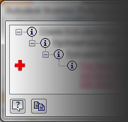
Items populating the document browser change states when they are worked on or when an issue occurs. The state icon displays so you are aware there has been a change. To understand more about the state icons and their use, see:
- State Browser Reference
Design Doctor
The Design Doctor tracks design errors and provides recovery guidance. The goal is to help detect design problems that occur as you work and provide paths to correct the problems. To work with Design Doctor, see Use Design Doctor to repair relationship errors.
When unresolved errors occur in a model, a red cross appears on the Quick Access toolbar or in the message dialog. You can click the red cross to open the Design Doctor where you begin the recover process.
Tip: When fixing design errors, use the shortcut keys to change the view in the graphics window: F2 to pan, F3 to zoom, and F4 to rotate.
At any time you can close the window to stop using Design Doctor and proceed to resolve issues without guidance. Or, return later and use the Recover option in the browser node context menu.
To suppress Design Doctor error messages, see Prompts Tab Reference (Application Options).
Drawings
Edit RVT Errors
If editing a simplified RVT «future» file there may be options and settings used in making the Simplified model that do not exist in the opening Inventor version. A warning message reports: «This Revit model was created using an unsupported value for the ‘Structure’ option.» The most likely explanation is that this file was created in a future («dot») version of Inventor.» The command is cancelled.
The message may occur if there is an invalid value for the Structure setting. The command is cancelled.
To resolve the issue the compatible release is needed. Install the compatible Inventor version and open the model.
Error Reporting
You can send error reports directly to Autodesk when software closes unexpectedly. You can determine who receives notification when reported errors are resolved. When reporting errors provide as much detail as needed to explain the workflow being used when the software closed.
It may be helpful to copy error messages to the clipboard when possible. With the dialog box active, use «Alt + Print Screen» to capture an image of the dialog box and place it on the clipboard. Paste the captured image into the error report or include it as an attachment.
File Save Errors
File Save errors can occur when there is a network connectivity issue preventing Inventor from reaching a server. When errors occur check that the network location is accessible. This can also occur this when the disk space is full.
iLogic
Imported Data Errors
Mold Design
Part Errors
Design errors sometimes occur if your changes interfere with other features. For example, an error occurs if:
- The specified fillet radius is larger than the size of the adjacent face.
- Too many edges are being filleted at one time. For more information about fillets see To Create Edge Fillets.
- The profile/direction for a cut extrusion doesn’t remove material from the body or bodies.
When the message dialog box displays an error list, the design failures display in red underlined text. If you select a design failure message in the list, the location of the failure highlights in the graphics window.
Because you can choose to accept errors and proceed, Inventor also provides Design Doctor and Sketch Doctor to help find design errors in parts, sketches, drawings, and assemblies.
Project Files
If you have not previously worked with Inventor Project files we strongly recommend reviewing the following information before you start a design. See About Project Files
See
Roll Back History
In Part models rolling back the history can help locate where a potential error occurred. To roll back the history:
- Do either of the following:
- Find the End of Part (or End of Feature) symbol at the bottom of the browser, and drag it up to “roll back” the model.
- Right-click a feature in the browser and select Move EOP Marker to move the EOP marker to that feature.
This temporarily removes the features below the EOP symbol from the model. This can be useful as you troubleshoot the model by moving the marker down one feature at a time until the errant feature is discovered. Then, analyze the reason for the error.
- To update the model, drag the symbol back to the bottom of the browser, or right-click the EOP marker and select Move EOP to End.
If an error occurs during the process, a message box displays an error list. The error occurred because the change affected a feature or one of its references and it fails to resolve the rebuild. Expand the levels in the message to reveal the root cause for the failure.
If it is not clear why the error occurred, move the EOP marker back to the point where the change was made. Then, move the marker down the browser one node at a time until the error occurs, then determine the cause for the error.
Routed Systems
Sheet Metal
Flat Pattern Errors may occur when editing and updating the model. A dialog box indicates any error conditions that exist in the flat pattern. You can accept and continue working, although the error warnings persist until the error conditions are eliminated.
Intersecting Features (such as flange features that overlap in the flat pattern) may prevent the model from unfolding. A warning dialog box indicates intersecting features. You can Edit or Cancel the dialog box, or you can Accept the intersecting errors. If you accept, the flat pattern is developed with intersecting features. Subsequent feature creation in the folded model displays the dialog box until you edit the features that intersect in the flattened state.
- For more on Sheet Metal design see About Sheet Metal Flat Patterns
Punch Tools
- To Work with Sheet Metal Punch Tools — If you attempt to save a sheet metal punch iFeature that contains no centermarks, an error message advises you to edit the sketch to add the centermarks.
Sketch Doctor
Sketches form the basis of most model features. Finding an error in a sketch requires that you understand the relationships among all of the pieces of sketch geometry. Also, be aware of how you plan to use the sketch to create subsequent model features.
The Sketch Doctor, part of the Design Doctor, can help you find overlapping curves, redundant points, missing coincident constraints, self-intersecting and open loops. Issues involving incorrect angles or dimensions require closer scrutiny.
Dimensional sketch constraints allow you to use formulas that include parameters. If there are parameter syntax errors, the text is red in the edit field. Correct the error and continue.
To use Sketch Doctor:
- Edit the sketch where the error occurs.
- In the browser, right-click the sketch node and click Sketch Doctor.
- In the Sketch Doctor dialog, click Diagnose Sketch.
- Specify the tests to apply to the sketch and click OK to run the diagnosis.
- The error(s) display in the Sketch Doctor and is highlighted in the display. If more than one error occurs, you can select each error in the dialog and see the error highlighted in the corresponding area in the display.
- Click Next to see the next step for resolving the error.
If your sketch includes imported geometry that another designer created, identifying design errors can be challenging. Common issues include the following:
- Imported geometry that appears to define a closed region can have small gaps between lines and arcs. These gaps prevent the region from behaving as expected during the creation of a solid feature.
- Lines that appear to be perpendicular do not actually measure 90 degrees. This issue might not become apparent until you attempt to assemble the part.
- Imported sketches sometimes cause unexpected behavior because of the way the geometry was created in the exporting system.
The Sketch Doctor, part of the Design Doctor, can help you find problems with overlapping curves, redundant points, missing coincident constraints, self-intersecting and open loops. Issues involving incorrect angles or dimensions require closer scrutiny. Dimensional sketch constraints allow you to use formulas that include parameters. If there are parameter syntax errors, the text is red in the edit field. Correct the error and continue.
Sketches and Sketch Dimensions
Sketch Dimension Precision
If you use formulas in sketch dimensions you may have experienced a result where a dimension has a very small value that is not visible in the rounded value seen in the edit field. For example, you might see a dimension such as 0.37500004 in display as 0.375 or 9.52500004 mm display as 9.525. In the status bar, click the dimension Value  list and select Precise Value
  . Adjust dimensions that are not conforming to your intention.
Offset value does not match your input
When creating an offset you input a value and the result is imprecise. Check whether or not Snap to Grid is turned on. If On, turn it Off. It is likely that Snap to Grid is causing the imprecise result by enforcing the use of a nearby grid point.
Driven (Reference) Dimensions
When a sketch is fully constrained all geometry is fully defined. If you attempt to add more dimensions, these are added as driven dimensions, enclosed in parentheses. You can change a driven dimension to a normal or driving dimension. Doing so, without removing other conflicting dimensions or constraint, will cause an error message to display. Accept the message and make the necessary changes so there are no conflicts. Some changes to consider making are:
- Changing another dimension to a Driven dimension
- Removing or relaxing geometric constraints. For example, removing a perpendicular constraint will allow a line to change angles relative to the line it is perpendicular to.
Task Scheduler
- Log File Reference — for more on Task Scheduler error messages
- To Export Task Errors to Excel — export error messages to an Excel spreadsheet
This topic includes information on why an issue might occur, approaches to resolving issues, and links to information that can assist in working through an issue.
Tip: When you use any of these links, consider the following:
- When a link takes you to a topic page and you want to find any mention of the word error, use CTRL + F (standard browser Find command) and enter error in the search field. This finds all occurrences of the word error in the topic page.
- Review related subtopics as you may find the answer there.
This list of links is designed to help locate information that may be useful in resolving an error.
- Analysis and Simulation
- Application Options and Document Settings
- Assembly Errors
- Best Practices for Fixing Errors
- Design Doctor
- Drawings
- Error Reporting
- Edit RVT errors
- File Open Errors
- File Save Errors
- iLogic
- Imported Data Errors
- Installation
- Mold Design
- Part Errors — related to feature creation and edit, material libraries, and Tolerance messages
- Project File
- Sheet Metal
- Routed Systems
- Sketch Doctor
- Sketches and Sketch Dimensions
- Task Scheduler
Analysis and Simulation
Application Options and Document Settings
Error: Cannot read texture image <path>
The specified *.dds file is not found in the specified folder mapping to the path. Locate the .dds files and put them in the folder or specify the path and folder where you find the .dds files. They may have been manually moved after install.
For information about the modeling environment application option, see: Colors Tab Reference.
For information about the document setting, see: Drawing Tab Reference.
Assembly errors
Assembly Features
If you delete a component that contains a dependent assembly feature, the assembly feature “goes sick,” and the dependent assembly sketches remain in the browser. In the Design Doctor, you can replace the deleted component with a new component using the Redefine command.
Assembly Relationships
Frame Generator
Content Center
Best Practices for Fixing Errors
When fixing several errors, work from the top of the list or browser to the bottom. Features with dependencies appear below the features on which they depend.
When errors occur in a design, you may see:
- , a browser node state icon indicating a design issue. From the context menu you can select Recover (takes you to the Design Doctor) or Diagnose (displays the Relationship Conflict Analysis tool).
- in the QAT (Quick Access Toolbar). Click the red cross to use the Design Doctor. More information about the Design Doctor is included later in this topic.
-
Error dialog box displaying a hierarchical list leading to the error and a red cross. From this dialog box you can start the Recover (Design Doctor) process or resolve the error without assistance.
Items populating the document browser change states when they are worked on or when an issue occurs. The state icon displays so you are aware there has been a change. To understand more about the state icons and their use, see:
- State Browser Reference
Design Doctor
The Design Doctor tracks design errors and provides recovery guidance. The goal is to help detect design problems that occur as you work and provide paths to correct the problems. To work with Design Doctor, see Use Design Doctor to repair relationship errors.
When unresolved errors occur in a model, a red cross appears on the Quick Access toolbar or in the message dialog. You can click the red cross to open the Design Doctor where you begin the recover process.
Tip: When fixing design errors, use the shortcut keys to change the view in the graphics window: F2 to pan, F3 to zoom, and F4 to rotate.
At any time you can close the window to stop using Design Doctor and proceed to resolve issues without guidance. Or, return later and use the Recover option in the browser node context menu.
To suppress Design Doctor error messages, see Prompts Tab Reference (Application Options).
Drawings
Edit RVT Errors
If editing a simplified RVT «future» file there may be options and settings used in making the Simplified model that do not exist in the opening Inventor version. A warning message reports: «This Revit model was created using an unsupported value for the ‘Structure’ option.» The most likely explanation is that this file was created in a future («dot») version of Inventor.» The command is cancelled.
The message may occur if there is an invalid value for the Structure setting. The command is cancelled.
To resolve the issue the compatible release is needed. Install the compatible Inventor version and open the model.
Error Reporting
You can send error reports directly to Autodesk when software closes unexpectedly. You can determine who receives notification when reported errors are resolved. When reporting errors provide as much detail as needed to explain the workflow being used when the software closed.
It may be helpful to copy error messages to the clipboard when possible. With the dialog box active, use «Alt + Print Screen» to capture an image of the dialog box and place it on the clipboard. Paste the captured image into the error report or include it as an attachment.
File Save Errors
File Save errors can occur when there is a network connectivity issue preventing Inventor from reaching a server. When errors occur check that the network location is accessible. This can also occur this when the disk space is full.
iLogic
Imported Data Errors
Mold Design
Part Errors
Design errors sometimes occur if your changes interfere with other features. For example, an error occurs if:
- The specified fillet radius is larger than the size of the adjacent face.
- Too many edges are being filleted at one time. For more information about fillets see To Create Edge Fillets.
- The profile/direction for a cut extrusion doesn’t remove material from the body or bodies.
When the message dialog box displays an error list, the design failures display in red underlined text. If you select a design failure message in the list, the location of the failure highlights in the graphics window.
Because you can choose to accept errors and proceed, Inventor also provides Design Doctor and Sketch Doctor to help find design errors in parts, sketches, drawings, and assemblies.
Project Files
If you have not previously worked with Inventor Project files we strongly recommend reviewing the following information before you start a design. See About Project Files
See
Roll Back History
In Part models rolling back the history can help locate where a potential error occurred. To roll back the history:
- Do either of the following:
- Find the End of Part (or End of Feature) symbol at the bottom of the browser, and drag it up to “roll back” the model.
- Right-click a feature in the browser and select Move EOP Marker to move the EOP marker to that feature.
This temporarily removes the features below the EOP symbol from the model. This can be useful as you troubleshoot the model by moving the marker down one feature at a time until the errant feature is discovered. Then, analyze the reason for the error.
- To update the model, drag the symbol back to the bottom of the browser, or right-click the EOP marker and select Move EOP to End.
If an error occurs during the process, a message box displays an error list. The error occurred because the change affected a feature or one of its references and it fails to resolve the rebuild. Expand the levels in the message to reveal the root cause for the failure.
If it is not clear why the error occurred, move the EOP marker back to the point where the change was made. Then, move the marker down the browser one node at a time until the error occurs, then determine the cause for the error.
Routed Systems
Sheet Metal
Flat Pattern Errors may occur when editing and updating the model. A dialog box indicates any error conditions that exist in the flat pattern. You can accept and continue working, although the error warnings persist until the error conditions are eliminated.
Intersecting Features (such as flange features that overlap in the flat pattern) may prevent the model from unfolding. A warning dialog box indicates intersecting features. You can Edit or Cancel the dialog box, or you can Accept the intersecting errors. If you accept, the flat pattern is developed with intersecting features. Subsequent feature creation in the folded model displays the dialog box until you edit the features that intersect in the flattened state.
- For more on Sheet Metal design see About Sheet Metal Flat Patterns
Punch Tools
- To Work with Sheet Metal Punch Tools — If you attempt to save a sheet metal punch iFeature that contains no centermarks, an error message advises you to edit the sketch to add the centermarks.
Sketch Doctor
Sketches form the basis of most model features. Finding an error in a sketch requires that you understand the relationships among all of the pieces of sketch geometry. Also, be aware of how you plan to use the sketch to create subsequent model features.
The Sketch Doctor, part of the Design Doctor, can help you find overlapping curves, redundant points, missing coincident constraints, self-intersecting and open loops. Issues involving incorrect angles or dimensions require closer scrutiny.
Dimensional sketch constraints allow you to use formulas that include parameters. If there are parameter syntax errors, the text is red in the edit field. Correct the error and continue.
To use Sketch Doctor:
- Edit the sketch where the error occurs.
- In the browser, right-click the sketch node and click Sketch Doctor.
- In the Sketch Doctor dialog, click Diagnose Sketch.
- Specify the tests to apply to the sketch and click OK to run the diagnosis.
- The error(s) display in the Sketch Doctor and is highlighted in the display. If more than one error occurs, you can select each error in the dialog and see the error highlighted in the corresponding area in the display.
- Click Next to see the next step for resolving the error.
If your sketch includes imported geometry that another designer created, identifying design errors can be challenging. Common issues include the following:
- Imported geometry that appears to define a closed region can have small gaps between lines and arcs. These gaps prevent the region from behaving as expected during the creation of a solid feature.
- Lines that appear to be perpendicular do not actually measure 90 degrees. This issue might not become apparent until you attempt to assemble the part.
- Imported sketches sometimes cause unexpected behavior because of the way the geometry was created in the exporting system.
The Sketch Doctor, part of the Design Doctor, can help you find problems with overlapping curves, redundant points, missing coincident constraints, self-intersecting and open loops. Issues involving incorrect angles or dimensions require closer scrutiny. Dimensional sketch constraints allow you to use formulas that include parameters. If there are parameter syntax errors, the text is red in the edit field. Correct the error and continue.
Sketches and Sketch Dimensions
Sketch Dimension Precision
If you use formulas in sketch dimensions you may have experienced a result where a dimension has a very small value that is not visible in the rounded value seen in the edit field. For example, you might see a dimension such as 0.37500004 in display as 0.375 or 9.52500004 mm display as 9.525. In the status bar, click the dimension Value list and select Precise Value . Adjust dimensions that are not conforming to your intention.
Offset value does not match your input
When creating an offset you input a value and the result is imprecise. Check whether or not Snap to Grid is turned on. If On, turn it Off. It is likely that Snap to Grid is causing the imprecise result by enforcing the use of a nearby grid point.
Driven (Reference) Dimensions
When a sketch is fully constrained all geometry is fully defined. If you attempt to add more dimensions, these are added as driven dimensions, enclosed in parentheses. You can change a driven dimension to a normal or driving dimension. Doing so, without removing other conflicting dimensions or constraint, will cause an error message to display. Accept the message and make the necessary changes so there are no conflicts. Some changes to consider making are:
- Changing another dimension to a Driven dimension
- Removing or relaxing geometric constraints. For example, removing a perpendicular constraint will allow a line to change angles relative to the line it is perpendicular to.
Task Scheduler
- Log File Reference — for more on Task Scheduler error messages
- To Export Task Errors to Excel — export error messages to an Excel spreadsheet
Магнитные ссылки — это простой и безопасный способ обмена файлами. Может быть очень неприятно встретить неработающую магнитную ссылку, поскольку она делает контент, который вы ищете, недоступным. Получение сообщения в браузере Chrome о том, что у вас есть ошибка магнитной ссылки, может поставить вас в тупик, что делать дальше.
Не беспокойтесь.
В этой статье мы рассмотрим, как исправить ошибки магнитных ссылок. Давайте посмотрим, как устранить ошибки, связанные с неработающей магнитной ссылкой в разных браузерах.
Использование магнитной ссылки
Во-первых, давайте начнем с того, как использовать магнитная ссылка. Неправильные процедуры могут быть причиной того, что вы не можете загрузить свою магнитную ссылку.
В вашем браузере должен быть установлен BitTorrent-клиент с поддержкой магнитных ссылок. Если у вас есть соответствующий клиент, нажмите на магнитную ссылку, как на любую гиперссылку на веб-сайте.
В следующем разделе мы рассмотрим загрузку магнитных ссылок в браузере Chrome.
Как открыть магнитную ссылку в Chrome
Сначала вам нужно настроить Chrome, чтобы вы могли создавать магнитные ссылки.
Для этого:
- Введите “chrome://settings/handlers” в браузер Chrome.

- Включите параметр “разрешить сайтам запрашивать статус обработчиков протоколов по умолчанию” option.

Далее:
- Найдите сайт загрузки с магнитными ссылками.
- Выберите файл, который хотите загрузить.
- Нажмите “Magnet Download”

- Вам будет предложено открыть магнитную ссылку, используя предпочитаемую вами платформу BitTorrent. Нажмите “Открыть”

Магнитная ссылка не работает в Chrome< /h2>
Иногда, когда вы открываете магнитную ссылку в Chrome, браузер возвращает сообщение об ошибке. Есть несколько шагов, которые вы можете предпринять, чтобы попытаться устранить проблему.
Проверьте настройки контента
Убедитесь, что настройки контента вашего браузера верны. Для этого:
- Откройте вкладку Chrome и нажмите значок меню.

- Выберите &ldquo ;Настройки.”

- Прокрутите вниз и нажмите кнопку “Дополнительно”

- Нажмите кнопку “Настройки содержания” кнопка.

- Найдите “Handlers” вариант с надписью “разрешить сайтам запрашивать статус обработчиков протоколов по умолчанию” Нажмите на нее.
- Убедитесь, что переключатель этой настройки находится в положении ВКЛ.
- Теперь ваш браузер Chrome должен иметь возможность загрузить вашу магнитную ссылку.

Отредактируйте реестр
Иногда в сообщении, связанном с вашей ошибкой, будет сказано “с этим файлом не связано приложение”.” Это означает, что ваш браузер Chrome не может определить правильное приложение для загрузки магнитной ссылки. Вам потребуется открыть и отредактировать реестр, чтобы исправить эту ошибку.
Вы можете сделать это, следуя приведенным ниже инструкциям:
- Откройте командную строку запуска, нажав Win+R.
- Введите “regedit” в открывшемся диалоговом окне.

- Откроется редактор реестра. в новом окне. Перейдите к местоположению файла: ComputerHKEY_CLASSES_ROOTMagnetshellopencommand

- На правой панели вы увидите столбец данных, показывающий путь к BitTorrent-клиенту.

- В новом окне откройте диск C.

- Нажмите Win+E, чтобы открыть Мой компьютер.

- Если файл хранится в неправильном каталоге, сбросьте параметры реестра.
- Теперь Chrome должен открыть вашу магнитную ссылку.
Магнитные ссылки не работают в Edge
Чтобы ваша магнитная ссылка открывалась в Edge, вы будете использовать процесс, очень похожий на открытие магнитной ссылки в Chrome. Однако нет необходимости настраивать обработчики. Вместо этого вам нужно будет загрузить “Magnet Linker” расширение для Microsoft Edge.
Чтобы найти и добавить это расширение, следуйте приведенным ниже инструкциям:
- Откройте Microsoft Edge.

- Нажмите в правом верхнем углу браузера.

- Нажмите “Расширения” затем “Получить расширения для Microsoft Edge”

- Найти расширение Magnet Linker, затем нажмите “Получить”

- Вы получите приглашение с информацией о разрешениях, необходимых для расширения. После просмотра нажмите “Добавить расширение”

- Вы получите уведомление о добавлении расширения.

< р>Как только расширение Magnet Linker будет включено в Edge, вы получите приглашение открыть магнитную ссылку на предпочитаемой вами платформе BitTorrent.
Редактировать реестр в Edge
Если вы все еще возникли трудности с загрузкой магнитных ссылок после настройки Magnet Linker в Edge, вы должны создать ассоциацию файлов вручную.
Вот как это сделать:
- Нажмите Win+R, чтобы перейти к реестру.
- Введите “regedit” в диалоговое окно.

- Перейдите по адресу: ComputerHKEY_CLASSES_ROOTMagnetshellopencommand

- На правой панели в разделе “Данные” вы должны увидеть каталог вашего приложения BitTorrent.

- Если информация в разделе «Данные» не соответствует каталогу BitTorrent, нажмите «Изменить». и введите правильный каталог для вашей платформы BitTorrent.
- Теперь ваш браузер сможет загружать ваши магнитные ссылки.
Магнитные ссылки не работают в Firefox
Если вы используете браузер Firefox, вы можете столкнуться со случаями, когда вам придется сбросить связь между вашим клиентом BitTorrent и вашим браузером.
Для этого:
< ol type=»1″>


Теперь вы сможете загружать магнитные ссылки из браузера Firefox.
Магнитная ссылка не работает в uTorrent
Ваш клиент Bittorent, такой как uTorrent, может время от времени возникли проблемы с ассоциацией с магнитными ссылками вашего браузера. Вы можете получить запрос на переключение приложений или сообщение о том, что файл не может быть открыт ни одним приложением на вашем устройстве.
Чтобы устранить эту проблему, вам придется вручную установить связь между вашим браузером и выбранной вами платформой BitTorrent.
Магнитная ссылка не работает на qBittorent
С qBittorent магнитная ссылка может не работать из-за вашего брандмауэра и антивирусного программного обеспечения. Это программное обеспечение может блокировать qBittorent и разрешение на его правильную работу. Шаги брандмауэра и антивирусного программного обеспечения могут различаться, но в целом вам нужно перейти в меню настроек и убедиться, что разрешения для приложения проверены.
Как заставить Magnet Links работать
< p>Магнитные ссылки — это простой, безопасный и надежный способ обмена контентом. Здесь и там могут возникнуть некоторые проблемы, когда вы впервые попытаетесь загрузить магнитные ссылки в новом браузере. Однако проблемы, как правило, относительно стандартны, и поэтому их легко устранить.
Были ли у вас проблемы с работой магнитных ссылок? Дайте нам знать в комментариях ниже!
