1
Safety engineering
Appendix
Field
Error number
Safety functions
97 0x61
98 0x62
99 0x63
100 0x64
101 0x65
102 0x66
103 0x67
104 0x68
105 0x69
106 0x6A
107 0x6B
108 0x6C
109 0x6D CAS: Hardware or discrepancy error
110
0x6E
111
0x6F
Test functions − output
128 0x80
129 0x81
130 0x82
131 0x83
134
Phone: 800.894.0412 — Fax: 888.723.4773 — Web: www.clrwtr.com — Email: info@clrwtr.com
Description
Description
SS1/SS2: Stopping time exceeded
(The drive has not reached zero speed within the stopping time.)
SLS1: Nlim1 exceeded
(The drive has exceeded the limited speed.)
SLS2: Nlim2 exceeded
(The drive has exceeded the limited speed.)
SLS3: Nlim3 exceeded
(The drive has exceeded the limited speed.)
SLS4: Nlim4 exceeded
(The drive has exceeded the limited speed.)
SLS/SMS: Error stop not executed
(The drive has exceeded the limited speed or maximum speed and
has not stopped the drive safely. Following error to no. 0x62 or
0x69)
SDIpos: Wrong direction of movement
SDIneg: Wrong direction of movement
SMS: Nmax exceeded
(The drive has exceeded the monitored maximum speed.)
SOS: Tolerance limit exceeded
(The drive has exceeded a tolerance limit.)
No encoder system parameterised
(SMS, SLS1 or SS2 are tried to be executed without an encoder
being parameterised.)
CAS: Circulation time exceeded
Maximum time between release and feedback of the cascading
function has been exceeded.
The cascading output has not been switched off quickly enough
by the hardware or there is a discrepancy at the cascading input.
SS1/SS2: Speed ramp exceeded
Monitoring of the speed ramp is activated. When the stop
function SS1/SS2 is executed, the deceleration of the speed ramp
is monitored. When the monitoring limits are exceeded, an error is
reported.
SLI: Safely limited increment exceeded
The safely limited increment is monitored in the special operation
mode. The parameterised increment has been exceeded.
Stuck at High SD−Out1, channel A
(Short circuit (High))
Stuck at Low SD−Out1, channel A
(Short circuit (Low))
Stuck at High SD−Out1, channel B
Stuck at Low SD−Out1, channel B
l
Error type/response/
Error type/response/
Note
Note
Warning/STO
Warning/response can be
set
Warning/response can be
set
Warning/response can be
set
Warning/response can be
set
Warning/STO
Warning/response can be
set
Warning/response can be
set
Warning/STO
Warning/STO
Warning/STO
Warning/STO
Warning/STO
Warning/STO
Trouble/−
SD−Out1: OFF state
EDS94AYAE EN 6.0

Lenze · Servo-Inverter 9400 HighLine · Reference manual · DMS 10.0 EN · 11/2013 · TD05/06
617
13
Diagnostics & fault analysis
13.7
Error messages of the operating system
_ _ _ _ _ _ _ _ _ _ _ _ _ _ _ _ _ _ _ _ _ _ _ _ _ _ _ _ _ _ _ _ _ _ _ _ _ _ _ _ _ _ _ _ _ _ _ _ _ _ _ _ _ _ _ _ _ _ _ _ _ _ _ _
0x00690000
6881280
Code refresh
System fault
—
0x00680019
6815769
Combination MXI1/MXI2 not possible
System fault
—
0x0068001f
6815775
Combination of memory module/device not possible
System fault
—
0x00680020
6815776
Combination of module in MXI1/device not possible
System fault
—
0x00680021
6815777
Combination of module in MXI2/device not possible
System fault
—
0x007f0002
8323074
Communication error between device and device module
No response
C01501
0x0091000e
9502734
Communication task: Standstill > 3 s
Fault
C01230
0x007f0003
8323075
Communication with module in MXI1 interrupted
Information
—
0x007f0004
8323076
Communication with module in MXI2 interrupted
Information
—
0x00920001
9568257
Communication with safety module interrupted
Information
—
0x008c001a
9175066
ConnectTable active
Information
—
0x0068000e
6815758
Control card incompatible
System fault
—
0x00680000
6815744
Control card is defective
System fault
—
0x00680008
6815752
Control card is defective
System fault
—
0x00780008
7864328
Control card is defective (UB18 neg.)
System fault
—
0x00780004
7864324
Control card is defective (UB24)
System fault
—
0x00780006
7864326
Control card is defective (UB8)
System fault
—
0x00780007
7864327
Control card is defective (VCC15 neg.)
System fault
—
0x00780005
7864325
Control card is defective (VCC15)
System fault
—
0x00780009
7864329
Control card is defective (VCC5)
System fault
—
0x006f0000
7274496
Control card: Supply voltage (24 V DC) too low
Trouble
—
0x00750001
7667713
Controller enabled
Information
—
0x00750003
7667715
Controller in STO state
Information
—
0x007b0047
8060999
Controller: Clamp operation
Information
—
0x007b0035
8060981
Controller: Overload during acceleration phases
Fault
—
0x00750005
7667717
Controller: Pulse inhibit is active
Information
—
0x00770009
7798793
CPU: Overtemperature
Warning
—
0x00770008
7798792
CPU: Temperature > C00126
No response
C00589
0x0077000e
7798798
CPU: thermal detector is defective
Fault
C00588
0x0091000f
9502735
Cyclic task: Standstill > 60 s
Information
—
0x0077000d
7798797
DC-bus capacitor: thermal detector is defective
Fault
C00588
0x007b000e
8060942
DC-bus overvoltage
Trouble
C00600
0x007b000f
8060943
DC-bus undervoltage
Trouble
—
0x00b8000d
12058637
Deceleration has been limited
Information
C02716/3
0x00780001
7864321
Device utilisation Ixt > 100 %
Fault
—
0x00780000
7864320
Device utilisation Ixt > C00123
Warning
C00604
0x00990003
10027011
DFIN (MXI1): Signal error enable/lamp control
Warning
C13041
0x00990004
10027012
DFIN (MXI1): Supply cannot be corrected anymore
Warning
C13042
0x00990000
10027008
DFIN (MXI1): Track error A-/A
Fault
C13040
0x00990001
10027009
DFIN (MXI1): Track error B-/B
Fault
C13040
0x00990002
10027010
DFIN (MXI1): Track error Z-/Z
Fault
C13040
0x00aa0003
11141123
DFIN (MXI2): Signal error enable/lamp control
Warning
C14041
0x00aa0004
11141124
DFIN (MXI2): Supply cannot be corrected anymore
Warning
C14042
0x00aa0000
11141120
DFIN (MXI2): Track error A-/A
Fault
C14040
0x00aa0001
11141121
DFIN (MXI2): Track error B-/B
Fault
C14040
0x00aa0002
11141122
DFIN (MXI2): Track error Z-/Z
Fault
C14040
0x00990005
10027013
DFOUT (MXI1): Maximum frequency reached
Warning
C13080
0x00aa0005
11141125
DFOUT (MXI2): Maximum frequency reached
Warning
C14080
0x0090000c
9437196
Disconnection in the case of par. storage
Fault
—
0x006a0011
6946833
Division by zero
Fault
—
0x007b0011
8060945
Earth fault detected
Fault
—
0x0068001d
6815773
Electronic nameplate: Checksum error
Warning
—
hex
dec
Error message
Response (Lenze setting)
can be set in
-
Contents
-
Table of Contents
-
Bookmarks
Quick Links
EDS94AYCEN
13416838
L-force
Communication
9400
E94AYCEN
Ethernet communication module
Communication Manual
L
Related Manuals for Lenze L-force 9400 Series
Summary of Contents for Lenze L-force 9400 Series
-
Page 1
L-force Communication EDS94AYCEN 13416838 Communication Manual 9400 E94AYCEN Ethernet communication module… -
Page 2
EDS94AYCEN EN 9.0 — 09/2012… -
Page 3: Table Of Contents
E94AYCEN communication manual (Ethernet) Contents Contents About this documentation …………Document history .
-
Page 4
E94AYCEN communication manual (Ethernet) Contents Commissioning …………..Before initial switch-on . -
Page 5: About This Documentation
Safety instructions that must be observed The basic technical data of the communication module Information on versions of the Lenze standard devices to be used Notes on troubleshooting and fault elimination The theoretical context is only explained as far as it is required for understanding the function of the communication module.
-
Page 6
This documentation addresses to persons who configure, install, commission, and maintain the networking and remote maintenance of a machine. Tip! Current documentation and software updates for Lenze products can be found in the download area at: www.Lenze.com Validity information… -
Page 7: Document History
E94AYCEN communication manual (Ethernet) About this documentation Document history Document history Version Description 11/2004 TD06 First edition 03/2005 TD06 Description of the GCI protocol added 03/2005 TD06 Description of displays added 10/2006 TD06 General revision 11/2007 TD17 General revision and provision of the documentation in the form of the »Engineer«…
-
Page 8: Conventions Used
In general, the decimal point is used. Example: 1234.56 Text Program name » « PC software Example: Lenze »Engineer« Control element Bold The OK button… / The Copy command… / The Properties tab… / The Name input field… Hyperlink Underlined Optically highlighted reference to another topic.
-
Page 9: Terminology Used
Lenze controllers of the «Servo Drives 9400» series Standard device »Engineer« Lenze PC software supporting you for the «Engineering» (parameterisation, diagnostics, and configuration) during the whole life cycle, i. e. from the design to the maintenance of the machine commissioned.
-
Page 10: Notes Used
E94AYCEN communication manual (Ethernet) About this documentation Notes used Notes used The following signal words and symbols are used in this documentation to indicate dangers and important information: Safety instructions Layout of the safety instructions: Pictograph and signal word! (characterise the type and severity of danger) Note (describes the danger and suggests how to prevent dangerous situations)
-
Page 11: Safety Instructions
– The procedural notes and circuit details described in this document are only proposals. It is up to the user to check whether they can be adapted to the particular applications. Lenze does not take any responsibility for the suitability of the procedures and circuit proposals described.
-
Page 12: Device And Application-Specific Safety Instructions
E94AYCEN communication manual (Ethernet) Safety instructions Device and application-specific safety instructions All operations with and on Lenze drive and automation components may only be carried out by qualified personnel. In accordance with IEC 60364 or CENELEC HD 384 these are persons …
-
Page 13: Product Description
E94AYCEN communication manual (Ethernet) Product description Application as directed Product description Application as directed The Ethernet communication module … is an accessory module that can be used in conjunction with the following standard devices: Product series Type designation From hardware From software version version…
-
Page 14: Product Features
Automatic detection and (internal) swapping of data signals from receive paths and transmit paths (auto-crossing) Access to all Lenze parameters via the Lenze »Engineer« Terminals and interfaces 2 RJ45 sockets for Ethernet connection Front LEDs for diagnosing the …
-
Page 15: Technical Data
E94AYCEN communication manual (Ethernet) Technical data General data and operating conditions Technical data General data and operating conditions Area Values Order designation E94AYCEN Communication profile GCI, based on TCP/IP Communication medium S/FTP (screened foiled twisted pair, ISO/IEC 11801 or EN 50173), CAT 5e Interface RJ45: Standard Ethernet (in accordance with IEEE 802.3), 100Base-TX (Fast Ethernet)
-
Page 16: Protective Insulation
E94AYCEN communication manual (Ethernet) Technical data Protective insulation Protective insulation Danger! Dangerous electrical voltage If Servo Drives 9400 are used on a phase earthed mains with a rated mains voltage ≥ 400 V, protection against accidental contact is not guaranteed without external measures.
-
Page 17
E94AYCEN communication manual (Ethernet) Technical data Protective insulation The following illustration … shows the arrangement of the terminal strips and the separate potential areas of the drive. serves to determine the decisive protective insulation between two terminals located in differently insulated separate potential areas. -
Page 18: Dimensions
E94AYCEN communication manual (Ethernet) Technical data Dimensions Example Which type of protective insulation is used between the bus terminal of the device module in slot MXI1 or MXI2 and the mains terminal X100? The separate potential area with the better protective insulation is decisive. –…
-
Page 19: Installation
E94AYCEN communication manual (Ethernet) Installation Installation Stop! Electrostatic discharge Electronic components within the communication module can be damaged or destroyed by electrostatic discharge. Possible consequences: • The communication module is damaged. • Fieldbus communication is not possible or faulty. Protective measures •…
-
Page 20: Mechanical Installation
E94AYCEN communication manual (Ethernet) Installation Mechanical installation Mechanical installation Note! Only one Ethernet module may be attached to a Servo Drive 9400, either in module slot MXI1 or MXI2. 5.1.1 Assembly E94YCXX001G [5-1] Assembly 5.1.2 Disassembly E94AYCXX001H [5-2] Disassembly EDS94AYCEN EN 9.0 — 09/2012…
-
Page 21: Electrical Installation
E94AYCEN communication manual (Ethernet) Installation Electrical installation Electrical installation Documentation for the standard device, control system, system/machine Observe the notes and wiring instructions contained in this documentation. 5.2.1 EMC-compliant wiring In typical systems, standard shielding is sufficient for Ethernet cables. However, in environments with a very high level of interference, EMC resistance can be improved by additionally earthing the cable shield on both sides.
-
Page 22: Ethernet Connection
( 23) Note! • Decouple your Ethernet house network from the system network for Ethernet-capable Lenze devices in order to prevent trouble in the Ethernet communication. Further information can be obtained from the «Ethernet in the industrial application» manual.
-
Page 23: Cable
E94AYCEN communication manual (Ethernet) Installation Electrical installation Free space When ordering and using your Ethernet cable, note the amount of free space available. E94YCET017 [5-4] Free space 5.2.3 Specification of the Ethernet cable Note! Only use cables that meet the listed specifications. Specification of the Ethernet cable Ethernet standard Standard Ethernet (in accordance with IEEE 802.3), 100Base-TX (Fast…
-
Page 24
E94AYCEN communication manual (Ethernet) Installation Electrical installation Colour coding of the Ethernet cable Note! Wiring and colour code are standardised in EIA/TIA 568A/568B. In accordance with the industrial standard, the use of 4-pin Ethernet cables is permissible. The cable type only connects the assigned pins 1, 2, 3 and 6 to one another. -
Page 25: Voltage Supply
E94AYCEN communication manual (Ethernet) Installation Electrical installation 5.2.4 Voltage supply Internal supply The communication module is solely supplied with voltage by the standard device. Note! If the standard device fails and daisy-chain wiring has been used, the transmission of data between the Ethernet nodes at interface X215 and the Ethernet nodes at interface X216 will be interrupted.
-
Page 26: Commissioning
During commissioning, system-related data such as motor parameters, operating parameters, responses, and parameters for fieldbus communication are defined for the drive. For Lenze devices, this is done via the codes. The codes of the drive and for communication are saved non-volatilely as a data set in the memory module.
-
Page 27: Configuring The Communication Module
The address settings required for Ethernet operation are displayed in the »Engineer« in the Settings tab (Fig. [6-1]). The settings correspond to the values of the codes: Parameter Code Lenze setting for slot MXI1 for slot MXI2 IP address C13000/1…4 C14000/1…4…
-
Page 28: Setting The Address
E94AYCEN communication manual (Ethernet) Commissioning Configuring the communication module 6.2.1 Setting the address Clicking the Change button in the Settings tab (Fig. [6-1]) opens the «Configure IP address» dialog window: [6-2] Setting the address In the input fields for the IP address, the subnet mask and the standard gateway, you can directly set the addresses.
-
Page 29: Address
E94AYCEN communication manual (Ethernet) Commissioning Configuring the communication module 6.2.2 Automatically receiving an IP address Clicking the Change button in the Settings tab (Fig. [6-1]) opens the «Configure IP address» dialog window. Mark «Receive IP address automatically» in order to receive an IP address automatically from the DHCP server: [6-3] Automatically receiving an IP address…
-
Page 30
E94AYCEN communication manual (Ethernet) Commissioning Configuring the communication module Output of the »Network Analyzer« With «DHCP ACK», the DHCP server (here IP address «192.216.31.1») assigns the IP address «192.216.31.239» to the Servo Drive 9400 (DHCP client): EDS94AYCEN EN 9.0 — 09/2012… -
Page 31: Ip Address
Eight bits are reserved for each of the four numbers, which makes a total of 32 bits. Examples 1. The first three numbers of the IP address indicate the network, the last number indicates the host (Lenze setting): Subnet mask: Subdivision of IP address:…
-
Page 32: Gateway Address
MAC-ID The MAC-ID is a globally unique identifier of an Ethernet-capable device. The MAC-ID is assigned by the manufacturer and permanently burnt into the device (Lenze communication module). The MAC-ID consists of six hexadecimal numerical codes (00 … FF) which respectively are separated from each other by a hyphen, e.
-
Page 33
The MAC-ID of the communication module is displayed in C13003/C14003: Parameter (MXI1): C13003/1 C13003/2 C13003/3 C13003/4 C13003/5 C13003/6 Display [hex]: Manufacturer’s identification mark Consecutive definite number (Lenze) Parameter (MXI2): C14003/1 C14003/2 C14003/3 C14003/4 C14003/5 C14003/6 Display [hex]: Manufacturer’s identification mark Consecutive definite number (Lenze) … -
Page 34: Dhcp Implementation In The Servo Drive 9400
C13005 C14005 available. These codes can be used to define whether DHCP is to be used or not: Value 0 (FALSE): Do not use DHCP (Lenze setting) Value 1 (TRUE): Use DHCP DHCP flag settings UseIPfromDhcp = TRUE (Use DHCP): The IP settings are assigned by the DHCP server.
-
Page 35: Dhcp Network Architecture
E94AYCEN communication manual (Ethernet) Commissioning DHCP implementation in the Servo Drive 9400 6.3.2 DHCP network architecture Data relating to the DHCP network architecture DHCP model Client/Server Transport protocol Ports Server — UDP port 67 Client — UDP port 68 DHCP packet size 576 bytes Compatibility DHCP is an advancement on BOOTP, so the DHCP server can also manage…
-
Page 36: Dhcp Packet Structure
E94AYCEN communication manual (Ethernet) Commissioning DHCP implementation in the Servo Drive 9400 6.3.4 DHCP packet structure The DHCP packets have the following structure: Bit 1 … 8 Bit 9 … 16 Bit 17 … 24 Bit 25 … 32 op (1 byte) htype (1 byte) hlen (1 byte) hops (1 byte)
-
Page 37: Initial Switch-On
After a fault (e.g. short-term mains failure), it is sometimes undesirable or even impermissible for the drive to restart. In the Lenze setting of Servo Drives 9400, the restart protection is activated. The restart behaviour of the controller can be set using C00142 («Auto-restart following mains connection»):…
-
Page 38: Parameter Data Transfer
The SDOs provide for the write and read access to the object directory in the controller. The transmission of the parameter data usually is not time-critical. The parameter data are saved in Lenze devices as «codes». Via the codes, for instance operating parameters, motor data or diagnostics information can be set.
-
Page 39: Structure Of The Ethernet Data Telegram
E94AYCEN communication manual (Ethernet) Parameter data transfer Structure of the Ethernet data telegram Structure of the Ethernet data telegram The GCI protocol is used for communication. The Ethernet data telegram is shown below. Here, the GCI header represents the part of the program that is independent of the type of command transmitted.
-
Page 40: Reading Parameters From The Controller
E94AYCEN communication manual (Ethernet) Parameter data transfer Reading parameters from the controller Tip! The GCI header will be described in greater detail during the course of this manual. The other signals refer to the transfer characteristics of the Ethernet telegram, which are not described in this documentation.
-
Page 41: Assignment Of User Data Areas P0
E94AYCEN communication manual (Ethernet) Parameter data transfer Assignment of user data areas P0 … P4 Assignment of user data areas P0 … P4 Area Byte 1 Byte 2 Byte 3 Byte 4 Status/error code Data type Reserved Code Reserved Reserved Subcode Reserved Reserved*…
-
Page 42: Transmission Abort
E94AYCEN communication manual (Ethernet) Parameter data transfer Transmission abort Assignment of the User data area with parameter values of different data lengths Depending on the data format, the parameter value occupies 1 to 8 bytes. Data are stored in little-endian format, i.e. first the low byte or low word, then the high byte or high word: Data length Data area P3 Data area P4…
-
Page 43: Error Codes
E94AYCEN communication manual (Ethernet) Parameter data transfer Error codes Error codes The error code is located in the User data area P0, byte 1 and byte 2. User data area P0 Byte 1 Byte 2 Byte 3 Byte 4 Error code Data type Reserved Example error code 0x9002…
-
Page 44
E94AYCEN communication manual (Ethernet) Parameter data transfer Error codes Error code Definition Description 36873 0x9009 Wrong GMT received The general telegram identification does not correspond to the GCI communication. 36874 0x900A Unknown server request Internal error in the GCI 36875 0x900B Wrong server parameter 36876… -
Page 45: Telegram Examples
E94AYCEN communication manual (Ethernet) Parameter data transfer Telegram examples Telegram examples 7.7.1 Example 1: Querying the heatsink temperature (read request) The heatsink temperature of the controller is to be read. Code to be read: C00061 Assumption: ϑ = 43°C Request …
-
Page 46
E94AYCEN communication manual (Ethernet) Parameter data transfer Telegram examples Response GCI message qualifier (GMQ) = 0x80 = 10000000B = «Response» GCI header SIZE SIZE 0x01 0x82 0x80 0x00 0x14 0x00 0x00 0x00 Fixed Reading Response Transactions ID Length of the user data = 20 bytes Reserved parameters User data area P0… -
Page 47: Example 2: Querying The Firmware Product Type (Read Request)
E94AYCEN communication manual (Ethernet) Parameter data transfer Telegram examples 7.7.2 Example 2: Querying the firmware product type (read request) The firmware product type of the controller is to be read. Code to be read: C00200 Assumption: product type = «E94AFH» Request …
-
Page 48
E94AYCEN communication manual (Ethernet) Parameter data transfer Telegram examples Response GCI message qualifier (GMQ) = 0x80 = 10000000B = «Response» GCI header SIZE SIZE 0x01 0x82 0x80 0x01 0x14 0x00 0x00 0x00 Fixed Reading Response Transactions ID Length of the user data = 20 bytes Reserved parameters User data area P0… -
Page 49: Example 3: Setting The Deceleration Time For Quick Stop (Qsp) (Write Request)
E94AYCEN communication manual (Ethernet) Parameter data transfer Telegram examples 7.7.3 Example 3: Setting the deceleration time for quick stop (QSP) (write request) The deceleration time for quick stop (QSP) is to be set to 50 ms in the controller. Code to be written: C00105 Request …
-
Page 50
E94AYCEN communication manual (Ethernet) Parameter data transfer Telegram examples Response GCI message qualifier (GMQ) = 0x80 = 10000000B = «Response» GCI header SIZE SIZE 0x01 0x83 0x80 0x2A 0x14 0x00 0x00 0x00 Fixed Writing Response Transactions ID Length of the user data = 20 bytes Reserved parameters User data area P0… -
Page 51: Diagnostics
E94AYCEN communication manual (Ethernet) Diagnostics Diagnostics The LEDs on the front of the Ethernet module are used to diagnose faults. Furthermore, the »Engineer« indicates via codes C13006 C14006 if an error has occurred during Ethernet communication or if a telegram has been lost. …
-
Page 52: Led Status Displays
E94AYCEN communication manual (Ethernet) Diagnostics LED status displays LED status displays MS and DE status displays LEDs Pos. Colour Status Description Green The communication module is supplied with voltage. The communication module is not accepted by the standard device. (See notes provided in the documentation for the standard device.) E94YCEN001B …
-
Page 53: Error Messages Of The Servo Drive 9400
E94AYCEN communication manual (Ethernet) Diagnostics Error messages of the Servo Drive 9400 Error messages of the Servo Drive 9400 In the »Engineer«, the content of the fault memory can be displayed via the standard device code C00168. Software manual/»Engineer« online help for the Servo Drive 9400 Here you will find general information on diagnostics &…
-
Page 54: Parameter Reference
= 5D83 C00636 | Resp. to new module in MXI1 Response if a new module has been plugged into module slot 1 of the standard device. Selection list (Lenze setting printed in bold) 1 Fault 6 Information 5 Warning 4 Warning Locked…
-
Page 55
= 5D83 C00637 | Resp. to new module in MXI2 Response if a new module has been plugged into module slot 2 of the standard device. Selection list (Lenze setting printed in bold) 1 Fault 6 Information 5 Warning 4 Warning Locked… -
Page 56: Parameters Of The Communication Module For Slot Mxi1
(min. value | unit | max. value) Subcodes Lenze setting Info C13001/1 Subnet mask • Sequence: «[1].[2].[3].[4]» C13001/2 • Lenze setting: «255.255.255.0» (The first three bytes C13001/3 of the IP address are the Net-ID.) C13001/4 Read access Write access CINH PLC STOP No transfer EDS94AYCEN EN 9.0 — 09/2012…
-
Page 57
The MAC-ID is a globally unique identifier of an Ethernet-capable device. The MAC-ID is assigned by the manufacturer and permanently burnt into the device (Lenze communication module). • The MAC-ID consists of six numbers from 0 to 255 which are displayed in the six subcodes. -
Page 58
You use this code to define whether DHCP is to be used or not. DHCP implementation in the Servo Drive 9400 ( 34) Selection list (Lenze setting printed in bold) 0 Do not use DHCP 1 Use DHCP Read access… -
Page 59
E94AYCEN communication manual (Ethernet) Parameter reference Parameters of the communication module for slot MXI1 C13007 Parameter | Name: Data type: UNSIGNED_8 Index: 11568 = 2D30 C13007 | Resolved Subnetmask The subnet mask indicates which part of the IP address is evaluated as Net-ID and which part as Host-ID. •… -
Page 60: Parameters Of The Communication Module For Slot Mxi2
(min. value | unit | max. value) Subcodes Lenze setting Info C14001/1 Subnet mask • Sequence: «[1].[2].[3].[4]» C14001/2 • Lenze setting: «255.255.255.0» (The first three bytes C14001/3 of the IP address are the Net-ID.) C14001/4 Read access Write access CINH PLC STOP No transfer EDS94AYCEN EN 9.0 — 09/2012…
-
Page 61
The MAC-ID is a globally unique identifier of an Ethernet-capable device. The MAC-ID is assigned by the manufacturer and permanently burnt into the device (Lenze communication module). • The MAC-ID consists of six numbers from 0 to 255 which are displayed in the six subcodes. -
Page 62
You use this code to define whether DHCP is to be used or not. DHCP implementation in the Servo Drive 9400 ( 34) Selection list (Lenze setting printed in bold) 0 Do not use DHCP 1 Use DHCP Read access… -
Page 63
E94AYCEN communication manual (Ethernet) Parameter reference Parameters of the communication module for slot MXI2 C14007 Parameter | Name: Data type: UNSIGNED_8 Index: 10568 = 2948 C14007 | Resolved Subnetmask The subnet mask indicates which part of the IP address is evaluated as Net-ID and which part as Host-ID. •… -
Page 64: Table Of Attributes
Name Parameter short text (display text) Text Index Index under which the parameter is addressed. 24575 — Lenze code number Only required for access via a bus The subindex for array variables corresponds to the system. 5FFF — Lenze code number Lenze subcode number.
-
Page 65
E94AYCEN communication manual (Ethernet) Parameter reference Table of attributes Table of attributes Code Name Index Data Access Factor CINH C13000 Ethernet: IP address 11575 2D37 UNSIGNED_8 C13001 Ethernet: Subnetwork mask 11574 2D36 UNSIGNED_8 C13002 Ethernet gateway address 11573 2D35 UNSIGNED_8 C13003 Ethernet: MAC-ID 11572… -
Page 66: Index
E94AYCEN communication manual (Ethernet) Index Index Device protection DHCP client Activate changed settings DHCP code Address settings DHCP flag settings Application as directed DHCP implementation in the Servo Drive 9400 Application notes (representation) DHCP network architecture Approvals DHCP operating mode Assembly DHCP packet structure Assignment of user data areas…
-
Page 67
E94AYCEN communication manual (Ethernet) Index Resp. to imp. device config. (C00615) Resp. to new module in MXI1 (C00636) Identification Resp. to new module in MXI2 (C00637) Initial switch-on Installation Interface Safety instructions Interfaces Safety instructions (representation) Internal voltage supply Screenshots IP address Setting the address Specification of the Ethernet cable… -
Page 68
© 09/2012 Lenze Automation GmbH Service Lenze Service GmbH Hans-Lenze-Str. 1 Breslauer Straße 3 D-31855 Aerzen D-32699 Extertal Germany Germany +49 (0)51 54 / 82-0 00 80 00 / 24 4 68 77 (24 h helpline) +49 (0)51 54 / 82-28 00 +49 (0)51 54 / 82-11 12 Lenze@Lenze.de…
-
Contents
-
Table of Contents
-
Bookmarks
Quick Links
EDS94AYCEN
13416838
L-force
Communication
9400
E94AYCEN
Ethernet communication module
Communication Manual
L
Related Manuals for Lenze L-force 9400 Series
Summary of Contents for Lenze L-force 9400 Series
-
Page 1
L-force Communication EDS94AYCEN 13416838 Communication Manual 9400 E94AYCEN Ethernet communication module… -
Page 2
EDS94AYCEN EN 9.0 — 09/2012… -
Page 3: Table Of Contents
E94AYCEN communication manual (Ethernet) Contents Contents About this documentation …………Document history .
-
Page 4
E94AYCEN communication manual (Ethernet) Contents Commissioning …………..Before initial switch-on . -
Page 5: About This Documentation
Safety instructions that must be observed The basic technical data of the communication module Information on versions of the Lenze standard devices to be used Notes on troubleshooting and fault elimination The theoretical context is only explained as far as it is required for understanding the function of the communication module.
-
Page 6
This documentation addresses to persons who configure, install, commission, and maintain the networking and remote maintenance of a machine. Tip! Current documentation and software updates for Lenze products can be found in the download area at: www.Lenze.com Validity information… -
Page 7: Document History
E94AYCEN communication manual (Ethernet) About this documentation Document history Document history Version Description 11/2004 TD06 First edition 03/2005 TD06 Description of the GCI protocol added 03/2005 TD06 Description of displays added 10/2006 TD06 General revision 11/2007 TD17 General revision and provision of the documentation in the form of the »Engineer«…
-
Page 8: Conventions Used
In general, the decimal point is used. Example: 1234.56 Text Program name » « PC software Example: Lenze »Engineer« Control element Bold The OK button… / The Copy command… / The Properties tab… / The Name input field… Hyperlink Underlined Optically highlighted reference to another topic.
-
Page 9: Terminology Used
Lenze controllers of the «Servo Drives 9400» series Standard device »Engineer« Lenze PC software supporting you for the «Engineering» (parameterisation, diagnostics, and configuration) during the whole life cycle, i. e. from the design to the maintenance of the machine commissioned.
-
Page 10: Notes Used
E94AYCEN communication manual (Ethernet) About this documentation Notes used Notes used The following signal words and symbols are used in this documentation to indicate dangers and important information: Safety instructions Layout of the safety instructions: Pictograph and signal word! (characterise the type and severity of danger) Note (describes the danger and suggests how to prevent dangerous situations)
-
Page 11: Safety Instructions
– The procedural notes and circuit details described in this document are only proposals. It is up to the user to check whether they can be adapted to the particular applications. Lenze does not take any responsibility for the suitability of the procedures and circuit proposals described.
-
Page 12: Device And Application-Specific Safety Instructions
E94AYCEN communication manual (Ethernet) Safety instructions Device and application-specific safety instructions All operations with and on Lenze drive and automation components may only be carried out by qualified personnel. In accordance with IEC 60364 or CENELEC HD 384 these are persons …
-
Page 13: Product Description
E94AYCEN communication manual (Ethernet) Product description Application as directed Product description Application as directed The Ethernet communication module … is an accessory module that can be used in conjunction with the following standard devices: Product series Type designation From hardware From software version version…
-
Page 14: Product Features
Automatic detection and (internal) swapping of data signals from receive paths and transmit paths (auto-crossing) Access to all Lenze parameters via the Lenze »Engineer« Terminals and interfaces 2 RJ45 sockets for Ethernet connection Front LEDs for diagnosing the …
-
Page 15: Technical Data
E94AYCEN communication manual (Ethernet) Technical data General data and operating conditions Technical data General data and operating conditions Area Values Order designation E94AYCEN Communication profile GCI, based on TCP/IP Communication medium S/FTP (screened foiled twisted pair, ISO/IEC 11801 or EN 50173), CAT 5e Interface RJ45: Standard Ethernet (in accordance with IEEE 802.3), 100Base-TX (Fast Ethernet)
-
Page 16: Protective Insulation
E94AYCEN communication manual (Ethernet) Technical data Protective insulation Protective insulation Danger! Dangerous electrical voltage If Servo Drives 9400 are used on a phase earthed mains with a rated mains voltage ≥ 400 V, protection against accidental contact is not guaranteed without external measures.
-
Page 17
E94AYCEN communication manual (Ethernet) Technical data Protective insulation The following illustration … shows the arrangement of the terminal strips and the separate potential areas of the drive. serves to determine the decisive protective insulation between two terminals located in differently insulated separate potential areas. -
Page 18: Dimensions
E94AYCEN communication manual (Ethernet) Technical data Dimensions Example Which type of protective insulation is used between the bus terminal of the device module in slot MXI1 or MXI2 and the mains terminal X100? The separate potential area with the better protective insulation is decisive. –…
-
Page 19: Installation
E94AYCEN communication manual (Ethernet) Installation Installation Stop! Electrostatic discharge Electronic components within the communication module can be damaged or destroyed by electrostatic discharge. Possible consequences: • The communication module is damaged. • Fieldbus communication is not possible or faulty. Protective measures •…
-
Page 20: Mechanical Installation
E94AYCEN communication manual (Ethernet) Installation Mechanical installation Mechanical installation Note! Only one Ethernet module may be attached to a Servo Drive 9400, either in module slot MXI1 or MXI2. 5.1.1 Assembly E94YCXX001G [5-1] Assembly 5.1.2 Disassembly E94AYCXX001H [5-2] Disassembly EDS94AYCEN EN 9.0 — 09/2012…
-
Page 21: Electrical Installation
E94AYCEN communication manual (Ethernet) Installation Electrical installation Electrical installation Documentation for the standard device, control system, system/machine Observe the notes and wiring instructions contained in this documentation. 5.2.1 EMC-compliant wiring In typical systems, standard shielding is sufficient for Ethernet cables. However, in environments with a very high level of interference, EMC resistance can be improved by additionally earthing the cable shield on both sides.
-
Page 22: Ethernet Connection
( 23) Note! • Decouple your Ethernet house network from the system network for Ethernet-capable Lenze devices in order to prevent trouble in the Ethernet communication. Further information can be obtained from the «Ethernet in the industrial application» manual.
-
Page 23: Cable
E94AYCEN communication manual (Ethernet) Installation Electrical installation Free space When ordering and using your Ethernet cable, note the amount of free space available. E94YCET017 [5-4] Free space 5.2.3 Specification of the Ethernet cable Note! Only use cables that meet the listed specifications. Specification of the Ethernet cable Ethernet standard Standard Ethernet (in accordance with IEEE 802.3), 100Base-TX (Fast…
-
Page 24
E94AYCEN communication manual (Ethernet) Installation Electrical installation Colour coding of the Ethernet cable Note! Wiring and colour code are standardised in EIA/TIA 568A/568B. In accordance with the industrial standard, the use of 4-pin Ethernet cables is permissible. The cable type only connects the assigned pins 1, 2, 3 and 6 to one another. -
Page 25: Voltage Supply
E94AYCEN communication manual (Ethernet) Installation Electrical installation 5.2.4 Voltage supply Internal supply The communication module is solely supplied with voltage by the standard device. Note! If the standard device fails and daisy-chain wiring has been used, the transmission of data between the Ethernet nodes at interface X215 and the Ethernet nodes at interface X216 will be interrupted.
-
Page 26: Commissioning
During commissioning, system-related data such as motor parameters, operating parameters, responses, and parameters for fieldbus communication are defined for the drive. For Lenze devices, this is done via the codes. The codes of the drive and for communication are saved non-volatilely as a data set in the memory module.
-
Page 27: Configuring The Communication Module
The address settings required for Ethernet operation are displayed in the »Engineer« in the Settings tab (Fig. [6-1]). The settings correspond to the values of the codes: Parameter Code Lenze setting for slot MXI1 for slot MXI2 IP address C13000/1…4 C14000/1…4…
-
Page 28: Setting The Address
E94AYCEN communication manual (Ethernet) Commissioning Configuring the communication module 6.2.1 Setting the address Clicking the Change button in the Settings tab (Fig. [6-1]) opens the «Configure IP address» dialog window: [6-2] Setting the address In the input fields for the IP address, the subnet mask and the standard gateway, you can directly set the addresses.
-
Page 29: Address
E94AYCEN communication manual (Ethernet) Commissioning Configuring the communication module 6.2.2 Automatically receiving an IP address Clicking the Change button in the Settings tab (Fig. [6-1]) opens the «Configure IP address» dialog window. Mark «Receive IP address automatically» in order to receive an IP address automatically from the DHCP server: [6-3] Automatically receiving an IP address…
-
Page 30
E94AYCEN communication manual (Ethernet) Commissioning Configuring the communication module Output of the »Network Analyzer« With «DHCP ACK», the DHCP server (here IP address «192.216.31.1») assigns the IP address «192.216.31.239» to the Servo Drive 9400 (DHCP client): EDS94AYCEN EN 9.0 — 09/2012… -
Page 31: Ip Address
Eight bits are reserved for each of the four numbers, which makes a total of 32 bits. Examples 1. The first three numbers of the IP address indicate the network, the last number indicates the host (Lenze setting): Subnet mask: Subdivision of IP address:…
-
Page 32: Gateway Address
MAC-ID The MAC-ID is a globally unique identifier of an Ethernet-capable device. The MAC-ID is assigned by the manufacturer and permanently burnt into the device (Lenze communication module). The MAC-ID consists of six hexadecimal numerical codes (00 … FF) which respectively are separated from each other by a hyphen, e.
-
Page 33
The MAC-ID of the communication module is displayed in C13003/C14003: Parameter (MXI1): C13003/1 C13003/2 C13003/3 C13003/4 C13003/5 C13003/6 Display [hex]: Manufacturer’s identification mark Consecutive definite number (Lenze) Parameter (MXI2): C14003/1 C14003/2 C14003/3 C14003/4 C14003/5 C14003/6 Display [hex]: Manufacturer’s identification mark Consecutive definite number (Lenze) … -
Page 34: Dhcp Implementation In The Servo Drive 9400
C13005 C14005 available. These codes can be used to define whether DHCP is to be used or not: Value 0 (FALSE): Do not use DHCP (Lenze setting) Value 1 (TRUE): Use DHCP DHCP flag settings UseIPfromDhcp = TRUE (Use DHCP): The IP settings are assigned by the DHCP server.
-
Page 35: Dhcp Network Architecture
E94AYCEN communication manual (Ethernet) Commissioning DHCP implementation in the Servo Drive 9400 6.3.2 DHCP network architecture Data relating to the DHCP network architecture DHCP model Client/Server Transport protocol Ports Server — UDP port 67 Client — UDP port 68 DHCP packet size 576 bytes Compatibility DHCP is an advancement on BOOTP, so the DHCP server can also manage…
-
Page 36: Dhcp Packet Structure
E94AYCEN communication manual (Ethernet) Commissioning DHCP implementation in the Servo Drive 9400 6.3.4 DHCP packet structure The DHCP packets have the following structure: Bit 1 … 8 Bit 9 … 16 Bit 17 … 24 Bit 25 … 32 op (1 byte) htype (1 byte) hlen (1 byte) hops (1 byte)
-
Page 37: Initial Switch-On
After a fault (e.g. short-term mains failure), it is sometimes undesirable or even impermissible for the drive to restart. In the Lenze setting of Servo Drives 9400, the restart protection is activated. The restart behaviour of the controller can be set using C00142 («Auto-restart following mains connection»):…
-
Page 38: Parameter Data Transfer
The SDOs provide for the write and read access to the object directory in the controller. The transmission of the parameter data usually is not time-critical. The parameter data are saved in Lenze devices as «codes». Via the codes, for instance operating parameters, motor data or diagnostics information can be set.
-
Page 39: Structure Of The Ethernet Data Telegram
E94AYCEN communication manual (Ethernet) Parameter data transfer Structure of the Ethernet data telegram Structure of the Ethernet data telegram The GCI protocol is used for communication. The Ethernet data telegram is shown below. Here, the GCI header represents the part of the program that is independent of the type of command transmitted.
-
Page 40: Reading Parameters From The Controller
E94AYCEN communication manual (Ethernet) Parameter data transfer Reading parameters from the controller Tip! The GCI header will be described in greater detail during the course of this manual. The other signals refer to the transfer characteristics of the Ethernet telegram, which are not described in this documentation.
-
Page 41: Assignment Of User Data Areas P0
E94AYCEN communication manual (Ethernet) Parameter data transfer Assignment of user data areas P0 … P4 Assignment of user data areas P0 … P4 Area Byte 1 Byte 2 Byte 3 Byte 4 Status/error code Data type Reserved Code Reserved Reserved Subcode Reserved Reserved*…
-
Page 42: Transmission Abort
E94AYCEN communication manual (Ethernet) Parameter data transfer Transmission abort Assignment of the User data area with parameter values of different data lengths Depending on the data format, the parameter value occupies 1 to 8 bytes. Data are stored in little-endian format, i.e. first the low byte or low word, then the high byte or high word: Data length Data area P3 Data area P4…
-
Page 43: Error Codes
E94AYCEN communication manual (Ethernet) Parameter data transfer Error codes Error codes The error code is located in the User data area P0, byte 1 and byte 2. User data area P0 Byte 1 Byte 2 Byte 3 Byte 4 Error code Data type Reserved Example error code 0x9002…
-
Page 44
E94AYCEN communication manual (Ethernet) Parameter data transfer Error codes Error code Definition Description 36873 0x9009 Wrong GMT received The general telegram identification does not correspond to the GCI communication. 36874 0x900A Unknown server request Internal error in the GCI 36875 0x900B Wrong server parameter 36876… -
Page 45: Telegram Examples
E94AYCEN communication manual (Ethernet) Parameter data transfer Telegram examples Telegram examples 7.7.1 Example 1: Querying the heatsink temperature (read request) The heatsink temperature of the controller is to be read. Code to be read: C00061 Assumption: ϑ = 43°C Request …
-
Page 46
E94AYCEN communication manual (Ethernet) Parameter data transfer Telegram examples Response GCI message qualifier (GMQ) = 0x80 = 10000000B = «Response» GCI header SIZE SIZE 0x01 0x82 0x80 0x00 0x14 0x00 0x00 0x00 Fixed Reading Response Transactions ID Length of the user data = 20 bytes Reserved parameters User data area P0… -
Page 47: Example 2: Querying The Firmware Product Type (Read Request)
E94AYCEN communication manual (Ethernet) Parameter data transfer Telegram examples 7.7.2 Example 2: Querying the firmware product type (read request) The firmware product type of the controller is to be read. Code to be read: C00200 Assumption: product type = «E94AFH» Request …
-
Page 48
E94AYCEN communication manual (Ethernet) Parameter data transfer Telegram examples Response GCI message qualifier (GMQ) = 0x80 = 10000000B = «Response» GCI header SIZE SIZE 0x01 0x82 0x80 0x01 0x14 0x00 0x00 0x00 Fixed Reading Response Transactions ID Length of the user data = 20 bytes Reserved parameters User data area P0… -
Page 49: Example 3: Setting The Deceleration Time For Quick Stop (Qsp) (Write Request)
E94AYCEN communication manual (Ethernet) Parameter data transfer Telegram examples 7.7.3 Example 3: Setting the deceleration time for quick stop (QSP) (write request) The deceleration time for quick stop (QSP) is to be set to 50 ms in the controller. Code to be written: C00105 Request …
-
Page 50
E94AYCEN communication manual (Ethernet) Parameter data transfer Telegram examples Response GCI message qualifier (GMQ) = 0x80 = 10000000B = «Response» GCI header SIZE SIZE 0x01 0x83 0x80 0x2A 0x14 0x00 0x00 0x00 Fixed Writing Response Transactions ID Length of the user data = 20 bytes Reserved parameters User data area P0… -
Page 51: Diagnostics
E94AYCEN communication manual (Ethernet) Diagnostics Diagnostics The LEDs on the front of the Ethernet module are used to diagnose faults. Furthermore, the »Engineer« indicates via codes C13006 C14006 if an error has occurred during Ethernet communication or if a telegram has been lost. …
-
Page 52: Led Status Displays
E94AYCEN communication manual (Ethernet) Diagnostics LED status displays LED status displays MS and DE status displays LEDs Pos. Colour Status Description Green The communication module is supplied with voltage. The communication module is not accepted by the standard device. (See notes provided in the documentation for the standard device.) E94YCEN001B …
-
Page 53: Error Messages Of The Servo Drive 9400
E94AYCEN communication manual (Ethernet) Diagnostics Error messages of the Servo Drive 9400 Error messages of the Servo Drive 9400 In the »Engineer«, the content of the fault memory can be displayed via the standard device code C00168. Software manual/»Engineer« online help for the Servo Drive 9400 Here you will find general information on diagnostics &…
-
Page 54: Parameter Reference
= 5D83 C00636 | Resp. to new module in MXI1 Response if a new module has been plugged into module slot 1 of the standard device. Selection list (Lenze setting printed in bold) 1 Fault 6 Information 5 Warning 4 Warning Locked…
-
Page 55
= 5D83 C00637 | Resp. to new module in MXI2 Response if a new module has been plugged into module slot 2 of the standard device. Selection list (Lenze setting printed in bold) 1 Fault 6 Information 5 Warning 4 Warning Locked… -
Page 56: Parameters Of The Communication Module For Slot Mxi1
(min. value | unit | max. value) Subcodes Lenze setting Info C13001/1 Subnet mask • Sequence: «[1].[2].[3].[4]» C13001/2 • Lenze setting: «255.255.255.0» (The first three bytes C13001/3 of the IP address are the Net-ID.) C13001/4 Read access Write access CINH PLC STOP No transfer EDS94AYCEN EN 9.0 — 09/2012…
-
Page 57
The MAC-ID is a globally unique identifier of an Ethernet-capable device. The MAC-ID is assigned by the manufacturer and permanently burnt into the device (Lenze communication module). • The MAC-ID consists of six numbers from 0 to 255 which are displayed in the six subcodes. -
Page 58
You use this code to define whether DHCP is to be used or not. DHCP implementation in the Servo Drive 9400 ( 34) Selection list (Lenze setting printed in bold) 0 Do not use DHCP 1 Use DHCP Read access… -
Page 59
E94AYCEN communication manual (Ethernet) Parameter reference Parameters of the communication module for slot MXI1 C13007 Parameter | Name: Data type: UNSIGNED_8 Index: 11568 = 2D30 C13007 | Resolved Subnetmask The subnet mask indicates which part of the IP address is evaluated as Net-ID and which part as Host-ID. •… -
Page 60: Parameters Of The Communication Module For Slot Mxi2
(min. value | unit | max. value) Subcodes Lenze setting Info C14001/1 Subnet mask • Sequence: «[1].[2].[3].[4]» C14001/2 • Lenze setting: «255.255.255.0» (The first three bytes C14001/3 of the IP address are the Net-ID.) C14001/4 Read access Write access CINH PLC STOP No transfer EDS94AYCEN EN 9.0 — 09/2012…
-
Page 61
The MAC-ID is a globally unique identifier of an Ethernet-capable device. The MAC-ID is assigned by the manufacturer and permanently burnt into the device (Lenze communication module). • The MAC-ID consists of six numbers from 0 to 255 which are displayed in the six subcodes. -
Page 62
You use this code to define whether DHCP is to be used or not. DHCP implementation in the Servo Drive 9400 ( 34) Selection list (Lenze setting printed in bold) 0 Do not use DHCP 1 Use DHCP Read access… -
Page 63
E94AYCEN communication manual (Ethernet) Parameter reference Parameters of the communication module for slot MXI2 C14007 Parameter | Name: Data type: UNSIGNED_8 Index: 10568 = 2948 C14007 | Resolved Subnetmask The subnet mask indicates which part of the IP address is evaluated as Net-ID and which part as Host-ID. •… -
Page 64: Table Of Attributes
Name Parameter short text (display text) Text Index Index under which the parameter is addressed. 24575 — Lenze code number Only required for access via a bus The subindex for array variables corresponds to the system. 5FFF — Lenze code number Lenze subcode number.
-
Page 65
E94AYCEN communication manual (Ethernet) Parameter reference Table of attributes Table of attributes Code Name Index Data Access Factor CINH C13000 Ethernet: IP address 11575 2D37 UNSIGNED_8 C13001 Ethernet: Subnetwork mask 11574 2D36 UNSIGNED_8 C13002 Ethernet gateway address 11573 2D35 UNSIGNED_8 C13003 Ethernet: MAC-ID 11572… -
Page 66: Index
E94AYCEN communication manual (Ethernet) Index Index Device protection DHCP client Activate changed settings DHCP code Address settings DHCP flag settings Application as directed DHCP implementation in the Servo Drive 9400 Application notes (representation) DHCP network architecture Approvals DHCP operating mode Assembly DHCP packet structure Assignment of user data areas…
-
Page 67
E94AYCEN communication manual (Ethernet) Index Resp. to imp. device config. (C00615) Resp. to new module in MXI1 (C00636) Identification Resp. to new module in MXI2 (C00637) Initial switch-on Installation Interface Safety instructions Interfaces Safety instructions (representation) Internal voltage supply Screenshots IP address Setting the address Specification of the Ethernet cable… -
Page 68
© 09/2012 Lenze Automation GmbH Service Lenze Service GmbH Hans-Lenze-Str. 1 Breslauer Straße 3 D-31855 Aerzen D-32699 Extertal Germany Germany +49 (0)51 54 / 82-0 00 80 00 / 24 4 68 77 (24 h helpline) +49 (0)51 54 / 82-28 00 +49 (0)51 54 / 82-11 12 Lenze@Lenze.de…
29 января 2023 г. 00:32

При работе промышленной электроники Lenze в системах вентиляции, теплоснабжения или автоматизированном производственном оборудовании часто возникают неисправности, распознать которые можно считав коды ошибок и произведя расшифровку этих кодов по инструкции на конкретную модель электронного оборудования. Своевременная расшифровка ошибок может значительно ускорить диагностику и ремонт преобразователей частоты, подробнее об этом написано здесь.
Частотные преобразователи Lenze имеют следующие распространенные ошибки:
Наиболее частые ошибки преобразователей Lenze SMD 8200:
Ошибка CF (error CF) — ошибка данных;
Ошибка FI (error FI) — ошибка EPM;
Ошибка CFG (error CFG) — неправильная конфигурация;
Ошибка dF (error dF) — ошибка динамического торможения;
Ошибка EEr (error EEr) — внешняя ошибка;
Ошибка F2 (error F2) — внутренняя ошибка;
Ошибка F0 (error F0) — внутренняя ошибка;
Ошибка FC3 (error FC3) — ошибка коммуникации;
Ошибка FC5 (error FC5) — ошибка коммуникации;
Ошибка JF (error JF) — ошибка удаленного пульта;
Ошибка LC (error LC) — блокировка автоматического пуска;
Ошибка OC1 (error OC1) — короткое замыкание или перегрузка преобразователя;
Ошибка OC2 (error OC2) — короткое замыкание на землю;
Ошибка OC6 (error OC6) — перегрузка двигателя;
Ошибка OH (error OH) — перегрев ПЧ;
Ошибка OU (error OU) — перегрузка по цепям постоянного тока;
Ошибка rSt (error rSt) — невозможен автоматический сброс триггера «Авария»;
Ошибка SdS (error SdS) — потеря аналогового сигнала 4-20 мА;
Ошибка SF (error SF) — обрыв фазы.
Контакты
Время выполнения запроса: 0,0023889541626 секунды.
 Loading…
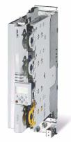
9400
Servo Drives 9400 HighLine_ _ _ _ _ _ _ _ _ _ _
Overview of technical documentation for Servo Drives 9400
_ _ _ _ _ _ _ _ _ _ _ _ _ _ _ _ _ _ _ _ _ _ _ _ _ _ _ _ _ _ _ _ _ _ _ _ _ _ _ _ _ _ _ _ _ _ _ _ _ _ _ _ _ _ _ _ _ _ _ _ _ _ _ _
Project planning, selection & order
Hardware manual 9400
Catalogue / electronic catalogue (DSC — Drive Solution Catalogue)
Mounting & wiring
MA — 9400 StateLine/HighLine
MA — communication module
MA — extension module
MA — safety module
MA — accessories
MA — remote maintenance components
Parameter setting
BA — keypad
SW — Lenze software »Engineer«
SW — controller (9400 StateLine/HighLine/PLC)
SW — regenerative power supply module
KHB — communication module
SW — extension module
SW — safety module
SW — Lenze technology application
SW — function library 9400
Configuring & programming
SW — Lenze software »Engineer«
SW — Lenze software »PLC Designer«
SW — controller (9400 HighLine/PLC)
KHB — communication module
SW — extension module
SW — safety module
SW — Lenze technology application
SW — function library 9400
Drive commissioning
Commissioning guide
SW — controller (9400 StateLine/HighLine/PLC)
Chapter «Commissioning» ( 22)
Chapter «Oscilloscope» ( 579)
Chapter «Diagnostics & fault analysis» ( 598)
Remote maintenance manual
Networking structure
KHB — communication medium used
Legend:
Printed documentation
Online documentation (PDF/Engineer online help)
Abbreviations used:
BA Operating instructions
KHB Communication manual
MA Mounting instructions
SW Software Manual
This documentation
This documentation
This documentation
|
2 |
Lenze · Servo-Inverter 9400 HighLine · Reference manual · DMS 10.0 EN · 11/2013 · TD05/06 |
Contents
_ _ _ _ _ _ _ _ _ _ _ _ _ _ _ _ _ _ _ _ _ _ _ _ _ _ _ _ _ _ _ _ _ _ _ _ _ _ _ _ _ _ _ _ _ _ _ _ _ _ _ _ _ _ _ _ _ _ _ _ _ _ _ _
|
1 |
About this documentation _ _ _ _ _ _ _ _ _ _ _ _ _ _ _ _ _ _ _ _ _ _ _ _ _ _ _ _ _ _ _ _ _ _ _ _ _ _ _ |
11 |
||||||||
|
1.1 |
Conventions used |
_ _ _ _ _ _ _ _ _ _ _ _ _ _ _ _ _ _ _ _ _ _ _ _ _ _ _ _ _ _ _ _ _ _ _ _ _ _ _ _ _ _ _ _ |
12 |
|||||||
|
1.2 |
Terminology used |
_ _ _ _ _ _ _ _ _ _ _ _ _ _ _ _ _ _ _ _ _ _ _ _ _ _ _ _ _ _ _ _ _ _ _ _ _ _ _ _ _ _ _ _ |
13 |
|||||||
|
1.3 |
Definition of notes used _ _ _ _ _ _ _ _ _ _ _ _ _ _ _ _ _ _ _ _ _ _ _ _ _ _ _ _ _ _ _ _ _ _ _ _ _ _ _ _ _ |
14 |
||||||||
|
2 |
Introduction _ _ _ _ _ _ _ _ _ _ _ _ _ _ _ _ _ _ _ _ _ _ _ _ _ _ _ _ _ _ _ _ _ _ _ _ _ _ _ _ _ _ _ _ _ _ _ |
15 |
||||||||
|
2.1 |
Parameter setting, configuring, or programming? |
_ _ _ _ _ _ _ _ _ _ _ _ _ _ _ _ _ _ _ _ _ _ _ _ _ _ |
15 |
|||||||
|
2.1.1 |
Basic functionalities _ _ _ _ _ _ _ _ _ _ _ _ _ _ _ _ _ _ _ _ _ _ _ _ _ _ _ _ _ _ _ _ _ _ _ _ _ _ |
16 |
||||||||
|
2.1.2 |
Technology applications _ _ _ _ _ _ _ _ _ _ _ _ _ _ _ _ _ _ _ _ _ _ _ _ _ _ _ _ _ _ _ _ _ _ _ _ |
16 |
||||||||
|
2.2 |
Communicating with the controller _ _ _ _ _ _ _ _ _ _ _ _ _ _ _ _ _ _ _ _ _ _ _ _ _ _ _ _ _ _ _ _ _ _ |
17 |
||||||||
|
2.2.1 |
Going online via diagnostic adapter |
_ _ _ _ _ _ _ _ _ _ _ _ _ _ _ _ _ _ _ _ _ _ _ _ _ _ _ _ _ |
17 |
|||||||
|
2.2.2 |
Going online via system bus (CAN on board) _ _ _ _ _ _ _ _ _ _ _ _ _ _ _ _ _ _ _ _ _ _ _ _ _ |
20 |
||||||||
|
2.2.3 |
Use of other communication interfaces |
_ _ _ _ _ _ _ _ _ _ _ _ _ _ _ _ _ _ _ _ _ _ _ _ _ _ _ |
20 |
|||||||
|
2.3 |
Signal types & scaling _ _ _ _ _ _ _ _ _ _ _ _ _ _ _ _ _ _ _ _ _ _ _ _ _ _ _ _ _ _ _ _ _ _ _ _ _ _ _ _ _ _ |
21 |
||||||||
|
3 |
Commissioning |
_ _ _ _ _ _ _ _ _ _ _ _ _ _ _ _ _ _ _ _ _ _ _ _ _ _ _ _ _ _ _ _ _ _ _ _ _ _ _ _ _ _ _ _ _ |
22 |
|||||||
|
3.1 |
General information _ _ _ _ _ _ _ _ _ _ _ _ _ _ _ _ _ _ _ _ _ _ _ _ _ _ _ _ _ _ _ _ _ _ _ _ _ _ _ _ _ _ _ |
23 |
||||||||
|
3.2 |
Notes on commissioning using the keypad |
_ _ _ _ _ _ _ _ _ _ _ _ _ _ _ _ _ _ _ _ _ _ _ _ _ _ _ _ _ _ |
24 |
|||||||
|
3.3 |
Initial commissioning _ _ _ _ _ _ _ _ _ _ _ _ _ _ _ _ _ _ _ _ _ _ _ _ _ _ _ _ _ _ _ _ _ _ _ _ _ _ _ _ _ _ |
25 |
||||||||
|
3.4 |
Standard set-up |
_ _ _ _ _ _ _ _ _ _ _ _ _ _ _ _ _ _ _ _ _ _ _ _ _ _ _ _ _ _ _ _ _ _ _ _ _ _ _ _ _ _ _ _ _ |
26 |
|||||||
|
3.5 |
Controller replacement |
_ _ _ _ _ _ _ _ _ _ _ _ _ _ _ _ _ _ _ _ _ _ _ _ _ _ _ _ _ _ _ _ _ _ _ _ _ _ _ _ _ |
27 |
|||||||
|
3.6 |
Motor replacement |
_ _ _ _ _ _ _ _ _ _ _ _ _ _ _ _ _ _ _ _ _ _ _ _ _ _ _ _ _ _ _ _ _ _ _ _ _ _ _ _ _ _ _ |
27 |
|||||||
|
4 |
Drive interface _ _ _ _ _ _ _ _ _ _ _ _ _ _ _ _ _ _ _ _ _ _ _ _ _ _ _ _ _ _ _ _ _ _ _ _ _ _ _ _ _ _ _ _ _ _ |
28 |
||||||||
|
4.1 |
Machine parameters |
_ _ _ _ _ _ _ _ _ _ _ _ _ _ _ _ _ _ _ _ _ _ _ _ _ _ _ _ _ _ _ _ _ _ _ _ _ _ _ _ _ _ |
29 |
|||||||
|
4.1.1 |
Mains voltage |
_ _ _ _ _ _ _ _ _ _ _ _ _ _ _ _ _ _ _ _ _ _ _ _ _ _ _ _ _ _ _ _ _ _ _ _ _ _ _ _ _ |
30 |
|||||||
|
4.1.2 |
Gearbox ratio _ _ _ _ _ _ _ _ _ _ _ _ _ _ _ _ _ _ _ _ _ _ _ _ _ _ _ _ _ _ _ _ _ _ _ _ _ _ _ _ _ _ |
31 |
||||||||
|
4.1.3 |
Motor mounting direction _ _ _ _ _ _ _ _ _ _ _ _ _ _ _ _ _ _ _ _ _ _ _ _ _ _ _ _ _ _ _ _ _ _ _ |
32 |
||||||||
|
4.1.4 |
Feedback configuration _ _ _ _ _ _ _ _ _ _ _ _ _ _ _ _ _ _ _ _ _ _ _ _ _ _ _ _ _ _ _ _ _ _ _ _ |
32 |
||||||||
|
4.1.5 |
Unit/user-defined unit _ _ _ _ _ _ _ _ _ _ _ _ _ _ _ _ _ _ _ _ _ _ _ _ _ _ _ _ _ _ _ _ _ _ _ _ _ |
33 |
||||||||
|
4.1.6 |
Traversing range _ _ _ _ _ _ _ _ _ _ _ _ _ _ _ _ _ _ _ _ _ _ _ _ _ _ _ _ _ _ _ _ _ _ _ _ _ _ _ _ |
34 |
||||||||
|
4.1.7 |
Feed constant |
_ _ _ _ _ _ _ _ _ _ _ _ _ _ _ _ _ _ _ _ _ _ _ _ _ _ _ _ _ _ _ _ _ _ _ _ _ _ _ _ _ |
36 |
|||||||
|
4.1.8 |
Resolution of an encoder revolution |
_ _ _ _ _ _ _ _ _ _ _ _ _ _ _ _ _ _ _ _ _ _ _ _ _ _ _ _ _ |
37 |
|||||||
|
4.1.9 |
Max. position, speed, and acceleration that can be displayed internally _ _ _ _ _ _ _ _ _ _ |
40 |
||||||||
|
4.2 |
Device commands _ _ _ _ _ _ _ _ _ _ _ _ _ _ _ _ _ _ _ _ _ _ _ _ _ _ _ _ _ _ _ _ _ _ _ _ _ _ _ _ _ _ _ _ |
42 |
||||||||
|
4.2.1 |
Load Lenze setting _ _ _ _ _ _ _ _ _ _ _ _ _ _ _ _ _ _ _ _ _ _ _ _ _ _ _ _ _ _ _ _ _ _ _ _ _ _ _ |
44 |
||||||||
|
4.2.2 |
Load start parameters _ _ _ _ _ _ _ _ _ _ _ _ _ _ _ _ _ _ _ _ _ _ _ _ _ _ _ _ _ _ _ _ _ _ _ _ _ |
45 |
||||||||
|
4.2.3 |
ENP:Load plant data _ _ _ _ _ _ _ _ _ _ _ _ _ _ _ _ _ _ _ _ _ _ _ _ _ _ _ _ _ _ _ _ _ _ _ _ _ _ |
46 |
||||||||
|
4.2.4 |
Activate application _ _ _ _ _ _ _ _ _ _ _ _ _ _ _ _ _ _ _ _ _ _ _ _ _ _ _ _ _ _ _ _ _ _ _ _ _ _ |
47 |
||||||||
|
4.2.5 |
Save selected application _ _ _ _ _ _ _ _ _ _ _ _ _ _ _ _ _ _ _ _ _ _ _ _ _ _ _ _ _ _ _ _ _ _ _ |
48 |
||||||||
|
4.2.6 |
Save start parameters _ _ _ _ _ _ _ _ _ _ _ _ _ _ _ _ _ _ _ _ _ _ _ _ _ _ _ _ _ _ _ _ _ _ _ _ _ |
49 |
||||||||
|
4.2.7 |
Delete logbook _ _ _ _ _ _ _ _ _ _ _ _ _ _ _ _ _ _ _ _ _ _ _ _ _ _ _ _ _ _ _ _ _ _ _ _ _ _ _ _ _ |
51 |
||||||||
|
4.2.8 |
Archive logbook |
_ _ _ _ _ _ _ _ _ _ _ _ _ _ _ _ _ _ _ _ _ _ _ _ _ _ _ _ _ _ _ _ _ _ _ _ _ _ _ _ |
52 |
|||||||
|
4.2.9 |
Start application |
_ _ _ _ _ _ _ _ _ _ _ _ _ _ _ _ _ _ _ _ _ _ _ _ _ _ _ _ _ _ _ _ _ _ _ _ _ _ _ _ |
53 |
|||||||
|
4.2.10 |
Stop application |
_ _ _ _ _ _ _ _ _ _ _ _ _ _ _ _ _ _ _ _ _ _ _ _ _ _ _ _ _ _ _ _ _ _ _ _ _ _ _ _ |
54 |
|||||||
|
4.2.11 |
Reset program |
_ _ _ _ _ _ _ _ _ _ _ _ _ _ _ _ _ _ _ _ _ _ _ _ _ _ _ _ _ _ _ _ _ _ _ _ _ _ _ _ _ |
55 |
|||||||
|
4.2.12 |
Delete program |
_ _ _ _ _ _ _ _ _ _ _ _ _ _ _ _ _ _ _ _ _ _ _ _ _ _ _ _ _ _ _ _ _ _ _ _ _ _ _ _ |
56 |
|||||||
|
4.2.13 |
Restart program |
_ _ _ _ _ _ _ _ _ _ _ _ _ _ _ _ _ _ _ _ _ _ _ _ _ _ _ _ _ _ _ _ _ _ _ _ _ _ _ _ |
57 |
|||||||
|
4.2.14 |
Reset runtime measurement _ _ _ _ _ _ _ _ _ _ _ _ _ _ _ _ _ _ _ _ _ _ _ _ _ _ _ _ _ _ _ _ _ |
58 |
||||||||
|
4.2.15 |
Inhibit controller _ _ _ _ _ _ _ _ _ _ _ _ _ _ _ _ _ _ _ _ _ _ _ _ _ _ _ _ _ _ _ _ _ _ _ _ _ _ _ _ |
60 |
||||||||
|
4.2.16 |
Enable controller _ _ _ _ _ _ _ _ _ _ _ _ _ _ _ _ _ _ _ _ _ _ _ _ _ _ _ _ _ _ _ _ _ _ _ _ _ _ _ _ |
61 |
||||||||
|
4.2.17 |
Reset error |
_ _ _ _ _ _ _ _ _ _ _ _ _ _ _ _ _ _ _ _ _ _ _ _ _ _ _ _ _ _ _ _ _ _ _ _ _ _ _ _ _ _ _ |
62 |
|||||||
|
4.2.18 |
Activate quick stop _ _ _ _ _ _ _ _ _ _ _ _ _ _ _ _ _ _ _ _ _ _ _ _ _ _ _ _ _ _ _ _ _ _ _ _ _ _ _ |
63 |
||||||||
|
4.2.19 |
Reset quick stop |
_ _ _ _ _ _ _ _ _ _ _ _ _ _ _ _ _ _ _ _ _ _ _ _ _ _ _ _ _ _ _ _ _ _ _ _ _ _ _ _ |
64 |
|
Lenze · Servo-Inverter 9400 HighLine · Reference manual · DMS 10.0 EN · 11/2013 · TD05/06 |
3 |
Contents
_ _ _ _ _ _ _ _ _ _ _ _ _ _ _ _ _ _ _ _ _ _ _ _ _ _ _ _ _ _ _ _ _ _ _ _ _ _ _ _ _ _ _ _ _ _ _ _ _ _ _ _ _ _ _ _ _ _ _ _ _ _ _ _
|
4.2.20 |
Identify pole position (360°) _ _ _ _ _ _ _ _ _ _ _ _ _ _ _ _ _ _ _ _ _ _ _ _ _ _ _ _ _ _ _ _ _ _ |
65 |
|||||||||
|
4.2.21 |
Identify pole position (min. motion) |
_ _ _ _ _ _ _ _ _ _ _ _ _ _ _ _ _ _ _ _ _ _ _ _ _ _ _ _ _ |
66 |
||||||||
|
4.2.22 |
Resolver error identification _ _ _ _ _ _ _ _ _ _ _ _ _ _ _ _ _ _ _ _ _ _ _ _ _ _ _ _ _ _ _ _ _ _ |
68 |
|||||||||
|
4.2.23 |
Load Lenze INV characteristic |
_ _ _ _ _ _ _ _ _ _ _ _ _ _ _ _ _ _ _ _ _ _ _ _ _ _ _ _ _ _ _ _ _ |
69 |
||||||||
|
4.2.24 |
Calculate inv. characteristic |
_ _ _ _ _ _ _ _ _ _ _ _ _ _ _ _ _ _ _ _ _ _ _ _ _ _ _ _ _ _ _ _ _ _ |
70 |
||||||||
|
4.2.25 |
Determine motor parameters _ _ _ _ _ _ _ _ _ _ _ _ _ _ _ _ _ _ _ _ _ _ _ _ _ _ _ _ _ _ _ _ _ |
71 |
|||||||||
|
4.2.26 |
Calculate current controller parameters _ _ _ _ _ _ _ _ _ _ _ _ _ _ _ _ _ _ _ _ _ _ _ _ _ _ _ |
72 |
|||||||||
|
4.2.27 |
Calculate speed controller parameters _ _ _ _ _ _ _ _ _ _ _ _ _ _ _ _ _ _ _ _ _ _ _ _ _ _ _ _ |
74 |
|||||||||
|
4.2.28 |
CAN on board: Reset Node |
_ _ _ _ _ _ _ _ _ _ _ _ _ _ _ _ _ _ _ _ _ _ _ _ _ _ _ _ _ _ _ _ _ _ |
75 |
||||||||
|
4.2.29 |
CAN module: Reset node |
_ _ _ _ _ _ _ _ _ _ _ _ _ _ _ _ _ _ _ _ _ _ _ _ _ _ _ _ _ _ _ _ _ _ _ |
76 |
||||||||
|
4.2.30 |
CAN on board: Pred.Connect.Set |
_ _ _ _ _ _ _ _ _ _ _ _ _ _ _ _ _ _ _ _ _ _ _ _ _ _ _ _ _ _ _ |
77 |
||||||||
|
4.2.31 |
CAN module: Pred.Connect.Set |
_ _ _ _ _ _ _ _ _ _ _ _ _ _ _ _ _ _ _ _ _ _ _ _ _ _ _ _ _ _ _ _ |
78 |
||||||||
|
4.2.32 |
CAN on board: Identify node |
_ _ _ _ _ _ _ _ _ _ _ _ _ _ _ _ _ _ _ _ _ _ _ _ _ _ _ _ _ _ _ _ _ |
79 |
||||||||
|
4.2.33 |
CAN module: Identify node |
_ _ _ _ _ _ _ _ _ _ _ _ _ _ _ _ _ _ _ _ _ _ _ _ _ _ _ _ _ _ _ _ _ _ |
80 |
||||||||
|
4.2.34 |
Unbind/bind Ethernet module MXI1 _ _ _ _ _ _ _ _ _ _ _ _ _ _ _ _ _ _ _ _ _ _ _ _ _ _ _ _ _ |
81 |
|||||||||
|
4.2.35 |
Unbind/bind Ethernet module MXI2 _ _ _ _ _ _ _ _ _ _ _ _ _ _ _ _ _ _ _ _ _ _ _ _ _ _ _ _ _ |
82 |
|||||||||
|
4.2.36 |
Activate parameter set 1 … 4 _ _ _ _ _ _ _ _ _ _ _ _ _ _ _ _ _ _ _ _ _ _ _ _ _ _ _ _ _ _ _ _ _ |
83 |
|||||||||
|
4.2.37 |
Activate parameter set 1 … 4 _ _ _ _ _ _ _ _ _ _ _ _ _ _ _ _ _ _ _ _ _ _ _ _ _ _ _ _ _ _ _ _ _ |
85 |
|||||||||
|
4.2.38 |
Load cam data |
_ _ _ _ _ _ _ _ _ _ _ _ _ _ _ _ _ _ _ _ _ _ _ _ _ _ _ _ _ _ _ _ _ _ _ _ _ _ _ _ _ |
87 |
||||||||
|
4.2.39 |
Save cam data |
_ _ _ _ _ _ _ _ _ _ _ _ _ _ _ _ _ _ _ _ _ _ _ _ _ _ _ _ _ _ _ _ _ _ _ _ _ _ _ _ _ |
89 |
||||||||
|
4.2.40 |
Calculate cam data _ _ _ _ _ _ _ _ _ _ _ _ _ _ _ _ _ _ _ _ _ _ _ _ _ _ _ _ _ _ _ _ _ _ _ _ _ _ _ |
91 |
|||||||||
|
4.2.41 |
Calculate cam data checksum _ _ _ _ _ _ _ _ _ _ _ _ _ _ _ _ _ _ _ _ _ _ _ _ _ _ _ _ _ _ _ _ _ |
92 |
|||||||||
|
4.2.42 |
Format file system _ _ _ _ _ _ _ _ _ _ _ _ _ _ _ _ _ _ _ _ _ _ _ _ _ _ _ _ _ _ _ _ _ _ _ _ _ _ _ |
93 |
|||||||||
|
4.2.43 |
Restore file system _ _ _ _ _ _ _ _ _ _ _ _ _ _ _ _ _ _ _ _ _ _ _ _ _ _ _ _ _ _ _ _ _ _ _ _ _ _ _ |
94 |
|||||||||
|
4.2.44 |
Prepare firmware update |
_ _ _ _ _ _ _ _ _ _ _ _ _ _ _ _ _ _ _ _ _ _ _ _ _ _ _ _ _ _ _ _ _ _ _ |
95 |
||||||||
|
4.2.45 |
Restart controller _ _ _ _ _ _ _ _ _ _ _ _ _ _ _ _ _ _ _ _ _ _ _ _ _ _ _ _ _ _ _ _ _ _ _ _ _ _ _ _ |
96 |
|||||||||
|
4.3 |
Device states _ _ _ _ _ _ _ _ _ _ _ _ _ _ _ _ _ _ _ _ _ _ _ _ _ _ _ _ _ _ _ _ _ _ _ _ _ _ _ _ _ _ _ _ _ _ _ |
97 |
|||||||||
|
4.3.1 |
«Initialisation active» state |
_ _ _ _ _ _ _ _ _ _ _ _ _ _ _ _ _ _ _ _ _ _ _ _ _ _ _ _ _ _ _ _ _ _ |
99 |
||||||||
|
4.3.2 |
«Safe torque off active» state |
_ _ _ _ _ _ _ _ _ _ _ _ _ _ _ _ _ _ _ _ _ _ _ _ _ _ _ _ _ _ _ _ _ |
100 |
||||||||
|
4.3.3 |
«Device is ready to switch on» state _ _ _ _ _ _ _ _ _ _ _ _ _ _ _ _ _ _ _ _ _ _ _ _ _ _ _ _ _ _ |
100 |
|||||||||
|
4.3.4 |
«Device is switched on» state |
_ _ _ _ _ _ _ _ _ _ _ _ _ _ _ _ _ _ _ _ _ _ _ _ _ _ _ _ _ _ _ _ _ |
101 |
||||||||
|
4.3.5 |
«Operation» state _ _ _ _ _ _ _ _ _ _ _ _ _ _ _ _ _ _ _ _ _ _ _ _ _ _ _ _ _ _ _ _ _ _ _ _ _ _ _ _ |
101 |
|||||||||
|
4.3.6 |
«Warning active» _ _ _ _ _ _ _ _ _ _ _ _ _ _ _ _ _ _ _ _ _ _ _ _ _ _ _ _ _ _ _ _ _ _ _ _ _ _ _ _ |
102 |
|||||||||
|
4.3.7 |
«Warning locked active» _ _ _ _ _ _ _ _ _ _ _ _ _ _ _ _ _ _ _ _ _ _ _ _ _ _ _ _ _ _ _ _ _ _ _ _ |
102 |
|||||||||
|
4.3.8 |
«Quick stop by trouble active» state _ _ _ _ _ _ _ _ _ _ _ _ _ _ _ _ _ _ _ _ _ _ _ _ _ _ _ _ _ _ |
102 |
|||||||||
|
4.3.9 |
«Trouble active» state |
_ _ _ _ _ _ _ _ _ _ _ _ _ _ _ _ _ _ _ _ _ _ _ _ _ _ _ _ _ _ _ _ _ _ _ _ _ |
103 |
||||||||
|
4.3.10 |
«Fault active» state _ _ _ _ _ _ _ _ _ _ _ _ _ _ _ _ _ _ _ _ _ _ _ _ _ _ _ _ _ _ _ _ _ _ _ _ _ _ _ |
103 |
|||||||||
|
4.3.11 |
«System fault active» state |
_ _ _ _ _ _ _ _ _ _ _ _ _ _ _ _ _ _ _ _ _ _ _ _ _ _ _ _ _ _ _ _ _ _ |
103 |
||||||||
|
4.4 Automatic restart after mains connection/trouble… |
_ _ _ _ _ _ _ _ _ _ _ _ _ _ _ _ _ _ _ _ _ _ _ _ _ |
104 |
|||||||||
|
4.5 Behaviour after task overflow |
_ _ _ _ _ _ _ _ _ _ _ _ _ _ _ _ _ _ _ _ _ _ _ _ _ _ _ _ _ _ _ _ _ _ _ _ _ |
106 |
|||||||||
|
4.6 |
Device output power _ _ _ _ _ _ _ _ _ _ _ _ _ _ _ _ _ _ _ _ _ _ _ _ _ _ _ _ _ _ _ _ _ _ _ _ _ _ _ _ _ _ |
107 |
|||||||||
|
4.6.1 |
Switching frequency _ _ _ _ _ _ _ _ _ _ _ _ _ _ _ _ _ _ _ _ _ _ _ _ _ _ _ _ _ _ _ _ _ _ _ _ _ _ |
107 |
|||||||||
|
4.6.2 |
Monitoring of the device utilisation |
_ _ _ _ _ _ _ _ _ _ _ _ _ _ _ _ _ _ _ _ _ _ _ _ _ _ _ _ _ |
108 |
||||||||
|
4.6.3 |
Operation with increased continuous power _ _ _ _ _ _ _ _ _ _ _ _ _ _ _ _ _ _ _ _ _ _ _ _ _ |
109 |
|||||||||
|
4.7 Internal interfaces | «LS_DriveInterface» system block |
_ _ _ _ _ _ _ _ _ _ _ _ _ _ _ _ _ _ _ _ _ _ _ _ |
110 |
|||||||||
|
4.7.1 |
Status signals _ _ _ _ _ _ _ _ _ _ _ _ _ _ _ _ _ _ _ _ _ _ _ _ _ _ _ _ _ _ _ _ _ _ _ _ _ _ _ _ _ _ |
113 |
|||||||||
|
4.7.2 |
Monitoring of external events |
_ _ _ _ _ _ _ _ _ _ _ _ _ _ _ _ _ _ _ _ _ _ _ _ _ _ _ _ _ _ _ _ |
114 |
|
4 |
Lenze · Servo-Inverter 9400 HighLine · Reference manual · DMS 10.0 EN · 11/2013 · TD05/06 |
Contents
_ _ _ _ _ _ _ _ _ _ _ _ _ _ _ _ _ _ _ _ _ _ _ _ _ _ _ _ _ _ _ _ _ _ _ _ _ _ _ _ _ _ _ _ _ _ _ _ _ _ _ _ _ _ _ _ _ _ _ _ _ _ _ _
|
5 |
Motor interface _ _ _ _ _ _ _ _ _ _ _ _ _ _ _ _ _ _ _ _ _ _ _ _ _ _ _ _ _ _ _ _ _ _ _ _ _ _ _ _ _ _ _ _ _ |
115 |
||||||
|
5.1 |
General information _ _ _ _ _ _ _ _ _ _ _ _ _ _ _ _ _ _ _ _ _ _ _ _ _ _ _ _ _ _ _ _ _ _ _ _ _ _ _ _ _ _ _ |
117 |
||||||
|
5.1.1 |
Reading out motor data from the controller _ _ _ _ _ _ _ _ _ _ _ _ _ _ _ _ _ _ _ _ _ _ _ _ _ |
117 |
||||||
|
5.1.2 |
Selecting a motor from the motor catalogue in the »Engineer« _ _ _ _ _ _ _ _ _ _ _ _ _ _ |
118 |
||||||
|
5.1.3 |
Displaying/editing motor data in »Engineer« _ _ _ _ _ _ _ _ _ _ _ _ _ _ _ _ _ _ _ _ _ _ _ _ |
119 |
||||||
|
5.2 |
Select motor control _ _ _ _ _ _ _ _ _ _ _ _ _ _ _ _ _ _ _ _ _ _ _ _ _ _ _ _ _ _ _ _ _ _ _ _ _ _ _ _ _ _ _ |
121 |
||||||
|
5.3 |
Adjusting motor and controller to each other _ _ _ _ _ _ _ _ _ _ _ _ _ _ _ _ _ _ _ _ _ _ _ _ _ _ _ _ _ |
123 |
||||||
|
5.3.1 |
Accepting/adapting plant parameters _ _ _ _ _ _ _ _ _ _ _ _ _ _ _ _ _ _ _ _ _ _ _ _ _ _ _ _ |
124 |
||||||
|
5.3.2 |
Parameterising motor encoder _ _ _ _ _ _ _ _ _ _ _ _ _ _ _ _ _ _ _ _ _ _ _ _ _ _ _ _ _ _ _ _ |
126 |
||||||
|
5.3.3 |
Pole position identification _ _ _ _ _ _ _ _ _ _ _ _ _ _ _ _ _ _ _ _ _ _ _ _ _ _ _ _ _ _ _ _ _ _ |
128 |
||||||
|
5.3.4 |
Optimising the switching performance of the inverter |
_ _ _ _ _ _ _ _ _ _ _ _ _ _ _ _ _ _ _ |
135 |
|||||
|
5.3.5 |
Determining the motor parameters |
_ _ _ _ _ _ _ _ _ _ _ _ _ _ _ _ _ _ _ _ _ _ _ _ _ _ _ _ _ |
138 |
|||||
|
5.4 |
Servo control (SC) _ _ _ _ _ _ _ _ _ _ _ _ _ _ _ _ _ _ _ _ _ _ _ _ _ _ _ _ _ _ _ _ _ _ _ _ _ _ _ _ _ _ _ _ |
142 |
||||||
|
5.4.1 |
Optimising the control mode |
_ _ _ _ _ _ _ _ _ _ _ _ _ _ _ _ _ _ _ _ _ _ _ _ _ _ _ _ _ _ _ _ _ |
143 |
|||||
|
5.4.2 |
Signal flow (servo control for synchronous motor) _ _ _ _ _ _ _ _ _ _ _ _ _ _ _ _ _ _ _ _ _ |
159 |
||||||
|
5.4.3 |
Signal flow (servo control for asynchronous motor) _ _ _ _ _ _ _ _ _ _ _ _ _ _ _ _ _ _ _ _ _ |
161 |
||||||
|
5.5 |
Sensorless vector control (SLVC) |
_ _ _ _ _ _ _ _ _ _ _ _ _ _ _ _ _ _ _ _ _ _ _ _ _ _ _ _ _ _ _ _ _ _ _ _ |
163 |
|||||
|
5.5.1 |
Basic settings _ _ _ _ _ _ _ _ _ _ _ _ _ _ _ _ _ _ _ _ _ _ _ _ _ _ _ _ _ _ _ _ _ _ _ _ _ _ _ _ _ _ |
164 |
||||||
|
5.5.2 |
Optimising motor parameters |
_ _ _ _ _ _ _ _ _ _ _ _ _ _ _ _ _ _ _ _ _ _ _ _ _ _ _ _ _ _ _ _ |
166 |
|||||
|
5.5.3 |
Optimising the control mode |
_ _ _ _ _ _ _ _ _ _ _ _ _ _ _ _ _ _ _ _ _ _ _ _ _ _ _ _ _ _ _ _ _ |
172 |
|||||
|
5.5.4 |
Signal flow |
_ _ _ _ _ _ _ _ _ _ _ _ _ _ _ _ _ _ _ _ _ _ _ _ _ _ _ _ _ _ _ _ _ _ _ _ _ _ _ _ _ _ _ |
180 |
|||||
|
5.6 |
V/f control (VFCplus) |
_ _ _ _ _ _ _ _ _ _ _ _ _ _ _ _ _ _ _ _ _ _ _ _ _ _ _ _ _ _ _ _ _ _ _ _ _ _ _ _ _ _ |
181 |
|||||
|
5.6.1 |
Basic settings _ _ _ _ _ _ _ _ _ _ _ _ _ _ _ _ _ _ _ _ _ _ _ _ _ _ _ _ _ _ _ _ _ _ _ _ _ _ _ _ _ _ |
181 |
||||||
|
5.6.2 |
Optimising the control mode |
_ _ _ _ _ _ _ _ _ _ _ _ _ _ _ _ _ _ _ _ _ _ _ _ _ _ _ _ _ _ _ _ _ |
188 |
|||||
|
5.6.3 |
Signal flow |
_ _ _ _ _ _ _ _ _ _ _ _ _ _ _ _ _ _ _ _ _ _ _ _ _ _ _ _ _ _ _ _ _ _ _ _ _ _ _ _ _ _ _ |
196 |
|||||
|
5.7 |
V/f control (VFCplus) |
_ _ _ _ _ _ _ _ _ _ _ _ _ _ _ _ _ _ _ _ _ _ _ _ _ _ _ _ _ _ _ _ _ _ _ _ _ _ _ _ _ _ |
197 |
|||||
|
5.7.1 |
Signal flow |
_ _ _ _ _ _ _ _ _ _ _ _ _ _ _ _ _ _ _ _ _ _ _ _ _ _ _ _ _ _ _ _ _ _ _ _ _ _ _ _ _ _ _ |
198 |
|||||
|
5.8 |
Parameterisable additional functions |
_ _ _ _ _ _ _ _ _ _ _ _ _ _ _ _ _ _ _ _ _ _ _ _ _ _ _ _ _ _ _ _ _ |
200 |
|||||
|
5.8.1 |
Correction of the stator leakage inductance… _ _ _ _ _ _ _ _ _ _ _ _ _ _ _ _ _ _ _ _ _ _ _ _ |
201 |
||||||
|
5.8.2 |
Field weakening for synchronous machines _ _ _ _ _ _ _ _ _ _ _ _ _ _ _ _ _ _ _ _ _ _ _ _ _ |
206 |
||||||
|
5.8.3 |
Flying restart function _ _ _ _ _ _ _ _ _ _ _ _ _ _ _ _ _ _ _ _ _ _ _ _ _ _ _ _ _ _ _ _ _ _ _ _ _ |
209 |
||||||
|
5.8.4 |
DC-injection braking _ _ _ _ _ _ _ _ _ _ _ _ _ _ _ _ _ _ _ _ _ _ _ _ _ _ _ _ _ _ _ _ _ _ _ _ _ _ |
212 |
||||||
|
5.9 |
Monitoring _ _ _ _ _ _ _ _ _ _ _ _ _ _ _ _ _ _ _ _ _ _ _ _ _ _ _ _ _ _ _ _ _ _ _ _ _ _ _ _ _ _ _ _ _ _ _ _ |
214 |
||||||
|
5.9.1 |
Signal flow |
_ _ _ _ _ _ _ _ _ _ _ _ _ _ _ _ _ _ _ _ _ _ _ _ _ _ _ _ _ _ _ _ _ _ _ _ _ _ _ _ _ _ _ |
214 |
|||||
|
5.9.2 |
Motor monitoring (I2xt) |
_ _ _ _ _ _ _ _ _ _ _ _ _ _ _ _ _ _ _ _ _ _ _ _ _ _ _ _ _ _ _ _ _ _ _ _ |
215 |
|||||
|
5.9.3 |
Motor temperature monitoring _ _ _ _ _ _ _ _ _ _ _ _ _ _ _ _ _ _ _ _ _ _ _ _ _ _ _ _ _ _ _ _ |
222 |
||||||
|
5.9.4 |
Motor phase failure monitoring _ _ _ _ _ _ _ _ _ _ _ _ _ _ _ _ _ _ _ _ _ _ _ _ _ _ _ _ _ _ _ _ |
226 |
||||||
|
5.9.5 |
Maximum current monitoring |
_ _ _ _ _ _ _ _ _ _ _ _ _ _ _ _ _ _ _ _ _ _ _ _ _ _ _ _ _ _ _ _ |
230 |
|||||
|
5.10 |
Internal interfaces | «LS_MotorInterface» system block _ _ _ _ _ _ _ _ _ _ _ _ _ _ _ _ _ _ _ _ _ _ _ _ |
231 |
||||||
|
6 |
Encoder evaluation |
_ _ _ _ _ _ _ _ _ _ _ _ _ _ _ _ _ _ _ _ _ _ _ _ _ _ _ _ _ _ _ _ _ _ _ _ _ _ _ _ _ _ _ |
236 |
|||||
|
6.1 |
Internal interfaces | «LS_Feedback» system block _ _ _ _ _ _ _ _ _ _ _ _ _ _ _ _ _ _ _ _ _ _ _ _ _ _ _ |
237 |
||||||
|
6.1.1 |
Use of an external position encoder |
_ _ _ _ _ _ _ _ _ _ _ _ _ _ _ _ _ _ _ _ _ _ _ _ _ _ _ _ _ |
239 |
|||||
|
6.2 |
Signal flow _ _ _ _ _ _ _ _ _ _ _ _ _ _ _ _ _ _ _ _ _ _ _ _ _ _ _ _ _ _ _ _ _ _ _ _ _ _ _ _ _ _ _ _ _ _ _ _ |
240 |
||||||
|
6.3 |
Parameter setting _ _ _ _ _ _ _ _ _ _ _ _ _ _ _ _ _ _ _ _ _ _ _ _ _ _ _ _ _ _ _ _ _ _ _ _ _ _ _ _ _ _ _ _ |
241 |
||||||
|
6.3.1 |
Controller configuration _ _ _ _ _ _ _ _ _ _ _ _ _ _ _ _ _ _ _ _ _ _ _ _ _ _ _ _ _ _ _ _ _ _ _ _ |
243 |
||||||
|
6.3.2 |
System with motor encoder _ _ _ _ _ _ _ _ _ _ _ _ _ _ _ _ _ _ _ _ _ _ _ _ _ _ _ _ _ _ _ _ _ _ |
245 |
||||||
|
6.3.3 |
System with motor encoder and position encoder _ _ _ _ _ _ _ _ _ _ _ _ _ _ _ _ _ _ _ _ _ _ |
246 |
||||||
|
6.3.4 |
Position feedback with a linear distance measuring device _ _ _ _ _ _ _ _ _ _ _ _ _ _ _ _ _ |
248 |
||||||
|
6.3.5 |
Adaptation of the resolver evaluation dynamics _ _ _ _ _ _ _ _ _ _ _ _ _ _ _ _ _ _ _ _ _ _ _ |
250 |
||||||
|
6.3.6 |
Parameterisation of an unknown Hiperface® encoder |
_ _ _ _ _ _ _ _ _ _ _ _ _ _ _ _ _ _ _ |
251 |
|||||
|
6.3.7 |
Parameterisation of a Hiperface® encoder with increased initialisation time _ _ _ _ _ _ _ |
251 |
||||||
|
6.3.8 |
Use of an SSI encoder at X8 _ _ _ _ _ _ _ _ _ _ _ _ _ _ _ _ _ _ _ _ _ _ _ _ _ _ _ _ _ _ _ _ _ _ |
252 |
||||||
|
6.3.9 |
Rotative encoder with SSI protocol |
_ _ _ _ _ _ _ _ _ _ _ _ _ _ _ _ _ _ _ _ _ _ _ _ _ _ _ _ _ _ |
258 |
|||||
|
6.3.10 |
Provision of the encoder signal of input X8 _ _ _ _ _ _ _ _ _ _ _ _ _ _ _ _ _ _ _ _ _ _ _ _ _ _ |
260 |
|
Lenze · Servo-Inverter 9400 HighLine · Reference manual · DMS 10.0 EN · 11/2013 · TD05/06 |
5 |
Contents
_ _ _ _ _ _ _ _ _ _ _ _ _ _ _ _ _ _ _ _ _ _ _ _ _ _ _ _ _ _ _ _ _ _ _ _ _ _ _ _ _ _ _ _ _ _ _ _ _ _ _ _ _ _ _ _ _ _ _ _ _ _ _ _
|
6.3.11 |
Resolver error compensation _ _ _ _ _ _ _ _ _ _ _ _ _ _ _ _ _ _ _ _ _ _ _ _ _ _ _ _ _ _ _ _ _ |
263 |
||||
|
6.3.12 |
Encoder angular drift monitoring _ _ _ _ _ _ _ _ _ _ _ _ _ _ _ _ _ _ _ _ _ _ _ _ _ _ _ _ _ _ _ |
264 |
||||
|
7 |
Braking operation _ _ _ _ _ _ _ _ _ _ _ _ _ _ _ _ _ _ _ _ _ _ _ _ _ _ _ _ _ _ _ _ _ _ _ _ _ _ _ _ _ _ _ _ |
266 |
||||
|
7.1 |
Parameter setting _ _ _ _ _ _ _ _ _ _ _ _ _ _ _ _ _ _ _ _ _ _ _ _ _ _ _ _ _ _ _ _ _ _ _ _ _ _ _ _ _ _ _ _ |
267 |
||||
|
7.1.1 |
Setting the voltage threshold for braking operation _ _ _ _ _ _ _ _ _ _ _ _ _ _ _ _ _ _ _ _ _ |
267 |
||||
|
7.2 |
Monitoring _ _ _ _ _ _ _ _ _ _ _ _ _ _ _ _ _ _ _ _ _ _ _ _ _ _ _ _ _ _ _ _ _ _ _ _ _ _ _ _ _ _ _ _ _ _ _ _ |
268 |
||||
|
7.2.1 |
Overcurrent protection |
_ _ _ _ _ _ _ _ _ _ _ _ _ _ _ _ _ _ _ _ _ _ _ _ _ _ _ _ _ _ _ _ _ _ _ _ |
268 |
|||
|
7.2.2 |
Ixt utilisation — brake transistor _ _ _ _ _ _ _ _ _ _ _ _ _ _ _ _ _ _ _ _ _ _ _ _ _ _ _ _ _ _ _ _ |
269 |
||||
|
7.2.3 |
I2t utilisation — brake resistor _ _ _ _ _ _ _ _ _ _ _ _ _ _ _ _ _ _ _ _ _ _ _ _ _ _ _ _ _ _ _ _ _ |
270 |
||||
|
7.2.4 |
DC bus overvoltage |
_ _ _ _ _ _ _ _ _ _ _ _ _ _ _ _ _ _ _ _ _ _ _ _ _ _ _ _ _ _ _ _ _ _ _ _ _ _ |
272 |
|||
|
8 |
I/O terminals _ _ _ _ _ _ _ _ _ _ _ _ _ _ _ _ _ _ _ _ _ _ _ _ _ _ _ _ _ _ _ _ _ _ _ _ _ _ _ _ _ _ _ _ _ _ _ |
273 |
||||
|
8.1 |
Overview _ _ _ _ _ _ _ _ _ _ _ _ _ _ _ _ _ _ _ _ _ _ _ _ _ _ _ _ _ _ _ _ _ _ _ _ _ _ _ _ _ _ _ _ _ _ _ _ _ |
273 |
||||
|
8.2 |
Analog inputs |
_ _ _ _ _ _ _ _ _ _ _ _ _ _ _ _ _ _ _ _ _ _ _ _ _ _ _ _ _ _ _ _ _ _ _ _ _ _ _ _ _ _ _ _ _ _ |
274 |
|||
|
8.2.1 |
Terminal assignment/electrical data _ _ _ _ _ _ _ _ _ _ _ _ _ _ _ _ _ _ _ _ _ _ _ _ _ _ _ _ _ |
274 |
||||
|
8.2.2 |
Parameter setting |
_ _ _ _ _ _ _ _ _ _ _ _ _ _ _ _ _ _ _ _ _ _ _ _ _ _ _ _ _ _ _ _ _ _ _ _ _ _ _ |
275 |
|||
|
8.2.3 |
Reconfiguring analog input 1 into current input _ _ _ _ _ _ _ _ _ _ _ _ _ _ _ _ _ _ _ _ _ _ _ |
275 |
||||
|
8.2.4 |
«LS_AnalogInput» system block _ _ _ _ _ _ _ _ _ _ _ _ _ _ _ _ _ _ _ _ _ _ _ _ _ _ _ _ _ _ _ _ |
276 |
||||
|
8.3 |
Analog outputs |
_ _ _ _ _ _ _ _ _ _ _ _ _ _ _ _ _ _ _ _ _ _ _ _ _ _ _ _ _ _ _ _ _ _ _ _ _ _ _ _ _ _ _ _ _ |
277 |
|||
|
8.3.1 |
Terminal assignment/electrical data _ _ _ _ _ _ _ _ _ _ _ _ _ _ _ _ _ _ _ _ _ _ _ _ _ _ _ _ _ |
277 |
||||
|
8.3.2 |
Parameter setting |
_ _ _ _ _ _ _ _ _ _ _ _ _ _ _ _ _ _ _ _ _ _ _ _ _ _ _ _ _ _ _ _ _ _ _ _ _ _ _ |
278 |
|||
|
8.3.3 |
«LS_AnalogOutput» system block _ _ _ _ _ _ _ _ _ _ _ _ _ _ _ _ _ _ _ _ _ _ _ _ _ _ _ _ _ _ _ |
278 |
||||
|
8.4 |
Digital inputs |
_ _ _ _ _ _ _ _ _ _ _ _ _ _ _ _ _ _ _ _ _ _ _ _ _ _ _ _ _ _ _ _ _ _ _ _ _ _ _ _ _ _ _ _ _ _ |
279 |
|||
|
8.4.1 |
Terminal assignment/electrical data _ _ _ _ _ _ _ _ _ _ _ _ _ _ _ _ _ _ _ _ _ _ _ _ _ _ _ _ _ |
279 |
||||
|
8.4.2 |
Parameter setting |
_ _ _ _ _ _ _ _ _ _ _ _ _ _ _ _ _ _ _ _ _ _ _ _ _ _ _ _ _ _ _ _ _ _ _ _ _ _ _ |
279 |
|||
|
8.4.3 |
«LS_DigitalInput» system block _ _ _ _ _ _ _ _ _ _ _ _ _ _ _ _ _ _ _ _ _ _ _ _ _ _ _ _ _ _ _ _ |
280 |
||||
|
8.5 |
Digital outputs _ _ _ _ _ _ _ _ _ _ _ _ _ _ _ _ _ _ _ _ _ _ _ _ _ _ _ _ _ _ _ _ _ _ _ _ _ _ _ _ _ _ _ _ _ _ |
281 |
||||
|
8.5.1 |
Terminal assignment/electrical data _ _ _ _ _ _ _ _ _ _ _ _ _ _ _ _ _ _ _ _ _ _ _ _ _ _ _ _ _ |
281 |
||||
|
8.5.2 |
Parameter setting |
_ _ _ _ _ _ _ _ _ _ _ _ _ _ _ _ _ _ _ _ _ _ _ _ _ _ _ _ _ _ _ _ _ _ _ _ _ _ _ |
281 |
|||
|
8.5.3 |
«LS_DigitalOutput» system block _ _ _ _ _ _ _ _ _ _ _ _ _ _ _ _ _ _ _ _ _ _ _ _ _ _ _ _ _ _ _ |
282 |
||||
|
8.6 |
«State bus» monitoring function |
_ _ _ _ _ _ _ _ _ _ _ _ _ _ _ _ _ _ _ _ _ _ _ _ _ _ _ _ _ _ _ _ _ _ _ _ |
283 |
|||
|
8.6.1 |
Detecting the current state _ _ _ _ _ _ _ _ _ _ _ _ _ _ _ _ _ _ _ _ _ _ _ _ _ _ _ _ _ _ _ _ _ _ |
284 |
||||
|
8.6.2 |
Setting the state bus to the «Error» state _ _ _ _ _ _ _ _ _ _ _ _ _ _ _ _ _ _ _ _ _ _ _ _ _ _ _ |
284 |
||||
|
8.7 |
Touch probe detection _ _ _ _ _ _ _ _ _ _ _ _ _ _ _ _ _ _ _ _ _ _ _ _ _ _ _ _ _ _ _ _ _ _ _ _ _ _ _ _ _ |
285 |
||||
|
8.7.1 |
Actual value interpolation (principle) _ _ _ _ _ _ _ _ _ _ _ _ _ _ _ _ _ _ _ _ _ _ _ _ _ _ _ _ _ |
286 |
||||
|
8.7.2 |
Dead time compensation _ _ _ _ _ _ _ _ _ _ _ _ _ _ _ _ _ _ _ _ _ _ _ _ _ _ _ _ _ _ _ _ _ _ _ |
287 |
||||
|
8.7.3 |
«LS_TouchProbe1…8» system block _ _ _ _ _ _ _ _ _ _ _ _ _ _ _ _ _ _ _ _ _ _ _ _ _ _ _ _ _ _ |
288 |
||||
|
8.7.4 |
«LS_TouchProbeMotor» system block _ _ _ _ _ _ _ _ _ _ _ _ _ _ _ _ _ _ _ _ _ _ _ _ _ _ _ _ _ |
289 |
||||
|
8.7.5 |
«LS_TouchProbeLoad» system block _ _ _ _ _ _ _ _ _ _ _ _ _ _ _ _ _ _ _ _ _ _ _ _ _ _ _ _ _ _ |
289 |
||||
|
8.8 |
Configure exception handling of the outputs _ _ _ _ _ _ _ _ _ _ _ _ _ _ _ _ _ _ _ _ _ _ _ _ _ _ _ _ _ |
290 |
|
6 |
Lenze · Servo-Inverter 9400 HighLine · Reference manual · DMS 10.0 EN · 11/2013 · TD05/06 |
Contents
_ _ _ _ _ _ _ _ _ _ _ _ _ _ _ _ _ _ _ _ _ _ _ _ _ _ _ _ _ _ _ _ _ _ _ _ _ _ _ _ _ _ _ _ _ _ _ _ _ _ _ _ _ _ _ _ _ _ _ _ _ _ _ _
|
9 |
«CAN on board» system bus _ _ _ _ _ _ _ _ _ _ _ _ _ _ _ _ _ _ _ _ _ _ _ _ _ _ _ _ _ _ _ _ _ _ _ _ _ _ _ |
292 |
||||||
|
9.1 |
General information _ _ _ _ _ _ _ _ _ _ _ _ _ _ _ _ _ _ _ _ _ _ _ _ _ _ _ _ _ _ _ _ _ _ _ _ _ _ _ _ _ _ _ |
293 |
||||||
|
9.1.1 |
General data and application conditions _ _ _ _ _ _ _ _ _ _ _ _ _ _ _ _ _ _ _ _ _ _ _ _ _ _ _ |
294 |
||||||
|
9.1.2 |
Supported protocols _ _ _ _ _ _ _ _ _ _ _ _ _ _ _ _ _ _ _ _ _ _ _ _ _ _ _ _ _ _ _ _ _ _ _ _ _ _ |
294 |
||||||
|
9.1.3 |
Communication time |
_ _ _ _ _ _ _ _ _ _ _ _ _ _ _ _ _ _ _ _ _ _ _ _ _ _ _ _ _ _ _ _ _ _ _ _ _ |
295 |
|||||
|
9.2 |
Possible settings by DIP switch _ _ _ _ _ _ _ _ _ _ _ _ _ _ _ _ _ _ _ _ _ _ _ _ _ _ _ _ _ _ _ _ _ _ _ _ _ |
296 |
||||||
|
9.2.1 |
Setting the node address _ _ _ _ _ _ _ _ _ _ _ _ _ _ _ _ _ _ _ _ _ _ _ _ _ _ _ _ _ _ _ _ _ _ _ |
296 |
||||||
|
9.2.2 |
Setting the baud rate |
_ _ _ _ _ _ _ _ _ _ _ _ _ _ _ _ _ _ _ _ _ _ _ _ _ _ _ _ _ _ _ _ _ _ _ _ _ |
297 |
|||||
|
9.3 |
LED status displays for the system bus _ _ _ _ _ _ _ _ _ _ _ _ _ _ _ _ _ _ _ _ _ _ _ _ _ _ _ _ _ _ _ _ _ |
298 |
||||||
|
9.4 |
Structure of the CAN data telegram |
_ _ _ _ _ _ _ _ _ _ _ _ _ _ _ _ _ _ _ _ _ _ _ _ _ _ _ _ _ _ _ _ _ _ |
299 |
|||||
|
9.4.1 |
Identifier _ _ _ _ _ _ _ _ _ _ _ _ _ _ _ _ _ _ _ _ _ _ _ _ _ _ _ _ _ _ _ _ _ _ _ _ _ _ _ _ _ _ _ _ |
299 |
||||||
|
9.4.2 |
User data _ _ _ _ _ _ _ _ _ _ _ _ _ _ _ _ _ _ _ _ _ _ _ _ _ _ _ _ _ _ _ _ _ _ _ _ _ _ _ _ _ _ _ _ |
301 |
||||||
|
9.5 |
Communication phases/network management _ _ _ _ _ _ _ _ _ _ _ _ _ _ _ _ _ _ _ _ _ _ _ _ _ _ _ _ |
302 |
||||||
|
9.5.1 |
State transitions _ _ _ _ _ _ _ _ _ _ _ _ _ _ _ _ _ _ _ _ _ _ _ _ _ _ _ _ _ _ _ _ _ _ _ _ _ _ _ _ |
303 |
||||||
|
9.5.2 |
Network management telegram (NMT) _ _ _ _ _ _ _ _ _ _ _ _ _ _ _ _ _ _ _ _ _ _ _ _ _ _ _ |
304 |
||||||
|
9.5.3 |
Parameterising the controller as CAN master |
_ _ _ _ _ _ _ _ _ _ _ _ _ _ _ _ _ _ _ _ _ _ _ _ |
305 |
|||||
|
9.6 |
Process data transfer |
_ _ _ _ _ _ _ _ _ _ _ _ _ _ _ _ _ _ _ _ _ _ _ _ _ _ _ _ _ _ _ _ _ _ _ _ _ _ _ _ _ _ |
306 |
|||||
|
9.6.1 |
Identifiers of the process data objects |
_ _ _ _ _ _ _ _ _ _ _ _ _ _ _ _ _ _ _ _ _ _ _ _ _ _ _ _ |
307 |
|||||
|
9.6.2 |
Transmission type _ _ _ _ _ _ _ _ _ _ _ _ _ _ _ _ _ _ _ _ _ _ _ _ _ _ _ _ _ _ _ _ _ _ _ _ _ _ _ |
308 |
||||||
|
9.6.3 |
Masking of the TPDOs for event control _ _ _ _ _ _ _ _ _ _ _ _ _ _ _ _ _ _ _ _ _ _ _ _ _ _ _ |
309 |
||||||
|
9.6.4 |
Monitoring of the RPDOs for data reception _ _ _ _ _ _ _ _ _ _ _ _ _ _ _ _ _ _ _ _ _ _ _ _ _ |
309 |
||||||
|
9.6.5 |
Synchronisation of PDOs via sync telegram |
_ _ _ _ _ _ _ _ _ _ _ _ _ _ _ _ _ _ _ _ _ _ _ _ _ |
310 |
|||||
|
9.7 |
Parameter data transfer _ _ _ _ _ _ _ _ _ _ _ _ _ _ _ _ _ _ _ _ _ _ _ _ _ _ _ _ _ _ _ _ _ _ _ _ _ _ _ _ _ |
315 |
||||||
|
9.7.1 |
Identifiers of the parameter data objects _ _ _ _ _ _ _ _ _ _ _ _ _ _ _ _ _ _ _ _ _ _ _ _ _ _ _ |
316 |
||||||
|
9.7.2 |
User data _ _ _ _ _ _ _ _ _ _ _ _ _ _ _ _ _ _ _ _ _ _ _ _ _ _ _ _ _ _ _ _ _ _ _ _ _ _ _ _ _ _ _ _ |
316 |
||||||
|
9.7.3 |
Parameter data telegram examples |
_ _ _ _ _ _ _ _ _ _ _ _ _ _ _ _ _ _ _ _ _ _ _ _ _ _ _ _ _ |
322 |
|||||
|
9.8 |
Diagnostics _ _ _ _ _ _ _ _ _ _ _ _ _ _ _ _ _ _ _ _ _ _ _ _ _ _ _ _ _ _ _ _ _ _ _ _ _ _ _ _ _ _ _ _ _ _ _ _ |
327 |
||||||
|
9.9 |
Monitoring _ _ _ _ _ _ _ _ _ _ _ _ _ _ _ _ _ _ _ _ _ _ _ _ _ _ _ _ _ _ _ _ _ _ _ _ _ _ _ _ _ _ _ _ _ _ _ _ |
328 |
||||||
|
9.9.1 |
Node guarding protocol _ _ _ _ _ _ _ _ _ _ _ _ _ _ _ _ _ _ _ _ _ _ _ _ _ _ _ _ _ _ _ _ _ _ _ _ |
328 |
||||||
|
9.9.2 |
Heartbeat protocol _ _ _ _ _ _ _ _ _ _ _ _ _ _ _ _ _ _ _ _ _ _ _ _ _ _ _ _ _ _ _ _ _ _ _ _ _ _ _ |
334 |
||||||
|
9.9.3 |
Emergency telegram _ _ _ _ _ _ _ _ _ _ _ _ _ _ _ _ _ _ _ _ _ _ _ _ _ _ _ _ _ _ _ _ _ _ _ _ _ _ |
338 |
||||||
|
9.10 |
Implemented CANopen objects _ _ _ _ _ _ _ _ _ _ _ _ _ _ _ _ _ _ _ _ _ _ _ _ _ _ _ _ _ _ _ _ _ _ _ _ _ |
339 |
||||||
|
9.11 |
System block «LS_SyncInput» _ _ _ _ _ _ _ _ _ _ _ _ _ _ _ _ _ _ _ _ _ _ _ _ _ _ _ _ _ _ _ _ _ _ _ _ _ _ |
364 |
||||||
|
9.11.1 |
Behaviour of the status signal bSyncInsideWindow _ _ _ _ _ _ _ _ _ _ _ _ _ _ _ _ _ _ _ _ _ |
365 |
||||||
|
10 |
Safety engineering |
_ _ _ _ _ _ _ _ _ _ _ _ _ _ _ _ _ _ _ _ _ _ _ _ _ _ _ _ _ _ _ _ _ _ _ _ _ _ _ _ _ _ _ |
366 |
|||||
|
10.1 |
Integration into the application |
_ _ _ _ _ _ _ _ _ _ _ _ _ _ _ _ _ _ _ _ _ _ _ _ _ _ _ _ _ _ _ _ _ _ _ _ |
367 |
|||||
|
10.2 |
Selecting the required safety module |
_ _ _ _ _ _ _ _ _ _ _ _ _ _ _ _ _ _ _ _ _ _ _ _ _ _ _ _ _ _ _ _ _ |
368 |
|||||
|
10.3 |
System block «LS_SafetyModuleInterface» _ _ _ _ _ _ _ _ _ _ _ _ _ _ _ _ _ _ _ _ _ _ _ _ _ _ _ _ _ _ _ |
368 |
||||||
|
10.3.1 |
Status information _ _ _ _ _ _ _ _ _ _ _ _ _ _ _ _ _ _ _ _ _ _ _ _ _ _ _ _ _ _ _ _ _ _ _ _ _ _ _ |
369 |
||||||
|
10.3.2 |
I/O status information _ _ _ _ _ _ _ _ _ _ _ _ _ _ _ _ _ _ _ _ _ _ _ _ _ _ _ _ _ _ _ _ _ _ _ _ _ |
370 |
||||||
|
10.3.3 |
Control information _ _ _ _ _ _ _ _ _ _ _ _ _ _ _ _ _ _ _ _ _ _ _ _ _ _ _ _ _ _ _ _ _ _ _ _ _ _ |
370 |
|
Lenze · Servo-Inverter 9400 HighLine · Reference manual · DMS 10.0 EN · 11/2013 · TD05/06 |
7 |
Contents
_ _ _ _ _ _ _ _ _ _ _ _ _ _ _ _ _ _ _ _ _ _ _ _ _ _ _ _ _ _ _ _ _ _ _ _ _ _ _ _ _ _ _ _ _ _ _ _ _ _ _ _ _ _ _ _ _ _ _ _ _ _ _ _
|
11 |
Basic drive functions |
_ _ _ _ _ _ _ _ _ _ _ _ _ _ _ _ _ _ _ _ _ _ _ _ _ _ _ _ _ _ _ _ _ _ _ _ _ _ _ _ _ _ |
372 |
|||
|
11.1 |
General information _ _ _ _ _ _ _ _ _ _ _ _ _ _ _ _ _ _ _ _ _ _ _ _ _ _ _ _ _ _ _ _ _ _ _ _ _ _ _ _ _ _ _ |
373 |
||||
|
11.1.1 |
Internal state machine _ _ _ _ _ _ _ _ _ _ _ _ _ _ _ _ _ _ _ _ _ _ _ _ _ _ _ _ _ _ _ _ _ _ _ _ _ |
373 |
||||
|
11.1.2 |
Function states _ _ _ _ _ _ _ _ _ _ _ _ _ _ _ _ _ _ _ _ _ _ _ _ _ _ _ _ _ _ _ _ _ _ _ _ _ _ _ _ _ |
375 |
||||
|
11.1.3 |
Interrupting/replacing states _ _ _ _ _ _ _ _ _ _ _ _ _ _ _ _ _ _ _ _ _ _ _ _ _ _ _ _ _ _ _ _ _ |
377 |
||||
|
11.1.4 |
Priorities |
_ _ _ _ _ _ _ _ _ _ _ _ _ _ _ _ _ _ _ _ _ _ _ _ _ _ _ _ _ _ _ _ _ _ _ _ _ _ _ _ _ _ _ _ |
378 |
|||
|
11.1.5 |
Requesting control via a basic function _ _ _ _ _ _ _ _ _ _ _ _ _ _ _ _ _ _ _ _ _ _ _ _ _ _ _ _ |
379 |
||||
|
11.1.6 |
Start acceleration/acceleration reduction when the basic function changes _ _ _ _ _ _ _ |
380 |
||||
|
11.1.7 |
Setting the S-ramp time _ _ _ _ _ _ _ _ _ _ _ _ _ _ _ _ _ _ _ _ _ _ _ _ _ _ _ _ _ _ _ _ _ _ _ _ |
382 |
||||
|
11.2 |
Stop _ _ _ _ _ _ _ _ _ _ _ _ _ _ _ _ _ _ _ _ _ _ _ _ _ _ _ _ _ _ _ _ _ _ _ _ _ _ _ _ _ _ _ _ _ _ _ _ _ _ _ _ |
384 |
||||
|
11.2.1 |
Internal interfaces | «LS_Stop» system block _ _ _ _ _ _ _ _ _ _ _ _ _ _ _ _ _ _ _ _ _ _ _ _ _ |
385 |
||||
|
11.2.2 |
Parameter setting _ _ _ _ _ _ _ _ _ _ _ _ _ _ _ _ _ _ _ _ _ _ _ _ _ _ _ _ _ _ _ _ _ _ _ _ _ _ _ |
386 |
||||
|
11.2.3 |
Behaviour of the function (example) _ _ _ _ _ _ _ _ _ _ _ _ _ _ _ _ _ _ _ _ _ _ _ _ _ _ _ _ _ |
387 |
||||
|
11.3 |
Quick stop _ _ _ _ _ _ _ _ _ _ _ _ _ _ _ _ _ _ _ _ _ _ _ _ _ _ _ _ _ _ _ _ _ _ _ _ _ _ _ _ _ _ _ _ _ _ _ _ |
388 |
||||
|
11.3.1 |
Internal interfaces | «LS_Quickstop» system block» _ _ _ _ _ _ _ _ _ _ _ _ _ _ _ _ _ _ _ _ _ |
388 |
||||
|
11.3.2 |
Parameter setting _ _ _ _ _ _ _ _ _ _ _ _ _ _ _ _ _ _ _ _ _ _ _ _ _ _ _ _ _ _ _ _ _ _ _ _ _ _ _ |
389 |
||||
|
11.3.3 |
Activate/deactivate quick stop _ _ _ _ _ _ _ _ _ _ _ _ _ _ _ _ _ _ _ _ _ _ _ _ _ _ _ _ _ _ _ _ |
391 |
||||
|
11.3.4 |
DC-injection braking _ _ _ _ _ _ _ _ _ _ _ _ _ _ _ _ _ _ _ _ _ _ _ _ _ _ _ _ _ _ _ _ _ _ _ _ _ _ |
392 |
||||
|
11.4 |
Manual jog _ _ _ _ _ _ _ _ _ _ _ _ _ _ _ _ _ _ _ _ _ _ _ _ _ _ _ _ _ _ _ _ _ _ _ _ _ _ _ _ _ _ _ _ _ _ _ _ |
395 |
||||
|
11.4.1 |
Internal interfaces | «LS_ManualJog» system block» _ _ _ _ _ _ _ _ _ _ _ _ _ _ _ _ _ _ _ _ _ |
396 |
||||
|
11.4.2 |
Parameter setting _ _ _ _ _ _ _ _ _ _ _ _ _ _ _ _ _ _ _ _ _ _ _ _ _ _ _ _ _ _ _ _ _ _ _ _ _ _ _ |
399 |
||||
|
11.4.3 |
Executing manual jogging _ _ _ _ _ _ _ _ _ _ _ _ _ _ _ _ _ _ _ _ _ _ _ _ _ _ _ _ _ _ _ _ _ _ _ |
401 |
||||
|
11.5 |
Manual job, encoderless |
_ _ _ _ _ _ _ _ _ _ _ _ _ _ _ _ _ _ _ _ _ _ _ _ _ _ _ _ _ _ _ _ _ _ _ _ _ _ _ _ |
407 |
|||
|
11.5.1 |
Parameter setting _ _ _ _ _ _ _ _ _ _ _ _ _ _ _ _ _ _ _ _ _ _ _ _ _ _ _ _ _ _ _ _ _ _ _ _ _ _ _ |
408 |
||||
|
11.5.2 |
Carrying out encoderless manual jogging _ _ _ _ _ _ _ _ _ _ _ _ _ _ _ _ _ _ _ _ _ _ _ _ _ _ |
409 |
||||
|
11.5.3 |
Internal interfaces | «LS_ManualJogOpenLoop» system block _ _ _ _ _ _ _ _ _ _ _ _ _ _ _ _ |
414 |
||||
|
11.6 |
Homing _ _ _ _ _ _ _ _ _ _ _ _ _ _ _ _ _ _ _ _ _ _ _ _ _ _ _ _ _ _ _ _ _ _ _ _ _ _ _ _ _ _ _ _ _ _ _ _ _ _ |
416 |
||||
|
11.6.1 |
Internal interfaces | «LS_Homing» system block _ _ _ _ _ _ _ _ _ _ _ _ _ _ _ _ _ _ _ _ _ _ _ |
418 |
||||
|
11.6.2 |
Parameter setting _ _ _ _ _ _ _ _ _ _ _ _ _ _ _ _ _ _ _ _ _ _ _ _ _ _ _ _ _ _ _ _ _ _ _ _ _ _ _ |
420 |
||||
|
11.6.3 |
Overview of the Lenze homing modes _ _ _ _ _ _ _ _ _ _ _ _ _ _ _ _ _ _ _ _ _ _ _ _ _ _ _ _ |
427 |
||||
|
11.6.4 |
Overview of DS402 homing modes _ _ _ _ _ _ _ _ _ _ _ _ _ _ _ _ _ _ _ _ _ _ _ _ _ _ _ _ _ _ |
440 |
||||
|
11.6.5 |
Execute homing |
_ _ _ _ _ _ _ _ _ _ _ _ _ _ _ _ _ _ _ _ _ _ _ _ _ _ _ _ _ _ _ _ _ _ _ _ _ _ _ _ |
471 |
|||
|
11.7 |
Positioning _ _ _ _ _ _ _ _ _ _ _ _ _ _ _ _ _ _ _ _ _ _ _ _ _ _ _ _ _ _ _ _ _ _ _ _ _ _ _ _ _ _ _ _ _ _ _ _ |
474 |
||||
|
11.7.1 |
Internal interfaces | «LS_Positioner» system block _ _ _ _ _ _ _ _ _ _ _ _ _ _ _ _ _ _ _ _ _ _ |
475 |
||||
|
11.7.2 |
Parameter setting _ _ _ _ _ _ _ _ _ _ _ _ _ _ _ _ _ _ _ _ _ _ _ _ _ _ _ _ _ _ _ _ _ _ _ _ _ _ _ |
480 |
||||
|
11.7.3 |
Carrying out positioning _ _ _ _ _ _ _ _ _ _ _ _ _ _ _ _ _ _ _ _ _ _ _ _ _ _ _ _ _ _ _ _ _ _ _ _ |
482 |
||||
|
11.8 |
Position follower _ _ _ _ _ _ _ _ _ _ _ _ _ _ _ _ _ _ _ _ _ _ _ _ _ _ _ _ _ _ _ _ _ _ _ _ _ _ _ _ _ _ _ _ _ |
485 |
||||
|
11.8.1 |
Internal interfaces | «LS_PositionFollower» system block _ _ _ _ _ _ _ _ _ _ _ _ _ _ _ _ _ _ |
486 |
||||
|
11.8.2 |
Signal flow |
_ _ _ _ _ _ _ _ _ _ _ _ _ _ _ _ _ _ _ _ _ _ _ _ _ _ _ _ _ _ _ _ _ _ _ _ _ _ _ _ _ _ _ |
487 |
|||
|
11.8.3 |
Parameter setting _ _ _ _ _ _ _ _ _ _ _ _ _ _ _ _ _ _ _ _ _ _ _ _ _ _ _ _ _ _ _ _ _ _ _ _ _ _ _ |
489 |
||||
|
11.8.4 |
Activating setpoint interface _ _ _ _ _ _ _ _ _ _ _ _ _ _ _ _ _ _ _ _ _ _ _ _ _ _ _ _ _ _ _ _ _ |
491 |
||||
|
11.9 |
Speed follower _ _ _ _ _ _ _ _ _ _ _ _ _ _ _ _ _ _ _ _ _ _ _ _ _ _ _ _ _ _ _ _ _ _ _ _ _ _ _ _ _ _ _ _ _ _ |
492 |
||||
|
11.9.1 |
Internal interfaces | «LS_SpeedFollower» system block _ _ _ _ _ _ _ _ _ _ _ _ _ _ _ _ _ _ _ |
492 |
||||
|
11.9.2 |
Signal flow |
_ _ _ _ _ _ _ _ _ _ _ _ _ _ _ _ _ _ _ _ _ _ _ _ _ _ _ _ _ _ _ _ _ _ _ _ _ _ _ _ _ _ _ |
494 |
|||
|
11.9.3 |
Parameter setting _ _ _ _ _ _ _ _ _ _ _ _ _ _ _ _ _ _ _ _ _ _ _ _ _ _ _ _ _ _ _ _ _ _ _ _ _ _ _ |
495 |
||||
|
11.9.4 |
Activating setpoint interface _ _ _ _ _ _ _ _ _ _ _ _ _ _ _ _ _ _ _ _ _ _ _ _ _ _ _ _ _ _ _ _ _ |
496 |
||||
|
11.10 |
Torque follower |
_ _ _ _ _ _ _ _ _ _ _ _ _ _ _ _ _ _ _ _ _ _ _ _ _ _ _ _ _ _ _ _ _ _ _ _ _ _ _ _ _ _ _ _ _ |
497 |
|||
|
11.10.1 Internal interfaces | «LS_TorqueFollower» system block _ _ _ _ _ _ _ _ _ _ _ _ _ _ _ _ _ _ _ |
498 |
|||||
|
11.10.2 Signal flow |
_ _ _ _ _ _ _ _ _ _ _ _ _ _ _ _ _ _ _ _ _ _ _ _ _ _ _ _ _ _ _ _ _ _ _ _ _ _ _ _ _ _ _ |
499 |
||||
|
11.10.3 Parameter setting _ _ _ _ _ _ _ _ _ _ _ _ _ _ _ _ _ _ _ _ _ _ _ _ _ _ _ _ _ _ _ _ _ _ _ _ _ _ _ |
500 |
|||||
|
11.10.4 Activating setpoint interface _ _ _ _ _ _ _ _ _ _ _ _ _ _ _ _ _ _ _ _ _ _ _ _ _ _ _ _ _ _ _ _ _ |
501 |
|||||
|
11.11 |
Limiter |
_ _ _ _ _ _ _ _ _ _ _ _ _ _ _ _ _ _ _ _ _ _ _ _ _ _ _ _ _ _ _ _ _ _ _ _ _ _ _ _ _ _ _ _ _ _ _ _ _ _ |
502 |
|||
|
11.11.1 |
Internal interfaces | «LS_Limiter» system block _ _ _ _ _ _ _ _ _ _ _ _ _ _ _ _ _ _ _ _ _ _ _ _ |
502 |
||||
|
11.11.2 |
Parameter setting _ _ _ _ _ _ _ _ _ _ _ _ _ _ _ _ _ _ _ _ _ _ _ _ _ _ _ _ _ _ _ _ _ _ _ _ _ _ _ |
507 |
|
8 |
Lenze · Servo-Inverter 9400 HighLine · Reference manual · DMS 10.0 EN · 11/2013 · TD05/06 |
Contents
_ _ _ _ _ _ _ _ _ _ _ _ _ _ _ _ _ _ _ _ _ _ _ _ _ _ _ _ _ _ _ _ _ _ _ _ _ _ _ _ _ _ _ _ _ _ _ _ _ _ _ _ _ _ _ _ _ _ _ _ _ _ _ _
|
11.12 |
Brake control _ _ _ _ _ _ _ _ _ _ _ _ _ _ _ _ _ _ _ _ _ _ _ _ _ _ _ _ _ _ _ _ _ _ _ _ _ _ _ _ _ _ _ _ _ _ _ |
517 |
||||
|
11.12.1 Internal interfaces | «LS_Brake» system block |
_ _ _ _ _ _ _ _ _ _ _ _ _ _ _ _ _ _ _ _ _ _ _ _ |
519 |
||||
|
11.12.2 Parameter setting _ _ _ _ _ _ _ _ _ _ _ _ _ _ _ _ _ _ _ _ _ _ _ _ _ _ _ _ _ _ _ _ _ _ _ _ _ _ _ |
521 |
|||||
|
11.12.3 Mode 0: Brake control is switched off |
_ _ _ _ _ _ _ _ _ _ _ _ _ _ _ _ _ _ _ _ _ _ _ _ _ _ _ _ |
537 |
||||
|
11.12.4 Mode 1/11: Direct control of the brake _ _ _ _ _ _ _ _ _ _ _ _ _ _ _ _ _ _ _ _ _ _ _ _ _ _ _ _ |
538 |
|||||
|
11.12.5 Mode 2/12: Automatic control of the brake |
_ _ _ _ _ _ _ _ _ _ _ _ _ _ _ _ _ _ _ _ _ _ _ _ _ |
539 |
||||
|
11.12.6 Mode 22: Automatic DC-injection braking _ _ _ _ _ _ _ _ _ _ _ _ _ _ _ _ _ _ _ _ _ _ _ _ _ _ |
544 |
|||||
|
11.12.7 Grinding the brake _ _ _ _ _ _ _ _ _ _ _ _ _ _ _ _ _ _ _ _ _ _ _ _ _ _ _ _ _ _ _ _ _ _ _ _ _ _ _ |
547 |
|||||
|
11.12.8 Carrying out brake test |
_ _ _ _ _ _ _ _ _ _ _ _ _ _ _ _ _ _ _ _ _ _ _ _ _ _ _ _ _ _ _ _ _ _ _ _ |
549 |
||||
|
11.12.9 Control of two motor holding brakes _ _ _ _ _ _ _ _ _ _ _ _ _ _ _ _ _ _ _ _ _ _ _ _ _ _ _ _ _ |
551 |
|||||
|
11.13 |
Cam data management _ _ _ _ _ _ _ _ _ _ _ _ _ _ _ _ _ _ _ _ _ _ _ _ _ _ _ _ _ _ _ _ _ _ _ _ _ _ _ _ _ |
552 |
||||
|
11.13.1 «Online» tab for cam data management _ _ _ _ _ _ _ _ _ _ _ _ _ _ _ _ _ _ _ _ _ _ _ _ _ _ _ |
553 |
|||||
|
11.13.2 Internal interfaces | «LS_CamInterface» system block _ _ _ _ _ _ _ _ _ _ _ _ _ _ _ _ _ _ _ _ |
558 |
|||||
|
11.13.3 Parameter setting _ _ _ _ _ _ _ _ _ _ _ _ _ _ _ _ _ _ _ _ _ _ _ _ _ _ _ _ _ _ _ _ _ _ _ _ _ _ _ |
560 |
|||||
|
11.13.4 Product/track change-over _ _ _ _ _ _ _ _ _ _ _ _ _ _ _ _ _ _ _ _ _ _ _ _ _ _ _ _ _ _ _ _ _ _ |
567 |
|||||
|
11.13.5 Invalid cam data due to changed machine parameters _ _ _ _ _ _ _ _ _ _ _ _ _ _ _ _ _ _ _ |
568 |
|||||
|
11.13.6 Behaviour after mains switching _ _ _ _ _ _ _ _ _ _ _ _ _ _ _ _ _ _ _ _ _ _ _ _ _ _ _ _ _ _ _ |
569 |
|||||
|
11.14 |
Pole position identification _ _ _ _ _ _ _ _ _ _ _ _ _ _ _ _ _ _ _ _ _ _ _ _ _ _ _ _ _ _ _ _ _ _ _ _ _ _ _ |
570 |
||||
|
11.14.1 |
Internal interfaces | System block «LS_PolePositionIdentification» _ _ _ _ _ _ _ _ _ _ _ _ _ |
571 |
||||
|
11.14.2 |
Parameter setting _ _ _ _ _ _ _ _ _ _ _ _ _ _ _ _ _ _ _ _ _ _ _ _ _ _ _ _ _ _ _ _ _ _ _ _ _ _ _ |
573 |
||||
|
11.14.3 |
Execute pole position identification |
_ _ _ _ _ _ _ _ _ _ _ _ _ _ _ _ _ _ _ _ _ _ _ _ _ _ _ _ _ |
573 |
|||
|
11.14.4 |
Signal characteristics |
_ _ _ _ _ _ _ _ _ _ _ _ _ _ _ _ _ _ _ _ _ _ _ _ _ _ _ _ _ _ _ _ _ _ _ _ _ |
575 |
|||
|
11.14.5 Impacts of parameter changes on the signal PPI_bPolePositionAvailable _ _ _ _ _ _ _ _ _ |
577 |
|||||
|
12 |
Oscilloscope _ _ _ _ _ _ _ _ _ _ _ _ _ _ _ _ _ _ _ _ _ _ _ _ _ _ _ _ _ _ _ _ _ _ _ _ _ _ _ _ _ _ _ _ _ _ _ |
579 |
||||
|
12.1 |
Technical data _ _ _ _ _ _ _ _ _ _ _ _ _ _ _ _ _ _ _ _ _ _ _ _ _ _ _ _ _ _ _ _ _ _ _ _ _ _ _ _ _ _ _ _ _ _ |
579 |
||||
|
12.2 |
Functional description _ _ _ _ _ _ _ _ _ _ _ _ _ _ _ _ _ _ _ _ _ _ _ _ _ _ _ _ _ _ _ _ _ _ _ _ _ _ _ _ _ _ |
580 |
||||
|
12.3 |
User interface _ _ _ _ _ _ _ _ _ _ _ _ _ _ _ _ _ _ _ _ _ _ _ _ _ _ _ _ _ _ _ _ _ _ _ _ _ _ _ _ _ _ _ _ _ _ |
581 |
||||
|
12.4 |
Operation _ _ _ _ _ _ _ _ _ _ _ _ _ _ _ _ _ _ _ _ _ _ _ _ _ _ _ _ _ _ _ _ _ _ _ _ _ _ _ _ _ _ _ _ _ _ _ _ |
582 |
||||
|
12.4.1 |
Selecting the variables to be recorded |
_ _ _ _ _ _ _ _ _ _ _ _ _ _ _ _ _ _ _ _ _ _ _ _ _ _ _ _ |
582 |
|||
|
12.4.2 |
Selecting the recording time/sample rate _ _ _ _ _ _ _ _ _ _ _ _ _ _ _ _ _ _ _ _ _ _ _ _ _ _ |
584 |
||||
|
12.4.3 |
Selecting the trigger condition _ _ _ _ _ _ _ _ _ _ _ _ _ _ _ _ _ _ _ _ _ _ _ _ _ _ _ _ _ _ _ _ |
585 |
||||
|
12.4.4 |
Starting recording _ _ _ _ _ _ _ _ _ _ _ _ _ _ _ _ _ _ _ _ _ _ _ _ _ _ _ _ _ _ _ _ _ _ _ _ _ _ _ |
586 |
||||
|
12.4.5 |
Adjusting the representation _ _ _ _ _ _ _ _ _ _ _ _ _ _ _ _ _ _ _ _ _ _ _ _ _ _ _ _ _ _ _ _ _ |
587 |
||||
|
12.4.6 |
Cursor function: Reading individual measured values _ _ _ _ _ _ _ _ _ _ _ _ _ _ _ _ _ _ _ _ |
589 |
||||
|
12.5 |
Managing oscillograms (measured data records) _ _ _ _ _ _ _ _ _ _ _ _ _ _ _ _ _ _ _ _ _ _ _ _ _ _ _ |
590 |
||||
|
12.5.1 |
Commenting the oscillogram _ _ _ _ _ _ _ _ _ _ _ _ _ _ _ _ _ _ _ _ _ _ _ _ _ _ _ _ _ _ _ _ _ |
590 |
||||
|
12.5.2 |
Saving the oscillogram _ _ _ _ _ _ _ _ _ _ _ _ _ _ _ _ _ _ _ _ _ _ _ _ _ _ _ _ _ _ _ _ _ _ _ _ _ |
591 |
||||
|
12.5.3 |
Loading an oscillogram |
_ _ _ _ _ _ _ _ _ _ _ _ _ _ _ _ _ _ _ _ _ _ _ _ _ _ _ _ _ _ _ _ _ _ _ _ |
592 |
|||
|
12.5.4 |
Closing an oscillogram _ _ _ _ _ _ _ _ _ _ _ _ _ _ _ _ _ _ _ _ _ _ _ _ _ _ _ _ _ _ _ _ _ _ _ _ _ |
593 |
||||
|
12.5.5 |
Overlay function _ _ _ _ _ _ _ _ _ _ _ _ _ _ _ _ _ _ _ _ _ _ _ _ _ _ _ _ _ _ _ _ _ _ _ _ _ _ _ _ |
593 |
||||
|
12.5.6 |
Deleting a data record saved in the project _ _ _ _ _ _ _ _ _ _ _ _ _ _ _ _ _ _ _ _ _ _ _ _ _ _ |
594 |
||||
|
12.6 |
Variables of the motor control (oscilloscope signals) |
_ _ _ _ _ _ _ _ _ _ _ _ _ _ _ _ _ _ _ _ _ _ _ _ _ |
595 |
|
Lenze · Servo-Inverter 9400 HighLine · Reference manual · DMS 10.0 EN · 11/2013 · TD05/06 |
9 |
Contents
_ _ _ _ _ _ _ _ _ _ _ _ _ _ _ _ _ _ _ _ _ _ _ _ _ _ _ _ _ _ _ _ _ _ _ _ _ _ _ _ _ _ _ _ _ _ _ _ _ _ _ _ _ _ _ _ _ _ _ _ _ _ _ _
|
13 |
Diagnostics & fault analysis |
_ _ _ _ _ _ _ _ _ _ _ _ _ _ _ _ _ _ _ _ _ _ _ _ _ _ _ _ _ _ _ _ _ _ _ _ _ _ |
598 |
||
|
13.1 |
LED status displays _ _ _ _ _ _ _ _ _ _ _ _ _ _ _ _ _ _ _ _ _ _ _ _ _ _ _ _ _ _ _ _ _ _ _ _ _ _ _ _ _ _ _ |
598 |
|||
|
13.1.1 LED status displays for the device state _ _ _ _ _ _ _ _ _ _ _ _ _ _ _ _ _ _ _ _ _ _ _ _ _ _ _ _ |
599 |
||||
|
13.2 |
Drive diagnostics with the »Engineer« _ _ _ _ _ _ _ _ _ _ _ _ _ _ _ _ _ _ _ _ _ _ _ _ _ _ _ _ _ _ _ _ _ |
600 |
|||
|
13.3 |
Drive diagnostics via keypad/bus system |
_ _ _ _ _ _ _ _ _ _ _ _ _ _ _ _ _ _ _ _ _ _ _ _ _ _ _ _ _ _ _ |
601 |
||
|
13.4 |
Logbook |
_ _ _ _ _ _ _ _ _ _ _ _ _ _ _ _ _ _ _ _ _ _ _ _ _ _ _ _ _ _ _ _ _ _ _ _ _ _ _ _ _ _ _ _ _ _ _ _ _ |
603 |
||
|
13.4.1 |
Functional description _ _ _ _ _ _ _ _ _ _ _ _ _ _ _ _ _ _ _ _ _ _ _ _ _ _ _ _ _ _ _ _ _ _ _ _ _ |
604 |
|||
|
13.4.2 |
Filtering logbook entries _ _ _ _ _ _ _ _ _ _ _ _ _ _ _ _ _ _ _ _ _ _ _ _ _ _ _ _ _ _ _ _ _ _ _ _ |
604 |
|||
|
13.4.3 Reading out logbook entries _ _ _ _ _ _ _ _ _ _ _ _ _ _ _ _ _ _ _ _ _ _ _ _ _ _ _ _ _ _ _ _ _ _ |
605 |
||||
|
13.4.4 |
Export logbook entries to a file _ _ _ _ _ _ _ _ _ _ _ _ _ _ _ _ _ _ _ _ _ _ _ _ _ _ _ _ _ _ _ _ |
606 |
|||
|
13.5 |
Monitoring _ _ _ _ _ _ _ _ _ _ _ _ _ _ _ _ _ _ _ _ _ _ _ _ _ _ _ _ _ _ _ _ _ _ _ _ _ _ _ _ _ _ _ _ _ _ _ _ |
607 |
|||
|
13.5.1 |
Setting the error response _ _ _ _ _ _ _ _ _ _ _ _ _ _ _ _ _ _ _ _ _ _ _ _ _ _ _ _ _ _ _ _ _ _ _ |
608 |
|||
|
13.6 |
Maloperation of the drive _ _ _ _ _ _ _ _ _ _ _ _ _ _ _ _ _ _ _ _ _ _ _ _ _ _ _ _ _ _ _ _ _ _ _ _ _ _ _ _ |
609 |
|||
|
13.7 |
Error messages of the operating system _ _ _ _ _ _ _ _ _ _ _ _ _ _ _ _ _ _ _ _ _ _ _ _ _ _ _ _ _ _ _ _ |
610 |
|||
|
13.7.1 |
Structure of the error number (bit coding) _ _ _ _ _ _ _ _ _ _ _ _ _ _ _ _ _ _ _ _ _ _ _ _ _ _ |
610 |
|||
|
13.7.2 |
Reset error message |
_ _ _ _ _ _ _ _ _ _ _ _ _ _ _ _ _ _ _ _ _ _ _ _ _ _ _ _ _ _ _ _ _ _ _ _ _ _ |
614 |
||
|
13.7.3 |
Short overview (A-Z) _ _ _ _ _ _ _ _ _ _ _ _ _ _ _ _ _ _ _ _ _ _ _ _ _ _ _ _ _ _ _ _ _ _ _ _ _ _ |
615 |
|||
|
13.7.4 |
Cause & possible remedies _ _ _ _ _ _ _ _ _ _ _ _ _ _ _ _ _ _ _ _ _ _ _ _ _ _ _ _ _ _ _ _ _ _ |
623 |
|||
|
14 |
Parameter reference _ _ _ _ _ _ _ _ _ _ _ _ _ _ _ _ _ _ _ _ _ _ _ _ _ _ _ _ _ _ _ _ _ _ _ _ _ _ _ _ _ _ _ |
713 |
|||
|
14.1 |
Structure of the parameter descriptions _ _ _ _ _ _ _ _ _ _ _ _ _ _ _ _ _ _ _ _ _ _ _ _ _ _ _ _ _ _ _ _ |
714 |
|||
|
14.1.1 |
Data type _ _ _ _ _ _ _ _ _ _ _ _ _ _ _ _ _ _ _ _ _ _ _ _ _ _ _ _ _ _ _ _ _ _ _ _ _ _ _ _ _ _ _ _ |
714 |
|||
|
14.1.2 |
Parameters with read-only access |
_ _ _ _ _ _ _ _ _ _ _ _ _ _ _ _ _ _ _ _ _ _ _ _ _ _ _ _ _ _ |
715 |
||
|
14.1.3 |
Parameters with write access _ _ _ _ _ _ _ _ _ _ _ _ _ _ _ _ _ _ _ _ _ _ _ _ _ _ _ _ _ _ _ _ _ |
715 |
|||
|
14.1.4 Parameter attributes _ _ _ _ _ _ _ _ _ _ _ _ _ _ _ _ _ _ _ _ _ _ _ _ _ _ _ _ _ _ _ _ _ _ _ _ _ _ |
719 |
||||
|
14.1.5 |
Abbreviations used in parameter & selection texts _ _ _ _ _ _ _ _ _ _ _ _ _ _ _ _ _ _ _ _ _ |
719 |
|||
|
14.2 |
Parameter list _ _ _ _ _ _ _ _ _ _ _ _ _ _ _ _ _ _ _ _ _ _ _ _ _ _ _ _ _ _ _ _ _ _ _ _ _ _ _ _ _ _ _ _ _ _ |
720 |
|||
|
14.3 |
Attribute table _ _ _ _ _ _ _ _ _ _ _ _ _ _ _ _ _ _ _ _ _ _ _ _ _ _ _ _ _ _ _ _ _ _ _ _ _ _ _ _ _ _ _ _ _ _ |
913 |
|||
|
Index _ _ _ _ _ _ _ _ _ _ _ _ _ _ _ _ _ _ _ _ _ _ _ _ _ _ _ _ _ _ _ _ _ _ _ _ _ _ _ _ _ _ _ _ _ _ _ _ _ _ _ |
927 |
||||
|
Your opinion is important to us _ _ _ _ _ _ _ _ _ _ _ _ _ _ _ _ _ _ _ _ _ _ _ _ _ _ _ _ _ _ _ _ _ _ _ _ _ |
952 |
|
10 |
Lenze · Servo-Inverter 9400 HighLine · Reference manual · DMS 10.0 EN · 11/2013 · TD05/06 |

1 About this documentation
_ _ _ _ _ _ _ _ _ _ _ _ _ _ _ _ _ _ _ _ _ _ _ _ _ _ _ _ _ _ _ _ _ _ _ _ _ _ _ _ _ _ _ _ _ _ _ _ _ _ _ _ _ _ _ _ _ _ _ _ _ _ _ _
|
1 |
About this documentation |
Danger!
The controller is a source of danger which may cause death or serious personal injury.
In order to ensure protection against this danger, observe the safety instructions before switching on the controller.
Please read the safety instructions in the mounting instructions and hardware manual of the Servo-Inverter 9400 HighLine. Both instructions are included in the scope of supply.
Target group
This documentation addresses to all persons who want to parameterise, configure, and diagnose the 9400 HighLine controller by means of the engineering software L-force »Engineer« and the keypad.
Validity
The information in this documentation are valid for the following standard devices:
|
Product series |
Type designation |
from software version |
|
9400 Servo Drives |
E94AxHExxxx |
1.5 |
Screenshots/application examples
All screenshots in this documentation are application examples. Depending on the firmware version of the 9400 HighLine and the software version of the engineering tools installed (»Engineer« or » Easy Starter«), the screenshots in this documentation may deviate from the screen representation.
Document history
|
Version |
Description |
||
|
10.0 |
11/2013 |
TD05 |
Error corrections; parameter reference V12.00.xx |
|
9.0 |
12/2012 |
TD06 |
Extended by new functions for 9400 HighLine V11 |
|
8.0 |
12/2011 |
TD06 |
Extended by new functions for 9400 HighLine V10 |
|
7.1 |
10/2010 |
TD06 |
Error corrections & supplements |
|
7.0 |
04/2010 |
TD06 |
Extended by new functions for 9400 HighLine V8 |
|
6.1 |
08/2009 |
TD05 |
Error corrections & supplements |
|
6.0 |
08/2009 |
TD05 |
Extended by new functions for 9400 HighLine V7 |
|
5.2 |
01/2009 |
TD05 |
Error corrections & supplements |
|
5.1 |
12/2008 |
TD05 |
Error corrections |
|
5.0 |
11/2008 |
TD05 |
Extended by new functions for 9400 HighLine V5 |
|
4.1 |
07/2008 |
TD05 |
New main chapter: «CAN on board» system bus |
|
4.0 |
06/2008 |
TD05 |
Supplemented with new functions for 9400 HighLine V4 |
|
3.0 |
11/2007 |
TD05 |
Supplemented with new functions for 9400 HighLine V3 |
|
2.0 |
05/2007 |
TD05 |
Extended edition |
|
1.0 |
12/2006 |
TD05 |
First edition for 9400 HighLine V1.5 |
|
Lenze · Servo-Inverter 9400 HighLine · Reference manual · DMS 10.0 EN · 11/2013 · TD05/06 |
11 |
1 About this documentation
1.1Conventions used
_ _ _ _ _ _ _ _ _ _ _ _ _ _ _ _ _ _ _ _ _ _ _ _ _ _ _ _ _ _ _ _ _ _ _ _ _ _ _ _ _ _ _ _ _ _ _ _ _ _ _ _ _ _ _ _ _ _ _ _ _ _ _ _
1.1Conventions used
This documentation uses the following conventions to distinguish between different types of information:
|
Type of information |
Writing |
Examples/notes |
|
Spelling of numbers |
||
|
Decimal separators |
Point |
The decimal point is generally used. |
|
For example: 1234.56 |
||
|
Text |
||
|
Version information |
Blue text colour |
Information that is only valid for or from a certain software |
|
version of the controller is marked accordingly in this |
||
|
manual. |
||
|
Example: This function extension is available from software |
||
|
version V3.0! |
||
|
Program name |
» « |
The Lenze PC software »PLC Designer«… |
|
Window |
italics |
The Message window … / The Options dialog box… |
|
Variable identifier |
By setting bEnable to TRUE… |
|
|
Control element |
bold |
The OK button… / The Copy command… / The Properties |
|
tab… / The Name input field… |
||
|
Sequence of menu |
If the execution of a function requires several commands, |
|
|
commands |
the individual commands are separated by an arrow: Select |
|
|
File Open to… |
||
|
Shortcut |
<bold> |
Press <F1> to open the online help. |
|
If a command requires a combination of keys, a «+» is placed |
||
|
between the key symbols: Use <Shift>+<ESC> to… |
||
|
Program code |
Courier |
IF var1 < var2 THEN |
|
Keyword |
Courier bold |
a = a + 1 |
|
END IF |
||
|
Hyperlink |
Underlined |
Optically highlighted reference to another topic. In this |
|
documentation activated by mouse-click. |
||
|
Icons |
||
|
Page reference |
( 12) |
Optically highlighted reference to another page. In this |
|
documentation activated by mouse-click. |
||
|
Step-by-step instructions |
Step-by-step instructions are indicated by a pictograph. |
|
12 |
Lenze · Servo-Inverter 9400 HighLine · Reference manual · DMS 10.0 EN · 11/2013 · TD05/06 |

1 About this documentation
1.2Terminology used
_ _ _ _ _ _ _ _ _ _ _ _ _ _ _ _ _ _ _ _ _ _ _ _ _ _ _ _ _ _ _ _ _ _ _ _ _ _ _ _ _ _ _ _ _ _ _ _ _ _ _ _ _ _ _ _ _ _ _ _ _ _ _ _
1.2Terminology used
|
Term |
Meaning |
|
|
Engineering tools |
Software solutions for easy engineering in all project stages |
|
|
»EASY Navigator« – provides a good guide to the user |
||
|
• All convenient Lenze engineering tools at a glance |
||
|
• Tools can be selected quickly |
||
|
• The clear structure simplifies the engineering process from the start |
||
|
»EASY Starter« – easy-to-use tool for service technicians |
||
|
• Specially designed for the commissioning and maintenance of Lenze |
||
|
devices |
||
|
• Graphical user interface with just a few buttons |
||
|
• Easy online diagnostics, parameterisation, and commissioning |
||
|
• No risk of an unintended change in applications |
||
|
• Loading of ready-to-use applications to the device |
||
|
»Engineer« – multi-device engineering |
||
|
• For all products in our L-force portfolio |
||
|
• Practical user interface |
||
|
• Graphic interfaces make it easy to navigate |
||
|
• Can be applied in every phase of a project (project planning, |
||
|
commissioning, production) |
||
|
• Parameter setting and configuration |
||
|
L-force Controller |
The L-force controller is the central component of the automation system which (by |
|
|
means of the runtime software) controls the Logic and Motion functionalities. |
||
|
The L-force Controller uses the fieldbus to communicate with the field devices. |
||
|
Engineering PC |
The Engineering PC and the engineering tools installed on it serve to configure and |
|
|
parameterise the system. |
||
|
The Engineering PC uses Ethernet to communicate with the L-force Controller. |
||
|
Code |
«Container» for one or several parameters used for controller parameter setting or |
|
|
monitoring. |
||
|
Subcode |
If a code contains several parameters, the individual parameters are stored under |
|
|
«subcodes». |
||
|
This Manual uses a slash «/» as a separator between code and subcode (e.g. «C00118/3»). |
||
|
Function block editor |
Graphical interconnection tool which is provided for controllers in the MotionControl |
|
|
HighLevel and TopLevel license level in the »Engineer« on the FB editor tab and by means |
||
|
of which the technology applications supplied can also be reconfigured and extended by |
||
|
individual functions. |
||
|
Function block |
A function block (FB) can be compared with an integrated circuit that contains a specific |
|
|
control logic and delivers one or several values when being executed. |
||
|
• An instance (reproduction, copy) of the function block is always inserted in the circuit. |
||
|
• It is also possible to insert several instances of a function block in a circuit. |
||
|
• Each instance has an unequivocal identifier (the instance name) and a processing |
||
|
number which defines the position at which the function block is calculated during |
||
|
the task cycle. |
||
|
Lenze · Servo-Inverter 9400 HighLine · Reference manual · DMS 10.0 EN · 11/2013 · TD05/06 |
13 |

1 About this documentation
1.3Definition of notes used
_ _ _ _ _ _ _ _ _ _ _ _ _ _ _ _ _ _ _ _ _ _ _ _ _ _ _ _ _ _ _ _ _ _ _ _ _ _ _ _ _ _ _ _ _ _ _ _ _ _ _ _ _ _ _ _ _ _ _ _ _ _ _ _
1.3Definition of notes used
The following signal words and symbols are used in this documentation to indicate dangers and important information:
Safety instructions
Layout of the safety instructions:
Danger!
(characterises the type and severity of danger)
Note
(describes the danger and gives information about how to prevent dangerous situations)
|
Pictograph |
Signal word |
Meaning |
|
Danger! |
Danger of personal injury through dangerous electrical voltage |
|
|
Reference to an imminent danger that may result in death or serious personal |
||
|
injury if the corresponding measures are not taken. |
||
|
Danger! |
Danger of personal injury through a general source of danger |
|
|
Reference to an imminent danger that may result in death or serious personal |
||
|
injury if the corresponding measures are not taken. |
||
|
Stop! |
Danger of property damage |
|
|
Reference to a possible danger that may result in property damage if the |
||
|
corresponding measures are not taken. |
||
|
Application notes |
||
|
Pictograph |
Signal word |
Meaning |
|
Note! |
Important note to ensure trouble-free operation |
|
|
Tip! |
Useful tip for simple handling |
|
|
Reference to other documentation |
||
|
14 |
Lenze · Servo-Inverter 9400 HighLine · Reference manual · DMS 10.0 EN · 11/2013 · TD05/06 |

2 Introduction
2.1Parameter setting, configuring, or programming?
_ _ _ _ _ _ _ _ _ _ _ _ _ _ _ _ _ _ _ _ _ _ _ _ _ _ _ _ _ _ _ _ _ _ _ _ _ _ _ _ _ _ _ _ _ _ _ _ _ _ _ _ _ _ _ _ _ _ _ _ _ _ _ _
2 Introduction
The basis of every L-force application is an easy and quick parameter setting of prepared technology applications and solutions*.
This chapter contains basic information on the runtime software model of L-force and on how you can establish an online connection between the PC and controller for parameter setting with »Engineer« very easily.
At the end of this chapter you will find an overview of the different signal types & scaling which serve to process physical values (e.g. a speed or position) within the application.
*In preparation!
2.1Parameter setting, configuring, or programming?
The graded runtime software model of L-force provides a simple and consistent solution for motion and process tasks as well as for complex machine functions:
Runtime software
PLC level
Freely programmable open and closed loop control functions*
Technology level
Motion Control TopLevel
Additional motion and process control modes for complex drive tasks.
Motion Control HighLevel
Individual extensibility of the basic functions & technology applications by means of the function block editor and the comprehensive function library.
Motion Control StateLevel
Parameterisable basic functions & technology applications.
Programming*
Configuring
The HighLevel and TopLevel licenses enable you to extend the provided technology applications by individual functions using the graphic function block editor of »Engineer«. Here you can access the comprehensive function libraries of Lenze which among other things contain process controllers, arithmetic functions, logic blocks, and ramp generators and integrators.
Parameter setting
The StateLevel license includes a range of technology applications which can be put into operation easily with a keypad or via dialogs in »Engineer«.
* In preparation!
|
Lenze · Servo-Inverter 9400 HighLine · Reference manual · DMS 10.0 EN · 11/2013 · TD05/06 |
15 |

2 Introduction
2.1Parameter setting, configuring, or programming?
_ _ _ _ _ _ _ _ _ _ _ _ _ _ _ _ _ _ _ _ _ _ _ _ _ _ _ _ _ _ _ _ _ _ _ _ _ _ _ _ _ _ _ _ _ _ _ _ _ _ _ _ _ _ _ _ _ _ _ _ _ _ _ _
2.1.1Basic functionalities
Important basic drive functions and further basic functions are implemented in the firmware of the controller and thus are always provided, irrespective of the runtime software licence available.
|
Firmware |
|||||
|
Motion Control basic drive functions |
Further basic functionalities |
||||
|
• Stop |
• Drive interface |
||||
|
• Quick stop |
• Motor interface |
||||
|
• Manual jog |
• Encoder evaluation |
||||
|
• Homing |
• I/O terminals |
||||
|
• Positioning |
• Safety engineering |
||||
|
• Position follower |
• Logbook |
||||
|
• Speed follower |
• Oscilloscope |
•Torque follower
•Limiter
•Brake control
2.1.2Technology applications
Technology applications (TAs) are applications prepared by Lenze which can serve as a basis for solving typical applications.
•The technology applications available for the Servo Drives 9400 can be selected in »Engineer« from the application catalogue.
Runtime software
Technology level
Motion Control TopLevel
•TA «Positioning sequence control»
•TA «Electronic cam» *
•TA «Register control» *
•TA «Winding technology» *
Motion Control HighLevel
•TA «Electronic gearbox»
•TA «Synchronism with mark synchronisation»
Motion Control StateLevel
•TA «Actuator – speed»
•TA «Actuator – torque»
•TA «Table positioning»
Each higher license contains additional technology applications for further application fields.
* In preparation!
Tip!
Detailed information about the individual technology applications can be found in the corresponding software manuals.
|
16 |
Lenze · Servo-Inverter 9400 HighLine · Reference manual · DMS 10.0 EN · 11/2013 · TD05/06 |
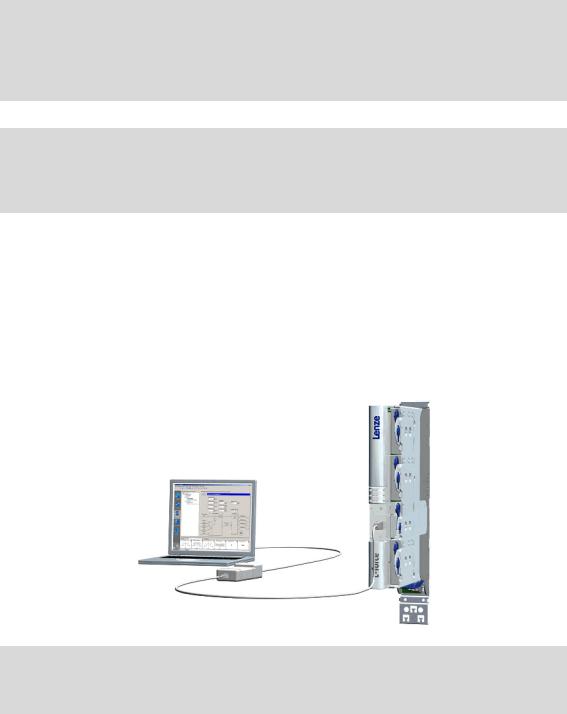
2 Introduction
2.2Communicating with the controller
_ _ _ _ _ _ _ _ _ _ _ _ _ _ _ _ _ _ _ _ _ _ _ _ _ _ _ _ _ _ _ _ _ _ _ _ _ _ _ _ _ _ _ _ _ _ _ _ _ _ _ _ _ _ _ _ _ _ _ _ _ _ _ _
2.2Communicating with the controller
The following interfaces/communication modules can be used to establish communication between the PC and controller:
•Diagnostic interface X6/Going online via diagnostic adapter
•CAN on board interface/Going online via system bus (CAN on board) ( 20)
•Optional interfaces which are provided by corresponding communication modules in the module slots MXI1/MXI2 of the controller.
Note!
For communication with the controller, at least the control electronics of the controller must be supplied with 24 V low voltage via plug X2. For detailed information, please see the Mounting Instructions for the controller.
Stop!
If you change parameters in the »Engineer« while the controller is connected online, the changes will be directly accepted by the controller!
Tip!
Detailed information about the individual interfaces can be found in the corresponding Communication Manuals (KHB).
2.2.1Going online via diagnostic adapter
For initial commissioning of the controller you can for instance use the diagnostic adapter offered by Lenze:
Note!
Please observe the documentation for the diagnostic adapter!
|
Lenze · Servo-Inverter 9400 HighLine · Reference manual · DMS 10.0 EN · 11/2013 · TD05/06 |
17 |
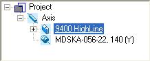
2 Introduction
2.2Communicating with the controller
_ _ _ _ _ _ _ _ _ _ _ _ _ _ _ _ _ _ _ _ _ _ _ _ _ _ _ _ _ _ _ _ _ _ _ _ _ _ _ _ _ _ _ _ _ _ _ _ _ _ _ _ _ _ _ _ _ _ _ _ _ _ _ _
Preconditions:
•The diagnostic adapter is connected to the controller at the diagnostic interface X6 and to the PC at a free USB port.
•The driver required for the diagnostic adapter is installed.
•The control electronics of the controller is supplied with 24 V low voltage via plug X2.
How to build up an online connection via the diagnostic adapter:
1.Select the 9400 HighLine controller to which you want to build up an online connection in the Project view of the »Engineer«:
2.Click the  icon.
icon.
If the changes you have made on the project have not been accepted yet, first a query on whether an update is to be carried out is effected.
If an update is to be carried out:
•Click on Yes to open the Update project dialog box.
•Press the Create button in the Update project dialog box to update the changed project elements.
•After the update a note is shown, saying whether the update was carried out successfully.
|
18 |
Lenze · Servo-Inverter 9400 HighLine · Reference manual · DMS 10.0 EN · 11/2013 · TD05/06 |
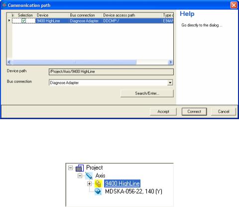
2 Introduction
2.2Communicating with the controller
_ _ _ _ _ _ _ _ _ _ _ _ _ _ _ _ _ _ _ _ _ _ _ _ _ _ _ _ _ _ _ _ _ _ _ _ _ _ _ _ _ _ _ _ _ _ _ _ _ _ _ _ _ _ _ _ _ _ _ _ _ _ _ _
If no communication path was configured yet for the controller selected, the
Communication path dialog box is shown after the update has been carried out:
•The «Diagnostic adapter» bus connection is already preset.
3.Click on Connect.
•The dialog box is closed and the online connection with the controller is built up.
•In the Project view a yellow icon indicates the online connection with the controller:
Now you can use the icons  and
and  to easily build up and end a connection with the controller. The communication settings are only required when communication with a controller is built up for the first time.
•If you want to change the configured communication path, select the command Online Set communication path and go online to open the Communication path dialog box and change the settings.
•When an online connection has been established, the »Engineer« displays the current parameter settings of the controller with a yellow background colour.
|
Lenze · Servo-Inverter 9400 HighLine · Reference manual · DMS 10.0 EN · 11/2013 · TD05/06 |
19 |
2 Introduction
2.2Communicating with the controller
_ _ _ _ _ _ _ _ _ _ _ _ _ _ _ _ _ _ _ _ _ _ _ _ _ _ _ _ _ _ _ _ _ _ _ _ _ _ _ _ _ _ _ _ _ _ _ _ _ _ _ _ _ _ _ _ _ _ _ _ _ _ _ _
2.2.2Going online via system bus (CAN on board)
As an alternative to the diagnostic adapter, you can use the integrated system bus interface (CAN on board, terminal X1) of the controller for communication.
• Lenze offers the following communication accessories for connection to the PC:
|
Communication accessories |
PC interface |
|
PC system bus adapter 2173 |
Parallel interface |
|
incl. connection cable and voltage supply adapter |
(LPT port) |
•for DIN keyboard connection (EMF2173IB)
•for PS/2 keyboard connection (EMF2173IBV002)
•for PS/2 keyboard connection with electrical isolation (EMF2173IBV003)
|
PC system bus adapter 2177 |
USB |
|
incl. connection cable (EMF2177IB) |
(Universal Serial Bus) |
Note!
•For detailed information about the PC system bus adapter, please see the «CAN Communication Manual».
•Please observe the documentation for the PC system bus adapter!
•The online connection is established as described in the previous chapter «Going online via diagnostic adapter«, only that this time the entry «CAN system bus» is to be selected in the Bus connection list field of the Communication path dialog box. ( 18)
2.2.3Use of other communication interfaces
The controller can be extended by further communication interfaces, if required, e.g. Ethernet, ETHERNET Powerlink, or PROFIBUS.
•For this the controller is provided with the module slots MXI1 and MXI2 for accepting communication modules.
•Detailed information on this subject can be found in the Hardware Manual and Communication Manual for the corresponding communication system.
|
20 |
Lenze · Servo-Inverter 9400 HighLine · Reference manual · DMS 10.0 EN · 11/2013 · TD05/06 |

2 Introduction
2.3Signal types & scaling
_ _ _ _ _ _ _ _ _ _ _ _ _ _ _ _ _ _ _ _ _ _ _ _ _ _ _ _ _ _ _ _ _ _ _ _ _ _ _ _ _ _ _ _ _ _ _ _ _ _ _ _ _ _ _ _ _ _ _ _ _ _ _ _
2.3Signal types & scaling
It is very helpful for the parameterisation & configuration of the controller to know the signal types and their scaling listed below, which serve to process physical quantities (e.g. a speed or position) within the function block interconnection.
Note!
From software version V3.0 the resolution of an encoder revolution can be parameterised in C00100 (Lenze setting: 16 bits/encoder revolution).
Resolution of an encoder revolution ( 37)
|
Signal type (data type) |
Connection |
Resolution |
Value range (external) |
Decimal positions/ |
||||
|
symbol in |
signal type suffix |
|||||||
|
the FB editor |
in the identifier |
|||||||
|
Scaled (INT) |
16 bits |
± 199.99 % |
2 |
_a |
||||
|
Scaled (DINT) |
32 bits |
± 200.00 % |
2 |
_n |
||||
|
Speed (INT) |
/ |
16 bits |
± 30000.0 rpm |
1 |
_v |
|||
|
Speed (DINT) |
32 bits |
± 480000.0 rpm |
1 |
_s |
||||
|
Position/angle (DINT) |
/ |
32 bits |
-231 … 231-1 increments |
3 |
_p |
|||
|
Digital (BOOL) |
Bit 1 |
0 ≡ FALSE; 1 ≡ TRUE |
0 |
|||||
|
Acceleration (DINT) |
32 bits |
± 7.69 * 109 rpm/s |
3 |
_x |
||||
|
Time |
28 bits |
0 … 268435.456 s |
3 |
|||||
|
Other (BYTE) |
8 bits |
0 … 255 |
0 |
|||||
|
Other (WORD) |
16 bits |
0 … 65535 |
0 |
|||||
|
Other (DWORD) |
32 bits |
0 … 4294967295 |
0 |
|||||
|
Other (INT) |
16 bits |
-32768 … 32767 |
0 |
|||||
|
Other (DINT) |
32 bits |
-2147483648 … 2147483647 |
0 |
|||||
|
Scaling of physical units |
||||||||
|
Signal type |
Connection |
Resolution |
Scaling |
|||||
|
symbol in |
External value |
≡ internal value |
||||||
|
the FB editor |
||||||||
|
Scaled (INT) |
16 bits |
100 % |
≡ 214 ≡ 16384 |
|||||
|
Scaled (DINT) |
32 bits |
100 % |
≡ 230 ≡ 1073741824 |
|||||
|
Speed (INT) |
/ |
16 bits |
15000 rpm |
≡ 214 ≡ 16384 |
||||
|
Speed (DINT) |
32 bits |
15000 rpm |
≡ 226 ≡ 67108864 |
|||||
|
Position/angle (DINT) |
/ |
32 bits |
1 encoder revolution |
≡ 216 increments |
||||
|
Acceleration (DINT) |
32 bits |
15000000 rpm/s |
≡ 222 ≡ 4194304 |
|
Lenze · Servo-Inverter 9400 HighLine · Reference manual · DMS 10.0 EN · 11/2013 · TD05/06 |
21 |
3 Commissioning
_ _ _ _ _ _ _ _ _ _ _ _ _ _ _ _ _ _ _ _ _ _ _ _ _ _ _ _ _ _ _ _ _ _ _ _ _ _ _ _ _ _ _ _ _ _ _ _ _ _ _ _ _ _ _ _ _ _ _ _ _ _ _ _
3 Commissioning
This documentation contains detailed information on parameter setting and configuration of the controller. Sequential reading is not required.
In order to obtain the information relevant for initial commissioning, this chapter describes different commissioning scenarios which can also be used as a guide through this manual:
A.Initial commissioning ( 25)
•Target: Adapting the controller to the electromechanics and the control system.
B.Standard set-up ( 26)
•Target: Taking over the application and parameter set of an already preconfigured «Engineer» project into several controllers.
C.Controller replacement ( 27)
•Target: Replacing a controller which has failed in a running system by a replacement device using the «old» memory module.
D.Motor replacement ( 27)
•Target: Replacing a motor which has failed in a running system.
|
22 |
Lenze · Servo-Inverter 9400 HighLine · Reference manual · DMS 10.0 EN · 11/2013 · TD05/06 |

3 Commissioning
3.1General information
_ _ _ _ _ _ _ _ _ _ _ _ _ _ _ _ _ _ _ _ _ _ _ _ _ _ _ _ _ _ _ _ _ _ _ _ _ _ _ _ _ _ _ _ _ _ _ _ _ _ _ _ _ _ _ _ _ _ _ _ _ _ _ _
3.1General information
Note!
Some parameters of the controller have a setting range depending on the device type.
If parameterisation is carried out offline or if the memory module is exchanged between different 9400 HighLine device types, always check the settings of the parameters listed in the following table and adapt them, if required, to prevent a parameter error after the parameter set download or module change!
|
Parameter |
Info |
Lenze setting |
|
|
C00018 |
Switching frequency |
8 kHz variable |
|
|
C00022 |
Maximum current |
0.00 A |
|
|
Accepting/adapting plant parameters ( 124) |
|||
|
C00173 |
Mains voltage and undervoltage threshold (LU) |
400/415 V, LU = 285 V |
|
|
C00174 |
Machine parameters ( 29) |
Tip!
The rated data of the different device types can be found in the Hardware Manual in the «Rated data» chapter.
Term definition of «Plant parameters»
The term «plant parameters» which is frequently used in the following chapters summarises all parameters which result from the combination of motor and load. They characterise the transfer behaviour of the entire controlled system including the desired monitoring functions. The plant parameters depend on the application in which the controller and motor are used.
|
Lenze · Servo-Inverter 9400 HighLine · Reference manual · DMS 10.0 EN · 11/2013 · TD05/06 |
23 |
3 Commissioning
3.2Notes on commissioning using the keypad
_ _ _ _ _ _ _ _ _ _ _ _ _ _ _ _ _ _ _ _ _ _ _ _ _ _ _ _ _ _ _ _ _ _ _ _ _ _ _ _ _ _ _ _ _ _ _ _ _ _ _ _ _ _ _ _ _ _ _ _ _ _ _ _
3.2Notes on commissioning using the keypad
For a motor with an electronic nameplate (ENP)
•A display of the plant parameters offered by ENP via keypad is not provided. The plant parameters must be edited and optimised individually.
•To avoid that the motor starts unintentionally without adjusting the plant parameters, the maximum current in the Lenze setting is set to «0 A» in C00022.
•After setting the plant parameters, they have to be saved on the memory module of the controller with mains failure protection, just as the motor data that have been read out from the ENP (C00002 = «11: Save start parameters»).
For a motor without an electronic nameplate (ENP)
•The motor data and plant parameters must be edited and set individually.
•To avoid that the motor starts unintentionally without adjusting the plant parameters, the maximum current is set to «0 A» in C00022 by the factory.
•After setting the motor data and plant parameters, they have to be saved on the memory module of the controller with mains failure protection (C00002 = «11: Save start parameters»).
Commissioning of the application
•The application must already be stored on the memory module of the controller. Otherwise commissioning by only using the keypad is not possible.
•All application parameters which deviate from the factory adjustment have to be edited individually. For this the project planner has to provide a corresponding list to the commissioner (including the motor and plant data).
•In the case of a standard set-up, a pole position identification may have to be carried out for synchronous motors of a third party manufacturer or Lenze synchronous motors with a Stegmann absolute value encoder.
•After setting the parameters, they have to be saved on the memory module of the controller with mains failure protection (C00002 = «11: Save start parameters»).
Tip!
Detailed information on the individual technology applications can be found in the corresponding Software Manual for the technology application and the »Engineer« online help in the chapter «L-force Servo Drives 9400 Technology applications».
|
24 |
Lenze · Servo-Inverter 9400 HighLine · Reference manual · DMS 10.0 EN · 11/2013 · TD05/06 |
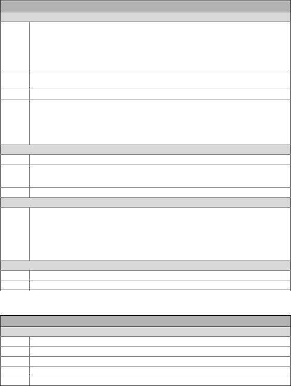
3 Commissioning
3.3Initial commissioning
_ _ _ _ _ _ _ _ _ _ _ _ _ _ _ _ _ _ _ _ _ _ _ _ _ _ _ _ _ _ _ _ _ _ _ _ _ _ _ _ _ _ _ _ _ _ _ _ _ _ _ _ _ _ _ _ _ _ _ _ _ _ _ _
3.3Initial commissioning
Worksteps
Parameterising motor control:
1.Read out the motor data of the controller or select them via the »Engineer« motor catalogue.
•If the motor connected to the controller is provided with an electronic nameplate (ENP), all motor data are automatically read out from the ENP and a selection in the motor catalogue is not required.Reading out motor data from the controller ( 117)
•If a motor without ENP or a motor by a third-party manufacturer is used, the selection is carried out via the »Engineer« motor catalogue. Selecting a motor from the motor catalogue in the »Engineer« ( 118)
2.Select motor control. ( 121)
•Servo control is preset for the synchronous motor.
3.Adjusting motor and controller to each other ( 123)
4.Carry out settings for selected motor control.
•For this see description for the corresponding motor control:
•Servo control (SC)
•Sensorless vector control (SLVC) (from software version V3.0)
•V/f control (VFCplus) (from software version V3.0)
•V/f control (VFCplus) (from software version V3.0)
Parameterise/configure application:
5. Load & parameterise technology application.
Detailed information on the individual technology applications can be found in the corresponding Software Manual for the technology application and the »Engineer« online help in the chapter «L-force Servo Drives 9400 Technology applications».
6.If required, reconfigure the interconnection of the technology application with the function block editor.
Optimise control mode:
7.Optimise control mode of the selected motor control.
•By means of traversing profile from the application and oscilloscope.
•For this see description for the corresponding motor control:
•Servo control (SC)
•Sensorless vector control (SLVC) (from software version V3.0)
•V/f control (VFCplus) (from software version V3.0)
•V/f control (VFCplus) (from software version V3.0)
Save project and parameter set:
8.Execute device command C00002 = «11: Save start parameters».
9.Save »Engineer« project.
More (optional) worksteps
Worksteps
Establish network:
1.Insert network and machine application into the »Engineer« project.
2.Interconnect port blocks reasonably to each other within the machine application.
3.Configure network (set addresses, baud rate, and process data channels in a reasonable manner).
4.Establish communication with the control system.
5.Establish communication with other drive components (e.g. HMIs, I/O extensions and other controllers).
|
Lenze · Servo-Inverter 9400 HighLine · Reference manual · DMS 10.0 EN · 11/2013 · TD05/06 |
25 |
3 Commissioning
3.4Standard set-up
_ _ _ _ _ _ _ _ _ _ _ _ _ _ _ _ _ _ _ _ _ _ _ _ _ _ _ _ _ _ _ _ _ _ _ _ _ _ _ _ _ _ _ _ _ _ _ _ _ _ _ _ _ _ _ _ _ _ _ _ _ _ _ _
Worksteps
Check & optimise application/DC-bus operation:
1.Traverse axis in manual operation.
•See chap. Basic drive functions Manual jog ( 395)
2.Check area boundaries (path, speed, torque).
3.Traverse axis in automatic operation with set-up speed, possibly together with coupled axes.
4.Check coupling with other movements (master/slave axes, tools, …).
5.Optimisation of the process at higher speeds.
6.Recording of typical signal characteristics using the oscilloscope function for the documentation.
•See chapter Oscilloscope ( 579)
Save & archive project and parameter set:
1.Execute device command C00002 = «11: Save start parameters».
2.Save »Engineer« project.
3.Deposit a backup copy of the »Engineer« project, e.g. on CD ROM, in the control cabinet.
3.4Standard set-up
Worksteps
Transfer application and parameter set to the controller:
1.Transfer the application preconfigured in »Engineer« and the corresponding parameter set to the memory module of the controller.
2.Execute device command C00002 = «11: Save start parameters».
For a motor with an electronic nameplate (ENP):
3.Restart controller with connected motor to read out the motor data from the electronic nameplate (ENP).
•Either by switching off/switching on again the voltage supply or by means of device command C00002 = «11000: Restart controller».
•See chap. Motor interface Reading out motor data from the controller ( 117)
4.Execute device command C00002 = «11: Save start parameters».
For a motor without an electronic nameplate (ENP):
Note:The motor is operated with the motor data and plant parameters identified during initial commissioning. Adjusting motor and controller to each other ( 123)
|
26 |
Lenze · Servo-Inverter 9400 HighLine · Reference manual · DMS 10.0 EN · 11/2013 · TD05/06 |

3 Commissioning
3.5Controller replacement
_ _ _ _ _ _ _ _ _ _ _ _ _ _ _ _ _ _ _ _ _ _ _ _ _ _ _ _ _ _ _ _ _ _ _ _ _ _ _ _ _ _ _ _ _ _ _ _ _ _ _ _ _ _ _ _ _ _ _ _ _ _ _ _
3.5Controller replacement
Scenario: The controller has failed in a running system.
Note!
For the procedure described in the following it is assumed that the memory module and possibly available extension modules in the controller, as well as the motor are not affected by the failure and that all parameters have been saved with mains failure protection.
Worksteps
Replacement of the controller:
1.Replace controller.
See Mounting Instructions for the controller!
2.Insert the memory module of the failed controller into the replacement device.
3.If further extension modules are plugged into the failed controller, they must be inserted into the replacement device as well.
Further steps are not required since all data required are on the memory module.
3.6Motor replacement
Scenario: The motor has failed in a running system.
Note!
For the procedure described in the following it is assumed that the controller is not affected by the failure.
Worksteps
Replacement of the motor:
1.Replace the motor.
See Mounting Instructions for the controller!
The motor connection on the controller is accessible without having to remove the standard device from the installation backplane.Note:
For a motor with an electronic nameplate (ENP):
2.Restart controller with connected motor to read out the motor data from the electronic nameplate.
•Either by switching off/switching on again the voltage supply or by means of device command C00002 = «11000: Restart controller».
•See chap. Motor interface Reading out motor data from the controller ( 117)
3.Execute device command C00002 = «11: Save start parameters».
For a motor without an electronic nameplate (ENP):
Note:The motor is operated with the motor data and plant data from the memory module.
|
Lenze · Servo-Inverter 9400 HighLine · Reference manual · DMS 10.0 EN · 11/2013 · TD05/06 |
27 |
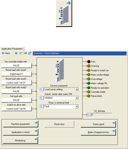
4 Drive interface
_ _ _ _ _ _ _ _ _ _ _ _ _ _ _ _ _ _ _ _ _ _ _ _ _ _ _ _ _ _ _ _ _ _ _ _ _ _ _ _ _ _ _ _ _ _ _ _ _ _ _ _ _ _ _ _ _ _ _ _ _ _ _ _
This chapter provides you with information on the drive interface via which you can control the drive controller into specific states and call different pieces of status information of the controller. Furthermore the machine constants for the motor end are entered via the drive interface.
How to get to the dialog for setting the drive interface parameters:
1.Go to the Project view of the »Engineer« and select the 9400 HighLine controller.
2.Select the Application parameters tab from the Workspace.
3.Click the following button of the Overview dialog level:
Parameterisation dialog in the »Engineer«
•The white buttons indicate the configuration of the drive interface inputs. Internal interfaces | «LS_DriveInterface» system block ( 110)
•The assignment is predefined by the technology application selected (in the example «Actuating drive – speed»). If required, this assignment configuration can be changed by clicking the corresponding buttons.
•If you click a button marked with the  symbol, you go one level deeper in the corresponding parameterisation dialog.
|
28 |
Lenze · Servo-Inverter 9400 HighLine · Reference manual · DMS 10.0 EN · 11/2013 · TD05/06 |
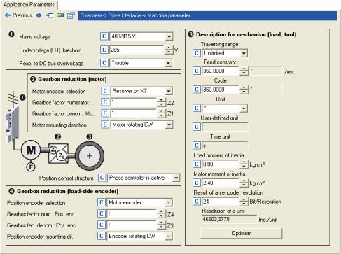
4 Drive interface
4.1Machine parameters
_ _ _ _ _ _ _ _ _ _ _ _ _ _ _ _ _ _ _ _ _ _ _ _ _ _ _ _ _ _ _ _ _ _ _ _ _ _ _ _ _ _ _ _ _ _ _ _ _ _ _ _ _ _ _ _ _ _ _ _ _ _ _ _
4.1Machine parameters
The global machine constants («machine parameters») are set in the »Engineer» on the Application parameters tab in the dialog level Overview Drive interface Machine parameters:
Tip!
Detailed information on the different machine parameters can be obtained from the following subchapters.
|
Lenze · Servo-Inverter 9400 HighLine · Reference manual · DMS 10.0 EN · 11/2013 · TD05/06 |
29 |

4 Drive interface
4.1Machine parameters
_ _ _ _ _ _ _ _ _ _ _ _ _ _ _ _ _ _ _ _ _ _ _ _ _ _ _ _ _ _ _ _ _ _ _ _ _ _ _ _ _ _ _ _ _ _ _ _ _ _ _ _ _ _ _ _ _ _ _ _ _ _ _ _
4.1.1Mains voltage
Via the Mains voltage list field (C00173) the mains voltage for the controller is set.
•If you set a mains voltage with an adjustable threshold for undervoltage («LU adjustable»), this undervoltage threshold can be set in the Undervoltage threshold (LU) input field (C00174).
•In the Resp. to DC-bus overvoltage list field (C00600) you can select the response that is to be effected when a DC-bus overvoltage occurs.
Note!
Changing the setting in C00173 also affects the permissible device utilisation!
Tip!
In the chapter «Rated data» of the hardware manual the device types and their permissible device utilisation at a certain mains voltage and switching frequency are specified.
See also: Monitoring of the device utilisation ( 108)
|
30 |
Lenze · Servo-Inverter 9400 HighLine · Reference manual · DMS 10.0 EN · 11/2013 · TD05/06 |

4 Drive interface
4.1Machine parameters
_ _ _ _ _ _ _ _ _ _ _ _ _ _ _ _ _ _ _ _ _ _ _ _ _ _ _ _ _ _ _ _ _ _ _ _ _ _ _ _ _ _ _ _ _ _ _ _ _ _ _ _ _ _ _ _ _ _ _ _ _ _ _ _
4.1.2Gearbox ratio
The gearbox ratio indicates the number of revolutions of the motor axis it takes for exactly one revolution of the load axis (e.g. spindle or drive roll) to take place.
M M
[4-1] Schematic diagram of gearbox ratio
•In the example shown in illustration [4-1] one revolution of the spindle is carried out at exactly 58,667 revolutions of the motor axis.
Specification of the gearbox ratio
•The gearbox ratio is to be defined in the form of a quotient (numerator/denominator); the data required can be found in the technical data for the gearbox:
M
LEXTERTAL / Germany
|
GFL05-2M HCR 080-32 |
004 B |
GFL 05 |
||||||||||||
|
295 Nm |
i |
z1 |
z2 |
z3 |
z4 |
|||||||||
|
24/min (50Hz) |
58.667 |
12 |
88 |
9 |
72 |
|||||||||
|
i = 58.667 |
CLP 460 |
1196 |
||||||||||||
|
GT/40000027 |
00500038 |
[4-2] Example: Technical data relating to the gearbox (from gearbox catalogue)
Tip!
In order to specify the gearbox ratio exactly, use the number of teeth indicated on the data sheet or in the catalogue, if possible, instead of the information on the nameplate (see following calculation).
In C02531/1 the gearbox factor is displayed in decimal format.
Example calculation on the basis of the technical gearbox data:
|
Gearbox factor numerator (C02520) |
= |
z2 × z4 |
= |
88 |
× 72 |
= |
6336 |
|
Gearbox factor denominator (C02521) |
= |
z1 × z3 |
= |
12 |
× 9 |
= |
108 |
[4-3] Calculation example
|
Lenze · Servo-Inverter 9400 HighLine · Reference manual · DMS 10.0 EN · 11/2013 · TD05/06 |
31 |

4 Drive interface
4.1Machine parameters
_ _ _ _ _ _ _ _ _ _ _ _ _ _ _ _ _ _ _ _ _ _ _ _ _ _ _ _ _ _ _ _ _ _ _ _ _ _ _ _ _ _ _ _ _ _ _ _ _ _ _ _ _ _ _ _ _ _ _ _ _ _ _ _
4.1.3Motor mounting direction
Depending on the motor mounting position, you can carry out an inversion of the direction of rotation via the Motor mounting direction list field (C02527), if required:
•C02527 = «0»: Clockwise rotating motor ≡ positive machine direction.
•C02527 = «1»: Counter-clockwise rotating motor ≡ positive machine direction.
4.1.4Feedback configuration
In most cases the system only has one motor encoder, i.e. no separate position encoder is installed on the load side. The motor position (angle of rotation) and motor speed are detected via the motor encoder selected in C00495 and converted with regard to the load side.
Motor encoder
[4-4] Schematic diagram — feedback with position encoder = motor encoder
The actual position and speed values on the machine side result from the conversion via the Gearbox ratio on the motor side and the Feed constant.
Tip!
Detailed information on the parameterisation of the feedback systems for the motor control can be found in the chapter «Encoder evaluation«. ( 236)
|
32 |
Lenze · Servo-Inverter 9400 HighLine · Reference manual · DMS 10.0 EN · 11/2013 · TD05/06 |

4 Drive interface
4.1Machine parameters
_ _ _ _ _ _ _ _ _ _ _ _ _ _ _ _ _ _ _ _ _ _ _ _ _ _ _ _ _ _ _ _ _ _ _ _ _ _ _ _ _ _ _ _ _ _ _ _ _ _ _ _ _ _ _ _ _ _ _ _ _ _ _ _
4.1.5Unit/user-defined unit
Via these machine parameters you define the real unit of the machine in which the feed constant and the parameters for a travel profile must be specified (e.g. position, speed, acceleration, and deceleration).
•If you for instance set the unit «mm» for a linear axis, the position must be specified in [mm] and the speed in [mm/s].
•By means of the user-defined unit, significant production units, like for example «bottles» can also be set.
•For this, select the «User-defined» entry as unit in C02525 and then enter the desired userdefined unit in C02526.
Note!
In this documentation the term «unit» in the parameter unit data only serves as a wildcard for the real unit of the machine.
Display parameter
|
Parameter |
Info |
|
C02534 |
Time unit used |
|
C02535 |
Unit used |
|
C02537 |
Speed unit |
|
C02538 |
Acceleration unit |
Greyed out = display parameter
|
Lenze · Servo-Inverter 9400 HighLine · Reference manual · DMS 10.0 EN · 11/2013 · TD05/06 |
33 |

4 Drive interface
4.1Machine parameters
_ _ _ _ _ _ _ _ _ _ _ _ _ _ _ _ _ _ _ _ _ _ _ _ _ _ _ _ _ _ _ _ _ _ _ _ _ _ _ _ _ _ _ _ _ _ _ _ _ _ _ _ _ _ _ _ _ _ _ _ _ _ _ _
4.1.6Traversing range
The selection of the traversing range («Unlimited», «Limited», or «Modulo») in the Traversing range list field (C02528) serves to define the machine measuring system.
Note!
A change-over of the traversing range results in a loss of the reference information!
«Unlimited» traversing range
The drive can rotate continuously in one direction.
•By referencing and activating the software limit positions the traversing range can be limited.
•For positioning with absolute travel command the home position must be known.
M
[4-5] Unlimited traversing range, taking the «feed control tape» as an example
«Limited» traversing range
The travel range is limited by positive and negative position limits (mechanical limits/travel range limit switches/software limit positions). Limiter ( 502)
•After a defined distance the drive must travel in the opposite direction again.
•For positioning in the limited traversing range the home position must be known.
•The software limit positions are basically monitored with regard to the maximum value range that can be represented internally (±231 increments), even if monitoring has been deactivated via C02700.
•An overflow of the value range results in a loss of the reference information.
M
[4-6] Example: Limited traversing range — «spindle drive» (linear axis)
|
34 |
Lenze · Servo-Inverter 9400 HighLine · Reference manual · DMS 10.0 EN · 11/2013 · TD05/06 |

4 Drive interface
4.1Machine parameters
_ _ _ _ _ _ _ _ _ _ _ _ _ _ _ _ _ _ _ _ _ _ _ _ _ _ _ _ _ _ _ _ _ _ _ _ _ _ _ _ _ _ _ _ _ _ _ _ _ _ _ _ _ _ _ _ _ _ _ _ _ _ _ _
«Modulo» traversing range
The measuring system is repeated.
•If the cycle set in C02536 is exceeded, a defined overflow occurs. In a rotative system, the cycle typically corresponds to a revolution or tool distance.
•For positioning in the «Modulo» traversing range the home position must be known.
•Software limit positions are not effective.
•Absolute targets can be approached by exceeding the measuring system limit, e.g. from 10° to 350°.
M
C02536: Cycle (illustration = 60°)
[4-7] Example: Modulo traversing range — «rotary table»»
Dependencies — traversing range/basic drive functions
•The following table lists the different dependencies between the selected traversing range and the basic drive functions.
|
Basic drive function |
Traversing range |
||
|
Unlimited |
Limited |
Modulo |
|
|
Position data for Encoder evaluation |
Continuously |
Continuously |
Clocked |
|
Position data for Position follower |
Absolute |
Absolute |
Absolute (in time) |
|
Positioning modes for Positioning |
1, 2, 5, 6, 7, 8 |
1, 2, 5, 6, 7, 8 |
5, 6, 11 … 16 |
|
Restrictions for Homing |
None |
None |
Home position must |
|
be in time |
|||
|
Limit positions (Limiter) |
Permitted |
Permitted |
Not permitted |
Example 1: Unlimited/limited position display
Reference setting
Position in the machine measuring system Position in the motor measuring system
Example 2: Modulo position display
Cycle
Position in the machine measuring system Position in the motor measuring system
|
Lenze · Servo-Inverter 9400 HighLine · Reference manual · DMS 10.0 EN · 11/2013 · TD05/06 |
35 |

4 Drive interface
4.1Machine parameters
_ _ _ _ _ _ _ _ _ _ _ _ _ _ _ _ _ _ _ _ _ _ _ _ _ _ _ _ _ _ _ _ _ _ _ _ _ _ _ _ _ _ _ _ _ _ _ _ _ _ _ _ _ _ _ _ _ _ _ _ _ _ _ _
4.1.7Feed constant
The feed constant corresponds to the movement of the machine during one revolution of the gearbox output shaft.
•The entry in the Feed constant field (C02524) is made in the unit defined in C02525 relating to one revolution.
•In the case of a conveyor drive, the feed constant is obtained from the drive roll’s circumference, which, in the following example, is calculated on the basis of the indicated diameter:
M
d = 200 mm
d = diameter
|
[unit] |
mm |
mm |
|||
Feed constant |
= π dRevolution————————— |
= |
π 200Revolution————————— |
= |
628.3185Revolution————————— |
[4-8] Schematic diagram: Feed constant for a conveyor driver
•In the case of a spindle drive (linear axis), the feed constant is derived from the leadscrew pitch. The feed constant indicates the distance the slide travels during one revolution of the spindle (in the following example: 5.023 mm).
M
h = 5.023 mm
h = leadscrew pitch (can be obtained from the technical data of the linear axis)
[4-9] Schematic diagram: Feed constant for a spindle drive
•In the case of a rotary table and its specification as an angle, the feed constant is = 360°/ revolution.
|
36 |
Lenze · Servo-Inverter 9400 HighLine · Reference manual · DMS 10.0 EN · 11/2013 · TD05/06 |

4 Drive interface
4.1Machine parameters
_ _ _ _ _ _ _ _ _ _ _ _ _ _ _ _ _ _ _ _ _ _ _ _ _ _ _ _ _ _ _ _ _ _ _ _ _ _ _ _ _ _ _ _ _ _ _ _ _ _ _ _ _ _ _ _ _ _ _ _ _ _ _ _
4.1.8Resolution of an encoder revolution
The following applies to software versions lower than V3.0:
The resolution of an encoder revolution and hence of a position value is constantly set to 16 bits/ revolution, which corresponds to 65536 increments/revolution. At this resolution, the traversing range comprises ±32767 revolutions.
The following applies from software version V3.0: C00100 serves to adjust the resolution to the application.
•The default resolution of 16 bits/revolution is sufficient for standard applications.
|
%LW |
||||||||||||||||||||||||||||||||||
Sign bit
Number of revolutions: 15 bits ≡ ±32767 revolutions
Resolution of one encoder revolution: 16 bits ≡ 65536 increments/revolution
[4-10] Example: standard resolution (16 bits/revolution)
•For more significant applications, a higher resolution of the position values can clearly improve the control properties and positioning accuracies:
•Finer resolution of the position targets improved positioning accuracy
•Finer quantisation of setpoints and actual values better control quality
•Higher loop gain adjustable less following errors
•However, a higher resolution at the same time causes a restricted number of encoder revolutions, and only smaller traversing distances can be displayed.
|
%LW |
||||||||||||||||||||||||||||||||||
Sign bit
Number of revolutions: 9 bits ≡ ±512 revolutions
Resolution of one encoder revolution: 22 bits ≡ 4194304 increments/revolution
[4-11] Example: Higher resolution (22 bits/revolution) with a restricted traversing range
Tip!
In the following subchapter «Determining the optimum resolution» ( 39) it is described how you can determine the optimum resolution of the position values.
|
Lenze · Servo-Inverter 9400 HighLine · Reference manual · DMS 10.0 EN · 11/2013 · TD05/06 |
37 |

4 Drive interface
4.1Machine parameters
_ _ _ _ _ _ _ _ _ _ _ _ _ _ _ _ _ _ _ _ _ _ _ _ _ _ _ _ _ _ _ _ _ _ _ _ _ _ _ _ _ _ _ _ _ _ _ _ _ _ _ _ _ _ _ _ _ _ _ _ _ _ _ _
Note!
The position values (e.g. setpoints, actual values, parameters, …) in the signal flow always use the resolution set in C00100. In this connection it is irrelevant which resolution is delivered directly by the encoder.
Multi-axis systems
In an interconnection via the electrical shaft, at least two measuring systems (master and slave) are available in the drive.
•Each measuring system is provided with an individual setting of the resolution.
•The machine parameters (gearbox factors, feed constants, encoder resolution and cycle) for the master measuring system or master value must be set identically for all drives in the system.
Technology applications «Electronic gearbox» and «Synchronism»
For these two technology applications the machine parameters of the master measuring system are defined on the Application parameters tab in the «Master value scaling» dialog level.
Electronic cam
The machine parameters of the master measuring system for electronic cams can be defined on the Measuring systems tab for the electrical shaft.
|
38 |
Lenze · Servo-Inverter 9400 HighLine · Reference manual · DMS 10.0 EN · 11/2013 · TD05/06 |

4 Drive interface
4.1Machine parameters
_ _ _ _ _ _ _ _ _ _ _ _ _ _ _ _ _ _ _ _ _ _ _ _ _ _ _ _ _ _ _ _ _ _ _ _ _ _ _ _ _ _ _ _ _ _ _ _ _ _ _ _ _ _ _ _ _ _ _ _ _ _ _ _
4.1.8.1Determining the optimum resolution
This function extension is available from software version V3.0!
How to determine the optimum resolution:
In the dialog level Overview Drive interface Machine parameters:
1.Set gearbox factors.
2.Set real unit of the machine.
3.Set feed constant.
4.Press the Optimum positional resolution button.
•The Optimum positional resolution dialog box is displayed:
5.Go to the Max. presentable position input field and enter the highest position which is to be entered in a parameter during operation.
•If required, set a reserve in the Overshoot input field to take into account possible following errors (overshoot of actual values).
Then the maximum resolution for the position entered is shown in the Maximum resolution for encoder revolution field.
6.Click Accept value to accept the displayed resolution in C00100.
7.Click Close to close the dialog box again.
Tip!
In order to display the position that can be maximally represented for a defined resolution, activate the second option Determine max. presentable position. Then you can set the resolution for which the maximally presentable position is to be displayed in the Maximum resolution for encoder revolution input field.
|
Lenze · Servo-Inverter 9400 HighLine · Reference manual · DMS 10.0 EN · 11/2013 · TD05/06 |
39 |

4 Drive interface
4.1Machine parameters
_ _ _ _ _ _ _ _ _ _ _ _ _ _ _ _ _ _ _ _ _ _ _ _ _ _ _ _ _ _ _ _ _ _ _ _ _ _ _ _ _ _ _ _ _ _ _ _ _ _ _ _ _ _ _ _ _ _ _ _ _ _ _ _
4.1.9Max. position, speed, and acceleration that can be displayed internally
By setting the following machine parameters, the connection between the real units (application units) of the machine and the internal units in the controller is described:
•Gearbox ratio (C02520, C02521, C02522, C02523)
•Feed constant (C02524)
•Resolution of an encoder revolution (C00100)
Possibly the defined values for position, speed, and acceleration cannot be represented in the internal units by the numerical 32-bit format used.
• The following display parameters show the values that can be maximally displayed:
|
Parameter |
Info |
Lenze setting |
|
|
Value |
Unit |
||
|
C02539 |
Max. presentable position |
— |
Unit |
|
C02540 |
Speed that can be maximally displayed |
— |
Unit/s |
|
C02541 |
Acceleration that can be maximally displayed |
— |
Unit/s2 |
Greyed out = display parameter
Response if a value that cannot be displayed internally is entered
If a position, speed, or acceleration which cannot be represented internally is defined via parameters, the value defined is limited to the maximum value that can be represented internally (±2147483647).
|
40 |
Lenze · Servo-Inverter 9400 HighLine · Reference manual · DMS 10.0 EN · 11/2013 · TD05/06 |

4 Drive interface
4.1Machine parameters
_ _ _ _ _ _ _ _ _ _ _ _ _ _ _ _ _ _ _ _ _ _ _ _ _ _ _ _ _ _ _ _ _ _ _ _ _ _ _ _ _ _ _ _ _ _ _ _ _ _ _ _ _ _ _ _ _ _ _ _ _ _ _ _
The following only applies to software version V3.0:
•If a position, speed, or acceleration which cannot be represented internally is defined via parameters, the value defined is rejected.
•If an internal counter overflow of a parameter value due to a subsequent change of the machine parameters for the gearbox ratio, feed constant, or resolution of an encoder revolution is detected, the «Fault» error response is triggered and a corresponding error message is entered in the logbook of the controller:
|
Error number |
Error message |
|
0x00B8001A |
Int. overflow C02620 (manual speed 1) |
|
0x00B8001B |
Int. overflow C02621 (manual speed 2) |
|
0x00B8001C |
Int. overflow C02622 (manual acceleration) |
|
0x00B8001D |
Int. overflow C02624 (manual deceleration) |
|
0x00B80020 |
Int. overflow C02701/1 (positive SW limit position) |
|
0x00B80021 |
Int. overflow C02701/2 (negative SW limit position) |
|
0x00B80022 |
Int. overflow C02703 (maximum speed) |
|
0x00B80023 |
Int. overflow C02705 (maximum acceleration) |
|
0x00B80024 |
Int. overflow C02708/1 (limited speed 1) |
|
0x00B80025 |
Int. overflow C02708/2 (limited speed 2) |
|
0x00B80026 |
Int. overflow C02708/3 (limited speed 3) |
|
0x00B80027 |
Int. overflow C02708/4 (limited speed 4) |
|
0x00B80028 |
Int. overflow C02710/1 (decel. limited speed 1) |
|
0x00B80029 |
Int. overflow C02710/2 (decel. limited speed 2) |
|
0x00B8002A |
Int. overflow C02710/3 (decel. limited speed 3) |
|
0x00B8002B |
Int. overflow C02710/4 (decel. limited speed 4) |
|
0x00B8002C |
Int. overflow C02713 (maximum distance manual jog) |
|
0x00B8002D |
Int. overflow C02642 (home position) |
|
0x00B8002E |
Int. overflow C02643 (homing: target position) |
|
0x00B8002F |
Int. overflow C02644 (homing: speed 1) |
|
0x00B80030 |
Int. overflow C02645 (homing: acceleration 1) |
|
0x00B80031 |
Int. overflow C02646 (homing: speed 2) |
|
0x00B80032 |
Int. overflow C02647 (homing: acceleration 2) |
|
0x00B80033 |
Int. overflow C02670 (positioning: tolerance for target position) |
Tip!
Possible measures for error correction:
•Plausibility check of the machine parameters set for gearbox ratio, feed constant, or resolution of an encoder revolution.
•Set parameters with a counter overflow to a value which can also be represented internally.
|
Lenze · Servo-Inverter 9400 HighLine · Reference manual · DMS 10.0 EN · 11/2013 · TD05/06 |
41 |

4 Drive interface
4.2Device commands
_ _ _ _ _ _ _ _ _ _ _ _ _ _ _ _ _ _ _ _ _ _ _ _ _ _ _ _ _ _ _ _ _ _ _ _ _ _ _ _ _ _ _ _ _ _ _ _ _ _ _ _ _ _ _ _ _ _ _ _ _ _ _ _
4.2Device commands
In the following subchapters the device commands of the controller are described, which are provided in C00002 and which can be executed by means of the »Engineer« or alternatively with the keypad when an online connection has been established.
Note!
Before switching off the supply voltage after a device command has been executed, check the successful execution of the device command via the status display in C00003!
The meaning of the status display in C00003 can be obtained from the subchapter for the corresponding device command.
Activating frequently required device commands via the toolbar
The simplest way to execute the frequently required device commands is directly via the Toolbar of »Engineer« when an online connection has been established.
Icon Function
Enable controller
Inhibit controller
Start application
Inhibit controller and Stop application
Note!
Device commands that can be executed via the Toolbar of the »Engineer« always affect the element currently selected in the Project view including all subelements!
•If no controller but a system module is selected in the Project view, the corresponding device command will be activated in all lower-level controllers having an online connection with the »Engineer«.
Before the desired action is carried out, a confirmation prompt appears first, asking whether the action is really to be carried out.
|
42 |
Lenze · Servo-Inverter 9400 HighLine · Reference manual · DMS 10.0 EN · 11/2013 · TD05/06 |

4 Drive interface
4.2Device commands
_ _ _ _ _ _ _ _ _ _ _ _ _ _ _ _ _ _ _ _ _ _ _ _ _ _ _ _ _ _ _ _ _ _ _ _ _ _ _ _ _ _ _ _ _ _ _ _ _ _ _ _ _ _ _ _ _ _ _ _ _ _ _ _
Activating device commands via the «Device commands» dialog box
All device commands of the controller are available in »Engineer« in the Device Commands dialog box:
•The Device commands dialog box can be opened by clicking on the Device commands list field on the Application parameters tab in the dialog level Overview Drive interface.
•The Device commands dialog box can also be opened by clicking the setting of C00002 on the All parameters tab.
Note!
If you click a device command in the list field of the Device commands dialog box, the corresponding device command is executed immediately!
•During and after the execution of the device command, the processing status is displayed in the
Device Commands dialog box:
|
Lenze · Servo-Inverter 9400 HighLine · Reference manual · DMS 10.0 EN · 11/2013 · TD05/06 |
43 |

4 Drive interface
4.2Device commands
_ _ _ _ _ _ _ _ _ _ _ _ _ _ _ _ _ _ _ _ _ _ _ _ _ _ _ _ _ _ _ _ _ _ _ _ _ _ _ _ _ _ _ _ _ _ _ _ _ _ _ _ _ _ _ _ _ _ _ _ _ _ _ _
4.2.1Load Lenze setting
The C00002 = «0: Load Lenze setting» device command is used to reset the parameters of the active application to the Lenze setting, which is stored in the controller firmware:
|
9400 |
RAM |
Memory module MM |
|
|
Firmware |
Application |
Application 1 |
|
|
PS |
PS |
PSApplication 2 |
|
|
PS |
3 |
||
PS
[4-12] «Load Lenze setting» function
•Only possible when the application has stopped and the controller is inhibited.
•All parameter changes made since the last saving of the parameter set will get lost!
•This device command only affects the settings of the operating system, application and module parameters, the active application or the configuration selected with the function block editor remains unchanged.
Possible status displays for this device command
|
Status (C00003) |
Meaning |
|
|
34050 |
Device command in process |
|
|
0 |
Device command executed successfully |
|
|
1 |
General fault |
|
|
39424 |
CAN fault |
|
|
… |
… |
|
|
39679 |
CAN fault |
|
Related device commands
Load start parameters ( 45)Save start parameters ( 49)
|
44 |
Lenze · Servo-Inverter 9400 HighLine · Reference manual · DMS 10.0 EN · 11/2013 · TD05/06 |

4 Drive interface
4.2Device commands
_ _ _ _ _ _ _ _ _ _ _ _ _ _ _ _ _ _ _ _ _ _ _ _ _ _ _ _ _ _ _ _ _ _ _ _ _ _ _ _ _ _ _ _ _ _ _ _ _ _ _ _ _ _ _ _ _ _ _ _ _ _ _ _
4.2.2Load start parameters
Via C00002 = «1: Load start parameters» the start parameters of the active application can be reloaded from the memory module to the controller:
|
9400 |
RAM |
Memory module MM |
|
|
Firmware |
Application 1* |
Application 1* |
|
|
PS |
PS |
PSApplication 2 |
|
|
PS |
3 |
||
PS
* In this example, application 1 is the active application
[4-13] «Load start parameters» function
•Only possible when the application has stopped and the controller is inhibited.
•All parameter changes made since the last saving of the parameter set will get lost!
•This device command only affects the settings of the operating system, application and module parameters, the active application or the configuration selected with the function block editor remains unchanged.
Possible status displays for this device command
|
Status (C00003) |
Meaning |
|
|
99586 |
Device command in process |
|
|
65536 |
Device command executed successfully |
|
|
65537 |
General fault |
|
|
99371 |
Fault while reading the parameter set partition |
|
|
99374 |
No memory module available |
|
|
104960 |
CAN fault |
|
|
… |
… |
|
|
105215 |
CAN fault |
|
Related device commands
Save start parameters ( 49)Load Lenze setting ( 44)
|
Lenze · Servo-Inverter 9400 HighLine · Reference manual · DMS 10.0 EN · 11/2013 · TD05/06 |
45 |

4 Drive interface
4.2Device commands
_ _ _ _ _ _ _ _ _ _ _ _ _ _ _ _ _ _ _ _ _ _ _ _ _ _ _ _ _ _ _ _ _ _ _ _ _ _ _ _ _ _ _ _ _ _ _ _ _ _ _ _ _ _ _ _ _ _ _ _ _ _ _ _
4.2.3ENP:Load plant data
If the Lenze motor connected to the controller is provided with an electronic nameplate (ENP), all motor data are automatically read out from the electronic nameplate of the motor when the controller is switched on for the first time and are temporarily stored in the controller at first.
With the device command C00002 = «2: ENP: Load plant data» the motor data can be reread from the electronic nameplate (ENP) of the motor.
•Only possible when the application has stopped and the controller is inhibited.
•For a permanent acceptance of the motor data, the parameter set must be saved. Save start parameters ( 49)
•The following plant data are read out from the ENP:
|
Parameter |
Info |
|
C00022 |
Maximum current |
|
C00070 |
Speed controller gain |
|
C00071 |
Speed controller reset time |
|
C00596 |
Threshold max. speed reached |
Note!
The two pieces of plant data C00011 and C00497 listed in the following table are not read out from the ENP and thus have to be checked and, if required, set manually after this device command has been executed!
|
Parameter |
Info |
|
C00011 |
Motor reference speed |
|
C00497 |
Speed act. val. time const. |
Possible status displays for this device command
|
Status (C00003) |
Meaning |
|
|
165122 |
Device command in process |
|
|
131072 |
Device command executed successfully |
|
|
131073 |
General fault |
|
|
46 |
Lenze · Servo-Inverter 9400 HighLine · Reference manual · DMS 10.0 EN · 11/2013 · TD05/06 |

4 Drive interface
4.2Device commands
_ _ _ _ _ _ _ _ _ _ _ _ _ _ _ _ _ _ _ _ _ _ _ _ _ _ _ _ _ _ _ _ _ _ _ _ _ _ _ _ _ _ _ _ _ _ _ _ _ _ _ _ _ _ _ _ _ _ _ _ _ _ _ _
4.2.4Activate application
If several applications are available on the memory module, the C00002 = «5: Activate application» device command can be used to activate the application the number of which has been set in C00005.
|
9400 |
RAM |
Memory module MM |
|
Firmware |
Application |
Application 1 |
|
PS |
PS |
Application 2* |
|
PSApplication 3 |
* In this example, application selection «2» is set in C00005
[4-14] «Activate application» function
•Only possible when the application has stopped and the controller is inhibited.
•Whether the application is started at the same time, depends on the auto-start setting selected in C02104.
•After mains switching, the preset application will be loaded into the controller.
•If after mains switching another application than the one preset by Lenze is to be loaded, it must be activated first and then the selected application must be saved with the device command «Save selected application«. ( 48).
•The number of the currently active application is displayed in C00007.
Note!
When the application is activated, the corresponding start parameter set is loaded automatically and parameter settings executed before will get lost unless the parameter set was saved before!
Possible status displays for this device command
|
Status (C00003) |
Meaning |
|
|
361730 |
Device command in process |
|
|
327680 |
Device command executed successfully |
|
|
327681 |
General fault |
|
Related device commands
Save selected application ( 48)
Start application ( 53) / Stop application ( 54)
|
Lenze · Servo-Inverter 9400 HighLine · Reference manual · DMS 10.0 EN · 11/2013 · TD05/06 |
47 |

4 Drive interface
4.2Device commands
_ _ _ _ _ _ _ _ _ _ _ _ _ _ _ _ _ _ _ _ _ _ _ _ _ _ _ _ _ _ _ _ _ _ _ _ _ _ _ _ _ _ _ _ _ _ _ _ _ _ _ _ _ _ _ _ _ _ _ _ _ _ _ _
4.2.5Save selected application
After mains switching the controller always loads the preset start application from the memory module, even if a different application has been active before.
With the device command C00002 = «7: Save selected application» the active application can be defined as start application.
|
9400 |
||||||||||||||||
|
RAM |
Memory module MM |
|||||||||||||||
|
Firmware |
Application 2* |
Application 1 |
||||||||||||||
|
PS |
PS |
Application 2* |
||||||||||||||
|
PSApplication 3 |
||||||||||||||||
* In this example, the active application 2 is defined as start application
[4-15] «Save selected application» function
•When this device command is executed, the parameter set is also saved automatically.
•The number of the currently active application is displayed in C00007.
Possible status displays for this device command
|
Status (C00003) |
Meaning |
|
|
492802 |
Device command in process |
|
|
458752 |
Device command executed successfully |
|
|
458753 |
General fault |
|
Related device commands
Activate application ( 47)Start application ( 53)Stop application ( 54)
|
48 |
Lenze · Servo-Inverter 9400 HighLine · Reference manual · DMS 10.0 EN · 11/2013 · TD05/06 |

4 Drive interface
4.2Device commands
_ _ _ _ _ _ _ _ _ _ _ _ _ _ _ _ _ _ _ _ _ _ _ _ _ _ _ _ _ _ _ _ _ _ _ _ _ _ _ _ _ _ _ _ _ _ _ _ _ _ _ _ _ _ _ _ _ _ _ _ _ _ _ _
4.2.6Save start parameters
Controller parameter changes made via »Engineer« or keypad will get lost after mains switching of the controller or loading of another application unless the settings have been explicitly saved.
With the device command C00002 = «11: Save start parameters» the current parameter settings of the active application can be saved with mains failure protection in the memory module of the controller:
|
9400 |
RAM |
Memory module MM |
|
|
Firmware |
Application 1* |
Application 1* |
|
|
PS |
PS |
PSApplication 2 |
|
|
PS |
3 |
||
|
PS |
* In this example, application 1 is the active application
[4-16] «Save start parameters» function
Tip!
With the keypad this device command can be executed via the left function key if it is currently assigned with the function.
Note!
The saving process can take several seconds. Before you switch off the supply voltage after having executed this device command, therefore be absolutely sure to check via the status display in C00003 whether the device command has been executed successfully!
Saving of the cam data
From software version V4.0, this device command also includes the powerfail-proof saving of the cam data on the memory module.
•The saving process is only carried out if the cam data in the controller and the memory module differ from each other (based on the time stamp/GUID of the cam data).
•For saving the cam data, you do not need to enter a possibly existing user password (C02900).
•The C00002 = «502: Save Cam Data» device command remains available. Save cam data ( 89)
|
Lenze · Servo-Inverter 9400 HighLine · Reference manual · DMS 10.0 EN · 11/2013 · TD05/06 |
49 |

4 Drive interface
4.2Device commands
_ _ _ _ _ _ _ _ _ _ _ _ _ _ _ _ _ _ _ _ _ _ _ _ _ _ _ _ _ _ _ _ _ _ _ _ _ _ _ _ _ _ _ _ _ _ _ _ _ _ _ _ _ _ _ _ _ _ _ _ _ _ _ _
Possible status displays for this device command
|
Status (C00003) |
Meaning |
|
|
754946 |
Device command in process |
|
|
720896 |
Device command executed successfully |
|
|
720897 |
General fault |
|
|
754718 |
Fault while writing into a file |
|
|
754734 |
No memory module available |
|
|
761857 |
Access to file has been denied since the file is already accessed from another position |
|
|
761861 |
I/O fault when accessing the file system |
|
|
761868 |
RAM is full |
|
|
761869 |
Access authorisation denied |
|
|
761884 |
No free memory on the memory module |
|
Related device commands
Load start parameters ( 45)
|
50 |
Lenze · Servo-Inverter 9400 HighLine · Reference manual · DMS 10.0 EN · 11/2013 · TD05/06 |