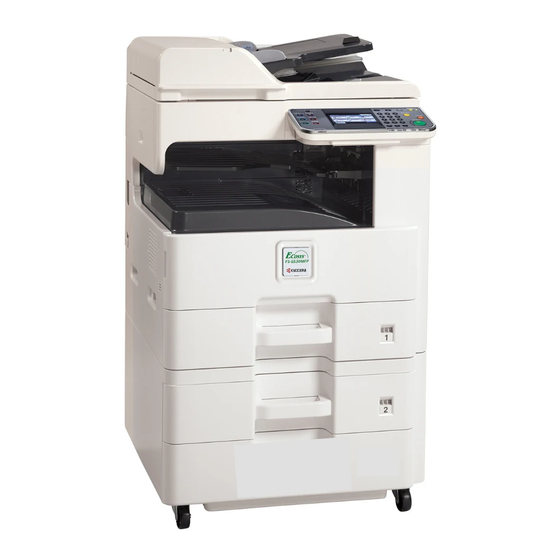
Все современные копировальные аппараты, мфу и принтеры Kyocera имеют возможность диагностировать все узлы устройства в режиме запуска и во время работы аппарата. По этому, если во время включения или во время работы произошел сбой, то техника Kyocera сможет сообщить о наличии ошибки.
В большинстве случаев у аппаратов Kyocera код ошибки отображается на дисплее, в остальных случаях тип ошибки зависит от последовательности и количества миганий индикаторов.
Если Ваш копировальный аппарат, МФУ или принтер Kyocera выдал на дисплее некий код, то узнать причину, описание возникновения ошибки, а так же в каком узле аппарата стоит искать проблему, Вы можете в этом разделе выбрав интересующую модель из списка.
Но диагностика не решит проблему сбоя аппарата, для этого лучше обратиться к профессиональным и опытным сервисным специалистам компании Kyomart! Позвоните нам по телефону
8 (343) 288-23-45 или отправьте запрос на электронную почту: sales@kyomart.ru , и мы обязательно свяжемся с Вами в кратчайшие сроки.
| Код ошибки | Описание ошибки | Причина ошибки |
|---|---|---|
| 0030 | FAX control PWB system error Processing with the fax software was disabled due to a hardware problem. |
Defective FAX control PWB. |
| 0060 | Engine PWB type error | Defective engine sub PCB. |
| 0070 | FAX control PWB incompatible detection error Abnormal detection of FAX control PWB incompatibility In the initial communication with the FAX control PWB, any normal communication command is not transmitted. |
Defective FAX software Defective FAX control PWB. |
| 0100 | Backup memory device error | Defective flash memory. |
| 0120 | MAC address data error For data in which the MAC address is invalid. |
Defective main PWB. Defective flash memory. Defective engine PWB. |
| 0130 | Backup memory read/write error (main PWB) | Defective flash memory. Defective main PWB. |
| 0140 | Backup memory data error (main PWB) | Defective flash memory. Defective main PWB. |
| 0150 | Backup memory read/write error (engine PWB) Detecting engine PWB EEPROM communication error. |
Improper installation engine PWB EEPROM. Defective engine PWB. Device damage of EEPROM. |
| 0160 | Backup memory data error (engine PWB) | Defective flash memory. Defective engine PWB. |
| 0170 | Billing counting error A checksum error is detected in the main and engine backup memories for the billing counters. |
Data damage of EEPROM. Defective PWB. |
| 0180 | Machine number mismatch Machine number of main and engine does not match. |
Data damage of EEPROM. |
| 0320 | I/O CPU communication error A communication error is detected 10 times in succession. |
Defective PWB. |
| 0630 | DMA error DMA transmission of image data does not complete within the specified period of time. | Poor contact in the connector terminals. Defective main PWB. |
| 0800 | Image processing error JAM05 is detected twice. |
Defective main PWB. |
| 0830 | FAX control PWB flash program area checksum error A checksum error occurred with the program of the FAX control PWB. |
Defective FAX software. Defective FAX control PWB. |
| 0840 | Faults of RTC The time is judged to go back based on the comparison of the RTC time and the current time or five years or more have passed. |
The battery is disconnected from the main PWB. Defective main PWB. |
| 0870 | FAX control PWB to main PWB high capacity data transfer error High-capacity data transfer between the FAX control PWB and the main PWB of the machine was not normally performed even if the data transfer was retried the specified times. |
Improper installation FAX control PWB. Defective FAX control PWB or main PWB. |
| 0920 | Fax file system error The backup data is not retained for file system abnormality of flash memory of the FAX control PWB. |
Defective FAX control PWB. |
| 1010 | Lift motor error After cassette 1 is inserted, lift sensor does not turn on within 12 s. This error is detected four times successively. |
Defective bottom plate elevation mechanism in the cassette. Defective connector cable or poor contact in the connector. Defective drive transmission system of the lift motor. Defective lift motor. Defective engine PWB. |
| 1020 | PF lift motor error (paper feeder) After cassette 2 is inserted, PF lift sensor 1 does not turn on within 12 s. This error is detected four times successively. |
Defective bottom plate elevation mechanism in the cassette. Defective connector cable or poor contact in the connector. Defective drive transmission system of the PF lift motor 1. Defective PF lift motor 1. Defective PF main PWB. |
| 1030 | PF lift motor error (paper feeder) After cassette 3 is inserted, PF lift sensor 2 does not turn on within 12 s. This error is detected four times successively. |
Defective bottom plate elevation mechanism in the cassette. Defective connector cable or poor contact in the connector. Defective drive transmission system of the PF lift motor 2. Defective PF lift motor 2. Defective PF main PWB. |
| 1800 | Paper feeder communication error A communication error is detected 10 times in succession. |
Improper installation paper feeder. Defective connector cable or poor contact in the connector. Defective engine PWB. Defective PF main PWB. |
| 1900 | Paper feeder EEPROM error When writing the data, the write data and the read data is not continuously in agreement 5 times. |
Defective PF main PWB. Device damage of EEPROM. |
| 2000 | Main motor steady-state error Stable OFF is detected for 1 s continuously after main motor stabilized. |
Defective connector cable or poor contact in the connector. Defective drive transmission system of the main motor. Defective main motor. Defective engine PWB. |
| 2010 | Main motor drive error The main motor is not stabilized within 2 s after driving starts. |
Defective connector cable or poor contact in the connector. Defective drive transmission system of the main motor. Defective main motor. Defective engine PWB. |
| 2600 | PF drive motor error (paper feeder) When the PF drive motor is driven, error signal is detected continuously for 1 s. |
Defective connector cable or poor contact in the connector. Defective drive transmission system of the PF drive motor. Defective PF drive motor. Defective PF main PWB. |
| 3100 | ISU home position error The home position is not correct when the power is turned on or at the start of copying using the table. |
Defective connector cable or poor contact in the connector. Defective home position sensor. Defective ISU motor. Defective CCD PWB. Defective engine PWB. |
| 3200 | Exposure lamp error When input value at the time of exposure lamp illumination does not exceed the threshold value between 5 s. |
Defective connector cable or poor contact in the connector. Defective exposure lamp. Defective CCD PWB. Defective main PWB. |
| 3500 | Communication error between scanner and ASIC An error code is detected 3 times in succession. |
Defective connector cable or poor contact in the connector. Defective CCD PWB. Defective main PWB. |
| 3600 | Scanner sequence error | Defective main PWB or engine PWB. |
| 4000 | Polygon motor synchronization error The polygon motor is not stabilized within 10 s after driving starts. |
Defective connector cable or poor contact in the connector. Defective polygon motor. Defective engine PWB. |
| 4010 | Polygon motor steady-state error Stable OFF is detected for 1 s continuously after polygon motor stabilized. |
Defective connector cable or poor contact in the connector. Defective polygon motor. Defective engine PWB. |
| 4100 | BD initialization error BD is not detected within 1 s after polygon motor stabilized. |
Defective connector cable or poor contact in the connector. Defective APC PWB. Defective BD PWB. Defective main PWB. |
| 4700 | VIDEO ASIC device error | Defective connector cable or poor contact in the connector. Defective main PWB or engine PWB. |
| 6000 | Broken fuser heater wire The detected temperature of fuser thermistor does not reach the specified temperature (ready indication temperature) after the fuser heater has been turned on continuously for 60 s in warming up. The fusing temperature at 7 seconds and 20 seconds since fuser temperature control has occurred differs by 43°C/109.4°F or less. |
Defective connector cable or poor contact in the connector. Deformed connector pin. Defective triac. Fuser thermostat triggered. Broken fuser heater wire. Defective engine PWB. |
| 6000 6020 6030 6050 |
Broken fuser heater wire Abnormally high fuser thermistor temperature Broken fuser thermistor wire Abnormally low fuser thermistor temperature |
Deformed connector pin. Defective triac. |
| 6020 | Abnormally high fuser thermistor temperature The fuser thermistor detects a temperature higher than 230°C/446°F continuously for 40 ms. High fuser temperature signal detects a temperature of 255°C/491°F continuously for 40 ms. |
Deformed connector pin. Defective triac. Shorted fuser thermistor. Defective engine PWB. |
| 6030 | Broken fuser thermistor wire A/D value of the fuser thermistor exceeds 251 bit continuously for 7 s during warming up. |
Defective connector cable or poor contact in the connector. Deformed connector pin. Defective triac. Defective fuser thermistor. Defective engine PWB |
| 6050 | Abnormally low fuser thermistor temperature As the stable temperature has reached the second time, the decrease in the fuser thermistor temperature of 60°C/140°F or greater is detected for one second. |
Deformed connector pin. Defective triac. Defective fuser thermistor Defective fuser heater. Defective engine PWB. |
| 6400 | Zero-cross signal error While fuser heater control is performed, the zero-cross signal is not input within 3 s. |
Defective connector cable or poor contact in the connector Defective power source PWB or engine PWB. |
| 7800 | Broken external thermistor wire The thermistor output value is 0.3 V or less. |
Defective connector cable or poor contact in the connector. Defective temperature sensor. |
| 7810 | Short-circuited external thermistor wire The thermistor output value is 3 V or more. |
Defective connector cable or poor contact in the connector. Defective temperature sensor. |
| 7900 | Drum unit EEPROM error No response is issued from the device in reading/writing for 5 ms or more and this problem is repeated five times successively. Mismatch of reading data from two locations occurs eight times successively. Mismatch between writing data and reading data occurs eight times successively. |
Defective connector cable or poor contact in the connector. Defective drum unit. |
| 7910 | Developer unit EEPROM error No response is issued from the device in reading/writing for 5 ms or more and this problem is repeated five times successively. Mismatch of reading data from two locations occurs eight times successively. Mismatch between writing data and reading data occurs eight times successively. |
Defective connector cable or poor contact in the connector. Defective developer unit. |
| 8030 | Tray upper limit detection problem (document finisher) When the tray elevation motor raises a tray, the ON status of the tray upper limit sensor is detected. |
Defective connector cable or poor contact in the connector. Defective tray upper limit sensor, paper surface sensor 1/2. Defective DF main PWB. |
| 8040 | Belt problem (document finisher) The belt sensor does not turn on/off within specified time of the belt solenoid turning on. |
Defective connector cable or poor contact in the connector. Defective belt sensor. Defective belt solenoid. Defective DF main PWB. |
| 8140 | Tray elevation motor problem (document finisher) The tray low limit sensor or paper surface sensor 1/2 cannot be detected to be on within 10 s since the tray elevation motor is activated. |
Defective connector cable or poor contact in the connector. Defective connector cable or poor contact in the connector. The tray elevation motor malfunctions. Defective tray lower limit sensor, paper surface sensor 1/2. Defective DF main PWB. |
| 8210 | Stapler problem (document finisher) Jam 7012 or 7023 is indicated. |
Defective connector cable of staple or poor contact in the connector. The stapler is blocked with a staple. The stapler is broken Defective DF main PWB. |
| 8320 | Adjustment motor 2 problem (document finisher) The adjustment sensor 2 does not turn on/off within specified time of the adjustment motor 2 turning on. |
Defective connector cable or poor contact in the connector. Defective adjustment sensor 2. Defective adjustment motor 2. Defective DF main PWB. |
| 8330 | Adjustment motor 1 problem (document finisher) The adjustment sensor 1 does not turn on/off within specified time of the adjustment motor 1 turning on. |
Defective connector cable or poor contact in the connector. Defective adjustment sensor 1. Defective adjustment motor 1. |
| 8350 | Roller motor problem (document finisher) The roller sensor does not turn on/off within specified time of the roller motor turning on. |
Defective DF main PWB. Defective connector cable or poor contact in the connector. Defective roller sensor. Defective roller motor. Defective DF main PWB. |
| 8360 | Slide motor problem (document finisher) The slide sensor does not turn on/off within specified time of the slide motor turning on. |
Defective connector cable or poor contact in the connector. Defective slide sensor. Defective slide motor. Defective DF main PWB. |
| 8460 | EEPROM problem (document finisher) Reading from or writing to EEPROM cannot be performed. |
Defective EEPROM or DF main PWB. |
| 8800 | Document finisher communication error A communication error is detected 10 times in succession. |
Defective connector cable or poor contact in the connector Defective DF main PWB. Defective engine PWB. |
| 8830 | Bridge communication error (document finisher) A communication error is detected 10 times in succession. |
Defective connector cable or poor contact in the connector. Defective bridge PWB. Defective engine PWB. |
| 8990 | Document finisher communication error | Defective connector cable or poor contact in the connector. Defective DF main PWB. Defective bridge PWB. |
| 9000 | Document processor communication error A communication error is detected 10 times in succession. |
Defective connector cable or poor contact in the connector. Defective DP main PWB. |
| 9060 | DP EEPROM error Read and write data does not match. Data in the specified area of the backup memory does not match the specified values. | Defective DP main PWB. Device damage of EEPROM. |
| 9500 | BRU communication error | IPU PWB error |
| 9510 | BRU PWB error | IPU PWB error |
| 9520 | BRU PWB data error | IPU PWB error |
| F000 | Main PWB — operation panel PWB communication error | Defective main PWB. Defective operation panel PWB. |
| F010 | Main PWB checksum error | Defective main PWB. |
| F040 | Main PWB — print engine communication error | Defective main PWB. Defective engine PWB. |
| F050 | Print engine ROM checksum error | Defective engine PWB. |
Ошибки Kyocera ECOSYS M2030dn
Ошибки Kyocera ECOSYS M2030pn
Ошибки Kyocera ECOSYS M2035dn
Ошибки Kyocera ECOSYS M2040dn
Ошибки Kyocera ECOSYS M2135dn
Ошибки Kyocera ECOSYS M2530dn
Ошибки Kyocera ECOSYS M2535dn
Ошибки Kyocera ECOSYS M2540dn
Ошибки Kyocera ECOSYS M2540dw
Ошибки Kyocera ECOSYS M2635dn
Ошибки Kyocera ECOSYS M2635dw
Ошибки Kyocera ECOSYS M2640idw
Ошибки Kyocera ECOSYS M3040dn
Ошибки Kyocera ECOSYS M3040idn
Ошибки Kyocera ECOSYS M3145dn
Ошибки Kyocera ECOSYS M3145idn
Ошибки Kyocera ECOSYS M2735dw
Ошибки Kyocera ECOSYS M3540dn
Ошибки Kyocera ECOSYS M3540idn
Ошибки Kyocera ECOSYS M3550idn
Ошибки Kyocera ECOSYS M3560idn
Ошибки Kyocera ECOSYS M3645dn
Ошибки Kyocera ECOSYS M3645idn
Ошибки Kyocera ECOSYS M3655idn
Ошибки Kyocera ECOSYS M3660idn
Ошибки Kyocera ECOSYS M3860idn
Ошибки Kyocera ECOSYS M3860idn
Ошибки Kyocera ECOSYS M4125idn
Ошибки Kyocera ECOSYS M4132idn
Ошибки Kyocera ECOSYS M5521cdn
Ошибки Kyocera ECOSYS M5521cdw
Ошибки Kyocera ECOSYS M5526cdn
Ошибки Kyocera ECOSYS M5526cdw
Ошибки Kyocera ECOSYS M6026cdn
Ошибки Kyocera ECOSYS M6026cidn
Ошибки Kyocera ECOSYS M6030cdn
Ошибки Kyocera ECOSYS M6035cidn
Ошибки Kyocera ECOSYS M6230cidn
Ошибки Kyocera ECOSYS M6235cidn
Ошибки Kyocera ECOSYS M6526cdn
Ошибки Kyocera ECOSYS M6526cidn
Ошибки Kyocera ECOSYS M6530cdn
Ошибки Kyocera ECOSYS M6535cidn
Ошибки Kyocera ECOSYS M6630cidn
Ошибки Kyocera ECOSYS M6635cidn
Ошибки Kyocera ECOSYS M8124cidn
Ошибки Kyocera ECOSYS M8130cidn
Ошибки Kyocera ECOSYS P2035d
Ошибки Kyocera ECOSYS P2040dn
Ошибки Kyocera ECOSYS P2040dw
Ошибки Kyocera ECOSYS P2135d
Ошибки Kyocera ECOSYS P2135dn
Ошибки Kyocera ECOSYS P2235dn
Ошибки Kyocera ECOSYS P2235dw
Ошибки Kyocera ECOSYS P3045dn
Ошибки Kyocera ECOSYS P3050dn
Ошибки Kyocera ECOSYS P3055dn
Ошибки Kyocera ECOSYS P3060dn
Ошибки Kyocera ECOSYS P3145dn
Ошибки Kyocera ECOSYS P3150dn
Ошибки Kyocera ECOSYS P3155dn
Ошибки Kyocera ECOSYS P3160dn
Ошибки Kyocera ECOSYS P3260dn
Ошибки Kyocera ECOSYS P4035dn
Ошибки Kyocera ECOSYS P4040dn
Ошибки Kyocera ECOSYS P5021cdn
Ошибки Kyocera ECOSYS P5021cdw
Ошибки Kyocera ECOSYS P5026cdn
Ошибки Kyocera ECOSYS P5026cdw
Ошибки Kyocera ECOSYS P6021cdn
Ошибки Kyocera ECOSYS P6026cdn
Ошибки Kyocera ECOSYS P6030cdn
Ошибки Kyocera ECOSYS P6035cdn
Ошибки Kyocera ECOSYS P6130cdn
Ошибки Kyocera ECOSYS P6230cdn
Ошибки Kyocera ECOSYS P6235cdn
Ошибки Kyocera ECOSYS P7035cdn
Ошибки Kyocera ECOSYS P7040cdn
Ошибки Kyocera ECOSYS P7240cdn
Ошибки Kyocera ECOSYS P8060cdn
Ошибки Kyocera FS-C8600DN
Ошибки Kyocera FS-C8650DN
Ошибки Kyocera FS1016MFP
Ошибки Kyocera FS1018MFP
Ошибки Kyocera FS1020MFP
Ошибки Kyocera FS1024MFP
Ошибки Kyocera FS1025MFP
Ошибки Kyocera FS1028MFP
Ошибки Kyocera FS1030MFP
Ошибки Kyocera FS1035MFP
Ошибки Kyocera FS1040
Ошибки Kyocera FS1050
Ошибки Kyocera FS1060DN
Ошибки Kyocera FS1100
Ошибки Kyocera FS1110
Ошибки Kyocera FS1116MFP
Ошибки Kyocera FS1118MFP
Ошибки Kyocera FS1120
Ошибки Kyocera FS1120MFP
Ошибки Kyocera FS1124MFP
Ошибки Kyocera FS1125MFP
Ошибки Kyocera FS1128MFP
Ошибки Kyocera FS1130MFP
Ошибки Kyocera FS1135MFP
Ошибки Kyocera FS1200
Ошибки Kyocera FS1220MFP
Ошибки Kyocera FS1300D
Ошибки Kyocera FS1320D
Ошибки Kyocera FS1320MFP
Ошибки Kyocera FS1325MFP
Ошибки Kyocera FS1350DN
Ошибки Kyocera FS1370DN
Ошибки Kyocera FS1500
Ошибки Kyocera FS6020
Ошибки Kyocera FS6025MFP
Ошибки Kyocera FS6025MFPB
Ошибки Kyocera FS6030MFP
Ошибки Kyocera FS6500
Ошибки Kyocera FS6525MFP
Ошибки Kyocera FS6530MFP
Ошибки Kyocera FS6700
Ошибки Kyocera FS6900
Ошибки Kyocera FS6950DN
Ошибки Kyocera FS8000CD
Ошибки Kyocera FS8000CN
Ошибки Kyocera FS8100DN
Ошибки Kyocera TASKalfa 180
Ошибки Kyocera TASKalfa 1800
Ошибки Kyocera TASKalfa 1801
Ошибки Kyocera TASKalfa 181
Ошибки Kyocera TASKalfa 205c
Ошибки Kyocera TASKalfa 220
Ошибки Kyocera TASKalfa 2200
Ошибки Kyocera TASKalfa 2201
Ошибки Kyocera TASKalfa 221
Ошибки Kyocera TASKalfa 2420w
Ошибки Kyocera TASKalfa 2460ci
Ошибки Kyocera TASKalfa 2470ci
Ошибки Kyocera TASKalfa 250ci
Ошибки Kyocera TASKalfa 2510i
Ошибки Kyocera TASKalfa 2520i
Ошибки Kyocera TASKalfa 255
Ошибки Kyocera TASKalfa 2550ci
Ошибки Kyocera TASKalfa 2551ci
Ошибки Kyocera TASKalfa 2552ci
Ошибки Kyocera TASKalfa 2553ci
Ошибки Kyocera TASKalfa 255b
Ошибки Kyocera TASKalfa 255c
Ошибки Kyocera TASKalfa 265ci
Ошибки Kyocera TASKalfa 300ci
Ошибки Kyocera TASKalfa 300i
Ошибки Kyocera TASKalfa 3010i
Ошибки Kyocera TASKalfa 3011i
Ошибки Kyocera TASKalfa 305
Ошибки Kyocera TASKalfa 3050ci
Ошибки Kyocera TASKalfa 3051ci
Ошибки Kyocera TASKalfa 306ci
Ошибки Kyocera TASKalfa 307ci
Ошибки Kyocera TASKalfa 308ci
Ошибки Kyocera TASKalfa 3212i
Ошибки Kyocera TASKalfa 3252ci
Ошибки Kyocera TASKalfa 3253ci
Ошибки Kyocera TASKalfa 3500i
Ошибки Kyocera TASKalfa 3501i
Ошибки Kyocera TASKalfa 350ci
Ошибки Kyocera TASKalfa 3510i
Ошибки Kyocera TASKalfa 3511i
Ошибки Kyocera TASKalfa 3550ci
Ошибки Kyocera TASKalfa 3551ci
Ошибки Kyocera TASKalfa 3552ci
Ошибки Kyocera TASKalfa 3553ci
Ошибки Kyocera TASKalfa 356ci
Ошибки Kyocera TASKalfa 358ci
Ошибки Kyocera TASKalfa 4002i
Ошибки Kyocera TASKalfa 4003i
Ошибки Kyocera TASKalfa 400ci
Ошибки Kyocera TASKalfa 4012i
Ошибки Kyocera TASKalfa 4052ci
Ошибки Kyocera TASKalfa 4053ci
Ошибки Kyocera TASKalfa 406ci
Ошибки Kyocera TASKalfa 408ci
Ошибки Kyocera TASKalfa 420i
Ошибки Kyocera TASKalfa 4500i
Ошибки Kyocera TASKalfa 4501i
Ошибки Kyocera TASKalfa 4550ci
Ошибки Kyocera TASKalfa 4551ci
Ошибки Kyocera TASKalfa 4820w
Ошибки Kyocera TASKalfa 5002i
Ошибки Kyocera TASKalfa 5003i
Ошибки Kyocera TASKalfa 500ci
Ошибки Kyocera TASKalfa 5052ci
Ошибки Kyocera TASKalfa 5053ci
Ошибки Kyocera TASKalfa 508ci
Ошибки Kyocera TASKalfa 520i
Ошибки Kyocera TASKalfa 5500i
Ошибки Kyocera TASKalfa 5501i
Ошибки Kyocera TASKalfa 550c
Ошибки Kyocera TASKalfa 552ci
Ошибки Kyocera TASKalfa 5550ci
Ошибки Kyocera TASKalfa 5551ci
Ошибки Kyocera TASKalfa 6002i
Ошибки Kyocera TASKalfa 6003i
Ошибки Kyocera TASKalfa 6052ci
Ошибки Kyocera TASKalfa 6053ci
Ошибки Kyocera TASKalfa 620
Ошибки Kyocera TASKalfa 6500i
Ошибки Kyocera TASKalfa 6501i
Ошибки Kyocera TASKalfa 650c
Ошибки Kyocera TASKalfa 6550ci
Ошибки Kyocera TASKalfa 6551ci
Ошибки Kyocera TASKalfa 7002i
Ошибки Kyocera TASKalfa 7003i
Ошибки Kyocera TASKalfa 7052ci
Ошибки Kyocera TASKalfa 7353ci
Ошибки Kyocera TASKalfa 750c
Ошибки Kyocera TASKalfa 7550ci
Ошибки Kyocera TASKalfa 7551ci
Ошибки Kyocera TASKalfa 8000i
Ошибки Kyocera TASKalfa 8001i
Ошибки Kyocera TASKalfa 8002i
Ошибки Kyocera TASKalfa 8003i
Ошибки Kyocera TASKalfa 8052ci
Ошибки Kyocera TASKalfa 820
Ошибки Kyocera TASKalfa 8353ci
Ошибки Kyocera TASKalfa 9002i
Ошибки Kyocera TASKalfa 9003i
 Если с аппаратом Kyocera TASKalfa 1800, Kyocera TASKalfa 2200 произошла проблема, откроется следующий экран с уведомлением.
• Индикатор [Внимание] на панели управления горит или мигает.
• На дисплее сообщений панели управления аппарата появилось сообщение об ошибке.
Если индикатор [Внимание] горит или мигает и на дисплее сообщений панели управления аппарата появилось сообщение об ошибке, проверьте KYOCERA Client Tool или Монитор состояния.
ПРИМЕЧАНИЕ Если индикаторы постоянно горят и мигают не так, как описано выше, вероятно, произошла ошибка службы. Выключите питание, отсоедините шнур питания и вставьте его обратно, после чего включите питание. Это может помочь сбросить ошибку. Если ошибка не исчезает, свяжитесь со своим представителем сервисной службы (тел. в Минске +375 17 291-28-24)
Ниже описаны неполадки, которые не могут быть устранены пользователем
|
Дисплей сообщений |
Описание |
Меры устранения |
|
Бункер отраб тонера перепол. или не уст. |
Бункер для отработанного тонера установлен неправильно |
Установите Бункер для отработанного тонера должным образом |
|
Бункер для отработанного тонера заполнен |
Замените бункер отработанного тонера |
|
|
Встряхните картр. с тонером |
Тонер слежался |
Откройте переднюю крышку аппарата и вытяните контейнер с тонером. Сильно встряхните контейнер с тонером и установите его на место |
|
Вызовите сервисный персонал. |
В аппарате произошла ошибка |
Обратите внимание на код ошибки, отображаемый в дисплее сообщений, и свяжитесь с представителем сервисной службы (тел. в Минске +375 17 291-28-24) |
|
Выньте бумагу с внутреннего лотка |
Извлеките бумагу из внутреннего лотка. Нажмите клавишу [OK], чтобы возобновить печать |
|
|
Добавьте тонер |
Закончился тонер |
Замените контейнер с тонером TK-4105 |
|
Загрузите бумагу в кассету # |
↑↓ (отображается попеременно) |
Загрузите бумагу. Нажмите клавишу [OK] и перейдите к следующему шагу. • Для выбора другого устройства подачи выберите [Выберите бумагу]. • Для печати на бумаге, в настоящее время находящейся в устройстве подачи, выберите [Продолж. без изм.] |
|
Загрузите бумагу в универсальный лоток |
↑↓ (отображается попеременно) |
Загрузите бумагу. Нажмите клавишу [OK] и перейдите к следующему шагу. • Для выбора другого устройства подачи выберите [Выберите бумагу]. • Для печати на бумаге, в настоящее время находящейся в устройстве подачи, выберите [Продолж. без изм.] |
|
Закройте автоподатчик оригиналов |
Открыт автоподатчик оригиналов |
Откройте и закройте автоподатчик оригиналов |
|
Закройте крышку автопод. оригиналов |
Открыта верхняя крышка автоподатчика оригиналов |
Откройте и закройте крышку автоподатчика оригинало |
|
Закройте переднюю крышку |
Открыта передняя крышка |
Откройте и закройте переднюю крышку |
|
Закройте правую крышку # |
Открыта какая-либо крышка |
Откройте и закройте крышку, обозначенную на экране |
|
Замятие бумаги. (DP) |
В автоподатчике произошло замятие бумаги. |
См. Устранение замятия бумаги в Руководстве по эксплуатации и извлеките замятую бумагу |
|
Замените МК |
Необходимо производить замену деталей комплекта техобслуживания MK-4105 (ремкомплекта) каждые 150 000 страниц печати. |
Данная операция должна производиться специалистом. Обратитесь к представителю сервисной службы (тел. в Минске +375 17 291-28-24) |
|
Замятие |
Произошло замятие бумаги в кассете или универсальном лотке |
См. Устранение замятия бумаги и извлеките замятую бумагу |
|
Извлеките оригиналы из автоподатчика |
Для продолжения работы необходимо извлечь оригиналы из автоподатчика оригиналов |
Извлеките оригиналы из автоподатчика оригиналов |
|
Кабель USB был отключен |
Кабель USB не подключен |
Нажмите клавишу [OK] и подключите кабель USB |
|
ПК выключен |
Нажмите клавишу [OK] и включите ПК |
|
|
Не удается найти KYOCERA Client Tool |
Нажмите клавишу [OK] и откройте KYOCERA Client Tool на ПК |
|
|
Макс. к-во сканируемых страниц |
Превышен предел сканирования |
Дальнейшее сканирование невозможно. Задание отменено. Нажмите клавишу [OK] |
|
Мало тонера. (Зам., когда законч.) |
Скоро понадобится заменить контейнер с тонером |
Получите новый контейнер с тонером TK-4105. |
|
Не оригинальный тонер |
Установлен контейнер с тонером не марки Kyocera |
Производитель не несет ответственности за повреждения, вызванные использованием неоригинального тонера. Мы рекомендуем использовать исключительно оригинальные контейнеры с тонером TK-4105. . |
|
Неверный ид. уч. зап. Задание отменено |
Указан неверный идентификатор учетной записи при внешней обработке задания. Задание отменено |
Нажмите клавишу [OK] |
|
Невозможна двусторонняя печать на этой бумаге |
Не возможна печать на бумаге выбранного формата или типа |
Нажмите клавишу [OK] и перейдите к следующему шагу: |
|
Недостаточно памяти. Невозможно начать выполнение задания |
Невозможно начать выполнение задания |
Повторите попытку позже |
|
Ограничено алгоритмом учета заданий(Печать) |
Задание отменено, поскольку его выполнение ограничено функцией учета заданий |
Нажмите клавишу [OK] |
|
Ограничено алгоритмом учета заданий(Сканер) |
Задание отменено, поскольку его выполнение ограничено функцией учета заданий |
Нажмите клавишу [OK] |
|
Очистите сканер |
Произошло загрязнение сканера |
Очистите щелевое стекло с помощью чистящей салфетки, поставляемой вместе с автоподатчиком оригиналов. |
|
Ошибка. Выключить |
— |
Отключите и снова включите аппарат с помощью выключателя питания |
|
Память переполнена |
Невозможно продолжить выполнение задания из-за отсутствия свободной памяти |
Измените разрешение печати с Быстр1200 до 600 dpi. См. Printer Driver User Guide |
|
Память сканера переполнена |
Дальнейшее сканирование невозможно из-за нехватки памяти сканера. |
Для отмены задания нажмите [OK] |
|
Перезагрузка печати. Задание отменено |
Предупреждение. Недостаточно памяти принтера. Задание отменено |
Нажмите клавишу [OK] |
|
Превышено ограничение учета заданий |
Превышено число распечаток из-за ограничения алгоритмом учета заданий. Достигнут предел печати |
Это задание отменено. Нажмите клавишу [OK] |
|
Уст.другую кассету |
Выбрано «Сдвиг» |
Для использования сдвига необходимо загрузить в другой лоток бумагу такого же формата, что и в выбранном устройстве подачи, но в другой ориентации |
|
Установите все оригиналы обратно и нажмите клавишу [Старт]. |
Возникает при печати двусторонних документов в режиме ручной двусторонней печати |
Извлеките оригиналы из автоподатчика оригиналов, расположите их в первоначальном порядке и положите обратно. Нажмите клавишу [OK], чтобы возобновить печать. Для отмены задания нажмите [Стоп] |
|
Установлен неизвестный тонер. ПК |
Региональная спецификация контейнера с тонером не соответствует спецификации аппарата |
Установите оригинальный контейнер с тонером Замените контейнер с тонером TK-4105 |
Item No.
U000
Event Log
MFP
(1)
Firmware version 2K3_2000.000.000 2010.09.04
(7)
Paper Jam Log
#
16
15
14
13
12
11
10
9
8
7
6
5
4
3
2
1
(11)
Counter Log
(f)
J0100:
J0101:
J0104:
J0106:
J0107:
.
.
.
.
.
.
Count.
Event Descriprions
1876543
0501.01.08.01.01
166554
4002.01.08.01.01
4988
0501.01.08.01.01
4988
4002.01.08.01.01
4988
0501.01.08.01.01
4988
4002.01.08.01.01
1103
0501.01.08.01.01
1103
4002.01.08.01.01
1103
0501.01.08.01.01
1103
4002.01.08.01.01
1027
0501.01.08.01.01
1027
4002.01.08.01.01
1027
0501.01.08.01.01
1027
4002.01.08.01.01
406
0501.01.08.01.01
36
4002.01.08.01.01
0501.01.08.01.01
(a)
(b)
(c)
0
J0511:
0
J4201:
0
0
J0512:
0
J4202:
0
0
J0513:
0
J4203:
0
0
J0518:
0
J4208:
0
0
J0519:
0
J4209:
0
.
.
.
.
.
.
.
.
.
.
.
.
Description
[XXXXXXXX] [XXXXXXXX] [XXXXXXXX]
(8)
Service Call Log
#
8
7
6
5
4
3
2
1
(9)
Maintenance Log
#
8
7
6
5
4
3
2
1
(10)
Unknown toner Log
(d)
(e)
#
5
4
3
2
1
(g)
C0030:
1
C2000:
C0070:
1
C2010:
C0100:
1
C2600:
C0120:
1
C3100:
C0130:
1
C3200:
.
.
.
.
.
.
Figure 1-3-1
1-3-8
(2)
04/Sep/2010 08:40
(3)
(4)
Count.
Service Code
1881214
01.6000
178944
01.2100
5296
01.4000
5295
01.6000
2099
01.2100
1054
01.4000
809
01.6000
30
01.2100
Count.
Item
1045571
01.00
104511
01.00
7045
01.00
3454
01.00
3454
01.01
3454
01.01
417
01.01
34
01.01
Count.
Item
3454
01.00
3454
01.00
3454
01.00
406
01.00
32
01.00
(h)
1
T00:
1
1
T01:
1
1
1
1
.
.
.
.
.
.
(6)
[XXXXXXXXXXXXXXXX]
2MW/2MX
(5)
- Manuals
- Brands
- Kyocera Manuals
- All in One Printer
- ECOSYS FS-6525MFP
- Service manual
-
Contents
-
Table of Contents
-
Troubleshooting
-
Bookmarks
Quick Links
FS-6525MFP
FS-6530MFP
SERVICE
MANUAL
Published in December 2012
842MW113
2MWSM063
Rev.3
Related Manuals for Kyocera FS-6525MFP
Summary of Contents for Kyocera FS-6525MFP
-
Page 1: Service Manual
FS-6525MFP FS-6530MFP SERVICE MANUAL Published in December 2012 842MW113 2MWSM063 Rev.3…
-
Page 2
CAUTION RISK OF EXPLOSION IF BATTERY IS REPLACED BY AN INCORRECT TYPE. DISPOSE OF USED BATTERIES ACCORDING TO THE INSTRUCTIONS. It may be illegal to dispose of this battery into the municipal waste stream. Check with your local solid waste officials for details in your area for proper disposal. ATTENTION IL Y A UN RISQUE D’EXPLOSION SI LA BATTERIE EST REMPLACEE PAR UN MODELE DE TYPE INCORRECT. -
Page 3: Revision History
Revision history Revision Date Replaced pages Remarks 20 June 2012 1-3-12, 1-4-20, Address 20 August 2012 1-3-65, 1-3-121, 1-3-122, 2-4-12 1 December 2012 CONTENTS, 1-6-2, 2-4-9…
-
Page 4
This page is intentionally left blank. -
Page 5: Safety Precautions
Safety precautions This booklet provides safety warnings and precautions for our service personnel to ensure the safety of their customers, their machines as well as themselves during maintenance activities. Service personnel are advised to read this booklet carefully to familiarize themselves with the warnings and precautions described here before engaging in maintenance activities.
-
Page 6
Safety warnings and precautions Various symbols are used to protect our service personnel and customers from physical danger and to prevent damage to their property. These symbols are described below: DANGER: High risk of serious bodily injury or death may result from insufficient attention to or incorrect compliance with warning messages using this symbol. -
Page 7: Installation Precautions
1. Installation Precautions WARNING • Do not use a power supply with a voltage other than that specified. Avoid multiple connections to one outlet: they may cause fire or electric shock. When using an extension cable, always check that it is adequate for the rated current…………………. •…
-
Page 8
2. Precautions for Maintenance WARNING • Always remove the power plug from the wall outlet before starting machine disassembly….• Always follow the procedures for maintenance described in the service manual and other related brochures……………………….• Under no circumstances attempt to bypass or disable safety features including safety mechanisms and protective circuits. -
Page 9
• Do not remove the ozone filter, if any, from the copier except for routine replacement……. • Do not pull on the AC power cord or connector wires on high-voltage components when removing them; always hold the plug itself………………….•… -
Page 10
This page is intentionally left blank. -
Page 11: Specifications
2MW/2MX CONTENTS 1-1 Specifications 1-1-1 Specifications ……………………1-1-1 1-1-2 Parts names …………………….. 1-1-5 (1) Machine (front side)………………….1-1-5 (2) Machine (rear side)………………….1-1-7 (3) Operation panel …………………… 1-1-8 1-1-3 Machine cross section ………………….1-1-9 1-2 Installation 1-2-1 Installation environment………………….1-2-1 1-2-2 Unpacking and installation…………………
-
Page 12: Table Of Contents
(1) Precautions……………………1-5-1 (2) Drum unit …………………….. 1-5-1 (3) Toner ……………………..1-5-1 (4) How to tell a genuine Kyocera Mita toner container …………1-5-2 1-5-2 Outer covers …………………….. 1-5-3 (1) Detaching and refitting the front cover…………….1-5-3 (2) Detaching and refitting the rear cover …………….1-5-5 (3) Detaching and refitting the inner tray…………….
-
Page 13: Table Of Contents
2MW/2MX-3 1-5-12 Others ……………………..1-5-38 (1) Detaching and refitting the language sheet …………..1-5-38 (2) Detaching and refitting the conveying unit…………..1-5-39 (3) Detaching and refitting the eject fan motor…………..1-5-41 (4) Direction of installing the principal fan motors …………..1-5-41 1-6 Requirements on PWB Replacement 1-6-1 Upgrading the firmware ………………….
-
Page 14
2MW/2MX 2-4 Appendixes 2-4-1 Appendixes ……………………..2-4-1 (1) Maintenance kits………………….. 2-4-1 (2) Repetitive defects gauge ………………..2-4-2 (3) Firmware environment commands ………………. 2-4-3 (4) Chart of image adjustment procedures …………….2-4-11 (5) Wiring diagram ………………….. 2-4-13 Installation Guide PF-470/471(Paper feeder) DF-470/AK-470(Document finisher) FAX System(U) -
Page 15
2MW/2MX 1-1 Specifications 1-1-1 Specifications Machine Specifications Item 25ppm 30ppm Type Desktop Printing method Electrophotography by semiconductor laser, single drum system Originals Sheet, Book, 3-dimensional objects (maximum original size: A3/Ledger) Original feed system Fixed Cassette 60 to 163 g/m (Duplex: 60 to 163 g/m Paper weight MP tray 45 to 256 g/m… -
Page 16
2MW/2MX Specifications Item 25ppm 30ppm Cassette 500 sheets (80g/m Paper capacity MP tray 100 sheets (80 g/m , plain paper, A4/Letter or less) Output tray capacity 250 sheets (80g/m Continuous copying 1 to 999 sheets Light source White LED Scanning system Flat bed scanning by CCD image sensor Photoconductor a-Si drum (diameter 30 mm) -
Page 17: Document Processor
2MW/2MX Document processor Item Specifications Original feed method Automatic feed Supported original types Sheet originals Maximum: A3/Ledger Original sizes Minimum : A5/Statement Simplex: 45 to 160 g/m Original weights Duplex : 50 to 120 g/m Loading capacity 50 sheets (50 to 80 g/m ) or less Printer Specifications…
-
Page 18
2MW/2MX Scanner Item Specifications Windows XP (32bit/64bit), Windows Vista (32bit/64bit), Operating system Windows 7 (32bit/64bit), Windows Server 2003 (32bit/64bit), Windows Server 2008 (32bit/64bit), Windows Server 2008 R2 Resolution 600 dpi, 400 dpi, 300 dpi, 200 dpi, 200 × 100dpi, 200 × 400dpi File format JPEG, TIFF, PDF, XPS B/W : 40 images/min… -
Page 19: Parts Names
2MW/2MX 1-1-2 Parts names (1) Machine (front side) Figure 1-1-1 1. Cassette 9. DP top cover 2. Paper width guides 10. DP paper feed roller 3. Paper length guide 11. DP forwarding roller 4. MP (multi purpose) tray 12. DP separation pully 5.
-
Page 20
2MW/2MX Figure 1-1-2 16. Front cover 23. Feed shift guide 17. Toner container 24. Drum unit 18. Waste toner box 25. Developing unit 19. Right cover 1 26. Toner container lever 20. MP paper feed roller 27. Fuser unit 21. Registration roller 22. -
Page 21
2MW/2MX (2) Machine (rear side) Figure 1-1-3 28. Scanner lock lever 35. Outlet connector 29. Main power switch 36. Inlet connector 30. Filter cover 37. Option interface slot 1 31. DP interface connector 38. Option interface slot 2 32. Controller box cover 39. -
Page 22
2MW/2MX (3) Operation panel Figure 1-1-4 1. Message display 10. Quick No.search key 17. Favorite/Application key / 2. Interrupt key / LED 11. Enter key 3. Numeric keys 12. Start key / LED 18. Send key / LED 4. Logout key / LED 13. -
Page 23
2MW/2MX 1-1-3 Machine cross section Light path Paper path Paper path (option) Figure 1-1-5 1. Cassette 7. Drum unit 13. Image scanner unit (ISU) 2. Cassette paper feed section 8. Developer unit 14. Laser scanner unit (LSU) 3. MP tray paper feed section 9. -
Page 24
2MW/2MX This page is intentionally left blank. 1-1-10… -
Page 25: Installation Environment
2MW/2MX 1-2 Installation 1-2-1 Installation environment 1. Temperature: 10 to 32.5°C/50 to 90.5°F 2. Humidity: 15 to 80% RH 3. Power supply: 120 V AC, 12.0 A 220 — 240 V AC, 6.5 A 4. Power supply frequency: 50 Hz ±2%/60 Hz ±2% 5.
-
Page 26: Unpacking And Installation
2MW/2MX 1-2-2 Unpacking and installation (1) Installation procedure Start Unpack Remove the tapes and spacer Install the other optional devices Connect the power cord Install the job separator tray Installing toner Release the scanner lock lever Output an own-status report Install the optional paper feeder (option) (maintenance item U000) Load paper…
-
Page 27
2MW/2MX Unpacking Figure 1-2-2 1. Bottom case 9. Plastic bag (630 × 730) 17. CD-ROM * 2. Bottom pad R 10. Spacer B 18. Installation guide, etc. 3. Bottom pad L 11. Outer case 19. Plastic bag 4. Machine cover (740 × 700) 12. -
Page 28
2MW/2MX Remove the tapes and spacer Tape 1. Remove four tapes. Tape Tape Tape Figure 1-2-3 2. Open the DP top cover. DP top cover 3. Slide two DP original width guides and then remove the pad. 4. Close the DP top cover. DP original width guide Figure 1-2-4 1-2-4… -
Page 29
2MW/2MX 5. Open the DP. 6. Remove the protective sheet and paper. Protective sheet Paper Figure 1-2-5 7. Remove the tape. Tape Figure 1-2-6 1-2-5… -
Page 30
2MW/2MX 8. Peel off two protective sheets. 9. Remove the spacer. Spacer Protective sheets Figure 1-2-7 1-2-6… -
Page 31
2MW/2MX Install the job separator tray 1. Gently push the job separator tray into Left guide the machine along the guides. Right guide Job separator tray Figure 1-2-8 Release the scanner lock lever 1. Pull the scanner lock lever in the direc- tion of the arrow. -
Page 32
2MW/2MX Install the optional paper feeder (option) 1. Install the optional paper feeder as required. Paper feeder Figure 1-2-10 Load paper 1. Pressing the paper width adjusting tab as shown, move the paper width guides to fit the paper size. Paper width adjusting tab Cassette… -
Page 33
2MW/2MX 2. Adjust the paper length guide to fit the paper size. Paper length guides Figure 1-2-12 3. Align the paper so that it is abut with the Paper right end of the cassette. 4. Insert the cassette size plate. 5. -
Page 34
2MW/2MX Install the toner container 1. Open the front cover. 2. Hold the toner container vertically and Toner container tap the upper part five times or more. Turn the toner container upside down and tap the upper part five times or more. -
Page 35
2MW/2MX 4. Shake the toner container approxi- mately five or six times in the horizontal direction to stir toner. Figure 1-2-16 5. Gently push the toner container into the machine. Push the container all the way into the machine until it locks in place. Toner container Figure 1-2-17 1-2-11… -
Page 36
2MW/2MX Switch the cassette heater switch 1. Release the hook and then remove the switch cover. 2. Turn the cassette heater switch on. Cassette heater switch Note: When the cassette heater is used, it turns it on. 3. Refit the switch cover. Hook Switch cover Figure 1-2-18… -
Page 37
2MW/2MX Output an own-status report (maintenance item U000) 1. Enter 000 using the numeric keys and press the start key. 2. Select Maintenance and press the start key to output a list of the current settings of the maintenance items. 3. -
Page 38
2MW/2MX 1-2-3 Install the expansion memory (option) Procedure 1. Turn off the main power switch. Caution: Do not insert or remove expansion memory while machine power is on. Doing so may cause damage to the machine and the expansion memory. 2. -
Page 39
2MW/2MX 1-2-4 Option composition DF-470 (500 sheets) (Document finisher) AK-470 (Bridge unit) PF-790 (500 sheets x 1) (Paper feeder + Cabinet) PF-471 (500 sheets x 2) (Paper feeder) IB-50 USB key board (Gigabit ethernet board) FAX System(U) RAM Memory UG-33 ThinPrint Activation Kit Card Authentication Kit (B) 1-2-15… -
Page 40
2MW/2MX This page is intentionally left blank. 1-2-16… -
Page 41
2MW/2MX 1-3 Maintenance Mode 1-3-1 Maintenance mode The machine is equipped with a maintenance function which can be used to maintain and service the machine. (1) Executing a maintenance item Start Press the status/Job cancel key. Enter “10871087” using Maintenance mode is entered. the numeric keys. -
Page 42
2MW/2MX (2) Maintenance modes item list Item Initial Section Content of maintenance item setting General U000 Outputting an own-status report U001 Exiting the maintenance mode U002 Setting the factory default data U004 Setting the machine number U019 Displaying the ROM version Initialization U021 Memory initializing… -
Page 43
2MW/2MX Item Initial Section Content of maintenance item setting -/-/0/0 High voltage U100 Setting the main high voltage -/-/1800 0/0/0/0/190/650/900 U101 Setting the voltage for the primary transfer 1100/450/650/750 U108 Setting separation shift bias U111 Checking the drum drive time U118 Displaying the drum history U127… -
Page 44
2MW/2MX Item Initial Section Content of maintenance item setting Image U402 Adjusting margins of image printing 3.0/2.5/2.5/5.0 processing U403 Adjusting margins for scanning an original on the contact 2.0/2.0/2.0/2.0 glass U404 Adjusting margins for scanning an original from the DP 3.0/2.5/3.0/4.0 U407 Adjusting the leading edge registration for memory image… -
Page 45
2MW/2MX Item Initial Section Content of maintenance item setting U625 Setting the transmission system 1 Setting the auto redialing interval 3 (120 V) 2 (220-240 V) Setting the number of times of auto redialing 2 (120 V) 3 (220-240 V) U630 Setting communication control 1 Setting the communication starting speed… -
Page 46
2MW/2MX Item Initial Section Content of maintenance item setting U651 Setting modem 2 Modem output level -11 (120 V) -11 (220-240 V) DTMF output level (main value) 6 (120 V) 8 (220-240 V) DTMF output level (level difference) 2 (120 V) 2 (220-240 V) U660 Setting the NCU… -
Page 47
2MW/2MX (3) Contents of the maintenance mode items Item No. Description U000 Outputting an own-status report Description Outputs lists of the current settings of the maintenance items and paper jam and service call occurrences. Outputs the event log. Also sends output data to the USB memory. Purpose To check the current setting of the maintenance items, or paper jam or service call occurrences. -
Page 48: Event Log
2MW/2MX Item No. Description U000 Event log Event Log 04/Sep/2010 08:40 Firmware version 2K3_2000.000.000 2010.09.04 [XXXXXXXX] [XXXXXXXX] [XXXXXXXX] Paper Jam Log Service Call Log Count. Event Descriprions Count. Service Code 1876543 0501.01.08.01.01 1881214 01.6000 166554 4002.01.08.01.01 178944 01.2100 4988 0501.01.08.01.01 5296 01.4000 4988…
-
Page 49
2MW/2MX Item No. Description U000 Detail of event log Items Description System version System date Engine soft version Engine boot version Operation panel mask version Machine serial number Paper Jam Count. Event Remembers 1 to 16 of The total page count Log code (hexadeci- occurrence. -
Page 50
2MW/2MX Item No. Description U000 Items Description Paper Jam 4012: Registration sensor stay jam (cassette 2) cont. 4013: Registration sensor stay jam (cassette 3) 4201: Eject sensor non arrival jam (cassette 1) 4202: Eject sensor non arrival jam (cassette 2) 4203: Eject sensor non arrival jam (cassette 3) 4208: Eject sensor non arrival jam (duplex) 4209: Eject sensor non arrival jam (Mp tray) -
Page 51
2MW/2MX Item No. Description U000 Items Description Paper Jam 6813: Front adjustment plate operation OFF error cont. 6903: Rear adjustment plate operation ON error 6913: Rear adjustment plate operation OFF error 7013: Staple operation error 7023: Staple initialoperation error 7913: Sequence error 1 (operation prohibited) 7923: Sequence error 2 (initialoperation error) 7933: Sequence error 3 (Error in the reception of backup data) 7943: Sequence error 4 (standby) -
Page 52
2MW/2MX-1 Item No. Description U000 Items Description Paper Jam (d) Detail of paper type (Hexadecimal) cont. 01: Plain 0A: Color 15: Custom 1 02: Transparency 0B: Prepunched 16: Custom 2 03: Preprinted 0C: Envelope 17: Custom 3 04: Labels 0D: Cardstock 18: Custom 4 05: Bond 0E: Coated… -
Page 53
2MW/2MX Item No. Description U000 Items Description (10) Unknown Toner Count. Item Remembers 1 to 5 The total page count Unknown toner log of occurrence of at the time of the code unknown toner toner empty error (1 byte, 2 categories) detection. -
Page 54
2MW/2MX Item No. Description Exiting the maintenance mode U001 Description Exits the maintenance mode and returns to the normal copy mode. Purpose To exit the maintenance mode. Method Press the start key. The normal copy mode is entered. U002 Setting the factory default data Description Restores the machine conditions to the factory default settings. -
Page 55
2MW/2MX Item No. Description U004 Setting the machine number Description Sets or displays the machine number. Purpose To check or set the machine number. Method 1. Press the start key. If the machine serial number of engine PWB matches with that of main PWB Display Description Machine No. -
Page 56
2MW/2MX Item No. Description U019 Displaying the ROM version Description Displays the part number of the ROM fitted to each PWB. Purpose To check the part number or to decide, if the newest version of ROM is installed. Method 1. Press the start key. The ROM version are displayed. 2. -
Page 57
2MW/2MX Item No. Description U021 Memory initializing Description Initializes all settings, except those pertinent to the type of machine, namely each counter, ser- vice call history and mode setting. Also initializes backup RAM according to region specification selected in maintenance item U252 Setting the destination. Purpose To return the machine settings to their factory default. -
Page 58
2MW/2MX Item No. Description U030 Checking the operation of the motors Description Drives each motor. Purpose To check the operation of each motor. Method 1. Press the start key. 2. Select the motor to be operated. 3. Press the start key. The operation starts. Display Description Main… -
Page 59
2MW/2MX Item No. Description U032 Checking the operation of the clutches Description Turns each clutch on. Purpose To check the operation of each clutch. Method 1. Press the start key. 2. Select the clutch to be operated. 3. Press the start key. The operation starts. Display Description Motor… -
Page 60
2MW/2MX Item No. Description U034 Adjusting the print start timing Description Adjusts the leading edge registration or center line. Purpose Make the adjustment if there is a regular error between the leading edges of the copy image and original. Make the adjustment if there is a regular error between the center lines of the copy image and original. -
Page 61
2MW/2MX Item No. Description U034 5. Change the setting value using the cursor left/right keys or numeric keys. For output example 1, increase the value. For output example 2, decrease the value. Leading edge registration (20 ± 1.5 mm) Correct image Output Output example 1… -
Page 62
2MW/2MX Item No. Description U034 5. Change the setting value using the cursor left/right keys or numeric keys. For output example 1, increase the value. For output example 2, decrease the value. Center line of printing (within ± 0.5 mm) Correct image Output Output… -
Page 63
2MW/2MX Item No. Description U035 Setting the printing area for folio paper Description Changes the printing area for copying on folio paper. Purpose To prevent cropped images on the trailing edge or left/right side of copy paper by setting the actual printing area for folio paper. -
Page 64
2MW/2MX Item No. Description U051 Adjusting the deflection in the paper Description Adjusts the deflection in the paper at the registration roller. Purpose Make the adjustment if the leading edge of the copy image is missing or varies randomly, or if the copy paper is Z-folded. -
Page 65
2MW/2MX Item No. Description U053 Setting the adjustment of the motor speed Description Performs fine adjustment of the speeds of the motors. Purpose To adjust the speed of the respective motors when the magnification is not correct. Method 1. Press the start key. 2. -
Page 66
2MW/2MX Item No. Description U063 Adjusting the shading position Description Changes the shading position of the scanner. Purpose Used when the white line continue to appear longitudinally on the image after the shading plate is cleaned. This is due to flaws or stains inside the shading plate. To prevent this problem, the shading posi- tion should be changed so that shading is possible without being affected by the flaws or stains. -
Page 67
2MW/2MX Item No. Description U065 Adjusting the scanner magnification Description Adjusts the magnification of the original scanning. Purpose Make the adjustment if the magnification in the main scanning direction is incorrect. Make the adjustment if the magnification in the auxiliary scanning direction is incorrect. Caution Adjust the magnification of the scanner in the following order. -
Page 68
2MW/2MX Item No. Description U065 Adjustment: [X Scan Zoom] 1. Change the setting value using the cursor left/right keys or numeric keys. For copy example 1, increase the value. For copy example 2, decrease the value. Copy Original Copy example 2 example 1 Figure 1-3-6 2. -
Page 69
2MW/2MX Item No. Description U066 Adjusting the scanner leading edge registration Description Adjusts the scanner leading edge registration of the original scanning. Purpose Make the adjustment if there is a regular error between the leading edges of the copy image and original. -
Page 70
2MW/2MX Item No. Description U067 Adjusting the scanner center line Description Adjusts the scanner center line of the original scanning. Purpose Make the adjustment if there is a regular error between the center lines of the copy image and original. Adjustment 1. -
Page 71
2MW/2MX Item No. Description U068 Adjusting the scanning position for originals from the DP Description Adjusts the position for scanning originals from the DP. Performs the test copy at the four scan- ning positions after adjusting. Purpose Used when the image fogging occurs because the scanning position is not proper when the DP is used. -
Page 72
2MW/2MX Item No. Description U070 Adjusting the DP magnification Description Adjusts the DP original scanning speed. Purpose Make the adjustment if the magnification is incorrect in the auxiliary scanning direction when the DP is used. Adjustment 1. Press the start key. 2. -
Page 73
2MW/2MX Item No. Description U070 Caution Check the copy image after the adjustment. If the image is still incorrect, perform the following adjustments in maintenance mode. U071 U404 U070 ( P.1-3-34) ( P.1-3-62) Completion Press the stop key. The screen for selecting a maintenance item No. is displayed. 1-3-33… -
Page 74
2MW/2MX Item No. Description U071 Adjusting the DP scanning timing Description Adjusts the DP original scanning timing. Purpose Make the adjustment if there is a regular error between the leading or trailing edges of the origi- nal and the copy image when the DP is used. Method 1. -
Page 75
2MW/2MX Item No. Description U071 Adjustment: Trailing edge registration 1. Change the setting value using the cursor left/right keys or numeric keys. For copy example 1, increase the value. For copy example 2, decrease the value. Original Copy Copy example 1 example 2 Figure 1-3-12 2. -
Page 76
2MW/2MX Item No. Description U072 Adjusting the DP center line Description Adjusts the scanning start position for the DP original. Purpose Make the adjustment if there is a regular error between the centers of the original and the copy image when the DP is used. Adjustment 1. -
Page 77
2MW/2MX Item No. Description U089 Outputting a MIP-PG pattern Description Selects and outputs the MIP-PG pattern created in the machine. Purpose To check copier status other than scanner when adjusting image printing, using MIP-PG pattern output (with-out scanning). Method 1. Press the start key. 2. -
Page 78
2MW/2MX Item No. Description U099 Adjusting original size detection Description Checks the operation of the original size sensor and sets the sensing threshold value. Purpose To adjust the sensitiveness of the sensor and size judgement time if the original size sensor mal- functions frequently due to incident light or the like. -
Page 79
2MW/2MX Item No. Description U100 Setting the main high voltage Description Performs main charging. Purpose To check main charging. Method 1. Press the start key. 2. Select the item. The screen for executing each item is displayed. Display Description Main charger Confirming of main motor driving and main charger operating Laser Confirming of laser operating… -
Page 80
2MW/2MX Item No. Description U100 Setting: [Idc Bias] 1. Select an item to be set. 2. Change the setting value using the cursor left/right keys or numeric keys. Setting Initial Display Description range setting Full Idc bias regulations value at the full 0?255 speed (Only the display) Half… -
Page 81
2MW/2MX Item No. Description U101 Setting the voltage for the primary transfer Description Sets the control voltage for the primary transfer. Purpose To change the setting when any density problems, such as too dark or light, occur. Setting 1. Press the start key. 2. -
Page 82
2MW/2MX Item No. Description U108 Setting separation shift bias Description Adjusts output of separation shift bias and ON/OFF timing. Purpose To set when the separated malfunction of the paper occurs. Setting 1. Press the start key. 2. Select [Mode]. 3. Change the setting value using the cursor left/right keys or numeric keys. Setting Initial Display… -
Page 83
2MW/2MX Item No. Description U111 Checking the drum drive time Description Displays the drum drive time for checking a figure, which is used as a reference when correcting the high voltage based on time. Purpose To check the drum status. Method 1. -
Page 84
2MW/2MX Item No. Description U127 Checking/clearing the transfer count Description Displays and clears the counts of the transfer counter. Purpose To check the count after replacement of the transfer roller. Also to clear the counts after replacing transfer roller. Method 1. -
Page 85
2MW/2MX Item No. Description U140 Displaying developer bias Description Displays various developer bias value. Purpose To check the developer bias value. Setting 1. Press the start key. 2. Select the item to be set. 3. Change the setting value using the cursor left/right keys or numeric keys. Setting Initial Display… -
Page 86
2MW/2MX Item No. Description U147 Setting for toner applying operation Description Sets the mode for removing charged toner in the developer unit (T7 control: Toner applying oper- ation). Purpose Changing settings are not required. However, when the documents with lower print density (e.g. less than 2%) should customarily printed in a great volume, mode must be changed. -
Page 87
2MW/2MX Item No. Description U157 Checking the developer drive time Description Displays the developer drive time for checking a figure, which is used as a reference when cor- recting the toner control. Purpose To check the developer drive time after replacing the developer unit. Method 1. -
Page 88
2MW/2MX Item No. Description U199 Displaying fuser heater temperature Description Displays the detected fuser temperature. Purpose To check the fuser temperature. Method 1. Press the start key. The fuser temperature is displayed. Completion Press the stop key. The screen for selecting a maintenance mode No. is displayed. U201 Initializing the touch panel Description… -
Page 89
2MW/2MX Item No. Description U203 Checking DP operation Description Simulates the original conveying operation separately in the DP. Purpose To check the DP operation. Method 1. Press the start key. 2. Place an original in the DP if running this simulation with paper. 3. -
Page 90
2MW/2MX Item No. Description U207 Checking the operation panel keys Description Checks operation of the operation panel keys. Purpose To check operation of all the keys and LEDs on the operation panel. Method 1. Press the start key. The screen for executing is displayed. 2. -
Page 91
2MW/2MX Item No. Description U243 Checking the operation of the DP motors Description Turns the motors or clutches in the DP on. Purpose To check the operation of the DP motors and clutches. Method 1. Press the start key. 2. Select the item to be operated. 3. -
Page 92
2MW/2MX Item No. Description U244 Checking the DP switches Description Displays the status of the respective switches in the DP. Purpose To check if respective switches in the DP operate correctly. Method 1. Press the start key. 2. Turn each switch or sensor on and off manually to check the status. When a switch or sensor is detected to be in the ON position, the display for that switch or sensor will be “1”. -
Page 93
2MW/2MX Item No. Description U250 Checking/clearing the maintenance cycle Description Changes preset values for maintenance cycle and automatic grayscale adjustment. Purpose Provides changing the time when the message to acknowledge to conduct maintenance and automatic grayscale adjustment is periodically displayed. Setting 1. -
Page 94
2MW/2MX Item No. Description U252 Setting the destination Description Switches the operations and screens of the machine according to the destination. Purpose To be executed after initializing the backup RAM, in order to return the setting to the value before replacement or initialization. -
Page 95
2MW/2MX Item No. Description U253 Switching between double and single counts Description Switches the count system for the total counter and other counters. Purpose Used to select, according to the preference of the user (copy service provider), if folio size paper is to be counted as one sheet (single count) or two sheets (double count). -
Page 96
2MW/2MX Item No. Description U265 Setting OEM purchaser code Description Sets the OEM purchaser code. Purpose Sets the code when replacing the main PWB and the like. Setting 1. Press the start key. 2. Change the preset value using the numeric keys. 3. -
Page 97
2MW/2MX Item No. Description U326 Setting the black line cleaning indication Description Sets whether to display the cleaning guidance when detecting the black line. Purpose Displays the cleaning guidance in order to make the call for service with the black line decrease by the rubbish on the contact glass when scanning from the DP. -
Page 98
2MW/2MX Item No. Description U332 Setting the size conversion factor Description Sets the coefficient of nonstandard sizes in relation to the A4/Letter size. The coefficient set here is used to convert the black ratio in relation to the A4/Letter size and to display the result in user simulation. -
Page 99
2MW/2MX Item No. Description U343 Switching between duplex/simplex copy mode Description Switches the initial setting between duplex and simplex copy. Purpose To be set according to frequency of use: set to the more frequently used mode. Setting 1. Press the start key. 2. -
Page 100
2MW/2MX Item No. Description U402 Adjusting margins of image printing Description Adjusts margins for image printing. Purpose Make the adjustment if margins are incorrect. Adjustment 1. Press the start key. 2. Press the system menu key. 3. Press the start key to output a test pattern. 4. -
Page 101
2MW/2MX Item No. Description U403 Adjusting margins for scanning an original on the contact glass Description Adjusts margins for scanning the original on the contact glass. Purpose Make the adjustment if margins are incorrect. Adjustment 1. Press the start key. 2. -
Page 102
2MW/2MX Item No. Description U404 Adjusting margins for scanning an original from the DP Description Adjusts margins for scanning the original from the DP. Purpose Make the adjustment if margins are incorrect. Caution Before making this adjustment, ensure that the following adjustments have been made in mainte- nance mode U402 U403… -
Page 103
2MW/2MX Item No. Description U407 Adjusting the leading edge registration for memory image printing Description Adjusts the leading edge registration during memory copying. Purpose Make the following adjustment if there is a regular error between the leading edge of the copy image on the front face and that on the reverse face during duplex switchback copying. -
Page 104
2MW/2MX Item No. Description U411 Adjusting the scanner automatically Description Uses a specified original and automatically adjusts the following items in the scanner and the DP scanning sections. Scanner section: Original size magnification, leading edge timing, center line, input gamma, input gamma in monochrome mode and matrix DP scanning section: Original size magnification, leading edge timing, center line Purpose… -
Page 105
2MW/2MX-2 Item No. Description U411 Method: DP 1. Select [DP]. 2. Set a specified original (P/N: 302AC68243) in the DP. * : When running this test chart, you first must clean the feed rollers with alcohol and ensure the DP width guides are correctly positioned against the original. 3. -
Page 106
2MW/2MX Item No. Description U411 Codes Description Original error (Dirt of the original for adjustment and damage) Original error (scanner input gamma adjustment) Original error (scanner matrix adjustment) TestRAW acquisition completion Completion Press the stop key. The screen for selecting a maintenance item is displayed. 1-3-66… -
Page 107
2MW/2MX Item No. Description U425 Setting the target Description Enters the lab values that is indicated on the back of the chart (P/N: 7505000005) used for adjustment. Purpose Performs data input in order to correct for differences in originals during automatic adjustment. Method 1. -
Page 108
2MW/2MX Item No. Description U425 Setting: [Adjust Original] 1. Measure the distance from the leading edge to the top of black belt 1 of the original at A, B and C. Measurement procedure 1) Measure the distance from the leading edge to the top of black belt 1 of the original at A (30 mm from the left edge), B (148.5 mm from the left edge) and C (267 mm from the left edge), respectively. -
Page 109
2MW/2MX Item No. Description U432 Setting the center offset for the exposure Description Sets the offset value for the setting data for exposure centering adjustment under user simula- tion. For example, if the value for the exposure centering adjustment is set to -1 and you change the offset value to +2, image processing is performed as though the exposure centering adjust- ment setting is +1. -
Page 110
2MW/2MX Item No. Description U470 Setting the JPEG compression ratio Description Sets the compression ratio for JPEG images in each image quality mode. Purpose To change the setting in accordance with the image that the user is copying. For example, in order to soften the coarseness of the image when making copies at over 200% magnification, change the level of compression by raising the value. -
Page 111
2MW/2MX Item No. Description U470 2. Select the item to be set. 3. Change the setting value using the cursor left/right keys or numeric keys. [Photo] or [Text] Setting Initial Display Description range setting Y1 to Y5 Compression ratio of brightness 1 to 100 30/40/51/70/90 CbCr1 to CbCr5 Compression ratio of color differential 1 to 100… -
Page 112
2MW/2MX Item No. Description U600 Initializing all data Description Initializes software switches and all data in the backup data on the FAX control PWB, according to the destination and OEM. Executes the check of the file system, when abnormality of the file system is detected, initializes the file system, communication past record and register setting contents. -
Page 113
2MW/2MX Item No. Description U601 Initializing permanent data Description Initializes software switches on the FAX control PWB according to the destination and OEM. Purpose To initialize the FAX control PWB without changing user registration data. Method 1. Press the start key. 2. -
Page 114
2MW/2MX Item No. Description U604 Setting user data 2 Description Makes user settings to enable the use of the machine as a fax. Purpose Use this if the user wishes to adjust the number of rings that occur before the unit switches into fax receiving mode when fax/telephone auto-select is enabled. -
Page 115
2MW/2MX Item No. Description U610 Setting system 1 Description Makes settings for fax reception regarding the sizes of the fax paper and received images and automatic printing of the protocol list. Method 1. Press the start key. 2. Select the item to be set. Display Description Cut Line:A4… -
Page 116
2MW/2MX Item No. Description U610 Setting the number of lines to be ignored when receiving a fax in the auto reduction mode Sets the maximum number of lines to be ignored if the received data volume exceeds the record- ing capacity when the data is recorded in the auto reduction mode. If the number of excess lines is below the setting, those lines are ignored. -
Page 117
2MW/2MX Item No. Description U611 Setting system 2 Description Sets the number of adjustment lines for automatic reduction. Method 1. Press the start key. 2. Select the item to be set. Display Description Adj Lines Sets the number of adjustment lines for automatic reduction. Adj Lines(A4) Sets the number of adjustment lines for automatic reduction when A4 paper is set. -
Page 118
2MW/2MX Item No. Description U612 Setting system 3 Description Makes settings for fax transmission regarding operation and automatic printing of the protocol list. Method 1. Press the start key. 2. Select the item to be set using the cursor up/down keys. Display Description Auto Reduct… -
Page 119
2MW/2MX Item No. Description U615 Setting system 6 Description Makes settings for fax reception regarding the sizes of the fax paper and received images. Purpose To set the maximum recording width and processing method when 11″ width fax paper is loaded on an inch specification machine. -
Page 120
2MW/2MX Item No. Description U625 Setting the transmission system 1 Description Makes settings for the auto redialing interval and the number of times of auto redialing. Purpose Change the setting to prevent the following problems: fax transmission is not possible due to too short redial interval, or fax transmission takes too much time to complete due to too long redial interval. -
Page 121
2MW/2MX Item No. Description U630 Setting communication control 1 Description Makes settings for fax transmission regarding the communication. Method 1. Press the start key. 2. Select the item to be set. Display Description TX Speed Sets the communication starting speed. RX Speed Sets the reception speed. -
Page 122
2MW/2MX Item No. Description U630 Setting the waiting period to prevent echo problems at the sender Sets the period before a DCS signal is sent after a DIS signal is received. Used when problems occur due to echoes at the sender. 1. -
Page 123
2MW/2MX Item No. Description U631 Setting communication control 2 Description Makes settings regarding fax transmission. Method 1. Press the start key. 2. Select the item to be set. Display Description ECM TX Sets ECM transmission. ECM RX Sets ECM reception. CED Freq Sets the frequency of the CED signal. -
Page 124
2MW/2MX Item No. Description U632 Setting communication control 3 Description Makes settings for fax transmission regarding the communication. Method 1. Press the start key. 2. Select the item to be set. Display Description DIS 4Byte Sets the DIS signal to 4 bytes. Num OF CNG(F/T) Sets the CNG detection times in the fax/telephone auto select mode. -
Page 125
2MW/2MX Item No. Description U633 Setting communication control 4 Description Makes settings for fax transmission regarding the communication. Purpose To reduce transmission errors when a low quality line is used. Method 1. Press the start key. 2. Select the item to be set. Display Description V.34… -
Page 126
2MW/2MX Item No. Description U633 Setting the number of times of DIS signal reception Sets the number of times to receive the DIS signal to once or twice. Used as one of the correction measures for transmission errors and other problems. 1. -
Page 127
2MW/2MX Item No. Description U640 Setting communication time 1 Description Sets the detection time when one-shot detection is selected for remote switching. (This setting item will be displayed, but the setting made is ineffective.) Sets the detection time when continuous detection is selected for remote switching. (This setting item will be displayed, but the setting made is ineffective.) Method 1. -
Page 128
2MW/2MX Item No. Description U641 Setting communication time 2 Description Sets the time-out time for fax transmission. Purpose To improve transmission performance for international communications mainly. Method 1. Press the start key. 2. Select the item to be set. Display Description T0 Time Out Sets the T0 time-out time. -
Page 129
2MW/2MX Item No. Description U641 Setting the T2 time-out time The T2 time-out time decides the following. From CFR signal output to image data reception From image data reception to the next signal reception In ECM, from RNR signal detection to the next signal reception 1. -
Page 130
2MW/2MX Item No. Description U641 Setting the Tb2 time-out time In the fax/telephone auto select mode, sets the time to start ringing an operator through the con- nected telephone after receiving a call as a fax machine (see figure 1-3-19). In the fax/telephone auto select mode, change the setting when fax reception is unsuccessful or a telephone fails to receive a call. -
Page 131
2MW/2MX Item No. Description U650 Setting modem 1 Description Sets the G3 cable equalizer. Sets the modem detection level. Purpose Perform the following adjustment to make the equalizer compatible with the line characteristics. To improve the transmission performance when a low quality line is used. Method 1. -
Page 132
2MW/2MX Item No. Description U651 Setting modem 2 Description Sets the modem output level. Sets the DTMF output level of a push-button dial telephone. Purpose Used if problems occur when sending a signal with a push-button dial telephone. Setting 1. Press the start key. 2. -
Page 133
2MW/2MX Item No. Description U660 Setting the NCU Description Makes setting regarding the network control unit (NCU). Purpose To be executed as required. Method 1. Press the start key. 2. Select the item to be set. Display Description Exchange Sets the connection to PBX/PSTN. Dial Tone Sets PSTN dial tone detection. -
Page 134
2MW/2MX Item No. Description U660 Setting busy tone detection When a fax signal is sent, sets whether the line is disconnected immediately after a busy tone is detected, or the busy tone is not detected and the line remains connected until T0 time-out time. Fax transmission may fail due to incorrect busy tone detection. -
Page 135
2MW/2MX Item No. Description U670 Outputting lists Description Outputs a list of data regarding fax transmissions. Printing a list is disabled either when a job is remaining in the buffer or when [Pause All Print Jobs] is pressed to halt printing. Purpose To check conditions of use, settings and transmission procedures of the fax. -
Page 136
2MW/2MX Item No. Description U695 FAX function customize Description Sets fax batch transmission ON/OFF. Also changes the print size priority at the time of small size reception. Purpose To be executed as required. Setting 1. Select the setting. Display Description FAX Bulk TX fax batch transmission On/Off A5 Pt Pri Chg… -
Page 137
2MW/2MX Item No. Description U699 Setting the software switches Description Sets the software switches on the FAX control PWB individually. Purpose To change the setting when a problem such as split output of received originals occurs. Since the communication performance is largely affected, normally this setting need not be changed. -
Page 138
2MW/2MX Item No. Description U699 <Communication time setting> Item 76543210 T3 timeout setting 76543210 T4 timeout setting (automatic equipment) 76543210 T5 timeout setting 76543210 Time before transmission of CNG (1100 Hz) signal 76543210 T0 timeout setting (manual equipment) 7 Phase C timeout in ECM reception 76543210 Timeout 1 in countermeasures against echo 76543210 Timeout for FSK detection start in V.8 <Modem setting>… -
Page 139
2MW/2MX Item No. Description U901 Checking copy counts by paper feed locations Description Displays or clears copy counts by paper feed locations. Purpose To check the time to replace consumable parts. Also to clear the counts after replacing the con- sumable parts. -
Page 140
2MW/2MX Item No. Description U903 Checking/clearing the paper jam counts Description Displays or clears the jam counts by jam locations. Purpose To check the paper jam status. Also to clear the jam counts after replacing consumable parts. Method 1. Press the start key. 2. -
Page 141
2MW/2MX Item No. Description U904 Checking/clearing the call for service counts Description Displays or clears the service call code counts by types. Purpose To check the service call code status by types. Also to clear the service call code counts after replacing consumable parts. Method 1. -
Page 142
2MW/2MX Item No. Description U905 Checking counts by optional devices Description Displays the counts of document processor or document finisher. Purpose To check the use of document processor or document finisher. Method 1. Press the start key. 2. Select the device to be checked. The count of the selected device is displayed. Display Description Counts of document processor… -
Page 143
2MW/2MX Item No. Description U917 Setting backup data reading/writing Description Retrieves the backup data to a USB memory from the machine; or writes the data from the USB memory to the machine. Purpose Machine information is backed up and restored. Method 1. -
Page 144
2MW/2MX Item No. Description U917 Error Codes Codes Description Codes Description e002 Parameter error e31e User managements error e003 File write error e31f User managements open error e004 File initialization error e320 User managements error e005 File error e321 User managements open error e006 Processing error e322… -
Page 145
2MW/2MX Item No. Description U917 Error Codes Codes Description Codes Description e913 Log file open error d008 File rename error e914 Log file error in writing d009 File open error e915 Directory open error d00a File close error e916 Directory error in reading d00b File reading error e917… -
Page 146
2MW/2MX Item No. Description U935 Relay board maintenance Description Sets the mode when call for service (C0060) occurs. Purpose Sets the machine status temporarily when call for service (C0060) occurs. However, after the set- ting, call for service (C0060) occurs again when progress of period. Setting 1. -
Page 147
2MW/2MX Item No. Description U942 Setting of deflection for feeding from DP Description Adjusts the deflection generated when the document processor is used. Purpose Use this mode if an original non-feed jam, oblique feed or wrinkling of original occurs when the document processor is used. -
Page 148
2MW/2MX Item No. Description U977 Data capture mode Description Store the print data sent to the machine into USB memory. Purpose In case to occur the error at printing, check the print data sent to the machine. Method 1. Press the power key on the operation panel, and after verifying the main power indicator has gone off, switch off the main power switch. -
Page 149
2MW/2MX Item No. Description U985 Displaying the developer history Description Displays the past record of machine number and the developer counter. Purpose To check the count value of machine number and the developer counter. Method 1. Press the start key. The each history displayed by five cases. Display Description Machine History 1 — 5… -
Page 150: Service Mode
2MW/2MX 1-3-2 Service mode The machine is equipped with a maintenance function which can be used to maintain and service the machine. (1) Printing the service status page Start Press the System Menu/Counter key. The Sys. Menu/Count. menu appears. Select [Report]. Select [Rerort print].
-
Page 151: Service Status Page
2MW/2MX Service items Description Service status page (1) Service Status Page 2011/09/28 15:15 Firmware version 2MW_2F00.001.001 2011.09.28 [XXXXXXXX] [XXXXXXXX] [XXXXXXXX] Controller Information Memory status (29) Standard Size 128.0 KB FRPO Status Option Slot 128.0 KB User Top Margin A1+A2/100 0.00 Total Size 256.0 KB User Left Margin…
-
Page 152: Engine Information
2MW/2MX Service items Description Service status page (2) Service Status Page 2011/09/28 15:15 Firmware version 2MW_2F00.001.001 2011.09.28 [XXXXXXXX] [XXXXXXXX] [XXXXXXXX] Engine Information Send Information (30) (34) NVRAM Version _1F31225_1F31225 Date and Time 09/03/05 15:30 (31) (35) Address mail@bjd.ne.jp FAX BOOT Version 2K3_5000.001.001 FAX APL Version 2K3_5100.001.001…
-
Page 153
2MW/2MX Service items Description Detail of service status page Description Supplement Firmware version System date Engine soft version Engine boot version Operation panel mask version Machine serial number Standard memory size Optional memory size Total memory size (10) Local time zone (11) Report output date Day/Month/Year hour:minute… -
Page 154
2MW/2MX Service items Description Description Supplement (29) FRPO setting (30) NV RAM version _ 1F3 1225 _ 1F3 1225 (a) (b) (d) (e) (a) Consistency of the present software version and the database _ (underscore): OK * (Asterisk): NG (b) Database version (c) The oldest time stamp of database version (d) Consistency of the present software version and the ME firmware version… -
Page 155
2MW/2MX Service items Description Description Supplement (43) Panel lock information 0: OFF/1: Partial lock/2: Full lock (44) USB information U00: Not installed/U01: Full speed/U02: Hi speed (45) Paper handling information 0: Paper source unit select/1: Paper source unit (46) Black and white printing double 0: All single counts count mode 3: Folio, Single count, Less than 330 mm (length) -
Page 156
2MW/2MX Service items Description Description Supplement (62) Altitude 0: Standard 1: High altitude 1 2: High altitude 2 (63) Charger roller correction 1 to 5 (64) Shift restrictions of an one-sheet 0:Off original 1:On (65) Drum serial number Black Code conversion 1-3-116… -
Page 157
2MW/2MX (2) Executing a service mode Start Press the System Menu/Counter key. The Sys. Menu/Count. menu appears. Select [Adjust/Maint.] The Adjust/Maint. menu appears. using the cursor up/down keys. Select [Service Setting] The Service Setting menu appears. using the cursor up/down keys. The selected service mode is run. -
Page 158
2MW/2MX Service items Description Maintenance Reset the counter of the maintenance kit. Description Reset the kit counter when replacing the maintenance kit. The menu is displayed only when replacing the maintenance kit. Purpose Perform when the maintenance kit is replaced. Method 1. -
Page 159
2MW/2MX Service items Description FAX country FAX Country Code code Description Initializes software switches and all data in the backup data on the FAX control PWB, according to the destination. Purpose To initialize the FAX control PWB. Method 1. Enter the Service Setting menu. 2. -
Page 160
2MW/2MX Service items Description FAX call Setting FAX call setting Description Selects if a fax is to be connected to either a PBX or public switched telephone network. Selects the mode to connect an outside call when connected to a PBX. Access code registration for connection to PSTN. -
Page 161
2MW/2MX-2 Service items Description Memory Perform a memory diagnostic Diagnostics Description Diagnose memory at power up (whether reading and writing are executable). Purpose Execute memory check in purpose of rectifying a defective memory device which may possibly cause an unresolvable F call, locking, or abnormal images. Method 1. -
Page 162
2MW/2MX-2 This page is intentionally left blank. 1-3-122… -
Page 163: Paper Misfeed Detection
2MW/2MX 1-4 Troubleshooting 1-4-1 Paper misfeed detection (1) Paper misfeed indication When a paper misfeed occurs, the machine immediately stops printing and displays the paper misfeed mes- sage on the operation panel. To remove paper misfed in the machine, pull out the cassette, open the right cover.
-
Page 164
2MW/2MX Code Contents Conditions location* 0000 Initial jam The power is turned on when a sensor in the con- veying system is on. 0100 Secondary paper feed Secondary paper feed request given by the con- request time out troller is unreachable. 0101 Waiting for process package Process package won’t be ready. -
Page 165
2MW/2MX Code Contents Conditions location* 1403 PF feed sensor 1 non arrival PF feed sensor 1 (PFFS1) does not turn on during paper feed from cassette 3. 1413 PF feed sensor 1 stay jam PF feed sensor 1 (PFFS1) does not turn off during paper feed from cassette 3. -
Page 166
2MW/2MX Code Contents Conditions location* 4311 Duplex sensor stay jam The duplex sensor (DUS) does not turn off during paper feed from cassette 1. 4312 The duplex sensor (DUS) does not turn off during paper feed from cassette 2. 4313 The duplex sensor (DUS) does not turn off during paper feed from cassette 3. -
Page 167
2MW/2MX Code Contents Conditions location* 5011 Bridge conveying sensor 3 The bridge conveying sensor 3 (BRCS3) does not stay jam turn off during paper feed from cassette 1. 5012 The bridge conveying sensor 3 (BRCS3) does not turn off during paper feed from cassette 2. 5013 The bridge conveying sensor 3 (BRCS3) does not turn off during paper feed from cassette 3. -
Page 168
2MW/2MX Code Contents Conditions location* 7933 Sequence error 3 A backup data command has been received in the (Error in the reception of state the operation has initiated. backup data) 7943 Sequence error 4 Start of operation has been received in the state of (standby) prohibiting to stand by. -
Page 169
2MW/2MX 1-4-2 Self-diagnostic function (1) Self-diagnostic function This machine is equipped with self-diagnostic function. When a problem is detected, the machine stops print- ing and display an error message on the operation panel. An error message consists of a message prompting a contact to service personnel and a four-digit error code indicating the type of the error. -
Page 170
2MW/2MX Check procedures/ Code Contents Causes corrective measures 0150 Backup memory read/write Improper installa- Check the installation of the EEPROM and error (engine PWB) tion engine PWB remedy if necessary. Detecting engine PWB EEPROM. EEPROM communication Defective engine Replace the engine PWB and check for cor- error. -
Page 171
2MW/2MX Check procedures/ Code Contents Causes corrective measures 0870 FAX control PWB to main Improper installa- Reinstall the FAX control PWB. PWB high capacity data tion FAX control transfer error PWB. High-capacity data transfer Defective FAX con- Replace the FAX control PWB or main PWB between the FAX control PWB trol PWB or main and check for correct operation (see page 1-… -
Page 172
2MW/2MX Check procedures/ Code Contents Causes corrective measures 1020 PF lift motor error Defective bottom Check to see if the bottom plate can move (paper feeder) plate elevation smoothly and repair it if any problem is After cassette 2 is inserted, mechanism in the found. -
Page 173
2MW/2MX Check procedures/ Code Contents Causes corrective measures 1900 Paper feeder EEPROM error Defective PF main Replace the PF main PWB (Refer to the ser- When writing the data, the PWB. vice manual for the paper feeder). write data and the read data is Device damage of Contact the Service Administrative Division. -
Page 174
2MW/2MX Check procedures/ Code Contents Causes corrective measures 3100 ISU home position error Defective connec- Reinsert the connector. Also check for conti- The home position is not cor- tor cable or poor nuity within the connector cable. If none, rect when the power is turned contact in the con- replace the cable. -
Page 175
2MW/2MX Check procedures/ Code Contents Causes corrective measures 4010 Polygon motor steady-state Defective connec- Reinsert the connector. Also check for conti- error tor cable or poor nuity within the connector cable. If none, Stable OFF is detected for 1 s contact in the con- replace the cable. -
Page 176
2MW/2MX Check procedures/ Code Contents Causes corrective measures 6020 Abnormally high fuser Deformed connec- See page 1-4-15. thermistor temperature tor pin. The fuser thermistor detects a Defective triac. See page 1-4-15. temperature higher than Shorted fuser Replace the fuser unit (see page 1-5-21). 230°C/446°F continuously for thermistor. -
Page 177
2MW/2MX Check procedures/ Code Contents Causes corrective measures 6000/ Broken fuser heater wire Deformed connec- If the I/F connector pins of the fuser unit and 6020/ Abnormally high fuser tor pin. the main unit are deformed owing to foreign 6030/ thermistor temperature matters, such as paper dusts, replace the 6050… -
Page 178
2MW/2MX Check procedures/ Code Contents Causes corrective measures 7810 Short-circuited external Defective connec- Reinsert the connector. Also check for conti- thermistor wire tor cable or poor nuity within the connector cable. If none, The thermistor output value is contact in the con- replace the cable. -
Page 179
2MW/2MX Check procedures/ Code Contents Causes corrective measures 8040 Belt problem (document fin- Defective connec- Reinsert the connector. Also check for conti- isher) tor cable or poor nuity within the connector cable. If none, The belt sensor does not turn contact in the con- replace the cable. -
Page 180
2MW/2MX Check procedures/ Code Contents Causes corrective measures 8320 Adjustment motor 2 prob- Defective connec- Reinsert the connector. Also check for conti- lem (document finisher) tor cable or poor nuity within the connector cable. If none, The adjustment sensor 2 does contact in the con- replace the cable. -
Page 181
2MW/2MX Check procedures/ Code Contents Causes corrective measures 8360 Slide motor problem (docu- Defective connec- Reinsert the connector. Also check for conti- ment finisher) tor cable or poor nuity within the connector cable. If none, The slide sensor does not turn contact in the con- replace the cable. -
Page 182
2MW/2MX-1 Check procedures/ Code Contents Causes corrective measures 8990 Document finisher commu- Defective connec- Reinsert the connector. Also check for conti- nication error tor cable or poor nuity within the connector cable. If none, contact in the con- replace the cable. nector. -
Page 183: Image Formation Problems
2MW/2MX 1-4-3 Image formation problems If the part causing the problem was not supplied, use the unit including the part for replacement. (1) No image (2) No image (3) Image is too (4) The back- (5) White streaks appears (entirely appears (entirely light.
-
Page 184
2MW/2MX (1) No image appears (entirely white). Print example Causes Check procedures/corrective measures Defective Defective connector cable Reinsert the connector. Also check for conti- transfer or poor contact in the con- nuity within the connector cable. If none, bias output. nector. -
Page 185
2MW/2MX (3) Image is too light. Print example Causes Check procedures/corrective measures Defective Defective connector cable Reinsert the connector. Also check for conti- transfer or poor contact in the con- nuity within the connector cable. If none, charger out- nector. replace the cable. -
Page 186
2MW/2MX (6) Black streaks are printed vertically. Print example Causes Check procedures/corrective measures Dirty contact glass. Clean the contact glass. Dirty slit glass. Clean the slit glass. Dirty or flawed drum. Perform the drum refresh operation. Flawed drum. Replace the drum unit (see page 1-5-19). Deformed or worn cleaning Replace the drum unit (see page 1-5-19). -
Page 187
2MW/2MX (9) Spots are printed. Print example Causes Check procedures/corrective measures Dirty contact glass. Clean the contact glass. Dirty or flawed drum. Perform the drum refresh operation. Flawed drum. Replace the drum unit (see page 1-5-19). Deformed or worn cleaning Replace the drum unit (see page 1-5-19). -
Page 188
2MW/2MX (13) Paper is wrinkled. Print example Causes Check procedures/corrective measures Paper curled. Check the paper storage conditions. Paper damp. Check the paper storage conditions. Defective pressure springs. Replace the fuser unit (see page 1-5-21). (14) Offset occurs. Print example Causes Check procedures/corrective measures Deformed or worn cleaning… -
Page 189
2MW/2MX (17) Image is out of focus. Print example Causes Check procedures/corrective measures Defective image scanning Replace the image scanning unit (see page 1-5-24). unit. Drum condensation. Perform the drum refresh operation. (18) Image center does not align with the original center. Print example Causes Check procedures/corrective measures… -
Page 190: Electric Problems
2MW/2MX 1-4-4 Electric problems If the part causing the problem was not supplied, use the unit including the part for replacement. Troubleshooting to each failure must be in the order of the numbered symptoms. Problem Causes Check procedures/corrective measures 1. No electricity at the Measure the input voltage.
-
Page 191
2MW/2MX Problem Causes Check procedures/corrective measures 1. Defective connector Reinsert the connector. Also check for continuity within the Controller fan cable or poor con- connector cable. If none, replace the cable. motor does not tact in the connector. Controller fan motor and main PWB (YC41) operate. -
Page 192
2MW/2MX Problem Causes Check procedures/corrective measures (11) 1. Defective connector Reinsert the connector. Also check for continuity within the Feedshift solenoid cable or poor con- connector cable. If none, replace the cable. does not operate. tact in the connector. Feedshift solenoid and engine PWB (YC5) 2. -
Page 193
2MW/2MX Problem Causes Check procedures/corrective measures (16) 1. Deformed actuator of Check visually and replace if necessary. A message indicat- the interlock switch. ing cover open is 2. Defective interlock Replace the interlock switch. displayed when the switch. front cover or right cover is closed. -
Page 194
2MW/2MX Problem Causes Check procedures/corrective measures (21) 1. Defective connector Reinsert the connector. Also check for continuity within the DP paper feed cable or poor con- connector cable. If none, replace the cable. clutch does not tact in the connector. DP paper feed clutch and DP main PWB (YC8) operate. -
Page 195: Mechanical Problems
2MW/2MX 1-4-5 Mechanical problems If the part causing the problem was not supplied, use the unit including the part for replacement. Problem Causes/check procedures Corrective measures Check if the surfaces of the following roll- Clean with isopropyl alcohol. No primary paper ers are dirty with paper powder.
-
Page 196
2MW/2MX Problem Causes/check procedures Corrective measures Check if the surfaces of the following pul- Clean with isopropyl alcohol. No primary original leys are dirty with paper powder. feed. DP forwarding pulley DP paper feed roller Check if the following pulleys is Check visually and replace any deformed. -
Page 197: Send Error Code
2MW/2MX 1-4-6 Send error code This section describes the scanning errors and descriptions, preventive actions, as well as corrective actions. Error codes not described here could fall within software errors. If such an error is encountered, turn power off then on, and advise the service representative. (1) Scan to SMB error codes Code Contents…
-
Page 198
2MW/2MX (2) Scan to FTP error codes Code Contents Check procedures/corrective measures 1101 FTP server does not exist on the net- 1. Check the FTP server name. work. 2. Confirm device’s network parameters. 3. Confirm the network parameters the device is con- nected. -
Page 199
2MW/2MX (3) Scan to E-mail error codes Code Contents Check procedures/corrective measures 1101 SMTP/POP3 server does not exist on 1. Check the SMTP/POP3 server name. the network. 2. Confirm device’s network parameters. 3. Confirm the network parameters the device is con- nected. -
Page 200
2MW/2MX This page is intentionally left blank. 1-4-38… -
Page 201: Precautions For Assembly And Disassembly
2MW/2MX 1-5 Assembly and disassembly 1-5-1 Precautions for assembly and disassembly (1) Precautions Before starting disassembly, press the Power key on the operation panel to off. Make sure that the Power lamp is off before turning off the main power switch. Unplug the power cable from the wall outlet. When the fax kit is installed, be sure to disconnect the modular code before starting disassembly.
-
Page 202
A black-colored band when seen through the left side window ( A shiny or gold-colored band when seen through the right side window ( The above will reveal that the toner container is a genuine Kyocera Mita branded toner container, otherwise, it is a counterfeit. -
Page 203: Outer Covers
2MW/2MX 1-5-2 Outer covers (1) Detaching and refitting the front cover Procedure 1. Remove the cassette. (See page 1-5-10) 2. Open the front cover. Front cover Figure 1-5-3 3. Unhitch the straps by squeezing the Strap Strap hooks inward as shown. Hooks Hooks Figure 1-5-4…
-
Page 204
2MW/2MX 4. Remove two fulcrum axes of the front cover. 5. Remove the front cover. Fulcrum axis Fulcrum axis Figure 1-5-5 1-5-4… -
Page 205
2MW/2MX (2) Detaching and refitting the rear cover Procedure 1. Remove the power cord. If the document feeder is installed, remove its interface connector. 2. Remove two screws of the DP interface Screw connector and then remove the DP interface connector. DP interface Screw (See page 1-5-29) -
Page 206
2MW/2MX (3) Detaching and refitting the inner tray Procedure 1. Release the lock lever and then remove Lock lever the job separator tray. Job separator tray Figure 1-5-7 2. Remove the cassette. (See page 1-5-10) 3. Open the front cover.(See page 1-5-3) 4. -
Page 207
2MW/2MX 8. Release two hooks of the front upper cover. 9. Tilt the front upper cover forward. Hooks Front upper cover Figure 1-5-9 10. Remove the inner tray. Inner tray Figure 1-5-10 1-5-7… -
Page 208
2MW/2MX (4) Detaching and refitting the eject rear cover Procedure 1. Release the hook by using a flat screwdriver and then remove the tray left cover. Tray left cover Eject rear cover Flat screwdriver Figure 1-5-11 2. Release the hook of the left upper cover Left upper cover at the rear side. -
Page 209
2MW/2MX 5. Remove the eject upper cover while supporting the rear tray cover. Eject upper cover Rear tray cover Figure 1-5-13 6. Remove the rear tray cover. Rear tray cover Figure 1-5-14 1-5-9… -
Page 210: Paper Feed Section
2MW/2MX 1-5-3 Paper feed section (1) Detaching and refitting the primary paper feed unit Procedure 1. Remove the cassette. Cassette Figure 1-5-15 2. Release the feed lever (yellow) and Feed lever (yellow) then remove the primary feed unit. 3. Check or replace the primary paper feed unit and refit all the removed parts.
-
Page 211
2MW/2MX (2) Detaching and refitting the MP paper feed roller and MP separation pad Procedure 1. Open the right cover 1. Right cover 1 Figure 1-5-17 2. While squeezing the holder inward, remove the MP feed roller. Holder(yellow) MP paper feed roller Figure 1-5-18 1-5-11… -
Page 212
2MW/2MX 3. Tilt the MP separation pad forward and then remove it upwards. 4. Check or replace the MP paper feed roller and MP separation pad and refit all the removed parts. MP separation pad Figure 1-5-19 1-5-12… -
Page 213
2MW/2MX (3) Detaching and refitting the registration roller Procedure 1. Open the right cover 1 (See page 1-5-11). Feed guide A 2. Remove the conveyning unit. (See page 1-5-39) 3. Release four hooks and then remove the feed guide A from the conveying Hooks unit. -
Page 214
2MW/2MX 5. Remove a spring in the middle at the Conveying unit back of the conveying unit. Spring Figure 1-5-22 6. Remove the transfer roller unit. (See page 1-5-20) 7. Remove two springs at the front and Registration roller back of the registration roller. 8. -
Page 215
2MW/2MX (4) Detaching and refitting the registration cleaner Procedure 1. Open the right cover 1. Cleaner lever(yellow) (See page 1-5-11) 2. Open the front cover. (See page 1-5-3) 3. Open the developing cover. (See page 1-5-17) 4. Set the cleaner lever (yellow) up and draw the registration cleaner frontward. -
Page 216: Developing Section
2MW/2MX 1-5-4 Developing section (1) Detaching and refitting the developing unit Procedure 1. Open the front cover. (See page 1-5-3) 2. Release the lock lever and then remove the waste toner box. Lock lever Waste toner box Figure 1-5-26 3. Release the toner container lever (blue) Toner container and then remove the toner container.
-
Page 217
2MW/2MX 4. Release the lock lever (yellow). Lock lever(yellow) Figure 1-5-28 5. Release the lock lever (yellow) of the Lock lever (yellow) Developing cover developing cover to open. Figure 1-5-29 1-5-17… -
Page 218
2MW/2MX 6. Release the lock lever (yellow) and then Lock lever (yellow) remove the developing unit. 7. Check or replace the developing unit and refit all the removed parts. Developing unit Figure 1-5-30 1-5-18… -
Page 219: Drum Section
2MW/2MX 1-5-5 Drum section (1) Detaching and refitting the drum unit Procedure 1. Open the front cover. (See page 1-5-3) 2. Release the waste toner box. (See page 1-5-16) 3. Release the lock lever and then open the developing cover. (See page 1-5-17) 4.
-
Page 220
2MW/2MX 1-5-6 Transfer/separation section (1) Detaching and refitting the transfer roller unit Procedure 1. Open the right cover 1. Lock lever(yellow) (See page 1-5-11) Lock lever(yellow) 2. Release two lock levers (yellow) and then remove the transfer roller unit. 3. Check or replace the transfer roller unit and refit all the removed parts. -
Page 221: Fuser Section
2MW/2MX 1-5-7 Fuser section (1) Detaching and refitting the fuser unit Procedure 1. Open the right cover 1. Knobs(yellow) Lock levers(blue) (See page 1-5-11) 2. Cause two knobs (yellow). 3. Release the lock lever (blue) and then remove the fuser unit. 4.
-
Page 222: Drive Section
2MW/2MX 1-5-8 Drive section (1) Detaching and refitting the main motor Procedure 1. Remove the rear cover. Engin PWB (See page 1-5-5) Socket(YC16) 2. Remove the connector from the engine Hook PWB. Wire 3. Remove the wire from the hook. 4.
-
Page 223: Optical Section
2MW/2MX 1-5-9 Optical section (1) Detaching and refitting the laser scanner unit Procedure 1. Remove the rear cover and inner tray.(See page 1-5-5,1-5-6) 2. Remove the connector. 3. Remove the screw and then remove the power source fan motor. Power source fan motor Screw Connector…
-
Page 224
2MW/2MX (2) Detaching and refitting the image scanner unit Procedure 1. Remove the DP or original cover. Screw (See page 1-5-29) Scanner right cover 2. Remove two screws and then remove the scanner right cover. CAUTION: To reinstall the rscanner Screw right cover,position it close to the platen. -
Page 225
2MW/2MX Screw 4. Remove four screws and then remove Screw the scanner cover. Screw Screw Scanner cover Figure 1-5-41 Screw 5. Remove the FFC from the connector. 6. Remove four screws and then remove Screw the image scanner unit. Screw Image scanner unit(ISU) Screw… -
Page 226
2MW/2MX Refitting the ISU 7. When re-installation, fix the image scanner unit by matching to the scale of a former position. When exchange, decide the fix position of ISU by the following. The right and left of machine: Confirm the number marked (a) and then match the line (c) of ISU to the positioning line (b) of same number on frame side. -
Page 227
2MW/2MX (3) Detaching and refitting the LED unit Procedure 1. Remove the DP or original cover. ISU front cover (See page 1-5-29) 2. Remove the sanner right cover and platen.(See page 1-5-24) 3. Remove the ISU front cover. Figure 1-5-44 Screw 4. -
Page 228
2MW/2MX 5. Move the exposure unit to the cutting FFC cover lack part. 6. Release the hook and then remove the FFC cover. Hook Exposure unit Figure 1-5-46 Screw 7. Remove the FFC from the connector. 8. Remove two screws and then remove LED unit the LED unit. -
Page 229: Document Processer
2MW/2MX 1-5-10 Document processer (1) Detaching and refitting the document processer Procedure 1. Remove the restriction parts. 2. Open the document processer on verti- cally. Restriction parts Figure 1-5-48 3. Remove two screws and then remove the DP interface connector. Screws 4.
-
Page 230
2MW/2MX (2) Detaching and refitting the DP paper feed roller and DP separation pulley Procedure 1. Open the DP top cover. DP top cover Figure 1-5-50 2. Pull the DP paper feed lever (yellow) DP paper feed lever down and then open it. (yellow) 3. -
Page 231
2MW/2MX 4. Release the hook and then remove DP separation pulley cover. Hook DP separation pulley cover Figure 1-5-52 5. Raise the DP separation pulley and remove it by pulling upward. 6. Check or replace the DP paper feed roller and DP separation pulley and refit all the removed parts. -
Page 232
2MW/2MX (3) Detaching and refitting the DP main PWB Procedure 1. Open the document processer. 2. Release three hooks of the DP rear cover. Hook Hook Hook Document processer(DP) DP rear cover Figure 1-5-54 3. Release two hooks of the DP rear cover Hooks and then remove it. -
Page 233
2MW/2MX 4. Remove all connectors from DP main Screw Clamps PWB. 5. Remove five clamps and then remove the waires from holder. Holder 6. Remove two screws and then remove the holder. Wires Screw DP main PWB Figure 1-5-56 7. Remove six screws and then remove Screw the DP main PWB. -
Page 234
2MW/2MX 1-5-11 PWBs (1) Detaching and refitting the main PWB Procedure 1. Remove the rear cover. (See page 1-5-5) Connector Clamp 2. Remove the left lower cover. (See page 1-5-6) 3. Remove the connector. 4. Remove the wire from the clamp. Connector 5. -
Page 235
2MW/2MX (2) Detaching and refitting the engine PWB Procedure 1. Remove the rear cover. (See page 1-5-5) 2. Remove all conectors from the engine PWB. 3. Remove four screws and then remove the engin PWB. 4. Check or replace the engine PWB and refit all the removed parts. -
Page 236
2MW/2MX (4) Detaching and refitting the operation panel PWB main Procedure 1. Remove the language sheets. (See page 1-5-38) Screw 2. Remove two screws. Screw Figure 1-5-62 3. Remove three connectors from the Connector operation panel PWB main. Operation panel Connector 4. -
Page 237
2MW/2MX 5. Remove four FFCs from the operatioon Operation panel panel PWB main. FFCs PWB main 6. Remove four screws and then remove the operation panel PWB main. Screw 7. Check or replace the operation panel PWB main and refit all the removed parts. -
Page 238
2MW/2MX 1-5-12 Others (1) Detaching and refitting the language sheet Procedure 1. Remove the upper cover by using a pen. Upper cover 2. Remove the LCD cover. 3. Remove two operation panel covers 4. Remove two language sheets. 5. Check or replace the language sheet and refit all the removed parts. -
Page 239
2MW/2MX (2) Detaching and refitting the conveying unit Procedure 1. Remove the MP tray.(See page 1-5-15) 2. Remove the right cover 1. (See page 1-5-11) Right cover 1 Figure 1-5-67 3. Remove two screws and then remove two straps. Screw Strap Screw Strap… -
Page 240
2MW/2MX 4. Remove the stop ring from the rear side Link F of conveying unit and then remove the link F. 5. To similar,remove the stop ring from the Conveying unit rear side of conveying unit and then remove the link R. Stop ring Link R Stop ring… -
Page 241
2MW/2MX (3) Detaching and refitting the eject fan motor Procedure 1. Remove the rear cover. (See page 1-5-5) 2. Remove the connector and then remove two wires from three hooks respectively. Eject fan motor 3. Remove two screws and then remove the eject fan motor. -
Page 242: Upgrading The Firmware
2MW/2MX 1-6 Requirements on PWB Replacement 1-6-1 Upgrading the firmware Follow the procedure to upgrade the firmware below. * Main PWB (CTRL) * Engine PWB (ENGN) * DP main PWB (DP) * FAX PWB (FAX) * PF main PWB (PF) * Language data (OPT) * DF main PWB (DF) * Dictionary data (DIC)
-
Page 243
2MW/2MX-3 Emergency-UPDATE If the device is accidentally switched off and upgrading was incomplete, upgrade becomes impossible. In that case, retry upgrading after recovering the software by following the procedure below. Preparation The USB memory must be formatted in FAT or FAT32 in advance. Extract the main firmware to download from the file. -
Page 244: Remarks On Pwb Replacement
2MW/2MX 1-6-2 Remarks on PWB replacement (1) Engine PWB NOTE: When replacing the PWB, remove the EEPROM from the PWB and then reattach it to Engine PWB the new PWB. EEPROM (U12) Figure 1-6-3 (2) DP main PWB NOTE: When replacing the PWB, remove the EEPROM from the PWB and then reattach it to the new PWB.
-
Page 245
2MW/2MX (3) Main PWB NOTE:The following operations are required when replacing the main board. 1. Execute maintenance mode U004 to resolve machine number mismatch that appears after replacing the main board. 2. Adjust the scanner image. (1)Input the value in the auto scanner adjustment chart by using the maintenance mode U425. (2)Execute the maintenance mode U411 with the auto scanner adjustment chart. -
Page 246: Paper Feed/Conveying Section
2MW/2MX 2-1 Mechanical Construction 2-1-1 Paper feed/conveying section Paper feed/conveying section consists of the paper feed unit that feeds paper from the cassette and the MP tray paper feed unit that feeds paper from the MP tray, and the paper conveying section that conveys the fed paper to the transfer/separation section.
-
Page 247
2MW/2MX EPWB MAIN_DIR YC16-1 MAIN_READY YC16-2 MAIN_CLK YC16-3 MAIN_REM YC16-4 LIFTFULL YC2-3 PAPEMP1 YC2-9 PAPEMP2 YC2-12 FED_CL_REM YC1-1 PFCL LMOT_REM YC1-9 PAPSIZE3 YC2-13 PAPSIZE2 PLSW YC2-14 PAPSIZE1 YC2-16 PAPSIZE1 PWSW YC2-17 Figure 2-1-2 Cassette paper feed section block diagram 2-1-2… -
Page 248
2MW/2MX (2) MP tray paper feed section The MP tray can contain 100 sheets. Feeding from the MP tray is performed by the rotation of the MP paper feed roller. Also, function of the MP separation pad prevents paper from multiple feeding. Figure 2-1-3 MP tray paper feed section 1. -
Page 249
2MW/2MX (3) Conveying section The conveying section conveys paper to the transfer/separation section as paper feeding from the cassette or MP tray, or as paper refeeding for duplex printing. Paper by feeding is conveyed by the paper feed roller to the position where the registration sensor (RS) is turned on, and then sent to the transfer/separation section by the right registration roller and left registration roller. -
Page 250
2MW/2MX 2-1-2 Drum section The drum section consists of the drum, the charger roller unit, and the cleaning unit, and the drum surface is uniformly charged in preparation for formation of residual image by laser beam. After transfer is complete, toner remaining on the drum surface is chipped off with the cleaning blade and is collected to the waste toner box with the drum screw. -
Page 251
2MW/2MX EPWB DRPWB DRRPWB EEPROM Main high voltage output HVPWB Figure 2-1-8 Drum section block diagram 2-1-6… -
Page 252
2MW/2MX 2-1-3 Developing section The developing unit consists of the developing roller that forms the magnetic brush, the developing blade and the developing screws that agitate the toner.Also, the toner sensor (TS) checks whether or not toner remains in the developing unit. Figure 2-1-9 Developing section 1. -
Page 253
2MW/2MX EPWB DEVRPWB HVPWB EEPROM TCSW DEVPWB Figure 2-1-10 Developing section block diagram 2-1-8… -
Page 254
2MW/2MX 2-1-4 Optical section The optical section consists of the image scanner section for scanning and the laser scanner section for print- ing. (1) Image scanner section The original image is illuminated by the exposure lamp (EL) and scanned by the CCD image sensor in the CCD PWB (CCDPWB) via the three mirrors and ISU lens, the reflected light being converted to an electrical signal. -
Page 255
2MW/2MX Original Platen YC112 LEDPWB ISU lens Mirrors YC113 Image sensor CCDPWB MPWB Image scanner unit(ISU) ISUM YC105 Scanner unit EPWB Figure 2-1-13 Scanner unit block diagram 2-1-10… -
Page 256
2MW/2MX (2) Laser scanner section The charged surface of the drum is then scanned by the laser beam from the laser scanner unit. The laser beam is dispersed as the polygon motor (PM) revolves to reflect the laser beam over the drum. Various lenses and mirror are housed in the laser scanner unit, adjust the diameter of the laser beam, and focalize it at the drum surface. -
Page 257
2MW/2MX 2-1-5 Transfer/Separation section The transfer and separation section consists mainly of the transfer roller, separation electrode and drum sep- aration claws. A high voltage generated by the high voltage PWB (HVPWB) is applied to the transfer roller for transfer charg- ing. -
Page 258
2MW/2MX 2-1-6 Fuser section The paper sent from the transfer/separation section is interleaved between the heat roller and the press roller. The heat roller is heated by the fuser heater (FH), and the toner is fused by heat and pressure and fixed onto the paper because the press roller is pressed by the fuser press spring. -
Page 259
2MW/2MX FUSER_JAM YC6-13 YC7-3 EPWB EJECT A YC6-1 EJECT B YC6-2 EJECT /A YC6-3 EJECT /B YC6-4 Fuser unit YC21-12 YC4-1 YC21-10 YC4-3 YC21-9 YC4-4 PSPWB Figure 2-1-19 Fuser section block diagram 2-1-14… -
Page 260: Eject/Feedshift Section
2MW/2MX 2-1-7 Eject/Feedshift section The paper eject/feedshift section consists of the conveying path which sends the paper that has passed the fuser section to the inner tray, the job separator tray or the duplex conveying section. Figure 2-1-20 Eject/Feedshift section 1.
-
Page 261
2MW/2MX EPWB EJE_FULL_UPPER JPFS YC6-7 EJE_FULL_DOWNE YC6-10 EJE_SOL_PULL YC5-1 FSSOL EJE_SOL_RETURN YC5-3 EJECT A YC6-1 EJECT B YC6-2 EJECT /A YC6-3 EJECT /B YC6-4 Figure 2-1-21 Eject/Feed shift section block diagram 2-1-16… -
Page 262: Duplex Conveying Section
2MW/2MX 2-1-8 Duplex conveying section The duplex conveying section consists of conveying path which sends the paper sent from the eject/feedshift section to the paper feed/conveying section when duplex printing. Figure 2-1-22 Duplex conveying section 1. Right cover 1 4. Duplex feed roller B 2.
-
Page 263
2MW/2MX EPWB DU_REG YC3-3 DU_CL_REM YC1-5 DUCL Figure 2-1-23 Duplex conveying section block diagram 2-1-18… -
Page 264
2MW/2MX 2-1-9 Document processor (1) Original feed section The original feed section consists of the parts shown in figure. An original placed on the original tray is con- veyed to the original conveying section. Original is fed by the rotation of the DP forwarding pulley and DP paper feed roller. -
Page 265
2MW/2MX DPMPWB LS_SW DPOLS YC4-4 CNVY_-BN YC9-1 CNVY_-AN YC9-2 DPPFM CNVY_+A YC9-3 CNVY_+B YC9-4 FEED_CL DPPFCL YC8-1 SET_SW DPOS YC3-3 WID1 YC4-4 WID2 YC4-2 DPOWS WID3 YC4-1 ENG_TMG YC18-10 YC1-2 ENG_RDY YC18-9 YC1-3 ENG_SEL YC18-7 YC1-4 ENG_CLK YC18-5 YC1-5 EPWB ENG_SI YC18-8 YC1-6… -
Page 266
2MW/2MX (2) Original conveying section The original conveying section consists of the parts shown in figure. A conveyed original is scanned by the optical section (CCD) of main machine when it passes through the slit glass of main machine. Figure 2-1-26 Original conveying section 1. -
Page 267
2MW/2MX DPMPWB FEED_SW DPPFS YC5-3 REGIST_SW DPRS YC5-6 REGIST_CL YC8-3 DPRCL TMG_SW YC5-15 DPTS CNVY_-BN YC9-1 CNVY_-AN YC9-2 DPPFM CNVY_+A YC9-3 CNVY_+B YC9-4 ENG_TMG YC18-10 YC1-2 ENG_RDY YC18-9 YC1-3 ENG_SEL YC18-7 YC1-4 ENG_CLK YC18-5 YC1-5 EPWB ENG_SI YC18-8 YC1-6 ENG_SO YC18-6 YC1-7 DP_OPEN… -
Page 268
2MW/2MX (3) Original switchback/eject sections The original switchback/eject sections consists of the parts shown in figure. An original of which scanning is complete is ejected to the original eject table by the eject roller. In the case of duplex switchback scanning, an original is conveyed temporarily to the switchback tray and conveyed again to the original conveying section by the switchback roller. -
Page 269
2MW/2MX DPMPWB FEED_CL YC8-1 DPPFCL HP_SW DPSBS YC5-12 JNC_-BN YC9-5 JNC_-AN YC9-6 DPSBM JNC_+A YC9-7 JNC_+B YC9-8 ENG_TMG YC18-10 YC1-2 ENG_RDY YC18-9 YC1-3 ENG_SEL YC18-7 YC1-4 ENG_CLK YC18-5 YC1-5 EPWB ENG_SI YC18-8 YC1-6 ENG_SO YC18-6 YC1-7 DP_OPEN YC18-11 YC1-8 Figure 2-1-29 Original switchback/eject sections block diagram 2-1-24… -
Page 270: Electrical Parts Layout
2MW/2MX 2-2 Electrical Parts Layout 2-2-1 Electrical parts layout (1) PWBs 16 17 Machine front Machine inner Machine rear Figure 2-2-1 PWBs 1. Main PWB (MPWB) ……Controls the software such as the print data processing and provides the interface with computers. 2.
-
Page 271
2MW/2MX 10. LCD relay PWB (LCDRPWB) ….Consists of wiring relay circuit between operation panel PWB main and LCD PWB. 11. CCD PWB (CCDPWB)……Reads the image of originals. 12. APC PWB (APCPWB) ……Generates and controls the laser beam. 13. -
Page 272
2MW/2MX List of correspondences of PWB names Name used in service manual Name used in parts list PARTS PWB MAIN ASSY SP Main PWB (MPWB) PARTS PWB MAIN ASSY SP EU PARTS PWB ENGINE ASSY SP Engine PWB (EPWB) PARTS HVU SP High voltage PWB (HVPWB) PARTS LVU MAIN 120 SP Power source PWB (PSPWB) -
Page 273
2MW/2MX (2) Switches and sensors Machine front Machine inner Machine rear Figure 2-2-2 Switches and sensors 1. Home position sensor (HPS) ….Detects the ISU in the home position. 2. Original detection switch (ODSW) ..Operates the original size detection sensor. 3. -
Page 274
2MW/2MX 19. Main power switch (MSW) ….Turns ON/OFF the AC power source. 20. Interlock switch (ILSW) ……Shuts off 24 V DC power line when the front cover is opened. 21. Cassette heater switch (CHSW) … Turns ON/OFF the cassette heater power source. 22. -
Page 275
2MW/2MX (3) Motors Machine front Machine inner Machine rear Figure 2-2-3 Motors 1. Main motor (MM)……..Drives the paper feed section and conveying section. 2. ISU motor (ISUM) ……… Drives the ISU. 3. Polygon motor (PM) ……Drives the polygon mirror. 4. -
Page 276
2MW/2MX (4) Others Machine front Machine inner Machine rear Figure 2-2-4 Others 1. Paper feed clutch (PFCL) ….. Primary paper feed from cassette. 2. Registration clutch (RCL)…… Controls the secondary paper feed. 3. Duplex clutch (DUCL) ……Controls the drive of the duplex feed roller. 4. -
Page 277
2MW/2MX (5) Document processor (PWBs and sensors) Machine front Machine inner Machine rear Figure 2-2-5 Document processor 1. DP main PWB (DPMPWB) ….Consists the motor and clutch driver circuit and wiring relay cir- cuit. 2. DP original size width sensor (DPOWS) ………. -
Page 278
2MW/2MX (6) Document processor (Motors and clutches) Machine front Machine inner Machine rear Figure 2-2-6 Document processor 1. DP paper feed motor (DPPFM)….. Drives the original feed section. 2. DP switchback motor (DPSBM) …. Drives the original switchback section. 3. DP paper feed clutch (DPPFCL) … Controls the drive of the DP forwarding pulley and DP paper feed roller. -
Page 279
2MW/2MX This page is intentionally left blank. 2-2-10… -
Page 280: Main Pwb
2MW/2MX 2-3 Operation of the PWBs 2-3-1 Main PWB YC101 YC113 YC112 YC100 YC118 YC102 YC107 U301 YC104 Figure 2-3-1 Main PWB silk-screen diagram 2-3-1…
-
Page 281
2MW/2MX Connector Signal Voltage Description YC100 VBUS 5 V DC 5 V DC power output Connected to DATA- LVDS USB data signal operathion DATA+ LVDS USB data signal panel PWB Not used main(USB) Ground YC101 Not used Connected to Ground operation PANEL_STAT 0/3.3 V DC… -
Page 282
2MW/2MX Connector Signal Voltage Description YC103 +3.3V4 3.3 V DC 3.3 V DC power output to BDPWB Connected to Ground APC PWB 0/3.3 V DC(pulse) Horizontal synchronizing signal Ground VCONT Analog Laser control signal ENBN 0/3.3 V DC Laser output permission signal 0/3.3 V DC Sample/hold signal VD0P… -
Page 283
2MW/2MX Connector Signal Voltage Description YC105 OVSYNCMON 0/3.3 V DC Sub-scanning monitor signal Connected to PAGEST 0/3.3 V DC Sub-scanning standard signal engine PWB EME_CLK 0/3.3 V DC(pulse) Clock signal EME_SO 0/3.3 V DC(pulse) Serial communication data signal output EME_SI 0/3.3 V DC(pulse) Serial communication data signal intput EME_BSY… -
Page 284
2MW/2MX Connector Signal Voltage Description YC113 CCDPWR 12 V DC 12 V DC power output to CCDPWB Connected to CCDPWR 12 V DC 12 V DC power output to CCDPWB CCD PWB +5V4 5 V DC 5 V DC power output to CCDPWB +5V4 5 V DC 5 V DC power output to CCDPWB… -
Page 285
2MW/2MX Connector Signal Voltage Description YC118 AUTODOWN 0/3.3 V DC Auto down signal Connected to Ground power source 5 V DC 5 V DC power input from PSPWB-S PWB sub YC41 +24V1 24 V DC 24 V DC power output to CONFM Connected to CONTFANDR 0/24 V DC… -
Page 286: Engine Pwb
2MW/2MX 2-3-2 Engine PWB YC13 YC14 YC10 YC17 YC18 YC28 YC22 YC27 YC26 YC30 YC16 YC25 17 18 YC19 YC20 YC12 Figure 2-3-2 Engine PWB silk-screen diagram 2-3-7…
-
Page 287
2MW/2MX Connector Signal Voltage Description FEED_CL_RE 0/24 V DC PFCL: On/Off Connected to 24V4 24 V DC 24V DC power output to PFCL paper feed REG_CL_RE 0/24 V DC RCL: On/Off clutch, registration 24V4 24 V DC 24V DC power output to RCL clutch, DU_CL_REM 0/24 V DC… -
Page 288
2MW/2MX Connector Signal Voltage Description 3.3VLED 3.3 V DC 3.3 V DC power output to DUS Connected to Ground duplex DU_REG 0/3.3 V DC DUS: On/Off sensor, MP 3.3VLEDDS 3.3 V DC 3.3 V DC power output to MPPS paper sensor Ground and feed sensor… -
Page 289
2MW/2MX Connector Signal Voltage Description BRSET 0/3.3 V DC BRDSW: On/Off Connected to Ground bridge detection switch 24VIL1 24 V DC 24 V DC power output to RCSW (By way of FCSW) Connected to 24VIL2 24 V DC 24 V DC power input from RCSW right cover switch YC10… -
Page 290
2MW/2MX Connector Signal Voltage Description YC12 Ground Connected to DLP_SDA 0/3.3 V DC(pulse) DEVPWB EEPROM data signal developing DLP_SCL 0/3.3 V DC(pulse) DEVPWB EEPROM clock signal relay 3.3V4 3.3 V DC 3.3 V DC power output to DEVPWB PWB,RFID Ground PWB,toner sensor,toner RFID_SDA… -
Page 291
2MW/2MX Connector Signal Voltage Description YC15 3.3V4 3.3V DC 3.3V DC power output to DRPWB Connected to DRUM_SDA 0/3.3 V DC(pulse) DRPWB EEPROM data signal drum relay DRUM_SCL 0/3.3 V DC(pulse) DRPWB EEPROM clock signal Ground WT_LED 0/3.3 V DC WTL: On/Off WT_SENS Analog… -
Page 292
2MW/2MX Connector Signal Voltage Description YC19 EH_CLK 0/3.3 V DC(pulse) Document finisher clock signal Connected to EH_SI 0/3.3 V DC(pulse) Serial communication data signal document EH_SO 0/3.3 V DC(pulse) Serial communication data signal finsher BR_SEL 0/3.3 V DC Bridge unit select signal DF_SEL 0/3.3 V DC Document finisher select signal… -
Page 293
2MW/2MX Connector Signal Voltage Description YC22 24VIL1 24 V DC 24 V DC power input from PSPWB Connected to 24VIL1 24 V DC 24 V DC power input from PSPWB power source 24VIL1 24 V DC 24 V DC power input from PSPWB PWB and Ground power source… -
Page 294: Power Source Pwb
2MW/2MX 2-3-3 Power source PWB 1 15 YC10 Figure 2-3-3 Main PWB silk-screen diagram 2-3-15…
-
Page 295
2MW/2MX Connector Signal Voltage Description TB1 LIVE 120 V AC AC power input 220-240 V AC Connected to TB2 NEUTRAL 120 V AC AC power input AC inlet and 220-240 V AC main power TB3 LIVE(SW) 120 V AC AC power output to MSW switch 220-240 V AC TB4 LIVE(SW) -
Page 296
2MW/2MX Connector Signal Voltage Description ILVCC 3.3 V DC 3.3 V DC power output to FCSW Connected to 24V2 24 V DC 24 V DC power input from FCSW front cover Not used switch 24VIL1 24 V DC 24 V DC power output to FCSW SELECT 0/3.3 V DC Destination selection signal… -
Page 297
2MW/2MX Connector Signal Voltage Description LIVE 120 V AC AC power output 220-240 V AC Connected to NEUTRAL 120 V AC AC power output AC outlet 220-240 V AC LIVE 120 V AC AC power output 220-240 V AC Connected to NEUTRAL 120 V AC AC power output… -
Page 298: Operation Panel Pwb Main
2MW/2MX 2-3-4 Operation panel PWB main YC15 YC10 YC11 YC13 YC14 Figure 2-3-4 Operation panel PWB main silk-screen diagram 2-3-19…
-
Page 299
2MW/2MX Connector Signal Voltage Description 5 V DC 5 V DC power intput from MPWB Connected to 5 V DC 5 V DC power input from MPWB main PWB Ground Ground VBUS 5 V DC 5 V DC power input Connected to LVDS USB data signal… -
Page 300
2MW/2MX Connector Signal Voltage Description Ground Connected to Ground LCD relay 0/3.3 V DC(pulse) Clock signal Ground Ground 0/3.3 V DC LCD Control signal 0/3.3 V DC LCD Control signal 0/3.3 V DC LCD Control signal 0/3.3 V DC LCD Control signal Ground 0/3.3 V DC LCD Control signal… -
Page 301
2MW/2MX Connector Signal Voltage Description 3.3V 3.3 V DC 3.3 V DC power output to LCDRPWB Connected to 3.3V 3.3 V DC 3.3 V DC power output to LCDRPWB LCD relay 3.3V 3.3 V DC 3.3 V DC power output to LCDRPWB A_LED 0/3.3 V DC Memory LED control signal… -
Page 302
2MW/2MX Connector Signal Voltage Description YC10 S_LED 0/3.3 V DC Memory LED contorol signal Connected to LED4 0/3.3 V DC(pulse) Operation panel LED display drive signal operation panel PWB LED2 0/3.3 V DC(pulse) Operation panel LED display drive signal right KEY5 0/3.3 V DC(pulse) Operation panel key scan return signal 5… -
Page 303: Dp Main Pwb
2MW/2MX 2-3-5 DP main PWB YC12 YC3 YC2 YC4 YC6 YC10 Figure 2-3-5 DP main PWB silk-screen diagram 2-3-24…
-
Page 304
2MW/2MX Connector Signal Voltage Description Ground Connected to ENG_TMG 0/3.3 V DC DPTS: On/Off engine PWB ENG_RDY 0/3.3 V DC Ready signal ENG_SEL 0/3.3 V DC Select signal ENG_CLK 0/3.3 V DC(pulse) Clock signal ENG_SI 0/3.3 V DC(pulse) Serial communication data signal ENG_SO 0/3.3 V DC(pulse) Serial communication data signal… -
Page 305
2MW/2MX Connector Signal Voltage Description ANODE 3.3 V DC 3.3 V DC power output to DPPFS Connected to Ground DP paper FEED SW 0/3.3 V DC DPPFS: On/Off feed ANODE 3.3 V DC 3.3 V DC power output to DPRS sensor,DP Ground registration… -
Page 306
2MW/2MX 2-4 Appendixes 2-4-1 Appendixes (1) Maintenance kits Maintenance part name Alternative Parts No. part No. Name used in service Name used in parts list MK-477/MAINTENANCE KIT MK-477/MAINTENANCE KIT 1702K37US0 072K37US Primary paper feed unit PRIMARY FEED UNIT MP separation pad SEPARATION PAD MP paper feed roller MPF ROLLER… -
Page 307
2MW/2MX (2) Repetitive defects gauge First occurrence of defect 37.5 mm/1 Chager roller 1/2” 46.5 mm/1 Right/Left registration roller 13/16” 49.5 mm/1 Transfer roller 15/16” 63 mm/2 Developing roller 1/2” 78.5 mm/3 Heat roller/Press roller 1/16” 94 mm/3 Drum 11/16” 2-4-2… -
Page 308
2MW/2MX (3) Firmware environment commands The printer maintains a number of printing parameters in its memory. There parameters may be changed per- manently with the FRPO (Firmware RePrOgram) commands. This section provides information on how to use the FRPO command and its parameters using examples. Using FRPO commands for reprogramming firmware The current settings of the FRPO parameters are listed as optional values on the service status page. -
Page 309
2MW/2MX Factory Item FRPO Setting values setting KIR mode 0: Off 2: On Duplex binding 0: Off 1: Long edge 2: Short edge Sleep timer time-out time 1 to 240 minutes [0: Off] Ecoprint level 0: Off 2: On Default emulation mode 6: PCL 6 9(U.S.A) 9: KPDL… -
Page 310
2MW/2MX Factory Item FRPO Setting values setting Default stacker 1 (inner tray) Default paper size 0: Size of the default paper cassette (See R4.) 1: Monarch (3-7/8 × 7-1/2 inches) 2: Business (4-1/8 × 9-1/2 inches) 3: International DL (11 × 22 cm) 4: International C5 (16.2 ×… -
Page 311
2MW/2MX Factory Item FRPO Setting values setting MP tray paper size Same as the R2 values except: 0 6(U.S.A) 8(Euro and other) A4/letter equation 0: Off 1: On Host buffer size 0: 10kB (x H8) 1: 100kB (x H8) 2: 1024kB (x H8) RAM disk size 1 to 1024 MB RAM disk mode… -
Page 312
2MW/2MX Factory Item FRPO Setting values setting Font pitch for fixed pitch scalable Integer value in cpi: 0 to 99 font Fraction value in 1/100 cpi: 0 to 99 Font height for the default scal- Integer value in 100 points: 0 to 9 able font * Integer value in points: 0 to 99 Fraction value in 1/100 points: 0, 25, 50, 75… -
Page 313
2MW/2MX Factory Item FRPO Setting values setting Paper type for the MP tray 1: Plain 1 2: Transparency 3: Preprinted 4: Label 5: Bond 6: Recycle 7: Vellum 9: Letterhead 10: Color 11: Prepunched 12: Envelope 13: Cardstock 16: Thick 17: High quality 21: Custom1 22: Custom2… -
Page 314
2MW/2MX-3 Factory Item FRPO Setting values setting Paper type for paper cassettes 1 1: Plain 3: Preprinted 5: Bond 6: Recycled 9: Letterhead 10: Color 11: Prepunched 17: High quality 21: Custom1 22: Custom2 23: Custom3 24: Custom4 25: Custom5 26: Custom6 27: Custom7 28: Custom8… -
Page 315
2MW/2MX Factory Item FRPO Setting values setting Automatic continue for ‘Press 0: Off GO’ 1: On Automatic continue timer Number from 0 to 99 in increments of 5 sec- onds (30 secons) Error message for device error 0: Not detect 1: Detect Duplex operation for specified 0: Off… -
Page 316
2MW/2MX (4) Chart of image adjustment procedures Maintenance mode Adjusting Item Image Description Original Page Remarks order Item No. Mode Adjusting the magnification in the Polygon motor speed adjustment U053 POLYGON U053 test pattern P.1-3-25 main scanning direction (printing adjustment) Adjusting the magnification in the Drive motor speed adjustment U053… -
Page 317
2MW/2MX-2 Maintenance mode Adjusting Item Image Description Original Page Remarks order Item No. Mode Adjusting magnification of the Original scanning speed U065 X SCAN ZOOM Test chart P.1-3-27 U065: For copying an original placed on scanner in the auxiliary scanning the platen. -
Page 318
2MW/2MX (5) Wiring diagram D (RYPWB) B (PSPWB-S) A (PSPWB) C O N FM EP W B (1 /3 ) AP C P W B CCD P W B L E D P W B B D P W B L CDR P W B SPEAKER L CD P W B… -
Page 319
2MW/2MX A (M P W B ) D E V R P W B D R R P W B 2-4-14… -
Page 320
2MW/2MX P A P E R F E E D E R D O C U M E N T FINISHER C (DPMPWB) D (M P W B ) B (M P W B ) *1: Excluding 120V AC model 2-4-15… -
Page 321
2MW/2MX F LA S H R O M S E R IA L D E B U G G E R D -sub C (EPWB) 2-4-16… -
Page 322
Installation Guide PF-470/471 (Paper feeder) Installation Guide… -
Page 323
PF-470/471 PAPER FEEDER PF-470 PF-471 PF-470 PF-471 2010.9 303NN56710… -
Page 324
2010.9 303NN56710… -
Page 325
DF-470/AK-470 (Document finisher) Installation Guide… -
Page 326
DF-470 DOCUMENT FINISHER , AK-470 ATTACHMENT KIT Black & White MFP 25/30 Color MFP 20/25 Black & White MFP 25/30 Color MFP 20/25 2010.9 305JS56710… -
Page 327
Black & White MFP 25/30 Color MFP 20/25 2010.9 305JS56710… -
Page 328
FAX System(U) Installation Guide… -
Page 331
Zhongshan Dist., Taipei 104, Taiwan R.O.C. Av.Tambore,1180 Mod.B-09 CEP 06460-000 Phone: +886-2-2507-6709 Tambore-Barueri-SP, Brazil Fax: +886-2-2507-8432 Phone: +55-11-4195-8496 Fax: +55-11-4195-6167 KYOCERA Document Solutions Korea Co., Ltd. 18F, Kangnam bldg, 1321-1, KYOCERA Document Solutions Seocho-Dong, Seocho-Gu, Seoul, Korea Phone: +822-6933-4050 Australia Pty. Ltd. Fax: +822-747-0084 Level 3, 6-10 Talavera Road North Ryde N.S.W, 2113,… -
Page 332
Fax: +33-1-69853409 KYOCERA Document Solutions South Africa (Pty) Ltd. KYOCERA Document Solutions Espana, S.A. 49 Kyalami Boulevard, Edificio Kyocera, Avda. de Manacor No.2, Kyalami Business Park 1685 Midrand, South Africa 28290 Las Matas (Madrid), Spain Phone: +27-11-540-2600 Phone: +34-91-6318392 Fax: +27-11-466-3050…
- Manuals
- Brands
- Kyocera Manuals
- All in One Printer
- ECOSYS FS-6525MFP
- Service manual
-
Contents
-
Table of Contents
-
Troubleshooting
-
Bookmarks
Quick Links
FS-6525MFP
FS-6530MFP
SERVICE
MANUAL
Published in December 2012
842MW113
2MWSM063
Rev.3
Related Manuals for Kyocera FS-6525MFP
Summary of Contents for Kyocera FS-6525MFP
-
Page 1: Service Manual
FS-6525MFP FS-6530MFP SERVICE MANUAL Published in December 2012 842MW113 2MWSM063 Rev.3…
-
Page 2
CAUTION RISK OF EXPLOSION IF BATTERY IS REPLACED BY AN INCORRECT TYPE. DISPOSE OF USED BATTERIES ACCORDING TO THE INSTRUCTIONS. It may be illegal to dispose of this battery into the municipal waste stream. Check with your local solid waste officials for details in your area for proper disposal. ATTENTION IL Y A UN RISQUE D’EXPLOSION SI LA BATTERIE EST REMPLACEE PAR UN MODELE DE TYPE INCORRECT. -
Page 3: Revision History
Revision history Revision Date Replaced pages Remarks 20 June 2012 1-3-12, 1-4-20, Address 20 August 2012 1-3-65, 1-3-121, 1-3-122, 2-4-12 1 December 2012 CONTENTS, 1-6-2, 2-4-9…
-
Page 4
This page is intentionally left blank. -
Page 5: Safety Precautions
Safety precautions This booklet provides safety warnings and precautions for our service personnel to ensure the safety of their customers, their machines as well as themselves during maintenance activities. Service personnel are advised to read this booklet carefully to familiarize themselves with the warnings and precautions described here before engaging in maintenance activities.
-
Page 6
Safety warnings and precautions Various symbols are used to protect our service personnel and customers from physical danger and to prevent damage to their property. These symbols are described below: DANGER: High risk of serious bodily injury or death may result from insufficient attention to or incorrect compliance with warning messages using this symbol. -
Page 7: Installation Precautions
1. Installation Precautions WARNING • Do not use a power supply with a voltage other than that specified. Avoid multiple connections to one outlet: they may cause fire or electric shock. When using an extension cable, always check that it is adequate for the rated current…………………. •…
-
Page 8
2. Precautions for Maintenance WARNING • Always remove the power plug from the wall outlet before starting machine disassembly….• Always follow the procedures for maintenance described in the service manual and other related brochures……………………….• Under no circumstances attempt to bypass or disable safety features including safety mechanisms and protective circuits. -
Page 9
• Do not remove the ozone filter, if any, from the copier except for routine replacement……. • Do not pull on the AC power cord or connector wires on high-voltage components when removing them; always hold the plug itself………………….•… -
Page 10
This page is intentionally left blank. -
Page 11: Specifications
2MW/2MX CONTENTS 1-1 Specifications 1-1-1 Specifications ……………………1-1-1 1-1-2 Parts names …………………….. 1-1-5 (1) Machine (front side)………………….1-1-5 (2) Machine (rear side)………………….1-1-7 (3) Operation panel …………………… 1-1-8 1-1-3 Machine cross section ………………….1-1-9 1-2 Installation 1-2-1 Installation environment………………….1-2-1 1-2-2 Unpacking and installation…………………
-
Page 12: Table Of Contents
(1) Precautions……………………1-5-1 (2) Drum unit …………………….. 1-5-1 (3) Toner ……………………..1-5-1 (4) How to tell a genuine Kyocera Mita toner container …………1-5-2 1-5-2 Outer covers …………………….. 1-5-3 (1) Detaching and refitting the front cover…………….1-5-3 (2) Detaching and refitting the rear cover …………….1-5-5 (3) Detaching and refitting the inner tray…………….
-
Page 13: Table Of Contents
2MW/2MX-3 1-5-12 Others ……………………..1-5-38 (1) Detaching and refitting the language sheet …………..1-5-38 (2) Detaching and refitting the conveying unit…………..1-5-39 (3) Detaching and refitting the eject fan motor…………..1-5-41 (4) Direction of installing the principal fan motors …………..1-5-41 1-6 Requirements on PWB Replacement 1-6-1 Upgrading the firmware ………………….
-
Page 14
2MW/2MX 2-4 Appendixes 2-4-1 Appendixes ……………………..2-4-1 (1) Maintenance kits………………….. 2-4-1 (2) Repetitive defects gauge ………………..2-4-2 (3) Firmware environment commands ………………. 2-4-3 (4) Chart of image adjustment procedures …………….2-4-11 (5) Wiring diagram ………………….. 2-4-13 Installation Guide PF-470/471(Paper feeder) DF-470/AK-470(Document finisher) FAX System(U) -
Page 15
2MW/2MX 1-1 Specifications 1-1-1 Specifications Machine Specifications Item 25ppm 30ppm Type Desktop Printing method Electrophotography by semiconductor laser, single drum system Originals Sheet, Book, 3-dimensional objects (maximum original size: A3/Ledger) Original feed system Fixed Cassette 60 to 163 g/m (Duplex: 60 to 163 g/m Paper weight MP tray 45 to 256 g/m… -
Page 16
2MW/2MX Specifications Item 25ppm 30ppm Cassette 500 sheets (80g/m Paper capacity MP tray 100 sheets (80 g/m , plain paper, A4/Letter or less) Output tray capacity 250 sheets (80g/m Continuous copying 1 to 999 sheets Light source White LED Scanning system Flat bed scanning by CCD image sensor Photoconductor a-Si drum (diameter 30 mm) -
Page 17: Document Processor
2MW/2MX Document processor Item Specifications Original feed method Automatic feed Supported original types Sheet originals Maximum: A3/Ledger Original sizes Minimum : A5/Statement Simplex: 45 to 160 g/m Original weights Duplex : 50 to 120 g/m Loading capacity 50 sheets (50 to 80 g/m ) or less Printer Specifications…
-
Page 18
2MW/2MX Scanner Item Specifications Windows XP (32bit/64bit), Windows Vista (32bit/64bit), Operating system Windows 7 (32bit/64bit), Windows Server 2003 (32bit/64bit), Windows Server 2008 (32bit/64bit), Windows Server 2008 R2 Resolution 600 dpi, 400 dpi, 300 dpi, 200 dpi, 200 × 100dpi, 200 × 400dpi File format JPEG, TIFF, PDF, XPS B/W : 40 images/min… -
Page 19: Parts Names
2MW/2MX 1-1-2 Parts names (1) Machine (front side) Figure 1-1-1 1. Cassette 9. DP top cover 2. Paper width guides 10. DP paper feed roller 3. Paper length guide 11. DP forwarding roller 4. MP (multi purpose) tray 12. DP separation pully 5.
-
Page 20
2MW/2MX Figure 1-1-2 16. Front cover 23. Feed shift guide 17. Toner container 24. Drum unit 18. Waste toner box 25. Developing unit 19. Right cover 1 26. Toner container lever 20. MP paper feed roller 27. Fuser unit 21. Registration roller 22. -
Page 21
2MW/2MX (2) Machine (rear side) Figure 1-1-3 28. Scanner lock lever 35. Outlet connector 29. Main power switch 36. Inlet connector 30. Filter cover 37. Option interface slot 1 31. DP interface connector 38. Option interface slot 2 32. Controller box cover 39. -
Page 22
2MW/2MX (3) Operation panel Figure 1-1-4 1. Message display 10. Quick No.search key 17. Favorite/Application key / 2. Interrupt key / LED 11. Enter key 3. Numeric keys 12. Start key / LED 18. Send key / LED 4. Logout key / LED 13. -
Page 23
2MW/2MX 1-1-3 Machine cross section Light path Paper path Paper path (option) Figure 1-1-5 1. Cassette 7. Drum unit 13. Image scanner unit (ISU) 2. Cassette paper feed section 8. Developer unit 14. Laser scanner unit (LSU) 3. MP tray paper feed section 9. -
Page 24
2MW/2MX This page is intentionally left blank. 1-1-10… -
Page 25: Installation Environment
2MW/2MX 1-2 Installation 1-2-1 Installation environment 1. Temperature: 10 to 32.5°C/50 to 90.5°F 2. Humidity: 15 to 80% RH 3. Power supply: 120 V AC, 12.0 A 220 — 240 V AC, 6.5 A 4. Power supply frequency: 50 Hz ±2%/60 Hz ±2% 5.
-
Page 26: Unpacking And Installation
2MW/2MX 1-2-2 Unpacking and installation (1) Installation procedure Start Unpack Remove the tapes and spacer Install the other optional devices Connect the power cord Install the job separator tray Installing toner Release the scanner lock lever Output an own-status report Install the optional paper feeder (option) (maintenance item U000) Load paper…
-
Page 27
2MW/2MX Unpacking Figure 1-2-2 1. Bottom case 9. Plastic bag (630 × 730) 17. CD-ROM * 2. Bottom pad R 10. Spacer B 18. Installation guide, etc. 3. Bottom pad L 11. Outer case 19. Plastic bag 4. Machine cover (740 × 700) 12. -
Page 28
2MW/2MX Remove the tapes and spacer Tape 1. Remove four tapes. Tape Tape Tape Figure 1-2-3 2. Open the DP top cover. DP top cover 3. Slide two DP original width guides and then remove the pad. 4. Close the DP top cover. DP original width guide Figure 1-2-4 1-2-4… -
Page 29
2MW/2MX 5. Open the DP. 6. Remove the protective sheet and paper. Protective sheet Paper Figure 1-2-5 7. Remove the tape. Tape Figure 1-2-6 1-2-5… -
Page 30
2MW/2MX 8. Peel off two protective sheets. 9. Remove the spacer. Spacer Protective sheets Figure 1-2-7 1-2-6… -
Page 31
2MW/2MX Install the job separator tray 1. Gently push the job separator tray into Left guide the machine along the guides. Right guide Job separator tray Figure 1-2-8 Release the scanner lock lever 1. Pull the scanner lock lever in the direc- tion of the arrow. -
Page 32
2MW/2MX Install the optional paper feeder (option) 1. Install the optional paper feeder as required. Paper feeder Figure 1-2-10 Load paper 1. Pressing the paper width adjusting tab as shown, move the paper width guides to fit the paper size. Paper width adjusting tab Cassette… -
Page 33
2MW/2MX 2. Adjust the paper length guide to fit the paper size. Paper length guides Figure 1-2-12 3. Align the paper so that it is abut with the Paper right end of the cassette. 4. Insert the cassette size plate. 5. -
Page 34
2MW/2MX Install the toner container 1. Open the front cover. 2. Hold the toner container vertically and Toner container tap the upper part five times or more. Turn the toner container upside down and tap the upper part five times or more. -
Page 35
2MW/2MX 4. Shake the toner container approxi- mately five or six times in the horizontal direction to stir toner. Figure 1-2-16 5. Gently push the toner container into the machine. Push the container all the way into the machine until it locks in place. Toner container Figure 1-2-17 1-2-11… -
Page 36
2MW/2MX Switch the cassette heater switch 1. Release the hook and then remove the switch cover. 2. Turn the cassette heater switch on. Cassette heater switch Note: When the cassette heater is used, it turns it on. 3. Refit the switch cover. Hook Switch cover Figure 1-2-18… -
Page 37
2MW/2MX Output an own-status report (maintenance item U000) 1. Enter 000 using the numeric keys and press the start key. 2. Select Maintenance and press the start key to output a list of the current settings of the maintenance items. 3. -
Page 38
2MW/2MX 1-2-3 Install the expansion memory (option) Procedure 1. Turn off the main power switch. Caution: Do not insert or remove expansion memory while machine power is on. Doing so may cause damage to the machine and the expansion memory. 2. -
Page 39
2MW/2MX 1-2-4 Option composition DF-470 (500 sheets) (Document finisher) AK-470 (Bridge unit) PF-790 (500 sheets x 1) (Paper feeder + Cabinet) PF-471 (500 sheets x 2) (Paper feeder) IB-50 USB key board (Gigabit ethernet board) FAX System(U) RAM Memory UG-33 ThinPrint Activation Kit Card Authentication Kit (B) 1-2-15… -
Page 40
2MW/2MX This page is intentionally left blank. 1-2-16… -
Page 41
2MW/2MX 1-3 Maintenance Mode 1-3-1 Maintenance mode The machine is equipped with a maintenance function which can be used to maintain and service the machine. (1) Executing a maintenance item Start Press the status/Job cancel key. Enter “10871087” using Maintenance mode is entered. the numeric keys. -
Page 42
2MW/2MX (2) Maintenance modes item list Item Initial Section Content of maintenance item setting General U000 Outputting an own-status report U001 Exiting the maintenance mode U002 Setting the factory default data U004 Setting the machine number U019 Displaying the ROM version Initialization U021 Memory initializing… -
Page 43
2MW/2MX Item Initial Section Content of maintenance item setting -/-/0/0 High voltage U100 Setting the main high voltage -/-/1800 0/0/0/0/190/650/900 U101 Setting the voltage for the primary transfer 1100/450/650/750 U108 Setting separation shift bias U111 Checking the drum drive time U118 Displaying the drum history U127… -
Page 44
2MW/2MX Item Initial Section Content of maintenance item setting Image U402 Adjusting margins of image printing 3.0/2.5/2.5/5.0 processing U403 Adjusting margins for scanning an original on the contact 2.0/2.0/2.0/2.0 glass U404 Adjusting margins for scanning an original from the DP 3.0/2.5/3.0/4.0 U407 Adjusting the leading edge registration for memory image… -
Page 45
2MW/2MX Item Initial Section Content of maintenance item setting U625 Setting the transmission system 1 Setting the auto redialing interval 3 (120 V) 2 (220-240 V) Setting the number of times of auto redialing 2 (120 V) 3 (220-240 V) U630 Setting communication control 1 Setting the communication starting speed… -
Page 46
2MW/2MX Item Initial Section Content of maintenance item setting U651 Setting modem 2 Modem output level -11 (120 V) -11 (220-240 V) DTMF output level (main value) 6 (120 V) 8 (220-240 V) DTMF output level (level difference) 2 (120 V) 2 (220-240 V) U660 Setting the NCU… -
Page 47
2MW/2MX (3) Contents of the maintenance mode items Item No. Description U000 Outputting an own-status report Description Outputs lists of the current settings of the maintenance items and paper jam and service call occurrences. Outputs the event log. Also sends output data to the USB memory. Purpose To check the current setting of the maintenance items, or paper jam or service call occurrences. -
Page 48: Event Log
2MW/2MX Item No. Description U000 Event log Event Log 04/Sep/2010 08:40 Firmware version 2K3_2000.000.000 2010.09.04 [XXXXXXXX] [XXXXXXXX] [XXXXXXXX] Paper Jam Log Service Call Log Count. Event Descriprions Count. Service Code 1876543 0501.01.08.01.01 1881214 01.6000 166554 4002.01.08.01.01 178944 01.2100 4988 0501.01.08.01.01 5296 01.4000 4988…
-
Page 49
2MW/2MX Item No. Description U000 Detail of event log Items Description System version System date Engine soft version Engine boot version Operation panel mask version Machine serial number Paper Jam Count. Event Remembers 1 to 16 of The total page count Log code (hexadeci- occurrence. -
Page 50
2MW/2MX Item No. Description U000 Items Description Paper Jam 4012: Registration sensor stay jam (cassette 2) cont. 4013: Registration sensor stay jam (cassette 3) 4201: Eject sensor non arrival jam (cassette 1) 4202: Eject sensor non arrival jam (cassette 2) 4203: Eject sensor non arrival jam (cassette 3) 4208: Eject sensor non arrival jam (duplex) 4209: Eject sensor non arrival jam (Mp tray) -
Page 51
2MW/2MX Item No. Description U000 Items Description Paper Jam 6813: Front adjustment plate operation OFF error cont. 6903: Rear adjustment plate operation ON error 6913: Rear adjustment plate operation OFF error 7013: Staple operation error 7023: Staple initialoperation error 7913: Sequence error 1 (operation prohibited) 7923: Sequence error 2 (initialoperation error) 7933: Sequence error 3 (Error in the reception of backup data) 7943: Sequence error 4 (standby) -
Page 52
2MW/2MX-1 Item No. Description U000 Items Description Paper Jam (d) Detail of paper type (Hexadecimal) cont. 01: Plain 0A: Color 15: Custom 1 02: Transparency 0B: Prepunched 16: Custom 2 03: Preprinted 0C: Envelope 17: Custom 3 04: Labels 0D: Cardstock 18: Custom 4 05: Bond 0E: Coated… -
Page 53
2MW/2MX Item No. Description U000 Items Description (10) Unknown Toner Count. Item Remembers 1 to 5 The total page count Unknown toner log of occurrence of at the time of the code unknown toner toner empty error (1 byte, 2 categories) detection. -
Page 54
2MW/2MX Item No. Description Exiting the maintenance mode U001 Description Exits the maintenance mode and returns to the normal copy mode. Purpose To exit the maintenance mode. Method Press the start key. The normal copy mode is entered. U002 Setting the factory default data Description Restores the machine conditions to the factory default settings. -
Page 55
2MW/2MX Item No. Description U004 Setting the machine number Description Sets or displays the machine number. Purpose To check or set the machine number. Method 1. Press the start key. If the machine serial number of engine PWB matches with that of main PWB Display Description Machine No. -
Page 56
2MW/2MX Item No. Description U019 Displaying the ROM version Description Displays the part number of the ROM fitted to each PWB. Purpose To check the part number or to decide, if the newest version of ROM is installed. Method 1. Press the start key. The ROM version are displayed. 2. -
Page 57
2MW/2MX Item No. Description U021 Memory initializing Description Initializes all settings, except those pertinent to the type of machine, namely each counter, ser- vice call history and mode setting. Also initializes backup RAM according to region specification selected in maintenance item U252 Setting the destination. Purpose To return the machine settings to their factory default. -
Page 58
2MW/2MX Item No. Description U030 Checking the operation of the motors Description Drives each motor. Purpose To check the operation of each motor. Method 1. Press the start key. 2. Select the motor to be operated. 3. Press the start key. The operation starts. Display Description Main… -
Page 59
2MW/2MX Item No. Description U032 Checking the operation of the clutches Description Turns each clutch on. Purpose To check the operation of each clutch. Method 1. Press the start key. 2. Select the clutch to be operated. 3. Press the start key. The operation starts. Display Description Motor… -
Page 60
2MW/2MX Item No. Description U034 Adjusting the print start timing Description Adjusts the leading edge registration or center line. Purpose Make the adjustment if there is a regular error between the leading edges of the copy image and original. Make the adjustment if there is a regular error between the center lines of the copy image and original. -
Page 61
2MW/2MX Item No. Description U034 5. Change the setting value using the cursor left/right keys or numeric keys. For output example 1, increase the value. For output example 2, decrease the value. Leading edge registration (20 ± 1.5 mm) Correct image Output Output example 1… -
Page 62
2MW/2MX Item No. Description U034 5. Change the setting value using the cursor left/right keys or numeric keys. For output example 1, increase the value. For output example 2, decrease the value. Center line of printing (within ± 0.5 mm) Correct image Output Output… -
Page 63
2MW/2MX Item No. Description U035 Setting the printing area for folio paper Description Changes the printing area for copying on folio paper. Purpose To prevent cropped images on the trailing edge or left/right side of copy paper by setting the actual printing area for folio paper. -
Page 64
2MW/2MX Item No. Description U051 Adjusting the deflection in the paper Description Adjusts the deflection in the paper at the registration roller. Purpose Make the adjustment if the leading edge of the copy image is missing or varies randomly, or if the copy paper is Z-folded. -
Page 65
2MW/2MX Item No. Description U053 Setting the adjustment of the motor speed Description Performs fine adjustment of the speeds of the motors. Purpose To adjust the speed of the respective motors when the magnification is not correct. Method 1. Press the start key. 2. -
Page 66
2MW/2MX Item No. Description U063 Adjusting the shading position Description Changes the shading position of the scanner. Purpose Used when the white line continue to appear longitudinally on the image after the shading plate is cleaned. This is due to flaws or stains inside the shading plate. To prevent this problem, the shading posi- tion should be changed so that shading is possible without being affected by the flaws or stains. -
Page 67
2MW/2MX Item No. Description U065 Adjusting the scanner magnification Description Adjusts the magnification of the original scanning. Purpose Make the adjustment if the magnification in the main scanning direction is incorrect. Make the adjustment if the magnification in the auxiliary scanning direction is incorrect. Caution Adjust the magnification of the scanner in the following order. -
Page 68
2MW/2MX Item No. Description U065 Adjustment: [X Scan Zoom] 1. Change the setting value using the cursor left/right keys or numeric keys. For copy example 1, increase the value. For copy example 2, decrease the value. Copy Original Copy example 2 example 1 Figure 1-3-6 2. -
Page 69
2MW/2MX Item No. Description U066 Adjusting the scanner leading edge registration Description Adjusts the scanner leading edge registration of the original scanning. Purpose Make the adjustment if there is a regular error between the leading edges of the copy image and original. -
Page 70
2MW/2MX Item No. Description U067 Adjusting the scanner center line Description Adjusts the scanner center line of the original scanning. Purpose Make the adjustment if there is a regular error between the center lines of the copy image and original. Adjustment 1. -
Page 71
2MW/2MX Item No. Description U068 Adjusting the scanning position for originals from the DP Description Adjusts the position for scanning originals from the DP. Performs the test copy at the four scan- ning positions after adjusting. Purpose Used when the image fogging occurs because the scanning position is not proper when the DP is used. -
Page 72
2MW/2MX Item No. Description U070 Adjusting the DP magnification Description Adjusts the DP original scanning speed. Purpose Make the adjustment if the magnification is incorrect in the auxiliary scanning direction when the DP is used. Adjustment 1. Press the start key. 2. -
Page 73
2MW/2MX Item No. Description U070 Caution Check the copy image after the adjustment. If the image is still incorrect, perform the following adjustments in maintenance mode. U071 U404 U070 ( P.1-3-34) ( P.1-3-62) Completion Press the stop key. The screen for selecting a maintenance item No. is displayed. 1-3-33… -
Page 74
2MW/2MX Item No. Description U071 Adjusting the DP scanning timing Description Adjusts the DP original scanning timing. Purpose Make the adjustment if there is a regular error between the leading or trailing edges of the origi- nal and the copy image when the DP is used. Method 1. -
Page 75
2MW/2MX Item No. Description U071 Adjustment: Trailing edge registration 1. Change the setting value using the cursor left/right keys or numeric keys. For copy example 1, increase the value. For copy example 2, decrease the value. Original Copy Copy example 1 example 2 Figure 1-3-12 2. -
Page 76
2MW/2MX Item No. Description U072 Adjusting the DP center line Description Adjusts the scanning start position for the DP original. Purpose Make the adjustment if there is a regular error between the centers of the original and the copy image when the DP is used. Adjustment 1. -
Page 77
2MW/2MX Item No. Description U089 Outputting a MIP-PG pattern Description Selects and outputs the MIP-PG pattern created in the machine. Purpose To check copier status other than scanner when adjusting image printing, using MIP-PG pattern output (with-out scanning). Method 1. Press the start key. 2. -
Page 78
2MW/2MX Item No. Description U099 Adjusting original size detection Description Checks the operation of the original size sensor and sets the sensing threshold value. Purpose To adjust the sensitiveness of the sensor and size judgement time if the original size sensor mal- functions frequently due to incident light or the like. -
Page 79
2MW/2MX Item No. Description U100 Setting the main high voltage Description Performs main charging. Purpose To check main charging. Method 1. Press the start key. 2. Select the item. The screen for executing each item is displayed. Display Description Main charger Confirming of main motor driving and main charger operating Laser Confirming of laser operating… -
Page 80
2MW/2MX Item No. Description U100 Setting: [Idc Bias] 1. Select an item to be set. 2. Change the setting value using the cursor left/right keys or numeric keys. Setting Initial Display Description range setting Full Idc bias regulations value at the full 0?255 speed (Only the display) Half… -
Page 81
2MW/2MX Item No. Description U101 Setting the voltage for the primary transfer Description Sets the control voltage for the primary transfer. Purpose To change the setting when any density problems, such as too dark or light, occur. Setting 1. Press the start key. 2. -
Page 82
2MW/2MX Item No. Description U108 Setting separation shift bias Description Adjusts output of separation shift bias and ON/OFF timing. Purpose To set when the separated malfunction of the paper occurs. Setting 1. Press the start key. 2. Select [Mode]. 3. Change the setting value using the cursor left/right keys or numeric keys. Setting Initial Display… -
Page 83
2MW/2MX Item No. Description U111 Checking the drum drive time Description Displays the drum drive time for checking a figure, which is used as a reference when correcting the high voltage based on time. Purpose To check the drum status. Method 1. -
Page 84
2MW/2MX Item No. Description U127 Checking/clearing the transfer count Description Displays and clears the counts of the transfer counter. Purpose To check the count after replacement of the transfer roller. Also to clear the counts after replacing transfer roller. Method 1. -
Page 85
2MW/2MX Item No. Description U140 Displaying developer bias Description Displays various developer bias value. Purpose To check the developer bias value. Setting 1. Press the start key. 2. Select the item to be set. 3. Change the setting value using the cursor left/right keys or numeric keys. Setting Initial Display… -
Page 86
2MW/2MX Item No. Description U147 Setting for toner applying operation Description Sets the mode for removing charged toner in the developer unit (T7 control: Toner applying oper- ation). Purpose Changing settings are not required. However, when the documents with lower print density (e.g. less than 2%) should customarily printed in a great volume, mode must be changed. -
Page 87
2MW/2MX Item No. Description U157 Checking the developer drive time Description Displays the developer drive time for checking a figure, which is used as a reference when cor- recting the toner control. Purpose To check the developer drive time after replacing the developer unit. Method 1. -
Page 88
2MW/2MX Item No. Description U199 Displaying fuser heater temperature Description Displays the detected fuser temperature. Purpose To check the fuser temperature. Method 1. Press the start key. The fuser temperature is displayed. Completion Press the stop key. The screen for selecting a maintenance mode No. is displayed. U201 Initializing the touch panel Description… -
Page 89
2MW/2MX Item No. Description U203 Checking DP operation Description Simulates the original conveying operation separately in the DP. Purpose To check the DP operation. Method 1. Press the start key. 2. Place an original in the DP if running this simulation with paper. 3. -
Page 90
2MW/2MX Item No. Description U207 Checking the operation panel keys Description Checks operation of the operation panel keys. Purpose To check operation of all the keys and LEDs on the operation panel. Method 1. Press the start key. The screen for executing is displayed. 2. -
Page 91
2MW/2MX Item No. Description U243 Checking the operation of the DP motors Description Turns the motors or clutches in the DP on. Purpose To check the operation of the DP motors and clutches. Method 1. Press the start key. 2. Select the item to be operated. 3. -
Page 92
2MW/2MX Item No. Description U244 Checking the DP switches Description Displays the status of the respective switches in the DP. Purpose To check if respective switches in the DP operate correctly. Method 1. Press the start key. 2. Turn each switch or sensor on and off manually to check the status. When a switch or sensor is detected to be in the ON position, the display for that switch or sensor will be “1”. -
Page 93
2MW/2MX Item No. Description U250 Checking/clearing the maintenance cycle Description Changes preset values for maintenance cycle and automatic grayscale adjustment. Purpose Provides changing the time when the message to acknowledge to conduct maintenance and automatic grayscale adjustment is periodically displayed. Setting 1. -
Page 94
2MW/2MX Item No. Description U252 Setting the destination Description Switches the operations and screens of the machine according to the destination. Purpose To be executed after initializing the backup RAM, in order to return the setting to the value before replacement or initialization. -
Page 95
2MW/2MX Item No. Description U253 Switching between double and single counts Description Switches the count system for the total counter and other counters. Purpose Used to select, according to the preference of the user (copy service provider), if folio size paper is to be counted as one sheet (single count) or two sheets (double count). -
Page 96
2MW/2MX Item No. Description U265 Setting OEM purchaser code Description Sets the OEM purchaser code. Purpose Sets the code when replacing the main PWB and the like. Setting 1. Press the start key. 2. Change the preset value using the numeric keys. 3. -
Page 97
2MW/2MX Item No. Description U326 Setting the black line cleaning indication Description Sets whether to display the cleaning guidance when detecting the black line. Purpose Displays the cleaning guidance in order to make the call for service with the black line decrease by the rubbish on the contact glass when scanning from the DP. -
Page 98
2MW/2MX Item No. Description U332 Setting the size conversion factor Description Sets the coefficient of nonstandard sizes in relation to the A4/Letter size. The coefficient set here is used to convert the black ratio in relation to the A4/Letter size and to display the result in user simulation. -
Page 99
2MW/2MX Item No. Description U343 Switching between duplex/simplex copy mode Description Switches the initial setting between duplex and simplex copy. Purpose To be set according to frequency of use: set to the more frequently used mode. Setting 1. Press the start key. 2. -
Page 100
2MW/2MX Item No. Description U402 Adjusting margins of image printing Description Adjusts margins for image printing. Purpose Make the adjustment if margins are incorrect. Adjustment 1. Press the start key. 2. Press the system menu key. 3. Press the start key to output a test pattern. 4. -
Page 101
2MW/2MX Item No. Description U403 Adjusting margins for scanning an original on the contact glass Description Adjusts margins for scanning the original on the contact glass. Purpose Make the adjustment if margins are incorrect. Adjustment 1. Press the start key. 2. -
Page 102
2MW/2MX Item No. Description U404 Adjusting margins for scanning an original from the DP Description Adjusts margins for scanning the original from the DP. Purpose Make the adjustment if margins are incorrect. Caution Before making this adjustment, ensure that the following adjustments have been made in mainte- nance mode U402 U403… -
Page 103
2MW/2MX Item No. Description U407 Adjusting the leading edge registration for memory image printing Description Adjusts the leading edge registration during memory copying. Purpose Make the following adjustment if there is a regular error between the leading edge of the copy image on the front face and that on the reverse face during duplex switchback copying. -
Page 104
2MW/2MX Item No. Description U411 Adjusting the scanner automatically Description Uses a specified original and automatically adjusts the following items in the scanner and the DP scanning sections. Scanner section: Original size magnification, leading edge timing, center line, input gamma, input gamma in monochrome mode and matrix DP scanning section: Original size magnification, leading edge timing, center line Purpose… -
Page 105
2MW/2MX-2 Item No. Description U411 Method: DP 1. Select [DP]. 2. Set a specified original (P/N: 302AC68243) in the DP. * : When running this test chart, you first must clean the feed rollers with alcohol and ensure the DP width guides are correctly positioned against the original. 3. -
Page 106
2MW/2MX Item No. Description U411 Codes Description Original error (Dirt of the original for adjustment and damage) Original error (scanner input gamma adjustment) Original error (scanner matrix adjustment) TestRAW acquisition completion Completion Press the stop key. The screen for selecting a maintenance item is displayed. 1-3-66… -
Page 107
2MW/2MX Item No. Description U425 Setting the target Description Enters the lab values that is indicated on the back of the chart (P/N: 7505000005) used for adjustment. Purpose Performs data input in order to correct for differences in originals during automatic adjustment. Method 1. -
Page 108
2MW/2MX Item No. Description U425 Setting: [Adjust Original] 1. Measure the distance from the leading edge to the top of black belt 1 of the original at A, B and C. Measurement procedure 1) Measure the distance from the leading edge to the top of black belt 1 of the original at A (30 mm from the left edge), B (148.5 mm from the left edge) and C (267 mm from the left edge), respectively. -
Page 109
2MW/2MX Item No. Description U432 Setting the center offset for the exposure Description Sets the offset value for the setting data for exposure centering adjustment under user simula- tion. For example, if the value for the exposure centering adjustment is set to -1 and you change the offset value to +2, image processing is performed as though the exposure centering adjust- ment setting is +1. -
Page 110
2MW/2MX Item No. Description U470 Setting the JPEG compression ratio Description Sets the compression ratio for JPEG images in each image quality mode. Purpose To change the setting in accordance with the image that the user is copying. For example, in order to soften the coarseness of the image when making copies at over 200% magnification, change the level of compression by raising the value. -
Page 111
2MW/2MX Item No. Description U470 2. Select the item to be set. 3. Change the setting value using the cursor left/right keys or numeric keys. [Photo] or [Text] Setting Initial Display Description range setting Y1 to Y5 Compression ratio of brightness 1 to 100 30/40/51/70/90 CbCr1 to CbCr5 Compression ratio of color differential 1 to 100… -
Page 112
2MW/2MX Item No. Description U600 Initializing all data Description Initializes software switches and all data in the backup data on the FAX control PWB, according to the destination and OEM. Executes the check of the file system, when abnormality of the file system is detected, initializes the file system, communication past record and register setting contents. -
Page 113
2MW/2MX Item No. Description U601 Initializing permanent data Description Initializes software switches on the FAX control PWB according to the destination and OEM. Purpose To initialize the FAX control PWB without changing user registration data. Method 1. Press the start key. 2. -
Page 114
2MW/2MX Item No. Description U604 Setting user data 2 Description Makes user settings to enable the use of the machine as a fax. Purpose Use this if the user wishes to adjust the number of rings that occur before the unit switches into fax receiving mode when fax/telephone auto-select is enabled. -
Page 115
2MW/2MX Item No. Description U610 Setting system 1 Description Makes settings for fax reception regarding the sizes of the fax paper and received images and automatic printing of the protocol list. Method 1. Press the start key. 2. Select the item to be set. Display Description Cut Line:A4… -
Page 116
2MW/2MX Item No. Description U610 Setting the number of lines to be ignored when receiving a fax in the auto reduction mode Sets the maximum number of lines to be ignored if the received data volume exceeds the record- ing capacity when the data is recorded in the auto reduction mode. If the number of excess lines is below the setting, those lines are ignored. -
Page 117
2MW/2MX Item No. Description U611 Setting system 2 Description Sets the number of adjustment lines for automatic reduction. Method 1. Press the start key. 2. Select the item to be set. Display Description Adj Lines Sets the number of adjustment lines for automatic reduction. Adj Lines(A4) Sets the number of adjustment lines for automatic reduction when A4 paper is set. -
Page 118
2MW/2MX Item No. Description U612 Setting system 3 Description Makes settings for fax transmission regarding operation and automatic printing of the protocol list. Method 1. Press the start key. 2. Select the item to be set using the cursor up/down keys. Display Description Auto Reduct… -
Page 119
2MW/2MX Item No. Description U615 Setting system 6 Description Makes settings for fax reception regarding the sizes of the fax paper and received images. Purpose To set the maximum recording width and processing method when 11″ width fax paper is loaded on an inch specification machine. -
Page 120
2MW/2MX Item No. Description U625 Setting the transmission system 1 Description Makes settings for the auto redialing interval and the number of times of auto redialing. Purpose Change the setting to prevent the following problems: fax transmission is not possible due to too short redial interval, or fax transmission takes too much time to complete due to too long redial interval. -
Page 121
2MW/2MX Item No. Description U630 Setting communication control 1 Description Makes settings for fax transmission regarding the communication. Method 1. Press the start key. 2. Select the item to be set. Display Description TX Speed Sets the communication starting speed. RX Speed Sets the reception speed. -
Page 122
2MW/2MX Item No. Description U630 Setting the waiting period to prevent echo problems at the sender Sets the period before a DCS signal is sent after a DIS signal is received. Used when problems occur due to echoes at the sender. 1. -
Page 123
2MW/2MX Item No. Description U631 Setting communication control 2 Description Makes settings regarding fax transmission. Method 1. Press the start key. 2. Select the item to be set. Display Description ECM TX Sets ECM transmission. ECM RX Sets ECM reception. CED Freq Sets the frequency of the CED signal. -
Page 124
2MW/2MX Item No. Description U632 Setting communication control 3 Description Makes settings for fax transmission regarding the communication. Method 1. Press the start key. 2. Select the item to be set. Display Description DIS 4Byte Sets the DIS signal to 4 bytes. Num OF CNG(F/T) Sets the CNG detection times in the fax/telephone auto select mode. -
Page 125
2MW/2MX Item No. Description U633 Setting communication control 4 Description Makes settings for fax transmission regarding the communication. Purpose To reduce transmission errors when a low quality line is used. Method 1. Press the start key. 2. Select the item to be set. Display Description V.34… -
Page 126
2MW/2MX Item No. Description U633 Setting the number of times of DIS signal reception Sets the number of times to receive the DIS signal to once or twice. Used as one of the correction measures for transmission errors and other problems. 1. -
Page 127
2MW/2MX Item No. Description U640 Setting communication time 1 Description Sets the detection time when one-shot detection is selected for remote switching. (This setting item will be displayed, but the setting made is ineffective.) Sets the detection time when continuous detection is selected for remote switching. (This setting item will be displayed, but the setting made is ineffective.) Method 1. -
Page 128
2MW/2MX Item No. Description U641 Setting communication time 2 Description Sets the time-out time for fax transmission. Purpose To improve transmission performance for international communications mainly. Method 1. Press the start key. 2. Select the item to be set. Display Description T0 Time Out Sets the T0 time-out time. -
Page 129
2MW/2MX Item No. Description U641 Setting the T2 time-out time The T2 time-out time decides the following. From CFR signal output to image data reception From image data reception to the next signal reception In ECM, from RNR signal detection to the next signal reception 1. -
Page 130
2MW/2MX Item No. Description U641 Setting the Tb2 time-out time In the fax/telephone auto select mode, sets the time to start ringing an operator through the con- nected telephone after receiving a call as a fax machine (see figure 1-3-19). In the fax/telephone auto select mode, change the setting when fax reception is unsuccessful or a telephone fails to receive a call. -
Page 131
2MW/2MX Item No. Description U650 Setting modem 1 Description Sets the G3 cable equalizer. Sets the modem detection level. Purpose Perform the following adjustment to make the equalizer compatible with the line characteristics. To improve the transmission performance when a low quality line is used. Method 1. -
Page 132
2MW/2MX Item No. Description U651 Setting modem 2 Description Sets the modem output level. Sets the DTMF output level of a push-button dial telephone. Purpose Used if problems occur when sending a signal with a push-button dial telephone. Setting 1. Press the start key. 2. -
Page 133
2MW/2MX Item No. Description U660 Setting the NCU Description Makes setting regarding the network control unit (NCU). Purpose To be executed as required. Method 1. Press the start key. 2. Select the item to be set. Display Description Exchange Sets the connection to PBX/PSTN. Dial Tone Sets PSTN dial tone detection. -
Page 134
2MW/2MX Item No. Description U660 Setting busy tone detection When a fax signal is sent, sets whether the line is disconnected immediately after a busy tone is detected, or the busy tone is not detected and the line remains connected until T0 time-out time. Fax transmission may fail due to incorrect busy tone detection. -
Page 135
2MW/2MX Item No. Description U670 Outputting lists Description Outputs a list of data regarding fax transmissions. Printing a list is disabled either when a job is remaining in the buffer or when [Pause All Print Jobs] is pressed to halt printing. Purpose To check conditions of use, settings and transmission procedures of the fax. -
Page 136
2MW/2MX Item No. Description U695 FAX function customize Description Sets fax batch transmission ON/OFF. Also changes the print size priority at the time of small size reception. Purpose To be executed as required. Setting 1. Select the setting. Display Description FAX Bulk TX fax batch transmission On/Off A5 Pt Pri Chg… -
Page 137
2MW/2MX Item No. Description U699 Setting the software switches Description Sets the software switches on the FAX control PWB individually. Purpose To change the setting when a problem such as split output of received originals occurs. Since the communication performance is largely affected, normally this setting need not be changed. -
Page 138
2MW/2MX Item No. Description U699 <Communication time setting> Item 76543210 T3 timeout setting 76543210 T4 timeout setting (automatic equipment) 76543210 T5 timeout setting 76543210 Time before transmission of CNG (1100 Hz) signal 76543210 T0 timeout setting (manual equipment) 7 Phase C timeout in ECM reception 76543210 Timeout 1 in countermeasures against echo 76543210 Timeout for FSK detection start in V.8 <Modem setting>… -
Page 139
2MW/2MX Item No. Description U901 Checking copy counts by paper feed locations Description Displays or clears copy counts by paper feed locations. Purpose To check the time to replace consumable parts. Also to clear the counts after replacing the con- sumable parts. -
Page 140
2MW/2MX Item No. Description U903 Checking/clearing the paper jam counts Description Displays or clears the jam counts by jam locations. Purpose To check the paper jam status. Also to clear the jam counts after replacing consumable parts. Method 1. Press the start key. 2. -
Page 141
2MW/2MX Item No. Description U904 Checking/clearing the call for service counts Description Displays or clears the service call code counts by types. Purpose To check the service call code status by types. Also to clear the service call code counts after replacing consumable parts. Method 1. -
Page 142
2MW/2MX Item No. Description U905 Checking counts by optional devices Description Displays the counts of document processor or document finisher. Purpose To check the use of document processor or document finisher. Method 1. Press the start key. 2. Select the device to be checked. The count of the selected device is displayed. Display Description Counts of document processor… -
Page 143
2MW/2MX Item No. Description U917 Setting backup data reading/writing Description Retrieves the backup data to a USB memory from the machine; or writes the data from the USB memory to the machine. Purpose Machine information is backed up and restored. Method 1. -
Page 144
2MW/2MX Item No. Description U917 Error Codes Codes Description Codes Description e002 Parameter error e31e User managements error e003 File write error e31f User managements open error e004 File initialization error e320 User managements error e005 File error e321 User managements open error e006 Processing error e322… -
Page 145
2MW/2MX Item No. Description U917 Error Codes Codes Description Codes Description e913 Log file open error d008 File rename error e914 Log file error in writing d009 File open error e915 Directory open error d00a File close error e916 Directory error in reading d00b File reading error e917… -
Page 146
2MW/2MX Item No. Description U935 Relay board maintenance Description Sets the mode when call for service (C0060) occurs. Purpose Sets the machine status temporarily when call for service (C0060) occurs. However, after the set- ting, call for service (C0060) occurs again when progress of period. Setting 1. -
Page 147
2MW/2MX Item No. Description U942 Setting of deflection for feeding from DP Description Adjusts the deflection generated when the document processor is used. Purpose Use this mode if an original non-feed jam, oblique feed or wrinkling of original occurs when the document processor is used. -
Page 148
2MW/2MX Item No. Description U977 Data capture mode Description Store the print data sent to the machine into USB memory. Purpose In case to occur the error at printing, check the print data sent to the machine. Method 1. Press the power key on the operation panel, and after verifying the main power indicator has gone off, switch off the main power switch. -
Page 149
2MW/2MX Item No. Description U985 Displaying the developer history Description Displays the past record of machine number and the developer counter. Purpose To check the count value of machine number and the developer counter. Method 1. Press the start key. The each history displayed by five cases. Display Description Machine History 1 — 5… -
Page 150: Service Mode
2MW/2MX 1-3-2 Service mode The machine is equipped with a maintenance function which can be used to maintain and service the machine. (1) Printing the service status page Start Press the System Menu/Counter key. The Sys. Menu/Count. menu appears. Select [Report]. Select [Rerort print].
-
Page 151: Service Status Page
2MW/2MX Service items Description Service status page (1) Service Status Page 2011/09/28 15:15 Firmware version 2MW_2F00.001.001 2011.09.28 [XXXXXXXX] [XXXXXXXX] [XXXXXXXX] Controller Information Memory status (29) Standard Size 128.0 KB FRPO Status Option Slot 128.0 KB User Top Margin A1+A2/100 0.00 Total Size 256.0 KB User Left Margin…
-
Page 152: Engine Information
2MW/2MX Service items Description Service status page (2) Service Status Page 2011/09/28 15:15 Firmware version 2MW_2F00.001.001 2011.09.28 [XXXXXXXX] [XXXXXXXX] [XXXXXXXX] Engine Information Send Information (30) (34) NVRAM Version _1F31225_1F31225 Date and Time 09/03/05 15:30 (31) (35) Address mail@bjd.ne.jp FAX BOOT Version 2K3_5000.001.001 FAX APL Version 2K3_5100.001.001…
-
Page 153
2MW/2MX Service items Description Detail of service status page Description Supplement Firmware version System date Engine soft version Engine boot version Operation panel mask version Machine serial number Standard memory size Optional memory size Total memory size (10) Local time zone (11) Report output date Day/Month/Year hour:minute… -
Page 154
2MW/2MX Service items Description Description Supplement (29) FRPO setting (30) NV RAM version _ 1F3 1225 _ 1F3 1225 (a) (b) (d) (e) (a) Consistency of the present software version and the database _ (underscore): OK * (Asterisk): NG (b) Database version (c) The oldest time stamp of database version (d) Consistency of the present software version and the ME firmware version… -
Page 155
2MW/2MX Service items Description Description Supplement (43) Panel lock information 0: OFF/1: Partial lock/2: Full lock (44) USB information U00: Not installed/U01: Full speed/U02: Hi speed (45) Paper handling information 0: Paper source unit select/1: Paper source unit (46) Black and white printing double 0: All single counts count mode 3: Folio, Single count, Less than 330 mm (length) -
Page 156
2MW/2MX Service items Description Description Supplement (62) Altitude 0: Standard 1: High altitude 1 2: High altitude 2 (63) Charger roller correction 1 to 5 (64) Shift restrictions of an one-sheet 0:Off original 1:On (65) Drum serial number Black Code conversion 1-3-116… -
Page 157
2MW/2MX (2) Executing a service mode Start Press the System Menu/Counter key. The Sys. Menu/Count. menu appears. Select [Adjust/Maint.] The Adjust/Maint. menu appears. using the cursor up/down keys. Select [Service Setting] The Service Setting menu appears. using the cursor up/down keys. The selected service mode is run. -
Page 158
2MW/2MX Service items Description Maintenance Reset the counter of the maintenance kit. Description Reset the kit counter when replacing the maintenance kit. The menu is displayed only when replacing the maintenance kit. Purpose Perform when the maintenance kit is replaced. Method 1. -
Page 159
2MW/2MX Service items Description FAX country FAX Country Code code Description Initializes software switches and all data in the backup data on the FAX control PWB, according to the destination. Purpose To initialize the FAX control PWB. Method 1. Enter the Service Setting menu. 2. -
Page 160
2MW/2MX Service items Description FAX call Setting FAX call setting Description Selects if a fax is to be connected to either a PBX or public switched telephone network. Selects the mode to connect an outside call when connected to a PBX. Access code registration for connection to PSTN. -
Page 161
2MW/2MX-2 Service items Description Memory Perform a memory diagnostic Diagnostics Description Diagnose memory at power up (whether reading and writing are executable). Purpose Execute memory check in purpose of rectifying a defective memory device which may possibly cause an unresolvable F call, locking, or abnormal images. Method 1. -
Page 162
2MW/2MX-2 This page is intentionally left blank. 1-3-122… -
Page 163: Paper Misfeed Detection
2MW/2MX 1-4 Troubleshooting 1-4-1 Paper misfeed detection (1) Paper misfeed indication When a paper misfeed occurs, the machine immediately stops printing and displays the paper misfeed mes- sage on the operation panel. To remove paper misfed in the machine, pull out the cassette, open the right cover.
-
Page 164
2MW/2MX Code Contents Conditions location* 0000 Initial jam The power is turned on when a sensor in the con- veying system is on. 0100 Secondary paper feed Secondary paper feed request given by the con- request time out troller is unreachable. 0101 Waiting for process package Process package won’t be ready. -
Page 165
2MW/2MX Code Contents Conditions location* 1403 PF feed sensor 1 non arrival PF feed sensor 1 (PFFS1) does not turn on during paper feed from cassette 3. 1413 PF feed sensor 1 stay jam PF feed sensor 1 (PFFS1) does not turn off during paper feed from cassette 3. -
Page 166
2MW/2MX Code Contents Conditions location* 4311 Duplex sensor stay jam The duplex sensor (DUS) does not turn off during paper feed from cassette 1. 4312 The duplex sensor (DUS) does not turn off during paper feed from cassette 2. 4313 The duplex sensor (DUS) does not turn off during paper feed from cassette 3. -
Page 167
2MW/2MX Code Contents Conditions location* 5011 Bridge conveying sensor 3 The bridge conveying sensor 3 (BRCS3) does not stay jam turn off during paper feed from cassette 1. 5012 The bridge conveying sensor 3 (BRCS3) does not turn off during paper feed from cassette 2. 5013 The bridge conveying sensor 3 (BRCS3) does not turn off during paper feed from cassette 3. -
Page 168
2MW/2MX Code Contents Conditions location* 7933 Sequence error 3 A backup data command has been received in the (Error in the reception of state the operation has initiated. backup data) 7943 Sequence error 4 Start of operation has been received in the state of (standby) prohibiting to stand by. -
Page 169
2MW/2MX 1-4-2 Self-diagnostic function (1) Self-diagnostic function This machine is equipped with self-diagnostic function. When a problem is detected, the machine stops print- ing and display an error message on the operation panel. An error message consists of a message prompting a contact to service personnel and a four-digit error code indicating the type of the error. -
Page 170
2MW/2MX Check procedures/ Code Contents Causes corrective measures 0150 Backup memory read/write Improper installa- Check the installation of the EEPROM and error (engine PWB) tion engine PWB remedy if necessary. Detecting engine PWB EEPROM. EEPROM communication Defective engine Replace the engine PWB and check for cor- error. -
Page 171
2MW/2MX Check procedures/ Code Contents Causes corrective measures 0870 FAX control PWB to main Improper installa- Reinstall the FAX control PWB. PWB high capacity data tion FAX control transfer error PWB. High-capacity data transfer Defective FAX con- Replace the FAX control PWB or main PWB between the FAX control PWB trol PWB or main and check for correct operation (see page 1-… -
Page 172
2MW/2MX Check procedures/ Code Contents Causes corrective measures 1020 PF lift motor error Defective bottom Check to see if the bottom plate can move (paper feeder) plate elevation smoothly and repair it if any problem is After cassette 2 is inserted, mechanism in the found. -
Page 173
2MW/2MX Check procedures/ Code Contents Causes corrective measures 1900 Paper feeder EEPROM error Defective PF main Replace the PF main PWB (Refer to the ser- When writing the data, the PWB. vice manual for the paper feeder). write data and the read data is Device damage of Contact the Service Administrative Division. -
Page 174
2MW/2MX Check procedures/ Code Contents Causes corrective measures 3100 ISU home position error Defective connec- Reinsert the connector. Also check for conti- The home position is not cor- tor cable or poor nuity within the connector cable. If none, rect when the power is turned contact in the con- replace the cable. -
Page 175
2MW/2MX Check procedures/ Code Contents Causes corrective measures 4010 Polygon motor steady-state Defective connec- Reinsert the connector. Also check for conti- error tor cable or poor nuity within the connector cable. If none, Stable OFF is detected for 1 s contact in the con- replace the cable. -
Page 176
2MW/2MX Check procedures/ Code Contents Causes corrective measures 6020 Abnormally high fuser Deformed connec- See page 1-4-15. thermistor temperature tor pin. The fuser thermistor detects a Defective triac. See page 1-4-15. temperature higher than Shorted fuser Replace the fuser unit (see page 1-5-21). 230°C/446°F continuously for thermistor. -
Page 177
2MW/2MX Check procedures/ Code Contents Causes corrective measures 6000/ Broken fuser heater wire Deformed connec- If the I/F connector pins of the fuser unit and 6020/ Abnormally high fuser tor pin. the main unit are deformed owing to foreign 6030/ thermistor temperature matters, such as paper dusts, replace the 6050… -
Page 178
2MW/2MX Check procedures/ Code Contents Causes corrective measures 7810 Short-circuited external Defective connec- Reinsert the connector. Also check for conti- thermistor wire tor cable or poor nuity within the connector cable. If none, The thermistor output value is contact in the con- replace the cable. -
Page 179
2MW/2MX Check procedures/ Code Contents Causes corrective measures 8040 Belt problem (document fin- Defective connec- Reinsert the connector. Also check for conti- isher) tor cable or poor nuity within the connector cable. If none, The belt sensor does not turn contact in the con- replace the cable. -
Page 180
2MW/2MX Check procedures/ Code Contents Causes corrective measures 8320 Adjustment motor 2 prob- Defective connec- Reinsert the connector. Also check for conti- lem (document finisher) tor cable or poor nuity within the connector cable. If none, The adjustment sensor 2 does contact in the con- replace the cable. -
Page 181
2MW/2MX Check procedures/ Code Contents Causes corrective measures 8360 Slide motor problem (docu- Defective connec- Reinsert the connector. Also check for conti- ment finisher) tor cable or poor nuity within the connector cable. If none, The slide sensor does not turn contact in the con- replace the cable. -
Page 182
2MW/2MX-1 Check procedures/ Code Contents Causes corrective measures 8990 Document finisher commu- Defective connec- Reinsert the connector. Also check for conti- nication error tor cable or poor nuity within the connector cable. If none, contact in the con- replace the cable. nector. -
Page 183: Image Formation Problems
2MW/2MX 1-4-3 Image formation problems If the part causing the problem was not supplied, use the unit including the part for replacement. (1) No image (2) No image (3) Image is too (4) The back- (5) White streaks appears (entirely appears (entirely light.
-
Page 184
2MW/2MX (1) No image appears (entirely white). Print example Causes Check procedures/corrective measures Defective Defective connector cable Reinsert the connector. Also check for conti- transfer or poor contact in the con- nuity within the connector cable. If none, bias output. nector. -
Page 185
2MW/2MX (3) Image is too light. Print example Causes Check procedures/corrective measures Defective Defective connector cable Reinsert the connector. Also check for conti- transfer or poor contact in the con- nuity within the connector cable. If none, charger out- nector. replace the cable. -
Page 186
2MW/2MX (6) Black streaks are printed vertically. Print example Causes Check procedures/corrective measures Dirty contact glass. Clean the contact glass. Dirty slit glass. Clean the slit glass. Dirty or flawed drum. Perform the drum refresh operation. Flawed drum. Replace the drum unit (see page 1-5-19). Deformed or worn cleaning Replace the drum unit (see page 1-5-19). -
Page 187
2MW/2MX (9) Spots are printed. Print example Causes Check procedures/corrective measures Dirty contact glass. Clean the contact glass. Dirty or flawed drum. Perform the drum refresh operation. Flawed drum. Replace the drum unit (see page 1-5-19). Deformed or worn cleaning Replace the drum unit (see page 1-5-19). -
Page 188
2MW/2MX (13) Paper is wrinkled. Print example Causes Check procedures/corrective measures Paper curled. Check the paper storage conditions. Paper damp. Check the paper storage conditions. Defective pressure springs. Replace the fuser unit (see page 1-5-21). (14) Offset occurs. Print example Causes Check procedures/corrective measures Deformed or worn cleaning… -
Page 189
2MW/2MX (17) Image is out of focus. Print example Causes Check procedures/corrective measures Defective image scanning Replace the image scanning unit (see page 1-5-24). unit. Drum condensation. Perform the drum refresh operation. (18) Image center does not align with the original center. Print example Causes Check procedures/corrective measures… -
Page 190: Electric Problems
2MW/2MX 1-4-4 Electric problems If the part causing the problem was not supplied, use the unit including the part for replacement. Troubleshooting to each failure must be in the order of the numbered symptoms. Problem Causes Check procedures/corrective measures 1. No electricity at the Measure the input voltage.
-
Page 191
2MW/2MX Problem Causes Check procedures/corrective measures 1. Defective connector Reinsert the connector. Also check for continuity within the Controller fan cable or poor con- connector cable. If none, replace the cable. motor does not tact in the connector. Controller fan motor and main PWB (YC41) operate. -
Page 192
2MW/2MX Problem Causes Check procedures/corrective measures (11) 1. Defective connector Reinsert the connector. Also check for continuity within the Feedshift solenoid cable or poor con- connector cable. If none, replace the cable. does not operate. tact in the connector. Feedshift solenoid and engine PWB (YC5) 2. -
Page 193
2MW/2MX Problem Causes Check procedures/corrective measures (16) 1. Deformed actuator of Check visually and replace if necessary. A message indicat- the interlock switch. ing cover open is 2. Defective interlock Replace the interlock switch. displayed when the switch. front cover or right cover is closed. -
Page 194
2MW/2MX Problem Causes Check procedures/corrective measures (21) 1. Defective connector Reinsert the connector. Also check for continuity within the DP paper feed cable or poor con- connector cable. If none, replace the cable. clutch does not tact in the connector. DP paper feed clutch and DP main PWB (YC8) operate. -
Page 195: Mechanical Problems
2MW/2MX 1-4-5 Mechanical problems If the part causing the problem was not supplied, use the unit including the part for replacement. Problem Causes/check procedures Corrective measures Check if the surfaces of the following roll- Clean with isopropyl alcohol. No primary paper ers are dirty with paper powder.
-
Page 196
2MW/2MX Problem Causes/check procedures Corrective measures Check if the surfaces of the following pul- Clean with isopropyl alcohol. No primary original leys are dirty with paper powder. feed. DP forwarding pulley DP paper feed roller Check if the following pulleys is Check visually and replace any deformed. -
Page 197: Send Error Code
2MW/2MX 1-4-6 Send error code This section describes the scanning errors and descriptions, preventive actions, as well as corrective actions. Error codes not described here could fall within software errors. If such an error is encountered, turn power off then on, and advise the service representative. (1) Scan to SMB error codes Code Contents…
-
Page 198
2MW/2MX (2) Scan to FTP error codes Code Contents Check procedures/corrective measures 1101 FTP server does not exist on the net- 1. Check the FTP server name. work. 2. Confirm device’s network parameters. 3. Confirm the network parameters the device is con- nected. -
Page 199
2MW/2MX (3) Scan to E-mail error codes Code Contents Check procedures/corrective measures 1101 SMTP/POP3 server does not exist on 1. Check the SMTP/POP3 server name. the network. 2. Confirm device’s network parameters. 3. Confirm the network parameters the device is con- nected. -
Page 200
2MW/2MX This page is intentionally left blank. 1-4-38… -
Page 201: Precautions For Assembly And Disassembly
2MW/2MX 1-5 Assembly and disassembly 1-5-1 Precautions for assembly and disassembly (1) Precautions Before starting disassembly, press the Power key on the operation panel to off. Make sure that the Power lamp is off before turning off the main power switch. Unplug the power cable from the wall outlet. When the fax kit is installed, be sure to disconnect the modular code before starting disassembly.
-
Page 202
A black-colored band when seen through the left side window ( A shiny or gold-colored band when seen through the right side window ( The above will reveal that the toner container is a genuine Kyocera Mita branded toner container, otherwise, it is a counterfeit. -
Page 203: Outer Covers
2MW/2MX 1-5-2 Outer covers (1) Detaching and refitting the front cover Procedure 1. Remove the cassette. (See page 1-5-10) 2. Open the front cover. Front cover Figure 1-5-3 3. Unhitch the straps by squeezing the Strap Strap hooks inward as shown. Hooks Hooks Figure 1-5-4…
-
Page 204
2MW/2MX 4. Remove two fulcrum axes of the front cover. 5. Remove the front cover. Fulcrum axis Fulcrum axis Figure 1-5-5 1-5-4… -
Page 205
2MW/2MX (2) Detaching and refitting the rear cover Procedure 1. Remove the power cord. If the document feeder is installed, remove its interface connector. 2. Remove two screws of the DP interface Screw connector and then remove the DP interface connector. DP interface Screw (See page 1-5-29) -
Page 206
2MW/2MX (3) Detaching and refitting the inner tray Procedure 1. Release the lock lever and then remove Lock lever the job separator tray. Job separator tray Figure 1-5-7 2. Remove the cassette. (See page 1-5-10) 3. Open the front cover.(See page 1-5-3) 4. -
Page 207
2MW/2MX 8. Release two hooks of the front upper cover. 9. Tilt the front upper cover forward. Hooks Front upper cover Figure 1-5-9 10. Remove the inner tray. Inner tray Figure 1-5-10 1-5-7… -
Page 208
2MW/2MX (4) Detaching and refitting the eject rear cover Procedure 1. Release the hook by using a flat screwdriver and then remove the tray left cover. Tray left cover Eject rear cover Flat screwdriver Figure 1-5-11 2. Release the hook of the left upper cover Left upper cover at the rear side. -
Page 209
2MW/2MX 5. Remove the eject upper cover while supporting the rear tray cover. Eject upper cover Rear tray cover Figure 1-5-13 6. Remove the rear tray cover. Rear tray cover Figure 1-5-14 1-5-9… -
Page 210: Paper Feed Section
2MW/2MX 1-5-3 Paper feed section (1) Detaching and refitting the primary paper feed unit Procedure 1. Remove the cassette. Cassette Figure 1-5-15 2. Release the feed lever (yellow) and Feed lever (yellow) then remove the primary feed unit. 3. Check or replace the primary paper feed unit and refit all the removed parts.
-
Page 211
2MW/2MX (2) Detaching and refitting the MP paper feed roller and MP separation pad Procedure 1. Open the right cover 1. Right cover 1 Figure 1-5-17 2. While squeezing the holder inward, remove the MP feed roller. Holder(yellow) MP paper feed roller Figure 1-5-18 1-5-11… -
Page 212
2MW/2MX 3. Tilt the MP separation pad forward and then remove it upwards. 4. Check or replace the MP paper feed roller and MP separation pad and refit all the removed parts. MP separation pad Figure 1-5-19 1-5-12… -
Page 213
2MW/2MX (3) Detaching and refitting the registration roller Procedure 1. Open the right cover 1 (See page 1-5-11). Feed guide A 2. Remove the conveyning unit. (See page 1-5-39) 3. Release four hooks and then remove the feed guide A from the conveying Hooks unit. -
Page 214
2MW/2MX 5. Remove a spring in the middle at the Conveying unit back of the conveying unit. Spring Figure 1-5-22 6. Remove the transfer roller unit. (See page 1-5-20) 7. Remove two springs at the front and Registration roller back of the registration roller. 8. -
Page 215
2MW/2MX (4) Detaching and refitting the registration cleaner Procedure 1. Open the right cover 1. Cleaner lever(yellow) (See page 1-5-11) 2. Open the front cover. (See page 1-5-3) 3. Open the developing cover. (See page 1-5-17) 4. Set the cleaner lever (yellow) up and draw the registration cleaner frontward. -
Page 216: Developing Section
2MW/2MX 1-5-4 Developing section (1) Detaching and refitting the developing unit Procedure 1. Open the front cover. (See page 1-5-3) 2. Release the lock lever and then remove the waste toner box. Lock lever Waste toner box Figure 1-5-26 3. Release the toner container lever (blue) Toner container and then remove the toner container.
-
Page 217
2MW/2MX 4. Release the lock lever (yellow). Lock lever(yellow) Figure 1-5-28 5. Release the lock lever (yellow) of the Lock lever (yellow) Developing cover developing cover to open. Figure 1-5-29 1-5-17… -
Page 218
2MW/2MX 6. Release the lock lever (yellow) and then Lock lever (yellow) remove the developing unit. 7. Check or replace the developing unit and refit all the removed parts. Developing unit Figure 1-5-30 1-5-18… -
Page 219: Drum Section
2MW/2MX 1-5-5 Drum section (1) Detaching and refitting the drum unit Procedure 1. Open the front cover. (See page 1-5-3) 2. Release the waste toner box. (See page 1-5-16) 3. Release the lock lever and then open the developing cover. (See page 1-5-17) 4.
-
Page 220
2MW/2MX 1-5-6 Transfer/separation section (1) Detaching and refitting the transfer roller unit Procedure 1. Open the right cover 1. Lock lever(yellow) (See page 1-5-11) Lock lever(yellow) 2. Release two lock levers (yellow) and then remove the transfer roller unit. 3. Check or replace the transfer roller unit and refit all the removed parts. -
Page 221: Fuser Section
2MW/2MX 1-5-7 Fuser section (1) Detaching and refitting the fuser unit Procedure 1. Open the right cover 1. Knobs(yellow) Lock levers(blue) (See page 1-5-11) 2. Cause two knobs (yellow). 3. Release the lock lever (blue) and then remove the fuser unit. 4.
-
Page 222: Drive Section
2MW/2MX 1-5-8 Drive section (1) Detaching and refitting the main motor Procedure 1. Remove the rear cover. Engin PWB (See page 1-5-5) Socket(YC16) 2. Remove the connector from the engine Hook PWB. Wire 3. Remove the wire from the hook. 4.
-
Page 223: Optical Section
2MW/2MX 1-5-9 Optical section (1) Detaching and refitting the laser scanner unit Procedure 1. Remove the rear cover and inner tray.(See page 1-5-5,1-5-6) 2. Remove the connector. 3. Remove the screw and then remove the power source fan motor. Power source fan motor Screw Connector…
-
Page 224
2MW/2MX (2) Detaching and refitting the image scanner unit Procedure 1. Remove the DP or original cover. Screw (See page 1-5-29) Scanner right cover 2. Remove two screws and then remove the scanner right cover. CAUTION: To reinstall the rscanner Screw right cover,position it close to the platen. -
Page 225
2MW/2MX Screw 4. Remove four screws and then remove Screw the scanner cover. Screw Screw Scanner cover Figure 1-5-41 Screw 5. Remove the FFC from the connector. 6. Remove four screws and then remove Screw the image scanner unit. Screw Image scanner unit(ISU) Screw… -
Page 226
2MW/2MX Refitting the ISU 7. When re-installation, fix the image scanner unit by matching to the scale of a former position. When exchange, decide the fix position of ISU by the following. The right and left of machine: Confirm the number marked (a) and then match the line (c) of ISU to the positioning line (b) of same number on frame side. -
Page 227
2MW/2MX (3) Detaching and refitting the LED unit Procedure 1. Remove the DP or original cover. ISU front cover (See page 1-5-29) 2. Remove the sanner right cover and platen.(See page 1-5-24) 3. Remove the ISU front cover. Figure 1-5-44 Screw 4. -
Page 228
2MW/2MX 5. Move the exposure unit to the cutting FFC cover lack part. 6. Release the hook and then remove the FFC cover. Hook Exposure unit Figure 1-5-46 Screw 7. Remove the FFC from the connector. 8. Remove two screws and then remove LED unit the LED unit. -
Page 229: Document Processer
2MW/2MX 1-5-10 Document processer (1) Detaching and refitting the document processer Procedure 1. Remove the restriction parts. 2. Open the document processer on verti- cally. Restriction parts Figure 1-5-48 3. Remove two screws and then remove the DP interface connector. Screws 4.
-
Page 230
2MW/2MX (2) Detaching and refitting the DP paper feed roller and DP separation pulley Procedure 1. Open the DP top cover. DP top cover Figure 1-5-50 2. Pull the DP paper feed lever (yellow) DP paper feed lever down and then open it. (yellow) 3. -
Page 231
2MW/2MX 4. Release the hook and then remove DP separation pulley cover. Hook DP separation pulley cover Figure 1-5-52 5. Raise the DP separation pulley and remove it by pulling upward. 6. Check or replace the DP paper feed roller and DP separation pulley and refit all the removed parts. -
Page 232
2MW/2MX (3) Detaching and refitting the DP main PWB Procedure 1. Open the document processer. 2. Release three hooks of the DP rear cover. Hook Hook Hook Document processer(DP) DP rear cover Figure 1-5-54 3. Release two hooks of the DP rear cover Hooks and then remove it. -
Page 233
2MW/2MX 4. Remove all connectors from DP main Screw Clamps PWB. 5. Remove five clamps and then remove the waires from holder. Holder 6. Remove two screws and then remove the holder. Wires Screw DP main PWB Figure 1-5-56 7. Remove six screws and then remove Screw the DP main PWB. -
Page 234
2MW/2MX 1-5-11 PWBs (1) Detaching and refitting the main PWB Procedure 1. Remove the rear cover. (See page 1-5-5) Connector Clamp 2. Remove the left lower cover. (See page 1-5-6) 3. Remove the connector. 4. Remove the wire from the clamp. Connector 5. -
Page 235
2MW/2MX (2) Detaching and refitting the engine PWB Procedure 1. Remove the rear cover. (See page 1-5-5) 2. Remove all conectors from the engine PWB. 3. Remove four screws and then remove the engin PWB. 4. Check or replace the engine PWB and refit all the removed parts. -
Page 236
2MW/2MX (4) Detaching and refitting the operation panel PWB main Procedure 1. Remove the language sheets. (See page 1-5-38) Screw 2. Remove two screws. Screw Figure 1-5-62 3. Remove three connectors from the Connector operation panel PWB main. Operation panel Connector 4. -
Page 237
2MW/2MX 5. Remove four FFCs from the operatioon Operation panel panel PWB main. FFCs PWB main 6. Remove four screws and then remove the operation panel PWB main. Screw 7. Check or replace the operation panel PWB main and refit all the removed parts. -
Page 238
2MW/2MX 1-5-12 Others (1) Detaching and refitting the language sheet Procedure 1. Remove the upper cover by using a pen. Upper cover 2. Remove the LCD cover. 3. Remove two operation panel covers 4. Remove two language sheets. 5. Check or replace the language sheet and refit all the removed parts. -
Page 239
2MW/2MX (2) Detaching and refitting the conveying unit Procedure 1. Remove the MP tray.(See page 1-5-15) 2. Remove the right cover 1. (See page 1-5-11) Right cover 1 Figure 1-5-67 3. Remove two screws and then remove two straps. Screw Strap Screw Strap… -
Page 240
2MW/2MX 4. Remove the stop ring from the rear side Link F of conveying unit and then remove the link F. 5. To similar,remove the stop ring from the Conveying unit rear side of conveying unit and then remove the link R. Stop ring Link R Stop ring… -
Page 241
2MW/2MX (3) Detaching and refitting the eject fan motor Procedure 1. Remove the rear cover. (See page 1-5-5) 2. Remove the connector and then remove two wires from three hooks respectively. Eject fan motor 3. Remove two screws and then remove the eject fan motor. -
Page 242: Upgrading The Firmware
2MW/2MX 1-6 Requirements on PWB Replacement 1-6-1 Upgrading the firmware Follow the procedure to upgrade the firmware below. * Main PWB (CTRL) * Engine PWB (ENGN) * DP main PWB (DP) * FAX PWB (FAX) * PF main PWB (PF) * Language data (OPT) * DF main PWB (DF) * Dictionary data (DIC)
-
Page 243
2MW/2MX-3 Emergency-UPDATE If the device is accidentally switched off and upgrading was incomplete, upgrade becomes impossible. In that case, retry upgrading after recovering the software by following the procedure below. Preparation The USB memory must be formatted in FAT or FAT32 in advance. Extract the main firmware to download from the file. -
Page 244: Remarks On Pwb Replacement
2MW/2MX 1-6-2 Remarks on PWB replacement (1) Engine PWB NOTE: When replacing the PWB, remove the EEPROM from the PWB and then reattach it to Engine PWB the new PWB. EEPROM (U12) Figure 1-6-3 (2) DP main PWB NOTE: When replacing the PWB, remove the EEPROM from the PWB and then reattach it to the new PWB.
-
Page 245
2MW/2MX (3) Main PWB NOTE:The following operations are required when replacing the main board. 1. Execute maintenance mode U004 to resolve machine number mismatch that appears after replacing the main board. 2. Adjust the scanner image. (1)Input the value in the auto scanner adjustment chart by using the maintenance mode U425. (2)Execute the maintenance mode U411 with the auto scanner adjustment chart. -
Page 246: Paper Feed/Conveying Section
2MW/2MX 2-1 Mechanical Construction 2-1-1 Paper feed/conveying section Paper feed/conveying section consists of the paper feed unit that feeds paper from the cassette and the MP tray paper feed unit that feeds paper from the MP tray, and the paper conveying section that conveys the fed paper to the transfer/separation section.
-
Page 247
2MW/2MX EPWB MAIN_DIR YC16-1 MAIN_READY YC16-2 MAIN_CLK YC16-3 MAIN_REM YC16-4 LIFTFULL YC2-3 PAPEMP1 YC2-9 PAPEMP2 YC2-12 FED_CL_REM YC1-1 PFCL LMOT_REM YC1-9 PAPSIZE3 YC2-13 PAPSIZE2 PLSW YC2-14 PAPSIZE1 YC2-16 PAPSIZE1 PWSW YC2-17 Figure 2-1-2 Cassette paper feed section block diagram 2-1-2… -
Page 248
2MW/2MX (2) MP tray paper feed section The MP tray can contain 100 sheets. Feeding from the MP tray is performed by the rotation of the MP paper feed roller. Also, function of the MP separation pad prevents paper from multiple feeding. Figure 2-1-3 MP tray paper feed section 1. -
Page 249
2MW/2MX (3) Conveying section The conveying section conveys paper to the transfer/separation section as paper feeding from the cassette or MP tray, or as paper refeeding for duplex printing. Paper by feeding is conveyed by the paper feed roller to the position where the registration sensor (RS) is turned on, and then sent to the transfer/separation section by the right registration roller and left registration roller. -
Page 250
2MW/2MX 2-1-2 Drum section The drum section consists of the drum, the charger roller unit, and the cleaning unit, and the drum surface is uniformly charged in preparation for formation of residual image by laser beam. After transfer is complete, toner remaining on the drum surface is chipped off with the cleaning blade and is collected to the waste toner box with the drum screw. -
Page 251
2MW/2MX EPWB DRPWB DRRPWB EEPROM Main high voltage output HVPWB Figure 2-1-8 Drum section block diagram 2-1-6… -
Page 252
2MW/2MX 2-1-3 Developing section The developing unit consists of the developing roller that forms the magnetic brush, the developing blade and the developing screws that agitate the toner.Also, the toner sensor (TS) checks whether or not toner remains in the developing unit. Figure 2-1-9 Developing section 1. -
Page 253
2MW/2MX EPWB DEVRPWB HVPWB EEPROM TCSW DEVPWB Figure 2-1-10 Developing section block diagram 2-1-8… -
Page 254
2MW/2MX 2-1-4 Optical section The optical section consists of the image scanner section for scanning and the laser scanner section for print- ing. (1) Image scanner section The original image is illuminated by the exposure lamp (EL) and scanned by the CCD image sensor in the CCD PWB (CCDPWB) via the three mirrors and ISU lens, the reflected light being converted to an electrical signal. -
Page 255
2MW/2MX Original Platen YC112 LEDPWB ISU lens Mirrors YC113 Image sensor CCDPWB MPWB Image scanner unit(ISU) ISUM YC105 Scanner unit EPWB Figure 2-1-13 Scanner unit block diagram 2-1-10… -
Page 256
2MW/2MX (2) Laser scanner section The charged surface of the drum is then scanned by the laser beam from the laser scanner unit. The laser beam is dispersed as the polygon motor (PM) revolves to reflect the laser beam over the drum. Various lenses and mirror are housed in the laser scanner unit, adjust the diameter of the laser beam, and focalize it at the drum surface. -
Page 257
2MW/2MX 2-1-5 Transfer/Separation section The transfer and separation section consists mainly of the transfer roller, separation electrode and drum sep- aration claws. A high voltage generated by the high voltage PWB (HVPWB) is applied to the transfer roller for transfer charg- ing. -
Page 258
2MW/2MX 2-1-6 Fuser section The paper sent from the transfer/separation section is interleaved between the heat roller and the press roller. The heat roller is heated by the fuser heater (FH), and the toner is fused by heat and pressure and fixed onto the paper because the press roller is pressed by the fuser press spring. -
Page 259
2MW/2MX FUSER_JAM YC6-13 YC7-3 EPWB EJECT A YC6-1 EJECT B YC6-2 EJECT /A YC6-3 EJECT /B YC6-4 Fuser unit YC21-12 YC4-1 YC21-10 YC4-3 YC21-9 YC4-4 PSPWB Figure 2-1-19 Fuser section block diagram 2-1-14… -
Page 260: Eject/Feedshift Section
2MW/2MX 2-1-7 Eject/Feedshift section The paper eject/feedshift section consists of the conveying path which sends the paper that has passed the fuser section to the inner tray, the job separator tray or the duplex conveying section. Figure 2-1-20 Eject/Feedshift section 1.
-
Page 261
2MW/2MX EPWB EJE_FULL_UPPER JPFS YC6-7 EJE_FULL_DOWNE YC6-10 EJE_SOL_PULL YC5-1 FSSOL EJE_SOL_RETURN YC5-3 EJECT A YC6-1 EJECT B YC6-2 EJECT /A YC6-3 EJECT /B YC6-4 Figure 2-1-21 Eject/Feed shift section block diagram 2-1-16… -
Page 262: Duplex Conveying Section
2MW/2MX 2-1-8 Duplex conveying section The duplex conveying section consists of conveying path which sends the paper sent from the eject/feedshift section to the paper feed/conveying section when duplex printing. Figure 2-1-22 Duplex conveying section 1. Right cover 1 4. Duplex feed roller B 2.
-
Page 263
2MW/2MX EPWB DU_REG YC3-3 DU_CL_REM YC1-5 DUCL Figure 2-1-23 Duplex conveying section block diagram 2-1-18… -
Page 264
2MW/2MX 2-1-9 Document processor (1) Original feed section The original feed section consists of the parts shown in figure. An original placed on the original tray is con- veyed to the original conveying section. Original is fed by the rotation of the DP forwarding pulley and DP paper feed roller. -
Page 265
2MW/2MX DPMPWB LS_SW DPOLS YC4-4 CNVY_-BN YC9-1 CNVY_-AN YC9-2 DPPFM CNVY_+A YC9-3 CNVY_+B YC9-4 FEED_CL DPPFCL YC8-1 SET_SW DPOS YC3-3 WID1 YC4-4 WID2 YC4-2 DPOWS WID3 YC4-1 ENG_TMG YC18-10 YC1-2 ENG_RDY YC18-9 YC1-3 ENG_SEL YC18-7 YC1-4 ENG_CLK YC18-5 YC1-5 EPWB ENG_SI YC18-8 YC1-6… -
Page 266
2MW/2MX (2) Original conveying section The original conveying section consists of the parts shown in figure. A conveyed original is scanned by the optical section (CCD) of main machine when it passes through the slit glass of main machine. Figure 2-1-26 Original conveying section 1. -
Page 267
2MW/2MX DPMPWB FEED_SW DPPFS YC5-3 REGIST_SW DPRS YC5-6 REGIST_CL YC8-3 DPRCL TMG_SW YC5-15 DPTS CNVY_-BN YC9-1 CNVY_-AN YC9-2 DPPFM CNVY_+A YC9-3 CNVY_+B YC9-4 ENG_TMG YC18-10 YC1-2 ENG_RDY YC18-9 YC1-3 ENG_SEL YC18-7 YC1-4 ENG_CLK YC18-5 YC1-5 EPWB ENG_SI YC18-8 YC1-6 ENG_SO YC18-6 YC1-7 DP_OPEN… -
Page 268
2MW/2MX (3) Original switchback/eject sections The original switchback/eject sections consists of the parts shown in figure. An original of which scanning is complete is ejected to the original eject table by the eject roller. In the case of duplex switchback scanning, an original is conveyed temporarily to the switchback tray and conveyed again to the original conveying section by the switchback roller. -
Page 269
2MW/2MX DPMPWB FEED_CL YC8-1 DPPFCL HP_SW DPSBS YC5-12 JNC_-BN YC9-5 JNC_-AN YC9-6 DPSBM JNC_+A YC9-7 JNC_+B YC9-8 ENG_TMG YC18-10 YC1-2 ENG_RDY YC18-9 YC1-3 ENG_SEL YC18-7 YC1-4 ENG_CLK YC18-5 YC1-5 EPWB ENG_SI YC18-8 YC1-6 ENG_SO YC18-6 YC1-7 DP_OPEN YC18-11 YC1-8 Figure 2-1-29 Original switchback/eject sections block diagram 2-1-24… -
Page 270: Electrical Parts Layout
2MW/2MX 2-2 Electrical Parts Layout 2-2-1 Electrical parts layout (1) PWBs 16 17 Machine front Machine inner Machine rear Figure 2-2-1 PWBs 1. Main PWB (MPWB) ……Controls the software such as the print data processing and provides the interface with computers. 2.
-
Page 271
2MW/2MX 10. LCD relay PWB (LCDRPWB) ….Consists of wiring relay circuit between operation panel PWB main and LCD PWB. 11. CCD PWB (CCDPWB)……Reads the image of originals. 12. APC PWB (APCPWB) ……Generates and controls the laser beam. 13. -
Page 272
2MW/2MX List of correspondences of PWB names Name used in service manual Name used in parts list PARTS PWB MAIN ASSY SP Main PWB (MPWB) PARTS PWB MAIN ASSY SP EU PARTS PWB ENGINE ASSY SP Engine PWB (EPWB) PARTS HVU SP High voltage PWB (HVPWB) PARTS LVU MAIN 120 SP Power source PWB (PSPWB) -
Page 273
2MW/2MX (2) Switches and sensors Machine front Machine inner Machine rear Figure 2-2-2 Switches and sensors 1. Home position sensor (HPS) ….Detects the ISU in the home position. 2. Original detection switch (ODSW) ..Operates the original size detection sensor. 3. -
Page 274
2MW/2MX 19. Main power switch (MSW) ….Turns ON/OFF the AC power source. 20. Interlock switch (ILSW) ……Shuts off 24 V DC power line when the front cover is opened. 21. Cassette heater switch (CHSW) … Turns ON/OFF the cassette heater power source. 22. -
Page 275
2MW/2MX (3) Motors Machine front Machine inner Machine rear Figure 2-2-3 Motors 1. Main motor (MM)……..Drives the paper feed section and conveying section. 2. ISU motor (ISUM) ……… Drives the ISU. 3. Polygon motor (PM) ……Drives the polygon mirror. 4. -
Page 276
2MW/2MX (4) Others Machine front Machine inner Machine rear Figure 2-2-4 Others 1. Paper feed clutch (PFCL) ….. Primary paper feed from cassette. 2. Registration clutch (RCL)…… Controls the secondary paper feed. 3. Duplex clutch (DUCL) ……Controls the drive of the duplex feed roller. 4. -
Page 277
2MW/2MX (5) Document processor (PWBs and sensors) Machine front Machine inner Machine rear Figure 2-2-5 Document processor 1. DP main PWB (DPMPWB) ….Consists the motor and clutch driver circuit and wiring relay cir- cuit. 2. DP original size width sensor (DPOWS) ………. -
Page 278
2MW/2MX (6) Document processor (Motors and clutches) Machine front Machine inner Machine rear Figure 2-2-6 Document processor 1. DP paper feed motor (DPPFM)….. Drives the original feed section. 2. DP switchback motor (DPSBM) …. Drives the original switchback section. 3. DP paper feed clutch (DPPFCL) … Controls the drive of the DP forwarding pulley and DP paper feed roller. -
Page 279
2MW/2MX This page is intentionally left blank. 2-2-10… -
Page 280: Main Pwb
2MW/2MX 2-3 Operation of the PWBs 2-3-1 Main PWB YC101 YC113 YC112 YC100 YC118 YC102 YC107 U301 YC104 Figure 2-3-1 Main PWB silk-screen diagram 2-3-1…
-
Page 281
2MW/2MX Connector Signal Voltage Description YC100 VBUS 5 V DC 5 V DC power output Connected to DATA- LVDS USB data signal operathion DATA+ LVDS USB data signal panel PWB Not used main(USB) Ground YC101 Not used Connected to Ground operation PANEL_STAT 0/3.3 V DC… -
Page 282
2MW/2MX Connector Signal Voltage Description YC103 +3.3V4 3.3 V DC 3.3 V DC power output to BDPWB Connected to Ground APC PWB 0/3.3 V DC(pulse) Horizontal synchronizing signal Ground VCONT Analog Laser control signal ENBN 0/3.3 V DC Laser output permission signal 0/3.3 V DC Sample/hold signal VD0P… -
Page 283
2MW/2MX Connector Signal Voltage Description YC105 OVSYNCMON 0/3.3 V DC Sub-scanning monitor signal Connected to PAGEST 0/3.3 V DC Sub-scanning standard signal engine PWB EME_CLK 0/3.3 V DC(pulse) Clock signal EME_SO 0/3.3 V DC(pulse) Serial communication data signal output EME_SI 0/3.3 V DC(pulse) Serial communication data signal intput EME_BSY… -
Page 284
2MW/2MX Connector Signal Voltage Description YC113 CCDPWR 12 V DC 12 V DC power output to CCDPWB Connected to CCDPWR 12 V DC 12 V DC power output to CCDPWB CCD PWB +5V4 5 V DC 5 V DC power output to CCDPWB +5V4 5 V DC 5 V DC power output to CCDPWB… -
Page 285
2MW/2MX Connector Signal Voltage Description YC118 AUTODOWN 0/3.3 V DC Auto down signal Connected to Ground power source 5 V DC 5 V DC power input from PSPWB-S PWB sub YC41 +24V1 24 V DC 24 V DC power output to CONFM Connected to CONTFANDR 0/24 V DC… -
Page 286: Engine Pwb
2MW/2MX 2-3-2 Engine PWB YC13 YC14 YC10 YC17 YC18 YC28 YC22 YC27 YC26 YC30 YC16 YC25 17 18 YC19 YC20 YC12 Figure 2-3-2 Engine PWB silk-screen diagram 2-3-7…
-
Page 287
2MW/2MX Connector Signal Voltage Description FEED_CL_RE 0/24 V DC PFCL: On/Off Connected to 24V4 24 V DC 24V DC power output to PFCL paper feed REG_CL_RE 0/24 V DC RCL: On/Off clutch, registration 24V4 24 V DC 24V DC power output to RCL clutch, DU_CL_REM 0/24 V DC… -
Page 288
2MW/2MX Connector Signal Voltage Description 3.3VLED 3.3 V DC 3.3 V DC power output to DUS Connected to Ground duplex DU_REG 0/3.3 V DC DUS: On/Off sensor, MP 3.3VLEDDS 3.3 V DC 3.3 V DC power output to MPPS paper sensor Ground and feed sensor… -
Page 289
2MW/2MX Connector Signal Voltage Description BRSET 0/3.3 V DC BRDSW: On/Off Connected to Ground bridge detection switch 24VIL1 24 V DC 24 V DC power output to RCSW (By way of FCSW) Connected to 24VIL2 24 V DC 24 V DC power input from RCSW right cover switch YC10… -
Page 290
2MW/2MX Connector Signal Voltage Description YC12 Ground Connected to DLP_SDA 0/3.3 V DC(pulse) DEVPWB EEPROM data signal developing DLP_SCL 0/3.3 V DC(pulse) DEVPWB EEPROM clock signal relay 3.3V4 3.3 V DC 3.3 V DC power output to DEVPWB PWB,RFID Ground PWB,toner sensor,toner RFID_SDA… -
Page 291
2MW/2MX Connector Signal Voltage Description YC15 3.3V4 3.3V DC 3.3V DC power output to DRPWB Connected to DRUM_SDA 0/3.3 V DC(pulse) DRPWB EEPROM data signal drum relay DRUM_SCL 0/3.3 V DC(pulse) DRPWB EEPROM clock signal Ground WT_LED 0/3.3 V DC WTL: On/Off WT_SENS Analog… -
Page 292
2MW/2MX Connector Signal Voltage Description YC19 EH_CLK 0/3.3 V DC(pulse) Document finisher clock signal Connected to EH_SI 0/3.3 V DC(pulse) Serial communication data signal document EH_SO 0/3.3 V DC(pulse) Serial communication data signal finsher BR_SEL 0/3.3 V DC Bridge unit select signal DF_SEL 0/3.3 V DC Document finisher select signal… -
Page 293
2MW/2MX Connector Signal Voltage Description YC22 24VIL1 24 V DC 24 V DC power input from PSPWB Connected to 24VIL1 24 V DC 24 V DC power input from PSPWB power source 24VIL1 24 V DC 24 V DC power input from PSPWB PWB and Ground power source… -
Page 294: Power Source Pwb
2MW/2MX 2-3-3 Power source PWB 1 15 YC10 Figure 2-3-3 Main PWB silk-screen diagram 2-3-15…
-
Page 295
2MW/2MX Connector Signal Voltage Description TB1 LIVE 120 V AC AC power input 220-240 V AC Connected to TB2 NEUTRAL 120 V AC AC power input AC inlet and 220-240 V AC main power TB3 LIVE(SW) 120 V AC AC power output to MSW switch 220-240 V AC TB4 LIVE(SW) -
Page 296
2MW/2MX Connector Signal Voltage Description ILVCC 3.3 V DC 3.3 V DC power output to FCSW Connected to 24V2 24 V DC 24 V DC power input from FCSW front cover Not used switch 24VIL1 24 V DC 24 V DC power output to FCSW SELECT 0/3.3 V DC Destination selection signal… -
Page 297
2MW/2MX Connector Signal Voltage Description LIVE 120 V AC AC power output 220-240 V AC Connected to NEUTRAL 120 V AC AC power output AC outlet 220-240 V AC LIVE 120 V AC AC power output 220-240 V AC Connected to NEUTRAL 120 V AC AC power output… -
Page 298: Operation Panel Pwb Main
2MW/2MX 2-3-4 Operation panel PWB main YC15 YC10 YC11 YC13 YC14 Figure 2-3-4 Operation panel PWB main silk-screen diagram 2-3-19…
-
Page 299
2MW/2MX Connector Signal Voltage Description 5 V DC 5 V DC power intput from MPWB Connected to 5 V DC 5 V DC power input from MPWB main PWB Ground Ground VBUS 5 V DC 5 V DC power input Connected to LVDS USB data signal… -
Page 300
2MW/2MX Connector Signal Voltage Description Ground Connected to Ground LCD relay 0/3.3 V DC(pulse) Clock signal Ground Ground 0/3.3 V DC LCD Control signal 0/3.3 V DC LCD Control signal 0/3.3 V DC LCD Control signal 0/3.3 V DC LCD Control signal Ground 0/3.3 V DC LCD Control signal… -
Page 301
2MW/2MX Connector Signal Voltage Description 3.3V 3.3 V DC 3.3 V DC power output to LCDRPWB Connected to 3.3V 3.3 V DC 3.3 V DC power output to LCDRPWB LCD relay 3.3V 3.3 V DC 3.3 V DC power output to LCDRPWB A_LED 0/3.3 V DC Memory LED control signal… -
Page 302
2MW/2MX Connector Signal Voltage Description YC10 S_LED 0/3.3 V DC Memory LED contorol signal Connected to LED4 0/3.3 V DC(pulse) Operation panel LED display drive signal operation panel PWB LED2 0/3.3 V DC(pulse) Operation panel LED display drive signal right KEY5 0/3.3 V DC(pulse) Operation panel key scan return signal 5… -
Page 303: Dp Main Pwb
2MW/2MX 2-3-5 DP main PWB YC12 YC3 YC2 YC4 YC6 YC10 Figure 2-3-5 DP main PWB silk-screen diagram 2-3-24…
-
Page 304
2MW/2MX Connector Signal Voltage Description Ground Connected to ENG_TMG 0/3.3 V DC DPTS: On/Off engine PWB ENG_RDY 0/3.3 V DC Ready signal ENG_SEL 0/3.3 V DC Select signal ENG_CLK 0/3.3 V DC(pulse) Clock signal ENG_SI 0/3.3 V DC(pulse) Serial communication data signal ENG_SO 0/3.3 V DC(pulse) Serial communication data signal… -
Page 305
2MW/2MX Connector Signal Voltage Description ANODE 3.3 V DC 3.3 V DC power output to DPPFS Connected to Ground DP paper FEED SW 0/3.3 V DC DPPFS: On/Off feed ANODE 3.3 V DC 3.3 V DC power output to DPRS sensor,DP Ground registration… -
Page 306
2MW/2MX 2-4 Appendixes 2-4-1 Appendixes (1) Maintenance kits Maintenance part name Alternative Parts No. part No. Name used in service Name used in parts list MK-477/MAINTENANCE KIT MK-477/MAINTENANCE KIT 1702K37US0 072K37US Primary paper feed unit PRIMARY FEED UNIT MP separation pad SEPARATION PAD MP paper feed roller MPF ROLLER… -
Page 307
2MW/2MX (2) Repetitive defects gauge First occurrence of defect 37.5 mm/1 Chager roller 1/2” 46.5 mm/1 Right/Left registration roller 13/16” 49.5 mm/1 Transfer roller 15/16” 63 mm/2 Developing roller 1/2” 78.5 mm/3 Heat roller/Press roller 1/16” 94 mm/3 Drum 11/16” 2-4-2… -
Page 308
2MW/2MX (3) Firmware environment commands The printer maintains a number of printing parameters in its memory. There parameters may be changed per- manently with the FRPO (Firmware RePrOgram) commands. This section provides information on how to use the FRPO command and its parameters using examples. Using FRPO commands for reprogramming firmware The current settings of the FRPO parameters are listed as optional values on the service status page. -
Page 309
2MW/2MX Factory Item FRPO Setting values setting KIR mode 0: Off 2: On Duplex binding 0: Off 1: Long edge 2: Short edge Sleep timer time-out time 1 to 240 minutes [0: Off] Ecoprint level 0: Off 2: On Default emulation mode 6: PCL 6 9(U.S.A) 9: KPDL… -
Page 310
2MW/2MX Factory Item FRPO Setting values setting Default stacker 1 (inner tray) Default paper size 0: Size of the default paper cassette (See R4.) 1: Monarch (3-7/8 × 7-1/2 inches) 2: Business (4-1/8 × 9-1/2 inches) 3: International DL (11 × 22 cm) 4: International C5 (16.2 ×… -
Page 311
2MW/2MX Factory Item FRPO Setting values setting MP tray paper size Same as the R2 values except: 0 6(U.S.A) 8(Euro and other) A4/letter equation 0: Off 1: On Host buffer size 0: 10kB (x H8) 1: 100kB (x H8) 2: 1024kB (x H8) RAM disk size 1 to 1024 MB RAM disk mode… -
Page 312
2MW/2MX Factory Item FRPO Setting values setting Font pitch for fixed pitch scalable Integer value in cpi: 0 to 99 font Fraction value in 1/100 cpi: 0 to 99 Font height for the default scal- Integer value in 100 points: 0 to 9 able font * Integer value in points: 0 to 99 Fraction value in 1/100 points: 0, 25, 50, 75… -
Page 313
2MW/2MX Factory Item FRPO Setting values setting Paper type for the MP tray 1: Plain 1 2: Transparency 3: Preprinted 4: Label 5: Bond 6: Recycle 7: Vellum 9: Letterhead 10: Color 11: Prepunched 12: Envelope 13: Cardstock 16: Thick 17: High quality 21: Custom1 22: Custom2… -
Page 314
2MW/2MX-3 Factory Item FRPO Setting values setting Paper type for paper cassettes 1 1: Plain 3: Preprinted 5: Bond 6: Recycled 9: Letterhead 10: Color 11: Prepunched 17: High quality 21: Custom1 22: Custom2 23: Custom3 24: Custom4 25: Custom5 26: Custom6 27: Custom7 28: Custom8… -
Page 315
2MW/2MX Factory Item FRPO Setting values setting Automatic continue for ‘Press 0: Off GO’ 1: On Automatic continue timer Number from 0 to 99 in increments of 5 sec- onds (30 secons) Error message for device error 0: Not detect 1: Detect Duplex operation for specified 0: Off… -
Page 316
2MW/2MX (4) Chart of image adjustment procedures Maintenance mode Adjusting Item Image Description Original Page Remarks order Item No. Mode Adjusting the magnification in the Polygon motor speed adjustment U053 POLYGON U053 test pattern P.1-3-25 main scanning direction (printing adjustment) Adjusting the magnification in the Drive motor speed adjustment U053… -
Page 317
2MW/2MX-2 Maintenance mode Adjusting Item Image Description Original Page Remarks order Item No. Mode Adjusting magnification of the Original scanning speed U065 X SCAN ZOOM Test chart P.1-3-27 U065: For copying an original placed on scanner in the auxiliary scanning the platen. -
Page 318
2MW/2MX (5) Wiring diagram D (RYPWB) B (PSPWB-S) A (PSPWB) C O N FM EP W B (1 /3 ) AP C P W B CCD P W B L E D P W B B D P W B L CDR P W B SPEAKER L CD P W B… -
Page 319
2MW/2MX A (M P W B ) D E V R P W B D R R P W B 2-4-14… -
Page 320
2MW/2MX P A P E R F E E D E R D O C U M E N T FINISHER C (DPMPWB) D (M P W B ) B (M P W B ) *1: Excluding 120V AC model 2-4-15… -
Page 321
2MW/2MX F LA S H R O M S E R IA L D E B U G G E R D -sub C (EPWB) 2-4-16… -
Page 322
Installation Guide PF-470/471 (Paper feeder) Installation Guide… -
Page 323
PF-470/471 PAPER FEEDER PF-470 PF-471 PF-470 PF-471 2010.9 303NN56710… -
Page 324
2010.9 303NN56710… -
Page 325
DF-470/AK-470 (Document finisher) Installation Guide… -
Page 326
DF-470 DOCUMENT FINISHER , AK-470 ATTACHMENT KIT Black & White MFP 25/30 Color MFP 20/25 Black & White MFP 25/30 Color MFP 20/25 2010.9 305JS56710… -
Page 327
Black & White MFP 25/30 Color MFP 20/25 2010.9 305JS56710… -
Page 328
FAX System(U) Installation Guide… -
Page 331
Zhongshan Dist., Taipei 104, Taiwan R.O.C. Av.Tambore,1180 Mod.B-09 CEP 06460-000 Phone: +886-2-2507-6709 Tambore-Barueri-SP, Brazil Fax: +886-2-2507-8432 Phone: +55-11-4195-8496 Fax: +55-11-4195-6167 KYOCERA Document Solutions Korea Co., Ltd. 18F, Kangnam bldg, 1321-1, KYOCERA Document Solutions Seocho-Dong, Seocho-Gu, Seoul, Korea Phone: +822-6933-4050 Australia Pty. Ltd. Fax: +822-747-0084 Level 3, 6-10 Talavera Road North Ryde N.S.W, 2113,… -
Page 332
Fax: +33-1-69853409 KYOCERA Document Solutions South Africa (Pty) Ltd. KYOCERA Document Solutions Espana, S.A. 49 Kyalami Boulevard, Edificio Kyocera, Avda. de Manacor No.2, Kyalami Business Park 1685 Midrand, South Africa 28290 Las Matas (Madrid), Spain Phone: +27-11-540-2600 Phone: +34-91-6318392 Fax: +27-11-466-3050…