- Code: C0030
- Description: FAX PWB system error
- Causes: The FAX processing cannot be continued due to the FAX firmware error.
- Remedy: 1 Resetting the main power The FAX PWB does not operate properly. Turn off the power switch and unplug the power plug. After 5s passes, reconnect the power plug and turn on the power switch.
2 Firmware upgrade The firmware is faulty. Reinstall the FAX firmware.
3 Replacing the FAX PWB The FAX PWB is faulty. Replace the FAX PWB.
- Code: C0060
- Description: Engine PWB communication error
- Causes: Error was detected at the initial communication of the Engine PWB
- Remedy: 1 Resetting the main power The Engine PWB does not operate properly. Turn off the power switch and unplug the power plug. After 5s passes, reconnect the power plug and turn on the power switch.
2 Checking the connection The connector is not properly connected. Clean the connector (YC12) terminal on the Engine PWB and re-insert the connector
3 Replacing the Engine PWB The Engine PWB is faulty. Replace the Engine PWB.
- Code: C0070
- Description: FAX PWB incompatible detection error
- Causes: Abnormal detection of FAX control PWB incompatibility in the initial communication with the FAX control PWB, any normal communication command is not transmitted.
- Remedy: 1 Checking the FAX PWB The incompatible FAX PWB is installed. Install the FAX PWB for the applicable model.
2 Firmware upgrade The FAX firmware is faulty. Reinstall the FAX firmware.
3 Replacing the main PWB The main PWB is faulty. Replace the main PWB.
- Code: C0100
- Description: Backup memory device error
- Causes: An abnormal status is output from the flash memory.
- Remedy: 1 Resetting the main power The flash memory does not operate properly. Turn off the power switch and unplug the power plug. After 5s passes, reconnect the power plug and turn on the power switch.
2 Checking the main PWB The connector or the FFC is not connected properly. Or, the wire, FFC, the PWB is faulty. Clean the terminal of the connectors on the main PWB, reconnect the connector of the wire, and reconnect the FFC terminal. If the wire or the FFC is faulty, repair or replace them. If not resolved, replace the main PWB.
- Code: C0120
- Description: MAC address data error
- Causes: The MAC address data is incorrect.
- Remedy: 1 Resetting the main power The flash memory does not operate properly. Turn off the power switch and unplug the power plug. After 5s passes, reconnect the power plug and turn on the power switch.
2 Checking the MAC address The MAC address is incorrect. Replace the main PWB when the MAC address is not indicated on the network status page.
- Code: C0130
- Description: Backup memory reading/writing error
- Causes: The reading or writing into the flash memory is unavailable.
- Remedy: 1 Resetting the main power The flash memory does not operate properly. Turn off the power switch and unplug the power plug. After 5s passes, reconnect the power plug and turn on the power switch.
2 Checking the main PWB The connector or the FFC is not connected properly. Or, the wire, FFC, the PWB is faulty. Clean the terminal of the connectors on the main PWB, reconnect the connector of the wire, and reconnect the FFC terminal. If the wire or the FFC is faulty, repair or replace them. If not resolved, replace the main PWB.
- Code: C0140
- Description: Backup memory data error
- Causes: The flash memory data read at the initial start-up is faulty
- Remedy: 1 Resetting the main power The flash memory does not operate properly. Turn off the power switch and unplug the power plug. After 5s passes, reconnect the power plug and turn on the power switch.
2 Checking the main PWB The connector or the FFC is not connected properly. Or, the wire, FFC, the PWB is faulty. Clean the terminal of the connectors on the main PWB, reconnect the connector of the wire, and reconnect the FFC terminal. If the wire or the FFC is faulty, repair or replace them. If not resolved, replace the main PWB.
- Code: C0150
- Description: Engine EEPROM reading / writing error
- Causes: 1. Continuous five times detection of no response from the device for 5ms or more on reading / writing.
2. Data read twice do not match continuous 8 times.
3. Writing data and reading data do not match continuous 8 times. - Remedy: 1 Resetting the main power The EEPROM on the Engine PWB does not operate properly. Turn off the power switch and unplug the power plug. After 5s passes, reconnect the power plug and turn on the power switch.
2 Checking the EEPROM on the Engine PWB The EEPROM is not properly attached. Reattach the EEPROM on the Engine PWB.
3 Replacing the EEPROM The EEPROM is faulty. 1. Print Maintenance Report at U000 beforehand. 2. Replace the EEPROM on the Engine PWB. C0180 appears when turning the power on. Execute U004 at that state. 3. Then, print Maintenance Report at U000. Compare the setting values with Maintenance Report printed before and change the different values. (Target maintenance mode: U051, U065, U067, U100, U101, U161, etc.)
4. Check the output image and adjust the image at U410, etc. if necessary. 4 Replacing the Engine PWB The Engine PWB is faulty. Replace the Engine PWB.
- Code: C0160
- Description: EEPROM data error
- Causes: The data read from the EEPROM is judged as abnormal.
- Remedy: 1 Resetting the main power The EEPROM on the Engine PWB does not operate properly. Turn off the power switch and unplug the power plug. After 5s passes, reconnect the power plug and turn on the power switch.
2 Executing U021 The storage data in the EEPROM on the Engine PWB is faulty. Execute U021.
3 Replacing the EEPROM The EEPROM is faulty. 1. Print Maintenance Report at U000 beforehand. 2. Replace the EEPROM on the Engine PWB. C0180 appears when turning the power on. Execute U004 at that state. 3. Then, print Maintenance Report at U000. Compare the setting values with Maintenance Report printed before and change the different values. (Target maintenance mode: U051, U065, U067, U100, U101, U161, etc.) 4. Check the output image and adjust the image at U410, etc. if necessary.
4 Replacing the Engine PWB The Engine PWB is faulty. Replace the Engine PWB.
- Code: C0170
- Description: Charger count error
- Causes: 1. Errors are detected in both backup memory of the Engine PWB charge counter and main PWB charge counter.
2. Main PWB counter data and Engine PWB counter date are faulty - Remedy: 1 Replacing the main PWB The main PWB is faulty. Replace the main PWB and execute U004
2 Replacing the EEPROM on the Engine PWB The EEPROM is faulty. 1. Print Maintenance Report at U000 beforehand. 2. Replace the EEPROM on the Engine PWB. C0180 appears when turning the power on. Execute U004 at that state. 3. Then, print Maintenance Report at U000. Compare the setting values with Maintenance Report printed before and change the different values. (Target maintenance mode: U051, U065, U067, U100, U101, U161, etc.) 4. Check the output image and adjust the image at U410, etc. if necessary.
3 Replacing the Engine PWB The Engine PWB is faulty. Replace the Engine PWB.
- Code: C0180
- Description: Machine serial number mismatch
- Causes: The machine serial Nos. in the main PWB and the EEPROM on the Engine PWB mismatch when turning the power on.
- Remedy: 1 Checking the machine serial No. of the main PWB The main PWB for the different main unit is installed. Check the machine serial Nos of MAIN and Engine at U004, and install the correct main PWB if the MAIN No. differs.
2 Checking the machine serial No. in the EEPROM on the Engine PWB The EEPROM for the different main unit is installed. Check the machine serial Nos of MAIN and Engine at U004, and install the correct EEPROM on the Engine PWB if the Engine machine serial No. differs.
3 Replacing the main PWB The main PWB is faulty. When the MAIN machine serial No. differs at U004, replace the main PWB and execute U004.
4 Checking the EEPROM on the Engine PWB The EEPROM is faulty. If the machine serial number on the Engine PWB is different at U004, reattach the EEPROM. If not repaired, replace the EEPROM on the Engine PWB. 1. Print Maintenance Report at U000 beforehand. 2. Replace the EEPROM on the Engine PWB. C0180 appears when turning the power on. Execute U004 at that state. 3. Then, print Maintenance Report at U000. Compare the setting values with Maintenance Report printed before and change the different values. (Target maintenance mode: U051, U065, U067, U100, U101, U161, etc.) 4. Check the output image and adjust the image at U410, etc. if necessary.
5 Replacing the Engine PWB The Engine PWB is faulty. Replace the Engine PWB.
- Code: C0190
- Description: Backup memory device error (Engine)
- Causes: Data from the main unit IC cannot be read out at power-up
- Remedy: 1 Resetting the main power The IC in the Engine PWB does not operate normally Turn off the power switch and unplug the power plug. After 5s passes, reconnect the power plug and turn on the power switch.
2 Replacing the Engine PWB The Engine PWB is faulty. Replace the Engine PWB.
- Code: C0500
- Description: Drive lock detected by the Engine firmware
- Causes: During the Engine steady state control, the main motor drive continued 60 minutes or more (except during the maintenance mode)
- Remedy: 1 Resetting the main power The firmware in the Engine PWB does not operate normally Turn off the power switch and unplug the power plug. After 5s passes, reconnect the power plug and turn on the power switch.
2 Replacing the Engine PWB The Engine PWB is faulty. Replace the Engine PWB.
- Code: C0510
- Description: High-voltage remote control error
- Causes: Only the high-voltage remote signal turns on while the drum is stopped
- Remedy: 1 Resetting the main power The firmware in the Engine PWB does not operate normally Turn off the power switch and unplug the power plug. After 5s passes, reconnect the power plug and turn on the power switch.
2 Replacing the Engine PWB The Engine PWB is faulty. Replace the Engine PWB.
- Code: C0520
- Description: Developer control error
- Causes: The developer bias off is detected during the main charge bias off
- Remedy: 1 Resetting the main power The firmware in the Engine PWB does not operate normally Turn off the power switch and unplug the power plug. After 5s passes, reconnect the power plug and turn on the power switch.
2 Replacing the Engine PWB The Engine PWB is faulty. Replace the Engine PWB.
- Code: C0530
- Description: Backup task error
- Causes: No operation 30s or more when monitoring the backup task operation
- Remedy: 1 Resetting the main power The firmware in the Engine PWB does not operate normally Turn off the power switch and unplug the power plug. After 5s passes, reconnect the power plug and turn on the power switch.
2 Replacing the Engine PWB The Engine PWB is faulty. Replace the Engine PWB.
- Code: C0540
- Description: Engine firmware unexpected control detection
- Causes: Eject switching solenoid turned on over the specified time
- Remedy: 1 Resetting the main power The firmware in the Engine PWB does not operate normally Turn off the power switch and unplug the power plug. After 5s passes, reconnect the power plug and turn on the power switch.
2 Replacing the Engine PWB The Engine PWB is faulty. Replace the Engine PWB.
- Code: C0800
- Description: Image processing error
- Causes: The print sequence jam (J010x) is detected 2 times continuously.
- Remedy: 1 Checking the image data The image data is faulty. When this issue occurs only when handling the certain image data, check if the image data is faulty.
2 Checking the situation The printing operation of the certain file is faulty. Acquire the job’s log if the phenomenon can be reproduced by specifying the job when the error was detected.
3 Checking the main PWB The connector or the FFC is not connected properly. Or, the wire, FFC, the PWB is faulty. Clean the terminal of the connectors on the main PWB, reconnect the connector of the wire, and reconnect the FFC terminal. If the wire or the FFC is faulty, repair or replace them. If not resolved, replace the main PWB.
- Code: C0830
- Description: FAX PWB flash program area checksum error
- Causes: The program stored in the flash memory on the FAX PWB is broken so it cannot perform.
- Remedy: 1 Resetting the main power The FAX PWB is not connected properly. Turn off the power switch and pull out the power plug. After passing 5s, reattach the FAX PWB and reinsert the power plug. Then, turn on the power switch.
2 Firmware upgrade The firmware is faulty. Reinstall the FAX firmware.
3 Initializing the fax The data in the FAX PWB is faulty. Execute U600 to initialize the FAX.
4 Replacing the FAX PWB The FAX PWB is faulty. Replace the FAX PWB.
- Code: C0840
- Description: RTC error
- Causes: • Not communicated with RTC correctly. • RTC data is inconsistent with empty battery.
- Remedy: 1 Setting time and date (RTC) Time and date (RTC) are erased Set Date and Time (RTC) from System Menu
2 Replacing the main PWB The main PWB is faulty, or the backup battery runs out. Replacing the main PWB [
- Code: C0870
- Description: PC FAX Image data transmission error
- Causes: Data was not properly transmitted even if the specified times of retry were made when the large volume data is transmitted between the FAX PWB and the main PWB.
- Remedy: 1 Resetting the main power The FAX PWB does not operate properly. Turn off the power switch and pull out the power plug. After passing 5s, reattach the FAX PWB and reinsert the power plug. Then, turn on the power switch.
2 Initializing the fax The data in the FAX PWB is faulty. Execute U600 to initialize the FAX.
3 Firmware upgrade The FAX firmware is faulty. Upgrade the fax firmware to the latest version.
4 Replacing the FAX PWB The FAX PWB is faulty. Replace the FAX PWB.
5 Replacing the main PWB The main PWB is faulty. Replace the main PWB.
- Code: C0920
- Description: FAX file system error
- Causes: The backup data could not be stored since the file system of the flash memory is faulty.
- Remedy: 1 Resetting the main power The FAX PWB does not operate properly. Turn off the power switch and pull out the power plug. After passing 5s, reattach the FAX PWB and reinsert the power plug. Then, turn on the power switch.
2 Initializing the fax FAX control values are incorrect Execute U600 to initialize the FAX.
3 Reconnecting the FAX PWB The FAX PWB is not connected properly. Reinstall FAX PWB to Main PWB.
4 Firmware upgrade The firmware is faulty. Reinstall the FAX firmware.
5 Replacing the FAX PWB The FAX PWB is faulty. Replace the FAX PWB.
- Code: C0980
- Description: 24V power interruption detection
- Causes: • 24V power shutoff signal is detected 1s continuously. • Other service call error occurs after 24V power shutoff signal is lowered, and then 24V power is recovered.
- Remedy: 1 Resetting the main power The firmware in the Engine PWB does not operate normally Turn off the power switch and unplug the power plug. After 5s passes, reconnect the power plug and turn on the power switch.
2 Checking the connection The connector is not connected properly, or the wire is faulty. Clean the terminal of the following wire connectors and reconnect the connectors. If there is no continuity, replace the wire. • Low voltage PWB — Engine PWB
3 Replacing the low voltage PWB The low voltage PWB is faulty. When the +24V generation from the low voltage PWB is not stable, and it lowers, replace the low voltage PWB.
4 Replacing the Engine PWB The Engine PWB is faulty. Replace the Engine PWB.
- Code: C1010
- Description: Lift motor 1 error
- Causes: • Cassette 1 lift motor over-current is detected 5 times continuously. • Lift sensor on is not detected 5 times continuously when passing 15s after cassette 1 is loaded.
- Remedy: 1 Checking the lift plate The lift plate does not operate properly. Repair or replace the lift plate when it does not move vertically.
2 Checking the connection The connector is not connected properly, or the wire is faulty. Clean the terminal of the following wire connectors and reconnect the connectors. If there is no continuity, replace the wire. • Lift motor — Engine PWB (YC18) • Lift sensor — Engine PWB (YC19)
3 Checking the lift motor The lift motor is faulty. Check the lift motor operation, and replace it if necessary.
4 Checking the lift sensor The lift sensor is not properly attached, or it is faulty. Reattach PF lift upper limit sensor. If not repaired, replace it.
5 Firmware upgrade The firmware is not the latest version. Upgrade the Engine firmware to the latest version
6 Replacing the Engine PWB The Engine PWB is faulty. Replace the Engine PWB.
- Code: C1020
- Description: PF lift motor 1 error Object: 500-sheet paper feeder, 500-sheetx2 paper feeder
- Causes: The PF lift sensor 1 on is not detected 5 times continuously when passing 15s after loading cassette 2.
- Remedy: 1 Checking the lift plate The lift plate does not operate properly. Repair or replace the lift plate when it does not move vertically.
2 Checking the connection The connector is not connected properly, or the wire is faulty. Clean the terminal of the following wire connectors and reconnect the connectors. If there is no continuity, replace the wire. • PF lift moor 1 — PF PWB (YC4) • PF upper limit sensor 1 — PF PWB (YC3)
3 Checking PF lift motor 1 PF lift motor 1 is faulty. Check the operation of lift motor 1, and replace it if necessary.
4 Checking PF lift sensor 1 PF lift sensor 1 is not properly attached, or it is faulty. Reattach PF lift sensor 1. If not repaired, replace it.
5 PF firmware upgrade The PF firmware is not the latest version. Upgrade the PF firmware to the latest version.
6 Replacing the PF PWB The PF PWB is faulty. Replace the PF PWB.
- Code: C1030
- Description: PF lift motor 2 error Object: 500-sheetx2 paper feeder
- Causes: The PF lift sensor 2 on is not detected 5 times continuously when passing 15s after loading cassette 3.
- Remedy: 1 Checking the lift plate The lift plate does not operate properly. Repair or replace the lift plate when it does not move vertically.
2 Checking the connection The connector is not connected properly, or the wire is faulty. Clean the terminal of the following wire connectors and reconnect the connectors. If there is no continuity, replace the wire. • PF lift moor 2 — PF PWB (YC6) • PF upper limit sensor 2 — PF PWB (YC5)
3 Checking PF lift motor 2 PF lift motor 2 is faulty. Check the operation of lift motor 2, and replace it if necessary.
4 Checking PF lift sensor 2 PF lift sensor 2 is not properly attached, or it is faulty. Reattach PF lift sensor 2. If not repaired, replace it.
5 PF firmware upgrade The PF firmware is not the latest version. Upgrade the PF firmware to the latest version.
6 Replacing the PF PWB The PF PWB is faulty. Replace the PF PWB.
- Code: C1800
- Description: Paper Feeder communication error Object: 500-sheet paper feeder, 500-sheetx2 paper feeder
- Causes: The communication error was detected 10 times continuously.
- Remedy: 1 Checking the connection The connector is not connected properly, or the wire is faulty. Clean the terminal of the following wire connectors and reconnect the connectors. If there is no continuity, replace the wire. • Engine PWB (YC6) — PF PWB (YC1)
2 Firmware upgrade The firmware is not the latest version. Upgrade the Engine firmware and PF firmware to the latest version
3 Replacing the PF PWB The PF PWB is faulty. Replace the PF PWB.
4 Replacing the Engine PWB The Engine PWB is faulty. Replace the Engine PWB.
- Code: C1900
- Description: Paper Feeder EEPROM error Object: 500-sheet paper feeder, 500-sheetx2 paper feeder For internal count
- Causes: The writing data and the reading data mismatch 4 times continuously when writing.
- Remedy: 1 Checking the connection The connector is not connected properly, or the wire is faulty. Clean the terminal of the following wire connectors and reconnect the connectors. If there is no continuity, replace the wire. • Engine PWB (YC6) — PF PWB (YC1)
2 Firmware upgrade The firmware is not the latest version. Upgrade the Engine firmware and PF firmware to the latest version
3 Replacing the PF PWB The PF PWB is faulty. Replace the PF PWB.
4 Replacing the Engine PWB The Engine PWB is faulty. Replace the Engine PWB.
- Code: C2000
- Description: Main motor steady state error
- Causes: The main motor steady state off is detected 1s continuously after becoming the steady state
- Remedy: 1 Checking the main motor The main motor drive is faulty Execute U030 [Main] and check the main motor operation. Check if the gear rotates or load is heavy in excess
2 Checking the connection The connector is not connected properly, or the wire is faulty. Clean the terminal of the following wire connectors and reconnect the connectors. If there is no continuity, replace the wire. • Main motor — Engine PWB (YC24)
3 Firmware upgrade The firmware is not the latest version. Upgrade the Engine firmware to the latest version
4 Replacing the main motor The main motor is faulty. Replace the main motor.
5 Replacing the Engine PWB The Engine PWB is faulty. Replace the Engine PWB.
- Code: C2010
- Description: Main motor startup error
- Causes: The main motor is not in the steady state within 3s after start-up
- Remedy: 1 Checking the main motor The main motor drive is faulty Execute U030 [Main] and check the main motor operation. Check if the gear rotates or load is heavy in excess
2 Checking the connection The connector is not connected properly, or the wire is faulty. Clean the terminal of the following wire connectors and reconnect the connectors. If there is no continuity, replace the wire. • Main motor — Engine PWB (YC24)
3 Firmware upgrade The firmware is not the latest version. Upgrade the Engine firmware to the latest version
4 Replacing the main motor The main motor is faulty. Replace the main motor.
5 Replacing the Engine PWB The Engine PWB is faulty. Replace the Engine PWB.
- Code: C2101
- Description: Developer motor steady state error
- Causes: Developer motor steady state off is detected 1s continuously after the steady state
- Remedy: 1 Checking the developer motor The developer motor drive is faulty. Execute U030 [DLP] and check the developer motor operation. Check if the gears in the drive unit rotate and there is heavy load in excess.
2 Checking the connection The connector is not connected properly, or the wire is faulty. Clean the terminal of the following wire connectors and reconnect the connectors. If there is no continuity, replace the wire. • Developer motor — Engine PWB (YC25)
3 Firmware upgrade The firmware is not the latest version. Upgrade the Engine firmware to the latest version
4 Replacing the developer motor The developer motor is faulty. Replace the developer motor.
5 Replacing the Engine PWB The Engine PWB is faulty. Replace the Engine PWB.
- Code: C2111
- Description: Developer motor start-up error
- Causes: Developer motor is not in the steady state within 3s after start-up
- Remedy: 1 Checking the developer motor The developer motor drive is faulty. Execute U030 [DLP] and check the developer motor operation. Check if the gears in the drive unit rotate and there is heavy load in excess.
2 Checking the connection The connector is not connected properly, or the wire is faulty. Clean the terminal of the following wire connectors and reconnect the connectors. If there is no continuity, replace the wire. • Developer motor — Engine PWB (YC25)
3 Firmware upgrade The firmware is not the latest version. Upgrade the Engine firmware to the latest version
4 Replacing the developer motor The developer motor is faulty. Replace the developer motor.
5 Replacing the Engine PWB The Engine PWB is faulty. Replace the Engine PWB.
- Code: C2300
- Description: Fuser motor steady state error
- Causes: The fuser motor steady state off is detected 1s continuously after becoming steady state
- Remedy: 1 Checking the fuser motor The fuser motor drive is faulty Execute U030 [Fuser] and check the fuser motor operation. Check if the gears in the drive unit rotate and there is heavy load in excess.
2 Checking the connection The connector is not connected properly, or the wire is faulty. Clean the terminal of the following wire connectors and reconnect the connectors. If there is no continuity, replace the wire. • Fuser motor — Engine PWB(YC24)
3 Firmware upgrade The firmware is not the latest version. Upgrade the Engine firmware to the latest version
4 Replacing the fuser motor The fuser motor is faulty. Replace the fuser motor.
5 Replacing the Engine PWB The Engine PWB is faulty. Replace the Engine PWB.
- Code: C2310
- Description: Fuser motor start-up error
- Causes: The fuser motor is not in the steady state within 3s after start-up
- Remedy: 1 Checking the fuser motor The fuser motor drive is faulty Execute U030 [Fuser] and check the fuser motor operation. Check if the gears in the drive unit rotate and there is heavy load in excess.
2 Checking the connection The connector is not connected properly, or the wire is faulty. Clean the terminal of the following wire connectors and reconnect the connectors. If there is no continuity, replace the wire. • Fuser motor — Engine PWB(YC24)
3 Firmware upgrade The firmware is not the latest version. Upgrade the Engine firmware to the latest version
4 Replacing the fuser motor The fuser motor is faulty. Replace the fuser motor.
5 Replacing the Engine PWB The Engine PWB is faulty. Replace the Engine PWB.
- Code: C2600
- Description: PF motor error Object: 500-sheet paper feeder, 500-sheetx2 paper feeder
- Causes: An error signal was detected 2s continuously during the PF motor drive
- Remedy: 1 Checking the connection The connector is not connected properly, or the wire is faulty. Clean the terminal of the following wire connectors and reconnect the connectors. If there is no continuity, replace the wire. • PF motor — PFPWB (YC2)
2 Firmware upgrade The firmware is not the latest version. Upgrade the PF firmware to the latest version.
3 Checking the PF motor The PF motor is faulty Replace the PF motor
4 Replacing the PF PWB The PF PWB is faulty. Replace the PF PWB.
- Code: C3100
- Description: Carriage error Object: CCD model
- Causes: The home position sensor is off and does not turn on when passing the specified time at initialization and it does not turn on at retry once.
- Remedy: 1 Unlocking the primary mirror unit The primary mirror unit is not unlocked. Unlock the primary mirror unit.
2 Checking the scanner and scanner wire A load is applied to the scanner movement. Move the mirror unit manually. If there is heavy load in excess, clean the scanner wire, wire drum, scanner rail, etc.
3 Checking the connection The connector is not connected properly, or the wire is faulty. Clean the terminal of the following wire connectors and reconnect the connectors. If there is no continuity, replace the wire.• Scanner motor — Engine PWB
4 Checking the scanner motor and the belt tension. The scanner motor or belt tension is faulty Reattach the scanner motor and adjust the belt tension. If not repaired, replace the scanner motor.
5 Checking the home position sensor The home position sensor is faulty. Reattach the home position sensor. If not repaired, replace it.
6 Firmware upgrade The firmware is not the latest version. Upgrade the Engine firmware to the latest version
7 Replacing the Engine PWB The Engine PWB is faulty. Replace the Engine PWB.
- Code: C3100
- Description: Carriage error Object: CIS model
- Causes: The home position sensor is off and does not turn on when passing the specified time at initialization and it does not turn on at retry once.
- Remedy: 1 Checking the scanner and ISU shaft A load is applied to the scanner movement. Move the mirror unit manually. If there is heavy load in excess, check the drive belt and clean the ISU shaft.
2 Checking the connection The connector is not connected properly, or the wire is faulty. Clean the terminal of the wire connectors and reconnect the connectors. If there is no continuity, replace the wire. • Scanner motor — Engine PWB
3 Checking the scanner motor The scanner motor is faulty. Reattach the scanner motor. If not repaired, replace it.
4 Checking the home position sensor The home position sensor is faulty. Reattach the home position sensor. If not repaired, replace it.
5 Firmware upgrade The firmware is not the latest version. Upgrade the Engine firmware to the latest version 6 Replacing the Engine PWB The Engine PWB is faulty. Replace the Engine PWB.
- Code: C3200
- Description: LED error Object: CCD model
- Causes: The white reference data retrieved by lighting the lamp at the initial operation is at the specified value or less.
- Remedy: 1 Checking the LED lamp The LED lamp does not light. Check if the LED lamp lights. If it does not light, replace the lamp unit and execute U411 [Table].
2 Checking the connection FFC is not connected properly. Or it is faulty. Clean the FFC terminals of the following FFC and reconnect them. If the FFC terminal is deformed or broken, replace the FFC. • LED drive PWB — Main PWB (YC3003)
3 Replacing the lens unit The CCD PWB is faulty. Replace the lens unit and execute U411.
4 Firmware upgrade The firmware is not the latest version. Upgrade the Engine firmware to the latest version
5 Replacing the Engine PWB The Engine PWB is faulty. Replace the Engine PWB.
- Code: C3200
- Description: CISerror Object: CIS model
- Causes: • The white reference data retrieved by lighting the lamp at the initial operation is lower than the specified value. • The white reference data retrieved by lighting the lamp at the auto table adjustment is lower than the specified value.
- Remedy: 1 Checking the CIS lamp The CIS lamp does not light Check if the CIS lamp turns on. If not, replace the lamp unit and execute U411 [Table]
2 Checking the connection FFC is not connected properly. Or it is faulty. Clean the FFC terminals of the following FFC and reconnect them. If the FFC terminal is deformed or broken, replace the FFC. • CIS PWB — Main PWB (YC3001)
3 Firmware upgrade The firmware is not the latest version. Upgrade the Engine firmware to the latest version
4 Replacing the Engine PWB The Engine PWB is faulty. Replace the Engine PWB.
- Code: C3300
- Description: CCD AGC error Object: CCD model For internal count
- Causes: The white reference data after adjustment is not within the target range
- Remedy: 1 Cleaning the backside of the contact glass The white reference sheet is dirty. Clean the white reference sheet at the backside of the contact glass.
2 Checking the LED lamp The LED lamp is broken. Check if the LED lamp lights. If it does not light, replace the lamp unit and execute U411 [Table].
3 Checking the connection FFC is not connected properly. Or it is faulty. Clean the FFC terminals of the following FFC and reconnect them. If the FFC terminal is deformed or broken, replace the FFC. • LED drive PWB — Main PWB (YC3003)
4 Replacing the lens unit The CCD PWB is faulty. Replace the lens unit and execute U411.
5 Firmware upgrade The firmware is not the latest version. Upgrade the Engine firmware to the latest version
6 Replacing the Engine PWB The Engine PWB is faulty. Replace the Engine PWB.
- Code: C3300
- Description: CIS AGC error Object: CIS model For internal count
- Causes: The white reference data after adjustment is not within the target range
- Remedy: 1 Cleaning the backside of the contact glass The white reference sheet is dirty. Clean the white reference sheet at the backside of the contact glass.
2 Checking the CIS lamp The CIS lamp does not light Check if the CIS lamp turns on. If not, replace the lamp unit and execute U411 [Table]
3 Checking the connection FFC is not connected properly. Or it is faulty. Clean the FFC terminals of the following FFC and reconnect them. If the FFC terminal is deformed or broken, replace the FFC. • CIS PWB — Main PWB (YC3001)
4 Firmware upgrade The firmware is not the latest version. Upgrade the Engine firmware to the latest version
5 Replacing the Engine PWB The Engine PWB is faulty. Replace the Engine PWB.
- Code: C3500
- Description: Scanner AISC communication error
- Causes: Readback values are different 4 times continuously during communication between the scanner and ASIC
- Remedy: 1 Checking the connection FFC is not connected properly. Or it is faulty. Clean the FFC terminals of the following FFC and reconnect them. If the FFC terminal is deformed or broken, replace the FFC. • Main PWB (YC26) — Engine PWB (YC3)
2 Firmware upgrade The firmware is not the latest version. Upgrade the main firmware and the Engine firmware to the latest version.
3 Replacing the Engine PWB The Engine PWB is faulty. Replace the Engine PWB.
4 Replacing the main PWB The main PWB is faulty. Replace the main PWB.
- Code: C3600
- Description: Scanner sequence error
- Causes: • Mail box buffer overflow is detected. • Software sequence error is detected.
- Remedy: 1 Executing U021 The memory operation is faulty. Execute U021 and initialize the backup data
2 Checking the connection FFC is not connected properly. Or it is faulty. Clean the FFC terminals of the following FFC and reconnect them. If the FFC terminal is deformed or broken, replace the FFC. • Main PWB (YC26) — Engine PWB (YC3)
3 Firmware upgrade The firmware is not the latest version. Upgrade the main firmware and the Engine firmware to the latest version.
4 Replacing the Engine PWB The Engine PWB is faulty. Replace the Engine PWB.
5 Replacing the main PWB The main PWB is faulty. Replace the main PWB.
- Code: C4001
- Description: Polygon motor synchronization error
- Causes: The polygon motor does not become steady state when passing 10s after starting the drive
- Remedy: 1 Checking the connection The connector is not connected properly, or the wire is faulty. Clean the terminal of the following wire connectors and reconnect the connectors. If there is no continuity, replace the wire. • Polygon motor — Engine PWB(YC23)
2 Checking the polygon motor The polygon motor does not rotate properly. Check the rotation sound of the polygon motor, and reattach or replace the LSU if it does not rotate properly.
3 Firmware upgrade The firmware is not the latest version. Upgrade the Engine firmware to the latest version
4 Replacing the Engine PWB The Engine PWB is faulty. Replace the Engine PWB.
- Code: C4011
- Description: Polygon motor steady-state error
- Causes: Steady state off is detected 1s continuously after the polygon motor is in the steady state
- Remedy: 1 Checking the connection The connector is not connected properly, or the wire is faulty. Clean the terminal of the following wire connectors and reconnect the connectors. If there is no continuity, replace the wire. • Polygon motor — Engine PWB(YC23)
2 Checking the polygon motor The polygon motor does not rotate properly. Check the rotation sound of the polygon motor, and reattach or replace the LSU if it does not rotate properly.
3 Firmware upgrade The firmware is not the latest version. Upgrade the Engine firmware to the latest version
4 Replacing the Engine PWB The Engine PWB is faulty. Replace the Engine PWB.
- Code: C4101
- Description: BD initialization error
- Causes: BD is not detected within 1s after the polygon motor is in the steady state
- Remedy: 1 Checking the connection The connector is not connected properly, or the wire is faulty. Clean the terminal of the following wire connectors and reconnect the connectors. If there is no continuity, replace the wire. • APC PWB(YC1) — Main PWB(YC24) • Main PWB(YC26) — Engine PWB(YC3)
2 Checking the LSU The APC PWB does not operate normally Reattach or replace the LSU
3 Firmware upgrade The firmware is not the latest version. Upgrade the main firmware and the Engine firmware to the latest version.
4 Replacing the Engine PWB The Engine PWB is faulty. Replace the Engine PWB.
5 Replacing the main PWB The main PWB is faulty. Replace the main PWB.
- Code: C5101
- Description: Main high-voltage error
- Causes: When measuring the rush-in current by changing the Vpp in 3 steps at the Vpp adjustment, the difference between zero current value and the third step current value is 5 or less.
- Remedy: 1 Checking the drum unit and the developer unit The drum or the drum screw does not rotate properly due to the excessive load. Check if the drum or drum screw rotates by manually and if not, replace the drum unit.
2 Checking the main motor The main motor is faulty. Replace the main motor.
3 Checking the main charger unit Since foreign objects adhere to the main charger highvoltage contact, it is deformed or damaged, proper current does not flow. Check the main charger unit high voltage contact. Clean it if foreign objects adhere. Replace the main charger unit if deformed or damaged and clear the main charger roller counter at U930.
4 Checking the connection FFC is not connected properly. Or it is faulty. Clean the FFC terminals of the following FFC and reconnect them. If the FFC terminal is deformed or broken, replace the FFC. • high voltage PWB — Engine PWB (YC10)
5 Checking the high-voltage PWB The high-voltage PWB is faulty. Replace the high-voltage PWB.
6 Firmware upgrade The firmware is not the latest version. Upgrade the Engine firmware to the latest version
7 Replacing the Engine PWB The Engine PWB is faulty. Replace the Engine PWB.
- Code: C6000
- Description: Fuser main heater broken wire
- Causes: 1. The fuser thermopile does not detect 100°C/212°F within 20s after starting warm-up.
2. During warm-up, the temperature detected by the fuser thermistor does reach the edge ready temperature within 60s after detecting 100°C/212°F. - Remedy: 1 Reinstalling the fuser unit There are foreign objects in the drawer contact terminal of the fuser unit Clean the drawer connector terminal of the fuser unit. Check if the pin of the drawer connector is not bent, and replace the fuser unit if it is bent. If it is normal, reinstall the fuser unit so that the drawer connector is securely connected.
2 Checking the connection The connector is not connected properly, or the wire is faulty. Clean the wire connector terminal and reconnect it. If there is no continuity, replace the wire. • Fuser heater — Low-voltage PWB (YC4) • Thermal cutout — Low-voltage PWB (TB3) • Fuser thermopile — Engine PWB (YC13)
3 Replacing the fuser thermopile The fuser thermopile does not detect temperature correctly Replace the fuser thermopile.
4 Replacing the fuser unit The fuser heater, thermal cutout or others is faulty Replace the fuser unit.
5 Replacing the low voltage PWB The low voltage PWB is faulty. Replace the low voltage PWB.
6 Firmware upgrade The firmware is not the latest version. Upgrade the Engine firmware to the latest version
7 Replacing the Engine PWB The Engine PWB is faulty. Replace the Engine PWB.
- Code: C6020
- Description: Fuser thermopile error
- Causes: The fuser thermopile detects high temperature 1s continuously
- Remedy: 1 Checking the connection The connector is not connected properly, or the wire is faulty. Clean the terminal of the following wire connectors and reconnect the connectors. If there is no continuity, replace the wire. • Fuser thermopile — Engine PWB (YC13)
2 Replacing the fuser thermopile The fuser thermopile does not detect temperature correctly Replace the fuser thermopile.
3 Replacing the low voltage PWB The low voltage PWB is faulty. Replace the low voltage PWB.
4 Firmware upgrade The firmware is not the latest version. Upgrade the Engine firmware to the latest version
5 Replacing the Engine PWB The Engine PWB is faulty. Replace the Engine PWB.
- Code: C6030
- Description: Fuser thermopile wire break detection
- Causes: 1. During warm-up, the fuser thermopile detected the abnormal outer temperature output value for 1s.
2. During warm-up, the fuser thermopile detected the abnormal target output value for 1s. - Remedy: 1 Checking the connection The connector is not connected properly, or the wire is faulty. Clean the terminal of the following wire connectors and reconnect the connectors. If there is no continuity, replace the wire. • Fuser thermopile — Engine PWB (YC13)
2 Replacing the fuser thermopile The fuser thermopile is faulty Replace the fuser thermopile.
3 Firmware upgrade The firmware is not the latest version. Upgrade the Engine firmware to the latest version
4 Replacing the Engine PWB The Engine PWB is faulty. Replace the Engine PWB.
- Code: C6050
- Description: Fuser thermopile low temperature error
- Causes: The fuser thermopile detected 100°C/212°F or less 1s continuously during printing
- Remedy: 1 Checking the connection The connector is not connected properly, or the wire is faulty. Clean the terminal of the following wire connectors and reconnect the connectors. If there is no continuity, replace the wire. • Fuser thermopile — Engine PWB (YC13)
2 Replacing the fuser thermopile The fuser thermopile does not detect temperature correctly Replace the fuser thermopile.
3 Replacing the low voltage PWB The low voltage PWB is faulty. Replace the low voltage PWB.
4 Firmware upgrade The firmware is not the latest version. Upgrade the Engine firmware to the latest version
5 Replacing the Engine PWB The Engine PWB is faulty. Replace the Engine PWB.
- Code: C6200
- Description: Broken fuser sub heater
- Causes: 1. During warm-up, the temperature detected by the fuser thermistor does not reach 100°C/212°F within 60s after starting warm-up.
2. During warm-up, the temperature detected by the fuser thermistor does not reach the edge ready temperature within 60s after detecting 100°C/212°F. - Remedy: 1 Reinstalling the fuser unit There are foreign objects in the drawer contact terminal of the fuser unit Clean the drawer connector terminal of the fuser unit. Check if the pin of the drawer connector is not bent, and replace the fuser unit if it is bent. If it is normal, reinstall the fuser unit so that the drawer connector is securely connected.
2 Checking the connection The connector is not connected properly, or the wire is faulty. Clean the wire connector terminal and reconnect it. If there is no continuity, replace the wire. • Fuser heater — Low-voltage PWB (YC4) • Thermal cutout — Low-voltage PWB (TB3) • Fuser thermistor — Engine PWB (YC13)
3 Replacing the fuser unit The fuser sub heater, fuser thermistor, or others is faulty Replace the fuser unit.
4 Replacing the low voltage PWB The low voltage PWB is faulty. Replace the low voltage PWB.
5 Firmware upgrade The firmware is not the latest version. Upgrade the Engine firmware to the latest version
6 Replacing the Engine PWB The Engine PWB is faulty. Replace the Engine PWB.
- Code: C6220
- Description: Fuser thermistor high temperature error
- Causes: The fuser thermistor detected high temperature 1s continuously
- Remedy: 1 Reinstalling the fuser unit There are foreign objects in the drawer contact terminal of the fuser unit Clean the drawer connector terminal of the fuser unit. Check if the pin of the drawer connector is not bent, and replace the fuser unit if it is bent. If it is normal, reinstall the fuser unit so that the drawer connector is securely connected.
2 Checking the connection The connector is not connected properly, or the wire is faulty. Clean the wire connector terminal and reconnect it. If there is no continuity, replace the wire. • Fuser heater — Low-voltage PWB (YC4) • Thermal cutout — Low-voltage PWB (TB3) • Fuser thermistor — Engine PWB (YC13)
3 Replacing the fuser unit The fuser thermistor does not detect temperature correctly Replace the fuser unit.
4 Replacing the low voltage PWB The low voltage PWB is faulty. Replace the low voltage PWB.
5 Firmware upgrade The firmware is not the latest version. Upgrade the Engine firmware to the latest version
6 Replacing the Engine PWB The Engine PWB is faulty. Replace the Engine PWB.
- Code: C6230
- Description: Broken fuser thermistor detection
- Causes: The fuser thermistor detects 42°C/108°F or less while the fuser thermopile detects 100°C/212°F or more during warmup
- Remedy: 1 Reinstalling the fuser unit There are foreign objects in the drawer contact terminal of the fuser unit Clean the drawer connector terminal of the fuser unit. Check if the pin of the drawer connector is not bent, and replace the fuser unit if it is bent. If it is normal, reinstall the fuser unit so that the drawer connector is securely connected.
2 Checking the connection The connector is not connected properly, or the wire is faulty. Clean the wire connector terminal and reconnect it. If there is no continuity, replace the wire. • Fuser heater — Low-voltage PWB (YC4) • Thermal cutout — Low-voltage PWB (TB3) • Fuser thermistor — Engine PWB (YC13)
3 Replacing the fuser unit The fuser thermistor is faulty Replace the fuser unit.
4 Firmware upgrade The firmware is not the latest version. Upgrade the Engine firmware to the latest version
5 Replacing the Engine PWB The Engine PWB is faulty. Replace the Engine PWB.
- Code: C6250
- Description: Fuser thermistor low temperature error
- Causes: The fuser thermistor detected 60 degree C or less 1s continuously during printing
- Remedy: 1 Reinstalling the fuser unit There are foreign objects in the drawer contact terminal of the fuser unit Clean the drawer connector terminal of the fuser unit. Check if the pin of the drawer connector is not bent, and replace the fuser unit if it is bent. If it is normal, reinstall the fuser unit so that the drawer connector is securely connected.
2 Checking the connection The connector is not connected properly, or the wire is faulty. Clean the wire connector terminal and reconnect it. If there is no continuity, replace the wire. • Fuser heater — Low-voltage PWB (YC4) • Thermal cutout — Low-voltage PWB (TB3) • Fuser thermistor — Engine PWB (YC13)
3 Replacing the fuser unit The fuser thermistor is faulty Replace the fuser unit.
4 Replacing the low voltage PWB The low voltage PWB is faulty. Replace the low voltage PWB.
5 Firmware upgrade The firmware is not the latest version. Upgrade the Engine firmware to the latest version
6 Replacing the Engine PWB The Engine PWB is faulty. Replace the Engine PWB.
- Code: C6400
- Description: Zero-cross signal error
- Causes: No zero-cross signal continued 3s during the heater control
- Remedy: 1 Checking the connection The connector is not connected properly, or the wire is faulty. Clean the terminal of the following wire connectors and reconnect the connectors. If there is no continuity, replace the wire. • Engine PWB (YC14) — Low-voltage PWB (YC8)
2 Replacing the low voltage PWB The low voltage PWB is faulty. Replace the low voltage PWB.
3 Firmware upgrade The firmware is not the latest version. Upgrade the Engine firmware to the latest version
4 Replacing the Engine PWB The Engine PWB is faulty. Replace the Engine PWB.
- Code: C6610
- Description: Pressure release error
- Causes: 1. The fuser pressure release sensor changing from on to off is not detected when passing 10s after starting the fuser pressure decrease.
2. The fuser pressure release sensor changing from off to on is not detected when passing 10s after starting the fuser pressure increase. - Remedy: 1 Reinstalling the fuser unit There are foreign objects in the drawer contact terminal of the fuser unit Clean the drawer connector terminal of the fuser unit. Check if the pin of the drawer connector is not bent, and replace the fuser unit if it is bent. If it is normal, reinstall the fuser unit so that the drawer connector is securely connected.
2 Checking the connection The connector is not connected properly, or the wire is faulty. Clean the wire connector terminal and reconnect it. If there is no continuity, replace the wire. • Engine PWB (YC21) — Fuser pressure release motor • Engine PWB (YC13) — Fuser pressure release sensor
3 Replacing the fuser unit The fuser unit is faulty at the fuser pressure release mechanism or the fuser pressure release sensor . Replace the fuser unit.
- Code: C6650
- Description: Fuser thermopile EEPROM error
- Causes: 1. Access to the thermopile EEPROM is not available.
2. During scanning, no response from the device is detected 5ms or more 5 times continuously. - Remedy: 1 Checking the connection The connector is not connected properly, or the wire is faulty. Clean the terminal of the following wire connectors and reconnect the connectors. If there is no continuity, replace the wire. • Fuser thermopile — Engine PWB(YC13)
2 Replacing the fuser thermopile The fuser thermopile does not detect temperature correctly Replace the fuser thermopile.
3 Firmware upgrade The firmware is not the latest version. Upgrade the Engine firmware to the latest version
4 Replacing the Engine PWB The Engine PWB is faulty. Replace the Engine PWB.
- Code: C7200
- Description: Inner thermistor broken (developer)
- Causes: The input sampling value of the sensor is at the reference value or more.
- Remedy: 1 Reinstalling the developer unit The developer unit is not properly installed. Reinstall developer unit so that the connector connects securely.
2 Checking the connection The connector is not connected properly, or the wire is faulty. Clean the terminal of the following wire connectors and reconnect the connectors. If there is no continuity, replace the wire. • Developer relay PWB — Engine PWB (YC8)
3 Developer unit replacement The sensor on the developer PWB is faulty Replace the developer unit.
4 Firmware upgrade The firmware is not the latest version. Upgrade the Engine firmware to the latest version
5 Replacing the Engine PWB The Engine PWB is faulty. Replace the Engine PWB.
- Code: C7210
- Description: Inner thermistor short-circuited (developer)
- Causes: The sensor input sampling value is at the reference value or less
- Remedy: 1 Reinstalling the developer unit The developer unit is not properly installed. Reinstall developer unit so that the connector connects securely.
2 Checking the connection The connector is not connected properly, or the wire is faulty. Clean the terminal of the following wire connectors and reconnect the connectors. If there is no continuity, replace the wire. • Developer relay PWB — Engine PWB (YC8)
3 Developer unit replacement The sensor on the developer PWB is faulty Replace the developer unit.
4 Firmware upgrade The firmware is not the latest version. Upgrade the Engine firmware to the latest version 5 Replacing the Engine PWB The Engine PWB is faulty. Replace the Engine PWB.
- Code: C7800
- Description: Outer thermistor broken
- Causes: The input sampling value of the sensor is at the reference value or more.
- Remedy: 1 Checking the connection The connector is not connected properly, or the wire is faulty. Clean the terminal of the wire connectors and reconnect the connectors. If there is no continuity, replace the wire. • Temperature/humidity sensor — Engine PWB (YC9)
2 Replacing the temperature/ humidity sensor The temperature/humidity sensor is faulty. Replace the temperature/humidity sensor.
3 Firmware upgrade The firmware is not the latest version. Upgrade the Engine firmware to the latest version
4 Replacing the Engine PWB The Engine PWB is faulty. Replace the Engine PWB.
- Code: C7810
- Description: Outer thermistor short-circuited
- Causes: The sensor input sampling value is at the reference value or less
- Remedy: 1 Checking the connection The connector is not connected properly, or the wire is faulty. Clean the terminal of the wire connectors and reconnect the connectors. If there is no continuity, replace the wire. • Temperature/humidity sensor — Engine PWB (YC9)
2 Replacing the temperature/ humidity sensor The temperature/humidity sensor is faulty. Replace the temperature/humidity sensor.
3 Firmware upgrade The firmware is not the latest version. Upgrade the Engine firmware to the latest version
4 Replacing the Engine PWB The Engine PWB is faulty. Replace the Engine PWB.
- Code: C8030
- Description: DF tray upper limit detection error Object: 500-sheet document finisher
- Causes: The DF tray upper limit sensor on is detected when the DF tray motor is in ascending operation
- Remedy: 1 Checking the connection The connector is not connected properly, or the wire is faulty. Clean the terminal of the following wire connectors and reconnect the connectors. If there is no continuity, replace the wire. • DF tray upper limit sensor — DFPWB (CN5) • Paper level sensor 1, 2 — DFPWB (CN6)
2 Replacing the sensor The Dr tray upper limit sensor, paper level sensor 1 or 2 is faulty Replace the DF tray upper limit sensor or paper level sensor.
3 Firmware upgrade The firmware is not the latest version. Upgrade the DP firmware to the latest version.
4 Replacing the DF PWB The DF PWB is faulty. Replace the DF PWB.
- Code: C8040
- Description: DF belt error Object: 500-sheet document finisher
- Causes: The DF belt sensor on or off cannot be detected when passing the specified time after the DF belt solenoid turns on
- Remedy: 1 Checking the connection The connector is not connected properly, or the wire is faulty. Clean the wire connector terminal and reconnect it. If there is no continuity, replace the wire. • DF belt sensor — DF PWB (CN10) • DF belt solenoid — DF PWB (CN21)
2 Replacing the DF belt sensor DF belt sensor is faulty Replace DF belt sensor
3 Replacing the DF belt solenoid DF belt solenoid is faulty Replace DF belt solenoid
4 Firmware upgrade The firmware is not the latest version. Upgrade the DP firmware to the latest version.
5 Replacing the DF PWB The DF PWB is faulty. Replace the DF PWB.
- Code: C8140
- Description: Dr tray motor error Object: 500-sheet document finisher
- Causes: During the DF tray motor drive, the DF tray lower limit sensor, paper level sensor 1 and 2 on is not detected within 10s.
- Remedy: 1 Checking the connection The connector is not connected properly, or the wire is faulty. Clean the terminal of the following wire connectors and reconnect the connectors. If there is no continuity, replace the wire. • DF tray motor — DF PWB (CN15) • DF tray lower limit sensor — DF PWB (CN5) • Paper level sensor1, 2 — DF PWB (CN6)
2 Replacing the DF tray motor The DF tray motor is faulty. Replace the DF tray motor.
3 Replacing the sensor The DF tray lower limit sensor, paper level sensor 1 or 2 is faulty Replace the DF tray lower limit sensor or paper level sensor.
4 Firmware upgrade The firmware is not the latest version. Upgrade the DP firmware to the latest version.
5 Replacing the DF PWB The DF PWB is faulty. Replace the DF PWB.
- Code: C8210
- Description: DF staple error Object: 500-sheet document finisher
- Causes: JAM7013 and 7023 was detected twice
- Remedy: 1 Checking the connection The connector is not connected properly, or the wire is faulty. Clean the terminal of the wire connectors and reconnect the connectors. If there is no continuity, replace the wire. • DF staple unit — DF PWB
2 Checking the staple Check if the upper BF registration guide shifts manually, and reattach it if it does not smoothly shift. Check if the lower BF registration guide shifts manually, and reattach it if it does not smoothly shift.
3 Replacing the DF staple unit The DF staple unit is faulty. Replace the DF staple unit.
4 Firmware upgrade The firmware is not the latest version. Upgrade the DP firmware to the latest version.
5 Replacing the DF PWB The DF PWB is faulty. Replace the DF PWB.
- Code: C8320
- Description: DF adjuster motor 2 error Object: 500-sheet document finisher
- Causes: The DF adjusting sensor 2 on or off cannot be detected when passing the specified time after the DF adjusting motor 2 turns on
- Remedy: 1 Checking the connection The connector is not connected properly, or the wire is faulty. Clean the terminal of the following wire connectors and reconnect the connectors. If there is no continuity, replace the wire. • DF adjusting motor 2 — DFPWB (CN18) • DF adjusting sensor
2 — DFPWB (CN7) 2 Replacing DF adjusting motor 2 DF adjusting motor 2 is faulty Replace DF adjusting motor 2
3 Replacing the DF adjusting sensor 2 DF adjusting sensor 2 is faulty Replace DF adjusting sensor 2
4 Firmware upgrade The firmware is not the latest version. Upgrade the DP firmware to the latest version.
5 Replacing the DF PWB The DF PWB is faulty. Replace the DF PWB.
- Code: C8330
- Description: DF adjuster motor 1error Object: 500-sheet document finisher
- Causes: The DF adjusting sensor 1 on or off cannot be detected when passing the specified time after the DF adjusting motor 1 turns on
- Remedy: 1 Checking the connection The connector is not connected properly, or the wire is faulty. Clean the terminal of the following wire connectors and reconnect the connectors. If there is no continuity, replace the wire.• DF adjusting motor 1 — DFPWB(CN18) • DF adjusting sensor 1 — DFPWB(CN7)
2 Replacing DF adjusting motor 1 DF adjusting motor 1 is faulty Replace DF adjusting motor 1
3 Replacing the DF adjusting sensor 1 DF adjusting sensor 1 is faulty Replace DF adjusting sensor 1
4 Firmware upgrade The firmware is not the latest version. Upgrade the DP firmware to the latest version.
5 Replacing the DF PWB The DF PWB is faulty. Replace the DF PWB.
- Code: C8350
- Description: DF roller motor error Object: 500-sheet document finisher
- Causes: The DF roller sensor on or off cannot be detected when passing the specified time after the DF roller motor turns on
- Remedy: 1 Checking the connection The connector is not connected properly, or the wire is faulty. Clean the terminal of the following wire connectors and reconnect the connectors. If there is no continuity, replace the wire. • DF roller motor — DF PWB (CN20) • DF roller sensor — DF PWB (CN11)
2 Replacing the DF roller sensor DF roller sensor is faulty Replace DF roller sensor
3 Replacing the DF roller motor The DF roller motor is faulty Replace DF roller motor 4 Firmware upgrade The firmware is not the latest version. Upgrade the DP firmware to the latest version. 5 Replacing the DF PWB The DF PWB is faulty. Replace the DF PWB.
- Code: C8360
- Description: DF slide motor error Object: 500-sheet document finisher
- Causes: The DF slide sensor on or off cannot be detected when passing the specified time after the DF slide motor turns on
- Remedy: 1 Checking the connection The connector is not connected properly, or the wire is faulty. Clean the terminal of the following wire connectors and reconnect the connectors. If there is no continuity, replace the wire. • DF slide motor — DF PWB(CN14) • DF slide sensor — DF PWB(CN22)
2 Replacing the DF slide sensor The DF slide sensor is faulty. Replace the DF slide sensor
3 Replacing the DF slide motor The DF slide motor is faulty. Replace the DF slide motor
4 Firmware upgrade The firmware is not the latest version. Upgrade the DP firmware to the latest version.
5 Replacing the DF PWB The DF PWB is faulty. Replace the DF PWB.
- Code: C8460
- Description: EEPROM error Object: 500-sheet document finisher
- Causes: EEPROM read/write is not available
- Remedy: 1 Firmware upgrade The firmware is not the latest version. Upgrade the DP firmware to the latest version.
2 Replacing the DF PWB The DF PWB is faulty. Replace the DF PWB.
- Code: C8800
- Description: Document finisher communication error Object: 500-sheet document finisher
- Causes: The communication error was detected 10 times continuously.
- Remedy: 1 Checking the connection The connector is not connected properly, or the wire is faulty. Clean the wire connector terminal and reconnect it. If there is no continuity, replace the wire. • Engine PWB (YC5) — DF relay PWB (YC2) • DF relay PWB (YC3) — DF PWB (CN1)
2 Firmware upgrade The firmware is not the latest version. Upgrade the DP firmware to the latest version.
3 Replacing the DF relay PWB The DF relay PWB is faulty Replace the DF relay PWB.
4 Replacing the DF PWB The DF PWB is faulty. Replace the DF PWB.
5 Firmware upgrade The firmware is not the latest version. Upgrade the Engine firmware to the latest version
6 Replacing the Engine PWB The Engine PWB is faulty. Replace the Engine PWB.
- Code: C8830
- Description: Relay conveying unit communication error Object: 500-sheet document finisher + relay conveying unit
- Causes: The communication error was detected 10 times continuously.
- Remedy: 1 Checking the connection The connector is not connected properly, or the wire is faulty. Clean the terminal of the following wire connectors and reconnect the connectors. If there is no continuity, replace the wire. • Engine PWB (YC5) — DF relay PWB (YC2) • DF relay PWB (YC4) — BR PWB (YC5)
2 Firmware upgrade The firmware is not the latest version. Upgrade the BR firmware to the latest version.
3 Replacing the BR PWB The BR PWB is faulty. Replace the BR PWB.
4 Replacing the DF relay PWB The DF relay PWB is faulty Replace the DF relay PWB.
5 Firmware upgrade The firmware is not the latest version. Upgrade the Engine firmware to the latest version
6 Replacing the Engine PWB The Engine PWB is faulty. Replace the Engine PWB.
- Code: C8990
- Description: Finisher setup error Object: 500-sheet document finisher + relay conveying unit
- Causes: 1. Communication error occurs with either the finisher or relay conveying unit.
2. Communication error occurs while installation of the relay conveying unit is detected - Remedy: 1 Checking the connection The connector is not connected properly, or the wire is faulty. Clean the wire connector terminal and reconnect it. If there is no continuity, replace the wire. • DF PWB (CN1) — DF relay PWB (YC3) • DF relay PWB (YC4) — BR PWB (YC5)
2 Firmware upgrade The firmware is not the latest version. Upgrade the DP firmware to the latest version.
3 Replacing the DF PWB The DF PWB is faulty. Replace the DF PWB.
4 Replacing the BR PWB The BR PWB is faulty. Replace the BR PWB.
- Code: C9000
- Description: DP communication error Object: Document processor
- Causes: The communication error was detected 10 times continuously.
- Remedy: 1 Firmware upgrade The main unit firmware and the document processor firmware mismatch Upgrade the main unit firmware and the document processor firmware to the latest version.
2 Checking the connection The connector is not connected properly, or the wire is faulty. Clean the terminal of the following wire connectors and reconnect the connectors. If there is no continuity, replace the wire. • DP PWB (YC2) — Engine PWB (YC4)
3 Replacing the DP PWB The DP PWB is faulty. Replace the DP PWB.
4 Replacing the Engine PWB The Engine PWB is faulty. Replace the Engine PWB.
- Code: C9060
- Description: DP EEPROM error Object: Document processor
- Causes: The writing data and the reading data into the EEPROM mismatch.
- Remedy: 1 Checking the EEPROM The EEPROM is not properly installed. Reattach the EEPROM on the DP PWB.
2 Replacing the DP PWB The DP PWB is faulty. Replace the DP PWB.
3 Replacing the EEPROM The EEPROM is faulty. Replace the EEPROM on the DP PWB, then execute U411.
- Code: C9180
- Description: DP feed-shift motor error Object: Document processor
- Causes: 1. The DP feed-shift motor home position cannot be detected even driving it for one round.
2. The DP feed-shift motor home position cannot be detected even after retrying the detection for 3 times. - Remedy: 1 Checking the connection The connector is not connected properly, or the wire is faulty. Clean the terminal of the following wire connectors and reconnect the connectors. If there is no continuity, replace the wire. • DP feed-shift motor — DP PWB (YC7) • DP feed-shift sensor — DP PWB (YC4) • DP PWB (YC2) — Engine PWB (YC18)
2 Replacing the DP feed-shift sensor The DP feed-shift sensor is faulty. Replce the DP feed-shift sensor.
3 Replacing the DP feed-shift motor The DP feed-shift motor is faulty. Replace the DP feed-shift motor.
4 Replacing the DP PWB The DP PWB is faulty. Replace the DP PWB.
5 Replacing the Engine PWB The Engine PWB is faulty. Replace the Engine PWB.
- Code: F000
- Description: Main unit CPU communication error (Controller — Panel)
- Causes: The panel cannot be detected since the CPU communication between the main PWB and the operation panel main PWB is unavailable.
- Remedy: 1 Resetting the main power The communication between the main PWB and the operation panel main PWB is faulty. Turn off the power switch and pull out the power plug. After passing 5s, reinsert the power plug and turn on the power switch.
2 Checking the connection The connector is not connected properly. Or, the wire or the SATA cable is faulty. Clean the wire, the terminal of SATA cable connector and reconnect them. If there is no continuity, replace the wire. • Main PWB — Operation panel PWB
3 Executing U021 The backup RAM data is faulty. Execute U021 to initialize the backup RAM data.
4 Replacing the main PWB The main PWB is faulty. Replace the main PWB.
5 Replacing the operation panel main PWB The operation panel main PWB is faulty. Replace the panel main PWB.
- Code: F010
- Description: Program read error
- Causes: Data corruption is detected at the program read
- Remedy: 1 Resetting the main power The communication between the main PWB and the operation panel main PWB is faulty. Turn off the power switch and pull out the power plug. After passing 5s, reinsert the power plug and turn on the power switch.
2 Executing U021 The backup RAM data is faulty. Execute U021 to initialize the backup RAM data.
3 Replacing the main PWB The main PWB is faulty. Replace the main PWB.
- Code: F020
- Description: System memory error (RAM reading/writing error or CPU memory error)
- Causes: The error appears during the reading/writing check of the RAM for the CPU when the main unit starts up.
- Remedy: 1 Resetting the main power The communication between the main PWB and the operation panel main PWB is faulty. Turn off the power switch and pull out the power plug. After passing 5s, reinsert the power plug and turn on the power switch.
2 Executing U021 The backup RAM data is faulty. Execute U021 to initialize the backup RAM data.
3 Checking the main PWB The connector or the FFC is not connected properly. Or, the wire, FFC, the PWB is faulty. Clean the terminal of the connectors on the main PWB, reconnect the connector of the wire, and reconnect the FFC terminal. If the wire or the FFC is faulty, repair or replace them. If not resolved, replace the main PWB.
- Code: F040
- Description: Communication error between the main unit CPU (Communication error between the controller and Engine)
- Causes: There is an error in the communication between the main PWB and the Engine PWB.
- Remedy: 1 Resetting the main power There is an error in the communication between the main PWB and the Engine PWB. Turn off the power switch and pull out the power plug. After passing 5s, reinsert the power plug and turn on the power switch.
2 Checking the connection The connector is not connected properly, or the wire is faulty. Clean the terminal of the following wire connectors and reconnect the connectors. If there is no continuity, replace the wire. • Engine PWB (YC3) — Main PWB (YC26)
3 Firmware upgrade The firmware is not the latest version. Upgrade the main firmware and the Engine firmware to the latest version.
4 Replacing the main PWB The main PWB is faulty. Replace the main PWB.
5 Replacing the Engine PWB The Engine PWB is faulty. Replace the Engine PWB.
- Code: F050
- Description: Engine program error
- Causes: The Engine program cannot start up.
- Remedy: 1 Firmware upgrade The firmware is not the latest version. Upgrade the Engine firmware to the latest version
2 Resetting the main power The Engine firmware checksum is faulty. Turn off the power switch and pull out the power plug. After passing 5s, reinsert the power plug and turn on the power switch.
3 Checking the EEPROM The EEPROM is not properly attached. Reattach the EEPROM.
4 Checking the Engine PWB The connector or the FFC is not connected properly. Or, the wire, FFC, the PWB is faulty. Clean the terminal of the connectors on the Engine PWB, reconnect the connector of the wire, and reconnect the FFC terminal. If the wire or the FFC is faulty, repair or replace it. If not resolved, replace the Engine PWB.
- Code: F052
- Description: Panel Engine program error
- Causes: The panel program cannot start up.
- Remedy: 1 Firmware upgrade The firmware is not the latest version. Upgrade the panel firmware to the latest version.
2 Resetting the main power The panel RAM checksum is faulty. Turn off the power switch and pull out the power plug. After passing 5s, reinsert the power plug and turn on the power switch.
3 Checking the connection The connector is not connected properly, or the wire is faulty. Clean the terminal of the connectors on the operation panel PWB, reconnect the connector of the wire. If there is no continuity, replace the wire.
4 Replacing the operation panel main PWB The operation panel main PWB is faulty. Replace the panel main PWB.
- Code: F12X
- Description: Abnormality detecting in a Scan control section
- Causes:
- Remedy: (1) Check the harness between Scan/DP<=>Main boards, and the connection state of a connector, and perform an operation check. (2) Initialize SSD and perform an operation check. * (3) U021 Controller backup initialization is carried out and an operation check is performed. (4) Exchange a Scan/DP board and perform an operation check. (5) Exchange a Main board and perform an operation check. (6) Get USBLOG and contact service headquarters. * Only SSD standard model
- Code: F14X
- Description: Abnormality detecting in a FAX control part
- Causes:
- Remedy: (1) Check the harness between FAX<=>Main boards, and the connection state of a connector, and perform an operation check. (2) Initialize SSD and perform an operation check. * (3) U021 Controller backup initialization is carried out and an operation check is performed. (4) Perform a deed operation check for DIMM Clear by U671. * Notes(Since it disappears when received data remain, cautions are required.) (5) Exchange FAX_DIMM and perform an operation check. * Notes (6) Exchange a FAX board and perform an operation check. (7) Exchange a Main board and perform an operation check. (8) Get USBLOG and contact service headquarters. * Only SSD standard model * Note Only model which has Flash for FAX data in a Main board
- Code: F15X
- Description: Abnormality detecting in an authentication device control section
- Causes:
- Remedy: (1) Check the harness between authentication device <=>Main boards, and the connection situation of a connector, and perform an operation check. (2) Initialize SSD and perform an operation check. * (3) Carry out U021 Main backup initialization and perform an operation check. (4) Exchange a Main board and perform an operation check. (5) Exchange SSD and perform an operation check. * (6) Get USBLOG and contact service headquarters. * Only SSD standard model
- Code: F17X
- Description: Abnormality detecting in a printer data control part
- Causes:
- Remedy: (1) Initialize SSD and perform an operation check. * (2) Carry out U021 Main backup initialization and perform an operation check. (3) Exchange a Main board and perform an operation check. (4) Exchange SSD and perform an operation check. * (5) Get USBLOG and contact service headquarters. * Only SSD standard model
- Code: F18X
- Description: Abnormality detecting in a Video control section
- Causes:
- Remedy: (1) Check the harness between Engine<=>Main boards, and the connection state of a connector, and perform an operation check. (2) Initialize SSD and perform an operation check. * (3) U021 Controller backup initialization is carried out and an operation check is performed. (4) Exchange an Engine board and perform an operation check. (5) Exchange a Main board and perform an operation check. (6) Get USBLOG and contact service headquarters. * Only SSD standard model
- Code: F1DX
- Description: Abnormality detecting of the image memory Management Department
- Causes: * Poor arrangement of F1D4:Random Access Memory(1) Confirmation of U340(2) Initialization of a set point (U021)
- Remedy: (1) Initialize SSD and perform an operation check. * (2) Carry out U021 Main backup initialization and perform an operation check. (3) Exchange a Main board and perform an operation check. (4) Exchange SSD and perform an operation check. * (5) Get USBLOG and contact service headquarters. * Only SSD standard model
- Code: F21X, F22X, F23X
- Description: Abnormality detecting in an image-processing part
- Causes: * F248 is the abnormalities of a printer process.In recurring by specific printer data, please give me cooperation at acquisition of capture data and USBLOG.
- Remedy: (1) Check contact of a DDR memory and perform an operation check. (2) Initialize SSD and perform an operation check. * (3) Carry out U021 Main backup initialization and perform an operation check. (4) Exchange a Main board and perform an operation check. (5) Exchange SSD and perform an operation check. * (6) Get USBLOG and contact service headquarters. * Only SSD standard model
- Code: F24X
- Description: Abnormality detecting in the system Management Department
- Causes: * F248 is the abnormalities of a printer process.In recurring by specific printer data, please give me cooperation at acquisition of capture data and USBLOG.
- Remedy: (1) Check contact of a DDR memory and perform an operation check. (2) Initialize SSD and perform an operation check. * (3) Carry out U021 Main backup initialization and perform an operation check. (4) Exchange a Main board and perform an operation check. (5) Exchange SSD and perform an operation check.* (6) Get USBLOG and contact service headquarters. * Only SSD standard model
- Code: F25X
- Description: Abnormality detecting in a network management department
- Causes: [Main body to External network] Ethernet connector * It may occur according to a visitor’s networkenvironment.
- Remedy: (1) Initialize SSD and perform an operation check. * (2) Carry out U021 Main backup initialization and perform an operation check. (3) Exchange a Main board and perform an operation check. (4) Get USBLOG and packet capture and contact service headquarters. * Only SSD standard model
- Code: F26X … F2AX
- Description: Abnormality detecting in the system Management Department
- Causes:
- Remedy: (1) Initialize SSD and perform an operation check. * (2) Carry out U021 Main backup initialization and perform an operation check. (3) Exchange a Main board and perform an operation check. (4) Exchange SSD and perform an operation check. * (5) Get USBLOG and contact service headquarters. * Only SSD standard model
- Code: F2BX … F32X
- Description: Abnormality detecting in a network control part
- Causes: [Main body to External network] Ethernet connector
- Remedy: (1) Initialize SSD and perform an operation check. * (2) Carry out U021 Main backup initialization and perform an operation check. (3) Exchange a Main board and perform an operation check. 4) Get USBLOG and contact service headquarters. (Depending on an analysis result, it is packet capture acquisition) * Only SSD standard model
- Code: F33X
- Description: Abnormality detecting in the Scan Management Department
- Causes:
- Remedy: (1) Check the harness between Scan/DP<=>Main boards, and the connection state of a connector, and perform an operation check. (2) Initialize SSD and perform an operation check. * (3) U021 Controller backup initialization is carried out and an operation check is performed. (4) Exchange a Scan/DP board and perform an operation check. (5) Exchange a Main board and perform an operation check. (6) Get USBLOG and contact service headquarters. * Only SSD standard model
- Code: F34X
- Description: Abnormality detecting in the Panel Management Department
- Causes:
- Remedy: (1) Check the harness between Panel<=>Main boards, and the connection state of a connector, and perform an operation check. * Notes (2) Initialize SSD and perform an operation check. * (3) U021 Controller backup initialization is carried out and an operation check is performed. (4) Exchange a Panel board and perform an operation check. * Notes (5) Exchange a Main board and perform an operation check. (6) Get USBLOG and contact service headquarters. * Only SSD standard model * Note : A Dual Core CPU model and HyPAS model
- Code: F35X
- Description: Abnormality detecting in the printing controlling Management Department
- Causes:
- Remedy: (1) Initialize SSD and perform an operation check. * (2) Carry out U021 Main backup initialization and perform an operation check. (3) Exchange a Main board and perform an operation check. (4) Exchange SSD and perform an operation check. * (5) Get USBLOG and contact service headquarters. * Only SSD standard model
- Code: F37X
- Description: Abnormality detecting in the FAX Management Department
- Causes:
- Remedy: (1) Initialize SSD and perform an operation check. * (2) Carry out U021 Main backup initialization and perform an operation check. (3) Perform a deed operation check for DIMM Clear by U671.(Since it disappears when received data remain, cautions are required.) * notes (4) Exchange FAX_DIMM and perform an operation check. * Notes (5) Exchange a Main board and perform an operation check. (6) Exchange SSD and perform an operation check. * (7) Get USBLOG and contact service headquarters. * Only SSD standard model * Note Only model which has Flash for FAX data in a Main board
- Code: F38X
- Description: Abnormality detecting in the authentication authorized Management Department
- Causes:
- Remedy: (1) Initialize SSD and perform an operation check. * (2) Carry out U021 Main backup initialization and perform an operation check. (3) Exchange a Main board and perform an operation check. (4) Exchange SSD and perform an operation check. * (5) Get USBLOG and contact service headquarters. * Only SSD standard model
- Code: F3AX … F45X
- Description: Abnormality detecting in the Entity Management Department
- Causes:
- Remedy: (1) Initialize SSD and perform an operation check. * (2) Carry out U021 Main backup initialization and perform an operation check. (3) Exchange a Main board and perform an operation check. (4) Exchange SSD and perform an operation check. * (5) Get USBLOG and contact service headquarters. * Only SSD standard model
- Code: F46X
- Description: Abnormality detecting of a printer rendering part
- Causes: * F46F is the abnormalities of a printer process.In recurring by specific printer data, please give me cooperation at acquisition of capture data and USBLOG.
- Remedy: (1) Exchange boards and perform an operation check. (2) the acquisition wish of USBLOG — carry out(Depending on the (2) case, it is print capture data acquisition) * Only SSD standard model
- Code: F47X
- Description: Abnormality detecting of an image editing processing part
- Causes:
- Remedy: (1) Initialize SSD and perform an operation check. * (2) Carry out U021 Main backup initialization and perform an operation check. (3) Exchange a Main board and perform an operation check. (4) Exchange SSD and perform an operation check. * (5) Get USBLOG and contact service headquarters. * Only SSD standard model
- Code: F4DX
- Description: Abnormality detecting in the Entity Management Department
- Causes:
- Remedy: (1) Initialize SSD and perform an operation check. * (2) Carry out U021 Main backup initialization and perform an operation check. (3) Exchange a Main board and perform an operation check. (4) Exchange SSD and perform an operation check. * (5) Get USBLOG and contact service headquarters. * Only SSD standard model
- Code: F50X
- Description: Abnormality detecting in the FAX Management Department
- Causes: Since the USB log immediately after occurrence is needed for analysis, please give me cooperation of acquisition.
- Remedy: (1) Initialize SSD and perform an operation check. * (2) Carry out U021 Main backup initialization and perform an operation check. (3) Exchange a Main board and perform an operation check. (4) Exchange SSD and perform an operation check. * (5) Get USBLOG and contact service headquarters. * Only SSD standard model
- Code: F52X … F57X
- Description: Abnormality detecting in a JOB execution part
- Causes: Since the USB log immediately after occurrence is needed for analysis, please give me cooperation of acquisition.
- Remedy: (1) Initialize SSD and perform an operation check. * (2) Carry out U021 Main backup initialization and perform an operation check. (3) Exchange a Main board and perform an operation check. (4) Exchange SSD and perform an operation check. * (5) Get USBLOG and contact service headquarters. * Only SSD standard model
- Code: F63X
- Description: Abnormality detecting in a device control section
- Causes:
- Remedy: (1) Initialize SSD and perform an operation check. * (2) Carry out U021 Main backup initialization and perform an operation check. (3) Exchange a Main board and perform an operation check. (4) Exchange SSD and perform an operation check. * (5) Get USBLOG and contact service headquarters. * Only SSD standard model
- Code: F68X
- Description: Abnormality detecting in a storage device control section
- Causes: * F684 is the overwrite error at the time of an SSD security kit.
- Remedy: (1) Initialize SSD and perform an operation check. * (2) Carry out U021 Main backup initialization and perform an operation check. (3) Exchange a Main board and perform an operation check. (4) Exchange SSD and perform an operation check. * (5) Get USBLOG and contact service headquarters. * Only SSD standard model
- Code: F80X
- Description: Abnormality detecting in the Data Access Platform Service
- Causes: Since the USB log immediately after occurrence is needed for analysis, please give me cooperation of acquisition.
- Remedy: (1) Initialize SSD and perform an operation check. * (2) Carry out U021 Main backup initialization and perform an operation check. (3) Exchange a Main board and perform an operation check. (4) Exchange SSD and perform an operation check. * (5) Get USBLOG and contact service headquarters. * Only SSD standard model
- Code: F90X
- Description: Abnormality detecting in the extension application service part
- Causes: Since the USB log immediately after occurrence is needed for analysis, please give me cooperation of acquisition.
- Remedy: (1) Initialize SSD and perform an operation check. * (2) Carry out U021 Main backup initialization and perform an operation check. (3) Exchange a Main board and perform an operation check. (4) Exchange SSD and perform an operation check. * (5) Get USBLOG and contact service headquarters. * Only SSD standard model
- Code: F93X
- Description: Abnormality detecting in the extension application management part
- Causes: Since the USB log immediately after occurrence is needed for analysis, please give me cooperation of acquisition.
- Remedy: (1) Initialize SSD and perform an operation check. * (2) Carry out U021 Main backup initialization and perform an operation check. (3) Exchange a Main board and perform an operation check. (4) Exchange SSD and perform an operation check. * (5) Get USBLOG and contact service headquarters. * Only SSD standard model
- Code: F9FX
- Description: Abnormality detecting in the extension application various service part
- Causes: Since the USB log immediately after occurrence is needed for analysis, please give me cooperation of acquisition.
- Remedy: (1) Initialize SSD and perform an operation check. * (2) Carry out U021 Main backup initialization and perform an operation check. (3) Exchange a Main board and perform an operation check. (4) Exchange SSD and perform an operation check. * (5) Get USBLOG and contact service headquarters. * Only SSD standard model
- Code: FC0X
- Description: Abnormality detecting in system application
- Causes: Since the USB log immediately after occurrence is needed for analysis, please give me cooperation of acquisition.
- Remedy: (1) Initialize SSD and perform an operation check. * (2) Carry out U021 Main backup initialization and perform an operation check. (3) Exchange a Main board and perform an operation check. (4) Exchange SSD and perform an operation check. * (5) Get USBLOG and contact service headquarters. * Only SSD standard model
- Code: FC5X
- Description: Abnormality detecting in Copy application
- Causes: Since the USB log immediately after occurrence is needed for analysis, please give me cooperation of acquisition.
- Remedy: (1) Initialize SSD and perform an operation check. * (2) Carry out U021 Main backup initialization and perform an operation check. (3) Exchange a Main board and perform an operation check. (4) Exchange SSD and perform an operation check. * (5) Get USBLOG and contact service headquarters. * Only SSD standard model
- Code: FCAX
- Description: Abnormality detecting in Print application
- Causes: Since the USB log immediately after occurrence is needed for analysis, please give me cooperation of acquisition.
- Remedy: (1) Initialize SSD and perform an operation check. * (2) Carry out U021 Main backup initialization and perform an operation check. (3) Exchange a Main board and perform an operation check. (4) Exchange SSD and perform an operation check. * (5) Get USBLOG and contact service headquarters. * Only SSD standard model
- Code: FCFX
- Description: Abnormality detecting in Send application
- Causes: Since the USB log immediately after occurrence is needed for analysis, please give me cooperation of acquisition.
- Remedy: (1) Initialize SSD and perform an operation check. * (2) Carry out U021 Main backup initialization and perform an operation check. (3) Exchange a Main board and perform an operation check. (4) Exchange SSD and perform an operation check. * (5) Get USBLOG and contact service headquarters. * Only SSD standard model
- Code: FD4X
- Description: Abnormality detecting in Box application
- Causes: Since the USB log immediately after occurrence is needed for analysis, please give me cooperation of acquisition.
- Remedy: (1) Initialize SSD and perform an operation check. * (2) Carry out U021 Main backup initialization and perform an operation check. (3) Exchange a Main board and perform an operation check. (4) Exchange SSD and perform an operation check. * (5) Get USBLOG and contact service headquarters. * Only SSD standard model
- Code: FD9X
- Description: Abnormality detecting in FAX application
- Causes: Since the USB log immediately after occurrence is needed for analysis, please give me cooperation of acquisition.
- Remedy: (1) Initialize SSD and perform an operation check. * (2) Carry out U021 Main backup initialization and perform an operation check. (3) Exchange a Main board and perform an operation check. (4) Exchange SSD and perform an operation check. * (5) Get USBLOG and contact service headquarters. * Only SSD standard model
- Code: FDEX
- Description: Abnormality detecting in maintenance application
- Causes: Since the USB log immediately after occurrence is needed for analysis, please give me cooperation of acquisition.
- Remedy: (1) Initialize SSD and perform an operation check. * (2) Carry out U021 Main backup initialization and perform an operation check. (3) Exchange a Main board and perform an operation check. (4) Exchange SSD and perform an operation check. * (5) Get USBLOG and contact service headquarters. * Only SSD standard model
- Code: FE3X
- Description: Abnormality detecting in a authentication/ authorization part
- Causes: Since the USB log immediately after occurrence is needed for analysis, please give me cooperation of acquisition.
- Remedy: (1) Initialize SSD and perform an operation check. * (2) Carry out U021 Main backup initialization and perform an operation check. (3) Exchange a Main board and perform an operation check. (4) Exchange SSD and perform an operation check. * (5) Get USBLOG and contact service headquarters. * Only SSD standard model
- Code: FF5X
- Description: Abnormality detecting in the Application Entity Management Department
- Causes: Since the USB log immediately after occurrence is needed for analysis, please give me cooperation of acquisition.
- Remedy: (1) Initialize SSD and perform an operation check. * (2) Carry out U021 Main backup initialization and perform an operation check. (3) Exchange a Main board and perform an operation check. (4) Exchange SSD and perform an operation check. * (5) Get USBLOG and contact service headquarters. * Only SSD standard model
- Code: FF7X
- Description: Abnormality detecting in a report creation part
- Causes: Since the USB log immediately after occurrence is needed for analysis, please give me cooperation of acquisition. [Controller problem] Resolution is only power off / On.
- Remedy: (1) Initialize SSD and perform an operation check. * (2) Carry out U021 Main backup initialization and perform an operation check. (3) Exchange a Main board and perform an operation check. (4) Exchange SSD and perform an operation check. * (5) Get USBLOG and contact service headquarters. * Only SSD standard model
Code
Contents
5101
Main high-voltage error
Measure the inflowing current
when Vpp is varied in 3 steps
and verify if the difference of
the currents of 0 and step 2 is
less than 5.
Related parts
Drum unit
Charger roller unit
High voltage PWB
Engine PWB
1-4-34
Check procedures/
corrective measures
1. Confirm that the drum or the drum screw
can rotate.
2. If it won’t rotate, replace the drum unit.
3. Check that the discharger lamp is
properly connected.
1. Check that the high-voltage contacts are
not distorted or adhered with foreign
objects.
2. Reinstall the chrager roller unit.Or,
replace the charger roller unit (see page
1-5-16).
1. Confirm that the wiring connector is
firmly connected and, if necessary,
connect the connector all the way in.
High voltage PWB (CN1) and Engine
PWB (YC31)
2. If the FCC wiring is disconnected,
shorted or grounded, replace the FCC
wiring.
3. Replace the High voltage PWB (see
page 1-5-50).
1. Check the engine software and upgrade
to the latest, if necessary.
2. Replace the engine PWB (see page 1-5-
44).
2NL/2P8
Содержание
- Kyocera ошибка соединения 0x2101 smtp
- Устранение ошибок передачи и соединения на принтерах Kyocera
- Что значит такая ошибка: информация из руководства
- Когда возникает
- Возможные причины сбоев
- Правильная настройка
- Другие ошибки и их решение
- Устранение ошибки передачи – Инструкция по эксплуатации Kyocera Ecosys m2040dn
- Страница 367
- Kyocera ошибка соединения 0x2101 smtp
- Thread: KM-5050 Scan to SMB Error 2101
- KM-5050 Scan to SMB Error 2101
- Re: KM-5050 Scan to SMB Error 2101
- Re: KM-5050 Scan to SMB Error 2101
- Re: KM-5050 Scan to SMB Error 2101
Kyocera ошибка соединения 0x2101 smtp

Код ошибки:4701,
5101, 5102, 5103, 5104,
7102, 720f
Выключите и затем включите
главный включатель питания. Если
эта ошибка возникнет повторно,
запишите код ошибки, который
отображается на дисплее
сообщений, и обратитесь к
специалисту по обслуживанию.
(См. процедуру в Сбой аппарата
Вызовите сервисный
персонал.)
Возможно, отсканированы
999 страниц оригиналов?
Если число страниц оригинала
превышает 999, передавайте
страницы отдельными пакетами.
Код ошибки при сканировании с отправкой по Email
Возможно, неправильное
имя сервера SMTP/POP3?
Установите правильное имя
сервера в COMMAND CENTER.
Возможно, вы указали
недопустимые имя
пользователя или пароль?
Введите правильные имя
пользователя и пароль.
Указали ли вы адрес
адресата?
Укажите адрес адресата.
Включен ли протокол
SMTP?
Включите протокол SMTP в
COMMAND CENTER.
Код ошибки:2101,
2102, 2103, 2201, 2202,
2203
Выбрано ли «Другая
аутентификация», когда
выполняется
аутентификация POP
перед SMTP?
Выберите действующего
пользователя POP3,
отличающегося от «Other».
Является ли указанный
сервер сервером SMTP?
Установите правильное имя
сервера в COMMAND CENTER.
Правильно ли выполнено
подключение к сети?
Убедитесь, что сетевой кабель
правильно подключен.
Убедитесь, что сетевая среда
(сервер, концентратор или другая
сеть LAN) работает правильно.
Не пытаетесь ли вы
передать слишком
большой объем данных?
Измените размер, который можно
передавать, в COMMAND
CENTER.
Источник
Устранение ошибок передачи и соединения на принтерах Kyocera
Ошибки передачи (1102, 1101, 2101) и соединения (0×1102) на принтерах Kyocera происходят из-за неправильной настройки, сетевых сбоев, неправильного ввода данных авторизации при подключении к папке на удаленном ПК.
Основной способ устранения сбоя – правильная настройка оборудования. Необходимо указать нужные параметры на печатающем устройстве и на компьютере, через который выполняется удаленное сканирование.
Что значит такая ошибка: информация из руководства
Неисправность возникает во время передачи документа в папку на удаленном ПК. Код 1102 или 1103 говорят, что принтер не получил доступ из-за неправильного ввода пары логин-пароль или адреса компьютера.
На устройствах Kyocera в случае такого сбоя отображается сообщение «Login to the host has failed». Также возможно появление надписи «Connection Error».
Когда возникает
На принтерах и МФУ ошибка вылетает в таких ситуациях:
- Работе через SMB или FTP сервер.
- Отправке электронных писем из-за ввода неактуальных username или пароля для сервера SMTP либо POP3.
Возможные причины сбоев
Причиной могут быть следующие факторы:
- Периодическое или постоянное отсутствие доступа к сети.
- Недопустимое число символов в названии устройства, логине, пароле.
- Указаны неполный домен, пользовательское имя.
- Путь к сетевой директории прописан неверно.
Неправильная настройка брандмауэра: наличие задач с более высоким приоритетом.
Правильная настройка
Для устранения неисправности нужно правильно настроить оборудование. Сначала проверьте параметры на компьютере, затем на печатающем устройстве.
Проверьте, правильно ли указано имя ПК, доменный адрес и username. Для этого введите в командной строке «net config workstation».
Убедитесь, что правильно указан путь к сетевой папке. Его можно посмотреть в свойствах.
 Windows 7
 Windows 10
Включите общий доступ для файлов и принтеров. Это можно сделать в «Центре управления сетями», во вкладке «Дополнительные параметры общего доступа».
 Windows 7
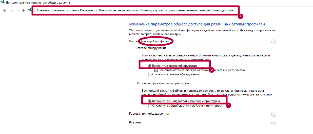 Windows 10
Убедитесь, что на МФУ включены протоколы FTP и SMB. Это можно сделать через интерфейс Command Center. Отправьте оригинал документа, выбрав направление обмена данными.
Укажите имя компьютера и название папки, открытой для общего доступа. Пропишите актуальные данные авторизации для входа на ПК. После проверки подтвердите операцию, нажав «Старт».
Другие ошибки и их решение
На МФУ также могут появиться похожие сбои. Наиболее распространенные – 1103 и 1105.
Появляется при передаче через SMB либо FTP сервер из-за неправильно указанного имени пользователя либо пароля. Также появляется при отсутствии прав доступа к сетевой папке.
Возникает, если в Command Center на Kyocera не включена функция передачи через FTP, SMB или SMTP сервер. В этом случае необходимо задать значение в настройках принтера.
Источник
Устранение ошибки передачи – Инструкция по эксплуатации Kyocera Ecosys m2040dn
Страница 367
Устранение неисправностей > Устранение неисправностей
Устранение ошибки передачи
Меры по устранению
Не удалось отправить
электронную почту.
Проверьте правильность имени хоста SMTP
сервера в Command Center RX.
Не удалось отправить через
FTP.
Проверьте имя хоста FTP.
Не удалось отправить через
SMB.
Проверьте имя хоста SMB.
Не удалось отправить через
SMB.
Проверьте настройки SMB:
•
имя пользователя и пароль при входе.
Если отправитель является пользователем
домена, укажите имя домена:
•
Не удалось отправить
электронную почту.
Проверьте следующее на Command Center RX:
•
имя пользователя и пароль для сервера SMTP;
имя пользователя и пароль для сервера POP3;
предел размера сообщения эл. почты.
Не удалось отправить через
FTP.
Проверьте настройки FTP-сервера:
•
имя пользователя и пароль при входе.
Если отправитель является пользователем
домена, укажите имя домена:
право доступа получателя к папке.
Не удалось отправить через
SMB.
Проверьте настройки SMB:
•
имя пользователя и пароль при входе.
Если отправитель является пользователем
домена, укажите имя домена:
право доступа получателя к папке.
Не удалось отправить через
FTP.
Проверьте настройки FTP-сервера:
•
право доступа получателя к папке.
Не удалось отправить
электронную почту.
Проверьте адрес электронной почты.
Если адрес отклонен доменом, отправка
электронного письма невозможна.
Источник
Kyocera ошибка соединения 0x2101 smtp
Для сканирования и отправки документов по e-mail для МФУ М2835dw необходимо не только наполнить адресную книгу, но и настроить отправку почты по e-mail. Для реализации этой возможности нужно настроить параметры почтовых протоколов, благодаря которым почта будет отправляться на выбранные адреса.
Для настройки отправки почты придется пройтись по меню аппарата, перепрыгивая с одного окна на другое. Над удобством меню, как и над логикой управления инженерам kyocera явно стоит поработать. Перед настройкой необходимо создать пользователя на любом почтовом сервере. В данном случае был создан пользователь Адрес электронной почты защищен от спам-ботов. Для просмотра адреса в вашем браузере должен быть включен Javascript. (на почтовом сервере yandex).
1. Открываем веб-панель МФУ Ecosys Kyocera M2835dw, набираем логин, пароль (по умолчанию Admin — Admin).
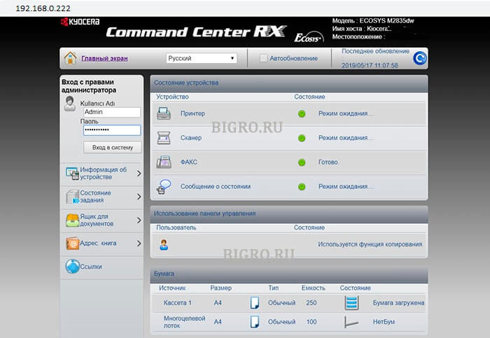
2. Далее переходим «Настройки функций» — «Электронная почта«.
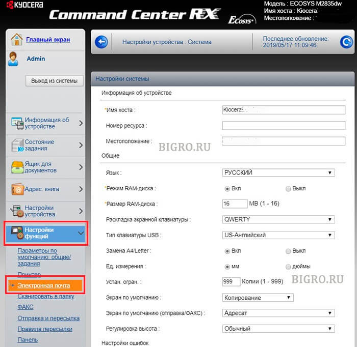
3. В открывшемся окне заполняем:
Имя сервера SMTP: 213.180.193.38
Имя севера SMTP (сервер исходящей почты) зависит от используемого почтового сервера. В данном случае IP-адрес почтового сервера по протоколу smtp 213.180.193.38 (smtp.yandex.ru). Посмотреть настройки основных почтовых серверов можно ЗДЕСЬ.
Имя сервера SMTP лучше задать по имени (например, для Yandex — smtp.yandex.ru), но если в сети не работает DNS, то МФУ не будет понимать, что такое smtp.yandex.ru. Проверить можно набрав в командной строке: ping smtp.yandex.ru. Если будет ответ от сервера (пройдут пинги), то можно прописать имя почтового сервера по протоколу smtp, если пинги не пройдут, тогда указываем IP-адрес.
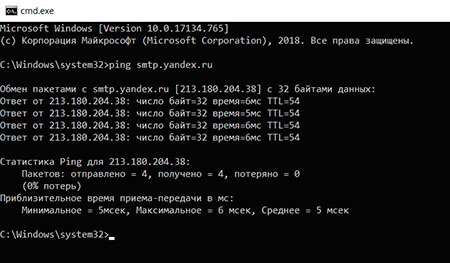
Номер порта smtp: 465.
В данном случае используется шифрование, данный порт используется на почтовом сервере Yandex по протоколу SMTP.
Протокол аутентификации: Вкл.
Аутенфицировать как: Пользователь 1 POP3.
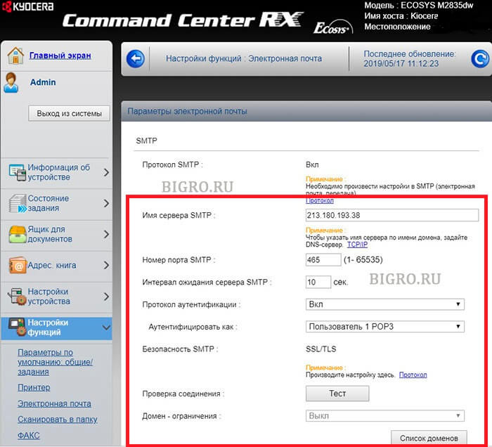
4. В секции «Настройки отправки электронной почты» настраиваем:
Адрес отправителя: Адрес электронной почты защищен от спам-ботов. Для просмотра адреса в вашем браузере должен быть включен Javascript. .
Адрес отправителя — созданный почтовый аккаунт.
Нажимаем «Передать» для сохранения настроек. Далее в секции «POP3» нажимаем кнопку «Параметры» («Настройки пользователя POP3«).
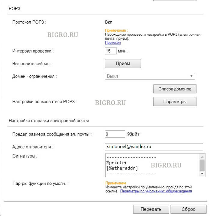
5. В окне «Настройки пользователя POP3«:
Профиль пользователя 1: Вкл.
Адрес электронной почты: Адрес электронной почты защищен от спам-ботов. Для просмотра адреса в вашем браузере должен быть включен Javascript. .
Адрес электронной почты — созданный почтовый аккаунт.
Имя сервера POP3: 213.180.204.212
Имя севера POP3 (сервер входящей почты) зависит от используемого почтового сервера. В данном случае IP-адрес почтового сервера по протоколу pop3 213.180.204.212 (pop.yandex.ru). Посмотреть настройки основных почтовых серверов можно ЗДЕСЬ.
Имя сервера POP3 лучше задать по имени (например, для Yandex — pop.yandex.ru), но если в сети не работает DNS, то МФУ не будет понимать, что такое pop.yandex.ru. Проверить можно набрав в командной строке: ping pop.yandex.ru. Если будет ответ от сервера (пройдут пинги), то можно прописать имя почтового сервера по протоколу POP3, если пинги не пройдут, тогда указываем IP-адрес.
Номер порта POP3: 995.
В данном случае используется шифрование, данный порт используется на почтовом сервере Yandex по протоколу POP3.
Имя пользователя для регистрации Адрес электронной почты защищен от спам-ботов. Для просмотра адреса в вашем браузере должен быть включен Javascript. .
Имя пользователя для регистрации — созданный почтовый аккаунт.
Нажимаем «Передать» для сохранения настроек. Далее нажимаем «Протокол» (Примечание: Произведите настройку здесь).
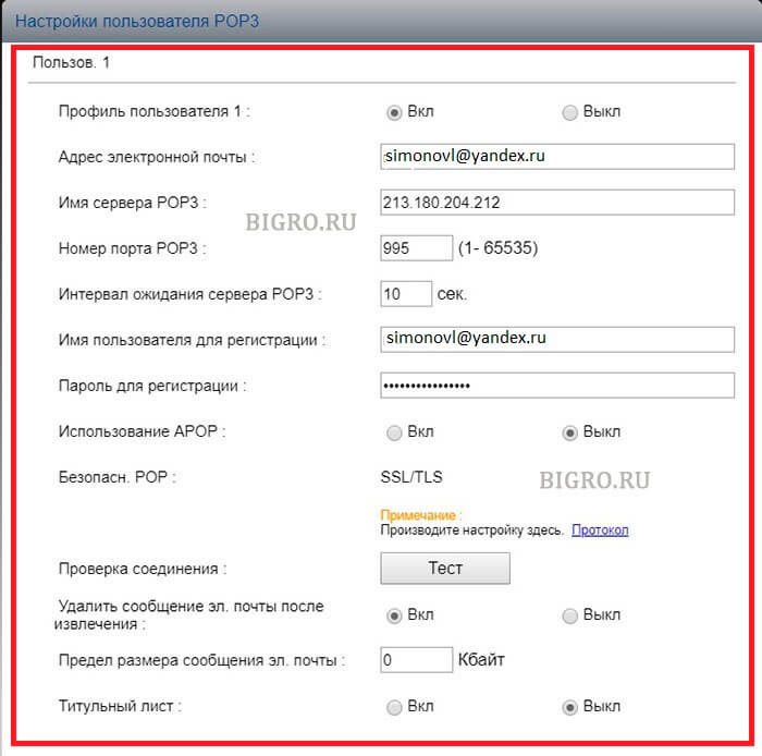
6. В новом окне настраиваем:
POP3 (прием эл. почты): Вкл.
Безоп. POP3 (Пользов. 1): SSL/TLS.
SMTP (передача эл. почты): Вкл.
Безопасность SMTP: SSL/TLS.
Нажимаем «Передать» для сохранения настроек. Далее нажимаем «Защита сети» (Примечание: Для использования этих настроек включите SSL).
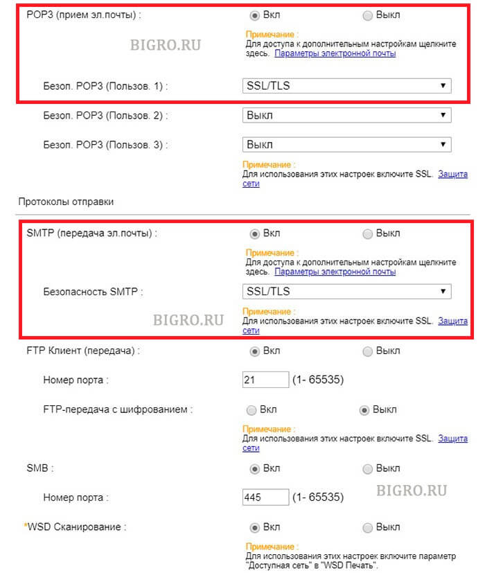
7. В открывшемся окне «Настройки сетевой безопасности» включаем SSL:
SSL: Вкл.
Нажимаем «Передать» для сохранения настроек.
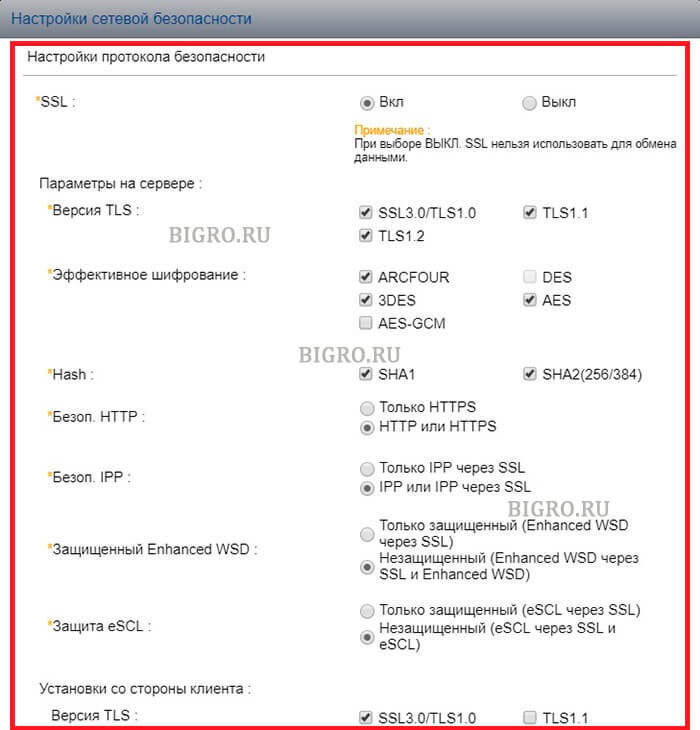
7. Далее переходим в «Настройки электронной почты» (Настройки функций — Электронная почта), в секции SMTP нажимаем кнопку «Тест«. При успешном соединении появится сообщение «Соединение ОК». Это значит, что настройки произведены правильно. Теперь можно сканировать документы и передавать по электронной почте выбранным в адресной книге адресатам.
Источник
Thread: KM-5050 Scan to SMB Error 2101
Thread Tools
Display
KM-5050 Scan to SMB Error 2101
Hello everyone,
I have a KM-5050 with firmware version 2GR_2000.014.028 2007.11.02,
Print works ok.
Trying to hook it up to scan to a folder (via SMB) on Windows Server 2008 R2 Data Center.
Scan to email is also working. I have tried using the hostname and IP address. The username and password is also a domain admin account.
For testing, when hooking it up to an individual laptop, the scan to SMB folder works ok.
Is there any suggestion anyone may know about to get this working?
Is my firmware the culprit?
Thanks in advance for your help.
Claudio
Re: KM-5050 Scan to SMB Error 2101
I remember seeing something like this before. When you put in the username info you need to add the domain info as well. I for the life can’t remember where I saw this but I’ll look around in some stuff I have around and see if I can find it.
update found the info in the Kyocera Scan to SMB(PC) set up guide. check this
Check the information in “domain nameuser name” format for logging onto Windows.
1 Press the Ctrl-Alt-Delete key combination on the
keyboard.
2 Check the Logon Information that appears on the
Windows Security window. In the sample window
below, “ABCDNETjames.smith” corresponds to
“domain nameuser name”.
(Example: ABCDNET james.smith)
Service Manager 1,000+ Posts 

 Join Date Feb 2010 Posts 1,910 Rep Power 71
I think 2101 implies a firewall/anti virus issue
Master Of The Obvious 10,000+ Posts
 Join Date Jul 2007 Location Lapeer, Michigan Posts 21,181 Rep Power 422
Re: KM-5050 Scan to SMB Error 2101
You can get 2101 for a hostname IP issue, or a login/password issue. Either one.
For the sake of diagnosis, I’d suggest creating a new user with a new known password, and new admin properties. Most times it’s login/password related, even if you can log in to the PC/server with this info sometimes it won’t work from the MFP. Many times this has resolved 2101 errors. =^..^=
Re: KM-5050 Scan to SMB Error 2101
Totally agree with this solution, I have a story
Call out to the Customer, 2 local Meath GAA players (Gaelic football) for top tray malfunction on a Kyocera model /Utax 1625. I cleaned the machine located the problem as the try paper size guide was broke etc. I taught I was done, when the Customer told me that the machine won’t print or scan.
I re-installed drivers etc., put in all the scan data and tried to scan ERROR 2101 kept coming up. So out to the car and plugged in the laptop and print and scan function working 100%. I asked the Customer any changes recently and they said the router so I inspect and its fine. I then check the only Pc connected to the machine and give it a good going over. I find the McAfee anti-virus software and disable it and hooray I can print but no scan. I ask the Customer was the anti-virus updated and he said no, shortly after my SM rang because I was there 1.5 hours I explained what happened and he told me to just get going.
I tell the Customer that I must go but would be back with the rtf parts that my SM has been on and that they should have logged the call regarding the print and scan, as I was only into my 2nd year and that call would require a more exp Tech and that if they wanted to print they must either disable or change their settings in the Anti-virus to allow printing. I was not long gone when the Customer called the Office giving out saying I was hopeless etc. and yes my SM called the Customer and asked was the Anti-Virus changed, when he finished that call he gave me the hairdryer treatment. I told him that when I finished the call they wanted me to look at the printing etc., I told him it was the Anti-Virus blocking the printing and he still fumed and sent my Supervisor there. The Supervisor rang me and I told him the story and he came back with a report that the Router was faulty and told the Customer to change it.
It was less than a week and the Customer was raging, the router did not work. The call was logged and the SM sent out his golden boy, the Polish Master who was a lazy git TBH, I have to admit he was there for 3 hours and solved the problem. It was the anti-virus, and yes they had recently got an IT guy in to install it. I was never thanked for attempting the repair but the Customer was charged for the call out and not telling anyone about the change. SUCKER
Источник
 Dislikes: 0
-
04-11-2014
#1

Junior Member
- Rep Power
- 0
C5101. error on Ta4550ci
Have swapped Black charge roller and drum unit. Still getting error. Is it main HV. Pcb?
-
04-11-2014
#2
Re: C5101. error on Ta4550ci
There is a troubleshooting guide that Kyocera has for that model, the file size is 16 meg if you have an email I can scan you the pages that pertain to your issue.
-
11-04-2014
#3
Technician

- Rep Power
- 0
Re: C5101. error on Ta4550ci
Hi,
I have a 4550CI that gives an error C-5101
Mostly early in the morning immediatly after switching on the machine.
Sometimes the machine works normal en it gives the error during a printjob.I already replaced: Drumunit (incl. maincharger)
main HV board
engineboard
main pwb.……………………but still the same code.
What can be the solution of this problem?
thanks in advance.
Grtz.
Dikyo
Last edited by dikyo; 11-04-2014 at 08:27 PM.
-
04-28-2015
#4
Trusted Tech
50+ Posts

- Rep Power
- 29
Re: C5101. error on Ta4550ci
 Originally Posted by RickyG

Have swapped Black charge roller and drum unit. Still getting error. Is it main HV. Pcb?
Hi Guys,
We had a TA4550ci with this error. It looks like we fixed it with the K main charge and resetting U930.
Our problem was we tried swapping out the K drum unit from another machine so we didnt reset U930, the error kept occurring and lead us down the HVT/Engine PWB/Drum Drive path with no results.
Its turned on this morning and worked perfectly.
The only other problem it had was faint black text on the first copy out after not being used for a few hours during the day which im guessing was tied in with the main charge issue, just not bad enough to bring up the error.
-
04-30-2015
#5
Re: C5101. error on Ta4550ci
uh…
It could be that its too cold and wet overnight. In the morning after room temperature warms up it has moisture in the system.
Idling colour developers are not healthy developers.
-
04-30-2015
#6
Trusted Tech
50+ Posts
- Rep Power
- 29
Re: C5101. error on Ta4550ci
Originally Posted by jmaister
uh…
It could be that its too cold and wet overnight. In the morning after room temperature warms up it has moisture in the system.
Our machine reproduced the same error code in our workshop, 2 other taskalfa’s next to it in the same conditions worked fine.
-
04-30-2015
#7
Re: C5101. error on Ta4550ci
ah ok.
if anyone gets random c5101/2/3/4, check environment~~~ could be.
Last edited by jmaister; 04-30-2015 at 08:27 AM.
Idling colour developers are not healthy developers.
-
04-30-2015
#8
Technician
- Rep Power
- 31
Re: C5101. error on Ta4550ci
Originally Posted by jmaister
ah ok.
if anyone gets random c5101/2/3/4, check environment~~~ could be.
the fix for this is to reset the charge roller count when it has done over life. unfortunately the majority of engineers when changing the charge roller itself do not reset the count so the machine still thinks it has done many thousands of copies so it will try and compensate for this. there comes a point when the machine says the high voltage unit cant give anymore and it throws a charge code. if in a cold enviro what I did was to fit the tray heaters from an old voyager 2525 and enabled the tray heaters -job done good luck
-
05-22-2015
#9
Re: C5101. error on Ta4550ci
Originally Posted by GUNit
the fix for this is to reset the charge roller count when it has done over life. unfortunately the majority of engineers when changing the charge roller itself do not reset the count so the machine still thinks it has done many thousands of copies so it will try and compensate for this. there comes a point when the machine says the high voltage unit cant give anymore and it throws a charge code. if in a cold enviro what I did was to fit the tray heaters from an old voyager 2525 and enabled the tray heaters -job done good luck
its uncanny how this worked right away. one color machine rebooted to this error code, replaced charge roller (but it came back few days later). The following visit u930 reset count executed, next reboot gave no problem and its been a week, no call back.
thx Kyocera engineer, another undocumented trick.
Idling colour developers are not healthy developers.
-
05-26-2015
#10
Technician
- Rep Power
- 31
Re: C5101. error on Ta4550ci
Originally Posted by jmaister
its uncanny how this worked right away. one color machine rebooted to this error code, replaced charge roller (but it came back few days later). The following visit u930 reset count executed, next reboot gave no problem and its been a week, no call back.
thx Kyocera engineer, another undocumented trick.
Think the general rule to follow is if there is a counter for it then reset it, the great thing about digital is there are so many calibrations and compensations for aging and dirty optics etc going on in the background that a lot of engineers forget this. if you think back to the analogue days when your optics got dirty then you got crappy copies, especially in dusty enviros, whereas now with digital you don’t. this is why when you clean the optics you need to do auto grey adjust just to bring back everything to base level again, just like saying ok the high voltage has adjusted enough for that 600k charge roller ill change it but I must tell the machine I have so it can once again return to base level and start recounting and compensating. hope this makes sense and glad you are up and running again.
Bookmarks
Bookmarks

Posting Permissions
- You may not post new threads
- You may not post replies
- You may not post attachments
- You may not edit your posts
- BB code is On
- Smilies are On
- [IMG] code is On
- [VIDEO] code is On
- HTML code is Off
Forum Rules
 Если с аппаратом Kyocera TASKalfa 1800, Kyocera TASKalfa 2200 произошла проблема, откроется следующий экран с уведомлением.
• Индикатор [Внимание] на панели управления горит или мигает.
• На дисплее сообщений панели управления аппарата появилось сообщение об ошибке.
Если индикатор [Внимание] горит или мигает и на дисплее сообщений панели управления аппарата появилось сообщение об ошибке, проверьте KYOCERA Client Tool или Монитор состояния.
ПРИМЕЧАНИЕ Если индикаторы постоянно горят и мигают не так, как описано выше, вероятно, произошла ошибка службы. Выключите питание, отсоедините шнур питания и вставьте его обратно, после чего включите питание. Это может помочь сбросить ошибку. Если ошибка не исчезает, свяжитесь со своим представителем сервисной службы (тел. в Минске +375 17 291-28-24)
Ниже описаны неполадки, которые не могут быть устранены пользователем
|
Дисплей сообщений |
Описание |
Меры устранения |
|
Бункер отраб тонера перепол. или не уст. |
Бункер для отработанного тонера установлен неправильно |
Установите Бункер для отработанного тонера должным образом |
|
Бункер для отработанного тонера заполнен |
Замените бункер отработанного тонера |
|
|
Встряхните картр. с тонером |
Тонер слежался |
Откройте переднюю крышку аппарата и вытяните контейнер с тонером. Сильно встряхните контейнер с тонером и установите его на место |
|
Вызовите сервисный персонал. |
В аппарате произошла ошибка |
Обратите внимание на код ошибки, отображаемый в дисплее сообщений, и свяжитесь с представителем сервисной службы (тел. в Минске +375 17 291-28-24) |
|
Выньте бумагу с внутреннего лотка |
Извлеките бумагу из внутреннего лотка. Нажмите клавишу [OK], чтобы возобновить печать |
|
|
Добавьте тонер |
Закончился тонер |
Замените контейнер с тонером TK-4105 |
|
Загрузите бумагу в кассету # |
↑↓ (отображается попеременно) |
Загрузите бумагу. Нажмите клавишу [OK] и перейдите к следующему шагу. • Для выбора другого устройства подачи выберите [Выберите бумагу]. • Для печати на бумаге, в настоящее время находящейся в устройстве подачи, выберите [Продолж. без изм.] |
|
Загрузите бумагу в универсальный лоток |
↑↓ (отображается попеременно) |
Загрузите бумагу. Нажмите клавишу [OK] и перейдите к следующему шагу. • Для выбора другого устройства подачи выберите [Выберите бумагу]. • Для печати на бумаге, в настоящее время находящейся в устройстве подачи, выберите [Продолж. без изм.] |
|
Закройте автоподатчик оригиналов |
Открыт автоподатчик оригиналов |
Откройте и закройте автоподатчик оригиналов |
|
Закройте крышку автопод. оригиналов |
Открыта верхняя крышка автоподатчика оригиналов |
Откройте и закройте крышку автоподатчика оригинало |
|
Закройте переднюю крышку |
Открыта передняя крышка |
Откройте и закройте переднюю крышку |
|
Закройте правую крышку # |
Открыта какая-либо крышка |
Откройте и закройте крышку, обозначенную на экране |
|
Замятие бумаги. (DP) |
В автоподатчике произошло замятие бумаги. |
См. Устранение замятия бумаги в Руководстве по эксплуатации и извлеките замятую бумагу |
|
Замените МК |
Необходимо производить замену деталей комплекта техобслуживания MK-4105 (ремкомплекта) каждые 150 000 страниц печати. |
Данная операция должна производиться специалистом. Обратитесь к представителю сервисной службы (тел. в Минске +375 17 291-28-24) |
|
Замятие |
Произошло замятие бумаги в кассете или универсальном лотке |
См. Устранение замятия бумаги и извлеките замятую бумагу |
|
Извлеките оригиналы из автоподатчика |
Для продолжения работы необходимо извлечь оригиналы из автоподатчика оригиналов |
Извлеките оригиналы из автоподатчика оригиналов |
|
Кабель USB был отключен |
Кабель USB не подключен |
Нажмите клавишу [OK] и подключите кабель USB |
|
ПК выключен |
Нажмите клавишу [OK] и включите ПК |
|
|
Не удается найти KYOCERA Client Tool |
Нажмите клавишу [OK] и откройте KYOCERA Client Tool на ПК |
|
|
Макс. к-во сканируемых страниц |
Превышен предел сканирования |
Дальнейшее сканирование невозможно. Задание отменено. Нажмите клавишу [OK] |
|
Мало тонера. (Зам., когда законч.) |
Скоро понадобится заменить контейнер с тонером |
Получите новый контейнер с тонером TK-4105. |
|
Не оригинальный тонер |
Установлен контейнер с тонером не марки Kyocera |
Производитель не несет ответственности за повреждения, вызванные использованием неоригинального тонера. Мы рекомендуем использовать исключительно оригинальные контейнеры с тонером TK-4105. . |
|
Неверный ид. уч. зап. Задание отменено |
Указан неверный идентификатор учетной записи при внешней обработке задания. Задание отменено |
Нажмите клавишу [OK] |
|
Невозможна двусторонняя печать на этой бумаге |
Не возможна печать на бумаге выбранного формата или типа |
Нажмите клавишу [OK] и перейдите к следующему шагу: |
|
Недостаточно памяти. Невозможно начать выполнение задания |
Невозможно начать выполнение задания |
Повторите попытку позже |
|
Ограничено алгоритмом учета заданий(Печать) |
Задание отменено, поскольку его выполнение ограничено функцией учета заданий |
Нажмите клавишу [OK] |
|
Ограничено алгоритмом учета заданий(Сканер) |
Задание отменено, поскольку его выполнение ограничено функцией учета заданий |
Нажмите клавишу [OK] |
|
Очистите сканер |
Произошло загрязнение сканера |
Очистите щелевое стекло с помощью чистящей салфетки, поставляемой вместе с автоподатчиком оригиналов. |
|
Ошибка. Выключить |
— |
Отключите и снова включите аппарат с помощью выключателя питания |
|
Память переполнена |
Невозможно продолжить выполнение задания из-за отсутствия свободной памяти |
Измените разрешение печати с Быстр1200 до 600 dpi. См. Printer Driver User Guide |
|
Память сканера переполнена |
Дальнейшее сканирование невозможно из-за нехватки памяти сканера. |
Для отмены задания нажмите [OK] |
|
Перезагрузка печати. Задание отменено |
Предупреждение. Недостаточно памяти принтера. Задание отменено |
Нажмите клавишу [OK] |
|
Превышено ограничение учета заданий |
Превышено число распечаток из-за ограничения алгоритмом учета заданий. Достигнут предел печати |
Это задание отменено. Нажмите клавишу [OK] |
|
Уст.другую кассету |
Выбрано «Сдвиг» |
Для использования сдвига необходимо загрузить в другой лоток бумагу такого же формата, что и в выбранном устройстве подачи, но в другой ориентации |
|
Установите все оригиналы обратно и нажмите клавишу [Старт]. |
Возникает при печати двусторонних документов в режиме ручной двусторонней печати |
Извлеките оригиналы из автоподатчика оригиналов, расположите их в первоначальном порядке и положите обратно. Нажмите клавишу [OK], чтобы возобновить печать. Для отмены задания нажмите [Стоп] |
|
Установлен неизвестный тонер. ПК |
Региональная спецификация контейнера с тонером не соответствует спецификации аппарата |
Установите оригинальный контейнер с тонером Замените контейнер с тонером TK-4105 |
Устранение неисправностей
5-17
5
Код ошибки:4701,
5101, 5102, 5103, 5104,
7102, 720f
–
Выключите и затем включите
главный включатель питания. Если
эта ошибка возникнет повторно,
запишите код ошибки, который
отображается на дисплее
сообщений, и обратитесь к
специалисту по обслуживанию.
(См. процедуру в Сбой аппарата
Вызовите сервисный
персонал.)
—
Код ошибки:9181
Возможно, отсканированы
999 страниц оригиналов?
Если число страниц оригинала
превышает 999, передавайте
страницы отдельными пакетами.
—
Код ошибки при сканировании с отправкой по Email
Код ошибки:1101
Возможно, неправильное
имя сервера SMTP/POP3?
Установите правильное имя
сервера в COMMAND CENTER.
—
Код ошибки:1102
Возможно, вы указали
недопустимые имя
пользователя или пароль?
Введите правильные имя
пользователя и пароль.
—
Код ошибки:1104
Указали ли вы адрес
адресата?
Укажите адрес адресата.
—
Код ошибки:1105
Включен ли протокол
SMTP?
Включите протокол SMTP в
COMMAND CENTER.
—
Код ошибки:2101,
2102, 2103, 2201, 2202,
2203
Выбрано ли «Другая
аутентификация», когда
выполняется
аутентификация POP
перед SMTP?
Выберите действующего
пользователя POP3,
отличающегося от «Other».
—
Является ли указанный
сервер сервером SMTP?
Установите правильное имя
сервера в COMMAND CENTER.
—
Правильно ли выполнено
подключение к сети?
Убедитесь, что сетевой кабель
правильно подключен.
Убедитесь, что сетевая среда
(сервер, концентратор или другая
сеть LAN) работает правильно.
—
Код ошибки:2204
Не пытаетесь ли вы
передать слишком
большой объем данных?
Измените размер, который можно
передавать, в COMMAND
CENTER.
—
Сообщение об
ошибке
Контрольные вопросы
Меры по устранению
Страница
для
справки
Модератор: vetal


 Доброго времени суток!
Kyocera M2035dn очень часто останавливаются листы, один на выходе из печки, второй идущий следом за ним, уже успевает пройти флажок регистрации, а его задняя часть еще находится в нижнем лотке. Выдает ошибку JAM0511.
Такое часто происходит при печати нескольких листов, когда они идут друг за другом, при одиночной печати такого не бывает.
Знаю, что у данной линейки принтеров есть распространенная проблема, когда принтер не может нормально взять бумагу из нижнего лотка, НО это не тот случай. Все ролики захвата и отделения были заменены на новые.
Листы ни за что не цепляются, а просто останавливаются. Есть предположение, что это происходит от того что в какой-то момент дистанция между идущими друг за другом листами становится настолько мала, что флажок регистрации не успевает возвратиться хоть немного в начальное положение и принтер не видит двух разных листов.
Такое предположение возникло, когда в очередной раз застряла бумага и убрав блок проявки и драм-картридж, увидел что между двумя листами вообще не было дистанции, они даже немного наложились друг на друга. А вообще обычно когда застревают листы, между ними есть небольшая дистанция.
Помогите с этой неисправностью!
-

Sveterkom
- Знает как починить копир
-

- Персональный альбом

 Sveterkom » Чт ноя 12, 2020 5:37 am
Пробег примерно 120 тысяч.
Ролики китайские.
Но с захватом и отделением же проблем нет? Иначе листы бы не брались или брались бы по несколько одновременно
-
Sveterkom
- Знает как починить копир
-
- Персональный альбом
Дормидонт_Генрихович » Пт ноя 13, 2020 9:06 am
Goldwater писал(а):Перечитал стартовый пост. Чем вам помочь? Прислать кошерных роликов? Снять анимацию, как они работают?
очень интересно, чем отличаются оригинальные ролики от тех же сет лонг лайф, если не затруднит, проясните вопрос
говорю правду в глаза…
-
Дормидонт_Генрихович
- Починил копир!
-
- Персональный альбом
MatrixAgent » Пт ноя 13, 2020 12:19 pm
Дормидонт_Генрихович писал(а):
Goldwater писал(а):Перечитал стартовый пост. Чем вам помочь? Прислать кошерных роликов? Снять анимацию, как они работают?
очень интересно, чем отличаются оригинальные ролики от тех же сет лонг лайф, если не затруднит, проясните вопрос
Конкретно по этим не скажу, а ранешние алиэкспрессовские отличались диаметром. Разница минимальная, но на скорость прохождения листа влияла. Датчик от такого счастья слегка офигивал.
П.С. Мой совет насчёт продуть ТС, интересно, принял к сведению?
П.П.С. Мне эти аппараты сейчас почти не попадаются, может, кто помнит, из-за чего образуется вертикальная серая полоса в правой части листа? Исключены проявка (блок менял), фотик (блок менял), тефлон. Под сомнением поролоновый валик (помыл, но подменить нечем, помнится, когда-то решал похожую проблему заменой).
Ксероксни Хьюлетца.
-

MatrixAgent
- Гадает по тонеру
-
- Персональный альбом
aresson » Пт ноя 13, 2020 2:08 pm
MatrixAgent писал(а):
П.П.С. Мне эти аппараты сейчас почти не попадаются, может, кто помнит, из-за чего образуется вертикальная серая полоса в правой части листа? Исключены проявка (блок менял), фотик (блок менял), тефлон. Под сомнением поролоновый валик (помыл, но подменить нечем, помнится, когда-то решал похожую проблему заменой).
а шторка есть на драме? а то у меня было пара случаев, менял барабан, проверяю — полоса с краю. первый раз долго бился в непонятках. Потом шторку одел — она пропала. Снял — появилась. Нифига не понял, как такое может быть.
-

aresson
- Чернокнижник
-
- Персональный альбом
a65rivn » Пт ноя 13, 2020 2:19 pm
aresson писал(а): Нифига не понял, как такое может быть.
Отсветка(а точней засветка фотика) от дозирующего лезвия. Помогает простая закраска доз.лезвия.
-
a65rivn
- Заправщик
-
-
-
Kyocera 1035 «бледная» печать
srMax в форуме Принтеры, МФУ, факсы, копиры формата A4
- 2
- 13541
srMax

Пт янв 23, 2015 2:49 pm
-
Kyocera 1035 «бледная» печать
-
-
[SCANNER ERROR] Lamp Error Kyocera FS-1016
мастерчип в форуме Принтеры, МФУ, факсы, копиры формата A4
- 3
- 6431
Усатый Полосатый
Вс окт 28, 2018 11:08 pm
-
[SCANNER ERROR] Lamp Error Kyocera FS-1016
-
-
Kyocera FS-1120d индикатор «Нет бумаги»
vs-dos в форуме Принтеры, МФУ, факсы, копиры формата A4
- 11
- 14579
СТРОНЦИЙ
Вт ноя 02, 2021 2:24 pm
-
Kyocera FS-1120d индикатор «Нет бумаги»
-
-
Taskalfa 180 ошибка «Е» и «Встряхните картр. с тонером»
manik.76 в форуме Принтеры, МФУ, копиры формата A3
- 3
- 9184
dviz
Пн фев 20, 2017 1:35 pm
-
Taskalfa 180 ошибка «Е» и «Встряхните картр. с тонером»
-
-
Kyocera Ecosys M2635dn «поворот» изображения
Искатель в форуме Принтеры, МФУ, факсы, копиры формата A4
- 10
- 5742
MatrixAgent
Ср апр 08, 2020 5:18 am
-
Kyocera Ecosys M2635dn «поворот» изображения
Вернуться в Принтеры, МФУ, факсы, копиры формата A4
Кто сейчас на форуме
Сейчас этот форум просматривают: нет зарегистрированных пользователей и гости: 96
Японская компания Kyocera производит высококачественные лазерные принтеры и МФУ для офисной печати. Их продукция одна из самых востребованных на сегодняшний день. Ведь печатающие устройства Kyocera характеризуются высокой надежностью, износостойкостью и большим сроком эксплуатации. Однако даже их изделия не являются вечными. Со временем принтеры Kyocera начинают сбоить.
К счастью, оргтехника Kyocera оснащена системой самодиагностики (так же, как и струйные принтеры Canon). Поэтому, в случае возникновения проблемы, устройство самостоятельно выявит уязвимое место и сообщит Вам об этом миганием соответствующего индикатора на панели управления либо кодом ошибки, выведенным на дисплей принтера.
Если Вы не являетесь мастером по обслуживанию принтеров и МФУ Kyocera, то, чтобы понять, о чем сообщает печатающее устройство, Вам потребуется расшифровать указанный им код. Для этого мы добавили в статью таблицу кодов ошибок лазерных принтеров Kyocera серии FS и не только.
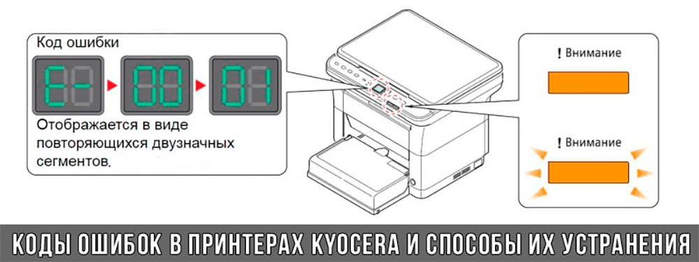
Коды ошибок принтеров и МФУ Kyocera, которые можно исправить самостоятельно
|
Код ошибки |
Значение ошибки |
Решение проблемы |
|
E-0001 (E1) |
Поврежден чип картриджа либо установлен неоригинальный картридж. |
Замените установленный картридж оригинальной версией изделия. Если хотите сэкономить, тогда купите и установите новый чип на картридж или перепрошейте принтер Kyocera. Однако предварительно не помешает попробовать сбросить ошибку соответствующей комбинацией клавиш (как это сделать, читайте в статье «Сброс ошибки установки неоригинального картриджа в принтерах Kyocera»). |
|
E-0002 (E2) |
Регион использования картриджа и принтера не совпадают. |
Замените чип или прошейте принтер Kyocera. |
|
E-0003 (E3) |
Заполнена память принтера или МФУ Kyocera. |
Отпечатайте ранее отсканированные листы или очистите очередь печати нажатием кнопки Стоп/Сброс (ранее отсканированные листы также удалятся из памяти принтера, даже если они еще не были распечатаны). |
|
E-0007 (E7) |
Тонер-картридж Kyocera израсходовал ресурс красящего вещества. |
Замените или заправьте картридж Kyocera (если используете совместимый или перезаправленный расходник, то после установки его в принтер не забудьте сбросить ошибку зажатием на 3-5 секунды кнопок [Ок] и [Сброс/Стоп]). |
|
E-0008 (E8) |
Открыта крышка принтера либо не работает датчик закрытия крышек устройства. |
Откройте и еще раз закройте переднюю и заднюю крышку принтера. Во время закрытия Вы должны услышать характерный щелчок. Если не помогло, то причина в неисправности датчика. |
|
E-0009 (E9) |
Лоток приема бумаги полон. |
Уберите все отпечатанные листы бумаги из выходящего лотка. Чтобы возобновить печать, нажмите кнопку [Старт]. |
|
E-0012 (E12) |
Ошибка памяти принтера Kyocera. |
Попробуйте уменьшить разрешение печати. Скорее всего, формат создаваемого отпечатка не соответствует возможностям принтера. |
|
E-0014 (E14) |
Установлен неверный формат бумаги (неподдерживаемый принтером Kyocera). |
Поменяйте бумагу на поддерживаемую принтером либо смените ее формат в настройках печати. Попробуйте обновить программное обеспечение. Возможно, это расширит поддерживаемые принтером Kyocera форматы. |
|
E-0015 (E15) |
Устройство не подключено к электрической сети либо на компьютере нет (не работает) драйвера принтера Kyocera. |
Проверьте подключение печатающего аппарата к электрической сети, а также целостность кабеля. Если ошибка не исчезает, скачайте драйвер принтера Kyocera и установите его на компьютер. |
|
E-0017 (E17) |
Ошибка передачи данных. |
Проверьте подключение принтера к компьютеру. Кабель не должен быть длиннее 5 метров, а также обязан поддерживать стандарт USB 2.0. Кроме того, переустановите драйвер принтера и утилиту Kyocera Client Tool. |
|
E-0018 (E18) |
Очередь печати заполнена. |
Очистите очередь печати нажатием кнопки [Сброс] либо через драйвер принтера. |
|
E-0019 (E19) |
Неверный формат печати. |
Отмените печать нажатием кнопки [Стоп/Сброс]. Выберите в настройках принтера соответствующий режим печати, а также установите в лоток поддерживаемый принтером формат бумаги. |
|
J-0000 (jam0000) |
Замятие бумаги за задней крышкой. |
Откройте крышку и извлеките бумагу. Проверьте надежность крепления бумаги в лотке, а также принтер на наличие посторонних предметов. Еще причина может быть в пружине выходного флажка. Если она растянулась, то может плохо работать фиксатор. Также проблема может быть из-за печки, сделайте ее ревизию, переборку и смазку. |
|
J-0501 (jam0501) |
Бумага застряла в принтере Kyocera |
Извлеките замятую бумагу. Проверьте надежность установки бумаги во входной лоток. Проверьте целостность роликов протяжки бумаги, а также принтер на наличие посторонних предметов. Если не помогло, стоит внимательно осмотреть ребра на направляющей пластине. На них могут образоваться сколы, трещины и заусенцы. Их можно слегка подчистить наждачной бумагой (нулевкой). |
|
J-0511 (jam0511) |
Принтер Kyocera замял бумагу. |
Извлеките замятую бумагу и повторите печать. Если проблема не исчезла, несите принтер в сервис. Скорее всего, изношен ролик протяжки бумаги. |
|
C7990 |
Бункер драм-картриджа (блока фотобарабана) заполнен отработанным тонером либо неисправен счетчик отработки красящего вещества. Еще проблема может быть в главной плате PWB. |
Осуществите чистку драм-картриджа (блока фотобарабана). Если проблема в датчике или плате, то нужно отнести принтер в СЦ на диагностику. |
|
F248 |
Ошибка обработки отпечатываемого материала. |
Перезагрузите принтер. Уберите неподдерживаемые спецсимволы из отпечатка. Обновите ПО принтера Kyocera. Смените режим работы принтера с PDL на GDI (Пуск -> Принтеры -> Свойства -> Параметры устройства). |
|
PF |
Отсутствует бумага в лотке подачи. |
Загрузите листы бумаги во входной лоток. Если принтер по-прежнему не печатает, значит нужно искать проблему в чем-то другом. |
|
1101 |
Ошибка сканирования через сеть из-за неправильного имени SMTP сервера. |
Пропишите DNS-адреса помимо прочих настроек печати по сети. |
|
1102 |
Некорректная настройка сканера для работы через сеть |
Зайдите в Web-панель управления принтером (нужно в адресную строку браузера ввести iP принтера Kyocera). Далее в зависимости от модели введите логин и пароль (Admin/Admin или просто admin00 без логина). Далее следуйте инструкции:
Логин и пароль нужны обязательно, если их нет, то следует создать. |
|
2101 |
Ошибка передачи данных при сканировании через сеть. |
Правильно настройте параметры (как для ошибки 1102), только предварительно отключите на ПК антивирус и брандмауэр. |
Если Вы испытали все способы, но не смогли убрать ошибку, то следует нести печатающее устройство в сервисный центр. Кроме того, есть ряд ошибок (высвечиваемых на дисплее принтера), которые нельзя устранить в домашних условиях. Соответствующие коды ошибок принтеров Kyocera представляем в очередной таблице.
Коды ошибок принтеров и МФУ Kyocera, которые нужно устранять в сервисном центре
|
Код ошибки |
Значение ошибки |
Решение проблемы |
|
0030 |
Неисправность платы управления факсом принтера. |
Замена платы. |
|
0100 |
Неисправность платы управления или флеш-памяти принтера. |
Замена платы. |
|
0120 |
Ошибка чтения mac-адреса из-за неисправности флеш-памяти принтера. |
Замена платы. |
|
0190 |
Неисправность платы управления или флеш-памяти принтера. |
Замена платы. |
|
0630 |
Неисправность платы управления принтера. |
Замена платы. |
|
1020 |
Неисправность мотора, привода или отсутствие контакта. |
Разборка принтера и замена изношенных частей. Проверка надежности подключений, замена разорванных (прогоревших) кабелей. Ремонт или замена привода мотора. |
|
1040 |
Неисправность мотора, привода или отсутствие контакта. |
Разборка принтера и замена изношенных частей. Проверка надежности подключений, замена разорванных (прогоревших) кабелей. Ремонт или замена привода мотора. |
|
2000 |
Неисправность главной платы управления, соединительного кабеля или привода принтера. |
Проверить ремни, шестерни и ролики привода. Смазать или заменить, если есть дефекты. Заменить привод или главную плату. |
|
3100 (C3100) |
Неисправность главной платы, привода сканера, датчика положения или нарушение целостности соединений. |
Проверить наличие разрывов и отсутствия контакта. Смазать или заменить изношенные элементы привода. Заменить привод, главную плату, датчик или соединительный кабель. Если Вам повезло, то возможно забыли отключить фиксатор блока сканера. |
|
3101 |
Сетевой кабель не подсоединен, или нарушена работа концентратора. Еще может быть из-за наличия вирусов в системе или неправильно заданным параметрам сервера SMTP. |
Проверить соединения, правильно настроить параметры сети. |
|
3300 |
Неисправность главной платы, датчика CIS или соединительного кабеля. |
Проверить контакты, заменить плату или датчик. |
|
3500 |
Неисправность главной платы или нарушение соединения контактов. |
Проверить контакты, заменить плату. |
|
4000 (C4000) |
Неисправность главной платы, привода сканера или нарушение соединений. Однако чаще всего ошибка лазера. |
Проверить контакты, заменить плату или привод блока сканера. Почистить лазер, смазать ось полигон-мотора, либо полностью заменить блок лазера. |
|
4200 |
Неисправность главной платы, блока сканера или датчика BD. |
Отключить питание принтера на 30 минут. Если не помогло, то следует заменить привод сканера или главную плату принтера. |
|
6000 (С6000) |
Неисправность главной платы, термостата, печки или нарушение соединения контактов. |
Проверить и поправить контакты. Заменить фьюзер. Ремонт или замена печки, термодатчика, термопредохранителя и т.д. |
|
6020 |
Сгорание термистора или главной платы. |
Замена термистора или главной платы. |
|
6030 |
Неисправность главной платы, термостата или термистора. Возможно, причина в отсутствии контакта. |
Проверить соединения. Заменить плату, термостат или термистор. |
|
6400 |
Неисправность главной платы, отсутствие питания или контакта. |
Заменить плату или источник питания. |
|
F000 |
Неисправность главной платы или отсутствие контакта. |
Проверить соединение ремня безопасности. Заменить ремень или плату управления. |
|
F020 |
Неисправность элементов памяти принтера. |
Перезагрузить принтер. Если ошибка не устранилась – заменить плату управления. |
|
F040 |
Неисправность главной платы принтера. |
Перезагрузить принтер. Если ошибка не устранилась – заменить плату управления. |
|
F05D |
Неисправность главной платы. Сбой программного оборудования привода. Проблемы с прошивкой принтера Kyocera. |
Перезагрузить принтер. Если ошибка не устранилась – заменить плату управления. Перепрошить принтер Kyocera. |
|
F245 F246 F247 F375 |
Принтер Kyocera заблокирован из-за проблемы, вызванной отказом источника питания. |
Нужно перепрошить принтер специальной сервисной микропрограммой. |
Обратите внимание: Если у печатающего устройства нет дисплея, то определить проблему можно по светодиодным индикаторам, встроенным в панель управления принтером. Например, у Kyocera Ecosys P2135D нужно сосчитать количество миганий индикаторов красного цвета и таким образом определить число, указывающее на ту или иную ошибку. В свою очередь, у модели Kyocera FS-1040 все зависит от темпа мигания светодиода с надписью «Внимание!» («Attention!»):
- Мигает медленно – указывает на отсутствие бумаги в лотке или тонера в картридже.
- Мигает быстро – оповещает о проблеме с памятью устройства, переполненном лотке или замятии бумаги, а также об использовании неоригинальных расходных материалов.
- Горит постоянно – говорит о проблемах с картриджем или фотобарабаном либо указывает на открытые крышки принтера.
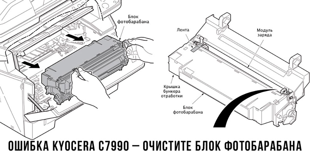
Чтобы потребитель мог наверняка определить проблему, рекомендуем использовать утилиту Kyocera Client Tool, которая идет в комплекте с драйверами принтера.
Ваше Имя:
Ваш вопрос:
Внимание: HTML не поддерживается! Используйте обычный текст.
Оценка:
Плохо
Хорошо
Введите код, указанный на картинке:
