Все современные копировальные аппараты, мфу и принтеры Kyocera имеют возможность диагностировать все узлы устройства в режиме запуска и во время работы аппарата. По этому, если во время включения или во время работы произошел сбой, то техника Kyocera сможет сообщить о наличии ошибки.
В большинстве случаев у аппаратов Kyocera код ошибки отображается на дисплее, в остальных случаях тип ошибки зависит от последовательности и количества миганий индикаторов.
Если Ваш копировальный аппарат, МФУ или принтер Kyocera выдал на дисплее некий код, то узнать причину, описание возникновения ошибки, а так же в каком узле аппарата стоит искать проблему, Вы можете в этом разделе выбрав интересующую модель из списка.
Но диагностика не решит проблему сбоя аппарата, для этого лучше обратиться к профессиональным и опытным сервисным специалистам компании Kyomart! Позвоните нам по телефону
8 (343) 288-23-45 или отправьте запрос на электронную почту: sales@kyomart.ru , и мы обязательно свяжемся с Вами в кратчайшие сроки.
| Код ошибки | Описание ошибки | Причина ошибки |
|---|---|---|
| 0100 | Backup memory device error | Defective flash memory. Defective control PWB. Defective flash memory. Defective control PWB. |
| 0120 | MAC address data error | Defective flash memory. |
| 0130 | Backup memory read/write error | Defective flash memory. Defective control PWB |
| 0140 | Backup memory data error | Defective flash memory. Defective control PWB. |
| 0150 | Control PWB EEPROM error Detecting control PWB EEPROM (U17) communication error. |
Improper installation control PWB EEPROM (U17). Defective control PWB. |
| 0160 | Backup memory data error (engine PWB) | Defective EEPROM.PWB. Defective engine PWB. |
| 0170 | Billing counting error A checksum error is detected in the main and engine backup memories for the billing counters. |
Data damage of EEPROM. Defective PWB. EEPROM. |
| 0190 | Backup memory device error (engine PWB) | Defective engine PWB. |
| 0800 | Image processing error JAM010x is detected twice. |
Defective main PWB.B. |
| 0840 | Faults of RTC The time is judged to go back based on the comparison of the RTC time and the current time or five years or more have passed. |
The battery is disconnected from the main PWB. Defective main PWB. |
| 1010 | Lift motor error (60/50/45 ppm model only) After cassette 1 is inserted, lift sensor does not turn on within 10 s. This error is detected four times successively. |
Defective bottom plate elevation mechanism in the cassette. Defective connector cable or poor contact in the connector. Defective drive transmission system of the lift motor. Defective lift motor. Defective engine PWB. |
| 1020 | PF lift motor 1 error (paper feeder) After cassette 2 is inserted, PF lift sensor 1 does not turn on. This error is detected four times successively. |
Defective bottom plate elevation mechanism in the cassette. Defective connector cable or poor contact in the connector. Defective drive transmission system of the PF lift motor. Defective PF lift motor. Defective PF main PWB. |
| 1030 | PF lift motor 2 error (paper feeder) After cassette 3 is inserted, PF lift sensor 2 does not turn on. This error is detected four times successively. |
Defective bottom plate elevation mechanism in the cassette. Defective connector cable or poor contact in the connector. Defective drive transmission system of the PF lift motor. Defective PF lift motor. Defective PF main PWB. |
| 1040 | PF lift motor 3 error (paper feeder) After cassette 4 is inserted, PF lift sensor 3 does not turn on. This error is detected four times successively. |
Defective bottom plate elevation mechanism in the cassette. Defective connector cable or poor contact in the connector. Defective drive transmission system of the PF lift motor. Defective PF lift motor. Defective PF main PWB. |
| 1050 | PF lift motor 4 error (paper feeder) After cassette 5 is inserted, PF lift sensor 4 does not turn on. This error is detected four times successively |
Defective bottom plate elevation mechanism in the cassette. Defective connector cable or poor contact in the connector. Defective drive transmission system of the PF lift motor. Defective PF lift motor. Defective PF main PWB. |
| 1140 | BPF lift motor upward error (Bulk paper feeder) BPF lift maximum sensor does not turn on. The lock signal of the motor is detected continuously three times. |
Defective connector cable or poor contact in the connector. Defective drive transmission system of the motor. Defective BPF lift motor. Defective BPF main PWB. |
| 1150 | BPF lift motor downward error (Bulk paper feeder) BPF lift minimum sensor does not turn on. The lock signal of the motor is detected continuously three times. |
Defective connector cable or poor contact in the connector. Defective drive transmission system of the motor. Defective BPF lift motor. Defective BPF main PWB. |
| 1800 | Paper feeder 1 communication error A communication error is detected 10 times in succession. |
Improper installation paper feeder. Defective connector cable or poor contact in the connector. Defective engine PWB. Defective PF main PWB. |
| 1810 | Paper feeder 2 communication error A communication error is detected 10 times in succession. |
Improper installation paper feeder. Defective connector cable or poor contact in the connector. Defective PF main PWB. |
| 1820 | Paper feeder 3 communication error A communication error is detected 10 times in succession. |
Improper installation paper feeder. Defective connector cable or poor contact in the connector. Defective PF main PWB. |
| 1830 | Paper feeder 4 communication error A communication error is detected 10 times in succession. |
Improper installation paper feeder. Defective connector cable or poor contact in the connector. Defective PF main PWB. |
| 1900 | Paper feeder 1/BPF paper feeder EEPROM error When writing the data, the write data and the read data is not in agreement. |
Defective PF main PWB. Device damage of EEPROM. |
| 1910 | Paper feeder 2 EEPROM error When writing the data, the write data and the read data is not in agreement. |
Defective PF main PWB. Device damage of EEPROM. |
| 1920 | Paper feeder 3 EEPROM error When writing the data, the write data and the read data is not in agreement. |
Defective PF main PWB. Device damage of EEPROM. |
| 1930 | Paper feeder 4 EEPROM error When writing the data, the write data and the read data is not in agreement. |
Defective PF main PWB. Device damage of EEPROM. |
| 2000 | Main motor drive error The main motor is not stabilized within 2 s after driving starts. |
Defective connector cable or poor contact in the connector. Defective drive transmission system of the main motor. Defective main motor. Defective engine PWB. |
| 2010 | Main motor steady-state error Stable OFF is detected for 2 s continuously after main motor stabilized. |
Defective connector cable or poor contact in the connector. Defective drive transmission system of the main motor. Defective main motor. Defective engine PWB. |
| 2200 | Drum motor drive error (60/50/45 ppm model only) The drum motor is not stabilized within 2 s after driving starts. |
Defective connector cable or poor contact in the connector. Defective drive transmission system of the main motor. Defective main motor. Defective engine PWB. |
| 2210 | Drum motor steady-state error (60/50/45 ppm model only) Stable OFF is detected for 2 s continuously after drum motor stabilized. |
Defective connector cable or poor contact in the connector. Defective drive transmission system of the main motor. Defective main motor. Defective engine PWB. |
| 2330 | Fuser pressure release motor error (Over-current) (60/50/45 ppm model only) The over-current detection signal of the motor is detected continuously twenty times. |
Defective connector cable or poor contact in the connector. Defective drive transmission system of the fuser pressure release motor. Defective fuser pressure release motor. Defective PWB. |
| 2340 | Fuser pressure release motor error (Timeout) (60/50/45 ppm model only) The position detection sensor is not detected continuously for 30 s. |
Defective connector cable or poor contact in the connector. Defective drive transmission system of the fuser pressure release motor. Defective fuser pressure release motor. Defective PWB. |
| 2600 | PF drive motor 1 error (paper feeder 1) When the PF drive motor is driven, error signal is detected continuously for 2 s. |
Defective connector cable or poor contact in the connector. Defective drive transmission system of the PF drive motor. Defective PF drive motor. Defective PF main PWB. |
| 2610 | PF drive motor 2 error (paper feeder 2) When the PF drive motor is driven, error signal is detected continuously for 2 s. |
Defective connector cable or poor contact in the connector. Defective drive transmission system of the PF drive motor. Defective PF drive motor. Defective PF main PWB. |
| 2620 | PF drive motor 3 error (paper feeder 3) When the PF drive motor is driven, error signal is detected continuously for 2 s. |
Defective harness between PF paper feed motor and PF main PWB (YC4), or improper connector insertion. Defective PF paper feed motor drive transmission system. Defective PF main motor. Defective control PWB. |
| 2630 | PF drive motor 4 error (paper feeder 4) When the PF drive motor is driven, error signal is detected continuously for 2 s. |
Defective harness between PF paper feed motor and PF main PWB (YC4), or improper connector insertion. Defective PF paper feed motor drive transmission system. Defective PF main motor. Defective control PWB. |
| 4000 | Polygon motor (laser scanner unit) error The polygon motor ready input is not given for 6 s during the polygon motor is ON. |
Defective harness between polygon motor and control PWB (YC10), or improper connector insertion. Defective laser scanner unit. Defective control PWB. |
| 4200 | BD steady-state error When the value of Register BDSET is 1 after setting Register BDSET as one and passing by BD1 cycle. |
Defective connector cable or poor contact in the connector. Defective PD PWB. Defective engine PWB. |
| 5100 | Chager current error When the current value measured at the time of potential adjustment is less than 20 iA. When the current values in the chager voltage 500V constitute not less than 85% of target current values. |
Defective connector cable or poor contact in the connector. Defective high voltage PWB. Defective engine PWB. |
| 6000 | Broken fuser heater wire (60/50/45 ppm model) The detection temperature of fuser thermistor 2 is 100 °C/ 212°F or less after the fuser heater lamp has been turned on continuously for 30 s. (40 ppm model) The detection temperature of fuser thermistor 1 is 100 °C/ 212°F or less after the fuser heater lamp has been turned on continuously for 30 s. |
Defective connector cable or poor contact in the connector. Deformed connector pin. Defective triac. Fuser thermostat triggered. Broken fuser heater wire. Defective engine PWB. |
| 6020 | Abnormally high fuser thermistor 2 temperature (60/50/45 ppm model only) The detection temperature of fuser thermistor 2 is higher than 235°C/455°F. In a heater-off state, the detection temperature of fuser thermistor 2 is higher than 195°C/383°F after the detection temperature of fuser thermistor 2 was 155°C/311°F or less. |
Deformed connector pin. Defective triac. Shorted fuser thermistor. Defective engine PWB. |
| 6030 | Broken fuser thermistor 2 wire (60/50/45 ppm model only) A/D value of the fuser thermistor 2 exceeds 1019 bit continuously for 4 s during warming up. |
Defective connector cable or poor contact in the connector. Deformed connector pin. Defective triac. Defective fuser thermistor. Defective engine PWB. |
| 6120 | Abnormally high fuser thermistor 1 temperature (60/50/45 ppm model) The detection temperature of fuser thermistor 1 is higher than 245°C/473°F. In a heater-off state, the detection temperature of fuser thermistor 1 is higher than 195°C/383°F after the detection temperature of fuser thermistor 1 was 155°C/311°F or less. (40 ppm model) |
Deformed connector pin. Defective triac. Shorted fuser thermistor. Defective engine PWB. |
| 6130 | Broken fuser thermistor 1 wire A/D value of the fuser thermistor 1 exceeds 1019 bit continuously for 4 s during warming up. |
Defective connector cable or poor contact in the connector. Deformed connector pin. Defective triac.or pin. Defective fuser thermistor. Defective engine PWB. |
| 6400 | Zero-cross signal error While fuser heater control is performed, the zero-cross signal is not input within 2 s. |
Defective connector cable or poor contact in the connector. Defective power source PWB or engine PWB. |
| 7000 | Toner motor error During driving the toner motor, an over-current detection signal is detected at intervals of 10 ms as for 300 accumulation. |
Defective connector cable or poor contact in the connector. Defective toner motor. Defective engine PWB. |
| 7100 | Toner sensor error Sensor output value of 930 or more continuously for 5 s. |
Defective connector cable or poor contact in the connector. Defective toner sensor. Defective engine PWB. |
| 7400 | Developer unit non-installing error Sensor output value of 31 or less continuously for 5 s.r. |
Defective connector cable or poor contact in the connector. Defective toner sensor. Defective engine PWB. |
| 7410 | Drum unit type mismatch error The drum PWB EEPROM does not communicate normally. Absence of the drum unit is detected. |
Defective connector cable or poor contact in the connector. Defective toner sensor. Defective engine PWB. |
| 7800 | Broken external thermistor wire The average of thermistor output value of 1016 or more continuously for 160 ms. The average of thermistor output value of 930 or more continuously for 5 s.? |
Defective connector cable or poor contact in the connector. Defective temperature sensor. |
| 7810 | Short-circuited external thermistor wire The average of thermistor output value of 31 or less continuously for 5 s. |
Defective connector cable or poor contact in the connector. Defective temperature sensor. |
| 7900 | Drum unit EEPROM error No response is issued from the device in reading/writing for 5 ms or more and this problem is repeated five times successively. Mismatch of reading data from two locations occurs eight times successively. Mismatch between writing data and reading data occurs eight times successively. |
Defective connector cable or poor contact in the connector. Defective drum unit. |
| F000 | Main PWB — operation PWB communication error | Defective connector cable or poor contact in the connector. Defective main PWB. Defective operation PWB |
| F010 | Main PWB checksum error | Defective main PWB. |
| F020 | Main PWB RAM checksum error | Defective main memory (RAM) in main PWB Defective expended memory (DIMM) |
| F040 | Main PWB — print engine communication error | Defective main PWB. Defective engine PWB. |
| F050 | Print engine ROM checksum error | Defective engine PWB |
Содержание
- Ошибка 6120 – Kyocera M3145dn
- Ремонт МФУ Kyocera Ecosys M3145dn
- Разборка узла термозакрепления FK-3300
- Замена тефлонового вала на МФУ Kyocera Ecosys M3145dn
МФУ Kyocera M3145dn клиент принёс на ремонт с жалобой на чёрные полосы вдоль отпечатка. Во время диагностики устройство Kyocera отказалось выходить в готовность и на информационном дисплее высветилась ошибка:
- «Сбой аппарата. Вызовите сервисный персонал. С6120»

Ошибка C6120 связана с неисправностью термистора в узле термозакрепления, но в моём случае помимо термистора неисправен и тефлоновый вал. Далее Вы поймёте почему требуется замена тефлонового вала на ремонтируемом МФУ Kyocera M3145dn.
Kyocera Ecosys M3145dn является надёжным устройством в своём классе и в большинстве случаев поломки случаются по вине пользователя. По моим предположениям и данный случай не исключение.
Ошибка 6120 – Kyocera M3145dn
В ходе диагностики МФУ Kyocera Ecosys M3145dn, при первом же включении выпала ошибка 6120. Простое выключение и включение аппарата результатов не принесли. Судя по мануалу, данная ошибка говорит о проблеме с термистором в печке. Следовательно, чтобы поставить точный диагноз и вылечить устройство, потребуется частичная разборка. Примерный курс куда «копать» в принципе понятен благодаря информации из мануала, который легко найти в свободном доступе.
План ремонта:
- Демонтаж узла термозакрепления (печки);
- Полная разборка узла термозакрепления (печки);
- Осмотр термистора и других частей термоузла;
- Восстановление или замена повреждённых частей узла;
- Сборка и проверка устройства Kyocera M3145dn.
Ремонт МФУ Kyocera Ecosys M3145dn


Разборка узла термозакрепления FK-3300


Замена тефлонового вала на МФУ Kyocera Ecosys M3145dn
Аппарат Kyocera M3145dn имеет узел термозакрепления FK-3300. Закрепление изображения происходит благодаря нагреву тефлонового вала. Со временем тефлоновое покрытие стирается и данную деталь приходится менять.
Заказать тефлоновый вал для МФУ Kyocera Ecosys M3145dn можете по ссылке:
- Тефлоновый вал для Kyocera Ecosys M3145dn, P3260dn, M3645dn, M3655idn, P3055dn, M3860idn, P3045dn CET7814

Теперь когда узел термозакрепления полностью разобран, можно легко невооружённым глазом найти повреждённые элементы печки. В данном случае выявлены следующие неисправности:
- Износ тефлонового вала — замена;
- Нагар на одном из термисторов — восстановление.
Причиной возникновения проблем с некачественной печатью, а в итоге и вовсе блокировка печати (ошибка 6120), является неисправность вала нагрева (тефлона) и термистора.

Вывод можно заключить следующий:
- Царапина на тефлоновом валу образовалась в результате попадания постороннего предмета внутрь тракта прохождения бумаги. Износ выглядит иначе, а здесь явно механическое повреждение. Из-за повреждения тефлонового покрытия на валу начал подсыпать не запёкшийся тонер. Следовательно, нагар на термисторе вызван повреждением тефлонового вала, отсюда и ошибка 6120 на МФУ Kyocera M3145dn.
Перед тем как очистить термистор от нагоревшего тонера, обязательно прозвоните тестером оба элемента. Термисторы, а их установлено два, разного форм-фактора и не взаимозаменяемы. Заказать новые можно по ссылкам:
- Термистор № 1;
- Термистор № 2.


Перед тем как установить новый тефлоновый вал, нужно почистить термистор от нагара. Чистим аккуратно, ватной палочкой смоченной в растворителе или ацетоне.

Чтобы тефлоновый вал сел на своё посадочное место без «танцев с бубном», подготовим корпус печки. Для этого нужно зафиксировать пальцы отделения в верхнем положении. Использовать для фиксации будем ватные палочки.


При восстановлении узла термозакрепления FK-3300 устанавливайте только качественные запасные части. Заказать тефлоновый вал хорошего качества по доступной цене Вы можете по ссылке выше. В данном случае я буду устанавливать тефлоновый вал с донора, так как клиент согласился на замену только б/у вала.


Далее собираем узел термозакрепления Kyocera M3145dn в обратной последовательности. Соединяем 2 половины узла и крепим 4 винтами, по 2 с каждого торца печки.

После полной сборки термоузла (печки) также в обратном порядке устанавливаем узел в устройство:
- Подсоединяем разъёмы термисторов;
- Фиксируем двумя винтами, не забыв слева надеть крышку;
- Устанавливаем защитную крышку закрывающую провода питания термоэлемента;
- Монтируем заднюю дверцу;
- Ставим пластиковые части корпуса на своё место.


На этом ремонт по замене тефлонового вала на МФУ Kyocera M3145dn окончен, пожалуйста пишите свои комментарии ниже!
2JZ/2JX/2JV/2H7-1
Code
C6010
Abnormally high fuser thermistor
temperature
The fuser Abnormally high signal is
detected for 60 s or more.
C6020
Abnormally high fuser thermistor 1
temperature
The fuser temperature exceeds 240
°
464
F for 1 s.
C6030
Fuser thermistor 1 break error
During warming up, fuser thermistor 1
does not detect temperature rise of 1
°
1.8
F for 10 s.
When the difference of temperature of
fuser thermistor 1 and 2 becomes 100
°
°
C/212
F or more.
C6040
Fuser heater error
Fuser thermistor 1 detects temperature
change of 20
ms 100 times or more since the power is
turned on.
C6050
Abnormally low fuser thermistor 1
temperature
During printing, the temperature at the
heat roller lower than 100
detected continuously for 1 s.
C6100
Fuser heater 2 break
Fuser thermistor 2 detected less than
°
°
100
C/212
Fuser thermistor 2 deduced less than
°
°
150
C/302
Fuser thermistor 2 deduced less than
°
°
100
C/212
C6120
Abnormally high fuser thermistor 2
temperature
The fuser temperature exceeds 190
°
374
F for 1 s.
1-4-44
Contents
°
C/
°
°
C/36
F or more for 160
°
°
C/212
F is
F for 120 s during driving.
F for 300 s during driving.
F for 5 s during driving.
°
C/
Causes
Defective PWB.
Installation defec-
tiveness on fuser
thermistor 1.
Defective PWB.
Defective fuser
heater 1.
°
C/
Installation defec-
tiveness on fuser
thermistor 1.
Defective PWB.
Defective fuser
heater 1.
Installation defec-
tiveness on fuser
thermistor 1.
Defective PWB.
Defective fuser
heater 1.
Defective PWB.
Defective fuser
heater 2.
Defective fuser
thermostat 2.
Installation defec-
tiveness on fuser
thermistor 2.
Defective PWB.
Installation defec-
tiveness on fuser
thermistor 2.
Defective PWB.
Remarks
Check procedures/corrective measures
Replace the power source PWB or engine
PWB and check for correct operation.
Measure the resistance. If it is ∞ Ω, replace
the fuser unit (see page 1-5-41).
Replace the power source PWB or engine
PWB and check for correct operation.
Check for continuity across each heater. If
none, replace the fuser unit (see page 1-5-
41).
Measure the resistance. If it is ∞ Ω, replace
the fuser unit (see page 1-5-41).
Replace the power source PWB or engine
PWB and check for correct operation.
Check for continuity across each heater. If
none, replace the fuser unit (see page 1-5-
41).
Measure the resistance. If it is ∞ Ω, replace
the fuser unit (see page 1-5-41).
Replace the power source PWB or engine
PWB and check for correct operation.
Replace the fuser unit (see page 1-5-41).
Replace the power source PWB or engine
PWB and check for correct operation.
Check for continuity across each heater. If
none, replace the fuser unit (see page 1-5-
41).
Check for continuity across thermostat. If
none, remove the cause and replace the
fuser unit (see page 1-5-41).
Measure the resistance. If it is ∞ Ω, replace
the fuser unit (see page 1-5-41).
Replace the power source PWB or engine
PWB and check for correct operation.
Measure the resistance. If it is ∞ Ω, replace
the fuser unit (see page 1-5-41).
Replace the power source PWB or engine
PWB and check for correct operation.
- Code: 0100
- Description: Backup memory device error
- Remedy: Defective flash memory. Replace the main PWB and check for correct operation.
Defective main PWB. Replace the main PWB and check for correct operation.
- Code: 0120
- Description: MAC address data error For data in which the MAC address is invalid.
- Remedy: Defective flash memory. Replace the main PWB and check for correct operation.
Defective main PWB. Replace the main PWB and check for correct operation.
- Code: 0130
- Description: Backup memory read/write error (main PWB)
- Remedy: Defective flash memory. Replace the main PWB and check for correct operation.
Defective main PWB. Replace the main PWB and check for correct operation.
- Code: 0140
- Description: Backup memory data error (main PWB)
- Remedy: Defective flash memory. Replace the main PWB and check for correct operation.
Defective main PWB. Replace the main PWB and check for correct operation.
- Code: 0150
- Description: Backup memory read/write error (engine PWB) Detecting engine PWB EEPROM communication error.
- Remedy: Improper installation engine PWB EEPROM. Check the installation of the EEPROM and remedy if necessary.
Defective engine PWB. Replace the engine PWB and check for correct operation.
Device damage of EEPROM. Contact the Service Administrative Division.
- Code: 0160
- Description: Backup memory data error (engine PWB)
- Remedy: Defective EEPROM. Replace the engine PWB and check for correct operation.
Defective engine PWB. Replace the engine PWB and check for correct operation.
- Code: 0170
- Description: Billing counting error A checksum error is detected in the main and engine backup memories for the billing counters.
- Remedy: Data damage of EEPROM. Contact the Service Administrative Division.
Defective PWB. Replace the main PWB or the engine PWB and check for correct operation.
- Code: 0190
- Description: Backup memory device error (engine PWB)
- Remedy: Defective engine PWB. Replace the engine PWB and check for correct operation.
- Code: 0800
- Description: Image processing error JAM010x is detected twice.
- Remedy: Defective main PWB. Replace the main PWB and check for correct operations page 1-5-22).
- Code: 0840
- Description: Faults of RTC Unable to communicate with the RTC device normally. The RTC data is mismatched due to dead battery or shortcircuit with the metal part.
- Remedy: Other RTC device failure due to dead battery or short-circuit with the metal part. Restart the main unit and set the correct time from the operation panel. Repair it if the battery comes off from the main PWB.
Defective main PWB. Replace the main PWB and check for correct operation.
- Code: 1010
- Description: Lift motor error (60/55/50 ppm model only) After cassette 1 is inserted, lift sensor does not turn on within 10 s. This error is detected five times successively.
- Remedy: Defective bottom plate elevation mechanism in the cassette. Check to see if the bottom plate can move smoothly and repair it if any problem is found.
Defective connector cable or poor contact in the connector. Reinsert the connector. Also check for continuity within the connector cable. If none, replace the cable. Lift motor and engine PWB (YC13)
Defective drive transmission system of the lift motor. Check if the gears rotate smoothly. If not, grease the bushes and gears. Check for broken gears and replace if any.
Defective lift motor. Replace the lift motor.
Defective engine PWB. Replace the engine PWB and check for correct operation.
- Code: 1020
- Description: PF lift motor 1 error (paper feeder) After cassette 2 is inserted, PF lift sensor 1 does not turn on. This error is detected four times successively.
- Remedy: Defective bottom plate elevation mechanism in the cassette. Check to see if the bottom plate can move smoothly and repair it if any problem is found.
Defective connector cable or poor contact in the connector. Reinsert the connector. Also check for continuity within the connector cable. If none, replace the cable. PF lift motor 1 and PF main PWB (YC7)
Defective drive transmission system of the PF lift motor. Check if the gears rotate smoothly. If not, grease the bushes and gears. Check for broken gears and replace if any.
Defective PF lift motor. Replace the PF lift motor 1.
Defective PF main PWB. Replace the PF main PWB (Refer to the service manual for the paper feeder).
- Code: 1030
- Description: PF lift motor 2 error (paper feeder) After cassette 3 is inserted, PF lift sensor 2 does not turn on. This error is detected four times successively.
- Remedy: Defective bottom plate elevation mechanism in the cassette. Check to see if the bottom plate can move smoothly and repair it if any problem is found.
Defective connector cable or poor contact in the connector. Reinsert the connector. Also check for continuity within the connector cable. If none, replace the cable. PF lift motor 2 and PF main PWB (YC7)
Defective drive transmission system of the PF lift motor. Check if the gears rotate smoothly. If not, grease the bushes and gears. Check for broken gears and replace if any.
Defective PF lift motor. Replace the PF lift motor 2.
Defective PF main PWB. Replace the PF main PWB (Refer to the service manual for the paper feeder).
- Code: 1040
- Description: PF lift motor 3 error (paper feeder) After cassette 4 is inserted, PF lift sensor 3 does not turn on. This error is detected four times successively.
- Remedy: Defective bottom plate elevation mechanism in the cassette. Check to see if the bottom plate can move smoothly and repair it if any problem is found.
Defective connector cable or poor contact in the connector. Reinsert the connector. Also check for continuity within the connector cable. If none, replace the cable. PF lift motor 3 and PF main PWB (YC7)
Defective drive transmission system of the PF lift motor. Check if the gears rotate smoothly. If not, grease the bushes and gears. Check for broken gears and replace if any.
Defective PF lift motor. Replace the PF lift motor 3.
Defective PF main PWB. Replace the PF main PWB (Refer to the service manual for the paper feeder).
- Code: 1050
- Description: PF lift motor 4 error (paper feeder) After cassette 5 is inserted, PF lift sensor 4 does not turn on. This error is detected four times successively.
- Remedy: Defective bottom plate elevation mechanism in the cassette. Check to see if the bottom plate can move smoothly and repair it if any problem is found.
Defective connector cable or poor contact in the connector. Reinsert the connector. Also check for continuity within the connector cable. If none, replace the cable. PF lift motor 4 and PF main PWB (YC7)
Defective drive transmission system of the PF lift motor. Check if the gears rotate smoothly. If not, grease the bushes and gears. Check for broken gears and replace if any.
Defective PF lift motor. Replace the PF lift motor 4.
Defective PF main PWB. Replace the PF main PWB (Refer to the service manual for the paper feeder).
- Code: 1140
- Description: BPF lift motor upward error (Bulk paper feeder) BPF lift maximum sensor does not turn on. The lock signal of the motor is detected continuously three times.
- Remedy: Defective connector cable or poor contact in the connector. Reinsert the connector. Also check for continuity within the connector cable. If none, replace the cable. BPF lift motor and BPF main PWB (YC4)
Defective drive transmission system of the motor. Check if the gears rotate smoothly. If not, grease the bushes and gears. Check for broken gears and replace if any.
Defective BPF lift motor. Replace the BPF lift motor.
Defective BPF main PWB. Replace the BPF main PWB (Refer to the service manual for the paper feeder).
- Code: 1150
- Description: BPF lift motor downward error (Bulk paper feeder) BPF lift minimum sensor does not turn on. The lock signal of the motor is detected continuously three times. When detecting an overcurrent detection signal.
- Remedy: Defective connector cable or poor contact in the connector. Reinsert the connector. Also check for continuity within the connector cable. If none, replace the cable. BPF lift motor and BPF main PWB (YC4)
Defective drive transmission system of the motor. Check if the gears rotate smoothly. If not, grease the bushes and gears. Check for broken gears and replace if any.
Defective BPF lift motor. Replace the BPF lift motor.
Defective BPF main PWB. Replace the BPF main PWB (Refer to the service manual for the paper feeder).
- Code: 1800
- Description: Paper feeder 1 communication error A communication error is detected 10 times in succession.
- Remedy: Improper installation paper feeder. Follow installation instruction carefully again.
Defective connector cable or poor contact in the connector. Reinsert the connector. Also check for continuity within the connector cable. If none, replace the cable. PF main PWB (YC3) and engine PWB (YC22)
Defective engine PWB. Replace the engine PWB and check for correct operation.
Defective PF main PWB. Replace the PF main PWB (Refer to the service manual for the paper feeder).
- Code: 1810
- Description: Paper feeder 2 communication error A communication error is detected 10 times in succession.
- Remedy: Improper installation paper feeder. Follow installation instruction carefully again.
Defective connector cable or poor contact in the connector. Reinsert the connector. Also check for continuity within the connector cable. If none, replace the cable. PF main PWB (YC3) and engine PWB (YC22)
Defective PF main PWB. Replace the PF main PWB (Refer to the service manual for the paper feeder).
- Code: 1820
- Description: Paper feeder 3 communication error A communication error is detected 10 times in succession.
- Remedy: Improper installation paper feeder. Follow installation instruction carefully again.
Defective connector cable or poor contact in the connector. Reinsert the connector. Also check for continuity within the connector cable. If none, replace the cable. PF main PWB (YC3) and engine PWB (YC22)
Defective PF main PWB. Replace the PF main PWB (Refer to the service manual for the paper feeder).
- Code: 1830
- Description: Paper feeder 4 communication error A communication error is detected 10 times in succession.
- Remedy: Improper installation paper feeder. Follow installation instruction carefully again.
Defective connector cable or poor contact in the connector. Reinsert the connector. Also check for continuity within the connector cable. If none, replace the cable. PF main PWB (YC3) and engine PWB (YC22)
Defective PF main PWB. Replace the PF main PWB (Refer to the service manual for the paper feeder).
- Code: 1900
- Description: Paper feeder 1/BPF paper feeder EEPROM error When writing the data, the write data and the read data is not in agreement.
- Remedy: Defective PF main PWB. Replace the PF main PWB or the BPF main PWB.
Device damage of EEPROM. Replace the PF main PWB or the BPF main PWB.
- Code: 1910
- Description: Paper feeder 2 EEPROM error When writing the data, the write data and the read data is not in agreement.
- Remedy: Defective PF main PWB. Replace the PF main PWB (Refer to the service manual for the paper feeder).
Device damage of EEPROM. Replace the PF main PWB (Refer to the service manual for the paper feeder).
- Code: 1920
- Description: Paper feeder 3 EEPROM error When writing the data, the write data and the read data is not in agreement.
- Remedy: Defective PF main PWB. Replace the PF main PWB (Refer to the service manual for the paper feeder).
Device damage of EEPROM. Replace the PF main PWB (Refer to the service manual for the paper feeder).
- Code: 1930
- Description: Paper feeder 4 EEPROM error When writing the data, the write data and the read data is not in agreement.
- Remedy: Defective PF main PWB. Replace the PF main PWB (Refer to the service manual for the paper feeder).
Device damage of EEPROM. Replace the PF main PWB (Refer to the service manual for the paper feeder).
- Code: 2000
- Description: Main motor drive error The main motor is not stabilized within 2 s after driving starts.
- Remedy: Defective connector cable or poor contact in the connector. Reinsert the connector. Also check for continuity within the connector cable. If none, replace the cable. Main motor and engine PWB (YC4)
Defective drive transmission system of the main motor. Check if the rollers and gears rotate smoothly. If not, grease the bushes and gears. Check for broken gears and replace if any.
Defective main motor. Replace the main motor.
Defective engine PWB. Replace the engine PWB and check for correct operation.
- Code: 2010
- Description: Main motor steady-state error Stable OFF is detected for 2 s continuously after main motor stabilized.
- Remedy: Defective connector cable or poor contact in the connector. Reinsert the connector. Also check for continuity within the connector cable. If none, replace the cable. Main motor and engine PWB (YC4)
Defective drive transmission system of the main motor. Check if the rollers and gears rotate smoothly. If not, grease the bushes and gears. Check for broken gears and replace if any.
Defective main motor. Replace the main motor.
Defective engine PWB. Replace the engine PWB and check for correct operation.
- Code: 2200
- Description: Drum motor drive error (60/55/50 ppm model only) The drum motor is not stabilized within 2 s after driving starts.
- Remedy: Defective connector cable or poor contact in the connector. Reinsert the connector. Also check for continuity within the connector cable. If none, replace the cable. Drum motor and engine PWB (YC4)
Defective drive transmission system of the drum motor. Check if the rollers and gears rotate smoothly. If not, grease the bushes and gears. Check for broken gears and replace if any.
Defective drum motor. Replace the drum motor.
Defective engine PWB. Replace the engine PWB and check for correct operation.
- Code: 2210
- Description: Drum motor steady-state error (60/55/50 ppm model only) Stable OFF is detected for 2 s continuously after drum motor stabilized.
- Remedy: Defective connector cable or poor contact in the connector. Reinsert the connector. Also check for continuity within the connector cable. If none, replace the cable. Drum motor and engine PWB (YC4)
Defective drive transmission system of the drum motor. Check if the rollers and gears rotate smoothly. If not, grease the bushes and gears. Check for broken gears and replace if any.
Defective drum motor. Replace the drum motor.
Defective engine PWB. Replace the engine PWB and check for correct operation.
- Code: 2330
- Description: Fuser pressure release motor error (Over-current) The over-current detection signal of the motor is detected continuously twenty times.
- Remedy: Defective connector cable or poor contact in the connector. Reinsert the connector. Also check for continuity within the connector cable. If none, replace the cable. Fuser pressure release motor and relay-L PWB(YC11) Relay-L PWB(YC3) and engine PWB(YC2)
Defective drive transmission system of the fuser pressure release motor. Check if the gears rotate smoothly. If not, grease the bushes and gears. Check for broken gears and replace if any.
Defective fuser pressure release motor. Replace the fuser pressure release motor.
Defective PWB. Replace the relay-L PWB or engine PWB.
- Code: 2340
- Description: Fuser pressure release motor error (Timeout) The position detection sensor is not detected continuously for 30 s.
- Remedy: Defective connector cable or poor contact in the connector. Reinsert the connector. Also check for continuity within the connector cable. If none, replace the cable. Fuser pressure release motor and relay-L PWB(YC11) Relay-L PWB(YC1) and engine PWB(YC2)
Defective drive transmission system of the fuser pressure release motor. Check if the gears rotate smoothly. If not, grease the bushes and gears. Check for broken gears and replace if any.
Defective fuser pressure release motor. Replace the fuser pressure release motor.
Defective PWB. Replace the relay-L PWB or engine PWB.
- Code: 2600
- Description: PF drive motor 1 error (paper feeder 1) When the PF drive motor is driven, error signal is detected continuously for 2 s.
- Remedy: Defective connector cable or poor contact in the connector. Reinsert the connector. Also check for continuity within the connector cable. If none, replace the cable. PF drive motor 1 and PF main PWB (YC6)
Defective drive transmission system of the PF drive motor. Check if the rollers and gears rotate smoothly. If not, grease the bushes and gears. Check for broken gears and replace if any.
Defective PF drive motor. Replace the PF drive motor 1.
Defective PF main PWB. Replace the PF main PWB (Refer to the service manual for the paper feeder).
- Code: 2610
- Description: PF drive motor 2 error (paper feeder 2) When the PF drive motor is driven, error signal is detected continuously for 2 s.
- Remedy: Defective connector cable or poor contact in the connector. Reinsert the connector. Also check for continuity within the connector cable. If none, replace the cable. PF drive motor 2 and PF main PWB (YC6)
Defective drive transmission system of the PF drive motor. Check if the rollers and gears rotate smoothly. If not, grease the bushes and gears. Check for broken gears and replace if any.
Defective PF drive motor. Replace the PF drive motor 2.
Defective PF main PWB. Replace the PF main PWB (Refer to the service manual for the paper feeder).
- Code: 2620
- Description: PF drive motor 3 error (paper feeder 3) When the PF drive motor is driven, error signal is detected continuously for 2 s.
- Remedy: Defective connector cable or poor contact in the connector. Reinsert the connector. Also check for continuity within the connector cable. If none, replace the cable. PF drive motor 3 and PF main PWB (YC6)
Defective drive transmission system of the PF drive motor. Check if the rollers and gears rotate smoothly. If not, grease the bushes and gears. Check for broken gears and replace if any.
Defective PF drive motor. Replace the PF drive motor 3.
Defective PF main PWB. Replace the PF main PWB (Refer to the service manual for the paper feeder).
- Code: 2630
- Description: PF drive motor 4 error (paper feeder 4) When the PF drive motor is driven, error signal is detected continuously for 2 s.
- Remedy: Defective connector cable or poor contact in the connector. Reinsert the connector. Also check for continuity within the connector cable. If none, replace the cable. PF drive motor 4 and PF main PWB (YC6)
Defective drive transmission system of the PF drive motor. Check if the rollers and gears rotate smoothly. If not, grease the bushes and gears. Check for broken gears and replace if any.
Defective PF drive motor. Replace the PF drive motor 4.
Defective PF main PWB. Replace the PF main PWB (Refer to the service manual for the paper feeder).
- Code: 4000
- Description: Polygon motor synchronization error The polygon motor is not stabilized within 20 s after driving starts.
- Remedy: Defective connector cable or poor contact in the connector. Reinsert the connector. Also check for continuity within the connector cable. If none, replace the cable. Polygon motor and engine PWB (YC15)
Defective polygon motor. Replace the laser scanner unit.
Defective engine PWB. Replace the engine PWB and check for correct operation.
- Code: 4200
- Description: BD steady-state error When the value of Register BDSET is 1 after setting Register BDSET as one and passing by BD1 cycle.
- Remedy: Defective connector cable or poor contact in the connector. Reinsert the connector. Also check for continuity within the connector cable. If none, replace the cable. APC PWB(YC1) and engine PWB (YC16) APC PWB(YC2) and PD PWB(YC1)
Defective PD PWB. Replace the laser scanner unit.
Defective engine PWB. Replace the engine PWB and check for correct operation.
- Code: 5100
- Description: Chager current error When the current value measured at the time of potential adjustment is less than 20 uA.
- Remedy: Defective connector cable or poor contact in the connector. Reinsert the connector. Also check for continuity within the connector cable. If none, replace the cable. Chager unit and high voltage PWB High voltage PWB (YC101) and engine PWB (YC19)
Defective high voltage PWB. Replace the high voltage PWB and check for correct operation.
Defective engine PWB. Replace the engine PWB and check for correct operation.
- Code: 6000
- Description: Broken fuser heater wire The detection temperature of fuser thermistor 2 is 100 °C/ 212°F or less after the fuser heater lamp has been turned on continuously for 30 s.
- Remedy: Defective connector cable or poor contact in the connector. Reinsert the connector. Also check for continuity within the connector cable. If none, replace the cable. Fuser heater and power source PWB (YC2) Fuser thermistor and Fuser thermistor connect PWB(YC1 and YC2) Fuser thermistor connect PWB(YC3) and engine PWB (YC21)
Deformed connector pin.
Defective triac.
Fuser thermostat triggered. Reinsert the fuser unit.
Broken fuser heater wire. Reinsert the fuser unit.
Defective engine PWB. Replace the engine PWB and check for correct operation.
- Code: 6020
- Description: Abnormally high fuser thermistor 2 temperature The detection temperature of fuser thermistor 2 is higher than 235°C/455°F. In a heater-off state, the detection temperature of fuser thermistor 2 is higher than 195°C/383°F after the detection temperature of fuser thermistor 2 was 155°C/311°F or less.
- Remedy: Deformed connector pin.
Defective triac.
Shorted fuser thermistor. Replace the fuser unit.
Defective engine PWB. Replace the engine PWB and check for correct operation.
- Code: 6030
- Description: Broken fuser thermistor 2 wire A/D value of the fuser thermistor 2 exceeds 1019 bit continuously for 4 s during warming up.
- Remedy: Defective connector cable or poor contact in the connector. Reinsert the connector. Also check for continuity within the connector cable. If none, replace the cable. Fuser thermistor and fuser thermistor connect PWB(YC2) Fuser thermistor connect PWB(YC3) and engine PWB (YC21)
Deformed connector pin.
Defective triac.
Defective fuser thermistor. Replace the fuser unit.
Defective engine PWB. Replace the engine PWB and check for correct operation.
- Code: 6120
- Description: Abnormally high fuser thermistor 1 temperature The detection temperature of fuser thermistor 1 is higher than 245°C/473°F. In a heater-off state, the detection temperature of fuser thermistor 1 is higher than 195°C/383°F after the detection temperature of fuser thermistor 1 was 155°C/311°F or less.
- Remedy: Deformed connector pin.
Defective triac.
Shorted fuser thermistor. Replace the fuser unit.
Defective engine PWB. Replace the engine PWB and check for correct operation.
- Code: 6130
- Description: Broken fuser thermistor 1 wire A/D value of the fuser thermistor 1 exceeds 1019 bit continuously for 4 s during warming up.
- Remedy: Defective connector cable or poor contact in the connector. Reinsert the connector. Also check for continuity within the connector cable. If none, replace the cable. Fuser thermistor and fuser thermistor connect PWB(YC1) Fuser thermistor connect PWB(YC3) and engine PWB (YC21)
Deformed connector pin.
Defective triac.
Defective fuser thermistor.
Defective engine PWB. Replace the engine PWB and check for correct operation.
- Code: 6400
- Description: Zero-cross signal error While fuser heater control is performed, the zero-cross signal is not input within 2 s.
- Remedy: Defective connector cable or poor contact in the connector. Reinsert the connector. Also check for continuity within the connector cable. If none, replace the cable. Power source PWB (YC3) and engine PWB (YC1)
Defective power source PWB or engine PWB. Replace the power source PWB or the engine PWB and check for correct operation.
- Code: 7100
- Description: Toner sensor error Sensor output value of 930 or more continuously for 5 s.
- Remedy: Defective connector cable or poor contact in the connector. Reinsert the connector. Also check for continuity within the connector cable. If none, replace the cable. Toner sensor and drum PWB (YC3) Drum connect PWB(YC2) and relay-L PWB (YC3) Relay-L PWB(YC1) and engine PWB (YC2)
Defective toner sensor. Replace the developer unit.
Defective engine PWB. Replace the engine PWB and check for correct operation.
- Code: 7400
- Description: Developer unit non-installing error Sensor output value of 31 or less continuously for 5 s.
- Remedy: Defective connector cable or poor contact in the connector. Reinsert the connector. Also check for continuity within the connector cable. If none, replace the cable. Toner sensor and drum PWB (YC3) Drum connect PWB(YC2) and relay-L PWB (YC3) Relay-L PWB(YC1) and engine PWB (YC2)
Defective toner sensor. Replace the developer unit.
Defective engine PWB. Replace the engine PWB and check for correct operation.
- Code: 7410
- Description: Drum unit type mismatch error The drum PWB EEPROM does not communicate normally. Absence of the drum unit is detected.
- Remedy: Defective connector cable or poor contact in the connector. Reinsert the connector. Also check for continuity within the connector cable. If none, replace the cable. Drum unit and drum connect PWB (YC1) Drum connect PWB(YC2) and relay-L PWB (YC3) Relay-L PWB(YC1) and engine PWB (YC2)
Defective toner sensor. Replace the drum unit.
Defective engine PWB. Replace the engine PWB and check for correct operation.
- Code: 7800
- Description: Broken external thermistor wire The average of thermistor output value of 93 or less.
- Remedy: Defective connector cable or poor contact in the connector. Reinsert the connector. Also check for continuity within the connector cable. If none, replace the cable. Operation PWB (YC1) and engine PWB (YC17)
Defective temperature sensor. Replace the operation PWB.
- Code: 7810
- Description: Short-circuited external thermistor wire The average of thermistor output value of 930 or more.
- Remedy: Defective connector cable or poor contact in the connector. Reinsert the connector. Also check for continuity within the connector cable. If none, replace the cable. Operation PWB (YC1) and engine PWB (YC17)
Defective temperature sensor. Replace the operation PWB.
- Code: 7900
- Description: Drum unit EEPROM error No response is issued from the device in reading/writing for 5 ms or more and this problem is repeated five times successively. Mismatch of reading data from two locations occurs eight times successively. Mismatch between writing data and reading data occurs eight times successively.
- Remedy: Defective connector cable or poor contact in the connector. Reinsert the connector. Also check for continuity within the connector cable. If none, replace the cable. Drum unit and drum connect PWB (YC1) Drum connect PWB(YC2) and relay-L PWB (YC3) Relay-L PWB(YC1) and engine PWB (YC2)
Defective drum unit. Replace the drum unit.
- Code: F000
- Description: Main PWB — operation PWB communication error
- Remedy: Defective connector cable or poor contact in the connector. Reinsert the connector. Also check for continuity within the connector cable. If none, replace the cable. Operation PWB(YC1) and engine PWB (YC17)
Defective main PWB. Turn the main power switch off/on to restart the machine. If the error is not resolved, replace main PWB.
Defective operation PWB. Replace the operation PWB and check for correct operation.
- Code: F000
- Description: CF000 will be displayed if * notes progress is carried out for a definite period of time with a Welcome screen.The communication fault between Panel-Main boardsCommunication fault between Panel Core-Main Core Notes 2
- Remedy: (1) Check the harness, and the connection state of a connector between Panel<=>Main boards, and perform an operation check. (2) Check contact of a DDR memory (extracting) and perform an operation check. If exchangeable, it will exchange and will perform an operation check. (3) U021 Controller backup initialization is carried out and an operation check is performed. (4) Exchange a Main board and perform an operation check. (5) Exchange a PanelMain board and perform an operation check. (6) It will get, if USBLOG is obtainable, and contact service headquarters. 1. Panel <=> Main IF (Engine PWB Relay) Main PWB: YC2 Engine PWB: YC20,YC30 Panel PWB: YC1 2. DDR memory Main PWB: YS1
- Code: F010
- Description: Main PWB checksum error
- Remedy: Defective main PWB. Turn the main power switch off/on to restart the machine. If the error is not resolved, replace main PWB.
- Code: F020
- Description: Main PWB RAM checksum error
- Remedy: Defective main memory (RAM) in main PWB Turn the main power switch off/on to restart the machine. If the error is not resolved, replace main PWB.
Defective expended memory (DIMM) Replace the expansion memory (DIMM). Also in the case of the capacity besides specification, it displays.
- Code: F040
- Description: Main PWB — print engine communication error
- Remedy: Defective main PWB. Turn the main power switch off/on to restart the machine. If the error is not resolved, replace main PWB.
Defective engine PWB. Replace the engine PWB and check for correct operation.
- Code: F050
- Description: Print engine ROM checksum error
- Remedy: Defective engine PWB. Turn the main power switch off/on to restart the machine. If the error is not resolved, replace engine PWB.
- Code: F15X
- Description: Abnormality detecting in an authentication device control section
- Remedy: (1) Check the harness between authentication device <=>Main boards, and the connection situation of a connector, and perform an operation check. (2) Carry out U021 Main backup initialization and perform an operation check. (3) Exchange a Main board and perform an operation check. (4) Get USBLOG and contact service headquarters. 1.Authentication device <=> Main IF Main PWB: YC6 Authentication device: IC card reader etc.
- Code: F17X
- Description: Abnormality detecting in a printer data control part
- Remedy: (1) U021 Controller backup initialization is carried out and an operation check is performed. (2) Exchange a Main board and perform an operation check. (3) Get USBLOG and contact service headquarters.
- Code: F18X
- Description: Abnormality detecting in a Video control section
- Remedy: (1) Check the harness between Engine<=>Main boards, and the connection state of a connector, and perform an operation check. (2) U021 Controller backup initialization is carried out and an operation check is performed. (3) Exchange an Engine board and perform an operation check. (4) Exchange a Main board and perform an operation check. (5) Get USBLOG and contact service headquarters.
- Code: F1DX
- Description: Abnormality detecting of the image memory Management Department
- Remedy: (1) U021 Controller backup initialization is carried out and an operation check is performed. (2) Exchange a Main board and perform an operation check. (3) Get USBLOG and contact service headquarters.
- Code: F21X, F22X, F23X
- Description: Abnormality detecting in an image-processing part
- Remedy: (1) Check contact of a DDR memory and perform an operation check. (2) Carry out U021 Main backup initialization and perform an operation check. (3) Exchange a Main board and perform an operation check. (4) Get USBLOG and contact service headquarters.
- Code: F24X
- Description: Abnormality detecting in the system Management Department
- Remedy: (1) Check contact of a DDR memory and perform an operation check. (2) Carry out U021 Main backup initialization and perform an operation check. (3) Exchange a Main board and perform an operation check. (4) Get USBLOG and contact service headquarters * F248 is the abnormalities of a printer process.In recurring by specific printer data, please give me cooperation at acquisition of capture data and USBLOG.
- Code: F25X
- Description: Abnormality detecting in a network management department
- Remedy: (1) U021 Controller backup initialization is carried out and an operation check is performed. (2) Exchange a Main board and perform an operation check. (3) Get USBLOG and contact service headquarters. * It may occur according to a visitor’s network environment
- Code: F26X, F27X, F28X
- Description: Abnormality detecting in the system Management Department
- Remedy: (1) U021 Controller backup initialization is carried out and an operation check is performed. (2) Exchange a Main board and perform an operation check. (3) Get USBLOG and contact service headquarters.
- Code: F29X, F2AX
- Description: Abnormality detecting in the system Management Department
- Remedy: (1) U021 Controller backup initialization is carried out and an operation check is performed. (2) Exchange a Main board and perform an operation check. (3) Get USBLOG and contact service headquarters.
- Code: F2BX, F2CX, F2DX
- Description: Abnormality detecting in a network control part
- Remedy: (1) Exchange a Main/Engine PWB and perform an operation check. (2) Get USBLOG and contact service headquarters.(Depending on an analysis result, it is packet capture acquisition)
- Code: F2EX, F2FX, F30X
- Description: Abnormality detecting in a network control part
- Remedy: (1) Exchange a Main/Engine PWB and perform an operation check. (2) Get USBLOG and contact service headquarters.(Depending on an analysis result, it is packet capture acquisition)
- Code: F31X, F32X
- Description: Abnormality detecting in a network control part
- Remedy: (1) Exchange a Main/Engine PWB and perform an operation check. (2) Get USBLOG and contact service headquarters.(Depending on an analysis result, it is packet capture acquisition)
- Code: F35X
- Description: Abnormality detecting in the printing controlling Management Department
- Remedy: (1) Exchange a Main/Engine PWB and perform an operation check. (2) Get USBLOG and contact service headquarters.
- Code: F38X
- Description: Abnormality detecting in the authentication authorized Management Department
- Remedy: (1) Exchange a Main/Engine PWB and perform an operation check. (2) Get USBLOG and contact service headquarters.
- Code: F3AX, F3BX, F3CX
- Description: Abnormality detecting in the Entity Management Department
- Remedy: (1) Exchange a Main/Engine PWB and perform an operation check. (2) Get USBLOG and contact service headquarters
- Code: F3DX, F3EX, F3FX
- Description: Abnormality detecting in the Entity Management Department
- Remedy: (1) Exchange a Main/Engine PWB and perform an operation check. (2) Get USBLOG and contact service headquarters
- Code: F40X, F41X, F42X
- Description: Abnormality detecting in the Entity Management Department
- Remedy: (1) Exchange a Main/Engine PWB and perform an operation check. (2) Get USBLOG and contact service headquarters
- Code: F43X, F44X, F45X
- Description: Abnormality detecting in the Entity Management Department
- Remedy: (1) Exchange a Main/Engine PWB and perform an operation check. (2) Get USBLOG and contact service headquarters
- Code: F46X
- Description: Abnormality detecting of a printer rendering part
- Remedy: (1) Exchange boards and perform an operation check. (2) the acquisition wish of USBLOG — carry out (Depending on the (2) case, it is print capture data acquisition)
- Code: F47X
- Description: Abnormality detecting of an image editing processing part
- Remedy: (1) Exchange a Main/Engine PWB and perform an operation check. (2) Get USBLOG and contact service headquarters.
- Code: F4DX, F4EX
- Description: Abnormality detecting in the Entity Management Department
- Remedy: (1) Exchange a Main/Engine PWB and perform an operation check. (2) Get USBLOG and contact service headquarters
- Code: F4FX
- Description: Abnormality detecting in the JOB Management Department
- Remedy: (1) Exchange a Main/Engine PWB and perform an operation check. (2) Get USBLOG and contact service headquarters.
- Code: F51X, F52X, F53X
- Description: Abnormality detecting in a JOB execution part
- Remedy: (1) Exchange a Main/Engine PWB and perform an operation check. (2) Get USBLOG and contact service headquarters
- Code: F55X, F56X, F57X
- Description: Abnormality detecting in a JOB execution part
- Remedy: (1) Exchange a Main/Engine PWB and perform an operation check. (2) Get USBLOG and contact service headquarters
- Code: F5FX
- Description: Abnormality detecting in a service execution part
- Remedy: (1) Exchange a Main/Engine PWB and perform an operation check. (2) Get USBLOG and contact service headquarters.
- Code: F62X
- Description: Abnormality detecting in a service execution part
- Remedy: (1) Exchange a Main/Engine PWB and perform an operation check. (2) Get USBLOG and contact service headquarters.
- Code: F63X
- Description: Abnormality detecting in a device control section
- Remedy: (1) Exchange a Main/Engine PWB and perform an operation check. (2) Get USBLOG and contact service headquarters.
Kyocera KM-3040 C6120 Error Code Repair Tips
1464 Views 0

Kyocera KM-3040 C6120 Error Code Repair Tips
The Kyocera KM-3040 C6120 Error Code comes about when the fuser assembly records a raised temperature reading. A wide variety of things could potentially cause . So on this page you’ll find some repair ideas for this fault as well as hyperlinks to get the most current fuser and also at the bottom of the page you will find a link to the illustrated fuser assembly replacement guidance.
$144.16
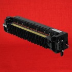
Kyocera KM-3040 Fuser Unit – 120 Volt (Genuine) – $169.95
from: Precision Roller
Notice : fusing assembly Corresponding Error Codes can cause the product not to work until the code is reset in Maintenance Mode. Here is a url to the directions for you to reset the code by means of the maintenance menu.
Kyocera KM-3040 Fuser Error Reset Procedure – 302K593060
Service Guide Guidance for the Kyocera KM-3040 C6120 Error Code
Unusually elevated fuser thermistor edge heat range
Fuser thermistor one is detected 230°C/446°F or greater for 40 ms.
1. Fitting defectiveness on fuser thermistor 1.
Inspect the mounting condition of the fuser thermistor 1. If any problem is found, correct it.
2. Defective fuser thermistor 1.
Replace the fuser thermistor 1.
3. Defective engine PWB.
Replace the engine PWB and verify for correct operation.
These particular fusers tend to be reasonably cheap. Like many components on the Kyocera equipment, many conditions its less costly to simply change out the complete part or maintenance kit. Therefore, when you’re experiencing difficulty] applying the fuser, I would be likely to just suggest saving efforts and money and obtain a complete replacement fuser assembly. Below, you will discover a url to the replacement instructions and also a link to order in your replacement fuser.
Kyocera KM-3040 Fuser Replacement Procedure
FUSER UNIT KYOCERA KM 2530 3035 3530 4030 4035 5035 Replacment
Fuser Unit KYOCERA KM2530 KM3035 KM3530 KM4030 KM4035 KM5035 KM4035 KM5035 / UTAX CD1025 CD1030 CD1035 CD1040 CD1050 / OLIVETTI DCopia 25 DCopia 35 DCopia 400, DCopia 500 DCopia 300.
Kyocera code c6000
Kyocera code c6020 Kyocera code c6050 code Kyocera KM1620 Kyocera KM1635 Kyocera KM1650 Kyocera KM2020 Kyocera KM2030 Kyocera KM2035 Kyocera KM2050 Kyocera KM2530 Kyocera KM2540 Kyocera…