9 Troubleshooting
Fault
Code
Controller
Err10
overload
Err11
Motor overload
Power supply
Err12
phase loss
9
Power output
Err13
phase loss
Module
Err14
overheat
— 270 —
Name
Possible Causes
● This fault is reported
generally when the
controller runs at the
current higher than the
rated value for a long
time. The causes include:
● The mechanical
resistance is too large.
● The balance coefficient is
improper.
● The encoder feedback
signal is abnormal.
● Motor auto-tuning is not
performed properly (the
elevator running current is
higher than the normal in
this case).
● FC-02 is set improperly.
● The mechanical
resistance is too large.
● The balance coefficient is
improper.
● The power input phases
are not symmetric.
● The drive control board
fails.
● The output wiring of the
main circuit is loose.
● The motor is damaged.
● The ambient temperature
is too high.
● The fan is damaged.
● The air filter is clogged.
NICE3000
Solution
1. Eliminate mechanical problems:
● Check whether the brake is released,
and whether the brake power supply is
normal.
● Check whether the balance coefficient is
proper.
● Check whether the guide shoes are too
tight.
2. Check the motor auto-tuning result:
● Check whether the encoder feedback
signal and parameter setting are correct,
and whether the initial angle of the
encoder for the PMSM is correct.
● Check the motor parameter setting and
perform motor auto-tuning again.
3. If this fault is reported when the slip
experiment is carried on, perform the slip
experiment by using the function set in F3-
24.
● Restore FC-02 to the default value.
● Refer to the solution of Err10.
● Check whether the three phases of
power supply are balanced and whether
the power voltage is normal. If not, adjust
the power supply.
● Contact us or directly our agent.
● Check whether the motor wiring is
secure.
● Check whether the RUN contactor on the
output side is normal.
● Eliminate the motor fault.
● Lower the ambient temperature.
● Clear the air filter.
● Replace the damaged fan.
● Check whether the installation clearance
of the controller satisfies the requirement.
new
User Manual
Level
4A
3A
4A
4A
5A
- Печать
Страницы: 1 … 14 15 [16] 17 18 … 30 Вниз

Тема: SJEC. Контроллер NICE 3000 (Прочитано 84177 раз)
0 Пользователей и 1 Гость просматривают эту тему.
Не-не… Никакого гугловского перевода. Только оригинальная английская версия, сначала со словарем…
Благодаря nice3000 мой технический английский стал заметно лучше, чего и всем желаю.

Записан
Не-не… Никакого гугловского перевода.
Да я про то иговорю, механики в заблуждении, и нас вводят в заблуждение.
Записан
Други, подскажите путь решения проблемы. Имеется проблема с включением охраны шахты. На одной из версий прошивок при Fd-08-10 и F6-42-bit8-1 сразу вылетает ошибка 64, в этой версии меню «А» отсутствует.
В другой версии, при включении Fd-08-10 и A1-00-000001 вылетает ошибка 81-101. Поиск описания этих ошибок на просторах сети результата не дал.
Записан
Err 64: External fault. Subcode 101: The external fault signal is continuously active for 2s.
Описание 81 ошибки в талмуте нет.
Скорее всего 81 ошибка и используется в качестве ошибки регистрации проникновения в шахту. На моих лифтах с Nice3000 использовалась ошибка 80. Это зависит от прошивки контроллера.
Записан
Уважай лифты: они делают твою жизнь комфортнее
NICE 3000 new, запущен в ревизию. Не выполняет самообучение шахты. Кабина установлена на нижнем этаже в ТО. На индикаторах кнопок вызова отображается режим инспекции при любых положениях переключателей в станции и в посту ревизии. В посту приказов переключателей режимов нет. Ошибка 35/103.
Где искать проблему?
Записан
NICE 3000 new, запущен в ревизию. Не выполняет самообучение шахты. Кабина установлена на нижнем этаже в ТО. На индикаторах кнопок вызова отображается режим инспекции при любых положениях переключателей в станции и в посту ревизии. В посту приказов переключателей режимов нет. Ошибка 35/103.
Где искать проблему?
Кабина должна быть ниже то, ~ на 50мм, датчик нижнего лимита должен быть сработан. В случае обучения лифта на 2 остановки, кабина должна стоять ниже ТО, так чтобы дто был неактивен.
Автоматическое объединение сообщений.
Err 64: External fault. Subcode 101: The external fault signal is continuously active for 2s.
Описание 81 ошибки в талмуте нет.
Скорее всего 81 ошибка и используется в качестве ошибки регистрации проникновения в шахту. На моих лифтах с Nice3000 использовалась ошибка 80. Это зависит от прошивки контроллера.
Уже пояснили что 81 это люк, его контроль активируется вместе с ОШ. Физически, люк отсутствует, на jp22 установлена перемычка. Er64 внешняя ошибка… Здесь вообще непонятно. В пятом меню ни один вход не назначен на external fault.
По прошивкам… FA-05
30.00 L04.50 error 81
19.01 L27.50 error 64
20.12L16.00 работает ОШ
Записан
Anosoff2017,
1. Определись с режимом инспекции. Найди в параметрах F5, какому входу назначен значение параметра 08 или 40 (запись типа F5-__=08 или F5-__=40). Посмотри по схеме,что на данном входе сидит и какой тип сигнала используется (NO/NC).
2. Проверь исходные требования для запуска режима обучения шахте: лифт в режиме инспекция, кабина в зоне точной остановки нижнего этажа, активен сигнал замедления вниз 1 на MCB, отсутствуют ошибки MCB. Если лифт на 2 остановки, то кабина должна стоять ниже шунта.
Записан
Уважай лифты: они делают твою жизнь комфортнее
Существует ли какая-либо возможность просмотреть состояния входов в вызывных аппаратах, используемых для охраны шахты?
Записан
Там специфическое ПО, вызывная плата сама определяет статус охраны. Контроллер только констатирует ошибку, номер этажа ему неизвестен, только этаж, где находится лифт.
Записан
То есть при открытии ДШ контроллер не сопоставляет местоположение кабины с номером этажа открытой ДШ?
На одном из этажей вызывная плата вообще не была соединена с линией передачи данных, при этом лифт работал…
Записан
Лифт и будет работать, не будет работать вызов. На вызывных платах с ОШ стоят специальные чипы для осуществления этой функции, неисправную плату надо менять на точно такую же, а не стандартную. В контроллере нет охраны шахты, он регистрирует готовую ошибку, переданную с платы.
Записан
спасибо
Где можно прочитать про условия возникновения ошибки 80? Каким образом это всё работает? В официальном представительстве SJEC сказали что только торгуют оборудованием и никакой технической поддержки нет, документации нет.
Записан
Err80
Истек срок наладки
◆ система обнаружила, что срок выполнения наладки по умолчанию, истекает менее чем через 1 день.
◆Сообщить о проблеме менеджеру, ответственного за проект.
Это для NICE 3000NEW
« Последнее редактирование: Март 22, 2020, 10:45:12 от Саня »
Записан
Призрак, У меня только это есть.
Отредактирована ссылка на изображение.
« Последнее редактирование: Март 22, 2020, 11:33:50 от Lift-man »
Записан
спасибо
Это всё примерно понятно. Ситуация такая: на одном из этажей не был подключен вызывной аппарат к линии передачи данных. При этом лифт работал. Значит этот этаж не контролировался. Впрочем, туда кабина и не приезжала.
При проверке балансировки кабину с грузом переместили на пару этажей вниз с нажатой кнопкой стоп на панели. После возвращения в НР сразу после открытия дверей появляется 80, которая никак не сбрасывается.
Всё-таки я думаю местоположение кабины здесь имеет какое то значение.
Записан
- Печать
Страницы: 1 … 14 15 [16] 17 18 … 30 Вверх
NICE3000
new
User Manual Preface
- 1 -
Preface
Thank you for purchasing the NICE3000
new
integrated elevator controller.
The NICE3000
new
is a new-generation integrated elevator controller independently
developed by Suzhou MONARCH Control Technology Co., Ltd., by optimizing the NICE3000
controller based on a large number of applications and combining new industrial features.
The NICE3000
new
has the following advantages:
1. It supports high-performance vector control and open-loop low speed running. It can
drive both asynchronous motor and permanent magnetic synchronous motor (PMSM),
and implement switchover between the two types of motors easily by modifying only one
parameter.
2. It supports direct parallel connection of two elevators and supports the CANbus and
Modbus communication protocols for remote monitoring, which reduces the required
quantity of travling cables.
3. It supports a maximum of 40 floors and is widely applied to elevators used in the
residence, ofce buildings, shopping centers, and hospitals.
This manual describes the correct use of the NICE3000
new
, including product features,
safety information and precautions, installation, parameter setting, commissioning, and
maintenance & inspection. Read and understand the manual before using the product, and
keep it carefully for future maintenance.
The personnel who involve in system installation, commissioning, and maintenance must
receive necessary safety and use training, understand this manual thoroughly, and have
related experience before performing operations.
Notes
•
The drawings in the manual are sometimes shown without covers or protective guards.
Remember to install the covers or protective guards as specied rst, and then perform
operations in accordance with the instructions.
•
The drawings in the manual are shown for description only and may not match the product
you purchased.
•
The instructions are subject to change, without notice, due to product upgrade, specication
modication as well as efforts to increase the accuracy and convenience of the manual.
•
Contact our agents or customer service center if you have some questions during the use.
Introduction NICE3000
new
User Manual
- 2 -
Introduction
1. Comparison with the NICE3000
The following table lists the comparison between the NICE3000
new
and the NICE3000.
Item NICE3000 NICE3000
new
Maximum number of
oors
31 (standard) 40 (standard)
Maximum elevator
speed
4 m/s 4 m/s
I/O terminals 24 inputs, 6 outputs
24 inputs, 6 outputs, 3 high-voltage
inputs
CANbus 1 x CANbus 2 x CANbus
Modbus 1 x Modbus 1 x Modbus
Motor driving type
Separate control for
synchronous and
asynchronous motors
Integrated control for synchronous and
asynchronous motors
No-load-cell startup
Supporting SIN/COS
encoder only
Supporting:
•
Push-pull encoder
•
Open-collector incremental encoder
•
UVW encoder
•
SIN/COS encoder
•
Endat encoder
Control mode
•
Sensorless ux vector
control (SFVC)
•
Closed-loop vector
control (CLVC)
•
Sensorless ux vector control (SFVC)
•
Closed-loop vector control (CLVC)
•
V/F control
LCD operator Not support Support
Inside-car
commissioning
Not support Support
NICE3000
new
User Manual Introduction
- 3 -
2. Connection to peripheral devices
NICE3000
new
integrated elevator
controller
Ground
AC input
reactor
Electromagnetic
contactor
Moulded case
circuit breaker
(MCCB) or earth
leakage circuit
breaker (ELCB)
Three-phase AC
power supply
Braking resistor
Noise filter on
input side
P(+)
BR
Braking unit
+
-
Motor
External operation
panel
Output
reactor
Ground
Ground
MF.K
RUN
STOP
RES
QUICK
PRG ENTER
RUN
LOCAL/REMOT FED/REV TUNE/TC
RPM
%
A VHz
Use within the allowable
power supply specification
of the controller.
Select a proper breaker
to resist large in-rush
current that flows into the
controller at power-on.
To guarantee safety, use an
electromagnetic contactor. Do not
use it to start or stop the controller
because such operation reduces
the service life of the controller.
Suppress the high order
harmonic to improve the
power factor.
Reduce the
electromagnetic
interference on
the input side.
Reliably ground the
motor and the
controller to prevent
electric shock.
•
Do not install the capacitor or surge suppressor on the output side of the controller.
Otherwise, it may cause faults to the controller or damage to the capacitor and surge
suppressor.
•
Inputs/Outputs (main circuit) of the controller contain harmonics, which may interfere
with the communication device connected to the controller. Therefore, install an anti-
interference lter to minimize the interference.
•
For more details on peripheral devices, refer to related selection guidelines.
Introduction NICE3000
new
User Manual
- 4 -
3. Function list of the NICE3000
new
Common Running Functions
Full collective
selective
In automatic running or attendant state, this function enables the
elevator to respond both car calls and hall calls. Passengers at any
service oor can call the elevator by pressing the up call button and
down call button.
Door open holding
time setting
The system automatically determines different door open time for door
open for call, command, protection, or delay according to the set door
open holding time.
Door open holding
In automatic running state, passengers can press the door open button
in the car to delay door open to facilitate goods to be moved in/out.
Door machine
service oor setting
You can set the required service oors of the door machines.
Door pre-close
by the door close
button
During door open holding in automatic running state, passengers
can press the door close button to close the door in advance, which
improves the efciency.
Floor number
display setting
The system supports display of oor numbers in combinations
of numbers and letters, which meets the requirements of special
conditions.
Light curtain signal
judgment
If the door is blocked by stuff during door close, the light curtain
acts and the elevator opens the door. This function is invalid in re
emergency state.
Auxiliary operation
box
An optional auxiliary operation box that has the same functions as the
main operation box is available.
Independent control
of the front door
and back door
When there are two doors for a car, automatic control on the two doors
depends on your requirements.
Repeat door close
If the door lock is not applied after the elevator performs door close
for a certain time, the elevator automatically opens the door and then
closes the door again.
Independent
command
When the main and auxiliary operation boxes are congured, they can
independently control door open/close according to the commands in
automatic running state.
Voice
announcement
The elevator automatically announces information such as the running
direction and next arriving oor during running.
Auto-leveling
The systems implements automatic accurate leveling based on the
oor pulse counting and up/down leveling feedback signals.
Response at
acceleration
The system allows the elevator to automatically respond to calls from
the service oors during acceleration.
Down collective
selective control
In automatic running or attendant state, the elevator responds only to
hall down calls besides car calls.
Idle elevator
returning to base
oor
In automatic running state, the elevator automatically returns to the set
parking oor and waits for passengers if there is no car call or hall call
within the set time.
NICE3000
new
User Manual Introduction
- 5 -
Landing at another
oor
If the door open time exceeds the door open protection time but the
door open limit signal is still inactive, the elevator closes the door and
then automatically runs to the next landing oor. The system reports
fault Err55.
Forced door close
When the door fails to close within the set time due to the action of the
light curtain or safety edge, the elevator enters the forced door close
state, closes the door slowly, and gives a prompt tone.
Cancellation of
wrong calls
Passengers can press the button consecutively twice to cancel wrong
calls.
Service oor setting
You can enable or disable the system service for certain oors exibly
based on actual requirements.
Time-based oor
service
You can exibly set the time periods and corresponding service oors
or select the service oors by using the service oor switchover switch.
Independent
running
The elevator does not respond to any call, and the door needs to
be closed manually. In the case of group control, the elevator runs
independently out of the group control system.
Attendant running
In attendant state, the running of the elevator is controlled by the
attendant.
Low-speed self-
rescue
When the elevator is in non-inspection state and stops at non-leveling
area, the elevator automatically runs to the leveling area at low speed if
the safety requirements are met, and then opens the door.
Door control
function
You can set whether the system keeps outputting commands after door
open limit and door close limit based on the type of the door machine.
Car arrival gong
After the elevator arrives at the destination oor, the CTB gives a
prompt tone.
Hall arrival forecast
indicator
When the elevator will arrive at the destination oor soon, the hall
arrival forecast indicator becomes ON.
Hall arrival gong
After the elevator will arrive at the destination oor soon, the system
outputs the hall arrival gong.
Hall I/O extension
function
If the hall I/O terminals are not sufcient, more terminals can be
provided by using an HCB-B board.
Car I/O extension
function
If the car I/O terminals are not sufcient, more terminals can be
provided by using an HCB-B board.
Button stuck check
The system can automatically identify whether a hall call button is stuck
and cancel the stuck call, preventing the condition that the elevator
cannot close and run due to stuck hall calls.
Automatic
startup torque
compensation
The system automatically implements startup torque compensation
based on the current car load, achieving smooth startup and improving
the riding comfort.
Direct stop
The system automatically calculates and generates the running curves
based on the distance, enabling the elevator to directly stop at the
leveling position without creeping.
Automatic
generation of
optimum curve
The system automatically calculates the optimum speed curve
compliant with the human-machine function principle based on the
distance, without being limited by the number of curves or short oor.
Introduction NICE3000
new
User Manual
- 6 -
Service suspension
output
When the elevator cannot respond to hall calls, the corresponding
terminal outputs the service suspension signal.
Running times
recording
In automatic running state, the system automatically records the
running times of the elevator.
Running time
recording
The system automatically records the accumulative power-on time,
working hours, and working days of the elevator.
Automatic door
open upon door
lock abnormality
If the system detects that the door lock circuit is abnormal during door
open/close, the elevator automatically opens and closes the door again,
and reports a fault after the set door open/close times is reached.
VIP service
The elevator rst directly runs to the VIP oor and provides services for
special persons.
Specied elevator
preferred
The specied elevator is preferred to respond to calls of specied
oors.
Disability service
When the elevator is waiting at the leveling position, if there is a call at
this oor from the disability operation box, the door open holding time is
prolonged. It is the same for the back door.
Full-load direct
running
When the car is full-loaded in automatic running state, the elevator
does not respond to hall calls from the passing oors. These halls calls,
however, can still be registered, and will be executed at next time of
running (in the case of single elevator) or by another elevator (in the
case of group control).
Overload protection
When the car load exceeds the rated elevator load, the elevator alarms
and stops running.
Fault data recording
The system automatically records detailed information of faults, which
helps improve the efciency of maintenance and repair.
Inspection-related Functions
Simple
maintenance
keypad
The 3-button keypad on the MCB provides the functions such as
commissioning the running oors and door open/close.
Operation box
commissioning
The LCD operator can be connected to the system in the car for
elevator commissioning, which improves the commissioning efciency.
Shaft auto-tuning
Shaft auto-tuning is required before rst-time automatic running. During
shaft auto-tuning, the elevator runs from the bottom oor to the top oor
at the inspection speed and automatically records all position signals in
the shaft.
User-dened
parameter display
You can view the parameters that are modied and different from the
default setting.
Inspection running
After entering the inspection state, the system cancels automatic
running and related operations. You can press the up or down call
button to make the elevator jog at the inspection speed.
Motor auto-tuning
With simple parameter setting, the system can obtain the motor
parameters no matter whether the motor is with-load or without load.
Floor position
intelligent correction
Every time the elevator runs to the terminal oor, the system
automatically checks and corrects the car position information based on
slow-down switch 1, and eliminates over travel top terminal or bottom
terminal with use of the slow-down switches.
NICE3000
new
User Manual Introduction
- 7 -
Dual-speed for
inspection
Considering inaccurate running control at high inspection speed but
a long running time at low inspection speed, the system provides the
dual-speed curve for inspection, which greatly improves the efciency
at inspection.
Test running
The test running includes the fatigue test of a new elevator, car call
oor test, hall call test, and tests such as hall call response forbidden,
door open/close forbidden, terminal oor limit switch shielded, and
overload signal shielded.
Fire Emergency and Security Functions
Returning to
base oor at re
emergency
After receiving a re emergency signal, the elevator does not respond
to any call but directly runs to the re emergency oor and waits.
Fireghter running
After the elevator enters the reghter running mode, door open/close
is implemented by the jog operation (optional) by using the door open
and close buttons rather than automatically. In addition, the elevator
responds to only car calls and only one call can be registered once.
Security oor
After the security oor function is enabled, the security oor is used at
10:00 p.m. to 6:00 a.m, and the elevator runs to the security oor rst
every time, stops and opens the door, and then runs to the destination
oor.
Elevator lock
In automatic running state, when the elevator lock switch acts or the
set elevator time is reached, the elevator cancels all registered calls,
returns to the elevator lock oor, stops running, and turns off the lamp
and fan in the car.
Troubleshooting
based on fault level
Faults are classied into different levels based on the severity. Different
levels of faults are rectied using different methods.
Runaway
prevention
The system detects the running state of the elevator in real time. If the
elevator speed exceeds the limit, the system immediately stops running
of the elevator.
Automatic
identication of
power failure
The system automatically identies power failure and outputs the relay
signal for emergency evacuation automatic switchover to implement
emergency evacuation at power failure.
Automatic running
mode switchover at
power failure
For the synchronous motor, when the power supply is interrupted, the
system can perform automatic switchover between shorting stator
braking mode and controller drive mode, implementing quick and stable
self-rescue.
Shorting stator braking mode: Upon power failure, UPS is used, the
motor stator is shorted, and the brake is automatically released, making
the car move slowly under the effect of the weighing difference between
the car and the counterweight.
Running direction
self-identication at
power failure
When the power supply is interrupted, the system can automatically
identify the current car load and determine the running direction.
Base oor
verication
After detecting a position abnormality, the system runs the elevator to
each oor until reaching the terminal oor for verication, guaranteeing
system security.
Introduction NICE3000
new
User Manual
- 8 -
Passenger
unloading
The system automatically determines the fault level. If the safety
running conditions are met, the elevator rst runs to the leveling
position to unload passengers.
Interference degree
judgment
The system judges the degree of interference on the communication.
Earthquake
protection
When the earthquake detection device acts and inputs a signal to the
system, the elevator lands at the nearest oor and stops running. After
the earthquake signal becomes inactive and the fault is reset manually,
the elevator restores to normal running.
Current cancellation
in ramp mode
For the PMSM, after the elevator decelerates to stop, the holding
current of the motor is cancelled in ramp mode, preventing abnormal
noise during current cancellation.
Independent
working power
supply
The NICE3000
new
system supports not only three-phase 380 VAC but
also single-phase 220 VAC to meet different applications of the power
supply system (such as 220 V UPS)
Automatic voltage
identication
The system detects the bus voltage and automatically adjusts the
running speed of the elevator to adapt to the situation of insufcient
power from power supply (such as emergency UPS).
Parallel/Group Control and Other Functions
Parallel control
The system supports parallel control of two elevators and provides
multiple scheduling algorithms to meet requirements of different
customers.
Dispersed waiting In parallel control, the elevators can wait at different oors.
Parallel/Group
control exit
If the parallel/group control exit switch of a certain elevator in a parallel/
group control system is valid or the time for exiting the parallel/group
control is reached, the elevator exits parallel/group control and runs
independently. This does not affect normal running of the parallel/group
control system.
Parallel/Group
control automatic
exit
If an elevator in the parallel/group control system cannot respond to
calls in time due to faults, the elevator automatically exits the parallel/
group control system and runs independently. This does not affect
normal running of the parallel/group control system.
Anti-nuisance
function
The system automatically judges the number of passengers in the
car and compares it with the number of registered car calls. If there
are excessive car calls, the system determines that it is nuisance and
cancels all car calls. In this case, passengers need to register correct
car calls again.
Prompt of non-door
zone stop
The system gives a prompt when the elevator stops at a non-door zone
area due to faults.
Full-load indication
When the elevator is full-loaded, a full-load indication is displayed on
the HCBs and the elevator directly runs to the desired oors.
Interface for
intelligent
residential
management
The system provides an interface for intelligent residential management
to perform remote monitoring on the state of elevators in the residential
district.
Parameter copy
You can conveniently upload and download parameters of the system
by using the LCD operator.
NICE3000
new
User Manual Introduction
- 9 -
Energy-saving Functions
Car energy-saving
If there is no running command within the set time, the system
automatically cuts off the power supply to the lamp and fan in the car.
Energy-saving
running with
standby power
supply
When the normal power supply is interrupted and the emergency power
supply is used, the system reduces the running speed of the elevator in
the prerequisite of guaranteeing the smooth running curve.
Arrival gong
disabled at night
Within the set time period, the arrival gong is disabled.
Energy-saving of
idle door machine
After the car lamp is turned off, the system does not output the door
close command, which reduces power consumption of the door
machine.
4. Optional functions
Function Description Remark
Micro-leveling
After landing at a oor, the elevator may move
upward or downward due to the load change and
the car door is not aligned with the ground, which
is inconvenient for in and out of passengers and
goods. In this case, the system allows the elevator
to run to the leveling position in the door open state
at the leveling speed.
MCTC-SCB
required
Power failure
emergency
evacuation
For the elevator congured with UPS, the system
uses the UPS to implement low-speed self-rescue in
the case of power failure.
UPS required
Onsite
commissioning
The system can control and monitor running of
elevators by using the NEMS software.
NEMS
software
required
Residential
monitoring
The control system can be connected to the
terminal in the monitoring room. By using the NEMS
software, you can view the oor position, running
direction, and fault state of the elevator.
NEMS and
accessories
required
Remote monitoring
The control system can be connected to the terminal
(such as PC) in the monitoring room. By using the
NEMS software, you can view the oor position,
running direction, and fault state of the elevator.
MCTC-MIB
required
Door pre-open
During normal stop, when the elevator speed is
smaller than 0.2 m/s and the door zone signal is
active, the system shorts the door lock by means of
the shorting door lock circuit contactor and outputs
the door open signal, implementing door pre-open.
This improves the elevator use efciency.
MCTC-SCB
required
IC card
Passengers can use an IC card to go to oors that
require authorization.
IC card
required
Operation
restoration
In case of an incorrect setting, you can restore to
parameters of the last operation state.
LCD operator
required
Contents
Preface ................................................................................................................ 1
Introduction .......................................................................................................... 2
Chapter 1 Safety Information and Precautions.................................................. 14
1.1 Safety Precautions ...................................................................................................... 14
1.2 General Precautions .................................................................................................... 17
1.3 Protective Functions .................................................................................................... 19
Chapter 2 Product Information .......................................................................... 22
2.1 System Conguration of the NICE3000
new
............................................................
22
2.2 Designation Rules and Model Description................................................................... 23
2.3 Models and Specications ........................................................................................... 24
2.4 Technical Specications .............................................................................................. 25
2.5 Physical Appearance and Mounting Dimensions ........................................................ 27
2.6 Optional Parts .............................................................................................................. 29
2.7 Selection of Braking Resistor ...................................................................................... 30
Chapter 3 Mechanical and Electrical Installation ............................................... 34
3.1 NICE3000
new
Integrated Elevator Controller ................................................................ 34
3.2 CTB Board (MCTC-CTB) ............................................................................................. 40
3.3 Display Board (MCTC-HCB)........................................................................................ 43
3.4 CCB Board (MCTC-CCB) ............................................................................................ 53
3.5 Selection and Use of the MCTC-PG Card ................................................................... 56
3.6 Selection of Peripheral Electrical Devices ................................................................... 59
3.7 Electrical Wiring Diagram of the NICE3000
new
Control System ................................... 60
3.8 Installation of Shaft Position Signals ........................................................................... 60
Chapter 4 Use of the NICE3000
new
.................................................................... 66
4.1 Use of the Onboard Keypad ........................................................................................ 66
4.2 Use of the LED Operation Panel ................................................................................. 70
4.3 Use of the LCD Operator ............................................................................................. 73
Chapter 5 System Commissioning and Application Example ............................ 78
5.1 System Commissioning ............................................................................................... 78
5.2 System Application ...................................................................................................... 89
Chapter 6 Function Code Table ....................................................................... 104
6.1 Function Code Description ........................................................................................ 104
6.2 Function Code Groups .............................................................................................. 104
6.3 Function Code Table .................................................................................................. 105
Chapter 7 Description of Function Codes........................................................ 136
Group F0: Basic Parameters ........................................................................................... 136
Group F1: Motor Parameter ............................................................................................ 138
Group F2: Vector Control Parameters ............................................................................. 141
Group F3: Running Control Parameters .......................................................................... 144
Group F4: Floor Parameters............................................................................................ 147
Group F5: Terminal Function Parameters ....................................................................... 148
Group F6: Basic Elevator Parameters ............................................................................. 159
Group F7: Test Function Parameters .............................................................................. 171
Group F8: Enhanced Function Parameters ..................................................................... 173
Group F9: Time Parameters ............................................................................................ 176
Group FA: Keypad Setting Parameters ........................................................................... 177
Group Fb: Door Function Parameter ............................................................................... 188
Group FC: Protection Function Parameters .................................................................... 190
Group Fd: Communication Parameters ........................................................................... 194
Group FE: Elevator Function Parameters ....................................................................... 196
Group Fr: Leveling Adjustment Parameters .................................................................... 200
Group FF: Factory Parameters........................................................................................ 201
Group FP: User Parameters ............................................................................................ 201
Chapter 8 EMC ................................................................................................ 204
8.1 Denition of Terms ..................................................................................................... 204
8.2 Introduction to EMC Standard ................................................................................... 204
8.3 Selection of Peripheral EMC Devices........................................................................ 205
8.4 Shielded Cable .......................................................................................................... 208
8.5 Solutions to Common EMC Interference Problems ................................................... 211
Chapter 9 Troubleshooting .............................................................................. 214
9.1 Description of Fault Levels ........................................................................................ 214
9.2 Fault Information and Troubleshooting ...................................................................... 215
1
Safety Information and Precautions
Safety Information and Precautions NICE3000
new
User Manual
- 14 -
Chapter 1 Safety Information and Precautions
In this manual, the notices are graded based on the degree of danger:
•
DANGER
indicates that failure to comply with the notice will result in severe
personal injury or even death.
•
WARNING
indicates that failure to comply with the notice will result in potential
risk of severe personal injury or even death.
•
CAUTION
indicates that failure to comply with the notice will result in minor or
moderate personal injury or equipment damage.
In addition,
NOTE
appearing in other chapters indicates that an unintended result or
situation may occur if the notice is not complied with.
The notices in this manual you have to observe are aimed at guaranteeing your personal
safety, as well as to prevent damage to the controller or the parts connected to it. Read this
manual carefully so that you have a thorough understanding and perform all operations by
following the notices in this chapter. Monarch will assume no liability or responsibility for any
injury or loss caused by improper operation.
1.1 Safety Precautions
Use Stage
Safety
Grade
Precautions
Warning
WARNING
•
This controller has hazardous high voltage and the controlled
motor is a dangerous rotating device. Failure to comply with
the notices may result in personal injury or damage to the
property.
•
Transportation, installation, operation and maintenance of
the controller can be performed only by qualied personnel
after they get familiar with the safety information in this
manual. This is the prerequisite of safe and stable running of
the equipment.
•
Do not open the front cover or touch the power terminals
on the main circuit within 10 minutes after the controller is
powered off. The capacitor on the DC circuit still has residual
high voltage even after power-off. Failure to comply will
result in electric shock.
NICE3000
new
User Manual Safety Information and Precautions
- 15 -
Use Stage
Safety
Grade
Precautions
During
Installation
DANGER
•
Do not install the equipment if you nd water seepage,
component missing or damage upon unpacking.
•
Do not install the equipment if the packing list does not
conform to the product you received.
•
Install the equipment on incombustible objects such as
metal, and keep it away from combustible materials. Failure
to comply may result in a re.
WARNING
•
Do not loosen the xed screws of the components, especially
the screws with red mark.
•
Do not install the controller on vibrating parts. Failure
to comply may result in damage to the equipment or
unexpected accidents.
CAUTION
•
Handle the equipment with care during transportation to
prevent damage to the equipment.
•
Do not drop wire end or screw into the controller. Failure to
comply will result in damage to the controller.
•
Do not use the equipment with damaged or missing
components. Failure to comply will result in personal injury.
•
Do not touch the components with your hands. Failure to
comply will result in static electricity damage.
•
Install the controller in places free of vibration and direct
sunlight.
At Wiring
DANGER
•
Wiring must be performed only by qualied personnel under
instructions described in this manual. Failure to comply may
result in unexpected accidents.
•
A circuit breaker must be used to isolate the power supply
and the controller. Failure to comply may result in a re.
•
Ensure that the power supply is cut off before wiring. Failure
to comply may result in electric shock.
•
Tie the controller to ground properly by standard. Failure to
comply may result in electric shock.
WARNING
•
Never connect the power cables to the output terminals (U,
V, W) of the controller. Pay attention to the marks of the
wiring terminals and ensure correct wiring. Failure to comply
will result in damage to the controller.
•
Never connect the braking resistor between the DC bus
terminals (+) and (-). Failure to comply may result in a re.
CAUTION
•
Ensure that the cabling satises the EMC requirements and
the regional safety standard. Use wire sizes recommended
in the manual. Failure to comply may result in accidents.
•
Use a shielded cable for the encoder, and ensure that the
shield is reliably grounded at one end.
•
Use a twisted cable with twisted distance of 20−30 mm
as the communication cable, and ensure that the shield is
reliably grounded.
Safety Information and Precautions NICE3000
new
User Manual
- 16 -
Use Stage
Safety
Grade
Precautions
During
running
DANGER
•
All peripheral devices must be connected properly according
to the circuit wiring instructions provided in this manual.
Failure to comply will result in accidents
•
Cover the controller properly before power-on to prevent
electric shock.
•
Do not open the controller’s cover after power-on. Failure to
comply may result in electric shock.
•
Do not touch the controller and peripheral circuits with wet
hand. Failure to comply may result in electric shock.
•
Do not touch any I/O terminal of the controller. Failure to
comply may result in electric shock.
•
The controller performs safety detection on external strong
power circuits automatically at the beginning of power-on.
Do not touch the U, V, W terminals of the controller or the
motor terminals at the moment. Failure to comply may result
in electric shock.
•
Do not touch the fan or the discharging resistor to check the
temperature. Failure to comply will result in personal burnt.
•
Signal detection must be performed only by qualied
personnel during operation. Failure to comply will result in
personal injury or damage to the controller.
WARNING
•
Do not touch the rotating part of the motor during the motor
auto-tuning or running. Failure to comply will result in
accidents.
•
Check that the following requirements are met:
•
The voltage class of the power supply is consistent with the
rated voltage class of the controller.
•
The input terminals (R, S, T) and output terminals (U, V, W)
are properly connected.
•
No short-circuit exists in the peripheral circuit.
•
The wiring is secured.
Failure to comply will result in damage to the controller.
CAUTION
•
For synchronous motor, ensure that motor auto-tuning is
performed successfully. Perform trial running before resuming
the steel rope so as to make the motor run properly.
•
Avoid objects falling into the controller when it is running.
Failure to comply will result in damage to the controller.
•
Do not perform the voltage resistance test on any part of the
controller because such test has been done in the factory.
Failure to comply will result in accidents.
•
Do not change the default settings of the controller. Failure
to comply will result in damage to the controller.
•
Do not start/stop the controller by opening or closing the
contactor. Failure to comply will result in damage to the
controller. Failure to comply will result in damage to the
controller.
NICE3000
new
User Manual Safety Information and Precautions
- 17 -
Use Stage
Safety
Grade
Precautions
During
maintenance
DANGER
•
Do not repair or maintain the controller at power-on. Failure
to comply will result in electric shock.
•
Repair or maintain the controller when its voltage is lower
than 36 VAC, about two minutes after the controller is
powered off. Otherwise, the residual voltage in the capacitor
may result in personal injury.
•
Do not allow unqualied personnel to repair or maintain the
controller. Failure to comply will result in personal injury or
damage to the controller.
WARNING
•
Repair or maintenance of the controller may be performed
only by the center authorized by Monarch or qualied
personnel. Failure to comply will result in personal injury or
damage to the controller.
•
Power supply must be cut off before repair or maintenance
of the controller.
CAUTION
•
Set the parameters again after the controller is replaced. All
the pluggable components must be plugged or removed only
after power-off.
•
Strictly obey the laws and regulations and repair and
maintain the elevator equipment periodically. Only timely
troubleshooting can ensure the safety of passengers.
Disposal
CAUTION
The packaging materials, screws and terminal blocks can be
re-used and it is suggested that you keep them well for future
use.
WARNING
The electrolytic capacitors on the main circuits and PCB may
explode when they are burnt. Poisonous gas is generated when
the plastic parts are burnt. Treat them as ordinary industrial
waste.
1.2 General Precautions
1. Motor insulation test
Perform the insulation test when the motor is used for the rst time, or when it is reused
after being stored for a long time, or in a regular check-up, in order to prevent the poor
insulation of motor windings from damaging the controller. The motor must be disconnected
from the controller during the insulation test. A 500-V mega-Ohm meter is recommended for
the test. Ensure that the insulation resistance is not less than 5 MΩ.
2. Thermal protection of the motor
If the rated capacity of the motor selected does not match that of the controller, especially
when the rated power of the controller is greater than that of the motor, adjust the motor
protection parameters on the operation panel of the controller or install a thermal relay for
the motor circuit for protection.
Safety Information and Precautions NICE3000
new
User Manual
- 18 -
3. Motor heat and noise
The output of the controller is pulse width modulation (PWM) wave with certain harmonic
wave, and therefore, the motor temperature rise, noise, and vibration are slightly greater
than those at running with the power frequency (50 Hz).
4. Voltage-sensitive device or capacitor on the output side of the controller
The controller outputs PWM waves, and therefore, do not install the capacitor for improving
power factor or lightning protection voltage-sensitive resistor on the output side of the
controller. Otherwise, the controller may suffer transient overcurrent or even be damaged.
5. Contactor on the input and output sides of the controller
When a contactor is installed between the input side of the controller and the power supply,
the controller must not be started or stopped by opening or closing the contactor. When a
contactor is installed between the output side of the controller and the motor, do not open or
close the contactor when the controller has output. Otherwise, modules inside the controller
may be damaged.
6. Use outside the rated voltage
The controller must not be used outside the allowable voltage range specified in this
manual. Otherwise, components inside the controller may be damaged. If required, use a
corresponding voltage step-up or step-down device.
7. Surge suppressor
The controller has a built-in voltage dependent resistor (VDR) for suppressing the surge
voltage generated when the inductive loads (electromagnetic contactor, electromagnetic
relay, solenoid valve, electromagnetic coil and electromagnetic brake) around the controller
are switched on or off. If the inductive loads generate very high surge voltage, use a surge
suppressor for the inductive load or also use a diode.
Note
Do not connect the surge suppressor on the output side of the controller.
8. Altitude and de-rating
In places where the altitude is above 1000 m and the cooling effect reduces due to thin air, it
is necessary to de-rate the controller. Contact Monarch for technical support.
9. Adaptable motor
The controller is adaptable to squirrel-cage asynchronous motor or AC PMSM. Select a
proper controller according to motor nameplate.
The default parameters configured inside the controller are squirrel-cage asynchronous
motor parameters. It is still necessary to perform motor auto-tuning or modify the default
values based on actual conditions. Otherwise, the running effect and protection performance
will be affected. For PMSM, motor auto-tuning must be performed.
10. Precautions on selecting residual-current circuit breaker (RCCB)
Tripping may be caused if an improper RCCB is selected when the controller drives the
motor. This is because the output wave of the controller has high harmonics and the motor
NICE3000
new
User Manual Safety Information and Precautions
- 19 -
cable and the cable connecting the controller and the motor produce leakage current, which
is much larger than the current when the motor runs at power frequency (50 Hz).
Thus, it is necessary to determine the proper RCCB sensitivity based on the general
leakage current of the cables and the motor. The leakage current is dependent on the motor
capacity, cable length, insulation class and wiring method. Generally, the leakage current on
the output side of the controller is three times of the current when the motor runs at power
frequency (50 Hz).
1.3 Protective Functions
Adopting different protective functions for different levels of faults, the NICE3000
new
provides
the elevator running system with full abnormality protection. For detailed solutions to the
faults, see chapter 8.
Faults of the controller are classied as follows:
1. Speed abnormal
The controller monitors the encoder feedback speed and output torque. Once the
feedback speed exceeds the limit or the deviation between the torque limit and the
speed feedback is too large, the controller performs protection immediately, reports an
alarm and prohibits running.
2. Drive control abnormal
The related faults include drive overcurrent, overvoltage/undervoltage, power input/
output phase loss, overload, and storage abnormality. If such a fault occurs, the
controller performs protection immediately, stops output, applies the brake and prohibits
running.
3. Encoder abnormal
The related faults include encoder phase loss, direction reversing, wire-breaking, and
pulse interference. If such a fault occurs, the controller performs protection immediately
to avoid unexpected accidents. If pulse interference is large, the controller reports
an alarm immediately. If pulse interference is small, the controller performs position
correction every time it receives a leveling signal and clears the accumulative error.
4. Leveling sensor abnormal
The related faults include sensor failure or sensor stuck. The controller judges whether a
fault occurs based on the leveling signal change. If the leveling signal does not change
within the set time, the system reports an alarm.
5. Floor data abnormal
The system stores the oor information through the shaft auto-tuning. If the oor data
is abnormal, the system prompts the fault information at the rst-time running. During
actual running, the controller continuously compares position information input by DIs
with the stored oor data. If the deviation is large, the system reports an alarm.
Safety Information and Precautions NICE3000
new
User Manual
- 20 -
2
Product Information
Product Information NICE3000
new
User Manual
- 22 -
Chapter 2 Product Information
2.1 System Conguration of the NICE3000
new
The NICE3000
new
series integrated elevator control system combines the functions of
both elevator controller and the high-performance vector controller. It mainly includes the
integrated elevator controller, car top board (MCTC-CTB), hall call board (MCTC-HCB),
car call board (MCTC-CCB), and optional door pre-open module, and remote monitoring
system.
The following gure shows the system components.
Figure 2-1 System components of the NICE3000
new
MCTC-CTB
MCTC-CCBMCTC-HCB
LED operation panel
(MDKE) or LCD
operator (MDKE3)
Load cell
MCTC-HCB
MCTC-HCB
CANbus
Modbus
Host
computer
NICE3000
new
integrated controller
CANbus
Communication
in parallel mode
Synchronous or
asynchronous motor
1. It controls the motor based on feedback signals from the encoder, and records
information of all position switches in the shaft by pulse, implementing accurate leveling
and direct travel ride and guaranteeing running safety.
2. It implements information collection and control of car-related components by means of
CANbus communication with the MCTC-CTB.
3. It registers and displays hall calls of all oors with easy address setting by means of
Modbus communication with the MCTC-HCB.
NICE3000
new
User Manual Product Information
- 23 -
The following gure shows the system structure of the NICE3000
new
.
Figure 2-2 System structure of the NICE3000
new
Braking
unit
Drive circuit
of the motor
Power supply
circuit
Control
circuit of
the
controller
MCTC-HCB
MCTC-CCB
Input power
CANbus
Modbus
MCTC-CTB
Modbus
MCTC-HCB
NICE3000
new
integrated
controller
MCTC-HCB
MCTC-HCB
M
Encoder
Motor
Encoder feedback
U
V
W
2.2 Designation Rules and Model Description
Figure 2-3 Designation rules and nameplate of the NICE3000
new
MODEL: NICE-L-C-4015
INPUT: 3PH AC380V 36A 50/60Hz
OUTPUT: 3PH AC 0~380V 33A 0~90Hz
Suzhou MONARCH Control Technology Co.Ltd
S/N: 010150602803825403
POWER: 15kW
Rating namplate
Controller model
Power class
Rated input
Rated output
Manufacturing SN
NICE–L–C–40 15
NICE series integrated
elevator controller
A
Asynchronous motor
Mark
Motor Type
B
Synchronous motor
C
Synchronous
/Asynchronous motor
integrator
L
Mark Controller Type
Specialized for
elevators
20
Single-phase/
Three-phase 220 V
Mark
Voltage Class
40
Three-phase 380 V
02 2.2 kW
Mark
03 3.7 kW
... ...
Power Class
30 30 kW
45 45 kW
Nameplate
position
NICE3000
new
integrated
elevator
controller
Note that the NICE3000
new
has multiple voltage classes and power classes. For details, see
the Table 2-1.
Product Information NICE3000
new
User Manual
- 24 -
2.3 Models and Specications
Table 2-1 NICE3000
new
models and specications
Controller Model
Power
Capacity (kVA)
Input Current
(A)
Output Current
(A)
Motor Power
(kW)
Single-phase 220 V, range: 200−240 V
NICE-L-C-2002 2.3 13.2 5.2 1.1
NICE-L-C-2003 3.4 17 7.5 1.5
220-NICE-L-C-4007 9.8 29 10.3 2.2
220-NICE-L-C-4011 12.1 36 15.5 3.7
220-NICE-L-C-4015 13.9 41 19 4.0
220-NICE-L-C-4018 17.3 40 22.5 5.5
220-NICE-L-C-4022 23.1 49 27.7 11
220-NICE-L-C-4030 33 61 34.6 15
Three-phase 220 V, range: 200−240 V
NICE-L-C-2002 4.0 11.0 9.6 2.2
NICE-L-C-2003 5.9 17.0 14.0 3.7
220-NICE-L-C-4007 17.0 29.0 18.0 4.0
220-NICE-L-C-4011 21.0 36.0 27.0 5.5
220-NICE-L-C-4015 24.0 41.0 33.0 7.5
220-NICE-L-C-4018 30.0 40.0 39.0 11.0
220-NICE-L-C-4022 40.0 49.0 48.0 15.0
220-NICE-L-C-4030 57.0 61.0 60.0 18.5
Three-phase 380 V, range: 340−450 V
NICE-L-C-4002 4.0 6.5 5.1 2.2
NICE-L-C-4003 5.9 10.5 9.0 3.7
NICE-L-C-4005 8.9 14.8 13.0 5.5
NICE-L-C-4007 11.0 20.5 18.0 7.5
NICE-L-C-4011 17.0 29.0 27.0 11.0
NICE-L-C-4015 21.0 36.0 33.0 15.0
NICE-L-C-4018 24.0 41.0 39.0 18.5
NICE-L-C-4022 30.0 49.5 48.0 22.0
NICE-L-C-4030 40.0 62.0 60.0 30.0
NICE-L-C-4037 57.0 77.0 75.0 37.0
NICE-L-C-4045 69.0 93.0 91.0 45.0
NICE-L-C-4055 85 113 112 55
NICE3000
new
User Manual Product Information
- 25 -
Note
1. In terms of single-phase and three-phase 220 VAC, NICE-L-A/B-2002 and NICE-L-A/B-2003
are specially designed for 220 VAC. The other models that are marked by prexing "220-" are
modied from the three-phase 380 VAC models.
2. Same models are available for single-phase 220 VAC and three-phase 220 VAC. Pay attentions
to the power class of the adaptable motor during the use.
3. Select the proper controller output current based on the rated motor current. Ensure that the
controller output current is equal to or greater than the rated motor current.
4. If you require high voltage or power class, contact Monarch.
2.4 Technical Specications
Table 2-2 Technical specications of the NICE3000
new
Item Specication
Basic
specications
Maximum frequency 300 Hz
Carrier frequency
2–16 kHz, adjusted automatically based on the load
features
Motor control mode
Sensorless ux vector control (SFVC)
Closed-loop vector control (CLVC)
Voltage/Frequency (V/F) control
Startup torque
0.5 Hz: 180% (SFVC)
0 Hz: 200% (CLVC)
Speed stability
accuracy
±0.5% (SFVC) ±0.05% (CLVC)
Torque control
accuracy
±5% (CLVC)
Overload
60s for 150% of the rated current, 1s for 200% of the
rated current
Motor auto-tuning With-load auto-tuning; no-load auto-tuning
Distance control
Direct travel ride mode in which the leveling position
can be adjusted exibly
Acceleration/
Deceleration curve
N curves generated automatically
Slow-down
New reliable slow-down function, automatically
identifying the position of the slow-down shelf
Shaft auto-tuning
32-bit data, recording the position in the shaft
accurately
Leveling adjustment Flexible and easy leveling adjustment function
Startup torque
compensation
Load cell startup pre-torque compensation
No-load-cell startup pre-torque self-adaption
Real-time clock
Real-time clock for time-based oor service, peak
service and automatic password
Product Information NICE3000
new
User Manual
- 26 -
Item Specication
Basic
specications
Test function
Easy to implement multiple elevators commissioning
functions.
Fault protection Solutions to different levels of elevator faults
Intelligent
management
Remote monitoring, user management, and group
control adjustment
Security check of
peripheral devices
after power-on
Security check of peripheral devices, such as
grounding and short circuit, after power-on
Status monitor
Monitoring the state of feedback signals to ensure
that the elevator works properly
I/O feature
Digital input (DI)
24 x DI
Input specication: 24 V, 5 mA
3 heavy-current detection input terminals of safety
circuit and door lock circuit
Input specication: 95−125 V
Analog input (AI) AI (voltage range: –10 V to +10 V)
Communication port
2 CANbus communication ports
1 Modbus communication port
Output terminal
block
6 relay outputs
The terminals can be allocated with different
functions.
Encoder interface
Supporting different encoders by using an optional
PG card
Operation and
display
LED operation
panel
5-digit LED display, querying/modifying most
parameters and monitoring the system state
Keypad
3-digit LED display, implementing certain
commissioning functions
LCD operator
Querying/modifying all parameters, uploading/
downloading parameters and monitoring various
status parameters of the system, including running
curves
Status monitor
Connecting the control system and the host computer,
convenient for querying/motoring the system state.
Environment
Altitude Below 1000 m (de-rated 1% for each 100 m higher)
Ambient
temperature
–10°C to +40°C (de-rated if the ambient temperature
is above 40°C)
Humidity Maximum relative humidity 95%, non-condensing
Vibration Maximum vibration: 5.9 m/s
2
(0.6 g)
Storage
temperature
–20°C to +60°C
NICE3000
new
User Manual Product Information
- 27 -
2.5 Physical Appearance and Mounting Dimensions
The following figures show the physical appearance and mounting dimensions of the
NICE3000
new
.
Figure 2-4 Physical appearance of the NICE3000
new
Figure 2-5 Mounting dimensions of the NICE3000
new
A
B
W
H
D
Φ
Product Information NICE3000
new
User Manual
- 28 -
Table 2-3 Mounting dimensions of the NICE3000
new
Controller Model
A
(mm)
B
(mm)
H
(mm)
W
(mm)
D
(mm)
Hole
Diameter
(mm)
Gross
Weight
(kg)
Size
Single-phase 220 V, range: 200−240 V
NICE-L-C-2002
150 334.5 347 223 143 6.5 10 SIZE-C
NICE-L-C-2003
220-NICE-L-C-4007
150 334.5 347 223 173.5 6.5 12 SIZE-D220-NICE-L-C-4011
220-NICE-L-C-4015
220-NICE-L-C-4018
235 541.5 554.5 289.6 223 6.5 14.5 SIZE-E220-NICE-L-C-4022
220-NICE-L-C-4030
Three-phase 220 V, range: 200−240 V
NICE-L-C-2002
150 334.5 347 223 143 6.5 10 SIZE-C
NICE-L-C-2003
220-NICE-L-C-4007
150 334.5 347 223 173.5 6.5 12 SIZE-D220-NICE-L-C-4011
220-NICE-L-C-4015
220-NICE-L-C-4018
235 541.5 554.5 289.6 223 6.5 14.5 SIZE-E220-NICE-L-C-4022
220-NICE-L-C-4030
Three-phase 380 V, range: 340−450 V
NICE-L-C-4002
150 334.5 347 223 143 6.5 10 SIZE-CNICE-L-C-4003
NICE-L-C-4005
NICE-L-C-4007
150 334.5 347 223 173.5 6.5 12 SIZE-DNICE-L-C-4011
NICE-L-C-4015
NICE-L-C-4018
235 541.5 554.5 289.6 223 6.5 14.5 SIZE-ENICE-L-C-4022
NICE-L-C-4030
NICE-L-C-4037
260 580 549 385 265 10 32 SIZE-FNICE-L-C-4045
NICE-L-C-4055
NICE3000
new
User Manual Product Information
- 29 -
2.6 Optional Parts
If any optional part in the following table is required, specify it in your order.
Table 2-4 Optional parts of the NICE3000
new
Name Model Function Remark
External
braking unit
MDBUN
It is provided for the NICE3000
new
of 37 kW and above.
For details, see section
2.7 "Selection of
Braking Resistor".
PG card
MCTC-PG-A2
It is used to adapt to the push-pull
and open-collector incremental
encoders.
-
MCTC-PG-D
It is used to adapt to the UVW
differential encoder and applied to
synchronous motor.
It requires 5 V power supply.
-
MCTC-PG-E
It is used to adapt to the SIN/COS
encoder.
-
MCTC-PG-F1
It is used to adapt to the
absolute encoder (Heidenhain
ECN413/1313)
-
Car top
board
(CTB)
MCTC-CTB
The MCTC-CTB is the car control
board of the NICE3000
new
. It has
8 DIs, 1 AI and 9 relay outputs (7
as standard conguration). It can
communicate with the CCB and
HCB simultaneously.
-
Hall call
board
(HCB)
MCTC-HCB
The HCB receives the passenger
calls and displays the oor where
the elevator is located and the
running direction. It can also be
used as car display board.
A number of HCB
models are available.
For details, see section
3.3.
Car call
board
(CCB)
MCTC-CCB
The MCTC-CCB is another
interface for passengers to interact
with the control system. It mainly
collects the car alls and outputs
the call indicator state.
-
External
LED
operation
panel
MDKE
It is the external LED display and
operation panel.
It provides the RJ45
interface for connecting
to the controller.
Hand-
held LCD
operator
MDKE3
It is the external LCD display and
operator.
You can copy
parameters by using
this operation panel.
Extension
cable
MDCAB
It is a standard 8-core network
cable and can be connected to
MDKE and MDKE3.
The cable length is
3 m in the standard
conguration.
Product Information NICE3000
new
User Manual
- 30 -
2.7 Selection of Braking Resistor
The NICE3000
new
models of 30 kW and below have a built-in braking unit, and you only need
to connect an external braking resistor between PB and + terminals. For models above 30
kW, you need to install a braking unit and a braking resistor externally.
Select the braking resistor based on the conguration listed in the following table.
Table 2-5 Braking resistor selection for the NICE3000
new
models
Controller Model
Power of
Adaptable
Motor (kW)
Max.
Resistance
(Ω)
Min.
Resistance
(Ω)
Power of
Braking
Resistor (W)
Braking Unit
Single-phase 220 V
NICE-L-C-2002 1.1 145.0 125.0 300
Built-in
NICE-L-C-2003 1.5 105.0 90.0 450
220-NICE-L-C-4007 2.2 72.0 63.0 600
220-NICE-L-C-4011 3.7 43.0 37.0 1100
220-NICE-L-C-4015 4.0 40.0 35.0 1200
220-NICE-L-C-4018 5.5 29.0 25.0 1600
220-NICE-L-C-4022 11.0 18.0 16.0 3500
220-NICE-L-C-4030 15.0 13.0 13.0 4500
Three-phase 220 V
NICE-L-C-2002 2.2 72.0 65.0 600
Built-in
NICE-L-C-2003 3.7 54.0 50.0 1100
220-NICE-L-C-4007 4.0 40.0 35.0 1200
220-NICE-L-C-4011 5.5 29.0 25.0 1600
220-NICE-L-C-4015 7.5 26.0 22.0 2500
220-NICE-L-C-4018 11.0 14.5 13.0 3500
220-NICE-L-C-4022 15.0 13.0 12.5 4500
220-NICE-L-C-4030 18.5 12.5 12.0 5500
Three-phase 380V
NICE-L-C-4002 2.2 290 230 600
Built-in
NICE-L-C-4003 3.7 170 135 1100
NICE-L-C-4005 5.5 115 90 1600
NICE-L-C-4007 7.5 85 65 2500
NICE-L-C-4011 11 55 43 3500
NICE-L-C-4015 15 43 35 4500
NICE-L-C-4018 18.5 34.0 25 5500
NICE-L-C-4022 22 24 22 6500
NICE-L-C-4030 30 20 16 9000
NICE3000
new
User Manual Product Information
- 31 -
Controller Model
Power of
Adaptable
Motor (kW)
Max.
Resistance
(Ω)
Min.
Resistance
(Ω)
Power of
Braking
Resistor (W)
Braking Unit
NICE-L-C-4037 37 16.0 13 11000 MDBUN-45-T
NICE-L-C-4045 45 14.0 11 13500 MDBUN-60-T
NICE-L-C-4055 55 12.0 10 16500 MDBUN-60-T
Note
1. The preceding conguration takes the synchronous motor as an example. The asynchronous
motor has poor energy transfer efciency, and you can reduce the power of the braking resistor or
increase the resistance of the braking resistor.
2. It is recommended that you select the braking resistor closest to the maximum resistance.
Product Information NICE3000
new
User Manual
- 32 -
3
Mechanical and Electrical Installation
Mechanical and Electrical Installation NICE3000
new
User Manual
- 34 -
Chapter 3 Mechanical and Electrical Installation
3.1 NICE3000
new
Integrated Elevator Controller
3.1.1 Installation Environment Requirements
Item Requirements
Ambient
temperature
-10°C to 50°C
Heat dissipation
Install the controller on the surface of an incombustible object, and
ensure that there is sufcient space around for heat dissipation.
Install the controller vertically on the support using screws.
Mounting location
Free from direct sunlight, high humidity and condensation
Free from corrosive, explosive and combustible gas
Free from oil dirt, dust and metal powder
Vibration Less than 0.6 g
3.1.2 Installation Clearance Requirements
The clearance that needs to be reserved varies with the power class of the NICE3000
new
, as
shown in the following gure.
Figure 3-1 Clearance around the NICE3000
new
for installation
B
B
A
A
Hot air
Cold air
1.1-18.5 kW
A
≥
10 mm
B
≥
100 mm
22-45 kW
A
≥
50 mm
B
≥
100 mm
Installation Clearance requirements
on the NICE3000
new
of different
power classes
Power Class Clearance Requirements
The controller should be
installed veritically upward.
NICE3000
new
The NICE3000
new
is installed vertically upward on the support with screws fixed into the four
mounting holes, as shown in the following gure.
NICE3000
new
User Manual Mechanical and Electrical Installation
- 35 -
Figure 3-2 Diagram of mounting holes
4-M5x15 bolt
4-M5×15 screw
4-M5x15 washer
Fixing
backplane
NICE3000
new
integrated
elevator
controller
4-M6×15 bolt
4-M6×15 screw
4-M6×15 washer
1.1 kW
≤
P
≤
15 kW
18.5 kW
≤
P
≤
45 kW
2.5 Nm
With fixing
washer
Fastening
torque
3.5 Nm
With fixing
washer
Fastener
The controller is generally installed in the control cabinet of the elevator equipment room.
Pay attention to the following points when designing the control cabinet:
1. The temperature inside the cabinet must not rise to 10°C higher than the temperature
outside the cabinet.
2. A closed control cabinet must be congured with a fan (or other air cooling device such as
air conditioner) to ensure air circulation.
3. The air from the fan must not blow directly to the drive unit because this easily causes
dust adhesion and further a fault on the drive unit.
4. A vent must be available at bottom of the control cabinet to form bottom-up air ow, which
prevents heat island effect on the surface of components or partial thermal conductivity
effect.
5. If the fan cannot meet the cooling requirements, install an air conditioner in the cabinet
or in the equipment room. Note that the temperature inside the cabinet must not be too low;
otherwise, condensation may occur, causing short-circuit of components.
6. For special environment where the temperature is high but cannot be reduced effectively,
de-rate the controller during use.
3.1.3 Terminal Arrangement and Wiring Description
■
Terminal Arrangement
The following gure shows terminal arrangement of the NICE3000
new
.
Mechanical and Electrical Installation NICE3000
new
User Manual
- 36 -
Figure 3-3 Terminal arrangement of the NICE3000
new
CN5
CN12
PRG
UP
SET
J9
J10
COP
HOP
CAN2
232
CN1
CN9
J5
J1
CN3
CN2
CN7
CN4
J7
NICE3000
new
integrated
elevator controller
J12
■
Description of Main Circuit Terminals
The following gure shows main circuit terminal arrangement.
Figure 3-4 Main circuit terminal arrangement
R
S
T
PB
U
V
W
POWER MOTOR
NICE3000
new
User Manual Mechanical and Electrical Installation
- 37 -
Figure 3-5 Wiring of the main circuit
R
S
T
PB
U
V
W
POWER MOTOR
Three-phase
power supply
Safety contactor
Braking resistor
(For models of below 37 kW)
Braking unit
R
S
T
PB
U
V
W
POWER
MOTOR
Three-phase AC
power supply
Safety contactor
Braking resistor
MDBUN
Jumper bar
(For models of 37 kW and above)
Table 3-1 Description of main circuit terminals
Terminal Name Description
R, S, T
Three-phase power input
terminals
Provide 380 VAC power supply.
(+), (-)
Positive and negative
terminals of DC bus
Connect the external braking unit and energy
feedback unit for models of 37 kW and above.
(+), PB
Connecting terminals of
braking resistor
Connect the braking resistor for models of below
37 kW.
U, V, W Controller output terminals Connect the three-phase motor.
Grounding terminal Must be grounded.
Mechanical and Electrical Installation NICE3000
new
User Manual
- 38 -
Precautions about wiring of the main circuit terminals are as follows:
1. Select the braking resistor according to the recommended values in the braking resistor
selection table.
2. The circuit on the output side must not be short-circuited or grounded.
3. U, V, W cables of the controller must pass through the grounding metal pipe and be laid
separately or vertically with the control circuit signal cable.
4. If the motor cable is too long, electrical resonance will be generated due to the impact
of distributed capacitance, thus damaging the motor insulation or generating higher
leakage current, causing the controller to trip in overcurrent protection.
5. The grounding terminal of the main circuit must be well grounded with a thick and short
cable. A multi-strand copper cable above 4 mm
2
special for grounding is recommended,
and the grounding resistance must not larger than 4 Ω. The grounding electrode cannot
be shared with the power zero line.
■
Description of Control Circuit Terminals
Table 3-2 Description of control circuit terminals
Mark Code Terminal Name Function Description Terminal Arrangement
CN1
X1 to
X16
DI
•
Input voltage range:
10–30 VDC
•
Input impedance: 4.7 kΩ
•
Optocoupler isolation
•
Input current limit: 5 mA
Functions set in F5-01 to
F5-24
X1
X2
X3
X4
X5
X6
X7
X8
X9
X10
X11
X12
X13
X14
X15
CN1
X16
X17
X18
X19
X20
X21
X22
X23
X24
M
Ai
CN9
CN9
X17 to
X24
DI
Ai/M AI
Used for the analog load
cell device
CN3
24V/
COM
External 24
VDC power
supply
24 VDC power supply for
the entire board
CN3
24V
COM
MOD+
MOD-
CAN+
CAN-
MOD+/-
RS485
differential
signal
Standard isolated RS485
communication interface,
used for hall call and
display
CAN+/-
CANbus
differential
signal
CANbus communication
interface, communication
with the CTB
CN2
X25 to
X27/
XCM
High-voltage
detection
terminal
Input voltage range: 110
VAC±15%
Safety circuit and door lock
circuit, function set in F5-37
to F5-39
CN2
X25
X26
X27
XCM
NICE3000
new
User Manual Mechanical and Electrical Installation
- 39 -
Mark Code Terminal Name Function Description Terminal Arrangement
CN7
Y1/M1
to
Y6/M6
Relay output
Normally-open (NO),
maximum current and
voltage rating: 5 A, 250
VAC
Function set in F5-26 to F5-
31
CN7
Y1
M1
Y2
M2
Y3
M3
Y4
M4
Y5
M5
Y6
M6
CN4 CAN2+/-
CAN2
differential
signal
CAN2 communication
interface, used for group
control or parallel control
CN4
CAN2+
CAN2-
GND
CN5
DB9
interface
RS232
communication
interface
Used as the interface for
commission software,
cell monitoring, RS232/
RS485 parallel control, and
software download for the
MCB and drive board
5 4 3 2 1
9 8 7 6
CN5
CN12
RJ45
interface
Operation
panel interface
Used to connect the LED
or LCD operator
CN12
J1
Optional grounding terminal for AI. The pins marked with
"COM" are connected to the ground.
J1
COM
J5
Used to connect the terminal resistor for the CANbus
communication control board; the pins marked with "ON"
are connected to the terminal resistor.
J5
ON
J7
Grounding terminal of the control board. If it is shorted, the
ground of the control board is connected to the ground of
the AC drive.
J7
J12 Interface for connecting the PG card
J12
J9/
J10
Factory reserved. Do not short them randomly. Otherwise,
the controller may not be used properly.
-
Table 3-3 Description of indicators on the MCB
Mark Terminal Name Function Description
COP
CAN1
communication
indicator
When communication between the MCB and the CTB
is normal, this indicator is on (green).
HOP
Modbus
communication
indicator
When communication between the MCB and the HCB
is normal, this indicator is on (green).
Mechanical and Electrical Installation NICE3000
new
User Manual
- 40 -
Mark Terminal Name Function Description
CAN2
Group control
communication
indicator
This indicator is steady on (green) when communication
for parallel control or group control is normal, and blinks
when the running in parallel mode or group mode is
normal.
232
Serial communication
indicator
This indicator is on (green) when communication with
the host computer or cell/remote monitoring board is
normal.
X1 to X24 Input signal indicator This indicator is on when the external input is active.
Y1 to Y6
Output signal
indicator
This indicator is on when the system output is active.
3.2 CTB Board (MCTC-CTB)
3.2.1 Dimensions and Installation
The car top board (MCTC-CTB) is the elevator car control board of the NICE3000
new
. It
consists of 8 DI terminals, 1 AI terminal, and 9 relay output terminals (standard: 7). The
following gures show the appearance and structure and installation method of the CTB.
Figure 3-6 Appearance and structure of the CTB
ON
J2
J9
CN2 CN1
CN6
CN3
CN4
CN5
CN10
CN7
CN8
MCTC-CTB
115
125
Φ4.9
A1B1B2B3C2 C1D2 D1 C3
X1
X2 X3
X4 X5
X6 X7
X8
CAN
RESET
D2
D1
DM
C3
C3M
C2
C1
CM
B3
B2
B1
BM
AM
B
A
24V
CAN+
CAN-
COM
24V
MOD+
MOD-
COM
Ai
M
24V
X1
X2
X3
X4
X5
X6
X7
X8
P24
P24
152
162
OFF
Unit: mm
Figure 3-7 Installation method of the CTB (unit: mm)
Self-tapping
screw
4-Φ4.9x30
Plastic support not lower
than 1 cm
Fixing
backplane
MCTC-CTB
Self-tapping
screws
4-Φ4.9×30
Car top
control box
MCTC-CTB
Plastic support
higher than 1 cm
NICE3000
new
User Manual Mechanical and Electrical Installation
- 41 -
3.2.2 Wiring of CTB Terminals
Table 3-4 Wiring description of CTB terminals
Mark Terminal Name Function Description
Terminal
Arrangement
CN2
+24V/COM
External 24 VDC
power supply
24 VDC power supply for
the entire CTB
CN2
24V
CAN+
CAN-
COM
CAN+/CAN-
CANbus
communication
interface
Connecting the MCB for
CANbus communication
CN1
+24V/COM
24 VDC power
supply
24 VDC power supply for
the HCB
CN1
24V
MOD+
MOD-
COM
MOD+/MOD-
Modbus
communication
Connecting the HCB for
Modbus communication
CN6 Ai-M
Load cell signal
input
0–10 VDC
CN6
Ai
M
24V
CN3
P24
24 VDC power
supply
DI common terminal
CN3
X
1
X2
X3
X4
X5
X6
X7
X8
P24
P24
X1 Light curtain 1
DI terminal
1. Photocoupler isolation,
unipolarity input
2. Input impedance: 3.3
kΩ
Signals of the CTB are
active when there is 24
VDC power supply.
X2 Light curtain 2
X3 Door open limit 1
X4 Door open limit 2
X5 Door close limit 1
X6 Door close limit 2
X7
Full-load signal
(100%)
X8
Overload signal
(110%)
Mechanical and Electrical Installation NICE3000
new
User Manual
- 42 -
Mark Terminal Name Function Description
Terminal
Arrangement
CN4
B1-BM Door open signal 1
Relay output terminal
Contact drive capacity:
30 VDC, 1 A
CN4
D2
D1
DM
C3
C3M
C2
C1
CM
B3
B2
B1
BM
B2-BM Door close signal 1
B3-BM Forced door close 1
C1-CM Door open signal 2
C2-CM Door close signal 2
C3-C3M Forced door close 2
D1-DM Up arrival signal
D2-DM Down arrival signal
CN5
A-AM (NC
contact)
B-AM (NO
contact)
Car fan and lamp
control
Relay output terminal
Contact drive capacity:
250 VAC, 3 A or 30 VDC,
1 A
CN5
A
B
AM
CN7/CN8
DB9-pin port for
communication with
the CCB
Connecting the CCB
1 2 3 4 5
6 7 8 9
CN7/CN8
CN10 RJ45 interface
Connecting the external
operation panel
CN10
J2
CTB address
jumper in parallel
control
Setting the CTB
addresses: Short OFF
or do not connect the
terminal for a single
elevator or the master
elevator in parallel
control; short ON for the
slave elevator in parallel
control.
J2
ON
OFF
NICE3000
new
User Manual Mechanical and Electrical Installation
- 43 -
Mark Terminal Name Function Description
Terminal
Arrangement
CAN
CANbus
communication
indicator
This indicator blinks when
communication between
the CTB and the MCB is
normal, and is steady on
when a communication
fault occurs.
CAN
RESET
Reset
CANbus
communication fault
indicator
This indicator blinks
and the CANbus
communication indicator
is steady on when a
fault occurs during
communication between
the CTB and the MCB.
X1 to X8 DI indicator
This indicator is on
(green) when the external
input is active.
X1
X2 X3
X4
X5
X6 X7
X8
A1 to D2
Relay output
indicator
This indicator is on
(green) when the system
output is active.
B1B2B3
C2
C1
D2 D1 C3
A1
J9 Reserved
It is factory reserved.
Do not short it randomly.
Otherwise, the controller
may not be used properly.
-
Note
•
To prevent external interference on the communication, you are advised to use the shielded
twisted pair as communication cables and lay them parallel.
•
Connect cables to the terminals according to the terminal marks, and x the cables.
3.3 Display Board (MCTC-HCB)
As an important interface between users and the control system, the MCTC-HCB receives
hall calls and displays the current oor and running direction for the hall. This board can also
be used as car display board.
Monarch provides many types of display boards. The following part describes only a
few common types. If the types available cannot meet your requirements, you can use a
parallel-serial conversion board to make the board provided match your own. For any further
requirement, contact Monarch.
The common types to be described are listed in the following table.
Mechanical and Electrical Installation NICE3000
new
User Manual
- 44 -
Table 3-5 Common HCB types
Name Feature Size (mm)
HCB-H Dot-matrix display board (red) 144 x 70 x 18
HCB-R1
Ultrathin dot-matrix display board (red)
144 x 70 x 10
HCB-D2
Ultrathin segment LCD display board (blue
background white display)
144 x 70 x 10
HCB-U1
4.3-inch segment LCD display board (blue
background white display)
143.5 x 79.2 x 9.4
HCB-V1
6.4-inch segment LCD display board (blue
background white display)
131 x 184.6 x 14.2
3.3.1 HCB-H (Dot-Matrix Display Board)
The following gure shows the appearance and dimensions of HCB-H.
Figure 3-8 Appearance and dimensions of HCB-H
4-
Φ
4.2
56.0
134.0
70.0
144.0
22.9
39.1
34.3
22.9
S1
CN1
JP1 JP2
JP3 JP4
UP
DOWN
MCTC-HCB-H
Unit: mm
The following gure shows the installation method of HCB-H.
Figure 3-9 Installation method of HCB-H
9.9
22.5
Dot-matrix
display board
HCB-H
Self-tapping
screw
4-
Φ
4.9x30
Plastic
support higher
than 1 cm
NICE3000
new
User Manual Mechanical and Electrical Installation
- 45 -
The following table describes the input and output terminals of HCB-H.
Table 3-6 Input and output terminals of HCB-H
Terminal
Name
Function Terminal Wiring
JP1
Interface for the elevator lock switch and up arrival
indicator
Pins 2 and 3 are for switch input.
Pins 1 and 4 are output of the up arrival indicator
(24 VDC output, load capacity: 40 mA).
1 2 3 4
Elevator
lock switch
input
Up arrival
indicator
JP2
Interface for the re emergency switch and down
arrival indicator
Pins 2 and 3 are for switch input.
Pins 1 and 4 are output of the down arrival
indicator (24 VDC output, load capacity: 40 mA).
1 2 3 4
Fire
emergency
switch input
Down arrival
indicator
JP3
Interface for the up call button and indicator
Pins 2 and 3 are for up call input.
Pins 1 and 4 are power supply for the up call
indicator (24 VDC output, load capacity: 40 mA).
1 2 3 4
Up call indicator
Up call
button
JP4
Interface for the down call button and indicator
Pins 2 and 3 are for down call input.
Pins 1 and 4 are power supply for the down call
indicator (24 VDC output, load capacity: 40 mA).
1 2 3 4
Down call indicator
Down call
button
S1
Button for setting the oor address.
Hold down the button to adjust the oor address
(range 0–56). After you stop pressing, the address
number blinks three times and the setting is
successful.
S1
Mechanical and Electrical Installation NICE3000
new
User Manual
- 46 -
Terminal
Name
Function Terminal Wiring
CN1
Modbus communication and power supply terminal
Pins 2 and 3 are for Modbus communication.
Pins 1 and 4 are for DC power supply.
1 2 3 4
MOD
-
MOD+
24V
COM
3.3.2 HCB-R1 (Ultrathin Dot-Matrix Display Board)
The following gure shows the appearance and dimensions of HCB-R1.
Figure 3-10 Appearance and dimensions of HCB-R1
4-Φ3.5
56.0
134.0
144.0
22.8
39.0
CN1
J1
UP DOWN ST XF
70
MCTC-HCB-R1
Unit: mm
The following gure shows the installation method of HCB-R1.
Figure 3-11 Installation method of HCB-R1
6.7
Ultrathin dot-
matrix display
board
HCB-R1
Self-tapping
screw
4-Φ4.9x30
Plastic support
higher than 1 cm
10
NICE3000
new
User Manual Mechanical and Electrical Installation
- 47 -
The following table describes the input and output terminals.
Table 3-7 Input and output terminals of HCB-R1
Terminal
Name
Function Terminal Wiring
UP
Interface for the up call button and indicator
Pins 2 and 3 are for up call input.
Pins 1 and 4 are power supply for the up call
indicator (24 VDC output, load capacity: 40 mA).
1 2 3 4
Up call indicator
Up call
button
DOWN
Interface for the down call button and indicator
Pins 2 and 3 are for down call input.
Pins 1 and 4 are power supply for the down call
indicator (24 VDC output, load capacity: 40 mA).
1 2 3 4
Down call indicator
Down call
button
XF/ST
Interface for the re emergency and elevator lock
switches
Pins 1 and 2 are for re emergency input.
Pins 3 and 4 are for elevator lock input.
1 2 3 4
Fire
emergency
input
Elevator
lock
input
J1
Terminal for setting the oor address.
Short J1, and press the UP button or DOWN button
to set the oor address (range 0–56). After the
jumper cap is removed, the address is automatically
stored.
J1
CN1
Modbus communication and power supply terminal
Pins 2 and 3 are for Modbus communication.
Pins 1 and 4 are for DC power supply.
1 2 3 4
MOD-
MOD+
24V
COM
Mechanical and Electrical Installation NICE3000
new
User Manual
- 48 -
3.3.3 HCB-D2 (Ultrathin Segment LED Display Board)
The following gure shows the appearance and dimensions of HCB-D2.
Figure 3-12 Appearance and dimensions of HCB-D2
4-Φ3.5
56.0
134.0
70.0
144.0
76.0
49
CN1
J1
UP DOWN ST XF
Unit: mm
The following gure shows the installation method of HCB-D2.
Figure 3-13 Installation method of HCB-D2
HCB-D2
Self-tapping
Screw
4-
Φ4.9x30
Plastic support
higher than 1 cm
10
NICE3000
new
User Manual Mechanical and Electrical Installation
- 49 -
The following table describes the input and output terminals of HCB-D2.
Table 3-8 Input and output terminals of HCB-D2
Terminal
Name
Function Terminal Wiring
UP
Interface for the up call button and indicator
Pins 2 and 3 are for up call input.
Pins 1 and 4 are power supply for the up call
indicator (24 VDC output, load capacity: 40 mA).
1 2 3 4
Up call indicator
Up call
button
DOWN
Interface for the down call button and indicator
Pins 2 and 3 are for down call input.
Pins 1 and 4 are power supply for the down call
indicator (24 VDC output, load capacity: 40 mA).
1 2 3 4
Down call indicator
Down call
button
XF/ST
Interface for the re emergency and elevator
lock switch
Pins 1 and 2 are for re emergency input.
Pins 3 and 4 are for elevator lock input.
1 2 3 4
Fire
emergency
input
Elevator
lock input
J1
Terminal for setting the oor address
Short J1, and press the UP button or DOWN
button to set the oor address (range 0–56).
After the jumper cap is removed, the address is
automatically stored.
J1
CN1
Modbus communication and power supply
terminal
Pins 2 and 3 are for Modbus communication.
Pins 1 and 4 are for power supply.
1 2 3 4
MOD-
MOD
+
24V
COM
Mechanical and Electrical Installation NICE3000
new
User Manual
- 50 -
3.3.4 HCB-U1 (4.3-inch Segment LED Display Board)
The following gure shows the appearance and dimensions of HCB-U1.
Figure 3-14 Appearance and dimensions of HCB-U1
3-5.5
3-4.5
Φ
4.5
143.5
79.2
118.0
60.0
53.0
92.0
Unit: mm
The following gure shows the installation method of HCB-U1.
Figure 3-15 Installation method of HCB-U1
9.4
15
HCB-U1
Self-tapping
screw
4-
Φ
4.9x30
Plastic support
higher than 1 cm
NICE3000
new
User Manual Mechanical and Electrical Installation
- 51 -
The following table describes the input and output terminals of HCB-U1.
Table 3-9 Input and output terminals of HCB-U1
Terminal
Name
Function Terminal Wiring
J1
Interface for the up call button and indicator
Pins 2 and 3 are for up call input.
Pins 1 and 4 are power supply for the up call
indicator (24 VDC output, load capacity: 40
mA).
1 2 3 4
Up call indicator
Up call
button
J2
Interface for the down call button and indicator
Pins 2 and 3 are for down call input.
Pins 1 and 4 are power supply for the down
call indicator (24 VDC output, load capacity: 40
mA).
1 2 3 4
Down call indicator
Down call
button
J3
Interface for the re emergency and elevator
lock switches
Pins 1 and 2 are for re emergency input.
Pins 3 and 4 are for elevator lock input.
1 2 3 4
Fire
emergency
input
Elevator
lock input
S1
Button for setting the oor address.
Hold down the button to adjust the oor
address (range: 0−56). After you stop pressing,
the address number blinks three times, and
therefore the setting is successful.
S1
CN1
Modbus communication and power supply
terminal
Pins 2 and 3 are for Modbus communication.
Pins 1 and 4 are for DC power supply.
1 2 3 4
MOD-
MOD+
24V
COM
Mechanical and Electrical Installation NICE3000
new
User Manual
- 52 -
3.3.5 HCB-V1 (6.4-inch Segment LED Display Board)
The following gure shows the appearance and dimensions of HCB-V1.
Figure 3-16 Appearance and dimensions of HCB-V1
184.6
131
160
105
95
135
Φ
4.5
Unit: mm
The following gure shows the installation method of HCB-V1.
Figure 3-17 Installation method of HCB-V1
17.9
14.2
HCB-V1
Self-tapping
screw
4-Φ4.9x30
Plastic support
higher than 1 cm
NICE3000
new
User Manual Mechanical and Electrical Installation
- 53 -
The following table describes the input and output terminals of HCB-V1.
Table 3-10 Input and output terminals of HCB-V1
Terminal Name Function Terminal Wiring
J1
Interface for the up call button and indicator
Pins 2 and 3 are for up call input.
Pins 1 and 4 are power supply for the up call
indicator (24 VDC output, load capacity: 40
mA).
1 2 3 4
Up call indicator
Up call
button
J2
Interface for the down call button and
indicator
Pins 2 and 3 are for down call input.
Pins 1 and 4 are power supply for the down
call indicator (24 VDC output, load capacity:
40 mA).
1 2 3 4
Down call indicator
Down call
button
J3
Interface for the re emergency and elevator
lock switch
Pins 1 and 2 are for re emergency input.
Pins 3 and 4 are for elevator lock input.
1 2 3 4
Fire
emergency
input
Elevator
lock
input
S1
Button for setting the oor address.
Hold down the button to adjust the oor
address (range: 0−56). After you stop
pressing, the address number blinks three
times, and therefore the setting is successful.
S1
CN1
Modbus communication and power supply
terminal
Pins 2 and 3 are for Modbus communication.
Pins 1 and 4 are for DC power supply.
1 2 3 4
MOD-
MOD+
24V
COM
3.4 CCB Board (MCTC-CCB)
The car call board (MCTC-CCB) is another interface between users and the control
system. Each CCB comprises 24 inputs and 22 outputs, including 16 oor buttons and 8
functional signals. The CCB mainly collects button calls and outputs signals of the button
call indicators. The need for 31-oor use can be implemented through cascaded connection.
CN2 is an input connector and CN1 is a cascaded output connector.
The following gure shows the appearance and dimensions of MCTC-CCB.
Mechanical and Electrical Installation NICE3000
new
User Manual
- 54 -
Figure 3-18 Appearance and dimensions of MCTC-CCB
1 2 3 4
1 2 3 4
1 2
3 4
1 2 3 4
1 2
3 4
1 2 3 4
1 2 3 4
1 2 3 4
1 2 3 4
1 2 3 4
1 2 3 4
1 2 3 4
1 2 3 4
1 2 3 4
1 2
3 4
1 2 3 4
1 2 3 4
1 2 3 4
1 2 3 4
1 2 3 4
1 2 3 4
1 2 3 4
1 2 3 4
1 2 3 4
JP1 JP2 JP3
JP4
JP5 JP6 JP7 JP8
JP9 JP10 JP11 JP12
JP13 JP14 JP15 JP16
JP17 JP18 JP19 JP20
JP21 JP22 JP23 JP24
CN1
Buzzer
Floor 1 Floor 2 Floor 3 Floor 4
Floor 5 Floor 6 Floor 7 Floor 8
Floor 9 Floor 10 Floor 11 Floor 12
Floor 13 Floor 14 Floor 15 Floor 16
Attendant
Direction
change
Independent
running
Fire
emergency
Door
open
Door
close
Door open
delay
Bypass
79 mm
69 mm
158 mm
148 mm
MCTC-CCB
CN2
R2.5
The following gure shows the installation method of MCTC-CCB.
Figure 3-19 Installation method of MCTC-CCB
MCTC-CCB
Self-tapping
screw
4-Φ4.9x30
Plastic support
higher than 1 cm
NICE3000
new
User Manual Mechanical and Electrical Installation
- 55 -
The following table describes the input and output terminals of MCTC-CCB.
Table 3-11 Input and output terminals of MCTC-CCB
No. Interface Pins 2 and 3 Pins 1 and 4 Remarks
1 JP1 Floor 1 button input Floor 1 display output
1 2 3 4
Floor button indicator
Floor
button
For CCB2, the
input signal of JPn
corresponds to oor
(16+n) button input.
2 JP2 Floor 2 button input Floor 2 display output
3 JP3 Floor 3 button input Floor 3 display output
4 JP4 Floor 4 button input Floor 4 display output
5 JP5 Floor 5 button input Floor 5 display output
6 JP6 Floor 6 button input Floor 6 display output
7 JP7 Floor 7 button input Floor 7 display output
8 JP8 Floor 8 button input Floor 8 display output
9 JP9 Floor 9 button input Floor 9 display output
10 JP10 Floor 10 button input Floor 10 display output
11 JP11 Floor 11 button input Floor 11 display output
12 JP12 Floor 12 button input Floor 12 display output
13 JP13 Floor 13 button input Floor 13 display output
14 JP14 Floor 14 button input Floor 14 display output
15 JP15 Floor 15 button input Floor 15 display output
16 JP16 Floor 16 button input Floor 16 display output
17 JP17
Door open button
input
Door open display
output
Invalid for CCB 2.
18 JP18
Door close button
input
Door close display
output
19 JP19
Door open delay
button input
Door open delay
display output
20 JP20 Bypass input Bypass display output
21 JP21 Attendant input Reserved
22 JP22
Direction change
input
Reserved
23 JP23
Independent running
input
Reserved
24 JP24 Fireghter input Reserved
Note: Pins 1 and 2 are positive of power supply. The pin with white dot mark or that is
rectangular is pin 1.
Note
•
Perform wiring strictly according to the terminal marks and ensure that the button is inserted
securely.
•
Because the MCTC-CCB has the same interface, do not make wrong connection when
connecting multiple boards in series.
Mechanical and Electrical Installation NICE3000
new
User Manual
- 56 -
3.5 Selection and Use of the MCTC-PG Card
The NICE3000
new
can implement CLVC only with use of the MCTC-PG card. The following
figures show the appearance of the MCTC-PG card and its installation on the controller.
Directly insert the J1 terminal of the MCTC-PG card into the J12 terminal of the controller.
Figure 3-20 Appearance of the MCTC-PG card and its installation on the controller
PRG
UP
SET
NICE3000
new
series integrated
elevator controller
J12
J1
MCTC-PG
card
CN1
3.5.1 Selection of the MCTC-PG Card
Monarch provides four PG card models, MCTC-PG-A2, MCTC-PG-D, MCTC-PG-E and
MCTC-PG-F1 for different encoder types, as described in the following table.
Table 3-12 Selection of the MCTC-PG card models
Encoder Type Adaptable PG Card Appearance and Dimension
•
Push-pull encoder
•
open-collector
incremental
encoder
MCTC-PG-A2
12
V
PGM
PGA
PGB
MCTC-PG-A2
J1
J2
UVW encoder MCTC-PG-D
J1
MCTC-PG-D
CN1
D2
D5
D8
D11
D14
M AI
CN2
NICE3000
new
User Manual Mechanical and Electrical Installation
- 57 -
Encoder Type Adaptable PG Card Appearance and Dimension
SIN/COS encoder MCTC-PG-E
J1
MCTC-PG-E
CN1
Absolute encoder
(ECN413/1313)
MCTC-PG-F1
J1
MCTC-PG-F1
CN1
3.5.2 Terminal Wiring and Description of the MCTC-PG Card
The MCTC-PG card is connected to the controller and the encoder as follows:
The J1 terminal and CN1 terminal of the MCTC-PG card are respectively connected to the
J12 terminal of the MCB on the controller and the encoder of the motor.
Different MCTC-PG card models are connected to the MCB in the same way. The
connection method to the encoder depends on the CN1 terminal of the model.
The following gure shows the wiring between MCTC-PG-E and the controller.
Figure 3-21 Wring between MCTC-PG-E and the controller
ON
J2
J9
CN2 CN1
CN6
CN3
CN4
CN5
CN10
CN7
CN8
MCTC-CTB
115
125
Φ4.9
A1B1B2B3C2 C1D2 D1 C3
X1
X2 X3
X4 X5
X6 X7
X8
CAN
RESET
D2
D1
DM
C3
C3M
C2
C1
CM
B3
B2
B1
BM
AM
B
A
24V
CAN+
CAN-
CO
M
24V
MOD+
MOD-
CO
M
Ai
M
24V
X1
X2
X3
X4
X5
X6
X7
X8
P24
P24
152
162
OFF
Unit: mm
The following table denes the CN1 terminals of different MCTC-PG card models.
Table 3-13 Denitions of the CN1 terminals of different MCTC-PG card models
MCTC-PG-A2 MCTC-PG-D MCTC-PG-E MCTC-PG-F1
1 12V 1 A+ 6 NC 11 W+ 1 B- 6 A- 11 C- 1 DT+ 6 GND 11 B+
2 PGM 2 A- 7 U+ 12 W- 2 NC 7 COM 12 D+ 2 DT- 7 U5V 12 B-
3 PGA 3 B+ 8 U- 13 VCC 3 Z+ 8 B+ 13 D- 3 CK+ 8 GND 13
Mechanical and Electrical Installation NICE3000
new
User Manual
- 58 -
MCTC-PG-A2 MCTC-PG-D MCTC-PG-E MCTC-PG-F1
4 PGB 4 B- 9 V+ 14 COM 4 Z- 9 VCC 14 NC 4 CK- 9 A+ 14
5 NC 10 V- 15 NC 5 A+ 10 C+ 15 NC 5 5V 10 A- 15
12V
PGM
PGA
PGB
CN1
1
2
3
4
5
9
10
11
12
6
7
8
13
14
15
CN1
1
2
3
4
5
9
10
11
12
6
7
8
13
14
15
CN1
1
2
3
4
5
9
10
11
12
6
7
8
13
14
15
CN1
3.5.3 Precautions on Connecting the MCTC-PG Card
1. The cable from the MCTC-PG card to the encoder must be separated from the cables of
the control circuit and the power circuit. Parallel cabling in close distance is forbidden.
2. The cable from the MCTC-PG card to the encoder must be a shielded cable. The shield
must be connected to the PE on the controller side. To minimize interference, single-end
grounding is suggested.
3. The cable from the MCTC-PG card to the encoder must run through the duct separately
and the metal shell is reliably grounded.
3.5.4 Selection of Adaptable Motor
The main counters of the electrical relationship between the controller and the motor are
voltage and current.
1. In general elevator applications, the input mains voltage is 380 V, and the motor voltage
can only be equal to or smaller than 380 V. Thus, when selecting the NICE3000
new
, you
can take only the current of the motor into consideration.
2. When the NICE3000
new
is designed, large safety allowance is reserved for the main
power module. The controller can run properly within 1.1 times of the nominal output
current. During stable running, the maximum output torque is 150% of the rated torque
and can reach up to 200% of the rated torque for a short time.
Therefore, for the motor with the rated voltage of 380 V, you can select the controller of the
same power class. As long as the rated current of the motor is smaller than 1.1 times of the
output current of the controller, the controller of the same power class can also be used.
Generally speaking, when selecting an adaptable motor, ensure that the rated current
of the motor is equal to or smaller than the output current of the controller. For technical
specications of the controller, see section 2.3.
NICE3000
new
User Manual Mechanical and Electrical Installation
- 59 -
3.6 Selection of Peripheral Electrical Devices
3.6.1 Description of Peripheral Electrical Devices
1. Do not install the capacitor or surge suppressor on the output side of the controller.
Otherwise, it may cause faults to the controller or damage to the capacitor and surge
suppressor.
2. Inputs/Outputs (main circuit) of the controller contain harmonics, which may interfere
with the communication device connected to the controller. Therefore, install an anti-
interference lter to minimize the interference.
3. Select the peripheral devices based on actual applications as well as by referring to
section 3.6.2.
The following table describes the peripheral electrical devices.
Table 3-14 Description of peripheral electrical devices
Part Mounting Location Function Description
MCCB
Forefront of controller
power input side
Cut off the power supply of the controller and
provide short-circuit protection.
Safety
contactor
Between MCCB and the
controller input side
Apply/Cut off the power supply of the controller.
The close/open of the contactor is controlled by the
external safety circuit.
AC input
reactor
Controller input side
Improve the power factor of the input side.
Eliminate the higher harmonics on the input side to
provide effective protection on the rectier bridge.
Eliminate the input current unbalance due to
unbalance between the power phases.
AC
output
reactor
Between the controller
output side and the motor,
close to the controller
If the distance between the controller and the
motor is greater than 100 m, install an AC output
reactor.
3.6.1 Selection of Peripheral Electrical Devices
Proper cable specification and cabling greatly improves anti-interference capability and
safety of the system, facilitating installation and commissioning and enhancing system
running stability.
The following table describes the specications of peripheral electrical devices for selection.
Table 3-15 Specication of peripheral electrical devices for selection
Controller
Model
MCCB (A)
Contactor
(A)
Cable of Main
Circuit (mm²)
Cable of Control
Circuit (mm²)
Grounding
Cable (mm²)
NICE-2002
16 18 2.5 0.75 2.5
NICE-2003
25 25 2.5 0.75 2.5
NICE-4002
10 12 2.5 0.75 2.5
Mechanical and Electrical Installation NICE3000
new
User Manual
- 60 -
Controller
Model
MCCB (A)
Contactor
(A)
Cable of Main
Circuit (mm²)
Cable of Control
Circuit (mm²)
Grounding
Cable (mm²)
NICE-4003
16 18 2.5 0.75 2.5
NICE-4005
20 25 2.5 0.75 2.5
NICE -4007
25 25 4 0.75 4
NICE -4011
32 32 4 0.75 4
NICE-4015
40 40 6 0.75 6
NICE-4018
50 50 10 1 10
NICE-4022
50 50 10 1 10
NICE-4030
65 65 16 1 16
NICE-4037 80 80 25 1 16
NICE-4045
100 115 35 1 16
NICE-4055 125 125 50 1 25
Note
To prevent the strong power from interfering with the weak power, the strong-power cables must
be separated from the weak-power cables during cabling in the shaft. Grounding cables must be
used to separate strong-power and weak-power traveling cables. "Strong power" refers to the
voltage of 36 V and above.
3.7 Electrical Wiring Diagram of the NICE3000
new
Control System
Figure 3-22 Electrical wiring diagram of the NICE3000
new
control system
See the last page of this chapter.
3.8 Installation of Shaft Position Signals
In elevator control, to implement landing accurately and running safely, car position needs to
be identied based on shaft position signals.
These shaft position signals include the leveling switches, up/down slow-down switches, up/
down limit switches, and up/down nal limit switches.
These shaft position signals are directly transmitted by the shaft cables to the MCB of the
controller. For the electrical wiring method, refer to Figure 3-22.
The following gure shows the arrangement of shaft position signals in the shaft.
NICE3000
new
User Manual Mechanical and Electrical Installation
- 61 -
Figure 3-23 Arrangement of shaft position signals
Leveling flag
(floor N)
L
80 ≤ D ≤ 200 mm
150 mm
L >
2 x F3-08
V²
Top leveling
position
D
L L >
2 x F3-08
V²
150 mm
Up final limit
switch
Up limit
switch
30-50 mm
(V: Rated
elevator speed)
Up slow-down switch
Down slow-down switch
Bottom leveling
position
(V: Rated
elevator speed)
Down limit
switch
Down final
limit switch
30─50 mm
Leveling flag
(floor N)
L
80 ≤ D ≤ 200 mm
150 mm
L >
2 x F3-08
V²
Top leveling
position
D
L L >
2 x F3-08
V²
150 mm
Up final limit
switch
Up limit
switch
30-50 mm
(V: Rated
elevator speed)
Up slow-down switch
Down slow-down switch
Bottom leveling
position
(V: Rated
elevator speed)
Down limit
switch
Down final
limit switch
30─50 mm
3.8.1 Installation of Leveling Signals
Leveling signals comprise the leveling switch and leveling plate and is directly connected
to the input terminal of the controller. It is used to enable the car to land at each floor
accurately.
The leveling switches are generally installed on the top of the car. The NICE3000
new
system
supports the installation of 1−3 leveling switches. The leveling plate is installed on the guide
rail in the shaft. A leveling plate needs to be installed at each floor. Ensure that leveling
plates at all oors are mounted with the same depth and verticality.
The following gure shows the installation of leveling signals
Mechanical and Electrical Installation NICE3000
new
User Manual
- 62 -
Figure 3-24 Installation of leveling signals
Car
Door zone signal
detection
Down leveling signal
detection
Up leveling signal
detection
Leveling flag
Leveling
switch
The following table describes the installation requirements of leveling switches
Table 3-16 Installation requirements of leveling switches
Number of
Leveling
Switches
Installation Method
Connecting to Input Terminals of
Controller
Setting of
Function Code
1
Door zone
signal detection
X1
X2
X3
+24 VDC
Door zone
signal
F5-01 = 0
F5-02 = 35 (NC)
F5-03 = 0
X1
X
2
X3
+24 VDC
Door zone
signal
F5-01 = 0
F5-02 = 03 (NO)
F5-03 = 0
2
Up leveling
signal detection
Down leveling
signal detection
X1
X2
X3
+24 VDC
Up leveling
Down leveling
F5-01 = 33 (NC)
F5-02 = 0
F5-03 = 34 (NC)
Down leveling
Up leveling
X1
X2
X3
+24 VDC
F5-01 = 01 (NO)
F5-02 = 0
F5-03 = 02 (NO)
NICE3000
new
User Manual Mechanical and Electrical Installation
- 63 -
Number of
Leveling
Switches
Installation Method
Connecting to Input Terminals of
Controller
Setting of
Function Code
3
Door zone
signal detection
Up leveling
signal detection
Down leveling
signal detection
Up leveling
X1
X
2
X3
+24 VDC
Door zone signal
Down leveling
F5-01 = 33 (NC)
F5-02 = 35 (NC)
F5-03 = 34 (NC)
Down leveling
Up leveling
X1
X2
X3
+24 VDC
Door zone signal
F5-01 = 01 (NO)
F5-02 = 03 (NO)
F5-03 = 02 (NO)
Note
•
When installing leveling plates, ensure that plates at all oors are mounted with the same depth
and verticality. Otherwise, the leveling accuracy will be affected. The recommended length of
the ag is 80–200 mm.
•
More leveling input signals need to be added if the door pre-open function is used. In this case,
you need to increase the length of the plate properly. For details on the door pre-open module,
contact Monarch or local agent.
3.8.2 Installation of Slow-Down Switches
The slow-down switch is one of the key protective components of the NICE3000
new
,
protecting the elevator from over travel top terminal or over travel bottom terminal at
maximum speed when the elevator position becomes abnormal.
The NICE3000
new
system supports a maximum of three pairs of slow-down switches. The
slow-down switch 1, slow-down switch 2 and slow-down switch 3 are installed from the
two ends of the shaft to the middle oor one by one. Generally, only one pair of slow-down
switches is required for the low-speed elevator. Two or three pairs of slow-down switches
are required for the high-speed elevator.
The slow-down distance L indicates the distance from the slow-down switch to the leveling
plate at the terminal oor. The calculating formula is as follows:
L >
2 x F3-08
V²
In the formula, L indicates the slow-down distance, V indicates the F0-04 (Rated elevator
speed), and F3-08 indicates the special deceleration rate.
The default value of F3-08 (Special deceleration rate) is 0.9 m/s
2
. The slow-down distances
calculated based on different rated elevator speeds are listed in the following table:
Mechanical and Electrical Installation NICE3000
new
User Manual
- 64 -
Table 3-17 Slow-down distances based on different rated elevator speeds
Rated Elevator Speed V ≤ 1.5 m/s 1.5 m/s < V ≤ 2.4 m/s 2.4 m/s < V ≤ 3.7 m/s
Distance of slow-down 1 1.3 m to H/2 1.3 m 1.3 m
Distance of slow-down 2 - 3.2 m 3.2 m
Distance of slow-down 3 - - 8.0 m
Note
•
"H" in the table indicates the landing height. The slow-down 1 will reset the terminal oor
display, and the slow-down 1 switch needs to be installed within H/2.
•
The slow-down distances above are calculated on the basis of the default values (special
deceleration rate 0.9 m/s
2
, and acceleration rate and deceleration rate 0.6 m/s
2
).
•
Increasing the acceleration rate and deceleration rate or reducing the special deceleration rate
may bring safety hazard. If any change is need, re-calculate the slow-down distance by using
the above formula.
3.8.3 Installation of Limit Switches
The up limit switch and down limit switch is to protect the elevator from over travel top/
bottom terminal when the elevator does not stop at the leveling position of the terminal oor.
•
The up limit switch needs to be installed 30−50 mm away from the top leveling position.
The limit switch acts when the car continues to run upward 30−50 mm from the top
leveling position.
•
The down limit switch needs to be installed 30−50 mm away from the bottom leveling
position. The limit switch acts when the car continues to run downward 30−50 mm from
the bottom leveling position.
3.8.4 Installation of Final Limit Switches
The nal limit switch is to protect the elevator from over travel top/bottom terminal when the
elevator does not stop completely upon passing the up/down limit switch.
•
The up nal limit switch is mounted above the up limit switch. It is usually 150 mm away
from the top leveling position.
•
The down nal limit switch is mounted below the down limit switch. It is usually 150 mm
away from the bottom leveling position.
NICE3000
new
User Manual
Mechanical and Electrical Installation
Figure 3-22 Electrical wiring diagram of the NICE3000new control system
Up slow-down switch 1
Down leveling
RUN contactor feedback
Safety circuit feedback
Door lock circuit feedback
Brake contactor feedback
Up leveling
Inspection signal
Inspection up
Inspection down
Up limit
Down limit
NICE3000
new
CN1
CN9
CN3
CN2
CN7
CN4
X1
X2
X3
X4
X5
X6
X7
X8
X9
X10
X11
X12
X13
X14
X15
X16
X17
X18
X19
X20
X21
X22
X23
X24
M
Ai
X25
X26
X27
XCOM
Y1
M1
Y2
M2
Y3
M3
Y4
M4
Y5
M5
Y6
M6
CAN2+
CAN2-
GND
CN5
R
S
T
Three-phase
AC power
supply
Safety
contactor
M
PRG UP SET
Braking resistor
+
– PB
U
V
W
J12
Encoder
Motor
CN1
CN3
CN10
MCTC-CTB
24V
MOD+
MOD-
COM
MCTC-CCBMCTC-CCB
CN8
CN7
CN2
CN2
CN1
CN1
Cascaded connection
24V
COM
CAN+
CAN-
MOD+
MOD-
CN2
24 V
CAN+
CAN-
COM
D2
D1
DM
C3
C3M
C2
C1
CM
B3
B2
B1
BM
MCTC-HCB
Car display
24V
COM
MOD+
MOD-
24V
COM
MOD+
MOD-
24V
COM
MOD+
MOD-
MCTC-HCB
24V
COM
MOD+
MOD-
MF.K
RUN
STOP
RES
QUICK
PRG ENTER
RUN
LOCAL/REMOT FED/REV TUNE/TC
RPM
%
A VHz
CN12
+24 VDC
Down slow-down switch 1
Up slow-down switch 2
Down slow-down switch 2
Up slow-down switch 3
Down slow-down switch 3
Analog load
cell signal
Inspection
circuit
Inspection
signal
Inspection 1
Inspection down
X9
X10
X11
+24 VDC
Inspection 1
common
Up
Down
Inspection up
Door 2 light curtain
Door 2 open limit
Overload signal
Door 1 open limit
Door 1 close limit
Full-load signal
Door 2 close limit
Door 1 light curtain
USB
24V
0V
A
B
M
C
T
C
-
C
H
M
(
v
o
i
c
e
a
n
n
o
u
n
c
e
m
e
n
t
)
CN4
X1
X2
X3
X4
X5
X6
X7
X8
P24
P24
J1
J2
J3
Arrival gong
Control of front door machine
CN1
MCTC-HCB
CN1
A
B
AM
CN5
Car lamp/fan
control
CN6
Wiring for an
analog load
cell device
Top floor
Bottom
floor
MCTC-PG
PG card
Braking
mechanism
Shield
K1
K2
K1
K2
Note: The cables for connecting the
MCTC-CCB are provided by Monarch and
the model is MCTC-CCL. Specify it in
your order.
Traveling cable
Door zone
Control of back door machine
Inspection 2
Up
Down
Inspection
circuit
24V
Ai
M
Hall operation
box
Car
Note: The functions of I/O terminals of the
controller are set in group F5. The wiring
in this figure uses the default setting.
4
Use of the
NICE3000
new
Use of the NICE3000
new
NICE3000
new
User Manual
- 66 -
Chapter 4 Use of the NICE3000
new
The NICE3000
new
supports four commissioning tools, 3-button keypad on the MCB, LED
operation panel, LCD operator, and host computer monitoring software.
Tool Function Description Remark
Onboard 3-button keypad
It is used to enter the shaft commissioning
commands and view oor information.
Standard
LED operation panel
It is used to view and modify parameters related
to elevator drive and control.
Optional
LCD operator
It is used to view parameters related to elevator
drive and control in diagram and text, and modify
and copy these parameters.
Optional
Host computer monitoring
software
It is used to monitor the current elevator state,
view and modify all parameters, and upload and
download parameters on the PC.
Optional
The following part describes the commonly used keypad, LED operation panel, and LCD
operator in detail.
4.1 Use of the Onboard Keypad
The onboard keypad consists of three 7-segment LEDs and three buttons. You can view
information about the controller and enter simple commands on the keypad.
Note
The keypad is exposed, and pay attentions to the following points during use:
1. Wear insulated gloves when performing operations on the keypad to prevent electric shock or
damage to the controller components due to electrostatic discharge.
2. Do not use a metal or sharp tool to press the button to prevent the short-circuit fault or damage
to the components on the MCB.
The following gure shows the appearance of the keypad.
Figure 4-1 Appearance of the keypad
PRG UP SET
3 2 1
A
B
C
DP
D
E
F
G
As shown in the preceding gure, the three buttons are PRG, UP, and SET. The functions of
the three buttons are as follows:
•
PRG: Press this button in any state to display the current function group number.
You can press the UP button to change the function group number.
NICE3000
new
User Manual Use of the NICE3000
new
- 67 -
•
UP: Press this button to increase the function group number.
Currently, the MCB denes a total of 13 function code groups, namely, F0 to F9, and
FA to FC. You can press the UP button to display them in turn. In addition, in special
function code group menu, you can input simple references by using the UP button.
•
SET: In the function code group menu, press this button to enter the menu of the
function code group.
In special function code group menu, after you input a simple reference and press this
button to save the setting, the display will return to the F0 menu by default.
The following gure shows the setting of increasing the called oor to 5.
Figure 4-2 Setting the called oor
05
F0
04
(Select the function
code group)
(Set the
parameter value)
Level-I menu
Level-II menu
PRG
Without
saving
SET
Saving
When there is a blinking digit,
press the UP button to modify it.
01
SET
Enter
Current floor
UP
Increase
(default display)
F1
PRG
Switch
UP
Increase
The function code groups displayed on the keypad are described as follows:
1. F0: display of oor and running direction
The F0 menu is displayed on the keypad by default upon power-on. The rst 7-segment
LED indicates the running direction, while the last two 7-segment LEDs indicate the
current oor number of the elevator.
When the elevator stops, the rst 7-segment LED has no display. When the elevator
runs, the rst 7-segment LED blinks to indicate the running direction.
When a system fault occurs, the 7-segment LEDs automatically display the fault code
and blink. If the fault is reset automatically, the F0 menu is displayed.
2. F1: command input of the running oor
After you enter the F1 menu, the 7-segment LEDs display the bottom oor (F6-01). You
can press the UP button to set the destination oor within the range of lowest to top and
then press the SET button to save the setting. The elevator runs to the destination oor,
and the display automatically switches over to the F0 menu at the same time.
3. F2: fault reset and fault code display
After you enter the F2 menu, the 7-segment LEDs display "0". You can press the UP
button to change the setting to 1 or 2.
־ Display "1": If you select this value and press the SET button, the system fault is reset.
Then, the display automatically switches over to the F0 menu.
־ Display "2": If you select this value and press the SET button, the 7-segment LEDs
display the 11 fault codes and occurrence time circularly. You can press the PRG button
to exit.
Use of the NICE3000
new
NICE3000
new
User Manual
- 68 -
4. F3: time display
After you enter the F3 menu, the 7-segment LEDs display the current system time
circularly.
5. F4: contract number display
After you enter the F4 menu, the 7-segment LEDs display the user’s contract number.
6. F5: running times display
After you enter the F5 menu, the 7-segment LEDs display the elevator running times
circularly.
7. F6: door open/close control
After you enter the F6 menu, the 7-segment LEDs display "1-1", and the UP and SET
buttons respectively stand for the door open button and door close button. You can
press the PRG button to exit.
8. F7: shaft auto-tuning command input
After you enter the F7 menu, the 7-segment LEDs display "0". You can select 0 or 1
here, where "1" indicates the shaft auto-tuning command available.
After you select "1" and press the SET button, shaft auto-tuning is implemented if the
conditions are met. Meanwhile, the display switches over to the F0 menu. After shaft
auto-tuning is complete, F7 is back to "0" automatically. If shaft auto-tuning conditions
are not met, fault code "Err35" is displayed.
9. F8: test function
After you enter the F8 menu, the 7-segment LEDs display "0". The setting range of F8 is
1–4, described as follows:
־ 1: Hall call forbidden
־ 2: Door open forbidden
־ 3: Overload forbidden
־ 4: Limit switches disabled
After the setting is complete, press the SET button. Then the 7-segment LEDs display
"Err88" and blink, prompting that the elevator is being tested. When you press PRG to
exit, F8 is back to 0 automatically.
10. F9: reserved
11. FA: auto-tuning
After you enter the FA menu, the 7-segment LEDs display "0". The setting range of FA is
1 and 2, as follows:
־ 1: With-load auto-tuning
־ 2: No-load auto-tuning
After the setting is complete, press the SET button. Then the 7-segment LEDs display
"TUNE", and the elevator enters the auto-tuning state. After conrming that the elevator
meets the safe running conditions, press the SET button again to start auto-tuning.
NICE3000
new
User Manual Use of the NICE3000
new
- 69 -
After auto-tuning is complete, the 7-segment LEDs display the current angle for 2s, and
then switch over to the F0 menu.
You can press the PRG button to exit the auto-tuning state.
12. FB: CTB state display
After you enter the FB menu, the 7-segment LEDs display the input/output state of the
CTB. The following table describes the meaning of each segment of the LEDs.
Table 4-1 Input/Output state of the CTB
LED
No.
Segment
Mark
Meaning of
Segment
Meaning of ON Diagram
1
A Light curtain 1 Light curtain 1 input active
A
B
C
DP
D
E
F
G
B Light curtain 2 Light curtain 2 input active
C Door open limit 1 Door open limit 1 input active
D Door open limit 2 Door open limit 2 input active
E Door close limit 1 Door close limit 1 input active
F Door close limit 2 Door close limit 2 input active
G Full-load Full-load input active
DP Overload Overload input active
2 A Light-load Light-load signal active
3
A Door open 1 Door open 1 relay output
B Door close 1 Door close 1 relay output
C
Forced door
close 1
Forced door close 1 relay
output
D Door open 2 Door open 2 relay output
E Door close 2 Door close 2 relay output
F
Forced door
close 2
Forced door close 2 relay
output
G Up arrival gong Up arrival gong relay output
DP
Down arrival
gong
Down arrival gong relay
output
13. FC: elevator direction change (same as the function of F2-10)
־ 0: Running direction and position pulse direction unchanged
־ 1: Running direction reversed, position pulse direction reversed
־ 2: Running direction unchanged, position pulse direction reversed
־ 3: Running direction reversed, position pulse direction unchanged
Use of the NICE3000
new
NICE3000
new
User Manual
- 70 -
4.2 Use of the LED Operation Panel
The LED operation panel is connected to the RJ45 interface of the controller by using an
8-core at cable. You can modify the parameters, monitor the working status and start or
stop the controller by operating the operation panel. The following gure shows the LED
operation panel.
Figure 4-3 Diagram of the LED operation panel
MF.K
RUN
STOP
RES
QUICK
PRG ENTER
RUN
LOCAL/REMOT FED/REV TUNE/TC
RPM
%
A VHz
Data display
Programming
key
Function
indicator
RUN key
Fault hiding key
Stop/Reset key
Shift key
Increment
key
Decrement
key
Confirm key
Unit indicator
Menu key
4.2.1 Description of Indicators
■
RUN
ON indicates that the controller is in the running state, and OFF indicates that the controller
is in the stop state.
■
LOCAL/REMOT
Reserved.
■
FWD/REV
ON indicates up direction of the elevator, and OFF indicates down direction of the elevator.
■
TUNE/TC
ON indicates the auto-tuning state.
■
Unit Indicators
means that the indicator is ON, and means that the indicator is OFF.
Hz A V
RPM
%
Hz: unit of frequency
Hz A V
RPM
%
A: unit of current
NICE3000
new
User Manual Use of the NICE3000
new
- 71 -
Hz A V
RPM
%
V: unit of voltage
Hz A V
RPM
%
RPM: unit of rotational speed
Hz A V
RPM
%
%: percentage
4.2.2 Description of Keys on the Operation Panel
Table 4-2 Description of keys on the operation panel
Key Name Function
PRG
Programming Enter or exit Level-I menu.
ENTER
Conrm
Enter the menu interfaces level by level, and conrm the
parameter setting.
Increment Increase data or function code.
Decrement Decrease data or function code.
Shift
Select the displayed parameters in turn in the stop or
running state, and select the digit to be modied when
modifying parameters.
RUN
Run Start the controller in the operation panel control mode.
STOP
RES
Stop/Reset
Stop the controller when it is in the running state and
perform the reset operation when it is in the fault state.
MF.K
Fault hiding
Press this key to display or hide the fault information in
the fault state, which facilitates parameter viewing.
QUICK
Quick Enter or exit Level-I quick menu.
4.2.3 Operation Procedure
The LED operation panel adopts three-level menu.
The three-level menu consists of function code group (Level I), function code (Level II), and
function code setting value (level III), as shown in the following gure.
Use of the NICE3000
new
NICE3000
new
User Manual
- 72 -
Figure 4-4 Operation procedure on the operation panel
F0
F0.06
50.00
(Select the function
code group)
(Select the
function code)
(Set the value of
the function code)
Level-I menu
Level-II menu
Level-III menu
PRG
PRG
Not to save
the setting
ENTER
To save
the setting
ENTER
0.000
ENTER
Status parameter
PRG
F0.07
ENTER
PRG
Next function
code
(default display)
If there is a blinking digit, press
/ / to modify the digit.
You can return to Level II menu from Level III menu by pressing
PRG
or
ENTER
. The
difference between the two is as follows:
•
After you press
ENTER
, the system saves the parameter setting first, and then goes
back to Level II menu and shifts to the next function code.
•
After you press
PRG
, the system does not save the parameter setting, but directly
returns to Level II menu and remains at the current function code.
The following gure shows the shift between the three levels of menus.
Figure 4-5 Shift between the three levels of menus
FD
…FX-00
PRG
ENTER
FE
FP
F0
F1
F2
F3
FE-00
FE-56
FP-02
F0-07
F1-25
F2-18
F3-21
FP-00
F0-00
F1-00
F2-00
F3-00
FD-00
FD-26
In Level III menu, if the parameter has no blinking digit, it means that the parameter cannot
be modied. This may be because:
•
Such a parameter is only readable, such as actually detected parameters and running
record parameters.
•
Such a parameter cannot be modied in the running state and can only be changed at
stop.
NICE3000
new
User Manual Use of the NICE3000
new
- 73 -
4.2.4 Viewing Status Parameters
In the stop or running state, the operation panel can display multiple status parameters.
Whether parameters are displayed is determined by the equivalent binary bits converted
from the values of FA-01 and FA-02.
In the stop state, a total of 12 parameters can be displayed circularly by pressing
. You can select the parameters to be displayed by setting FA-02 (each of the binary bits
converted from the value of FA-02 indicates a parameter).
Figure 4-6 Shift between parameters displayed in the stop state
B
u
s
v
o
l
t
a
g
e
I
n
p
u
t
t
e
r
m
i
n
a
l
l
o
w
b
i
t
s
I
n
p
u
t
t
e
r
m
i
n
a
l
h
i
g
h
b
i
t
s
O
u
t
p
u
t
f
u
n
c
t
i
o
n
C
u
r
r
e
n
t
f
l
o
o
r
C
u
r
r
e
n
t
p
o
s
i
t
i
o
n
C
a
r
l
o
a
d
S
l
o
w
-
d
o
w
n
d
i
s
t
a
n
c
e
a
t
r
a
t
e
d
s
p
e
e
d
C
T
B
o
u
t
p
u
t
s
t
a
t
u
s
S
y
s
t
e
m
s
t
a
t
u
s
R
a
t
e
d
s
p
e
e
d
C
T
B
i
n
p
u
t
s
t
a
t
u
s
Shift between parameters
displayed in the stop state
In the running state, a total of 16 parameters can be displayed circularly by pressing
. You can select the parameters to be displayed by setting FA-01 (each of the binary bits
converted from the value of FA-02 indicates a parameter).
Figure 4-7 Shift between parameters displayed in the running state
R
a
t
e
d
s
p
e
e
d
B
u
s
v
o
l
t
a
g
e
O
u
t
p
u
t
v
o
l
t
a
g
e
O
u
t
p
u
t
c
u
r
r
e
n
t
O
u
t
p
u
t
f
r
e
q
u
e
n
c
y
I
n
p
u
t
t
e
r
m
i
n
a
l
l
o
w
b
i
t
s
I
n
p
u
t
t
e
r
m
i
n
a
l
h
i
g
h
b
i
t
s
O
u
t
p
u
t
f
u
n
c
t
i
o
n
C
u
r
r
e
n
t
p
o
s
i
t
i
o
n
C
a
r
l
o
a
d
R
u
n
n
i
n
g
s
p
e
e
d
C
u
r
r
e
n
t
f
l
o
o
r
Shift between parameters
displayed in the running state
C
T
B
i
n
p
u
t
s
t
a
t
u
s
P
r
e
-
t
o
r
q
u
e
c
u
r
r
e
n
t
S
y
s
t
e
m
s
t
a
t
u
s
C
T
B
o
u
t
p
u
t
s
t
a
t
u
s
For details, see the description of corresponding parameters in Chapter 7.
4.3 Use of the LCD Operator
The LCD operator is a commissioning tool specially designed for the NICE3000
new
, and is
connected to the RJ45 interface of the NICE3000
new
by using an 8-core at cable. The LCD
operator provides functions such as parameter modication, parameter copy, curve display,
port monitoring, error help, and call display, which facilitates monitoring on all system states.
It is portal and can display various information, making commissioning of the elevator more
convenient.
The following gure shows the appearance of the LCD operator.
Use of the NICE3000
new
NICE3000
new
User Manual
- 74 -
Figure 4-8 Appearance of the LCD operator
Knob/Confirm
key
Left key
Run key
Programming
key
Display
Right key
Stop key
4.3.1 Keys on the LCD operator
Key Name Function
Left
Press this key to implement the function displayed on the lower
left corner of the display.
Right
Press this key to implement the function displayed on the lower
right corner of the display.
Knob/Conrm
It has both the knob function and conrm key function. You can
rotate the knob to increase or decrease the function code or
data, and press the conrm key to execute the operation or move
the cursor.
Run
Press this key to start the controller in operation panel control
mode.
Stop
In operation panel control mode, press this key to stop the
running in the running state and reset the fault in the fault state.
PRG
Programming Press this key to return to the upper level menu.
4.3.2 Description of the Display
The following figure shows the structure of the display on the LCD operator (with the
monitoring interface as an example).
Figure 4-9 Structure of the display
1 Set speed:
0.534
m/s
3 Bus voltage:
220.3
V
2 Rated speed:
1.600
m/s
Menu
Normal
01
Function indication
bar, indicating the
function of the key
Main display area,
indicating the
required information
Status bar,
indicatinging the real-
time elevator status
Err31
NICE3000
new
User Manual Use of the NICE3000
new
- 75 -
The display of the LCD operator is divided into the following three areas:
•
Status bar
It displays the current state information of the elevator, such as running mode, elevator
state, current oor, and fault information at stop.
•
Main display area
It displays the values that can be viewed or modied for different functions. It is the main
operation interface.
•
Operation indication bar
It indicates the functions of the left key and the right key. In the preceding gure, if you
press the right key, the operation panel switches to the menu interface.
4.3.3 Brief Description of the Interfaces
•
Startup interface
This interface displays when the LCD operator is powered on. After staying on this
interface for a few seconds, the LCD operator switches to the next interface if the
verication is correct. If the verication is incorrect, a prompt is displayed. All keys are
invalid on this interface.
Figure 4-10 Startup interface
Elevator control expert
Step with the world
MDKE3-MNK
The monitoring interface automatically appears after the startup interface. The
monitoring interface displays the values of the monitoring parameters. A maximum of 32
parameters can be monitored totally, set in FA-01 and FA-02. You can rotate the knob to
view these parameter values circularly.
Figure 4-11 Monitoring interface
1 Set speed:
0.534
m/s
3 Bus voltage:
220.3
V
2 Rated speed:
1.600
m/s
Menu
Normal
01
Err31
•
Main operation interface
The main operation interface includes seven icons. You can select each icon by rotating
the knob and press the Conrm key to enter the corresponding interface.
Use of the NICE3000
new
NICE3000
new
User Manual
- 76 -
Figure 4-12 Main operation interface
Select
Normal
01
Back
Parameters
Copy
Port
Curve view Call
Err help
?
־ Parameters
You can view or modify all function codes of the controller. A three-level menu is
supported, and you can read and modify the function code value in Level III menu.
־ Copy
You can copy parameters of the controller to the LCD operator and download
parameters to the controller. The LCD operator can store three groups of elevator
parameters.
־ Port
On this interface, you can view the status of all input and output terminals of the
controller.
־ Curve view
You can view the curve of specied controller parameters (such as torque current and
feedback frequency) changed with the time.
־ Call
You can use this function to simulate the car call and hall call signals of all oors.
־ Err help
You can view the causes and solutions corresponding to the error code on this interface.
־ Operation panel setting
On this interface, you can set the parameters of the LCD operator, including the
password, time, date, and language. The setting is irrelative to the controller.
5
System Commissioning
and Application Example
System Commissioning and Application Example NICE3000
new
User Manual
- 78 -
Chapter 5 System Commissioning and Application Example
5.1 System Commissioning
CAUTION
•
Ensure that there is no person in the shaft or car before performing commissioning on the
elevator.
•
Ensure that the peripheral circuit and mechanical installation are ready before performing
commissioning.
The following gure shows the commissioning procedure of the system.
Figure 5-1 Commissioning procedure of the system
End
Perform trial
inspection
running
Perform shaft
auto-tuning
Perform load cell
auto-tuning
Commission the
door machine
Perform trial
normal-speed
running
Check the
leveling
accuracy
Perform riding
comfort
commissioning
Perform function
commissioning
Start
Check the
peripheral circuit
Check the
encoder
Set related
parameters of the
elevator
Perform motor
auto-tuning
5.1.1 Check Before Commissioning
The elevator needs to be commissioned after being installed; the correct commissioning
guarantees safe and normal running of the elevator. Before performing electric
commissioning, check whether the electrical part and mechanical part are ready for
commissioning to ensure safety.
At least two persons need to be onsite during commissioning so that the power supply can
be cut off immediately when an abnormality occurs.
NICE3000
new
User Manual System Commissioning and Application Example
- 79 -
1. Check the eld mechanical and electric wiring.
Before power-on, check the peripheral wiring to ensure component and personal safety.
The items to be checked include:
1) Whether the component models are matched
2) Whether the safety circuit is conducted and reliable
3) Whether the door lock circuit is conducted and reliable
4) Whether the shaft is unobstructed, and the car has no passenger and meets the
conditions for safe running
5) Whether the cabinet and traction motor are well grounded
6) Whether the peripheral circuit is correctly wired according to the drawings of the vendor
7) Whether all switches act reliably
8) Whether there is short-circuit to ground by checking the inter-phase resistance of the
main circuit
9) Whether the elevator is set to the inspection state
10) Whether the mechanical installation is complete (otherwise, it will result in equipment
damage and personal injury)
2. Check the encoder.
The pulse signal from the encoder is critical to accurate control of the system. Before
commissioning, check the following items carefully:
1) The encoder is installed reliably with correct wiring. For details on the encoder wiring,
see section 3.7.
2) The signal cable and strong-current circuit of the encoder are laid in different ducts to
prevent interference.
3) The encoder cable is preferably directly connected to the control cabinet. If the cable
is not long enough and an extension cable is required, the extension cable must be
a shielding cable and preferably welded to the original encoder cable by using the
soldering iron.
4) The shielding cable of the encoder cable is grounded on the end connected to the
controller (only one end is grounded to prevent interference).
3. Check the power supply before power-on.
1) The inter-phase voltage of the user power supply is within (380 V ± 15%), and the
unbalance degree does not exceed 3%.
2) The power input voltage between terminals 24V and COM on the MCB is within (24
VDC ± 15%).
3) The total lead-in wire gauge and total switch capacity meet the requirements.
System Commissioning and Application Example NICE3000
new
User Manual
- 80 -
Note
If the input voltage exceeds the allowable value, serious damage will be caused. Distinguish the
negative and positive of the DC power supply. Do not run the system when there is input power
phase loss.
4. Check the grounding.
1) Check that the resistance between the following points and the ground is close to
innity.
־ R, S, T and PE
־ U, V, W and PE
־ 24V and PE on the MCB
־ Motor U, V, W and PE
־ Encoder 15V, A, B, PGM and PE
־ +, – bus terminals and PE
־ Safety circuit, door lock circuit, and inspection circuit terminals and PE
2) Check the grounding terminals of all elevator electrical components and the power
supply of the control cabinet
5.1.2 Setting and Auto-tuning of Motor Parameters
The NICE3000
new
supports two major control modes, sensorless ux vector control (SFVC)
and closed-loop vector control (CLVC). SFVC is applicable to inspection speed running for
commissioning and fault judgment running during maintenance of the asynchronous motor.
CLVC is applicable to normal elevator running. In CLVC mode, good driving performance
and running efciency can be achieved in the prerequisite of correct motor parameters.
■
Motor Parameters to Be Set
The motor parameters that need to be set are listed in the following table.
Table 5-1 Motor parameters to be set
Function Code Parameter Name Description
F1-25 Motor type
0: Asynchronous motor
1: Synchronous motor
F1-00 Encoder type
0: SIN/COS encoder
1: UVW encoder
2: ABZ incremental encoder
F1-12 Encoder pulses per revolution 0–10000
NICE3000
new
User Manual System Commissioning and Application Example
- 81 -
Function Code Parameter Name Description
F1-01 to F1-05
Rated motor power
Rated motor voltage
Rated motor current
Rated motor frequency
Rated motor rotational speed
These parameters are model dependent,
and you need to manually input them
according to the nameplate.
F0-00 Control mode
0: Sensorless ux vector control (SFVC)
1: Closed-loop vector control (CLVC)
2: Voltage/Frequency (V/F) control
F0-01 Command source selection
0: Operation panel control
1: Distance control
F8-01 Pre-torque selection
0: Pre-torque invalid
1: Load cell pre-torque compensation
2: Automatic pre-torque compensation
F1-11 Auto-tuning mode
0: No operation
1: With-load auto-tuning
2: No-load auto-tuning
3: Shaft auto-tuning
■
Precautions for Motor Auto-tuning
Follow the following precautions:
•
Ensure that all wiring and installation meet the safety specications.
•
Ensure that the motor wiring is correct (UVW cables of the motor respectively connected
to UVW cables of the controller) for with-load auto-tuning. If the motor wiring is incorrect,
the motor may jitter or fail to run after the brake is released; in this case, you need to
replace any two of the motor UVW cables.
•
Reset the current fault and then start auto-tuning, because the system cannot enter the
auto-tuning state ("TUNE" is not displayed) when there is a fault.
•
Perform motor auto-tuning again if the phase sequence or encoder of the synchronous
motor is changed.
•
For the synchronous motor, perform three or more times of auto-tuning, compare the
obtained values of F1-06 (Encoder initial angle). The value deviation of F1-06 shall be
within ±5°, which indicates that the auto-tuning is successful.
•
After the auto-tuning is completed, perform trial inspection running. Check whether the
current is normal, whether the actual running direction is the same as the set direction.
If the running direction is different from the set direction, change the value of F2-10.
•
With-load auto-tuning is dangerous (inspection-speed running of many control cabinets
is emergency electric running and the shaft safety circuit is shorted). Ensure that there
is no person in the shaft in this auto-tuning mode.
The following gure shows the motor auto-tuning process.
System Commissioning and Application Example NICE3000
new
User Manual
- 82 -
Figure 5-2 Motor auto-tuning process
Set F1-25 correctly based on
the actually used motor type
Set encoder parameters F1-00
and F1-12 and motor parameters
F1-01 to F1-05 correctly
Set F0-01 to 0
(Operation panel
control)
For with-load auto-tuning,
set F1-11 to 1. After the
operation panel displays
"TUNE", press the RUN
key. Static motor auto-
tuning starts.
(Asynchronous
motor)
With-load
auto-tuning
F1-25 = 1
(Synchronous motor)
With-load auto-tuning
F0-01 = 1
F1-11 = 1
F0-01 = 0
F1-11 = 2
For no-load auto-tuning, set F1-11
to 2. The operation panel displays
"TUNE". Release the brake
manually and press the RUN key.
Motor auto-tuning starts.
After motor parameters F1-
14 to F1-18 are obtained,
restore F0-01 to 1
(Distance control). Motor
auto-tuning is completed.
Check the initial angle and wiring mode
of the encoder (F1-06 and F1-08) after
motor auto-tuning. Perform motor auto-
tuning multiple times and ensure that
the difference between values of F1-06
is within 5° and values of F1-08 are the
same.
After motor parameter values
(F1-06 to F1-08, F1-14, F1-19
to F1-20)) and current loop
parameters are obtained,
restore F0-01 to 1 (Distance
control). Motor auto-tuning is
completed.
No-load auto-tuning
No-load auto-
tuning
For with-load auto-tuning, set F1-11 to
1. After the operation panel displays
"TUNE", press the UP/DOWN button
for inspection to start auto-tuning. The
motor starts to run.
More descriptions of motor auto-tuning are as follows:
a. When the NICE3000
new
drives the synchronous motor, an encoder is required to provide
feedback signals. You must set the encoder parameters correctly before performing
motor auto-tuning.
b. During synchronous motor auto-tuning, the motor needs to rotate. The best auto-tuning
mode is no-load auto-tuning; if this mode is impossible, then try with-load auto-tuning.
c. For synchronous motor, with-load auto-tuning learns stator resistance, shaft-D and
shaft-Q inductance, current loop (including zero servo) PI parameters, and encoder
initial angle; no-load auto-tuning additionally learns the encoder wiring mode.
d. For the asynchronous motor, static auto-tuning learns stator resistance, rotor
resistance, and leakage inductance, and automatically calculates the mutual inductance
and motor magnetizing current. Complete auto-tuning learns the mutual inductance,
motor magnetizing current, and current loop parameters are learned.
■
Output State of RUN and Brake Contactors
For the sake of safety in different control modes, the system handles the output commands
to the RUN contactor or brake contactor differently. In some situations, it is necessary to
release the RUN contactor or the brake contactor manually
The following table lists the output state of the running and brake contactors.
NICE3000
new
User Manual System Commissioning and Application Example
- 83 -
Table 5-2 Output state of the running and brake contactors
Control mode
Output State
No-load Auto-
tuning
(F1-11 = 2)
With-load Auto-tuning
(F1-11 = 1)
Operation
Panel
Control
(F0-01 = 0)
Distance
Control
(F0-01 = 1)
Synchronous
motor
Asynchronous
Motor
RUN contactor Output Output Output Not output Output
Brake contactor Not output Output Not output Not output Output
5.1.3 Trial Running at Normal Speed
After ensuring that running at inspection speed is normal, perform shaft auto-tuning, and
then you can perform trial running at normal speed (the elevator satises the safety running
requirements).
To perform shaft auto-tuning, the following conditions must be satised:
1. The signals of the encoder and leveling sensors (NC, NO) are correct and the slow-
down switches are installed properly and act correctly.
2. When the elevator is at the bottom oor, the down slow-down 1 switch acts.
3. The elevator is in the inspection state. The control mode is distance control and CLVC
(F0-00 = 1, F0-01 = 1).
4. The top oor number (F6-00) and bottom oor number (F6-01) are set correctly.
5. The system is not in the fault alarm state. If there is a fault at the moment, press
STOP
RES
to reset the fault.
Then set F1-11 to 3 on the operation panel or set F7 to 1 on the keypad of the MCB, and
start shaft auto-tuning.
Note
For shaft auto-tuning when there are only two oors, the elevator needs to run to below the bottom
leveling position, that is, the leveling sensor is disconnected from the leveling plate. There is no
such requirement when there are multiple oors.
5.1.4 Door Machine Commissioning
Correlation of the door machine controller and the elevator controller is that the CTB outputs
door open/close command and the door machine controller feeds back the door open/close
limit signal.
After commissioning and installation of the door machine are complete, check whether the
wiring is correct and whether the door open/close limit signals are consistent with the default
setting. To perform the door machine commissioning, do as follows:
1. In the terminal control mode of the door machine controller, manually short the door
open relay output terminal BM/B1 and the door close relay output terminal BM/B2 on
the CTB, and observe whether the door machine can open and close correspondingly.
System Commissioning and Application Example NICE3000
new
User Manual
- 84 -
If the door machine cannot act properly, check whether BM/B1 and BM/B2 are
wrongly connected to the input terminals of the door machine controller and whether
commissioning of the door machine controller is complete.
2. After ensuring that control of door open/close is normal, check whether the door open/
close signal feedback from the door machine is normal.
a. Check the NO/NC states of the door input signals by observing the input indicators on
the CTB, as listed in the following table.
Table 5-3 NO/NC state of the door input signals
Door
State
Signal Input Point
NO Input Signal NC Input Signal
Indicator State
F5-25
Setting
Indicator State
F5-25
Setting
Door open
limit
X3 (door open limit 1)
When the signal
is active, the
corresponding
input indicator
is ON.
Bit2 = 1 When the
signal is
active, the
corresponding
input indicator
is OFF.
Bit2 = 0
X4 (door open limit 2) Bit4 = 1 Bit4 = 0
Door
close limit
X5 (door close limit 1) Bit3 = 1 Bit3 = 0
X6 (door close limit 2) Bit5 = 1 Bit5 = 0
For details on the setting of F5-25, see the description of F5-25 in Chapter 7.
b. Check whether the door open/close limit signal received by the system is correct.
As shown in the following figure which is part of display of parameter F5-35 on the
operation panel, segments E and C of the upmost right 7-segment LED are the
monitoring points of door open limit and door close limit.
־ Segment C ON, segment E OFF: The system receives the door open limit signal and
the door is in the open state.
־ Segment E ON, segment C OFF: The system receives the door close limit signal and
the door is in the close state.
The two segments should be OFF in the door open/close process.
Control the door to the open or close state manually and view the value of F5-35. If the
following screen is displayed, it indicates that the door machine controller feeds back
the correct door open and close signals.
Figure 5-3 Door open and close limit monitoring signals
12345
A
B
C
D
E
F
G
DP
A
B
C
D
E
F
G
DP
Door 1 open limit
Door 1 close limit
NICE3000
new
User Manual System Commissioning and Application Example
- 85 -
5.1.5 Riding Comfort
The riding comfort is an important factor of the elevator's overall performance. Improper
installation of mechanical parts and improper parameter settings will cause bad comfort.
Enhancing the riding comfort mainly involves adjustment of the controller output and the
elevator's mechanical construction.
■
Controller Output
The parameters that may inuence the riding comfort are described in this part.
Function
Code
Parameter Name Setting Range Default Description
F1-09
Current lter time
(synchronous motor)
0.00–40.00 0.00
It can reduce the lower-
frequency vertical jitter during
running.
F1-18 Magnetizing current 0.01–300.00 0.00 A
Increasing the value can
improve the loading capacity of
the asynchronous motor.
F2-00
Speed loop proportional
gain KP1
0–100 40
F2-00 and F2-01 are the PI
regulation parameters when
the running frequency is
lower than F2-02 (Switchover
frequency 1). F2-03 and
F2-04 are the PI regulation
parameters when the running
frequency is higher than F2-
02 (Switchover frequency 2).
The regulation parameters
between F2-02 and F2-04 are
the weighted average value
of F2-00 & F2-01 and F2-03 &
F2-04.
F2-01
Speed loop integral
time TI1
0.01–10.00s 0.60s
F2-02 Switchover frequency 1 0.00 to F2-05 2.00 Hz
F2-03
Speed loop proportional
gain KP2
0–100 35
F2-04
Speed loop integral
time TI2
0.01–10.00s 0.80s
F2-05 Switchover frequency 2 F2-02 to F0-06 5.00 Hz
For a faster system response, increase the proportional gain and reduce the integral time.
Be aware that a fast system response causes system oscillation.
The recommended regulating method is as follows:
If the default setting cannot satisfy the requirements, make slight regulation. Increase the
proportional gain rst to the largest value under which the system does not oscillate. Then
decrease the integral time to ensure fast responsiveness and small overshoot.
If both F2-02 (Switchover frequency 1) and F2-05 (Switchover frequency 2) are set to 0,
only F2-03 and F2-04 are valid.
Function
Code
Parameter Name
Setting
Range
Default Description
F2-06 Current loop proportional gain 10–500 60
F2-06 and F2-07 are the
current loop adjustment
parameters in the vector
control algorithm.
F2-07 Current loop integral gain 10–500 30
System Commissioning and Application Example NICE3000
new
User Manual
- 86 -
The optimum values of these two parameters are obtained during motor auto-tuning, and
you need not modify them. Appropriate setting of the parameters can restrain jitter during
running and have obvious effect on the riding comfort.
Function
Code
Parameter Name Setting Range Default Description
F2-18
Startup acceleration
time
0.000–1.500s 0.000s
It can reduce the terrace
feeling at startup caused by the
breakout friction of the guide
rail.
F3-00 Startup speed 0.000–0.030 m/s 0.000 m/s
F3-01 Startup holding time 0.000–0.500s 0.000s
F3-18
Zero-speed control
time at startup
0.000–1.000s 0.200s
It species the zero speed
holding time before brake
output.
F3-19 Brake release delay 0.000–1.000s 0.200s
It species the time required
from when the system outputs
the open signal to when the
brake is completely released.
F3-20
Zero-speed control
time at end
0.200–1.500s 0.200s
It species the zero speed
holding time after the brake is
applied.
F8-11 Brake apply delay 0.000–1.000s 0.600s
It species the time from when
the system outputs the brake
applying signal to when the
brake is completely applied.
Figure 5-4 Running time sequence
V (speed)
t (time)
F3-18
F3-19
F8-11
F3-20
RUN contactor
Brake contactor
Shorting door lock
circuit contactor
Shorting motor
stator contactor
Internal
running status
Leveling signal
RUN contactor feedback
Brake contactor feedback
Shorting door lock circuit
contactor feedback
Shorting motor stator
contactor feedback
F2-17
NICE3000
new
User Manual System Commissioning and Application Example
- 87 -
The release time of the brakes varies according to the types and the response time of the
brakes is greatly influenced by the ambient temperature. A high brake coil temperature
slows the brake responsiveness. Thus, when the riding comfort at startup or stop cannot
be improved by adjusting zero servo or load cell compensation parameters, appropriately
increase the values of F3-19 and F3-20 to check whether the brake release time inuences
the riding comfort.
Function Code Parameter Name Setting Range Default Remarks
F8-01
Pre-torque
selection
0: Pre-torque invalid
1: Load cell pre-torque
compensation
2: Automatic pre-torque
compensation
0
Set this parameter
based on actual
requirement.
F2-11
Zero servo current
coefcient
0.20%–50.0% 15.0%
These are zero-
servo regulating
parameters when
F8-01 is set to
2 (Automatic
pre-torque
compensation).
F2-12
Zero servo speed
loop KP
0.00–2.00 0.50
F2-13
Zero servo speed
loop KI
0.00–2.00 0.60
When F8-01 is set to 2 (Automatic pre-torque compensation), the system automatically
adjusts the compensated torque at startup.
a. Gradually increase F2-11 (Zero servo current coefficient) until that the rollback is
cancelled at brake release and the motor does not vibrate.
b. Increase the value of F2-11 (Zero servo current coefcient) if the motor jitters when F2-
13 (Zero servo speed loop TI) is less than 1.00.
c. Motor vibration and acoustic noise indicate excessive value of F2-12 (Zero servo speed
loop KP). Use the default value of F2-12.
d. If the motor noise is large at no-load-cell startup, decrease the values of the zero servo
current loop parameters (F2-14 and F2-15).
Function Code Parameter Name Setting Range Default Remarks
F8-02 Pre-torque offset 0.0%–100.0% 50.0%
These are pre-torque
regulating parameters.
F8-03 Drive gain 0.00–2.00 0.60
F8-04 Brake gain 0.00–2.00 0.60
When F8-01 is set to 1 (Load cell pre-torque compensation), the system with a load cell pre-
outputs the torque matched the load to ensure the riding comfort of the elevator.
•
Motor driving state: full-load up, no-load down
•
Motor braking state: full-load down, no-load up
"Pre-torque offset" is actually the elevator balance coefcient, namely, the percentage of the
car load to the rated load when the car and counterweight are balanced.
"Drive gain" or "Brake gain" scales the elevator’s present pre-torque coefcient when the
motor runs at the drive or brake side. If the gain set is higher, then the calculated value of
System Commissioning and Application Example NICE3000
new
User Manual
- 88 -
startup pro-torque compensation is higher. The controller identies the braking or driving
state according to the load cell signal and automatically calculates the required torque
compensation value.
When an analog device is used to measure the load, these parameters are used to adjust
the elevator startup. The method of adjusting the startup is as follows:
•
In the driving state, increasing the value of F8-03 could reduce the rollback during the
elevator startup, but a very high value could cause car lurch at start.
•
In the braking state, increasing the value of F8-04 could reduce the jerk in command
direction during the elevator startup, but a very high value could cause car lurch at start.
■
Mechanical Construction
The mechanical construction affecting the riding comfort involves installation of the guide
rail, guide shoe, steel rope, and brake, balance of the car, and the resonance caused by the
car, guild rail and motor. For asynchronous motor, abrasion or improper installation of the
gearbox may arouse bad riding comfort.
1. Installation of the guide rail mainly involves the verticality and surface atness of the
guide rail, smoothness of the guide rail connection and parallelism between two guide
rails (including guide rails on the counterweight side).
2. Tightness of the guide shoes (including the one on the counterweight side) also
inuences the riding comfort. The guide shoes must not be too loose or tight.
3. The drive from the motor to the car totally depends on the steel rope. Large exibility of
the steel rope with irregular resistance during the car running may cause curly oscillation
of the car. In addition, unbalanced stress of multiple steel ropes may cause the car to
jitter during running.
4. The riding comfort during running may be inuenced if the brake arm is installed too
tightly or released incompletely.
5. If the car weight is unbalanced, it will cause uneven stress of the guide shoes that
connect the car and the guide rail. As a result, the guide shoes will rub with the guide
rail during running, affecting the riding comfort.
6. For asynchronous motor, abrasion or improper installation of the gearbox may also
affect the riding comfort.
7. Resonance is an inherent character of a physical system, related to the material
and quality of system components. If you are sure that the oscillation is caused by
resonance, reduce the resonance by increasing or decreasing the car weight or
counterweight and adding resonance absorbers at connections of the components (for
example, place rubber blanket under the motor).
5.1.6 Password Setting
The NICE3000
new
provides the parameter password protection function. Here gives an
example of changing the password into 12345 ( indicates the blinking digit), as shown in
the following gure.
NICE3000
new
User Manual System Commissioning and Application Example
- 89 -
Figure 5-5 Example of changing the password
F00.000
Status parameter
PRG
(default display)
FP
PRG
FP-00
00000
PRG
PRG
ENTER
To save the
setting
ENTER
ENTER
PRG
FP-01
12345
If there is a blinking digit, press
/ / to modify the digit.
•
After you set the user password (set FP-00 to a non-zero value), the system requires
user password authentication (the system displays "------") when you press PRG. In this
case, you can modify the function code parameters only after entering the password
correctly.
•
For factory parameters (group FF), you also need to enter the factory password.
•
Do not try to modify the factory parameters. If these parameters are set improperly, the
system may be unstable or abnormal.
•
In the password protection unlocked state, you can change the password at any time.
The last input number will be the user password.
•
If you want to disable the password protection function, enter the correct password
and then set FP-00 to 0. If FP-00 is a non-zero value at power-on, the parameters are
protected by the password.
•
Remember the password you set. Otherwise, the system cannot be unlocked.
5.2 System Application
5.2.1 Emergency Evacuation at Power Failure
Passengers may be trapped in the car if power failure suddenly happens during the use of
the elevator. The emergency evacuation function at power failure is designed to solve the
problem.
The emergency evacuation function is implemented in the following two modes:
•
Uninterrupted power supply (UPS)
•
Shorting PMSM stator
The two modes are described in detailed in the following part.
■
Emergency Evacuation 220 V UPS
In this scheme, the 220 V UPS provides power supply to the main unit and the drive control
circuit. The following gure shows the emergency evacuation 220 V UPS circuit.
System Commissioning and Application Example NICE3000
new
User Manual
- 90 -
Figure 5-6 Emergency evacuation 220 V UPS circuit
220 VAC
115 VAC
UPS-220 V
UPC
Safety circuit
21
22
Y6
M6
MCB
61
62
21
22
2
1
3
4
R
N
Transformer
115 VDC
220 VAC
UPS-0 V
(6 A)
(6 A)
A1
A2
65
1413
UPC
NICE3000
new
R
S
T
UPC
Note
The UPS emergency evacuation signal can be output only by Y6.
The following gure shows various contacts of the contactors.
Figure 5-7 Various contacts of the contactors
0 V
Safety contactor
A1 A2
53
54
11
14
Phase sequence relay
Safety circuit
UPC
UPC
71
72
21
22
UPC
X20
24 V
Emergency
feedback
UPC
2
1
4
3
6
5
13
14
22
21
54
53
61
62 72
71
81
82
110 V
The UPS power is recommended in the following table.
Table 5-4 Recommended UPS power for each power class
UPS Power Controller Power
1 kVA (700–800 W) P ≤ 5.5 kW
2 kVA (1400–1600 W) 5.5 kW < P ≤ 11 kW
3 kVA (2100–2400 W) 15 kW ≤ P ≤ 22 kW
NICE3000
new
User Manual System Commissioning and Application Example
- 91 -
The following table lists the setting of the related parameters.
Table 5-5 Parameter setting under the 220 V UPS scheme
Function Code Parameter Name Setting Range
F6-48
Emergency evacuation switching
speed
0.010–0.630 m/s
F6-49 Evacuation parking oor 0 to F6-01
F8-09
Emergency evacuation operation
speed at power failure
0.05 m/s
F8-10
Emergency evacuation operation
mode at power failure
0: Invalid
1: UPS
2: 48 V battery power
supply
F5-20 (X20) X20 function selection 59 (UPS valid signal)
F5-31 (Y6) Y6 function selection
13 (Emergency evacuation
automatic switchover)
■
Shorting PMSM Stator
Shorting PMSM stator means shorting phases UVW of the PMSM, which produces
resistance to restrict movement of the elevator car. In field application, an auxiliary NC
contact is usually added to the NO contact of the output contactor to short PMSM UVW
phases to achieve the effect. It is feasible in theory but may cause over-current actually.
Due to the poor quality of the contactor and the wiring of adding the auxiliary contact, the
residual current of the controller is still high when the outputs UVW are shorted at abnormal
stop. This results in an over-current fault and may damage the controller or motor.
Monarch's shorting PMSM stator scheme requires the installation of an independent
contactor for shorting PMSM stator. The shorting PMSM stator function is implemented via
the relay NC contact. On the coil circuit of the RUN contactor, an NO contact of the shorting
PMSM stator contactor is connected in serial, to ensure that output short-circuit does not
occur when the parameter setting is incorrect.
The following gure shows wiring of the independent shorting PMSM stator contactor.
System Commissioning and Application Example NICE3000
new
User Manual
- 92 -
Figure 5-8 Wiring of the independent shorting PMSM stator contactor
Y1
M1
FX: Shorting PMSM stator contactor
NICE3000
new
CN7
Y1
M1
Y2
M2
Y3
M3
Y4
M4
Y5
M5
Y6
M6
R
S
T
Three-phase
AC power
supply
Safety contactor
Braking resistor
+
– PB
U
V
W
SW: RUN contactor
Safety circuit
5 6
FX
1
2
3
4
5 6
FX
1
2
3
4
M
Encoder
Motor
MCTC-PG
PG card
Y3
M3
110 VAC
FX
SW
X18
CN1
X18
24V
SW
Shielding layer
The parameter setting in such wiring mode is described in the following table.
Table 5-6 Parameter setting under the shorting PMSM stator scheme
Function
Code
Parameter Name Value Description
F5-18 X18 function selection 30
Allocate X18 with "Input of shorting PMSM
stator feedback signal".
F5-28 Y3 function selection 12
Allocate Y3 with "Output of shorting PMSM
stator contactor feedback signal".
FE-33 Bit8 0 Use an NC shorting motor stator contactor.
More details on the emergency evacuation setting are provided in F6-45, as listed in the
following table.
Table 5-7 Parameter description of F6-45
Bit
Function
Description
Binary Setting Remarks
Bit0
Direction
determine
mode
0
Automatically
calculating
the direction
0
Load
direction
determining
(based on
load cell
data or half-
load signal)
1
Direction
of
nearest
landing
oor
If the torque
direction is
automatically
calculated, the no-
load-cell function
must be enabled,
that is, F8-01 is set
to 2.
Bit1 0 1 0
NICE3000
new
User Manual System Commissioning and Application Example
- 93 -
Bit
Function
Description
Binary Setting Remarks
Bit2 Stop position
1 Stop at the base oor -
0 Stop at nearest landing oor -
Bit3
Door open at
single leveling
signal
1 Stop and open door at a single leveling signal -
0 Normal leveling stop -
Bit4
Startup
compensation
1
Startup torque compensation valid in
emergency evacuation running
When it is set
that the torque
direction is
automatically
calculated,
enable automatic
startup torque
compensation.
Bit8
Emergency
evacuation
running time
protection
1
If the elevator does not arrive at the required
oor after 50s emergency evacuation running
time, Err31 is reported.
This function
is invalid when
the function of
switching over
shorting stator
braking mode to
controller drive is
used.
Bit10
Emergency
buzzer output
1
The buzzer output is active during UPS
emergency evacuation running.
-
Bit11 Reserved 0 - -
Bit12
Shorting stator
braking mode
switched over
to controller
drive
1
Enable the function of switching over the
shorting stator braking mode to controller drive.
-
Bit13
Mode of
shorting stator
braking mode
switched over
to controller
drive
1 Speed setting
If the speed is still
lower than the
value set in F6-48
after the elevator
is in shorting stator
braking mode for
10s, the controller
starts to drive the
elevator.
0 Time setting
If the time of the
shorting stator
braking mode
exceeds 50s, the
controller starts to
drive the elevator.
System Commissioning and Application Example NICE3000
new
User Manual
- 94 -
Bit
Function
Description
Binary Setting Remarks
Bit14
Emergency
evacuation
exit mode
1 Exit at door close limit -
0 Exit at door open limit -
Bit15
Function
selection of
shorting stator
braking mode
1 Enable this function.
When this function
is enabled, the
setting of related
function codes
becomes effective.
5.2.2 Parallel Control of Two Elevators
The NICE3000
new
supports parallel control of two elevators, which is implemented by using
the CANbus communication port for information exchange and processing between the two
elevators. The NICE3000
new
also supports group control of three to eight elevators if a group
control board is used. This implements coordination between multiple elevators to respond
to hall calls and improves the elevator use efciency.
The NICE3000
new
is compatible with the NICE3000 and NICE5000. This section describes
the use of two elevators in parallel control. For use of multiple elevators in group control,
refer to the description of the group control board or contact Monarch.
■
Communication Ports for Parallel Control
The following table lists the parameter setting of parallel control.
Table 5-8 Parameter setting of parallel control by means of communication ports
Function
Code
Parameter Name Setting Range Setting in Parallel Control
F6-07
Number of elevators
in group mode
1–8 2
F6-08 Elevator No. 1–8
Master elevator: 1
Slave elevator: 2
F6-09
Program control
selection 2
Bit2: Parallel
implemented at
monitoring port
Bit2 = 1 when CN5 of the
RS232 communication port is
used for parallel control
Bit3: Parallel
implemented at
CAN2
Bit3 = 1 when CN4 of the CAN2
communication port is used for
parallel control
Bit4: Parallel control
in compatibility with
NICE3000
Bit4 = 1 when the NICE3000
is involved in parallel/group
control
Note
By default, the CAN1 communication port is used for parallel control by default. Therefore, you
need not select the parallel control port.
When the CAN2 communication port is used for parallel control, you need not set the CTB address
NICE3000
new
User Manual System Commissioning and Application Example
- 95 -
switch.
■
Parallel Control by Using CAN1 (Terminal CN3)
When the CAN1 communication port (CN3 terminal) is used for parallel control, you need to
set the CTB addresses, according to the following table.
Table 5-9 Address and jumper setting of the CTB for CAN1 is used for parallel control
CTB Jumper Setting Address Setting
CTB of elevator 1#
J2
ON OFF
CTB of master elevator
CTB of elevator 2#
J2
ON
OFF
CTB of slave elevator
Figure 5-9 Wiring when CAN1 is used for parallel control
NICE3000
new
CN3
CN7
Y1
M1
Y2
M2
Y3
M3
Y4
M4
Y5
M5
Y6
M6
24V
COM
CAN+
CAN-
MOD+
MOD-
CN2
24V
CAN+
CAN-
COM
CTB
MCTC-CTB
HCB
MCTC-HCB
24V
COM
MOD+
MOD-
1
2
3
4
Up button indicator
Up button
NICE3000
new
CN3
CN7
Y1
M1
Y2
M2
Y3
M3
Y4
M4
Y5
M5
Y6
M6
24V
COM
CAN+
CAN-
MOD+
MOD-
CN2
24V
CAN+
CAN-
COM
CTB
MCTC-CTB
HCB
MCTC-HCB
24V
COM
MOD+
MOD-
1
2
3
4
Elevator
1#
Elevator
1#
Elevator
2#
Elevator
2#
1
2
3
4
Down button indicator
Down button
1
2
3
4
1
2
3
4
JP3
JP4
JP1
JP2
1
2
3
4
JP3
JP4
1
2
3
4
JP1
JP2
1
2
3
4
CAN1 cables for
parallel control
■
Parallel Control by Using CAN2 (Terminal CN4)
This mode can be implemented by directly connecting the CN4 terminals of two elevators
and setting related parameters of group F6. You need not set the CTB addresses.
System Commissioning and Application Example NICE3000
new
User Manual
- 96 -
Figure 5-10 Wiring when CAN2 is used for parallel control
NICE3000
new
CN3
CN4
24V
COM
CAN+
CAN-
MOD+
MOD-
CN2
24V
CAN+
CAN-
COM
CTB
MCTC-CTB
HCB
MCTC-HCB
24V
COM
MOD+
MOD-
1
2
3
4
Up button indicator
Up button
NICE3000
new
CN3
CN4
24V
COM
CAN+
CAN-
MOD+
MOD-
CN2
24V
CAN+
CAN-
COM
CTB
MCTC-CTB
HCB
MCTC-HCB
24V
COM
MOD+
MOD-
1
2
3
4
Elevator
1#
Elevator
1#
Elevator
2#
Elevator
2#
1
2
3
4
Down button indicator
Down button
1
2
3
4
1
2
3
4
JP3
JP4
JP1
JP2
1
2
3
4
JP3
JP4
1
2
3
4
JP1
JP2
1
2
3
4
CAN2+
CAN2-
GND
CAN2+
CAN2-
GND
CAN2 cables for
parallel control
■
Parallel Control by Using RS232 (Terminal CN5)
When CANbus communication is applied for parallel control, if the 24 V power voltages of
two systems are different or the external interference is severe, the communication effect
is affected. To achieve better communication effect in parallel mode, we adopt RS485 at
terminal CN5 of the monitoring port on the MCB for communication of the parallel mode.
In this case, the RS232 communication signal needs to be converted to RS485
communication signal. Thus, two optical-isolated RS232/RS485 converters (model: U485A)
are required.
The following figure shows the wiring of parallel control implemented at the RS232
monitoring port.
NICE3000
new
User Manual System Commissioning and Application Example
- 97 -
Figure 5-11 Wiring of parallel control implemented at the monitoring port
NICE3000
new
CN3
24V
COM
CAN+
CAN-
MOD+
MOD-
CN2
24V
CAN+
CAN-
COM
CTB
MCTC-CTB
HCB
MCTC-HCB
24V
COM
MOD+
MOD-
1
2
3
4
Up button indicator
Up button
NICE3000
new
CN3
24V
COM
CAN+
CAN-
MOD+
MOD-
CN2
24V
CAN+
CAN-
CO
M
CTB
MCTC-CTB
HCB
MCTC-HCB
24V
COM
MOD+
MOD-
1
2
3
4
Elevator
1#
Elevator
1#
Elevator
2#
Elevator
2#
1
2
3
4
Down button indicator
Down button
1
2
3
4
1
2
3
4
JP3
JP4
JP1
JP2
1
2
3
4
JP3
JP4
1
2
3
4
JP1
JP2
1
2
3
4
CN5 CN5
B
D+
D-
D+
D-
RS232-RS485 converter
RS232-RS485 converter
RS485 cables for
parallel control
■
Setting of Physical Floors
Physical oors, relative to the NICE control system, are dened by the installation position
of the leveling plate. The oor (such as the ground oor) at which the lowest leveling plate is
installed corresponds to physical oor 1. The top physical oor is the accumulative number
of the leveling plates. In parallel mode, the physical oor numbers of the same oor for two
elevators are consistent.
If the oor structures of two elevators are different, physical oors should start with the oor
with the lowest position. The physical oors at the overlapped area of the two elevators are
the same. Even if one elevator does not stop a oor in the overlapped area, a leveling plate
should be installed there. You can make the elevator not stop at the oor by setting service
oors.
System Commissioning and Application Example NICE3000
new
User Manual
- 98 -
When two elevators are in parallel mode, the addresses of the HCBs should be set
according to physical floors. Parallel running can be implemented only when the HCB
address set for one elevator is the same as that for the other elevator in terms of the same
oor.
Note
In parallel mode, the top oor (F6-00) and bottom oor (F6-01) of the elevators should be set
based on corresponding physical oors.
Assume that there are two elevators in parallel mode. Elevator 1 stops at oor B1, oor 1,
oor 2, and oor 3, while elevator 2 stops at oor 1, oor 3, and oor 4. Now, you need to
set related parameters and HCB addresses according to the following table.
Table 5-10 Parameter setting and HCB addresses of two elevators
Elevator 1 Elevator 2
Number of elevators in
group mode
2 2
Elevator No. 1 2
Actual oor
Physical
oor
HCB
address
HCB display HCB address HCB display
B1 1 1 FE-01 = 1101
1 2 2 FE-02 = 1901 2 FE-02 = 1901
2 3 3 FE-03 = 1902
Non-stop oor
but leveling
plate required
FE-03 = 1902
3 4 4 FE-04 = 1903 4 FE-04 = 1903
4 5 5 FE-05 = 1904
Bottom oor
(F6-01)
1 2
Top oor (F6-00) 4 5
Service oor (F6-05) 65535
65531 (not stop at physical oor
3)
NICE3000
new
User Manual System Commissioning and Application Example
- 99 -
5.2.3 Opposite Door Control
Set related parameters according to the following table.
Table 5-11 Parameter setting for opposite door control
Function
Code
Parameter Name Setting Range Default
F6-40
Program control
selection 1
Bit2: JP16 input used as back door selection
(button)
0
Bit3: JP16 input used as the back door open
signal
0
Bit4: Opening only one door of opposite doors
under manual control
0
Bit13: Folding command used as disability
function (= 1) and back door function (= 0)
0
Bit14: Car call command folding 0
Bit15: JP20 used for switchover to back door 0
F8-16
Start address of
hall call auxiliary
command
0–40 0
FB-00
Number of door
machine(s)
1–2 1
FE-33
Elevator function
selection 2
Bit15: Opposite door independent control 0
System Commissioning and Application Example NICE3000
new
User Manual
- 100 -
Table 5-12 Selection of the opposite door mode
Opposite
Door Mode
Parameter Setting Function Description Use Method
Old mode (same as the NICE3000)
Mode 1
FE-33
Bit15 = 1;
Fb-00 = 2
FC-04 = 0
(Simultaneous
control)
The front door and back
door acts simultaneously
upon arrival for hall calls
and car calls.
The hall call
addresses of the
front door are set
based on oor (1-
15). The hall call
addresses of the
back door are set
based on oor +16
(17-31).
Two CCBs are
connected in serial.
The car calls of
the front door are
controlled by JP1
to JP15 of CCB1,
and the car calls of
the back door are
controlled by JP1 to
JP15 of CCB2.
A maximum of 15
oors are supported.
Mode 2
FC-04 = 1 (Hall call
independent, car
call simultaneous)
The corresponding door
opens upon arrival for hall
calls from this door. The
front door and back door
act simultaneously upon
arrival for car calls.
Mode 3
FC-04 = 2 (Hall call
independent, car
call manual control)
The corresponding door
opens upon arrival for halls
call from this door. Upon
arrival for car calls, the
door to open is selected
between the front door and
back door by using the door
switchover switch.
Mode 4
FC-04 = 3 (Hall call
independent, car
call independent)
The corresponding door
opens upon arrival for halls
call and car calls from this
door.
New mode
Mode 1
Fb-00 = 2
F8-16 =
N (N >
current
top oor
FC-04 = 0
(Simultaneous
control)
The front door and back
door act simultaneously
upon arrival for hall calls
and car calls.
The hall call
addresses of the
front door are set
based on oor (1-
N). The hall call
addresses of the
back door are set
based on oor (N+1
to 40).
The front door CCB
is connected to CN7
of the CTB, and the
back door CCB is
connected to CN8 of
the CTB.
A maximum of 20
oors are supported.
Mode 2
FC-04 = 1 (Hall call
independent, car
call simultaneous)
The corresponding door
opens upon arrival for hall
calls from this door. The
front door and back door
act simultaneously upon
arrival for car calls.
Mode 3
FC-04 = 2 (Hall call
independent, car
call manual control)
The corresponding door
opens upon arrival for halls
call from this door. Upon
arrival for car calls, the
door to open is selected
between the front door and
back door by using the door
switchover switch.
Mode 4
FC-04 = 3 (Hall call
independent, car
call independent)
The corresponding door
opens upon arrival for halls
call and car calls from this
door.
NICE3000
new
User Manual System Commissioning and Application Example
- 101 -
Note
In the re emergency, inspection or re-leveling state, the opposite door is under simultaneous
control rather than independent control.
5.2.4 VIP Function Description
The NICE3000
new
provides the VIP function that the elevator rst directly runs to the VIP
floor and provides services for special persons. After the system enters the VIP state,
current car calls and halls are cleared; door open or close needs to be controlled manually;
the elevator does not respond to hall calls.
Here gives an example to explain how to use the VIP function and set the VIP oor.
Assume that there are oors 1 to 20 for the elevator, and oor 8 is set as the VIP oor.
Table 5-13 Parameter setting of the VIP function
Function
Code
Parameter
Name
Setting Range Value Remarks
F6-00
Top oor of
the elevator
F6-01 to 40 20
They are used to set the top
oor and bottom oor of the
elevator, determined by the
number of actually installed
leveling plates.
F6-01
Bottom
oor of the
elevator
1 to F6-00 1
F6-12 VIP oor 0 to F6-00 8 Set oor 8 as the VIP oor.
FE-32
Elevator
function
selection 1
Bit9: VIP function Bit9 = 1 The VIP service is enabled.
Fd-07
HCB:JP1
input
0: Reserved
NO/NC input:
1/33: Elevator lock signal
2/34: Fire emergency signal
3/35: Current oor forbidden
4/36: VIP oor signal
5/37: Security oor signal
6/38: Door close button
input
4
These parameters are used
to set the functions of pins 2
and 3 of JP1 and JP2 on the
HCB. The setting is effective
to the HCBs for all oors.
Fd-08
HCB:JP2
input
4
F6-46
VIP function
selection
Bit0: VIP enabled by hall
call (at VIP oor)
Bit0 = 1
The VIP function is enabled
at a hall call.
Bit1: VIP enabled by
terminal
Bit1 = 1
After the hall call input for
the VIP function is active, the
system enters the VIP state.
Bit2 to Bit7: Reserved - -
Bit8: Number of VIP car
calls limited
Bit8 = 1
If this function is enabled,
only one car call is supported
in the VIP state.
System Commissioning and Application Example NICE3000
new
User Manual
- 102 -
When there is a hall call at the VIP oor, the system automatically enters the VIP state. After
the VIP input terminal is ON, the elevator returns to the VIP oor to provide the VIP service.
The VIP running times is limited by bit8 of F6-46. If bit8 is set to 1, the elevator responds to
only one car call (the last one); after arriving at the oor required by the car call, the elevator
automatically exits the VIP state. If bit8 is set to 0, the number of car calls is not limited.
The elevator automatically exits the VIP state if it does not enter the car call running within
30s after each time stop or after it executes all car calls. If there is no car call 30s after the
elevator enters the VIP state, the elevator automatically exits the VIP state.
6
Function Code Table
Function Code Table NICE3000
new
User Manual
- 104 -
Chapter 6 Function Code Table
6.1 Function Code Description
1. There are a total of 18 function code groups, each of which includes several function
codes. The function codes adopt the three-level menu. The function code group number
is Level-I menu; the function code number is Level-II menu; the function code setting is
Level-III menu.
2. The meaning of each column in the function code table is as follows:
Function Code Indicates the function code number.
Parameter Name
Indicates the parameter name of the function
code.
Setting Range Indicates the setting range of the parameter.
Default
Indicates the default setting of the parameter at
factory.
Unit Indicates the measurement unit of the parameter.
Property
Indicates whether the parameter can be modied
(including the modication conditions)
The modication property of the parameters includes three types, described as follows:
"
☆
": The parameter can be modied when the controller is in either stop or running state.
"
★
": The parameter cannot be modied when the controller is in the running state.
"
●
": The parameter is the actually measured value and cannot be modied.
The system automatically restricts the modification property of all parameters to prevent
mal-function.
6.2 Function Code Groups
On the LED operation panel, press
PRG
and then or , and you can view
the function code groups. The function code groups are classied as follows:
NICE3000
new
User Manual Function Code Table
- 105 -
F0 Basic parameters F9 Time parameters
F1 Motor parameters FA Keypad setting parameters
F2 Vector control parameters Fb Door function parameters
F3 Running control parameters FC Protection function parameters
F4 Floor parameters Fd Communication parameters
F5 Terminal function parameters FE Elevator function parameters
F6 Basic elevator parameters FF Factory parameters
F7 Test function parameters FP User parameters
F8 Enhanced function parameters Fr Leveling adjustment parameters
6.3 Function Code Table
Function
Code
Parameter Name Setting Range Default Unit Property
Group F0: Basic parameters
F0-00 Control mode
0: Sensorless ux vector
control (SFVC)
1: Closed-loop vector
control (CLVC)
2: Voltage/Frequency (V/
F) control
1 -
★
F0-01
Command source
selection
0: Operation panel
control
1: Distance control
1 -
★
F0-02
Running speed under
operation panel control
0.050 to F0-04 0.050 m/s
☆
F0-03
Maximum running
speed
0.100 to F0-04 1.600 m/s
★
F0-04 Rated elevator speed 0.250–4.000 1.600 m/s
★
F0-05 Rated elevator load 300–9999 1000 kg
★
F0-06 Maximum frequency 20.00–99.00 50.00 Hz
★
F0-07 Carrier frequency 0.5–16.0 6.0 kHz
★
Group F1: Motor parameters
F1-00 Encoder type
0: SIN/COS encoder
1: UVW encoder
2: ABZ incremental
encoder
0 -
★
F1-01 Rated motor power 0.7–75.0
Model
dependent
kW
★
F1-02 Rated motor voltage 0–600
Model
dependent
V
★
Function Code Table NICE3000
new
User Manual
- 106 -
Function
Code
Parameter Name Setting Range Default Unit Property
F1-03 Rated motor current 0.00–655.00
Model
dependent
A
★
F1-04 Rated motor frequency 0.00–99.00 50.00 Hz
★
F1-05
Rated motor rotational
speed
0–3000 1460 RPM
★
F1-06
Encoder initial angle
(synchronous motor)
0.0–359.9 0
Degree
(°)
★
F1-07
Encoder angle
at power-off
(synchronous motor)
0.0–359.9 0
Degree
(°)
★
F1-08
Synchronous motor
wiring mode
0–15 0 -
★
F1-09
Current lter time
(synchronous motor)
0–40 0 -
★
F1-10
Encoder verication
selection
0–65535 0 -
★
F1-11 Auto-tuning mode
0: No operation
1: With-load auto-tuning
2: No-load auto-tuning
3: Shaft auto-tuning
0 -
★
F1-12
Encoder pulses per
revolution
0–10000 2048 PPR
★
F1-13
Encoder wire-breaking
detection time
0–10.0 1.0 s
★
F1-14
Stator resistance
(asynchronous motor)
0.000–30.000
Model
dependent
Ω
★
F1-15
Rotor resistance
(asynchronous motor)
0.000–30.000
Model
dependent
Ω
★
F1-16
Leakage inductance
(asynchronous motor)
0.00–300.00
Model
dependent
mH
★
F1-17
Mutual inductance
(asynchronous motor)
0.1–3000.0
Model
dependent
mH
★
F1-18
Magnetizing current
(asynchronous motor)
0.01–300.00
Model
dependent
A
★
F1-19
Shaft Q inductance
(torque)
0.00–650.00 3.00 mH
★
F1-20
Shaft D inductance
(excitation)
0.00–650.00 3.00 mH
★
F1-21 Back EMF 0–65535 0 -
★
F1-25 Motor type
0: Asynchronous motor
1: Synchronous motor
1 -
★
NICE3000
new
User Manual Function Code Table
- 107 -
Function
Code
Parameter Name Setting Range Default Unit Property
Group F2: Vector control parameters
F2-00
Speed loop
proportional gain KP1
0–100 40 -
★
F2-01
Speed loop integral
time TI1
0.01–10.00 0.60 s
★
F2-02
Switchover frequency
1
0.00 to F2-05 2.00 Hz
★
F2-03
Speed loop
proportional gain KP2
0–100 35 -
★
F2-04
Speed loop integral
time TI2
0.01–10.00 0.80 s
★
F2-05
Switchover frequency
2
F2-02 to F0-06 5.00 Hz
★
F2-06
Current loop KP1
(torque)
10–500 60 -
★
F2-07
Current loop KI1
(torque)
10–500 30 -
★
F2-08 Torque upper limit 0.0–200.0 150.0 %
★
F2-10
Elevator running
direction
0: Running direction and
position pulse direction
unchanged
1: Running direction
reversed, position pulse
direction reversed
2: Running direction
unchanged, position
pulse direction reversed
3: Running direction
reversed, position pulse
direction unchanged
0 -
★
F2-11
Zero servo current
coefcient
0.20–50.0 15 -
★
F2-12
Zero servo speed loop
KP
0.00–2.00 0.5 -
★
F2-13
Zero servo speed loop
KI
0.00–2.00 0.6 -
★
F2-16
Torque acceleration
time
1–500 1 ms
★
F2-17
Torque deceleration
time
1–500 350 ms
★
F2-18
Startup acceleration
time
0.000–1.500 0.000 s
★
Function Code Table NICE3000
new
User Manual
- 108 -
Function
Code
Parameter Name Setting Range Default Unit Property
Group F3: Running control parameters
F3-00 Startup speed 0.000–0.030 0.000 m/s
★
F3-01 Startup holding time 0.000–0.500 0.000 s
★
F3-02 Acceleration rate 0.200–2.000 0.600 m/s
2
★
F3-03
Acceleration start jerk
time
0.300–4.000 2.500 s
★
F3-04
Acceleration end jerk
time
0.300–4.000 2.500 s
★
F3-05 Deceleration rate 0.200–2.000 0.600 m/s
2
★
F3-06
Deceleration end jerk
time
0.300–4.000 2.500 s
★
F3-07
Deceleration start jerk
time
0.300–4.000 2.500 s
★
F3-08
Special deceleration
rate
0.500–2.000 0.900 m/s
2
★
F3-09
Pre-deceleration
distance
0–90.0 0.0 mm
★
F3-10 Re-leveling speed 0.000–0.080 0.040 m/s
★
F3-11 Inspection speed 0.100–0.630 0.250 m/s
★
F3-12
Position of up slow-
down 1
0.000–300.00 0.00 m
★
F3-13
Position of down slow-
down 1
0.000–300.00 0.00 m
★
F3-14
Position of up slow-
down 2
0.000–300.00 0.00 m
★
F3-15
Position of down slow-
down 2
0.000–300.00 0.00 m
★
F3-16
Position of up slow-
down 3
0.000–300.00 0.00 m
★
F3-17
Position of down slow-
down 3
0.000–300.00 0.00 m
★
F3-18
Zero-speed control
time at startup
0.000–1.000 0.200 s
★
F3-19 Brake release delay 0.000–1.000 0.600 s
★
F3-20
Zero-speed control
time at end
0.200–1.500 0.200 s
★
F3-21
Low-speed re-leveling
speed
0.080 to F3-11 0.100 m/s
★
Group F4: Floor parameters
F4-00 Leveling adjustment 0–60 30 mm
★
NICE3000
new
User Manual Function Code Table
- 109 -
Function
Code
Parameter Name Setting Range Default Unit Property
F4-01 Current oor F6-01 to F6-00 1 -
★
F4-02
High byte of current
oor position
0–65535 1 Pulses
●
F4-03
Low byte of current
oor position
0–65535 34464 Pulses
●
F4-04
Length 1 of leveling
plate
0–65535 0 Pulses
★
F4-05
Length 2 of leveling
plate
0–65535 0 Pulses
★
F4-06
High byte of oor
height 1
0–65535 0 Pulses
★
F4-07
Low byte of oor height
1
0–65535 0 Pulses
★
F4-08
High byte of oor
height 2
0–65535 0 Pulses
★
F4-09
Low byte of oor height
2
0–65535 0 Pulses
★
F4-10
High byte of oor
height 3
0–65535 0 Pulses
★
F4-11
Low byte of oor height
3
0–65535 0 Pulses
★
F4-12
High byte of oor
height 4
0–65535 0 Pulses
★
F4-13
Low byte of oor height
4
0–65535 0 Pulses
★
F4-14
High byte of oor
height 5
0–65535 0 Pulses
★
F4-15
Low byte of oor height
5
0–65535 0 Pulses
★
F4-16
High byte of oor
height 6
0–65535 0 Pulses
★
F4-17
Low byte of oor height
6
0–65535 0 Pulses
★
F4-18
High byte of oor
height 7
0–65535 0 Pulses
★
F4-19
Low byte of oor height
7
0–65535 0 Pulses
★
F4-20
High byte of oor
height 8
0–65535 0 Pulses
★
F4-21
Low byte of oor height
8
0–65535 0 Pulses
★
Function Code Table NICE3000
new
User Manual
- 110 -
Function
Code
Parameter Name Setting Range Default Unit Property
F4-22
High byte of oor
height 9
0–65535 0 Pulses
★
F4-23
Low byte of oor height
9
0–65535 0 Pulses
★
F4-24
High byte of oor
height 10
0–65535 0 Pulses
★
F4-25
Low byte of oor height
10
0–65535 0 Pulses
★
Floor height 11 to oor height 37
F4-80
High byte of oor
height 38
0–65535 0 Pulses
★
F4-81
Low byte of oor height
38
0–65535 0 Pulses
★
F4-82
High byte of oor
height 39
0–65535 0 Pulses
★
F4-83
Low byte of oor height
39
0–65535 0 Pulses
★
Group F5: Terminal function parameters
F5-00
Attendant/Automatic
switchover time
3–200 3 s
★
F5-01 X1 function selection
08/40: Inspection signal
09/41: Inspection up
signal
10/42: Inspection down
signal
11/43: Fire emergency
signal
12/44: Up limit signal
13/45: Down limit signal
14/46: Overload signal
15/47: Full-load signal
16/48: Up slow-down 1
signal
17/49: Down slow-down
1 signal
18/50: Up slow-down 2
signal
(To be continued)
33 -
★
F5-02 X2 function selection 35 -
★
F5-03 X3 function selection 34 -
★
F5-04 X4 function selection 4 -
★
F5-05 X5 function selection 5 -
★
F5-06 X6 function selection 38 -
★
F5-07 X7 function selection 39 -
★
F5-08 X8 function selection 22 -
★
NICE3000
new
User Manual Function Code Table
- 111 -
Function
Code
Parameter Name Setting Range Default Unit Property
F5-09 X9 function selection
19/51: Down slow-down
2 signal
20/52: Up slow-down 3
signal
21/53: Down slow-down
3 signal
22/54: Shorting door
lock circuit contactor
feedback
23/55: Fireghter switch
signal
24/56: Door machine 1
light curtain signal
25/57: Door machine 2
light curtain signal
26/58: Brake contactor
feedback 2 signal
27/59: UPS valid signal
28/60: Elevator lock
signal
29/61: Safety circuit 2
feedback signal
30/62: Shorting PMSM
stator feedback signal
31/63: Door lock circuit 2
feedback signal
32/64: Reserved
65/97: Door machine 1
safety edge signal
66/98: Door machine 2
safety edge signal
67/99: Motor overheat
signal
68/100: Earthquake
signal
69/101: Back door
forbidden signal
70/102: Light-load signal
71/103: Half-load signal
72/104: Fire emergency
oor switchover signal
(End)
40 -
★
F5-10 X10 function selection 09 -
★
F5-11 X11 function selection 10 -
★
F5-12 X12 function selection 44 -
★
F5-13 X13 function selection 45 -
★
F5-14 X14 function selection 48 -
★
F5-15 X15 function selection 49 -
★
F5-16 X16 function selection 50 -
★
F5-17 X17 function selection 51 -
★
F5-18 X18 function selection 00 -
★
F5-19 X19 function selection 00 -
★
F5-20 X20 function selection 00 -
★
F5-21 X21 function selection 00 -
★
F5-22 X22 function selection 00 -
★
F5-23 X23 function selection 00 -
★
F5-24 X24 function selection 00 -
★
F5-25 CTB input type 0–511 320 -
★
Function Code Table NICE3000
new
User Manual
- 112 -
Function
Code
Parameter Name Setting Range Default Unit Property
F5-26 Y1 function selection
0: Invalid
1: RUN contactor control
2: Brake contactor
control
3: Shorting door lock
circuit contactor control
4: Fire emergency oor
arrival signal feedback
5: Door machine 1 open
6: Door machine 1 close
7: Door machine 2 open
8: Door machine 2 close
9: Brake and RUN
contactors healthy
10: Fault state
11: Running monitor
12: Shorting PMSM
stator contactor
13: Emergency
evacuation automatic
switchover
14: System healthy
15: Emergency buzzer
control
16: High-voltage startup
of brake
17: Elevator running in
up direction
18: Lamp/Fan running
19: Medical sterilization
20: Non-door zone stop
21: Electric lock
22: Non-service state
1 -
★
F5-27 Y2 function selection 2 -
★
F5-28 Y3 function selection 3 -
★
F5-29 Y4 function selection 4 -
★
F5-30 Y5 function selection 0 -
★
F5-31 Y6 function selection 0 -
★
F5-32
Communication state
display
Monitoring of
CANbus and Modbus
communication states
- -
●
NICE3000
new
User Manual Function Code Table
- 113 -
Function
Code
Parameter Name Setting Range Default Unit Property
F5-33
Terminal program
control
Bit3: Elevator re
emergency requirement
for Hong Kong
Bit4: Arrival gong
disabled at night
Bit6: Door lock
disconnected at
inspection switched over
to normal running
Bit7: Fault code not
displayed on the keypad
Bit8: Door open
command cancelled
immediately at door
open limit
Bit9: Car stop and zero-
speed torque holding
at abnormal brake
feedback
0 -
★
F5-34 Terminal state display
Monitoring of I/O
terminals on MCB
- -
●
F5-35 Terminal state display
Monitoring of I/O
terminals on CTB, CCB
and HOP
- -
●
F5-36
Load cell input
selection
0: Invalid
1: CTB digital input
2: CTB analog input
3: MCB analog input
1 -
★
F5-37 X25 function selection
0: No function
4: Safety circuit signal
5: Door lock circuit signal
0 -
★
F5-38 X26 function selection 0 -
★
F5-39 X27 function selection 0 -
★
Group F6: Basic elevator parameters
F6-00
Top oor of the
elevator
F6-01 to 40 9 -
★
F6-01
Bottom oor of the
elevator
1 to F6-00 1 -
★
F6-02 Parking oor F6-01 to F6-00 1 -
★
F6-03 Fire emergency oor F6-01 to F6-00 1 -
★
F6-04 Elevator lock oor F6-01 to F6-00 1 -
★
F6-05 Service oors 1 0–65535 65535 -
★
F6-06 Service oors 2 0–65535 65535 -
★
Function Code Table NICE3000
new
User Manual
- 114 -
Function
Code
Parameter Name Setting Range Default Unit Property
F6-07
Number of elevators in
group mode
1–8 1 -
★
F6-08 Elevator No. 1–8 1 -
★
F6-09
Elevator program
control
Bit0: Dispersed waiting
Bit2: Parallel
implemented at
monitoring port
Bit3: Parallel
implemented at CAN2
Bit4: Parallel control
in compatibility with
NICE3000
Bit6: Clear oor number
and display direction in
advance
Bit8: Single hall call
button
Bit10: Err30 judgment at
re-leveling cancellation
Bit14: Time interval
detection of safety circuit
2 and door lock circuit 2
0 -
★
F6-10
Leveling sensor lter
time
10–50 14 ms
★
NICE3000
new
User Manual Function Code Table
- 115 -
Function
Code
Parameter Name Setting Range Default Unit Property
F6-11
Elevator function
selection
Bit1: Disabling returning
to base oor for
verication
Bit2: Cancelling auto
sequential arrange of
hall call oor addresses
to be displayed
Bit5: Current detection
valid at startup for
synchronous motor
Bit6: Reversing MCB
lamp output
Bit7: Door open valid
at non-door zone in the
inspection state
Bit8: Door open and
close once after
inspection turned to
normal
Bit10: Buzzer not tweet
upon re-leveling
Bit11: Super short oor
function
Bit13: Err53 fault auto
reset
Bit14: Up slow-down not
reset for super short oor
Bit15: Down slow-down
not reset for super short
oor
8448 -
★
F6-12 VIP oor 0 to F6-00 0 -
★
F6-13 VIP oor 0 to F6-00 0 -
★
F6-14
Start time of down
collective selective 1
00.00–23.59 00.00 HH.MM
☆
F6-15
End time of down
collective selective 1
00.00–23.59 00.00 HH.MM
☆
F6-16
Start time of down
collective selective 2
00.00–23.59 00.00 HH.MM
☆
F6-17
End time of down
collective selective 2
00.00–23.59 00.00 HH.MM
☆
F6-18
Start time of time-
based oor service 1
00.00–23.59 00.00 HH.MM
☆
F6-19
End time of time-based
oor service 1
00.00–23.59 0 HH.MM
☆
Function Code Table NICE3000
new
User Manual
- 116 -
Function
Code
Parameter Name Setting Range Default Unit Property
F6-20
Service oor 1 of time-
based oor service 1
0–65535 65535 -
☆
F6-21
Service oor 2 of time-
based oor service 1
0–65535 65535 -
☆
F6-22
Start time of time-
based oor service 2
00.00–23.59 00.00 HH.MM
☆
F6-23
End time of time-based
oor service 2
00.00–23.59 00.00 HH.MM
☆
F6-24
Service oor 1 of time-
based oor service 2
0–65535 65535 -
☆
F6-25
Service oor 2 of time-
based oor service 2
0–65535 65535 -
☆
F6-26 Peak 1 start time 00.00–23.59 0 HH.MM
☆
F6-27 Peak 1 end time 00.00–23.59 0 HH.MM
☆
F6-28 Peak 1 oor F6-01 to F6-00 1 -
★
F6-29 Peak 2 start time 00.00–23.59 00.00 HH.MM
☆
F6-30 Peak 2 end time 00.00–23.59 00.00 HH.MM
☆
F6-31 Peak 2 oor F6-01 to F6-00 1 -
★
F6-35 Service oor 3 0–65535 65535 -
☆
F6-36
Service oor 3 of time-
based oor service 1
0–65535 65535 -
☆
F6-37
Service oor 3 of time-
based oor service 2
0–65535 65535 -
☆
F6-38 Elevator lock start time 00.00–23.59 00.00 HH.MM
☆
F6-39 Elevator lock end time 00.00–23.59 00.00 HH.MM
☆
NICE3000
new
User Manual Function Code Table
- 117 -
Function
Code
Parameter Name Setting Range Default Unit Property
F6-40
Program control
selection 1
Bit0: Disability function
Bit1: Soft limit function
Bit2: JP16 input used as
back door selection
Bit3: JP16 input used
as the back door open
signal
Bit4: Opening only one
door of opposite doors
under manual control
Bit5: Timed elevator lock
Bit6: Manual door
Bit7: Elevator lock/Fire
emergency under hall
call at any oor
Bit9: Disabling reverse
oor number clear
Bit10: Displaying next
arriving oor number
Bit11: Responding to car
calls rst
Bit12: Car call assisted
command in single
door used as disability
function
Bit13: Folding command
used as disability
function and back door
function
Bit14: Car call command
folding
Bit15: JP20 used for
switchover to back door
0 -
★
Function Code Table NICE3000
new
User Manual
- 118 -
Function
Code
Parameter Name Setting Range Default Unit Property
F6-41
Program control
selection 2
Bit2: Inspection to stop
due to slow-down 1
Bit4: Buzzer tweet during
door open delay
Bit6: Cancelling door
open delay
Bit8: Elevator lock at
door open
Bit9: Display available at
elevator lock
Bit10: Elevator lock in
the attendant state
Bit11: Blinking at arrival
(within the time set in
F6-47)
Bit12: Door re-open
during door open delay
Bit13: Door re-open after
car call of the present
oor
0 -
★
F6-42
Program control
selection 3
Bit1: Cancelling door
open/close command at
delay after door open/
close limit
Bit2: Not judging door
lock state at door close
output
Bit3: Door close
command output during
running
0 -
★
F6-43
Attendant function
selection
bit0: Calls cancelled after
entering attendant state
bit1: Not responding to
hall calls
bit2: Attendant/Automatic
state switchover
bit3: Door close at
jogging
bit4: Automatic door
close
bit5: Buzzer tweet at
intervals in attendant
state
bit6: Buzzer tweet at
intervals in attendant
state
0 -
★
NICE3000
new
User Manual Function Code Table
- 119 -
Function
Code
Parameter Name Setting Range Default Unit Property
F6-44
Fire emergency
function selection
Bit3: Arrival gong output
in inspection or re
emergency state
Bit4: Multiple car
calls registered in re
emergency state
Bit5: Retentive at power
failure in re emergency
state
Bit6: Closing door by
holding down the door
close button
Bit7: Door close at low
speed
Bit8: Door close at car
call registering
Bit9: Displaying hall calls
in re emergency state
Bit11: Exiting re
emergency state for
reghter
Bit14: Opening door by
holding down the door
open button
Bit15: Automatic door
open in re emergency
oor
16456 -
★
Function Code Table NICE3000
new
User Manual
- 120 -
Function
Code
Parameter Name Setting Range Default Unit Property
F6-45
Emergency evacuation
function selection
Bit0-Bit1: Direction
determine mode
(00: Automatically
calculating direction;
01: Load direction
determining; 10:
Direction of nearest
landing oor)
Bit2: Stopping at
evacuation parking oor
Bit3: Door open at single
leveling signal
Bit4: Compensation at
startup
Bit8: Emergency running
time protection
Bit10: Emergency buzzer
output
Bit12: Shorting stator
braking mode switched
over to controller drive
Bit13: Mode of shorting
stator braking mode
switched over to
controller drive
Bit14: Emergency
evacuation exit mode
Bit15: Function selection
of shorting stator braking
mode
0 -
★
F6-46 VIP function selection
Bit0: VIP enabled by hall
call (at VIP oor)
Bit1: VIP enabled by
terminal
Bit8: Number of VIP car
calls limited
0 s
★
F6-47 Blinking advance time 0.0–15.0 0 s
☆
F6-48
Emergency evacuation
switching speed
0.010–0.630 0.010 m/s
★
F6-49
Evacuation parking
oor
0 to F6-01 0 -
★
Group F7: Test function parameters
F7-00 Car call oor registered 0 to F6-00 0 -
☆
F7-01 Up call oor registered 0 to F6-00 0 -
☆
NICE3000
new
User Manual Function Code Table
- 121 -
Function
Code
Parameter Name Setting Range Default Unit Property
F7-02
Down call oor
registered
0 to F6-00 0 -
☆
F7-03 Random running times 0–60000 0 -
☆
F7-04 Hall call enabled
0: Yes
1: No
0 -
☆
F7-05 Door open enabled
0: Yes
1: No
0 -
☆
F7-06 Overload function
0: Disabled
1: Enabled
0 -
☆
F7-07 Limit switch
0: Enabled
1: Disabled
0 -
☆
F7-08
Time interval of
random running
0–1000 0 s
☆
Group F8: Enhanced function parameters
F8-00
Load for load cell auto-
tuning
0–100 0 %
★
F8-01 Pre-torque selection
0: Pre-torque invalid
1: Load cell pre-torque
compensation
2: Automatic pre-torque
compensation
0 -
★
F8-02 Pre-torque offset 0.0–100.0 50.0 %
★
F8-03 Drive gain 0.00–2.00 0.60 -
★
F8-04 Brake gain 0.00–2.00 0.60 -
★
F8-05 Current car load 0–1023 0 -
●
F8-06 Car no-load load 0–1023 0 -
★
F8-07 Car full-load load 0–1023 100 -
★
F8-08 Anti-nuisance function
0: Anti-nuisance function
disabled
1: Nuisance judged by
load cell
2: Nuisance judged by
light curtain
4: Nuisance judged by
light-load signal
0 -
☆
F8-09
Emergency evacuation
operation speed at
power failure
0.000–0.100 0.050 m/s
★
Function Code Table NICE3000
new
User Manual
- 122 -
Function
Code
Parameter Name Setting Range Default Unit Property
F8-10
Emergency evacuation
operation mode at
power failure
0: Motor not running
1: UPS
2: 48 V battery power
supply
0 -
★
F8-11 Brake apply delay 0.000–1.000 0.600 s
☆
F8-12 Fire emergency oor 2 Fire emergency oor 2 0 -
☆
F8-14
HCB communication
setting
Bit4: Energy saving of
HCB communication
0 -
☆
F8-16
Start address of hall
call auxiliary command
0–40 0 -
☆
F8-17 Hall call address check 0–1 0 -
☆
Group F9: Time parameters
F9-00
Idle time before
returning to base oor
0–240 10 min
☆
F9-01
Time for fan and lamp
to be turned off
0–240 2 min
☆
F9-02
Motor running time
limit
0–45 45 s
★
F9-03 Clock: year 2000–2100
Current
year
YYYY
☆
F9-04 Clock: month 1–12
Current
month
MM
☆
F9-05 Clock: day 1–31
Current
day
DD
☆
F9-06 Clock: hour 0–23
Current
hour
HH
☆
F9-07 Clock: minute 0–59
Current
minute
MM
☆
F9-09
Accumulative running
time
0–65535 0 h
●
F9-11
High byte of running
times
0–9999 0 -
●
F9-12
Low byte or running
times
0–9999 0 -
●
NICE3000
new
User Manual Function Code Table
- 123 -
Function
Code
Parameter Name Setting Range Default Unit Property
Group FA: Keypad setting parameters
FA-00
Keypad display
selection
0: Reversed display of
physical oor
1: Positive display of
physical oor
2: Reversed display of
hall call oor
3: Positive display of hall
call oor
3 -
☆
FA-01
Display in running
state
1–65535 65535 -
☆
FA-02 Display in stop state 1–65535 65535 -
☆
FA-03 Current encoder angle 0.0–359.9 0.0
Degree
(°)
●
FA-05
Control board software
(ZK)
0–65535 0 -
●
FA-06
Drive board software
(DSP)
0–65535 0 -
●
FA-07 Heatsink temperature 0–100 0 °C
●
FA-11 Pre-torque current 0.0–200.0 0 %
●
FA-12 Pre-torque current 0.0–200.0 0 -
●
FA-13 Curve information 0–65535 0 -
●
FA-14 Set speed 0.000–4.000 0 m/s
●
FA-15 Feedback speed 0.000–4.000 0 m/s
●
FA-16 Bus voltage 0–999.9 0 V
●
FA-17 Present position 0.00–300.0 0 m
●
FA-18 Output current 0.0–999.9 0 A
●
FA-19 Output frequency 0.00–99.99 0 Hz
●
FA-20 Torque current 0.0–999.9 0 A
●
FA-21 Output voltage 0–999.9 0 V
●
FA-22 Output torque 0–100 0 %
●
FA-23 Output power 0.00–99.99 0 kW
●
Function Code Table NICE3000
new
User Manual
- 124 -
Function
Code
Parameter Name Setting Range Default Unit Property
FA-24
Communication
interference
0–65535 0 -
●
FA-26 Input state 1 0–65535 0 -
●
FA-27 Input state 2 0–65535 0 -
●
FA-28 Input state 3 0–65535 0 -
●
FA-30 Input state 5 0–65535 0 -
●
FA-31 Output state 1 0–65535 0 -
●
FA-32 Output state 2 0–65535 0 -
●
FA-33 Car input state 0–65535 0 -
●
FA-34 Car output state 0–65535 0 -
●
FA-35 Hall sate 0–65535 0 -
●
FA-36 System state 1 0–65535 0 -
●
FA-37 System state 2 0–65535 0 -
●
FA-46
Hall call
communication state 1
0–65535 (oors 1–16) 0 -
●
FA-47
Hall call
communication state 2
0–65535 (oors 17–32) 0 -
●
FA-48
Hall call
communication state 3
0–65535 (oors 33–40) 0 -
●
Group FB: Door function parameters
Fb-00
Number of door
machine(s)
1–2 1 -
☆
Fb-01 CTB software 00–999 0 -
●
Fb-02
Service oors 1 of door
machine 1
0–65535 65535 -
☆
Fb-03
Service oors 2 of door
machine 1
0–65535 65535 -
☆
Fb-04
Service oors 1 of door
machine 2
0–65535 65535 -
☆
Fb-05
Service oors 2 of door
machine 2
0–65535 65535 -
☆
Fb-06
Door open protection
time
5–99 10 s
☆
Fb-07
Arrival gong output
delay
0–1000 0 ms
☆
Fb-08
Door close protection
time
5–99 15 s
☆
Fb-09 Door re-open times 0–20 0 -
☆
NICE3000
new
User Manual Function Code Table
- 125 -
Function
Code
Parameter Name Setting Range Default Unit Property
Fb-10
Door state of standby
elevator
0: Closing the door as
normal at base oor
1: Waiting with door
open at base oor
2: Waiting with door
open at each oor
0 -
☆
Fb-11
Door open holding
time for hall call
1–1000 5 s
☆
Fb-12
Door open holding
time for car call
1–1000 3 s
☆
Fb-13
Door open holding
time at base oor
1–1000 10 s
☆
Fb-14 Door open delay 10–1000 30 s
☆
Fb-15
Special door open
holding time
10–1000 30 s
☆
Fb-16
Manual door open
holding time
1–60 5 s
☆
Fb-17
Holding time for forced
door close
5–180 120 s
☆
Fb-18
Service oors 3 of door
machine 1
0–65535 65535 -
☆
Fb-19
Service oors 3 of door
machine 2
0–65535 65535 -
☆
Group FC: Protection function parameters
FC-00
Program control for
protection function
Bit0: Short-circuit to
ground detection at
power-on
Bit2: Decelerating to stop
at valid light curtain
Bit9: Mode without door
open/close limit
0 -
★
Function Code Table NICE3000
new
User Manual
- 126 -
Function
Code
Parameter Name Setting Range Default Unit Property
FC-01
Program control 2 for
protection function
Bit0: Overload protection
Bit1: Canceling
protection at output
phase loss
Bit2: Canceling over-
modulation function
Bit4: Light curtain
judgment at door close
limit
Bit5: Canceling SPI
communication judgment
Bit14: Canceling
protection at input phase
loss
65 -
★
FC-02
Overload protection
coefcient
0.50–10.00 1.00 -
★
FC-03
Overload pre-warning
coefcient
50–100 80 %
★
FC-04
Opposite door
selection
0–3 0 -
★
FC-06 Designated fault 0–99 0 -
☆
FC-07 Designated fault code 0–9999 0 -
●
FC-08
Designated fault
subcode
0–65535 0 -
●
FC-09
Designated fault month
and day
0–1231 0 MM.DD
●
FC-10
Designated fault hour
and minute
0–23.59 0 HH.MM
●
FC-11
Logic information of
designated fault
0–65535 0 -
●
FC-12
Curve information of
designated fault
0–65535 0 -
●
FC-13
Set speed upon
designated fault
0.000–4.000 0 m/s
●
FC-14
Feedback speed upon
designated fault
0.000–4.000 0 m/s
●
FC-15
Bus voltage upon
designated fault
0.0–999.9 0 v
●
FC-16
Current position upon
designated fault
0.0–300.0 0 m
●
FC-17
Output current upon
designated fault
0.0–999.9 0 A
●
NICE3000
new
User Manual Function Code Table
- 127 -
Function
Code
Parameter Name Setting Range Default Unit Property
FC-18
Output frequency upon
designated fault
0.00–99.99 0 Hz
●
FC-19
Torque current upon
designated fault
0.0–999.9 0 A
●
FC-20 1st fault code 0–9999 0 -
●
FC-21 1st fault subcode 0–65535 0 -
●
FC-22
1st fault month and
day
0–1231 0 MM.DD
●
FC-23
1st fault hour and
minute
0–23.59 0 HH.MM
●
FC-24 2nd fault code 0–9999 0 -
●
FC-25 2nd fault subcode 0–65535 0 -
●
FC-26
2nd fault month and
day
0–1231 0 MM.DD
●
FC-27
2nd fault hour and
minute
0–23.59 0 HH.MM
●
FC-28 3rd fault code 0–9999 0 -
●
FC-29 3rd fault subcode 0–65535 0 -
●
FC-30
3rd fault month and
day
0–1231 0 MM.DD
●
FC-31
3rd fault hour and
minute
0–23.59 0 HH.MM
●
FC-32 4th fault code 0–9999 0 -
●
FC-33 4th fault subcode 0–65535 0 -
●
FC-34
4th fault month and
day
0–1231 0 MM.DD
●
FC-35
4th fault hour and
minute
0–23.59 0 HH.MM
●
···
●
FC-56 10th fault code 0–9999 0 -
●
FC-57 10th fault subcode 0–65535 0 -
●
FC-58
10th fault month and
day
0–1231 0 MM.DD
●
FC-59
10th fault hour and
minute
0–23.59 0 HH.MM
●
FC-60 Latest fault code 0–9999 0 -
●
FC-61 Latest fault subcode 0–65535 0 -
●
Function Code Table NICE3000
new
User Manual
- 128 -
Function
Code
Parameter Name Setting Range Default Unit Property
FC-62
Latest fault month and
day
0–1231 0 MM.DD
●
FC-63
Latest fault hour and
minute
0–23.59 0 HH.MM
●
FC-64
Logic information of
latest fault
0–65535 0 -
●
FC-65
Curve information of
latest fault
0–65535 0 -
●
FC-66
Set speed upon latest
fault
0.000–4.000 0 m/s
●
FC-67
Feedback speed upon
latest fault
0.000–4.000 0 m/s
●
FC-68
Bus voltage upon
latest fault
0.0–999.9 0 v
●
FC-69
Current position upon
latest fault
0.0–300.0 0 m
●
FC-70
Output current upon
latest fault
0–999.9 0 A
●
FC-71
Output frequency upon
latest fault
0.00–99.99 0 Hz
●
FC-72
Torque current upon
latest fault
0.0–999.9 0 A
●
Group Fd: Communication parameters
FD-00 Baud rate
0: 9600
1: 38400
0 bit/s
★
FD-02 Local address
0–127
0: Broadcast address
1 -
★
FD-03
Communication
response delay
0–20 10 ms
★
FD-04
Communication
timeout
0.0–60.0 0.0 s
★
FD-05 Re-leveling stop delay 0.00–2.00 0.00 s
★
NICE3000
new
User Manual Function Code Table
- 129 -
Function
Code
Parameter Name Setting Range Default Unit Property
FD-07 HCB:JP1 input
0: Reserved
NO/NC input:
1/33: Elevator lock signal
2/34: Fire emergency
signal
3/35: Current oor
forbidden
4/36: VIP oor signal
5/37: Security oor
signal
6/38: Door close button
input
1 -
★
FD-08 HCB:JP2 input 2 -
★
FD-09 HCB:JP1 output
0: Invalid
1: Up arrival indicator
2: Down arrival indicator
3: Fault output
4: Non-door zone stop
output
5: Non-service state
output
6: Door close button
indicator output
1 -
★
FD-10 HCB:JP2 output 2 -
★
FD-11 HCB-B:JP1 input
0: Reserved
NO/NC input:
1/33: Light-load signal
2/34: Half-load signal
3/35: Door 2 selection
4/36: Door 2 restricted
(back door forbidden)
5/37: Door 1 safety edge
6/38: Door 2 safety edge
7/39: Single/double door
selection
0 -
★
FD-12 HCB-B:JP2 input 0 -
★
FD-13 HCB-B:JP3 input 0 -
★
FD-14 HCB-B:JP4 input 0 -
★
FD-15 HCB-B:JP5 input 0 -
★
FD-16 HCB-B:JP6 input 0 -
★
Function Code Table NICE3000
new
User Manual
- 130 -
Function
Code
Parameter Name Setting Range Default Unit Property
FD-17 HCB-B:A1 output
0: Reserved
1: Fault output
2: Non-door zone stop
output
3: Non-service state
output
4: Fire emergency output
5: Power failure
emergency output
6: Door lock valid
7: Night output signal
0 -
★
FD-18 HCB-B:A2 output 0 -
★
FD-19 HCB-B:B1 output 0 -
★
FD-20 HCB-B:B2 output 0 -
★
FD-21 HCB-B:C1 output 0 -
★
FD-22 HCB-B:C2 output 0 -
★
FD-23 HCB-B:C3 output 0 -
★
FD-24 HCB-B:C4 output 0 -
★
FD-25 HCB-B:C5 output 0 -
★
FD-26 HCB-B:C6 output 0 -
★
Group FE: Elevator function parameters
FE-00
Collective selective
mode
0: Full collective
selective
1: Down collective
selective
2: Up collective selective
0 -
★
FE-01 Floor 1 display
The two high digits
indicate the display code
of the ten's digit, and the
two low digits indicate
the display code of the
unit's digit.
00: Display "0"
01: Display "1"
02: Display "2"
03: Display "3"
04: Display "4"
05: Display "5"
06: Display "6"
07: Display "7"
08: Display "8"
09: Display "9"
10: Display "A"
11: Display "B"
12: Display "G"
13: Display "H"
14: Display "L"
15: Display "M"
16: Display "P"
(To be continued)
1901 -
☆
FE-02 Floor 2 display 1902 -
☆
FE-03 Floor 3 display 1903 -
☆
FE-04 Floor 4 display 1904 -
☆
FE-05 Floor 5 display 1905 -
☆
FE-06 Floor 6 display 1906 -
☆
NICE3000
new
User Manual Function Code Table
- 131 -
Function
Code
Parameter Name Setting Range Default Unit Property
FE-07 Floor 7 display
17: Display "R"
18: Display "-"
19: No display
20: Display "12"
21: Display "13"
22: Display "23"
23: Display "C"
24: Display "D"
25: Display "E"
26: Display "F"
27: Display "I"
28: Display "J"
29: Display "K"
30: Display "N"
31: Display "O"
32: Display "Q"
33: Display "S"
34: Display "T"
35: Display "U"
36: Display "V"
37: Display "W"
38: Display "X"
39: Display "Y"
40: Display "Z"
41: Display "15"
42: Display "17"
43: Display "19"
(End)
1907 -
☆
FE-08 Floor 8 display 1908 -
☆
FE-09 Floor 9 display 1909 -
☆
FE-10 Floor 10 display 0100 -
☆
FE-11 Floor 11 display 0101 -
☆
FE-12 Floor 12 display 0102 -
☆
FE-13 Floor 13 display 0103 -
☆
FE-14 Floor 14 display 0104 -
☆
FE-15 Floor 15 display 0105 -
☆
Floor 16 to oor 30 display
FE-31 Floor 31 display 0301 -
☆
FE-35 Floor 32 display 0 -
☆
FE-36 Floor 33 display 0 -
☆
FE-37 Floor 34 display 0 -
☆
FE-38 Floor 35 display 0 -
☆
FE-39 Floor 36 display 0 -
☆
FE-40 Floor 37 display 0 -
☆
FE-41 Floor 38 display 0 -
☆
FE-42 Floor 39 display 0 -
☆
FE-43 Floor 40 display 0 -
☆
FE-52 Highest digit selection 1 0 -
☆
FE-53 Highest digit selection 2 0 -
☆
FE-54 Highest digit selection 3 0 -
☆
FE-55 Highest digit selection 4 0 -
☆
FE-56 Highest digit selection 5 0 -
☆
Function Code Table NICE3000
new
User Manual
- 132 -
Function
Code
Parameter Name Setting Range Default Unit Property
FE-32
Elevator function
selection 1
Bit2: Re-leveling function
Bit3: Door pre-open
function
Bit4: Stuck hall call
cancellation
Bit5: Night security oor
function
Bit6: Down collective
selective peak service
Bit7: Parallel peak
service
Bit8: Time-based service
oor function
Bit9: VIP function
Bit11: Car call deletion
Bit12: Hall call deletion
Bit15: Door lock short-
circuit detection
34816 -
☆
FE-33
Elevator function
selection 2
Bit1: Door open holding
at open limit
Bit2: Door close
command not output
upon door close limit
Bit4: Auto reset for RUN
and brake contactor
stuck
Bit5: Slow-down switch
stuck detection
Bit7: Forced door close
Bit8: NO shorting motor
stator contactor
Bit9: Immediate stop
upon re-leveling
Bit13: High-speed
elevator protection
function
Bit15: Opposite door
independent control
36 -
☆
Group Fr: Leveling adjustment parameters
Fr-00
Leveling adjustment
function
0: Disabled
1: Enabled
0 -
★
NICE3000
new
User Manual Function Code Table
- 133 -
Function
Code
Parameter Name Setting Range Default Unit Property
Fr-01
Leveling adjustment
record 1
00000–60060
30030 mm
★
Fr-02
Leveling adjustment
record 2
30030 mm
★
… …
Fr-20
Leveling adjustment
record 20
30030 mm
★
Group FF: Factory parameters
Group FP: User parameters
FP-00 User password 0–65535 0 -
☆
FP-01 Parameter update
0: No operation
1: Restore default
settings
2: Clear fault records
0 -
★
FP-02
User-dened
parameter display
0: Invalid
1: Valid
0 -
★
Function Code Table NICE3000
new
User Manual
- 134 -
7
Description of Function Codes
Description of Function Codes NICE3000
new
User Manual
- 136 -
Chapter 7 Description of Function Codes
Group F0: Basic Parameters
Function
Code
Parameter
Name
Setting Range Default Unit Property
F0-00
Control
mode
•
0: Sensorless ux vector
control (SFVC)
•
1: Closed-loop vector control
(CLVC)
•
2: Voltage/Frequency (V/F)
control
1 -
★
It is used to set the control mode of the system.
•
0: Sensorless ux vector control (SFVC)
It is applicable to low-speed running during no-load commissioning of the asynchronous
motor, fault judgment at inspection, and synchronous motor running on special
conditions.
•
1: Closed-loop vector control (CLVC)
It is applicable to normal running in distance control.
•
2: Voltage/Frequency (V/F) control
It is applicable to equipment detection where the ratio between the voltage and the
frequency is xed, control is simple, and the low-frequency output torque feature is poor.
Function
Code
Parameter Name Setting Range Default Unit Property
F0-01
Command source
selection
0: Operation panel control
1: Distance control
1 - ★
It is used to set the source of running commands and running speed references.
•
0: Operation panel control
The controller is operated by pressing
RUN
and
STOP
RES
on the operation panel, and
the running speed is set by F0-02 (Running speed under operation panel control). This
method is applicable only to the test or motor no-load auto-tuning.
•
1: Distance control
This method is used in the NICE series integrated elevator controller. During inspection,
the elevator runs at the speed set in F3-11. During normal running, the controller
automatically calculates the speed and running curve for the elevator based on the
distance between the current oor and the target oor within the rated elevator speed,
implementing direct stop.
NICE3000
new
User Manual Description of Function Codes
- 137 -
Function Code Parameter Name Setting Range Default Unit Property
F0-02
Running speed under
operation panel control
0.050 to F0-04 0.050 m/s
☆
It is used to set the running speed in the operation panel control mode.
Note that this function is enabled only when F0-01 is set to 0 (Operation panel control). You
can change the running speed of the elevator by modifying this parameter during running
Function Code Parameter Name Setting Range Default Unit Property
F0-03 Maximum running speed 0.250 to F0-04 1.600 m/s
★
It is used to set the actual maximum running speed of the elevator. The value must be
smaller than the rated elevator speed.
Function Code Parameter Name Setting Range Default Unit Property
F0-04 Rated elevator speed
0.250–4.000 1.600 m/s ★
It is used to set the norminal rated speed of the elevator. The value of this parameter is
dependent on the elevator mechanism and traction motor.
Note
F0-03 is the actual running speed within the elevator speed range set in F0-04. For example, for a
certain elevator, if F0-04 is 1.750 m/s and the actually required maximum running speed is 1.600
m/s, set F0-03 to 1.600 m/s.
Function Code Parameter Name Setting Range Default Unit Property
F0-05 Rated elevator load 300–9999 1000 kg
★
It is used to set the rated elevator load. This parameter is used for the anti-nuisance
function.
Function Code Parameter Name Setting Range Default Unit Property
F0-06 Maximum frequency 20.00–99.00 50.00
Hz ★
It is used to set the maximum output frequency of the system. This value must be larger
than the rated motor frequency.
Function Code Parameter Name Setting Range Default Unit Property
F0-07 Carrier frequency 0.5–16.0 6.0
kHz ★
It is used to set the carrier frequency of the controller.
The carrier frequency is closely related to the motor noise during running. When it is
generally set above 6 kHz, mute running is achieved. It is recommended to set the carrier
frequency to the lowest within the allowable noise, which reduces the controller loss and
radio frequency interference.
•
If the carrier frequency is low, output current has high harmonics, and the power loss
and temperature rise of the motor increase.
Description of Function Codes NICE3000
new
User Manual
- 138 -
•
If the carrier frequency is high, power loss and temperature rise of the motor declines.
However, the system has an increase in power loss, temperature rise and interference.
Adjusting the carrier frequency will exert inuences on the aspects listed in the following
table.
Table 7-1 Inuences of carrier frequency adjustment
Carrier frequency
Low High
Motor noise
Large Small
Output current waveform
Bad Good
Motor temperature rise
High Low
Controller temperature rise
Low High
Leakage current
Small Large
External radiation interference
Small Large
Note
On certain environment conditions (the heatsink temperature is too high), the system will reduce
the carrier frequency to provide overheat protection for the controller, preventing the controller
from being damaged due to overheat. If the temperature cannot reduce in this case, the controller
reports the overheat fault.
Group F1: Motor Parameter
Function Code Parameter Name Setting Range Default Unit Property
F1-00 Encoder type
0: SIN/COS encoder
1: UVW encoder
2: ABZ incremental encoder
0 - ★
It is used to set the encoder type matching the motor.
When F1-25 is set to 1 (Synchronous motor), set this parameter correctly before auto-
tuning; otherwise, the motor cannot run properly.
When F1-25 is set to 0 (Asynchronous motor), this parameter is automatically changed to 2.
You need not modify it manually.
Function
Code
Parameter Name Setting Range Default Unit Property
F1-01 Rated motor power 0.7–75.0
Model
dependent
kW ★
F1-02 Rated motor voltage 0–600
Model
dependent
V
★
F1-03 Rated motor current 0.00–655.00
Model
dependent
A
★
F1-04
Rated motor
frequency
0.00–99.00
Model
dependent
Hz
★
NICE3000
new
User Manual Description of Function Codes
- 139 -
Function
Code
Parameter Name Setting Range Default Unit Property
F1-05
Rated motor rotational
speed
0–3000
Model
dependent
RPM
★
Set these parameters according to the motor nameplate.
Ensure that these motor parameters are set correctly. Incorrect setting affects the motor
auto-tuning and the vector control effect.
Function Code Parameter Name Setting Range Default Unit Property
F1-06
Encoder initial angle
(synchronous motor)
0.0–359.9 0
Degree
(°)
★
F1-07
Encoder angle at power-
off (synchronous motor)
0.0–359.9 0
Degree
(°)
★
F1-08
Synchronous motor
wiring mode
0–15 0 -
★
These parameters are obtained by means of motor auto-tuning.
F1-06 species the encoder angle at zero point. After multiple times of auto-tuning, compare
the obtained values, and the value deviation of F1-06 shall be within ±5°.
F1-07 species the angle of the magnetic pole when the motor is powered off. The value is
recorded at power-off and is used for comparison at next power-on.
F1-08 species the motor wiring mode, that is, whether the output phase sequence of the
drive board is consistent with the UVW phase sequence of the motor. If the value obtained
by means of no-load auto-tuning is an even number, the phase sequence is correct. If the
value is an odd number, the sequence is incorrect; in this case, exchange any two of UWW
phases of the motor.
Note
With-load auto-tuning of the synchronous motor can be performed only when the UVW phase
sequence of the motor is consistent with the output phase sequence of the controller.
Function Code Parameter Name Setting Range Default Unit Property
F1-09
Current lter time
(synchronous motor)
0–40 0
- ★
It is used to set the current lter time, which suppress the periodic vertical jitter. Increase the
value in ascending order of 3 to achieve the optimum effect.
Function Code Parameter Name Setting Range Default Unit Property
F1-10 Encoder verication selection 0–65535 0 -
★
It is used to set encoder signal verication. This parameter is set by the manufacturer, and
you need not modify it generally.
Description of Function Codes NICE3000
new
User Manual
- 140 -
Function Code Parameter Name Setting Range Default Unit Property
F1-11 Auto-tuning mode
0: No operation
1: With-load auto-tuning
2: No-load auto-tuning
3: Shaft auto-tuning
0 - ★
It is used to select the auto-tuning mode.
"With-load auto-tuning" is static auto-tuning for the asynchronous motor and rotary auto-
tuning for the synchronous motor. "No-load auto-tuning" is complete auto-tuning, by which
all motor parameters can be obtained.
When F1-11 is set to 2 (No-load auto-tuning), the motor must be completely disconnected
from the load; otherwise, the auto-tuning effect will be affected. When TUNE is displayed on
the operation panel, you need to manually release the brake before starting auto-tuning. For
details on the auto-tuning process, see the description in section 5.1.3.
Function Code Parameter Name Setting Range Default Unit Property
F1-12 Encoder pulses per revolution 0–10000 2048 PPR ★
It is used to set the pulses per revolution of the encoder (according to the encoder
nameplate).
This parameter is critical to CLVC. Set the encoder nominal value in this parameter.
Otherwise, the elevator may not run properly. When the feedback pulses received by the
system is data after frequency division by other equipment, set the frequency-division value
rather than the encoder nominal value in this parameter. For example, if the pulses per
revolution of the encoder is 8192 and is sent to the system after 1/4 frequency division, set
this parameter to 2048 (8192/4 = 2048).
Note
F0-04 (Rated elevator speed), F1-05 (Rated motor rotational speed), and F1-12 (Encoder pulses
per revolution) determine whether the elevator can run properly. If any of these parameters is
changed, shaft auto-tuning must be performed again.
Function Code Parameter Name Setting Range Default Unit Property
F1-13
Encoder wire-breaking
detection time
0–10.0 1.0 s ★
This parameter is used to set the time that a wire-break fault lasts before being detected.
After the elevator starts running at non-zero speed, if there is no encoder signal input within
the time set in this parameter, the system prompts the encoder fault and stops running.
When the value is smaller than 0.5s, this function is disabled.
Function Code Parameter Name Setting Range Default Unit Property
F1-14
Stator resistance
(asynchronous motor)
0.000–30.000
Model
dependent
Ω
★
NICE3000
new
User Manual Description of Function Codes
- 141 -
Function Code Parameter Name Setting Range Default Unit Property
F1-15
Rotor resistance
(asynchronous motor)
0.000–30.000
Model
dependent
Ω
★
F1-16
Leakage inductance
(asynchronous motor)
0.00–300.00
Model
dependent
mH
★
F1-17
Mutual inductance
(asynchronous motor)
0.1–3000.0
Model
dependent
mH
★
F1-18
Magnetizing current
(asynchronous motor)
0.01–300.00
Model
dependent
A
★
These parameters are obtained by means of motor auto-tuning. After the motor auto-tuning
is completed successfully, the values of these parameters are updated automatically.
If motor auto-tuning cannot be performed onsite, manually enter the values by referring to
data of the motor with the same nameplate parameters.
Each time F1-01 (Rated motor power) of the asynchronous motor is modified, these
parameters automatically resume to the default values for the standard motor.
Function Code Parameter Name Setting Range Default Unit Property
F1-19 Shaft Q inductance (torque) 0.00–650.00 3.00 mH
★
F1-20 Shaft D inductance (excitation) 0.00–650.00 3.00 mH
★
F1-21 Back EMF 0–65535 0 -
★
These parameters are obtained by means of motor auto-tuning.
Function Code Parameter Name Setting Range Default Unit Property
F1-25 Motor type
0: Asynchronous motor
1: Synchronous motor
1 - ★
It is used to set the motor type. This parameter must be set correctly before motor auto-
tuning; otherwise, the motor auto-tuning cannot be performed.
Group F2: Vector Control Parameters
Function Code Parameter Name Setting Range Default Unit Property
F2-00 Speed loop proportional gain KP1 0–100 40 -
★
F2-01 Speed loop integral time TI1 0.01–10.00 0.60 s
★
F2-02 Switchover frequency 1 0.00 to F2-05 2.00 Hz
★
F2-00 and F2-01 are PI regulation parameters when the running frequency is smaller than
the value of F2-02 (Switchover frequency 1).
Function Code Parameter Name Setting Range Default Unit Property
F2-03 Speed loop proportional gain KP2 0–100 35 -
★
F2-04 Speed loop integral time TI2 0.01–10.00 0.80 s
★
F2-05 Switchover frequency 2 F2-02 to F0-06 5.00 Hz
★
Description of Function Codes NICE3000
new
User Manual
- 142 -
F2-03 and F2-04 are PI regulation parameters when the running frequency is larger than the
value of F2-05 (Switchover frequency 2).
If the running frequency is between F2-02 and F2-05, the speed loop PI parameters are
obtained from the weighted average value of the two groups of PI parameters (F2-00, F2-01
and F2-03, F2-04), as shown in Figure 7-1.
Figure 7-1 Relationship between running frequencies and PI parameters
Frequency
reference
PI
parameters
F2-00
F2-01
F2-03
F2-04
F2-02 (Switchover
frequency 1)
F2-05 (Switchover
frequency 2)
The speed dynamic response characteristics in vector control can be adjusted by setting the
proportional gain and integral time of the speed regulator.
To achieve a faster system response, increase the proportional gain and reduce the integral
time. Be aware that this may lead to system oscillation.
The recommended adjustment method is as follows:
If the default setting cannot meet the requirements, make proper adjustment. Increase the
proportional gain first to ensure that the system does not oscillate, and then reduce the
integral time to ensure that the system has quick response and small overshoot.
If both F2-02 (Switchover frequency 1) and F2-05 (Switchover frequency 2) are 0, only F2-
03 and F2-04 are valid.
Function Code Parameter Name Setting Range Default Unit Property
F2-06 Current loop KP1 (torque) 10–500 60 -
★
F2-07 Current loop KI1 (torque) 10–500 30 -
★
These two parameters are regulation parameters for the torque axis current loop.
These parameters are used as the torque axis current regulator in vector control. The best
values of the parameters matching the motor characteristics are obtained by means of
motor auto-tuning. You need not modify them generally.
Function Code Parameter Name Setting Range Default Unit Property
F2-08 Torque upper limit 0.0–200.0 150.0 %
★
It is used to set the torque upper limit of the motor. The value 100% corresponds to the rated
output torque of the adaptable motor.
Function Code Parameter Name Setting Range Default Unit Property
F2-10 Elevator running direction 0–3 0 -
★
NICE3000
new
User Manual Description of Function Codes
- 143 -
It is used to set the elevator running direction.
The values are as follows:
•
0: Running direction and position pulse direction unchanged
•
1: Running direction reversed, position pulse direction reversed
•
2: Running direction unchanged, position pulse direction reversed
•
3: Running direction reversed, position pulse direction unchanged
You can modify this parameter to reverse the running direction (without changing the wiring
of the motor) and position pulse direction (pulse direction for determining the elevator
position in F4-03).
For example, if inspection on the up direction needs to be performed after the elevator is
installed, but the elevator is in down direction, you need to reverse the running direction; if
the pulses indicated by F4-03 decrease (that is, down direction) during inspection up, you
need to reverse the position pulse direction.
The correct directions are as follows:
During inspection up, the car moves upward, and the pulses indicated by F4-03 increase;
during inspection down, the car moves downward, and the pulses indicated by F4-03
decrease.
Pay attention to the setting of this parameter when restoring the default setting.
Function Code Parameter Name Setting Range Default Unit Property
F2-11 Zero servo current coefcient 0.20–50.0 15 %
★
F2-12 Zero servo speed loop KP 0.00–2.00 0.5 -
★
F2-13 Zero servo speed loop KI 0.00–2.00 0.6 -
★
These parameters are used to adjust automatic pre-torque compensation in the case of no-
load-cell. The no-load-cell startup function is enabled when F8-01 is set to 2.
Decrease the values of these parameters in the case of car lurch at startup, and increase
the values in the case of rollback at startup. For details, see the description of section 5.1.5.
Function Code Parameter Name Setting Range Default Unit Property
F2-16 Torque acceleration time 1–500 1 ms
★
F2-17 Torque deceleration time 1–500 350 ms
★
These two parameters are used to set the acceleration time and deceleration time of the
torque current.
Due to different characteristics, the motor may have an abnormal sound when the current
is withdrawn at stop. In this case, you can increase the torque deceleration time properly to
eliminate the abnormal sound.
Function Code Parameter Name Setting Range Default Unit Property
F2-18 Startup acceleration time 0.000–1.500 0.000 s
★
It is used to set the acceleration time of the startup speed. It is used with F3-00. For details,
see Figure 7-2.
Description of Function Codes NICE3000
new
User Manual
- 144 -
Group F3: Running Control Parameters
Function Code Parameter Name Setting Range Default Unit Property
F3-00 Startup speed 0.000–0.030 0.000 m/s
★
F3-01 Startup holding time 0.000–0.500 0.000 s
★
These two parameters are used to set the startup speed and startup speed holding time.
For details, see Figure 7-2.
The parameters may reduce the terrace feeling at startup due to static friction between the
guide rail and the guide shoes.
Function Code Parameter Name Setting Range Default Unit Property
F3-02 Acceleration rate 0.200–2.000 0.600 m/s
2
★
F3-03 Acceleration start jerk time 0.300–4.000 2.500 s
★
F3-04 Acceleration end jerk time 0.300–4.000 2.500 s
★
These parameters are used to set the running curve during acceleration of the elevator.
Function Code Parameter Name Setting Range Default Unit Property
F3-05 Deceleration rate 0.200–2.000 0.600 m/s
2
★
F3-06 Deceleration end jerk time 0.300–4.000 2.500 s
★
F3-07 Deceleration start jerk time 0.300–4.000 2.500 s
★
These parameters are used to set the running curve during deceleration of the elevator.
•
F3-02 (F3-05) is the acceleration rate (deceleration rate) in the straight-line acceleration
process (deceleration process) of the S curve.
•
F3-03 (F3-07) is the time for the rate to increase from 0 to the value set in F3-02 (F3-05)
in the end jerk segment of the S curve. The larger the value is, the smoother the jerk is.
•
F3-04 (F3-06) is the time for the rate to decrease from the value set in F3-02 (F3-05) to 0
in the start jerk segment of the S curve. The larger the value is, the smoother the jerk is.
Figure 7-2 Setting the running curve
t (time)
V (speed)
F3-04
F3-02
F3-03
F3-09
F3-07
F3-05
F3-06
F2-18
F3-00
F3-01
NICE3000
new
User Manual Description of Function Codes
- 145 -
Function Code Parameter Name Setting Range Default Unit Property
F3-08 Special deceleration rate 0.500–2.000 0.900 m/s
2
★
It is used to set the deceleration rate in elevator slow-down, inspection, and shaft auto-tuning.
This parameter is not used during normal running. It is used only when the elevator position
is abnormal or the slow-down signal is abnormal, preventing over travel top terminal or over
travel bottom terminal.
Function Code Parameter Name Setting Range Default Unit Property
F3-09 Pre-deceleration distance 0–90.0 0.0 mm
★
It is used to set the pre-deceleration distance of the elevator in distance control, as shown
in Figure 7-2. This function is to eliminate the effect of encoder signal loss or leveling signal
delay.
Function Code Parameter Name Setting Range Default Unit Property
F3-10 Re-leveling speed 0.000–0.080 0.040 m/s
★
is used to set the elevator speed during re-leveling.
This parameter is valid only when the pre-open module (MCTC-SCB-A) is added to
implement the re-leveling function (set in FE-32).
Function Code Parameter Name Setting Range Default Unit Property
F3-11 Inspection speed 0.100–0.630 0.250 m/s
★
It is used to set the elevator speed during inspection and shaft auto-tuning.
Function Code Parameter Name Setting Range Default Unit Property
F3-12 Position of up slow-down 1 0.000–300.00 0.00 m
★
F3-13 Position of down slow-down 1 0.000–300.00 0.00 m
★
F3-14 Position of up slow-down 2
0.000–300.00 0.00 m
★
F3-15
Position of down slow-down 2 0.000–300.00 0.00 m
★
F3-16 Position of up slow-down 3 0.000–300.00 0.00 m
★
F3-17 Position of down slow-down 3 0.000–300.00 0.00 m
★
These parameters specify the positions of all slow-down switches relative to the bottom
leveling position, and the positions are automatically recorded during shaft auto-tuning. For
the installation positions of the slow-down switches, see the description of section 3.8.2.
The NICE3000
new
integrated elevator controller supports a maximum of three pairs of slow-
down switches. From two sides of the shaft to the middle, slow-down 1, slow-down 2, and
slow-down 3 are installed in order; that is, slow-down 1 is installed near the terminal oor.
There may be only one pair of slow-sown switches for the low-speed elevator, and two or
three pairs of slow-down switches for the high-speed elevator.
The system automatically detects the speed when the elevator reaches a slow-down switch.
If the detected speed or position is abnormal, the system enables the elevator to slow down
at the special deceleration rate set in F3-08, preventing over travel top terminal or over
travel bottom terminal.
Description of Function Codes NICE3000
new
User Manual
- 146 -
Function Code Parameter Name Setting Range Default Unit Property
F3-18 Zero-speed control time at startup 0.000–1.000 0.200 s
★
F3-19 Brake release delay 0.000–1.000 0.600 s
★
F3-20 Zero-speed control time at end 0.200–1.500 0.200 s
★
These parameters are used to set the time related to the zero-speed holding current output
and braking action delay.
•
F3-18 (Zero-speed control time at startup) species the time from output of the RUN
contactor to output of the brake contactor, during which the controller performs excitation
on the motor and outputs zero-speed current with large startup torque.
•
F3-19 (Brake release delay) species the time from the moment when the system sends
the brake release command to the moment when the brake is completely released,
during which the system retains the zero-speed torque current output.
•
F3-20 (Zero-speed control time at end) species the zero-speed output time when the
running curve ends.
•
F8-11 (Brake apply delay) species the time from the moment when the system sends
the brake apply command to the moment when the brake is completely applied, during
which the system retains the zero-speed torque current output.
Figure 7-3 Running time sequence
V (speed)
t (time)
F3-18
F3-19
F8-11
F3-20
300 ms
RUN contactor
Brake contactor
Shorting door lock
circuit contactor
Shorting motor
stator contactor
Internal running
status
Leveling signal
RUN contactor feedback
Brake contactor
feedback
Shorting door lock circuit
contactor feedback
Shorting motor stator
contactor
Function Code Parameter Name Setting Range Default Unit Property
F3-21 Low-speed re-leveling speed 0.080 to F3-11 0.100 m/s
★
It is used to set the elevator speed of returning to the leveling position at normal non-leveling
stop.
NICE3000
new
User Manual Description of Function Codes
- 147 -
Group F4: Floor Parameters
Function Code Parameter Name Setting Range Default Unit Property
F4-00 Leveling adjustment 0–60 30 mm
★
It is used to adjust the leveling accuracy at elevator stop. If over-leveling occurs in elevator
stop at all oors, decrease the value of this parameter properly. If under-leveling occurs in
elevator stop at all oors, increase the value of this parameter properly.
This parameter takes effect to leveling of all oors. Therefore, if leveling at a single oor is
inaccurate, adjust the position of the leveling plate.
The NICE3000
new
has the advanced distance control algorithm and adopts many methods to
ensure reliability of direct stop. Generally you need not modify this parameter.
Function Code Parameter Name Setting Range Default Unit Property
F4-01 Current oor F6-01 to F6-00 1 -
★
This parameter indicates the current oor of the elevator car.
The system automatically changes the value of this parameter during running, and corrects
it at leveling position (door open limit) after the up slow-down and down slow-down switches
act. At non-bottom oor and top-oor leveling, you can also manually modify this parameter,
but the value must be consistent with the actual current oor.
Function Code Parameter Name Setting Range Default Unit Property
F4-02 High byte of current oor position 0–65535 1 Pulses
●
F4-03 Low byte of current oor position 0–65535 34464 Pulses
●
These two parameters indicate the absolute pulses of the current position of the elevator car
relative to the bottom leveling position.
The position data of the NICE3000
new
in the shaft is recorded in pulses. Each position is
expressed by a 32-bit binary number, where the high 16 bits indicate the high byte of the
oor position, and the low 16 bits indicate the low byte of the oor position.
Function Code Parameter Name Setting Range Default Unit Property
F4-04 Length 1 of leveling plate 0–65535 0 mm
★
F4-05 Length 2 of leveling plate 0–65535 0 mm
★
These two parameters respectively indicate the pulses corresponding to the length of
the magnetic value and the length between two leveling sensors. They are automatically
recorded during shaft auto-tuning.
Function Code Parameter Name Setting Range Default Unit Property
F4-06 High byte of oor height 1 0–65535 0 Pulses
★
F4-07 Low byte of oor height 1 0–65535 0 Pulses
★
…(Floor height 2 to oor height 38)
F4-82 High byte of oor height 39 0–65535 0 Pulses
★
F4-83 Low byte of oor height 39 0–65535 0 Pulses
★
Description of Function Codes NICE3000
new
User Manual
- 148 -
These parameters indicate the pulses corresponding to the floor height i (between the
leveling plates of oor n and oor i+1). Each oor height is expressed by a 32-bit binary
number, where the high 16 bits indicate the high byte of the oor height, and the low 16 bits
indicate the low byte of the oor height. On normal conditions, the oor height i of each oor
is almost the same.
Group F5: Terminal Function Parameters
Function Code Parameter Name Setting Range Default Unit Property
F5-00
Attendant/Automatic
switchover time
3–200 3 s
★
If there is a hall call at current oor in attendant state, the system automatically switches
over to the automatic (normal) state after the time set in this parameter. After this running is
completed, the system automatically restores to the attendant state (BIT2 of F6-43 must be
set to 1). When the value of this parameter is smaller than 5, this function is disabled, and
the system is in the normal attendant state.
Function Code Parameter Name Setting Range Default Unit Property
F5-01 X1 function selection
0–127
33 -
★
F5-02 X2 function selection 35 -
★
F5-03 X3 function selection 34 -
★
… ···
F5-23 X23 function selection 00 -
★
F5-24 X24 function selection 00 -
★
These parameters are used to set the functions of input terminals X1 to X24.
Note
Functions 04/36 (Safety circuit feedback NO/NC input), 05/37 (Door lock circuit feedback NO/NC
input), 06/38 (Main contactor feedback NO/NC input), 07/39 (Brake feedback contactor NO/NC
input), 26/58 (Brake contactor feedback 2 NO/NC input) can be repeatedly allocated to the input
terminals.
Terminals X1 to X24 are digital inputs, and are allocated with corresponding functions based
on the input signals. All these terminals share the COM terminal. After the 24 V voltage is
input, the corresponding input terminal indicator becomes ON. The functions are described
as follows:
00: Invalid
Even if there is signal input to the terminal, the system has no response. You can allocate
this function to terminals that are not used to prevent mis-function.
01: Up leveling signal 02: Down leveling signal 03: Door zone signal
The NICE3000
new
system determines the elevator leveling position based on the leveling
sensor signal. The system supports three types of leveling conguration: single door zone
sensor, up/down leveling sensor, and door zone sensor plus the up/down leveling sensor.
NICE3000
new
User Manual Description of Function Codes
- 149 -
If three leveling sensors are used, the system receives the up leveling signal, door zone
signal, and down leveling signal in sequence in the up direction, and receives down leveling
signal, door zone signal, and up leveling signal in sequence in the down direction.
If two leveling sensors (up leveling sensor and down leveling sensor) are used, the system
receives the up leveling signal and down leveling signal in sequence in the up direction, and
receives down leveling signal and up leveling signal in sequence in the down direction.
If the leveling signal is abnormal (stuck or unavailable), the system reports fault Err22.
04: Safety circuit feedback signal 05: Door lock circuit feedback signal
29: Safety circuit 2 feedback signal 31: Door lock circuit 2 feedback
signal
The safety circuit is important to safe and reliable running of the elevator, and the door lock
circuit ensures that the hall door and car door are closed before the elevator starts to run.
Valid feedback signals of the safety circuit and door lock circuit are necessary to elevator
running.
It is recommended that these signals are set to NO input. If they are set to NC input, the
system considers the input active even though there is no input. In this case, the actual state
of the safety circuit cannot be detected, which may cause potential safety risks.
06: RUN contactor feedback signal 07: Brake contactor feedback
signal 26: Brake contactor feedback 2 signal
The system sends commands to the RUN and brake contactors and automatically detects
the feedback from the RUN and brake contactors. If the commands and the feedback are
inconsistent, the system reports a fault.
08: Inspection signal 09: Inspection up signal 1 0 : I n s p e c t i o n d o w n
signal
When the Automatic/Inspection switch is set to the Inspection position, the elevator enters
the inspection state; in this case, the system cancels all automatic running including the
automatic door operations. When the inspection up signal or inspection down signal is valid,
the elevator runs at the inspection speed.
11: Fire emergency signal
When the re emergency switch is turned on, the elevator enters the re emergency state,
and immediately cancels the registered hall calls and car calls. The elevator stops at the
nearest oor without opening the door, and then directly runs to the re emergency oor and
automatically opens the door after arrival.
12: Up limit signal 13: Down limit signal
The up limit signal and down limit signal are used as the stop switches at the terminal oor
to prevent over travel top terminal or over travel bottom terminal when the elevator runs over
the leveling position of the terminal oor but does not stop.
Description of Function Codes NICE3000
new
User Manual
- 150 -
14: Overload signal
When the elevator load exceeds 110% of the rated load during normal use, the elevator
enters the overload state. Then the overload buzzer beeps, the overload indicator in the
car becomes ON, and the elevator door keeps open. The overload signal becomes invalid
when the door lock is applied. If the running with 110% of the rated load is required during
inspection, you can set F7-06 to 1 to allow overload running (note that this function has
potential safety risks and use it with caution).
It is recommended that the overload signal be set to NC input. If it is set to NO, the system
cannot detect the overload state when the overload switch is damaged or the connection
is broken, and the elevator running in this case may cause potential safety risks. It is also
recommended that the up limit signal, down limit signal, and slow-down signal are set to NC.
15: Full-load signal
When the elevator load is 80% to 110% of the rated load, the HOP displays the full-load state, and
the elevator does not respond to hall calls.
Note
When terminal X on the MCB is used for input of the overload and full-load signals, ensure that
F5-36 has been set to 0.
16: Up slow-down 1 signal 17: Down slow-down 1 signal
18: Up slow-down 2 signal 19: Down slow-down 2 signal
20: Up slow-down 3 signal 21: Down slow-down 3 signal
The slow-down signals are used to enable the elevator to stop at the slow-down speed when
the car position is abnormal, which is an important method to guarantee elevator safety. The
system automatically records the positions of the switches in group F3 during shaft auto-
tuning.
22: Shorting door lock circuit contactor feedback
It is the feedback signal when the door lock circuit is shorted at enabling of the function of
door pre-open upon arrival or re-leveling at door open for the elevator congured with the
pre-open module. This is to ensure safety during the elevator running.
23: Fireghter switch signal
It is the firefighter switch signal and is used to enable the firefighter running. After the
elevator returns to the re emergency oor, the elevator enters the reghter running state if
the reghter signal is active.
24: Door machine 1 light curtain signal; 25: Door machine 2 light curtain
signal
They are used to detect the light curtain signals of door machine 1 and door machine 2 (if
existing).
NICE3000
new
User Manual Description of Function Codes
- 151 -
27: UPS valid signal
It is the emergency running signal at power failure. If it is active, it indicates that the elevator
is running for emergency evacuation at power failure. For more details, see section 5.2.1.
28: Elevator lock signal
If this signal is active, the elevator enters the locked state, returns to the elevator lock oor
and does not respond to any calls until the signal becomes inactive. It has the same function
as the hall call elevator lock signal.
30: Shorting PMSM stator feedback signal
The shorting PMSM stator contactor protects the elevator from falling at high speed in the
case of brake failure. This signal is used to monitor whether the shorting PMSM stator
contactor is normal.
65: Door machine 1 safety edge signal; 66: Door machine 2 safety edge
signal
They are used to detect the safety edge signal state of door machine 1 and door machine 2
(if existing).
67: Motor overheat signal
If this signal remains active for more than 2s, the controller stops output and reports
fault Err39 to prompt motor overheat. After this signal becomes inactive, Err39 is reset
automatically and the system resumes to normal operation.
68: Earthquake signal
If this signal remains active for more than 2s, the elevator enters the earthquake stop state,
stops at the nearest landing oor and opens the door. Then the elevator starts running again
after the earthquake signal becomes inactive.
69: Back door forbidden signal
If double door machines are applied, it is used to prohibit the use of door machine 2.
70: Light-load signal
It is used for nuisance judgment in the anti-nuisance function. If Bit2 in F8-08 is set to 1,
the system performs nuisance judgment by using the light-load switch. 30% of rated load is
regarded as light load.
71: Half-load signal
It is used for allocation of elevators in parallel or group mode and judgment of the
emergency running direction at power failure.
72: Fire emergency oor switchover signal
The NICE3000
new
supports two re emergency oors. By default, the elevator stops at re
Description of Function Codes NICE3000
new
User Manual
- 152 -
emergency oor 1 in re emergency state. If this signal is active, the elevator stops at re
emergency oor 2 in re emergency state.
Function Code Parameter Name Setting Range Default Unit Property
F5-25 CTB input type 0–511 320 -
★
It is used to dene the input signal type (NO/NC) of the CTB by binary bit.
For example, the input signal types of the CTB of an elevator are set as follows:
Bit Parameter Name Default Bit Parameter Name Default
Bit0 Door machine 1 light curtain 0 Bit5 Door machine 2 close limit 0
Bit1 Door machine 2 light curtain 0 Bit6 Full-load signal (digital) 1
Bit2 Door machine 1 open limit 0 Bit7 Over-load signal (digital) 0
Bit3 Door machine 2 open limit 0 Bit8 Light-load signal (digital) 1
Bit4 Door machine 1 close limit 0 0: NC input; 1: NO input
Function Code Parameter Name Setting Range Default Unit Property
F5-26 Y1 function selection
0–31
1 -
★
F5-27 Y2 function selection 2 -
★
F5-28 Y3 function selection 3 -
★
F5-29 Y4 function selection 4 -
★
F5-30 Y5 function selection 0 -
★
F5-31 Y6 function selection 0 -
★
These parameters are used to set the functions of relay output terminals Y1 to Y6.
00: Invalid
The terminal has no function.
01: RUN contactor control; 02: Brake contactor control; 03: Shorting door
lock circuit contactor control
The terminal with one of these functions controls whether the contactor is opened or closed.
04: Fire emergency oor arrival signal feedback
In the re emergency state, the system sends the feedback signal for monitoring after the
elevator stops at the re emergency oor.
05: Door machine 1 open; 06: Door machine 1 close; 07: Door machine 2
open; 08: Door machine 2 close
The terminal with one of these functions is used to control open/close of door 1/2.
NICE3000
new
User Manual Description of Function Codes
- 153 -
09: Brake and RUN contactors healthy
When the brake and RUN contactors operate properly (non-Err36/Err37 state), the system
sends the feedback signal for monitoring.
10: Fault state
The terminal with the function has output when the system is in the level-3, level-4 or level-5
fault state.
11: Running monitor
The terminal with the function has output when the controller is running.
12: Shorting PMSM stator contactor
When the shorting PMSM stator contactor is applied in synchronous motor, the terminal with
the function is used to control whether the contactor is closed or opened. For details, see
section 5.2.1.
13: Emergency evacuation automatic switchover
When detecting that the bus voltage declines to a certain value after power failure occurs on
the mains supply, the controller outputs this signal and uses the battery for temporary power
supply, implementing emergency evacuation running.
Only Y6/M6 can be allocated with this function because the controller needs to depend on
its residual power to drive the relay at power failure of the mains supply.
14: System healthy
The terminal with the function has output when the system operates properly.
15: Emergency buzzer control
The terminal with the function has output when the system is in the emergency evacuation
running state. The buzzer tweets to prompt.
16: High-voltage startup of brake
This function is used for the brake that keeps the release state with voltage reduction. The
terminal with this function keeps the output for 4s to release the brake, and then the voltage
is reduced to keep the brake release state.
17: Elevator running in up direction
The terminal with the function has output when the elevator runs in the up direction.
18: Lamp/Fan running
It is used for the lamp/fan running output, the same as the energy saving control output of
the CTB.
Description of Function Codes NICE3000
new
User Manual
- 154 -
19: Medical sterilization
It is used to control the output of the ultraviolet sterilizing lamp signal. After the elevator
stops running and the lamp/fan stops operating, the medical sterilization output is started.
20: Non-door zone stop
The terminal with this function has output when the elevator stops at the non-door zone.
21: Electric lock
It is used to control applying and releasing of the electric lock in the case of manual door.
22: Non-service state
It is output when the elevator is in the non-service state and cannot respond to hall calls.
Function Code Parameter Name Setting Range Default Unit Property
F5-32
Communication
state display
Monitoring of CANbus and
Modbus communication states
- -
●
It is used to monitor the state of CANbus communication with the CTB and Modbus
communication with the HOP.
When you enter the menu of F5-32, the LEDs on the operation panel indicate the current
HOP communication state. The LEDs are arranged as 5, 4, 3, 2, 1 from left to right.
Figure 7-4 Communication state monitoring
12345
A
B
C
D
E
F
G
DP
A
B
C
D
E
F
G
DP
A
B
C
D
E
F
G
DP
A
B
C
D
E
F
G
DP
Monitoring CANbus
communication status
between the CTB and the MCB
Monitoring Modbus communication status
between the HOPs at all floors and the MCB
Each segment of the LEDs is dened in the following table.
NICE3000
new
User Manual Description of Function Codes
- 155 -
Table 7-2 Denition of LED segments
LED
No.
Corresponding Normal Modbus
Communication Address of LED
Meaning of Segment ON
A B C D E F G DP
HOP Modbus Communication
Normal
1 1 2 3 4 5 6 7 8
A
B
C
DP
D
E
F
G
2 9 10 11 12 13 14 15 16
3 17 18 19 20 21 22 23 24
4 25 26 27 28 29 30 31 Reserved
LED
No.
Corresponding Abnormal Modbus
Communication Address of LED
Meaning of Segment OFF
A B C D E F G DP
HOP Modbus Communication
Abnormal
1 1 2 3 4 5 6 7 8
A
B
C
DP
D
E
F
G
2 9 10 11 12 13 14 15 16
3 17 18 19 20 21 22 23 24
4 25 26 27 28 29 30 31 Reserved
LED
No.
CTB CANbus Communication State Number Displayed by the LED
5
Communication status from strong to weak
Best
communication status
Communication
interrupted
A
B
C
DP
D
E
F
G
For example, if the LEDs are shown as the following gure, it indicates that the Modbus
communication of addresses 1, 5, 6, 7, 12, 15, 16, 18, 19, 21, 22, 23, 25, 26 and 27
are abnormal. The Modbus communication of other addresses is normal. The CANbus
communication state displayed by the LED is 3, indicating normal communication.
Description of Function Codes NICE3000
new
User Manual
- 156 -
Figure 7-5 Example of LED display indicating the communication state
1
2
3
4
5
6
7
8
9
10
11
12
13
14
15
16
17
18
19
20
21
22
23
24
25
26
27
28
29
30
31
Function Code Parameter Name Setting Range Default Unit Property
F5-33 Terminal program control 0–65535 0 -
★
It is used to set the elevator functions. Whether a function is enabled is indicated by a binary
bit: "1" indicates that the function is enabled, and "0" indicates that the function is disabled.
The functions dened by the binary bits are described in the following table.
Table 7-3 Functions indicated by bits of F5-33
Bit Function Description Default
Bit3
Elevator re emergency
requirement for Hong
Kong
If it is enabled, the re emergency functions in
F6-44 applied to Hong Kong become enabled
automatically.
0
Bit4
Arrival gong disabled at
night
The arrival gong is disabled from 22:00 p.m. to
7:00 a.m.
0
Bit6
Door lock disconnected at
inspection switched over
to normal running
The door lock is additionally disconnected once
when the inspection state is switched over to the
normal running state.
0
Bit7
Fault code not displayed
on the keypad
The keypad does not blink to display the fault code. 0
Bit8
Door open command
cancelled immediately at
door open limit
The system immediately cancels the door open
command after receiving the door open limit.
0
Bit9
Car stop and zero-speed
torque holding at abnormal
brake feedback
When the brake feedback is abnormal, the elevator
arrives at the door-zone position and stops. The
door keeps closed, and the system holds torque
output as long as possible. After the system is
over-loaded, there is no torque output, and the
elevator may fall in this case. Be cautious of using
this function.
0
Function Code Parameter Name Setting Range Default Unit Property
F5-34 Terminal state display
Monitoring of I/O terminals
on MCB
- - ●
F5-35 Terminal state display
Monitoring of I/O terminals
on CTB, CCB and HOP
- - ●
NICE3000
new
User Manual Description of Function Codes
- 157 -
These parameters are used to monitor the state of all I/O terminals of the system.
The LEDs of F5-34/F5-35 are arranged as 5, 4, 3, 2, 1 from left to right.
Figure 7-6 Monitoring of all I/O terminals
12345
A
B
C
D
E
F
G
DP
A
B
C
D
E
F
G
DP
A
B
C
D
E
F
G
DP
A
B
C
D
E
F
G
DP
A
B
C
D
E
F
G
DP
Each segment of the LEDs is dened in the following table.
Table 7-4 Denition of LED segments
F5-34 F5-35
No. Segment Indication No. Segment Indication
1
A -
1
A Light curtain 1
B Up leveling signal B Light curtain 2
C Down leveling signal C Door 1 open limit
D Door zone signal D Door 2 open limit
E Safety circuit feedback 1 E Door 1 close limit
F Door lock circuit feedback 1 F Door 2 close limit
G RUN contactor feedback G Full-load signal
DP Brake contactor feedback 1 DP Overload signal
2
A Inspection signal
2
A Door open button
B Inspection up signal B Door close button
C Inspection down signal C Door open delay button
D Fire emergency signal D Bypass signal
E Up limit signal E Attendant signal
F Down limit signal F Direction change signal
G Overload signal G Independent running signal
DP Full-load signal DP Fireghter operation signal
Description of Function Codes NICE3000
new
User Manual
- 158 -
F5-34 F5-35
No. Segment Indication No. Segment Indication
3
A Up slow-down 1 signal
3
A Door open output 1
B Down slow-down 1 signal B Door close output 1
C Up slow-down 2 signal C Door lock signal
D Down slow-down 2 signal D Door open output 1
E Up slow-down 3 signal E Door close output 2
F Down slow-down 3 signal F Door lock signal
G
Shorting door lock circuit
contactor feedback
G Up arrival gong
DP Fireghter running signal DP Down arrival gong
4
A Door machine 1 light curtain
4
A Door open button display
B Door machine 2 light curtain B Door close button display
C Brake contactor feedback 2 C Door open delay button display
D UPS input D Non-door zone stop
E Elevator lock input E Reserved
F Safety circuit feedback 2 F Buzzer output
G
Shorting PMSM stator
contactor feedback
G Reserved
DP Door lock circuit feedback 2 DP Energy saving sign
5
A Reserved
5
A System light curtain state 1
B RUN contactor output B System light curtain state 2
C Brake contactor output C Hall call elevator lock input
D
Shorting door lock circuit
contactor control
D Hall call re emergency input
E
Fire emergency oor arrival
signal
E Full-load signal
F - F Over-load signal
DP - DP -
Function Code Parameter Name Setting Range Default Unit Property
F5-36 Load cell input selection 0–3 1 -
★
It is used to set the channel of setting the elevator load cell signal. When a load cell device
is used, set this parameter correctly rst.
The values are as follows:
•
0: Invalid
•
1: CTB digital input
•
2: CTB analog input
•
3: MCB analog input
NICE3000
new
User Manual Description of Function Codes
- 159 -
Function Code Parameter Name Setting Range Default Unit Property
F5-37 X25 function selection
0: No function
4: Safety circuit signal
5: Door lock circuit signal
0 -
★
F5-38 X26 function selection 0 -
★
F5-39 X27 function selection 0 -
★
These parameters are used to set the functions of heavy-current detection input terminals
X25 to X27.
The functions 0, 4, and 5 can be repeatedly allocated to terminals. If X25 to X27 are not
used, cancel the setting of these parameters.
Group F6: Basic Elevator Parameters
Function Code Parameter Name Setting Range Default Unit Property
F6-00 Top oor of the elevator F6-01 to 40 9 -
★
F6-01 Bottom oor of the elevator 1 to F6-00 1 -
★
These two parameters are used to set the top floor and bottom floor of the elevator,
determined by the number of actually installed leveling plates.
Function Code Parameter Name Setting Range Default Unit Property
F6-02 Parking oor F6-01 to F6-00 1 -
★
When the idle time of the elevator exceeds the value set in F9-00, the elevator returns to the
parking oor automatically.
Function Code Parameter Name Setting Range Default Unit Property
F6-03 Fire emergency oor F6-01 to F6-00 1 -
★
When entering the state of returning to the re emergency oor, the elevator returns to this
oor.
Function Code Parameter Name Setting Range Default Unit Property
F6-04 Elevator lock oor F6-01 to F6-00 1 -
★
When entering the elevator lock state, the elevator returns to this oor.
Function Code Parameter Name Setting Range Default Unit Property
F6-05 Service oors 1 0–65535 (oors 1–16) 65535 -
★
F6-06 Service oors 2 0–65535 (oors 17–32) 65535 -
★
F6-35 Service oors 3 0–65535 (oors 33–40) 65535 -
★
These parameters are used to set the service floors among floors 1–40. F6-05 (Service
oors 1) corresponds to oors 1–16. F6-06 (Service oors 2) corresponds to oors 17–32.
F6-35 (Service oors 3) corresponds to oors 33–40.
Set these parameters as follows:
Description of Function Codes NICE3000
new
User Manual
- 160 -
Whether service oors of a parameter are allowed is indicated by a 16-bit binary number.
The 16 bits respectively correspond to 16 floors from low to high. "1" indicates that the
elevator will respond to calls of this oor, and "0" indicates that the elevator will not respond
to calls of this oor.
For example, the service oors of a 16-oor elevator are listed in the following table.
Table 7-5 Service oors of a 16-oor elevator
Bit Floor Whether Service Setting Bit Floor Whether Service Setting
Bit0 Floor 1 Allowed 1 Bit8 Floor 9 Forbidden 0
Bit1 Floor 2 Forbidden 0 Bit9 Floor 10 Allowed 1
Bit2 Floor 3 Allowed 1 Bit10 Floor 11 Allowed 1
Bit3 Floor 4 Allowed 1 Bit11 Floor 12 Forbidden 0
Bit4 Floor 5 Allowed 1 Bit12 Floor 13 Allowed 1
Bit5 Floor 6 Allowed 1 Bit13 Floor 14 Allowed 1
Bit6 Floor 7 Allowed 1 Bit14 Floor 15 Allowed 1
Bit7 Floor 8 Forbidden 0 Bit15 Floor 16 Allowed 1
The binary number indicated by the preceding table is 1111011001111101. The decimal
equivalent of this binary number is 63101. Then set F6-05 to 63101.
Function Code Parameter Name Setting Range Default Unit Property
F6-07
Number of elevators in
group mode
1–8 1 -
★
F6-08 Elevator No. 1–8 1 -
★
These parameters are used to set the number of elevators and elevator No. in group/parallel
mode.
Note
•
If F6-07 is set to 1, the setting of F6-08 becomes invalid.
•
Elevator No.1 is the master elevator in parallel mode and completes the most parallel logics.
Function Code Parameter Name Setting Range Default Unit Property
F6-09 Elevator program control 0–65535 0 -
★
It is used to select the required elevator functions. Whether a function is enabled is indicated
by a binary bit: "1" indicates that the function is enabled, and "0" indicates that the function
is disabled.
The functions dened by the binary bits are described in the following table.
NICE3000
new
User Manual Description of Function Codes
- 161 -
Table 7-6 Functions indicated by bits of F6-09
Bit Function Description Default
Bit0 Dispersed waiting
In single elevator or parallel mode, if this function
is enabled, an idle elevator will not return to the
base oor.
In group mode, this function is used together with
the group control board to implement dispersed
waiting.
0
Bit2
Parallel implemented
at monitoring port
This function is enabled when the parallel mode
is implemented at the RS232 serial port.
0
Bit3
Parallel implemented
at CAN2
This function is enabled when parallel mode is
implemented at CAN2.
0
Bit4
Parallel control in
compatibility with
NICE3000
This function is used when the NICE3000 is
included in the group control system. The setting
of this bit must be the same as that for all the
other elevators in the group.
0
Bit6
Clear oor number
and display direction
in advance
The displayed oor number is cleared before the
elevator reaches the target oor.
If the elevator needs to change the direction, the
changed direction is displayed in advance.
0
Bit8 Single hall call button
It is applied to applications where there is only
one hall call button.
0
Bit10
Err30 judgment at re-
leveling cancellation
It indicates Err30 judgment when re-leveling is
cancelled.
0
Bit14
Time interval
detection of safety
circuit 2 and door lock
circuit 2
If the states of safety circuits 1 and 2 or the states
of door lock circuits 1 and 2 are inconsistent,
the system will prohibit running. After the states
restore normal, the system is powered on again
and starts running.
0
Function Code Parameter Name Setting Range Default Unit Property
F6-10 Leveling sensor lter time 10–50 14 ms
★
It indicates the delay time from the moment when the leveling sensor acts to the moment
when the leveling signal becomes active. You need not modify it.
Function Code Parameter Name Setting Range Default Unit Property
F6-11 Elevator function selection 0–65535 8448 -
★
It is used to set the elevator functions. "1" indicates that the function is enabled, and "0"
indicates that the function is disabled.
The functions dened by the binary bits are described in the following table.
Description of Function Codes NICE3000
new
User Manual
- 162 -
Table 7-7 Functions indicated by bits of F6-09
Bit Function Description Default
Bit1
Disabling returning
to base oor for
verication
The function of returning to base oor for verication
due to large deviation of the car position is disabled.
0
Bit2
Cancelling auto
sequential arrange
of hall call oor
addresses to be
displayed
If the display of a oor in group FE is set to 1, the
following oors to be displayed are automatically
arranged in the ascending order.
0
Bit5
Current detection
valid at startup for
synchronous motor
The controller performs output current detection when
the synchronous motor is started up. If the current is
abnormal, the output will be locked and the running will
be forbidden.
0
Bit6
Reversing MCB
lamp output
After this function is enabled, the MCB lamp output logic
is reversed.
0
Bit7
Door open valid at
non-door zone in
the inspection state
In the inspection state, you can open/close the door by
pressing the door open/close button at the non-door
zone.
0
Bit8
Door open and
close once after
inspection turned to
normal
The elevator door opens and closes once after the
system turns from rst-time inspection to normal
running.
1
Bit10
Buzzer not tweet
upon re-leveling
The buzzer inside the car does not tweet upon re-
leveling.
0
Bit11
Super short oor
function
The controller cannot perform shaft-tuning if the oor
height is less than 500 mm. After this function is
enabled, shaft-tuning can be performed normally.
0
Bit12 Fault auto reset
The controller automatically resets the faults once every
hour.
0
Bit13
Err53 fault auto
reset
When Err53 is reported, if the conditions of door open
limit valid and door lock release are satised, the
controller resets Err53 automatically. A maximum of
three times of auto reset is allowed.
1
Bit14
Up slow-down not
reset for super short
oor
If this function is enabled, the up slow-down 1 signal
does not reset oor display. The down slow-down 1
signal still resets oor display. This is valid only when
the customized super short oor function is enabled.
0
Bit15
Down slow-down
not reset for super
short oor
If this function is enabled, the down slow-down 1 signal
does not reset oor display. The up slow-down 1 signal
still resets oor display. This is valid only when the
customized super short oor function is enabled.
0
Function Code Parameter Name Setting Range Default Unit Property
F6-12 VIP oor 0 to F6-00 0 -
★
It is used to set the VIP oor. For details, see section 5.2.4.
NICE3000
new
User Manual Description of Function Codes
- 163 -
Function Code Parameter Name Setting Range Default Unit Property
F6-13 Security oor 0 to F6-00 0 -
★
It is used to set the security oor of the elevator. If the security signal is active or it is during
the night security period, the elevator runs to the security oor rst every time, stops and
opens the door, and then runs to the target oor.
The elevator can be made to stop at the security oor in the following two ways:
•
Fd-07/Fd-08 is set to 5 (Security signal). If the security signal is active, the elevator
enters the security state.
•
The night security floor function is enabled (FE-32 Bit5 = 2), the elevator enters the
security state from 22:00 p.m. to 6:00 a.m.
Function Code Parameter Name Setting Range Default Unit Property
F6-14
Start time of down
collective selective 1
00.00–23.59 00.00 HH.MM
☆
F6-15
End time of down
collective selective 1
00.00–23.59 00.00 HH.MM
☆
F6-16
Start time of down
collective selective 2
00.00–23.59 00.00 HH.MM
☆
F6-17
End time of down
collective selective 2
00.00–23.59 00.00 HH.MM
☆
These four parameters define the time periods of down collective selective 1 and down
collective selective 2, during which, the elevator responds to only downward hall calls.
Function Code Parameter Name Setting Range Default Unit Property
F6-18
Start time of time-based
oor service 1
00.00–23.59 00.00 HH.MM
☆
F6-19
End time of time-based
oor service 1
00.00–23.59 00.00 HH.MM
☆
F6-20
Service oor 1 of time-
based oor service 1
0–65535 65535
-
☆
F6-21
Service oor 2 of time-
based oor service 1
0–65535 65535 -
☆
F6-36
Service oor 3 of time-
based oor service 1
0–65535 65535 -
☆
F6-22
Start time of time-based
oor service 2
00.00–23.59 00.00 HH.MM
☆
F6-23
End time of time-based
oor service 2
00.00–23.59 00.00 HH.MM
☆
F6-24
Service oor 1 of time-
based oor service 2
0–65535 65535 -
☆
F6-25
Service oor 2 of time-
based oor service 2
0–65535 65535 -
☆
F6-37
Service oor 3 of time-
based oor service 2
0–65535 65535 -
☆
Description of Function Codes NICE3000
new
User Manual
- 164 -
These parameters define the time periods of two groups of time-based services and
corresponding service oors.
Service oor 1 corresponds to oors 1–16, service oor 2 corresponds to oors 17–32, and
service oor 3 corresponds to oors 33–30.
In the time period of time-based service 1 (set by F6-18 and F6-19), the elevator responds to the
service oors set by F6-20, F6-21 and F6-36 but ignores the service oors set by F6-05, F6-06
and F5-35. The setting of time-based service oors is the same as that of service oors in F6-05.
Note
During the time-based oor service period, the settings of F6-05, F6-06 and F5-35 are invalid.
If the two periods of time-based oor service 1 and time-based oor service 2 are overlapped, the
system implements time-based oor service 1 because it has higher priority level.
Function Code Parameter Name Setting Range Default Unit Property
F6-26 Peak 1 start time 00.00–23.59 00.00 HH.MM
☆
F6-27 Peak 1 end time 00.00–23.59 00.00 HH.MM
☆
F6-28 Peak 1 oor F6-01 to F6-00 1 -
★
F6-29 Peak 2 start time 00.00–23.59 00.00 HH.MM
☆
F6-30 Peak 2 end time 00.00–23.59 00.00 HH.MM
☆
F6-31 Peak 2 oor F6-01 to F6-00 1 -
★
These parameters dene two peak time periods in parallel mode and corresponding oors.
During a peak time period, if there are more than three car calls from the peak oor, the
elevator enters the peak service state. At the moment, the car calls from the peak oor are
valid all the time. The elevator returns to this oor if it is idle.
Function Code Parameter Name Setting Range Default Unit Property
F6-38 Elevator lock start time 00.00–23.59 00.00 HH.MM
☆
F6-39 Elevator lock end time 00.00–23.59 00.00 HH.MM
☆
These two parameters dene the elevator lock time period, during which automatic elevator
lock has the same effect as elevator lock by means of the elevator lock switch.
Function Code Parameter Name Setting Range Default Unit Property
F6-40 Program control selection 1 0–65535 0 -
★
F6-41 Program control selection 2 0–65535 0 -
★
F6-42 Program control selection 3 0–65535 0 -
★
These parameters are used to set program control functions. "1" indicates that the function
is enabled, and "0" indicates that the function is disabled.
The functions dened by the binary bits are described in the following table.
NICE3000
new
User Manual Description of Function Codes
- 165 -
Table 7-8 Functions indicated by the bits of F6-40 to F6-42
F6-40 Program Control Selection 1
Bit Function Description Default
Bit0 Disability function It is used to enable or disable the disability function. 0
Bit1 Soft limit function
When the up slow-down and down leveling signals are
active and the up leveling signal is inactive, the system
considers that the up limit is performed. It is the same
for the down limit signal.
0
Bit2
JP16 input used as
back door selection
This function is enabled if the opposite door function is
used. When JP16 has input, the elevator opens only
the back door. When IP16 has no input, the elevator
opens only the front door.
0
Bit3
JP16 input used as
the back door open
signal
JP16 is used for the input of the back door open signal. 0
Bit4
Opening only one
door of opposite
doors under manual
control
This function is enabled only in the opposite door
control mode 2 (hall call independent, opposite-door
manual control). In this case, only one door opens
each time while the other door must stay in the door
close limit state.
In group Fd, the HCB-B extended input includes
"Single/Double door selection". If this input is active,
both doors open if there is a car call.
0
Bit5 Timed elevator lock F6-38/F6-39 is valid only when this function is enabled. 0
Bit6 Manual door This function is used for the elevator with manual door. 0
Bit7
Elevator lock/Fire
emergency under
hall call at any oor
When this function is enabled, the system enters the
elevator lock or returning to re emergency oor state
if the elevator lock input or re emergency input at any
oor is active.
0
Bit8 Reserved - 0
Bit9
Disabling reverse
oor number clear
The system clears all the current car calls every time
the elevator changes the direction by default. When
this function is enabled, the function of clearing reverse
oor numbers is disabled.
0
Bit10
Displaying next
arriving oor
number
The next oor to be arrived at is displayed during
elevator running.
0
Bit11
Responding to car
calls rst
The system responds to hall calls only after executing
all car calls.
0
Bit12
Car call assisted
command in single
door used as
disability function
You can set the auxiliary command terminal (CN8)
on the CTB for input of the disability calls (folding
command not required).
0
Description of Function Codes NICE3000
new
User Manual
- 166 -
F6-40 Program Control Selection 1
Bit Function Description Default
Bit13
Folding command
used as disability
function and back
door function
It is valid only when the function of Bit14 is enabled.
Bit13 = 1: Disability
Bit13 = 0: Back door
0
Bit14
Car call command
folding
There are two folding methods when this function is
enabled:
A. CN7 is used for front door calls or ordinary calls,
and CN8 is used for back door calls or disability calls.
B. For CN7 and CN8, inputs 1 to 16 are used for front
door calls or ordinary calls, and inputs 17 to 32 are
used for back door calls or disability calls.
0
Bit15
JP20 used for
switchover to back
door
JP20 is used for input of switchover between the front
door and the back door.
0
F6-41 Program Control Selection 2
Bit Function Description Default
Bit0 Reserved - 0
Bit1 Reserved - 0
Bit2
Inspection to stop
due to slow-down 1
During inspection running, if the slow-down 1 acts, the
system decelerates to stop.
0
Bit3 Reserved - 0
Bit4
Buzzer tweet during
door open delay
The buzzer will tweet when the door open delay time
set in Fb-14 is reached.
0
Bit5 Reserved - 0
Bit6
Cancelling door
open delay
Door open delay is cancelled when the door open
delay button is pressed again.
0
Bit7 Reserved - 0
Bit8
Elevator lock at door
open
In the elevator lock state, the elevator keeps the door
open at the elevator lock oor.
0
Bit9
Display available at
elevator lock
In the elevator lock state, hall calls are is displayed
normally.
0
Bit10
Elevator lock in the
attendant state
The elevator is locked properly in the attendant state. 0
Bit11 Blinking at arrival
The car display blinks when the elevator arrives at a
oor. The blinking advance time is set in F6-47.
0
Bit12
Door re-open during
door open delay
The door re-opens if the door open delay input is
active during door close.
0
Bit13
Door re-open after
car call of the
present oor
The door re-opens if the car call of the present oor is
valid during door close.
0
NICE3000
new
User Manual Description of Function Codes
- 167 -
F6-42 Program Control Selection 3
Bit Function Description Default
Bit0 Reserved - 0
Bit1
Cancelling door
open/close
command at delay
after door open/
close limit
If this function is enabled, the door open/close
command is cancelled at the delay of 1s after door
open/close limit.
0
Bit2
Not judging door
lock state at door
close output
On normal conditions, the system determines that the
door is completely closed only when the door close
limit signal is active and the door lock is applied.
If this function is enabled, the system need not judge
the door lock state.
0
Bit3
Door close
command output
during running
The door close command is output continuously during
the elevator running.
0
Function Code Parameter Name Setting Range Default Unit Property
F6-43 Attendant function selection 0–65535 0 -
★
It is used to select the attendant-related elevator functions. "1" indicates that the function is
enabled, and "0" indicates that the function is disabled.
The functions dened by the binary bits are described in the following table.
Table 7-9 Attendant-related functions indicated by bits of F6-43
F6-43 Attendant Function Selection
Bit Function Description Default
Bit0
Calls cancelled after
entering attendant
state
All car calls and hall calls are cancelled after the system
enters the attendant state for the rst time.
0
Bit1
Not responding to
hall calls
The car blinks inside, prompting there is hall call, but
the system does not respond.
0
Bit2
Attendant/Automatic
state switchover
If this function is enabled, the setting of F5-00
(Attendant/Normal switchover time) is valid.
0
Bit3 Door close at jogging
The elevator door closes after the attendant presses the
door close button manually.
0
Bit4 Automatic door close
It is the same as the normal state. After the door open
holding time is reached, the door closes automatically.
0
Bit5
Buzzer tweet at
intervals in attendant
state
When the hall call oor and the car call oor are
different, the buzzer tweets 2.5s at intervals.
0
Bit6
Continuous buzzer
tweet in attendant
state
When the hall call oor and the car call oor are
different, the buzzer tweets continuously.
0
Description of Function Codes NICE3000
new
User Manual
- 168 -
Function Code Parameter Name Setting Range Default Unit Property
F6-44
Fire emergency
function selection
0–65535 0 -
★
It is used to select the re emergency functions. "1" indicates that the function is enabled,
and "0" indicates that the function is disabled.
The functions dened by the binary bits are described in the following table.
Table 7-10 Fire emergency functions indicated by bits of F6-44
F6-44 Fire Emergency Function Selection
Bit Function Description Default
Bit0 to
Bit2
Reserved - 0
Bit3
Arrival gong output
in inspection or re
emergency state
The arrival gong is output in the inspection or re
emergency state.
0
Bit4
Multiple car calls
registered in re
emergency state
Multiple car calls can be registered in the re
emergency state. Otherwise, only one car call can be
registered.
0
Bit5
Retentive at power
failure in re
emergency state
In the re emergency state, the current system and
car state will be memorized at power failure and be
resumed after the system is powered on again.
0
Bit6
Closing door by
holding down the door
close button
In the re emergency state, the door close process
can be completed only by holding down the door close
button until the door close limit is reached. Otherwise,
it will be switched over to door open automatically.
0
Bit7
Door close at low
speed
To implement door close at low speed in re
emergency state, wiring to the CTB for output of door
close at low speed needs to be added.
0
Bit8
Door close at car call
registering
The elevator enters the door close process
automatically if a car call is registered.
0
Bit9
Displaying hall calls in
re emergency state
Hall calls are displayed in the re emergency state. 0
Bit10 Reserved - 0
Bit11
Exiting re emergency
state for reghter
The system can exit the re emergency state only
after the elevator arrives at the re emergency oor.
0
Bit12 Reserved - 0
Bit13 Reserved - 0
Bit14
Opening door by
holding down the door
open button
In the re emergency state, the door open process
can be completed only by holding down the door open
button until the door open limit is reached. Otherwise,
it will be switched over to door close automatically.
0
Bit15
Automatic door open
in re emergency oor
The door opens automatically after the elevator arrives
at the re emergency oor.
0
NICE3000
new
User Manual Description of Function Codes
- 169 -
Function Code Parameter Name Setting Range Default Unit Property
F6-45
Emergency evacuation
function selection
0–65535 0 -
★
It is used to select the emergency evacuation-related functions. "1" indicates that the
function is enabled, and "0" indicates that the function is disabled.
The functions dened by the binary bits are described in the following table.
Table 7-11 Emergency evacuation functions indicated by bits of F6-45
F6-45 Emergency Evacuation Function Selection
Bit Function Description Default
Bit0
Direction
determine mode
0
Automatically
calculating
direction
1
Load direction
determining (based
on load cell data or
half-load signal)
1
Direction
of nearest
landing
oor
0
Bit1 0 0 0 0
Bit2
Stopping at
evacuation
parking oor
During evacuation running, the elevator arrives at the
evacuation parking oor set in F6-49 (it must be a non-zero
value and is a service oor). Otherwise, the elevator stops
at the nearest oor.
0
Bit3
Door open at
single leveling
signal
During evacuation running, when the elevator arrives at
the target oor and a leveling signal is active, the elevator
decelerates to stop.
0
Bit4
Compensation at
startup
The non-load-cell startup is still valid in the process of
evacuation running.
0
Bit5 to
Bit7
Reserved - 0
Bit8
Emergency
running time
protection
If the elevator does not arrive at the required oor after
50s emergency evacuation running time, Err33 is reported.
In this case, the function of switching over shorting stator
braking mode to controller drive based on the time setting
cannot be implemented.
0
Bit9 Reserved - 0
Bit10
Emergency
buzzer output
The buzzer tweets at intervals in the emergency evacuation
running state.
0
Bit11 Reserved - 0
Bit12
Shorting stator
braking mode
switched over to
controller drive
It enables the function of switching over shorting stator
braking mode to controller drive.
0
Description of Function Codes NICE3000
new
User Manual
- 170 -
F6-45 Emergency Evacuation Function Selection
Bit Function Description Default
Bit13
Mode of shorting
stator braking
mode switched
over to controller
drive
0
Time setting
If the time of the shorting stator braking mode exceeds
50s, the controller starts to drive the elevator.
0
1
Speed setting
If the speed is still smaller than the value of F6-48
after 10s in the shorting stator braking mode, the
controller starts to drive the elevator.
Bit14
Emergency
evacuation exit
mode
0
The system exits emergency evacuation when
receiving the door open limit signal from the elevator
that arrives at the target oor.
0
1
The system exits emergency evacuation when
receiving the door close limit signal from the elevator
that arrives at the target oor.
Bit15
Function
selection of
shorting stator
braking mode
It enables the function. When this function is enabled, the
setting of related function codes becomes effective.
0
Function Code Parameter Name Setting Range Default Unit Property
F6-46 VIP function selection 0–65535 0 -
★
It is used to select the elevator VIP function. "1" indicates that the function is enabled, and
"0" indicates that the function is disabled.
The functions dened by the binary bits are described in the following table.
Table 7-12 VIP functions indicated by bits of F6-46
F6-46 VIP Function Selection
Bit Function Description Default
Bit0
VIP enabled by hall
call (at VIP oor)
After this function is enabled, the system enters VIP
running.
0
Bit1
VIP enabled by
terminal
After the terminal for VIP hall call becomes ON, the
system enters VIP running.
0
Bit2-Bit7 Reserved - 0
Bit8
Number of VIP car
calls limited
If this function is enabled, only one car call can be
selected simultaneously in the VIP state.
0
Function Code Parameter Name Setting Range Default Unit Property
F6-47 Blinking advance time 0.0–15.0 0 s
☆
It is used to set the blinking advance time when the elevator arrives the oor required by the
car call.
NICE3000
new
User Manual Description of Function Codes
- 171 -
Function Code Parameter Name Setting Range Default Unit Property
F6-48
Emergency evacuation
switching speed
0.010–0.630 0.010 m/s
★
It is used to set the switching speed at shorting stator braking mode switched over to
controller drive via speed setting.
Function Code Parameter Name Setting Range Default Unit Property
F6-49 Evacuation parking oor 0 to F6-01 0 s
★
It is used to set the evacuation parking oor when Bit2 (Stopping at evacuation parking oor)
in F6-45 is enabled.
Group F7: Test Function Parameters
This group of parameters is specialized for elevator commissioning.
Follow the instructions for normal-speed commissioning:
1. Before the commissioning, ensure that the shaft is unobstructed and the related
parameters have been set properly.
2. Run the elevator to the middle oor of the shaft at the inspection speed so as to prevent
wrong running direction.
3. Perform single-oor command commissioning and then perform multi-oor command
commissioning.
4. After the commissioning is complete, check that the parameters in this group are set
properly.
Function Code Parameter Name Setting Range Default Unit Property
F7-00 Car call oor registered 0 to F6-00 0 -
☆
F7-01 Up call oor registered 0 to F6-00 0 -
☆
F7-02
Down call oor registered 0 to F6-00 0 -
☆
These parameters are used to set the destination floors at elevator commissioning or
repairing. They can be respectively used as the car call button, hall call up button and hall
call down button. They remain valid after the commissioning command is input, and become
invalid until they are set to 0 or the system suffers power failure.
Function Code Parameter Name Setting Range Default Unit Property
F7-03 Random running times 0–60000 0 -
☆
It is used to set the random running times of the system.
The NICE3000
new
has the random automatic running function. If the setting of F7-03 is
greater than 60000, the system keeps implementing random automatic running until you set
F7-03 to 0.
You can set the time interval between two times of random running in F7-08.
Description of Function Codes NICE3000
new
User Manual
- 172 -
Function Code Parameter Name Setting Range Default Unit Property
F7-04 Hall call enabled
0: Yes
1: No
0 -
☆
It is used to enable the hall call function.
•
0: Yes (hall call allowed)
•
1: No (hall call forbidden)
Function Code Parameter Name Setting Range Default Unit Property
F7-05 Door open enabled
0: Yes
1: No
0 -
☆
It is used to enable the door open function.
•
0: Yes (door open allowed)
•
1: No (door open forbidden)
Note
Continuous running of the elevator without opening the door accelerates overheating of the
controller module. Long-time use in such mode may cause overheat protection, and therefore, use
the function with caution.
Function Code Parameter Name Setting Range Default Unit Property
F7-06 Overload function
0: Disabled
1: Enabled
0 -
☆
It is used to enable the overload function.
Note
This function is used only in the heavy-load test. Once the test is complete, prohibit over-load
running immediately.
Function Code Parameter Name Setting Range Default Unit Property
F7-07 Limit switch
0: Enabled
1: Disabled
0 -
☆
It is used to enable the limit switch function.
Note
The limit switch is disabled only in the test of the nal limit switch. Use the function with caution.
Function Code Parameter Name Setting Range Default Unit Property
F7-08 Time interval of random running 0–1000 0 s
☆
It is used to set the time interval between two times of random running.
NICE3000
new
User Manual Description of Function Codes
- 173 -
Group F8: Enhanced Function Parameters
Function Code Parameter Name Setting Range Default Unit Property
F8-00 Load for load cell auto-tuning 0–100 0 %
★
It is used to set the load for load cell auto-tuning.
To perform load cell auto-tuning, do as follows:
1. Ensure that F8-01 is set to 0 and F5-36 is set to 2 or 3 to make the system allow load
cell auto tuning.
2. Stop the elevator at any oor, with the car in the no-load state. Set F8-00 to 0 and press
the ENTER key.
3. Put N% load in the car. Then set F8-00 to N and press the ENTER key.
For example, if you put 500 kg load in the elevator with rated load of 1000 kg, set F8-00
to 50.
After the load-cell auto-tuning is completed, the corresponding no-load and full-load data
will be recorded in F8-06 and F8-07. You can also manually input the data according to the
actual situation.
Function Code Parameter Name Setting Range Default Unit Property
F8-01 Pre-torque selection 0–2 0 -
★
It is used to set the pre-torque compensation mode at startup of the elevator.
The values are as follows:
•
0: Pre-torque invalid
Load cell auto-tuning is allowed.
•
1: Load cell pre-torque compensation
With a load cell, the system implements the pre-torque compensation function.
•
2: Automatic pre-torque compensation
The system automatically adjusts the compensated torque at startup without a load cell.
If F8-01 is set to 1, the system outputs the torque matching the load in advance to ensure
the riding comfort at startup. The output torque is limited by F2-08 (Torque upper limit).
When the load torque is greater than the set torque upper limit, the output torque of the
system is the torque upper limit.
Function Code Parameter Name Setting Range Default Unit Property
F8-02 Pre-torque offset 0.0–100.0 50.0 %
★
It is used to set the pre-torque offset. It is actually the balance coefcient of the elevator,
indicating the percentage of the car load to the rated load when the counterweight and the
car weight are balanced.
Description of Function Codes NICE3000
new
User Manual
- 174 -
Function Code Parameter Name Setting Range Default
Unit Property
F8-03 Drive gain 0.00–2.00 0.60 -
★
F8-04 Brake gain 0.00–2.00 0.60 -
★
These two parameters are used to set the pre-torque gain when the elevator runs on the
drive side or the brake side.
For details, see section 5.1.5.
Function Code Parameter Name Setting Range Default Unit Property
F8-05 Current car load 0–1023 0 - ●
This parameter is readable and reects the load situation in the car. The value is sampled by
the NICE3000
new
by using a load cell. This parameter is used to judge overload or full-load,
or calculate the torque current for load cell pre-torque compensation.
Function Code Parameter Name Setting Range Default Unit Property
F8-06 Car no-load load 0–1023 0 -
★
F8-07 Car full-load load 0–1023 100 -
★
These two parameters respectively specify the car no-load load and full-load load. They are AD
sampling values.
Note
If F8-06 = F8-07, the full-load and over-load become invalid.
Function Code Parameter Name Setting Range Default Unit Property
F8-08 Anti-nuisance function 0, 1, 2, 4 0 -
☆
It is the criteria for judging whether nuisance exists.
The values are as follows:
•
0: Anti-nuisance function disabled
•
1: Nuisance judged by load cell
A load cell is required. The system judges whether nuisance exists by comparing the
load cell data and the number of car calls.
•
2: Nuisance judged by light curtain
The system determines that nuisance exists when the light curtain does not act after the
elevator stops at arrival for three consecutive times.
•
4: Nuisance judged by light-load signal
If the light-load signal is active, the system determines that nuisance exists when the
number of car calls is greater than a certain value.
When the system determines that the elevator is in the nuisance state, it cancels all car
calls. In this case, call calls need to be registered again.
NICE3000
new
User Manual Description of Function Codes
- 175 -
Function Code Parameter Name Setting Range Default Unit Property
F8-09
Emergency evacuation
operation speed at power failure
0.000–0.100 0.050 m/s
★
It is used to set the speed for emergency evacuation operation at power failure.
Function Code Parameter Name Setting Range Default Unit Property
F8-10
Emergency evacuation
operation mode at power failure
0–2 0 -
★
It is used to set the emergency evacuation operation mode at power failure.
•
0: Motor not running
•
1: UPS
•
2: 48 V battery power supply
For details, see section 5.2.1.
Function Code Parameter Name Setting Range Default Unit Property
F8-11 Brake apply delay 0.000–1.000 0.600 s
★
It is used to set the time from the moment when the system sends the brake apply command
to the moment when the brake is completely applied. For details, see Figure 7-3.
Function Code Parameter Name Setting Range Default Unit Property
F8-12 Fire emergency oor 2 0 to F6-00 0 -
★
It is used to set the second re emergency oor. The switchover between re emergency
oor 1 and re emergency oor 2 is implemented by means of input from the MCB. When
this signal is input, the elevator enters the re emergency state and returns to this oor.
Function Code Parameter Name Setting Range Default Unit Property
F8-16
Start address of hall call
auxiliary command
0–40 0 -
☆
It is used to set the start address of hall calls from the back door.
Address of a hall call from the back door = Address of a hall call from the front door at the
same oor + F8-16
Function Code Parameter Name Setting Range Default Unit Property
F8-17 Hall call address check 0–1 0 -
☆
If it is valid, the HCB no longer displays the current oor information of the car but displays
the set address of itself, convenient for inspection in the case of wrong oor address setting.
Description of Function Codes NICE3000
new
User Manual
- 176 -
Group F9: Time Parameters
Function Code Parameter Name Setting Range Default Unit Property
F9-00
Idle time before
returning to base oor
0–240 10 min
☆
It is used to set the idle time of the elevator before returning to the base oor.
When the idle time of the elevator exceeds the setting of this parameter, the elevator returns
to the base oor.
If this parameter is set to 0, it becomes invalid.
Function Code Parameter Name Setting Range Default Unit Property
F9-01
Time for fan and lamp
to be turned off
0–240 2 min ☆
It is used to set the time that fan and lamp stays ON before being turned off automatically.
If there is no running command in the automatic running state, the system turns off the fan
and lamp automatically after the time set in this parameter.
If this parameter is set to 0, it becomes invalid.
Function Code Parameter Name Setting Range Default Unit Property
F9-02 Motor running time limit 0–45 45 s
★
It is used to set the running time limit of the motor.
In normal running state, if the continuous motor running time in the same direction between
two adjacent oors exceeds the setting of this parameter but no leveling signal is received,
the system will perform protection.
This parameter is mainly used for over-time protection in the case of steel rope slipping on
the traction sheave.
If this parameter is set to a value smaller than 3s, it becomes invalid.
Function Code Parameter Name Setting Range Default Unit Property
F9-03 Clock: year 2000–2100 Current year YYYY
☆
F9-04 Clock: month 1–12 Current month MM
☆
F9-05 Clock: day 1–31 Current day DD
☆
F9-06 Clock: hour 0–23 Current hour HH
☆
F9-07 Clock: minute 0–59 Current minute MM
☆
These parameters are used to set the current date and time of the system.
Timekeeping is supported at power failure. You need to set the current system time correctly
so that functions related to the time can be implemented.
NICE3000
new
User Manual Description of Function Codes
- 177 -
Function Code Parameter Name Setting Range Default Unit Property
F9-09 Accumulative running time 0–65535 0 h
●
F9-11 High byte of running times 0–9999 0 -
●
F9-12 Low byte or running times 0–9999 0 -
●
These parameters are used to view the actual accumulative running time and running times
of the elevator.
Running times of the elevator = F9-11 x 10000 + F9-12.
Group FA: Keypad Setting Parameters
Function Code Parameter Name Setting Range Default Unit Property
FA-00 Keypad display selection 0–3 3 -
☆
The NICE3000
new
system has three buttons and three 7-segment LEDs on the MCB. You
can change the display content through the setting of this parameter.
•
0: Reversed display of physical oor
•
1: Positive display of physical oor
•
2: Reversed display of hall call oor
•
3: Positive display of hall call oor
Function Code Parameter Name Setting Range Default Unit Property
FA-01 Display in running state 1–65535 65535 -
☆
It is used to set the running parameters displayed on the keypad when the elevator is in the
running state.
A total of 16 running parameters can be displayed during running, each respectively
corresponding to the 16 binary bits of FA-01. "1" indicates that the parameter is displayed,
while "0" indicates that the parameter is not displayed. You can switch over the displayed
parameter by pressing the shift button and set whether to display this parameter according
to your own using habit.
The 16 binary bits correspond to the running parameters listed in the following table.
Table 7-13 Running parameters corresponding to 16 bits of FA-01
Bit Parameter Name Default Bit Parameter Name Default
Bit0 Running speed 1 Bit8 Output terminal 1
Bit1 Set speed 1 Bit9 Current oor 1
Bit2 Bus voltage 1 Bit10 Current position 1
Bit3 Output voltage 1 Bit11 Car load 1
Bit4 Output current 1 Bit12 CTB input state 1
Bit5 Output frequency 1 Bit13 CTB output state 1
Bit6 Input terminal low bits 1 Bit14 System state 1
Bit7 Input terminal high bits
1
Bit15 Pre-toque current
1
Description of Function Codes NICE3000
new
User Manual
- 178 -
Function Code Parameter Name Setting Range Default Unit Property
FA-02 Display in stop state 1–65535 65535 -
☆
It is used to set the parameters displayed on the keypad when the elevator is in the stop
state.
A total of 16 parameters can be displayed at stop. The use is the same as that of FA-01.
The 16 binary bits correspond to the stop parameters listed in the following table.
Table 7-14 Stop parameters corresponding to 16 bits of FA-02
Bit Parameter Name Default Bit Parameter Name Default
Bit0 Running speed
1
Bit8
Slow-down distance at
rated speed
1
Bit1 Bus voltage 1 Bit9 CTB input state 1
Bit2 Input terminal low bits 1 Bit10 CTB output state 1
Bit3 Input terminal high bits 1 Bit11 System state 1
Bit4 Output terminal 1 Bit12 Reserved 0
Bit5 Current oor 1 Bit13 Reserved 0
Bit6 Current position 1 Bit14 Reserved 0
Bit7 Car load 1 Bit15 Reserved 0
The running and stop parameters of the NICE3000
new
system are the important references
for engineers to perform commissioning on site. The parameters are described as follows:
1) Running speed: indicates the actual running speed of the elevator.
Its maximum value is F0-03 (Maximum running speed), in unit of m/s.
2) Set speed: indicates the set speed of the NICE3000
new
system during elevator running.
It is the running speed calculated by the system theoretically at which the elevator
should run. Its unit is m/s.
3) Bus voltage: indicates the DC bus voltage of the NICE3000
new
system, in unit of m/s.
4) Output voltage: indicates the effective value of the equivalent voltage of the PWM wave
output by the NICE3000
new
system, in unit of V.
5) Output current: indicates the effective value of the actual current when the NICE3000
new
system drives the motor to turn, in unit of A.
6) Output frequency: indicates the actual frequency of the motor during running. It has a
xed corresponding relationship with the running speed. The unit is Hz.
7) Input terminal low bits: indicate the meaning of input terminals by bit. "1" indicates that
the signal is active.
A total of 16 bits are dened as below:
NICE3000
new
User Manual Description of Function Codes
- 179 -
Bit Meaning Bit Meaning
BIT0 Reserved BIT8 Inspection signal
BIT1 Up leveling signal BIT9 Inspection up signal
BIT2 Down leveling signal BIT10 Inspection down signal
BIT3 Door zone signal BIT11 Fire emergency signal
BIT4 Safety circuit feedback 1 BIT12 Up limit signal
BIT5 Door lock circuit feedback 1 BIT13 Down limit signal
BIT6 RUN contactor feedback BIT14 Overload signal
BIT7 Brake contactor feedback 1 BIT15 Full-load signal
8) Input terminal high bits: indicate the meaning of input terminals by bit. "1" indicates that
the signal is active.
A total of 16 bits are dened as below:
Bit Meaning Bit Meaning
BIT0 Up slow-down 1 signal BIT8 Door machine 1 light curtain
BIT1 Down slow-down 1 signal BIT9 Door machine 2 light curtain
BIT2 Up slow-down 2 signal BIT10 Brake output feedback 2
BIT3 Down slow-down 2 signal BIT11 UPS input
BIT4 Up slow-down 3 signal BIT12 Elevator lock input
BIT5 Down slow-down 3 signal BIT13 Safety circuit feedback 2
BIT6
Shorting door lock circuit
contactor output feedback
BIT14
Synchronous motor self-locked
feedback
BIT7 Motor overheat signal BIT15 Door lock circuit feedback 2
9) Output terminal: indicates the meaning of output terminals by bit. "1" indicates that the
signal is active.
A total of 16 bits are dened as below:
Bit Meaning Bit Meaning
BIT0 Reserved BIT8 Door machine 2 close
BIT1 RUN contactor output BIT9 Contactor healthy
BIT2 Brake contactor output BIT10 Fault state
BIT3
Shorting door lock circuit contactor
output
BIT11 System in running state
BIT4 Fire emergency oor arrival signal BIT12 Reserved
BIT5 Door machine 1 open BIT13 Reserved
BIT6 Door machine 1 close BIT14 Reserved
BIT7 Door machine 2 open BIT15 Emergency leveling buzzer output
Description of Function Codes NICE3000
new
User Manual
- 180 -
10) Current floor: indicates the information of the physical floor where the elevator is
located. It is the same as the value of F4-01.
11) Current position: indicates the absolute distance from the current elevator car to the
leveling ag of the rst oor, in unit of m.
12) Car load: indicates the percentage of the car load to the rated load judged by the
NICE3000
new
system based on data from the sensor, in unit of %.
13) CTB input state: indicates the meaning of CTB inputs by bit. "1" indicates that the signal
is active.
A total of 16 bits are dened as below:
Bit Meaning Bit Meaning
BIT0 Light curtain 1 BIT8 Door open button
BIT1 Light curtain 2 BIT9 Door close button
BIT2 Door open limit 1 BIT10 Door open delay button
BIT3 Door open limit 2 BIT11 Direct travel ride signal
BIT4 Door close limit 1 BIT12 Attendant signal
BIT5 Door close limit 2 BIT13 Direction change signal
BIT6 Full-load signal BIT14 Independent running signal
BIT7 Overload signal BIT15 Fireghter operation signal
14) CTB output state: indicates the meaning of CTB outputs by bit. "1" indicates that the
signal is active.
A total of 16 bits are dened as below:
Bit Meaning Bit Meaning
BIT0 Door open output 1 BIT8 Door open button display
BIT1 Door close output 1 BIT9 Door close button display
BIT2 Door lock signal BIT10
Door open delay button display
BIT3 Door open output 2 BIT11 Non-door zone stop
BIT4 Door close output 2 BIT12 Reserved
BIT5 Door lock signal BIT13 Buzzer output
BIT6 Up arrival gong signal BIT14 Reserved
BIT7 Down arrival gong signal BIT15 Energy saving signal
15) System state: indicates the system state by bit. "1" indicates that the signal is active.
A total of 16 bits are dened as below:
NICE3000
new
User Manual Description of Function Codes
- 181 -
Bit Meaning Bit Meaning
BIT0 Light curtain state 1 BIT8 Car state:
1: Door open
2: Door open holding
3: Door close
4: Door close limit
5: Running
BIT1 Light curtain state 2 BIT9
BIT2 Hall elevator lock (indicated on HCB) BIT10
BIT3 Hall re emergency (indicated on HCB) BIT11
BIT4 Elevator state:
0: Inspection
1: Shaft auto-tuning
3: Return to base oor at re
emergency
4: Fireghter operation
6: Attendant operation
7: Automatic (normal)
BIT12 Full-load
BIT5 BIT13 Overload
BIT6 BIT14 Reserved
BIT7 BIT15 Reserved
16) Pre-torque current: indicates the percentage of the pre-torque current compensated by
the NICE3000
new
system at startup to the rated current, in unit of %.
Function Code Parameter Name Setting Range Default Unit Property
FA-03 Current encoder angle 0.0–359.9 0.0 Degree (°)
●
It displays the real-time encoder angle. This parameter cannot be modied.
Function Code Parameter Name Setting Range Default Unit Property
FA-05 Control board software 0–65535 0 -
●
FA-06 Drive board software 0–65535 0 -
●
These two parameters respectively display the program version number of the logic control
board and the drive control board.
Function Code Parameter Name Setting Range Default Unit Property
FA-07 Heatsink temperature 0–100 0 °C
●
It displays the current temperature of the heatsink.
Normally, the heatsink temperature is below 40°C. When the heatsink temperature is too
high, the system lowers the carrier frequency automatically to reduce heat dissipation. When
the heatsink temperature rises to a certain value, the system reports the module overheat
fault and stops running.
Function Code Parameter Name Setting Range Default Unit Property
FA-11 Pre-torque current 0.0–200.0 0 %
●
It displays the percentage of pre-torque current to the rated current (positive/negative
display, indicating driving or braking).
Description of Function Codes NICE3000
new
User Manual
- 182 -
Function Code Parameter Name Setting Range Default Unit Property
FA-12 Logic information 0–65535 0 -
●
It displays the elevator status parameters.
The LEDs are arranged as 5, 4, 3, 2, 1 from left to right. LED 1 shows the state of door 1.
LEDs 2 and 3 have no display. LEDs 4 and 5 together show the elevator state.
Figure 7-7 Elevator state display
12345
The LEDs are dened in the following table.
Table 7-15 LED display of the elevator state
LED 5
LED 4
LED 3 LED 2 LED 1
Elevator State
No
Display
No
Display
Door 1 State
00 Inspection state 8 Elevator lock
- -
0 Waiting state
01 Shaft auto-tuning 09
Idle elevator
parking
1 Door open state
02 Micro-leveling 10
Re-leveling at
inspection speed
2 Door open limit
03
Returning to
base oor at re
emergency
11
Emergency
evacuation
operation
3 Door close state
04
Fireghter
operation
12 Motor auto-tuning 4 Door close limit
05 Fault state 13 Keypad control - -
06
Attendant
operation
14 Base oor check - -
07 Automatic running 15 VIP state - -
Function Code Parameter Name Setting Range Default Unit Property
FA-13 Curve information 0–65535 0 -
●
It displays the system running curve information. LEDs 5, 4 and 3 have no display, while
LEDs 2 and 1 show the running curve information.
NICE3000
new
User Manual Description of Function Codes
- 183 -
LED 5 LED 4 LED 3 LED 2 LED 1
No
Display
No
Display
No
Display
Curve Information
- - -
00 Standby state 09 Deceleration start segment
01
Zero-speed start
segment
10
Linear deceleration
segment
02
Zero-speed holding
segment
11 Deceleration end segment
03 Reserved 12 Zero speed at stop
04 Startup speed stage 13 Current stop phase
05
Acceleration start
segment
14 Reserved
06
Linear acceleration
segment
15 Stop data processing
07
Acceleration end
segment
16-20 Auto-tuning stage
08
Stable-speed running
segment
21 Emergency operation
Function Code Parameter Name Setting Range Default Unit Property
FA-14 Set speed 0.000–4.000 0 m/s
●
FA-15 Feedback speed 0.000–4.000 0 m/s
●
FA-16 Bus voltage 0–999.9 0 V
●
FA-17 Present position 0.00–300.0 0 m
●
FA-18 Output current 0.0–999.9 0 A
●
FA-19 Output frequency 0.00–99.99 0 Hz
●
FA-20 Torque current 0.0–999.9 0 A
●
FA-21 Output voltage 0–999.9 0 V
●
FA-22 Output torque 0–100 0 %
●
FA-23 Output power 0.00–99.99 0 kW
●
These parameters display the current performance state parameters of the system (the
output torque and output power supports positive/negative display).
Function Code Parameter Name Setting Range Default Unit Property
FA-24 Communication interference 0–65535 0 -
●
It displays the current communication quality of the system, as described in the following
table.
Description of Function Codes NICE3000
new
User Manual
- 184 -
Table 7-16 Communication quality display
LED 5 LED 4 LED 3 LED 2 LED 1
SPI
Communication
Quality
No
Display
CAN2
Communication
Quality
Modbus
Communication
Quality
CAN1
Communication
Quality
0 Good
-
0 Good 0 Good 0 Good
· · · · · · · ·
· · · · · · · ·
9 Interrupted 9 Interrupted 9 Interrupted 9 Interrupted
0–9 indicates the communication quality. The greater the number is, the larger interference
the communication suffers and the poorer the communication quality is.
Function Code Parameter Name Setting Range Default Unit Property
FA-26 Input state 1 0–65535 0 -
●
FA-27 Input state 2 0–65535 0 -
●
FA-28 Input state 3 0–65535 0 -
●
FA-30 Input state 5 0–65535 0 -
●
FA-31 Output state 1 0–65535 0 -
●
FA-32 Output state 2 0–65535 0 -
●
FA-33 Car input state 0–65535 0 -
●
FA-34 Car output state 0–65535 0 -
●
FA-35 Hall sate 0–65535 0 -
●
FA-36 System state 1 0–65535 0 -
●
FA-37 System state 2 0–65535 0 -
●
The following gure shows an example of the displayed input states.
Figure 7-8 Example of input state display
12345
A
B
C
E
F
G
DP
Each segment indicates a
function code.
DP
A
B
C
E
F
G
DD
Function code
State
As shown in the preceding gure, the LEDs from right to left are numbered 1, 2, 3, 4, and
5. For FA-26 to FA-37, LEDs 5 and 4 shows the function No.; LED 3 shows whether the
function is valid (1) or invalid (0); the 16 segments of LEDs 1 and 2 show the states of the
16 functions in this parameter. According to the gure, LEDs 5, 4, and 3 show that function
10 (Inspection down) is 1 (Valid); LEDs 1 and 2 show that besides function 10, functions
4 (Safety circuit feedback), 5 (Door lock circuit feedback), 6 (RUN contactor feedback), 7
(Brake contactor feedback), and 8 (Inspection signal) are valid.
NICE3000
new
User Manual Description of Function Codes
- 185 -
FA-26 Input state 1 FA-28 Input state 3
No. Function No. Function No. Function No. Function
0 Reserved 8 Inspection signal 64 Reserved 72
Fire
emergency
oor
switchover
1 Up leveling signal 9 Inspection up 65
Door 1 safety
edge signal
73 Reserved
2
Down leveling
signal
10 Inspection down 66
Door 2 safety
edge signal
74 Reserved
3 Door zone signal 11
Fire emergency
signal
67
Motor overheat
signal
75 Reserved
4
Safety circuit
feedback
12 Up limit signal 68
Earthquake
signal
76 Reserved
5
Door lock circuit
feedback
13 Down limit signal 69
Back door
forbidden
77 Reserved
6
RUN contactor
feedback
14 Overload signal 70 Light-load 78 Reserved
7
Brake contactor
feedback
15 Full-load signal 71 Half-load 79 Reserved
FA-27 Input state 2 FA-30 Input state 5
No. Function No. Function No. Function No. Function
16
Up slow-down 1
signal
24
Door machine 1
light curtain
0 Reserved 8 Reserved
17
Down slow-down 1
signal
25
Door machine 2
light curtain
1 Reserved 9 Reserved
18
Up slow-down 2
signal
26
Brake contactor
feedback 2
2 Reserved 10 Reserved
19
Down slow-down 2
signal
27 UPS input 3 Reserved 11 Reserved
20
Up slow-down 3
signal
28
Elevator lock
input
4
High-voltage
safety circuit
signal
12 Reserved
21
Down slow-down 3
signal
29
Safety circuit 2
signal
5
High-voltage
door lock
circuit signal
13 Reserved
22
Shorting door lock
circuit contactor
feedback
30
Shorting motor
stator contactor
feedback
6 Reserved 14 Reserved
23
Fireghter running
signal
31
Door lock circuit
2 feedback
7 Reserved 15 Reserved
Description of Function Codes NICE3000
new
User Manual
- 186 -
FA-31 Output state 1 FA-32 Output state 2
No. Function No. Function No. Function No. Function
0 Reserved 8 Door 2 close 16
High-voltage
startup of
brake
24 Reserved
1
RUN contactor
output
9
Brake and RUN
contactors
healthy
17
Elevator
running in up
direction
25 Reserved
2
Brake contactor
output
10
Fault state
above level 3
18
Lamp/Fan
output
26 Reserved
3
Shorting door lock
circuit contactor
output
11 Running state 19
Medical
sterilization
27 Reserved
4
Fire emergency
oor arrival
12
Shorting motor
stator contactor
output
20
Non-door zone
stop
28 Reserved
5 Door 1 open 13
Power failure
emergency
output
21
Electric lock
output
29 Reserved
6 Door 1 close 14 System healthy 22
Non-service
state
30 Reserved
7 Door 2 open 15
Emergency
leveling tweet
23 Reserved 31 Reserved
FA-33 Car input state FA-34 Car output state
No. Function No. Function No. Function No. Function
0 Reserved 8 Overload input 0 Reserved 8
Down arrival
gong
1 Door 1 light curtain 9
Light-load
input
1 Door 1 open 9 Reserved
2 Door 2 light curtain 10 Reserved 2 Door 1 close 10 Reserved
3 Door 1 open limit 11 Reserved 3
Forced door
close 1
11 Reserved
4 Door 2 open limit 12 Reserved 4 Door 2 open 12 Reserved
5 Door 1 close limit 13 Reserved 5 Door 2 close 13 Reserved
6 Door 2 close limit 14 Reserved 6
Forced door
close 2
14 Reserved
7 Full-load input 15 Reserved 7 Up arrival gong 15 Reserved
NICE3000
new
User Manual Description of Function Codes
- 187 -
FA-35 Hall state
No. Function No. Function No. Function No. Function
0 Reserved 4 VIP signal 8 Reserved 12 Reserved
1 Elevator lock signal 5 Reserved 9 Reserved 13 Reserved
2
Fire emergency
signal
6
Door close
button input
10 Reserved 14 Reserved
3
Current oor
forbidden
7 Reserved 11 Reserved 15 Reserved
FA-36 System state 1 FA-37 System state 2
No. Function No. Function No. Function No. Function
0 Door open 1 button 8
Door open 2
button
0
Up direction
display
8 Reserved
1 Door close 1 button 9
Door close 2
button
1
Down direction
display
9 Reserved
2 Door open delay 1 10 Door open 2 2 Running state 10 Reserved
3
Direct travel ride
switch
11 Reserved 3
System full-
load
11 Reserved
4 Attendant switch 12 Reserved 4
System
overload
12 Reserved
5
Direction change
switch
13 Reserved 5
System half-
load
13 Reserved
6
Independent
running switch
14 Reserved 6
System light-
load
14 Reserved
7
Fire emergency 2
switch
15 Reserved 7 Reserved 15 Reserved
Function Code Parameter Name Setting Range Default Unit Property
FA-46 Hall call communication state 1 0–65535 0 -
●
FA-47 Hall call communication state 2 0–65535 0 -
●
FA-48 Hall call communication state 3 0–65535
0 -
●
These parameters display the communication state between HCBs of all floors and the
MCB.
FA-46, FA-47, and FA-48 respectively indicate the communication state of oors 1 to 16,
17 to 32, and 33 to 40. As shown in Figure 7-4, LEDs 5 and 4 show the oor address; LED
3 show whether the communication for this floor address is normal ("1" is displayed) or
interrupted ("0" is displayed). The communication quality can be viewed from LEDs 1 and
2: The 16 segments show the communication state of 16 oor addresses; ON indicates that
the communication is normal, and OFF indicates that the communication is interrupted.
Description of Function Codes NICE3000
new
User Manual
- 188 -
Group Fb: Door Function Parameter
Function Code Parameter Name Setting Range Default Unit Property
Fb-00 Number of door machine (s) 1–2 1 -
★
It is used to set the number of door machine(s).
Set this parameter based on actual conditions.
Function Code Parameter Name Setting Range Default Unit Property
Fb-01 CTB software 00–999 0 -
●
It displays the software of the CTB connected to the controller.
Function Code Parameter Name Setting Range Default Unit Property
Fb-02
Service oors 1 of door
machine 1
0–65535 65535 -
☆
Fb-03
Service oors 2 of door
machine 1
0–65535 65535 -
☆
Fb-18
Service oors 3 of door
machine 1
0–65535 65535 -
☆
Fb-04
Service oors 1 of door
machine 2
0–65535 65535 -
☆
Fb-05
Service oors 2 of door
machine 2
0–65535 65535 -
☆
Fb-19
Service oors 3 of door
machine 2
0–65535 65535 -
☆
These parameters are used to set the service oors of door machine 1 and door machine 2.
Service floors 1 correspond to floors 1–16; service floors 2 correspond to floors 17–32;
service oors 3 correspond to oors 33–48. The setting method is the same as that for F6-
05.
Function Code Parameter Name Setting Range Default Unit Property
Fb-06 Door open protection time 5–99 10 s
☆
It is used to set the door open protection time.
After outputting the door open command, if the system does not receive the door open limit
signal after the time set in this parameter, the system re-opens the door. When the door
open/close times reach the value set in Fb-09, the system reports fault Err48.
Function Code Parameter Name Setting Range Default Unit Property
Fb-07 Arrival gong output delay 0–1000 0 ms
☆
When the value of this parameter is larger than 10 and the car display is switched over to
the destination oor, the system outputs the arrival gong after the time set in this parameter.
If the value is smaller than 10, the system outputs the arrival gong at stop.
NICE3000
new
User Manual Description of Function Codes
- 189 -
Function Code Parameter Name Setting Range Default Unit Property
Fb-08 Door close protection time 5–99 15 s
☆
It is used to set the door close protection time.
After outputting the door close command, if the system does not receive the door close limit
signal after the time set in this parameter, the system re-closes the door. When the door
open/close times reach the value set in Fb-09, the system reports fault Err49.
Function Code Parameter Name Setting Range Default Unit Property
Fb-09 Door re-open times 0–20 0 -
☆
It is used to set the door re-open/re-close times allowed when door open/close is abnormal.
Note
If this parameter is set to 0, it indicates that door re-open is not supported; in this case, the
elevator keeps opening/closing the door if it does not receive the door open/close limit signal.
Function Code Parameter Name Setting Range Default Unit Property
Fb-10 Door state of standby elevator 0–2 0 -
☆
It is used to set the door state when the elevator is in stop and standby state.
The values are as follows:
•
0: Closing the door as normal at base oor
•
1: Waiting with door open at base oor
•
2: Waiting with door open at each oor
Function Code Parameter Name Setting Range Default Unit Property
Fb-11
Door open holding
time for hall call
1–1000 5 s
☆
It is used to set the door open holding time when there is a hall call. The elevator closes the
door immediately after receiving a door close command.
Function Code Parameter Name Setting Range Default Unit Property
Fb-12
Door open holding
time for car call
1–1000 3 s
☆
It is used to set the door open holding time when there is a car call. The elevator closes the
door immediately after receiving a door close command.
Function Code Parameter Name Setting Range Default Unit Property
Fb-13
Door open holding
time at base oor
1–1000 10 s
☆
It is used to set the door open holding time after the elevator arrives at the base oor. The
elevator closes the door immediately after receiving a door close command.
Description of Function Codes NICE3000
new
User Manual
- 190 -
Function Code Parameter Name Setting Range Default Unit Property
Fb-14 Door open delay 10–1000 30 s
☆
It is used to set the door open holding time when there is door open delay input. The
elevator closes the door immediately after receiving a door close command.
Function Code Parameter Name Setting Range Default Unit Property
Fb-15 Special door open holding time 10–1000 30 s
☆
It is used to set the door open holding time when there is a disability call.
Function Code Parameter Name Setting Range Default Unit Property
Fb-16 Manual door open holding time 1–60 5 s
☆
It is used to set the door open limit delay in the case of manual door. This parameter is valid
when the manual door function is used.
Function Code Parameter Name Setting Range Default Unit Property
Fb-17
Holding time for
forced door close
5–180 120 s
☆
It is used to set the holding time before forced door close is implemented.
If the forced door close function is enabled, the system enters the forced door close state
and sends a forced door close signal when there is no door close signal after the time set in
this parameter is reached.
Group FC: Protection Function Parameters
Function Code Parameter Name Setting Range Default Unit Property
FC-00
Program control for
protection function
0–65535 0 -
★
It is used to set program control related to protection functions. "1" indicates that the function
is enabled, and "0" indicates that the function is disabled.
FC-00 Program control for protection function
Bit Function Description Default
Bit0
Short-circuit to
ground detection at
power-on
Whether the motor is short-circuited to ground is
detected at power-on. If the motor is short-circuited to
ground, the controller blocks the output immediately,
and reports the fault.
0
Bit1 Reserved - 0
Bit2
Decelerating to
stop at valid light
curtain
During normal-speed running, the elevator decelerates
to stop immediately after the light curtain acts, and
then runs to the registered destination oor after the
light curtain restores. This function is mainly used in
the case of manual door.
0
NICE3000
new
User Manual Description of Function Codes
- 191 -
FC-00 Program control for protection function
Bit Function Description Default
Bit9
Mode without door
open/close limit
In this mode, the door open/close limit signal is not
required, and the system automatically judges door
open/close limit. The system determines that door
open limit is implemented 3s after the door open
command is output and door close limit is implemented
3s after the door close command is output.
0
Function Code Parameter Name Setting Range Default Unit Property
FC-01
Program control 2 for
protection function
0–65535 0 -
★
It is used to set program control related to protection functions. "1" indicates that the function
is enabled, and "0" indicates that the function is disabled.
FC-01 Program control 2 for protection function
Bit Function Description Default
Bit0 Overload protection It sets whether to implement overload protection. 1
Bit1
Canceling protection
at output phase loss
It sets whether to implement protection at output phase
loss.
0
Bit4
Light curtain
judgment at door
close limit
At door close limit, the door re-opens if the light curtain
is valid.
0
Bit5
Canceling SPI
communication
judgment
It sets whether to implement wire-breaking detection
on SPI communication between the MCB and the drive
board.
0
Bit6
Canceling MCB
overspeed judgment
It sets whether to implement MCB overspeed judgment . 0
Bit8 Reserved - 0
Bit14
Canceling protection
at input phase loss
It sets whether to implement protection at input phase
loss.
0
Function Code Parameter Name Setting Range Default Unit Property
FC-02 Overload protection coefcient 0.50–10.00 1.00 -
★
After detecting that the output current exceeds (FC-02 x Rated motor current) and the
duration lasts the time specied in the inverse time lag curve, the system outputs fault Err11
indicating motor overload.
Function Code Parameter Name Setting Range Default Unit Property
FC-03 Overload pre-warning coefcient 50–100 80 %
★
After detecting that the output current exceeds (FC-03 x Rated motor current) and the
duration lasts the time specied in the inverse time lag curve, the system outputs a pre-
warning signal.
Description of Function Codes NICE3000
new
User Manual
- 192 -
Function Code Parameter Name Setting Range Default Unit Property
FC-04 Opposite door selection 0–3 0 -
★
It is used to set opposite door-related control function.
The values are as follows:
•
0: Simultaneous control
•
1: Hall call independent, car call simultaneous
•
2: Hall call independent, car call manual control
•
3: Hall call independent, car call independent
For details on the use of the opposite door, see section 5.2.3.
Function Code Parameter Name Setting Range Default Unit Property
FC-06 Designated fault 0–99 0 -
☆
It is used to designate the fault to be monitored.
The designated fault code is saved in parameters of FC-07 to FC-19, and will not be
overwritten.
Function Code Parameter Name Setting Range Default Unit Property
FC-07 Designated fault code 0–9999 0 -
●
FC-08 Designated fault subcode 0–65535 0 -
●
FC-09
Designated fault month
and day
0–1231 0 MM.DD
●
FC-10
Designated fault hour and
minute
0–23.59 0 HH.MM
●
FC-11
Logic information of
designated fault
0–65535 0 -
●
FC-12
Curve information of
designated fault
0–65535 0 -
●
FC-13
Set speed upon
designated fault
0.000–4.000 0 m/s
●
FC-14
Feedback speed upon
designated fault
0.000–4.000 0 m/s
●
FC-15
Bus voltage upon
designated fault
0.0–999.9 0 V
●
FC-16
Current position upon
designated fault
0.0–300.0 0 m
●
FC-17
Output current upon
designated fault
0.0–999.9 0 A
●
FC-18
Output frequency upon
designated fault
0.00–99.99 0 Hz
●
FC-19
Torque current upon
designated fault
0.0–999.9 0 A
●
NICE3000
new
User Manual Description of Function Codes
- 193 -
Function Code Parameter Name Setting Range Default Unit Property
FC-20 1st fault code 0–9999 0 -
●
FC-21 1st fault subcode 0–65535 0 -
●
FC-22 1st fault month and day 0–1231 0 MM.DD
●
FC-23 1st fault hour and minute 0–23.59 0 HH.MM
●
FC-24 2nd fault code 0–9999 0 -
●
FC-25 2nd fault subcode 0–65535 0 -
●
FC-26 2nd fault month and day 0–1231 0 MM.DD
●
FC-27 2nd fault hour and minute 0–23.59 0 HH.MM
●
···
FC-56 10th fault code 0–9999 0 -
●
FC-57 10th fault subcode 0–65535 0 -
●
FC-58 10th fault month and day 0–1231 0 MM.DD
●
FC-59 10th fault hour and minute 0–23.59 0 HH.MM
●
These parameters record the latest 10 faults of the elevator.
The fault code is a 4-digit number. The two high digits indicate the oor where the car is
located when the fault occurs, and the two low digits indicate the fault code. For example,
the 1st fault code is 0835, indicating that when the 1st fault (fault Err35) occurs, the car is
near oor 8.
The fault subcode is used to locate the causes of the fault. The specific fault time is
recorded in month, day, hour and minute.
Function Code Parameter Name Setting Range Default Unit Property
FC-60 Latest fault code 0–9999 0 -
●
FC-61 Latest fault subcode 0–65535 0 -
●
FC-62 Latest fault month and day 0–1231 0 MM.DD
●
FC-63
Latest fault hour and minute 0–23.59 0
HH.MM
●
FC-64 Logic information of latest fault 0–65535 0 -
●
FC-65 Curve information of latest fault 0–65535 0 -
●
FC-66 Set speed upon latest fault 0.000–4.000 0 m/s
●
FC-67
Feedback speed upon latest
fault
0.000–4.000 0 m/s
●
FC-68 Bus voltage upon latest fault 0.0–999.9 0 V
●
FC-69 Current position upon latest fault 0.0–300.0 0 m
●
FC-70 Output current upon latest fault 0–999.9 0 A
●
FC-71
Output frequency upon latest
fault
0.00–99.99 0 Hz
●
FC-72 Torque current upon latest fault 0.0–999.9 0 A
●
Description of Function Codes NICE3000
new
User Manual
- 194 -
Group Fd: Communication Parameters
Function Code Parameter Name Setting Range Default Unit Property
Fd-00 Baud rate
0: 9600
1: 38400
0 bit/s
★
Fd-02 Local address
0–127
0: Broadcast address
1 -
★
Fd-03
Communication
response delay
0–20 10 ms
★
Fd-04
Communication
timeout
0.0–60.0
0: Invalid
0.0 s
★
These RS232 serial port communication parameters are used for communication with the
monitor software in the host computer.
•
Fd-00 specifies the baud rate for serial communication. Fd-02 specifies the current
address of the controller. The setting of these two parameters must be consistent with
the setting of the serial port parameters on the host computer.
•
Fd-03 species the delay for the controller to send data by means of the serial port.
•
Fd-04 species the communication timeout time of the serial port. Transmission of each
frame must be completed within the time set in Fd-04; otherwise, a communication fault
occurs.
Function Code Parameter Name Setting Range Default Unit Property
Fd-05 Re-leveling stop delay 0.00–2.00 0.00 s
★
It is used to set the stop delay at re-leveling. After receiving the leveling signal during re-
leveling, the elevator stops after the delay set in this parameter.
Function Code Parameter Name Setting Range Default Unit
Property
Fd-07 HCB:JP1 input
0: Reserved
NO/NC input:
1/33: Elevator lock signal
2/34: Fire emergency signal
3/35: Current oor forbidden
4/36: VIP oor signal
5/37: Security oor signal
6/38: Door close button input
1 -
★
Fd-08 HCB:JP2 input 2 -
★
These parameters are used to set the functions of pins 2 and 3 of JP1 and JP2 on the HCB.
The setting is effective to the HCBs for all oors.
NICE3000
new
User Manual Description of Function Codes
- 195 -
Function Code Parameter Name Setting Range Default Unit Property
Fd-09 HCB:JP1 output
0: Invalid
1: Up arrival indicator
2: Down arrival indicator
3: Fault output
4: Non-door zone stop output
5: Non-service state output
6: Door close button indicator
output
1 -
★
Fd-10 HCB:JP2 output 2 -
★
These parameters are used to set the functions of pins 1 and 4 of JP1 and JP2 on the HCB. The
setting is effective to the HCBs for all oors.
Note
The output load capacity of the HCB is limited, with the output voltage of 24 V and the load power
not larger than 1 W.
Function Code Parameter Name Setting Range Default Unit Property
Fd-11 HCB-B:JP1 input
0: Reserved
NO/NC input:
1/33: Light-load signal
2/34: Half-load signal
3/35: Door 2 selection
4/36: Door 2 restricted
(back door forbidden)
5/37: Door 1 safety edge
6/38: Door 2 safety edge
7/39: Single/double door
selection
0 -
★
Fd-12 HCB-B:JP2 input 0 -
★
Fd-13 HCB-B:JP3 input 0 -
★
Fd-14 HCB-B:JP4 input 0 -
★
Fd-15 HCB-B:JP5 input 0 -
★
Fd-16
HCB-B:JP6 input 0 -
★
These parameters are used to set the functions of pins 2 and 3 of JP1 to JP6 on the HCB-B
no-display parallel-serial conversion board. The setting is effective to all HCB-Bs connected
to the system.
Description of Function Codes NICE3000
new
User Manual
- 196 -
Function Code Parameter Name Setting Range Default Unit Property
Fd-17 HCB-B:A1 output
0: Reserved
1: Fault output
2: Non-door zone stop
output
3: Non-service state output
4: Fire emergency output
5: Power failure emergency
output
6: Door lock valid
7: Night output signal
0 -
★
Fd-18 HCB-B:A2 output 0 -
★
Fd-19 HCB-B:B1 output 0 -
★
Fd-20 HCB-B:B2 output 0 -
★
Fd-21 HCB-B:C1 output 0 -
★
Fd-22 HCB-B:C2 output 0 -
★
Fd-23 HCB-B:C3 output 0 -
★
Fd-24 HCB-B:C4 output 0 -
★
Fd-25 HCB-B:C5 output 0 -
★
Fd-26 HCB-B:C6 output 0 -
★
These parameters are used to set the functions of four relay outputs and six open-collector
outputs on the HCB-B no-display parallel-serial conversion board. The setting is effective to
all HCB-Bs connected to the system.
Group FE: Elevator Function Parameters
Function Code Parameter Name Setting Range Default Unit Property
FE-00 Collective selective mode 0–2 0 -
★
It is used to set the collective selective mode of the system.
The values are as follows:
•
0: Full collective selective
The elevator responds to both up and down hall calls.
•
1: Down collective selective
The elevator responds to down hall calls but does not respond to up hall calls.
•
2: Up collective selective
The elevator responds to hall up calls but does not respond to hall down calls.
NICE3000
new
User Manual Description of Function Codes
- 197 -
Function
Code
Parameter
Name
Setting Range Default Unit Property
FE-01 Floor 1 display
00: Display "0"
01: Display "1"
02: Display "2"
03: Display "3"
04: Display "4"
05: Display "5"
06: Display "6"
07: Display "7"
08: Display "8"
09: Display "9"
10: Display "A"
11: Display "B"
12: Display "G"
13: Display "H"
14: Display "L"
15: Display "M"
16: Display "P"
17: Display "R"
18: Display "-"
19: No display
20: Display "12"
21: Display "13"
22: Display "23"
23: Display "C"
24: Display "D"
25: Display "E"
26: Display "F"
27: Display "I"
28: Display "J"
29: Display "K"
30: Display "N"
31: Display "O"
32: Display "Q"
33: Display "S"
34: Display "T"
35: Display "U"
36: Display "V"
37: Display "W"
38: Display "X"
39: Display "Y"
40: Display "Z"
41: Display "15"
42: Display "17"
43: Display "19"
1901 -
☆
FE-02 Floor 2 display 1902 -
☆
FE-03 Floor 3 display 1903 -
☆
FE-04 Floor 4 display 1904 -
☆
FE-05 Floor 5 display 1905 -
☆
FE-06 Floor 6 display 1906 -
☆
FE-07 Floor 7 display 1907 -
☆
FE-08 Floor 8 display 1908 -
☆
FE-09 Floor 9 display 1909 -
☆
FE-10 Floor 10 display 0100 -
☆
Floor 11 to oor 30 display ···
FE-31 Floor 31 display 0301 -
☆
FE-35 Floor 32 display 0302 -
☆
FE-36 Floor 33 display 0303 -
☆
FE-37 Floor 34 display 0304 -
☆
FE-38 Floor 35 display 0305 -
☆
FE-39 Floor 36 display 0306 -
☆
FE-40 Floor 37 display 0307 -
☆
FE-41 Floor 38 display 0308 -
☆
FE-42 Floor 39 display 0309 -
☆
FE-43 Floor 40 display 0400 -
☆
These parameters are used to set the display of each oor. The setting range is 0000–9999,
where the two high digits indicate the display code of the ten's digit, and the two low digits
indicate the display code of the unit's digit.
Function Code Parameter Name Setting Range Default Unit Property
FE-52 Highest digit selection 1
0–4099
0 -
☆
FE-53 Highest digit selection 2 0 -
☆
FE-54 Highest digit selection 3 0 -
☆
FE-55 Highest digit selection 4 0 -
☆
FE-56 Highest digit selection 5 0 -
☆
These parameters are used to set special oor display.
When the 2-digit display cannot meet the requirement, you can add the third-digit display
by setting these parameters. In the values of these parameters, the two high digits indicate
the oor address that requires special display, and the two low digits indicate the display
content.
For example, if oor 18 needs to be displayed as "17A", set FE-18 to 0710 (display "7A"),
and then set the highest digit display, that is, FE-52 to 1801 (indicating that the highest digit
display of oor address 18 is "1").
Description of Function Codes NICE3000
new
User Manual
- 198 -
Function Code Parameter Name Setting Range Default Unit Property
FE-32 Elevator function selection 1 0–65535 34816 -
☆
It is used to set the elevator functions. "1" indicates that the function is enabled, and "0"
indicates that the function is disabled.
FE-32 Elevator function selection 1
Bit Function Description Default
Bit0 Reserved - 0
Bit1 Reserved - 0
Bit2
Re-leveling
function
The elevator performs re-leveling at a low speed with
door open. An external shorting door lock circuit contactor
needs to be used together.
0
Bit3
Door pre-open
function
During normal stop, when the elevator speed is smaller
than a certain value and the door zone signal is active,
the system shorts the door lock by means of the shorting
door lock circuit contactor and outputs the door open
signal, implementing door pre-open. This improves the
elevator use efciency.
0
Bit4
Stuck hall call
cancellation
The system automatically identies the state of the hall
call buttons. If the state is abnormal, the system cancels
the stuck hall call.
0
Bit5
Night security oor
function
From 10:00 p.m to 6:00 a.m., the elevator runs to the
security oor rst every time, stops and opens the door,
and then runs to the destination oor.
0
Bit6
Down collective
selective peak
service
The peak service at down collective selective is used. 0
Bit7
Parallel peak
service
The peak service in parallel control is used. 0
Bit8
Time-based
service oor
function
For details, see the description of related parameters in
group F6.
0
Bit9 VIP function The VIP function is used. 0
Bit10 Reserved - 0
Bit11 Car call deletion
A call can be deleted by pressing the button twice
consecutively.
1
Bit12 Hall call deletion 0
Bit13 Reserved - 0
Bit14 Reserved - 0
Bit15
Door lock short-
circuit detection
After detecting the door lock short-circuit, the system
reports fault Err53.
1
Function Code Parameter Name Setting Range Default Unit Property
FE-33 Elevator function selection 2 0–65535 36 -
☆
It is used to set the elevator functions. "1" indicates that the function is enabled, and "0"
indicates that the function is disabled.
NICE3000
new
User Manual Description of Function Codes
- 199 -
FE-33 Elevator Function Selection 2
Bit Function Description Default
Bit0 Reserved - 0
Bit1
Door open holding
at open limit
The system still outputs the door open command
upon door open limit.
0
Bit2
Door close
command not
output upon door
close limit
The system stops outputting the door close
command upon door close limit.
1
Bit3 Reserved - 0
Bit4
Auto reset for
RUN and brake
contactor stuck
If the feedback of the RUN and brake contactors is
abnormal, faults Err36 and Err37 are reported, and
you need to manually reset the system.
With this function, the system resets automatically
after the fault symptom disappears. A maximum of
three auto reset times are supported.
0
Bit5
Slow-down switch
stuck detection
The system detects the state of slow-down switches.
Once detecting that a slow-down switch is stuck,
the system instructs the elevator to slow down
immediately and reports a corresponding fault.
1
Bit6 Reserved - 0
Bit7 Forced door close
If the door still does not close within the time set in
Fb-17 in automatic state, the system outputs the
forced door close signal; at this moment, the light
curtain becomes invalid and the buzzer tweets.
0
Bit8
NO shorting motor
stator contactor
When Bit8 is set to 1, an NO shorting motor stator
contactor is used.
0
Bit9
Immediate stop
upon re-leveling
The elevator decelerates to stop immediately after
receiving a single leveling signal during re-leveling.
By default, when receiving a leveling signal, the
elevator stops after the re-leveling stop delay set in
Fd-05.
0
Bit10
to
Bit12
Reserved - 0
Bit13
High-speed
elevator protection
function
A maximum allowable speed is set when the car is
in the slow-down switch position. When the elevator
exceeds the speed at the position, the system
outputs a protection signal.
0
Bit14 Reserved - 0
Bit15
Opposite door
independent
control
For details, see section 5.2.3. 0
Group Fr: Leveling Adjustment Parameters
Function Code Parameter Name Setting Range Default Unit Property
Description of Function Codes NICE3000
new
User Manual
- 200 -
Fr-00
Leveling
adjustment function
0: Disabled
1: Enabled
0 -
★
This parameter is used to enable the leveling adjustment function.
Function Code Parameter Name Setting Range Default Unit Property
Fr-01 Leveling adjustment record 1
00000–60060
30030 mm ★
Fr-02 Leveling adjustment record 2 30030 mm ★
… …
Fr-20 Leveling adjustment record 20 30030 mm ★
These parameters are used to record the leveling adjustment values. Each parameter
records the adjustment information of two oors, and therefore, the adjustment information
of 40 oors can be recorded totally.
The method of viewing the record is shown in the following gure.
Figure 7-9 Viewing the leveling adjustment record
Floor 1 Floor 2
Unit: mm
As shown in the preceding gure, the left two LEDs and the right two LEDs respectively
show the adjustment bases of oor 1 and oor 2. If the value is larger than 30, it is upward
leveling adjustment; if the value is smaller than 30, it is downward leveling adjustment. The
default value "30" indicates that there is no leveling adjustment. The maximum adjustment
range is ± 30 mm.
The leveling adjustment method is as follows:
17. Ensure that shaft auto-tuning is completed successfully, and the elevator runs properly
at normal speed.
18. Set Fr-00 to 1 to enable the car leveling adjustment function. Then, the elevator shields
hall calls, automatically runs to the top oor, and keeps the door open after arrival. If the
elevator is at the top oor, it directly keeps the door open.
19. Go into the car, press the top oor button, and the leveling position is changed 1 mm
upward; press the bottom floor button, and the leveling position is changed 1 mm
downward. The value is displayed in the car.
Positive value: up arrow + value, negative value: down arrow + value, adjustment range:
± 30 mm
20. After completing adjustment for the current oor, press the top oor button and bottom
oor button in the car at the same time to save the adjustment result. The car display
restores to the normal state. If the leveling position of the current floor need not be
adjusted, press the top oor button and bottom oor button in the car at the same time
NICE3000
new
User Manual Description of Function Codes
- 201 -
to exit the leveling adjustment state. Then, car calls can be registered.
21. Press the door close button, and press the button for the next oor. The elevator runs
to the next oor and keeps the door open after arrival. Then, you can perform leveling
adjustment.
22. After completing adjustment for all floors, set Fr-00 to 0 to disable the leveling
adjustment function. Otherwise, the elevator cannot be used.
Pay attention to the following precautions during the operation:
1. Each time shaft auto-tuning is performed, all leveling adjustment parameters can be
cleared or reserved.
a. If you set F1-11 to 3 on the operator or F7 to 1 on the keypad, all leveling
adjustment parameters are reserved.
b. If you set F1-11 to 4 on the operator or F-7 to 2 on the keypad, all leveling
adjustment parameters are reserved.
2. When the re-leveling function is used, the leveling adjustment function is automatically
shielded and cannot be used.
Group FF: Factory Parameters
Group FP: User Parameters
Function Code Parameter Name Setting Range Default Unit Property
FP-00 User password 0–65535 0 -
☆
It is used to set the user password.
If it is set to any non-zero number, the password protection function is enabled. After a
password has been set and taken effect, you must enter the correct password in order to
enter the menu. If the entered password is incorrect, you cannot view or modify parameters.
If FP-00 is set to 00000, the previously set user password is cleared, and the password
protection function is disabled.
Remember the password that you set. If the password is set incorrectly or forgotten, contact
Monarch to replace the control board.
Function Code Parameter Name Setting Range Default Unit Property
FP-01 Parameter update 0–2 0 -
★
It is used to set processing on the parameters.
The values are as follows:
•
0: No operation
•
1: Restore default settings
•
2: Clear fault records
If you set this parameter to 1 (Restore default settings), all parameters except group F1 are
Description of Function Codes NICE3000
new
User Manual
- 202 -
restored to the default settings. Be cautions with this setting.
Function Code Parameter Name Setting Range Default Unit Property
FP-02
User-dened
parameter display
0: Invalid
1: Valid
0 -
★
It is used to set whether to display the parameters that are modied.
When it is set to 1, the parameters that are different from the default setting are displayed.
8
EMC
EMC NICE3000
new
User Manual
- 204 -
Chapter 8 EMC
8.1 Denition of Terms
1. EMC
Electromagnetic compatibility (EMC) describes the ability of electronic and electrical
devices or systems to work properly in the electromagnetic environment and not to
generate electromagnetic interference that inuences other local devices or systems.
In other words, EMC includes two aspects: The electromagnetic interference generated
by a device or system must be restricted within a certain limit; the device or system must
have sufcient immunity to the electromagnetic interference in the environment.
2. First environment
Environment that includes domestic premises, it also includes establishments directly
connected without intermediate transformers to a low-voltage power supply network
which supplies buildings used for domestic purposes
3. Second environment
Environment that includes all establishments other than those directly connected to a
low-voltage power supply network which supplies buildings used for domestic purposes
4. Category C1 Controller
Power Drive System (PDS) of rated voltage less than 1 000 V, intended for use in the
rst environment
5. Category C2 Controller
PDS of rated voltage less than 1 000 V, which is neither a plug in device nor a movable
device and, when used in the first environment, is intended to be installed and
commissioned only by a professional
6. Category C3 Controller
PDS of rated voltage less than 1 000 V, intended for use in the second environment and
not intended for use in the rst environment
7. Category C4 Controller
PDS of rated voltage equal to or above 1 000 V, or rated current equal to or above 400
A, or intended for use in complex systems in the second environment
8.2 Introduction to EMC Standard
8.2.1 Installation Environment
The system manufacturer using the controller is responsible for compliance of the system
with the European EMC directive. Based on the application of the system, the integrator
must ensure that the system complies with standard EN 61800-3: 2004 Category C2, C3 or
C4.
NICE3000
new
User Manual EMC
- 205 -
The system (machinery or appliance) installed with the controller must also have the CE
mark. The system integrator is responsible for compliance of the system with the EMC
directive and standard EN 61800-3: 2004 Category C2.
WARNING
If applied in the rst environment, the controller may generate radio interference. Besides the
CE compliance described in this chapter, users must take measures to avoid such interference,
if necessary.
8.2 2 Requirements on Satisfying the EMC Directive
1. The controller requires an external EMC lter. The recommended lter models are listed
in Table 8-1. The cable connecting the lter and the controller should be as short as
possible and be not longer than 30 cm. Furthermore, install the lter and the controller
on the same metal plate, and ensure that the grounding terminal of the controller and
the grounding point of the lter are in good contact with the metal plate.
2. Select the motor and the control cable according to the description of the cable in
section 8.4.
3. Install the controller and arrange the cables according to the cabling and grounding in
section 8.4.
4. Install an AC reactor to restrict the current harmonics. For the recommended models,
see Table 8-2.
8.3 Selection of Peripheral EMC Devices
8.3.1 Installation of EMC Input Filter on Power Input Side
An EMC lter installed between the controller and the power supply can not only restrict the
interference of electromagnetic noise in the surrounding environment on the controller, but
also prevents the interference from the controller on the surrounding equipment.
The NICE3000
new
controller satises the requirements of category C2 only with an EMC lter
installed on the power input side. The installation precautions are as follows:
•
Strictly comply with the ratings when using the EMC lter. The EMC lter is category
I electric apparatus, and therefore, the metal housing ground of the filter should be
in good contact with the metal ground of the installation cabinet on a large area, and
requires good conductive continuity. Otherwise, it will result in electric shock or poor
EMC effect.
•
The grounds of the EMC lter and the PE conductor of the controller must be tied to the
same common ground. Otherwise, the EMC effect will be affected seriously.
•
The EMC lter should be installed as closely as possible to the power input side of the
controller.
The following table lists the recommended manufacturers and models of EMC lters for the
NICE3000
new
controller. Select a proper one based on actual requirements.
EMC NICE3000
new
User Manual
- 206 -
Table 8-1 Recommended manufacturers and models of EMC lter
Controller Model
Power
Capacity
Rated Input
Current
AC Input Filter Model AC Input Filter Model
kVA A Changzhou Jianli (Schaffner)
Three-phase 380 V
NICE-L-C-4002 4.0 6.5 DL-10EBK5 FN 3258-7-44
NICE-L-C-4003 5.9 10.5 DL-16EBK5 FN 3258-16-33
NICE-L-C-4005 8.9 14.8 DL-16EBK5 FN 3258-16-33
NICE-L-C-4007 11.0 20.5 DL-25EBK5 FN 3258-30-33
NICE-L-C-4011 17.0 29.0 DL-35EBK5 FN 3258-30-33
NICE-L-C-4015 21.0 36.0 DL-50EBK5 FN 3258-42-33
NICE-L-C-4018 24.0 41.0 DL-50EBK5 FN 3258-42-33
NICE-L-C-4022 30.0 49.5 DL-50EBK5 FN 3258-55-34
NICE-L-C-4030 40.0 62.0 DL-65EBK5 FN 3258-75-34
NICE-L-C-4037 57.0 77.0 DL-80EBK5 FN 3258-100-35
NICE-L-C-4045 69.0 93.0 DL-100EBK5 FN 3258-100-35
NICE-L-C-4055 85 113 DL-130EBK5 FN3258-130-35
Three-phase 220 V
NICE-L-C-2002 4.0 11.0 DL-16EBK5 FN 3258-7-44
NICE-L-C-2003 5.9 17.0 DL-25EBK5 FN 3258-7-44
220-NICE-L-C-4007 17.0 29.0 DL-35EBK5 FN 3258-7-44
220-NICE-L-C-4011 21.0 36.0 DL-50EBK5 FN 3258-16-33
220-NICE-L-C-4015 24.0 41.0 DL-50EBK5 FN 3258-16-33
220-NICE-L-C-4018 30.0 40.0 DL-50EBK5 FN 3258-30-33
220-NICE-L-C-4022 40.0 49.0 DL-50EBK5 FN 3258-30-33
220-NICE-L-C-4030 57.0 61.0 DL-65EBK5 FN 3258-42-33
Single-phase 220 V
NICE-L-C-2002 2.3 13.2 DL-20TH1 FN2090-20-06
NICE-L-C-2003 3.4 17.0 DL-20TH1 FN2090-20-06
220-NICE-L-C-4007 9.8 29.0 DL-30TH1 FN2090-30-08
NICE3000
new
User Manual EMC
- 207 -
Controller Model
Power
Capacity
Rated Input
Current
AC Input Filter Model AC Input Filter Model
kVA A Changzhou Jianli (Schaffner)
220-NICE-L-C-4011 12.1 36.0 DL-40K3
Consult the
manufacturer.
220-NICE-L-C-4015 13.9 41.0 DL-50T3
220-NICE-L-C-4018 17.3 40.0 DL-50T3
220-NICE-L-C-4022 23.1 49.0 DL-50T3
220-NICE-L-C-4030 33.0 61.0 DL-70TH1
8.3.2 Installation of AC Input Reactor on Power Input Side
An AC input reactor is installed to eliminate the harmonics of the input current. As an optional
device, the reactor can be installed externally to meet strict requirements of an application
environment for harmonics. The following table lists the recommended manufacturers and
models of input reactors.
Table 8-2 Recommended manufacturers and models of AC input reactors
Controller Model
Power Capacity Rated Input Current AC Input Reactor Model
kVA (A) (Inovance)
Three-phase 380 V
NICE-L-C-4002 4.0 6.5 MD-ACL-7-4T-222-2%
NICE-L-C-4003 5.9 10.5 MD-ACL-10-4T-372-2%
NICE-L-C-4005 8.9 14.8 MD-ACL-15-4T-552-2%
NICE-L-C-4007 11.0 20.5 MD-ACL-30-4T-113-2%
NICE-L-C-4011 17.0 29.0 MD-ACL-30-4T-113-2%
NICE-L-C-4015 21.0 36.0 MD-ACL-40-4T-153-2%
NICE-L-C-4018 24.0 41.0 MD-ACL-50-4T-183-2%
NICE-L-C-4022 30.0 49.5 MD-ACL-50-4T-183-2%
NICE-L-C-4030 40.0 62.0 MD-ACL-80-4T-303-2%
NICE-L-C-4037 57.0 77.0 MD-ACL-80-4T-303-2%
NICE-L-C-4045 69.0 93.0 MD-ACL-120-4T-453-2%
NICE-L-C-4055 85 113 MD-ACL-120-4T-453-2%
Three-phase 220 V
NICE-L-C-2002 4.0 11.0 MD-ACL-15-4T-222-2%
NICE-L-C-2003 5.9 17.0 MD-ACL-30-4T-222-2%
EMC NICE3000
new
User Manual
- 208 -
Controller Model
Power Capacity Rated Input Current AC Input Reactor Model
kVA (A) (Inovance)
220-NICE-L-C-4007 17.0 29.0 MD-ACL-30-4T-113-2%
220-NICE-L-C-4011 21.0 36.0 MD-ACL-50-4T-113-2%
220-NICE-L-C-4015 24.0 41.0 MD-ACL-50-4T-153-2%
220-NICE-L-C-4018 30.0 40.0 MD-ACL-50-4T-183-2%
220-NICE-L-C-4022 40.0 49.0 MD-ACL-50-4T-183-2%
220-NICE-L-C-4030 57.0 61.0 MD-ACL-80-4T-303-2%
Single-phase 220 V
NICE-L-C-2002 2.3 13.2
Consult the manufacturer.
NICE-L-C-2003 3.4 17.0
220-NICE-L-C-4007 9.8 29.0
220-NICE-L-C-4011 12.1 36.0
220-NICE-L-C-4015 13.9 41.0
220-NICE-L-C-4018 17.3 40.0
220-NICE-L-C-4022 23.1 49.0
220-NICE-L-C-4030 33.0 61.0
8.4 Shielded Cable
8.4.1 Requirements for the Shielded Cable
The shielded cable must be used to satisfy the EMC requirements. Shielded cables are
classied into three-conductor cable and four-conductor cable. If conductivity of the cable
shield is not sufficient, add an independent PE cable, or use a four-conductor cable, of
which one phase conductor is PE cable.
The three-conductor cable and four-conductor cable are shown in the following gure.
PE
Shield
PE conductor
and shield
PE
Shield
The motor cable and PE shielded conducting wire (twisted shielded) should be as short
as possible to reduce electromagnetic radiation and external stray current and capacitive
current of the cable.
NICE3000
new
User Manual EMC
- 209 -
To suppress emission and conduction of the radio frequency interference effectively, the
shield of the shielded cable is cooper braid. The braided density of the cooper braid should
be greater than 90% to enhance the shielding efciency and conductivity, as shown in the
following gure.
Cable
core
Internal
insulator
Copper braid
Copper shield
Insulation jacket
It is recommended that all control cables be shielded. The grounding area of the shielded
cable should be as large as possible. A suggested method is to x the shield on the metal
plate using the metal cable clamp so as to achieve good contact, as shown in the following
gure.
Metal plate
Metal cable clamp
Shielded cable
The following gure shows the grounding method of the shielded cable.
Figure 8-1 Grounding of the shielded cable
The shield must
be grounded.
8.4.2 Installation Precautions of the Shielded Cable
•
Symmetrical shielded cable is recommended. The four-conductor shielded cable can
also be used as an input cable.
•
The motor cable and PE shielded conducting wire (twisted shielded) should be as
short as possible to reduce electromagnetic radiation and external stray current and
capacitive current of the cable. If the motor cable is over 100 meters long, an output
lter or reactor is required.
EMC NICE3000
new
User Manual
- 210 -
•
It is recommended that all control cables be shielded.
•
It is recommended that a shielded cable be used as the output power cable of the AC
drive; the cable shield must be well grounded. For devices suffering from interference,
shielded twisted pair (STP) cable is recommended as the lead wire and the cable shield
must be well grounded.
8.4.3 Cabling Requirement
1. The motor cables must be laid far away from other cables, with recommended distance
larger than 0.5 m. The motor cables of several controllers can be laid side by side.
2. It is recommended that the motor cables, power input cables and control cables be laid
in different ducts. To avoid electromagnetic interference caused by rapid change of the
output voltage of the controller, the motor cables and other cables must not be laid side
by side for a long distance.
3. If the control cable must run across the power cable, make sure they are arranged at an
angle of close to 90°. Other cables must not run across the controller.
4. The power input and output cables of the controller and weak-current signal cables
(such as control cable) should be laid vertically (if possible) rather than in parallel.
5. The cable ducts must be in good connection and well grounded. Aluminium ducts can
be used to improve electric potential.
6. The filter, controller and motor should be connected to the system (machinery or
appliance) properly, with spraying protection at the installation part and conductive metal
in full contact.
7. The controller must be connected to the cabinet properly, with spraying protection at the
installation part and conductive metal in full contact.
8. The filter must be connected to the cabinet properly, with spraying protection at the
installation part and conductive metal in full contact.
9. The motor should be connected to the system (machinery or appliance) properly, with
spraying protection at the installation part and conductive metal in full contact.
Figure 8-2 Cabling diagram
NICE3000
new
integrated
elevator
controller
Min. 200 mm
Min. 300 mm
Power cable
Motor cable
Min. 500 mm
Min. 500 mm
Braking resistor cable
Motor cable
Power cable
90°
90°
90°
Control cable
Control cable
Power cable
Control cable
Control cable
NICE3000
new
User Manual EMC
- 211 -
8.5 Solutions to Common EMC Interference Problems
The controller generates very strong interference. Although EMC measures are taken,
the interference may still exist due to improper cabling or grounding during use. When the
controller interferes with other devices, adopt the following solutions.
Interference Type Solution
Leakage protection
switch tripping
•
Connect the motor housing to the PE of the controller.
•
Connect the PE of the controller to the PE of the mains power supply.
•
Add a safety capacitor to the power input cable.
•
Add magnetic rings to the input drive cable.
Controller
interference during
running
•
Connect the motor housing to the PE of the controller.
•
Connect the PE of the controller to the PE of the mains voltage.
•
Add a safety capacitor to the power input cable and wind the cable
with magnetic rings.
•
Add a safety capacitor to the interfered signal port or wind the signal
cable with magnetic rings.
•
Connect the equipment to the common ground.
Communication
interference
•
Connect the motor housing to the PE of the controller.
•
Connect the PE of the controller to the PE of the mains voltage.
•
Add a safety capacitor to the power input cable and wind the cable
with magnetic rings.
•
Add a matching resistor between the communication cable source
and the load side.
•
Add a common grounding cable besides the communication cable.
•
Use a shielded cable as the communication cable and connect the
cable shield to the common grounding point.
I/O interference
•
Enlarge the capacitance at the low-speed DI. A maximum of 0.11 uF
capacitance is suggested.
•
Enlarge the capacitance at the AI. A maximum of 0.22 uF is
suggested.
EMC NICE3000
new
User Manual
- 212 -
9
Troubleshooting
Troubleshooting NICE3000
new
User Manual
- 214 -
Chapter 9 Troubleshooting
9.1 Description of Fault Levels
The NICE3000
new
has almost 60 pieces of alarm information and protective functions. It
monitors various input signals, running conditions and feedback signals. If a fault occurs, the
system implements the relevant protective function and displays the fault code.
The controller is a complicated electronic control system and the displayed fault information
is graded into ve levels according to the severity. The faults of different levels are handled
according to the following table.
Table 9-1 Fault levels
Category Action Remarks
Level 1
1. Display the fault code.
2. Output the fault relay action
command.
1A. The elevator running is not affected on any
condition.
Level 2
1. Display fault code.
2. Output the fault relay action
command.
3. Continue normal running of
the elevator.
2A. The parallel function is disabled.
2B. The door pre-open/re-leveling function is
disabled.
Level 3
1. Display the fault code.
2. Output the fault relay action
command.
3. Stop output and apply the
brake immediately after stop.
3A. In low-speed running, the elevator stops at
special deceleration rate, and cannot restart.
3B. In low-speed running, the elevator does
not stop. In normal-speed running, the elevator
stops, and then can start running at low speed
after a delay of 3s.
Level 4
1. Display the fault code.
2. Output the fault relay action
command.
3. In distance control, the
elevator decelerates to stop
and cannot run again.
4A. In low-speed running, the elevator stops
under special deceleration rate, and cannot
restart.
4B. In low-speed running, the elevator does
not stop. In normal-speed running, the elevator
stops, and then can start running at low speed
after a delay of 3s.
4C. In low-speed running, the elevator does
not stop. In normal-speed running, the elevator
stops, and then can start running at low speed
after a delay of 3s.
Level 5
1. Display the fault code.
2. Output the fault relay action
command.
3. The elevator stops
immediately.
5A. In low-speed running, the elevator stops
immediately and cannot restart.
5B. In low-speed running, the elevator does
not stop. In normal-speed running, the elevator
stops, and then can start running at low speed
after a delay of 3s.
NICE3000
new
User Manual Troubleshooting
- 215 -
Note
•
A, B, and C are fault sub-category.
•
Low-speed running involves inspection, emergency evacuation, shaft auto-tuning, re-leveling,
motor auto-tuning, base oor detection, and running in operation panel control.
•
Normal-speed running involves automatic running, returning to base oor in re emergency
state, reghter operation, attendant operation, elevator lock, and elevator parking.
9.2 Fault Information and Troubleshooting
If an alarm is reported, the system performs corresponding processing based on the fault
level. You can handle the fault according to the possible causes described in the following
table.
Table 9-2 Fault codes and troubleshooting
Fault
Code
Name Possible Causes Solution Level
Err02
Over-current
during
acceleration
1. The main circuit
output is grounded or
short circuited.
2. Motor auto-tuning is
performed improperly.
3. The load is too
heavy.
4. The encoder signal
is incorrect.
1. Check whether the RUN
contactor at the controller output
side is normal.
2. Check.
•
Whether the power cable jacket
is damaged
•
Whether the power cable is
possibly short circuited to ground
•
Whether the cable is connected
reliably
3. Check the insulation of motor
power terminals, and check
WHETHER the motor winding is
short-circuited or grounded.
4. Check whether the shorting
PMSM stator contactor causes
controller output short circuit.
5. Check whether motor parameters
comply with the nameplate.
6. Perform motor auto-tuning again.
7. Check whether the brake keeps
released before the fault occurs
and whether the brake is stuck
mechanically.
(To be continued)
5A
Troubleshooting NICE3000
new
User Manual
- 216 -
Fault
Code
Name Possible Causes Solution Level
Err03
Over-current
during
deceleration
1. The main circuit
output is grounded or
short circuited.
2. Motor auto-tuning is
performed improperly.
3. The load is too
heavy.
4. The deceleration
rate is too short.
5. The encoder signal
is incorrect.
8. Check whether the balance
coefcient is correct.
9. Check whether the encoder
wirings are correct. For
asynchronous motor, perform
SFVC and compare the current to
judge whether the encoder works
properly.
10. Check:
•
Whether encoder pulses per
revolution (PPR) is set correctly
•
Whether the encoder signal is
interfered with
•
Whether the encoder cable runs
through the duct independently
•
Whether the cable is too long
•
Whether the shield is grounded
at one end
•
11. Check whether:
•
Whether the encoder is installed
reliably
•
Whether the rotating shaft is
connected to the motor shaft
reliably
•
Whether the encoder is stable
during normal-speed running
12. Check whether UPS feedback
is valid in the non-UPS running
state (Err02).
13. Check whether the acceleration/
deceleration rate is too high (Err02,
Err03).
(End)
5A
Err04
Over-current at
constant speed
1. The main circuit
output is grounded or
short circuited.
2. Motor auto-tuning is
performed properly.
3. The load is too
heavy.
4. The encoder is
seriously interfered
with.
5A
NICE3000
new
User Manual Troubleshooting
- 217 -
Fault
Code
Name Possible Causes Solution Level
Err05
Over-voltage
during
acceleration
1. The input voltage is
too high.
2. The regeneration
power of the motor is
too high.
3. The braking
resistance is too large,
or the braking unit fails.
4. The acceleration rate
is too short.
1. Adjust the input voltage. Observe
whether the bus voltage is normal
and whether it rises too quickly
during running.
2. Check for the balance coefcient.
3. Select a proper braking
resistor and check whether the
resistance is too large based on the
recommended braking resistance
table in chapter 3.
4. Check:
•
Whether the cable connecting
the braking resistor is damaged
•
Whether the cooper wire touches
the ground
•
Whether the connection is
reliable
5A
Err06
Over-voltage
during
deceleration
1. The input voltage is
too high.
2. The braking
resistance is too large,
or the braking unit fails.
3. The deceleration
rate is too short.
5A
Err07
Over-voltage at
constant speed
1. The input voltage is
too high.
2. The braking
resistance is too large,
or the braking unit fails.
5A
Err08
Pre-charge
relay not close
at power-on
1. The external power
supply is instable.
2. The hardware is
faulty.
1. Check whether the external
power supply is stable and whether
the wiring of all power input cables
is secure.
2. Forbid frequently powering on
the controller on the condition that
the controller is not powered off
completely.
3. For the hardware fault, contact
the agent or Monarch.
5A
Err09 Under-voltage
1. Instantaneous power
failure occurs on the
input power supply.
2. The input voltage is
too low.
3. The drive control
board fails.
1. Eliminate external power supply
faults and check whether the power
fails during running.
2. Check whether the wiring of all
power input cables is secure.
3. Contact the agent or Monarch.
5A
Troubleshooting NICE3000
new
User Manual
- 218 -
Fault
Code
Name Possible Causes Solution Level
Err10
Controller
overload
1. The brake circuit is
abnormal.
2. The load is too
heavy.
3. The encoder
feedback signal is
abnormal.
4. The motor
parameters are
incorrect.
5. A fault occurs on the
motor power cables.
1. Check the brake circuit and
power input.
2. Reduce the load.
3. Check whether the encoder
feedback signal and setting are
correct, and whether the initial
angle of the encoder for the PMSM
is correct.
4. Check the motor parameter
setting and perform motor auto-
tuning.
5. Check the power cables of
the motor (refer to the solution of
Err02).
4A
Err11 Motor overload
1. FC-02 is set
improperly.
2. The brake circuit is
abnormal.
3. The load is too
heavy.
1. Adjust the parameter (FC-02 can
be set to the default value).
2. Refer to the solution of Err10.
3A
Err12
Power supply
phase loss
1. The power input
phases are not
symmetric.
2. The drive control
board fails.
1. Check whether the three phases
of power supply are balanced
and whether the power voltage is
normal. If not, adjust the power
input.
2. Contact the agent or Monarch.
4A
Err13
Power output
phase loss
1. The output wiring
of the main circuit is
loose.
2. The motor is
damaged.
1. Check the wiring.
2. Check whether the contactor on
the output side is normal.
3. Eliminate the motor fault.
4A
Err14
Module
overheat
1. The ambient
temperature is too high.
2. The fan is damaged.
3. The air lter is
blocked.
1. Lower the ambient temperature.
2. Clear the air lter.
3. Replace the damaged fan.
4. Check whether the installation
clearance of the controller satises
the requirement.
5A
Err16
Current control
fault
1. The excitation
current deviation is too
large.
2. The torque current
deviation is too large.
3. The torque limit is
exceeded for a very
long time.
1. Check the circuit of the encoder.
2. The output MCCB becomes OFF.
3. The values of the current loop
parameters are too small.
4. Perform motor auto-tuning
again if the zero-point position is
incorrect.
5. Reduce the load if it too heavy.
5A
NICE3000
new
User Manual Troubleshooting
- 219 -
Fault
Code
Name Possible Causes Solution Level
Err17
Reference
signal of
the encoder
incorrect
1. The deviation
between the Z signal
position and the
absolute position is too
large.
2. The deviation
between the absolute
position angle and the
accumulative angle is
too large.
1. Check whether the encoder runs
properly.
2. Check whether the encoder
wiring is correct and reliable.
3. Check whether the PG card
wiring is correct.
4. Check whether the grounding of
the control cabinet and the motor is
normal.
5A
Err18
Current
detection fault
The drive control board
fails.
Contact the agent or Monarch. 5A
Err19
Motor auto-
tuning fault
1. The motor cannot
rotate properly.
2. The motor auto-
tuning times out.
3. The encoder for the
PMSM fails.
1. Enter the motor parameters
correctly.
2. Check the motor wiring and
whether phase loss occurs on the
contactor at the output side.
3. Check the encoder wiring and
ensure that the encoder PPR is set
properly.
4. Check whether the brake keeps
released during no-load auto-
tuning.
5. Check whether the inspection
button is released before the PMSM
with-load auto-tuning is nished.
5A
Err20
Speed
feedback
incorrect
1. The encoder model
does not match the
motor.
2. The encoder wiring
is incorrect.
3. The current keeps
large during low-speed
running.
1. Check whether F1-00 is set
correctly.
2. Check the encoder wiring.
3. If Err20 is reported in the stop
state, check whether signal lines C,
D of the SIN/COS encoder or signal
lines U, V, W of the UVW encoder
are broken.
4. Check whether the encoder is
stuck mechanically during running.
5. Check whether the brake keeps
released during running.
5A
Err22
Leveling signal
abnormal
The leveling position
deviation is too large.
1. Check whether the leveling and
door zone sensors work properly.
2. Check the installation verticality
and depth of the leveling plates.
3. Check the leveling signal input
points of the MCB.
4. Check whether the steel rope
slips.
1A
Troubleshooting NICE3000
new
User Manual
- 220 -
Fault
Code
Name Possible Causes Solution Level
Err24 RTC clock fault
The RTC clock
information of the MCB
is abnormal.
1. Replace the clock battery.
2. Replace the MCB.
3B
Err25
Storage data
abnormal
The storage data of the
MCB is abnormal.
Contact the agent or Monarch. 4A
Err26
Earthquake
signal
The earthquake signal
is active and the
duration exceeds 2s.
Check whether the earthquake
signal is consistent with the
parameter setting (NC, NO) of the
MCB.
3B
Err29
Shorting
PMSM stator
feedback
abnormal
The shorting PMSM
stator feedback is
abnormal.
1. Check whether the state (NO,
NC) of the feedback contact on
the contactor is consistent with the
parameter setting of the MCB.
2. Check whether the state of the
MCB output indicator is consistent
with the contactor action.
3. Check whether corresponding
feedback contact acts after the
contactor acts, and whether the
corresponding feedback input point
of the MCB acts correctly.
4. Check whether the shorting
PMSM stator contactor is consistent
with the MCB output feature.
5. Check the coil circuit of the
shorting PMSM stator contactor.
3B
Err30
Elevator
position
abnormal
1. The automatic
running time of the
elevator is too long.
2. The re-leveling
running time of the
elevator is too long.
3. The up/down limit
switch acts during the
re-leveling process.
4. The steel rope slips
or locked-rotor occurs
on the motor.
1. Check whether the up/down limit
switch acts during re-leveling.
2. Check whether the leveling
signal cables are connected reliably
and whether the signal copper
wires may touch the ground or be
short circuited with other signal
cables.
3. Check whether the distance
between two oors is too large,
causing too long re-leveling running
time.
4. Check whether F9-02 is set
properly (greater than the whole
normal-speed running time).
5. Check whether signal loss exists
in the encoder circuits.
4A
NICE3000
new
User Manual Troubleshooting
- 221 -
Fault
Code
Name Possible Causes Solution Level
Err33
Elevator speed
abnormal
1. The detected running
speed exceeds the
upper protection limit.
2. The speed exceeds
the limit during self-
sliding.
3. The speed exceeds
the limit or re-leveling
is not performed within
the required time during
emergency running.
1. Check whether the encoder is
used properly.
2. Check the setting of motor
nameplate parameters. Perform
motor auto-tuning again.
3. Check whether the inspection
signal acts at normal speed
running.
4. Check the inspection switch and
signal cables.
5. Check whether the emergency
power capacity meets the
requirements.
6. Check whether the emergency
running speed is set properly.
5A
Err34 Logic fault
Logic of the MCB is
abnormal
Contact the agent or Monarch. 4C
Err35
Shaft auto-
tuning data
abnormal
1. The elevator is not at
the bottom oor when
shaft auto-tuning is
started.
2. No leveling signal
is received within 45s
continuous running.
3. The distance
between two oors is
too small.
4. The maximum
number of landing
oors is inconsistent
with the setting value.
5. The oor pulses
change inversely.
6. The system is not
in the inspection state
when shaft auto-tuning
is performed.
7. Shaft auto-tuning
is not performed upon
power-on.
1. If Err35 is reported when the
RUN contactor is not closed, check:
•
Whether the next slow-down
switch is valid
•
Whether F4-01 (Current oor) is
set to 1
•
Whether the inspection switch is
in inspection state and supports
inspection running
•
Whether F0-00 is set to 1
2. If Err35 is reported at the rst
leveling position, check:
•
Whether the value of F4-03
increases in UP direction and
decreases in DOWN direction.
If not, exchange the MCBs PGA
and PGB.
•
Whether the NO/NC setting
of the leveling sensor is set
correctly
•
Whether the leveling plates are
inserted properly if the leveling
sensor signal blinks
(To be continued)
4C
Troubleshooting NICE3000
new
User Manual
- 222 -
Fault
Code
Name Possible Causes Solution Level
Err35
Shaft auto-
tuning data
abnormal
1. The elevator is not at
the bottom oor when
shaft auto-tuning is
started.
2. No leveling signal
is received within 45s
continuous running.
3. The distance
between two oors is
too small.
4. The maximum
number of landing
oors is inconsistent
with the setting value.
5. The oor pulses
change inversely.
6. The system is not
in the inspection state
when shaft auto-tuning
is performed.
7. Shaft auto-tuning
is not performed upon
power-on.
3. If Err35 is reported during
running, check:
•
Whether the running times out:
No leveling signal is received
when the running time exceeds
F9-02
•
Whether the super short oor
function is enabled when the
oor distance is less than 50 cm
•
Whether the setting of F6-00
(Top oor of the elevator) is
smaller than the actual condition
4: If Err35 is reported when the
elevator arrives at the top oor,
check:
•
Whether the obtained top oor of
the elevator and bottom oor of
the elevator are consistent with
the setting of F6-00 and F6-01
when the up slow-down signal is
valid and the elevator reaches
the door zone
•
Whether the obtained oor
distance is less than 50 cm
5. If Err35 is reported at power-on,
check whether the detected ag
length is 0.
(End)
4C
Err36
RUN contactor
feedback
abnormal
1. The feedback of
the RUN contactor
is effective at startup
of the elevator, but
the contactor has no
output.
2. The controller
outputs the RUN signal
but receives no RUN
feedback during the
startup.
3. When both feedback
signals of the RUN
contactor are enabled,
their states are
inconsistent.
1. Check whether the feedback
contact of the contactor acts
properly.
2. Check the signal feature (NO,
NC) of the feedback contact.
3. Check whether the output
cables UVW of the controller are
connected properly.
4. Check whether the control circuit
of the RUN contactor coil is normal.
5A
NICE3000
new
User Manual Troubleshooting
- 223 -
Fault
Code
Name Possible Causes Solution Level
Err37
Brake
contactor
feedback
abnormal
1. The output of the
brake contactor is
inconsistent with the
feedback.
2. When both feedback
signals of the brake
contactor are enabled,
their states are
inconsistent.
1. Check whether the brake coil
and feedback contact are correct.
2. Check the signal feature (NO,
NC) of the feedback contact.
3. Check whether the control
circuit of the brake contactor coil is
normal.
5A
Err38
Encoder signal
abnormal
1. There is no input
of the encoder pulses
when the elevator runs
automatically.
2. The direction of the
input encoder signal
is incorrect when
the elevator runs
automatically.
3. F0-00 is set to 0
(SFVC) in distance
control.
1. Check whether the encoder is
used correctly.
2. Exchange phases A and B of the
encoder.
3. Check the setting of F0-00, and
change it to CLVC.
4. Check whether the system and
signal cables are grounded reliably.
5. Check whether cabling between
the encoder and the PG card is
correct.
5A
Err39 Motor overheat
The motor overheat
relay input remains
valid for a certain time.
1. Check whether the thermal
protection relay is normal.
2. Check whether the motor is used
properly and whether it is damaged.
3. Improve cooling conditions of the
motor.
3A
Err40
Elevator
running
timeout
The set elevator
running time is
reached.
The elevator is used for a long time
and needs maintenance.
4B
Err41
Safety circuit
breaking off
The safety circuit signal
is cut off.
1. Check the safety circuit switches
and their states.
2. Check whether the external
power supply is normal.
3. Check whether the safety circuit
contactor acts properly.
4. Conrm the signal feature (NO,
NC) of the feedback contact of the
safety circuit contactor.
5A
Troubleshooting NICE3000
new
User Manual
- 224 -
Fault
Code
Name Possible Causes Solution Level
Err42
Door lock
breaking off
during running
The door lock circuit
feedback is invalid
during the elevator
running.
1. Check whether the hall door lock
and the car door lock are in good
contact.
2. Check whether the door lock
contactor acts properly.
3. Check the signal feature (NO,
NC) of the feedback contact on the
door lock contactor.
4. Check whether the external
power supply is normal.
5A
Err43
Up limit signal
abnormal
The up limit switch acts
when the elevator is
running upward.
1. Check the signal feature (NO,
NC) of the up limit switch.
2. Check whether the up limit
switch is in good contact.
3. Check whether the limit switch
is installed at a relatively low
position and acts even when the
elevator arrives at the terminal oor
normally.
4C
Err44
Down limit
signal
abnormal
The down limit switch
acts when the elevator
is running downward.
1. Check the signal feature (NO,
NC) of the down limit switch.
2. Check whether the down limit
switch is in good contact.
3. Check whether the limit switch is
installed at a relatively high position
and thus acts even when the
elevator arrives at the terminal oor
normally.
4C
Err45
Slow-down
switch position
abnormal
1. The slow-down
signal is abnormal.
2. The obtained slow-
down distance is
incorrect during shaft
auto-tuning.
1. Check whether the up slow-down
1 and the down slow-down 1 are in
good contact.
2. Check the signal feature (NO,
NC) of the up slow-down 1 and the
down slow-down 1.
3. Ensure that the obtained slow-
down distance satises the slow-
down requirement at the elevator
speed.
4B
NICE3000
new
User Manual Troubleshooting
- 225 -
Fault
Code
Name Possible Causes Solution Level
Err46
Re-leveling
abnormal
1. The re-leveling
running speed exceeds
0.1 m/s.
2. The elevator is out of
the door zone when re-
leveling.
3. The feedback of
the shorting door
lock circuit contactor
is abnormal during
running.
1. Check the original and secondary
wiring of the shorting door lock
circuit relay.
2. Check whether the shorting door
lock circuit contactor feedback
function is enabled and whether the
feedback signal is normal.
3. Check whether the encoder is
used properly.
2B
Err47
Shorting door
lock circuit
contactor
abnormal
1. The feedback of
the shorting door lock
circuit contactor is
abnormal when the
door pre-open and re-
leveling function is
enabled.
2. The output of the
shorting door lock
circuit contactor times
out.
3. The elevator speed
exceeds the limit during
running in the condition
that the shorting door
lock circuit function is
enabled.
1. Check the signal feature (NO,
NC) of the feedback contact on the
shorting door lock circuit contactor.
2. Check whether the shorting door
lock circuit contactor acts properly.
3. Check whether the elevator
running speed at door pre-open or
re-leveling is set properly.
2B
Err48 Door open fault
The consecutive times
that the door does
not open to the limit
reaches the setting in
Fb-13.
1. Check whether the door machine
system works properly.
2. Check whether the CTB is
normal.
3. Check whether the door open
limit signal is normal.
5A
Err49
Door close
fault
The consecutive times
that the door does
not open to the limit
reaches the setting in
Fb-13.
1. Check whether the door machine
system works properly.
2. Check whether the CTB is
normal.
3. Check whether the door lock
acts properly.
5A
Troubleshooting NICE3000
new
User Manual
- 226 -
Fault
Code
Name Possible Causes Solution Level
Err51
CAN
communication
abnormal
Feedback data
of CANbus
communication with the
CTB remains incorrect.
1. Check the communication cable
connection.
2. Check the power supply of the
CTB.
3. Check whether the 24 V power
supply of the controller is normal.
4. Check whether strong-power
interference on communication
exists.
1A
Err52
HCB
communication
abnormal
Feedback data
of Modbus
communication with the
HCB remains incorrect.
1. Check the communication cable
connection.
2. Check whether the 24 V power
supply of the controller is normal.
3. Check whether the HCB
addresses are repeated.
4. Check whether strong-power
interference on communication
exists.
1A
Err53 Door lock fault
In the automatic
running state, the
relevant door lock
signal is abnormal.
1. Check whether the door lock
circuit is normal.
2. Check whether the feedback
contact of the door lock contactor
acts properly.
3. Check whether the system
receives the door open limit signal
when the door lock signal is valid.
4. Check whether when the hall
door lock signal and the car door
lock signal are detected separately,
the detected states of the hall
door locks and car door lock are
inconsistent.
5A
Err55
Stop at another
landing oor
During automatic
running of the elevator,
the door open limit is
not achieved at the
present oor.
Check the door open limit signal at
the present oor.
1A
Err57
Serial
peripheral
interface (SPI)
communication
abnormal
The SPI
communication is
abnormal.
1. Check the wiring between the
control board and the drive board.
2. Contact the agent or Monarch.
5A
NICE3000
new
User Manual Troubleshooting
- 227 -
Fault
Code
Name Possible Causes Solution Level
Err58
Shaft position
switches
abnormal
1. The up limit and
down limit switches are
valid simultaneously.
2. The up slow-down
and down slow-down
switches are valid
simultaneously.
1. Check whether the states (NO,
NC) of the slow-down switches and
limit switches are consistent with
the parameter setting of the MCB
2. Check whether malfunction of
the slow-down switches and limit
switches exists.
4B
Note
•
Fault Err41 is not recorded in the elevator stop state.
•
Fault Err42 is reset automatically when the door lock circuit is shorted or 1s after the fault
occurs in the door zone.
•
If faults Err51 and Err52 persist, they are recorded once every one hour.
Warranty Agreement
1. The warranty period of the product is 18 months (refer to the barcode on the
equipment). During the warranty period, if the product fails or is damaged under the
condition of normal use by following the instructions, Monarch will be responsible for
free maintenance.
2. Within the warranty period, maintenance will be charged for the damages caused by the
following reasons:
a. Improper use or repair/modication without prior permission
b. Fire, ood, abnormal voltage, other disasters and secondary disaster
c. Hardware damage caused by dropping or transportation after procurement
d. Improper operation
e. Damage out of the equipment (for example, external device)
3. If there is any failure or damage to the product, please correctly fill out the Product
Warranty Card in detail.
4. The maintenance fee is charged according to the latest Maintenance Price List of
Monarch.
5. The Product Warranty Card is not re-issued. Please keep the card and present it to the
maintenance personnel when asking for maintenance.
6. If there is any problem during the service, contact Monarch's agent or Monarch directly.
7. This agreement shall be interpreted by Suzhou MONARCH Control Technology Co., Ltd.
Service Department, Suzhou MONARCH Control Technology Co., Ltd.
Address: 16, Youciang Rd, Wangshan Industrial Park, Wuzhong Economic Development
Zone, Suzhou, China P.C.: 215104
Website: http://www.szmctc.cn
Product Warranty Card
Customer
information
Add. of unit:
Name of unit:
P.C.:
Contact person:
Tel.:
Product
information
Product model:
Body barcode (Attach here):
Name of agent:
Failure
information
(Maintenance time and content):
Maintenance personnel:
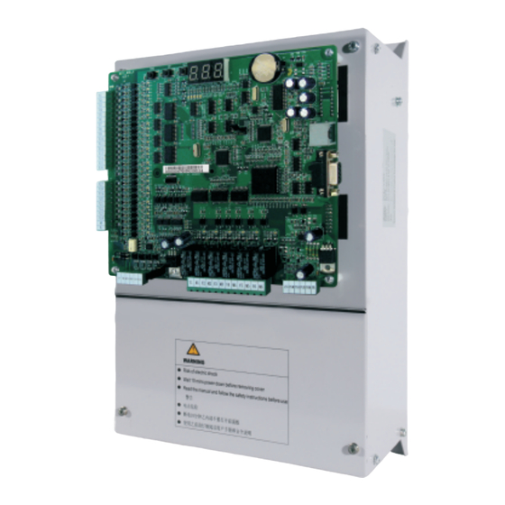
-
Contents
-
Table of Contents
-
Troubleshooting
-
Bookmarks
Quick Links
Summary of Contents for Suzhou MONARCH Control Technology Co., Ltd. NICE3000 New
-
Page 2: Preface
NICE3000 User Manual Preface Preface Thank you for purchasing the NICE3000 integrated elevator controller. The NICE3000 is a new-generation integrated elevator controller independently developed by Suzhou MONARCH Control Technology Co., Ltd., by optimizing the NICE3000 controller based on a large number of applications and combining new industrial features. The NICE3000 has the following advantages: 1.
-
Page 3
Introduction NICE3000 User Manual Introduction 1. Comparison with the NICE3000 The following table lists the comparison between the NICE3000 and the NICE3000. Item NICE3000 NICE3000 Maximum number of 31 (standard) 40 (standard) floors Maximum elevator 4 m/s 4 m/s speed 24 inputs, 6 outputs, 3 high-voltage I/O terminals 24 inputs, 6 outputs… -
Page 4: Introduction
NICE3000 User Manual Introduction 2. Connection to peripheral devices Use within the allowable Three-phase AC power supply specification power supply of the controller. Select a proper breaker Moulded case to resist large in-rush circuit breaker current that flows into the (MCCB) or earth controller at power-on.
-
Page 5
Introduction NICE3000 User Manual 3. Function list of the NICE3000 Common Running Functions In automatic running or attendant state, this function enables the Full collective elevator to respond both car calls and hall calls. Passengers at any selective service floor can call the elevator by pressing the up call button and down call button. -
Page 6
NICE3000 User Manual Introduction If the door open time exceeds the door open protection time but the Landing at another door open limit signal is still inactive, the elevator closes the door and floor then automatically runs to the next landing floor. The system reports fault Err55. -
Page 7
Introduction NICE3000 User Manual Service suspension When the elevator cannot respond to hall calls, the corresponding output terminal outputs the service suspension signal. Running times In automatic running state, the system automatically records the recording running times of the elevator. Running time The system automatically records the accumulative power-on time, recording… -
Page 8
NICE3000 User Manual Introduction Considering inaccurate running control at high inspection speed but Dual-speed for a long running time at low inspection speed, the system provides the inspection dual-speed curve for inspection, which greatly improves the efficiency at inspection. The test running includes the fatigue test of a new elevator, car call floor test, hall call test, and tests such as hall call response forbidden, Test running door open/close forbidden, terminal floor limit switch shielded, and… -
Page 9
Introduction NICE3000 User Manual The system automatically determines the fault level. If the safety Passenger running conditions are met, the elevator first runs to the leveling unloading position to unload passengers. Interference degree The system judges the degree of interference on the communication. judgment When the earthquake detection device acts and inputs a signal to the Earthquake… -
Page 10
NICE3000 User Manual Introduction Energy-saving Functions If there is no running command within the set time, the system Car energy-saving automatically cuts off the power supply to the lamp and fan in the car. Energy-saving When the normal power supply is interrupted and the emergency power running with supply is used, the system reduces the running speed of the elevator in standby power… -
Page 11: Table Of Contents
Contents Preface …………………… 1 Introduction ………………….2 Chapter 1 Safety Information and Precautions……….14 1.1 Safety Precautions …………………. 14 1.2 General Precautions ………………..17 1.3 Protective Functions ………………..19 Chapter 2 Product Information …………….22 …………2.1 System Configuration of the NICE3000 2.2 Designation Rules and Model Description…………..
-
Page 12: Table Of Contents
Chapter 6 Function Code Table …………… 104 6.1 Function Code Description ………………104 6.2 Function Code Groups ………………..104 6.3 Function Code Table ………………..105 Chapter 7 Description of Function Codes…………136 Group F0: Basic Parameters ………………. 136 Group F1: Motor Parameter ……………….. 138 Group F2: Vector Control Parameters …………….
-
Page 14
Safety Information and Precautions… -
Page 15
Safety Information and Precautions NICE3000 User Manual Chapter 1 Safety Information and Precautions In this manual, the notices are graded based on the degree of danger: • indicates that failure to comply with the notice will result in severe DANGER personal injury or even death. -
Page 16: Chapter 1 Safety Information And Precautions
NICE3000 User Manual Safety Information and Precautions Safety Use Stage Precautions Grade • Do not install the equipment if you find water seepage, component missing or damage upon unpacking. • Do not install the equipment if the packing list does not conform to the product you received.
-
Page 17
Safety Information and Precautions NICE3000 User Manual Safety Use Stage Precautions Grade • All peripheral devices must be connected properly according to the circuit wiring instructions provided in this manual. Failure to comply will result in accidents • Cover the controller properly before power-on to prevent electric shock. -
Page 18: General Precautions
NICE3000 User Manual Safety Information and Precautions Safety Use Stage Precautions Grade • Do not repair or maintain the controller at power-on. Failure to comply will result in electric shock. • Repair or maintain the controller when its voltage is lower than 36 VAC, about two minutes after the controller is powered off.
-
Page 19
Safety Information and Precautions NICE3000 User Manual 3. Motor heat and noise The output of the controller is pulse width modulation (PWM) wave with certain harmonic wave, and therefore, the motor temperature rise, noise, and vibration are slightly greater than those at running with the power frequency (50 Hz). 4. -
Page 20: Protective Functions
NICE3000 User Manual Safety Information and Precautions cable and the cable connecting the controller and the motor produce leakage current, which is much larger than the current when the motor runs at power frequency (50 Hz). Thus, it is necessary to determine the proper RCCB sensitivity based on the general leakage current of the cables and the motor.
-
Page 21
Safety Information and Precautions NICE3000 User Manual — 20 -… -
Page 22
Product Information… -
Page 23
Product Information NICE3000 User Manual Chapter 2 Product Information 2.1 System Configuration of the NICE3000 The NICE3000 series integrated elevator control system combines the functions of both elevator controller and the high-performance vector controller. It mainly includes the integrated elevator controller, car top board (MCTC-CTB), hall call board (MCTC-HCB), car call board (MCTC-CCB), and optional door pre-open module, and remote monitoring system. -
Page 24: Chapter 2 Product Information
NICE3000 User Manual Product Information The following figure shows the system structure of the NICE3000 Figure 2-2 System structure of the NICE3000 Modbus MCTC-HCB CANbus Braking MCTC-CTB unit MCTC-CCB Input power Control Encoder feedback Modbus circuit of Encoder MCTC-HCB Drive circuit of the motor controller Motor…
-
Page 25: Models And Specifications
Product Information NICE3000 User Manual 2.3 Models and Specifications Table 2-1 NICE3000 models and specifications Power Input Current Output Current Motor Power Controller Model Capacity (kVA) (kW) Single-phase 220 V, range: 200−240 V NICE-L-C-2002 13.2 NICE-L-C-2003 220-NICE-L-C-4007 10.3 220-NICE-L-C-4011 12.1 15.5 220-NICE-L-C-4015 13.9…
-
Page 26: Technical Specifications
NICE3000 User Manual Product Information Note 1. In terms of single-phase and three-phase 220 VAC, NICE-L-A/B-2002 and NICE-L-A/B-2003 are specially designed for 220 VAC. The other models that are marked by prefixing «220-» are modified from the three-phase 380 VAC models. 2.
-
Page 27
Product Information NICE3000 User Manual Item Specification Easy to implement multiple elevators commissioning Test function functions. Fault protection Solutions to different levels of elevator faults Intelligent Remote monitoring, user management, and group Basic management control adjustment specifications Security check of Security check of peripheral devices, such as peripheral devices grounding and short circuit, after power-on… -
Page 28: Physical Appearance And Mounting Dimensions
NICE3000 User Manual Product Information 2.5 Physical Appearance and Mounting Dimensions The following figures show the physical appearance and mounting dimensions of the NICE3000 Figure 2-4 Physical appearance of the NICE3000 Figure 2-5 Mounting dimensions of the NICE3000 Φ — 27 -…
-
Page 29
Product Information NICE3000 User Manual Table 2-3 Mounting dimensions of the NICE3000 Hole Gross Controller Model Diameter Weight Size (mm) (mm) (mm) (mm) (mm) (mm) (kg) Single-phase 220 V, range: 200−240 V NICE-L-C-2002 334.5 SIZE-C NICE-L-C-2003 220-NICE-L-C-4007 220-NICE-L-C-4011 334.5 173.5 SIZE-D 220-NICE-L-C-4015 220-NICE-L-C-4018… -
Page 30: Optional Parts
NICE3000 User Manual Product Information 2.6 Optional Parts If any optional part in the following table is required, specify it in your order. Table 2-4 Optional parts of the NICE3000 Name Model Function Remark For details, see section External It is provided for the NICE3000 MDBUN 2.7 «Selection of braking unit…
-
Page 31: Selection Of Braking Resistor
Product Information NICE3000 User Manual 2.7 Selection of Braking Resistor The NICE3000 models of 30 kW and below have a built-in braking unit, and you only need to connect an external braking resistor between PB and + terminals. For models above 30 kW, you need to install a braking unit and a braking resistor externally.
-
Page 32
NICE3000 User Manual Product Information Power of Max. Min. Power of Controller Model Adaptable Resistance Resistance Braking Braking Unit Motor (kW) (Ω) (Ω) Resistor (W) NICE-L-C-4037 16.0 11000 MDBUN-45-T NICE-L-C-4045 14.0 13500 MDBUN-60-T NICE-L-C-4055 12.0 16500 MDBUN-60-T Note 1. The preceding configuration takes the synchronous motor as an example. The asynchronous motor has poor energy transfer efficiency, and you can reduce the power of the braking resistor or increase the resistance of the braking resistor. -
Page 33
Product Information NICE3000 User Manual — 32 -… -
Page 34
Mechanical and Electrical Installation… -
Page 35
Mechanical and Electrical Installation NICE3000 User Manual Chapter 3 Mechanical and Electrical Installation 3.1 NICE3000 Integrated Elevator Controller 3.1.1 Installation Environment Requirements Item Requirements Ambient -10°C to 50°C temperature Install the controller on the surface of an incombustible object, and ensure that there is sufficient space around for heat dissipation. -
Page 36: Chapter 3 Mechanical And Electrical Installation
NICE3000 User Manual Mechanical and Electrical Installation Figure 3-2 Diagram of mounting holes Fastening Fastener torque 1.1 kW 15 kW ≤ ≤ 2.5 Nm 4-M5x15 bolt With fixing 4-M5×15 screw washer 4-M5x15 washer 18.5 kW 45 kW 3.5 Nm ≤ ≤…
-
Page 37
Mechanical and Electrical Installation NICE3000 User Manual Figure 3-3 Terminal arrangement of the NICE3000 CN12 NICE3000 integrated elevator controller Description of Main Circuit Terminals ■ The following figure shows main circuit terminal arrangement. Figure 3-4 Main circuit terminal arrangement POWER MOTOR — 36 -… -
Page 38
NICE3000 User Manual Mechanical and Electrical Installation Figure 3-5 Wiring of the main circuit Three-phase power supply Safety contactor POWER MOTOR (For models of below 37 kW) Braking resistor Three-phase AC power supply Safety contactor POWER MOTOR (For models of 37 kW and above) Jumper bar Braking unit MDBUN… -
Page 39
Mechanical and Electrical Installation NICE3000 User Manual Precautions about wiring of the main circuit terminals are as follows: 1. Select the braking resistor according to the recommended values in the braking resistor selection table. 2. The circuit on the output side must not be short-circuited or grounded. 3. -
Page 40
NICE3000 User Manual Mechanical and Electrical Installation Mark Code Terminal Name Function Description Terminal Arrangement Normally-open (NO), maximum current and Y1/M1 voltage rating: 5 A, 250 Relay output Y6/M6 Function set in F5-26 to F5- CAN2 CAN2 communication CAN2+/- differential interface, used for group signal control or parallel control… -
Page 41: Ctb Board (Mctc-Ctb)
Mechanical and Electrical Installation NICE3000 User Manual Mark Terminal Name Function Description This indicator is steady on (green) when communication Group control for parallel control or group control is normal, and blinks CAN2 communication when the running in parallel mode or group mode is indicator normal.
-
Page 42
NICE3000 User Manual Mechanical and Electrical Installation 3.2.2 Wiring of CTB Terminals Table 3-4 Wiring description of CTB terminals Terminal Mark Terminal Name Function Description Arrangement External 24 VDC 24 VDC power supply for +24V/COM power supply the entire CTB CAN+ CAN- CANbus… -
Page 43
Mechanical and Electrical Installation NICE3000 User Manual Terminal Mark Terminal Name Function Description Arrangement B1-BM Door open signal 1 B2-BM Door close signal 1 B3-BM Forced door close 1 C1-CM Door open signal 2 Relay output terminal Contact drive capacity: C2-CM Door close signal 2 30 VDC, 1 A… -
Page 44: Display Board (Mctc-Hcb)
NICE3000 User Manual Mechanical and Electrical Installation Terminal Mark Terminal Name Function Description Arrangement This indicator blinks when communication between CANbus the CTB and the MCB is communication normal, and is steady on indicator when a communication fault occurs. This indicator blinks RESET and the CANbus CANbus…
-
Page 45
Mechanical and Electrical Installation NICE3000 User Manual Table 3-5 Common HCB types Name Feature Size (mm) HCB-H Dot-matrix display board (red) 144 x 70 x 18 HCB-R1 Ultrathin dot-matrix display board (red) 144 x 70 x 10 Ultrathin segment LCD display board (blue HCB-D2 144 x 70 x 10 background white display) -
Page 46
NICE3000 User Manual Mechanical and Electrical Installation The following table describes the input and output terminals of HCB-H. Table 3-6 Input and output terminals of HCB-H Terminal Function Terminal Wiring Name Up arrival indicator Interface for the elevator lock switch and up arrival indicator Elevator lock switch… -
Page 47
Mechanical and Electrical Installation NICE3000 User Manual Terminal Function Terminal Wiring Name Modbus communication and power supply terminal Pins 2 and 3 are for Modbus communication. Pins 1 and 4 are for DC power supply. 1 2 3 4 3.3.2 HCB-R1 (Ultrathin Dot-Matrix Display Board) The following figure shows the appearance and dimensions of HCB-R1. -
Page 48
NICE3000 User Manual Mechanical and Electrical Installation The following table describes the input and output terminals. Table 3-7 Input and output terminals of HCB-R1 Terminal Function Terminal Wiring Name Up call indicator Interface for the up call button and indicator Pins 2 and 3 are for up call input. -
Page 49
Mechanical and Electrical Installation NICE3000 User Manual 3.3.3 HCB-D2 (Ultrathin Segment LED Display Board) The following figure shows the appearance and dimensions of HCB-D2. Figure 3-12 Appearance and dimensions of HCB-D2 Φ 56.0 UP DOWN ST XF Unit: mm 70.0 The following figure shows the installation method of HCB-D2. -
Page 50
NICE3000 User Manual Mechanical and Electrical Installation The following table describes the input and output terminals of HCB-D2. Table 3-8 Input and output terminals of HCB-D2 Terminal Function Terminal Wiring Name Up call indicator Interface for the up call button and indicator Pins 2 and 3 are for up call input. -
Page 51
Mechanical and Electrical Installation NICE3000 User Manual 3.3.4 HCB-U1 (4.3-inch Segment LED Display Board) The following figure shows the appearance and dimensions of HCB-U1. Figure 3-14 Appearance and dimensions of HCB-U1 3-5.5 Φ 53.0 60.0 Unit: mm 79.2 The following figure shows the installation method of HCB-U1. Figure 3-15 Installation method of HCB-U1 Self-tapping Plastic support… -
Page 52
NICE3000 User Manual Mechanical and Electrical Installation The following table describes the input and output terminals of HCB-U1. Table 3-9 Input and output terminals of HCB-U1 Terminal Function Terminal Wiring Name Up call indicator Interface for the up call button and indicator Pins 2 and 3 are for up call input. -
Page 53
Mechanical and Electrical Installation NICE3000 User Manual 3.3.5 HCB-V1 (6.4-inch Segment LED Display Board) The following figure shows the appearance and dimensions of HCB-V1. Figure 3-16 Appearance and dimensions of HCB-V1 Unit: mm The following figure shows the installation method of HCB-V1. Figure 3-17 Installation method of HCB-V1 Plastic support higher than 1 cm… -
Page 54: Ccb Board (Mctc-Ccb)
NICE3000 User Manual Mechanical and Electrical Installation The following table describes the input and output terminals of HCB-V1. Table 3-10 Input and output terminals of HCB-V1 Terminal Name Function Terminal Wiring Up call indicator Interface for the up call button and indicator Pins 2 and 3 are for up call input.
-
Page 55
Mechanical and Electrical Installation NICE3000 User Manual Figure 3-18 Appearance and dimensions of MCTC-CCB 79 mm 69 mm Buzzer MCTC-CCB 1 2 3 4 1 2 3 4 1 2 3 4 1 2 3 4 Floor 1 Floor 2 Floor 3 Floor 4 1 2 3 4… -
Page 56
NICE3000 User Manual Mechanical and Electrical Installation The following table describes the input and output terminals of MCTC-CCB. Table 3-11 Input and output terminals of MCTC-CCB Interface Pins 2 and 3 Pins 1 and 4 Remarks Floor 1 button input Floor 1 display output Floor 2 button input Floor 2 display output… -
Page 57: Selection And Use Of The Mctc-Pg Card
Mechanical and Electrical Installation NICE3000 User Manual 3.5 Selection and Use of the MCTC-PG Card The NICE3000 can implement CLVC only with use of the MCTC-PG card. The following figures show the appearance of the MCTC-PG card and its installation on the controller. Directly insert the J1 terminal of the MCTC-PG card into the J12 terminal of the controller.
-
Page 58
NICE3000 User Manual Mechanical and Electrical Installation Encoder Type Adaptable PG Card Appearance and Dimension MCTC-PG-E SIN/COS encoder MCTC-PG-E Absolute encoder MCTC-PG-F1 MCTC-PG-F1 (ECN413/1313) 3.5.2 Terminal Wiring and Description of the MCTC-PG Card The MCTC-PG card is connected to the controller and the encoder as follows: The J1 terminal and CN1 terminal of the MCTC-PG card are respectively connected to the J12 terminal of the MCB on the controller and the encoder of the motor. -
Page 59
Mechanical and Electrical Installation NICE3000 User Manual MCTC-PG-A2 MCTC-PG-D MCTC-PG-E MCTC-PG-F1 4 B- 9 V+ 14 COM 4 Z- 9 VCC 14 NC 4 CK- 9 5 NC 10 V- 15 5 A+ 10 C+ 15 NC 5 5V 10 3.5.3 Precautions on Connecting the MCTC-PG Card 1. -
Page 60: Selection Of Peripheral Electrical Devices
NICE3000 User Manual Mechanical and Electrical Installation 3.6 Selection of Peripheral Electrical Devices 3.6.1 Description of Peripheral Electrical Devices 1. Do not install the capacitor or surge suppressor on the output side of the controller. Otherwise, it may cause faults to the controller or damage to the capacitor and surge suppressor.
-
Page 61
Mechanical and Electrical Installation NICE3000 User Manual Controller Contactor Cable of Main Cable of Control Grounding MCCB (A) Model Circuit (mm²) Circuit (mm²) Cable (mm²) 0.75 NICE-4003 0.75 NICE-4005 0.75 NICE -4007 0.75 NICE -4011 0.75 NICE-4015 NICE-4018 NICE-4022 NICE-4030 NICE-4037 NICE-4045 NICE-4055… -
Page 62
NICE3000 User Manual Mechanical and Electrical Installation Figure 3-23 Arrangement of shaft position signals Up final limit switch 150 mm Up limit switch 30-50 mm Top leveling position V² (V: Rated L > 2 x F3-08 elevator speed) Up slow-down switch Leveling flag Up final limit switch… -
Page 63
Mechanical and Electrical Installation NICE3000 User Manual Figure 3-24 Installation of leveling signals Leveling switch Up leveling signal detection Door zone signal detection Leveling flag Down leveling signal detection The following table describes the installation requirements of leveling switches Table 3-16 Installation requirements of leveling switches Number of Connecting to Input Terminals of Setting of… -
Page 64
NICE3000 User Manual Mechanical and Electrical Installation Number of Connecting to Input Terminals of Setting of Leveling Installation Method Controller Function Code Switches +24 VDC F5-01 = 33 (NC) F5-02 = 35 (NC) Up leveling Door zone signal F5-03 = 34 (NC) Down leveling Up leveling signal detection… -
Page 65
Mechanical and Electrical Installation NICE3000 User Manual Table 3-17 Slow-down distances based on different rated elevator speeds Rated Elevator Speed V ≤ 1.5 m/s 1.5 m/s < V ≤ 2.4 m/s 2.4 m/s < V ≤ 3.7 m/s Distance of slow-down 1 1.3 m to H/2 1.3 m 1.3 m… -
Page 66: Electrical Wiring Diagram Of The Nice3000 New Control System
NICE3000 User Manual Mechanical and Electrical Installation Figure 3-22 Electrical wiring diagram of the NICE3000new control system Note: The functions of I/O terminals of the controller are set in group F5. The wiring Braking resistor in this figure uses the default setting. Safety contactor –…
-
Page 67
Use of the NICE3000… -
Page 68: Chapter 4 Use Of The Nice3000 New
Use of the NICE3000 NICE3000 User Manual Chapter 4 Use of the NICE3000 The NICE3000 supports four commissioning tools, 3-button keypad on the MCB, LED operation panel, LCD operator, and host computer monitoring software. Tool Function Description Remark It is used to enter the shaft commissioning Onboard 3-button keypad Standard commands and view floor information.
-
Page 69
NICE3000 User Manual Use of the NICE3000 • UP: Press this button to increase the function group number. Currently, the MCB defines a total of 13 function code groups, namely, F0 to F9, and FA to FC. You can press the UP button to display them in turn. In addition, in special function code group menu, you can input simple references by using the UP button. -
Page 70
Use of the NICE3000 NICE3000 User Manual 4. F3: time display After you enter the F3 menu, the 7-segment LEDs display the current system time circularly. 5. F4: contract number display After you enter the F4 menu, the 7-segment LEDs display the user’s contract number. 6. -
Page 71
NICE3000 User Manual Use of the NICE3000 After auto-tuning is complete, the 7-segment LEDs display the current angle for 2s, and then switch over to the F0 menu. You can press the PRG button to exit the auto-tuning state. 12. FB: CTB state display After you enter the FB menu, the 7-segment LEDs display the input/output state of the CTB. -
Page 72: Use Of The Led Operation Panel
Use of the NICE3000 NICE3000 User Manual 4.2 Use of the LED Operation Panel The LED operation panel is connected to the RJ45 interface of the controller by using an 8-core flat cable. You can modify the parameters, monitor the working status and start or stop the controller by operating the operation panel.
-
Page 73
NICE3000 User Manual Use of the NICE3000 V: unit of voltage RPM: unit of rotational speed %: percentage 4.2.2 Description of Keys on the Operation Panel Table 4-2 Description of keys on the operation panel Name Function Programming Enter or exit Level-I menu. Enter the menu interfaces level by level, and confirm the Confirm ENTER… -
Page 74
Use of the NICE3000 NICE3000 User Manual Figure 4-4 Operation procedure on the operation panel If there is a blinking digit, press Level-I menu Status parameter (Select the function to modify the digit. (default display) code group) 0.000 ENTER F0.07 F0.06 Level-II menu ENTER… -
Page 75: Use Of The Lcd Operator
NICE3000 User Manual Use of the NICE3000 4.2.4 Viewing Status Parameters In the stop or running state, the operation panel can display multiple status parameters. Whether parameters are displayed is determined by the equivalent binary bits converted from the values of FA-01 and FA-02. In the stop state, a total of 12 parameters can be displayed circularly by pressing .
-
Page 76
Use of the NICE3000 NICE3000 User Manual Figure 4-8 Appearance of the LCD operator Display Right key Left key Knob/Confirm Run key Programming Stop key 4.3.1 Keys on the LCD operator Name Function Press this key to implement the function displayed on the lower Left left corner of the display. -
Page 77
NICE3000 User Manual Use of the NICE3000 The display of the LCD operator is divided into the following three areas: • Status bar It displays the current state information of the elevator, such as running mode, elevator state, current floor, and fault information at stop. •… -
Page 78
Use of the NICE3000 NICE3000 User Manual Figure 4-12 Main operation interface Normal Copy Port Parameters Curve view Call Err help Back Select ־Parameters You can view or modify all function codes of the controller. A three-level menu is supported, and you can read and modify the function code value in Level III menu. -
Page 79
System Commissioning and Application Example… -
Page 80: Chapter 5 System Commissioning And Application Example
System Commissioning and Application Example NICE3000 User Manual Chapter 5 System Commissioning and Application Example 5.1 System Commissioning CAUTION • Ensure that there is no person in the shaft or car before performing commissioning on the elevator. • Ensure that the peripheral circuit and mechanical installation are ready before performing commissioning.
-
Page 81
NICE3000 User Manual System Commissioning and Application Example 1. Check the field mechanical and electric wiring. Before power-on, check the peripheral wiring to ensure component and personal safety. The items to be checked include: Whether the component models are matched Whether the safety circuit is conducted and reliable Whether the door lock circuit is conducted and reliable Whether the shaft is unobstructed, and the car has no passenger and meets the… -
Page 82
System Commissioning and Application Example NICE3000 User Manual Note If the input voltage exceeds the allowable value, serious damage will be caused. Distinguish the negative and positive of the DC power supply. Do not run the system when there is input power phase loss. -
Page 83
NICE3000 User Manual System Commissioning and Application Example Function Code Parameter Name Description Rated motor power Rated motor voltage These parameters are model dependent, F1-01 to F1-05 Rated motor current and you need to manually input them according to the nameplate. Rated motor frequency Rated motor rotational speed 0: Sensorless flux vector control (SFVC) -
Page 84
System Commissioning and Application Example NICE3000 User Manual Figure 5-2 Motor auto-tuning process Set F1-25 correctly based on the actually used motor type For with-load auto-tuning, With-load set F1-11 to 1. After the (Asynchronous auto-tuning operation panel displays motor) Set F0-01 to 0 Set encoder parameters F1-00 «TUNE», press the RUN (Operation panel… -
Page 85
NICE3000 User Manual System Commissioning and Application Example Table 5-2 Output state of the running and brake contactors With-load Auto-tuning Operation Control mode No-load Auto- Distance Panel (F1-11 = 1) tuning Control Control Synchronous Asynchronous (F0-01 = 1) (F1-11 = 2) Output State (F0-01 = 0) motor… -
Page 86
System Commissioning and Application Example NICE3000 User Manual If the door machine cannot act properly, check whether BM/B1 and BM/B2 are wrongly connected to the input terminals of the door machine controller and whether commissioning of the door machine controller is complete. 2. -
Page 87
NICE3000 User Manual System Commissioning and Application Example 5.1.5 Riding Comfort The riding comfort is an important factor of the elevator’s overall performance. Improper installation of mechanical parts and improper parameter settings will cause bad comfort. Enhancing the riding comfort mainly involves adjustment of the controller output and the elevator’s mechanical construction. -
Page 88
System Commissioning and Application Example NICE3000 User Manual The optimum values of these two parameters are obtained during motor auto-tuning, and you need not modify them. Appropriate setting of the parameters can restrain jitter during running and have obvious effect on the riding comfort. Function Parameter Name Setting Range… -
Page 89
NICE3000 User Manual System Commissioning and Application Example The release time of the brakes varies according to the types and the response time of the brakes is greatly influenced by the ambient temperature. A high brake coil temperature slows the brake responsiveness. Thus, when the riding comfort at startup or stop cannot be improved by adjusting zero servo or load cell compensation parameters, appropriately increase the values of F3-19 and F3-20 to check whether the brake release time influences the riding comfort. -
Page 90
System Commissioning and Application Example NICE3000 User Manual startup pro-torque compensation is higher. The controller identifies the braking or driving state according to the load cell signal and automatically calculates the required torque compensation value. When an analog device is used to measure the load, these parameters are used to adjust the elevator startup. -
Page 91: System Application
NICE3000 User Manual System Commissioning and Application Example Figure 5-5 Example of changing the password Status parameter (default display) 0.000 ENTER FP-00 FP-01 ENTER 00000 If there is a blinking digit, press to modify the digit. 12345 ENTER To save the setting •…
-
Page 92
System Commissioning and Application Example NICE3000 User Manual Figure 5-6 Emergency evacuation 220 V UPS circuit Transformer (6 A) UPS-220 V 220 VAC 220 VAC 115 VAC Safety circuit 21 115 VDC (6 A) UPS-0 V NICE3000 Note The UPS emergency evacuation signal can be output only by Y6. The following figure shows various contacts of the contactors. -
Page 93
NICE3000 User Manual System Commissioning and Application Example The following table lists the setting of the related parameters. Table 5-5 Parameter setting under the 220 V UPS scheme Function Code Parameter Name Setting Range Emergency evacuation switching F6-48 0.010–0.630 m/s speed F6-49 Evacuation parking floor… -
Page 94
System Commissioning and Application Example NICE3000 User Manual Figure 5-8 Wiring of the independent shorting PMSM stator contactor Braking resistor Safety contactor – PB Motor Three-phase AC power supply NICE3000 Encoder PG card MCTC-PG Shielding layer Safety circuit 110 VAC FX: Shorting PMSM stator contactor SW: RUN contactor The parameter setting in such wiring mode is described in the following table. -
Page 95
NICE3000 User Manual System Commissioning and Application Example Function Binary Setting Remarks Description Stop at the base floor Bit2 Stop position Stop at nearest landing floor Stop and open door at a single leveling signal Door open at Bit3 single leveling signal Normal leveling stop When it is set… -
Page 96
System Commissioning and Application Example NICE3000 User Manual Function Binary Setting Remarks Description Exit at door close limit Emergency Bit14 evacuation exit mode Exit at door open limit When this function Function is enabled, the selection of Bit15 Enable this function. setting of related shorting stator function codes… -
Page 97
NICE3000 User Manual System Commissioning and Application Example switch. Parallel Control by Using CAN1 (Terminal CN3) ■ When the CAN1 communication port (CN3 terminal) is used for parallel control, you need to set the CTB addresses, according to the following table. Table 5-9 Address and jumper setting of the CTB for CAN1 is used for parallel control Jumper Setting Address Setting… -
Page 98
System Commissioning and Application Example NICE3000 User Manual Figure 5-10 Wiring when CAN2 is used for parallel control Elevator Elevator NICE3000 NICE3000 CAN2 cables for parallel control CAN2+ CAN2+ CAN2- CAN2- Elevator Elevator CAN+ CAN+ MCTC-CTB MCTC-CTB CAN- CAN- Up button indicator MOD+ MOD+ MCTC-HCB… -
Page 99
NICE3000 User Manual System Commissioning and Application Example Figure 5-11 Wiring of parallel control implemented at the monitoring port RS232-RS485 converter RS232-RS485 converter RS485 cables for parallel control Elevator Elevator NICE3000 NICE3000 Elevator Elevator CAN+ CAN+ MCTC-CTB MCTC-CTB CAN- CAN- Up button indicator MOD+ MOD+… -
Page 100
System Commissioning and Application Example NICE3000 User Manual When two elevators are in parallel mode, the addresses of the HCBs should be set according to physical floors. Parallel running can be implemented only when the HCB address set for one elevator is the same as that for the other elevator in terms of the same floor. -
Page 101
NICE3000 User Manual System Commissioning and Application Example 5.2.3 Opposite Door Control Set related parameters according to the following table. Table 5-11 Parameter setting for opposite door control Function Parameter Name Setting Range Default Code Bit2: JP16 input used as back door selection (button) Bit3: JP16 input used as the back door open signal… -
Page 102
System Commissioning and Application Example NICE3000 User Manual Table 5-12 Selection of the opposite door mode Opposite Parameter Setting Function Description Use Method Door Mode Old mode (same as the NICE3000) The front door and back The hall call FC-04 = 0 door acts simultaneously addresses of the Mode 1… -
Page 103
NICE3000 User Manual System Commissioning and Application Example Note In the fire emergency, inspection or re-leveling state, the opposite door is under simultaneous control rather than independent control. 5.2.4 VIP Function Description The NICE3000 provides the VIP function that the elevator first directly runs to the VIP floor and provides services for special persons. -
Page 104
System Commissioning and Application Example NICE3000 User Manual When there is a hall call at the VIP floor, the system automatically enters the VIP state. After the VIP input terminal is ON, the elevator returns to the VIP floor to provide the VIP service. The VIP running times is limited by bit8 of F6-46. -
Page 105
Function Code Table… -
Page 106: Chapter 6 Function Code Table
Function Code Table NICE3000 User Manual Chapter 6 Function Code Table 6.1 Function Code Description 1. There are a total of 18 function code groups, each of which includes several function codes. The function codes adopt the three-level menu. The function code group number is Level-I menu;…
-
Page 107: Function Code Table
NICE3000 User Manual Function Code Table Basic parameters Time parameters Motor parameters Keypad setting parameters Vector control parameters Door function parameters Running control parameters Protection function parameters Floor parameters Communication parameters Terminal function parameters Elevator function parameters Basic elevator parameters Factory parameters Test function parameters User parameters…
-
Page 108
Function Code Table NICE3000 User Manual Function Parameter Name Setting Range Default Unit Property Code Model F1-03 Rated motor current 0.00–655.00 ★ dependent F1-04 Rated motor frequency 0.00–99.00 50.00 ★ Rated motor rotational F1-05 0–3000 1460 ★ speed Encoder initial angle Degree F1-06 0.0–359.9… -
Page 109
NICE3000 User Manual Function Code Table Function Parameter Name Setting Range Default Unit Property Code Group F2: Vector control parameters Speed loop F2-00 0–100 ★ proportional gain KP1 Speed loop integral F2-01 0.01–10.00 0.60 ★ time TI1 Switchover frequency F2-02 0.00 to F2-05 2.00 ★… -
Page 110
Function Code Table NICE3000 User Manual Function Parameter Name Setting Range Default Unit Property Code Group F3: Running control parameters F3-00 Startup speed 0.000–0.030 0.000 ★ F3-01 Startup holding time 0.000–0.500 0.000 ★ F3-02 Acceleration rate 0.200–2.000 0.600 ★ Acceleration start jerk F3-03 0.300–4.000 2.500… -
Page 111
NICE3000 User Manual Function Code Table Function Parameter Name Setting Range Default Unit Property Code F4-01 Current floor F6-01 to F6-00 ★ High byte of current F4-02 0–65535 Pulses ● floor position Low byte of current F4-03 0–65535 34464 Pulses ●… -
Page 112
Function Code Table NICE3000 User Manual Function Parameter Name Setting Range Default Unit Property Code High byte of floor F4-22 0–65535 Pulses ★ height 9 Low byte of floor height F4-23 0–65535 Pulses ★ High byte of floor F4-24 0–65535 Pulses ★… -
Page 113
NICE3000 User Manual Function Code Table Function Parameter Name Setting Range Default Unit Property Code 19/51: Down slow-down F5-09 X9 function selection 2 signal ★ 20/52: Up slow-down 3 signal F5-10 X10 function selection ★ 21/53: Down slow-down 3 signal 22/54: Shorting door F5-11 X11 function selection… -
Page 114
Function Code Table NICE3000 User Manual Function Parameter Name Setting Range Default Unit Property Code 0: Invalid 1: RUN contactor control F5-26 Y1 function selection 2: Brake contactor ★ control 3: Shorting door lock circuit contactor control 4: Fire emergency floor arrival signal feedback F5-27 Y2 function selection… -
Page 115
NICE3000 User Manual Function Code Table Function Parameter Name Setting Range Default Unit Property Code Bit3: Elevator fire emergency requirement for Hong Kong Bit4: Arrival gong disabled at night Bit6: Door lock disconnected at inspection switched over to normal running Terminal program F5-33 ★… -
Page 116
Function Code Table NICE3000 User Manual Function Parameter Name Setting Range Default Unit Property Code Number of elevators in F6-07 1–8 ★ group mode F6-08 Elevator No. 1–8 ★ Bit0: Dispersed waiting Bit2: Parallel implemented at monitoring port Bit3: Parallel implemented at CAN2 Bit4: Parallel control in compatibility with… -
Page 117
NICE3000 User Manual Function Code Table Function Parameter Name Setting Range Default Unit Property Code Bit1: Disabling returning to base floor for verification Bit2: Cancelling auto sequential arrange of hall call floor addresses to be displayed Bit5: Current detection valid at startup for synchronous motor Bit6: Reversing MCB lamp output… -
Page 118
Function Code Table NICE3000 User Manual Function Parameter Name Setting Range Default Unit Property Code Service floor 1 of time- F6-20 0–65535 65535 ☆ based floor service 1 Service floor 2 of time- F6-21 0–65535 65535 ☆ based floor service 1 Start time of time- F6-22 00.00–23.59… -
Page 119
NICE3000 User Manual Function Code Table Function Parameter Name Setting Range Default Unit Property Code Bit0: Disability function Bit1: Soft limit function Bit2: JP16 input used as back door selection Bit3: JP16 input used as the back door open signal Bit4: Opening only one door of opposite doors under manual control… -
Page 120
Function Code Table NICE3000 User Manual Function Parameter Name Setting Range Default Unit Property Code Bit2: Inspection to stop due to slow-down 1 Bit4: Buzzer tweet during door open delay Bit6: Cancelling door open delay Bit8: Elevator lock at door open Bit9: Display available at Program control elevator lock… -
Page 121
NICE3000 User Manual Function Code Table Function Parameter Name Setting Range Default Unit Property Code Bit3: Arrival gong output in inspection or fire emergency state Bit4: Multiple car calls registered in fire emergency state Bit5: Retentive at power failure in fire emergency state Bit6: Closing door by holding down the door… -
Page 122
Function Code Table NICE3000 User Manual Function Parameter Name Setting Range Default Unit Property Code Bit0-Bit1: Direction determine mode (00: Automatically calculating direction; 01: Load direction determining; 10: Direction of nearest landing floor) Bit2: Stopping at evacuation parking floor Bit3: Door open at single leveling signal Bit4: Compensation at startup… -
Page 123
NICE3000 User Manual Function Code Table Function Parameter Name Setting Range Default Unit Property Code Down call floor F7-02 0 to F6-00 ☆ registered F7-03 Random running times 0–60000 ☆ 0: Yes F7-04 Hall call enabled ☆ 1: No 0: Yes F7-05 Door open enabled ☆… -
Page 124
Function Code Table NICE3000 User Manual Function Parameter Name Setting Range Default Unit Property Code 0: Motor not running Emergency evacuation 1: UPS F8-10 operation mode at ★ 2: 48 V battery power power failure supply F8-11 Brake apply delay 0.000–1.000 0.600 ☆… -
Page 125
NICE3000 User Manual Function Code Table Function Parameter Name Setting Range Default Unit Property Code Group FA: Keypad setting parameters 0: Reversed display of physical floor 1: Positive display of physical floor Keypad display FA-00 ☆ selection 2: Reversed display of hall call floor 3: Positive display of hall call floor… -
Page 126
Function Code Table NICE3000 User Manual Function Parameter Name Setting Range Default Unit Property Code Communication FA-24 0–65535 ● interference FA-26 Input state 1 0–65535 ● FA-27 Input state 2 0–65535 ● FA-28 Input state 3 0–65535 ● FA-30 Input state 5 0–65535 ●… -
Page 127
NICE3000 User Manual Function Code Table Function Parameter Name Setting Range Default Unit Property Code 0: Closing the door as normal at base floor Door state of standby 1: Waiting with door Fb-10 ☆ elevator open at base floor 2: Waiting with door open at each floor Door open holding Fb-11… -
Page 128
Function Code Table NICE3000 User Manual Function Parameter Name Setting Range Default Unit Property Code Bit0: Overload protection Bit1: Canceling protection at output phase loss Bit2: Canceling over- modulation function Program control 2 for Bit4: Light curtain FC-01 ★ protection function judgment at door close limit Bit5: Canceling SPI… -
Page 129
NICE3000 User Manual Function Code Table Function Parameter Name Setting Range Default Unit Property Code Output frequency upon FC-18 0.00–99.99 ● designated fault Torque current upon FC-19 0.0–999.9 ● designated fault FC-20 1st fault code 0–9999 ● FC-21 1st fault subcode 0–65535 ●… -
Page 130
Function Code Table NICE3000 User Manual Function Parameter Name Setting Range Default Unit Property Code Latest fault month and FC-62 0–1231 MM.DD ● Latest fault hour and FC-63 0–23.59 HH.MM ● minute Logic information of FC-64 0–65535 ● latest fault Curve information of FC-65 0–65535… -
Page 131
NICE3000 User Manual Function Code Table Function Parameter Name Setting Range Default Unit Property Code 0: Reserved NO/NC input: FD-07 HCB:JP1 input ★ 1/33: Elevator lock signal 2/34: Fire emergency signal 3/35: Current floor forbidden 4/36: VIP floor signal FD-08 HCB:JP2 input 5/37: Security floor ★… -
Page 132
Function Code Table NICE3000 User Manual Function Parameter Name Setting Range Default Unit Property Code FD-17 HCB-B:A1 output ★ 0: Reserved FD-18 HCB-B:A2 output ★ 1: Fault output FD-19 HCB-B:B1 output ★ 2: Non-door zone stop output FD-20 HCB-B:B2 output ★… -
Page 133
NICE3000 User Manual Function Code Table Function Parameter Name Setting Range Default Unit Property Code FE-07 Floor 7 display 17: Display «R» 1907 ☆ 18: Display «-» FE-08 Floor 8 display 1908 ☆ 19: No display FE-09 Floor 9 display 1909 ☆… -
Page 134
Function Code Table NICE3000 User Manual Function Parameter Name Setting Range Default Unit Property Code Bit2: Re-leveling function Bit3: Door pre-open function Bit4: Stuck hall call cancellation Bit5: Night security floor function Bit6: Down collective selective peak service Elevator function FE-32 34816 ☆… -
Page 135
NICE3000 User Manual Function Code Table Function Parameter Name Setting Range Default Unit Property Code Leveling adjustment Fr-01 30030 ★ record 1 Leveling adjustment Fr-02 30030 ★ record 2 00000–60060 … … Leveling adjustment Fr-20 30030 ★ record 20 Group FF: Factory parameters Group FP: User parameters FP-00 User password… -
Page 136
Function Code Table NICE3000 User Manual — 134 -… -
Page 137
Description of Function Codes… -
Page 138: Chapter 7 Description Of Function Codes
Description of Function Codes NICE3000 User Manual Chapter 7 Description of Function Codes Group F0: Basic Parameters Function Parameter Setting Range Default Unit Property Code Name • 0: Sensorless flux vector control (SFVC) Control • 1: Closed-loop vector control F0-00 ★…
-
Page 139
NICE3000 User Manual Description of Function Codes Function Code Parameter Name Setting Range Default Unit Property Running speed under F0-02 0.050 to F0-04 0.050 ☆ operation panel control It is used to set the running speed in the operation panel control mode. Note that this function is enabled only when F0-01 is set to 0 (Operation panel control). -
Page 140: Group F1: Motor Parameter
Description of Function Codes NICE3000 User Manual • If the carrier frequency is high, power loss and temperature rise of the motor declines. However, the system has an increase in power loss, temperature rise and interference. Adjusting the carrier frequency will exert influences on the aspects listed in the following table.
-
Page 141
NICE3000 User Manual Description of Function Codes Function Parameter Name Setting Range Default Unit Property Code Rated motor rotational Model F1-05 0–3000 ★ speed dependent Set these parameters according to the motor nameplate. Ensure that these motor parameters are set correctly. Incorrect setting affects the motor auto-tuning and the vector control effect. -
Page 142
Description of Function Codes NICE3000 User Manual Function Code Parameter Name Setting Range Default Unit Property 0: No operation 1: With-load auto-tuning F1-11 Auto-tuning mode ★ 2: No-load auto-tuning 3: Shaft auto-tuning It is used to select the auto-tuning mode. «With-load auto-tuning»… -
Page 143: Group F2: Vector Control Parameters
NICE3000 User Manual Description of Function Codes Function Code Parameter Name Setting Range Default Unit Property Rotor resistance Model F1-15 0.000–30.000 Ω ★ (asynchronous motor) dependent Leakage inductance Model F1-16 0.00–300.00 ★ (asynchronous motor) dependent Mutual inductance Model F1-17 0.1–3000.0 ★…
-
Page 144
Description of Function Codes NICE3000 User Manual F2-03 and F2-04 are PI regulation parameters when the running frequency is larger than the value of F2-05 (Switchover frequency 2). If the running frequency is between F2-02 and F2-05, the speed loop PI parameters are obtained from the weighted average value of the two groups of PI parameters (F2-00, F2-01 and F2-03, F2-04), as shown in Figure 7-1. -
Page 145
NICE3000 User Manual Description of Function Codes It is used to set the elevator running direction. The values are as follows: • 0: Running direction and position pulse direction unchanged • 1: Running direction reversed, position pulse direction reversed • 2: Running direction unchanged, position pulse direction reversed •… -
Page 146: Group F3: Running Control Parameters
Description of Function Codes NICE3000 User Manual Group F3: Running Control Parameters Function Code Parameter Name Setting Range Default Unit Property F3-00 Startup speed 0.000–0.030 0.000 ★ F3-01 Startup holding time 0.000–0.500 0.000 ★ These two parameters are used to set the startup speed and startup speed holding time. For details, see Figure 7-2.
-
Page 147
NICE3000 User Manual Description of Function Codes Function Code Parameter Name Setting Range Default Unit Property F3-08 Special deceleration rate 0.500–2.000 0.900 ★ It is used to set the deceleration rate in elevator slow-down, inspection, and shaft auto-tuning. This parameter is not used during normal running. It is used only when the elevator position is abnormal or the slow-down signal is abnormal, preventing over travel top terminal or over travel bottom terminal. -
Page 148
Description of Function Codes NICE3000 User Manual Function Code Parameter Name Setting Range Default Unit Property F3-18 Zero-speed control time at startup 0.000–1.000 0.200 ★ F3-19 Brake release delay 0.000–1.000 0.600 ★ F3-20 Zero-speed control time at end 0.200–1.500 0.200 ★… -
Page 149: Group F4: Floor Parameters
NICE3000 User Manual Description of Function Codes Group F4: Floor Parameters Function Code Parameter Name Setting Range Default Unit Property F4-00 Leveling adjustment 0–60 ★ It is used to adjust the leveling accuracy at elevator stop. If over-leveling occurs in elevator stop at all floors, decrease the value of this parameter properly.
-
Page 150: Group F5: Terminal Function Parameters
Description of Function Codes NICE3000 User Manual These parameters indicate the pulses corresponding to the floor height i (between the leveling plates of floor n and floor i+1). Each floor height is expressed by a 32-bit binary number, where the high 16 bits indicate the high byte of the floor height, and the low 16 bits indicate the low byte of the floor height.
-
Page 151
NICE3000 User Manual Description of Function Codes If three leveling sensors are used, the system receives the up leveling signal, door zone signal, and down leveling signal in sequence in the up direction, and receives down leveling signal, door zone signal, and up leveling signal in sequence in the down direction. If two leveling sensors (up leveling sensor and down leveling sensor) are used, the system receives the up leveling signal and down leveling signal in sequence in the up direction, and receives down leveling signal and up leveling signal in sequence in the down direction. -
Page 152
Description of Function Codes NICE3000 User Manual 14: Overload signal When the elevator load exceeds 110% of the rated load during normal use, the elevator enters the overload state. Then the overload buzzer beeps, the overload indicator in the car becomes ON, and the elevator door keeps open. The overload signal becomes invalid when the door lock is applied. -
Page 153
NICE3000 User Manual Description of Function Codes 27: UPS valid signal It is the emergency running signal at power failure. If it is active, it indicates that the elevator is running for emergency evacuation at power failure. For more details, see section 5.2.1. 28: Elevator lock signal If this signal is active, the elevator enters the locked state, returns to the elevator lock floor and does not respond to any calls until the signal becomes inactive. -
Page 154
Description of Function Codes NICE3000 User Manual emergency floor 1 in fire emergency state. If this signal is active, the elevator stops at fire emergency floor 2 in fire emergency state. Function Code Parameter Name Setting Range Default Unit Property F5-25 CTB input type 0–511… -
Page 155
NICE3000 User Manual Description of Function Codes 09: Brake and RUN contactors healthy When the brake and RUN contactors operate properly (non-Err36/Err37 state), the system sends the feedback signal for monitoring. 10: Fault state The terminal with the function has output when the system is in the level-3, level-4 or level-5 fault state. -
Page 156
Description of Function Codes NICE3000 User Manual 19: Medical sterilization It is used to control the output of the ultraviolet sterilizing lamp signal. After the elevator stops running and the lamp/fan stops operating, the medical sterilization output is started. 20: Non-door zone stop The terminal with this function has output when the elevator stops at the non-door zone. -
Page 157
NICE3000 User Manual Description of Function Codes Table 7-2 Definition of LED segments Corresponding Normal Modbus Meaning of Segment ON Communication Address of LED HOP Modbus Communication Normal Reserved Corresponding Abnormal Modbus Meaning of Segment OFF Communication Address of LED HOP Modbus Communication Abnormal Reserved… -
Page 158
Description of Function Codes NICE3000 User Manual Figure 7-5 Example of LED display indicating the communication state Function Code Parameter Name Setting Range Default Unit Property F5-33 Terminal program control 0–65535 ★ It is used to set the elevator functions. Whether a function is enabled is indicated by a binary bit: «1»… -
Page 159
NICE3000 User Manual Description of Function Codes These parameters are used to monitor the state of all I/O terminals of the system. The LEDs of F5-34/F5-35 are arranged as 5, 4, 3, 2, 1 from left to right. Figure 7-6 Monitoring of all I/O terminals Each segment of the LEDs is defined in the following table. -
Page 160
Description of Function Codes NICE3000 User Manual F5-34 F5-35 Segment Indication No. Segment Indication Up slow-down 1 signal Door open output 1 Down slow-down 1 signal Door close output 1 Up slow-down 2 signal Door lock signal Down slow-down 2 signal Door open output 1 Up slow-down 3 signal Door close output 2… -
Page 161: Group F6: Basic Elevator Parameters
NICE3000 User Manual Description of Function Codes Function Code Parameter Name Setting Range Default Unit Property F5-37 X25 function selection ★ 0: No function F5-38 X26 function selection 4: Safety circuit signal ★ 5: Door lock circuit signal F5-39 X27 function selection ★…
-
Page 162
Description of Function Codes NICE3000 User Manual Whether service floors of a parameter are allowed is indicated by a 16-bit binary number. The 16 bits respectively correspond to 16 floors from low to high. «1» indicates that the elevator will respond to calls of this floor, and «0» indicates that the elevator will not respond to calls of this floor. -
Page 163
NICE3000 User Manual Description of Function Codes Table 7-6 Functions indicated by bits of F6-09 Function Description Default In single elevator or parallel mode, if this function is enabled, an idle elevator will not return to the base floor. Bit0 Dispersed waiting In group mode, this function is used together with the group control board to implement dispersed… -
Page 164
Description of Function Codes NICE3000 User Manual Table 7-7 Functions indicated by bits of F6-09 Function Description Default Disabling returning The function of returning to base floor for verification Bit1 to base floor for due to large deviation of the car position is disabled. verification Cancelling auto sequential arrange… -
Page 165
NICE3000 User Manual Description of Function Codes Function Code Parameter Name Setting Range Default Unit Property F6-13 Security floor 0 to F6-00 ★ It is used to set the security floor of the elevator. If the security signal is active or it is during the night security period, the elevator runs to the security floor first every time, stops and opens the door, and then runs to the target floor. -
Page 166
Description of Function Codes NICE3000 User Manual These parameters define the time periods of two groups of time-based services and corresponding service floors. Service floor 1 corresponds to floors 1–16, service floor 2 corresponds to floors 17–32, and service floor 3 corresponds to floors 33–30. In the time period of time-based service 1 (set by F6-18 and F6-19), the elevator responds to the service floors set by F6-20, F6-21 and F6-36 but ignores the service floors set by F6-05, F6-06 and F5-35. -
Page 167
NICE3000 User Manual Description of Function Codes Table 7-8 Functions indicated by the bits of F6-40 to F6-42 F6-40 Program Control Selection 1 Function Description Default Bit0 Disability function It is used to enable or disable the disability function. When the up slow-down and down leveling signals are active and the up leveling signal is inactive, the system Bit1 Soft limit function… -
Page 168
Description of Function Codes NICE3000 User Manual F6-40 Program Control Selection 1 Function Description Default Folding command It is valid only when the function of Bit14 is enabled. used as disability Bit13 Bit13 = 1: Disability function and back Bit13 = 0: Back door door function There are two folding methods when this function is enabled:… -
Page 169
NICE3000 User Manual Description of Function Codes F6-42 Program Control Selection 3 Function Description Default Bit0 Reserved Cancelling door open/close If this function is enabled, the door open/close Bit1 command at delay command is cancelled at the delay of 1s after door after door open/ open/close limit. -
Page 170
Description of Function Codes NICE3000 User Manual Function Code Parameter Name Setting Range Default Unit Property Fire emergency F6-44 0–65535 ★ function selection It is used to select the fire emergency functions. «1» indicates that the function is enabled, and «0» indicates that the function is disabled. The functions defined by the binary bits are described in the following table. -
Page 171
NICE3000 User Manual Description of Function Codes Function Code Parameter Name Setting Range Default Unit Property Emergency evacuation F6-45 0–65535 ★ function selection It is used to select the emergency evacuation-related functions. «1» indicates that the function is enabled, and «0» indicates that the function is disabled. The functions defined by the binary bits are described in the following table. -
Page 172
Description of Function Codes NICE3000 User Manual F6-45 Emergency Evacuation Function Selection Function Description Default Time setting If the time of the shorting stator braking mode exceeds Mode of shorting 50s, the controller starts to drive the elevator. stator braking Bit13 mode switched Speed setting… -
Page 173: Group F7: Test Function Parameters
NICE3000 User Manual Description of Function Codes Function Code Parameter Name Setting Range Default Unit Property Emergency evacuation F6-48 0.010–0.630 0.010 ★ switching speed It is used to set the switching speed at shorting stator braking mode switched over to controller drive via speed setting.
-
Page 174
Description of Function Codes NICE3000 User Manual Function Code Parameter Name Setting Range Default Unit Property 0: Yes F7-04 Hall call enabled ☆ 1: No It is used to enable the hall call function. • 0: Yes (hall call allowed) •… -
Page 175: Group F8: Enhanced Function Parameters
NICE3000 User Manual Description of Function Codes Group F8: Enhanced Function Parameters Function Code Parameter Name Setting Range Default Unit Property F8-00 Load for load cell auto-tuning 0–100 ★ It is used to set the load for load cell auto-tuning. To perform load cell auto-tuning, do as follows: 1.
-
Page 176
Description of Function Codes NICE3000 User Manual Unit Property Function Code Parameter Name Setting Range Default F8-03 Drive gain 0.00–2.00 0.60 ★ F8-04 Brake gain 0.00–2.00 0.60 ★ These two parameters are used to set the pre-torque gain when the elevator runs on the drive side or the brake side. -
Page 177
NICE3000 User Manual Description of Function Codes Function Code Parameter Name Setting Range Default Unit Property Emergency evacuation F8-09 0.000–0.100 0.050 ★ operation speed at power failure It is used to set the speed for emergency evacuation operation at power failure. Function Code Parameter Name Setting Range… -
Page 178: Group F9: Time Parameters
Description of Function Codes NICE3000 User Manual Group F9: Time Parameters Function Code Parameter Name Setting Range Default Unit Property Idle time before F9-00 0–240 ☆ returning to base floor It is used to set the idle time of the elevator before returning to the base floor. When the idle time of the elevator exceeds the setting of this parameter, the elevator returns to the base floor.
-
Page 179: Group Fa: Keypad Setting Parameters
NICE3000 User Manual Description of Function Codes Function Code Parameter Name Setting Range Default Unit Property F9-09 Accumulative running time 0–65535 ● F9-11 High byte of running times 0–9999 ● F9-12 Low byte or running times 0–9999 ● These parameters are used to view the actual accumulative running time and running times of the elevator.
-
Page 180
Description of Function Codes NICE3000 User Manual Function Code Parameter Name Setting Range Default Unit Property FA-02 Display in stop state 1–65535 65535 ☆ It is used to set the parameters displayed on the keypad when the elevator is in the stop state. -
Page 181
NICE3000 User Manual Description of Function Codes Meaning Meaning BIT0 Reserved BIT8 Inspection signal BIT1 Up leveling signal BIT9 Inspection up signal BIT2 Down leveling signal BIT10 Inspection down signal BIT3 Door zone signal BIT11 Fire emergency signal BIT4 Safety circuit feedback 1 BIT12 Up limit signal BIT5… -
Page 182
Description of Function Codes NICE3000 User Manual 10) Current floor: indicates the information of the physical floor where the elevator is located. It is the same as the value of F4-01. 11) Current position: indicates the absolute distance from the current elevator car to the leveling flag of the first floor, in unit of m. -
Page 183
NICE3000 User Manual Description of Function Codes Meaning Meaning BIT0 Light curtain state 1 BIT8 Car state: 1: Door open BIT1 Light curtain state 2 BIT9 2: Door open holding BIT2 Hall elevator lock (indicated on HCB) BIT10 3: Door close 4: Door close limit BIT3 Hall fire emergency (indicated on HCB) -
Page 184
Description of Function Codes NICE3000 User Manual Function Code Parameter Name Setting Range Default Unit Property FA-12 Logic information 0–65535 ● It displays the elevator status parameters. The LEDs are arranged as 5, 4, 3, 2, 1 from left to right. LED 1 shows the state of door 1. LEDs 2 and 3 have no display. -
Page 185
NICE3000 User Manual Description of Function Codes LED 5 LED 4 LED 3 LED 2 LED 1 Curve Information Display Display Display Standby state Deceleration start segment Zero-speed start Linear deceleration segment segment Zero-speed holding Deceleration end segment segment Reserved Zero speed at stop Startup speed stage Current stop phase… -
Page 186
Description of Function Codes NICE3000 User Manual Table 7-16 Communication quality display LED 5 LED 4 LED 3 LED 2 LED 1 CAN2 Modbus CAN1 Communication Communication Communication Communication Display Quality Quality Quality Quality Good Good Good Good · · ·… -
Page 187
NICE3000 User Manual Description of Function Codes FA-26 Input state 1 FA-28 Input state 3 Function Function Function Function Fire emergency Reserved Inspection signal Reserved floor switchover Door 1 safety Up leveling signal Inspection up Reserved edge signal Down leveling Door 2 safety Inspection down Reserved… -
Page 188
Description of Function Codes NICE3000 User Manual FA-31 Output state 1 FA-32 Output state 2 Function Function Function Function High-voltage Reserved Door 2 close startup of Reserved brake Brake and RUN Elevator RUN contactor contactors running in up Reserved output healthy direction Brake contactor… -
Page 189
NICE3000 User Manual Description of Function Codes FA-35 Hall state Function Function Function Function Reserved VIP signal Reserved Reserved Elevator lock signal Reserved Reserved Reserved Fire emergency Door close Reserved Reserved signal button input Current floor Reserved Reserved Reserved forbidden FA-36 System state 1 FA-37 System state 2 Function… -
Page 190: Group Fb: Door Function Parameter
Description of Function Codes NICE3000 User Manual Group Fb: Door Function Parameter Function Code Parameter Name Setting Range Default Unit Property Fb-00 Number of door machine (s) 1–2 ★ It is used to set the number of door machine(s). Set this parameter based on actual conditions. Function Code Parameter Name Setting Range…
-
Page 191
NICE3000 User Manual Description of Function Codes Function Code Parameter Name Setting Range Default Unit Property Fb-08 Door close protection time 5–99 ☆ It is used to set the door close protection time. After outputting the door close command, if the system does not receive the door close limit signal after the time set in this parameter, the system re-closes the door. -
Page 192: Group Fc: Protection Function Parameters
Description of Function Codes NICE3000 User Manual Function Code Parameter Name Setting Range Default Unit Property Fb-14 Door open delay 10–1000 ☆ It is used to set the door open holding time when there is door open delay input. The elevator closes the door immediately after receiving a door close command.
-
Page 193
NICE3000 User Manual Description of Function Codes FC-00 Program control for protection function Function Description Default In this mode, the door open/close limit signal is not required, and the system automatically judges door Mode without door open/close limit. The system determines that door Bit9 open/close limit open limit is implemented 3s after the door open… -
Page 194
Description of Function Codes NICE3000 User Manual Function Code Parameter Name Setting Range Default Unit Property FC-04 Opposite door selection 0–3 ★ It is used to set opposite door-related control function. The values are as follows: • 0: Simultaneous control •… -
Page 195
NICE3000 User Manual Description of Function Codes Function Code Parameter Name Setting Range Default Unit Property FC-20 1st fault code 0–9999 ● FC-21 1st fault subcode 0–65535 ● FC-22 1st fault month and day 0–1231 MM.DD ● FC-23 1st fault hour and minute 0–23.59 HH.MM ●… -
Page 196: Group Fd: Communication Parameters
Description of Function Codes NICE3000 User Manual Group Fd: Communication Parameters Function Code Parameter Name Setting Range Default Unit Property 0: 9600 Fd-00 Baud rate bit/s ★ 1: 38400 0–127 Fd-02 Local address ★ 0: Broadcast address Communication Fd-03 0–20 ★…
-
Page 197
NICE3000 User Manual Description of Function Codes Function Code Parameter Name Setting Range Default Unit Property 0: Invalid 1: Up arrival indicator Fd-09 HCB:JP1 output ★ 2: Down arrival indicator 3: Fault output 4: Non-door zone stop output 5: Non-service state output Fd-10 HCB:JP2 output ★… -
Page 198: Group Fe: Elevator Function Parameters
Description of Function Codes NICE3000 User Manual Function Code Parameter Name Setting Range Default Unit Property Fd-17 HCB-B:A1 output ★ 0: Reserved Fd-18 HCB-B:A2 output ★ 1: Fault output Fd-19 HCB-B:B1 output ★ 2: Non-door zone stop Fd-20 HCB-B:B2 output ★…
-
Page 199
NICE3000 User Manual Description of Function Codes Function Parameter Setting Range Default Unit Property Code Name FE-01 Floor 1 display 1901 ☆ 00: Display «0» 22: Display «23» FE-02 Floor 2 display 1902 01: Display «1» 23: Display «C» ☆ FE-03 Floor 3 display 02: Display «2»… -
Page 200
Description of Function Codes NICE3000 User Manual Function Code Parameter Name Setting Range Default Unit Property FE-32 Elevator function selection 1 0–65535 34816 ☆ It is used to set the elevator functions. «1» indicates that the function is enabled, and «0» indicates that the function is disabled. -
Page 201: Group Fr: Leveling Adjustment Parameters
NICE3000 User Manual Description of Function Codes FE-33 Elevator Function Selection 2 Function Description Default Bit0 Reserved Door open holding The system still outputs the door open command Bit1 at open limit upon door open limit. Door close command not The system stops outputting the door close Bit2 output upon door…
-
Page 202
Description of Function Codes NICE3000 User Manual 0: Disabled Leveling Fr-00 ★ adjustment function 1: Enabled This parameter is used to enable the leveling adjustment function. Function Code Parameter Name Setting Range Default Unit Property Fr-01 Leveling adjustment record 1 30030 ★… -
Page 203: Group Ff: Factory Parameters
NICE3000 User Manual Description of Function Codes to exit the leveling adjustment state. Then, car calls can be registered. 21. Press the door close button, and press the button for the next floor. The elevator runs to the next floor and keeps the door open after arrival. Then, you can perform leveling adjustment.
-
Page 204
Description of Function Codes NICE3000 User Manual restored to the default settings. Be cautions with this setting. Function Code Parameter Name Setting Range Default Unit Property 0: Invalid User-defined FP-02 ★ parameter display 1: Valid It is used to set whether to display the parameters that are modified. When it is set to 1, the parameters that are different from the default setting are displayed. -
Page 206: Chapter 8 Emc
NICE3000 User Manual Chapter 8 EMC 8.1 Definition of Terms Electromagnetic compatibility (EMC) describes the ability of electronic and electrical devices or systems to work properly in the electromagnetic environment and not to generate electromagnetic interference that influences other local devices or systems. In other words, EMC includes two aspects: The electromagnetic interference generated by a device or system must be restricted within a certain limit;…
-
Page 207: Selection Of Peripheral Emc Devices
NICE3000 User Manual The system (machinery or appliance) installed with the controller must also have the CE mark. The system integrator is responsible for compliance of the system with the EMC directive and standard EN 61800-3: 2004 Category C2. WARNING If applied in the first environment, the controller may generate radio interference.
-
Page 208
NICE3000 User Manual Table 8-1 Recommended manufacturers and models of EMC filter Power Rated Input AC Input Filter Model AC Input Filter Model Capacity Current Controller Model Changzhou Jianli (Schaffner) Three-phase 380 V NICE-L-C-4002 DL-10EBK5 FN 3258-7-44 NICE-L-C-4003 10.5 DL-16EBK5 FN 3258-16-33 NICE-L-C-4005 14.8… -
Page 209
NICE3000 User Manual Power Rated Input AC Input Filter Model AC Input Filter Model Capacity Current Controller Model Changzhou Jianli (Schaffner) 220-NICE-L-C-4011 12.1 36.0 DL-40K3 220-NICE-L-C-4015 13.9 41.0 DL-50T3 Consult the 220-NICE-L-C-4018 17.3 40.0 DL-50T3 manufacturer. 220-NICE-L-C-4022 23.1 49.0 DL-50T3 220-NICE-L-C-4030 33.0 61.0… -
Page 210: Shielded Cable
NICE3000 User Manual Power Capacity Rated Input Current AC Input Reactor Model Controller Model (Inovance) 220-NICE-L-C-4007 17.0 29.0 MD-ACL-30-4T-113-2% 220-NICE-L-C-4011 21.0 36.0 MD-ACL-50-4T-113-2% 220-NICE-L-C-4015 24.0 41.0 MD-ACL-50-4T-153-2% 220-NICE-L-C-4018 30.0 40.0 MD-ACL-50-4T-183-2% 220-NICE-L-C-4022 40.0 49.0 MD-ACL-50-4T-183-2% 220-NICE-L-C-4030 57.0 61.0 MD-ACL-80-4T-303-2% Single-phase 220 V NICE-L-C-2002 13.2 NICE-L-C-2003…
-
Page 211
NICE3000 User Manual To suppress emission and conduction of the radio frequency interference effectively, the shield of the shielded cable is cooper braid. The braided density of the cooper braid should be greater than 90% to enhance the shielding efficiency and conductivity, as shown in the following figure. -
Page 212
NICE3000 User Manual • It is recommended that all control cables be shielded. • It is recommended that a shielded cable be used as the output power cable of the AC drive; the cable shield must be well grounded. For devices suffering from interference, shielded twisted pair (STP) cable is recommended as the lead wire and the cable shield must be well grounded. -
Page 213: Solutions To Common Emc Interference Problems
NICE3000 User Manual 8.5 Solutions to Common EMC Interference Problems The controller generates very strong interference. Although EMC measures are taken, the interference may still exist due to improper cabling or grounding during use. When the controller interferes with other devices, adopt the following solutions. Interference Type Solution •…
-
Page 214
NICE3000 User Manual — 212 -… -
Page 215
Troubleshooting… -
Page 216: Chapter 9 Troubleshooting
Troubleshooting NICE3000 User Manual Chapter 9 Troubleshooting 9.1 Description of Fault Levels The NICE3000 has almost 60 pieces of alarm information and protective functions. It monitors various input signals, running conditions and feedback signals. If a fault occurs, the system implements the relevant protective function and displays the fault code. The controller is a complicated electronic control system and the displayed fault information is graded into five levels according to the severity.
-
Page 217: Fault Information And Troubleshooting
NICE3000 User Manual Troubleshooting Note • A, B, and C are fault sub-category. • Low-speed running involves inspection, emergency evacuation, shaft auto-tuning, re-leveling, motor auto-tuning, base floor detection, and running in operation panel control. • Normal-speed running involves automatic running, returning to base floor in fire emergency state, firefighter operation, attendant operation, elevator lock, and elevator parking.
-
Page 218
Troubleshooting NICE3000 User Manual Fault Name Possible Causes Solution Level Code 8. Check whether the balance coefficient is correct. 1. The main circuit 9. Check whether the encoder output is grounded or wirings are correct. For short circuited. asynchronous motor, perform SFVC and compare the current to 2. -
Page 219
NICE3000 User Manual Troubleshooting Fault Name Possible Causes Solution Level Code 1. The input voltage is too high. 2. The regeneration 1. Adjust the input voltage. Observe power of the motor is whether the bus voltage is normal Over-voltage too high. Err05 during and whether it rises too quickly… -
Page 220
Troubleshooting NICE3000 User Manual Fault Name Possible Causes Solution Level Code 1. Check the brake circuit and 1. The brake circuit is power input. abnormal. 2. Reduce the load. 2. The load is too 3. Check whether the encoder heavy. feedback signal and setting are 3. -
Page 221
NICE3000 User Manual Troubleshooting Fault Name Possible Causes Solution Level Code 1. The deviation 1. Check whether the encoder runs between the Z signal properly. position and the 2. Check whether the encoder absolute position is too Reference wiring is correct and reliable. large. -
Page 222
Troubleshooting NICE3000 User Manual Fault Name Possible Causes Solution Level Code The RTC clock 1. Replace the clock battery. Err24 RTC clock fault information of the MCB 2. Replace the MCB. is abnormal. Storage data The storage data of the Err25 Contact the agent or Monarch. -
Page 223
NICE3000 User Manual Troubleshooting Fault Name Possible Causes Solution Level Code 1. Check whether the encoder is used properly. 2. Check the setting of motor 1. The detected running nameplate parameters. Perform speed exceeds the motor auto-tuning again. upper protection limit. 3. -
Page 224
Troubleshooting NICE3000 User Manual Fault Name Possible Causes Solution Level Code 3. If Err35 is reported during running, check: • Whether the running times out: No leveling signal is received 1. The elevator is not at when the running time exceeds the bottom floor when F9-02 shaft auto-tuning is… -
Page 225
NICE3000 User Manual Troubleshooting Fault Name Possible Causes Solution Level Code 1. The output of the 1. Check whether the brake coil brake contactor is and feedback contact are correct. inconsistent with the Brake feedback. 2. Check the signal feature (NO, contactor Err37 NC) of the feedback contact. -
Page 226
Troubleshooting NICE3000 User Manual Fault Name Possible Causes Solution Level Code 1. Check whether the hall door lock and the car door lock are in good contact. 2. Check whether the door lock The door lock circuit Door lock contactor acts properly. feedback is invalid Err42 breaking off… -
Page 227
NICE3000 User Manual Troubleshooting Fault Name Possible Causes Solution Level Code 1. The re-leveling running speed exceeds 1. Check the original and secondary 0.1 m/s. wiring of the shorting door lock circuit relay. 2. The elevator is out of the door zone when re- 2. -
Page 228
Troubleshooting NICE3000 User Manual Fault Name Possible Causes Solution Level Code 1. Check the communication cable connection. 2. Check the power supply of the Feedback data CTB. of CANbus Err51 communication 3. Check whether the 24 V power communication with the abnormal supply of the controller is normal. -
Page 229
NICE3000 User Manual Troubleshooting Fault Name Possible Causes Solution Level Code 1. The up limit and 1. Check whether the states (NO, down limit switches are NC) of the slow-down switches and valid simultaneously. limit switches are consistent with Shaft position the parameter setting of the MCB Err58 switches… -
Page 231
Warranty Agreement 1. The warranty period of the product is 18 months (refer to the barcode on the equipment). During the warranty period, if the product fails or is damaged under the condition of normal use by following the instructions, Monarch will be responsible for free maintenance. -
Page 232
Product Warranty Card Add. of unit: Customer information Name of unit: Contact person: P.C.: Tel.: Product model: Product Body barcode (Attach here): information Name of agent: (Maintenance time and content): Failure information Maintenance personnel:…
-
Contents
-
Table of Contents
-
Troubleshooting
-
Bookmarks
Quick Links
Summary of Contents for Suzhou MONARCH Control Technology Co., Ltd. NICE3000 New
-
Page 2: Preface
NICE3000 User Manual Preface Preface Thank you for purchasing the NICE3000 integrated elevator controller. The NICE3000 is a new-generation integrated elevator controller independently developed by Suzhou MONARCH Control Technology Co., Ltd., by optimizing the NICE3000 controller based on a large number of applications and combining new industrial features. The NICE3000 has the following advantages: 1.
-
Page 3
Introduction NICE3000 User Manual Introduction 1. Comparison with the NICE3000 The following table lists the comparison between the NICE3000 and the NICE3000. Item NICE3000 NICE3000 Maximum number of 31 (standard) 40 (standard) floors Maximum elevator 4 m/s 4 m/s speed 24 inputs, 6 outputs, 3 high-voltage I/O terminals 24 inputs, 6 outputs… -
Page 4: Introduction
NICE3000 User Manual Introduction 2. Connection to peripheral devices Use within the allowable Three-phase AC power supply specification power supply of the controller. Select a proper breaker Moulded case to resist large in-rush circuit breaker current that flows into the (MCCB) or earth controller at power-on.
-
Page 5
Introduction NICE3000 User Manual 3. Function list of the NICE3000 Common Running Functions In automatic running or attendant state, this function enables the Full collective elevator to respond both car calls and hall calls. Passengers at any selective service floor can call the elevator by pressing the up call button and down call button. -
Page 6
NICE3000 User Manual Introduction If the door open time exceeds the door open protection time but the Landing at another door open limit signal is still inactive, the elevator closes the door and floor then automatically runs to the next landing floor. The system reports fault Err55. -
Page 7
Introduction NICE3000 User Manual Service suspension When the elevator cannot respond to hall calls, the corresponding output terminal outputs the service suspension signal. Running times In automatic running state, the system automatically records the recording running times of the elevator. Running time The system automatically records the accumulative power-on time, recording… -
Page 8
NICE3000 User Manual Introduction Considering inaccurate running control at high inspection speed but Dual-speed for a long running time at low inspection speed, the system provides the inspection dual-speed curve for inspection, which greatly improves the efficiency at inspection. The test running includes the fatigue test of a new elevator, car call floor test, hall call test, and tests such as hall call response forbidden, Test running door open/close forbidden, terminal floor limit switch shielded, and… -
Page 9
Introduction NICE3000 User Manual The system automatically determines the fault level. If the safety Passenger running conditions are met, the elevator first runs to the leveling unloading position to unload passengers. Interference degree The system judges the degree of interference on the communication. judgment When the earthquake detection device acts and inputs a signal to the Earthquake… -
Page 10
NICE3000 User Manual Introduction Energy-saving Functions If there is no running command within the set time, the system Car energy-saving automatically cuts off the power supply to the lamp and fan in the car. Energy-saving When the normal power supply is interrupted and the emergency power running with supply is used, the system reduces the running speed of the elevator in standby power… -
Page 11: Table Of Contents
Contents Preface …………………… 1 Introduction ………………….2 Chapter 1 Safety Information and Precautions……….14 1.1 Safety Precautions …………………. 14 1.2 General Precautions ………………..17 1.3 Protective Functions ………………..19 Chapter 2 Product Information …………….22 …………2.1 System Configuration of the NICE3000 2.2 Designation Rules and Model Description…………..
-
Page 12: Table Of Contents
Chapter 6 Function Code Table …………… 104 6.1 Function Code Description ………………104 6.2 Function Code Groups ………………..104 6.3 Function Code Table ………………..105 Chapter 7 Description of Function Codes…………136 Group F0: Basic Parameters ………………. 136 Group F1: Motor Parameter ……………….. 138 Group F2: Vector Control Parameters …………….
-
Page 14
Safety Information and Precautions… -
Page 15
Safety Information and Precautions NICE3000 User Manual Chapter 1 Safety Information and Precautions In this manual, the notices are graded based on the degree of danger: • indicates that failure to comply with the notice will result in severe DANGER personal injury or even death. -
Page 16: Chapter 1 Safety Information And Precautions
NICE3000 User Manual Safety Information and Precautions Safety Use Stage Precautions Grade • Do not install the equipment if you find water seepage, component missing or damage upon unpacking. • Do not install the equipment if the packing list does not conform to the product you received.
-
Page 17
Safety Information and Precautions NICE3000 User Manual Safety Use Stage Precautions Grade • All peripheral devices must be connected properly according to the circuit wiring instructions provided in this manual. Failure to comply will result in accidents • Cover the controller properly before power-on to prevent electric shock. -
Page 18: General Precautions
NICE3000 User Manual Safety Information and Precautions Safety Use Stage Precautions Grade • Do not repair or maintain the controller at power-on. Failure to comply will result in electric shock. • Repair or maintain the controller when its voltage is lower than 36 VAC, about two minutes after the controller is powered off.
-
Page 19
Safety Information and Precautions NICE3000 User Manual 3. Motor heat and noise The output of the controller is pulse width modulation (PWM) wave with certain harmonic wave, and therefore, the motor temperature rise, noise, and vibration are slightly greater than those at running with the power frequency (50 Hz). 4. -
Page 20: Protective Functions
NICE3000 User Manual Safety Information and Precautions cable and the cable connecting the controller and the motor produce leakage current, which is much larger than the current when the motor runs at power frequency (50 Hz). Thus, it is necessary to determine the proper RCCB sensitivity based on the general leakage current of the cables and the motor.
-
Page 21
Safety Information and Precautions NICE3000 User Manual — 20 -… -
Page 22
Product Information… -
Page 23
Product Information NICE3000 User Manual Chapter 2 Product Information 2.1 System Configuration of the NICE3000 The NICE3000 series integrated elevator control system combines the functions of both elevator controller and the high-performance vector controller. It mainly includes the integrated elevator controller, car top board (MCTC-CTB), hall call board (MCTC-HCB), car call board (MCTC-CCB), and optional door pre-open module, and remote monitoring system. -
Page 24: Chapter 2 Product Information
NICE3000 User Manual Product Information The following figure shows the system structure of the NICE3000 Figure 2-2 System structure of the NICE3000 Modbus MCTC-HCB CANbus Braking MCTC-CTB unit MCTC-CCB Input power Control Encoder feedback Modbus circuit of Encoder MCTC-HCB Drive circuit of the motor controller Motor…
-
Page 25: Models And Specifications
Product Information NICE3000 User Manual 2.3 Models and Specifications Table 2-1 NICE3000 models and specifications Power Input Current Output Current Motor Power Controller Model Capacity (kVA) (kW) Single-phase 220 V, range: 200−240 V NICE-L-C-2002 13.2 NICE-L-C-2003 220-NICE-L-C-4007 10.3 220-NICE-L-C-4011 12.1 15.5 220-NICE-L-C-4015 13.9…
-
Page 26: Technical Specifications
NICE3000 User Manual Product Information Note 1. In terms of single-phase and three-phase 220 VAC, NICE-L-A/B-2002 and NICE-L-A/B-2003 are specially designed for 220 VAC. The other models that are marked by prefixing «220-» are modified from the three-phase 380 VAC models. 2.
-
Page 27
Product Information NICE3000 User Manual Item Specification Easy to implement multiple elevators commissioning Test function functions. Fault protection Solutions to different levels of elevator faults Intelligent Remote monitoring, user management, and group Basic management control adjustment specifications Security check of Security check of peripheral devices, such as peripheral devices grounding and short circuit, after power-on… -
Page 28: Physical Appearance And Mounting Dimensions
NICE3000 User Manual Product Information 2.5 Physical Appearance and Mounting Dimensions The following figures show the physical appearance and mounting dimensions of the NICE3000 Figure 2-4 Physical appearance of the NICE3000 Figure 2-5 Mounting dimensions of the NICE3000 Φ — 27 -…
-
Page 29
Product Information NICE3000 User Manual Table 2-3 Mounting dimensions of the NICE3000 Hole Gross Controller Model Diameter Weight Size (mm) (mm) (mm) (mm) (mm) (mm) (kg) Single-phase 220 V, range: 200−240 V NICE-L-C-2002 334.5 SIZE-C NICE-L-C-2003 220-NICE-L-C-4007 220-NICE-L-C-4011 334.5 173.5 SIZE-D 220-NICE-L-C-4015 220-NICE-L-C-4018… -
Page 30: Optional Parts
NICE3000 User Manual Product Information 2.6 Optional Parts If any optional part in the following table is required, specify it in your order. Table 2-4 Optional parts of the NICE3000 Name Model Function Remark For details, see section External It is provided for the NICE3000 MDBUN 2.7 «Selection of braking unit…
-
Page 31: Selection Of Braking Resistor
Product Information NICE3000 User Manual 2.7 Selection of Braking Resistor The NICE3000 models of 30 kW and below have a built-in braking unit, and you only need to connect an external braking resistor between PB and + terminals. For models above 30 kW, you need to install a braking unit and a braking resistor externally.
-
Page 32
NICE3000 User Manual Product Information Power of Max. Min. Power of Controller Model Adaptable Resistance Resistance Braking Braking Unit Motor (kW) (Ω) (Ω) Resistor (W) NICE-L-C-4037 16.0 11000 MDBUN-45-T NICE-L-C-4045 14.0 13500 MDBUN-60-T NICE-L-C-4055 12.0 16500 MDBUN-60-T Note 1. The preceding configuration takes the synchronous motor as an example. The asynchronous motor has poor energy transfer efficiency, and you can reduce the power of the braking resistor or increase the resistance of the braking resistor. -
Page 33
Product Information NICE3000 User Manual — 32 -… -
Page 34
Mechanical and Electrical Installation… -
Page 35
Mechanical and Electrical Installation NICE3000 User Manual Chapter 3 Mechanical and Electrical Installation 3.1 NICE3000 Integrated Elevator Controller 3.1.1 Installation Environment Requirements Item Requirements Ambient -10°C to 50°C temperature Install the controller on the surface of an incombustible object, and ensure that there is sufficient space around for heat dissipation. -
Page 36: Chapter 3 Mechanical And Electrical Installation
NICE3000 User Manual Mechanical and Electrical Installation Figure 3-2 Diagram of mounting holes Fastening Fastener torque 1.1 kW 15 kW ≤ ≤ 2.5 Nm 4-M5x15 bolt With fixing 4-M5×15 screw washer 4-M5x15 washer 18.5 kW 45 kW 3.5 Nm ≤ ≤…
-
Page 37
Mechanical and Electrical Installation NICE3000 User Manual Figure 3-3 Terminal arrangement of the NICE3000 CN12 NICE3000 integrated elevator controller Description of Main Circuit Terminals ■ The following figure shows main circuit terminal arrangement. Figure 3-4 Main circuit terminal arrangement POWER MOTOR — 36 -… -
Page 38
NICE3000 User Manual Mechanical and Electrical Installation Figure 3-5 Wiring of the main circuit Three-phase power supply Safety contactor POWER MOTOR (For models of below 37 kW) Braking resistor Three-phase AC power supply Safety contactor POWER MOTOR (For models of 37 kW and above) Jumper bar Braking unit MDBUN… -
Page 39
Mechanical and Electrical Installation NICE3000 User Manual Precautions about wiring of the main circuit terminals are as follows: 1. Select the braking resistor according to the recommended values in the braking resistor selection table. 2. The circuit on the output side must not be short-circuited or grounded. 3. -
Page 40
NICE3000 User Manual Mechanical and Electrical Installation Mark Code Terminal Name Function Description Terminal Arrangement Normally-open (NO), maximum current and Y1/M1 voltage rating: 5 A, 250 Relay output Y6/M6 Function set in F5-26 to F5- CAN2 CAN2 communication CAN2+/- differential interface, used for group signal control or parallel control… -
Page 41: Ctb Board (Mctc-Ctb)
Mechanical and Electrical Installation NICE3000 User Manual Mark Terminal Name Function Description This indicator is steady on (green) when communication Group control for parallel control or group control is normal, and blinks CAN2 communication when the running in parallel mode or group mode is indicator normal.
-
Page 42
NICE3000 User Manual Mechanical and Electrical Installation 3.2.2 Wiring of CTB Terminals Table 3-4 Wiring description of CTB terminals Terminal Mark Terminal Name Function Description Arrangement External 24 VDC 24 VDC power supply for +24V/COM power supply the entire CTB CAN+ CAN- CANbus… -
Page 43
Mechanical and Electrical Installation NICE3000 User Manual Terminal Mark Terminal Name Function Description Arrangement B1-BM Door open signal 1 B2-BM Door close signal 1 B3-BM Forced door close 1 C1-CM Door open signal 2 Relay output terminal Contact drive capacity: C2-CM Door close signal 2 30 VDC, 1 A… -
Page 44: Display Board (Mctc-Hcb)
NICE3000 User Manual Mechanical and Electrical Installation Terminal Mark Terminal Name Function Description Arrangement This indicator blinks when communication between CANbus the CTB and the MCB is communication normal, and is steady on indicator when a communication fault occurs. This indicator blinks RESET and the CANbus CANbus…
-
Page 45
Mechanical and Electrical Installation NICE3000 User Manual Table 3-5 Common HCB types Name Feature Size (mm) HCB-H Dot-matrix display board (red) 144 x 70 x 18 HCB-R1 Ultrathin dot-matrix display board (red) 144 x 70 x 10 Ultrathin segment LCD display board (blue HCB-D2 144 x 70 x 10 background white display) -
Page 46
NICE3000 User Manual Mechanical and Electrical Installation The following table describes the input and output terminals of HCB-H. Table 3-6 Input and output terminals of HCB-H Terminal Function Terminal Wiring Name Up arrival indicator Interface for the elevator lock switch and up arrival indicator Elevator lock switch… -
Page 47
Mechanical and Electrical Installation NICE3000 User Manual Terminal Function Terminal Wiring Name Modbus communication and power supply terminal Pins 2 and 3 are for Modbus communication. Pins 1 and 4 are for DC power supply. 1 2 3 4 3.3.2 HCB-R1 (Ultrathin Dot-Matrix Display Board) The following figure shows the appearance and dimensions of HCB-R1. -
Page 48
NICE3000 User Manual Mechanical and Electrical Installation The following table describes the input and output terminals. Table 3-7 Input and output terminals of HCB-R1 Terminal Function Terminal Wiring Name Up call indicator Interface for the up call button and indicator Pins 2 and 3 are for up call input. -
Page 49
Mechanical and Electrical Installation NICE3000 User Manual 3.3.3 HCB-D2 (Ultrathin Segment LED Display Board) The following figure shows the appearance and dimensions of HCB-D2. Figure 3-12 Appearance and dimensions of HCB-D2 Φ 56.0 UP DOWN ST XF Unit: mm 70.0 The following figure shows the installation method of HCB-D2. -
Page 50
NICE3000 User Manual Mechanical and Electrical Installation The following table describes the input and output terminals of HCB-D2. Table 3-8 Input and output terminals of HCB-D2 Terminal Function Terminal Wiring Name Up call indicator Interface for the up call button and indicator Pins 2 and 3 are for up call input. -
Page 51
Mechanical and Electrical Installation NICE3000 User Manual 3.3.4 HCB-U1 (4.3-inch Segment LED Display Board) The following figure shows the appearance and dimensions of HCB-U1. Figure 3-14 Appearance and dimensions of HCB-U1 3-5.5 Φ 53.0 60.0 Unit: mm 79.2 The following figure shows the installation method of HCB-U1. Figure 3-15 Installation method of HCB-U1 Self-tapping Plastic support… -
Page 52
NICE3000 User Manual Mechanical and Electrical Installation The following table describes the input and output terminals of HCB-U1. Table 3-9 Input and output terminals of HCB-U1 Terminal Function Terminal Wiring Name Up call indicator Interface for the up call button and indicator Pins 2 and 3 are for up call input. -
Page 53
Mechanical and Electrical Installation NICE3000 User Manual 3.3.5 HCB-V1 (6.4-inch Segment LED Display Board) The following figure shows the appearance and dimensions of HCB-V1. Figure 3-16 Appearance and dimensions of HCB-V1 Unit: mm The following figure shows the installation method of HCB-V1. Figure 3-17 Installation method of HCB-V1 Plastic support higher than 1 cm… -
Page 54: Ccb Board (Mctc-Ccb)
NICE3000 User Manual Mechanical and Electrical Installation The following table describes the input and output terminals of HCB-V1. Table 3-10 Input and output terminals of HCB-V1 Terminal Name Function Terminal Wiring Up call indicator Interface for the up call button and indicator Pins 2 and 3 are for up call input.
-
Page 55
Mechanical and Electrical Installation NICE3000 User Manual Figure 3-18 Appearance and dimensions of MCTC-CCB 79 mm 69 mm Buzzer MCTC-CCB 1 2 3 4 1 2 3 4 1 2 3 4 1 2 3 4 Floor 1 Floor 2 Floor 3 Floor 4 1 2 3 4… -
Page 56
NICE3000 User Manual Mechanical and Electrical Installation The following table describes the input and output terminals of MCTC-CCB. Table 3-11 Input and output terminals of MCTC-CCB Interface Pins 2 and 3 Pins 1 and 4 Remarks Floor 1 button input Floor 1 display output Floor 2 button input Floor 2 display output… -
Page 57: Selection And Use Of The Mctc-Pg Card
Mechanical and Electrical Installation NICE3000 User Manual 3.5 Selection and Use of the MCTC-PG Card The NICE3000 can implement CLVC only with use of the MCTC-PG card. The following figures show the appearance of the MCTC-PG card and its installation on the controller. Directly insert the J1 terminal of the MCTC-PG card into the J12 terminal of the controller.
-
Page 58
NICE3000 User Manual Mechanical and Electrical Installation Encoder Type Adaptable PG Card Appearance and Dimension MCTC-PG-E SIN/COS encoder MCTC-PG-E Absolute encoder MCTC-PG-F1 MCTC-PG-F1 (ECN413/1313) 3.5.2 Terminal Wiring and Description of the MCTC-PG Card The MCTC-PG card is connected to the controller and the encoder as follows: The J1 terminal and CN1 terminal of the MCTC-PG card are respectively connected to the J12 terminal of the MCB on the controller and the encoder of the motor. -
Page 59
Mechanical and Electrical Installation NICE3000 User Manual MCTC-PG-A2 MCTC-PG-D MCTC-PG-E MCTC-PG-F1 4 B- 9 V+ 14 COM 4 Z- 9 VCC 14 NC 4 CK- 9 5 NC 10 V- 15 5 A+ 10 C+ 15 NC 5 5V 10 3.5.3 Precautions on Connecting the MCTC-PG Card 1. -
Page 60: Selection Of Peripheral Electrical Devices
NICE3000 User Manual Mechanical and Electrical Installation 3.6 Selection of Peripheral Electrical Devices 3.6.1 Description of Peripheral Electrical Devices 1. Do not install the capacitor or surge suppressor on the output side of the controller. Otherwise, it may cause faults to the controller or damage to the capacitor and surge suppressor.
-
Page 61
Mechanical and Electrical Installation NICE3000 User Manual Controller Contactor Cable of Main Cable of Control Grounding MCCB (A) Model Circuit (mm²) Circuit (mm²) Cable (mm²) 0.75 NICE-4003 0.75 NICE-4005 0.75 NICE -4007 0.75 NICE -4011 0.75 NICE-4015 NICE-4018 NICE-4022 NICE-4030 NICE-4037 NICE-4045 NICE-4055… -
Page 62
NICE3000 User Manual Mechanical and Electrical Installation Figure 3-23 Arrangement of shaft position signals Up final limit switch 150 mm Up limit switch 30-50 mm Top leveling position V² (V: Rated L > 2 x F3-08 elevator speed) Up slow-down switch Leveling flag Up final limit switch… -
Page 63
Mechanical and Electrical Installation NICE3000 User Manual Figure 3-24 Installation of leveling signals Leveling switch Up leveling signal detection Door zone signal detection Leveling flag Down leveling signal detection The following table describes the installation requirements of leveling switches Table 3-16 Installation requirements of leveling switches Number of Connecting to Input Terminals of Setting of… -
Page 64
NICE3000 User Manual Mechanical and Electrical Installation Number of Connecting to Input Terminals of Setting of Leveling Installation Method Controller Function Code Switches +24 VDC F5-01 = 33 (NC) F5-02 = 35 (NC) Up leveling Door zone signal F5-03 = 34 (NC) Down leveling Up leveling signal detection… -
Page 65
Mechanical and Electrical Installation NICE3000 User Manual Table 3-17 Slow-down distances based on different rated elevator speeds Rated Elevator Speed V ≤ 1.5 m/s 1.5 m/s < V ≤ 2.4 m/s 2.4 m/s < V ≤ 3.7 m/s Distance of slow-down 1 1.3 m to H/2 1.3 m 1.3 m… -
Page 66: Electrical Wiring Diagram Of The Nice3000 New Control System
NICE3000 User Manual Mechanical and Electrical Installation Figure 3-22 Electrical wiring diagram of the NICE3000new control system Note: The functions of I/O terminals of the controller are set in group F5. The wiring Braking resistor in this figure uses the default setting. Safety contactor –…
-
Page 67
Use of the NICE3000… -
Page 68: Chapter 4 Use Of The Nice3000 New
Use of the NICE3000 NICE3000 User Manual Chapter 4 Use of the NICE3000 The NICE3000 supports four commissioning tools, 3-button keypad on the MCB, LED operation panel, LCD operator, and host computer monitoring software. Tool Function Description Remark It is used to enter the shaft commissioning Onboard 3-button keypad Standard commands and view floor information.
-
Page 69
NICE3000 User Manual Use of the NICE3000 • UP: Press this button to increase the function group number. Currently, the MCB defines a total of 13 function code groups, namely, F0 to F9, and FA to FC. You can press the UP button to display them in turn. In addition, in special function code group menu, you can input simple references by using the UP button. -
Page 70
Use of the NICE3000 NICE3000 User Manual 4. F3: time display After you enter the F3 menu, the 7-segment LEDs display the current system time circularly. 5. F4: contract number display After you enter the F4 menu, the 7-segment LEDs display the user’s contract number. 6. -
Page 71
NICE3000 User Manual Use of the NICE3000 After auto-tuning is complete, the 7-segment LEDs display the current angle for 2s, and then switch over to the F0 menu. You can press the PRG button to exit the auto-tuning state. 12. FB: CTB state display After you enter the FB menu, the 7-segment LEDs display the input/output state of the CTB. -
Page 72: Use Of The Led Operation Panel
Use of the NICE3000 NICE3000 User Manual 4.2 Use of the LED Operation Panel The LED operation panel is connected to the RJ45 interface of the controller by using an 8-core flat cable. You can modify the parameters, monitor the working status and start or stop the controller by operating the operation panel.
-
Page 73
NICE3000 User Manual Use of the NICE3000 V: unit of voltage RPM: unit of rotational speed %: percentage 4.2.2 Description of Keys on the Operation Panel Table 4-2 Description of keys on the operation panel Name Function Programming Enter or exit Level-I menu. Enter the menu interfaces level by level, and confirm the Confirm ENTER… -
Page 74
Use of the NICE3000 NICE3000 User Manual Figure 4-4 Operation procedure on the operation panel If there is a blinking digit, press Level-I menu Status parameter (Select the function to modify the digit. (default display) code group) 0.000 ENTER F0.07 F0.06 Level-II menu ENTER… -
Page 75: Use Of The Lcd Operator
NICE3000 User Manual Use of the NICE3000 4.2.4 Viewing Status Parameters In the stop or running state, the operation panel can display multiple status parameters. Whether parameters are displayed is determined by the equivalent binary bits converted from the values of FA-01 and FA-02. In the stop state, a total of 12 parameters can be displayed circularly by pressing .
-
Page 76
Use of the NICE3000 NICE3000 User Manual Figure 4-8 Appearance of the LCD operator Display Right key Left key Knob/Confirm Run key Programming Stop key 4.3.1 Keys on the LCD operator Name Function Press this key to implement the function displayed on the lower Left left corner of the display. -
Page 77
NICE3000 User Manual Use of the NICE3000 The display of the LCD operator is divided into the following three areas: • Status bar It displays the current state information of the elevator, such as running mode, elevator state, current floor, and fault information at stop. •… -
Page 78
Use of the NICE3000 NICE3000 User Manual Figure 4-12 Main operation interface Normal Copy Port Parameters Curve view Call Err help Back Select ־Parameters You can view or modify all function codes of the controller. A three-level menu is supported, and you can read and modify the function code value in Level III menu. -
Page 79
System Commissioning and Application Example… -
Page 80: Chapter 5 System Commissioning And Application Example
System Commissioning and Application Example NICE3000 User Manual Chapter 5 System Commissioning and Application Example 5.1 System Commissioning CAUTION • Ensure that there is no person in the shaft or car before performing commissioning on the elevator. • Ensure that the peripheral circuit and mechanical installation are ready before performing commissioning.
-
Page 81
NICE3000 User Manual System Commissioning and Application Example 1. Check the field mechanical and electric wiring. Before power-on, check the peripheral wiring to ensure component and personal safety. The items to be checked include: Whether the component models are matched Whether the safety circuit is conducted and reliable Whether the door lock circuit is conducted and reliable Whether the shaft is unobstructed, and the car has no passenger and meets the… -
Page 82
System Commissioning and Application Example NICE3000 User Manual Note If the input voltage exceeds the allowable value, serious damage will be caused. Distinguish the negative and positive of the DC power supply. Do not run the system when there is input power phase loss. -
Page 83
NICE3000 User Manual System Commissioning and Application Example Function Code Parameter Name Description Rated motor power Rated motor voltage These parameters are model dependent, F1-01 to F1-05 Rated motor current and you need to manually input them according to the nameplate. Rated motor frequency Rated motor rotational speed 0: Sensorless flux vector control (SFVC) -
Page 84
System Commissioning and Application Example NICE3000 User Manual Figure 5-2 Motor auto-tuning process Set F1-25 correctly based on the actually used motor type For with-load auto-tuning, With-load set F1-11 to 1. After the (Asynchronous auto-tuning operation panel displays motor) Set F0-01 to 0 Set encoder parameters F1-00 «TUNE», press the RUN (Operation panel… -
Page 85
NICE3000 User Manual System Commissioning and Application Example Table 5-2 Output state of the running and brake contactors With-load Auto-tuning Operation Control mode No-load Auto- Distance Panel (F1-11 = 1) tuning Control Control Synchronous Asynchronous (F0-01 = 1) (F1-11 = 2) Output State (F0-01 = 0) motor… -
Page 86
System Commissioning and Application Example NICE3000 User Manual If the door machine cannot act properly, check whether BM/B1 and BM/B2 are wrongly connected to the input terminals of the door machine controller and whether commissioning of the door machine controller is complete. 2. -
Page 87
NICE3000 User Manual System Commissioning and Application Example 5.1.5 Riding Comfort The riding comfort is an important factor of the elevator’s overall performance. Improper installation of mechanical parts and improper parameter settings will cause bad comfort. Enhancing the riding comfort mainly involves adjustment of the controller output and the elevator’s mechanical construction. -
Page 88
System Commissioning and Application Example NICE3000 User Manual The optimum values of these two parameters are obtained during motor auto-tuning, and you need not modify them. Appropriate setting of the parameters can restrain jitter during running and have obvious effect on the riding comfort. Function Parameter Name Setting Range… -
Page 89
NICE3000 User Manual System Commissioning and Application Example The release time of the brakes varies according to the types and the response time of the brakes is greatly influenced by the ambient temperature. A high brake coil temperature slows the brake responsiveness. Thus, when the riding comfort at startup or stop cannot be improved by adjusting zero servo or load cell compensation parameters, appropriately increase the values of F3-19 and F3-20 to check whether the brake release time influences the riding comfort. -
Page 90
System Commissioning and Application Example NICE3000 User Manual startup pro-torque compensation is higher. The controller identifies the braking or driving state according to the load cell signal and automatically calculates the required torque compensation value. When an analog device is used to measure the load, these parameters are used to adjust the elevator startup. -
Page 91: System Application
NICE3000 User Manual System Commissioning and Application Example Figure 5-5 Example of changing the password Status parameter (default display) 0.000 ENTER FP-00 FP-01 ENTER 00000 If there is a blinking digit, press to modify the digit. 12345 ENTER To save the setting •…
-
Page 92
System Commissioning and Application Example NICE3000 User Manual Figure 5-6 Emergency evacuation 220 V UPS circuit Transformer (6 A) UPS-220 V 220 VAC 220 VAC 115 VAC Safety circuit 21 115 VDC (6 A) UPS-0 V NICE3000 Note The UPS emergency evacuation signal can be output only by Y6. The following figure shows various contacts of the contactors. -
Page 93
NICE3000 User Manual System Commissioning and Application Example The following table lists the setting of the related parameters. Table 5-5 Parameter setting under the 220 V UPS scheme Function Code Parameter Name Setting Range Emergency evacuation switching F6-48 0.010–0.630 m/s speed F6-49 Evacuation parking floor… -
Page 94
System Commissioning and Application Example NICE3000 User Manual Figure 5-8 Wiring of the independent shorting PMSM stator contactor Braking resistor Safety contactor – PB Motor Three-phase AC power supply NICE3000 Encoder PG card MCTC-PG Shielding layer Safety circuit 110 VAC FX: Shorting PMSM stator contactor SW: RUN contactor The parameter setting in such wiring mode is described in the following table. -
Page 95
NICE3000 User Manual System Commissioning and Application Example Function Binary Setting Remarks Description Stop at the base floor Bit2 Stop position Stop at nearest landing floor Stop and open door at a single leveling signal Door open at Bit3 single leveling signal Normal leveling stop When it is set… -
Page 96
System Commissioning and Application Example NICE3000 User Manual Function Binary Setting Remarks Description Exit at door close limit Emergency Bit14 evacuation exit mode Exit at door open limit When this function Function is enabled, the selection of Bit15 Enable this function. setting of related shorting stator function codes… -
Page 97
NICE3000 User Manual System Commissioning and Application Example switch. Parallel Control by Using CAN1 (Terminal CN3) ■ When the CAN1 communication port (CN3 terminal) is used for parallel control, you need to set the CTB addresses, according to the following table. Table 5-9 Address and jumper setting of the CTB for CAN1 is used for parallel control Jumper Setting Address Setting… -
Page 98
System Commissioning and Application Example NICE3000 User Manual Figure 5-10 Wiring when CAN2 is used for parallel control Elevator Elevator NICE3000 NICE3000 CAN2 cables for parallel control CAN2+ CAN2+ CAN2- CAN2- Elevator Elevator CAN+ CAN+ MCTC-CTB MCTC-CTB CAN- CAN- Up button indicator MOD+ MOD+ MCTC-HCB… -
Page 99
NICE3000 User Manual System Commissioning and Application Example Figure 5-11 Wiring of parallel control implemented at the monitoring port RS232-RS485 converter RS232-RS485 converter RS485 cables for parallel control Elevator Elevator NICE3000 NICE3000 Elevator Elevator CAN+ CAN+ MCTC-CTB MCTC-CTB CAN- CAN- Up button indicator MOD+ MOD+… -
Page 100
System Commissioning and Application Example NICE3000 User Manual When two elevators are in parallel mode, the addresses of the HCBs should be set according to physical floors. Parallel running can be implemented only when the HCB address set for one elevator is the same as that for the other elevator in terms of the same floor. -
Page 101
NICE3000 User Manual System Commissioning and Application Example 5.2.3 Opposite Door Control Set related parameters according to the following table. Table 5-11 Parameter setting for opposite door control Function Parameter Name Setting Range Default Code Bit2: JP16 input used as back door selection (button) Bit3: JP16 input used as the back door open signal… -
Page 102
System Commissioning and Application Example NICE3000 User Manual Table 5-12 Selection of the opposite door mode Opposite Parameter Setting Function Description Use Method Door Mode Old mode (same as the NICE3000) The front door and back The hall call FC-04 = 0 door acts simultaneously addresses of the Mode 1… -
Page 103
NICE3000 User Manual System Commissioning and Application Example Note In the fire emergency, inspection or re-leveling state, the opposite door is under simultaneous control rather than independent control. 5.2.4 VIP Function Description The NICE3000 provides the VIP function that the elevator first directly runs to the VIP floor and provides services for special persons. -
Page 104
System Commissioning and Application Example NICE3000 User Manual When there is a hall call at the VIP floor, the system automatically enters the VIP state. After the VIP input terminal is ON, the elevator returns to the VIP floor to provide the VIP service. The VIP running times is limited by bit8 of F6-46. -
Page 105
Function Code Table… -
Page 106: Chapter 6 Function Code Table
Function Code Table NICE3000 User Manual Chapter 6 Function Code Table 6.1 Function Code Description 1. There are a total of 18 function code groups, each of which includes several function codes. The function codes adopt the three-level menu. The function code group number is Level-I menu;…
-
Page 107: Function Code Table
NICE3000 User Manual Function Code Table Basic parameters Time parameters Motor parameters Keypad setting parameters Vector control parameters Door function parameters Running control parameters Protection function parameters Floor parameters Communication parameters Terminal function parameters Elevator function parameters Basic elevator parameters Factory parameters Test function parameters User parameters…
-
Page 108
Function Code Table NICE3000 User Manual Function Parameter Name Setting Range Default Unit Property Code Model F1-03 Rated motor current 0.00–655.00 ★ dependent F1-04 Rated motor frequency 0.00–99.00 50.00 ★ Rated motor rotational F1-05 0–3000 1460 ★ speed Encoder initial angle Degree F1-06 0.0–359.9… -
Page 109
NICE3000 User Manual Function Code Table Function Parameter Name Setting Range Default Unit Property Code Group F2: Vector control parameters Speed loop F2-00 0–100 ★ proportional gain KP1 Speed loop integral F2-01 0.01–10.00 0.60 ★ time TI1 Switchover frequency F2-02 0.00 to F2-05 2.00 ★… -
Page 110
Function Code Table NICE3000 User Manual Function Parameter Name Setting Range Default Unit Property Code Group F3: Running control parameters F3-00 Startup speed 0.000–0.030 0.000 ★ F3-01 Startup holding time 0.000–0.500 0.000 ★ F3-02 Acceleration rate 0.200–2.000 0.600 ★ Acceleration start jerk F3-03 0.300–4.000 2.500… -
Page 111
NICE3000 User Manual Function Code Table Function Parameter Name Setting Range Default Unit Property Code F4-01 Current floor F6-01 to F6-00 ★ High byte of current F4-02 0–65535 Pulses ● floor position Low byte of current F4-03 0–65535 34464 Pulses ●… -
Page 112
Function Code Table NICE3000 User Manual Function Parameter Name Setting Range Default Unit Property Code High byte of floor F4-22 0–65535 Pulses ★ height 9 Low byte of floor height F4-23 0–65535 Pulses ★ High byte of floor F4-24 0–65535 Pulses ★… -
Page 113
NICE3000 User Manual Function Code Table Function Parameter Name Setting Range Default Unit Property Code 19/51: Down slow-down F5-09 X9 function selection 2 signal ★ 20/52: Up slow-down 3 signal F5-10 X10 function selection ★ 21/53: Down slow-down 3 signal 22/54: Shorting door F5-11 X11 function selection… -
Page 114
Function Code Table NICE3000 User Manual Function Parameter Name Setting Range Default Unit Property Code 0: Invalid 1: RUN contactor control F5-26 Y1 function selection 2: Brake contactor ★ control 3: Shorting door lock circuit contactor control 4: Fire emergency floor arrival signal feedback F5-27 Y2 function selection… -
Page 115
NICE3000 User Manual Function Code Table Function Parameter Name Setting Range Default Unit Property Code Bit3: Elevator fire emergency requirement for Hong Kong Bit4: Arrival gong disabled at night Bit6: Door lock disconnected at inspection switched over to normal running Terminal program F5-33 ★… -
Page 116
Function Code Table NICE3000 User Manual Function Parameter Name Setting Range Default Unit Property Code Number of elevators in F6-07 1–8 ★ group mode F6-08 Elevator No. 1–8 ★ Bit0: Dispersed waiting Bit2: Parallel implemented at monitoring port Bit3: Parallel implemented at CAN2 Bit4: Parallel control in compatibility with… -
Page 117
NICE3000 User Manual Function Code Table Function Parameter Name Setting Range Default Unit Property Code Bit1: Disabling returning to base floor for verification Bit2: Cancelling auto sequential arrange of hall call floor addresses to be displayed Bit5: Current detection valid at startup for synchronous motor Bit6: Reversing MCB lamp output… -
Page 118
Function Code Table NICE3000 User Manual Function Parameter Name Setting Range Default Unit Property Code Service floor 1 of time- F6-20 0–65535 65535 ☆ based floor service 1 Service floor 2 of time- F6-21 0–65535 65535 ☆ based floor service 1 Start time of time- F6-22 00.00–23.59… -
Page 119
NICE3000 User Manual Function Code Table Function Parameter Name Setting Range Default Unit Property Code Bit0: Disability function Bit1: Soft limit function Bit2: JP16 input used as back door selection Bit3: JP16 input used as the back door open signal Bit4: Opening only one door of opposite doors under manual control… -
Page 120
Function Code Table NICE3000 User Manual Function Parameter Name Setting Range Default Unit Property Code Bit2: Inspection to stop due to slow-down 1 Bit4: Buzzer tweet during door open delay Bit6: Cancelling door open delay Bit8: Elevator lock at door open Bit9: Display available at Program control elevator lock… -
Page 121
NICE3000 User Manual Function Code Table Function Parameter Name Setting Range Default Unit Property Code Bit3: Arrival gong output in inspection or fire emergency state Bit4: Multiple car calls registered in fire emergency state Bit5: Retentive at power failure in fire emergency state Bit6: Closing door by holding down the door… -
Page 122
Function Code Table NICE3000 User Manual Function Parameter Name Setting Range Default Unit Property Code Bit0-Bit1: Direction determine mode (00: Automatically calculating direction; 01: Load direction determining; 10: Direction of nearest landing floor) Bit2: Stopping at evacuation parking floor Bit3: Door open at single leveling signal Bit4: Compensation at startup… -
Page 123
NICE3000 User Manual Function Code Table Function Parameter Name Setting Range Default Unit Property Code Down call floor F7-02 0 to F6-00 ☆ registered F7-03 Random running times 0–60000 ☆ 0: Yes F7-04 Hall call enabled ☆ 1: No 0: Yes F7-05 Door open enabled ☆… -
Page 124
Function Code Table NICE3000 User Manual Function Parameter Name Setting Range Default Unit Property Code 0: Motor not running Emergency evacuation 1: UPS F8-10 operation mode at ★ 2: 48 V battery power power failure supply F8-11 Brake apply delay 0.000–1.000 0.600 ☆… -
Page 125
NICE3000 User Manual Function Code Table Function Parameter Name Setting Range Default Unit Property Code Group FA: Keypad setting parameters 0: Reversed display of physical floor 1: Positive display of physical floor Keypad display FA-00 ☆ selection 2: Reversed display of hall call floor 3: Positive display of hall call floor… -
Page 126
Function Code Table NICE3000 User Manual Function Parameter Name Setting Range Default Unit Property Code Communication FA-24 0–65535 ● interference FA-26 Input state 1 0–65535 ● FA-27 Input state 2 0–65535 ● FA-28 Input state 3 0–65535 ● FA-30 Input state 5 0–65535 ●… -
Page 127
NICE3000 User Manual Function Code Table Function Parameter Name Setting Range Default Unit Property Code 0: Closing the door as normal at base floor Door state of standby 1: Waiting with door Fb-10 ☆ elevator open at base floor 2: Waiting with door open at each floor Door open holding Fb-11… -
Page 128
Function Code Table NICE3000 User Manual Function Parameter Name Setting Range Default Unit Property Code Bit0: Overload protection Bit1: Canceling protection at output phase loss Bit2: Canceling over- modulation function Program control 2 for Bit4: Light curtain FC-01 ★ protection function judgment at door close limit Bit5: Canceling SPI… -
Page 129
NICE3000 User Manual Function Code Table Function Parameter Name Setting Range Default Unit Property Code Output frequency upon FC-18 0.00–99.99 ● designated fault Torque current upon FC-19 0.0–999.9 ● designated fault FC-20 1st fault code 0–9999 ● FC-21 1st fault subcode 0–65535 ●… -
Page 130
Function Code Table NICE3000 User Manual Function Parameter Name Setting Range Default Unit Property Code Latest fault month and FC-62 0–1231 MM.DD ● Latest fault hour and FC-63 0–23.59 HH.MM ● minute Logic information of FC-64 0–65535 ● latest fault Curve information of FC-65 0–65535… -
Page 131
NICE3000 User Manual Function Code Table Function Parameter Name Setting Range Default Unit Property Code 0: Reserved NO/NC input: FD-07 HCB:JP1 input ★ 1/33: Elevator lock signal 2/34: Fire emergency signal 3/35: Current floor forbidden 4/36: VIP floor signal FD-08 HCB:JP2 input 5/37: Security floor ★… -
Page 132
Function Code Table NICE3000 User Manual Function Parameter Name Setting Range Default Unit Property Code FD-17 HCB-B:A1 output ★ 0: Reserved FD-18 HCB-B:A2 output ★ 1: Fault output FD-19 HCB-B:B1 output ★ 2: Non-door zone stop output FD-20 HCB-B:B2 output ★… -
Page 133
NICE3000 User Manual Function Code Table Function Parameter Name Setting Range Default Unit Property Code FE-07 Floor 7 display 17: Display «R» 1907 ☆ 18: Display «-» FE-08 Floor 8 display 1908 ☆ 19: No display FE-09 Floor 9 display 1909 ☆… -
Page 134
Function Code Table NICE3000 User Manual Function Parameter Name Setting Range Default Unit Property Code Bit2: Re-leveling function Bit3: Door pre-open function Bit4: Stuck hall call cancellation Bit5: Night security floor function Bit6: Down collective selective peak service Elevator function FE-32 34816 ☆… -
Page 135
NICE3000 User Manual Function Code Table Function Parameter Name Setting Range Default Unit Property Code Leveling adjustment Fr-01 30030 ★ record 1 Leveling adjustment Fr-02 30030 ★ record 2 00000–60060 … … Leveling adjustment Fr-20 30030 ★ record 20 Group FF: Factory parameters Group FP: User parameters FP-00 User password… -
Page 136
Function Code Table NICE3000 User Manual — 134 -… -
Page 137
Description of Function Codes… -
Page 138: Chapter 7 Description Of Function Codes
Description of Function Codes NICE3000 User Manual Chapter 7 Description of Function Codes Group F0: Basic Parameters Function Parameter Setting Range Default Unit Property Code Name • 0: Sensorless flux vector control (SFVC) Control • 1: Closed-loop vector control F0-00 ★…
-
Page 139
NICE3000 User Manual Description of Function Codes Function Code Parameter Name Setting Range Default Unit Property Running speed under F0-02 0.050 to F0-04 0.050 ☆ operation panel control It is used to set the running speed in the operation panel control mode. Note that this function is enabled only when F0-01 is set to 0 (Operation panel control). -
Page 140: Group F1: Motor Parameter
Description of Function Codes NICE3000 User Manual • If the carrier frequency is high, power loss and temperature rise of the motor declines. However, the system has an increase in power loss, temperature rise and interference. Adjusting the carrier frequency will exert influences on the aspects listed in the following table.
-
Page 141
NICE3000 User Manual Description of Function Codes Function Parameter Name Setting Range Default Unit Property Code Rated motor rotational Model F1-05 0–3000 ★ speed dependent Set these parameters according to the motor nameplate. Ensure that these motor parameters are set correctly. Incorrect setting affects the motor auto-tuning and the vector control effect. -
Page 142
Description of Function Codes NICE3000 User Manual Function Code Parameter Name Setting Range Default Unit Property 0: No operation 1: With-load auto-tuning F1-11 Auto-tuning mode ★ 2: No-load auto-tuning 3: Shaft auto-tuning It is used to select the auto-tuning mode. «With-load auto-tuning»… -
Page 143: Group F2: Vector Control Parameters
NICE3000 User Manual Description of Function Codes Function Code Parameter Name Setting Range Default Unit Property Rotor resistance Model F1-15 0.000–30.000 Ω ★ (asynchronous motor) dependent Leakage inductance Model F1-16 0.00–300.00 ★ (asynchronous motor) dependent Mutual inductance Model F1-17 0.1–3000.0 ★…
-
Page 144
Description of Function Codes NICE3000 User Manual F2-03 and F2-04 are PI regulation parameters when the running frequency is larger than the value of F2-05 (Switchover frequency 2). If the running frequency is between F2-02 and F2-05, the speed loop PI parameters are obtained from the weighted average value of the two groups of PI parameters (F2-00, F2-01 and F2-03, F2-04), as shown in Figure 7-1. -
Page 145
NICE3000 User Manual Description of Function Codes It is used to set the elevator running direction. The values are as follows: • 0: Running direction and position pulse direction unchanged • 1: Running direction reversed, position pulse direction reversed • 2: Running direction unchanged, position pulse direction reversed •… -
Page 146: Group F3: Running Control Parameters
Description of Function Codes NICE3000 User Manual Group F3: Running Control Parameters Function Code Parameter Name Setting Range Default Unit Property F3-00 Startup speed 0.000–0.030 0.000 ★ F3-01 Startup holding time 0.000–0.500 0.000 ★ These two parameters are used to set the startup speed and startup speed holding time. For details, see Figure 7-2.
-
Page 147
NICE3000 User Manual Description of Function Codes Function Code Parameter Name Setting Range Default Unit Property F3-08 Special deceleration rate 0.500–2.000 0.900 ★ It is used to set the deceleration rate in elevator slow-down, inspection, and shaft auto-tuning. This parameter is not used during normal running. It is used only when the elevator position is abnormal or the slow-down signal is abnormal, preventing over travel top terminal or over travel bottom terminal. -
Page 148
Description of Function Codes NICE3000 User Manual Function Code Parameter Name Setting Range Default Unit Property F3-18 Zero-speed control time at startup 0.000–1.000 0.200 ★ F3-19 Brake release delay 0.000–1.000 0.600 ★ F3-20 Zero-speed control time at end 0.200–1.500 0.200 ★… -
Page 149: Group F4: Floor Parameters
NICE3000 User Manual Description of Function Codes Group F4: Floor Parameters Function Code Parameter Name Setting Range Default Unit Property F4-00 Leveling adjustment 0–60 ★ It is used to adjust the leveling accuracy at elevator stop. If over-leveling occurs in elevator stop at all floors, decrease the value of this parameter properly.
-
Page 150: Group F5: Terminal Function Parameters
Description of Function Codes NICE3000 User Manual These parameters indicate the pulses corresponding to the floor height i (between the leveling plates of floor n and floor i+1). Each floor height is expressed by a 32-bit binary number, where the high 16 bits indicate the high byte of the floor height, and the low 16 bits indicate the low byte of the floor height.
-
Page 151
NICE3000 User Manual Description of Function Codes If three leveling sensors are used, the system receives the up leveling signal, door zone signal, and down leveling signal in sequence in the up direction, and receives down leveling signal, door zone signal, and up leveling signal in sequence in the down direction. If two leveling sensors (up leveling sensor and down leveling sensor) are used, the system receives the up leveling signal and down leveling signal in sequence in the up direction, and receives down leveling signal and up leveling signal in sequence in the down direction. -
Page 152
Description of Function Codes NICE3000 User Manual 14: Overload signal When the elevator load exceeds 110% of the rated load during normal use, the elevator enters the overload state. Then the overload buzzer beeps, the overload indicator in the car becomes ON, and the elevator door keeps open. The overload signal becomes invalid when the door lock is applied. -
Page 153
NICE3000 User Manual Description of Function Codes 27: UPS valid signal It is the emergency running signal at power failure. If it is active, it indicates that the elevator is running for emergency evacuation at power failure. For more details, see section 5.2.1. 28: Elevator lock signal If this signal is active, the elevator enters the locked state, returns to the elevator lock floor and does not respond to any calls until the signal becomes inactive. -
Page 154
Description of Function Codes NICE3000 User Manual emergency floor 1 in fire emergency state. If this signal is active, the elevator stops at fire emergency floor 2 in fire emergency state. Function Code Parameter Name Setting Range Default Unit Property F5-25 CTB input type 0–511… -
Page 155
NICE3000 User Manual Description of Function Codes 09: Brake and RUN contactors healthy When the brake and RUN contactors operate properly (non-Err36/Err37 state), the system sends the feedback signal for monitoring. 10: Fault state The terminal with the function has output when the system is in the level-3, level-4 or level-5 fault state. -
Page 156
Description of Function Codes NICE3000 User Manual 19: Medical sterilization It is used to control the output of the ultraviolet sterilizing lamp signal. After the elevator stops running and the lamp/fan stops operating, the medical sterilization output is started. 20: Non-door zone stop The terminal with this function has output when the elevator stops at the non-door zone. -
Page 157
NICE3000 User Manual Description of Function Codes Table 7-2 Definition of LED segments Corresponding Normal Modbus Meaning of Segment ON Communication Address of LED HOP Modbus Communication Normal Reserved Corresponding Abnormal Modbus Meaning of Segment OFF Communication Address of LED HOP Modbus Communication Abnormal Reserved… -
Page 158
Description of Function Codes NICE3000 User Manual Figure 7-5 Example of LED display indicating the communication state Function Code Parameter Name Setting Range Default Unit Property F5-33 Terminal program control 0–65535 ★ It is used to set the elevator functions. Whether a function is enabled is indicated by a binary bit: «1»… -
Page 159
NICE3000 User Manual Description of Function Codes These parameters are used to monitor the state of all I/O terminals of the system. The LEDs of F5-34/F5-35 are arranged as 5, 4, 3, 2, 1 from left to right. Figure 7-6 Monitoring of all I/O terminals Each segment of the LEDs is defined in the following table. -
Page 160
Description of Function Codes NICE3000 User Manual F5-34 F5-35 Segment Indication No. Segment Indication Up slow-down 1 signal Door open output 1 Down slow-down 1 signal Door close output 1 Up slow-down 2 signal Door lock signal Down slow-down 2 signal Door open output 1 Up slow-down 3 signal Door close output 2… -
Page 161: Group F6: Basic Elevator Parameters
NICE3000 User Manual Description of Function Codes Function Code Parameter Name Setting Range Default Unit Property F5-37 X25 function selection ★ 0: No function F5-38 X26 function selection 4: Safety circuit signal ★ 5: Door lock circuit signal F5-39 X27 function selection ★…
-
Page 162
Description of Function Codes NICE3000 User Manual Whether service floors of a parameter are allowed is indicated by a 16-bit binary number. The 16 bits respectively correspond to 16 floors from low to high. «1» indicates that the elevator will respond to calls of this floor, and «0» indicates that the elevator will not respond to calls of this floor. -
Page 163
NICE3000 User Manual Description of Function Codes Table 7-6 Functions indicated by bits of F6-09 Function Description Default In single elevator or parallel mode, if this function is enabled, an idle elevator will not return to the base floor. Bit0 Dispersed waiting In group mode, this function is used together with the group control board to implement dispersed… -
Page 164
Description of Function Codes NICE3000 User Manual Table 7-7 Functions indicated by bits of F6-09 Function Description Default Disabling returning The function of returning to base floor for verification Bit1 to base floor for due to large deviation of the car position is disabled. verification Cancelling auto sequential arrange… -
Page 165
NICE3000 User Manual Description of Function Codes Function Code Parameter Name Setting Range Default Unit Property F6-13 Security floor 0 to F6-00 ★ It is used to set the security floor of the elevator. If the security signal is active or it is during the night security period, the elevator runs to the security floor first every time, stops and opens the door, and then runs to the target floor. -
Page 166
Description of Function Codes NICE3000 User Manual These parameters define the time periods of two groups of time-based services and corresponding service floors. Service floor 1 corresponds to floors 1–16, service floor 2 corresponds to floors 17–32, and service floor 3 corresponds to floors 33–30. In the time period of time-based service 1 (set by F6-18 and F6-19), the elevator responds to the service floors set by F6-20, F6-21 and F6-36 but ignores the service floors set by F6-05, F6-06 and F5-35. -
Page 167
NICE3000 User Manual Description of Function Codes Table 7-8 Functions indicated by the bits of F6-40 to F6-42 F6-40 Program Control Selection 1 Function Description Default Bit0 Disability function It is used to enable or disable the disability function. When the up slow-down and down leveling signals are active and the up leveling signal is inactive, the system Bit1 Soft limit function… -
Page 168
Description of Function Codes NICE3000 User Manual F6-40 Program Control Selection 1 Function Description Default Folding command It is valid only when the function of Bit14 is enabled. used as disability Bit13 Bit13 = 1: Disability function and back Bit13 = 0: Back door door function There are two folding methods when this function is enabled:… -
Page 169
NICE3000 User Manual Description of Function Codes F6-42 Program Control Selection 3 Function Description Default Bit0 Reserved Cancelling door open/close If this function is enabled, the door open/close Bit1 command at delay command is cancelled at the delay of 1s after door after door open/ open/close limit. -
Page 170
Description of Function Codes NICE3000 User Manual Function Code Parameter Name Setting Range Default Unit Property Fire emergency F6-44 0–65535 ★ function selection It is used to select the fire emergency functions. «1» indicates that the function is enabled, and «0» indicates that the function is disabled. The functions defined by the binary bits are described in the following table. -
Page 171
NICE3000 User Manual Description of Function Codes Function Code Parameter Name Setting Range Default Unit Property Emergency evacuation F6-45 0–65535 ★ function selection It is used to select the emergency evacuation-related functions. «1» indicates that the function is enabled, and «0» indicates that the function is disabled. The functions defined by the binary bits are described in the following table. -
Page 172
Description of Function Codes NICE3000 User Manual F6-45 Emergency Evacuation Function Selection Function Description Default Time setting If the time of the shorting stator braking mode exceeds Mode of shorting 50s, the controller starts to drive the elevator. stator braking Bit13 mode switched Speed setting… -
Page 173: Group F7: Test Function Parameters
NICE3000 User Manual Description of Function Codes Function Code Parameter Name Setting Range Default Unit Property Emergency evacuation F6-48 0.010–0.630 0.010 ★ switching speed It is used to set the switching speed at shorting stator braking mode switched over to controller drive via speed setting.
-
Page 174
Description of Function Codes NICE3000 User Manual Function Code Parameter Name Setting Range Default Unit Property 0: Yes F7-04 Hall call enabled ☆ 1: No It is used to enable the hall call function. • 0: Yes (hall call allowed) •… -
Page 175: Group F8: Enhanced Function Parameters
NICE3000 User Manual Description of Function Codes Group F8: Enhanced Function Parameters Function Code Parameter Name Setting Range Default Unit Property F8-00 Load for load cell auto-tuning 0–100 ★ It is used to set the load for load cell auto-tuning. To perform load cell auto-tuning, do as follows: 1.
-
Page 176
Description of Function Codes NICE3000 User Manual Unit Property Function Code Parameter Name Setting Range Default F8-03 Drive gain 0.00–2.00 0.60 ★ F8-04 Brake gain 0.00–2.00 0.60 ★ These two parameters are used to set the pre-torque gain when the elevator runs on the drive side or the brake side. -
Page 177
NICE3000 User Manual Description of Function Codes Function Code Parameter Name Setting Range Default Unit Property Emergency evacuation F8-09 0.000–0.100 0.050 ★ operation speed at power failure It is used to set the speed for emergency evacuation operation at power failure. Function Code Parameter Name Setting Range… -
Page 178: Group F9: Time Parameters
Description of Function Codes NICE3000 User Manual Group F9: Time Parameters Function Code Parameter Name Setting Range Default Unit Property Idle time before F9-00 0–240 ☆ returning to base floor It is used to set the idle time of the elevator before returning to the base floor. When the idle time of the elevator exceeds the setting of this parameter, the elevator returns to the base floor.
-
Page 179: Group Fa: Keypad Setting Parameters
NICE3000 User Manual Description of Function Codes Function Code Parameter Name Setting Range Default Unit Property F9-09 Accumulative running time 0–65535 ● F9-11 High byte of running times 0–9999 ● F9-12 Low byte or running times 0–9999 ● These parameters are used to view the actual accumulative running time and running times of the elevator.
-
Page 180
Description of Function Codes NICE3000 User Manual Function Code Parameter Name Setting Range Default Unit Property FA-02 Display in stop state 1–65535 65535 ☆ It is used to set the parameters displayed on the keypad when the elevator is in the stop state. -
Page 181
NICE3000 User Manual Description of Function Codes Meaning Meaning BIT0 Reserved BIT8 Inspection signal BIT1 Up leveling signal BIT9 Inspection up signal BIT2 Down leveling signal BIT10 Inspection down signal BIT3 Door zone signal BIT11 Fire emergency signal BIT4 Safety circuit feedback 1 BIT12 Up limit signal BIT5… -
Page 182
Description of Function Codes NICE3000 User Manual 10) Current floor: indicates the information of the physical floor where the elevator is located. It is the same as the value of F4-01. 11) Current position: indicates the absolute distance from the current elevator car to the leveling flag of the first floor, in unit of m. -
Page 183
NICE3000 User Manual Description of Function Codes Meaning Meaning BIT0 Light curtain state 1 BIT8 Car state: 1: Door open BIT1 Light curtain state 2 BIT9 2: Door open holding BIT2 Hall elevator lock (indicated on HCB) BIT10 3: Door close 4: Door close limit BIT3 Hall fire emergency (indicated on HCB) -
Page 184
Description of Function Codes NICE3000 User Manual Function Code Parameter Name Setting Range Default Unit Property FA-12 Logic information 0–65535 ● It displays the elevator status parameters. The LEDs are arranged as 5, 4, 3, 2, 1 from left to right. LED 1 shows the state of door 1. LEDs 2 and 3 have no display. -
Page 185
NICE3000 User Manual Description of Function Codes LED 5 LED 4 LED 3 LED 2 LED 1 Curve Information Display Display Display Standby state Deceleration start segment Zero-speed start Linear deceleration segment segment Zero-speed holding Deceleration end segment segment Reserved Zero speed at stop Startup speed stage Current stop phase… -
Page 186
Description of Function Codes NICE3000 User Manual Table 7-16 Communication quality display LED 5 LED 4 LED 3 LED 2 LED 1 CAN2 Modbus CAN1 Communication Communication Communication Communication Display Quality Quality Quality Quality Good Good Good Good · · ·… -
Page 187
NICE3000 User Manual Description of Function Codes FA-26 Input state 1 FA-28 Input state 3 Function Function Function Function Fire emergency Reserved Inspection signal Reserved floor switchover Door 1 safety Up leveling signal Inspection up Reserved edge signal Down leveling Door 2 safety Inspection down Reserved… -
Page 188
Description of Function Codes NICE3000 User Manual FA-31 Output state 1 FA-32 Output state 2 Function Function Function Function High-voltage Reserved Door 2 close startup of Reserved brake Brake and RUN Elevator RUN contactor contactors running in up Reserved output healthy direction Brake contactor… -
Page 189
NICE3000 User Manual Description of Function Codes FA-35 Hall state Function Function Function Function Reserved VIP signal Reserved Reserved Elevator lock signal Reserved Reserved Reserved Fire emergency Door close Reserved Reserved signal button input Current floor Reserved Reserved Reserved forbidden FA-36 System state 1 FA-37 System state 2 Function… -
Page 190: Group Fb: Door Function Parameter
Description of Function Codes NICE3000 User Manual Group Fb: Door Function Parameter Function Code Parameter Name Setting Range Default Unit Property Fb-00 Number of door machine (s) 1–2 ★ It is used to set the number of door machine(s). Set this parameter based on actual conditions. Function Code Parameter Name Setting Range…
-
Page 191
NICE3000 User Manual Description of Function Codes Function Code Parameter Name Setting Range Default Unit Property Fb-08 Door close protection time 5–99 ☆ It is used to set the door close protection time. After outputting the door close command, if the system does not receive the door close limit signal after the time set in this parameter, the system re-closes the door. -
Page 192: Group Fc: Protection Function Parameters
Description of Function Codes NICE3000 User Manual Function Code Parameter Name Setting Range Default Unit Property Fb-14 Door open delay 10–1000 ☆ It is used to set the door open holding time when there is door open delay input. The elevator closes the door immediately after receiving a door close command.
-
Page 193
NICE3000 User Manual Description of Function Codes FC-00 Program control for protection function Function Description Default In this mode, the door open/close limit signal is not required, and the system automatically judges door Mode without door open/close limit. The system determines that door Bit9 open/close limit open limit is implemented 3s after the door open… -
Page 194
Description of Function Codes NICE3000 User Manual Function Code Parameter Name Setting Range Default Unit Property FC-04 Opposite door selection 0–3 ★ It is used to set opposite door-related control function. The values are as follows: • 0: Simultaneous control •… -
Page 195
NICE3000 User Manual Description of Function Codes Function Code Parameter Name Setting Range Default Unit Property FC-20 1st fault code 0–9999 ● FC-21 1st fault subcode 0–65535 ● FC-22 1st fault month and day 0–1231 MM.DD ● FC-23 1st fault hour and minute 0–23.59 HH.MM ●… -
Page 196: Group Fd: Communication Parameters
Description of Function Codes NICE3000 User Manual Group Fd: Communication Parameters Function Code Parameter Name Setting Range Default Unit Property 0: 9600 Fd-00 Baud rate bit/s ★ 1: 38400 0–127 Fd-02 Local address ★ 0: Broadcast address Communication Fd-03 0–20 ★…
-
Page 197
NICE3000 User Manual Description of Function Codes Function Code Parameter Name Setting Range Default Unit Property 0: Invalid 1: Up arrival indicator Fd-09 HCB:JP1 output ★ 2: Down arrival indicator 3: Fault output 4: Non-door zone stop output 5: Non-service state output Fd-10 HCB:JP2 output ★… -
Page 198: Group Fe: Elevator Function Parameters
Description of Function Codes NICE3000 User Manual Function Code Parameter Name Setting Range Default Unit Property Fd-17 HCB-B:A1 output ★ 0: Reserved Fd-18 HCB-B:A2 output ★ 1: Fault output Fd-19 HCB-B:B1 output ★ 2: Non-door zone stop Fd-20 HCB-B:B2 output ★…
-
Page 199
NICE3000 User Manual Description of Function Codes Function Parameter Setting Range Default Unit Property Code Name FE-01 Floor 1 display 1901 ☆ 00: Display «0» 22: Display «23» FE-02 Floor 2 display 1902 01: Display «1» 23: Display «C» ☆ FE-03 Floor 3 display 02: Display «2»… -
Page 200
Description of Function Codes NICE3000 User Manual Function Code Parameter Name Setting Range Default Unit Property FE-32 Elevator function selection 1 0–65535 34816 ☆ It is used to set the elevator functions. «1» indicates that the function is enabled, and «0» indicates that the function is disabled. -
Page 201: Group Fr: Leveling Adjustment Parameters
NICE3000 User Manual Description of Function Codes FE-33 Elevator Function Selection 2 Function Description Default Bit0 Reserved Door open holding The system still outputs the door open command Bit1 at open limit upon door open limit. Door close command not The system stops outputting the door close Bit2 output upon door…
-
Page 202
Description of Function Codes NICE3000 User Manual 0: Disabled Leveling Fr-00 ★ adjustment function 1: Enabled This parameter is used to enable the leveling adjustment function. Function Code Parameter Name Setting Range Default Unit Property Fr-01 Leveling adjustment record 1 30030 ★… -
Page 203: Group Ff: Factory Parameters
NICE3000 User Manual Description of Function Codes to exit the leveling adjustment state. Then, car calls can be registered. 21. Press the door close button, and press the button for the next floor. The elevator runs to the next floor and keeps the door open after arrival. Then, you can perform leveling adjustment.
-
Page 204
Description of Function Codes NICE3000 User Manual restored to the default settings. Be cautions with this setting. Function Code Parameter Name Setting Range Default Unit Property 0: Invalid User-defined FP-02 ★ parameter display 1: Valid It is used to set whether to display the parameters that are modified. When it is set to 1, the parameters that are different from the default setting are displayed. -
Page 206: Chapter 8 Emc
NICE3000 User Manual Chapter 8 EMC 8.1 Definition of Terms Electromagnetic compatibility (EMC) describes the ability of electronic and electrical devices or systems to work properly in the electromagnetic environment and not to generate electromagnetic interference that influences other local devices or systems. In other words, EMC includes two aspects: The electromagnetic interference generated by a device or system must be restricted within a certain limit;…
-
Page 207: Selection Of Peripheral Emc Devices
NICE3000 User Manual The system (machinery or appliance) installed with the controller must also have the CE mark. The system integrator is responsible for compliance of the system with the EMC directive and standard EN 61800-3: 2004 Category C2. WARNING If applied in the first environment, the controller may generate radio interference.
-
Page 208
NICE3000 User Manual Table 8-1 Recommended manufacturers and models of EMC filter Power Rated Input AC Input Filter Model AC Input Filter Model Capacity Current Controller Model Changzhou Jianli (Schaffner) Three-phase 380 V NICE-L-C-4002 DL-10EBK5 FN 3258-7-44 NICE-L-C-4003 10.5 DL-16EBK5 FN 3258-16-33 NICE-L-C-4005 14.8… -
Page 209
NICE3000 User Manual Power Rated Input AC Input Filter Model AC Input Filter Model Capacity Current Controller Model Changzhou Jianli (Schaffner) 220-NICE-L-C-4011 12.1 36.0 DL-40K3 220-NICE-L-C-4015 13.9 41.0 DL-50T3 Consult the 220-NICE-L-C-4018 17.3 40.0 DL-50T3 manufacturer. 220-NICE-L-C-4022 23.1 49.0 DL-50T3 220-NICE-L-C-4030 33.0 61.0… -
Page 210: Shielded Cable
NICE3000 User Manual Power Capacity Rated Input Current AC Input Reactor Model Controller Model (Inovance) 220-NICE-L-C-4007 17.0 29.0 MD-ACL-30-4T-113-2% 220-NICE-L-C-4011 21.0 36.0 MD-ACL-50-4T-113-2% 220-NICE-L-C-4015 24.0 41.0 MD-ACL-50-4T-153-2% 220-NICE-L-C-4018 30.0 40.0 MD-ACL-50-4T-183-2% 220-NICE-L-C-4022 40.0 49.0 MD-ACL-50-4T-183-2% 220-NICE-L-C-4030 57.0 61.0 MD-ACL-80-4T-303-2% Single-phase 220 V NICE-L-C-2002 13.2 NICE-L-C-2003…
-
Page 211
NICE3000 User Manual To suppress emission and conduction of the radio frequency interference effectively, the shield of the shielded cable is cooper braid. The braided density of the cooper braid should be greater than 90% to enhance the shielding efficiency and conductivity, as shown in the following figure. -
Page 212
NICE3000 User Manual • It is recommended that all control cables be shielded. • It is recommended that a shielded cable be used as the output power cable of the AC drive; the cable shield must be well grounded. For devices suffering from interference, shielded twisted pair (STP) cable is recommended as the lead wire and the cable shield must be well grounded. -
Page 213: Solutions To Common Emc Interference Problems
NICE3000 User Manual 8.5 Solutions to Common EMC Interference Problems The controller generates very strong interference. Although EMC measures are taken, the interference may still exist due to improper cabling or grounding during use. When the controller interferes with other devices, adopt the following solutions. Interference Type Solution •…
-
Page 214
NICE3000 User Manual — 212 -… -
Page 215
Troubleshooting… -
Page 216: Chapter 9 Troubleshooting
Troubleshooting NICE3000 User Manual Chapter 9 Troubleshooting 9.1 Description of Fault Levels The NICE3000 has almost 60 pieces of alarm information and protective functions. It monitors various input signals, running conditions and feedback signals. If a fault occurs, the system implements the relevant protective function and displays the fault code. The controller is a complicated electronic control system and the displayed fault information is graded into five levels according to the severity.
-
Page 217: Fault Information And Troubleshooting
NICE3000 User Manual Troubleshooting Note • A, B, and C are fault sub-category. • Low-speed running involves inspection, emergency evacuation, shaft auto-tuning, re-leveling, motor auto-tuning, base floor detection, and running in operation panel control. • Normal-speed running involves automatic running, returning to base floor in fire emergency state, firefighter operation, attendant operation, elevator lock, and elevator parking.
-
Page 218
Troubleshooting NICE3000 User Manual Fault Name Possible Causes Solution Level Code 8. Check whether the balance coefficient is correct. 1. The main circuit 9. Check whether the encoder output is grounded or wirings are correct. For short circuited. asynchronous motor, perform SFVC and compare the current to 2. -
Page 219
NICE3000 User Manual Troubleshooting Fault Name Possible Causes Solution Level Code 1. The input voltage is too high. 2. The regeneration 1. Adjust the input voltage. Observe power of the motor is whether the bus voltage is normal Over-voltage too high. Err05 during and whether it rises too quickly… -
Page 220
Troubleshooting NICE3000 User Manual Fault Name Possible Causes Solution Level Code 1. Check the brake circuit and 1. The brake circuit is power input. abnormal. 2. Reduce the load. 2. The load is too 3. Check whether the encoder heavy. feedback signal and setting are 3. -
Page 221
NICE3000 User Manual Troubleshooting Fault Name Possible Causes Solution Level Code 1. The deviation 1. Check whether the encoder runs between the Z signal properly. position and the 2. Check whether the encoder absolute position is too Reference wiring is correct and reliable. large. -
Page 222
Troubleshooting NICE3000 User Manual Fault Name Possible Causes Solution Level Code The RTC clock 1. Replace the clock battery. Err24 RTC clock fault information of the MCB 2. Replace the MCB. is abnormal. Storage data The storage data of the Err25 Contact the agent or Monarch. -
Page 223
NICE3000 User Manual Troubleshooting Fault Name Possible Causes Solution Level Code 1. Check whether the encoder is used properly. 2. Check the setting of motor 1. The detected running nameplate parameters. Perform speed exceeds the motor auto-tuning again. upper protection limit. 3. -
Page 224
Troubleshooting NICE3000 User Manual Fault Name Possible Causes Solution Level Code 3. If Err35 is reported during running, check: • Whether the running times out: No leveling signal is received 1. The elevator is not at when the running time exceeds the bottom floor when F9-02 shaft auto-tuning is… -
Page 225
NICE3000 User Manual Troubleshooting Fault Name Possible Causes Solution Level Code 1. The output of the 1. Check whether the brake coil brake contactor is and feedback contact are correct. inconsistent with the Brake feedback. 2. Check the signal feature (NO, contactor Err37 NC) of the feedback contact. -
Page 226
Troubleshooting NICE3000 User Manual Fault Name Possible Causes Solution Level Code 1. Check whether the hall door lock and the car door lock are in good contact. 2. Check whether the door lock The door lock circuit Door lock contactor acts properly. feedback is invalid Err42 breaking off… -
Page 227
NICE3000 User Manual Troubleshooting Fault Name Possible Causes Solution Level Code 1. The re-leveling running speed exceeds 1. Check the original and secondary 0.1 m/s. wiring of the shorting door lock circuit relay. 2. The elevator is out of the door zone when re- 2. -
Page 228
Troubleshooting NICE3000 User Manual Fault Name Possible Causes Solution Level Code 1. Check the communication cable connection. 2. Check the power supply of the Feedback data CTB. of CANbus Err51 communication 3. Check whether the 24 V power communication with the abnormal supply of the controller is normal. -
Page 229
NICE3000 User Manual Troubleshooting Fault Name Possible Causes Solution Level Code 1. The up limit and 1. Check whether the states (NO, down limit switches are NC) of the slow-down switches and valid simultaneously. limit switches are consistent with Shaft position the parameter setting of the MCB Err58 switches… -
Page 231
Warranty Agreement 1. The warranty period of the product is 18 months (refer to the barcode on the equipment). During the warranty period, if the product fails or is damaged under the condition of normal use by following the instructions, Monarch will be responsible for free maintenance. -
Page 232
Product Warranty Card Add. of unit: Customer information Name of unit: Contact person: P.C.: Tel.: Product model: Product Body barcode (Attach here): information Name of agent: (Maintenance time and content): Failure information Maintenance personnel:…
| Автор | Сообщение | |||
|---|---|---|---|---|
|
Заголовок сообщения: Re: NICE 3000
|
||||
|
Завтра только на лифт попаду…буду разбираться… |
|||
| Вернуться к началу |
|
|||
 |
 Добавлено: Пт, 27 фев 2015, 09:46


|
maxman11 |
Заголовок сообщения: Re: NICE 3000
|
|
Реальное имя: Алексей
|
|
| Вернуться к началу |
|
|
|
пэлк |
Заголовок сообщения: Re: NICE 3000
|
||
|
Уважаемые колеги помогите ошибка er 41 безопасность собрал пускатель сработал но ошибка все равно осталось что делать ?? За ранее благодарен |
||
| Вернуться к началу |
|
||
|
|
Джентльмен |
Заголовок сообщения: Re: NICE 3000
|
|
|
Цепи собрал, пускатель сработал, а соответствующая индикация на входе контроллера появилась???? |
| Вернуться к началу |
|
|
|
пэлк |
Заголовок сообщения: Re: NICE 3000
|
||
|
Убил я 41 ошибку.теперь пише ер 52 и едеть зараза только вниз.вверх вообще не реагирует что может быть подскажите уважаемые колеги |
||
| Вернуться к началу |
|
||
|
|
Джентльмен |
Заголовок сообщения: Re: NICE 3000
|
|
|
Данную тему почитай с первой страницы, это уже обсуждалось. |
| Вернуться к началу |
|
|
|
пэлк |
Заголовок сообщения: Re: NICE 3000
|
||
|
|||
| Вернуться к началу |
|
||
|
|
YAN |
Заголовок сообщения: Re: NICE 3000
|
||
|
Уважаемые коллеги подскажите, что означает ошибка Еrr58. В документации NICE3000 нет описания этой ошибки. Цепи безопасности собраны, двери закрыты, но в инспекции не идет. |
||
| Вернуться к началу |
|
||
|
|
tim55 |
Заголовок сообщения: Re: NICE 3000
|
|
|
Лифт на стадии наладки? |
| Вернуться к началу |
|
|
|
Naladchik2006 |
Заголовок сообщения: Re: NICE 3000
|
|
Реальное имя: Евгений
|
Да описывали уже эту ошибку на обоих форумах. |
| Вернуться к началу |
|
|
|
пэлк |
Заголовок сообщения: Re: NICE 3000
|
||
|
Господа наладчики подскажите найс 3000 ошибка ер 80 кто сталкивался? |
||
| Вернуться к началу |
|
||
|
|
Джентльмен |
Заголовок сообщения: Re: NICE 3000
|
|
|
Судя по мануалу, а конкретно по спецификации контрольной системы, 80- конечный выключатель. Я бы посмотрел на индикацию входных сигналов для начала. |
| Вернуться к началу |
|
|
|
Naladchik2006 |
Заголовок сообщения: Re: NICE 3000
|
|
Реальное имя: Евгений
|
80-я это тест на логику. |
| Вернуться к началу |
|
|

|
Джентльмен |
Заголовок сообщения: Re: NICE 3000
|
|
|
Злюка |
| Вернуться к началу |
|
|

|
пэлк |
Заголовок сообщения: Re: NICE 3000
|
||
|
Господа наладчики подскажите найс 3000 ошибка ер 16 кто сталкивался за ранее спасибо |
||
| Вернуться к началу |
|
||
|