
A
Диагностические сообщения
158
Festo – GDCP-CMMS-AS-G2-FW-RU – 1310NH – Русский
A.3
Коды ошибок по CiA 301/402
Диагностические сообщения
Код
№
Сообщение
Реакция
2311h
31-1
Ошибка I²t, контроллер (I²t при 100 %)
конфигурируемая
2312h
31-0
Ошибка I²t, мотор (I²t при 100 %)
конфигурируемая
2320h
06-0
Перегрузка по току, промежуточный контур/выходной каскад
PS off
2380h
19-0
I²t на уровне 80 %
конфигурируемая
3210h
07-0
Повышенное напряжение, промежуточный контур
PS off
3220h
02-0
Пониженное напряжение, промежуточный контур
конфигурируемая
3280h
32-0
Превышение времени загрузки промежуточного контура
PS off
3285h
32-8
Сбой сетевого напряжения питания при разблокировке
контроллера
PS off
4210h
04-0
Повышенная/пониженная температура, силовая электроника
конфигурируемая
4280h
18-1
Температура выходного каскада на 5 °C ниж е максимума
конфигурируемая
4310h
03-1
Контроль температуры, мотор
конфигурируемая
5114h
05-0
Ошибка по напряжению питания 5 В для электронного
оборудования
PS off
5115h
05-1
Ошибка питания 24 В
PS off
5210h
21-0
Ошибка смещения, замер тока
PS off
5581h
26-1
Ошибка контрольной суммы
PS off
6081h
25-1
Неправильная встроенная программа
PS off
6180h
01-0
Stack overflow (Переполнение памяти)
PS off
6183h
16-3
Неожиданное состояние / ошибка программирования
PS off
6187h
16-2
Ошибка при инициализации
PS off
6191h
42-9
Ошибка набора данных по позициям
PS off
6192h
41-9
Ошибка программы пути, цель перехода
конфигурируемая
6193h
41-8
Ошибка программы пути, цель перехода
конфигурируемая
6195h
70-2
Общая арифметическая ошибка
PS off
6197h
14-9
Ошибка идентификации мотора
PS off
6199h
35-1
Предел времени при быстрой остановке
PS off
6380h
70-3
Ошибка режима работы
конфигурируемая
7386h
08-6
Ошибка связи, датчик углового положения
PS off
7388h
08-8
Внутренняя ошибка датчика углового положения
PS off
7500h
22-0
Ошибка инициализации PROFIBUS
конфигурируемая
22-2
Ошибка связи PROFIBUS
конфигурируемая
7510h
79-0
Ошибка связи по интерфейсу RS232
конфигурируемая
 26:49
26:49
CMMP-AS-M0 x1 + IO Control + Wiring + FCT Config + Record Sequence
 14:46
14:46
Festo FCT and EPCO Demo
 10:13
10:13
CMMS-AS x1 + MicroLogix1400 + IO Control
 21:24
21:24
CMMS-AS x1 + CECC-D + CANopen FHPP V3_05_04_08
 14:27
14:27
Стартовый набор промышленного контроллера Siemens S7-1500. Обзор. Часть 1
 00:25
00:25
Teste — Drive, Festo — CMMS-AS-C4-3A-G2
 25:52
25:52
S7-1200 Программирование в режиме симуляции (Simulation & programming
 01:37
01:37
Servo-pneumatic drive solution YHBP in balancer systems at KIA Motors
B
Диагностические сообщения
Festo – GDCP-CMMS-AS-G2-HW-RU – 1310NH – Русский
61
Группа ошибок 29
Карта памяти SD
№
Реакция
Сообщение
Код
29-2
7682h
Ошибка набора параметров SD-карты памяти
конфигури-
руемая
Причина
–
Контрольная сумма неверна.
–
Отсутствует файл.
–
Формат файла неверен.
–
Ошибка при сохранении файла параметров на SD-карте.
Действие
•
Проверить содержимое (данные) SD-карты.
Группа ошибок 31
Контроль I²t
№
Код
Сообщение
Реакция
31-0
2312h
Ошибка I²t, мотор (I²t при 100 %)
конфигури-
руемая
Причина
Функция контроля I²t мотора сработала.
–
Мотор/механическое оборудование заклинило, или они
движутся с затруднением.
–
Выбрано малое значение мощности мотора?
Действие
•
Проверить мотор и механическое оборудование.
31-1
2311h
Ошибка I²t, контроллер (I²t при 100 %)
конфигури-
руемая
Причина
Функция контроля I²t контроллера сработала.
Действие
•
Проверить выбор значения мощности приводного блока.
Группа ошибок 32
Промежуточный контур
№
Код
Сообщение
Реакция
32-0
3280h
Превышение времени загрузки промежуточного контура
PS off
Причина
После подачи сетевого напряжения не удалось загрузить проме-
жуточный контур.
–
Возможно, неисправен предохранитель.
–
Внутренний тормозной резистор неисправен.
–
При эксплуатации с внешним тормозным резистором он не
присоединен
Действие
•
Проверить сетевое напряжение (UZK < 150 В)
•
Проверить подсоединение внешнего тормозного резистора.
•
Если подсоединение выполнено правильно, то, возможно,
неисправен внутренний тормозной резистор или встроенный
предохранитель
Проведение ремонта производителем.
32-8
3285h
Сбой сетевого напряжения питания при разблокировке
контроллера
PS off
Причина
Прерывание/сбой сетевого питания во время, когда была акти-
вирована разблокировка контроллера.
Действие
•
Проверить сетевое напряжение/напряжение в питающей
сети.

B
Диагностические сообщения
62
Festo – GDCP-CMMS-AS-G2-HW-RU – 1310NH – Русский
Группа ошибок 35
Быстрая остановка
№
Код
Сообщение
Реакция
35-1
6199h
Предел времени при быстрой остановке
PS off
Причина
Параметризованное время для быстрой остановки превышено.
Действие
•
Проверить параметризацию.
Группа ошибок 40
Программное конечное положение
№
Код
Сообщение
Реакция
40-0
8612h
Достигнут отрицательный программный концевой вы-
ключатель
конфигури-
руемая
Причина
Заданное значение положения достигло или превысило уровень
отрицательного программного концевого выключателя.
Действие
•
Проверить целевые данные.
•
Проверить диапазон позиционирования.
40-1
8612h
Достигнут положительный программный концевой вы-
ключатель
конфигури-
руемая
Причина
Заданное значение положения достигло или превысило уровень
положительного программного концевого выключателя.
Действие
•
Проверить целевые данные.
•
Проверить диапазон позиционирования.
40-2
8612h
Целевая позиция находится позади отрицательного про-
граммного концевого выключателя
конфигури-
руемая
Причина
Запуск позиционирования заблокирован, поскольку цель нахо-
дится за отрицательным программным концевым выключа-
телем.
Действие
•
Проверить целевые данные.
•
Проверить диапазон позиционирования.
40-3
8612h
Целевая позиция находится позади положительного про-
граммного концевого выключателя
конфигури-
руемая
Причина
Запуск позиционирования заблокирован, поскольку цель нахо-
дится за положительным программным концевым выключа-
телем.
Действие
•
Проверить целевые данные.
•
Проверить диапазон позиционирования.
Группа ошибок 41
Программа пути
№
Код
Сообщение
Реакция
41-8
6193h
Ошибка программы пути, неизвестная команда
конфигуриру-
емая
Причина
Найдена неизвестная команда при последовательном включе-
нии набора данных.
Действие
•
Проверить параметризацию.
41-9
6192h
Ошибка программы пути, цель перехода
конфигури-
руемая
Причина
Переход к набору данных позиции за пределами допустимого
диапазона.
Действие
•
Проверить параметризацию.

B
Диагностические сообщения
Festo – GDCP-CMMS-AS-G2-HW-RU – 1310NH – Русский
63
Группа ошибок 42
Позиционирование
№
Код
Сообщение
Реакция
42-1
8681h
Позиционирование: Ошибка в предварительном расчете
конфигури-
руемая
Причина
Позиционирование не может быть достигнуто с помощью опций
позиционирования (например, конечной скорости) или гранич-
ных условий.
Действие
•
Проверить параметризацию задействованных наборов дан-
ных по позициям.
42-4
8600h
Сообщение: требуется перемещение к началу отсчета
конфигури-
руемая
Причина
–
Позиционирование без перемещения к началу отсчета
невозможно.
–
Должно быть выполнено перемещение к началу отсчета.
Действие
•
Вернуть в исходное состояние опциональную параметриза-
цию “Требуется перемещение к началу отсчета”.
•
Выполнить новое перемещение к началу отсчета после кви-
тирования ошибки датчика углового положения.
42-9
6191h
Ошибка набора данных по позициям
PS off
Причина
–
Делается попытка запустить неизвестный или
деактивированный набор данных позиции.
–
Настроенное ускорение слишком мало для допустимой
максимальной скорости.
–
(Риск переполнения объема вычислений при расчете
траектории).
Действие
•
Проверить и при необходимости скорректировать парамет-
ры и управление процессом.
Группа ошибок 43
Ошибка концевого выключателя
№
Код
Сообщение
Реакция
43-0
8612h
Ошибка отрицательного концевого выключателя
конфигури-
руемая
Причина
Достигнут отрицательный аппаратный концевой выключатель.
Действие
•
Проверить параметризацию, электропроводку и концевой
выключатель.
43-1
8612h
Ошибка положительного концевого выключателя
конфигури-
руемая
Причина
Достигнут положительный аппаратный концевой выключатель.
Действие
•
Проверить параметризацию, электропроводку и концевой
выключатель.
43-9
8612h
Ошибка концевого выключателя
конфигури-
руемая
Причина
Оба аппаратных концевых выключателя одновременно актив-
ны.
Действие
•
Проверить параметризацию, электропроводку и концевой
выключатель.
B
Диагностические сообщения
64
Festo – GDCP-CMMS-AS-G2-HW-RU – 1310NH – Русский
Группа ошибок 45
Ошибка STO
№
Код
Сообщение
Реакция
45-0
8000h
Ошибка питания задающего устройства
PS off
Причина
Несмотря на запрос STO, питание задающего устройства все
еще активно.
Действие
Возможно, существует неполадка внутренней логической схемы
вследствие высокочастотных процессов переключения на входе
для запроса STO.
•
Проверить управление; ошибка не должна возникать
повторно.
•
Если ошибка при запросе STO возникает снова:
•
Проверить встроенную программу (разблокированная
версия?).
Если исключены все вышеуказанные варианты, то оборудова-
ние контроллера мотора неисправно.
45-1
8000h
Ошибка питания задающего устройства
PS off
Причина
Подача питания задающего устройства снова активна, хотя STO
все еще запрашивается.
Действие
Возможно, существует неполадка внутренней логической схемы
вследствие высокочастотных процессов переключения на входе
для запроса STO.
•
Проверить управление; ошибка не должна возникать
повторно.
•
Если ошибка при запросе STO возникает снова:
•
Проверить встроенную программу (разблокированная
версия?).
Если исключены все вышеуказанные варианты, то оборудова-
ние контроллера мотора неисправно.
45-2
8000h
Ошибка питания задающего устройства
PS off
Причина
Подача питания задающего устройства не стала активна снова,
хотя STO уже не запрашивается.
Действие
Если при завершении запроса STO ошибка возникает повторно,
то оборудование контроллера мотора неисправно.
45-3
8087h
Ошибка достоверности DIN4
PS off
Причина
Выходной каскад больше не переключается
Оборудование
неисправно.
Действие
Проведение ремонта производителем.

B
Диагностические сообщения
Festo – GDCP-CMMS-AS-G2-HW-RU – 1310NH – Русский
65
Группа ошибок 64
Ошибка DeviceNet
№
Код
Сообщение
Реакция
64-0
7582h
Ошибка связи DeviceNet
PS off
Причина
Имеется двойной номер узла.
Действие
•
Проверить конфигурацию.
64-1
7584h
Общая ошибка DeviceNet
PS off
Причина
Отсутствует напряжение шины 24 В.
Действие
•
Дополнительно к контроллеру мотора также подключить
интерфейс DeviceNet к 24 В пост. тока.
64-2
7582h
Ошибка связи DeviceNet
PS off
Причина
–
Приемный буфер переполнен.
–
Слишком много сообщений получено за короткое время.
Действие
•
Уменьшить скорость сканирования.
64-3
7582h
Ошибка связи DeviceNet
PS off
Причина
–
Передающий буфер переполнен.
–
Недостаточно свободного места на шине CAN для отправки
сообщений.
Действие
•
Повысить скорость передачи данных в бодах.
•
Сократить количество узлов.
•
Уменьшить скорость сканирования.
64-4
7582h
Ошибка связи DeviceNet
PS off
Причина
Сообщение входов/выходов (IO) не удалось отправить
Действие
•
Проверить, подсоединена ли сеть надлежащим образом,
и нет ли неполадок.
64-5
7582h
Ошибка связи DeviceNet
PS off
Причина
Шина в выключенном состоянии (Off ).
Действие
•
Проверить, подсоединена ли сеть надлежащим образом,
и нет ли неполадок.
64-6
7582h
Ошибка связи DeviceNet
PS off
Причина
Переполнение в контроллере CAN.
Действие
•
Повысить скорость передачи данных в бодах.
•
Сократить количество узлов.
•
Уменьшить скорость сканирования.

B
Диагностические сообщения
66
Festo – GDCP-CMMS-AS-G2-HW-RU – 1310NH – Русский
Группа ошибок 65
Ошибка DeviceNet
№
Код
Сообщение
Реакция
65-0
7584h
Общая ошибка DeviceNet
конфигури-
руемая
Причина
–
Связь активирована, но интерфейс не вставлен.
–
Интерфейс DeviceNet пытается считывать неизвестный
объект.
–
Неизвестная ошибка DeviceNet.
Действие
•
Проверить, правильно ли вставлен интерфейс DeviceNet.
•
Проверить, подсоединена ли сеть надлежащим образом,
и нет ли неполадок.
65-1
7582h
Ошибка по DeviceNet-связи
конфигури-
руемая
Причина
Предел времени соединения IO
В течение ожидаемого периода времени не было получено
I/O-сообщение.
Действие
•
Обратиться в службу технической поддержки.
Группа ошибок 70
Ошибка режима работы
№
Код
Сообщение
Реакция
70-2
6195h
Общая арифметическая ошибка
PS off
Причина
Невозможно правильно рассчитать коэффициент Factor Group
для Fieldbus.
Действие
•
Проверить Factor Group.
70-3
6380h
Ошибка режима работы
конфигури-
руемая
Причина
Это изменение режима работы не поддерживается
контроллером мотора.
Действие
•
Проверить свой вариант применения.
Не каждая смена режима допустима.
Группа ошибок 79
Ошибка RS232
№
Код
Сообщение
Реакция
79-0
7510h
Ошибка связи по интерфейсу RS232
конфигури-
руемая
Причина
Переполнение при приеме команд интерфейса RS232.
Действие
•
Проверить кабельное соединение.
•
Проверить передаваемые данные.

B
Диагностические сообщения
Festo – GDCP-CMMS-AS-G2-HW-RU – 1310NH – Русский
67
B.3
Коды ошибок по CiA 301/402
Диагностические сообщения
Код
№
Сообщение
Реакция
2311h
31-1
Ошибка I²t, контроллер (I²t при 100 %)
конфигурируемая
2312h
31-0
Ошибка I²t, мотор (I²t при 100 %)
конфигурируемая
2320h
06-0
Перегрузка по току, промежуточный контур/выходной
каскад
PS off
2380h
19-0
I²t на уровне 80 %
конфигурируемая
3210h
07-0
Повышенное напряжение, промежуточный контур
PS off
3220h
02-0
Пониженное напряжение, промежуточный контур
конфигурируемая
3280h
32-0
Превышение времени загрузки промежуточного контура
PS off
3285h
32-8
Сбой сетевого напряжения питания при разблокировке
контроллера
PS off
4210h
04-0
Повышенная/пониженная температура, силовая
электроника
конфигурируемая
4280h
18-1
Температура выходного каскада на 5 °C ниж е максимума
конфигурируемая
4310h
03-1
Контроль температуры, мотор
конфигурируемая
5114h
05-0
Ошибка по напряжению питания 5V для электронного
оборудования
PS off
5115h
05-1
Ошибка питания 24V
PS off
5210h
21-0
Ошибка смещения, замер тока
PS off
5581h
26-1
Ошибка контрольной суммы
PS off
6081h
25-1
Неправильная встроенная программа
PS off
6180h
01-0
Stack overflow (Переполнение памяти)
PS off
6183h
16-3
Неожиданное состояние / ошибка программирования
PS off
6187h
16-2
Ошибка при инициализации
PS off
6191h
42-9
Ошибка набора данных по позициям
PS off
6192h
41-9
Ошибка программы пути, цель перехода
конфигурируемая
6193h
41-8
Ошибка программы пути, цель перехода
конфигурируемая
6195h
70-2
Общая арифметическая ошибка
PS off
6197h
14-9
Ошибка идентификации мотора
PS off
6199h
35-1
Предел времени при быстрой остановке
PS off
6380h
70-3
Ошибка режима работы
конфигурируемая
7386h
08-6
Ошибка связи, датчик углового положения
PS off
7388h
08-8
Внутренняя ошибка датчика углового положения
PS off
7500h
22-0
Ошибка инициализации PROFIBUS
конфигурируемая
22-2
Ошибка связи PROFIBUS
конфигурируемая
7510h
79-0
Ошибка связи по интерфейсу RS232
конфигурируемая
7582h
64-0
Ошибка связи DeviceNet
PS off
64-2
Ошибка связи DeviceNet
PS off
64-3
Ошибка связи DeviceNet
PS off
64-4
Ошибка связи DeviceNet
PS off

B
Диагностические сообщения
68
Festo – GDCP-CMMS-AS-G2-HW-RU – 1310NH – Русский
Диагностические сообщения
Код
Реакция
Сообщение
№
64-5
Ошибка связи DeviceNet
PS off
64-6
Ошибка связи DeviceNet
PS off
65-1
Ошибка по DeviceNet-связи
конфигурируемая
7584h
64-1
Общая ошибка DeviceNet
PS off
65-0
Общая ошибка DeviceNet
конфигурируемая
7680h
29-0
Отсутствует карта памяти SD
конфигурируемая
7681h
29-1
Ошибка инициализации SD-карты памяти
конфигурируемая
7682h
29-2
Ошибка набора параметров SD-карты памяти
конфигурируемая
8000h
45-0
Ошибка питания задающего устройства
PS off
45-1
Ошибка питания задающего устройства
PS off
45-2
Ошибка питания задающего устройства
PS off
05-2
Ошибка питания задающего устройства
PS off
8087h
45-3
Ошибка достоверности DIN4
PS off
8130h
12-4
CAN: Предел времени Node Guarding
конфигурируемая
8181h
12-0
CAN: Общая ошибка
конфигурируемая
12-1
CAN: Ошибка Выкл. шины
конфигурируемая
12-2
CAN: Ошибка при отправке
конфигурируемая
12-3
CAN: Ошибка при получении
конфигурируемая
12-5
CAN: Ошибка в режиме IPO
конфигурируемая
8600h
42-4
Сообщение: требуется перемещение к началу отсчета
конфигурируемая
8611h
17-0
Контроль ошибки рассогласования
конфигурируемая
8612h
40-0
Достигнут отрицательный программный концевой
выключатель
конфигурируемая
40-1
Достигнут положительный программный концевой
выключатель
конфигурируемая
40-2
Целевая позиция находится позади отрицательного
программного концевого выключателя
конфигурируемая
40-3
Целевая позиция находится позади положительного
программного концевого выключателя
конфигурируемая
43-0
Ошибка отрицательного концевого выключателя
конфигурируемая
43-1
Ошибка положительного концевого выключателя
конфигурируемая
43-9
Ошибка концевого выключателя
конфигурируемая
8681h
42-1
Позиционирование: Ошибка в предварительном расчете
конфигурируемая
8A81h
11-1
Ошибка перемещения к началу отсчета
PS off

B
Диагностические сообщения
Festo – GDCP-CMMS-AS-G2-HW-RU – 1310NH – Русский
69
B.4
Диагностика PROFIBUS
Диагностические сообщения
Unit_Diag_Bit
№
Сообщение
Реакция
00
E429
Position dataset
42-9 Ошибка набора данных по пози-
циям
PS off
01
E703
Operating mode
70-3 Ошибка режима работы
конфигурируемая
02
E702
Arithmetic error
70-2 Общая арифметическая ошибка
PS off
03
E421
Position
precomputation
42-1 Позиционирование: Ошибка в
предварительном расчете
конфигурируемая
04
E163
Unexpected state
16-3 Неожиданное состояние / ошиб-
ка программирования
PS off
05
E010
Stack Overflow
01-0 Stack overflow (Переполнение
памяти)
PS off
06
E261
Checksum error
26-1 Ошибка контрольной суммы
PS off
07
E162
Initialisation
16-2 Ошибка при инициализации
PS off
08
E290
No SD available
29-0 Отсутствует SD-карта памяти
конфигурируемая
09
E291
SD initialisation
29-1 Ошибка инициализации SD-кар-
ты памяти
конфигурируемая
10
E292
SD parameter set
29-2 Ошибка набора параметров SD-
карты памяти
конфигурируемая
13
E222
PROFIBUS
communication
22-2 Ошибка связи PROFIBUS
конфигурируемая
14
—
unknown
12-x Неизвестная ошибка (CAN)
конфигурируемая
15
E790
RS232 communication
error
79-0 Ошибка связи по интерфейсу
RS232
конфигурируемая
18
E418
Record seq. unknown
cmd
41-9 Ошибка программы пути, цель
перехода
конфигурируемая
19
E419
Record seq. invalid
dest.
41-8 Ошибка программы пути, цель
перехода
конфигурируемая
20
—
unknown
64-x Неизвестная ошибка (DeviceNet)
PS off
65-x Неизвестная ошибка (DeviceNet)
конфигурируемая
23
E220
PROFIBUS assembly
22-0 Ошибка инициализации
PROFIBUS
конфигурируемая
26
E351
Time out: Quick stop
35-1 Предел времени при быстрой
остановке
PS off
27
E111
Error during homing
11-1 Ошибка перемещения к началу
отсчета
PS off
31
E149
Motor identification
14-9 Ошибка идентификации мотора
PS off
33
E190
I2t at 80%
19-0 I²t на уровне 80 %
конфигурируемая
35
E181
Outp. stage temp. 5 <
max.
18-1 Температура выходного каскада
на 5 °C ниже максимума
конфигурируемая
36
E170
Following error
17-0 Контроль ошибки рассогласова-
ния
конфигурируемая
37
E424
Enforce homing run
42-4 Сообщение: требуется переме-
щение к началу отсчета
конфигурируемая
38
E43x
limit switches
43-0 Ошибка отрицательного конце-
вого выключателя
конфигурируемая
43-1 Ошибка положительного конце-
вого выключателя
конфигурируемая
43-9 Ошибка концевого выключателя
конфигурируемая

B
Диагностические сообщения
70
Festo – GDCP-CMMS-AS-G2-HW-RU – 1310NH – Русский
Диагностические сообщения
Unit_Diag_Bit
Реакция
Сообщение
№
39
E40x
Softwarelimit
40-0 Достигнут отрицательный про-
граммный концевой выключатель
конфигурируемая
40-1 Достигнут положительный про-
граммный концевой выключатель
конфигурируемая
40-2 Целевая позиция находится по-
зади отрицательного программ-
ного концевого выключателя
конфигурируемая
40-3 Целевая позиция находится по-
зади положительного программ-
ного концевого выключателя
конфигурируемая
40
E320
Loading time link
overflow
32-0 Превышение времени загрузки
промежуточного контура
PS off
41
E328
Fail. power supply
ctr.ena.
32-8 Сбой сетевого напряжения пита-
ния при разблокировке контрол-
лера
PS off
42
E310
I2t-error motor
31-0 Ошибка I²t, мотор (I²t при 100 %)
конфигурируемая
43
E311
I2t-error controller
31-1 Ошибка I²t, контроллер (I²t при
100 %)
конфигурируемая
45
E052
Driver supply
45-0 Ошибка питания задающего
устройства
PS off
45-1 Ошибка питания задающего
устройства
PS off
45-2 Ошибка питания задающего
устройства
PS off
05-2 Ошибка питания задающего
устройства
PS off
46
E453
Plausibility DIN 4
45-3 Ошибка достоверности DIN4
PS off
47
E124
Time out
Nodeguarding
12-4 CAN: Предел времени Node
Guarding
конфигурируемая
48
E050
5V — Internal supply
05-0 Ошибка по напряжению питания
5V для электронного оборудования
PS off
50
E051
24V — Internal supply
05-1 Ошибка питания 24V
PS off
51
E251
Hardware error
25-1 Неправильная встроенная про-
грамма
PS off
52
E210
Offset current metering 21-0 Ошибка смещения, замер тока
PS off
53
E060
Overcurrent output
stage
06-0 Перегрузка по току, промежуточ-
ный контур/выходной каскад
PS off
54
E020
Undervoltage power
stage
02-0 Пониженное напряжение, про-
межуточный контур
конфигурируемая
55
E070
Overvoltage output
stage
07-0 Повышенное напряжение, про-
межуточный контур
PS off
58
E03x
Overheating error
(Motor)
03-1 Контроль температуры, мотор
конфигурируемая
59
E040
Overtemperature
power stage
04-0 Повышенная/пониженная тем-
пература, силовая электроника
конфигурируемая
61
E086
SINCOS-RS485
communication
08-6 Ошибка связи, датчик углового
положения
PS off
62
E088
SINCOS track signals
08-8 Внутренняя ошибка датчика уг-
лового положения
PS off

Комментарии
|
|
Ремонт сервопривода FESTO
 Ремонт сервопривода FESTO, впрочем, как и ремонт частотников других производителей имеет ряд особенностей в силу своего конструктива. Приводы, точнее их начинка делятся на две части:
- Аппаратная часть,
- Программная часть.
Приводы данного производителя не являются исключением из правил, именно поэтому ремонт сервопривода FESTO имеет точно такой же ряд особенностей.
Диагностировать ту или иную неисправность помогают коды ошибок сервопривода, которые отображаются с помощью светодиодной индикации. Ошибки сервопривода FESTO в зависимости от серии описаны в инструкции, пользователя которые можно скачать с нашего сайта.
Ремонт сервопривода FESTO, всегда начинается с аппаратной части, и только после успешного ремонта аппаратной наступает очередь программной.
Настройка сервопривода FESTO также прописана в инструкции завода производителя, для каждой серии сервопривода настройка будет индивидуальной, так как каждая линейка решает свои собственные задачи, этим обусловливается широкая номенклатура данного промышленного оборудования.
Ремонт сервопривода FESTO в сервисном центре
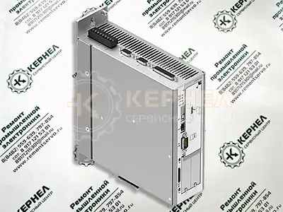 Компания «Кернел» производит ремонт сервопривода FESTO в с 2002 года. За время существования компании наши сотрудники накопили колоссальный опыт в ремонте сервоприводов такого известного производителя как FESTO. Ремонт подобного промышленного оборудования ответственное и сложное занятие, требующие максимальной отдачи, профессионализма и максимально полной материальной базе.
Специалисты сервисного центра особое внимание уделяют качеству исполнения ремонта, программирования и настройке сервопривода, не зависимо от производителя данного промышленного оборудования. Именно поэтому мы смело даем гарантию на ремонт сервопривода FESTO в и на запасные части, замененные в процессе ремонта работы шесть месяцев.
Ремонт сервопривода FESTO производится исключительно с использованием оригинальных запасных частей, на компонентном уровне с применением высокотехнологичного диагностического оборудования, квалифицированным персоналом с инженерным образованием.
В случае выхода из строя подобного промышленного оборудования на вашем производстве либо появились проблемы с приводом, которые вы не можете решить самостоятельно, мы всегда рады вам помочь. Специалисты нашего сервисного центра в минимальные сроки проведут глубокую диагностику и последующий ремонт сервопривода FESTO в .
Инженеры сервисного центра выполняют качественный ремонт сервопривода FESTO всех серий, когда-либо выпускаемых компанией.
|
Сервопривод FESTO серии CMMT-AS |
CMMT-AS-C2-3A-EC-S1, CMMT-AS-C4-3A-EC-S1, CMMT-AS-C2-11A-P3-EC-S1, CMMT-AS-C3-11A-P3-EC-S1, CMMT-AS-C5-11A-P3-EC-S1, CMMT-AS-C2-3A-PN-S1, CMMT-AS-C4-3A-PN-S1, CMMT-AS-C2-11A-P3-PN-S1, CMMT-AS-C3-11A-P3-PN-S1, CMMT-AS-C5-11A-P3-PN-S1, CMMT-AS-C2-3A-EP-S1, CMMT-AS-C4-3A-EP-S1, CMMT-AS-C2-11A-P3-EP-S1, CMMT-AS-C3-11A-P3-EP-S1, CMMT-AS-C5-11A-P3-EP-S1 |
|
Сервопривод FESTO серии CMMP-AS |
CMMP-AS-C10-11A-P3-M0, CMMP-AS-C10-11A-P3-M3, CMMP-AS-C15-11A-P3-M3, CMMP-AS-C2-3A-M0, CMMP-AS-C2-3A-M3, CMMP-AS-C5-11A-P3-M0, CMMP-AS-C5-11A-P3-M3, CMMP-AS-C5-3A-M0, CMMP-AS-C5-3A-M3 |
|
Встроенные привода FESTO серии EMCA |
EMCA-EC-67-S-1TE-DIO, EMCA-EC-67-S-1TE-CO, EMCA-EC-67-S-1TE-EC, EMCA-EC-67-S-1TE-PN, EMCA-EC-67-S-1TE-EP, EMCA-EC-67-M-1TE-DIO, EMCA-EC-67-M-1TE-CO, EMCA-EC-67-M-1TE-PN, EMCA-EC-67-S-1TM-DIO, EMCA-EC-67-S-1TM-CO, EMCA-EC-67-M-1TE-EC, EMCA-EC-67-S-1TM-EP, EMCA-EC-67-M-1TM-DIO, EMCA-EC-67-M-1TM-CO, EMCA-EC-67-M-1TE-EP, EMCA-EC-67-M-1TM-EC, EMCA-EC-67-M-1TM-PN, EMCA-EC-67-M-1TM-EP, EMCA-EC-67-S-1TM-EC, EMCA-EC-67-S-1TM-PN |
В данной таблице присутствуют далеко не все сервопривода FESTO ремонт которых предлагает наш сервисный центр.
Ошибки сервопривода FESTO
 При включении, сервопривод проходит фазу инициализации, по окончании которой выполнит тестирование светодиодов. В момент тестирования 4 светодиода состояния привода одновременно пройдут следующую цветовую последовательность:
- Красный;
- Желтый;
- Зеленый.
Длительность присутствия каждого цвета соответствует периоду мигания. После прогона последовательности тест завершается. Данный тест оборудования помогает определить наличие ошибок при запуске привода.
Светодиодная индикация ошибок сервопривода FESTO
Светодиод Status, индикация состояния устройства.
|
Ошибка, реакция светодиода |
Пояснение |
|
|
Имеется ошибка. |
|
|
Имеется предупреждение, или сервопривод непосредственно выполняет обновление встроенного ПО. |
|
|
Сервопривод находится в фазе инициализации. |
|
|
Регулятор привода готов, и выходной каскад выключен (Ready). |
|
|
Выходной каскад и серворазблокированы. |
 Мигает красным.
 Мигает желтым.
 Горит желтым.
 Мигает зеленым.
 Горит зеленым.
Светодиод Power, состояние электропитания.
|
Ошибка, реакция светодиода |
Пояснение |
|
|
Присутствует подача напряжения логики и переменного тока. Промежуточный контур заряжается. |
|
|
Подача напряжения логики присутствует, но подача переменного тока отсутствует. |
|
|
Подача напряжения логики присутствует, и промежуточный контур заряжается. |
Светодиод Safety, состояние технических средств безопасности.
|
Ошибка, реакция светодиода |
Пояснение |
|
|
Ошибка в элементе обеспечения безопасности, или условие безопасности нарушено. |
|
|
Функция обеспечения безопасности запрошена, но еще не активна. |
|
|
Функция обеспечения безопасности запрошена и активна. |
|
|
Выходной каскад, выходы тормозов и выходы диагностики Safety заблокированы (выполняется параметризация Safety). |
|
|
Ready (готовность), не запрошена ни одна функция обеспечения безопасности. |
Состояние приложения
|
Ошибка, реакция светодиода |
Пояснение |
|
|
Последовательность идентификации активна (для оптической идентификации устройства в сети), можно активировать с помощью программы параметризации. |
|
|
Зарезервировано для расширений в будущем. |
|
|
|
|
|
|
|
|
 Поочередно мигает красным, желтым, зеленым.
EtherNet/IP, светодиод MS; состояние модуля.
|
Ошибка, реакция светодиода |
Пояснение |
Устранение |
|
|
Подача питания логики отсутствует. |
Проверить подачу питания логики. |
|
|
Устройство не сконфигурировано. |
Провести конфигурирование. |
|
|
Штатное рабочее состояние. |
|
|
|
Устройство проводит самотестирование. |
|
|
|
Устранимая ошибка, возможно наличие ошибки конфигурации. |
Проверить конфигурацию. |
|
|
Неустранимая ошибка. |
Обратитесь в сервисный центр. |
 Выключено.
 Мигает поочередно красным и зеленым.
 Горит красным.
В данных таблицах приведены далеко не все возникающие ошибки сервопривода FESTO
При возникновении проблем, проведите диагностику в соответствии с приведённой таблицей. Если требуется замена деталей или проблему нельзя решить одним из описанных здесь способов, обратитесь в сервисный центр.
Регулятор привода разработан таким образом, что он пытается избежать аварийных отключений, появление сбоев при вводе в эксплуатацию или вскоре после него обычно свидетельствует о неверной настройке или неправильном подключении.
Возникновение неисправностей или проблем после длительного режима бесперебойной работы обычно происходит по причине изменений в системе или ее окружении (например, в результате износа).
Дополнительную информацию по сервоприводам FESTO можно посмотреть и скачать в файлах ниже.
Настройка сервопривода FESTO, программирование
 Настройка сервопривода FESTO (программирование) происходит в рамках установленных производителем правил, существует общий алгоритм по программированию (настройке сервоприводов), относящийся ко всем производителям данного промышленного оборудования. Ниже представлена пошаговая инструкция по настройке сервопривода FESTO.
- Выбор режима управления приводом FESTO (управление по показанию датчиков, дистанционное управление, дистанционное управление).
- В случае использования отдельного (выносного) монитора, настраивается вывод на него технической информации.
- Далее определяем конфигурацию подключения серводвигателя. На данной стадии задаются такие параметры как- возможность применения обратной связи либо без ее применения, а в память блока заносятся данные по: величине крутящего момента, мощности потребителей, номинальное значения частоты, напряжение, ток и скорости вращения ротора.
- Программируется минимально допустимая величина напряжения и частоты, а также время ускорения ротора от ноля до номинального значения.
- И в завершении, в программу управления сервопривода FESTO вносятся функциональные данные со значениями отдельных клемм и особенностями сигналов. Отмечаются действия оборудования, выполняющиеся автоматически при отсутствии информации поступающей в оперативном режиме с датчика.
Все настройки привода FESTO приведены в технической документации ниже в удобном формате (PDF) который можно скачать на свой компьютер, распечатать или просто открыть на нашем сайте.
Скачать инструкции по эксплуатации сервопривода FESTO
Ниже вы можете скачать руководства по эксплуатации сервопривода FESTO для всех серий, когда-либо выпущенных данным производителем.
|
Сервопривод FESTO CMMT-AS-C2-C4-3A-S1 инструкция, руководство пользователя. |
 Скачать PDF Скачать PDF |
|
Сервопривод FESTO CMMT-AS-C2-C3-C5-11A-P3-S1 инструкция, руководство пользователя. |
Скачать PDF |
|
Сервопривод FESTO CMMP-AS инструкция, руководство пользователя. |
Скачать PDF |
|
Встроенный привод FESTO EMCA-EC инструкция, руководство пользователя. |
Скачать PDF |
Схемы сервопривода FESTO
|
Схема подключения, 1-фазное подключение к сети сервопривода FESTO |
Схема подключения, 2-фазное подключение к сети сервопривода FESTO |
|
|

|
|
Перекрестная схема без подключения промежуточного контура. |
|

|

Другие схемы сервопривода FESTO вы найдете в руководстве пользователя.
Оставьте заявку на ремонт промышленного оборудования, используя форму на сайте, либо свяжетесь с нашими менеджерами, сделать это очень просто.
Оставить заявку на ремонт сервопривода FESTO
У вас вышло из строя дорогостоящее промышленное оборудование? Вам необходим срочный ремонт сервопривода FESTO в ? Оставьте заявку на ремонт нажав на одноименную кнопку в верхней правой части экрана либо свяжитесь с нашими менеджерами. Связаться с ними можно несколькими способами:

- Заказав обратный звонок (кнопка в правом нижнем углу сайта)
- Посредством чата (кнопка расположена с левой стороны сайта)
- Позвонив по номеру телефона: +7(8482) 79-78-54; +7(917) 121-53-01
- Написав на электронную почту: 89171215301@mail.ru
Далеко не полный список производителей промышленной электроники и оборудования, ремонтируемой в нашей компании.

A
Диагностические сообщения
144
Festo – GDCP-CMMS-AS-G2-FW-RU – 1310NH – Русский
A
Диагностические сообщения
A.1
Пояснения к диагностическим сообщениям
При возникновении ошибки контроллер мотора CMMS-AS-…-G2 отображает сообщение об ошибке
циклически на семисегментном индикаторе. Сообщение об ошибке состоит из “E” (Error), главного
индекса и субиндекса, например, “E 01 0”.
Предупреждения имеют тот же номер, что и сообщение об ошибке. Однако, в отличие от последне-
го, предупреж дение взято в стоящие впереди и позади черточки, например, “- 1 7 0 -”
В приведенных ниже таблицах ошибок содержится следующая информация:
Столбец
Значение
№
Главный индекс и субиндекс диагностического сообщения.
Код
Столбец “Код” содержит код ошибки (шестнадцатеричн.) по CiA 402.
Сообщение
Сообщение, которое отображается в FCT.
Причина
Возможные причины появления сообщения.
Действие
Мероприятие, проводимое пользователем.
Реакция
В столбце “Реакция” указана реакция на ошибку (настройка по умолчанию,
частично конфигурируемая):
–
PS off (отключение выходного каскада)
–
QStop (быстрая остановка с параметризованным профилем)
–
Warn (предупреждение)
–
Ignore (игнорирование).
Tab. A.1
Пояснения к таблицам ошибок
Столбец “Реакция” содержит реакции на ошибки из принятого по умолчанию набора
параметров. После конфигурирования контроллера мотора с помощью FCT действуют
определенные в FCT стандартные значения или сконфигурированные реакции.
Полный список диагностических сообщений в соответствии с состоянием встроенного ПО на мо-
мент печати данного документа приводится в разделе A.2
5 Диагностика
Festo P.BE-CMMS-FHPP-PB-SW-RU ru 1103a 25 5
Диагностика 5.1
Светодиод состояния сети
Светодиод состояния сети отображает состояние связи
Светодиод Состояние
Указывает на: выкл
Нет связи с шиной
Нет связи через PROFIBUS зеленый
Связь шины активна
Таблица 5.1 Светодиод состояния 5.2
Коды ошибок PROFIBUS
Ниже приведены характерные ошибки которые могут возникнуть при использовании модуля PROFIBUS Полный список вы найдете в описании системы контроллера
Сообщение об ошибке
Главный индекс
Субин декс
Значение сообщения об ошибке
Мероприятия по устранению 0 PROFIBUS:
Ошибочная инициализация
Дефект технологического модуля?
Просим вас обратиться в службу технической поддержки 22 2
Коммуникационная ошибка PROFIIBUS
Проверить настроенный адрес ведомого устройства
Проверить оконечную нагрузку шины
Проверить кабельные соединения
Таблица 5.2 Коды ошибок PROFIBUS
Ошибки указанные ниже относятся к FHPP однако могут появиться и при использовании модуля PROFIBUS Подробные описания см в документации по FHPP
Название
Описание
Действие 70-2 FHPP:
Factor Group invalid
При расчете факторгруппы получаются недействительные внутренние значения
Проверить факторгруппу 70-3 FHPP:
Operation mode change failure
Переключение из текущего в нужный режим работы не допускается
Проверить имеющийся вариант применения Возможно не каждое переключение является допустимым
Таблица 5.3 Коды ошибок FHPP
B Диагностические сообщения Festo .
Festo – GDCP-CMMS-AS-G2-HW-RU – 1310NH – Русский
Ошибка набора параметров SD-карты памяти
Контрольная сумма неверна.
Ошибка при сохранении файла параметров на SD-карте.
Проверить содержимое (данные) SD-карты.
Ошибка I²t, мотор (I²t при 100 %)
Функция контроля I²t мотора сработала.
–
Мотор/механическое оборудование заклинило, или они
движутся с затруднением.
Выбрано малое значение мощности мотора?
Проверить мотор и механическое оборудование.
Ошибка I²t, контроллер (I²t при 100 %)
Функция контроля I²t контроллера сработала.
Проверить выбор значения мощности приводного блока.
Превышение времени загрузки промежуточного контура
После подачи сетевого напряжения не удалось загрузить проме-
жуточный контур.
–
Возможно, неисправен предохранитель.
Внутренний тормозной резистор неисправен.
При эксплуатации с внешним тормозным резистором он не
присоединен
Проверить сетевое напряжение (UZK
B Диагностические сообщения .
Festo – GDCP-CMMS-AS-G2-HW-RU – 1310NH – Русский
Предел времени при быстрой остановке
Параметризованное время для быстрой остановки превышено.
Программное конечное положение
Достигнут отрицательный программный концевой вы-
ключатель
Заданное значение положения достигло или превысило уровень
отрицательного программного концевого выключателя.
Проверить диапазон позиционирования.
Достигнут положительный программный концевой вы-
ключатель
Заданное значение положения достигло или превысило уровень
положительного программного концевого выключателя.
Проверить диапазон позиционирования.
Целевая позиция находится позади отрицательного про-
граммного концевого выключателя
Запуск позиционирования заблокирован, поскольку цель нахо-
дится за отрицательным программным концевым выключа-
телем.
Проверить диапазон позиционирования.
Целевая позиция находится позади положительного про-
граммного концевого выключателя
Запуск позиционирования заблокирован, поскольку цель нахо-
дится за положительным программным концевым выключа-
телем.
Проверить диапазон позиционирования.
Ошибка программы пути, неизвестная команда
Найдена неизвестная команда при последовательном включе-
нии набора данных.
Ошибка программы пути, цель перехода
Переход к набору данных позиции за пределами допустимого
диапазона.
B Диагностические сообщения Festo .
Festo – GDCP-CMMS-AS-G2-HW-RU – 1310NH – Русский
Позиционирование: Ошибка в предварительном расчете
Позиционирование не может быть достигнуто с помощью опций
позиционирования (например, конечной скорости) или гранич-
ных условий.
Проверить параметризацию задействованных наборов дан-
ных по позициям.
Сообщение: требуется перемещение к началу отсчета
Позиционирование без перемещения к началу отсчета
невозможно.
Должно быть выполнено перемещение к началу отсчета.
Вернуть в исходное состояние опциональную параметриза-
цию “Требуется перемещение к началу отсчета”.
Выполнить новое перемещение к началу отсчета после кви-
тирования ошибки датчика углового положения.
Ошибка набора данных по позициям
Делается попытка запустить неизвестный или
деактивированный набор данных позиции.
Настроенное ускорение слишком мало для допустимой
максимальной скорости.
(Риск переполнения объема вычислений при расчете
траектории).
Проверить и при необходимости скорректировать парамет-
ры и управление процессом.
Ошибка концевого выключателя
Ошибка отрицательного концевого выключателя
Достигнут отрицательный аппаратный концевой выключатель.
Проверить параметризацию, электропроводку и концевой
выключатель.
Ошибка положительного концевого выключателя
Достигнут положительный аппаратный концевой выключатель.
Проверить параметризацию, электропроводку и концевой
выключатель.
Ошибка концевого выключателя
Оба аппаратных концевых выключателя одновременно актив-
ны.
Проверить параметризацию, электропроводку и концевой
выключатель.
Источник
Ошибки и ремонт сервопривода FESTO в
Ремонт сервопривода FESTO
Ремонт сервопривода FESTO, впрочем, как и ремонт частотников других производителей имеет ряд особенностей в силу своего конструктива. Приводы, точнее их начинка делятся на две части:
- Аппаратная часть,
- Программная часть.
Приводы данного производителя не являются исключением из правил, именно поэтому ремонт сервопривода FESTO имеет точно такой же ряд особенностей.
Диагностировать ту или иную неисправность помогают коды ошибок сервопривода, которые отображаются с помощью светодиодной индикации. Ошибки сервопривода FESTO в зависимости от серии описаны в инструкции, пользователя которые можно скачать с нашего сайта.
Ремонт сервопривода FESTO, всегда начинается с аппаратной части, и только после успешного ремонта аппаратной наступает очередь программной.
Настройка сервопривода FESTO также прописана в инструкции завода производителя, для каждой серии сервопривода настройка будет индивидуальной, так как каждая линейка решает свои собственные задачи, этим обусловливается широкая номенклатура данного промышленного оборудования.
Ремонт сервопривода FESTO в сервисном центре
Компания «Кернел» производит ремонт сервопривода FESTO в с 2002 года. За время существования компании наши сотрудники накопили колоссальный опыт в ремонте сервоприводов такого известного производителя как FESTO. Ремонт подобного промышленного оборудования ответственное и сложное занятие, требующие максимальной отдачи, профессионализма и максимально полной материальной базе.
Специалисты сервисного центра особое внимание уделяют качеству исполнения ремонта, программирования и настройке сервопривода, не зависимо от производителя данного промышленного оборудования. Именно поэтому мы смело даем гарантию на ремонт сервопривода FESTO в и на запасные части, замененные в процессе ремонта работы шесть месяцев.
Ремонт сервопривода FESTO производится исключительно с использованием оригинальных запасных частей, на компонентном уровне с применением высокотехнологичного диагностического оборудования, квалифицированным персоналом с инженерным образованием.
В случае выхода из строя подобного промышленного оборудования на вашем производстве либо появились проблемы с приводом, которые вы не можете решить самостоятельно, мы всегда рады вам помочь. Специалисты нашего сервисного центра в минимальные сроки проведут глубокую диагностику и последующий ремонт сервопривода FESTO в .
Инженеры сервисного центра выполняют качественный ремонт сервопривода FESTO всех серий, когда-либо выпускаемых компанией.
Сервопривод FESTO серии CMMT-AS
CMMT-AS-C2-3A-EC-S1, CMMT-AS-C4-3A-EC-S1, CMMT-AS-C2-11A-P3-EC-S1, CMMT-AS-C3-11A-P3-EC-S1, CMMT-AS-C5-11A-P3-EC-S1, CMMT-AS-C2-3A-PN-S1, CMMT-AS-C4-3A-PN-S1, CMMT-AS-C2-11A-P3-PN-S1, CMMT-AS-C3-11A-P3-PN-S1, CMMT-AS-C5-11A-P3-PN-S1, CMMT-AS-C2-3A-EP-S1, CMMT-AS-C4-3A-EP-S1, CMMT-AS-C2-11A-P3-EP-S1, CMMT-AS-C3-11A-P3-EP-S1, CMMT-AS-C5-11A-P3-EP-S1
Сервопривод FESTO серии CMMP-AS
CMMP-AS-C10-11A-P3-M0, CMMP-AS-C10-11A-P3-M3, CMMP-AS-C15-11A-P3-M3, CMMP-AS-C2-3A-M0, CMMP-AS-C2-3A-M3, CMMP-AS-C5-11A-P3-M0, CMMP-AS-C5-11A-P3-M3, CMMP-AS-C5-3A-M0, CMMP-AS-C5-3A-M3
Встроенные привода FESTO серии EMCA
EMCA-EC-67-S-1TE-DIO, EMCA-EC-67-S-1TE-CO, EMCA-EC-67-S-1TE-EC, EMCA-EC-67-S-1TE-PN, EMCA-EC-67-S-1TE-EP, EMCA-EC-67-M-1TE-DIO, EMCA-EC-67-M-1TE-CO, EMCA-EC-67-M-1TE-PN, EMCA-EC-67-S-1TM-DIO, EMCA-EC-67-S-1TM-CO, EMCA-EC-67-M-1TE-EC, EMCA-EC-67-S-1TM-EP, EMCA-EC-67-M-1TM-DIO, EMCA-EC-67-M-1TM-CO, EMCA-EC-67-M-1TE-EP, EMCA-EC-67-M-1TM-EC, EMCA-EC-67-M-1TM-PN, EMCA-EC-67-M-1TM-EP, EMCA-EC-67-S-1TM-EC, EMCA-EC-67-S-1TM-PN
В данной таблице присутствуют далеко не все сервопривода FESTO ремонт которых предлагает наш сервисный центр.
Ошибки сервопривода FESTO
При включении, сервопривод проходит фазу инициализации, по окончании которой выполнит тестирование светодиодов. В момент тестирования 4 светодиода состояния привода одновременно пройдут следующую цветовую последовательность:
Длительность присутствия каждого цвета соответствует периоду мигания. После прогона последовательности тест завершается. Данный тест оборудования помогает определить наличие ошибок при запуске привода.
Светодиодная индикация ошибок сервопривода FESTO
Светодиод Status, индикация состояния устройства.
Ошибка, реакция светодиода
Имеется предупреждение, или сервопривод непосредственно выполняет обновление встроенного ПО.
Сервопривод находится в фазе инициализации.
Регулятор привода готов, и выходной каскад выключен (Ready).
Выходной каскад и серворазблокированы.
Светодиод Power, состояние электропитания.
Ошибка, реакция светодиода
Присутствует подача напряжения логики и переменного тока. Промежуточный контур заряжается.
Подача напряжения логики присутствует, но подача переменного тока отсутствует.
Подача напряжения логики присутствует, и промежуточный контур заряжается.
Светодиод Safety, состояние технических средств безопасности.
Ошибка, реакция светодиода
Ошибка в элементе обеспечения безопасности, или условие безопасности нарушено.
Функция обеспечения безопасности запрошена, но еще не активна.
Функция обеспечения безопасности запрошена и активна.
Выходной каскад, выходы тормозов и выходы диагностики Safety заблокированы (выполняется параметризация Safety).
Ready (готовность), не запрошена ни одна функция обеспечения безопасности.
Состояние приложения
Ошибка, реакция светодиода
Поочередно мигает красным, желтым, зеленым.
Последовательность идентификации активна (для оптической идентификации устройства в сети), можно активировать с помощью программы параметризации.
Зарезервировано для расширений в будущем.
EtherNet/IP, светодиод MS; состояние модуля.
Ошибка, реакция светодиода
Подача питания логики отсутствует.
Проверить подачу питания логики.
Устройство не сконфигурировано.
Штатное рабочее состояние.
Мигает поочередно красным и зеленым.
Устройство проводит самотестирование.
Устранимая ошибка, возможно наличие ошибки конфигурации.
Обратитесь в сервисный центр.
В данных таблицах приведены далеко не все возникающие ошибки сервопривода FESTO
При возникновении проблем, проведите диагностику в соответствии с приведённой таблицей. Если требуется замена деталей или проблему нельзя решить одним из описанных здесь способов, обратитесь в сервисный центр.
Регулятор привода разработан таким образом, что он пытается избежать аварийных отключений, появление сбоев при вводе в эксплуатацию или вскоре после него обычно свидетельствует о неверной настройке или неправильном подключении.
Возникновение неисправностей или проблем после длительного режима бесперебойной работы обычно происходит по причине изменений в системе или ее окружении (например, в результате износа).
Дополнительную информацию по сервоприводам FESTO можно посмотреть и скачать в файлах ниже.
Настройка сервопривода FESTO, программирование
Настройка сервопривода FESTO (программирование) происходит в рамках установленных производителем правил, существует общий алгоритм по программированию (настройке сервоприводов), относящийся ко всем производителям данного промышленного оборудования. Ниже представлена пошаговая инструкция по настройке сервопривода FESTO.
- Выбор режима управления приводом FESTO (управление по показанию датчиков, дистанционное управление, дистанционное управление).
- В случае использования отдельного (выносного) монитора, настраивается вывод на него технической информации.
- Далее определяем конфигурацию подключения серводвигателя. На данной стадии задаются такие параметры как- возможность применения обратной связи либо без ее применения, а в память блока заносятся данные по: величине крутящего момента, мощности потребителей, номинальное значения частоты, напряжение, ток и скорости вращения ротора.
- Программируется минимально допустимая величина напряжения и частоты, а также время ускорения ротора от ноля до номинального значения.
- И в завершении, в программу управления сервопривода FESTO вносятся функциональные данные со значениями отдельных клемм и особенностями сигналов. Отмечаются действия оборудования, выполняющиеся автоматически при отсутствии информации поступающей в оперативном режиме с датчика.
Все настройки привода FESTO приведены в технической документации ниже в удобном формате (PDF) который можно скачать на свой компьютер, распечатать или просто открыть на нашем сайте.
Скачать инструкции по эксплуатации сервопривода FESTO
Ниже вы можете скачать руководства по эксплуатации сервопривода FESTO для всех серий, когда-либо выпущенных данным производителем.
Сервопривод FESTO CMMT-AS-C2-C4-3A-S1 инструкция, руководство пользователя.
Сервопривод FESTO CMMT-AS-C2-C3-C5-11A-P3-S1 инструкция, руководство пользователя.
Сервопривод FESTO CMMP-AS инструкция, руководство пользователя.
Встроенный привод FESTO EMCA-EC инструкция, руководство пользователя.
Схемы сервопривода FESTO
Схема подключения, 1-фазное подключение к сети сервопривода FESTO
Схема подключения, 2-фазное подключение к сети сервопривода FESTO
Перекрестная схема без подключения промежуточного контура.
Другие схемы сервопривода FESTO вы найдете в руководстве пользователя.
Оставьте заявку на ремонт промышленного оборудования, используя форму на сайте, либо свяжетесь с нашими менеджерами, сделать это очень просто.
Оставить заявку на ремонт сервопривода FESTO
У вас вышло из строя дорогостоящее промышленное оборудование? Вам необходим срочный ремонт сервопривода FESTO в ? Оставьте заявку на ремонт нажав на одноименную кнопку в верхней правой части экрана либо свяжитесь с нашими менеджерами. Связаться с ними можно несколькими способами:
- Заказав обратный звонок (кнопка в правом нижнем углу сайта)
- Посредством чата (кнопка расположена с левой стороны сайта)
- Позвонив по номеру телефона: +7(8482) 79-78-54; +7(917) 121-53-01
- Написав на электронную почту: 89171215301@mail.ru
Далеко не полный список производителей промышленной электроники и оборудования, ремонтируемой в нашей компании.
Источник
-
Contents
-
Table of Contents
-
Bookmarks
Quick Links
PROFIBUS for motor controller
CMMP…
Description
PROFIBUS
CMMP…
Description
557 338
de 0708NH
[723 751]
Related Manuals for Festo CMMP Series
Summary of Contents for Festo CMMP Series
-
Page 1
PROFIBUS for motor controller CMMP… Description PROFIBUS CMMP… Description 557 338 de 0708NH [723 751]… -
Page 3
Edition __________________________________________________ de 0708NH Description ________________________________ P.BE-CMMS-FHPP-PB-SW-EN Order no ____________________________________________________ 557 338 (Festo AG & Co KG., D-73726 Esslingen, 2008) Internet: http://www.festo.com E-mail: service_international@festo.com The copying, distribution and utilization of this document as well as the communication of its contents to others without expressed authorization is prohibited. Offenders will be held liable for compensation of damages. -
Page 4
File name: File saved at: Consec. no. Description Index of revisions Date of amendment Produced 0708NH 21.04.2008 Trade names PROFIBUS, PROFIBUS-DP® are registered trade marks of PROFIBUS International (P.I.) SIMATIC® is registered trade mark of Siemens AG Festo P.BE-CMMS-FHPP-PB-SW-EN en 0708NH… -
Page 5: Table Of Contents
Table of contents General information ………………..6 Documentation …………………. 6 Festo Profile for Handling and Positioning (FHPP) ……….6 Data exchange in the PROFIBUS …………….7 Safety instructions for electric drives and controllers ……….8 Icons and signs …………………. 8 General instructions ………………..
-
Page 6: General Information
The documentation contains safety instructions which must be observed. Festo Profile for Handling and Positioning (FHPP) Festo has developed an optimised data profile, the «Festo Handling and Positioning Profile (FHPP)», tailored to the target applications for handling and positioning tasks.
-
Page 7: Data Exchange In The Profibus
PROFIBUS-DP can be found for fast data exchange in manufacturing technology and building automation (DP = decentral periphery). The incorporation into the ISO/OSI layer model is also described in this standard. Further information, contact addresses etc. can be found under www.PROFIBUS.com Festo P.BE-CMMS-FHPP-PB-SW-EN en 0708NH…
-
Page 8: Safety Instructions For Electric Drives And Controllers
The safety instructions contain reference to dangerous voltages which may occur. General instructions Festo AG & Co. KG is not liable for damage caused by failure to observe the warning instructions in these operating instructions. Note Before commissioning you must read the “Safety instructions for electric drives and controllers”…
-
Page 9
Request that the operating instructions are sent immediately to the responsible person, in order that the motor controller can be operated correctly and safely. These safety instructions must also be provided if the motor controller is sold, lent and/or passed on to third parties. Festo P.BE-CMMS-FHPP-PB-SW-EN en 0708NH… -
Page 10: Dangers Due To Incorrect Use
DANGER! Surfaces of the device housing may be hot. Danger of injury. Danger of burning. Warning DANGER! Dangerous movements. Danger of death, serious bodily injury or damage to property due to unintentional movement of the motors. Festo P.BE-CMMS-FHPP-PB-SW-EN en 0708NH…
-
Page 11: Safety Instructions
Warning The environmental conditions specified in the product documentation must be observed. Safety-critical applications are not permitted if they are not explicitly approved of by the manufacturer. Festo P.BE-CMMS-FHPP-PB-SW-EN en 0708NH…
-
Page 12: Safety Instructions For Assembly And Maintenance
The system manufacturer or the user is responsible for ensuring that these regulations are observed. Warning The operation, maintenance and/or commissioning of the motor controller may only be carried out by trained qualified personnel and with electrical appliances suited for this work. Festo P.BE-CMMS-FHPP-PB-SW-EN en 0708NH…
-
Page 13
Make sure also that the external voltage supply of the controller (24 V) is switched off. The intermediate circuit or the mains voltage must always be switched off before the 24 V controller supply is switched off. Festo P.BE-CMMS-FHPP-PB-SW-EN en 0708NH… -
Page 14: Protection Aganst Touching Electric Components
For operation the relevant DIN, VDE, EN und IEC regulations, as well as all national and local safety and accident prevention regulations must always be observed. The system manufacturer or the user is responsible for ensuring that these regulations are observed. Festo P.BE-CMMS-FHPP-PB-SW-EN en 0708NH…
-
Page 15
During installation note the amount of intermediate circuit voltage, especially with regard to insulation and protective measures. Make sure that the earthing, the cross section size of the conductor and the corresponding short-circuit protection are correct. Festo P.BE-CMMS-FHPP-PB-SW-EN en 0708NH… -
Page 16: Protection By Low Voltage (Pelv) Against Electric Shock
Faults in the measured value and signal generators Defective or non-EMC valid components Faults in the software in the higher-order control system These faults can occur immediately after the device is switched on or after a certain period of operation. Festo P.BE-CMMS-FHPP-PB-SW-EN en 0708NH…
-
Page 17: Protection Aganst Touching Hot Components
After switching devices off, leave them for 10 minutes to cool down before touching them. If you touch hot parts of the device such as the housing which contains the heat sink and resistors, you may burn yourself. Festo P.BE-CMMS-FHPP-PB-SW-EN en 0708NH…
-
Page 18: Protection When Handling And Assembling
Use lifting devices and tools in a correct manner. If necessary, use suitable protective equipment (e.g. protective glasses, safety shoes, safety gloves). Do not stand under hanging loads. Wipe up spilt liquids on the floor to avoid slipping. Festo P.BE-CMMS-FHPP-PB-SW-EN en 0708NH…
-
Page 19: Assembly And Installation
9-pin sub-D socket two DIP switches for actuating the terminating resistors. 1 Two DIP switches 2 9-pin sub-D socket 3 LED for the bus readiness message Fig. 3.1: Connecting and display elements on the PROFIBUS-DP interface Festo P.BE-CMMS-FHPP-PB-SW-EN en 0708NH…
-
Page 20: Assembly
Philips screw. Make sure that the front plate fits flush with the front in order that it has conductive contact with the housing. Front cover Fig. 3.2: Unscrew front cover Festo P.BE-CMMS-FHPP-PB-SW-EN en 0708NH…
-
Page 21: Installation
If the cabling is not correct, faults may occur on the PROFIBUS which cause the motor controller to switch off with a fault for safety reasons. Festo P.BE-CMMS-FHPP-PB-SW-EN en 0708NH…
-
Page 22: Pin Assignment Of Profibus Interface
Reference potential GND 5V Use for external bus termination or for suppling transmitter/receiver of an external LWL module. Signal is optional, serves for direction control when used with an external LWL module. Tab. 3.1: Connector pin assignment: PROFIBUS-DP interface Festo P.BE-CMMS-FHPP-PB-SW-EN en 0708NH…
-
Page 23: Termination And Bus Terminating Resistors
Fig. 3.5: Bus termination If the set baud rate is greater than 1.5 MBaud, plugs with integrated series inductance (110 nH) must be used due to the capacitive load of the slave and the cable reflexion thereby created. Festo P.BE-CMMS-FHPP-PB-SW-EN en 0708NH…
-
Page 24: Configuration Of The Profibus Module
2. Parametrizing and commissioning with the FCT. Especially also the setting physical units. 3. Configuration of the PROFIBUS master. For correct functioning it is necesary to define the physical units of the processing data transmitted via the field bus. These can be set via the FCT. Festo P.BE-CMMS-FHPP-PB-SW-EN en 0708NH…
-
Page 25: Setting The Slave Address
All parameters are only valid when the PROFIBUS communication is deactivated and then re-activated. Please note that the PROFIBUS communication can only be acti- vated when the parameter records have been saved and a Reset has been carried out. Festo P.BE-CMMS-FHPP-PB-SW-EN en 0708NH…
-
Page 26: Profibus Configuration
FCT without connection to the PROFIBUS be carried out first. Note on commissioning with the Festo Configuration Tool can be found in the help to the device-specific FCT PlugIn. Important processing data for position, velocity and acceleration are transferred in physical units.
-
Page 27: Configuration With Simatic Manager
(HW Config) –SIMATIC…). The motor controller CMMP can be found under «PROFIBUS-DPAdditional Field Devices DrivesFesto»). 1. Pull the station type «Festo CMMP» by drag and drop onto the PROFIBUS-DP master system. Festo P.BE-CMMS-FHPP-PB-SW-EN en 0708NH…
-
Page 28
2 x 8 bytes of I/O data, As FHPP standard, additional 8 bytes I/O data for + FPC consistent transmission parametrizing Tab. 4.4: Configuration The I/O addresses can be defined with a double click on the location. Festo P.BE-CMMS-FHPP-PB-SW-EN en 0708NH… -
Page 29
4. When the configuration is concluded, transfer the data to the master. Control and parametrizing methods and the functioning of the parametrizing can be found in manual CMMP-AS-PB-S7-EN. System functions used An example of a project and the documentation CMMP-AS-PB-S7 can be found on the CD. Festo P.BE-CMMS-FHPP-PB-SW-EN en 0708NH… -
Page 30: Diagnosis
Value range of the data and the physical units are not suited together. Contact technical support Tab. 5.2: PROFIBUS error codes The following faults concern FHPP, but can also occur if the PROFIBUS module is used: Please refer to the FHPP manual for detailed information. Festo P.BE-CMMS-FHPP-PB-SW-EN en 0708NH…
-
Page 31
Tab. 5.3: FHPP error codes Fault messages can be quitted with: the parametrizing interface via the field bus (control word), a falling edge at DIN5 (controller enable). Festo P.BE-CMMS-FHPP-PB-SW-EN en 0708NH… -
Page 32: Technical Specifications
1.5 MBaud 3.0 MBaud 6.0 MBaud 12.0 MBaud Protocol PROFIBUS-DP Interface Potential-isolated, D-SUB 9-pin, integrated switchable bus terminating resistors Special functions Supports diagnostic data, RTS signal, no fail-safe mode, no Sync/Freeze Tab. A.2: PROFIBUS technical specifications module Festo P.BE-CMMS-FHPP-PB-SW-EN en 0708NH…
-
Contents
-
Table of Contents
-
Bookmarks
Quick Links
PROFIBUS for motor controller
CMMP…
Description
PROFIBUS
CMMP…
Description
557 338
de 0708NH
[723 751]
Related Manuals for Festo CMMP Series
Summary of Contents for Festo CMMP Series
-
Page 1
PROFIBUS for motor controller CMMP… Description PROFIBUS CMMP… Description 557 338 de 0708NH [723 751]… -
Page 3
Edition __________________________________________________ de 0708NH Description ________________________________ P.BE-CMMS-FHPP-PB-SW-EN Order no ____________________________________________________ 557 338 (Festo AG & Co KG., D-73726 Esslingen, 2008) Internet: http://www.festo.com E-mail: service_international@festo.com The copying, distribution and utilization of this document as well as the communication of its contents to others without expressed authorization is prohibited. Offenders will be held liable for compensation of damages. -
Page 4
File name: File saved at: Consec. no. Description Index of revisions Date of amendment Produced 0708NH 21.04.2008 Trade names PROFIBUS, PROFIBUS-DP® are registered trade marks of PROFIBUS International (P.I.) SIMATIC® is registered trade mark of Siemens AG Festo P.BE-CMMS-FHPP-PB-SW-EN en 0708NH… -
Page 5: Table Of Contents
Table of contents General information ………………..6 Documentation …………………. 6 Festo Profile for Handling and Positioning (FHPP) ……….6 Data exchange in the PROFIBUS …………….7 Safety instructions for electric drives and controllers ……….8 Icons and signs …………………. 8 General instructions ………………..
-
Page 6: General Information
The documentation contains safety instructions which must be observed. Festo Profile for Handling and Positioning (FHPP) Festo has developed an optimised data profile, the «Festo Handling and Positioning Profile (FHPP)», tailored to the target applications for handling and positioning tasks.
-
Page 7: Data Exchange In The Profibus
PROFIBUS-DP can be found for fast data exchange in manufacturing technology and building automation (DP = decentral periphery). The incorporation into the ISO/OSI layer model is also described in this standard. Further information, contact addresses etc. can be found under www.PROFIBUS.com Festo P.BE-CMMS-FHPP-PB-SW-EN en 0708NH…
-
Page 8: Safety Instructions For Electric Drives And Controllers
The safety instructions contain reference to dangerous voltages which may occur. General instructions Festo AG & Co. KG is not liable for damage caused by failure to observe the warning instructions in these operating instructions. Note Before commissioning you must read the “Safety instructions for electric drives and controllers”…
-
Page 9
Request that the operating instructions are sent immediately to the responsible person, in order that the motor controller can be operated correctly and safely. These safety instructions must also be provided if the motor controller is sold, lent and/or passed on to third parties. Festo P.BE-CMMS-FHPP-PB-SW-EN en 0708NH… -
Page 10: Dangers Due To Incorrect Use
DANGER! Surfaces of the device housing may be hot. Danger of injury. Danger of burning. Warning DANGER! Dangerous movements. Danger of death, serious bodily injury or damage to property due to unintentional movement of the motors. Festo P.BE-CMMS-FHPP-PB-SW-EN en 0708NH…
-
Page 11: Safety Instructions
Warning The environmental conditions specified in the product documentation must be observed. Safety-critical applications are not permitted if they are not explicitly approved of by the manufacturer. Festo P.BE-CMMS-FHPP-PB-SW-EN en 0708NH…
-
Page 12: Safety Instructions For Assembly And Maintenance
The system manufacturer or the user is responsible for ensuring that these regulations are observed. Warning The operation, maintenance and/or commissioning of the motor controller may only be carried out by trained qualified personnel and with electrical appliances suited for this work. Festo P.BE-CMMS-FHPP-PB-SW-EN en 0708NH…
-
Page 13
Make sure also that the external voltage supply of the controller (24 V) is switched off. The intermediate circuit or the mains voltage must always be switched off before the 24 V controller supply is switched off. Festo P.BE-CMMS-FHPP-PB-SW-EN en 0708NH… -
Page 14: Protection Aganst Touching Electric Components
For operation the relevant DIN, VDE, EN und IEC regulations, as well as all national and local safety and accident prevention regulations must always be observed. The system manufacturer or the user is responsible for ensuring that these regulations are observed. Festo P.BE-CMMS-FHPP-PB-SW-EN en 0708NH…
-
Page 15
During installation note the amount of intermediate circuit voltage, especially with regard to insulation and protective measures. Make sure that the earthing, the cross section size of the conductor and the corresponding short-circuit protection are correct. Festo P.BE-CMMS-FHPP-PB-SW-EN en 0708NH… -
Page 16: Protection By Low Voltage (Pelv) Against Electric Shock
Faults in the measured value and signal generators Defective or non-EMC valid components Faults in the software in the higher-order control system These faults can occur immediately after the device is switched on or after a certain period of operation. Festo P.BE-CMMS-FHPP-PB-SW-EN en 0708NH…
-
Page 17: Protection Aganst Touching Hot Components
After switching devices off, leave them for 10 minutes to cool down before touching them. If you touch hot parts of the device such as the housing which contains the heat sink and resistors, you may burn yourself. Festo P.BE-CMMS-FHPP-PB-SW-EN en 0708NH…
-
Page 18: Protection When Handling And Assembling
Use lifting devices and tools in a correct manner. If necessary, use suitable protective equipment (e.g. protective glasses, safety shoes, safety gloves). Do not stand under hanging loads. Wipe up spilt liquids on the floor to avoid slipping. Festo P.BE-CMMS-FHPP-PB-SW-EN en 0708NH…
-
Page 19: Assembly And Installation
9-pin sub-D socket two DIP switches for actuating the terminating resistors. 1 Two DIP switches 2 9-pin sub-D socket 3 LED for the bus readiness message Fig. 3.1: Connecting and display elements on the PROFIBUS-DP interface Festo P.BE-CMMS-FHPP-PB-SW-EN en 0708NH…
-
Page 20: Assembly
Philips screw. Make sure that the front plate fits flush with the front in order that it has conductive contact with the housing. Front cover Fig. 3.2: Unscrew front cover Festo P.BE-CMMS-FHPP-PB-SW-EN en 0708NH…
-
Page 21: Installation
If the cabling is not correct, faults may occur on the PROFIBUS which cause the motor controller to switch off with a fault for safety reasons. Festo P.BE-CMMS-FHPP-PB-SW-EN en 0708NH…
-
Page 22: Pin Assignment Of Profibus Interface
Reference potential GND 5V Use for external bus termination or for suppling transmitter/receiver of an external LWL module. Signal is optional, serves for direction control when used with an external LWL module. Tab. 3.1: Connector pin assignment: PROFIBUS-DP interface Festo P.BE-CMMS-FHPP-PB-SW-EN en 0708NH…
-
Page 23: Termination And Bus Terminating Resistors
Fig. 3.5: Bus termination If the set baud rate is greater than 1.5 MBaud, plugs with integrated series inductance (110 nH) must be used due to the capacitive load of the slave and the cable reflexion thereby created. Festo P.BE-CMMS-FHPP-PB-SW-EN en 0708NH…
-
Page 24: Configuration Of The Profibus Module
2. Parametrizing and commissioning with the FCT. Especially also the setting physical units. 3. Configuration of the PROFIBUS master. For correct functioning it is necesary to define the physical units of the processing data transmitted via the field bus. These can be set via the FCT. Festo P.BE-CMMS-FHPP-PB-SW-EN en 0708NH…
-
Page 25: Setting The Slave Address
All parameters are only valid when the PROFIBUS communication is deactivated and then re-activated. Please note that the PROFIBUS communication can only be acti- vated when the parameter records have been saved and a Reset has been carried out. Festo P.BE-CMMS-FHPP-PB-SW-EN en 0708NH…
-
Page 26: Profibus Configuration
FCT without connection to the PROFIBUS be carried out first. Note on commissioning with the Festo Configuration Tool can be found in the help to the device-specific FCT PlugIn. Important processing data for position, velocity and acceleration are transferred in physical units.
-
Page 27: Configuration With Simatic Manager
(HW Config) –SIMATIC…). The motor controller CMMP can be found under «PROFIBUS-DPAdditional Field Devices DrivesFesto»). 1. Pull the station type «Festo CMMP» by drag and drop onto the PROFIBUS-DP master system. Festo P.BE-CMMS-FHPP-PB-SW-EN en 0708NH…
-
Page 28
2 x 8 bytes of I/O data, As FHPP standard, additional 8 bytes I/O data for + FPC consistent transmission parametrizing Tab. 4.4: Configuration The I/O addresses can be defined with a double click on the location. Festo P.BE-CMMS-FHPP-PB-SW-EN en 0708NH… -
Page 29
4. When the configuration is concluded, transfer the data to the master. Control and parametrizing methods and the functioning of the parametrizing can be found in manual CMMP-AS-PB-S7-EN. System functions used An example of a project and the documentation CMMP-AS-PB-S7 can be found on the CD. Festo P.BE-CMMS-FHPP-PB-SW-EN en 0708NH… -
Page 30: Diagnosis
Value range of the data and the physical units are not suited together. Contact technical support Tab. 5.2: PROFIBUS error codes The following faults concern FHPP, but can also occur if the PROFIBUS module is used: Please refer to the FHPP manual for detailed information. Festo P.BE-CMMS-FHPP-PB-SW-EN en 0708NH…
-
Page 31
Tab. 5.3: FHPP error codes Fault messages can be quitted with: the parametrizing interface via the field bus (control word), a falling edge at DIN5 (controller enable). Festo P.BE-CMMS-FHPP-PB-SW-EN en 0708NH… -
Page 32: Technical Specifications
1.5 MBaud 3.0 MBaud 6.0 MBaud 12.0 MBaud Protocol PROFIBUS-DP Interface Potential-isolated, D-SUB 9-pin, integrated switchable bus terminating resistors Special functions Supports diagnostic data, RTS signal, no fail-safe mode, no Sync/Freeze Tab. A.2: PROFIBUS technical specifications module Festo P.BE-CMMS-FHPP-PB-SW-EN en 0708NH…
-
Contents
-
Table of Contents
-
Bookmarks
Related Manuals for Festo SFC-DC series
Summary of Contents for Festo SFC-DC series
-
Page 1
Motor controller SFC−DC Manual Electronic Motor controller type SFC−DC−…−IO Manual 540 418 en 0801a [731 438]… -
Page 2
® ® Adobe and Reader are either a registered trademark or a trademark of Adobe Systems Incorporated in the United States and/or other countries. -
Page 3
……. . . 540 418 E (Festo AG & Co. KG, D 73726 Esslingen, Federal Republic of Germany, 2008) Internet: http://www.festo.com… -
Page 4
Contents and general instructions Festo P.BE−SFC−DC−IO−EN en 0801a… -
Page 5: Table Of Contents
….1−17 1.3.2 Festo Configuration Tool (FCT) ……1−17 Fitting .
-
Page 6
….. 5−23 5.4.1 Installing and starting the Festo Configuration Tool … . 5−23 5.4.2 Procedure for commissioning with the Festo Configuration Tool 5−24 Festo P.BE−SFC−DC−IO−EN en 0801a… -
Page 7
……….B−11 Festo P.BE−SFC−DC−IO−EN en 0801a… -
Page 8
…………C−1 Festo P.BE−SFC−DC−IO−EN en 0801a… -
Page 9: Designated Use
Please observe the standards specified in the relevant chapters and comply with technical regulations, as well as with national and local regulations. Festo P.BE−SFC−DC−IO−EN en 0801a…
-
Page 10: Safety Instructions
Warning Faults in parametrization can cause injury to people and damage to property. Enable the controller only if the axis system is correctly installed and parametrized. VIII Festo P.BE−SFC−DC−IO−EN en 0801a…
-
Page 11: Target Group
Service Please consult your local Festo repair service at the following e−mail address if you have any technical problems: service_international@festo.com Scope of delivery The scope of delivery of the Single Field Controller type SFC−DC includes the following:…
-
Page 12: Important User Instructions
This means that failure to observe this instruction may result in damage to property. The following pictogram marks passages in the text which describe activities with electrostatically sensitive compo nents. Electrostatically sensitive components may be damaged if they are not handled correctly. Festo P.BE−SFC−DC−IO−EN en 0801a…
-
Page 13
Accessories: Information on necessary or sensible accessories for the Festo product. Environment: Information on environment−friendly use of Festo products. Text markings The bullet indicates activities which may be carried out in · any order. 1. Figures denote activities which must be carried out in the numerical order specified. -
Page 14: Manuals For The Single Field Controller Sfc−Dc
Single Field Controller type SFC−DC−..It also contains information on the functions of the I/O interface for type SFC−DC−…−IO as well as on commissioning with the Festo Configuration Tool software package. Product variants are available for coupling to field bus sys tems.
-
Page 15
SFC−DC. You can find the specifications on the version status as follows: Hardware version and firmware version in the Festo Configuration Tool with active device connection to the SFC−DC under Device data» Firmware version on the control panel under [Diagnostic] [Software information]. -
Page 16: Product−Specific Terms And Abbreviations
The special wishes of a device type are supported by plug−ins with the necessary descriptions and dialogues. Input Output Input and/or output Positioning mode Operating mode for processing a position set. (Profile Position mode) Programmable logic controller; in brief: controller. Festo P.BE−SFC−DC−IO−EN en 0801a…
-
Page 17
Tip mode Manual positioning in positive or negative direction (only on field bus variants of the SFC−DC via the field bus or only with FCT or operator panel) Tab. 0/1: Index of terms and abbreviations Festo P.BE−SFC−DC−IO−EN en 0801a… -
Page 18
Contents and general instructions Festo P.BE−SFC−DC−IO−EN en 0801a… -
Page 19: System Summary
System summary Chapter 1 1−1 Festo P.BE−SFC−DC−IO−EN en 0801a…
-
Page 20
….1−17 1.3.2 Festo Configuration Tool (FCT) ……1−17 1−2… -
Page 21: Positioning With Electric Drives
Coupling to a higher−order PLC/IPC can be accomplished via digital inputs/outputs (SFC−DC−…−IO) or with the appropriate product variants via the field bus (in preparation: DeviceNet, CanOpen, PROFIBUS−DP). For positioning systems Festo offers accessories suited to the drive packages and linear drives (see Festo delivery program or catalogue). 1−3…
-
Page 22
1. System summary Components Higher−level controller e.g. Festo type FEC… Software level: Festo Configuration Tool Controller level: SFC−DC Motor drive level: SLTE−… Fig. 1/1: Principle of an electric axis with the SFC−DC−… 1−4 Festo P.BE−SFC−DC−IO−EN en 0801a… -
Page 23
SFC−DC (see accessories, appendix A.2). Reference switch Optional: suitable sensor (normally open) as reference switch, e.g. type SME−10/SMT−10. The SFC−DC supports the electric mini−slide SLTE−..Consult Festo if you wish to use other drives. Supported Manual Permitted drive… -
Page 24
(Teach mode) Positioning travel for testing all position sets in the posi tion set table (Demo posit. tab.) Positioning travel for testing a certain position set in the position set table (Move posit. set.) 1−6 Festo P.BE−SFC−DC−IO−EN en 0801a… -
Page 25
(measurement of the power end stage temperature) voltage monitoring detection of faults in the logic voltage supply detection of faults in the logic voltage supply t monitoring / overload protection following error monitoring software end position recognition. 1−7 Festo P.BE−SFC−DC−IO−EN en 0801a… -
Page 26: Structure Of The Sfc−Dc
Remove the protective foil from the display before commis sioning. LC display Touch−sensitive keyboard LEDs Fig. 1/3: Control panel and status display on the SFC−DC−…−H2−… 1−8 Festo P.BE−SFC−DC−IO−EN en 0801a…
-
Page 27
(= interface / field bus) Fault Error» Connections The SFC−DC has the following connections: Reference switch RS232 interface to PC I/O interface Power Electric mini−slide Error SLTE−… Power supply RS–232 3 4 5 Fig. 1/4: Connections of the SFC−DC 1−9 Festo P.BE−SFC−DC−IO−EN en 0801a… -
Page 28: Method Of Operation
Fig. 1/5: Simplified technical representation of the cascade regulator function The controller takes over the following tasks: sequence control via digital inputs and outputs (type SFC−DC−…−IO) specification of the nominal positions by positioning control control of the following variables: Position, speed, acceleration, current (power). 1−10 Festo P.BE−SFC−DC−IO−EN en 0801a…
-
Page 29
20F1 (Data memory control) (see chapter 7). User−specific settings will then be lost. Use CI commands only if you already have experience of · Service Data Objects. If necessary consult the Festo Service. · 1−11 Festo P.BE−SFC−DC−IO−EN en 0801a… -
Page 30: Reference Coordinates And Working Area
The project zero point is specified for the SFC−DC with I/O interface, and is identical to the axis zero point (project zero point offset = 0). 1−12 Festo P.BE−SFC−DC−IO−EN en 0801a…
-
Page 31
Rated stroke: Rated stroke of the drive used, see Technical Specifications for the drive (with SLTE the stroke specified in the order). Vector representation for the referencing method: Example of fixed stop, negative Tab. 1/2: Measuring reference system of the electric axis 1−13 Festo P.BE−SFC−DC−IO−EN en 0801a… -
Page 32
Negative values face from the reference point in the direction towards the motor. Factory setting (see also appendix B, object 607E) All values are entered or displayed according to the measur ing system set either for the Festo Configuration Tool or the control panel. Measuring system Linear axis Metric Metric measuring units e.g. -
Page 33: Emergency Stop Concept
By the arrangement of the software end positions and, if · necessary, by means of external safety limit switches and additional appropriate mechanical stops, make sure that the axis always lies within the permitted positioning range. 1−15 Festo P.BE−SFC−DC−IO−EN en 0801a…
-
Page 34: Commissioning Options
Commissioning Reference travel Teaching of positions Moving in individual steps Starting and stopping positioning procedures during commissioning Expanded test functions, e.g. status displays Testing or demonstrating the position sets Diagnosis/Service Reading and displaying diagnostic data 1−16 Festo P.BE−SFC−DC−IO−EN en 0801a…
-
Page 35: Control Panel (Only Type Sfc−Dc−…−H2−…)
4, a description of commission ing with the control panel as from chapter 5.3. 1.3.2 Festo Configuration Tool (FCT) The Festo Configuration Tool (or brief FCT) is the software platform for configuring and commissioning different compo nents or devices from Festo.
-
Page 36
An overview of commissioning with the FCT can be found in chapter 5.4.2. The help for the FCT contains the complete information on operating the Festo Configuration Tool. The device−specific PlugIns each have their own help files. You can use the complete help or parts thereof irrespective of a PC by printing them. -
Page 37
1. System summary The help system of the Festo Configuration Tool The Festo Configuration Tool offers various possibilities of obtaining information or help with operation. Install and start the program as described in chapter 5. · FCT help You can open the help for the FCT as follows: Access the help in the menu [Help] with the command ·… -
Page 38
Printed version Directory File FCT help …(FCT installation directory)Help FCT_en.pdf FCT_en.rtf PlugIn help …(FCT installation directory)HardwareFamilies SFC−DC_en.pdf (SFC−DC) FestoSFC−DCV…Help SFC−DC_en.rtf For using the print version in the Adobe PDF format you will require the Adobe Reader. 1−20 Festo P.BE−SFC−DC−IO−EN en 0801a… -
Page 39: Fitting
Fitting Chapter 2 2−1 Festo P.BE−SFC−DC−IO−EN en 0801a…
-
Page 40
……..2−6 2−2 Festo P.BE−SFC−DC−IO−EN en 0801a… -
Page 41: General Instructions
The specified torques must be observed. The modules must not be offset. Contact surfaces must be clean (avoid contact faults). Dimensions of the controller 126 mm 120 mm Power Error RS–232 Fig. 2/1: Dimensions of the controller 2−3 Festo P.BE−SFC−DC−IO−EN en 0801a…
-
Page 42: Fitting The Controller
The four brackets are clipped onto the edge of the housing (see Fig. 2/2). 4 threaded holes for screw size M3 (for dimensions see Fig. 2/2) with suitable screws. 120 mm Power Error RS−232 approx. 105 Fig. 2/2: Screwing the SFC−DC to the wall 2−4 Festo P.BE−SFC−DC−IO−EN en 0801a…
-
Page 43
When you let go, the clamping element presses the SFC−DC into the upper groove. Top−hat rail Clamping element Distance between housing web and top−hat rail: 3.3 mm Fig. 2/3: Fitting the SFC−DC on a top−hat rail 2−5 Festo P.BE−SFC−DC−IO−EN en 0801a… -
Page 44: Notes On Fitting Of Electric Axes
· size for operation with a work load, the work load does not collide with any component of the · axis when the axis moves into the end position. 2−6 Festo P.BE−SFC−DC−IO−EN en 0801a…
-
Page 45
Installation Chapter 3 3−1 Festo P.BE−SFC−DC−IO−EN en 0801a… -
Page 46
Input for external reference switch ……. . . 3−16 3−2 Festo P.BE−SFC−DC−IO−EN en 0801a… -
Page 47: Installation
Only in this way can you guarantee the correct function ing of the system. Please note Lay all moveable cables free of bends and free of mech · anical stress, if necessary in a drag chain. Observe the maximum specified cable lengths. · 3−3 Festo P.BE−SFC−DC−IO−EN en 0801a…
-
Page 48
Control of motor with connection Socket encoder signals Reference M8, 3−pin Sensor input for reference switch Socket switch Serial M8, 4−pin RS232 interface for interface Socket parametrizing, commis sioning and diagnosing Tab. 3/1: Overview of connections 3−4 Festo P.BE−SFC−DC−IO−EN en 0801a… -
Page 49
Place protective caps on unused connections in order to prevent such discharges. The plug connectors of the following Festo cables have been designed so that, when inserted and screwed tight, or if fitted with protective covers, the connections on the SFC−DC will comply with protection class IP54. -
Page 50: Power Supply
SFC−DC. For the power supply, use exclusively one of the follow · ing cables from the Festo accessories: power supply cable KPWR−MC−1−SUB−15HC−… cable length max. 10 m. Use a closed−loop power unit with: ·…
-
Page 51
M4 cable Earth connec tion (housing) Cable colours with power cable type KPWR−MC−1−SUB−15HC−… Not connected with cables of type KPWR−MC−1−SUB−15HC−… Use only one connection, see section 3.3 Tab. 3/3: Connection Power» (power supply) on the SFC−DC 3−7 Festo P.BE−SFC−DC−IO−EN en 0801a… -
Page 52
1 A slow−blowing Tab. 3/4: Power supply specifications 1 2 3 4 Equipotential bonding absolutely necessary! External fuses (optional, for protection of the internal fuses) Earth connection (optional, see section 3.3) Fig. 3/2: Power supply connection example 3−8 Festo P.BE−SFC−DC−IO−EN en 0801a… -
Page 53: Earthing
When using the earth connection on the housing of the SFC−DC: Use a suitable earthing cable with an M4 cable lug and · the supplied nut with toothed lock washer. Tighten the nut with max. 1.7 Nm. · 3−9 Festo P.BE−SFC−DC−IO−EN en 0801a…
-
Page 54: Motor Connection
The motor connection is used to control the motor of the con nected SLTE, and to transfer the encoder signals. Please note To connect the SLTE, use exclusively one of the following cables from the Festo accessories: motor cable KMTR−DC−SUB−15−M12−… cable length max. 10 m. Connection…
-
Page 55: Controller
· (see section 5.6.3). Information on controlling the SFC−DC via the I/O interface can be found in section 5.6. Recommendation: Use the control cable type KES−MC−1−SUB−15−..You will then comply with protection class IP54. 3−11 Festo P.BE−SFC−DC−IO−EN en 0801a…
-
Page 56
Output Ready red−blue Output Acknowledge white−green Fault output brown−green Electrically isolated GND white−yellow Plug housing / cable shield Cable colours with control cable type KES−MC−1−SUB−15−… Tab. 3/6: Connection I/F» (controller connection) on the SFC−DC−…−IO 3−12 Festo P.BE−SFC−DC−IO−EN en 0801a… -
Page 57
The I/O power supply must fulfil the following requirements: Power supply Value I/O supply (pins 1, 8) Rated voltage 24 V DC ± 10 % Rated current 0.05 A Peak current Tab. 3/7: Power supply specifications I/O specification see section 5.6.3. 3−13 Festo P.BE−SFC−DC−IO−EN en 0801a… -
Page 58: Serial Interface
Serial interface for parametrizing, commissioning and diagnosing. Please note To connect a PC to the SFC−DC, use exclusively one of the following cables from the Festo accessories: programming cable KDI−MC−M8−SUB−9−… cable length 2.5 m. If necessary, remove the protective cap from the serial ·…
-
Page 59
3. Installation Information on commissioning and parametrizing the SFC−DC via the serial interface can be found in section 5.4.2 and in the help system for the Festo Configuration Tool software package. Information on transmitting CI commands via the serial inter face can be found in chapter 7. -
Page 60: Input For External Reference Switch
Seal the connection with the protective cap supplied · (type ISK−M8). Use e.g. the following proximity switches from Festo: electric proximity switch SME−10F−… /SMT−10F−… (can be installed in sensor grooves of the drive profile). If necessary, use an extension cable type KM8−M8−..
-
Page 61
Technical specifications». M8 socket Manual + 24 VDC + 24 VDC voltage output for reference switch Contact reference switch Ground Tab. 3/9: Connection Ref» (reference switch) on the SFC−DC 3−17 Festo P.BE−SFC−DC−IO−EN en 0801a… -
Page 62
3. Installation 3−18 Festo P.BE−SFC−DC−IO−EN en 0801a… -
Page 63: Control Panel (Only Type Sfc−Dc−…−H2−…)
Control panel (only type SFC−DC−…−H2−…) Chapter 4 4−1 Festo P.BE−SFC−DC−IO−EN en 0801a…
-
Page 64
……..4−18 4−2 Festo P.BE−SFC−DC−IO−EN en 0801a… -
Page 65
With the SFC−DC−…−H0−… (without control panel) you can carry out commissioning of the SFC−DC via the RS232 inter face with the Festo Configuration Tool. Instructions on this can be found in Section 5.4.2. Caution Faults may occur if you attempt to access control and oper ating functions at the same time by the FCT and the control panel. -
Page 66: Composition And Function Of The Control Panel
With the 4 buttons on the control panel you can carry out all operating functions and settings as indicated in the menu. The graphic LCD display shows all texts in English. The display can be turned in 180° steps, see menu command [LCD adjust ment]. 4−4 Festo P.BE−SFC−DC−IO−EN en 0801a…
-
Page 67
(only in Demo mode). After stop: Display of the current position, with <Menu> return to the higher−order menu level. Scrolls within a menu level in order to select a menu command. EDIT Sets the parameter Tab. 4/1: Button function (overview) 4−5 Festo P.BE−SFC−DC−IO−EN en 0801a… -
Page 68: The Menu System
SFC–DC… cally carries out an internal check. At first the display shows SLTE… Xa = 0.00 mm the Festo Logo then changes to the status display. The status display shows the following information: HMI:off <Menu> the type designation of your SFC−DC…
-
Page 69
Presetting the device control via the control panel (see chapter 4.2.3) LCD adjustment Rotate the display in steps of 180° If necessary password protection Control interface must be deactivated, see [HMI control]: HMI=on Teach mode Tab. 4/3: Menu commands (overview) 4−7 Festo P.BE−SFC−DC−IO−EN en 0801a… -
Page 70: Diagnostic» Menu
System parameter [System paramet.] Firmware version of the SFC−DC, e.g. V1.00 [Software information] Function Button You can scroll through» the diagnostic data with the arrow buttons. With <Menu> you can return to the Menu higher−order menu level. 4−8 Festo P.BE−SFC−DC−IO−EN en 0801a…
-
Page 71
Menu command for displaying the following axis parameters and data: [Axis parameter] Manual Vmax Maximum positioning speed Xmin Stroke limitation: Software end position, negative Xmax Stroke limitation: Software end position, positive Offset axis zero point Feed Feed constant (e.g. thread pitch) 4−9 Festo P.BE−SFC−DC−IO−EN en 0801a… -
Page 72
Measurement system (millimetre) Hom.meth. bl.pos Fixed stop in positive direction bl.neg Fixed stop in negative direction sw.pos Reference switch in positive direction sw.neg Reference switch in neg. direction Gear e.g. 4.38 Gear ratio of the drive 4−10 Festo P.BE−SFC−DC−IO−EN en 0801a… -
Page 73: Device Control Hmi Control»
When control via the control panel is activated, the drive cannot be stopped with the STOP input. The device control is carried out via the control interface of the SFC−DC. Human Machine Interface 4−11 Festo P.BE−SFC−DC−IO−EN en 0801a…
-
Page 74: Settings» Menu
[Position set] the password setting [Password edit]. [Axis type] Design of axis driven by the SFC−DC. [Axis type] Parameters [SLTE…] Electric mini−slide from Festo, type SLTE−… Select the type used: SLTE10_50_G04: type SLTE−10−50−LS5,0−DC−VCSC−G04 SLTE10_80_G04: type SLTE−10−80−LS5,0−DC−VCSC−G04 SLTE16_50_G04: type SLTE−16−50−LS7,5−DC−VCSC−G04…
-
Page 75
EEPROM with the menu command [SAVE…]: Save the parameter settings with the menu command · [SAVE]. Only then will the settings be retained even if the power supply is switched off or if there is a power failure. 4−13 Festo P.BE−SFC−DC−IO−EN en 0801a… -
Page 76
EEPROM with the menu command [SAVE…]: Save the parameter settings with the menu command · [SAVE]. Only then will the settings be retained even if the power supply is switched off or if there is a power failure. 4−14 Festo P.BE−SFC−DC−IO−EN en 0801a… -
Page 77
EEPROM with the menu command [SAVE…]: Save the parameter settings with [SAVE]. Only then will · the settings be retained even if the power supply is switched off or if there is a power failure. 4−15 Festo P.BE−SFC−DC−IO−EN en 0801a… -
Page 78
2. Confirm your entry with <Enter>. The next entry position will be displayed. 3. Repeat the entry for the further entry positions. When the third figure has been entered, access via the con trol panel is enabled. 4−16 Festo P.BE−SFC−DC−IO−EN en 0801a… -
Page 79
If the active password in the SFC−DC should be lost in spite of care being taken: You can delete it by entering a master password. In this case please contact your Festo Service partner. 4−17 Festo P.BE−SFC−DC−IO−EN en 0801a… -
Page 80: Positioning» Menu
Please note Please note that position sets with speed v = 0 or invalid target positions (−> Fault TARGET POSITION OUT OF LIMIT) cannot be processed. 4−18 Festo P.BE−SFC−DC−IO−EN en 0801a…
-
Page 81
STOP<Menu> the positioning speed to the axis zero point v_zp. Function STOP With <Menu> you can abort the reference run; Menu this automatically returns you to the status display. 4−19 Festo P.BE−SFC−DC−IO−EN en 0801a… -
Page 82
If the position set table contains a position set with speed v = 0, this position set and all the following sets will not be processed; the positioning run will be continued with position set 1. 4−20 Festo P.BE−SFC−DC−IO−EN en 0801a… -
Page 83
With <Enter> you can interrupt the positioning Enter STOP run Position set table» [Demo pos tab]. The current positioning set will be processed be fore the axis stops. A new start will be made with position set 1. 4−21 Festo P.BE−SFC−DC−IO−EN en 0801a… -
Page 84
4. Control panel (only type SFC−DC−…−H2−…) 4−22 Festo P.BE−SFC−DC−IO−EN en 0801a… -
Page 85
Commissioning Chapter 5 5−1 Festo P.BE−SFC−DC−IO−EN en 0801a… -
Page 86
… . 5−23 5.4.2 Procedure for commissioning with the Festo Configuration Tool 5−24 I/O function test (only type SFC−DC−…−IO) …… -
Page 87: Commissioning
Please observe the notes in the operating instructions for · the positioning drive. 5−3 Festo P.BE−SFC−DC−IO−EN en 0801a…
-
Page 88: General Instructions On Commissioning
General instructions on commissioning Caution Faults may occur if you attempt to access control and oper ating functions at the same time by the Festo Configuration Tool and the control panel. Make sure that the Festo Configuration Tool, the control ·…
-
Page 89
[Diagnostic]. Carry out parametrizing and commissioning with the con · trol panel or the Festo Configuration Tool, as described in the following chapters and in the Festo Configuration Tool/PlugIn help. Explanations of reference coordinates and the working area can be found in Section 1.1.3. -
Page 90
CI command 20F1 (Data memory control) (see chapter 7). User−specific settings will then be lost. Use CI commands only if you already have experience of · Service Data Objects. If necessary consult the Festo Service. · 5−6 Festo P.BE−SFC−DC−IO−EN en 0801a… -
Page 91: Commissioning With The Control Panel (Only Type Sfc−Dc
SFC−DC, the control interface of the SFC−DC must be Settings deactivated and the controller enable must be set. [HMI = on]. HMI control The actual statuses of the ENABLE and STOP inputs then have LCD adjustment no effect. 5−7 Festo P.BE−SFC−DC−IO−EN en 0801a…
-
Page 92
8. Check the function of the control interface of the SFC−DC (function test). 9. In order to complete commissioning note the instruc tions on operation. Tab. 5/1: Commissioning steps 5−8 Festo P.BE−SFC−DC−IO−EN en 0801a… -
Page 93: Setting The Axis Type
5. Commissioning 5.3.1 Setting the axis type 1. Select the Festo positioning drive which matches your } Settings positioning system. Axis type SLTE10_50_G04 SLTE10_80_G04 Size 10, stroke 50 [SLTE_10_50_G04] <Enter> SLTE16_50_G04 SLTE16_80_G04 SLTE16_100_G04 Size 10, stroke 80 [SLTE_10_80_G04] <Enter> SLTE16_150_G04 Size 16, stroke 50 [SLTE_16_50_G04] <Enter>…
-
Page 94
Positive fixed stop (remote from motor) 1 Slide moves at search speed v_rp to the mechanical fixed stop. 2 Slide moves at speed v_zp from reference point to axis zero point AZ Tab. 5/2: Referencing to fixed stop 5−10 Festo P.BE−SFC−DC−IO−EN en 0801a… -
Page 95
(default: 100 % of the rated current). Limit the maximum current during the reference run by · means of the Festo Configuration Tool (see help for PlugIn SFC−DC) the CI command Object 6073 Max. current» (see appendix B.4). Caution… -
Page 96
2 After that, the slide moves at speed v_zp from the reference point to the axis zero point. Tab. 5/3: Referencing to reference switch 5−12 Festo P.BE−SFC−DC−IO−EN en 0801a… -
Page 97
[SAVE]. Only then will the settings be retained even if the power supply is switched off or if there is a power failure. 5. Finally, carry out reference travel, otherwise the previous reference system of the SFC−DC will remain unmodified. 5−13 Festo P.BE−SFC−DC−IO−EN en 0801a… -
Page 98: Carrying Out Reference Travel
The drive then moves at speed v_zp to the axis zero point (Fig. 5/1 2 ). Travel reference point REF Travel to the axis zero point AZ Fig. 5/1: Reference travel (example: Fixed stop, negative) 5−14 Festo P.BE−SFC−DC−IO−EN en 0801a…
-
Page 99
(see also section 5.3.6). Move the drive to the desired position manually with · the arrow buttons. Interrupt the procedure with ESC <menu>, in order that · the position is not included in the position set table. 5−15 Festo P.BE−SFC−DC−IO−EN en 0801a… -
Page 100
Check the settings of the parameters. · Position the drive in the Teach mode so that at the start in · the search direction it stands in front of the stop or refer ence switch. Repeat reference travel. · 5−16 Festo P.BE−SFC−DC−IO−EN en 0801a… -
Page 101: Teach The Axis Zero Point And The Software End Positions
Check existing settings of the software end positions and of target positions in the position table. Note that these values refer to the previous axis zero point. Teach the software end positions and the target posi · tions again. 5−17 Festo P.BE−SFC−DC−IO−EN en 0801a…
-
Page 102
4. Save the parameter settings with [SAVE]. Only then will the settings be retained even if the power supply is switched off or if there is a power failure. 5−18 Festo P.BE−SFC−DC−IO−EN en 0801a… -
Page 103: Positioning With Position Sets
During the teach procedure the motor turns or the connected axis starts to move. Make sure that nobody can place his/her hand in the · positioning range of the moveable mass and that no objects lie in its path. 5−19 Festo P.BE−SFC−DC−IO−EN en 0801a…
-
Page 104: Teach The Position Sets
Move the drive to the desired target position manually · with the arrow buttons. Accept the position reached with OK <Enter>. The set · ting of the target position and the positioning mode will then become effective in the drive. 5−20 Festo P.BE−SFC−DC−IO−EN en 0801a…
-
Page 105
7. Save the position set table with [SAVE]. Only then will the settings be retained even if the power supply is switched off or if there is a power failure. 8. Enter the next position set. 5−21 Festo P.BE−SFC−DC−IO−EN en 0801a… -
Page 106: Test Run
Check the displayed coordinates of the axis. · With EMERG.STOP <Menu> you can interrupt the current positioning procedure. 5. If necessary, optimize the settings for position sets as well as for the reference coordinates and the working area. 5−22 Festo P.BE−SFC−DC−IO−EN en 0801a…
-
Page 107: Commissioning With The Festo Configuration Tool
Commissioning with the Festo Configuration Tool 5.4.1 Installing and starting the Festo Configuration Tool The Festo Configuration Tool (FCT) is installed on your PC with an installation program. The PlugIn SFC−DC is installed on your PC together with the installation program of the Festo Configuration Tool.
-
Page 108: Procedure For Commissioning With The Festo Configuration Tool
Windows and select the entry [Festo Software] [Festo Configuration Tool] in the menu [Start]. 3. Create a project in the Festo Configuration Tool or open an existing project. Add a device to the project with the Plu gIn SFC−DC.
-
Page 109
5. Commissioning Instructions on parametrizing and commissioning Further information can be found in the help for the Festo Configuration Tool with the command [Help] [Contents FCT general] e.g. help on working with projects and on adding a device to a project help on defining the measuring reference system (referencing and reference coordinates). -
Page 110: I/O Function Test (Only Type Sfc−Dc
SFC−DC with the menu com mand [HMI control] (HMI = off). with the Festo Configuration Tool under Device control» in the window Project output» (Separate I/O). In order to check the configuration and the axis set−up, enter a simple test program or simulate control by directly setting the inputs.
-
Page 111: Communication With The Higher−Level Controller (Only Type Sfc−Dc
If a voltage is applied and the output pins are used incor rectly, the device may be seriously damaged, therefore: Do not connect voltage to the outputs. · Note the current limit at the outputs. · 5−27 Festo P.BE−SFC−DC−IO−EN en 0801a…
-
Page 112: Description Of The I/Os
(0…31). Position set 0 carries out the reference run. The position sets are selected via the binary code of the inputs I1 (bit 0) … I5 (bit4). Position I1 (2 I2 (2 I3 (2 I4 (2 I5 (2 Reference run 5−28 Festo P.BE−SFC−DC−IO−EN en 0801a…
-
Page 113
5. Commissioning Position I1 (2 I2 (2 I3 (2 I4 (2 I5 (2 Tab. 5/4: Binary code of the position set 5−29 Festo P.BE−SFC−DC−IO−EN en 0801a… -
Page 114
0−signal active at ERROR 0−signal active at MC. Readiness to operate is restore by a rising edge at the input STOP under the following preconditions: 1−signal active at ENABLE 1−signal active at ERROR. 5−30 Festo P.BE−SFC−DC−IO−EN en 0801a… -
Page 115
The sequence of a position set is started by a rising edge at the input START under the following preconditions: 1−signal active at READY, 1−signal active at MC, 1−signal active at STOP, the desired position set is active at I1 … I5. 5−31 Festo P.BE−SFC−DC−IO−EN en 0801a… -
Page 116
System is not ready to operate. 0−signal active at ENABLE or There is a fault or 0−signal active at STOP. 1−signal System is ready to operate. 1−signal active at ENABLE and No fault and STOP is set. 5−32 Festo P.BE−SFC−DC−IO−EN en 0801a… -
Page 117
A 0−signal at output ERROR indicates that the SFC−DC is reporting a fault (see section 6.3). A 1−signal at output ERROR indicates that the SFC−DC is not reporting any fault. Output Status ERROR (output) 0−signal Fault 1−signal No error 5−33 Festo P.BE−SFC−DC−IO−EN en 0801a… -
Page 118: Function Description (Pulse−Time Diagrams)
Ï Ï Ï Ï READY Ï Ï Ï Ï ERROR Ï Ï Drive in motion Initialization Start of Reference run Start of Reference run completed reference run signal Fig. 5/2: Pulse−time diagram switch−on and reference run 5−34 Festo P.BE−SFC−DC−IO−EN en 0801a…
-
Page 119
If an error occurs during the reference run, the drive is reference run stopped immediately; the MC signal, the READY signal and the ERROR signal are reset (> 0). The SFC−DC reports a HOMING ERROR». 5−35 Festo P.BE−SFC−DC−IO−EN en 0801a… -
Page 120
Position set I1…I5 = 0 READY Fault ERROR Drive in motion Start of Reference run Start Clear faults reference run stopped position set Fig. 5/3: Pulse−time diagram stopping a reference run / error during positioning procedure 5−36 Festo P.BE−SFC−DC−IO−EN en 0801a… -
Page 121
Complete) is reset (> 0), the drive moves to the specified target position. As long as the drive is in motion, the MC signal remains reset, and no additional position set can be started with the START signal. 5−37 Festo P.BE−SFC−DC−IO−EN en 0801a… -
Page 122
(> 1), and the READY signal is reset (> 0). The READY signal is set again with 1−signal at the input STOP (> 1), after that any desired position set can be started. 5−38 Festo P.BE−SFC−DC−IO−EN en 0801a… -
Page 123
Fig. 5/6: Pulse−time diagram acknowledging faults with STOP Fault during positioning If a fault occurs during the positioning procedure, the drive is stopped immediately, the ERROR signal and the READY signal are reset (> 0). The SFC−DC reports the corresponding fault. 5−39 Festo P.BE−SFC−DC−IO−EN en 0801a… -
Page 124
The motor no longer has current, and the drive can be shifted. As long as the logic voltage supply is not switched off, the actual position is still acquired. It is not necessary to carry out a new reference run. 5−40 Festo P.BE−SFC−DC−IO−EN en 0801a… -
Page 125: I/O Specification
Max. permitted input voltage 30 V DC Min. input voltage 0 V DC Protection against incorrect polarity Yes Electrical isolation Outputs Number of digital logic outputs Maximum current 0.5 A per output Overload protection Tab. 5/5: I/O specification 5−41 Festo P.BE−SFC−DC−IO−EN en 0801a…
-
Page 126: Instructions On Operation
5−42 Festo P.BE−SFC−DC−IO−EN en 0801a…
-
Page 127
Enable the controller only if the axis system is correctly · installed and parametrized. Caution Note the manufacturer’s specifications for the permitted operating conditions of the motors and drives used, e.g. in respect of the permitted speeds. 5−43 Festo P.BE−SFC−DC−IO−EN en 0801a… -
Page 128
EMERGENCY STOP concept correspon dingly in the control programs. Care and maintenance The motor units do not require maintenance during their specified service life. Follow the maintenance instructions for the components used. 5−44 Festo P.BE−SFC−DC−IO−EN en 0801a… -
Page 129: Diagnosis And Error Treatment
Diagnosis and error treatment Chapter 6 6−1 Festo P.BE−SFC−DC−IO−EN en 0801a…
-
Page 130
……….6−4 Fault messages on the display (only type SFC−DC−…−H2−…) … . . 6−6 6−2 Festo P.BE−SFC−DC−IO−EN en 0801a… -
Page 131: Diagnostic Options
The FCT (with active device connection): Display of the current position set, target and actual positions as well as speed. Display the operating mode, special outputs and operating states as swell as fault messages of the connected SFC−DC. 6−3 Festo P.BE−SFC−DC−IO−EN en 0801a…
-
Page 132: Led Status Displays
Interface LED, e.g. positioning status, controller enable (I/F) Fault LED (ERROR) Operating voltage Power Status Operating voltage applied. green Operating voltage not applied. Check the operating voltage connection if necessary. Check the operating voltage connection if necessary. 6−4 Festo P.BE−SFC−DC−IO−EN en 0801a…
-
Page 133
Fault. The SFC−DC is not ready for operation. Warning. Check cause and rectify if necessary, see section 6.3. flashes No internal fault registered. The SFC−DC is ready for operation. The SFC−DC is ready for operation. 6−5 Festo P.BE−SFC−DC−IO−EN en 0801a… -
Page 134: Fault Messages On The Display (Only Type Sfc−Dc−…−H2−…)
Cause MOTOR STOP A positioning procedure has been stopped with the key <Menu> (EMERG. STOP [Menu] ), with the Festo Configuration Tool or via the control interface. Warnings In the event of an impermissible operating temperature or an unfavourable position of the reference switch, the SFC−DC will display an appropriate warning.
-
Page 135
I/Os with a falling edge (see section 5.6.2), via I/Os with a falling edge of the ENABLE signal (the axis can move once the enable is switched off!), with the button Acknowledge fault» in the Festo Configuration Tool. Fault Possible cause DIGITAL−POWER−DOWN… -
Page 136
TARGET OUT OF LIMIT! The specified target position is outside the permitted positioning range. Check the software end positions and the target position. · 6−8 Festo P.BE−SFC−DC−IO−EN en 0801a… -
Page 137
Technical appendix Appendix A A−1 Festo P.BE−SFC−DC−IO−EN en 0801a… -
Page 138: A. Technical Appendix
……….. . A−5 A−2 Festo P.BE−SFC−DC−IO−EN en 0801a…
-
Page 139: A.1 Technical Specifications
Display resolution 128 x 64 pixels Serial interface RS232, 9600 baud Fitting Fitting on a wall or top−hat rail The device is intended for industrial use. The maximum permitted I/O signal cable length is 30 m. A−3 Festo P.BE−SFC−DC−IO−EN en 0801a…
-
Page 140
Specifications for electric inputs and outputs As per DIN/EN 61131 part 2 (IEC 1131−2), see section 5.6.3 Specifications for serial interface See section 3.6 Specifications for reference switch input As per DIN/EN 61131 part 2 (IEC 1131−2), see section 3.7 A−4 Festo P.BE−SFC−DC−IO−EN en 0801a… -
Page 141: A.2 Accessories
Fitting on a top−hat rail is done on a mounting rail EN 50022 − 35×7.5; width 35 mm, height 7.5 mm or 15 mm User documentation in paper form German P.BE−SFC−DC−IO−DE English P.BE−SFC−DC−IO−EN French P.BE−SFC−DC−IO−FR Italian P.BE−SFC−DC−IO−IT Spanish P.BE−SFC−DC−IO−ES Swedish P.BE−SFC−DC−IO−SV A−5 Festo P.BE−SFC−DC−IO−EN en 0801a…
-
Page 142
A. Technical appendix A−6 Festo P.BE−SFC−DC−IO−EN en 0801a… -
Page 143
Supplementary information Appendix B B−1 Festo P.BE−SFC−DC−IO−EN en 0801a… -
Page 144: B. Supplementary Information
……..B−47 B−2 Festo P.BE−SFC−DC−IO−EN en 0801a…
-
Page 145: Supplementary Information
(1, 2 or 4 data bytes) depends on the data type of the Object to be read or written. As from version 1.10, the firmware of the SFC−DC offers the possibility of simulating SDO access with CI commands via the RS232 interface. B−3 Festo P.BE−SFC−DC−IO−EN en 0801a…
-
Page 146: Procedure For Data Transfer
Inform yourself about using the Objects in the CiA Draft · Standard 402 before you use the CI commands of the Command Interpreter of the SFC−DC. For data transfer you will require a commercially−available terminal program. B−4 Festo P.BE−SFC−DC−IO−EN en 0801a…
-
Page 147
Use only CI commands if you already know their effects · and if they are permitted for your SFC−DC. Transfer the commands with a terminal program. · For the syntax of the commands see appendix B.4. B−5 Festo P.BE−SFC−DC−IO−EN en 0801a… -
Page 148
Please note Transmission of the command is repeated 8 times by the host. After that the serial connection is regarded as unusable and is interrupted. Transmission must then be initialized again. B−6 Festo P.BE−SFC−DC−IO−EN en 0801a… -
Page 149: Object Directory
Note the detailed description on using the Objects in · appendix B.5 (sorted according to index number). Please contact Festo if you require a firmware update. · The Objects listed are implemented in the controller of the SFC−DC as from firmware version V1.10.
-
Page 150: General Objects
Homing Speeds Defining or reading the speeds during reference travel 6099 Drive data Defining or reading motor current values 6510 Switch on /off the I/O interface Max Current Limiting the maximum current during reference travel 6073 B−8 Festo P.BE−SFC−DC−IO−EN en 0801a…
-
Page 151: Objects For Creating Position Sets
Defining or reading the acceleration of the braking ramp for a positioning procedure B.3.5 Objects for controlling Please note The control parameters of the SFC−DC are preset. Modification is only permitted for service cases. If necessary consult the Festo Service. Name Explanation Index 6062 Position Demand Value…
-
Page 152: Objects For Setting The Operating Mode And Control
Transmission fault between host (PC) and target device Device Error Read or delete a device fault 2FF1 Cycle Number Display cycles traversed, for diagnostic purposes 2FFF Status Word Display status (fault, motion complete ..) 6041 B−10 Festo P.BE−SFC−DC−IO−EN en 0801a…
-
Page 153: Ci Commands
All commands will be entered as a character sequence with out empty spaces. A hex character corresponds to a Char character in hex format. Command Reply =IIIISS:<value>CR =IIIISS:<value> <PS> <CR> ?IIIISS<CR> =IIIISS:<value> <PS> <CR> Access: W = write, R = read B−11 Festo P.BE−SFC−DC−IO−EN en 0801a…
-
Page 154
8 bits with sign: −128…127 UINT16 16 bits without sign: 0…65535 INT16 16 bits with sign: −32768…32767 UINT32 32 bits without sign: 0…2 INT32 32 bits with sign: −(2 )…+(2 −1) V−STRING Corresponds to the preset string B−12 Festo P.BE−SFC−DC−IO−EN en 0801a… -
Page 155
The checksum is formed from the sum of all sent bytes and shortened to 1 byte (modulo 256). The other station must compare the sent command with the echo» of the controller and process the checksum. Checksum Syntax IIIISS:<Checksum> Format 2 hexadecimal figures Type UINT8 B−13 Festo P.BE−SFC−DC−IO−EN en 0801a… -
Page 156: Object Description
Velocity Actual Value INT32 606C Max Current UINT16 6073 Motor Rated Current UINT32 6075 R = read only, W = write RW = read/write, IIII = Index (4 hex figures), SS = Subindex (2 hex figures) B−14 Festo P.BE−SFC−DC−IO−EN en 0801a…
-
Page 157
HTTP Drive Catalog Address V−String 6505 Drive Data Array UINT16 RW [R] 6510 R = read only, W = write RW = read/write, IIII = Index (4 hex figures), SS = Subindex (2 hex figures) B−15 Festo P.BE−SFC−DC−IO−EN en 0801a… -
Page 158: B.5.2 Group 1Xxx
Object 1009 Coding of hardware version Example: V 01.00″ Name Class IIII Type manufacturer_ 1009 V−STRING hardware_version Object 100A Coding of firmware version Example: V 01.10″ Name Class IIII Type manufacturer_ 100A V−STRING firmware_version B−16 Festo P.BE−SFC−DC−IO−EN en 0801a…
-
Page 159: B.5.3 Group 2Xxx
Comment <0> Do not use reserved for CANopen <1> <2> Reference travel (position record 0) <3> Position record 1 <4> Position record 2 <5> Position record 3 <32> Position record 30 <33> Position record 31 B−17 Festo P.BE−SFC−DC−IO−EN en 0801a…
-
Page 160
Subindex 02 Scaling factor, number of positions after the decimal point (n) Value Default Comment Cannot be set for SFC−DC−IO (fix n = 2) <0>…<4> <2> B−18 Festo P.BE−SFC−DC−IO−EN en 0801a… -
Page 161
Type position_table_ Struct 20E0 UINT16 positioning ele positioning ele INT32 ment INT32 UINT32 UINT32 Subindex 01 Positioning mode Value Comment <0> Absolute positioning <1> Relative positioning 1…15 Not used Unused bits have contents = 0 B−19 Festo P.BE−SFC−DC−IO−EN en 0801a… -
Page 162
Object 20E2 Setting and reading the axis parameters Name Class IIII Type axis_parameter Array 20E2 INT32 INT32 INT32 Subindex 01 Axis length Value Default Unit −2 …+(2 −1) <89796> Increments (Z 50 mm for SLTE−10) B−20 Festo P.BE−SFC−DC−IO−EN en 0801a… -
Page 163
Value is automatically entered by selecting an axis type Object 20E2 Setting and reading the axis controller type (with/without keyboard and display) Name Class IIII Type controller_type 20E3 UINT8 Value Controller type SFC−DC−VC−3−E−H0−IO (without keyboard and display) SFC−DC−VC−3−E−H2−IO (with keyboard and display) B−21 Festo P.BE−SFC−DC−IO−EN en 0801a… -
Page 164
The status after deletion corresponds to the standard factory setting. The gear factor is set to the standard factory setting for the SLTE. To set the gear factor: Consult Festo Service. · Always carry out a first commissioning after deleting the ·… -
Page 165
Entering the super password For resetting all passwords (FCT password and local password for HMI, Object 20FB) Contact the Festo Service if you require the super password. Object 20FB Managing the (local) HMI password for enabling certain func tions which are carried out via the control panel. -
Page 166
With an unfavourable parameter setting the LCD remains black. Name Class IIII Type LCD_parameter Array 20FF UINT8 UINT8 Subindex 01 LCD voltage Value Default Comment <1>…<5> <5> Subindex 02 LCD contrast Value Default Comment <0>…<63> <10> B−24 Festo P.BE−SFC−DC−IO−EN en 0801a… -
Page 167
Please note The host repeats transmission of the command eight times. After that the serial connection is regarded as unus able and is interrupted. The transmission must be reinitial ized (initialization see appendix B.2). B−25 Festo P.BE−SFC−DC−IO−EN en 0801a… -
Page 168
Reserved (LAST POSITION NOT SAVED) PLEASE ENFORCE HOMING RUN! Reserved (POSITION PLAUS. ERROR) DIGITAL−POWER−DOWN INDEX PULSE WARNING MOTOR ERROR Explanations of the fault messages can be found in chapter 6.3. Tab. B/1: Value table: device_error B−26 Festo P.BE−SFC−DC−IO−EN en 0801a… -
Page 169
B. Supplementary information Object 2FFF Display cycles traversed (for diagnostic purposes) Name Class IIII Type cycle_number 2FFF UINT32 R(W) Value Default Unit 0…+(2 −1) <0> B−27 Festo P.BE−SFC−DC−IO−EN en 0801a… -
Page 170: Group 6Xxx
Function 0x000F ENABLE OPERATION, Controller enable 0x000D VOLTAGE DISABLE, end stage OFF 0x001F Start ABSOLUTE movement 0x005F Start RELATIVE movement 0x010F Stop movement 0x008F Reset fault + ENABLE OPERATION 0x004F Set Target Position as RELATIVE B−28 Festo P.BE−SFC−DC−IO−EN en 0801a…
-
Page 171
FAULT There is a fault 0x0010 VOLTAGE_DISABLED Status 1: End stage OFF 0: End stage ON 0x0400 1: TARGET_REACHED/MOTION_COMPLETE 0: MOTION_NOT_COMPLETE. 0x0800 1: Internal limit active, 0: Internal limit not active t Is active 0x2000 1: HOMING_ERROR 0: HOMING_NO_ERROR B−29 Festo P.BE−SFC−DC−IO−EN en 0801a… -
Page 172
Profile Velocity Mode 0x04 Reserved Torque Profile Mode 0x06 Homing Mode (reference travel) Cannot be set for SFC−DC−…−IO Object 6061 Reading the current operating mode Name Class IIII Type modes_of_ 6061 INT8 operation_display Values see Object 6060 B−30 Festo P.BE−SFC−DC−IO−EN en 0801a… -
Page 173
Actual value of the position controller Name Class IIII Type position_actual_ 6064 UINT32 value Value Unit 0…+(2 −1) Increments Object 6068 Defining or reading a readjustment period Name Class IIII Type position_window_ 6068 UINT16 time Value Default Unit 1…30000 B−31 Festo P.BE−SFC−DC−IO−EN en 0801a… -
Page 174
Class IIII Type Velocity_Demand_ 606B INT32 Value Value Unit −2 …+(2 −1) Increments/s Object 606C Actual value of the speed regulator Name Class IIII Type Velocity_Actual_ 606C INT32 Value Value Unit −2 …+(2 −1) Increments/s B−32 Festo P.BE−SFC−DC−IO−EN en 0801a… -
Page 175
Rated current of the motor as per type plate Name Class IIII Type motor_rated_ 6075 UINT32 current Value Default Unit 0…+(2 −1) 336 SLTE−10 (presetting) 1440 SLTE−16 Value is automatically entered by selecting an axis type B−33 Festo P.BE−SFC−DC−IO−EN en 0801a… -
Page 176
INT32 Subindex 01 Lower limit value (Min−Limit) Value Default Unit −2 …+(2 −1) Increments Subindex 02 Upper limit value (Max−Limit) Value Default Unit −2 …+(2 −1) 89 796 (Z 50 mm for SLTE−10) Increments B−34 Festo P.BE−SFC−DC−IO−EN en 0801a… -
Page 177
This will be saved in the column intended in the line addressed by Object <2032> in the position table. No move ment is yet made. Name Class IIII Type profile_velocity 6081 INT32 Value Default Unit −2 …+(2 −1) Increments/s B−35 Festo P.BE−SFC−DC−IO−EN en 0801a… -
Page 178
897 969 Increments/s 0…5 846 154 SLTE−16 (Z 2500 mm/s Object 608F Defining or reading the encoder resolution = encoder in crements / motor revolutions Name Class IIII Type encoder_ Array 608F UINT32 resolution resolution UINT32 B−36 Festo P.BE−SFC−DC−IO−EN en 0801a… -
Page 179
Type gear_ratio Array 6091 UINT32 UINT32 Write (W) only in service cases Subindex 01 Motor revolutions (gear ratio counter) Value Default 0…+(2 −1) Subindex 02 Power take−off revolutions (gear ratio denominator) Value Default 0…+(2 −1) B−37 Festo P.BE−SFC−DC−IO−EN en 0801a… -
Page 180
Search for reference switch in positive direction, followed by index search 0x0B Search for reference switch in negative direction, followed by index search 0xEE −18 Search for stop in a positive direction 0xEF −17 Search for stop in a negative direction B−38 Festo P.BE−SFC−DC−IO−EN en 0801a… -
Page 181
Speed for searching for the reference point <REF> Value Default Unit 1…17959 (SLTE−10) 17959 Increments/s 1…23384 (SLTE−16) Subindex 02 Speed of travel to axis zero point Value Default Unit 1…17959 (SLTE−10) 17959 Increments/s 1…23384 (SLTE−16) B−39 Festo P.BE−SFC−DC−IO−EN en 0801a… -
Page 182
The control parameters of the SFC−DC are defined in predefined parameter sets via the Festo Configuration Tool Modification of individual parameters should only take place in service cases. If necessary consult the Festo Service. Subindex 12 Amplification of position controller… -
Page 183
Do not save current position in EEPROM at power− off (default) Please note When non−self−locking drives like the SLTE are used, the current position should not be saved at power−off, since the drive can shift in the de−energized state. B−41 Festo P.BE−SFC−DC−IO−EN en 0801a… -
Page 184
From bit 16 onwards (bits 0…15 are reserved) Subindex 01 Image of the digital outputs Subindex 02 Mask Value Default 0…+(2 −1) Object 6402 Classification of the motor Name Class IIII Type motor_type 6402 UINT16 Value (default) Comment Cannot be set B−42 Festo P.BE−SFC−DC−IO−EN en 0801a… -
Page 185
SLTE. Values which are too high can damage the motor. Object 6502 Classification of the drive functionality Name Class IIII Type supported_drive_ 6502 UINT32 modes Value (default) Comment 0x21 Cannot be set B−43 Festo P.BE−SFC−DC−IO−EN en 0801a… -
Page 186
B. Supplementary information Object 6504 Manufacturer name Name Class IIII Type drive_ 6504 V−string manufacturer Value (default) Festo AG & Co. KG Object 6505 Internet address of the manufacturer Name Class IIII Type http_drive_ 6505 V−string catalog_address Value (default) www.festo.com… -
Page 187
Value Default Comment 0 … 3000 1000 In 1/1000 of the motor rated current Subindex 42 Lower current limit value I Value Default Comment −3000 … 0 −1000 In 1/1000 of the motor rated current B−45 Festo P.BE−SFC−DC−IO−EN en 0801a… -
Page 188
I/O interface OFF <1> I/O interface ON (default) Subindex A0 Series number of the controller Format: 0xTTMYYSSS Value Comment 8 bits: 0x01…0x1F 4 bits: 0x1…0xC Month 8 bits: 0x00…0x63 Year 12 bits: 0x001…0xFFF Series number B−46 Festo P.BE−SFC−DC−IO−EN en 0801a… -
Page 189: Converting The Measuring Units
Conversion is carried out via the parameters: feed constant, depending on the drive gear reduction encoder resolution = physical measuring step per motor revolution. For the SFC−DC: pulse quadruplication by digi tal interpolation. B−47 Festo P.BE−SFC−DC−IO−EN en 0801a…
-
Page 190
1 [minch] 1 [°] [rot] [ m] > [inc] gear feed [ inch] > [inc] gear minch minch minch feed minch gear minch feed 25,4 + UF 25, 4 minch [rev] > [inc] + enc gear B−48 Festo P.BE−SFC−DC−IO−EN en 0801a… -
Page 191
] x [ìm/ìinch] x [inc/ìm] ì inch ì m) x UF [ìinch/s ] x [inc/ìinch] ì inch ì inch [rev] > [inc] x UF [rev/s ] x [inc/rev] * Conversion [ m] > [ inch]: 1ìinch = 25.4 ìm B−49 Festo P.BE−SFC−DC−IO−EN en 0801a… -
Page 192
B. Supplementary information B−50 Festo P.BE−SFC−DC−IO−EN en 0801a… -
Page 193
Index Appendix C C−1 Festo P.BE−SFC−DC−IO−EN en 0801a… -
Page 194: C. Index
…………C−1 C−2 Festo P.BE−SFC−DC−IO−EN en 0801a…
-
Page 195
……5−7 With the Festo Configuration Tool (FCT) … -
Page 196
……Festo Configuration Tool (FCT) ….. -
Page 197
Menu system ……. 4−6 , 4−7 C−5 Festo P.BE−SFC−DC−IO−EN en 0801a… -
Page 198
……. . . 1−5 , 3−6 Profile position mode ……XIV , 1−6 C−6 Festo P.BE−SFC−DC−IO−EN en 0801a… -
Page 199
……… . . C−7 Festo P.BE−SFC−DC−IO−EN en 0801a… -
Page 200
Festo Configuration Tool (FCT) ….1−17 Installing the Festo Configuration Tool … . 5−23 Starting the Festo Configuration Tool . -
Page 201
Working stroke ……. . . 1−13 C−9 Festo P.BE−SFC−DC−IO−EN en 0801a… -
Page 202
C. Index C−10 Festo P.BE−SFC−DC−IO−EN en 0801a…
-
Contents
-
Table of Contents
-
Bookmarks
Related Manuals for Festo SFC-DC series
Summary of Contents for Festo SFC-DC series
-
Page 1
Motor controller SFC−DC Manual Electronic Motor controller type SFC−DC−…−IO Manual 540 418 en 0801a [731 438]… -
Page 2
® ® Adobe and Reader are either a registered trademark or a trademark of Adobe Systems Incorporated in the United States and/or other countries. -
Page 3
……. . . 540 418 E (Festo AG & Co. KG, D 73726 Esslingen, Federal Republic of Germany, 2008) Internet: http://www.festo.com… -
Page 4
Contents and general instructions Festo P.BE−SFC−DC−IO−EN en 0801a… -
Page 5: Table Of Contents
….1−17 1.3.2 Festo Configuration Tool (FCT) ……1−17 Fitting .
-
Page 6
….. 5−23 5.4.1 Installing and starting the Festo Configuration Tool … . 5−23 5.4.2 Procedure for commissioning with the Festo Configuration Tool 5−24 Festo P.BE−SFC−DC−IO−EN en 0801a… -
Page 7
……….B−11 Festo P.BE−SFC−DC−IO−EN en 0801a… -
Page 8
…………C−1 Festo P.BE−SFC−DC−IO−EN en 0801a… -
Page 9: Designated Use
Please observe the standards specified in the relevant chapters and comply with technical regulations, as well as with national and local regulations. Festo P.BE−SFC−DC−IO−EN en 0801a…
-
Page 10: Safety Instructions
Warning Faults in parametrization can cause injury to people and damage to property. Enable the controller only if the axis system is correctly installed and parametrized. VIII Festo P.BE−SFC−DC−IO−EN en 0801a…
-
Page 11: Target Group
Service Please consult your local Festo repair service at the following e−mail address if you have any technical problems: service_international@festo.com Scope of delivery The scope of delivery of the Single Field Controller type SFC−DC includes the following:…
-
Page 12: Important User Instructions
This means that failure to observe this instruction may result in damage to property. The following pictogram marks passages in the text which describe activities with electrostatically sensitive compo nents. Electrostatically sensitive components may be damaged if they are not handled correctly. Festo P.BE−SFC−DC−IO−EN en 0801a…
-
Page 13
Accessories: Information on necessary or sensible accessories for the Festo product. Environment: Information on environment−friendly use of Festo products. Text markings The bullet indicates activities which may be carried out in · any order. 1. Figures denote activities which must be carried out in the numerical order specified. -
Page 14: Manuals For The Single Field Controller Sfc−Dc
Single Field Controller type SFC−DC−..It also contains information on the functions of the I/O interface for type SFC−DC−…−IO as well as on commissioning with the Festo Configuration Tool software package. Product variants are available for coupling to field bus sys tems.
-
Page 15
SFC−DC. You can find the specifications on the version status as follows: Hardware version and firmware version in the Festo Configuration Tool with active device connection to the SFC−DC under Device data» Firmware version on the control panel under [Diagnostic] [Software information]. -
Page 16: Product−Specific Terms And Abbreviations
The special wishes of a device type are supported by plug−ins with the necessary descriptions and dialogues. Input Output Input and/or output Positioning mode Operating mode for processing a position set. (Profile Position mode) Programmable logic controller; in brief: controller. Festo P.BE−SFC−DC−IO−EN en 0801a…
-
Page 17
Tip mode Manual positioning in positive or negative direction (only on field bus variants of the SFC−DC via the field bus or only with FCT or operator panel) Tab. 0/1: Index of terms and abbreviations Festo P.BE−SFC−DC−IO−EN en 0801a… -
Page 18
Contents and general instructions Festo P.BE−SFC−DC−IO−EN en 0801a… -
Page 19: System Summary
System summary Chapter 1 1−1 Festo P.BE−SFC−DC−IO−EN en 0801a…
-
Page 20
….1−17 1.3.2 Festo Configuration Tool (FCT) ……1−17 1−2… -
Page 21: Positioning With Electric Drives
Coupling to a higher−order PLC/IPC can be accomplished via digital inputs/outputs (SFC−DC−…−IO) or with the appropriate product variants via the field bus (in preparation: DeviceNet, CanOpen, PROFIBUS−DP). For positioning systems Festo offers accessories suited to the drive packages and linear drives (see Festo delivery program or catalogue). 1−3…
-
Page 22
1. System summary Components Higher−level controller e.g. Festo type FEC… Software level: Festo Configuration Tool Controller level: SFC−DC Motor drive level: SLTE−… Fig. 1/1: Principle of an electric axis with the SFC−DC−… 1−4 Festo P.BE−SFC−DC−IO−EN en 0801a… -
Page 23
SFC−DC (see accessories, appendix A.2). Reference switch Optional: suitable sensor (normally open) as reference switch, e.g. type SME−10/SMT−10. The SFC−DC supports the electric mini−slide SLTE−..Consult Festo if you wish to use other drives. Supported Manual Permitted drive… -
Page 24
(Teach mode) Positioning travel for testing all position sets in the posi tion set table (Demo posit. tab.) Positioning travel for testing a certain position set in the position set table (Move posit. set.) 1−6 Festo P.BE−SFC−DC−IO−EN en 0801a… -
Page 25
(measurement of the power end stage temperature) voltage monitoring detection of faults in the logic voltage supply detection of faults in the logic voltage supply t monitoring / overload protection following error monitoring software end position recognition. 1−7 Festo P.BE−SFC−DC−IO−EN en 0801a… -
Page 26: Structure Of The Sfc−Dc
Remove the protective foil from the display before commis sioning. LC display Touch−sensitive keyboard LEDs Fig. 1/3: Control panel and status display on the SFC−DC−…−H2−… 1−8 Festo P.BE−SFC−DC−IO−EN en 0801a…
-
Page 27
(= interface / field bus) Fault Error» Connections The SFC−DC has the following connections: Reference switch RS232 interface to PC I/O interface Power Electric mini−slide Error SLTE−… Power supply RS–232 3 4 5 Fig. 1/4: Connections of the SFC−DC 1−9 Festo P.BE−SFC−DC−IO−EN en 0801a… -
Page 28: Method Of Operation
Fig. 1/5: Simplified technical representation of the cascade regulator function The controller takes over the following tasks: sequence control via digital inputs and outputs (type SFC−DC−…−IO) specification of the nominal positions by positioning control control of the following variables: Position, speed, acceleration, current (power). 1−10 Festo P.BE−SFC−DC−IO−EN en 0801a…
-
Page 29
20F1 (Data memory control) (see chapter 7). User−specific settings will then be lost. Use CI commands only if you already have experience of · Service Data Objects. If necessary consult the Festo Service. · 1−11 Festo P.BE−SFC−DC−IO−EN en 0801a… -
Page 30: Reference Coordinates And Working Area
The project zero point is specified for the SFC−DC with I/O interface, and is identical to the axis zero point (project zero point offset = 0). 1−12 Festo P.BE−SFC−DC−IO−EN en 0801a…
-
Page 31
Rated stroke: Rated stroke of the drive used, see Technical Specifications for the drive (with SLTE the stroke specified in the order). Vector representation for the referencing method: Example of fixed stop, negative Tab. 1/2: Measuring reference system of the electric axis 1−13 Festo P.BE−SFC−DC−IO−EN en 0801a… -
Page 32
Negative values face from the reference point in the direction towards the motor. Factory setting (see also appendix B, object 607E) All values are entered or displayed according to the measur ing system set either for the Festo Configuration Tool or the control panel. Measuring system Linear axis Metric Metric measuring units e.g. -
Page 33: Emergency Stop Concept
By the arrangement of the software end positions and, if · necessary, by means of external safety limit switches and additional appropriate mechanical stops, make sure that the axis always lies within the permitted positioning range. 1−15 Festo P.BE−SFC−DC−IO−EN en 0801a…
-
Page 34: Commissioning Options
Commissioning Reference travel Teaching of positions Moving in individual steps Starting and stopping positioning procedures during commissioning Expanded test functions, e.g. status displays Testing or demonstrating the position sets Diagnosis/Service Reading and displaying diagnostic data 1−16 Festo P.BE−SFC−DC−IO−EN en 0801a…
-
Page 35: Control Panel (Only Type Sfc−Dc−…−H2−…)
4, a description of commission ing with the control panel as from chapter 5.3. 1.3.2 Festo Configuration Tool (FCT) The Festo Configuration Tool (or brief FCT) is the software platform for configuring and commissioning different compo nents or devices from Festo.
-
Page 36
An overview of commissioning with the FCT can be found in chapter 5.4.2. The help for the FCT contains the complete information on operating the Festo Configuration Tool. The device−specific PlugIns each have their own help files. You can use the complete help or parts thereof irrespective of a PC by printing them. -
Page 37
1. System summary The help system of the Festo Configuration Tool The Festo Configuration Tool offers various possibilities of obtaining information or help with operation. Install and start the program as described in chapter 5. · FCT help You can open the help for the FCT as follows: Access the help in the menu [Help] with the command ·… -
Page 38
Printed version Directory File FCT help …(FCT installation directory)Help FCT_en.pdf FCT_en.rtf PlugIn help …(FCT installation directory)HardwareFamilies SFC−DC_en.pdf (SFC−DC) FestoSFC−DCV…Help SFC−DC_en.rtf For using the print version in the Adobe PDF format you will require the Adobe Reader. 1−20 Festo P.BE−SFC−DC−IO−EN en 0801a… -
Page 39: Fitting
Fitting Chapter 2 2−1 Festo P.BE−SFC−DC−IO−EN en 0801a…
-
Page 40
……..2−6 2−2 Festo P.BE−SFC−DC−IO−EN en 0801a… -
Page 41: General Instructions
The specified torques must be observed. The modules must not be offset. Contact surfaces must be clean (avoid contact faults). Dimensions of the controller 126 mm 120 mm Power Error RS–232 Fig. 2/1: Dimensions of the controller 2−3 Festo P.BE−SFC−DC−IO−EN en 0801a…
-
Page 42: Fitting The Controller
The four brackets are clipped onto the edge of the housing (see Fig. 2/2). 4 threaded holes for screw size M3 (for dimensions see Fig. 2/2) with suitable screws. 120 mm Power Error RS−232 approx. 105 Fig. 2/2: Screwing the SFC−DC to the wall 2−4 Festo P.BE−SFC−DC−IO−EN en 0801a…
-
Page 43
When you let go, the clamping element presses the SFC−DC into the upper groove. Top−hat rail Clamping element Distance between housing web and top−hat rail: 3.3 mm Fig. 2/3: Fitting the SFC−DC on a top−hat rail 2−5 Festo P.BE−SFC−DC−IO−EN en 0801a… -
Page 44: Notes On Fitting Of Electric Axes
· size for operation with a work load, the work load does not collide with any component of the · axis when the axis moves into the end position. 2−6 Festo P.BE−SFC−DC−IO−EN en 0801a…
-
Page 45
Installation Chapter 3 3−1 Festo P.BE−SFC−DC−IO−EN en 0801a… -
Page 46
Input for external reference switch ……. . . 3−16 3−2 Festo P.BE−SFC−DC−IO−EN en 0801a… -
Page 47: Installation
Only in this way can you guarantee the correct function ing of the system. Please note Lay all moveable cables free of bends and free of mech · anical stress, if necessary in a drag chain. Observe the maximum specified cable lengths. · 3−3 Festo P.BE−SFC−DC−IO−EN en 0801a…
-
Page 48
Control of motor with connection Socket encoder signals Reference M8, 3−pin Sensor input for reference switch Socket switch Serial M8, 4−pin RS232 interface for interface Socket parametrizing, commis sioning and diagnosing Tab. 3/1: Overview of connections 3−4 Festo P.BE−SFC−DC−IO−EN en 0801a… -
Page 49
Place protective caps on unused connections in order to prevent such discharges. The plug connectors of the following Festo cables have been designed so that, when inserted and screwed tight, or if fitted with protective covers, the connections on the SFC−DC will comply with protection class IP54. -
Page 50: Power Supply
SFC−DC. For the power supply, use exclusively one of the follow · ing cables from the Festo accessories: power supply cable KPWR−MC−1−SUB−15HC−… cable length max. 10 m. Use a closed−loop power unit with: ·…
-
Page 51
M4 cable Earth connec tion (housing) Cable colours with power cable type KPWR−MC−1−SUB−15HC−… Not connected with cables of type KPWR−MC−1−SUB−15HC−… Use only one connection, see section 3.3 Tab. 3/3: Connection Power» (power supply) on the SFC−DC 3−7 Festo P.BE−SFC−DC−IO−EN en 0801a… -
Page 52
1 A slow−blowing Tab. 3/4: Power supply specifications 1 2 3 4 Equipotential bonding absolutely necessary! External fuses (optional, for protection of the internal fuses) Earth connection (optional, see section 3.3) Fig. 3/2: Power supply connection example 3−8 Festo P.BE−SFC−DC−IO−EN en 0801a… -
Page 53: Earthing
When using the earth connection on the housing of the SFC−DC: Use a suitable earthing cable with an M4 cable lug and · the supplied nut with toothed lock washer. Tighten the nut with max. 1.7 Nm. · 3−9 Festo P.BE−SFC−DC−IO−EN en 0801a…
-
Page 54: Motor Connection
The motor connection is used to control the motor of the con nected SLTE, and to transfer the encoder signals. Please note To connect the SLTE, use exclusively one of the following cables from the Festo accessories: motor cable KMTR−DC−SUB−15−M12−… cable length max. 10 m. Connection…
-
Page 55: Controller
· (see section 5.6.3). Information on controlling the SFC−DC via the I/O interface can be found in section 5.6. Recommendation: Use the control cable type KES−MC−1−SUB−15−..You will then comply with protection class IP54. 3−11 Festo P.BE−SFC−DC−IO−EN en 0801a…
-
Page 56
Output Ready red−blue Output Acknowledge white−green Fault output brown−green Electrically isolated GND white−yellow Plug housing / cable shield Cable colours with control cable type KES−MC−1−SUB−15−… Tab. 3/6: Connection I/F» (controller connection) on the SFC−DC−…−IO 3−12 Festo P.BE−SFC−DC−IO−EN en 0801a… -
Page 57
The I/O power supply must fulfil the following requirements: Power supply Value I/O supply (pins 1, 8) Rated voltage 24 V DC ± 10 % Rated current 0.05 A Peak current Tab. 3/7: Power supply specifications I/O specification see section 5.6.3. 3−13 Festo P.BE−SFC−DC−IO−EN en 0801a… -
Page 58: Serial Interface
Serial interface for parametrizing, commissioning and diagnosing. Please note To connect a PC to the SFC−DC, use exclusively one of the following cables from the Festo accessories: programming cable KDI−MC−M8−SUB−9−… cable length 2.5 m. If necessary, remove the protective cap from the serial ·…
-
Page 59
3. Installation Information on commissioning and parametrizing the SFC−DC via the serial interface can be found in section 5.4.2 and in the help system for the Festo Configuration Tool software package. Information on transmitting CI commands via the serial inter face can be found in chapter 7. -
Page 60: Input For External Reference Switch
Seal the connection with the protective cap supplied · (type ISK−M8). Use e.g. the following proximity switches from Festo: electric proximity switch SME−10F−… /SMT−10F−… (can be installed in sensor grooves of the drive profile). If necessary, use an extension cable type KM8−M8−..
-
Page 61
Technical specifications». M8 socket Manual + 24 VDC + 24 VDC voltage output for reference switch Contact reference switch Ground Tab. 3/9: Connection Ref» (reference switch) on the SFC−DC 3−17 Festo P.BE−SFC−DC−IO−EN en 0801a… -
Page 62
3. Installation 3−18 Festo P.BE−SFC−DC−IO−EN en 0801a… -
Page 63: Control Panel (Only Type Sfc−Dc−…−H2−…)
Control panel (only type SFC−DC−…−H2−…) Chapter 4 4−1 Festo P.BE−SFC−DC−IO−EN en 0801a…
-
Page 64
……..4−18 4−2 Festo P.BE−SFC−DC−IO−EN en 0801a… -
Page 65
With the SFC−DC−…−H0−… (without control panel) you can carry out commissioning of the SFC−DC via the RS232 inter face with the Festo Configuration Tool. Instructions on this can be found in Section 5.4.2. Caution Faults may occur if you attempt to access control and oper ating functions at the same time by the FCT and the control panel. -
Page 66: Composition And Function Of The Control Panel
With the 4 buttons on the control panel you can carry out all operating functions and settings as indicated in the menu. The graphic LCD display shows all texts in English. The display can be turned in 180° steps, see menu command [LCD adjust ment]. 4−4 Festo P.BE−SFC−DC−IO−EN en 0801a…
-
Page 67
(only in Demo mode). After stop: Display of the current position, with <Menu> return to the higher−order menu level. Scrolls within a menu level in order to select a menu command. EDIT Sets the parameter Tab. 4/1: Button function (overview) 4−5 Festo P.BE−SFC−DC−IO−EN en 0801a… -
Page 68: The Menu System
SFC–DC… cally carries out an internal check. At first the display shows SLTE… Xa = 0.00 mm the Festo Logo then changes to the status display. The status display shows the following information: HMI:off <Menu> the type designation of your SFC−DC…
-
Page 69
Presetting the device control via the control panel (see chapter 4.2.3) LCD adjustment Rotate the display in steps of 180° If necessary password protection Control interface must be deactivated, see [HMI control]: HMI=on Teach mode Tab. 4/3: Menu commands (overview) 4−7 Festo P.BE−SFC−DC−IO−EN en 0801a… -
Page 70: Diagnostic» Menu
System parameter [System paramet.] Firmware version of the SFC−DC, e.g. V1.00 [Software information] Function Button You can scroll through» the diagnostic data with the arrow buttons. With <Menu> you can return to the Menu higher−order menu level. 4−8 Festo P.BE−SFC−DC−IO−EN en 0801a…
-
Page 71
Menu command for displaying the following axis parameters and data: [Axis parameter] Manual Vmax Maximum positioning speed Xmin Stroke limitation: Software end position, negative Xmax Stroke limitation: Software end position, positive Offset axis zero point Feed Feed constant (e.g. thread pitch) 4−9 Festo P.BE−SFC−DC−IO−EN en 0801a… -
Page 72
Measurement system (millimetre) Hom.meth. bl.pos Fixed stop in positive direction bl.neg Fixed stop in negative direction sw.pos Reference switch in positive direction sw.neg Reference switch in neg. direction Gear e.g. 4.38 Gear ratio of the drive 4−10 Festo P.BE−SFC−DC−IO−EN en 0801a… -
Page 73: Device Control Hmi Control»
When control via the control panel is activated, the drive cannot be stopped with the STOP input. The device control is carried out via the control interface of the SFC−DC. Human Machine Interface 4−11 Festo P.BE−SFC−DC−IO−EN en 0801a…
-
Page 74: Settings» Menu
[Position set] the password setting [Password edit]. [Axis type] Design of axis driven by the SFC−DC. [Axis type] Parameters [SLTE…] Electric mini−slide from Festo, type SLTE−… Select the type used: SLTE10_50_G04: type SLTE−10−50−LS5,0−DC−VCSC−G04 SLTE10_80_G04: type SLTE−10−80−LS5,0−DC−VCSC−G04 SLTE16_50_G04: type SLTE−16−50−LS7,5−DC−VCSC−G04…
-
Page 75
EEPROM with the menu command [SAVE…]: Save the parameter settings with the menu command · [SAVE]. Only then will the settings be retained even if the power supply is switched off or if there is a power failure. 4−13 Festo P.BE−SFC−DC−IO−EN en 0801a… -
Page 76
EEPROM with the menu command [SAVE…]: Save the parameter settings with the menu command · [SAVE]. Only then will the settings be retained even if the power supply is switched off or if there is a power failure. 4−14 Festo P.BE−SFC−DC−IO−EN en 0801a… -
Page 77
EEPROM with the menu command [SAVE…]: Save the parameter settings with [SAVE]. Only then will · the settings be retained even if the power supply is switched off or if there is a power failure. 4−15 Festo P.BE−SFC−DC−IO−EN en 0801a… -
Page 78
2. Confirm your entry with <Enter>. The next entry position will be displayed. 3. Repeat the entry for the further entry positions. When the third figure has been entered, access via the con trol panel is enabled. 4−16 Festo P.BE−SFC−DC−IO−EN en 0801a… -
Page 79
If the active password in the SFC−DC should be lost in spite of care being taken: You can delete it by entering a master password. In this case please contact your Festo Service partner. 4−17 Festo P.BE−SFC−DC−IO−EN en 0801a… -
Page 80: Positioning» Menu
Please note Please note that position sets with speed v = 0 or invalid target positions (−> Fault TARGET POSITION OUT OF LIMIT) cannot be processed. 4−18 Festo P.BE−SFC−DC−IO−EN en 0801a…
-
Page 81
STOP<Menu> the positioning speed to the axis zero point v_zp. Function STOP With <Menu> you can abort the reference run; Menu this automatically returns you to the status display. 4−19 Festo P.BE−SFC−DC−IO−EN en 0801a… -
Page 82
If the position set table contains a position set with speed v = 0, this position set and all the following sets will not be processed; the positioning run will be continued with position set 1. 4−20 Festo P.BE−SFC−DC−IO−EN en 0801a… -
Page 83
With <Enter> you can interrupt the positioning Enter STOP run Position set table» [Demo pos tab]. The current positioning set will be processed be fore the axis stops. A new start will be made with position set 1. 4−21 Festo P.BE−SFC−DC−IO−EN en 0801a… -
Page 84
4. Control panel (only type SFC−DC−…−H2−…) 4−22 Festo P.BE−SFC−DC−IO−EN en 0801a… -
Page 85
Commissioning Chapter 5 5−1 Festo P.BE−SFC−DC−IO−EN en 0801a… -
Page 86
… . 5−23 5.4.2 Procedure for commissioning with the Festo Configuration Tool 5−24 I/O function test (only type SFC−DC−…−IO) …… -
Page 87: Commissioning
Please observe the notes in the operating instructions for · the positioning drive. 5−3 Festo P.BE−SFC−DC−IO−EN en 0801a…
-
Page 88: General Instructions On Commissioning
General instructions on commissioning Caution Faults may occur if you attempt to access control and oper ating functions at the same time by the Festo Configuration Tool and the control panel. Make sure that the Festo Configuration Tool, the control ·…
-
Page 89
[Diagnostic]. Carry out parametrizing and commissioning with the con · trol panel or the Festo Configuration Tool, as described in the following chapters and in the Festo Configuration Tool/PlugIn help. Explanations of reference coordinates and the working area can be found in Section 1.1.3. -
Page 90
CI command 20F1 (Data memory control) (see chapter 7). User−specific settings will then be lost. Use CI commands only if you already have experience of · Service Data Objects. If necessary consult the Festo Service. · 5−6 Festo P.BE−SFC−DC−IO−EN en 0801a… -
Page 91: Commissioning With The Control Panel (Only Type Sfc−Dc
SFC−DC, the control interface of the SFC−DC must be Settings deactivated and the controller enable must be set. [HMI = on]. HMI control The actual statuses of the ENABLE and STOP inputs then have LCD adjustment no effect. 5−7 Festo P.BE−SFC−DC−IO−EN en 0801a…
-
Page 92
8. Check the function of the control interface of the SFC−DC (function test). 9. In order to complete commissioning note the instruc tions on operation. Tab. 5/1: Commissioning steps 5−8 Festo P.BE−SFC−DC−IO−EN en 0801a… -
Page 93: Setting The Axis Type
5. Commissioning 5.3.1 Setting the axis type 1. Select the Festo positioning drive which matches your } Settings positioning system. Axis type SLTE10_50_G04 SLTE10_80_G04 Size 10, stroke 50 [SLTE_10_50_G04] <Enter> SLTE16_50_G04 SLTE16_80_G04 SLTE16_100_G04 Size 10, stroke 80 [SLTE_10_80_G04] <Enter> SLTE16_150_G04 Size 16, stroke 50 [SLTE_16_50_G04] <Enter>…
-
Page 94
Positive fixed stop (remote from motor) 1 Slide moves at search speed v_rp to the mechanical fixed stop. 2 Slide moves at speed v_zp from reference point to axis zero point AZ Tab. 5/2: Referencing to fixed stop 5−10 Festo P.BE−SFC−DC−IO−EN en 0801a… -
Page 95
(default: 100 % of the rated current). Limit the maximum current during the reference run by · means of the Festo Configuration Tool (see help for PlugIn SFC−DC) the CI command Object 6073 Max. current» (see appendix B.4). Caution… -
Page 96
2 After that, the slide moves at speed v_zp from the reference point to the axis zero point. Tab. 5/3: Referencing to reference switch 5−12 Festo P.BE−SFC−DC−IO−EN en 0801a… -
Page 97
[SAVE]. Only then will the settings be retained even if the power supply is switched off or if there is a power failure. 5. Finally, carry out reference travel, otherwise the previous reference system of the SFC−DC will remain unmodified. 5−13 Festo P.BE−SFC−DC−IO−EN en 0801a… -
Page 98: Carrying Out Reference Travel
The drive then moves at speed v_zp to the axis zero point (Fig. 5/1 2 ). Travel reference point REF Travel to the axis zero point AZ Fig. 5/1: Reference travel (example: Fixed stop, negative) 5−14 Festo P.BE−SFC−DC−IO−EN en 0801a…
-
Page 99
(see also section 5.3.6). Move the drive to the desired position manually with · the arrow buttons. Interrupt the procedure with ESC <menu>, in order that · the position is not included in the position set table. 5−15 Festo P.BE−SFC−DC−IO−EN en 0801a… -
Page 100
Check the settings of the parameters. · Position the drive in the Teach mode so that at the start in · the search direction it stands in front of the stop or refer ence switch. Repeat reference travel. · 5−16 Festo P.BE−SFC−DC−IO−EN en 0801a… -
Page 101: Teach The Axis Zero Point And The Software End Positions
Check existing settings of the software end positions and of target positions in the position table. Note that these values refer to the previous axis zero point. Teach the software end positions and the target posi · tions again. 5−17 Festo P.BE−SFC−DC−IO−EN en 0801a…
-
Page 102
4. Save the parameter settings with [SAVE]. Only then will the settings be retained even if the power supply is switched off or if there is a power failure. 5−18 Festo P.BE−SFC−DC−IO−EN en 0801a… -
Page 103: Positioning With Position Sets
During the teach procedure the motor turns or the connected axis starts to move. Make sure that nobody can place his/her hand in the · positioning range of the moveable mass and that no objects lie in its path. 5−19 Festo P.BE−SFC−DC−IO−EN en 0801a…
-
Page 104: Teach The Position Sets
Move the drive to the desired target position manually · with the arrow buttons. Accept the position reached with OK <Enter>. The set · ting of the target position and the positioning mode will then become effective in the drive. 5−20 Festo P.BE−SFC−DC−IO−EN en 0801a…
-
Page 105
7. Save the position set table with [SAVE]. Only then will the settings be retained even if the power supply is switched off or if there is a power failure. 8. Enter the next position set. 5−21 Festo P.BE−SFC−DC−IO−EN en 0801a… -
Page 106: Test Run
Check the displayed coordinates of the axis. · With EMERG.STOP <Menu> you can interrupt the current positioning procedure. 5. If necessary, optimize the settings for position sets as well as for the reference coordinates and the working area. 5−22 Festo P.BE−SFC−DC−IO−EN en 0801a…
-
Page 107: Commissioning With The Festo Configuration Tool
Commissioning with the Festo Configuration Tool 5.4.1 Installing and starting the Festo Configuration Tool The Festo Configuration Tool (FCT) is installed on your PC with an installation program. The PlugIn SFC−DC is installed on your PC together with the installation program of the Festo Configuration Tool.
-
Page 108: Procedure For Commissioning With The Festo Configuration Tool
Windows and select the entry [Festo Software] [Festo Configuration Tool] in the menu [Start]. 3. Create a project in the Festo Configuration Tool or open an existing project. Add a device to the project with the Plu gIn SFC−DC.
-
Page 109
5. Commissioning Instructions on parametrizing and commissioning Further information can be found in the help for the Festo Configuration Tool with the command [Help] [Contents FCT general] e.g. help on working with projects and on adding a device to a project help on defining the measuring reference system (referencing and reference coordinates). -
Page 110: I/O Function Test (Only Type Sfc−Dc
SFC−DC with the menu com mand [HMI control] (HMI = off). with the Festo Configuration Tool under Device control» in the window Project output» (Separate I/O). In order to check the configuration and the axis set−up, enter a simple test program or simulate control by directly setting the inputs.
-
Page 111: Communication With The Higher−Level Controller (Only Type Sfc−Dc
If a voltage is applied and the output pins are used incor rectly, the device may be seriously damaged, therefore: Do not connect voltage to the outputs. · Note the current limit at the outputs. · 5−27 Festo P.BE−SFC−DC−IO−EN en 0801a…
-
Page 112: Description Of The I/Os
(0…31). Position set 0 carries out the reference run. The position sets are selected via the binary code of the inputs I1 (bit 0) … I5 (bit4). Position I1 (2 I2 (2 I3 (2 I4 (2 I5 (2 Reference run 5−28 Festo P.BE−SFC−DC−IO−EN en 0801a…
-
Page 113
5. Commissioning Position I1 (2 I2 (2 I3 (2 I4 (2 I5 (2 Tab. 5/4: Binary code of the position set 5−29 Festo P.BE−SFC−DC−IO−EN en 0801a… -
Page 114
0−signal active at ERROR 0−signal active at MC. Readiness to operate is restore by a rising edge at the input STOP under the following preconditions: 1−signal active at ENABLE 1−signal active at ERROR. 5−30 Festo P.BE−SFC−DC−IO−EN en 0801a… -
Page 115
The sequence of a position set is started by a rising edge at the input START under the following preconditions: 1−signal active at READY, 1−signal active at MC, 1−signal active at STOP, the desired position set is active at I1 … I5. 5−31 Festo P.BE−SFC−DC−IO−EN en 0801a… -
Page 116
System is not ready to operate. 0−signal active at ENABLE or There is a fault or 0−signal active at STOP. 1−signal System is ready to operate. 1−signal active at ENABLE and No fault and STOP is set. 5−32 Festo P.BE−SFC−DC−IO−EN en 0801a… -
Page 117
A 0−signal at output ERROR indicates that the SFC−DC is reporting a fault (see section 6.3). A 1−signal at output ERROR indicates that the SFC−DC is not reporting any fault. Output Status ERROR (output) 0−signal Fault 1−signal No error 5−33 Festo P.BE−SFC−DC−IO−EN en 0801a… -
Page 118: Function Description (Pulse−Time Diagrams)
Ï Ï Ï Ï READY Ï Ï Ï Ï ERROR Ï Ï Drive in motion Initialization Start of Reference run Start of Reference run completed reference run signal Fig. 5/2: Pulse−time diagram switch−on and reference run 5−34 Festo P.BE−SFC−DC−IO−EN en 0801a…
-
Page 119
If an error occurs during the reference run, the drive is reference run stopped immediately; the MC signal, the READY signal and the ERROR signal are reset (> 0). The SFC−DC reports a HOMING ERROR». 5−35 Festo P.BE−SFC−DC−IO−EN en 0801a… -
Page 120
Position set I1…I5 = 0 READY Fault ERROR Drive in motion Start of Reference run Start Clear faults reference run stopped position set Fig. 5/3: Pulse−time diagram stopping a reference run / error during positioning procedure 5−36 Festo P.BE−SFC−DC−IO−EN en 0801a… -
Page 121
Complete) is reset (> 0), the drive moves to the specified target position. As long as the drive is in motion, the MC signal remains reset, and no additional position set can be started with the START signal. 5−37 Festo P.BE−SFC−DC−IO−EN en 0801a… -
Page 122
(> 1), and the READY signal is reset (> 0). The READY signal is set again with 1−signal at the input STOP (> 1), after that any desired position set can be started. 5−38 Festo P.BE−SFC−DC−IO−EN en 0801a… -
Page 123
Fig. 5/6: Pulse−time diagram acknowledging faults with STOP Fault during positioning If a fault occurs during the positioning procedure, the drive is stopped immediately, the ERROR signal and the READY signal are reset (> 0). The SFC−DC reports the corresponding fault. 5−39 Festo P.BE−SFC−DC−IO−EN en 0801a… -
Page 124
The motor no longer has current, and the drive can be shifted. As long as the logic voltage supply is not switched off, the actual position is still acquired. It is not necessary to carry out a new reference run. 5−40 Festo P.BE−SFC−DC−IO−EN en 0801a… -
Page 125: I/O Specification
Max. permitted input voltage 30 V DC Min. input voltage 0 V DC Protection against incorrect polarity Yes Electrical isolation Outputs Number of digital logic outputs Maximum current 0.5 A per output Overload protection Tab. 5/5: I/O specification 5−41 Festo P.BE−SFC−DC−IO−EN en 0801a…
-
Page 126: Instructions On Operation
5−42 Festo P.BE−SFC−DC−IO−EN en 0801a…
-
Page 127
Enable the controller only if the axis system is correctly · installed and parametrized. Caution Note the manufacturer’s specifications for the permitted operating conditions of the motors and drives used, e.g. in respect of the permitted speeds. 5−43 Festo P.BE−SFC−DC−IO−EN en 0801a… -
Page 128
EMERGENCY STOP concept correspon dingly in the control programs. Care and maintenance The motor units do not require maintenance during their specified service life. Follow the maintenance instructions for the components used. 5−44 Festo P.BE−SFC−DC−IO−EN en 0801a… -
Page 129: Diagnosis And Error Treatment
Diagnosis and error treatment Chapter 6 6−1 Festo P.BE−SFC−DC−IO−EN en 0801a…
-
Page 130
……….6−4 Fault messages on the display (only type SFC−DC−…−H2−…) … . . 6−6 6−2 Festo P.BE−SFC−DC−IO−EN en 0801a… -
Page 131: Diagnostic Options
The FCT (with active device connection): Display of the current position set, target and actual positions as well as speed. Display the operating mode, special outputs and operating states as swell as fault messages of the connected SFC−DC. 6−3 Festo P.BE−SFC−DC−IO−EN en 0801a…
-
Page 132: Led Status Displays
Interface LED, e.g. positioning status, controller enable (I/F) Fault LED (ERROR) Operating voltage Power Status Operating voltage applied. green Operating voltage not applied. Check the operating voltage connection if necessary. Check the operating voltage connection if necessary. 6−4 Festo P.BE−SFC−DC−IO−EN en 0801a…
-
Page 133
Fault. The SFC−DC is not ready for operation. Warning. Check cause and rectify if necessary, see section 6.3. flashes No internal fault registered. The SFC−DC is ready for operation. The SFC−DC is ready for operation. 6−5 Festo P.BE−SFC−DC−IO−EN en 0801a… -
Page 134: Fault Messages On The Display (Only Type Sfc−Dc−…−H2−…)
Cause MOTOR STOP A positioning procedure has been stopped with the key <Menu> (EMERG. STOP [Menu] ), with the Festo Configuration Tool or via the control interface. Warnings In the event of an impermissible operating temperature or an unfavourable position of the reference switch, the SFC−DC will display an appropriate warning.
-
Page 135
I/Os with a falling edge (see section 5.6.2), via I/Os with a falling edge of the ENABLE signal (the axis can move once the enable is switched off!), with the button Acknowledge fault» in the Festo Configuration Tool. Fault Possible cause DIGITAL−POWER−DOWN… -
Page 136
TARGET OUT OF LIMIT! The specified target position is outside the permitted positioning range. Check the software end positions and the target position. · 6−8 Festo P.BE−SFC−DC−IO−EN en 0801a… -
Page 137
Technical appendix Appendix A A−1 Festo P.BE−SFC−DC−IO−EN en 0801a… -
Page 138: A. Technical Appendix
……….. . A−5 A−2 Festo P.BE−SFC−DC−IO−EN en 0801a…
-
Page 139: A.1 Technical Specifications
Display resolution 128 x 64 pixels Serial interface RS232, 9600 baud Fitting Fitting on a wall or top−hat rail The device is intended for industrial use. The maximum permitted I/O signal cable length is 30 m. A−3 Festo P.BE−SFC−DC−IO−EN en 0801a…
-
Page 140
Specifications for electric inputs and outputs As per DIN/EN 61131 part 2 (IEC 1131−2), see section 5.6.3 Specifications for serial interface See section 3.6 Specifications for reference switch input As per DIN/EN 61131 part 2 (IEC 1131−2), see section 3.7 A−4 Festo P.BE−SFC−DC−IO−EN en 0801a… -
Page 141: A.2 Accessories
Fitting on a top−hat rail is done on a mounting rail EN 50022 − 35×7.5; width 35 mm, height 7.5 mm or 15 mm User documentation in paper form German P.BE−SFC−DC−IO−DE English P.BE−SFC−DC−IO−EN French P.BE−SFC−DC−IO−FR Italian P.BE−SFC−DC−IO−IT Spanish P.BE−SFC−DC−IO−ES Swedish P.BE−SFC−DC−IO−SV A−5 Festo P.BE−SFC−DC−IO−EN en 0801a…
-
Page 142
A. Technical appendix A−6 Festo P.BE−SFC−DC−IO−EN en 0801a… -
Page 143
Supplementary information Appendix B B−1 Festo P.BE−SFC−DC−IO−EN en 0801a… -
Page 144: B. Supplementary Information
……..B−47 B−2 Festo P.BE−SFC−DC−IO−EN en 0801a…
-
Page 145: Supplementary Information
(1, 2 or 4 data bytes) depends on the data type of the Object to be read or written. As from version 1.10, the firmware of the SFC−DC offers the possibility of simulating SDO access with CI commands via the RS232 interface. B−3 Festo P.BE−SFC−DC−IO−EN en 0801a…
-
Page 146: Procedure For Data Transfer
Inform yourself about using the Objects in the CiA Draft · Standard 402 before you use the CI commands of the Command Interpreter of the SFC−DC. For data transfer you will require a commercially−available terminal program. B−4 Festo P.BE−SFC−DC−IO−EN en 0801a…
-
Page 147
Use only CI commands if you already know their effects · and if they are permitted for your SFC−DC. Transfer the commands with a terminal program. · For the syntax of the commands see appendix B.4. B−5 Festo P.BE−SFC−DC−IO−EN en 0801a… -
Page 148
Please note Transmission of the command is repeated 8 times by the host. After that the serial connection is regarded as unusable and is interrupted. Transmission must then be initialized again. B−6 Festo P.BE−SFC−DC−IO−EN en 0801a… -
Page 149: Object Directory
Note the detailed description on using the Objects in · appendix B.5 (sorted according to index number). Please contact Festo if you require a firmware update. · The Objects listed are implemented in the controller of the SFC−DC as from firmware version V1.10.
-
Page 150: General Objects
Homing Speeds Defining or reading the speeds during reference travel 6099 Drive data Defining or reading motor current values 6510 Switch on /off the I/O interface Max Current Limiting the maximum current during reference travel 6073 B−8 Festo P.BE−SFC−DC−IO−EN en 0801a…
-
Page 151: Objects For Creating Position Sets
Defining or reading the acceleration of the braking ramp for a positioning procedure B.3.5 Objects for controlling Please note The control parameters of the SFC−DC are preset. Modification is only permitted for service cases. If necessary consult the Festo Service. Name Explanation Index 6062 Position Demand Value…
-
Page 152: Objects For Setting The Operating Mode And Control
Transmission fault between host (PC) and target device Device Error Read or delete a device fault 2FF1 Cycle Number Display cycles traversed, for diagnostic purposes 2FFF Status Word Display status (fault, motion complete ..) 6041 B−10 Festo P.BE−SFC−DC−IO−EN en 0801a…
-
Page 153: Ci Commands
All commands will be entered as a character sequence with out empty spaces. A hex character corresponds to a Char character in hex format. Command Reply =IIIISS:<value>CR =IIIISS:<value> <PS> <CR> ?IIIISS<CR> =IIIISS:<value> <PS> <CR> Access: W = write, R = read B−11 Festo P.BE−SFC−DC−IO−EN en 0801a…
-
Page 154
8 bits with sign: −128…127 UINT16 16 bits without sign: 0…65535 INT16 16 bits with sign: −32768…32767 UINT32 32 bits without sign: 0…2 INT32 32 bits with sign: −(2 )…+(2 −1) V−STRING Corresponds to the preset string B−12 Festo P.BE−SFC−DC−IO−EN en 0801a… -
Page 155
The checksum is formed from the sum of all sent bytes and shortened to 1 byte (modulo 256). The other station must compare the sent command with the echo» of the controller and process the checksum. Checksum Syntax IIIISS:<Checksum> Format 2 hexadecimal figures Type UINT8 B−13 Festo P.BE−SFC−DC−IO−EN en 0801a… -
Page 156: Object Description
Velocity Actual Value INT32 606C Max Current UINT16 6073 Motor Rated Current UINT32 6075 R = read only, W = write RW = read/write, IIII = Index (4 hex figures), SS = Subindex (2 hex figures) B−14 Festo P.BE−SFC−DC−IO−EN en 0801a…
-
Page 157
HTTP Drive Catalog Address V−String 6505 Drive Data Array UINT16 RW [R] 6510 R = read only, W = write RW = read/write, IIII = Index (4 hex figures), SS = Subindex (2 hex figures) B−15 Festo P.BE−SFC−DC−IO−EN en 0801a… -
Page 158: B.5.2 Group 1Xxx
Object 1009 Coding of hardware version Example: V 01.00″ Name Class IIII Type manufacturer_ 1009 V−STRING hardware_version Object 100A Coding of firmware version Example: V 01.10″ Name Class IIII Type manufacturer_ 100A V−STRING firmware_version B−16 Festo P.BE−SFC−DC−IO−EN en 0801a…
-
Page 159: B.5.3 Group 2Xxx
Comment <0> Do not use reserved for CANopen <1> <2> Reference travel (position record 0) <3> Position record 1 <4> Position record 2 <5> Position record 3 <32> Position record 30 <33> Position record 31 B−17 Festo P.BE−SFC−DC−IO−EN en 0801a…
-
Page 160
Subindex 02 Scaling factor, number of positions after the decimal point (n) Value Default Comment Cannot be set for SFC−DC−IO (fix n = 2) <0>…<4> <2> B−18 Festo P.BE−SFC−DC−IO−EN en 0801a… -
Page 161
Type position_table_ Struct 20E0 UINT16 positioning ele positioning ele INT32 ment INT32 UINT32 UINT32 Subindex 01 Positioning mode Value Comment <0> Absolute positioning <1> Relative positioning 1…15 Not used Unused bits have contents = 0 B−19 Festo P.BE−SFC−DC−IO−EN en 0801a… -
Page 162
Object 20E2 Setting and reading the axis parameters Name Class IIII Type axis_parameter Array 20E2 INT32 INT32 INT32 Subindex 01 Axis length Value Default Unit −2 …+(2 −1) <89796> Increments (Z 50 mm for SLTE−10) B−20 Festo P.BE−SFC−DC−IO−EN en 0801a… -
Page 163
Value is automatically entered by selecting an axis type Object 20E2 Setting and reading the axis controller type (with/without keyboard and display) Name Class IIII Type controller_type 20E3 UINT8 Value Controller type SFC−DC−VC−3−E−H0−IO (without keyboard and display) SFC−DC−VC−3−E−H2−IO (with keyboard and display) B−21 Festo P.BE−SFC−DC−IO−EN en 0801a… -
Page 164
The status after deletion corresponds to the standard factory setting. The gear factor is set to the standard factory setting for the SLTE. To set the gear factor: Consult Festo Service. · Always carry out a first commissioning after deleting the ·… -
Page 165
Entering the super password For resetting all passwords (FCT password and local password for HMI, Object 20FB) Contact the Festo Service if you require the super password. Object 20FB Managing the (local) HMI password for enabling certain func tions which are carried out via the control panel. -
Page 166
With an unfavourable parameter setting the LCD remains black. Name Class IIII Type LCD_parameter Array 20FF UINT8 UINT8 Subindex 01 LCD voltage Value Default Comment <1>…<5> <5> Subindex 02 LCD contrast Value Default Comment <0>…<63> <10> B−24 Festo P.BE−SFC−DC−IO−EN en 0801a… -
Page 167
Please note The host repeats transmission of the command eight times. After that the serial connection is regarded as unus able and is interrupted. The transmission must be reinitial ized (initialization see appendix B.2). B−25 Festo P.BE−SFC−DC−IO−EN en 0801a… -
Page 168
Reserved (LAST POSITION NOT SAVED) PLEASE ENFORCE HOMING RUN! Reserved (POSITION PLAUS. ERROR) DIGITAL−POWER−DOWN INDEX PULSE WARNING MOTOR ERROR Explanations of the fault messages can be found in chapter 6.3. Tab. B/1: Value table: device_error B−26 Festo P.BE−SFC−DC−IO−EN en 0801a… -
Page 169
B. Supplementary information Object 2FFF Display cycles traversed (for diagnostic purposes) Name Class IIII Type cycle_number 2FFF UINT32 R(W) Value Default Unit 0…+(2 −1) <0> B−27 Festo P.BE−SFC−DC−IO−EN en 0801a… -
Page 170: Group 6Xxx
Function 0x000F ENABLE OPERATION, Controller enable 0x000D VOLTAGE DISABLE, end stage OFF 0x001F Start ABSOLUTE movement 0x005F Start RELATIVE movement 0x010F Stop movement 0x008F Reset fault + ENABLE OPERATION 0x004F Set Target Position as RELATIVE B−28 Festo P.BE−SFC−DC−IO−EN en 0801a…
-
Page 171
FAULT There is a fault 0x0010 VOLTAGE_DISABLED Status 1: End stage OFF 0: End stage ON 0x0400 1: TARGET_REACHED/MOTION_COMPLETE 0: MOTION_NOT_COMPLETE. 0x0800 1: Internal limit active, 0: Internal limit not active t Is active 0x2000 1: HOMING_ERROR 0: HOMING_NO_ERROR B−29 Festo P.BE−SFC−DC−IO−EN en 0801a… -
Page 172
Profile Velocity Mode 0x04 Reserved Torque Profile Mode 0x06 Homing Mode (reference travel) Cannot be set for SFC−DC−…−IO Object 6061 Reading the current operating mode Name Class IIII Type modes_of_ 6061 INT8 operation_display Values see Object 6060 B−30 Festo P.BE−SFC−DC−IO−EN en 0801a… -
Page 173
Actual value of the position controller Name Class IIII Type position_actual_ 6064 UINT32 value Value Unit 0…+(2 −1) Increments Object 6068 Defining or reading a readjustment period Name Class IIII Type position_window_ 6068 UINT16 time Value Default Unit 1…30000 B−31 Festo P.BE−SFC−DC−IO−EN en 0801a… -
Page 174
Class IIII Type Velocity_Demand_ 606B INT32 Value Value Unit −2 …+(2 −1) Increments/s Object 606C Actual value of the speed regulator Name Class IIII Type Velocity_Actual_ 606C INT32 Value Value Unit −2 …+(2 −1) Increments/s B−32 Festo P.BE−SFC−DC−IO−EN en 0801a… -
Page 175
Rated current of the motor as per type plate Name Class IIII Type motor_rated_ 6075 UINT32 current Value Default Unit 0…+(2 −1) 336 SLTE−10 (presetting) 1440 SLTE−16 Value is automatically entered by selecting an axis type B−33 Festo P.BE−SFC−DC−IO−EN en 0801a… -
Page 176
INT32 Subindex 01 Lower limit value (Min−Limit) Value Default Unit −2 …+(2 −1) Increments Subindex 02 Upper limit value (Max−Limit) Value Default Unit −2 …+(2 −1) 89 796 (Z 50 mm for SLTE−10) Increments B−34 Festo P.BE−SFC−DC−IO−EN en 0801a… -
Page 177
This will be saved in the column intended in the line addressed by Object <2032> in the position table. No move ment is yet made. Name Class IIII Type profile_velocity 6081 INT32 Value Default Unit −2 …+(2 −1) Increments/s B−35 Festo P.BE−SFC−DC−IO−EN en 0801a… -
Page 178
897 969 Increments/s 0…5 846 154 SLTE−16 (Z 2500 mm/s Object 608F Defining or reading the encoder resolution = encoder in crements / motor revolutions Name Class IIII Type encoder_ Array 608F UINT32 resolution resolution UINT32 B−36 Festo P.BE−SFC−DC−IO−EN en 0801a… -
Page 179
Type gear_ratio Array 6091 UINT32 UINT32 Write (W) only in service cases Subindex 01 Motor revolutions (gear ratio counter) Value Default 0…+(2 −1) Subindex 02 Power take−off revolutions (gear ratio denominator) Value Default 0…+(2 −1) B−37 Festo P.BE−SFC−DC−IO−EN en 0801a… -
Page 180
Search for reference switch in positive direction, followed by index search 0x0B Search for reference switch in negative direction, followed by index search 0xEE −18 Search for stop in a positive direction 0xEF −17 Search for stop in a negative direction B−38 Festo P.BE−SFC−DC−IO−EN en 0801a… -
Page 181
Speed for searching for the reference point <REF> Value Default Unit 1…17959 (SLTE−10) 17959 Increments/s 1…23384 (SLTE−16) Subindex 02 Speed of travel to axis zero point Value Default Unit 1…17959 (SLTE−10) 17959 Increments/s 1…23384 (SLTE−16) B−39 Festo P.BE−SFC−DC−IO−EN en 0801a… -
Page 182
The control parameters of the SFC−DC are defined in predefined parameter sets via the Festo Configuration Tool Modification of individual parameters should only take place in service cases. If necessary consult the Festo Service. Subindex 12 Amplification of position controller… -
Page 183
Do not save current position in EEPROM at power− off (default) Please note When non−self−locking drives like the SLTE are used, the current position should not be saved at power−off, since the drive can shift in the de−energized state. B−41 Festo P.BE−SFC−DC−IO−EN en 0801a… -
Page 184
From bit 16 onwards (bits 0…15 are reserved) Subindex 01 Image of the digital outputs Subindex 02 Mask Value Default 0…+(2 −1) Object 6402 Classification of the motor Name Class IIII Type motor_type 6402 UINT16 Value (default) Comment Cannot be set B−42 Festo P.BE−SFC−DC−IO−EN en 0801a… -
Page 185
SLTE. Values which are too high can damage the motor. Object 6502 Classification of the drive functionality Name Class IIII Type supported_drive_ 6502 UINT32 modes Value (default) Comment 0x21 Cannot be set B−43 Festo P.BE−SFC−DC−IO−EN en 0801a… -
Page 186
B. Supplementary information Object 6504 Manufacturer name Name Class IIII Type drive_ 6504 V−string manufacturer Value (default) Festo AG & Co. KG Object 6505 Internet address of the manufacturer Name Class IIII Type http_drive_ 6505 V−string catalog_address Value (default) www.festo.com… -
Page 187
Value Default Comment 0 … 3000 1000 In 1/1000 of the motor rated current Subindex 42 Lower current limit value I Value Default Comment −3000 … 0 −1000 In 1/1000 of the motor rated current B−45 Festo P.BE−SFC−DC−IO−EN en 0801a… -
Page 188
I/O interface OFF <1> I/O interface ON (default) Subindex A0 Series number of the controller Format: 0xTTMYYSSS Value Comment 8 bits: 0x01…0x1F 4 bits: 0x1…0xC Month 8 bits: 0x00…0x63 Year 12 bits: 0x001…0xFFF Series number B−46 Festo P.BE−SFC−DC−IO−EN en 0801a… -
Page 189: Converting The Measuring Units
Conversion is carried out via the parameters: feed constant, depending on the drive gear reduction encoder resolution = physical measuring step per motor revolution. For the SFC−DC: pulse quadruplication by digi tal interpolation. B−47 Festo P.BE−SFC−DC−IO−EN en 0801a…
-
Page 190
1 [minch] 1 [°] [rot] [ m] > [inc] gear feed [ inch] > [inc] gear minch minch minch feed minch gear minch feed 25,4 + UF 25, 4 minch [rev] > [inc] + enc gear B−48 Festo P.BE−SFC−DC−IO−EN en 0801a… -
Page 191
] x [ìm/ìinch] x [inc/ìm] ì inch ì m) x UF [ìinch/s ] x [inc/ìinch] ì inch ì inch [rev] > [inc] x UF [rev/s ] x [inc/rev] * Conversion [ m] > [ inch]: 1ìinch = 25.4 ìm B−49 Festo P.BE−SFC−DC−IO−EN en 0801a… -
Page 192
B. Supplementary information B−50 Festo P.BE−SFC−DC−IO−EN en 0801a… -
Page 193
Index Appendix C C−1 Festo P.BE−SFC−DC−IO−EN en 0801a… -
Page 194: C. Index
…………C−1 C−2 Festo P.BE−SFC−DC−IO−EN en 0801a…
-
Page 195
……5−7 With the Festo Configuration Tool (FCT) … -
Page 196
……Festo Configuration Tool (FCT) ….. -
Page 197
Menu system ……. 4−6 , 4−7 C−5 Festo P.BE−SFC−DC−IO−EN en 0801a… -
Page 198
……. . . 1−5 , 3−6 Profile position mode ……XIV , 1−6 C−6 Festo P.BE−SFC−DC−IO−EN en 0801a… -
Page 199
……… . . C−7 Festo P.BE−SFC−DC−IO−EN en 0801a… -
Page 200
Festo Configuration Tool (FCT) ….1−17 Installing the Festo Configuration Tool … . 5−23 Starting the Festo Configuration Tool . -
Page 201
Working stroke ……. . . 1−13 C−9 Festo P.BE−SFC−DC−IO−EN en 0801a… -
Page 202
C. Index C−10 Festo P.BE−SFC−DC−IO−EN en 0801a…