EVCO S.p.A. | EV3B23/EV3B33 | Data sheet ver. 1.0 | Code 1043B33E103 | Page 1 of 2 | PT 43/14
EV3B23/EV3B33
GB
ENGLISH
IMPORTANT
Read this document thoroughly before installation and before use of the device and follow all recommendations; keep this
document with the device for future consultation.
Only use the device in the way described in this document; do not use the same as a safety device.
The device must be disposed of in compliance with local standards regarding the collection of electric and electronic
equipment.
1
DIMENSIONS AND INSTALLATION
1.1
Dimensions
Dimensions are expressed in mm (in).
59.0 (2.322) is the depth with fixed screw connection terminal blocks; 81.5 (3.208) is the depth with removable screw
connection terminal blocks.
1.2
Installation
—
disconnect the device power supply before proceeding
Panel installation with snap-in brackets.
with any type of maintenance
—
position the power cables as far away as possible from
the signal cables
—
for repairs and information regarding the device, contact
the EVCO sales network.
3
USER INTERFACE
3.1
Preliminary notes
Operating statuses:
—
«on» status (the device is powered and is on; utilities
may be on
—
stand-by» status (the device is powered but is switched
1.3
Installation warnings
off via software; utilities are off
—
the thickness of the panel on which the devise is to be
—
the «off» status: the device is not powered; utilities are
installed must be between 0.8 and 2.0 mm (0.031 and
off.
0.078 in)
Hereafter, if the POF parameter is set to 0, with the word
—
make sure that the device work conditions (tempera-
«switch-on» means the passage from «off» status to «on»
ture of use, humidity, etc.) lie within the limits indi-
status; the word «switch-off» means the passage from «on»
cated; see chapter 8
status to «off» status.
—
do not install the device near to any heat sources
If the POF parameter is set to 1, with the word «switch-on»
(heating elements, hot air ducts etc.), equipment con-
means the passage from «stand-by» status to «on» status; the
taining powerful magnets (large diffusers, etc.), areas
word «switch-off» means the passage from «on» status to
affected by direct sunlight, rain, humidity, excessive
«stand-by» status.
dust, mechanical vibrations or shocks
When the power is switched back on, the device displays the
—
in compliance with safety standards, the device must
status that it was in at the time it was disconnected.
be installed correctly and in a way to protect against
3.2
Device switch-on/off
any contact with electric parts; all parts that ensure
If the POF parameter is set to 0:
protection must be fixed in a way that they cannot be
1.
Connect/disconnect the device power supply.
removed without the use of tools.
If the POF parameter is set to 1:
2.
Make sure that the keyboard is not locked and that no
2
ELECTRIC CONNECTION
procedure is in progress.
2.1
Electric connection
3.
Touch the
which it will turn off/on.
3.3
The display
If the device is switched on, during normal operation, the
display will show the magnitude established with P5, except
during defrost, when the device will show the temperature
established with d6 parameter.
If the device is switched off, the display will be switched off;
the
LED shall be on.
If the device is in «low consumption» mode, the display will be
switched off and the
3.4
Temperature display as detected by the probes
1.
Make sure that the keyboard is not locked and that no
procedure is in progress.
2.
Touch the
first label available.
3.
Touch the
4.
Touch the
The following table shows the correspondence between the
labels and the temperature displayed.
Label Displayed temperature
Pb1
room temperature
Pb2
if the P4 parameter is set to 1 or 2, evaporator
temperature
if the P4 parameter is set to 3, condenser tempera-
2.2
Warnings for the electric connection
ture
—
do not use electric or pneumatic screwdrivers on the
device terminal board
To exit the procedure:
—
if the device has been taken from a cold to hot place,
5.
Touch the
humidity could condense inside; wait about 1 hour
6.
Touch the
before powering it
If the second analog input is absent (that is to say, if the P4
—
check that the power supply voltage, mains frequency
parameter is set to 0), the «Pb2» label shall not be displayed.
and electric power fall within the set limits; see chap-
ter 8
Basic controllers for low temperature bottle coolers, refrigerated cabinets, tables and pizza counters, with energy saving strategies
3.5
Compressor operation hours
To show the compressor operation hours:
1.
Make sure that the keyboard is not locked and that no
procedure is in progress.
2.
Touch the
first label available.
3.
Touch the
4.
Touch the
To exit the procedure:
5.
Touch the
6.
Touch the
To cancel the compressor operation hours:
7.
From step 3. touch the
«rCH».
8.
Touch the
9.
Touch the
«149».
10. Touch the
display will show a flashing «- — -» for 4 s, after which the
device will exit the procedure.
3.6
Defrost manual activation
1.
Make sure that the keyboard is not locked and that no
procedure is in progress.
2.
Touch the
If the evaporator probe functions as a defrost probe (that is to
say, if the P4 parameter is set to 1) and when the defrost
starts the evaporator temperature exceeds the value set with
the d2 parameter, the defrost shall not be activated.
3.7
Keyboard locking/unlocking
To lock the keyboard proceed as follows:
1.
Make sure no procedure is in progress.
2.
Do not operate for 30 s: the display will show the mes-
sage «Loc» for 1 s and the keybord shall lock automati-
cally.
To unlock the keyboard:
3.
Touch a key for 1 s: the display will show the message
«UnL» for 1 s.
4
SETTINGS
4.1
Setting the working setpoint
1.
Make sure that the keyboard is not locked and that no
procedure is in progress.
2.
Touch the
3.
Touch the
and r2 parameters.
4.
Touch the
key or do not operate for 15 s: the LED
will switch off after which, the device will exit the
procedure.
To exit the procedure before the operation is complete:
5.
Touch the
The working setpoint can also be set via SP parameter.
4.2
Setting the configuration parameters
To access the procedure:
1.
Make sure no procedure is in progress.
2.
Touch the
3.
Touch the
4.
Touch the
key for 4 s: the
LED will flash, after
value determined with the «PAS» parameter (the pa-
rameter is set at «-19» by default).
5.
Touch the
will show «SP».
To select a parameter:
6.
Touch the
To set a parameter:
7.
Touch the
8.
Touch the
9.
Touch the
LED shall be on.
To exit the procedure:
10. Touch the
(any changes will be saved).
After setting the parameters, suspend power supply flow to
key for 4 s: the display will show the
the device.
4.3
Manufacturer’s settings
or
key to select a label.
To access the procedure:
key.
1.
Make sure no procedure is in progress.
2.
Touch the
3.
Touch the
To restore the manufacturer’s settings:
4.
Touch the
«149».
5.
Touch the
display will show «dEF».
6.
Touch the
7.
Touch the
8.
Touch the
key or do not operate for 60 s.
display will show a flashing «- — -» for 4 s, after which the
key.
device will exit the procedure.
9.
Cut the device power supply off.
Make sure that the manufacturer’s settings are appropriate;
see chapter 9.
To store customized settings as manufacturer’s:
10. Set the configuration parameters (with the procedure
described in paragraph 4.2).
11. From step 4. touch the
key for 4 s: the display will show the
s to set «161».
12. Touch the
key or do not operate for 15 s: the
or
key to select «CH».
display will show «MAP».
key.
13. Repeat steps 6. 7. 8. and 9.
To exit the procedure in advance:
key or do not operate for 60 s.
14. Touch the
key for 4 s during the procedure (i.e.
key.
before setting «4»: Restore will not be performed).
or
key to select
5
WARNING LIGHTS AND DIRECTIONS
5.1
Signals
key.
LED
Meaning
or
key within 15 s to set
Compressor LED
If the LED is on, the compressor is on
key or do not operate for 15 s: the
If the LED is flashing:
—
the working setpoint is in the process of being
set (via the procedure described in paragraph
4.1)
—
a compressor protection will be in progress
Defrost LED
key for 4 s.
If the LED is on, defrost is in progress
If the LED is flashing:
—
defrost will be requested but a compressor pro-
tection will be in progress
—
dripping will be in progress
—
defrost will be requested but a compressor mini-
mum switch-on shall be in progress
Evaporator fan LED
If the LED is on the evaporator fan will be on
If the LED is flashing evaporator fan standstill will be
in progress
Energy saving LED
If the LED is on and the display is switched on, the
«energy saving» function is in progress
If the LED is on and the display is switched off, the
«low consumption» function is in progress; touch a
key to restore normal display
°C
Celsius degrees LED
If the LED is on, the unit of measurement for tem-
key: the LED
will flash.
perature is Celsius degrees
or
key within 15 s; see also r1
°F
Fahrenheit degrees LED
If the LED is on, the unit of measurement for tem-
perature is Fahrenheit degrees
LED on/stand-by
If the LED is on, the device is switched off
(any changes will not be saved).
5.2
Signals
Code Meaning
Loc
the keyboard is blocked; see paragraph 3.7
— — —
the operation requested is not available
key for 4 s: the display will show «PA».
6
ALARMS
key.
6.1
Alarms
or
key within 15 s to set the
Code Meaning
AL
Minimum temperature alarm
Solutions:
or do not operate for 15 s: the display
—
check the room temperature; see A1 parameter
Main consequences:
—
the device will continue to operate normally
or
key.
AH
Maximum temperature alarm
Solutions:
key.
—
check the room temperature; see A4 parameter
or
key within 15 s.
Main consequences:
key or do not operate for 15 s.
—
the device will continue to operate normally
id
Door switch input alarm
key for 4 s or do not operate for 60 s
Solutions:
—
check the causes of the activation of the input;
see i0 and i1 parameters
Main consequences:
—
the effect established with the i0 parameter
iA
Multifunction input alarm or pressure switch alarm
Solutions:
key for 4 s: the display will show «PA».
—
check the causes of the activation of the input;
key.
see i0 and i1 parameters
Main consequences:
or
key within 15 s to set
—
the effect established with the i0 parameter
COH
Condenser overheated alarm
key or do not operate for 15 s: the
Solutions:
—
check the condenser temperature; see C6 pa-
key.
rameter
or
key within 15 s to set «4».
Main consequences:
key or do not operate for 15 s: the
—
the device will continue to operate normally
CSd
Compressor shut down alarm
Solutions:
—
check the condenser temperature; see C7 pa-
or
key within 15
rameter
—
switch the device off and back on again: if
when the device is switched back on, the tem-
perature of the condenser is still higher than
that established in C7 parameter, disconnect
the power supply and clean the condenser
Main consequences:
—
the compressor will be switched off
dFd
Defrost alarm switched off because maximum time
has been reached
Solutions:
—
check the integrity of the evaporator probe; see
d2, d3 and d11 parameters
—
touch a key to restore normal display
Main consequences:
—
the device will continue to operate normally
When the cause of the alarm disappears, the device restores
normal operation, except for the following alarms:
—
compressor shut down alarm (code «CSd») which re-
quires the switching off of the device or the temporary
suspension of the power supply
—
defrost alarm switched off because maximum time has
been reached (code «dFd») which requires the touching
of a key.
7
ERRORS
7.1
Errors
Code Meaning
Pr1
Room temperature probe error
Solutions:
—
check that the probe is the PTC or NTC type;
see P0 parameter
—
check the device-probe connection
—
check room temperature
Main consequences:
—
compressor activity will depend on C4 and C5
parameters
—
the defrost will not be activated
Pr2
Evaporator probe or condenser probe error
Solutions:
—
the same as in the previous example, but with
regard to the evaporator probe or the condenser
probe
Main consequences:
—
if P4 parameter is set at 1, the defrost interval
will last for the amount of time set with d3
parameter
—
if P4 parameter is set at 1 and d8 parameter is
set at 2 or to 3, the device will operate as if d8
parameter were set at 0
—
if P4 parameter is set at 1 or 2 and F0 param-
eter is set at 3 to 4, the device will operate as if
parameter were set at 2
—
if P4 parameter is set at 3, the condenser over-
heated alarm (code «COH») will never be acti-
vated
—
if P4 parameter is set at 3, the compressor shut
down alarm (code «CSd») will never be acti-
vated
When the cause of the error disappears, the device restores
normal operation.
8
TECHNICAL DATA
8.1
Technical data
Purpose of the command device: operating command
device.
Construction of the command device: built-in electronic
device.
Container: grey self-extinguishing.
Heat and fire protection class: D.
Dimensions: according to model:
—
75.0 x 33.0 x 59.0 mm (2.952 x 1.299 x 2.322 in; L x H
x P) with fixed screw connection terminal blocks
—
75.0 x 33.0 x 81.5 mm (2.952 x 1.299 x 3.208 in; L x H
x P) with removable screw connection terminal blocks.
Method of mounting the command device: on panel,
with snap-in brackets.
Shell protection rating: IP65 (the front one).
Connection method: according to model:
—
fixed screw connection terminal blocks for wires up to 2.5
mm² (0.0038 in²): power supply, analog inputs, digital
inputs and digital outputs
—
removable screw connection terminal blocks for wires up
to 2.5 mm² (0.0038 in²): power supply, analog inputs,
digital inputs and digital outputs.
The maximum lengths of the connection cables are:
—
power supply: 10 m (32.8 ft)
—
analog inputs: 10 m (32.8 ft)
—
digital inputs: 10 m (32.8 ft)
—
digital outputs: 10 m (32.8 ft).
Operating temperature: from 0 to 55 °C (from 32 to 131
°F).
Storage temperature: from -25 to 70 °C (from -13 to
158 °F).
Humidity for use: from 10 to 90 % relative humidity
without condensate.
Command device pollution situation: 2.
Environmental standards:
—
RoHS 2011/65/CE
—
WEEE 2012/19/EU
—
REACH (CE) regulation n. 1907/2006.
EMC standards:
—
EN 60730-1
—
IEC 60730-1.
Power supply: 230 VAC (+10 % -15%), 50… 60 Hz
(±3 Hz), 2 VA.
Control device grounding method: none.
Rated impulse voltage: 4 KV.
Overvoltage category: III.
Class and structure of software: A.
Analog inputs: 2 inputs (room temperature probe and
evaporator probe or condenser probe) configurable via con-
figuration parameter for PTC or NTC probes.
Analog inputs PTC (990 Ω @ 25 °C, 77 °F)
Type of sensor:
KTY 81-121.
Measurement field:
from -50 to 150 °C (from -58
to 302 °F).
Resolution:
0,1 °C (1 °F).
Analog inputs NTC (10 KΩ @ 25 °C, 77 °F)
Type of sensor:
ß3435.
Measurement field:
from -40 to 105 °C (from -40
to 221 °F).
Resolution:
0,1 °C (1 °F).
Digital inputs: 1 input (door switch input or multifunction
input)
Digital inputs (free of voltage contact 5 VDC 1.5 mA)
Displays: 3 digit custom display, with function icons.
Digital outputs:
—
1 output (SPST electromechanical relay with 16 A res.
@ 250 VAC) for compressor management in model
EV3B23
—
1 output (SPST electromechanical relay with 30 A res.
@ 250 VAC) for compressor management in model
EV3B33
—
1 output (SPDT electromechanical relay with 8 A res.
@ 250 VAC) for defrost management
—
1 output (SPST electromechanical relay with 5 A res. @
250 VAC) for evaporator fan management.
The maximum allowable current on the loads in 10 A.
Classification of the command device according to
protection against electric shock: class II, according
to the EMC standard EN 60730-1 §2.7.5.
Type 1 or Type 2 actions: type 1.
Complementary features of Type 1 or Type 2 actions:
C.
EVCO S.p.A. | EV3B23/EV3B33 | Data sheet ver. 1.0 | Code 1043B33E103 | Page 1 of 2 | PT 43/14
EV3B23/EV3B33
GB
ENGLISH
IMPORTANT
Read this document thoroughly before installation and before use of the device and follow all recommendations; keep this
document with the device for future consultation.
Only use the device in the way described in this document; do not use the same as a safety device.
The device must be disposed of in compliance with local standards regarding the collection of electric and electronic
equipment.
1
DIMENSIONS AND INSTALLATION
1.1
Dimensions
Dimensions are expressed in mm (in).
59.0 (2.322) is the depth with fixed screw connection terminal blocks; 81.5 (3.208) is the depth with removable screw
connection terminal blocks.
1.2
Installation
—
disconnect the device power supply before proceeding
Panel installation with snap-in brackets.
with any type of maintenance
—
position the power cables as far away as possible from
the signal cables
—
for repairs and information regarding the device, contact
the EVCO sales network.
3
USER INTERFACE
3.1
Preliminary notes
Operating statuses:
—
«on» status (the device is powered and is on; utilities
may be on
—
stand-by» status (the device is powered but is switched
1.3
Installation warnings
off via software; utilities are off
—
the thickness of the panel on which the devise is to be
—
the «off» status: the device is not powered; utilities are
installed must be between 0.8 and 2.0 mm (0.031 and
off.
0.078 in)
Hereafter, if the POF parameter is set to 0, with the word
—
make sure that the device work conditions (tempera-
«switch-on» means the passage from «off» status to «on»
ture of use, humidity, etc.) lie within the limits indi-
status; the word «switch-off» means the passage from «on»
cated; see chapter 8
status to «off» status.
—
do not install the device near to any heat sources
If the POF parameter is set to 1, with the word «switch-on»
(heating elements, hot air ducts etc.), equipment con-
means the passage from «stand-by» status to «on» status; the
taining powerful magnets (large diffusers, etc.), areas
word «switch-off» means the passage from «on» status to
affected by direct sunlight, rain, humidity, excessive
«stand-by» status.
dust, mechanical vibrations or shocks
When the power is switched back on, the device displays the
—
in compliance with safety standards, the device must
status that it was in at the time it was disconnected.
be installed correctly and in a way to protect against
3.2
Device switch-on/off
any contact with electric parts; all parts that ensure
If the POF parameter is set to 0:
protection must be fixed in a way that they cannot be
1.
Connect/disconnect the device power supply.
removed without the use of tools.
If the POF parameter is set to 1:
2.
Make sure that the keyboard is not locked and that no
2
ELECTRIC CONNECTION
procedure is in progress.
2.1
Electric connection
3.
Touch the
which it will turn off/on.
3.3
The display
If the device is switched on, during normal operation, the
display will show the magnitude established with P5, except
during defrost, when the device will show the temperature
established with d6 parameter.
If the device is switched off, the display will be switched off;
the
LED shall be on.
If the device is in «low consumption» mode, the display will be
switched off and the
3.4
Temperature display as detected by the probes
1.
Make sure that the keyboard is not locked and that no
procedure is in progress.
2.
Touch the
first label available.
3.
Touch the
4.
Touch the
The following table shows the correspondence between the
labels and the temperature displayed.
Label Displayed temperature
Pb1
room temperature
Pb2
if the P4 parameter is set to 1 or 2, evaporator
temperature
if the P4 parameter is set to 3, condenser tempera-
2.2
Warnings for the electric connection
ture
—
do not use electric or pneumatic screwdrivers on the
device terminal board
To exit the procedure:
—
if the device has been taken from a cold to hot place,
5.
Touch the
humidity could condense inside; wait about 1 hour
6.
Touch the
before powering it
If the second analog input is absent (that is to say, if the P4
—
check that the power supply voltage, mains frequency
parameter is set to 0), the «Pb2» label shall not be displayed.
and electric power fall within the set limits; see chap-
ter 8
Basic controllers for low temperature bottle coolers, refrigerated cabinets, tables and pizza counters, with energy saving strategies
3.5
Compressor operation hours
To show the compressor operation hours:
1.
Make sure that the keyboard is not locked and that no
procedure is in progress.
2.
Touch the
first label available.
3.
Touch the
4.
Touch the
To exit the procedure:
5.
Touch the
6.
Touch the
To cancel the compressor operation hours:
7.
From step 3. touch the
«rCH».
8.
Touch the
9.
Touch the
«149».
10. Touch the
display will show a flashing «- — -» for 4 s, after which the
device will exit the procedure.
3.6
Defrost manual activation
1.
Make sure that the keyboard is not locked and that no
procedure is in progress.
2.
Touch the
If the evaporator probe functions as a defrost probe (that is to
say, if the P4 parameter is set to 1) and when the defrost
starts the evaporator temperature exceeds the value set with
the d2 parameter, the defrost shall not be activated.
3.7
Keyboard locking/unlocking
To lock the keyboard proceed as follows:
1.
Make sure no procedure is in progress.
2.
Do not operate for 30 s: the display will show the mes-
sage «Loc» for 1 s and the keybord shall lock automati-
cally.
To unlock the keyboard:
3.
Touch a key for 1 s: the display will show the message
«UnL» for 1 s.
4
SETTINGS
4.1
Setting the working setpoint
1.
Make sure that the keyboard is not locked and that no
procedure is in progress.
2.
Touch the
3.
Touch the
and r2 parameters.
4.
Touch the
key or do not operate for 15 s: the LED
will switch off after which, the device will exit the
procedure.
To exit the procedure before the operation is complete:
5.
Touch the
The working setpoint can also be set via SP parameter.
4.2
Setting the configuration parameters
To access the procedure:
1.
Make sure no procedure is in progress.
2.
Touch the
3.
Touch the
4.
Touch the
key for 4 s: the
LED will flash, after
value determined with the «PAS» parameter (the pa-
rameter is set at «-19» by default).
5.
Touch the
will show «SP».
To select a parameter:
6.
Touch the
To set a parameter:
7.
Touch the
8.
Touch the
9.
Touch the
LED shall be on.
To exit the procedure:
10. Touch the
(any changes will be saved).
After setting the parameters, suspend power supply flow to
key for 4 s: the display will show the
the device.
4.3
Manufacturer’s settings
or
key to select a label.
To access the procedure:
key.
1.
Make sure no procedure is in progress.
2.
Touch the
3.
Touch the
To restore the manufacturer’s settings:
4.
Touch the
«149».
5.
Touch the
display will show «dEF».
6.
Touch the
7.
Touch the
8.
Touch the
key or do not operate for 60 s.
display will show a flashing «- — -» for 4 s, after which the
key.
device will exit the procedure.
9.
Cut the device power supply off.
Make sure that the manufacturer’s settings are appropriate;
see chapter 9.
To store customized settings as manufacturer’s:
10. Set the configuration parameters (with the procedure
described in paragraph 4.2).
11. From step 4. touch the
key for 4 s: the display will show the
s to set «161».
12. Touch the
key or do not operate for 15 s: the
or
key to select «CH».
display will show «MAP».
key.
13. Repeat steps 6. 7. 8. and 9.
To exit the procedure in advance:
key or do not operate for 60 s.
14. Touch the
key for 4 s during the procedure (i.e.
key.
before setting «4»: Restore will not be performed).
or
key to select
5
WARNING LIGHTS AND DIRECTIONS
5.1
Signals
key.
LED
Meaning
or
key within 15 s to set
Compressor LED
If the LED is on, the compressor is on
key or do not operate for 15 s: the
If the LED is flashing:
—
the working setpoint is in the process of being
set (via the procedure described in paragraph
4.1)
—
a compressor protection will be in progress
Defrost LED
key for 4 s.
If the LED is on, defrost is in progress
If the LED is flashing:
—
defrost will be requested but a compressor pro-
tection will be in progress
—
dripping will be in progress
—
defrost will be requested but a compressor mini-
mum switch-on shall be in progress
Evaporator fan LED
If the LED is on the evaporator fan will be on
If the LED is flashing evaporator fan standstill will be
in progress
Energy saving LED
If the LED is on and the display is switched on, the
«energy saving» function is in progress
If the LED is on and the display is switched off, the
«low consumption» function is in progress; touch a
key to restore normal display
°C
Celsius degrees LED
If the LED is on, the unit of measurement for tem-
key: the LED
will flash.
perature is Celsius degrees
or
key within 15 s; see also r1
°F
Fahrenheit degrees LED
If the LED is on, the unit of measurement for tem-
perature is Fahrenheit degrees
LED on/stand-by
If the LED is on, the device is switched off
(any changes will not be saved).
5.2
Signals
Code Meaning
Loc
the keyboard is blocked; see paragraph 3.7
— — —
the operation requested is not available
key for 4 s: the display will show «PA».
6
ALARMS
key.
6.1
Alarms
or
key within 15 s to set the
Code Meaning
AL
Minimum temperature alarm
Solutions:
or do not operate for 15 s: the display
—
check the room temperature; see A1 parameter
Main consequences:
—
the device will continue to operate normally
or
key.
AH
Maximum temperature alarm
Solutions:
key.
—
check the room temperature; see A4 parameter
or
key within 15 s.
Main consequences:
key or do not operate for 15 s.
—
the device will continue to operate normally
id
Door switch input alarm
key for 4 s or do not operate for 60 s
Solutions:
—
check the causes of the activation of the input;
see i0 and i1 parameters
Main consequences:
—
the effect established with the i0 parameter
iA
Multifunction input alarm or pressure switch alarm
Solutions:
key for 4 s: the display will show «PA».
—
check the causes of the activation of the input;
key.
see i0 and i1 parameters
Main consequences:
or
key within 15 s to set
—
the effect established with the i0 parameter
COH
Condenser overheated alarm
key or do not operate for 15 s: the
Solutions:
—
check the condenser temperature; see C6 pa-
key.
rameter
or
key within 15 s to set «4».
Main consequences:
key or do not operate for 15 s: the
—
the device will continue to operate normally
CSd
Compressor shut down alarm
Solutions:
—
check the condenser temperature; see C7 pa-
or
key within 15
rameter
—
switch the device off and back on again: if
when the device is switched back on, the tem-
perature of the condenser is still higher than
that established in C7 parameter, disconnect
the power supply and clean the condenser
Main consequences:
—
the compressor will be switched off
dFd
Defrost alarm switched off because maximum time
has been reached
Solutions:
—
check the integrity of the evaporator probe; see
d2, d3 and d11 parameters
—
touch a key to restore normal display
Main consequences:
—
the device will continue to operate normally
When the cause of the alarm disappears, the device restores
normal operation, except for the following alarms:
—
compressor shut down alarm (code «CSd») which re-
quires the switching off of the device or the temporary
suspension of the power supply
—
defrost alarm switched off because maximum time has
been reached (code «dFd») which requires the touching
of a key.
7
ERRORS
7.1
Errors
Code Meaning
Pr1
Room temperature probe error
Solutions:
—
check that the probe is the PTC or NTC type;
see P0 parameter
—
check the device-probe connection
—
check room temperature
Main consequences:
—
compressor activity will depend on C4 and C5
parameters
—
the defrost will not be activated
Pr2
Evaporator probe or condenser probe error
Solutions:
—
the same as in the previous example, but with
regard to the evaporator probe or the condenser
probe
Main consequences:
—
if P4 parameter is set at 1, the defrost interval
will last for the amount of time set with d3
parameter
—
if P4 parameter is set at 1 and d8 parameter is
set at 2 or to 3, the device will operate as if d8
parameter were set at 0
—
if P4 parameter is set at 1 or 2 and F0 param-
eter is set at 3 to 4, the device will operate as if
parameter were set at 2
—
if P4 parameter is set at 3, the condenser over-
heated alarm (code «COH») will never be acti-
vated
—
if P4 parameter is set at 3, the compressor shut
down alarm (code «CSd») will never be acti-
vated
When the cause of the error disappears, the device restores
normal operation.
8
TECHNICAL DATA
8.1
Technical data
Purpose of the command device: operating command
device.
Construction of the command device: built-in electronic
device.
Container: grey self-extinguishing.
Heat and fire protection class: D.
Dimensions: according to model:
—
75.0 x 33.0 x 59.0 mm (2.952 x 1.299 x 2.322 in; L x H
x P) with fixed screw connection terminal blocks
—
75.0 x 33.0 x 81.5 mm (2.952 x 1.299 x 3.208 in; L x H
x P) with removable screw connection terminal blocks.
Method of mounting the command device: on panel,
with snap-in brackets.
Shell protection rating: IP65 (the front one).
Connection method: according to model:
—
fixed screw connection terminal blocks for wires up to 2.5
mm² (0.0038 in²): power supply, analog inputs, digital
inputs and digital outputs
—
removable screw connection terminal blocks for wires up
to 2.5 mm² (0.0038 in²): power supply, analog inputs,
digital inputs and digital outputs.
The maximum lengths of the connection cables are:
—
power supply: 10 m (32.8 ft)
—
analog inputs: 10 m (32.8 ft)
—
digital inputs: 10 m (32.8 ft)
—
digital outputs: 10 m (32.8 ft).
Operating temperature: from 0 to 55 °C (from 32 to 131
°F).
Storage temperature: from -25 to 70 °C (from -13 to
158 °F).
Humidity for use: from 10 to 90 % relative humidity
without condensate.
Command device pollution situation: 2.
Environmental standards:
—
RoHS 2011/65/CE
—
WEEE 2012/19/EU
—
REACH (CE) regulation n. 1907/2006.
EMC standards:
—
EN 60730-1
—
IEC 60730-1.
Power supply: 230 VAC (+10 % -15%), 50… 60 Hz
(±3 Hz), 2 VA.
Control device grounding method: none.
Rated impulse voltage: 4 KV.
Overvoltage category: III.
Class and structure of software: A.
Analog inputs: 2 inputs (room temperature probe and
evaporator probe or condenser probe) configurable via con-
figuration parameter for PTC or NTC probes.
Analog inputs PTC (990 Ω @ 25 °C, 77 °F)
Type of sensor:
KTY 81-121.
Measurement field:
from -50 to 150 °C (from -58
to 302 °F).
Resolution:
0,1 °C (1 °F).
Analog inputs NTC (10 KΩ @ 25 °C, 77 °F)
Type of sensor:
ß3435.
Measurement field:
from -40 to 105 °C (from -40
to 221 °F).
Resolution:
0,1 °C (1 °F).
Digital inputs: 1 input (door switch input or multifunction
input)
Digital inputs (free of voltage contact 5 VDC 1.5 mA)
Displays: 3 digit custom display, with function icons.
Digital outputs:
—
1 output (SPST electromechanical relay with 16 A res.
@ 250 VAC) for compressor management in model
EV3B23
—
1 output (SPST electromechanical relay with 30 A res.
@ 250 VAC) for compressor management in model
EV3B33
—
1 output (SPDT electromechanical relay with 8 A res.
@ 250 VAC) for defrost management
—
1 output (SPST electromechanical relay with 5 A res. @
250 VAC) for evaporator fan management.
The maximum allowable current on the loads in 10 A.
Classification of the command device according to
protection against electric shock: class II, according
to the EMC standard EN 60730-1 §2.7.5.
Type 1 or Type 2 actions: type 1.
Complementary features of Type 1 or Type 2 actions:
C.
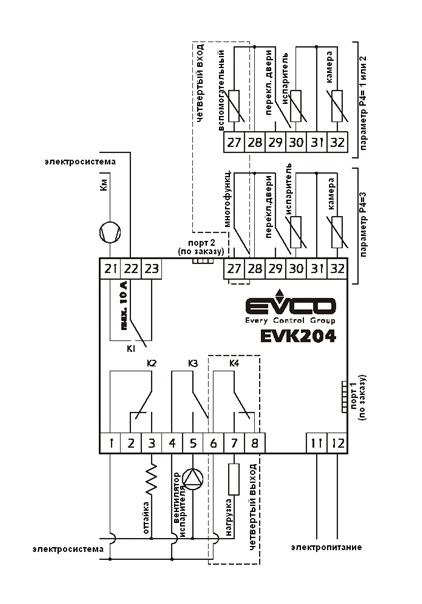
EVK204 является контроллером, предназначенным для управления холодильной установкой с вентилируемым испарителем. Управление производится путем остановки компрессора по температуре и времени, оттайка производится горячим газом или электрическим ТЭНом. Четвертый релейный выход может быть сконфигурирован для управления различными процессами, в том числе: освещение камеры, ТЭН от запотевания стекла холодильной камеры, реле тревоги, и другое.
Документация
| Корпус | самозатухающий пластик |
| Фронтальная защита | IP 65 |
| Подключение | ввинчиваемые терминальные блоки (силовой кабель, входы и выходы), 6-ти полосный соединитель (серийный порт, по заказу), 4-х полосный соединитель (для выносного дисплея; по заказу) |
| Температура окружающей среды | от 0 до 55 ºС (от 32 до 131 ºF, 10 … 90 % относительной влажности при отсутствии конденсата) |
| Электропитание | 230 Vac, 50/60 Гц, 3 ВА (приблизительно); 115 Vac, 24 Vac, 12-24 Vac/dc или 12 Vac/dc по заказу |
| Сигнал звуковой тревоги | по заказу |
| Входы для измерительных приборов |
2 (датчик камеры и датчик испарителя) для PTC/NTC датчиков. |
| Цифровые входы |
1 (микро-порт) для NO/NC контакта (сухой контакт, 5 В, 1 мА); четвертый вход может быть настроен в качестве входа измерительных приборов (датчика дисплея или датчика конденсатора, для PTC/NTC датчиков) или в качестве цифрового входа (многофункционального, сухой контакт, 5 В, 1 мА) |
| Рабочий диапазон температур | от – 50 до 150 ºС (-50 до 300 ºF) для PTС датчика, от – 40 до 105 ºС (-40 до 220 ºF) для NTC датчика |
| Разрешающая способность | 0.1°С/ 1°С/ 1°F |
| Цифровые выходы | 4 реле: реле контроля компрессора: 16 A @ 250 VAC (переключающийся контакт) реле контроля оттайки: 8 А @ 250 VАС (переключающий контакт) реле контроля вентилятора испарителя: 8 А @ 250 VАС (NА контакт) реле контроля четвертого выхода: 8 А @ 250 VАС (переключающий контакт) |
| Максимальный ток нагрузки | 10 А |
| Серийный порт | порт для связи с системой мониторинга (через серийный интерфейс при помощи TTL с протоколом связи MODBUS) или с ключом программирования; по заказу |
| Дополнительные порты связи | порт для связи с выносным дисплеем; по заказу |
При нормальной работе включенного прибора, дисплей отобразит величину, установленную параметром Р5:
— если Р5=0, дисплей отобразит температуру холодильной камеры.
— если Р5=1, дисплей отобразит температуру рабочей установки камеры.
— если Р5=2, дисплей отобразит температуру испарителя.
— если Р5=3, дисплей отобразит разность температур: “температура холодильной камеры «минус» температура испарителя”.
— если Р5=4, дисплей покажет температуру, считываемую вспомогательным датчиком (если параметр Р4 имеет значение 1 или 2).
В контроллере предусмотрены функции HACCP (запись тревог и событий) и энергосбережение. Многоцветные значки функций позволяет легко определить статус установки.Прибор способен хранить до 3 сигналов тревоги НАССР и предоставлять информацию о критическом значении и времени действия сигнала тревоги (от 1 мин до 99 час или 59 мин, частично в случае действия сигнала тревоги).
Коды сигналов тревоги:
AL — Сигнал тревоги при достижении нижнего критического значения температуры (минимальное значение температуры холодильной камеры или минимальное значение температуры, считываемой вспомогательным датчиком во время действия любого сигнала температурной тревоги).
AH — Сигнал тревоги при достижении верхнего критического значения температуры (максимальное значение температуры холодильной камеры или максимальное значение температуры, считываемой вспомогательным датчиком во время действия любого сигнала температурной тревоги).
id — Сигнал тревоги от активации входа микро-порта (максимальное значение температуры холодильной камеры, во время действия любого из сигналов температурной тревоги); также см. i4.
Контроллер хранит данные о сигналах тревоги при достижении нижнего и верхнего критического значения температуры, при условии, что температурой, вызывающей включение сигнала тревоги является температура холодильной камеры (параметры А0 и А3=1) или считываемая вспомогательным датчиком, при условии, что эта функция является функцией датчика дисплея (параметры А0= 2 , А3=1 и параметр Р4=1);
Прибор обновляет информацию о срабатывание сигнала тревоги при условии, что достигнутое критическое значение, при котором сработал сигнал тревоги, превысило то, которое хранилось в памяти прибора или достигло того же значения;
Если контроллер находится в режиме ожидания, данные о сигналах тревоги сохранятся не будут.
Когда причина, вызвавшая активацию сигнала тревоги, будет устранена, прибор вернется к нормальной работе.