Home » Doosan » Doosan DX225LCA Excavator Fault Codes List
See also: Doosan Service Repair Manuals PDF
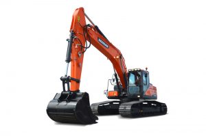
DOOSAN DX 255LC
Failure Information Code at Machine Side
| Code | Failure Component | Measuring Points | Correct Value | Remarks | |
| Active | Passive | ||||
| V201 | Gauge Panel
Communication Error |
CN7-4
CN7-5 |
– |
R = 60 ±5 Ω | It is a composite resistance of CAN line. This value has to be measured by connected condition of CAN line. |
|
V202 |
Ecu Communication Error |
CN4-4 CN4-5 |
– |
R = 60 ±5 Ω |
|
|
V210 |
Pump P/V |
CN1-10 CN1-21 |
– |
R = 18 ±2 Ω (25°C (77°F)) |
Pump proportional pressure reducing valve. |
| V211 | Cooling Fan P/V | – | – | N.A. | |
|
V212 |
Flow Control P/V |
CN1-19 CN1-20 |
– |
R = 14 ±2 Ω (25°C (77°F)) |
Flow control proportional pressure reducing valve. |
|
V213 |
Relief Pressure Up S/V |
CN1-1 CN1-11 |
V = V_volt (Note 4.) |
R = 26.2 ±2 Ω (25°C (77°F)) |
Breaker/boost/ shear selector switch has to be selected as a boost function and the boost switch on the right-hand joystick is “ON” status. |
|
V214 |
High Speed S/V |
CN1-1 CN1-12 |
V = V_volt |
R = 26.2 ±2 Ω (25°C (77°F)) |
Voltage is only measured when the pressure switch (Py) is turned “ON.” |
|
V215 |
Swing Priority S/V |
CN1-1 CN1-13 |
V = V_volt |
R = 26.2 ±2 Ω (25°C (77°F)) |
Work mode has to be selected as a trenching mode. |
| V216 | Reverse Fan Speed S/V | – | – | N.A. | |
|
V217 |
Starter Relay |
CN1-1 CN1-15 |
V = V_volt |
– |
It has to be measured in engine start up state. |
| V218 |
After Heat Relay |
1-16
1-04 |
– |
– |
N.A. |
| Code | Failure Component | Measuring Points | Correct Value | Remarks | |
| Active | Passive | ||||
| V220 |
Front Pump Press. Sensor |
CN3-1
CN3-2 |
V = IV |
– |
It has to be measured in engine stop state. |
| V221 |
Rear Pump Press. Sensor |
CN3-3
CN3-4 |
V = IV |
– |
|
|
V222 |
Hyd. Oil Temperature Sensor |
CN3-9 CN3-10 |
– |
R = 2.45 ±0.25 k Ω (25°C (77°F))
R = 320 ±32 Ω (80°C (176°F)) |
|
| V223 | Water Temperature Sensor | – | – | N.A. | |
| V224 | Engine Speed Sensor | – | – | N.A. | |
|
V225 |
Fuel Level Sensor |
CN3-7 CN3-8 |
– |
Empty: 5 ±0.25 k Ω
Full: 320 ±32 Ω |
|
|
V226 |
Alternator Potential |
CN2-14 CN1-8 |
V = 2 ±1V |
– |
It has to be measured in engine stop state. |
|
V227 |
Dial |
CN3-16 CN3-7 |
– |
R = 1.0 ±0.3 k Ω
R = 4.0 ±1.5 k Ω |
|
| V228 | Tps (Wheel) | – | – | N.A. | |
| V229 | Parking Brake Press. Sensor | – | – | N.A. | |
| V230 | E/g Control Motor Sensor | – | – | N.A. |
Active value: Starter switch has to be turned “ON”NOTE:
- Measuring points between component and wire harness have to be connected. Passive value: Starter switch has to be turned “OFF”
- Measuring points between component and wire harness have to be disconnected.
- Measuring points are engine controller’s points and passive value is each component’s value.
- V_batt: Source power of equipment.
FMIs (Failure Mode Identifier)
| FMI 0 | Above normal range (DATA VALID but ABOVE NORMAL OPERATIONAL RANGE) |
| FMI 1 | Below normal range (DATA VALID but BELOW NORMAL OPERATIONAL RANGE) |
| FMI 2 | Incorrect signal (DATA ERRATIC, INTERMITTENT OR INCORRECT) |
| FMI 3 | Voltage above normal (VOLTAGE ABOVE NORMAL OR SHORTED TO HIGH SOURCE) |
| FMI 4 | Voltage below normal (VOLTAGE BELOW NORMAL OR SHORTED TO LOW SOURCE) |
| FMI 5 | Current below normal (CURRENT BELOW NORMAL OR OPEN CIRCUIT) |
| FMI 6 | Current above normal (CURRENT ABOVE NORMAL OR GROUNDED CIRCUIT) |
| FMI 8 | Abnormal signal (ABNORMAL FREQUENCY OR PULSE WIDTH OR PERIOD) |
| FMI 11 | Failure mode not identifiable (ROOT CAUSE NOT KNOWN – Malfunction) |
| FMI 31 | NOT AVAILABLE OR CONDITION EXISTS |
Doosan DX225LCA Excavator Fault Codes List – FMI & V-Codes See also: Doosan Service Repair Manuals PDF
Failure Information Code at Machine Side
| Code | Failure Component | Measuring Points | Correct Value | Remarks | |
| Active | Passive | ||||
| V201 | Gauge Panel
Communication Error |
CN7-4
CN7-5 |
– |
R = 60 ±5 Ω | It is a composite resistance of CAN line. This value has to be measured by connected condition of CAN line. |
|
V202 |
Ecu Communication Error |
CN4-4 CN4-5 |
– |
R = 60 ±5 Ω |
|
|
V210 |
Pump P/V |
CN1-10 CN1-21 |
– |
R = 18 ±2 Ω (25°C (77°F)) |
Pump proportional pressure reducing valve. |
| V211 | Cooling Fan P/V | – | – | N.A. | |
|
V212 |
Flow Control P/V |
CN1-19 CN1-20 |
– |
R = 14 ±2 Ω (25°C (77°F)) |
Flow control proportional pressure reducing valve. |
|
V213 |
Relief Pressure Up S/V |
CN1-1 CN1-11 |
V = V_volt (Note 4.) |
R = 26.2 ±2 Ω (25°C (77°F)) |
Breaker/boost/ shear selector switch has to be selected as a boost function and the boost switch on the right-hand joystick is “ON” status. |
|
V214 |
High Speed S/V |
CN1-1 CN1-12 |
V = V_volt |
R = 26.2 ±2 Ω (25°C (77°F)) |
Voltage is only measured when the pressure switch (Py) is turned “ON.” |
|
V215 |
Swing Priority S/V |
CN1-1 CN1-13 |
V = V_volt |
R = 26.2 ±2 Ω (25°C (77°F)) |
Work mode has to be selected as a trenching mode. |
| V216 | Reverse Fan Speed S/V | – | – | N.A. | |
|
V217 |
Starter Relay |
CN1-1 CN1-15 |
V = V_volt |
– |
It has to be measured in engine start up state. |
| V218 |
After Heat Relay |
1-16
1-04 |
– |
– |
N.A. |
| Code | Failure Component | Measuring Points | Correct Value | Remarks | |
| Active | Passive | ||||
| V220 |
Front Pump Press. Sensor |
CN3-1
CN3-2 |
V = IV |
– |
It has to be measured in engine stop state. |
| V221 |
Rear Pump Press. Sensor |
CN3-3
CN3-4 |
V = IV |
– |
|
|
V222 |
Hyd. Oil Temperature Sensor |
CN3-9 CN3-10 |
– |
R = 2.45 ±0.25 k Ω (25°C (77°F))
R = 320 ±32 Ω (80°C (176°F)) |
|
| V223 | Water Temperature Sensor | – | – | N.A. | |
| V224 | Engine Speed Sensor | – | – | N.A. | |
|
V225 |
Fuel Level Sensor |
CN3-7 CN3-8 |
– |
Empty: 5 ±0.25 k Ω
Full: 320 ±32 Ω |
|
|
V226 |
Alternator Potential |
CN2-14 CN1-8 |
V = 2 ±1V |
– |
It has to be measured in engine stop state. |
|
V227 |
Dial |
CN3-16 CN3-7 |
– |
R = 1.0 ±0.3 k Ω
R = 4.0 ±1.5 k Ω |
|
| V228 | Tps (Wheel) | – | – | N.A. | |
| V229 | Parking Brake Press. Sensor | – | – | N.A. | |
| V230 | E/g Control Motor Sensor | – | – | N.A. |
Active value: Starter switch has to be turned “ON”NOTE:
- Measuring points between component and wire harness have to be connected. Passive value: Starter switch has to be turned “OFF”
- Measuring points between component and wire harness have to be disconnected.
- Measuring points are engine controller’s points and passive value is each component’s value.
- V_batt: Source power of equipment.
FMIs (Failure Mode Identifier)
| FMI 0 | Above normal range (DATA VALID but ABOVE NORMAL OPERATIONAL RANGE) |
| FMI 1 | Below normal range (DATA VALID but BELOW NORMAL OPERATIONAL RANGE) |
| FMI 2 | Incorrect signal (DATA ERRATIC, INTERMITTENT OR INCORRECT) |
| FMI 3 | Voltage above normal (VOLTAGE ABOVE NORMAL OR SHORTED TO HIGH SOURCE) |
| FMI 4 | Voltage below normal (VOLTAGE BELOW NORMAL OR SHORTED TO LOW SOURCE) |
| FMI 5 | Current below normal (CURRENT BELOW NORMAL OR OPEN CIRCUIT) |
| FMI 6 | Current above normal (CURRENT ABOVE NORMAL OR GROUNDED CIRCUIT) |
| FMI 8 | Abnormal signal (ABNORMAL FREQUENCY OR PULSE WIDTH OR PERIOD) |
| FMI 11 | Failure mode not identifiable (ROOT CAUSE NOT KNOWN – Malfunction) |
| FMI 31 | NOT AVAILABLE OR CONDITION EXISTS |
Коды ошибок трансмиссии
Первая цифра в коде ошибки показывает категорию, в которой она относится. Для первых номеров представлены следующие категории:
1.сигналы цифрового ввода
2. сигналы аналогового ввода
- сигналы скорости
- сигналы скорости
7 аналоговые выходные сигналы
8 аналоговые выходные сигналы
9 цифровые выходные сигналы
А цифровые выходные сигналы
В ошибки сцепления
D источник питания
Е высокоскоростные сигналы
F ошибки общего характера
| Кодовый номер ошибки | Значение кода ошибки | Примечания |
| 11 | Логическая ошибка при сигнале уровня передачи | |
| 12 | Логическая ошибка при сигнале выбора направления | |
| 21 | Короткое замыкание напряжения батареи при вводе сброса сцепления | |
| 22 | Короткое замыкание заземления или незамкнутой цепи при вводе сброса сцепления | |
| 23 | Короткое замыкание напряжения батареи при вводе сенсора загрузки | Не используется |
| 24 | Короткое замыкание заземления или незамкнутой цепи при вводе сенсора загрузки | Не используется |
| 25 | Короткое замыкание напряжения батареи или незамкнутой цепи при вводе сенсора температуры | |
| 26 | Короткое замыкание заземления при вводе сенсора температуры | |
| 31 | Короткое замыкание напряжения батареи при вводе скорости двигателя | |
| 32 | Короткое замыкание заземления или незамкнутой цепи при вводе скорости двигателя | |
| 33 | Логическая ошибка при вводе скорости двигателя | |
| 34 | Короткое замыкание напряжения батареи при вводе скорости турбинного колеса | |
| 35 | Короткое замыкание заземления или незамкнутой цепи при вводе скорости турбинного колеса | |
| 36 | Логическая ошибка при вводе скорости турбинного колеса | |
| 37 | Короткое замыкание напряжения батареи при вводе внутренней скорости |
6-8
| Кодовый номер ошибки | Значение кода ошибки | Примечания |
| 38 | Короткое замыкание заземления или незамкнутой цепи при вводе внутренней скорости | |
| 39 | Логическая ошибка при вводе внутренней скорости | |
| 3А | Короткое замыкание напряжения батареи при вводе внешней скорости | |
| 3В | Короткое замыкание заземления или незамкнутой цепи при вводе внешней скорости | |
| 3С | Логическая ошибка при вводе внешней скорости | |
| 71 | Короткое замыкание напряжения батареи в сцеплении К1 | |
| 72 | Короткое замыкание заземления в сцеплении К1 | |
| 73 | Незамкнутая цепь в сцеплении К1 | |
| 74 | Короткое замыкание напряжения батареи в сцеплении К2 | |
| 75 | Короткое замыкание заземления в сцеплении К2 | |
| 76 | Незамкнутая цепь в сцеплении К2 | |
| 77 | Короткое замыкание напряжения батареи в сцеплении К3 | |
| 78 | Короткое замыкание заземления в сцеплении К3 | |
| 7А | Короткое замыкание напряжения батареи в сцеплении конвертера | Не используется |
| 7В | Короткое замыкание заземления в сцеплении конвертера | Не используется |
| 7С | Незамкнутая цепь в сцеплении конвертера | Не используется |
| 81 | Короткое замыкание напряжения батареи в сцеплении К4 | |
| 82 | Короткое замыкание заземления в сцеплении К4 | |
| 83 | Незамкнутая цепь в сцеплении К4 | |
| 84 | Короткое замыкание напряжения батареи в сцеплении KV | |
| 85 | Короткое замыкание заземления в сцеплении KV | |
| 86 | Незамкнутая цепь в сцеплении KV | |
| 87 | Короткое замыкание напряжения батареи в сцеплении KR | |
| 88 | Короткое замыкание заземления в сцеплении KR | |
| 89 | Незамкнутая цепь в сцеплении KR | |
| 91 | Короткое замыкание напряжения батареи в аварийном сигнале реле обратного тока | |
| 92 | Короткое замыкание заземления в аварийном сигнале реле обратного тока |
6-9
| Кодовый номер ошибки | Значение кода ошибки | Примечания |
| 93 | Незамкнутая цепь в аварийном сигнале реле обратного тока | |
| 94 | Короткое замыкание напряжения батареи в реле внутреннего замка стартера | |
| 95 | Короткое замыкание заземления в реле внутреннего замка стартера | |
| 96 | Незамкнутая цепь в реле внутреннего замка стартера | |
| 97 | Короткое замыкание напряжения батареи в соленоиде ручного тормоза | |
| 98 | Короткое замыкание заземления в соленоиде ручного тормоза | |
| 99 | Незамкнутая цепь в соленоиде ручного тормоза | |
| В1 | Пробуксовка в сцеплении К1 | |
| В2 | Пробуксовка в сцеплении К2 | |
| В3 | Пробуксовка в сцеплении К3 | |
| В4 | Пробуксовка в сцеплении К4 | |
| В5 | Пробуксовка в сцеплении КV | |
| B6 | Пробуксовка в сцеплении КR | |
| D1 | Короткое замыкание напряжения батареи в электропитании сенсоров | |
| D2 | Короткое замыкание заземления в электропитании сенсоров | |
| D3 | Слабая подача питания в аккумулятор | |
| D4 | Чрезмерная подача питания в аккумулятор | |
| D5 | Ошибка в переключателе 1 для клапана подачи питания | |
| D6 | Ошибка в переключателе 2 для клапана подачи питания | |
| Е1 | Короткое замыкание батареи в выходе спидометра | Не используется |
| Е2 | Короткое замыкание заземления или незамкнутая цепь в выходе спидометра | Не используется |
| Е3 | Короткое замыкание батареи на выходе дисплея | Не используется |
| Е4 | Короткое замыкание заземления или незамкнутая цепь на выходе дисплея | Не используется |
| Е5 | Ошибка соединения на CAN | |
| F1 | Общая неисправность EEPROM | |
| F2 | Потеря конфигурации | |
| F3 | Ошибка использования |
6-10
РУЛЕВОЕ УПРАВЛЕНИЕ
| ПРОБЛЕМА | ВОЗМОЖНЫЕ ПРИЧИНЫ | ИСПРАВЛЕНИЕ |
| Трудно повернуть рулевое колесо | Отложения блокируют отверстие золотника поворотного механизма внутри приоритетного клапана
Отложения блокируют отверстие золотника усилителя крутящего момента внутри приоритетного клапана Отложения блокируют проходное сечение линии определения нагрузки внутри приоритетного клапана Заклинивание золотника приоритетного клапана внутри клапана рулевого управления Неправильный сброс давления предохранительного клапана внутри приоритетного клапана Неисправность насоса гидроусилителя рулевого управления Протекающий цилиндр усилителя рулевого механизма Ржавчина на подшипнике рулевой колонки и шлице Низкое давление в шинах |
Прочистить
и отремонтировать Прочистить и отремонтировать Прочистить и отремонтировать и отремонтировать Отрегулировать давление Смазать |
| Высокое первоначальное сопротивление движению рулевого колеса | Воздух в линии определения нагрузки внутри приоритетного клапана
Отложения блокируют проходное сечение линии определения нагрузки внутри приоритетного клапана Отложения блокируют отверстие золотника поворотного механизма внутри приоритетного клапана Поврежден пружинный амортизатор управления внутри приоритетного клапана |
Стравить воздух из системы
Прочистить и отремонтировать Прочистить и отремонтировать Заменить приоритетный клапан |
| Рулевое колесо трясется | Вибрирующий подшипник в дифференциале в цапфе полуоси
Давление в шинах левой и правой сторон неодинаково |
Заменить подшипник Уравнять давление в шинах |
DOOSAN Forklift Truck Flash Fault Codes DTC list
DTC — POSSIBLE FAULTS — MALFUNCTIONS * — FIRST CHECK IN METHODS ELIMINATION**
12 None. Indicates the end of one pass through the list faults. NONE*. None, used at the endidentification list faults**
131 Inj1open. Open circuit gasoline injector 1, wire broken injector or defective 1 injector. TurnOnMil*. Check INJ1 wiring for open circuit SECM () A5 signal
to pin A injector 1**. Switched B to pin B 12 injector 1. Check injector resistance* 1, 12-14 ohm (cold)**.
132 Inj2Open. Open circuit gasoline injector 2, wire broken injector or defective 2 injector. TurnOnMil*. Check INJ2 wiring for open circuit SECM () A8 signal
to pin A injector 2. Switched B to pin B 12 injector 2. Check injector resistance 2, 12-14 ohm (cold).**
133 Inj3open. Open circuit gasoline injector 3, wire broken injector silt 3 and defective injector. TurnOnMil*. Check INJ3 wiring for open circuit SECM ()
Signal A4 to pin A injector 3. Switched B to pin 12 B injector 3. Check injector resistance 3, 12-14 ohm (cold)**.
134 Inj4open. Open circuit gasoline injector 4, wire broken injector or defective 4 injector. TurnOnMil*. Check INJ4 wiring for open circuit SECM () Signal
A7 to pin A injector 4. Switched B to pin 12 B injector 4. Check injector resistance 4, 12-14 ohms (cold)**.
141 (14) ECTRangeLow. Refrigerant sensor failure or closed on GND. TurnOnMil*. Check the ECT sensor connector and wiring for short
circuit in GND SECM (). Signal B15 Blvd. 3 to ECT Blvd SECM (GND sensor). Bl. B1 1 to Blvd. Ect SECM (GND System) pin A16, B17**.
151 (15) ECTRangeHigh. Refrigerant sensor disconnected or open circuit. (1) TurnOnMil*. (2) Delayed Engine Shutdown*. (3) Check Engine
Light*. Check if the sensor connector disconnected or for open circuit SECM. Signal B15 Blvd. 3 to ECT Blvd SECM (GND sensor). Bl. B1 .1 to Blvd.**
DOOSAN Forklift Error Flash Codes list
161 (16) ECTOverTempFault. Engine coolant temperature is high Sensor. measured excessive refrigerant temperature, typical due to engine overheating.
(1) TurnOnMil*
(2) DelayedEngine Shutdown*
(3) CheckEngineLight*
Check the refrigerant system by locking the radiator for proper refrigerant level and for leaks in the system. Possible ECT closure to GND, check ECT signal wiring SECM. Signal Bl. B15 .3 to Blt
ECT SECM (GND sensor). Bl B1. 1 to Blvd. SECM (GND System). Blvd A16, B17.Check the regulator for refrigerant leaks**.
171 ECT_IR_Fault. Engine coolant temperature does not change as expected.None*.Check for problems with the refrigerant system such as defective or, viscous
thermostat**.
181 FuelSelectConflict. Signal conflict fuel selection ok install if both of the signals fuel selection closed to the ground. TurnOnMil**. Check connection
fuel selection switch is, whether short to gnd
SECM () SIGNAL A12 pin
SECM (SIGNAL) pin A15
SECM (GND Sensor) pin B1**.
191 CamEdgesFault. No CAM signal, when the engine is like, known rotates, broken sensor crankshaft leads or defective CAM sensor. None*. Check CAM sensor
connections
SECM (SIGNAL) Blvd. B10 to Blvd. 2 CAM sensor
SECM (GND sensor) Bl. Bl. To Bul. 3 CAM sensor
Switched in to the sensor sensor 12 .1 Cam
Check for defective CAM sensor**.
192 CamSyncFault. Loss of sync on CAM sensor, usually due to noise on the signal ordisconnected on CAM sensor. None*. Check CAM sensor connections SECM
(SIGNAL) Blvd. B10 to Blvd. 2
CAM sensor SECM (GND sensor) Bl. Bl. To Bul. 3
CAM sensor Switched in to the sensor sensor 12 .1
Cam Check for defective CAM sensor**.
193 CrankEdgesFault. No signal crankshaft when engine is known, rotates broken, crankshaft sensor leads or defective crankshaft sensor. None*.Check sensor connections
crankshaft
SECM (). SIGNAL Blvd B5 .3 to Blvd.
crankshaft sensor SECM (GND sensor) Bl. B1 .2 to Blvd.
crankshaft sensor Switched in to the sensor sensor 12 .1
crankshaft Check for defective sensor
194 Cranksyncfault. Loss of sync on crankshaft sensor, usually due to noise on signal or discontinuous connection on the sensor crankshaft. None*. Check
sensor connectionscrankshaft
SECM (). SIGNAL Blvd B5 .3 to Blvd.
crankshaft sensor
SECM (GND sensor). Bl. B1 .2 to Blvd.
crankshaft sensor
Switched in to the sensor sensor 12 .1
crankshaft
Check for defective sensor**.


DOOSAN Fault Codes DTC
Doosan Fault Codes DTC
Doosan Fault Codes DTC.pdf
Adobe Acrobat Document
181.9 KB
DOOSAN Excavator Fault Codes List DTC
FAULT CODE — NAME — FAULT DESCRIPTION
12 NONE Signifies the end of one pass through the fault list
14 ECTSensorInputLow Normally set if the coolant sensor wire is shorted to ground
15 ECTSensorInputHigh Set if the coolant sensor wire is disconnected or open
16 ECTRangeHigh Coolant sensor has measured an excessive temperature or shorted to GND
22 ThrottleSensorInputLo TPS1 signal wire is open
23 ThrottleSensorInputHi TPS1 signal wire is shorted
24 ThrottleSensorRangeLo TPS Sensor malfunction
25 ThrottleSensorRangeHi TPS Sensor malfunction
26 ETCSticking ETC driver signal wire is open or the throttle plate is sticking inside the throttle body
27 PredictedTPSDifference TPS1 is different than calculated position
28 ETCSpringTestFailed Throttle return spring failed keyup test
29 ETCDriverFault Throttle driver over-current or driver signals shorted
33 MapSensorInputLow MAP signal disconnected or open circuit
34 MapSensorInputHigh MAP signal shorted or sensor failure
37 IATSensorInputLow TMAP sensor failure or shorted circuit
38 IATSensorInputHigh TMAP disconnected or IAT signal open
42 EST1Low Coil driver signal low or under current
43 EST1High Coil driver signal high or over current
52 LowOilPressure Low engine oil pressure
53 BatterySensorInputLow Battery voltage measured below 8.0 VDC
54 BatterySensorInputHigh Battery voltage measured above 15.9 VDC
55 XDRPSensorInputLow Measured sensor transducer power is below 4.6 VDC
56 XDRPSensorInputHigh Measured sensor transducer power is above 5.2 VDC
57 Engine OverSpeed RPM increased above maximum rpm setpoint
61 Pedal1SensorInputLo APP1 signal disconnected, open circuit or sensor malfunction
62 Pedal1SensorInputHi APP1 sensor failure or shorted circuit
63 Pedal1SensorRangeLo APP1 potentiometer malfunction
64 Pedal1SensorRangeHi APP1 potentiometer malfunction
65 Pedal2SensorInputLo APP2 sensor failure or shorted signal
66 Pedal2SensorInputHi APP2 signal disconnected, open circuit or sensor malfunction
67 Pedal2SensorRangeLo APP2 potentiometer malfunction
68 Pedal2SensorRangeHi APP2 potentiometer malfunction
69 Pedal1ToPedal2Difference Measured APP2 pedal position signal is different than APP1
signal
71 AFRTrimValveOutput FTV modulation driver signal fault
72 AFRTrimValveLowerDC FTV duty cycle at lower (LEAN) limit
73 AFRTrimValveUpperDC FTV duty cycle at upper (RICH) limit
74 O2SensorSwitching O2 sensor not switching across the reference AFR voltage
77 OxygenSensorInputHigh O2 sensor signal shorted to +5 VDC
DOOSAN Forklift Truck Flash Fault Codes DTC list
DTC — POSSIBLE FAULTS — MALFUNCTIONS * — FIRST CHECK IN METHODS ELIMINATION**
12 None. Indicates the end of one pass through the list faults. NONE*. None, used at the endidentification list faults**
131 Inj1open. Open circuit gasoline injector 1, wire broken injector or defective 1 injector. TurnOnMil*. Check INJ1 wiring for open circuit SECM () A5 signal
to pin A injector 1**. Switched B to pin B 12 injector 1. Check injector resistance* 1, 12-14 ohm (cold)**.
132 Inj2Open. Open circuit gasoline injector 2, wire broken injector or defective 2 injector. TurnOnMil*. Check INJ2 wiring for open circuit SECM () A8 signal
to pin A injector 2. Switched B to pin B 12 injector 2. Check injector resistance 2, 12-14 ohm (cold).**
133 Inj3open. Open circuit gasoline injector 3, wire broken injector silt 3 and defective injector. TurnOnMil*. Check INJ3 wiring for open circuit SECM ()
Signal A4 to pin A injector 3. Switched B to pin 12 B injector 3. Check injector resistance 3, 12-14 ohm (cold)**.
134 Inj4open. Open circuit gasoline injector 4, wire broken injector or defective 4 injector. TurnOnMil*. Check INJ4 wiring for open circuit SECM () Signal
A7 to pin A injector 4. Switched B to pin 12 B injector 4. Check injector resistance 4, 12-14 ohms (cold)**.
141 (14) ECTRangeLow. Refrigerant sensor failure or closed on GND. TurnOnMil*. Check the ECT sensor connector and wiring for short
circuit in GND SECM (). Signal B15 Blvd. 3 to ECT Blvd SECM (GND sensor). Bl. B1 1 to Blvd. Ect SECM (GND System) pin A16, B17**.
151 (15) ECTRangeHigh. Refrigerant sensor disconnected or open circuit. (1) TurnOnMil*. (2) Delayed Engine Shutdown*. (3) Check Engine
Light*. Check if the sensor connector disconnected or for open circuit SECM. Signal B15 Blvd. 3 to ECT Blvd SECM (GND sensor). Bl. B1 .1 to Blvd.**
DOOSAN Forklift Error Flash Codes list
161 (16) ECTOverTempFault. Engine coolant temperature is high Sensor. measured excessive refrigerant temperature, typical due to engine overheating.
(1) TurnOnMil*
(2) DelayedEngine Shutdown*
(3) CheckEngineLight*
Check the refrigerant system by locking the radiator for proper refrigerant level and for leaks in the system. Possible ECT closure to GND, check ECT signal wiring SECM. Signal Bl. B15 .3 to Blt
ECT SECM (GND sensor). Bl B1. 1 to Blvd. SECM (GND System). Blvd A16, B17.Check the regulator for refrigerant leaks**.
171 ECT_IR_Fault. Engine coolant temperature does not change as expected.None*.Check for problems with the refrigerant system such as defective or, viscous
thermostat**.
181 FuelSelectConflict. Signal conflict fuel selection ok install if both of the signals fuel selection closed to the ground. TurnOnMil**. Check connection
fuel selection switch is, whether short to gnd
SECM () SIGNAL A12 pin
SECM (SIGNAL) pin A15
SECM (GND Sensor) pin B1**.
191 CamEdgesFault. No CAM signal, when the engine is like, known rotates, broken sensor crankshaft leads or defective CAM sensor. None*. Check CAM sensor
connections
SECM (SIGNAL) Blvd. B10 to Blvd. 2 CAM sensor
SECM (GND sensor) Bl. Bl. To Bul. 3 CAM sensor
Switched in to the sensor sensor 12 .1 Cam
Check for defective CAM sensor**.
192 CamSyncFault. Loss of sync on CAM sensor, usually due to noise on the signal ordisconnected on CAM sensor. None*. Check CAM sensor connections SECM
(SIGNAL) Blvd. B10 to Blvd. 2
CAM sensor SECM (GND sensor) Bl. Bl. To Bul. 3
CAM sensor Switched in to the sensor sensor 12 .1
Cam Check for defective CAM sensor**.
193 CrankEdgesFault. No signal crankshaft when engine is known, rotates broken, crankshaft sensor leads or defective crankshaft sensor. None*.Check sensor connections
crankshaft
SECM (). SIGNAL Blvd B5 .3 to Blvd.
crankshaft sensor SECM (GND sensor) Bl. B1 .2 to Blvd.
crankshaft sensor Switched in to the sensor sensor 12 .1
crankshaft Check for defective sensor
194 Cranksyncfault. Loss of sync on crankshaft sensor, usually due to noise on signal or discontinuous connection on the sensor crankshaft. None*. Check
sensor connectionscrankshaft
SECM (). SIGNAL Blvd B5 .3 to Blvd.
crankshaft sensor
SECM (GND sensor). Bl. B1 .2 to Blvd.
crankshaft sensor
Switched in to the sensor sensor 12 .1
crankshaft
Check for defective sensor**.
DOOSAN Fault Codes DTC
Doosan Fault Codes DTC
Doosan Fault Codes DTC.pdf
Adobe Acrobat Document
181.9 KB
DOOSAN Excavator Fault Codes List DTC
FAULT CODE — NAME — FAULT DESCRIPTION
12 NONE Signifies the end of one pass through the fault list
14 ECTSensorInputLow Normally set if the coolant sensor wire is shorted to ground
15 ECTSensorInputHigh Set if the coolant sensor wire is disconnected or open
16 ECTRangeHigh Coolant sensor has measured an excessive temperature or shorted to GND
22 ThrottleSensorInputLo TPS1 signal wire is open
23 ThrottleSensorInputHi TPS1 signal wire is shorted
24 ThrottleSensorRangeLo TPS Sensor malfunction
25 ThrottleSensorRangeHi TPS Sensor malfunction
26 ETCSticking ETC driver signal wire is open or the throttle plate is sticking inside the throttle body
27 PredictedTPSDifference TPS1 is different than calculated position
28 ETCSpringTestFailed Throttle return spring failed keyup test
29 ETCDriverFault Throttle driver over-current or driver signals shorted
33 MapSensorInputLow MAP signal disconnected or open circuit
34 MapSensorInputHigh MAP signal shorted or sensor failure
37 IATSensorInputLow TMAP sensor failure or shorted circuit
38 IATSensorInputHigh TMAP disconnected or IAT signal open
42 EST1Low Coil driver signal low or under current
43 EST1High Coil driver signal high or over current
52 LowOilPressure Low engine oil pressure
53 BatterySensorInputLow Battery voltage measured below 8.0 VDC
54 BatterySensorInputHigh Battery voltage measured above 15.9 VDC
55 XDRPSensorInputLow Measured sensor transducer power is below 4.6 VDC
56 XDRPSensorInputHigh Measured sensor transducer power is above 5.2 VDC
57 Engine OverSpeed RPM increased above maximum rpm setpoint
61 Pedal1SensorInputLo APP1 signal disconnected, open circuit or sensor malfunction
62 Pedal1SensorInputHi APP1 sensor failure or shorted circuit
63 Pedal1SensorRangeLo APP1 potentiometer malfunction
64 Pedal1SensorRangeHi APP1 potentiometer malfunction
65 Pedal2SensorInputLo APP2 sensor failure or shorted signal
66 Pedal2SensorInputHi APP2 signal disconnected, open circuit or sensor malfunction
67 Pedal2SensorRangeLo APP2 potentiometer malfunction
68 Pedal2SensorRangeHi APP2 potentiometer malfunction
69 Pedal1ToPedal2Difference Measured APP2 pedal position signal is different than APP1
signal
71 AFRTrimValveOutput FTV modulation driver signal fault
72 AFRTrimValveLowerDC FTV duty cycle at lower (LEAN) limit
73 AFRTrimValveUpperDC FTV duty cycle at upper (RICH) limit
74 O2SensorSwitching O2 sensor not switching across the reference AFR voltage
77 OxygenSensorInputHigh O2 sensor signal shorted to +5 VDC
Doosan (& Daewoo) B20T-5:
Error Code F3 Inverter Fault and F6 R Motor Offline
I have a Doosan B20T-5 Electric with intermittent Trouble codes F3 Inverter Fault and F6 R motor offline. Does one cause the other to pop up or what causes this codes to display? Also, I know that this lift has a D/D Converter. Is this the same as the inverter? A little help please.
Showing items 1 — 3 of 3 results.
Sort messages by:
The Power Inverters are located in the back panel, and yes for that model there are 3 power inverters, two traction and one pump. I would suggest you check the power inverters with Ohm meter from Batt+ post to then UVW terminals and check resistance. The do the same tests from Batt- connector to all three phases.
we are having the same issue any solution
A little update here. I’ve been doing a little research and this is what I’ve found about this piece of equipment;
F3- Inverter Fault actually means drive right module desat/overcurrent
F6- R Motor Offline actually means drive right motor current offset
Also found out that this F/L has 3 inverters — one for each drive motor and one for the pump motor. So, I believe that the right inverter may be defective (F3) and causing the F6 code.
Just gotta find out where the inverters are located and I should be good to go.
Having trouble using the Discussion Forums? Contact us for help.
Forkliftaction.com accepts no responsibility for forum content and requires forum participants to adhere to the rules. Click here for more information.
- Manuals
- Brands
- Doosan Manuals
- Engine
- D80S-5
Manuals and User Guides for Doosan D80S-5. We have 5 Doosan D80S-5 manuals available for free PDF download: Service Manual, Operation & Maintenance Manual, Specifications Systems Operation Testing & Adjusting Disassembly & Assembly
Doosan D80S-5 Service Manual (366 pages)
Brand: Doosan
|
Category: Engine
|
Size: 16.51 MB
Table of Contents
-
Table of Contents
5
-
General
9
-
General Precautions for Servicing
13
-
-
General
18
-
Specification
22
-
Tightening Torque
26
-
Special Tool
30
-
Diagnosis
32
-
Adjustment
34
-
-
Timing System
35
-
Removal
37
-
Inspection
41
-
Replacement
44
-
Installation
45
-
-
Cylinder Head Assembly
51
-
Removal
53
-
Disassembly
56
-
Inspection
57
-
Replacement
61
-
Reassembly
63
-
Installation
65
-
-
Crankcase
67
-
Removal
68
-
Installation
69
-
-
Cylinder Block Assembly
71
-
Removal
73
-
Disassembly
76
-
Inspection
77
-
Reassembly
83
-
Installation
84
-
-
Intake and Exhaust System
88
-
Troubleshooting
89
-
-
Turbocharger
91
-
Removal
93
-
Inspection
94
-
Installation
95
-
-
Intake Manifold
97
-
Removal
98
-
Installation
99
-
-
Exhaust Manifold
100
-
Removal
101
-
Installation
102
-
-
Lubrication System
103
-
Specification
107
-
Troubleshooting
109
-
Adjustment
111
-
-
-
Oil Pump
113
-
Disassembly
115
-
-
Oil Cooler
116
-
Disassembly
117
-
Reassembly
118
-
-
Cooling System
119
-
Specification
120
-
Trouble Shooting
122
-
-
Water Pump
124
-
Removal
125
-
Inspection
126
-
Installation
127
-
-
General
128
-
Service Standards
130
-
Troubleshooting
131
-
-
Charging System
133
-
Adjustment
134
-
-
Alternator
138
-
Disassembly
139
-
Inspection
141
-
Reassembly
142
-
-
Starting System
143
-
Inspection
144
-
-
Preheating System
146
-
General
147
-
Sealant
148
-
Engine Control
150
-
Fuel Tank and Fuel Line
151
-
Troubleshooting Procedure
152
-
Troubleshooting Procedure
156
-
-
Engine Control System-Electronic
169
-
Engine Control Unit (ECU)
172
-
ECU Circuit Diagram
177
-
Removal
179
-
Inspection
180
-
-
Intake Air Temperature Sensor
186
-
Intake Air Pressure Sensor
187
-
Coolant Temperature Sensor
188
-
Installation
189
-
-
Camshaft Position Sensor
190
-
Crankshaft Position Sensor
191
-
Rail Pressure Sensor
192
-
Supply Control Valve
193
-
Fuel Delivery System-Electronic
194
-
Fuel Filter
195
-
Injector
196
-
Cleaning
197
-
Replacement
198
-
Injector Replacement
199
-
Installation
200
-
-
Common Rail Assembly
201
-
Injection Pump-Electronic
202
-
Check before Use
205
-
Safety Warning and Caution before Use
206
-
-
Hardware
210
-
Introduction of Components
213
-
-
Basic Usage of G-Scan
214
-
Power ON/OFF
217
-
Description for Main Components of H/W
219
-
Description for Layout of S/W Screen
224
-
Connecting the DLC Cable
228
-
Self Test Adapter
231
-
-
Configuration
232
-
User Information
240
-
Version
243
-
Self Test
245
-
STEP-B Test
249
-
-
Vehicle Communication Function
252
-
Fault Code Searching
259
-
DTC Analysis
262
-
Data Analysis
270
-
Actuation Test
282
-
Vehicle S/W Management
284
-
ECU Upgrade
288
-
Carb Obd-II
301
-
Flight Record
307
-
-
PC Utility
327
-
How to Use PC Utility
336
-
-
Appendix
354
-
O/S Update
358
-
Advertisement
Doosan D80S-5 Operation & Maintenance Manual (204 pages)
Brand: Doosan
|
Category: Forklifts
|
Size: 9.11 MB
Table of Contents
-
Operation & Maintenance Manual
2
-
Table of Contents
2
-
Information Section
3
-
Foreword
3
-
-
Safety Section
5
-
Important Safety Information
5
-
Safety
6
-
Warning Signs and Labels
6
-
General Hazard Information
11
-
Operation Information
12
-
Maintenance Information
15
-
Operator Restraint System (if Equipped)
18
-
Avoiding Lift Truck Tipover
22
-
Safety Rules
24
-
How to Survive in a Tipover (if Operator Restraint System Equipped)
30
-
-
-
General Section
32
-
Declaration of Conformity
32
-
Specifications
33
-
Noise &Vibration
49
-
Capacity Chart — Without Side Shifter
50
-
Capacity Chart — with Side Shifter
52
-
Serial Number
54
-
Operator’s Warning and Identification Plate
56
-
-
Operation Section
58
-
Operator’s Station and Monitoring Systems
58
-
Seat Switch System
68
-
Lift Truck Controls
68
-
Refueling
73
-
Before Starting the Engine
76
-
Starting the Engine
79
-
After Starting the Engine
82
-
Lift Truck Operation
118
-
Auto Shift Controller ASC-202/204/208 (if Equipped)
120
-
Operating Techniques
125
-
Parking the Lift Truck
129
-
Lift Fork Adjustment
130
-
Storage Information
131
-
Transportation Hints
132
-
Towing Information
133
-
-
Maintenance Section
134
-
Inspection, Maintenance and Repair of Lift Truck Forks
134
-
Tire Inflation Information
138
-
Torque Specifications
139
-
Cooling System Specifications
141
-
Fuel Specifications
143
-
Lubricant Specifications
145
-
-
-
Maintenance Intervals
149
-
Notice
153
-
Engine Valve Lash (Diesel E/G Only) — Check, Adjust
153
-
Priming the Fuel System (Diesel Engine Only)
153
-
Test Fuel System for Leaks (LP Engine Only)
154
-
Fuel Tank Filter Cap & Screen — Clean
155
-
Seat — Check, Lubricate
155
-
Fuses, Bulbs & Circuit Breaker — Change, Reset
156
-
Tires and Wheels — Inspect, Check
157
-
Radiator Cap — Clean, Change
158
-
Carriage Roller Extrusion — Adjust
158
-
Brake Oil (OCDB) — Check
159
-
-
When Required
153
-
Every 10 Service Hours or Daily
160
-
Inspection Engine for Fluid Leaks
160
-
Engine Oil Level — Check
160
-
Coolant Level — Check
160
-
Air Cleaner Indicator — Check
161
-
Inspect Foot Pedal Operation (LP Engine Only)
162
-
Inspect Engine for Exhaust Leaks
162
-
Walk-Around Inspection — Inspect
162
-
Mast Channels — Lubricate
163
-
Transmission Oil Level — Check
164
-
-
First 50-100 Service Hours or a Week
165
-
Engine Oil & Oil Filter (Diesel E/G Only) — Change
165
-
Transmission Oil & Oil Filter — Change
166
-
Drive Axle Oil — Change
168
-
Parking Brake — Test, Adjust
170
-
-
First 250 Service Hours or a Month
172
-
Hydraulic Return Filter — Change
172
-
-
Every 250 Service Hours or Monthly
173
-
Air Intake System — Check, Clean
173
-
Engine Oil & Filter(LP Engine Only) — Change
176
-
Hydraulic Oil Level — Check
177
-
Drive Axle Oil Level — Check
177
-
Mast, Carriage, Lift Chains & Attachments — Inspect, Lubricate
178
-
Steering Mechanism — Check, Lubricate
179
-
Battery Terminal — Clean, Inspect
180
-
Wheel Bolts & Nuts — Inspect
180
-
-
Every 500 Service Hours or 3 Months
181
-
Belts (Diesel E/G Only) — Check, Adjust
181
-
Mast Hinge Pins — Lubricate
181
-
Tilt Cylinders — Check, Adjust, Lubricate
182
-
Crosshead Rollers — Inspect
182
-
Transmission Oil Filter (2 Speed Only) — Change
182
-
Parking Brake — Test, Adjust
182
-
Drive Axle Oil (OCDB) — Change
182
-
Horn and Lights(if Equipped) — Check
183
-
Overhead Guard — Inspect
183
-
Steer Suspension — Inspect
183
-
Universal Joint — Inspect, Lubricate
183
-
Engine Oil & Filter(Diesel Engine Only) — Change
184
-
Inspect Vacuum Lines and Fittings (G643(E) Engine Only)
184
-
Fuel Trim Valve(FTV) Inspection (G643E Engine Only)
184
-
Inspect Electrical System (G643E Engine Only)
184
-
-
Every 1000 Service Hours or 6 Months
185
-
Carburetor (LP — Gas Engine Only) — Adjust, Clean
185
-
Fuel Filter — Check, Clean, Change
185
-
Air Intake System — Change
185
-
Inspect Coolant Hoses (LP Engines Only)
186
-
LP Regulator/Converter Inspection (LP Engine Only)
186
-
Fuel Lines & Fittings — Check
186
-
Inspect Mixer Assembly (LP Engine Only)
186
-
Inspect Throttle Assembly (LP Engine Only)
186
-
Hydraulic Oil, Return Filter, Strainer & Breather — Check, Clean, Change
187
-
Transmission Oil & Filter (3 Speed, ZF 3WG116) — Change
188
-
Transmission Oil (2 Speed Only) — Change
188
-
Lift Chains — Test, Check, Adjust
188
-
-
Every 1500 Service Hours or 9 Months
191
-
Drive Axle Oil (Shoe Brake Only) — Change
191
-
Inspect Ignition System (LP Engine Only)
191
-
Replace Spark Plugs (LP Engine Only)
191
-
Replace LP Fuel Filter Element (LP Engine Only)
192
-
Testing Fuel Lock-Off Operation (LP Engine Only)
193
-
-
Every 2000 Service Hours or Yearly
194
-
Steer Wheel Bearings — Reassemble
194
-
Transmission Oil & Filter (3 Speed, ZF 3WG94) — Change
194
-
Cooling System — Clean, Change
195
-
Fork — Inspect
196
-
-
Every 2500 Service Hours or 15 Months
198
-
Inspect Battery System
198
-
Checking the TMAP Sensor (LP Engine Only)
198
-
Inspect for Intake Leaks (LP Engine Only)
199
-
Replace PCV Valve and Breather Element — Change (LP Engine Only)
199
-
Replace Oxygen Sensor (G643E Engine Only)
199
-
Every 3000 Service Hours or 18 Months
200
-
-
Index
201
-
Doosan D80S-5 Service Manual (152 pages)
Brand: Doosan
|
Category: Engine
|
Size: 24.02 MB
Table of Contents
-
Important Safety Information
3
-
Table of Contents
7
-
1 General Information
9
-
Engine Specifications
9
-
D50/60/70/80/90S-5 (3 Speed)
9
-
-
Performance Curve
10
-
Performance Curve (ECRFD), D35/40/45S-5, D50/55C-5
11
-
Performance Curve (ECRFE), D50/60/70S-5 (2 Speed)
12
-
-
Engine Assembly
13
-
Engine Assembly View (ECRFA), D50/60/70/80/90S-5 (3 Speed)
13
-
Engine Assembly View (ECRFD), D35/40/45S-5, D50/55C-5
14
-
Engine Assembly Views (ECRFE), D50/60/70S-5 (2 Speed)
15
-
-
Safety Regulations
16
-
General Notes
16
-
Regulations Designed to Prevent Accidents
16
-
Regulations Designed to Prevent Damage to Engine and Premature Wear
17
-
Regulations Designed to Prevent Pollution
18
-
General Repair Instructions
19
-
-
-
2 Technical Information
20
-
Engine Model and Serial Number
20
-
Engine Type
21
-
Cylinder Block
21
-
Piston Con-Rod / Crankshaft
21
-
-
Engine Timing
21
-
Valves
22
-
Lubrication System
22
-
Recommend of Lubricating Oil
23
-
Oil Cooler
24
-
Oil Filter
24
-
-
Air Cleaner
25
-
Fuel System
25
-
Injection Pump
26
-
Fuel Filter
26
-
Fuel Requirements
26
-
How to Select Fuel Oil
27
-
-
Cooling System
28
-
Anti-Freeze
29
-
Cooling Water
29
-
-
V-Belt Tension Check and Adjust
31
-
Valve Clearance and Adjustment
32
-
Cylinder Compression Pressure
33
-
Injection Nozzle
34
-
Battery
34
-
Starting Motor
34
-
Diagnosis and Remedy
35
-
Engine Inspection
44
-
Stopping Engine
44
-
General Engine Inspection Cycle36
44
-
-
Use of Original Parts for Repair and Replacement
45
-
-
3 Maintenance
46
-
Engine Disassembly
46
-
Major Part Fixing Nuts and Bolts
46
-
Main Structure Parts (1)
57
-
Main Structure Parts (2)
59
-
Rocker Arm Disassembly
61
-
Cylinder Head Disassembly
62
-
Piston and Connecting Rod Disassembly
63
-
-
Engine Inspection
65
-
Cylinder Block
65
-
Cylinder Head
65
-
Valve Stem and Valve Guide Clearance
66
-
Valve Spring
70
-
Tappet
71
-
Push Rod
71
-
Rocker Arm Correction
72
-
Idler Gear and Shaft
73
-
Camshaft
73
-
Cylinder Liner
75
-
Cylinder Block
76
-
Piston
79
-
Maintenance of Cylinder Block, Cylinder Liner and Piston
82
-
Connecting Rod
83
-
Crankshaft
85
-
Flywheel and Flywheel Housing
89
-
-
Engine Reassembly
90
-
Piston and Connecting Rod Assembly
90
-
Cylinder Head Assembly Parts
92
-
Rocker Arm and Shaft Assembly
95
-
Main Components
96
-
Major Component Assembly
102
-
External Parts
106
-
-
-
4 Commissioning and Operation
111
-
Preparation
111
-
Starting
111
-
-
Starting and Operation
112
-
Operation of a New Engine (Break-In)
112
-
Check Points for Break-In
112
-
-
Inspections after Starting
114
-
Operation in Winter Time
114
-
Prevention against the Freeze of Cooling Water
114
-
Prevention against Excessive Cooling
114
-
Lubricating Oil
115
-
Starting of Engine in Winter
115
-
Tuning the Engine
115
-
-
Maintenance and Care
116
-
Periodical Inspection and Maintenance
116
-
Exchanging of Lubrication Oil
116
-
Oil Level
116
-
Oil Exchange Procedure
116
-
Replacement of Oil Filter Cartridge109
117
-
-
Cooling System
118
-
Coolant Draining
118
-
Cleaning of the Cooling Inside System Circuit
119
-
-
Valve Clearance and Adjustment
119
-
Injection Timing
121
-
Tightening the Cylinder Head Bolts
124
-
Fuel Injection Pump
124
-
Feed Pump Strainer
125
-
Separator (Add if Necessary)
125
-
Air Bleeding
125
-
Belts
126
-
-
5 Maintenance of Major Components
129
-
Lubrication System
129
-
Oil Pump
129
-
Oil Cooler
131
-
-
Cooling System
132
-
Water Pump
132
-
Thermostat
136
-
-
Fuel System
137
-
Fuel Filter
137
-
Injection Nozzle
138
-
Injection Pump Calibration
142
-
Precautions for Operation
145
-
Walk-Around Check and Servicing
146
-
Diagnostics and Troubleshooting139
147
-
-
-
6 Special Tool List
148
-
Appendix
150
Advertisement
Doosan D80S-5 Operation & Maintenance Manual (204 pages)
Brand: Doosan
|
Category: Forklifts
|
Size: 5.54 MB
Doosan D80S-5 Specifications Systems Operation Testing & Adjusting Disassembly & Assembly (68 pages)
Brand: Doosan
|
Category: Control Unit
|
Size: 4.58 MB
Table of Contents
-
Table of Contents
4
-
Specification
6
-
General Tightening Torque
6
-
Drive Axle Specification
7
-
Torque Converter
8
-
Transmission Pump
8
-
Drive Axle Mounting
9
-
Differential
9
-
Wheel Bearing and Drive Wheel
9
-
Brake Assembly
10
-
Brake Drum Diameter
11
-
U — Joint
11
-
-
System Operation
12
-
General Information
12
-
Power Shift Transmission
13
-
General Information
13
-
Power Flow at Low Speed Forward
14
-
Power Flow at High Speed Forward
15
-
Power Flow at Low Speed Reverse
16
-
Power Flow at High Speed Reverse
17
-
-
Transmission Control Valve
18
-
Cross-Section View
18
-
Hydraulic Schematic
19
-
-
Differential and Drive Axles
21
-
Differential
21
-
Wheel Hub
21
-
-
Brake Components
22
-
Shoe Brake
22
-
Brake Adjuster
22
-
Ocdb
23
-
-
-
Testing and Adjusting
24
-
Troubleshooting
24
-
Visual Checks
24
-
Checks During Operation
24
-
Check List During Operation
24
-
Check List from Operation Noise
26
-
Check List from Pressure Test
27
-
Differential
28
-
-
Transmission Pressure
29
-
Converter Stall Test
30
-
Shimming of Transmission Shaft
31
-
Wheel Brake Adjustment
31
-
Inching Pedal Adjustment
33
-
-
Disassembly and Assembly
36
-
Drive Shaft and Universal Joint
36
-
Engine, Torque Converter and Transmission
37
-
Transmission Control Valve
41
-
Transmission
44
-
Drive Axle
55
-
Advertisement
Related Products
-
Doosan DB33A
-
Doosan D40S-5
-
Doosan DP158LCF
-
Doosan DP180LBS
-
Doosan DP222LBS
-
Doosan D110S-5 with OCDB
-
Doosan D15S-5
-
Doosan D18S-5
-
Doosan DP180L Series
-
Doosan DP158L Series
Doosan Categories
Air Compressor
Engine
Excavators
Forklifts
Power Tool
More Doosan Manuals