В
цифровых каналах связи при передаче
информации по разным причинам
(неисправность оборудования, помехи)
могут возникать ошибки. Поэтому на
приемной стороне используются различные
способы обнаружения ошибок, а также
способы, позволяющие выполнить как
обнаружение, так исправление ошибки.
Если
контроль передачи информации выполняется
только с обнаружением ошибки, то в случае
ошибки приемник запрашивает повторную
передачу искаженной информации. Если
же контроль выполняется с обнаружением
и исправлением ошибки, то приемник сам
выполняет коррекцию искаженной информации
без обращения к передатчику.
Из
теории кодирования информации известно,
что вероятность двойной или тройной
ошибки (в двух или трех битах одновременно)
на один или два порядка меньше, чем
вероятность возникновения одиночной
ошибки. Поэтому при контроле передачи
информации основное внимание уделяется
обнаружению, а также обнаружению и
исправлению одиночной ошибки. Различают
коды, которые позволяют только обнаруживать
ошибку, и коды, которые позволяют как
обнаруживать, так и исправлять ее.
Коды для обнаружения ошибок код грея
При
использовании обыкновенного двоичного
кода изменение числа на 1 может привести
к изменению двоичного числа сразу в
нескольких битах, что может вызвать
значительные ошибки считывания.
Погрешности
считывания можно устранить, если
воспользоваться невесовыми кодами,
представляющими собой последовательности
n-разрядных
двоичных чисел, в которых каждые два
соседних числа отличаются одно от
другого только в одном разряде. У таких
кодов много названий – коды
Грея, рефлексные, отраженные, циклические,
прогрессивные коды.
Частный
случай, получивший наибольшее
распространение, – «код Грея». Главная
особенность кода Грея, обеспечившая
ему широкое практическое применение,
состоит в простоте его построения.
Пусть
а
– двоичное n-разрядное
число обычной (весовой) системы счисления,
b
– соответствующее число в коде Грея.
Тогда правило, по которому можно найти
код Грея по заданному числу а, представится
формулой вида:

где
⊕
– знак сложения по модулю 2; i
–
порядковый номер разряда в числе а;
i
=
1, 2, 3, …, n;
счет начинается с младшего разряда.
Чтобы по этому правилу найти код Грея,
достаточно поразрядно сложить по модулю
2 число а
с самим собой, но сдвинутым вправо на
один разряд с потерей цифры младшего
разряда и записью нуля в старшем разряде:

где

Например,
при n
=
4 последовательность кодов Грея имеет
вид: 0000, 0001, 0011, 0010, 0110, 0111, 0101, 0100, 1100, 1101,
1111, 1110, 1010, 1011, 1001, 1000.
Код
Грея является невесовым в отличие от
обычной двоичной системы счисления.
Это значит, что образующие его двоичные
числа надо рассматривать только как
упорядоченные наборы нулей и единиц
без присвоения им весов. Например,
двоичному весовому числу 10011 (в десятичной
системе – это 19) соответствует код Грея
11010, и если его считать весовым, то
получится число 26 (в десятичной системе).
В связи с этим каждому невесовому коду
обычно присваивается та или иная величина
либо с применением правила, как в случае
кода Грея, либо при помощи таблицы.
Коды
Грея часто используются в датчиках-энкодерах.
Также они используются для кодирования
номера дорожек в жестких дисках.
Примером
могут служить датчики механических
перемещений. Один из таких датчиков
представляет собой соосно укрепленный
на валу прозрачный диск с нанесенной
на него кодовой маской. Коды считываются
при помощи системы каких-либо фотоэлементов.
Главное назначение датчика – определить
положение вала, т.е. угол его поворота
по отношению к некоторому исходному
состоянию.
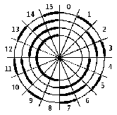
Для
примера на рисунке показан диск,
разделенный на 16 равных частей – секторов
(на практике их обычно тысячи). Все
сектора пронумерованы и каждый номер
представлен в двоичном коде в виде
сочетаний темных и светлых участков,
расположенных на четырех концентрических
кольцах.
Внутреннему
кольцу поставлен в соответствие старший
разряд номера, внешнему – младший. Нуль
на диске обозначен светлой частью
кольца, единица – зачернением. Считываются
числа с диска параллельно, т.е. все четыре
разряда одновременно, при помощи четырех
фотоэлементов.
Главное
достоинство датчика – его простота.
Однако с практической точки зрения он
почти непригоден. Дело в том, что
параллельные коды хорошо считываются
только в пределах каждого отдельного
сектора, а при переходе от одного сектора
к другому возникают помехи. Пусть число
считывается в момент, когда под
фотоэлементами проходит 15-й сектор, а
за ним идет сектор с нулевым номером.
Какое число получится на границе
секторов? Это зависит от таких причин,
как неточность изготовления маски и
блока фотоэлементов, тепловая
нестабильность, влияние различных
вибраций и др. В общем случае на границе
15-го и нулевого секторов может быть
считано любое число от 0 до 15. Помехи
имеют место также при переходе от первого
сектора ко второму, от третьего к
четвертому, от пятого к шестому и др.
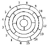
Если
на рисунке вместо обычной двоичной
(весовой) системы использовать код Грея,
то на границах секторов всегда будет
изменяться цифра только в одном каком-либо
разряде. Благодаря этому в моменты
перехода диска от одного кода к другому
помехи появиться не могут.
Соседние файлы в папке Теоретический материал
- #
- #
- #
- #
- #
| Lucal code[1][2] | |||||
|---|---|---|---|---|---|
| 5 | 4 | 3 | 2 | 1 | |
| Gray code | |||||
| 4 | 3 | 2 | 1 | ||
| 0 | 0 | 0 | 0 | 0 | 0 |
| 1 | 0 | 0 | 0 | 1 | 1 |
| 2 | 0 | 0 | 1 | 1 | 0 |
| 3 | 0 | 0 | 1 | 0 | 1 |
| 4 | 0 | 1 | 1 | 0 | 0 |
| 5 | 0 | 1 | 1 | 1 | 1 |
| 6 | 0 | 1 | 0 | 1 | 0 |
| 7 | 0 | 1 | 0 | 0 | 1 |
| 8 | 1 | 1 | 0 | 0 | 0 |
| 9 | 1 | 1 | 0 | 1 | 1 |
| 10 | 1 | 1 | 1 | 1 | 0 |
| 11 | 1 | 1 | 1 | 0 | 1 |
| 12 | 1 | 0 | 1 | 0 | 0 |
| 13 | 1 | 0 | 1 | 1 | 1 |
| 14 | 1 | 0 | 0 | 1 | 0 |
| 15 | 1 | 0 | 0 | 0 | 1 |
The reflected binary code (RBC), also known as reflected binary (RB) or Gray code after Frank Gray, is an ordering of the binary numeral system such that two successive values differ in only one bit (binary digit).
For example, the representation of the decimal value «1» in binary would normally be «001» and «2» would be «010«. In Gray code, these values are represented as «001» and «011«. That way, incrementing a value from 1 to 2 requires only one bit to change, instead of two.
Gray codes are widely used to prevent spurious output from electromechanical switches and to facilitate error correction in digital communications such as digital terrestrial television and some cable TV systems.
Function[edit]
Many devices indicate position by closing and opening switches. If that device uses natural binary codes, positions 3 and 4 are next to each other but all three bits of the binary representation differ:
-
Decimal Binary … … 3 011 4 100 … …
The problem with natural binary codes is that physical switches are not ideal: it is very unlikely that physical switches will change states exactly in synchrony. In the transition between the two states shown above, all three switches change state. In the brief period while all are changing, the switches will read some spurious position. Even without keybounce, the transition might look like 011 — 001 — 101 — 100. When the switches appear to be in position 001, the observer cannot tell if that is the «real» position 1, or a transitional state between two other positions. If the output feeds into a sequential system, possibly via combinational logic, then the sequential system may store a false value.
This problem can be solved by changing only one switch at a time, so there is never any ambiguity of position, resulting in codes assigning to each of a contiguous set of integers, or to each member of a circular list, a word of symbols such that no two code words are identical and each two adjacent code words differ by exactly one symbol. These codes are also known as unit-distance,[3][4][5][6][7] single-distance, single-step, monostrophic[8][9][6][7] or syncopic codes,[8] in reference to the Hamming distance of 1 between adjacent codes.
Invention[edit]

Gray’s patent introduces the term «reflected binary code»
In principle, there can be more than one such code for a given word length, but the term Gray code was first applied to a particular binary code for non-negative integers, the binary-reflected Gray code, or BRGC. Bell Labs researcher
George R. Stibitz described such a code in a 1941 patent application, granted in 1943.[10][11][12] Frank Gray introduced the term reflected binary code in his 1947 patent application, remarking that the code had «as yet no recognized name».[13] He derived the name from the fact that it «may be built up from the conventional binary code by a sort of reflection process».
In the standard encoding the least significant bit follows a repetitive pattern of 2 on, 2 off ( … 11001100 … ); the next digit a pattern of 4 on, 4 off; the nth least significant bit a pattern of 2n on 2n off. The four-bit version of this is shown below:


Gray code along the number line
-
Decimal Binary Gray Decimal
of Gray0 0000 0000 0 1 0001 0001 1 2 0010 0011 3 3 0011 0010 2 4 0100 0110 6 5 0101 0111 7 6 0110 0101 5 7 0111 0100 4 8 1000 1100 12 9 1001 1101 13 10 1010 1111 15 11 1011 1110 14 12 1100 1010 10 13 1101 1011 11 14 1110 1001 9 15 1111 1000 8
For decimal 15 the code rolls over to decimal 0 with only one switch change. This is called the cyclic or adjacency property of the code.[14]
In modern digital communications, Gray codes play an important role in error correction. For example, in a digital modulation scheme such as QAM where data is typically transmitted in symbols of 4 bits or more, the signal’s constellation diagram is arranged so that the bit patterns conveyed by adjacent constellation points differ by only one bit. By combining this with forward error correction capable of correcting single-bit errors, it is possible for a receiver to correct any transmission errors that cause a constellation point to deviate into the area of an adjacent point. This makes the transmission system less susceptible to noise.
Despite the fact that Stibitz described this code[10][11][12] before Gray, the reflected binary code was later named after Gray by others who used it. Two different 1953 patent applications use «Gray code» as an alternative name for the «reflected binary code»;[15][16] one of those also lists «minimum error code» and «cyclic permutation code» among the names.[16] A 1954 patent application refers to «the Bell Telephone Gray code».[17] Other names include «cyclic binary code»,[11] «cyclic progression code»,[18][11] «cyclic permuting binary»[19] or «cyclic permuted binary» (CPB).[20][21]
The Gray code is sometimes misattributed to 19th century electrical device inventor Elisha Gray.[12][22][23][24]
History and practical application[edit]
Mathematical puzzles[edit]
Reflected binary codes were applied to mathematical puzzles before they became known to engineers.
The binary-reflected Gray code represents the underlying scheme of the classical Chinese rings puzzle, a sequential mechanical puzzle mechanism described by the French Louis Gros in 1872.[25][12]
It can serve as a solution guide for the Towers of Hanoi problem, based on a game by the French Édouard Lucas in 1883.[26][27][28][29] Similarly, the so-called Towers of Bucharest and Towers of Klagenfurt game configurations yield ternary and pentary Gray codes.[30]
Martin Gardner wrote a popular account of the Gray code in his August 1972 Mathematical Games column in Scientific American.[31]
The code also forms a Hamiltonian cycle on a hypercube, where each bit is seen as one dimension.
Telegraphy codes[edit]
When the French engineer Émile Baudot changed from using a 6-unit (6-bit) code to 5-unit code for his printing telegraph system, in 1875[32] or 1876,[33][34] he ordered the alphabetic characters on his print wheel using a reflected binary code, and assigned the codes using only three of the bits to vowels. With vowels and consonants sorted in their alphabetical order,[35][36][37] and other symbols appropriately placed, the 5-bit character code has been recognized as a reflected binary code.[12] This code became known as Baudot code[38] and, with minor changes, was eventually adopted as International Telegraph Alphabet No. 1 (ITA1, CCITT-1) in 1932.[39][40][37]
About the same time, the German-Austrian Otto Schäffler [de][41] demonstrated another printing telegraph in Vienna using a 5-bit reflected binary code for the same purpose, in 1874.[42][12]
Analog-to-digital signal conversion[edit]
Frank Gray, who became famous for inventing the signaling method that came to be used for compatible color television, invented a method to convert analog signals to reflected binary code groups using vacuum tube-based apparatus. Filed in 1947, the method and apparatus were granted a patent in 1953,[13] and the name of Gray stuck to the codes. The «PCM tube» apparatus that Gray patented was made by Raymond W. Sears of Bell Labs, working with Gray and William M. Goodall, who credited Gray for the idea of the reflected binary code.[43]
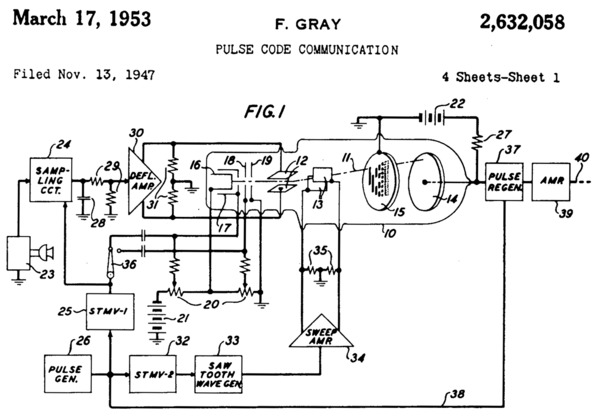
Part of front page of Gray’s patent, showing PCM tube (10) with reflected binary code in plate (15)
Gray was most interested in using the codes to minimize errors in converting analog signals to digital; his codes are still used today for this purpose.
Position encoders[edit]

Rotary encoder for angle-measuring devices marked in 3-bit binary-reflected Gray code (BRGC)
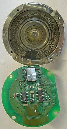
A Gray code absolute rotary encoder with 13 tracks. Housing, interrupter disk, and light source are in the top; sensing element and support components are in the bottom.
Gray codes are used in linear and rotary position encoders (absolute encoders and quadrature encoders) in preference to weighted binary encoding. This avoids the possibility that, when multiple bits change in the binary representation of a position, a misread will result from some of the bits changing before others.
For example, some rotary encoders provide a disk which has an electrically conductive Gray code pattern on concentric rings (tracks). Each track has a stationary metal spring contact that provides electrical contact to the conductive code pattern. Together, these contacts produce output signals in the form of a Gray code. Other encoders employ non-contact mechanisms based on optical or magnetic sensors to produce the Gray code output signals.
Regardless of the mechanism or precision of a moving encoder, position measurement error can occur at specific positions (at code boundaries) because the code may be changing at the exact moment it is read (sampled). A binary output code could cause significant position measurement errors because it is impossible to make all bits change at exactly the same time. If, at the moment the position is sampled, some bits have changed and others have not, the sampled position will be incorrect. In the case of absolute encoders, the indicated position may be far away from the actual position and, in the case of incremental encoders, this can corrupt position tracking.
In contrast, the Gray code used by position encoders ensures that the codes for any two consecutive positions will differ by only one bit and, consequently, only one bit can change at a time. In this case, the maximum position error will be small, indicating a position adjacent to the actual position.
Genetic algorithms[edit]
Due to the Hamming distance properties of Gray codes, they are sometimes used in genetic algorithms.[14] They are very useful in this field, since mutations in the code allow for mostly incremental changes, but occasionally a single bit-change can cause a big leap and lead to new properties.
Boolean circuit minimization[edit]
Gray codes are also used in labelling the axes of Karnaugh maps since 1953[44][45][46] as well as in Händler circle graphs since 1958,[47][48][49][50] both graphical methods for logic circuit minimization.
Error correction[edit]
In modern digital communications, Gray codes play an important role in error correction. For example, in a digital modulation scheme such as QAM where data is typically transmitted in symbols of 4 bits or more, the signal’s constellation diagram is arranged so that the bit patterns conveyed by adjacent constellation points differ by only one bit. By combining this with forward error correction capable of correcting single-bit errors, it is possible for a receiver to correct any transmission errors that cause a constellation point to deviate into the area of an adjacent point. This makes the transmission system less susceptible to noise.
Communication between clock domains[edit]
Digital logic designers use Gray codes extensively for passing multi-bit count information between synchronous logic that operates at different clock frequencies. The logic is considered operating in different «clock domains». It is fundamental to the design of large chips that operate with many different clocking frequencies.
Cycling through states with minimal effort[edit]
If a system has to cycle through all possible combinations of on-off states of some set of controls, and the changes of the controls require non-trivial expense (e.g. time, wear, human work), a Gray code minimizes the number of setting changes to just one change for each combination of states. An example would be testing a piping system for all combinations of settings of its manually operated valves.
A balanced Gray code can be constructed,[51] that flips every bit equally often. Since bit-flips are evenly distributed, this is optimal in the following way: balanced Gray codes minimize the maximal count of bit-flips for each digit.
Gray code counters and arithmetic[edit]
George R. Stibitz utilized a reflected binary code in a binary pulse counting device in 1941 already.[10][11][12]
A typical use of Gray code counters is building a FIFO (first-in, first-out) data buffer that has read and write ports that exist in different clock domains. The input and output counters inside such a dual-port FIFO are often stored using Gray code to prevent invalid transient states from being captured when the count crosses clock domains.[52]
The updated read and write pointers need to be passed between clock domains when they change, to be able to track FIFO empty and full status in each domain. Each bit of the pointers is sampled non-deterministically for this clock domain transfer. So for each bit, either the old value or the new value is propagated. Therefore, if more than one bit in the multi-bit pointer is changing at the sampling point, a «wrong» binary value (neither new nor old) can be propagated. By guaranteeing only one bit can be changing, Gray codes guarantee that the only possible sampled values are the new or old multi-bit value. Typically Gray codes of power-of-two length are used.
Sometimes digital buses in electronic systems are used to convey quantities that can only increase or decrease by one at a time, for example the output of an event counter which is being passed between clock domains or to a digital-to-analog converter. The advantage of Gray codes in these applications is that differences in the propagation delays of the many wires that represent the bits of the code cannot cause the received value to go through states that are out of the Gray code sequence. This is similar to the advantage of Gray codes in the construction of mechanical encoders, however the source of the Gray code is an electronic counter in this case. The counter itself must count in Gray code, or if the counter runs in binary then the output value from the counter must be reclocked after it has been converted to Gray code, because when a value is converted from binary to Gray code,[nb 1] it is possible that differences in the arrival times of the binary data bits into the binary-to-Gray conversion circuit will mean that the code could go briefly through states that are wildly out of sequence. Adding a clocked register after the circuit that converts the count value to Gray code may introduce a clock cycle of latency, so counting directly in Gray code may be advantageous.[53]
To produce the next count value in a Gray-code counter, it is necessary to have some combinational logic that will increment the current count value that is stored. One way to increment a Gray code number is to convert it into ordinary binary code,[54] add one to it with a standard binary adder, and then convert the result back to Gray code.[55] Other methods of counting in Gray code are discussed in a report by Robert W. Doran, including taking the output from the first latches of the master-slave flip flops in a binary ripple counter.[56]
Gray code addressing[edit]
As the execution of program code typically causes an instruction memory access pattern of locally consecutive addresses, bus encodings using Gray code addressing instead of binary addressing can reduce the number of state changes of the address bits significantly, thereby reducing the CPU power consumption in some low-power designs.[57][58]
Constructing an n-bit Gray code[edit]
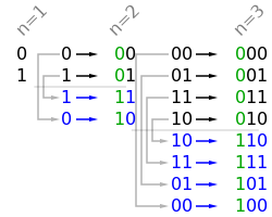
The first few steps of the reflect-and-prefix method.

4-bit Gray code permutation
The binary-reflected Gray code list for n bits can be generated recursively from the list for n − 1 bits by reflecting the list (i.e. listing the entries in reverse order), prefixing the entries in the original list with a binary 0, prefixing the entries in the reflected list with a binary 1, and then concatenating the original list with the reversed list.[12] For example, generating the n = 3 list from the n = 2 list:
| 2-bit list: | 00, 01, 11, 10 | |
| Reflected: | 10, 11, 01, 00 | |
| Prefix old entries with 0: | 000, 001, 011, 010, | |
| Prefix new entries with 1: | 110, 111, 101, 100 | |
| Concatenated: | 000, 001, 011, 010, | 110, 111, 101, 100 |
The one-bit Gray code is G1 = (0,1). This can be thought of as built recursively as above from a zero-bit Gray code G0 = ( Λ ) consisting of a single entry of zero length. This iterative process of generating Gn+1 from Gn makes the following properties of the standard reflecting code clear:
- Gn is a permutation of the numbers 0, …, 2n − 1. (Each number appears exactly once in the list.)
- Gn is embedded as the first half of Gn+1.
- Therefore, the coding is stable, in the sense that once a binary number appears in Gn it appears in the same position in all longer lists; so it makes sense to talk about the reflective Gray code value of a number: G(m) = the mth reflecting Gray code, counting from 0.
- Each entry in Gn differs by only one bit from the previous entry. (The Hamming distance is 1.)
- The last entry in Gn differs by only one bit from the first entry. (The code is cyclic.)
These characteristics suggest a simple and fast method of translating a binary value into the corresponding Gray code. Each bit is inverted if the next higher bit of the input value is set to one. This can be performed in parallel by a bit-shift and exclusive-or operation if they are available: the nth Gray code is obtained by computing 


- 000,001,010,011,100,101,110,111 → 001,000,011,010,101,100,111,110 (invert bit 0)
If bit 1 is inverted, blocks of 2 codewords change order:
- 000,001,010,011,100,101,110,111 → 010,011,000,001,110,111,100,101 (invert bit 1)
If bit 2 is inverted, blocks of 4 codewords reverse order:
- 000,001,010,011,100,101,110,111 → 100,101,110,111,000,001,010,011 (invert bit 2)
Thus, performing an exclusive or on a bit 


A similar method can be used to perform the reverse translation, but the computation of each bit depends on the computed value of the next higher bit so it cannot be performed in parallel. Assuming 


To construct the binary-reflected Gray code iteratively, at step 0 start with the 


Converting to and from Gray code[edit]
The following functions in C convert between binary numbers and their associated Gray codes. While it may seem that Gray-to-binary conversion requires each bit to be handled one at a time, faster algorithms exist.[59][54][nb 1]
typedef unsigned int uint;

// This function converts an unsigned binary number to reflected binary Gray code.
uint BinaryToGray(uint num)
{
    return num ^ (num >> 1); // The operator >> is shift right. The operator ^ is exclusive or.
}

// This function converts a reflected binary Gray code number to a binary number.
uint GrayToBinary(uint num)
{
    uint mask = num;
    while (mask) {           // Each Gray code bit is exclusive-ored with all more significant bits.
        mask >>= 1;
        num   ^= mask;
    }
    return num;
}

// A more efficient version for Gray codes 32 bits or fewer through the use of SWAR (SIMD within a register) techniques.
// It implements a parallel prefix XOR function. The assignment statements can be in any order.
//
// This function can be adapted for longer Gray codes by adding steps.

uint GrayToBinary32(uint num)
{
    num ^= num >> 16;
    num ^= num >>  8;
    num ^= num >>  4;
    num ^= num >>  2;
    num ^= num >>  1;
    return num;
}
// A Four-bit-at-once variant changes a binary number (abcd)2 to (abcd)2 ^ (00ab)2, then to (abcd)2 ^ (00ab)2 ^ (0abc)2 ^ (000a)2.
On newer processors, the number of ALU instructions in the decoding step can be reduced by taking advantage of the CLMUL instruction set. If MASK is the constant binary string of ones ended with a single zero digit, then carryless multiplication of MASK with the grey encoding of x will always give either x or its bitwise negation.
Special types of Gray codes[edit]
In practice, «Gray code» almost always refers to a binary-reflected Gray code (BRGC).
However, mathematicians have discovered other kinds of Gray codes.
Like BRGCs, each consists of a list of words, where each word differs from the next in only one digit (each word has a Hamming distance of 1 from the next word).
Gray codes with n bits and of length less than 2n[edit]
It is possible to construct binary Gray codes with n bits with a length of less than 2n, if the length is even. One possibility is to start with a balanced Gray code and remove pairs of values at either the beginning and the end, or in the middle.[60] OEIS sequence A290772 [61] gives the number of possible Gray sequences of length 2 n which include zero and use the minimum number of bits.
n-ary Gray code[edit]
0 → 000
1 → 001
2 → 002
10 → 012
11 → 011
12 → 010
20 → 020
21 → 021
22 → 022
100 → 122
101 → 121
102 → 120
110 → 110
111 → 111
112 → 112
120 → 102
121 → 101
122 → 100
200 → 200
201 → 201
202 → 202
210 → 212
211 → 211
212 → 210
220 → 220
221 → 221
222 → 222
There are many specialized types of Gray codes other than the binary-reflected Gray code. One such type of Gray code is the n-ary Gray code, also known as a non-Boolean Gray code. As the name implies, this type of Gray code uses non-Boolean values in its encodings.
For example, a 3-ary (ternary) Gray code would use the values 0,1,2.[30] The (n, k)-Gray code is the n-ary Gray code with k digits.[62]
The sequence of elements in the (3, 2)-Gray code is: 00,01,02,12,11,10,20,21,22. The (n, k)-Gray code may be constructed recursively, as the BRGC, or may be constructed iteratively. An algorithm to iteratively generate the (N, k)-Gray code is presented (in C):
// inputs: base, digits, value
// output: Gray
// Convert a value to a Gray code with the given base and digits.
// Iterating through a sequence of values would result in a sequence
// of Gray codes in which only one digit changes at a time.
void toGray(unsigned base, unsigned digits, unsigned value, unsigned gray[digits])
{
	unsigned baseN[digits];	// Stores the ordinary base-N number, one digit per entry
	unsigned i;		// The loop variable

	// Put the normal baseN number into the baseN array. For base 10, 109
	// would be stored as [9,0,1]
	for (i = 0; i < digits; i++) {
		baseN[i] = value % base;
		value    = value / base;
	}

	// Convert the normal baseN number into the Gray code equivalent. Note that
	// the loop starts at the most significant digit and goes down.
	unsigned shift = 0;
	while (i--) {
		// The Gray digit gets shifted down by the sum of the higher
		// digits.
		gray[i] = (baseN[i] + shift) % base;
		shift = shift + base - gray[i];	// Subtract from base so shift is positive
	}
}
// EXAMPLES
// input: value = 1899, base = 10, digits = 4
// output: baseN[] = [9,9,8,1], gray[] = [0,1,7,1]
// input: value = 1900, base = 10, digits = 4
// output: baseN[] = [0,0,9,1], gray[] = [0,1,8,1]
There are other Gray code algorithms for (n,k)-Gray codes. The (n,k)-Gray code produced by the above algorithm is always cyclical; some algorithms, such as that by Guan,[62] lack this property when k is odd. On the other hand, while only one digit at a time changes with this method, it can change by wrapping (looping from n − 1 to 0). In Guan’s algorithm, the count alternately rises and falls, so that the numeric difference between two Gray code digits is always one.
Gray codes are not uniquely defined, because a permutation of the columns of such a code is a Gray code too. The above procedure produces a code in which the lower the significance of a digit, the more often it changes, making it similar to normal counting methods.
See also Skew binary number system, a variant ternary number system where at most two digits change on each increment, as each increment can be done with at most one digit carry operation.
Balanced Gray code[edit]
Although the binary reflected Gray code is useful in many scenarios, it is not optimal in certain cases because of a lack of «uniformity».[51] In balanced Gray codes, the number of changes in different coordinate positions are as close as possible. To make this more precise, let G be an R-ary complete Gray cycle having transition sequence 

A Gray code is uniform or uniformly balanced if its transition counts are all equal, in which case we have
for all k. Clearly, when 


For example, a balanced 4-bit Gray code has 16 transitions, which can be evenly distributed among all four positions (four transitions per position), making it uniformly balanced:[51]
- 0 1 1 1 1 1 1 0 0 0 0 0 0 1 1 0
- 0 0 1 1 1 1 0 0 1 1 1 1 0 0 0 0
- 0 0 0 0 1 1 1 1 1 0 0 1 1 1 0 0
- 0 0 0 1 1 0 0 0 0 0 1 1 1 1 1 1
whereas a balanced 5-bit Gray code has a total of 32 transitions, which cannot be evenly distributed among the positions. In this example, four positions have six transitions each, and one has eight:[51]
- 1 1 1 1 1 0 0 0 0 1 1 1 1 1 1 0 0 1 1 1 1 1 0 0 0 0 0 0 0 0 0 0
- 0 0 0 1 1 1 1 1 1 1 1 0 0 0 0 0 0 0 1 1 1 1 1 1 0 0 0 1 1 0 0 0
- 1 1 0 0 1 1 1 0 0 0 0 0 0 1 1 1 0 0 0 1 1 1 1 1 1 0 0 0 0 0 1 1
- 1 0 0 0 0 0 0 0 1 1 1 1 1 1 0 0 0 0 0 0 1 1 1 1 1 1 1 1 0 0 0 1
- 1 1 1 1 1 1 0 0 0 0 1 1 0 0 0 0 0 0 0 0 0 1 1 0 0 0 1 1 1 1 1 1
We will now show a construction[65] and implementation[66] for well-balanced binary Gray codes which allows us to generate an n-digit balanced Gray code for every n. The main principle is to inductively construct an (n + 2)-digit Gray code 


where 







If we define the transition multiplicities

to be the number of times the digit in position i changes between consecutive blocks in a partition, then for the (n + 2)-digit Gray code induced by this partition the transition spectrum 

The delicate part of this construction is to find an adequate partitioning of a balanced n-digit Gray code such that the code induced by it remains balanced, but for this only the transition multiplicities matter; joining two consecutive blocks over a digit 


Long run Gray codes[edit]
Long run (or maximum gap) Gray codes maximize the distance between consecutive changes of digits in the same position. That is, the minimum run-length of any bit remains unchanged for as long as possible.[67]
Monotonic Gray codes[edit]
Monotonic codes are useful in the theory of interconnection networks, especially for minimizing dilation for linear arrays of processors.[68]
If we define the weight of a binary string to be the number of 1s in the string, then although we clearly cannot have a Gray code with strictly increasing weight, we may want to approximate this by having the code run through two adjacent weights before reaching the next one.
We can formalize the concept of monotone Gray codes as follows: consider the partition of the hypercube 

for 
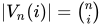





An elegant construction of monotonic n-digit Gray codes for any n is based on the idea of recursively building subpaths 



otherwise. Here, 



The choice of 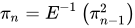
|
|
j = 0 | j = 1 | j = 2 | j = 3 |
|---|---|---|---|---|
| n = 1 | 0, 1 | |||
| n = 2 | 00, 01 | 10, 11 | ||
| n = 3 | 000, 001 | 100, 110, 010, 011 | 101, 111 | |
| n = 4 | 0000, 0001 | 1000, 1100, 0100, 0110, 0010, 0011 | 1010, 1011, 1001, 1101, 0101, 0111 | 1110, 1111 |
These monotonic Gray codes can be efficiently implemented in such a way that each subsequent element can be generated in O(n) time. The algorithm is most easily described using coroutines.
Monotonic codes have an interesting connection to the Lovász conjecture, which states that every connected vertex-transitive graph contains a Hamiltonian path. The «middle-level» subgraph 

Beckett–Gray code[edit]
Another type of Gray code, the Beckett–Gray code, is named for Irish playwright Samuel Beckett, who was interested in symmetry. His play «Quad» features four actors and is divided into sixteen time periods. Each period ends with one of the four actors entering or leaving the stage. The play begins and ends with an empty stage, and Beckett wanted each subset of actors to appear on stage exactly once.[70] Clearly the set of actors currently on stage can be represented by a 4-bit binary Gray code. Beckett, however, placed an additional restriction on the script: he wished the actors to enter and exit so that the actor who had been on stage the longest would always be the one to exit. The actors could then be represented by a first in, first out queue, so that (of the actors onstage) the actor being dequeued is always the one who was enqueued first.[70] Beckett was unable to find a Beckett–Gray code for his play, and indeed, an exhaustive listing of all possible sequences reveals that no such code exists for n = 4. It is known today that such codes do exist for n = 2, 5, 6, 7, and 8, and do not exist for n = 3 or 4. An example of an 8-bit Beckett–Gray code can be found in Donald Knuth’s Art of Computer Programming.[12] According to Sawada and Wong, the search space for n = 6 can be explored in 15 hours, and more than 9,500 solutions for the case n = 7 have been found.[71]
Snake-in-the-box codes[edit]

Maximum lengths of snakes (Ls) and coils (Lc) in the snakes-in-the-box problem for dimensions n from 1 to 4
Snake-in-the-box codes, or snakes, are the sequences of nodes of induced paths in an n-dimensional hypercube graph, and coil-in-the-box codes,[72] or coils, are the sequences of nodes of induced cycles in a hypercube. Viewed as Gray codes, these sequences have the property of being able to detect any single-bit coding error. Codes of this type were first described by William H. Kautz in the late 1950s;[4] since then, there has been much research on finding the code with the largest possible number of codewords for a given hypercube dimension.
Single-track Gray code[edit]
Yet another kind of Gray code is the single-track Gray code (STGC) developed by Norman B. Spedding[73][74] and refined by Hiltgen, Paterson and Brandestini in «Single-track Gray codes» (1996).[75][76] The STGC is a cyclical list of P unique binary encodings of length n such that two consecutive words differ in exactly one position, and when the list is examined as a P × n matrix, each column is a cyclic shift of the first column.[77]

Single-track Gray code with 5 sensors.

Animated and color-coded version of the STGC rotor.
The name comes from their use with rotary encoders, where a number of tracks are being sensed by contacts, resulting for each in an output of 0 or 1. To reduce noise due to different contacts not switching at exactly the same moment in time, one preferably sets up the tracks so that the data output by the contacts are in Gray code. To get high angular accuracy, one needs lots of contacts; in order to achieve at least 1° accuracy, one needs at least 360 distinct positions per revolution, which requires a minimum of 9 bits of data, and thus the same number of contacts.
If all contacts are placed at the same angular position, then 9 tracks are needed to get a standard BRGC with at least 1° accuracy. However, if the manufacturer moves a contact to a different angular position (but at the same distance from the center shaft), then the corresponding «ring pattern» needs to be rotated the same angle to give the same output. If the most significant bit (the inner ring in Figure 1) is rotated enough, it exactly matches the next ring out. Since both rings are then identical, the inner ring can be cut out, and the sensor for that ring moved to the remaining, identical ring (but offset at that angle from the other sensor on that ring). Those two sensors on a single ring make a quadrature encoder. That reduces the number of tracks for a «1° resolution» angular encoder to 8 tracks. Reducing the number of tracks still further cannot be done with BRGC.
For many years, Torsten Sillke[78] and other mathematicians believed that it was impossible to encode position on a single track such that consecutive positions differed at only a single sensor, except for the 2-sensor, 1-track quadrature encoder. So for applications where 8 tracks were too bulky, people used single-track incremental encoders (quadrature encoders) or 2-track «quadrature encoder + reference notch» encoders.
Norman B. Spedding, however, registered a patent in 1994 with several examples showing that it was possible.[73] Although it is not possible to distinguish 2n positions with n sensors on a single track, it is possible to distinguish close to that many. Etzion and Paterson conjecture that when n is itself a power of 2, n sensors can distinguish at most 2n − 2n positions and that for prime n the limit is 2n − 2 positions.[79] The authors went on to generate a 504-position single track code of length 9 which they believe is optimal. Since this number is larger than 28 = 256, more than 8 sensors are required by any code, although a BRGC could distinguish 512 positions with 9 sensors.
An STGC for P = 30 and n = 5 is reproduced here:
-
Single-track Gray code for 30 positions
Angle Code Angle Code Angle Code Angle Code Angle Code 0° 10000 72° 01000 144° 00100 216° 00010 288° 00001 12° 10100 84° 01010 156° 00101 228° 10010 300° 01001 24° 11100 96° 01110 168° 00111 240° 10011 312° 11001 36° 11110 108° 01111 180° 10111 252° 11011 324° 11101 48° 11010 120° 01101 192° 10110 264° 01011 336° 10101 60° 11000 132° 01100 204° 00110 276° 00011 348° 10001
Each column is a cyclic shift of the first column, and from any row to the next row only one bit changes.[80]
The single-track nature (like a code chain) is useful in the fabrication of these wheels (compared to BRGC), as only one track is needed, thus reducing their cost and size.
The Gray code nature is useful (compared to chain codes, also called De Bruijn sequences), as only one sensor will change at any one time, so the uncertainty during a transition between two discrete states will only be plus or minus one unit of angular measurement the device is capable of resolving.[81]
Two-dimensional Gray code[edit]

A Gray-coded constellation diagram for rectangular 16-QAM
Two-dimensional Gray codes are used in communication to minimize the number of bit errors in quadrature amplitude modulation (QAM) adjacent points in the constellation. In a typical encoding the horizontal and vertical adjacent constellation points differ by a single bit, and diagonal adjacent points differ by 2 bits.[82]
Two-dimensional Gray codes also have uses in location identifications schemes, where the code would be applied to area maps such as a Mercator projection of the earth’s surface and an appropriate cyclic two-dimensional distance function such as the Mannheim metric be used to calculate the distance between two encoded locations, thereby combining the characteristics of the Hamming distance with the cyclic continuation of a Mercator projection.[83]
Excess-Gray-Code[edit]
If a subsection of a specific codevalue is extracted from that value, for example the last 3 bits of a 4-bit gray-code, the resulting code will be an «excess gray code». This code shows the property of counting backwards in those extracted bits if the original value is further increased. Reason for this is that gray-encoded values do not show the behaviour of overflow, known from classic binary encoding, when increasing past the «highest» value.
Example: The highest 3-bit gray code, 7, is encoded as (0)100. Adding 1 results in number 8, encoded in gray as 1100. The last 3 bits do not overflow and count backwards if you further increase the original 4 bit code.
When working with sensors that output multiple, gray-encoded values in a serial fashion, one should therefore pay attention whether the sensor produces those multiple values encoded in 1 single gray-code or as separate ones, as otherwise the values might appear to be counting backwards when an «overflow» is expected.
Gray isometry[edit]
The bijective mapping { 0 ↔ 00, 1 ↔ 01, 2 ↔ 11, 3 ↔ 10 } establishes an isometry between the metric space over the finite field 


[edit]
There are a number of binary codes similar to Gray codes, including:
- Datex codes aka Giannini codes (1954), as described by Carl P. Spaulding,[8][86][87][88][89][7] use a variant of O’Brien code II.
- Codes used by Varec (ca. 1954),[90][91][92][93] use a variant of O’Brien code I as well as base-12 and base-16 Gray code variants.
- Lucal code (1959)[1][2][56] aka modified reflected binary code (MRB)[1][2][nb 3]
- Gillham code (1961/1962),[87][94][7][95][96] uses a variant of Datex code and O’Brien code II.
- Leslie and Russell code (1964)[97][9][98][94]
- Royal Radar Establishment code[94]
- Hoklas code (1988)[99][100][101]
The following binary-coded decimal (BCD) codes are Gray code variants as well:
- Petherick code (1953),[18][102][103][104][54][100][nb 4] also known as Royal Aircraft Establishment (RAE) code.[105]
- O’Brien codes I and II (1955)[106][107][108][88][89][100] (An O’Brien type-I code[nb 5] was already described by Frederic A. Foss of IBM[109][110] and used by Varec in 1954. Later, it was also known as Watts code or Watts reflected decimal (WRD) code and is sometimes ambiguously referred to as reflected binary modified Gray code.[111][19][20][112][113][114][115][116][117][nb 1][nb 3] An O’Brien type-II code was already used by Datex in 1954.[nb 4])
- Excess-3 Gray code (1956)[118] (aka Gray excess-3 code,[88][89][7] Gray 3-excess code, reflex excess-3 code, excess Gray code,[100] Gray excess code, 10-excess-3 Gray code or Gray–Stibitz code), described by Frank P. Turvey Jr. of ITT.[118]
- Tompkins codes I and II (1956)[3][107][108][88][89][100]
- Glixon code (1957), sometimes ambiguously also called modified Gray code[119][54][120][121][107][108][88][89][100][nb 3][nb 5]
| Name | Bit | 0 | 1 | 2 | 3 | 4 | 5 | 6 | 7 | 8 | 9 | Weights[nb 7] | Tracks | Compl. | Cyclic | 5s | Comment |
| Gray BCD | 4 | 0 | 0 | 0 | 0 | 0 | 0 | 0 | 0 | 1 | 1 | 0—3 | 4 (3[nb 8]) | No | (2, 4, 8, 16) | No | [107][108] |
| 3 | 0 | 0 | 0 | 0 | 1 | 1 | 1 | 1 | 1 | 1 | |||||||
| 2 | 0 | 0 | 1 | 1 | 1 | 1 | 0 | 0 | 0 | 0 | |||||||
| 1 | 0 | 1 | 1 | 0 | 0 | 1 | 1 | 0 | 0 | 1 | |||||||
| Paul | 4 | 1 | 0 | 0 | 0 | 0 | 0 | 0 | 0 | 1 | 1 | 1—3 | 4 (3[nb 8]) | No | 2, 10 | No | [122] |
| 3 | 0 | 0 | 0 | 0 | 1 | 1 | 1 | 1 | 1 | 1 | |||||||
| 2 | 0 | 0 | 1 | 1 | 1 | 1 | 0 | 0 | 0 | 0 | |||||||
| 1 | 1 | 1 | 1 | 0 | 0 | 1 | 1 | 0 | 0 | 1 | |||||||
| Glixon | 4 | 0 | 0 | 0 | 0 | 0 | 0 | 0 | 0 | 1 | 1 | 0—3 | 4 | No | 2, 4, 8, 10 | (shifted +1) | [119][107][108][120][121][nb 5] |
| 3 | 0 | 0 | 0 | 0 | 1 | 1 | 1 | 1 | 1 | 0 | |||||||
| 2 | 0 | 0 | 1 | 1 | 1 | 1 | 0 | 0 | 0 | 0 | |||||||
| 1 | 0 | 1 | 1 | 0 | 0 | 1 | 1 | 0 | 0 | 0 | |||||||
| Tompkins I | 4 | 0 | 0 | 0 | 0 | 0 | 1 | 1 | 1 | 1 | 1 | 0—4 | 2 | No | 2, 4, 10 | Yes | [3][107][108] |
| 3 | 0 | 0 | 0 | 0 | 1 | 1 | 1 | 1 | 1 | 0 | |||||||
| 2 | 0 | 0 | 1 | 1 | 1 | 1 | 1 | 0 | 0 | 0 | |||||||
| 1 | 0 | 1 | 1 | 0 | 0 | 0 | 1 | 1 | 0 | 0 | |||||||
| O’Brien I (Watts) | 4 | 0 | 0 | 0 | 0 | 0 | 1 | 1 | 1 | 1 | 1 | 0—3 | 4 | 9[100][101][nb 9] | 2, 4, 10 | Yes | [106][107][108][nb 5] |
| 3 | 0 | 0 | 0 | 0 | 1 | 1 | 0 | 0 | 0 | 0 | |||||||
| 2 | 0 | 0 | 1 | 1 | 1 | 1 | 1 | 1 | 0 | 0 | |||||||
| 1 | 0 | 1 | 1 | 0 | 0 | 0 | 0 | 1 | 1 | 0 | |||||||
| Petherick (RAE) | 4 | 0 | 0 | 0 | 0 | 0 | 1 | 1 | 1 | 1 | 1 | 1—3 | 3 | 9[100][101][nb 9] | 2, 10 | Yes | [18][104][nb 4] |
| 3 | 1 | 0 | 0 | 0 | 1 | 1 | 0 | 0 | 0 | 1 | |||||||
| 2 | 0 | 0 | 1 | 1 | 1 | 1 | 1 | 1 | 0 | 0 | |||||||
| 1 | 1 | 1 | 1 | 0 | 0 | 0 | 0 | 1 | 1 | 1 | |||||||
| O’Brien II | 4 | 0 | 0 | 0 | 0 | 0 | 1 | 1 | 1 | 1 | 1 | 1—3 | 3 | 9[88][100][101][nb 9] | 2, 10 | Yes | [106][107][108][nb 4] |
| 3 | 0 | 0 | 0 | 1 | 1 | 1 | 1 | 0 | 0 | 0 | |||||||
| 2 | 0 | 1 | 1 | 1 | 0 | 0 | 1 | 1 | 1 | 0 | |||||||
| 1 | 1 | 1 | 0 | 0 | 0 | 0 | 0 | 0 | 1 | 1 | |||||||
| Susskind | 4 | 0 | 0 | 0 | 0 | 0 | 1 | 1 | 1 | 1 | 1 | 1—4 | 3 | 9[nb 9] | 2, 10 | Yes | [5] |
| 3 | 0 | 0 | 1 | 1 | 1 | 1 | 1 | 1 | 0 | 0 | |||||||
| 2 | 0 | 1 | 1 | 1 | 0 | 0 | 1 | 1 | 1 | 0 | |||||||
| 1 | 1 | 1 | 1 | 0 | 0 | 0 | 0 | 1 | 1 | 1 | |||||||
| Klar | 4 | 0 | 0 | 0 | 0 | 0 | 1 | 1 | 1 | 1 | 1 | 0—4 | 4 (3[nb 8]) | 9[nb 9] | 2, 10 | Yes | [123][124] |
| 3 | 0 | 0 | 0 | 1 | 1 | 1 | 1 | 0 | 0 | 0 | |||||||
| 2 | 0 | 0 | 1 | 1 | 1 | 1 | 1 | 1 | 0 | 0 | |||||||
| 1 | 0 | 1 | 1 | 1 | 0 | 0 | 1 | 1 | 1 | 0 | |||||||
| Tompkins II | 4 | 0 | 0 | 0 | 0 | 0 | 1 | 1 | 1 | 1 | 1 | 1—3 | 2 | 9[nb 10] | 2, 10 | Yes | [3][107][108] |
| 3 | 0 | 0 | 1 | 1 | 1 | 1 | 1 | 0 | 0 | 0 | |||||||
| 2 | 1 | 1 | 1 | 0 | 0 | 0 | 0 | 0 | 1 | 1 | |||||||
| 1 | 0 | 1 | 1 | 1 | 0 | 0 | 1 | 1 | 1 | 0 | |||||||
| Excess-3 Gray | 4 | 0 | 0 | 0 | 0 | 0 | 1 | 1 | 1 | 1 | 1 | 1—4 | 4 | 9[100][101][nb 9] | 2, 10 | Yes | [7][100] |
| 3 | 0 | 1 | 1 | 1 | 1 | 1 | 1 | 1 | 1 | 0 | |||||||
| 2 | 1 | 1 | 1 | 0 | 0 | 0 | 0 | 1 | 1 | 1 | |||||||
| 1 | 0 | 0 | 1 | 1 | 0 | 0 | 1 | 1 | 0 | 0 |
See also[edit]
- Linear-feedback shift register
- De Bruijn sequence
- Steinhaus–Johnson–Trotter algorithm – an algorithm that generates Gray codes for the factorial number system
- Minimum distance code
- Prouhet–Thue–Morse sequence – related to inverse Gray code
- Ryser formula
- Hilbert curve
Notes[edit]
- ^ a b c By applying a simple inversion rule, the Gray code and the O’Brien code I can be translated into the 8421 pure binary code and the 2421 Aiken code, respectively, to ease arithmetic operations.[C]
- ^ Sequence 0, 1, 0, 2, 0, 1, 0, 3, … (sequence A007814 in the OEIS).
- ^ a b c There are several Gray code variants which are called «modified» of some sort: The Glixon code is sometimes called modified Gray code.[D] The Lucal code is also called modified reflected binary code (MRB).[E] The O’Brien code I or Watts code is sometimes referred to as reflected binary modified Gray code.[F]
- ^ a b c d By interchanging and inverting three bit rows, the O’Brien code II and the Petherick code can be transferred into each other.
- ^ a b c d By swapping two pairs of bit rows, individually shifting four bit rows and inverting one of them, the Glixon code and the O’Brien code I can be transferred into each other.
- ^ Other unit-distance BCD codes include the non-Gray code related 5-bit Libaw–Craig and the 1-2-1 code.
- ^ Depending on a code’s target application, the Hamming weights of a code can be important properties beyond coding-theoretical considerations also for physical reasons. Under some circumstances the all-cleared and/or all-set states must be omitted (f.e. to avoid non-conductive or short-circuit conditions), it may be desirable to keep the highest used weight as low as possible (f.e. to reduce power consumption of the reader circuit) or to keep the variance of used weights small (f.e. to reduce acoustic noise or current fluctuations).
- ^ a b c For Gray BCD, Paul and Klar codes, the number of necessary reading tracks can be reduced from 4 to 3 if inversion of one of the middle tracks is acceptable.
- ^ a b c d e f For O’Brien codes I and II and Petherick, Susskind, Klar as well as Excess-3 Gray codes, a 9s complement can be derived by inverting the most-significant (fourth) binary digit.
- ^ For Tompkins code II, a 9s complement can be derived by inverting the first three digits and swapping the two middle binary digits.
References[edit]
- ^ a b c Lucal, Harold M. (December 1959). «Arithmetic Operations for Digital Computers Using a Modified Reflected Binary». IRE Transactions on Electronic Computers. EC-8 (4): 449–458. doi:10.1109/TEC.1959.5222057. ISSN 0367-9950. S2CID 206673385. (10 pages)
- ^ a b c Sellers, Jr., Frederick F.; Hsiao, Mu-Yue; Bearnson, Leroy W. (November 1968). Error Detecting Logic for Digital Computers (1st ed.). New York, USA: McGraw-Hill Book Company. pp. 152–164. LCCN 68-16491. OCLC 439460.
- ^ a b c d Tompkins, Howard E. (September 1956) [1956-07-16]. «Unit-Distance Binary-Decimal Codes for Two-Track Commutation». IRE Transactions on Electronic Computers. Correspondence. Moore School of Electrical Engineering, University of Pennsylvania, Philadelphia, Pennsylvania, USA. EC-5 (3): 139. doi:10.1109/TEC.1956.5219934. ISSN 0367-9950. Retrieved 2020-05-18. (1 page)
- ^ a b Kautz, William H. (June 1958). «Unit-Distance Error-Checking Codes». IRE Transactions on Electronic Computers. EC-7 (2): 179–180. doi:10.1109/TEC.1958.5222529. ISSN 0367-9950. S2CID 26649532. (2 pages)
- ^ a b Susskind, Alfred Kriss; Ward, John Erwin (1958-03-28) [1957, 1956]. «III.F. Unit-Distance Codes / VI.E.2. Reflected Binary Codes». Written at Cambridge, Massachusetts, USA. In Susskind, Alfred Kriss (ed.). Notes on Analog-Digital Conversion Techniques. Technology Books in Science and Engineering. Vol. 1 (3 ed.). New York, USA: Technology Press of the Massachusetts Institute of Technology / John Wiley & Sons, Inc. / Chapman & Hall, Ltd. pp. 3-10–3-16 [3-13–3-16], 6-65–6-60 [6-60]. (x+416+2 pages) (NB. The contents of the book was originally prepared by staff members of the Servomechanisms Laboraratory, Department of Electrical Engineering, MIT, for Special Summer Programs held in 1956 and 1957. Susskind’s «reading-type code» is actually a minor variant of the code shown here with the two most significant bit rows swapped to better illustrate symmetries. Also, by swapping two bit rows and inverting one of them, the code can be transferred into the Petherick code, whereas by swapping and inverting two bit rows, the code can be transferred into the O’Brien code II.)
- ^ a b Chinal, Jean P. (January 1973). «3.3. Unit Distance Codes». Written at Paris, France. Design Methods for Digital Systems. Translated by Preston, Alan; Summer, Arthur (1st English ed.). Berlin, Germany: Akademie-Verlag / Springer-Verlag. p. 50. doi:10.1007/978-3-642-86187-1. ISBN 978-0-387-05871-9. S2CID 60362404. License No. 202-100/542/73. Order No. 7617470(6047) ES 19 B 1 / 20 K 3. Retrieved 2020-06-21. (xviii+506 pages) (NB. The French 1967 original book was named «Techniques Booléennes et Calculateurs Arithmétiques», published by Éditions Dunod [fr].)
- ^ a b c d e f Military Handbook: Encoders – Shaft Angle To Digital (PDF). United States Department of Defense. 1991-09-30. MIL-HDBK-231A. Archived (PDF) from the original on 2020-07-25. Retrieved 2020-07-25. (NB. Supersedes MIL-HDBK-231(AS) (1970-07-01).)
- ^ a b c Spaulding, Carl P. (1965-01-12) [1954-03-09]. «Digital coding and translating system» (PDF). Monrovia, California, USA: Datex Corporation. U.S. Patent 3165731A. Serial No. 415058. Archived (PDF) from the original on 2020-08-05. Retrieved 2018-01-21. (28 pages)
- ^ a b Russell, A. (August 1964). «Some Binary Codes and a Novel Five-Channel Code». Control (Systems, Instrumentation, Data Processing, Automation, Management, incorporating Automation Progress). Special Features. London, UK: Morgan-Grampain (Publishers) Limited. 8 (74): 399–404. Retrieved 2020-06-22. (6 pages)
- ^ a b c Stibitz, George Robert (1943-01-12) [1941-11-26]. «Binary counter». New York, USA: Bell Telephone Laboratories, Incorporated. U.S. Patent 2,307,868. Serial No. 420537. Retrieved 2020-05-24. p. 2, right column, rows 43–73:
[…] A clearer idea of the position of the balls after each pulse will be obtained if the set of balls is represented by a number having a similar number of digits, each of which may have one of two arbitrary values, for example 0 and 1. If the upper position is called 0 and the lower position […] 1, then the setting of the counter […] may be read from left to right as 0,100,000. […] Following is a translation of the number of pulses received into this form of binary notation for the first sixteen pulses as received on the first five balls […] Pulse number […] Binary notation […]
[1] (4 pages) - ^ a b c d e Winder, C. Farrell (October 1959). «Shaft Angle Encoders Afford High Accuracy» (PDF). Electronic Industries. Chilton Company. 18 (10): 76–80. Archived from the original (PDF) on 2020-09-28. Retrieved 2018-01-14. p. 78:
[…] The type of code wheel most popular in optical encoders contains a cyclic binary code pattern designed to give a cyclic sequence of «on-off» outputs. The cyclic binary code is also known as the cyclic progression code, the reflected binary code, and the Gray code. This code was originated by G. R. Stibitz, of Bell Telephone Laboratories, and was first proposed for pulse-code modulation systems by Frank Gray, also of BTL. Thus the name Gray code. The Gray or cyclic code is used mainly to eliminate the possibility of errors at code transition which could result in gross ambiguities. […]
- ^ a b c d e f g h i Knuth, Donald Ervin (2014-09-12). «Enumeration and Backtracking / Generating all n-tuples». The Art of Computer Programming, Volume 4A: Combinatorial Algorithms, Part 1. Vol. 4A (1 ed.). Addison-Wesley Professional. pp. 442–443. ISBN 978-0-13348885-2. (912 pages)
- ^ a b Gray, Frank (1953-03-17) [1947-11-13]. Pulse Code Communication (PDF). New York, USA: Bell Telephone Laboratories, Incorporated. U.S. Patent 2,632,058. Serial No. 785697. Archived (PDF) from the original on 2020-08-05. Retrieved 2020-08-05. (13 pages)
- ^ a b Goldberg, David Edward (1989). Genetic Algorithms in Search, Optimization, and Machine Learning (1 ed.). Reading, Massachusetts, USA: Addison-Wesley. Bibcode:1989gaso.book…..G.
- ^ Breckman, Jack (1956-01-31) [1953-12-31]. Encoding Circuit (PDF). Long Branch, New Jersey, USA: US Secretary of the Army. U.S. Patent 2,733,432. Serial No. 401738. Archived (PDF) from the original on 2020-08-05. Retrieved 2020-08-05. (8 pages)
- ^ a b Ragland, Earl Albert; Schultheis, Jr., Harry B. (1958-02-11) [1953-10-16]. Direction-Sensitive Binary Code Position Control System (PDF). North Hollywood, California, USA: Bendix Aviation Corporation. U.S. Patent 2,823,345. Serial No. 386524. Archived (PDF) from the original on 2020-08-05. Retrieved 2020-08-05. (10 pages)
- ^ Domeshek, Sol; Reiner, Stewart (1958-06-24) [1954-01-08]. Automatic Rectification System (PDF). US Secretary of the Navy. U.S. Patent 2,839,974. Serial No. 403085. Archived (PDF) from the original on 2020-08-05. Retrieved 2020-08-05. (8 pages)
- ^ a b c Petherick, Edward John (October 1953). A Cyclic Progressive Binary-coded-decimal System of Representing Numbers (Technical Note MS15). Farnborough, UK: Royal Aircraft Establishment (RAE). (4 pages) (NB. Sometimes referred to as A Cyclic-Coded Binary-Coded-Decimal System of Representing Numbers.)
- ^ a b Evans, David Silvester (1960). Fundamentals of Digital Instrumentation (1 ed.). London, UK: Hilger & Watts Ltd. Retrieved 2020-05-24. (39 pages)
- ^ a b Evans, David Silvester (March 1961). «Chapter Three: Direct Reading from Coded Scales». Digital Data: Their derivation and reduction for analysis and process control (1 ed.). London, UK: Hilger & Watts Ltd / Interscience Publishers. pp. 18–23. Retrieved 2020-05-24. p. 20–23:
[…] Decoding. […] To decode C.P.B. or W.R.D. codes, a simple inversion rule can be applied. The readings of the higher tracks determine the way in which the lower tracks are translated. The inversion rule is applied line by line for the C.P.B. and for the W.R.D. it is applied decade by decade or line by line. Starting therefore with the top or slowest changing track of the C.P.B., if the result is odd (1) the next track value has to be inverted, i.e. 0 for 1 and 1 for 0. If, however, the first track is even (0), the second track is left as read, i.e. 0 for 0 and 1 for 1. Again, if the resultant reading of the second track is odd, the third track reading is inverted and so on. When an odd is changed to an even the line below is not inverted and when an even is changed to an odd the line below is inverted. The result of applying this rule to the pattern […] is the pure binary (P.B.) pattern […] where each track or digit can be given a definite numerical value (in this instance 1, 2, 4, 8, etc.). […] Using the line-by-line inversion rule on the W.R.D. code produces [a] pattern [of 1, 2, 4, 2 code] where again the digits can be given numerical values and summed decade by decade. The summing of the digits can be very useful, for example, in a high-speed scanning system; but in a parallel decoding system […], it is usual to treat each binary quartet or decade as an entity. In other words, if the first or more significant decade is odd, the second decade is rectified or complemented by inverting the D track and so on, the result being the repeating pattern of [rectified W.R.D. code]. This is an extremely easy thing to achieve since the only change required is the inversion of the meaning of the D track or complementing digit. […]
(8+82 pages) (NB. The author does not mention Gray at all and calls the standard Gray code «Cyclic Permuted Binary Code» (C.P.B.), the book index erroneously lists it as «cyclic pure binary code».) - ^ Newson, P. A. (1965). Tables for the Binary Encoding of Angles (1 ed.). United Kingdom Atomic Energy Authority, Research Group, Atomic Energy Research Establishment, Harwell, UK: H. M. Stationery Office. Retrieved 2020-05-24. (12 pages)
- ^ Heath, F. G. (September 1961). «Pioneers Of Binary Coding». Journal of the Institution of Electrical Engineers. Manchester College of Science and Technology, Faculty of Technology of the University of Manchester, Manchester, UK: Institution of Engineering and Technology (IET). 7 (81): 539–541. doi:10.1049/jiee-3.1961.0300. Retrieved 2020-06-22. (3 pages)
- ^ Cattermole, Kenneth W. (1969). Written at Harlow, Essex, UK. Principles of pulse code modulation (1 ed.). London, UK / New York, USA: Iliffe Books Ltd. / American Elsevier Publishing Company, Inc. pp. 245, 434. ISBN 978-0-444-19747-4. LCCN 78-80432. SBN 444-19747-8. p. 245:
[…] There seems to be some confusion about the attributation of this code, because two inventors named Gray have been associated with it. When I first heard the name I took it as referring to Elisha Gray, and Heath testifies to his usage of it. Many people take it as referring to Frank Gray of Bell Telephone Laboratories, who in 1947 first proposed its use in coding tubes: his patent is listed in the bibliography. […]
(2+448+2 pages) - ^ Edwards, Anthony William Fairbank (2004). Cogwheels of the Mind: The Story of Venn Diagrams. Baltimore, Maryland, USA: Johns Hopkins University Press. pp. 48, 50. ISBN 0-8018-7434-3.
- ^ Gros, Luc-Agathon-Louis (1872). Théorie du baguenodier par un clerc de notaire lyonnais (in French) (1 ed.). Lyon, France: Aimé Vingtrinier. Archived from the original on 2017-04-03. Retrieved 2020-12-17. [2](2+16+4 pages and 4 pages foldout) (NB. This booklet was published anonymously, but is known to have been authored by Louis Gros.)
- ^ Lucas, Édouard (November 1883). La tour d’Hanoï: Véritable casse tête annamite — Jeu rapporté du Tonkin par le Professeur N. Claus (de Siam) Mandarin du Collège Li Sou Stian! (in French). Imprimerie Paul Bousrez, Tours. (NB. N. Claus de Siam is an anagram of Lucas d’Amiens, pseudonym of the author Édouard Lucas.)
- ^ de Parville, Henri [in French], ed. (1883-12-27). «La tour d’Hanoï, véritable casse-tête annamite, jeu rapporté du Tonkin par le professeur N. Claus (de Siam), mandarin du collège Li-Sou-Stian. Un vrai casse-tête, en effet, mais intéressant. Nous ne saurions mieux remercier le mandarin de son aimable intention à l’égard d’un profane qu’en signalant la Tour d’Hanoï aux personnes patientes possédées par le démon du jeu». Journal des Débats Politiques et Littéraires (Review). Revue des science (in French) (Matin ed.). Paris, France: 1–2 [2]. ark:/12148/bpt6k462461g. Archived from the original on 2020-12-18. Retrieved 2020-12-18. (1 page)
- ^ Allardice, R. E.; Fraser, A. Y. (February 1883). Allardice, Robert Edgar; Fraser, Alexander Yule (eds.). «La Tour d’Hanoï». Proceedings of the Edinburgh Mathematical Society (in English and French). Edinburgh Mathematical Society. 2 (5): 50–53. doi:10.1017/S0013091500037147. eISSN 1464-3839. ISSN 0013-0915. S2CID 122159381. Archived from the original on 2020-12-18. Retrieved 2020-12-18. [3] (4 pages)
- ^ Lucas, Édouard (1979) [1892]. Récréations mathématiques (in French). Vol. 3 (Librairie Albert Blanchard reissue ed.). p. 58. (The first edition of this book was published post-humously.)
- ^ a b Herter, Felix; Rote, Günter (2018-11-14) [2018-08-09, 2017-12, 2017-08-09, 2016-04-22]. «Loopless Gray Code Enumeration and the Tower of Bucharest» (PDF). Theoretical Computer Science. Berlin, Germany. 748: 40–54. arXiv:1604.06707. doi:10.1016/j.tcs.2017.11.017. ISSN 0304-3975. S2CID 4014870. Archived (PDF) from the original on 2020-12-16. Retrieved 2020-12-16. [4] (15/18/19/24 pages)
- ^ Gardner, Martin (August 1972). «The curious properties of the Gray code and how it can be used to solve puzzles». Scientific American. Mathematical Games. Vol. 227, no. 2. p. 106. (1 page)
- ^ Zeman, Johann; Fischer, Ferdinand, eds. (1877). «Einige neuere Vorschläge zur mehrfachen Telegraphie: A. Absatzweise vielfache Telegraphie». Dingler’s Polytechnisches Journal (in German). Augsburg, Germany: J. G. Cotta’sche Buchhandlung. 226: 499–507. Archived from the original on 2020-12-21. Retrieved 2020-12-21. p. 499:
[…] Der um die Mitte des J[ahres] 1874 patenti[e]rte, ebenfalls dem Highton’schen verwandte Typendrucker des französischen Telegraphen-Verwaltungsbeamten Baudot wurde bei seiner 1875 patenti[e]rten Weiterentwicklung in einen fünffachen umgewandelt […]
- ^ Butrica, Andrew J. (1991-06-21). «Baudot, Jean Maurice Emile». In Froehlich, Fritz E.; Kent, Allen; Hall, Carolyn M. (eds.). The Froehlich/Kent Encyclopedia of Telecommunications: Volume 2 — Batteries to Codes-Telecommunications. Vol. 2. Marcel Dekker Inc. / CRC Press. pp. 31–34. ISBN 0-8247-2901-3. LCCN 90-3966. Retrieved 2020-12-20. p. 31:
[…] A Baudot prototype (4 years in the making) was built in 1876. The transmitter had 5 keys similar to those of a piano. Messages were sent in a special 5-element code devised by Baudot […]
- ^ Fischer, Eric N. (2000-06-20). «The Evolution of Character Codes, 1874–1968». ark:/13960/t07x23w8s. Retrieved 2020-12-20.
[…] In 1872, [Baudot] started research toward a telegraph system that would allow multiple operators to transmit simultaneously over a single wire and, as the transmissions were received, would print them in ordinary alphabetic characters on a strip of paper. He received a patent for such a system on June 17, 1874. […] Instead of a variable delay followed by a single-unit pulse, Baudot’s system used a uniform six time units to transmit each character. […] his early telegraph probably used the six-unit code […] that he attributes to Davy in an 1877 article. […] in 1876 Baudot redesigned his equipment to use a five-unit code. Punctuation and digits were still sometimes needed, though, so he adopted from Hughes the use of two special letter space and figure space characters that would cause the printer to shift between cases at the same time as it advanced the paper without printing. The five-unit code he began using at this time […] was structured to suit his keyboard […], which controlled two units of each character with switches operated by the left hand and the other three units with the right hand. […]
[5][6] - ^ Rothen, Timotheus (1884-12-25). «Le télégraphe imprimeur Baudot». Journal Télégraphique (in French). Berne, Switzerland: Le Bureau International des Administrations Télégraphiques. VIII / #16 (12): 241–253 [249]. eISSN 2725-738X. ISSN 2223-1420. ark:/12148/bpt6k5725454q. Retrieved 2020-12-20. [7]
- ^ Pendry, Henry Walter (1920) [October 1919]. Written at London, UK. The Baudôt Printing Telegraph System (2 ed.). London, Bath, Melbourne, New York: Sir Isaac Pitman and Sons, Ltd. pp. 43–44. LCCN 21005277. OCLC 778309351. OL 6633244M. Retrieved 2020-12-20. (vii+184 pages) (NB. A first edition was published in 1913.)
- ^ a b MacMillan, David M. (2010-04-27) [2010-04-25, 2010-04-23]. «Codes that Don’t Count — Some Printing Telegraph Codes as Products of their Technologies (With Particular Attention to the Teletypesetter)». lemur.com. Revision 3. Mineral Point, Wisconsin, USA. Archived from the original on 2020-12-18. Retrieved 2020-12-20.
- ^ Written at Lisbon, Portugual. Convention télégraphique internationale de Saint-Pétersbourg et Règlement et tarifs y annexés, Revision de Lisbonne, 1908 / Extraits de la publication: Documents de la Conférence télégraphique internationale de Lisbonne (in French). Berne, Switzerland: Bureau Internationale de L’Union Télégraphique. 1909 [1908].
- ^ «Chapter IX. Signaux de transmission, Article 35. Signaux de transmission des alphabets télegraphiques internationaux ‘nos 1 et 2, signaux d.u code Morse, de l’appareil Hughes et de l’appareil Siemens». Written at Madrid, Spain. Règlement télégraphique annexé à la convention internationale des télécommunications — protocol finale audit règlement — Madrid, 1932 (PDF) (in French). Berne, Switzerland: Bureau Internationale de L’Union Télégraphique. 1933 [1932]. pp. 31–40 [33]. Archived (PDF) from the original on 2020-12-21. Retrieved 2020-12-21. (1+188 pages) [8]
- ^ «Chapter IX. Transmission Signals. Article 35. Transmission Signals of the International Telegraph Alphabets Nos. 1 and 2, Morse Code Signals and Signals of the Hughes and Siemens Instruments.». Telegraph Regulations Annexed To The International Telecommunication Convention — Final Protocol To The Telegraph Regulations — Madrid 1932 (PDF) (in English and French). London, UK: General Post Office / His Majesty’s Stationery Office. 1933 [1932]. pp. 32–40 [34]. 43-152-2 / 18693. Archived (PDF) from the original on 2020-12-21. Retrieved 2020-12-21. (1+2*120+26 pages) [9]
- ^ Zemanek, Heinrich «Heinz» Josef (1983-12-01). Otto Schäffler (1838-1928). Pionier des Telephons, der Telegraphie und der Lochkarte sowie Erbauer der ersten Wiener Telephonzentrale. Blätter für Technikgeschichte (in German and English). Vol. 41–43 (1979–1981) (1 ed.). Vienna, Austria: Technisches Museum für Industrie und Gewerbe, Forschungsinstitut für Technikgeschichte / Springer-Verlag. pp. 81–118. ISBN 3-21181779-4. ISSN 0067-9127. OCLC 952698275.
- ^ Zemanek, Heinrich «Heinz» Josef (1976-06-07). «Computer prehistory and history in central Europe». Written at Vienna, Austria. International Workshop on Managing Requirements Knowledge. AFIPS ’76: Proceedings of the June 7–10, 1976, national computer conference and exposition June 1976. Vol. 1. New York, USA: American Federation of Information Processing Societies, Association for Computing Machinery. pp. 15–20. doi:10.1145/1499799.1499803. ISBN 978-1-4503-7917-5. S2CID 14114959. Archived from the original on 2020-12-17. Retrieved 2020-12-17. p. 17:
[…] In 1874, Schaeffler [de] invented another printing telegraph, a quadruple system like the Baudot, but mechanically more sophisticated. The Hughes telegraph had two synchronously rotating fingers, one in the sender and one in the receiver. By a piano-like keyboard the operator selected a letter and thereby made contact with the rotating finger in the corresponding direction. Since the receiving finger was in the same direction at this moment, the receiver could print the correct letter. The Baudot and the Schaeffler printing telegraphs use a five-bit binary code. … Schaeffler’s code is a reflected binary code! What F. Gray patented in 1953 for PCM, Schaeffler had applied in his telegraph in 1874, and for a similar reason: reliability. He had contact fingers sensing on five cams consecutively all combinations; the right one triggers printing. If the fingers are to make a minimal number of movements, the solution is the reflected binary code. For Schaeffler, this idea was a minor one. More exactly, the code is described in a letter by the Austrian Post employee, J[ohann] N[epomuk] Teufelhart, inserted there as a footnote and telling that Schaeffler found the code by combining wooden bars with the different combinations until he had the best solution. Another Post employee, Alexander Wilhelm Lambert of Linz, claims to have shown this code to Schaeffler as early as 1872, but this claim is not clear and cannot be checked. […]
(6 pages) - ^ Goodall, William M. (January 1951). «Television by Pulse Code Modulation». Bell System Technical Journal. 30 (1): 33–49. doi:10.1002/j.1538-7305.1951.tb01365.x. (NB. Presented orally before the I.R.E. National Convention, New York City, March 1949.)
- ^ Karnaugh, Maurice (November 1953) [1953-04-23, 1953-03-17]. «The Map Method for Synthesis of Combinational Logic Circuits» (PDF). Transactions of the American Institute of Electrical Engineers, Part I: Communication and Electronics. 72 (5): 593–599. doi:10.1109/TCE.1953.6371932. S2CID 51636736. Paper 53-217. Archived from the original (PDF) on 2017-04-16. Retrieved 2017-04-16. (NB. Also contains a short review by Samuel H. Caldwell.)
- ^ Wakerly, John F. (1994). Digital Design: Principles & Practices. New Jersey, USA: Prentice Hall. pp. 48–49, 222. ISBN 0-13-211459-3. (NB. The two page sections taken together say that K-maps are labeled with Gray code. The first section says that they are labeled with a code that changes only one bit between entries and the second section says that such a code is called Gray code.)
- ^ Brown, Frank Markham (2012) [2003, 1990]. «3.9.2 Maps». Boolean Reasoning – The Logic of Boolean Equations (reissue of 2nd ed.). Mineola, New York, USA: Dover Publications, Inc. p. 49. ISBN 978-0-486-42785-0. p. 49:
[…] Karnaugh’s map orders the arguments of the discriminants according to the reflected binary code, also called the Gray code. […]
(xii+291+3 pages) 1st edition - ^ Händler, Wolfgang (1958). Ein Minimisierungsverfahren zur Synthese von Schaltkreisen (Minimisierungsgraphen) (Dissertation) (in German). Potsdam, Germany: Technische Hochschule Darmstadt. D 17. (73 pages+app.) [10]
- ^ Berger, Erich R.; Händler, Wolfgang (1967) [1962]. Steinbuch, Karl W.; Wagner, Siegfried W. (eds.). Taschenbuch der Nachrichtenverarbeitung (in German) (2 ed.). Berlin, Germany: Springer-Verlag OHG. pp. 64, 1034–1035, 1036, 1038. LCCN 67-21079. Title No. 1036. p. 64:
[…] Übersichtlich ist die Darstellung nach Händler, die sämtliche Punkte, numeriert nach dem Gray-Code […], auf dem Umfeld eines Kreises anordnet. Sie erfordert allerdings sehr viel Platz. […]
[Händler’s diagram, where all points, numbered according to the Gray code, are arranged on the circumference of a circle, is easily comprehensible. It needs, however, a lot of space.] - ^ «Informatik Sammlung Erlangen (ISER)» (in German). Erlangen, Germany: Friedrich-Alexander Universität. 2012-03-13. Archived from the original on 2017-05-16. Retrieved 2017-04-12.
- ^ «Informatik Sammlung Erlangen (ISER) – Impressum» (in German). Erlangen, Germany: Friedrich-Alexander Universität. 2012-03-13. Archived from the original on 2012-02-26. Retrieved 2017-04-15.
- ^ a b c d e Bhat, Girish S.; Savage, Carla Diane (1996). «Balanced Gray Codes». Electronic Journal of Combinatorics. 3 (1). doi:10.37236/1249.
- ^ Donohue, Ryan (2003). «Synchronization in Digital Logic Circuits» (PDF). Archived (PDF) from the original on 2018-01-15. Retrieved 2018-01-15.
- ^ Hulst, George D. (1962-02-06) [1957-11-15]. Reflected binary code counter (PDF). Nutley, New Jersey, USA: International Telephone and Telegraph Corporation (ITT). U.S. Patent 3,020,481. Serial No. 696793. Archived (PDF) from the original on 2020-08-06. Retrieved 2020-08-06. (5 pages)
- ^ a b c d Powell, E. Alexander (June 1968). «Codes particularly useful for analogue to digital conversions». A short note on useful codes for Fluidic Control Circuits (PDF). Cranfield, UK: The College of Aeronautics, Department of Production Engineering. pp. 7, 9. S2CID 215864694. CoA Memo 156. Archived (PDF) from the original on 2020-12-15. Retrieved 2020-12-15. (18 pages) (NB. The paper names the Glixon code modified Gray code and misspells Richard W. Hamming’s name.)
- ^ Mehta, Huzefa; Owens, Robert Michael; Irwin, Mary Jane «Janie» (1996-03-22). «Some issues in Gray code addressing». Proceedings of the Sixth Great Lakes Symposium on VLSI. Proceedings of the 6th Great Lakes Symposium on VLSI (GLSVLSI 96). IEEE Computer Society. pp. 178–181. doi:10.1109/GLSV.1996.497616. ISBN 978-0-8186-7502-7. ISSN 1066-1395. S2CID 52837310.
- ^ a b Doran, Robert «Bob» William (March 2007). The Gray Code (PDF). CDMTCS Research Report Series. Centre for Discrete Mathematics and Theoretical Computer Science, University of Auckland, New Zealand. CDMTCS-304. Archived (PDF) from the original on 2020-05-22. Retrieved 2020-05-23. (25 pages)
- ^ Su, Ching-Long; Tsui, Chi-Ying; Despain, Alvin M. (1994). Low Power Architecture Design and Compilation Techniques for High-Performance Processors (PDF) (Report). Advanced Computer Architecture Laboratory. ACAL-TR-94-01. Archived (PDF) from the original on 2020-07-26. Retrieved 2020-12-17.
- ^ Guo, Hui; Parameswaran, Sri (April–June 2010). «Shifted Gray encoding to reduce instruction memory address bus switching for low-power embedded systems». Journal of Systems Architecture. 56 (4–6): 180–190. doi:10.1016/j.sysarc.2010.03.003.
- ^ Dietz, Henry Gordon «Hank» (2002). «The Aggregate Magic Algorithms: Gray Code Conversion». The Aggregate. Electrical and Computer Engineering Department, College of Engineering, University of Kentucky. Archived from the original on 2020-12-16. Retrieved 2020-12-16.
- ^ Maxfield, Max (2007-06-29). «How to generate Gray Codes for non-power-of-2 sequences». Archived from the original on 2022-01-29. Retrieved 2022-01-29.
- ^ (sequence A290772 in the OEIS)
- ^ a b Guan, Dah-Jyh (1998). «Generalized Gray Codes with Applications». Proceedings of the National Scientific Council, Republic of China, Part A. 22: 841–848. CiteSeerX 10.1.1.119.1344.
- ^ D. G. Wagner, J. West (1991). «Construction of Uniform Gray Codes». Congressus Numerantium. 80: 217–223.
- ^ a b Suparta, I. Nengah (2005). «A simple proof for the existence of exponentially balanced Gray codes». Electronic Journal of Combinatorics. 12. doi:10.37236/1986.
- ^ a b Flahive, Mary Elizabeth; Bose, Bella (2007). «Balancing cyclic R-ary Gray codes». Electronic Journal of Combinatorics. 14. doi:10.37236/949.
- ^ Strackx, Raoul; Piessens, Frank (2016). «Ariadne: A Minimal Approach to State Continuity». Usenix Security. 25.
- ^ Savage, Carla Diane (1997). «A Survey of Combinatorial Gray Codes». SIAM Review. Society for Industrial and Applied Mathematics (SIAM). 39 (4): 605–629. Bibcode:1997SIAMR..39..605S. CiteSeerX 10.1.1.39.1924. doi:10.1137/S0036144595295272. JSTOR 2132693.
- ^ a b Savage, Carla Diane; Winkler, Peter (1995). «Monotone Gray codes and the middle levels problem». Journal of Combinatorial Theory. Series A. 70 (2): 230–248. doi:10.1016/0097-3165(95)90091-8. ISSN 0097-3165.
- ^ Savage, Carla Diane (1997-01-16). «Long cycles in the middle two levels of the Boolean lattice». Ars Combinatoria. North Carolina State University, Raleigh, North Carolina, USA. 35 (A): 97–108. CiteSeerX 10.1.1.39.2249. ISSN 0381-7032. S2CID 15975960. Archived from the original on 2020-05-13. Retrieved 2020-05-13. (15 pages)
- ^ a b Goddyn, Luis (1999). «MATH 343 Applied Discrete Math Supplementary Materials» (PDF). Department of Mathematics, Simon Fraser University. Archived from the original (PDF) on 2015-02-17.
- ^ Sawada, Joseph «Joe»; Wong, Dennis Chi-Him (2007). «A Fast Algorithm to generate Beckett–Gray codes». Electronic Notes in Discrete Mathematics. 29: 571–577. doi:10.1016/j.endm.2007.07.091.
- ^ Richards, Richard Kohler (January 1971). «Snake-in-the-Box Codes». Written at Ames, Iowa, USA. Digital Design. New York, USA: Wiley-Interscience, John Wiley & Sons, Inc. pp. 206–207. ISBN 0-471-71945-5. LCCN 73-147235. (12+577+1 pages)
- ^ a b NZ 264738, Spedding, Norman Bruce, «A position encoder», published 1994-10-28[failed verification]
- ^ Spedding, Norman Bruce (1994-10-28). «The following is a copy of the provisional patent filed on behalf of Industrial Research Limited on 1994-10-28 – NZ Patent 264738» (PDF). Industrial Research Limited. NZ Patent 264738. Archived (PDF) from the original on 2017-10-29. Retrieved 2018-01-14.
- ^ Hiltgen, Alain P.; Paterson, Kenneth G.; Brandestini, Marco (September 1996). «Single-Track Gray Codes» (PDF). IEEE Transactions on Information Theory. 42 (5): 1555–1561. doi:10.1109/18.532900. Zbl 857.94007.
- ^ Hiltgen, Alain P.; Paterson, Kenneth G. (September 2001). «Single-Track Circuit Codes» (PDF). IEEE Transactions on Information Theory. 47 (6): 2587–2595. CiteSeerX 10.1.1.10.8218. doi:10.1109/18.945274. Archived (PDF) from the original on 2018-01-15. Retrieved 2018-01-15.
- ^ Etzion, Tuvi; Schwartz, Moshe (November 1999) [1998-05-17]. «The Structure of Single-Track Gray Codes» (PDF). IEEE Transactions on Information Theory. IT-45 (7): 2383–2396. CiteSeerX 10.1.1.14.8333. doi:10.1109/18.796379. Archived (PDF) from the original on 2018-01-15. Retrieved 2018-01-15. Technical Report CS0937
- ^ Sillke, Torsten (1997) [1993-03-01]. «Gray-Codes with few tracks (a question of Marco Brandestini)». Archived from the original on 2017-10-29. Retrieved 2017-10-29.
- ^ Etzion, Tuvi; Paterson, Kenneth G. (May 1996). «Near Optimal Single-Track Gray Codes» (PDF). IEEE Transactions on Information Theory. IT-42 (3): 779–789. CiteSeerX 10.1.1.14.1527. doi:10.1109/18.490544. Archived (PDF) from the original on 2016-10-30. Retrieved 2018-04-08.
- ^ Ruskey, Frank; Weston, Mark (2005-06-18). «A Survey of Venn Diagrams: Symmetric Diagrams». Dynamic Surveys. Electronic Journal of Combinatorics. doi:10.37236/26.
- ^ Alciatore, David G.; Histand, Michael B. (1999). Mechatronics. McGraw–Hill Education – Europe. ISBN 978-0-07-131444-2.
- ^ Krishna (2008-05-11). «Gray code for QAM». Archived from the original on 2017-10-29. Retrieved 2017-10-29.
- ^ Strang, Thomas; Dammann, Armin; Röckl, Matthias; Plass, Simon (October 2009). Using Gray codes as Location Identifiers (PDF). 6. GI/ITG KuVS Fachgespräch Ortsbezogene Anwendungen und Dienste (in English and German). Oberpfaffenhofen, Germany: Institute of Communications and Navigation, German Aerospace Center (DLR). CiteSeerX 10.1.1.398.9164. Archived (PDF) from the original on 2015-05-01. Retrieved 2020-12-16. (5/8 pages) [11]
- Thomas Strang; et al. (October 2009). «Using Gray codes as Location Identifiers» (PDF). ResearchGate (Abstract) (in German and English). Archived from the original on 2020-09-03.
- ^ Greferath, Marcus (2009). «An Introduction to Ring-Linear Coding Theory». In Sala, Massimiliano; Mora, Teo; Perret, Ludovic; Sakata, Shojiro; Traverso, Carlo (eds.). Gröbner Bases, Coding, and Cryptography. Springer Science & Business Media. p. 220. ISBN 978-3-540-93806-4.
- ^ Solé, Patrick (2016-04-17). Hazewinkel, Michiel (ed.). Kerdock and Preparata codes. Encyclopedia of Mathematics. Springer Science+Business Media. ISBN 978-1-4020-0609-8. Archived from the original on 2017-10-29. Retrieved 2017-10-29.
- ^ Spaulding, Carl P. (1965-07-12). How to Use Shaft Encoders. Monrovia, California, USA: Datex Corporation. (85 pages)
- ^ a b Wheeler, Edwin L. (1969-12-30) [1968-04-05]. Analog to digital encoder (PDF). New York, USA: Conrac Corporation. U.S. Patent 3487460A. Serial No. 719026 (397812). Archived (PDF) from the original on 2020-08-05. Retrieved 2018-01-21. p. 5, left column 9, rows 15–22:
[…] The MOA-GILLHAM code is essentially the combination of the Gray code discussed thereinabove and the well known Datex code; the Datex code is disclosed in U.S. Patent 3,165,731. The arrangement is such that the Datex code defines the bits for the units count of the encoder and the Gray code defines the bits for each of the higher order decades, the tens, hundreds, etc. […]
(11 pages) - ^ a b c d e f Dokter, Folkert; Steinhauer, Jürgen (1973-06-18). «2.4. Coding numbers in the binary system». Digital Electronics. Philips Technical Library (PTL) / Macmillan Education (Reprint of 1st English ed.). Eindhoven, Netherlands: The Macmillan Press Ltd. / N. V. Philips’ Gloeilampenfabrieken. pp. 32, 39, 50–53. doi:10.1007/978-1-349-01417-0. ISBN 978-1-349-01419-4. SBN 333-13360-9. Retrieved 2020-05-11. p. 53:
[…] The Datex code […] uses the O’Brien code II within each decade, and reflected decimal numbers for the decimal transitions. For further processing, code conversion to the natural decimal notation is necessary. Since the O’Brien II code forms a 9s complement, this does not give rise to particular difficulties: whenever the code word for the tens represents an odd number, the code words for the decimal units are given as the 9s complements by inversion of the fourth binary digit. […]
(270 pages) - ^ a b c d e Dokter, Folkert; Steinhauer, Jürgen (1975) [1969]. «2.4.4.6. Einschrittige Kodes». Digitale Elektronik in der Meßtechnik und Datenverarbeitung: Theoretische Grundlagen und Schaltungstechnik. Philips Fachbücher (in German). Vol. I (improved and extended 5th ed.). Hamburg, Germany: Deutsche Philips GmbH. pp. 41, 48, 51, 58, 60–61. ISBN 3-87145-272-6. (xii+327+3 pages)
- ^ «…accurate liquid level metering – at ANY DISTANCE!». Petroleum Refiner (Advertisement). Gulf Publishing Company. 33 (9): 368. September 1954. ISSN 0096-6517. p. 368:
[…] The complete dispatching operation, gauging, and remote control is integrated into one single unitized system when a «Varec» Pulse Code Telemetering System is installed. […]
- ^ Bishup, Bernard W.; Repeta, Anthony A.; Giarrizzo, Frank C. (1968-08-13) [1963-04-03]. «Telemetering and supervisory control system having normally continuous telemetering signals». Leeds and Northrup Co. US3397386A. [12]
- ^ «Encoder Pulse Format». Installation and Operations Manual for the Model 1900 Micro 4-Wire Transmitter (PDF). Cypress, California, USA: Whessoe Varec, Inc. January 1993 [1991-07-01]. pp. 04-4–04-8. 33-08461. Archived (PDF) from the original on 2020-05-16. Retrieved 2020-05-16. (38 pages) (NB. Position 5 for «Inches» on page 04-8 should read «0111» rather than «1111».)
- ^ «2.2.3.3 MSP Level Data Format». Varec Model 1900 – Micro 4-Wire Transmitter (BSAP to Mark / Space Protocol (MSP)) – Application Notes (PDF). Emerson Electric. pp. 11–14. Archived (PDF) from the original on 2020-05-16. Retrieved 2020-05-16. (vi+33 pages)
- ^ a b c Wightman, Eric Jeffrey (1972). «Chapter 6. Displacement measurement». Instrumentation in Process Control (1 ed.). London, UK: Butterworth & Co (Publishers) Ltd. pp. 122–123. ISBN 0-408-70293-1. p. 122–123:
[…] Other forms of code are also well known. Among these are the Royal Radar Establishment code; The Excess Three decimal code; Gillham code which is recommended by ICAO for automatic height transmission for air traffic control purposes; the Petherick code, and the Leslie and Russell code of the National Engineering Laboratory. Each has its particular merits and they are offered as options by various encoder manufacturers. […]
(12+367+5 pages) - ^ Phillips, Darryl (2012-07-26) [1998]. «Altitude – MODEC ASCII». AirSport Avionics. Archived from the original on 2012-07-26.
- ^ Stewart, K. (2010-12-03). «Aviation Gray Code: Gillham Code Explained». Custom Computer Services (CCS). Archived from the original on 2018-01-16. Retrieved 2018-01-14.
- ^ Leslie, William «Bill» H. P.; Russell, A. (1964). A cyclic progressive decimal code for simple translation to decimal and analogue outputs (Report). East Kilbride, Glasgow, UK: National Engineering Laboratory. NEL Report 129. (17 pages)
- ^ Leslie, William «Bill» H. P. (1974). «The work on NC at NEL». In Koenigsberger, Franz; Tobias, Stephen Albert (eds.). Proceedings of the Fourteenth International Machine Tool Design and Research Conference, 12–14 September 1973. The Macmillan Press Ltd. pp. 215–224 [215, 217]. doi:10.1007/978-1-349-01921-2_30. ISBN 978-1-34901921-2. LCCN 73-16545. SBN 333-14913-0.
- ^ Hoklas, Archibald (1989-09-06) [1988-04-29]. «Abtastvorrichtung zur digitalen Weg- oder Winkelmessung» (PDF) (in German). VEB Schiffselektronik Johannes Warnke [de]. GDR Patent DD271603A1. WP H 03 M / 315 194 8. Archived from the original (PDF) on 2018-01-18. Retrieved 2018-01-18 – via DEPATIS [de]. [13] [14]
- ^ a b c d e f g h i j k Hoklas, Archibald (2005). «Gray code – Unit distance code». Archived from the original on 2018-01-15. Retrieved 2018-01-15.
- ^ a b c d e Hoklas, Archibald (2005). «Gray-Kode – Einschrittiger Abtastkode» (in German). Archived from the original on 2018-01-15. Retrieved 2018-01-15.
- ^ Petherick, Edward John; Hopkins, A. J. (1958). Some Recently Developed Digital Devices for Encoding the Rotations of Shafts (Technical Note MS21). Farnborough, UK: Royal Aircraft Establishment (RAE).
- ^ «Digitizer als Analog-Digital-Wandler in der Steuer-, Meß- und Regeltechnik» (PDF). Technische Mitteilungen. Relais, elektronische Geräte, Steuerungen (in German). No. 13. Cologne-Niehl, Germany: Franz Baumgartner (FraBa). May 1963. pp. 1–2. Archived from the original (PDF) on 2020-05-21. Retrieved 2020-05-21. pp. 1–2:
[…] Die Firma Harrison Reproduction Equipment, Farnborough/England […] hat in jahrelanger Entwicklung in Zusammenarbeit mit der Britischen Luftwaffe und britischen Industriebetrieben den mechanischen Digitizer […] zu einer technischen Reife gebracht, die fast allen Anforderungen […] genügt. […] Um bei der dezimalen Entschlüsselung des verwendeten Binärcodes zu eindeutigen und bei der Übergabe von einer Dezimalstelle zur anderen in der Reihenfolge immer richtigen Ergebnissen zu kommen, wurde ein spezieller Code entwickelt, der jede Möglichkeit einer Fehlaussage durch sein Prinzip ausschließt und der außerdem durch seinen Aufbau eine relativ einfache Entschlüsselung erlaubt. Der Code basiert auf dem Petherick-Code. […]
(4 pages) - ^ a b Charnley, C. J.; Bidgood, R. E.; Boardman, G. E. T. (October 1965). «The Design of a Pneumatic Position Encoder» (PDF). IFAC Proceedings Volumes. The College of Aeronautics, Cranfield, Bedford, England. 2 (3): 75–88. doi:10.1016/S1474-6670(17)68955-9. Chapter 1.5. Retrieved 2018-01-14.
- ^ Hollingdale, Stuart H. (1958-09-19). «Session 14. Data Processing». Applications of Computers. Atlas – Application of Computers, University of Nottingham 15–19 September 1958 (Conference paper). Archived from the original on 2020-05-25. Retrieved 2020-05-25.
- ^ a b c O’Brien, Joseph A. (May 1956) [1955-11-15, 1955-06-23]. «Cyclic Decimal Codes for Analogue to Digital Converters». Transactions of the American Institute of Electrical Engineers, Part I: Communication and Electronics. Bell Telephone Laboratories, Whippany, New Jersey, USA. 75 (2): 120–122. doi:10.1109/TCE.1956.6372498. ISSN 0097-2452. S2CID 51657314. Paper 56-21. Retrieved 2020-05-18. (3 pages) (NB. This paper was prepared for presentation at the AIEE Winter General Meeting, New York, USA, 1956-01-30 to 1956-02-03.)
- ^ a b c d e f g h i Steinbuch, Karl W., ed. (1962). Written at Karlsruhe, Germany. Taschenbuch der Nachrichtenverarbeitung (in German) (1 ed.). Berlin / Göttingen / New York: Springer-Verlag OHG. pp. 71–74, 97, 761–764, 770, 1080–1081. LCCN 62-14511.
- ^ a b c d e f g h i Steinbuch, Karl W.; Weber, Wolfgang; Heinemann, Traute, eds. (1974) [1967]. Taschenbuch der Informatik – Band II – Struktur und Programmierung von EDV-Systemen. Taschenbuch der Nachrichtenverarbeitung (in German). Vol. 2 (3 ed.). Berlin, Germany: Springer Verlag. pp. 98–100. ISBN 3-540-06241-6. LCCN 73-80607.
- ^ Foss, Frederic A. (1960-12-27) [1954-12-17]. «Control Systems» (PDF). International Business Machines Corp. Fig. 7, Fig. 8, Fig. 11. U.S. Patent 2966670A. Serial No. 475945. Archived (PDF) from the original on 2020-06-21. Retrieved 2020-08-05. (14 pages) (NB. The author called his code 2*-4-2-1 (+9-±7-±3-±1) reflected decimal code.)
- ^ Foss, Frederic A. (December 1954). «The Use of a Reflected Code in Digital Control Systems». IRE Transactions on Electronic Computers. EC-3 (4): 1–6. doi:10.1109/IREPGELC.1954.6499244. ISSN 2168-1740. (6 pages)
- ^ Evans, David Silvester (1958). «[unknown]». Transactions. Institute of Measurement and Control. 10–12: 87. (NB. The Watts code was called W.R.D. code or Watts Reflected Decimal to distinguish it from other codes used at Hilger & Watts Ltd.)
- ^ Benjamin, P. W.; Nicholls, G. S. (1963). «3.2.2 Electromechanical Digitizers». Measurement of Neutron Spectra by Semi-Automatic Scanning of Recoil Protons in Photographic Emulsions. United Kingdom Atomic Energy Authority, Atomic Weapons Research Establishment, UK: U.S. Department of Energy. pp. 8–10, 19. AWRE Report No. NR 5/63. [15] (23 pages)
- ^ Klinkowski, James J. (1967-03-14) [1964-03-23]. «Electronic Diode Matrix Decoder Circuits» (PDF). Detroit, Michigan, USA: Burroughs Corporation. U.S. Patent 3309695A. Serial No. 353845. Archived (PDF) from the original on 2020-05-23. Retrieved 2020-05-23. (5 pages) [16]
- ^ Klinkowski, James J. (1970-03-31) [1966-12-22]. «Binary-coded decimal signal converter» (PDF). Detroit, Michigan, USA: Burroughs Corporation. U.S. Patent 3504363A. Serial No. 603926. Archived (PDF) from the original on 2020-05-23. Retrieved 2020-05-23. (7 pages)
- ^ «[unknown]». Electrical Design News. Rogers Publishing Company. 12. 1967. ISSN 0012-7515. [17][18]
- ^ Tóth-Zentai, Györgyi (1979-10-05). «Some Problems Of Angular Rotational Digital Converters». Periodica Polytechnica Electrical Engineering. Department of Electronics Technology, Technical University, Budapest, Hungary. 23 (3–4): 265–270 [266]. Retrieved 2020-05-23. [19] (6 pages) (NB. Shows a 6-digit Watts code.)
- ^ Savard, John J. G. (2018) [2006]. «Decimal Representations». quadibloc. Archived from the original on 2018-07-16. Retrieved 2018-07-16.
- ^ a b Turvey, Jr., Frank P. (1958-07-29) [1956-05-17]. «Pulse-Count Coder» (PDF). Nutley, New Jersey, USA: International Telephone and Telegraph Corporation. U.S. Patent 2845617A. Serial No. 585494. Archived (PDF) from the original on 2020-05-23. Retrieved 2020-05-23. (5 pages)
- ^ a b Glixon, Harry Robert (March 1957). «Can You Take Advantage of the Cyclic Binary-Decimal Code?». Control Engineering. Technical Publishing Company, a division of Dun-Donnelley Publishing Corporation, Dun & Bradstreet Corp. 4 (3): 87–91. ISSN 0010-8049. (5 pages)
- ^ a b Borucki, Lorenz; Dittmann, Joachim (1971) [July 1970, 1966, Autumn 1965]. «2.3 Gebräuchliche Codes in der digitalen Meßtechnik». Written at Krefeld / Karlsruhe, Germany. Digitale Meßtechnik: Eine Einführung (in German) (2 ed.). Berlin / Heidelberg, Germany: Springer-Verlag. pp. 10–23 [12–14]. doi:10.1007/978-3-642-80560-8. ISBN 3-540-05058-2. LCCN 75-131547. ISBN 978-3-642-80561-5. (viii+252 pages) 1st edition (NB. Like Kämmerer, the authors describe a 6-bit 20-cyclic Glixon code.)
- ^ a b Kämmerer, Wilhelm [in German] (May 1969). «II.15. Struktur: Informationsdarstellung im Automaten». Written at Jena, Germany. In Frühauf, Hans [in German]; Kämmerer, Wilhelm; Schröder, Kurz; Winkler, Helmut (eds.). Digitale Automaten – Theorie, Struktur, Technik, Programmieren. Elektronisches Rechnen und Regeln (in German). Vol. 5 (1 ed.). Berlin, Germany: Akademie-Verlag GmbH. p. 173. License no. 202-100/416/69. Order no. 4666 ES 20 K 3. (NB. A second edition 1973 exists as well. Like Borucki and Dittmann, but without naming it Glixon code, the author creates a 20-cyclic tetradic code from Glixon code and a Glixon code variant with inverted high-order bit.)
- ^ Paul, Matthias R. (1995-08-10) [1994]. «Unterbrechungsfreier Schleifencode» [Continuous loop code]. 1.02 (in German). Retrieved 2008-02-11. (NB. The author called this code Schleifencode (English: «loop code»). It differs from Gray BCD code only in the encoding of state 0 to make it a cyclic unit-distance code for full-circle rotatory applications. Avoiding the all-zero code pattern allows for loop self-testing and to use the data lines for uninterrupted power distribution.)
- ^ Klar, Rainer (1970-02-01). Digitale Rechenautomaten – Eine Einführung [Digital Computers – An Introduction]. Sammlung Göschen (in German). Vol. 1241/1241a (1 ed.). Berlin, Germany: Walter de Gruyter & Co. / G. J. Göschen’sche Verlagsbuchhandlung [de]. p. 17. ISBN 3-11-083160-0. . Archiv-Nr. 7990709. Archived from the original on 2020-06-01. Retrieved 2020-04-13. (205 pages) (NB. A 2019 reprint of the first edition is available under ISBN 3-11002793-3, 978-3-11002793-8. A reworked and expanded 4th edition exists as well.)
- ^ Klar, Rainer (1989) [1988-10-01]. Digitale Rechenautomaten – Eine Einführung in die Struktur von Computerhardware [Digital Computers – An Introduction into the structure of computer hardware]. Sammlung Göschen (in German). Vol. 2050 (4th reworked ed.). Berlin, Germany: Walter de Gruyter & Co. p. 28. ISBN 3-11011700-2. (320 pages) (NB. The author called this code Einheitsabstandscode (English: «unit-distance code»). By swapping two bit rows and inverting one of them, it can be transferred into the O’Brien code II, whereas by swapping and inverting two bit rows, it can be transferred into the Petherick code.)
Further reading[edit]
- Richards, Richard Kohler (1955). Arithmetic Operations in Digital Computers (5 ed.). New York, USA: D. Van Nostrand Co., Inc.
- Richards, Richard Kohler (1967). Electronic Digital Components and Circuits. D. Van Nostrand Co., Inc. pp. 490, 500–504, 510–511.
- Black, Paul E. (2004-02-25). «Gray code». NIST.
- Press, William H.; Teukolsky, Saul A.; Vetterling, William T.; Flannery, Brian P. (2007). «Section 22.3. Gray Codes». Numerical Recipes: The Art of Scientific Computing (3rd ed.). New York, USA: Cambridge University Press. ISBN 978-0-521-88068-8.
- Savage, Carla Diane (1997). «A Survey of Combinatorial Gray Codes». SIAM Review. Society for Industrial and Applied Mathematics (SIAM). 39 (4): 605–629. Bibcode:1997SIAMR..39..605S. CiteSeerX 10.1.1.39.1924. doi:10.1137/S0036144595295272. JSTOR 2132693.
- Wilf, Herbert Saul (1989). «Chapters 1–3». Combinatorial algorithms: An update. Society for Industrial and Applied Mathematics (SIAM). ISBN 0-89871-231-9.
- Dewar, Megan; Stevens, Brett (2012-08-29). Ordering Block Designs – Gray Codes, Universal Cycles and Configuration. CMS Books in Mathematics (1 ed.). New York, USA: Springer Science+Business Media. doi:10.1007/978-1-4614-4325-4. ISBN 978-1-46144324-7. ISSN 1613-5237.
- Maxfield, Clive «Max» (2012-10-01) [2011-05-28]. «Gray Code Fundamentals». Design How-To. EETimes. Part 1. Archived from the original on 2017-10-30. Retrieved 2017-10-30. Part 2 Part 3
- Warren, Jr., Henry S. (2013). «Chapter 13: Gray Code». Hacker’s Delight (2 ed.). Addison Wesley – Pearson Education, Inc. pp. 311–317. ISBN 978-0-321-84268-8. (7 pages)
- Zinovik, Igor; Kroening, Daniel; Chebiryak, Yury (2008-03-21). «Computing Binary Combinatorial Gray Codes Via Exhaustive Search With SAT Solvers». IEEE Transactions on Information Theory. IEEE. 54 (4): 1819–1823. doi:10.1109/TIT.2008.917695. hdl:20.500.11850/11304. S2CID 2854180. (5 pages)
- O’Brien, Joseph A. (June 1957). «Unit-Distance Binary-Decimal Code Translators». IRE Transactions on Electronic Computers. EC-6 (2): 122–123. doi:10.1109/TEC.1957.5221585. ISSN 0367-9950. Retrieved 2020-05-25. (2 pages)
- Barr, K. G. (March 1981). «A decimal Gray code – Easily converted for shaft position coding» (PDF). Wireless World. Vol. 87, no. 1542. Faculty of Natural Sciences, University of the West Indies. pp. 86–87. Archived (PDF) from the original on 2020-07-28. Retrieved 2020-07-28.
External links[edit]
- «Gray Code» demonstration by Michael Schreiber, Wolfram Demonstrations Project (with Mathematica implementation). 2007.
- NIST Dictionary of Algorithms and Data Structures: Gray code.
- Hitch Hiker’s Guide to Evolutionary Computation, Q21: What are Gray codes, and why are they used?, including C code to convert between binary and BRGC.
- Dragos A. Harabor uses Gray codes in a 3D digitizer.
- Single-track gray codes, binary chain codes (Lancaster 1994), and linear-feedback shift registers are all useful in finding one’s absolute position on a single-track rotary encoder (or other position sensor).
- AMS Column: Gray codes
- Optical Encoder Wheel Generator
- ProtoTalk.net – Understanding Quadrature Encoding – Covers quadrature encoding in more detail with a focus on robotic applications
| Lucal code[1][2] | |||||
|---|---|---|---|---|---|
| 5 | 4 | 3 | 2 | 1 | |
| Gray code | |||||
| 4 | 3 | 2 | 1 | ||
| 0 | 0 | 0 | 0 | 0 | 0 |
| 1 | 0 | 0 | 0 | 1 | 1 |
| 2 | 0 | 0 | 1 | 1 | 0 |
| 3 | 0 | 0 | 1 | 0 | 1 |
| 4 | 0 | 1 | 1 | 0 | 0 |
| 5 | 0 | 1 | 1 | 1 | 1 |
| 6 | 0 | 1 | 0 | 1 | 0 |
| 7 | 0 | 1 | 0 | 0 | 1 |
| 8 | 1 | 1 | 0 | 0 | 0 |
| 9 | 1 | 1 | 0 | 1 | 1 |
| 10 | 1 | 1 | 1 | 1 | 0 |
| 11 | 1 | 1 | 1 | 0 | 1 |
| 12 | 1 | 0 | 1 | 0 | 0 |
| 13 | 1 | 0 | 1 | 1 | 1 |
| 14 | 1 | 0 | 0 | 1 | 0 |
| 15 | 1 | 0 | 0 | 0 | 1 |
The reflected binary code (RBC), also known as reflected binary (RB) or Gray code after Frank Gray, is an ordering of the binary numeral system such that two successive values differ in only one bit (binary digit).
For example, the representation of the decimal value «1» in binary would normally be «001» and «2» would be «010«. In Gray code, these values are represented as «001» and «011«. That way, incrementing a value from 1 to 2 requires only one bit to change, instead of two.
Gray codes are widely used to prevent spurious output from electromechanical switches and to facilitate error correction in digital communications such as digital terrestrial television and some cable TV systems.
Function[edit]
Many devices indicate position by closing and opening switches. If that device uses natural binary codes, positions 3 and 4 are next to each other but all three bits of the binary representation differ:
-
Decimal Binary … … 3 011 4 100 … …
The problem with natural binary codes is that physical switches are not ideal: it is very unlikely that physical switches will change states exactly in synchrony. In the transition between the two states shown above, all three switches change state. In the brief period while all are changing, the switches will read some spurious position. Even without keybounce, the transition might look like 011 — 001 — 101 — 100. When the switches appear to be in position 001, the observer cannot tell if that is the «real» position 1, or a transitional state between two other positions. If the output feeds into a sequential system, possibly via combinational logic, then the sequential system may store a false value.
This problem can be solved by changing only one switch at a time, so there is never any ambiguity of position, resulting in codes assigning to each of a contiguous set of integers, or to each member of a circular list, a word of symbols such that no two code words are identical and each two adjacent code words differ by exactly one symbol. These codes are also known as unit-distance,[3][4][5][6][7] single-distance, single-step, monostrophic[8][9][6][7] or syncopic codes,[8] in reference to the Hamming distance of 1 between adjacent codes.
Invention[edit]
Gray’s patent introduces the term «reflected binary code»
In principle, there can be more than one such code for a given word length, but the term Gray code was first applied to a particular binary code for non-negative integers, the binary-reflected Gray code, or BRGC. Bell Labs researcher
George R. Stibitz described such a code in a 1941 patent application, granted in 1943.[10][11][12] Frank Gray introduced the term reflected binary code in his 1947 patent application, remarking that the code had «as yet no recognized name».[13] He derived the name from the fact that it «may be built up from the conventional binary code by a sort of reflection process».
In the standard encoding the least significant bit follows a repetitive pattern of 2 on, 2 off ( … 11001100 … ); the next digit a pattern of 4 on, 4 off; the nth least significant bit a pattern of 2n on 2n off. The four-bit version of this is shown below:
Gray code along the number line
-
Decimal Binary Gray Decimal
of Gray0 0000 0000 0 1 0001 0001 1 2 0010 0011 3 3 0011 0010 2 4 0100 0110 6 5 0101 0111 7 6 0110 0101 5 7 0111 0100 4 8 1000 1100 12 9 1001 1101 13 10 1010 1111 15 11 1011 1110 14 12 1100 1010 10 13 1101 1011 11 14 1110 1001 9 15 1111 1000 8
For decimal 15 the code rolls over to decimal 0 with only one switch change. This is called the cyclic or adjacency property of the code.[14]
In modern digital communications, Gray codes play an important role in error correction. For example, in a digital modulation scheme such as QAM where data is typically transmitted in symbols of 4 bits or more, the signal’s constellation diagram is arranged so that the bit patterns conveyed by adjacent constellation points differ by only one bit. By combining this with forward error correction capable of correcting single-bit errors, it is possible for a receiver to correct any transmission errors that cause a constellation point to deviate into the area of an adjacent point. This makes the transmission system less susceptible to noise.
Despite the fact that Stibitz described this code[10][11][12] before Gray, the reflected binary code was later named after Gray by others who used it. Two different 1953 patent applications use «Gray code» as an alternative name for the «reflected binary code»;[15][16] one of those also lists «minimum error code» and «cyclic permutation code» among the names.[16] A 1954 patent application refers to «the Bell Telephone Gray code».[17] Other names include «cyclic binary code»,[11] «cyclic progression code»,[18][11] «cyclic permuting binary»[19] or «cyclic permuted binary» (CPB).[20][21]
The Gray code is sometimes misattributed to 19th century electrical device inventor Elisha Gray.[12][22][23][24]
History and practical application[edit]
Mathematical puzzles[edit]
Reflected binary codes were applied to mathematical puzzles before they became known to engineers.
The binary-reflected Gray code represents the underlying scheme of the classical Chinese rings puzzle, a sequential mechanical puzzle mechanism described by the French Louis Gros in 1872.[25][12]
It can serve as a solution guide for the Towers of Hanoi problem, based on a game by the French Édouard Lucas in 1883.[26][27][28][29] Similarly, the so-called Towers of Bucharest and Towers of Klagenfurt game configurations yield ternary and pentary Gray codes.[30]
Martin Gardner wrote a popular account of the Gray code in his August 1972 Mathematical Games column in Scientific American.[31]
The code also forms a Hamiltonian cycle on a hypercube, where each bit is seen as one dimension.
Telegraphy codes[edit]
When the French engineer Émile Baudot changed from using a 6-unit (6-bit) code to 5-unit code for his printing telegraph system, in 1875[32] or 1876,[33][34] he ordered the alphabetic characters on his print wheel using a reflected binary code, and assigned the codes using only three of the bits to vowels. With vowels and consonants sorted in their alphabetical order,[35][36][37] and other symbols appropriately placed, the 5-bit character code has been recognized as a reflected binary code.[12] This code became known as Baudot code[38] and, with minor changes, was eventually adopted as International Telegraph Alphabet No. 1 (ITA1, CCITT-1) in 1932.[39][40][37]
About the same time, the German-Austrian Otto Schäffler [de][41] demonstrated another printing telegraph in Vienna using a 5-bit reflected binary code for the same purpose, in 1874.[42][12]
Analog-to-digital signal conversion[edit]
Frank Gray, who became famous for inventing the signaling method that came to be used for compatible color television, invented a method to convert analog signals to reflected binary code groups using vacuum tube-based apparatus. Filed in 1947, the method and apparatus were granted a patent in 1953,[13] and the name of Gray stuck to the codes. The «PCM tube» apparatus that Gray patented was made by Raymond W. Sears of Bell Labs, working with Gray and William M. Goodall, who credited Gray for the idea of the reflected binary code.[43]
Part of front page of Gray’s patent, showing PCM tube (10) with reflected binary code in plate (15)
Gray was most interested in using the codes to minimize errors in converting analog signals to digital; his codes are still used today for this purpose.
Position encoders[edit]
Rotary encoder for angle-measuring devices marked in 3-bit binary-reflected Gray code (BRGC)
A Gray code absolute rotary encoder with 13 tracks. Housing, interrupter disk, and light source are in the top; sensing element and support components are in the bottom.
Gray codes are used in linear and rotary position encoders (absolute encoders and quadrature encoders) in preference to weighted binary encoding. This avoids the possibility that, when multiple bits change in the binary representation of a position, a misread will result from some of the bits changing before others.
For example, some rotary encoders provide a disk which has an electrically conductive Gray code pattern on concentric rings (tracks). Each track has a stationary metal spring contact that provides electrical contact to the conductive code pattern. Together, these contacts produce output signals in the form of a Gray code. Other encoders employ non-contact mechanisms based on optical or magnetic sensors to produce the Gray code output signals.
Regardless of the mechanism or precision of a moving encoder, position measurement error can occur at specific positions (at code boundaries) because the code may be changing at the exact moment it is read (sampled). A binary output code could cause significant position measurement errors because it is impossible to make all bits change at exactly the same time. If, at the moment the position is sampled, some bits have changed and others have not, the sampled position will be incorrect. In the case of absolute encoders, the indicated position may be far away from the actual position and, in the case of incremental encoders, this can corrupt position tracking.
In contrast, the Gray code used by position encoders ensures that the codes for any two consecutive positions will differ by only one bit and, consequently, only one bit can change at a time. In this case, the maximum position error will be small, indicating a position adjacent to the actual position.
Genetic algorithms[edit]
Due to the Hamming distance properties of Gray codes, they are sometimes used in genetic algorithms.[14] They are very useful in this field, since mutations in the code allow for mostly incremental changes, but occasionally a single bit-change can cause a big leap and lead to new properties.
Boolean circuit minimization[edit]
Gray codes are also used in labelling the axes of Karnaugh maps since 1953[44][45][46] as well as in Händler circle graphs since 1958,[47][48][49][50] both graphical methods for logic circuit minimization.
Error correction[edit]
In modern digital communications, Gray codes play an important role in error correction. For example, in a digital modulation scheme such as QAM where data is typically transmitted in symbols of 4 bits or more, the signal’s constellation diagram is arranged so that the bit patterns conveyed by adjacent constellation points differ by only one bit. By combining this with forward error correction capable of correcting single-bit errors, it is possible for a receiver to correct any transmission errors that cause a constellation point to deviate into the area of an adjacent point. This makes the transmission system less susceptible to noise.
Communication between clock domains[edit]
Digital logic designers use Gray codes extensively for passing multi-bit count information between synchronous logic that operates at different clock frequencies. The logic is considered operating in different «clock domains». It is fundamental to the design of large chips that operate with many different clocking frequencies.
Cycling through states with minimal effort[edit]
If a system has to cycle through all possible combinations of on-off states of some set of controls, and the changes of the controls require non-trivial expense (e.g. time, wear, human work), a Gray code minimizes the number of setting changes to just one change for each combination of states. An example would be testing a piping system for all combinations of settings of its manually operated valves.
A balanced Gray code can be constructed,[51] that flips every bit equally often. Since bit-flips are evenly distributed, this is optimal in the following way: balanced Gray codes minimize the maximal count of bit-flips for each digit.
Gray code counters and arithmetic[edit]
George R. Stibitz utilized a reflected binary code in a binary pulse counting device in 1941 already.[10][11][12]
A typical use of Gray code counters is building a FIFO (first-in, first-out) data buffer that has read and write ports that exist in different clock domains. The input and output counters inside such a dual-port FIFO are often stored using Gray code to prevent invalid transient states from being captured when the count crosses clock domains.[52]
The updated read and write pointers need to be passed between clock domains when they change, to be able to track FIFO empty and full status in each domain. Each bit of the pointers is sampled non-deterministically for this clock domain transfer. So for each bit, either the old value or the new value is propagated. Therefore, if more than one bit in the multi-bit pointer is changing at the sampling point, a «wrong» binary value (neither new nor old) can be propagated. By guaranteeing only one bit can be changing, Gray codes guarantee that the only possible sampled values are the new or old multi-bit value. Typically Gray codes of power-of-two length are used.
Sometimes digital buses in electronic systems are used to convey quantities that can only increase or decrease by one at a time, for example the output of an event counter which is being passed between clock domains or to a digital-to-analog converter. The advantage of Gray codes in these applications is that differences in the propagation delays of the many wires that represent the bits of the code cannot cause the received value to go through states that are out of the Gray code sequence. This is similar to the advantage of Gray codes in the construction of mechanical encoders, however the source of the Gray code is an electronic counter in this case. The counter itself must count in Gray code, or if the counter runs in binary then the output value from the counter must be reclocked after it has been converted to Gray code, because when a value is converted from binary to Gray code,[nb 1] it is possible that differences in the arrival times of the binary data bits into the binary-to-Gray conversion circuit will mean that the code could go briefly through states that are wildly out of sequence. Adding a clocked register after the circuit that converts the count value to Gray code may introduce a clock cycle of latency, so counting directly in Gray code may be advantageous.[53]
To produce the next count value in a Gray-code counter, it is necessary to have some combinational logic that will increment the current count value that is stored. One way to increment a Gray code number is to convert it into ordinary binary code,[54] add one to it with a standard binary adder, and then convert the result back to Gray code.[55] Other methods of counting in Gray code are discussed in a report by Robert W. Doran, including taking the output from the first latches of the master-slave flip flops in a binary ripple counter.[56]
Gray code addressing[edit]
As the execution of program code typically causes an instruction memory access pattern of locally consecutive addresses, bus encodings using Gray code addressing instead of binary addressing can reduce the number of state changes of the address bits significantly, thereby reducing the CPU power consumption in some low-power designs.[57][58]
Constructing an n-bit Gray code[edit]
The first few steps of the reflect-and-prefix method.
4-bit Gray code permutation
The binary-reflected Gray code list for n bits can be generated recursively from the list for n − 1 bits by reflecting the list (i.e. listing the entries in reverse order), prefixing the entries in the original list with a binary 0, prefixing the entries in the reflected list with a binary 1, and then concatenating the original list with the reversed list.[12] For example, generating the n = 3 list from the n = 2 list:
| 2-bit list: | 00, 01, 11, 10 | |
| Reflected: | 10, 11, 01, 00 | |
| Prefix old entries with 0: | 000, 001, 011, 010, | |
| Prefix new entries with 1: | 110, 111, 101, 100 | |
| Concatenated: | 000, 001, 011, 010, | 110, 111, 101, 100 |
The one-bit Gray code is G1 = (0,1). This can be thought of as built recursively as above from a zero-bit Gray code G0 = ( Λ ) consisting of a single entry of zero length. This iterative process of generating Gn+1 from Gn makes the following properties of the standard reflecting code clear:
- Gn is a permutation of the numbers 0, …, 2n − 1. (Each number appears exactly once in the list.)
- Gn is embedded as the first half of Gn+1.
- Therefore, the coding is stable, in the sense that once a binary number appears in Gn it appears in the same position in all longer lists; so it makes sense to talk about the reflective Gray code value of a number: G(m) = the mth reflecting Gray code, counting from 0.
- Each entry in Gn differs by only one bit from the previous entry. (The Hamming distance is 1.)
- The last entry in Gn differs by only one bit from the first entry. (The code is cyclic.)
These characteristics suggest a simple and fast method of translating a binary value into the corresponding Gray code. Each bit is inverted if the next higher bit of the input value is set to one. This can be performed in parallel by a bit-shift and exclusive-or operation if they are available: the nth Gray code is obtained by computing
- 000,001,010,011,100,101,110,111 → 001,000,011,010,101,100,111,110 (invert bit 0)
If bit 1 is inverted, blocks of 2 codewords change order:
- 000,001,010,011,100,101,110,111 → 010,011,000,001,110,111,100,101 (invert bit 1)
If bit 2 is inverted, blocks of 4 codewords reverse order:
- 000,001,010,011,100,101,110,111 → 100,101,110,111,000,001,010,011 (invert bit 2)
Thus, performing an exclusive or on a bit
A similar method can be used to perform the reverse translation, but the computation of each bit depends on the computed value of the next higher bit so it cannot be performed in parallel. Assuming
To construct the binary-reflected Gray code iteratively, at step 0 start with the
Converting to and from Gray code[edit]
The following functions in C convert between binary numbers and their associated Gray codes. While it may seem that Gray-to-binary conversion requires each bit to be handled one at a time, faster algorithms exist.[59][54][nb 1]
typedef unsigned int uint;

// This function converts an unsigned binary number to reflected binary Gray code.
uint BinaryToGray(uint num)
{
    return num ^ (num >> 1); // The operator >> is shift right. The operator ^ is exclusive or.
}

// This function converts a reflected binary Gray code number to a binary number.
uint GrayToBinary(uint num)
{
    uint mask = num;
    while (mask) {           // Each Gray code bit is exclusive-ored with all more significant bits.
        mask >>= 1;
        num   ^= mask;
    }
    return num;
}

// A more efficient version for Gray codes 32 bits or fewer through the use of SWAR (SIMD within a register) techniques.
// It implements a parallel prefix XOR function. The assignment statements can be in any order.
//
// This function can be adapted for longer Gray codes by adding steps.

uint GrayToBinary32(uint num)
{
    num ^= num >> 16;
    num ^= num >>  8;
    num ^= num >>  4;
    num ^= num >>  2;
    num ^= num >>  1;
    return num;
}
// A Four-bit-at-once variant changes a binary number (abcd)2 to (abcd)2 ^ (00ab)2, then to (abcd)2 ^ (00ab)2 ^ (0abc)2 ^ (000a)2.
On newer processors, the number of ALU instructions in the decoding step can be reduced by taking advantage of the CLMUL instruction set. If MASK is the constant binary string of ones ended with a single zero digit, then carryless multiplication of MASK with the grey encoding of x will always give either x or its bitwise negation.
Special types of Gray codes[edit]
In practice, «Gray code» almost always refers to a binary-reflected Gray code (BRGC).
However, mathematicians have discovered other kinds of Gray codes.
Like BRGCs, each consists of a list of words, where each word differs from the next in only one digit (each word has a Hamming distance of 1 from the next word).
Gray codes with n bits and of length less than 2n[edit]
It is possible to construct binary Gray codes with n bits with a length of less than 2n, if the length is even. One possibility is to start with a balanced Gray code and remove pairs of values at either the beginning and the end, or in the middle.[60] OEIS sequence A290772 [61] gives the number of possible Gray sequences of length 2 n which include zero and use the minimum number of bits.
n-ary Gray code[edit]
0 → 000
1 → 001
2 → 002
10 → 012
11 → 011
12 → 010
20 → 020
21 → 021
22 → 022
100 → 122
101 → 121
102 → 120
110 → 110
111 → 111
112 → 112
120 → 102
121 → 101
122 → 100
200 → 200
201 → 201
202 → 202
210 → 212
211 → 211
212 → 210
220 → 220
221 → 221
222 → 222
There are many specialized types of Gray codes other than the binary-reflected Gray code. One such type of Gray code is the n-ary Gray code, also known as a non-Boolean Gray code. As the name implies, this type of Gray code uses non-Boolean values in its encodings.
For example, a 3-ary (ternary) Gray code would use the values 0,1,2.[30] The (n, k)-Gray code is the n-ary Gray code with k digits.[62]
The sequence of elements in the (3, 2)-Gray code is: 00,01,02,12,11,10,20,21,22. The (n, k)-Gray code may be constructed recursively, as the BRGC, or may be constructed iteratively. An algorithm to iteratively generate the (N, k)-Gray code is presented (in C):
// inputs: base, digits, value
// output: Gray
// Convert a value to a Gray code with the given base and digits.
// Iterating through a sequence of values would result in a sequence
// of Gray codes in which only one digit changes at a time.
void toGray(unsigned base, unsigned digits, unsigned value, unsigned gray[digits])
{
	unsigned baseN[digits];	// Stores the ordinary base-N number, one digit per entry
	unsigned i;		// The loop variable

	// Put the normal baseN number into the baseN array. For base 10, 109
	// would be stored as [9,0,1]
	for (i = 0; i < digits; i++) {
		baseN[i] = value % base;
		value    = value / base;
	}

	// Convert the normal baseN number into the Gray code equivalent. Note that
	// the loop starts at the most significant digit and goes down.
	unsigned shift = 0;
	while (i--) {
		// The Gray digit gets shifted down by the sum of the higher
		// digits.
		gray[i] = (baseN[i] + shift) % base;
		shift = shift + base - gray[i];	// Subtract from base so shift is positive
	}
}
// EXAMPLES
// input: value = 1899, base = 10, digits = 4
// output: baseN[] = [9,9,8,1], gray[] = [0,1,7,1]
// input: value = 1900, base = 10, digits = 4
// output: baseN[] = [0,0,9,1], gray[] = [0,1,8,1]
There are other Gray code algorithms for (n,k)-Gray codes. The (n,k)-Gray code produced by the above algorithm is always cyclical; some algorithms, such as that by Guan,[62] lack this property when k is odd. On the other hand, while only one digit at a time changes with this method, it can change by wrapping (looping from n − 1 to 0). In Guan’s algorithm, the count alternately rises and falls, so that the numeric difference between two Gray code digits is always one.
Gray codes are not uniquely defined, because a permutation of the columns of such a code is a Gray code too. The above procedure produces a code in which the lower the significance of a digit, the more often it changes, making it similar to normal counting methods.
See also Skew binary number system, a variant ternary number system where at most two digits change on each increment, as each increment can be done with at most one digit carry operation.
Balanced Gray code[edit]
Although the binary reflected Gray code is useful in many scenarios, it is not optimal in certain cases because of a lack of «uniformity».[51] In balanced Gray codes, the number of changes in different coordinate positions are as close as possible. To make this more precise, let G be an R-ary complete Gray cycle having transition sequence
A Gray code is uniform or uniformly balanced if its transition counts are all equal, in which case we have
for all k. Clearly, when
For example, a balanced 4-bit Gray code has 16 transitions, which can be evenly distributed among all four positions (four transitions per position), making it uniformly balanced:[51]
- 0 1 1 1 1 1 1 0 0 0 0 0 0 1 1 0
- 0 0 1 1 1 1 0 0 1 1 1 1 0 0 0 0
- 0 0 0 0 1 1 1 1 1 0 0 1 1 1 0 0
- 0 0 0 1 1 0 0 0 0 0 1 1 1 1 1 1
whereas a balanced 5-bit Gray code has a total of 32 transitions, which cannot be evenly distributed among the positions. In this example, four positions have six transitions each, and one has eight:[51]
- 1 1 1 1 1 0 0 0 0 1 1 1 1 1 1 0 0 1 1 1 1 1 0 0 0 0 0 0 0 0 0 0
- 0 0 0 1 1 1 1 1 1 1 1 0 0 0 0 0 0 0 1 1 1 1 1 1 0 0 0 1 1 0 0 0
- 1 1 0 0 1 1 1 0 0 0 0 0 0 1 1 1 0 0 0 1 1 1 1 1 1 0 0 0 0 0 1 1
- 1 0 0 0 0 0 0 0 1 1 1 1 1 1 0 0 0 0 0 0 1 1 1 1 1 1 1 1 0 0 0 1
- 1 1 1 1 1 1 0 0 0 0 1 1 0 0 0 0 0 0 0 0 0 1 1 0 0 0 1 1 1 1 1 1
We will now show a construction[65] and implementation[66] for well-balanced binary Gray codes which allows us to generate an n-digit balanced Gray code for every n. The main principle is to inductively construct an (n + 2)-digit Gray code
where
If we define the transition multiplicities
to be the number of times the digit in position i changes between consecutive blocks in a partition, then for the (n + 2)-digit Gray code induced by this partition the transition spectrum
The delicate part of this construction is to find an adequate partitioning of a balanced n-digit Gray code such that the code induced by it remains balanced, but for this only the transition multiplicities matter; joining two consecutive blocks over a digit
Long run Gray codes[edit]
Long run (or maximum gap) Gray codes maximize the distance between consecutive changes of digits in the same position. That is, the minimum run-length of any bit remains unchanged for as long as possible.[67]
Monotonic Gray codes[edit]
Monotonic codes are useful in the theory of interconnection networks, especially for minimizing dilation for linear arrays of processors.[68]
If we define the weight of a binary string to be the number of 1s in the string, then although we clearly cannot have a Gray code with strictly increasing weight, we may want to approximate this by having the code run through two adjacent weights before reaching the next one.
We can formalize the concept of monotone Gray codes as follows: consider the partition of the hypercube
for
An elegant construction of monotonic n-digit Gray codes for any n is based on the idea of recursively building subpaths
otherwise. Here,
The choice of
|
|
j = 0 | j = 1 | j = 2 | j = 3 |
|---|---|---|---|---|
| n = 1 | 0, 1 | |||
| n = 2 | 00, 01 | 10, 11 | ||
| n = 3 | 000, 001 | 100, 110, 010, 011 | 101, 111 | |
| n = 4 | 0000, 0001 | 1000, 1100, 0100, 0110, 0010, 0011 | 1010, 1011, 1001, 1101, 0101, 0111 | 1110, 1111 |
These monotonic Gray codes can be efficiently implemented in such a way that each subsequent element can be generated in O(n) time. The algorithm is most easily described using coroutines.
Monotonic codes have an interesting connection to the Lovász conjecture, which states that every connected vertex-transitive graph contains a Hamiltonian path. The «middle-level» subgraph
Beckett–Gray code[edit]
Another type of Gray code, the Beckett–Gray code, is named for Irish playwright Samuel Beckett, who was interested in symmetry. His play «Quad» features four actors and is divided into sixteen time periods. Each period ends with one of the four actors entering or leaving the stage. The play begins and ends with an empty stage, and Beckett wanted each subset of actors to appear on stage exactly once.[70] Clearly the set of actors currently on stage can be represented by a 4-bit binary Gray code. Beckett, however, placed an additional restriction on the script: he wished the actors to enter and exit so that the actor who had been on stage the longest would always be the one to exit. The actors could then be represented by a first in, first out queue, so that (of the actors onstage) the actor being dequeued is always the one who was enqueued first.[70] Beckett was unable to find a Beckett–Gray code for his play, and indeed, an exhaustive listing of all possible sequences reveals that no such code exists for n = 4. It is known today that such codes do exist for n = 2, 5, 6, 7, and 8, and do not exist for n = 3 or 4. An example of an 8-bit Beckett–Gray code can be found in Donald Knuth’s Art of Computer Programming.[12] According to Sawada and Wong, the search space for n = 6 can be explored in 15 hours, and more than 9,500 solutions for the case n = 7 have been found.[71]
Snake-in-the-box codes[edit]
Maximum lengths of snakes (Ls) and coils (Lc) in the snakes-in-the-box problem for dimensions n from 1 to 4
Snake-in-the-box codes, or snakes, are the sequences of nodes of induced paths in an n-dimensional hypercube graph, and coil-in-the-box codes,[72] or coils, are the sequences of nodes of induced cycles in a hypercube. Viewed as Gray codes, these sequences have the property of being able to detect any single-bit coding error. Codes of this type were first described by William H. Kautz in the late 1950s;[4] since then, there has been much research on finding the code with the largest possible number of codewords for a given hypercube dimension.
Single-track Gray code[edit]
Yet another kind of Gray code is the single-track Gray code (STGC) developed by Norman B. Spedding[73][74] and refined by Hiltgen, Paterson and Brandestini in «Single-track Gray codes» (1996).[75][76] The STGC is a cyclical list of P unique binary encodings of length n such that two consecutive words differ in exactly one position, and when the list is examined as a P × n matrix, each column is a cyclic shift of the first column.[77]
Single-track Gray code with 5 sensors.
Animated and color-coded version of the STGC rotor.
The name comes from their use with rotary encoders, where a number of tracks are being sensed by contacts, resulting for each in an output of 0 or 1. To reduce noise due to different contacts not switching at exactly the same moment in time, one preferably sets up the tracks so that the data output by the contacts are in Gray code. To get high angular accuracy, one needs lots of contacts; in order to achieve at least 1° accuracy, one needs at least 360 distinct positions per revolution, which requires a minimum of 9 bits of data, and thus the same number of contacts.
If all contacts are placed at the same angular position, then 9 tracks are needed to get a standard BRGC with at least 1° accuracy. However, if the manufacturer moves a contact to a different angular position (but at the same distance from the center shaft), then the corresponding «ring pattern» needs to be rotated the same angle to give the same output. If the most significant bit (the inner ring in Figure 1) is rotated enough, it exactly matches the next ring out. Since both rings are then identical, the inner ring can be cut out, and the sensor for that ring moved to the remaining, identical ring (but offset at that angle from the other sensor on that ring). Those two sensors on a single ring make a quadrature encoder. That reduces the number of tracks for a «1° resolution» angular encoder to 8 tracks. Reducing the number of tracks still further cannot be done with BRGC.
For many years, Torsten Sillke[78] and other mathematicians believed that it was impossible to encode position on a single track such that consecutive positions differed at only a single sensor, except for the 2-sensor, 1-track quadrature encoder. So for applications where 8 tracks were too bulky, people used single-track incremental encoders (quadrature encoders) or 2-track «quadrature encoder + reference notch» encoders.
Norman B. Spedding, however, registered a patent in 1994 with several examples showing that it was possible.[73] Although it is not possible to distinguish 2n positions with n sensors on a single track, it is possible to distinguish close to that many. Etzion and Paterson conjecture that when n is itself a power of 2, n sensors can distinguish at most 2n − 2n positions and that for prime n the limit is 2n − 2 positions.[79] The authors went on to generate a 504-position single track code of length 9 which they believe is optimal. Since this number is larger than 28 = 256, more than 8 sensors are required by any code, although a BRGC could distinguish 512 positions with 9 sensors.
An STGC for P = 30 and n = 5 is reproduced here:
-
Single-track Gray code for 30 positions
Angle Code Angle Code Angle Code Angle Code Angle Code 0° 10000 72° 01000 144° 00100 216° 00010 288° 00001 12° 10100 84° 01010 156° 00101 228° 10010 300° 01001 24° 11100 96° 01110 168° 00111 240° 10011 312° 11001 36° 11110 108° 01111 180° 10111 252° 11011 324° 11101 48° 11010 120° 01101 192° 10110 264° 01011 336° 10101 60° 11000 132° 01100 204° 00110 276° 00011 348° 10001
Each column is a cyclic shift of the first column, and from any row to the next row only one bit changes.[80]
The single-track nature (like a code chain) is useful in the fabrication of these wheels (compared to BRGC), as only one track is needed, thus reducing their cost and size.
The Gray code nature is useful (compared to chain codes, also called De Bruijn sequences), as only one sensor will change at any one time, so the uncertainty during a transition between two discrete states will only be plus or minus one unit of angular measurement the device is capable of resolving.[81]
Two-dimensional Gray code[edit]
A Gray-coded constellation diagram for rectangular 16-QAM
Two-dimensional Gray codes are used in communication to minimize the number of bit errors in quadrature amplitude modulation (QAM) adjacent points in the constellation. In a typical encoding the horizontal and vertical adjacent constellation points differ by a single bit, and diagonal adjacent points differ by 2 bits.[82]
Two-dimensional Gray codes also have uses in location identifications schemes, where the code would be applied to area maps such as a Mercator projection of the earth’s surface and an appropriate cyclic two-dimensional distance function such as the Mannheim metric be used to calculate the distance between two encoded locations, thereby combining the characteristics of the Hamming distance with the cyclic continuation of a Mercator projection.[83]
Excess-Gray-Code[edit]
If a subsection of a specific codevalue is extracted from that value, for example the last 3 bits of a 4-bit gray-code, the resulting code will be an «excess gray code». This code shows the property of counting backwards in those extracted bits if the original value is further increased. Reason for this is that gray-encoded values do not show the behaviour of overflow, known from classic binary encoding, when increasing past the «highest» value.
Example: The highest 3-bit gray code, 7, is encoded as (0)100. Adding 1 results in number 8, encoded in gray as 1100. The last 3 bits do not overflow and count backwards if you further increase the original 4 bit code.
When working with sensors that output multiple, gray-encoded values in a serial fashion, one should therefore pay attention whether the sensor produces those multiple values encoded in 1 single gray-code or as separate ones, as otherwise the values might appear to be counting backwards when an «overflow» is expected.
Gray isometry[edit]
The bijective mapping { 0 ↔ 00, 1 ↔ 01, 2 ↔ 11, 3 ↔ 10 } establishes an isometry between the metric space over the finite field
[edit]
There are a number of binary codes similar to Gray codes, including:
- Datex codes aka Giannini codes (1954), as described by Carl P. Spaulding,[8][86][87][88][89][7] use a variant of O’Brien code II.
- Codes used by Varec (ca. 1954),[90][91][92][93] use a variant of O’Brien code I as well as base-12 and base-16 Gray code variants.
- Lucal code (1959)[1][2][56] aka modified reflected binary code (MRB)[1][2][nb 3]
- Gillham code (1961/1962),[87][94][7][95][96] uses a variant of Datex code and O’Brien code II.
- Leslie and Russell code (1964)[97][9][98][94]
- Royal Radar Establishment code[94]
- Hoklas code (1988)[99][100][101]
The following binary-coded decimal (BCD) codes are Gray code variants as well:
- Petherick code (1953),[18][102][103][104][54][100][nb 4] also known as Royal Aircraft Establishment (RAE) code.[105]
- O’Brien codes I and II (1955)[106][107][108][88][89][100] (An O’Brien type-I code[nb 5] was already described by Frederic A. Foss of IBM[109][110] and used by Varec in 1954. Later, it was also known as Watts code or Watts reflected decimal (WRD) code and is sometimes ambiguously referred to as reflected binary modified Gray code.[111][19][20][112][113][114][115][116][117][nb 1][nb 3] An O’Brien type-II code was already used by Datex in 1954.[nb 4])
- Excess-3 Gray code (1956)[118] (aka Gray excess-3 code,[88][89][7] Gray 3-excess code, reflex excess-3 code, excess Gray code,[100] Gray excess code, 10-excess-3 Gray code or Gray–Stibitz code), described by Frank P. Turvey Jr. of ITT.[118]
- Tompkins codes I and II (1956)[3][107][108][88][89][100]
- Glixon code (1957), sometimes ambiguously also called modified Gray code[119][54][120][121][107][108][88][89][100][nb 3][nb 5]
| Name | Bit | 0 | 1 | 2 | 3 | 4 | 5 | 6 | 7 | 8 | 9 | Weights[nb 7] | Tracks | Compl. | Cyclic | 5s | Comment |
| Gray BCD | 4 | 0 | 0 | 0 | 0 | 0 | 0 | 0 | 0 | 1 | 1 | 0—3 | 4 (3[nb 8]) | No | (2, 4, 8, 16) | No | [107][108] |
| 3 | 0 | 0 | 0 | 0 | 1 | 1 | 1 | 1 | 1 | 1 | |||||||
| 2 | 0 | 0 | 1 | 1 | 1 | 1 | 0 | 0 | 0 | 0 | |||||||
| 1 | 0 | 1 | 1 | 0 | 0 | 1 | 1 | 0 | 0 | 1 | |||||||
| Paul | 4 | 1 | 0 | 0 | 0 | 0 | 0 | 0 | 0 | 1 | 1 | 1—3 | 4 (3[nb 8]) | No | 2, 10 | No | [122] |
| 3 | 0 | 0 | 0 | 0 | 1 | 1 | 1 | 1 | 1 | 1 | |||||||
| 2 | 0 | 0 | 1 | 1 | 1 | 1 | 0 | 0 | 0 | 0 | |||||||
| 1 | 1 | 1 | 1 | 0 | 0 | 1 | 1 | 0 | 0 | 1 | |||||||
| Glixon | 4 | 0 | 0 | 0 | 0 | 0 | 0 | 0 | 0 | 1 | 1 | 0—3 | 4 | No | 2, 4, 8, 10 | (shifted +1) | [119][107][108][120][121][nb 5] |
| 3 | 0 | 0 | 0 | 0 | 1 | 1 | 1 | 1 | 1 | 0 | |||||||
| 2 | 0 | 0 | 1 | 1 | 1 | 1 | 0 | 0 | 0 | 0 | |||||||
| 1 | 0 | 1 | 1 | 0 | 0 | 1 | 1 | 0 | 0 | 0 | |||||||
| Tompkins I | 4 | 0 | 0 | 0 | 0 | 0 | 1 | 1 | 1 | 1 | 1 | 0—4 | 2 | No | 2, 4, 10 | Yes | [3][107][108] |
| 3 | 0 | 0 | 0 | 0 | 1 | 1 | 1 | 1 | 1 | 0 | |||||||
| 2 | 0 | 0 | 1 | 1 | 1 | 1 | 1 | 0 | 0 | 0 | |||||||
| 1 | 0 | 1 | 1 | 0 | 0 | 0 | 1 | 1 | 0 | 0 | |||||||
| O’Brien I (Watts) | 4 | 0 | 0 | 0 | 0 | 0 | 1 | 1 | 1 | 1 | 1 | 0—3 | 4 | 9[100][101][nb 9] | 2, 4, 10 | Yes | [106][107][108][nb 5] |
| 3 | 0 | 0 | 0 | 0 | 1 | 1 | 0 | 0 | 0 | 0 | |||||||
| 2 | 0 | 0 | 1 | 1 | 1 | 1 | 1 | 1 | 0 | 0 | |||||||
| 1 | 0 | 1 | 1 | 0 | 0 | 0 | 0 | 1 | 1 | 0 | |||||||
| Petherick (RAE) | 4 | 0 | 0 | 0 | 0 | 0 | 1 | 1 | 1 | 1 | 1 | 1—3 | 3 | 9[100][101][nb 9] | 2, 10 | Yes | [18][104][nb 4] |
| 3 | 1 | 0 | 0 | 0 | 1 | 1 | 0 | 0 | 0 | 1 | |||||||
| 2 | 0 | 0 | 1 | 1 | 1 | 1 | 1 | 1 | 0 | 0 | |||||||
| 1 | 1 | 1 | 1 | 0 | 0 | 0 | 0 | 1 | 1 | 1 | |||||||
| O’Brien II | 4 | 0 | 0 | 0 | 0 | 0 | 1 | 1 | 1 | 1 | 1 | 1—3 | 3 | 9[88][100][101][nb 9] | 2, 10 | Yes | [106][107][108][nb 4] |
| 3 | 0 | 0 | 0 | 1 | 1 | 1 | 1 | 0 | 0 | 0 | |||||||
| 2 | 0 | 1 | 1 | 1 | 0 | 0 | 1 | 1 | 1 | 0 | |||||||
| 1 | 1 | 1 | 0 | 0 | 0 | 0 | 0 | 0 | 1 | 1 | |||||||
| Susskind | 4 | 0 | 0 | 0 | 0 | 0 | 1 | 1 | 1 | 1 | 1 | 1—4 | 3 | 9[nb 9] | 2, 10 | Yes | [5] |
| 3 | 0 | 0 | 1 | 1 | 1 | 1 | 1 | 1 | 0 | 0 | |||||||
| 2 | 0 | 1 | 1 | 1 | 0 | 0 | 1 | 1 | 1 | 0 | |||||||
| 1 | 1 | 1 | 1 | 0 | 0 | 0 | 0 | 1 | 1 | 1 | |||||||
| Klar | 4 | 0 | 0 | 0 | 0 | 0 | 1 | 1 | 1 | 1 | 1 | 0—4 | 4 (3[nb 8]) | 9[nb 9] | 2, 10 | Yes | [123][124] |
| 3 | 0 | 0 | 0 | 1 | 1 | 1 | 1 | 0 | 0 | 0 | |||||||
| 2 | 0 | 0 | 1 | 1 | 1 | 1 | 1 | 1 | 0 | 0 | |||||||
| 1 | 0 | 1 | 1 | 1 | 0 | 0 | 1 | 1 | 1 | 0 | |||||||
| Tompkins II | 4 | 0 | 0 | 0 | 0 | 0 | 1 | 1 | 1 | 1 | 1 | 1—3 | 2 | 9[nb 10] | 2, 10 | Yes | [3][107][108] |
| 3 | 0 | 0 | 1 | 1 | 1 | 1 | 1 | 0 | 0 | 0 | |||||||
| 2 | 1 | 1 | 1 | 0 | 0 | 0 | 0 | 0 | 1 | 1 | |||||||
| 1 | 0 | 1 | 1 | 1 | 0 | 0 | 1 | 1 | 1 | 0 | |||||||
| Excess-3 Gray | 4 | 0 | 0 | 0 | 0 | 0 | 1 | 1 | 1 | 1 | 1 | 1—4 | 4 | 9[100][101][nb 9] | 2, 10 | Yes | [7][100] |
| 3 | 0 | 1 | 1 | 1 | 1 | 1 | 1 | 1 | 1 | 0 | |||||||
| 2 | 1 | 1 | 1 | 0 | 0 | 0 | 0 | 1 | 1 | 1 | |||||||
| 1 | 0 | 0 | 1 | 1 | 0 | 0 | 1 | 1 | 0 | 0 |
See also[edit]
- Linear-feedback shift register
- De Bruijn sequence
- Steinhaus–Johnson–Trotter algorithm – an algorithm that generates Gray codes for the factorial number system
- Minimum distance code
- Prouhet–Thue–Morse sequence – related to inverse Gray code
- Ryser formula
- Hilbert curve
Notes[edit]
- ^ a b c By applying a simple inversion rule, the Gray code and the O’Brien code I can be translated into the 8421 pure binary code and the 2421 Aiken code, respectively, to ease arithmetic operations.[C]
- ^ Sequence 0, 1, 0, 2, 0, 1, 0, 3, … (sequence A007814 in the OEIS).
- ^ a b c There are several Gray code variants which are called «modified» of some sort: The Glixon code is sometimes called modified Gray code.[D] The Lucal code is also called modified reflected binary code (MRB).[E] The O’Brien code I or Watts code is sometimes referred to as reflected binary modified Gray code.[F]
- ^ a b c d By interchanging and inverting three bit rows, the O’Brien code II and the Petherick code can be transferred into each other.
- ^ a b c d By swapping two pairs of bit rows, individually shifting four bit rows and inverting one of them, the Glixon code and the O’Brien code I can be transferred into each other.
- ^ Other unit-distance BCD codes include the non-Gray code related 5-bit Libaw–Craig and the 1-2-1 code.
- ^ Depending on a code’s target application, the Hamming weights of a code can be important properties beyond coding-theoretical considerations also for physical reasons. Under some circumstances the all-cleared and/or all-set states must be omitted (f.e. to avoid non-conductive or short-circuit conditions), it may be desirable to keep the highest used weight as low as possible (f.e. to reduce power consumption of the reader circuit) or to keep the variance of used weights small (f.e. to reduce acoustic noise or current fluctuations).
- ^ a b c For Gray BCD, Paul and Klar codes, the number of necessary reading tracks can be reduced from 4 to 3 if inversion of one of the middle tracks is acceptable.
- ^ a b c d e f For O’Brien codes I and II and Petherick, Susskind, Klar as well as Excess-3 Gray codes, a 9s complement can be derived by inverting the most-significant (fourth) binary digit.
- ^ For Tompkins code II, a 9s complement can be derived by inverting the first three digits and swapping the two middle binary digits.
References[edit]
- ^ a b c Lucal, Harold M. (December 1959). «Arithmetic Operations for Digital Computers Using a Modified Reflected Binary». IRE Transactions on Electronic Computers. EC-8 (4): 449–458. doi:10.1109/TEC.1959.5222057. ISSN 0367-9950. S2CID 206673385. (10 pages)
- ^ a b c Sellers, Jr., Frederick F.; Hsiao, Mu-Yue; Bearnson, Leroy W. (November 1968). Error Detecting Logic for Digital Computers (1st ed.). New York, USA: McGraw-Hill Book Company. pp. 152–164. LCCN 68-16491. OCLC 439460.
- ^ a b c d Tompkins, Howard E. (September 1956) [1956-07-16]. «Unit-Distance Binary-Decimal Codes for Two-Track Commutation». IRE Transactions on Electronic Computers. Correspondence. Moore School of Electrical Engineering, University of Pennsylvania, Philadelphia, Pennsylvania, USA. EC-5 (3): 139. doi:10.1109/TEC.1956.5219934. ISSN 0367-9950. Retrieved 2020-05-18. (1 page)
- ^ a b Kautz, William H. (June 1958). «Unit-Distance Error-Checking Codes». IRE Transactions on Electronic Computers. EC-7 (2): 179–180. doi:10.1109/TEC.1958.5222529. ISSN 0367-9950. S2CID 26649532. (2 pages)
- ^ a b Susskind, Alfred Kriss; Ward, John Erwin (1958-03-28) [1957, 1956]. «III.F. Unit-Distance Codes / VI.E.2. Reflected Binary Codes». Written at Cambridge, Massachusetts, USA. In Susskind, Alfred Kriss (ed.). Notes on Analog-Digital Conversion Techniques. Technology Books in Science and Engineering. Vol. 1 (3 ed.). New York, USA: Technology Press of the Massachusetts Institute of Technology / John Wiley & Sons, Inc. / Chapman & Hall, Ltd. pp. 3-10–3-16 [3-13–3-16], 6-65–6-60 [6-60]. (x+416+2 pages) (NB. The contents of the book was originally prepared by staff members of the Servomechanisms Laboraratory, Department of Electrical Engineering, MIT, for Special Summer Programs held in 1956 and 1957. Susskind’s «reading-type code» is actually a minor variant of the code shown here with the two most significant bit rows swapped to better illustrate symmetries. Also, by swapping two bit rows and inverting one of them, the code can be transferred into the Petherick code, whereas by swapping and inverting two bit rows, the code can be transferred into the O’Brien code II.)
- ^ a b Chinal, Jean P. (January 1973). «3.3. Unit Distance Codes». Written at Paris, France. Design Methods for Digital Systems. Translated by Preston, Alan; Summer, Arthur (1st English ed.). Berlin, Germany: Akademie-Verlag / Springer-Verlag. p. 50. doi:10.1007/978-3-642-86187-1. ISBN 978-0-387-05871-9. S2CID 60362404. License No. 202-100/542/73. Order No. 7617470(6047) ES 19 B 1 / 20 K 3. Retrieved 2020-06-21. (xviii+506 pages) (NB. The French 1967 original book was named «Techniques Booléennes et Calculateurs Arithmétiques», published by Éditions Dunod [fr].)
- ^ a b c d e f Military Handbook: Encoders – Shaft Angle To Digital (PDF). United States Department of Defense. 1991-09-30. MIL-HDBK-231A. Archived (PDF) from the original on 2020-07-25. Retrieved 2020-07-25. (NB. Supersedes MIL-HDBK-231(AS) (1970-07-01).)
- ^ a b c Spaulding, Carl P. (1965-01-12) [1954-03-09]. «Digital coding and translating system» (PDF). Monrovia, California, USA: Datex Corporation. U.S. Patent 3165731A. Serial No. 415058. Archived (PDF) from the original on 2020-08-05. Retrieved 2018-01-21. (28 pages)
- ^ a b Russell, A. (August 1964). «Some Binary Codes and a Novel Five-Channel Code». Control (Systems, Instrumentation, Data Processing, Automation, Management, incorporating Automation Progress). Special Features. London, UK: Morgan-Grampain (Publishers) Limited. 8 (74): 399–404. Retrieved 2020-06-22. (6 pages)
- ^ a b c Stibitz, George Robert (1943-01-12) [1941-11-26]. «Binary counter». New York, USA: Bell Telephone Laboratories, Incorporated. U.S. Patent 2,307,868. Serial No. 420537. Retrieved 2020-05-24. p. 2, right column, rows 43–73:
[…] A clearer idea of the position of the balls after each pulse will be obtained if the set of balls is represented by a number having a similar number of digits, each of which may have one of two arbitrary values, for example 0 and 1. If the upper position is called 0 and the lower position […] 1, then the setting of the counter […] may be read from left to right as 0,100,000. […] Following is a translation of the number of pulses received into this form of binary notation for the first sixteen pulses as received on the first five balls […] Pulse number […] Binary notation […]
[1] (4 pages) - ^ a b c d e Winder, C. Farrell (October 1959). «Shaft Angle Encoders Afford High Accuracy» (PDF). Electronic Industries. Chilton Company. 18 (10): 76–80. Archived from the original (PDF) on 2020-09-28. Retrieved 2018-01-14. p. 78:
[…] The type of code wheel most popular in optical encoders contains a cyclic binary code pattern designed to give a cyclic sequence of «on-off» outputs. The cyclic binary code is also known as the cyclic progression code, the reflected binary code, and the Gray code. This code was originated by G. R. Stibitz, of Bell Telephone Laboratories, and was first proposed for pulse-code modulation systems by Frank Gray, also of BTL. Thus the name Gray code. The Gray or cyclic code is used mainly to eliminate the possibility of errors at code transition which could result in gross ambiguities. […]
- ^ a b c d e f g h i Knuth, Donald Ervin (2014-09-12). «Enumeration and Backtracking / Generating all n-tuples». The Art of Computer Programming, Volume 4A: Combinatorial Algorithms, Part 1. Vol. 4A (1 ed.). Addison-Wesley Professional. pp. 442–443. ISBN 978-0-13348885-2. (912 pages)
- ^ a b Gray, Frank (1953-03-17) [1947-11-13]. Pulse Code Communication (PDF). New York, USA: Bell Telephone Laboratories, Incorporated. U.S. Patent 2,632,058. Serial No. 785697. Archived (PDF) from the original on 2020-08-05. Retrieved 2020-08-05. (13 pages)
- ^ a b Goldberg, David Edward (1989). Genetic Algorithms in Search, Optimization, and Machine Learning (1 ed.). Reading, Massachusetts, USA: Addison-Wesley. Bibcode:1989gaso.book…..G.
- ^ Breckman, Jack (1956-01-31) [1953-12-31]. Encoding Circuit (PDF). Long Branch, New Jersey, USA: US Secretary of the Army. U.S. Patent 2,733,432. Serial No. 401738. Archived (PDF) from the original on 2020-08-05. Retrieved 2020-08-05. (8 pages)
- ^ a b Ragland, Earl Albert; Schultheis, Jr., Harry B. (1958-02-11) [1953-10-16]. Direction-Sensitive Binary Code Position Control System (PDF). North Hollywood, California, USA: Bendix Aviation Corporation. U.S. Patent 2,823,345. Serial No. 386524. Archived (PDF) from the original on 2020-08-05. Retrieved 2020-08-05. (10 pages)
- ^ Domeshek, Sol; Reiner, Stewart (1958-06-24) [1954-01-08]. Automatic Rectification System (PDF). US Secretary of the Navy. U.S. Patent 2,839,974. Serial No. 403085. Archived (PDF) from the original on 2020-08-05. Retrieved 2020-08-05. (8 pages)
- ^ a b c Petherick, Edward John (October 1953). A Cyclic Progressive Binary-coded-decimal System of Representing Numbers (Technical Note MS15). Farnborough, UK: Royal Aircraft Establishment (RAE). (4 pages) (NB. Sometimes referred to as A Cyclic-Coded Binary-Coded-Decimal System of Representing Numbers.)
- ^ a b Evans, David Silvester (1960). Fundamentals of Digital Instrumentation (1 ed.). London, UK: Hilger & Watts Ltd. Retrieved 2020-05-24. (39 pages)
- ^ a b Evans, David Silvester (March 1961). «Chapter Three: Direct Reading from Coded Scales». Digital Data: Their derivation and reduction for analysis and process control (1 ed.). London, UK: Hilger & Watts Ltd / Interscience Publishers. pp. 18–23. Retrieved 2020-05-24. p. 20–23:
[…] Decoding. […] To decode C.P.B. or W.R.D. codes, a simple inversion rule can be applied. The readings of the higher tracks determine the way in which the lower tracks are translated. The inversion rule is applied line by line for the C.P.B. and for the W.R.D. it is applied decade by decade or line by line. Starting therefore with the top or slowest changing track of the C.P.B., if the result is odd (1) the next track value has to be inverted, i.e. 0 for 1 and 1 for 0. If, however, the first track is even (0), the second track is left as read, i.e. 0 for 0 and 1 for 1. Again, if the resultant reading of the second track is odd, the third track reading is inverted and so on. When an odd is changed to an even the line below is not inverted and when an even is changed to an odd the line below is inverted. The result of applying this rule to the pattern […] is the pure binary (P.B.) pattern […] where each track or digit can be given a definite numerical value (in this instance 1, 2, 4, 8, etc.). […] Using the line-by-line inversion rule on the W.R.D. code produces [a] pattern [of 1, 2, 4, 2 code] where again the digits can be given numerical values and summed decade by decade. The summing of the digits can be very useful, for example, in a high-speed scanning system; but in a parallel decoding system […], it is usual to treat each binary quartet or decade as an entity. In other words, if the first or more significant decade is odd, the second decade is rectified or complemented by inverting the D track and so on, the result being the repeating pattern of [rectified W.R.D. code]. This is an extremely easy thing to achieve since the only change required is the inversion of the meaning of the D track or complementing digit. […]
(8+82 pages) (NB. The author does not mention Gray at all and calls the standard Gray code «Cyclic Permuted Binary Code» (C.P.B.), the book index erroneously lists it as «cyclic pure binary code».) - ^ Newson, P. A. (1965). Tables for the Binary Encoding of Angles (1 ed.). United Kingdom Atomic Energy Authority, Research Group, Atomic Energy Research Establishment, Harwell, UK: H. M. Stationery Office. Retrieved 2020-05-24. (12 pages)
- ^ Heath, F. G. (September 1961). «Pioneers Of Binary Coding». Journal of the Institution of Electrical Engineers. Manchester College of Science and Technology, Faculty of Technology of the University of Manchester, Manchester, UK: Institution of Engineering and Technology (IET). 7 (81): 539–541. doi:10.1049/jiee-3.1961.0300. Retrieved 2020-06-22. (3 pages)
- ^ Cattermole, Kenneth W. (1969). Written at Harlow, Essex, UK. Principles of pulse code modulation (1 ed.). London, UK / New York, USA: Iliffe Books Ltd. / American Elsevier Publishing Company, Inc. pp. 245, 434. ISBN 978-0-444-19747-4. LCCN 78-80432. SBN 444-19747-8. p. 245:
[…] There seems to be some confusion about the attributation of this code, because two inventors named Gray have been associated with it. When I first heard the name I took it as referring to Elisha Gray, and Heath testifies to his usage of it. Many people take it as referring to Frank Gray of Bell Telephone Laboratories, who in 1947 first proposed its use in coding tubes: his patent is listed in the bibliography. […]
(2+448+2 pages) - ^ Edwards, Anthony William Fairbank (2004). Cogwheels of the Mind: The Story of Venn Diagrams. Baltimore, Maryland, USA: Johns Hopkins University Press. pp. 48, 50. ISBN 0-8018-7434-3.
- ^ Gros, Luc-Agathon-Louis (1872). Théorie du baguenodier par un clerc de notaire lyonnais (in French) (1 ed.). Lyon, France: Aimé Vingtrinier. Archived from the original on 2017-04-03. Retrieved 2020-12-17. [2](2+16+4 pages and 4 pages foldout) (NB. This booklet was published anonymously, but is known to have been authored by Louis Gros.)
- ^ Lucas, Édouard (November 1883). La tour d’Hanoï: Véritable casse tête annamite — Jeu rapporté du Tonkin par le Professeur N. Claus (de Siam) Mandarin du Collège Li Sou Stian! (in French). Imprimerie Paul Bousrez, Tours. (NB. N. Claus de Siam is an anagram of Lucas d’Amiens, pseudonym of the author Édouard Lucas.)
- ^ de Parville, Henri [in French], ed. (1883-12-27). «La tour d’Hanoï, véritable casse-tête annamite, jeu rapporté du Tonkin par le professeur N. Claus (de Siam), mandarin du collège Li-Sou-Stian. Un vrai casse-tête, en effet, mais intéressant. Nous ne saurions mieux remercier le mandarin de son aimable intention à l’égard d’un profane qu’en signalant la Tour d’Hanoï aux personnes patientes possédées par le démon du jeu». Journal des Débats Politiques et Littéraires (Review). Revue des science (in French) (Matin ed.). Paris, France: 1–2 [2]. ark:/12148/bpt6k462461g. Archived from the original on 2020-12-18. Retrieved 2020-12-18. (1 page)
- ^ Allardice, R. E.; Fraser, A. Y. (February 1883). Allardice, Robert Edgar; Fraser, Alexander Yule (eds.). «La Tour d’Hanoï». Proceedings of the Edinburgh Mathematical Society (in English and French). Edinburgh Mathematical Society. 2 (5): 50–53. doi:10.1017/S0013091500037147. eISSN 1464-3839. ISSN 0013-0915. S2CID 122159381. Archived from the original on 2020-12-18. Retrieved 2020-12-18. [3] (4 pages)
- ^ Lucas, Édouard (1979) [1892]. Récréations mathématiques (in French). Vol. 3 (Librairie Albert Blanchard reissue ed.). p. 58. (The first edition of this book was published post-humously.)
- ^ a b Herter, Felix; Rote, Günter (2018-11-14) [2018-08-09, 2017-12, 2017-08-09, 2016-04-22]. «Loopless Gray Code Enumeration and the Tower of Bucharest» (PDF). Theoretical Computer Science. Berlin, Germany. 748: 40–54. arXiv:1604.06707. doi:10.1016/j.tcs.2017.11.017. ISSN 0304-3975. S2CID 4014870. Archived (PDF) from the original on 2020-12-16. Retrieved 2020-12-16. [4] (15/18/19/24 pages)
- ^ Gardner, Martin (August 1972). «The curious properties of the Gray code and how it can be used to solve puzzles». Scientific American. Mathematical Games. Vol. 227, no. 2. p. 106. (1 page)
- ^ Zeman, Johann; Fischer, Ferdinand, eds. (1877). «Einige neuere Vorschläge zur mehrfachen Telegraphie: A. Absatzweise vielfache Telegraphie». Dingler’s Polytechnisches Journal (in German). Augsburg, Germany: J. G. Cotta’sche Buchhandlung. 226: 499–507. Archived from the original on 2020-12-21. Retrieved 2020-12-21. p. 499:
[…] Der um die Mitte des J[ahres] 1874 patenti[e]rte, ebenfalls dem Highton’schen verwandte Typendrucker des französischen Telegraphen-Verwaltungsbeamten Baudot wurde bei seiner 1875 patenti[e]rten Weiterentwicklung in einen fünffachen umgewandelt […]
- ^ Butrica, Andrew J. (1991-06-21). «Baudot, Jean Maurice Emile». In Froehlich, Fritz E.; Kent, Allen; Hall, Carolyn M. (eds.). The Froehlich/Kent Encyclopedia of Telecommunications: Volume 2 — Batteries to Codes-Telecommunications. Vol. 2. Marcel Dekker Inc. / CRC Press. pp. 31–34. ISBN 0-8247-2901-3. LCCN 90-3966. Retrieved 2020-12-20. p. 31:
[…] A Baudot prototype (4 years in the making) was built in 1876. The transmitter had 5 keys similar to those of a piano. Messages were sent in a special 5-element code devised by Baudot […]
- ^ Fischer, Eric N. (2000-06-20). «The Evolution of Character Codes, 1874–1968». ark:/13960/t07x23w8s. Retrieved 2020-12-20.
[…] In 1872, [Baudot] started research toward a telegraph system that would allow multiple operators to transmit simultaneously over a single wire and, as the transmissions were received, would print them in ordinary alphabetic characters on a strip of paper. He received a patent for such a system on June 17, 1874. […] Instead of a variable delay followed by a single-unit pulse, Baudot’s system used a uniform six time units to transmit each character. […] his early telegraph probably used the six-unit code […] that he attributes to Davy in an 1877 article. […] in 1876 Baudot redesigned his equipment to use a five-unit code. Punctuation and digits were still sometimes needed, though, so he adopted from Hughes the use of two special letter space and figure space characters that would cause the printer to shift between cases at the same time as it advanced the paper without printing. The five-unit code he began using at this time […] was structured to suit his keyboard […], which controlled two units of each character with switches operated by the left hand and the other three units with the right hand. […]
[5][6] - ^ Rothen, Timotheus (1884-12-25). «Le télégraphe imprimeur Baudot». Journal Télégraphique (in French). Berne, Switzerland: Le Bureau International des Administrations Télégraphiques. VIII / #16 (12): 241–253 [249]. eISSN 2725-738X. ISSN 2223-1420. ark:/12148/bpt6k5725454q. Retrieved 2020-12-20. [7]
- ^ Pendry, Henry Walter (1920) [October 1919]. Written at London, UK. The Baudôt Printing Telegraph System (2 ed.). London, Bath, Melbourne, New York: Sir Isaac Pitman and Sons, Ltd. pp. 43–44. LCCN 21005277. OCLC 778309351. OL 6633244M. Retrieved 2020-12-20. (vii+184 pages) (NB. A first edition was published in 1913.)
- ^ a b MacMillan, David M. (2010-04-27) [2010-04-25, 2010-04-23]. «Codes that Don’t Count — Some Printing Telegraph Codes as Products of their Technologies (With Particular Attention to the Teletypesetter)». lemur.com. Revision 3. Mineral Point, Wisconsin, USA. Archived from the original on 2020-12-18. Retrieved 2020-12-20.
- ^ Written at Lisbon, Portugual. Convention télégraphique internationale de Saint-Pétersbourg et Règlement et tarifs y annexés, Revision de Lisbonne, 1908 / Extraits de la publication: Documents de la Conférence télégraphique internationale de Lisbonne (in French). Berne, Switzerland: Bureau Internationale de L’Union Télégraphique. 1909 [1908].
- ^ «Chapter IX. Signaux de transmission, Article 35. Signaux de transmission des alphabets télegraphiques internationaux ‘nos 1 et 2, signaux d.u code Morse, de l’appareil Hughes et de l’appareil Siemens». Written at Madrid, Spain. Règlement télégraphique annexé à la convention internationale des télécommunications — protocol finale audit règlement — Madrid, 1932 (PDF) (in French). Berne, Switzerland: Bureau Internationale de L’Union Télégraphique. 1933 [1932]. pp. 31–40 [33]. Archived (PDF) from the original on 2020-12-21. Retrieved 2020-12-21. (1+188 pages) [8]
- ^ «Chapter IX. Transmission Signals. Article 35. Transmission Signals of the International Telegraph Alphabets Nos. 1 and 2, Morse Code Signals and Signals of the Hughes and Siemens Instruments.». Telegraph Regulations Annexed To The International Telecommunication Convention — Final Protocol To The Telegraph Regulations — Madrid 1932 (PDF) (in English and French). London, UK: General Post Office / His Majesty’s Stationery Office. 1933 [1932]. pp. 32–40 [34]. 43-152-2 / 18693. Archived (PDF) from the original on 2020-12-21. Retrieved 2020-12-21. (1+2*120+26 pages) [9]
- ^ Zemanek, Heinrich «Heinz» Josef (1983-12-01). Otto Schäffler (1838-1928). Pionier des Telephons, der Telegraphie und der Lochkarte sowie Erbauer der ersten Wiener Telephonzentrale. Blätter für Technikgeschichte (in German and English). Vol. 41–43 (1979–1981) (1 ed.). Vienna, Austria: Technisches Museum für Industrie und Gewerbe, Forschungsinstitut für Technikgeschichte / Springer-Verlag. pp. 81–118. ISBN 3-21181779-4. ISSN 0067-9127. OCLC 952698275.
- ^ Zemanek, Heinrich «Heinz» Josef (1976-06-07). «Computer prehistory and history in central Europe». Written at Vienna, Austria. International Workshop on Managing Requirements Knowledge. AFIPS ’76: Proceedings of the June 7–10, 1976, national computer conference and exposition June 1976. Vol. 1. New York, USA: American Federation of Information Processing Societies, Association for Computing Machinery. pp. 15–20. doi:10.1145/1499799.1499803. ISBN 978-1-4503-7917-5. S2CID 14114959. Archived from the original on 2020-12-17. Retrieved 2020-12-17. p. 17:
[…] In 1874, Schaeffler [de] invented another printing telegraph, a quadruple system like the Baudot, but mechanically more sophisticated. The Hughes telegraph had two synchronously rotating fingers, one in the sender and one in the receiver. By a piano-like keyboard the operator selected a letter and thereby made contact with the rotating finger in the corresponding direction. Since the receiving finger was in the same direction at this moment, the receiver could print the correct letter. The Baudot and the Schaeffler printing telegraphs use a five-bit binary code. … Schaeffler’s code is a reflected binary code! What F. Gray patented in 1953 for PCM, Schaeffler had applied in his telegraph in 1874, and for a similar reason: reliability. He had contact fingers sensing on five cams consecutively all combinations; the right one triggers printing. If the fingers are to make a minimal number of movements, the solution is the reflected binary code. For Schaeffler, this idea was a minor one. More exactly, the code is described in a letter by the Austrian Post employee, J[ohann] N[epomuk] Teufelhart, inserted there as a footnote and telling that Schaeffler found the code by combining wooden bars with the different combinations until he had the best solution. Another Post employee, Alexander Wilhelm Lambert of Linz, claims to have shown this code to Schaeffler as early as 1872, but this claim is not clear and cannot be checked. […]
(6 pages) - ^ Goodall, William M. (January 1951). «Television by Pulse Code Modulation». Bell System Technical Journal. 30 (1): 33–49. doi:10.1002/j.1538-7305.1951.tb01365.x. (NB. Presented orally before the I.R.E. National Convention, New York City, March 1949.)
- ^ Karnaugh, Maurice (November 1953) [1953-04-23, 1953-03-17]. «The Map Method for Synthesis of Combinational Logic Circuits» (PDF). Transactions of the American Institute of Electrical Engineers, Part I: Communication and Electronics. 72 (5): 593–599. doi:10.1109/TCE.1953.6371932. S2CID 51636736. Paper 53-217. Archived from the original (PDF) on 2017-04-16. Retrieved 2017-04-16. (NB. Also contains a short review by Samuel H. Caldwell.)
- ^ Wakerly, John F. (1994). Digital Design: Principles & Practices. New Jersey, USA: Prentice Hall. pp. 48–49, 222. ISBN 0-13-211459-3. (NB. The two page sections taken together say that K-maps are labeled with Gray code. The first section says that they are labeled with a code that changes only one bit between entries and the second section says that such a code is called Gray code.)
- ^ Brown, Frank Markham (2012) [2003, 1990]. «3.9.2 Maps». Boolean Reasoning – The Logic of Boolean Equations (reissue of 2nd ed.). Mineola, New York, USA: Dover Publications, Inc. p. 49. ISBN 978-0-486-42785-0. p. 49:
[…] Karnaugh’s map orders the arguments of the discriminants according to the reflected binary code, also called the Gray code. […]
(xii+291+3 pages) 1st edition - ^ Händler, Wolfgang (1958). Ein Minimisierungsverfahren zur Synthese von Schaltkreisen (Minimisierungsgraphen) (Dissertation) (in German). Potsdam, Germany: Technische Hochschule Darmstadt. D 17. (73 pages+app.) [10]
- ^ Berger, Erich R.; Händler, Wolfgang (1967) [1962]. Steinbuch, Karl W.; Wagner, Siegfried W. (eds.). Taschenbuch der Nachrichtenverarbeitung (in German) (2 ed.). Berlin, Germany: Springer-Verlag OHG. pp. 64, 1034–1035, 1036, 1038. LCCN 67-21079. Title No. 1036. p. 64:
[…] Übersichtlich ist die Darstellung nach Händler, die sämtliche Punkte, numeriert nach dem Gray-Code […], auf dem Umfeld eines Kreises anordnet. Sie erfordert allerdings sehr viel Platz. […]
[Händler’s diagram, where all points, numbered according to the Gray code, are arranged on the circumference of a circle, is easily comprehensible. It needs, however, a lot of space.] - ^ «Informatik Sammlung Erlangen (ISER)» (in German). Erlangen, Germany: Friedrich-Alexander Universität. 2012-03-13. Archived from the original on 2017-05-16. Retrieved 2017-04-12.
- ^ «Informatik Sammlung Erlangen (ISER) – Impressum» (in German). Erlangen, Germany: Friedrich-Alexander Universität. 2012-03-13. Archived from the original on 2012-02-26. Retrieved 2017-04-15.
- ^ a b c d e Bhat, Girish S.; Savage, Carla Diane (1996). «Balanced Gray Codes». Electronic Journal of Combinatorics. 3 (1). doi:10.37236/1249.
- ^ Donohue, Ryan (2003). «Synchronization in Digital Logic Circuits» (PDF). Archived (PDF) from the original on 2018-01-15. Retrieved 2018-01-15.
- ^ Hulst, George D. (1962-02-06) [1957-11-15]. Reflected binary code counter (PDF). Nutley, New Jersey, USA: International Telephone and Telegraph Corporation (ITT). U.S. Patent 3,020,481. Serial No. 696793. Archived (PDF) from the original on 2020-08-06. Retrieved 2020-08-06. (5 pages)
- ^ a b c d Powell, E. Alexander (June 1968). «Codes particularly useful for analogue to digital conversions». A short note on useful codes for Fluidic Control Circuits (PDF). Cranfield, UK: The College of Aeronautics, Department of Production Engineering. pp. 7, 9. S2CID 215864694. CoA Memo 156. Archived (PDF) from the original on 2020-12-15. Retrieved 2020-12-15. (18 pages) (NB. The paper names the Glixon code modified Gray code and misspells Richard W. Hamming’s name.)
- ^ Mehta, Huzefa; Owens, Robert Michael; Irwin, Mary Jane «Janie» (1996-03-22). «Some issues in Gray code addressing». Proceedings of the Sixth Great Lakes Symposium on VLSI. Proceedings of the 6th Great Lakes Symposium on VLSI (GLSVLSI 96). IEEE Computer Society. pp. 178–181. doi:10.1109/GLSV.1996.497616. ISBN 978-0-8186-7502-7. ISSN 1066-1395. S2CID 52837310.
- ^ a b Doran, Robert «Bob» William (March 2007). The Gray Code (PDF). CDMTCS Research Report Series. Centre for Discrete Mathematics and Theoretical Computer Science, University of Auckland, New Zealand. CDMTCS-304. Archived (PDF) from the original on 2020-05-22. Retrieved 2020-05-23. (25 pages)
- ^ Su, Ching-Long; Tsui, Chi-Ying; Despain, Alvin M. (1994). Low Power Architecture Design and Compilation Techniques for High-Performance Processors (PDF) (Report). Advanced Computer Architecture Laboratory. ACAL-TR-94-01. Archived (PDF) from the original on 2020-07-26. Retrieved 2020-12-17.
- ^ Guo, Hui; Parameswaran, Sri (April–June 2010). «Shifted Gray encoding to reduce instruction memory address bus switching for low-power embedded systems». Journal of Systems Architecture. 56 (4–6): 180–190. doi:10.1016/j.sysarc.2010.03.003.
- ^ Dietz, Henry Gordon «Hank» (2002). «The Aggregate Magic Algorithms: Gray Code Conversion». The Aggregate. Electrical and Computer Engineering Department, College of Engineering, University of Kentucky. Archived from the original on 2020-12-16. Retrieved 2020-12-16.
- ^ Maxfield, Max (2007-06-29). «How to generate Gray Codes for non-power-of-2 sequences». Archived from the original on 2022-01-29. Retrieved 2022-01-29.
- ^ (sequence A290772 in the OEIS)
- ^ a b Guan, Dah-Jyh (1998). «Generalized Gray Codes with Applications». Proceedings of the National Scientific Council, Republic of China, Part A. 22: 841–848. CiteSeerX 10.1.1.119.1344.
- ^ D. G. Wagner, J. West (1991). «Construction of Uniform Gray Codes». Congressus Numerantium. 80: 217–223.
- ^ a b Suparta, I. Nengah (2005). «A simple proof for the existence of exponentially balanced Gray codes». Electronic Journal of Combinatorics. 12. doi:10.37236/1986.
- ^ a b Flahive, Mary Elizabeth; Bose, Bella (2007). «Balancing cyclic R-ary Gray codes». Electronic Journal of Combinatorics. 14. doi:10.37236/949.
- ^ Strackx, Raoul; Piessens, Frank (2016). «Ariadne: A Minimal Approach to State Continuity». Usenix Security. 25.
- ^ Savage, Carla Diane (1997). «A Survey of Combinatorial Gray Codes». SIAM Review. Society for Industrial and Applied Mathematics (SIAM). 39 (4): 605–629. Bibcode:1997SIAMR..39..605S. CiteSeerX 10.1.1.39.1924. doi:10.1137/S0036144595295272. JSTOR 2132693.
- ^ a b Savage, Carla Diane; Winkler, Peter (1995). «Monotone Gray codes and the middle levels problem». Journal of Combinatorial Theory. Series A. 70 (2): 230–248. doi:10.1016/0097-3165(95)90091-8. ISSN 0097-3165.
- ^ Savage, Carla Diane (1997-01-16). «Long cycles in the middle two levels of the Boolean lattice». Ars Combinatoria. North Carolina State University, Raleigh, North Carolina, USA. 35 (A): 97–108. CiteSeerX 10.1.1.39.2249. ISSN 0381-7032. S2CID 15975960. Archived from the original on 2020-05-13. Retrieved 2020-05-13. (15 pages)
- ^ a b Goddyn, Luis (1999). «MATH 343 Applied Discrete Math Supplementary Materials» (PDF). Department of Mathematics, Simon Fraser University. Archived from the original (PDF) on 2015-02-17.
- ^ Sawada, Joseph «Joe»; Wong, Dennis Chi-Him (2007). «A Fast Algorithm to generate Beckett–Gray codes». Electronic Notes in Discrete Mathematics. 29: 571–577. doi:10.1016/j.endm.2007.07.091.
- ^ Richards, Richard Kohler (January 1971). «Snake-in-the-Box Codes». Written at Ames, Iowa, USA. Digital Design. New York, USA: Wiley-Interscience, John Wiley & Sons, Inc. pp. 206–207. ISBN 0-471-71945-5. LCCN 73-147235. (12+577+1 pages)
- ^ a b NZ 264738, Spedding, Norman Bruce, «A position encoder», published 1994-10-28[failed verification]
- ^ Spedding, Norman Bruce (1994-10-28). «The following is a copy of the provisional patent filed on behalf of Industrial Research Limited on 1994-10-28 – NZ Patent 264738» (PDF). Industrial Research Limited. NZ Patent 264738. Archived (PDF) from the original on 2017-10-29. Retrieved 2018-01-14.
- ^ Hiltgen, Alain P.; Paterson, Kenneth G.; Brandestini, Marco (September 1996). «Single-Track Gray Codes» (PDF). IEEE Transactions on Information Theory. 42 (5): 1555–1561. doi:10.1109/18.532900. Zbl 857.94007.
- ^ Hiltgen, Alain P.; Paterson, Kenneth G. (September 2001). «Single-Track Circuit Codes» (PDF). IEEE Transactions on Information Theory. 47 (6): 2587–2595. CiteSeerX 10.1.1.10.8218. doi:10.1109/18.945274. Archived (PDF) from the original on 2018-01-15. Retrieved 2018-01-15.
- ^ Etzion, Tuvi; Schwartz, Moshe (November 1999) [1998-05-17]. «The Structure of Single-Track Gray Codes» (PDF). IEEE Transactions on Information Theory. IT-45 (7): 2383–2396. CiteSeerX 10.1.1.14.8333. doi:10.1109/18.796379. Archived (PDF) from the original on 2018-01-15. Retrieved 2018-01-15. Technical Report CS0937
- ^ Sillke, Torsten (1997) [1993-03-01]. «Gray-Codes with few tracks (a question of Marco Brandestini)». Archived from the original on 2017-10-29. Retrieved 2017-10-29.
- ^ Etzion, Tuvi; Paterson, Kenneth G. (May 1996). «Near Optimal Single-Track Gray Codes» (PDF). IEEE Transactions on Information Theory. IT-42 (3): 779–789. CiteSeerX 10.1.1.14.1527. doi:10.1109/18.490544. Archived (PDF) from the original on 2016-10-30. Retrieved 2018-04-08.
- ^ Ruskey, Frank; Weston, Mark (2005-06-18). «A Survey of Venn Diagrams: Symmetric Diagrams». Dynamic Surveys. Electronic Journal of Combinatorics. doi:10.37236/26.
- ^ Alciatore, David G.; Histand, Michael B. (1999). Mechatronics. McGraw–Hill Education – Europe. ISBN 978-0-07-131444-2.
- ^ Krishna (2008-05-11). «Gray code for QAM». Archived from the original on 2017-10-29. Retrieved 2017-10-29.
- ^ Strang, Thomas; Dammann, Armin; Röckl, Matthias; Plass, Simon (October 2009). Using Gray codes as Location Identifiers (PDF). 6. GI/ITG KuVS Fachgespräch Ortsbezogene Anwendungen und Dienste (in English and German). Oberpfaffenhofen, Germany: Institute of Communications and Navigation, German Aerospace Center (DLR). CiteSeerX 10.1.1.398.9164. Archived (PDF) from the original on 2015-05-01. Retrieved 2020-12-16. (5/8 pages) [11]
- Thomas Strang; et al. (October 2009). «Using Gray codes as Location Identifiers» (PDF). ResearchGate (Abstract) (in German and English). Archived from the original on 2020-09-03.
- ^ Greferath, Marcus (2009). «An Introduction to Ring-Linear Coding Theory». In Sala, Massimiliano; Mora, Teo; Perret, Ludovic; Sakata, Shojiro; Traverso, Carlo (eds.). Gröbner Bases, Coding, and Cryptography. Springer Science & Business Media. p. 220. ISBN 978-3-540-93806-4.
- ^ Solé, Patrick (2016-04-17). Hazewinkel, Michiel (ed.). Kerdock and Preparata codes. Encyclopedia of Mathematics. Springer Science+Business Media. ISBN 978-1-4020-0609-8. Archived from the original on 2017-10-29. Retrieved 2017-10-29.
- ^ Spaulding, Carl P. (1965-07-12). How to Use Shaft Encoders. Monrovia, California, USA: Datex Corporation. (85 pages)
- ^ a b Wheeler, Edwin L. (1969-12-30) [1968-04-05]. Analog to digital encoder (PDF). New York, USA: Conrac Corporation. U.S. Patent 3487460A. Serial No. 719026 (397812). Archived (PDF) from the original on 2020-08-05. Retrieved 2018-01-21. p. 5, left column 9, rows 15–22:
[…] The MOA-GILLHAM code is essentially the combination of the Gray code discussed thereinabove and the well known Datex code; the Datex code is disclosed in U.S. Patent 3,165,731. The arrangement is such that the Datex code defines the bits for the units count of the encoder and the Gray code defines the bits for each of the higher order decades, the tens, hundreds, etc. […]
(11 pages) - ^ a b c d e f Dokter, Folkert; Steinhauer, Jürgen (1973-06-18). «2.4. Coding numbers in the binary system». Digital Electronics. Philips Technical Library (PTL) / Macmillan Education (Reprint of 1st English ed.). Eindhoven, Netherlands: The Macmillan Press Ltd. / N. V. Philips’ Gloeilampenfabrieken. pp. 32, 39, 50–53. doi:10.1007/978-1-349-01417-0. ISBN 978-1-349-01419-4. SBN 333-13360-9. Retrieved 2020-05-11. p. 53:
[…] The Datex code […] uses the O’Brien code II within each decade, and reflected decimal numbers for the decimal transitions. For further processing, code conversion to the natural decimal notation is necessary. Since the O’Brien II code forms a 9s complement, this does not give rise to particular difficulties: whenever the code word for the tens represents an odd number, the code words for the decimal units are given as the 9s complements by inversion of the fourth binary digit. […]
(270 pages) - ^ a b c d e Dokter, Folkert; Steinhauer, Jürgen (1975) [1969]. «2.4.4.6. Einschrittige Kodes». Digitale Elektronik in der Meßtechnik und Datenverarbeitung: Theoretische Grundlagen und Schaltungstechnik. Philips Fachbücher (in German). Vol. I (improved and extended 5th ed.). Hamburg, Germany: Deutsche Philips GmbH. pp. 41, 48, 51, 58, 60–61. ISBN 3-87145-272-6. (xii+327+3 pages)
- ^ «…accurate liquid level metering – at ANY DISTANCE!». Petroleum Refiner (Advertisement). Gulf Publishing Company. 33 (9): 368. September 1954. ISSN 0096-6517. p. 368:
[…] The complete dispatching operation, gauging, and remote control is integrated into one single unitized system when a «Varec» Pulse Code Telemetering System is installed. […]
- ^ Bishup, Bernard W.; Repeta, Anthony A.; Giarrizzo, Frank C. (1968-08-13) [1963-04-03]. «Telemetering and supervisory control system having normally continuous telemetering signals». Leeds and Northrup Co. US3397386A. [12]
- ^ «Encoder Pulse Format». Installation and Operations Manual for the Model 1900 Micro 4-Wire Transmitter (PDF). Cypress, California, USA: Whessoe Varec, Inc. January 1993 [1991-07-01]. pp. 04-4–04-8. 33-08461. Archived (PDF) from the original on 2020-05-16. Retrieved 2020-05-16. (38 pages) (NB. Position 5 for «Inches» on page 04-8 should read «0111» rather than «1111».)
- ^ «2.2.3.3 MSP Level Data Format». Varec Model 1900 – Micro 4-Wire Transmitter (BSAP to Mark / Space Protocol (MSP)) – Application Notes (PDF). Emerson Electric. pp. 11–14. Archived (PDF) from the original on 2020-05-16. Retrieved 2020-05-16. (vi+33 pages)
- ^ a b c Wightman, Eric Jeffrey (1972). «Chapter 6. Displacement measurement». Instrumentation in Process Control (1 ed.). London, UK: Butterworth & Co (Publishers) Ltd. pp. 122–123. ISBN 0-408-70293-1. p. 122–123:
[…] Other forms of code are also well known. Among these are the Royal Radar Establishment code; The Excess Three decimal code; Gillham code which is recommended by ICAO for automatic height transmission for air traffic control purposes; the Petherick code, and the Leslie and Russell code of the National Engineering Laboratory. Each has its particular merits and they are offered as options by various encoder manufacturers. […]
(12+367+5 pages) - ^ Phillips, Darryl (2012-07-26) [1998]. «Altitude – MODEC ASCII». AirSport Avionics. Archived from the original on 2012-07-26.
- ^ Stewart, K. (2010-12-03). «Aviation Gray Code: Gillham Code Explained». Custom Computer Services (CCS). Archived from the original on 2018-01-16. Retrieved 2018-01-14.
- ^ Leslie, William «Bill» H. P.; Russell, A. (1964). A cyclic progressive decimal code for simple translation to decimal and analogue outputs (Report). East Kilbride, Glasgow, UK: National Engineering Laboratory. NEL Report 129. (17 pages)
- ^ Leslie, William «Bill» H. P. (1974). «The work on NC at NEL». In Koenigsberger, Franz; Tobias, Stephen Albert (eds.). Proceedings of the Fourteenth International Machine Tool Design and Research Conference, 12–14 September 1973. The Macmillan Press Ltd. pp. 215–224 [215, 217]. doi:10.1007/978-1-349-01921-2_30. ISBN 978-1-34901921-2. LCCN 73-16545. SBN 333-14913-0.
- ^ Hoklas, Archibald (1989-09-06) [1988-04-29]. «Abtastvorrichtung zur digitalen Weg- oder Winkelmessung» (PDF) (in German). VEB Schiffselektronik Johannes Warnke [de]. GDR Patent DD271603A1. WP H 03 M / 315 194 8. Archived from the original (PDF) on 2018-01-18. Retrieved 2018-01-18 – via DEPATIS [de]. [13] [14]
- ^ a b c d e f g h i j k Hoklas, Archibald (2005). «Gray code – Unit distance code». Archived from the original on 2018-01-15. Retrieved 2018-01-15.
- ^ a b c d e Hoklas, Archibald (2005). «Gray-Kode – Einschrittiger Abtastkode» (in German). Archived from the original on 2018-01-15. Retrieved 2018-01-15.
- ^ Petherick, Edward John; Hopkins, A. J. (1958). Some Recently Developed Digital Devices for Encoding the Rotations of Shafts (Technical Note MS21). Farnborough, UK: Royal Aircraft Establishment (RAE).
- ^ «Digitizer als Analog-Digital-Wandler in der Steuer-, Meß- und Regeltechnik» (PDF). Technische Mitteilungen. Relais, elektronische Geräte, Steuerungen (in German). No. 13. Cologne-Niehl, Germany: Franz Baumgartner (FraBa). May 1963. pp. 1–2. Archived from the original (PDF) on 2020-05-21. Retrieved 2020-05-21. pp. 1–2:
[…] Die Firma Harrison Reproduction Equipment, Farnborough/England […] hat in jahrelanger Entwicklung in Zusammenarbeit mit der Britischen Luftwaffe und britischen Industriebetrieben den mechanischen Digitizer […] zu einer technischen Reife gebracht, die fast allen Anforderungen […] genügt. […] Um bei der dezimalen Entschlüsselung des verwendeten Binärcodes zu eindeutigen und bei der Übergabe von einer Dezimalstelle zur anderen in der Reihenfolge immer richtigen Ergebnissen zu kommen, wurde ein spezieller Code entwickelt, der jede Möglichkeit einer Fehlaussage durch sein Prinzip ausschließt und der außerdem durch seinen Aufbau eine relativ einfache Entschlüsselung erlaubt. Der Code basiert auf dem Petherick-Code. […]
(4 pages) - ^ a b Charnley, C. J.; Bidgood, R. E.; Boardman, G. E. T. (October 1965). «The Design of a Pneumatic Position Encoder» (PDF). IFAC Proceedings Volumes. The College of Aeronautics, Cranfield, Bedford, England. 2 (3): 75–88. doi:10.1016/S1474-6670(17)68955-9. Chapter 1.5. Retrieved 2018-01-14.
- ^ Hollingdale, Stuart H. (1958-09-19). «Session 14. Data Processing». Applications of Computers. Atlas – Application of Computers, University of Nottingham 15–19 September 1958 (Conference paper). Archived from the original on 2020-05-25. Retrieved 2020-05-25.
- ^ a b c O’Brien, Joseph A. (May 1956) [1955-11-15, 1955-06-23]. «Cyclic Decimal Codes for Analogue to Digital Converters». Transactions of the American Institute of Electrical Engineers, Part I: Communication and Electronics. Bell Telephone Laboratories, Whippany, New Jersey, USA. 75 (2): 120–122. doi:10.1109/TCE.1956.6372498. ISSN 0097-2452. S2CID 51657314. Paper 56-21. Retrieved 2020-05-18. (3 pages) (NB. This paper was prepared for presentation at the AIEE Winter General Meeting, New York, USA, 1956-01-30 to 1956-02-03.)
- ^ a b c d e f g h i Steinbuch, Karl W., ed. (1962). Written at Karlsruhe, Germany. Taschenbuch der Nachrichtenverarbeitung (in German) (1 ed.). Berlin / Göttingen / New York: Springer-Verlag OHG. pp. 71–74, 97, 761–764, 770, 1080–1081. LCCN 62-14511.
- ^ a b c d e f g h i Steinbuch, Karl W.; Weber, Wolfgang; Heinemann, Traute, eds. (1974) [1967]. Taschenbuch der Informatik – Band II – Struktur und Programmierung von EDV-Systemen. Taschenbuch der Nachrichtenverarbeitung (in German). Vol. 2 (3 ed.). Berlin, Germany: Springer Verlag. pp. 98–100. ISBN 3-540-06241-6. LCCN 73-80607.
- ^ Foss, Frederic A. (1960-12-27) [1954-12-17]. «Control Systems» (PDF). International Business Machines Corp. Fig. 7, Fig. 8, Fig. 11. U.S. Patent 2966670A. Serial No. 475945. Archived (PDF) from the original on 2020-06-21. Retrieved 2020-08-05. (14 pages) (NB. The author called his code 2*-4-2-1 (+9-±7-±3-±1) reflected decimal code.)
- ^ Foss, Frederic A. (December 1954). «The Use of a Reflected Code in Digital Control Systems». IRE Transactions on Electronic Computers. EC-3 (4): 1–6. doi:10.1109/IREPGELC.1954.6499244. ISSN 2168-1740. (6 pages)
- ^ Evans, David Silvester (1958). «[unknown]». Transactions. Institute of Measurement and Control. 10–12: 87. (NB. The Watts code was called W.R.D. code or Watts Reflected Decimal to distinguish it from other codes used at Hilger & Watts Ltd.)
- ^ Benjamin, P. W.; Nicholls, G. S. (1963). «3.2.2 Electromechanical Digitizers». Measurement of Neutron Spectra by Semi-Automatic Scanning of Recoil Protons in Photographic Emulsions. United Kingdom Atomic Energy Authority, Atomic Weapons Research Establishment, UK: U.S. Department of Energy. pp. 8–10, 19. AWRE Report No. NR 5/63. [15] (23 pages)
- ^ Klinkowski, James J. (1967-03-14) [1964-03-23]. «Electronic Diode Matrix Decoder Circuits» (PDF). Detroit, Michigan, USA: Burroughs Corporation. U.S. Patent 3309695A. Serial No. 353845. Archived (PDF) from the original on 2020-05-23. Retrieved 2020-05-23. (5 pages) [16]
- ^ Klinkowski, James J. (1970-03-31) [1966-12-22]. «Binary-coded decimal signal converter» (PDF). Detroit, Michigan, USA: Burroughs Corporation. U.S. Patent 3504363A. Serial No. 603926. Archived (PDF) from the original on 2020-05-23. Retrieved 2020-05-23. (7 pages)
- ^ «[unknown]». Electrical Design News. Rogers Publishing Company. 12. 1967. ISSN 0012-7515. [17][18]
- ^ Tóth-Zentai, Györgyi (1979-10-05). «Some Problems Of Angular Rotational Digital Converters». Periodica Polytechnica Electrical Engineering. Department of Electronics Technology, Technical University, Budapest, Hungary. 23 (3–4): 265–270 [266]. Retrieved 2020-05-23. [19] (6 pages) (NB. Shows a 6-digit Watts code.)
- ^ Savard, John J. G. (2018) [2006]. «Decimal Representations». quadibloc. Archived from the original on 2018-07-16. Retrieved 2018-07-16.
- ^ a b Turvey, Jr., Frank P. (1958-07-29) [1956-05-17]. «Pulse-Count Coder» (PDF). Nutley, New Jersey, USA: International Telephone and Telegraph Corporation. U.S. Patent 2845617A. Serial No. 585494. Archived (PDF) from the original on 2020-05-23. Retrieved 2020-05-23. (5 pages)
- ^ a b Glixon, Harry Robert (March 1957). «Can You Take Advantage of the Cyclic Binary-Decimal Code?». Control Engineering. Technical Publishing Company, a division of Dun-Donnelley Publishing Corporation, Dun & Bradstreet Corp. 4 (3): 87–91. ISSN 0010-8049. (5 pages)
- ^ a b Borucki, Lorenz; Dittmann, Joachim (1971) [July 1970, 1966, Autumn 1965]. «2.3 Gebräuchliche Codes in der digitalen Meßtechnik». Written at Krefeld / Karlsruhe, Germany. Digitale Meßtechnik: Eine Einführung (in German) (2 ed.). Berlin / Heidelberg, Germany: Springer-Verlag. pp. 10–23 [12–14]. doi:10.1007/978-3-642-80560-8. ISBN 3-540-05058-2. LCCN 75-131547. ISBN 978-3-642-80561-5. (viii+252 pages) 1st edition (NB. Like Kämmerer, the authors describe a 6-bit 20-cyclic Glixon code.)
- ^ a b Kämmerer, Wilhelm [in German] (May 1969). «II.15. Struktur: Informationsdarstellung im Automaten». Written at Jena, Germany. In Frühauf, Hans [in German]; Kämmerer, Wilhelm; Schröder, Kurz; Winkler, Helmut (eds.). Digitale Automaten – Theorie, Struktur, Technik, Programmieren. Elektronisches Rechnen und Regeln (in German). Vol. 5 (1 ed.). Berlin, Germany: Akademie-Verlag GmbH. p. 173. License no. 202-100/416/69. Order no. 4666 ES 20 K 3. (NB. A second edition 1973 exists as well. Like Borucki and Dittmann, but without naming it Glixon code, the author creates a 20-cyclic tetradic code from Glixon code and a Glixon code variant with inverted high-order bit.)
- ^ Paul, Matthias R. (1995-08-10) [1994]. «Unterbrechungsfreier Schleifencode» [Continuous loop code]. 1.02 (in German). Retrieved 2008-02-11. (NB. The author called this code Schleifencode (English: «loop code»). It differs from Gray BCD code only in the encoding of state 0 to make it a cyclic unit-distance code for full-circle rotatory applications. Avoiding the all-zero code pattern allows for loop self-testing and to use the data lines for uninterrupted power distribution.)
- ^ Klar, Rainer (1970-02-01). Digitale Rechenautomaten – Eine Einführung [Digital Computers – An Introduction]. Sammlung Göschen (in German). Vol. 1241/1241a (1 ed.). Berlin, Germany: Walter de Gruyter & Co. / G. J. Göschen’sche Verlagsbuchhandlung [de]. p. 17. ISBN 3-11-083160-0. . Archiv-Nr. 7990709. Archived from the original on 2020-06-01. Retrieved 2020-04-13. (205 pages) (NB. A 2019 reprint of the first edition is available under ISBN 3-11002793-3, 978-3-11002793-8. A reworked and expanded 4th edition exists as well.)
- ^ Klar, Rainer (1989) [1988-10-01]. Digitale Rechenautomaten – Eine Einführung in die Struktur von Computerhardware [Digital Computers – An Introduction into the structure of computer hardware]. Sammlung Göschen (in German). Vol. 2050 (4th reworked ed.). Berlin, Germany: Walter de Gruyter & Co. p. 28. ISBN 3-11011700-2. (320 pages) (NB. The author called this code Einheitsabstandscode (English: «unit-distance code»). By swapping two bit rows and inverting one of them, it can be transferred into the O’Brien code II, whereas by swapping and inverting two bit rows, it can be transferred into the Petherick code.)
Further reading[edit]
- Richards, Richard Kohler (1955). Arithmetic Operations in Digital Computers (5 ed.). New York, USA: D. Van Nostrand Co., Inc.
- Richards, Richard Kohler (1967). Electronic Digital Components and Circuits. D. Van Nostrand Co., Inc. pp. 490, 500–504, 510–511.
- Black, Paul E. (2004-02-25). «Gray code». NIST.
- Press, William H.; Teukolsky, Saul A.; Vetterling, William T.; Flannery, Brian P. (2007). «Section 22.3. Gray Codes». Numerical Recipes: The Art of Scientific Computing (3rd ed.). New York, USA: Cambridge University Press. ISBN 978-0-521-88068-8.
- Savage, Carla Diane (1997). «A Survey of Combinatorial Gray Codes». SIAM Review. Society for Industrial and Applied Mathematics (SIAM). 39 (4): 605–629. Bibcode:1997SIAMR..39..605S. CiteSeerX 10.1.1.39.1924. doi:10.1137/S0036144595295272. JSTOR 2132693.
- Wilf, Herbert Saul (1989). «Chapters 1–3». Combinatorial algorithms: An update. Society for Industrial and Applied Mathematics (SIAM). ISBN 0-89871-231-9.
- Dewar, Megan; Stevens, Brett (2012-08-29). Ordering Block Designs – Gray Codes, Universal Cycles and Configuration. CMS Books in Mathematics (1 ed.). New York, USA: Springer Science+Business Media. doi:10.1007/978-1-4614-4325-4. ISBN 978-1-46144324-7. ISSN 1613-5237.
- Maxfield, Clive «Max» (2012-10-01) [2011-05-28]. «Gray Code Fundamentals». Design How-To. EETimes. Part 1. Archived from the original on 2017-10-30. Retrieved 2017-10-30. Part 2 Part 3
- Warren, Jr., Henry S. (2013). «Chapter 13: Gray Code». Hacker’s Delight (2 ed.). Addison Wesley – Pearson Education, Inc. pp. 311–317. ISBN 978-0-321-84268-8. (7 pages)
- Zinovik, Igor; Kroening, Daniel; Chebiryak, Yury (2008-03-21). «Computing Binary Combinatorial Gray Codes Via Exhaustive Search With SAT Solvers». IEEE Transactions on Information Theory. IEEE. 54 (4): 1819–1823. doi:10.1109/TIT.2008.917695. hdl:20.500.11850/11304. S2CID 2854180. (5 pages)
- O’Brien, Joseph A. (June 1957). «Unit-Distance Binary-Decimal Code Translators». IRE Transactions on Electronic Computers. EC-6 (2): 122–123. doi:10.1109/TEC.1957.5221585. ISSN 0367-9950. Retrieved 2020-05-25. (2 pages)
- Barr, K. G. (March 1981). «A decimal Gray code – Easily converted for shaft position coding» (PDF). Wireless World. Vol. 87, no. 1542. Faculty of Natural Sciences, University of the West Indies. pp. 86–87. Archived (PDF) from the original on 2020-07-28. Retrieved 2020-07-28.
External links[edit]
- «Gray Code» demonstration by Michael Schreiber, Wolfram Demonstrations Project (with Mathematica implementation). 2007.
- NIST Dictionary of Algorithms and Data Structures: Gray code.
- Hitch Hiker’s Guide to Evolutionary Computation, Q21: What are Gray codes, and why are they used?, including C code to convert between binary and BRGC.
- Dragos A. Harabor uses Gray codes in a 3D digitizer.
- Single-track gray codes, binary chain codes (Lancaster 1994), and linear-feedback shift registers are all useful in finding one’s absolute position on a single-track rotary encoder (or other position sensor).
- AMS Column: Gray codes
- Optical Encoder Wheel Generator
- ProtoTalk.net – Understanding Quadrature Encoding – Covers quadrature encoding in more detail with a focus on robotic applications
| Определение: |
| Код Грея (англ. Gray code) — такое упорядочение -ичных (обычно двоичных) векторов, что соседние вектора отличаются только в одном разряде. |
Код назван в честь Фрэнка Грея, который в 1947-ом году получил патент на «отражённый двоичный код».
Содержание
- 1 Алгоритм построения
- 1.1 Псевдокод
- 1.2 Доказательство правильности работы алгоритма
- 2 Явная формула для получения зеркального двоичного кода Грея
- 2.1 Сбалансированный код Грея
- 2.2 Однодорожечный код Грея
- 3 Применение
- 3.1 Задача о Ханойских башнях
- 4 См. Также
- 5 Примечания
- 6 Источники информации
Алгоритм построения
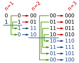
Получение зеркального двоичного кода Грея.
Существует несколько видов кода Грея, самый простой из них — так называемый зеркальный двоичный код Грея. Строится он так:
Для получения кода длины производится шагов. На первом шаге код имеет длину и состоит из двух векторов и . На каждом следующем шаге в конец списка заносятся все уже имеющиеся вектора в обратном порядке, и затем к первой половине получившихся векторов дописывается , а ко второй . С каждым шагом длина векторов увеличивается на , а их количество — вдвое.
Таким образом, количество векторов длины равно
Псевдокод
- — двумерный массив типа boolean, в котором — -ый бит в -ом коде Грея,
- — Счетчик количества уже имеющихся кодов,
- — Показывает количество кодов в -м коде Грея.
buildCode(n):
   GrayCode[1, n] = false
   GrayCode[2, n] = true                  // Построение кода длины 1
   p = 2
   for i = 2 to n
      t = p
      p = p * 2
      for k = (p / 2 + 1) to p
         GrayCode[k] = GrayCode[t]        // Отражение имеющихся кодов
         GrayCode[t, n + 1 - i] = false
         GrayCode[k, n + 1 - i] = true    // Добавление 0 и 1 в начало
         t--
   return GrayCode
Доказательство правильности работы алгоритма
По индукции:
- на первом шаге код отвечает условиям
- предположим, что код, получившийся на -ом шаге, является кодом Грея
- тогда на шаге : первая половина кода будет корректна, так как она совпадает с кодом с шага за исключением добавленного последнего бита . Вторая половина тоже соответствует условиям, так как она является зеркальным отражением первой половины, только добавлен везде бит . На стыке: первые бит совпадают в силу зеркальности, последние различны по построению.
Таким образом, этот код — код Грея. Индукционное предположение доказано, алгоритм работает верно.
Этот алгоритм можно обобщить и для -ичных векторов. Также известен алгоритм преобразования двоичного кода в код Грея.
Существует ещё несколько видов кода Грея — сбалансированный код Грея, код Баркера-Грея, одноколейный код Грея.[1] Кроме того, коды Грея используются для упорядочения перестановок.
Явная формула для получения зеркального двоичного кода Грея
| Теорема: |
|
В двоичном зеркальном коде Грея -ый код может быть получен по формуле при нумерации кодов с нуля. |
| Доказательство: |
|
Для кода длиной бит утверждение проверяется непосредственно. Пусть существует зеркальный двоичный код Грея длины , для которого выполнено, что для любого выполняется Обозначим за код длины , полученный из описанным выше алгоритмом. Тогда: Для любого выполняется и, по условию, равно раскрыв скобки, получим новое выражение : что равно (второе слагаемое равно первому, побитово сдвинутого вправо.) Для любого выполняется , где , то есть что по свойству xor () равно или (все по тому же свойству) раскрыв скобки, получим откуда получаем, зная из условия, что старший разряд равен что, аналогично первому пункту, равно Таким образом, шаг индукции доказан, следовательно, теорема верна. |

Пример однодорожечного кода грея.
Сбалансированный код Грея
Несмотря на то, что зеркальный двоичный код Грея полезен во многих случаях, он не является оптимальным в некоторых ситуациях из-за отсутствия «однородности». В сбалансированном коде Грея, количество изменений в различных координатных позициях сделаны максимально приближенными настолько, насколько это возможно.
Чтобы показать это точнее, пусть — это -ичный полный цикл Грея, имеющий последовательность перехода , , для если в коде Грея -й и биты различны и — кол-во таких различий; отсчёты переходов (спектры) являются наборами целых чисел, определенных как для .
Код Грея является однородным или равномерно сбалансированным, если все его отсчёты переходов равны, и в этом случае у нас есть для всех . Ясно, что при , такие коды существуют только при . В противном случае, если не делится на равномерно, то можно построить сбалансированные коды Грея, где каждый отсчёт перехода либо либо .
Коды Грея также могут быть экспоненциально сбалансироваными, если все их отсчеты переходов являются смежными степеням двойки, и такие коды существуют для каждой степени двойки.
Однодорожечный код Грея
Еще один вид кода Грея — это однодорожечный код Грея, разработанный Спеддингом и уточнен Хильтгеном, Патерсоном и Брандестини.
Однодорожечный код Грея является циклическим списком уникальных двоичных кодировок длины так, что два последовательных слова отличаются ровно в одной позиции, и когда список рассматривается как матрица, каждая колонка — это циклический сдвиг первого столбца. Название происходит от их использования датчиками вращения, где количество дорожек в настоящее время измеряется с помощью контактов, в результате для каждой дорожки на выход подаётся или .
Чтобы снизить уровнень шума различных контактов не переключаясь в тот же момент времени, один датчик предпочтительно устанавливает дорожки так, что выход данных от контактов находится в коде Грея. Чтобы получить высокую угловую точность, нужно много контактов; для достижения точности хотя бы в градус нужно, по крайней мере, различных позиций на оборот, который требует минимум бит данных, и тем самым такое же количество контактов.
Не путать с цепными кодами, получаемых циклическим сдвигом.
Применение
Фрэнк Грей изобрел метод для преобразования аналоговых сигналов в отраженные двоичные кодовые группы с использованием аппарата на основе вакуумной трубки. Способ и устройство были запатентованы в 1953 году, а код получил название код Грея. «PCM трубка» — аппарат, запатентованный Греем, был сделан Раймондом У. Сирсом из (англ.) Bell Labs, работая с Греем и Уильямом М. Гудоллом.
- В технике коды Грея используются для минимизации ошибок при преобразовании аналоговых сигналов в цифровые (например, в датчиках-энкодерах [2]).
В частности, коды Грея и были открыты в связи с этим применением. (Код Грея — это код преобразования бинарных символов в -арные, такие, что двоичные последовательности, соответствующие соседним символам (сдвигам фаз), отличаются только одним битом. Обычная бинарная кодировка сравнивается с кодировкой Грея. При появлении ошибки в -арном символе наиболее вероятными являются ближайшие соседние символы, отличающиеся от переданного лишь одним битом, если используется кодировка Грея.
Таким образом, высока вероятность того, что при кодировании с помощью кода Грея в случае возникновения ошибки ошибочным будет только один из переданных битов.)
- Коды Грея используются для кодирования номера дорожек в жёстких дисках.
- Коды Грея широко применяются в теории генетических алгоритмов [3] для кодирования генетических признаков, представленных целыми числами.
- Коды Грея используются в Картах Карно[4] (при передаче в карту переменные сортируются в код Грея).
- Алгоритм модуляции 2B1Q (англ. 2 Binary 1 Quandary) [5]
- Код Грея можно использовать также и для решения следующей задачи[6]:
Задача о Ханойских башнях
| Задача: |
| Даны три стержня, на один из которых нанизаны восемь колец, причем кольца отличаются размером и лежат меньшее на большем. Задача состоит в том, чтобы перенести пирамиду из восьми колец за наименьшее число ходов на другой стержень. За один раз разрешается переносить только одно кольцо, причём нельзя класть большее кольцо на меньшее. |
Решение:
Пусть — количество дисков. Начнём с кода Грея длины , состоящего из одних нулей (т.е. ), и будем двигаться по кодам Грея (от переходить к ).
Поставим в соответствие каждому -ому биту текущего кода Грея -ый диск (причём самому младшему биту соответствует наименьший по размеру диск, а самому старшему биту — наибольший). Поскольку на каждом шаге изменяется ровно один бит, то мы можем понимать изменение бита как перемещение -го диска. То есть, будем понимать переход от последовательности к как перемещение -го диска на свободное место, а от к — как перемещение -го диска на свободное место.
Заметим, что для всех дисков, кроме наименьшего, на каждом шаге имеется ровно один вариант хода (за исключением стартовой и финальной позиций). Для самого маленького диска всегда есть две свободные позиции, потому что он самый маленький, его можно положить сверху на любой диск. Если диск не самый маленький, то для него может быть не более одной свободной позиции. Допустим, что для него свободные две позиции. Это означает, что на двух других стержнях расположены диски размером больше, чем рассматриваемый. А так как рассматриваемый диск не самый маленький, то где-то расположен наименьший. Либо он расположен на рассматриваемом диске, тогда мы не можем переместить рассматриваемый, либо на каком-то другом, но тогда у нашего диска остаётся не более одной свободной позиции. Для наименьшего диска всегда имеется два варианта хода, однако имеется стратегия выбора хода, всегда приводящая к ответу: если нечётно, то последовательность перемещений наименьшего диска имеет вид (где — стартовый стержень, — финальный стержень, — оставшийся стержень), а если чётно, то
Выбор обусловлен тем, на каком стержне окажется в конце пирамидка, решение с помощью кода Грея является следствием классического нерекурсивного решения[7].
См. Также
- Коды антигрея
Примечания
- ↑ Wikipedia — Special types of Gray codes
- ↑ Википедия — Датчик угла поворота
- ↑ Википедия — Генетический алгоритм
- ↑ Википедия — Карта Карно
- ↑ Wikipedia — 2B1Q
- ↑ Википедия — Ханойская Башня
- ↑ Wikipedia — Tower of Hanoi Non-recursive solution
Источники информации
- Wikipedia — Gray code
- Википедия — Код Грея
- Robert W. Doran The Gray Code, Journal of Universal Computer Science, vol. 13, no. 11 (2007).
| Lucal код[1][2] | |||||
|---|---|---|---|---|---|
| 5 | 4 | 3 | 2 | 1 | |
| Код Грея | |||||
| 4 | 3 | 2 | 1 | ||
| 0 | 0 | 0 | 0 | 0 | 0 |
| 1 | 0 | 0 | 0 | 1 | 1 |
| 2 | 0 | 0 | 1 | 1 | 0 |
| 3 | 0 | 0 | 1 | 0 | 1 |
| 4 | 0 | 1 | 1 | 0 | 0 |
| 5 | 0 | 1 | 1 | 1 | 1 |
| 6 | 0 | 1 | 0 | 1 | 0 |
| 7 | 0 | 1 | 0 | 0 | 1 |
| 8 | 1 | 1 | 0 | 0 | 0 |
| 9 | 1 | 1 | 0 | 1 | 1 |
| 10 | 1 | 1 | 1 | 1 | 0 |
| 11 | 1 | 1 | 1 | 0 | 1 |
| 12 | 1 | 0 | 1 | 0 | 0 |
| 13 | 1 | 0 | 1 | 1 | 1 |
| 14 | 1 | 0 | 0 | 1 | 0 |
| 15 | 1 | 0 | 0 | 0 | 1 |
В отраженный двоичный код (РБК), также известный как отраженный двоичный (РБ) или же Код Грея после Фрэнк Грей, это порядок двоичная система счисления такие, что два последовательных значения отличаются только одним кусочек (двоичный символ).
Например, представление десятичного значения «1» в двоичном формате обычно будет «001», а «2» будет «010». В коде Грея эти значения представлены как «001» и «011». Таким образом, для увеличения значения с 1 до 2 потребуется изменить только один бит вместо двух.
Коды Грея широко используются для предотвращения ложного вывода электромеханический переключатели и облегчить исправление ошибки в цифровых коммуникациях, таких как цифровое наземное телевидение и немного Кабельное ТВ системы.
Имя
Патент Грея вводит термин «отраженный двоичный код».
Bell Labs Исследователь Фрэнк Грей ввел термин отраженный двоичный код в своей патентной заявке 1947 года, отмечая, что у кода «пока нет признанного названия».[3] Он получил свое название от того факта, что он «может быть построен из обычного двоичного кода посредством своего рода процесса отражения».
Код был позже назван в честь Грея другими, кто его использовал. Две разные патентные заявки 1953 года используют «код Грея» в качестве альтернативного названия «отраженного двоичного кода»;[4][5] в одном из них также указаны «минимальный код ошибки» и «код циклической перестановки» среди имен.[5] В заявке на патент 1954 года упоминается «код Грея по телефону Bell».[6] Другие названия включают «циклический двоичный код», «код циклической прогрессии»,[7][8] «циклическая перестановка двоичного кода»[9] или «циклический переставленный двоичный код» (CPB).[10][11]
Мотивация
Многие устройства указывают положение, замыкая и размыкая переключатели. Если это устройство использует естественные двоичные коды, позиции 3 и 4 расположены рядом друг с другом, но все три бита двоичного представления различаются:
| Десятичный | Двоичный |
|---|---|
| … | … |
| 3 | 011 |
| 4 | 100 |
| … | … |
Проблема с естественными двоичными кодами заключается в том, что физические переключатели не идеальны: очень маловероятно, что физические переключатели будут изменять состояния точно синхронно. При переходе между двумя показанными выше состояниями все три переключателя изменяют состояние. За короткий период, пока все меняется, переключатели будут считывать какое-то ложное положение. Даже без keybounce, переход может выглядеть как 011 — 001 — 101 — 100. Когда переключатели оказываются в положении 001, наблюдатель не может сказать, является ли это «реальным» положением 001 или переходным состоянием между двумя другими положениями. Если вывод подается в последовательный система, возможно через комбинационная логика, то последовательная система может сохранить ложное значение.
Отраженный двоичный код решает эту проблему, изменяя только один переключатель за раз, поэтому нет двусмысленности положения:
| Десятичный | Двоичный | серый |
|---|---|---|
| 0 | 0000 | 0000 |
| 1 | 0001 | 0001 |
| 2 | 0010 | 0011 |
| 3 | 0011 | 0010 |
| 4 | 0100 | 0110 |
| 5 | 0101 | 0111 |
| 6 | 0110 | 0101 |
| 7 | 0111 | 0100 |
| 8 | 1000 | 1100 |
| 9 | 1001 | 1101 |
| 10 | 1010 | 1111 |
| 11 | 1011 | 1110 |
| 12 | 1100 | 1010 |
| 13 | 1101 | 1011 |
| 14 | 1110 | 1001 |
| 15 | 1111 | 1000 |
Код Грея для десятичного числа 15 переключается на десятичный 0 с одним переключением переключателя. Это называется «циклическим» свойством кода Грея. В стандартном кодировании Грея младший значащий бит следует повторяющейся схеме: 2 вкл., 2 выкл. ( … 11001100 … ); следующая цифра — образец 4 вкл., 4 выкл .; n-й младший бит шаблон 
Более формально Код Грея это код, присваивающий каждому из непрерывного набора целые числа или для каждого члена кругового списка — слово символов, такое, что никакие два кодовых слова не являются идентичными, а каждые два соседних кодовых слова отличаются ровно на один символ. Эти коды также известны как единичное расстояние,[12][13][14][8][15][16] на одно расстояние, один шаг, монострофический[17][18][15][16] или же синкопические коды,[17] в отношении Расстояние Хэмминга 1 между соседними кодами. В принципе, для данной длины слова может быть более одного такого кода, но термин «код Грея» впервые был применен к конкретному двоичный код для неотрицательных целых чисел, двоично-отраженный код Грея, или же BRGC, четырехбитная версия которого показана выше.
История и практическое применение
Отраженные двоичные коды применялись к математическим головоломкам еще до того, как они стали известны инженерам. Мартин Гарднер написал популярный отчет о коде Грея в августе 1972 г. Колонка «Математические игры» в журнале Scientific American. Французский инженер Эмиль Бодо использовали коды Грея в телеграфия в 1878 г.[19] Он получил французский Почетный легион медаль за свою работу. Код Грея иногда неправильно приписывают[20] к Элиша Грей.[21][22][23]
Фрэнк Грей, который прославился изобретением метода передачи сигналов, который стал использоваться для совместимого цветного телевидения, изобрел метод преобразования аналоговых сигналов в группы отраженного двоичного кода с использованием вакуумная труба на базе аппарата. Метод и устройство были запатентованы в 1953 году, и имя Грея закрепилось за кодами. «Трубка PCM «Аппарат, который запатентовал Грей, был создан Рэймондом У. Сирсом из Bell Labs в сотрудничестве с Греем и Уильямом М. Гудоллом, которые приписывали Грею идею отраженного двоичного кода.[24]
Часть первой страницы патента Грея, показывающая трубку PCM (10) с отраженным двоичным кодом на пластине (15)
Грея больше всего интересовало использование кодов для минимизации ошибок преобразования аналоговых сигналов в цифровые; его коды до сих пор используются для этой цели.
Датчики положения
Энкодер для угловых приборов, маркированных 3-битным двоичным кодом Грея (BRGC)
Абсолютный поворотный энкодер с кодом Грея с 13 дорожками. Корпус, диск прерывателя и источник света находятся сверху; чувствительный элемент и компоненты поддержки находятся внизу.
Коды Грея используются в линейных и поворотных датчиках положения (абсолютные энкодеры и квадратурные энкодеры ) вместо взвешенного двоичного кодирования. Это исключает возможность того, что при изменении нескольких битов в двоичном представлении позиции неправильное чтение будет результатом того, что некоторые биты изменятся раньше других.
Например, некоторые поворотные энкодеры предоставляют диск, на концентрических кольцах (дорожках) которого нанесен электропроводящий код Грея. Каждая дорожка имеет неподвижный металлический пружинный контакт, который обеспечивает электрический контакт с проводящим шаблоном кода. Вместе эти контакты создают выходные сигналы в виде кода Грея. В других кодерах используются бесконтактные механизмы на основе оптических или магнитных датчиков для создания выходных сигналов кода Грея.
Независимо от механизма или точности движущегося энкодера, ошибка измерения положения может возникать в определенных положениях (на границах кода), поскольку код может изменяться в тот самый момент, когда он считывается (дискретизируется). Двоичный выходной код может вызвать значительные ошибки измерения положения, поскольку невозможно изменить все биты в одно и то же время. Если в момент выборки позиции некоторые биты изменились, а другие нет, позиция выборки будет неправильной. В случае абсолютных энкодеров указанное положение может быть далеко от фактического положения, а в случае инкрементальных энкодеров это может нарушить отслеживание положения.
Напротив, код Грея, используемый датчиками положения, гарантирует, что коды для любых двух последовательных положений будут отличаться только на один бит, и, следовательно, только один бит может изменяться за раз. В этом случае максимальная ошибка положения будет небольшой, указывая на положение, смежное с фактическим положением.
Математические головоломки
Код Грея, отраженный двоичным кодом, может служить руководством для решения Башни ханойской проблемы, а также классический Пазл китайские кольца, последовательный механический механизм головоломки.[20] Он также образует Гамильтонов цикл на гиперкуб, где каждый бит рассматривается как одно измерение.
Генетические алгоритмы
Из-за Расстояние Хэмминга свойств кодов Грея, они иногда используются в генетические алгоритмы. Они очень полезны в этой области, поскольку мутации в коде позволяют вносить в основном инкрементные изменения, но иногда изменение одного бита может вызвать большой скачок и привести к новым свойствам.
Минимизация логической схемы
Коды Грея также используются при маркировке осей Карты Карно[25][26] а также в Круговые графы Хендлера,[27][28][29][30] оба графических метода для минимизация логической схемы.
Исправление ошибки
В современном цифровые коммуникации, Коды Грея играют важную роль в исправление ошибки. Например, в цифровая модуляция схема, такая как QAM где данные обычно передаются в символы 4 бит или более, сигнал диаграмма созвездия устроен так, что битовые комбинации, передаваемые соседними точками совокупности, отличаются только на один бит. Объединив это с упреждающее исправление ошибок способный исправлять однобитовые ошибки, возможно приемник для исправления любых ошибок передачи, которые вызывают отклонение точки созвездия в область соседней точки. Это делает систему передачи менее восприимчивой к шум.
Связь между доменами часов
Разработчики цифровой логики широко используют коды Грея для передачи многобитовой информации счетчика между синхронной логикой, которая работает на разных тактовых частотах. Считается, что логика работает в разных «тактовых областях». Это фундаментально для дизайна больших микросхем, которые работают с множеством разных тактовых частот.
Циклическое переключение состояний с минимальными усилиями
Если системе необходимо циклически перебрать все возможные комбинации состояний включения-выключения некоторого набора элементов управления, а изменение элементов управления требует нетривиальных затрат (например, время, износ, человеческая работа), код Грея минимизирует количество настроек. изменяется только на одно изменение для каждой комбинации состояний. Примером может служить тестирование системы трубопроводов на все комбинации настроек клапанов с ручным управлением.
А сбалансированный код Грея могут быть построены,[31] которые переворачиваются одинаково часто. Поскольку перевороты битов распределены равномерно, это оптимально следующим образом: сбалансированные коды Грея минимизируют максимальное количество переворотов битов для каждой цифры.
Счетчики кода Грея и арифметика
Типичное использование счетчиков кода Грея — создание ФИФО (первым пришел — первым вышел) буфер данных, который имеет порты чтения и записи, которые существуют в разных тактовых доменах. Счетчики входов и выходов внутри такого двухпортового FIFO часто хранятся с использованием кода Грея, чтобы предотвратить захват недопустимых переходных состояний, когда счетчик пересекает тактовые области.[32]Обновленные указатели чтения и записи должны передаваться между доменами часов при их изменении, чтобы иметь возможность отслеживать состояние пустого и полного FIFO в каждом домене. Каждый бит указателей выбирается недетерминированно для этой передачи тактовой области. Таким образом, для каждого бита распространяется либо старое значение, либо новое значение. Следовательно, если в точке выборки изменяется более одного бита в многобитовом указателе, «неправильное» двоичное значение (ни новое, ни старое) не может быть передано. Гарантируя возможность изменения только одного бита, коды Грея гарантируют, что единственными возможными значениями выборки являются новое или старое многобитовое значение. Обычно используются коды Грея с длиной степени двойки.
Иногда цифровые шины в электронных системах используются для передачи величин, которые могут увеличиваться или уменьшаться только по одному за раз, например, выходной сигнал счетчика событий, который передается между доменами часов или на цифро-аналоговый преобразователь. Преимущество кодов Грея в этих приложениях состоит в том, что различия в задержках распространения множества проводов, которые представляют биты кода, не могут привести к тому, что полученное значение пройдет через состояния, которые находятся вне последовательности кода Грея. Это похоже на преимущество кодов Грея в конструкции механических энкодеров, однако источником кода Грея в этом случае является электронный счетчик. Сам счетчик должен вести счет в коде Грея, или, если счетчик работает в двоичном формате, то выходное значение счетчика должно быть повторно синхронизировано после преобразования в код Грея, потому что при преобразовании значения из двоичного кода в код Грея,[nb 1] возможно, что различия во времени поступления битов двоичных данных в схему преобразования двоичного кода в серый будут означать, что код может на короткое время пройти через состояния, которые сильно не соответствуют последовательности. Добавление синхронизированного регистра после схемы, которая преобразует значение счетчика в код Грея, может привести к тактовому циклу задержки, поэтому прямой счет в коде Грея может быть полезным.[33]
Чтобы произвести следующее значение счетчика в счетчике кода Грея, необходимо иметь некоторую комбинационную логику, которая будет увеличивать текущее сохраненное значение счетчика. Один из способов увеличения числа кода Грея — преобразовать его в обычный двоичный код, добавить к нему единицу с помощью стандартного двоичного сумматора, а затем преобразовать результат обратно в код Грея.[34] Другие методы подсчета в коде Грея обсуждаются в отчете Роберт В. Доран, включая получение выходных данных с первых защелок триггеров ведущий-ведомый в двоичный счетчик пульсаций.[35]
Адресация кода Грея
Как исполнение программный код обычно вызывает шаблон доступа к памяти команд локально последовательных адресов, кодировки автобусов использование адресации кода Грея вместо двоичной адресации может значительно уменьшить количество изменений состояния битов адреса, тем самым уменьшая Потребляемая мощность процессора в некоторых маломощных конструкциях.[36][37]
Строительство п-битовый код Грея
Первые несколько шагов метода отражения и префикса.
4-битная перестановка кода Грея
Список двоичных кодов Грея для п биты могут быть сгенерированы рекурсивно из списка для п — 1 бит, отражая список (то есть перечисляя записи в обратном порядке), добавляя к записям в исходном списке префикс двоичного 0, добавляя к записям в отраженном списке двоичную единицу, а затем конкатенируя исходный список с обратным список.[20] Например, создание п = 3 список из п = 2 список:
| 2-битный список: | 00, 01, 11, 10 | |
| Отражено: | 10, 11, 01, 00 | |
| Префикс старых записей с 0: | 000, 001, 011, 010, | |
| Добавляйте к новым записям префикс 1: | 110, 111, 101, 100 | |
| Составные: | 000, 001, 011, 010, | 110, 111, 101, 100 |
Однобитовый код Грея грамм1 = (0, 1). Это можно представить как построенное рекурсивно, как указано выше, из нулевого битового кода Грея. грамм0 = ( Λ ), состоящий из единственной записи нулевой длины. Этот итеративный процесс создания граммп+1 из граммп проясняет следующие свойства стандартного отражающего кода:
- граммп это перестановка чисел 0,…, 2п — 1. (Каждое число появляется в списке ровно один раз.)
- граммп встроена как первая половина граммп+1.
- Следовательно, кодировка стабильный, в том смысле, что как только двоичное число появляется в граммп он отображается в том же месте во всех более длинных списках; так что имеет смысл поговорить о то отражающий код Грея значение числа: грамм(м) = м-й отражающий код Грея, считая от 0.
- Каждая запись в граммп отличается от предыдущей записи всего на один бит. (Расстояние Хэмминга равно 1.)
- Последняя запись в граммп отличается от первой записи всего на один бит. (Код циклический.)
Эти характеристики предлагают простой и быстрый метод преобразования двоичного значения в соответствующий код Грея. Каждый бит инвертируется, если следующий старший бит входного значения установлен в единицу. Это может выполняться параллельно с помощью битового сдвига и операции исключающее ИЛИ, если они доступны: п-й код Грея получается путем вычисления 
{000,001,010,011,100,101,110,111} -> {001,000,011,010,101,100,111,110} (инвертировать бит 0)
Если бит 1 инвертирован, блоки из 2 кодовых слов изменяют порядок:
{000,001,010,011,100,101,110,111} -> {010,011,000,001,110,111,100,101} (инвертировать бит 1)
Если бит 2 инвертирован, блоки из 4 кодовых слов меняют порядок:
{000,001,010,011,100,101,110,111} -> {100,101,110,111,000,001,010,011} (инвертировать бит 2)
Таким образом, немного оторвавшись 

Аналогичный метод можно использовать для выполнения обратного преобразования, но вычисление каждого бита зависит от вычисленного значения следующего более высокого бита, поэтому его нельзя выполнять параллельно. Предполагая
Чтобы итеративно построить двоично-отраженный код Грея, на шаге 0 начните с 
Преобразование в код Грея и обратно
Следующие функции в C преобразование между двоичными числами и связанными с ними кодами Грея. Хотя может показаться, что преобразование Грея в двоичное требует, чтобы каждый бит обрабатывался по отдельности, существуют более быстрые алгоритмы.[38][nb 1]
typedef беззнаковый int uint;// Эта функция преобразует двоичное число без знака в отраженный двоичный код Грея.uint BinaryToGray(uint число){ возвращаться число ^ (число >> 1); // Оператор >> сдвиг вправо. Оператор ^ исключает или.}// Эта функция преобразует отраженный двоичный код Грея в двоичное число.uint GrayToBinary(uint число){ uint маска = число; пока (маска) { // Каждый бит кода Грея эксклюзивен для всех более значимых битов. маска >>= 1; число ^= маска; } возвращаться число;}// Более эффективная версия для кодов Грея 32 бита или меньше за счет использования методов SWAR (SIMD в регистре). // Он реализует функцию XOR с параллельным префиксом. Операторы присваивания могут быть в любом порядке.// // Эта функция может быть адаптирована для более длинных кодов Грея путем добавления шагов. uint GrayToBinary32(uint число){ число ^= число >> 16; число ^= число >> 8; число ^= число >> 4; число ^= число >> 2; число ^= число >> 1; возвращаться число;}// Вариант «Четыре бита сразу» заменяет двоичное число (abcd) 2 на (abcd) 2 ^ (00ab) 2, затем на (abcd) 2 ^ (00ab) 2 ^ (0abc) 2 ^ (000a) 2.
Специальные типы кодов Грея
На практике «код Грея» почти всегда относится к двоично-отраженному коду Грея (BRGC). Однако математики открыли другие виды кодов Грея. Как и BRGC, каждое слово состоит из списка слов, каждое из которых отличается от следующего. только одной цифрой (каждое слово имеет Расстояние Хэмминга из 1 от следующего слова).
п-арный код Грея
0 → 000 1 → 001 2 → 002 10 → 012 11 → 011 12 → 010 20 → 020 21 → 021 22 → 022100 → 122101 → 121102 → 120110 → 110111 → 111112 → 112120 → 102121 → 101122 → 100200 → 200201 → 201202 → 202210 → 212211 → 211212 → 210220 → 220221 → 221222 → 222
Помимо двоичного кода Грея, существует множество специализированных типов кодов Грея. Одним из таких типов кода Грея является п-арный код Грея, также известный как не-логический код Грея. Как следует из названия, этот тип кода Грея использует не-Булево значения в его кодировках.
Например, 3-арный (тройной ) Код Грея будет использовать значения {0, 1, 2}. (п, k)-Код Грея это п-арный код Грея с k цифры.[39]Последовательность элементов в (3, 2) -сером коде: {00, 01, 02, 12, 11, 10, 20, 21, 22}. (п, k) -Серый код может быть построен рекурсивно, как BRGC, или может быть построен итеративно. An алгоритм итеративно генерировать (N, k) -Серый код представлен (в C ):
// входные данные: основание, цифры, значение// вывод: серый// Преобразование значения в код Грея с заданной базой и цифрами.// Итерация по последовательности значений приведет к последовательности// кодов Грея, в которых одновременно изменяется только одна цифра.пустота toGray(беззнаковый основание, беззнаковый цифры, беззнаковый ценить, беззнаковый серый[цифры]){ беззнаковый baseN[цифры]; // Сохраняет обычное число с основанием N, по одной цифре на запись беззнаковый я; // Переменная цикла // Поместите нормальное число baseN в массив baseN. Для базы 10, 109 // будет сохранено как [9,0,1] за (я = 0; я < цифры; я++) { baseN[я] = ценить % основание; ценить = ценить / основание; } // Преобразование нормального числа baseN в эквивалент кода Грея. Обратите внимание, что // цикл начинается со старшей цифры и идет вниз. беззнаковый сдвиг = 0; пока (я--) { // Серая цифра сдвигается вниз на сумму более высоких // цифры. серый[я] = (baseN[я] + сдвиг) % основание; сдвиг = сдвиг + основание - серый[я]; // Вычесть из базы, чтобы сдвиг был положительным }}// ПРИМЕРЫ// ввод: значение = 1899, основание = 10, цифры = 4// вывод: baseN [] = [9,9,8,1], серый [] = [0,1,7,1]// ввод: значение = 1900, основание = 10, цифры = 4// вывод: baseN [] = [0,0,9,1], серый [] = [0,1,8,1]
Существуют и другие алгоритмы кода Грея для (п,k) -Серые коды. (п,k) -Серый код, созданный указанным выше алгоритмом, всегда циклический; некоторые алгоритмы, например, Гуан,[39] это свойство отсутствует, когда k нечетное. С другой стороны, хотя с помощью этого метода изменяется только одна цифра за раз, она может измениться путем переноса (цикл от п — от 1 до 0). В алгоритме Гуана счетчик поочередно растет и падает, так что числовая разница между двумя цифрами кода Грея всегда равна единице.
Коды Грея не определены однозначно, поскольку перестановка столбцов такого кода также является кодом Грея. Вышеупомянутая процедура создает код, в котором чем ниже значение цифры, тем чаще она изменяется, что делает его похожим на обычные методы подсчета.
Смотрите также Косая двоичная система счисления, вариантная троичная система счисления, в которой при каждом приращении изменяется не более 2 цифр, так как каждое приращение может быть выполнено не более чем с одной цифрой нести операция.
Сбалансированный код Грея
Хотя двоичный отраженный код Грея полезен во многих сценариях, в некоторых случаях он не является оптимальным из-за отсутствия «единообразия».[31] В сбалансированные коды Грея, количество изменений в разных положениях координат максимально приближено. Чтобы уточнить это, пусть грамм быть р-арный полный цикл Грея с переходной последовательностью
Код Грея униформа или же равномерно сбалансированный если его количество переходов все равно, и в этом случае мы имеем 


Например, сбалансированный 4-битный код Грея имеет 16 переходов, которые могут быть равномерно распределены по всем четырем позициям (четыре перехода на позицию), что делает его равномерно сбалансированным:[31]
0 1 1 1 1 1 1 0 0 0 0 0 0 1 1 0 0 0 1 1 1 1 0 0 1 1 1 1 0 0 0 0 0 0 0 0 1 1 1 1 1 0 0 1 1 1 0 0 0 0 0 1 1 0 0 0 0 0 1 1 1 1 1 1
тогда как сбалансированный 5-битный код Грея имеет всего 32 перехода, которые не могут быть равномерно распределены по позициям. В этом примере четыре позиции имеют шесть переходов каждая, а одна — восемь:[31]
1 1 1 1 1 0 0 0 0 1 1 1 1 1 1 0 0 1 1 1 1 1 0 0 0 0 0 0 0 0 0 0 0 0 0 1 1 1 1 1 1 1 1 0 0 0 0 0 0 0 1 1 1 1 1 1 0 0 0 1 1 0 0 0 1 1 0 0 1 1 1 0 0 0 0 0 0 1 1 1 0 0 0 1 1 1 1 1 1 0 0 0 0 0 1 1 1 0 0 0 0 0 0 0 1 1 1 1 1 1 0 0 0 0 0 0 1 1 1 1 1 1 1 1 0 0 0 1 1 1 1 1 1 1 0 0 0 0 1 1 0 0 0 0 0 0 0 0 0 1 1 0 0 0 1 1 1 1 1 1
Сейчас мы покажем конструкцию[41] и реализация[42] для хорошо сбалансированных двоичных кодов Грея, что позволяет нам генерировать п-цифровой сбалансированный код Грея для каждого п. Главный принцип — индуктивно построить (п + 2) -цифровой код Грея

куда 





Если мы определим кратности переходов 
Тонкая часть этой конструкции — найти адекватное разделение сбалансированного п-цифровой код Грея, такой, что индуцированный им код остается сбалансированным, но для этого имеет значение только кратность переходов; соединение двух последовательных блоков по цифре
Монотонные коды Грея
Монотонные коды полезны в теории взаимосвязанных сетей, особенно для минимизации расширения линейных массивов процессоров.[43]Если мы определим масса двоичной строки быть числом единиц в строке, то, хотя мы явно не можем иметь код Грея со строго возрастающим весом, мы можем аппроксимировать это, прогнав код через два смежных веса до достижения следующего.
Мы можем формализовать понятие монотонных кодов Грея следующим образом: рассмотрим разбиение гиперкуба
за 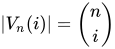
Элегантная конструкция монотонной п-цифровые коды Грея для любых п основан на идее рекурсивного построения подпути 


иначе. Здесь,
Выбор 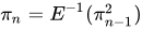
|
j = 0 | j = 1 | j = 2 | j = 3 |
|---|---|---|---|---|
| п = 1 | 0, 1 | |||
| п = 2 | 00, 01 | 10, 11 | ||
| п = 3 | 000, 001 | 100, 110, 010, 011 | 101, 111 | |
| п = 4 | 0000, 0001 |
1000, 1100, 0100, 0110, 0010, 0011 |
1010, 1011, 1001, 1101, 0101, 0111 |
1110, 1111 |
Эти монотонные коды Грея могут быть эффективно реализованы таким образом, что каждый последующий элемент может быть сгенерирован в О(п) время. Алгоритм проще всего описать с помощью сопрограммы.
Монотонные коды имеют интересную связь с Гипотеза Ловаса, в котором говорится, что каждый подключенный вершинно-транзитивный граф содержит гамильтонов путь. Подграф «среднего уровня»
Код Беккета – Грея
Другой тип кода Грея, Код Беккета – Грея, назван в честь ирландского драматурга Сэмюэл Беккет, кто интересовался симметрия. Его игра «Quad «состоит из четырех актеров и разделен на шестнадцать периодов времени. Каждый период заканчивается тем, что один из четырех актеров выходит на сцену или покидает ее. Спектакль начинается с пустой сцены, и Беккет хотел, чтобы каждая подгруппа актеров появлялась на сцене ровно один раз.[45] Очевидно, что набор актеров, которые сейчас находятся на сцене, может быть представлен 4-битным двоичным кодом Грея. Беккет, однако, наложил дополнительное ограничение на сценарий: он хотел, чтобы актеры входили и выходили, чтобы актер, который находился на сцене дольше всех, всегда выходил. Тогда актеров можно было бы представить в виде первым пришел-первым вышел очередь, так что (из актеров на сцене) удаляемый из очереди всегда тот, кто был поставлен в очередь первым.[45] Беккет не смог найти код Беккета – Грея для своей пьесы, и действительно, исчерпывающий список всех возможных последовательностей показывает, что такого кода не существует для п = 4. Сегодня известно, что такие коды существуют для п = 2, 5, 6, 7 и 8 и не существуют для п = 3 или 4. Пример 8-битного кода Беккета – Грея можно найти в Дональд Кнут с Искусство программирования.[20] По словам Савады и Вонга, пространство поиска п = 6 можно изучить за 15 часов, и более 9500 решений для случая п = 7 найдено.[46]
Коды змейки в коробке
Змея в коробке коды, или змеи, — последовательности узлов индуцированные пути в п-размерный граф гиперкуба, и коды катушки в коробке,[47] или же катушки, — последовательности узлов индуцированных циклы в гиперкубе. Рассматриваемые как коды Грея, эти последовательности обладают способностью обнаруживать любую однобитовую ошибку кодирования. Коды этого типа впервые были описаны Уильям Х. Каутц в конце 1950-х гг .;[13] с тех пор было проведено много исследований по поиску кода с максимально возможным количеством кодовых слов для данного измерения гиперкуба.
Однодорожечный код Грея
Еще один вид кода Грея — это однопутный код Грея (STGC) разработан Норманом Б. Спеддингом.[48][49] и усовершенствован Хильтгеном, Патерсоном и Брандестини в «Одноколейных кодах Грея» (1996).[50][51] STGC — это циклический список п уникальное двоичное кодирование длины n, такое, что два последовательных слова отличаются ровно в одной позиции, и когда список рассматривается как п × п матрица, каждый столбец представляет собой циклический сдвиг первого столбца.[52]
Однопутный код Грея с 5 датчиками.
Анимированная и цветная версия ротора STGC.
Название происходит от их использования с поворотные энкодеры, где несколько дорожек распознаются контактами, в результате чего для каждого на выходе получается 0 или 1. Чтобы уменьшить шум из-за того, что разные контакты не переключаются в один и тот же момент времени, предпочтительно настраивать дорожки так, чтобы данные вывод контактов в коде Грея. To get high angular accuracy, one needs lots of contacts; in order to achieve at least 1 degree accuracy, one needs at least 360 distinct positions per revolution, which requires a minimum of 9 bits of data, and thus the same number of contacts.
If all contacts are placed at the same angular position, then 9 tracks are needed to get a standard BRGC with at least 1 degree accuracy. However, if the manufacturer moves a contact to a different angular position (but at the same distance from the center shaft), then the corresponding «ring pattern» needs to be rotated the same angle to give the same output. If the most significant bit (the inner ring in Figure 1) is rotated enough, it exactly matches the next ring out. Since both rings are then identical, the inner ring can be cut out, and the sensor for that ring moved to the remaining, identical ring (but offset at that angle from the other sensor on that ring). Those two sensors on a single ring make a quadrature encoder. That reduces the number of tracks for a «1 degree resolution» angular encoder to 8 tracks. Reducing the number of tracks still further can’t be done with BRGC.
For many years, Torsten Sillke[53] and other mathematicians believed that it was impossible to encode position on a single track such that consecutive positions differed at only a single sensor, except for the 2-sensor, 1-track quadrature encoder. So for applications where 8 tracks were too bulky, people used single-track incremental encoders (quadrature encoders) or 2-track «quadrature encoder + reference notch» encoders.
Norman B. Spedding, however, registered a patent in 1994 with several examples showing that it was possible.[48] Although it is not possible to distinguish 2п positions with п sensors on a single track, it является possible to distinguish close to that many. Etzion and Paterson conjecture that when п is itself a power of 2, п sensors can distinguish at most 2п − 2п positions and that for prime п the limit is 2п − 2 positions.[54] The authors went on to generate a 504 position single track code of length 9 which they believe is optimal. Since this number is larger than 28 = 256, more than 8 sensors are required by any code, although a BRGC could distinguish 512 positions with 9 sensors.
An STGC for п = 30 and п = 5 is reproduced here:
| Angle | Код | Angle | Код | Angle | Код | Angle | Код | Angle | Код | ||||
|---|---|---|---|---|---|---|---|---|---|---|---|---|---|
| 0° | 10000 | 72° | 01000 | 144° | 00100 | 216° | 00010 | 288° | 00001 | ||||
| 12° | 10100 | 84° | 01010 | 156° | 00101 | 228° | 10010 | 300° | 01001 | ||||
| 24° | 11100 | 96° | 01110 | 168° | 00111 | 240° | 10011 | 312° | 11001 | ||||
| 36° | 11110 | 108° | 01111 | 180° | 10111 | 252° | 11011 | 324° | 11101 | ||||
| 48° | 11010 | 120° | 01101 | 192° | 10110 | 264° | 01011 | 336° | 10101 | ||||
| 60° | 11000 | 132° | 01100 | 204° | 00110 | 276° | 00011 | 348° | 10001 |
Each column is a cyclic shift of the first column, and from any row to the next row only one bit changes.[55]The single-track nature (like a code chain) is useful in the fabrication of these wheels (compared to BRGC), as only one track is needed, thus reducing their cost and size.The Gray code nature is useful (compared to chain codes, также называемый De Bruijn sequences ), as only one sensor will change at any one time, so the uncertainty during a transition between two discrete states will only be plus or minus one unit of angular measurement the device is capable of resolving.[56]
Two-dimensional Gray code
A Gray-coded constellation diagram for rectangular 16-QAM
Two-dimensional Gray codes are used in communication to minimize the number of bit errors in quadrature amplitude modulation adjacent points in the созвездие. In a typical encoding the horizontal and vertical adjacent constellation points differ by a single bit, and diagonal adjacent points differ by 2 bits.[57]
Gray isometry
The bijective mapping { 0 ↔ 00, 1 ↔ 01, 2 ↔ 11, 3 ↔ 10 } establishes an isometry между metric space над finite field
There are a number of binary codes similar to Gray codes, including:
- Datex codes aka Giannini codes (1954), as described by Carl P. Spaulding,[17][60][61][62][63][16] use a variant of O’Brien code II.
- Codes used by Varec (ca. 1954),[64][65][66][67] use a variant of O’Brien code I as well as base-12 and base-16 Gray code variants.
- Lucal code (1959)[1][2][35] aka modified reflected binary code (MRB)[1][2]
- Gillham code (1961/1962),[61][68][16][69][70] uses a variant of Datex code and O’Brien code II.
- Leslie and Russell code (1964)[71][18][72][68]
- Royal Radar Establishment code[68]
- Hoklas code (1988)[73][74][75]
Следующее binary-coded decimal (BCD) codes are Gray code variants as well:
- Petherick code (1953),[7][76][77][78][74][nb 3] также известный как Royal Aircraft Establishment (RAE) code.[79]
- O’Brien codes I and II (1955)[80][81][82][62][63][74] (An O’Brien type-I code[nb 4] was already described by Frederic A. Foss of IBM[83][84] and used by Varec in 1954. Later, it was also known as Watts code or Watts reflected decimal (WRD) code.[85][9][10][86][87][88][89][90][nb 1] An O’Brien type-II code was already used by Datex in 1954.[nb 3])
- Excess-3 Gray code (1956)[91] (aka Gray excess-3 code,[62][63][16] Gray 3-excess code, reflex excess-3 code, excess Gray code,[74] Gray excess code, 10-excess-3 Gray code or Gray–Stibitz code), described by Frank P. Turvey Jr. of ITT.[91]
- Tompkins codes I and II (1956)[12][81][82][62][63][74]
- Glixon code (1957)[92][93][94][81][82][62][63][74][nb 4]
| Имя | Кусочек | 0 | 1 | 2 | 3 | 4 | 5 | 6 | 7 | 8 | 9 | Weights | Треки | Compl. | Cyclic | 5 с | Comment |
| серый | 4 | 0 | 0 | 0 | 0 | 0 | 0 | 0 | 0 | 1 | 1 | 0..3 | 4 | — | (2, 4, 8, 16) | — | [81][82] |
| 3 | 0 | 0 | 0 | 0 | 1 | 1 | 1 | 1 | 1 | 1 | |||||||
| 2 | 0 | 0 | 1 | 1 | 1 | 1 | 0 | 0 | 0 | 0 | |||||||
| 1 | 0 | 1 | 1 | 0 | 0 | 1 | 1 | 0 | 0 | 1 | |||||||
| Павел | 4 | 1 | 0 | 0 | 0 | 0 | 0 | 0 | 0 | 1 | 1 | 1..3 | 4 | — | 2, 10 | — | [95] |
| 3 | 0 | 0 | 0 | 0 | 1 | 1 | 1 | 1 | 1 | 1 | |||||||
| 2 | 0 | 0 | 1 | 1 | 1 | 1 | 0 | 0 | 0 | 0 | |||||||
| 1 | 1 | 1 | 1 | 0 | 0 | 1 | 1 | 0 | 0 | 1 | |||||||
| Glixon | 4 | 0 | 0 | 0 | 0 | 0 | 0 | 0 | 0 | 1 | 1 | 0..3 | 4 | — | 2, 4, 8, 10 | shifted +1 | [92][81][82][93][94][nb 4] |
| 3 | 0 | 0 | 0 | 0 | 1 | 1 | 1 | 1 | 1 | 0 | |||||||
| 2 | 0 | 0 | 1 | 1 | 1 | 1 | 0 | 0 | 0 | 0 | |||||||
| 1 | 0 | 1 | 1 | 0 | 0 | 1 | 1 | 0 | 0 | 0 | |||||||
| Tompkins I | 4 | 0 | 0 | 0 | 0 | 0 | 1 | 1 | 1 | 1 | 1 | 0..4 | 2 | — | 2, 4, 10 | + | [12][81][82] |
| 3 | 0 | 0 | 0 | 0 | 1 | 1 | 1 | 1 | 1 | 0 | |||||||
| 2 | 0 | 0 | 1 | 1 | 1 | 1 | 1 | 0 | 0 | 0 | |||||||
| 1 | 0 | 1 | 1 | 0 | 0 | 0 | 1 | 1 | 0 | 0 | |||||||
| O’Brien I (Watts) | 4 | 0 | 0 | 0 | 0 | 0 | 1 | 1 | 1 | 1 | 1 | 0..3 | 4 | 9[nb 5] | 2, 4, 10 | + | [80][81][82][nb 4] |
| 3 | 0 | 0 | 0 | 0 | 1 | 1 | 0 | 0 | 0 | 0 | |||||||
| 2 | 0 | 0 | 1 | 1 | 1 | 1 | 1 | 1 | 0 | 0 | |||||||
| 1 | 0 | 1 | 1 | 0 | 0 | 0 | 0 | 1 | 1 | 0 | |||||||
| Petherick (RAE) | 4 | 0 | 0 | 0 | 0 | 0 | 1 | 1 | 1 | 1 | 1 | 1..3 | 3 | 2, 10 | + | [7][78][nb 3] | |
| 3 | 1 | 0 | 0 | 0 | 1 | 1 | 0 | 0 | 0 | 1 | |||||||
| 2 | 0 | 0 | 1 | 1 | 1 | 1 | 1 | 1 | 0 | 0 | |||||||
| 1 | 1 | 1 | 1 | 0 | 0 | 0 | 0 | 1 | 1 | 1 | |||||||
| O’Brien II | 4 | 0 | 0 | 0 | 0 | 0 | 1 | 1 | 1 | 1 | 1 | 1..3 | 3 | 9[nb 5] | 2, 10 | + | [80][81][82][nb 3] |
| 3 | 0 | 0 | 0 | 1 | 1 | 1 | 1 | 0 | 0 | 0 | |||||||
| 2 | 0 | 1 | 1 | 1 | 0 | 0 | 1 | 1 | 1 | 0 | |||||||
| 1 | 1 | 1 | 0 | 0 | 0 | 0 | 0 | 0 | 1 | 1 | |||||||
| Susskind | 4 | 0 | 0 | 0 | 0 | 0 | 1 | 1 | 1 | 1 | 1 | 1..4 | 3 | 2, 10 | + | [14] | |
| 3 | 0 | 0 | 1 | 1 | 1 | 1 | 1 | 1 | 0 | 0 | |||||||
| 2 | 0 | 1 | 1 | 1 | 0 | 0 | 1 | 1 | 1 | 0 | |||||||
| 1 | 1 | 1 | 1 | 0 | 0 | 0 | 0 | 1 | 1 | 1 | |||||||
| Klar | 4 | 0 | 0 | 0 | 0 | 0 | 1 | 1 | 1 | 1 | 1 | 0..4 | 4 | 2, 10 | + | [96][97] | |
| 3 | 0 | 0 | 0 | 1 | 1 | 1 | 1 | 0 | 0 | 0 | |||||||
| 2 | 0 | 0 | 1 | 1 | 1 | 1 | 1 | 1 | 0 | 0 | |||||||
| 1 | 0 | 1 | 1 | 1 | 0 | 0 | 1 | 1 | 1 | 0 | |||||||
| Tompkins II | 4 | 0 | 0 | 0 | 0 | 0 | 1 | 1 | 1 | 1 | 1 | 1..3 | 2 | 9[nb 6] | 2, 10 | + | [12][81][82] |
| 3 | 0 | 0 | 1 | 1 | 1 | 1 | 1 | 0 | 0 | 0 | |||||||
| 2 | 1 | 1 | 1 | 0 | 0 | 0 | 0 | 0 | 1 | 1 | |||||||
| 1 | 0 | 1 | 1 | 1 | 0 | 0 | 1 | 1 | 1 | 0 | |||||||
| Excess-3 Gray | 4 | 0 | 0 | 0 | 0 | 0 | 1 | 1 | 1 | 1 | 1 | 1..4 | 4 | — | 2, 10 | + | [16][74] |
| 3 | 0 | 1 | 1 | 1 | 1 | 1 | 1 | 1 | 1 | 0 | |||||||
| 2 | 1 | 1 | 1 | 0 | 0 | 0 | 0 | 1 | 1 | 1 | |||||||
| 1 | 0 | 0 | 1 | 1 | 0 | 0 | 1 | 1 | 0 | 0 |
Смотрите также
- Linear feedback shift register
- De Bruijn sequence — a Gray code on a larger alphabet than {0,1}.
- Steinhaus–Johnson–Trotter algorithm, an algorithm that generates Gray codes for the factorial number system
- Minimum distance code
Примечания
- ^ а б c By applying a simple inversion rule, the Gray code and the O’Brien code I can be translated into the 8421 pure binary code and the 2421 Aiken code, respectively, to ease arithmetic operations.[A]
- ^ Sequence 0, 1, 0, 2, 0, 1, 0, 3, … (sequence A007814 в OEIS ).
- ^ а б c d By interchanging and inverting three bit columns, the O’Brien code II и Petherick code can be transferred into each other.
- ^ а б c d By swapping two pairs of bit columns, individually shifting four bit columns and inverting one of them, the Glixon code и O’Brien code I can be transferred into each other.
- ^ а б За O’Brien codes I и II, а 9s complement can be derived by inverting the most-significant (fourth) binary digit.
- ^ За Tompkins code II, а 9s complement can be derived by inverting the first three digits and swapping the two middle binary digits.
Рекомендации
- ^ а б c Lucal, Harold M. (December 1959). «Arithmetic Operations for Digital Computers Using a Modified Reflected Binary». IRE Transactions on Electronic Computers. EC-8 (4): 449–458. Дои:10.1109/TEC.1959.5222057. ISSN 0367-9950. S2CID 206673385. (10 pages)
- ^ а б c Sellers, Jr., Frederick F.; Hsiao, Mu-Yue; Bearnson, Leroy W. (November 1968). Error Detecting Logic for Digital Computers (1-е изд.). Нью-Йорк, США: McGraw-Hill Book Company. pp. 152–164. LCCN 68-16491. OCLC 439460.
- ^ Gray, Frank (1953-03-17) [1947-11-13]. Pulse Code Communication (PDF). Нью-Йорк, США: Bell Telephone Laboratories, Incorporated. U.S. Patent 2,632,058 . Serial No. 785697. В архиве (PDF) from the original on 2020-08-05. Получено 2020-08-05. (13 pages)
- ^ Breckman, Jack (1956-01-31) [1953-12-31]. Encoding Circuit (PDF). Long Branch, New Jersey, USA: US Secretary of the Army. U.S. Patent 2,733,432 . Serial No. 401738. В архиве (PDF) from the original on 2020-08-05. Получено 2020-08-05. (8 pages)
- ^ а б Ragland, Earl Albert; Schultheis, Jr., Harry B. (1958-02-11) [1953-10-16]. Direction-Sensitive Binary Code Position Control System (PDF). North Hollywood, California, USA: Bendix Aviation Corporation. U.S. Patent 2,823,345 . Serial No. 386524. В архиве (PDF) from the original on 2020-08-05. Получено 2020-08-05. (10 pages)
- ^ Domeshek, Sol; Reiner, Stewart (1958-06-24) [1954-01-08]. Automatic Rectification System (PDF). US Secretary of the Navy. U.S. Patent 2,839,974 . Serial No. 403085. В архиве (PDF) from the original on 2020-08-05. Получено 2020-08-05. (8 pages)
- ^ а б c Petherick, Edward John (October 1953). A Cyclic Progressive Binary-coded-decimal System of Representing Numbers (Technical Note MS15). Farnborough, UK: Royal Aircraft Establishment (RAE). (4 pages) (NB. Sometimes referred to as A Cyclic-Coded Binary-Coded-Decimal System of Representing Numbers.)
- ^ а б Winder, C. Farrell (October 1959). «Shaft Angle Encoders Afford High Accuracy» (PDF). Electronic Industries. Chilton Company. 18 (10): 76–80. Получено 2018-01-14.
[…] The type of code wheel most popular in optical encoders contains a cyclic binary code pattern designed to give a cyclic sequence of «on-off» outputs. The cyclic binary code is also known as the cyclic progression code, the reflected binary code, and the Gray code. This code was originated by G. R. Stibitz, из Bell Telephone Laboratories, and was first proposed for pulse code modulation systems by Frank Gray, also of BTL. Thus the name Gray code. It is also named as «Unit Distance Code» as any two adjacent codes is differ by one (1). The Gray or cyclic code is used mainly to eliminate the possibility of errors at code transition which could result in gross ambiguities. […]
- ^ а б Evans, David Silvester (1960). Fundamentals of Digital Instrumentation (1-е изд.). London, UK: Hilger & Watts Ltd. Получено 2020-05-24. (39 pages)
- ^ а б Evans, David Silvester (March 1961). «Chapter Three: Direct Reading from Coded Scales». Digital Data: Their derivation and reduction for analysis and process control (1-е изд.). London, UK: Hilger & Watts Ltd / Interscience Publishers. pp. 18–23. Получено 2020-05-24. п. 20–23:
[…] Decoding. […] To decode C.P.B or W.R.D. codes, a simple inversion rule can be applied. The readings of the higher tracks determine the way in which the lower tracks are translated. The inversion rule is applied line by line for the C.P.B. and for the W.R.D it is applied decade by decade or line by line. Starting therefore with the top or slowest changing track of the C.P.B., if the result is odd (1) the next track value has to be inverted, i.e. 0 for 1 and 1 for 0. If, however, the first track is even (0), the second track is left as read, i.e. 0 for 0 and 1 for 1. Again, if the resultant reading of the second track is odd, the third track reading is inverted and so on. When an odd is changed to an even the line below is not inverted and when an even is changed to an odd the line below is inverted. The result of applying this rule to the pattern […] is the pure binary (P.B.) pattern […] where each track or digit can be given a definite numerical value (in this instance 1, 2, 4, 8, etc.). […] Using the line-by-line inversion rule on the W.R.D. code produces [a] pattern [of 1, 2, 4, 2 code ] where again the digits can be given numerical values and summed decade by decade. The summing of the digits can be very useful, for example, in a high-speed scanning system; but in a parallel decoding system […], it is usual to treat each binary quartet or decade as an entity. In other words, if the first or more significant decade is odd, the second decade is rectified or complemented by inverting the D track and so on, the result being the repeating pattern of [rectified W.R.D. code]. This is an extremely easy thing to achieve since the only change required is the inversion of the meaning of the D track or complementing digit. […]
(8+82 pages) (NB. The author does not mention Gray at all and calls the standard Gray code «Cyclic Permuted Binary Code» (C.P.B.), the book index erroneously lists it as «cyclic pure binary code».) - ^ Newson, P. A. (1965). Tables for the Binary Encoding of Angles (1-е изд.). United Kingdom Atomic Energy Authority, Research Group, Научно-исследовательский центр по атомной энергии, Harwell, UK: H. M. Stationery Office. Получено 2020-05-24. (12 pages)
- ^ а б c d Tompkins, Howard E. (September 1956) [1956-07-16]. «Unit-Distance Binary-Decimal Codes for Two-Track Commutation». IRE Transactions on Electronic Computers. Correspondence. Moore School of Electrical Engineering, Пенсильванский университет, Philadelphia, Pennsylvania, USA. EC-5 (3): 139. Дои:10.1109/TEC.1956.5219934. ISSN 0367-9950. Получено 2020-05-18. (1 page)
- ^ а б Kautz, William H. (June 1958). «Unit-Distance Error-Checking Codes». IRE Transactions on Electronic Computers. EC-7 (2): 179–180. Дои:10.1109/TEC.1958.5222529. ISSN 0367-9950. S2CID 26649532. (2 pages)
- ^ а б Susskind, Alfred Kriss; Ward, John Erwin (1958-03-28) [1957, 1956]. «III.F. Unit-Distance Codes / VI.E.2. Reflected Binary Codes». Written at Cambridge, Massachusetts, USA. In Susskind, Alfred Kriss (ed.). Notes on Analog-Digital Conversion Techniques. Technology Books in Science and Engineering. 1 (3 ed.). Нью-Йорк, США: Technology Press of the Massachusetts Institute of Technology / John Wiley & Sons, Inc. / Chapman & Hall, Ltd. pp. 3-10–3-16 [3-13–3-16], 6-65–6-60 [6-60]. (x+416+2 pages) (NB. The contents of the book was originally prepared by staff members of the Servomechanisms Laboraratory, Department of Electrical Engineering, Массачусетский технологический институт, for Special Summer Programs held in 1956 and 1957. Susskind’s «reading-type code» is actually a minor variant of the code shown here with the two most significant bit columns swapped to better illustrate symmetries. Also, by swapping two bit columns and inverting one of them, the code can be transferred into the Petherick code, whereas by swapping and inverting two bit columns, the code can be transferred into the O’Brien code II.)
- ^ а б Chinal, Jean P. (January 1973). «3.3. Unit Distance Codes». Written at Paris, France. Design Methods for Digital Systems. Translated by Preston, Alan; Summer, Arthur (1st English ed.). Berlin, Germany: Akademie-Verlag / Springer-Verlag. п. 50. Дои:10.1007/978-3-642-86187-1_3. ISBN 978-0-387-05871-9. License No. 202-100/542/73. Order No. 7617470(6047) ES 19 B 1 / 20 K 3. Получено 2020-06-21. (xviii+506 pages) (NB. The French 1967 original book was named «Techniques Booléennes et Calculateurs Arithmétiques», published by Éditions Dunod [fr ].)
- ^ а б c d е ж Military Handbook: Encoders – Shaft Angle To Digital (PDF). United States Department of Defense. 1991-09-30. MIL-HDBK-231A. В архиве (PDF) from the original on 2020-07-25. Получено 2020-07-25. (NB. Supersedes MIL-HDBK-231(AS) (1970-07-01).)
- ^ а б c Spaulding, Carl P. (1965-01-12) [1954-03-09]. «Digital coding and translating system» (PDF). Monrovia, California, USA: Datex Corporation. U.S. Patent 3165731A . Serial No. 415058. В архиве (PDF) from the original on 2020-08-05. Получено 2018-01-21. (28 pages)
- ^ а б Russell, A. (August 1964). «Some Binary Codes and a Novel Five-Channel Code». Control (Systems, Instrumentation, Data Processing, Automation, Management, incorporating Automation Progress). Special Features. London, UK: Morgan-Grampain (Publishers) Limited. 8 (74): 399–404. Получено 2020-06-22. (6 pages)
- ^ Pickover, Clifford A. (2009). The Math Book: From Pythagoras to the 57th Dimension, 250 Milestones in the History of Mathematics. Sterling Publishing Company. п. 392. ISBN 978-1-40275796-9.
- ^ а б c d Knuth, Donald Ervin (2004-10-15). «Generating all п-tuples». The Art of Computer Programming, Volume 4A: Enumeration and Backtracking. pre-fascicle 2a.
- ^ Heath, F. G. (September 1961). «Pioneers Of Binary Coding». Journal of the Institution of Electrical Engineers. Manchester College of Science and Technology, Faculty of Technology of the Манчестерский университет, Manchester, UK: Институт инженерии и технологий (IET). 7 (81): 539–541. Дои:10.1049/jiee-3.1961.0300. Получено 2020-06-22. (3 pages)
- ^ Cattermole, Kenneth W. (1969). Written at Harlow, Essex, UK. Principles of pulse code modulation (1-е изд.). London, UK / New York, USA: Iliffe Books Ltd. / American Elsevier Publishing Company, Inc. pp. 245, 434. ISBN 978-0-444-19747-4. LCCN 78-80432. SBN 444-19747-8. п. 245:
[…] There seems to be some confusion about the attributation of this code, because two inventors named Gray have been associated with it. When I first heard the name I took it as referring to Elisha Gray, и Хит testifies to his usage of it. Many people take it as referring to Frank Gray из Bell Telephone Laboratories, who in 1947 first proposed its use in coding tubes: his patent is listed in the bibliography. […]
(2+448+2 pages) - ^ Edwards, Anthony William Fairbank (2004). Cogwheels of the Mind: The Story of Venn Diagrams. Baltimore, Maryland, USA: Johns Hopkins University Press. pp. 48, 50. ISBN 0-8018-7434-3. ISBN 978-0-8018-7434-5.
- ^ Goodall, William M. (January 1951). «Television by Pulse Code Modulation». Bell System Technical Journal. 30 (1): 33–49. Дои:10.1002/j.1538-7305.1951.tb01365.x. (NB. Presented orally before the I.R.E. National Convention, New York City, March 1949.)
- ^ Wakerly, John F. (1994). Digital Design: Principles & Practices. Нью-Джерси, США: Prentice Hall. pp. 48–49, 222. ISBN 0-13-211459-3. ISBN 978-0-13-211459-2. (NB. The two page sections taken together say that K-maps are labeled with Gray code. The first section says that they are labeled with a code that changes only one bit between entries and the second section says that such a code is called Gray code.)
- ^ Brown, Frank Markham (2012) [2003, 1990]. Boolean Reasoning – The Logic of Boolean Equations (reissue of 2nd ed.). Mineola, New York: Dover Publications, Inc. п. 49. ISBN 978-0-486-42785-0. 1st edition
- ^ Händler, Wolfgang (1958). Ein Minimisierungsverfahren zur Synthese von Schaltkreisen (Minimisierungsgraphen) (Dissertation) (in German). Potsdam, Germany: Technische Hochschule Darmstadt. D 17. (73 pages+app.) [1]
- ^ Berger, Erich R.; Händler, Wolfgang (1967) [1962]. Steinbuch, Karl W.; Wagner, Siegfried W. (eds.). Taschenbuch der Nachrichtenverarbeitung (in German) (2 ed.). Berlin, Germany: Springer-Verlag OHG. pp. 64, 1034–1035, 1036, 1038. LCCN 67-21079. Title No. 1036. p. 64:
[…] Übersichtlich ist die Darstellung nach Händler, die sämtliche Punkte, numeriert nach dem Gray-Code […], auf dem Umfeld eines Kreises anordnet. Sie erfordert allerdings sehr viel Platz. […]
[Händler’s diagram, where all points, numbered according to the Gray code, are arranged on the circumference of a circle, is easily comprehensible. It needs, however, a lot of space.] - ^ «Informatik Sammlung Erlangen (ISER)» (на немецком). Erlangen, Germany: Friedrich-Alexander Universität. 2012-03-13. Архивировано из оригинал on 2017-05-16. Получено 2017-04-12.
- ^ «Informatik Sammlung Erlangen (ISER) – Impressum» (на немецком). Erlangen, Germany: Friedrich-Alexander Universität. 2012-03-13. В архиве from the original on 2012-02-26. Получено 2017-04-15.
- ^ а б c d е Bhat, Girish S.; Savage, Carla Diane (1996). «Balanced Gray Codes». Electronic Journal of Combinatorics. 3 (1). Дои:10.37236/1249.
- ^ Donohue, Ryan (2003). «Synchronization in Digital Logic Circuits» (PDF). В архиве (PDF) from the original on 2018-01-15. Получено 2018-01-15.
- ^ Hulst, George D. (1962-02-06) [1957-11-15]. Reflected binary code counter (PDF). Nutley, New Jersey, USA: International Telephone and Telegraph Corporation (ITT). U.S. Patent 3,020,481 . Serial No. 696793. В архиве (PDF) from the original on 2020-08-06. Получено 2020-08-06. (5 pages)
- ^ Mehta, Huzefa; Owens, Robert Michael; Irwin, Mary Jane «Janie» (1996-03-22). Some issues in Gray code addressing. Proceedings of the 6th Great Lakes Symposium on VLSI (GLSVLSI 96). IEEE Computer Society. pp. 178–181. Дои:10.1109/GLSV.1996.497616. ISBN 978-0-8186-7502-7. ISSN 1066-1395.
- ^ а б Doran, Robert «Bob» William (March 2007). The Gray Code (PDF). CDMTCS Research Report Series. Centre for Discrete Mathematics and Theoretical Computer Science, University of Auckland, Новая Зеландия. CDMTCS-304. В архиве (PDF) from the original on 2020-05-22. Получено 2020-05-23. (25 pages)
- ^ Su, Ching-Long; Tsui, Chi-Ying; Despain, Alvin M. (1994). Low Power Architecture Design and Compilation Techniques for High-Performance Processors (PDF) (Отчет). Advanced Computer Architecture Laboratory. ACAL-TR-94-01.
- ^ Guo, Hui; Parameswaran, Sri (April–June 2010). «Shifted Gray encoding to reduce instruction memory address bus switching for low-power embedded systems». Journal of Systems Architecture. 56 (4–6): 180–190. Дои:10.1016/j.sysarc.2010.03.003.
- ^ Dietz, Henry Gordon. «The Aggregate Magic Algorithms: Gray Code Conversion».
- ^ а б Guan, Dah-Jyh (1998). «Generalized Gray Codes with Applications». Proceedings of the National Scientific Council, Republic of China, Part A. 22: 841–848. CiteSeerX 10.1.1.119.1344.
- ^ а б Suparta, I. Nengah (2005). «A simple proof for the existence of exponentially balanced Gray codes». Electronic Journal of Combinatorics. 12. Дои:10.37236/1986.
- ^ а б Flahive, Mary Elizabeth; Bose, Bella (2007). «Balancing cyclic р-ary Gray codes». Electronic Journal of Combinatorics. 14. Дои:10.37236/949.
- ^ Strackx, Raoul; Piessens, Frank (2016). «Ariadne: A Minimal Approach to State Continuity». Usenix Security. 25.
- ^ а б Savage, Carla Diane; Winkler, Peter (1995). «Monotone Gray codes and the middle levels problem». Journal of Combinatorial Theory, Series A. 70 (2): 230–248. Дои:10.1016/0097-3165(95)90091-8. ISSN 0097-3165.
- ^ Savage, Carla Diane (1997-01-16). «Long cycles in the middle two levels of the Boolean lattice». Ars Combinatoria. North Carolina State University, Raleigh, North Carolina, USA. 35 (A): 97–108. CiteSeerX 10.1.1.39.2249. ISSN 0381-7032. S2CID 15975960. В архиве from the original on 2020-05-13. Получено 2020-05-13. (15 pages)
- ^ а б Goddyn, Luis (1999). «MATH 343 Applied Discrete Math Supplementary Materials» (PDF). Department of Mathematics, Университет Саймона Фрейзера. Архивировано из оригинал (PDF) on 2015-02-17.
- ^ Sawada, Joseph «Joe»; Wong, Dennis Chi-Him (2007). «A Fast Algorithm to generate Beckett–Gray codes». Electronic Notes in Discrete Mathematics. 29: 571–577. Дои:10.1016/j.endm.2007.07.091.
- ^ Richards, Richard Kohler (January 1971). «Snake-in-the-Box Codes». Written at Ames, Iowa, USA. Digital Design. Нью-Йорк, США: Wiley-Interscience, John Wiley & Sons, Inc. pp. 206–207. ISBN 0-471-71945-5. LCCN 73-147235. (12+577+1 pages)
- ^ а б NZ 264738, Spedding, Norman Bruce, «A position encoder», published 1994-10-28[неудачная проверка ]
- ^ Spedding, Norman Bruce (1994-10-28). «The following is a copy of the provisional patent filed on behalf of Industrial Research Limited on 1994-10-28 – NZ Patent 264738» (PDF). Industrial Research Limited. NZ Patent 264738. В архиве (PDF) from the original on 2017-10-29. Получено 2018-01-14.
- ^ Hiltgen, Alain P.; Paterson, Kenneth G.; Brandestini, Marco (September 1996). «Single-Track Gray Codes» (PDF). IEEE Transactions on Information Theory. 42 (5): 1555–1561. Дои:10.1109/18.532900. Zbl 857.94007.
- ^ Hiltgen, Alain P.; Paterson, Kenneth G. (September 2001). «Single-Track Circuit Codes» (PDF). IEEE Transactions on Information Theory. 47 (6): 2587–2595. CiteSeerX 10.1.1.10.8218. Дои:10.1109/18.945274. В архиве (PDF) from the original on 2018-01-15. Получено 2018-01-15.
- ^ Etzion, Tuvi; Schwartz, Moshe (November 1999) [1998-05-17]. «The Structure of Single-Track Gray Codes» (PDF). IEEE Transactions on Information Theory. IT-45 (7): 2383–2396. CiteSeerX 10.1.1.14.8333. Дои:10.1109/18.796379. В архиве (PDF) from the original on 2018-01-15. Получено 2018-01-15. Technical Report CS0937
- ^ Sillke, Torsten (1997) [1993-03-01]. «Gray-Codes with few tracks (a question of Marco Brandestini)». В архиве from the original on 2017-10-29. Получено 2017-10-29.
- ^ Etzion, Tuvi; Paterson, Kenneth G. (May 1996). «Near Optimal Single-Track Gray Codes» (PDF). IEEE Transactions on Information Theory. IT-42 (3): 779–789. CiteSeerX 10.1.1.14.1527. Дои:10.1109/18.490544. В архиве (PDF) from the original on 2016-10-30. Получено 2018-04-08.
- ^ Ruskey, Frank; Weston, Mark (2005-06-18). «A Survey of Venn Diagrams: Symmetric Diagrams». Dynamic Surveys. Electronic Journal of Combinatorics. Дои:10.37236/26.
- ^ Alciatore, David G.; Histand, Michael B. (1999). Mechatronics. McGraw–Hill Education – Europe. ISBN 978-0-07-131444-2.
- ^ Krishna (2008-05-11). «Gray code for QAM». В архиве from the original on 2017-10-29. Получено 2017-10-29.
- ^ Greferath, Marcus (2009). «An Introduction to Ring-Linear Coding Theory». In Sala, Massimiliano; Mora, Teo; Perret, Ludovic; Sakata, Shojiro; Traverso, Carlo (eds.). Gröbner Bases, Coding, and Cryptography. Springer Science & Business Media. п.220. ISBN 978-3-540-93806-4.
- ^ Solé, Patrick (2016-04-17). Hazewinkel, Michiel (ред.). Kerdock and Preparata codes. Энциклопедия математики. Springer Science+Business Media. ISBN 1-4020-0609-8. ISBN 978-1-4020-0609-8. В архиве from the original on 2017-10-29. Получено 2017-10-29.
- ^ Spaulding, Carl P. (1965-07-12). How to Use Shaft Encoders. Monrovia, California, USA: Datex Corporation. (85 pages)
- ^ а б Wheeler, Edwin L. (1969-12-30) [1968-04-05]. Analog to digital encoder (PDF). New York, USA: Conrac Corporation. U.S. Patent 3487460A . Serial No. 719026 (397812). В архиве (PDF) from the original on 2020-08-05. Получено 2018-01-21. п. column 9:
[…] The MOA-GILLHAM code is essentially the combination of the Gray code discussed thereinabove and the well known Datex code; the Datex code is disclosed in U.S. Patent 3,165,731. The arrangement is such that the Datex code defines the bits for the units count of the encoder and the Gray code defines the bits for each of the higher order decades, the tens, hundreds, etc. […]
(11 pages) - ^ а б c d е Dokter, Folkert; Steinhauer, Jürgen (1973-06-18). «2.4. Coding numbers in the binary system». Digital Electronics. Philips Technical Library (PTL) / Macmillan Education (Reprint of 1st English ed.). Eindhoven, Netherlands: The Macmillan Press Ltd. / N. V. Philips’ Gloeilampenfabrieken. pp. 32, 39, 50–53. Дои:10.1007/978-1-349-01417-0. ISBN 978-1-349-01419-4. SBN 333-13360-9. Получено 2020-05-11. п. 53:
[…] The Datex code […] uses the O’Brien code II within each decade, and reflected decimal numbers for the decimal transitions. For further processing, code conversion to the natural decimal notation is necessary. Since the O’Brien II code forms a 9s complement, this does not give rise to particular difficulties: whenever the code word for the tens represents an odd number, the code words for the decimal units are given as the 9s complements by inversion of the fourth binary digit. […]
(270 pages) - ^ а б c d е Dokter, Folkert; Steinhauer, Jürgen (1975) [1969]. «2.4.4.6. Einschrittige Kodes». Digitale Elektronik in der Meßtechnik und Datenverarbeitung: Theoretische Grundlagen und Schaltungstechnik. Philips Fachbücher (in German). я (improved and extended 5th ed.). Hamburg, Germany: Deutsche Philips GmbH. pp. 41, 48, 51, 58, 60–61. ISBN 3-87145-272-6. (xii+327+3 pages)
- ^ «…accurate liquid level metering – at ANY DISTANCE!». Petroleum Refiner (Advertisement). Gulf Publishing Company. 33 (9): 368. September 1954. ISSN 0096-6517. п. 368:
[…] The complete dispatching operation, gauging, and remote control is integrated into one single unitized system when a «Varec» Pulse Code Telemetering System is installed. […]
- ^ Bishup, Bernard W.; Repeta, Anthony A.; Giarrizzo, Frank C. (1968-08-13) [1963-04-03]. «Telemetering and supervisory control system having normally continuous telemetering signals». Leeds and Northrup Co. US3397386A. [2]
- ^ «Encoder Pulse Format». Installation and Operations Manual for the Model 1900 Micro 4-Wire Transmitter (PDF). Cypress, California, USA: Whessoe Varec, Inc. January 1993 [1991-07-01]. pp. 04-4–04-8. 33-08461. В архиве (PDF) from the original on 2020-05-16. Получено 2020-05-16. (38 pages) (NB. Position 5 for «Inches» on page 04-8 should read «0111» rather than «1111».)
- ^ «2.2.3.3 MSP Level Data Format». Varec Model 1900 – Micro 4-Wire Transmitter (BSAP to Mark / Space Protocol (MSP)) – Application Notes (PDF). Emerson Electric. pp. 11–14. В архиве (PDF) from the original on 2020-05-16. Получено 2020-05-16. (vi+33 pages)
- ^ а б c Wightman, Eric Jeffrey (1972). «Chapter 6. Displacement measurement». Instrumentation in Process Control (1-е изд.). London, UK: Butterworth & Co (Publishers) Ltd. pp. 122–123. ISBN 0-408-70293-1. ISBN 1-48316335-0, 978-1-48316335-2. п. 122–123:
[…] Other forms of code are also well known. Among these are the Royal Radar Establishment code; В Excess Three decimal code; Gillham code which is recommended by ИКАО for automatic height transmission for управления воздушным движением purposes; то Petherick code, а Leslie and Russell code из National Engineering Laboratory. Each has its particular merits and they are offered as options by various encoder manufacturers. […]
(12+367+5 pages) - ^ Phillips, Darryl (2012-07-26) [1998]. «Altitude – MODEC ASCII». AirSport Avionics. Архивировано из оригинал on 2012-07-26.
- ^ Stewart, K. (2010-12-03). «Aviation Gray Code: Gillham Code Explained». Custom Computer Services (CCS). В архиве from the original on 2018-01-16. Получено 2018-01-14.
- ^ Leslie, William «Bill» H. P.; Russell, A. (1964). A cyclic progressive decimal code for simple translation to decimal and analogue outputs (Отчет). East Kilbride, Glasgow, UK: National Engineering Laboratory. NEL Report 129. (17 pages)
- ^ Leslie, William «Bill» H. P. (1974). «The work on NC at NEL». В Koenigsberger, Franz; Tobias, Stephen Albert (eds.). Proceedings of the Fourteenth International Machine Tool Design and Research Conference, 12–14 September 1973. The Macmillan Press Ltd. pp. 215–224 [215, 217]. ISBN 978-1-34901921-2. LCCN 73-16545. SBN 333-14913-0. ISBN 1-34901921-6.
- ^ Hoklas, Archibald (1989-09-06) [1988-04-29]. «Abtastvorrichtung zur digitalen Weg- oder Winkelmessung» (PDF) (на немецком). VEB Schiffselektronik Johannes Warnke [де ]. GDR Patent DD271603A1. WP H 03 M / 315 194 8. Archived from оригинал (PDF) on 2018-01-18. Получено 2018-01-18 — через DEPATIS [де ]. [3] [4]
- ^ а б c d е ж грамм Hoklas, Archibald (2005). «Gray code – Unit distance code». В архиве from the original on 2018-01-15. Получено 2018-01-15.
- ^ Hoklas, Archibald (2005). «Gray-Kode – Einschrittiger Abtastkode» (на немецком). В архиве from the original on 2018-01-15. Получено 2018-01-15.
- ^ Petherick, Edward John; Hopkins, A. J. (1958). Некоторые недавно разработанные цифровые устройства для кодирования вращения валов (Техническая нота MS21). Фарнборо, Великобритания: Royal Aircraft Establishment (РАЭ).
- ^ «Дигитайзер как Analog-Digital-Wandler in der Steuer-, Meß- und Regeltechnik» (PDF). Technische Mitteilungen. Relais, elektronische Geräte, Steuerungen (на немецком языке). № 13. Кельн-Ниль, Германия: Франц Баумгартнер (FraBa). Май 1963. С. 1–2. Архивировано из оригинал (PDF) на 2020-05-21. Получено 2020-05-21. стр. 1–2:
[…] Die Firma Harrison Reproduction Equipment, Фарнборо / Англия […] шляпа в jahrelanger Entwicklung в Zusammenarbeit mit der Britischen Luftwaffe und britischen Industriebetrieben den Mechanischen Digitizer […] zu einer technischen Reife gebracht, die fast allen… Genderügen. […] Um bei der dezimalen Entschlüsselung des verwendeten Binärcodes zu eindeutigen und bei der Übergabe von einer Dezimalstelle zur anderen in der Reihenfolge immer Richtigen Ergebnissen zu au kommenliez, wurde eebnissen zu kommenliez, wurde eeglüssen zu kommenlee, seeller seinen Aufbau eine relativ einfache Entschlüsselung erlaubt. Der Code basiert auf dem Код Петерика. […]
(4 страницы) - ^ а б Charnley, C.J .; Bidgood, R.E .; Бордман, Г. Э. Т. (октябрь 1965 г.). «Конструкция пневматического датчика положения» (PDF). Объемы разбирательств МФБ. Колледж воздухоплавания, Крэнфилд, Бедфорд, Англия. 2 (3): 75–88. Дои:10.1016 / S1474-6670 (17) 68955-9. Глава 1.5. Получено 2018-01-14.
- ^ Холлингдейл, Стюарт Х. (1958-09-19). «Сессия 14. Обработка данных». Приложения компьютеров. Атлас — применение компьютеров, Ноттингемский университет, 15–19 сентября 1958 г. (Документ конференции). В архиве из оригинала на 2020-05-25. Получено 2020-05-25.
- ^ а б c О’Брайен, Джозеф А. (май 1956 г.) [1955-11-15, 1955-06-23]. «Циклические десятичные коды для аналого-цифровых преобразователей». Труды Американского института инженеров-электриков, часть I: Связь и электроника. Bell Telephone Laboratories, Уиппани, Нью-Джерси, США. 75 (2): 120–122. Дои:10.1109 / TCE.1956.6372498. ISSN 0097-2452. S2CID 51657314. Документ 56-21. Получено 2020-05-18. (3 страницы) (Примечание. Этот документ был подготовлен для презентации на Зимнем общем собрании AIEE, Нью-Йорк, США, с 30 января 1956 по 03 февраля 1956).
- ^ а б c d е ж грамм час я Штайнбух, Карл В., изд. (1962). Написано в Карлсруэ, Германия. Taschenbuch der Nachrichtenverarbeitung (на немецком языке) (1-е изд.). Берлин / Геттинген / Нью-Йорк: Springer-Verlag OHG. С. 71–74, 97, 761–764, 770, 1080–1081. LCCN 62-14511.
- ^ а б c d е ж грамм час я Штайнбух, Карл В.; Вебер, Вольфганг; Heinemann, Traute, eds. (1974) [1967]. Taschenbuch der Informatik — Band II — Struktur und Programmierung von EDV-Systemen. Taschenbuch der Nachrichtenverarbeitung (на немецком). 2 (3-е изд.). Берлин, Германия: Springer Verlag. С. 98–100. ISBN 3-540-06241-6. LCCN 73-80607. ISBN 978-3-540-06241-7.
- ^ Фосс, Фредерик А. (1960-12-27) [1954-12-17]. «Системы управления» (PDF). International Business Machines Corp.. Рис.7, Рис.8, Рис.11. Патент США 2966670A . Серийный номер 475945. В архиве (PDF) из оригинала на 21.06.2020. Получено 2020-08-05. (14 страниц) (NB. Автор назвал свой код 2 * -4-2-1 (+ 9- ± 7- ± 3- ± 1) отраженным десятичным кодом.)
- ^ Фосс, Фредерик А. (декабрь 1954 г.). «Использование отраженного кода в цифровых системах управления». Операции IRE на электронных компьютерах. ИС-3 (4): 1–6. Дои:10.1109 / IREPGELC.1954.6499244. ISSN 2168-1740. (6 страниц)
- ^ Эванс, Дэвид Сильвестр (1958). «[неизвестный]». Сделки. Институт Измерения и Контроля. 10–12: 87. (NB. Код Уоттса был назван кодом W.R.D. или отраженным десятичным числом Уоттса, чтобы отличать его от других кодов, используемых в Hilger & Watts Ltd..)
- ^ Benjamin, P.W .; Николлс, Г. С. (1963). «3.2.2 Электромеханические дигитайзеры». Измерение нейтронных спектров с помощью полуавтоматического сканирования протонов отдачи в фотоэмульсиях. Управление по атомной энергии Соединенного Королевства, Центр исследования атомного оружия, ВЕЛИКОБРИТАНИЯ: Министерство энергетики США. С. 8–10, 19. Отчет AWRE № NR 5/63. [5] (23 страницы)
- ^ Клинковски, Джеймс Дж. (14 марта 1967 г.) [23 марта 1964 г.]. «Электронные схемы диодно-матричного декодера» (PDF). Детройт, Мичиган, США: Корпорация Берроуз. Патент США 3309695A . Серийный номер 353845. В архиве (PDF) из оригинала 2020-05-23. Получено 2020-05-23. (5 страниц) [6]
- ^ Клинковски, Джеймс Дж. (31 марта 1970 г.) [22 декабря 1966 г.]. «Преобразователь двоично-десятичных сигналов» (PDF). Детройт, Мичиган, США: Корпорация Берроуз. Патент США 3504363A . Серийный номер 603926. В архиве (PDF) из оригинала 2020-05-23. Получено 2020-05-23. (7 страниц)
- ^ «[неизвестный]». Новости электрического дизайна. Издательство Роджерс. 12. 1967. ISSN 0012-7515. [7][8]
- ^ Тот-Зентаи, Дьёрдьи (1979-10-05). «Некоторые проблемы угловых вращательных цифровых преобразователей». Периодика Политехника Электротехника. Кафедра электронных технологий, Технический университет, Будапешт, Венгрия. 23 (3–4): 265–270 [266]. Получено 2020-05-23. (NB. Показывает 6-значный код мощности.)
- ^ а б Терви младший, Фрэнк П. (1958-07-29) [1956-05-17]. «Кодер счетчика импульсов» (PDF). Натли, Нью-Джерси, США: Международная телефонная и телеграфная корпорация. Патент США 2845617A. . Серийный номер 585494. В архиве (PDF) из оригинала 2020-05-23. Получено 2020-05-23. (5 страниц)
- ^ а б Гликсон, Гарри Роберт (март 1957). «Можете ли вы воспользоваться преимуществами циклического двоично-десятичного кода?». Инженерия управления (CtE). Техническое Издательство. 4 (3): 87–91. ISSN 0010-8049. (5 страниц)
- ^ а б Боруки, Лоренц; Диттманн, Иоахим (1971) [июль 1970, 1966, осень 1965]. «2.3 Gebräuchliche Codes in der digitalen Meßtechnik». Написано в Крефельде / Карлсруэ, Германия. Digitale Meßtechnik: Eine Einführung (на немецком языке) (2-е изд.). Берлин / Гейдельберг, Германия: Springer-Verlag. С. 10–23 [12–14]. Дои:10.1007/978-3-642-80560-8. ISBN 3-540-05058-2. LCCN 75-131547. ISBN 978-3-642-80561-5. (viii + 252 стр.) 1-е издание (NB. Нравится Каммерер, авторы описывают 6-битный 20-циклический код Glixon.)
- ^ а б Каммерер, Вильгельм (Май 1969 г.). «II.15. Informationsdarstellung im Automaten». Написано в Йене, Германия. В Фрюхауф, Ганс; Каммерер, Вильгельм; Шредер, Курц; Винклер, Гельмут (ред.). Digitale Automaten — Theorie, Struktur, Technik, Programmieren. Elektronisches Rechnen und Regeln (на немецком языке). 5 (1-е изд.). Берлин, Германия: Akademie-Verlag GmbH. п. 173. Лицензия №. 202-100 / 416/69. № заказа. 4666 ES 20 К 3. (NB. Существует также второе издание 1973 года. Боруки и Диттманн, но не называя его кодом Glixon, автор создает 20-циклический тетрадный код из кода Glixon и вариант кода Glixon с инвертированным старшим битом.)
- ^ Пол, Маттиас Р. (1995-08-10) [1994]. «Unterbrechungsfreier Schleifencode» [Код непрерывного цикла]. 1.02 (на немецком языке). Получено 2008-02-11. (NB. Автор назвал этот код Schleifencode (Английский: «код цикла»). Он отличается от BCD-кода Грея только кодированием состояния 0, чтобы сделать его циклическим кодом единичного расстояния для приложений полного вращения. Избегание шаблона кода с нулями позволяет проводить самотестирование контура и использовать линии данных для бесперебойного распределения энергии.)
- ^ Клар, Райнер (1970-02-01). Digitale Rechenautomaten — Eine Einführung [Цифровые компьютеры — Введение]. Sammlung Göschen (на немецком языке). 1241 / 1241a (1-е изд.). Берлин, Германия: Walter de Gruyter & Co. / G. J. Göschen’sche Verlagsbuchhandlung [де ]. п. 17. ISBN 3-11-083160-0. ISBN 978-3-11-083160-3. Archiv-Nr. 7990709. В архиве из оригинала на 2020-06-01. Получено 2020-04-13. (205 страниц) (NB. Переиздание первого издания 2019 г. доступно по ссылке ISBN 3-11002793-3, 978-3-11002793-8. Переработанный и расширенный 4-е издание тоже существует.)
- ^ Клар, Райнер (1989) [1988-10-01]. Digitale Rechenautomaten — Eine Einführung in die Struktur von Computerhardware [Цифровые компьютеры — Введение в структуру компьютерного оборудования]. Sammlung Göschen (на немецком языке). 2050 (4-е переработанное изд.). Берлин, Германия: Walter de Gruyter & Co. п. 28. ISBN 3-11011700-2. ISBN 978-3-11011700-4. (320 страниц) (NB. Автор назвал этот код Einheitsabstandscode (Английский: «код расстояния»). Поменяв местами два битовых столбца и инвертируя один из них, его можно перенести в Код О’Брайена II, тогда как путем перестановки и инвертирования двух битовых столбцов его можно перенести в Код Петерика.)
дальнейшее чтение
- Ричардс, Ричард Колер (1955). Арифметические операции в цифровых компьютерах (5-е изд.). Нью-Йорк, США: D. Van Nostrand Co., Inc.
- Ричардс, Ричард Колер (1967). Электронные цифровые компоненты и схемы. D. Van Nostrand Co., Inc. С. 490, 500–504, 510–511.
- Блэк, Пол Э. (25 февраля 2004 г.). «Код Грея». NIST.
- Press, William H .; Teukolsky, Saul A .; Веттерлинг, Уильям Т .; Фланнери, Брайан П. (2007). «Раздел 22.3. Коды Грея». Числовые рецепты: искусство научных вычислений (3-е изд.). Нью-Йорк, США: Издательство Кембриджского университета. ISBN 978-0-521-88068-8.
- Дикарь, Карла Дайан (1997). «Обзор комбинаторных кодов Грея». SIAM Обзор. Общество промышленной и прикладной математики (СИАМ). 39 (4): 605–629. CiteSeerX 10.1.1.39.1924. Дои:10.1137 / S0036144595295272. JSTOR 2132693.
- Уилф, Герберт Сол (1989). «Главы 1–3». Комбинаторные алгоритмы: обновление. Общество промышленной и прикладной математики (СИАМ). ISBN 0-89871-231-9. ISBN 978-0-89871-231-5.
- Дьюар, Меган; Стивенс, Бретт (29 августа 2012 г.). Заказ блочных конструкций — коды Грея, универсальные циклы и конфигурация. CMS Книги по математике (1-е изд.). Нью-Йорк, США: Springer Science + Business Media. Дои:10.1007/978-1-4614-4325-4. ISBN 978-1-46144324-7. ISSN 1613-5237. ISBN 1-46144324-5.
- Максфилд, Клайв «Макс» (01.10.2012) [28.05.2011]. «Основы кода Грея». Как сделать дизайн. EETimes. Часть 1. В архиве с оригинала на 30.10.2017. Получено 2017-10-30. Часть 2 Часть 3
- Уоррен-младший, Генри С. (2013). «Глава 13: Код Грея». Хакерское наслаждение (2-е изд.). Эддисон Уэсли – Pearson Education, Inc. С. 311–317. ISBN 978-0-321-84268-8. (7 страниц)
- Зиновик, Игорь; Кронинг, Даниэль; Чебиряк, Юрий (21.03.2008). «Вычисление двоичных комбинаторных кодов Грея с помощью исчерпывающего поиска с помощью SAT-решателей». IEEE Transactions по теории информации. IEEE. 54 (4): 1819–1823. Дои:10.1109 / TIT.2008.917695. HDL:20.500.11850/11304. (5 страниц)
- О’Брайен, Джозеф А. (июнь 1957 г.). «Преобразователи двоично-десятичного кода единиц измерения расстояния». Операции IRE на электронных компьютерах. ИС-6 (2): 122–123. Дои:10.1109 / TEC.1957.5221585. ISSN 0367-9950. Получено 2020-05-25. (2 страницы)
- Барр, К. Г. (март 1981). «Десятичный код Грея — легко конвертируется для кодирования положения вала» (PDF). Беспроводной мир. Vol. 87 нет. 1542. Факультет естественных наук, Университет Вест-Индии. С. 86–87. В архиве (PDF) из оригинала на 2020-07-28. Получено 2020-07-28.
внешняя ссылка
- Демонстрация «кода серого» Майкл Шрайбер, Вольфрам Демонстрационный проект (с реализацией Mathematica). 2007 г.
- Словарь алгоритмов и структур данных NIST: код Грея.
- Hitch Hiker’s Guide по эволюционным вычислениям, Q21: Что такое коды Грея и почему они используются?, включая C код для преобразования между двоичным и BRGC.
- Драгос А. Харабор использует Коды Грея в 3D-дигитайзере.
- Однодорожечные коды Грея, двоичные цепные коды (Ланкастер 1994 ), и регистры сдвига с линейной обратной связью все они полезны для определения абсолютного положения на одноколейном поворотном энкодере (или другом датчике положения).
- Столбец AMS: коды Грея
- Генератор колеса оптического кодировщика
- ProtoTalk.net — Понимание квадратурного кодирования — Более подробно описывает квадратурное кодирование с акцентом на роботизированные приложения
Код ГРЕЯ в многопозиционных видах модуляций
При многопозиционных видах модуляций (М-ФМн и М-КАМ) выбор положения символа в сигнальном созвездии влияет на вероятность битовой ошибки.

Рассмотрим положение символов в сигнальном созвездии для четверичной фазовой модуляции. Для 4-ФМн каждый символ представляется 2 битами. Назначим каждому символу по часовой стрелке комбинацию бит в обычной двоичной системе счисления: {00; 01; 10; 11}.

При воздействии шумов могут возникать ошибки, которые появляются в результате того, что был принят не тот символ, который передавался. Вероятность перепутать один символ с другим (т.е. допустить ошибку при приёме) тем больше, чем ближе символы на созвездии находятся друг к другу.
Пример кодирования двоичного кода
Рассмотрим пример по рисунку выше. Пусть был передан символ S0, который кодирован битами {00}. Из-за воздействия шумов наиболее частой ошибкой будет прием символа S1 или S3, т.к. они расположены ближе, чем символ S2. Ошибочный прием символа S2 также будет, но такие ошибки будут происходить реже.
Если возникла ошибка, при которой был принят символ S1 {01} вместо S0 {00}, то будет потерян всего 1 бит информации, т.к. символ S1 отличается от символа S2 на один бит. Однако если возникла ошибка, при которой был принят символ S3 {11}, то будет потеряно уже 2 бита информации.
Возникает вопрос, можно ли символам назначить такие комбинации бит, чтобы любые два соседних символа отличались не более чем на один бит. Ответ на этот вопрос положительный – нужно воспользоваться кодом Грея.
Код Грея определение
В таблице ниже представлен код Грея для 2-х и 3-х бит.
Код Грея образуется путем перестановки некоторых кодовых комбинаций таким образом, что любые две соседние кодовые комбинации отличаются друг от друга на один бит.

Если символы 4-ФМн закодировать кодом Грея, т.е. символам S0 S1 S2 S3 назначить комбинацию бит {00; 01; 10; 11} соответственно, то любые два соседних символа будут отличаться друг от друга не более чем на один бит. В этом случае, если произойдет любая ошибка, где будут перепутаны два соседних символа, будет потерян только один бит информации.

Возникает вопрос, а есть ли существенная разница между тем, сколько бит информации потеряно? Ведь информация в любом случае оказалась искаженной! Дело в том, что в радиотехнических системах практически всегда применяется помехоустойчивое кодирование, задача которого исправлять ошибки. У помехоустойчивого кода есть ограничение на количество ошибок, которые он может исправить – этот параметр называется кратностью исправляемых ошибок. Соответственно необходимо стремиться к уменьшению количества ошибок, т.к. малое количество ошибок может исправить помехоустойчивый код.
Код Грея применим в том случае, когда у каждого символа в созвездии только два соседа, т.е. близлежащих символов. Это случай четверичной и восьмеричной фазовой манипуляции.
Если рассматривать созвездие амплитудно-фазовых модуляций, в том числе КАМ, то видно, что у каждого символа более двух соседей. В этом случае нельзя придумать такой код, при котором все близлежащие символы отличались бы только на один бит. Но и в этом случае играет большую роль, каким символам, какие кодовые комбинации назначаются. Те символы, которые расположены ближе всего друг к другу, должны отличаться на минимальное количество бит, в идеальном случае на один.

Если невозможно сделать так, чтобы все соседи отличались на один бит, тогда допускается отличие на два бита, и т.д. Чем дальше символы в созвездии располагаются друг от друга, тем реже возникает ошибка, при которой эти символы будут перепутаны, следовательно, тем на большее количество бит они могут отличаться.
Задача назначения битовых комбинаций каждому символу в созвездии сводится к минимизации среднего количества битовых ошибок при фиксированном отношении сигнал/шум.