- Manuals
- Brands
- JLG Manuals
- Boom Lifts
- 1250AJP
- Troubleshooting manual
-
Contents
-
Table of Contents
-
Troubleshooting
-
Bookmarks
Quick Links
Troubleshooting Manual
Model
1250AJP
3128411
April 5, 2007
?
Related Manuals for JLG 1250AJP
Summary of Contents for JLG 1250AJP
-
Page 1
Troubleshooting Manual Model 1250AJP 3128411 April 5, 2007… -
Page 3: Section A. Introduction
Is Distress and read Help Ground System Lamp Blinking? Message Tests “Ground/ Everything OK” Troubleshoot by Help Message in Section 1 Using Analyzer, find logged Help Messages Identify Fault Repair Machine Problem Solved? Done Figure A-1. Troubleshooting Flowchart 3128411 1250AJP…
-
Page 4: Visual Inspection
A.8 Service Fault Code Cross References on Pg. 9 to find possible faults based on the flashed code. FAULT CODE LIGHT 1705744 A 1705745 B 1702938 1705170 A 1705171 A Figure A-2. Ground Module and Platform Fault (System Distress) Lights 1250AJP 3128411…
-
Page 5: Connector References
[X006.21.soc] refers to the socket side of terminal 21, connector X006. [X006.21.pin] refers to the pin side of terminal 21, connector X006. A.5 GROUND REFERENCE Battery negative [X117] should be used as the ground reference for voltage measurements, unless stated otherwise. 3128411 1250AJP…
-
Page 6: Control Module Power
Ground Platform Power Battery — CAN HI X233 CAN LO Analyzer Power X235 Analyzer RS232 Receive Analyzer Analyzer RS232 Transmit Note: BLAM and Chassis Module Analyzer connections for download only Analyzer Ground Figure A-3. Basic Electronic Module Connections 1250AJP 3128411…
-
Page 7: Critical Sensors
In transport position typical values are: MAIN LIFT 1 ANGLE A/D: 2800 — 6000 MAIN LIFT 2 ANGLE A/D: 26000 — 30010 MAIN LIFT 1 RAW ANGLE A/D: 15 — 33 MAIN LIFT 2 RAW ANGLE A/D: 145 — 165 3128411 1250AJP…
-
Page 8
BLAM module. Each sensor should measure 5k Ω resistance between the A and B pins. In transport position typical values are: TOWER LENGTH 1 SENSOR: 305.4″ TOWER LENGTH 2 SENSOR: 305.4″ TOWER LENGTH 1 A/D: 880 TOWER LENGTH 2 A/D: 1180 1250AJP 3128411… -
Page 9: Service Fault Code Cross References
2-5 DRIVE PREVENTED — BOOM SELECTED ………………….1-68 2-5 DRIVE PREVENTED — TILTED & ABOVE ELEVATION ………………1-68 2-5 FUNCTIONS LOCKED OUT — BLAM MODULE SOFTWARE VERSION IMPROPER ……..1-87 2-5 FUNCTIONS LOCKED OUT — CHASSIS MODULE SOFTWARE VERSION IMPROPER ……… 1-87 3128411 1250AJP…
-
Page 10
3-3 LEFT FORWARD DRIVE PUMP SHORT TO BATTERY ………………1-93 3-3 LEFT FORWARD DRIVE PUMP SHORT TO GROUND ………………1-93 3-3 LEFT REVERSE DRIVE PUMP OPEN CIRCUIT ………………..1-93 3-3 LEFT REVERSE DRIVE PUMP SHORT TO BATTERY ………………1-93 A-10 1250AJP 3128411… -
Page 11
3-3 SWING LEFT OPEN CIRCUIT …………………….. 1-142 3-3 SWING LEFT SHORT TO BATTERY ……………………. 1-142 3-3 SWING RIGHT OPEN CIRCUIT ……………………1-142 3-3 SWING RIGHT SHORT TO BATTERY ………………….1-143 3-3 THROTTLE ACTUATOR OPEN CIRCUIT ………………….1-143 3128411 1250AJP A-11… -
Page 12
3-4 JIB UP OPEN CIRCUIT ……………………….. 1-92 3-4 JIB UP SHORT TO BATTERY ……………………… 1-92 3-4 JIB UP SHORT TO GROUND ……………………… 1-92 3-4 PLATFORM CONTROL VALVE OPEN CIRCUIT ………………..1-123 3-4 PLATFORM CONTROL VALVE SHORT TO BATTERY ………………1-123 A-12 1250AJP 3128411… -
Page 13
4-5 TOWER LIFT PVG VALVE SEND UNRECOGNIZED FAULT …………….1-152 4-5 TOWER LIFT PVG VALVE SETUP FAULT ………………….1-152 4-5 TOWER LIFT PVG VALVE STUCK EXTENDED ………………..1-152 4-5 TOWER LIFT PVG VALVE STUCK NEUTRAL ………………..1-152 3128411 1250AJP A-13… -
Page 14
8-3 BASKET LEVELING SENSOR 1 SHORT TO GROUND OR OPEN CIRCUIT ……….. 1-39 8-3 BASKET LEVELING SENSOR 2 SHORT TO BATTERY ………………. 1-39 8-3 BASKET LEVELING SENSOR 2 SHORT TO GROUND OR OPEN CIRCUIT ……….. 1-39 8-3 BASKET LEVELING SYSTEM TIMEOUT ………………….1-39 A-14 1250AJP 3128411… -
Page 15
8-4 TWR LENGTH SENSOR TWO VALUE OUT OF RANGE LOW ……………. 1-170 8-4 TWR TRN SW DISAGREEMENT ……………………1-171 8-4 WRONG MAIN LIFT RESPONSE ……………………1-173 8-4 WRONG MAIN TELE RESPONSE ……………………1-173 8-4 WRONG TWR LIFT RESPONSE ……………………1-173 3128411 1250AJP A-15… -
Page 16
8-6 RT FNT STEER LT STB OR OC ……………………1-138 8-6 RT FNT STEER LT STG ………………………. 1-138 8-6 RT FNT STEER RT STB OR OC ……………………1-138 8-6 RT FNT STEER RT STG ……………………… 1-138 8-6 RT REAR STEER LT STB OR OC ……………………1-138 A-16 1250AJP 3128411… -
Page 17
9-9 PLATFORM MODULE FAILURE HWFS CODE 1 ………………… 1-123 9-9 PLATFORM MODULE SOFTWARE UPDATE REQUIRED …………….1-123 9-9 PLATFORM SENSOR REF VOLTAGE OUT OF RANGE ……………… 1-124 9-9 RUNNING AT CREEP — CREEP SWITCH OPEN ………………..1-139 9-9 STEER SENSORS NOT CALIBRATED ………………….1-142 3128411 1250AJP A-17… -
Page 18
INTRODUCTION This Page Left Blank Intentionally A-18 1250AJP 3128411… -
Page 19: Section B. Troubleshooting Safety Precautions
Every effort should be made to relieve any system pressure prior to disconnecting or removing any portion of • Use only approved, nonflammable cleaning solvents. the system. 3128411 1250AJP B-19…
-
Page 20: Revision Log
January 16, 2006 — Original issue of fault guide for use with P7.0 Software. August 29, 2006 — Incremental release. Updated and added many procedures. February 12, 2007 — Fault definitions added. April 5, 2007 — Cover icon added. 1250AJP 3128411…
-
Page 21: Table Of Contents
BASKET LEVELING SYSTEM TIMEOUT ……….1-39 3128411 1250AJP…
-
Page 22
CYLINDER LOAD PIN CAN COMMUNICATIONS LOST ……. . 1-63 1250AJP… -
Page 23
GLOW PLUG OPEN CIRCUIT ……….. . 1-88 3128411 1250AJP… -
Page 24
LEFT REVERSE DRIVE PUMP SHORT TO BATTERY ……..1-93 1250AJP… -
Page 25
MAIN LIFT ENABLE OPEN CIRCUIT ……….1-110 3128411 1250AJP… -
Page 26
PLATFORM MODULE FAILURE: HWFS CODE 1 ……..1-123 1250AJP… -
Page 27
START SOLENOID SHORT TO GROUND ……… . . 1-142 1.291 START SWITCH LOCKED — SELECTED BEFORE KEYSWITCH ……1-142 3128411 1250AJP… -
Page 28
TOWER TELESCOPE APU OPEN CIRCUIT ……… 1-154 1250AJP… -
Page 29
COMMON STG PROCEDURE ……….. . 1-175 3128411 1250AJP… -
Page 30
To Connect the JLG Control System Analyzer …….. -
Page 31
Hydraulic Schematic — Traction Control — Sheet 1 of 2 ……. . . 3-256 3128411 1250AJP… -
Page 32
X233 (J5) Chassis Module Pinout ……….2-218 1250AJP… -
Page 33
Calibrations Listed by Service Action ……….5-289 3128411 1250AJP… -
Page 34
TABLE OF CONTENTS (Continued) This Page Left Blank Intentionally 1250AJP 3128411… -
Page 35: Section 1. Fault Dictionary And Selected Troubleshooting
Axle retract short to battery or open circuit. The control system detected a short to battery or open circuit on the axle retract valves output [X230.12] controlling the front axles retract solenoid [X209] and the rear axles retract solenoid [X221]. See 1.377 COMMON STB OR OC PROCEDURE on Pg. 174. 3128411 1250AJP 1-35…
-
Page 36: Axle Ret Stg
1.17 BASKET LEFT SHORT TO BATTERY Flash Code: 3-4 Basket left short to battery. The platform module J7 platform rotate left output [X169.5] is shorted to battery. See 1.377 COMMON STB OR OC PROCEDURE on Pg. 174. 1-36 1250AJP 3128411…
-
Page 37: Basket Left Short To Ground
[X136] and level down installed common to level up solenoid [X136] and solenoid [X135] with the cartridge common to level down solenoid [X135] rotate right [X138] and rotate left [X139]. Does Go to step 1.19.11 the crackpoint calibrate? 3128411 1250AJP 1-37…
-
Page 38: Basket Leveling Crackpoint Up Not Calibrated
Go to step 1.20.10 Go to step 1.20.9 1.20.9 Turn off machine. Discon- Does the platform dump solenoid [X135] Clean/repair/replace platform dump valve [X135] measure about 6.4 Ω? nect platform dump sole- cartridge. noid [X135]. Replace platform dump solenoid [X135] 1-38 1250AJP 3128411…
-
Page 39: Basket Leveling Override Off
Basket leveling system timeout. The control system detected the platform tilt angle was not within 5.0° of the setpoint for at least 2 seconds while out of transport or for at least 15 seconds while in the transport position. These values are program- 3128411 1250AJP 1-39…
-
Page 40
2000 cylinder assembly platform valve. Start engine. psi? Also, activate level up to end of stroke. Repair/replace relief valve that does not produce Does pressure measure or adjust to about proper pressure. 2500 psi? 1-40 1250AJP 3128411… -
Page 41: Basket Leveling Tilt Reference 1 Out Of Range
Is there continuity between platform level sen- Replace platform level sensor 1 [X150] sensor 1 [X150] and plat- sor 1 pin 2 [X150.2.pin] and platform module Go to step 1.30.6 form module J1 J1 socket 25 [X165.25.soc]? 3128411 1250AJP 1-41…
-
Page 42
1 [X150] and plat- sor 1 pin 3 [X150.3.pin] and ground. Also, is Repair/replace harness(es) that did not have con- form level sensor 2 [X148]. there continuity between platform level sensor tinuity. Ground meter. 2 pin 3 [X148.3.pin] and ground. 1-42 1250AJP 3128411… -
Page 43: Basket Leveling Tilt Sensor 2 Communications Lost
Go to step 1.31.12 sor 1 pin 1 [X150.1.pin] and pin 3 Go to step 1.31.11 [X150.3.pin]. -AND- measure voltage between platform level sensor 2 pin 1 [X148.1.pin] and pin 3 [X148.3.pin]. Do they measure about 12 VDC? 3128411 1250AJP 1-43…
-
Page 44: Basket Leveling Tilt Sensor Difference Too Great
1.34 BASKET RIGHT SHORT TO BATTERY Flash Code: 3-4 Basket right short to battery. The platform module J7 platform rotate right output [X169.6] is shorted to battery. See 1.377 COMMON STB OR OC PROCEDURE on Pg. 174. 1-44 1250AJP 3128411…
-
Page 45: Basket Right Short To Ground
Battery too low — system shut down. A warning that the voltage at ground module J8 [X008.2] is below 9 volts. The system will shut down after about 5 seconds. Remove any corrosion on battery terminals and battery cable terminals. Recharge or replace battery. 3128411 1250AJP 1-45…
-
Page 46: Blam Backup Communications Link Faulty
1.44.11 Disconnect RS-232 Is there continuity between RS-232 passthru Replace ground module passthru [X015] and ground socket 8[X015.8.soc] and ground module J1 Repair/replace harness between RS-232 module J1 socket 9 [X002.9.soc]? passthru [X015] and ground module J1 1-46 1250AJP 3128411…
-
Page 47: Blam Backup Communications Lost — Hydraulics Suspended
Note Pretest Instructions Test Result Corrective Action 1.45.1 Have all personnel been removed from basket See 1.44 BLAM BACKUP COMMUNICATIONS and has it been lowered to transport position? LINK FAULTY on Pg. 46 Call JLG for help. 3128411 1250AJP 1-47…
-
Page 48: Blam Can Communications Lost
Are the BLAM and ground modules BOTH run- Replace the BLAM module. NOSTICS ⇒ VERSIONS ⇒ ning the current software version? Update all the software to the same version (latest GROUND MODULE SOFT- available) WARE: Px.x and B.L.A. MODULE SOFTWARE: Px.x 1-48 1250AJP 3128411…
-
Page 49
J7 connector pin 30 of the platform module J7 connector connector [X169] [X007] [X169.31.pin X169.30.pin] measure 120Ω Replace the platform module and open circuit between pin 31and shield [X169.32.pin] and open circuit between pin 30 and shield [X169.32.pin]? 3128411 1250AJP 1-49… -
Page 50
19 position tower boom passthru con- measure 120Ω and open circuit between nector [X045] socket 2 and socket 1 [X050.2.soc Go to step 1.46.25 X050.1.soc] and open circuit between socket 3 and socket 1 [X050.3.soc X050.1.soc]? 1-50 1250AJP 3128411… -
Page 51
Deutz EMR2 Chassis CAN connector [X084] measure 120Ω and open circuit between pin A and the top swivel connector [X083] and pin C [X084.A.pin X084.C.pin] and open circuit between pin B and pin C [X084.B.pin X084.C.pin]? 3128411 1250AJP 1-51… -
Page 52
2 of the bottom swivel connector Repair/replace the slip ring connections in the [X216.1.soc X216.2.soc] measure 120Ω and swivel open circuit between socket 1 and shield [X216.1.soc X216.3.soc] and open circuit between socket 2 and shield [X216.2.soc X216.3.soc]? 1-52 1250AJP 3128411… -
Page 53: Blam High Res A/D Failure
Troubleshoot BLAM J3 [X088] harness wire with [X088]. Disconnect battery nal [X116] and any of the following: BLAM J3, short (+) terminal [X116] socket 1 [X088.1.soc], socket 4 Reprogram/replace BLAM [X088.4.soc], socket 7 [X088.7.soc], or socket 10 [X088.10.soc]? 3128411 1250AJP 1-53…
-
Page 54: Blam Sensor Supply Out Of Range Low
Turn on machine. Discon- Is there 12VDC between 12-pin Deutsch Go to step 1.50.11 nect 12-pin Deutsch con- socket 2 [X058.2soc] and socket 5 Leave 12-pin Deutsch connector [X058] dicon- nector [X058]. [X058.5.soc]? nected. Go to step 1.50.6. 1-54 1250AJP 3128411…
-
Page 55
1 [X099.1.soc] Repair/replace the harness and or connectors machine. and socket 3 [X099.3.soc]? between the #1 right side tower boom angle sen- sor [X099] and #1 right side tower boom angle sensor passthru [X095] 3128411 1250AJP 1-55… -
Page 56: Boom Angle Sensor #2 Communications Fault
J3 control module J3 socket 3 [X008.3.soc]? the connector bodies and that there is continuity [X008] between all pins. Repair/replace harness and or connectors between 12-pin Deutsch connector [X058] and ground control module J3 socket 3 [X008.3] 1-56 1250AJP 3128411…
-
Page 57: Boom Length Sensor #1 Out Of Range High
Tower boom length sensor #1 out of range high. The BLAM module J3 input [X088.8] for tower boom length sensor #1 (Top) is reading over 4.95 volts. See 1.366 TWR LENGTH SENSOR ONE VALUE OUT OF RANGE HIGH on Pg. 167. 3128411 1250AJP 1-57…
-
Page 58: Boom Length Sensor #1 Out Of Range Low
Note Pretest Instructions Test Result Corrective Action 1.59.1 Check fault log for other Have most modules lost communications? See 1.93 EXCESSIVE CAN BUS COMMUNICA- modules having lost com- TION ERRORS on Pg. 73 munication Go to step 1.59.2 1-58 1250AJP 3128411…
-
Page 59
1.59.14 Disconnect the 12 position Is there about 12 VDC at pin 3 of the 12 posi- Go to step 1.59.15 BLAM passthru connector tion BLAM passthru connector [X058.3.pin]? Go to step 1.59.16 [X058]. Turn on machine 3128411 1250AJP 1-59… -
Page 60: Chassis Sensor Supply Out Of Range High
Chassis sensor supply out of range high. The supply voltage for steer angle sensors is above the expected range. A power cycle is required. Note Pretest Instructions Test Result Corrective Action 1.60.1 Cycle power Does fault clear? Troubleshooting complete Go to step 1.60.2 1-60 1250AJP 3128411…
-
Page 61: Chassis Sensor Supply Out Of Range Low
Chassis tilt sensor gain out of range. Chassis tilt sensor calibration information has been corrupted. This calibration data is programmed into the ground module during its manufacture, not in the field. Note Pretest Instructions Test Result Corrective Action 1.62.1 Cycle power Does fault clear? Troubleshooting complete Replace ground module 3128411 1250AJP 1-61…
-
Page 62: Chassis Tilt Sensor Not Calibrated
Tower cylinder angle sensor/switch disagreement. The BLAM module reads the tower lift cylinder angle from the tower lift cylinder angle sensor [X092]. The BLAM module transmits this angle over the CAN bus to the ground module. As a commu- 1-62 1250AJP 3128411…
-
Page 63: Cylinder Load Pin Can Communications Lost
1 and terminal 2 of the BLAM module J4 ule J4 connector [X089.1 [X089.1 X089.2] measure 12VDC? connector [X089.1 X089.2] and terminals A and X089.2] B of the load pin connector [X062.A X062.B] Replace the BLAM module 3128411 1250AJP 1-63…
-
Page 64: D/S Joy. Center Tap Bad
1.75.3 Access the dual capacity Are both switches off cam? Check for mechanical failure of the boom tele- switches #1 [X052] and #2 scope cylinder mechanism. [X053]. Keep access to switches. Keep machine on. Go to step 1.75.4 1-64 1250AJP 3128411…
-
Page 65
Keep machine in same condition. Go to step [X052] and #2 [X053]. Dis- between switch #1 terminals 21 and 22? 1.75.9 . connect dual capacity switch passthru — 3 position [X046]. Turn on machine and switch to 500 lb. mode. 3128411 1250AJP 1-65… -
Page 66
— 3 position switch passthru — 3 position [X046] probing and grounding contact B [X046.B]? Repair/replace harness between and dual capac- meter near connector. ity switch #1 and dual capacity switch passthru — 3 position [X046] 1-66 1250AJP 3128411… -
Page 67: Disconnect Analyzer And Cycle Ems To Perform Boom Retrieval
(ports 3, 4, 5, and about 500psi? Shut down, and reassemble, but keep gauge 6). Tee in a gauge with the installed. hoses at the charge (pres- Go to step 1.78.7. sure) filter (on engine side). Plug open lines. 3128411 1250AJP 1-67…
-
Page 68: Drive Locked — Joystick Moved Before Footswitch
& boom operation. 1.82 DRIVE PREVENTED — TILTED & ABOVE ELEVATION Flash Code: 2-5 Drive prevented — tilted & above elevation. Notification that drive was selected while tilted and above elevation and tilt is con- figured to cutout drive. 1-68 1250AJP 3128411…
-
Page 69: Eeprom Failure — Check All Settings
EMR2 ECU equipment connector [X240] and ter- minal 8 of the ground module J1 connector [X001.8] Check the connections, make sure the machine is turned on, and return to step 1.87.3. If the prob- lem persists, replace the ground module 3128411 1250AJP 1-69…
-
Page 70: Engine Shutdown — Axle Lockout Valve Fault
Pg. 70 or consult the engine control module manual to interpret the engine specific fault code. Table 1-1. Common Deutz Engine Fault Codes Fault Code using Fault Code using Troubleshooting Troubleshooting Fault Description Cause Results JLG Analyzer Deutz SERDIA Engine Machine 190:8 Speed sensor Engine speed sen- Loss of engine Check distance…
-
Page 71
Engine may level. Check oil Machine Program- acceptable value. also shutdown pressure sensor ming the engine will depending on JLG and wiring. Check either Shutdown OR Machine program- engine for other only give a warning ming possible mechani- cal causes. -
Page 72: Common Deutz Engine Fault Codes Table
Emer- Warning info gency stop of the engine. But EMR is not programmed to directly shutdown the engine in JLG machines. Only if the JLG machine is programmed to shutdown will this occur 110:0 Coolant tempera-…
-
Page 73: Envelope Control Disabled
1.91 ENVELOPE ENCROACHED — HYDRAULICS SUSPENDED Flash Code: 0-0 Envelope encroached — hydraulics suspended. The system detected a violation of the safe operating area envelope. If plat- form is stuck in the air call JLG for help. Note Pretest Instructions Test…
-
Page 74
J7 connector [X007.13] and CAN LO conti- position connector [X045] nuity between terminal 2 of the MTB pass thru Go to step 1.93.10 — 19 position connector [X043.2] and terminal 24 of the ground module J7 connector [X007.24]? 1-74 1250AJP 3128411… -
Page 75
#2 connector [X049.5] and terminal 24 of the ground module J7 connector [X007.24]? 1.93.17 Does the BLAM software version show «??» in Go to step 1.93.18 ANALYZER ⇒ DIAGNOSTICS ⇒ VERSIONS Go to step 1.93.19 ⇒ B.L.A. MODULE SOFTWARE:?? 3128411 1250AJP 1-75… -
Page 76
[X240.13] and terminal 24 of the ground module J7 connector [X007.24]? 1.93.27 Does the Chassis software version show «??» Go to step 1.93.28 in ANALYZER ⇒ DIAGNOSTICS ⇒ VERSIONS Go to step 1.93.29 ⇒ CHASSIS MODULE SOFTWARE:?? 1-76 1250AJP 3128411… -
Page 77: Footswitch Selected Before Start
This could be caused by a mechanical blockage, a hydraulic problem or a faulty angle sensor. Note Pretest Instructions Test Result Corrective Action 1.95.1 Is the front left wheel kept from moving? Free the wheel from any obstructions Go to step 1.95.2 3128411 1250AJP 1-77…
-
Page 78: Front Left Wheel Sensor Fault — Check Mounting
When fully retracted, the steering will be mechanically limited to about 25°. As the axle is extended, the mechanical limit will increase to about 45°, however the control system will maintain a 25° limit until the 1-78 1250AJP 3128411…
-
Page 79
1.96.11 Disconnect chassis module Is there 5VDC between chassis module J3 pin Repair/Replace harness between front left steer J3. Turn on machine. 4 [X231.4.pin] and pin 6 [X231.6.pin]? passthru [X202] and chassis module J3 [X231] Replace chassis module 3128411 1250AJP 1-79… -
Page 80: Front Left Wheel Sensor Out Of Range High
1.97.9 Disconnect chassis module Is there 5VDC between chassis module J3 pin Repair/Replace harness between front left steer J3. Turn on machine. 4 [X231.4.pin] and pin 6 [X231.6.pin]? passthru [X202] and chassis module J3 [X231] Replace chassis module 1-80 1250AJP 3128411…
-
Page 81: Front Left Wheel Sensor Out Of Range Low
1.98.9 Disconnect chassis module Is there 5VDC between chassis module J3 pin Repair/Replace harness between front left steer J3. Turn on machine. 4 [X231.4.pin] and pin 6 [X231.6.pin]? passthru [X202] and chassis module J3 [X231] Replace chassis module 3128411 1250AJP 1-81…
-
Page 82: Front Right Wheel Blocked
10% on load sense 1.99.9 Swap valve section with the Does condition follow valve section to other Repair/replace valve section one on the other side of side of machine? Repair/replace front left steer cylinder and/or machine. hoses. 1-82 1250AJP 3128411…
-
Page 83: Front Right Wheel Sensor Fault — Check Mounting
1.100.11 Disconnect chassis module Is there 5VDC between chassis module J3 pin Repair/Replace harness between front right steer J3. Turn on machine. 1 [X231.1.pin] and pin 3 [X231.3.pin]? passthru [X201] and chassis module J3 [X231] Replace chassis module 3128411 1250AJP 1-83…
-
Page 84: Front Right Wheel Sensor Out Of Range High
1.101.9 Disconnect chassis module Is there 5VDC between chassis module J3 pin Repair/Replace harness between front right steer J3. Turn on machine. 1 [X231.1.pin] and pin 3 [X231.3.pin]? passthru [X201] and chassis module J3 [X231] Replace chassis module 1-84 1250AJP 3128411…
-
Page 85: Front Right Wheel Sensor Out Of Range Low
Flash Code: 2-1 Footswitch faulty. The two footswitch inputs [X169.8 X007.15] have read the same state for more than one second. These signals should always be opposite. Check the footswitch and wiring for shorts or open circuits. 3128411 1250AJP 1-85…
-
Page 86: Fsw Interlock Tripped
J7 [X007]. With a helper or ground module J7 terminal 15 [X007.15]? ground module an object, hold the foot- Go to step 1.105.9 switch down. Ground the meter near the main terminal box. Take the following mea- surement by backprobing. 1-86 1250AJP 3128411…
-
Page 87: Fuel Sensor Short To Battery
Load the same version of software in the platform and ground modules. 1.111 GEN SET/WELDER OPEN CIRCUIT Flash Code: 3-3 Generator set/welder open circuit. The output for the generator [X001.22] is open. See 1.377 COMMON STB OR OC PRO- CEDURE on Pg. 174. 3128411 1250AJP 1-87…
-
Page 88: Gen Set/Welder Short To Battery
Ground alarm short to battery. The ground alarm output [X002.27] is shorted to battery. See 1.377 COMMON STB OR OC PROCEDURE on Pg. 174. 1.120 GROUND ALARM SHORT TO GROUND Flash Code: 3-3 Ground alarm short to ground. The ground alarm output [X002.27] is shorted to ground. See 1.378 COMMON STG PROCE- DURE on Pg. 175. 1-88 1250AJP 3128411…
-
Page 89: Head Tail Light Open Circuit
1.126 HEAD TAIL LIGHT SHORT TO BATTERY Flash Code: 3-3 Head tail light short to battery. The head and tail light output [X002.26] is shorted to battery. See 1.377 COMMON STB OR OC PROCEDURE on Pg. 174. 3128411 1250AJP 1-89…
-
Page 90: Head Tail Light Short To Ground
Hour meter short to battery. The hourmeter output [X004.12] is shorted to battery. See 1.377 COMMON STB OR OC PRO- CEDURE on Pg. 174. 1.135 HOUR METER SHORT TO GROUND Flash Code: 3-3 Hour meter short to ground. The hourmeter output [X004.12] is shorted to ground. See 1.378 COMMON STG PROCEDURE on Pg. 175. 1-90 1250AJP 3128411…
-
Page 91: Jib Down Open Circuit
Jib down short to ground. The jib down output [X169.26] is shorted to ground. See 1.378 COMMON STG PROCEDURE on Pg. 175. 1.141 JIB LEFT OPEN CIRCUIT Flash Code: 3-4 Jib left open circuit. The jib swing left output [X169.28] is open. See 1.377 COMMON STB OR OC PROCEDURE on Pg. 174. 3128411 1250AJP 1-91…
-
Page 92: Keyswitch Faulty
1.151 KEYSWITCH FAULTY Flash Code: 2-1 Keyswitch faulty. Both platform [X007.2] and ground [X007.3] modes are selected simultaneously. This could be due to a bad keyswitch [X030], wiring, or bad diodes at the power down relay [X011]. 1-92 1250AJP 3128411…
-
Page 93: L/S Joy. Center Tap Bad
1.160 LEFT REVERSE DRIVE PUMP SHORT TO GROUND Flash Code: 3-3 Left reverse drive pump short to ground. The left reverse drive pump output [X090.2] is shorted to ground. See 1.378 COM- MON STG PROCEDURE on Pg. 175. 3128411 1250AJP 1-93…
-
Page 94: Length Sensor Ref Voltage High
Lift up & telescope out prevented — platform overloaded. Notification that the machine is configured with load system cut- outs, the platform is overloaded, and lift up or tele out is selected. Lift up and telescope out are prevented while the platform is overloaded. 1-94 1250AJP 3128411…
-
Page 95: Lift/Swing Locked — Joystick Moved Before Footswitch
TIONS LOST or LOAD PIN/TOWER LIFT CYL- Go to step 1.170.2 INDER ANGLE DISAGREEMENT fault present? 1.170.2 Is the load pin mounting hardware in good Go to step 1.170.3 condition and secure, including the keeper pin Repair as needed and keeper pin bolt? 3128411 1250AJP 1-95…
-
Page 96: Load Pin Sensor Fault
Low oil pressure. This fault should only occur on machines configured with non-ECM engines. Notification that the oil pres- sure input [X001.15] is below 8 PSI and the engine has been running for at least 10 seconds. 1-96 1250AJP 3128411…
-
Page 97: Lt Fnt Steer Lt Stb Or Oc
Repair/replace harness between Auxiliary Power terminal [X117] Pump negative terminal and the negative bat- Pump negative terminal and negative battery ter- tery terminal [X117]. minal. Repair/replace harness between Upper Swivel connector and Auxiliary Power Pump negative connector. 3128411 1250AJP 1-97…
-
Page 98: Lt Fnt Steer Lt Stg
Are there loose, bent, broken or corroded Repair/Replace harness between terminal 5 of the wires or contacts or moisture in the connec- Repair/Replace connector as needed. bottom swivel connector tors? [X216.5.soc] and the left front steer right solenoid connector [X207] 1-98 1250AJP 3128411…
-
Page 99: Lt Fnt Steer Rt Stg
Left rear steer right short to battery or open circuit. the control system detected a short to battery or open circuit on the chas- sis module left rear steer right valve output [X233.7]. See 1.377 COMMON STB OR OC PROCEDURE on Pg. 174. 3128411 1250AJP 1-99…
-
Page 100: Lt Rear Steer Rt Stg
Is there 60 Ω between main boom angle sen- 1.185.8 Disconnect the main boom Go to step 1.185.9 angle sensor 1 (right) con- sor 1 socket 4 and socket 5 [X048.4.soc See 1.46 BLAM CAN COMMUNICATIONS LOST nector [X048] X048.5.soc]? on Pg. 48 1-100 1250AJP 3128411…
-
Page 101: Main Angl1 Invalid Angle
Manually adjust angle sensor that failed cali- Troubleshooting complete bration previous in step. Perform boom cali- Repeat this step. If a sensor cannot be adjusted or bration. Does it pass? continually falls outside of calibration replace the sensor. 3128411 1250AJP 1-101…
-
Page 102: Main Angl2 Can Communications Lost
Is there 60 Ω between main boom angle sen- 1.187.8 Disconnect the main boom Go to step 1.187.9 angle sensor 2 (left) con- sor 2 socket 4 and socket 5 [X049.4.soc See 1.46 BLAM CAN COMMUNICATIONS LOST nector [X049] X049.5.soc]? on Pg. 48 1-102 1250AJP 3128411…
-
Page 103: Main Angl2 Invalid Angle
Manually adjust angle sensor that failed cali- Troubleshooting complete bration previous in step. Perform boom cali- Repeat this step. If a sensor cannot be adjusted or bration. Does it pass? continually falls outside of calibration replace sensor. 3128411 1250AJP 1-103…
-
Page 104: Main Angle Movement Without Cmd
Check the fault log for primary faults, MAIN Troubleshoot the primary fault before continuing ANGL1 CAN COMMUNICATIONS LOST, MAIN Go to step 1.190.2 ANGL1 INVALID ANGLE, MAIN ANGL2 CAN COMMUNICATIONS LOST, or MAIN ANGL2 INVALID ANGLE. Are any primary faults present? 1-104 1250AJP 3128411…
-
Page 105: Main Angle Sensor Not Detecting Angle Change
1.191.3 View fault log Are any engine faults indicated? Troubleshoot them first Go to step 1.191.4 1.191.4 Are there any leaks between function pump, Repair/replace as needed PVG main lift valve, and main lift cylinder? Go to step 1.191.5 3128411 1250AJP 1-105…
-
Page 106
«MP1» port on the using the adjustment screw under the low Repair/replace function pump/low pressure relief main valve block. pressure relief adjustment cover nut on the function pump. Does the gauge read 450 psi or adjust to it? 1-106 1250AJP 3128411… -
Page 107
Go to step 1.191.22 nect PVG enable [X068]. the connector of the PVG enable solenoid Repair/replace harness to ground including MTB Ground meter. (See Section [X068] and ground? ground bus connector [X009] 6. Multimeter Basics on Pg. 319 for details.) 3128411 1250AJP 1-107… -
Page 108: Main Boom Trn Angle Sw/Sensor Disagreement
Remove main transport angle switch [X051] Do not re-install sensor mount. Go to step completely mount. is the sensor flush +/- 0.015 inches 1.192.7. with bottom of counterbore in sensor mount? Adjust sensor to achieve proper distance. 1-108 1250AJP 3128411…
-
Page 109: Main Dump Open Circuit
1.200 MAIN LIFT APU OPEN CIRCUIT Flash Code: 3-3 Main lift auxiliary power unit pilot valve open circuit. The main lift pilot valve output [X002.1] is open. See 1.377 COMMON STB OR OC PROCEDURE on Pg. 174. 3128411 1250AJP 1-109…
-
Page 110: Main Lift Apu Short To Battery
CAN bus problem or a ground module problem. Note Pretest Instructions Test Result Corrective Action 1.208.1 Check faults Is EXCESSIVE CAN BUS COMMUNICATION Troubleshoot that fault first ERRORS present? Go to step 1.208.2 1.208.2 Cycle power. Does problem clear? Troubleshooting complete Reprogram/replace ground module 1-110 1250AJP 3128411…
-
Page 111: Main Lift Pvg Valve Communications
See Min/Max on Pg. 319 for details. Is it per- 2 [X259.2] and 3 [X259.3], forming properly? or use insulated alligator clips to those terminals. 3128411 1250AJP 1-111…
-
Page 112: Main Lift Pvg Valve Internal Fault
Is there about 12 VDC between main lift PVG Transient caused condition. If it occurs again valve connector [X065]. valve socket 2 [X065.2.soc] and socket 3 troubleshoot charging and 12 VDC electrical Turn on machine. [X065.3.soc]? power generation system. Go to step 1.213.5 1-112 1250AJP 3128411…
-
Page 113: Main Lift Pvg Valve Obstructed
(for drive pump). Take note of filters/housings that have contamination. 1.214.7 Do machine hydraulics function properly? Troubleshooting complete Replace hydraulic components that are not func- tioning properly. Focus first on components upstream of any filters/housings with contamina- tion. Calibrate if necessary. 3128411 1250AJP 1-113…
-
Page 114: Main Lift Pvg Valve Parameters Incorrect
1.220 MAIN LIFT PVG VALVE STUCK RETRACTED Flash Code: 4-5 Main lift PVG valve stuck retracted. Main lift PVG valve spool did not move in the required time. Follow same procedure as 1.214 MAIN LIFT PVG VALVE OBSTRUCTED on Pg. 113. 1-114 1250AJP 3128411…
-
Page 115: Main Lift Pvg Valve Timeout
STG PROCEDURE on Pg. 175. 1.226 MAIN TELE FLOW CONTROL OPEN CIRCUIT Flash Code: 3-3 Main telescope flow control valve open circuit. The main telescope proportional valve output [X002.9] is open. See 1.377 COMMON STB OR OC PROCEDURE on Pg. 174. 3128411 1250AJP 1-115…
-
Page 116: Main Tele Flow Control Short To Battery
Ground. Is it about 12 VDC? and turntable pass thru — 21 position pin E Ground multimeter. [X044.E.soc] Repair/replace harness between main boom transport angle switch socket 1 [X051.1.soc] and turntable pass thru — 21 position pin B [X044.B.soc] 1-116 1250AJP 3128411…
-
Page 117
N [X044.N.soc] and MTB sor to a part of the boom. Does it measure passthru — 21 position pin N [X042.N.pin] about 12VDC? Repair/replace harness between turntable passthru pin N [X044.N.pin] and boom transport angle switch socket 4 [X051.4.soc] 3128411 1250AJP 1-117… -
Page 118: Main Trn Len Sw Disagreement
21 position socket B [X042.B.soc] and tower passthru — 21 position [X042.B.soc]? boom passthru socket B [X044.B.soc] [X042]. Take the following Repair/replace harness between MTB passthru — measurement by backprob- 21 position socket B [X042.B.soc] and Power ing. Down Relay [X011] 1-118 1250AJP 3128411…
-
Page 119
J7 socket 12 [X007.12.soc]? replace ground module. passthru — 21 position Repair/replace harness between MTB passthru — [X042]. Take the following 21 position pin S [X042.S.pin] and ground mod- measurement by backprob- ule J7 socket 12 [X007.12.soc] ing. 3128411 1250AJP 1-119… -
Page 120: Model Changed — Hydraulics Suspended — Cycle Ems
Note Pretest Instructions Test Result Corrective Action 1.232.1 Cycle power Does fault still occur? Go to step 1.232.2 Troubleshooting complete 1.232.2 Perform 5.8 Boom Sensor Does fault still occur? Replace ground module Calibration on Pg. 309 Troubleshooting complete 1-120 1250AJP 3128411…
-
Page 121: New Load Pin Detected Fault
Flash Code: 4-3 Oil pressure short to battery. This fault should only occur on machines configured with non-ECM engines. The engine oil pressure input [X001.15] is shorted to battery. See 1.377 COMMON STB OR OC PROCEDURE on Pg. 174. 3128411 1250AJP 1-121…
-
Page 122: Oil Pressure Short To Ground
11VDC or more between socket 12 and socket sor passthru — 19 position connector [X050] and nector [X050] 16 of the boom sensor passthru — 19 position the 19 position platform control box passthru connector [X050.12.soc X050.16.soc]? connector [X160] Go to step 1.243.7 1-122 1250AJP 3128411…
-
Page 123: Platform Control Valve Open Circuit
Troubleshooting complete Replace platform module 1.248 PLATFORM MODULE SOFTWARE UPDATE REQUIRED Flash Code: 9-9 Platform module software update required. The platform module software is a different major version than the ground mod- ule. Load new platform module software. 3128411 1250AJP 1-123…
-
Page 124: Platform Sensor Ref Voltage Out Of Range
[X199] pin 4 [X199.4.pin] and pin 6 form module J1 [X165]. [X165.34.soc]. Is there a short? [X199.6.pin] and platform module J1 [X 165] socket 13 [X165.13.soc] and socket 34 [X165.34.soc] Short inside module. Replace platform module 1-124 1250AJP 3128411…
-
Page 125: Pump Switches Faulty — Check Diagnostics/Boom
Run ANALYZER ⇒ SYSTEM TEST from the ground controls and platform controls to find the specific switch. 1.254 PVG VALVE ENABLE OPEN CIRCUIT Flash Code: 3-3 PVG valve enable open circuit. The PVG valve enable output [X002.31] is open. See 1.377 COMMON STB OR OC PROCE- DURE on Pg. 174. 3128411 1250AJP 1-125…
-
Page 126: Pvg Valve Enable Short To Battery
STEER VALUE = XX. gauge on port MS1. Adjust relief next to port to 2000 psi ± 10% on port MS2. ESC out of cali- brate mode. Cycle E-stop switch to clear failed calibration message. Is condition clear? 1-126 1250AJP 3128411…
-
Page 127: Rear Left Wheel Sensor Fault — Check Mounting
2 [X238.2.soc] and chassis module J3 steer passthru — 4 pos. passthru pin 2 [X237.2.pin]? socket 11 [X231.11.soc] [X237] Repair/replace harness between rear left wheel sensor socket B [X238.B.soc] and rear left steer passthru pin 2 [X237.2.pin] 3128411 1250AJP 1-127…
-
Page 128: Rear Left Wheel Sensor Out Of Range High
Is there 5VDC between rear left steer passthru Repair/replace harness between rear left steer passthru — 4 pos. [X237]. socket 1 [X237.1.soc] and socket 3 passthru [X237] and rear left wheel sensor Turn on machine. [X237.3.soc]? [X238] Go to step 1.259.9 1-128 1250AJP 3128411…
-
Page 129: Rear Left Wheel Sensor Out Of Range Low
1.260.9 Disconnect chassis module Is there 5VDC between chassis module J3 pin Repair/Replace harness between rear left steer J3. Turn on machine. 10 [X231.10.pin] and pin 12 [X231.12.pin]? passthru [X237] and chassis module J3 [X231] Replace chassis module 3128411 1250AJP 1-129…
-
Page 130: Rear Right Wheel Blocked
10% on load sense 1.261.9 Swap valve section with the Does condition follow valve section to other Repair/replace valve section one on the other side of side of machine? Repair/replace front left steer cylinder and/or machine. hoses. 1-130 1250AJP 3128411…
-
Page 131: Rear Right Wheel Sensor Fault — Check Mounting
1.262.11 Disconnect chassis module Is there 5VDC between chassis module J3 pin Repair/Replace harness between rear right steer J3. Turn on machine. 10 [X231.10.pin] and pin 12 [X231.12.pin]? passthru [X236] and chassis module J3 [X231] Replace chassis module 3128411 1250AJP 1-131…
-
Page 132: Rear Right Wheel Sensor Out Of Range High
1.263.9 Disconnect chassis module Is there 5VDC between chassis module J3 pin Repair/Replace harness between rear right steer J3. Turn on machine. 7 [X231.7.pin] and pin 9 [X231.9.pin]? passthru [X236] and chassis module J3 [X231] Replace chassis module 1-132 1250AJP 3128411…
-
Page 133: Rear Right Wheel Sensor Out Of Range Low
1.264.9 Disconnect chassis module Is there 5VDC between chassis module J3 pin Repair/Replace harness between rear right steer J3. Turn on machine. 7 [X231.10.pin] and pin 9 [X231.9.pin]? passthru [X236] and chassis module J3 [X231] Replace chassis module 3128411 1250AJP 1-133…
-
Page 134: Restricted To Transport — Axle Lockout Valve Stb Or Oc
(bottom) swivel out valve solenoid DIN connector terminal 1 of the axle lockout valve solenoid con- connector [X216.8] [X212.1.soc] measure 12VDC? nector [212.1] and terminal 8 of the chassis (bot- tom) swivel connector [X216.8] Go to step 1.265.12 1-134 1250AJP 3128411…
-
Page 135: Restricted To Transport — Osc Axle Press Sw Disagreement
When out of transport position, drive/steer, tower lift up, main lift up, and main telescope out are prevented. This fault will be 3128411 1250AJP 1-135…
-
Page 136
A3, a4, A5, has been warmed up. Does the gauge read Repair/replace traction valve. A6, B3, B4, B5, and B6. about 500psi? Plug/cap open lines and ports. Tee a gauge in with the hoses at the charge filter. 1-136 1250AJP 3128411… -
Page 137: Restricted To Transport — Parking Brake Stb
1.269 RIGHT FORWARD DRIVE PUMP SHORT TO BATTERY Flash Code: 3-3 Right forward drive pump short to battery. The right forward drive pump output [X087.1] is shorted to battery. See 1.377 COMMON STB OR OC PROCEDURE on Pg. 174. 3128411 1250AJP 1-137…
-
Page 138: Right Forward Drive Pump Short To Ground
Flash Code: 8-6 Right rear steer left short to ground. The control system detected a short to ground on the chassis module right rear steer left valve output [233.6]. See 1.378 COMMON STG PROCEDURE on Pg. 175. 1-138 1250AJP 3128411…
-
Page 139: Rt Rear Steer Rt Stb Or Oc
CW 1/4 turn to 9 o’clock Go to step 1.282.9 position. 1.282.8 Turn on machine. Rotate Does fault message clear? Normal operation. Troubleshooting complete. function speed control knob Reprogram/replace ground module CW 1/4 turn to 9 o’clock position. 3128411 1250AJP 1-139…
-
Page 140: Running At Creep — Platform Overloaded
STOWED? Perform 5.8 Boom Sensor Calibration on Pg. ground. ANALYZER ⇒ DIAGNOSTICS ⇒ TRANS- PORT DATA 1.284.4 Is the Tilt indicator on? Perform 5.7 Calibrating Tilt Sensor on Pg. 307 Repair/reprogram ground module 1-140 1250AJP 3128411…
-
Page 141: Running At Cutback — Out Of Transport Position
[X001.16] is indicating a speed that greater than 4000 RPM or approxi- mately 8875 Hz. 1.288 START SOLENOID OPEN CIRCUIT Flash Code: 3-3 Start solenoid open circuit. The engine start solenoid output [X001.11] is open. See 1.377 COMMON STB OR OC PROCE- DURE on Pg. 174. 3128411 1250AJP 1-141…
-
Page 142: Start Solenoid Short To Battery
Swing left short to battery. The swing left valve output [X002.34] is shorted to battery. See 1.377 COMMON STB OR OC PROCEDURE on Pg. 174. 1.297 SWING RIGHT OPEN CIRCUIT Flash Code: 3-3 Swing right open circuit. The swing right valve output [X002.35] is open. See 1.377 COMMON STB OR OC PROCEDURE on Pg. 174. 1-142 1250AJP 3128411…
-
Page 143: Swing Right Short To Battery
Go to step 1.303.4 boom. ANALYZER ⇒ DIAG- 1.5°? Replace sensor out of specified range NOSTICS ⇒ BOOM SEN- SORS ⇒ TOWER ANGLE # SENSOR 1.303.4 Calibrate boom Did boom calibrate successfully? Troubleshooting complete Troubleshoot according to calibration fault 3128411 1250AJP 1-143…
-
Page 144: Tower Envelope Encroached — Hydraulics Suspended
400 inches (33’ 4″). (Do not allow A [X093.A.pin] to pin C cable to retract in an uncontrolled or rapid [X093.C.pin]. manner. This will break the sensor.) Does resistance change smoothly and consistently up to 5000 Ω ± 500 Ω and back? 1-144 1250AJP 3128411…
-
Page 145: Tower Length Switch/Sensor Disagreement
90 degrees from the switch body 1.306.3 Is there any loose hardware on the length sen- Tighten any loose hardware sors [X093 X094], length switch [X056], Go to step 1.306.4 mounting points, or cable mounts 3128411 1250AJP 1-145…
-
Page 146
Go to step 1.306.15 position Mate-N-Lok connector in the main Repair/Replace the black wire between the terminal box [X017.2] should measure 12VDC switch and terminal 2 of the 6 position Mate-N- Lok connector in the main terminal box [X017.2] 1-146 1250AJP 3128411… -
Page 147: Tower Lift Apu Valve Open Circuit
1.308 TOWER LIFT APU VALVE SHORT TO BATTERY Flash Code: 3-3 Tower lift auxiliary power unit pilot valve short to battery. The tower lift pilot valve output [X002.12] is shorted to battery. See 1.377 COMMON STB OR OC PROCEDURE on Pg. 174. 3128411 1250AJP 1-147…
-
Page 148: Tower Lift Apu Valve Short To Ground
CAN bus problem or a ground module problem. Note Pretest Instructions Test Result Corrective Action 1.315.1 Check faults Is EXCESSIVE CAN BUS COMMUNICATION Troubleshoot that fault first ERRORS present? Go to step 1.315.2 1.315.2 Cycle power. Does problem clear? Troubleshooting complete Reprogram/replace ground module 1-148 1250AJP 3128411…
-
Page 149: Tower Lift Pvg Valve Communications
2 See Min/Max on Pg. 319 for details. Is it per- [X260.2] and 3 [X260.3], or forming properly? use insulated alligator clips to those terminals. 3128411 1250AJP 1-149…
-
Page 150: Tower Lift Pvg Valve Internal Fault
Is there about 12 VDC between tower lift PVG Transient caused condition. If it occurs again valve connector [X066]. valve socket 2 [X066.2.soc] and socket 3 troubleshoot charging and 12 VDC electrical Turn on machine. [X066.3.soc]? power generation system. Go to step 1.320.5 1-150 1250AJP 3128411…
-
Page 151: Tower Lift Pvg Valve Obstructed
(for drive pump). Take note of filters/housings that have contamination. 1.321.7 Do machine hydraulics function properly? Troubleshooting complete Replace hydraulic components that are not func- tioning properly. Focus first on components upstream of any filters/housings with contamina- tion. Calibrate if necessary. 3128411 1250AJP 1-151…
-
Page 152: Tower Lift Pvg Valve Parameters Incorrect
1.327 TOWER LIFT PVG VALVE STUCK RETRACTED Flash Code: 4-5 Tower lift PVG valve stuck retracted. Tower lift PVG valve spool did not move in the required time. Follow same procedure as 1.321 TOWER LIFT PVG VALVE OBSTRUCTED on Pg. 151. 1-152 1250AJP 3128411…
-
Page 153: Tower Lift Pvg Valve Timeout
COMMON STB OR OC PROCEDURE on Pg. 174. 1.333 TOWER TELE ENABLE SHORT TO GROUND Flash Code: 3-3 Tower telescope enable short to ground. The tower telescope enable valve output [X001.6] is shorted to ground. See 1.378 COMMON STG PROCEDURE on Pg. 175. 3128411 1250AJP 1-153…
-
Page 154: Tower Tele Enable Stuck Open
4 pos. [X067] and ground pos. socket 2 [X067.2.soc] and ground mod- [X067] and battery ground module J2 [X002] ule J1 socket? [X001.?.soc]? Repair harness between tower tele PVG — 4 pos. [X067] and ground module J1 1-154 1250AJP 3128411…
-
Page 155: Tower Telescope Pvg Valve High Voltage
Are there any 6-6 communication faults? Troubleshoot those first Go to step 1.341.2 1.341.2 Cycle machine power. Keep power off at least Replace tower tele PVG valve actuator [X067] 20 seconds. Does fault still occur? Troubleshooting complete 3128411 1250AJP 1-155…
-
Page 156: Tower Telescope Pvg Valve Location Improper
Repair harness between ground module J1 ment by backprobing. Turn J1 terminal 3 [X001.3] and ground module J8 [X001] and MTB ground bus -12 pos. [X009] on machine after setting up terminal 1? Reprogram/replace ground module measurement. 1-156 1250AJP 3128411…
-
Page 157: Tower Telescope Pvg Valve Obstructed
1.345.1 Calibrate boom valves. See Did it pass calibration? Troubleshooting complete. If fault is recurring 5.4 Calibrating Boom replace tower tele PVG valve [X067] actuator. Valves on Pg. 296 for Replace tower tele PVG valve [X067] actuator details. 3128411 1250AJP 1-157…
-
Page 158: Tower Telescope Pvg Valve Sent Unrecognized Fault
Tower telescope PVG valve timeout. Position instructions were not received by the tower telescope PVG valve within the allowed amount of time. Note Pretest Instructions Test Result Corrective Action 1.351.1 Is EXCESSIVE CAN BUS COMMUNICATION Troubleshoot those faults first ERRORS or other CAN bus communication Go to step 1.351.2 error faults present? 1-158 1250AJP 3128411…
-
Page 159: Tower Telescope Pvg Valve Wiring Incorrect
258? 1.353.4 Disconnect main tele retract Does the fault MAIN IN OPEN CIRCUIT Repair/replace main tele cylinder holding valve [X073] connector appear? Harnesses for main tele retract [X073] and main tele extend [X071] are swapped. Correct them. 3128411 1250AJP 1-159…
-
Page 160: Trn Dual Cap Switches Bad
PROCEDURE on Pg. 174. 1.357 TWO SPEED SHORT TO GROUND Flash Code: 3-3 Two speed short to ground. The two speed valve output [X001.20] is shorted to ground. See 1.378 COMMON STG PROCE- DURE on Pg. 175. 1-160 1250AJP 3128411…
-
Page 161: Twr Angl1 Invalid Angle
[X100]. Does the BOOM ANGLE SENSOR #2 boom angle sensor #1 (Right) [X099] with Red, COMMUNICATIONS FAULT show? Blue, and Black wires; and #2 (Left) [X100] with Orange, Yellow and Black wires. See Figure 2-13. BLAM Electrical Schematic on Pg. 201 for details. 3128411 1250AJP 1-161…
-
Page 162: Twr Cyl Angle Movement Without Cmd
Tower cylinder angle not detecting angle change. The control system did not detect at least 0.5° of movement within 3 sec- onds while the tower lift function was commanded. This fault is not detected for tower lift up angles greater than 79.9° or 1-162 1250AJP 3128411…
-
Page 163
1.361.9 Swap the tower tele enable Will the tower now lift and tele and is the fault Replace the valve cartridge originally from the valve cartridge with the main cleared? tower tele enable lift enable valve cartridge Go to step 1.361.10 3128411 1250AJP 1-163… -
Page 164: Twr Cyl Angle Sensor Out Of Range High
Go to step 1.363.5 angle sensor [X092] and sensor pin B [X092.B.pin] and BLAM J3 pin 5 Repair blue wire (including contacts) or replace BLAM J3 [X088]. [X088.5.pin] harness between tower lift cyl angle sensor [X092] and BLAM J3 [X088] 1-164 1250AJP 3128411…
-
Page 165: Twr Length Movement Without Cmd
Is there fluid flowing continuously out of the Repair/replace tower tele cylinder holding valve same as in step 1.364.6. hose? Repack tower tele cylinder piston seal Disconnect hose on port 2 from tower tele enable valve [X081]. 3128411 1250AJP 1-165…
-
Page 166: Twr Length Sensor Not Detecting Length Change
Replace PVG enable valve solenoid [X081] 1.365.9 Swap the PVG enable valve Does fault clear? Replace cartridge originally in PVG enable valve [X068] cartridge with the [X081] main lift enable valve [X082] Go to step 1.365.10 cartridge. 1-166 1250AJP 3128411…
-
Page 167: Twr Length Sensor One Value Out Of Range High
1.366.4 Turn on machine. Discon- Is there about 5VDC between BLAM J 3 pin 7 Repair/replace harness between BLAM J3 nect BLAM J 3 [X088] [X088.7.pin] and pin 9 [X088.7.pin]? [X088] and tower boom length sensor #1 (top) [X093] Replace BLAM 3128411 1250AJP 1-167…
-
Page 168: Twr Length Sensor One Value Out Of Range Low
1.367.3 Disconnect tower boom Is there about 5VDC between tower boom Leave machine on. Go to step1.367.5 length sensor #1 (top) length sensor #1 (top) socket A [X093.A.soc] Go to step 1.367.4 [X093]. Turn on machine. and socket B [X093.B.soc]? 1-168 1250AJP 3128411…
-
Page 169: Twr Length Sensor Two Value Out Of Range High
Is there about 5VDC between BLAM J 3 socket Repair/replace harness between BLAM J3 nect BLAM J 3 [X088] 7 [X088.7.pin] and pin 9 [X088.9.pin]? [X088] and tower boom length sensor #2 (bot- tom) [X094] Replace BLAM 3128411 1250AJP 1-169…
-
Page 170: Twr Length Sensor Two Value Out Of Range Low
1.369.3 Disconnect tower boom Is there about 5VDC between tower boom Leave machine on. Go to step1.369.5 length sensor #2 (bottom) length sensor #2 (bottom) socket A Go to step 1.369.4 [X094]. Turn on machine. [X094.A.soc] and socket B [X094.B.soc]? 1-170 1250AJP 3128411…
-
Page 171: Twr Trn Sw Disagreement
Repair/Replace the YEL/RED 2-60 wire between ground module J7 connector [X007.29] the 6 position Mate-N-Lok connector in the main should measure 12VDC. terminal box [X017.1] and terminal 29 of the ground module J7 connector [X007.29] Repair/Replace the ground module 3128411 1250AJP 1-171…
-
Page 172: Waiting For Fsw To Be Open
1.372 WRONG ENGINE SELECTED — ECM PRESENT Flash Code: 4-3 Wrong engine selected — ECM present. The machine is configured to be a non-ECM engine, but an ECM signal is detected on the CAN bus. Change the machine engine configuration. 1-172 1250AJP 3128411…
-
Page 173: Wrong Main Lift Response
[X080] and the tower lift cylinder? 1.375.4 Raise tower boom. Discon- Does fluid continue to flow from the hose? Repair/replace tower cylinder holding valve nect the hose on the #2 port Repack main cylinder of the tower lift enable valve [X080]. 3128411 1250AJP 1-173…
-
Page 174: Wrong Twr Tele Response
Some values are given on the sche- matics. For details on what some switch posi- tions mean see Table 2-1. Limit Switch States on Pg. 177. Also, inspect the connector for pins that are damaged, loose pushed out, etc. 1-174 1250AJP 3128411…
-
Page 175: Common Stg Procedure
Not all components are ing for power or continuity. Typically, the failure powered by 12VDC. isn’t too close to the battery ground terminal because then so many things wouldn’t work, this fault would not be detected. Repair as needed 3128411 1250AJP 1-175…
-
Page 176
If the component and wiring are in question connection to the nearest major good, reprogram/replace the associated module. component. It should have continuity to the Fail Repair as needed module, swivel, bus or other connector in accordance with the schematic. 1-176 1250AJP 3128411… -
Page 177: Limit Switch States
LF Axle Extension Closed = Extended X213 Osc Axle Lockout Pressure Closed = Pressure > 200psi X216 Drive Orientation Open = Normal Orientation X225 LR Axle Extension Closed = Extended X226 RR Axle Extension Closed = Extended 3128411 1250AJP 2-177…
-
Page 178: Main Boom Dual Capacity Zones
Figure 2-1. Main Boom Angle and Length Zones Table 2-2. Main Boom Dual Capacity Zones Functions Main Lift Up 1,2,3,4,5,6,7,8 1,2,3,4,5,6,7,8 1,2,3,4,5,6,7,8 1,2,3,4,8 Main Lift Down 1,2,3,4,5,6,7,8 1,2,3,4,5,6,7,8 1,2,3,4,5,6,7,8 1,5,6,7,8 Main Tele Out 1,2,3,4,5,6,7,8 1,2,3,4,5,6,7,8 1,2,7,8 1,2,7,8 Main Tele In 1,2,3,4,5,6,7,8 1,2,3,4,5,6,7,8 1,2,3,4,5,6,7,8 1,2,3,6,7,8 2-178 1250AJP 3128411…
-
Page 179: Switch States / Boom Length Regions
On Cam Disagree Off Cam Off Cam Off Cam Disagree On Cam On Cam Disagree Control System Conclusion of Main Transport Disagree Disagree A/D Disagree Switches Control System Conclusion of Main Boom Switch Fault Switch Length Fault 3128411 1250AJP 2-179…
-
Page 180
SECTION 2 — ELECTRICAL REFERENCE This Page Left Blank Intentionally 2-180 1250AJP 3128411… -
Page 181
SECTION 2 — ELECTRICAL REFERENCE Color Key PLATFORM CONTROL AREA BOOM AREA ENGINE SIDE AREA MAIN VALVE AREA GROUND CONTROL BOX AREA CHASSIS AREA Figure 2-3. Color Key 3128411 1250AJP 2-181… -
Page 182: Platform Area Solenoids
X135 Platform Dump X136 Level Up 10.1 X137 Level Down 10.1 X138 Rotate Right 10.1 X139 Rotate Left 10.1 X140 Jig Swing Right 10.1 X141 Jib Swing Left 10.1 X142 Jib Up 10.1 X143 Jib Down 10.1 2-182 1250AJP 3128411…
-
Page 183
X135 LEVEL UP X155 X136 LEVEL DOWN X137 ROTATE RIGHT X138 JIB SWING RIGHT ROTATE LEFT X140 X139 JIB SWING X152 LEFT X141 JIB UP X142 JIB DOWN X143 PLATFORM CONTROL AREA Figure 2-4. Platform Area Connectors 3128411 1250AJP 2-183… -
Page 184
SECTION 2 — ELECTRICAL REFERENCE This Page Left Blank Intentionally 2-184 1250AJP 3128411… -
Page 185
±0.060 (1.52mm) with main SWITCH ANGLE boom pivot pin as shown SENSOR #1 RIGHT X092 X060 X056 TOWER X099 BOOM LENGTH X062 SENSOR #2 BOOM AREA X094 Figure 2-5. Boom Area Connectors 3128411 1250AJP 2-185… -
Page 186
SECTION 2 — ELECTRICAL REFERENCE This Page Left Blank Intentionally 2-186 1250AJP 3128411… -
Page 187
X240 X103 X113 STARTER 7500W GENERATOR X120 RIGHT DRIVE FWD X118 RIGHT DRIVE REV X121 LEFT DRIVE FWD X119 LEFT DRIVE REV THESE VIEWS SHOWN FOR CLARITY X250 X251 ENGINE SIDE AREA Figure 2-6. Engine Area Connectors 3128411 1250AJP 2-187… -
Page 188: Main Valve Area Solenoids
Main Tele Extend X072 Main Tele Proportional X073 Main Tele Retract X074 Main Dump X075 Tower Lift Pilot X076 Tower Tele Pilot X077 Main Lift Pilot X080 Tower Lift Enable X081 Tower Tele Enable X082 Main Lift Enable 2-188 1250AJP 3128411…
-
Page 189
CONNECTION X065 X071 DUMP MAIN X072 MAIN TELE X073 LIFT PVG EXTEND MAIN TELE MAIN TELE PROPORTIONAL RETRACT X262 X063 * X268 has cable going into valve harness MAIN VALVE AREA Figure 2-7. Main Valve Area Connectors 3128411 1250AJP 2-189… -
Page 190
SECTION 2 — ELECTRICAL REFERENCE This Page Left Blank Intentionally 2-190 1250AJP 3128411… -
Page 191
X003 X012 X011 X024 X023 X025 X021 X022 X029 X020 X026 X028 X019 X030 X014 CAN to Ground Module X018 GROUND CONTROL BOX AREA X270 CAN to Platform X269 CAN to BLAM Figure 2-8. Ground Control Connectors 3128411 1250AJP 2-191… -
Page 192: Chassis Area Solenoids
Axle Lockout Solenoid X214 2 Speed Solenoid X215 Brake Release Solenoid X219 Rear Right Steer Left X220 Rear Left Steer left X221 Rear Axles Retract X222 Rear Right Steer Right X223 Rear Left Steer Right X224 Rear Axles Extend 2-192 1250AJP 3128411…
-
Page 193
REAR RIGHT STEER LEFT RELEASE X219 REAR RIGHT STEER LEFT X222 FRONT RIGHT STEER RIGHT FRONT RIGHT X208 STEER RIGHT X211 STEER LEFT TRACTION CONTROL VALVE VALVES TURNED FOR CLARITY CHASSIS AREA Figure 2-9. Chassis Area Connectors 3128411 1250AJP 2-193… -
Page 194
SECTION 2 — ELECTRICAL REFERENCE This Page Left Blank Intentionally 2-194 1250AJP 3128411… -
Page 195
DRIVE ORIENTATION OVERIDE YEL/RED 2-16 YEL/RED 2-16-1 X189 JIB STOW V BAT. WHITE 59-60 YEL/RED 2-16-2 YEL/RED 2-16-3 SOFT TOUCH LIMIT SWITCHS BLACK WHITE ORN/RED 49-67 BLACK WHITE PLATFORM SCH. Ref. 1870197C Figure 2-10. Platform Electrical Schematic 3128411 1250AJP 2-195… -
Page 196
SECTION 2 — ELECTRICAL REFERENCE This Page Left Blank Intentionally 2-196 1250AJP 3128411… -
Page 197
DEUTSCH 21 POS. TWIST LOCK IN MTB. TO CHASSIS TO BLAM THRU ENGINE HARNESS TO BLAM 12 POS CONNECTOR (THRU VALVE HARNESS) Ref. 1870197C TOWER & MAIN BOOM SCH. Figure 2-11. Tower and Main Boom Electrical Schematic 3128411 1250AJP 2-197… -
Page 198
SECTION 2 — ELECTRICAL REFERENCE This Page Left Blank Intentionally 2-198 1250AJP 3128411… -
Page 199
DEUTSCH 21 POS. TWIST LOCK IN MTB. X058 TO CHASSIS X083 TO BLAM THRU ENGINE HARNESS X106 X058 TO BLAM 12 POS CONNECTOR (THRU VALVE HARNESS) GROUND CONTROL SCH. Ref. 1870197C Figure 2-12. Ground Control Electrical Schematic 3128411 1250AJP 2-199… -
Page 200
SECTION 2 — ELECTRICAL REFERENCE This Page Left Blank Intentionally 2-200 1250AJP 3128411… -
Page 201
DEUTSCH 19 POS. TWIST LOCK IN MTB. X043 X042 DEUTSCH 21 POS. TWIST LOCK IN MTB. TO CHASSIS X083 X106 TO BLAM THRU ENGINE HARNESS X058 TO BLAM 12 POS CONNECTOR (THRU VALVE HARNESS) BLAM SCH. Ref. 1870197C Figure 2-13. BLAM Electrical Schematic 3128411 1250AJP 2-201… -
Page 202
SECTION 2 — ELECTRICAL REFERENCE This Page Left Blank Intentionally 2-202 1250AJP 3128411… -
Page 203
YELLOW 11-1 LEFT REAR STEER LEFT X220 WHITE BLUE STEER SENSOR BLACK BLACK BLACK BRN/BLK BRN/BLK BLACK GROUND X237 WHITE BLACK J1 GRAY X229 X235 Chassis Analyzer Connection CHASSIS SCH. Ref. 1870197C Figure 2-14. Chassis Electrical Schematic 3128411 1250AJP 2-203… -
Page 204
SECTION 2 — ELECTRICAL REFERENCE This Page Left Blank Intentionally 2-204 1250AJP 3128411… -
Page 205
X104 RELAY RELAY X028 HORN X109 FUEL X112 X112 X242 X105 LEVEL TAILLIGHTS SENSOR X022 X019 X017 X029 X020 X016 X111 X111 X002 X011 X015 X030 X018 X012 X004 Figure 2-15. Electrical Wiring (Sheet 1 of 2) 3128411 1250AJP 2-205… -
Page 206
SECTION 2 — ELECTRICAL REFERENCE This Page Left Blank Intentionally 2-206 1250AJP 3128411… -
Page 207
LIMIT X267 SWITCH CHASSIS BATTERY CABLE CONNECTIONS POWER RELAY X117 AUX PUMP X108 X203 X116 X238 STARTER STEER STEER X113 START RELAY ANGLE ANGLE POWER SENSOR SENSOR RELAY X112 Figure 2-16. Electrical Wiring (Sheet 2 of 2) 3128411 1250AJP 2-207… -
Page 208
SECTION 2 — ELECTRICAL REFERENCE This Page Left Blank Intentionally 2-208 1250AJP 3128411… -
Page 209: Connector Index
X044 Tower Boom passthru — 21 Position DHD21R DHD21P 2-11. (3E) 2-5. X045 Tower Boom passthru — 19 Position DHD19R DHD21P 2-11. (3G) 2-5. X046 Dual Capacity Switch Passthru — 3 Position DT03P DT03RD 2-11. (4D) 2-5. 3128411 1250AJP 2-209…
-
Page 210
X091 BLAM Analyzer — 4 Position AMP04R 2-13. (3G) 2-7. X092 Tower Lift Cyl Angle Sensor — 3 Position DT03P DT03R 2-13. (7G) 2-5. X093 Tower Boom Length Sensor 1(Top) — 3 Position DT03P DT03R 2-13. (7F) 2-5. 2-210 1250AJP 3128411… -
Page 211
2-4. X137 Platform Level Down Solenoid DIN43650P 2-10. (4F) 2-4. X138 Platform Rotate Right Solenoid DIN43650P 2-10. (4F) 2-4. X139 Platform Rotate Left Solenoid DIN43650P 2-10. (4F) 2-4. X140 Platform Jib Swing Right DIN43650P 2-10. (4F) 2-4. 3128411 1250AJP 2-211… -
Page 212
X184 Platform Soft Touch Override Switch 2-10. (7E) 2-4. X185 Platform Jib Swing Switch — 6 Position E06P 2-10. (7B) 2-4. X186 Platform Tower Boom Lift Switch — 6 Position E06P 2-10. (7F) 2-4. X187 Platform Soft Touch Indicator 2-10. (7D) 2-4. 2-212 1250AJP 3128411… -
Page 213
X231 Chassis Module J3 Connector, Green — 12 Position DT12CP 2-14. (4D) 2-9. X232 Chassis Module J4 Connector, Gray — 8 Position DT08AP 2-14. (1G) 2-9. X233 Chassis Module J5 Connector, Brown — 12 Position DT12DP 2-14. (8C) 2-9. X234 Not Used 3128411 1250AJP 2-213… -
Page 214: Connector Index
X268 CAN pass thru for EMR2 — 3 position DT03P DT03R 2-13. (1D) 2-7. X269 CAN 3way — to BLAM, Blue DT03P032BP (Blue) 2-12. (7B) 2-8. X270 CAN 3way — to Platform, Blue DT03P032BP (Blue) 2-12. (7B) 2-8. 2-214 1250AJP 3128411…
-
Page 215: X086 (J1) Blam Module Pinout
Analog Input 5VDC Ground Ground 0VDC Reference Voltage Other Voltage 5VDC Tower Boom Length Sensor 1 Analog Input 5VDC Ground Ground 0VDC Reference Voltage Other Voltage 5VDC Tower Boom Length Sensor 2 Analog Input 5VDC Ground Ground 0VDC 3128411 1250AJP 2-215…
-
Page 216: X089 (J4) Blam Module Pinout
Output Oscillating Axles Output Tower Boom Transport Angle Output Spare Output Output Spare Output Output Spare Output Output Spare Output Output Analyzer Power Other Voltage Vbatt RS232 Receive Input/Output Comm RS232 Transmit Input/Output Comm Ground Ground 0VDC 2-216 1250AJP 3128411…
-
Page 217: X229 (J1) Chassis Module Pinout
0VDC Reference Voltage Other Voltage 5VDC Rear Right Steer Angle Sensor Analog Input 0 — 5VDC Ground Ground 0VDC Reference Voltage Other Voltage 5VDC Rear Left Steer Angle Sensor Analog Input 0 — 5VDC Ground Ground 0VDC 3128411 1250AJP 2-217…
-
Page 218: X232 (J4) Chassis Module Pinout
Right Rear Steer Left Solenoid Output Vbatt Left Rear Steer Right Solenoid Output Vbatt Left Rear Steer Left Solenoid Output Vbatt Analyzer Power Vbatt Vbatt Analyzer RS-232 Receive Input Comm Analyzer RS-232 Transmit Output Comm Analyzer Ground Ground 0VDC 2-218 1250AJP 3128411…
-
Page 219: Ground Module Connector Pinouts
Main Lift Pilot Output Vbatt Horn Output Vbatt Platform Control Valve Output Vbatt Main Telescope In Output Vbatt Basket Level Up Override Output Vbatt Ground Ground 0VDC Basket Level Down Override Output Vbatt Tower Telescope Power Output 3128411 1250AJP 2-219…
-
Page 220
Vbatt Tower Up Input Vbatt Main Boom Transport Angle Open Input Vbatt Hour Meter Output Vbatt BCS Calibrated Lamp Output Vbatt Overload Lamp Output Vbatt Spare Output Vbatt Auxiliary Power Input Vbatt Basket Level Up Input Vbatt 2-220 1250AJP 3128411… -
Page 221
Ground Spare Analog Input 1 Input Main Boom Transport Length #2 Open Input Vbatt Tower Boom Transport Angle Input Vbatt Ground Control Enable Input Vbatt CAN Lo Input/Output Comm Ground Ground 0VDC Reference Voltage Other Voltage 7VDC 3128411 1250AJP 2-221… -
Page 222
Tower Boom Transport Length Open Input Vbatt Table 2-22. X008 (J8) Ground Module Pinout Function Type Range (V) Ground from Battery Ground 0VDC Ground EMS Output Vbatt Ground to Platform Ground 0VDC Ground EMS Out to Platform Output Vbatt 2-222 1250AJP 3128411… -
Page 223: Platform Module Connector Pinouts
Jib Right Input Vbatt Jib Left Input Vbatt Switch Input Battery Vbatt Vbatt Drive Orientation Override Switch Input Vbatt Basket Stow Switch Input Vbatt Tilt Lamp Output Vbatt Enable Lamp Output Vbatt System Distress/Fault Lamp Output Vbatt 3128411 1250AJP 2-223…
-
Page 224
Swing & Lift Joystick Supply Vref 7VDC Lift Center Tap Input 0 — 7VDC Lift Signal Input 0 — 7VDC Swing Signal Input 0 — 7VDC Swing Center Tap Input 0 — 7VDC Not Used Ground Ground 0VDC Not Used 2-224 1250AJP 3128411… -
Page 225
Output Jib Down Output Jib Right Output Jib Left Output Digital Output Return Ground 0VDC CAN LO Input/Output Comm CAN HI Input/Output Comm CAN Shield Ground 0VDC Secondary Tilt Sensor Ground Ground 0VDC Not Used Not Used 3128411 1250AJP 2-225… -
Page 226
SECTION 2 — ELECTRICAL REFERENCE Table 2-28. X170 (J8) Platform Module Pinout Function Type Range (V) Ground from Ground Module Ground 0VDC Ground EMS Ground 0VDC 2-226 1250AJP 3128411… -
Page 227: Connector Loading Diagrams
Amp 2 position plug AMP02R Amp 2 position recepta- AMPJT82600 Amp 2 position plug AMP04P Amp 4 position plug AMP04R Amp 4 position recepta- AMP06P Amp 6 position plug 3 2 1 6 5 4 AMP06R Amp 6 position recepta- 3128411 1250AJP 2-227…
-
Page 228
AMP15R Amp 15 position recep- tacle AMP25LP Amp Rectangular 25 position plug with key for left AMP25RP Amp Rectangular 25 position plug with key for right AMPPVG4P Amp PVG Valve 4 posi- (Black) tion plug AMPPVG4GP (Gray) 2-228 1250AJP 3128411… -
Page 229
AMP14P Ampseal 14 position Socket Rear Insert AMP351P Ampseal 35 position (Black) AMP352P (Neutral) AMP354P (Gray) AMP355P (Blue) Socket Rear Insert AN350P Anderson Power Con- nector ANL06P Amphenol 6 Position Sealed Plug BOSCH05P Bosch Relay Sealed Plug 3128411 1250AJP 2-229… -
Page 230
Deutz Supplied 12 posi- tion receptacle 10 11 DEUTZ12P Deutz Supplied 12 posi- tion plug DEUTZ12R Deutz Supplied 12 posi- tion receptacle 10 11 DEUTZ16P Deutz Supplied 16 posi- tion plug 14 15 DEUTZ16R Deutz Supplied 16 posi- tion receptacle 2-230 1250AJP 3128411… -
Page 231
DEUTZG Deutz Supplied 2 posi- tion air filter pressure switch Receptacle DIN43650P Din 43650 4 position plug DHD14P Deutsch 14 position HD series alum. Plug Rear View DHD14R Deutsch 14 position HD series alum. Receptacle Rear View 3128411 1250AJP 2-231… -
Page 232
Deutsch 19 position HD series alum. Plug DHD19R Deutsch 19 position HD series alum. Receptacle DHD1821P Deutsch 21 position HD series alum. Plug DHD1821R Deutsch 21 position HD series alum. Receptacle DHD21P Deutsch 21 position HD series alum. Plug 2-232 1250AJP 3128411… -
Page 233
DT02R Deutsch 2 position DT series receptacle DT03P Deutsch 3 position DT series plug DT03R Deutsch 3 position DT series receptacle DT03P032GP Deutsch 3 position DT (Green) series plug with over- mold adaptor DT03P032BP (Blue) 3128411 1250AJP 2-233… -
Page 234
Deutsch 6 position DT series plug DT06EP032R Deutsch 6 position bus receptacle DT06R Deutsch 6 position DT series receptacle DT08AP Deutsch 8 position DT series plug with A keys DT08AR Deutsch 8 position DT series receptacle with A keys 2-234 1250AJP 3128411… -
Page 235
Deutsch 12 position DT series plug with B keys DT12BR Deutsch 12 position DT series receptacle with B keys DT12CP Deutsch 12 position DT series plug with C keys DT12DP Deutsch 12 position DT series plug with D keys 3128411 1250AJP 2-235… -
Page 236
Deutsch 4 position DTM series mini receptacle DTM12AP Deutsch 12 position DT 10 11 12 series mini plug with A DTM12BP Deutsch 12 position DT 10 11 12 series mini plug with B DTP02P Deutsch 2 position DTP series plug 2-236 1250AJP 3128411… -
Page 237
Diagram DTP02R Deutsch 2 position DTP series receptacle E06P Eaton Toggle Switch ITTC12P ITT Cannon 12 position plug MMF02P Molex 2 position plug MMF04P Molex 4 position plug MMF08P Molex Mini Fit 8 position plug Rear View 3128411 1250AJP 2-237… -
Page 238
Molex Mini Fit 10 posi- tion plug MMF12P Molex Mini Fit 12 posi- tion plug MMF24P Molex Mini Fit 24 posi- tion plug PHEONIX5P Pheonix 5 position M-12 Plug PACKARD2LR Packard Light Recepta- PACKARD2P Packard 2 position plug 2-238 1250AJP 3128411… -
Page 239: Working With Amp Connectors
3. Install a hole plug into this and/or any unused wire seal that has silicone dielectric compound escaping from it. Assembly Check to be sure the wedge lock is in the open, or as-shipped, position (See Figure 2-17. Connector Assembly Figure 1). Proceed as follows: 3128411 1250AJP 2-239…
-
Page 240
2. Pull back on the contact wire with a force of 1 or 2 lbs. to be sure the retention fingers are holding the contact (See Fig- ure 2-19. Connector Assembly Figure 2). Figure 2-18. AMP Connector 2-240 1250AJP 3128411… -
Page 241
(See Figure 2-20. Connector Assembly Figure 3). Figure 2-20. Connector Assembly Figure 3 4. Slide the wedge lock into the housing until it is flush with the housing (See Figure 2-21. Connector Assembly Figure 4). 3128411 1250AJP 2-241… -
Page 242
The wedge lock has slotted openings in the forward, or mating end. These slots accommodate circuit testing in the field, by using a flat probe such as a pocket knife. DO NOT use a sharp point such as an ice pick. 2-242 1250AJP 3128411… -
Page 243
AMPSEAL plug assembly, or any other sealed connector system. The resulting pinholes in the insulation will allow moisture to invade the system by traveling along the wire strands. This nullifies the effectiveness of the connector seals and could result in system failure. Figure 2-23. Connector Installation 3128411 1250AJP 2-243… -
Page 244: Working With Deutsch Connectors
3. Hold the rear seal in place, as removing the contact may displace the seal. HD30/HDP20 Series Assembly Figure 2-26. HD/HDP Contact Installation 1. Grasp contact about 25mm behind the contact crimp barrel. 2. Hold connector with rear grommet facing you. 2-244 1250AJP 3128411…
-
Page 245
2. Slide tool along into the insert cavity until it engages contact and resistance is felt. 3. Pull contact-wire assembly out of connector. Figure 2-29. HD/HDP Unlocking Contacts NOTE: Do Not twist or insert tool at an angle. 3128411 1250AJP 2-245… -
Page 246
SECTION 2 — ELECTRICAL REFERENCE This Page Left Blank Intentionally 2-246 1250AJP 3128411… -
Page 247
MAIN TELE SHOCK VALVE RETRACT SHOCK VALVE LS PORT MAIN VALVE MAIN LIFT EXTEND SHOCK VALVE ADJUSTMENT SCREW MAIN LIFT RETRACT SHOCK VALVE TOWER LIFT EXTEND SHOCK VALVE MAIN TELE EXTEND SHOCK VALVE Figure 3-1. Main Valve Layout 3128411 1250AJP 3-247… -
Page 248
SECTION 3 — HYDRAULIC REFERENCE PUMPS VIEW ROTATED RIGHT SIDE DRIVE PUMP LEFT SIDE DRIVE PUMP FUNCTION PUMP LOW PRESS RELIEF ADJ. HIGH PRESS RELIEF ADJ. Figure 3-2. Pumps Layout 3-248 1250AJP 3128411… -
Page 249
VALVE PLATFORM LEVEL DOWN RELIEF ADJUST 0.2 GPM PLATFORM LEVEL DOWN RELIEF ADJUST 0.3 GPM JIB UP/DOWN 2.0 GPM JIB UP/DOWN RELIEF ADJUST JIB UP/DOWN SHUTTLE 10 MICRON VALVE FILTER BASKET SUPPORT Figure 3-3. Platform Valve Layout 3128411 1250AJP 3-249… -
Page 250
B2 — #4 A2 — #3 #3 — A2 A1 — #6 #6 — A1 1200SJP , 1350SJP , 1250AJP CD — #7 #7 — CD SHT. #2 Figure 3-4. Hydraulic Schematic — Pump Circuit — Sheet 1 of 2… -
Page 251
3400 5000 PSI 1.7in 3 .37in 3 2.74in 3 5000 PSI 550 PSI SWIVEL PORT SWIVEL PORT SWIVEL PORT RESERVOIR BOOM CTL “T3” 2792527 G Figure 3-5. Hydraulic Schematic — Pump Circuit — Sheet 2 of 2 3128411 1250AJP 3-251… -
Page 252
Platform Control Schematic LEVEL CYLINDER 1200SJP-1350SJP Annulus: 16.49 sq. in. Cyl. Area Ratio: 1.19:1 PLATFORM ROTATOR Displacement: 14 c.i.r. .047 LEVEL CYLINDER 1250AJP Annulus: 14.73 sq. in. Cyl. Area Ratio: 1.33:1 2000 PSI (1250AJP) 1500 PSI (1200SJP-1350SJP) 3000 PSI (1250AJP) -
Page 253
Displacement: 54.7 cu. in. for 180 degrees Annulus: 5.3 sq. in. Cyl. Area Ratio: 1.33:1 .047 2750 PSI 2.0 GPM 0.3 GPM 1200SJP ,1350SJP ,1250AJP 2792527 G Figure 3-7. Hydraulic Schematic — Platform Control — Sheet 2 of 2 3128411 1250AJP 3-253… -
Page 254
SECTION 3 — HYDRAULIC REFERENCE Axle Steer Control Schematic SWIVEL PORT 2000 PSI 2600 PSI 2000 PSI 1200SJP,1350SJP, 1250AJP 2600 PSI 2500 PSI 2500 PSI AXLE EXTENSION CYLINDERS STEERING CYLINDERS ANNULUS: 10.16 SQ. IN. ANNULUS: 6.48 SQ. IN. CYL. AREA RATIO: 1.23:1 CYL. -
Page 255
SECTION 3 — HYDRAULIC REFERENCE 2500 PSI SWIVEL PORT 2500 PSI 2600 PSI 2000 PSI 2600 PSI 2000 PSI 2792527 G Figure 3-9. Hydraulic Schematic — Axle Steer Control — Sheet 2 of 2 3128411 1250AJP 3-255… -
Page 256
MLOP 2.74 CU. IN. MAX PRESSURE 1.0 CU. IN. MIN SWITCH 200 PSI FIXED SET POINT SWIVEL PORT SWIVEL PORT SWIVEL PORT 1200SJP ,1350SJP ,1250AJP Figure 3-10. Hydraulic Schematic — Traction Control — Sheet 1 of 2 3-256 1250AJP 3128411… -
Page 257
CYL AREA RATIO: 6.25:1 PROVISION FOR ORIFICE 2.74 CU. IN. MAX 1.0 CU. IN. MIN OSC. AXLE L.O. CYL. SWIVEL PORT SWIVEL PORT SWIVEL PORT 2792527 G Figure 3-11. Hydraulic Schematic — Traction Control — Sheet 2 of 2 3128411 1250AJP 3-257… -
Page 258
SECTION 3 — HYDRAULIC REFERENCE Boom Control Schematic SWING SWING 3800 ENABLE Main Lift Tower Lift Tower Tele 1250AJP Figure 3-12. Hydraulic Schematic — Boom Control — Sheet 1 of 2 3-258 1250AJP 3128411… -
Page 259
MAIN TELE AUX. PUMP MAIN TELE PROP . 10 MICRON ABS B10 >= 200 MAIN PLATFORM CTL DUMP “P” 43 PSI BYPASS SWIVEL 2792527 G Figure 3-13. Hydraulic Schematic — Boom Control — Sheet 2 of 2 3128411 1250AJP 3-259… -
Page 260
SECTION 3 — HYDRAULIC REFERENCE This Page Left Blank Intentionally 3-260 1250AJP 3128411… -
Page 261: Ground Analyzer Connection Point
SECTION 4 — JLG ANALYZER SECTION 4. JLG ANALYZER 4.1 TO CONNECT THE JLG CONTROL SYSTEM 4.2 USING THE ANALYZER ANALYZER With the machine power on and the analyzer connected properly, the analyzer will display the following: 1. Connect the cable supplied with the analyzer, to the…
-
Page 262
SECTION 4 — JLG ANALYZER If ENTER is pressed again, the display moves to the fol- lowing display: LOGGED HELP 1: POWER CYCLE (0/0) At this point, the analyzer will display the last fault the sys- tem has seen, if any are present. You may scroll through the fault logs to view what the last 25 faults were. -
Page 263: Analyzer Flow Chart
SECTION 4 — JLG ANALYZER Figure 4-3. Analyzer Flow Chart NOTE: The layout shown includes all possible analyzer screens. Please note that some screens may not be available depend- ing upon machine configuration. 3128411 1250AJP 4-263…
-
Page 264: Analyzer Flow Chart — Personalities (Software Version 6.X To Present)
SECTION 4 — JLG ANALYZER Figure 4-4. Analyzer Flow Chart — Personalities (Software Version 6.X to Present) NOTE: The layout shown includes all possible analyzer screens. Please note that some screens may not be available depend- ing upon machine configuration.
-
Page 265: Analyzer Flow Chart — Machine Setup (Software Version 6.X To Present)
SECTION 4 — JLG ANALYZER Figure 4-5. Analyzer Flow Chart — Machine Setup (Software Version 6.X to Present) NOTE: The layout shown includes all possible analyzer screens. Please note that some screens may not be available depend- ing upon machine configuration.
-
Page 266: Analyzer Flow Chart — Calibrations (Software Version 6.X To Present)
SECTION 4 — JLG ANALYZER Figure 4-6. Analyzer Flow Chart — Calibrations (Software Version 6.X to Present) NOTE: The layout shown includes all possible analyzer screens. Please note that some screens may not be available depend- ing upon machine configuration.
-
Page 267
SECTION 4 — JLG ANALYZER Figure 4-7. Analyzer Flow Chart — Diagnostics (Software Version 6.X to Present) — Sheet 1 of 3 NOTE: The layout shown includes all possible analyzer screens. Please note that some screens may not be available depend- ing upon machine configuration. -
Page 268
SECTION 4 — JLG ANALYZER Figure 4-8. Analyzer Flow Chart — Diagnostics (Software Version 6.X to Present) — Sheet 2 of 3 NOTE: The layout shown includes all possible analyzer screens. Please note that some screens may not be available depend- ing upon machine configuration. -
Page 269
SECTION 4 — JLG ANALYZER Figure 4-9. Analyzer Flow Chart — Diagnostics(Software Version 6.X to Present) — Sheet 3 of 3 NOTE: The layout shown includes all possible analyzer screens. Please note that some screens may not be available depend- ing upon machine configuration. -
Page 270
SECTION 4 — JLG ANALYZER 4.3 CHANGING THE ACCESS LEVEL OF THE Once the correct password is displayed, press ENTER. The access level should display the following, if the pass- HAND HELD ANALYZER word was entered correctly: When the analyzer is first connected, you will be in access… -
Page 271: Machine Setup
NOTE: Password 33271 will give you access to level 1, which will permit you to change all machine person- ality settings. There is a setting that JLG strongly recommends that you do not change. This setting is so noted below: ELEVATION CUTBACK CHANGING THIS SETTING MAY ADVERSELY AFFECT THE PER- FORMANCE OF YOUR MACHINE.
-
Page 272
SECTION 4 — JLG ANALYZER Table 4-1. Machine Configuration Programming Information Default Configuration Digit Number Description Number NOTE: The machine configuration must be completed before any personality settings can be changed. Changing the personality settings first and then changing the model number of the machine configuration will cause… -
Page 273
SECTION 4 — JLG ANALYZER Table 4-1. Machine Configuration Programming Information Default Configuration Digit Number Description Number GLOW PLUG: NO GLOW PLUGS: No glow plugs installed. AIR INTAKE: Glow plugs installed in the air intake on the manifold. IN-CYLINDER: Glow plugs installed in each cylinder. -
Page 274
SECTION 4 — JLG ANALYZER Table 4-1. Machine Configuration Programming Information Default Configuration Digit Number Description Number GEN SET/WELDER: NO: No generator installed. BELT DRIVE: Belt driven setup. HYDRAULIC DRIVE: Hydraulic driven setup. GEN SET CUTOUT: MOTION ENABLED: Motion enabled when generator is ON. -
Page 275
SECTION 4 — JLG ANALYZER Table 4-1. Machine Configuration Programming Information Default Configuration Digit Number Description Number FUNCTION CUTOUT: NO: No drive cutout. BOOM CUTOUT: Boom function cutout while driving above elevation. DRIVE CUTOUT: Drive cutout above elevation. DRIVE CUT E&T: Drive cutout above elevation and tilted. -
Page 276
SECTION 4 — JLG ANALYZER NOTE: Bold Italic Numbers indicate the default setting. Plain text indicates another available selection. Bold, Italic underlined numbers indicate the default when the option is factory installed. 1250AJP ANSI USA ANSI EXPORT AUSTRALIA JAPAN 1250AJP… -
Page 277
SECTION 4 — JLG ANALYZER Table 4-2. Machine Personality Settings and Speeds TIME RANGE Submenu (SEC) (SEE 4.6 Parameter (Displayed on DEFAULT Machine (Displayed on Analyzer 2nd Description Range Analyzer 1st VALUES Orientation Line) Line) When Setting Speeds DRIVE: ACCEL X.Xs Displays/adjusts drive acceleration 0.1 to 5.0 sec… -
Page 278
SECTION 4 — JLG ANALYZER Table 4-2. Machine Personality Settings and Speeds TIME RANGE Submenu (SEC) (SEE 4.6 Parameter (Displayed on DEFAULT Machine (Displayed on Analyzer 2nd Description Range Analyzer 1st VALUES Orientation Line) Line) When Setting Speeds SWING: ACCEL X.Xs Displays/adjusts swing acceleration 0.1 to 5.0 sec… -
Page 279
SECTION 4 — JLG ANALYZER Table 4-2. Machine Personality Settings and Speeds TIME RANGE Submenu (SEC) (SEE 4.6 Parameter (Displayed on DEFAULT Machine (Displayed on Analyzer 2nd Description Range Analyzer 1st VALUES Orientation Line) Line) When Setting Speeds TOWER TELESCOPE: ACCEL X.Xs… -
Page 280
SECTION 4 — JLG ANALYZER Table 4-2. Machine Personality Settings and Speeds TIME RANGE Submenu (SEC) (SEE 4.6 Parameter (Displayed on DEFAULT Machine (Displayed on Analyzer 2nd Description Range Analyzer 1st VALUES Orientation Line) Line) When Setting Speeds ACCEL X.Xs Displays/adjusts jib lift acceleration 0.1 to 5.0 sec… -
Page 281
SECTION 4 — JLG ANALYZER Table 4-2. Machine Personality Settings and Speeds TIME RANGE Submenu (SEC) (SEE 4.6 Parameter (Displayed on DEFAULT Machine (Displayed on Analyzer 2nd Description Range Analyzer 1st VALUES Orientation Line) Line) When Setting Speeds NOTE: Personality settings can be adjusted anywhere within the adjustment range in order to achieve optimum machine per- formance. -
Page 282: System Test
SECTION 4 — JLG ANALYZER Test Notes 1. Personality settings can be adjusted anywhere 4.6 MACHINE ORIENTATION WHEN SETTING within the adjustment range in order to achieve opti- SPEEDS mum machine performance 2. Stop watch should start when the function is acti- MAIN BOOM LIFT UP: From platform control, lowest ele- vated.Not with the controller or switch.
-
Page 283
SECTION 4 — JLG ANALYZER 2. Plug the analyzer into the connector at the base of 4. The analyzer screen should read: the platform control box. 3. Pull out the Emergency Stop switch and Start the engine. 5. Use the arrow button to reach SYSTEM TEST. Hit Enter. -
Page 284: System Test Flow Chart — Platform Tests
SECTION 4 — JLG ANALYZER Figure 4-10. System Test Flow Chart — Platform Tests 4-284 1250AJP 3128411…
-
Page 285
SECTION 4 — JLG ANALYZER Test from the Ground Station 3. Pull out the Emergency Stop switch. and Start the engine. 1. Position the Platform/Ground select switch to the Ground position. 4. The analyzer screen should read: 2. Plug the analyzer into the connector inside the Ground control box. -
Page 286: System Test Flow Chart — Ground Station Tests
SECTION 4 — JLG ANALYZER Figure 4-11. System Test Flow Chart — Ground Station Tests 4-286 1250AJP 3128411…
-
Page 287
SECTION 4 — JLG ANALYZER Table 4-3. System Test Messages Message Displayed on Message Displayed on Description Analyzer Analyzer RUNNING Initial display when system test is run; certain “critical” checks are made. Prob- lems that can be reported include below messages. -
Page 288
SECTION 4 — JLG ANALYZER Table 4-3. System Test Messages Message Displayed on Message Displayed on Description Analyzer Analyzer CHECKING INPUTS Indicates that the inputs test is beginning. Every input is checked to ensure that it is in its “normal” position; function switches should be open, cutout switches should be closed, joysticks should be in neutral. -
Page 289
All calibration procedures are menu driven through the Main boom angle sensor removal or Boom Sensors use of the standard JLG analyzer. With the exception of replacement steering calibration, no external tools are required to com- Main lift valve/control module replacement Boom Valve plete the calibration procedures. -
Page 290: Calibrating Steer
2. Plug the analyzer into the connector at the base of the platform control box. 3. Pull out the Emergency Stop switch and Start the engine. 5-290 1250AJP 3128411…
-
Page 291
5. Use the arrow button to reach ACCESS LEVEL 2. Hit Enter. 9. Hit Enter. The screen will read: 6. Enter the Access Code, 33271. 7. Use the right Arrow key to reach CALIBRATIONS. Hit Enter. 3128411 1250AJP 5-291… -
Page 292: Calibrating Drive
12. Activate the steer control until the tire and wheel are straight in relationship with the chassis, then leave off the control. The display will read FRT LEFT = and show the numeric calibration value for that wheel. 5-292 1250AJP 3128411…
-
Page 293
3. Pull out the Emergency Stop switch and Start the engine. 5. Use the arrow button to reach ACCESS LEVEL 2. Hit Enter. 6. Enter the Access Code, 33271. 7. Use the right Arrow key to reach CALIBRATIONS. Hit Enter. 3128411 1250AJP 5-293… -
Page 294
11. Hit Enter again. The screen will read: 12. Activate the Drive Joystick forward full stroke until the machine just begins to move, then leave off the joystick immediately. The display will read CRK PT = and show the numeric crack point value. 5-294 1250AJP 3128411… -
Page 295
14. Hit Enter. The screen will read: 15. Repeat steps 10 thru 12 for left reverse drive. 16. Left Reverse Drive Calibration will be followed by Right Forward Drive Calibration which will be fol- lowed by Right Reverse Calibration. 3128411 1250AJP 5-295… -
Page 296: Calibrating Boom Valves
Enter. 6. Enter the Access Code, 33271. 7. Use the arrow keys to reach CALIBRATIONS. Hit Enter. 8. Use the arrow keys to reach Boom Valves. The screen will read: 3. Pull out the Emergency Stop switch. 5-296 1250AJP 3128411…
-
Page 297
12. If the tower lift wiring and hosing is properly installed and not damaged, hit enter. The screen will read: 13. If the tower telescope wiring and hosing is properly installed and not damaged, hit enter. The screen will 3128411 1250AJP 5-297… -
Page 298
LIFT, and TWR TELE valves. This can be confirmed by watching the LED’s on the respective valves as they are being calibrated. When the valves are cali- brated, the screen will read: NOTE: It may take several minutes per valve section for the calibration procedure. 5-298 1250AJP 3128411… -
Page 299: Electronic Platform Leveling
TILT SENSOR ERRORS There are three possible level valve driver errors, short to If the secondary tilt sensor is faulty, the control system will battery, short to ground, and open circuit. continue to utilize information from the primary sensor. 3128411 1250AJP 5-299…
-
Page 300
5. Go to the “Personalities” menu and adjust the fol- lost). lowing personalities. Refer to the Personality 3. The platform alarm will sound. Ranges/Defaults table in Section 6 — JLG Control System for proper setting values. 4. A system fault will be logged. Basket Level Up Min 5. -
Page 301
5 seconds in each direction. 9. Return the personality settings back to the values as shown in the Personality Ranges/Defaults table in Section 6 — JLG Control System. 10. Recycle EMS. STEP 4: CALIBRATING THE PLATFORM LEVEL UP AND DOWN VALVE CRACKPOINTS 1. -
Page 302: Calibrating Platform Level
Ranges/Defaults table for proper setting val- ues. Basket Level Up Min Basket Level Up Max Basket Level Down Max Jib Up Min Jib Down Min 8. Recycle EMS. 3. Pull out the Emergency Stop switch and start the engine. 5-302 1250AJP 3128411…
-
Page 303
8. Use the arrow button to reach CALIBRATIONS menu and hit ENTER. 9. Use right arrow go to PLAT. LEVELING screen. 3. Pull out the Emergency Stop switch and start the engine. 4. Manually level the platform with the switch on the Main Terminal Box. 3128411 1250AJP 5-303… -
Page 304
6. Enter the Access Code, 33271. 7. Go to the PERSONALITIES menu. 8. Using the left arrow button, go to the GROUND MODE menu. 9. Hit ENTER. 10. Using the UP/DOWN arrows, adjust the following personalities to 100%. 5-304 1250AJP 3128411… -
Page 305
5 seconds in each direction. 11. Return the personality settings back to the values as shown in the Personality Ranges/Defaults table in Section 6 — JLG Control System. 12. Recycle EMS. STEP 4: CALIBRATING THE PLATFORM LEVEL UP AND DOWN VALVE CRACKPOINTS 1. -
Page 306
SECTION 5 — CALIBRATIONS Hit ENTER again. CAL. COMPLETE message should appear Engine should again return to idle. Hit ESC to exit. Cycle power to the machine. 5-306 1250AJP 3128411… -
Page 307: Calibrating Tilt Sensor
2. Position the Platform/Ground select switch to the Ground position. 6. Use the arrow button to reach ACCESS LEVEL 2. Hit Enter. 7. Enter the Access Code, 33271. 8. Use the right Arrow key to reach CALIBRATIONS. Hit Enter. 3128411 1250AJP 5-307…
-
Page 308
11. When prompted, swing turntable 180° to opposite end of chassis. 12. Press ENTER. The screen should read: 13. Upon completing swing calibration, swing turntable 180° back to the stowed position. 14. Hit ESC twice to go back to CALIBRATIONS. 5-308 1250AJP 3128411… -
Page 309: Boom Sensor Calibration
Potential System Check Failure Messages as displayed on the JLG Analyzer: • BLAM CAN LOST — communications to BLAM module lost • CAN BUS FAULTY — the system is reporting CAN bus issues.
-
Page 310
Visible through DIAGNOSTICS ? LOAD ? JIB IN-LINE SWITCH: XX (CLOSED or OPEN) • LEVEL MACHINE — chassis tilt reading must be less than 1.5°. Visible through DIAGNOSTICS ? SYSTEM ? CHASSIS TILT: XX.X DEGREES. 5-310 1250AJP 3128411… -
Page 311
#1(right) must be between -46.7° and -26.7°. Visible through ACCESS LEVEL 1 ? DIAGNOSTICS ? BOOM SENSORS ? TOWER ANGLE 1 A/D: XX.X. • TWR ANGL2 FAILED — the raw tower boom angle #2 (left) must be between -46.7° and -26.7°. Visible through 3128411 1250AJP 5-311… -
Page 312
Potential Calibration Failure Messages: • CYLINDER ANGL FAULT — raw tower lift cylinder angle sensor A/D counts not between 22871 and 29535. Visi- ble through ACCESS LEVEL 1 ? DIAGNOSTICS ? BOOM SENSORS ? TOWER CYLINDER ANGLE A/D: XXXXX. 5-312 1250AJP 3128411… -
Page 313
? TOWER LENGTH 2 A/D: XXXXX. • TWR L SW FAULT — control system did not detect change in state of tower transport length switch within tower length readings of 303.9″ and 308.9″ (771.9 and 784.6 cm) 3128411 1250AJP 5-313… -
Page 314
12.8° and 18.8°. Visible through DIAGNOSTICS ? BOOM SEN- SORS ? MAIN ANGLE 1 TO TWR XX.X. Potential Calibration Failure Messages: 5-314 1250AJP 3128411… -
Page 315
Control system will allow additional attempts to correct tower angle. • LOAD PIN FAULT — load pin corrected angle not between -10.0° and 10.0°. Visible through DIAGNOS- TICS ? LOAD PIN ? LOAD PIN ANGLE VALUE: XXX.X. 3128411 1250AJP 5-315… -
Page 316
• LOAD PIN FAULT — load pin resultant force (V-FORCE. on analyzer) not within 18,140 and 44,140 or load pin cal moment not between 445,000 and 1,577,000. Visible through DIAGNOSTICS ? LOAD PIN ? LOAD PIN MOMENT VALUE: XXXX. 5-316 1250AJP 3128411… -
Page 317
12.0° and 18.0° when ENTER is pressed. Control system will allow additional attempts to correct main boom angle. • MAIN DWN TO STOP — main boom angle sensor not reading between 12.0° and 18.0° when ENTER is 3128411 1250AJP 5-317… -
Page 318
SECTION 5 — CALIBRATIONS This Page Left Blank Intentionally 5-318 1250AJP 3128411… -
Page 319
M = Mega = 1,000,000 * (Displayed Number) k = kilo = 1,000 * (Displayed Number) m = milli = (Displayed Number) / 1,000 µ = micro = (Displayed Number) / 1,000,000 Example: 1.2 kΩ = 1200 Ω Example: 50 mA = 0.05 A 3128411 1250AJP 6-319… -
Page 320: Voltage Measurement (Dc)
• Circuit power must be turned OFF before testing resis- tance • Disconnect component from circuit before testing • If meter is not auto ranging, set it to the correct range (See multimeter’s operation manual) • Use firm contact with meter leads 6-320 1250AJP 3128411…
-
Page 321: Current Measurement (Dc)
• Meter that can measure resistance or continuity. Procedure Test multimeter leads resistance. Subtract this value from the measured resistance of the wires to get a more accurate mea- surement. In the example below, the meter tested at 1.4Ω. 3128411 1250AJP 6-321…
-
Page 322: Example Circuit Schematic
One can find the continuity of two wires, here #1 and #2, at once by following steps 1 through . If there is a problem the third wire is used to troubleshoot the other wires. To find the problem, start at step 1 and use the entire procedure. Figure 6-5. Example Circuit Schematic 6-322 1250AJP 3128411…
-
Page 323: Example Continuity Test Setup
SECTION 6 — MULTIMETER BASICS Figure 6-6. Example Continuity Test Setup 3128411 1250AJP 6-323…
-
Page 324
SECTION 6 — MULTIMETER BASICS This Page Left Blank Intentionally 6-324 1250AJP 3128411… -
Page 326
1 JLG Drive McConnellsburg PA. 17233-9533 Phone: (717) 485-5161 Fax: (717) 485-6417 JLG Worldwide Locations JLG Industries (Australia) JLG Latino Americana Ltda. JLG Industries (UK) JLG Deutschland GmbH P.O. Box 5119 Rua Eng. Carlos Stevenson, Unit 12, Southside Max Planck Strasse 21…
- Manuals
- Brands
- JLG Manuals
- Boom Lifts
- 1250AJP
- Troubleshooting manual
-
Contents
-
Table of Contents
-
Troubleshooting
-
Bookmarks
Quick Links
Troubleshooting Manual
Model
1250AJP
3128411
April 5, 2007
?
Related Manuals for JLG 1250AJP
Summary of Contents for JLG 1250AJP
-
Page 1
Troubleshooting Manual Model 1250AJP 3128411 April 5, 2007… -
Page 3: Section A. Introduction
Is Distress and read Help Ground System Lamp Blinking? Message Tests “Ground/ Everything OK” Troubleshoot by Help Message in Section 1 Using Analyzer, find logged Help Messages Identify Fault Repair Machine Problem Solved? Done Figure A-1. Troubleshooting Flowchart 3128411 1250AJP…
-
Page 4: Visual Inspection
A.8 Service Fault Code Cross References on Pg. 9 to find possible faults based on the flashed code. FAULT CODE LIGHT 1705744 A 1705745 B 1702938 1705170 A 1705171 A Figure A-2. Ground Module and Platform Fault (System Distress) Lights 1250AJP 3128411…
-
Page 5: Connector References
[X006.21.soc] refers to the socket side of terminal 21, connector X006. [X006.21.pin] refers to the pin side of terminal 21, connector X006. A.5 GROUND REFERENCE Battery negative [X117] should be used as the ground reference for voltage measurements, unless stated otherwise. 3128411 1250AJP…
-
Page 6: Control Module Power
Ground Platform Power Battery — CAN HI X233 CAN LO Analyzer Power X235 Analyzer RS232 Receive Analyzer Analyzer RS232 Transmit Note: BLAM and Chassis Module Analyzer connections for download only Analyzer Ground Figure A-3. Basic Electronic Module Connections 1250AJP 3128411…
-
Page 7: Critical Sensors
In transport position typical values are: MAIN LIFT 1 ANGLE A/D: 2800 — 6000 MAIN LIFT 2 ANGLE A/D: 26000 — 30010 MAIN LIFT 1 RAW ANGLE A/D: 15 — 33 MAIN LIFT 2 RAW ANGLE A/D: 145 — 165 3128411 1250AJP…
-
Page 8
BLAM module. Each sensor should measure 5k Ω resistance between the A and B pins. In transport position typical values are: TOWER LENGTH 1 SENSOR: 305.4″ TOWER LENGTH 2 SENSOR: 305.4″ TOWER LENGTH 1 A/D: 880 TOWER LENGTH 2 A/D: 1180 1250AJP 3128411… -
Page 9: Service Fault Code Cross References
2-5 DRIVE PREVENTED — BOOM SELECTED ………………….1-68 2-5 DRIVE PREVENTED — TILTED & ABOVE ELEVATION ………………1-68 2-5 FUNCTIONS LOCKED OUT — BLAM MODULE SOFTWARE VERSION IMPROPER ……..1-87 2-5 FUNCTIONS LOCKED OUT — CHASSIS MODULE SOFTWARE VERSION IMPROPER ……… 1-87 3128411 1250AJP…
-
Page 10
3-3 LEFT FORWARD DRIVE PUMP SHORT TO BATTERY ………………1-93 3-3 LEFT FORWARD DRIVE PUMP SHORT TO GROUND ………………1-93 3-3 LEFT REVERSE DRIVE PUMP OPEN CIRCUIT ………………..1-93 3-3 LEFT REVERSE DRIVE PUMP SHORT TO BATTERY ………………1-93 A-10 1250AJP 3128411… -
Page 11
3-3 SWING LEFT OPEN CIRCUIT …………………….. 1-142 3-3 SWING LEFT SHORT TO BATTERY ……………………. 1-142 3-3 SWING RIGHT OPEN CIRCUIT ……………………1-142 3-3 SWING RIGHT SHORT TO BATTERY ………………….1-143 3-3 THROTTLE ACTUATOR OPEN CIRCUIT ………………….1-143 3128411 1250AJP A-11… -
Page 12
3-4 JIB UP OPEN CIRCUIT ……………………….. 1-92 3-4 JIB UP SHORT TO BATTERY ……………………… 1-92 3-4 JIB UP SHORT TO GROUND ……………………… 1-92 3-4 PLATFORM CONTROL VALVE OPEN CIRCUIT ………………..1-123 3-4 PLATFORM CONTROL VALVE SHORT TO BATTERY ………………1-123 A-12 1250AJP 3128411… -
Page 13
4-5 TOWER LIFT PVG VALVE SEND UNRECOGNIZED FAULT …………….1-152 4-5 TOWER LIFT PVG VALVE SETUP FAULT ………………….1-152 4-5 TOWER LIFT PVG VALVE STUCK EXTENDED ………………..1-152 4-5 TOWER LIFT PVG VALVE STUCK NEUTRAL ………………..1-152 3128411 1250AJP A-13… -
Page 14
8-3 BASKET LEVELING SENSOR 1 SHORT TO GROUND OR OPEN CIRCUIT ……….. 1-39 8-3 BASKET LEVELING SENSOR 2 SHORT TO BATTERY ………………. 1-39 8-3 BASKET LEVELING SENSOR 2 SHORT TO GROUND OR OPEN CIRCUIT ……….. 1-39 8-3 BASKET LEVELING SYSTEM TIMEOUT ………………….1-39 A-14 1250AJP 3128411… -
Page 15
8-4 TWR LENGTH SENSOR TWO VALUE OUT OF RANGE LOW ……………. 1-170 8-4 TWR TRN SW DISAGREEMENT ……………………1-171 8-4 WRONG MAIN LIFT RESPONSE ……………………1-173 8-4 WRONG MAIN TELE RESPONSE ……………………1-173 8-4 WRONG TWR LIFT RESPONSE ……………………1-173 3128411 1250AJP A-15… -
Page 16
8-6 RT FNT STEER LT STB OR OC ……………………1-138 8-6 RT FNT STEER LT STG ………………………. 1-138 8-6 RT FNT STEER RT STB OR OC ……………………1-138 8-6 RT FNT STEER RT STG ……………………… 1-138 8-6 RT REAR STEER LT STB OR OC ……………………1-138 A-16 1250AJP 3128411… -
Page 17
9-9 PLATFORM MODULE FAILURE HWFS CODE 1 ………………… 1-123 9-9 PLATFORM MODULE SOFTWARE UPDATE REQUIRED …………….1-123 9-9 PLATFORM SENSOR REF VOLTAGE OUT OF RANGE ……………… 1-124 9-9 RUNNING AT CREEP — CREEP SWITCH OPEN ………………..1-139 9-9 STEER SENSORS NOT CALIBRATED ………………….1-142 3128411 1250AJP A-17… -
Page 18
INTRODUCTION This Page Left Blank Intentionally A-18 1250AJP 3128411… -
Page 19: Section B. Troubleshooting Safety Precautions
Every effort should be made to relieve any system pressure prior to disconnecting or removing any portion of • Use only approved, nonflammable cleaning solvents. the system. 3128411 1250AJP B-19…
-
Page 20: Revision Log
January 16, 2006 — Original issue of fault guide for use with P7.0 Software. August 29, 2006 — Incremental release. Updated and added many procedures. February 12, 2007 — Fault definitions added. April 5, 2007 — Cover icon added. 1250AJP 3128411…
-
Page 21: Table Of Contents
BASKET LEVELING SYSTEM TIMEOUT ……….1-39 3128411 1250AJP…
-
Page 22
CYLINDER LOAD PIN CAN COMMUNICATIONS LOST ……. . 1-63 1250AJP… -
Page 23
GLOW PLUG OPEN CIRCUIT ……….. . 1-88 3128411 1250AJP… -
Page 24
LEFT REVERSE DRIVE PUMP SHORT TO BATTERY ……..1-93 1250AJP… -
Page 25
MAIN LIFT ENABLE OPEN CIRCUIT ……….1-110 3128411 1250AJP… -
Page 26
PLATFORM MODULE FAILURE: HWFS CODE 1 ……..1-123 1250AJP… -
Page 27
START SOLENOID SHORT TO GROUND ……… . . 1-142 1.291 START SWITCH LOCKED — SELECTED BEFORE KEYSWITCH ……1-142 3128411 1250AJP… -
Page 28
TOWER TELESCOPE APU OPEN CIRCUIT ……… 1-154 1250AJP… -
Page 29
COMMON STG PROCEDURE ……….. . 1-175 3128411 1250AJP… -
Page 30
To Connect the JLG Control System Analyzer …….. -
Page 31
Hydraulic Schematic — Traction Control — Sheet 1 of 2 ……. . . 3-256 3128411 1250AJP… -
Page 32
X233 (J5) Chassis Module Pinout ……….2-218 1250AJP… -
Page 33
Calibrations Listed by Service Action ……….5-289 3128411 1250AJP… -
Page 34
TABLE OF CONTENTS (Continued) This Page Left Blank Intentionally 1250AJP 3128411… -
Page 35: Section 1. Fault Dictionary And Selected Troubleshooting
Axle retract short to battery or open circuit. The control system detected a short to battery or open circuit on the axle retract valves output [X230.12] controlling the front axles retract solenoid [X209] and the rear axles retract solenoid [X221]. See 1.377 COMMON STB OR OC PROCEDURE on Pg. 174. 3128411 1250AJP 1-35…
-
Page 36: Axle Ret Stg
1.17 BASKET LEFT SHORT TO BATTERY Flash Code: 3-4 Basket left short to battery. The platform module J7 platform rotate left output [X169.5] is shorted to battery. See 1.377 COMMON STB OR OC PROCEDURE on Pg. 174. 1-36 1250AJP 3128411…
-
Page 37: Basket Left Short To Ground
[X136] and level down installed common to level up solenoid [X136] and solenoid [X135] with the cartridge common to level down solenoid [X135] rotate right [X138] and rotate left [X139]. Does Go to step 1.19.11 the crackpoint calibrate? 3128411 1250AJP 1-37…
-
Page 38: Basket Leveling Crackpoint Up Not Calibrated
Go to step 1.20.10 Go to step 1.20.9 1.20.9 Turn off machine. Discon- Does the platform dump solenoid [X135] Clean/repair/replace platform dump valve [X135] measure about 6.4 Ω? nect platform dump sole- cartridge. noid [X135]. Replace platform dump solenoid [X135] 1-38 1250AJP 3128411…
-
Page 39: Basket Leveling Override Off
Basket leveling system timeout. The control system detected the platform tilt angle was not within 5.0° of the setpoint for at least 2 seconds while out of transport or for at least 15 seconds while in the transport position. These values are program- 3128411 1250AJP 1-39…
-
Page 40
2000 cylinder assembly platform valve. Start engine. psi? Also, activate level up to end of stroke. Repair/replace relief valve that does not produce Does pressure measure or adjust to about proper pressure. 2500 psi? 1-40 1250AJP 3128411… -
Page 41: Basket Leveling Tilt Reference 1 Out Of Range
Is there continuity between platform level sen- Replace platform level sensor 1 [X150] sensor 1 [X150] and plat- sor 1 pin 2 [X150.2.pin] and platform module Go to step 1.30.6 form module J1 J1 socket 25 [X165.25.soc]? 3128411 1250AJP 1-41…
-
Page 42
1 [X150] and plat- sor 1 pin 3 [X150.3.pin] and ground. Also, is Repair/replace harness(es) that did not have con- form level sensor 2 [X148]. there continuity between platform level sensor tinuity. Ground meter. 2 pin 3 [X148.3.pin] and ground. 1-42 1250AJP 3128411… -
Page 43: Basket Leveling Tilt Sensor 2 Communications Lost
Go to step 1.31.12 sor 1 pin 1 [X150.1.pin] and pin 3 Go to step 1.31.11 [X150.3.pin]. -AND- measure voltage between platform level sensor 2 pin 1 [X148.1.pin] and pin 3 [X148.3.pin]. Do they measure about 12 VDC? 3128411 1250AJP 1-43…
-
Page 44: Basket Leveling Tilt Sensor Difference Too Great
1.34 BASKET RIGHT SHORT TO BATTERY Flash Code: 3-4 Basket right short to battery. The platform module J7 platform rotate right output [X169.6] is shorted to battery. See 1.377 COMMON STB OR OC PROCEDURE on Pg. 174. 1-44 1250AJP 3128411…
-
Page 45: Basket Right Short To Ground
Battery too low — system shut down. A warning that the voltage at ground module J8 [X008.2] is below 9 volts. The system will shut down after about 5 seconds. Remove any corrosion on battery terminals and battery cable terminals. Recharge or replace battery. 3128411 1250AJP 1-45…
-
Page 46: Blam Backup Communications Link Faulty
1.44.11 Disconnect RS-232 Is there continuity between RS-232 passthru Replace ground module passthru [X015] and ground socket 8[X015.8.soc] and ground module J1 Repair/replace harness between RS-232 module J1 socket 9 [X002.9.soc]? passthru [X015] and ground module J1 1-46 1250AJP 3128411…
-
Page 47: Blam Backup Communications Lost — Hydraulics Suspended
Note Pretest Instructions Test Result Corrective Action 1.45.1 Have all personnel been removed from basket See 1.44 BLAM BACKUP COMMUNICATIONS and has it been lowered to transport position? LINK FAULTY on Pg. 46 Call JLG for help. 3128411 1250AJP 1-47…
-
Page 48: Blam Can Communications Lost
Are the BLAM and ground modules BOTH run- Replace the BLAM module. NOSTICS ⇒ VERSIONS ⇒ ning the current software version? Update all the software to the same version (latest GROUND MODULE SOFT- available) WARE: Px.x and B.L.A. MODULE SOFTWARE: Px.x 1-48 1250AJP 3128411…
-
Page 49
J7 connector pin 30 of the platform module J7 connector connector [X169] [X007] [X169.31.pin X169.30.pin] measure 120Ω Replace the platform module and open circuit between pin 31and shield [X169.32.pin] and open circuit between pin 30 and shield [X169.32.pin]? 3128411 1250AJP 1-49… -
Page 50
19 position tower boom passthru con- measure 120Ω and open circuit between nector [X045] socket 2 and socket 1 [X050.2.soc Go to step 1.46.25 X050.1.soc] and open circuit between socket 3 and socket 1 [X050.3.soc X050.1.soc]? 1-50 1250AJP 3128411… -
Page 51
Deutz EMR2 Chassis CAN connector [X084] measure 120Ω and open circuit between pin A and the top swivel connector [X083] and pin C [X084.A.pin X084.C.pin] and open circuit between pin B and pin C [X084.B.pin X084.C.pin]? 3128411 1250AJP 1-51… -
Page 52
2 of the bottom swivel connector Repair/replace the slip ring connections in the [X216.1.soc X216.2.soc] measure 120Ω and swivel open circuit between socket 1 and shield [X216.1.soc X216.3.soc] and open circuit between socket 2 and shield [X216.2.soc X216.3.soc]? 1-52 1250AJP 3128411… -
Page 53: Blam High Res A/D Failure
Troubleshoot BLAM J3 [X088] harness wire with [X088]. Disconnect battery nal [X116] and any of the following: BLAM J3, short (+) terminal [X116] socket 1 [X088.1.soc], socket 4 Reprogram/replace BLAM [X088.4.soc], socket 7 [X088.7.soc], or socket 10 [X088.10.soc]? 3128411 1250AJP 1-53…
-
Page 54: Blam Sensor Supply Out Of Range Low
Turn on machine. Discon- Is there 12VDC between 12-pin Deutsch Go to step 1.50.11 nect 12-pin Deutsch con- socket 2 [X058.2soc] and socket 5 Leave 12-pin Deutsch connector [X058] dicon- nector [X058]. [X058.5.soc]? nected. Go to step 1.50.6. 1-54 1250AJP 3128411…
-
Page 55
1 [X099.1.soc] Repair/replace the harness and or connectors machine. and socket 3 [X099.3.soc]? between the #1 right side tower boom angle sen- sor [X099] and #1 right side tower boom angle sensor passthru [X095] 3128411 1250AJP 1-55… -
Page 56: Boom Angle Sensor #2 Communications Fault
J3 control module J3 socket 3 [X008.3.soc]? the connector bodies and that there is continuity [X008] between all pins. Repair/replace harness and or connectors between 12-pin Deutsch connector [X058] and ground control module J3 socket 3 [X008.3] 1-56 1250AJP 3128411…
-
Page 57: Boom Length Sensor #1 Out Of Range High
Tower boom length sensor #1 out of range high. The BLAM module J3 input [X088.8] for tower boom length sensor #1 (Top) is reading over 4.95 volts. See 1.366 TWR LENGTH SENSOR ONE VALUE OUT OF RANGE HIGH on Pg. 167. 3128411 1250AJP 1-57…
-
Page 58: Boom Length Sensor #1 Out Of Range Low
Note Pretest Instructions Test Result Corrective Action 1.59.1 Check fault log for other Have most modules lost communications? See 1.93 EXCESSIVE CAN BUS COMMUNICA- modules having lost com- TION ERRORS on Pg. 73 munication Go to step 1.59.2 1-58 1250AJP 3128411…
-
Page 59
1.59.14 Disconnect the 12 position Is there about 12 VDC at pin 3 of the 12 posi- Go to step 1.59.15 BLAM passthru connector tion BLAM passthru connector [X058.3.pin]? Go to step 1.59.16 [X058]. Turn on machine 3128411 1250AJP 1-59… -
Page 60: Chassis Sensor Supply Out Of Range High
Chassis sensor supply out of range high. The supply voltage for steer angle sensors is above the expected range. A power cycle is required. Note Pretest Instructions Test Result Corrective Action 1.60.1 Cycle power Does fault clear? Troubleshooting complete Go to step 1.60.2 1-60 1250AJP 3128411…
-
Page 61: Chassis Sensor Supply Out Of Range Low
Chassis tilt sensor gain out of range. Chassis tilt sensor calibration information has been corrupted. This calibration data is programmed into the ground module during its manufacture, not in the field. Note Pretest Instructions Test Result Corrective Action 1.62.1 Cycle power Does fault clear? Troubleshooting complete Replace ground module 3128411 1250AJP 1-61…
-
Page 62: Chassis Tilt Sensor Not Calibrated
Tower cylinder angle sensor/switch disagreement. The BLAM module reads the tower lift cylinder angle from the tower lift cylinder angle sensor [X092]. The BLAM module transmits this angle over the CAN bus to the ground module. As a commu- 1-62 1250AJP 3128411…
-
Page 63: Cylinder Load Pin Can Communications Lost
1 and terminal 2 of the BLAM module J4 ule J4 connector [X089.1 [X089.1 X089.2] measure 12VDC? connector [X089.1 X089.2] and terminals A and X089.2] B of the load pin connector [X062.A X062.B] Replace the BLAM module 3128411 1250AJP 1-63…
-
Page 64: D/S Joy. Center Tap Bad
1.75.3 Access the dual capacity Are both switches off cam? Check for mechanical failure of the boom tele- switches #1 [X052] and #2 scope cylinder mechanism. [X053]. Keep access to switches. Keep machine on. Go to step 1.75.4 1-64 1250AJP 3128411…
-
Page 65
Keep machine in same condition. Go to step [X052] and #2 [X053]. Dis- between switch #1 terminals 21 and 22? 1.75.9 . connect dual capacity switch passthru — 3 position [X046]. Turn on machine and switch to 500 lb. mode. 3128411 1250AJP 1-65… -
Page 66
— 3 position switch passthru — 3 position [X046] probing and grounding contact B [X046.B]? Repair/replace harness between and dual capac- meter near connector. ity switch #1 and dual capacity switch passthru — 3 position [X046] 1-66 1250AJP 3128411… -
Page 67: Disconnect Analyzer And Cycle Ems To Perform Boom Retrieval
(ports 3, 4, 5, and about 500psi? Shut down, and reassemble, but keep gauge 6). Tee in a gauge with the installed. hoses at the charge (pres- Go to step 1.78.7. sure) filter (on engine side). Plug open lines. 3128411 1250AJP 1-67…
-
Page 68: Drive Locked — Joystick Moved Before Footswitch
& boom operation. 1.82 DRIVE PREVENTED — TILTED & ABOVE ELEVATION Flash Code: 2-5 Drive prevented — tilted & above elevation. Notification that drive was selected while tilted and above elevation and tilt is con- figured to cutout drive. 1-68 1250AJP 3128411…
-
Page 69: Eeprom Failure — Check All Settings
EMR2 ECU equipment connector [X240] and ter- minal 8 of the ground module J1 connector [X001.8] Check the connections, make sure the machine is turned on, and return to step 1.87.3. If the prob- lem persists, replace the ground module 3128411 1250AJP 1-69…
-
Page 70: Engine Shutdown — Axle Lockout Valve Fault
Pg. 70 or consult the engine control module manual to interpret the engine specific fault code. Table 1-1. Common Deutz Engine Fault Codes Fault Code using Fault Code using Troubleshooting Troubleshooting Fault Description Cause Results JLG Analyzer Deutz SERDIA Engine Machine 190:8 Speed sensor Engine speed sen- Loss of engine Check distance…
-
Page 71
Engine may level. Check oil Machine Program- acceptable value. also shutdown pressure sensor ming the engine will depending on JLG and wiring. Check either Shutdown OR Machine program- engine for other only give a warning ming possible mechani- cal causes. -
Page 72: Common Deutz Engine Fault Codes Table
Emer- Warning info gency stop of the engine. But EMR is not programmed to directly shutdown the engine in JLG machines. Only if the JLG machine is programmed to shutdown will this occur 110:0 Coolant tempera-…
-
Page 73: Envelope Control Disabled
1.91 ENVELOPE ENCROACHED — HYDRAULICS SUSPENDED Flash Code: 0-0 Envelope encroached — hydraulics suspended. The system detected a violation of the safe operating area envelope. If plat- form is stuck in the air call JLG for help. Note Pretest Instructions Test…
-
Page 74
J7 connector [X007.13] and CAN LO conti- position connector [X045] nuity between terminal 2 of the MTB pass thru Go to step 1.93.10 — 19 position connector [X043.2] and terminal 24 of the ground module J7 connector [X007.24]? 1-74 1250AJP 3128411… -
Page 75
#2 connector [X049.5] and terminal 24 of the ground module J7 connector [X007.24]? 1.93.17 Does the BLAM software version show «??» in Go to step 1.93.18 ANALYZER ⇒ DIAGNOSTICS ⇒ VERSIONS Go to step 1.93.19 ⇒ B.L.A. MODULE SOFTWARE:?? 3128411 1250AJP 1-75… -
Page 76
[X240.13] and terminal 24 of the ground module J7 connector [X007.24]? 1.93.27 Does the Chassis software version show «??» Go to step 1.93.28 in ANALYZER ⇒ DIAGNOSTICS ⇒ VERSIONS Go to step 1.93.29 ⇒ CHASSIS MODULE SOFTWARE:?? 1-76 1250AJP 3128411… -
Page 77: Footswitch Selected Before Start
This could be caused by a mechanical blockage, a hydraulic problem or a faulty angle sensor. Note Pretest Instructions Test Result Corrective Action 1.95.1 Is the front left wheel kept from moving? Free the wheel from any obstructions Go to step 1.95.2 3128411 1250AJP 1-77…
-
Page 78: Front Left Wheel Sensor Fault — Check Mounting
When fully retracted, the steering will be mechanically limited to about 25°. As the axle is extended, the mechanical limit will increase to about 45°, however the control system will maintain a 25° limit until the 1-78 1250AJP 3128411…
-
Page 79
1.96.11 Disconnect chassis module Is there 5VDC between chassis module J3 pin Repair/Replace harness between front left steer J3. Turn on machine. 4 [X231.4.pin] and pin 6 [X231.6.pin]? passthru [X202] and chassis module J3 [X231] Replace chassis module 3128411 1250AJP 1-79… -
Page 80: Front Left Wheel Sensor Out Of Range High
1.97.9 Disconnect chassis module Is there 5VDC between chassis module J3 pin Repair/Replace harness between front left steer J3. Turn on machine. 4 [X231.4.pin] and pin 6 [X231.6.pin]? passthru [X202] and chassis module J3 [X231] Replace chassis module 1-80 1250AJP 3128411…
-
Page 81: Front Left Wheel Sensor Out Of Range Low
1.98.9 Disconnect chassis module Is there 5VDC between chassis module J3 pin Repair/Replace harness between front left steer J3. Turn on machine. 4 [X231.4.pin] and pin 6 [X231.6.pin]? passthru [X202] and chassis module J3 [X231] Replace chassis module 3128411 1250AJP 1-81…
-
Page 82: Front Right Wheel Blocked
10% on load sense 1.99.9 Swap valve section with the Does condition follow valve section to other Repair/replace valve section one on the other side of side of machine? Repair/replace front left steer cylinder and/or machine. hoses. 1-82 1250AJP 3128411…
-
Page 83: Front Right Wheel Sensor Fault — Check Mounting
1.100.11 Disconnect chassis module Is there 5VDC between chassis module J3 pin Repair/Replace harness between front right steer J3. Turn on machine. 1 [X231.1.pin] and pin 3 [X231.3.pin]? passthru [X201] and chassis module J3 [X231] Replace chassis module 3128411 1250AJP 1-83…
-
Page 84: Front Right Wheel Sensor Out Of Range High
1.101.9 Disconnect chassis module Is there 5VDC between chassis module J3 pin Repair/Replace harness between front right steer J3. Turn on machine. 1 [X231.1.pin] and pin 3 [X231.3.pin]? passthru [X201] and chassis module J3 [X231] Replace chassis module 1-84 1250AJP 3128411…
-
Page 85: Front Right Wheel Sensor Out Of Range Low
Flash Code: 2-1 Footswitch faulty. The two footswitch inputs [X169.8 X007.15] have read the same state for more than one second. These signals should always be opposite. Check the footswitch and wiring for shorts or open circuits. 3128411 1250AJP 1-85…
-
Page 86: Fsw Interlock Tripped
J7 [X007]. With a helper or ground module J7 terminal 15 [X007.15]? ground module an object, hold the foot- Go to step 1.105.9 switch down. Ground the meter near the main terminal box. Take the following mea- surement by backprobing. 1-86 1250AJP 3128411…
-
Page 87: Fuel Sensor Short To Battery
Load the same version of software in the platform and ground modules. 1.111 GEN SET/WELDER OPEN CIRCUIT Flash Code: 3-3 Generator set/welder open circuit. The output for the generator [X001.22] is open. See 1.377 COMMON STB OR OC PRO- CEDURE on Pg. 174. 3128411 1250AJP 1-87…
-
Page 88: Gen Set/Welder Short To Battery
Ground alarm short to battery. The ground alarm output [X002.27] is shorted to battery. See 1.377 COMMON STB OR OC PROCEDURE on Pg. 174. 1.120 GROUND ALARM SHORT TO GROUND Flash Code: 3-3 Ground alarm short to ground. The ground alarm output [X002.27] is shorted to ground. See 1.378 COMMON STG PROCE- DURE on Pg. 175. 1-88 1250AJP 3128411…
-
Page 89: Head Tail Light Open Circuit
1.126 HEAD TAIL LIGHT SHORT TO BATTERY Flash Code: 3-3 Head tail light short to battery. The head and tail light output [X002.26] is shorted to battery. See 1.377 COMMON STB OR OC PROCEDURE on Pg. 174. 3128411 1250AJP 1-89…
-
Page 90: Head Tail Light Short To Ground
Hour meter short to battery. The hourmeter output [X004.12] is shorted to battery. See 1.377 COMMON STB OR OC PRO- CEDURE on Pg. 174. 1.135 HOUR METER SHORT TO GROUND Flash Code: 3-3 Hour meter short to ground. The hourmeter output [X004.12] is shorted to ground. See 1.378 COMMON STG PROCEDURE on Pg. 175. 1-90 1250AJP 3128411…
-
Page 91: Jib Down Open Circuit
Jib down short to ground. The jib down output [X169.26] is shorted to ground. See 1.378 COMMON STG PROCEDURE on Pg. 175. 1.141 JIB LEFT OPEN CIRCUIT Flash Code: 3-4 Jib left open circuit. The jib swing left output [X169.28] is open. See 1.377 COMMON STB OR OC PROCEDURE on Pg. 174. 3128411 1250AJP 1-91…
-
Page 92: Keyswitch Faulty
1.151 KEYSWITCH FAULTY Flash Code: 2-1 Keyswitch faulty. Both platform [X007.2] and ground [X007.3] modes are selected simultaneously. This could be due to a bad keyswitch [X030], wiring, or bad diodes at the power down relay [X011]. 1-92 1250AJP 3128411…
-
Page 93: L/S Joy. Center Tap Bad
1.160 LEFT REVERSE DRIVE PUMP SHORT TO GROUND Flash Code: 3-3 Left reverse drive pump short to ground. The left reverse drive pump output [X090.2] is shorted to ground. See 1.378 COM- MON STG PROCEDURE on Pg. 175. 3128411 1250AJP 1-93…
-
Page 94: Length Sensor Ref Voltage High
Lift up & telescope out prevented — platform overloaded. Notification that the machine is configured with load system cut- outs, the platform is overloaded, and lift up or tele out is selected. Lift up and telescope out are prevented while the platform is overloaded. 1-94 1250AJP 3128411…
-
Page 95: Lift/Swing Locked — Joystick Moved Before Footswitch
TIONS LOST or LOAD PIN/TOWER LIFT CYL- Go to step 1.170.2 INDER ANGLE DISAGREEMENT fault present? 1.170.2 Is the load pin mounting hardware in good Go to step 1.170.3 condition and secure, including the keeper pin Repair as needed and keeper pin bolt? 3128411 1250AJP 1-95…
-
Page 96: Load Pin Sensor Fault
Low oil pressure. This fault should only occur on machines configured with non-ECM engines. Notification that the oil pres- sure input [X001.15] is below 8 PSI and the engine has been running for at least 10 seconds. 1-96 1250AJP 3128411…
-
Page 97: Lt Fnt Steer Lt Stb Or Oc
Repair/replace harness between Auxiliary Power terminal [X117] Pump negative terminal and the negative bat- Pump negative terminal and negative battery ter- tery terminal [X117]. minal. Repair/replace harness between Upper Swivel connector and Auxiliary Power Pump negative connector. 3128411 1250AJP 1-97…
-
Page 98: Lt Fnt Steer Lt Stg
Are there loose, bent, broken or corroded Repair/Replace harness between terminal 5 of the wires or contacts or moisture in the connec- Repair/Replace connector as needed. bottom swivel connector tors? [X216.5.soc] and the left front steer right solenoid connector [X207] 1-98 1250AJP 3128411…
-
Page 99: Lt Fnt Steer Rt Stg
Left rear steer right short to battery or open circuit. the control system detected a short to battery or open circuit on the chas- sis module left rear steer right valve output [X233.7]. See 1.377 COMMON STB OR OC PROCEDURE on Pg. 174. 3128411 1250AJP 1-99…
-
Page 100: Lt Rear Steer Rt Stg
Is there 60 Ω between main boom angle sen- 1.185.8 Disconnect the main boom Go to step 1.185.9 angle sensor 1 (right) con- sor 1 socket 4 and socket 5 [X048.4.soc See 1.46 BLAM CAN COMMUNICATIONS LOST nector [X048] X048.5.soc]? on Pg. 48 1-100 1250AJP 3128411…
-
Page 101: Main Angl1 Invalid Angle
Manually adjust angle sensor that failed cali- Troubleshooting complete bration previous in step. Perform boom cali- Repeat this step. If a sensor cannot be adjusted or bration. Does it pass? continually falls outside of calibration replace the sensor. 3128411 1250AJP 1-101…
-
Page 102: Main Angl2 Can Communications Lost
Is there 60 Ω between main boom angle sen- 1.187.8 Disconnect the main boom Go to step 1.187.9 angle sensor 2 (left) con- sor 2 socket 4 and socket 5 [X049.4.soc See 1.46 BLAM CAN COMMUNICATIONS LOST nector [X049] X049.5.soc]? on Pg. 48 1-102 1250AJP 3128411…
-
Page 103: Main Angl2 Invalid Angle
Manually adjust angle sensor that failed cali- Troubleshooting complete bration previous in step. Perform boom cali- Repeat this step. If a sensor cannot be adjusted or bration. Does it pass? continually falls outside of calibration replace sensor. 3128411 1250AJP 1-103…
-
Page 104: Main Angle Movement Without Cmd
Check the fault log for primary faults, MAIN Troubleshoot the primary fault before continuing ANGL1 CAN COMMUNICATIONS LOST, MAIN Go to step 1.190.2 ANGL1 INVALID ANGLE, MAIN ANGL2 CAN COMMUNICATIONS LOST, or MAIN ANGL2 INVALID ANGLE. Are any primary faults present? 1-104 1250AJP 3128411…
-
Page 105: Main Angle Sensor Not Detecting Angle Change
1.191.3 View fault log Are any engine faults indicated? Troubleshoot them first Go to step 1.191.4 1.191.4 Are there any leaks between function pump, Repair/replace as needed PVG main lift valve, and main lift cylinder? Go to step 1.191.5 3128411 1250AJP 1-105…
-
Page 106
«MP1» port on the using the adjustment screw under the low Repair/replace function pump/low pressure relief main valve block. pressure relief adjustment cover nut on the function pump. Does the gauge read 450 psi or adjust to it? 1-106 1250AJP 3128411… -
Page 107
Go to step 1.191.22 nect PVG enable [X068]. the connector of the PVG enable solenoid Repair/replace harness to ground including MTB Ground meter. (See Section [X068] and ground? ground bus connector [X009] 6. Multimeter Basics on Pg. 319 for details.) 3128411 1250AJP 1-107… -
Page 108: Main Boom Trn Angle Sw/Sensor Disagreement
Remove main transport angle switch [X051] Do not re-install sensor mount. Go to step completely mount. is the sensor flush +/- 0.015 inches 1.192.7. with bottom of counterbore in sensor mount? Adjust sensor to achieve proper distance. 1-108 1250AJP 3128411…
-
Page 109: Main Dump Open Circuit
1.200 MAIN LIFT APU OPEN CIRCUIT Flash Code: 3-3 Main lift auxiliary power unit pilot valve open circuit. The main lift pilot valve output [X002.1] is open. See 1.377 COMMON STB OR OC PROCEDURE on Pg. 174. 3128411 1250AJP 1-109…
-
Page 110: Main Lift Apu Short To Battery
CAN bus problem or a ground module problem. Note Pretest Instructions Test Result Corrective Action 1.208.1 Check faults Is EXCESSIVE CAN BUS COMMUNICATION Troubleshoot that fault first ERRORS present? Go to step 1.208.2 1.208.2 Cycle power. Does problem clear? Troubleshooting complete Reprogram/replace ground module 1-110 1250AJP 3128411…
-
Page 111: Main Lift Pvg Valve Communications
See Min/Max on Pg. 319 for details. Is it per- 2 [X259.2] and 3 [X259.3], forming properly? or use insulated alligator clips to those terminals. 3128411 1250AJP 1-111…
-
Page 112: Main Lift Pvg Valve Internal Fault
Is there about 12 VDC between main lift PVG Transient caused condition. If it occurs again valve connector [X065]. valve socket 2 [X065.2.soc] and socket 3 troubleshoot charging and 12 VDC electrical Turn on machine. [X065.3.soc]? power generation system. Go to step 1.213.5 1-112 1250AJP 3128411…
-
Page 113: Main Lift Pvg Valve Obstructed
(for drive pump). Take note of filters/housings that have contamination. 1.214.7 Do machine hydraulics function properly? Troubleshooting complete Replace hydraulic components that are not func- tioning properly. Focus first on components upstream of any filters/housings with contamina- tion. Calibrate if necessary. 3128411 1250AJP 1-113…
-
Page 114: Main Lift Pvg Valve Parameters Incorrect
1.220 MAIN LIFT PVG VALVE STUCK RETRACTED Flash Code: 4-5 Main lift PVG valve stuck retracted. Main lift PVG valve spool did not move in the required time. Follow same procedure as 1.214 MAIN LIFT PVG VALVE OBSTRUCTED on Pg. 113. 1-114 1250AJP 3128411…
-
Page 115: Main Lift Pvg Valve Timeout
STG PROCEDURE on Pg. 175. 1.226 MAIN TELE FLOW CONTROL OPEN CIRCUIT Flash Code: 3-3 Main telescope flow control valve open circuit. The main telescope proportional valve output [X002.9] is open. See 1.377 COMMON STB OR OC PROCEDURE on Pg. 174. 3128411 1250AJP 1-115…
-
Page 116: Main Tele Flow Control Short To Battery
Ground. Is it about 12 VDC? and turntable pass thru — 21 position pin E Ground multimeter. [X044.E.soc] Repair/replace harness between main boom transport angle switch socket 1 [X051.1.soc] and turntable pass thru — 21 position pin B [X044.B.soc] 1-116 1250AJP 3128411…
-
Page 117
N [X044.N.soc] and MTB sor to a part of the boom. Does it measure passthru — 21 position pin N [X042.N.pin] about 12VDC? Repair/replace harness between turntable passthru pin N [X044.N.pin] and boom transport angle switch socket 4 [X051.4.soc] 3128411 1250AJP 1-117… -
Page 118: Main Trn Len Sw Disagreement
21 position socket B [X042.B.soc] and tower passthru — 21 position [X042.B.soc]? boom passthru socket B [X044.B.soc] [X042]. Take the following Repair/replace harness between MTB passthru — measurement by backprob- 21 position socket B [X042.B.soc] and Power ing. Down Relay [X011] 1-118 1250AJP 3128411…
-
Page 119
J7 socket 12 [X007.12.soc]? replace ground module. passthru — 21 position Repair/replace harness between MTB passthru — [X042]. Take the following 21 position pin S [X042.S.pin] and ground mod- measurement by backprob- ule J7 socket 12 [X007.12.soc] ing. 3128411 1250AJP 1-119… -
Page 120: Model Changed — Hydraulics Suspended — Cycle Ems
Note Pretest Instructions Test Result Corrective Action 1.232.1 Cycle power Does fault still occur? Go to step 1.232.2 Troubleshooting complete 1.232.2 Perform 5.8 Boom Sensor Does fault still occur? Replace ground module Calibration on Pg. 309 Troubleshooting complete 1-120 1250AJP 3128411…
-
Page 121: New Load Pin Detected Fault
Flash Code: 4-3 Oil pressure short to battery. This fault should only occur on machines configured with non-ECM engines. The engine oil pressure input [X001.15] is shorted to battery. See 1.377 COMMON STB OR OC PROCEDURE on Pg. 174. 3128411 1250AJP 1-121…
-
Page 122: Oil Pressure Short To Ground
11VDC or more between socket 12 and socket sor passthru — 19 position connector [X050] and nector [X050] 16 of the boom sensor passthru — 19 position the 19 position platform control box passthru connector [X050.12.soc X050.16.soc]? connector [X160] Go to step 1.243.7 1-122 1250AJP 3128411…
-
Page 123: Platform Control Valve Open Circuit
Troubleshooting complete Replace platform module 1.248 PLATFORM MODULE SOFTWARE UPDATE REQUIRED Flash Code: 9-9 Platform module software update required. The platform module software is a different major version than the ground mod- ule. Load new platform module software. 3128411 1250AJP 1-123…
-
Page 124: Platform Sensor Ref Voltage Out Of Range
[X199] pin 4 [X199.4.pin] and pin 6 form module J1 [X165]. [X165.34.soc]. Is there a short? [X199.6.pin] and platform module J1 [X 165] socket 13 [X165.13.soc] and socket 34 [X165.34.soc] Short inside module. Replace platform module 1-124 1250AJP 3128411…
-
Page 125: Pump Switches Faulty — Check Diagnostics/Boom
Run ANALYZER ⇒ SYSTEM TEST from the ground controls and platform controls to find the specific switch. 1.254 PVG VALVE ENABLE OPEN CIRCUIT Flash Code: 3-3 PVG valve enable open circuit. The PVG valve enable output [X002.31] is open. See 1.377 COMMON STB OR OC PROCE- DURE on Pg. 174. 3128411 1250AJP 1-125…
-
Page 126: Pvg Valve Enable Short To Battery
STEER VALUE = XX. gauge on port MS1. Adjust relief next to port to 2000 psi ± 10% on port MS2. ESC out of cali- brate mode. Cycle E-stop switch to clear failed calibration message. Is condition clear? 1-126 1250AJP 3128411…
-
Page 127: Rear Left Wheel Sensor Fault — Check Mounting
2 [X238.2.soc] and chassis module J3 steer passthru — 4 pos. passthru pin 2 [X237.2.pin]? socket 11 [X231.11.soc] [X237] Repair/replace harness between rear left wheel sensor socket B [X238.B.soc] and rear left steer passthru pin 2 [X237.2.pin] 3128411 1250AJP 1-127…
-
Page 128: Rear Left Wheel Sensor Out Of Range High
Is there 5VDC between rear left steer passthru Repair/replace harness between rear left steer passthru — 4 pos. [X237]. socket 1 [X237.1.soc] and socket 3 passthru [X237] and rear left wheel sensor Turn on machine. [X237.3.soc]? [X238] Go to step 1.259.9 1-128 1250AJP 3128411…
-
Page 129: Rear Left Wheel Sensor Out Of Range Low
1.260.9 Disconnect chassis module Is there 5VDC between chassis module J3 pin Repair/Replace harness between rear left steer J3. Turn on machine. 10 [X231.10.pin] and pin 12 [X231.12.pin]? passthru [X237] and chassis module J3 [X231] Replace chassis module 3128411 1250AJP 1-129…
-
Page 130: Rear Right Wheel Blocked
10% on load sense 1.261.9 Swap valve section with the Does condition follow valve section to other Repair/replace valve section one on the other side of side of machine? Repair/replace front left steer cylinder and/or machine. hoses. 1-130 1250AJP 3128411…
-
Page 131: Rear Right Wheel Sensor Fault — Check Mounting
1.262.11 Disconnect chassis module Is there 5VDC between chassis module J3 pin Repair/Replace harness between rear right steer J3. Turn on machine. 10 [X231.10.pin] and pin 12 [X231.12.pin]? passthru [X236] and chassis module J3 [X231] Replace chassis module 3128411 1250AJP 1-131…
-
Page 132: Rear Right Wheel Sensor Out Of Range High
1.263.9 Disconnect chassis module Is there 5VDC between chassis module J3 pin Repair/Replace harness between rear right steer J3. Turn on machine. 7 [X231.7.pin] and pin 9 [X231.9.pin]? passthru [X236] and chassis module J3 [X231] Replace chassis module 1-132 1250AJP 3128411…
-
Page 133: Rear Right Wheel Sensor Out Of Range Low
1.264.9 Disconnect chassis module Is there 5VDC between chassis module J3 pin Repair/Replace harness between rear right steer J3. Turn on machine. 7 [X231.10.pin] and pin 9 [X231.9.pin]? passthru [X236] and chassis module J3 [X231] Replace chassis module 3128411 1250AJP 1-133…
-
Page 134: Restricted To Transport — Axle Lockout Valve Stb Or Oc
(bottom) swivel out valve solenoid DIN connector terminal 1 of the axle lockout valve solenoid con- connector [X216.8] [X212.1.soc] measure 12VDC? nector [212.1] and terminal 8 of the chassis (bot- tom) swivel connector [X216.8] Go to step 1.265.12 1-134 1250AJP 3128411…
-
Page 135: Restricted To Transport — Osc Axle Press Sw Disagreement
When out of transport position, drive/steer, tower lift up, main lift up, and main telescope out are prevented. This fault will be 3128411 1250AJP 1-135…
-
Page 136
A3, a4, A5, has been warmed up. Does the gauge read Repair/replace traction valve. A6, B3, B4, B5, and B6. about 500psi? Plug/cap open lines and ports. Tee a gauge in with the hoses at the charge filter. 1-136 1250AJP 3128411… -
Page 137: Restricted To Transport — Parking Brake Stb
1.269 RIGHT FORWARD DRIVE PUMP SHORT TO BATTERY Flash Code: 3-3 Right forward drive pump short to battery. The right forward drive pump output [X087.1] is shorted to battery. See 1.377 COMMON STB OR OC PROCEDURE on Pg. 174. 3128411 1250AJP 1-137…
-
Page 138: Right Forward Drive Pump Short To Ground
Flash Code: 8-6 Right rear steer left short to ground. The control system detected a short to ground on the chassis module right rear steer left valve output [233.6]. See 1.378 COMMON STG PROCEDURE on Pg. 175. 1-138 1250AJP 3128411…
-
Page 139: Rt Rear Steer Rt Stb Or Oc
CW 1/4 turn to 9 o’clock Go to step 1.282.9 position. 1.282.8 Turn on machine. Rotate Does fault message clear? Normal operation. Troubleshooting complete. function speed control knob Reprogram/replace ground module CW 1/4 turn to 9 o’clock position. 3128411 1250AJP 1-139…
-
Page 140: Running At Creep — Platform Overloaded
STOWED? Perform 5.8 Boom Sensor Calibration on Pg. ground. ANALYZER ⇒ DIAGNOSTICS ⇒ TRANS- PORT DATA 1.284.4 Is the Tilt indicator on? Perform 5.7 Calibrating Tilt Sensor on Pg. 307 Repair/reprogram ground module 1-140 1250AJP 3128411…
-
Page 141: Running At Cutback — Out Of Transport Position
[X001.16] is indicating a speed that greater than 4000 RPM or approxi- mately 8875 Hz. 1.288 START SOLENOID OPEN CIRCUIT Flash Code: 3-3 Start solenoid open circuit. The engine start solenoid output [X001.11] is open. See 1.377 COMMON STB OR OC PROCE- DURE on Pg. 174. 3128411 1250AJP 1-141…
-
Page 142: Start Solenoid Short To Battery
Swing left short to battery. The swing left valve output [X002.34] is shorted to battery. See 1.377 COMMON STB OR OC PROCEDURE on Pg. 174. 1.297 SWING RIGHT OPEN CIRCUIT Flash Code: 3-3 Swing right open circuit. The swing right valve output [X002.35] is open. See 1.377 COMMON STB OR OC PROCEDURE on Pg. 174. 1-142 1250AJP 3128411…
-
Page 143: Swing Right Short To Battery
Go to step 1.303.4 boom. ANALYZER ⇒ DIAG- 1.5°? Replace sensor out of specified range NOSTICS ⇒ BOOM SEN- SORS ⇒ TOWER ANGLE # SENSOR 1.303.4 Calibrate boom Did boom calibrate successfully? Troubleshooting complete Troubleshoot according to calibration fault 3128411 1250AJP 1-143…
-
Page 144: Tower Envelope Encroached — Hydraulics Suspended
400 inches (33’ 4″). (Do not allow A [X093.A.pin] to pin C cable to retract in an uncontrolled or rapid [X093.C.pin]. manner. This will break the sensor.) Does resistance change smoothly and consistently up to 5000 Ω ± 500 Ω and back? 1-144 1250AJP 3128411…
-
Page 145: Tower Length Switch/Sensor Disagreement
90 degrees from the switch body 1.306.3 Is there any loose hardware on the length sen- Tighten any loose hardware sors [X093 X094], length switch [X056], Go to step 1.306.4 mounting points, or cable mounts 3128411 1250AJP 1-145…
-
Page 146
Go to step 1.306.15 position Mate-N-Lok connector in the main Repair/Replace the black wire between the terminal box [X017.2] should measure 12VDC switch and terminal 2 of the 6 position Mate-N- Lok connector in the main terminal box [X017.2] 1-146 1250AJP 3128411… -
Page 147: Tower Lift Apu Valve Open Circuit
1.308 TOWER LIFT APU VALVE SHORT TO BATTERY Flash Code: 3-3 Tower lift auxiliary power unit pilot valve short to battery. The tower lift pilot valve output [X002.12] is shorted to battery. See 1.377 COMMON STB OR OC PROCEDURE on Pg. 174. 3128411 1250AJP 1-147…
-
Page 148: Tower Lift Apu Valve Short To Ground
CAN bus problem or a ground module problem. Note Pretest Instructions Test Result Corrective Action 1.315.1 Check faults Is EXCESSIVE CAN BUS COMMUNICATION Troubleshoot that fault first ERRORS present? Go to step 1.315.2 1.315.2 Cycle power. Does problem clear? Troubleshooting complete Reprogram/replace ground module 1-148 1250AJP 3128411…
-
Page 149: Tower Lift Pvg Valve Communications
2 See Min/Max on Pg. 319 for details. Is it per- [X260.2] and 3 [X260.3], or forming properly? use insulated alligator clips to those terminals. 3128411 1250AJP 1-149…
-
Page 150: Tower Lift Pvg Valve Internal Fault
Is there about 12 VDC between tower lift PVG Transient caused condition. If it occurs again valve connector [X066]. valve socket 2 [X066.2.soc] and socket 3 troubleshoot charging and 12 VDC electrical Turn on machine. [X066.3.soc]? power generation system. Go to step 1.320.5 1-150 1250AJP 3128411…
-
Page 151: Tower Lift Pvg Valve Obstructed
(for drive pump). Take note of filters/housings that have contamination. 1.321.7 Do machine hydraulics function properly? Troubleshooting complete Replace hydraulic components that are not func- tioning properly. Focus first on components upstream of any filters/housings with contamina- tion. Calibrate if necessary. 3128411 1250AJP 1-151…
-
Page 152: Tower Lift Pvg Valve Parameters Incorrect
1.327 TOWER LIFT PVG VALVE STUCK RETRACTED Flash Code: 4-5 Tower lift PVG valve stuck retracted. Tower lift PVG valve spool did not move in the required time. Follow same procedure as 1.321 TOWER LIFT PVG VALVE OBSTRUCTED on Pg. 151. 1-152 1250AJP 3128411…
-
Page 153: Tower Lift Pvg Valve Timeout
COMMON STB OR OC PROCEDURE on Pg. 174. 1.333 TOWER TELE ENABLE SHORT TO GROUND Flash Code: 3-3 Tower telescope enable short to ground. The tower telescope enable valve output [X001.6] is shorted to ground. See 1.378 COMMON STG PROCEDURE on Pg. 175. 3128411 1250AJP 1-153…
-
Page 154: Tower Tele Enable Stuck Open
4 pos. [X067] and ground pos. socket 2 [X067.2.soc] and ground mod- [X067] and battery ground module J2 [X002] ule J1 socket? [X001.?.soc]? Repair harness between tower tele PVG — 4 pos. [X067] and ground module J1 1-154 1250AJP 3128411…
-
Page 155: Tower Telescope Pvg Valve High Voltage
Are there any 6-6 communication faults? Troubleshoot those first Go to step 1.341.2 1.341.2 Cycle machine power. Keep power off at least Replace tower tele PVG valve actuator [X067] 20 seconds. Does fault still occur? Troubleshooting complete 3128411 1250AJP 1-155…
-
Page 156: Tower Telescope Pvg Valve Location Improper
Repair harness between ground module J1 ment by backprobing. Turn J1 terminal 3 [X001.3] and ground module J8 [X001] and MTB ground bus -12 pos. [X009] on machine after setting up terminal 1? Reprogram/replace ground module measurement. 1-156 1250AJP 3128411…
-
Page 157: Tower Telescope Pvg Valve Obstructed
1.345.1 Calibrate boom valves. See Did it pass calibration? Troubleshooting complete. If fault is recurring 5.4 Calibrating Boom replace tower tele PVG valve [X067] actuator. Valves on Pg. 296 for Replace tower tele PVG valve [X067] actuator details. 3128411 1250AJP 1-157…
-
Page 158: Tower Telescope Pvg Valve Sent Unrecognized Fault
Tower telescope PVG valve timeout. Position instructions were not received by the tower telescope PVG valve within the allowed amount of time. Note Pretest Instructions Test Result Corrective Action 1.351.1 Is EXCESSIVE CAN BUS COMMUNICATION Troubleshoot those faults first ERRORS or other CAN bus communication Go to step 1.351.2 error faults present? 1-158 1250AJP 3128411…
-
Page 159: Tower Telescope Pvg Valve Wiring Incorrect
258? 1.353.4 Disconnect main tele retract Does the fault MAIN IN OPEN CIRCUIT Repair/replace main tele cylinder holding valve [X073] connector appear? Harnesses for main tele retract [X073] and main tele extend [X071] are swapped. Correct them. 3128411 1250AJP 1-159…
-
Page 160: Trn Dual Cap Switches Bad
PROCEDURE on Pg. 174. 1.357 TWO SPEED SHORT TO GROUND Flash Code: 3-3 Two speed short to ground. The two speed valve output [X001.20] is shorted to ground. See 1.378 COMMON STG PROCE- DURE on Pg. 175. 1-160 1250AJP 3128411…
-
Page 161: Twr Angl1 Invalid Angle
[X100]. Does the BOOM ANGLE SENSOR #2 boom angle sensor #1 (Right) [X099] with Red, COMMUNICATIONS FAULT show? Blue, and Black wires; and #2 (Left) [X100] with Orange, Yellow and Black wires. See Figure 2-13. BLAM Electrical Schematic on Pg. 201 for details. 3128411 1250AJP 1-161…
-
Page 162: Twr Cyl Angle Movement Without Cmd
Tower cylinder angle not detecting angle change. The control system did not detect at least 0.5° of movement within 3 sec- onds while the tower lift function was commanded. This fault is not detected for tower lift up angles greater than 79.9° or 1-162 1250AJP 3128411…
-
Page 163
1.361.9 Swap the tower tele enable Will the tower now lift and tele and is the fault Replace the valve cartridge originally from the valve cartridge with the main cleared? tower tele enable lift enable valve cartridge Go to step 1.361.10 3128411 1250AJP 1-163… -
Page 164: Twr Cyl Angle Sensor Out Of Range High
Go to step 1.363.5 angle sensor [X092] and sensor pin B [X092.B.pin] and BLAM J3 pin 5 Repair blue wire (including contacts) or replace BLAM J3 [X088]. [X088.5.pin] harness between tower lift cyl angle sensor [X092] and BLAM J3 [X088] 1-164 1250AJP 3128411…
-
Page 165: Twr Length Movement Without Cmd
Is there fluid flowing continuously out of the Repair/replace tower tele cylinder holding valve same as in step 1.364.6. hose? Repack tower tele cylinder piston seal Disconnect hose on port 2 from tower tele enable valve [X081]. 3128411 1250AJP 1-165…
-
Page 166: Twr Length Sensor Not Detecting Length Change
Replace PVG enable valve solenoid [X081] 1.365.9 Swap the PVG enable valve Does fault clear? Replace cartridge originally in PVG enable valve [X068] cartridge with the [X081] main lift enable valve [X082] Go to step 1.365.10 cartridge. 1-166 1250AJP 3128411…
-
Page 167: Twr Length Sensor One Value Out Of Range High
1.366.4 Turn on machine. Discon- Is there about 5VDC between BLAM J 3 pin 7 Repair/replace harness between BLAM J3 nect BLAM J 3 [X088] [X088.7.pin] and pin 9 [X088.7.pin]? [X088] and tower boom length sensor #1 (top) [X093] Replace BLAM 3128411 1250AJP 1-167…
-
Page 168: Twr Length Sensor One Value Out Of Range Low
1.367.3 Disconnect tower boom Is there about 5VDC between tower boom Leave machine on. Go to step1.367.5 length sensor #1 (top) length sensor #1 (top) socket A [X093.A.soc] Go to step 1.367.4 [X093]. Turn on machine. and socket B [X093.B.soc]? 1-168 1250AJP 3128411…
-
Page 169: Twr Length Sensor Two Value Out Of Range High
Is there about 5VDC between BLAM J 3 socket Repair/replace harness between BLAM J3 nect BLAM J 3 [X088] 7 [X088.7.pin] and pin 9 [X088.9.pin]? [X088] and tower boom length sensor #2 (bot- tom) [X094] Replace BLAM 3128411 1250AJP 1-169…
-
Page 170: Twr Length Sensor Two Value Out Of Range Low
1.369.3 Disconnect tower boom Is there about 5VDC between tower boom Leave machine on. Go to step1.369.5 length sensor #2 (bottom) length sensor #2 (bottom) socket A Go to step 1.369.4 [X094]. Turn on machine. [X094.A.soc] and socket B [X094.B.soc]? 1-170 1250AJP 3128411…
-
Page 171: Twr Trn Sw Disagreement
Repair/Replace the YEL/RED 2-60 wire between ground module J7 connector [X007.29] the 6 position Mate-N-Lok connector in the main should measure 12VDC. terminal box [X017.1] and terminal 29 of the ground module J7 connector [X007.29] Repair/Replace the ground module 3128411 1250AJP 1-171…
-
Page 172: Waiting For Fsw To Be Open
1.372 WRONG ENGINE SELECTED — ECM PRESENT Flash Code: 4-3 Wrong engine selected — ECM present. The machine is configured to be a non-ECM engine, but an ECM signal is detected on the CAN bus. Change the machine engine configuration. 1-172 1250AJP 3128411…
-
Page 173: Wrong Main Lift Response
[X080] and the tower lift cylinder? 1.375.4 Raise tower boom. Discon- Does fluid continue to flow from the hose? Repair/replace tower cylinder holding valve nect the hose on the #2 port Repack main cylinder of the tower lift enable valve [X080]. 3128411 1250AJP 1-173…
-
Page 174: Wrong Twr Tele Response
Some values are given on the sche- matics. For details on what some switch posi- tions mean see Table 2-1. Limit Switch States on Pg. 177. Also, inspect the connector for pins that are damaged, loose pushed out, etc. 1-174 1250AJP 3128411…
-
Page 175: Common Stg Procedure
Not all components are ing for power or continuity. Typically, the failure powered by 12VDC. isn’t too close to the battery ground terminal because then so many things wouldn’t work, this fault would not be detected. Repair as needed 3128411 1250AJP 1-175…
-
Page 176
If the component and wiring are in question connection to the nearest major good, reprogram/replace the associated module. component. It should have continuity to the Fail Repair as needed module, swivel, bus or other connector in accordance with the schematic. 1-176 1250AJP 3128411… -
Page 177: Limit Switch States
LF Axle Extension Closed = Extended X213 Osc Axle Lockout Pressure Closed = Pressure > 200psi X216 Drive Orientation Open = Normal Orientation X225 LR Axle Extension Closed = Extended X226 RR Axle Extension Closed = Extended 3128411 1250AJP 2-177…
-
Page 178: Main Boom Dual Capacity Zones
Figure 2-1. Main Boom Angle and Length Zones Table 2-2. Main Boom Dual Capacity Zones Functions Main Lift Up 1,2,3,4,5,6,7,8 1,2,3,4,5,6,7,8 1,2,3,4,5,6,7,8 1,2,3,4,8 Main Lift Down 1,2,3,4,5,6,7,8 1,2,3,4,5,6,7,8 1,2,3,4,5,6,7,8 1,5,6,7,8 Main Tele Out 1,2,3,4,5,6,7,8 1,2,3,4,5,6,7,8 1,2,7,8 1,2,7,8 Main Tele In 1,2,3,4,5,6,7,8 1,2,3,4,5,6,7,8 1,2,3,4,5,6,7,8 1,2,3,6,7,8 2-178 1250AJP 3128411…
-
Page 179: Switch States / Boom Length Regions
On Cam Disagree Off Cam Off Cam Off Cam Disagree On Cam On Cam Disagree Control System Conclusion of Main Transport Disagree Disagree A/D Disagree Switches Control System Conclusion of Main Boom Switch Fault Switch Length Fault 3128411 1250AJP 2-179…
-
Page 180
SECTION 2 — ELECTRICAL REFERENCE This Page Left Blank Intentionally 2-180 1250AJP 3128411… -
Page 181
SECTION 2 — ELECTRICAL REFERENCE Color Key PLATFORM CONTROL AREA BOOM AREA ENGINE SIDE AREA MAIN VALVE AREA GROUND CONTROL BOX AREA CHASSIS AREA Figure 2-3. Color Key 3128411 1250AJP 2-181… -
Page 182: Platform Area Solenoids
X135 Platform Dump X136 Level Up 10.1 X137 Level Down 10.1 X138 Rotate Right 10.1 X139 Rotate Left 10.1 X140 Jig Swing Right 10.1 X141 Jib Swing Left 10.1 X142 Jib Up 10.1 X143 Jib Down 10.1 2-182 1250AJP 3128411…
-
Page 183
X135 LEVEL UP X155 X136 LEVEL DOWN X137 ROTATE RIGHT X138 JIB SWING RIGHT ROTATE LEFT X140 X139 JIB SWING X152 LEFT X141 JIB UP X142 JIB DOWN X143 PLATFORM CONTROL AREA Figure 2-4. Platform Area Connectors 3128411 1250AJP 2-183… -
Page 184
SECTION 2 — ELECTRICAL REFERENCE This Page Left Blank Intentionally 2-184 1250AJP 3128411… -
Page 185
±0.060 (1.52mm) with main SWITCH ANGLE boom pivot pin as shown SENSOR #1 RIGHT X092 X060 X056 TOWER X099 BOOM LENGTH X062 SENSOR #2 BOOM AREA X094 Figure 2-5. Boom Area Connectors 3128411 1250AJP 2-185… -
Page 186
SECTION 2 — ELECTRICAL REFERENCE This Page Left Blank Intentionally 2-186 1250AJP 3128411… -
Page 187
X240 X103 X113 STARTER 7500W GENERATOR X120 RIGHT DRIVE FWD X118 RIGHT DRIVE REV X121 LEFT DRIVE FWD X119 LEFT DRIVE REV THESE VIEWS SHOWN FOR CLARITY X250 X251 ENGINE SIDE AREA Figure 2-6. Engine Area Connectors 3128411 1250AJP 2-187… -
Page 188: Main Valve Area Solenoids
Main Tele Extend X072 Main Tele Proportional X073 Main Tele Retract X074 Main Dump X075 Tower Lift Pilot X076 Tower Tele Pilot X077 Main Lift Pilot X080 Tower Lift Enable X081 Tower Tele Enable X082 Main Lift Enable 2-188 1250AJP 3128411…
-
Page 189
CONNECTION X065 X071 DUMP MAIN X072 MAIN TELE X073 LIFT PVG EXTEND MAIN TELE MAIN TELE PROPORTIONAL RETRACT X262 X063 * X268 has cable going into valve harness MAIN VALVE AREA Figure 2-7. Main Valve Area Connectors 3128411 1250AJP 2-189… -
Page 190
SECTION 2 — ELECTRICAL REFERENCE This Page Left Blank Intentionally 2-190 1250AJP 3128411… -
Page 191
X003 X012 X011 X024 X023 X025 X021 X022 X029 X020 X026 X028 X019 X030 X014 CAN to Ground Module X018 GROUND CONTROL BOX AREA X270 CAN to Platform X269 CAN to BLAM Figure 2-8. Ground Control Connectors 3128411 1250AJP 2-191… -
Page 192: Chassis Area Solenoids
Axle Lockout Solenoid X214 2 Speed Solenoid X215 Brake Release Solenoid X219 Rear Right Steer Left X220 Rear Left Steer left X221 Rear Axles Retract X222 Rear Right Steer Right X223 Rear Left Steer Right X224 Rear Axles Extend 2-192 1250AJP 3128411…
-
Page 193
REAR RIGHT STEER LEFT RELEASE X219 REAR RIGHT STEER LEFT X222 FRONT RIGHT STEER RIGHT FRONT RIGHT X208 STEER RIGHT X211 STEER LEFT TRACTION CONTROL VALVE VALVES TURNED FOR CLARITY CHASSIS AREA Figure 2-9. Chassis Area Connectors 3128411 1250AJP 2-193… -
Page 194
SECTION 2 — ELECTRICAL REFERENCE This Page Left Blank Intentionally 2-194 1250AJP 3128411… -
Page 195
DRIVE ORIENTATION OVERIDE YEL/RED 2-16 YEL/RED 2-16-1 X189 JIB STOW V BAT. WHITE 59-60 YEL/RED 2-16-2 YEL/RED 2-16-3 SOFT TOUCH LIMIT SWITCHS BLACK WHITE ORN/RED 49-67 BLACK WHITE PLATFORM SCH. Ref. 1870197C Figure 2-10. Platform Electrical Schematic 3128411 1250AJP 2-195… -
Page 196
SECTION 2 — ELECTRICAL REFERENCE This Page Left Blank Intentionally 2-196 1250AJP 3128411… -
Page 197
DEUTSCH 21 POS. TWIST LOCK IN MTB. TO CHASSIS TO BLAM THRU ENGINE HARNESS TO BLAM 12 POS CONNECTOR (THRU VALVE HARNESS) Ref. 1870197C TOWER & MAIN BOOM SCH. Figure 2-11. Tower and Main Boom Electrical Schematic 3128411 1250AJP 2-197… -
Page 198
SECTION 2 — ELECTRICAL REFERENCE This Page Left Blank Intentionally 2-198 1250AJP 3128411… -
Page 199
DEUTSCH 21 POS. TWIST LOCK IN MTB. X058 TO CHASSIS X083 TO BLAM THRU ENGINE HARNESS X106 X058 TO BLAM 12 POS CONNECTOR (THRU VALVE HARNESS) GROUND CONTROL SCH. Ref. 1870197C Figure 2-12. Ground Control Electrical Schematic 3128411 1250AJP 2-199… -
Page 200
SECTION 2 — ELECTRICAL REFERENCE This Page Left Blank Intentionally 2-200 1250AJP 3128411… -
Page 201
DEUTSCH 19 POS. TWIST LOCK IN MTB. X043 X042 DEUTSCH 21 POS. TWIST LOCK IN MTB. TO CHASSIS X083 X106 TO BLAM THRU ENGINE HARNESS X058 TO BLAM 12 POS CONNECTOR (THRU VALVE HARNESS) BLAM SCH. Ref. 1870197C Figure 2-13. BLAM Electrical Schematic 3128411 1250AJP 2-201… -
Page 202
SECTION 2 — ELECTRICAL REFERENCE This Page Left Blank Intentionally 2-202 1250AJP 3128411… -
Page 203
YELLOW 11-1 LEFT REAR STEER LEFT X220 WHITE BLUE STEER SENSOR BLACK BLACK BLACK BRN/BLK BRN/BLK BLACK GROUND X237 WHITE BLACK J1 GRAY X229 X235 Chassis Analyzer Connection CHASSIS SCH. Ref. 1870197C Figure 2-14. Chassis Electrical Schematic 3128411 1250AJP 2-203… -
Page 204
SECTION 2 — ELECTRICAL REFERENCE This Page Left Blank Intentionally 2-204 1250AJP 3128411… -
Page 205
X104 RELAY RELAY X028 HORN X109 FUEL X112 X112 X242 X105 LEVEL TAILLIGHTS SENSOR X022 X019 X017 X029 X020 X016 X111 X111 X002 X011 X015 X030 X018 X012 X004 Figure 2-15. Electrical Wiring (Sheet 1 of 2) 3128411 1250AJP 2-205… -
Page 206
SECTION 2 — ELECTRICAL REFERENCE This Page Left Blank Intentionally 2-206 1250AJP 3128411… -
Page 207
LIMIT X267 SWITCH CHASSIS BATTERY CABLE CONNECTIONS POWER RELAY X117 AUX PUMP X108 X203 X116 X238 STARTER STEER STEER X113 START RELAY ANGLE ANGLE POWER SENSOR SENSOR RELAY X112 Figure 2-16. Electrical Wiring (Sheet 2 of 2) 3128411 1250AJP 2-207… -
Page 208
SECTION 2 — ELECTRICAL REFERENCE This Page Left Blank Intentionally 2-208 1250AJP 3128411… -
Page 209: Connector Index
X044 Tower Boom passthru — 21 Position DHD21R DHD21P 2-11. (3E) 2-5. X045 Tower Boom passthru — 19 Position DHD19R DHD21P 2-11. (3G) 2-5. X046 Dual Capacity Switch Passthru — 3 Position DT03P DT03RD 2-11. (4D) 2-5. 3128411 1250AJP 2-209…
-
Page 210
X091 BLAM Analyzer — 4 Position AMP04R 2-13. (3G) 2-7. X092 Tower Lift Cyl Angle Sensor — 3 Position DT03P DT03R 2-13. (7G) 2-5. X093 Tower Boom Length Sensor 1(Top) — 3 Position DT03P DT03R 2-13. (7F) 2-5. 2-210 1250AJP 3128411… -
Page 211
2-4. X137 Platform Level Down Solenoid DIN43650P 2-10. (4F) 2-4. X138 Platform Rotate Right Solenoid DIN43650P 2-10. (4F) 2-4. X139 Platform Rotate Left Solenoid DIN43650P 2-10. (4F) 2-4. X140 Platform Jib Swing Right DIN43650P 2-10. (4F) 2-4. 3128411 1250AJP 2-211… -
Page 212
X184 Platform Soft Touch Override Switch 2-10. (7E) 2-4. X185 Platform Jib Swing Switch — 6 Position E06P 2-10. (7B) 2-4. X186 Platform Tower Boom Lift Switch — 6 Position E06P 2-10. (7F) 2-4. X187 Platform Soft Touch Indicator 2-10. (7D) 2-4. 2-212 1250AJP 3128411… -
Page 213
X231 Chassis Module J3 Connector, Green — 12 Position DT12CP 2-14. (4D) 2-9. X232 Chassis Module J4 Connector, Gray — 8 Position DT08AP 2-14. (1G) 2-9. X233 Chassis Module J5 Connector, Brown — 12 Position DT12DP 2-14. (8C) 2-9. X234 Not Used 3128411 1250AJP 2-213… -
Page 214: Connector Index
X268 CAN pass thru for EMR2 — 3 position DT03P DT03R 2-13. (1D) 2-7. X269 CAN 3way — to BLAM, Blue DT03P032BP (Blue) 2-12. (7B) 2-8. X270 CAN 3way — to Platform, Blue DT03P032BP (Blue) 2-12. (7B) 2-8. 2-214 1250AJP 3128411…
-
Page 215: X086 (J1) Blam Module Pinout
Analog Input 5VDC Ground Ground 0VDC Reference Voltage Other Voltage 5VDC Tower Boom Length Sensor 1 Analog Input 5VDC Ground Ground 0VDC Reference Voltage Other Voltage 5VDC Tower Boom Length Sensor 2 Analog Input 5VDC Ground Ground 0VDC 3128411 1250AJP 2-215…
-
Page 216: X089 (J4) Blam Module Pinout
Output Oscillating Axles Output Tower Boom Transport Angle Output Spare Output Output Spare Output Output Spare Output Output Spare Output Output Analyzer Power Other Voltage Vbatt RS232 Receive Input/Output Comm RS232 Transmit Input/Output Comm Ground Ground 0VDC 2-216 1250AJP 3128411…
-
Page 217: X229 (J1) Chassis Module Pinout
0VDC Reference Voltage Other Voltage 5VDC Rear Right Steer Angle Sensor Analog Input 0 — 5VDC Ground Ground 0VDC Reference Voltage Other Voltage 5VDC Rear Left Steer Angle Sensor Analog Input 0 — 5VDC Ground Ground 0VDC 3128411 1250AJP 2-217…
-
Page 218: X232 (J4) Chassis Module Pinout
Right Rear Steer Left Solenoid Output Vbatt Left Rear Steer Right Solenoid Output Vbatt Left Rear Steer Left Solenoid Output Vbatt Analyzer Power Vbatt Vbatt Analyzer RS-232 Receive Input Comm Analyzer RS-232 Transmit Output Comm Analyzer Ground Ground 0VDC 2-218 1250AJP 3128411…
-
Page 219: Ground Module Connector Pinouts
Main Lift Pilot Output Vbatt Horn Output Vbatt Platform Control Valve Output Vbatt Main Telescope In Output Vbatt Basket Level Up Override Output Vbatt Ground Ground 0VDC Basket Level Down Override Output Vbatt Tower Telescope Power Output 3128411 1250AJP 2-219…
-
Page 220
Vbatt Tower Up Input Vbatt Main Boom Transport Angle Open Input Vbatt Hour Meter Output Vbatt BCS Calibrated Lamp Output Vbatt Overload Lamp Output Vbatt Spare Output Vbatt Auxiliary Power Input Vbatt Basket Level Up Input Vbatt 2-220 1250AJP 3128411… -
Page 221
Ground Spare Analog Input 1 Input Main Boom Transport Length #2 Open Input Vbatt Tower Boom Transport Angle Input Vbatt Ground Control Enable Input Vbatt CAN Lo Input/Output Comm Ground Ground 0VDC Reference Voltage Other Voltage 7VDC 3128411 1250AJP 2-221… -
Page 222
Tower Boom Transport Length Open Input Vbatt Table 2-22. X008 (J8) Ground Module Pinout Function Type Range (V) Ground from Battery Ground 0VDC Ground EMS Output Vbatt Ground to Platform Ground 0VDC Ground EMS Out to Platform Output Vbatt 2-222 1250AJP 3128411… -
Page 223: Platform Module Connector Pinouts
Jib Right Input Vbatt Jib Left Input Vbatt Switch Input Battery Vbatt Vbatt Drive Orientation Override Switch Input Vbatt Basket Stow Switch Input Vbatt Tilt Lamp Output Vbatt Enable Lamp Output Vbatt System Distress/Fault Lamp Output Vbatt 3128411 1250AJP 2-223…
-
Page 224
Swing & Lift Joystick Supply Vref 7VDC Lift Center Tap Input 0 — 7VDC Lift Signal Input 0 — 7VDC Swing Signal Input 0 — 7VDC Swing Center Tap Input 0 — 7VDC Not Used Ground Ground 0VDC Not Used 2-224 1250AJP 3128411… -
Page 225
Output Jib Down Output Jib Right Output Jib Left Output Digital Output Return Ground 0VDC CAN LO Input/Output Comm CAN HI Input/Output Comm CAN Shield Ground 0VDC Secondary Tilt Sensor Ground Ground 0VDC Not Used Not Used 3128411 1250AJP 2-225… -
Page 226
SECTION 2 — ELECTRICAL REFERENCE Table 2-28. X170 (J8) Platform Module Pinout Function Type Range (V) Ground from Ground Module Ground 0VDC Ground EMS Ground 0VDC 2-226 1250AJP 3128411… -
Page 227: Connector Loading Diagrams
Amp 2 position plug AMP02R Amp 2 position recepta- AMPJT82600 Amp 2 position plug AMP04P Amp 4 position plug AMP04R Amp 4 position recepta- AMP06P Amp 6 position plug 3 2 1 6 5 4 AMP06R Amp 6 position recepta- 3128411 1250AJP 2-227…
-
Page 228
AMP15R Amp 15 position recep- tacle AMP25LP Amp Rectangular 25 position plug with key for left AMP25RP Amp Rectangular 25 position plug with key for right AMPPVG4P Amp PVG Valve 4 posi- (Black) tion plug AMPPVG4GP (Gray) 2-228 1250AJP 3128411… -
Page 229
AMP14P Ampseal 14 position Socket Rear Insert AMP351P Ampseal 35 position (Black) AMP352P (Neutral) AMP354P (Gray) AMP355P (Blue) Socket Rear Insert AN350P Anderson Power Con- nector ANL06P Amphenol 6 Position Sealed Plug BOSCH05P Bosch Relay Sealed Plug 3128411 1250AJP 2-229… -
Page 230
Deutz Supplied 12 posi- tion receptacle 10 11 DEUTZ12P Deutz Supplied 12 posi- tion plug DEUTZ12R Deutz Supplied 12 posi- tion receptacle 10 11 DEUTZ16P Deutz Supplied 16 posi- tion plug 14 15 DEUTZ16R Deutz Supplied 16 posi- tion receptacle 2-230 1250AJP 3128411… -
Page 231
DEUTZG Deutz Supplied 2 posi- tion air filter pressure switch Receptacle DIN43650P Din 43650 4 position plug DHD14P Deutsch 14 position HD series alum. Plug Rear View DHD14R Deutsch 14 position HD series alum. Receptacle Rear View 3128411 1250AJP 2-231… -
Page 232
Deutsch 19 position HD series alum. Plug DHD19R Deutsch 19 position HD series alum. Receptacle DHD1821P Deutsch 21 position HD series alum. Plug DHD1821R Deutsch 21 position HD series alum. Receptacle DHD21P Deutsch 21 position HD series alum. Plug 2-232 1250AJP 3128411… -
Page 233
DT02R Deutsch 2 position DT series receptacle DT03P Deutsch 3 position DT series plug DT03R Deutsch 3 position DT series receptacle DT03P032GP Deutsch 3 position DT (Green) series plug with over- mold adaptor DT03P032BP (Blue) 3128411 1250AJP 2-233… -
Page 234
Deutsch 6 position DT series plug DT06EP032R Deutsch 6 position bus receptacle DT06R Deutsch 6 position DT series receptacle DT08AP Deutsch 8 position DT series plug with A keys DT08AR Deutsch 8 position DT series receptacle with A keys 2-234 1250AJP 3128411… -
Page 235
Deutsch 12 position DT series plug with B keys DT12BR Deutsch 12 position DT series receptacle with B keys DT12CP Deutsch 12 position DT series plug with C keys DT12DP Deutsch 12 position DT series plug with D keys 3128411 1250AJP 2-235… -
Page 236
Deutsch 4 position DTM series mini receptacle DTM12AP Deutsch 12 position DT 10 11 12 series mini plug with A DTM12BP Deutsch 12 position DT 10 11 12 series mini plug with B DTP02P Deutsch 2 position DTP series plug 2-236 1250AJP 3128411… -
Page 237
Diagram DTP02R Deutsch 2 position DTP series receptacle E06P Eaton Toggle Switch ITTC12P ITT Cannon 12 position plug MMF02P Molex 2 position plug MMF04P Molex 4 position plug MMF08P Molex Mini Fit 8 position plug Rear View 3128411 1250AJP 2-237… -
Page 238
Molex Mini Fit 10 posi- tion plug MMF12P Molex Mini Fit 12 posi- tion plug MMF24P Molex Mini Fit 24 posi- tion plug PHEONIX5P Pheonix 5 position M-12 Plug PACKARD2LR Packard Light Recepta- PACKARD2P Packard 2 position plug 2-238 1250AJP 3128411… -
Page 239: Working With Amp Connectors
3. Install a hole plug into this and/or any unused wire seal that has silicone dielectric compound escaping from it. Assembly Check to be sure the wedge lock is in the open, or as-shipped, position (See Figure 2-17. Connector Assembly Figure 1). Proceed as follows: 3128411 1250AJP 2-239…
-
Page 240
2. Pull back on the contact wire with a force of 1 or 2 lbs. to be sure the retention fingers are holding the contact (See Fig- ure 2-19. Connector Assembly Figure 2). Figure 2-18. AMP Connector 2-240 1250AJP 3128411… -
Page 241
(See Figure 2-20. Connector Assembly Figure 3). Figure 2-20. Connector Assembly Figure 3 4. Slide the wedge lock into the housing until it is flush with the housing (See Figure 2-21. Connector Assembly Figure 4). 3128411 1250AJP 2-241… -
Page 242
The wedge lock has slotted openings in the forward, or mating end. These slots accommodate circuit testing in the field, by using a flat probe such as a pocket knife. DO NOT use a sharp point such as an ice pick. 2-242 1250AJP 3128411… -
Page 243
AMPSEAL plug assembly, or any other sealed connector system. The resulting pinholes in the insulation will allow moisture to invade the system by traveling along the wire strands. This nullifies the effectiveness of the connector seals and could result in system failure. Figure 2-23. Connector Installation 3128411 1250AJP 2-243… -
Page 244: Working With Deutsch Connectors
3. Hold the rear seal in place, as removing the contact may displace the seal. HD30/HDP20 Series Assembly Figure 2-26. HD/HDP Contact Installation 1. Grasp contact about 25mm behind the contact crimp barrel. 2. Hold connector with rear grommet facing you. 2-244 1250AJP 3128411…
-
Page 245
2. Slide tool along into the insert cavity until it engages contact and resistance is felt. 3. Pull contact-wire assembly out of connector. Figure 2-29. HD/HDP Unlocking Contacts NOTE: Do Not twist or insert tool at an angle. 3128411 1250AJP 2-245… -
Page 246
SECTION 2 — ELECTRICAL REFERENCE This Page Left Blank Intentionally 2-246 1250AJP 3128411… -
Page 247
MAIN TELE SHOCK VALVE RETRACT SHOCK VALVE LS PORT MAIN VALVE MAIN LIFT EXTEND SHOCK VALVE ADJUSTMENT SCREW MAIN LIFT RETRACT SHOCK VALVE TOWER LIFT EXTEND SHOCK VALVE MAIN TELE EXTEND SHOCK VALVE Figure 3-1. Main Valve Layout 3128411 1250AJP 3-247… -
Page 248
SECTION 3 — HYDRAULIC REFERENCE PUMPS VIEW ROTATED RIGHT SIDE DRIVE PUMP LEFT SIDE DRIVE PUMP FUNCTION PUMP LOW PRESS RELIEF ADJ. HIGH PRESS RELIEF ADJ. Figure 3-2. Pumps Layout 3-248 1250AJP 3128411… -
Page 249
VALVE PLATFORM LEVEL DOWN RELIEF ADJUST 0.2 GPM PLATFORM LEVEL DOWN RELIEF ADJUST 0.3 GPM JIB UP/DOWN 2.0 GPM JIB UP/DOWN RELIEF ADJUST JIB UP/DOWN SHUTTLE 10 MICRON VALVE FILTER BASKET SUPPORT Figure 3-3. Platform Valve Layout 3128411 1250AJP 3-249… -
Page 250
B2 — #4 A2 — #3 #3 — A2 A1 — #6 #6 — A1 1200SJP , 1350SJP , 1250AJP CD — #7 #7 — CD SHT. #2 Figure 3-4. Hydraulic Schematic — Pump Circuit — Sheet 1 of 2… -
Page 251
3400 5000 PSI 1.7in 3 .37in 3 2.74in 3 5000 PSI 550 PSI SWIVEL PORT SWIVEL PORT SWIVEL PORT RESERVOIR BOOM CTL “T3” 2792527 G Figure 3-5. Hydraulic Schematic — Pump Circuit — Sheet 2 of 2 3128411 1250AJP 3-251… -
Page 252
Platform Control Schematic LEVEL CYLINDER 1200SJP-1350SJP Annulus: 16.49 sq. in. Cyl. Area Ratio: 1.19:1 PLATFORM ROTATOR Displacement: 14 c.i.r. .047 LEVEL CYLINDER 1250AJP Annulus: 14.73 sq. in. Cyl. Area Ratio: 1.33:1 2000 PSI (1250AJP) 1500 PSI (1200SJP-1350SJP) 3000 PSI (1250AJP) -
Page 253
Displacement: 54.7 cu. in. for 180 degrees Annulus: 5.3 sq. in. Cyl. Area Ratio: 1.33:1 .047 2750 PSI 2.0 GPM 0.3 GPM 1200SJP ,1350SJP ,1250AJP 2792527 G Figure 3-7. Hydraulic Schematic — Platform Control — Sheet 2 of 2 3128411 1250AJP 3-253… -
Page 254
SECTION 3 — HYDRAULIC REFERENCE Axle Steer Control Schematic SWIVEL PORT 2000 PSI 2600 PSI 2000 PSI 1200SJP,1350SJP, 1250AJP 2600 PSI 2500 PSI 2500 PSI AXLE EXTENSION CYLINDERS STEERING CYLINDERS ANNULUS: 10.16 SQ. IN. ANNULUS: 6.48 SQ. IN. CYL. AREA RATIO: 1.23:1 CYL. -
Page 255
SECTION 3 — HYDRAULIC REFERENCE 2500 PSI SWIVEL PORT 2500 PSI 2600 PSI 2000 PSI 2600 PSI 2000 PSI 2792527 G Figure 3-9. Hydraulic Schematic — Axle Steer Control — Sheet 2 of 2 3128411 1250AJP 3-255… -
Page 256
MLOP 2.74 CU. IN. MAX PRESSURE 1.0 CU. IN. MIN SWITCH 200 PSI FIXED SET POINT SWIVEL PORT SWIVEL PORT SWIVEL PORT 1200SJP ,1350SJP ,1250AJP Figure 3-10. Hydraulic Schematic — Traction Control — Sheet 1 of 2 3-256 1250AJP 3128411… -
Page 257
CYL AREA RATIO: 6.25:1 PROVISION FOR ORIFICE 2.74 CU. IN. MAX 1.0 CU. IN. MIN OSC. AXLE L.O. CYL. SWIVEL PORT SWIVEL PORT SWIVEL PORT 2792527 G Figure 3-11. Hydraulic Schematic — Traction Control — Sheet 2 of 2 3128411 1250AJP 3-257… -
Page 258
SECTION 3 — HYDRAULIC REFERENCE Boom Control Schematic SWING SWING 3800 ENABLE Main Lift Tower Lift Tower Tele 1250AJP Figure 3-12. Hydraulic Schematic — Boom Control — Sheet 1 of 2 3-258 1250AJP 3128411… -
Page 259
MAIN TELE AUX. PUMP MAIN TELE PROP . 10 MICRON ABS B10 >= 200 MAIN PLATFORM CTL DUMP “P” 43 PSI BYPASS SWIVEL 2792527 G Figure 3-13. Hydraulic Schematic — Boom Control — Sheet 2 of 2 3128411 1250AJP 3-259… -
Page 260
SECTION 3 — HYDRAULIC REFERENCE This Page Left Blank Intentionally 3-260 1250AJP 3128411… -
Page 261: Ground Analyzer Connection Point
SECTION 4 — JLG ANALYZER SECTION 4. JLG ANALYZER 4.1 TO CONNECT THE JLG CONTROL SYSTEM 4.2 USING THE ANALYZER ANALYZER With the machine power on and the analyzer connected properly, the analyzer will display the following: 1. Connect the cable supplied with the analyzer, to the…
-
Page 262
SECTION 4 — JLG ANALYZER If ENTER is pressed again, the display moves to the fol- lowing display: LOGGED HELP 1: POWER CYCLE (0/0) At this point, the analyzer will display the last fault the sys- tem has seen, if any are present. You may scroll through the fault logs to view what the last 25 faults were. -
Page 263: Analyzer Flow Chart
SECTION 4 — JLG ANALYZER Figure 4-3. Analyzer Flow Chart NOTE: The layout shown includes all possible analyzer screens. Please note that some screens may not be available depend- ing upon machine configuration. 3128411 1250AJP 4-263…
-
Page 264: Analyzer Flow Chart — Personalities (Software Version 6.X To Present)
SECTION 4 — JLG ANALYZER Figure 4-4. Analyzer Flow Chart — Personalities (Software Version 6.X to Present) NOTE: The layout shown includes all possible analyzer screens. Please note that some screens may not be available depend- ing upon machine configuration.
-
Page 265: Analyzer Flow Chart — Machine Setup (Software Version 6.X To Present)
SECTION 4 — JLG ANALYZER Figure 4-5. Analyzer Flow Chart — Machine Setup (Software Version 6.X to Present) NOTE: The layout shown includes all possible analyzer screens. Please note that some screens may not be available depend- ing upon machine configuration.
-
Page 266: Analyzer Flow Chart — Calibrations (Software Version 6.X To Present)
SECTION 4 — JLG ANALYZER Figure 4-6. Analyzer Flow Chart — Calibrations (Software Version 6.X to Present) NOTE: The layout shown includes all possible analyzer screens. Please note that some screens may not be available depend- ing upon machine configuration.
-
Page 267
SECTION 4 — JLG ANALYZER Figure 4-7. Analyzer Flow Chart — Diagnostics (Software Version 6.X to Present) — Sheet 1 of 3 NOTE: The layout shown includes all possible analyzer screens. Please note that some screens may not be available depend- ing upon machine configuration. -
Page 268
SECTION 4 — JLG ANALYZER Figure 4-8. Analyzer Flow Chart — Diagnostics (Software Version 6.X to Present) — Sheet 2 of 3 NOTE: The layout shown includes all possible analyzer screens. Please note that some screens may not be available depend- ing upon machine configuration. -
Page 269
SECTION 4 — JLG ANALYZER Figure 4-9. Analyzer Flow Chart — Diagnostics(Software Version 6.X to Present) — Sheet 3 of 3 NOTE: The layout shown includes all possible analyzer screens. Please note that some screens may not be available depend- ing upon machine configuration. -
Page 270
SECTION 4 — JLG ANALYZER 4.3 CHANGING THE ACCESS LEVEL OF THE Once the correct password is displayed, press ENTER. The access level should display the following, if the pass- HAND HELD ANALYZER word was entered correctly: When the analyzer is first connected, you will be in access… -
Page 271: Machine Setup
NOTE: Password 33271 will give you access to level 1, which will permit you to change all machine person- ality settings. There is a setting that JLG strongly recommends that you do not change. This setting is so noted below: ELEVATION CUTBACK CHANGING THIS SETTING MAY ADVERSELY AFFECT THE PER- FORMANCE OF YOUR MACHINE.
-
Page 272
SECTION 4 — JLG ANALYZER Table 4-1. Machine Configuration Programming Information Default Configuration Digit Number Description Number NOTE: The machine configuration must be completed before any personality settings can be changed. Changing the personality settings first and then changing the model number of the machine configuration will cause… -
Page 273
SECTION 4 — JLG ANALYZER Table 4-1. Machine Configuration Programming Information Default Configuration Digit Number Description Number GLOW PLUG: NO GLOW PLUGS: No glow plugs installed. AIR INTAKE: Glow plugs installed in the air intake on the manifold. IN-CYLINDER: Glow plugs installed in each cylinder. -
Page 274
SECTION 4 — JLG ANALYZER Table 4-1. Machine Configuration Programming Information Default Configuration Digit Number Description Number GEN SET/WELDER: NO: No generator installed. BELT DRIVE: Belt driven setup. HYDRAULIC DRIVE: Hydraulic driven setup. GEN SET CUTOUT: MOTION ENABLED: Motion enabled when generator is ON. -
Page 275
SECTION 4 — JLG ANALYZER Table 4-1. Machine Configuration Programming Information Default Configuration Digit Number Description Number FUNCTION CUTOUT: NO: No drive cutout. BOOM CUTOUT: Boom function cutout while driving above elevation. DRIVE CUTOUT: Drive cutout above elevation. DRIVE CUT E&T: Drive cutout above elevation and tilted. -
Page 276
SECTION 4 — JLG ANALYZER NOTE: Bold Italic Numbers indicate the default setting. Plain text indicates another available selection. Bold, Italic underlined numbers indicate the default when the option is factory installed. 1250AJP ANSI USA ANSI EXPORT AUSTRALIA JAPAN 1250AJP… -
Page 277
SECTION 4 — JLG ANALYZER Table 4-2. Machine Personality Settings and Speeds TIME RANGE Submenu (SEC) (SEE 4.6 Parameter (Displayed on DEFAULT Machine (Displayed on Analyzer 2nd Description Range Analyzer 1st VALUES Orientation Line) Line) When Setting Speeds DRIVE: ACCEL X.Xs Displays/adjusts drive acceleration 0.1 to 5.0 sec… -
Page 278
SECTION 4 — JLG ANALYZER Table 4-2. Machine Personality Settings and Speeds TIME RANGE Submenu (SEC) (SEE 4.6 Parameter (Displayed on DEFAULT Machine (Displayed on Analyzer 2nd Description Range Analyzer 1st VALUES Orientation Line) Line) When Setting Speeds SWING: ACCEL X.Xs Displays/adjusts swing acceleration 0.1 to 5.0 sec… -
Page 279
SECTION 4 — JLG ANALYZER Table 4-2. Machine Personality Settings and Speeds TIME RANGE Submenu (SEC) (SEE 4.6 Parameter (Displayed on DEFAULT Machine (Displayed on Analyzer 2nd Description Range Analyzer 1st VALUES Orientation Line) Line) When Setting Speeds TOWER TELESCOPE: ACCEL X.Xs… -
Page 280
SECTION 4 — JLG ANALYZER Table 4-2. Machine Personality Settings and Speeds TIME RANGE Submenu (SEC) (SEE 4.6 Parameter (Displayed on DEFAULT Machine (Displayed on Analyzer 2nd Description Range Analyzer 1st VALUES Orientation Line) Line) When Setting Speeds ACCEL X.Xs Displays/adjusts jib lift acceleration 0.1 to 5.0 sec… -
Page 281
SECTION 4 — JLG ANALYZER Table 4-2. Machine Personality Settings and Speeds TIME RANGE Submenu (SEC) (SEE 4.6 Parameter (Displayed on DEFAULT Machine (Displayed on Analyzer 2nd Description Range Analyzer 1st VALUES Orientation Line) Line) When Setting Speeds NOTE: Personality settings can be adjusted anywhere within the adjustment range in order to achieve optimum machine per- formance. -
Page 282: System Test
SECTION 4 — JLG ANALYZER Test Notes 1. Personality settings can be adjusted anywhere 4.6 MACHINE ORIENTATION WHEN SETTING within the adjustment range in order to achieve opti- SPEEDS mum machine performance 2. Stop watch should start when the function is acti- MAIN BOOM LIFT UP: From platform control, lowest ele- vated.Not with the controller or switch.
-
Page 283
SECTION 4 — JLG ANALYZER 2. Plug the analyzer into the connector at the base of 4. The analyzer screen should read: the platform control box. 3. Pull out the Emergency Stop switch and Start the engine. 5. Use the arrow button to reach SYSTEM TEST. Hit Enter. -
Page 284: System Test Flow Chart — Platform Tests
SECTION 4 — JLG ANALYZER Figure 4-10. System Test Flow Chart — Platform Tests 4-284 1250AJP 3128411…
-
Page 285
SECTION 4 — JLG ANALYZER Test from the Ground Station 3. Pull out the Emergency Stop switch. and Start the engine. 1. Position the Platform/Ground select switch to the Ground position. 4. The analyzer screen should read: 2. Plug the analyzer into the connector inside the Ground control box. -
Page 286: System Test Flow Chart — Ground Station Tests
SECTION 4 — JLG ANALYZER Figure 4-11. System Test Flow Chart — Ground Station Tests 4-286 1250AJP 3128411…
-
Page 287
SECTION 4 — JLG ANALYZER Table 4-3. System Test Messages Message Displayed on Message Displayed on Description Analyzer Analyzer RUNNING Initial display when system test is run; certain “critical” checks are made. Prob- lems that can be reported include below messages. -
Page 288
SECTION 4 — JLG ANALYZER Table 4-3. System Test Messages Message Displayed on Message Displayed on Description Analyzer Analyzer CHECKING INPUTS Indicates that the inputs test is beginning. Every input is checked to ensure that it is in its “normal” position; function switches should be open, cutout switches should be closed, joysticks should be in neutral. -
Page 289
All calibration procedures are menu driven through the Main boom angle sensor removal or Boom Sensors use of the standard JLG analyzer. With the exception of replacement steering calibration, no external tools are required to com- Main lift valve/control module replacement Boom Valve plete the calibration procedures. -
Page 290: Calibrating Steer
2. Plug the analyzer into the connector at the base of the platform control box. 3. Pull out the Emergency Stop switch and Start the engine. 5-290 1250AJP 3128411…
-
Page 291
5. Use the arrow button to reach ACCESS LEVEL 2. Hit Enter. 9. Hit Enter. The screen will read: 6. Enter the Access Code, 33271. 7. Use the right Arrow key to reach CALIBRATIONS. Hit Enter. 3128411 1250AJP 5-291… -
Page 292: Calibrating Drive
12. Activate the steer control until the tire and wheel are straight in relationship with the chassis, then leave off the control. The display will read FRT LEFT = and show the numeric calibration value for that wheel. 5-292 1250AJP 3128411…
-
Page 293
3. Pull out the Emergency Stop switch and Start the engine. 5. Use the arrow button to reach ACCESS LEVEL 2. Hit Enter. 6. Enter the Access Code, 33271. 7. Use the right Arrow key to reach CALIBRATIONS. Hit Enter. 3128411 1250AJP 5-293… -
Page 294
11. Hit Enter again. The screen will read: 12. Activate the Drive Joystick forward full stroke until the machine just begins to move, then leave off the joystick immediately. The display will read CRK PT = and show the numeric crack point value. 5-294 1250AJP 3128411… -
Page 295
14. Hit Enter. The screen will read: 15. Repeat steps 10 thru 12 for left reverse drive. 16. Left Reverse Drive Calibration will be followed by Right Forward Drive Calibration which will be fol- lowed by Right Reverse Calibration. 3128411 1250AJP 5-295… -
Page 296: Calibrating Boom Valves
Enter. 6. Enter the Access Code, 33271. 7. Use the arrow keys to reach CALIBRATIONS. Hit Enter. 8. Use the arrow keys to reach Boom Valves. The screen will read: 3. Pull out the Emergency Stop switch. 5-296 1250AJP 3128411…
-
Page 297
12. If the tower lift wiring and hosing is properly installed and not damaged, hit enter. The screen will read: 13. If the tower telescope wiring and hosing is properly installed and not damaged, hit enter. The screen will 3128411 1250AJP 5-297… -
Page 298
LIFT, and TWR TELE valves. This can be confirmed by watching the LED’s on the respective valves as they are being calibrated. When the valves are cali- brated, the screen will read: NOTE: It may take several minutes per valve section for the calibration procedure. 5-298 1250AJP 3128411… -
Page 299: Electronic Platform Leveling
TILT SENSOR ERRORS There are three possible level valve driver errors, short to If the secondary tilt sensor is faulty, the control system will battery, short to ground, and open circuit. continue to utilize information from the primary sensor. 3128411 1250AJP 5-299…
-
Page 300
5. Go to the “Personalities” menu and adjust the fol- lost). lowing personalities. Refer to the Personality 3. The platform alarm will sound. Ranges/Defaults table in Section 6 — JLG Control System for proper setting values. 4. A system fault will be logged. Basket Level Up Min 5. -
Page 301
5 seconds in each direction. 9. Return the personality settings back to the values as shown in the Personality Ranges/Defaults table in Section 6 — JLG Control System. 10. Recycle EMS. STEP 4: CALIBRATING THE PLATFORM LEVEL UP AND DOWN VALVE CRACKPOINTS 1. -
Page 302: Calibrating Platform Level
Ranges/Defaults table for proper setting val- ues. Basket Level Up Min Basket Level Up Max Basket Level Down Max Jib Up Min Jib Down Min 8. Recycle EMS. 3. Pull out the Emergency Stop switch and start the engine. 5-302 1250AJP 3128411…
-
Page 303
8. Use the arrow button to reach CALIBRATIONS menu and hit ENTER. 9. Use right arrow go to PLAT. LEVELING screen. 3. Pull out the Emergency Stop switch and start the engine. 4. Manually level the platform with the switch on the Main Terminal Box. 3128411 1250AJP 5-303… -
Page 304
6. Enter the Access Code, 33271. 7. Go to the PERSONALITIES menu. 8. Using the left arrow button, go to the GROUND MODE menu. 9. Hit ENTER. 10. Using the UP/DOWN arrows, adjust the following personalities to 100%. 5-304 1250AJP 3128411… -
Page 305
5 seconds in each direction. 11. Return the personality settings back to the values as shown in the Personality Ranges/Defaults table in Section 6 — JLG Control System. 12. Recycle EMS. STEP 4: CALIBRATING THE PLATFORM LEVEL UP AND DOWN VALVE CRACKPOINTS 1. -
Page 306
SECTION 5 — CALIBRATIONS Hit ENTER again. CAL. COMPLETE message should appear Engine should again return to idle. Hit ESC to exit. Cycle power to the machine. 5-306 1250AJP 3128411… -
Page 307: Calibrating Tilt Sensor
2. Position the Platform/Ground select switch to the Ground position. 6. Use the arrow button to reach ACCESS LEVEL 2. Hit Enter. 7. Enter the Access Code, 33271. 8. Use the right Arrow key to reach CALIBRATIONS. Hit Enter. 3128411 1250AJP 5-307…
-
Page 308
11. When prompted, swing turntable 180° to opposite end of chassis. 12. Press ENTER. The screen should read: 13. Upon completing swing calibration, swing turntable 180° back to the stowed position. 14. Hit ESC twice to go back to CALIBRATIONS. 5-308 1250AJP 3128411… -
Page 309: Boom Sensor Calibration
Potential System Check Failure Messages as displayed on the JLG Analyzer: • BLAM CAN LOST — communications to BLAM module lost • CAN BUS FAULTY — the system is reporting CAN bus issues.
-
Page 310
Visible through DIAGNOSTICS ? LOAD ? JIB IN-LINE SWITCH: XX (CLOSED or OPEN) • LEVEL MACHINE — chassis tilt reading must be less than 1.5°. Visible through DIAGNOSTICS ? SYSTEM ? CHASSIS TILT: XX.X DEGREES. 5-310 1250AJP 3128411… -
Page 311
#1(right) must be between -46.7° and -26.7°. Visible through ACCESS LEVEL 1 ? DIAGNOSTICS ? BOOM SENSORS ? TOWER ANGLE 1 A/D: XX.X. • TWR ANGL2 FAILED — the raw tower boom angle #2 (left) must be between -46.7° and -26.7°. Visible through 3128411 1250AJP 5-311… -
Page 312
Potential Calibration Failure Messages: • CYLINDER ANGL FAULT — raw tower lift cylinder angle sensor A/D counts not between 22871 and 29535. Visi- ble through ACCESS LEVEL 1 ? DIAGNOSTICS ? BOOM SENSORS ? TOWER CYLINDER ANGLE A/D: XXXXX. 5-312 1250AJP 3128411… -
Page 313
? TOWER LENGTH 2 A/D: XXXXX. • TWR L SW FAULT — control system did not detect change in state of tower transport length switch within tower length readings of 303.9″ and 308.9″ (771.9 and 784.6 cm) 3128411 1250AJP 5-313… -
Page 314
12.8° and 18.8°. Visible through DIAGNOSTICS ? BOOM SEN- SORS ? MAIN ANGLE 1 TO TWR XX.X. Potential Calibration Failure Messages: 5-314 1250AJP 3128411… -
Page 315
Control system will allow additional attempts to correct tower angle. • LOAD PIN FAULT — load pin corrected angle not between -10.0° and 10.0°. Visible through DIAGNOS- TICS ? LOAD PIN ? LOAD PIN ANGLE VALUE: XXX.X. 3128411 1250AJP 5-315… -
Page 316
• LOAD PIN FAULT — load pin resultant force (V-FORCE. on analyzer) not within 18,140 and 44,140 or load pin cal moment not between 445,000 and 1,577,000. Visible through DIAGNOSTICS ? LOAD PIN ? LOAD PIN MOMENT VALUE: XXXX. 5-316 1250AJP 3128411… -
Page 317
12.0° and 18.0° when ENTER is pressed. Control system will allow additional attempts to correct main boom angle. • MAIN DWN TO STOP — main boom angle sensor not reading between 12.0° and 18.0° when ENTER is 3128411 1250AJP 5-317… -
Page 318
SECTION 5 — CALIBRATIONS This Page Left Blank Intentionally 5-318 1250AJP 3128411… -
Page 319
M = Mega = 1,000,000 * (Displayed Number) k = kilo = 1,000 * (Displayed Number) m = milli = (Displayed Number) / 1,000 µ = micro = (Displayed Number) / 1,000,000 Example: 1.2 kΩ = 1200 Ω Example: 50 mA = 0.05 A 3128411 1250AJP 6-319… -
Page 320: Voltage Measurement (Dc)
• Circuit power must be turned OFF before testing resis- tance • Disconnect component from circuit before testing • If meter is not auto ranging, set it to the correct range (See multimeter’s operation manual) • Use firm contact with meter leads 6-320 1250AJP 3128411…
-
Page 321: Current Measurement (Dc)
• Meter that can measure resistance or continuity. Procedure Test multimeter leads resistance. Subtract this value from the measured resistance of the wires to get a more accurate mea- surement. In the example below, the meter tested at 1.4Ω. 3128411 1250AJP 6-321…
-
Page 322: Example Circuit Schematic
One can find the continuity of two wires, here #1 and #2, at once by following steps 1 through . If there is a problem the third wire is used to troubleshoot the other wires. To find the problem, start at step 1 and use the entire procedure. Figure 6-5. Example Circuit Schematic 6-322 1250AJP 3128411…
-
Page 323: Example Continuity Test Setup
SECTION 6 — MULTIMETER BASICS Figure 6-6. Example Continuity Test Setup 3128411 1250AJP 6-323…
-
Page 324
SECTION 6 — MULTIMETER BASICS This Page Left Blank Intentionally 6-324 1250AJP 3128411… -
Page 326
1 JLG Drive McConnellsburg PA. 17233-9533 Phone: (717) 485-5161 Fax: (717) 485-6417 JLG Worldwide Locations JLG Industries (Australia) JLG Latino Americana Ltda. JLG Industries (UK) JLG Deutschland GmbH P.O. Box 5119 Rua Eng. Carlos Stevenson, Unit 12, Southside Max Planck Strasse 21…
SECTION 1 — FAULT DICTIONARY AND SELECTED TROUBLESHOOTING
Fault Code using
Fault Code using
JLG Analyzer
Deutz SERDIA
100:1
40
110:0
41
91:11
67
898:2
68
743:12
70
743:9
71
743:14
74
1-72
Table 1-1. Common Deutz Engine Fault Codes
Fault Description
Cause
Oil pressure switch
Oil pressure below
off
switch-off limit.
Coolant tempera-
Oil temperature has
ture switch-off
exceeded switch off
limit
Error Hand Setp1
Loss of CAN bus
input.
Error CAN Setp1
CAN-Bus controller Controller for CAN-
bus is faulty. Fault
removal despite
reinitializing contin-
uously not possi-
ble.
CAN interface SAE
Overflow in input
J 1939
buffer or a trans-
mission cannot be
placed on the bus.
CAN Passive error
Open or Short cir-
cuit in wiring
1250AJP
Troubleshooting
Results
Engine
Normally this would
See Oil Pressure
cause an Emer-
Warning info
gency stop of the
engine. But EMR is
not programmed to
directly shutdown
the engine in JLG
machines. Only if
the JLG machine is
programmed to
shutdown will this
occur
Normally this would
See Coolant Tem-
cause an Emer-
perature Warning
gency stop of the
info
engine. But EMR is
not programmed to
directly shutdown
the engine in JLG
machines. Only if
the JLG machine is
programmed to
shutdown will this
occur
Engine will only run
Check CAN con-
at constant speed
nection and wiring
of 1835 rpm
connection entering
engine ECU from
Engine will shut-
machine. Check
down or not restart
ECU for proper CAN
OR Engine will only
bus data flow and
run at constant
correct program-
speed of 1835 rpm
ming.
Engine will shut-
Check CAN con-
down or not restart
nection and wiring
OR engine will only
connection entering
run at constant
engine ECU from
speed of 1835 rpm
machine.
Troubleshooting
Machine
Check relevant wir-
ing and connec-
tions between
machine and ECU
for open or short
circuit. Check Ter-
minating resistor in
machine wiring
3128411

РАЗДЕЛ 3 — ОРГАНЫ УПРАВЛЕНИЯ И ИНДИКАТОРЫ МАШИНЫ
3-16
— Подъемник JLG —
3122801
10. Индикатор неисправности системы
Лампочка показывает, что система управления
компании «JLG» обнаружила неисправность, и в
память системы был введен диагностический код
неисправности. Коды неисправностей и процедуры
их извлечения из памяти системы см. в Руководстве
по техобслуживанию.
При включении машины ключом индикатор
неисправности зажигается на 2-3 секунды для
самотестирования.
11. Индикатор ориентации движения
Если стрела повешена вне задних управляемых шин
или дальше в любом направлении, индикаторная
лампочка ориентации движения загорается, когда
выбирается функция движения. Это сигнал для
оператора убедиться в том, что управление
движением осуществляется в нужном направлении
(то есть контролирует ситуации реверсирования).
12. Индикатор установки осей
Показывает, что оси полностью выдвинуты.
Индикаторная лампочка будет мигать во время
выдвижения или втягивания осей и горит ровным
светом, когда оси полностью выдвинуты. Лампочка
гаснет, когда оси полностью втянуты.
13. Сигнальный индикатор системы управления стрелой
Показывает, что платформа находится вне рабочей
зоны, и что некоторые функции стрелы (то есть
подъем, телескопическое соединение) могут быть
деактивированы. При попытке использовать
деактивированные функции индикаторная лампочка
начинает мигать и раздается звуковой сигнал.
Немедленно верните платформу на землю. Если
индикаторная лампочка продолжает гореть, это
означает, что был обнаружен отказ или повреждение
системы управления стрелой. Если обнаружено
повреждение, то перед использованием машины
система должна быть отремонтирована силами
персонала, уполномоченного компанией «JLG».
Troubleshooting Manual
Model
1250AJP
3128411
 April 5, 2007
?


INTRODUCTION
3128411 1250AJP A-3
SECTION A.  INTRODUCTION
A.1 HOW TO USE THIS MANUAL
Troubleshooting system problems can be difficult. System wiring and hydraulic diagrams are provided in this book to help
isolate problems.
Follow the flow chart of Figure A-1. Troubleshooting Flowchart on Pg. 3. Only perform calibrations when indicated in proce-
dures or in section 5.1  Calibration Instructions on Pg. 289.
Each troubleshooting step setup is specified in the step instructions and applies only to that step. Any special wiring, dis-
connected connectors, programming modes, etc. should be removed, re-connected, restored, etc. after completing
the step unless directed otherwise. Some procedures call for swapping components, connections, etc. All instructions to
repair refer to the machine as assembled before the procedure started. Reinstall to proper locations all swapped compo-
nents, connections before repairing machine.
When a function will not operate with the same speed or power as a machine in good working condition, refer to the topic
which most closely describes the problem.
Conclude each session by rerunning the system test, checking for other problems.
If this method does not identify the problem, contact the factory for assistance.
Figure A-1.  Troubleshooting Flowchart
Is Distress
Lamp Blinking?
Plug in Analyzer
and read Help
Message
No Yes
Start
Troubleshoot by
Help Message in
Section 1
Problem
Solved?
No
Yes
Identify Fault
Repair Machine
Done
Using Analyzer,
find logged Help
Messages
“Ground/
Everything OK”
Using Analyzer,
Run Platform and
Ground System
Tests
Yes
No


INTRODUCTION
A-4 1250AJP 3128411
A.2 VISUAL INSPECTION
Perform a thorough visual and “hands on” inspection before starting any troubleshooting procedure. Also, perform a visual
inspection at every connector, sensor, hose, harness, etc. opened or accessed during the procedure. You can quickly find
the cause of many problems just by looking.
Has the machine been serviced recently? Check that everything has been reconnected properly.
Inspect Hoses for:
• Correct routing
• Pinches and kinks
• Splits, cuts, or breaks.
Inspect Wiring for:
• Contact with sharp edges
• Contact with hot surfaces
• Pinched, burned or chafed insulation
• Proper routing and connections
Check Sensors and Actuators for Damage.
Check Electrical Connectors for:
• Corrosion on pins
• Moisture in the housing or on the contacts
• Bent or damaged pins
• Contacts not properly seated in housing
• Bad wire crimps to terminals
A.3 READING FAULT CODES
Current and logged system fault codes and ADE service flash codes can be read from the analyzer. Refer to 4.2  Using the
Analyzer on Pg. 261. Fault logs are separated by POWER CYCLE messages. In Troubleshooting, you may be asked to see
all of the currently active faults. This simply means all of the faults since the latest power cycle. Scroll through the chronolog-
ical faults on the analyzer, listing all the faults until the first “POWER CYCLE” message. Troubleshoot each of these items
separately unless instructed otherwise.
ADE service flash codes can also be read from the green LED on the face of the ground module or the system distress lamp
in the platform console, see Figure A-2. Ground Module and Platform Fault (System Distress) Lights on Pg. 4. Use the table
in A.8  Service Fault Code Cross References on Pg. 9 to find possible faults based on the flashed code.
Figure A-2.  Ground Module and Platform Fault (System Distress) Lights
1705744 A
1705745 B
1702938
1705170 A
1705171 A
J1 J4
J2 J3
FAULT
CODE
LIGHT


INTRODUCTION
3128411 1250AJP A-5
A.4 CONNECTOR REFERENCES
Electrical connectors are given a three digit identifier number preceded with “X”. See 2.1  Connector Index on Pg. 209 for a
list.
For Example:
[X006.21] refers to terminal 21 (pin and socket) of connector X006.
[X006.21.soc] refers to the socket side of terminal 21, connector X006.
[X006.21.pin] refers to the pin side of terminal 21, connector X006.
A.5 GROUND REFERENCE
Battery negative [X117] should be used as the ground reference for voltage measurements, unless stated otherwise.


INTRODUCTION
A-6 1250AJP 3128411
A.6 CONTROL MODULE POWER
Always make sure that all of the control models are properly powered. See Figure A-3. Basic Electronic Module Connections
on Pg. 6
1. For Ground Module operation, Terminals [X001.24], and [X008.2] should have a voltage of Vbatt. Terminal [X008.1]
should be grounded.
2. CAN communication wires should have 60Ω resistance between CAN HI and CAN LO whenever both the Platform
Module and Chassis Module are connected or 120Ω when one of them are disconnected. Both CAN HI and CAN LO
should be isolated (show very high resistance or overload, OL) from the shield and ground. A CAN termination 120Ω
resistor is located at both ends of the CAN bus. One is embedded in the platform module. The other terminator is jum-
pered in the chassis module.
Figure A-3.  Basic Electronic Module Connections
Chassis Power
Relay
X266
Platform
Module
Ground Module
CAN Shield
CAN HI
CAN LO
Platform Ground
Platform Power
Ground from B-
Vbatt from Power
Down Relay
13
14
3
2
4
1
3
X007
X008
X001
Analyzer Power
Analyzer RS232 Receive
Analyzer RS232 Transmit
Analyzer Ground
Analyzer
28
29
30
31
CAN HI
CAN LO
31
30
X169
Constant Battery (Vbatt)
24
120Ω
X170
2
1
BLAM Module
CAN HI
CAN LO
6
7
X086
8
CAN Shield
X090
Analyzer Power
Analyzer RS232 Receive
Analyzer RS232 Transmit
Analyzer Ground
Analyzer
9
10
11
12
X089
1
2
3
4
5
CAN HI
CAN LO
CAN Shield
Load Pin
Main Lift
PVG
Tower
Tele
PVG
Tower
Lift PVG
ABDE
123412341234
Chassis
Module
CAN HI
CAN LO
6
7
X229
8
CAN Shield
X233
Analyzer Power
Analyzer RS232 Receive
Analyzer RS232 Transmit
Analyzer Ground
Analyzer
9
10
11
12
120Ω
3
X002
8
11
Tower Tele PVG Power
Main Lift PVG Power
Tower Lift PVG Power
X066 X067 X065
X062
Main
Boom
Angle #1
1234
X048
5
Main
Boom
Angle #2
1234
X049
5
32
10
21
Vbatt from Ground Module X008.4
Ground from Ground Module X008.3
5
4
Ignition Power
5
4
Chassis Power
J1
J5
J8
J2
J7 J1
J1
J5
J4
J7
J8
Note: BLAM and Chassis Module Analyzer connections for download only
9
10
CAN Jumper
Vbatt from EMS
Platform Mode Select
2
1
Vbatt from EMS
Mode Select from Ground Module X007.14
24
18
Main Angle #1 Power
Main Angle #2 Power
Engine
Module
X240
12
13
X060
1234 5
X014
X043
X045
X044
X042
X050 X160
X262
X083
123
1
23
JK
J
K
1
2
3
1
2
3
1
2
3
A
B
C
X058
10
11
12
X091
X013
X235
Analyzer
X171
X166
J2
26
28
29
27
X216
123
CBA
CBA
A
B
C
X269
X270
45
Ground
45
12 16
16
12
16
12
16
12
87
30
Constant Battery (Vbatt)
86
Ignition Power
85
Battery +
Battery -
CAN HI
CAN LO
X268
A
B
C
X084
ABC
X263
21
X267
X058
3
2
X097
E
E
Ignition Power
14
1
Ground from Ground Module X001.8
8
Ground to Engine Module X240.1


INTRODUCTION
3128411 1250AJP A-7
A.7 CRITICAL SENSORS
Tower Angle Sensors
Tower Boom Angle Sensor #1 (Right) [X099]
Tower Boom Angle Sensor #2 (Left) [X100]
ANALYZER ⇒ ACCESS LEVEL 1 ⇒ DIAGNOSTICS ⇒ BOOM SENSORS ⇒ TOWER ANGLE 1 A/D: XXXXX
ANALYZER ⇒ ACCESS LEVEL 1 ⇒ DIAGNOSTICS ⇒ BOOM SENSORS ⇒ TOWER ANGLE 2 A/D: XXXXX
Digital Inclinometers measure the angle of the tower boom with respect to gravity. The sensors are mounted such that they
generate opposite signals with respect to boom movement. Clockwise rotation of the sensor (looking at the cover) will pro-
duce a signal of increased angle. The tower angle sensors communicate with the BLAM module using serial communica-
tions. There should be 12 volts between X099.1 and X099.3 on the right sensor and 12 volts between X100.1 and X100.3 on
the left sensor. In transport position TOWER ANGLE 1 A/D and TOWER ANGLE 2 A/D are typically between -26 and -35.
Tower Cylinder Angle Sensor
Tower Lift Cylinder Pivot Pin Angle Sensor [X092]
5V between [X092.A] and [X092.C]
ANALYZER ⇒ DIAGNOSTICS ⇒ BOOM SENSORS ⇒ TOWER CYLINDER ANGLE: XX.X
In transport position, the sensor value should be at 5.9 degrees or less
ANALYZER ⇒ ACCESS LEVEL 1 ⇒ DIAGNOSTICS ⇒ BOOM SENSORS ⇒ TOWER CYLINDER ANGLE A/D: XXXXX
In transport position, the A/D value should be 4721 - 11385
Fully lifted, the A/D value should be 22871 - 29535
A hall effect analog potentiometer that measures the angle of the tower boom cylinder with respect to the turntable. The sen-
sor’s analog output is read by the BLAM module. The sensor is powered by a 5 volt reference and ground from the BLAM
module.
Main Angle Sensors
Main Boom Rotary Angle Sensor #1 (Right) [X048]
Main Boom Rotary Angle Sensor #2 (Left) [X049]
Measure the angle of the main boom with respect to the tower boom. Power is supplied by the Ground Module so the sen-
sors can be turned on separately at startup for identification and diagnostic purposes. Once initialized, a constant 12 volts
should be supplied by the Ground Module. Main Angle Sensor #1, [X048.2] is powered by [X002.10]. Main Angle Sensor
#2, [X049.2] is powered by [X002.21]. These sensors communicate with the system on the CAN bus.
ANALYZER ⇒ ACCESS LEVEL 1 ⇒ DIAGNOSTICS ⇒ BOOM SENSORS ⇒ MAIN LIFT 1 ANGLE A/D: XXXXX
ANALYZER ⇒ ACCESS LEVEL 1 ⇒ DIAGNOSTICS ⇒ BOOM SENSORS ⇒ MAIN LIFT 2 ANGLE A/D: XXXXX
ANALYZER ⇒ ACCESS LEVEL 1 ⇒ DIAGNOSTICS ⇒ BOOM SENSORS ⇒ MAIN LIFT 1 RAW ANGLE A/D: XXXXX
ANALYZER ⇒ ACCESS LEVEL 1 ⇒ DIAGNOSTICS ⇒ BOOM SENSORS ⇒ MAIN LIFT 2 RAW ANGLE A/D: XXXXX
In transport position typical values are:
MAIN LIFT 1 ANGLE A/D: 2800 - 6000
MAIN LIFT 2 ANGLE A/D: 26000 - 30010
MAIN LIFT 1 RAW ANGLE A/D: 15 - 33
MAIN LIFT 2 RAW ANGLE A/D: 145 - 165


INTRODUCTION
A-8 1250AJP 3128411
Tower Length Sensors
Tower Boom Length Sensor #1 (Top Right) [X093]
Tower Boom Length Sensor #2 (Bottom Left) [X094]
ANALYZER ⇒ DIAGNOSTICS ⇒ BOOM SENSORS ⇒ TOWER LENGTH 1 SENSOR: X.X"
ANALYZER ⇒ DIAGNOSTICS ⇒ BOOM SENSORS ⇒ TOWER LENGTH 2 SENSOR: X.X"
ANALYZER ⇒ ACCESS LEVEL 1 ⇒ DIAGNOSTICS ⇒ BOOM SENSORS ⇒ TOWER LENGTH 1 A/D: XXXXX
ANALYZER ⇒ ACCESS LEVEL 1 ⇒ DIAGNOSTICS ⇒ BOOM SENSORS ⇒ TOWER LENGTH 2 A/D: XXXXX
Cable potentiometers that measure the total stroke of the tower boom. The sensors’ analog outputs are read by the BLAM
module. Both increase as the boom length increases. Each sensor is powered by a 5 volt reference and ground from the
BLAM module. Each sensor should measure 5k Ω resistance between the A and B pins.
In transport position typical values are:
TOWER LENGTH 1 SENSOR: 305.4"
TOWER LENGTH 2 SENSOR: 305.4"
TOWER LENGTH 1 A/D: 880
TOWER LENGTH 2 A/D: 1180


INTRODUCTION
3128411 1250AJP A-9
A.8 SERVICE FAULT CODE CROSS REFERENCES
CODE - MESSAGE PAGE NO.
0
0-0 CHASSIS TILT SENSOR OUT OF RANGE ....................................................................................................... 1-62
0-0 ENVELOPE ENCROACHED - HYDRAULICS SUSPENDED  ............................................................................ 1-73
0-0 EVERYTHING OK  ............................................................................................................................................. 1-73
0-0 FSW OPEN  ....................................................................................................................................................... 1-86
0-0 LOAD SENSOR READING UNDER WEIGHT ................................................................................................... 1-96
0-0 MAIN ENVELOPE ENCROACHED - HYDRAULICS SUSPENDED  .................................................................. 1-109
0-0 RUNNING AT CREEP - TILTED AND ABOVE ELEVATION ..............................................................................1-140
0-0 RUNNING AT CUTBACK - OUT OF TRANSPORT POSITION  ......................................................................... 1-141
0-0 TOWER ENVELOPE ENCROACHED - HYDRAULICS SUSPENDED  .............................................................. 1-144
2-?
2-1 FSW FAULTY  .................................................................................................................................................... 1-85
2-1 KEYSWITCH FAULTY  ....................................................................................................................................... 1-92
2-2 D/S JOY. CENTER TAP BAD ............................................................................................................................ 1-64
2-2 D/S JOY. OUT OF RANGE HIGH  ..................................................................................................................... 1-64
2-2 D/S JOY. OUT OF RANGE LOW  ...................................................................................................................... 1-64
2-2 DRIVE LOCKED - JOYSTICK MOVED BEFORE FOOTSWITCH  ..................................................................... 1-68
2-2 FSW INTERLOCK TRIPPED  ............................................................................................................................. 1-86
2-2 STEER LOCKED - SELECTED BEFORE FOOTSWITCH  ................................................................................. 1-142
2-2 STEER SWITCHES FAULTY ............................................................................................................................. 1-142
2-2 WAITING FOR FSW TO BE OPEN  ................................................................................................................... 1-172
2-3 FOOTSWITCH SELECTED BEFORE START  ................................................................................................... 1-77
2-3 L/S JOY. CENTER TAP BAD  ............................................................................................................................ 1-93
2-3 L/S JOY. OUT OF RANGE HIGH ...................................................................................................................... 1-93
2-3 L/S JOY. OUT OF RANGE LOW ....................................................................................................................... 1-93
2-3 LIFT/SWING LOCKED - JOYSTICK MOVED BEFORE FOOTSWITCH ............................................................ 1-95
2-3 PUMP SWITCHES FAULTY - CHECK DIAGNOSTICS/BOOM ......................................................................... 1-125
2-3 PUMP SWITCHES LOCKED - SELECTED BEFORE AUX POWER  ................................................................. 1-125
2-3 PUMP SWITCHES LOCKED - SELECTED BEFORE FOOTSWITCH ............................................................... 1-125
2-3 PUMP SWITCHES LOCKED - SELECTED BEFORE START SWITCH  ............................................................ 1-125
2-3 START SWITCH LOCKED - SELECTED BEFORE KEYSWITCH  ..................................................................... 1-142
2-5 BACKUP BLAM COMMUNICATIONS ACTIVE ................................................................................................. 1-36
2-5 BOOM PREVENTED - DRIVE SELECTED ........................................................................................................ 1-58
2-5 CAN DONGLE ATTACHED - HYDRAULICS NOT RESTRICTED  ..................................................................... 1-58
2-5 DISCONNECT ANALYZER AND CYCLE EMS TO PERFORM BOOM RETRIEVAL ......................................... 1-67
2-5 DRIVE PREVENTED - ABOVE ELEVATION  ..................................................................................................... 1-68
2-5 DRIVE PREVENTED - BOOM SELECTED ........................................................................................................ 1-68
2-5 DRIVE PREVENTED - TILTED & ABOVE ELEVATION  ..................................................................................... 1-68
2-5 FUNCTIONS LOCKED OUT - BLAM MODULE SOFTWARE VERSION IMPROPER  ....................................... 1-87
2-5 FUNCTIONS LOCKED OUT - CHASSIS MODULE SOFTWARE VERSION IMPROPER  ................................. 1-87


INTRODUCTION
A-10 1250AJP 3128411
2-5 FUNCTIONS LOCKED OUT - PLATFORM MODULE SOFTWARE VERSION IMPROPER .............................. 1-87
2-5 GENERATOR MOTION CUTOUT ACTIVE  ....................................................................................................... 1-88
2-5 JIB SWING PREVENTED - IN 1000# MODE  ................................................................................................... 1-92
2-5 MODEL CHANGED - HYDRAULICS SUSPENDED - CYCLE EMS  .................................................................. 1-120
3-?
3-3 ALTERNATOR POWER SHORT TO GROUND  ................................................................................................ 1-35
3-3 AUX POWER OPEN CIRCUIT .......................................................................................................................... 1-35
3-3 AUX POWER SHORT TO BATTERY ................................................................................................................. 1-35
3-3 AUX POWER SHORT TO GROUND ................................................................................................................. 1-35
3-3 BASKET DOWN OVERRIDE OPEN CIRCUIT ................................................................................................... 1-36
3-3 BASKET DOWN OVERRIDE SHORT TO BATTERY ......................................................................................... 1-36
3-3 BASKET DOWN OVERRIDE SHORT TO GROUND ......................................................................................... 1-36
3-3 BASKET UP OVERRIDE OPEN CIRCUIT  ......................................................................................................... 1-45
3-3 BASKET UP OVERRIDE SHORT TO BATTERY  ............................................................................................... 1-45
3-3 BASKET UP OVERRIDE SHORT TO GROUND  ............................................................................................... 1-45
3-3 COLD START ADVANCE SOLENOID OPEN CIRCUIT  .................................................................................... 1-62
3-3 COLD START ADVANCE SOLENOID SHORT TO BATTERY  .......................................................................... 1-62
3-3 COLD START ADVANCE SOLENOID SHORT TO GROUND  .......................................................................... 1-62
3-3 COMMON STB OR OC PROCEDURE  ............................................................................................................. 1-174
3-3 COMMON STG PROCEDURE  ......................................................................................................................... 1-175
3-3 ELECTRIC PUMP OPEN CIRCUIT  ................................................................................................................... 1-69
3-3 ELECTRIC PUMP SHORT TO BATTERY  ......................................................................................................... 1-69
3-3 ELECTRIC PUMP SHORT TO GROUND  ......................................................................................................... 1-69
3-3 GEN SET/WELDER OPEN CIRCUIT  ................................................................................................................ 1-87
3-3 GEN SET/WELDER SHORT TO BATTERY  ...................................................................................................... 1-88
3-3 GEN SET/WELDER SHORT TO GROUND  ...................................................................................................... 1-88
3-3 GLOW PLUG OPEN CIRCUIT  .......................................................................................................................... 1-88
3-3 GLOW PLUG SHORT TO BATTERY  ................................................................................................................ 1-88
3-3 GLOW PLUG SHORT TO GROUND  ................................................................................................................ 1-88
3-3 GROUND ALARM OPEN CIRCUIT ................................................................................................................... 1-88
3-3 GROUND ALARM SHORT TO BATTERY  ......................................................................................................... 1-88
3-3 GROUND ALARM SHORT TO GROUND  ......................................................................................................... 1-88
3-3 HEAD TAIL LIGHT OPEN CIRCUIT  .................................................................................................................. 1-89
3-3 HEAD TAIL LIGHT SHORT TO BATTERY  ........................................................................................................ 1-89
3-3 HEAD TAIL LIGHT SHORT TO GROUND  ........................................................................................................ 1-90
3-3 HORN OPEN CIRCUIT  ..................................................................................................................................... 1-90
3-3 HORN SHORT TO BATTERY  ........................................................................................................................... 1-90
3-3 HORN SHORT TO GROUND  ........................................................................................................................... 1-90
3-3 HOUR METER SHORT TO BATTERY  .............................................................................................................. 1-90
3-3 HOUR METER SHORT TO GROUND  .............................................................................................................. 1-90
3-3 LEFT FORWARD DRIVE PUMP OPEN CIRCUIT .............................................................................................. 1-93
3-3 LEFT FORWARD DRIVE PUMP SHORT TO BATTERY .................................................................................... 1-93
3-3 LEFT FORWARD DRIVE PUMP SHORT TO GROUND ....................................................................................1-93
3-3 LEFT REVERSE DRIVE PUMP OPEN CIRCUIT  ............................................................................................... 1-93
3-3 LEFT REVERSE DRIVE PUMP SHORT TO BATTERY  ..................................................................................... 1-93
CODE - MESSAGE PAGE NO.


INTRODUCTION
3128411 1250AJP A-11
3-3 LEFT REVERSE DRIVE PUMP SHORT TO GROUND  ..................................................................................... 1-93
3-3 MAIN DUMP OPEN CIRCUIT  ........................................................................................................................... 1-109
3-3 MAIN DUMP SHORT TO BATTERY .................................................................................................................. 1-109
3-3 MAIN DUMP SHORT TO GROUND .................................................................................................................. 1-109
3-3 MAIN IN OPEN CIRCUIT  .................................................................................................................................. 1-109
3-3 MAIN IN SHORT TO BATTERY ......................................................................................................................... 1-109
3-3 MAIN IN SHORT TO GROUND ......................................................................................................................... 1-109
3-3 MAIN LIFT APU OPEN CIRCUIT ....................................................................................................................... 1-109
3-3 MAIN LIFT APU SHORT TO BATTERY ............................................................................................................. 1-110
3-3 MAIN LIFT APU SHORT TO GROUND ............................................................................................................. 1-110
3-3 MAIN LIFT ENABLE OPEN CIRCUIT ................................................................................................................ 1-110
3-3 MAIN LIFT ENABLE SHORT TO BATTERY  ...................................................................................................... 1-110
3-3 MAIN LIFT ENABLE SHORT TO GROUND  ...................................................................................................... 1-110
3-3 MAIN LIFT PILOT PRESSURE FAILURE  .......................................................................................................... 1-110
3-3 MAIN LIFT PILOT PRESSURE SWITCH FAILURE  ........................................................................................... 1-110
3-3 MAIN OUT OPEN CIRCUIT  .............................................................................................................................. 1-115
3-3 MAIN OUT SHORT TO BATTERY ..................................................................................................................... 1-115
3-3 MAIN OUT SHORT TO GROUND ..................................................................................................................... 1-115
3-3 MAIN TELE FLOW CONTROL OPEN CIRCUIT ................................................................................................ 1-115
3-3 MAIN TELE FLOW CONTROL SHORT TO BATTERY ...................................................................................... 1-116
3-3 MAIN TELE FLOW CONTROL SHORT TO GROUND  ...................................................................................... 1-116
3-3 NO MAIN LIFT PILOT PRESSURE  ................................................................................................................... 1-121
3-3 PARKING BRAKE OPEN CIRCUIT  ................................................................................................................... 1-122
3-3 PARKING BRAKE SHORT TO BATTERY  ......................................................................................................... 1-122
3-3 PARKING BRAKE SHORT TO GROUND .......................................................................................................... 1-122
3-3 PVG VALVE ENABLE OPEN CIRCUIT .............................................................................................................. 1-125
3-3 PVG VALVE ENABLE SHORT TO BATTERY .................................................................................................... 1-126
3-3 PVG VALVE ENABLE SHORT TO GROUND .................................................................................................... 1-126
3-3 RESTRICTED TO TRANSPORT - AXLE LOCKOUT VALVE STB OR OC ......................................................... 1-134
3-3 RESTRICTED TO TRANSPORT - PARKING BRAKE STB  ................................................................................1-137
3-3 RIGHT FORWARD DRIVE PUMP OPEN CIRCUIT  ........................................................................................... 1-137
3-3 RIGHT FORWARD DRIVE PUMP SHORT TO BATTERY  ................................................................................. 1-137
3-3 RIGHT FORWARD DRIVE PUMP SHORT TO GROUND  ................................................................................. 1-138
3-3 RIGHT REVERSE DRIVE PUMP OPEN CIRCUIT ............................................................................................. 1-138
3-3 RIGHT REVERSE DRIVE PUMP SHORT TO BATTERY  ................................................................................... 1-138
3-3 RIGHT REVERSE DRIVE PUMP SHORT TO GROUND  ...................................................................................1-138
3-3 START SOLENOID OPEN CIRCUIT  ................................................................................................................. 1-141
3-3 START SOLENOID SHORT TO BATTERY  ....................................................................................................... 1-142
3-3 START SOLENOID SHORT TO GROUND  ....................................................................................................... 1-142
3-3 SWING LEFT OPEN CIRCUIT  .......................................................................................................................... 1-142
3-3 SWING LEFT SHORT TO BATTERY ................................................................................................................. 1-142
3-3 SWING RIGHT OPEN CIRCUIT  ........................................................................................................................ 1-142
3-3 SWING RIGHT SHORT TO BATTERY  .............................................................................................................. 1-143
3-3 THROTTLE ACTUATOR OPEN CIRCUIT  ......................................................................................................... 1-143
CODE - MESSAGE PAGE NO.


INTRODUCTION
A-12 1250AJP 3128411
3-3 THROTTLE ACTUATOR SHORT TO BATTERY  ............................................................................................... 1-143
3-3 THROTTLE ACTUATOR SHORT TO GROUND  ............................................................................................... 1-143
3-3 TOWER LIFT APU VALVE OPEN CIRCUIT  ...................................................................................................... 1-147
3-3 TOWER LIFT APU VALVE SHORT TO BATTERY ............................................................................................. 1-147
3-3 TOWER LIFT APU VALVE SHORT TO GROUND ............................................................................................. 1-148
3-3 TOWER LIFT APU VALVE STUCK OPEN ......................................................................................................... 1-148
3-3 TOWER LIFT ENABLE OPEN CIRCUIT ............................................................................................................ 1-148
3-3 TOWER LIFT ENABLE SHORT TO BATTERY .................................................................................................. 1-148
3-3 TOWER LIFT ENABLE SHORT TO GROUND .................................................................................................. 1-148
3-3 TOWER LIFT ENABLE STUCK OPEN  .............................................................................................................. 1-148
3-3 TOWER TELE APU VALVE STUCK OPEN  ....................................................................................................... 1-153
3-3 TOWER TELE ENABLE OPEN CIRCUIT  .......................................................................................................... 1-153
3-3 TOWER TELE ENABLE SHORT TO BATTERY  ................................................................................................ 1-153
3-3 TOWER TELE ENABLE SHORT TO GROUND  ................................................................................................ 1-153
3-3 TOWER TELE ENABLE STUCK OPEN  ............................................................................................................ 1-154
3-3 TOWER TELESCOPE APU OPEN CIRCUIT  .................................................................................................... 1-154
3-3 TOWER TELESCOPE APU SHORT TO BATTERY ........................................................................................... 1-154
3-3 TOWER TELESCOPE APU SHORT TO GROUND ........................................................................................... 1-154
3-3 TWO SPEED OPEN CIRCUIT ........................................................................................................................... 1-160
3-3 TWO SPEED SHORT TO BATTERY ................................................................................................................. 1-160
3-3 TWO SPEED SHORT TO GROUND ................................................................................................................. 1-160
3-4 BASKET DOWN SHORT TO BATTERY OR OPEN CIRCUIT  ........................................................................... 1-36
3-4 BASKET DOWN SHORT TO GROUND ............................................................................................................ 1-36
3-4 BASKET LEFT OPEN CIRCUIT  ........................................................................................................................ 1-36
3-4 BASKET LEFT SHORT TO BATTERY ............................................................................................................... 1-36
3-4 BASKET LEFT SHORT TO GROUND ............................................................................................................... 1-37
3-4 BASKET RIGHT OPEN CIRCUIT  ...................................................................................................................... 1-44
3-4 BASKET RIGHT SHORT TO BATTERY  ............................................................................................................ 1-44
3-4 BASKET RIGHT SHORT TO GROUND  ............................................................................................................ 1-45
3-4 BASKET UP SHORT TO BATTERY OR OPEN CIRCUIT .................................................................................. 1-45
3-4 BASKET UP SHORT TO GROUND  .................................................................................................................. 1-45
3-4 JIB DOWN OPEN CIRCUIT  .............................................................................................................................. 1-91
3-4 JIB DOWN SHORT TO BATTERY  .................................................................................................................... 1-91
3-4 JIB DOWN SHORT TO GROUND  .................................................................................................................... 1-91
3-4 JIB LEFT OPEN CIRCUIT  ................................................................................................................................. 1-91
3-4 JIB LEFT SHORT TO BATTERY  ....................................................................................................................... 1-92
3-4 JIB LEFT SHORT TO GROUND  ....................................................................................................................... 1-92
3-4 JIB RIGHT OPEN CIRCUIT ............................................................................................................................... 1-92
3-4 JIB RIGHT SHORT TO BATTERY ..................................................................................................................... 1-92
3-4 JIB RIGHT SHORT TO GROUND ..................................................................................................................... 1-92
3-4 JIB UP OPEN CIRCUIT ..................................................................................................................................... 1-92
3-4 JIB UP SHORT TO BATTERY ........................................................................................................................... 1-92
3-4 JIB UP SHORT TO GROUND ........................................................................................................................... 1-92
3-4 PLATFORM CONTROL VALVE OPEN CIRCUIT  .............................................................................................. 1-123
3-4 PLATFORM CONTROL VALVE SHORT TO BATTERY  .................................................................................... 1-123
CODE - MESSAGE PAGE NO.


INTRODUCTION
3128411 1250AJP A-13
3-4 PLATFORM CONTROL VALVE SHORT TO GROUND .....................................................................................1-123
4-?
4-3 AIR FILTER BYPASSED .................................................................................................................................... 1-35
4-3 COOLANT TEMPERATURE SHORT TO GROUND .......................................................................................... 1-62
4-3 ENGINE TROUBLE CODE ................................................................................................................................ 1-70
4-3 FUEL SENSOR SHORT TO BATTERY  ............................................................................................................. 1-87
4-3 FUEL SENSOR SHORT TO GROUND  ............................................................................................................. 1-87
4-3 HIGH ENGINE TEMP ........................................................................................................................................ 1-90
4-3 LOW OIL PRESSURE  ....................................................................................................................................... 1-96
4-3 NO ALTERNATOR OUTPUT ............................................................................................................................. 1-121
4-3 OIL PRESSURE SHORT TO BATTERY  ............................................................................................................ 1-121
4-3 OIL PRESSURE SHORT TO GROUND  ............................................................................................................ 1-122
4-3 THROTTLE ACTUATOR FAILURE .................................................................................................................... 1-143
4-3 WRONG ENGINE SELECTED - ECM PRESENT  ............................................................................................. 1-172
4-4 BATTERY LOW  ................................................................................................................................................. 1-45
4-4 BATTERY TOO HIGH - SYSTEM SHUT DOWN  ............................................................................................... 1-45
4-4 BATTERY TOO LOW - SYSTEM SHUT DOWN  ................................................................................................ 1-45
4-5 MAIN LIFT PVG VALVE COMMAND IMPROPER  ............................................................................................. 1-110
4-5 MAIN LIFT PVG VALVE COMMUNICATIONS  .................................................................................................. 1-111
4-5 MAIN LIFT PVG VALVE HIGH VOLTAGE  ......................................................................................................... 1-111
4-5 MAIN LIFT PVG VALVE INTERNAL FAULT  ...................................................................................................... 1-112
4-5 MAIN LIFT PVG VALVE LOCATION IMPROPER  .............................................................................................. 1-112
4-5 MAIN LIFT PVG VALVE LOW VOLTAGE  .......................................................................................................... 1-112
4-5 MAIN LIFT PVG VALVE OBSTRUCTED  ........................................................................................................... 1-113
4-5 MAIN LIFT PVG VALVE PARAMETERS INCORRECT  ...................................................................................... 1-114
4-5 MAIN LIFT PVG VALVE SENT UNRECOGNIZED FAULT  ................................................................................1-114
4-5 MAIN LIFT PVG VALVE SETUP FAULT  ............................................................................................................ 1-114
4-5 MAIN LIFT PVG VALVE STUCK EXTENDED .................................................................................................... 1-114
4-5 MAIN LIFT PVG VALVE STUCK NEUTRAL  ...................................................................................................... 1-114
4-5 MAIN LIFT PVG VALVE STUCK RETRACTED .................................................................................................. 1-114
4-5 MAIN LIFT PVG VALVE TIMEOUT .................................................................................................................... 1-115
4-5 MAIN LIFT PVG VALVE WIRING INCORRECT ................................................................................................. 1-115
4-5 TOWER LIFT PVG VALVE COMMAND IMPROPER  ......................................................................................... 1-148
4-5 TOWER LIFT PVG VALVE COMMUNICATIONS .............................................................................................. 1-149
4-5 TOWER LIFT PVG VALVE HIGH VOLTAGE  ..................................................................................................... 1-149
4-5 TOWER LIFT PVG VALVE INTERNAL FAULT  .................................................................................................. 1-150
4-5 TOWER LIFT PVG VALVE LOCATION IMPROPER  .......................................................................................... 1-150
4-5 TOWER LIFT PVG VALVE LOW VOLTAGE  ...................................................................................................... 1-150
4-5 TOWER LIFT PVG VALVE OBSTRUCTED  ....................................................................................................... 1-151
4-5 TOWER LIFT PVG VALVE PARAMETERS INCORRECT ..................................................................................1-152
4-5 TOWER LIFT PVG VALVE SEND UNRECOGNIZED FAULT ............................................................................ 1-152
4-5 TOWER LIFT PVG VALVE SETUP FAULT  ........................................................................................................ 1-152
4-5 TOWER LIFT PVG VALVE STUCK EXTENDED ................................................................................................ 1-152
4-5 TOWER LIFT PVG VALVE STUCK NEUTRAL  .................................................................................................. 1-152
CODE - MESSAGE PAGE NO.


INTRODUCTION
A-14 1250AJP 3128411
4-5 TOWER LIFT PVG VALVE STUCK RETRACTED  ............................................................................................. 1-152
4-5 TOWER LIFT PVG VALVE TIMEOUT ................................................................................................................ 1-153
4-5 TOWER LIFT PVG VALVE WIRING INCORRECT ............................................................................................. 1-153
4-5 TOWER TELESCOPE PVG VALVE COMMAND IMPROPER ........................................................................... 1-154
4-5 TOWER TELESCOPE PVG VALVE COMMUNICATIONS  ................................................................................ 1-154
4-5 TOWER TELESCOPE PVG VALVE HIGH VOLTAGE  ....................................................................................... 1-155
4-5 TOWER TELESCOPE PVG VALVE INTERNAL FAULT  .................................................................................... 1-155
4-5 TOWER TELESCOPE PVG VALVE LOCATION IMPROPER ............................................................................ 1-156
4-5 TOWER TELESCOPE PVG VALVE LOW VOLTAGE  ........................................................................................ 1-156
4-5 TOWER TELESCOPE PVG VALVE OBSTRUCTED  ......................................................................................... 1-157
4-5 TOWER TELESCOPE PVG VALVE PARAMETERS INCORRECT .................................................................... 1-157
4-5 TOWER TELESCOPE PVG VALVE SENT UNRECOGNIZED FAULT  .............................................................. 1-158
4-5 TOWER TELESCOPE PVG VALVE SETUP FAULT .......................................................................................... 1-158
4-5 TOWER TELESCOPE PVG VALVE STUCK EXTENDED .................................................................................. 1-158
4-5 TOWER TELESCOPE PVG VALVE STUCK NEUTRAL  .................................................................................... 1-158
4-5 TOWER TELESCOPE PVG VALVE STUCK RETRACTED  ............................................................................... 1-158
4-5 TOWER TELESCOPE PVG VALVE TIMEOUT .................................................................................................. 1-158
4-5 TOWER TELESCOPE PVG VALVE WIRING INCORRECT ............................................................................... 1-159
5-?
5-5 SPEED INPUT LOST  ........................................................................................................................................ 1-141
5-5 SPEED SENSOR READING INVALID SPEED .................................................................................................. 1-141
6-?
6-6 BLAM CAN COMMUNICATIONS LOST  ........................................................................................................... 1-48
6-6 CHASSIS CAN COMMUNICATIONS LOST  ..................................................................................................... 1-58
6-6 CYLINDER LOAD PIN CAN COMMUNICATIONS LOST ..................................................................................1-63
6-6 ENGINE CONTROLLER CAN COMMUNICATIONS LOST  .............................................................................. 1-69
6-6 EXCESSIVE CAN BUS COMMUNICATION ERRORS ...................................................................................... 1-73
6-6 MAIN ANGL1 CAN COMMUNICATIONS LOST  ............................................................................................... 1-100
6-6 MAIN ANGL2 CAN COMMUNICATIONS LOST  ............................................................................................... 1-102
6-6 PLATFORM CAN COMMUNICATIONS LOST .................................................................................................. 1-122
8-?
8-1 CHASSIS TILT SENSOR NOT CALIBRATED ................................................................................................... 1-62
8-2 DRIVE & BOOM PREVENTED - PLATFORM OVERLOADED  .......................................................................... 1-67
8-2 LIFT UP & TELE OUT PREVENTED - PLATFORM OVERLOADED .................................................................. 1-94
8-2 LOAD SENSOR NOT CALIBRATED ................................................................................................................. 1-96
8-2 RUNNING AT CREEP - PLATFORM OVERLOADED  ....................................................................................... 1-140
8-3 BASKET LEVELING CRACKPOINT DOWN NOT CALIBRATED  ...................................................................... 1-37
8-3 BASKET LEVELING CRACKPOINT UP NOT CALIBRATED ............................................................................. 1-38
8-3 BASKET LEVELING OVERRIDE OFF ............................................................................................................... 1-39
8-3 BASKET LEVELING OVERRIDE ON  ................................................................................................................ 1-39
8-3 BASKET LEVELING SENSOR 1 SHORT TO BATTERY  ................................................................................... 1-39
8-3 BASKET LEVELING SENSOR 1 SHORT TO GROUND OR OPEN CIRCUIT ................................................... 1-39
8-3 BASKET LEVELING SENSOR 2 SHORT TO BATTERY  ................................................................................... 1-39
8-3 BASKET LEVELING SENSOR 2 SHORT TO GROUND OR OPEN CIRCUIT ................................................... 1-39
8-3 BASKET LEVELING SYSTEM TIMEOUT .......................................................................................................... 1-39
CODE - MESSAGE PAGE NO.


INTRODUCTION
3128411 1250AJP A-15
8-3 BASKET LEVELING TILT REFERENCE 1 OUT OF RANGE ............................................................................. 1-41
8-3 BASKET LEVELING TILT REFERENCE 2 OUT OF RANGE ............................................................................. 1-41
8-3 BASKET LEVELING TILT SENSOR 1 COMMUNICATIONS LOST ................................................................... 1-41
8-3 BASKET LEVELING TILT SENSOR 2 COMMUNICATIONS LOST ................................................................... 1-43
8-3 BASKET LEVELING TILT SENSOR DIFFERENCE TOO GREAT  ..................................................................... 1-44
8-4 BOOM ANGLE SENSOR #1 COMMUNICATIONS FAULT .............................................................................. 1-54
8-4 BOOM ANGLE SENSOR #2 COMMUNICATIONS FAULT .............................................................................. 1-56
8-4 BOOM LENGTH SENSOR #1 OUT OF RANGE HIGH  ....................................................................................1-57
8-4 BOOM LENGTH SENSOR #1 OUT OF RANGE LOW .....................................................................................1-58
8-4 BOOM LENGTH SENSOR #2 OUT OF RANGE HIGH  ....................................................................................1-58
8-4 BOOM LENGTH SENSOR #2 OUT OF RANGE LOW .....................................................................................1-58
8-4 CYL ANGLE SENSOR/SW DISAGREEMENT ................................................................................................... 1-62
8-4 DCAP LEN SW DISAGREEMENT ..................................................................................................................... 1-64
8-4 INVALID ANGLE SENSOR #1 MODEL  ............................................................................................................ 1-91
8-4 INVALID ANGLE SENSOR #2 MODEL  ............................................................................................................ 1-91
8-4 MAIN ANGL1 INVALID ANGLE ......................................................................................................................... 1-101
8-4 MAIN ANGL2 INVALID ANGLE ......................................................................................................................... 1-103
8-4 MAIN ANGLE MOVEMENT WITHOUT CMD  .................................................................................................... 1-104
8-4 MAIN ANGLE SENSOR DISAGREEMENT  ....................................................................................................... 1-104
8-4 MAIN ANGLE SENSOR NOT DETECTING ANGLE CHANGE  ......................................................................... 1-105
8-4 MAIN BOOM TRN ANGLE SW/SENSOR DISAGREEMENT  ............................................................................ 1-108
8-4 MAIN TRN ANGLE SW FAILED  ........................................................................................................................ 1-116
8-4 MAIN TRN LEN SW DISAGREEMENT  ............................................................................................................. 1-118
8-4 TOWER ANGLE SENSOR DISAGREEMENT ................................................................................................... 1-143
8-4 TOWER LENGTH SENSOR DISAGREEMENT ................................................................................................. 1-144
8-4 TOWER LENGTH SWITCH/SENSOR DISAGREEMENT .................................................................................. 1-145
8-4 TRN DUAL CAP BAD TRANSITION .................................................................................................................. 1-159
8-4 TRN DUAL CAP SWITCHES BAD  .................................................................................................................... 1-160
8-4 TWR ANGL1 INVALID ANGLE  .......................................................................................................................... 1-161
8-4 TWR ANGL2 INVALID ANGLE  .......................................................................................................................... 1-161
8-4 TWR CYL ANGLE MOVEMENT WITHOUT CMD  ............................................................................................. 1-162
8-4 TWR CYL ANGLE NOT DETECTING ANGLE CHANGE  .................................................................................. 1-162
8-4 TWR CYL ANGLE SENSOR OUT OF RANGE HIGH ........................................................................................ 1-164
8-4 TWR CYL ANGLE SENSOR OUT OF RANGE LOW ......................................................................................... 1-164
8-4 TWR LENGTH MOVEMENT WITHOUT CMD ................................................................................................... 1-165
8-4 TWR LENGTH SENSOR NOT DETECTING LENGTH CHANGE  ..................................................................... 1-166
8-4 TWR LENGTH SENSOR ONE VALUE OUT OF RANGE HIGH ........................................................................ 1-167
8-4 TWR LENGTH SENSOR ONE VALUE OUT OF RANGE LOW ......................................................................... 1-168
8-4 TWR LENGTH SENSOR TWO VALUE OUT OF RANGE HIGH  ....................................................................... 1-169
8-4 TWR LENGTH SENSOR TWO VALUE OUT OF RANGE LOW  ........................................................................ 1-170
8-4 TWR TRN SW DISAGREEMENT  ...................................................................................................................... 1-171
8-4 WRONG MAIN LIFT RESPONSE ...................................................................................................................... 1-173
8-4 WRONG MAIN TELE RESPONSE  .................................................................................................................... 1-173
8-4 WRONG TWR LIFT RESPONSE ....................................................................................................................... 1-173
CODE - MESSAGE PAGE NO.


INTRODUCTION
A-16 1250AJP 3128411
8-4 WRONG TWR TELE RESPONSE  ..................................................................................................................... 1-174
8-5 LOAD PIN FORCE TOO LOW OVER MAIN ANGLE CHANGE  ........................................................................ 1-95
8-5 LOAD PIN FORCE TOO LOW OVER MAIN LENGTH TRANSITION ................................................................ 1-95
8-5 LOAD PIN FORCE TOO LOW OVER TOWER ANGLE CHANGE  .................................................................... 1-95
8-5 LOAD PIN FORCE VALUES NOT CHANGING ................................................................................................. 1-95
8-5 LOAD PIN HORIZONTAL FORCE OUT OF RANGE  ........................................................................................ 1-95
8-5 LOAD PIN SENSOR FAULT  ............................................................................................................................. 1-96
8-5 LOAD PIN VERTICAL FORCE OUT OF RANGE  .............................................................................................. 1-96
8-5 LOAD PIN/TOWER LIFT CYLINDER ANGLE DISAGREEMENT  ...................................................................... 1-96
8-5 NEW LOAD PIN DETECTED FAULT  ................................................................................................................ 1-121
8-6 AXLE EXT STB OR OC  ..................................................................................................................................... 1-35
8-6 AXLE EXT STG  ................................................................................................................................................. 1-35
8-6 AXLE RET STB OR OC ..................................................................................................................................... 1-35
8-6 AXLE RET STG  ................................................................................................................................................. 1-36
8-6 ENGINE SHUTDOWN - AXLE LOCKOUT VALVE FAULT  ................................................................................ 1-70
8-6 FRONT LEFT WHEEL BLOCKED ..................................................................................................................... 1-77
8-6 FRONT LEFT WHEEL SENSOR FAULT - CHECK MOUNTING ....................................................................... 1-78
8-6 FRONT LEFT WHEEL SENSOR OUT OF RANGE HIGH  ................................................................................. 1-80
8-6 FRONT LEFT WHEEL SENSOR OUT OF RANGE LOW .................................................................................. 1-81
8-6 FRONT RIGHT WHEEL BLOCKED  .................................................................................................................. 1-82
8-6 FRONT RIGHT WHEEL SENSOR FAULT - CHECK MOUNTING  .................................................................... 1-83
8-6 FRONT RIGHT WHEEL SENSOR OUT OF RANGE HIGH ............................................................................... 1-84
8-6 FRONT RIGHT WHEEL SENSOR OUT OF RANGE LOW ................................................................................ 1-85
8-6 LT FNT STEER LT STB OR OC  ........................................................................................................................ 1-97
8-6 LT FNT STEER LT STG  .................................................................................................................................... 1-98
8-6 LT FNT STEER RT STB OR OC ........................................................................................................................ 1-98
8-6 LT FNT STEER RT STG .................................................................................................................................... 1-99
8-6 LT REAR STEER LT STB OR OC  ..................................................................................................................... 1-99
8-6 LT REAR STEER LT STG .................................................................................................................................. 1-99
8-6 LT REAR STEER RT STB OR OC ..................................................................................................................... 1-99
8-6 LT REAR STEER RT STG  ................................................................................................................................. 1-100
8-6 REAR LEFT WHEEL BLOCKED  ....................................................................................................................... 1-126
8-6 REAR LEFT WHEEL SENSOR FAULT - CHECK MOUNTING  ......................................................................... 1-127
8-6 REAR LEFT WHEEL SENSOR OUT OF RANGE HIGH .................................................................................... 1-128
8-6 REAR LEFT WHEEL SENSOR OUT OF RANGE LOW ..................................................................................... 1-129
8-6 REAR RIGHT WHEEL BLOCKED  ..................................................................................................................... 1-130
8-6 REAR RIGHT WHEEL SENSOR FAULT - CHECK MOUNTING ....................................................................... 1-131
8-6 REAR RIGHT WHEEL SENSOR OUT OF RANGE HIGH  ................................................................................. 1-132
8-6 REAR RIGHT WHEEL SENSOR OUT OF RANGE LOW  .................................................................................. 1-133
8-6 RESTRICTED TO TRANSPORT - OSC AXLE PRESS SW DISAGREEMENT .................................................. 1-135
8-6 RT FNT STEER LT STB OR OC ........................................................................................................................ 1-138
8-6 RT FNT STEER LT STG .................................................................................................................................... 1-138
8-6 RT FNT STEER RT STB OR OC  ....................................................................................................................... 1-138
8-6 RT FNT STEER RT STG  ................................................................................................................................... 1-138
8-6 RT REAR STEER LT STB OR OC ................................................................................................
..................... 1-138
CODE - MESSAGE PAGE NO.


INTRODUCTION
3128411 1250AJP A-17
8-6 RT REAR STEER LT STG  ................................................................................................................................. 1-138
8-6 RT REAR STEER RT STB OR OC ..................................................................................................................... 1-139
8-6 RT REAR STEER RT STG ................................................................................................................................. 1-139
8-7 NEW MAIN ANGL1 SENSOR DETECTED  ....................................................................................................... 1-121
8-7 NEW MAIN ANGL2 SENSOR DETECTED  ....................................................................................................... 1-121
9-?
9-9 BLAM BACKUP COMMUNICATIONS LINK FAULTY  ....................................................................................... 1-46
9-9 BLAM BACKUP COMMUNICATIONS LOST - HYDRAULICS SUSPENDED  ................................................... 1-47
9-9 BLAM HIGH RES A/D FAILURE ........................................................................................................................ 1-53
9-9 BLAM SENSOR SUPPLY OUT OF RANGE HIGH ............................................................................................ 1-53
9-9 BLAM SENSOR SUPPLY OUT OF RANGE LOW ............................................................................................. 1-54
9-9 BOOM SENSORS NOT CALIBRATED  ............................................................................................................. 1-58
9-9 CHASSIS SENSOR SUPPLY OUT OF RANGE HIGH  ...................................................................................... 1-60
9-9 CHASSIS SENSOR SUPPLY OUT OF RANGE Low  ........................................................................................ 1-61
9-9 CHASSIS TILT SENSOR GAIN OUT OF RANGE  ............................................................................................. 1-61
9-9 CHASSIS TILT SENSOR NOT GAIN CALIBRATED  ......................................................................................... 1-62
9-9 DRIVE CRACKPOINTS NOT CALIBRATED ...................................................................................................... 1-67
9-9 EEPROM FAILURE - CHECK ALL SETTINGS .................................................................................................. 1-69
9-9 ENVELOPE CONTROL DISABLED  .................................................................................................................. 1-73
9-9 GROUND MODULE CONSTANT DATA UPDATE REQUIRED ......................................................................... 1-89
9-9 GROUND MODULE FAILURE HIGH SIDE DRIVER CUTOUT FAULTY  ........................................................... 1-89
9-9 GROUND MODULE FAILURE HWFS CODE 1 ................................................................................................. 1-89
9-9 GROUND SENSOR REF VOLTAGE OUT OF RANGE  .....................................................................................1-89
9-9 HIGH RESOLUTION A2D FAILURE-INTERRUPT LOST  .................................................................................. 1-90
9-9 HIGH RESOLUTION A2D FAILURE-REINIT LIMIT  ........................................................................................... 1-90
9-9 LENGTH SENSOR REF VOLTAGE HIGH  ........................................................................................................ 1-94
9-9 LENGTH SENSOR REF VOLTAGE LOW  ......................................................................................................... 1-94
9-9 LOAD PIN NOT CALIBRATED  .......................................................................................................................... 1-95
9-9 MOMENT CONTROL DISABLED  ..................................................................................................................... 1-120
9-9 PLATFORM MODULE FAILURE HWFS CODE 1  ............................................................................................. 1-123
9-9 PLATFORM MODULE SOFTWARE UPDATE REQUIRED  ............................................................................... 1-123
9-9 PLATFORM SENSOR REF VOLTAGE OUT OF RANGE .................................................................................. 1-124
9-9 RUNNING AT CREEP - CREEP SWITCH OPEN  .............................................................................................. 1-139
9-9 STEER SENSORS NOT CALIBRATED ............................................................................................................. 1-142
CODE - MESSAGE PAGE NO.


INTRODUCTION
A-18 1250AJP 3128411
This Page Left Blank Intentionally


SAFETY
3128411 1250AJP B-19
SECTION B.  TROUBLESHOOTING SAFETY PRECAUTIONS
B.1 GENERAL
This section contains the general safety precautions
which must be observed during troubleshooting of the
aerial platform. It is of utmost importance that mainte-
nance personnel pay strict attention to these warnings
and precautions to avoid possible injury to themselves or
others, or damage to the equipment. A maintenance pro-
gram must be followed to ensure that the machine is safe
to operate.
MODIFICATION OF THE MACHINE WITHOUT CERTIFICATION BY
A RESPONSIBLE AUTHORITY THAT THE MACHINE IS AT LEAST
AS SAFE AS ORIGINALLY MANUFACTURED, IS A SAFETY VIOLA-
TION.
The specific precautions to be observed during trouble-
shooting are inserted at the appropriate point in the man-
ual. These precautions are, for the most part, those that
apply when servicing hydraulic and larger machine com-
ponent parts.
Your safety, and that of others, is the first consideration
when engaging in the troubleshooting of equipment.
Always be conscious of weight. Never attempt to move
heavy parts without the aid of a mechanical device. Do not
allow heavy objects to rest in an unstable position. When
raising a portion of the equipment, ensure that adequate
support is provided.
SINCE THE MACHINE MANUFACTURER HAS NO
DIRECT CONTROL OVER troubleshooting, SAFETY IN
THIS AREA IS THE RESPONSIBILITY OF THE OWNER/
OPERATOR.
B.2 HYDRAULIC SYSTEM SAFETY
It should be noted that the machines hydraulic systems
operate at extremely high potentially dangerous pres-
sures. Every effort should be made to relieve any system
pressure prior to disconnecting or removing any portion of
the system.
B.3 TROUBLESHOOTING SAFETY
FAILURE TO COMPLY WITH SAFETY PRECAUTIONS LISTED IN
THIS SECTION MAY RESULT IN MACHINE DAMAGE, PERSONNEL
INJURY OR DEATH AND IS A SAFETY VIOLATION.
• No smoking is mandatory. Never refuel during electrical
storms. Ensure that fuel cap is closed and secure at all
other times.
• Remove all rings, watches and jewelry when performing
any troubleshooting.
• Do not wear long hair unrestrained, or loose-fitting
clothing and neckties which are apt to become caught
on or entangled in equipment.
• Observe and obey all warnings and cautions on
machine and in service and operators manuals.
• Keep oil, grease, water, etc. wiped from standing sur-
faces and hand holds.
• Use caution when checking a hot, pressurized coolant
system.
• Never work under an elevated boom until boom has
been safely restrained from any movement by blocking
or overhead sling, or boom safety prop has been
engaged.
• A machine that is damaged or malfunctioning should
immediately be tagged and removed from service.
• Repair any machine damage or malfunction before
operating the machine.
• Unless otherwise specified, perform any troubleshoot-
ing procedure with the machine parked on a flat level
surface, boom stowed, key switch off and key removed,
park brake applied.
• Battery should always be disconnected during replace-
ment of electrical components.
• Keep all support equipment and attachments stowed in
their proper place.
• Use only approved, nonflammable cleaning solvents.


20 1250AJP 3128411
REVISION LOG
January 16, 2006 - Original issue of fault guide for use with P7.0 Software.
August 29, 2006 - Incremental release. Updated and added many procedures.
February 12, 2007 - Fault definitions added.
April 5, 2007 - Cover icon added.


3128411 1250AJP 21
TABLE OF CONTENTS
TABLE OF CONTENTS
SUBJECT - SECTION / PARAGRAPH PAGE NO.
SECTION A - INTRODUCTION
A.1 How To Use This Manual. . . . . . . . . . . . . . . . . . . . . . . . . . . . . . . . . . . . . . . . . . . . . . . . . . . . . . . .  A-3
A.2 Visual Inspection  . . . . . . . . . . . . . . . . . . . . . . . . . . . . . . . . . . . . . . . . . . . . . . . . . . . . . . . . . . . . . .  A-4
A.3 Reading Fault Codes . . . . . . . . . . . . . . . . . . . . . . . . . . . . . . . . . . . . . . . . . . . . . . . . . . . . . . . . . . .  A-4
A.4 Connector References . . . . . . . . . . . . . . . . . . . . . . . . . . . . . . . . . . . . . . . . . . . . . . . . . . . . . . . . . .  A-5
A.5 Ground Reference . . . . . . . . . . . . . . . . . . . . . . . . . . . . . . . . . . . . . . . . . . . . . . . . . . . . . . . . . . . . .  A-5
A.6 Control Module Power . . . . . . . . . . . . . . . . . . . . . . . . . . . . . . . . . . . . . . . . . . . . . . . . . . . . . . . . . .  A-6
A.7 Critical Sensors  . . . . . . . . . . . . . . . . . . . . . . . . . . . . . . . . . . . . . . . . . . . . . . . . . . . . . . . . . . . . . . .  A-7
A.8 Service Fault Code Cross References. . . . . . . . . . . . . . . . . . . . . . . . . . . . . . . . . . . . . . . . . . . . . .  A-9
SECTION B - TROUBLESHOOTING SAFETY PRECAUTIONS
B.1 General. . . . . . . . . . . . . . . . . . . . . . . . . . . . . . . . . . . . . . . . . . . . . . . . . . . . . . . . . . . . . . . . . . . . . .  B-19
B.2 Hydraulic System Safety . . . . . . . . . . . . . . . . . . . . . . . . . . . . . . . . . . . . . . . . . . . . . . . . . . . . . . . .  B-19
B.3 Troubleshooting Safety . . . . . . . . . . . . . . . . . . . . . . . . . . . . . . . . . . . . . . . . . . . . . . . . . . . . . . . . .  B-19
SECTION 1 - FAULT DICTIONARY AND SELECTED TROUBLESHOOTING
1.1 AIR FILTER BYPASSED . . . . . . . . . . . . . . . . . . . . . . . . . . . . . . . . . . . . . . . . . . . . . . . . . . . . . . . . .  1-35
1.2 ALTERNATOR POWER SHORT TO GROUND  . . . . . . . . . . . . . . . . . . . . . . . . . . . . . . . . . . . . . . .  1-35
1.3 AUX POWER OPEN CIRCUIT  . . . . . . . . . . . . . . . . . . . . . . . . . . . . . . . . . . . . . . . . . . . . . . . . . . . .  1-35
1.4 AUX POWER SHORT TO BATTERY  . . . . . . . . . . . . . . . . . . . . . . . . . . . . . . . . . . . . . . . . . . . . . . .  1-35
1.5 AUX POWER SHORT TO GROUND  . . . . . . . . . . . . . . . . . . . . . . . . . . . . . . . . . . . . . . . . . . . . . . .  1-35
1.6 AXLE EXT STB OR OC. . . . . . . . . . . . . . . . . . . . . . . . . . . . . . . . . . . . . . . . . . . . . . . . . . . . . . . . . .  1-35
1.7 AXLE EXT STG . . . . . . . . . . . . . . . . . . . . . . . . . . . . . . . . . . . . . . . . . . . . . . . . . . . . . . . . . . . . . . . .  1-35
1.8 AXLE RET STB OR OC  . . . . . . . . . . . . . . . . . . . . . . . . . . . . . . . . . . . . . . . . . . . . . . . . . . . . . . . . .  1-35
1.9 AXLE RET STG. . . . . . . . . . . . . . . . . . . . . . . . . . . . . . . . . . . . . . . . . . . . . . . . . . . . . . . . . . . . . . . .  1-36
1.10 BACKUP BLAM COMMUNICATIONS ACTIVE  . . . . . . . . . . . . . . . . . . . . . . . . . . . . . . . . . . . . . . .  1-36
1.11 BASKET DOWN OVERRIDE OPEN CIRCUIT  . . . . . . . . . . . . . . . . . . . . . . . . . . . . . . . . . . . . . . . .  1-36
1.12 BASKET DOWN OVERRIDE SHORT TO BATTERY  . . . . . . . . . . . . . . . . . . . . . . . . . . . . . . . . . . .  1-36
1.13 BASKET DOWN OVERRIDE SHORT TO GROUND  . . . . . . . . . . . . . . . . . . . . . . . . . . . . . . . . . . .  1-36
1.14 BASKET DOWN SHORT TO BATTERY OR OPEN CIRCUIT. . . . . . . . . . . . . . . . . . . . . . . . . . . . .  1-36
1.15 BASKET DOWN SHORT TO GROUND . . . . . . . . . . . . . . . . . . . . . . . . . . . . . . . . . . . . . . . . . . . . .  1-36
1.16 BASKET LEFT OPEN CIRCUIT  . . . . . . . . . . . . . . . . . . . . . . . . . . . . . . . . . . . . . . . . . . . . . . . . . . .  1-36
1.17 BASKET LEFT SHORT TO BATTERY  . . . . . . . . . . . . . . . . . . . . . . . . . . . . . . . . . . . . . . . . . . . . . .  1-36
1.18 BASKET LEFT SHORT TO GROUND  . . . . . . . . . . . . . . . . . . . . . . . . . . . . . . . . . . . . . . . . . . . . . .  1-37
1.19 BASKET LEVELING CRACKPOINT DOWN NOT CALIBRATED . . . . . . . . . . . . . . . . . . . . . . . . . .  1-37
1.20 BASKET LEVELING CRACKPOINT UP NOT CALIBRATED  . . . . . . . . . . . . . . . . . . . . . . . . . . . . .  1-38
1.21 BASKET LEVELING OVERRIDE OFF  . . . . . . . . . . . . . . . . . . . . . . . . . . . . . . . . . . . . . . . . . . . . . .  1-39
1.22 BASKET LEVELING OVERRIDE ON  . . . . . . . . . . . . . . . . . . . . . . . . . . . . . . . . . . . . . . . . . . . . . . .  1-39
1.23 BASKET LEVELING SENSOR 1 SHORT TO BATTERY. . . . . . . . . . . . . . . . . . . . . . . . . . . . . . . . .  1-39
1.24 BASKET LEVELING SENSOR 1 SHORT TO GROUND OR OPEN CIRCUIT  . . . . . . . . . . . . . . . .  1-39
1.25 BASKET LEVELING SENSOR 2 SHORT TO BATTERY. . . . . . . . . . . . . . . . . . . . . . . . . . . . . . . . .  1-39
1.26 BASKET LEVELING SENSOR 2 SHORT TO GROUND OR OPEN CIRCUIT  . . . . . . . . . . . . . . . .  1-39
1.27 BASKET LEVELING SYSTEM TIMEOUT . . . . . . . . . . . . . . . . . . . . . . . . . . . . . . . . . . . . . . . . . . . .  1-39


22 1250AJP 3128411
TABLE OF CONTENTS (Continued)
1.28 BASKET LEVELING TILT REFERENCE 1 OUT OF RANGE  . . . . . . . . . . . . . . . . . . . . . . . . . . . . . 1-41
1.29 BASKET LEVELING TILT REFERENCE 2 OUT OF RANGE  . . . . . . . . . . . . . . . . . . . . . . . . . . . . . 1-41
1.30 BASKET LEVELING TILT SENSOR 1 COMMUNICATIONS LOST  . . . . . . . . . . . . . . . . . . . . . . . .  1-41
1.31 BASKET LEVELING TILT SENSOR 2 COMMUNICATIONS LOST  . . . . . . . . . . . . . . . . . . . . . . . .  1-43
1.32 BASKET LEVELING TILT SENSOR DIFFERENCE TOO GREAT. . . . . . . . . . . . . . . . . . . . . . . . . . 1-44
1.33 BASKET RIGHT OPEN CIRCUIT  . . . . . . . . . . . . . . . . . . . . . . . . . . . . . . . . . . . . . . . . . . . . . . . . . . 1-44
1.34 BASKET RIGHT SHORT TO BATTERY  . . . . . . . . . . . . . . . . . . . . . . . . . . . . . . . . . . . . . . . . . . . . . 1-44
1.35 BASKET RIGHT SHORT TO GROUND  . . . . . . . . . . . . . . . . . . . . . . . . . . . . . . . . . . . . . . . . . . . . . 1-45
1.36 BASKET UP OVERRIDE OPEN CIRCUIT. . . . . . . . . . . . . . . . . . . . . . . . . . . . . . . . . . . . . . . . . . . . 1-45
1.37 BASKET UP OVERRIDE SHORT TO BATTERY . . . . . . . . . . . . . . . . . . . . . . . . . . . . . . . . . . . . . . . 1-45
1.38 BASKET UP OVERRIDE SHORT TO GROUND . . . . . . . . . . . . . . . . . . . . . . . . . . . . . . . . . . . . . . .  1-45
1.39 BASKET UP SHORT TO BATTERY OR OPEN CIRCUIT . . . . . . . . . . . . . . . . . . . . . . . . . . . . . . . . 1-45
1.40 BASKET UP SHORT TO GROUND  . . . . . . . . . . . . . . . . . . . . . . . . . . . . . . . . . . . . . . . . . . . . . . . . 1-45
1.41 BATTERY LOW . . . . . . . . . . . . . . . . . . . . . . . . . . . . . . . . . . . . . . . . . . . . . . . . . . . . . . . . . . . . . . . . 1-45
1.42 BATTERY TOO HIGH - SYSTEM SHUT DOWN. . . . . . . . . . . . . . . . . . . . . . . . . . . . . . . . . . . . . . . 1-45
1.43 BATTERY TOO LOW - SYSTEM SHUT DOWN . . . . . . . . . . . . . . . . . . . . . . . . . . . . . . . . . . . . . . .  1-45
1.44 BLAM BACKUP COMMUNICATIONS LINK FAULTY . . . . . . . . . . . . . . . . . . . . . . . . . . . . . . . . . . . 1-46
1.45 BLAM BACKUP COMMUNICATIONS LOST - HYDRAULICS SUSPENDED . . . . . . . . . . . . . . . . .  1-47
1.46 BLAM CAN COMMUNICATIONS LOST . . . . . . . . . . . . . . . . . . . . . . . . . . . . . . . . . . . . . . . . . . . . .  1-48
1.47 BLAM HIGH RES A/D FAILURE . . . . . . . . . . . . . . . . . . . . . . . . . . . . . . . . . . . . . . . . . . . . . . . . . . .  1-53
1.48 BLAM SENSOR SUPPLY OUT OF RANGE HIGH . . . . . . . . . . . . . . . . . . . . . . . . . . . . . . . . . . . . . 1-53
1.49 BLAM SENSOR SUPPLY OUT OF RANGE LOW. . . . . . . . . . . . . . . . . . . . . . . . . . . . . . . . . . . . . . 1-54
1.50 BOOM ANGLE SENSOR #1 COMMUNICATIONS FAULT . . . . . . . . . . . . . . . . . . . . . . . . . . . . . . 1-54
1.51 BOOM ANGLE SENSOR #2 COMMUNICATIONS FAULT . . . . . . . . . . . . . . . . . . . . . . . . . . . . . . 1-56
1.52 BOOM LENGTH SENSOR #1 OUT OF RANGE HIGH . . . . . . . . . . . . . . . . . . . . . . . . . . . . . . . . . 1-57
1.53 BOOM LENGTH SENSOR #1 OUT OF RANGE LOW. . . . . . . . . . . . . . . . . . . . . . . . . . . . . . . . . .  1-58
1.54 BOOM LENGTH SENSOR #2 OUT OF RANGE HIGH . . . . . . . . . . . . . . . . . . . . . . . . . . . . . . . . . 1-58
1.55 BOOM LENGTH SENSOR #2 OUT OF RANGE LOW. . . . . . . . . . . . . . . . . . . . . . . . . . . . . . . . . .  1-58
1.56 BOOM PREVENTED - DRIVE SELECTED . . . . . . . . . . . . . . . . . . . . . . . . . . . . . . . . . . . . . . . . . . . 1-58
1.57 BOOM SENSORS NOT CALIBRATED . . . . . . . . . . . . . . . . . . . . . . . . . . . . . . . . . . . . . . . . . . . . . . 1-58
1.58 CAN DONGLE ATTACHED - HYDRAULICS NOT RESTRICTED. . . . . . . . . . . . . . . . . . . . . . . . . .  1-58
1.59 CHASSIS CAN COMMUNICATIONS LOST . . . . . . . . . . . . . . . . . . . . . . . . . . . . . . . . . . . . . . . . . .  1-58
1.60 CHASSIS SENSOR SUPPLY OUT OF RANGE HIGH . . . . . . . . . . . . . . . . . . . . . . . . . . . . . . . . . . 1-60
1.61 CHASSIS SENSOR SUPPLY OUT OF RANGE LOW. . . . . . . . . . . . . . . . . . . . . . . . . . . . . . . . . . . 1-61
1.62 CHASSIS TILT SENSOR GAIN OUT OF RANGE. . . . . . . . . . . . . . . . . . . . . . . . . . . . . . . . . . . . . .  1-61
1.63 CHASSIS TILT SENSOR NOT CALIBRATED. . . . . . . . . . . . . . . . . . . . . . . . . . . . . . . . . . . . . . . . . 1-62
1.64 CHASSIS TILT SENSOR NOT GAIN CALIBRATED . . . . . . . . . . . . . . . . . . . . . . . . . . . . . . . . . . . . 1-62
1.65 CHASSIS TILT SENSOR OUT OF RANGE  . . . . . . . . . . . . . . . . . . . . . . . . . . . . . . . . . . . . . . . . . . 1-62
1.66 COLD START ADVANCE SOLENOID OPEN CIRCUIT  . . . . . . . . . . . . . . . . . . . . . . . . . . . . . . . . . 1-62
1.67 COLD START ADVANCE SOLENOID SHORT TO BATTERY  . . . . . . . . . . . . . . . . . . . . . . . . . . . . 1-62
1.68 COLD START ADVANCE SOLENOID SHORT TO GROUND  . . . . . . . . . . . . . . . . . . . . . . . . . . . . 1-62
1.69 COOLANT TEMPERATURE SHORT TO GROUND . . . . . . . . . . . . . . . . . . . . . . . . . . . . . . . . . . . . 1-62
1.70 CYL ANGLE SENSOR/SW DISAGREEMENT  . . . . . . . . . . . . . . . . . . . . . . . . . . . . . . . . . . . . . . . .  1-62
1.71 CYLINDER LOAD PIN CAN COMMUNICATIONS LOST . . . . . . . . . . . . . . . . . . . . . . . . . . . . . . . . 1-63
SUBJECT - SECTION / PARAGRAPH PAGE NO.


3128411 1250AJP 23
               TABLE OF CONTENTS (Continued)
1.72 D/S JOY. CENTER TAP BAD . . . . . . . . . . . . . . . . . . . . . . . . . . . . . . . . . . . . . . . . . . . . . . . . . . . . . 1-64
1.73 D/S JOY. OUT OF RANGE HIGH . . . . . . . . . . . . . . . . . . . . . . . . . . . . . . . . . . . . . . . . . . . . . . . . . . 1-64
1.74 D/S JOY. OUT OF RANGE LOW  . . . . . . . . . . . . . . . . . . . . . . . . . . . . . . . . . . . . . . . . . . . . . . . . . . 1-64
1.75 DCAP LEN SW DISAGREEMENT  . . . . . . . . . . . . . . . . . . . . . . . . . . . . . . . . . . . . . . . . . . . . . . . . . 1-64
1.76 DISCONNECT ANALYZER AND CYCLE EMS TO PERFORM BOOM RETRIEVAL. . . . . . . . . . . . 1-67
1.77 DRIVE & BOOM PREVENTED - PLATFORM OVERLOADED  . . . . . . . . . . . . . . . . . . . . . . . . . . . . 1-67
1.78 DRIVE CRACKPOINTS NOT CALIBRATED . . . . . . . . . . . . . . . . . . . . . . . . . . . . . . . . . . . . . . . . . . 1-67
1.79 DRIVE LOCKED - JOYSTICK MOVED BEFORE FOOTSWITCH . . . . . . . . . . . . . . . . . . . . . . . . . . 1-68
1.80 DRIVE PREVENTED - ABOVE ELEVATION . . . . . . . . . . . . . . . . . . . . . . . . . . . . . . . . . . . . . . . . . . 1-68
1.81 DRIVE PREVENTED - BOOM SELECTED . . . . . . . . . . . . . . . . . . . . . . . . . . . . . . . . . . . . . . . . . . . 1-68
1.82 DRIVE PREVENTED - TILTED & ABOVE ELEVATION. . . . . . . . . . . . . . . . . . . . . . . . . . . . . . . . . . 1-68
1.83 EEPROM FAILURE - CHECK ALL SETTINGS . . . . . . . . . . . . . . . . . . . . . . . . . . . . . . . . . . . . . . . . 1-69
1.84 ELECTRIC PUMP OPEN CIRCUIT . . . . . . . . . . . . . . . . . . . . . . . . . . . . . . . . . . . . . . . . . . . . . . . . . 1-69
1.85 ELECTRIC PUMP SHORT TO BATTERY . . . . . . . . . . . . . . . . . . . . . . . . . . . . . . . . . . . . . . . . . . . . 1-69
1.86 ELECTRIC PUMP SHORT TO GROUND . . . . . . . . . . . . . . . . . . . . . . . . . . . . . . . . . . . . . . . . . . . . 1-69
1.87 ENGINE CONTROLLER CAN COMMUNICATIONS LOST  . . . . . . . . . . . . . . . . . . . . . . . . . . . . . . 1-69
1.88 ENGINE SHUTDOWN - AXLE LOCKOUT VALVE FAULT  . . . . . . . . . . . . . . . . . . . . . . . . . . . . . . . 1-70
1.89 ENGINE TROUBLE CODE . . . . . . . . . . . . . . . . . . . . . . . . . . . . . . . . . . . . . . . . . . . . . . . . . . . . . . . 1-70
1.90 ENVELOPE CONTROL DISABLED  . . . . . . . . . . . . . . . . . . . . . . . . . . . . . . . . . . . . . . . . . . . . . . . . 1-73
1.91 ENVELOPE ENCROACHED - HYDRAULICS SUSPENDED . . . . . . . . . . . . . . . . . . . . . . . . . . . . . 1-73
1.92 EVERYTHING OK . . . . . . . . . . . . . . . . . . . . . . . . . . . . . . . . . . . . . . . . . . . . . . . . . . . . . . . . . . . . . . 1-73
1.93 EXCESSIVE CAN BUS COMMUNICATION ERRORS . . . . . . . . . . . . . . . . . . . . . . . . . . . . . . . . . . 1-73
1.94 FOOTSWITCH SELECTED BEFORE START. . . . . . . . . . . . . . . . . . . . . . . . . . . . . . . . . . . . . . . . . 1-77
1.95 FRONT LEFT WHEEL BLOCKED. . . . . . . . . . . . . . . . . . . . . . . . . . . . . . . . . . . . . . . . . . . . . . . . . . 1-77
1.96 FRONT LEFT WHEEL SENSOR FAULT - CHECK MOUNTING. . . . . . . . . . . . . . . . . . . . . . . . . . . 1-78
1.97 FRONT LEFT WHEEL SENSOR OUT OF RANGE HIGH. . . . . . . . . . . . . . . . . . . . . . . . . . . . . . . . 1-80
1.98 FRONT LEFT WHEEL SENSOR OUT OF RANGE LOW . . . . . . . . . . . . . . . . . . . . . . . . . . . . . . . . 1-81
1.99 FRONT RIGHT WHEEL BLOCKED  . . . . . . . . . . . . . . . . . . . . . . . . . . . . . . . . . . . . . . . . . . . . . . . . 1-82
1.100 FRONT RIGHT WHEEL SENSOR FAULT - CHECK MOUNTING  . . . . . . . . . . . . . . . . . . . . . . . . . 1-83
1.101 FRONT RIGHT WHEEL SENSOR OUT OF RANGE HIGH. . . . . . . . . . . . . . . . . . . . . . . . . . . . . . . 1-84
1.102 FRONT RIGHT WHEEL SENSOR OUT OF RANGE LOW . . . . . . . . . . . . . . . . . . . . . . . . . . . . . . . 1-85
1.103 FSW FAULTY . . . . . . . . . . . . . . . . . . . . . . . . . . . . . . . . . . . . . . . . . . . . . . . . . . . . . . . . . . . . . . . . . 1-85
1.104 FSW INTERLOCK TRIPPED . . . . . . . . . . . . . . . . . . . . . . . . . . . . . . . . . . . . . . . . . . . . . . . . . . . . . . 1-86
1.105 FSW OPEN . . . . . . . . . . . . . . . . . . . . . . . . . . . . . . . . . . . . . . . . . . . . . . . . . . . . . . . . . . . . . . . . . . . 1-86
1.106 FUEL SENSOR SHORT TO BATTERY . . . . . . . . . . . . . . . . . . . . . . . . . . . . . . . . . . . . . . . . . . . . . . 1-87
1.107 FUEL SENSOR SHORT TO GROUND . . . . . . . . . . . . . . . . . . . . . . . . . . . . . . . . . . . . . . . . . . . . . . 1-87
1.108 FUNCTIONS LOCKED OUT - BLAM MODULE SOFTWARE VERSION IMPROPER. . . . . . . . . . . 1-87
1.109 FUNCTIONS LOCKED OUT - CHASSIS MODULE SOFTWARE VERSION IMPROPER. . . . . . . . 1-87
1.110 FUNCTIONS LOCKED OUT - PLATFORM MODULE SOFTWARE VERSION IMPROPER . . . . . . 1-87
1.111 GEN SET/WELDER OPEN CIRCUIT  . . . . . . . . . . . . . . . . . . . . . . . . . . . . . . . . . . . . . . . . . . . . . . . 1-87
1.112 GEN SET/WELDER SHORT TO BATTERY  . . . . . . . . . . . . . . . . . . . . . . . . . . . . . . . . . . . . . . . . . . 1-88
1.113 GEN SET/WELDER SHORT TO GROUND  . . . . . . . . . . . . . . . . . . . . . . . . . . . . . . . . . . . . . . . . . . 1-88
1.114 GENERATOR MOTION CUTOUT ACTIVE . . . . . . . . . . . . . . . . . . . . . . . . . . . . . . . . . . . . . . . . . . . 1-88
1.115 GLOW PLUG OPEN CIRCUIT  . . . . . . . . . . . . . . . . . . . . . . . . . . . . . . . . . . . . . . . . . . . . . . . . . . . . 1-88
SUBJECT - SECTION / PARAGRAPH PAGE NO.


24 1250AJP 3128411
TABLE OF CONTENTS (Continued)
1.116 GLOW PLUG SHORT TO BATTERY  . . . . . . . . . . . . . . . . . . . . . . . . . . . . . . . . . . . . . . . . . . . . . . . 1-88
1.117 GLOW PLUG SHORT TO GROUND  . . . . . . . . . . . . . . . . . . . . . . . . . . . . . . . . . . . . . . . . . . . . . . . 1-88
1.118 GROUND ALARM OPEN CIRCUIT. . . . . . . . . . . . . . . . . . . . . . . . . . . . . . . . . . . . . . . . . . . . . . . . . 1-88
1.119 GROUND ALARM SHORT TO BATTERY. . . . . . . . . . . . . . . . . . . . . . . . . . . . . . . . . . . . . . . . . . . .  1-88
1.120 GROUND ALARM SHORT TO GROUND. . . . . . . . . . . . . . . . . . . . . . . . . . . . . . . . . . . . . . . . . . . . 1-88
1.121 GROUND MODULE CONSTANT DATA UPDATE REQUIRED  . . . . . . . . . . . . . . . . . . . . . . . . . . . 1-89
1.122 GROUND MODULE FAILURE: HWFS CODE 1 . . . . . . . . . . . . . . . . . . . . . . . . . . . . . . . . . . . . . . . 1-89
1.123 GROUND MODULE FAILURE:HIGH SIDE DRIVER CUTOUT FAULTY. . . . . . . . . . . . . . . . . . . . . 1-89
1.124 GROUND SENSOR REF VOLTAGE OUT OF RANGE. . . . . . . . . . . . . . . . . . . . . . . . . . . . . . . . . .  1-89
1.125 HEAD TAIL LIGHT OPEN CIRCUIT  . . . . . . . . . . . . . . . . . . . . . . . . . . . . . . . . . . . . . . . . . . . . . . . . 1-89
1.126 HEAD TAIL LIGHT SHORT TO BATTERY  . . . . . . . . . . . . . . . . . . . . . . . . . . . . . . . . . . . . . . . . . . . 1-89
1.127 HEAD TAIL LIGHT SHORT TO GROUND  . . . . . . . . . . . . . . . . . . . . . . . . . . . . . . . . . . . . . . . . . . . 1-90
1.128 HIGH ENGINE TEMP . . . . . . . . . . . . . . . . . . . . . . . . . . . . . . . . . . . . . . . . . . . . . . . . . . . . . . . . . . . 1-90
1.129 HIGH RESOLUTION A2D FAILURE-INTERRUPT LOST  . . . . . . . . . . . . . . . . . . . . . . . . . . . . . . . . 1-90
1.130 HIGH RESOLUTION A2D FAILURE-REINIT LIMIT. . . . . . . . . . . . . . . . . . . . . . . . . . . . . . . . . . . . .  1-90
1.131 HORN OPEN CIRCUIT . . . . . . . . . . . . . . . . . . . . . . . . . . . . . . . . . . . . . . . . . . . . . . . . . . . . . . . . . . 1-90
1.132 HORN SHORT TO BATTERY . . . . . . . . . . . . . . . . . . . . . . . . . . . . . . . . . . . . . . . . . . . . . . . . . . . . . 1-90
1.133 HORN SHORT TO GROUND . . . . . . . . . . . . . . . . . . . . . . . . . . . . . . . . . . . . . . . . . . . . . . . . . . . . . 1-90
1.134 HOUR METER SHORT TO BATTERY  . . . . . . . . . . . . . . . . . . . . . . . . . . . . . . . . . . . . . . . . . . . . . . 1-90
1.135 HOUR METER SHORT TO GROUND  . . . . . . . . . . . . . . . . . . . . . . . . . . . . . . . . . . . . . . . . . . . . . .  1-90
1.136 INVALID ANGLE SENSOR #1 MODEL . . . . . . . . . . . . . . . . . . . . . . . . . . . . . . . . . . . . . . . . . . . . . 1-91
1.137 INVALID ANGLE SENSOR #2 MODEL . . . . . . . . . . . . . . . . . . . . . . . . . . . . . . . . . . . . . . . . . . . . . 1-91
1.138 JIB DOWN OPEN CIRCUIT  . . . . . . . . . . . . . . . . . . . . . . . . . . . . . . . . . . . . . . . . . . . . . . . . . . . . . .  1-91
1.139 JIB DOWN SHORT TO BATTERY  . . . . . . . . . . . . . . . . . . . . . . . . . . . . . . . . . . . . . . . . . . . . . . . . . 1-91
1.140 JIB DOWN SHORT TO GROUND  . . . . . . . . . . . . . . . . . . . . . . . . . . . . . . . . . . . . . . . . . . . . . . . . . 1-91
1.141 JIB LEFT OPEN CIRCUIT. . . . . . . . . . . . . . . . . . . . . . . . . . . . . . . . . . . . . . . . . . . . . . . . . . . . . . . .  1-91
1.142 JIB LEFT SHORT TO BATTERY . . . . . . . . . . . . . . . . . . . . . . . . . . . . . . . . . . . . . . . . . . . . . . . . . . .  1-92
1.143 JIB LEFT SHORT TO GROUND . . . . . . . . . . . . . . . . . . . . . . . . . . . . . . . . . . . . . . . . . . . . . . . . . . . 1-92
1.144 JIB RIGHT OPEN CIRCUIT. . . . . . . . . . . . . . . . . . . . . . . . . . . . . . . . . . . . . . . . . . . . . . . . . . . . . . . 1-92
1.145 JIB RIGHT SHORT TO BATTERY. . . . . . . . . . . . . . . . . . . . . . . . . . . . . . . . . . . . . . . . . . . . . . . . . . 1-92
1.146 JIB RIGHT SHORT TO GROUND. . . . . . . . . . . . . . . . . . . . . . . . . . . . . . . . . . . . . . . . . . . . . . . . . . 1-92
1.147 JIB SWING PREVENTED - IN 1000# MODE . . . . . . . . . . . . . . . . . . . . . . . . . . . . . . . . . . . . . . . . . 1-92
1.148 JIB UP OPEN CIRCUIT. . . . . . . . . . . . . . . . . . . . . . . . . . . . . . . . . . . . . . . . . . . . . . . . . . . . . . . . . . 1-92
1.149 JIB UP SHORT TO BATTERY. . . . . . . . . . . . . . . . . . . . . . . . . . . . . . . . . . . . . . . . . . . . . . . . . . . . . 1-92
1.150 JIB UP SHORT TO GROUND. . . . . . . . . . . . . . . . . . . . . . . . . . . . . . . . . . . . . . . . . . . . . . . . . . . . . 1-92
1.151 KEYSWITCH FAULTY. . . . . . . . . . . . . . . . . . . . . . . . . . . . . . . . . . . . . . . . . . . . . . . . . . . . . . . . . . . 1-92
1.152 L/S JOY. CENTER TAP BAD  . . . . . . . . . . . . . . . . . . . . . . . . . . . . . . . . . . . . . . . . . . . . . . . . . . . . .  1-93
1.153 L/S JOY. OUT OF RANGE HIGH . . . . . . . . . . . . . . . . . . . . . . . . . . . . . . . . . . . . . . . . . . . . . . . . . .  1-93
1.154 L/S JOY. OUT OF RANGE LOW. . . . . . . . . . . . . . . . . . . . . . . . . . . . . . . . . . . . . . . . . . . . . . . . . . . 1-93
1.155 LEFT FORWARD DRIVE PUMP OPEN CIRCUIT . . . . . . . . . . . . . . . . . . . . . . . . . . . . . . . . . . . . . . 1-93
1.156 LEFT FORWARD DRIVE PUMP SHORT TO BATTERY . . . . . . . . . . . . . . . . . . . . . . . . . . . . . . . . . 1-93
1.157 LEFT FORWARD DRIVE PUMP SHORT TO GROUND . . . . . . . . . . . . . . . . . . . . . . . . . . . . . . . . . 1-93
1.158 LEFT REVERSE DRIVE PUMP OPEN CIRCUIT. . . . . . . . . . . . . . . . . . . . . . . . . . . . . . . . . . . . . . . 1-93
1.159 LEFT REVERSE DRIVE PUMP SHORT TO BATTERY . . . . . . . . . . . . . . . . . . . . . . . . . . . . . . . . . . 1-93
SUBJECT - SECTION / PARAGRAPH PAGE NO.


3128411 1250AJP 25
               TABLE OF CONTENTS (Continued)
1.160 LEFT REVERSE DRIVE PUMP SHORT TO GROUND . . . . . . . . . . . . . . . . . . . . . . . . . . . . . . . . . . 1-93
1.161 LENGTH SENSOR REF VOLTAGE HIGH  . . . . . . . . . . . . . . . . . . . . . . . . . . . . . . . . . . . . . . . . . . . 1-94
1.162 LENGTH SENSOR REF VOLTAGE LOW . . . . . . . . . . . . . . . . . . . . . . . . . . . . . . . . . . . . . . . . . . . . 1-94
1.163 LIFT UP & TELE OUT PREVENTED - PLATFORM OVERLOADED . . . . . . . . . . . . . . . . . . . . . . . . 1-94
1.164 LIFT/SWING LOCKED - JOYSTICK MOVED BEFORE FOOTSWITCH . . . . . . . . . . . . . . . . . . . . . 1-95
1.165 LOAD PIN FORCE TOO LOW OVER MAIN ANGLE CHANGE  . . . . . . . . . . . . . . . . . . . . . . . . . . . 1-95
1.166 LOAD PIN FORCE TOO LOW OVER MAIN LENGTH TRANSITION  . . . . . . . . . . . . . . . . . . . . . . . 1-95
1.167 LOAD PIN FORCE TOO LOW OVER TOWER ANGLE CHANGE  . . . . . . . . . . . . . . . . . . . . . . . . . 1-95
1.168 LOAD PIN FORCE VALUES NOT CHANGING  . . . . . . . . . . . . . . . . . . . . . . . . . . . . . . . . . . . . . . . 1-95
1.169 LOAD PIN HORIZONTAL FORCE OUT OF RANGE  . . . . . . . . . . . . . . . . . . . . . . . . . . . . . . . . . . . 1-95
1.170 LOAD PIN NOT CALIBRATED . . . . . . . . . . . . . . . . . . . . . . . . . . . . . . . . . . . . . . . . . . . . . . . . . . . . 1-95
1.171 LOAD PIN SENSOR FAULT . . . . . . . . . . . . . . . . . . . . . . . . . . . . . . . . . . . . . . . . . . . . . . . . . . . . . . 1-96
1.172 LOAD PIN VERTICAL FORCE OUT OF RANGE  . . . . . . . . . . . . . . . . . . . . . . . . . . . . . . . . . . . . . . 1-96
1.173 LOAD PIN/TOWER LIFT CYLINDER ANGLE DISAGREEMENT  . . . . . . . . . . . . . . . . . . . . . . . . . . 1-96
1.174 LOAD SENSOR NOT CALIBRATED. . . . . . . . . . . . . . . . . . . . . . . . . . . . . . . . . . . . . . . . . . . . . . . . 1-96
1.175 LOAD SENSOR READING UNDER WEIGHT. . . . . . . . . . . . . . . . . . . . . . . . . . . . . . . . . . . . . . . . . 1-96
1.176 LOW OIL PRESSURE . . . . . . . . . . . . . . . . . . . . . . . . . . . . . . . . . . . . . . . . . . . . . . . . . . . . . . . . . . . 1-96
1.177 LT FNT STEER LT STB OR OC  . . . . . . . . . . . . . . . . . . . . . . . . . . . . . . . . . . . . . . . . . . . . . . . . . . . 1-97
1.178 LT FNT STEER LT STG  . . . . . . . . . . . . . . . . . . . . . . . . . . . . . . . . . . . . . . . . . . . . . . . . . . . . . . . . . 1-98
1.179 LT FNT STEER RT STB OR OC . . . . . . . . . . . . . . . . . . . . . . . . . . . . . . . . . . . . . . . . . . . . . . . . . . . 1-98
1.180 LT FNT STEER RT STG . . . . . . . . . . . . . . . . . . . . . . . . . . . . . . . . . . . . . . . . . . . . . . . . . . . . . . . . . 1-99
1.181 LT REAR STEER LT STB OR OC . . . . . . . . . . . . . . . . . . . . . . . . . . . . . . . . . . . . . . . . . . . . . . . . . . 1-99
1.182 LT REAR STEER LT STG . . . . . . . . . . . . . . . . . . . . . . . . . . . . . . . . . . . . . . . . . . . . . . . . . . . . . . . . 1-99
1.183 LT REAR STEER RT STB OR OC. . . . . . . . . . . . . . . . . . . . . . . . . . . . . . . . . . . . . . . . . . . . . . . . . . 1-99
1.184 LT REAR STEER RT STG . . . . . . . . . . . . . . . . . . . . . . . . . . . . . . . . . . . . . . . . . . . . . . . . . . . . . . . . 1-100
1.185 MAIN ANGL1 CAN COMMUNICATIONS LOST . . . . . . . . . . . . . . . . . . . . . . . . . . . . . . . . . . . . . . . 1-100
1.186 MAIN ANGL1 INVALID ANGLE. . . . . . . . . . . . . . . . . . . . . . . . . . . . . . . . . . . . . . . . . . . . . . . . . . . . 1-101
1.187 MAIN ANGL2 CAN COMMUNICATIONS LOST . . . . . . . . . . . . . . . . . . . . . . . . . . . . . . . . . . . . . . . 1-102
1.188 MAIN ANGL2 INVALID ANGLE. . . . . . . . . . . . . . . . . . . . . . . . . . . . . . . . . . . . . . . . . . . . . . . . . . . . 1-103
1.189 MAIN ANGLE MOVEMENT WITHOUT CMD . . . . . . . . . . . . . . . . . . . . . . . . . . . . . . . . . . . . . . . . . 1-104
1.190 MAIN ANGLE SENSOR DISAGREEMENT . . . . . . . . . . . . . . . . . . . . . . . . . . . . . . . . . . . . . . . . . . . 1-104
1.191 MAIN ANGLE SENSOR NOT DETECTING ANGLE CHANGE. . . . . . . . . . . . . . . . . . . . . . . . . . . . 1-105
1.192 MAIN BOOM TRN ANGLE SW/SENSOR DISAGREEMENT . . . . . . . . . . . . . . . . . . . . . . . . . . . . . 1-108
1.193 MAIN DUMP OPEN CIRCUIT . . . . . . . . . . . . . . . . . . . . . . . . . . . . . . . . . . . . . . . . . . . . . . . . . . . . . 1-109
1.194 MAIN DUMP SHORT TO BATTERY . . . . . . . . . . . . . . . . . . . . . . . . . . . . . . . . . . . . . . . . . . . . . . . . 1-109
1.195 MAIN DUMP SHORT TO GROUND . . . . . . . . . . . . . . . . . . . . . . . . . . . . . . . . . . . . . . . . . . . . . . . . 1-109
1.196 MAIN ENVELOPE ENCROACHED - HYDRAULICS SUSPENDED  . . . . . . . . . . . . . . . . . . . . . . . . 1-109
1.197 MAIN IN OPEN CIRCUIT  . . . . . . . . . . . . . . . . . . . . . . . . . . . . . . . . . . . . . . . . . . . . . . . . . . . . . . . . 1-109
1.198 MAIN IN SHORT TO BATTERY  . . . . . . . . . . . . . . . . . . . . . . . . . . . . . . . . . . . . . . . . . . . . . . . . . . . 1-109
1.199 MAIN IN SHORT TO GROUND  . . . . . . . . . . . . . . . . . . . . . . . . . . . . . . . . . . . . . . . . . . . . . . . . . . . 1-109
1.200 MAIN LIFT APU OPEN CIRCUIT  . . . . . . . . . . . . . . . . . . . . . . . . . . . . . . . . . . . . . . . . . . . . . . . . . . 1-109
1.201 MAIN LIFT APU SHORT TO BATTERY. . . . . . . . . . . . . . . . . . . . . . . . . . . . . . . . . . . . . . . . . . . . . . 1-110
1.202 MAIN LIFT APU SHORT TO GROUND. . . . . . . . . . . . . . . . . . . . . . . . . . . . . . . . . . . . . . . . . . . . . . 1-110
1.203 MAIN LIFT ENABLE OPEN CIRCUIT . . . . . . . . . . . . . . . . . . . . . . . . . . . . . . . . . . . . . . . . . . . . . . . 1-110
SUBJECT - SECTION / PARAGRAPH PAGE NO.


26 1250AJP 3128411
TABLE OF CONTENTS (Continued)
1.204 MAIN LIFT ENABLE SHORT TO BATTERY . . . . . . . . . . . . . . . . . . . . . . . . . . . . . . . . . . . . . . . . . . 1-110
1.205 MAIN LIFT ENABLE SHORT TO GROUND . . . . . . . . . . . . . . . . . . . . . . . . . . . . . . . . . . . . . . . . . . 1-110
1.206 MAIN LIFT PILOT PRESSURE FAILURE  . . . . . . . . . . . . . . . . . . . . . . . . . . . . . . . . . . . . . . . . . . . . 1-110
1.207 MAIN LIFT PILOT PRESSURE SWITCH FAILURE . . . . . . . . . . . . . . . . . . . . . . . . . . . . . . . . . . . . .  1-110
1.208 MAIN LIFT PVG VALVE COMMAND IMPROPER . . . . . . . . . . . . . . . . . . . . . . . . . . . . . . . . . . . . . . 1-110
1.209 MAIN LIFT PVG VALVE COMMUNICATIONS  . . . . . . . . . . . . . . . . . . . . . . . . . . . . . . . . . . . . . . . .  1-111
1.210 MAIN LIFT PVG VALVE HIGH VOLTAGE . . . . . . . . . . . . . . . . . . . . . . . . . . . . . . . . . . . . . . . . . . . .  1-111
1.211 MAIN LIFT PVG VALVE INTERNAL FAULT  . . . . . . . . . . . . . . . . . . . . . . . . . . . . . . . . . . . . . . . . . . 1-112
1.212 MAIN LIFT PVG VALVE LOCATION IMPROPER . . . . . . . . . . . . . . . . . . . . . . . . . . . . . . . . . . . . . .  1-112
1.213 MAIN LIFT PVG VALVE LOW VOLTAGE  . . . . . . . . . . . . . . . . . . . . . . . . . . . . . . . . . . . . . . . . . . . . 1-112
1.214 MAIN LIFT PVG VALVE OBSTRUCTED . . . . . . . . . . . . . . . . . . . . . . . . . . . . . . . . . . . . . . . . . . . . .  1-113
1.215 MAIN LIFT PVG VALVE PARAMETERS INCORRECT . . . . . . . . . . . . . . . . . . . . . . . . . . . . . . . . . . 1-114
1.216 MAIN LIFT PVG VALVE SENT UNRECOGNIZED FAULT  . . . . . . . . . . . . . . . . . . . . . . . . . . . . . . . 1-114
1.217 MAIN LIFT PVG VALVE SETUP FAULT . . . . . . . . . . . . . . . . . . . . . . . . . . . . . . . . . . . . . . . . . . . . . 1-114
1.218 MAIN LIFT PVG VALVE STUCK EXTENDED . . . . . . . . . . . . . . . . . . . . . . . . . . . . . . . . . . . . . . . . .  1-114
1.219 MAIN LIFT PVG VALVE STUCK NEUTRAL  . . . . . . . . . . . . . . . . . . . . . . . . . . . . . . . . . . . . . . . . . . 1-114
1.220 MAIN LIFT PVG VALVE STUCK RETRACTED . . . . . . . . . . . . . . . . . . . . . . . . . . . . . . . . . . . . . . . . 1-114
1.221 MAIN LIFT PVG VALVE TIMEOUT . . . . . . . . . . . . . . . . . . . . . . . . . . . . . . . . . . . . . . . . . . . . . . . . . 1-115
1.222 MAIN LIFT PVG VALVE WIRING INCORRECT. . . . . . . . . . . . . . . . . . . . . . . . . . . . . . . . . . . . . . . .  1-115
1.223 MAIN OUT OPEN CIRCUIT  . . . . . . . . . . . . . . . . . . . . . . . . . . . . . . . . . . . . . . . . . . . . . . . . . . . . . . 1-115
1.224 MAIN OUT SHORT TO BATTERY  . . . . . . . . . . . . . . . . . . . . . . . . . . . . . . . . . . . . . . . . . . . . . . . . . 1-115
1.225 MAIN OUT SHORT TO GROUND  . . . . . . . . . . . . . . . . . . . . . . . . . . . . . . . . . . . . . . . . . . . . . . . . . 1-115
1.226 MAIN TELE FLOW CONTROL OPEN CIRCUIT . . . . . . . . . . . . . . . . . . . . . . . . . . . . . . . . . . . . . . . 1-115
1.227 MAIN TELE FLOW CONTROL SHORT TO BATTERY . . . . . . . . . . . . . . . . . . . . . . . . . . . . . . . . . . 1-116
1.228 MAIN TELE FLOW CONTROL SHORT TO GROUND . . . . . . . . . . . . . . . . . . . . . . . . . . . . . . . . . . 1-116
1.229 MAIN TRN ANGLE SW FAILED . . . . . . . . . . . . . . . . . . . . . . . . . . . . . . . . . . . . . . . . . . . . . . . . . . . 1-116
1.230 MAIN TRN LEN SW DISAGREEMENT . . . . . . . . . . . . . . . . . . . . . . . . . . . . . . . . . . . . . . . . . . . . . . 1-118
1.231 MODEL CHANGED - HYDRAULICS SUSPENDED - CYCLE EMS . . . . . . . . . . . . . . . . . . . . . . . . 1-120
1.232 MOMENT CONTROL DISABLED . . . . . . . . . . . . . . . . . . . . . . . . . . . . . . . . . . . . . . . . . . . . . . . . . . 1-120
1.233 NEW LOAD PIN DETECTED FAULT  . . . . . . . . . . . . . . . . . . . . . . . . . . . . . . . . . . . . . . . . . . . . . . . 1-121
1.234 NEW MAIN ANGL1 SENSOR DETECTED . . . . . . . . . . . . . . . . . . . . . . . . . . . . . . . . . . . . . . . . . . . 1-121
1.235 NEW MAIN ANGL2 SENSOR DETECTED . . . . . . . . . . . . . . . . . . . . . . . . . . . . . . . . . . . . . . . . . . . 1-121
1.236 NO ALTERNATOR OUTPUT. . . . . . . . . . . . . . . . . . . . . . . . . . . . . . . . . . . . . . . . . . . . . . . . . . . . . . 1-121
1.237 NO MAIN LIFT PILOT PRESSURE . . . . . . . . . . . . . . . . . . . . . . . . . . . . . . . . . . . . . . . . . . . . . . . . . 1-121
1.238 OIL PRESSURE SHORT TO BATTERY  . . . . . . . . . . . . . . . . . . . . . . . . . . . . . . . . . . . . . . . . . . . . . 1-121
1.239 OIL PRESSURE SHORT TO GROUND  . . . . . . . . . . . . . . . . . . . . . . . . . . . . . . . . . . . . . . . . . . . . . 1-122
1.240 PARKING BRAKE OPEN CIRCUIT . . . . . . . . . . . . . . . . . . . . . . . . . . . . . . . . . . . . . . . . . . . . . . . . . 1-122
1.241 PARKING BRAKE SHORT TO BATTERY . . . . . . . . . . . . . . . . . . . . . . . . . . . . . . . . . . . . . . . . . . . .  1-122
1.242 PARKING BRAKE SHORT TO GROUND . . . . . . . . . . . . . . . . . . . . . . . . . . . . . . . . . . . . . . . . . . . .  1-122
1.243 PLATFORM CAN COMMUNICATIONS LOST . . . . . . . . . . . . . . . . . . . . . . . . . . . . . . . . . . . . . . . .  1-122
1.244 PLATFORM CONTROL VALVE OPEN CIRCUIT  . . . . . . . . . . . . . . . . . . . . . . . . . . . . . . . . . . . . . . 1-123
1.245 PLATFORM CONTROL VALVE SHORT TO BATTERY  . . . . . . . . . . . . . . . . . . . . . . . . . . . . . . . . . 1-123
1.246 PLATFORM CONTROL VALVE SHORT TO GROUND  . . . . . . . . . . . . . . . . . . . . . . . . . . . . . . . . . 1-123
1.247 PLATFORM MODULE FAILURE: HWFS CODE 1 . . . . . . . . . . . . . . . . . . . . . . . . . . . . . . . . . . . . . 1-123
SUBJECT - SECTION / PARAGRAPH PAGE NO.


3128411 1250AJP 27
               TABLE OF CONTENTS (Continued)
1.248 PLATFORM MODULE SOFTWARE UPDATE REQUIRED . . . . . . . . . . . . . . . . . . . . . . . . . . . . . . . 1-123
1.249 PLATFORM SENSOR REF VOLTAGE OUT OF RANGE . . . . . . . . . . . . . . . . . . . . . . . . . . . . . . . . 1-124
1.250 PUMP SWITCHES FAULTY - CHECK DIAGNOSTICS/BOOM. . . . . . . . . . . . . . . . . . . . . . . . . . . . 1-125
1.251 PUMP SWITCHES LOCKED - SELECTED BEFORE AUX POWER . . . . . . . . . . . . . . . . . . . . . . . . 1-125
1.252 PUMP SWITCHES LOCKED - SELECTED BEFORE FOOTSWITCH. . . . . . . . . . . . . . . . . . . . . . . 1-125
1.253 PUMP SWITCHES LOCKED - SELECTED BEFORE START SWITCH  . . . . . . . . . . . . . . . . . . . . . 1-125
1.254 PVG VALVE ENABLE OPEN CIRCUIT . . . . . . . . . . . . . . . . . . . . . . . . . . . . . . . . . . . . . . . . . . . . . . 1-125
1.255 PVG VALVE ENABLE SHORT TO BATTERY . . . . . . . . . . . . . . . . . . . . . . . . . . . . . . . . . . . . . . . . . 1-126
1.256 PVG VALVE ENABLE SHORT TO GROUND . . . . . . . . . . . . . . . . . . . . . . . . . . . . . . . . . . . . . . . . . 1-126
1.257 REAR LEFT WHEEL BLOCKED . . . . . . . . . . . . . . . . . . . . . . . . . . . . . . . . . . . . . . . . . . . . . . . . . . . 1-126
1.258 REAR LEFT WHEEL SENSOR FAULT - CHECK MOUNTING . . . . . . . . . . . . . . . . . . . . . . . . . . . . 1-127
1.259 REAR LEFT WHEEL SENSOR OUT OF RANGE HIGH . . . . . . . . . . . . . . . . . . . . . . . . . . . . . . . . . 1-128
1.260 REAR LEFT WHEEL SENSOR OUT OF RANGE LOW  . . . . . . . . . . . . . . . . . . . . . . . . . . . . . . . . . 1-129
1.261 REAR RIGHT WHEEL BLOCKED . . . . . . . . . . . . . . . . . . . . . . . . . . . . . . . . . . . . . . . . . . . . . . . . . . 1-130
1.262 REAR RIGHT WHEEL SENSOR FAULT - CHECK MOUNTING . . . . . . . . . . . . . . . . . . . . . . . . . . . 1-131
1.263 REAR RIGHT WHEEL SENSOR OUT OF RANGE HIGH . . . . . . . . . . . . . . . . . . . . . . . . . . . . . . . . 1-132
1.264 REAR RIGHT WHEEL SENSOR OUT OF RANGE LOW  . . . . . . . . . . . . . . . . . . . . . . . . . . . . . . . . 1-133
1.265 RESTRICTED TO TRANSPORT - AXLE LOCKOUT VALVE STB OR OC. . . . . . . . . . . . . . . . . . . . 1-134
1.266 RESTRICTED TO TRANSPORT - OSC AXLE PRESS SW DISAGREEMENT  . . . . . . . . . . . . . . . . 1-135
1.267 RESTRICTED TO TRANSPORT - PARKING BRAKE STB  . . . . . . . . . . . . . . . . . . . . . . . . . . . . . . . 1-137
1.268 RIGHT FORWARD DRIVE PUMP OPEN CIRCUIT . . . . . . . . . . . . . . . . . . . . . . . . . . . . . . . . . . . . . 1-137
1.269 RIGHT FORWARD DRIVE PUMP SHORT TO BATTERY . . . . . . . . . . . . . . . . . . . . . . . . . . . . . . . . 1-137
1.270 RIGHT FORWARD DRIVE PUMP SHORT TO GROUND . . . . . . . . . . . . . . . . . . . . . . . . . . . . . . . . 1-138
1.271 RIGHT REVERSE DRIVE PUMP OPEN CIRCUIT. . . . . . . . . . . . . . . . . . . . . . . . . . . . . . . . . . . . . . 1-138
1.272 RIGHT REVERSE DRIVE PUMP SHORT TO BATTERY. . . . . . . . . . . . . . . . . . . . . . . . . . . . . . . . . 1-138
1.273 RIGHT REVERSE DRIVE PUMP SHORT TO GROUND . . . . . . . . . . . . . . . . . . . . . . . . . . . . . . . . . 1-138
1.274 RT FNT STEER LT STB OR OC . . . . . . . . . . . . . . . . . . . . . . . . . . . . . . . . . . . . . . . . . . . . . . . . . . . 1-138
1.275 RT FNT STEER LT STG . . . . . . . . . . . . . . . . . . . . . . . . . . . . . . . . . . . . . . . . . . . . . . . . . . . . . . . . . 1-138
1.276 RT FNT STEER RT STB OR OC . . . . . . . . . . . . . . . . . . . . . . . . . . . . . . . . . . . . . . . . . . . . . . . . . . . 1-138
1.277 RT FNT STEER RT STG . . . . . . . . . . . . . . . . . . . . . . . . . . . . . . . . . . . . . . . . . . . . . . . . . . . . . . . . . 1-138
1.278 RT REAR STEER LT STB OR OC. . . . . . . . . . . . . . . . . . . . . . . . . . . . . . . . . . . . . . . . . . . . . . . . . . 1-138
1.279 RT REAR STEER LT STG . . . . . . . . . . . . . . . . . . . . . . . . . . . . . . . . . . . . . . . . . . . . . . . . . . . . . . . . 1-138
1.280 RT REAR STEER RT STB OR OC  . . . . . . . . . . . . . . . . . . . . . . . . . . . . . . . . . . . . . . . . . . . . . . . . . 1-139
1.281 RT REAR STEER RT STG. . . . . . . . . . . . . . . . . . . . . . . . . . . . . . . . . . . . . . . . . . . . . . . . . . . . . . . . 1-139
1.282 RUNNING AT CREEP - CREEP SWITCH OPEN . . . . . . . . . . . . . . . . . . . . . . . . . . . . . . . . . . . . . . 1-139
1.283 RUNNING AT CREEP - PLATFORM OVERLOADED . . . . . . . . . . . . . . . . . . . . . . . . . . . . . . . . . . . 1-140
1.284 RUNNING AT CREEP - TILTED AND ABOVE ELEVATION . . . . . . . . . . . . . . . . . . . . . . . . . . . . . . 1-140
1.285 RUNNING AT CUTBACK - OUT OF TRANSPORT POSITION . . . . . . . . . . . . . . . . . . . . . . . . . . . . 1-141
1.286 SPEED INPUT LOST  . . . . . . . . . . . . . . . . . . . . . . . . . . . . . . . . . . . . . . . . . . . . . . . . . . . . . . . . . . . 1-141
1.287 SPEED SENSOR READING INVALID SPEED . . . . . . . . . . . . . . . . . . . . . . . . . . . . . . . . . . . . . . . . 1-141
1.288 START SOLENOID OPEN CIRCUIT . . . . . . . . . . . . . . . . . . . . . . . . . . . . . . . . . . . . . . . . . . . . . . . . 1-141
1.289 START SOLENOID SHORT TO BATTERY . . . . . . . . . . . . . . . . . . . . . . . . . . . . . . . . . . . . . . . . . . . 1-142
1.290 START SOLENOID SHORT TO GROUND . . . . . . . . . . . . . . . . . . . . . . . . . . . . . . . . . . . . . . . . . . . 1-142
1.291 START SWITCH LOCKED - SELECTED BEFORE KEYSWITCH . . . . . . . . . . . . . . . . . . . . . . . . . . 1-142
SUBJECT - SECTION / PARAGRAPH PAGE NO.


28 1250AJP 3128411
TABLE OF CONTENTS (Continued)
1.292 STEER LOCKED - SELECTED BEFORE FOOTSWITCH. . . . . . . . . . . . . . . . . . . . . . . . . . . . . . . . 1-142
1.293 STEER SENSORS NOT CALIBRATED. . . . . . . . . . . . . . . . . . . . . . . . . . . . . . . . . . . . . . . . . . . . . . 1-142
1.294 STEER SWITCHES FAULTY  . . . . . . . . . . . . . . . . . . . . . . . . . . . . . . . . . . . . . . . . . . . . . . . . . . . . .  1-142
1.295 SWING LEFT OPEN CIRCUIT  . . . . . . . . . . . . . . . . . . . . . . . . . . . . . . . . . . . . . . . . . . . . . . . . . . . . 1-142
1.296 SWING LEFT SHORT TO BATTERY  . . . . . . . . . . . . . . . . . . . . . . . . . . . . . . . . . . . . . . . . . . . . . . .  1-142
1.297 SWING RIGHT OPEN CIRCUIT . . . . . . . . . . . . . . . . . . . . . . . . . . . . . . . . . . . . . . . . . . . . . . . . . . . 1-142
1.298 SWING RIGHT SHORT TO BATTERY  . . . . . . . . . . . . . . . . . . . . . . . . . . . . . . . . . . . . . . . . . . . . . .  1-143
1.299 THROTTLE ACTUATOR FAILURE . . . . . . . . . . . . . . . . . . . . . . . . . . . . . . . . . . . . . . . . . . . . . . . . . 1-143
1.300 THROTTLE ACTUATOR OPEN CIRCUIT . . . . . . . . . . . . . . . . . . . . . . . . . . . . . . . . . . . . . . . . . . . . 1-143
1.301 THROTTLE ACTUATOR SHORT TO BATTERY . . . . . . . . . . . . . . . . . . . . . . . . . . . . . . . . . . . . . . .  1-143
1.302 THROTTLE ACTUATOR SHORT TO GROUND . . . . . . . . . . . . . . . . . . . . . . . . . . . . . . . . . . . . . . . 1-143
1.303 TOWER ANGLE SENSOR DISAGREEMENT. . . . . . . . . . . . . . . . . . . . . . . . . . . . . . . . . . . . . . . . . 1-143
1.304 TOWER ENVELOPE ENCROACHED - HYDRAULICS SUSPENDED  . . . . . . . . . . . . . . . . . . . . . . 1-144
1.305 TOWER LENGTH SENSOR DISAGREEMENT  . . . . . . . . . . . . . . . . . . . . . . . . . . . . . . . . . . . . . . . 1-144
1.306 TOWER LENGTH SWITCH/SENSOR DISAGREEMENT . . . . . . . . . . . . . . . . . . . . . . . . . . . . . . . . 1-145
1.307 TOWER LIFT APU VALVE OPEN CIRCUIT  . . . . . . . . . . . . . . . . . . . . . . . . . . . . . . . . . . . . . . . . . .  1-147
1.308 TOWER LIFT APU VALVE SHORT TO BATTERY  . . . . . . . . . . . . . . . . . . . . . . . . . . . . . . . . . . . . . 1-147
1.309 TOWER LIFT APU VALVE SHORT TO GROUND. . . . . . . . . . . . . . . . . . . . . . . . . . . . . . . . . . . . . . 1-148
1.310 TOWER LIFT APU VALVE STUCK OPEN. . . . . . . . . . . . . . . . . . . . . . . . . . . . . . . . . . . . . . . . . . . . 1-148
1.311 TOWER LIFT ENABLE OPEN CIRCUIT . . . . . . . . . . . . . . . . . . . . . . . . . . . . . . . . . . . . . . . . . . . . . 1-148
1.312 TOWER LIFT ENABLE SHORT TO BATTERY . . . . . . . . . . . . . . . . . . . . . . . . . . . . . . . . . . . . . . . . 1-148
1.313 TOWER LIFT ENABLE SHORT TO GROUND . . . . . . . . . . . . . . . . . . . . . . . . . . . . . . . . . . . . . . . . 1-148
1.314 TOWER LIFT ENABLE STUCK OPEN . . . . . . . . . . . . . . . . . . . . . . . . . . . . . . . . . . . . . . . . . . . . . .  1-148
1.315 TOWER LIFT PVG VALVE COMMAND IMPROPER. . . . . . . . . . . . . . . . . . . . . . . . . . . . . . . . . . . . 1-148
1.316 TOWER LIFT PVG VALVE COMMUNICATIONS  . . . . . . . . . . . . . . . . . . . . . . . . . . . . . . . . . . . . . . 1-149
1.317 TOWER LIFT PVG VALVE HIGH VOLTAGE . . . . . . . . . . . . . . . . . . . . . . . . . . . . . . . . . . . . . . . . . . 1-149
1.318 TOWER LIFT PVG VALVE INTERNAL FAULT  . . . . . . . . . . . . . . . . . . . . . . . . . . . . . . . . . . . . . . . .  1-150
1.319 TOWER LIFT PVG VALVE LOCATION IMPROPER . . . . . . . . . . . . . . . . . . . . . . . . . . . . . . . . . . . . 1-150
1.320 TOWER LIFT PVG VALVE LOW VOLTAGE . . . . . . . . . . . . . . . . . . . . . . . . . . . . . . . . . . . . . . . . . .  1-150
1.321 TOWER LIFT PVG VALVE OBSTRUCTED . . . . . . . . . . . . . . . . . . . . . . . . . . . . . . . . . . . . . . . . . . . 1-151
1.322 TOWER LIFT PVG VALVE PARAMETERS INCORRECT . . . . . . . . . . . . . . . . . . . . . . . . . . . . . . . . 1-152
1.323 TOWER LIFT PVG VALVE SEND UNRECOGNIZED FAULT . . . . . . . . . . . . . . . . . . . . . . . . . . . . . 1-152
1.324 TOWER LIFT PVG VALVE SETUP FAULT . . . . . . . . . . . . . . . . . . . . . . . . . . . . . . . . . . . . . . . . . . .  1-152
1.325 TOWER LIFT PVG VALVE STUCK EXTENDED . . . . . . . . . . . . . . . . . . . . . . . . . . . . . . . . . . . . . . . 1-152
1.326 TOWER LIFT PVG VALVE STUCK NEUTRAL  . . . . . . . . . . . . . . . . . . . . . . . . . . . . . . . . . . . . . . . . 1-152
1.327 TOWER LIFT PVG VALVE STUCK RETRACTED . . . . . . . . . . . . . . . . . . . . . . . . . . . . . . . . . . . . . .  1-152
1.328 TOWER LIFT PVG VALVE TIMEOUT . . . . . . . . . . . . . . . . . . . . . . . . . . . . . . . . . . . . . . . . . . . . . . . 1-153
1.329 TOWER LIFT PVG VALVE WIRING INCORRECT. . . . . . . . . . . . . . . . . . . . . . . . . . . . . . . . . . . . . . 1-153
1.330 TOWER TELE APU VALVE STUCK OPEN . . . . . . . . . . . . . . . . . . . . . . . . . . . . . . . . . . . . . . . . . . . 1-153
1.331 TOWER TELE ENABLE OPEN CIRCUIT  . . . . . . . . . . . . . . . . . . . . . . . . . . . . . . . . . . . . . . . . . . . . 1-153
1.332 TOWER TELE ENABLE SHORT TO BATTERY  . . . . . . . . . . . . . . . . . . . . . . . . . . . . . . . . . . . . . . . 1-153
1.333 TOWER TELE ENABLE SHORT TO GROUND  . . . . . . . . . . . . . . . . . . . . . . . . . . . . . . . . . . . . . . .  1-153
1.334 TOWER TELE ENABLE STUCK OPEN  . . . . . . . . . . . . . . . . . . . . . . . . . . . . . . . . . . . . . . . . . . . . . 1-154
1.335 TOWER TELESCOPE APU OPEN CIRCUIT  . . . . . . . . . . . . . . . . . . . . . . . . . . . . . . . . . . . . . . . . . 1-154
SUBJECT - SECTION / PARAGRAPH PAGE NO.


3128411 1250AJP 29
               TABLE OF CONTENTS (Continued)
1.336 TOWER TELESCOPE APU SHORT TO BATTERY. . . . . . . . . . . . . . . . . . . . . . . . . . . . . . . . . . . . . 1-154
1.337 TOWER TELESCOPE APU SHORT TO GROUND. . . . . . . . . . . . . . . . . . . . . . . . . . . . . . . . . . . . . 1-154
1.338 TOWER TELESCOPE PVG VALVE COMMAND IMPROPER . . . . . . . . . . . . . . . . . . . . . . . . . . . . . 1-154
1.339 TOWER TELESCOPE PVG VALVE COMMUNICATIONS  . . . . . . . . . . . . . . . . . . . . . . . . . . . . . . . 1-154
1.340 TOWER TELESCOPE PVG VALVE HIGH VOLTAGE . . . . . . . . . . . . . . . . . . . . . . . . . . . . . . . . . . . 1-155
1.341 TOWER TELESCOPE PVG VALVE INTERNAL FAULT  . . . . . . . . . . . . . . . . . . . . . . . . . . . . . . . . . 1-155
1.342 TOWER TELESCOPE PVG VALVE LOCATION IMPROPER . . . . . . . . . . . . . . . . . . . . . . . . . . . . . 1-156
1.343 TOWER TELESCOPE PVG VALVE LOW VOLTAGE  . . . . . . . . . . . . . . . . . . . . . . . . . . . . . . . . . . . 1-156
1.344 TOWER TELESCOPE PVG VALVE OBSTRUCTED . . . . . . . . . . . . . . . . . . . . . . . . . . . . . . . . . . . . 1-157
1.345 TOWER TELESCOPE PVG VALVE PARAMETERS INCORRECT . . . . . . . . . . . . . . . . . . . . . . . . . 1-157
1.346 TOWER TELESCOPE PVG VALVE SENT UNRECOGNIZED FAULT  . . . . . . . . . . . . . . . . . . . . . . 1-158
1.347 TOWER TELESCOPE PVG VALVE SETUP FAULT . . . . . . . . . . . . . . . . . . . . . . . . . . . . . . . . . . . . 1-158
1.348 TOWER TELESCOPE PVG VALVE STUCK EXTENDED . . . . . . . . . . . . . . . . . . . . . . . . . . . . . . . . 1-158
1.349 TOWER TELESCOPE PVG VALVE STUCK NEUTRAL  . . . . . . . . . . . . . . . . . . . . . . . . . . . . . . . . . 1-158
1.350 TOWER TELESCOPE PVG VALVE STUCK RETRACTED . . . . . . . . . . . . . . . . . . . . . . . . . . . . . . . 1-158
1.351 TOWER TELESCOPE PVG VALVE TIMEOUT . . . . . . . . . . . . . . . . . . . . . . . . . . . . . . . . . . . . . . . . 1-158
1.352 TOWER TELESCOPE PVG VALVE WIRING INCORRECT. . . . . . . . . . . . . . . . . . . . . . . . . . . . . . . 1-159
1.353 TRN DUAL CAP BAD TRANSITION . . . . . . . . . . . . . . . . . . . . . . . . . . . . . . . . . . . . . . . . . . . . . . . . 1-159
1.354 TRN DUAL CAP SWITCHES BAD  . . . . . . . . . . . . . . . . . . . . . . . . . . . . . . . . . . . . . . . . . . . . . . . . . 1-160
1.355 TWO SPEED OPEN CIRCUIT. . . . . . . . . . . . . . . . . . . . . . . . . . . . . . . . . . . . . . . . . . . . . . . . . . . . . 1-160
1.356 TWO SPEED SHORT TO BATTERY. . . . . . . . . . . . . . . . . . . . . . . . . . . . . . . . . . . . . . . . . . . . . . . . 1-160
1.357 TWO SPEED SHORT TO GROUND. . . . . . . . . . . . . . . . . . . . . . . . . . . . . . . . . . . . . . . . . . . . . . . . 1-160
1.358 TWR ANGL1 INVALID ANGLE . . . . . . . . . . . . . . . . . . . . . . . . . . . . . . . . . . . . . . . . . . . . . . . . . . . . 1-161
1.359 TWR ANGL2 INVALID ANGLE . . . . . . . . . . . . . . . . . . . . . . . . . . . . . . . . . . . . . . . . . . . . . . . . . . . . 1-161
1.360 TWR CYL ANGLE MOVEMENT WITHOUT CMD . . . . . . . . . . . . . . . . . . . . . . . . . . . . . . . . . . . . . . 1-162
1.361 TWR CYL ANGLE NOT DETECTING ANGLE CHANGE  . . . . . . . . . . . . . . . . . . . . . . . . . . . . . . . . 1-162
1.362 TWR CYL ANGLE SENSOR OUT OF RANGE HIGH . . . . . . . . . . . . . . . . . . . . . . . . . . . . . . . . . . . 1-164
1.363 TWR CYL ANGLE SENSOR OUT OF RANGE LOW  . . . . . . . . . . . . . . . . . . . . . . . . . . . . . . . . . . . 1-164
1.364 TWR LENGTH MOVEMENT WITHOUT CMD. . . . . . . . . . . . . . . . . . . . . . . . . . . . . . . . . . . . . . . . . 1-165
1.365 TWR LENGTH SENSOR NOT DETECTING LENGTH CHANGE . . . . . . . . . . . . . . . . . . . . . . . . . . 1-166
1.366 TWR LENGTH SENSOR ONE VALUE OUT OF RANGE HIGH . . . . . . . . . . . . . . . . . . . . . . . . . . . 1-167
1.367 TWR LENGTH SENSOR ONE VALUE OUT OF RANGE LOW. . . . . . . . . . . . . . . . . . . . . . . . . . . . 1-168
1.368 TWR LENGTH SENSOR TWO VALUE OUT OF RANGE HIGH . . . . . . . . . . . . . . . . . . . . . . . . . . . 1-169
1.369 TWR LENGTH SENSOR TWO VALUE OUT OF RANGE LOW  . . . . . . . . . . . . . . . . . . . . . . . . . . . 1-170
1.370 TWR TRN SW DISAGREEMENT  . . . . . . . . . . . . . . . . . . . . . . . . . . . . . . . . . . . . . . . . . . . . . . . . . . 1-171
1.371 WAITING FOR FSW TO BE OPEN . . . . . . . . . . . . . . . . . . . . . . . . . . . . . . . . . . . . . . . . . . . . . . . . . 1-172
1.372 WRONG ENGINE SELECTED - ECM PRESENT . . . . . . . . . . . . . . . . . . . . . . . . . . . . . . . . . . . . . . 1-172
1.373 WRONG MAIN LIFT RESPONSE . . . . . . . . . . . . . . . . . . . . . . . . . . . . . . . . . . . . . . . . . . . . . . . . . . 1-173
1.374 WRONG MAIN TELE RESPONSE . . . . . . . . . . . . . . . . . . . . . . . . . . . . . . . . . . . . . . . . . . . . . . . . . 1-173
1.375 WRONG TWR LIFT RESPONSE. . . . . . . . . . . . . . . . . . . . . . . . . . . . . . . . . . . . . . . . . . . . . . . . . . . 1-173
1.376 WRONG TWR TELE RESPONSE. . . . . . . . . . . . . . . . . . . . . . . . . . . . . . . . . . . . . . . . . . . . . . . . . . 1-174
1.377 COMMON STB OR OC PROCEDURE . . . . . . . . . . . . . . . . . . . . . . . . . . . . . . . . . . . . . . . . . . . . . . 1-174
1.378 COMMON STG PROCEDURE . . . . . . . . . . . . . . . . . . . . . . . . . . . . . . . . . . . . . . . . . . . . . . . . . . . . 1-175
SUBJECT - SECTION / PARAGRAPH PAGE NO.


30 1250AJP 3128411
TABLE OF CONTENTS (Continued)
SECTION 2 - ELECTRICAL REFERENCE
2.1 Connector Index. . . . . . . . . . . . . . . . . . . . . . . . . . . . . . . . . . . . . . . . . . . . . . . . . . . . . . . . . . . . . . . 2-209
2.2 BLAM Module Connector Pinouts . . . . . . . . . . . . . . . . . . . . . . . . . . . . . . . . . . . . . . . . . . . . . . . . . 2-215
2.3 Chassis Module Connector Pinouts  . . . . . . . . . . . . . . . . . . . . . . . . . . . . . . . . . . . . . . . . . . . . . . . 2-217
2.4 Ground Module Connector Pinouts. . . . . . . . . . . . . . . . . . . . . . . . . . . . . . . . . . . . . . . . . . . . . . . . 2-219
2.5 Platform Module Connector Pinouts . . . . . . . . . . . . . . . . . . . . . . . . . . . . . . . . . . . . . . . . . . . . . . . 2-223
2.6 Connector Loading Diagrams . . . . . . . . . . . . . . . . . . . . . . . . . . . . . . . . . . . . . . . . . . . . . . . . . . . .  2-227
2.7 Working with AMP Connectors  . . . . . . . . . . . . . . . . . . . . . . . . . . . . . . . . . . . . . . . . . . . . . . . . . . . 2-239
2.8 Working with Deutsch Connectors  . . . . . . . . . . . . . . . . . . . . . . . . . . . . . . . . . . . . . . . . . . . . . . . .  2-244
SECTION 3 - HYDRAULIC REFERENCE
SECTION 4 - JLG ANALYZER
4.1 To Connect the JLG Control System Analyzer  . . . . . . . . . . . . . . . . . . . . . . . . . . . . . . . . . . . . . . . 4-261
4.2 Using the Analyzer . . . . . . . . . . . . . . . . . . . . . . . . . . . . . . . . . . . . . . . . . . . . . . . . . . . . . . . . . . . . . 4-261
4.3 Changing the Access Level of the Hand Held Analyzer . . . . . . . . . . . . . . . . . . . . . . . . . . . . . . . . 4-270
4.4 Adjusting Parameters Using the Hand Held Analyzer. . . . . . . . . . . . . . . . . . . . . . . . . . . . . . . . . . 4-271
4.5 Machine Setup . . . . . . . . . . . . . . . . . . . . . . . . . . . . . . . . . . . . . . . . . . . . . . . . . . . . . . . . . . . . . . . . 4-271
4.6 Machine Orientation When Setting Speeds. . . . . . . . . . . . . . . . . . . . . . . . . . . . . . . . . . . . . . . . . .  4-282
4.7 System Test . . . . . . . . . . . . . . . . . . . . . . . . . . . . . . . . . . . . . . . . . . . . . . . . . . . . . . . . . . . . . . . . . . 4-282
SECTION 5 - CALIBRATIONS
5.1 Calibration Instructions  . . . . . . . . . . . . . . . . . . . . . . . . . . . . . . . . . . . . . . . . . . . . . . . . . . . . . . . . . 5-289
5.2 Calibrating Steer. . . . . . . . . . . . . . . . . . . . . . . . . . . . . . . . . . . . . . . . . . . . . . . . . . . . . . . . . . . . . . . 5-290
5.3 Calibrating Drive. . . . . . . . . . . . . . . . . . . . . . . . . . . . . . . . . . . . . . . . . . . . . . . . . . . . . . . . . . . . . . .  5-292
5.4 Calibrating Boom Valves . . . . . . . . . . . . . . . . . . . . . . . . . . . . . . . . . . . . . . . . . . . . . . . . . . . . . . . . 5-296
5.5 Electronic Platform Leveling. . . . . . . . . . . . . . . . . . . . . . . . . . . . . . . . . . . . . . . . . . . . . . . . . . . . . . 5-299
5.6 Calibrating Platform Level  . . . . . . . . . . . . . . . . . . . . . . . . . . . . . . . . . . . . . . . . . . . . . . . . . . . . . . . 5-302
5.7 Calibrating Tilt Sensor . . . . . . . . . . . . . . . . . . . . . . . . . . . . . . . . . . . . . . . . . . . . . . . . . . . . . . . . . . 5-307
5.8 Boom Sensor Calibration. . . . . . . . . . . . . . . . . . . . . . . . . . . . . . . . . . . . . . . . . . . . . . . . . . . . . . . .  5-309
SECTION 6 - MULTIMETER BASICS
6.1 Introduction  . . . . . . . . . . . . . . . . . . . . . . . . . . . . . . . . . . . . . . . . . . . . . . . . . . . . . . . . . . . . . . . . . . 6-319
6.2 Continuity Measurement Over Long Distances . . . . . . . . . . . . . . . . . . . . . . . . . . . . . . . . . . . . . . . 6-321
SUBJECT - SECTION / PARAGRAPH PAGE NO.


3128411 1250AJP 31
               TABLE OF CONTENTS (Continued)
LIST OF FIGURES
FIGURE NO. TITLE PAGE NO.
A-1. Troubleshooting Flowchart  . . . . . . . . . . . . . . . . . . . . . . . . . . . . . . . . . . . . . . . . . . . . . . . . . . . . . . A-3
A-2. Ground Module and Platform Fault (System Distress) Lights . . . . . . . . . . . . . . . . . . . . . . . . . . . . A-4
A-3. Basic Electronic Module Connections . . . . . . . . . . . . . . . . . . . . . . . . . . . . . . . . . . . . . . . . . . . . . . A-6
2-1. Main Boom Angle and Length Zones  . . . . . . . . . . . . . . . . . . . . . . . . . . . . . . . . . . . . . . . . . . . . . . 2-178
2-2. Dual Capacity / Transport Switch Mounting  . . . . . . . . . . . . . . . . . . . . . . . . . . . . . . . . . . . . . . . . . 2-179
2-3. Color Key . . . . . . . . . . . . . . . . . . . . . . . . . . . . . . . . . . . . . . . . . . . . . . . . . . . . . . . . . . . . . . . . . . . . 2-181
2-4. Platform Area Connectors  . . . . . . . . . . . . . . . . . . . . . . . . . . . . . . . . . . . . . . . . . . . . . . . . . . . . . . . 2-183
2-5. Boom Area Connectors . . . . . . . . . . . . . . . . . . . . . . . . . . . . . . . . . . . . . . . . . . . . . . . . . . . . . . . . . 2-185
2-6. Engine Area Connectors  . . . . . . . . . . . . . . . . . . . . . . . . . . . . . . . . . . . . . . . . . . . . . . . . . . . . . . . . 2-187
2-7. Main Valve Area Connectors . . . . . . . . . . . . . . . . . . . . . . . . . . . . . . . . . . . . . . . . . . . . . . . . . . . . . 2-189
2-8. Ground Control Connectors. . . . . . . . . . . . . . . . . . . . . . . . . . . . . . . . . . . . . . . . . . . . . . . . . . . . . . 2-191
2-9. Chassis Area Connectors. . . . . . . . . . . . . . . . . . . . . . . . . . . . . . . . . . . . . . . . . . . . . . . . . . . . . . . . 2-193
2-10. Platform Electrical Schematic  . . . . . . . . . . . . . . . . . . . . . . . . . . . . . . . . . . . . . . . . . . . . . . . . . . . . 2-195
2-11. Tower and Main Boom Electrical Schematic . . . . . . . . . . . . . . . . . . . . . . . . . . . . . . . . . . . . . . . . . 2-197
2-12. Ground Control Electrical Schematic. . . . . . . . . . . . . . . . . . . . . . . . . . . . . . . . . . . . . . . . . . . . . . . 2-199
2-13. BLAM Electrical Schematic  . . . . . . . . . . . . . . . . . . . . . . . . . . . . . . . . . . . . . . . . . . . . . . . . . . . . . . 2-201
2-14. Chassis Electrical Schematic . . . . . . . . . . . . . . . . . . . . . . . . . . . . . . . . . . . . . . . . . . . . . . . . . . . . . 2-203
2-15. Electrical Wiring (Sheet 1 of 2). . . . . . . . . . . . . . . . . . . . . . . . . . . . . . . . . . . . . . . . . . . . . . . . . . . . 2-205
2-16. Electrical Wiring (Sheet 2 of 2). . . . . . . . . . . . . . . . . . . . . . . . . . . . . . . . . . . . . . . . . . . . . . . . . . . . 2-207
2-17. Connector Assembly Figure 1 . . . . . . . . . . . . . . . . . . . . . . . . . . . . . . . . . . . . . . . . . . . . . . . . . . . . 2-240
2-18. AMP Connector  . . . . . . . . . . . . . . . . . . . . . . . . . . . . . . . . . . . . . . . . . . . . . . . . . . . . . . . . . . . . . . . 2-240
2-19. Connector Assembly Figure 2 . . . . . . . . . . . . . . . . . . . . . . . . . . . . . . . . . . . . . . . . . . . . . . . . . . . . 2-241
2-20. Connector Assembly Figure 3 . . . . . . . . . . . . . . . . . . . . . . . . . . . . . . . . . . . . . . . . . . . . . . . . . . . . 2-241
2-21. Connector Assembly Figure 4 . . . . . . . . . . . . . . . . . . . . . . . . . . . . . . . . . . . . . . . . . . . . . . . . . . . . 2-242
2-22. Connector Disassembly . . . . . . . . . . . . . . . . . . . . . . . . . . . . . . . . . . . . . . . . . . . . . . . . . . . . . . . . . 2-242
2-23. Connector Installation  . . . . . . . . . . . . . . . . . . . . . . . . . . . . . . . . . . . . . . . . . . . . . . . . . . . . . . . . . . 2-243
2-24. DT/DTP Contact Installation . . . . . . . . . . . . . . . . . . . . . . . . . . . . . . . . . . . . . . . . . . . . . . . . . . . . . . 2-244
2-25. DT/DTP Contact Removal  . . . . . . . . . . . . . . . . . . . . . . . . . . . . . . . . . . . . . . . . . . . . . . . . . . . . . . . 2-244
2-26. HD/HDP Contact Installation . . . . . . . . . . . . . . . . . . . . . . . . . . . . . . . . . . . . . . . . . . . . . . . . . . . . . 2-244
2-27. HD/HDP Locking Contacts Into Position . . . . . . . . . . . . . . . . . . . . . . . . . . . . . . . . . . . . . . . . . . . . 2-245
2-28. HD/HDP Contact Removal . . . . . . . . . . . . . . . . . . . . . . . . . . . . . . . . . . . . . . . . . . . . . . . . . . . . . . . 2-245
2-29. HD/HDP Unlocking Contacts . . . . . . . . . . . . . . . . . . . . . . . . . . . . . . . . . . . . . . . . . . . . . . . . . . . . . 2-245
3-1. Main Valve Layout  . . . . . . . . . . . . . . . . . . . . . . . . . . . . . . . . . . . . . . . . . . . . . . . . . . . . . . . . . . . . . 3-247
3-2. Pumps Layout  . . . . . . . . . . . . . . . . . . . . . . . . . . . . . . . . . . . . . . . . . . . . . . . . . . . . . . . . . . . . . . . . 3-248
3-3. Platform Valve Layout. . . . . . . . . . . . . . . . . . . . . . . . . . . . . . . . . . . . . . . . . . . . . . . . . . . . . . . . . . . 3-249
3-4. Hydraulic Schematic - Pump Circuit - Sheet 1 of 2 . . . . . . . . . . . . . . . . . . . . . . . . . . . . . . . . . . . . 3-250
3-5. Hydraulic Schematic - Pump Circuit - Sheet 2 of 2 . . . . . . . . . . . . . . . . . . . . . . . . . . . . . . . . . . . . 3-251
3-6. Hydraulic Schematic - Platform Control - Sheet 1 of 2  . . . . . . . . . . . . . . . . . . . . . . . . . . . . . . . . . 3-252
3-7. Hydraulic Schematic - Platform Control - Sheet 2 of 2  . . . . . . . . . . . . . . . . . . . . . . . . . . . . . . . . . 3-253
3-8. Hydraulic Schematic - Axle Steer Control - Sheet 1 of 2 . . . . . . . . . . . . . . . . . . . . . . . . . . . . . . . . 3-254
3-9. Hydraulic Schematic - Axle Steer Control - Sheet 2 of 2 . . . . . . . . . . . . . . . . . . . . . . . . . . . . . . . . 3-255
3-10. Hydraulic Schematic - Traction Control - Sheet 1 of 2  . . . . . . . . . . . . . . . . . . . . . . . . . . . . . . . . . 3-256


32 1250AJP 3128411
TABLE OF CONTENTS (Continued)
LIST OF TABLES
3-11. Hydraulic Schematic - Traction Control - Sheet 2 of 2  . . . . . . . . . . . . . . . . . . . . . . . . . . . . . . . . . 3-257
3-12. Hydraulic Schematic - Boom Control - Sheet 1 of 2 . . . . . . . . . . . . . . . . . . . . . . . . . . . . . . . . . . .  3-258
3-13. Hydraulic Schematic - Boom Control - Sheet 2 of 2 . . . . . . . . . . . . . . . . . . . . . . . . . . . . . . . . . . .  3-259
4-1. Ground Analyzer Connection Point . . . . . . . . . . . . . . . . . . . . . . . . . . . . . . . . . . . . . . . . . . . . . . . . 4-261
4-2. Platform Analyzer Connection Point  . . . . . . . . . . . . . . . . . . . . . . . . . . . . . . . . . . . . . . . . . . . . . . . 4-261
4-3. Analyzer Flow Chart . . . . . . . . . . . . . . . . . . . . . . . . . . . . . . . . . . . . . . . . . . . . . . . . . . . . . . . . . . . . 4-263
4-4. Analyzer Flow Chart - Personalities (Software Version 6.X to Present). . . . . . . . . . . . . . . . . . . . .  4-264
4-5. Analyzer Flow Chart - Machine Setup (Software Version 6.X to Present). . . . . . . . . . . . . . . . . . .  4-265
4-6. Analyzer Flow Chart - Calibrations (Software Version 6.X to Present) . . . . . . . . . . . . . . . . . . . . . 4-266
4-7. Analyzer Flow Chart - Diagnostics (Software Version 6.X to Present) - Sheet 1 of 3 . . . . . . . . . . 4-267
4-8. Analyzer Flow Chart - Diagnostics (Software Version 6.X to Present) - Sheet 2 of 3 . . . . . . . . . . 4-268
4-9. Analyzer Flow Chart - Diagnostics(Software Version 6.X to Present) - Sheet 3 of 3. . . . . . . . . . . 4-269
4-10. System Test Flow Chart - Platform Tests. . . . . . . . . . . . . . . . . . . . . . . . . . . . . . . . . . . . . . . . . . . . 4-284
4-11. System Test Flow Chart - Ground Station Tests . . . . . . . . . . . . . . . . . . . . . . . . . . . . . . . . . . . . . . 4-286
6-1. Voltage Measurement (DC) . . . . . . . . . . . . . . . . . . . . . . . . . . . . . . . . . . . . . . . . . . . . . . . . . . . . . .  6-320
6-2. Resistance Measurement. . . . . . . . . . . . . . . . . . . . . . . . . . . . . . . . . . . . . . . . . . . . . . . . . . . . . . . . 6-320
6-3. Current Measurement (DC) . . . . . . . . . . . . . . . . . . . . . . . . . . . . . . . . . . . . . . . . . . . . . . . . . . . . . . 6-321
6-4. Continuity Measurement  . . . . . . . . . . . . . . . . . . . . . . . . . . . . . . . . . . . . . . . . . . . . . . . . . . . . . . . .  6-321
6-5. Example Circuit Schematic  . . . . . . . . . . . . . . . . . . . . . . . . . . . . . . . . . . . . . . . . . . . . . . . . . . . . . .  6-322
6-6. Example Continuity Test Setup . . . . . . . . . . . . . . . . . . . . . . . . . . . . . . . . . . . . . . . . . . . . . . . . . . .  6-323
TABLE NO. TITLE PAGE NO.
1-1 Common Deutz Engine Fault Codes . . . . . . . . . . . . . . . . . . . . . . . . . . . . . . . . . . . . . . . . . . . . . . . 1-70
2-1 Limit Switch States . . . . . . . . . . . . . . . . . . . . . . . . . . . . . . . . . . . . . . . . . . . . . . . . . . . . . . . . . . . . . 2-177
2-2 Main Boom Dual Capacity Zones  . . . . . . . . . . . . . . . . . . . . . . . . . . . . . . . . . . . . . . . . . . . . . . . . . 2-178
2-3 Switch States / Boom Length Regions  . . . . . . . . . . . . . . . . . . . . . . . . . . . . . . . . . . . . . . . . . . . . . 2-179
2-4 Platform Area Solenoids. . . . . . . . . . . . . . . . . . . . . . . . . . . . . . . . . . . . . . . . . . . . . . . . . . . . . . . . . 2-182
2-5 Main Valve Area Solenoids  . . . . . . . . . . . . . . . . . . . . . . . . . . . . . . . . . . . . . . . . . . . . . . . . . . . . . .  2-188
2-6 Chassis Area Solenoids . . . . . . . . . . . . . . . . . . . . . . . . . . . . . . . . . . . . . . . . . . . . . . . . . . . . . . . . . 2-192
2-7 Connector Index. . . . . . . . . . . . . . . . . . . . . . . . . . . . . . . . . . . . . . . . . . . . . . . . . . . . . . . . . . . . . . . 2-209
2-8 X086 (J1) BLAM Module Pinout . . . . . . . . . . . . . . . . . . . . . . . . . . . . . . . . . . . . . . . . . . . . . . . . . . . 2-215
2-9 X087 (J2) BLAM Module Pinout . . . . . . . . . . . . . . . . . . . . . . . . . . . . . . . . . . . . . . . . . . . . . . . . . . . 2-215
2-10 X088 (J3) BLAM Module Pinout . . . . . . . . . . . . . . . . . . . . . . . . . . . . . . . . . . . . . . . . . . . . . . . . . . . 2-215
2-11 X089 (J4) BLAM Module Pinout . . . . . . . . . . . . . . . . . . . . . . . . . . . . . . . . . . . . . . . . . . . . . . . . . . . 2-216
2-12 X090 (J5) BLAM Module Pinout . . . . . . . . . . . . . . . . . . . . . . . . . . . . . . . . . . . . . . . . . . . . . . . . . . . 2-216
2-13 X229 (J1) Chassis Module Pinout . . . . . . . . . . . . . . . . . . . . . . . . . . . . . . . . . . . . . . . . . . . . . . . . . 2-217
2-14 X230 (J2) Chassis Module Pinout . . . . . . . . . . . . . . . . . . . . . . . . . . . . . . . . . . . . . . . . . . . . . . . . . 2-217
2-15 X231 (J3) Chassis Module Pinout . . . . . . . . . . . . . . . . . . . . . . . . . . . . . . . . . . . . . . . . . . . . . . . . . 2-217
2-16 X232 (J4) Chassis Module Pinout . . . . . . . . . . . . . . . . . . . . . . . . . . . . . . . . . . . . . . . . . . . . . . . . . 2-218
2-17 X233 (J5) Chassis Module Pinout . . . . . . . . . . . . . . . . . . . . . . . . . . . . . . . . . . . . . . . . . . . . . . . . . 2-218
FIGURE NO. TITLE PAGE NO.


3128411 1250AJP 33
               TABLE OF CONTENTS (Continued)
2-18 X001 (J1) Ground Module Pinout  . . . . . . . . . . . . . . . . . . . . . . . . . . . . . . . . . . . . . . . . . . . . . . . . . 2-219
2-19 X002 (J2) Ground Module Pinout  . . . . . . . . . . . . . . . . . . . . . . . . . . . . . . . . . . . . . . . . . . . . . . . . . 2-219
2-20 X004 (J4) Ground Module Pinout  . . . . . . . . . . . . . . . . . . . . . . . . . . . . . . . . . . . . . . . . . . . . . . . . . 2-220
2-21 X007 (J7) Ground Module Pinout  . . . . . . . . . . . . . . . . . . . . . . . . . . . . . . . . . . . . . . . . . . . . . . . . . 2-221
2-22 X008 (J8) Ground Module Pinout  . . . . . . . . . . . . . . . . . . . . . . . . . . . . . . . . . . . . . . . . . . . . . . . . . 2-222
2-23 X165 (J1) Platform Module Pinout . . . . . . . . . . . . . . . . . . . . . . . . . . . . . . . . . . . . . . . . . . . . . . . . . 2-223
2-24 X166 (J2) Platform Module Pinout . . . . . . . . . . . . . . . . . . . . . . . . . . . . . . . . . . . . . . . . . . . . . . . . . 2-223
2-25 X167 (J5) Platform Module Pinout . . . . . . . . . . . . . . . . . . . . . . . . . . . . . . . . . . . . . . . . . . . . . . . . . 2-224
2-26 X168 (J6) Platform Module Pinout . . . . . . . . . . . . . . . . . . . . . . . . . . . . . . . . . . . . . . . . . . . . . . . . . 2-225
2-27 X169 (J7) Platform Module Pinout . . . . . . . . . . . . . . . . . . . . . . . . . . . . . . . . . . . . . . . . . . . . . . . . . 2-225
2-28 X170 (J8) Platform Module Pinout . . . . . . . . . . . . . . . . . . . . . . . . . . . . . . . . . . . . . . . . . . . . . . . . . 2-226
2-29 Connector Loading Diagrams . . . . . . . . . . . . . . . . . . . . . . . . . . . . . . . . . . . . . . . . . . . . . . . . . . . . 2-227
4-1 Machine Configuration Programming Information  . . . . . . . . . . . . . . . . . . . . . . . . . . . . . . . . . . . . 4-272
4-2 Machine Personality Settings and Speeds  . . . . . . . . . . . . . . . . . . . . . . . . . . . . . . . . . . . . . . . . . . 4-277
4-3 System Test Messages  . . . . . . . . . . . . . . . . . . . . . . . . . . . . . . . . . . . . . . . . . . . . . . . . . . . . . . . . . 4-287
5-1 Calibrations Listed by Symptom  . . . . . . . . . . . . . . . . . . . . . . . . . . . . . . . . . . . . . . . . . . . . . . . . . . 5-289
5-2 Calibrations Listed by Service Action  . . . . . . . . . . . . . . . . . . . . . . . . . . . . . . . . . . . . . . . . . . . . . . 5-289
TABLE NO. TITLE PAGE NO.


34 1250AJP 3128411
TABLE OF CONTENTS (Continued)
This Page Left Blank Intentionally


SECTION 1 - FAULT DICTIONARY AND SELECTED TROUBLESHOOTING
3128411 1250AJP 1-35
SECTION 1.  FAULT DICTIONARY AND SELECTED TROUBLESHOOTING
For a cross-reference list of fault codes, see A.8  Service Fault Code Cross References on Pg. 9
1.1 AIR FILTER BYPASSED
Air filter bypassed. This fault should never occur on properly configured machines. Reload ground module software or
replace the ground module.
1.2 ALTERNATOR POWER SHORT TO GROUND
Alternator power short to ground. The alternator power output [X001.10] is shorted to ground. See 1.378  COMMON STG
PROCEDURE on Pg. 175.
1.3 AUX POWER OPEN CIRCUIT
Auxiliary power open circuit. There is an open circuit in the auxiliary power output [X001.13]. See 1.377  COMMON STB OR
OC PROCEDURE on Pg. 174.
1.4 AUX POWER SHORT TO BATTERY
Auxiliary power short to battery. The auxiliary power output [X001.13] is shorted to battery voltage. See 1.377  COMMON
STB OR OC PROCEDURE on Pg. 174.
1.5 AUX POWER SHORT TO GROUND
Auxiliary power short to ground. The auxiliary power output [X001.13] is shorted to ground. See 1.378  COMMON STG PRO-
CEDURE on Pg. 175.
1.6 AXLE EXT STB OR OC
Axle extend short to battery or open circuit. The control system detected a short to battery or open circuit on the axle exten-
sion valve output [X230.11] controlling the front axle extend solenoid [X206] and rear axle extend solenoid [X224]. See
1.377  COMMON STB OR OC PROCEDURE on Pg. 174.
1.7 AXLE EXT STG
Axle extend short to ground. The control system detected a short to ground on the axle extension valves output [X230.11]
controlling the front axle extend solenoid [X206] and rear axle extend solenoid [X224]. See 1.378  COMMON STG PROCE-
DURE on Pg. 175.
1.8 AXLE RET STB OR OC
Axle retract short to battery or open circuit. The control system detected a short to battery or open circuit on the axle retract
valves output [X230.12] controlling the front axles retract solenoid [X209] and the rear axles retract solenoid [X221]. See
1.377  COMMON STB OR OC PROCEDURE on Pg. 174.
Flash Code:  4-3
Flash Code:  3-3
Flash Code:  3-3
Flash Code:  3-3
Flash Code:  3-3
Flash Code:  8-6
Flash Code:  8-6
Flash Code:  8-6


SECTION 1 - FAULT DICTIONARY AND SELECTED TROUBLESHOOTING
1-36 1250AJP 3128411
1.9 AXLE RET STG
Axle retract short to ground. The control system detected a short to ground on the axle retract valves output [X230.12] con-
trolling the front axle extend solenoid [X206] and rear axle extend solenoid [X224]. See 1.378  COMMON STG PROCEDURE
on Pg. 175.
1.10 BACKUP BLAM COMMUNICATIONS ACTIVE
Backup BLAM communications active. Notification that the serial backup communications link to the BLAM module is active.
Look for 6-6 CAN fault codes in the fault log and troubleshoot those faults.
1.11 BASKET DOWN OVERRIDE OPEN CIRCUIT
Basket down override open circuit. The ground module J2 platform level down override output [X002.7] is open. If the open
is in or near the platform down solenoid [X137], the fault 1.14  BASKET DOWN SHORT TO BATTERY OR OPEN CIRCUIT on
Pg. 36 should also be active. See 1.377  COMMON STB OR OC PROCEDURE on Pg. 174.
1.12 BASKET DOWN OVERRIDE SHORT TO BATTERY
Basket down override short to battery. The ground module J2 platform level down override output [X002.7] is shorted to bat-
tery. If there are no open wires, the fault 1.14  BASKET DOWN SHORT TO BATTERY OR OPEN CIRCUIT on Pg. 36 should
also be active. See 1.377  COMMON STB OR OC PROCEDURE on Pg. 174.
1.13 BASKET DOWN OVERRIDE SHORT TO GROUND
Basket down override short to ground. The ground module J2 platform level down override output [X002.7] is shorted to
ground. If there are no open wires, the fault 1.15  BASKET DOWN SHORT TO GROUND on Pg. 36 should also be active. See
1.378  COMMON STG PROCEDURE on Pg. 175.
1.14 BASKET DOWN SHORT TO BATTERY OR OPEN CIRCUIT
Basket down short to battery or open circuit. The platform module J7 platform level down output [X169.16] is shorted to bat-
tery or open. If there are no open wires, the fault 1.12  BASKET DOWN OVERRIDE SHORT TO BATTERY on Pg. 36 should
also be active. See 1.377  COMMON STB OR OC PROCEDURE on Pg. 174.
1.15 BASKET DOWN SHORT TO GROUND
Basket down short to ground. The platform module J7 platform level down output [X169.16] is shorted to ground. If there are
no open wires, the fault 1.13  BASKET DOWN OVERRIDE SHORT TO GROUND on Pg. 36 should also be active. See 1.378
COMMON STG PROCEDURE on Pg. 175.
1.16 BASKET LEFT OPEN CIRCUIT
Basket left open circuit. The platform module J7 platform rotate left output [X169.5] is open. See 1.377  COMMON STB OR
OC PROCEDURE on Pg. 174.
1.17 BASKET LEFT SHORT TO BATTERY
Basket left short to battery. The platform module J7 platform rotate left output [X169.5] is shorted to battery. See 1.377
COMMON STB OR OC PROCEDURE on Pg. 174.
Flash Code:  8-6
Flash Code:  2-5
Flash Code:  3-3
Flash Code:  3-3
Flash Code:  3-3
Flash Code:  3-4
Flash Code:  3-4
Flash Code:  3-4
Flash Code:  3-4


SECTION 1 - FAULT DICTIONARY AND SELECTED TROUBLESHOOTING
3128411 1250AJP 1-37
1.18 BASKET LEFT SHORT TO GROUND
Basket left short to ground. The platform module J7 platform rotate left output [X169.5] is shorted to ground. See 1.378
COMMON STG PROCEDURE on Pg. 175.
1.19 BASKET LEVELING CRACKPOINT DOWN NOT CALIBRATED
Basket leveling crackpoint down not calibrated. The control system detected there was no stored calibration data for the
platform leveling down valve current crackpoint. This could be due to installing a new ground module that has not yet been
calibrated or prematurely escaping from a level down calibration. A default crackpoint will be assumed, but automatic plat-
form leveling will be disabled. Platform leveling can still be performed manually, but the BASKET LEVELING SYSTEM TIME-
OUT fault will still be enabled. Complete a level down crackpoint calibration, see 5.6  Calibrating Platform Level on Pg. 302
Flash Code:  3-4
Flash Code:  8-3
Note Pretest Instructions Test Result Corrective Action
 1.19.1 Run a system test Are there any basket leveling sensor faults? Yes Troubleshoot those faults first.
No Go to step 1.19.2
 1.19.2 Complete a level down crackpoint calibration,
see 5.6  Calibrating Platform Level on Pg. 302.
Did it complete successfully?
Yes Troubleshooting complete
No Go to step 1.19.3
  1.19.3 Install a high pressure gauge
on port M2 of the platform
valve. Start engine.
Activate level down to end of stroke. Does
gauge read or adjust to about 2000 psi?
Yes Go to step 1.19.4
No Keep machine in same condition.
Go to step 1.19.5 .
 1.19.4 Remove hose from platform
valve port L1. - Cap port L1.
Install a high pressure gauge
on end of hose.
Start engine. Activate level down. Does pres-
sure on gauge read about 2000 psi?
Yes Repair/replace level circuit check valve
No Repair/replace level cylinder holding valve.
  1.19.5 Install a high pressure gauge
on port MP of the platform
valve. Start engine.
Activate level down to end of stroke. Does
gauge read about 3400psi?
Yes Go to step 1.19.8
No Go to step 1.19.6
  1.19.6 Install a high pressure gauge
on port mp1 of the main
valve. Start engine.
Activate level down to end of stroke. Does
gauge read about 3400psi?
Yes Unclog/repair/replace pressure filter at the plat-
form and/or hose from main valve port P3 to plat-
form valve port P.
No Keep machine in same condition.
Go to step 1.19.7.
  1.19.7 Install a high pressure gauge
on port MP1 of the main
valve. start engine.
Activate level down to end of stroke. Adjust
high pressure relief to 3400psi. See Figure 3-
2. Pumps Layout on Pg. 248 for location. Can
it be adjusted to proper pressure?
Yes Inspect/repair/replace hydraulics between main
valve and platform valve, including filter at plat-
form valve.
No  Repair/replace function pump and/or high pres-
sure relief
 1.19.8 Start engine. Do the other platform functions operate? Yes Go to step 1.19.10
No Go to step 1.19.9
 1.19.9 Turn off machine. Discon-
nect platform dump sole-
noid [X135].
Does the platform dump solenoid [X135]
measure about 6.4 Ω?
Yes Clean/repair/replace platform dump valve [X135]
cartridge.
No Replace platform dump solenoid [X135]
  1.19.10 In the platform valve, swap cartridge common
to level up solenoid [X136] and level down
solenoid [X135] with the cartridge common to
rotate right [X138] and rotate left [X139]. Does
the crackpoint calibrate?
Yes Repair/replace cartridge that was originally
installed common to level up solenoid [X136] and
level down solenoid [X135]
No Go to step 1.19.11


SECTION 1 - FAULT DICTIONARY AND SELECTED TROUBLESHOOTING
1-38 1250AJP 3128411
1.20 BASKET LEVELING CRACKPOINT UP NOT CALIBRATED
Basket leveling crackpoint up not calibrated. The control system detected there was no stored calibration data for the plat-
form leveling up valve current crackpoint. This could be due to installing a new ground module that has not yet been cali-
brated or prematurely escaping from a level down calibration. A default crackpoint will be assumed, but automatic platform
leveling will be disabled. Platform leveling can still be performed manually, but the BASKET LEVELING SYSTEM TIMEOUT
fault will still be enabled. Complete a level up crackpoint calibration, see 5.6  Calibrating Platform Level on Pg. 302
 1.19.11 Cap platform valve port L2
and its hose. Install a high
pressure gauge in port M2.
Start engine.
Operate level down to end of stroke. Adjust
pressure of the platform level down relief for
2000psi. See Figure 3-3. Platform Valve Lay-
out on Pg. 249 for location. Does gauge read
the proper pressure?
Yes Repair/replace platform level cylinder
No Repair/replace platform level down relief
Flash Code:  8-3
Note Pretest Instructions Test Result Corrective Action
 1.20.1 Run a system test Are there any basket leveling sensor faults? Yes Troubleshoot those faults first.
No Go to step 1.20.2
  1.20.2 Complete a level up crackpoint calibration, see
5.6  Calibrating Platform Level on Pg. 302. Did
it complete successfully?
Yes Troubleshooting complete
No Go to step 1.20.3
  1.20.3 Install a high pressure gauge
on port M1 of the platform
valve. Start engine.
Activate level up to end of stroke. Does gauge
read or adjust to about 3000 psi?
Yes Go to step 1.20.4
No Keep machine in same condition.
Go to step 1.20.5.
 1.20.4 Remove hose from platform
valve port L2. - Cap port L2.
Install a high pressure gauge
on end of hose.
Start engine. Activate level down. Does pres-
sure on gauge read about 3000 psi?
Yes Repair/replace level circuit check valve
No Repair/replace level cylinder holding valve.
  1.20.5 Install a high pressure gauge
on port MP of the platform
valve. Start engine.
Activate level down to end of stroke. Does
gauge read about 3400psi?
Yes Go to step 1.20.8
No Go to step 1.20.6
  1.20.6 Install a high pressure gauge
on port MP1 of the main
valve. Start engine.
Activate level down to end of stroke. Does
gauge read about 3400psi?
Yes Unclog/repair/replace pressure filter at the plat-
form and/or hose from main valve port P3 to plat-
form valve port P.
No Keep machine in same condition.
Go to step 1.20.7.
  1.20.7 Install a high pressure gauge
on port MP1 of the main
valve. Start engine.
Activate level down to end of stroke. Adjust
high pressure relief to 3400psi. See Figure 3-
2. Pumps Layout on Pg. 248 for location. Can
it be adjusted to proper pressure?
Yes Inspect/repair/replace hydraulics between main
valve and platform valve, including filter at plat-
form valve.
No  Repair/replace function pump and/or high pres-
sure relief
 1.20.8 Start engine. Do the other platform functions operate? Yes Go to step 1.20.10
No Go to step 1.20.9
 1.20.9 Turn off machine. Discon-
nect platform dump sole-
noid [X135].
Does the platform dump solenoid [X135]
measure about 6.4 Ω?
Yes Clean/repair/replace platform dump valve [X135]
cartridge.
No Replace platform dump solenoid [X135]
Note Pretest Instructions Test Result Corrective Action


SECTION 1 - FAULT DICTIONARY AND SELECTED TROUBLESHOOTING
3128411 1250AJP 1-39
1.21 BASKET LEVELING OVERRIDE OFF
Basket leveling override off. This fault only applies to service access levels. Notification that the user has forced basket level-
ing off.
1.22 BASKET LEVELING OVERRIDE ON
Basket leveling override on. This fault only applies to service access levels. Notification that the user has forced basket level-
ing on.
1.23 BASKET LEVELING SENSOR 1 SHORT TO BATTERY
Basket leveling sensor 1 short to battery. The platform module J1 right platform level sensor communication terminal
[X016.25] is shorted to battery. See 1.377  COMMON STB OR OC PROCEDURE on Pg. 174.
1.24 BASKET LEVELING SENSOR 1 SHORT TO GROUND OR OPEN CIRCUIT
Basket leveling sensor 1 short to ground or open circuit. The platform module J1 right platform level sensor communication
terminal [X016.25] is shorted to ground or open. See 1.378  COMMON STG PROCEDURE on Pg. 175.
1.25 BASKET LEVELING SENSOR 2 SHORT TO BATTERY
Basket leveling sensor 2 short to battery. The platform module J1 left platform level sensor communication terminal
[X016.26] is shorted to battery. See 1.377  COMMON STB OR OC PROCEDURE on Pg. 174.
1.26 BASKET LEVELING SENSOR 2 SHORT TO GROUND OR OPEN CIRCUIT
Basket leveling sensor 2 short to ground or open circuit. The platform module J1 left platform level sensor communication
terminal [X016.26] is shorted to ground or open. See 1.378  COMMON STG PROCEDURE on Pg. 175.
1.27 BASKET LEVELING SYSTEM TIMEOUT
Basket leveling system timeout. The control system detected the platform tilt angle was not within 5.0° of the setpoint for at
least 2 seconds while out of transport or for at least 15 seconds while in the transport position. These values are program-
  1.20.10 In the platform valve, swap cartridge common
to level up solenoid [X136] and level down
solenoid [X135] with the cartridge common to
rotate right [X138] and rotate left [X139]. Does
the crackpoint calibrate?
Yes Repair/replace cartridge that was originally
installed common to level up solenoid [X136] and
level down solenoid [X135]
No Go to step 1.20.11
 1.20.11 Cap platform valve port L2
and its hose. Install a high
pressure gauge in port M2.
Start engine.
Operate level up to end of stroke. Adjust pres-
sure of the platform level down relief for
3000psi. See Figure 3-3. Platform Valve Lay-
out on Pg. 249 for location. Does gauge read
the proper pressure?
Yes Repair/replace platform level cylinder
No Repair/replace platform level up relief
Flash Code:  8-3
Flash Code:  8-3
Flash Code:  8-3
Flash Code:  8-3
Flash Code:  8-3
Flash Code:  8-3
Flash Code:  8-3
Note Pretest Instructions Test Result Corrective Action


SECTION 1 - FAULT DICTIONARY AND SELECTED TROUBLESHOOTING
1-40 1250AJP 3128411
able. This fault can happen when driving too fast over abrupt terrain changes because the basket leveling system cannot
respond fast enough. Platform operations will be disabled.
Note Pretest Instructions Test Result Corrective Action
 1.27.1 Examine active faults Are there any other basket leveling faults? Yes Troubleshoot those first
No Go to step 1.27.2
 1.27.2 Does the fault only occur when driving over
changing terrain?
Yes Drive slower. If fault still occurs, go to step 1.27.3
No Go to step 1.27.3
 1.27.3 Are the mounting blocks for both sensors
properly assembled? -AND- Is the hardware
tight?
Yes Go to step 1.27.4
No Repair as needed
 1.27.4 Disconnect platform level
sensor #1 (Right) connec-
tor [X150]
Is the fault BASKET LEVELING TILT SENSOR 1
COMMUNICATIONS LOST now an active
fault?
Yes Go to step 1.27.5
No Connections are swapped. Make proper harness
connections to sensors.
 1.27.5 Does the platform move slowly or not at all
when commanded?
Yes Perform platform leveling calibration. See 5.6
Calibrating Platform Level on Pg. 302. If this does
not fix problem go to step 1.27.6
No Go to step 1.27.6
 1.27.6 Do the other platform functions operate? Yes Go to step 1.27.10
No Go to step 1.27.7
  1.27.7 Install a high pressure gauge
on port MP of the platform
valve. Start engine.
Activate level down to end of stroke. Does
gauge read about 3400psi?
Yes Go to step 1.27.9
No Go to step 1.27.8
  1.27.8 Install a high pressure gauge
on port MP1 of the main
valve. Start engine.
Activate level down to end of stroke. Adjust
high pressure relief to 3400psi. See Figure 3-
2. Pumps Layout on Pg. 248 for location. Can
it be adjusted to proper pressure?
Yes Inspect/repair/replace hydraulics between main
valve and platform valve, including filter at plat-
form valve.
No  Repair/replace function pump and/or high pres-
sure relief
 1.27.9 Turn off machine. Discon-
nect platform dump sole-
noid [X135].
Does the platform dump solenoid [X135]
measure about 6.4 Ω?
Yes Clean/repair/replace platform dump valve [X135]
cartridge.
No Replace platform dump solenoid [X135]
 1.27.10 Turn off machine. Discon-
nect platform level UP
[X136] and level DOWN
[X137].
Do both solenoids measure 10.1Ω? Yes Go to step 1.27.11
No Replace platform level valve coil [X136] [X137]
  1.27.11 Take car tridge from platform
level valve [X136] [X137]
and swap it with the one in
the jib swing valve [X142]
[X143]
Does problem clear or move? Yes Replace cartridge originally in the platform level
valve [X136] [X137].
No Go to step 1.27.12
  1.27.12 Install a high pressure gauge
on ports M1 and M2 of the
platform valve. Start engine.
Activate level down to end of stroke. Does
pressure measure or adjust to about 2000
psi? Also, activate level up to end of stroke.
Does pressure measure or adjust to about
2500 psi?
Yes Repair/replace 75psi check valve and/or level
cylinder assembly
No Repair/replace relief valve that does not produce
proper pressure.


SECTION 1 - FAULT DICTIONARY AND SELECTED TROUBLESHOOTING
3128411 1250AJP 1-41
1.28 BASKET LEVELING TILT REFERENCE 1 OUT OF RANGE
Basket leveling tilt reference 1 out of range. Platform J7, terminal 11 [X169.11] is reading outside of the expected range of
4.9V to 5.1V. This terminal is not used and should not be connected. Check the wiring. An EMS cycle is required. This fault is
present only in software before version P7.0.
1.29 BASKET LEVELING TILT REFERENCE 2 OUT OF RANGE
Basket leveling tilt reference 2 out of range. Platform J7, terminal 12 [X169.12] is reading outside of the expected range of
4.9V to 5.1V. This terminal is not used and should not be connected. Check the wiring. An EMS cycle is required. This fault is
present only in software before version P7.0.
1.30 BASKET LEVELING TILT SENSOR 1 COMMUNICATIONS LOST
Basket leveling tilt sensor 1 communications lost. The control system lost serial communications with platform tilt angle sen-
sor #1 (right). A power cycle is required.
Flash Code:  8-3
Note Pretest Instructions Test Result Corrective Action
 1.28.1 Cycle power Is fault still present?  Yes Go to step 1.28.2
No Troubleshooting complete
 1.28.2 Inspect harness and at platform module J7. Is
there a wire or short to terminal 11 [X169.11]?
Yes Repair/replace harness
No Reprogram/replace platform module
Flash Code:  8-3
Note Pretest Instructions Test Result Corrective Action
 1.29.1 Cycle power Is fault still present?  Yes Go to step 1.29.2
No Troubleshooting complete
 1.29.2 Inspect harness and at platform module J7. Is
there a wire or short to terminal 12 [X169.12]?
Yes Repair/replace harness
No Reprogram/replace platform module
Flash Code:  8-3
Note Pretest Instructions Test Result Corrective Action
  1.30.1 Is harness from platform level sensor 1 [X150]
plugged into the platform level passthru 1
[X162]? Also, are those connections in good
condition?
Yes Go to step 1.30.2
No Correct wiring
 1.30.2 Check the faults. Is the fault BASKET LEVELING TILT SENSOR 2
COMMUNICATIONS LOST active?
Yes Go to step 1.30.9
No Go to step 1.30.3
 1.30.3 Plug platform level sensor 2
(left) [X148] into connector
for platform level sensor 1
(right) [X150]
Does the BASKET LEVELING TILT SENSOR 1
COMMUNICATIONS LOST fault clear?
Yes Replace original platform level sensor 1 (RIGHT)
[X150]
No Go to step 1.30.4
 1.30.4 Disconnect platform level
sensor 1 [X150]. Turn on
machine.
Measure voltage between platform level sen-
sor 1 pin1[X150.1.pin] and pin 3
[X150.3.pin]. Does it measure about 12VDC?
Yes Go to step 1.30.5
No Go to step 1.30.7
 1.30.5 Disconnect platform level
sensor 1 [X150] and plat-
form module J1
Is there continuity between platform level sen-
sor 1 pin 2 [X150.2.pin] and platform module
J1 socket 25 [X165.25.soc]?
Yes Replace platform level sensor 1 [X150]
No Go to step 1.30.6


SECTION 1 - FAULT DICTIONARY AND SELECTED TROUBLESHOOTING
1-42 1250AJP 3128411
 1.30.6 Disconnect platform level
passthru 1 [X162] and plat-
form module J1 [X165]
Is there continuity between platform level
passthru 1 pin 2 [X162.2.pin] and platform
module J1 socket 25 [X165.25.soc]?
Yes Repair/replace harness between platform level
passthru 1 [X162] and platform level sensor 1
[X150]
No Repair/replace harness between platform level
passthru 1 [X162] and platform module J1
[X165]
 1.30.7 Disconnect platform mod-
ule J2 [X166]. Ground
meter. See  Grounding on
Pg. 319 for details.
Turn on machine. Measure voltage between
platform module J2 pin 32 [X166.32] and
ground. Does it measure about 12VDC?
Yes Go to step 1.30.8
No Replace platform module
 1.30.8 Disconnect platform level
passthru 1 [X162]. Turn on
machine.
Measure voltage between platform level
passthru 1 pin 1 [X162.1.pin] and pin 3
[X162.3.pin]. Does it measure about 12VDC?
Yes Repair/replace harness between platform level
passthru 1 [X162] and platform level sensor 1
[X150]
No Repair/replace harness between platform level
passthru 1 [X162] and platform module J7
[X169] and/or J1 [X165]
 1.30.9 Take the following measure-
ment by backprobing. See
Backprobing on Pg. 319 for
details.
Is there about 12 VDC between platform mod-
ule J2 terminal 32 [X166.32] and platform
module J7 terminal 21 [X169.21]?
Yes Go to step 1.30.10
No Replace platform module
 1.30.10 Turn on machine. Measure voltage between platform level sen-
sor 1 pin 1 [X150.1.pin] and pin 3
[X150.3.pin]. Also, between platform level
sensor 2 pin 1 [X148.1.pin] and pin 3
[X148.3.pin]. Do they measure about 12
VDC?
Yes Go to step 1.30.12
No Go to step 1.30.11
 1.30.11 Turn on machine. Discon-
nect platform level passthru
1 [X162] and platform level
passthru 2 [X163]
Measure voltage between platform level
passthru pin 1 [X162.1.pin] and pin 3
[X162.3.pin]. Also, measure voltage between
platform level passthru 2 pin 1 [X163.1.pin]
and pin 3 [X163.3.pin]. Do they measure
about 12 VDC?
Yes Repair/replace harness between the platform
level sensor and platform level passthru connec-
tor that did not have the proper voltage.
No Repair/Replace harness between the platform
level passthru connector +1 [X162] and 2
[X163] and the platform module connector J1
[X165] that did not have the proper voltage.
 1.30.12 Disconnect platform level
passthru 1 [X162] and plat-
form level passthru 2
[X163]. Ground meter.
Is there continuity between platform level
passthru 1 pin 3 [X162.3.pin] and ground?
Also, is there continuity between platform
level passthru 2 pin 3 [X163.3.pin] and
ground?
Yes Go to step 1.30.13
No Repair/replace harness between platform mod-
ule J7 [X169] and the connectors platform level
passthru 1 [X162] and platform level passthru 2
[X163].
 1.30.13 Disconnect platform level
sensor 1 [X150] and plat-
form level sensor 2 [X148].
Ground meter.
Is there continuity between platform level sen-
sor 1 pin 3 [X150.3.pin] and ground. Also, is
there continuity between platform level sensor
2 pin 3 [X148.3.pin] and ground.
Yes Replace both platform level sensors
No Repair/replace harness(es) that did not have con-
tinuity.
Note Pretest Instructions Test Result Corrective Action


SECTION 1 - FAULT DICTIONARY AND SELECTED TROUBLESHOOTING
3128411 1250AJP 1-43
1.31 BASKET LEVELING TILT SENSOR 2 COMMUNICATIONS LOST
Basket leveling tilt sensor 2 communications lost. The control system lost serial communications with platform tilt angle sen-
sor #2 (Left).
Flash Code:  8-3
Note Pretest Instructions Test Result Corrective Action
  1.31.1 Is harness from platform level sensor 2 [X148]
plugged into the platform level passthru 2
[X163]? Also, are those connections in good
condition?
Yes Go to step 1.31.2
No Correct wiring
 1.31.2 Check the faults. Is the fault BASKET LEVELING TILT SENSOR 1
COMMUNICATIONS LOST active?
Yes Go to step 1.31.9
No Go to step 1.31.3
 1.31.3 Plug platform level sensor 1
(right) [X150] into connec-
tor for platform level sensor
2 (left) [X148]
Does the BASKET LEVELING TILT SENSOR 2
COMMUNICATIONS LOST fault clear?
Yes Replace original platform level sensor 2 (left)
[X148]
No Go to step 1.31.4
 1.31.4 Disconnect platform level
sensor 2 (left) [X148]. Turn
on machine.
Measure voltage between platform level sen-
sor 2 pin1[X148.1.pin] and pin 3
[X148.3.pin]. Does it measure about 12VDC?
Yes Go to step 1.31.5
No Go to step 1.31.7
 1.31.5 Disconnect platform level
sensor 2 (left) [X148] and
platform module J1
Is there continuity between platform level sen-
sor 1 pin 2 [X148.2.pin] and platform module
J1 socket 26 [X165.26.soc]?
Yes Replace platform level sensor 2 (left) [X148]
No Go to step 1.31.6
 1.31.6 Disconnect platform level
passthru 2 [X163] and plat-
form module J1 [X165]
Is there continuity between platform level
passthru 2 pin 5 [X163.5.pin] and platform
module J1 socket 26 [X165.26.soc]?
Yes Repair/replace harness between platform level
passthru 2 [X163] and platform level sensor 2
(LEFT) [X148]
No Repair/replace harness between platform level
passthru 2 [X163] and platform module J1
[X165]
 1.31.7 Disconnect platform mod-
ule J2 [X166]. Ground
meter. See  Grounding on
Pg. 319 for details.
Turn on machine. Measure voltage between
platform module J2 pin 32 [X166.32] and
ground. Does it measure about 12VDC?
Yes Go to step 1.31.8
No Replace platform module
 1.31.8 Disconnect platform level
passthru 1 [X162]. Turn on
machine.
Measure voltage between platform level
passthru 1 pin 1 [X162.1.pin] and pin 3
[X162.3.pin]. Does it measure about 12VDC?
Yes Repair/replace harness between platform level
passthru 1 [X162] and platform level sensor 1
[X150]
No Repair/replace harness between platform level
passthru 1 [X162] and platform module J7
[X169] and/or J1 [X165]
 1.31.9 Take the following measure-
ment by backprobing. See
Backprobing on Pg. 319 for
details.
Is there about 12 VDC between platform mod-
ule J2 terminal 32 [X166.32] and platform
module J7 terminal 21 [X169.21]?
Yes Go to step 1.31.10
No Replace platform module
 1.31.10 Turn on machine. Measure voltage between platform level sen-
sor 1 pin 1 [X150.1.pin] and pin 3
[X150.3.pin]. -AND- measure voltage
between platform level sensor 2 pin 1
[X148.1.pin] and pin 3 [X148.3.pin]. Do they
measure about 12 VDC?
Yes Go to step 1.31.12
No Go to step 1.31.11


SECTION 1 - FAULT DICTIONARY AND SELECTED TROUBLESHOOTING
1-44 1250AJP 3128411
1.32 BASKET LEVELING TILT SENSOR DIFFERENCE TOO GREAT
Basket leveling tilt sensor difference too great. The basket leveling tilt readings from platform tilt sensor #1 and #2 both
appear to be good, but their measurements are not within 5.0° of each other. This value is programmable. A power cycle is
required.
1.33 BASKET RIGHT OPEN CIRCUIT
Basket right open circuit. The platform module J7 platform rotate right output [X169.6] is open. See 1.377  COMMON STB
OR OC PROCEDURE on Pg. 174.
1.34 BASKET RIGHT SHORT TO BATTERY
Basket right short to battery. The platform module J7 platform rotate right output [X169.6] is shorted to battery. See 1.377
COMMON STB OR OC PROCEDURE on Pg. 174.
 1.31.11 Turn on machine. Discon-
nect platform level passthru
1 [X162] and platform level
passthru 2 [X163]
Measure voltage between platform level
passthru pin 1 [X162.1.pin] and pin 3
[X162.3.pin]. -AND- measure voltage
between platform level passthru 2 pin 1
[X163.1.pin] and pin 3 [X163.3.pin]. Do they
measure about 12 VDC?
Yes Repair/Replace harness between the platform
level sensor and platform level passthru connec-
tor that did not have the proper voltage.
No Repair/Replace harness between the platform
level passthru connector 1 [X162] and 2 [X163]
and the platform module connector J1 [X165]
that did not have the proper voltage.
 1.31.12 Disconnect platform level
passthru 1 [X162] and plat-
form level passthru 2
[X163]. Ground meter.
Is there continuity between platform level
passthru 1 pin 3 [X162.3.pin] and ground?
-AND- Is there continuity between platform
level passthru 2 pin 3 [X163.3.pin] and
ground?
Yes Go to step 1.31.13
No Repair/replace harness between platform mod-
ule J7 [X169] and the connectors platform level
passthru 1 [X162] and platform level passthru 2
[X163].
 1.31.13 Disconnect platform level
sensor 1 [X150] and plat-
form level sensor 2 [X148].
Ground meter.
Is there continuity between platform level sen-
sor 1 pin 3 [X150.3.pin] and ground.
-AND- Is there continuity between platform
level sensor 2 pin 3 [X148.3.pin] and ground.
Yes Replace both platform level sensors
No Repair/replace harness(es) that did not have con-
tinuity.
Flash Code:  8-3
Note Pretest Instructions Test Result Corrective Action
 1.32.1 Are there any other basket leveling faults? Yes Troubleshoot them first
No Go to step 1.32.2
 1.32.2 Are both sensors mounted properly and
securely?
Yes Go to step 1.32.3
No Repair as needed
 1.32.3 Disconnect platform level
sensor #1 (Right) [X150]
Turn on machine. Does the BASKET LEVEL-
ING TILT SENSOR 1 COMMUNICATIONS LOST
fault appear?
Yes Go to step 1.32.4
No Wires to wrong sensor. Swap harness connec-
tions and ensure they attach to the correct sensor.
 1.32.4 Perform 5.6  Calibrating
Platform Level on Pg. 302.
(There is also helpful infor-
mation in section 5.5  Elec-
tronic Platform Leveling on
Pg. 299.)
Does it calibrate successfully? -AND- Does
fault clear?
Yes Troubleshooting complete
No Replace both platform level sensors, #1 [X148]
and #2 [X150]
Flash Code:  3-4
Flash Code:  3-4
Note Pretest Instructions Test Result Corrective Action


SECTION 1 - FAULT DICTIONARY AND SELECTED TROUBLESHOOTING
3128411 1250AJP 1-45
1.35 BASKET RIGHT SHORT TO GROUND
Basket right short to ground. The platform module J7 platform rotate right output [X169.6] is shorted to ground. See 1.378
COMMON STG PROCEDURE on Pg. 175.
1.36 BASKET UP OVERRIDE OPEN CIRCUIT
Basket up override open circuit. The ground module J2 platform level up override output [X002.5] is open. If the open is in or
near the platform up solenoid [X136], the fault 1.39  BASKET UP SHORT TO BATTERY OR OPEN CIRCUIT on Pg. 45 should
also be active. See 1.377  COMMON STB OR OC PROCEDURE on Pg. 174.
1.37 BASKET UP OVERRIDE SHORT TO BATTERY
Basket up override short to battery. The ground module J2 platform level up override output [X002.5] is shorted to battery. If
there are no open wires, the fault 1.39  BASKET UP SHORT TO BATTERY OR OPEN CIRCUIT on Pg. 45 should also be
active. See 1.377  COMMON STB OR OC PROCEDURE on Pg. 174.
1.38 BASKET UP OVERRIDE SHORT TO GROUND
Basket up override short to ground. The ground module J2 platform level up override output [X002.5] is shorted to ground.
If there are no open wires, the fault 1.40  BASKET UP SHORT TO GROUND on Pg. 45 should also be active. See 1.378
COMMON STG PROCEDURE on Pg. 175.
1.39 BASKET UP SHORT TO BATTERY OR OPEN CIRCUIT
Basket up short to battery or open circuit. The platform module J7 platform level up output [X169.15] is shorted to battery or
open. If there are no open wires, the fault 1.37  BASKET UP OVERRIDE SHORT TO BATTERY on Pg. 45 should also be
active. See 1.377  COMMON STB OR OC PROCEDURE on Pg. 174.
1.40 BASKET UP SHORT TO GROUND
Basket up short to ground. The platform module J7 platform level up output [X169.15] is shorted to ground. If there are no
open wires, the fault 1.38  BASKET UP OVERRIDE SHORT TO GROUND on Pg. 45 should also be active. See 1.378  COM-
MON STG PROCEDURE on Pg. 175.
1.41 BATTERY LOW
Battery low. A warning that the voltage at ground module J8 [X008.2] is below 11 volts. Remove any corrosion on battery ter-
minals and battery cable terminals. Recharge or replace battery.
1.42 BATTERY TOO HIGH - SYSTEM SHUT DOWN
Battery too high - system shut down. The voltage at ground module J8 [X008.2] is above 18.69 volts. The system will shut
down. Check battery and battery connections or replace battery.
1.43 BATTERY TOO LOW - SYSTEM SHUT DOWN
Battery too low - system shut down. A warning that the voltage at ground module J8 [X008.2] is below 9 volts. The system
will shut down after about 5 seconds. Remove any corrosion on battery terminals and battery cable terminals. Recharge or
replace battery.
Flash Code:  3-4
Flash Code:  3-3
Flash Code:  3-3
Flash Code:  3-3
Flash Code:  3-4
Flash Code:  3-4
Flash Code:  4-4
Flash Code:  4-4
Flash Code:  4-4


SECTION 1 - FAULT DICTIONARY AND SELECTED TROUBLESHOOTING
1-46 1250AJP 3128411
1.44 BLAM BACKUP COMMUNICATIONS LINK FAULTY
BLAM backup communications link faulty. The ground module was not able to communicate with the BLAM during the star-
tup test of the backup communications link. The BCS indicator will turn on and the machine will not leave transport position.
Flash Code:  9-9
Note Pretest Instructions Test Result Corrective Action
 1.44.1 Connect analyzer at ground
module. Turn on machine.
Does the analyzer turn on?  Yes Keep test setup in place.
Go to step 1.44.4
No Go to step 1.44.2
 1.44.2 Take the following measure-
ment by backprobing. See
Backprobing on Pg. 319.
Is there about 8.5 VDC between ground mod-
ule J1 terminal 28 [X001.28] and terminal
31[X001.31]?
Yes Go to step 1.44.3
No Reprogram/replace ground module
 1.44.3 Disconnect ground module
J1 [X001]
Is there continuity between ground module J1
socket 31 [X001] and ground analyzer pin 4
[X013.4.pin]?
Yes Repair/replace harness between ground module
J1 socket 28 [X001.28.soc] and ground analyzer
pin 1 [X013.1.pin]
No Repair/replace harness between ground module
J1 socket 31 [X001.31.soc] and ground analyzer
pin 4 [X013.4.pin]
 1.44.4 Connect analyzer at ground
module. Turn on machine
Does the analyzer start up and say "MENU:
HELP: PRESS ENTER"?
Yes Go to step 1.44.8
No Keep analyzer connected and machine on.
Go to step 1.44.5
 1.44.5 Connect analyzer at ground
module. Turn on machine.
Does the analyzer say, "CONNECT FAILURE"? Yes Go to step 1.44.6
No Go to step 1.44.8
 1.44.6 Disconnect ground module
J1 [X001]
Is there continuity between ground module J1
socket 29 [X001.29.soc] and ground analyzer
pin 2 [X013.2.pin]? -AND- Is there continuity
between ground module J1 socket 30
[X001.30.soc] and ground analyzer pin 3
[X013.3.pin]?
Yes Replace ground module
No Go to step 1.44.7
 1.44.7 Disconnect RS-232
passthru [X015]
Is there continuity between RS-232 passthru
pin 1 [X015.1.pin] and RS-232 passthru pin 2
[X015.2.pin]? Also, is there continuity
between RS-232 passthru pin 5 [X015.5.pin]
and RS-232 passthru pin 6 [X015.6.pin]?
Yes Repair/replace harness between ground module
J1 [X001] and RS-232 passthru [X015]
No Repair/replace RS-232 backup relay assembly.
 1.44.8 Disconnect RS-232
passthru [X015]
Is there 160Ω ±15% between RS-234
passthru pin 4 [X015.4.pin] and pin 8
[X015.8.pin]?
Yes Keep RS-232 passthru disconnected.
Go to step 1.44.9
No Replace RS-232 backup relay
 1.44.9 Turn off machine. Discon-
nect RS-232 passthru
[X015].
Turn on machine. About 4 seconds after
machine is turned on does voltage measure
about 8.5 VDC between RS-232 passthru
socket 4 [X015.4.soc] and socket 8
[X015.8.soc]?
Yes Go to step 1.44.12
No Keep connector disconnected.
Go to step 1.44.10
 1.44.10 Disconnect RS-232
passthru [X015] and ground
module J2
Is there continuity between RS-232 passthru
socket 4[X015.4.soc] and ground module J2
socket 45 [X002.45.soc]?
Yes Keep connectors disconnected
Go to step 1.44.11.
No Repair/replace harness between RS-232
passthru [X015] and ground module J2
 1.44.11 Disconnect RS-232
passthru [X015] and ground
module J1
Is there continuity between RS-232 passthru
socket 8[X015.8.soc] and ground module J1
socket 9 [X002.9.soc]?
Yes Replace ground module
No Repair/replace harness between RS-232
passthru [X015] and ground module J1


SECTION 1 - FAULT DICTIONARY AND SELECTED TROUBLESHOOTING
3128411 1250AJP 1-47
1.45 BLAM BACKUP COMMUNICATIONS LOST - HYDRAULICS SUSPENDED
BLAM backup communications lost - hydraulics suspended. If the ground module loses CAN communications with the
BLAM it will attempt to communicate via the RS-232 backup communications link. If the backup communications link cannot
be established, all main boom, tower boom, jib, swing and drive functions are disabled, and this fault is logged.
 1.44.12 Turn off machine. Discon-
nect RS-232 passthru
[X015]. Remove socket 4
with ORN/Red wire
[X015.4.soc] and socket 8
with Black wire
[X015.8.soc] from connec-
tor body. Insert them onto
the mating pin. Disconnect
CAN line to ground module
at the T-connection in MTB.
Turn on machine. Ignore faults generated by
the test setup. Is there continuity between RS-
232 passthru pin 1 [X015.1.pin] and pin 3
[X015.3.pin] -AND- Is there continuity
between pin 5 [X015.5.pin] and pin 7
[X015.7.pin]?
Yes Keep RS-232 passthru [X015] disconnected.
Go to step 1.44.13
No Replace RS-232 backup relay and harness
assembly
 1.44.13 Turn off machine. Discon-
nect RS-232 passthru
[X015] and BLAM J5
[X090].
Is there continuity between RS-232 passthru
socket 3 [X015.3.soc] and BLAM J5 socket
10 [X090.10.soc]?
Yes Go to step 1.44.15
No Keep RS-232 passthru [X015] disconnected.
Go to step 1.44.14.
 1.44.14 Turn off machine. Discon-
nect RS-232 passthru
[X015] and RS-232 backup
passthru [X059].
Is there continuity between RS-232 passthru
socket 3 [X015.3.soc] and RS-232 backup
passthru socket 1 [X059.1.soc]?
Yes Repair/replace harness between RS-232 backup
passthru socket 1 [X059.1.soc] and BLAM J5
socket 10 [X090.10.soc]
No Repair/replace harness between RS-232
passthru socket 3 [X015.3.soc] and RS-232
backup passthru socket 1 [X059.1.soc]
 1.44.15 Turn off machine. Discon-
nect RS-232 passthru
[X015] and BLAM J5
[X090].
Is there continuity between RS-232 passthru
socket 7 [X015.3.soc] and BLAM J5 socket
11 [X090.11.soc]?
Yes Keep BLAM J5 [X090] disconnected.
Go to step 1.44.17
No Keep RS-232 passthru [X015] disconnected.
Go to step 1.44.16
 1.44.16 Turn off machine. Discon-
nect RS-232 passthru
[X015] and RS-232 backup
passthru [X059].
Is there continuity RS-232 passthru socket 7
[X015.7.soc] and RS-232 backup passthru
socket 2 [X059]?
Yes Repair/replace harness between RS-232 backup
passthru socket 2 [X059] and BLAM J5 socket
11 [X090.11.soc]
No Repair/replace harness between RS-232
passthru socket 7 [X015.7.soc] and RS-232
backup passthru socket 2 [X059]
 1.44.17 Disconnect ground module
J1 [X001] and BLAM J5
[X090]
Is there continuity between ground module J 1
socket 5 [X001.5.soc] and BLAM J5 socket
12 [X090.12.soc]?
Yes Reprogram/replace BLAM
No Keep BLAM disconnected.
Go to step 1.44.18
 1.44.18 Disconnect BLAM J5
[X090] and RS-232 backup
passthru [X059]
Is there continuity between RS-232 backup
passthru pin 3 [X059.3.pin] and BLAM J5
socket 12 [X090.12.soc]?
Yes Repair/replace harness between ground module
J1 [X001] and BLAM J5 [X090]
No Repair/replace harness between RS-232 backup
passthru [X059] and BLAM J5 [X090]
Flash Code:  9-9
Note Pretest Instructions Test Result Corrective Action
 1.45.1 Have all personnel been removed from basket
and has it been lowered to transport position?
Yes See 1.44  BLAM BACKUP COMMUNICATIONS
LINK FAULTY on Pg. 46
No Call JLG for help.
Note Pretest Instructions Test Result Corrective Action


SECTION 1 - FAULT DICTIONARY AND SELECTED TROUBLESHOOTING
1-48 1250AJP 3128411
1.46 BLAM CAN COMMUNICATIONS LOST
BLAM CAN communications lost. The system cannot communicate with the Boom Length Angle Module (BLAM). This may
be due to wiring problems between the platform and chassis modules. Since the trunk of the CAN bus passes through the
BLAM, other CAN faults are also likely active. If power is lost to the BLAM, then power will not be provided to the cylinder
load pin and the CYLINDER LOAD PIN CAN COMMUNICATIONS LOST fault will also be active.
Flash Code:  6-6
Note Pretest Instructions Test Result Corrective Action
 1.46.1 Check the fault log for other
modules having lost com-
munication (6-6 codes)
Is the CYLINDER LOAD PIN CAN COMMUNI-
CATIONS LOST fault active?
Yes Go to step 1.46.2
No Go to step 1.46.5
 1.46.2 Disconnect the BLAM mod-
ule J1 connector [X086]
Does the voltage between socket 5 and socket
4 of the BLAM module J1 connector
[X086.5.soc X086.4.soc] measure 12VDC?
Yes Go to step 1.46.5
No Go to step 1.46.3
 1.46.3 Disconnect the 12 position
BLAM passthru connector
[X058]
Does the voltage between socket 1 and socket
6 of the 12 position BLAM passthru connector
[X058.1.soc X058.6.soc] measure 12VDC?
Yes Repair/replace the YEL/RED 2-70-2 and/or
BLACK wires between the Power or ground bus
connector [X010 X009] and the 12 position
BLAM passthru connector [X058]
No Go to step 1.46.4
 1.46.4 Does the voltage between any terminal of the
MTB Power Bus [X010] and any terminal of
the MTB ground bus [X009] measure 12VDC?
Yes Repair the YEL/RED 2-70-2 and/or BLACK wires
between the battery and terminal 5 and terminal 4
of the BLAM module J1 connector [X086.5
X086.4]
No Check the connections, make sure the machine is
turned on, and return to step 1.46.2
 1.46.5 Does the CAN resistance between terminal 6
and terminal 7 of the BLAM module J1 con-
nector [X086.6 X086.7] measure 60Ω and
open circuit between terminal 6 and shield
[X086.6] and open circuit between terminal 7
and shield [X086.7]?
Yes Go to step 1.46.8
No Go to step 1.46.6
 1.46.6 Disconnect the BLAM mod-
ule J1 connector [X086]
Does the CAN resistance between socket 6
and socket 7 of the BLAM module J1 connec-
tor [X086.6.soc X086.7.soc] measure 120Ω
and open circuit between socket 6 and shield
[X086.6.soc] and open circuit between socket
7 and shield [X086.7.soc]?
Yes Go to step 1.46.26
No Go to step 1.46.7
 1.46.7 Is the MAIN ANGL1 CAN COMMUNICATIONS
LOST fault active in the fault log?
Yes Go to step 1.46.13 to examine the CAN wiring
between the ground module and BLAM module
No Go to step 1.46.8
 1.46.8 Disconnect the BLAM mod-
ule J1 connector [X086] and
the ground module J7 con-
nector [X007]
Is there CAN HI continuity between socket 6 of
the BLAM module J1 connector [X086.6.soc]
and socket 13 of the ground module J7 con-
nector [X007.13.soc] and CAN LO continuity
between socket 7 of the BLAM module J1 con-
nector [X086.7.soc] and socket 24 of the
ground module J7 connector [X007.24.soc]?
Yes Go to step 1.46.9
No Go to step 1.46.10
 1.46.9 View ANALYZER ⇒ DIAG-
NOSTICS ⇒ VERSIONS ⇒
GROUND MODULE SOFT-
WARE: Px.x and B.L.A.
MODULE SOFTWARE: Px.x
Are the BLAM and ground modules BOTH run-
ning the current software version?
Yes Replace the BLAM module.
No Update all the software to the same version (latest
available)


SECTION 1 - FAULT DICTIONARY AND SELECTED TROUBLESHOOTING
3128411 1250AJP 1-49
 1.46.10 Disconnect the 12 position
BLAM passthru connector
[X058] and the ground mod-
ule J7 connector [X007]
Is there CAN HI continuity between socket 10
of the 12 position BLAM passthru connector
[X058.10.soc] and socket 13 of the ground
module J7 connector [X007.13.soc] and CAN
LO continuity between socket 11 of the 12
position BLAM passthru connector
[X058.11.soc] and socket 24 of the ground
module J7 connector [X007.24.soc]?
Yes Repair/Replace the harness between the BLAM
module J1 connector [X086] and the 12 position
BLAM passthru connector [X058]
No Go to step 1.46.11
 1.46.11 Disconnect the BLAM side
of the 3 way CAN connector
in the main terminal box
[X269] and the ground mod-
ule J7 connector [X007]
Is there CAN HI continuity between pin A of the
3 way CAN connector [X269.A.pin] and
socket 13 of the ground module J7 connector
[X007.13.soc] and CAN LO continuity
between pin B of the 3 way CAN connector
[X269.B.pin] and socket 24 of the ground
module J7 connector [X007.24.soc]?
Yes Repair/Replace the harness between the 12 posi-
tion BLAM passthru connector [X058] and the 3
way CAN connector in the main terminal box
[X269]
No Go to step 1.46.12
 1.46.12 Disconnect the ground
module side of the 3 way
CAN connector in the main
terminal box [X014] and the
ground module J7 connec-
tor [X007]
Is there CAN HI continuity between socket A of
the 3 way CAN connector [X014.A.soc] and
socket 13 of the ground module J7 connector
[X007.13.soc] and CAN LO continuity
between socket B of the 3 way CAN connector
[X269.B.soc] and socket 24 of the ground
module J7 connector [X007.24.soc]?
Yes Repair/Replace the 3 way CAN connector in the
main terminal box [X014 X269 X270]
No Repair/Replace the harness between the 3 way
CAN connector in the main terminal box [X014]
and the ground module J7 connector [X007]
 1.46.13 Disconnect the main boom
angle sensor 1 connector
[X048] and the BLAM mod-
ule J1 connector [X086]
Does the CAN resistance between socket 6
and socket 7 of the BLAM module J1 connec-
tor [X086.6.soc X086.7.soc] measure 120Ω
and open circuit between socket 6 and shield
[X086.6.soc] and open circuit between socket
7 and shield [X086.7.soc]?
Yes Replace main boom angle sensor 1
No Go to step 1.46.14
 1.46.14 Disconnect the main boom
angle sensor 2 connector
[X049] and the BLAM mod-
ule J1 connector [X086]
Does the CAN resistance between socket 6
and socket 7 of the BLAM module J1 connec-
tor [X086.6.soc X086.7.soc] measure 120Ω
and open circuit between socket 6 and shield
[X086.6.soc] and open circuit between socket
7 and shield [X086.7.soc]?
Yes Replace main boom angle sensor 2
No Go to step 1.46.15
 1.46.15 Disconnect the ground
module J7 connector
[X007] and the BLAM mod-
ule J1 connector [X086]
Does the CAN resistance between socket 6
and socket 7 of the BLAM module J1 connec-
tor [X086.6.soc X086.7.soc] measure 120Ω
and open circuit between socket 6 and shield
[X086.6.soc] and open circuit between socket
7 and shield [X086.7.soc]?
Yes Replace the ground module
No Go to step 1.46.16
 1.46.16 Disconnect the platform
module J7 connector
[X007]
Does the CAN resistance between socket 31
and socket 30 of the platform module J7 con-
nector [X169.31.soc X169.30.soc] measure
120Ω and open circuit between socket 6 and
shield [X086.6.soc] and open circuit between
socket 7 and shield [X086.7.soc]?
Yes Go to step 1.46.17
No Go to step 1.46.18
 1.46.17 Disconnect the platform
module J7 connector
[X007]
Does the CAN resistance between pin 31 and
pin 30 of the platform module J7 connector
[X169.31.pin X169.30.pin] measure 120Ω
and open circuit between pin 31and shield
[X169.32.pin] and open circuit between pin
30 and shield [X169.32.pin]?
Yes Check the connections at the platform module J7
connector [X169]
No Replace the platform module
Note Pretest Instructions Test Result Corrective Action


SECTION 1 - FAULT DICTIONARY AND SELECTED TROUBLESHOOTING
1-50 1250AJP 3128411
 1.46.18 Disconnect the ground
module side of the 3 way
CAN connector in the main
terminal box [X014] and the
BLAM module J1 connector
[X086]
Does the CAN resistance between socket 6
and socket 7 of the BLAM module J1 connec-
tor [X086.6.soc X086.7.soc] measure 120Ω
and open circuit between socket 6 and shield
[X086.6.soc] and open circuit between socket
7 and shield [X086.7.soc]?
Yes Repair/Replace the harness between the ground
module side of the 3 way CAN connector in the
main terminal box [X014] and the ground module
J7 connector [X007]
No Go to step 1.46.19
 1.46.19 Disconnect the 12 position
BLAM passthru connector
[X058]
Does the CAN resistance between socket 10
and socket 11 of the 12 position BLAM
passthru connector [X058.10.soc
X058.11.soc] measure 120Ω and open cir-
cuit between socket 10 and socket 12
[X058.10.soc X058.12.soc] and open circuit
between socket 11 and socket 12
[X058.11.soc X058.12.soc]?
Yes Repair/Replace the harness between the BLAM
module J1 connector [X086] and the 12 position
BLAM passthru connector [X058]
No Go to step 1.46.20
 1.46.20 Disconnect the BLAM mod-
ule side of the 3 way CAN
connector in the main termi-
nal box [X269]
Does the CAN resistance between socket A
and socket B of the BLAM module side of the 3
way CAN connector in the main terminal box
[X269.A.soc X269.B.soc] measure 120Ω
and open circuit between socket A and socket
C [X269.A.soc X269.C.soc] and open circuit
between socket B and socket C [X269.B.soc
X269.C.soc]?
Yes Repair/Replace the harness between the BLAM
module side of the 3 way CAN connector in the
main terminal box [X269] and the 12 position
BLAM passthru connector [X058]
No Go to step 1.46.21
 1.46.21 Disconnect the platform
module side of the 3 way
CAN connector in the main
terminal box [X270]
Does the CAN resistance between socket A
and socket B of the platform module side of the
3 way CAN connector in the main terminal box
[X270.A.soc X270.B.soc] measure 120Ω
and open circuit between socket A and socket
C [X270.A.soc X270.C.soc] and open circuit
between socket B and socket C [X270.B.soc
X270.C.soc]?
Yes Repair/Replace the 3 way CAN connector in the
main terminal box [X014 X269 X270]
No Go to step 1.46.22
 1.46.22 Disconnect the 19 position
main terminal box passthru
connector [X043]
Does the CAN resistance between socket 2
and socket 3 of the 19 position main terminal
box passthru connector [X043.2.soc
X043.3.soc] measure 120Ω and open circuit
between socket 2 and socket 1 [X043.2.soc
X043.1.soc] and open circuit between socket
3 and socket 1 [X043.3.soc X043.1.soc]?
Yes Repair/Replace the harness between the 19 posi-
tion main terminal box passthru connector
[X043] and the platform module side of the 3 way
CAN connector in the main terminal box [X270]
No Go to step 1.46.23
 1.46.23 Disconnect the 19 position
tower boom passthru con-
nector [X045]
Does the CAN resistance between pin 2 and
pin 3 of the 19 position tower boom passthru
connector [X045.2.pin X045.3.pin] measure
120Ω and open circuit between pin 2 and pin 1
[X045.2.pin X045.1.pin] and open circuit
between pin 3 and pin 1 [X045.3.pin
X045.1.pin]?
Yes Repair/Replace the harness between the 19 posi-
tion tower boom passthru connector [X045] and
the 19 position main terminal box passthru con-
nector [X043]
No Go to step 1.46.24
 1.46.24 Disconnect the 19 position
boom sensor passthru con-
nector [X050]
Does the CAN resistance between socket 2
and socket 3 of the 19 position boom sensor
passthru connector [X050.2.soc X050.3.soc]
measure 120Ω and open circuit between
socket 2 and socket 1 [X050.2.soc
X050.1.soc] and open circuit between socket
3 and socket 1 [X050.3.soc X050.1.soc]?
Yes Repair/Replace the harness between the 19 posi-
tion boom sensor passthru connector [X050]
and the 19 position tower boom passthru con-
nector [X045]
No Go to step 1.46.25
Note Pretest Instructions Test Result Corrective Action


SECTION 1 - FAULT DICTIONARY AND SELECTED TROUBLESHOOTING
3128411 1250AJP 1-51
 1.46.25 Disconnect the 19 position
platform control box
passthru connector [X160]
Does the CAN resistance between pin 2 and
pin 3 of the 19 position platform control box
passthru connector [X160.2.pin X160.3.pin]
measure 120Ω and open circuit between pin 2
and pin 1 [X160.2.pin X160.1.pin] and open
circuit between pin 3 and pin 1 [X160.3.pin
X160.1.pin]?
Yes Repair/Replace the harness between the 19 posi-
tion platform control box passthru connector
[X160] and the 19 position boom sensor
passthru connector [X050]
No Repair/Replace the harness between the platform
module J7 connector [X169] and the 19 position
platform control box passthru connector [X160]
 1.46.26 Disconnect the BLAM mod-
ule J4 connector [X089]
Does the CAN resistance between socket 3
and socket 4 of the BLAM module J4 connec-
tor [X089.3.soc X089.4.soc] measure 120Ω
and open circuit between socket 3 and shield
[X089.3.soc X089.5.soc] and open circuit
between socket 4 and shield [X089.4.soc
X089.5.soc]?
Yes Go to step 1.46.27
No Go to step 1.46.28
 1.46.27 Disconnect the BLAM mod-
ule J4 connector [X089]
Does the CAN resistance between pin 3 and
pin 4 of the BLAM module J4 connector
[X089.3.pin X089.4.pin] measure 120Ω and
open circuit between pin 3 and shield
[X089.3.pin X089.5.pin] and open circuit
between pin 4 and shield [X089.4.pin
X089.5.pin]?
Yes Check the connections at the BLAM module J4
connector [X089]
No Replace the BLAM module
 1.46.28 Disconnect the load pin
passthru connector[X060]
located near the tower lift
cylinder load pin and the
BLAM module J4 connector
[X089]
Does the CAN resistance between socket 3
and socket 4 of the BLAM module J4 connec-
tor [X089.3.soc X089.4.soc] measure 120Ω
and open circuit between socket 3 and shield
[X089.3.soc X089.5.soc] and open circuit
between socket 4 and shield [X089.4.soc
X089.5.soc]?
Yes Go to step 1.46.29
No Go to step 1.46.30
 1.46.29 Disconnect the load pin con-
nector[X062] and the load
pin passthru connec-
tor[X060] located near the
tower lift cylinder load pin
Is there CAN HI continuity between socket D of
the load pin connector [X062.D.soc] and
socket 3 of the load pin passthru connec-
tor[X060.3.soc] and CAN LO continuity
between socket E of the load pin connector
[X062.E.soc] and socket 4 of the load pin
passthru connector[X060.4.soc]
Yes Replace the load pin
No Repair/Replace the harness between the load pin
connector [X062.D X062.E] and the load pin
passthru connector[X060.3 X060.4]
 1.46.30 Disconnect the top swivel
connector [X083]
Does the CAN resistance between pin 1 and
pin 2 of the top swivel connector [X083.1.pin
X083.2.pin] measure 120Ω and open circuit
between pin 1 and shield [X083.1.pin
X083.3.pin] and open circuit between pin 2
and shield [X083.2.pin X083.3.pin]?
Yes Go to step 1.46.31
No Go to step 1.46.38 to examine the CAN wiring in
the swivel and chassis
 1.46.31 Disconnect the 3 position
deutz EMR2 chassis CAN
connector [X084]
Does the CAN resistance between pin A and
pin B of the 3 position Deutz EMR2 Chassis
CAN connector [X084.A.pin X084.B.pin]
measure 120Ω and open circuit between pin A
and pin C [X084.A.pin X084.C.pin] and open
circuit between pin B and pin C [X084.B.pin
X084.C.pin]?
Yes Go to step 1.46.32
No Repair/Replace the harness between the 3 posi-
tion Deutz EMR2 Chassis CAN connector [X084]
and the top swivel connector [X083]
Note Pretest Instructions Test Result Corrective Action


SECTION 1 - FAULT DICTIONARY AND SELECTED TROUBLESHOOTING
1-52 1250AJP 3128411
 1.46.32 Disconnect the engine mod-
ule connector [X240] and
the BLAM module J4 con-
nector [X089]
Does the CAN resistance between socket 3
and socket 4 of the BLAM module J4 connec-
tor [X089.3.soc X089.4.soc] measure 120Ω
and open circuit between socket 3 and shield
[X089.3.soc X089.5.soc] and open circuit
between socket 4 and shield [X089.4.soc
X089.5.soc]?
Yes Replace the engine module
No Go to step 1.46.33
 1.46.33 Disconnect the engine mod-
ule can connector [X268]
and the BLAM module J4
connector [X089]
Does the CAN resistance between pin A and
pin B of the engine module CAN connector
[X268.A.pin X268.B.pin] measure 120Ω and
open circuit between pin A and pin C
[X268.A.pin X268.C.pin] and open circuit
between pin B and pin C [X268.B.pin
X268.C.pin]?
Yes Go to step 1.46.34
No Repair/replace the harness between the engine
module CAN connector [X268], the engine mod-
ule connector [X240], and the 3 position deutz
EMR2 chassis CAN connector [X084]
 1.46.34 Disconnect the 3 position
load pin CAN pass thru con-
nector [X262]
Does the CAN resistance between pin A and
pin B of the 3 position load pin can pass thru
connector [X262.A.pin X262.B.pin] measure
120Ω and open circuit between pin A and pin
C [X262.A.pin X262.C.pin] and open circuit
between pin B and pin C [X262.B.pin
X262.C.pin]?
Yes Go to step 1.46.35
No Repair/Replace the harness between the 3 posi-
tion load pin can pass thru connector [X262] and
the engine module CAN connector [X268]
 1.46.35 Disconnect the tower lift
PVG connector [X066] and
the BLAM module J4 con-
nector [X089]
Does the CAN resistance between socket 3
and socket 4 of the BLAM module J4 connec-
tor [X089.3.soc X089.4.soc] measure 120Ω
and open circuit between socket 3 and shield
[X089.3.soc X089.5.soc] and open circuit
between socket 4 and shield [X089.4.soc
X089.5.soc]?
Yes Replace the tower lift PVG valve section
No Go to step 1.46.36
 1.46.36 Disconnect the tower tele
PVG connector [X067] and
the BLAM module J4 con-
nector [X089]
Does the CAN resistance between socket 3
and socket 4 of the BLAM module J4 connec-
tor [X089.3.soc X089.4.soc] measure 120Ω
and open circuit between socket 3 and shield
[X089.3.soc X089.5.soc] and open circuit
between socket 4 and shield [X089.4.soc
X089.5.soc]?
Yes Replace the tower tele PVG valve section
No Go to step 1.46.37
  1.46.37 Disconnect the main lift PVG
connector [X065] and the
BLAM module J4 connector
[X089]
Does the CAN resistance between socket 3
and socket 4 of the BLAM module J4 connec-
tor [X089.3.soc X089.4.soc] measure 120Ω
and open circuit between socket 3 and shield
[X089.3.soc X089.5.soc] and open circuit
between socket 4 and shield [X089.4.soc
X089.5.soc]?
Yes Replace the main lift PVG valve section
No Repair/Replace the harness between the BLAM
module J4 connector [X089], the tower lift PVG
connector [X066], the tower tele PVG connector
[X067], the main lift PVG connector [X065], and
the 3 position load pin can pass thru connector
[X262]
 1.46.38 Disconnect the bottom
swivel connector [X216]
Does the CAN resistance between socket 1
and socket 2 of the bottom swivel connector
[X216.1.soc X216.2.soc] measure 120Ω and
open circuit between socket 1 and shield
[X216.1.soc X216.3.soc] and open circuit
between socket 2 and shield [X216.2.soc
X216.3.soc]?
Yes Go to step 1.46.39
No Repair/replace the slip ring connections in the
swivel
Note Pretest Instructions Test Result Corrective Action


SECTION 1 - FAULT DICTIONARY AND SELECTED TROUBLESHOOTING
3128411 1250AJP 1-53
1.47 BLAM HIGH RES A/D FAILURE
BLAM high resolution analog to digital converter failure. A BLAM internal circuit to measure sensor output had a failure. A
power cycle is required.
1.48 BLAM SENSOR SUPPLY OUT OF RANGE HIGH
BLAM sensor supply out of range high. BLAM sensor power supply voltage for the boom angle sensors is above the
expected range. A power cycle is required.
 1.46.39 Disconnect the chassis
module J1 connector
[X229]
Does the CAN resistance between socket 6
and socket 7 of the chassis module J1 con-
nector [X229.6.soc X229.7.soc] measure
120Ω and open circuit between socket 6 and
shield [X229.6.soc X229.8.soc] and open cir-
cuit between socket 7 and shield [X229.7.soc
X229.8.soc]?
Yes Go to step 1.46.40
No Repair/Replace the harness between the Bottom
Swivel connector [X216] and the chassis module
J1 connector [X229]
 1.46.40 Disconnect the chassis
module J1 connector
[X229]
Is the jumper in place between socket 9 and
socket 10 of the chassis module J1 connector
[X229.9 X229.10](is there continuity)
Yes Replace the chassis module
No Replace the CAN jumper between socket 9 and
socket 10 of the chassis module J1 connector
Flash Code:  9-9
Note Pretest Instructions Test Result Corrective Action
 1.47.1 Cycle power. Check faults. Does fault continue to occur after cycling
power?
Yes Reprogram/replace BLAM
No Troubleshooting complete
Flash Code:  9-9
Note Pretest Instructions Test Result Corrective Action
 1.48.1 Cycle power Does fault clear? Yes Troubleshooting complete
No Go to step 1.48.2
 1.48.2 Ensure all optional power
sources are de-energized,
including welding and off-
board power.
Does fault clear? Yes Leave all optional power sources de-energized.
Go to step 1.48.3.
No Go to step 1.48.4
 1.48.3 Ensure all optional power
sources are de-energized,
including welding and off-
board power.
Re-energize one source and re-check faults.
Does fault re-appear?
Yes Look for shorts in the harness for that system to
harness at BLAM J3.
No Go to "Test" box in this step.
 1.48.4 Disconnect BLAM J3
[X088]. Turn on machine.
Is there between 5.5 V and 4.5 volts measured
between the following points on
BLAM J3:
pin 1 [X088.8.pin] to pin 3 [X088.3.pin];
pin 4 [X088.4.pin] to pin 6 [X088.6.pin];
pin 7 [X088.7.pin] to pin 9 [X088.9.pin];
pin 10 [X088.10.pin] to pin 12 [X088.12.pin]?
Yes Go to step 1.48.5
No Replace BLAM
 1.48.5 Disconnect BLAM J3
[X088]. Disconnect battery
(+) terminal [X116]
Is there a short between the battery (+) termi-
nal [X116] and any of the following: BLAM J3,
socket 1 [X088.1.soc], socket 4
[X088.4.soc], socket 7 [X088.7.soc], or
socket 10 [X088.10.soc]?
Yes Troubleshoot BLAM J3 [X088] harness wire with
short
No Reprogram/replace BLAM
Note Pretest Instructions Test Result Corrective Action


SECTION 1 - FAULT DICTIONARY AND SELECTED TROUBLESHOOTING
1-54 1250AJP 3128411
1.49 BLAM SENSOR SUPPLY OUT OF RANGE LOW
BLAM sensor supply out of range low. BLAM sensor power supply voltage for the boom angle sensors is below the expected
range. A power cycle is required.
1.50 BOOM ANGLE SENSOR #1 COMMUNICATIONS FAULT
Boom angle sensor #1 communications fault. The control system lost serial communications with tower angle sensor #1
(Right).
Flash Code:  9-9
Note Pretest Instructions Test Result Corrective Action
 1.49.1 Cycle power Does fault clear? Yes Troubleshooting complete
No Go to step 1.49.2
 1.49.2 Disconnect BLAM J3
[X088]. Turn on machine.
Is there between 5.5 V and 4.5 volts measured
between the following points on
BLAM J3:
pin 1 [X088.8.pin] to pin 3 [X088.3.pin];
pin 4 [X088.4.pin] to pin 6 [X088.6.pin];
pin 7 [X088.7.pin] to pin 9 [X088.9.pin];
pin 10 [X088.10.pin] to pin 12 [X088.12.pin]?
Yes Go to step 1.49.3
No Replace BLAM
 1.49.3 Disconnect BLAM J3
[X088]. Disconnect battery (
- ) terminal [X117]
Is there a short between the battery ( - ) termi-
nal [X117] and any of the following: chassis
module J3, socket 1 [X088.1.soc], socket 4
[X088.4.soc], socket 7 [X088.7.soc], or
socket 10 [X088.10.soc]?
Yes Troubleshoot BLAM J3 [X088] harness wire with
short
No Reprogram/replace BLAM
Flash Code:  8-4
Note Pretest Instructions Test Result Corrective Action
  1.50.1 Are there loose or damaged connections at the
right tower boom angle sensor connector
[X099]?
Yes Repair any loose or damaged wires or connec-
tors
No Go to step 1.50.2
 1.50.2 Does the fault log show BOOM ANGLE SEN-
SOR #2 COMMUNICATIONS FAULT before a
power cycle?
Yes Go to step 1.50.4
No Go to step 1.50.3
 1.50.3 Turn on machine. Discon-
nect right tower boom angle
sensor connector [X099]
Is there 12VDC on right tower boom angle sen-
sor connector socket 1 [X099.1.soc] and
socket 3 [X099.3.soc]?
Yes Leave connector disconnected. Go to step
1.50.8.
No Go to step 1.50.4
 1.50.4 Turn on machine. Back-
probe between the 12-pin
ground bus connector
[X098] and 12-pin V-Batt+
bus connector [X097] by the
BLAM. (See Section 6. Mul-
timeter Basics on Pg. 319
for details on backprobing.)
Is there 12VDC between 12-pin V-Batt+ bus
connector[X097] and 12-pin ground bus con-
nector [X098]?
Yes Repair/replace 12-pin V-Batt+ bus connector
[X097] and/or 12-pin ground bus connector
[X098].
No Leave machine on. Go to step 1.50.5.
 1.50.5  Turn on machine. Discon-
nect 12-pin Deutsch con-
nector [X058].
Is there 12VDC between 12-pin Deutsch
socket 2 [X058.2soc] and socket 5
[X058.5.soc]?
Yes Go to step 1.50.11
No Leave 12-pin Deutsch connector [X058] dicon-
nected. Go to step 1.50.6.


SECTION 1 - FAULT DICTIONARY AND SELECTED TROUBLESHOOTING
3128411 1250AJP 1-55
 1.50.6 Disconnect 12-pin Deutsch
connector [X058] and
Power Down Relay [X011]
Is there a short between 12-pin Deutsch con-
nector socket 2 [X058.2.soc] and Power
Down Relay socket 87 [X011.87.soc]?
Yes Leave 12-pin Deutsch connector [X058] discon-
nected. Go to step 1.50.7.
No Repair/Replace harness between 12-pin Deutsch
connector [X058], including the bus connector
itself and the Power Down Relay [X011]
 1.50.7 Disconnect 12-pin Deutsch
connector [X058] and
ground control module J3
[X008]
Is there a short between 12-pin Deutsch con-
nector socket 2 [X058.2.soc] and ground
control module J3 socket 3 [X008.3.soc]?
Yes Ensure both contacts of the 12-pin Deutsch con-
nector socket 2 [X058.2] are seated properly in
the connector bodies and that there is continuity
between all pins.
No Repair/replace harness and or connectors
between 12-pin Deutsch connector [X058] and
ground control module J3 socket 3 [X008.3]
 1.50.8 Plug the tower boom angle
sensor connector #2 (Left)
[X100] into the #1 (right)
sensor and the tower boom
angle sensor #1 (Right)
connector [X099] into the
#2 (left) sensor. Read
faults.
Does the BOOM ANGLE SENSOR #2 COM-
MUNICATIONS FAULT appear?
Yes Replace sensor #1
No Go to step 1.50.9
 1.50.9 Disconnect right tower
boom angle sensor connec-
tor [X099] and BLAM J2
[X087]
Is there continuity between right angle sensor
socket 2 [X099.2.soc] and BLAM J2 socket 8
[X087.8.soc]?
Yes Go to step 1.50.11
No Leave the right angle sensor [X099] discon-
nected. Go to step 1.50.10.
 1.50.10 Disconnect the right angle
sensor [X099] and tower
angle sensor 1 passthru
[X095] (See Figure 2-7.
Main Valve Area Connectors
on Pg. 189 for location).
Is there continuity between right angle sensor
socket 2 [X099.2.soc] and tower angle sensor
1 passthru [X095.2.soc]? Also, are the con-
tacts free from damage?
Yes Repair/replace harness between tower angle
sensor 1 pass through [X095] and BLAM J2
[X087]
No Repair/replace harness between right angle sen-
sor socket 2 [X099.2.soc] and tower angle sen-
sor 1 passthru - 4 position [X095]
  1.50.11 Disconnect the #1 right side
tower boom angle sensor
passthru - 4 position
[X095]. Turn on the
machine.
Is there 12VDC between the #1 right side
tower boom angle sensor passthru pin 1
[X095.1.pin] and pin 3 [X095.3.pin]?
Yes Leave the connector disconnected and machine
on. Go to step 1.50.13.
No Go to step 1.50.12
 1.50.12 Disconnect battery busbar -
12 pos. [X097] and ground
busbar - 12 pos. [X098]
Is there 12VDC between battery busbar socket
5 [X097.5.soc] and ANY of the sockets in
ground busbar [X098]?
Yes Repair/replace harness and or connectors
between #1 right side tower boom angle sensor
passthru [X095] and the 12-pin V-Batt+ bus
connector sockets [X097] and/or 12-pin ground
bus connector sockets [X098].
No Repair/replace harness and or connectors
between battery busbar - 12 pos. [X097] and 12-
pin Deutsch connector socket 2 [X058.2.soc]
and/or the ground busbar - 12 pos. [X098] and
12-pin Deutsch connector socket 5 [X058.5.soc]
  1.50.13 Disconnect the #1 right side
tower boom angle sensor
[X099]. Turn on the
machine.
Is there 12VDC between the #1 right side
tower boom angle sensor harness connector
closest to the sensor socket 1 [X099.1.soc]
and socket 3 [X099.3.soc]?
Yes Leave the connector disconnected. Go to step
1.50.14.
No Repair/replace the harness and or connectors
between the #1 right side tower boom angle sen-
sor [X099] and #1 right side tower boom angle
sensor passthru [X095]
Note Pretest Instructions Test Result Corrective Action


SECTION 1 - FAULT DICTIONARY AND SELECTED TROUBLESHOOTING
1-56 1250AJP 3128411
1.51 BOOM ANGLE SENSOR #2 COMMUNICATIONS FAULT
Boom angle sensor #2 communications fault. The control system lost serial communications with tower angle sensor #2
(Left).
  1.50.14 Disconnect the #1 right side
tower boom angle sensor
[X099] and the BLAM con-
nector J2 [X087]
Is there continuity between #1 right side
tower boom angle sensor socket 2
[X099.2.soc] and the BLAM connector J2
socket 8 [X087.8.soc]? Also, are the contacts
free from damage?
Yes Reprogram/replace the BLAM
No Repair/replace harness and/or contacts as
needed
Flash Code:  8-4
Note Pretest Instructions Test Result Corrective Action
  1.51.1 Are there loose or damaged connections at the
left tower boom angle sensor connector
[X100]?
Yes Repair any loose or damaged wires or connec-
tors
No Go to step 1.51.2
 1.51.2 Does the fault log show BOOM ANGLE SEN-
SOR #1 COMMUNICATIONS FAULT before a
power cycle?
Yes Go to step 1.51.4
No Go to step 1.51.3
 1.51.3 Turn on machine. Discon-
nect left tower boom angle
sensor #2 connector
[X100]
Is there 12VDC on left tower boom angle sen-
sor #2 connector socket 1 [X100.1.soc] and
socket 3 [X100.3.soc]?
Yes Leave connector disconnected. Go to step
1.51.8.
No Go to step 1.51.4
 1.51.4 Turn on machine. Back-
probe between the 12-pin
ground bus connector
[X098] and 12-pin V-Batt+
bus connector [X097] by the
BLAM. (See  Backprobing
on Pg. 319 for details on
backprobing.)
Is there 12VDC between 12-pin V-Batt+ bus
connector[X097] and 12-pin ground bus con-
nector [X098]?
Yes Repair/replace 12-pin V-Batt+ bus connector
[X097] and/or 12-pin ground bus connector
[X098].
No Leave machine on. Go to step 1.51.5.
 1.51.5  Turn on machine. Discon-
nect 12-pin Deutsch con-
nector [X058].
Is there 12VDC between 12-pin Deutsch
socket 2 [X058.2soc] and socket 5
[X058.5.soc]?
Yes Go to step 1.51.11
No Leave 12-pin Deutsch connector [X058] dicon-
nected. Go to step 1.51.6.
 1.51.6 Disconnect 12-pin Deutsch
connector [X058] and
Power Down Relay [X011]
Is there a short between 12-pin Deutsch con-
nector socket 2 [X058.2.soc] and Power
Down Relay socket 87 [X011.87.soc]?
Yes Leave 12-pin Deutsch connector [X058] discon-
nected. Go to step 1.51.7.
No Repair/Replace harness between 12-pin Deutsch
connector [X058], including the bus connector
itself and the Power Down Relay [X011]
 1.51.7 Disconnect 12-pin Deutsch
connector [X058] and
ground control module J3
[X008]
Is there a short between 12-pin Deutsch con-
nector socket 2 [X058.2.soc] and ground
control module J3 socket 3 [X008.3.soc]?
Yes Ensure both contacts of the 12-pin Deutsch con-
nector socket 2 [X058.2] are seated properly in
the connector bodies and that there is continuity
between all pins.
No Repair/replace harness and or connectors
between 12-pin Deutsch connector [X058] and
ground control module J3 socket 3 [X008.3]
Note Pretest Instructions Test Result Corrective Action


SECTION 1 - FAULT DICTIONARY AND SELECTED TROUBLESHOOTING
3128411 1250AJP 1-57
1.52 BOOM LENGTH SENSOR #1 OUT OF RANGE HIGH
Tower boom length sensor #1 out of range high. The BLAM module J3 input [X088.8] for tower boom length sensor #1
(Top) is reading over 4.95 volts. See 1.366  TWR LENGTH SENSOR ONE VALUE OUT OF RANGE HIGH on Pg. 167.
 1.51.8 Plug the tower boom angle
sensor connector #1
(Right) [X099] into the #2
(left) sensor and the tower
boom angle sensor #2
(Left) connector [X100] into
the #1 (right) sensor. Read
faults.
Does the BOOM ANGLE SENSOR #1 COM-
MUNICATIONS FAULT appear?
Yes Replace sensor #2
No Go to step 1.51.9
 1.51.9 Disconnect tower boom
angle sensor #2 (Left) con-
nector [X100] and BLAM J2
[X087]
Is there continuity between left angle sensor
socket 2 [X100.2.soc] and BLAM J2 socket 8
[X087.8.soc]?
Yes Go to step 1.51.11
No Leave the left angle sensor [X100] disconnected.
Go to step 1.51.10.
 1.51.10 Disconnect the left angle
sensor [X100] and tower
angle sensor 2 passthru
[X096] (See Figure 2-7.
Main Valve Area Connectors
on Pg. 189 for location).
Is there continuity between left angle sensor
socket 2 [X100.2.soc] and tower angle sensor
2 passthru [X096.2.soc]? Also, are the con-
tacts free from damage?
Yes Repair/replace harness between tower angle
sensor 2 pass through [X096] and BLAM J2
[X087]
No Repair/replace harness between left angle sen-
sor socket 2 [X100.2.soc] and tower angle sen-
sor 2 passthru - 4 position [X096]
 1.51.11 Disconnect the #2 left side
tower boom angle sensor
passthru - 4 position
[X096]. Turn on the
machine.
Is there 12VDC between the #2 left side tower
boom angle sensor passthru pin 1
[X096.1.pin] and pin 3 [X096.3.pin]?
Yes Leave the connector disconnected and machine
on. Go to step 1.51.13
No Go to step 1.51.12
 1.51.12 Disconnect battery busbar -
12 pos. [X097] and ground
busbar - 12 pos. [X098]
Is there 12VDC between battery busbar socket
5 [X097.5.soc] and ANY of the sockets in
ground busbar [X098]?
Yes Repair/replace harness and or connectors
between #2 left side tower boom angle sensor
passthru [X096] and the 12-pin V-Batt+ bus
connector sockets [X097] and/or 12-pin ground
bus connector sockets [X098].
No Repair/replace harness and or connectors
between battery busbar - 12 pos. [X097] and 12-
pin Deutsch connector socket 2 [X058.2.soc]
and/or the ground Busbar - 12 pos. [X098] and
12-pin Deutsch connector socket 5 [X058.5.soc]
 1.51.13 Disconnect the #2 left side
tower boom angle sensor
[X100]. Turn on the
machine.
Is there 12VDC between the #2 left side tower
boom angle sensor harness connector clos-
est to the sensor socket 1 [X100.1.soc] and
socket 3 [X100.3.soc]?
Yes Leave the connector disconnected. Go to step
1.51.14
No Repair/replace the harness and or connectors
between the #2 left side tower boom angle sen-
sor [X100] and #2 left side tower boom angle
sensor passthru [X096].
 1.51.14 Disconnect the #2 left side
tower boom angle sensor
[X100] and the BLAM con-
nector J2 [X087]
Is there continuity between #2 left side tower
boom angle sensor socket 2 [X100.2.soc]
and the BLAM connector J2 socket 9
[X087.9.soc]? Also, are the contacts free
from damage?
Yes Reprogram/replace the BLAM
No Repair/replace harness and/or contacts as
needed
Flash Code:  8-4
Note Pretest Instructions Test Result Corrective Action


SECTION 1 - FAULT DICTIONARY AND SELECTED TROUBLESHOOTING
1-58 1250AJP 3128411
1.53 BOOM LENGTH SENSOR #1 OUT OF RANGE LOW
Tower boom length sensor #1 out of range low. The BLAM module J3 input [X088.8] for tower boom length sensor #1 (Top)
is reading under 0.007 volts. See 1.367  TWR LENGTH SENSOR ONE VALUE OUT OF RANGE LOW on Pg. 168.
1.54 BOOM LENGTH SENSOR #2 OUT OF RANGE HIGH
Tower boom length sensor #2 out of range high. The BLAM module J3 input [X088.11] for tower boom length sensor #2
(Bottom) is reading over 4.95 volts. See 1.368  TWR LENGTH SENSOR TWO VALUE OUT OF RANGE HIGH on Pg. 169.
1.55 BOOM LENGTH SENSOR #2 OUT OF RANGE LOW
Tower boom length sensor #2 out of range low. The BLAM module J3 input [X088.11] for tower boom length sensor #2 (Bot-
tom) is reading under 0.007 volts. See 1.369  TWR LENGTH SENSOR TWO VALUE OUT OF RANGE LOW on Pg. 170.
1.56 BOOM PREVENTED - DRIVE SELECTED
Boom prevented - drive selected. Notification that ANALYZER ⇒ MACHINE SETUP ⇒ FUNCTION CUTOUT is set to BOOM
CUTOUT and the machine is driving above elevation and a boom function is being attempted. Operate drive and boom sep-
arately or change the machine setup.
1.57 BOOM SENSORS NOT CALIBRATED
Boom sensors not calibrated. The Boom sensors require calibration. See 5.1  Calibration Instructions on Pg. 289, Table 5-2.
Calibrations Listed by Service Action on Pg. 289 and 5.8  Boom Sensor Calibration on Pg. 309 for more details. The machine
will be in electrical retrieval mode until in transport position. Then, tower path control, controlled angle, auto main lift, main lift
up, and tower lift up will be disabled.
1.58 CAN DONGLE ATTACHED - HYDRAULICS NOT RESTRICTED
CAN dongle attached - hydraulics not restricted. Notification the production dongle control tool is connected.
1.59 CHASSIS CAN COMMUNICATIONS LOST
Chassis CAN communications lost. The system cannot communicate with the chassis module. This may be due to wiring
problems between the chassis and ground module.
Flash Code:  8-4
Flash Code:  8-4
Flash Code:  8-4
Flash Code:  2-5
Flash Code:  9-9
Note Pretest Instructions Test Result Corrective Action
 1.57.1 Read active faults Are there any boom sensor faults? Yes Troubleshoot those faults first
No Go to step 1.57.2
 1.57.2 Perform boom sensor cali-
bration.
Does machine calibrate successfully? Yes Troubleshooting complete
No Troubleshoot in accordance with calibration fault
Flash Code:  2-5
Flash Code:  6-6
Note Pretest Instructions Test Result Corrective Action
 1.59.1 Check fault log for other
modules having lost com-
munication
Have most modules lost communications? Yes See 1.93  EXCESSIVE CAN BUS COMMUNICA-
TION ERRORS on Pg. 73
No Go to step 1.59.2


SECTION 1 - FAULT DICTIONARY AND SELECTED TROUBLESHOOTING
3128411 1250AJP 1-59
 1.59.2 Is Chassis Power fuse [X267] blown?
(Located by Aux Power Pump.)
Yes Replace with 30A fuse. If it blows again immedi-
ately, repair the short to ground on terminals 30
and/or 87a of Chassis Power Relay [X266.30
X266.87a]. It it blows again, but only after turning
on the machine, go to step 1.59.17
No Go to step 1.59.3
 1.59.3 Disconnect the chassis
module J1 connector
[X229]. Turn on machine
Is there 11VDC or more between socket 5 and
socket 4 of the chassis module J1 connector
[X229.5.soc X229.4.soc]?
Yes See 1.93  EXCESSIVE CAN BUS COMMUNICA-
TION ERRORS on Pg. 73 fault step 1.93.3
No Keep machine on. Go to step 1.59.4
 1.59.4 Disconnect the chassis
module J1 connector
[X229]. Turn on machine
Is there zero VDC between socket 5 and socket
4 of the chassis module J1 connector
[X229.5.soc X229.4.soc]?
Yes Keep machine on. Go to step 1.59.6
No Go to step 1.59.5
 1.59.5 Remove any corrosion on
battery terminals and bat-
tery cable terminals. Run
machine to recharge battery.
Does battery still exhibit low power? Yes Replace battery
No Retry normal vehicle operation
 1.59.6 Disconnect Lower Swivel
connector [X216]. Turn on
machine
Is there 11VDC or more between socket 4 and
socket 5 of the Lower Swivel connector
[X216.4.soc X216.5.soc]?
Yes Inspect/repair/replace harness between the
Lower Swivel connector [X216] and the chassis
module J1 connector [X229]
No Go to step 1.59.7
 1.59.7 Disconnect Upper Swivel
connector [X083]. Turn on
machine
Is there 11VDC or more between socket 4 and
socket 5 of the Upper Swivel connector
[X083.4.soc X083.5.soc]?
Yes Repair/replace swivel harness or replace Swivel
No Go to step 1.59.8
 1.59.8 Turn on machine Is there 11VDC or more at the Chassis Power
relay terminal 87 [X266.87]?
Yes Repair/replace harness between the Upper
Swivel connector [X083] and the Chassis Power
relay terminal 87 [X266.87]
No Keep machine on. Go to step 1.59.9
 1.59.9 Disconnect Chassis Power
Relay [X266]. Turn on
machine
Is there about 12 VDC at the Chassis Power
relay terminal 30 [X266.30]?
Yes Go to step 1.59.12
No Go to step 1.59.10
 1.59.10 Remove the Chassis Power
Fuse from the holder [X267]
Is there about 12 VDC at the relay side of the
Chassis Power fuse holder [X267]?
Yes Repair/replace harness between the Chassis
Power fuse connector [X267] and the Chassis
Power relay terminal 30 [X266.30]
No Go to step 1.59.11
 1.59.11 Remove the Chassis Power
Fuse from the holder [X267]
Is there about 12 VDC at the Auxiliary pump
side of the Chassis Power fuse holder [X267]?
Yes Replace the Chassis Power Fuse
No Repair/replace harness between the Chassis
Power fuse connector [X267] and the battery
positive [X116] through the Auxiliary Pump Relay
positive terminal [X108]
 1.59.12 Disconnect Chassis Power
Relay [X266]. Turn on
machine.
Is there about 12 VDC between socket 86 and
socket 85 of the Chassis Power relay connec-
tor [X266.86.soc X266.85.soc]?
Yes Replace Chassis Power relay
No Go to step 1.59.13
 1.59.13 Disconnect the 2 position
chassis power connector
[X263]. Turn on machine
Is there about 12 VDC between socket 2 and
socket 1 of the 2 position chassis power con-
nector [X263.2.soc X263.1.soc]?
Yes Repair/replace harness between the 2 position
chassis power connector [X263] and the chassis
power relay connector [X266]
No Go to step 1.59.14
 1.59.14 Disconnect the 12 position
BLAM passthru connector
[X058]. Turn on machine
Is there about 12 VDC at pin 3 of the 12 posi-
tion BLAM passthru connector [X058.3.pin]?
Yes Go to step 1.59.15
No Go to step 1.59.16
Note Pretest Instructions Test Result Corrective Action


SECTION 1 - FAULT DICTIONARY AND SELECTED TROUBLESHOOTING
1-60 1250AJP 3128411
1.60 CHASSIS SENSOR SUPPLY OUT OF RANGE HIGH
Chassis sensor supply out of range high. The supply voltage for steer angle sensors is above the expected range. A power
cycle is required.
 1.59.15 Is there continuity between terminal 1 of the 2
position chassis power connector [X263.1]
and the ground bus connector [X009]?
Yes Repair/replace the YEL/RED 2-70-4 wire
between the 2 position chassis power connector
[X263.2] and the 12 position BLAM passthru
connector [X058.3]
No Repair/replace the Black wire/harness between
the 2 position chassis power connector [X263.1]
and the ground bus connector [X009] or battery
negative [X117]
 1.59.16 Do the faults BOOM ANGLE SENSOR #1
COMMUNICATIONS FAULT and BOOM ANGLE
SENSOR #2 COMMUNICATIONS FAULT both
show in the fault log before a power cycle?
Yes See 1.50  BOOM ANGLE SENSOR #1 COMMU-
NICATIONS FAULT on Pg. 54 to troubleshoot the
power supply
No Repair/replace harness between the 12 position
BLAM passthru connector [X058] and the 12-pin
V-Batt+ bus connector [X097] and/or the 12-pin
ground bus connector [X098]
 1.59.17 Disconnect chassis module
J1 connector [X229]
Is there a short to ground on socket 5 of chas-
sis module J1 connector [X229.5.soc]?
Yes Go to step 1.59.19
No Leave chassis module disconnected. Go to step
1.59.18
 1.59.18 Disconnect chassis module
J1 connector [X229]
Is there a short between pin 4 and pin 5 of the
chassis module J1 connector [X229.4.pin
X229.5.pin]?
Yes Replace the chassis module
No Check the connections at the chassis module J1
connector [X229]
 1.59.19 Disconnect Lower Swivel
connector [X216]
Is there a short between pin 4 and pin 5 of the
Lower Swivel connector [X216.4.pin
X216.5.pin]?
Yes Repair/replace Chassis harness between the
Lower Swivel connector [X216] and chassis
module J1 connector [X229]
No Go to step 1.59.20
 1.59.20 Disconnect Upper Swivel
connector [X083]
Is there a short between pin 4 and pin 5 of the
Upper Swivel connector [X083.4.pin
X083.5.pin]?
Yes Repair Swivel harness or replace Swivel
No Go to step 1.59.21
 1.59.21 Disconnect the chassis
power relay connector
[X266]
Is there a short between socket 87 of the
Chassis Power Relay connector
[X266.87.soc] and socket 85 of the Chassis
Power Relay connector [X266.85.soc] or the
negative side of the battery [X117]?
Yes Repair/replace harness between the chassis
power relay connector [X266] and the Upper
Swivel connector [X083]
No Leave the chassis power relay connector discon-
nected. Go to step 1.59.22
 1.59.22 Disconnect the chassis
power relay connector
[X266]
Is there a short between socket 30 of the
Chassis Power Relay connector
[X266.30.soc] and socket 85 of the Chassis
Power Relay connector [X266.85.soc] or the
negative side of the battery [X117]?
Yes Repair/replace harness between the Chassis
Power Relay [X266] and the Chassis Power Fuse
[X267]
No Replace Chassis Power Relay
Flash Code:  9-9
Note Pretest Instructions Test Result Corrective Action
 1.60.1 Cycle power Does fault clear? Yes Troubleshooting complete
No Go to step 1.60.2
Note Pretest Instructions Test Result Corrective Action


SECTION 1 - FAULT DICTIONARY AND SELECTED TROUBLESHOOTING
3128411 1250AJP 1-61
1.61 CHASSIS SENSOR SUPPLY OUT OF RANGE LOW
Chassis sensor supply out of range low. The supply voltage for chassis steer angle sensors is below the expected range. A
power cycle is required.
1.62 CHASSIS TILT SENSOR GAIN OUT OF RANGE
Chassis tilt sensor gain out of range. Chassis tilt sensor calibration information has been corrupted. This calibration data is
programmed into the ground module during its manufacture, not in the field.
 1.60.2 Ensure all optional power
sources are de-energized,
including welding and off-
board power.
Does fault clear? Yes Leave all optional power sources de-energized.
Go to step 1.60.3.
No Go to step 1.60.4
 1.60.3 Ensure all optional power
sources are de-energized,
including welding and off-
board power.
Re-energize one source and re-check faults.
Does fault re-appear?
Yes Look for shorts in the harness for the system just
energized to harness at chassis module J3.
No Go to "Test" box in this step. Repeat until source of
fault is found.
 1.60.4 Disconnect chassis module
J3 [X 23 1].  Tur n o n mac hi ne .
Is there between 5.5 V and 4.5 volts measured
between the following points on
chassis module J3:
pin 1 [X231.1.pin] to pin 3 [X231.3.pin];
pin 4 [X231.4.pin] to pin 6 [X231.6.pin];
pin 7 [X231.7.pin] to pin 9 [X231.9.pin];
pin 10 [X231.10.pin] to pin 12 [X231.12.pin]?
Yes Go to step 1.60.5
No Replace chassis module
 1.60.5 Disconnect chassis module
J3 [X231]. Disconnect bat-
tery (+) terminal [X116]
Is there a short between the battery (+) termi-
nal [X116] and any of the following: chassis
module J3, socket 1 [X231.1.soc], socket 4
[X231.4.soc], socket 7 [X231.7.soc], or
socket 10 [X231.10.soc]?
Yes Troubleshoot chassis module J3 [X231] harness
wire with short
No Reprogram/replace chassis module
Flash Code:  9-9
Note Pretest Instructions Test Result Corrective Action
 1.61.1 Cycle power Does fault clear? Yes Troubleshooting complete
No Go to step 1.61.2
 1.61.2 Disconnect chassis module
J3 [X 23 1].  Tur n o n mac hi ne .
Is there between 5.5 V and 4.5 volts measured
between the following points on
chassis module J3:
pin 1 [X231.1.pin] to pin 3 [X231.3.pin];
pin 4 [X231.4.pin] to pin 6 [X231.6.pin];
pin 7 [X231.7.pin] to pin 9 [X231.9.pin];
pin 10 [X231.10.pin] to pin 12 [X231.12.pin]?
Yes Go to step 1.61.3
No Replace chassis module
 1.61.3 Disconnect chassis module
J3 [X231]. Disconnect bat-
tery - terminal [X117]
Is there a short between the battery(-) terminal
[X117] and any of the following: chassis mod-
ule J3, socket 1 [X231.1.soc], socket 4
[X231.4.soc], socket 7 [X231.7.soc], or
socket 10 [X231.10.soc]?
Yes Troubleshoot chassis module J3 [X231] harness
wire with short
No Reprogram/replace chassis module
Flash Code:  9-9
Note Pretest Instructions Test Result Corrective Action
 1.62.1 Cycle power Does fault clear? Yes Troubleshooting complete
No Replace ground module
Note Pretest Instructions Test Result Corrective Action


SECTION 1 - FAULT DICTIONARY AND SELECTED TROUBLESHOOTING
1-62 1250AJP 3128411
1.63 CHASSIS TILT SENSOR NOT CALIBRATED
Chassis tilt sensor not calibrated. Notification that the chassis tilt sensor calibration information has been lost. Machine will
indicate that it is tilted at all times. Perform tilt calibration. See 5.7  Calibrating Tilt Sensor on Pg. 307.
1.64 CHASSIS TILT SENSOR NOT GAIN CALIBRATED
Chassis tilt sensor not gain calibrated. Chassis tilt sensor calibration information has been lost. Machine will indicate that it is
tilted at all times. This calibration data is programmed into the ground module during its manufacture, not in the field.
1.65 CHASSIS TILT SENSOR OUT OF RANGE
Chassis tilt sensor out of range. Chassis tilt sensor has indicated a tilt angle greater than 19° for more than 4 seconds.
1.66 COLD START ADVANCE SOLENOID OPEN CIRCUIT
Cold start advance solenoid open circuit. This fault should never occur on properly configured machines. Reload ground
module software or replace the ground module.
1.67 COLD START ADVANCE SOLENOID SHORT TO BATTERY
Cold start advance solenoid short to battery. This fault should never occur on properly configured machines. Reload ground
module software or replace the ground module.
1.68 COLD START ADVANCE SOLENOID SHORT TO GROUND
Cold start advance solenoid short to ground. This fault should never occur on properly configured machines. Reload ground
module software or replace the ground module.
1.69 COOLANT TEMPERATURE SHORT TO GROUND
Coolant temperature short to ground. This fault is only active for machines configured with older non-ECM Deutz engines.
The engine coolant temperature input [X001.14] is shorted to ground.
1.70 CYL ANGLE SENSOR/SW DISAGREEMENT
Tower cylinder angle sensor/switch disagreement. The BLAM module reads the tower lift cylinder angle from the tower lift
cylinder angle sensor [X092]. The BLAM module transmits this angle over the CAN bus to the ground module. As a commu-
Flash Code:  8-1
Flash Code:  9-9
Note Pretest Instructions Test Result Corrective Action
 1.64.1 Cycle power Does fault clear? Yes Troubleshooting complete
No Replace ground module
Flash Code:  0-0
Note Pretest Instructions Test Result Corrective Action
 1.65.1 Put machine on level sur-
face
Did fault clear? Yes Normal operation. Troubleshooting complete.
No Go to step 1.65.2
 1.65.2 Perform Tilt calibration. See
5.7  Calibrating Tilt Sensor
on Pg. 307.
Did it calibrate successfully? Yes Troubleshooting complete
No Replace ground module
Flash Code:  3-3
Flash Code:  3-3
Flash Code:  3-3
Flash Code:  4-3
Flash Code:  8-4


SECTION 1 - FAULT DICTIONARY AND SELECTED TROUBLESHOOTING
3128411 1250AJP 1-63
nications backup, the BLAM module also sets a digital output [X090.4] to the ground module [X007.22] high if the tower lift
cylinder angle sensor raw reading is at or below the stored elevation point recorded during calibration. The ground module
treats this digital input as a switch. This fault occurs when this digital input t to the ground module disagrees with the tower
lift cylinder angle sensor [X092] data from the CAN bus. If CAN communications are operating properly, this probably means
there is a problem with the digital signal line between the ground and BLAM modules.
1.71 CYLINDER LOAD PIN CAN COMMUNICATIONS LOST
Cylinder load pin CAN communications lost. The system cannot communicate with the cylinder load pin. This may be due to
wiring problems between the cylinder load pin and BLAM module.
Note Pretest Instructions Test Result Corrective Action
 1.70.1  Ensure the tower lift cylinder angle sensor
[X092] is mounted properly, the keeper pin on
cylinder pin is in tact and that the Pilot Adapter
is installed. Is fault still present?
Yes Go to step 1.70.2
No Troubleshooting complete.
 1.70.2 Disconnect BLAM J5
[X090] and ground module
J7 [X007]
Is there continuity between BLAM J5 socket 4
[X090.4.soc] and ground module J7 socket
22 [X090.22.soc]?
Yes Go to step 1.70.5
No Leave connectors disconnected. Go to step
1.70.3
 1.70.3 Disconnect BLAM J5
[X090], ground module J7
[X007] and BLAM pump
passthru [X106].
Is there continuity between BLAM J5 socket 4
[X090.4.soc] and pump passthru socket 5
[X106]?
Yes Leave ground module J7 [X007] and BLAM pump
passthru [X106] disconnected. Go to step 1.70.4
No Repair/replace harness between BLAM J5
[X090] and BLAM pump passthru [X106]
 1.70.4 Disconnect ground module
J7 [X007] and BLAM pump
passthru [X106].
Is there continuity between ground module J7
socket 22 [X007.22.soc] and BLAM pump
passthru pin 5 [X106.5.pin]?
Yes Go to 1.70.5
No Repair/replace harness between ground module
J7 [X007] and BLAM pump passthru [X106]
 1.70.5 Perform 5.8  Boom Sensor
Calibration on Pg. 309
Receive calibration failure message: CYL
ANGL FAULT?
Yes Replace Cylinder Angle sensor and recalibrate.
No Retain calibration failure message if any. Go to
step 1.70.6
 1.70.6 Any other calibration failure message? Yes Troubleshoot in accordance with calibration fault
No Troubleshooting complete
Flash Code:  6-6
Note Pretest Instructions Test Result Corrective Action
 1.71.1 Is the EXCESSIVE CAN BUS COMMUNICA-
TION ERRORS fault active in the fault log?
Yes Troubleshoot 1.93  EXCESSIVE CAN BUS COM-
MUNICATION ERRORS on Pg. 73 first
No Go to step 1.71.2
 1.71.2 Does the BLAM software version show "??" in
ANALYZER ⇒ DIAGNOSTICS ⇒ VERSIONS
⇒ B.L.A. MODULE SOFTWARE:?
Yes See 1.46  BLAM CAN COMMUNICATIONS LOST
on Pg. 48
No Go to step 1.71.3
 1.71.3 Disconnect the load pin con-
nector [X062]. Turn on the
machine
Does the voltage between socket A and socket
B of the load pin connector [X062.A.soc
X062.B.soc] measure 12VDC?
Yes Go to step 1.71.5
No Go to step 1.71.4
 1.71.4 Backprobe terminal 1 and
terminal 2 of the BLAM mod-
ule J4 connector [X089.1
X089.2]
Does the voltage between terminal 1 and ter-
minal 2 of the BLAM module J4 connector
[X089.1 X089.2] measure 12VDC?
Yes Repair the WHITE and/or GREEN wires between
terminal 1 and terminal 2 of the BLAM module J4
connector [X089.1 X089.2] and terminals A and
B of the load pin connector [X062.A X062.B]
No Replace the BLAM module


SECTION 1 - FAULT DICTIONARY AND SELECTED TROUBLESHOOTING
1-64 1250AJP 3128411
1.72 D/S JOY. CENTER TAP BAD
Drive/Steer joystick center tap bad. The drive joystick center tap input [X168.2] is not reading the correct voltage, +/- 10%
from the reference voltage middle point.
1.73 D/S JOY. OUT OF RANGE HIGH
Drive/Steer joystick out of range high. The drive joystick input [X168.3] is above the working voltage range.
1.74 D/S JOY. OUT OF RANGE LOW
Drive/Steer joystick out of range low. The drive joystick input [X168.3] is below the working voltage range.
1.75 DCAP LEN SW DISAGREEMENT
Dual Capacity Length Switch Disagreement. The two main boom dual capacity limit switches are reading the same state. As
in Figure 2-2. Dual Capacity / Transport Switch Mounting on Pg. 179 and Table 2-3. Switch States / Boom Length Regions on
Pg. 179, the dual capacity limit switches should always read opposite, except at the B/C transition.
 1.71.5 Backprobe terminal 3, ter-
minal 4, and terminal 5 of the
BLAM module J4 connector
[X089.3 X089.4 X089.5]
Does the CAN resistance between terminal 3
and terminal 4 of the BLAM module J4 con-
nector [X089.3 X089.4] measure 60Ω and
open circuit between terminal 3 and shield on
terminal 5 [X089.3 X089.5] and open circuit
between terminal 4 and shield on terminal 5
[X089.4 X089.5]?
Yes Go to step 1.71.6
No See 1.46  BLAM CAN COMMUNICATIONS LOST
on Pg. 48
 1.71.6 Disconnect the load pin con-
nector [X062] and the BLAM
module J4 connector
[X089].
Is there CAN HI continuity between socket D of
the load pin connector [X062.D.soc] and
socket 3 of the BLAM module J4 connector
[X089.3.soc] and CAN LO continuity between
socket E of the load pin connector
[X062.E.soc] and socket 4 of the BLAM mod-
ule J4 connector [X089.4.soc]?
Yes Replace the load pin
No Check the RED, BLACK, and Shield wires
between the load pin connector [X062.D X062.E]
and the BLAM module J4 connector [X089.3
X089.4]
Flash Code:  2-2
Flash Code:  2-2
Flash Code:  2-2
Flash Code:  8-4
Note Pretest Instructions Test Result Corrective Action
 1.75.1 Access the dual capacity
switches #1 [X052] and #2
[X053].
Are any of these switches stuck or frozen? Yes Clean/repair/replace as needed.
No Keep access to the switches. Go to step 1.75.2
 1.75.2 Access the dual capacity
switches #1 [X052] and #2
[X053]. Fully retract the
boom. Note the cams that
the switch levers ride upon
on the side of the fly boom.
Are the switches and cam strips mounted so
that the switch levers engage the entire length
of cam? Also, are the switch levers mounted at
90° to housing as seen when not engaging a
cam?
Yes Keep access to the switches. Go to step 1.75.3
No Repair as needed
 1.75.3 Access the dual capacity
switches #1 [X052] and #2
[X053].
Are both switches off cam? Yes Check for mechanical failure of the boom tele-
scope cylinder mechanism.
No Keep access to switches. Keep machine on. Go
to step 1.75.4
Note Pretest Instructions Test Result Corrective Action


SECTION 1 - FAULT DICTIONARY AND SELECTED TROUBLESHOOTING
3128411 1250AJP 1-65
 1.75.4 Turn on machine and switch
to 500 lb. mode. Ground the
meter to clean, non-painted
metal surface on boom.
(See Section 6. Multimeter
Basics on Pg. 319 for details
on "grounding the meter".)
Access black and white
wires in the dual capacity
switches #1 [X052] and #2
[X053].
Move boom such that switch #1 (top) is off
cam and switch #2 (bottom) is on cam.
Switch #1 should measure 12VDC on white
and 12 VDC on black. Switch #2 should mea-
sure 9VDC on white and 12 VDC on black.
Move boom such that switch #1 (top) is on
cam and switch #2 (bottom) is off cam.
Switch #1 should measure 12VDC on white
and 9 VDC on black. Switch #2 should mea-
sure 12VDC on white and 1 2 V D C o n b la ck . D o
switches respond correctly?
Yes Keep machine on and switched to 500 lb. mode.
Go to step 1.75.5 .
No Keep access to switch wires, machine on and
switched to 500 lb. mode. Go to step 1.75.6 .
 1.75.5 Turn on machine and switch
to 500 lb. mode. Ground the
meter to clean, non-painted
metal surface near MTB
passthru - 21 position
[X042] and ground control
module. Take the following
readings by backprobing the
contact in question. (See
Section 6. Multimeter
Basics on Pg. 319 for back-
probing details.)
Move boom such that switch #1 (top) is off
cam and switch #2 (bottom) is on cam. MTB
passthru - 21 position contact B [X042.B]
should measure 12VDC. Switch #1 should
make ground control module J4 contact 18
[X004.18] measure 12 VDC. Switch #2
should make ground control module J4 con-
tact 6 [X004.6] measure 9VDC. Move boom
such that switch #1 (top) is on cam and
switch #2 (bottom) is off cam. MTB passthru
- 21 position contact B [X042.B] should mea-
sure 12VDC. Switch #1 should make ground
control module J4 contact 18 [X004.18] mea-
sure 9 VDC. Switch #2 should make ground
control module J4 contact 6 [X004.6] mea-
sure 12VDC. Are voltages correct?
Yes Reprogram/replace ground control module
No Go to step 1.75.12
 1.75.6 Access switch wire termi-
nals. Disconnect dual
capacity switch passthru - 3
position [X046] near left
main rotary angle sensor
[X049]. Turn on machine
and switch to 500 lb. mode.
Move boom such that switch #1 is off cam
and switch #2 is on cam. Is there continuity
between switch #1 terminals 21 and 22?
Yes Keep machine in same condition. Go to step
1.75.7 .
No Replace switch dual capacity switch #1
 1.75.7 Access terminals in dual
capacity switches #1
[X052] and #2 [X053]. Dis-
connect dual capacity
switch passthru - 3 position
[X046]. Turn on machine
and switch to 500 lb. mode.
Move boom such that switch #1 is off cam
and switch #2 is on cam. Is there continuity
between switch #2 terminals 21 and 22?
Yes Replace switch dual capacity switch #2
No Go to step 1.75.8 .
 1.75.8 Access terminals in dual
capacity switches #1
[X052] and #2 [X053]. Dis-
connect dual capacity
switch passthru - 3 position
[X046]. Turn on machine
and switch to 500 lb. mode.
Move boom such that switch #1 is on cam
and switch #2 is off cam. Is there continuity
between switch #1 terminals 21 and 22?
Yes Replace switch dual capacity switch #1
No Keep machine in same condition. Go to step
1.75.9 .
Note Pretest Instructions Test Result Corrective Action


SECTION 1 - FAULT DICTIONARY AND SELECTED TROUBLESHOOTING
1-66 1250AJP 3128411
 1.75.9 Access terminals in dual
capacity switches #1
[X052] and #2 [X053]. Dis-
connect dual capacity
switch passthru - 3 position
[X046]. Turn on machine
and switch to 500 lb. mode.
Move boom such that switch #1 is on cam
and switch #2 is off cam. Is there continuity
between switch #2 terminals 21 and 22?
Yes Keep access switch terminals. Go to step
1.75.10 .
No Replace switch dual capacity switch #2
 1.75.10 Turn on machine. Access
terminals in dual capacity
switches #1 [X052] and #2
[X053]. Take the following
readings by grounding
meter near switches.
Is there 12 VDC on switch #1 terminal 22 and
on switch #2 terminal 21?
Yes Keep machine on. Go to step 1.75.14 .
No Keep machine on. Go to step 1.75.11 .
 1.75.11 Turn on machine. Take the
following readings by back-
probing and grounding
meter near connector.
Is there 12 VDC on turntable passthru - 21
position contact B [X044.B]?
Yes Keep machine on. Go to step 1.75.12 .
No Keep machine on. Go to step 1.75.13
 1.75.12 Turn on machine. Take the
following readings by back-
probing and grounding
meter near connector.
Is there 12 VDC on dual capacity switch
passthru contact A [X046.A]?
Yes Repair/replace harness between dual capacity
switch passthru [X046] and any dual capacity
switch that didn’t have the proper voltage in step
1.75.10
No Repair/replace harness between dual capacity
switch passthru [X046] and turntable passthru -
21 position [X044]
 1.75.13 Turn on machine. Take the
following readings by back-
probing and grounding
meter near connector.
Is there 12 VDC on MTB passthru - 21 position
contact B [X042.B]?
Yes Repair/replace harness between MTB passthru -
21 position [X042] and turntable passthru - 21
position [X044]
No Repair/replace harness between MTB passthru -
21 position [X042] and Power Down Relay
[X011]
 1.75.14 Turn on machine and switch
to 500 lb. mode. Take the fol-
lowing readings by back-
probing and grounding
meter near connector.
Move boom such that switch #1 is on cam
and switch #2 is off cam. Is there 12VDC on
MTB passthru - 21 position contact M
[X042.M]?
Yes Keep machine in same condition. Go to step
1.75.15
No Repair/replace harness between MTB passthru -
21 position [X042] and turntable passthru - 21
position [X044]
 1.75.15 Turn on machine and switch
to 500 lb. mode. Take the fol-
lowing readings by back-
probing and grounding
meter near connector.
Move boom such that switch #1 is on cam
and switch #2 is off cam. Is there 12VDC on
ground control module J4 contact 6
[X004.6]?
Yes Keep machine in same condition. Go to step
1.75.16 .
No Repair/replace harness between MTB passthru -
21 position [X042] and ground control module J4
[X004].
 1.75.16 Turn on machine and switch
to 500 lb. mode. Take the fol-
lowing readings by back-
probing and grounding
meter near connector.
Move boom such that switch #1 is off cam
and switch #2 is on cam. Is there 12VDC on
turntable passthru - 21 position contact L
[X044.L]?
Yes Keep machine in same condition. Go to step
1.75.18
No Keep machine in same condition. Go to step
1.75.17
 1.75.17 Turn on machine and switch
to 500 lb. mode. Take the fol-
lowing readings by back-
probing and grounding
meter near connector.
Move boom such that switch #1 is off cam
and switch #2 is on cam. Is there 12VDC on
dual capacity switch passthru - 3 position
contact B [X046.B]?
Yes Repair/replace harness between turntable
passthru - 21 position [X044] and dual capacity
switch passthru - 3 position [X046]
No Repair/replace harness between and dual capac-
ity switch #1 and dual capacity switch passthru -
3 position [X046]
Note Pretest Instructions Test Result Corrective Action


SECTION 1 - FAULT DICTIONARY AND SELECTED TROUBLESHOOTING
3128411 1250AJP 1-67
1.76 DISCONNECT ANALYZER AND CYCLE EMS TO PERFORM BOOM RETRIEVAL
Disconnect analyzer and cycle ems to perform boom retrieval. The ground module has detected that it needs to use the
backup communications link to the BLAM module but an analyzer is connected. Remove the analyzer and cycle power.
1.77 DRIVE & BOOM PREVENTED - PLATFORM OVERLOADED
Drive & boom prevented - platform overloaded. Only applies to machines configured with platform load sensing. Drive and
boom functions will be prevented while the platform is overloaded.
1.78 DRIVE CRACKPOINTS NOT CALIBRATED
Drive crackpoints not calibrated. The drive valves require a calibration that has not been performed.
 1.75.18 Turn on machine and switch
to 500 lb. mode. Take the fol-
lowing readings by back-
probing and grounding
meter near connector.
Move boom such that switch #1 is off cam
and switch #2 is on cam. Is there 12VDC on
MTB passthru - 21 position contact L
[X042.L]?
Yes Keep machine in same condition. Go to step
1.75.19
No Repair/replace harness between MTB passthru -
21 position [X042] and turntable passthru - 21
position [X044]
 1.75.19 Turn on machine and switch
to 500 lb. mode. Take the fol-
lowing readings by back-
probing and grounding
meter near connector.
Move boom such that switch #1 is off cam
and switch #2 is on cam. Is there 12VDC on
ground control module J4 contact 18
[X004.18]?
Yes Reprogram/replace ground control module.
No Repair/replace harness between MTB passthru -
21 position [X042] and ground control module J4
[X004].
Flash Code:  2-5
Flash Code:  8-2
Flash Code:  9-9
Note Pretest Instructions Test Result Corrective Action
 1.78.1 Are there any Drive faults? Yes Troubleshoot those first
No Go to step 1.78.2
 1.78.2 Perform dive calibration.
See 5.3  Calibrating Drive on
Pg. 292.
Did calibration complete successfully? Yes Troubleshooting complete
No Go to step 1.78.3
 1.78.3 Were there any calibration faults? Yes Troubleshoot all calibration faults
No Go to step 1.78.4
 1.78.4 Tee in a 1000 psi pressure
gauge next to the pressure
switch on the traction con-
trol valve manifold
While drive is activated in the transport posi-
tion does the gauge read about 500 psi?
Yes Replace the ground module
No Go to step 1.78.5
 1.78.5 Connect a 1000 psi pres-
sure gauge to the MP port on
the traction control valve
manifold
With the machine idling, can the pressure be
adjusted with the adjacent charge relief valve
so that the gauge reads 500psi?
Yes Replace the axle lockout valve cartridge
No Go to step 1.78.6
 1.78.6 Disconnect, plug and cap all
four drive hoses at the top of
the swivel (ports 3, 4, 5, and
6). Tee in a gauge with the
hoses at the charge (pres-
sure) filter (on engine side).
Plug open lines.
Start engine and let it idle. Ensure hydraulic oil
has been warmed up. Does the gauge read
about 500psi?
Yes Reassemble, but keep gauge installed.
Go to step 1.78.8.
No Shut down, and reassemble, but keep gauge
installed.
Go to step 1.78.7.
Note Pretest Instructions Test Result Corrective Action


SECTION 1 - FAULT DICTIONARY AND SELECTED TROUBLESHOOTING
1-68 1250AJP 3128411
1.79 DRIVE LOCKED - JOYSTICK MOVED BEFORE FOOTSWITCH
Drive locked - joystick moved before footswitch. Notification that drive was selected before and during footswitch signal
[X007.15] closure. Can be reported during power-up sequence. Allow the joystick to return to neutral before activating the
footswitch. This may also indicated a problem with the footswitch wiring.
1.80 DRIVE PREVENTED - ABOVE ELEVATION
Drive prevented - above elevation. Notification that drive was selected while above elevation and drive cutout is configured to
prevent drive.
1.81 DRIVE PREVENTED - BOOM SELECTED
Drive prevented - boom selected. Notification that drive was selected while a boom function was selected and drive cutout is
configured to prevent simultaneous drive & boom operation.
1.82 DRIVE PREVENTED - TILTED & ABOVE ELEVATION
Drive prevented - tilted & above elevation. Notification that drive was selected while tilted and above elevation and tilt is con-
figured to cutout drive.
  1.78.7 Tee in a gauge with the hoses
at the charge filter. Discon-
nect the front drive pump
charge pressure lines (ports
Fa and Fe). A jumper hose
between the fittings on the
pump is required to prevent
pump damage.
Start engine and let it idle. Ensure hydraulic oil
has been warmed up. Does the gauge read
about 500psi?
Yes Repair/replace right side drive pump
No Repair/replace left side drive pump.
 1.78.8 Disconnect, plug and cap all
four drive hoses at the bot-
tom of the swivel (ports 3, 4,
5, and 6). Tee in a gauge with
the hoses at the charge filter.
Plug open lines.
Start engine and let it idle. Ensure hydraulic oil
has been warmed up. Does the gauge read
about 500psi?
Yes Shut down, and reassemble, but keep gauge
installed.
Go to step 1.78.9.
No Repair seals in swivel.
 1.78.9 Disconnect hoses to trac-
tion valve ports A3, a4, A5,
A6, B3, B4, B5, and B6.
Plug/cap open lines and
ports. Tee a gauge in with the
hoses at the charge filter.
Start engine and let it idle. Ensure hydraulic oil
has been warmed up. Does the gauge read
about 500psi?
Yes Repair drive motor leakage or replace drive motor.
No Repair/replace traction valve.
Flash Code:  2-2
Flash Code:  2-5
Flash Code:  2-5
Flash Code:  2-5
Note Pretest Instructions Test Result Corrective Action


SECTION 1 - FAULT DICTIONARY AND SELECTED TROUBLESHOOTING
3128411 1250AJP 1-69
1.83 EEPROM FAILURE - CHECK ALL SETTINGS
EEPROM failure - check all settings. A critical failure occurred with the EEPROM. Personalities, machine configuration digits,
etc. may be reset to default values and should be checked. A power cycle is required. This can occur if new software that
adds a personality or other configurations, is downloaded to the machine.
1.84 ELECTRIC PUMP OPEN CIRCUIT
Electric pump open circuit. This fault should never occur on properly configured machines. Reload ground module software
or replace the ground module.
1.85 ELECTRIC PUMP SHORT TO BATTERY
Electric pump short to battery. This fault should never occur on properly configured machines. Reload ground module soft-
ware or replace the ground module.
1.86 ELECTRIC PUMP SHORT TO GROUND
Electric pump short to ground. This fault should never occur on properly configured machines. Reload ground module soft-
ware or replace the ground module.
1.87 ENGINE CONTROLLER CAN COMMUNICATIONS LOST
Engine controller CAN communications lost. The ground module is not receiving CAN messages from the engine controller.
Flash Code:  9-9
Note Pretest Instructions Test Result Corrective Action
 1.83.1 Cycle power Does fault clear? Yes Troubleshooting complete
No Reprogram/replace ground module
Flash Code:  3-3
Flash Code:  3-3
Flash Code:  3-3
Flash Code:  6-6
Note Pretest Instructions Test Result Corrective Action
 1.87.1 Is the EXCESSIVE CAN BUS COMMUNICA-
TION ERRORS fault active in the fault log?
Yes Troubleshoot 1.93  EXCESSIVE CAN BUS COM-
MUNICATION ERRORS on Pg. 73 first
No Go to step 1.87.2
 1.87.2 Does the BLAM software version show "??" in
ANALYZER ⇒ DIAGNOSTICS ⇒ VERSIONS
⇒ B.L.A. MODULE SOFTWARE:?
Yes See 1.46  BLAM CAN COMMUNICATIONS LOST
on Pg. 48
No Go to step 1.87.3
 1.87.3 Disconnect the EMR2 ECU
equipment connector
[X240]. Turn on the machine
Does the voltage between socket 14 and
socket 1 of the EMR2 ECU equipment connec-
tor [X240.14.soc X240.1.soc] measure
12VDC?
Yes Go to step 1.87.5
No Go to step 1.87.4
 1.87.4 Backprobe between any ter-
minal of the MTB power bus
connector [X010] and ter-
minal 8 of the ground mod-
ule J1 connector [X001.8]
Does the voltage between any terminal of the
MTB power bus connector [X010] and termi-
nal 8 of the ground module J1 connector
[X001.8] measure 12VDC?
Yes Repair the YEL/RED 2-1-99 wire between he MTB
power bus connector [X010] and terminal 14 of
the EMR2 ECU equipment connector [X240.14]
and/or the black wire between terminal 1 of the
EMR2 ECU equipment connector [X240] and ter-
minal 8 of the ground module J1 connector
[X001.8]
No Check the connections, make sure the machine is
turned on, and return to step 1.87.3. If the prob-
lem persists, replace the ground module


SECTION 1 - FAULT DICTIONARY AND SELECTED TROUBLESHOOTING
1-70 1250AJP 3128411
1.88 ENGINE SHUTDOWN - AXLE LOCKOUT VALVE FAULT
Engine shutdown - axle lockout valve fault. The control system detected a short to battery or open circuit on the axle lockout
valve and detects pressure on the pressure switch and the boom is out of transport position. Engine starting will be pre-
vented while this fault is active. Use auxiliary power to lower the boom to transport. See 1.265  RESTRICTED TO TRANS-
PORT - AXLE LOCKOUT VALVE STB OR OC on Pg. 134.
1.89 ENGINE TROUBLE CODE
Engine trouble code. This fault text is followed by the engine’s specific fault code. This code could represent engine faults
like low oil pressure warning, high coolant temperature warning, etc. See Table 1-1. Common Deutz Engine Fault Codes on
Pg. 70 or consult the engine control module manual to interpret the engine specific fault code.
 1.87.5 Backprobe terminal 12 and
terminal 13 of the EMR2
ECU equipment connector
[X240]
Does the CAN resistance between terminal 12
and terminal 13 of the EMR2 ECU equipment
connector [X240] measure 60Ω?
Yes Go to step 1.87.6
No See 1.46  BLAM CAN COMMUNICATIONS LOST
on Pg. 48
 1.87.6 Disconnect the EMR2 ECU
equipment connector
[X240] and the BLAM mod-
ule J4 connector [X089].
See 6.2  Continuity Mea-
surement Over Long Dis-
tances on Pg. 321.
Is there CAN HI continuity between socket 12
of the EMR2 ECU equipment connector
[X240.12.soc] and socket 3 of the BLAM
module J4 connector [X089.3.soc] and CAN
LO continuity between socket 13 of the EMR2
ECU equipment connector [X240.13.soc] and
socket 4 of the BLAM module J4 connector
[X089.4.soc]?
Yes Replace the engine module
No Go to step 1.87.7
 1.87.7 Disconnect the EMR2 ECU
equipment connector
[X240] and the CAN pass
thru for EMR2 - 3 position
connector [X268]. See 6.2
Continuity Measurement
Over Long Distances on Pg.
321.
Is there CAN HI continuity between socket 12
of the EMR2 ECU equipment connector
[X240.12.soc] and pin A of the CAN pass thru
for EMR2 - 3 position connector [X268.A.pin]
and CAN LO continuity between socket 13 of
the EMR2 ECU equipment connector
[X240.13.soc] and pin B of the CAN pass thru
for EMR2 - 3 position connector
[X268.B.pin]?
Yes Replace the valve harness between the BLAM
module J4 connector [X089] and the CAN pass
thru for EMR2 - 3 position connector [X268]
No Check the RED and BLACK wires between the
EMR2 ECU equipment connector [X240.12
X240.13] and the CAN pass thru for EMR2 - 3
position connector [X268.A X268.B]
Flash Code:  8-6
Flash Code:  4-3
Table 1-1. Common Deutz Engine Fault Codes
Fault Code using
JLG Analyzer
Fault Code using
Deutz SERDIA
Fault Description  Cause Results
Troubleshooting
Engine
Troubleshooting
Machine
190:8 1 Speed sensor Engine speed sen-
sor failure OR Gap
from sensor tip to
ringgear too large
OR Additional
incorrect impulses
received OR Wiring
to sensor inter-
rupted.
Loss of engine
speed signal will
cause the engine to
shut down or not
start.
Check distance
from sensor to
ringgear. Check for
contamination on
sensor end. Check
wiring connection.
Check sensor
located at flywheel
housing and
replace if required.
Note Pretest Instructions Test Result Corrective Action


SECTION 1 - FAULT DICTIONARY AND SELECTED TROUBLESHOOTING
3128411 1250AJP 1-71
100:2 8 Oil Pressure Fault at corre-
sponding sensor
OR wiring connec-
tion has a short cir-
cuit or open circuit.
The engine will con-
tinue operating with
the failure of either
Oil Pressure or
Coolant Tempera-
ture sensors. How-
ever with a failure of
the sensor, the
associated moni-
toring function is
de-activated
Check relevant sen-
sor replace if
required. Check rel-
evant wiring and
connections
between sensor
and ECU.
110:2 9 Coolant tempera-
ture
100:1 30 Oil Pressure warn-
ing
Engine Oil Pressure
has fallen below
acceptable value.
Fault message
occurs. Engine may
also shutdown
depending on JLG
Machine program-
ming
Check engine oil
level. Check oil
pressure sensor
and wiring. Check
engine for other
possible mechani-
cal causes. The
engine has a 12
second monitoring
delay on startup, so
proceed carefully
not to cause further
low oil pressure
damage to engine
on repeated start
attempts
Depending on
Machine Program-
ming the engine will
either Shutdown OR
only give a warning
110:0 31 Coolant Tempera-
ture warning
Engine Oil Tempera-
ture has exceeded
acceptable value.
Fault message
occurs. Engine may
also shutdown
depending on JLG
Machine program-
ming. Fault will dis-
appear when Oil
Temperature drops
below preset recov-
ery temperature.
Check engine oil
level. Check Oil
temperature sen-
sor and wiring.
Check cooling sys-
tem for leaks or
contamination, etc.
Depending on
Machine Program-
ming the engine will
either Shutdown OR
only give a warning
702:14 35 Overspeed warning
(with thrust mode
operation).
Engine RPM was or
is above maximum
allowed rpm limit
limit. "Thrust mode"
function is active
If engine exceeds
maximum rpm set
point (3300 rpm)
the fuel rack is set to
zero position until
engine speed
returns below
acceptable recov-
ery speed (2810
rpm).
If condition per-
sists: Check fuel
rack. Check actua-
tor and replace if
required. Check
wiring to actuator.
Check engine
speed sensor,
ringgear teeth, etc.
Check for external
environmental con-
ditions that could
cause engine over-
speed condition
Table 1-1. Common Deutz Engine Fault Codes
Fault Code using
JLG Analyzer
Fault Code using
Deutz SERDIA
Fault Description  Cause Results
Troubleshooting
Engine
Troubleshooting
Machine


SECTION 1 - FAULT DICTIONARY AND SELECTED TROUBLESHOOTING
1-72 1250AJP 3128411
100:1 40 Oil pressure switch
off
Oil pressure below
switch-off limit.
Normally this would
cause an Emer-
gency stop of the
engine. But EMR is
not programmed to
directly shutdown
the engine in JLG
machines. Only if
the JLG machine is
programmed to
shutdown will this
occur
See Oil Pressure
Warning info
110:0 41 Coolant tempera-
ture switch-off
Oil temperature has
exceeded switch off
limit
Normally this would
cause an Emer-
gency stop of the
engine. But EMR is
not programmed to
directly shutdown
the engine in JLG
machines. Only if
the JLG machine is
programmed to
shutdown will this
occur
See Coolant Tem-
perature Warning
info
91:11 67 Error Hand Setp1 Loss of CAN bus
input.
Engine will only run
at constant speed
of 1835 rpm
Check CAN con-
nection and wiring
connection entering
engine ECU from
machine. Check
ECU for proper CAN
bus data flow and
correct program-
ming.
Check relevant wir-
ing and connec-
tions between
machine and ECU
for open or short
circuit. Check Ter-
minating resistor in
machine wiring
898:2 68 Error CAN Setp1
743:12 70 CAN-Bus controller Controller for CAN-
bus is faulty. Fault
removal despite
reinitializing contin-
uously not possi-
ble.
Engine will shut-
down or not restart
OR Engine will only
run at constant
speed of 1835 rpm
743:9 71 CAN interface SAE
J 1939
Overflow in input
buffer or a trans-
mission cannot be
placed on the bus.
743:14 74 CAN Passive error Open or Short cir-
cuit in wiring
Engine will shut-
down or not restart
OR engine will only
run at constant
speed of 1835 rpm
Check CAN con-
nection and wiring
connection entering
engine ECU from
machine.
Table 1-1. Common Deutz Engine Fault Codes
Fault Code using
JLG Analyzer
Fault Code using
Deutz SERDIA
Fault Description  Cause Results
Troubleshooting
Engine
Troubleshooting
Machine


SECTION 1 - FAULT DICTIONARY AND SELECTED TROUBLESHOOTING
3128411 1250AJP 1-73
1.90 ENVELOPE CONTROL DISABLED
Envelope control disabled. The user has forced envelope control off with the analyzer from access level 0. This can happen
if calibration procedure is not followed properly.
1.91 ENVELOPE ENCROACHED - HYDRAULICS SUSPENDED
Envelope encroached - hydraulics suspended. The system detected a violation of the safe operating area envelope. If plat-
form is stuck in the air call JLG for help.
1.92 EVERYTHING OK
Everything OK. The "normal" help message when the analyzer is plugged into the platform. No troubleshooting is needed.
1.93 EXCESSIVE CAN BUS COMMUNICATION ERRORS
Excessive CAN bus communication errors. More than 500 bus off or more than 500 bus passive conditions have been
detected by the ground module in the current power cycle. This could be due to faulty bus wiring or termination resistors,
capacitance on the bus, or a module not communicating.
Flash Code:  9-9
Note Pretest Instructions Test Result Corrective Action
 1.90.1 Perform 5.8  Boom Sensor
Calibration on Pg. 309 then
cycle power.
Did fault clear? Yes Troubleshooting complete
No Reprogram/replace ground module
Flash Code:  0-0
Note Pretest Instructions Test Result Corrective Action
 1.91.1 Is the platform stuck in the air? Yes Call JLG for help
No Go to step 1.91.2
 1.91.2 Perform boom sensor cali-
bration
Did calibration complete successfully? Yes Go to step 1.91.3
No Troubleshoot according to calibration fault
  1.91.3 Perform Chassis Tilt calibra-
tion
Did calibration complete successfully? Yes Troubleshooting complete
No Troubleshoot according to calibration fault
Flash Code:  0-0
Flash Code:  6-6
Note Pretest Instructions Test Result Corrective Action
 1.93.1 Does the CAN resistance between terminal 13
and terminal 24 of the ground module J7 con-
nector [X007.13 X007.24] measure 60Ω and
open circuit between terminal 13 and shield
[X007.18] and open circuit between terminal
24 and shield [X007.18]?
Yes Go to step 1.93.2
No Go to step 1.93.29 to examine the CAN termina-
tion
  1.93.2 Does the platform software version show "??"
in ANALYZER ⇒ DIAGNOSTICS ⇒ VERSIONS
⇒ PLATFORM MODULE SOFTWARE:??
Yes Go to step 1.93.3
No Go to step 1.93.13
 1.93.3 For help with this type of test
see 6.2  Continuity Mea-
surement Over Long Dis-
tances on Pg. 321
Is there CAN HI continuity between terminal 31
of the platform module J7 connector
[X169.31] and terminal 13 of the ground mod-
ule J7 connector [X007.13] and CAN LO conti-
nuity between terminal 30 of the platform
module J7 connector [X169.30] and terminal
24 of the ground module J7 connector
[X007.24]?
Yes Go to step 1.93.13
No Go to step 1.93.4


SECTION 1 - FAULT DICTIONARY AND SELECTED TROUBLESHOOTING
1-74 1250AJP 3128411
 1.93.4 Is there CAN HI continuity between terminal 3
of the platform control box passthru - 19 posi-
tion connector [X160.3] and terminal 13 of the
ground module J7 connector [X007.13] and
CAN LO continuity between terminal 2 of the
platform control box passthru - 19 position
connector [X160.2] and terminal 24 of the
ground module J7 connector [X007.24]?
Yes Check the RED, BLACK, and Shield wires
between the platform module J7 connector
[X169] and the platform control box passthru - 19
position connector [X160]
No Go to step 1.93.5
 1.93.5 Is there CAN HI continuity between terminal 3
of the boom sensor passthru - 19 position
connector [X050.3] and terminal 13 of the
ground module J7 connector [X007.13] and
CAN LO continuity between terminal 2 of the
boom sensor passthru - 19 position connec-
tor [X050.2] and terminal 24 of the ground
module J7 connector [X007.24]?
Yes Check the RED, BLACK, and Shield wires
between the platform control box passthru - 19
position connector [X160] and the boom sensor
passthru - 19 position connector [X050]
No Go to step 1.93.6
 1.93.6 Is there CAN HI continuity between terminal 4
of the main boom angle sensor 2 (Left) con-
nector [X049.4] and terminal 13 of the ground
module J7 connector [X007.13] and CAN LO
continuity between terminal 5 of the main
boom angle sensor 2 (Left) connector
[X049.5] and terminal 24 of the ground mod-
ule J7 connector [X007.24]?
Yes Check the RED, BLACK, and Shield wires
between the main boom angle sensor 2 (Left)
connector [X049] and the boom sensor passthru
- 19 position connector [X050]
No Go to step 1.93.7
 1.93.7 Is there CAN HI continuity between terminal 4
of the main boom angle sensor 1 (Right) con-
nector [X048.4] and terminal 13 of the ground
module J7 connector [X007.13] and CAN LO
continuity between terminal 5 of the main
boom angle sensor 1 connector [X048.5] and
terminal 24 of the ground module J7 connec-
tor [X007.24]?
Yes Check the RED, BLACK, and Shield wires
between the main boom angle sensor 1 (Right)
connector [X048] and the boom sensor passthru
- 19 position connector [X050]
No Go to step 1.93.8
 1.93.8 Is there CAN HI continuity between terminal 3
of the tower boom passthru - 19 position con-
nector [X045.3] and terminal 13 of the ground
module J7 connector [X007.13] and CAN LO
continuity between terminal 2 of the tower
boom passthru - 19 position connector
[X045.2] and terminal 24 of the ground mod-
ule J7 connector [X007.24]?
Yes Check the RED, BLACK, and Shield wires
between the tower boom passthru - 19 position
connector [X045] and the boom sensor passthru
- 19 position connector [X050]
No Go to step 1.93.9
 1.93.9 Is there CAN HI continuity between terminal 3
of the MTB pass thru - 19 position connector
[X043.3] and terminal 13 of the ground mod-
ule J7 connector [X007.13] and CAN LO conti-
nuity between terminal 2 of the MTB pass thru
- 19 position connector [X043.2] and terminal
24 of the ground module J7 connector
[X007.24]?
Yes Check the RED, BLACK, and Shield wires
between the MTB pass thru - 19 position connec-
tor [X043] and the tower boom passthru - 19
position connector [X045]
No Go to step 1.93.10
Note Pretest Instructions Test Result Corrective Action


SECTION 1 - FAULT DICTIONARY AND SELECTED TROUBLESHOOTING
3128411 1250AJP 1-75
 1.93.10 Is there CAN HI continuity between terminal 3
of the MTB pass thru - 19 position connector
[X043.3] and terminal 13 of the ground mod-
ule J7 connector [X007.13] and CAN LO conti-
nuity between terminal 2 of the MTB pass thru
- 19 position connector [X043.2] and terminal
24 of the ground module J7 connector
[X007.24]?
Yes Check the RED, BLACK, and Shield wires
between the MTB pass thru - 19 position connec-
tor [X043] and the tower boom passthru - 19
position connector [X045]
No Go to step 1.93.11
 1.93.11 Is there CAN HI continuity between terminal A
of the platform module side of the 3 way CAN
connector in the main terminal box [X270.A]
and terminal 13 of the ground module J7 con-
nector [X007.13] and CAN LO continuity
between terminal B of the platform module
side of the 3 way CAN connector in the main
terminal box [X270.B] and terminal 24 of the
ground module J7 connector [X007.24]?
Yes Check the RED, BLACK, and Shield wires
between the platform module side of the 3 way
CAN connector in the main terminal box [X270]
and the MTB pass thru - 19 position connector
[X043]
No Go to step 1.93.12
 1.93.12 Is there CAN HI continuity between terminal A
of the 3 way CAN connector [X014.A] and ter-
minal 13 of the ground module J7 connector
[X007.13] and CAN LO continuity between ter-
minal B of the 3 way CAN connector [X269.B]
and terminal 24 of the ground module J7 con-
nector [X007.24]?
Yes Repair/Replace the 3 way CAN connector in the
main terminal box [X014 X269 X270]
No Repair/Replace the harness between the 3 way
CAN connector in the main terminal box [X014]
and the ground module J7 connector [X007]
 1.93.13 Is the MAIN ANGL1 CAN COMMUNICATIONS
LOST fault active in the fault log?
Yes Go to step 1.93.14
No Go to step 1.93.15
 1.9 3. 14 Fo r he lp  wit h th is  ty pe o f t est
see 6.2  Continuity Mea-
surement Over Long Dis-
tances on Pg. 321
Is there CAN HI continuity between terminal 4
of the main boom angle #1 connector
[X048.4] and terminal 13 of the ground mod-
ule J7 connector [X007.13] and CAN LO conti-
nuity between terminal 5 of the main boom
angle #1 connector [X048.5] and terminal 24
of the ground module J7 connector
[X007.24]?
Yes Go to step 1.93.15
No Check the RED, BLACK, and Shield wires be-
tween the main boom angle #1 connector
[X048] and the ground module J7 connector
[X007]. See step 1.93.6
 1.93.15 Is the MAIN ANGL2 CAN COMMUNICATIONS
LOST fault active in the fault log?
Yes Go to step 1.93.16
No Go to step 1.93.17
 1.9 3. 16 Fo r he lp  wit h th is  ty pe o f t est
see 6.2  Continuity Mea-
surement Over Long Dis-
tances on Pg. 321
Is there CAN HI continuity between terminal 4
of the main boom angle #2 connector
[X049.4] and terminal 13 of the ground mod-
ule J7 connector [X007.13] and CAN LO conti-
nuity between terminal 5 of the main boom
angle #2 connector [X049.5] and terminal 24
of the ground module J7 connector
[X007.24]?
Yes Go to step 1.93.17
No Check the RED, BLACK, and Shield wires be-
tween the main boom angle #2 connector
[X049] and the ground module J7 connector
[X007]. See step 1.93.6
 1.93.17 Does the BLAM software version show "??" in
ANALYZER ⇒ DIAGNOSTICS ⇒ VERSIONS
⇒ B.L.A. MODULE SOFTWARE:??
Yes Go to step 1.93.18
No Go to step 1.93.19
Note Pretest Instructions Test Result Corrective Action


SECTION 1 - FAULT DICTIONARY AND SELECTED TROUBLESHOOTING
1-76 1250AJP 3128411
 1.9 3. 18 Fo r he lp  wit h th is  ty pe o f t est
see 6.2  Continuity Mea-
surement Over Long Dis-
tances on Pg. 321
Is there CAN HI continuity between terminal 6
of the BLAM module J1 connector [X086.6]
and terminal 13 of the ground module J7 con-
nector [X007.13] and CAN LO continuity
between terminal 7 of the BLAM module J1
connector [X086.7] and terminal 24 of the
ground module J7 connector [X007.24]?
Yes Go to step 1.93.19
No Check the RED, BLACK, and Shield wires be-
tween the BLAM module J1 connector [X086]
and the ground module J7 connector [X007].
See step 1.46.8 of 1.46  BLAM CAN COMMUNI-
CATIONS LOST on Pg. 48
 1.93.19 Is the TOWER LIFT PVG VALVE COMMUNI-
CATIONS fault active in the fault log?
Yes Go to step 1.93.20
No Go to step 1.93.21
 1.9 3. 20 Fo r he lp  wit h th is  ty pe o f t est
see 6.2  Continuity Mea-
surement Over Long Dis-
tances on Pg. 321
Is there CAN HI continuity between terminal 4
of the tower lift PVG valve connector [X066.4]
and terminal 13 of the ground module J7 con-
nector [X007.13] and CAN LO continuity
between terminal 1 of the tower lift PVG valve
connector [X066.1] and terminal 24 of the
ground module J7 connector [X007.24]?
Yes Go to step 1.93.21
No Check the RED, BLACK, and Shield wires be-
tween the tower lift PVG valve connector [X066]
and the ground module J7 connector [X007].
See step 1.46.8 of 1.46  BLAM CAN COMMUNI-
CATIONS LOST on Pg. 48
 1.93.21 Is the TOWER TELESCOPE PVG VALVE COM-
MUNICATIONS fault active in the fault log?
Yes Go to step 1.93.22
No Go to step 1.93.23
 1.9 3. 22 Fo r he lp  wit h th is  ty pe o f t est
see 6.2  Continuity Mea-
surement Over Long Dis-
tances on Pg. 321
Is there CAN HI continuity between terminal 4
of the tower tele PVG valve connector
[X067.4] and terminal 13 of the ground mod-
ule J7 connector [X007.13] and CAN LO conti-
nuity between terminal 1 of the tower tele PVG
valve connector [X067.1] and terminal 24 of
the ground module J7 connector [X007.24]?
Yes Go to step 1.93.23
No Check the RED, BLACK, and Shield wires be-
tween the tower tele PVG valve connector
[X067] and the ground module J7 connector
[X007]. See step 1.46.8 of 1.46  BLAM CAN
COMMUNICATIONS LOST on Pg. 48
 1.93.23 Is the MAIN LIFT PVG VALVE COMMUNICA-
TIONS fault active in the fault log?
Yes Go to step 1.93.24
No Go to step 1.93.25
 1.9 3. 24 Fo r he lp  wit h th is  ty pe o f t est
see 6.2  Continuity Mea-
surement Over Long Dis-
tances on Pg. 321
Is there CAN HI continuity between terminal 4
of the main lift PVG valve connector [X065.4]
and terminal 13 of the ground module J7 con-
nector [X007.13] and CAN LO continuity
between terminal 1 of the main lift PVG valve
connector [X065.1] and terminal 24 of the
ground module J7 connector [X007.24]?
Yes Go to step 1.93.25
No Check the RED, BLACK, and Shield wires be-
tween the main lift PVG valve connector [X065]
and the ground module J7 connector [X007].
See step 1.46.8 of 1.46  BLAM CAN COMMUNI-
CATIONS LOST on Pg. 48
 1.93.25 Is the ENGINE CONTROLLER CAN COMMU-
NICATIONS LOST fault active in the fault log?
Yes Go to step 1.93.26
No Go to step 1.93.27
 1.9 3. 26 Fo r he lp  wit h th is  ty pe o f t est
see 6.2  Continuity Mea-
surement Over Long Dis-
tances on Pg. 321
Is there CAN HI continuity between terminal 12
of the engine module connector [X240.12]
and terminal 13 of the ground module J7 con-
nector [X007.13] and CAN LO continuity
between terminal 13 of the engine module
connector [X240.13] and terminal 24 of the
ground module J7 connector [X007.24]?
Yes Go to step 1.93.27
No Check the RED, BLACK, and shield wires
between the engine module connector [X240]
and the ground module J7 connector [X007]
 1.93.27 Does the Chassis software version show "??"
in ANALYZER ⇒
 DIAGNOSTICS ⇒ VERSIONS
⇒ CHASSIS MODULE SOFTWARE:??
Yes Go to step 1.93.28
No Go to step 1.93.29
Note Pretest Instructions Test Result Corrective Action


SECTION 1 - FAULT DICTIONARY AND SELECTED TROUBLESHOOTING
3128411 1250AJP 1-77
1.94 FOOTSWITCH SELECTED BEFORE START
Footswitch selected before start. Notification that the footswitch was selected before starting the machine. Release the foot-
switch before starting the machine.
1.95 FRONT LEFT WHEEL BLOCKED
Front left wheel blocked. The control system is unable to steer the front left wheel. Steering was commanded for at least 1.3
seconds without sensing an appropriate change in angle from the front left steer angle sensor. This could be caused by a
mechanical blockage, a hydraulic problem or a faulty angle sensor.
 1.9 3. 28 Fo r he lp  wit h th is  ty pe o f t est
see 6.2  Continuity Mea-
surement Over Long Dis-
tances on Pg. 321
Is there CAN HI continuity between terminal 6
of the chassis module J1 connector [X229.6]
and terminal 13 of the ground module J7 con-
nector [X007.13] and CAN LO continuity
between terminal 7 of the chassis module J1
connector [X229.7] and terminal 24 of the
ground module J7 connector [X007.24]?
Yes Check all CAN connections for moisture and bad
connections
No Check the RED, BLACK, and Shield wires
between the chassis module J1 connector
[X229], through the swivel [X083 X216] and the
ground module J7 connector [X007]
 1.93.29 Disconnect the platform
module J7 connector
[X167]
Does the CAN resistance between pin 31 and
pin 30 of the platform module J7 connector
[X169.31.pin X169.30.pin] measure 120Ω?
Yes Go to step 1.93.30
No Replace the platform module
 1.93.30 Disconnect the chassis
module J1 connector
[X229]
Does the CAN resistance between pin 6 and
pin 10 of the chassis module J1 connector
[X229.6.pin X229.10.pin] measure 120Ω?
Yes Leave the chassis module disconnected and go
to step 1.93.31
No Replace the chassis module
 1.93.31 Disconnect the chassis
module J1 connector
[X229]
Does the CAN resistance between socket 9
and socket 10 of the chassis module J1 con-
nector [X229.9.soc X229.10.soc] measure
0Ω?
Yes Go to step 1.93.32
No Repair/Replace the Chassis harness or CAN ter-
mination jumper wire between socket 9 and
socket 10 of the platform module J7 connector
[X229.9.soc X229.10.soc]
 1.93.32 Disconnect the Top Swivel
connector [X083]
Does the CAN resistance between socket 1
and socket 2 of the Top Swivel connector
[X083.1.soc X083.2.soc] measure 120Ω?
Yes Go to step 1.93.33
No Go to step 1.93.34
 1.93.33 Disconnect the Bottom
Swivel connector [X216]
Does the CAN resistance between socket 1
and socket 2 of the Bottom Swivel connector
[X216.1.soc X216.2.soc] measure 120Ω?
Yes Repair the RED, BLACK, and/or Shield wires
between the Bottom Swivel connector [X216]
and the chassis module J1 connector [X229]
No Replace the Swivel
 1.93.34 Disconnect the BLAM mod-
ule J1 connector [X086]
Does the CAN resistance between socket 6
and socket 7 of the BLAM module J1 connec-
tor [X087.6.soc X087.7.soc] measure
120Ω?
Yes Repair the RED, BLACK, and/or Shield wires
between the Top Swivel connector [X083] and the
BLAM module J1 connector [X086]
No Repair the RED, BLACK, and/or Shield wires
between the ground module J7 connector [X007]
and the BLAM module J1 connector [X086]
Flash Code:  2-3
Flash Code:  8-6
Note Pretest Instructions Test Result Corrective Action
 1.95.1 Is the front left wheel kept from moving? Yes Free the wheel from any obstructions
No Go to step 1.95.2
Note Pretest Instructions Test Result Corrective Action


SECTION 1 - FAULT DICTIONARY AND SELECTED TROUBLESHOOTING
1-78 1250AJP 3128411
1.96 FRONT LEFT WHEEL SENSOR FAULT - CHECK MOUNTING
Front left wheel sensor fault - check mounting. The control system detected the front left steer angle sensor value was below
the mechanical minimum angle while the wheel was detected as blocked. The mechanical limitations on the maximum steer-
ing angle depend on the axle extension. When fully retracted, the steering will be mechanically limited to about 25°. As the
axle is extended, the mechanical limit will increase to about 45°, however the control system will maintain a 25° limit until the
 1.95.2 Check the fault log for primary faults, LT FNT
S TE ER  LT S T B O R O C,  LT F N T S TE ER  LT S TG ,
LT FNT STEER RT STB OR OC, LT FNT STEER
RT S TG,  or  an y st ee rin g angle sensor fault
Yes If a primary fault is found, troubleshoot it before
this fault
No Go to step 1.95.3
 1.95.3 Note that glow plug’s large
power draw can aggravate
existing problems with
power distribution wiring
and low battery power. Fre-
quent starting can drain bat-
tery when preheating.
When engine coolant temperature is below
140°F (60°C), air temperature is below 59°F
(15°C), and battery voltage is less than 11VDC
before starting, does fault mainly occur within
30 seconds after starting engine?
Yes Examine the battery condition and contacts
within the Chassis power distribution wiring.
Repair/replace as needed.
No Go to step 1.95.4
 1.95.4 Watch the angle sensor
value on ANALYZER ⇒
ACCESS LEVEL 1 ⇒ CALI-
BRATIONS ⇒ STEER ⇒
CALIBRATE? Press Enter to
view raw value FRONT LT
STEER VALUE = XX Do not
press Enter.
Steer completely left, pause, then completely
right, pause. Does the value continuously and
smoothly change while steering?
Yes ESC out of calibrate mode. Cycle E-stop switch to
clear failed calibration message.
Go to step 1.95.5
No Repair/Replace the sensor and calibrate.
 1.95.5 If the wheel will not steer in either direction,
check the steer valve for a stuck spool.
Yes Repair/Replace the valve
No Go to step 1.95.6
 1.95.6 Are there any bent, damaged, or seized steer-
ing components?
Yes Repair/Replace the component
No Go to step 1.95.7
  1.95.7 Ensure proper pressure with
ANALYZER ⇒ ACCESS
LEVEL 1 ⇒ CALIBRATIONS
⇒ STEER ⇒ FRONT LT
STEER VALUE = XX.
Install a 3000 psi gauge or higher on Front
Steer Axle valve port MS1 and MS2 Adjust
steer pressures on Front Steer/Axle valve.
Adjust relief next to port to 2600 psi ± 10% on
g a u g e  o n  p o r t  M S 1 .  A dj u s t  r e li e f  n e x t t o  p o r t  t o
2000 psi ± 10% on port MS2. ESC out of cali-
brate mode. Cycle E-stop switch to clear failed
calibration message. Is condition clear?
Yes Troubleshooting complete
No Do not remove gauges.
Go to step 1.95.8
 1.95.8  Install a low pressure gauge
(1000 psi) on main manifold
MP1 and adjust to 450 psi ±
10% on load sense
Is condition clear? Yes Troubleshooting complete
No Do not remove gauges.
Go to step 1.95.9
 1.95.9 Swap valve section with the
one on the other side of
machine.
Does condition follow valve section to other
side of machine?
Yes Repair/replace valve section
No Repair/replace front left steer cylinder and/or
hoses.
Flash Code:  8-6
Note Pretest Instructions Test Result Corrective Action


SECTION 1 - FAULT DICTIONARY AND SELECTED TROUBLESHOOTING
3128411 1250AJP 1-79
axle is fully extended, when the control system allows the full 45° of steering. The sensor may be mounted improperly or the
sensor may be faulty.
Note Pretest Instructions Test Result Corrective Action
 1.96.1 Check faults Is the fault FRONT LEFT WHEEL BLOCKED
present?
Yes Troubleshoot that first
No 1.96.2
 1.96.2 Disconnect front left steer
sensor [X203]
Do the connectors have any loose, damaged,
corroded contacts or moisture inside?
Yes Repair as needed
No Go to step 1.96.3
 1.96.3 Is the front left wheel sensor X203] in tact and
properly installed? This includes checking that
the sensor pin will turn the sensor and the sen-
sor is properly tensioned.
Yes Go to step 1.96.4
No Reinstall and recheck
 1.96.4 Extend axles. Go to ANA-
LYZER ⇒ DIAGNOSTICS ⇒
DRIVE ⇒ L FRONT WHEEL
ANGL
Monitor value while operating steering. Steer
fully to the left, then fully to the right. Does the
displayed angle ever climb above ±42.11?
-OR- Does the value pause, jump or act errati-
cally?
Yes Repair/replace sensor and mounting as needed
No Go to step 1.96.5
  1.96.5 Swap front left wheel sensor
[X203] with a sensor that
doesn’t have a fault.
Check faults. Does the new location now have
a wheel sensor fault?
Yes Replace sensor originally at the front left wheel.
No Go to step 1.96.6
 1.96.6 Calibrate steering. Does fault clear? Yes Troubleshooting complete
No Go to step 1.96.7
 1.96.7 Disconnect front left wheel
sensor [X203]
Turn on machine. Is there 5VDC between front
left wheel sensor socket A [X203.A.soc] and
socket C [X203.C.soc]?
Yes Keep sensor disconnected.
Go to step 1.96.8.
No Go to step 1.96.10
 1.96.8 Disconnect front left wheel
sensor [X203] and chassis
module J3 [X231]
Is there continuity between front left wheel
sensor socket B [X203.B.soc] and chassis
module J3 socket 5 [X231.5.soc]?
Yes Reprogram/replace ground module
No Keep front left wheel sensor [X203] discon-
nected.
Go to step 1.96.9
 1.96.9 Disconnect front left wheel
sensor [X203] and front left
steer passthru - 4 pos.
[X202]
Is there continuity between front left wheel
sensor socket B [X203.B.soc] and front left
steer passthru pin 2 [X202.2.pin]?
Yes Repair harness between front left steer passthru
socket 2 [X202.2.soc] and chassis module J3
socket 5 [X231.5.soc]
No Repair/replace harness between front left wheel
sensor socket B [X203.B.soc] and front left steer
passthru pin 2 [X202.2.pin]
 1.96.10 Disconnect front left steer
passthru - 4 pos. [X202].
Turn on machine.
Is there 5VDC between front left steer passthru
socket 1 [X202.1.soc] and socket 3
[X202.3.soc]?
Yes Repair/replace harness between front left steer
passthru [X202] and front left wheel sensor
[X203]
No Go to step 1.96.11
 1.96.11 Disconnect chassis module
J3. Turn on machine.
Is there 5VDC between chassis module J3 pin
4 [X231.4.pin] and pin 6 [X231.6.pin]?
Yes Repair/Replace harness between front left steer
passthru [X202] and chassis module J3 [X231]
No Replace chassis module


SECTION 1 - FAULT DICTIONARY AND SELECTED TROUBLESHOOTING
1-80 1250AJP 3128411
1.97 FRONT LEFT WHEEL SENSOR OUT OF RANGE HIGH
Front left wheel sensor out of range high. The control system detected the front left steer angle sensor value was above the
electrical maximum. This may be due to a short to battery or a wiring problem.
Flash Code:  8-6
Note Pretest Instructions Test Result Corrective Action
 1.97.1 Is the front left steer angle sensor [X203]
installed and connected properly?
Yes Go to step 1.97.2
No Repair as needed
 1.97.2 Extend axles. Enable crab
steering mode. Go to ANA-
LYZER ⇒ DIAGNOSTICS ⇒
DRIVE ⇒ L FRONT WHEEL
ANGL.
Observe angle while operating steering. Steer
fully to the left. Check all wheel angles. They
should be within 2 °. Return to L FRONT
WHEEL ANGL analyzer screen. Steer to right
about two seconds while monitoring the value.
Repeat checks. Repeat process for entire
swing of wheel. Did the value, while steering,
pause, jump or act erratically? -OR- Was the
left front wheel angle more than 2° difference
from other wheels?
Yes Go to step 1.97.3
No Go to step 1.97.5
  1.97.3 Swap front left wheel sensor
[X203] with a sensor that
doesn’t have a fault.
Check faults. Does the new location now have
a wheel sensor out of range high fault?
Yes Replace sensor originally at the front left wheel.
No Go to step 1.97.4
 1.97.4 Calibrate steering. Does fault clear? Yes Troubleshooting complete
No Go to step 1.97.5
 1.97.5 Disconnect front left wheel
sensor [X203]
Turn on machine. Is there 5VDC between front
left wheel sensor socket A [X203.A.soc] and
socket C [X203.C.soc]?
Yes Keep sensor disconnected.
Go to step 1.97.6.
No Go to step 1.97.8
 1.97.6 Disconnect front left wheel
sensor [X203] and chassis
module J3 [X231]
Is there continuity between front left wheel
sensor socket B [X203.B.soc] and chassis
module J3 socket 5 [X231.5.soc]?
Yes Reprogram/replace ground module
No Keep front left wheel sensor [X203] discon-
nected.
Go to step 1.97.7
 1.97.7 Disconnect front left wheel
sensor [X203] and front left
steer passthru - 4 pos.
[X202]
Is there continuity between front left wheel
sensor socket B [X203.B.soc] and front left
steer passthru pin 2 [X202.2.pin]?
Yes Repair harness between front left steer passthru
socket 2 [X202.2.soc] and chassis module J3
socket 5 [X231.5.soc]
No Repair/replace harness between front left wheel
sensor socket B [X203.B.soc] and front left steer
passthru pin 2 [X202.2.pin]
 1.97.8 Disconnect front left steer
passthru - 4 pos. [X202].
Turn on machine.
Is there 5VDC between front left steer passthru
socket 1 [X202.1.soc] and socket 3
[X202.3.soc]?
Yes Repair/replace harness between front left steer
passthru [X202] and front left wheel sensor
[X203]
No Go to step 1.97.9
 1.97.9 Disconnect chassis module
J3. Turn on machine.
Is there 5VDC between chassis module J3 pin
4 [X231.4.pin] and pin 6 [X231.6.pin]?
Yes Repair/Replace harness between front left steer
passthru [X202] and chassis module J3 [X231]
No Replace chassis module


SECTION 1 - FAULT DICTIONARY AND SELECTED TROUBLESHOOTING
3128411 1250AJP 1-81
1.98 FRONT LEFT WHEEL SENSOR OUT OF RANGE LOW
Front left wheel sensor out of range low. The control system detected the front left steer angle sensor value was below the
electrical minimum. This may be due to an open circuit or a poor connection.
Flash Code:  8-6
Note Pretest Instructions Test Result Corrective Action
 1.98.1 Is the front left steer angle sensor [X203]
installed and connected properly?
Yes Go to step 1.98.2
No Repair as needed
 1.98.2 Extend axles. Enable crab
steering mode. Go to ANA-
LYZER ⇒ DIAGNOSTICS ⇒
DRIVE ⇒ L FRONT WHEEL
ANGL.
Observe angle while operating steering. Steer
fully to the left. Check all wheel angles. They
should be within 2 °. Return to L FRONT
WHEEL ANGL analyzer screen. Steer to right
about two seconds while monitoring the value.
Repeat checks. Repeat process for entire
swing of wheel. Did the value, while steering,
pause, jump or act erratically? -OR- Was the
left front wheel angle more than 2° difference
from other wheels?
Yes Go to step 1.98.3
No Go to step 1.98.5
  1.98.3 Swap front left wheel sensor
[X203] with a sensor that
doesn’t have a fault.
Check faults. Does the new location now have
a wheel sensor out of range low fault?
Yes Replace sensor originally at the front left wheel.
No Go to step 1.98.4
 1.98.4 Calibrate steering. Does fault clear? Yes Troubleshooting complete
No Go to step 1.98.5
 1.98.5 Disconnect front left wheel
sensor [X203]
Turn on machine. Is there 5VDC between front
left wheel sensor socket A [X203.A.soc] and
socket C [X203.C.soc]?
Yes Keep sensor disconnected.
Go to step 1.98.6.
No Go to step 1.98.8
 1.98.6 Disconnect front left wheel
sensor [X203] and chassis
module J3 [X231]
Is there continuity between front left wheel
sensor socket B [X203.B.soc] and chassis
module J3 socket 5 [X231.5.soc]?
Yes Reprogram/replace ground module
No Keep front left wheel sensor [X203] discon-
nected.
Go to step 1.98.7
 1.98.7 Disconnect front left wheel
sensor [X203] and front left
steer passthru - 4 pos.
[X202]
Is there continuity between front left wheel
sensor socket B [X203.B.soc] and front left
steer passthru pin 2 [X202.2.pin]?
Yes Repair harness between front left steer passthru
socket 2 [X202.2.soc] and chassis module J3
socket 5 [X231.5.soc]
No Repair/replace harness between front left wheel
sensor socket B [X203.B.soc] and front left steer
passthru pin 2 [X202.2.pin]
 1.98.8 Disconnect front left steer
passthru - 4 pos. [X202].
Turn on machine.
Is there 5VDC between front left steer passthru
socket 1 [X202.1.soc] and socket 3
[X202.3.soc]?
Yes Repair/replace harness between front left steer
passthru [X202] and front left wheel sensor
[X203]
No Go to step 1.98.9
 1.98.9 Disconnect chassis module
J3. Turn on machine.
Is there 5VDC between chassis module J3 pin
4 [X231.4.pin] and pin 6 [X231.6.pin]?
Yes Repair/Replace harness between front left steer
passthru [X202] and chassis module J3 [X231]
No Replace chassis module


SECTION 1 - FAULT DICTIONARY AND SELECTED TROUBLESHOOTING
1-82 1250AJP 3128411
1.99 FRONT RIGHT WHEEL BLOCKED
Front right wheel blocked. The control system is unable to steer the front right wheel. Steering was commanded for at least
1.3 seconds without sensing an appropriate change in angle from the front left steer angle sensor. This could be caused by
a mechanical blockage, a hydraulic problem or a faulty angle sensor.
Flash Code:  8-6
Note Pretest Instructions Test Result Corrective Action
 1.99.1 Is the front right wheel kept from moving? Yes Free the wheel from any obstructions
No Go to step 1.99.2
 1.99.2 Check the fault log for primary faults, RT FNT
STEER LT STB OR OC, RT FNT STEER LT STG,
RT FNT STEER RT STB OR OC, RT FNT STEER
RT STG, or any sensor value too high or too
low
Yes If a primary fault is found, troubleshoot it before
this fault
No Go to step 1.99.3
 1.99.3 Note that glow plug’s large
power draw can aggravate
existing problems with
power distribution wiring
and low battery power. Fre-
quent starting can drain bat-
tery when preheating.
When engine coolant temperature is below
140°F (60°C), air temperature is below 59°F
(15°C), and battery voltage is less than 11VDC
before starting, does fault mainly occur within
30 seconds after starting engine?
Yes Examine the battery condition and contacts
within the Chassis power distribution wiring.
Repair/replace as needed.
No Go to step 1.99.4
 1.99.4 Watch the angle sensor
value on ANALYZER ⇒
ACCESS LEVEL 1 ⇒ CALI-
BRATIONS ⇒ STEER ⇒
CALIBRATE? Press Enter
then right arrow to view
FRONT RT STEER VALUE =
XX Do not press Enter.
Steer completely left, pause, then completely
right, pause. Does the value continuously and
smoothly change while steering?
Yes ESC out of calibrate mode. Cycle E-stop switch to
clear failed calibration message. Go to step
1.99.5
No Repair/Replace the sensor and calibrate.
 1.99.5 If the wheel will not steer in either direction,
check the steer valve for a stuck spool.
Yes Repair/Replace the valve
No Go to step 1.99.6
 1.99.6 Are there any bent, damaged, or seized steer-
ing components?
Yes Repair/Replace the component
No Go to step 1.99.7
  1.99.7 Ensure proper pressure with
ANALYZER ⇒ ACCESS
LEVEL 1 ⇒ CALIBRATIONS
⇒ STEER ⇒ FRONT RT
STEER VALUE = XX.
Install a 3000 psi gauge or higher on Front
Steer Axle valve port MS3 and MS4 Adjust
steer pressures on Front Steer/Axle valve.
Adjust proper cartridge for 2600 psi ± 10% on
gauge on port MS3. Adjust proper cartridge
for 2000 psi ± 10% on port MS4. ESC out of
calibrate mode. Cycle E-stop switch to clear
failed calibration message. Is condition clear?
Yes Troubleshooting complete
No Do not remove gauges. Go to step 1.99.8
 1.99.8  Install a low pressure gauge
(1000 psi) on main manifold
MP1 and adjust to 450 psi ±
10% on load sense
Is condition clear? Yes Troubleshooting complete
No Do not remove gauges. Go to step 1.99.9
 1.99.9 Swap valve section with the
one on the other side of
machine.
Does condition follow valve section to other
side of machine?
Yes Repair/replace valve section
No Repair/replace front left steer cylinder and/or
hoses.


SECTION 1 - FAULT DICTIONARY AND SELECTED TROUBLESHOOTING
3128411 1250AJP 1-83
1.100 FRONT RIGHT WHEEL SENSOR FAULT - CHECK MOUNTING
Front right wheel sensor fault - check mounting. The control system detected the front right steer angle sensor value was
below the mechanical minimum angle while the wheel was detected as blocked. The sensor may be mounted improperly or
the sensor may be faulty.
Flash Code:  8-6
Note Pretest Instructions Test Result Corrective Action
 1.100.1 Check faults Is the fault FRONT RIGHT WHEEL BLOCKED
present?
Yes Troubleshoot that first
No Go to step 1.100.2
 1.100.2 Disconnect front right steer
sensor [X200]
Do the connectors have any loose, damaged,
corroded contacts or moisture inside?
Yes Repair as needed
No Go to step 1.100.3
 1.100.3 Is the front right wheel sensor [X200] in tact
and properly installed? This includes checking
that the sensor pin will turn the sensor and the
sensor is properly tensioned.
Yes Go to step 1.100.4
No Reinstall and recheck
 1.100.4 Extend axles. Go to ANA-
LYZER ⇒ DIAGNOSTICS ⇒
DRIVE ⇒R FRONT WHEEL
ANGL
Monitor value while operating steering. Steer
fully to the left, then fully to the right. Does the
displayed angle ever climb above ±42.11?
-OR- Does the value pause, jump or act errati-
cally?
Yes Repair/replace sensor and mounting as needed
No Go to step 1.100.5
 1.100.5 Swap front right wheel sen-
sor [X200] with a sensor
that doesn’t have a fault.
Check faults. Does the new location now have
a wheel sensor fault?
Yes Replace sensor originally at the front right wheel.
No Go to step 1.100.6
 1.100.6 Calibrate steering. Does fault clear? Yes Troubleshooting complete
No Go to step 1.100.7
 1.100.7 Disconnect front right wheel
sensor [X200]
Turn on machine. Is there 5VDC between front
right wheel sensor socket A [X200.A.soc] and
socket C [X200.C.soc]?
Yes Keep sensor disconnected.
Go to step 1.100.8.
No Go to step 1.100.10
 1.100.8 Disconnect front right wheel
sensor [X200] and chassis
module J3 [X231]
Is there continuity between front left wheel
sensor socket B [X200.B.soc] and chassis
module J3 socket 2 [X231.2.soc]?
Yes Reprogram/replace ground module
No Keep front right wheel sensor [X200] discon-
nected.
Go to step 1.100.9
 1.100.9 Disconnect front right wheel
sensor [X200] and front
right steer passthru - 4 pos.
[X201]
Is there continuity between front right wheel
sensor socket B [X200.B.soc] and front right
steer passthru pin 2 [X201.2.pin]?
Yes Repair harness between front right steer passthru
socket 2 [X201.2.soc] and chassis module J3
socket 2 [X231.2.soc]
No Repair/replace harness between front right wheel
sensor socket B [X200.B.soc] and front right
steer passthru pin 2 [X201.2.pin]
 1.100.10 Disconnect front right steer
passthru - 4 pos. [X201].
Turn on machine.
Is there 5VDC between front right steer
passthru socket 1 [X201.1.soc] and socket 3
[X201.3.soc]?
Yes Repair/replace harness between front right steer
passthru [X201] and front right wheel sensor
[X200]
No Go to step 1.100.11
 1.100.11 Disconnect chassis module
J3. Turn on machine.
Is there 5VDC between chassis module J3 pin
1 [X231.1.pin] and pin 3 [X231.3.pin]?
Yes Repair/Replace harness between front right steer
passthru [X201] and chassis module J3 [X231]
No Replace chassis module


SECTION 1 - FAULT DICTIONARY AND SELECTED TROUBLESHOOTING
1-84 1250AJP 3128411
1.101 FRONT RIGHT WHEEL SENSOR OUT OF RANGE HIGH
Front right wheel sensor out of range high. The control system detected the front right steer angle sensor value was above
the electrical maximum. This may be due to a short to battery or a wiring problem.
Flash Code:  8-6
Note Pretest Instructions Test Result Corrective Action
 1.101.1 Is the front right steer angle sensor [X200]
installed and connected properly?
Yes Go to step 1.101.2
No Repair as needed
 1.101.2 Extend axles. Enable crab
steering mode. Go to ANA-
LYZER ⇒ DIAGNOSTICS ⇒
DRIVE ⇒ L FRONT WHEEL
ANGL.
Observe angle while operating steering. Steer
fully to the left. Check all wheel angles. They
should be within 2 °. Return to R FRONT
WHEEL ANGL analyzer screen. Steer to right
about two seconds while monitoring the value.
Repeat checks. Repeat process for entire
swing of wheel. Did the value, while steering,
pause, jump or act erratically? -OR- Was the
right front wheel angle more than 2° difference
from other wheels?
Yes Go to step 1.101.3
No Go to step 1.101.5
 1.101.3 Swap front right wheel sen-
sor [X200] with a sensor
that doesn’t have a fault.
Check faults. Does the new location now have
a wheel sensor out of range high fault?
Yes Replace sensor originally at the front right wheel.
No Go to step 1.101.4
 1.101.4 Calibrate steering. Does fault clear? Yes Troubleshooting complete
No Go to step 1.101.5
 1.101.5 Disconnect front right wheel
sensor [X200]
Turn on machine. Is there 5VDC between front
right wheel sensor socket A [X200.A.soc] and
socket C [X200.C.soc]?
Yes Keep sensor disconnected.
Go to step 1.101.6.
No Go to step 1.101.8
 1.101.6 Disconnect front right wheel
sensor [X200] and chassis
module J3 [X231]
Is there continuity between front right wheel
sensor socket B [X200.B.soc] and chassis
module J3 socket 2 [X231.2.soc]?
Yes Reprogram/replace ground module
No Keep front right wheel sensor [X200] discon-
nected.
Go to step 1.101.7
 1.101.7 Disconnect front right wheel
sensor [X200] and front
right steer passthru - 4 pos.
[X201]
Is there continuity between front right wheel
sensor socket B [X200.B.soc] and front right
steer passthru pin 2 [X201.2.pin]?
Yes Repair harness between front right steer passthru
socket 2 [X202.2.soc] and chassis module J3
socket 2 [X231.2.soc]
No Repair/replace harness between front right wheel
sensor socket B [X200.B.soc] and front right
steer passthru pin 2 [X201.2.pin]
 1.101.8 Disconnect front right steer
passthru - 4 pos. [X201].
Turn on machine.
Is there 5VDC between front right steer
passthru socket 1 [X201.1.soc] and socket 3
[X201.3.soc]?
Yes Repair/replace harness between front right steer
passthru [X201] and front right wheel sensor
[X201]
No Go to step 1.101.9
 1.101.9 Disconnect chassis module
J3. Turn on machine.
Is there 5VDC between chassis module J3 pin
1 [X231.1.pin] and pin 3 [X231.3.pin]?
Yes Repair/Replace harness between front right steer
passthru [X201] and chassis module J3 [X231]
No Replace chassis module


SECTION 1 - FAULT DICTIONARY AND SELECTED TROUBLESHOOTING
3128411 1250AJP 1-85
1.102 FRONT RIGHT WHEEL SENSOR OUT OF RANGE LOW
Front right wheel sensor out of range low. The control system detected the front right steer angle sensor value was below the
electrical minimum. This may be due to an open circuit or a poor connection.
1.103 FSW FAULTY
Footswitch faulty. The two footswitch inputs [X169.8 X007.15] have read the same state for more than one second. These
signals should always be opposite. Check the footswitch and wiring for shorts or open circuits.
Flash Code:  8-6
Note Pretest Instructions Test Result Corrective Action
 1.102.1 Is the front right steer angle sensor [X200]
installed and connected properly?
Yes Go to step 1.102.2
No Repair as needed
 1.102.2 Extend axles. Enable crab
steering mode. Go to ANA-
LYZER ⇒ DIAGNOSTICS ⇒
DRIVE ⇒ R FRONT WHEEL
ANGL.
Observe angle while operating steering. Steer
fully to the left. Check all wheel angles. They
should be within 2 °. Return to R FRONT
WHEEL ANGL analyzer screen. Steer to right
about two seconds while monitoring the value.
Repeat checks. Repeat process for entire
swing of wheel. Did the value, while steering,
pause, jump or act erratically? -OR- Was the
left front wheel angle more than 2° difference
from other wheels?
Yes Go to step 1.102.3
No Go to 1.102.5
 1.102.3 Swap front right wheel sen-
sor [X200] with a sensor
that doesn’t have a fault.
Check faults. Does the new location now have
a wheel sensor out of range low fault?
Yes Replace sensor originally at the front right wheel.
No Go to step 1.102.4
 1.102.4 Calibrate steering. Does fault clear? Yes Troubleshooting complete
No Go to step 1.102.5
 1.102.5 Disconnect front right wheel
sensor [X200]
Turn on machine. Is there 5VDC between front
right wheel sensor socket A [X200.A.soc] and
socket C [X200.C.soc]?
Yes Keep sensor disconnected.
Go to step 1.102.6.
No Go to step 1.102.8
 1.102.6 Disconnect front right wheel
sensor [X200] and chassis
module J3 [X231]
Is there continuity between front right wheel
sensor socket B [X200.B.soc] and chassis
module J3 socket 2 [X231.2.soc]?
Yes Reprogram/replace ground module
No Keep front right wheel sensor [X200] discon-
nected.
Go to step 1.102.7
 1.102.7 Disconnect front right wheel
sensor [X200] and front
right steer passthru - 4 pos.
[X201]
Is there continuity between front right wheel
sensor socket B [X200.B.soc] and front right
steer passthru pin 2 [X201.2.pin]?
Yes Repair harness between front right steer passthru
socket 2 [X201.2.soc] and chassis module J3
socket 2 [X231.2.soc]
No Repair/replace harness between front right wheel
sensor socket B [X200.B.soc] and front left steer
passthru pin 2 [X201.2.pin]
 1.102.8 Disconnect front right steer
passthru - 4 pos. [X201].
Turn on machine.
Is there 5VDC between front right steer
passthru socket 1 [X201.1.soc] and socket 3
[X202.3.soc]?
Yes Repair/replace harness between front right steer
passthru [X201] and front right wheel sensor
[X200]
No Go to step 1.102.9
 1.102.9 Disconnect chassis module
J3. Turn on machine.
Is there 5VDC between chassis module J3 pin
1 [X231.1.pin] and pin 3 [X231.3.pin]?
Yes Repair/Replace harness between front right steer
passthru [X201] and chassis module J3 [X231]
No Replace chassis module
Flash Code:  2-1


SECTION 1 - FAULT DICTIONARY AND SELECTED TROUBLESHOOTING
1-86 1250AJP 3128411
1.104 FSW INTERLOCK TRIPPED
Footswitch interlock tripped. Notification that the footswitch was closed for seven seconds with no function selected.
Release the footswitch, close the footswitch again, then activate the desired function with seven seconds.
1.105 FSW OPEN
Footswitch open. A drive or boom function has been selected but the platform footswitch[X152] is open. This could be
caused by operator not depressing the footswitch before utilizing a machine control in the platform.
Flash Code:  2-2
Flash Code:  0-0
Note Pretest Instructions Test Result Corrective Action
 1.105.1 Go to ANALYZER ⇒ DIAG-
NOSTICS ⇒ SYSTEM ⇒
FOOTSWITCH INPUT PLAT-
FORM
Does the analyzer read OPEN? -AND- Does
the analyzer read CLOSED with the footswitch
depressed?
Yes If fault is clear, this is normal operation. Otherwise
reprogram/replace the ground module
No Go to step 1.105.2
 1.105.2 Locate platform passthru -
15 pos [X164]. Ground
meter. See  Grounding on
Pg. 319 for details. Take the
following reading by back-
probing. See  Backprobing
on Pg. 319 for details.
Turn on machine. Is there about 12 VDC on
platform passthru terminal 8 [X164.8]?
Yes Keep the test setup in same condition.
Go to step 1.105.4
No Go to step 1.105.3
 1.105.3 Ground meter. Take the fol-
lowing measurement by
backprobing.
Turn on machine. Is there about 12 VDC on
platform module J2 terminal 3 [X166.3]?
Yes Repair/replace harness between platform mod-
ule J2 terminal 3 [X166.3] and platform passthru
terminal 8 [X164.8]
No Replace platform module
 1.105.4 Locate platform passthru
[X164]. Ground meter. Take
the following reading by
backprobing.
Turn on machine. Is there about 12 VDC on
platform passthru terminal 7 [X164.7]?
Yes Go to step 1.105.5
No Repair/replace footswitch
 1.105.5 Disconnect platform
passthru [X164] and plat-
form module J7 [X169]
Is there continuity between platform passthru
pin 7 [X164.7.pin] and platform module J7
socket 8 [X169.8.soc]?
Yes Go to step 1.105.6
No Repair/replace harness between platform
passthru pin 7 [X164.7.pin] and platform module
J7 socket 8 [X169.8.soc]
 1.105.6 Locate platform control box
passthru - 19 pos [X160].
Ground meter. Take the fol-
lowing reading by backprob-
ing.
Turn on machine. Is there about 12 VDC on
platform control box terminal 6 [X160.6]?
Yes Repair/replace footswitch
No Keep test setup in place.
Go to step 1.105.7
 1.105.7 Locate platform control box
passthru - 19 pos [X160].
Ground meter. Take the fol-
lowing reading by backprob-
ing.
Turn on machine. Depress footswitch. Is there
about 12 VDC on platform control box terminal
6 [X160.6]?
Yes Go to step 1.105.8
No Repair/replace footswitch
 1.105.8 Disconnect ground module
J7 [X007]. With a helper or
an object, hold the foot-
switch down. Ground the
meter near the main terminal
box. Take the following mea-
surement by backprobing.
Turn on machine. Is there about 12 VDC on
ground module J7 terminal 15 [X007.15]?
Yes Reprogram/replace platform module and/or
ground module
No Go to step 1.105.9


SECTION 1 - FAULT DICTIONARY AND SELECTED TROUBLESHOOTING
3128411 1250AJP 1-87
1.106 FUEL SENSOR SHORT TO BATTERY
Fuel sensor short to battery. Indicates that the fuel sensor signal [X002.25] may be shorted to battery. See 1.377  COMMON
STB OR OC PROCEDURE on Pg. 174.
1.107 FUEL SENSOR SHORT TO GROUND
Fuel sensor short to ground. Indicates that the fuel sensor signal [X002.25] may be shorted to ground. See 1.378  COMMON
STG PROCEDURE on Pg. 175.
1.108 FUNCTIONS LOCKED OUT - BLAM MODULE SOFTWARE VERSION IMPROPER
Functions locked out - BLAM module software version improper. Notification that the functions have been locked out
because the major version of the BLAM module software does not match the major version of the ground module software.
Load the same version of software in the BLAM and ground modules.
1.109 FUNCTIONS LOCKED OUT - CHASSIS MODULE SOFTWARE VERSION IMPROPER
Functions locked out - chassis module software version improper. Notification that the functions have been locked out
because the major version of the chassis module software does not match the major version of the ground module software.
Load the same version of software in the chassis and ground modules.
1.110 FUNCTIONS LOCKED OUT - PLATFORM MODULE SOFTWARE VERSION IMPROPER
Functions locked out - platform module software version improper. Notification that the functions have been locked out
because the major version of the platform module software does not match the major version of the ground module soft-
ware. Load the same version of software in the platform and ground modules.
1.111 GEN SET/WELDER OPEN CIRCUIT
Generator set/welder open circuit. The output for the generator [X001.22] is open. See 1.377  COMMON STB OR OC PRO-
CEDURE on Pg. 174.
 1.105.9 Disconnect ground module
J7 [X007] and tower boom
passthru - 19 pos [X045]
Is there continuity between ground module J7
socket15 [X007.15.soc] to tower boom
passthru socket 6 [X045.6.soc]?
Yes Go to step 1.105.11
No Go to step 1.105.10
 1.105.10 Disconnect ground module
J7 [X007] and MTB
passthru - 19 pos [X043]
Is there continuity between ground module J7
socket 15 [X007.15.soc] and MTB passthru
pin 6 [X043.6.pin]?
Yes Repair/replace harness between MTB passthru
socket 6 [X043.6.soc] and tower boom passthru
socket 6 [X045.6.soc]
No Repair/replace harness between ground module
J7 socket 15 [X007.15.soc] and MTB passthru
pin 6 [X043.6.pin]
 1.105.11 Disconnect tower boom
passthru - 19 pos [X045]
and boom sensor passthru -
19 pos [X050]
Is there continuity between tower boom
passthru pin 6 [X045.6.pin] and boom sensor
passthru pin 6 [X050.6.pin]?
Yes Repair/replace harness between tower boom
passthru socket 6 [X045.6.soc] and platform
control box socket 6 [X160.6.soc]
No Repair/replace harness between tower boom
passthru pin 6 [X045.6.pin] and boom sensor
passthru pin 6 [X050.6.pin]
Flash Code:  4-3
Flash Code:  4-3
Flash Code:  2-5
Flash Code:  2-5
Flash Code:  2-5
Flash Code:  3-3
Note Pretest Instructions Test Result Corrective Action


SECTION 1 - FAULT DICTIONARY AND SELECTED TROUBLESHOOTING
1-88 1250AJP 3128411
1.112 GEN SET/WELDER SHORT TO BATTERY
Generator set/welder short to battery. The output for the generator [X001.22] is shorted to battery. See 1.377  COMMON STB
OR OC PROCEDURE on Pg. 174.
1.113 GEN SET/WELDER SHORT TO GROUND
Generator set/welder short to ground. The output for the generator [X001.22] is shorted to ground. See 1.378  COMMON
STG PROCEDURE on Pg. 175.
1.114 GENERATOR MOTION CUTOUT ACTIVE
Generator motion cutout active. Notification that the generator motion cutout is configured and the machine is in platform
mode with the generator active and a function was engaged. Do not engage functions while the generator is active or
change the machine configuration.
1.115 GLOW PLUG OPEN CIRCUIT
Glow plug open circuit. The glow plug / intake heater output [X001.12] is open. See 1.377  COMMON STB OR OC PROCE-
DURE on Pg. 174.
1.116 GLOW PLUG SHORT TO BATTERY
Glow plug short to battery. The glow plug / intake heater output [X001.12] is shorted to battery. See 1.377  COMMON STB
OR OC PROCEDURE on Pg. 174.
1.117 GLOW PLUG SHORT TO GROUND
Glow plug short to ground. The glow plug / intake heater output [X001.12] is shorted to ground. See 1.378  COMMON STG
PROCEDURE on Pg. 175.
1.118 GROUND ALARM OPEN CIRCUIT
Ground alarm open circuit. The ground alarm output [X002.27] is open. See 1.377  COMMON STB OR OC PROCEDURE on
Pg. 174.
1.119 GROUND ALARM SHORT TO BATTERY
Ground alarm short to battery. The ground alarm output [X002.27] is shorted to battery. See 1.377  COMMON STB OR OC
PROCEDURE on Pg. 174.
1.120 GROUND ALARM SHORT TO GROUND
Ground alarm short to ground. The ground alarm output [X002.27] is shorted to ground. See 1.378  COMMON STG PROCE-
DURE on Pg. 175.
Flash Code:  3-3
Flash Code:  3-3
Flash Code:  2-5
Flash Code:  3-3
Flash Code:  3-3
Flash Code:  3-3
Flash Code:  3-3
Flash Code:  3-3
Flash Code:  3-3


SECTION 1 - FAULT DICTIONARY AND SELECTED TROUBLESHOOTING
3128411 1250AJP 1-89
1.121 GROUND MODULE CONSTANT DATA UPDATE REQUIRED
Ground module constant data update required. The ground module has old constant data that is not compatible with the
current ground module software. The ground module constant data must be updated to a newer version. A power cycle is
required.
1.122 GROUND MODULE FAILURE: HWFS CODE 1
Ground module failure: hardware failsafe code 1. The ground module V(low) FET has failed. A power cycle is required.
1.123 GROUND MODULE FAILURE:HIGH SIDE DRIVER CUTOUT FAULTY
Ground module failure: high side driver cutout faulty. There is an internal problem with the ground module.
1.124 GROUND SENSOR REF VOLTAGE OUT OF RANGE
Ground sensor reference voltage out of range. The ground module 7VDC reference voltage is out of acceptable range. This
reference voltage is unused at this time. Possible causes of this fault include bad supply circuit in the module, or wires mis-
takenly connected to the following pins on ground module J7 [X007]: J7-5, J7-16, J7-26, or J7-27.
1.125 HEAD TAIL LIGHT OPEN CIRCUIT
Head tail light open circuit. The head and tail light output [X002.26] is open. See 1.377  COMMON STB OR OC PROCE-
DURE on Pg. 174.
1.126 HEAD TAIL LIGHT SHORT TO BATTERY
Head tail light short to battery. The head and tail light output [X002.26] is shorted to battery. See 1.377  COMMON STB OR
OC PROCEDURE on Pg. 174.
Flash Code:  9-9
Note Pretest Instructions Test Result Corrective Action
 1.121.1 Cycle power Does fault clear? Yes Troubleshooting complete
No Reprogram/replace ground module
Flash Code:  9-9
Note Pretest Instructions Test Result Corrective Action
 1.122.1 Cycle power Does fault clear? Yes Troubleshooting complete
No Replace ground module
Flash Code:  9-9
Flash Code:  9-9
Note Pretest Instructions Test Result Corrective Action
 1.124.1 Are there any wires present in any of the fol-
lowing terminals: ground module J7 terminal
5 [X007.5], terminal 16 [X007.16], terminal
26 [X007.26], or terminal 27 [X007.27]?
Yes Make note of other faults then remove one wire. If
any new faults appear or faults go away, use that
information to find proper place for the wire.
Repeat until all wires are placed correctly.
No Go to step 1.124.2
 1.124.2 Use backprobing for follow-
ing measurement. See
Backprobing on Pg. 319 for
details.
Is there 6.6VDC - 7.5VDC at the following ter-
minals: ground module J7 terminal 5
[X007.5], terminal 16 [X007.16], terminal 26
[X007.26], or terminal 27 [X007.27]?
Yes Reprogram/replace the ground module
No Replace the ground module
Flash Code:  3-3
Flash Code:  3-3


SECTION 1 - FAULT DICTIONARY AND SELECTED TROUBLESHOOTING
1-90 1250AJP 3128411
1.127 HEAD TAIL LIGHT SHORT TO GROUND
Head tail light short to ground. The head and tail light output [X002.26] is shorted to ground. See 1.378  COMMON STG
PROCEDURE on Pg. 175.
1.128 HIGH ENGINE TEMP
High engine temperature. This fault should only occur on machines configured with non-ECM engines. The engine tempera-
ture is above 130°C.
1.129 HIGH RESOLUTION A2D FAILURE-INTERRUPT LOST
High resolution analog to digital failure-interrupt lost. This fault should only occur with software versions prior to 7.0. There is
an internal problem with the platform module.
1.130 HIGH RESOLUTION A2D FAILURE-REINIT LIMIT
High resolution analog to digital failure - reinit limit. This fault should only occur with software versions prior to 7.0. There is
an internal problem with the platform module.
1.131 HORN OPEN CIRCUIT
Horn open circuit. The ground module horn output [X002.2] is open. See 1.377  COMMON STB OR OC PROCEDURE on
Pg. 174.
1.132 HORN SHORT TO BATTERY
Horn short to battery. The ground module horn output [X002.2] is shorted to battery. See 1.377  COMMON STB OR OC
PROCEDURE on Pg. 174.
1.133 HORN SHORT TO GROUND
Horn short to ground. The ground module horn output [X002.2] is shorted to ground. See 1.378  COMMON STG PROCE-
DURE on Pg. 175.
1.134 HOUR METER SHORT TO BATTERY
Hour meter short to battery. The hourmeter output [X004.12] is shorted to battery. See 1.377  COMMON STB OR OC PRO-
CEDURE on Pg. 174.
1.135 HOUR METER SHORT TO GROUND
Hour meter short to ground. The hourmeter output [X004.12] is shorted to ground. See 1.378  COMMON STG PROCEDURE
on Pg. 175.
Flash Code:  3-3
Flash Code:  4-3
Flash Code:  9-9
Flash Code:  9-9
Flash Code:  3-3
Flash Code:  3-3
Flash Code:  3-3
Flash Code:  3-3
Flash Code:  3-3


SECTION 1 - FAULT DICTIONARY AND SELECTED TROUBLESHOOTING
3128411 1250AJP 1-91
1.136 INVALID ANGLE SENSOR #1 MODEL
Invalid angle sensor #1 model. The tower angle sensor #1 (Right) is sending 10 bits of data instead of 11 bits of data. The
sensor must be replaced.
1.137 INVALID ANGLE SENSOR #2 MODEL
Invalid angle sensor #2 model. The tower angle sensor #2 (Left) is sending 10 bits of data instead of 11 bits of data. The
sensor must be replaced.
1.138 JIB DOWN OPEN CIRCUIT
Jib down open circuit. The jib down output [X169.26] is open. See 1.377  COMMON STB OR OC PROCEDURE on Pg. 174.
1.139 JIB DOWN SHORT TO BATTERY
Jib down short to battery. The jib down output [X169.26] is shorted to battery. See 1.377  COMMON STB OR OC PROCE-
DURE on Pg. 174.
1.140 JIB DOWN SHORT TO GROUND
Jib down short to ground. The jib down output [X169.26] is shorted to ground. See 1.378  COMMON STG PROCEDURE on
Pg. 175.
1.141 JIB LEFT OPEN CIRCUIT
Jib left open circuit. The jib swing left output [X169.28] is open. See 1.377  COMMON STB OR OC PROCEDURE on Pg. 174.
Flash Code:  8-4
Note Pretest Instructions Test Result Corrective Action
 1.136.1 Read fault log. Is INVALID ANGLE SENSOR #2 MODEL in
log?
Yes Replace both sensors.
No Go to step 1.136.2
 1.136.2 Plug the right tower boom
angle sensor connector
[X099] into the tower angle
sensor #2 and the left tower
boom angle sensor connec-
tor [X100] into tower angle
sensor #1
Is the message INVALID ANGLE SENSOR #2
MODEL gone and the message INVALID
ANGLE SENSOR #2 MODEL in the fault
stack?
Yes Replace sensor #1
No Reprogram/replace BLAM
Flash Code:  8-4
Note Pretest Instructions Test Result Corrective Action
 1.137.1 Read fault log. Is INVALID ANGLE SENSOR #1 MODEL in
log?
Yes Replace both sensors.
No Go to step 1.137.2
 1.137.2 Plug the left tower boom
angle sensor connector
[X100] into the tower angle
sensor #1 and the right
tower boom angle sensor
connector [X099] into tower
angle sensor #2
Is the message INVALID ANGLE SENSOR #1
MODEL gone and the message INVALID
ANGLE SENSOR #2 MODEL in the fault
stack?
Yes Replace sensor #2
No Reprogram/replace BLAM
Flash Code:  3-4
Flash Code:  3-4
Flash Code:  3-4
Flash Code:  3-4


SECTION 1 - FAULT DICTIONARY AND SELECTED TROUBLESHOOTING
1-92 1250AJP 3128411
1.142 JIB LEFT SHORT TO BATTERY
Jib left short to battery. The jib swing left output [X169.28] is shorted to battery. See 1.377  COMMON STB OR OC PROCE-
DURE on Pg. 174.
1.143 JIB LEFT SHORT TO GROUND
Jib left short to ground. The jib swing left output [X169.28] is shorted to ground. See 1.378  COMMON STG PROCEDURE on
Pg. 175.
1.144 JIB RIGHT OPEN CIRCUIT
Jib right open circuit. The jib swing right output [X169.27] is open. See 1.377  COMMON STB OR OC PROCEDURE on Pg.
174.
1.145 JIB RIGHT SHORT TO BATTERY
Jib right short to battery. The jib swing right output [X169.27] is shorted to battery. See 1.377  COMMON STB OR OC PRO-
CEDURE on Pg. 174.
1.146 JIB RIGHT SHORT TO GROUND
Jib right short to ground. The jib swing right output [X169.27] is shorted to ground. See 1.378  COMMON STG PROCEDURE
on Pg. 175.
1.147 JIB SWING PREVENTED - IN 1000# MODE
Jib swing prevented - in 1000 pound mode. Notification that the machine is in 1000# mode and the jib swing function was
engaged. Swinging the jib is not allowed in 1000# mode.
1.148 JIB UP OPEN CIRCUIT
Jib up open circuit. The jib up output [X169.25] is open. See 1.377  COMMON STB OR OC PROCEDURE on Pg. 174.
1.149 JIB UP SHORT TO BATTERY
Jib up short to battery. The jib up output [X169.25] is shorted to battery. See 1.377  COMMON STB OR OC PROCEDURE on
Pg. 174.
1.150 JIB UP SHORT TO GROUND
Jib up short to ground. The jib up output [X169.25] is shorted to ground. See 1.378  COMMON STG PROCEDURE on Pg.
175.
1.151 KEYSWITCH FAULTY
Keyswitch faulty. Both platform [X007.2] and ground [X007.3] modes are selected simultaneously. This could be due to a
bad keyswitch [X030], wiring, or bad diodes at the power down relay [X011].
Flash Code:  3-4
Flash Code:  3-4
Flash Code:  3-4
Flash Code:  3-4
Flash Code:  3-4
Flash Code:  2-5
Flash Code:  3-4
Flash Code:  3-4
Flash Code:  3-4
Flash Code:  2-1


SECTION 1 - FAULT DICTIONARY AND SELECTED TROUBLESHOOTING
3128411 1250AJP 1-93
1.152 L/S JOY. CENTER TAP BAD
Lift/Swing joystick center tap bad. The lift and/or swing joystick center tap inputs [X167.2 X167.5] are not reading the correct
voltage, +/- 10% from the reference voltage middle point.
1.153 L/S JOY. OUT OF RANGE HIGH
Lift/Swing joystick out of range high. The lift and/or swing joystick input [X167.3 X167.4] is above the working voltage range.
1.154 L/S JOY. OUT OF RANGE LOW
Lift/Swing joystick out of range low. The lift and/or swing joystick input [X167.3 X167.4] is below the working voltage range.
1.155 LEFT FORWARD DRIVE PUMP OPEN CIRCUIT
Left forward drive pump open circuit. The left forward drive pump output [X090.1] is open. See 1.377  COMMON STB OR OC
PROCEDURE on Pg. 174.
1.156 LEFT FORWARD DRIVE PUMP SHORT TO BATTERY
Left forward drive pump short to battery. The left forward drive pump output [X090.1] is shorted to battery. See 1.377  COM-
MON STB OR OC PROCEDURE on Pg. 174.
1.157 LEFT FORWARD DRIVE PUMP SHORT TO GROUND
Left forward drive pump short to ground. The left forward drive pump output [X090.1] is shorted to ground. See 1.378  COM-
MON STG PROCEDURE on Pg. 175.
1.158 LEFT REVERSE DRIVE PUMP OPEN CIRCUIT
Left reverse drive pump open circuit. The left reverse drive pump output [X090.2] is open. See 1.377  COMMON STB OR OC
PROCEDURE on Pg. 174.
1.159 LEFT REVERSE DRIVE PUMP SHORT TO BATTERY
Left reverse drive pump short to battery. The left reverse drive pump output [X090.2] is shorted to battery. See 1.377  COM-
MON STB OR OC PROCEDURE on Pg. 174.
1.160 LEFT REVERSE DRIVE PUMP SHORT TO GROUND
Left reverse drive pump short to ground. The left reverse drive pump output [X090.2] is shorted to ground. See 1.378  COM-
MON STG PROCEDURE on Pg. 175.
Flash Code:  2-3
Flash Code:  2-3
Flash Code:  2-3
Flash Code:  3-3
Flash Code:  3-3
Flash Code:  3-3
Flash Code:  3-3
Flash Code:  3-3
Flash Code:  3-3


SECTION 1 - FAULT DICTIONARY AND SELECTED TROUBLESHOOTING
1-94 1250AJP 3128411
1.161 LENGTH SENSOR REF VOLTAGE HIGH
Length sensor reference voltage high. Supply voltage for the boom length sensors is above 5.5VDC. A power cycle is
required.
1.162 LENGTH SENSOR REF VOLTAGE LOW
Length sensor reference voltage low. Supply voltage for the boom length sensors is below 4.5VDC. A power cycle is
required.
1.163 LIFT UP & TELE OUT PREVENTED - PLATFORM OVERLOADED
Lift up & telescope out prevented - platform overloaded. Notification that the machine is configured with load system cut-
outs, the platform is overloaded, and lift up or tele out is selected. Lift up and telescope out are prevented while the platform
is overloaded.
Flash Code:  9-9
Note Pretest Instructions Test Result Corrective Action
 1.161.1 Cycle power Did fault clear? Yes Troubleshooting complete
No Go to step 1.161.2
  1.161.2 Disconnect all on-board and
off-board optional power
systems such as 110VAC
and welders to keep them
from energizing
Did fault clear? Yes Isolate system by turing on each optional power
system individually and checking fault. Then look
for shorts between length sensor harness and
faulty system harness.
No Go to step 1.161.3
 1.161.3 Disconnect BLAM J3
[X088]. Turn on machine.
Is there between 5.5 VDC and 4.5 VDC mea-
sured between all of the following points on
BLAM J3:
pin 1 [X088.1.pin] to pin 3 [X088.3.pin];
pin 4 [X088.4.pin] to pin 6 [X088.6.pin];
pin 7 [X088.7.pin] to pin 9 [X088.9.pin];
pin 10 [X088.10.pin] to pin 12 [X088.12.pin]?
Yes Go to step 1.161.4
No Replace BLAM
 1.161.4 Disconnect BLAM J3
[X088] and battery + termi-
nal [X116].
Is there a short between the battery (+) termi-
nal [X116] and any of the following: BLAM J3
socket 1 [X088.1.soc], socket 4
[X088.4.soc], socket 7 [X088.7.soc], or
socket 10 [X088.10.soc]?
Yes Troubleshoot BLAM J3 [X088] harness wire(s)
with short
No Reprogram/replace BLAM
Flash Code:  9-9
Note Pretest Instructions Test Result Corrective Action
 1.162.1 Cycle power Did fault clear? Yes Troubleshooting complete
No Go to step 1.161.3
 1.162.2 Disconnect BLAM J3
[X088]. Turn on machine.
Is there between 5.5 VDC and 4.5 VDC mea-
sured between the following points on
BLAM J3:
pin 1 [X088.1.pin] to pin 3 [X088.3.pin];
pin 4 [X088.4.pin] to pin 6 [X088.6.pin];
pin 7 [X088.7.pin] to pin 9 [X088.9.pin];
pin 10 [X088.10.pin] to pin 12 [X088.12.pin]?
Yes Go to step 1.161.4
No Replace BLAM
 1.162.3 Disconnect BLAM J3
[X088]. Ground meter. See
Grounding on Pg. 319 for
details.
Is there a short between ground and any of the
following: BLAM J3 socket 1 [X088.1.soc],
socket 4 [X088.4.soc], socket 7
[X088.7.soc], or socket 10 [X088.10.soc]?
Yes Troubleshoot BLAM J3 [X088] harness wire(s)
with short
No Reprogram/replace BLAM
Flash Code:  8-2


SECTION 1 - FAULT DICTIONARY AND SELECTED TROUBLESHOOTING
3128411 1250AJP 1-95
1.164 LIFT/SWING LOCKED - JOYSTICK MOVED BEFORE FOOTSWITCH
Lift/swing locked - joystick moved before footswitch. Notification that the platform lift and/or swing joystick was not centered
before the footswitch was closed. Lift and swing will be prevented. Close the footswitch before selecting any function or
moving the joystick. This could also be due to faulty joystick not returning to center.
1.165 LOAD PIN FORCE TOO LOW OVER MAIN ANGLE CHANGE
Load pin force too low over main angle change. Reported when the tower is above elevation and the force magnitude
remains less than 5000 pounds for more than 45° net main lift movement and the main boom angle referenced to gravity is
not between +15° and -15°. This fault also invalidates the current load pin calibration. There may be a problem with the load
pin or its mounting. See 5.8  Boom Sensor Calibration on Pg. 309.
1.166 LOAD PIN FORCE TOO LOW OVER MAIN LENGTH TRANSITION
Load pin force too low over main length transition. Reported when the tower is above elevation and the force magnitude
remains less than 5000 pounds during main boom length transitions from C to A. This fault also invalidates the current load
pin calibration. There may be a problem with the load pin or its mounting. See 5.8  Boom Sensor Calibration on Pg. 309.
1.167 LOAD PIN FORCE TOO LOW OVER TOWER ANGLE CHANGE
Load pin force too low over tower angle change. Reported when the force magnitude remains less than 5000 pounds for
more than 45° of net tower lift cylinder angle movement slower then 0.5 seconds. This fault also invalidates the current load
pin calibration. There may be a problem with the load pin or its mounting. See 5.8  Boom Sensor Calibration on Pg. 309.
1.168 LOAD PIN FORCE VALUES NOT CHANGING
Load pin force values not changing. Reported when tower lift is being commanded for at least 2 seconds, not lifting down
below elevation and the load pin is not reporting changes in both the x and y force values of at least 100 pounds per 3° of
tower lift cylinder angle change slower then 0.5 seconds. Except, if the greater tower inclinometer angle is between 15° and
50°, the y force check shall be ignored. This fault also invalidates the current load pin calibration. There may be a problem
with the load pin or its mounting. See 5.8  Boom Sensor Calibration on Pg. 309.
1.169 LOAD PIN HORIZONTAL FORCE OUT OF RANGE
Load pin horizontal force out of range. The X component of the load pin has been out of range, greater than +125,000 lbs or
less than -125,000 lbs, for at least 1.0 second. This fault also invalidates the current load pin calibration. There may be a
problem with the load pin or its mounting. See 5.8  Boom Sensor Calibration on Pg. 309.
1.170 LOAD PIN NOT CALIBRATED
Load pin not calibrated. The tower lift cylinder load pin is not calibrated, or the calibration data has been removed because
of a fault condition. Calibration could be invalidated by a rotated pin and cause this fault.
Flash Code:  2-3
Flash Code:  8-5
Flash Code:  8-5
Flash Code:  8-5
Flash Code:  8-5
Flash Code:  8-5
Flash Code:  9-9
Note Pretest Instructions Test Result Corrective Action
 1.170.1 Check faults Is CYLINDER LOAD PIN CAN COMMUNICA-
TIONS LOST or LOAD PIN/TOWER LIFT CYL-
INDER ANGLE DISAGREEMENT fault present?
Yes Troubleshoot that fault first
No Go to step 1.170.2
 1.170.2 Is the load pin mounting hardware in good
condition and secure, including the keeper pin
and keeper pin bolt?
Yes Go to step 1.170.3
No Repair as needed


SECTION 1 - FAULT DICTIONARY AND SELECTED TROUBLESHOOTING
1-96 1250AJP 3128411
1.171 LOAD PIN SENSOR FAULT
Load pin sensor fault. This fault is reported when any load pin fault(s) other than the over range and under range faults are
detected. Check the fault log for the specific fault: 1.165  LOAD PIN FORCE TOO LOW OVER MAIN ANGLE CHANGE on Pg.
95, 1.166  LOAD PIN FORCE TOO LOW OVER MAIN LENGTH TRANSITION on Pg. 95, 1.167  LOAD PIN FORCE TOO LOW
OVER TOWER ANGLE CHANGE on Pg. 95, 1.168  LOAD PIN FORCE VALUES NOT CHANGING on Pg. 95, 1.170  LOAD PIN
NOT CALIBRATED on Pg. 95, or 1.173  LOAD PIN/TOWER LIFT CYLINDER ANGLE DISAGREEMENT on Pg. 96. Refer to the
troubleshooting for that fault.
1.172 LOAD PIN VERTICAL FORCE OUT OF RANGE
Load pin vertical force out of range. The Y component of the load pin has been out of range, greater than +125,000 lbs or
less than -125,000 lbs, for at least 1.0 second. This fault also invalidates the current load pin calibration. There may be a
problem with the load pin or its mounting. See 5.8  Boom Sensor Calibration on Pg. 309.
1.173 LOAD PIN/TOWER LIFT CYLINDER ANGLE DISAGREEMENT
Load pin/tower lift cylinder angle disagreement. This fault is reported if the force magnitude is greater than 50000 lbs and the
angle of the load pin force vector and the tower lift cylinder angle sensor reading disagree by 20° for 5 seconds. This fault
also invalidates the current load pin calibration. There may be a problem with the load pin or its mounting or the tower cylin-
der angle sensor or its wiring. Check for other load pin or cylinder angle faults in the fault log. See 5.8  Boom Sensor Calibra-
tion on Pg. 309.
1.174 LOAD SENSOR NOT CALIBRATED
Load sensor not calibrated. The load sense system (LSS) sensors require calibration. See the calibration procedure in the
LSS manual for more details.
1.175 LOAD SENSOR READING UNDER WEIGHT
Load sensor reading under weight. The load sensor is reading 20% or more under the calibrated zero point. This fault may
occur if the basket is resting on the ground. Not reported during the 2 second power-up.
1.176 LOW OIL PRESSURE
Low oil pressure. This fault should only occur on machines configured with non-ECM engines. Notification that the oil pres-
sure input [X001.15] is below 8 PSI and the engine has been running for at least 10 seconds.
 1.170.3 Perform 5.8  Boom Sensor
Calibration on Pg. 309.
Does it calibrate successfully? Yes Troubleshooting complete
No Troubleshoot in accordance with calibration fault.
Flash Code:  8-5
Flash Code:  8-5
Flash Code:  8-5
Flash Code:  8-2
Flash Code:  0-0
Note Pretest Instructions Test Result Corrective Action
 1.175.1 Safely ensure basket is not
resting on anything.
Does fault clear? Yes Troubleshooting complete
No Go to step 1.175.2
 1.175.2 Perform 5.8  Boom Sensor
Calibration on Pg. 309.
Does calibration complete successfully? Yes Troubleshooting complete
No Troubleshoot according to calibration fault
Flash Code:  4-3
Note Pretest Instructions Test Result Corrective Action


SECTION 1 - FAULT DICTIONARY AND SELECTED TROUBLESHOOTING
3128411 1250AJP 1-97
1.177 LT FNT STEER LT STB OR OC
Left front steer left short to battery or open circuit. The control system detected a short to battery or open circuit on the chas-
sis module left front steer left valve output [X233.4].
Flash Code:  8-6
Note Pretest Instructions Test Result Corrective Action
 1.177.1 Connect analyzer and read
fault log
 Does fault log shows other steer STB or OC
faults.
Yes Go to step 1.177.2
No Go to step 1.177.4
 1.177.2 Disconnect chassis module
J1 [X230] and battery nega-
tive terminal [X117]
Check for an open between chassis module J1
[X229] socket 4 [X229.4.soc] and the nega-
tive battery terminal
Yes Leave negative battery terminal disconnected.
Go to step 1.177.8
No Go to step 1.177.3
  1.177.3 Is there a bad connection at chassis module J5
connector [X233] or the left front steer left
solenoid connector [X210]?
Yes Re-connect connector
No Go to step 1.177.4
 1.177.4 Disconnect the left front
steer left solenoid connector
[X210]. Measure the sole-
noid resistance.
Is the solenoid resistance about 4.9 Ω? Yes Go to step 1.177.5
No Replace solenoid
 1.177.5 Disconnect the left front
steer left solenoid connector
[X210] and chassis module
J5 [X233].
Are all contacts good and is there continuity
between left front steer left solenoid connector
yellow wire and Chassis module J5 socket 4
[X233.4.soc]?
Yes Leave solenoid connector and chassis module J5
disconnected. Go to step 1.177.6
No Repair/Replace harness
 1.177.6 Disconnect positive battery
terminal [X116], left front
steer left solenoid [X210]
and chassis module J5
[X233].
Is there a short between left front steer left
solenoid [X210] YELLOW 9-1 wire and posi-
tive battery terminal [X116]?
Yes Repair/Replace harness
No Go to step 1.177.7
 1.177.7 Check black ground wire
between terminal 5 of the
bottom (chassis) swivel
connector [X216.5.soc] and
the left front steer left sole-
noid connector [X210]
Are there loose, bent, broken or corroded
wires or contacts or moisture in the connec-
tors?
Yes Repair/Replace harness
No  Repair/Replace connector as needed.
 1.177.8 Disconnect Upper Swivel
connector [X083] and nega-
tive battery terminal [X117].
Is there an open between socket 5
[X083.5.soc] and battery negative terminal
[X117]?
Yes Leave negative battery terminal disconnected.
Go to step 1.177.10
No Leave negative battery terminal disconnected.
Go to step 1.177.9
 1.177.9 Disconnect negative battery
terminal [X117] and Lower
Swivel connector [X216].
Is there an open between negative battery ter-
minal [X117] and Lower Swivel connector pin
5 [X216.5.pin]?
Yes Replace swivel
No Repair/replace harness to Chassis module.
 1.177.10 Disconnect negative battery
terminal [X117]
Is there an open between Auxiliary Power
Pump negative terminal and the negative bat-
tery terminal [X117].
Yes Repair/replace harness between Auxiliary Power
Pump negative terminal and negative battery ter-
minal.
No Repair/replace harness between Upper Swivel
connector and Auxiliary Power Pump negative
connector.


SECTION 1 - FAULT DICTIONARY AND SELECTED TROUBLESHOOTING
1-98 1250AJP 3128411
1.178 LT FNT STEER LT STG
Left front steer left short to ground. The control system detected a short to ground on the chassis module left front steer left
valve output [X233.4].
1.179 LT FNT STEER RT STB OR OC
Left front steer right short to battery or open circuit. The control system detected a short to battery or open circuit on the
chassis module left front steer left valve output [X233.3].
Flash Code:  8-6
Note Pretest Instructions Test Result Corrective Action
 1.178.1 Disconnect the left front
steer left solenoid connector
[X210].
Is the solenoid about 4.9 Ω? Yes Leave the left front steer left solenoid [X210]dis-
connected. Go to step 1.178.2
No Replace the solenoid
 1.178.2 Disconnect chassis module
connector J5 [X233] left
front steer left solenoid con-
nector [X210] and the Lower
Swivel connector [X216]
Is there a short between YELLOW 9-1 on the
left front steer left solenoid connector [X210]
and the Lower Swivel connector socket 5
[X216.5.soc]?
Yes Repair/Replace harness
No Check for loose, bent or corroded contacts or
moisture in the connectors. Repair/Replace con-
nector as needed.
Flash Code:  8-6
Note Pretest Instructions Test Result Corrective Action
 1.179.1 Connect analyzer and read
fault log
 Does fault log shows other steer STB or OC
faults.
Yes Go to step 1.179.2
No Go to step 1.179.4
 1.179.2 Disconnect chassis module
J1 [X230] and battery nega-
tive terminal [X117]
Check for an open between chassis module J1
[X229] socket 4 [X229.4.soc] and the nega-
tive battery terminal
Yes Leave negative battery terminal disconnected.
Go to step 1.179.8
No Go to step 1.179.3
  1.179.3 Is there a bad connection at chassis module J5
connector [X233] or the left front steer right
solenoid connector [X207]?
Yes Re-connect connector
No Go to step 1.179.4
 1.179.4 Disconnect the left front
steer right solenoid connec-
tor [X207]. Measure the
solenoid resistance.
Is the solenoid resistance about 4.9 Ω? Yes Go to step 1.179.5
No Replace solenoid
 1.179.5 Disconnect the left front
steer right solenoid connec-
tor [X207] and chassis
module J5 [X233].
Are all contacts good and is there continuity
between left front steer right solenoid connec-
tor [X207] YELLOW wire and Chassis module
J5 socket 4 [X233.4.soc]?
Yes Leave solenoid connector and chassis module J5
disconnected. Go to step 1.179.6
No Repair/Replace harness
 1.179.6 Disconnect positive battery
terminal [X116], left front
steer right solenoid [X207]
and chassis module J5
[X233].
Is there a short between left front steer right
solenoid [X207] YELLOW 9-1 wire and posi-
tive battery terminal [X116]?
Yes Repair/Replace harness
No Go to step 1.179.7
 1.179.7 Check black ground wire
between terminal 5 of the
bottom swivel connector
[X216.5.soc] and the left
front steer right solenoid
connector [X207]
Are there loose, bent, broken or corroded
wires or contacts or moisture in the connec-
tors?
Yes Repair/Replace harness
No  Repair/Replace connector as needed.


SECTION 1 - FAULT DICTIONARY AND SELECTED TROUBLESHOOTING
3128411 1250AJP 1-99
1.180 LT FNT STEER RT STG
Left front steer right short to ground. The control system detected a short to ground on the chassis module left front steer
right valve output [X233.3].
1.181 LT REAR STEER LT STB OR OC
Left rear steer left short to battery or open circuit. the control system detected a short to battery or open circuit on the chassis
module left rear steer left valve output [X233.8]. See 1.377  COMMON STB OR OC PROCEDURE on Pg. 174.
1.182 LT REAR STEER LT STG
Left rear steer left short to ground. The control system detected a short to ground on the chassis module left rear steer left
valve output [X233.8]. See 1.378  COMMON STG PROCEDURE on Pg. 175.
1.183 LT REAR STEER RT STB OR OC
Left rear steer right short to battery or open circuit. the control system detected a short to battery or open circuit on the chas-
sis module left rear steer right valve output [X233.7]. See 1.377  COMMON STB OR OC PROCEDURE on Pg. 174.
 1.179.8 Disconnect Upper Swivel
connector [X083] and nega-
tive battery terminal [X117].
Is there an open between socket 5
[X083.5.soc] and battery negative terminal
[X117]?
Yes Leave negative battery terminal disconnected.
Go to step 1.179.10
No Leave negative battery terminal disconnected.
Go to step 1.179.9
 1.179.9 Disconnect negative battery
terminal [X117] and Lower
Swivel connector [X216].
Is there an open between negative battery ter-
minal [X117] and Lower Swivel connector pin
5 [X216.5.pin]?
Yes Replace swivel
No Repair/replace harness to Chassis module.
 1.179.10 Disconnect negative battery
terminal [X117]
Is there an open between Auxiliary Power
Pump negative terminal and the negative bat-
tery terminal [X117].
Yes Repair/replace harness between Auxiliary Power
Pump negative terminal and negative battery ter-
minal.
No Repair/replace harness between Upper Swivel
connector and Auxiliary Power Pump negative
connector.
Flash Code:  8-6
Note Pretest Instructions Test Result Corrective Action
 1.180.1 Disconnect the left front
steer right solenoid connec-
tor [X207]
Is the solenoid about 4.9 Ω? Yes Leave the left front steer right solenoid connector
[X207] disconnected. Go to step
No Replace solenoid
 1.180.2 Disconnect the left front
steer right solenoid connec-
tor [X207], the chassis
module J5 connector and
the and the Lower Swivel
connector [X216].
Is there a short between the left front steer
right solenoid connector [X207] YELLOW 10-
1 wire and the Lower Swivel connector socket
5 [X216.5.soc]?
Yes Repair/Replace harness
No Check for loose, bent or corroded contacts or
moisture in the connectors. Repair/Replace con-
nector as needed.
Flash Code:  8-6
Flash Code:  8-6
Flash Code:  8-6
Note Pretest Instructions Test Result Corrective Action


SECTION 1 - FAULT DICTIONARY AND SELECTED TROUBLESHOOTING
1-100 1250AJP 3128411
1.184 LT REAR STEER RT STG
Left rear steer right short to ground. The control system detected a short to ground on the chassis module left rear steer right
valve output [X233.7]. See 1.378  COMMON STG PROCEDURE on Pg. 175.
1.185 MAIN ANGL1 CAN COMMUNICATIONS LOST
Main angle sensor 1 (right) CAN bus communications lost. The system cannot communicate with main angle sensor #1
(right). This may be due to wiring problems between main angle sensor #1 and ground module.
Flash Code:  8-6
Flash Code:  6-6
Note Pretest Instructions Test Result Corrective Action
 1.185.1 Is the EXCESSIVE CAN BUS COMMUNICA-
TION ERRORS fault active in the fault log?
Yes Troubleshoot 1.93  EXCESSIVE CAN BUS COM-
MUNICATION ERRORS on Pg. 73 first
No Go to step 1.185.2
 1.185.2 Does the BLAM software version show "??" in
ANALYZER ⇒ DIAGNOSTICS ⇒ VERSIONS
⇒ B.L.A. MODULE SOFTWARE: ??
Yes See 1.46  BLAM CAN COMMUNICATIONS LOST
on Pg. 48
No Go to step 1.185.3
 1.185.3 Disconnect the main boom
angle sensor 1 (right) con-
nector [X048]. Turn on the
machine
Does the voltage between socket 2 and socket
3 of the main boom angle sensor 1 (right) con-
nector [X048.2.soc X048.3.soc] measure
more than 7 VDC?
Yes Go to step 1.185.4
No Go to step 1.185.5
 1.185.4 Ground meter and take the
following measurement by
backprobing. See Ground-
ing and  Backprobing on Pg.
319 for details.
Use meter’s min/max feature or observe
meter while turning on machine. Set up to
measure voltage at ground module J2 terminal
10 [X002.10]. Turn on the machine. Does volt-
age peak at 12 VDC? (This may need to be
repeated several times to see voltage spike.)
Yes Go to step 1.185.8
No Replace ground module
 1.185.5 Disconnect the tower boom
passthru - 21 position con-
nector [X044]. Turn on the
machine
Does the voltage between socket J and socket
E of the tower boom passthru connector
[X044.J.soc X044.E.soc] measure more than
7 VDC?
Yes Repair the RED/BLK and/or BLACK wires
between the tower boom passthru connector
[X044.J X044.E] and the main boom angle sen-
sor 1 (right) connector [X048.2 X048.3]
No Go to step 1.185.6
 1.185.6 Disconnect the MTB pass
thru - 21 position connector
[X042]. Turn on the machine
Does the voltage between pin J and pin E of the
MTB pass thru connector [X042.J.pin
X042.E.pin] measure more than 7 VDC?
Yes Repair the RED/BLK and/or BLACK wires
between the MTB pass thru connector [X042.J
X042.E] and the tower boom passthru connector
[X044.J X044.E]
No Go to step 1.185.7
 1.185.7 Ground meter and take the
following measurement by
backprobing. Turn on the
machine.
Does the voltage on terminal 10 of the ground
module J2 connector [X002.10] measure
more than 7VDC?
Yes Repair the WHT/RED 57-10 wire between the
MTB pass thru connector [X042.J] and the
ground module J2 connector [X002.10] and/or
the BLACK wire between the MTB pass thru con-
nector and ground [X042.E]
No Replace the ground module
 1.185.8 Disconnect the main boom
angle sensor 1 (right) con-
nector [X048]
Is there 60 Ω between main boom angle sen-
sor 1 socket 4 and socket 5 [X048.4.soc
X048.5.soc]?
Yes Go to step 1.185.9
No See 1.46  BLAM CAN COMMUNICATIONS LOST
on Pg. 48


SECTION 1 - FAULT DICTIONARY AND SELECTED TROUBLESHOOTING
3128411 1250AJP 1-101
1.186 MAIN ANGL1 INVALID ANGLE
Main angle sensor 1 (right) invalid angle. The right main boom angle sensor #1 is reading an angle less than 3° or greater
than 177°. The control system is able to communicate with this sensor over the CAN bus, but the value returned from the
sensor is outside of the allowed range. When fully stowed, the screen ANALYZER ⇒ ACCESS LEVEL 1 ⇒ DIAGNOSTICS ⇒
BOOM SENSORS ⇒ MAIN LIFT 1 ANGLE A/D: XXXX should show between 5 and 25.
 1.185.9 Disconnect CAN 3 way - to
platform [X270], CAN 3 way
- to BLAM [X269] and
ground module J7
Is there CAN HI continuity between CAN 3 way
- to platform pin A [X270.A.pin] and socket 13
of the ground module J7 connector
[X007.13.soc] also CAN LO continuity
between CAN 3 way - to platform pin B
[X270.B.pin] and socket 24 of the ground
module J7 connector [X007.24.soc]? -AND-
Is it open between CAN 3 way - to platform pin
A [X270.A.pin] and CAN 3 way - to platform
pin C [X270.C.pin]? -AND- Is it open between
CAN 3 way - to platform pin B [X270.B.pin]
and CAN 3 way - to platform pin C
[X270.C.pin]
Yes Go to step 1.185.10
No Repair/replace the RED, BLACK, and Shield
wires, harness and/or CAN 3-way between the
CAN 3 way - to platform pin A,B,C [X270.A.pin
X270.B.pin X270.C.pin] and the ground module
J7 connector [X007.13 X007.24 X007.18]. See
step 1.93.14 of 1.93  EXCESSIVE CAN BUS
COMMUNICATION ERRORS on Pg. 73
 1.185.10 Swap the right main boom
angle sensor 1 with t he left
main boom angle sensor 2,
plugging the right harness
plug [X048] into the left sen-
sor [X049]
Does this fault still occur? Yes Check the connections at the right main boom
angle sensor 1 connector [X048] and see 1.93
EXCESSIVE CAN BUS COMMUNICATION
ERRORS on Pg. 73
No Repair/replace the sensor that was originally
installed on the right [X048]. Re-calibration of the
boom sensors will be necessary
Flash Code:  8-4
Note Pretest Instructions Test Result Corrective Action
 1.186.1 Examine fault log Does the fault EXCESSIVE CAN BUS COMMU-
NICATION ERRORS appear?
Yes Trouble shot that fault first.
No Go to step 1.186.2
 1.186.2 Examine the coupling, clamps, rotary sensor,
mounting blocks and the cross bolt in the main
boom pivot pin for loose hardware or damage.
Is there any? See Figure 2-5. Boom Area Con-
nectors on Pg. 185 for details.
Yes Repair as needed
No Go to step 1.186.3
 1.186.3 Retract and lower boom
completely
Is the timing mark for the sensor in the proper
place? See Figure 2-5. Boom Area Connectors
on Pg. 185 for details.
Yes Go to step 1.186.4
No Re-align mark on shaft to the mark on the face
near "R", for right side, on label. It is on the side
opposite of the connector. See Figure 2-5. Boom
Area Connectors on Pg. 185. Go to step 1.186.5.
 1.186.4 Remove sensor coupler Is it between 2.6 and 2.8 inches? Yes Go to step 1.186.5
No Replace any coupler outside the given length
 1.186.5 Perform boom calibration. Does it pass? Yes Troubleshooting complete
No Go to step 1.186.6
 1.186.6 Manually adjust angle sensor that failed cali-
bration previous in step. Perform boom cali-
bration. Does it pass?
Yes Troubleshooting complete
No Repeat this step. If a sensor cannot be adjusted or
continually falls outside of calibration replace the
sensor.
Note Pretest Instructions Test Result Corrective Action


SECTION 1 - FAULT DICTIONARY AND SELECTED TROUBLESHOOTING
1-102 1250AJP 3128411
1.187 MAIN ANGL2 CAN COMMUNICATIONS LOST
Main angle sensor 2 CAN communications lost. The system cannot communicate with main angle sensor #2 (Left). This
may be due to wiring problems between main angle sensor #2 and ground module.
Flash Code:  6-6
Note Pretest Instructions Test Result Corrective Action
 1.187.1 Is the EXCESSIVE CAN BUS COMMUNICA-
TION ERRORS fault active in the fault log?
Yes Troubleshoot 1.93  EXCESSIVE CAN BUS COM-
MUNICATION ERRORS on Pg. 73 first
No Go to step 1.187.2
 1.187.2 Does the BLAM software version show "??" in
ANALYZER ⇒ DIAGNOSTICS ⇒ VERSIONS
⇒ B.L.A. MODULE SOFTWARE: ??
Yes See 1.46  BLAM CAN COMMUNICATIONS LOST
on Pg. 48
No Go to step 1.187.3
 1.187.3 Disconnect the main boom
angle sensor 2 (left) con-
nector [X049]. Turn on the
machine
Does the voltage between socket 2 and socket
3 of the main boom angle sensor 2 (left) con-
nector [X049.2.soc X049.3.soc] measure
more than 7 VDC?
Yes Go to step 1.187.4
No Go to step 1.187.5
 1.187.4 Ground meter and take the
following measurement by
backprobing. See Ground-
ing and  Backprobing on Pg.
319 for details.
Use meter’s min/max feature or observe
meter while turning on machine. Set up to
measure voltage at ground module J2 terminal
21 [X002.21]. Turn on the machine. Does volt-
age peak at 12 VDC? (This may need to be
repeated several times to see voltage spike.)
Yes Go to step 1.187.8
No Replace ground module
 1.187.5 Disconnect the tower boom
passthru - 21 position con-
nector [X044]. Turn on the
machine
Does the voltage between socket K and socket
E of the tower boom passthru connector
[X044.K.soc X044.E.soc] measure more than
7 VDC?
Yes Repair the RED/BLK and/or BLACK wires
between the tower boom passthru connector
[X044.K X044.E] and the main boom angle sen-
sor 2 (left) connector [X049.2 X049.3]
No Go to step 1.187.6
 1.187.6 Disconnect the MTB pass
thru - 21 position connector
[X042]. Turn on the machine
Does the voltage between pin K and pin E of the
MTB pass thru connector [X042.K.pin
X042.E.pin] measure more than 7 VDC?
Yes Repair the RED/BLK and/or BLACK wires
between the MTB pass thru connector [X042.K
X042.E] and the tower boom passthru connector
[X044.K X044.E]
No Go to step 1.187.7
 1.187.7 Ground meter and take the
following measurement by
backprobing. Turn on the
machine.
Does the voltage on terminal 21 of the ground
module J2 connector [X002.21] measure
more than 7VDC?
Yes Repair the WHT/RED 57-11 wire between the
MTB pass thru connector [X042.K] and the
ground module J2 connector [X002.21] and/or
the BLACK wire between the MTB pass thru con-
nector and ground [X042.E]
No Replace the ground module
 1.187.8 Disconnect the main boom
angle sensor 2 (left) con-
nector [X049]
Is there 60 Ω between main boom angle sen-
sor 2 socket 4 and socket 5 [X049.4.soc
X049.5.soc]?
Yes Go to step 1.187.9
No See 1.46  BLAM CAN COMMUNICATIONS LOST
on Pg. 48


SECTION 1 - FAULT DICTIONARY AND SELECTED TROUBLESHOOTING
3128411 1250AJP 1-103
1.188 MAIN ANGL2 INVALID ANGLE
Main angle sensor 2 (left) invalid angle. The left main boom angle sensor #2 is reading an angle less than 3° or greater than
177°. The control system is able to communicate with this sensor over the CAN bus, but the value returned from the sensor
is outside of the allowed range. When fully stowed, the screen ANALYZER ⇒ ACCESS LEVEL 1 ⇒ DIAGNOSTICS ⇒ BOOM
SENSORS ⇒ MAIN LIFT 2 ANGLE A/D: XXXX should show between 5 and 25.
 1.187.9 Disconnect CAN 3 way - to
platform [X270], CAN 3 way
- to BLAM [X269] and
ground module J7
Is there CAN HI continuity between CAN 3 way
- to platform pin A [X270.A.pin] and socket 13
of the ground module J7 connector
[X007.13.soc] also CAN LO continuity
between CAN 3 way - to platform pin B
[X270.B.pin] and socket 24 of the ground
module J7 connector [X007.24.soc]? -AND-
Is it open between CAN 3 way - to platform pin
A [X270.A.pin] and CAN 3 way - to platform
pin C [X270.C.pin]? -AND- Is it open between
CAN 3 way - to platform pin B [X270.B.pin]
and CAN 3 way - to platform pin C
[X270.C.pin]
Yes Go to step 1.187.10
No Repair/replace the RED, BLACK, and Shield
wires, harness and/or CAN 3-way between the
CAN 3 way - to platform pin A,B,C [X270.A.pin
X270.B.pin X270.C.pin] and the ground module
J7 connector [X007.13 X007.24 X007.18]. See
step 1.93.14 of 1.93  EXCESSIVE CAN BUS
COMMUNICATION ERRORS on Pg. 73
 1.187.10 Swap the right main boom
angle sensor 1 with t he left
main boom angle sensor 2,
plugging the right harness
plug [X048] into the left sen-
sor [X049]
Does this fault still occur? Yes Check the connections at the right main boom
angle sensor 2 connector [X049] and see 1.93
EXCESSIVE CAN BUS COMMUNICATION
ERRORS on Pg. 73
No Repair/replace the sensor that was originally
installed on the left [X049]. Re-calibration of the
boom sensors will be necessary
Flash Code:  8-4
Note Pretest Instructions Test Result Corrective Action
 1.188.1 Examine fault log Does the fault EXCESSIVE CAN BUS COMMU-
NICATION ERRORS appear?
Yes Trouble shot that fault first.
No Go to step 1.188.2
 1.188.2 Examine the coupling, clamps, rotary sensor,
mounting blocks and the cross bolt in the main
boom pivot pin for loose hardware or damage.
Is there any? See Figure 2-5. Boom Area Con-
nectors on Pg. 185 for details.
Yes Repair as needed
No Go to step 1.188.3
 1.188.3 Retract and lower boom
completely
Is the timing mark for the sensor in the proper
place? See Figure 2-5. Boom Area Connectors
on Pg. 185 for details.
Yes Go to step 1.188.4
No Re-align mark on shaft to the mark on the face
near "L", for left side, on label. It is on the same
side as the connector. See Figure 2-5. Boom Area
Connectors on Pg. 185. Go to step 1.186.5.
 1.188.4 Remove sensor coupler Is it between 2.6 and 2.8 inches? Yes Go to step 1.188.5
No Replace any coupler outside the given length
 1.188.5 Perform boom calibration. Does it pass? Yes Troubleshooting complete
No Go to step 1.188.6
 1.188.6 Manually adjust angle sensor that failed cali-
bration previous in step. Perform boom cali-
bration. Does it pass?
Yes Troubleshooting complete
No Repeat this step. If a sensor cannot be adjusted or
continually falls outside of calibration replace
sensor.
Note Pretest Instructions Test Result Corrective Action


SECTION 1 - FAULT DICTIONARY AND SELECTED TROUBLESHOOTING
1-104 1250AJP 3128411
1.189 MAIN ANGLE MOVEMENT WITHOUT CMD
Main angle movement without command. The control system detected at least 2.5° of main angle movement in 0.5 seconds,
while the main lift command was not being operated. This is most likely caused by a problem with the hydraulics.
1.190 MAIN ANGLE SENSOR DISAGREEMENT
Main angle sensor disagreement. The BLAM detected a difference between the left and right main boom angle sensors. A
difference greater than 3.0° was held for at least 2.0 seconds.
Flash Code:  8-4
Note Pretest Instructions Test Result Corrective Action
 1.189.1 Read fault log. Does the main lift PVG valve have one or more
faults in the stack?
Yes Repair main lift PVG valve in accordance with
fault(s) in stack.
No Go to step 1.189.2
 1.189.2 Open main boom to maximum angle and
return to fully closed. Does fault still occur?
Yes Go to step 1.189.3
No Air was in cylinder. Troubleshooting complete.
 1.189.3 Read fault log. Are there any 3-3 faults regarding main lift pilot
pressure?
Yes Repair machine in accordance with those fault(s)
first.
No Go to step 1.189.4
 1.189.4 Are there visible hydraulic leaks? Yes Repair/replace as needed
No Go to step 1.189.5
 1.189.5 Are the main lift cylinder hydraulic connec-
tions good?
Yes Go to step 1.189.6
No Repair as needed
 1.189.6 Swap cartridge from main
lift enable valve [X082] to
tower tele enable valve
[X081].
Does this fault still occur? No Repair/replace main lift enable valve [X082]
Yes Go to step 1.189.7
 1.189.7 Rig wires from battery +
and ground to reach the
main lift enable valve
[X082]. Raise main boom.
Do not allow stripped area of
wires to touch each other.
Disconnect main lift enable connector [X082].
Energize main lift enable valve [X082] by
touching wires from battery (+) and (-) wires
to solenoid contacts. Does main boom move
when solenoid is energized?
Yes Keep machine in same condition. Go to step
1.189.8.
No Repair/replace main cylinder
  1.189.8 Ensure machine is set up the
same as in step 1.189.7.
Disconnect hose on port 2
from main lift enable valve
[X082].
Disconnect main lift enable connector [X082].
Energize main lift enable valve [X082] by
touching wires from battery (+) and (-) wires
to solenoid contacts. Is there fluid flowing out
of the hose?
Yes Repair/replace main cylinder holding valve
No Repack main cylinder piston seal
Flash Code:  8-4
Note Pretest Instructions Test Result Corrective Action
 1.190.1 Check the fault log for primary faults, MAIN
ANGL1 CAN COMMUNICATIONS LOST, MAIN
ANGL1 INVALID ANGLE, MAIN ANGL2 CAN
COMMUNICATIONS LOST, or MAIN ANGL2
INVALID ANGLE. Are any primary faults
present?
Yes Troubleshoot the primary fault before continuing
No Go to step 1.190.2


SECTION 1 - FAULT DICTIONARY AND SELECTED TROUBLESHOOTING
3128411 1250AJP 1-105
1.191 MAIN ANGLE SENSOR NOT DETECTING ANGLE CHANGE
Main angle sensor not detecting angle change. The control system did not detect at least  0.3° of movement within  6 sec-
onds while the main lift function was commanded. This fault is not detected for main lift Up within 2° of the maximum angle or
main lift Down within  2° of the minimum angle. This fault is most likely caused by a mechanical or hydraulic failure, prevent-
ing the machine from responding.
 1.190.2 Examine the couplings, rotary sensors, and
mounting blocks. Is there any loose hardware
or boom side to side movement on the pivot
pin in excess of 0.375"?
Yes Tighten any loose hardware and use thrust wash-
ers to limit excess movement on the pin. For more
information, see Figure 2-5. Boom Area Connec-
tors on Pg. 185.
No Go to step 1.190.3
 1.190.3 In the transport position, are the left and right
main angle sensors rotated to align with their
corresponding timing marks?
Yes Go to step 1.190.4
No Re-align. For more information, see Figure 2-5.
Boom Area Connectors on Pg. 185.
 1.190.4 Is each coupler’s length is between 2.6 and
2.8 inches?
Yes Go to step 1.190.5
No Replace couplers. For more information, see Fig-
ure 2-5. Boom Area Connectors on Pg. 185.
  1.190.5 Perform a boom sensor cali-
bration, see 5.8  Boom Sen-
sor Calibration on Pg. 309
Did the calibration complete successfully? Yes Cycle power to clear the fault
No Do not cycle power and Go to step 1.190.6
 1.190.6 If power was cycled, go to
step 1.190.5
Did the calibration fail with a MAIN ANGL1
FAULT or MAINANGL2 FAULT? (Note that ter-
minal 10 of the ground module J2 connector
[X002.10] must power the RIGHT main angle
sensor and terminal 21 of the ground module
J2 connector [X002.21] must power the LEFT
main angle sensor.)
Yes Adjust sensor #1 to read between 5° and 25° in
ANALYZER ⇒ ACCESS LEVEL 1 ⇒ DIAGNOS-
TICS ⇒ BOOM SENSORS ⇒ MAIN LIFT 1 RAW
ANGLE: XXX.X and sensor #2 between 155° and
175° in ANALYZER ⇒ ACCESS LEVEL 1 ⇒ DIAG-
NOSTICS ⇒ BOOM SENSORS ⇒ MAIN LIFT 2
RAW ANGLE: XXX.X. Go to step 1.190.5. If a sen-
sor cannot be adjusted into range or continually
fails calibration, replace that main angle sensor
and recalibrate
No Follow the calibration instructions to calibrate the
boom sensors
Flash Code:  8-4
Note Pretest Instructions Test Result Corrective Action
 1.191.1 Read active faults Are there any faults with the main dump valve
[X074], PVG enable valve [X086], or main lift
enable valve [X082]
Yes Troubleshoot them first.
No Go to step 1.191.2
 1.191.2 Are the main angle sensors securely mounted
to the machine? Also does the pin attached to
the main rotary angle sensors [X048] and
[X049] have the cross bolt and nut secure?
(See Figure 2-5. Boom Area Connectors on
Pg. 185 for details.)
Yes Go to step 1.191.3
No Repair as needed
 1.191.3 View fault log Are any engine faults indicated? Yes Troubleshoot them first
No Go to step 1.191.4
 1.191.4 Are there any leaks between function pump,
PVG main lift valve, and main lift cylinder?
Yes Repair/replace as needed
No Go to step 1.191.5
Note Pretest Instructions Test Result Corrective Action


SECTION 1 - FAULT DICTIONARY AND SELECTED TROUBLESHOOTING
1-106 1250AJP 3128411
  1.191.5 Install a high pressure gauge
on the LS port on main valve
block next to main lift PVG
valve. turn on machine.
Extend axles. ANALYZER ⇒
ACCESS LEVEL 1 ⇒ SER-
VICE MODE ⇒ SET PRES-
SURES ⇒ Enter code
14605 ⇒ SET PRES-
SURES: MAIN LIFT ⇒
WARNING: MOVEMENT
POSSIBLE.
WHEN THE STABILITY CONTROL
IS OFF, THE MACHINE WILL TIP IF
USED INCORRECTLY.
Observe pressure while operating main lift UP
and main lift DOWN. Are both pressures
between 2755psi and 3088 psi? If analyzer
read "SERVICE FAILED" repair/replace main
lift enable valve [X082] and recheck for fault.
Yes Turn off machine.
Go to step 1.191.6
No Record which pressure is not within range. Keep
machine in same condition.
Go to step 1.191.11
 1.191.6  ANALYZER ⇒ DIAGNOS-
TICS ⇒ SYSTEM ⇒ MAIN
LIFT PILOT PRES.SW.
Does analyzer indicate "CL" while operating
main lift?
Yes Repair/replace main lift cylinder
No Go to step 1.191.7
 1.191.7 Disconnect main lift enable
valve solenoid [X082]. Mea-
sure resistance across the
solenoid.
Does the solenoid measure approximately
8.7Ω?
Yes Go to step 1.191.8
No Replace solenoid
 1.191.8 Disconnect main lift enable
valve solenoid [X082].
Ground meter. See Section
6. Multimeter Basics on Pg.
319 for details.
Is there continuity between the black wire in
the connector for the main lift enable valve
solenoid [X082] and ground?
Yes Go to step 1.191.9
No Repair/replace harness between main lift enable
valve solenoid [X082] and ground including
ground bus connector [X009].
 1.191.9 Disconnect main lift enable
valve solenoid [X082]. Start
machine. Fully stow boom,
center turntable between
rear wheels. ANALYZER ⇒
ACCESS LEVEL 1 ⇒ SER-
VICE MODE ⇒ MAIN LIFT.
Enter code 55050.
WHEN THE STABILITY CONTROL
IS OFF, THE MACHINE WILL TIP IF
USED INCORRECTLY.
Measure voltage across main lift enable valve
solenoid [X082] while operating boom lift.
Only lift a few feet or operate it several sec-
onds. Does the meter read about 12VDC?
Yes Repair/replace main lift enable valve [X082].
Look for stuck spool, etc.
No Keep machine in the same condition. Go to step
1.191.10
 1.191.10 Ensure machine is in same
condition as step 1.191.9
Pretest Instructions. Fully
stow boom. Ground meter.
Take the following measure-
ment by backprobing. (See
Section 6. Multimeter
Basics on Pg. 319 for
details.)
WHEN THE STABILITY CONTROL
IS OFF, THE MACHINE WILL TIP IF
USED INCORRECTLY.
Measure voltage at ground control module J2
pin 23 [X002.23.pin] while operating boom
lift. Only lift a few feet. Does the meter read
about 12VDC?
Yes Repair/replace harness between ground control
module and main lift enable valve [X082].
No Reprogram/replace ground control module
 1.191.11 Keep machine in same con-
dition as step 1.191.5.
Ensure the adjusting screw, just below the LS
port, is turned fully clockwise. Are pressures
between 2755psi and 3088 psi?
Yes Turn off machine. Troubleshooting complete
No Turn off machine. Go to step 1.191.12
 1.191.12 Install a low pressure gauge
to the "MP1" port on the
main valve block.
Start engine. The pressure can be adjusted
using the adjustment screw under the low
pressure relief adjustment cover nut on the
function pump. Does the gauge read 450 psi
or adjust to it?
Yes Go to step 1.191.13
No Repair/replace function pump/low pressure relief
Note Pretest Instructions Test Result Corrective Action


SECTION 1 - FAULT DICTIONARY AND SELECTED TROUBLESHOOTING
3128411 1250AJP 1-107
 1.191.13 Swap cartridge in main dump valve [X074]
with the one in the PVG enable valve[X068].
Does fault clear?
Yes Replace cartridge originally in the main dump
valve [X074]
No Go to step 1.191.14
 1.191.14 Disconnect main dump
solenoid [X074].
Measure resistance across the solenoid. Does
the solenoid measure approximately 7.2Ω?
Yes Go to step 1.191.15
No Replace solenoid
 1.191.15 Disconnect main dump
solenoid [X074]. Ground
meter.
Is there continuity between the black wire in
the connector for the main lift enable valve
solenoid [X082] and ground?
Yes Go to step 1.191.16
No Repair/replace harness to ground including MTB
ground bus connector [X009]
 1.191.16 Disconnect main dump
solenoid [X074]. Start
machine. Fully stow boom,
center turntable between
rear wheels. ANALYZER ⇒
ACCESS LEVEL 1 ⇒ SER-
VICE MODE ⇒ MAIN LIFT.
Enter code 55050.
WHEN THE STABILITY CONTROL
IS OFF, THE MACHINE WILL TIP IF
USED INCORRECTLY.
Measure voltage across main dump solenoid
[X074] while operating boom lift. Only lift a
few feet or operate it several seconds. Does
the meter read about 12 VDC?
Yes Go to step 1.191.18
No Keep machine in same condition. Go to step
1.191.17
 1.191.17 Ensure machine is in same
condition as step 1.191.16
Pretest Instructions. Fully
stow boom. Ground meter.
Take the following measure-
ment by backprobing. (See
Section 6. Multimeter
Basics on Pg. 319 for
details.)
WHEN THE STABILITY CONTROL
IS OFF, THE MACHINE WILL TIP IF
USED INCORRECTLY.
Measure voltage at ground control module J2
pin 13 [X002.13.pin] while operating boom
lift. Only lift a few feet. Does the meter read
about 12VDC?
Yes Turn off machine. Repair/replace harness
between ground control module J2 [X002] and
main dump solenoid [X074]
No Turn off machine. Replace ground control mod-
ule.
 1.191.18 Install a high pressure gauge
at the "MP1" port on the
main valve block. Remove
coil for the main tele propor-
tional valve [X072], but
leave harness connected.
Start engine. While activating main tele,
observe pressure. Adjust pressure with the
adjustment screw under the high pressure
relief adjustment cover nut on the function
pump. Does the pressure read or adjust to
3400 psi?
Yes Keep machine in same condition. Go to step
1.191.19.
No Repair/replace function pump or high pressure
relief circuit on the function pump
 1.191.19 Turn off machine. Discon-
nect PVG enable [X068].
Measure resistance of PVG
enable solenoid.
Is resistance approximately 4.7 Ω?  Yes Keep machine in same condition. Go to step
1.191.20.
No Replace PVG enable solenoid [X068]
 1.191.20 Swap cartridge from PVG
enable valve [[X068] with
the one in the main dump
valve [X074]
Does fault clear? Yes Replace PVG enable valve [X068] cartridge
No Go to step 1.191.21
 1.191.21 Turn off machine. Discon-
nect PVG enable [X068].
Ground meter. (See Section
6. Multimeter Basics on Pg.
319 for details.)
Is there continuity between the black wire in
the connector of the PVG enable solenoid
[X068] and ground?
Yes Go to step 1.191.22
No Repair/replace harness to ground including MTB
ground bus connector [X009]
Note Pretest Instructions Test Result Corrective Action


SECTION 1 - FAULT DICTIONARY AND SELECTED TROUBLESHOOTING
1-108 1250AJP 3128411
1.192 MAIN BOOM TRN ANGLE SW/SENSOR DISAGREEMENT
Main boom transport angle switch and sensor disagreement. The main boom transport angle switch changed states outside
of the +4/-8° tolerance window to the stored calibration point. This could indicate a problem with the main boom transport
switch, the main boom angle sensor, or the calibration stored transport switch point.
 1.191.22 Disconnect PVG enable
[X068]. Start machine. Fully
stow boom, center turntable
between rear wheels. ANA-
LYZER ⇒ ACCESS LEVEL 1
⇒ SERVICE MODE ⇒ MAIN
LIFT. Enter code 55050.
WHEN THE STABILITY CONTROL
IS OFF, THE MACHINE WILL TIP IF
USED INCORRECTLY.
Measure voltage across PVG enable [X068]
while operating boom lift momentarily. Only lift
a few feet. Does the meter read about 12VDC?
Yes Replace any main lift PVG valve [X074] shock
valve that was not in specified range as recorded
in step 1.191.5
No Keep machine in same condition. Go to step
1.191.23.
 1.191.23 Ensure machine is in same
condition as step 1.191.22
Pretest Instructions. Return
boom to fully stowed posi-
tion. Ground meter. Take the
following readings by back-
probing the contact in ques-
tion. (See Section 6.
Multimeter Basics on Pg.
319 for details.)
WHEN THE STABILITY CONTROL
IS OFF, THE MACHINE WILL TIP IF
USED INCORRECTLY.
Measure voltage at ground control module J2
pin 31 [X002.31.pin] by backprobing while
operating boom lift. Only lift a few feet. Does
the meter read about 12VDC?
Yes Turn off machine. Repair/replace harness
between ground control module J2 [X002] and
PVG enable [X068]
No Turn off machine. Replace ground control mod-
ule.
Flash Code:  8-4
Note Pretest Instructions Test Result Corrective Action
 1.192.1 Are the following faults present? MAIN
TRANSPORT ANGLE SWITCH FAILED, main
angle sensor faults
Yes Troubleshoot those first
No Go to step 1.192.2
 1.192.2 Examine the coupling, rotary sensor, mount-
ing blocks and the cross bolt in the main boom
pivot pin for loose hardware or damage. See
Figure 2-5. Boom Area Connectors on Pg. 185
for details. Is there any?
Yes Repair as needed
No Go to step 1.192.3
 1.192.3 Retract and lower boom
completely
Is the timing mark for the sensor in the proper
place? See Figure 2-5. Boom Area Connectors
on Pg. 185 for details.
Yes Go to step 1.192.4
No Re-align mark on shaft to the mark on the face
near "R", for right side, on label. It is on the side
opposite of the connector. Go to step 1.192.8
 1.192.4 Remove sensor coupler Is it between 2.6 and 2.8 inches? Yes Go to step 1.192.5
No Replace any coupler outside the given length
 1.192.5 Retract and lower boom
completely
Is there 0.075+/-0.030 inches clearance
between the sensor mount and the main boom
pivot doubler?
Yes Go to step 1.192.6
No Adjust sensor mount to achieve proper distance.
 1.192.6 Retract and lower boom
completely
Remove main transport angle switch [X051]
mount. is the sensor flush +/- 0.015 inches
with bottom of counterbore in sensor mount?
Yes Do not re-install sensor mount. Go to step
1.192.7.
No Adjust sensor to achieve proper distance.
Note Pretest Instructions Test Result Corrective Action


SECTION 1 - FAULT DICTIONARY AND SELECTED TROUBLESHOOTING
3128411 1250AJP 1-109
1.193 MAIN DUMP OPEN CIRCUIT
Main dump open circuit. The main dump output [X002.13] is open. See 1.377  COMMON STB OR OC PROCEDURE on Pg.
174.
1.194 MAIN DUMP SHORT TO BATTERY
Main dump short to battery. The main dump output [X002.13] is shorted to battery. See 1.377  COMMON STB OR OC PRO-
CEDURE on Pg. 174.
1.195 MAIN DUMP SHORT TO GROUND
Main dump short to ground. The main dump output [X002.13] is shorted to ground. See 1.378  COMMON STG PROCE-
DURE on Pg. 175.
1.196 MAIN ENVELOPE ENCROACHED - HYDRAULICS SUSPENDED
Main envelope encroached - hydraulics suspended. Notification that the system has detected a main envelope violation and
suspended hydraulics to prevent further encroachment. Use the APU to telescope in or lift down inside the envelope. See
1.91  ENVELOPE ENCROACHED - HYDRAULICS SUSPENDED on Pg. 73.
1.197 MAIN IN OPEN CIRCUIT
Main telescope in open circuit. The main telescope in output [X002.4] is open. See 1.377  COMMON STB OR OC PROCE-
DURE on Pg. 174.
1.198 MAIN IN SHORT TO BATTERY
Main telescope in short to battery. The main telescope in output [X002.4] is shorted to battery. See 1.377  COMMON STB OR
OC PROCEDURE on Pg. 174.
1.199 MAIN IN SHORT TO GROUND
Main telescope in short to ground. The main telescope in output [X002.4] is shorted to ground. See 1.378  COMMON STG
PROCEDURE on Pg. 175.
1.200 MAIN LIFT APU OPEN CIRCUIT
Main lift auxiliary power unit pilot valve open circuit. The main lift pilot valve output [X002.1] is open. See 1.377  COMMON
STB OR OC PROCEDURE on Pg. 174.
 1.192.7 Remove main transport
angle switch [X051] mount
and reconnect harness.
Hold the mount and sensor to the metal sur-
face of the boom. In ANALYZER ⇒ DIAGNOS-
TICS ⇒ BOOM SWITCHES ⇒ MAIN LIFT
ANGLE SWITCH, check the switch states. Is
the NC Switch CLOSED and NO switch OPEN?
Yes Go to step 1.192.8
No Go to 1.229  MAIN TRN ANGLE SW FAILED on
Pg. 116
 1.192.8 Perform boom calibration. Did calibration
pass?
Yes Troubleshooting complete
No Repair according to calibration failure
Flash Code:  3-3
Flash Code:  3-3
Flash Code:  3-3
Flash Code:  0-0
Flash Code:  3-3
Flash Code:  3-3
Flash Code:  3-3
Flash Code:  3-3
Note Pretest Instructions Test Result Corrective Action


SECTION 1 - FAULT DICTIONARY AND SELECTED TROUBLESHOOTING
1-110 1250AJP 3128411
1.201 MAIN LIFT APU SHORT TO BATTERY
Main lift auxiliary power unit pilot valve short to battery. The main lift pilot valve output [X002.1] is shorted to battery. See
1.377  COMMON STB OR OC PROCEDURE on Pg. 174.
1.202 MAIN LIFT APU SHORT TO GROUND
Main lift auxiliary power unit pilot valve short to ground. The main lift pilot valve output [X002.1] is shorted to ground. See
1.378  COMMON STG PROCEDURE on Pg. 175.
1.203 MAIN LIFT ENABLE OPEN CIRCUIT
Main lift enable open circuit. The main lift enable valve output [X002.23] is open. See 1.377  COMMON STB OR OC PROCE-
DURE on Pg. 174.
1.204 MAIN LIFT ENABLE SHORT TO BATTERY
Main lift enable short to battery. The main lift enable valve output [X002.23] is shorted to battery. See 1.377  COMMON STB
OR OC PROCEDURE on Pg. 174.
1.205 MAIN LIFT ENABLE SHORT TO GROUND
Main lift enable short to ground. The main lift enable valve output [X002.23] is shorted to ground. See 1.378  COMMON STG
PROCEDURE on Pg. 175.
1.206 MAIN LIFT PILOT PRESSURE FAILURE
Main lift pilot pressure failure. Notification that the main lift pilot valve output [X002.1] is not engaged, but the main lift pilot
pressure switch input [X001.21] is indicating pressure. The hydraulics will be suspended while this fault is active. This could
be a problem with the main lift pilot pressure switch [X079], the switch wiring, wrong hydraulic connections, or residual pres-
sure in the lift circuit. With the key on, engine off, check for the fault 1.207  MAIN LIFT PILOT PRESSURE SWITCH FAILURE
on Pg. 110.
1.207 MAIN LIFT PILOT PRESSURE SWITCH FAILURE
Main lift pilot pressure switch failure. Notification that the machine is not running and the machine is not in auxiliary power
mode, but the main lift pilot pressure switch input [X001.21] is indicating pressure. This is likely due to a problem with the
main lift pilot pressure switch [X079] or its wiring.
1.208 MAIN LIFT PVG VALVE COMMAND IMPROPER
Main lift PVG valve command improper. Main lift PVG valve received an incorrect instruction from the CAN bus. This could be
due to a CAN bus problem or a ground module problem.
Flash Code:  3-3
Flash Code:  3-3
Flash Code:  3-3
Flash Code:  3-3
Flash Code:  3-3
Flash Code:  3-3
Flash Code:  3-3
Flash Code:  4-5
Note Pretest Instructions Test Result Corrective Action
 1.208.1 Check faults Is EXCESSIVE CAN BUS COMMUNICATION
ERRORS present?
Yes Troubleshoot that fault first
No Go to step 1.208.2
 1.208.2 Cycle power. Does problem clear? Yes Troubleshooting complete
No Reprogram/replace ground module


SECTION 1 - FAULT DICTIONARY AND SELECTED TROUBLESHOOTING
3128411 1250AJP 1-111
1.209 MAIN LIFT PVG VALVE COMMUNICATIONS
Main lift PVG valve communications. The main lift PVG valve is required to send it's status message every 100mS. If the sta-
tus message from the PVG valve is not received within 500mS then this fault is issued.
1.210 MAIN LIFT PVG VALVE HIGH VOLTAGE
Main lift PVG valve high voltage. Voltage powering the main lift PVG valve exceeded 32 VDC. Restore proper system voltage
to clear fault.
Flash Code:  4-5
Note Pretest Instructions Test Result Corrective Action
 1.209.1 Check faults Is EXCESSIVE CAN BUS COMMUNICATION
ERRORS present?
Yes Troubleshoot that fault first
No Go to step 1.209.2
 1.209.2 Disconnect main lift PVG - 4
pos. [X065]. Turn on
machine.
Measure voltage between main lift PVG con-
nector socket 2 [X065.2.soc] and socket 3
[X065.3.soc]. Is it about 12 VDC?
Yes Go to step 1.209.4
No Go to step 1.209.3
 1.209.3 Disconnect main lift PVG - 4
pos. [X065] and ground
module J2 [X002]
Is there continuity between main lift PVG - 4
pos. socket 2 [X065.2.soc] and ground mod-
ule J2 socket 11 [X002.11.soc]?
Yes Repair harness between main lift PVG - 4 pos.
[X065] and battery ground
No Repair harness between main lift PVG - 4 pos.
[X065] and ground module J2
 1.209.4 Turn off machine. Discon-
nect main lift PVG - 4 pos.
[X065].
Measure resistance between main lift PVG
socket 1 [X065.1.soc] and socket 4
[X065.4.soc]. Is it about 60Ω?
Yes Replace main lift PVG valve [X065] actuator
No Go to step 1.209.5
 1.209.5 Turn off machine. Discon-
nect main lift PVG - 4 pos.
[X065] and BLAM J4
[X089].
Is there continuity between main lift PVG
socket 1 [X065.1.soc] and BLAM J4 socket 4
[X089.4.soc]? AND Is there continuity
between main lift PVG socket 4 [X065.4.soc]
and BLAM J4 socket 3 [X089.3.soc]?
Yes Replace main lift PVG valve [X065] actuator or
see 1.46  BLAM CAN COMMUNICATIONS LOST
on Pg. 48
No Repair harness between main lift PVG - 4 pos.
[X065] and BLAM J4 [X089]
Flash Code:  4-5
Note Pretest Instructions Test Result Corrective Action
 1.210.1 Ensure all off-board power
connections, such as
110VAC, are disconnected.
Ensure all on-board power
systems are turned off, such
as generators, welders, etc.
Turn on machine and start engine. Is battery
voltage about 12 VDC? -AND- Does charging
and 12VDC electrical power generation sys-
tem appear to be working properly?
Yes Go to step 1.210.2
No Repair 12 VDC charging and electrical power
generation system.
 1.210.2 Turn off machine. Ensure all
off-board power connec-
tions, such as 110VAC, are
disconnected. Ensure all on-
board power systems are
turned off, such as genera-
tors, welders, etc. Turn off
machine. Disconnect main
lift PVG valve [X065]
Are there any shorts between main lift PVG
valve socket 2 [X065.2.soc] or socket 3
[X065.3.soc] and wiring for off-board power
sources such as 110VAC, or on-board power
sources such as welder or generator outputs,
etc.? Note, main lift PVG valve socket 3
[X065.3.soc] to ground continuity is OK. Be
sure to check for intermittent problems.
Yes Repair shorts as needed
No Transient condition likely set fault. If fault keeps
occurring, go to step 1.210.3.
 1.210.3 Measure voltage on the sec-
ond main lift PVG valve con-
nector[X259] using a spare
harness exposing terminals
2 [X259.2] and 3 [X259.3],
or use insulated alligator
clips to those terminals.
Observe 12VDC system voltage at the valve
over an extended time under various operating
conditions, for example, during engine start.
See  Min/Max on Pg. 319 for details. Is it per-
forming properly?
Yes Replace main lift PVG valve actuator [X065]
No Repair as needed


SECTION 1 - FAULT DICTIONARY AND SELECTED TROUBLESHOOTING
1-112 1250AJP 3128411
1.211 MAIN LIFT PVG VALVE INTERNAL FAULT
Main lift PVG valve internal fault. Hardware or software inside the main lift PVG valve caused an error. There are no service-
able parts that cause this problem.
1.212 MAIN LIFT PVG VALVE LOCATION IMPROPER
Main lift PVG valve location improper. Main lift PVG valve parameters entered into the incorrect valve. This could be due to a
calibration or wiring problem. The valve harnesses have one wire in it that is labeled with a number. The valves are located as
follows: main lift at lower left with wire TAN 55-50, tower lift at top left with wire TAN 55-51, tower tele at top right with wire
BROWN 55-50.
1.213 MAIN LIFT PVG VALVE LOW VOLTAGE
Main lift PVG valve low voltage. Voltage powering the main lift PVG valve fell below about 10 VDC. Increase system voltage
above 11 VDC to clear fault.
Flash Code:  4-5
Note Pretest Instructions Test Result Corrective Action
 1.211.1 Read faults Are there any 6-6 communication faults? Yes Troubleshoot those first
No Go to step 1.211.2
 1.211.2 Cycle machine power. Keep power off at least
20 seconds. Does fault still occur?
Yes Replace main lift PVG valve actuator [X065]
No Troubleshooting complete
Flash Code:  4-5
Note Pretest Instructions Test Result Corrective Action
 1.212.1 Open hood covering the
main valve body. Locate the
LED’s on the PVG valves.
Turn on the machine while watching the LED’s.
Do they start off, then turn on, in order, LEFT,
CENTER, then RIGHT?
Yes Calibrate boom valves. See 5.4  Calibrating
Boom Valves on Pg. 296 for details.
No Connect harnesses to the correct PVG valve
according to wires listed above in description.
Then calibrate boom valves and recheck. See
5.4  Calibrating Boom Valves on Pg. 296 for
details.
Flash Code:  4-5
Note Pretest Instructions Test Result Corrective Action
 1.213.1 Are either of the faults MAIN LIFT PVG VALVE
COMMUNICATIONS or BLAM CAN COMMU-
NICATIONS LOST present?
Yes Troubleshoot them first.
No Go to step 1.213.2
  1.213.2 Are the battery and battery connections good? Yes Go to step 1.213.3
No Repair/replace as needed
 1.213.3 Turn on machine and start engine. Is battery
voltage about 12 VDC and does system
appear to be working properly?
Yes Go to step 1.213.4
No Repair charging and 12 VDC electrical power
generation system.
 1.213.4 Disconnect main lift PVG
valve connector [X065].
Turn on machine.
Is there about 12 VDC between main lift PVG
valve socket 2 [X065.2.soc] and socket 3
[X065.3.soc]?
Yes Transient caused condition. If it occurs again
troubleshoot charging and 12 VDC electrical
power generation system.
No Go to step 1.213.5


SECTION 1 - FAULT DICTIONARY AND SELECTED TROUBLESHOOTING
3128411 1250AJP 1-113
1.214 MAIN LIFT PVG VALVE OBSTRUCTED
Main lift PVG valve obstructed. Main lift PVG valve spool is not free to move completely. This could be from contamination
inside the valve or a blocked filter.
 1.213.5 Take the following measure-
ment by backprobing. See
Backprobing on Pg. 319 for
details. Turn on machine
after setting up measure-
ment.
Is there about 12VDC between ground module
J2 terminal 11 [X002.11] and any terminal on
the MTB ground bus -12 pos. [X009]?
Yes Repair/replace harness from main lift PVG valve
[X065] to ground J2 [X002] and the MTB ground
bus -12 pos. [X009].
No Go to step 1.213.6
 1.213.6 Take the following measure-
ment by backprobing. Turn
on machine after setting up
measurement.
Is there about 12VDC between ground module
J2 terminal 11 [X002.11] and ground module
J8 terminal 1?
Yes Repair harness between ground module J2
[X002] and MTB ground bus -12 pos. [X009]
No Reprogram/replace ground module
Flash Code:  4-5
Note Pretest Instructions Test Result Corrective Action
 1.214.1 Is there dirt in the hydraulic module part of the
valve, especially around the spool?
Yes Clean and repair as needed.
Go to step 1.214.2
No Go to step 1.214.2
 1.214.2 Is the filter at the main lift PVG valve [X065]
pilot oil inlet blocked?
Yes Clean and repair as needed.
Go to step 1.214.3.
No Go to step 1.214.3
 1.214.3 Is the fault clear? Yes Go to step 1.214.5
No Go to step 1.214.4
 1.214.4 Mark to identify the main lift
PVG valve actuator [X065]
using string, tape, etc. Swap
it with an actuator that
doesn’t have a fault.
Perform 5.4  Calibrating Boom Valves on Pg.
296. Does fault move to new location of actua-
tor?
Yes Replace PVG valve actuator that was initially on
the main lift PVG valve [X065].
Go to step 1.214.5
No Replace hydraulic module of main lift PVG valve
[X065].
Go to step 1.214.5
 1.214.5 Does the return filter have contamination in fil-
ter media or housing?
Yes Go to step 1.214.6
No Troubleshooting complete
 1.214.6 Inspect all 4 hydraulic filters
and housings and replace all
4 filters: output of function
pump, platform filter (If filter
is not external to platform
valve it must be updated.),
return filter and charge filter
(for drive pump). Take note
of filters/housings that have
contamination.
Cycle boom from fully lowered and retracted
to fully extended and then back. Test hydraulic
fluid. Does it test bad, appear cloudy, appear
dark, smell burned or is otherwise abnormal?
-OR- Was there any contamination in the filters
or housings?
Yes Replace all hydraulic fluid
Go to step 1.214.7
No Go to step 1.214.7
 1.214.7 Do machine hydraulics function properly?  Yes Troubleshooting complete
No Replace hydraulic components that are not func-
tioning properly. Focus first on components
upstream of any filters/housings with contamina-
tion. Calibrate if necessary.
Note Pretest Instructions Test Result Corrective Action


SECTION 1 - FAULT DICTIONARY AND SELECTED TROUBLESHOOTING
1-114 1250AJP 3128411
1.215 MAIN LIFT PVG VALVE PARAMETERS INCORRECT
Main lift PVG valve parameters incorrect. Programing parameters contained in the main lift PVG valve do not match those
stored in the ground module. The valve needs to be calibrated.
1.216 MAIN LIFT PVG VALVE SENT UNRECOGNIZED FAULT
Main lift PVG valve sent unrecognized fault. An error code sent by the main lift PVG valve was not recognized by the control
system.
1.217 MAIN LIFT PVG VALVE SETUP FAULT
Main lift PVG valve setup fault. Main lift PVG valve received programing parameter values that are not allowed. PVG setup is
done over the CAN bus by the ground module.
1.218 MAIN LIFT PVG VALVE STUCK EXTENDED
Main lift PVG valve stuck extended. The main lift PVG valve spool has moved out further than intended. Follow same proce-
dure as 1.214  MAIN LIFT PVG VALVE OBSTRUCTED on Pg. 113.
1.219 MAIN LIFT PVG VALVE STUCK NEUTRAL
Main lift PVG valve stuck neutral. The main lift PVG valve spool stuck outside of neutral position. This could be cause by dirt
in the valve body or a PVG valve software issue. Follow same procedure as 1.214  MAIN LIFT PVG VALVE OBSTRUCTED on
Pg. 113.
1.220 MAIN LIFT PVG VALVE STUCK RETRACTED
Main lift PVG valve stuck retracted. Main lift PVG valve spool did not move in the required time. Follow same procedure as
1.214  MAIN LIFT PVG VALVE OBSTRUCTED on Pg. 113.
Flash Code:  4-5
Note Pretest Instructions Test Result Corrective Action
 1.215.1 Calibrate boom valves. See
5.4  Calibrating Boom
Valves on Pg. 296 for
details.
Did it pass calibration? Yes Troubleshooting complete. If fault is recurring
replace main lift PVG valve [X065] actuator.
No Replace main lift PVG valve [X065] actuator
Flash Code:  4-5
Note Pretest Instructions Test Result Corrective Action
 1.216.1 Cycle machine power Operate main lift. Does fault occur again? Yes Replace main lift PVG valve [X065] actuator
No Troubleshooting complete. If fault is recurring,
replace main lift PVG valve [X065] actuator.
Flash Code:  4-5
Note Pretest Instructions Test Result Corrective Action
 1.217.1 Check faults Is EXCESSIVE CAN BUS COMMUNICATION
ERRORS or other CAN bus communication
error faults present?
Yes Troubleshoot other fault(s) first
No Go to step 1.217.2
 1.217.2 Perform 5.4  Calibrating
Boom Valves on Pg. 296
Does the valve calibrate successfully? -AND-
Does fault clear?
Yes Troubleshooting complete. If fault is recurring,
reprogram/replace ground module.
No Reprogram/replace ground module
Flash Code:  4-5
Flash Code:  4-5
Flash Code:  4-5


SECTION 1 - FAULT DICTIONARY AND SELECTED TROUBLESHOOTING
3128411 1250AJP 1-115
1.221 MAIN LIFT PVG VALVE TIMEOUT
Main lift PVG valve timeout. Position instructions were not received by the main lift PVG valve within the allowed amount of
time.
1.222 MAIN LIFT PVG VALVE WIRING INCORRECT
Main lift PVG valve wiring incorrect. A different valve powered up during power up time for main lift PVG valve or the main lift
PVG valve powered up outside of the allotted PVG valve power up time. This could be due to a calibration or wiring problem.
The valves are located as follows: main lift at lower left with wire TAN 55-50, tower lift at top left (center of three) with wire TAN
55-51, tower tele at top right with wire BROWN 55-50.
1.223 MAIN OUT OPEN CIRCUIT
Main telescope out open circuit. The main telescope out output [X002.16] is open. See 1.377  COMMON STB OR OC PRO-
CEDURE on Pg. 174.
1.224 MAIN OUT SHORT TO BATTERY
Main telescope out short to battery. The main telescope out output [X002.16] is shorted to battery. See 1.377  COMMON
STB OR OC PROCEDURE on Pg. 174.
1.225 MAIN OUT SHORT TO GROUND
Main telescope out short to ground. The main telescope out output [X002.16] is shorted to ground. See 1.378  COMMON
STG PROCEDURE on Pg. 175.
1.226 MAIN TELE FLOW CONTROL OPEN CIRCUIT
Main telescope flow control valve open circuit. The main telescope proportional valve output [X002.9] is open. See 1.377
COMMON STB OR OC PROCEDURE on Pg. 174.
Flash Code:  4-5
Note Pretest Instructions Test Result Corrective Action
 1.221.1 Is EXCESSIVE CAN BUS COMMUNICATION
ERRORS or other CAN bus communication
error faults present?
Yes Troubleshoot those faults first
No Go to step 1.221.2
 1.221.2 Disconnect main lift PVG
valve [X065]
Does MAIN LIFT PVG VALVE COMMUNICA-
TIONS fault appear?
Yes Replace main lift PVG valve [X065] actuator
No Reprogram/replace ground module
Flash Code:  4-5
Note Pretest Instructions Test Result Corrective Action
 1.222.1 Open hood covering the
main valve body. Locate the
LED’s on the PVG valves.
Turn on the machine while watching the LED’s.
Do they start all off, then turn on in this order:
LEFT, CENTER, then RIGHT?
Yes Calibrate boom valves. See 5.4  Calibrating
Boom Valves on Pg. 296 for details.
No Go to step 1.222.2
 1.222.2 Turn off machine. Discon-
nect ignition on relay [X012]
and main lift PVG valve
[X065].
Is there a short between ignition on relay
socket 30 [X012.30.soc]and main lift PVG
valve socket 2 [X065.2.soc]?
Yes Repair/replace harness between relay [X012]
and main lift PVG valve [X065]
No Connect harnesses to the correct PVG valve as in
the description above. Then calibrate boom
valves. See 5.4  Calibrating Boom Valves on Pg.
296 for details.
Flash Code:  3-3
Flash Code:  3-3
Flash Code:  3-3
Flash Code:  3-3


SECTION 1 - FAULT DICTIONARY AND SELECTED TROUBLESHOOTING
1-116 1250AJP 3128411
1.227 MAIN TELE FLOW CONTROL SHORT TO BATTERY
Main telescope flow control short to battery. The main telescope proportional valve output [X002.9] is shorted to battery. See
1.377  COMMON STB OR OC PROCEDURE on Pg. 174.
1.228 MAIN TELE FLOW CONTROL SHORT TO GROUND
Main telescope flow control short to ground. The main telescope proportional valve output [X002.9] is shorted to ground.
See 1.377  COMMON STB OR OC PROCEDURE on Pg. 174.
1.229 MAIN TRN ANGLE SW FAILED
Main transport angle switch failed. The two main boom transport angle switch [X051] inputs at the ground control module
are reading the same state. The normally closed (NC) and normally open (NO) switch inputs should always read opposite. In
the Transport position the NC contacts are closed and the NO contacts are open. Switch states are visible in ANALYZER ⇒
DIAGNOSTICS ⇒ BOOM SWITCHES ⇒ MAIN LIFT ANGLE SWITCH Nx.
Flash Code:  3-3
Flash Code:  3-3
Flash Code:  8-4
Note Pretest Instructions Test Result Corrective Action
 1.229.1 Disconnect main boom
transport angle switch
[X051]. Turn on machine.
Measure main boom transport angle switch
voltage between socket 1 [X051.1.soc] and
socket 3 [X051.3.soc]. Does it measure
12VDC?
Yes Go to step 1.229.7
No Go to step 1.229.2
 1.229.2 Turn on machine. Take fol-
lowing measurement by
backprobing. See  Back-
probing on Pg. 319 for
details.
Measure voltage between mtb pass thru - 21
position terminal B [X042.B] and terminal E
[X042.E]. Is it about 12 VDC?
Yes Go to step 1.229.4
No Go to step 1.229.3
 1.229.3 Turn on machine. ground
multimeter. See  Grounding
on Pg. 319 for details. Take
the following measurement
by backprobing.
Measure voltage between MTB pass Thru - 21
position terminal B [X042.B] (backprobing)
and ground. Is it about 12 VDC?
Yes Repair/replace harness between MTB pass thru -
21 position pin E [X042.E.pin] and MTB ground
bus [X009]
No Repair/replace harness between MTB pass thru -
21 position pin B [X042.B.pin] and Power Down
Relay [X011]
 1.229.4 Turn on machine. Take the
following measurement by
backprobing.
Measure voltage between turntable pass thru -
21 position terminal B [X044.B] and terminal E
[X044.E]. Is it about 12 VDC?
Yes Go to step 1.229.6
No Go to step 1.229.5
 1.229.5 Turn on machine. Ground
multimeter. Take the follow-
ing measurement by back-
probing.
Measure voltage between turntable pass thru -
21 position terminal B [X044.B] (backprob-
ing) and ground. Is it about 12 VDC?
Yes Repair/replace harness between turntable pass
thru - 21 position socket E [X044.E.soc] and MTB
pass thru - 21 position pin E [X042.E.pin]
No Repair/replace harness between turntable pass
Thru - 21 position socket B [X044.B.soc] and
MTB pass thru - 21 position pin B [X042.B.pin]
 1.229.6 Disconnect main boom
transport angle switch
[X051]. Turn on machine.
Ground multimeter.
Measure main boom transport angle switch
voltage between socket 1 [X051.1.soc] and
Ground. Is it about 12 VDC?
Yes Repair/replace harness between main boom
transport angle switch socket 3 [X051.3.soc]
and turntable pass thru - 21 position pin E
[X044.E.soc]
No Repair/replace harness between main boom
transport angle switch socket 1 [X051.1.soc]
and turntable pass thru - 21 position pin B
[X044.B.soc]


SECTION 1 - FAULT DICTIONARY AND SELECTED TROUBLESHOOTING
3128411 1250AJP 1-117
 1.229.7 Fully retract and lower the
boom. Remove sensor from
machine, but reconnect har-
ness. Turn on machine.
Ground meter by backprob-
ing boom transport angle
switch terminal 3 [X051.3].
Backprobe boom transport angle switch pin 2
[X051.2.pin] to measure voltage. Touch the
sensor face (opposite of the wires) to a part of
the boom. Does it measure about 12VDC?
Yes Keep machine in same condition.
Go to step 1.229.8.
No Replace boom transport angle switch [X051]
 1.229.8 Ensure machine is set up as
in step 1.229.7, except do
not ground meter. Hold sen-
sor to a part of the boom.
In ANALYZER ⇒ DIAGNOSTICS ⇒ BOOM
SWITCHES ⇒ MAIN LIFT ANGLE SWITCH,
check the switch states. Is the NC Switch
CLOSED?
Yes Keep machine in same condition.
Go to step 1.229.12.
No Keep machine in same condition.
Go to step 1.229.9
 1.229.9 Ensure machine is set up as
in step 1.229.7
Backprobe MTB passthru - 21 position termi-
nal R [X042.R] to measure voltage. Touch the
sensor face (opposite of the wires) to a part of
the boom. Does it measure about 12VDC?
Yes Keep machine in same condition.
Go to step 1.229.10.
No Keep machine in same condition.
Go to step 1.229.11
 1.229.10 Ensure machine is set up as
in step 1.229.7
Backprobe ground module J7 terminal 22
[X007.22] to measure voltage. Touch the sen-
sor face (opposite of the wires) to a part of the
boom. Does it measure about 12VDC?
Yes Reprogram/replace ground module.
No Repair/replace harness between ground module
J7 socket 22 [X007.22.soc] and MTB passthru -
21 position pin R [X042.R.pin]
 1.229.11 Ensure machine is set up as
in step 1.229.7
Backprobe turntable passthru R [X044.R] to
measure voltage. Touch the sensor face
(opposite of the wires) to a part of the boom.
Does it measure about 12VDC?
Yes Repair/replace harness between turntable
passthru socket R [X044.R.soc] and MTB
passthru - 21position pin R [X042.R.pin]
No Repair/replace harness between turntable
passthru pin R [X044.R.pin] and boom transport
angle switch socket 2 [X051.2.soc]
 1.229.12 Ensure machine is set up as
in step 1.229.7 with meter
grounded.
Backprobe boom transport angle switch ter-
minal 4 [X051.4] to measure voltage while
sensor is removed and away from metal. Does
it measure about 12VDC?
Yes Keep machine in same condition.
Go to step 1.229.13.
No Replace boom transport angle switch [X051]
 1.229.13 Ensure machine is set up as
in step 1.229.7, except do
not ground meter. Hold sen-
sor away from metal.
In ANALYZER ⇒ DIAGNOSTICS ⇒ BOOM
SWITCHES ⇒ MAIN LIFT ANGLE SWITCH,
check the switch state. Is the NO Switch
CLOSED?
Yes Reprogram/replace ground control module.
No Go to step 1.229.14
 1.229.14 Ensure machine is set up as
in step 1.229.7
Backprobe MTB passthru - 21 position termi-
nal N [X042.N] to measure voltage. Touch the
sensor to a part of the boom. Does it measure
about 12VDC?
Yes Keep machine in same condition.
Go to step 1.229.15.
No Keep machine in same condition.
Go to step 1.229.16
 1.229.15 Ensure machine is set up as
in step 1.229.7
Backprobe ground module J7 terminal 11
[X007.11] to measure voltage. Touch the sen-
sor to a part of the boom. Does it measure
about 12VDC?
Yes Reprogram/replace ground module.
No Repair/replace harness between ground module
J7 socket 11 [X007.11.soc] and MTB passthru -
21 position pin N [X042.N.pin]
 1.229.16 Ensure machine is set up as
in step 1.229.7
Backprobe turntable passthru terminal N
[X044.N] to measure voltage. Touch the sen-
sor to a part of the boom. Does it measure
about 12VDC?
Yes Repair/replace harness between turntable
passthru socket N [X044.N.soc] and MTB
passthru - 21 position pin N [X042.N.pin]
No Repair/replace harness between turntable
passthru pin N [X044.N.pin] and boom transport
angle switch socket 4 [X051.4.soc]
Note Pretest Instructions Test Result Corrective Action


SECTION 1 - FAULT DICTIONARY AND SELECTED TROUBLESHOOTING
1-118 1250AJP 3128411
1.230 MAIN TRN LEN SW DISAGREEMENT
Main Transport Length Switch Disagreement. The two main boom transport length switches are reading the same state. As
in Figure 2-2. Dual Capacity / Transport Switch Mounting on Pg. 179 and Table 2-3. Switch States / Boom Length Regions on
Pg. 179, the main boom transport length switches should always read opposite, except at the A/B and C/D transitions.
Flash Code:  8-4
Note Pretest Instructions Test Result Corrective Action
 1.230.1 Access the main boom
transport switches #1
[X054] and #2 [X055]
Are any of these switches stuck or frozen Yes Clean/repair/replace as needed
No Keep access to the switches open.
Go to step 1.230.2
 1.230.2 Access the main boom
transport switches #1
[X054] and #2 [X055]. Fully
retract the boom. Note the
cam strips that the switch
levers ride upon on the side
of the fly boom.
Are the switches and cam strips mounted so
that the switch levers engage the entire length
of cam? Are the cams and switches securely
mounted? Also, are the switch levers mounted
at 90° to housing as seen when not engaging a
cam?
Yes Keep access to the switches open.
Go to step 1.230.3
No Repair as needed
 1.230.3 Access the main boom
transport switches #1
[X054] and #2 [X055]. Fully
retract the boom.
Are both switches off cam? Yes Check for mechanical failure of the boom tele-
scope cylinder mechanism
No Keep access to the switches and the boom in the
same position.
Go to step 1.230.4.
 1.230.4 On right side of boom
access the main boom
transport switches #1
[X054] interior terminals.
Ground multimeter.
Turn on machine. Measure voltage on main
boom transport switch #1 (top) [X054] termi-
nal 22 (white wire) and terminal 21 (black
wire). Do they both measure about 12 volts?
Yes Keep machine in same condition.
Go to step 1.230.8.
No Go to step 1.230.5
 1.230.5 Fully retract main boom.
Ground meter near tower
boom passthru [X044].
Take the following measure-
ment by backprobing. See
Grounding and  Backprobing
on Pg. 319 for details.
Turn on machine. Is there about 12 VDC on
tower boom passthru socket B [X044.B.soc].
Yes Keep machine in same condition.
Go to step 1.230.6
No Keep machine in same condition.
Go to step 1.230.7
 1.230.6 Fully retract main boom.
Ground meter near main
boom transport switch
passthru [X047]. Take the
following measurement by
backprobing.
Turn on machine. Is there about 12 VDC on
main boom transport switch passthru pin A
[X047.A.pin]?
Yes Repair/replace switch wiring between main
boom transport switches #1 and #2 (top and
bottom) [X054] [X055] and main boom transport
switch passthru [X047]
No Repair/replace harness between main boom
transport switch passthru pin A [X047.A.pin] and
tower boom passthru socket B [X044.B.soc]
 1.230.7 Fully retract main boom.
Ground meter near MTB
passthru - 21 position
[X042]. Take the following
measurement by backprob-
ing.
Turn on machine. Is there about 12 VDC on
MTB passthru - 21 position socket B
[X042.B.soc]?
Yes Repair/replace harness between MTB passthru -
21 position socket B [X042.B.soc] and tower
boom passthru socket B [X044.B.soc]
No Repair/replace harness between MTB passthru -
21 position socket B [X042.B.soc] and Power
Down Relay [X011]


SECTION 1 - FAULT DICTIONARY AND SELECTED TROUBLESHOOTING
3128411 1250AJP 1-119
 1.230.8 On right side of boom
access the main boom
transport switches #1
[X054] interior terminals.
Ground multimeter. See
Grounding on Pg. 319 for
details.
Turn on machine. Fully retract the boom. Mea-
sure voltage on main boom transport switch
#2 (bottom) [X055]. Is there about 9 volts on
terminal 22 (white wire)? Also, is there about
12 volts on terminal 21 (black wire)?
Yes Keep machine in same condition.
Go to step 1.230.9.
No Replace switch
 1.230.9 On right side of boom
access the main boom
transport switch #2 [X055]
interior terminals. Ground
multimeter.
Turn on machine. From the fully retracted posi-
tion, extend main boom approximately 6 ft. (2
m.) to get out of transport length. Measure
voltage on main boom transport switch #1
(top) terminal 22 (white wire) [X054]. Is there
about 12 volts? Measure voltage on terminal
21 (black wire) [X054]. Is there about 9 volts?
Yes Keep machine in same condition.
Go to step 1.230.10.
No Replace switch
 1.230.10 On right side of boom
access the main boom
transport switches #2
[X055] interior terminals.
Ground multimeter.
Turn on machine. From the fully retracted posi-
tion, extend main boom approximately 6 ft. (2
m.) to get out of transport length. Measure
voltage on main boom transport switch #2
(bottom) terminal 22 (black wire) [X055] and
on terminal 21 (white wire). Is there about 12
volts in both places?
Yes Keep machine in same condition.
Go to step 1.230.11.
No Replace switch
 1.230.11 Read switch position in
ANALYZER ⇒ DIAGNOS-
TICS BOOM SWITCHES ⇒
MAIN BOOM LENGTH
SWITCH NC
 Fully retract main boom. Does switch read,
"CLOSED"? Also, extend boom about 6 ft. (2
m.) out of transport position. Does switch
read "OPEN"?
Yes Go to step 1.230.16
No Go to step 1.230.12
 1.230.12 Fully retract main boom.
Ground meter near tower
boom passthru [X044].
Take the following measure-
ment by backprobing.
Turn on machine. Is there about 12 VDC on
tower boom passthru socket S [X044.S.soc]?
Yes Keep machine in same condition.
Go to step 1.230.13.
No Keep machine in same condition.
Go to step 1.230.14.
 1.230.13 Fully retract main boom.
Ground meter near main
boom transport switch
passthru [X047]. Take the
following measurement by
backprobing.
Turn on machine. Is there about 12 VDC on
main boom transport switch passthru socket
B [X047.B.soc]?
Yes Repair/replace harness between main boom
transport switch passthru socket B [X047.B.soc]
and tower boom passthru socket S [X044.S.soc
No Repair/replace switch wiring between main
boom transport switch #1 (top) [X054] and main
boom transport switch passthru [X047]
 1.230.14 Fully retract main boom.
Ground meter near MTB
passthru - 21 position
[X042]. Take the following
measurement by backprob-
ing.
Turn on machine. Is there about 12 VDC on
MTB passthru - 21 position pin S
[X042.S.pin]?
Yes Go to step 1.230.15
No Repair/replace harness between MTB passthru -
21 position pin S [X042.S.pin] and tower boom
passthru socket S [X044.S.soc]
 1.230.15 Fully retract main boom.
Ground meter near MTB
passthru - 21 position
[X042]. Take the following
measurement by backprob-
ing.
Turn on machine. Is there about 12 VDC on
ground module J7 socket 12 [X007.12.soc]?
Yes Inspect connection contacts. If OK, reprogram/
replace ground module.
No Repair/replace harness between MTB passthru -
21 position pin S [X042.S.pin] and ground mod-
ule J7 socket 12 [X007.12.soc]
Note Pretest Instructions Test Result Corrective Action


SECTION 1 - FAULT DICTIONARY AND SELECTED TROUBLESHOOTING
1-120 1250AJP 3128411
1.231 MODEL CHANGED - HYDRAULICS SUSPENDED - CYCLE EMS
Model changed - hydraulics suspended - cycle emergency stop switch. Notification that the model number was changed
using the analyzer. The hydraulics will be suspended until the power is cycled.
1.232 MOMENT CONTROL DISABLED
Moment control disabled. The user has forced envelope control off with the analyzer from access level 0.
 1.230.16 Turn on machine. Read
switch position in ANA-
LYZER ⇒ DIAGNOSTICS
BOOM SWITCHES ⇒ MAIN
BOOM LENGTH SWITCH NO
Fully retract main boom. Does switch read,
"OPEN"? Also, extend boom about 6 ft. (2 m.)
out of transport position. Does switch read
"CLOSED"?
Yes Reprogram/replace ground module
No Go to step 1.230.17
 1.230.17 Extend boom about 6 ft.
(2m.) from fully retracted.
Ground meter near tower
boom passthru [X044].
Take the following measure-
ment by backprobing. See
Grounding and  Backprobing
on Pg. 319 for details.
Turn on machine. Is there about 12 VDC on
tower boom passthru socket U [X044.S.soc]?
Yes Keep machine in same condition.
Go to step 1.230.19
No Keep machine in same condition.
Go to step 1.230.18
 1.230.18 Extend boom about 6 ft.
(2m.) from fully retracted.
Ground meter near main
boom transport switch
passthru [X047]. Take the
following measurement by
backprobing.
Turn on machine. Is there about 12 VDC on
main boom transport switch passthru socket
C [X047.C.soc]?
Yes Repair/replace harness between main boom
transport switch passthru socket C
[X047.C.soc] and tower boom passthru socket U
[X044.U.soc]
No Repair/replace switch wiring between main
boom transport switch #2 (bottom) [X055] and
main boom transport switch passthru [X047]
 1.230.19 Extend boom about 6 ft.
(2m.) from fully retracted.
Ground meter near MTB
passthru - 21 position
[X042]. Take the following
measurement by backprob-
ing.
Turn on machine. Is there about 12 VDC on
MTB passthru - 21 position pin U
[X042.U.pin]?
Yes Keep machine in same condition. Go to step
1.230.20
No Repair/replace harness between MTB passthru -
21 position pin U [X042.U.pin] and tower boom
passthru socket U [X044.U.soc]
 1.230.20 Extend boom about 6 ft.
(2m.) from fully retracted.
Ground meter near MTB
passthru - 21 position
[X042]. Take the following
measurement by backprob-
ing.
Turn on machine. Is there about 12 VDC on
ground module J7 socket 12 [X007.12.soc]?
Yes Inspect connection contacts. If OK, reprogram/
replace ground module.
No Repair/replace harness between MTB passthru -
21 position pin S [X042.S.pin] and ground mod-
ule J7 socket 12 [X007.12.soc]
Flash Code:  2-5
Flash Code:  9-9
Note Pretest Instructions Test Result Corrective Action
 1.232.1 Cycle power Does fault still occur? Yes Go to step 1.232.2
No Troubleshooting complete
 1.232.2 Perform 5.8  Boom Sensor
Calibration on Pg. 309
Does fault still occur? Yes Replace ground module
No Troubleshooting complete
Note Pretest Instructions Test Result Corrective Action


SECTION 1 - FAULT DICTIONARY AND SELECTED TROUBLESHOOTING
3128411 1250AJP 1-121
1.233 NEW LOAD PIN DETECTED FAULT
New load pin detected fault. The load pin currently communicating on the CAN bus is not the same serial number pin as that
stored in calibration information. APU mode will be active until a valid load pin calibration is performed. Perform a boom sen-
sor calibration, see 5.8  Boom Sensor Calibration on Pg. 309.
1.234 NEW MAIN ANGL1 SENSOR DETECTED
New main angle 1 sensor detected. The serial number for the current main angle sensor 1 is different from the one stored
during previous calibration.
1.235 NEW MAIN ANGL2 SENSOR DETECTED
New main angle 2 sensor detected. The serial number for the current main angle sensor 2 is different from the one stored
during previous calibration.
1.236 NO ALTERNATOR OUTPUT
No alternator output. Notification that the engine has been running for 15 seconds or more and the battery voltage is still
below 11.5 volts. This probably indicates a problem with the alternator or its wiring.
1.237 NO MAIN LIFT PILOT PRESSURE
No main lift pilot pressure. This fault will be set when the main lift pilot valve output [X002.1] is engaged, but the main lift pilot
pressure switch input [X001.21] is not indicating pressure. This could be caused by a problem with the main lift pilot pres-
sure switch [X079], its wiring, wrong hydraulic connections, or a hydraulic failure.
1.238 OIL PRESSURE SHORT TO BATTERY
Oil pressure short to battery. This fault should only occur on machines configured with non-ECM engines. The engine oil
pressure input [X001.15] is shorted to battery. See 1.377  COMMON STB OR OC PROCEDURE on Pg. 174.
Flash Code:  8-5
Flash Code:  8-7
Note Pretest Instructions Test Result Corrective Action
 1.234.1 Disconnect main angle sen-
sor 1 (right) [X048]. Check
faults.
Does the fault MAIN ANGL1 CAN COMMUNI-
CATIONS LOST appear?
Yes Go to step 1.234.2
No Harness connections to sensors are swapped.
Connect harness to correct sensors.
 1.234.2 Calibrate boom sensors Is calibration successful?  Yes Troubleshooting complete
No Troubleshoot in accordance with calibration fault
Flash Code:  8-7
Note Pretest Instructions Test Result Corrective Action
 1.235.1 Disconnect main angle sen-
sor 2 (Left) [X049]. Check
faults.
Does the fault MAIN ANGL2 CAN COMMUNI-
CATIONS LOST appear?
Yes Go to step 1.235.2
No Harness connections to sensors are swapped.
Connect harness to correct sensors.
 1.235.2 Calibrate boom sensors Is calibration successfull? Yes Troubleshooting complete
No Troubleshoot in accordance with calibration fault
Flash Code:  4-3
Flash Code:  3-3
Flash Code:  4-3


SECTION 1 - FAULT DICTIONARY AND SELECTED TROUBLESHOOTING
1-122 1250AJP 3128411
1.239 OIL PRESSURE SHORT TO GROUND
Oil pressure short to ground. This fault should only occur on machines configured with non-ECM engines. The engine oil
pressure input [X001.15] is shorted to ground. See 1.378  COMMON STG PROCEDURE on Pg. 175.
1.240 PARKING BRAKE OPEN CIRCUIT
Parking brake open circuit. The parking brake output [X001.23] is open. See 1.377  COMMON STB OR OC PROCEDURE on
Pg. 174.
1.241 PARKING BRAKE SHORT TO BATTERY
Parking brake short to battery. The parking brake output [X001.23] is shorted to battery. See 1.377  COMMON STB OR OC
PROCEDURE on Pg. 174.
1.242 PARKING BRAKE SHORT TO GROUND
Parking brake short to ground. The parking brake output [X001.23] is shorted to ground. See 1.378  COMMON STG PRO-
CEDURE on Pg. 175.
1.243 PLATFORM CAN COMMUNICATIONS LOST
Platform CAN communications lost. The system cannot communicate with the platform module. This may be due to wiring
problems between platform and ground modules.
Flash Code:  4-3
Flash Code:  3-3
Flash Code:  3-3
Flash Code:  3-3
Flash Code:  6-6
Note Pretest Instructions Test Result Corrective Action
 1.243.1 Check fault log for other
modules having lost com-
munication
Have most modules lost communications? Yes See 1.93  EXCESSIVE CAN BUS COMMUNICA-
TION ERRORS on Pg. 73
No Go to step 1.243.2
 1.243.2 Disconnect the platform
module J8 connector
[X170]. Turn machine on in
platform mode
Is there 11VDC or more between socket 2 and
socket 1 of the platform module J8 connector
[X170.2.soc X170.1.soc]?
Yes See 1.93  EXCESSIVE CAN BUS COMMUNICA-
TION ERRORS on Pg. 73 fault step 1.93.3
No Keep machine on. Go to step 1.243.3
 1.243.3 Disconnect the platform
module J8 connector
[X170]. Turn machine on in
platform mode
Is there zero VDC between socket 2 and socket
1 of the platform module J8 connector
[X170.2.soc X170.1.soc]?
Yes Keep machine on. Go to step 1.243.5
No Go to step 1.243.4
 1.243.4 Remove any corrosion on
battery terminals and bat-
tery cable terminals. Run
machine to recharge battery.
Does battery still exhibit low power? Yes Replace battery
No Retry normal vehicle operation
 1.243.5 Turn machine on in platform
mode. Backprobe to take the
following measurement.
See  Backprobing on Pg.
319 for details.
Is there 11VDC or more between terminal 12
and terminal 16 of the 19 position platform
control box passthru connector [X160.12
X160.16]?
Yes Repair/replace harness between the 19 position
platform control box passthru connector [X160]
and the platform module J8 connector [X170]
No Go to step 1.243.6
 1.243.6 Disconnect boom sensor
passthru - 19 position con-
nector [X050]
Turn machine on in platform mode. Is there
11VDC or more between socket 12 and socket
16 of the boom sensor passthru - 19 position
connector [X050.12.soc X050.16.soc]?
Yes Repair/replace harness between the boom sen-
sor passthru - 19 position connector [X050] and
the 19 position platform control box passthru
connector [X160]
No Go to step 1.243.7


SECTION 1 - FAULT DICTIONARY AND SELECTED TROUBLESHOOTING
3128411 1250AJP 1-123
1.244 PLATFORM CONTROL VALVE OPEN CIRCUIT
Platform control valve open circuit. The platform dump valve output [X002.3] is open. See 1.377  COMMON STB OR OC
PROCEDURE on Pg. 174.
1.245 PLATFORM CONTROL VALVE SHORT TO BATTERY
Platform control valve short to battery. The platform dump valve output [X002.3] is shorted to battery. See 1.377  COMMON
STB OR OC PROCEDURE on Pg. 174.
1.246 PLATFORM CONTROL VALVE SHORT TO GROUND
Platform control valve short to ground. The platform dump valve output [X002.3] is shorted to ground. See 1.378  COMMON
STG PROCEDURE on Pg. 175.
1.247 PLATFORM MODULE FAILURE: HWFS CODE 1
Platform module failure: hardware failsafe code 1. Platform module V(low) FET has failed. A power cycle is required.
1.248 PLATFORM MODULE SOFTWARE UPDATE REQUIRED
Platform module software update required. The platform module software is a different major version than the ground mod-
ule. Load new platform module software.
 1.243.7 Disconnect boom sensor
passthru - 19 position con-
nector [X045]
Turn machine on in platform mode. Is there
11VDC or more between socket 12 and socket
16 of the tower boom passthru - 19 position
connector [X045.12 X045.16]?
Yes Repair/replace harness between the tower boom
passthru - 19 position connector [X045] and the
boom sensor passthru - 19 position connector
[X050]
No Go to step 1.243.8
 1.243.8 Take the following measure-
ment by backprobing
Turn machine on in platform mode. Is there
11VDC or more between pin 12 and pin 16 of
the MTB pass thru - 19 position connector
[X043.12.pin X043.16.pin]?
Yes Repair/replace harness between the MTB pass
thru - 19 position connector [X043] and the tower
boom passthru - 19 position connector [X045]
No Go to step 1.243.9
 1.243.9 Take the following measure-
ment by backprobing
Turn machine on in platform mode. Is there
11VDC or more between pin 4 and pin 3 of the
ground module J8 connector [X008.4
X008.3]?
Yes Repair/replace harness between the ground
module J8 connector [X008] and the MTB pass
thru - 19 position connector [X043]
No Go to step 1.243.10
 1.243.10 Disconnect the ground
module J8 connector
[X008]. Turn machine on in
platform mode
Is there 11VDC or more between pin 4 and pin
3 of the ground module J8 connector [X008.4
X008.3]?
Yes Repair/replace harness between the ground
module J8 connector [X008] and the MTB pass
thru - 19 position connector [X043]
No Replace the ground module
Flash Code:  3-4
Flash Code:  3-4
Flash Code:  3-4
Flash Code:  9-9
Note Pretest Instructions Test Result Corrective Action
 1.247.1 Cycle power Does fault clear? Yes Troubleshooting complete
No Replace platform module
Flash Code:  9-9
Note Pretest Instructions Test Result Corrective Action


SECTION 1 - FAULT DICTIONARY AND SELECTED TROUBLESHOOTING
1-124 1250AJP 3128411
1.249 PLATFORM SENSOR REF VOLTAGE OUT OF RANGE
Platform sensor reference voltage out of range. The platform module 7VDC reference voltage is out of acceptable range.
This supply is used for the lift, swing, drive and pump controls.
Flash Code:  9-9
Note Pretest Instructions Test Result Corrective Action
 1.249.1 Disconnect platform mod-
ule J5 [X167]
Is there about 2.5kΩ between platform mod-
ule J5 socket 1 [X167.1.soc] and J5 socket 7
[X167.7.soc]?
Yes Keep connector disconnected.
Go to step 1.249.2.
No Repair/replace Lift & Swing joystick assembly
and/or wiring
 1.249.2 Disconnect platform mod-
ule J5 [X167] and J6 [X168]
and hyd speed pot passthru
- 6 pos [X199]. Turn on
machine.
Is there 6.6V - 7.5V between platform module
J5 pin 1 [X167.1.pin] and J5 pin 7
[X167.7.pin]?
Yes Keep J5 [X167] disconnected.
Go to step 1.249.3.
No Go to step 1.249.12
 1.249.3 Disconnect platform mod-
ule J5 [X167]. Ground multi-
meter. See  Grounding on
Pg. 319 for details.
Is there a short between platform module J5
socket 1 [X167.1.soc] and ground?
Yes Repair/replace harness affecting Lift & Swing
joystick wiring.
No Go to step 1.249.4
 1.249.4 Disconnect platform mod-
ule J5 [X167]. Ground multi-
meter. See  Grounding on
Pg. 319 for details.
Turn on machine. Is there about 12 VDC
between platform module J5 socket 1
[X167.1.soc] and ground?
Yes Shor t to battery. Repair/replace harness affecting
the Lift & Swing joystick wiring.
No Go to step 1.249.5
 1.249.5 Disconnect platform mod-
ule J6 [X168]
Is there about 5kΩ between platform module
J6 socket 1 [X168.1.soc] and J6 socket 7
[X168.7.soc]?
Yes Go to step 1.249.6
No Repair/replace Drive joystick and/or wiring
 1.249.6 Disconnect platform mod-
ule J6 [X168]. Ground multi-
meter. See  Grounding on
Pg. 319 for details.
Is there a short between platform module J6
socket 1 [X168.1.soc] and ground?
Yes Short to ground. Repair/replace harness affect-
ing Drive joystick assembly.
No Go to step 1.249.7
 1.249.7 Disconnect platform mod-
ule J6 [X168]. Ground multi-
meter. See  Grounding on
Pg. 319 for details.
Turn on machine. Is there about 12 VDC
between platform module J6 socket 1
[X168.1.soc] and ground?
Yes Shor t to battery. Repair/replace harness affecting
Drive joystick wiring.
No Go to step 1.249.8
 1.249.8 Disconnect hyd speed pot
passthru - 6 pos. [X199]
Measure resistance between hyd speed pot
passthru socket 4 [X199.4.soc] and socket 5
[X199.5.soc]. Is there a short or open?
Yes Repair/replace hyd speed pot passthru [X199]
and or Speed Controller [X192]
No Keep hyd speed pot passthru [X199] discon-
nected.
Go to step 1.249.9
 1.249.9 Disconnect hyd speed pot
passthru - 6 pos. [X199].
Measure resistance from hyd speed pot
passthru pin 4 [X199.4.pin] and pin 5
[X199.5.pin]. Is there a short?
Yes Keep hyd speed pot passthru [X199] discon-
nected.
Go to step 1.249.10
No Keep hyd speed pot passthru [X199] discon-
nected.
Go to step 1.249.11
 1.249.10 Disconnect hyd speed pot
passthru [X199] and plat-
for m modu le  J1  [X 165 ].
Measure resistance from platform module J1
socket 13 [X165.13.soc] and socket 34
[X165.34.soc]. Is there a short?
Yes Repair/replace harness between hyd speed pot
passthru [X199] pin 4 [X199.4.pin] and pin 6
[X199.6.pin] and platform module J1 [X 165]
socket 13 [X165.13.soc] and socket 34
[X165.34.soc]
No Short inside module. Replace platform module


SECTION 1 - FAULT DICTIONARY AND SELECTED TROUBLESHOOTING
3128411 1250AJP 1-125
1.250 PUMP SWITCHES FAULTY - CHECK DIAGNOSTICS/BOOM
Pump switches faulty - check diagnostics/boom. A ground control or platform control boom function switch (lower lift, tele-
scope, platform level, platform rotate, jib, etc.) has both directions selected together. This may be caused by a problem with
a switch or its wiring. Run ANALYZER ⇒ SYSTEM TEST from the ground controls and platform controls to find the specific
switch.
1.251 PUMP SWITCHES LOCKED - SELECTED BEFORE AUX POWER
Pump switches locked - selected before aux power. A ground function switch input (lower lift, telescope, platform level, plat-
form rotate, jib) was selected before the ground auxiliary power switch input [X004.16]. The auxiliary power (enable) switch
must be activated before the desired function switch. This also may be caused by a problem with a switch or its wiring. Run
ANALYZER ⇒ SYSTEM TEST from the ground controls to find the specific switch.
1.252 PUMP SWITCHES LOCKED - SELECTED BEFORE FOOTSWITCH
Pump switches locked - selected before footswitch. A platform boom function switch input (lower lift, telescope, basket level,
basket rotate, jib) was selected before key switch or footswitch input [X169.8] closure. The footswitch must be activated
before any function. This may be caused by a problem with a switch or its wiring. Run ANALYZER ⇒ SYSTEM TEST from the
platform controls to find the specific switch.
1.253 PUMP SWITCHES LOCKED - SELECTED BEFORE START SWITCH
Pump switches locked - selected before start switch. A ground control or platform control boom function switch (lower lift,
telescope, platform level, platform rotate, jib, etc.) input was selected before the start switch input [X165.14 X004.4]. The
start switch may only be activated when no function is commanded. This also may be caused by a problem with a switch or
its wiring. Run ANALYZER ⇒ SYSTEM TEST from the ground controls and platform controls to find the specific switch.
1.254 PVG VALVE ENABLE OPEN CIRCUIT
PVG valve enable open circuit. The PVG valve enable output [X002.31] is open. See 1.377  COMMON STB OR OC PROCE-
DURE on Pg. 174.
 1.249.11 Disconnect hyd speed pot
passthru [X199]
Measure resistance between hyd speed pot
passthru socket 3 [X199.3.soc] and socket 4
[X199.4.soc]. Is there a short?
Yes Repair/replace Speed Controller [X192]
No Keep hyd speed pot passthru [X199] discon-
nected.
Go to step 1.249.12
 1.249.12 Disconnect hyd speed pot
passthru [X199]
Measure resistance between hyd speed pot
passthru pin 3[X199.3.pin] and pin 4
[X199.4.pin]. Is there a short?
Yes Keep hyd speed pot passthru [X199] discon-
nected.
Go to step 1.249.13.
No Reprogram/replace platform module
 1.249.13 Disconnect hyd speed pot
passthru [X199] and plat-
form module J1 [X165]
Measure resistance between hyd speed pot
passthru pin 3[X199.3.pin] and pin 4
[X199.4.pin]. Is there a short?
Yes Repair/replace harness between hyd speed pot
passthru pin 3[X199.3.pin] and pin 4
[X199.4.pin]
No Short inside module. Replace platform module.
Flash Code:  2-3
Flash Code:  2-3
Flash Code:  2-3
Flash Code:  2-3
Flash Code:  3-3
Note Pretest Instructions Test Result Corrective Action


SECTION 1 - FAULT DICTIONARY AND SELECTED TROUBLESHOOTING
1-126 1250AJP 3128411
1.255 PVG VALVE ENABLE SHORT TO BATTERY
PVG valve enable short to battery. The PVG valve enable output [X002.31] is shorted to battery. See 1.377  COMMON STB
OR OC PROCEDURE on Pg. 174.
1.256 PVG VALVE ENABLE SHORT TO GROUND
PVG valve enable short to ground. The PVG valve enable output [X002.31] is shorted to ground. See 1.378  COMMON STG
PROCEDURE on Pg. 175.
1.257 REAR LEFT WHEEL BLOCKED
Rear left wheel blocked. The control system is unable to steer the rear left wheel. Steering was commanded for at least 1.3
seconds without sensing an appropriate change in angle from the rear left steer angle sensor. This could be caused by a
mechanical blockage, a hydraulic problem, or a faulty angle sensor.
Flash Code:  3-3
Flash Code:  3-3
Flash Code:  8-6
Note Pretest Instructions Test Result Corrective Action
 1.257.1 Is the rear left wheel kept from moving? Yes Free the wheel from any obstructions
No Go to step 1.257.2
 1.257.2 Check the fault log for primary faults, LT REAR
STEER LT STB OR OC, LT REAR STEER LT
STG, LT REAR STEER RT STB OR OC, LT REAR
STEER RT STG, or any steer angle sensor fault
Yes If a primary fault is found, troubleshoot it before
this fault
No Go to step 1.257.3
 1.257.3 Note that glow plug’s large
power draw can aggravate
existing problems with
power distribution wiring
and low battery power. Fre-
quent starting can drain bat-
tery when preheating.
When engine coolant temperature is below
140°F (60°C), air temperature is below 59°F
(15°C), and battery voltage is less than 11VDC
before starting, does fault mainly occur within
30 seconds after starting engine?
Yes Examine the battery condition and contacts
within the Chassis power distribution wiring.
Repair/replace as needed.
No Go to step 1.257.4
 1.257.4 Watch the angle sensor
value on ANALYZER ⇒
ACCESS LEVEL 1 ⇒ CALI-
BRATIONS ⇒ STEER ⇒
CALIBRATE? Press Enter to
view raw value REAR LT
STEER VALUE = XX Do not
press Enter.
Steer completely left, pause, then completely
right, pause. Does the value continuously and
smoothly change while steering?
Yes ESC out of calibrate mode. Cycle E-stop switch to
clear failed calibration message.
Go to step 1.257.5
No Repair/Replace the sensor and calibrate.
 1.257.5 If the wheel will not steer in either direction,
check the steer valve for a stuck spool.
Yes Repair/Replace the valve
No Go to step 1.257.6
 1.257.6 Are there any bent, damaged, or seized steer-
ing components?
Yes Repair/Replace the component
No Go to step 1.257.7
 1.257.7 Ensure proper pressure with
ANALYZER ⇒ ACCESS
LEVEL 1 ⇒ CALIBRATIONS
⇒ STEER ⇒ REAR LT
STEER VALUE = XX.
Install a 3000 psi gauge or higher on Rear
Steer Axle valve port MS1 and MS2 Adjust
steer pressures on Rear Steer/Axle valve.
Adjust relief next to port to 2600 psi ± 10% on
g a u g e  o n  p o r t  M S 1 .  A dj u s t  r e li e f  n e x t t o  p o r t  t o
2000 psi ± 10% on port MS2. ESC out of cali-
brate mode. Cycle E-stop switch to clear failed
calibration message. Is condition clear?
Yes Troubleshooting complete
No Do not remove gauges.
Go to step 1.257.8


SECTION 1 - FAULT DICTIONARY AND SELECTED TROUBLESHOOTING
3128411 1250AJP 1-127
1.258 REAR LEFT WHEEL SENSOR FAULT - CHECK MOUNTING
Rear left wheel sensor fault - check mounting. The control system detected the rear left steer angle sensor value was below
the mechanical minimum angle while the wheel was detected as blocked. The sensor may be mounted improperly or the
sensor may be faulty.
 1.257.8  Install a low pressure gauge
(1000 psi) on main manifold
MP1 and adjust to 450 psi ±
10% on load sense
Is condition clear? Yes Troubleshooting complete
No Do not remove gauges.
Go to step 1.257.9
 1.257.9 Swap valve section with the
one on the other side of
machine.
Does condition follow valve section to other
side of machine?
Yes Repair/replace valve section
No Repair/replace rear left steer cylinder and/or
hoses.
Flash Code:  8-6
Note Pretest Instructions Test Result Corrective Action
 1.258.1 Check faults Is the fault REAR LEFT WHEEL BLOCKED
present?
Yes Troubleshoot that first
No 1.258.2
 1.258.2 Disconnect rear left steer
sensor [X238]
Do the connectors have any loose, damaged,
corroded contacts or moisture inside?
Yes Repair as needed
No Go to step 1.258.3
 1.258.3 Is the rear left wheel sensor [X238] in tact and
properly installed? This includes checking that
the sensor pin will turn the sensor and the sen-
sor is properly tensioned.
Yes Go to step 1.258.4
No Reinstall and recheck
 1.258.4 Extend axles. Go to ANA-
LYZER ⇒ DIAGNOSTICS ⇒
DRIVE ⇒ L REAR WHEEL
ANGL
Monitor value while operating steering. Steer
fully to the left, then fully to the right. Does the
displayed angle ever climb above ±42.11?
-OR- Does the value pause, jump or act errati-
cally?
Yes Repair/replace sensor and mounting as needed
No Go to step 1.258.5
 1.258.5 Swap rear left wheel sensor
[X238] with a sensor that
doesn’t have a fault.
Check faults. Does the new location now have
a wheel sensor fault?
Yes Replace sensor originally at the rear left wheel.
No Go to step 1.258.6
 1.258.6 Calibrate steering. Does fault clear? Yes Troubleshooting complete
No Go to step 1.258.7
 1.258.7 Disconnect rear left wheel
sensor [X238]
Turn on machine. Is there 5VDC between rear
left wheel sensor socket A [X238.A.soc] and
socket C [X238.C.soc]?
Yes Keep sensor disconnected.
Go to step 1.258.8.
No Go to step 1.258.10
 1.258.8 Disconnect rear left wheel
sensor [X238] and chassis
module J3 [X231]
Is there continuity between rear left wheel sen-
sor socket B [X238.B.soc] and chassis mod-
ule J3 socket 11 [X231.11.soc]?
Yes Reprogram/replace ground module
No Keep rear left wheel sensor [X238] disconnected.
Go to step 1.258.9
 1.258.9 Disconnect rear left wheel
sensor [X238] and rear left
steer passthru - 4 pos.
[X237]
Is there continuity between rear left wheel sen-
sor socket B [X238.B.soc] and rear left steer
passthru pin 2 [X237.2.pin]?
Yes Repair harness between rear left steer passthru
socket 2 [X238.2.soc] and chassis module J3
socket 11 [X231.11.soc]
No Repair/replace harness between rear left wheel
sensor socket B [X238.B.soc] and rear left steer
passthru pin 2 [X237.2.pin]
Note Pretest Instructions Test Result Corrective Action


SECTION 1 - FAULT DICTIONARY AND SELECTED TROUBLESHOOTING
1-128 1250AJP 3128411
1.259 REAR LEFT WHEEL SENSOR OUT OF RANGE HIGH
Rear left wheel sensor out of range high. The control system detected the rear left steer angle sensor value was above the
electrical maximum. This may be due to a short to battery or a wiring problem.
 1.258.10 Disconnect rear left steer
passthru - 4 pos. [X237].
Turn on machine.
Is there 5VDC between rear left steer passthru
socket 1 [X237.1.soc] and socket 3
[X237.3.soc]?
Yes Repair/replace harness between rear left steer
passthru [X237] and rear left wheel sensor
[X238]
No Go to step 1.258.11
 1.258.11 Disconnect chassis module
J3. Turn on machine.
Is there 5VDC between chassis module J3 pin
10 [X231.10.pin] and pin 12 [X231.12.pin]?
Yes Repair/Replace harness between rear left steer
passthru [X237] and chassis module J3 [X231]
No Replace chassis module
Flash Code:  8-6
Note Pretest Instructions Test Result Corrective Action
 1.259.1 Is the rear left steer angle sensor [X238]
installed and connected properly?
Yes Go to step 1.259.2
No Repair as needed
 1.259.2 Extend axles. Enable crab
steering mode. Go to ANA-
LYZER ⇒ DIAGNOSTICS ⇒
DRIVE ⇒ L REAR WHEEL
ANGL.
Observe angle while operating steering. Steer
fully to the left. Check all wheel angles. They
should be within 2 °. Return to L REAR WHEEL
ANGL analyzer screen. Steer to right about two
seconds while monitoring the value. Repeat
checks. Repeat process for entire swing of
wheel. Did the value, while steering, pause,
jump or act erratically? -OR- Was the left rear
wheel angle more than 2° difference from
other wheels?
Yes Go to step 1.259.3
No Go to step 1.259.5
 1.259.3 Swap rear left wheel sensor
[X238] with a sensor that
doesn’t have a fault.
Check faults. Does the new location now have
a wheel sensor out of range high fault?
Yes Replace sensor originally at the rear left wheel.
No Go to step 1.259.4
 1.259.4 Calibrate steering. Does fault clear? Yes Troubleshooting complete
No Go to step 1.259.5
 1.259.5 Disconnect rear left wheel
sensor [X238]
Turn on machine. Is there 5VDC between rear
left wheel sensor socket A [X238.A.soc] and
socket C [X238.C.soc]?
Yes Keep sensor disconnected.
Go to step 1.259.6.
No Go to step 1.259.8
 1.259.6 Disconnect rear left wheel
sensor [X238] and chassis
module J3 [X231]
Is there continuity between rear left wheel sen-
sor socket B [X238.B.soc] and chassis mod-
ule J3 socket 11 [X231.11.soc]?
Yes Reprogram/replace ground module
No Keep rear left wheel sensor [X238] disconnected.
Go to step 1.259.7
 1.259.7 Disconnect rear left wheel
sensor [X238] and rear left
steer passthru - 4 pos.
[X237]
Is there continuity between rear left wheel sen-
sor socket B [X238.B.soc] and rear left steer
passthru pin 2 [X237.2.pin]?
Yes Repair harness between rear left steer passthru
socket 2 [X237.2.soc] and chassis module J3
socket 11 [X231.11.soc]
No Repair/replace harness between rear left wheel
sensor socket B [X238.B.soc] and rear left steer
passthru pin 2 [X237.2.pin]
 1.259.8 Disconnect rear left steer
passthru - 4 pos. [X237].
Turn on machine.
Is there 5VDC between rear left steer passthru
socket 1 [X237.1.soc] and socket 3
[X237.3.soc]?
Yes Repair/replace harness between rear left steer
passthru [X237] and rear left wheel sensor
[X238]
No Go to step 1.259.9
Note Pretest Instructions Test Result Corrective Action


SECTION 1 - FAULT DICTIONARY AND SELECTED TROUBLESHOOTING
3128411 1250AJP 1-129
1.260 REAR LEFT WHEEL SENSOR OUT OF RANGE LOW
Rear left wheel sensor out of range low. The control system detected the rear left steer angle sensor value was below the
electrical minimum. This may be due to an open circuit or a poor connection.
 1.259.9 Disconnect chassis module
J3. Turn on machine.
Is there 5VDC between chassis module J3 pin
10 [X231.10.pin] and pin 12 [X231.12.pin]?
Yes Repair/Replace harness between rear left steer
passthru [X237] and chassis module J3 [X231]
No Replace chassis module
Flash Code:  8-6
Note Pretest Instructions Test Result Corrective Action
 1.260.1 Is the rear left steer angle sensor [X238]
installed and connected properly?
Yes Go to step 1.260.2
No Repair as needed
 1.260.2 Extend axles. Enable crab
steering mode. Go to ANA-
LYZER ⇒ DIAGNOSTICS ⇒
DRIVE ⇒ L REAR WHEEL
ANGL.
Observe angle while operating steering. Steer
fully to the left. Check all wheel angles. They
should be within 2 °. Return to L REAR WHEEL
ANGL analyzer screen. Steer to right about two
seconds while monitoring the value. Repeat
checks. Repeat process for entire swing of
wheel. Did the value, while steering, pause,
jump or act erratically? -OR- Was the left front
wheel angle more than 2° difference from
other wheels?
Yes Go to step 1.260.3
No Go to step 1.260.5
 1.260.3 Swap rear left wheel sensor
[X238] with a sensor that
doesn’t have a fault.
Check faults. Does the new location now have
a wheel sensor out of range low fault?
Yes Replace sensor originally at the front left wheel.
No Go to step 1.260.4
 1.260.4 Calibrate steering. Does fault clear? Yes Troubleshooting complete
No Go to step 1.260.5
 1.260.5 Disconnect rear left wheel
sensor [X238]
Turn on machine. Is there 5VDC between rear
left wheel sensor socket A [X238.A.soc] and
socket C [X238.C.soc]?
Yes Keep sensor disconnected.
Go to step 1.260.6.
No Go to step 1.260.8
 1.260.6 Disconnect rear left wheel
sensor [X238] and chassis
module J3 [X231]
Is there continuity between rear left wheel sen-
sor socket B [X238.B.soc] and chassis mod-
ule J3 socket 11 [X231.11.soc]?
Yes Reprogram/replace ground module
No Keep rear left wheel sensor [X238] disconnected.
Go to step 1.260.7
 1.260.7 Disconnect rear left wheel
sensor [X238] and rear left
steer passthru - 4 pos.
[X237]
Is there continuity between rear left wheel sen-
sor socket B [X238.B.soc] and rear left steer
passthru pin 2 [X237.2.pin]?
Yes Repair harness between rear left steer passthru
socket 2 [X2.237.soc] and chassis module J3
socket 11 [X231.11.soc]
No Repair/replace harness between rear left wheel
sensor socket B [X238.B.soc] and rear left steer
passthru pin 2 [X237.2.pin]
 1.260.8 Disconnect rear left steer
passthru - 4 pos. [X237].
Turn on machine.
Is there 5VDC between rear left steer passthru
socket 1 [X237.1.soc] and socket 3
[X237.3.soc]?
Yes Repair/replace harness between rear left steer
passthru [X237] and rear left wheel sensor
[X237]
No Go to step 1.260.9
 1.260.9 Disconnect chassis module
J3. Turn on machine.
Is there 5VDC between chassis module J3 pin
10 [X231.10.pin] and pin 12 [X231.12.pin]?
Yes Repair/Replace harness between rear left steer
passthru [X237] and chassis module J3 [X231]
No Replace chassis module
Note Pretest Instructions Test Result Corrective Action


SECTION 1 - FAULT DICTIONARY AND SELECTED TROUBLESHOOTING
1-130 1250AJP 3128411
1.261 REAR RIGHT WHEEL BLOCKED
Rear right wheel blocked. The control system is unable to steer the rear right wheel. Steering was commanded for at least
1.3 seconds without sensing an appropriate change in angle from the rear right steer angle sensor. This could be caused by
a mechanical blockage, a hydraulic problem, or a faulty angle sensor.
Flash Code:  8-6
Note Pretest Instructions Test Result Corrective Action
 1.261.1 Is the right rear wheel kept from moving? Yes Free the wheel from any obstructions
No Go to step 1.261.2
  1.261.2 Check the fault log for primary faults, RT REAR
STEER LT STB OR OC, RT REAR STEER LT
STG, RT REAR STEER RT STB OR OC, RT
REAR STEER RT STG, or any steer angle sen-
sor fault
Yes If a primary fault is found, troubleshoot it before
this fault
No Go to step 1.261.3
 1.261.3 Note that glow plug’s large
power draw can aggravate
existing problems with
power distribution wiring
and low battery power. Fre-
quent starting can drain bat-
tery when preheating.
When engine coolant temperature is below
140°F (60°C), air temperature is below 59°F
(15°C), and battery voltage is less than 11VDC
before starting, does fault mainly occur within
30 seconds after starting engine?
Yes Examine the battery condition and contacts
within the Chassis power distribution wiring.
Repair/replace as needed.
No Go to step 1.261.4
 1.261.4 Watch the angle sensor
value on ANALYZER ⇒
ACCESS LEVEL 1 ⇒ CALI-
BRATIONS ⇒ STEER ⇒
CALIBRATE? Press Enter to
view raw value REAR RT
STEER VALUE = XX Do not
press Enter.
Steer completely left, pause, then completely
right, pause. Does the value continuously and
smoothly change while steering?
Yes ESC out of calibrate mode. Cycle E-stop switch to
clear failed calibration message.
Go to step 1.261.5
No Repair/Replace the sensor and calibrate.
 1.261.5 If the wheel will not steer in either direction,
check the steer valve for a stuck spool.
Yes Repair/Replace the valve
No Go to step 1.261.6
 1.261.6 Are there any bent, damaged, or seized steer-
ing components?
Yes Repair/Replace the component
No Go to step 1.261.7
 1.261.7 Ensure proper pressure with
ANALYZER ⇒ ACCESS
LEVEL 1 ⇒ CALIBRATIONS
⇒ STEER ⇒ REAR RT
STEER VALUE = XX.
Install a 3000 psi gauge or higher on Rear
Steer Axle valve port MS1 and MS2 Adjust
steer pressures on Rear Steer/Axle valve.
Adjust relief next to port to 2600 psi ± 10% on
g a u g e  o n  p o r t  M S 1 .  A dj u s t  r e li e f  n e x t t o  p o r t  t o
2000 psi ± 10% on port MS2. ESC out of cali-
brate mode. Cycle E-stop switch to clear failed
calibration message. Is condition clear?
Yes Troubleshooting complete
No Do not remove gauges.
Go to step 1.261.8
 1.261.8  Install a low pressure gauge
(1000 psi) on main manifold
MP1 and adjust to 450 psi ±
10% on load sense
Is condition clear? Yes Troubleshooting complete
No Do not remove gauges.
Go to step 1.261.9
 1.261.9 Swap valve section with the
one on the other side of
machine.
Does condition follow valve section to other
side of machine?
Yes Repair/replace valve section
No Repair/replace front left steer cylinder and/or
hoses.


SECTION 1 - FAULT DICTIONARY AND SELECTED TROUBLESHOOTING
3128411 1250AJP 1-131
1.262 REAR RIGHT WHEEL SENSOR FAULT - CHECK MOUNTING
Rear right wheel sensor fault - check mounting. The control system detected the rear right steer angle sensor value was
below the mechanical minimum angle while the wheel was detected as blocked. The sensor may be mounted improperly or
the sensor may be faulty.
Flash Code:  8-6
Note Pretest Instructions Test Result Corrective Action
 1.262.1 Check faults Is the fault REAR RIGHT WHEEL BLOCKED
present?
Yes Troubleshoot that first
No 1.262.2
 1.262.2 Disconnect rear right steer
sensor [X239]
Do the connectors have any loose, damaged,
corroded contacts or moisture inside?
Yes Repair as needed
No Go to step 1.262.3
 1.262.3 Is the rear right wheel sensor [X239] in tact
and properly installed? This includes checking
that the sensor pin will turn the sensor and the
sensor is properly tensioned.
Yes Go to step 1.262.4
No Reinstall and recheck
 1.262.4 Extend axles. Go to ANA-
LYZER ⇒ DIAGNOSTICS ⇒
DRIVE ⇒ R REAR WHEEL
ANGL
Monitor value while operating steering. Steer
fully to the left, then fully to the right. Does the
displayed angle ever climb above ±42.11?
-OR- Does the value pause, jump or act errati-
cally?
Yes Repair/replace sensor and mounting as needed
No Go to step 1.262.5
 1.262.5 Swap rear right wheel sen-
sor [X239] with a sensor
that doesn’t have a fault.
Check faults. Does the new location now have
a wheel sensor fault?
Yes Replace sensor originally at the rear right wheel.
No Go to step 1.262.6
 1.262.6 Calibrate steering. Does fault clear? Yes Troubleshooting complete
No Go to step 1.262.7
 1.262.7 Disconnect rear right wheel
sensor [X239]
Turn on machine. Is there 5VDC between rear
right wheel sensor socket A [X239.A.soc] and
socket C [X239.C.soc]?
Yes Keep sensor disconnected.
Go to step 1.262.8.
No Go to step 1.262.10
 1.262.8 Disconnect rear right wheel
sensor [X239] and chassis
module J3 [X231]
Is there continuity between rear right wheel
sensor socket B [X239.B.soc] and chassis
module J3 socket 8 [X231.8.soc]?
Yes Reprogram/replace ground module
No Keep rear right wheel sensor [X239] discon-
nected.
Go to step 1.262.9
 1.262.9 Disconnect rear right wheel
sensor [X239] and rear right
steer passthru - 4 pos.
[X236]
Is there continuity between rear right wheel
sensor socket B [X239.B.soc] and rear right
steer passthru pin 2 [X236.2.pin]?
Yes Repair harness between rear right steer passthru
socket 2 [X236.2.soc] and chassis module J3
socket 8 [X231.8.soc]
No Repair/replace harness between rear right wheel
sensor socket B [X239.B.soc] and rear right steer
passthru pin 2 [X236.2.pin]
 1.262.10 Disconnect rear left steer
passthru - 4 pos. [X237].
Turn on machine.
Is there 5VDC between rear right steer
passthru socket 1 [X236.1.soc] and socket 3
[X236.3.soc]?
Yes Repair/replace harness between rear left steer
passthru [X237] and rear left wheel sensor
[X238]
No Go to step 1.262.11

1.262.11 Disconnect chassis module
J3. Turn on machine.
Is there 5VDC between chassis module J3 pin
10 [X231.10.pin] and pin 12 [X231.12.pin]?
Yes Repair/Replace harness between rear right steer
passthru [X236] and chassis module J3 [X231]
No Replace chassis module


SECTION 1 - FAULT DICTIONARY AND SELECTED TROUBLESHOOTING
1-132 1250AJP 3128411
1.263 REAR RIGHT WHEEL SENSOR OUT OF RANGE HIGH
Rear right wheel sensor out of range high. The control system detected the rear right steer angle sensor value was above the
electrical maximum. This may be due to a short to battery or a wiring problem.
Flash Code:  8-6
Note Pretest Instructions Test Result Corrective Action
 1.263.1 Is the rear right steer angle sensor [X239]
installed and connected properly?
Yes Go to step 1.263.2
No Repair as needed
 1.263.2 Extend axles. Enable crab
steering mode. Go to ANA-
LYZER ⇒ DIAGNOSTICS ⇒
DRIVE ⇒ R REAR WHEEL
ANGL.
Observe angle while operating steering. Steer
fully to the left. Check all wheel angles. They
s h o u l d  be  w i t h in  2  ° .  Re t u r n  t o  R  RE A R  W H E EL
ANGL analyzer screen. Steer to right about two
seconds while monitoring the value. Repeat
checks. Repeat process for entire swing of
wheel. Did the value, while steering, pause,
jump or act erratically? -OR- Was the right rear
wheel angle more than 2° difference from
other wheels?
Yes Go to step 1.263.3
No Go to step 1.263.5
 1.263.3 Swap rear right wheel sen-
sor [X239] with a sensor
that doesn’t have a fault.
Check faults. Does the new location now have
a wheel sensor out of range high fault?
Yes Replace sensor originally at the rear right wheel.
No Go to step 1.263.4
 1.263.4 Calibrate steering. Does fault clear? Yes Troubleshooting complete
No Go to step 1.263.5
 1.263.5 Disconnect rear right wheel
sensor [X239]
Turn on machine. Is there 5VDC between rear
right wheel sensor socket A [X239.A.soc] and
socket C [X239.C.soc]?
Yes Keep sensor disconnected.
Go to step 1.263.6.
No Go to step 1.263.8
 1.263.6 Disconnect rear right wheel
sensor [X239] and chassis
module J3 [X231]
Is there continuity between rear right wheel
sensor socket B [X239.B.soc] and chassis
module J3 socket 8 [X231.8.soc]?
Yes Reprogram/replace ground module
No Keep rear right wheel sensor [X239] discon-
nected.
Go to step 1.263.7
 1.263.7 Disconnect rear right wheel
sensor [X239] and rear left
steer passthru - 4 pos.
[X236]
Is there continuity between rear right wheel
sensor socket B [X239.B.soc] and rear right
steer passthru pin 2 [X236.2.pin]?
Yes Repair harness between rear right steer passthru
socket 2 [X236.2.soc] and chassis module J3
socket 8 [X231.8.soc]
No Repair/replace harness between rear right wheel
sensor socket B [X239.B.soc] and rear right steer
passthru pin 2 [X236.2.pin]
 1.263.8 Disconnect rear right steer
passthru - 4 pos. [X236].
Turn on machine.
Is there 5VDC between rear right steer
passthru socket 1 [X237.1.soc] and socket 3
[X236.3.soc]?
Yes Repair/replace harness between rear right steer
passthru [X236] and rear right wheel sensor
[X239]
No Go to step 1.263.9
 1.263.9 Disconnect chassis module
J3. Turn on machine.
Is there 5VDC between chassis module J3 pin
7 [X231.7.pin] and pin 9 [X231.9.pin]?
Yes Repair/Replace harness between rear right steer
passthru [X236] and chassis module J3 [X231]
No Replace chassis module


SECTION 1 - FAULT DICTIONARY AND SELECTED TROUBLESHOOTING
3128411 1250AJP 1-133
1.264 REAR RIGHT WHEEL SENSOR OUT OF RANGE LOW
Rear right wheel sensor out of range low. The control system detected the rear right steer angle sensor value was below the
electrical minimum. This may be due to an open circuit or a poor connection.
Flash Code:  8-6
Note Pretest Instructions Test Result Corrective Action
 1.264.1 Is the rear right steer angle sensor [X239]
installed and connected properly?
Yes Go to step 1.264.2
No Repair as needed
 1.264.2 Extend axles. Enable crab
steering mode. Go to ANA-
LYZER ⇒ DIAGNOSTICS ⇒
DRIVE ⇒ R REAR WHEEL
ANGL.
Observe angle while operating steering. Steer
fully to the left. Check all wheel angles. They
s h o u l d  be  w i t h in  2  ° .  Re t u r n  t o  R  RE A R  W H E EL
ANGL analyzer screen. Steer to right about two
seconds while monitoring the value. Repeat
checks. Repeat process for entire swing of
wheel. Did the value, while steering, pause,
jump or act erratically? -OR- Was the left front
wheel angle more than 2° difference from
other wheels?
Yes Go to step 1.264.3
No Go to step 1.264.5
 1.264.3 Swap rear right wheel sen-
sor [X239] with a sensor
that doesn’t have a fault.
Check faults. Does the new location now have
a wheel sensor out of range low fault?
Yes Replace sensor originally at the rear right wheel.
No Go to step 1.264.4
 1.264.4 Calibrate steering. Does fault clear? Yes Troubleshooting complete
No Go to step 1.264.5
 1.264.5 Disconnect rear right wheel
sensor [X239]
Turn on machine. Is there 5VDC between rear
right wheel sensor socket A [X239.A.soc] and
socket C [X239.C.soc]?
Yes Keep sensor disconnected.
Go to step 1.264.6.
No Go to step 1.264.8
 1.264.6 Disconnect rear right wheel
sensor [X239] and chassis
module J3 [X231]
Is there continuity between rear right wheel
sensor socket B [X239.B.soc] and chassis
module J3 socket 8 [X231.8.soc]?
Yes Reprogram/replace ground module
No Keep rear right wheel sensor [X239] discon-
nected.
Go to step 1.264.7
 1.264.7 Disconnect rear right wheel
sensor [X239] and rear right
steer passthru - 4 pos.
[X236]
Is there continuity between rear right wheel
sensor socket B [X239.B.soc] and rear right
steer passthru pin 2 [X236.2.pin]?
Yes Repair harness between rear right steer passthru
socket 2 [X2.236.soc] and chassis module J3
socket 8 [X231.8.soc]
No Repair/replace harness between rear right wheel
sensor socket B [X239.B.soc] and rear right steer
passthru pin 2 [X236.2.pin]
 1.264.8 Disconnect rear right steer
passthru - 4 pos. [X236].
Turn on machine.
Is there 5VDC between rear right steer
passthru socket 1 [X236.1.soc] and socket 3
[X236.3.soc]?
Yes Repair/replace harness between rear right steer
passthru [X236] and rear right wheel sensor
[X239]
No Go to step 1.264.9
 1.264.9 Disconnect chassis module
J3. Turn on machine.
Is there 5VDC between chassis module J3 pin
7 [X231.10.pin] and pin 9 [X231.9.pin]?
Yes Repair/Replace harness between rear right steer
passthru [X236] and chassis module J3 [X231]
No Replace chassis module


SECTION 1 - FAULT DICTIONARY AND SELECTED TROUBLESHOOTING
1-134 1250AJP 3128411
1.265 RESTRICTED TO TRANSPORT - AXLE LOCKOUT VALVE STB OR OC
Restricted to transport - Axle lockout valve short to battery or open circuit. The control system detected a short to battery or
an open circuit on the PWM output for the Axle Lockout valve.
Flash Code:  3-3
Note Pretest Instructions Test Result Corrective Action
 1.265.1 Is the resistance of the axle lockout valve sole-
noid [X212] 6.2Ω
Yes Go to step 1.265.2
No Replace the axle lockout valve solenoid
 1.265.2 Disconnect the axle lockout
valve solenoid DIN connec-
tor [X212]
Does the voltage between the positive battery
terminal [X116] and terminal 2 of the Axle
Lockout valve solenoid DIN connector
[X212.2.soc] measure 12VDC?
Yes Go to step 1.265.10
No Go to step 1.265.3
 1.265.3 Does the voltage between the positive battery
terminal [X116] and terminal 2 of the chassis
module J4 connector [X232.2.pin] measure
12VDC?
Yes Repair/replace the black wire between terminal 2
of the axle lockout valve solenoid DIN connector
[X212.2.soc] and terminal 2 of the chassis mod-
ule J4 connector [X232.2.soc]
No Go to step 1.265.4
 1.265.4 Does the voltage between the positive battery
terminal [X116] and terminal 4 of the chassis
module J1 connector [X229.4] measure
12VDC?
Yes Replace the chassis module
No Go to step 1.265.5
 1.265.5 Does the voltage between the positive battery
terminal [X116] and terminal 5 of the chassis
(bottom) swivel connector [X216.5] measure
12VDC?
Yes Repair/Replace the black wire between terminal 5
of the chassis (bottom) swivel connector
[X216.5] and terminal 4 of the chassis module J1
connector [X229.4]
No Go to step 1.265.6
 1.265.6 Does the voltage between the positive battery
terminal [X116] and terminal 5 of the Turntable
(top) Swivel connector [X083.5] measure
12VDC?
Yes Replace the Collector Ring and swivel harness
No Go to step 1.265.7
 1.265.7 Does the voltage between the positive battery
terminal [X116] and any terminal of the 12
position MTB ground buss connector [X009]
measure 12VDC?
Yes Replace the valve harness
No Go to step 1.265.8
 1.265.8 Does the voltage between the positive battery
terminal [X116] and terminal 3 of the ground
module J8 connector [X008.3] measure
12VDC?
Yes Repair/Replace the Black wire between terminal 3
of the ground module J8 connector [X008.3] and
the MTB ground buss connector [X009]
No Go to step 1.265.9
 1.265.9 Does the voltage between the positive battery
terminal [X116] and terminal 1 of the ground
module J8 connector [X008.1] measure
12VDC?
Yes Replace the ground module
No Repair/Replace the Black wire from the battery
 1.265.10 Disconnect the axle lockout
valve solenoid DIN connec-
tor [X212]
Does the voltage on terminal 1 of the axle lock-
out valve solenoid DIN connector
[X212.1.soc] measure 12VDC?
Yes Go to step 1.265.11
No Go to step 1.265.15
 1.265.11 Remove terminal 8 of the
chassis (bottom) swivel
connector [X216.8]
Does the voltage on terminal 1 of the axle lock-
out valve solenoid DIN connector
[X212.1.soc] measure 12VDC?
Yes Repair/replace the ORANGE 60-2 wire between
terminal 1 of the axle lockout valve solenoid con-
nector [212.1] and terminal 8 of the chassis (bot-
tom) swivel connector [X216.8]
No Go to step 1.265.12


SECTION 1 - FAULT DICTIONARY AND SELECTED TROUBLESHOOTING
3128411 1250AJP 1-135
1.266 RESTRICTED TO TRANSPORT - OSC AXLE PRESS SW DISAGREEMENT
Restricted to transport - Oscillating axle pressure switch disagreement. The control system detected hydraulic pressure at
the oscillating axle lockout pressure switch while the oscillating axle lockout valve solenoid was not being energized or did
not detect pressure while the solenoid was energized. These fault conditions were detected for at least 5 seconds. This fault
is ignored if the engine speed is under 1200 RPM. Only when driving in transport position should the oscillating axle lockout
valve solenoid be energized, closing the oscillating axle lockout pressure switch and unlocking the oscillating axle cylinders.
When out of transport position, drive/steer, tower lift up, main lift up, and main telescope out are prevented. This fault will be
 1.265.12 Remove terminal 8 of the
turntable (top) swivel con-
nector [X083.8]
Does the voltage on terminal 1 of the axle lock-
out valve solenoid DIN connector
[X212.1.soc] measure 12VDC?
Yes Replace the collector ring and swivel harness
No Go to step 1.265.13
 1.265.13 Remove terminal 4 of the 12
position BLAM-Valve har-
ness passthru connector
[X058.4]
Does the voltage on terminal 1 of the axle lock-
out valve solenoid DIN connector
[X212.1.soc] measure 12VDC?
Yes Repair/Replace the ORANGE 60-1 wire between
terminal 4 of the 12 position BLAM-Valve harness
passthru connector [X058.4] and terminal 8 of
the Turntable (top) swivel connector [X083.8]
No Go to step 1.265.14
 1.265.14 Remove terminal 3 of the
BLAM module J5 connector
[X090.3]
Does the voltage on terminal 1 of the axle lock-
out valve solenoid DIN connector
[X212.1.soc] measure 12VDC?
Yes Repair/Replace the ORANGE 60-1 wire between
terminal 3 of the BLAM module J5 connector
[X090.3] and terminal 4 of the 12 position BLAM-
Valve harness passthru connector [X058.4]
No Replace the BLAM module
 1.265.15 Remove terminal 8 of the
chassis (bottom) swivel
connector [X216.8] and dis-
connect the axle lockout
valve solenoid DIN connec-
tor [X212]
Is there continuity between terminal 8 of the
chassis (bottom) swivel connector
[X216.8.pin] and terminal 1 of the axle lockout
valve solenoid DIN connector [X212.1.soc]?
Yes Go to step 1.265.16
No Repair/replace the ORANGE 60-2 wire between
terminal 1 of the axle lockout valve solenoid con-
nector [212.1] and terminal 8 of the chassis (bot-
tom) swivel connector [X216.8]
 1.265.16 Remove terminal 8 of the
Turntable (top) swivel con-
nector [X083.8] and discon-
nect the axle lockout valve
solenoid DIN connector
[X212]
Is there continuity between terminal 8 of the
Turntable (top) swivel connector [X083.8] and
terminal 1 of the axle lockout valve solenoid
DIN connector [X212.1.soc]?
Yes Go to step 1.265.17
No Replace the Collector Ring and swivel harness
 1.265.17 Remove terminal 4 of the 12
position BLAM-Valve har-
ness passthru connector
[X058.4] and disconnect the
axle lockout valve solenoid
DIN connector [X212]
Is there continuity between terminal 4 of the 12
position BLAM-Valve harness passthru con-
nector [X058.4] and disconnect the axle lock-
out valve solenoid DIN connector [X212] and
terminal 1 of the axle lockout valve solenoid
DIN connector [X212.1.soc]?
Yes Go to step 1.265.18
No Repair/Replace the ORANGE 60-1 wire between
terminal 4 of the 12 position BLAM-Valve harness
passthru connector [X058.4] and terminal 8 of
the Turntable (top) swivel connector [X083.8]
 1.265.18 Remove terminal 3 of the
BLAM module J5 connector
[X090.3] and disconnect the
axle lockout valve solenoid
DIN connector [X212]
Is there continuity between terminal 3 of the
BLAM module J5 connector [X090.3] and ter-
minal 1 of the axle lockout valve solenoid DIN
connector [X212.1.soc]?
Yes Replace the BLAM module
No Repair/Replace the ORANGE 60-1 wire between
terminal 3 of the BLAM module J5 connector
[X090.3] and terminal 4 of the 12 position BLAM-
Valve harness passthru connector [X058.4]
Flash Code:  8-6
Note Pretest Instructions Test Result Corrective Action


SECTION 1 - FAULT DICTIONARY AND SELECTED TROUBLESHOOTING
1-136 1250AJP 3128411
active until an EMS cycle, the engine will be stopped if out of transport and pressure is indicated with this fault, and engine
starting will be prevented while out of transport and pressure is indicated by this switch.
Note Pretest Instructions Test Result Corrective Action
 1.266.1 Is the primary fault, RESTRICTED TO TRANS-
PORT - AXLE LOCKOUT VALVE STB OR OC
present in the fault log?
Yes Troubleshoot any primary faults first
No Go to step 1.266.2
 1.266.2 With the machine idling, does ANALYZER ⇒
DIAGNOSTICS ⇒ SYSTEM ⇒ OSCILATING
AXLE PRES. SW. read CLOSED?
Yes Go to step 1.266.14
No Go to step 1.266.3
 1.266.3 While drive is activated in the transport posi-
tion does ANALYZER ⇒ DIAGNOSTICS ⇒
SYSTEM ⇒ OSCILATING AXLE PRES. SW.
read CLOSED?
Yes Go to step 1.266.4
No Go to step 1.266.5
  1.266.4 While drive is activated in the elevated position
does ANALYZER ⇒ DIAGNOSTICS ⇒ SYS-
TEM ⇒ OSCILATING AXLE PRES. SW. read
OPEN?
Yes Perform drive calibration. See 5.3  Calibrating
Drive on Pg. 292.
No Check the fault log. Troubleshoot any 3-3 codes
in the fault log first
 1.266.5 Tee in a 1000 psi pressure
gauge next to the pressure
switch on the traction con-
trol valve manifold
While drive is activated in the transport posi-
tion does the gauge read above 200 psi?
Yes Go to step 1.266.11
No Go to step 1.266.6
 1.266.6 Connect a 1000 psi pres-
sure gauge to the MP port on
the traction control valve
manifold
With the machine idling, can the pressure be
adjusted with the adjacent charge relief valve
so that the gauge reads 500psi?
Yes Replace the axle lockout valve cartridge
No Go to step 1.266.7
 1.266.7 Disconnect, plug and cap all
four drive hoses at the top of
the swivel (ports 3, 4, 5, and
6). Tee a gauge in with the
hoses at the charge (pres-
sure) filter (on engine side).
Plug open lines.
Start engine and let it idle. Ensure hydraulic oil
has been warmed up. Does the gauge read
about 500psi?
Yes Reassemble, but keep gauge installed. Go to step
1.266.9.
No Shut down, and reassemble, but keep gauge
installed. Go to step 1.266.8.
  1.266.8 Tee a gauge in with the hoses
at the charge filter. Discon-
nect the front drive pump
charge pressure lines (ports
Fa and Fe). A jumper hose
between the fittings on the
pump is required to prevent
pump damage.
Start engine and let it idle. Ensure hydraulic oil
has been warmed up. Does the gauge read
about 500psi?
Yes Repair/replace right side drive pump
No Repair/replace left side drive pump.
 1.266.9 Disconnect, plug and cap all
four drive hoses at the bot-
tom of the swivel (ports 3, 4,
5, and 6). Tee a gauge in with
the hoses at the charge filter.
Plug open lines.
Start engine and let it idle. Ensure hydraulic oil
has been warmed up. Does the gauge read
about 500psi?
Yes Shut down, and reassemble, but keep gauge
installed. Go to step 1.266.10.
No Repair seals in swivel.
 1.266.10 Disconnect hoses to trac-
tion valve ports A3, a4, A5,
A6, B3, B4, B5, and B6.
Plug/cap open lines and
ports. Tee a gauge in with the
hoses at the charge filter.
Start engine and let it idle. Ensure hydraulic oil
has been warmed up. Does the gauge read
about 500psi?
Yes Repair drive motor leakage or replace.
No Repair/replace traction valve.


SECTION 1 - FAULT DICTIONARY AND SELECTED TROUBLESHOOTING
3128411 1250AJP 1-137
1.267 RESTRICTED TO TRANSPORT - PARKING BRAKE STB
Restricted to transport - parking brake short to battery. The parking brake output [X001.23] is shorted to battery so the boom
cannot go above the transport position. See 1.241  PARKING BRAKE SHORT TO BATTERY on Pg. 122.
1.268 RIGHT FORWARD DRIVE PUMP OPEN CIRCUIT
Right forward drive pump open circuit. The right forward drive pump output [X087.1] is open. See 1.377  COMMON STB OR
OC PROCEDURE on Pg. 174.
1.269 RIGHT FORWARD DRIVE PUMP SHORT TO BATTERY
Right forward drive pump short to battery. The right forward drive pump output [X087.1] is shorted to battery. See 1.377
COMMON STB OR OC PROCEDURE on Pg. 174.
 1.266.11 Does the voltage at the axle lockout pressure
switch connector YEL/RED 2-1-7 wire
[X213.1.soc] measure 12VDC?
Yes Go to step 1.266.12
No Check YEL/RED 2-1-7 wire for breaks between
the axle lockout pressure switch [X213] and ter-
minal 1 of the Chassis module J4 connector
[X232.1]
 1.266.12 While drive is activated in the transport posi-
tion, does the voltage at the axle lockout pres-
sure switch connector ORN/RED 49-107 wire
[X213.3] measure 12VDC?
Yes Go to step 1.266.13
No Replace the axle lockout pressure switch
 1.266.13 While drive is activated in the transport posi-
tion, does the voltage at terminal 7 of the chas-
sis module J2 connector ORN/RED 49-107
wire [X230.7.soc] measure 12VDC?
Yes Replace the chassis module
No Check ORN/RED 49-107 wire for breaks between
the axle lockout pressure switch [X213] and ter-
minal 7 of the Chassis module J2 connector
[X230.7]
 1.266.14 Plumb a 1000 psi pressure
gauge to the pressure
switch port on the traction
control valve manifold
With the machine idling, does the gauge read
any pressure?
Yes Go to step 1.266.15
No Go to step 1.266.16
 1.266.15 Remove the axle lockout
valve solenoid from the
valve. Tee in a 1000 psi pres-
sure gauge next to the pres-
sure switch on the traction
control valve manifold
With the machine idling, does the gauge read
any pressure?
Yes Replace the axle lockout valve cartridge
No Go to 1.265  RESTRICTED TO TRANSPORT -
AXLE LOCKOUT VALVE STB OR OC
 1.266.16 Disconnect the axle lockout
pressure switch DIN con-
nector [X213]
With the machine idling, does ANALYZER ⇒
DIAGNOSTICS ⇒ SYSTEM ⇒ OSCILATING
AXLE PRES. SW. read CLOSED?
Yes Go to step 1.266.17
No Replace the axle lockout pressure switch
 1.266.17 Remove socket 7 from the
chassis module J2 connec-
tor [X230.7.soc]
With the machine idling, does ANALYZER ⇒
DIAGNOSTICS ⇒ SYSTEM ⇒ OSCILATING
AXLE PRES. SW. read CLOSED?
Yes Replace the chassis module
No Check the ORN/RED 49-107 wire for shorts
between the axle lockout pressure switch [X213]
and terminal 7 of the Chassis module J2 connec-
tor [X230.7]
Flash Code:  3-3
Flash Code:  3-3
Flash Code:  3-3
Note Pretest Instructions Test Result Corrective Action


SECTION 1 - FAULT DICTIONARY AND SELECTED TROUBLESHOOTING
1-138 1250AJP 3128411
1.270 RIGHT FORWARD DRIVE PUMP SHORT TO GROUND
Right forward drive pump short to ground. The right forward drive pump output [X087.1] is shorted to ground. See 1.378
COMMON STG PROCEDURE on Pg. 175.
1.271 RIGHT REVERSE DRIVE PUMP OPEN CIRCUIT
Right reverse drive pump open circuit. The right reverse drive pump output [X087.12] is open. See 1.377  COMMON STB OR
OC PROCEDURE on Pg. 174.
1.272 RIGHT REVERSE DRIVE PUMP SHORT TO BATTERY
Right reverse drive pump short to battery. The right reverse drive pump output [X087.12] is shorted to battery. See 1.377
COMMON STB OR OC PROCEDURE on Pg. 174.
1.273 RIGHT REVERSE DRIVE PUMP SHORT TO GROUND
Right reverse drive pump short to ground. The right reverse drive pump output [X087.12] is shorted to ground. See 1.378
COMMON STG PROCEDURE on Pg. 175.
1.274 RT FNT STEER LT STB OR OC
Right front steer left short to battery or open circuit. The control system detected a short to battery or open circuit on the
chassis module right front steer left valve output [X233.2]. See 1.377  COMMON STB OR OC PROCEDURE on Pg. 174.
1.275 RT FNT STEER LT STG
Right front steer left short to ground. The control system detected a short to ground on the chassis module right front steer
left valve output [X233.2]. See 1.378  COMMON STG PROCEDURE on Pg. 175.
1.276 RT FNT STEER RT STB OR OC
Right front steer right short to battery or open circuit. The control system detected a short to battery or open circuit on the
chassis module right front steer right valve output [X233.1]. See 1.377  COMMON STB OR OC PROCEDURE on Pg. 174.
1.277 RT FNT STEER RT STG
Right front steer right short to ground. The control system detected a short to ground on the chassis module right front steer
right valve output [X233.1]. See 1.378  COMMON STG PROCEDURE on Pg. 175.
1.278 RT REAR STEER LT STB OR OC
Right rear steer left short to battery or open circuit. The control system detected a short to battery or open circuit on the
chassis module right rear steer left valve output [233.6]. See 1.377  COMMON STB OR OC PROCEDURE on Pg. 174.
1.279 RT REAR STEER LT STG
Right rear steer left short to ground. The control system detected a short to ground on the chassis module right rear steer left
valve output [233.6]. See 1.378  COMMON STG PROCEDURE on Pg. 175.
Flash Code:  3-3
Flash Code:  3-3
Flash Code:  3-3
Flash Code:  3-3
Flash Code:  8-6
Flash Code:  8-6
Flash Code:  8-6
Flash Code:  8-6
Flash Code:  8-6
Flash Code:  8-6


SECTION 1 - FAULT DICTIONARY AND SELECTED TROUBLESHOOTING
3128411 1250AJP 1-139
1.280 RT REAR STEER RT STB OR OC
Right rear steer right short to battery or open circuit. The control system detected a short to battery or open circuit on the
chassis module right rear steer right valve output [233.5]. See 1.377  COMMON STB OR OC PROCEDURE on Pg. 174.
1.281 RT REAR STEER RT STG
Right rear steer right short to ground. The control system detected a short to ground on the chassis module right rear steer
right valve output [233.5]. See 1.378  COMMON STG PROCEDURE on Pg. 175.
1.282 RUNNING AT CREEP - CREEP SWITCH OPEN
Running at creep - creep switch open. All function speeds are limited to creep because the creep switch is open. This switch
is part of the hydraulic speed potentiometer operated by a knob on the platform console. The creep indicator will light when
in creep mode or blink in super creep mode. Circumstances that cause the machine to automatically enter creep/super
creep mode include encroachment of the operating envelope limit by tower or main boom, platform leveling fault, throttle
actuator failure, stowed basket, software version faults, boom sensor failures, hydraulic warm-up mode, and hydraulic or
electrical retrieval mode.
Flash Code:  8-6
Flash Code:  8-6
Flash Code:  9-9
Note Pretest Instructions Test Result Corrective Action
  1.282.1 Are any of the circumstances that cause creep
or super creep mode automatically present?
Yes Clear any condition present
No Go to step 1.282.2
 1.282.2 Rotate function speed con-
trol knob fully CCW until it
clicks.
Is creep light on? Yes Go to step 1.282.7
No Go to step 1.282.3
 1.282.3 Watch creep light while turning on machine
from both the platform. Is creep light on for the
lamp check?
Yes Go to step 1.282.4
No Replace LED light panel with light that is bad.
 1.282.4 Disconnect hyd speed pot
passthru - 6 pos. [X199].
Ground meter. See  Ground-
ing on Pg. 319 for details.
Turn on machine.
Is there about 12VDC at hyd speed pot
passthru socket 3 [X199.3.soc]?
Yes Keep hyd speed pot passthru - 6 pos. [X199] dis-
connected.
Go to step 1.282.6
No Keep hyd speed pot passthru - 6 pos. [X199] dis-
connected.
Go to step 1.282.5
 1.282.5 Disconnect hyd speed pot
passthru - 6 pos. [X199] and
platform module J1 [X165]
Is there continuity between hyd speed pot
passthru socket 3 [X199.3.soc] and platform
module J1 socket 18 [X165.18.soc]?
Yes Replace platform module
No Replace/repair harness between hyd speed pot
passthru socket 3 [X199.3.soc] and platform
module J1 socket 18 [X165.18.soc]
 1.282.6 Disconnect hyd speed pot
passthru - 6 pos. [X199] and
platform module J1 [X165]
Is there continuity between hyd speed pot
passthru pin 2 [X199.2.pin] and platform
module J1socket 32 [X165.32.soc]?
Yes Repair/replace hyd speed pot and/or harness
[X199]
No Repair/replace harness between hyd speed pot
passthru pin 2 [X199.2.pin] and platform module
J1socket 32 [X165.32.soc]
 1.282.7 Turn on machine. Rotate
function speed control knob
CW 1/4 turn to 9 o’clock
position.
Does creep light turn off? Yes Keep machine in same condition.
Go to step 1.282.8
No Go to step 1.282.9
 1.282.8 Turn on machine. Rotate
function speed control knob
CW 1/4 turn to 9 o’clock
position.
Does fault message clear? Yes Normal operation. Troubleshooting complete.
No Reprogram/replace ground module


SECTION 1 - FAULT DICTIONARY AND SELECTED TROUBLESHOOTING
1-140 1250AJP 3128411
1.283 RUNNING AT CREEP - PLATFORM OVERLOADED
Running at creep - platform overloaded. Reported when the platform is overloaded, causing the machine to be in creep
mode. Only displayed when the load sensor machine configuration is set to WARN ONLY.
1.284 RUNNING AT CREEP - TILTED AND ABOVE ELEVATION
Running at creep - tilted and above elevation. All boom function speeds are limited to creep because the machine is tilted
and above elevation. The machine is "Tilted" if the chassis is greater than 5.0° in any direction, or 3.0° to the side when the
tower angle is greater than 60°. If Tilt calibration has not been performed after the ground module or the main terminal box
has been removed or replaced the machine will also indicate it is tilted. The machine is "Above Elevation" if either the tower
boom or main boom is above elevation. The tower boom is above elevation if it is greater than +2.0° from the turntable. If
one sensor has failed the tower boom is above elevation if the good sensor indicates greater than +8.4° from the turntable.
This resets at +5.9°. The main boom is above elevation if it is greater than +2.0° from the tower boom. This resets at 0.0°. If
there is a main boom angle sensor failure the main boom is above elevation as indicated by the main boom transport angle
switch.
 1.282.9 Rotate function speed con-
trol knob CW 1/4 turn to 9
o’clock position. Discon-
nect hyd speed pot passthru
- 6 pos. [X199].
 Is there a short between hyd speed pot
passthru socket 2 [X199.2.soc] and pin 3
[X199.3.pin]?
Yes Repair/replace function speed control and/or har-
ness to hyd speed pot passthru - 6 pos. [X199]
No Go to step 1.282.10
 1.282.10 Disconnect hyd speed pot
passthru - 6 pos. [X199] and
platform module J1 [X165]
Is there a short between platform module J1
socket 32 [X165.32.soc] and socket 18
[X165.18.soc]?
Yes Repair/replace harness between platform mod-
ule J1 socket 32 [X165.32.soc] and socket 18
[X165.18.soc]
No Keep hyd speed pot passthru - 6 pos. [X199] dis-
connected.
Go to step 1.282.11
 1.282.11 Disconnect hyd speed pot
passthru - 6 pos.
[X199].Ground meter. Turn
on machine.
Is there about 12 VDC on hyd speed pot
passthru pin 2 [X199.2.pin]?
Yes Repair/replace harness between hyd speed pot
passthru pin 2 [X199.2.pin]
No Reprogram/replace platform module
Flash Code:  8-2
Flash Code:  0-0
Note Pretest Instructions Test Result Corrective Action
 1.284.1 Return machine to Trans-
port position and level
ground
Is fault still active? Yes Go to step 1.284.2
No Troubleshooting complete
 1.284.2 Are there any boom sensor or Chassis tilt sen-
sor faults?
Yes Troubleshoot those faults
No Go to step 1.284.3
 1.284.3 Return machine to Trans-
port position and level
ground. ANALYZER ⇒
DIAGNOSTICS ⇒ TRANS-
PORT DATA
Does TOWER LIFT and MAIN LIFT read
STOWED?
Yes Go to step 1.284.4
No Perform 5.8  Boom Sensor Calibration on Pg.
309
 1.284.4 Is the Tilt indicator on? Yes Perform 5.7  Calibrating Tilt Sensor on Pg. 307
No Repair/reprogram ground module
Note Pretest Instructions Test Result Corrective Action


SECTION 1 - FAULT DICTIONARY AND SELECTED TROUBLESHOOTING
3128411 1250AJP 1-141
1.285 RUNNING AT CUTBACK - OUT OF TRANSPORT POSITION
Running at cutback - out of transport position. Drive speed is limited to programmed maximum because the vehicle is out of
transport position. Maximum drive speed is set in the Personality of the machine. Transport position is defined as main boom
retracted to less than 4’ and parallel to tower boom, and the tower boom retracted and down to within 2.0° of the turntable.
1.286 SPEED INPUT LOST
Speed input lost. This fault should only occur on machines configured with non-ECM engines. Notification that there is no
engine speed detected on the engine flywheel speed sensor input [X001.16], but the oil pressure input [X001.15] reads
above 8 PSI for more than 3 seconds.
1.287 SPEED SENSOR READING INVALID SPEED
Speed sensor reading invalid speed. This fault should only occur on machines configured with non-ECM engines. Notifica-
tion that the engine flywheel speed sensor input [X001.16] is indicating a speed that greater than 4000 RPM or approxi-
mately 8875 Hz.
1.288 START SOLENOID OPEN CIRCUIT
Start solenoid open circuit. The engine start solenoid output [X001.11] is open. See 1.377  COMMON STB OR OC PROCE-
DURE on Pg. 174.
Flash Code:  0-0
Note Pretest Instructions Test Result Corrective Action
  1.285.1 Read faults Are there any tower angle sensor, tower length
sensor, main (boom) angle sensor, dual
capacity switch or transport length switch
faults?
Yes Troubleshoot those faults first
No Go to step 1.285.2
  1.285.2 Return machine to transport
position
Did fault clear? Yes Troubleshooting Complete
No Go to step 1.285.3
 1.285.3 ANALYZER ⇒ DIAGNOS-
TICS ⇒ TRANSPORT DATA
⇒ TRANSPORT MODE
Does it read OUT OF TRANSPORT? Yes Go to step 1.285.4
No Reprogram/replace ground module
 1.285.4 ANALYZER ⇒ DIAGNOS-
TICS ⇒ TRANSPORT DATA
⇒ TOWER LIFT STATUS
Does it read STOWED, or can the tower boom
be lowered to make it read STOWED?
Yes Keep analyzer connected.
Go to step 1.285.5
No Calibrate boom sensors
 1.285.5 ANALYZER ⇒ DIAGNOS-
TICS ⇒ TRANSPORT DATA
⇒ TOWER TELESCOPE
STATUS
Does it read RETRACTED, or can the main
boom be moved within the transport position
envelope to make it read RETRACTED?
Yes Keep analyzer connected.
Go to step 1.285.6
No Calibrate boom sensors
 1.285.6 ANALYZER ⇒ DIAGNOS-
TICS ⇒ TRANSPORT DATA
⇒ MAIN LIFT STATUS
Does it read STOWED, or can the main boom
be lowered to make it read STOWED?
Yes Keep analyzer connected.
Go to step 1.285.7
No Calibrate boom sensors
 1.285.7 ANALYZER ⇒ DIAGNOS-
TICS ⇒ TRANSPORT DATA
⇒ MAIN TELESCOPE STA-
TUS
Does it read RETRACTED, or can the main
boom be moved within the transport position
envelope to make it read RETRACTED?
Yes Normal operation. Troubleshooting complete.
No Calibrate boom sensors
Flash Code:  5-5
Flash Code:  5-5
Flash Code:  3-3


SECTION 1 - FAULT DICTIONARY AND SELECTED TROUBLESHOOTING
1-142 1250AJP 3128411
1.289 START SOLENOID SHORT TO BATTERY
Start solenoid short to battery. The engine start solenoid output [X001.11] is shorted to battery. See 1.377  COMMON STB
OR OC PROCEDURE on Pg. 174.
1.290 START SOLENOID SHORT TO GROUND
Start solenoid short to ground. The engine start solenoid output [X001.11] is shorted to ground. See 1.378  COMMON STG
PROCEDURE on Pg. 175.
1.291 START SWITCH LOCKED - SELECTED BEFORE KEYSWITCH
Start switch locked - selected before keyswitch. The start switch input [X004.4] was selected at startup. The engine start
switch [X026] is likely stuck or the wiring is shorted.
1.292 STEER LOCKED - SELECTED BEFORE FOOTSWITCH
Steer locked - selected before footswitch. Notification that one of the platform steer inputs [X168.5 X168.6] was selected
before the footswitch was closed. Steering will be prevented. Close the footswitch before steering. This could also be due to
a faulty steer switch [X176] or wiring.
1.293 STEER SENSORS NOT CALIBRATED
Steer sensors not calibrated. The steering sensors require calibration. This fault can happen if calibration is incorrect or a
new chassis module has been installed and steering calibration is not done.
1.294 STEER SWITCHES FAULTY
Steer switches faulty. Notification that both left and right steer switch inputs [X168.5 X168.6] are active at the same time. This
could be due to a faulty steer switch [X176] or wiring.
1.295 SWING LEFT OPEN CIRCUIT
Swing left open circuit. The swing left valve output [X002.34] is open. See 1.377  COMMON STB OR OC PROCEDURE on
Pg. 174.
1.296 SWING LEFT SHORT TO BATTERY
Swing left short to battery. The swing left valve output [X002.34] is shorted to battery. See 1.377  COMMON STB OR OC
PROCEDURE on Pg. 174.
1.297 SWING RIGHT OPEN CIRCUIT
Swing right open circuit. The swing right valve output [X002.35] is open. See 1.377  COMMON STB OR OC PROCEDURE on
Pg. 174.
Flash Code:  3-3
Flash Code:  3-3
Flash Code:  2-3
Flash Code:  2-2
Flash Code:  9-9
Note Pretest Instructions Test Result Corrective Action
 1.293.1 Perform 5.2  Calibrating
Steer on Pg. 290.
Does calibration complete successfully? Yes Troubleshooting complete
No Troubleshoot according to calibration fault
Flash Code:  2-2
Flash Code:  3-3
Flash Code:  3-3
Flash Code:  3-3


SECTION 1 - FAULT DICTIONARY AND SELECTED TROUBLESHOOTING
3128411 1250AJP 1-143
1.298 SWING RIGHT SHORT TO BATTERY
Swing right short to battery. The swing right valve output [X002.35] is shorted to battery. See 1.377  COMMON STB OR OC
PROCEDURE on Pg. 174.
1.299 THROTTLE ACTUATOR FAILURE
Throttle actuator failure. This fault should only occur on machines configured with non-ECM engines. The engine is over-
speeding, reading over 3050 RPM. This probably indicates the throttle actuator has failed.
1.300 THROTTLE ACTUATOR OPEN CIRCUIT
Throttle actuator open circuit. This fault should only occur on machines configured with non-ECM engines. The engine throt-
tle actuator output [X001.1] is open. See 1.377  COMMON STB OR OC PROCEDURE on Pg. 174.
1.301 THROTTLE ACTUATOR SHORT TO BATTERY
Throttle actuator short to battery. This fault should only occur on machines configured with non-ECM engines. The engine
throttle actuator output [X001.1] is shorted to battery. See 1.377  COMMON STB OR OC PROCEDURE on Pg. 174.
1.302 THROTTLE ACTUATOR SHORT TO GROUND
Throttle actuator short to ground. This fault should only occur on machines configured with non-ECM engines. The engine
throttle actuator output [X001.1] is shorted to ground. See 1.378  COMMON STG PROCEDURE on Pg. 175.
1.303 TOWER ANGLE SENSOR DISAGREEMENT
Tower angle sensor disagreement. The control system detected a difference between the #1 (Right) [X099] and #2 (Left)
[X100] tower boom angle sensors. A difference greater than 1.5° was held for at least 2.0 seconds. A power cycle is
required.
Flash Code:  3-3
Flash Code:  4-3
Flash Code:  3-3
Flash Code:  3-3
Flash Code:  3-3
Flash Code:  8-4
Note Pretest Instructions Test Result Corrective Action
 1.303.1 Read fault log Are any of the following faults active on the
machine? TWR ANGL1 (or 2) INVALID ANGLE
or INVALID ANGLE SENSOR #1 (or 2) MODEL
o r B OOM  ANG LE S ENS OR  #1  (o r 2 ) C OMM U-
NICATIONS FAULT
Yes Troubleshoot them first
No Go to step 1.303.2
 1.303.2 Access tower boom angle
sensor #1 (Right) [X099]
Check they aren’t swapped by unplugging
tower boom angle sensor #1 (Right) [X099].
Does the BOOM ANGLE SENSOR #1 COM-
MUNICATIONS FAULT show?
Yes Go to step 1.303.3
No Plug sensor harnesses into correct sensors
 1.303.3 Fully retract and lower
boom. ANALYZER ⇒ DIAG-
NOSTICS ⇒ BOOM SEN-
SORS ⇒ TOWER ANGLE #
SENSOR
Are both sensor angles approximately -4.3 ±
1.5°?
Yes Go to step 1.303.4
No Replace sensor out of specified range
 1.303.4 Calibrate boom Did boom calibrate successfully? Yes Troubleshooting complete
No Troubleshoot according to calibration fault


SECTION 1 - FAULT DICTIONARY AND SELECTED TROUBLESHOOTING
1-144 1250AJP 3128411
1.304 TOWER ENVELOPE ENCROACHED - HYDRAULICS SUSPENDED
Tower envelope encroached - hydraulics suspended. The system has detected a tower envelope violation and suspended
hydraulics to prevent further encroachment. Use the APU to telescope in or lift down inside the envelope. See 1.91  ENVE-
LOPE ENCROACHED - HYDRAULICS SUSPENDED on Pg. 73.
1.305 TOWER LENGTH SENSOR DISAGREEMENT
Tower length sensor disagreement. The control system detected a difference between the #1 (top) and #2 (bottom) tower
boom length sensors. A difference greater than 2.0“was held for at least 2.0 seconds. The lengths are visible in ANALYZER
⇒ DIAGNOSTICS ⇒ BOOM SENSORS ⇒ TOWER LENGTH 1 SENSOR and TOWER LENGTH 2 SENSOR.
Flash Code:  0-0
Flash Code:  8-4
Note Pretest Instructions Test Result Corrective Action
 1.305.1 Read fault log with analyzer Are there any tower length sensor value out of
range faults?
Yes Troubleshoot, fix and clear them first
No Go to step 1.305.2
 1.305.2 Examine the cables, tower boom length sen-
sors #1 [X093] and #2 [X094], and mount-
ing blocks. Is there any visible damage, loose
hardware, kinked or stuck cables, etc.? Or, are
there any corroded or wet electrical connec-
tions?
Yes Tighten any loose hardware. Clean, repair or
replace any bad connections. Repair/replace
damaged items. Do not disassemble length sen-
sor.
No Go to step 1.305.3
 1.305.3 Disconnect cable at sensor
#1 (top) [X093].
If sensor #1 (top) [X093] is unplugged at the
top tower boom length sensor connector
[X093], message TWR LENGTH SENSOR
ONE VALUE OUT OF RANGE LOW should
show in the fault log. If sensor 2 shows, the
wires are swapped. Are the wires swapped?
Yes Connect the top tower boom length sensor con-
nector [X093] to sensor #1 (top) and the bottom
tower boom length sensor connector [X094] to
sensor #2 (bottom)
No Go to step 1.305.4
  1.305.4 Fully lower tower. Check this
by looking for marks on the
tower boom from the wear
pads to be hidden. ANA-
LYZER ⇒ DIAGNOSTICS ⇒
BOOM SENSORS
TOWER LENGTH 1 and TOWER LENGTH 2
should read approximately 305 inches. Do
they?
Yes Keep tower lowered and analyzer reading boom
sensors. Go to step 1.305.9
No Note sensor(s) with bad reading. Go to step
1.305.5
 1.305.5 Is the sensor with bad reading sensor #1? Yes Go to step 1.305.6
No Go to step 1.305.10
 1.305.6 Turn on machine. Discon-
nect tower boom length sen-
sor #1 [X093].
Measure voltage from socket A[X093].A.soc]
to socket B [X093.B.soc]. Does voltage read
5VDC?
Yes Go to step 1.305.8
No Go to step 1.305.7
 1.305.7 Turn on machine. Discon-
nect BLAM J3 [X088].
Measure voltage from pin 7 [X088.7.pin] to
pin 9 [X088.9.pin]. Does voltage read about
5VDC?
Yes Repair/replace harness between tower boom
length sensor #1 [X093] and BLAM J3 [X088]
No Replace BLAM
 1.305.8 Disconnect tower boom
length sensor #1 [X093].
Disconnect BLAM J3
[X088].
Is there continuity from tower boom length
sensor #1 socket C [X093.C.soc] socket C to
BLAM J3 socket 8 [X088.8.soc]?
Yes Go to step 1.305.9
No Repair/replace harness between tower boom
length sensor #1 [X093] and BLAM J3 [X088]
 1.305.9 Remove tower boom length
sensor #1 (top) [X093].
Measure resistance from pin
A [X093.A.pin] to pin C
[X093.C.pin].
Have second person slowly walk cable out
and back completely. The sensor cable
extends 400 inches (33’ 4"). (Do not allow
cable to retract in an uncontrolled or rapid
manner. This will break the sensor.) Does
resistance change smoothly and consistently
up to 5000 Ω ± 500 Ω
 and back?
Yes Go to step 1.305.13
No Replace tower boom length sensor #1 [X093]


SECTION 1 - FAULT DICTIONARY AND SELECTED TROUBLESHOOTING
3128411 1250AJP 1-145
1.306 TOWER LENGTH SWITCH/SENSOR DISAGREEMENT
Tower length switch/sensor disagreement. The tower length switch did not change states by 306.4 inches while retracting or
by 315.4 inches while extending. Measured by tower length sensor #1. The calibrated switch point can be viewed in ANA-
LYZ ER ⇒ ACCESS LEVEL 1 ⇒ DIAGNOSTICS ⇒ BOOM SENSORS ⇒ TOWER TRIP POINT LENGTH. The length is visible
in ANALYZER ⇒ DIAGNOSTICS ⇒ BOOM SENSORS ⇒ TOWER LENGTH 1 SENSOR. The normally closed tower length
switch should be closed when the tower is telescoped in to transport position and the limit switch arm is off the cam. The
length switch state is visible in ANALYZER ⇒ DIAGNOSTICS ⇒ BOOM SWITCHES ⇒ TOWER TELESCOPE SWITCH NC.
This could be caused by a sticking switch and may be an intermittent fault.
 1.305.10 Turn on machine. Discon-
nect tower boom length sen-
sor #2 [X094].
Measure voltage from socket A [X094.A.soc]
to socket B [X094.B.soc]. Does voltage read
5VDC?
Yes Go to step 1.305.12
No Go to step 1.305.11
 1.305.11 Turn on machine. Discon-
nect BLAM J3 [X088].
Measure voltage from pin 4 [X088.4.pin] to
pin 6 [X088.6.pin]. Does voltage read 5VDC?
Yes Repair/replace harness between tower boom
length sensor #2 [X094] and BLAM J3 [X088]
No Replace BLAM
 1.305.12 Disconnect tower boom
length sensor #2 [X094].
Disconnect BLAM J3
[X088].
Is there continuity from tower boom length
sensor #2 pin C [X094.C.soc] to BLAM J3
socket 8 [X088.8.soc]?
Yes Go to step 1.305.13
No Repair/replace harness between tower boom
length sensor #2 [X094] and BLAM J3 [X088]
 1.305.13 Remove tower boom length
sensor #2 (bottom) [X094].
Measure resistance from pin
A [X094.A.pin] to pin C
[X094.C.pin].
Have second person slowly walk cable out
and back completely. The sensor cable
extends 400 inches (33’ 4"). (Do not allow
cable to retract in an uncontrolled or rapid
manner. This will break the sensor.) Does
resistance change smoothly and consistently
up to 5000 Ω ± 500 Ω and back?
Yes Go to step 1.305.14
No Replace tower boom length sensor #2 [X094]
 1.305.14 Perform a boom sensor Calibration, see 5.8
Boom Sensor Calibration on Pg. 309. Did fault
clear?
Yes Troubleshooting complete
No Replace sensor causing failure
Flash Code:  8-4
Note Pretest Instructions Test Result Corrective Action
 1.306.1 Check the fault log for primary faults, TOWER
LENGTH SENSOR DISAGREEMENT, TWR
LENGTH SENSOR NOT DETECTING LENGTH
CHANGE, TWR LENGTH SENSOR ONE VALUE
OUT OF RANGE HIGH, TWR LENGTH SENSOR
ONE VALUE OUT OF RANGE LOW, or TWR
TRN SW DISAGREEMENT
Yes Troubleshoot the primary fault before continuing
No Go to step 1.306.2
 1.306.2 Verify that the tower length limit switch [X056]
is operating smoothly and in the transport
position the switch arm is oriented at 90
degrees from the switch body
Yes Go to step 1.306.3
No Repair, lubricate, or replace the switch
 1.306.3 Is there any loose hardware on the length sen-
sors [X093 X094], length switch [X056],
mounting points, or cable mounts
Yes Tighten any loose hardware
No Go to step 1.306.4
Note Pretest Instructions Test Result Corrective Action


SECTION 1 - FAULT DICTIONARY AND SELECTED TROUBLESHOOTING
1-146 1250AJP 3128411
 1.306.4 Check circuit connections at the tower boom
transport length switch [X056], 6 position
Mate-N-Lok connector in the main terminal
box [X017], ground module J7 connector
[X007], right & left tower boom length sensor
[X093, X094], and BLAM module J3 connec-
tor [X088]. Are there any loose terminals or
moisture or corrosion?
Yes Clean or replace any bad connections
No Go to step 1.306.5
  1.306.5 Check the tower boom transport length switch
power. Terminal 14 and 22 of the tower boom
transport switch [X056.14 X056.22] should
measure 12VDC.
Yes Go to step 1.306.8
No Go to step 1.306.6
 1.306.6 In the transport position, terminal 1 of the 6
position Mate-N-Lok connector in the main
terminal box [X017.1] should measure
12VDC.
Yes Repair/Replace the white wire between the
switch and the 6 position Mate-N-Lok connector
in the main terminal box [X017.1]
No Go to step 1.306.7
 1.306.7 In the transport position, terminal 29 of the
ground module J7 connector [X007.29]
should measure 12VDC.
Yes Repair/Replace the YEL/RED 2-60 wire between
the 6 position Mate-N-Lok connector in the main
terminal box [X017.1] and terminal 29 of the
ground module J7 connector [X007.29]
No Repair/Replace the ground module
 1.306.8 In the transport position, does terminal 13 of
the tower boom transport switch [X056.13]
measure 12VDC?
Yes Repair/Replace the tower boom transport length
switch
No Go to step 1.306.9
 1.306.9 Manually close the tower
boom transport length
switch by rotating and hold-
ing the switch arm
In the transport position, terminal 13 of the
tower boom transport switch [X056.13]
should measure 12VDC
Yes Go to step 1.306.13
No Go to step 1.306.10
 1.306.10 Manually close the tower
boom transport length
switch by rotating and hold-
ing the switch arm
In the transport position, terminal 6 of the 6
position Mate-N-Lok connector in the main
terminal box [X017.6] should measure 12VDC
Yes Repair/Replace the red wire between the switch
and the 6 position Mate-N-Lok connector in the
main terminal box [X017.6]
No Go to step 1.306.11
 1.306.11 Manually close the tower
boom transport length
switch by rotating and hold-
ing the switch arm
In the transport position, terminal 35 of the
ground module J7 connector [X007.35]
should measure 12VDC
Yes Repair/Replace the ORN/RED 49-65 wire
between the 6 position Mate-N-Lok connector in
the main terminal box [X017.6] and terminal 35 of
the ground module J7 connector [X007.35]
No Go to step 1.306.12
 1.306.12 Manually close the tower
boom transport length
switch by rotating and hold-
ing the switch arm
Check that ANALYZER ⇒ DIAGNOSTICS ⇒
BOOM SWITCHES ⇒ TOWER TELESCOPE
SWITCH NO: CLOSED is displayed.
Yes Go to step 1.306.13
No Replace the ground module
 1.306.13 In the transport position, terminal 21 of the
tower boom transport switch [X056.21]
should measure 12VDC
Yes Go to step 1.306.14
No Repair/Replace the tower boom transport length
switch
 1.306.14 In the transport position, terminal 2 of the 6
position Mate-N-Lok connector in the main
terminal box [X017.2] should measure 12VDC
Yes Go to step 1.306.15
No Repair/Replace the black wire between the
switch and terminal 2 of the 6 position Mate-N-
Lok connector in the main terminal box [X017.2]
Note Pretest Instructions Test Result Corrective Action


SECTION 1 - FAULT DICTIONARY AND SELECTED TROUBLESHOOTING
3128411 1250AJP 1-147
1.307 TOWER LIFT APU VALVE OPEN CIRCUIT
Tower lift auxiliary power unit pilot valve open circuit. The tower lift pilot valve output [X002.12] is open. See 1.377  COMMON
STB OR OC PROCEDURE on Pg. 174.
1.308 TOWER LIFT APU VALVE SHORT TO BATTERY
Tower lift auxiliary power unit pilot valve short to battery. The tower lift pilot valve output [X002.12] is shorted to battery. See
1.377  COMMON STB OR OC PROCEDURE on Pg. 174.
 1.306.15 In the transport position, terminal 11 of the
ground module J7 connector [X007.11]
should measure 12VDC
Yes Go to step 1.306.16
No Repair/Replace the ORN/RED 49-64 wire
between the 6 position Mate-N-Lok connector in
the main terminal box [X017.2] and terminal 11 of
the ground module J7 connector [X007.11]
 1.306.16 Check that ANALYZER ⇒ DIAGNOSTICS ⇒
BOOM SWITCHES ⇒ TOWER TELESCOPE
SWITCH NC: CLOSED is displayed.
No Replace the ground module
Yes Go to step 1.306.17
 1.306.17 Recalibrate, see 5.8  Boom
Sensor Calibration on Pg.
309
Does recalibration clear this fault? No Go to step 1.306.18
Yes Troubleshooting complete
 1.306.18 Does ANALYZER ⇒ DIAGNOSTICS ⇒ BOOM
SENSORS ⇒ TOWER LENGTH 1 SENSOR
read about 305" when in transport position?
Yes Recycle the EMS switch, then go to step
1.306.17
No Go to step 1.306.19
 1.306.19 Disconnect the BLAM mod-
ule J3 connector [X088]
Does the resistance between terminals 7 and
9 of the BLAM module J3 connector
[X088.7.soc and X088.9.soc] measure 5k Ω?
Yes Go to step 1.306.21
No Go to step 1.306.20
 1.306.20 Disconnect the right tower
length sensor connector
[X093]
Does the resistance between terminals A and
B of the right tower length sensor connector
[X093.A.pin and X093.B.pin] measure 5k Ω?
Yes Repair/replace the red and black wires between
the right tower length sensor [X093] and the
BLAM module J3 connector [X088]
No Repair/replace the right tower length sensor
 1.306.21 Disconnect the BLAM mod-
ule J3 connector [X088]
Does the resistance between terminals 10 and
12 of the BLAM module J3 connector
[X088.10 and X088.12] measure 5k Ω?
Yes Go to step 1.306.23
No Go to step 1.306.22
 1.306.22 Disconnect the left tower
length sensor connector
[X094]
Does the resistance between terminals A and
B of the left tower length sensor connector
[X094.A.pin and X094.B.pin] measure 5k Ω?
Yes Repair/replace the Orange and Black wires
between the left tower length sensor [X094] and
the BLAM module J3 connector [X088]
No Repair/replace the left tower length sensor
 1.306.23 Does the voltage between terminals A and B of
the right tower length sensor connector
[X093] measure 5VDC?
Yes Possible Causes: Faulty sensor, Faulty BLAM
module
No Go to step 1.306.24
 1.306.24 Disconnect the BLAM mod-
ule J3 connector [X088]
Does the voltage between terminals 7 and 9 of
the BLAM module J3 connector [X088.7.pin
and X088.9.pin] measure 5VDC?
Yes Possible Causes: Faulty sensor, Faulty BLAM
module
No Possible Causes: Faulty BLAM module
Flash Code:  3-3
Flash Code:  3-3
Note Pretest Instructions Test Result Corrective Action


SECTION 1 - FAULT DICTIONARY AND SELECTED TROUBLESHOOTING
1-148 1250AJP 3128411
1.309 TOWER LIFT APU VALVE SHORT TO GROUND
Tower lift auxiliary power unit pilot valve short to ground. The tower lift pilot valve output [X002.12] is shorted to ground. See
1.378  COMMON STG PROCEDURE on Pg. 175.
1.310 TOWER LIFT APU VALVE STUCK OPEN
Tower lift auxiliary power unit pilot valve stuck open. This fault is detected at the end of a tower lift down command. The con-
troller keeps the tower lift enable valve [X080] on with the tower lift PVG valve [X066] off and looks for tower angle sensor
movement. If movement is detected, the tower lift pilot valve [X075] is likely stuck open.
1.311 TOWER LIFT ENABLE OPEN CIRCUIT
Tower lift enable open circuit. The tower lift enable output [X002.33] is open. See 1.377  COMMON STB OR OC PROCE-
DURE on Pg. 174.
1.312 TOWER LIFT ENABLE SHORT TO BATTERY
Tower lift enable short to battery. The tower lift enable output [X002.33] is shorted to battery. See 1.377  COMMON STB OR
OC PROCEDURE on Pg. 174.
1.313 TOWER LIFT ENABLE SHORT TO GROUND
Tower lift enable short to ground. The tower lift enable output [X002.33] is shorted to ground. See 1.378  COMMON STG
PROCEDURE on Pg. 175.
1.314 TOWER LIFT ENABLE STUCK OPEN
Tower lift enable stuck open. Fault is detected when a tower lift up is engaged. The controller keeps the tower lift enable
valve [X080] off and engages the tower lift PVG valve [X066] and looks for tower angle sensor movement. If movement is
detected, the tower lift enable valve is likely stuck open.
1.315 TOWER LIFT PVG VALVE COMMAND IMPROPER
Tower lift PVG valve command improper. Tower lift PVG valve received an incorrect instruction from the CAN bus. This could
be due to a CAN bus problem or a ground module problem.
Flash Code:  3-3
Flash Code:  3-3
Flash Code:  3-3
Flash Code:  3-3
Flash Code:  3-3
Flash Code:  3-3
Flash Code:  4-5
Note Pretest Instructions Test Result Corrective Action
 1.315.1 Check faults Is EXCESSIVE CAN BUS COMMUNICATION
ERRORS present?
Yes Troubleshoot that fault first
No Go to step 1.315.2
 1.315.2 Cycle power. Does problem clear? Yes Troubleshooting complete
No Reprogram/replace ground module


SECTION 1 - FAULT DICTIONARY AND SELECTED TROUBLESHOOTING
3128411 1250AJP 1-149
1.316 TOWER LIFT PVG VALVE COMMUNICATIONS
Tower lift PVG valve communications. The tower lift PVG valve is required to send it's status message every 100mS. If the sta-
tus message from the PVG valve is not received within 500mS then this fault is issued.
1.317 TOWER LIFT PVG VALVE HIGH VOLTAGE
Tower lift PVG valve high voltage. Voltage powering the tower lift PVG valve exceeded 32 VDC. Restore proper system volt-
age to clear fault.
Flash Code:  4-5
Note Pretest Instructions Test Result Corrective Action
 1.316.1 Check faults Is EXCESSIVE CAN BUS COMMUNICATION
ERRORS present?
Yes Troubleshoot that fault first
No Go to step 1.316.2
  1.316.2 Disconnect tower lift PVG - 4
pos. [X066]. Turn on
machine.
Measure voltage between tower lift PVG con-
nector socket 2 [X066.2.soc] and socket 3
[X066.3.soc]. Is it about 12 VDC?
Yes Go to step 1.316.4
No Go to step 1.316.3
  1.316.3 Disconnect tower lift PVG - 4
pos. [X066] and ground
module J2 [X002]
Is there continuity between tower lift PVG - 4
pos. socket 2 [X066.2.soc] and ground mod-
ule J1 socket 3 [X001.3.soc]?
Yes Repair harness between tower lift PVG - 4 pos.
[X066] and battery ground
No Repair harness between tower lift PVG - 4 pos.
[X066] and ground module J1
 1.316.4 Turn off machine. Discon-
nect tower lift PVG - 4 pos.
[X066].
Measure resistance between tower lift PVG
socket 1 [X066.1.soc] and socket 4
[X066.4.soc]. Is it about 60Ω?
Yes Replace tower lift PVG valve [X066] actuator
No Go to step 1.316.5
 1.316.5 Turn off machine. Discon-
nect tower lift PVG - 4 pos.
[X066] and BLAM J4
[X089].
Is there continuity between tower lift PVG
socket 1 [X066.1.soc] and BLAM J4 socket 4
[X089.4.soc]? - AND - Is there continuity
between tower lift PVG socket 4 [X066.4.soc]
and BLAM J4 socket 3 [X089.3.soc]?
Yes Replace tower lift PVG valve [X066] actuator or
see 1.46  BLAM CAN COMMUNICATIONS LOST
on Pg. 48
No Repair harness between tower lift PVG - 4 pos.
[X066] and BLAM J4 [X089]
Flash Code:  4-5
Note Pretest Instructions Test Result Corrective Action
 1.317.1 Ensure all off-board power
connections, such as
110VAC, are disconnected.
Ensure all on-board power
systems are turned off, such
as generators, welders, etc.
Turn on machine and start engine. Is battery
voltage about 12 VDC? -AND- Does charging
and 12VDC electrical power generation sys-
tem appear to be working properly?
Yes Go to step 1.317.2
No Repair 12 VDC charging and electrical power
generation system.
 1.317.2 Turn off machine. Ensure all
off-board power connec-
tions, such as 110VAC, are
disconnected. Ensure all on-
board power systems are
turned off, such as genera-
tors, welders, etc. Turn off
machine. Disconnect tower
lift PVG valve [X066]
Are there any shorts between tower lift PVG
valve socket 2 [X066.2.soc] or socket 3
[X066.3.soc] and wiring for off-board power
sources such as 110VAC, or on-board power
sources such as welder or generator outputs,
etc.? Note, tower lift PVG valve socket 3
[X066.3.soc] to ground continuity is OK. Be
sure to check for intermittent problems.
Yes Repair shorts as needed
No Transient condition likely set fault. If fault keeps
occurring, go to step 1.317.3.
 1.317.3 Measure voltage on the sec-
ond tower lift PVG valve con-
nector[X260] using a spare
harness exposing terminal 2
[X260.2] and 3 [X260.3], or
use insulated alligator clips
to those terminals.
Observe 12VDC system voltage at the valve
over an extended time under various operating
conditions, for example, during engine start.
See  Min/Max on Pg. 319 for details. Is it per-
forming properly?
Yes Replace tower lift PVG valve actuator [X066]
No Repair as needed


SECTION 1 - FAULT DICTIONARY AND SELECTED TROUBLESHOOTING
1-150 1250AJP 3128411
1.318 TOWER LIFT PVG VALVE INTERNAL FAULT
Tower lift PVG valve internal fault. Hardware or software inside the tower lift PVG valve caused an error. There are no service-
able parts that cause this problem.
1.319 TOWER LIFT PVG VALVE LOCATION IMPROPER
Tower lift PVG valve location improper. Tower lift PVG valve parameters entered into the incorrect valve. This could be due to
a calibration or wiring problem. The valve harnesses have one wire in it that is labeled with a number. The valves are located
as follows: main lift at lower left with wire TAN 55-50, tower lift at top left with wire TAN 55-51, tower tele at top right with wire
BROWN 55-50.
1.320 TOWER LIFT PVG VALVE LOW VOLTAGE
Tower lift PVG valve low voltage. Voltage powering the tower lift PVG valve fell below about 10 VDC. Increase system voltage
above 11 VDC to clear fault.
Flash Code:  4-5
Note Pretest Instructions Test Result Corrective Action
 1.318.1 Read faults Are there any 6-6 communication faults? Yes Troubleshoot those first
No Go to step 1.318.2
 1.318.2 Cycle machine power. Keep power off at least
20 seconds. Does fault still occur?
Yes Replace tower lift PVG valve actuator [X066]
No Troubleshooting complete
Flash Code:  4-5
Note Pretest Instructions Test Result Corrective Action
 1.319.1 Open hood covering the
main valve body. Locate the
LED’s on the PVG valves.
Turn on the machine while watching the LED’s.
Do they start off, then turn on, in order, LEFT,
CENTER, then RIGHT?
Yes Calibrate boom valves. See 5.4  Calibrating
Boom Valves on Pg. 296 for details.
No Connect harnesses to the correct PVG valve
according to wires listed above in description.
Then calibrate boom valves and recheck. See
5.4  Calibrating Boom Valves on Pg. 296 for
details.
Flash Code:  4-5
Note Pretest Instructions Test Result Corrective Action
 1.320.1 Are either of the faults TOWER LIFT PVG
VALVE COMMUNICATIONS or BLAM CAN
COMMUNICATIONS LOST present?
Yes Troubleshoot them first.
No Go to step 1.320.2
  1.320.2 Are the battery and battery connections good? Yes Go to step 1.320.3
No Repair/replace as needed
 1.320.3 Turn on machine and start engine. Is battery
voltage about 12 VDC and does system
appear to be working properly?
Yes Go to step 1.320.4
No Repair charging and 12 VDC electrical power
generation system.
 1.320.4 Disconnect tower lift PVG
valve connector [X066].
Turn on machine.
Is there about 12 VDC between tower lift PVG
valve socket 2 [X066.2.soc] and socket 3
[X066.3.soc]?
Yes Transient caused condition. If it occurs again
troubleshoot charging and 12 VDC electrical
power generation system.
No Go to step 1.320.5


SECTION 1 - FAULT DICTIONARY AND SELECTED TROUBLESHOOTING
3128411 1250AJP 1-151
1.321 TOWER LIFT PVG VALVE OBSTRUCTED
Tower lift PVG valve obstructed. Tower lift PVG valve spool is not free to move completely. This could be from contamination
inside the valve or a blocked filter.
 1.320.5 Take the following measure-
ment by backprobing. See
Backprobing on Pg. 319 for
details. Turn on machine
after setting up measure-
ment.
Is there about 12VDC between ground module
J1 terminal 3 [X001.3] and any terminal on the
MTB ground bus -12 pos. [X009]?
Yes Repair/replace harness from tower lift PVG valve
[X066] to ground J1 [X001] and the MTB ground
bus -12 pos. [X009].
No Go to step 1.320.6
 1.320.6 Take the following measure-
ment by backprobing. Turn
on machine after setting up
measurement.
Is there about 12VDC between ground module
J1 terminal 3 [X002.3] and ground module J8
terminal 1?
Yes Repair harness between ground module J1
[X001] and MTB ground bus -12 pos. [X009]
No Reprogram/replace ground module
Flash Code:  4-5
Note Pretest Instructions Test Result Corrective Action
 1.321.1 Is there dirt in the hydraulic module part of the
valve, especially around the spool?
Yes Clean and repair as needed.
Go to step 1.321.2
No Go to step 1.321.2
 1.321.2 Is the filter at the tower lift PVG valve [X066]
pilot oil inlet blocked?
Yes Clean and repair as needed.
Go to step 1.321.3.
No Go to step 1.321.3
 1.321.3 Is the fault clear? Yes Go to step 1.321.5
No Go to step 1.321.4
 1.321.4 Mark to identify the tower lift
PVG valve actuator [X066]
using string, tape, etc. Swap
it with an actuator that
doesn’t have a fault.
Perform 5.4  Calibrating Boom Valves on Pg.
296. Does fault move to new location of actua-
tor?
Yes Replace PVG valve actuator that was initially on
the tower lift PVG valve [X066].
Go to step 1.321.5
No Replace hydraulic module of tower lift PVG valve
[X066].
Go to step 1.321.5
 1.321.5 Does the return filter have contamination in fil-
ter media or housing?
Yes Go to step 1.321.6
No Troubleshooting complete
 1.321.6 Inspect all 4 hydraulic filters
and housings and replace all
4 filters: output of function
pump, platform filter (If filter
is not external to platform
valve it must be updated.),
return filter and charge filter
(for drive pump). Take note
of filters/housings that have
contamination.
Cycle boom from fully lowered and retracted
to fully extended and then back. Test hydraulic
fluid. Does it test bad, appear cloudy, appear
dark, smell burned or is otherwise abnormal?
-OR- Was there any contamination in the filters
or housings?
Yes Replace all hydraulic fluid
Go to step 1.321.7
No Go to step 1.321.7
 1.321.7 Do machine hydraulics function properly?  Yes Troubleshooting complete
No Replace hydraulic components that are not func-
tioning properly. Focus first on components
upstream of any filters/housings with contamina-
tion. Calibrate if necessary.
Note Pretest Instructions Test Result Corrective Action


SECTION 1 - FAULT DICTIONARY AND SELECTED TROUBLESHOOTING
1-152 1250AJP 3128411
1.322 TOWER LIFT PVG VALVE PARAMETERS INCORRECT
Tower lift PVG valve parameters incorrect. Programing parameters contained in the tower lift PVG valve do not match those
stored in the ground module. The valve needs to be calibrated.
1.323 TOWER LIFT PVG VALVE SEND UNRECOGNIZED FAULT
Tower lift PVG valve send unrecognized fault. An error code sent by the tower lift PVG valve was not recognized by the con-
trol system.
1.324 TOWER LIFT PVG VALVE SETUP FAULT
Tower lift PVG valve setup fault. Tower lift PVG valve received programing parameter values that are not allowed. PVG setup
is done over the CAN bus by the ground module.
1.325 TOWER LIFT PVG VALVE STUCK EXTENDED
Tower lift PVG valve stuck extended. The tower lift PVG valve spool has moved out further than intended. Follow same proce-
dure as 1.321  TOWER LIFT PVG VALVE OBSTRUCTED on Pg. 151.
1.326 TOWER LIFT PVG VALVE STUCK NEUTRAL
Tower lift PVG valve stuck neutral. The tower lift PVG valve spool stuck outside of neutral position. This could be caused by
dirt in the valve body or a PVG valve software issue. Follow same procedure as 1.321  TOWER LIFT PVG VALVE
OBSTRUCTED on Pg. 151.
1.327 TOWER LIFT PVG VALVE STUCK RETRACTED
Tower lift PVG valve stuck retracted. Tower lift PVG valve spool did not move in the required time. Follow same procedure as
1.321  TOWER LIFT PVG VALVE OBSTRUCTED on Pg. 151.
Flash Code:  4-5
Note Pretest Instructions Test Result Corrective Action
 1.322.1 Calibrate boom valves. See
5.4  Calibrating Boom
Valves on Pg. 296 for
details.
Did it pass calibration? Yes Troubleshooting complete. If fault is recurring
replace tower lift PVG valve [X066] actuator.
No Replace tower lift PVG valve [X066] actuator
Flash Code:  4-5
Note Pretest Instructions Test Result Corrective Action
 1.323.1 Cycle machine power Operate main lift. Does fault occur again? Yes Replace tower lift PVG valve [X066] actuator
No Troubleshooting complete. If fault is recurring,
replace tower lift PVG valve [X066] actuator.
Flash Code:  4-5
Note Pretest Instructions Test Result Corrective Action
 1.324.1 Check faults Is EXCESSIVE CAN BUS COMMUNICATION
ERRORS or other CAN bus communication
error faults present?
Yes Troubleshoot other fault(s) first
No Go to step 1.324.2
 1.324.2 Perform 5.4  Calibrating
Boom Valves on Pg. 296
Does the valve calibrate successfully? -AND-
Does fault clear?
Yes Troubleshooting complete. If fault is recurring,
reprogram/replace ground module.
No Reprogram/replace ground module
Flash Code:  4-5
Flash Code:  4-5
Flash Code:  4-5


SECTION 1 - FAULT DICTIONARY AND SELECTED TROUBLESHOOTING
3128411 1250AJP 1-153
1.328 TOWER LIFT PVG VALVE TIMEOUT
Tower lift PVG valve timeout. Position instructions were not received by the tower lift PVG valve within the allowed amount of
time.
1.329 TOWER LIFT PVG VALVE WIRING INCORRECT
Tower lift PVG valve wiring incorrect. A different valve powered up during power up time for tower lift PVG valve or the tower
lift PVG valve powered up outside of the allotted PVG valve power up time. This could be due to a calibration or wiring prob-
lem. The valves are located as follows: main lift at lower left with wire TAN 55-50, tower lift at top left (center of three) with wire
TAN 55-51, tower tele at top right with wire BROWN 55-50.
1.330 TOWER TELE APU VALVE STUCK OPEN
Tower telescope auxiliary power unit pilot valve stuck open. This fault is detected at the end of a tower lift down command.
The controller keeps the tower tele enable valve [X081] on with the tower tele PVG valve [X067] off and looks for tower length
sensor movement. If movement is detected, the tower tele pilot valve [X076] is likely stuck open.
1.331 TOWER TELE ENABLE OPEN CIRCUIT
Tower telescope enable open circuit. The tower telescope enable valve output [X001.6] is open. See 1.377  COMMON STB
OR OC PROCEDURE on Pg. 174.
1.332 TOWER TELE ENABLE SHORT TO BATTERY
Tower telescope enable short to battery. The tower telescope enable valve output [X001.6] is shorted to battery. See 1.377
COMMON STB OR OC PROCEDURE on Pg. 174.
1.333 TOWER TELE ENABLE SHORT TO GROUND
Tower telescope enable short to ground. The tower telescope enable valve output [X001.6] is shorted to ground. See 1.378
COMMON STG PROCEDURE on Pg. 175.
Flash Code:  4-5
Note Pretest Instructions Test Result Corrective Action
 1.328.1 Is EXCESSIVE CAN BUS COMMUNICATION
ERRORS or other CAN bus communication
error faults present?
Yes Troubleshoot those faults first
No Go to step 1.328.2
 1.328.2 Disconnect tower lift PVG
valve [X066]
Does TOWER LIFT PVG VALVE COMMUNI-
CATIONS fault appear?
Yes Replace tower lift PVG valve [X066] actuator
No Reprogram/replace ground module
Flash Code:  4-5
Note Pretest Instructions Test Result Corrective Action
 1.329.1 Open hood covering the
main valve body. Locate the
LED’s on the PVG valves.
Turn on the machine while watching the LED’s.
Do they start all off, then turn on in this order:
LEFT, CENTER, then RIGHT?
Yes Calibrate boom valves. See 5.4  Calibrating
Boom Valves on Pg. 296 for details.
No Go to step 1.329.2
 1.329.2 Turn off machine. Discon-
nect Ignition On Relay
[X012] and tower lift PVG
valve [X066].
Is there a short between Ignition On Relay
socket 30 [X012.30.soc]and tower lift PVG
valve socket 2 [X066.2.soc]?
Yes Repair/replace harness between Relay [X012]
and tower lift PVG valve [X066].
No Connect harnesses to the correct PVG valve as in
the description above. Then calibrate boom
valves. See 5.4  Calibrating Boom Valves on Pg.
296 for details.
Flash Code:  3-3
Flash Code:  3-3
Flash Code:  3-3
Flash Code:  3-3


SECTION 1 - FAULT DICTIONARY AND SELECTED TROUBLESHOOTING
1-154 1250AJP 3128411
1.334 TOWER TELE ENABLE STUCK OPEN
Tower telescope enable stuck open. This fault is detected when a tower lift up is engaged. The controller keeps the tower
tele enable valve [X081] off and engages the tower tele PVG valve [X067] and looks for tower length sensor movement. If
movement is detected, the tower tele enable valve is likely stuck open.
1.335 TOWER TELESCOPE APU OPEN CIRCUIT
Tower telescope auxiliary power unit pilot valve open circuit. The tower telescope pilot valve output [X002.32] is open. See
1.377  COMMON STB OR OC PROCEDURE on Pg. 174.
1.336 TOWER TELESCOPE APU SHORT TO BATTERY
Tower telescope auxiliary power unit pilot valve short to battery. The tower telescope pilot valve output [X002.32] is shorted
to battery. See 1.377  COMMON STB OR OC PROCEDURE on Pg. 174.
1.337 TOWER TELESCOPE APU SHORT TO GROUND
Tower telescope auxiliary power unit pilot valve short to ground. The tower telescope pilot valve output [X002.32] is shorted
to ground. See 1.378  COMMON STG PROCEDURE on Pg. 175.
1.338 TOWER TELESCOPE PVG VALVE COMMAND IMPROPER
Tower telescope PVG valve command improper. Tower telescope PVG valve received an incorrect instruction from the CAN
bus. This could be due to a CAN bus problem or a ground module problem.
1.339 TOWER TELESCOPE PVG VALVE COMMUNICATIONS
Tower telescope PVG valve communications. The tower telescope PVG valve is required to send it's status message every
100mS. If the status message from the PVG valve is not received within 500mS then this fault is issued.
Flash Code:  3-3
Flash Code:  3-3
Flash Code:  3-3
Flash Code:  3-3
Flash Code:  4-5
Note Pretest Instructions Test Result Corrective Action
 1.338.1 Check faults Is EXCESSIVE CAN BUS COMMUNICATION
ERRORS present?
Yes Troubleshoot that fault first
No Go to step 1.338.2
 1.338.2 Cycle power. Does problem clear? Yes Troubleshooting complete
No Reprogram/replace ground module
Flash Code:  4-5
Note Pretest Instructions Test Result Corrective Action
 1.339.1 Check faults Is EXCESSIVE CAN BUS COMMUNICATION
ERRORS present?
Yes Troubleshoot that fault first
No Go to step 1.339.2
 1.339.2 Disconnect tower tele PVG -
4 pos. [X067]. Turn on
machine.
Measure voltage between tower tele PVG con-
nector socket 2 [X067.2.soc] and socket 3
[X067.3.soc]. Is it about 12 VDC?
Yes Go to step 1.339.4
No Go to step 1.339.3
 1.339.3 Disconnect tower tele PVG -
4 pos. [X067] and ground
module J2 [X002]
Is there continuity between tower tele PVG - 4
pos. socket 2 [X067.2.soc] and ground mod-
ule J1 socket? [X001.?.soc]?
Yes Repair harness between tower tele PVG - 4 pos.
[X067] and battery ground
No Repair harness between tower tele PVG - 4 pos.
[X067] and ground module J1


SECTION 1 - FAULT DICTIONARY AND SELECTED TROUBLESHOOTING
3128411 1250AJP 1-155
1.340 TOWER TELESCOPE PVG VALVE HIGH VOLTAGE
Tower telescope PVG valve high voltage. Voltage powering the tower telescope PVG valve exceeded 32 VDC. Restore
proper system voltage to clear fault.
1.341 TOWER TELESCOPE PVG VALVE INTERNAL FAULT
Tower telescope PVG valve internal fault. Hardware or software inside the tower telescope PVG valve caused an error. There
are no serviceable parts that cause this problem.
 1.339.4 Turn off machine. Discon-
nect tower tele PVG - 4 pos.
[X067].
Measure resistance between tower tele PVG
socket 1 [X067.1.soc] and socket 4
[X067.4.soc]. Is it about 60Ω?
Yes Replace tower tele PVG valve [X067] actuator
No Go to step 1.339.5
 1.339.5 Turn off machine. Discon-
nect tower tele PVG - 4 pos.
[X067] and BLAM J4
[X089].
Is there continuity between tower tele PVG
socket 1 [X067.1.soc] and BLAM J4 socket 4
[X089.4.soc]? - AND - Is there continuity
between tower tele PVG socket 4
[X067.4.soc] and BLAM J4 socket 3
[X089.3.soc]?
Yes Replace tower tele PVG valve [X067] actuator or
see 1.46  BLAM CAN COMMUNICATIONS LOST
on Pg. 48
No Repair harness between tower tele PVG - 4 pos.
[X067] and BLAM J4 [X089]
Flash Code:  4-5
Note Pretest Instructions Test Result Corrective Action
 1.340.1 Ensure all off-board power
connections, such as
110VAC, are disconnected.
Ensure all on-board power
systems are turned off, such
as generators, welders, etc.
Turn on machine and start engine. Is battery
voltage about 12 VDC? -AND- Does charging
and 12VDC electrical power generation sys-
tem appear to be working properly?
Yes Go to step 1.340.2
No Repair 12 VDC charging and electrical power
generation system.
 1.340.2 Turn off machine. Ensure all
off-board power connec-
tions, such as 110VAC, are
disconnected. Ensure all on-
board power systems are
turned off, such as genera-
tors, welders, etc. Turn off
machine. Disconnect tower
tele PVG valve [X067]
Are there any shorts between tower tele PVG
valve socket 2 [X067.2.soc] or socket 3
[X067.3.soc] and wiring for off-board power
sources such as 110VAC, or on-board power
sources such as welder or generator outputs,
etc.? Note, tower tele PVG valve socket 3
[X067.3.soc] to ground continuity is OK. Be
sure to check for intermittent problems.
Yes Repair shorts as needed
No Transient condition likely set fault. If fault keeps
occurring, go to step 1.340.3.
 1.340.3 Measure voltage on the sec-
ond tower tele PVG valve
connector[X261] using a
spare harness exposing ter-
minal 2 [X261.2] and 3
[X261.3], or use insulated
alligator clips to those termi-
nals.
Observe 12VDC system voltage at the valve
over an extended time under various operating
conditions, for example, during engine start.
See  Min/Max on Pg. 319 for details. Is it per-
forming properly?
Yes Replace tower tele PVG valve actuator [X067]
No Repair as needed
Flash Code:  4-5
Note Pretest Instructions Test Result Corrective Action
 1.341.1 Read faults Are there any 6-6 communication faults? Yes Troubleshoot those first
No Go to step 1.341.2
 1.341.2 Cycle machine power. Keep power off at least
20 seconds. Does fault still occur?
Yes Replace tower tele PVG valve actuator [X067]
No Troubleshooting complete
Note Pretest Instructions Test Result Corrective Action


SECTION 1 - FAULT DICTIONARY AND SELECTED TROUBLESHOOTING
1-156 1250AJP 3128411
1.342 TOWER TELESCOPE PVG VALVE LOCATION IMPROPER
Tower telescope PVG valve location improper. Tower telescope PVG valve parameters entered into the incorrect valve. This
could be due to a calibration or wiring problem. The valve harnesses have one wire in it that is labeled with a number. The
valves are located as follows: main lift at lower left with wire TAN 55-50, tower lift at top left with wire TAN 55-51, tower tele at
top right with wire BROWN 55-50.
1.343 TOWER TELESCOPE PVG VALVE LOW VOLTAGE
Tower telescope PVG valve low voltage. Voltage powering the tower telescope PVG valve fell below about 10 VDC. Increase
system voltage above 11 VDC to clear fault.
Flash Code:  4-5
Note Pretest Instructions Test Result Corrective Action
 1.342.1 Open hood covering the
main valve body. Locate the
LED’s on the PVG valves.
Turn on the machine while watching the LED’s.
Do they start off, then turn on, in order, LEFT,
CENTER, then RIGHT?
Yes Calibrate boom valves. See 5.4  Calibrating
Boom Valves on Pg. 296 for details.
No Connect harnesses to the correct PVG valve
according to wires listed above in description.
Then calibrate boom valves and recheck. See
5.4  Calibrating Boom Valves on Pg. 296 for
details.
Flash Code:  4-5
Note Pretest Instructions Test Result Corrective Action
 1.343.1 Are either of the faults TOWER TELESCOPE
PVG VALVE COMMUNICATIONS or BLAM
CAN COMMUNICATIONS LOST present?
Yes Troubleshoot them first.
No Go to step 1.343.2
  1.343.2 Are the battery and battery connections good? Yes Go to step 1.343.3
No Repair/replace as needed
 1.343.3 Turn on machine and start engine. Is battery
voltage about 12 VDC and does system
appear to be working properly?
Yes Go to step 1.343.4
No Repair charging and 12 VDC electrical power
generation system.
 1.343.4 Disconnect tower tele PVG
valve connector [X067].
Turn on machine.
Is there about 12 VDC between tower tele PVG
valve socket 2 [X067.2.soc] and socket 3
[X067.3.soc]?
Yes Transient caused condition. If it occurs again
troubleshoot charging and 12 VDC electrical
power generation system.
No Go to step 1.343.5
 1.343.5 Take the following measure-
ment by backprobing. See
Backprobing on Pg. 319 for
details. Turn on machine
after setting up measure-
ment.
Is there about 12VDC between ground module
J1 terminal 3 [X001.3] and any terminal on the
MTB ground bus -12 pos. [X009]?
Yes Repair/replace harness from tower tele PVG valve
[X067] to ground J1 [X001] and the MTB ground
bus -12 pos. [X009].
No Go to step 1.343.6
 1.343.6 Take the following measure-
ment by backprobing. Turn
on machine after setting up
measurement.
Is there about 12VDC between ground module
J1 terminal 3 [X001.3] and ground module J8
terminal 1?
Yes Repair harness between ground module J1
[X001] and MTB ground bus -12 pos. [X009]
No Reprogram/replace ground module


SECTION 1 - FAULT DICTIONARY AND SELECTED TROUBLESHOOTING
3128411 1250AJP 1-157
1.344 TOWER TELESCOPE PVG VALVE OBSTRUCTED
Tower telescope PVG valve obstructed. Tower telescope PVG valve spool is not free to move completely. This could be from
contamination inside the valve or a blocked filter.
1.345 TOWER TELESCOPE PVG VALVE PARAMETERS INCORRECT
Tower telescope PVG valve parameters incorrect. Programing parameters contained in the tower telescope PVG valve do
not match those stored in the ground module. The valve needs to be calibrated.
Flash Code:  4-5
Note Pretest Instructions Test Result Corrective Action
 1.344.1 Is there dirt in the hydraulic module part of the
valve, especially around the spool?
Yes Clean and repair as needed.
Go to step 1.344.2
No Go to step 1.344.2
 1.344.2 Is the filter at the tower tele PVG valve [X067]
pilot oil inlet blocked?
Yes Clean and repair as needed.
Go to step 1.344.3.
No Go to step 1.344.3
 1.344.3 Is the fault clear? Yes Go to step 1.344.5
No Go to step 1.344.4
 1.344.4 Mark to identify the tower
tele PVG valve actuator
[X067] using string, tape,
etc. Swap it with an actuator
that doesn’t have a fault.
Perform 5.4  Calibrating Boom Valves on Pg.
296. Does fault move to new location of actua-
tor?
Yes Replace PVG valve actuator that was initially on
the tower tele PVG valve [X067].
Go to step 1.344.5
No Replace hydraulic module of tower tele PVG valve
[X067].
Go to step 1.344.5
 1.344.5 Does the return filter have contamination in fil-
ter media or housing?
Yes Go to step 1.344.6
No Troubleshooting complete
 1.344.6 Inspect all 4 hydraulic filters
and housings and replace all
4 filters: output of function
pump, platform filter (If filter
is not external to platform
valve it must be updated.),
return filter and charge filter
(for drive pump). Take note
of filters/housings that have
contamination.
Cycle boom from fully lowered and retracted
to fully extended and then back. Test hydraulic
fluid. Does it test bad, appear cloudy, appear
dark, smell burned or is otherwise abnormal?
-OR- Was there any contamination in the filters
or housings?
Yes Replace all hydraulic fluid
Go to step 1.344.7
No Go to step 1.344.7
 1.344.7 Do machine hydraulics function properly?  Yes Troubleshooting complete
No Replace hydraulic components that are not func-
tioning properly. Focus first on components
upstream of any filters/housings with contamina-
tion. Calibrate if necessary.
Flash Code:  4-5
Note Pretest Instructions Test Result Corrective Action
 1.345.1 Calibrate boom valves. See
5.4  Calibrating Boom
Valves on Pg. 296 for
details.
Did it pass calibration? Yes Troubleshooting complete. If fault is recurring
replace tower tele PVG valve [X067] actuator.
No Replace tower tele PVG valve [X067] actuator


SECTION 1 - FAULT DICTIONARY AND SELECTED TROUBLESHOOTING
1-158 1250AJP 3128411
1.346 TOWER TELESCOPE PVG VALVE SENT UNRECOGNIZED FAULT
Tower telescope PVG valve sent unrecognized fault. An error code sent by the tower telescope PVG valve was not recog-
nized by the control system.
1.347 TOWER TELESCOPE PVG VALVE SETUP FAULT
Tower telescope PVG valve setup fault. Tower telescope PVG valve received programing parameter values that are not
allowed. PVG setup is done over the CAN bus by the ground module.
1.348 TOWER TELESCOPE PVG VALVE STUCK EXTENDED
Tower telescope PVG valve stuck extended. The tower telescope PVG valve spool has moved out further than intended. Fol-
low same procedure as 1.344  TOWER TELESCOPE PVG VALVE OBSTRUCTED on Pg. 157.
1.349 TOWER TELESCOPE PVG VALVE STUCK NEUTRAL
Tower telescope PVG valve stuck neutral. The tower telescope PVG valve spool stuck outside of neutral position. This could
be cause by dirt in the valve body or a PVG valve software issue. Follow same procedure as 1.344  TOWER TELESCOPE
PVG VALVE OBSTRUCTED on Pg. 157.
1.350 TOWER TELESCOPE PVG VALVE STUCK RETRACTED
Tower telescope PVG valve stuck retracted. Tower telescope PVG valve spool did not move in the required time. Follow
same procedure as 1.344  TOWER TELESCOPE PVG VALVE OBSTRUCTED on Pg. 157.
1.351 TOWER TELESCOPE PVG VALVE TIMEOUT
Tower telescope PVG valve timeout. Position instructions were not received by the tower telescope PVG valve within the
allowed amount of time.
Flash Code:  4-5
Note Pretest Instructions Test Result Corrective Action
 1.346.1 Cycle machine power Operate main lift. Does fault occur again? Yes Replace tower tele PVG valve [X067] actuator
No Troubleshooting complete. If fault is recurring,
replace tower tele PVG valve [X067] actuator.
Flash Code:  4-5
Note Pretest Instructions Test Result Corrective Action
 1.347.1 Check faults Is EXCESSIVE CAN BUS COMMUNICATION
ERRORS or other CAN bus communication
error faults present?
Yes Troubleshoot other fault(s) first
No Go to step 1.347.2
 1.347.2 Perform 5.4  Calibrating
Boom Valves on Pg. 296
Does the valve calibrate successfully? -AND-
Does fault clear?
Yes Troubleshooting complete. If fault is recurring,
reprogram/replace ground module.
No Reprogram/replace ground module
Flash Code:  4-5
Flash Code:  4-5
Flash Code:  4-5
Flash Code:  4-5
Note Pretest Instructions Test Result Corrective Action
 1.351.1 Is EXCESSIVE CAN BUS COMMUNICATION
ERRORS or other CAN bus communication
error faults present?
Yes Troubleshoot those faults first
No Go to step 1.351.2


SECTION 1 - FAULT DICTIONARY AND SELECTED TROUBLESHOOTING
3128411 1250AJP 1-159
1.352 TOWER TELESCOPE PVG VALVE WIRING INCORRECT
Tower telescope PVG valve wiring incorrect. A different valve powered up during power up time for tower tele PVG valve or
the tower tele PVG valve powered up outside of the allotted PVG valve power up time. This could be due to a calibration or
wiring problem. The valves are located as follows: main lift at lower left with wire TAN 55-50, tower lift at top left (center of
three) with wire TAN 55-51, tower tele at top right with wire BROWN 55-50.
1.353 TRN DUAL CAP BAD TRANSITION
Transport or Dual Capacity Bad Transition. The control system detected that the main boom length switches did not transi-
tion in the correct sequence based on the telescope command, as in Table 2-3. Switch States / Boom Length Regions on Pg.
179 and Figure 2-2. Dual Capacity / Transport Switch Mounting on Pg. 179. If in the 1000# mode of operation, the main tele-
scope function will be disabled. This could be caused by incorrect wiring to the main boom transport or dual capacity
switches or a hydraulic problem preventing the boom from telescoping in the direction commanded.
 1.351.2 Disconnect tower tele PVG
valve [X067]
Does TOWER TELESCOPE PVG VALVE COM-
MUNICATIONS fault appear?
Yes Replace tower tele PVG valve [X067] actuator
No Reprogram/replace ground module
Flash Code:  4-5
Note Pretest Instructions Test Result Corrective Action
 1.352.1 Open hood covering the
main valve body. Locate the
LED’s on the PVG valves.
Turn on the machine while watching the LED’s.
Do they start all off, then turn on in this order:
LEFT, CENTER, then RIGHT?
Yes Calibrate boom valves. See 5.4  Calibrating
Boom Valves on Pg. 296 for details.
No Go to step 1.222.2
 1.352.2 Turn off machine. Discon-
nect Ignition On Relay
[X012] and tower tele PVG
valve [X067].
Is there a short between Ignition On Relay
socket 30 [X012.30.soc]and tower tele PVG
valve socket 2 [X067.2.soc]?
Yes Repair/replace harness between Relay [X012]
and tower tele PVG valve [X067]
No Connect harnesses to the correct PVG valve as in
the description above. Then calibrate boom
valves. See 5.4  Calibrating Boom Valves on Pg.
296 for details.
Flash Code:  8-4
Note Pretest Instructions Test Result Corrective Action
 1.353.1 Are there any faults for the DCAP Length
Switches [X052] & [X053], main boom trans-
port switches [X054] & [X055], MAIN IN... -
OR- MAIN OUT...?
Yes Troubleshoot them first
No Go to step 1.353.2
 1.353.2 Operate main boom telescope IN and OUT. Is
the response correct?
Yes Go to step 1.353.5
No Go to step 1.353.3
 1.353.3 Does the hosing between the main valve -
main tele section and main tele cylinder match
the schematic in Figure 3-12. Hydraulic Sche-
matic - Boom Control - Sheet 1 of 2 on Pg.
258?
Yes Go to step 1.353.4
No Correct hosing as needed
 1.353.4 Disconnect main tele retract
[X073] connector
Does the fault MAIN IN OPEN CIRCUIT
appear?
Yes Repair/replace main tele cylinder holding valve
No Harnesses for main tele retract [X073] and main
tele extend [X071] are swapped. Correct them.
Note Pretest Instructions Test Result Corrective Action


SECTION 1 - FAULT DICTIONARY AND SELECTED TROUBLESHOOTING
1-160 1250AJP 3128411
1.354 TRN DUAL CAP SWITCHES BAD
Transport or dual capacity switches bad. The main length transport switches are reporting “A/D”, but the dual capacity length
switches are reporting a disagreement. See Table 2-3. Switch States / Boom Length Regions and Figure 2-1. Main Boom
Angle and Length Zones on Pg. 178. The dual capacity length switches should only report a disagreement while passing
between the B and C regions. The main boom allowable functions for angle regions 1,2,7 and 8 will follow Dual Capacity
Zones D1,D2,D7 and D8 respectively. For angle regions 3 and 4 the allowable functions will follow Dual Capacity Zone D3
and for angle regions 5 and 6 the allowable functions will follow Dual Capacity Zone D6. If the tower boom is recognized as
being in transport position then main boom lift down will be allowed.
1.355 TWO SPEED OPEN CIRCUIT
Two speed open circuit. The two speed valve output [X001.20] is open. See 1.377  COMMON STB OR OC PROCEDURE on
Pg. 174.
1.356 TWO SPEED SHORT TO BATTERY
Two speed short to battery. The two speed valve output [X001.20] is shorted to battery. See 1.377  COMMON STB OR OC
PROCEDURE on Pg. 174.
1.357 TWO SPEED SHORT TO GROUND
Two speed short to ground. The two speed valve output [X001.20] is shorted to ground. See 1.378  COMMON STG PROCE-
DURE on Pg. 175.
 1.353.5 Access DCAP Length
Switches [X052] & [X053]
and main boom transport
switches [X054] & [X055].
Switch to 500 lb. mode.
Are the switches free to move? Also, are the
switch levers mounted at 90° to housing as
seen when not engaging a cam? Also, are the
switches and cam strips mounted so that the
switch levers engage the entire length of cam?
Also, are the strips mounted such that they
match Figure 2-2. Dual Capacity / Transport
Switch Mounting on Pg. 179.
Yes Ensure the dual capacity switch passthru [X046]
and main boom transport switch passthru
[X047] connections are not swapped. Also,
ensure wiring of switches is correct.
No Repair as needed
Flash Code:  8-4
Note Pretest Instructions Test Result Corrective Action
 1.354.1 Is the fault DCAP LEN SW DISAGREEMENT
present?
Yes Go to 1.75  DCAP LEN SW DISAGREEMENT on
Pg. 64. If instructed to replace module DO NOT.
Go to step 1.354.2 instead.
No Go to step 1.354.2
 1.354.2 Is the fault MAIN TRN LEN SW DISAGREE-
MENT present?
Yes Go to 1.230  MAIN TRN LEN SW DISAGREE-
MENT on Pg. 118
No Go to step 1.354.3
 1.354.3 Go to 1.75  DCAP LEN SW DISAGREEMENT
on Pg. 64. If instructed to replace module, DO
NOT. Did fault clear?
Yes Done troubleshooting
No Go to 1.230  MAIN TRN LEN SW DISAGREE-
MENT on Pg. 118
Flash Code:  3-3
Flash Code:  3-3
Flash Code:  3-3
Note Pretest Instructions Test Result Corrective Action


SECTION 1 - FAULT DICTIONARY AND SELECTED TROUBLESHOOTING
3128411 1250AJP 1-161
1.358 TWR ANGL1 INVALID ANGLE
Tower angle 1 (right side) invalid angle. Tower boom angle sensor #1 (Right) is reporting an invalid angle, over +85° or less
than -30°.
1.359 TWR ANGL2 INVALID ANGLE
Tower angle 2 (left) invalid angle. Tower boom angle sensor #2 (Left) is reporting an invalid angle, over +85° or less than -
30°.
Flash Code:  8-4
Note Pretest Instructions Test Result Corrective Action
 1.358.1 Read fault log Are any of the following faults active on the
machine? BOOM ANGLE SENSOR #1 (or 2)
COMMUNICATIONS FAULT
Yes Troubleshoot them first
No Go to step 1.358.2
 1.358.2 Access tower boom angle
sensor 1 (Right) [X099] and
2 (Left) [X100]
Is there any lose mounting hardware, etc.? Yes Repair as needed
No Keep access to tower boom angle sensor #1
(Right) [X099] open.
Go to step 1.358.3
 1.358.3 Access tower boom angle
sensor #1 (Right) [X099]
Check the sensors aren’t swapped by unplug-
ging tower boom angle sensor #1 (Right)
[X099]. Does the BOOM ANGLE SENSOR #1
COMMUNICATIONS FAULT show?
Yes Go to step 1.358.4
No Ensure harnesses go to correct sensor, tower
boom angle sensor #1 (Right) [X099] with Red,
Blue, and Black wires; and #2 (Left) [X100] with
Orange, Yellow and Black wires. See Figure 2-13.
BLAM Electrical Schematic on Pg. 201 for
details.
 1.358.4 Fully retract and lower
boom. ANALYZER ⇒ DIAG-
NOSTICS ⇒ BOOM SEN-
SORS ⇒ TOWER ANGLE 1
(and 2) SENSOR
Are both sensor angles approximately -4.3° ±
1.5°?
Yes Go to step 1.358.5
No Replace sensor out of specified range
 1.358.5 Calibrate boom sensors.
See 5.8  Boom Sensor Cali-
bration on Pg. 309.
Did boom calibrate successfully? Yes Troubleshooting complete
No Troubleshoot according to calibration fault
Flash Code:  8-4
Note Pretest Instructions Test Result Corrective Action
 1.359.1 Read fault log Are any of the following faults active on the
machine? BOOM ANGLE SENSOR #2 (or 1)
COMMUNICATIONS FAULT
Yes Troubleshoot them first
No Go to step 1.359.2
 1.359.2 Access tower boom angle
sensor 1 (Right) [X099] and
2 (Left) [X100]
Is there any lose mounting hardware, etc.? Yes Repair as needed
No Keep access to tower boom angle sensor #2
(Left) [X100] open.
Go to step 1.359.3
 1.359.3 Access tower boom angle
sensor #2 (Left) [X100]
Check the sensors aren’t swapped by unplug-
ging tower boom angle sensor #2 (Left)
[X100]. Does the BOOM ANGLE SENSOR #2
COMMUNICATIONS FAULT show?
Yes Go to step 1.359.4
No Ensure harnesses go to correct sensor, tower
boom angle sensor #1 (Right) [X099] with Red,
Blue, and Black wires; and #2 (Left) [X100] with
Orange, Yellow and Black wires. See Figure 2-13.
BLAM Electrical Schematic on Pg. 201 for
details.


SECTION 1 - FAULT DICTIONARY AND SELECTED TROUBLESHOOTING
1-162 1250AJP 3128411
1.360 TWR CYL ANGLE MOVEMENT WITHOUT CMD
Tower cylinder angle movement without command. The control system detected greater than 2.5° of tower angle movement
in 0.5 seconds, while the tower lift command was not being operated. This is most likely caused by a problem with the
hydraulics.
1.361 TWR CYL ANGLE NOT DETECTING ANGLE CHANGE
Tower cylinder angle not detecting angle change. The control system did not detect at least 0.5° of movement within 3 sec-
onds while the tower lift function was commanded. This fault is not detected for tower lift up angles greater than 79.9° or
 1.359.4 Fully retract and lower
boom. ANALYZER ⇒ DIAG-
NOSTICS ⇒ BOOM SEN-
SORS ⇒ TOWER ANGLE 1
(and 2) SENSOR
Are both sensor angles approximately -4.3° ±
1.5°?
Yes Go to step 1.359.5
No Replace sensor out of specified range
 1.359.5 Calibrate boom sensors.
See 5.8  Boom Sensor Cali-
bration on Pg. 309.
Did boom calibrate successfully? Yes Troubleshooting complete
No Troubleshoot according to calibration fault
Flash Code:  8-4
Note Pretest Instructions Test Result Corrective Action
  1.360.1 Read fault log. Does the tower lift PVG valve have any faults in
the stack?
Yes Repair tower lift PVG valve in accordance with
faults in stack.
No Go to step 1.360.2
 1.360.2 Open tower boom to maximum angle and
return to fully closed. Does fault still occur?
Yes Go to step 1.360.3
No Air was in cylinder. Troubleshooting complete.
 1.360.3 Are there visible hydraulic leaks? Yes Repair/replace as needed
No Go to step 1.360.4
 1.360.4 Are the tower lift cylinder hydraulic connec-
tions correct?
Yes Go to step 1.360.5
No Repair as needed
 1.360.5 Swap main lift enable valve
[X082] cartridge with tower
lift enable valve [X080] car-
tridge.
 Does this fault still occur? No Repair/replace cartridge originally in tower lift
enable valve [X080]
Yes Go to step 1.360.6
 1.360.6 Rig wires from battery (+)
[X116] and battery ( - )
[X117] to reach the tower lift
enable valve [X080]. Do not
allow uninsulated area of
wires to touch other con-
ductors. Raise tower boom.
Disconnect tower lift enable solenoid [X080].
Energize tower lift enable solenoid [X080] by
touching wires from battery (+) and (-) wires
to solenoid contacts. Does tower boom move
when solenoid is energized?
Yes Remove wires from solenoid. Keep the rest of the
test setup in place.
Go to step 1.360.7
No Repair/replace tower lift cylinder
  1.360.7 Ensure machine is set up the
same as in step 1.360.6.
Disconnect hose on port 2
from tower lift enable valve
[X080].
Disconnect tower lift enable solenoid [X080].
Energize tower lift enable solenoid [X080] by
touching wires from battery (+) and (-) wires
to solenoid contacts. Is there fluid flowing out
of the hose continuously?
Yes Repair/replace tower lift cylinder holding valve
No Repack tower lift cylinder piston seal
Flash Code:  8-4
Note Pretest Instructions Test Result Corrective Action


SECTION 1 - FAULT DICTIONARY AND SELECTED TROUBLESHOOTING
3128411 1250AJP 1-163
tower lift down angles less than 3°. This fault is most likely caused by a mechanical or hydraulic failure, preventing the
machine from responding. Before troubleshooting, warm up the oil to operating temperature.
Note Pretest Instructions Test Result Corrective Action
 1.361.1 Examine the electrical connections at the
tower cylinder angle sensor [X092] and BLAM
module J3 connector [X088]. Is there any
loose connections or moisture or corrosion?
Yes Clean or replace any bad connections
No Go to step 1.361.2
 1.361.2 Is the tower angle sensor properly mounted to
the machine?
Yes Go to step 1.361.3
No Remount the sensor
 1.361.3 Connect a 1000 psi pres-
sure gauge to MP1 on the
main valve manifold
With the machine idling, does the gauge read
about 300 psi?
Yes Go to step 1.361.4
No Adjust the outside relief on the function pump till
gauge reads 300 psi. If adjustment does not cor-
rect the pressure, replace the control valve on the
function pump
 1.361.4 Connect a 5000 psi pres-
sure gauge to MP1 on the
main valve manifold.
Remove the solenoid from
the main tele proportional
valve
While activating main telescope in, does the
gauge read 3400 psi?
Yes Go to step 1.361.6
No Adjust the inside relief on the function pump till
the gauge reads 3400 psi while activating the
function. If adjustment does not correct the pres-
sure, go to step 1.361.5
 1.361.5 Swap the main dump car-
tridge with the PVG enable
cartridge. Connect a 5000
psi pressure gauge to MP1
on the main valve manifold.
Remove the solenoid from
the main tele proportional
valve
While activating main telescope in, does the
gauge read 3400 psi?
Yes Replace the cartridge originally from the main
dump valve
No Replace the control valve on the function pump
 1.361.6 Connect a 5000 psi pres-
sure gauge to LS on the main
valve manifold. ANALYZER
⇒ ACCESS LEVEL 1 ⇒
SERVICE MODE ⇒ SET
PRESSURES ⇒
CODE(146005) ⇒ TWR
LIFT? ⇒ ENTER
While activating tower lift UP, does the gauge
read 2755 to 3088 psi AND while activating
tower lift DOWN, does the gauge read 2755 to
3088?
Yes Go to step 1.361.7
No Replace the tower lift PVG Section
 1.361.7 Connect a 5000 psi pres-
sure gauge to LS on the main
valve manifold. ANALYZER
⇒ ACCESS LEVEL 1 ⇒
SERVICE MODE ⇒ SET
PRESSURES ⇒
CODE(146005) ⇒ TWR
TELE? ⇒ ENTER
While activating tower tele Out, does the gauge
read 2537 to 2871 psi AND while activating
tower tele IN, does the gauge read 2537 to
2871?
Yes Go to step 1.361.8
No Replace the tower tele PVG Section
 1.361.8 Swap the tower lift enable
valve cartridge with the main
lift enable valve cartridge
Will the tower now lift and is the fault cleared? Yes Replace the valve cartridge originally from the
tower lift enable
No Go to step 1.361.9
 1.361.9 Swap the tower tele enable
valve cartridge with the main
lift enable valve cartridge
Will the tower now lift and tele and is the fault
cleared?
Yes Replace the valve cartridge originally from the
tower tele enable
No Go to step 1.361.10


SECTION 1 - FAULT DICTIONARY AND SELECTED TROUBLESHOOTING
1-164 1250AJP 3128411
1.362 TWR CYL ANGLE SENSOR OUT OF RANGE HIGH
Tower cylinder angle sensor out of range high. The tower lift cylinder angle sensor [X092] is reading over 23484 A/D counts
(4.46 volts).
1.363 TWR CYL ANGLE SENSOR OUT OF RANGE LOW
Tower cylinder angle sensor out of range low. The tower lift cylinder angle sensor [X092] is reading less than 3949 A/D
counts (0.75 volts).
 1.361.10 While activating tower lift, does the tower
boom move?
Yes Replace tower cylinder angle sensor
No Possible Causes: Faulty counterbalance valve,
faulty tower lift or tele cylinder
Flash Code:  8-4
Note Pretest Instructions Test Result Corrective Action
 1.362.1 Is there any loose mounting hardware? Also,
is the sensor not mounted properly?
Yes Repair as needed
No Go to step 1.362.2
 1.362.2 Disconnect tower lift cyl
angle sensor [X092] and
BLAM J3 [X088]. Ground
meter. See  Grounding on
Pg. 319 for details.
Turn on machine. Is there any voltage between
tower lift cyl angle sensor pin B [X092.B.pin]
(Blue wire) and ground?
Yes Repair/replace harness and/or blue wire between
tower lift cyl angle sensor [X092] and BLAM J3
[X088]
No Go to step 1.362.3
 1.362.3 Disconnect tower lift cyl
angle sensor [X092]. Turn
on machine.
Is there 5 VDC between tower lift cyl angle sen-
sor pin A[X092.A.pin] (Red wire) and pin C
[X092.C.pin] (Black wire)?
Yes Replace sensor
No Go to step 1.362.4
 1.362.4 Turn on machine. Take the
following measurement by
backprobing. (See  Back-
probing on Pg. 319 for
details.)
Is there about 5 VDC between BLAM J3 pin 4
[X088.4.pin] and pin 6 [X088.6.pin]?
No Replace BLAM
Yes Repair/replace harness between BLAM J3
[X088] and tower lift cyl angle sensor [X092]
Flash Code:  8-4
Note Pretest Instructions Test Result Corrective Action
 1.363.1 Is there any loose mounting hardware? Also,
is the sensor not mounted properly?
Yes Repair as needed
No Go to step 1.363.2
 1.363.2 Disconnect tower lift cyl
angle sensor [X092] and
BLAM J3 [X088]
Is there any damage, moisture or corrosion in
the connections?
Yes Clean/repair as needed
No Keep connectors disconnected.
Go to step 1.363.3.
 1.363.3 Disconnect tower lift cyl
angle sensor [X092], BLAM
J3 [X088]. Ground meter.
See  Grounding on Pg. 319
for details.
Is there a short between ground and the blue
wire on either tower lift cyl angle sensor pin B
[X092.B.pin] -OR- between ground and the
blue wire at BLAM J3 socket 5 [X088.5.soc]?
Yes Repair blue wire (including associated contacts)
or replace harness between tower lift cyl angle
sensor [X092], BLAM J3 [X088]. Also repair
short/replace harness in the battery harness -
side [X117].
No Keep connectors disconnected.
Go to step 1.363.4.
 1.363.4 Disconnect tower lift cyl
angle sensor [X092] and
BLAM J3 [X088].
Is there continuity between tower lift cyl angle
sensor pin B [X092.B.pin] and BLAM J3 pin 5
[X088.5.pin]
Yes Go to step 1.363.5
No Repair blue wire (including contacts) or replace
harness between tower lift cyl angle sensor
[X092] and BLAM J3 [X088]
Note Pretest Instructions Test Result Corrective Action


SECTION 1 - FAULT DICTIONARY AND SELECTED TROUBLESHOOTING
3128411 1250AJP 1-165
1.364 TWR LENGTH MOVEMENT WITHOUT CMD
Tower length movement without command. The control system detected at least 4.0“of tower length movement in 0.8 sec-
onds, while the tower telescope command was not being operated. This is most likely caused by a problem with the hydrau-
lics.
 1.363.5 Disconnect tower lift cyl
angle sensor [X092]. Turn
on machine.
Is there 5 VDC between tower lift cyl angle sen-
sor pin A[X092.A.pin] (Red wire) and pin C
[X092.C.pin] (Black wire)?
Yes Replace sensor
No Go to step 1.363.6
 1.363.6 Turn on machine. Take the
following measurement by
backprobing. (See  Back-
probing on Pg. 319 for
details.)
Is there about 5 VDC between BLAM J3 pin 4
[X088.4.pin] and pin 6 [X088.6.pin]?
No Replace BLAM
Yes Repair/replace harness between BLAM J3
[X088] and tower lift cyl angle sensor [X092]
Flash Code:  8-4
Note Pretest Instructions Test Result Corrective Action
 1.364.1 Read fault log. Does the tower tele PVG valve have one or
more faults in the stack?
Yes Repair tower tele PVG valve in accordance with
fault(s) in stack.
No Go to step 1.364.2
 1.364.2 Telescope main boom to maximum length and
return to fully retracted. Does fault still occur?
Yes Go to step 1.364.3
No Air was in cylinder. Troubleshooting complete.
 1.364.3 Are there visible hydraulic leaks? Yes Repair/replace as needed
No Go to step 1.364.4
 1.364.4 Are the tower tele cylinder hydraulic connec-
tions correct?
Yes Go to step 1.364.5
No Repair as needed
 1.364.5 Swap main lift enable valve
[X082] cartridge with tower
tele enable valve [X081].
Does this fault still occur? No Repair/replace cartridge originally in tower tele
enable valve [X081]
Yes Go to step 1.364.6
 1.364.6 Rig wires from battery (+)
[X116] and battery ( - )
[X117] to reach the tower
tele enable valve [X081]. Do
not allow stripped area of
wires to touch each other.
Raise and extend main
boom.
Disconnect tower tele enable valve [X081]
connector. Energize tower tele enable valve
[X081] by touching wires from battery (+)
[X116] and ( - ) [X117] wires to solenoid con-
tacts. Does main boom retract when solenoid
is energized?
Yes Keep machine in same condition. Go to step
1.364.7
No Repair/replace tower tele cylinder
  1.364.7 Ensure machine is set up the
same as in step 1.364.6.
Disconnect hose on port 2
from tower tele enable valve
[X081].
Is there fluid flowing continuously out of the
hose?
Yes Repair/replace tower tele cylinder holding valve
No Repack tower tele cylinder piston seal
Note Pretest Instructions Test Result Corrective Action


SECTION 1 - FAULT DICTIONARY AND SELECTED TROUBLESHOOTING
1-166 1250AJP 3128411
1.365 TWR LENGTH SENSOR NOT DETECTING LENGTH CHANGE
Tower length sensor not detecting length change. The control system did not detect at least 0.3“of movement within 3 sec-
onds while the tower telescope function was commanded. This fault is not detected for tower telescope within 5" of the max-
imum or minimum mechanical length.
Flash Code:  8-4
Note Pretest Instructions Test Result Corrective Action
 1.365.1 Check fault log Are there any other tower length sensor or
tower tele PVG or tower tele enable faults?
Yes Troubleshoot them first
No Go to step 1.365.2
 1.365.2 Examine the electrical connections at the
tower boom length sensor [X093] and BLAM
module J3 connector [X088]. Are there any
loose connections, moisture or corrosion?
Yes Clean or replace any bad connections
No Go to step 1.365.3
 1.365.3 Are the tower boom length sensors #1 (Top)
[X093] and #2 (bottom) [X094] properly
mounted to the machine. -AND- Are the sen-
sor cables free to move with boom?
Yes Go to step 1.365.4
No Remount/repair any affected sensor
 1.365.4 Connect a 1000 psi pres-
sure gauge to MP1 on the
main valve manifold
With the machine idling, does the gauge read
400 - 450 psi?
Yes Go to step 1.365.5
No Adjust the low pressure relief on the function
pump till gauge reads 450 psi. See Figure 3-2.
Pumps Layout on Pg. 248 for location. If adjust-
ment does not correct the pressure, replace the
control valve on the function pump.
 1.365.5 Connect a 5000 psi pres-
sure gauge to MP1 on the
main valve manifold.
Remove the solenoid from
the main tele proportional
valve.
While activating main telescope in, does the
gauge read 3400 psi?
Yes Go to step 1.365.8
No Adjust the high pressure relief on the function
pump till the gauge reads 3400 psi while activat-
ing the function. See Figure 3-2. Pumps Layout
on Pg. 248 for location. If adjustment does not
correct the pressure, go to step 1.365.6.
 1.365.6 Disconnect main dump
valve solenoid [X074]
Does the solenoid measure 7.2 Ω? Yes Go to step 1.365.7
No Replace solenoid
  1.365.7 Swap the main dump enable
valve [X074] cartridge with
the main lift enable valve
[X082] cartridge. Connect a
5000 psi pressure gauge to
MP1 on the main valve man-
ifold. Remove the solenoid
from the main tele propor-
tional valve, but keep sole-
noid connected to the
harness.
While activating main telescope in, does the
gauge read 3400 psi?
Yes Replace the cartridge originally from the main
dump valve
No Replace the control valve on the function pump
 1.365.8 Disconnect PVG enable
valve connector [X068]
Does the solenoid measure 7.2 Ω? Yes Go to 1.365.9
No Replace PVG enable valve solenoid [X081]
 1.365.9 Swap the PVG enable valve
[X068] cartridge with the
main lift enable valve [X082]
cartridge.
Does fault clear? Yes Replace cartridge originally in PVG enable valve
[X081]
No Go to step 1.365.10


SECTION 1 - FAULT DICTIONARY AND SELECTED TROUBLESHOOTING
3128411 1250AJP 1-167
1.366 TWR LENGTH SENSOR ONE VALUE OUT OF RANGE HIGH
Tower length sensor 1 (top) value out of range high. The BLAM module is reading a value above 675.4" for the calibrated
tower boom length sensor #1 (top). This sensor should always read between 299.4" and 675.4". This could be caused by a
mechanical problem with the sensor or cable, the sensor ground wire being broken, or a sensor failure.
 1.365.10 Connect a 5000 psi pres-
sure gauge to LS on the main
valve manifold. ANALYZER
⇒ ACCESS LEVEL 1 ⇒
SERVICE MODE ⇒ SET
PRESSURES ⇒
CODE(14605) ⇒ TWR
LIFT? ⇒ WARNING MOVE-
MENT POSSIBLE
WHEN THE STABILITY CONTROL
IS OFF, THE MACHINE WILL TIP IF
USED INCORRECTLY.
While activating tower lift UP, does the gauge
read 2755 to 3088 psi? -AND- While activat-
ing tower lift DOWN, does the gauge read
2755 to 3088?
Yes Go to step 1.365.11
No Replace the tower lift PVG Section
 1.365.11 Connect a 5000 psi pres-
sure gauge to LS on the main
valve manifold. ANALYZER
⇒ ACCESS LEVEL 1 ⇒
SERVICE MODE ⇒ SET
PRESSURES ⇒
CODE(14605) ⇒ TWR
TELE? ⇒ WARNING MOVE-
MENT POSSIBLE
WHEN THE STABILITY CONTROL
IS OFF, THE MACHINE WILL TIP IF
USED INCORRECTLY.
While activating tower tele OUT, AND while
activating tower tele IN, does the gauge read
2537 to 2871?
Yes Go to step 1.365.12
No Replace the tower tele PVG section
 1.365.12 Disconnect tower tele
enable valve connector
[X081]
Does it measure 4.8 Ω? Yes Go to step 1.365.13
No Replace tower tele enable valve solenoid [X081]
 1.365.13 Swap the tower tele enable
valve cartridge with the main
lift enable valve cartridge
Will the tower now extend and is the fault
cleared?
Yes Replace the valve cartridge originally from the
tower tele enable
No Go to step 1.365.14
 1.365.14 Raise tower. Disconnect
hose from port 2 of the tower
tele enable valve [X081]
Does fluid flow out of hose continuously? Yes Repair/replace tower tele holding valve
No Repack tower tele cylinder
Flash Code:  8-4
Note Pretest Instructions Test Result Corrective Action
 1.366.1 Is the tower boom length sensor #1 (top)
[X093] securely mounted to the machine and
is cable free to move?
Yes Go to step 1.366.2
No Repair as needed
 1.366.2 Disconnect tower boom
length sensor #1 (top)
[X093]
Does the tower boom length sensor #1 (top)
connector [X093] have moisture, damage or
corrosion?
Yes Repair as needed
No Keep tower boom length sensor #1 (top) [X093]
disconnected. Go to step 1.366.3
 1.366.3 Turn on machine. Discon-
nect tower boom length sen-
sor #1 (top) [X093]
Is there about 5VDC between tower boom
length sensor #1 (top) socket A [X093.A.soc]
and socket B [X093.B.soc]?
Yes Go to step 1.366.5.
No Keep machine in same state. Go to step 1.366.4
 1.366.4 Turn on machine. Discon-
nect BLAM J 3 [X088]
Is there about 5VDC between BLAM J 3 pin 7
[X088.7.pin] and pin 9 [X088.7.pin]?
Yes Repair/replace harness between BLAM J3
[X088] and tower boom length sensor #1 (top)
[X093]
No Replace BLAM
Note Pretest Instructions Test Result Corrective Action


SECTION 1 - FAULT DICTIONARY AND SELECTED TROUBLESHOOTING
1-168 1250AJP 3128411
1.367 TWR LENGTH SENSOR ONE VALUE OUT OF RANGE LOW
Tower length sensor 1 (top) value out of range low. The BLAM module is reading a value below 299.4" for the calibrated
tower boom length sensor #1 (top) [X093]. This sensor should always read between 299.4" and 675.4". This could be
caused by a mechanical problem with the sensor or cable, a disconnected or broken sensor cable clip, the sensor power
and/or signal wire being broken, or sensor failure.
 1.366.5 Unclip sensor #1 cable
from boom. Observe resis-
tance between tower boom
length sensor 1 (Top) pin A
[X093.A.pin] and pin C
[X093.C.pin].
Have second person slowly walk cable out
and back completely. The sensor cable
extends 400 inches (33’ 4"). (Do not allow
cable to retract in an uncontrolled or rapid
manner. This will break the sensor.) Does
resistance change smoothly and consistently
up to 5000 Ω ± 500 Ω and back?
Yes Go to step 1.366.6
No Replace tower boom length sensor #1 (top)
[X093]
 1.366.6 Disconnect tower boom
length sensor #1 (top)
[X093] and BLAM module
J3 connector [X088].
Is there a short between the Blue wire in tower
boom length sensor #1 (top) socket C
[X093.C.soc] and socket A [X093.A.soc] -
OR- between tower boom length sensor #1
(top) socket C [X093.C.soc] and battery posi-
tive [X116]?
Yes Repair short or replace harness between tower
boom length sensor #1 (top) socket C
[X093.C.soc] and socket A [X093.A.soc] or
BLAM module J3 connector socket 8
[X088.8.soc] to battery positive [X116]
No Leave tower boom length sensor #1 (top) [X093]
and BLAM module J3 [X088] disconnected. Go
to step 1.366.7
 1.366.7 Disconnect tower boom
length sensor #1 (top)
[X093] and BLAM module
J3 connector [X088].
Is there continuity between tower boom length
sensor #1 (top) socket C [X093.C.soc] and
BLAM module J3 socket 8 [X088.8.soc]?
Yes Go to step 1.366.8
No Repair/replace harness between tower boom
length sensor #1 (top) [X093] and BLAM module
J3 connector [X088].
 1.366.8 Disconnect tower boom
length sensor #1 (top)
[X093] and BLAM module
J3 connector [X088]
Is there continuity between tower boom length
sensor #1 (top) socket B [X093.B.soc] and
BLAM module J3 connector socket 9
[X088.9.soc]?
Yes Leave tower boom length sensor #1 (top) [X093]
disconnected. Go to step 1.366.9
No Repair/replace harness between tower boom
length sensor #1 (top) socket B [X093.B.soc]
and BLAM module J3 connector socket 9
[X088.9.soc]
 1.366.9 Turn on machine. Discon-
nect tower boom length sen-
sor #1 (top) [X093]
Does the fault become inactive -AND- the fault
TWR LENGTH SENSOR ONE VALUE OUT OF
RANGE LOW appear?
Yes Replace tower boom length sensor #1 (top)
[X093]
No Reprogram/replace BLAM
Flash Code:  8-4
Note Pretest Instructions Test Result Corrective Action
 1.367.1 Is the tower boom length sensor #1 (top)
[X093] securely mounted to the machine, is
cable free to move and is it connected cor-
rectly?
Yes Go to step 1.367.2
No Repair as needed
 1.367.2 Disconnect tower boom
length sensor #1 (top)
[X093]
Does the tower boom length sensor #1 (top)
connector [X093] have moisture, damage or
corrosion?
Yes Repair as needed
No Keep tower boom length sensor #1 (top) [X093]
disconnected and machine on. Go to step
1.367.3
 1.367.3 Disconnect tower boom
length sensor #1 (top)
[X093]. Turn on machine.
Is there about 5VDC between tower boom
length sensor #1 (top) socket A [X093.A.soc]
and socket B [X093.B.soc]?
Yes Leave machine on. Go to step1.367.5
No Go to step 1.367.4
Note Pretest Instructions Test Result Corrective Action


SECTION 1 - FAULT DICTIONARY AND SELECTED TROUBLESHOOTING
3128411 1250AJP 1-169
1.368 TWR LENGTH SENSOR TWO VALUE OUT OF RANGE HIGH
Tower length sensor 2 (bottom) value out of range high. The BLAM module is reading a value above 675.4" for the calibrated
tower length sensor #2 (bottom). This sensor should always read between 299.4" and 675.4". This could be caused by a
mechanical problem with the sensor or cable, the sensor ground wire being broken, or a sensor failure.
  1.367.4 Disconnect BLAM J3 X088].
Turn on machine.
I s there about 5VDC between BLAM J3 pin 7
[X088.7.pin] and pin 9 [X088.9.pin]?
Yes Repair/replace harness between BLAM J3
[X088] and tower boom length sensor #1 (top)
[X093]
No Replace BLAM
 1.367.5 Unclip sensor #1 cable
from boom. Observe resis-
tance between tower boom
length sensor 1 (Top) pin A
[X093.A.pin] and pin C
[X093.C.pin].
Have second person slowly walk cable out
and back completely. The sensor cable
extends 400 inches (33’ 4"). (Do not allow
cable to retract in an uncontrolled or rapid
manner. This will break the sensor.) Does
resistance change smoothly and consistently
up to 5000 Ω ± 500 Ω and back?
Yes Go to step 1.367.6
No Replace tower boom length sensor #1 (top)
[X093]
 1.367.6 Disconnect tower boom
length sensor #1 (top)
[X093] and BLAM J3 [X088]
Is there a short between tower boom length
sensor #1 (top) socket C [X093.C.soc] or
BLAM J3 socket 8 [X088.8.soc] to battery
negative [X117]?
Yes Repair/Replace harness between tower boom
length sensor #1 (top) socket C [X093.C.soc],
BLAM J3 socket 8 [X088.8.soc] and battery neg-
ative [X117]
No Leave tower boom length sensor #1 (top) [X093]
and BLAM J3 [X088] disconnected. Go to step
1.367.7
 1.367.7 Disconnect tower boom
length sensor #1 (top)
[X093] and BLAM J3 [X088]
Is there continuity between tower boom length
sensor #1 (top) socket C [X093.C.soc] and
BLAM J3 socket 8 [X088.8.soc]?
Yes Go to step 1.367.8
No Repair/Replace harness between tower boom
length sensor #1 (top) socket C [X093.C.soc],
BLAM J3 socket 8 [X088.8.soc].
 1.367.8 Disconnect tower boom
length sensor #1 (top)
[X093] and BLAM J3 [X088]
Is there a short between tower boom length
sensor #1 (top) socket C [X093.C.soc] and
socket B [X093.B.soc]?
Yes Repair/Replace harness between tower boom
length sensor #1 (top) socket C [X093.C.soc]
and socket B [X093.B.soc]
No Reprogram/replace BLAM
Flash Code:  8-4
Note Pretest Instructions Test Result Corrective Action
 1.368.1 Is the tower boom length sensor #2 (bottom)
[X094] securely mounted to the machine and
is cable free to move?
Yes Go to step 1.368.2
No Repair as needed
 1.368.2 Disconnect tower boom
length sensor #2 (top)
[X094]
Does the tower boom length sensor #2 (bot-
tom) connector [X094] have moisture, dam-
age or corrosion?
Yes Repair as needed
No Keep tower boom length sensor #2 (bottom)
[X094] disconnected. Go to step 1.368.3
 1.368.3 Turn on machine. Discon-
nect tower boom length sen-
sor #2 (bottom) [X094]
Is there about 5VDC between tower boom
length sensor #2 (bottom) socket A
[X094.A.soc] and socket B [X094.B.soc]?
Yes Go to step 1.368.5.
No Keep machine in same state. Go to step 1.368.4
 1.368.4 Turn on machine. Discon-
nect BLAM J 3 [X088]
Is there about 5VDC between BLAM J 3 socket
7 [X088.7.pin] and pin 9 [X088.9.pin]?
Yes Repair/replace harness between BLAM J3
[X088] and tower boom length sensor #2 (bot-
tom) [X094]
No Replace BLAM
Note Pretest Instructions Test Result Corrective Action


SECTION 1 - FAULT DICTIONARY AND SELECTED TROUBLESHOOTING
1-170 1250AJP 3128411
1.369 TWR LENGTH SENSOR TWO VALUE OUT OF RANGE LOW
Tower length sensor 2 (bottom) value out of range low. The BLAM module is reading a value below 299.4" for the calibrated
tower boom length sensor #2 (bottom) [X094]. This sensor should always read between 299.4" and 675.4". This could be
caused by a mechanical problem with the sensor or cable, a disconnected or broken sensor cable clip, the sensor power
and/or signal wire being broken, or sensor failure.
 1.368.5 Unclip sensor #2 cable
from boom. Observe resis-
tance between tower boom
length sensor #2 (bottom)
pin A [X094.A.pin] and pin C
[X094.C.pin].
Have second person slowly walk cable out
and back completely. The sensor cable
extends 400 inches (33’ 4"). (Do not allow
cable to retract in an uncontrolled or rapid
manner. This will break the sensor.) Does
resistance change smoothly and consistently
up to 5000 Ω ± 500 Ω and back?
Yes Go to step 1.368.6
No Replace tower boom length sensor #2 (bottom)
[X094]
 1.368.6 Disconnect tower boom
length sensor #2 (bottom)
[X094] and BLAM module
J3 connector [X088].
Is there a short between the Blue wire in tower
boom length sensor #2 (bottom) [X094]
socket C [X094.C.socket] and socket A
[X094.A.socket] -OR- between tower boom
length sensor #2 (bottom) socket C
[X094.C.socket] and battery positive [X116]?
Yes Repair short or replace harness between tower
boom length sensor #2 (bottom) socket C
[X094.C.socket] and socket A [X094.A.socket]
or BLAM module J3 connector socket 8
[X088.8.soc] to battery positive [X116]
No Leave tower boom length sensor #2 (bottom)
[X094] and BLAM module J3 [X088] discon-
nected. Go to step 1.368.7
 1.368.7 Disconnect tower boom
length sensor #2 (bottom)
[X094] and BLAM module
J3 connector [X088].
Is there continuity between tower boom length
sensor #2 (bottom) socket C
[X094.C.socket] and BLAM module J3 socket
8 [X088.8.soc]?
Yes Go to step 1.368.8
No Repair/replace harness between tower boom
length sensor #2 (bottom) [X094] and BLAM
module J3 connector [X088].
 1.368.8 Disconnect tower boom
length sensor #2 (bottom)
[X094] and BLAM module
J3 connector [X088]
Is there continuity between tower boom length
sensor #2 (bottom) socket B
[X094.B.socket] and BLAM module J3 con-
nector socket 9 [X088.9.soc]?
Yes Leave tower boom length sensor #2 (bottom)
[X094] disconnected. Go to step 1.368.9.
No Repair/replace harness between tower boom
length sensor #2 (bottom) socket B
[X094.B.socket] and BLAM module J3 connec-
tor socket 9 [X088.9.soc]
 1.368.9 Turn on machine. Discon-
nect tower boom length sen-
sor #2 (bottom) [X094]
Does the fault become inactive -AND- the fault
TWR LENGTH SENSOR ONE VALUE OUT OF
RANGE LOW appear?
Yes Replace tower boom length sensor #2 (bottom)
[X094]
No Reprogram/replace BLAM
Flash Code:  8-4
Note Pretest Instructions Test Result Corrective Action
 1.369.1 Is the tower boom length sensor #2 (bottom)
[X094] securely mounted to the machine, is
cable free to move and is it connected cor-
rectly?
Yes Go to step 1.369.2
No Repair as needed
 1.369.2 Disconnect tower boom
length sensor #2 (bottom)
[X094]
Does the tower boom length sensor #2 (bot-
tom) [X094] have moisture, damage or corro-
sion?
Yes Repair as needed
No Keep tower boom length sensor #2 (bottom)
[X094] disconnected and machine on. Go to step
1.369.3
 1.369.3 Disconnect tower boom
length sensor #2 (bottom)
[X094]. Turn on machine.
Is there about 5VDC between tower boom
length sensor #2 (bottom) socket A
[X094.A.soc] and socket B [X094.B.soc]?
Yes Leave machine on. Go to step1.369.5
No Go to step 1.369.4
Note Pretest Instructions Test Result Corrective Action


SECTION 1 - FAULT DICTIONARY AND SELECTED TROUBLESHOOTING
3128411 1250AJP 1-171
1.370 TWR TRN SW DISAGREEMENT
Tower transport switch disagreement. The two tower boom transport length switch inputs are reading the same state. The
normally closed (NC) and normally open (NO) switch inputs should always read opposite. In the transport position the NC
switch should be CLOSED and the NO switch should be OPEN. Switch states are visible in ANALYZER ⇒ DIAGNOSTICS ⇒
BOOM SWITCHES ⇒ TOWER TELESCOPE SWITCH Nx
  1.369.4 Disconnect BLAM J3 X088].
Turn on machine.
Is there about 5VDC between BLAM J3 pin 10
[X088.10.pin] and pin 12 [X088.12.pin]?
Yes Repair/replace harness between BLAM J3
[X088] and tower boom length sensor #2 (top)
[X094]
No Replace BLAM
 1.369.5 Unclip sensor #2 (bottom)
[X094] cable from boom.
Observe resistance between
tower boom length sensor 1
(Top) pin A [X094.A.pin] and
pin C [X094.C.pin].
Have second person slowly walk cable out
and back completely. The sensor cable
extends 400 inches (33’ 4"). (Do not allow
cable to retract in an uncontrolled or rapid
manner. This will break the sensor.) Does
resistance change smoothly and consistently
up to 5000 Ω ± 500 Ω and back?
Yes Go to step 1.369.6
No Replace tower boom length sensor #2 (bottom)
[X094]
 1.369.6 Disconnect tower boom
length sensor #2 (bottom)
[X094] and BLAM J3 [X088]
Is there a short between tower boom length
sensor #2 (bottom) socket C [X094.C.soc] or
BLAM J3 socket 11 [X088.11.soc] to battery
negative [X117]?
Yes Repair/Replace harness between tower boom
length sensor #2 (bottom) socket C
[X094.C.soc], BLAM J3 socket 11
[X088.11.soc] and battery negative [X117]
No Leave tower boom length sensor #2 (bottom)
[X094] and BLAM J3 [X088] disconnected. Go to
step 1.369.7
 1.369.7 Disconnect tower boom
length sensor #2 (bottom)
[X094] and BLAM J3 [X088]
Is there continuity between tower boom length
sensor #2 (bottom) socket C [X094.C.soc]
and BLAM J3 socket 11 [X088.11.soc]?
Yes Go to step 1.369.8
No Repair/Replace harness between tower boom
length sensor #2 (bottom) socket C
[X094.C.soc], BLAM J3 socket 11
[X088.11.soc].
 1.369.8 Disconnect tower boom
length sensor #2 (bottom)
[X094] and BLAM J3 [X088]
Is there a short between tower boom length
sensor #2 (bottom) socket C [X094.C.soc]
and socket B [X094.B.soc]?
Yes Repair/Replace harness between tower boom
length sensor #2 (bottom) socket C
[X094.C.soc] and socket B [X094.B.soc]
No Reprogram/replace BLAM
Flash Code:  8-4
Note Pretest Instructions Test Result Corrective Action
  1.370.1 Check the tower boom transport length switch
power. Terminal 14 and 22 of the tower boom
transport switch [X056.22] should measure
12VDC.
Yes Go to step 1.370.4
No Go to step 1.370.2
 1.370.2 In the transport position, terminal 1 of the 6
position Mate-N-Lok connector in the main
terminal box [X017.1] should measure
12VDC.
Yes Repair/Replace the white wire between the
switch and the 6 position Mate-N-Lok connector
in the main terminal box [X017.1]
No Go to step 1.370.3
 1.370.3 In the transport position, terminal 29 of the
ground module J7 connector [X007.29]
should measure 12VDC.
Yes Repair/Replace the YEL/RED 2-60 wire between
the 6 position Mate-N-Lok connector in the main
terminal box [X017.1] and terminal 29 of the
ground module J7 connector [X007.29]
No Repair/Replace the ground module
Note Pretest Instructions Test Result Corrective Action


SECTION 1 - FAULT DICTIONARY AND SELECTED TROUBLESHOOTING
1-172 1250AJP 3128411
1.371 WAITING FOR FSW TO BE OPEN
Waiting for footswitch to be open. Notification that the platform footswitch input [X169.8] was open when the platform mode
was selected. This indicates that the footswitch [X152] was engaged before platform power-on and may be blocked or
stuck. This can also be reported during the power-up sequence. The footswitch or its wiring may be faulty.
1.372 WRONG ENGINE SELECTED - ECM PRESENT
Wrong engine selected - ECM present. The machine is configured to be a non-ECM engine, but an ECM signal is detected
on the CAN bus. Change the machine engine configuration.
 1.370.4 In the transport position, does terminal 13 of
the tower boom transport switch [X056.13]
measure 12VDC?
Yes Repair/Replace the tower boom transport length
switch
No Go to step 1.370.5
 1.370.5 Manually close the tower
boom transport length
switch by rotating and hold-
ing the switch arm
In the transport position, terminal 13 of the
tower boom transport switch [X056.13]
should measure 12VDC
Yes Go to step 1.370.9
No Go to step 1.370.6
 1.370.6 Manually close the tower
boom transport length
switch by rotating and hold-
ing the switch arm
In the transport position, terminal 6 of the 6
position Mate-N-Lok connector in the main
terminal box [X017.6] should measure 12VDC
Yes Repair/Replace the red wire between the switch
and the 6 position Mate-N-Lok connector in the
main terminal box [X017.6]
No Go to step 1.370.7
 1.370.7 Manually close the tower
boom transport length
switch by rotating and hold-
ing the switch arm
In the transport position, terminal 35 of the
ground module J7 connector [X007.35]
should measure 12VDC
Yes Repair/Replace the ORN/RED 49-65 wire
between the 6 position Mate-N-Lok connector in
the main terminal box [X017.6] and terminal 35 of
the ground module J7 connector [X007.35]
No Go to step 1.370.8
 1.370.8 Manually close the tower
boom transport length
switch by rotating and hold-
ing the switch arm
Check that ANALYZER ⇒ DIAGNOSTICS ⇒
BOOM SWITCHES⇒ TOWER TELESCOPE
SWITCH NO: CLOSED is displayed.
Yes Go to step 1.370.9
No Repair/Replace the ground module
 1.370.9 In the transport position, terminal 21 of the
tower boom transport switch [X056.21]
should measure 12VDC
Yes Go to step 1.370.10
No Repair/Replace the tower boom transport length
switch
 1.370.10 In the transport position, terminal 2 of the 6
position Mate-N-Lok connector in the main
terminal box [X017.2] should measure 12VDC
Yes Repair/Replace the black wire between the
switch and the 6 position Mate-N-Lok connector
in the main terminal box [X017.2]
No Go to step 1.370.11
 1.370.11 In the transport position, terminal 11 of the
ground module J7 connector [X007.11]
should measure 12VDC
Yes Repair/Replace the ORN/RED 49-64 wire
between the 6 position Mate-N-Lok connector in
the main terminal box [X017.2] and terminal 11 of
the ground module J7 connector [X007.11]
No Go to step 1.370.12
 1.370.12 Check that ANALYZER ⇒ DIAGNOSTICS ⇒
BOOM SWITCHES ⇒ TOWER TELESCOPE
SWITCH NC: CLOSED is displayed.
No Repair/Replace the ground module
Flash Code:  2-2
Flash Code:  4-3
Note Pretest Instructions Test Result Corrective Action


SECTION 1 - FAULT DICTIONARY AND SELECTED TROUBLESHOOTING
3128411 1250AJP 1-173
1.373 WRONG MAIN LIFT RESPONSE
Wrong main lift response. While the main lift was being commanded in one direction, the control system detected at least
2.5° of main angle movement in 3 seconds in the wrong direction. This is most likely caused by a problem with the hydrau-
lics. The system will revert to the hydraulic retrieval mode of operation.
1.374 WRONG MAIN TELE RESPONSE
Wrong main telescope response. Refer to 1.353  TRN DUAL CAP BAD TRANSITION on Pg. 159 for troubleshooting.
1.375 WRONG TWR LIFT RESPONSE
Wrong tower lift response. While the tower lift was being commanded in one direction, the control system detected at least
2.5° of tower angle movement in 3 seconds in the wrong direction. This is most likely caused by a problem with the hydrau-
lics. The system will revert to the hydraulic retrieval mode of operation.
Flash Code:  8-4
Note Pretest Instructions Test Result Corrective Action
 1.373.1 Are there any main lift PVG valve or main lift
pilot valve faults?
Yes Troubleshoot those first
No Go to step 1.373.2
 1.373.2 Are there any hydraulic leaks, especially
between the main Lift PVG valve [X065] the
main lift enable valve [X082] and the main lift
cylinder?
Yes Repair as needed
No Go to step 1.373.3
 1.373.3 Do the hydraulic connections match the sche-
matic in Figure 3-12. Hydraulic Schematic -
Boom Control - Sheet 1 of 2 on Pg. 258, espe-
cially between main lift PVG valve [X065] the
main lift enable valve [X082] and the main lift
cylinder?
Yes Go to step 1.373.4
No Repair as needed
 1.373.4 Raise main boom. Discon-
nect the hose on the #2 port
of the main lift enable valve
[X082].
Does fluid continue to flow from the hose? Yes Repair/replace main cylinder holding valve
No Repack main cylinder
Flash Code:  8-4
Flash Code:  8-4
Note Pretest Instructions Test Result Corrective Action
 1.375.1 Are there any tower lift PVG valve or tower lift
APU valve faults?
Yes Troubleshoot those first
No Go to step 1.375.2
 1.375.2 Are there any hydraulic leaks, especially
between the tower lift PVG valve [X066] the
tower lift enable valve [X080] and the tower lift
cylinder?
Yes Repair as needed
No Go to step 1.375.3
 1.375.3 Do the hydraulic connections match the sche-
matic in Figure 3-12. Hydraulic Schematic -
Boom Control - Sheet 1 of 2 on Pg. 258, espe-
cially between tower lift PVG valve [X066] the
tower lift enable valve [X080] and the tower lift
cylinder?
Yes Go to step 1.375.4
No Repair as needed
 1.375.4 Raise tower boom. Discon-
nect the hose on the #2 port
of the tower lift enable valve
[X080].
Does fluid continue to flow from the hose? Yes Repair/replace tower cylinder holding valve
No Repack main cylinder


SECTION 1 - FAULT DICTIONARY AND SELECTED TROUBLESHOOTING
1-174 1250AJP 3128411
1.376 WRONG TWR TELE RESPONSE
Wrong tower telescope response. While the tower telescope was being commanded in one direction, the control system
detected at least 4.0" of tower length movement in 2 seconds in the wrong direction. This is most likely caused by a problem
with the hydraulics. The system will revert to the hydraulic retrieval mode of operation.
1.377 COMMON STB OR OC PROCEDURE
Common short to battery or open circuit procedure. A module input or output pin has been shorted to battery or the circuit
has an open in it. All driver faults are detected in a similar manner. Open circuit faults are detected when the analog feedback
reads too high and the output is commanded off. Short to battery is detected when the analog feedback reads Vbat and the
output is commanded off. See the fault description for the component or module pin identification. Frequently, this is due to
a failed component shorting to battery voltage. This procedure applies to a number of faults, so it leaves the determination of
specific troubleshooting steps to the technician. However, it provides guidance to create those steps. Use of the machine
schematics is required. Note that power for a particular component does not necessarily come directly from the battery. For
example, the platform module power and ground circuits use the ground module, but the platform lighting does not. Some
components are effectively a separate module, such as the main boom angle sensors and PVG valves. When opening any
electrical connection, inspect the connectors for moisture inside the connector, and pins that are loose, damaged or cor-
roded. Several examples are given starting at 1.177  LT FNT STEER LT STB OR OC on Pg. 97.
Flash Code:  8-4
Note Pretest Instructions Test Result Corrective Action
 1.376.1 Are there any tower telescope PVG valve or
tower telescope APU valve faults?
Yes Troubleshoot those first
No Go to step 1.376.2
 1.376.2 Are there any hydraulic leaks, especially
between the tower tele. PVG valve [X067] the
tower tele enable valve [X081] and the main lift
cylinder?
Yes Repair as needed
No Go to step 1.376.3
 1.376.3 Do the hydraulic connections match the sche-
matic in Figure 3-12. Hydraulic Schematic -
Boom Control - Sheet 1 of 2 on Pg. 258, espe-
cially between tower tele PVG valve [X067] the
tower tele enable valve [X081] and the tower
telescope cylinder?
Yes Go to step 1.376.4
No Repair as needed
 1.376.4 Raise tower boom. Discon-
nect the hose on the #2 port
of the tower tele enable valve
[X081].
Does fluid continue to flow from the hose? Yes Repair/replace main cylinder holding valve
No Repack main cylinder
Flash Code:  3-3
Note Pretest Instructions Test Result Corrective Action
 1.377.1 Are other STB/OC faults in the fault log?  Yes Check for an open at a point in circuit common to
this fault and the others.
No Go to step 1.377.2
 1.377.2 Find component on sche-
matic and on the machine.
Is the component good? Check the compo-
nent resistance. Resistances of coils are given
in Section 2. Electrical Reference on Pg. 177.
Other loads or sensors should be neither short
nor open. Some values are given on the sche-
matics. For details on what some switch posi-
tions mean see Table 2-1. Limit Switch States
on Pg. 177. Also, inspect the connector for
pins that are damaged, loose pushed out, etc.
Pass Go to step 1.377.3
Fail Repair as needed


SECTION 1 - FAULT DICTIONARY AND SELECTED TROUBLESHOOTING
3128411 1250AJP 1-175
1.378 COMMON STG PROCEDURE
Common short to ground procedure. A module input or output pin has been shorted to ground. All driver faults are detected
in a similar manner. Short to ground is detected when the analog feedback reads low and the output is commanded on. See
the fault description for the component or module pin identification. Frequently, this is due to a failed component shorting
ground. This procedure applies to a number of faults so it leaves the determination of specific troubleshooting steps to the
technician. However, it provides guidance to create those steps. Use of the machine schematics is required. Note that power
for a particular component does not necessarily come directly from the battery. For example, the platform module power and
ground circuits use the ground module, but the platform lighting does not. Some components are effectively a separate
module, such as the main boom angle sensors and PVG valves. When opening any electrical connection, inspect the con-
nectors for moisture inside the connector, and pins that are loose, damaged or corroded. Several examples are given start-
ing at 1.178  LT FNT STEER LT STG on Pg. 98.
 1.377.3 Find component  power con-
tacts.
Is the component power good? Turn on
machine and check the harness connector
contacts for power. Not all components are
powered by 12VDC.
Pass Go to step 1.377.4
Fail Follow power connections back to source check-
ing for power or continuity.  Typically, the failure
isn’t too close to the battery ground terminal
because then so many things wouldn’t work, this
fault would not be detected. Repair as needed
 1.377.4 Is the signal wire good? Check the signal wire
between the component and the signal input/
output on the module. Signal lists start with
section 2.2  BLAM Module Connector Pinouts
on Pg. 215. The information is also on the
schematics. There should only  be  con ti nui ty
between the component and the proper pin on
the module in accordance with the schematic.
There should not be shorts between the wire
and battery + or - terminals, etc. Isolate har-
ness sections that may have a problem by dis-
connecting connectors as needed. Be sure to
check for pins that are damaged, loose or
pushed out of the connector, etc.
Pass Go to step 1.377.5
Fail Repair as needed
  1.377.5 Are the other wires good? Check wire from the
component in question ground connection to
the nearest major component. It should have
continuity to the module, swivel or bus con-
nector in accordance with the schematic.
Pass Recheck measurements or try troubleshooting a
different fault. If the component and wiring are
good, reprogram/replace the associated module.
Fail Repair as needed
Flash Code:  3-3
Note Pretest Instructions Test Result Corrective Action
 1.378.1 Find component on sche-
matic and on the machine.
Is the component good? Check the compo-
nent resistance. Resistances of coils are given
in Section 2. Electrical Reference on Pg. 177.
Other loads or sensors should be neither short
nor open. Also, inspect the connector for pins
that are damaged, loose or pushed out, etc.
Pass Go to step 1.378.3
Fail Repair as needed
 1.378.2 Find component  power con-
tacts.
Is the component power good? Turn on
machine and check the harness connector
contacts for power. Not all components are
powered by 12VDC.
Pass Go to step 1.377.4
Fail Follow power connections back to source check-
ing for power or continuity.  Typically, the failure
isn’t too close to the battery ground terminal
because then so many things wouldn’t work, this
fault would not be detected. Repair as needed
Note Pretest Instructions Test Result Corrective Action


SECTION 1 - FAULT DICTIONARY AND SELECTED TROUBLESHOOTING
1-176 1250AJP 3128411
 1.378.3 Is the signal wire good? Check the signal wire
between the component and the signal input/
output on the module. Signal lists start with
section 2.2  BLAM Module Connector Pinouts
on Pg. 215. The information is also on the
schematics. There should only be continuity
between the component and the proper pin on
the module in accordance with the schematic.
There should not be shorts between the wire
and battery + or - terminals, etc. Isolate har-
ness sections that may have a problem by dis-
connecting connectors as needed. Be sure to
include checking for pins that are damaged,
loose or pushed out of the connector.
Pass Go to step 1.378.4
Fail Repair as needed
 1.378.4 Are the other wires good? If it does not go to
ground, check other wire from the component
in question connection to the nearest major
component. It should have continuity to the
module, swivel, bus or other connector in
accordance with the schematic.
Pass Recheck measurements or try troubleshooting a
different fault.  If the component and wiring are
good, reprogram/replace the associated module.
Fail Repair as needed
Note Pretest Instructions Test Result Corrective Action


SECTION 2 - ELECTRICAL REFERENCE
3128411 1250AJP 2-177
SECTION 2.  ELECTRICAL REFERENCE
Limit Switch States
Table 2-1. Limit Switch States
Connector Switch
Normally Open or
Closed
Reference State
X051 Main Boom Transport Angle Prox 1-4 NC, 2-3 NO 2-3 Closed = Transport
X052 Dual Capacity 1 NC See Table 2-3. Switch States / Boom Length Regions on Pg. 179
X053 Dual Capacity 2 NC See Table 2-3. Switch States / Boom Length Regions on Pg. 179
X054 Main Boom Transport Length 1 NC See Table 2-3. Switch States / Boom Length Regions on Pg. 179
X055 Main Boom Transport Length 2 NC See Table 2-3. Switch States / Boom Length Regions on Pg. 179
X056 Tower Boom Transport Length 21-22 NC, 13-14 NO 21-22 Closed = Transport
X079 Main Lift Pilot Pressure NO Closed = Pressure > 200psi
X146 Jib Stow NC Open = Stowed (Jib > 70° Right)
X147 Jib Center NC Open = Jib Centered ±5°
X204 RF Axle Extension NC Closed = Extended
X205 LF Axle Extension NC Closed = Extended
X213 Osc Axle Lockout Pressure NO Closed = Pressure > 200psi
X216 Drive Orientation NO Open = Normal Orientation
X225 LR Axle Extension NC Closed = Extended
X226 RR Axle Extension NC Closed = Extended


SECTION 2 - ELECTRICAL REFERENCE
2-178 1250AJP 3128411
Boom Angle Regions
Figure 2-1.  Main Boom Angle and Length Zones
Table 2-2. Main Boom Dual Capacity Zones
Functions A B C D
Main Lift Up 1,2,3,4,5,6,7,8 1,2,3,4,5,6,7,8 1,2,3,4,5,6,7,8 1,2,3,4,8
Main Lift Down 1,2,3,4,5,6,7,8 1,2,3,4,5,6,7,8 1,2,3,4,5,6,7,8 1,5,6,7,8
Main Tele Out 1,2,3,4,5,6,7,8 1,2,3,4,5,6,7,8 1,2,7,8 1,2,7,8
Main Tele In 1,2,3,4,5,6,7,8 1,2,3,4,5,6,7,8 1,2,3,4,5,6,7,8 1,2,3,6,7,8
A
B
C
D
L
e
n
g
t
h
R
e
g
io
n
s
+55
+53
+50
0
-40
-43
-45
1
2
3
4
5
6
7
8
Angle Regions


SECTION 2 - ELECTRICAL REFERENCE
3128411 1250AJP 2-179
Figure 2-2.  Dual Capacity / Transport Switch Mounting
Table 2-3. Switch States / Boom Length Regions
Switch Off Cam = Switch Closed, On Cam = Switch Open
Dual Cap. Switch #1 Off Cam Off Cam Off Cam Disagree On Cam On Cam On Cam Disagree Disagree
Dual Cap. Switch #2 On Cam On Cam On Cam Disagree Off Cam Off Cam Off Cam Disagree Disagree
Control System Conclusion of Dual Cap Switches B/A B/A B/A Disagree C/D C/D C/D Disagree Disagree
Main Transport Switch #1 Off Cam Disagree On Cam On Cam On Cam Disagree Off Cam Off Cam Disagree
Main Transport Switch #2 On Cam Disagree Off Cam Off Cam Off Cam Disagree On Cam On Cam Disagree
Control System Conclusion of Main Transport
Switches
A/D Disagree B/C B/C B/C Disagree A/D A/D Disagree
Control System Conclusion of Main Boom
Length
A A/B B B/C C C/D D Switch Fault Switch
Fault
A/D B/C A/D
D C B A
(Left Side of Boom)
TRANSPORT
(Right Side of Boom)
Dual Cap. Switch #1
(Top)
Dual Cap. Switch #2
(Bottom)
Main Transport Switch #2
(Bottom)
Main Transport Switch #1
(Top)


SECTION 2 - ELECTRICAL REFERENCE
2-180 1250AJP 3128411
This Page Left Blank Intentionally


SECTION 2 - ELECTRICAL REFERENCE
3128411 1250AJP 2-181
Color Key
Figure 2-3.  Color Key
PLATFORM CONTROL AREA
BOOM AREA
ENGINE SIDE AREA
MAIN VALVE AREA
GROUND CONTROL BOX AREA
CHASSIS AREA


SECTION 2 - ELECTRICAL REFERENCE
2-182 1250AJP 3128411
Platform Area Solenoids
Table 2-4. Platform Area Solenoids
Connector Function
Nominal Resistance
(Ohms)
X135 Platform Dump 6.4
X136 Level Up 10.1
X137 Level Down 10.1
X138 Rotate Right 10.1
X139 Rotate Left 10.1
X140 Jig Swing Right 10.1
X141 Jib Swing Left 10.1
X142 Jib Up 10.1
X143 Jib Down 10.1


SECTION 2 - ELECTRICAL REFERENCE
3128411 1250AJP 2-183
Platform Area Connectors
Figure 2-4.  Platform Area Connectors
PLATFORM CONTROL AREA
1705744 A
1705745 B
1702938
1705170 A
1702565 A
1705171 A
17
18 19 20
21
J1 J4
J2 J3
22
56
7
981013
14 12 11
1516
12
3
4
1.   Power/Emergency Stop
2.   Engine Start / Aux Power
3.   Capacity Select
4.   Drive Orientation Override
5.   Drive/Steer
6.   Main Boom Telescope
7.   Lights
8.   Jib Lift
9.   Soft Touch Override
10. Jib Swing
11. Tower Boom Lift (1250 Only)
12.   Soft Touch Indicator
13.   Platform Rotate
14.   Jib Stow Override
15.   Function Speed Control
16.   Main Lift / Swing
17.   Drive Speed / Torque Select
18.   Steer Select
19.   Platform Level Override
20.   Axle Extend / Retract
21.   Horn
22.   Indicator Panel
X197
X198
X192
X196
X189
X195 X194
X188
X193
X190 X191 X182 X183
X187 X186 X185 X184
X179
X180 X181
X177
X178
X175
X176
X174
VALVE ROTATED FOR CLARITY
X135
X153
X154
X155
X152
X136
X137
X138
X139
X141
X143
X142
X140
LEVEL UP
LEVEL DOWN
ROTATE RIGHT
ROTATE LEFT
JIB SWING
LEFT
JIB DOWN
JIB UP
JIB SWING
RIGHT
PLATFORM DUMP


SECTION 2 - ELECTRICAL REFERENCE
2-184 1250AJP 3128411
This Page Left Blank Intentionally


SECTION 2 - ELECTRICAL REFERENCE
3128411 1250AJP 2-185
Boom Area Connectors
Figure 2-5.  Boom Area Connectors
BOOM AREA
X099
X100
X093
X094
X056
X048
X049
X147
X146
X150
X148
X054
X052
X053
X055
X105
(NEAR SIDE)
(FAR SIDE)
X104
TOWER
TRANSPORT
SWITCH
X060
X062
X092
TOWER LIFT CYL
ANGLE SENSOR
TOWER
BOOM LENGTH
SENSOR #2
TOWER
BOOM
ANGLE
SENSOR
#1 RIGHT
TOWER
BOOM
ANGLE
SENSOR
#2 LEFT
JIB
POSITION
SWITCH
JIB
STOW
SWITCH
PLATFORM LEVEL
SENSOR RIGHT
PLATFORM LEVEL
SENSOR LEFT
MAIN BOOM
TRANSPORT
SWITCH #1
DUAL CAPACITY
SWITCH #1
DUAL CAPACITY
SWITCH #2
MAIN
ROTARY
ANGLE
SENSOR
RIGHT
MAIN
ROTARY
ANGLE
SENSOR
LEFT
WASHER
WASHER
Pivot Pin Cross Bolt
MAIN BOOM
TRANSPORT
SWITCH #2
TOWER
BOOM LENGTH
SENSOR #1
X044 (21 pos.)
X045 (19 pos.)
X046 (Blue/Black wire)
X047 (Blue wire)
TAI LL IG HT
TAI LL IG HT
Align timing marks on shaft with timing
marks at labeled letters (L or R).  Each
sensor must correspond with side of
boom on which it is mounted.
Measurement surfac

e

Initial adjustment:
Use trunnion keeper shims to adjust sensor
mount bar to be flush ±0.060 (1.52mm) with main
boom pivot pin as shown
Slide coupling onto mount until it
bottoms out.  Torque clamp screw
to 0.8 in-lbs. (0.9 Nm)
If space is available, install (1) thrust washer on each side of the
boom assembly between the tower fly boom section and the
main boom section.  If space only allows for the use of (1)
washer, install it on the side of the boom angle switch (Left side).
MAIN
BOOM
TRANSPORT
ANGLE
SWITCH
X051
X050 (to Platform)


SECTION 2 - ELECTRICAL REFERENCE
2-186 1250AJP 3128411
This Page Left Blank Intentionally


SECTION 2 - ELECTRICAL REFERENCE
3128411 1250AJP 2-187
Engine Area Connectors
Figure 2-6.  Engine Area Connectors
ENGINE SIDE AREA
THESE VIEWS SHOWN FOR CLARITY
X250
X251
7500W
GENERATOR
X120
X121
X118
X119
X113
X241
X103
X24

0

STARTER
RIGHT DRIVE FWD
LEFT DRIVE FWD
RIGHT DRIVE REV
LEFT DRIVE REV


SECTION 2 - ELECTRICAL REFERENCE
2-188 1250AJP 3128411
Main Valve Area Solenoids
Table 2-5. Main Valve Area Solenoids
Connector Function
Nominal Resistance
(Ohms)
X068 PVG Enable 7.2
X069 Swing Right 5.2
X070 Swing left 5.2
X071 Main Tele Extend 4.7
X072 Main Tele Propor tional 4.7
X073 Main Tele Retract 4.7
X074 Main Dump 7.2
X075 Tower Lift Pilot 8.7
X0 76 To we r Te le  Pi lo t 8 .7
X077 Main Lift Pilot 8.7
X080 Tower Lift Enable 4.8
X 08 1 Tow er  Tel e E n ab le 4.8
X082 Main Lift Enable 4.8


SECTION 2 - ELECTRICAL REFERENCE
3128411 1250AJP 2-189
Main Valve Area Connectors
Figure 2-7.  Main Valve Area Connectors
MAIN VALVE AREA
X090
X088
X107

X

057
X102
X089
X087
X086
J1
J3
J4
X091
ANALYZER
CONNECTION
X090
X088
X089
X087
X086
X082
X063
X081
X066
X260 X261
X068
X071
X073
X072
X067 X070 X069
X059
X077
X079
X078
X076
X075
X110
X116
X117
X080
MAIN LIFT
ENABLE
TOWER LIFT
ENABLE
TOWER TELE.
ENABLE
TOWER
LIFT PVG
PVG
ENABLE
MAIN TELE
EXTEND
MAIN TELE
RETRACT
MAIN
DUMP
MAIN TELE
PROPORTIONAL
TOWER
TELE PVG
SWING
LEFT
SWING
RIGHT
MAIN
LIFT PILOT
PRESSURE
SWITCH
OIL
TEMP
TOWER
TELE PILOT
TOWER
LIFT PILOT
B.L.A.M.
MODULE
X065
MAIN
LIFT PVG
J2
J5
AUX PUMP
X097
BATTERY
BUSSBAR
X098
X095
TOWER SENSOR
1 PASSTHRU
(4 POS.)
X096
TOWER SENSOR
2 PASSTHRU
(4 POS.)
LOCATION
APPROXIMATE
GROUND
BUSSBAR
X058
X083
X263
X084
X268*
X074
* X268 has cable going into valve harness
X259
X262


SECTION 2 - ELECTRICAL REFERENCE
2-190 1250AJP 3128411
This Page Left Blank Intentionally


SECTION 2 - ELECTRICAL REFERENCE
3128411 1250AJP 2-191
Ground Control Connectors
Figure 2-8.  Ground Control Connectors
GROUND CONTROL BOX AREA
X010
X009
X001
X008
X007
X042
X043
X016
X004
X012
X011
X002
X003
X023
X270
 CAN to Platform
X014
CAN to Ground Module
X2

69


C

AN to BLAM
X024
X025
X022
X021
X020
X019
X018
X029
X026
X030
X028


SECTION 2 - ELECTRICAL REFERENCE
2-192 1250AJP 3128411
Chassis Area Solenoids
Table 2-6. Chassis Area Solenoids
Connector Function
Nominal Resistance
(Ohms)
X206 Front Axles Extend 4.9
X207 Front Left Steer Right 4.9
X208 Front Right Steer Right 4.9
X209 Front Axles Retract 4.9
X210 Front Left Steer Left 4.9
X211 Front Right Steer Left 4.9
X212 Axle Lockout Solenoid 6.2
X214 2 Speed Solenoid 6.2
X215 Brake Release Solenoid 6.3
X219 Rear Right Steer Left 4.9
X220 Rear Left Steer left 4.9
X221 Rear Axles Retract 4.9
X222 Rear Right Steer Right 4.9
X223 Rear Left Steer Right 4.9
X224 Rear Axles Extend 4.9


SECTION 2 - ELECTRICAL REFERENCE
3128411 1250AJP 2-193
Chassis Area Connectors
Figure 2-9.  Chassis Area Connectors
CHASSIS AREA
VALVES TURNED FOR CLARITY
CHASSIS MODULE
FRONT
STEER
VALVE
REAR
STEER
VALVE
TRACTION CONTROL VALVE
AXLE LIMIT
SWITCHES
(FRONT)
AXLE LIMIT
SWITCHES
(REAR)
J1
J3
J4
ANALYZER
CONNECTION
X231
X233
X235
X229
X232
X230
X225
X238
X083
X212
X216
X213
X215
X222
X223
X224
X219
X220
X221
X239
X226
X214
X209
X210
X211
X206
X207
X208
X204
X200
X205
X203
J5
J2
REAR LEFT
STEER LEFT
FRONT LEFT
STEER LEFT
AXLE
LOCKOUT
BRAKE
RELEASE
AXLE
LOCKOUT
PRESSURE
SWITCH
2 SPEED
REAR LEFT
STEER RIGHT
FRONT LEFT
STEER RIGHT
REAR RIGHT
STEER LEFT
FRONT RIGHT
STEER LEFT
REAR RIGHT
STEER RIGHT
FRONT RIGHT
STEER RIGHT
RETRACT
RETRACT
REAR RIGHT
STEER ANGLE
FRONT RIGHT
STEER ANGLE
REAR LEFT
STEER ANGLE
FRONT LEFT
STEER ANGLE
REAR LEFT
AXLE SWITCH
FRONT LEFT
AXLE SWITCH
REAR REAR
AXLE SWITCH
FRONT REAR
AXLE SWITCH
EXTEND
EXTEND


SECTION 2 - ELECTRICAL REFERENCE
2-194 1250AJP 3128411
This Page Left Blank Intentionally


SECTION 2 - ELECTRICAL REFERENCE
3128411 1250AJP 2-195
Platform Electrical Schematic
Figure 2-10.  Platform Electrical Schematic
A
B
C
D
E
F
G
H
12345678
G
H
E
F
C
D
A
B
87654321
PLATFORM SCH. Ref. 1870197C
12
DEU TSCH  19 P OS.  TWIS T LOC K IN M TB.
= 19 POSITION DEUTSCH  CONNECTOR IN PLATFORM BOX
= 21 POSITION DEUTSCH  CONNECTOR IN PLATFORM BOX
= TERMINAL STRIP IN PLATFORM BOX
= 15 POS. AMP MATE-N-LOCK CONNECT OR (KK2 ON HARNESS DW G.)
= 15 POS. AMP MATE-N-LOCK CONNECTOR (KK1 ON HARNESS DWG.)
TO BLAM 12 POS CONNECTOR (TH RU VALVE HARNESS)
TO BLAM THRU ENGINE HARNESS
TO CHASSIS
A
DEUTSCH 21 POS. TWIST LOCK IN MTB.
]   ] = 6  POS. MATE-N-LOC IN MTB
LEVEL
JIB
UP
DOWN
RIGHT
LEFT
DOWN
UP
ROTATE
RED
BLACK
BLACK
RED
PLATFORM WORK LIGHTS
ALARM
FUEL GAGE
FULL
3/4
1/2
1/4
MAIN TELE
IN
OUT
ROTATE
RIGHT
LEFT
LEVEL
UP
DOWN
JIB
UP
UP
DOWN
DOWN
EMS PTF TO MTB
PTF EMS
GND MODE
GND EMS
GND FROM GND MODULE
CAN LO
CAN HI
START SWITCH
AUX POW ER
CRAB STEER
COORDINATED STEER
TWO SPEED
ENGINE SPEED
SOFT TOUCH OVERIDE
HEAD/TAIL LIGHTS
HORN
FOOTSWITCH
CREEP
GENERATOR
TILT
AUTO LEVEL SYSTEM
FOOTSWITCH/ENABLE
CREEP
BROKEN CABLE
OVERLOAD
226KG/500# CAPACITY
453KG/1000# CAPACITY
AXLE SET
GENERATOR ON
SOFT TOUCH
GLOW PLUG
BOOM CONTROL SYSTEM
DRIVE ORIENTATION
LEFT


RIGHT

PUMP
TOWER
POTENTIOMETER
LIFT
JIB SWING


ANALYZER POWER
ANALYZER RECEIVE
ANALYZER TRANSMIT
ANALYZER GROUND
STEER
LEFT
RIGHT
J1  (WHITE)
BRN/WHT 47-13
YEL/RED 2-21
ORN/RED 49-15
RED/YEL 54-3-1
WHT/YEL 39-1
GRAY 23-3
GRAY 24-3
PINK 25-3-2
PINK 26-3-2
BLUE 27-3
BLUE 28-3
SWING
LIFT
DRIVE
BLU/ORN 52-12
BLUE 27-1
BLUE 28-1
PINK 26-1
PINK 25-1
GRAY 23-1
GRAY 24-1
BROWN 14-1
BROWN 13-1
J2  (GRAY)
J5  (WHITE)
J6  (BLACK)
output
PLATFORM
EMS
CAN SHIELD
5
6
7
8
9
10
11
12
33
34
35
13
32
18
1
2
3
4
16
17
20
21
22
23
24
14
15
28
27
31
29
30
J8  (BLACK)
J7  (BLACK)
19
5
6
15
16
25
26
27
28
29
2
31
30
32
3
1
8
19
18
9
1
2
35
23
24
22
25
16
9
7
21
18
19
14
30
13
10
8
15
11
12
6
17
33
26
28
29
6
5
6
4
2
1
3
7
Ref.V
WIPER
GND
20
27
BLK/WHT (12)
BLU/ORN 52-11
YEL/RED
2-3(16)
YEL/RED
2-2(12)
ORANGE (12)
RED (18)
BLACK (18)
SHIELD
ORANGE (18)
YEL/BLK (18)
15
13
YEL/RED
2-5
ORN/BLK (18)
10
3
2
1
4
YELLOW (18)
16
12
11
BLU/BLK (18)
WHT/YEL 48-1
BRN/ORN 53-1
WHT/YEL 48-5
BLU/ORN 52-1
RED (18)
BLACK (18)
YEL/RED 2-3-1
YEL/RED 2-30-1
BLACK (12)
YEL/RED 2-1- 2 (12)
RED
GREEN
WHITE
BLACK/SHIELD
1
2
3
4
HOLE PLUG
HOLE PLUG
HOLE PLUG
14
17
19
4
6
5
3
2
YEL/RED 2-10
RED/WHT 55-30
RED/WHT 55-31
BLACK
ORN/RED 49-11
ORN 55-46
ORN/RED 49-40
GREEN
BLU/ORN 52-4
20 AMP C.B.
ORN/RED 49-1000
YELLOW 55-16
YELLOW 55-17
ORN/RED 49-101
ORN/RED 49-42
BRN/WHT 47-4
BRN/WHT 47-3
BRN/WHT 47-2
BRN/WHT 47-1
BLACK
18
5K
5K
5
1
4
2
3
7
GRAY 23-3
GRAY 24-3
PINK 25-3-3
PINK 26-3-3
BLUE 27-3
BLUE 28-3
WHITE 60-3
WHITE 59-3
BLACK
WHITE 60-3
WHITE 59-3
BLACK
8
9
10
11
19
20
12
4
33
1
2
3
7
21
1
2
3
BRN/BLK (18)
BRAIDED SHIELD
ORN/RED 49-12
21
PINK 26-3-3
PINK 25-3-3
PINK 26-3-1
PINK 25-3-1
6
7
RED/WHT 50-2-1
RED/WHT 50-2-3
5
PLATFORM DUMP
9
7
5
RED
WHITE
BLACK
RED
WHITE
BLACK
25
26
19
ORN/RED 49-10
14
YEL/RED 2-11
YEL/RED 2-11
13
YEL/RED 2-11-1
1
YEL/RED 2-11-2
1
ORN/RED 49-11
2
ORN/RED 49-12
2
17
32
BASKET LEVEL SENSOR #1
BASKET LEVEL SENSOR #2
MOUNTED ON LEFT
SIDE OF BOOM
MOUNTED ON RIGHT
SIDE OF BOOM
AXLE SET
RET
EXT
YEL/WHT 43-1
YEL/WHT 44-1
RED/YEL 54-1
500#
1000#
CAPACITY
1
2
3
6
1
2
3
4
5
6
1
2
3
4
6
3
2
4
1
SYSTEM DISTRESS
J3
J2
J1
5
6
J4
BLACK
BRN/WHT 47-12
BRN/WHT 47-10
RED/YEL 54-2
ORN/RED 49-3
WHT/YEL 48-6
ORN/RED 49-100
BLU/ORN 52-4-1
ORANGE 55-51
ORN/RED 49-92
ORN/RED 49-91
ORN/RED 49-90
ORN/RED 49-89
LEFT
RIGHT
DRIVE ORIENTATION OVERIDE
JIB STOW
2
34
1
4
3
5
WHITE 59-1
YEL/RED 2-10-14
WHITE 60-1
JIB SWING
ORANGE 55-50
YEL/RED 2-16
YEL/RED 2-16-1
YEL/RED 2-16 -2
YEL/RED 2-16-3
WHITE 59-60
BLACK (12)
BLACK (12)
RED (12)
BLACK
WHITE
ORN/RED 49-70
YEL/RED 2-16-2
WHITE (10)
BLACK (10)
GREEN (10)
5
5
4
RED/YEL 54-3
BLU/ORN 52-3
20
BROWN (18)
RED/BLK
BLUE (18)
JIB INLINE LIM IT SWITCH
JIB STOW LIMIT SWITCH
SOFT TOUCH LIMIT SWITCHS
1
2
BLU/ORN 52-4
BLU/ORN 52-3
ORN/RED 49-69
3
7
8
BLACK
ORN/RED 49-4
8
YEL/RED 2-37
15
11
10
9
8
ORN/RED 49-63
YEL/RED 2-12-2
ORN/RED 49-68
1
2
3
RED
BLUE
BLACK
BRN/BLK (18)
BRAIDED SHIELD
4
5
6
ORANGE
YELLOW
BLACK
YEL/RED 2-12-1
ORN/RED 49-80
ORN/RED 49-81
10
11
12
13
14
22
23
24
34
35
6
RED/WHT 50-2-3
TAN 5 -1
TAN 6 -1
31
WHITEBLACK
4
ORN/RED 49-67
5
WHITE
BLACK
6
YEL/RED 2-36
14
8
SEE
SHEET 2
18
9
7
5
8
15
13
10
3
2
1
4
6
16
12
11
14
17
19
8
8
V BAT.
V REF.
X199
X185
X189
X176
X178
X188
X195
X180
X192
X196
X175
X186
X194
X177
X177
X198
X193
X184
X181
X165
X169
X155
X172
X161
X162
X163
X136
X137
X139
X138
X142
X143
X140
X141
X152
X197
X144
X145
X146
X147
X153
X179
X160
X161
X164
X173
X017
X043
X042
X050
X109
X154
X167
X168
X174
X171
X190
X191
X182
X183
X187
X166


SECTION 2 - ELECTRICAL REFERENCE
2-196 1250AJP 3128411
This Page Left Blank Intentionally


SECTION 2 - ELECTRICAL REFERENCE
3128411 1250AJP 2-197
Tower and Main Boom Electrical Schematic
Figure 2-11.  Tower and Main Boom Electrical Schematic
A
B
C
D
E
F
G
H
12345678
G
H
E
F
C
D
A
B
87654321
STROBE LIGHT
BLK/WHT (12)
ORANGE (12)
RED (18)
BLACK (18)
SHIELD
ORANGE (18)
18
YEL/BLK(18)
BLU/ORN 52-1115
13
ORN/BLK(18)
10
3
2
1
4
6
6
YELLOW (18)
16
12
11
BLU/BLK
HOLE PLUG
HOLE PLUG
HOLE PLUG
19
17
14
2
1
8BLACK (12)
BLACK (12)
RED (12)
BLK/WHT (12)
ORANGE (12)
RED (18)
BLACK (18)
SHIELD
ORANGE (18)
YEL/BLK(18)
15
13
ORN/BLK (18)
10
3
2
1
4
YELLOW (18)
16
12
11
BLU/BLK
HOLE PLUG
HOLE PLUG
HOLE PLUG
14
17
19
18
9
BLACK (12)
BLACK (12)
RED (12)
RED/BLK
ORANGE (18)
YELLOW
BLU/BLK
HOLE PLUG
HOLE PLUG
HOLE PLUG
BLACK (12)
RED (12)
BLK/WHT (12)
ORANGE (12)
YEL/BLK(18)
ORN/BLK(18)
RED/BLK
ORN/RED 49-122
ORN/RED 49-123
#1 DUAL CAPACITY LIMIT SWITCH, MOUNTED ON LEFT SIDE OF
BOOM (TOP SWITCH). THIS SWIT CH IS IN THE N.C. POSITION
WHEN THE MAIN BOOM  IS FULLY RETRACTED.
#2 DUAL CAPACITY LIMIT SWITCH, MOUNTED ON LEFT SIDE OF
BOOM (BOTTOM SWITCH). THIS SWITCH IS OPEN
WHEN THE MAIN BOOM  IS FULLY RETRACTED.
#1 MAIN BOOM TRANSPORT LIMIT SWITCH, MOUNTED ON THE RIGHT
SIDE OF MAIN BOOM (TOP SWITCH) THIS SWITCH IS IN THE N.C.
POSITION WHEN THE  MAIN  BOOM IS FULLY RETRACTED.
#2 MAIN BOOM TRANSPORT LIMIT SWITCH, MOUNTED ON THE RIGHT
SIDE OF MAIN BOOM (BOTTOM SWITCH) THIS SWITCH IS OPEN
 WHEN THE MAIN  BOOM IS FULLY RETRACTED.
MAIN BOOM TRANS PORT
ANGLE LIMIT SWITCH
13
14
21
22
MAIN BOOM ANGLE LIMIT SWITCH
BLACK (CAN H)
GRAY (CAN L)
BROWN (SHIELD)
WHITE (POWER)
BLUE (GROUND)
BLACK (CAN H)
GRAY (CAN L)
BROWN (SHIELD)
WHITE (POWER)
BLUE (GROUND)
#1 RIGHT SIDE  MAIN
BOOM ANGLE SE NSOR
#2  LEFT SIDE MAIN
BOOM ANGLE SENSOR
BROWN
BLUE
E
S
U
L
B
M
J
K
RED
BLACK
SHIELD
RED
WHITE
BLACK
B
A
C
ORN/RED 49-120
YEL/RED 2-70-8
ORN/RED 49-121
RED
WHITE
BLACK
B
A
C
ORN/RED 49-130
YEL/RED 2-70-7
ORN/RED 49-131
WHT
RED
BLK
BLK
WHT
2221
21
22
WHT
RED
BLK
BLK
WHT
22
21
21
22
4
5
1
2
3
4
5
1
2
3
E
S
U
L
B
M
J
K
D
G
R
N
HOLE PLUG
HOLE PLUG
H
P
V
W
X
N
R
G
BLUE (18)
5
BROWN (18) 7
RED/BLK (18)
9
RED
BLACK
SHIELD
BROWN (18)
5
BLUE (18)
7
8
6
YEL/RED 2-70-5
YELLOW
RED/BLK
BLACK (14)
1
2
3
18
16
15
13
12
11
10
9
8
7
5
4
4
5
6
7
8
9
10
11
12
13
14
15
16
17
18
19
3
2
1
WHITE
BLACK
RED
]1]
]2]
]6]
TOWER BOOM TRANSPORT LIMIT SWITCH
13
14
21
22
D
BLK/WHT (12)
ORANGE (12)
RED (18)
BLACK (18)
SHIELD
ORANGE (18)
YEL/BLK(18)
ORN/BLK (18)
YELLOW (18)
BLU/BLK
BLACK (12)
BLACK (12)
RED (12)
RED/BLK
BROWN (18)
BLUE (18)
TOWER & MAIN BOOM SCH.
YEL/RED 2-70-5
MAIN BOOM TRANSPORT
ANGLE PROXIMITY SENSOR
BLUE (22)
3
BLACK
E
BLK (22)
2
ORN/RED 49-122
R
WHT (22)
4
ORN/RED 49-123
N
BRN (22)
1
YEL/RED 2-70-9
B
B
N
R
WHICHEVER IS PRESENT
(EARLY MACHINES HAD LIMIT SWITCH)
SEE
SHEET 1
12
DEUTSCH 19 POS. TWIST LOCK IN MTB.
= 19 POSITION DEUTSCH  CONNECTOR IN PLATFORM BOX
= 21 POSITION DEUTSCH  CO NNECTOR IN PLATFORM BOX
= TERMINAL STRIP IN PLATFORM BOX
= 15 POS. AMP MATE-N-LOCK CONNECTOR (KK2 ON HARNESS DWG.)
= 15 POS. AMP MATE-N-LOCK CONNECTOR (KK1 ON HARNESS DWG.)
TO BLAM 12 POS CONNECTOR (THRU VALVE HARNESS)
TO BLAM THRU ENGINE HARNESS
TO CHASSIS
A
DEUTSCH 21 POS. TWI ST LOCK IN MTB.
]   ]
 = 6 POS. MATE-N-LOC I N MTB
Ref. 1870197C
X160
X050
X160
X161
X164
X173
X017
X043
X042
X045
X044
X056
X048
X049
X052
X053
X054
X055
X046
X047
X051
X051
X057


SECTION 2 - ELECTRICAL REFERENCE
2-198 1250AJP 3128411
This Page Left Blank Intentionally


SECTION 2 - ELECTRICAL REFERENCE
3128411 1250AJP 2-199
Ground Control Electrical Schematic
Figure 2-12.  Ground Control Electrical Schematic
12345678
G
H
E
F
C
D
A
B
87654321
A
B
C
D
E
F
G
H
ALARM
MAIN TELE
IN
OUT
ROTATE
RIGHT
LEFT
LEVEL
UP
DOWN
JIB
UP
DOWN
MTB MODE OUTPUT
MAIN LIFT
SWING
START SWITCH
AUX POW ER
LEFT
RIGHT
DOWN
UP
ENGINE LOW OIL PRESSURE
ENGINE HIGH TEMPERATURE
NO CHARGE
GROUND CONTROL BOX
HOURMETER
OUT
IN
TOWER TELE. PILOT
LEFT
RIGHT

MAIN DUMP
TELE. FLOW CONTROL
17
2
13
31
9
8
4
24
7
30
6
18
17
5
4
16
19
8
23
33
35
34
20
9
10
21
25
32
12
29
28
26
15
13
1
14
2
27
3
31
16
1
12
32
11
35
34
19
14
30
27
15
29
26
18
24
28
25
6
HEAD/TAIL LIGHT
FUEL SENSOR (SIGNAL)
SENSOR (GROUND)
J4
(BLUE)
29
12
13
22
7
21
26
27
35
2
1
6
32
33
34
15
3
14
9
30
21
31
10
12
17
6
27
35
25
7
13
24
18
5
8
28
FOOTSWITCH
MTB MODE SELECT
MTB
EMS
2
3
4
1
MTB EMS input
GND FROM BATTERY
GND TO PLATFORM
MTB EMS TO PLATFORM
TO BATTERY NEG.
J2  (GRAY)
J7
(BLACK)
J1  (WHITE)
HORN OUTPUT
HORN GND
BLACK
BLU/ORN 52-2
RED/WHT 50-1
BROWN 55-60
BROWN 13-3
BROWN 14-3
BROWN 55-10
WHITE 22-3
WHITE 21-3
BLU/ORN 52-10
BLACK
BRN/WHT 47-12
BRN/ORN 53-2
BLU/ORN 52-5
BROWN 13-2
BROWN 14-2
GRAY 24-2
GRAY 23-2
PINK 25-2
PINK 26-2
WHT/YEL 48-1
BRN/ORN 53-2
BLUE 27-2
BLUE 28-2
TAN 3 -2
TAN 4 -2
WHITE 22-2
WHITE 21-2
BRN/WHT 47-11-1
BRN/WHT 47-5-1
BRN/WHT 47-6-1
BRN/WHT  47-8-1
BLACK
BLACK (10)
BLACK (12)
YEL/RED 2-1-2(12)
YEL/RED 2-30
YEL/RED 2-30-1
2-40-1
ALL WIRES ARE 18 GA. UNLESS NOTED OTHERWISE.
BLACK
ANALYZER POWER
ANALYZER RECEIVE
ANALYZER TRANSMIT
ANALYZER GROUND
RED
GREEN
WHITE
BLACK/SHIELD
1
2
3
4
28
18
5
24
31
YEL/RED 2-21
RED 1-2 (6)
B+
12 VDC
BATTERY
30
15
14
11
8
25
9
17
16
BATTERY CABLE (1 GA.)
30 AMP
22
34
19
32
29
11
1
2
33
4
16
23
26
ORN/RED 49-103
WHT/YEL 39-1-1
ORN/RED 49-100
RED/YEL 54-2-1
RED/YEL 54-3-1
ORN/RED 49-101
AXLES SET
PLATFORM OVERLOAD
500# CAP
1000# CAP
86
85
87
30
87a
86
85
87
30
87a
2
4
1
3
B1
B2
YEL/RED 2-2 (12)
YEL/RED 2-5
YEL/RED 2-30-4
YEL/RED 20-70-1
YEL/RED 2-4 (12)
YEL/RED 2-1 (12)
YEL/RED 2-70 (14)
YEL/RED 2-4-1
BLACK
BLACK
IGN. ON
 RELAY
POWER DOWN
RELAY
YEL/RED 2-30
YEL/RED 2-3-1
YEL/RED 2-1-1(12)
YEL/RED 2-1-3 (12)
RED
BLACK
SHIELD
CAN HI
CAN LO
CAN SHIELD
A
B
C
A
B
C
RED(18)
BLACK
SHIELD
3
2
1
CB
A
SHEILD
BLACK
RED
YEL/RED 2-60
ORN/RED 49-64
ORN/RED 49-65
13
10
16
12
11
YEL/RED 2-6-2
5
7
3
RED/WHT  50-2-1
PINK 26-3-1
PINK 25-3-1
5
7
9
4
MOMENT CONTROL TEST
BOOM SYSTEM CONTROL
YEL/RED 2-3-2
YEL/RED 2-2-1
TAN  55- 22
TAN 55-32
MAIN LIFT PILOT
BLACK (14)
6
YEL/RED 2-40-11
]1]
]2]
]6]
GROUND CONTROL SCH.
YEL/RED
POWER
AUXILIARY
PUMP MOTOR
M
10
21
22
20
4
8
3
1
275
6
10
9
19
1
2
3
BLACK
BLACK
RED
WHITE
GREEN
RED
WHITE
GREEN
WHITE
GREEN
BLACK
RED
WHITE
GREEN
RED
WHITE
GREEN
5
9
1
8
12
4
13
14
GLOW PLUGS
WHT/YEL 48-6
JIB SWING
LEFT
RIGHT
WHITE 60-2
WHITE 59-2
TOWER LIFT
DOWN
UP
TAN 5 -2
TAN 6 -2
ORN/RED 49-121
ORN/RED 49-120
BRN/ORN 53-3
CANNOT BE USED
CANNOT BE USED
WHT/RED 57-10
WHT/RED 57-11
TO BLAM
TO BLAM
7
8
RED/WHT 50-2
PVG ENABLE
23
33
MAIN LIFT ENABLE
TAN  55- 21
TAN 55-31 TOWER LIFT ENABLE
TOWER LIFT PILOT
BROWN 55-50
TAN 55-50
15
ORN/RED 49-301
RS 232 BACK-UP RELAY
20
23
ORANGE 55-47
ORANGE 55-45
6
7
TOWER TELE. ENABLE
BROWN 55-1
HYD OIL TEMP.
SENDOR
BRN/WHT 48-1
BLACK (14)
TAN 55-23
MAIN LIFT
PILOT PRESSURE
10
11
12
22
11
ORN/RED 49-200
5
3
TAN 55-51
TOWER LIFT POWER
18
5
YEL/RED 2-70-2 (14)
YEL/RED 2-70 -3 (14)
4
BLACK (16)
BLACK (16)
BLACK (14)
BLACK (14)
6
5
5
4
20
V REF.
V BAT.
2
1
TO BLAM
9
ORN/RED 49-102
J8
(BLACK)
J
E
K
U
S
N
R
M
L ORN/RED 49-130
ORN/RED 49-131
ORN/RED 49-123
ORN/RED 49-122
1 GA
86
85
87
30
87a
BLU/ORN 52-12
B+
FUSIBLE
LINK
RECTIFER
REGULATOR
ALTERNATOR
STATOR
SENSING AND
SWITCHING
CIRCUITS
WHT/YEL
48-12(12)
D+
sol.
RED 1-1(10)
STARTER
MOTOR
SOL.
STARTER
 MOTOR
BRN/WHT 47-8
WHT/YEL 48-3
DEUTZ ENGINE
BLACK (16)
1
2
10
11
12
13
14
MTB TO EMR2 ENGINE CONTROL
ENGINE OIL
PRESSURE
COOLANT
TEMPERATURE
EMR
ACTUATOR
ENGINE
SPEED
CAMSHAFT
CHARGE
AIR
PRESSURE
8
9
13
12
23
4
25
24
22
21
20
14
15
17
19
GRD (SPEED)
SPEED
GRD(TempAll)
GRD (ACD2)
ADC5(TEMP1)
+5Vref(ADC2)
ADC2
+5Vref(ADC4)
ADC4
GND (ADC4)
ActorOut
ActorOut
RackMea sCom
RackMea sRef
18
RackMea sSignal
ADC7(TEMP3)
EMR2 ENGINE CONTROL TO ENGINE
2
1
2
1
1
2
3
4
1
2
3
1
2
3
4
5
YEL/RED 2-1-99
ORN/RED 49-198
ORN/RED 49-199
BLACK 0-1
A
K
L
B
DEUTZ
DIANOSTICS
PLUG
YEL/RED 2-1-98
WHT/YEL 48-3
WHT/YEL 48-9
GENERATOR
86
85
87
30
87a
86
85
87
30
87a
7500 W GENERATOR
86
86
85
85
87
87
2
30
30
87a
87a
RED
RED
YELLOW
BLU/ORN 52-6
YEL/RED 2-20
C
A
B
GENERATOR
CONTROL
BOX
RED 1-3 (12)
BLACK (14)
14 GA. FUSE LINK
2500W
CHASSIS POWER
CHASSIS POWER
2500W
GENERATOR
5 AMP
30 AMP
BRN/WHT 47-20
BLACK
RED 1-1 (12)
RED
SHIELD
BLACK
RED
SHIELD
BLACK
B
A
C
B
A
C
TO BOOM LENGTH
ANGLE MODULE
B
YEL/RED 2-70-5 (14)
BLACK (16)
J8-3
30
29
BLACK
BLACK
12
DEUTSCH 19 POS. TWIST LOCK IN MTB.
= 21 POSITION DEUTSCH  CONNECTOR IN PLATFORM BOX
= TERMINAL STRIP IN PLATFORM BOX
= 15 POS. AMP MATE-N-LOCK CONNECTOR (KK2 ON HARNE SS DWG.)
= 15 POS. AMP MATE-N-LOCK CONNECTOR (KK1 ON HARNESS  DWG.)
TO BLAM 12 POS CONNECTOR (THRU VALVE HARNESS)
TO B LAM T HRU  ENG INE H ARN ESS
TO CHASSIS
A
DEUTSCH 21 POS. TWIST LOCK IN MTB.
]   ]
 = 6 P OS. M ATE-N -LOC  IN M TB
WHT/YEL 48-9
WHT/YEL 48-13 (8)
IN HEAD GLOW PLUG
NOTE: ENGINE WILL ONLY
HAVE INTAKE HEATERS OR
GLOW PLUGS NOT BOTH.
INTAKE HEATERS
sol.
WHT/YEL 48-10 (10)
WHT/YEL 48 -11 (10)
DISTRIBUTION RELAY
RELAY HARNESS
YEL/RED 2-70-5
YEL/RED 2-70-6
1
SWING
MAIN TELE.
Ref. 1870197C
X024
X021
X025
X026
X022
X020
X018
X023
X019
X028
X035
X034
X036
X033
X040
XO32
X038
X031
X037
X039
X004
X002
X008
X001
X007
X064
X074
X068
X072
X082
X080
X077
X075
X076
X066.2
X065.2
X067.2
X101
X063
X107
X058
X030
X011
X106.5
X014
X270
X269
X058
X161
X164
X173
X017
X043
X042
X083
X106
X058
X058
X083
X079
X078
X081
X010
X029
X027
X012
X124
X240
X241
X122
X257
X256
X126
X016
X015
X059
X013
X108
X110
X127
X267
X248
X246
X266
X263
X247
X116
X117
X084
X268
X112
X113
X125
X111
X242
X009
X069
X070
X073
X071
= 19 POS ITION D EUTSCH   CONNE CTOR IN P LATFORM  BOX
X160


SECTION 2 - ELECTRICAL REFERENCE
2-200 1250AJP 3128411
This Page Left Blank Intentionally


SECTION 2 - ELECTRICAL REFERENCE
3128411 1250AJP 2-201
BLAM Electrical Schematic
Figure 2-13.  BLAM Electrical Schematic
A
B
C
D
E
F
G
H
87654321
G
H
E
F
C
D
A
B
12345678
4
BRN/BLK
BRN/BLK
1
2
5
9
10
11
12
6
5
2
1
ORANGE 8-3
ORANGE 8-2
J5
ORANGE 8-3
ORANGE 8-2
3
4
12
11
9
8
1
2
3
4
YEL/RED 2-82
ORN/RED 49-112
BLACK
BRN/BLK
J2
ORANGE
YELLOW
BLACK
BRN/BLK
1
2
6
7
8
9
12
5
4
3
J1
1
2
3
4
YEL/RED 2-81
ORN/RED 49-111
BLACK
BRN/BLK
RED
BLUE
BLACK
BRN/BLK
RED
WHITE
BLACK
RED
WHITE
BLACK
2
3
1
2
3
#1 RIGHT SI DE TOWER BOO M
ANGLE SENSOR
SERIAL OUTPUT
ORANGE 7-3
ORANGE 7-2
ORANGE 7-2
ORANGE 7-3
LEFT FORWARD DRIVE PUMP
LEFT REVERSE DRIVE PUMP
RIGHT FORWARD DRIVE PUMP
RIGHT REVERSE DRIVE PUMP
ANALYZER POWER
ANALYZER RECEIVE
ANALYZER TRANSMIT
ANALYZER GROUND
RED
GREEN
WHITE
BLACK/SHIELD
1
2
3
4
CAN HI
CAN LO
CAN SHIELD
RED
BLACK
SHIELD
10
11
12
1
2
3
3
2
2
87
3
4
1
6
YEL/RED 2-70-2 (14)
BLACK (14)
ORANGE 60-1
4
YEL/RED 2-70-3 (14)
YEL/RED 2-70-4 (14)
YEL/RED 2-70-4 (14)
8
BLACK (14)
ORANGE 55-47
ORANGE 55-45
5
6
7
5
BLACK 5 (16)
J4
1
2
3
4
5
LIFT
CYL. PIN
SLIP RING CONNECTOR TO CHASSIS
BOOM LENGTH ANGLE MODULE
V-BAT +
GND -
BLACK
GRAY
GRAY
BROWN
6
4
5
1
A
2
B
3
D
4
E
5
1
23
4
1
2
3
4
12
3
4
WHITE
GREEN
RED
BLACK
BRN/BLK
ORN/RED 49-102
GRAY 24-2
GRAY 23-2
TOWER
 LIFT PVG
TOWER
 TELE. PVG
MAIN LIFT PVG
BLACK
TAN 55-51
BLACK
BROWN 55-50
BLACK
TAN 55-50
BLACK
TAN 55 -51
BLACK
BROWN 55-50
BLACK
TAN 55-50
ORN/RED 49-102
GRAY 24-2
GRAY 23-2
8
7
9
1
2
6
7
8
9
12
5
4
3
J3
GREEN
11
10
ORN/RED
C
A
C
B
B
B
A
C
A
RED
BLUE
BLACK
RED
BLUE
BLACK
ORANGE
YELLOW
BLACK
TOWER BOOM LIFT CYL.  ANGLE SENSOR
TOWER BOOM LENGTH SENSOR #1 T OP
TOWER BOOM LENGTH SENSOR #2 BOTTOM
BRN/BLK
BRN/BLK
6
7
8
4
ORN/RED 49-200
RED
GREEN
WHITE
BLACK/SHIELD
RED
GREEN
WHITE
BLACK/SHIELD
1
2
3
A
B
TO ENGINE
MODULE
5
6
2
9
DEUTSCH 3 PO S. CONNECTOR
DEUTSCH 3 PO S. CONNECTOR
DEUTSCH 3 P OS. CONNECTOR
DEUTSCH 12 POS. CONNECTOR
DEUTSCH 12 POS. CONNECTOR
DEUTSCH 12 POS. CONNECTOR
DEUTSCH 12 POS. CONNECTOR
DEUTSCH 12 POS. CONNECTOR
DEUTSCH 12 POS. CONNECTOR
DEUTSCH 12 POS. CONNECTOR
DEUTSCH 12 POS. CONNECTOR
DEUTSCH 12 POS. CONNECTOR
CHASSIS POWER RELAY HARNESS
CHASSIS POWER RELAY
ORN/RED 49-200
TO MTB   J7-22
CAN HI
CAN LO
CAN SHIELD
11
10
1
5V REF.
V BAT.
3
2
1
ROTATE LEFT
ROTATE RIGHT
(LOAD PIN PUSH TO TEST NOT USED AT THIS TIME)
J2-11
J2-8
J1-3
AUX POWER PUMP MOTOR
BLAM SCH.
12 POS. GND CONNE CTOR IN MTB
TO MTB
12 POS. GND CONNECTOR IN MTB
TO MTB
12 POS. GND CONNECTOR IN MTB
TO MTB
J1-20TO MTB
J1-23TO MTB
C
RED
BLACK
SHIELD
A
B
C
RED
SHIELD
BLACK
FROM
ENGINE
MODULE
V BAT.
12
DEUTSCH 19 POS. TWIST LOCK IN MTB.
= 19 POSITION DEUTSCH  CONNECTOR IN PLATFORM BOX
= 21 POSITION DEUTSCH  CONNECTOR IN PLATFORM BOX
= TERMINAL STRIP IN PLATFORM BOX
= 15 POS. AMP MATE-N-LOCK CONNECTOR (KK2 ON HARNESS DWG.)
= 15 POS. AMP MATE-N-LOCK CONNECTOR (KK1 ON HARNESS DWG.)
TO BLAM 12 POS CONNECTOR  (THRU VALVE HARNESS)
TO B LAM  THRU  ENG INE H ARN ESS
TO CHASSIS
A
DEUTSCH 21 POS. TWIST LOCK IN MTB.
]   ]
 = 6 POS. MATE-N-LOC IN MTB
Ref. 1870197C
X059
X092
X093
X094
X058
X058
X058
X263
X266
X058
X084
X058
X058
X110
X058
X083
X009
X009
X009
X098
X097
X086
X088
X090
X087
X096 X100
X095
X099
X089
X091
X121
X119
X118
X120
X106
X066
X067
X065
X062
X268
X060
X160
X161
X164
X173
X017
X043
X042
X083
X106
X058


SECTION 2 - ELECTRICAL REFERENCE
2-202 1250AJP 3128411
This Page Left Blank Intentionally


SECTION 2 - ELECTRICAL REFERENCE
3128411 1250AJP 2-203
Chassis Electrical Schematic
Figure 2-14.  Chassis Electrical Schematic
A
B
C
D
E
F
G
H
87654321
G
H
E
F
C
D
A
B
12345678
DRIVE  ORIENTATION
SWITCH
TWO
SPD
VALVE
BRAKE
VALVE
 RIGHT FRONT STEER RIGHT
 RIGHT FRONT STEER LEFT
 LEFT FRONT STEER RIGHT
 LEFT FRONT STEER LEFT
 RIGHT REAR STEER RIGHT
 RIGHT REAR STEER LEFT
 LEFT REAR STEER RIGH T
 LEFT REAR STEER LEFT
1
RED
 RED
2
BLACK
 BLACK
3
SHIELD
 SHIELD
4
YEL/BLK 14G A
 RED 14GA
5
BLK 14GA
 BLACK 14GA
6
ORANGE 55-47
 YELLOW (16)
7
ORANGE 55-45
 ORANGE (16)
8
ORANGE 60-2
 VIOLET
9
10
11
YEL/RED
 BLACK
12
ORN/RED 49-106
 BLACK
1
2
3
4
5
6
7
8
9
10
11
12
1
23456789
10
11
12
1
2
3
4
5
6
7
8
9
10
11
12
1
2
3
4
5
6
7
8
BLACK
BLACK
WHITE
WHITE
BLACK
BLACK
WHITE
WHITE
LEFT FRONT AXLE
EXTEND LIMIT SWITCH
RIGHT FRONT AXLE
EXTEND LIMIT SWITCH
LEFT REAR AXLE
EXTEND LIMIT SWITCH
RIGHT REAR AXLE
EXTEND LIMIT SWITCH
OSC. AXLE
LOCK-O UT
VALVE
 YEL/WHT 39-2
 YEL/WHT 43-1
 YEL/WHT 44-1
  FRONT AXLE EXTEND
  REAR AXLE EXTEND
  REAR AXLE RETRACT
  FRONT AXLE RETRACT
 YEL/RED 2-1-3
 YEL/RED 2-1-2
1
2
3
4
5
6
 YEL/WHT 40-2
ORN/RED
ORN/RED
YEL/RED 2-1- 7
BLACK
YEL/WHT 39-2-43-1
YEL/WHT 40-2-44-1
ORN/RED 49-105
ORN/RED 49-104
ORN/RED 49-106
ORN/RED 49-107
1
2
3
4
5
6
7
8
9
10
11
12
 1
 2
 3
 4
 1
 2
 3
 4
 1
 2
 3
 4
 1
 2
 3
 4
  RED
  WHITE
  BLACK
  BLACK
  RED
  WHITE
  BLACK
  BLACK
  RED
  WHITE
  BLACK
  BLACK
  RED
  WHITE
  BLACK
  BLACK
BRN/BLK
BRN/BLK
BRN/BLK
BRN/BLK
 RED
 BLUE
 BLACK
 BRN/BLK
 RED
 BLUE
 BLACK
 BRN/BLK
 RED
 BLUE
 BLACK
 BRN/BLK
 RED
 BLUE
 BLACK
 BRN/BLK
 A
 B
 C
 A
 B
 C
 A
 B
 C
 A
 B
 C
RIGHT FRONT
STEER SENSOR
LEFT FRONT
STEER SENSOR
RIGHT REAR
STEER SENSOR
LEFT REAR
STEER SENSOR
6 PIN
BUSS
CONNECTOR
OSC. AXLE
LOCK-O UT
PRESSURE
SWITCH
BLACK 14GA
YEL/RED 2-1-1 (14GA)
J2 BLACK
J5 RUST
J3 GREEN
J1 GRAY
J4 GRAY
YELLOW 10-2
YELLOW 9-2
YELLOW 10-1
YELLOW 9-1
YELLOW 12-2
YELLOW 11-2
YELLOW 12-1
YELLOW 11-1
RED
GROUND
WHITE
BLACK
BLACK
YEL/RED 2-1-5
RED
BLACK
SHIELD
YEL/RED 2-1-6
CHASSIS SCH.
1
2
3
4
Chassis Analyzer Connection
Ref. 1870197C
X230
X205
X204
X225
X226
X206
X224
X221
X209
X233
X208
X211
X207
X210
X222
X219
X223
X220
X235
X229
X216
X212
X215
X214
X231
X213
X232
X227
X201
X200
X202
X203
X236
X239
X237
X238


SECTION 2 - ELECTRICAL REFERENCE
2-204 1250AJP 3128411
This Page Left Blank Intentionally


SECTION 2 - ELECTRICAL REFERENCE
3128411 1250AJP 2-205
Electrical Wiring Sheet 1
Figure 2-15.  Electrical Wiring (Sheet 1 of 2)
FUEL
LEVEL
SENSOR
LIGHTS
RELAY
HORN
AUX PUMP
AUX
POWER
RELAY

A

LARM
MAIN
CONTROL
VALVE
SWIVEL
#1 TOWER
BOOM
ANGLE
SENSOR
(RIGHT)
#2 TOWER
BOOM
ANGLE
SENSOR
(LEFT)
B.L.A.M.
MODULE
ANALYZER
CONNECTION
MAIN
LIFT
ENABLE
VALVE
TOWER
LIFT/TELE
ENABLE
VALVES
TOWER
BOOM
LENGTH
SENSOR #2
(BOTTOM)
TOWER
LIFT CYL
ANGLE
SENSOR
HEADLIGHTS
TAILLIGHTS
HYDRAULIC
PUMPS
2500W
GENERATOR
TOWER
LIFT
CYL
PIVOT
PIN
GENERATOR
RELAY
GENERATOR
CONTROL BOX
ENGINE CONTROL
(DEUTZ EMR2)
STARTER
ENGINE
HARNESS
(DEUTZ)
7500W
GENERATOR
CONTROL BOX
TOWER
BOOM
LENGTH
SENSOR #1
(TOP)
7500W
GENERATOR
PLATFORM
BOX
7500W
GENERATOR
RELAYS
7500W
SKYPOWER
GENERATOR
GLOW
PLUG
RELAY
START
RELAY
OIL
PRESSURE
SWITCH
TEMP
SWITCH
ENGINE
SPEED
SENSOR
CHARGE
PRESSURE
OIL
PRESSURE
THROTTLE
ACTUATOR
AIR FILTER
PRESSURE
SWITCH
ALTERNATOR
J1
J4
J3
J5
J2
TO
CHASSIS
POWER
RELAY
J5
J6
J7
J2
J2
J1
J8
J3
J1
J8
PLATFORM
LEVEL SENSOR
(LEFT)
PLATFORM
LEVEL SENSOR
(RIGHT)
DIAGNOSTIC
ANALYZER
PLATFORM
CONTROL
VALVE
PLATFORM
CONTROL
BOX
GROUND
CONTROL
BOX
JIB STOW
SWITCH
JIB POSITION
SWITCH
FOOTSWITCH
MAIN BOOM
TRANSPORT
SWITCHES
MAIN BOOM
DUAL CAPACITY
SWITCHES
MAIN BOOM
ANGLE SWITCH
TOWER
BOOM
LENGTH
SWITCH
#1 RIGHT
#2 LEFT
MAIN
ROTARY
ANGLE
SENSOR
GENERATOR
SWITCH
J4
J7
PLATFORM
WORK LIGHTS
PLATFORM
FLOODLIGHTS
X001
X007
X008
X002
X004
X022
X087
X078
X077
X088
X079
X099
X090
X080
X093
X083
X268
X091
X081
X094
X095
X096
X089
X101
X102
X103
X104
X105
X106
X107
X108
X109
X110
X111X111
X262
X112X112
X121
X127
X128
X129
X130
X131
X132
X133
X134
X136
X137
X138

X

139
X140
X141
X142
X143
X144
X145
X146
X147
X148
X150
X152
X153
X154
X155
X156
X157
X158
X160
X162
X163
X164
X165
X166
X167
X168
X169
X170
X171
X172
X173
X174
X175
X176
X177
X178
X179
X180
X181
X182
X183
X184
X185
X186
X187
X188
X189
X190
X191
X192
X193
X194
X195
X196
X197
X198
X199
X120
X119
X118
X097
X086
X098
X092
X263
X084
X264
X265
X240
X241
X243
X244
X245
X246
X247
X248
X249
X250
X251
X252
X253
X254
X255
X082
X100
X021
X009
X011
X067
X260
X261
X069
X068
X070
X071
X072
X073
X074
X075
X076
X010
X012
X013
X023
X028
X030
X031
X032
X033
X034
X037
X038
X050
X051
X052
X054
X053
X056
X057
X058
X059
X060
X061
X062
X063
X064
X065
X259
X066
X040
X047
X048
X049
X045
X043
X042
X044
X046
X035
X036
X025
X024
X026
X029
X027
X269
X014
X270
X039
X016
X015
X017
X018
X020
X019
X055
X123
X124
X122
X242
X125
X126
X258
X113
X256
X257


SECTION 2 - ELECTRICAL REFERENCE
2-206 1250AJP 3128411
This Page Left Blank Intentionally


SECTION 2 - ELECTRICAL REFERENCE
3128411 1250AJP 2-207
Electrical Wiring Sheet 2
Figure 2-16.  Electrical Wiring (Sheet 2 of 2)
STEER
ANGLE
SENSOR
AXLE
POWER
TRACK
AXLE
POWER
TRACK
AXLE
LIMIT
SWITCH
AXLE
LIMIT
SWITCH
STEER
VALVE
TRACTION
VALVE
STEER
ANGLE
SENSOR
Front
J2 J5
J1 J3
J4
SWIVEL
DIAGNOSTIC
CONNECTION
TO ANALYZER
CHASSIS
MODULE
AXLE
LIMIT
SWITCH
AXLE
LIMIT
SWITCH
STEER

A

NGLE
SENSOR
AXLE
POWER
TRACK
AXLE
POWER
TRACK
STEER

A

NGLE
SENSOR
STEER
VALVE
AUX PUMP
AUX
POWER
RELAY
START RELAY
STARTER
BATTERY CABLE CONNECTIONS
+
Rear
CHASSIS
POWER
RELAY
X200
X201
X202
X203
X204
X205
X206
X207
X208
X209
X210
X211
X212
X213
X214
X215
X216
X219
X220
X222
X223
X224
X225
X226
X227
X228
X230
X231
X232
X233
X235
X236
X237
X238
X239
X113
X116
X117
X112
X266
X267
X108


SECTION 2 - ELECTRICAL REFERENCE
2-208 1250AJP 3128411
This Page Left Blank Intentionally


SECTION 2 - ELECTRICAL REFERENCE
3128411 1250AJP 2-209
2.1 CONNECTOR INDEX
Table 2-7. Connector Index
ID Description End 1 ID End 2 ID Schematic Figures
X001 Ground J1, White/Natural - 35 Position AMP351P (Black) -- 2-12. (6E) 2-8.
X002 Ground J2, Gray - 35 Position AMP354P (Gray) -- 2-12. (6G) 2-8.
X003 Not Used -- -- -- --
X004 Ground J4, Blue - 35 Position AMP355P (Blue) -- 2-12. (7G) 2-8.
X005 Not Used -- -- -- --
X006 Not Used -- -- -- --
X007 Ground J7, Black - 35 Position  AMP351P (Black) -- 2-12. (7D) 2-8.
X008 Ground J8 - 4 Position MMF04P -- 2-12. (7E) 2-8.
X009 MTB Ground Bus - 12 Position DT12BP DT12PBR 2-12. (6B) 2-8.
X010 MTB Power Bus - 6 Position DT06AP DT06EP032R 2-12. (6B) 2-8.
X011 Power Down Relay -- -- 2-12. (4H) 2-8.
X012 Ignition On Relay -- -- 2-12. (4H) 2-8.
X013 Ground Analyzer - 4 Position AMP04R AMP04P 2-12. (2D) --
X014 CAN 3way - to Ground Module, Green DT03P032GP (Green) -- 2-12. (7B) 2-8.
X015 RS232 passthru DT08AP DT08AR 2-12. (3E) --
X016 Ground Panel Relay -- -- 2-12. (3F) 2-8.
X017 Tower Boom Transport Switch passthru AMP06P AMP06R 2-11. (1B) --
X018 Ground Swing Switch E06P -- 2-12. (7F) 2-8.
X019 Ground Tower Lift Switch E06P -- 2-12. (7F) 2-8.
X020 Ground Main Lift Switch E06P -- 2-12. (7G) 2-8.
X021 Ground Main Tele Switch E06P -- 2-12. (7G) 2-8.
X022 Ground Jib Lift Switch E06P -- 2-12. (7G) 2-8.
X023 Ground Jib Swing Switch E06P -- 2-12. (7F) 2-8.
X024 Ground Rotate Switch E06P -- 2-12. (7G) 2-8.
X025 Ground Level Switch E06P -- 2-12. (7G) 2-8.
X026 Ground Start Switch E06P -- 2-12. (7G) 2-8.
X027 Officeholder with Cover -- -- 2-12. (3H) --
X028 Ground Hourmeter -- -- 2-12. (7F) 2-8.
X029 Ground EMS Switch -- -- 2-12. (3H) 2-8.
X030 Ground Key Switch -- -- 2-12. (4H) 2-8.
X031 500 Capacity Light PACKARD2LR -- 2-12. (7E) --
X032 Axle Lock Light PACKARD2LR -- 2-12. (7E) --
X033 Glow Plugs Light PACKARD2LR -- 2-12. (7F) --
X034 High Engine Temperature Light PACKARD2LR -- 2-12. (7F) --
X035 Oil Pressure Light PACKARD2LR -- 2-12. (7F) --
X036 Battery Voltage Light PACKARD2LR -- 2-12. (7F) --
X037 1000 Capacity Light PACKARD2LR -- 2-12. (7E) --
X038 Platform Overload (Euro) Light PACKARD2LR -- 2-12. (7E) --
X039 Envelope Light PACKARD2LR -- 2-12. (7E) --
X040 Test Light PACKARD2LR -- 2-12. (7F) --
X041 Not Used -- -- -- --
X042 MTB pass thru - 21 Position DHD21R DHD21P 2-11. (1D) 2-8.
X043 MTB pass thru - 19 Position DHD19R DHD21P 2-11. (1G) 2-8.
X044 Tower Boom passthru - 21 Position DHD21R DHD21P 2-11. (3E) 2-5.
X045 Tower Boom passthru - 19 Position DHD19R DHD21P 2-11. (3G) 2-5.
X046 Dual Capacity Switch Passthru - 3 Position DT03P DT03RD 2-11. (4D) 2-5.


SECTION 2 - ELECTRICAL REFERENCE
2-210 1250AJP 3128411
X047 Main Boom Transport Switch Passthru - 3 Position DT03R DT03P 2-11. (4D) 2-5.
X048 Main Rotary Angle Sensor Right - 5 Position PHEONIX5P -- 2-11. (5F) 2-5.
X049 Main Rotary Angle Sensor Left - 5 Position PHEONIX5P -- 2-11. (5E) 2-5.
X050 Boom  Sen sor  Pa ss thr u  - 19  Position DHD19R DHD19P 2-10. (2F) 2-5.
X051 Main Boom Angle Switch DTM04P -- 2-11. (4C) 2-5.
X052 Dual Capacity Switch #1 -- -- 2-11. (5D) 2-5.
X053 Dual Capacity Switch #2 -- -- 2-11. (5D) 2-5.
X054 Main Boom Transport Switch #1 -- -- 2-11. (5D) 2-5.
X055 Main Boom Transport Switch #2 -- -- 2-11. (5D) 2-5.
X056 Tower Boom Transport Switch -- -- 2-11. (2B) 2-5.
X057 Strobe Light AMP02R -- 2-11. (1G) 2-7.
X058 BLAM passthru - 12 Position DT12AR DT12AP 2-12. (7A) 2-7.
X059 RS232 Backup passthru DT03R -- 2-12. (2D) 2-7.
X060 Load Pin Pass Thru - 8 Position (Gray) DT08AR DT08AP 2-13. (1C) 2-5.
X061 Not Used -- -- -- --
X062 Load Pin panel - 6 Position ANL06P -- 2-13. (1C) 2-5.
X063 Alarm Connector AMP02P -- 2-12. (5G) 2-7.
X064 Fuel Level Sensor - 2 Position PACKARD2P -- 2-12. (5F) --
X065 Main Lift PVG - 4 Position (Black) AMPPVG4P (Black) -- 2-13. (2C) 2-7.
X066 Tower Lift PVG - 4 Position (Black) AMPPVG4P (Black) -- 2-13. (3C) 2-7.
X067 Tower Tele PVG - 4 Position (Black) AMPPVG4P (Black) -- 2-13. (3C) 2-7.
X068 PVG Enable Solenoid DIN43650P -- 2-12. (6F) 2-7.
X069 Swing Right Solenoid DIN43650P -- 2-12. (5E) 2-7.
X070 Swing Left Solenoid DIN43650P -- 2-12. (5E) 2-7.
X071 Main Tele Extend Solenoid DIN43650P -- 2-12. (5F) 2-7.
X072 Main Tele Proportional Solenoid DIN43650P -- 2-12. (5F) 2-7.
X073 Main Tele Retract Solenoid DIN43650P -- 2-12. (5F) 2-7.
X074 Main Dump Solenoid DIN43650P -- 2-12. (5F) 2-7.
X075 Tower Lift Pilot Solenoid DIN43650P -- 2-12. (5F) 2-7.
X076 Tower Tele Pilot Solenoid DIN43650P -- 2-12. (6F) 2-7.
X077 Main Lift Pilot Solenoid DIN43650P -- 2-12. (6F) 2-7.
X078 Hyd Oil Temp Switch - 2 Position  DT02P -- 2-12. (6C) 2-7.
X079 Pressure Switch DIN43650P -- 2-12. (6C) 2-7.
X080 Tower Lift Enable Solenoid DIN43650P -- 2-12. (5F) 2-7.
X081 Tower Tele Enable Solenoid DIN43650P -- 2-12. (6C) 2-7.
X082 Main Lift Enable Solenoid DIN43650P -- 2-12. (5F) 2-7.
X083 Swivel - 12 Position (Black) DT12BP -- 2-13. (7D) 2-7.
X084 Deutz EMR2 Chassis CAN - 3 Position DT03R DT03P 2-12. (1F) 2-7.
X085 Not Used -- -- -- --
X086 BLAM J1 - 12 Position (Gray) DT12AP -- 2-13. (5F) 2-7.
X087 BLAM J2 - 12 Position (Black) DT12BP -- 2-13. (5E) 2-7.
X088 BLAM J3 - 12 Position DT12CP -- 2-13. (6G) 2-7.
X089 BLAM J4 - 8 Position  DT08AP -- 2-13. (5D) 2-7.
X090 BLAM J5 - 12 Position (Green) DT12DP -- 2-13. (5G) 2-7.
X091 BLAM Analyzer - 4 Position AMP04R -- 2-13. (3G) 2-7.
X092 Tower Lift Cyl Angle Sensor - 3 Position DT03P DT03R 2-13. (7G) 2-5.
X093 Tower Boom Length Sensor 1(Top) - 3 Position DT03P DT03R 2-13. (7F) 2-5.
Table 2-7. Connector Index
ID Description End 1 ID End 2 ID Schematic Figures


SECTION 2 - ELECTRICAL REFERENCE
3128411 1250AJP 2-211
X094 Tower Boom Length Sensor 2 (Bottom) - 3 Position DT03P DT03R 2-13. (7F) 2-5.
X095 Tower Angle Sensor1 Passthru - 4 Position (Gray) DT04R DT04P 2-13. (4E) 2-7.
X096 Tower Angle Sensor2 Passthru - 4 Position (Gray) DT04P DT04R 2-13. (4E) 2-7.
X097 12 Pos Batt Busbar DT12BP DT12PBR 2-13. (4E) 2-7.
X098 12 Pos Ground Busbar DT12BP DT12PBR 2-13. (4C) 2-7.
X099 Tower Boom Angle Sensor #1 (Right) DTM03P DTM03R 2-13. (3E) 2-5.
X100 Tower Boom Angle Sensor #2 (Left) DTM03P DTM03R 2-13. (3E) 2-5.
X101 Lights Relay -- -- 2-12. (6G) --
X102 Headlight -- -- -- 2-7.
X103 Headlight -- -- -- 2-6.
X104 Taillight -- -- -- 2-5.
X105 Taillight -- -- -- 2-5.
X106 BLAM Pump Passthru DT06R -- 2-13. (4G) --
X107 Horn -- -- 2-12. (6G) 2-7.
X108 Aux Power Relay -- -- 2-12. (1E) --
X109 Power Relay Fuse -- -- 2-10. (3G) --
X110 Aux Pump -- -- 2-12. (1D) 2-7.
X111 Glow Plugs Relay -- -- 2-12. (2G) --
X112 Start Relay -- -- 2-12. (2G) --
X113 Starter -- -- 2-12. (2H) 2-6.
X114 Not Used -- -- -- --
X115 Not Used -- -- -- --
X116 Battery Positive -- -- 2-12. (1B) 2-7.
X117 Battery Negative -- -- 2-12. (1B) 2-7.
X118 Right Side Drive Reverse Solenoid DIN43650P -- 2-13. (3F) 2-6.
X119 Left Side Drive Reverse Solenoid DIN43650P -- 2-13. (3F) 2-6.
X120 Right Side Drive Forward Solenoid DIN43650P -- 2-13. (3F) 2-6.
X121 Left Side Drive Forward Solenoid DIN43650P -- 2-13. (3F) 2-6.
X122 Engine Speed Sensor - 2 Position  AMPJT826008P -- 2-12. (3G) --
X123 Engine Oil Pressure Switch -- -- -- --
X124 Engine Coolant Temp Switch -- -- 2-12. (3H) --
X125 Engine Alternator -- -- 2-12. (1G) --
X126 Engine Throttle Actuator DIN43650P -- 2-12. (3F) --
X127 Generator Relay -- -- 2-12. (3C) --
X128 Generator Connector -- -- -- --
X129 Generator Control Box -- -- -- --
X130 Generator Extension -- -- -- --
X131 Generator Extension -- -- -- --
X132 Generator Outlet -- -- -- --
X133 Generator -- -- -- --
X134 Worklight passthru - 3 Position PACKARD3P PACKARD3R -- --
X135 Platform Dump Solenoid DIN43650P -- 2-10. (4F) 2-4.
X136 Platform Level Up Solenoid DIN43650PD -- 2-10. (4F) 2-4.
X137 Platform Level Down Solenoid DIN43650P -- 2-10. (4F) 2-4.
X138 Platform Rotate Right Solenoid DIN43650P -- 2-10. (4F) 2-4.
X139 Platform Rotate Left Solenoid DIN43650P -- 2-10. (4F) 2-4.
X140 Platform Jib Swing Right DIN43650P -- 2-10. (4F) 2-4.
Table 2-7. Connector Index
ID Description End 1 ID End 2 ID Schematic Figures


SECTION 2 - ELECTRICAL REFERENCE
2-212 1250AJP 3128411
X141 Platform Jib Swing Left DIN43650P -- 2-10. (4F) 2-4.
X142 Platform Jib Up DIN43650P -- 2-10. (4F) 2-4.
X143 Platform Jib Down DIN43650P -- 2-10. (4F) 2-4.
X144 Jib Stow Pass Thru - 2 Position DT02R -- 2-10. (5H) --
X145 Jib Limit Switch Pass Thru - 2 Position DT02R -- 2-10. (5H) --
X146 Jib Stow Switch -- -- 2-10. (4H) 2-5.
X147 Jib Position Switch -- -- 2-10. (4H) 2-5.
X148 Platform Level Sensor (Left) DTM03R DTM03P 2-10. (5G) 2-5.
X149 Not Used -- -- -- --
X150 Platform Level Sensor (Right) DTM03R DTM03P 2-10. (5G) 2-5.
X151 Not Used -- -- -- --
X152 Footswitch -- -- 2-10. (3E) 2-4.
X153 Platform Worklight -- -- 2-10. (3H) 2-4.
X154 Platform Worklight -- -- 2-10. (3G) 2-4.
X155 Generator Switch -- -- 2-10. (5E) 2-4.
X156 Floodlights passthru - 3 Position PACKARD3P PACKARD3R -- --
X157 Platform Floodlights component -- -- -- --
X158 Floodlight passthru - 2 Position AMP02P AMP02R -- --
X159 Floodlight passthru - 2 Position AMP02P AMP02R -- --
X160 Platform Control Box Passthru - 19 Position DHD19R DHD19P 2-10. (3H) --
X161 Platform Valve passthru - Deutsch 21 Pin  DHD1821R DHD1821P 2-10. (5F) --
X162 Platform Level Passthru #1 -- -- 2-10. (5G) --
X163 Platform Level Passthru #2 -- -- 2-10. (5G) --
X164 Platform passthru - Amp 15 Position AMP15R AMP15P 2-10. (5D) --
X165 Platform J1 Connector - 35 Position (Natural) AMP352P (Neutral) -- 2-10. (6F) --
X166 Platform J2 Connector - 35 Position (Blue) AMP355P (Blue) -- 2-10. (6D) --
X167 Platform J5 Connector, Male - 8 Position AMP08NP -- 2-10. (6C) --
X168 Platform J6 Connector, Female - 8 Position AMP08BP -- 2-10. (6B) --
X169 Platform J7 Connector - 35 Position (Black) AMP351P (Black) -- 2-10. (6F) --
X170 Platform J8 Connector, Male - 2 Position MMF02P -- 2-10. (6D) --
X171 Platform Diagnostics Connector AMP04R -- 2-10. (8B) --
X172 Platform Alarm MMF02P -- 2-10. (5E) --
X173 Platform Analyzer Pass Thru AMP15R AMP15P 2-10. (7B) --
X174 Drive Orientation Override Switch - 6 Position E06P -- 2-10. (8B) 2-4.
X175 Platform Capacity Select Switch - 6 Position E06P -- 2-10. (7F) 2-4.
X176 Controller Harness/Circuit Board Assembly (Drive and Steer) -- -- 2-10. (5B) 2-4.
X177 Platform Engine Start/ Aux Power Switch - 6 Position E06P -- 2-10. (7E) 2-4.
X178 Platform Main Boom Telescope Switch - 6 Position E06P -- 2-10. (7G) 2-4.
X179 Platform EMS Switch -- -- 2-10. (3F) 2-4.
X180 Platform Jib Lift Switch - 6 Position E06P -- 2-10. (7G) 2-4.
X181 Platform Lights Switch -- -- 2-10. (7E) 2-4.
X182 Platform LED J4 - 6 Position AMP06P -- 2-10. (7C) 2-4.
X183 Platform LED J3 - 6 Position AMP06P -- 2-10. (7C) 2-4.
X184 Platform Soft Touch Override Switch -- -- 2-10. (7E) 2-4.
X185 Platform Jib Swing Switch - 6 Position E06P -- 2-10. (7B) 2-4.
X186 Platform Tower Boom Lift Switch - 6 Position E06P -- 2-10. (7F) 2-4.
X187 Platform Soft Touch Indicator -- -- 2-10. (7D) 2-4.
Table 2-7. Connector Index
ID Description End 1 ID End 2 ID Schematic Figures


SECTION 2 - ELECTRICAL REFERENCE
3128411 1250AJP 2-213
X188 Platform Rotate Switch - 6 Position E06P -- 2-10. (7G) 2-4.
X189 Platform Jib Stow Override -- -- 2-10. (7A) 2-4.
X190 Platform LED J1 - 6 Position AMP06P -- 2-10. (8D) 2-4.
X191 Platform LED J2 - 6 Position AMP06P -- 2-10. (8D) 2-4.
X192 Speed Control Harness -- -- 2-10. (7G) 2-4.
X193 Platform Horn Switch -- -- 2-10. (7E) 2-4.
X194 Platform Axle Extent/Retract Switch - 6 Position E06P -- 2-10. (7F) 2-4.
X195 Platform Level Override Switch - 6 Position E06P -- 2-10. (7G) 2-4.
X196 Platform Steer Select Switch - 6 Position E06P -- 2-10. (7F) 2-4.
X197 Controller Harness Assembly (Lift and Swing) -- -- 2-10. (5C) 2-4.
X198 Platform Drive Speed / Torque Select Switch - 6 Position E06P -- 2-10. (7E) 2-4.
X199 Hyd Speed Pot passthru - 6 Position AMP06P -- 2-10. (7G) --
X200 Front Right Steer Angle Sensor - 3 Position DT03P DT03R 2-14. (2D) 2-9.
X201 Front Right Steer Passthru Connector, Gray - 4 Position DT04P DT04R 2-14. (2D) --
X202 Front Left Steer Passthru Connector, Gray - 4 Position DT04P DT04R 2-14. (2D) --
X203 Front Left Steer Angle Sensor - 3 Position DT03P DT03R 2-14. (2D) 2-9.
X204 Front Right Axle Limit Switch -- -- 2-14. (6G) 2-9.
X205 Front Left Axle Limit Switch -- -- 2-14. (7G) 2-9.
X206 Front Axles Extend Solenoid DIN43650P -- 2-14. (8G) 2-9.
X207 Left Front Steer Right Solenoid DIN43650P -- 2-14. (7G) 2-9.
X208 Right Front Steer Right Solenoid DIN43650P -- 2-14. (7D) 2-9.
X209 Front Axles Retract Solenoid DIN43650P -- 2-14. (7E) 2-9.
X210 Left Front Steer Left Solenoid DIN43650P -- 2-14. (7E) 2-9.
X211 Right Front Steer Left Solenoid DIN43650P -- 2-14. (7D) 2-9.
X212 Axle Lockout Solenoid DIN43650P -- 2-14. (4G) 2-9.
X213 Axle Lockout Pressure Switch DIN43650P -- 2-14. (2G) 2-9.
X214 2spd Solenoid DIN43650P -- 2-14. (4F) 2-9.
X215 Brake Release Solenoid DIN43650P -- 2-14. (4F) 2-9.
X216 Swivel Chassis Connector - 12 Position DT12BR DT12BP 2-14. (5G) 2-9.
X217 Not Used -- -- -- --
X218 Not Used -- -- -- --
X219 Right Rear Steer Left Solenoid DIN43650P -- 2-14. (7C) 2-9.
X220 Left Rear Steer Left Solenoid DIN43650P -- 2-14. (7C) 2-9.
X221 Rear Axles Retract Solenoid DIN43650P -- 2-14. (7E) 2-9.
X222 Right Rear Steer Right Solenoid DIN43650P -- 2-14. (7C) 2-9.
X223 Left Rear Steer Right Solenoid DIN43650P -- 2-14. (7C) 2-9.
X224 Rear Axles Extend Solenoid DIN43650P -- 2-14. (7E) 2-9.
X225 Left Rear Axle Limit Switch -- -- 2-14. (7G) 2-9.
X226 Right Rear Axle Limit Switch -- -- 2-14. (6G) 2-9.
X227 Ground Bus - 6 Position DT06AP -- 2-14. (2F) --
X228 Deleted in Newer revisions - 2 Position DT02P -- -- --
X229 Chassis Module J1 Connector, Gray - 12 Position DT12AP -- 2-14. (5B) 2-9.
X230 Chassis Module J2 Connector, Black - 12 Position DT12BP -- 2-14. (8G) 2-9.
X231 Chassis Module J3 Connector, Green - 12 Position DT12CP -- 2-14. (4D) 2-9.
X232 Chassis Module J4 Connector, Gray - 8 Position DT08AP -- 2-14. (1G) 2-9.
X233 Chassis Module J5 Connector, Brown - 12 Position DT12DP -- 2-14. (8C) 2-9.
X234 Not Used -- -- -- --
Table 2-7. Connector Index
ID Description End 1 ID End 2 ID Schematic Figures


SECTION 2 - ELECTRICAL REFERENCE
2-214 1250AJP 3128411
X235 Chassis Module Diagnostics Connector AMP04R -- 2-14. (7A) 2-9.
X236 Rear Right Steer Passthru Connector, Gray - 4 Position DT04P DT04R 2-14. (2C) --
X237 Rear Left Steer Passthru Connector, Gray - 4 Position DT04P -- 2-14. (2C) --
X238 Rear Left Steer Angle Sensor - 3 Position DT03P DT03R 2-14. (2C) 2-9.
X239 Rear Right Steer Angle Sensor - 3 Position DT03P DT03R 2-14. (2C) 2-9.
X240 EMR2 ECU Equipment Connector AMP25RP -- 2-12. (3G) 2-6.
X241 EMR2 ECU Engine Connector AMP25LP -- 2-12. (3G) 2-6.
X242 EMR2 Engine Diagnostics Connector ITTC12P -- 2-12. (1F) --
X243 EMR2 Capped 12 position Plug DEUTZ12ENGR -- -- --
X244 EMR2 16 position sensor passthru DEUTZ16P DEUTZ16R -- --
X245 EMR2 12 position passthru DEUTZ12R DEUTZ12P -- --
X246 Skypower Relay -- -- 2-12. (3B) --
X247 Skypower Relay -- -- 2-12. (3B) --
X248 Skypower Control Box -- -- 2-12. (3C) --
X249 Skypower Control Box -- -- -- --
X250 Skypower Generator -- -- -- 2-6.
X251 Skypower Generator -- -- -- 2-6.
X252 Skypower Distribution Box -- -- -- --
X253 Skypower Outlet -- -- -- --
X254 Skypower Outlet -- -- -- --
X255 Skypower Outlet -- -- -- --
X256 EMR2 charge air pressure - 4 position DEUTZE -- 2-12. (3G) --
X257 EMR2 engine oil pressure -- -- 2-12. (3G) --
X258 EMR2 air filter pressure switch DEUTZG -- -- --
X259 Main Lift PVG unused (Gray) AMPPVG4GP (Gray) -- -- 2-7.
X260 Tower Lift PVG unused (Gray) AMPPVG4GP (Gray) -- -- 2-7.
X261 Tower Tele PVG unused (Gray) AMPPVG4GP (Gray) -- -- 2-7.
X262 Load Pin CAN Pass thru - 3 position DT03P DT03R -- 2-7.
X263 Chassis Power - 2 position DT02P DT02R 2-12. (4C) 2-7.
X264 Generator Platform Box Pass Thru -- -- -- --
X265 Generator Platform Box Pass Thru -- -- -- --
X266 Chassis Power Relay BOSCH05P -- 2-12. (3C) --
X267 Chassis Power Fuse -- -- 2-12. (2C) --
X268 CAN pass thru for EMR2 - 3 position DT03P DT03R 2-13. (1D) 2-7.
X269 CAN 3way - to BLAM, Blue DT03P032BP (Blue) -- 2-12. (7B) 2-8.
X270 CAN 3way - to Platform, Blue DT03P032BP (Blue) -- 2-12. (7B) 2-8.
Table 2-7. Connector Index
ID Description End 1 ID End 2 ID Schematic Figures


SECTION 2 - ELECTRICAL REFERENCE
3128411 1250AJP 2-215
2.2 BLAM MODULE CONNECTOR PINOUTS
Table 2-8. X086 (J1) BLAM Module Pinout
Pin Function Type Range (V)
1 Not Used Input --
2 Not Used Input --
3 Not Used Input --
4 Ground Ground 0VDC
5 V Bat Battery Vbatt
6 CAN HI Input/Output Comm
7 CAN LO Input/Output Comm
8 CAN Shield Ground 0VDC
9 CAN Termination Connection Input/Output Comm
10 CAN Termination Connection Input/Output Comm
11 V Bat Battery Vbatt
12 Ground Ground 0VDC
Table 2-9. X087 (J2) BLAM Module Pinout
Pin Function Type Range (V)
1 Not Used Input --
2 Not Used Input --
3 Ground Ground 0VDC
4 Not Used Input --
5 Basket Rotate Right Input Vbatt
6 Basket Rotate Left Input Vbatt
7 Spare Input  Input --
8 Tower Boom Angle 1 Input/Output Comm
9 Tower Boom Angle 2 Input/Output Comm
10 Spare Analog Input Input --
11 Right Drive Pump Forward Output PWM
12 Right Drive Pump Reverse Output PWM
Table 2-10. X088 (J3) BLAM Module Pinout
Pin Function Type Range (V)
1 Reference Voltage Other Voltage 5VDC
2 Reference Voltage From J3-1 Analog Input 5VDC
3 Ground Ground 0VDC
4 Reference Voltage Other Voltage 5VDC
5 Tower Boom Cylinder Angle Analog Input 5VDC
6 Ground Ground 0VDC
7 Reference Voltage Other Voltage 5VDC
8 Tower Boom Length Sensor 1 Analog Input 5VDC
9 Ground Ground 0VDC
10 Reference Voltage Other Voltage 5VDC
11 Tower Boom Length Sensor 2 Analog Input 5VDC
12 Ground Ground 0VDC


SECTION 2 - ELECTRICAL REFERENCE
2-216 1250AJP 3128411
Table 2-11. X089 (J4) BLAM Module Pinout
Pin Function Type Range (V)
1 V Bat Battery Vbatt
2 Ground Ground 0VDC
3 CAN HI Input/Output Comm
4 CAN LO Input/Output Comm
5 CAN Shield Ground 0VDC
6 Bootstrap Pin -- --
7Not Used -- --
8Not Used -- --
Table 2-12. X090 (J5) BLAM Module Pinout
Pin Function Type Range (V)
1 Left Drive Pump Forward Output PWM
2 Left Drive Pump Reverse Output PWM
3 Oscillating Axles Output PWM
4 Tower Boom Transport Angle Output PWM
5 Spare Output Output PWM
6 Spare Output Output PWM
7 Spare Output Output PWM
8 Spare Output Output PWM
9 Analyzer Power Other Voltage Vbatt
10 RS232 Receive Input/Output Comm
11 RS232 Transmit Input/Output Comm
12 Ground Ground 0VDC


SECTION 2 - ELECTRICAL REFERENCE
3128411 1250AJP 2-217
2.3 CHASSIS MODULE CONNECTOR PINOUTS
Table 2-13. X229 (J1) Chassis Module Pinout
Pin Function Type Range (V)
1Not Used -- --
2Not Used -- --
3Not Used -- --
4 Main Ground Ground 0VDC
5 Main Ignition Vbatt Vbatt
6 CAN HI Input/Output Comm
7 CAN LOW Input/Output Comm
8 CAN Shield Input/Output 0VDC
9 CAN Terminator (Connected to J1-10) Input/Output Comm
10 CAN Terminator (Connected to J1-9) Input/Output Comm
11 Ignition Vbatt Vbatt
12 Not used -- --
Table 2-14. X230 (J2) Chassis Module Pinout
Pin Function Type Range (V)
1 Not Used -- --
2 Not Used -- --
3 Ground Ground 0VDC
4 Front Axle Extend Limit Switches Input Vbatt
5 Rear Axle Extend Limit Switches Input Vbatt
6 Drive Orientation Switch Input Vbatt
7 Axle Lockout Pressure Switch Input Vbatt
8 Not Used -- --
9 Not Used -- --
10 Not Used -- --
11 Axle Extend Output Vbatt
12 Axle Retract Output Vbatt
Table 2-15. X231 (J3) Chassis Module Pinout
Pin Function Type Range (V)
1 Reference Voltage Other Voltage 5VDC
2 Front Right Steer Angle Sensor Analog Input 0 - 5VDC
3 Ground Ground 0VDC
4 Reference Voltage Other Voltage 5VDC
5 Front Left Steer Angle Sensor Analog Input 0 - 5VDC
6 Ground Ground 0VDC
7 Reference Voltage Other Voltage 5VDC
8 Rear Right Steer Angle Sensor Analog Input 0 - 5VDC
9 Ground Ground 0VDC
10 Reference Voltage Other Voltage 5VDC
11 Rear Left Steer Angle Sensor Analog Input 0 - 5VDC
12 Ground Ground 0VDC


SECTION 2 - ELECTRICAL REFERENCE
2-218 1250AJP 3128411
Table 2-16. X232 (J4) Chassis Module Pinout
Pin Function Type Range (V)
1 Axle Lockout Pressure Switch Power Vbatt Vbatt
2 Axle Lockout Solenoid Ground 0VDC
3Not Used -- --
4Not Used -- --
5Not Used -- --
6Not Used -- --
7Not Used -- --
8Not Used -- --
Table 2-17. X233 (J5) Chassis Module Pinout
Pin Function Type Range (V)
1 Right Front Steer Right Solenoid Output Vbatt
2 Right Front Steer Left Solenoid Outupt Vbatt
3 Left Front Steer Right Solenoid Output Vbatt
4 Left Front Steer Left Solenoid Output Vbatt
5 Right Rear Steer Right Solenoid Output Vbatt
6 Right Rear Steer Left Solenoid Output Vbatt
7 Left Rear Steer Right Solenoid Output Vbatt
8 Left Rear Steer Left Solenoid Output Vbatt
9 Analyzer Power Vbatt Vbatt
10 Analyzer RS-232 Receive Input Comm
11 Analyzer RS-232 Transmit Output Comm
12 Analyzer Ground Ground 0VDC


SECTION 2 - ELECTRICAL REFERENCE
3128411 1250AJP 2-219
2.4 GROUND MODULE CONNECTOR PINOUTS
Table 2-18. X001 (J1) Ground Module Pinout
Pin Function Type Range (V)
1 Throttle Actuator (Diesel Only) Output PWM
2 Not Used Output --
3 Tower Boom Lift Power Output Vbatt
4 Ground Ground 0VDC
5 Ground Ground 0VDC
6 Tower Telescope Enable Output Vbatt
7 Not Used Output --
8 Ground Ground 0VDC
9 Ground Ground 0VDC
10 Ignition On Relay Output Vbatt
11 Start Solenoid (Diesel Only) Output Vbatt
12 Glow Plug (Diesel Only Option) Output Vbatt
13 Auxiliary Power Output Vbatt
14 Coolant Temp (Diesel Only) Input Vbatt
15 Oil Pressure (Diesel Only) Input Vbatt
16 Flywheel Speed Pickup (Diesel Only) Input Freq
17 Ground Ground 0VDC
18 Spare Ground Ground 0VDC
19 Spare Ground Ground 0VDC
20 Two Speed Output Vbatt
21 Main Lift Pilot Pressure Switch Input Vbatt
22 Generator/Welder (Option) Output Vbatt
23 Parking Brake Output Vbatt
24 Constant Battery Battery Vbatt
25 RS-485 Hi Input/Output Comm
26 RS-485 Lo Input/Output Comm
27 Ground Ground 0VDC
28 Analyzer Power Other Voltage 9.5VDC
29 Analyzer RS-232 Rx Input Comm
30 Analyzer RS-232 Tx Output Comm
31 Analyzer Ground Ground 0VDC
32 Alternator Excitation Output --
33 Ground Shield Ground 0VDC
34 Spare Input --
35 Hydraulic Oil Temperature Switch Input Vbatt
Table 2-19. X002 (J2) Ground Module Pinout
Pin Function Type Range (V)
1 Main Lift Pilot Output Vbatt
2Horn Output Vbatt
3 Platform Control Valve Output Vbatt
4 Main Telescope In Output Vbatt
5 Basket Level Up Override Output Vbatt
6 Ground Ground 0VDC
7 Basket Level Down Override Output Vbatt
8 Tower Telescope Power Output PWM


SECTION 2 - ELECTRICAL REFERENCE
2-220 1250AJP 3128411
9 Main Telescope Flow Control Output PWM
10 Main Boom Angle Sensor #1 Power Output Vbatt
11 Main Lift Boom Power Output PWM
12 Tower Boom Lift Pilot Output Vbatt
13 Main Dump Output Vbatt
14 Ground Ground 0VDC
15 RS232 Backup Comm. Enable Output Vbatt
16 Main Telescope Out Output Vbatt
17 Ground Ground Vbatt
18 Spare Pin Ground --
19 Spare Output --
20 Spare Output --
21 Main Boom Angle Sensor #2 Power Output PWM
22 spare Output --
23 Main Boom Lift Enable Output Vbatt
24 Spare Input --
25 Fuel Sensor Input Vbatt
26 Head/Tail Light Output Vbatt
27 Alarm Output Vbatt
28 Spare Pin Ground --
29 Ground Ground 0VDC
30 Ground Ground 0VDC
31 PVG Enable Output Vbatt
32 Tower Boom Telescope Pilot Output Vbatt
33 Tower Boom Lift Enable Output Vbatt
34 Swing Left Output PWM
35 Swing Right Output PWM
Table 2-20. X004 (J4) Ground Module Pinout
Pin Function Type Range (V)
1 Axles Set Lamp Output Vbatt
2 500# Capacity Lamp Output Vbatt
3 Boom Control System Lamp Output Vbatt
4 Start Switch Input Vbatt
5 Basket Level Down Input Vbatt
6 Dual Capacity Switch #2 Input Input Vbatt
7 Upper Telescope In Input Vbatt
8 Jib Down Input Vbatt
9 Jib Left Input Vbatt
10 Tower Up Input Vbatt
11 Main Boom Transport Angle Open Input Vbatt
12 Hour Meter Output Vbatt
13 BCS Calibrated Lamp Output Vbatt
14 Overload Lamp Output Vbatt
15 Spare Output Vbatt
16 Auxiliary Power Input Vbatt
17 Basket Level Up Input Vbatt
Table 2-19. X002 (J2) Ground Module Pinout
Pin Function Type Range (V)


SECTION 2 - ELECTRICAL REFERENCE
3128411 1250AJP 2-221
18 Dual Capacity Switch #1 Input Input Vbatt
19 Jib Up Input Vbatt
20 Jib Right Input Vbatt
21 Tower Down Input Vbatt
22 Main Boom Transport Angle Closed Input Vbatt
23 Main Boom Lift Up Input Vbatt
24 V Bat Battery Vbatt
25 V Bat Battery Vbatt
26 No Charge Lamp Output Vbatt
27 1000# Capacity Lamp Output Vbatt
28 Engine High Temperature Lamp Output Vbatt
29 Engine Low Oil Pressure Lamp Output Vbatt
30 Upper Telescope Out Input Vbatt
31 Ground Ground 0VDC
32 Spare Pin Ground 0VDC
33 Main Boom Lift Down Input Vbatt
34 Swing Left Input Vbatt
35 Swing Right Input Vbatt
Table 2-21. X007 (J7) Ground Module Pinout
Pin Function Type Range (V)
1 Platform EMS Input Vbatt
2 Platform Mode Input Vbatt
3 Ground Mode Input Vbatt
4 Spare Input --
5 Reference Voltage Other Voltage 7VDC
6 CAN Termination Ground Comm
7 Spare Input --
8 Spare Analog Input 2 Input --
9 Ground Ground 0VDC
10 Ground Ground 0VDC
11 Tower Boom Transport Length Closed Input Vbatt
12 Main Boom Transport Length #1 Closed Input Vbatt
13 CAN Hi Input/Output Comm
14 Ground Mode Out to Platform Input Vbatt
15 Footswitch Engage Input Vbatt
16 Reference Voltage Other Voltage 7VDC
17 CAN Termination Ground Comm
18 CAN Shield Ground 0VDC
19 Spare Pin Ground --
20 Spare Analog Input 1 Input --
21 Main Boom Transport Length #2 Open Input Vbatt
22 Tower Boom Transport Angle Input Vbatt
23 Ground Control Enable Input Vbatt
24 CAN Lo Input/Output Comm
25 Ground Ground 0VDC
26 Reference Voltage Other Voltage 7VDC
Table 2-20. X004 (J4) Ground Module Pinout
Pin Function Type Range (V)


SECTION 2 - ELECTRICAL REFERENCE
2-222 1250AJP 3128411
27 Reference Voltage Other Voltage 7VDC
28 Ground Ground 0VDC
29 V Bat Battery Vbatt
30 V Bat Battery Vbatt
31 V Bat Battery Vbatt
32 V Bat Battery Vbatt
33 V Bat Battery Vbatt
34 V Bat Battery Vbatt
35 Tower Boom Transport Length Open Input Vbatt
Table 2-22. X008 (J8) Ground Module Pinout
Pin Function Type Range (V)
1 Ground from Battery Ground 0VDC
2 Ground EMS Output Vbatt
3 Ground to Platform Ground 0VDC
4 Ground EMS Out to Platform Output Vbatt
Table 2-21. X007 (J7) Ground Module Pinout
Pin Function Type Range (V)


SECTION 2 - ELECTRICAL REFERENCE
3128411 1250AJP 2-223
2.5 PLATFORM MODULE CONNECTOR PINOUTS
Table 2-23. X165 (J1) Platform Module Pinout
Pin Function Type Range (V)
1 Tower Lift Up Input Vbatt
2 Tower Lift Down Input Vbatt
3Not Used -- --
4Not Used -- --
5 Main Telescope In Input Vbatt
6 Main Telescope Out Input Vbatt
7 Basket Rotate Right Input Vbatt
8 Basket Rotate Left Input Vbatt
9 Basket Level Up Input Vbatt
10 Basket Level Down Input Vbatt
11 Jib Up Input Vbatt
12 Jib Down Input Vbatt
13 Pump Potentiometer Return Ground 0VDC
14 Start Switch Input Vbatt
15 Auxiliary Switch Input Vbatt
16 Crab Steer Select Input Vbatt
17 Coordinated Steer Select Input Vbatt
18 Switch Input Battery Vbatt Vbatt
19 Inline Limit Switch Input Vbatt
20  LSS Platform Overload Input Vbatt
21 500/1000 # Capacity Select Input Vbatt
22 Not Used -- --
23 Axle Extend Input Vbatt
24 Axle Retract Input Vbatt
25 Serial Tilt Sensor Input 1 Input/Output Comm
26 Serial Tilt Sensor input 2 Input/Output Comm
27 Two Speed Input Vbatt
28 Engine Speed Input Vbatt
29 Soft Touch Override Switch Input Vbatt
30 Head/Tail Light Switch Input Vbatt
31 Horn Input Vbatt
32 Creep Switch Input Vbatt
33 Not Used -- --
34 Pump Potentiometer Ref. Voltage Other Voltage 7VDC
35 Pump Potentiometer Input 0 - 7 VDC
Table 2-24. X166 (J2) Platform Module Pinout
Pin Function Type Range (V)
1 Jib Right Input Vbatt
2 Jib Left Input Vbatt
3 Switch Input Battery Vbatt Vbatt
4 Drive Orientation Override Switch Input Vbatt
5 Basket Stow Switch Input Vbatt
6 Tilt Lamp Output Vbatt
7 Enable Lamp Output Vbatt
8 System Distress/Fault Lamp Output Vbatt


SECTION 2 - ELECTRICAL REFERENCE
2-224 1250AJP 3128411
9 Creep Lamp Output Vbatt
10 Not Used -- --
11 Overload Lamp Output Vbatt
12 500# Capacity Lamp Output Vbatt
13 1000# Capacity Lamp Output Vbatt
14 Axle Set Lamp Output Vbatt
15 Generator On Lamp Output Vbatt
16 Soft Touch Lamp Output Vbatt
17 Glow Plug Lamp Output Vbatt
18 Lamp Return Ground 0VDC
19 Boom Control System Warning Lamp Output Vbatt
20 Auto Leveling System Lamp Output Vbatt
21 Not Used -- --
22 Fuel 1/4 Full Lamp Output Vbatt
23 Fuel 3/4 Full Lamp Output Vbatt
24 Fuel 1/2 Full Lamp Output Vbatt
25 Fuel Lamp Return Output Vbatt
26 Analyzer PWR Vbatt Vbatt
27 Analyzer Ground Ground 0VDC
28 Analyzer RS232 Receive Input/Output Comm
29 Analyzer RS232 Transmit Input/Output Comm
30 Drive Orientation Lamp Output Vbatt
31 Not Used -- --
32 Battery Vbatt Vbatt
33 Battery Vbatt Vbatt
34 Switch Input Battery Vbatt Vbatt
35 Fuel Full Lamp Output Vbatt
Table 2-25. X167 (J5) Platform Module Pinout
Pin Function Type Range (V)
1 Swing & Lift Joystick Supply Vref 7VDC
2 Lift Center Tap Input 0 - 7VDC
3 Lift Signal Input 0 - 7VDC
4 Swing Signal Input 0 - 7VDC
5 Swing Center Tap Input 0 - 7VDC
6 Not Used -- --
7 Ground Ground 0VDC
8 Not Used -- --
Table 2-24. X166 (J2) Platform Module Pinout
Pin Function Type Range (V)


SECTION 2 - ELECTRICAL REFERENCE
3128411 1250AJP 2-225
Table 2-26. X168 (J6) Platform Module Pinout
Pin Function Type Range (V)
1 Steer & Drive Joystick Supply Vref 7VDC
2 Drive Center Tap Input 0 - 7VDC
3 Drive Signal Input 0 - 7VDC
4Not Used -- --
5 Steer Left Input 0 - 7VDC
6 Steer Right Input 0 - 7VDC
7 Ground Ground 0VDC
8Not Used  -- --
Table 2-27. X169 (J7) Platform Module Pinout
Pin Function Type Range (V)
1 GND Mode Switch Input Vbatt
2 Platform EMS Switch Input Vbatt
3 Platform EMS to GND Module Input Vbatt
4Not Used -- --
5 Rotate Left Output PWM
6 Rotate Right Output PWM
7Not Used -- --
8 Footswitch Disengage Input Vbatt
9 Generator On Input Vbatt
10 Not used -- --
11 Not Used -- --
12 Not Used -- --
13 Not Used -- --
14 Not Used -- --
15 Basket Level Up Output PWM
16 Basket Level Down Output PWM
17 Jib Block Limit Switch Input Vbatt
18 Soft Touch Limit Switch Input Vbatt
19 Platform Alarm Output Vbatt
20 Platform Alarm Return Ground 0VDC
21 Primary Tilt Sensor Ground Ground 0VDC
22 Not used -- --
23 Not used -- --
24 Not used -- --
25 Jib Up Output PWM
26 Jib Down Output PWM
27 Jib Right Output PWM
28 Jib Left Output PWM
29 Digital Output Return Ground 0VDC
30 CAN LO Input/Output Comm
31 CAN HI Input/Output Comm
32 CAN Shield Ground 0VDC
33 Secondary Tilt Sensor Ground Ground 0VDC
34 Not Used -- --
35 Not Used -- --


SECTION 2 - ELECTRICAL REFERENCE
2-226 1250AJP 3128411
Table 2-28. X170 (J8) Platform Module Pinout
Pin Function Type Range (V)
1 Ground from Ground Module Ground 0VDC
2 Ground EMS Ground 0VDC


SECTION 2 - ELECTRICAL REFERENCE
3128411 1250AJP 2-227
2.6 CONNECTOR LOADING DIAGRAMS
Table 2-29. Connector Loading Diagrams
ID Description Diagram
AMP02P Amp 2 position plug
AMP02R Amp 2 position recepta-
cle
AMPJT82600
8P
Amp 2 position plug
AMP04P Amp 4 position plug
AMP04R Amp 4 position recepta-
cle
AMP06P Amp 6 position plug
AMP06R Amp 6 position recepta-
cle
1
2

2

1
1
2
4
3
2
1
4
3
1
321
6
54
321
6
54


SECTION 2 - ELECTRICAL REFERENCE
2-228 1250AJP 3128411
AMP08BP Amp 8 position black
plug
AMP08NP Amp 8 position natural
plug
AMP15P Amp 15 position plug
AMP15R Amp 15 position recep-
tacle
AMP25LP Amp Rectangular 25
position plug with key for
left
AMP25RP Amp Rectangular 25
position plug with key for
right
AMPPVG4P
(Black)
Amp PVG Valve 4 posi-
tion plug
AMPPVG4GP
(Gray)
Table 2-29. Connector Loading Diagrams
ID Description Diagram
1
3
6
8
1
2
3
4
6
7
9
10
12
13
15
14
1
2
3
4
6
7
9
10
12
13
1

5

14
12
14
3
15
4
16
5
17
6
18
7
19
8
20
9
21
10
22
11
23
12
24
13
25
12
14
3
15
4
16
5
17
6
18
7
19
8
20
9
21
10
22
11
23
12
24
13
25
1
2
3
4


SECTION 2 - ELECTRICAL REFERENCE
3128411 1250AJP 2-229
AMP14P Ampseal 14 position
AMP351P
(Black)
Ampseal 35 position
AMP352P
(Neutral)
AMP354P
(Gray)
AMP355P
(Blue)
AN350P Anderson Power Con-
nector
ANL06P Amphenol 6 Position
Sealed Plug
BOSCH05P Bosch Relay Sealed Plug
Table 2-29. Connector Loading Diagrams
ID Description Diagram
1
5
14
10
AMP
S

oc

k

e

t R

e

ar Ins

e

rt
1
12
35
24
AMP
S

oc

k

e

t R

e

ar Ins

e

rt


SECTION 2 - ELECTRICAL REFERENCE
2-230 1250AJP 3128411
DEUTZ12ENG
R
Deutz Supplied 12 posi-
tion receptacle
DEUTZ12P Deutz Supplied 12 posi-
tion plug
DEUTZ12R Deutz Supplied 12 posi-
tion receptacle
DEUTZ16P Deutz Supplied 16 posi-
tion plug
DEUTZ16R Deutz Supplied 16 posi-
tion receptacle
Table 2-29. Connector Loading Diagrams
ID Description Diagram
1
9
4
1

2

10
11

23

12
4

9

1
23
10
11
1

2

4
9
1
23
1

0

11
1
9
4
12
14
15
23
13
5
8
16
1
9
4
12
14
1

5
23

1

3

5
8
16


SECTION 2 - ELECTRICAL REFERENCE
3128411 1250AJP 2-231
DEUTZE Deutz Supplied 4 posi-
tion charge air pressure
sensor Plug
DEUTZG Deutz Supplied 2 posi-
tion air filter pressure
switch Receptacle
DIN43650P Din 43650 4 position
plug
DHD14P Deutsch 14 position HD
series alum. Plug
DHD14R Deutsch 14 position HD
series alum. Receptacle
Table 2-29. Connector Loading Diagrams
ID Description Diagram
1

3

2
4
R

e

ar Vi

e

w
R

e

ar Vi

e

w


SECTION 2 - ELECTRICAL REFERENCE
2-232 1250AJP 3128411
DHD19P Deutsch 19 position HD
series alum. Plug
DHD19R Deutsch 19 position HD
series alum. Receptacle
DHD1821P Deutsch 21 position HD
series alum. Plug
DHD1821R Deutsch 21 position HD
series alum. Receptacle
DHD21P Deutsch 21 position HD
series alum. Plug
Table 2-29. Connector Loading Diagrams
ID Description Diagram


SECTION 2 - ELECTRICAL REFERENCE
3128411 1250AJP 2-233
DHD21R Deutsch 21 position HD
series alum. Receptacle
DHTP31R
(receptacle)
Deutsch HDP 31 posi-
tion
DHTP31P
(plug)
DT02P Deutsch 2 position DT
series plug
DT02R Deutsch 2 position DT
series receptacle
DT03P Deutsch 3 position DT
series plug
DT03R Deutsch 3 position DT
series receptacle
DT03P032GP
(Green)
Deutsch 3 position DT
series plug with over-
mold adaptor
DT03P032BP
(Blue)
Table 2-29. Connector Loading Diagrams
ID Description Diagram
28
29
30
31
20
21
22
23
25
24
26
27
18
19
8
9
10
11
12
13
14
15
16
17
7
2
1
6
5
4
3
S

oc

k

e

t R

e

ar Ins

e

rt
1

2

2

1

B

C

A
B

C

A

B

C

A

B
A
C


SECTION 2 - ELECTRICAL REFERENCE
2-234 1250AJP 3128411
DT04P Deutsch 4 position DT
series plug
DT04R Deutsch 4 position DT
series receptacle
DT06AP Deutsch 6 position DT
series plug
DT06EP032R Deutsch 6 position bus
receptacle
DT06R Deutsch 6 position DT
series receptacle
DT08AP Deutsch 8 position DT
series plug with A keys
DT08AR Deutsch 8 position DT
series receptacle with A
keys
Table 2-29. Connector Loading Diagrams
ID Description Diagram


SECTION 2 - ELECTRICAL REFERENCE
3128411 1250AJP 2-235
DT12AP Deutsch 12 position DT
series plug with A keys
DT12AR Deutsch 12 position DT
series receptacle with A
keys
DT12BP Deutsch 12 position DT
series plug with B keys
DT12BR Deutsch 12 position DT
series receptacle with B
keys
DT12CP Deutsch 12 position DT
series plug with C keys
DT12DP Deutsch 12 position DT
series plug with D keys
Table 2-29. Connector Loading Diagrams
ID Description Diagram
12
11
10
9
8
7
6
5
4
3
2
1
12
11
10
9
8
7

6
5
4
3
2

1
12
11
10
9
8
7
6
5
4
3
2
1
12
11
10
9
8
7
6
5
4
3
2
1
12
11
10
9
8
7
6
5
4
3
2
1
1
2
3
4
5
6
7
8
9
10
11
12


SECTION 2 - ELECTRICAL REFERENCE
2-236 1250AJP 3128411
DT12PBR Deutsch 12 position bus
receptacle
DTM03P Deutsch 3 position DTM
series mini plug
DTM03R Deutsch 3 position DTM
series mini receptacle
DTM04P Deutsch 4 position DTM
series mini plug
DTM04R Deutsch 4 position DTM
series mini receptacle
DTM12AP Deutsch 12 position DT
series mini plug with A
key
DTM12BP Deutsch 12 position DT
series mini plug with B
key
DTP02P Deutsch 2 position DTP
series plug
Table 2-29. Connector Loading Diagrams
ID Description Diagram
1
2
3
4
5
67
8
9
10
11
12
123
12 3
4
3
1
2
1
2
4
3

7

89 10

11

12
6

5

4

3

2
1

7

89 10

11

12
6

5

4

3

2
1
1
2


SECTION 2 - ELECTRICAL REFERENCE
3128411 1250AJP 2-237
DTP02R Deutsch 2 position DTP
series receptacle
E06P Eaton Toggle Switch
ITTC12P ITT Cannon 12 position
plug
MMF02P Molex 2 position plug
MMF04P Molex 4 position plug
MMF08P Molex Mini Fit 8 position
plug
Table 2-29. Connector Loading Diagrams
ID Description Diagram
2
1
1
2
3

4
5
6

1
2
1
2
3
4
Rear View


SECTION 2 - ELECTRICAL REFERENCE
2-238 1250AJP 3128411
MMF10P Molex Mini Fit 10 posi-
tion plug
MMF12P Molex Mini Fit 12 posi-
tion plug
MMF24P Molex Mini Fit 24 posi-
tion plug
PHEONIX5P Pheonix 5 position M-12
Plug
PACKARD2LR Packard Light Recepta-
cle
PACKARD2P Packard 2 position plug
Table 2-29. Connector Loading Diagrams
ID Description Diagram
1
2
3
4
5
10
9
8
7
6
12
11
109
87
12

3

4

56

1
13
4
16
5
17
6
18
7
19
8
20
9
21
10
22
11
23
12
24
2
14
3
15
A
B


SECTION 2 - ELECTRICAL REFERENCE
3128411 1250AJP 2-239
2.7 WORKING WITH AMP CONNECTORS
Applying Silicone Dielectric Compound to AMP Connectors
Silicone Dielectric Compound must be used on the AMP connections for the following reasons:
• To prevent oxidation at the mechanical joint between male and female pins.
• To prevent electrical malfunction caused by low level conductivity between pins when wet.
Use the following procedure to apply Silicone Dielectric Compound to the electrical connectors.
1. To prevent oxidation and low level conductivity, silicone dielectric grease must be packed completely around male and
female pins on the inside of the connector after the mating of the housing to the header. This is easily achieved by
using a syringe to fill the header with silicone dielectric compound, to a point just above the top of the male pins inside
the header. When assembling the housing to the header, it is possible that the housing will become air locked, thus
preventing the housing latch from engaging.
2. Pierce one of the unused wire seals to allow the trapped air inside the housing to escape.
3. Install a hole plug into this and/or any unused wire seal that has silicone dielectric compound escaping from it.
Assembly
Check to be sure the wedge lock is in the open, or as-shipped, position (See Figure 2-17. Connector Assembly Figure 1).
Proceed as follows:
PACKARD3P Packard 3 position
receptacle
PACKARD3R Packard 3 position
receptacle
SUM02N Sumitomo 2 position
natural
SUM06N Sumitomo 6 position
natural
Table 2-29. Connector Loading Diagrams
ID Description Diagram

C

B
A
1
2
1

2
3

4
5
6


SECTION 2 - ELECTRICAL REFERENCE
2-240 1250AJP 3128411
Figure 2-17.  Connector Assembly Figure 1
1. To insert a contact, push it straight into the appropriate circuit cavity as far as it will go (See Figure 2-19. Connector
Assembly Figure 2).
2. Pull back on the contact wire with a force of 1 or 2 lbs. to be sure the retention fingers are holding the contact (See Fig-
ure 2-19. Connector Assembly Figure 2).
Figure 2-18.  AMP Connector


SECTION 2 - ELECTRICAL REFERENCE
3128411 1250AJP 2-241
Figure 2-19.  Connector Assembly Figure 2
3. After all required contacts have been inserted, the wedge lock must be closed to its locked position. Release the lock-
ing latches by squeezing them inward (See Figure 2-20. Connector Assembly Figure 3).
Figure 2-20.  Connector Assembly Figure 3
4. Slide the wedge lock into the housing until it is flush with the housing (See Figure 2-21. Connector Assembly Figure 4).


SECTION 2 - ELECTRICAL REFERENCE
2-242 1250AJP 3128411
Figure 2-21.  Connector Assembly Figure 4
Disassembly
1. Insert a 4.8 mm (3/16”) wide screwdriver blade between the mating seal and one of the red wedge lock tabs.
2. Pry open the wedge lock to the open position.
3. While rotating the wire back and forth over a half turn (1/4 turn in each direction), gently pull the wire until the contact is
removed.
Figure 2-22.  Connector Disassembly
NOTE: The wedge lock should never be removed from the housing for insertion or removal of the contacts.
Wedge Lock
The wedge lock has slotted openings in the forward, or mating end. These slots accommodate circuit testing in the field, by
using a flat probe such as a pocket knife. DO NOT use a sharp point such as an ice pick.


SECTION 2 - ELECTRICAL REFERENCE
3128411 1250AJP 2-243
Service - Voltage Reading
CAUTION
DO NOT PIERCE WIRE INSULATION TO TAKE VOLTAGE READINGS.
It has been common practice in electrical troubleshooting to probe wires by piercing the insulation with a sharp point. This
practice should be discouraged when dealing with the AMPSEAL plug assembly, or any other sealed connector system. The
resulting pinholes in the insulation will allow moisture to invade the system by traveling along the wire strands. This nullifies
the effectiveness of the connector seals and could result in system failure.
Figure 2-23.  Connector Installation


SECTION 2 - ELECTRICAL REFERENCE
2-244 1250AJP 3128411
2.8 WORKING WITH DEUTSCH CONNECTORS
DT/DTP Series Assembly
Figure 2-24.  DT/DTP Contact Installation
1. Grasp crimped contact about 25mm behind the contact barrel.
2. Hold connector with rear grommet facing you.
3. Push contact straight into connector grommet until a click is felt. A slight tug will confirm that it is properly locked in
place.
4. Once all contacts are in place, insert wedgelock with arrow pointing toward exterior locking mechanism. The wedge-
lock will snap into place. Rectangular wedges are not oriented. Thy may go in either way.
NOTE: The receptacle is shown - use the same procedure for plug.
DT/DTP Series Disassembly
Figure 2-25.  DT/DTP Contact Removal
1. Remove wedgelock using needlenose pliers or a hook shaped wire to pull wedge straight out.
2. To remove the contacts, gently pull wire backwards, while at the same time releasing the locking finger by moving it
away from the contact with a screwdriver.
3. Hold the rear seal in place, as removing the contact may displace the seal.
HD30/HDP20 Series Assembly
Figure 2-26.  HD/HDP Contact Installation
1. Grasp contact about 25mm behind the contact crimp barrel.
2. Hold connector with rear grommet facing you.


SECTION 2 - ELECTRICAL REFERENCE
3128411 1250AJP 2-245
3. Push contact straight into connector grommet until a positive stop is felt. A slight tug will confirm that it is properly
locked in place.
Figure 2-27.  HD/HDP Locking Contacts Into Position
NOTE: For unused wire cavities, insert sealing plugs for full environmental sealing
HD30/HDP20 Series Disassembly
Figure 2-28.  HD/HDP Contact Removal
1. With rear insert toward you, snap appropriate size extractor tool over the wire of contact to be removed.
2. Slide tool along into the insert cavity until it engages contact and resistance is felt.
3. Pull contact-wire assembly out of connector.
Figure 2-29.  HD/HDP Unlocking Contacts
NOTE: Do Not twist or insert tool at an angle.


SECTION 2 - ELECTRICAL REFERENCE
2-246 1250AJP 3128411
This Page Left Blank Intentionally


SECTION 3 - HYDRAULIC REFERENCE
3128411 1250AJP 3-247
SECTION 3.  HYDRAULIC REFERENCE
Figure 3-1.  Main Valve Layout
MAIN VALVE
M2
M13
M1
M14
ADJUSTMENT
SCREW
MAIN LIFT
RETRACT
SHOCK VALVE
TOWER LIFT
EXTEND
SHOCK VALVE
MAIN TELE
EXTEND
SHOCK VALVE
LS PORT
MAIN LIFT
EXTEND
SHOCK VALVE
TOWER LIFT
RETRACT
SHOCK VALVE
MAIN TELE
RETRACT
SHOCK VALVE
MP1


SECTION 3 - HYDRAULIC REFERENCE
3-248 1250AJP 3128411
Figure 3-2.  Pumps Layout
LEFT SIDE DRIVE PUMP
FUNCTION PUMP
RIGHT SIDE DRIVE PUMP
LOW PRESS
RELIEF ADJ.
HIGH PRESS
RELIEF ADJ.
PUMPS

V

IEW ROTATED


SECTION 3 - HYDRAULIC REFERENCE
3128411 1250AJP 3-249
Platform Valve Layout
Figure 3-3.  Platform Valve Layout
PLATFORM LEVEL
DOWN RELIEF
ADJUST
JIB UP/DOWN
RELIEF ADJUST
JIB UP/DOWN
SHUTTLE
VALVE
JIB UP/DOWN
2.0 GPM
PLATFORM LEVEL
DOWN RELIEF ADJUST
2.0 GPM
0.3 GPM
0.2 GPM
75 PSI
CHECK
VALVE
BASKET SUPPORT
10 MICRON
FILTER
MP
M1
M2
M3
P
L1
L

2

R1
R2
S1
S2
J1
J2
T


SECTION 3 - HYDRAULIC REFERENCE
3-250 1250AJP 3128411
Pump Circuit Schematic
Figure 3-4.  Hydraulic Schematic - Pump Circuit - Sheet 1 of 2
a
b
Ps
Ma
THROTTLE
POSITION
G (Fa)
(Fe) B
SWIVEL PORT
#5
SWIVEL PORT
#6
1.2mm
"
OIL COOLER
.37in
3
5000 PSI
5000 PSI
1.7in
3
1200SJP, 1350SJP, 1250AJP
T2T1R
Mb
X1 X2 S
A
#1 - T
T - #1
#2 - P
  P - #2
#5 - B1B1 - #5
#4 - B2
B2 - #4
#3 - A2
A2 - #3
#6 - A1
A1 - #6
#7 - CD
CD - #7
SHT. #2


SECTION 3 - HYDRAULIC REFERENCE
3128411 1250AJP 3-251
Figure 3-5.  Hydraulic Schematic - Pump Circuit - Sheet 2 of 2
27

9

2

5

27

G

L1
BOOM CTL
“P1”
Ps
a
b
Ma
G (Fa)
(Fe) B
Mb
B
L
S
SWIVEL PORT
#4
SWIVEL PORT
#3
RESERVOIR
SWIVEL PORT
#7
SWIVEL PORT
#1
SET AT
 300
PSI
SET AT
3400
PSI
2.74in
3
.37in
3
550 PSI
5000 PSI
5000 PSI
1.7in
3
RT2T1 X1 X2
SA
BOOM CTL
“LS”
BOOM CTL
“T3”


SECTION 3 - HYDRAULIC REFERENCE
3-252 1250AJP 3128411
Platform Control Schematic
Figure 3-6.  Hydraulic Schematic - Platform Control - Sheet 1 of 2
1
3
2
1
2
1
2
1
2
1
2
1
2
1
2
BOOM CTL
“T2”
LEVEL CYLINDER
1200SJP-1350SJP

A

nnulus: 16.49 sq. in.
Cyl. Area Ratio: 1.19:1
PLATFORM ROTATOR
Displacement: 14 c.i.r.
10 MICRON ABS
B10 >= 1000
IN
OUT
1500 PSI
2500 PSI
75 PSI
2000 PSI
3000 PSI
(1250AJP)
(1200SJP-1350SJP)
(1250AJP)
(1200SJP-1350SJP)
LEVEL CYLINDER
    1250AJP
Annulus: 14.73 sq. in.
Cyl. Area Ratio: 1.33:1
.047
S1S2
24
13
31
24
S2
M1 L1 L2 M2 R1 R2
T
P
2.0 GPM
0.2 GPM
C2
V2
V1
C1
MP
S1
L1 L2
BOOM CTL
“P3”
100 PSI
BYPASS


SECTION 3 - HYDRAULIC REFERENCE
3128411 1250AJP 3-253
Figure 3-7.  Hydraulic Schematic - Platform Control - Sheet 2 of 2
1
2
2
1
2
1
1
2
3
JIB SWING ROTATOR
Displacement: 74.2 cu. in. for 244 degrees
Displacement: 54.7 cu. in. for 180 degrees
JIB CYLINDER
Annulus: 5.3 sq. in.
Cyl. Area Ratio: 1.33:1
.047
2750 PSI
1200SJP,1350SJP,1250AJP
3
S1
2
1
S2
4
3
S1
2
1
S2
4
S1 S2 M3 J1 J2
0.3 GPM
2.0 GPM
C2
V2
V1
C1
2792527 G


SECTION 3 - HYDRAULIC REFERENCE
3-254 1250AJP 3128411
Axle Steer Control Schematic
Figure 3-8.  Hydraulic Schematic - Axle Steer Control - Sheet 1 of 2
2
b
PT
a
A
B
1
2
1 1
2
b
1
2
A3
A1 A2
A4
S1 S2
b
1
2
1
a
2
P
T
S3 S4

REAR


AXLE

LEFT SIDE
LEFT SIDE

REAR


STEER

RIGHT SIDE
RIGHT SIDE
SWIVEL PORT
#1
V2
V1
V1
V2
LEFT
RIGHT
RIGHT
LEFT
STEERING CYLINDERS
ANNULUS: 10.16 SQ. IN.
CYL. AREA RATIO: 1.23:1
AXLE EXTENSION CYLINDERS
ANNULUS: 6.48 SQ. IN.

C

YL. AREA RATI

O

: 1.4

8

:1
MS1
MS2
MS3
MS4
2500 PSI
2500 PSI
MA3
MA4
2600 PSI
2000 PSI
2600 PSI
2000 PSI
1200SJP,1350SJP,
    1250AJP


SECTION 3 - HYDRAULIC REFERENCE
3128411 1250AJP 3-255
Figure 3-9.  Hydraulic Schematic - Axle Steer Control - Sheet 2 of 2
2
1
2
1
2
1
2
11
2
1
2
a
PT
b
AB
A3
A1
A2
S2S1
S3
S4
T
P

FRONT


AXLE

LEFT SIDE
RIGHT SIDE
LEFT SIDE

FRONT


STEER

RIGHT SIDE
SWIVEL PORT
#2
A4
V2
V1
V1
V2
LEFTRIGHTRIGHT
LEFT
MA3 MA4
MS1
MS2
MS3
MS4
2000 PSI
2600 PSI
2000 PSI
2600 PSI
2500 PSI
2500 PSI
2792527 G


SECTION 3 - HYDRAULIC REFERENCE
3-256 1250AJP 3128411
Traction Control Schematic
Figure 3-10.  Hydraulic Schematic - Traction Control - Sheet 1 of 2
SWIVEL PORT
#6
SWIVEL PORT
#5
SWIVEL PORT
#4
B2 B1
A1
A2
B5
A5
BR
TS
B3
A3
1
2
3
2
3
1
1
3
2
1
3
2
2
1
3
1
2
1
2
1
2
1
2
3
24
3
4
2
1.2mm
1.2mm
2.74 CU. IN. MAX
1.0 CU. IN. MIN
2.74 CU. IN. MAX
1.0 CU. IN. MIN
.025
  ORF.
RIGHT
B
G
B
LEFT
MLOP
LOP
MBR
PRESSURE
SWITCH
200 PSI
FIXED SET
POINT
AXLE LOCK OUT
TWO
SPEED
SHIFT
BRAKE
RELEASE
G
1200SJP

,

1350SJP

,

1250AJP


SECTION 3 - HYDRAULIC REFERENCE
3128411 1250AJP 3-257
Figure 3-11.  Hydraulic Schematic - Traction Control - Sheet 2 of 2
SWIVEL PORT
#1
SWIVEL PORT
#3
SWIVEL PORT
#7
D
A6
B6
MP
B4
A4
1
2
SET AT 500 PSI
2
4
3
2.74 CU. IN. MAX
1.0 CU. IN. MIN
2.74 CU. IN. MAX
1.0 CU. IN. MIN
RIGHT
G
B
B
LEFT
PROVISION
FOR ORIFICE
G

A

XLE LOCK OUT CYLINDERS
ANNULUS: 16.49 SQ. IN.
CYL AREA RATIO: 6.25:1
OSC. AXLE L.O. CYL.
OSC. AXLE L.O. CYL.
2792527 G


SECTION 3 - HYDRAULIC REFERENCE
3-258 1250AJP 3128411
Boom Control Schematic
Figure 3-12.  Hydraulic Schematic - Boom Control - Sheet 1 of 2
SWING
M
To w e r  Li f tMain Lift
LS
3800
PT
To w e r  Tel e
B
A
B
A
B
A
1250AJP
(P)
SWING
PVG
ENABLE
(W)


SECTION 3 - HYDRAULIC REFERENCE
3128411 1250AJP 3-259
Figure 3-13.  Hydraulic Schematic - Boom Control - Sheet 2 of 2
TOWER LIFT
TOWER TELE
MAIN LIFT
2792527 G
MAIN
SWIVEL
TELE
E
PSI. SW

A

UX. PUMP
(R)
MAIN
DUMP
(Q)
MAIN
TELE
PROP.
MAIN
TELE
OUT
(L)
(M)
MAIN
TELE
IN
(I)
(J)
(K)
1
2
12
CXBA XAN  (4 PSI)
CXDA XFN  (100 PSI)
V
C
10 MICRON ABS
B10 >= 200
43 PSI
BYPASS
OUT
IN
PLATFORM CTL
“T”
PLATFORM CTL
“P”


SECTION 3 - HYDRAULIC REFERENCE
3-260 1250AJP 3128411
This Page Left Blank Intentionally


SECTION 4 - JLG ANALYZER
3128411 1250AJP 4-261
SECTION 4.  JLG ANALYZER
4.1 TO CONNECT THE JLG CONTROL SYSTEM
ANALYZER
1. Connect the cable supplied with the analyzer, to the
controller module located in the platform box or at
the controller module in the ground control box and
connect the remaining end of the cable to the ana-
lyzer.
NOTE: The cable has a four pin connector at each end of
the cable; the cable cannot be connected back-
wards.
2. Power up the Control System by turning the key to
the platform or ground position and pulling both
emergency stop buttons on.
Figure 4-1.  Ground Analyzer Connection Point
Figure 4-2.  Platform Analyzer Connection Point
4.2 USING THE ANALYZER
With the machine power on and the analyzer connected
properly, the analyzer will display the following:
HELP:
PRESS ENTER
At this point, using the RIGHT and LEFT arrow keys, you
can move between the top level menu items. To select a
displayed menu item, press ENTER. To cancel a selected
menu item, press ESC.; then you will be able to scroll
using the right and left arrow keys to select a different
menu item.
The top level menus are as follows:
HELP
DIAGNOSTICS
SYSTEM TEST
ACCESS LEVEL
PERSONALITIES
MACHINE SETUP
CALIBRATIONS (view only)
If you press ENTER, at the HELP: PRESS ENTER display,
and a fault is present, the analyzer display will scroll the
fault across the screen. If there was no fault detected, the
display will read: HELP: EVERYTHING OK. If powered up
at the ground station, the display will read: GROUND OK.


SECTION 4 - JLG ANALYZER
4-262 1250AJP 3128411
If ENTER is pressed again, the display moves to the fol-
lowing display:
LOGGED HELP
1: POWER CYCLE (0/0)
At this point, the analyzer will display the last fault the sys-
tem has seen, if any are present. You may scroll through
the fault logs to view what the last 25 faults were. Use the
right and left arrow keys to scroll through the fault logs. To
return to the beginning, press ESC. two times. POWER
CYCLE (0/0) indicates a power up.
When a top level menu is selected, a new set of menu
items may be offered: for example:
DRIVE
BOOM
SYSTEM
DATALOG
VERSIONS
Pressing ENTER with any of the above displayed menus,
will display additional sub-menus within the selected
menu. In some cases, such as DRIVE, the next level is the
parameter or information to be changed. Refer to the flow
chart for what menus are available within the top level
menus. You may only view the personality settings for
selected menus while in access level 2. Remember, you
may always cancel a selected menu item by pressing the
ESC. key.


SECTION 4 - JLG ANALYZER
3128411 1250AJP 4-263
Figure 4-3.  Analyzer Flow Chart
NOTE: The layout shown includes all possible analyzer screens. Please note that some screens may not be available depend-
ing upon machine configuration.


SECTION 4 - JLG ANALYZER
4-264 1250AJP 3128411
Figure 4-4.  Analyzer Flow Chart - Personalities (Software Version 6.X to Present)
NOTE: The layout shown includes all possible analyzer screens. Please note that some screens may not be available depend-
ing upon machine configuration.
MENU:
FROM:
PERSONALITIES
ACCESS LEVEL 1
MENU:
PERSONALITIES
PERSONALITIES:
DRIVE
PERSONALITIES:
STEER
PERSONALITIES:
MAIN LIFT
PERSONALITIES:
SWING
PERSONALITIES:
TOWER LIFT
PERSONALITIES:
MAIN TELESCOPE
PERSONALITIES:
PLATFORM LEVEL
PERSONALITIES:
TOWER TELESCOPE
PERSONALITIES:
PLATFORM ROTATE
PERSONALITIES:
JIB LIFT
PERSONALITIES:
GROUND MODE
PERSONALITIES:
GEN SET/WELDER
DRIVE:
ACCEL X.XS
DRIVE:
DECEL X.XS
DRIVE:
TO:
MIN FORWARD X%
MACHINE SETUP
DRIVE:
MAX FORWARD X%
DRIVE:
MIN REVERSE X%
DRIVE:
MAX REVERSE X%
DRIVE:
ELEV. MAX X%
DRIVE:
CREEP MAX X%
STEER:
MAX SPEED X%
MAIN LIFT:
ACCEL X.XS
MAIN LIFT:
DECEL X.XS
MAIN LIFT:
MIN UP X%
MAIN LIFT:
MAX UP X%
MAIN LIFT:
CREEP UP X%
MAIN LIFT:
MIN DOWN X%
MAIN LIFT:
MAX DOWN X%
MAIN LIFT:
CREEP DOWN X%
SWING:
ACCEL X.XS
SWING:
DECEL X.XS
SWING:
MIN LEFT X%
SWING:
MAX LEFT X%
SWING:
CREEP LEFT X%
SWING:
MIN RIGHT X%
SWING:
MAX RIGHT X%
SWING:
CREEP RIGHT X%
TOWER LIFT:
ACCEL X.XS
TOWER LIFT:
DECEL     MEDIUM
TOWER LIFT:
MIN UP X%
TOWER LIFT:
MAX UP X%
TOWER LIFT:
MIN DOWN X%
TOWER LIFT:
MAX DOWN X%
MAIN TELESCOPE:
ACCEL X.XS
MAIN TELESCOPE:
DECEL X.XS
MAIN TELESCOPE:
MIN IN X%
MAIN TELESCOPE:
MAX IN X%
MAIN TELESCOPE:
MIN OUT X%
MAIN TELESCOPE:
MAX OUT X%
TOWER TELESCOPE:
ACCEL X.XS
TOWER TELESCOPE:
DECEL X.XS
TOWER TELESCOPE:
MIN IN X%
TOWER TELESCOPE:
MAX IN X%
TOWER TELESCOPE:
MIN OUT X%
TOWER TELESCOPE:
MAX OUT X%
PLATFORM LEVEL:
ACCEL X.XS
PLATFORM LEVEL:
DECEL X.XS
PLATFORM LEVEL:
MIN UP X%
PLATFORM LEVEL:
MAX UP X%
PLATFORM LEVEL:
MIN DOWN X%
PLATFORM LEVEL:
MAX DOWN X%
PLATFORM ROTATE:
ACCEL X.XS
PLATFORM ROTATE:
DECEL X.XS
PLATFORM ROTATE:
MIN LEFT X%
PLATFORM ROTATE:
MAX LEFT X%
PLATFORM ROTATE:
MIN RIGHT X%
PLATFORM ROTATE:
MAX RIGHT X%
JIB LIFT:
ACCEL X.XS
JIB LIFT:
DECEL X.XS
JIB LIFT:
MIN UP X%
JIB LIFT:
MAX UP X%
JIB LIFT:
MIN DOWN X%
JIB LIFT:
MAX DOWN X%
GROUND MODE:
MAIN UP: XXX%
GROUND MODE:
MAIN DOWN: XXX%
GROUND MODE:
SWING: XXX%
GROUND MODE:
PLT LEVEL: XXX%
GROUND MODE:
PLT ROTATE: XXX%
GROUND MODE:
MAIN TELE: XXX%
GROUND MODE:
TOWER TELE: XXX%
GROUND MODE:
TOWER UP: XXX%
GROUND MODE:
TOWER DOWN: XXX%
GROUND MODE:
JIB (U/D): XXX%
GEN SET/WELDER:
ENGINE 1800 RPM
PERSONALITIES:
JIB SWING
JIB LIFT:
ACCEL X.XS
JIB LIFT:
DECEL X.XS
JIB LIFT:
MIN LEFT X%
JIB LIFT:
MAX LEFT X%
JIB LIFT:
MIN RIGHT X%
JIB LIFT:
MAX RIGHT X%
GROUND MODE:
JIB (L/R): XXX%


SECTION 4 - JLG ANALYZER
3128411 1250AJP 4-265
Figure 4-5.  Analyzer Flow Chart - Machine Setup (Software Version 6.X to Present)
NOTE: The layout shown includes all possible analyzer screens. Please note that some screens may not be available depend-
ing upon machine configuration.
FROM:
TO:
PERSONALITIES
CALIBRATIONS
TILT:
1=5 DEG
TILT:
2=4 DEG
TILT:
3=3 DEG
TILT:
4=4 DEG PLUS CUT
TILT:
5=3 DEG PLUS CUT
MENU:
MACHINE SETUP
MODEL NUMBER:
1200S
ENGINE:
DEUTZ F4 TIER1
GLOW PLUG:
NO GLOW PLUGS
ENGINE SHUTDOWN:
STARTER LOCKOUT:
ENABLED
DISABLED
CHASSIS TILT:
5 DEGREES
SOFT TOUCH:
NO
GEN SET/WELDER:
NO
H & T LIGHTS:
NO
LOAD SYSTEM:
NO
FUNCTION CUTOUT:
NO
GROUND ALARM:
NO
OSCILLATING
AXLE: YES
MODEL NUMBER:
1250A
MODEL NUMBER:
1350S
ENGINE:
DEUTZ F4 TIER2
GLOW PLUG:
AIR INTAKE
ENGINE SHUTDOWN:
STARTER LOCKOUT:
DISABLED
ENABLED
CHASSIS TILT:
4 DEGREES
CHASSIS TILT:
3 DEGREES
CHASSIS TILT:
4 DEGREES + CUT
CHASSIS TILT:
3 DEGREES + CUT
SOFT TOUCH:
YES
GEN SET/WELDER:
BELT DRIVE
GEN SET/WELDER:
HYDRAULIC DRIVE
H & T LIGHTS:
YES
LOAD SYSTEM:
WARN ONLY
LOAD SYSTEM:
CUTOUT PLATFORM
LOAD SYSTEM:
CUTOUT ALL
LOAD SYSTEM:
SPECIAL 1
FUNCTION CUTOUT:
BOOM CUTOUT
FUNCTION CUTOUT:
DRIVE CUTOUT
FUNCTION CUTOUT:
DRIVE CUT E&T
GROUND ALARM:
DRIVE
GROUND ALARM:
DESCENT
GROUND ALARM:
MOTION
OSCILLATING
AXLE: NO
GLOW PLUG:
IN-CYLINDER*
ENVELOPE HEIGHT:
1350S: 135' MAX
ENVELOPE HEIGHT:
1350S: 125' MAX
ENVELOPE HEIGHT:
1350S: 120' MAX
ENVELOPE HEIGHT:
1350S: 110' MAX
ENVELOPE HEIGHT:
1200S: 120' MAX
ENVELOPE HEIGHT:
1200S: 110' MAX
ENVELOPE HEIGHT:
1250A: 125' MAX
ENVELOPE HEIGHT:
1250A: 100' MAX
ENVELOPE HEIGHT:
1250A: 80' MAX
MARKET:
ANSI USA
MARKET:
ANSI EXPORT
MARKET:
CSA
MARKET:
CE
MARKET:
AUSTRALIA
MARKET:
JAPAN
ENGINE:
DEUTZ ECM
GEN SET CUTOUT:
MOTION ENABLED
GEN SET CUTOUT:
MOTION CUTOUT
TEMP DISPLAY:
CELSIUS
TEMP DISPLAY:
FAHRENHEIT


SECTION 4 - JLG ANALYZER
4-266 1250AJP 3128411
Figure 4-6.  Analyzer Flow Chart - Calibrations (Software Version 6.X to Present)
NOTE: The layout shown includes all possible analyzer screens. Please note that some screens may not be available depend-
ing upon machine configuration.
FROM:
MACHINE SETUP
MENU:
CALIBRATIONS
CALIBRATIONS:
STEER
CALIBRATIONS:
DRIVE
CALIBRATE
STEER?
CALIBRATE
DRIVE?
CALIBRATIONS:
LEVEL UP CRKPT
CALIBRATIONS:
LEVEL DOWN CRKPT
CALIBRATE LEVEL
UP CRACKPOINT?
CALIBRATE LEVEL
DOWN CRACKPOINT?
CALIBRATIONS:
MAIN LIFT CRKPT
CALIBRATIONS:
MAIN TELE CRKPT
CALIBRATE MAIN
LIFT CRACKPOINT?
CALIBRATE MAIN
TELE CRACKPOINT?
CALIBRATIONS:
TILT SENSOR
CALIBRATIONS:
BOOM SENSORS
POSITION 1:
CHECK SYSTEM?
POSITION 1:
CHECK SYSTEM?
CALIBRATIONS: CALIBRATIONS:
DEUTZ SETUP: NONE AVAILABLE
CALIBRATIONS:
BOOM VALVES
CALIBRATE
BOOM VALVES?
DEUTZ SETUP:
DEUTZ SETUP:
DEUTZ SETUP:
DEUTZ SETUP:
SETUP 1
SETUP 2
SETUP 3
SETUP 4


SECTION 4 - JLG ANALYZER
3128411 1250AJP 4-267
Figure 4-7.  Analyzer Flow Chart - Diagnostics (Software Version 6.X to Present) - Sheet 1 of 3
NOTE: The layout shown includes all possible analyzer screens. Please note that some screens may not be available depend-
ing upon machine configuration.
TO:
SHEET 2
FROM:
TO:
HELP:PRESS ENTER
SYSTEM TEST
MENU:
DIAGNOSTICS
DIAGNOSTICS:
DRIVE
DIAGNOSTICS:
BOOM FUNCTIONS
DIAGNOSTICS:
ENGINE
DIAGNOSTICS:
SYSTEM
JOYSTICK LIFT:
MAIN UP     XXX%
JOYSTICK SWING:
LEFT        XXX%
PLATFORM LEVEL:
UP          XXX%
PLATFORM ROTATE:
LEFT        XXX%
MAIN TELESCOPE:
IN          XXX%
TOWER TELESCOPE:
IN          XXX%
TOWER LIFT:
UP          XXX%
JIB LIFT:
UP          XXX%
FUNCTION SPEED:
PUMP POT XXX%
CREEP
SWITCH: CLOSED
CREEP MODE:
OFF
GROUND MODULE
BATTERY: XX.XV
PLATFORM MODULE
BATTERY: XX.XV
AMBIENT
TEMPERATURE:XXXC
PLATFORM SELECT
KEYSWITCH:CLOSED
GROUND SELECT
KEYSWITCH: OPEN
STATION CONTROL:
GROUND
CREEP
SWITCH: CLOSED
CREEP MODE:
OFF
JOYSTICK DRIVE:
FORWARD     XXX%
JOYSTICK STEER:
LEFT        XXX%
STEER TYPE:
NORMAL
BRAKES STATUS:
LOCKED
CREEP
SWITCH: CLOSED
CREEP MODE:
OFF
2-SPEED
SWITCH: CLOSED
2-SPEED VALVE
OUTPUT: OFF
HIGH ENGINE
SWITCH: OPEN
START SEQUENCE:
NOT ACTIVE
BATTERY VOLTAGE:
XX.XV
COOLANT
TEMPERATURE:XXXC
ENGINE OIL
PRESSURE:XXXXPSI
AMBIENT
TEMPERATURE:XXXC
FUEL LEVEL
SENSOR: OK
STARTER
CRANK TIME: XX S
ENGINE SPEED
ACTUAL: XXXX RPM
L FRONT WHEEL
ANGLE: XX.X
R FRONT WHEEL
ANGLE: XX.X
L REAR WHEEL
ANGLE: XX.X
R REAR WHEEL
ANGLE: XX.X
DRV. ORIENTATION
SWITCH: CLOSED
DRV. ORIENTATION
OVERRIDE: OPEN
JIB SWING:
LEFT        XXX%
PLATFORM CONTROL
VALVE: OFF
CHASSIS TILT:
XX.X DEGREES
CHASSIS TILT
X-AXIS: X.X
CHASSIS TILT
Y-AXIS: X.X
AUXILIARY POWER
SWITCH: OPEN
HORN
SWITCH: OPEN
SOFT TOUCH LIMIT
SWITCH: OPEN
SOFT TOUCH
OVERRIDE: OPEN
GENSET/WELDER
SWITCH: OPEN
LIGHTS
SWITCH: OPEN
PLATFORM TILT1
ANGLE: XX.X DEG
PLATFORM TILT2
ANGLE: XX.X DEG
OSCILATING AXLE
PRES. SW.: OPEN
HYDRAULIC OIL
TEMP. SW.: OPEN
HYDRAULIC OIL:
WARM UP NOT DONE
MAIN LIFT PILOT
PRES. SW.: OPEN
CABLE BREAK
SWITCH: CLOSED
DRIVE OUTPUT:
FORWARD     XXX%
STEER OUTPUT:
LEFT        XXX%
DRIVE MODE:
MID ENGINE
LIFT OUTPUT:
MAIN UP     XXX%
SWING OUTPUT:
LEFT        XXX%
ENGINE SPEED
TARGET: XXXX RPM
TRANSPORT MODE:
OUT OF TRANSPORT
PLATFORM TILT1
RAW: XXXX
PLATFORM TILT2
RAW: XXXX
FOOTSWITCH INPUT
GROUND: OPEN
FOOTSWITCH INPUT
PLATFORM: CLOSED


SECTION 4 - JLG ANALYZER
4-268 1250AJP 3128411
Figure 4-8.  Analyzer Flow Chart - Diagnostics (Software Version 6.X to Present) - Sheet 2 of 3
NOTE: The layout shown includes all possible analyzer screens. Please note that some screens may not be available depend-
ing upon machine configuration.
FROM:
TO:
SHEET 1
SHEET 3
BCS STATUS:
NORMAL
JIB STOWED LIMIT
SWITCH: CLOSED
JIB STOWED LIMIT
OVERRIDE: OPEN
AXLE INPUT SW.:
EXTEND    CLOSED
DIAGNOSTICS:
BCS
MAIN BOOM ANGLE
ZONE: 4
MAIN BOOM LENGTH
ZONE: A
DIAGNOSTICS:
LOAD PIN
DIAGNOSTICS:
ENVELOPE
DIAGNOSTICS:
BOOM SENSORS
LOAD PIN MOMENT
VALUE: XXXX
LOAD PIN RATIO
VALUE: XX.XXX
LOAD PIN ANGLE
VALUE: XXX.X
LOAD PIN VECTOR
FORCE: XXXXXX
LOAD PIN MOMENT
RAW: XXXXX
LOAD PIN RATIO
RAW: XX.XXX
LOAD PIN ANGLE
RAW: XXX.X
LOAD PIN V-FORCE
RAW: XXXXXXXX
LOAD PIN ANGLE
CAL POINT: XXX.X
LOAD PIN V-FORCE
CAL: XXXXX
LOAD PIN MOMENT
CAL POINT: XXXXX
LOAD PIN ERROR
FLAGS: 0X0000
LOAD PIN X-AXIS
VALUE: XXX
LOAD PIN Y-AXIS
VALUE: XXX
LOAD PIN X-AXIS
RAW VALUE: XXX
LOAD PIN Y-AXIS
RAW VALUE: XXX
TOWER LENGTH 1
SENSOR: X.X"
TOWER LENGTH 2
SENSOR: X.X"
TOWER ANGLE 1
SENSOR: XX.X
TOWER ANGLE 2
SENSOR: XX.X
TOWER CYLINDER
ANGLE: XX.X
MAIN ANGLE 1 TO
TOWER: XX.X
MAIN ANGLE 2 TO
TOWER: XX.X
TOWER LENGTH 2
A/D: XXXXX
TOWER ANGLE 2
A/D: XX.X
TOWER CYLINDER
ANGLE A/D: XXXXX
MAIN LIFT 1
ANGLE A/D: XXXXX
MAIN LIFT 2
ANGLE A/D: XXXXX
MAIN LIFT 1 RAW
ANGLE: XXX.X
MAIN LIFT 2 RAW
ANGLE: XXX.X
TOWER RETRACTED
LENGTH 1: XXXXXX
TOWER RETRACTED
LENGTH 2: XXXXXX
TOWER EXTENDED
LENGTH 1: XXXXXX
TOWER EXTENDED
LENGTH 2: XXXXXX
TOWER TRIP POINT
LENGTH: XXXX.X"
TOWER ANGLE 1
LOW CAL: XXX.X
TOWER ANGLE 2
LOW CAL: XXX.X
TOWER ANGLE 1
HIGH CAL: XXX.X
TOWER ANGLE 2
HIGH CAL: XXX.X
TOWER CYLINDER
LOW CAL: XXXXXX
TOWER CYLINDER
HIGH CAL: XXXXXX
MAIN ANGLE 1
LOW CAL: XXXXXX
MAIN ANGLE 2
LOW CAL: XXXXXX
MAIN ANGLE 1
HIGH CAL: XXXXXX
MAIN ANGLE 2
HIGH CAL: XXXXXX
MAIN TRIP POINT
ANGLE: XXX.X
MAIN ANGLE L TO
GRAVITY: XXX.X
MAIN ANGLE H TO
GRAVITY: XXX.X
TOWER LENGTH 1
A/D: XXXXX
TOWER ANGLE 1
A/D: XX.X
MAIN BOOM
LENGTH: XXX.X"
MAIN BOOM
ANGLE1: XX.X DEG
MAIN BOOM
ANGLE2: XX.X DEG
MAIN BOOM A/D
LENGTH: XXXXX
MAIN BOOM A/D
BOOM CONTROL:
ANGLE1:  XXX.X
AUTOMATIC
MAIN BOOM A/D
ANGLE2:  XXX.X
MODE SW: OPEN
PLATFORM
STOWED: NO
MAIN ENVELOPE
STATUS: NOMINAL
TOWER ENVELOPE
STATUS: NOMINAL
DIAGNOSTICS:
TRANSPORT DATA
TOWER LIFT
STATUS: STOWED
TOWER TELESCOPE
STATUS:RETRACTED
MAIN LIFT
STATUS: ELEVATED
MAIN TELESCOPE
STATUS:RETRACTED
AXLE STATUS:
EXTENDED
MAIN BOOM LENGTH
SWITCH NC: OPEN
MAIN BOOM LENGTH
SWITCH NO:CLOSED
MAIN BOOM LENGTH
ZONE: A/D
DUAL CAPACITY
SWITCH NC: OPEN
DUAL CAPACITY
SWITCH NO:CLOSED
DUAL CAPACITY
LENGTH ZONE: A/B
TOWER TELESCOPE
SWITCH NC: OPEN
TOWER TELESCOPE
SWITCH NO:CLOSED
TOWER TELESCOPE
STATUS:RETRACTED
TOWER LIFT ANGLE
SWITCH: OPEN
MAIN LIFT ANGLE
SWITCH NC: OPEN
MAIN LIFT ANGLE
SWITCH NO:CLOSED
MAIN LIFT ANGLE
STATUS:TRANSPORT
TRANSPORT MODE:
OUT OF TRANSPORT
DIAGNOSTICS:
BOOM SWITCHES
MAIN ENVELOPE
LOW: NOMINAL
ELEC. RETRIEVAL:
NOT ACTIVE
HYD. RETRIEVAL:
NOT ACTIVE


SECTION 4 - JLG ANALYZER
3128411 1250AJP 4-269
Figure 4-9.  Analyzer Flow Chart - Diagnostics(Software Version 6.X to Present) - Sheet 3 of 3
NOTE: The layout shown includes all possible analyzer screens. Please note that some screens may not be available depend-
ing upon machine configuration.
FROM:
SHEET 2
DIAGNOSTICS:
LOAD
DIAGNOSTICS:
CAN STATISTICS
DIAGNOSTICS:
DATALOG
DIAGNOSTICS:
VERSIONS
DIAGNOSTICS:
CALIBRATION DATA
PLATFORM LOAD
STATE: OK
CAN STATISTICS
RX/SEC: X
CAN STATISTICS
TX/SEC: X
CAN STATISTICS
BUS OFF X
CAN STATISTICS
PASSIVE XXXXX
DATALOG:
ON XXH XXM
DATALOG:
ENGINE XH XM
DATALOG:
DRIVE XH XM
DATALOG:
LIFT XH XM
DATALOG:
SWING XH XM
DATALOG:
TELE XH XM
DATALOG:
MAX TEMP XXC
DATALOG:
MIN TEMP XXC
DATALOG:
MAX VOLTS XX.XV
DATALOG:
RENTAL XH XM
DATALOG:
ERASE RENTAL?
GROUND MODULE
SOFTWARE: P7.X
GROUND MODULE
HARDWARE: REV 4
GROUND MODULE
S/N: XXXXXX
PLATFORM MODULE
SOFTWARE: P7.X
PLATFORM MODULE
HARDWARE: REV 2
PLATFORM MODULE
S/N: XXXXXX
DIAGNOSTICS:
MOMENT
CAN STATISTICS
MSG ERROR: XXXX
PLATFORM UP
CAL: X
PLATFORM DOWN
CAL: X
LEFT FORWARD
DRIVE CAL: XXXX
RIGHT FORWARD
DRIVE CAL: XXXX
LEFT REVERSE
DRIVE CAL: XXXX
RIGHT REVERSE
DRIVE CAL: XXXX
L FRONT STEER
CAL: XXXXX
R FRONT STEER
CAL: XXXXX
L REAR STEER
CAL: XXXXX
R REAR STEER
CAL: XXXXX
MAIN LIFT UP
CAL: XXXXX
MAIN LIFT DOWN
CAL: XXXX
MAIN TELESCOPE
IN CAL: XXXXX
MAIN TELESCOPE
OUT CAL: XXXXX
MAIN ANGLE 1
LO CAL: X
MAIN ANGLE 1
HI CAL: X
MAIN ANGLE 2
LO CAL: X
MAIN ANGLE 2
HI CAL: X
LENGTH RETRACTED
CAL: XXXXX
LENGTH EXTENDED
CAL: XXXXX
YELLOW WITNESS
MARK CAL: X
LENGTH SWITCH
CAL: XXXXX
CHASSIS MODULE
SOFTWARE: P7.X
B.L.A. MODULE
SOFTWARE: P7.X
ACTUAL MOMENT
XXXXXXXX LB*IN
OVER MOMENT
XXXXXXXX LB*IN
UNDER MOMENT
XXXXXXXX LB*IN
UNDER MOMENT CAL
POINT: X
YELLOW WITNESS
CAL: XXXXXXXX
GREEN WITNESS
CAL: XXXXXXXX
LOAD PIN RATIO
VALUE: XX.XXX
LOAD PIN ERROR
FLAGS: 0X0000
SKY WELDER
INSTALLED: NO
SKY CUTTER
INSTALLED: NO
SKY GLAZIER
INSTALLED: NO
SKY BRIGHT
INSTALLED: NO
PIPE RACKS
INSTALLED: NO
CAMERA MOUNT
INSTALLED: NO
CYLINDER PIN
SOFTWARE: RX.XX
CYLINDER PIN
S/N: XXXXXX
MAIN ANGLE 1
S/N: XXXXXX
MAIN ANGLE 1
REV X.X
VERSIONS:
 ANALYZER  V6.3
MAIN ANGLE 2
S/N: XXXXXX
MAIN ANGLE 2
REV X.X
DUAL CAPACITY
SWITCH NC: OPEN
DUAL CAPACITY
SWITCH NO:CLOSED
DUAL CAPACITY
LENGTH ZONE: A/B
PLATFORM
CAPACITY:1000 LB
JIB IN-LINE
SWITCH: OPEN
GROUND MODULE
CNST DATA: P7.X


SECTION 4 - JLG ANALYZER
4-270 1250AJP 3128411
4.3 CHANGING THE ACCESS LEVEL OF THE
HAND HELD ANALYZER
When the analyzer is first connected, you will be in access
level 2 which enables you to only view most settings
which cannot be changed until you enter a password to
advance to a lower level. This ensures that a setting can-
not be accidentally altered. To change the access level,
the correct password must be entered. To enter the pass-
word, scroll to the ACCESS LEVEL menu. For example:
MENU:
ACCESS LEVEL 2
Press ENTER to select the ACCESS LEVEL menu.
Using the UP or DOWN arrow keys, enter the first digit of
the password, 3.
Then using the RIGHT arrow key, position the cursor to
the right one space to enter the second digit of the pass-
word.
Use the UP or DOWN arrow key to enter the second digit
of the password which is 33271.
Continue using the arrow keys until all the remaining digits
of the password is shown.
Once the correct password is displayed, press ENTER.
The access level should display the following, if the pass-
word was entered correctly:
MENU:
ACCESS LEVEL 1
Repeat the above steps if the correct access level is not
displayed or you can not adjust the personality settings.


SECTION 4 - JLG ANALYZER
3128411 1250AJP 4-271
4.4 ADJUSTING PARAMETERS USING THE
HAND HELD ANALYZER
Once you have gained access to level 1, and a personality
item is selected, press the UP or DOWN arrow keys to
adjust its value, for example:
PERSONALITIES:
DRIVE ACCEL 1.0s
There will be a minimum and maximum for the value to
ensure efficient operation. The Value will not increase if
the UP arrow is pressed when at the maximum value nor
will the value decrease if the DOWN arrow is pressed and
the value is at the minimum value for any particular per-
sonality. If the value does not change when pressing the
up and down arrows, check the access level to ensure
you are at access level 1.
4.5 MACHINE SETUP
When a machine digit item is selected, press the UP or
DOWN arrow keys to adjust its value, for example:
GROUND ALARM:
2 = LIFT DOWN
The effect of the machine digit value is displayed along
with its value. The above display would be selected if the
machine was equipped with a ground alarm and you
wanted it to sound when lifting down. There are certain
settings allowed to install optional features or select the
machine model.
When selection the machine model to match the size of
the machine, the personality settings will all default to the
factory recommended setting.
NOTE: Refer to Table 4-2. Machine Personality Settings and
Speeds on Pg. 277 in this Service Manual for the
recommended factory settings.
NOTE: Password 33271 will give you access to level 1,
which will permit you to change all machine person-
ality settings.
There is a setting that JLG strongly recommends that you
do not change. This setting is so noted below:
ELEVATION CUTBACK
CHANGING THIS SETTING MAY ADVERSELY AFFECT THE PER-
FORMANCE OF YOUR MACHINE.


SECTION 4 - JLG ANALYZER
4-272 1250AJP 3128411
Table 4-1. Machine Configuration Programming Information
Configuration Digit Number Description
Default
Number
NOTE: The machine configuration must be completed before any personality settings can be changed. Changing
the personality settings first and then changing the model number of the machine configuration will cause
the personality settings to return to default
MODEL NUMBER:
1
1 1200S 1
2 1250A
3 1350S
ENVELOPE HEIGHT:
2
1 1350S: 135' MAX 5
2 1350S: 125' MAX
3 1350S: 120' MAX
4 1350S: 110' MAX
5 1200S: 120' MAX
6 1200S: 110' MAX
7 1250A: 125' MAX
8 1250A: 100' MAX
9 1250A: 80' MAX
NOTE: The default settings (bold) will vary depending on the model selection with selection # 5 being the initial
default setting.
MARKET:
3
0ANSI USA 0
1 ANSI EXPORT
2CSA
3CE
4 AUSTRALIA
5JAPAN
ENGINE:
4
1 DEUTZ F4 TIER1: Deutz BF4M1011 Diesel (Tier 1) 3
2 DEUTZ F4 TIER2: Deutz BF4M2011 Diesel (Tier 2)
3 DEUTZ ECM: Engine Control Module


SECTION 4 - JLG ANALYZER
3128411 1250AJP 4-273
GLOW PLUG:
5
0 NO GLOW PLUGS: No glow plugs installed. 2
1 AIR INTAKE: Glow plugs installed in the air intake on the manifold.
2 IN-CYLINDER: Glow plugs installed in each cylinder.
STARTER LOCKOUT:
6
0 DISABLED: Automatic pre-glow time determined by ambient air temperature;
engine start can be attempted at any time during pre-glow.
0
1 ENABLED: Automatic pre-glow time determined by ambient air temperature; engine
start is NOT permitted until pre-glow is finished.
ENGINE SHUTDOWN:
7
0 DISABLED: No engine shutdown. 1
1 ENABLED: Shutdown engine when coolant temperature is greater than 110 deg. C
or the oil pressure is less than 8 PSI.
TILT:
8
1 5 DEGREES: Reduces the maximum speed of all boom functions to creep when
tilted more than 5 degrees and above elevation; also reduces drive speed to
creep.
1
2 4 DEGREES: Reduces the maximum speed of all boom functions to creep when tilted
more than 4 degrees and above elevation; also reduces drive speed to creep.
3 3 DEGREES: Reduces the maximum speed of all boom functions to creep when tilted
more than 3 degrees and above elevation; also reduces drive speed to creep.
4 4 DEGREES + CUT: Reduces the maximum speed of all boom functions to creep
when tilted more than 4 degrees and above elevation; also disallows tower lift up,
tower telescope out, drive, main telescope out and main lift up.
5 3 DEGREES + CUT: Reduces the maximum speed of all boom functions to creep
when tilted more than 3 degrees and above elevation; also disallows tower lift up,
tower telescope out, drive, main telescope out and main lift up.
NOTE: Any of the selections above will light the tilt lamp when a tilted condition occurs and will sound the platform
alarm when the machine is also above elevation.
SOFT TOUCH:
9
0 NO: No soft touch system installed. 0
1 YES: Soft touch system installed.
Table 4-1. Machine Configuration Programming Information
Configuration Digit Number Description
Default
Number


SECTION 4 - JLG ANALYZER
4-274 1250AJP 3128411
GEN SET/WELDER:
10
0NO: No generator installed. 1
1 BELT DRIVE: Belt driven setup.
2 HYDRAULIC DRIVE: Hydraulic driven setup.
GEN SET CUTOUT:
11*
0 MOTION ENABLED: Motion enabled when generator is ON. 0
1 MOTION CUTOUT: Motion cutout in platform mode only.
* Only visible if Gen Set / Welder Menu selection is not 0.
H & T LIGHTS:
12
0 NO: No head and tail lights installed. 0
1 YES: Head and tail lights installed.
LOAD SYSTEM:
13*
0 NO: No load sensor installed. 0
1 WARN ONLY: Functions in creep, overload lamp lit, platform alarm beeps (5 sec ON, 2
sec OFF).
2 CUTOUT PLATFORM: All functions cutout, overload lamp lit, platform alarm beeps (5
sec ON, 2 sec OFF).
3 CUTOUT ALL: All functions cutout, flash overload light (500mS on, 500mS off), plat-
form alarm beeps (5 sec ON, 2 sec OFF).
4 SPECIAL 1: Functions in creep, overload lamp lit, disables main telescope out & main
lift up, platform alarm beeps (5 sec ON, 2 sec OFF).
* Only visible under certain market selections.
* Certain market selections will limit load system options or alter default setting.
Table 4-1. Machine Configuration Programming Information
Configuration Digit Number Description
Default
Number


SECTION 4 - JLG ANALYZER
3128411 1250AJP 4-275
FUNCTION CUTOUT:
14*
0NO: No drive cutout. 0
1 BOOM CUTOUT: Boom function cutout while driving above elevation.
2 DRIVE CUTOUT: Drive cutout above elevation.
3 DRIVE CUT E&T: Drive cutout above elevation and tilted.
* Only visible under certain market selections.
* Certain market selections will limit function cutout options or alter default setting.
GROUND ALARM:
15*
0 NO: No ground alarm installed. 0
1 DRIVE: Travel alarm sounds when the drive function is active (Option).
2 DESCENT: Descent alarm sounds when lift down is active (Option).
3 MOTION: Motion alarm sounds when any function is active (Option).
* Certain market selections will alter default setting.
OSCILLATING AXLE:
16
0 NO: No oscillating axle system installed. 1
1 YES: Oscillating axle system installed.
TEMPERATURE:
17*
0 CELSIUS: Celsius unit selection. 1
1 FAHRENHEIT: Fahrenheit unit selection.
* Certain market selections will alter default setting.
4150364-15
Table 4-1. Machine Configuration Programming Information
Configuration Digit Number Description
Default
Number


SECTION 4 - JLG ANALYZER
4-276 1250AJP 3128411
NOTE: Bold Italic Numbers indicate the default setting. Plain text indicates another available selection. Bold, Italic underlined
numbers indicate the default when the option is factory installed.
1250AJP
MODEL NUMBER
ENVELOPE HEIGHT
MARKET
ENGINE
GLOW PLUGS
ENGINE SHUTDOWN
TILT
SOFT TOUCH
GEN SET / WELDER
GEN SET CUTOUT
HEAD & TAIL LIGHTS
ANSI USA 2 7 0 3 0 1 2 0 1 1 2 3 4 5 0 1 0 1 2 0 1 0 1
ANSI EXPORT 2 7 1 3 0 1 2 0 1 1 2 3 4 5 0 1 0 1 2 0 1 0 1
CSA 2 7 2 3 0 1 2 0 1 1 2 3 4 5 0 1 0 1 2 0 1 0 1
CE 2 7 3 3 0 1 2 0 112 3 4 5 0 1 0 1 2 0 1 0 1
AUSTRALIA 2 7 4 3 0 1 2 0 112 3 4 5 0 1 0 1 2 0 1 0 1
JAPAN 2 7 5 3 0 1 2 0 1 1 2 3 4 5 0 1 0 1 2 0 1 0 1
1250AJP
LOAD SYSTEM
FUNCTION CUTOUT
GROUND ALARM
OSCILLATING AXLE
TEMPERATURE
ANSI USA 0 X X X X 0 X X X 0 1 2 3 0 1 0 1
ANSI EXPORT 0 1 2 3 4 0 1 2 3 0 1 2 3 0 1 0 1
CSA 0 X X X X 0 1 2 3 0 1 2 3 0 1 0 1
CE 0 X 2 3 X 0 1 X X 0 1 2 3 0 1 0 1
AUSTRALIA 0 1 2 3 4 0 1 2 3 0 1 2 3 0 1 0 1
JAPAN 0 1 2 3 4 0 1 2 3 0 1 2 3 0 1 0 1


SECTION 4 - JLG ANALYZER
3128411 1250AJP 4-277
Table 4-2. Machine Personality Settings and Speeds
Submenu
(Displayed on
Analyzer 1st
Line)
Parameter
(Displayed on Analyzer 2nd
Line)
Description Range
DEFAULT
VALUES
TIME RANGE
(SEC) (SEE 4.6
Machine
Orientation
When Setting
Speeds
DRIVE:
ACCEL X.Xs Displays/adjusts drive acceleration 0.1 to 5.0 sec 2.0
DECEL X.Xs Displays/adjusts drive deceleration 0.1 to 3.0 sec 1.3
MIN forward XX% Displays/adjusts minimum forward drive
speed
0 to 35% 1
MAX forward XXX% Displays/adjusts maximum forward drive
speed
0 to 100% 100 36-38 (see
orientation)
MIN reverse XX% Displays/adjusts minimum reverse drive
speed
0 to 35% 1
MAX reverse XXX% Displays/adjusts maximum reverse drive
speed
0 to 100% 100 36-38 (see
orientation)
ELEV. MAX XX% Displays/adjusts maximum drive speed
NOTE: used when elevation cutout
switches are limiting maximum speed
0 to 50% 25 93-104 (see
orientation)
CREEP MAX XX% Displays/adjusts maximum drive speed
NOTE: used when creep switch on pump
pot is active
0 to 50% 35 79-87 (see
orientation)
STEER:
max SPEED XXX% Displays/adjusts maximum steer speed. 0 to 100% 100
MAIN LIFT:
ACCEl X.Xs Displays/adjusts main lift acceleration 0.1 to 5.0 sec 1.0
DECEl X.Xs Displays/adjusts main lift deceleration 0.1 to 3.0 sec 1.0
MIN Up XX% Displays/adjusts minimum main lift up
speed
0 to 60% 1
MAX UP XX% Displays/adjusts maximum main lift up
speed
0 to 60% 60 57-69 (see
orientation)
CREEP UP XX% Displays/adjusts maximum main lift up
speed
NOTE: used when creep switch on pump
pot is active
0 to 65% 35
MIN DOWN XX% Displays/adjusts minimum main lift down
speed
0 to 60% 1
MAX DOWN XXX% Displays/adjusts maximum main lift down
speed
0 to 60% 60 59-70 (see
orientation)
CREEP DOWN XX% Displays/adjusts maximum main lift down
speed
NOTE: used when creep switch on pump
pot is active
0 to 75% 35


SECTION 4 - JLG ANALYZER
4-278 1250AJP 3128411
SWING:
ACCEL X.Xs Displays/adjusts swing acceleration 0.1 to 5.0 sec 2.0
DECEL X.Xs Displays/adjusts swing deceleration 0.1 to 3.0 sec 1.5
MIN LEFT XX% Displays/adjusts minimum swing left
speed
0 to 50% 20
MAX LEFT XXX% Displays/adjusts maximum swing left
speed
0 to 65% 73 102-146 (see
orientation)
CREEP LEFT XX% Displays/adjusts maximum swing left
speed
NOTE: used when creep switch on pump
pot is active
0 to 65% 45
MIN RIGHT XX% Displays/adjusts minimum swing right
speed
0 to 50% 20
MAX RIGHT XXX% Displays/adjusts maximum swing right
speed
0 to 65% 65 102-146 (see
orientation)
CREEP RIGHT XX% Displays/adjusts maximum swing right
speed
NOTE: used when creep switch on pump
pot is active
0 to 65% 45
TOWER LIFT:
ACCEl X.Xs Displays/adjusts tower lift acceleration 1.0 to 1.0 sec 1.0
DECElSLOW-FAST Displays/adjusts tower lift deceleration Slow, Medium,
Fast
0.5
MIN Up XX% Displays/adjusts minimum tower lift up
speed
1 to 1% 1
MAX UP XX% Displays/adjusts maximum tower lift up
speed
60 to 60% 60 90-107 (see
orientation)
MIN DOWN XX% Displays/adjusts minimum tower lift down
speed
1 to 1% 1
MAX DOWN XXX% Displays/adjusts maximum tower lift
down speed
60 to 60% 60 94-107 (see
orientation)
MAIN TELESCOPE:
ACCEL X.Xs Displays/adjusts main telescope acceler-
ation
0.1 to 5.0 sec 1.5
DECEL X.Xs Displays/adjusts main telescope deceler-
ation
0.1 to 3.0 sec 0.5
MIN IN XX% Displays/adjusts minimum main tele-
scope in speed. Same as Creep speed
0 to 65% 40
MAX IN XXX% Displays/adjusts maximum main tele-
scope in speed
0 to 100% 85 35-54 (see
orientation)
MIN OUT XX% Displays/adjusts minimum main tele-
scope out speed. Same as Creep speed
0 to 65% 40
MAX OUT XXX% Displays/adjusts maximum main tele-
scope out speed
0 to 100% 85 29-49 (see
orientation)
Table 4-2. Machine Personality Settings and Speeds
Submenu
(Displayed on
Analyzer 1st
Line)
Parameter
(Displayed on Analyzer 2nd
Line)
Description Range
DEFAULT
VALUES
TIME RANGE
(SEC) (SEE 4.6
Machine
Orientation
When Setting
Speeds


SECTION 4 - JLG ANALYZER
3128411 1250AJP 4-279
TOWER TELESCOPE:
ACCEL X.Xs Displays/adjusts tower telescope acceler-
ation
1.0 to 1.0 sec 1.0
DECEL X.Xs Displays/adjusts tower telescope deceler-
ation
0.5 to 0.5 sec 0.5
MIN IN XX% Displays/adjusts minimum tower tele-
scope in speed. Same as Creep speed
1 to 1% 1
MAX IN XXX% Displays/adjusts maximum tower tele-
scope in speed
60 to 60% 60
MIN OUT XX% Displays/adjusts minimum tower tele-
scope out speed. Same as Creep speed
1 to 1% 1
MAX OUT XXX% Displays/adjusts maximum tower tele-
scope out speed
60 to 60% 60
BASKET LEVEL:
ACCEL X.Xs Displays/adjusts basket level acceleration 0.1 to 5.0 sec 1.5
DECEL X.Xs Displays/adjusts basket level deceleration 0.1 to 3.0 sec 0.5
MIN UP XX% Displays/adjusts minimum basket level up
speed. Same as Creep speed
0 to 65% 40
MAX UP XXX% Displays/adjusts maximum basket level
up speed
0 to 100% 70
MIN DOWN XX% Displays/adjusts minimum basket level
down speed. Same as Creep speed
0 to 65% 40
MAX DOWN XXX% Displays/adjusts maximum basket level
down speed
0 to 100% 70
BASKET ROTATE:
ACCEL X.Xs Displays/adjusts basket rotate accelera-
tion
0.1 to 5.0 sec 1.0
DECEL X.Xs Displays/adjusts basket rotate decelera-
tion
0.1 to 3.0 sec 0.5
MIN LEFT XX% Displays/adjusts minimum basket rotate
left speed. Same as Creep speed
0 to 100% 60
MAX LEFT XXX% Displays/adjusts maximum basket rotate
left speed
0 to 100% 60 24-30 (180°)
MIN RIGHT XX% Displays/adjusts minimum basket rotate
right speed. Same as Creep speed
0 to 100% 60
MAX RIGHT XXX% Displays/adjusts maximum basket rotate
right speed
0 to 100% 60 24-30 (180°)
JIB LIFT:
Table 4-2. Machine Personality Settings and Speeds
Submenu
(Displayed on
Analyzer 1st
Line)
Parameter
(Displayed on Analyzer 2nd
Line)
Description Range
DEFAULT
VALUES
TIME RANGE
(SEC) (SEE 4.6
Machine
Orientation
When Setting
Speeds


SECTION 4 - JLG ANALYZER
4-280 1250AJP 3128411
ACCEL X.Xs Displays/adjusts jib lift acceleration 0.1 to 5.0 sec 1.5
DECEL X.Xs Displays/adjusts jib lift deceleration 0.1 to 3.0 sec 1.0
MIN UP XX% Displays/adjusts minimum jib up speed.
Same as Creep speed
0 to 65% 40
MAX UP XXX% Displays/adjusts maximum jib up speed 0 to 100% 65 30-36
MIN DOWN XX% Displays/adjusts minimum jib down
speed. Same as Creep speed
0 to 65% 40
MAX DOWN XXX% Displays/adjusts maximum jib down
speed
0 to 100% 60 30-36
JIB SWING:
ACCEL X.Xs Displays/adjusts jib swing acceleration 0.1 to 5.0 sec 1.5
DECEL X.Xs Displays/adjusts jib swing deceleration 0.1 to 3.0 sec 0.5
MIN LEFT XX% Displays/adjusts minimum jib left speed.
Same as Creep speed
0 to 65% 40
MAX LEFT XXX% Displays/adjusts maximum jib left speed 0 to 100% 70 42-47 (125°)
MIN RIGHT XX% Displays/adjusts minimum jib right speed.
Same as Creep speed
0 to 65% 40
MAX RIGHT XXX% Displays/adjusts maximum jib right speed 0 to 100% 70 42-47 (125°)
GROUND MODE:
m. LIFT UP XXX% Displays/adjusts fixed main lift up speed 0 to 100% 60
m. lift DN XXX% Displays/adjusts main lift down speed  0 to 100% 60
SWING XXX% Displays/adjusts fixed swing speed 0 to 65% 45
BASKET LVL XXX% Displays/adjusts fixed basket level speed 0 to 100% 75
BASKET ROT XXX% Displays/adjusts fixed basket rotate speed 0 to 100% 75
MAIN TELE XXX% Displays/adjusts fixed main telescope
speed
0 to 100% 65
TOWER TELE XXX% Displays/adjusts fixed tower telescope
speed
Not displayed if TOWER TELE=NO
40 to 40% 40
T. LIFT UP XXX% Displays/adjusts fixed tower lift up speed
Not displayed if TOWER LIFT=NO
40 to 40% 40
T. LIFT DN XXX% Displays/adjusts fixed tower lift down
speed
Not displayed if TOWER LIFT=NO
40 to 40% 40
JIB (U/D) XXX% Displays/adjusts jib lift speed
Not displayed if JIB = 0
0 to 100% 60
JIB (L/R) XXX% Displays/adjusts jib swing speed
 Displayed if JIB = 2
0 to 100% 70
GEN SET/WELDER:
Engine XXXX RPM Control generator/welder RPM. Not dis-
played if GEN SET/WELDER = 0
1200-2800 1800
Table 4-2. Machine Personality Settings and Speeds
Submenu
(Displayed on
Analyzer 1st
Line)
Parameter
(Displayed on Analyzer 2nd
Line)
Description Range
DEFAULT
VALUES
TIME RANGE
(SEC) (SEE 4.6
Machine
Orientation
When Setting
Speeds


SECTION 4 - JLG ANALYZER
3128411 1250AJP 4-281
NOTE: Personality settings can be adjusted anywhere within the adjustment range in order to achieve optimum machine per-
formance.
Stop watch should start when the function is activated.Not with the controller or switch.
Unless noted, function speeds should be measured from platform.
Platform speed knob must be at full speed (fully clockwise).
All test should be done with the oil temp above 100° F (38° C).
4150517-3
Table 4-2. Machine Personality Settings and Speeds
Submenu
(Displayed on
Analyzer 1st
Line)
Parameter
(Displayed on Analyzer 2nd
Line)
Description Range
DEFAULT
VALUES
TIME RANGE
(SEC) (SEE 4.6
Machine
Orientation
When Setting
Speeds


SECTION 4 - JLG ANALYZER
4-282 1250AJP 3128411
4.6 MACHINE ORIENTATION WHEN SETTING
SPEEDS
MAIN BOOM LIFT UP: From platform control, lowest ele-
vation up to maximum elevation, main boom retracted,
tower boom on boom rest.
MAIN BOOM LIFT DOWN: From platform control, maxi-
mum elevation down to minimum elevation, main boom
retracted, tower boom on boom rest.
TOWER BOOM LIFT UP: From platform control, lowest
elevation up to maximum elevation, main boom retracted
and horizontal.
TOWER BOOM LIFT DOWN: From platform control, max-
imum elevation down to minimum elevation, main boom
retracted and horizontal.
SWING RIGHT (Max): 360 Degrees, from platform con-
trol, main boom retracted, tower boom on boom rest.
SWING LEFT (Max): 360 Degrees, from platform control,
main boom retracted, tower boom on boom rest.
MAIN BOOM TELESCOPE OUT: from platform control,
main boom horizontal, tower boom on boom rest, 500 lb.
capacity selected, jib swing centered.
MAIN BOOM TELESCOPE IN: from platform control,
boom horizontal, tower boom on boom rest, 500 lb.
capacity selected, jib swing centered.
DRIVE FORWARD (Max): high speed - low torque set-
ting, drive 200 ft. front wheels to front wheels. Timed after
machine has obtained maximum speed.
DRIVE REVERSE (Max): high speed - low torque setting,
drive 200 ft. front wheels to front wheels. Timed after
machine has obtained maximum speed.
DRIVE FORWARD (Creep Max): high torque - low speed
setting, platform speed knob at full creep
DRIVE REVERSE (Creep Max): high torque - low speed
setting, platform speed knob at full creep
DRIVE FORWARD (Elevated Max - Boom Beyond
Transport): high speed - low torque setting, platform
speed knob out of creep, Lift boom above transport, drive
forward 50 ft.
DRIVE REVERSE (Elevated Max - Boom Beyond Trans-
port): high speed - low torque setting, platform speed
knob out of creep, Lift boom above transport, drive back-
ward 50 ft.
Test Notes
1. Personality settings can be adjusted anywhere
within the adjustment range in order to achieve opti-
mum machine performance
2. Stop watch should start when the function is acti-
vated.Not with the controller or switch.
3. Unless noted, function speeds should be measured
from platform.
4. Platform speed knob must be at full speed (fully
clockwise).
5. All test should be done with the oil temp above 100°
F (38° C).
4.7 SYSTEM TEST
The Control System Incorporates a built-in system test to
check the system components and functions. To use this
function, use the following procedures.
Test from the Platform
1. Position the Platform/Ground select switch to the
Platform position.


SECTION 4 - JLG ANALYZER
3128411 1250AJP 4-283
2. Plug the analyzer into the connector at the base of
the platform control box.
3. Pull out the Emergency Stop switch and Start the
engine.
4. The analyzer screen should read:
5. Use the arrow button to reach SYSTEM TEST. Hit
Enter. The analyzer will prompt you asking if you
want to activate the system test; hit Enter again to
activate.
6. Follow the flow path in Figure 4-10. System Test
Flow Chart - Platform Tests on Pg. 284 and go
through the component tests. Hit the ESC key dur-
ing any part of the test to return to the main menu
without completing all tests or wait until all tests are
complete. During the TEST ALL INPUTS sequence,
the analyzer allows control switches to be operated
and shows if they are closed (CL) or open (OP).


SECTION 4 - JLG ANALYZER
4-284 1250AJP 3128411
Figure 4-10.  System Test Flow Chart - Platform Tests


SECTION 4 - JLG ANALYZER
3128411 1250AJP 4-285
Test from the Ground Station
1. Position the Platform/Ground select switch to the
Ground position.
2. Plug the analyzer into the connector inside the
Ground control box.
3. Pull out the Emergency Stop switch. and Start the
engine.
4. The analyzer screen should read:
5. Use the arrow button to reach SYSTEM TEST. Hit
Enter. The analyzer will prompt you asking if you
want to activate the system test; hit Enter again to
activate.
6. Follow the flow path in Figure 4-11. System Test
Flow Chart - Ground Station Tests on Pg. 286 and
go through the component tests. Hit the ESC key
during any part of the test to return to the main menu
without completing all tests or wait until all tests are
complete. During the TEST ALL INPUTS sequence,
the analyzer allows control switches to be operated
and shows if they are closed (CL) or open (OP).


SECTION 4 - JLG ANALYZER
4-286 1250AJP 3128411
Figure 4-11.  System Test Flow Chart - Ground Station Tests


SECTION 4 - JLG ANALYZER
3128411 1250AJP 4-287
Table 4-3. System Test Messages
Message Displayed on
Analyzer
Message Displayed on
Analyzer
Description
RUNNING Initial display when system test is run; certain “critical” checks are made. Prob-
lems that can be reported include below messages.
ONLY 1 ANALYZER! Do not connect two Analyzers while running the system test.
BATTERY TOO LOW The system test cannot run with battery voltage below minimum (9 V).
BATTERY TOO HIGH The system test cannot run with battery voltage above maximum. (16 V).
CHECK CAN WIRING The system test cannot run in platform mode unless data is being received from
the platform and ground modules. The system test cannot run in ground mode
unless data is being received from the platform module.
CHECK SPEED There is an open- or short- circuit in the speed encoder wiring. Check speed
encoder.
BAD GROUND MODULE An internal problem was detected in the ground module.
HIGH TILT ANGLE The vehicle is very tilted (19.3°), or the tilt sensor has been damaged. Check tilt
sensor.
HOT ENGINE  The engine temperature exceeds 100×C. This is only a warning.
BAD I/O PORTS The controller detected a problem with its internal circuits at switch on. If other
problems are also detected, the controller may need replacing.
SUSPECT EEPROM The controller detected a problem with its EEPROM stored personality settings
at switch on. Check and, if necessary correct, all personality settings.
OPEN FSW In platform mode, the footswitch must be open at the start of the test.
CLOSE FSW In platform mode, the footswitch must be closed when this message is dis-
played; the footswitch MUST BE KEPT CLOSED during the valve & contactor
tests.
BAD FSW The two footswitch signals are not changing together, probably because one is
open-circuit. One footswitch signal (“FSW1”) is routed to the power module,
the other (“FSW2”) is routed to the platform module. Check footswitch and wir-
ing.
TESTING VALVES Indicates that the valve test is beginning. Each valve is alternately energized and
de-energized; checks are made for open- and short- circuit valve coils.
NOTE: In platform mode, the footswitch must be closed.
NOTE: Tower lift valves are not tested if TOWER LIFT=NO. Tower telescope
valves are not tested if TOWER TELE=NO. Jib valves are not tested if JIB = NO.
Extendable axle valves are not tested if EXT AXLES=NO. Four wheel steer valves
are not tested if 4WS=NO.
NOTE: Left/right jib valves are not tested unless JIB = SIDESWING.
Problems that can be reported include below messages.
CANT TEST VALVES There is a wiring problem, which prevents the valve test from functioning cor-
rectly. Check valve wiring. Check ground alarm & hour meter wiring.
XXXXXXX S/C The named valve is drawing too much current so is presumed to be short-cir-
cuited. Check valve wiring.
XXXXXXX O/C The named valve is drawing too little current so is presumed to be open-circuit.
Check valve wiring.


SECTION 4 - JLG ANALYZER
4-288 1250AJP 3128411
CHECKING INPUTS Indicates that the inputs test is beginning. Every input is checked to ensure that it
is in its “normal” position; function switches should be open, cutout switches
should be closed, joysticks should be in neutral.
In platform mode any non-neutral platform switch or joystick is reported; any
active cutouts are reported.
In ground mode any non-neutral ground switches is reported; any active cut-
outs are reported.
NOTE: Switches, which are not in use (due to the settings of machine digits), are
not checked.
NOTE: The pump pot is checked only for a wire-off condition; it can be at any
demand from creep to maximum.
Problems that can be reported include below messages.
CHECK XXXXXXX The named switch is not in its “normal” position. Check switch & wiring.
CHECK XXXXXXX JOY The named joystick appears to be faulty. Check joystick.
TESTING LAMPS Indicates that the lamps test is beginning. Each lamp is energized in turn; a
prompt asks for confirmation that the lamp is lit.
ENTER must be pressed or clicked to continue the test.
NOTE: Lamps, which are not in use (due to the settings of machine digits), are
not checked.
NOTE: Platform Lamps are only tested in platform mode.
NOTE: The GM overload lamp and 500# capacity lamp are not tested.
NOTE: Head and tail lamps are tested in both platform and ground mode if
enabled by a machine digit.
TESTING ALARMS Indicates that the alarms test is beginning. Each alarm is energized in turn; a
prompt asks for confirmation that the alarm is sounding.
ENTER must be pressed or clicked to continue the test.
NOTE: The platform alarm and the horn are only tested in platform mode.
NOTE: The ground alarm is not tested if GROUND ALARM = NO.
TEST ALL INPUTS? Prompts whether to check every operator input. If ESC is pressed or clicked, the
system test ends. If ENTER is pressed or clicked, each operator input is
prompted for in turn.
In platform mode every platform switch and joystick is tested.
In ground mode every ground switch is tested.
NOTE: Tower lift switches are not tested if TOWER LIFT=NO. Tower telescope
switches are not tested if TOWER TELE=NO. Jib switches are not tested if JIB =
NO. Extendable axle switches are not tested if EXT AXLES=NO. Four wheel steer
switches are not tested if 4WS=NO.
NOTE: Left/right jib switches are not tested unless JIB = SIDESWING.
Prompts displayed during the operator input test below messages.
CLOSE XXXXXXX The named switch should be closed.
OPEN XXXXXXX The named switch should be opened.
XXXXXXX XXXXXXX TO MAX The named joystick should be pushed to its full extent in the named direction.
XXXXXXX XXXXXXX TO MIN The named joystick should be returned to neutral from the named direction.
PUMP POT TO MAX The pump pot should be turned to maximum.
PUMP POT TO MIN The pump pot should be turned to minimum.
MULTIPLE CLOSURE More than one operator input is closed; if only one has been operated, there
could be a short between two inputs.
TESTS COMPLETE Indicates that the system test is complete. Any problems reported should have
been noted and should now be rectified. Press ESC/CANCEL to return to the
RUN SYSTEM TEST Analyzer menu.
Table 4-3. System Test Messages
Message Displayed on
Analyzer
Message Displayed on
Analyzer
Description


SECTION 5 - CALIBRATIONS
3128411 1250AJP 5-289
SECTION 5. CALIBRATIONS
5.1 CALIBRATION INSTRUCTIONS
This machine incorporates a variety of sensors and a high
degree of function interaction. For safety and proper
machine functionality, the calibration procedures must be
repeated for any control module replacement, system cal-
ibration related fault, or removal or replacement of any
sensors, valves, coils, motors, or pumps. The chart below
lists the calibrations required and potential reasons for re-
calibration.
All calibration procedures are menu driven through the
use of the standard JLG analyzer. With the exception of
steering calibration, no external tools are required to com-
plete the calibration procedures. The user is prompted to
exercise the machine in a specific order to use the
machines physical properties to consistently establish
sensor response and the interaction of valves, pumps,
and motors. Steering calibration also uses the analyzer
and is performed on one side of the machine at a time
requiring the use of a string or other means to determine
when the tires are in line with each other. With the excep-
tion of the load control calibration, all calibrations are
accessed by connecting the analyzer into the control sys-
tem inside the main terminal box or on the bottom of the
platform control box. Calibration of the platform load sens-
ing system is accessed by connecting the analyzer
directly into the LSS module.
Table 5-1. Calibrations Listed by Symptom
Symptom Calibration
Boom control system inaccuracy Boom Sensors
Drive lugs engine Drive
Drive pulls to one side Drive
Load control inaccuracy Platform Load Sensing
Platform leveling erratic  Platform Level Crack Point
Speed control for slow speed is poor Drive
Tilt indication inaccuracy Chassis Tilt
Wheel misaligned persistently Steering
Table 5-2. Calibrations Listed by Service Action
Service Action Calibration
BLAM removal  Boom Sensors
BLAM replacement Boom Sensors
Drive
Chassis Module replacement Steering
Drive pump/coil replacement Drive
LSS module replacement Platform Load Sensing
Ground Module removal  Boom Sensors
Chassis Tilt
Ground Module replacement Boom Sensors
Chassis Tilt
Drive
Platform Level Crack Point
Steering
Load cell removal or replacement Platform Load Sensing
Load pin removal or replacement Boom Sensors
Main boom angle sensor removal or
replacement
Boom Sensors
Main lift valve/control module replacement Boom Valve
Main terminal box removal or replacement Chassis Tilt
Platform level valve/coil replacement Platform Level Crack Point
Platform module replacement Platform Level Crack Point
Steer Angle Sensor replacement Steering
Tower boom angle sensor removal or
replacement
Boom Sensors
Tower boom length sensor removal or
replacement
Boom Sensors
Tower lift cylinder angle sensor removal or
replacement
Boom Sensors
Tower lift valve/control module replace-
ment
Boom Valve
Tower telescope valve/control module
replacement
Boom Valve
Table 5-2. Calibrations Listed by Service Action
Service Action Calibration


SECTION 5 - CALIBRATIONS
5-290 1250AJP 3128411
5.2 CALIBRATING STEER
When calibrating steering, each individual wheel must be
calibrated in order to make the tire and wheel parallel with
the frame. Two methods to help ensure proper calibration
are the use of a carpenter’s square to square the spindle
to the axle or aligning the two wheels on one side using a
stretched string.
1. Position the Platform/Ground select switch to the
Platform position.
2. Plug the analyzer into the connector at the base of
the platform control box.
3. Pull out the Emergency Stop switch and Start the
engine.


SECTION 5 - CALIBRATIONS
3128411 1250AJP 5-291
4. The analyzer screen should read:
5. Use the arrow button to reach ACCESS LEVEL 2. Hit
Enter.
6. Enter the Access Code, 33271.
7. Use the right Arrow key to reach CALIBRATIONS. Hit
Enter.
8. Use the arrow keys to reach Steer. The screen will
read:
9. Hit Enter. The screen will read:


SECTION 5 - CALIBRATIONS
5-292 1250AJP 3128411
10. Hit Enter. The screen will read:
11. Hit Enter again. The screen will read:
12. Activate the steer control until the tire and wheel are
straight in relationship with the chassis, then leave
off the control. The display will read FRT LEFT =
and show the numeric calibration value for that
wheel.
13. Hit Enter. The screen will read:
14. Repeat steps 10 thru 12 for left rear steer.
15. Left Rear Steer Calibration will be followed by Right
Forward Steer Calibration which will be followed by
Right Rear Steer Calibration.
16. After completing all the Steer Calibrations, hit ESC
twice to go back to CALIBRATIONS.
5.3 CALIBRATING DRIVE
1. Position the Platform/Ground select switch to the
Platform position.


SECTION 5 - CALIBRATIONS
3128411 1250AJP 5-293
2. Plug the analyzer into the connector at the base of
the platform control box.
3. Pull out the Emergency Stop switch and Start the
engine.
4. The analyzer screen should read:
5. Use the arrow button to reach ACCESS LEVEL 2. Hit
Enter.
6. Enter the Access Code, 33271.
7. Use the right Arrow key to reach CALIBRATIONS. Hit
Enter.


SECTION 5 - CALIBRATIONS
5-294 1250AJP 3128411
8. Use the arrow keys to reach DRIVE.
9. Hit Enter. The screen will read:
10. Hit Enter again. The screen will read:
11. Hit Enter again. The screen will read:
12. Activate the Drive Joystick forward full stroke until
the machine just begins to move, then leave off the
joystick immediately. The display will read CRK PT =
and show the numeric crack point value.


SECTION 5 - CALIBRATIONS
3128411 1250AJP 5-295
13. Hit Enter. The number displayed will be the value
that the crack point is set to. The screen will show:
14. Hit Enter. The screen will read:
15. Repeat steps 10 thru 12 for left reverse drive.
16. Left Reverse Drive Calibration will be followed by
Right Forward Drive Calibration which will be fol-
lowed by Right Reverse Calibration.
17. After completing all the Drive Calibrations, hit ESC
twice to go back to CALIBRATIONS.


SECTION 5 - CALIBRATIONS
5-296 1250AJP 3128411
5.4 CALIBRATING BOOM VALVES
1. Position the Platform/Ground select switch to the
Ground position.
2. Plug the analyzer into the connector inside the
Ground control box.
3. Pull out the Emergency Stop switch.
4. The analyzer screen should read:
5. Use the arrow button to reach ACCESS LEVEL 2. Hit
Enter.
6. Enter the Access Code, 33271.
7. Use the arrow keys to reach CALIBRATIONS. Hit
Enter.
8. Use the arrow keys to reach Boom Valves. The
screen will read:


SECTION 5 - CALIBRATIONS
3128411 1250AJP 5-297
9. Hit Enter. The screen will read:
10. Hit Enter. The screen will read:
11. If the main lift wiring and hosing is properly installed
and not damaged, hit enter. The screen will read:
12. If the tower lift wiring and hosing is properly installed
and not damaged, hit enter. The screen will read:
13. If the tower telescope wiring and hosing is properly
installed and not damaged, hit enter. The screen will


SECTION 5 - CALIBRATIONS
5-298 1250AJP 3128411
read:
14. The control system will next calibrate the LIFT, TWR
LIFT, and TWR TELE valves. This can be confirmed
by watching the LED’s on the respective valves as
they are being calibrated. When the valves are cali-
brated, the screen will read:
NOTE: It may take several minutes per valve section for the
calibration procedure.
15. After completing Boom Valve Calibration, hit ESC
twice to go back to CALIBRATIONS.


SECTION 5 - CALIBRATIONS
3128411 1250AJP 5-299
5.5 ELECTRONIC PLATFORM LEVELING
Platform Leveling Fault Warning
If a fault occurs in the platform leveling system the follow-
ing will occur:
1. Automatic platform leveling will stop (except when
there is a fault in only one sensor automatic leveling
will remain active as the control system will use the
other sensor to control leveling)
2. The level fault lamp will flash
3. The audible alarm will sound
4. All functions will default to creep speed if the plat-
form is out of the transport position.
To reset the fault the emergency stop switch should be
recycled.
IMPORTANT
IF THE FAULT PERSISTS BRING THE PLATFORM TO THE
GROUND POSITION, SWITCH THE MACHINE OFF AND CONTACT
A QUALIFIED SERVICE REPRESENTATIVE TO INVESTIGATE THE
FAULT.
Fault Response
ERROR RESPONSE
If basket level varies from the current setpoint by ± 5.5° for
more than 1.5 seconds when the platform is not in the
transport position, the following events will occur:
1. The platform dump valve will be disabled (level,
rotate and jib functions disabled).
2. The level system fault lamp will flash (to indicate that
the leveling function has been lost).
3. The platform alarm will sound.
4. A system fault will be logged.
5. All function speeds (lift, swing, telescope and drive)
will be placed in creep mode (except when the plat-
form is in the transport position see below).
When the unit is in the transport position and driving and
the current setpoint varies by ± 5.5° for more than 8 sec-
onds the events 1,2,3 & 4 above will occur. (note function
speeds will operate normally). Cycling the EMS will clear
the fault and allow the operator to operate the machine as
a new level setpoint is taken.
VALVE DRIVER ERRORS
There are three possible level valve driver errors, short to
battery, short to ground, and open circuit.
1. In the case of a short to ground or an open circuit,
the platform valve cannot be turned on and the fol-
lowing will occur:
a. All interactions with platform leveling shall cease
b. The Electronic Leveling System Fault Lamp shall
flash (to indicate that the leveling function has
been lost).
c. The platform alarm will sound.
d. A system fault will be logged.
e. All function speeds (lift, swing, telescope and
drive) will be placed in creep mode (except
when the platform is in the transport position).
2. In the case of a short to battery on one of the plat-
form leveling valves, the valve cannot be turned off
and the following will occur:
a. The platform dump valve will be turned off to
prevent unintended tilting of the platform.
b. All interactions with platform leveling shall
cease.
c. The Electronic Leveling System Fault Lamp shall
flash (to indicate that the leveling function has
been lost).
d. The platform alarm will sound.
e. A system fault will be logged.
f. All function speeds (lift, swing, telescope and
drive) will be placed in creep mode (except
when the platform is in the transport position)
3. In the case of a short to battery on the platform
dump valve, the valve cannot be turned off. The con-
trollability of the platform leveling function will be
impaired and the following will occur:
a. All interactions with platform leveling shall
cease.
b. The Electronic Leveling System Fault Lamp shall
flash (to indicate that the leveling function has
been lost).
c. The platform alarm will sound.
d. A system fault will be logged.
e. All function speeds (lift, swing, telescope and
drive) will be placed in creep mode (except
when the platform is in the transport position).
Lift, swing, drive and telescope will continue to operate
In each of the cases above it shall be necessary to re-
cycle the EMS to clear the fault. Operable functions shall
be in the creep mode except while below elevation.
TILT SENSOR ERRORS
If the secondary tilt sensor is faulty, the control system will
continue to utilize information from the primary sensor.


SECTION 5 - CALIBRATIONS
5-300 1250AJP 3128411
If the primary sensor is faulty, the control system will
switch to the backup sensor for control.
In both cases above the following will occur:
1. The Electronic Leveling System Fault Lamp will flash
(to indicate that there is a leveling fault).
2. The platform alarm will sound.
3. A system fault will be logged.
4. All function speeds (lift, swing, telescope, jib and
drive) will be placed in creep mode (except when
the platform is in the transport position).
5. Automatic leveling remains active.
Lift, swing, drive and telescope will continue to operate.
In each of the cases above it will be necessary to re-cycle
the EMS to clear the fault. Operable functions shall be in
the creep mode except while below elevation.
When both sensors appear to be working but have mea-
surements that disagree by ±5.5° The following will occur:
1. All interactions with platform leveling shall cease.
2. The Electronic Leveling System Fault Lamp shall
flash (to indicate that the leveling function has been
lost).
3. The platform alarm will sound.
4. A system fault will be logged.
5. All function speeds (lift, swing, telescope and drive)
will be placed in creep mode (except when the plat-
form is in the transport position)
At this point, the operator must use the level up and down
toggle switch to manually level during descent. It shall be
necessary to re-cycle the EMS to clear the fault.
CAN Errors
The Ground Module has two direct outputs dedicated to
overriding the Platform Module’s control of the leveling
valves. The Ground Module “Platform Level Up/Down”
outputs are used to control the platform level up and
down valves.
When in ground mode, if the Ground Module reads a plat-
form leveling switch command, the switch command is
communicated over CAN to the Platform Module where it
is handled normally.
If Ground Module determines that CAN communication is
inoperable, it turns on the platform control valve and the
appropriate platform leveling override outputs while the
switch is engaged.
If the Platform Module is still running when CAN is down
nothing will operate when in platform mode. When the
operator switches to ground mode, the platform will not
control any of its valve outputs and a CAN error message
is signaled.
Additional Platform and Jib Valves
The high side drivers for the platform left and right and the
jib up and down valves are be located in the Platform
Module and are proportional. Flow through the valves is
individually controllable. The individually controlled duty
cycle will be the same as would otherwise have been
commanded to the flow control valve.
Only one platform or jib function is allowed at one time to
limit the amount of current draw, minimizing the voltage
drop on the supply to the Platform Module.
The function is enabled first shall remain active until it is
released. Any other function commanded while another
function is active is ignored.
Platform Leveling Calibration Procedure
STEP 1: SETTING THE PLATFORM VALVE MINIMUMS
1. Put machine into “Ground Mode”.
2. Start machine and plug in Analyzer.
3. Go to the “Access Level 2” screen.
4. Enter “33271” to get into Access Level 1 mode.
5. Go to the “Personalities” menu and adjust the fol-
lowing personalities. Refer to the Personality
Ranges/Defaults table in Section 6 - JLG Control
System for proper setting values.
Basket Level Up Min
Basket Level Up Max
Basket Level Down Max
Jib Up Min
Jib Down Min
6. Recycle EMS.
STEP 2: CALIBRATING THE PLATFORM LEVEL
SENSORS
1. Put machine into “Ground Mode”.
2. Start machine and plug in Analyzer.
3. Manually level the platform with the switch on the
MTB.
4. Go to the “Access Level 2” screen.
5. Enter “33271” to get into Access Level 1 mode.
6. Go to the “Calibrations” menu and hit ENTER.
7. Use RIGHT ARROW go to “Plat. Leveling” screen.
8. Hit ENTER. “Calibrate?” prompt should appear.
9.  Hit ENTER again to calibrate level sensors.
10. When calibration has been successful “Cal. Com-
plete” should appear.
11. Cycle power to the machine.


SECTION 5 - CALIBRATIONS
3128411 1250AJP 5-301
STEP 3: BLEEDING THE PLATFORM VALVES
1. Put machine into “Ground Mode”.
2. Start machine and plug in Analyzer.
3. Go to the “Access Level 2” screen.
4. Enter “33271” to get into Access Level 1 mode.
5. Go to the “Personalities” menu.
6. Using the left arrow button, go to the “Ground
Mode” menu.
7. Hit ENTER.
8. Using the UP/DOWN arrows, adjust the following
personalities to 100%.
Basket Rotate
Basket Level
Jib U/D (if configured)
Start up the machine and exercise each above plat-
form function (from the ground) eight (8) to ten (10)
times for 5 seconds in each direction.
9. Return the personality settings back to the values as
shown in the Personality Ranges/Defaults table in
Section 6 - JLG Control System.
10. Recycle EMS.
STEP 4: CALIBRATING THE PLATFORM LEVEL UP AND
DOWN VALVE CRACKPOINTS
1. Put machine into “Ground Mode”.
2. Start machine and plug in Analyzer.
3. Go to the “Access Level 2” screen.
4. Enter “33271” to get into Access Level 1 mode.
5. Go to the “Calibrations” menu and hit ENTER.
6. Go to the “Basket U Crkpt” Screen. Hit ENTER.
7. “Calibrate?” prompt should appear. Hit ENTER
again.
8. You will hear engine go to 1800 rpm.
9. Using UP ARROW, increase the value until you see
the basket up movement.
10. Hit ENTER again. “Cal. Complete” message should
appear
11. Engine should again return to idle.
12. Hit ESC should return to “Basket U Crkpt” screen.
13. Hit RIGHT ARROWto get to the “Basket D Crkpt”
screen. Hit ENTER.
14. “Calibrate?” prompt should appear. Hit ENTER
again.
15. You will hear engine go to 1800 rpm.
Using DOWN ARROW, decrease the value until you see
the basket down movement.
Hit ENTER again. “Cal. Complete” message should
appear
Engine should again return to idle.
Hit ESC to exit.
Cycle power to the machine.


SECTION 5 - CALIBRATIONS
5-302 1250AJP 3128411
5.6 CALIBRATING PLATFORM LEVEL
STEP 1: SETTING THE PLATFORM VALVE
MINIMUMS
1. Position the Platform/Ground select switch to the
Ground position.
2. Plug the analyzer into the connector inside the
Ground control box.
3. Pull out the Emergency Stop switch and start the
engine.
4. The analyzer screen should read:
5. Use the arrow button to reach ACCESS LEVEL 2. Hit
Enter.
6. Enter the Access Code, 33271.
7. Use the arrow button to reach PERSONALITIES
adjust the following personalities. Refer to the Per-
sonality Ranges/Defaults table for proper setting val-
ues.
Basket Level Up Min
Basket Level Up Max
Basket Level Down Max
Jib Up Min
Jib Down Min
8. Recycle EMS.


SECTION 5 - CALIBRATIONS
3128411 1250AJP 5-303
STEP 2: CALIBRATING THE PLATFORM LEVEL
SENSORS
1. Position the Platform/Ground select switch to the
Ground position.
2. Plug the analyzer into the connector inside the
Ground control box.
3. Pull out the Emergency Stop switch and start the
engine.
4. Manually level the platform with the switch on the
Main Terminal Box.
5. The analyzer screen should read:
6. Use the arrow button to reach ACCESS LEVEL 2. Hit
Enter.
7. Enter the Access Code, 33271.
8. Use the arrow button to reach CALIBRATIONS menu
and hit ENTER.
9. Use right arrow go to PLAT. LEVELING screen.


SECTION 5 - CALIBRATIONS
5-304 1250AJP 3128411
10. Hit ENTER. The screen should read:
11.  Hit ENTER again to calibrate level sensors.
12. When calibration has been successful CAL. COM-
PLETE should appear.
13. Cycle power to the machine.
STEP 3: BLEEDING THE PLATFORM VALVES
1. Position the Platform/Ground select switch to the
Ground position.
2. Plug the analyzer into the connector inside the
Ground control box.
3. Pull out the Emergency Stop switch and start the
engine.
4. The analyzer screen should read:
5. Use the arrow button to reach ACCESS LEVEL 2. Hit
Enter.
6. Enter the Access Code, 33271.
7. Go to the PERSONALITIES menu.
8. Using the left arrow button, go to the GROUND
MODE menu.
9. Hit ENTER.
10. Using the UP/DOWN arrows, adjust the following
personalities to 100%.


SECTION 5 - CALIBRATIONS
3128411 1250AJP 5-305
Basket Rotate
Basket Level
Jib U/D (if configured)
Start up the machine and exercise each above plat-
form function (from the ground) eight (8) to ten (10)
times for 5 seconds in each direction.
11. Return the personality settings back to the values as
shown in the Personality Ranges/Defaults table in
Section 6 - JLG Control System.
12. Recycle EMS.
STEP 4: CALIBRATING THE PLATFORM LEVEL
UP AND DOWN VALVE CRACKPOINTS
1. Position the Platform/Ground select switch to the
Ground position.
2. Plug the analyzer into the connector inside the
Ground control box.
3. Pull out the Emergency Stop switch and start the
engine.
4. The analyzer screen should read:
5. Use the arrow button to reach ACCESS LEVEL 2. Hit
Enter.
6. Enter the Access Code, 33271.
7. Go to the CALIBRATIONS menu and hit ENTER.
8. Go to the BASKET U CRKPT Screen. Hit ENTER.
9. CALIBRATE? prompt should appear. Hit ENTER
again.
10. You will hear engine go to 1800 rpm.
11. Using UP ARROW, increase the value until you see
the basket up movement.
12. Hit ENTER again. CAL. COMPLETE message
should appear
13. Engine should again return to idle.
14. Hit ESC should return to BASKET U CRKPT screen.
15. Hit RIGHT ARROW to get to the “BASKET D CRKPT”
screen. Hit ENTER.
16. CALIBRATE? prompt should appear. Hit ENTER
again.
17. You will hear engine go to 1800 rpm.
Using DOWN ARROW, decrease the value until you see
the basket down movement.


SECTION 5 - CALIBRATIONS
5-306 1250AJP 3128411
Hit ENTER again. CAL. COMPLETE message should
appear
Engine should again return to idle.
Hit ESC to exit.
Cycle power to the machine.


SECTION 5 - CALIBRATIONS
3128411 1250AJP 5-307
5.7 CALIBRATING TILT SENSOR
IMPORTANT
A NEW TILT MODULE WILL ACT AS IF IT IS TILTED ALL OF THE
TIME UNTIL THE FOLLOWING PROCEDURE IS PERFORMED.
DO NOT CALIBRATE THE LEVEL SENSOR EXCEPT ON A LEVEL
SURFACE.
1. Use the following procedure to calibrate the tilt sen-
sor.
Before the tilt sensor can be calibrated, the following
conditions must be met:
a. Steering previously calibrated.
b. Axles extended.
c. Wheels straight.
d. Turntable centered.
e. Boom fully retracted.
f. Boom angle is less than 45°.
g. Machine on firm, level ground.
2. Position the Platform/Ground select switch to the
Ground position.
3. Plug the analyzer into the connector inside the
Ground control box.
4. Pull out the Emergency Stop switch and start the
engine.
5. The analyzer screen should read:
6. Use the arrow button to reach ACCESS LEVEL 2. Hit
Enter.
7. Enter the Access Code, 33271.
8. Use the right Arrow key to reach CALIBRATIONS. Hit
Enter.


SECTION 5 - CALIBRATIONS
5-308 1250AJP 3128411
9. Use the arrow keys to reach the TILT SENSOR. The
screen should read:
10. Press ENTER.
11. When prompted, swing turntable 180° to opposite
end of chassis.
12. Press ENTER. The screen should read:
13. Upon completing swing calibration, swing turntable
180° back to the stowed position.
14. Hit ESC twice to go back to CALIBRATIONS.


SECTION 5 - CALIBRATIONS
3128411 1250AJP 5-309
5.8 BOOM SENSOR CALIBRATION
 Step 1 - Position 1
(Initial Position – Booms Stowed With Jib Lifted To Max
Angle)
With both tower and main booms stowed, lift the jib up to
maximum angle as shown below.
The control system will prompt and check for initial condi-
tions.
The analyzer will read:
To begin calibration of the boom sensors, the following
conditions must first be met:
• Steering and tilt previously calibrated
• Axles extended
• Wheels straight
• Platform unloaded and booms clean
•Jib raised
• Jib swing centered
• Platform level and centered
• Turntable centered in the normal driving direction
• Tower boom retracted and lowered
• Main boom retracted and lowered
• Level ground (must be under 1.5°). Visible through
DIAGNOSTICS ? SYSTEM ? CHASSIS TILT: XX.X
DEGREES.
• Ground mode selected
After these conditions are met, follow all sub-sections
below in sequence to properly calibrate all boom sensors.
Potential System Check Failure Messages as displayed
on the JLG Analyzer:
• BLAM CAN LOST - communications to BLAM module
lost
• CAN BUS FAULTY - the system is reporting CAN bus
issues. Visible through DIAGNOSTICS ? CAN STATIS-
TICS ? BUS OFF (or MSG ERR)
• MN LFT VLV FAULT - there is a fault being reported on
the main lift valve
• TW LFT VLV FAULT - there is a fault being reported on
the tower lift valve
• TW TEL VLV FAULT - there is a fault being reported on
the tower tele valve
• LOAD PIN FAULT - communications to load pin lost
• MAIN ANGL1 FAULT - main angle #1 (right side) is not
communicating on the CAN bus. This could be a power
issue or communications (CAN) issue.
• MAIN ANGL2 FAULT - main angle #2 (left side) is not
communicating on the CAN bus. This could be a power
issue or communications (CAN) issue.
• TWR ANGL1 FAULT - invalid data received from the right
(#1) tower angle sensor
• TWR ANGL2 FAULT - invalid data received from the left
(#2) tower angle sensor
• CYL ANGL FAULT - invalid raw data received from the
tower lift cylinder angle.
• TWR LEN1 FAULT - raw top (#1) length sensor A/D
counts are unknown by the ground module. This value
is sent out from the BLAM module.
• TWR LEN2 FAULT - raw bottom (#2) length sensor A/D
counts are unknown by the ground module. This value
is sent out from the BLAM module.
• EXTEND AXLES - one or more axle switches not closed.
Visible through DIAGNOSTICS ? TRANSPORT DATA ?
AXLE STATUS: XXX (EXTENDED or RETRACTED)
• CENTER WHEELS - one or more wheels steered
beyond 10° of straight. Visible through DIAGNOSTICS ?
DRIVE ? L FRONT WHEEL ANGLE: XX.X (similar for
other wheels)
• TWR IN - tower boom transport length switch must be
indicating retracted. Visible through DIAGNOSTICS ?


SECTION 5 - CALIBRATIONS
5-310 1250AJP 3128411
TRANSPORT DATA ? TOWER TELESCOPE STATUS:
XXX (RETRACTED or EXTENDED). For the tower boom
to be retracted the twr transport switch closed must be
closed (DIAGNOSTICS ? BOOM SWITCHES ? TOWER
TELESCOPE SWITCH NC: XX (CLOSED or OPEN)) and
the twr transport switch open must be opened (DIAG-
NOSTICS ? BOOM SWITCHES ? TOWER TELESCOPE
SWITCH NC: XX (CLOSED or OPEN)). Raw top (#1)
length sensor A/D counts must be less than 1388
counts. Visible through ACCESS LEVEL 1 ? DIAGNOS-
TICS ? BOOM SENSORS ? TOWER LENGTH 1 A/D:
XXXXX. Raw bottom (#2) length sensor A/D counts
must be less than 1698 counts. Visible through
ACCESS LEVEL 1 ? DIAGNOSTICS ? BOOM SENSORS
? TOWER LENGTH 2 A/D: XXXXX.
• MAIN DOWN - main boom transport angle switches
must be indicating below elevation. Visible through
DIAGNOSTICS ? TRANSPORT DATA ? TRANSPORT
MODE: XXX (OUT OF TRANSPORT or TRANSPORT).
For the main boom to be below elevation the main
transport angle switch closed must be closed (DIAG-
NOSTICS ? BOOM SWITCHES ? MAIN LIFT ANGLE
SWITCH NC: XXX (CLOSED or OPEN)) and the main
transport angle switch open must be opened (DIAG-
NOSTICS ? BOOM SWITCHES ? MAIN LIFT ANGLE
SWITCH NO: XXX (CLOSED or OPEN)).
• TOWER DOWN - raw tower lift cylinder angle A/D
counts higher than 11385. Visible through ACCESS
LEVEL 1 ? DIAGNOSTICS ? BOOM SENSORS ?
TOWER CYLINDER ANGLE A/D: XXXXX.
• RETRACT MAIN - control system must recognize the
main boom to be in length zone A. Visible through
DIAGNOSTICS ? BCS ? MAIN BOOM LENGTH ZONE:
X (A, B, C, or D). For the main boom to be considered in
length zone A the main transport length normally open
switch must be open (DIAGNOSTICS ? BOOM
SWITCHES ? MAIN BOOM LENGTH SWITCH NO: XX
(CLOSED or OPEN)) and the main transport length nor-
mally closed switch must be closed (DIAGNOSTICS ?
BOOM SWITCHES ? MAIN BOOM LENGTH SWITCH
NC: XX (CLOSED or OPEN)). Also, the normally closed
Dual capacity switch must be closed (DIAGNOSTICS ?
BOOM SWITCHES ? DUAL CAPACITY SWITCH NC
(CLOSED or OPEN)) and the normally open Dual
capacity switch must be opened (DIAGNOSTICS ?
BOOM SWITCHES ? DUAL CAPACITY SWITCH NO
(CLOSED or OPEN)).
• ALIGN TURNTABLE - drive orientation switch must be in
the closed state. Visible through DIAGNOSTICS ?
DRIVE ? DRV. ORIENTATION SWITCH: XX (CLOSED or
OPEN)
• CENTER JIB SWING - jib centered switch must be in the
closed state. Visible through DIAGNOSTICS ? LOAD ?
JIB IN-LINE SWITCH: XX (CLOSED or OPEN)
• LEVEL MACHINE - chassis tilt reading must be less
than 1.5°. Visible through DIAGNOSTICS ? SYSTEM ?
CHASSIS TILT: XX.X DEGREES.
• CAL STEERING - control system requires a valid steer-
ing calibration prior to boom sensors calibration
•CAL TILT SENSOR - control system requires a valid
chassis tilt calibration prior to boom sensors calibration
• SELECT GRND MODE - must calibrate in ground mode
• REMOVE DONGLE - the system detects that a Dongle is
attached. The dongle must be removed prior to boom
sensors calibration
Potential Calibration Failure Messages:
• MAIN ANGL1 FAULT - main angle sensor #1 (right) raw
value is not between 5° and 25°. Visible through
ACCESS LEVEL 1 ? DIAGNOSTICS ? BOOM SENSORS
? MAIN LIFT 1 RAW ANGLE: XXX.X.
• MAIN ANGL2 FAULT - main angle sensor #2 (left) raw
value is not between 155° and 175°. Visible through
ACCESS LEVEL 1 ? DIAGNOSTICS ? BOOM SENSORS
? MAIN LIFT 2 RAW ANGLE: XXX.X.
• TWR LEN1 FAULT - Raw top (#1) length sensor A/D
counts must be between 1388 counts and 410 counts.
Visible through ACCESS LEVEL 1 ? DIAGNOSTICS ?
BOOM SENSORS ? TOWER LENGTH 1 A/D: XXXXX.
• TWR LEN2 FAULT - Raw bottom (#2) length sensor A/D
counts must be between 1698 counts and 720 counts.
Visible through ACCESS LEVEL 1 ? DIAGNOSTICS ?
BOOM SENSORS ? TOWER LENGTH 2 A/D: XXXXX.
• CYL ANGL FAULT - the tower cylinder angle A/D counts
must be between 4721 counts and 11385 counts. Visi-
ble through ACCESS LEVEL 1 ? DIAGNOSTICS ?
BOOM SENSORS ? TOWER CYLINDER ANGLE A/D:
XXXXX.
Step 2 - Position 2
The analyzer will read:


SECTION 5 - CALIBRATIONS
3128411 1250AJP 5-311
Lift Main Boom To Stop - Control System Will Stop At Main
Boom Angle Limit Switch Trip Point - Approx 15° Above
To we r
Potential Calibration Failure Messages:
• TWR NOT IN - control system detected movement of
tower telescope during main lift movement (length sen-
sor 1 read more than 80 counts of movement during
main lift)
• TWR NOT DWN - control system detected movement of
tower lift during main lift movement (tower cylinder
angle sensor read more than 80 counts of movement
during main lift)
• MAIN ANGL FAULT - control system did not detect
change in state of main boom transport angle switch
before raw main boom angle sensors reached 30° rela-
tive to tower.
• MAIN UP TO STOP - the transport angle switch has not
changed states. Visible through DIAGNOSTICS ?
BOOM SWITCHES ? MAIN LIFT ANGLE SWITCH NC:
XX (CLOSED or OPEN) and DIAGNOSTICS ? BOOM
SWITCHES ? MAIN LIFT ANGLE SWITCH NO: XX
(CLOSED or OPEN).
Step 3 - Position 3
The analyzer will read:
Swing turntable 180° - Technician must center turntable
over opposite end of chassis
Potential Calibration Failure Messages:
• DRIVE ORNT SW - control system must detect change
in state of the drive orientation switch. Visible through
DIAGNOSTICS ? DRIVE ? DRV. ORIENTATION
SWITCH: XX (CLOSED or OPEN)
• TWR ANGL1 FAILED - the raw tower boom angle
#1(right) must be between -46.7° and -26.7°. Visible
through ACCESS LEVEL 1 ? DIAGNOSTICS ? BOOM
SENSORS ? TOWER ANGLE 1 A/D: XX.X.
• TWR ANGL2 FAILED - the raw tower boom angle #2
(left) must be between -46.7° and -26.7°. Visible through


SECTION 5 - CALIBRATIONS
5-312 1250AJP 3128411
ACCESS LEVEL 1 ? DIAGNOSTICS ? BOOM SENSORS
? TOWER ANGLE 2 A/D: XX.X.
• TILT CAL FAULT - control system detected ground slope
of more than 1.75° using current calibration data regard-
less of initial chassis tilt reading
Step 4 - Position 4
The analyzer will read:
Lift tower to max angle (approx 79°)
Potential Calibration Failure Messages:
• CYLINDER ANGL FAULT - raw tower lift cylinder angle
sensor A/D counts not between 22871 and 29535. Visi-
ble through ACCESS LEVEL 1 ? DIAGNOSTICS ?
BOOM SENSORS ? TOWER CYLINDER ANGLE A/D:
XXXXX.
• TWR ANGL1 FAILED - the raw tower boom angle #1
(right) must be between 36.3° and 56.3°. Visible through
ACCESS LEVEL 1 ? DIAGNOSTICS ? BOOM SENSORS
? TOWER ANGLE 1 A/D: XX.X.
• TWR ANGL2 FAILED - the raw tower boom angle #2
(left) must be between 36.3° and 56.3°. Visible through
DIAGNOSTICS ? BOOM SENSORS ? TOWER ANGLE 2
A/D: XX.X.
Step 5 - Position 5
The analyzer will read:
Telescope tower out to max length


SECTION 5 - CALIBRATIONS
3128411 1250AJP 5-313
Potential Calibration Failure Messages:
• TWR NOT UP - control system detected movement of
tower lift cylinder angle sensor during tower telescope
movement (tower cylinder angle sensor read more than
665 counts during tower telescope). Visible through
ACCESS LEVEL 1 ? DIAGNOSTICS ? BOOM SENSORS
? TOWER CYLINDER ANGLE A/D: XXXXX.
• TWR LEN FAULT - control system did not detect change
in state of tower transport length switch within 1 to 7
inches (2.5 to 17.8 cm) of movement using raw length
sensor data.
• TWR LEN1 FAULT - raw top (#1) length sensor A/D
counts not between 28267 and 29245. Visible through
ACCESS LEVEL 1 ? DIAGNOSTICS ? BOOM SENSORS
? TOWER LENGTH 1 A/D: XXXXX.
• TWR LEN2 FAULT - raw bottom (#2) length sensor A/D
counts not between 28577 and 29555. Visible through
ACCESS LEVEL 1 ? DIAGNOSTICS ? BOOM SENSORS
? TOWER LENGTH 2 A/D: XXXXX.
• TWR L SW FAULT - control system did not detect
change in state of tower transport length switch within
tower length readings of 303.9" and 308.9" (771.9 and
784.6 cm)
Step 6 - Position 6
The analyzer will read:
Lift main boom to max angle


SECTION 5 - CALIBRATIONS
5-314 1250AJP 3128411
Potential Calibration Failure Messages:
• TWR NOT OUT - control system detected movement of
tower length sensor during main lift movement (more
than 80 counts)
• MAIN ANGL1 FAULT - right side (#1) sensor not reading
raw values between 155° and 175°. Visible through
ACCESS LEVEL 1 ? DIAGNOSTICS ? BOOM SENSORS
? MAIN LIFT 1 RAW ANGLE: XXX.X.
• MAIN ANGL2 FAULT - left side (#2) sensor not reading
raw values between 5° and 25°. Visible through
ACCESS LEVEL 1 ? DIAGNOSTICS ? BOOM SENSORS
? MAIN LIFT 2 RAW ANGLE: XXX.X.
• MAIN A SW FAULT - control system did not detect
change in state of main boom transport angle switch
within main boom angle sensor readings of 12.8° and
18.8°. Visible through DIAGNOSTICS ? BOOM SEN-
SORS ? MAIN ANGLE 1 TO TWR XX.X.
Step 7 - Position 7
The analyzer will read:
Telescope tower in to min length
Potential Calibration Failure Messages:


SECTION 5 - CALIBRATIONS
3128411 1250AJP 5-315
• MAIN NOT UP - control system detected movement of
main boom angle sensor during tower telescope move-
ment (more than 80 counts)
• TWR IN TO MIN - tower length sensor not reading
between 304.9" and 305.9" (774.4 and 776.9 cm) when
ENTER is pressed. Visible through DIAGNOSTICS ?
BOOM SENSORS ? TOWER LENGTH 1 SENSOR: X.X".
Control system will allow additional attempts to retract
tower.
Step 8 - Position 8
The analyzer will read:
Lift tower down to stop – control system will stop at cylin-
der angle reading of 74.6° (approx 70° tower angle)
Potential Calibration Failure Messages:
• TOWER TOO LOW - control system detected tower
angle less than 66° (visible through DIAGNOSTICS ?
BOOM SENSORS ? MAIN ANGLE L TO GRAVITY:
XXX.X) without stopping between tower lift cylinder
angle readings of 74.1° to 75.1° (visible through DIAG-
NOSTICS ? BOOM SENSORS ? TOWER CYLINDER
ANGLE: XX.X).
• TWR UP TO STOP - tower lift cylinder angle sensor not
reading between 74.1° and 75.1° when ENTER is
pressed. Control system will allow additional attempts
to correct tower angle.
• TOWER DOWN TO STOP - tower lift cylinder angle sen-
sor not reading between 74.1° and 75.1° when ENTER
is pressed. Control system will allow additional attempts
to correct tower angle.
• LOAD PIN FAULT - load pin corrected angle not
between -10.0° and 10.0°. Visible through DIAGNOS-
TICS ? LOAD PIN ? LOAD PIN ANGLE VALUE: XXX.X.


SECTION 5 - CALIBRATIONS
5-316 1250AJP 3128411
Step 9 - Position 9
The analyzer will read:
Swing turntable 180° - Technician must center turntable
over original end of chassis
Potential Calibration Failure Messages:
• DRIVE ORNT SW - control system must detect change
in state of the drive orientation switch. Visible through
DIAGNOSTICS ? DRIVE ? DRV. ORIENTATION
SWITCH: XX (CLOSED or OPEN)
• LOAD PIN FAULT - load pin resultant force (V-FORCE.
on analyzer) not within 18,140 and 44,140 or load pin
cal moment not between 445,000 and 1,577,000. Visible
through DIAGNOSTICS ? LOAD PIN ? LOAD PIN
MOMENT VALUE: XXXX.


SECTION 5 - CALIBRATIONS
3128411 1250AJP 5-317
Step 10 - Position 10
The analyzer will read:
Lift main down to stop – control system will stop when
main boom is 15° above tower
Potential Calibration Failure Messages:
• MAIN UP TO STOP – main boom angle sensor not read-
ing between 12.0° and 18.0° when ENTER is pressed.
Control system will allow additional attempts to correct
main boom angle.
• MAIN DWN TO STOP - main boom angle sensor not
reading between 12.0° and 18.0° when ENTER is
pressed. Control system will allow additional attempts
to correct main boom angle.
Step 11 - Position 11
The analyzer will read:
Lift tower down to min angle
Potential Calibration Failure Messages:
• TWR NOT DOWN - tower cylinder angle sensor reads
more than 5.9° when ENTER is pressed. Visible through
DIAGNOSTICS ? BOOM SENSORS ? TOWER CYLIN-
DER ANGLE: XX.X. Control system will allow additional
attempts to correct tower angle.


SECTION 5 - CALIBRATIONS
5-318 1250AJP 3128411
This Page Left Blank Intentionally


SECTION 6 - MULTIMETER BASICS
3128411 1250AJP 6-319
SECTION 6.  MULTIMETER BASICS
6.1 INTRODUCTION
A wide variety of multimeters or Volt Ohm Meters (VOM) can be used for troubleshooting your equipment. A digital meter
with reasonable accuracy (within 7%) is recommended for the measurements in these procedures. This section shows dia-
grams of a common, digital VOM configured for several different circuit measurements. Instructions for your VOM may vary.
Please consult the meter operator’s manual for more information.
Grounding
"Grounding the meter" means to take the black lead (which is connected to the COM (common) or negative port) and touch
it to a good path to the negative side of the voltage source.
Backprobing
To "backprobe" means to take the measurement by accessing a connector’s contact on the same side as the wires, the back
of the connector. Readings can be done while maintaining circuit continuity this way. If the connector is the sealed type,
great care must be taken to avoid damaging the seal around the wire. It is best to use probes or probe tips specifically
designed for this technique, especially on sealed connectors. Whenever possible insert probes into the side of the connec-
tor such that the test also checks both terminals of the connection. It is possible to inspect a connection within a closed con-
nector by backprobing both sides of a connector terminal and measuring resistance. Do this after giving each wire a gentle
pull to ensure the wires are still attached to the contact and contacts are seated in the connector.
Min/Max
Use of the "Min/Max" recording feature of some meters can help when taking measurements of intermittent conditions while
alone. For example, you can read the voltage applied to a solenoid when it is only operational while a switch, far from the
solenoid and meter, is held down.
Polarity
Getting a negative voltage or current reading when expecting a positive reading frequently means the leads are reversed.
Check what reading is expected, the location of the signal and that the leads are connected to the device under test cor-
rectly. Also check that the lead on the "COM" port goes to the ground or negative side of the signal and the lead on the other
port goes to the positive side of the signal.
Scale
M = Mega = 1,000,000 * (Displayed Number)
k = kilo = 1,000 * (Displayed Number)
m = milli = (Displayed Number) / 1,000
µ = micro = (Displayed Number) / 1,000,000
Example: 1.2 kΩ = 1200 Ω
Example: 50 mA = 0.05 A


SECTION 6 - MULTIMETER BASICS
6-320 1250AJP 3128411
Voltage Measurement Resistance Measurement
Figure 6-1.  Voltage Measurement (DC) Figure 6-2.  Resistance Measurement
• If meter is not auto ranging, set it to the correct range
(See multimeter’s operation manual)
• Use firm contact with meter leads
• First test meter and leads by touching leads together.
Resistance should read a short circuit (very low resis-
tance)
• Circuit power must be turned OFF before testing resis-
tance
• Disconnect component from circuit before testing
• If meter is not auto ranging, set it to the correct range
(See multimeter’s operation manual)
• Use firm contact with meter leads


SECTION 6 - MULTIMETER BASICS
3128411 1250AJP 6-321
6.2 CONTINUITY MEASUREMENT OVER LONG DISTANCES
When trying to determine continuity of a harness or wire, longer than the reach of standard instrument leads, is possible to
perform the check without excessively long leads. Using the other wires in the harness one can determine the condition of a
particular wire in the harness.
Requirements:
• Harness with at least three separate wires including the wire under test.
• These wires must be able to be isolated from other wires, etc.
• Jumper or method to connect contacts on one side of harness.
• Meter that can measure resistance or continuity.
Procedure
Test multimeter leads resistance. Subtract this value from the measured resistance of the wires to get a more accurate mea-
surement. In the example below, the meter tested at 1.4Ω.
Current Measurement Continuity Measurement
Figure 6-3.  Current Measurement (DC) Figure 6-4.  Continuity Measurement
• Set up the meter for the expected current range
• Be sure to connect the meter leads to the correct jacks
for the current range you have selected
• If meter is not auto ranging, set it to the correct range
(See multi meter’s operation manual)
• Use firm contact with meter leads
• Some meters require a separate button press to enable
audible continuity testing
• Circuit power must be turned OFF before testing conti-
nuity
• Disconnect component from circuit before testing
• Use firm contact with meter leads
• First test meter and leads by touching leads together.
Meter should produce an audible alarm, indicating con-
tinuity


SECTION 6 - MULTIMETER BASICS
6-322 1250AJP 3128411
Consult the circuit schematic to determine which wires to use in addition to wire under test, here called wire #1 and wire #2,
and how to isolate these wires. These wires should appear in the same connectors as the wire under test or are within reach
of the jumper.
Disconnect all connections associated with the wire under test and the two additional wires. If harness is not completely iso-
lated disconnect battery terminals also, as a precaution. In the example, X160 and X050, which are 83’ apart, will be discon-
nected.
Measure continuity between all three wires, the wire under test, wire #1 and wire #2. These should be open. If not, repair the
shorted wires or replace the harness.
On one side, jumper from contact of wire #1 and wire #2.
Measure continuity between wire #1 and wire #2. If there is continuity, both wires are good and can be used for this test. If
there is not continuity, either wire could be bad. Check connections and measurement setup. Redo measurement. If still no
continuity, repair wires or consult schematic for other wires to use for test.
Jumper from wire under test to wire #1.
Measure continuity. If there is continuity, the wire under test is good. See Figure 6-6. Example Continuity Test Setup on Pg.
323 for a typical measurement. In the example, the wire under test is good. Resistance of a wire increases as the length
increases and as the diameter decreases.
One can find the continuity of two wires, here #1 and #2, at once by following steps 1 through . If there is a problem the third
wire is used to troubleshoot the other wires. To find the problem, start at step 1 and use the entire procedure.
Figure 6-5.  Example Circuit Schematic


SECTION 6 - MULTIMETER BASICS
3128411 1250AJP 6-323
Figure 6-6.  Example Continuity Test Setup


SECTION 6 - MULTIMETER BASICS
6-324 1250AJP 3128411
This Page Left Blank Intentionally


JLG Worldwide Locations
Corporate Office
JLG Industries, Inc.
1 JLG Drive
McConnellsburg PA. 17233-9533
USA
Phone: (717) 485-5161
Fax: (717) 485-6417
JLG Industries (Australia)
P.O. Box 5119
11 Bolwarra Road
Port Macquarie
N.S.W. 2444
Australia
Phone: (61) 2 65 811111
Fax: (61) 2 65 810122
JLG Latino Americana Ltda.
Rua Eng. Carlos Stevenson,
80-Suite 71
13092-310 Campinas-SP
Brazil
Phone: (55) 19 3295 0407
Fax: (55) 19 3295 1025
JLG Industries (UK)
Unit 12, Southside
Bredbury Park Industrial Estate
Bredbury
Stockport
SK6 2sP
England
Phone: (44) 870 200 7700
Fax: (44) 870 200 7711
JLG Deutschland GmbH
Max Planck Strasse 21
D-27721 Ritterhude/lhlpohl
Bei Bremen
Germany
Phone: (49) 421 693 500
Fax: (49) 421 693 5035
JLG Industries (Italia)
Via Po. 22
20010 Pregnana Milanese - MI
Italy
Phone: (39) 02 9359 5210
Fax: (39) 02 9359 5845
JLG Europe B.V.
Jupiterstraat 234
2132 HJ Foofddorp
The Netherlands
Phone: (31) 23 565 5665
Fax: (31) 23 557 2493
JLG Polska
UI. Krolewska
00-060 Warsawa
Poland
Phone: (48) 91 4320 245
Fax: (48) 91 4358 200
JLG Industries (Europe)
Wright Business Centre,
1 Lonmay Road
Queenslie,Glasgow
Scotland
Phone: (44) (0) 141 781 6725
Fax: (44) (0) 141 773 1908
JLG Industries (Pty) Ltd.
Unit 1, 24 Industrial Complex
Herman Street
Meadowdale
Germiston
South Africa
Phone: (27) 11 453 1334
Fax: (27) 11 453 1342
Plataformas Elevadoras
JLG Iberica, S.L.
Trapadella, 2
P.I. Castellbisbal Sur
08755Castellbisbal
Spain
Phone: (34) 93 77 24700
Fax: (34) 93 77 11762
JLG Industries (Sweden)
Enkopingsvagen 150
Box 704
SE - 175 27 Jarfalla
Sweden
Phone: (46) 8 506 59500
Fax: (46) 8 506 59534
 Loading…
Operation and Safety Manual
Original Instructions — Keep this manual with the machine at all times.
Boom Lift Models 1250AJP
|
ANSI |
® |
3121170 |
||||||||
September 11, 2014

FOREWORD
FOREWORD
This manual is a very important tool! Keep it with the machine at all times.
The purpose of this manual is to provide owners, users, operators, lessors, and lessees with the precautions and operating procedures essential for the safe and proper machine operation for its intended purpose.
Due to continuous product improvements, JLG Industries, Inc. reserves the right to make specification changes without prior notification. Contact JLG Industries, Inc. for updated information.

FOREWORD
SAFETY ALERT SYMBOLS AND SAFETY SIGNAL WORDS
This is the Safety Alert Symbol. It is used to alert you to the potential personal injury hazards. Obey all safety messages that follow this symbol to avoid possible injury or death
INDICATES AN IMMINENTLY HAZARDOUS SITUATION. IF NOT AVOIDED, WILL RESULT IN SERIOUS INJURY OR DEATH. THIS DECAL WILL HAVE A RED BACKGROUND.
INDICATES A POTENTIALLY HAZARDOUS SITUATION. IF NOT AVOIDED, COULD RESULT IN SERIOUS INJURY OR DEATH. THIS DECAL WILL HAVE AN ORANGE BACKGROUND.
INDICATES A POTENTIALLY HAZARDOUS SITUATION. IF NOT AVOIDED, MAY RESULT IN MINOR OR MODERATE INJURY. IT MAY ALSO ALERT AGAINST UNSAFE PRACTICES. THIS DECAL WILL HAVE A YELLOW BACKGROUND.
INDICATES INFORMATION OR A COMPANY POLICY THAT RELATES DIRECTLY OR INDIRECTLY TO THE SAFETY OF PERSONNEL OR PROTECTION OF PROPERTY.

FOREWORD
THIS PRODUCT MUST COMPLY WITH ALL SAFETY RELATED BULLETINS. CONTACT JLG INDUSTRIES, INC. OR THE LOCAL AUTHORIZED JLG REPRESENTATIVE FOR INFORMATION REGARDING SAFETY-RELATED BULLETINS WHICH MAY HAVE BEEN ISSUED FOR THIS PRODUCT.
JLG INDUSTRIES, INC. SENDS SAFETY RELATED BULLETINS TO THE OWNER OF RECORD OF THIS MACHINE. CONTACT JLG INDUSTRIES, INC. TO ENSURE THAT THE CURRENT OWNER RECORDS ARE UPDATED AND ACCURATE.
JLG INDUSTRIES, INC. MUST BE NOTIFIED IMMEDIATELY IN ALL INSTANCES WHERE JLG PRODUCTS HAVE BEEN INVOLVED IN AN ACCIDENT INVOLVING BODILY INJURY OR DEATH OF PERSONNEL OR WHEN SUBSTANTIAL DAMAGE HAS OCCURRED TO PERSONAL PROPERTY OR THE JLG PRODUCT.
For:
|
• |
Accident Reporting |
• |
Standards and Regulations |
|
• Product Safety Publica- |
Compliance Information |
||
|
tions |
• |
Questions Regarding Special |
|
|
• |
Current Owner Updates |
Product Applications |
|
|
• |
Questions Regarding |
• Questions Regarding Prod- |
|
|
uct Modifications |
|||
|
Product Safety |
|||
Contact:
Product Safety and Reliability Department
JLG Industries, Inc.
13224 Fountainhead Plaza
Hagerstown, MD 21742
USA
or Your Local JLG Office
(See addresses on inside of manual cover)
In USA:
Toll Free: 877-JLG-SAFE (877-554-7233)
Outside USA:
Phone: 240-420-2661
Fax: 301-745-3713
E-mail: ProductSafety@JLG.com

FOREWORD
|
REVISION LOG |
|
|
Original Issue |
— March 1, 2004 |
|
Revised |
— May 4, 2005 |
|
Revised |
— January 12, 2006 |
|
Revised |
— May 9, 2006 |
|
Revised |
— July 21, 2006 |
|
Revised |
— November 30, 2006 |
|
Revised |
— April 10, 2007 |
|
Revised |
— March 19, 2008 |
|
Revised |
— November 19, 2009 |
|
Revised |
— August 31, 2010 |
|
Revised |
— August 18, 2011 |
|
Revised |
— August 9, 2012 |
|
Revised |
— September 11, 2014 |

TABLE OF CONTENTS
|
SECTION — PARAGRAPH, SUBJECT |
PAGE |
SECTION — 1 — SAFETY PRECAUTIONS
1.1 GENERAL . . . . . . . . . . . . . . . . . . . . . . . . . . . . . . . . . . . . . . . . . . . . 1-1
1.2 PRE-OPERATION . . . . . . . . . . . . . . . . . . . . . . . . . . . . . . . . . . . . . 1-1
Operator Training and Knowledge . . . . . . . . . . . . . . . . . 1-1
Workplace Inspection. . . . . . . . . . . . . . . . . . . . . . . . . . . . . . 1-2
Machine Inspection. . . . . . . . . . . . . . . . . . . . . . . . . . . . . . . . 1-3
1.3 OPERATION . . . . . . . . . . . . . . . . . . . . . . . . . . . . . . . . . . . . . . . . . . 1-3
General . . . . . . . . . . . . . . . . . . . . . . . . . . . . . . . . . . . . . . . . . . . 1-3
Trip and Fall Hazards. . . . . . . . . . . . . . . . . . . . . . . . . . . . . . . 1-4
Electrocution Hazards . . . . . . . . . . . . . . . . . . . . . . . . . . . . . 1-5
Tipping Hazards . . . . . . . . . . . . . . . . . . . . . . . . . . . . . . . . . . . 1-7
Crushing and Collision Hazards . . . . . . . . . . . . . . . . . . 1-10
1.4 TOWING, LIFTING, AND HAULING . . . . . . . . . . . . . . . . . . . . 1-11
1.5 MAINTENANCE. . . . . . . . . . . . . . . . . . . . . . . . . . . . . . . . . . . . . . 1-11
Maintenance Hazards. . . . . . . . . . . . . . . . . . . . . . . . . . . . 1-11
Battery Hazards. . . . . . . . . . . . . . . . . . . . . . . . . . . . . . . . . . 1-13
SECTION — 2 — USER RESPONSIBILITIES, MACHINE PREPARATION, AND INSPECTION
2.1 PERSONNEL TRAINING . . . . . . . . . . . . . . . . . . . . . . . . . . . . . . . 2-1
Operator Training . . . . . . . . . . . . . . . . . . . . . . . . . . . . . . . . . 2-1
Training Supervision . . . . . . . . . . . . . . . . . . . . . . . . . . . . . . . 2-1
Operator Responsibility . . . . . . . . . . . . . . . . . . . . . . . . . . . . 2-1
2.2 PREPARATION, INSPECTION, AND MAINTENANCE . . . . . 2-2
Pre-Start Inspection. . . . . . . . . . . . . . . . . . . . . . . . . . . . . . . . 2-4
Function Check. . . . . . . . . . . . . . . . . . . . . . . . . . . . . . . . . . . . 2-5
|
SECTION — PARAGRAPH, SUBJECT |
PAGE |
General . . . . . . . . . . . . . . . . . . . . . . . . . . . . . . . . . . . . . . . . . . . 2-9
2.3 OSCILLATING AXLE LOCKOUT TEST (IF EQUIPPED). . . . 2-10
SECTION — 3 — MACHINE CONTROLS AND INDICATORS
3.1 GENERAL . . . . . . . . . . . . . . . . . . . . . . . . . . . . . . . . . . . . . . . . . . . . 3-1
3.2 CONTROLS AND INDICATORS . . . . . . . . . . . . . . . . . . . . . . . . 3-1
Ground Control Station . . . . . . . . . . . . . . . . . . . . . . . . . . . . 3-2
Ground Control Indicator Panel . . . . . . . . . . . . . . . . . . . . 3-5
Platform Station . . . . . . . . . . . . . . . . . . . . . . . . . . . . . . . . . . . 3-7
Platform Control Indicator Panel . . . . . . . . . . . . . . . . . 3-13
SECTION — 4 — MACHINE OPERATION
4.1 DESCRIPTION . . . . . . . . . . . . . . . . . . . . . . . . . . . . . . . . . . . . . . . . 4-1 4.2 HYDRAULIC SYSTEM WARM UP. . . . . . . . . . . . . . . . . . . . . . . 4-2
4.3BOOM OPERATING CHARACTERISTICS AND
LIMITATIONS . . . . . . . . . . . . . . . . . . . . . . . . . . . . . . . . . . . . . . . . 4-2
Capacities . . . . . . . . . . . . . . . . . . . . . . . . . . . . . . . . . . . . . . . . . 4-2
Envelope Control System . . . . . . . . . . . . . . . . . . . . . . . . . . 4-3
Tower Path Control System . . . . . . . . . . . . . . . . . . . . . . . . 4-4
Automatic Main Boom Control System . . . . . . . . . . . . . 4-5
Slow Down System . . . . . . . . . . . . . . . . . . . . . . . . . . . . . . . . 4-5
Controlled Angle . . . . . . . . . . . . . . . . . . . . . . . . . . . . . . . . . . 4-6
Swing Speed Proportioning. . . . . . . . . . . . . . . . . . . . . . . . 4-6
Stability . . . . . . . . . . . . . . . . . . . . . . . . . . . . . . . . . . . . . . . . . . . 4-6

TABLE OF CONTENTS
|
SECTION — PARAGRAPH, SUBJECT |
PAGE |
4.4 AUXILIARY POWER OPERATION . . . . . . . . . . . . . . . . . . . . . 4-10
4.5 CAPACITY SELECT. . . . . . . . . . . . . . . . . . . . . . . . . . . . . . . . . . . 4-10
4.6 ENGINE OPERATION . . . . . . . . . . . . . . . . . . . . . . . . . . . . . . . . 4-12
Starting Procedure . . . . . . . . . . . . . . . . . . . . . . . . . . . . . . . 4-12
Shutdown Procedure . . . . . . . . . . . . . . . . . . . . . . . . . . . . . 4-12
4.7 TRAVELING (DRIVING) . . . . . . . . . . . . . . . . . . . . . . . . . . . . . . . 4-13
Traveling Forward and Reverse . . . . . . . . . . . . . . . . . . . 4-15
4.8 STEERING. . . . . . . . . . . . . . . . . . . . . . . . . . . . . . . . . . . . . . . . . . . 4-15
4.9 EXTENDING THE AXLES . . . . . . . . . . . . . . . . . . . . . . . . . . . . . 4-15
4.10 PLATFORM . . . . . . . . . . . . . . . . . . . . . . . . . . . . . . . . . . . . . . . . . 4-15
Platform Level Adjustment . . . . . . . . . . . . . . . . . . . . . . . 4-15
Platform Rotation . . . . . . . . . . . . . . . . . . . . . . . . . . . . . . . . 4-16
4.11 BOOM . . . . . . . . . . . . . . . . . . . . . . . . . . . . . . . . . . . . . . . . . . . . . . 4-16
Swinging the Boom . . . . . . . . . . . . . . . . . . . . . . . . . . . . . . 4-16
Raising and Lowering the Main Boom . . . . . . . . . . . . . 4-16
Telescoping the Main Boom . . . . . . . . . . . . . . . . . . . . . . 4-16
Tower Lift . . . . . . . . . . . . . . . . . . . . . . . . . . . . . . . . . . . . . . . . 4-17
Swinging the Jib . . . . . . . . . . . . . . . . . . . . . . . . . . . . . . . . . 4-17
4.12 FUNCTION SPEED CONTROL . . . . . . . . . . . . . . . . . . . . . . . . 4-17
4.13 EMERGENCY TOWING . . . . . . . . . . . . . . . . . . . . . . . . . . . . . . . 4-17
4.14 SHUT DOWN AND PARK. . . . . . . . . . . . . . . . . . . . . . . . . . . . . 4-18
4.15 LIFTING AND TIE DOWN. . . . . . . . . . . . . . . . . . . . . . . . . . . . . 4-19
Lifting. . . . . . . . . . . . . . . . . . . . . . . . . . . . . . . . . . . . . . . . . . . . 4-19
Tie Down. . . . . . . . . . . . . . . . . . . . . . . . . . . . . . . . . . . . . . . . . 4-19
|
SECTION — PARAGRAPH, SUBJECT |
PAGE |
4.16 STOWING THE JIB FOR TRANSPORT. . . . . . . . . . . . . . . . . . 4-19
SECTION — 5 — EMERGENCY PROCEDURES
5.1 GENERAL . . . . . . . . . . . . . . . . . . . . . . . . . . . . . . . . . . . . . . . . . . . . 5-1 5.2 INCIDENT NOTIFICATION. . . . . . . . . . . . . . . . . . . . . . . . . . . . . 5-1 5.3 EMERGENCY OPERATION . . . . . . . . . . . . . . . . . . . . . . . . . . . . 5-1 Operator Unable to Control Machine. . . . . . . . . . . . . . . 5-1 Platform or Boom Caught Overhead . . . . . . . . . . . . . . . 5-2 5.4 EMERGENCY TOWING PROCEDURES. . . . . . . . . . . . . . . . . . 5-2
SECTION — 6 — GENERAL SPECIFICATIONS & OPERATOR MAINTENANCE
6.1 INTRODUCTION. . . . . . . . . . . . . . . . . . . . . . . . . . . . . . . . . . . . . . 6-1
6.2OPERATING SPECIFICATIONS AND PERFORMANCE
DATA . . . . . . . . . . . . . . . . . . . . . . . . . . . . . . . . . . . . . . . . . . . . . . . 6-1 Dimensional Data . . . . . . . . . . . . . . . . . . . . . . . . . . . . . . . . . 6-3 Chassis. . . . . . . . . . . . . . . . . . . . . . . . . . . . . . . . . . . . . . . . . . . . 6-3 Capacities. . . . . . . . . . . . . . . . . . . . . . . . . . . . . . . . . . . . . . . . . 6-4 Tires . . . . . . . . . . . . . . . . . . . . . . . . . . . . . . . . . . . . . . . . . . . . . . 6-4 Engine Data — Deutz 2011 Prior to S/N 0300127698 . 6-5 Engine Data — Deutz 2011 S/N 0300127698 to
Present . . . . . . . . . . . . . . . . . . . . . . . . . . . . . . . . . . . . . . . . . 6-5 Engine Data — Caterpillar . . . . . . . . . . . . . . . . . . . . . . . . . . 6-6 Hydraulic Oil . . . . . . . . . . . . . . . . . . . . . . . . . . . . . . . . . . . . . . 6-7 Major Component Weights . . . . . . . . . . . . . . . . . . . . . . . 6-10

TABLE OF CONTENTS
|
SECTION — PARAGRAPH, SUBJECT |
PAGE |
SECTION — PARAGRAPH, SUBJECT |
PAGE |
6.3 OPERATOR MAINTENANCE . . . . . . . . . . . . . . . . . . . . . . . . . . 6-17
6.4 TIRES & WHEELS. . . . . . . . . . . . . . . . . . . . . . . . . . . . . . . . . . . . . 6-33
Tire Inflation. . . . . . . . . . . . . . . . . . . . . . . . . . . . . . . . . . . . . 6-33
Tire Damage. . . . . . . . . . . . . . . . . . . . . . . . . . . . . . . . . . . . . 6-33
Tire Replacement . . . . . . . . . . . . . . . . . . . . . . . . . . . . . . . . 6-33
Wheel and Tire Replacement. . . . . . . . . . . . . . . . . . . . . 6-34
Wheel Installation . . . . . . . . . . . . . . . . . . . . . . . . . . . . . . . 6-34
6.5 SUPPLEMENTAL INFORMATION . . . . . . . . . . . . . . . . . . . . . 6-35
SECTION — 7 — INSPECTION AND REPAIR LOG

TABLE OF CONTENTS
|
SECTION — PARAGRAPH, SUBJECT |
PAGE |
SECTION — PARAGRAPH, SUBJECT |
PAGE |
This Page Left Blank Intentionally.
|
LIST OF FIGURES |
||||||
|
FIGURE NUMBER — TITLE |
PAGE |
FIGURE NUMBER — TITLE |
PAGE |
|||
|
2-1. |
Basic Nomenclature. . . . . . . . . . . . . . . . . . . . . . . . . . . . . . . |
. . . 2-7 |
6-4. Engine Operating Temperature Specifications — |
|||
|
2-2. |
Daily Walk-Around Inspection — Sheet 1 of 2 . . . . . . . |
. . . 2-8 |
Caterpillar — Sheet 2 of 2 . . . . . . . . . . . . . . . . . . . . . . . . |
. . 6-14 |
||
|
2-3. |
Daily Walk-Around Inspection — Sheet 2 of 2 . . . . . . . |
. . . 2-9 |
6-5. Operator Maintenance and Lubrication Diagram — |
|||
|
3-1. |
Ground Control Station . . . . . . . . . . . . . . . . . . . . . . . . . . . |
. . . 3-3 |
Deutz 2011/CAT Engines. . . . . . . . . . . . . . . . . . . . . . . . . |
. 6-15 |
||
|
3-1. |
Ground Control Indicator Panel . . . . . . . . . . . . . . . . . . . |
. . . 3-6 |
6-6. Operator Maintenance and Lubrication Diagram — |
|||
|
3-2. |
Platform Control Console . . . . . . . . . . . . . . . . . . . . . . . . . |
. . . 3-8 |
Deutz 2.9 Engine . . . . . . . . . . . . . . . . . . . . . . . . . . . . . . . . |
. 6-16 |
||
|
3-3. |
Platform Control Indicator Panel. . . . . . . . . . . . . . . . . . . |
. . 3-14 |
6-7. Hydraulic Return Filter Condition Indicator — |
|||
|
4-1. |
Tower Path vs. Main Boom Angle . . . . . . . . . . . . . . . . . . |
. . . 4-4 |
Prior to S/N 139396 . . . . . . . . . . . . . . . . . . . . . . . . . . . . . . |
. 6-21 |
||
|
4-2. |
Position of Least Forward Stability . . . . . . . . . . . . . . . . . |
. . . 4-7 |
6-8. Hydraulic Return Filter Condition Indicator — |
|||
|
4-3. |
Position of Least Backward Stability — Sheet 1 of 2 . . |
. . . 4-8 |
S/N 139396 to Present . . . . . . . . . . . . . . . . . . . . . . . . . . . |
. 6-22 |
||
|
4-4. |
Position of Least Backward Stability — Sheet 2 of 2 . . |
. . . 4-9 |
6-9. Deutz 2011 Engine Dipstick . . . . . . . . . . . . . . . . . . . . . . . . |
. 6-27 |
||
|
4-5. |
Range Diagram . . . . . . . . . . . . . . . . . . . . . . . . . . . . . . . . . . . |
. . 4-11 |
||||
|
4-6. |
Grade and Side Slopes . . . . . . . . . . . . . . . . . . . . . . . . . . . . |
. . 4-14 |
||||
|
4-7. |
Drive Disconnect Hub . . . . . . . . . . . . . . . . . . . . . . . . . . . . . |
. . 4-18 |
||||
|
4-8. |
Lifting and Tie Down Chart . . . . . . . . . . . . . . . . . . . . . . . . |
. . 4-20 |
||||
|
4-9. |
Decal Location Sheet 1 of 5. . . . . . . . . . . . . . . . . . . . . . . . |
. . 4-21 |
||||
|
4-10. |
Decal Location Sheet 2 of 5. . . . . . . . . . . . . . . . . . . . . . . . |
. . 4-22 |
||||
|
4-11. |
Decal Location Sheet 3 of 5. . . . . . . . . . . . . . . . . . . . . . . . |
. . 4-23 |
||||
|
4-12. |
Decal Location Sheet 4 of 5. . . . . . . . . . . . . . . . . . . . . . . . |
. . 4-24 |
||||
|
4-13. |
Decal Location Sheet 5 of 5. . . . . . . . . . . . . . . . . . . . . . . . |
. . 4-25 |
||||
|
6-1. |
Engine Operating Temperature Specifications — Deutz — |
|||||
|
Sheet 1 of 2. . . . . . . . . . . . . . . . . . . . . . . . . . . . . . . . . . . . . |
. . 6-11 |
|||||
|
6-2. |
Engine Operating Temperature Specifications — Deutz — |
|||||
|
Sheet 2 of 2. . . . . . . . . . . . . . . . . . . . . . . . . . . . . . . . . . . . . |
. . 6-12 |
|||||
|
6-3. |
Engine Operating Temperature Specifications — Caterpillar |
|||||
|
— Sheet 1 of 2 . . . . . . . . . . . . . . . . . . . . . . . . . . . . . . . . . . . |
. . 6-13 |

LIST OF FIGURES
|
FIGURE NUMBER — TITLE |
PAGE FIGURE NUMBER — TITLE |
PAGE |
This Page Left Blank Intentionally.

LIST OF TABLES
|
TABLE NUMBER — TITLE |
PAGE TABLE NUMBER — TITLE |
PAGE |
1-1 Minimum Approach Distances (M.A.D.) . . . . . . . . . . . . . . . 1-6 1-2 Beaufort Scale (For Reference Only). . . . . . . . . . . . . . . . . . . 1-9 2-1 Inspection and Maintenance Table . . . . . . . . . . . . . . . . . . . 2-3 4-1 Decal Legend — Prior to S/N 0300141446 . . . . . . . . . . . . .4-26 4-2 Decal Legend — S/N 0300141446 to Present . . . . . . . . . .4-30 6-1 Operating Specifications — Prior to S/N 0300141446 . . . 6-1 6-2 Operating Specifications — S/N 0300141446 to Present. 6-2 6-3 Dimensional Data . . . . . . . . . . . . . . . . . . . . . . . . . . . . . . . . . . . . 6-3 6-4 Chassis Specifications . . . . . . . . . . . . . . . . . . . . . . . . . . . . . . . . 6-3 6-5 Capacities . . . . . . . . . . . . . . . . . . . . . . . . . . . . . . . . . . . . . . . . . . . 6-4 6-6 Tire Specifications. . . . . . . . . . . . . . . . . . . . . . . . . . . . . . . . . . . . 6-4 6-7 Deutz BF4M2011 Specifications . . . . . . . . . . . . . . . . . . . . . . 6-5 6-8 Deutz TD2011L4 Specifications . . . . . . . . . . . . . . . . . . . . . . . 6-5 6-9 Deutz TCD2.9L4 Specifications . . . . . . . . . . . . . . . . . . . . . . . 6-6 6-10 Caterpillar 3.4T. . . . . . . . . . . . . . . . . . . . . . . . . . . . . . . . . . . . . . . 6-6 6-11 Hydraulic Oil Specifications. . . . . . . . . . . . . . . . . . . . . . . . . . . 6-7 6-12 Mobilfluid 424 Specs . . . . . . . . . . . . . . . . . . . . . . . . . . . . . . . . . 6-7 6-13 Mobil DTE 13M Specs . . . . . . . . . . . . . . . . . . . . . . . . . . . . . . . . 6-8 6-14 UCon Hydrolube HP-5046 . . . . . . . . . . . . . . . . . . . . . . . . . . . . 6-8 6-15 Exxon Univis HVI 26 Specs . . . . . . . . . . . . . . . . . . . . . . . . . . . . 6-9 6-16 Mobil EAL H 46 Specs . . . . . . . . . . . . . . . . . . . . . . . . . . . . . . . . 6-9 6-17 Component Weights . . . . . . . . . . . . . . . . . . . . . . . . . . . . . . . .6-10 6-18 Lubrication Specifications . . . . . . . . . . . . . . . . . . . . . . . . . . .6-17 6-19 Wheel Torque Chart. . . . . . . . . . . . . . . . . . . . . . . . . . . . . . . . .6-35 7-1 Inspection and Repair Log. . . . . . . . . . . . . . . . . . . . . . . . . . . . 7-1

LIST OF TABLES
|
TABLE NUMBER — TITLE |
PAGE TABLE NUMBER — TITLE |
PAGE |
This Page Left Blank Intentionally.
|
viii |
– JLG Lift – |
3121170 |

SECTION 1 — SAFETY PRECAUTIONS
SECTION 1. SAFETY PRECAUTIONS
1.1GENERAL
This section outlines the necessary precautions for proper and safe machine usage and maintenance. It is mandatory that a daily routine is established based on the content of this manual to promote proper machine usage. A maintenance program, using the information provided in this manual and the Service and Maintenance Manual, must also be established by a qualified person and must be followed to ensure that the machine is safe to operate.
The owner/user/operator/lessor/lessee of the machine must not accept operating responsibility until this manual has been read, training is accomplished, and operation of the machine has been completed under the supervision of an experienced and qualified operator.
This section contains the responsibilities of the owner, user, operator, lessor, and lessee concerning safety, training, inspection, maintenance, application, and operation. If there are any questions with regard to safety, training, inspection, maintenance, application, and operation, please contact JLG Industries, Inc. (“JLG”).
FAILURE TO COMPLY WITH THE SAFETY PRECAUTIONS LISTED IN THIS MANUAL COULD RESULT IN MACHINE DAMAGE, PROPERTY DAMAGE, PERSONAL INJURY OR DEATH.
1.2PRE-OPERATION
Operator Training and Knowledge
•The Operation and Safety Manual must be read and understood in its entirety before operating the machine. For clarification, questions, or additional information regarding any portions of this manual, contact JLG Industries, Inc.

SECTION 1 — SAFETY PRECAUTIONS
•An operator must not accept operating responsibilities until adequate training has been given by competent and authorized persons.
•Allow only those authorized and qualified personnel to operate the machine who have demonstrated that they understand the safe and proper operation and maintenance of the unit.
•Read, understand, and obey all DANGERS, WARNINGS, CAUTIONS, and operating instructions on the machine and in this manual.
•Ensure that the machine is to be used in a manner which is within the scope of its intended application as determined by JLG.
•All operating personnel must be familiar with the emergency controls and emergency operation of the machine as specified in this manual.
•Read, understand, and obey all applicable employer, local, and governmental regulations as they pertain to your utilization and application of the machine.
Workplace Inspection
•Precautions to avoid all hazards in the work area must be taken by the user before and during operation of the machine.
•Do not operate or raise the platform from a position on trucks, trailers, railway cars, floating vessels, scaffolds or other equipment unless the application is approved in writing by JLG.
•Before operation, check work area for overhead hazards such as electric lines, bridge cranes, and other potential overhead obstructions.
•Check operating surfaces for holes, bumps, drop-offs, obstructions, debris, concealed holes, and other potential hazards.
•Check the work area for hazardous locations. Do not operate the machine in hazardous environments unless approved for that purpose by JLG.
•Ensure that the ground conditions are adequate to support the maximum tire load indicated on the tire load decals located on the chassis adjacent to each wheel. Do not travel on unsupported surfaces.

SECTION 1 — SAFETY PRECAUTIONS
Machine Inspection
•Do not operate this machine until the inspections and functional checks as specified in Section 2 of this manual have been performed.
•Do not operate this machine until it has been serviced and maintained according to the maintenance and inspection requirements as specified in the machine’s Service and Maintenance Manual.
•Ensure all safety devices are operating properly. Modification of these devices is a safety violation.
MODIFICATION OR ALTERATION OF AN AERIAL WORK PLATFORM SHALL BE MADE ONLY WITH PRIOR WRITTEN PERMISSION FROM THE MANUFACTURER.
•Do not operate any machine on which the safety or instruction placards or decals are missing or illegible.
•Check the machine for modifications to original components. Ensure that any modifications have been approved by JLG.
•Avoid accumulation of debris on platform floor. Keep mud, oil, grease, and other slippery substances from footwear and platform floor.
1.3OPERATION
General
•Machine operation requires your full attention. Bring the machine to a full stop before using any device, i.e. cell phones, two-way radios, etc. that will distract your attention from safely operating the machine.
•Do not use the machine for any purpose other than positioning personnel, their tools, and equipment.
•Before operation, the user must be familiar with the machine capabilities and operating characteristics of all functions.
•Never operate a malfunctioning machine. If a malfunction occurs, shut down the machine. Remove the unit from service and notify the proper authorities.
•Do not remove, modify, or disable any safety devices.
•Never slam a control switch or lever through neutral to an opposite direction. Always return switch to neutral and stop before moving the switch to the next function. Operate controls with slow and even pressure.
•Do not allow personnel to tamper with or operate the machine from the ground with personnel in the platform, except in an emergency.

SECTION 1 — SAFETY PRECAUTIONS
•Do not carry materials directly on platform railing unless approved by JLG.
•When two or more persons are in the platform, the operator shall be responsible for all machine operations.
•Always ensure that power tools are properly stowed and never left hanging by their cord from the platform work area.
•When driving, always position boom over rear axle in line with the direction of travel. Remember, if boom is over the front axle, steer and drive functions will be reversed.
•Do not assist a stuck or disabled machine by pushing or pulling except by pulling at the chassis tie-down lugs.
•Fully lower platform and shut off all power before leaving machine.
•Remove all rings, watches, and jewelry when operating machine. Do not wear loose fitting clothing or long hair unrestrained which may become caught or entangled in equipment.
•Persons under the influence of drugs or alcohol or who are subject to seizures, dizziness or loss of physical control must not operate this machine.
Trip and Fall Hazards
•During operation, occupants in the platform must wear a full body harness with a lanyard attached to an authorized lanyard anchorage point. Attach only one (1) lanyard per lanyard anchorage point..
•Enter and exit only through gate area. Use extreme caution when entering or leaving platform. Ensure that the platform assembly is fully lowered. Face the machine when entering or leaving the platform. Always maintain “three point contact” with the machine, using two hands and one foot or two feet and one hand at all times during entry and exit.
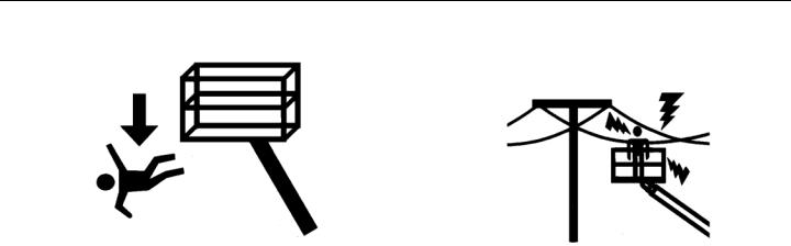
SECTION 1 — SAFETY PRECAUTIONS
• Before operating the machine, make sure all gates are closed Electrocution Hazards and fastened in their proper position.
• This machine is not insulated and does not provide protection from contact or proximity to electrical current.
•Keep both feet firmly positioned on the platform floor at all times. Never position ladders, boxes, steps, planks, or similar items on unit to provide additional reach for any purpose.
•Keep oil, mud, and slippery substances cleaned from footwear and the platform floor.
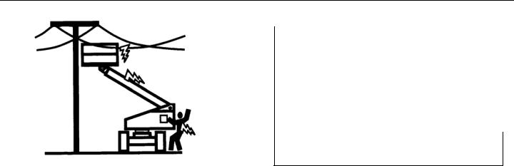
SECTION 1 — SAFETY PRECAUTIONS
•Maintain distance from electrical lines, apparatus, or any energized (exposed or insulated) parts according to the Minimum Approach Distance (MAD) as shown in Table 1-1.
•Allow for machine movement and electrical line swaying.
Table 1-1. Minimum Approach Distances (M.A.D.)
|
Voltage Range |
MINIMUM APPROACH DISTANCE |
|
|
(Phase to Phase) |
in Feet (Meters) |
|
|
0to50KV |
10(3) |
|
|
Over50KVto200KV |
15(5) |
|
|
Over200KVto350KV |
20(6) |
|
|
Over350KVto500KV |
25(8) |
|
|
Over500KVto750KV |
35(11) |
|
|
Over750KVto1000KV |
45(14) |
|
|
NOTE: This requirement |
shall apply except where |
employer, local or governmental regulations are more stringent.
•Maintain a clearance of at least 10 ft. (3m) between any part of the machine and its occupants, their tools, and their equipment from any electrical line or apparatus carrying up to 50,000 volts. One foot additional clearance is required for every additional 30,000 volts or less.
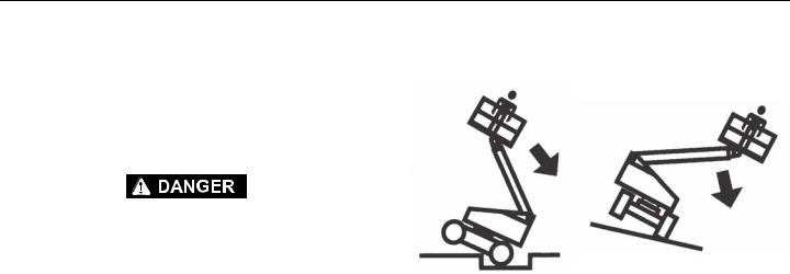
SECTION 1 — SAFETY PRECAUTIONS
•The minimum approach distance may be reduced if insulating barriers are installed to prevent contact, and the barriers are rated for the voltage of the line being guarded. These barriers shall not be part of (or attached to) the machine. The minimum approach distance shall be reduced to a distance within the designed working dimensions of the insulating barrier. This determination shall be made by a qualified person in accordance with the employer, local, or governmental requirements for work practices near energized equipment
DO NOT MANEUVER MACHINE OR PERSONNEL INSIDE PROHIBITED ZONE (MAD). ASSUME ALL ELECTRICAL PARTS AND WIRING ARE ENERGIZED UNLESS KNOWN OTHERWISE.
Tipping Hazards
•The user must be familiar with the surface before driving. Do not exceed the allowable sideslope and grade while driving.
•Do not elevate platform or drive with platform elevated while on or near a sloping, uneven, or soft surface. Ensure machine is positioned on a firm, level and smooth surface before elevating platform or driving with the platform in the elevated position.
•Before driving on floors, bridges, trucks, and other surfaces, check allowable capacity of the surfaces.

SECTION 1 — SAFETY PRECAUTIONS
•Never exceed the maximum work load as specified on the platform. Keep all loads within the confines of the platform, unless authorized by JLG.
•Keep the chassis of the machine a minimum of 2 ft. (0.6m) from holes, bumps, drop-offs, obstructions, debris, concealed holes, and other potential hazards at the ground level.
•Do not push or pull any object with the boom.
•Never attempt to use the machine as a crane. Do not tie-off machine to any adjacent structure. Never attach wire, cable, or any similar items to platform.
•Do not operate the machine when wind conditions exceed 28 mph (12.5 m/s). Refer to Table 1-2, Beaufort Scale (For Reference Only).
•Do not increase the surface area of the platform or the load. Increase of the area exposed to the wind will decrease stability.
•Do not increase the platform size with unauthorized deck extensions or attachments.
•If boom assembly or platform is in a position that one or more wheels are off the ground, all persons must be removed before attempting to stabilize the machine. Use cranes, forklift trucks, or other appropriate equipment to stabilize machine.

SECTION 1 — SAFETY PRECAUTIONS
DO NOT OPERATE THE MACHINE WHEN WIND CONDITIONS EXCEED 28 MPH (12.5 M/
S).
Table 1-2. Beaufort Scale (For Reference Only)
|
Beaufort |
Wind Speed |
Description |
Land Conditions |
||
|
Number |
mph |
m/s |
|||
|
0 |
0 |
0-0.2 |
Calm |
Calm.Smokerisesvertically |
|
|
1 |
1-3 |
0.3-1.5 |
Lightair |
Windmotionvisibleinsmoke |
|
|
2 |
4-7 |
1.6-3.3 |
Lightbreeze |
Windfeltonexposedskin.Leavesrustle |
|
|
3 |
8-12 |
3.4-5.4 |
Gentlebreeze |
Leavesandsmallertwigsinconstantmotion |
|
|
4 |
13-18 |
5.5-7.9 |
Moderatebreeze |
Dust andloosepaperraised.Smallbranchesbegintomove. |
|
|
5 |
19-24 |
8.0-10.7 |
Freshbreeze |
Smallertreessway. |
|
|
6 |
25-31 |
10.8-13.8 |
Strongbreeze |
Largebranchesinmotion.Flagswavingnear horizontal.Umbrellause |
|
|
becomesdifficult. |
|||||
|
7 |
32-38 |
13.9-17.1 |
NearGale/ModerateGale |
Whole treesin motion.Effortneededtowalkagainstthewind. |
|
|
8 |
39-46 |
17.2-20.7 |
FreshGale |
Twigsbrokenfromtrees.Carsveer onroad. |
|
|
9 |
47-54 |
20.8-24.4 |
StrongGale |
Lightstructuredamage. |
|

SECTION 1 — SAFETY PRECAUTIONS
Crushing and Collision Hazards
•Approved head gear must be worn by all operating and ground personnel.
•Check work area for clearances overhead, on sides, and bottom of platform when lifting or lowering platform, and driving.
•During operation, keep all body parts inside platform railing.
•Use the boom functions, not the drive function, to position the platform close to obstacles.
•Always post a lookout when driving in areas where vision is obstructed.
•Keep non-operating personnel at least 6 ft. (1.8m) away from machine during all driving and swing operations.
•Under all travel conditions, the operator must limit travel speed according to conditions of ground surface, congestion, visibility, slope, location of personnel, and other factors which may cause collision or injury to personnel.
•Be aware of stopping distances in all drive speeds. When driving in high speed, switch to low speed before stopping. Travel grades in low speed only.
•Do not use high speed drive in restricted or close quarters or when driving in reverse.
•Exercise extreme caution at all times to prevent obstacles from striking or interfering with operating controls and persons in the platform.
•Be sure that operators of other overhead and floor level machines are aware of the aerial work platform’s presence. Disconnect power to overhead cranes.
•Warn personnel not to work, stand, or walk under a raised boom or platform. Position barricades on floor if necessary.
|
1-10 |
– JLG Lift – |
3121170 |

SECTION 1 — SAFETY PRECAUTIONS
1.4 TOWING, LIFTING, AND HAULING |
1.5 MAINTENANCE |
•Never allow personnel in platform while towing, lifting, or hauling.
•This machine should not be towed, except in the event of emergency, malfunction, power failure, or loading/unloading. Refer to the Emergency Procedures section of this manual for emergency towing procedures.
•Ensure boom is in the stowed position and the turntable locked prior to towing, lifting or hauling. The platform must be completely empty of tools.
•When lifting machine, lift only at designated areas of the machine. Lift the unit with equipment of adequate capacity.
•Refer to the Machine Operation section of this manual for lifting information.
This sub-section contains general safety precautions which must be observed during maintenance of this machine. Additional precautions to be observed during machine maintenance are inserted at the appropriate points in this manual and in the Service and Maintenance Manual. It is of utmost importance that maintenance personnel pay strict attention to these precautions to avoid possible injury to personnel or damage to the machine or property. A maintenance program must be established by a qualified person and must be followed to ensure that the machine is safe.
Maintenance Hazards
•Shut off power to all controls and ensure that all moving parts are secured from inadvertent motion prior to performing any adjustments or repairs.
•Never work under an elevated platform until it has been fully lowered to the full down position, if possible, or otherwise supported and restrained from movement with appropriate safety props, blocking, or overhead supports.
•DO NOT attempt to repair or tighten any hydraulic hoses or fittings while the machine is powered on or when the hydraulic system is under pressure.
•Always relieve hydraulic pressure from all hydraulic circuits before loosening or removing hydraulic components.
|
3121170 |
– JLG Lift – |
1-11 |

SECTION 1 — SAFETY PRECAUTIONS
•DO NOT use your hand to check for leaks. Use a piece of cardboard or paper to search for leaks. Wear gloves to help protect hands from spraying fluid.
•Do not use machine as a ground for welding.
•When performing welding or metal cutting operations, precautions must be taken to protect the chassis from direct exposure to weld and metal cutting spatter.
•Do not refuel the machine with the engine running.
•Use only approved non-flammable cleaning solvents.
•Do not replace items critical to stability, such as batteries or solid tires, with items of different weight or specification. Do not modify unit in any way to affect stability.
•Refer to the Service and Maintenance Manual for the weights of critical stability items.
•Ensure replacement parts or components are identical or equivalent to original parts or components.
•Never attempt to move heavy parts without the aid of a mechanical device. Do not allow heavy objects to rest in an unstable position. Ensure adequate support is provided when raising components of the machine.
MODIFICATION OR ALTERATION OF AN AERIAL WORK PLATFORM SHALL BE MADE ONLY WITH PRIOR WRITTEN PERMISSION FROM THE MANUFACTURER.
|
1-12 |
– JLG Lift – |
3121170 |

SECTION 1 — SAFETY PRECAUTIONS
Battery Hazards
•Always disconnect batteries when servicing electrical components or when performing welding on the machine.
•Do not allow smoking, open flame, or sparks near battery during charging or servicing.
•Do not contact tools or other metal objects across the battery terminals.
•Always wear hand, eye, and face protection when servicing batteries. Ensure that battery acid does not come in contact with skin or clothing.
BATTERY FLUID IS HIGHLY CORROSIVE. AVOID CONTACT WITH SKIN AND CLOTHING AT ALL TIMES. IMMEDIATELY RINSE ANY CONTACTED AREA WITH CLEAN WATER AND SEEK MEDICAL ATTENTION.
•Charge batteries only in a well ventilated area.
•Avoid overfilling the battery fluid level. Add distilled water to batteries only after the batteries are fully charged.
|
3121170 |
– JLG Lift – |
1-13 |

SECTION 1 — SAFETY PRECAUTIONS
 NOTES:
|
1-14 |
– JLG Lift – |
3121170 |

SECTION 2 — USER RESPONSIBILITIES, MACHINE PREPARATION, AND INSPECTION
SECTION 2. USER RESPONSIBILITIES, MACHINE PREPARATION, AND INSPECTION
2.1 PERSONNEL TRAINING
The aerial platform is a personnel handling device; so it is necessary that it be operated and maintained only by trained personnel.
Persons under the influence of drugs or alcohol or who are subject to seizures, dizziness or loss of physical control must not operate this machine.
Operator Training
Operator training must cover:
1.Use and limitations of the controls in the platform and at the ground, emergency controls and safety systems.
2.Control labels, instructions, and warnings on the machine.
3.Rules of the employer and government regulations.
4.Use of approved fall protection device.
5.Enough knowledge of the mechanical operation of the machine to recognize a malfunction or potential malfunction.
6.The safest means to operate the machine where overhead obstructions, other moving equipment, and obstacles, depressions, holes, drop-offs.
7.Means to avoid the hazards of unprotected electrical conductors.
8.Specific job requirements or machine application.
Training Supervision
Training must be done under the supervision of a qualified person in an open area free of obstructions until the trainee has developed the ability to safely control and operate the machine.
Operator Responsibility
The operator must be instructed that he/she has the responsibility and authority to shut down the machine in case of a malfunction or other unsafe condition of either the machine or the job site.

SECTION 2 — USER RESPONSIBILITIES, MACHINE PREPARATION, AND INSPECTION
2.2 PREPARATION, INSPECTION, AND MAINTENANCE
The following table covers the periodic machine inspections and maintenance required by JLG Industries, Inc. Consult local regulations for further requirements for aerial work platforms. The frequency of inspections and maintenance must be increased as necessary when the machine is used in a harsh or hostile environment, if the machine is used with increased frequency, or if the machine is used in a severe manner.
JLG INDUSTRIES, INC. RECOGNIZES A FACTORY-QUALIFIED SERVICE TECHNICIAN AS A PERSON WHO HAS SUCCESSFULLY COMPLETED THE JLG SERVICE TRAINING SCHOOL FOR THE SPECIFIC JLG PRODUCT MODEL.

SECTION 2 — USER RESPONSIBILITIES, MACHINE PREPARATION, AND INSPECTION
Table 2-1. Inspection and Maintenance Table
|
Type |
Frequency |
Primary |
Service |
Reference |
|
|
Responsibility |
Qualification |
||||
|
Pre-Start Inspection |
Beforeusingeachday; or |
UserorOperator |
UserorOperator |
OperatorandSafetyManual |
|
|
wheneverthere’sanOperatorchange. |
|||||
|
Pre-DeliveryInspection(See |
Beforeeachsale,lease,orrentaldelivery. |
Owner,Dealer,orUser |
QualifiedJLGMechanic |
ServiceandMaintenanceManual |
|
|
Note) |
andapplicableJLGinspectionform |
||||
|
FrequentInspection |
Inservicefor3monthsor150hours,whichevercomesfirst; |
Owner,Dealer,orUser |
QualifiedJLGMechanic |
ServiceandMaintenanceManual |
|
|
(SeeNote) |
or |
andapplicableJLGinspectionform |
|||
|
Outofserviceforaperiodofmorethan3months;or |
|||||
|
Purchasedused. |
|||||
|
AnnualMachineInspection |
Annually,nolater than13monthsfromthedateofprior |
Owner,Dealer,orUser |
Factory-QualifiedService |
ServiceandMaintenanceManual |
|
|
(SeeNote) |
inspection. |
Technician |
andapplicableJLGinspectionform |
||
|
(Recommended) |
|||||
|
PreventativeMaintenance |
AtintervalsasspecifiedintheServiceandMaintenance |
Owner,Dealer,orUser |
QualifiedJLGMechanic |
ServiceandMaintenanceManual |
|
|
Manual. |
|||||
|
NOTE: Inspection forms |
are available from JLG. Use the Service and Maintenance Manual to perform inspections. |
||||

SECTION 2 — USER RESPONSIBILITIES, MACHINE PREPARATION, AND INSPECTION
Pre-Start Inspection
The Pre-Start Inspection should include each of the following:
1.Cleanliness – Check all surfaces for leakage (oil, fuel, or battery fluid) or foreign objects. Report any leakage to the proper maintenance personnel.
2.Structure — Inspect the machine structure for dents, damage, weld or parent metal cracks or other discrepancies.
|
ParentMetalCrack |
WeldCrack |
3.Decals and Placards – Check all for cleanliness and legibility. Make sure none of the decals and placards are missing. Make sure all illegible decals and placards are cleaned or replaced.
4.Operation and Safety Manuals – Make sure a copy of the Operator and Safety Manual, AEM Safety Manual (ANSI markets only), and ANSI Manual of Responsibilities (ANSI markets only) is enclosed in the weather resistant storage container.
5.“Walk-Around” Inspection – Refer to Figure 2-2.
6.Battery – Charge as required.
7.Fuel (Combustion Engine Powered Machines) – Add the proper fuel as necessary.
8.Engine Oil Supply — Ensure the engine oil level is at the Full mark on the dipstick and the filler cap is secure.
9.Hydraulic Oil – Check the hydraulic oil level. Ensure hydraulic oil is added as required.
10.Accessories/Attachments — Reference the Operator and Safety Manual of each attachment or accessory installed upon the machine for specific inspection, operation, and maintenance instructions.

SECTION 2 — USER RESPONSIBILITIES, MACHINE PREPARATION, AND INSPECTION
11.Function Check – Once the “Walk-Around” Inspection is complete, perform a functional check of all systems in an area free of overhead and ground level obstructions. Refer to Section 4 for more specific operating instructions.
IF THE MACHINE DOES NOT OPERATE PROPERLY, TURN OFF THE MACHINE IMMEDIATELY! REPORT THE PROBLEM TO THE PROPER MAINTENANCE PERSONNEL. DO NOT OPERATE THE MACHINE UNTIL IT IS DECLARED SAFE FOR OPERATION.
Function Check
Perform the Function Check as follows:
1.From the ground control console with no load in the platform:
a.Check that all guards protecting the switches or locks are in place;
b.Operate all functions and make sure the Boom Control System warning light does not come on;
c.Check auxiliary power;
d.Ensure that all machine functions are disabled when the Emergency Stop Button is pushed in.
e.Ensure all boom functions stop when the function enable switch is released.

SECTION 2 — USER RESPONSIBILITIES, MACHINE PREPARATION, AND INSPECTION
2.From the platform control console:
a.Ensure that the control console is firmly secured in the proper location;
b.Check that all guards protecting the switches or locks are in place;
c.Operate all functions and make sure the Boom Control System warning light does not come on;
d.Ensure that all machine functions are disabled when the Emergency Stop Button is pushed in.
3.With the platform in the stowed position:
a.Drive the machine on a grade, not to exceed the rated gradeability, and stop to ensure the brakes hold;
b.Check the tilt sensor alarm to ensure proper operation.
c.Check that all boom functions are disabled with the axles retracted and the boom out of transport mode.
NOTE: The machine is in transport mode until one of the following three factors are exceeded:
Main boom extended more than 4 ft. (1.2 m) OR Main boom 6° above horizontal (w/tower stowed) OR Tower above horizontal.
4.Swing the boom over either of the rear tires and ensure that the Drive Orientation indicator illuminates and that the Drive Orientation Override switch must be used for the drive function to operate.

SECTION 2 — USER RESPONSIBILITIES, MACHINE PREPARATION, AND INSPECTION
|
1. |
FrontDriveSteerWheels |
|
2. |
RearDriveSteer Wheels |
|
3. |
TowerLiftCylinder |
|
4. |
GroundConsole |
|
5. |
TowerBaseBoomSection |
|
6. |
TowerMidBoomSection |
|
7. |
TowerFlyBoomSection |
|
8. |
TowerBoomAssembly |
|
9. |
MainLiftCylinder |
|
10. |
MainBaseBoomSection |
|
11. |
MainBoomFlySection |
|
12. |
MainBoomAssembly |
|
13. |
Jib |
|
14. |
Platform |
|
15. |
PlatformConsole |
Figure 2-1. Basic Nomenclature

SECTION 2 — USER RESPONSIBILITIES, MACHINE PREPARATION, AND INSPECTION
Figure 2-2. Daily Walk-Around Inspection — Sheet 1 of 2

SECTION 2 — USER RESPONSIBILITIES, MACHINE PREPARATION, AND INSPECTION
General
Begin the «Walk-Around Inspection» at Item 1, as noted on the diagram. Continue checking each item in sequence for the conditions listed in the following checklist.
TO AVOID POSSIBLE INJURY, BE SURE MACHINE POWER IS OFF.
DO NOT OPERATE MACHINE UNTIL ALL MALFUNCTIONS HAVE BEEN CORRECTED.
INSPECTION NOTE: On all components, make sure there are no loose or missing parts, that they are securely fastened, and no visible damage, leaks or excessive wear exists in addition to any other criteria mentioned.
1.Platform Assembly and Gate — Footswitch works properly, not modified, disabled or blocked. Latch and hinges in working condition.
2.Platform & Ground Control Consoles — Switches and levers return to neutral, decals/placards secure and legible, control markings legible.
3.Boom Sections/Turntable — See Inspection Note.
4.Swing Drive — No evidence of damage.
5.Wheel/Tire Assemblies — Properly secured, no missing lug nuts. Inspect for worn tread, cuts, tears or other discrepancies. Inspect wheels for damage and corrosion.
6.Drive Motor, Brake, and Hub — No evidence of leakage.
7.Hood Assemblies — See Inspection Note.
8.Auxiliary Hydraulic Pump — See Inspection Note.
9.All Hydraulic Cylinders — No visible damage; pivot pins and hydraulic hoses undamaged, not leaking.
10.Turntable Bearing — Evidence of proper lubrication. No evidence of loose bolts or looseness between bearing and machine.
11.Steering Spindles and Sensors — See Inspection Note.
12.Main Hydraulic Pump — See Inspection Note.
13.Platform Rotator — See Inspection Note.
14.Jib Rotator — See Inspection Note.
Figure 2-3. Daily Walk-Around Inspection — Sheet 2 of 2

SECTION 2 — USER RESPONSIBILITIES, MACHINE PREPARATION, AND INSPECTION
2.3OSCILLATING AXLE LOCKOUT TEST (IF EQUIPPED)
The front axles will oscillate when the boom is in the transport position.
LOCKOUT SYSTEM TEST MUST BE PERFORMED QUARTERLY, ANY TIME A SYSTEM COMPONENT IS REPLACED, OR WHEN IMPROPER SYSTEM OPERATION IS SUSPECTED.
NOTE: Ensure the axles are extended and the boom is fully retracted, lowered, and centered between the rear wheels prior to beginning lockout cylinder test.
1.Place a 6 inches (15.2 cm) high block with ascension ramp in front of left front wheel.
2.From platform control station, start engine.
3.Place the Drive control lever to the forward position and carefully drive machine up ascension ramp until left front wheel is on top of block.
4.Carefully extend the boom just enough to get it out of the transport position.
5.With boom in this position, place Drive control lever to Reverse and carefully drive machine off of block and ramp.
6.Have an assistant check to see that left front or right rear wheel remains elevated in position off of the ground.
7.Carefully return the boom to the transport position. When boom reaches the transport position, carefully activate Drive to release cylinders. The lockout cylinders should release and allow the wheel to rest on ground.
8.Repeat the procedure for the right oscillation cylinder checking to see that the right front or left rear wheel remains elevated in position off of the ground.
9.If lockout cylinders do not function properly, have qualified personnel correct the malfunction prior to any further operation.
|
2-10 |
– JLG Lift – |
3121170 |

SECTION 3 — MACHINE CONTROLS AND INDICATORS
SECTION 3. MACHINE CONTROLS AND INDICATORS
3.1GENERAL
NOTE: The indicator panels use different shaped symbols to alert the operator to different types of operational situations that could arise. The meaning of those symbols are explained below.
THE MANUFACTURER HAS NO DIRECT CONTROL OVER MACHINE APPLICATION AND OPERATION. THE USER AND OPERATOR ARE RESPONSIBLE FOR CONFORMING WITH GOOD SAFETY PRACTICES.
Indicates a potentially hazardous situation, which if not corrected, could result in serious injury or death. This indicator will be red.
This section provides the necessary information needed to understand control functions.
3.2CONTROLS AND INDICATORS
NOTE: All machines are equipped with control panels that use symbols to indicate control functions. On ANSI machines refer to decal located on the control box guard in front of the control box or by the ground controls for these symbols and the corresponding functions.
Indicates an abnormal operating condition, which if not corrected, may result in machine interruption or damage. This indicator will be yellow.
Indicates important information regarding the operating condition, i.e. procedures essential for safe operation. This indicator will be green with the exception of the capacity indicator which will be green or yellow depending upon platform position.

SECTION 3 — MACHINE CONTROLS AND INDICATORS
TO AVOID SERIOUS INJURY, DO NOT OPERATE MACHINE IF ANY CONTROL LEVERS OR TOGGLE SWITCHES CONTROLLING PLATFORM MOVEMENT DO NOT RETURN TO THE OFF POSITION WHEN RELEASED.
Ground Control Station
(See Figure 3-1., Ground Control Station)
1.Indicator Panel
The Indicator Panel contains indicator lights that signal problem conditions or functions operating during machine operation.
3.Tower Lift Control
Provides raising and lowering of the tower boom.
4.Swing Control
Provides 360 degrees continuous turntable rotation.
5.Main Lift Control
Provides raising and lowering of the main boom.
6.Jib Lift
Provides raising and lowering of the jib.
NOTE: The Function Enable switch must be held down in order to operate Main Boom Telescope, Tower Lift, Swing, Main Lift, Jib Lift, Platform Level Override, Platform Rotate, and Jib Swing functions.
2.Main Boom Telescope Control
Provides extension and retraction of the main boom.
ONLY USE THE PLATFORM LEVELING OVERRIDE FUNCTION FOR SLIGHT LEVELING OF THE PLATFORM. INCORRECT USE COULD CAUSE THE LOAD/OCCUPANTS TO SHIFT OR FALL. FAILURE TO DO SO COULD RESULT IN DEATH OR SERIOUS INJURY.
7.Platform Leveling Override
A three position switch allows the operator to adjust the automatic self leveling system. This switch is used to adjust platform level in situations such as ascending/descending a grade.

Service and Maintenance Manual
Model
1250AJP
P/N — 3121171
December 7, 2012
59 страниц подробных инструкций и пользовательских руководств по эксплуатации
 02:58
02:58
JLG Compact Crawler Booms Lifts
 08:52
08:52
JLG® Self-Leveling Boom Lift Demo
 11:17
11:17
Worlds Tallest Boom Lift 185 Feet JLG 1850SJ
 07:20
07:20
JLG 600sj boom lift repair
 01:13
01:13
JLG 1850SJ Telescopic Boom Lift at ABLE Equipment Rental
 01:18
01:18
How to Operate the JLG Boom Lift Drive Orientation System
 11:14
11:14
Product Review: JLG 1850SJ Telescopic Boom Lift
 02:18
02:18
250,000th Boom Lift Time-Lapse: See What It Takes To Build a JLG® Boom
РАЗДЕЛ 3 — ТЕХОБСЛУЖИВАНИЕ — СТРЕЛОВЫЕ ПОДЪЕМНИКИ С ЭЛЕКТРОПРИВОДОМ
3122746
– Подъемник JLG –
3-9
3.4 УСТРАНЕНИЕ НЕИСПРАВНОСТЕЙ
В нижеследующих таблицах содержатся возможные
решения наиболее распространенных проблем.
Проблемы делятся на общие, связанные с
калибровкой, связанные с точностью измерений и
связанные с функциональностью главной системы.
Таблица 3-1. Таблица устранения неисправностей СИН — неисправности общего характера
Проблема
Возможное решение
Анализатор JLG не выдает
сообщения «HELP: PRESS
ENTER» после
подсоединения к разъему
модуля СИН, но светодиод
модуля горит или мигает.
Анализатор JLG не может установить связь с модулем СИН, но на модуль СИН
подается питание (на что указывает светодиод модуля). Обследуйте соединения
последовательной связи и питания анализатора JLG.
1. Если после небольшого интервала анализатор выдает сообщения
«CONNECTING…» или «CONNECTION ERROR», обследуйте жгут проводов
анализатора на разъеме J2. J2-2 должен подсоединяться к контакту 3
анализатора, а J2-11 должен подсоединяться к контакту 2.
2. Если анализатор не выдает никаких сообщений (и отсутствует подсветка),
проверьте питание анализатора. Отсоедините разъем жгута проводов от J2, и
убедитесь, что напряжение на J2-1 составляет приблизительно 12 В, а на J2-12 —
0 В Жгут проводов должен соединять J2-1 с контактом 1 анализатора, а J2-12 — с
контактом 4 анализатора.
3. Возможно, неисправен анализатор JLG. Замените его, чтобы определить
причину неисправности.
4. Возможно, неисправен модуль СИН. Замените его, чтобы определить причину
неисправности.
Не горит светодиод на
модуле СИН.
На модуль СИН не подается питание, имеется короткое замыкание, либо устройство
повреждено.
1. На модуль СИН подается неправильное питание. Проверьте наличие
приблизительно 12 В на J1-1 и 0 В на J1-2. Питание модуля поступает от пульта
управления с платформы. Воспользуйтесь схемой проводки, чтобы отследить
проводники до источника.
2. Короткое замыкание в цепях опорного напряжения на J5-J8. Отсоединяйте
разъемы по одному и наблюдайте, начнет ли модуль работать после
отсоединения одного из разъемов. Если да, тщательно обследуйте проводку
между модулем и этим датчиком.
3. Короткое замыкание в цепи стабилизированного питания для анализатора JLG
на J2-1. Отсоедините разъем от J2 и наблюдайте, начнет ли модуль работать.
Если да, обследуйте жгут проводов анализатора на предмет повреждений.
4. Возможно, неисправен модуль СИН. Замените его, чтобы определить причину
неисправности.

РАЗДЕЛ 3 — ТЕХОБСЛУЖИВАНИЕ — СТРЕЛОВЫЕ ПОДЪЕМНИКИ С ЭЛЕКТРОПРИВОДОМ
3-10
– Подъемник JLG –
3122746
Таблица 3-2. Таблица устранения неисправностей СИН — калибровка
Проблема
Возможное решение
После попытки калибровки
анализатор JLG выдает
сообщение «<MIN CAL».
При калибровке модуль СИН ожидает, что вес пустой платформы будет больше.
1. Во время калибровки платформа опирается на землю или на другое
препятствие. Для точной калибровки вес платформы должен передаваться
через cдвиговые балочные силоизмерительные элементы на опорную
конструкцию.
2. Была выбрана неправильная модель в подменю модуля СИН MACHINE
SETUP, MODEL. Этот параметр следует установить на «MODEL=BOOM LIFT».
Неправильный выбор может привести к тому, что модуль СИН будет ожидать
другой вес пустой платформы.
3. Один или несколько силоизмерительных элементов неправильно установлены
(имеются помехи между платформой и опорной конструкцией) или
перевернуты. Для устранения проблемы см. раздел данного руководства,
посвященный установке.
4. Проблема с калибровкой может быть следствием проблемы с точностью
измерений. Просмотрите возможные решения в этой категории.
После попытки калибровки
анализатор JLG выдает
сообщение «>MAX CAL».
При калибровке модуль СИН ожидает, что вес пустой платформы будет меньше.
1. Перед началом калибровки не были убраны инструменты, мусор и устройства,
установленные заказчиками. Модуль СИН должен тарировать пустую
платформу с дополнительными приспособлениями JLG.
2. Была выбрана неправильная модель в подменю модуля СИН MACHINE
SETUP, MODEL. Этот параметр следует установить на «MODEL=BOOM LIFT».
Неправильный выбор может привести к тому, что модуль СИН будет ожидать
другой вес пустой платформы.
3. Один или несколько силоизмерительных элементов неправильно установлены
(имеются помехи между платформой и опорной конструкцией) или
перевернуты. Для устранения проблемы см. раздел данного руководства,
посвященный установке.
4. Проблема с калибровкой может быть следствием проблемы с точностью
измерений. Просмотрите возможные решения в этой категории.

РАЗДЕЛ 3 — ТЕХОБСЛУЖИВАНИЕ — СТРЕЛОВЫЕ ПОДЪЕМНИКИ С ЭЛЕКТРОПРИВОДОМ
3122746
– Подъемник JLG –
3-11
Таблица 3-3. Таблица устранения неисправностей СИН — точность измерений
Проблема
Возможное решение
Масса пустой платформы
(DIAGNOSTICS, PLTLOAD)
отклоняется от нуля больше,
чем на ±7 кг.
или
Показания нагрузки на
платформу (DIAGNOSTICS,
PLTLOAD) колеблются
больше, чем на ±1 кг (без
воздействия вибрации или
ветра).
или
Возникают большие
расхождения нагрузки на
платформу (DIAGNOSTICS,
PLTLOAD) в зависимости от
расположения груза на
платформе. Допуск
расхождений составляет 9 кг
для оценки с помощью веса
техника и +5% от
номинальной
грузоподъемности, если
используются аттестованные
грузы.
(см. продолжение)
Модуль СИН не может правильно измерить вес платформы.
1. Один из cдвиговых балочных силоизмерительных элементов не подключен
надлежащим образом к модулю СИН. Поскольку разъемы герметизируются
уплотнительными кольцами и находятся в тесных местах, возможно, что
разъемы были сращены, но электрическое соединение плохое. Попытайтесь
покачать запрессованную часть каждого разъема на J5-J8. Если разъемы
затянуты правильно, запрессованная часть не должна шататься. Также
проверьте показания каждого силоизмерительного элемента с помощью
анализатора JLG. Войдите в экраны DIAGNOSTICS, CELL 1-4, LOAD и
проверьте, являются ли показания нормальными. Обратите внимание, что
возможны ситуации, когда два датчика несут всю нагрузку платформы из-за
посадки платформы на опорной конструкции (это нормально).
2. Повреждена проводка, идущая к одному из силоизмерительных элементов.
Проверьте показания каждого датчика с помощью анализатора JLG. Войдите в
экраны DIAGNOSTICS, CELL 1-4, LOAD и проверьте, являются ли показания
нормальными, и реагируют ли они на небольшое давления прижатия над
датчиком, показания которого вы проверяете. Внимательно обследуйте
проводку в тех местах, где она проходит через кабельные хомуты, на предмет
повреждений. Обследуйте проводку в тех местах, где имеются видимые
повреждения швеллера. Если обнаружено повреждение шнурового набора
датчика, замените соответствующий силоизмерительный элемент балочного
типа, поскольку шнуровой набор не подлежит обслуживанию (разъем
запрессован для защиты от попадания влаги; шнуровой набор запаян в датчик
под сварным кожухом из нержавеющей стали).
3. Во время установки один из силоизмерительных элементов был собран
неправильно. Проверьте показания каждого датчика с помощью анализатора
JLG. Войдите в экраны DIAGNOSTICS, CELL 1-4, LOAD и проверьте, являются
ли показания нормальными. Зачастую полезно слегка прижать платформу над
проверяемым датчиком и проверить, увеличивается ли сигнал датчика
(увеличивая показание усилия; уменьшение означает, что датчик перевернут).
Сравните порядок сборки с деталями на чертеже установки и убедитесь, что
контакт между платформой и опорой осуществляется только через тела
датчиков (кроме них ничего не соприкасается, за исключением проводки). При
необходимости выполните сборку согласно чертежу.
(см. продолжение)

РАЗДЕЛ 3 — ТЕХОБСЛУЖИВАНИЕ — СТРЕЛОВЫЕ ПОДЪЕМНИКИ С ЭЛЕКТРОПРИВОДОМ
3-12
– Подъемник JLG –
3122746
Масса пустой платформы
(DIAGNOSTICS, PLTLOAD)
отклоняется от нуля больше,
чем на ±7 кг.
или
Показания нагрузки на
платформу (DIAGNOSTICS,
PLTLOAD) колеблются
больше, чем на ±1 кг (без
воздействия вибрации или
ветра).
или
Возникают большие
расхождения нагрузки на
платформу (DIAGNOSTICS,
PLTLOAD) в зависимости от
расположения груза на
платформе. Допуск
расхождений составляет 9 кг
для оценки с помощью веса
техника и +5% от
номинальной
грузоподъемности, если
используются аттестованные
грузы.
4. При затяжке деталей крепления силоизмерительных элементов использовалась
неправильная процедура. Несоблюдение указаний в руководстве по установке
может привести к значительным неосевым нагрузкам на датчики (что приведет к
искажению показаний по основной оси измерений). Отпустите все крепежные
детали и последовательно затяните их в соответствии с рекомендациями в
руководстве по установке (для достижения правильного момента затяжки
рекомендуется использовать новые крепежные детали).
5. Произошло повреждение платформы или опорной конструкции, либо один из
компонентов находится вне пределов допуска (не лежит в одной плоскости с
другими компонентами). После того, как все крепежные детали будут затянуты
согласно спецификации, на датчики будут воздействовать значительные
неосевые нагрузки (что приведет к искажению показаний по основной оси
измерений). Ослабьте все крепежные детали и проверьте, не были ли
платформа или опора перетянуты крепежными деталями (они должны быть
плоскими и точно подогнанными). Решением этой проблемы будет замена
поврежденного или неисправного компонента. Проверьте, не были ли
повреждены (деформированы) силоизмерительные элементы в результате этой
проблемы.
6. Один из силоизмерительных элементов загрязнен или влажный. Проверьте
показания каждого датчика с помощью анализатора JLG. Войдите в экраны
DIAGNOSTICS, CELL 1-4, LOAD и проверьте, являются ли показания
нормальными и стабильными (не изменяются больше чем на ±1 кг) (в отсутствие
вибрации или ветра). Неустойчивость показаний является основным признаком
загрязнения. Отсоедините соответствующий разъем (J5 для ЭЛЕМЕНТА 1, J6 для
ЭЛЕМЕНТА 2, J7 для ЭЛЕМЕНТА 3 И J8 для ЭЛЕМЕНТА 4) и осмотрите его на
предмет загрязнений или влаги. Внимательно осмотрите гнездовую часть
шнурового набора датчика на признаки загрязнений. Мусор следует удалить
щеткой с мягкой щетиной (не используйте никаких чистящих веществ, поскольку
они оставят токопроводящий осадок). Следует дать влаге испариться или
ускорить этот процесс с помощью воздушной сушилки (используйте низкие
температуры, чтобы не расплавить материал разъема). В случае попадания
влаги в запрессованную часть разъема (капиллярным путем через провода) или
непосредственно в силоизмерительный элемент потребуется заменить датчик.
7. Один из силоизмерительных элементов механически поврежден
(деформирован). Если силоизмерительный элемент физически деформирован,
или поврежден один из его щитков из нержавеющей стали, этот элемент
следует немедленно заменить. Возможны и невидимые механические
повреждения в результате сильной перегрузки (>2722 кг). Такие повреждения
можно обнаружить, сняв все детали, которые крепят платформу, и установив
платформу на пару пильных козел или бочек (чтобы разгрузить
силоизмерительные элементы). Проверьте показания каждого датчика с
помощью анализатора JLG. Войдите в экраны DIAGNOSTICS, CELL 1-4, LOAD и
проверьте, находятся ли показания разгруженных датчиков в пределах ±7 кг от
нуля (по отдельности). Замените датчики, которые в разгруженном состоянии
регистрируют чрезмерное усилие.
8. Возможно, неисправен модуль СИН. Поменяйте местами разъемы
силоизмерительных элементов балочного типа (J5-J8) и проверьте результаты в
анализаторе JLG. Войдите в экраны DIAGNOSTICS, CELL 1-4, LOAD и проверьте
показания. Если проблема связана с конкретным датчиком, внимательно
проверьте все возможные проблемы, описанные выше. Если проблема остается с
конкретным каналом модуля СИН, замените его на другой модуль.
Таблица 3-3. Таблица устранения неисправностей СИН — точность измерений
Проблема
Возможное решение

РАЗДЕЛ 3 — ТЕХОБСЛУЖИВАНИЕ — СТРЕЛОВЫЕ ПОДЪЕМНИКИ С ЭЛЕКТРОПРИВОДОМ
3122746
– Подъемник JLG –
3-13
Таблица 3-4. Таблица устранения неисправностей СИН — функциональность главной системы
Проблема
Возможное решение
Визуальная и и звуковая
сигнализация перегрузки
не срабатывают, когда
платформа нагружена
сверх номинальной
грузоподъемности, или когда
перегрузка моделируется
отсоединением
силоизмерительного
элемента балочного типа
от модуля СИН. Органы
управления на платформе
и на земле функционируют.
Единая система управления не регистрирует сигнал перегрузки, поступающий от
модуля СИН, либо сигнал закорочен.
1. Необходимо ввести в действие систему измерения нагрузки в главной системе
управления. Подсоедините анализатор JLG к главной системе управления,
введите пароль уровня доступа 1 (33271) и войдите в подменю MACHINE
SETUP, LOAD. Вариант выбора «2=CUTOUT PLT» должен присутствовать для
соответствия требованиям Европейской комиссии (органы управления с
платформы блокируются во время перегрузки, органы управления с земли
продолжают функционировать). В отдельных обстоятельствах, связанных
с конкретной страной или с конкретным заказчиком, используется вариант
выбора «3=CUTOUT ALL» (во время перегрузки блокируются органы
управления с земли и с платформы).
2. Закорочена цепь сигнала между модулем СИН и главной системой управления.
J8-6 модуля платформы является входом, он соединен с выходом J1-5 модуля
СИН. Чтобы проверить состояние этого сигнала, подсоедините анализатор JLG
к единой системе управления, введите пароль уровня доступа 1 (33271) и
посмотрите на экран DIAGNOSTICS, LOAD. Если на вход модуля платформы
поступает напряжение (приблизительно 12 В), на дисплее появится надпись
«OK», а если напряжение не поступает (0 В) — появится надпись
«OVERLOADED». Подробности см. на схеме проводки системы измерения
нагрузки.
3. Наблюдайте за оценкой перегрузки модулем СИН, подсоединив анализатор
JLG к разъему модуля СИН. Перейдите на экран DIAGNOSTICS,
OVERLOADED?. На дисплее должно быть показано «OVERLOADED? N», если
платформа пуста, и «OVERLOADED? Y», если платформа перегружена. Если
эта оценка неправильна, то проблема может быть связана с проблемой общего
характера или с проблемой точности измерений. Просмотрите возможные
решения в этих категориях.
4. Если сигнал на выходе J1-5 модуля СИН не совпадает с показаниями экрана
DIAGNOSTICS, OVERLOADED?, то, возможно, неисправен модуль СИН.
Замените его, чтобы определить причину неисправности.

РАЗДЕЛ 3 — ТЕХОБСЛУЖИВАНИЕ — СТРЕЛОВЫЕ ПОДЪЕМНИКИ С ЭЛЕКТРОПРИВОДОМ
3-14
– Подъемник JLG –
3122746
Визуальная и звуковая
сигнализация перегрузки
работают, даже если
платформа пуста. Органы
управления блокируются так
же, как и в ситуации
перегрузки.
На модуль СИН не подается питание, модуль не откалиброван, или имеется
проблема, связанная с точностью измерений. Возможно также, что в главную систему
управления не поступает правильный сигнал от модуля СИН.
1. Убедитесь, что на модуль СИН подается питание. Если на модуль подается
питание, то светодиод модуля СИН будет гореть или мигать. Если нет,
убедитесь, что между J1-1 и J1-2 на модуле СИН присутствует приблизительно
12 В (J1-1 положителен). Для установления источника проблемы проследите
провода питания зажигания и земли до жгута проводов пульта управления с
платформы с помощью схемы проводки.
2. Подсоедините анализатор JLG к разъему модуля СИН и убедитесь, что в
главную систему управления подается питание. После появления на экране
анализатора надписи HELP:PRESS ENTER нажмите кнопку ENTER. Если
появится надпись «EVERYTHING OK», то, скорее всего, сигнал перегрузки от
модуля СИН не поступает в главную систему управления. Этот сигнал
присутствует на J1-5 модуля СИН; он равен приблизительно 12 В в обычном
состоянии и 0 В при перегрузке. В итоге этот сигнал поступает на J8-6 модуля
платформы. Информацию о цвете провода, его номере и клемме см. на
схеме проводки.
3. Если в предыдущем шаге на экране анализатора появляется надпись
«OVERLOADED», еще раз нажмите кнопку ENTER. Если появится надпись
«NO CAL», это означает, что система измерения нагрузки не была надлежащим
образом откалибрована. См. раздел данного руководства, посвященный
калибровке.
4. Если появляется сообщение о другой неисправности, см. раздел данного
руководства, описывающий сообщения о неисправностях и их причины.
5. Это затруднение может быть следствием проблемы с точностью измерений.
Просмотрите возможные решения в этих категориях.
Звуковая сигнализация на
земле не срабатывает, а на
платформе работает
нормально.
Звуковая сигнализация главной системы управления на земле отсутствует или
неправильно установлена. Убедитесь, что это устройство установлено. Проверьте
проводку, идущую от главной распределительной коробки и модуля управления на
земле в соответствии с документацией главной системы управления. На звуковую
сигнализацию на земле подается питание от J11-1 модуля управления на земле
(приблизительно 12 В). Убедитесь в присутствии надлежащего заземления (0 В).
Органы управления
функционируют при
перегрузке или когда
перегрузка моделируется
отсоединением cдвигового
балочного
силоизмерительного
элемента от модуля СИН.
Органы управления на пульте
управления с платформы
блокируются
при использовании
двигателя, но не блокируются
при использовании
вспомогательного
силового блока.
Главная система управления сконфигурирована на блокирование органов управления
на платформе в случае перегрузки (в соответствии с требованиями EN280). Кроме
того, главную систему управления можно сконфигурировать для блокирования
органов управления на земле и на платформе в отдельных обстоятельствах,
связанных с конкретной страной или с конкретным заказчиком.
Подсоедините анализатор JLG к модулю СИН и введите пароль для уровня доступа
1 (33271). Войдите в подменю MACHINE SETUP, LOAD. Установите этот параметр на
«2=CUTOUT PLT», чтобы органы управления на платформе блокировались в случае
перегрузки. Установите этот параметр на «3=CUTOUT ALL», чтобы органы управления
на платформе и на земле блокировались в случае перегрузки.
Таблица 3-4. Таблица устранения неисправностей СИН — функциональность главной системы
Проблема
Возможное решение

РАЗДЕЛ 3 — ТЕХОБСЛУЖИВАНИЕ — СТРЕЛОВЫЕ ПОДЪЕМНИКИ С ЭЛЕКТРОПРИВОДОМ
3122746
– Подъемник JLG –
3-15
Таблица 3-5. Разъем системного интерфейса модуля
СИН — питание и цифровой сигнал (J1 — серый)
Контакт
Сигнал
Описание
1
VBAT
Положительное напряжение
питания от главной системы
управления (12 — 24 В)
2
GND
Отрицательное напряжение
питания от главной системы
управления (0 В)
3
GND-2
Подсоединяется к GND
4
N/C
Не используется
5
DO1
Выход индикатора перегрузки
(нормальный =VBAT / перегрузка =
0 В)
6
DO2
Выход индикатора сигнализации
(нормальный =VBAT / перегрузка =
VBAT в течение 5 сек, 0 В в течение
2 сек)
7
DI3
Не используется
8
DI2
Выбор параметра персонализации
OVERLD3 (нет = 0 В / да = VBAT)
9
DI1
Выбор параметра персонализации
OVERLD2 (нет = 0 В / да = VBAT)
10
GND-2
Подсоединяется к GND
11
VBAT-2
Подсоединяется к VBAT
12
VBAT-2
Подсоединяется к VBAT
Таблица 3-6. Разъем системного интерфейса модуля
СИН — связь (J1 — черный)
Контакт
Сигнал
Описание
1
APWR
Стабилизированное напряжение
питания анализатора JLG (контакт
1 анализатора; прибл. 12 В)
2
TX
RS-232 анализатора JLG (контакт
3 анализатора)
3
TRP1
Заглушка шины CAN — 120 Ом
4
CANH-1
Высокое напряжение интерфейса
шины CAN
5
CANS-1
Вывод на экран шины CAN (не тоже,
что и GND)
6
CANH-2
Подсоединяется к CANH-1
7
CANL-2
Подсоединяется к CANL-1
8
CANS-2
Подсоединяется к CANS-1
9
CANL-1
Низкое напряжение интерфейса
шины CAN
10
TRP2
Заглушка шины CAN — 120 Ом
11
RX
RS-232 анализатора JLG (контакт
2 анализатора)
12
GND
Земля анализатора JLG (контакт
4 анализатора)
Таблица 3-7. Разводка контактов разъема
силоизмерительных элементов модуля СИН
(J5, J6, J7, J8)
Контакт
Сигнал
Описание
1
+ Signal
Положительный выход датчика
(прибл. 2,5 В)
2
Cal Clock
Последовательный сигнал
синхронизации к встроенной памяти
датчика
3
— Excitation
Отрицательное напряжение
питания датчика (прибл. 0 В)
4
+Excitation
Положительное напряжение
питания датчика (прибл. 5 В)
5
— Signal
Отрицательный выход датчика
(прибл. 2,5 В)
6
Cal Data
Последовательный сигнал данных
из встроенной памяти датчика
Рисунок 3-3. Разводка контактов разъема
силоизмерительных элементов модуля СИН
(J5, J6, J7, J8)
ПРИМЕЧАНИЕ: Физический разъем — вид на конец
кабеля
КОНТАКТ 5
КОНТАКТ 4
КОНТАКТ 6
КОНТАКТ 1
КОНТАКТ 2
КОНТАКТ 3

Электриyeckoe cxemhoe -16, Рисунок 3-4. электриyeckoe cxemhoe, Platform console box
Platform power module
- Изображение
- Текст
РАЗДЕЛ 3 — ТЕХОБСЛУЖИВАНИЕ — СТРЕЛОВЫЕ ПОДЪЕМНИКИ С ЭЛЕКТРОПРИВОДОМ
3-16
– Подъемник JLG –
3122746
4933278 F
4933289 A
(A
N
A
L
Y
Z
E
R
C
O
N
N
E
C
T
O
R
)
S
O
C
K
E
T
1
0
S
O
C
K
E
T
1
1
G
R
E
E
N
S
O
C
K
E
T
1
2
B
L
A
C
K
/S
H
IE
L
D
S
O
C
K
E
T
1
R
E
D
S
O
C
K
E
T
3
W
H
IT
E
S
O
C
K
E
T
2
G
R
E
E
N
S
O
C
K
E
T
4
B
L
A
C
K
/S
H
IE
L
D
P
IN
1
+
S
IG
N
A
L
P
IN
2
C
A
L
C
L
O
C
K
P
IN
3
—
E
X
C
IT
A
T
IO
N
P
IN
4
+
E
X
C
IT
A
T
IO
N
P
IN
5
—
S
IG
N
A
L
P
IN
7
C
A
L
D
A
T
A
BLACK
OR
N
/R
E
D 4
9
-1
0
0
J4
-1
4
PL
A
T
FO
R
M
OV
ER
L
O
AD
L
A
MP
L
O
CA
TE
D I
N
G
R
OU
N
D
CON
T
R
O
L BO
X
J8
REAR RIGHT
LOAD CELL
J7
REAR LEFT
LOAD CELL
J6
FRONT RIGHT
LOAD CELL
J5
FRONT LEFT
LOAD CELL
V+
B
A
T
T
PLATFORM CONSOLE BOX
(E
IM
O
U
T
P
U
T
)
J1
G
R
A
Y
J1
G
R
A
Y
E300A
/AJ/A
J
P
—
E/M4
00
AJ
/A
JP
E/M45
0
A/A
J
—
E/M600
/J/J
P
150H
A
X
— 40
0S
— 45
0A/A
J
45
0A/A
J Series
II
510
AJ —
600S
/SC
/S
J
/S
J
C
66
0SJ/S
J
C
—
800A
/AJ
800S
/SJ —
1
2
0
0
SJP
125
0AJP
—
1350
SJP
15
0
0
S
J
OR
J2
BL
A
C
K
J3-4
INS
T
AL
L
I
N
T
O
(P
IN
14
) O
F
15
PO
SIT
IO
N
MA
T
E
-N
-L
O
C
K
1
000
#
/75
0KG
10
00#
C
A
P
A
C
IT
Y
LIGH
T
750
#
C
A
P
A
C
IT
Y
LIGHT
R
E
D
/Y
E
L
5
4
-3
-1
YEL/RE
D
2-37 T
O
(
P
IN 1
5
)
1
5
POS
IT
ION MA
T
E
-N-L
OC
K
BLACK
J1-4
LE
D BOAR
D
TE
R
M
IN
AL
S
T
R
IP
I
S
L
O
C
A
TE
D O
N
THE
LE
F
T
SI
DE
OF
T
H
E
CO
N
S
OLE
BO
X
BOT
T
OM
.
T
E
R
M
INAL
ST
RIP
IS L
O
C
A
T
E
D
O
N
T
H
E
LE
F
T
S
ID
E
OF
THE
CON
S
OLE
BO
X
BOT
T
OM
.
(C
AP
AC
IT
IY
INPUT
)
(G
R
O
U
N
D
)
1
2
3
4
5
6
J2-25 BLAC
K
J2-13
RED
/YE
L
54-3
S
O
C
K
E
T
2
WHT
/BLK
58-8
SO
C
K
E
T
5 B
R
N
/W
H
T
47
-9
SO
C
K
E
T
8
SO
C
K
E
T
9
SO
C
K
E
T
3
SO
C
K
E
T
6
SO
CK
E
T
10
SO
CK
E
T
11
SO
CK
E
T
12
SO
C
K
E
T
4
SO
C
K
ET
1 WH
T
/RED
57
-5
WH
T
/BL
K
58-
8
BRN
/W
H
T
47
-9
1
2
3
4
5
6
W
H
T
/RED 5
7
-5
PLATFORM POWER MODULE
J2
1
1
2
2 5
3
3 6
4
J7
J8
WH
T
/R
E
D
57-
5
W
H
T
/RED
57-5
WH
T/
B
L
K
5
8
-8
BRN/W
H
T
47-9
SOC
K
ET
1
R
E
D
SO
C
K
ET
2 W
H
IT
E
SO
C
K
ET
3
SO
C
K
ET
4
SO
C
K
ET
5
SO
C
K
ET
6
SO
C
K
ET
4
SO
C
K
ET
4
S
O
C
K
ET
1
Y
E
L/RED
2-36
SOCK
E
T
2
B
L
A
C
K
S
O
C
K
ET
5
Y
E
L/RED
2-37
SO
C
K
ET
8 R
E
D/
Y
E
L
5
4
-2
-1
SO
C
K
ET
9 R
E
D/
Y
E
L
5
4
-2
-1
SO
C
K
ET
3
SO
C
K
ET
6
SO
C
K
ET
10
SO
C
K
ET
11
SO
C
K
ET
12
SO
C
K
ET
4
J1 GREY
J2 BLACK
REAR L
E
F
T
LO
A
D
P
IN
(
R
L
)
FR
ON
T L
E
F
T
LO
A
D
P
IN
(
F
L
)
FRON
T R
IGH
T
LO
A
D
P
IN
(
F
R
)
REAR R
IG
H
T
L
O
AD PI
N (RR)
J1 N
O
TE
INST
ALL
RED
/YE
L
54-2-1 INT
O
S
O
C
K
E
T
8
FO
R 1000LB
C
A
P
A
C
IT
Y
.
INST
ALL
RED
/YE
L
54-2-1 INT
O
S
O
C
K
E
T
9
FO
R 750LB
C
A
P
A
C
IT
Y
.
NOTE:
RED/YE
L
5
4
-2-1 N
O
T RE
QUIRED
O
N
500
LB CAP
A
CIT
Y
M
A
C
H
INE
S
.
PLEASE
IN
ST
ALL O
N
E
WIRE
C
A
P
(
446
0121
)
O
N
T
H
E
RE
D
/YE
L 54-2-1
WIRE
A
T
T
H
E J
1
C
O
N
N
EC
T
O
R
.
A
L
W
A
YS INS
T
AL
L
T
H
E
O
T
HER
EN
D
O
F
T
H
IS
WIRE
T
O
T
E
R
M
IN
AL
ST
RIP
IN #
1
PO
S
IT
IO
N
.
IN
ST
A
L
L
R
E
D
/Y
E
L
5
4
-2
-1
FR
OM
S
O
CK
ET
9
TO
T
O
SO
C
K
ET
12
FO
R
4
00S
WIT
H
7
50 LB C
A
P
A
C
IT
Y
Рисунок 3-4. ЭЛЕКТРИYECKOE CXEMHOE

3122746
– JLG Lift –
4-1
SECTION 4. PARTS
TABLE OF CONTENTS
FIgure
Description
Page
4-1
PLATFORM SUPPORT AND LOAD SENSING INSTALLATION . . . . . . . . . . . . . . . . . . . . . . . . 4-2
4-2
LOAD SENSING ELECTRICAL COMPONENTS . . . . . . . . . . . . . . . . . . . . . . . . . . . . . . . . . . . 4-8

4-2
– JLG Lift –
3122746
Figure 4-1. Platform Support & Load Sensing Installation
105
117
121
130
106
122
131
104
121
128
107
134
123
134
111
112
RIGHT SIDE
LEFT SIDE
103
116
121
128
103
116
121
128
11
115
132
115
112
112
110
109
111
135
119
114
124
136
113A
118
108
126
125
129
DESIGN B
OR
DESIGN A
113B
140
105
117
121
130
106
122
131
104
121
128
107
134
123
134
111
112
RIGHT SIDE
LEFT SIDE
103
116
121
128
103
116
121
128
111
115
132
115
112
112
110
109
111
135
119
114
124
136
113A
118
108
126
125
129
DESIGN B
OR
DESIGN A
113B
140
