Fourth Edition • Second Printing
Error indicator readout
If the LED diagnostic readout
displays an error code, such as LL,
push in and pull out the red
Emergency Stop button to reset the
system.
To Extend and Retract Platform
1 Step on the platform extension release pedal on
the platform toeboard.
2 Grasp the platform guard rails and carefully push
to extend the platform to the mid-position stop.
3 Step on the release pedal again and push to
fully extend the platform.
Do not stand on the platform extension while trying
to extend it.
4 Step on the platform extension release pedal
and pull to retract the platform to the mid-
position stop. Step again to fully retract the
platform.
Operation From Ground with
Controller
Maintain safe distances between the operator,
machine and fixed objects.
Be aware of the direction the machine will travel
when using the controller.
Battery Level Indicator
Full
Use the LED diagnostic readout to determine the
battery level.
Part No. 1000033
Low
GS-2032 • GS-2632
OPERATING INSTRUCTIONS
Fall Protection
Personal fall protection equipment (PFPE) is not
required when operating this machine. If PFPE is
required by job site or employer rules, the following
shall apply:
All PFPE must comply with applicable
governmental regulations and must be inspected
and used in accordance with the manufacturer’s
instructions.
After Each Use
1 Select a safe parking location—firm level
surface, clear of obstruction and traffic.
2 Lower the platform.
3 Turn the key switch to the off position and
remove the key to secure from unauthorized
use.
4 Chock the wheels.
5 Charge the batteries.
How to use the Safety Arm
1 Raise the platform approximately 2.4 m from the
ground.
2 Rotate the safety arm away from the machine
and let it hang down.
3 Lower the platform until the safety arm rests
securely on the link. Keep clear of the safety
arm when lowering the platform.
Operator’s Manual
25
 Loading…
![]()
Operator’s Manual
with Maintenance Information
Second Edition
Second Printing
Part No. 82784
CE Models

|
Operator’s Manual |
Second Edition • Second Printing |
|
Important
Read, understand and obey these safety rules and operating instructions before operating this machine. Only trained and authorized personnel shall be permitted to operate this machine. This manual should be considered a permanent part of your machine and should remain with the machine at all times. If you have any questions, call Genie Industries.
|
Contents |
|
|
Page |
|
|
Safety ……………………………………………………………… |
1 |
|
Legend …………………………………………………………….. |
9 |
|
Controls ………………………………………………………….. |
10 |
|
Pre-operation Inspection ……………………………………. |
12 |
|
Maintenance ……………………………………………………. |
14 |
|
Function Tests …………………………………………………. |
16 |
|
Workplace Inspection ………………………………………… |
21 |
|
Operating Instructions ……………………………………….. |
22 |
|
Transport Instructions ……………………………………….. |
27 |
|
Decals ……………………………………………………………. |
28 |
|
Specifications ………………………………………………….. |
30 |
|
Contact us: |
|
|
Internet: http://www.genielift.com |
|
|
e-mail: techpub@genieind.com |
Copyright © 1997 by Genie Industries
First Edition: Seventeenth Printing, October 2002
Second Edition: Second Printing, March 2004
«Genie» is a registered trademark of
Genie Industries in the U.S.A. and many other countries. «GS» is a trademark of Genie
Industries.
These machines comply with
ANSI/SIA 92.6-1999.

 Printed on recycled paper
Printed in U.S.A.
|
Genie GS-2032 and Genie GS-2632 |
Part No. 82784 |

|
Second Edition • Second Printing |
Operator’s Manual |
|
Safety Rules
Danger
Failure to obey the instructions and safety rules in this manual will result in death or serious injury.
Do Not Operate Unless:
 You learn and practice the principles of safe machine operation contained in this operator’s manual.
1 Avoid hazardous situations.
Know and understand the safety rules before going on to the next section.
2 Always perform a pre-operation inspection.
3 Always perform function tests prior to use.
4 Inspect the workplace.
5 Only use the machine as it was intended.
 You read, understand and obey the manufacturer’s instructions and safety rules— safety and operator’s manuals and machine decals
 You read, understand and obey employer’s safety rules and worksite regulations
 You read, understand and obey all applicable governmental regulations
 You are properly trained to safely operate the machine.
|
Part No. 82784 |
Genie GS-2032 and Genie GS-2632 |
1 |
|
Operator’s Manual |
Second Edition • Second Printing |
|
SAFETY RULES
Electrocution Hazards
This machine is not electrically insulated and will not provide protection from contact with or proximity to electrical current.
Maintain safe distances from electrical power lines and apparatus in accordance with applicable governmental regulations and the following chart.
|
Voltage |
Minimum Safe |
|
Phase to Phase |
Approach Distance |
|
Meters |
|
|
0 to 300V |
Avoid Contact |
|
300V to 50KV |
3.05 |
|
50KV to 200KV |
4.60 |
|
200KV to 350KV |
6.10 |
|
350KV to 500KV |
7.62 |
|
500KV to 750KV |
10.67 |
|
750KV to 1000KV |
13.72 |
Allow for platform movement, electrical line sway or sag and beware of strong or gusty winds.
Keep away from the machine if it contacts energized power lines. Personnel on the ground or in the platform must not touch or operate the machine until energized power lines are shut off.
Do not operate the machine during lightning or storms.
Do not use the machine as a ground for welding.
|
2 |
Genie GS-2032 and Genie GS-2632 |
Part No. 82784 |

|
Second Edition • Second Printing |
Operator’s Manual |
|
Tip-over Hazards
Occupants, equipment and materials must not exceed the maximum platform capacity.
The maximum capacity varies with the height of the platform.
Maximum capacity — GS-2032
|
Height of Platform |
Maximum Capacity |
|
6 m |
363 kg |
|
4.75 m |
520 kg |
|
3.5 m |
677 kg |
|
2.25 m |
520 kg |
|
1 m |
363 kg |
|
Maximum capacity — GS-2632 |
|
|
Height of Platform |
Maximum Capacity |
|
7.9 m |
227 kg |
|
6.2 m |
367 kg |
|
4.5 m |
508 kg |
|
2.7 m |
367 kg |
|
1 m |
227 kg |
SAFETY RULES
Do not raise the platform unless the machine is on a firm, level surface.
Do not depend on the tilt alarm as a level indicator. The tilt alarm sounds on the chassis only when the machine is on a slope.
If the tilt alarm sounds:
Lower the platform. Move the machine to a firm, level surface. If the tilt alarm sounds when the platform is raised, use extreme caution to lower the platform.
Do not alter or disable the limit switches.
Do not drive over 0.7 km/h with the platform raised.
|
Part No. 82784 |
Genie GS-2032 and Genie GS-2632 |
3 |

|
Operator’s Manual |
Second Edition • Second Printing |
|
SAFETY RULES
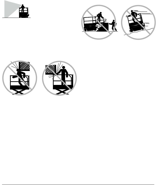
Do not operate the machine in strong or gusty winds. Do not increase the surface area of the platform or the load. Increasing the area exposed to the wind will decrease machine stability.
Do not drive the machine on or near uneven terrain, unstable surfaces or other hazardous conditions with the platform raised.
Use extreme care and slow speeds while driving the machine in a stowed position across uneven terrain, debris, unstable or slippery surfaces and near holes and drop-offs.
Do not push off or pull toward any object outside of the platform.
Maximum allowable manual force
|
GS-2032 |
|
|
CE — Indoor use only — 2 person |
400 N |
|
CE — Outdoor use — 1 person |
200 N |
|
GS-2632 |
|
|
CE — Indoor use only — 2 person |
400 N |
Do not alter or disable machine components that in any way affect safety and stability.
Do not place or attach fixed or overhanging loads to any part of this machine.
Do not transport tools and materials unless they are evenly distributed and can be safely handled by person(s) in the platform.
Do not place ladders or scaffolds in the platform or against any part of this machine.
Do not modify or alter an aerial work platform without prior written permission from the manufacturer. Mounting attachments for holding tools or other materials onto the platform, toeboards or guard rail system can increase the weight in the platform and the surface area of the platform or the load.
|
4 |
Genie GS-2032 and Genie GS-2632 |
Part No. 82784 |
|
Second Edition • Second Printing |
Operator’s Manual |
|
Do not replace items critical to machine stability with items of different weight or specification.
Do not use the machine on a moving or mobile surface or vehicle.
Be sure all tires are in good condition, castle nuts are properly tightened and cotter pins are properly installed.
Do not use batteries that weigh less than the original equipment. Batteries are used as counterweight and are critical to machine stability. Each battery must weigh 30 kg.
Do not use the machine as a crane.
Do not push the machine or other objects with the platform.
Do not contact adjacent structures with the platform.
Do not tie the platform to adjacent structures.
Do not place loads outside the platform perimeter.
Do not operate the machine with the chassis trays open.
Do not use the platform controls to free a platform that is caught, snagged or otherwise prevented from normal motion by an adjacent structure. All personnel must be removed from the platform before attempting to free the platform using the ground controls.
SAFETY RULES
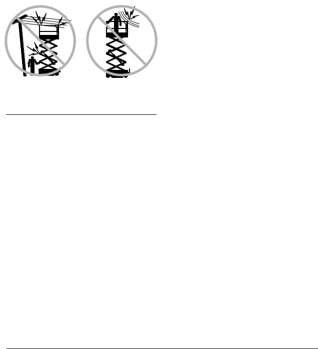
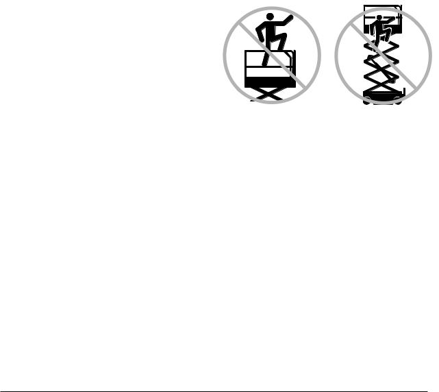
Fall Hazards
The guard rail system provides fall protection. If occupants of the platform are required to wear personal fall protection equipment (PFPE) due to job site or employer rules, PFPE equipment and its use shall be in accordance with the PFPE manufacturer’s instructions and applicable governmental requirements.
Do not sit, stand or climb on the platform guard rails. Maintain a firm footing on the platform floor at all times.
Do not climb down from the platform when raised.
Keep the platform floor clear of debris.
Attach the platform entry chain or close the entry gate before operating.
Do not operate the machine unless the guard rails are properly installed and the entry is secured for operation.
|
Part No. 82784 |
Genie GS-2032 and Genie GS-2632 |
5 |
|
Operator’s Manual |
Second Edition • Second Printing |
|
SAFETY RULES
Collision Hazards
Be aware of limited sight distance and blind spots when driving or operating.
Be aware of the extended platform position when moving the machine.
The machine must be on a level surface or secured before releasing the brakes.
Operators must comply with employer, job site and governmental rules regarding use of personal protective quipment.
Check the work area for overhead obstructions or other possible hazards.
Be aware of crushing hazards when grasping the platform guard rail.
Observe and use the color-coded direction arrows on the platform controls and platform decal plate for drive and steer functions.
No stunt driving or horseplay while operating a machine.
Do not lower the platform unless the area below is clear of personnel and obstructions.
Limit travel speed according to the condition of the ground surface, congestion, slope, location of personnel, and any other factors which may cause collision.
Do not operate a machine in the path of any crane or moving overhead machinery unless the controls of the crane have been locked out and/or precautions have been taken to prevent any potential collision.
Crushing Hazards
Keep hands and limbs out of scissors.
Use common sense and planning when operating the machine with the controller from the ground. Maintain safe distances between the operator, the machine and fixed objects.
|
6 |
Genie GS-2032 and Genie GS-2632 |
Part No. 82784 |

|
Second Edition • Second Printing |
Operator’s Manual |
|
Component Damage Hazard
Do not use the machine as a ground for welding.
Explosion and Fire Hazard
Do not operate the machine in hazardous locations or locations where potentially flammable or explosive gases or particles may be present.
Damaged Machine Hazards
Do not use a damaged or malfunctioning machine.
Conduct a thorough pre-operation inspection of the machine and test all functions before each work shift. Immediately tag and remove from service a damaged or malfunctioning machine.
Be sure all maintenance has been performed as specified in this manual and the appropriate service manual.
Be sure all decals are in place and legible.
Be sure the operator’s, safety, and responsibilities manuals are complete, legible and in the storage container located on the platform.
Bodily Injury Hazard
Do not operate the machine with a hydraulic oil or air leak. An air leak or hydraulic leak can penetrate and/or burn skin.
Improper contact with components under any cover will cause serious injury. Only trained maintenance personnel should access compartments. Access by the operator is only advised when performing a pre-operation inspection. All compartments must remain closed and secured during operation.
SAFETY RULES
Decal Legend
Genie product decals use symbols, color coding and signal words to identify the following:
Safety alert symbol—used to alert personnel to potential personal injury hazards. Obey all safety messages that follow this symbol to avoid possible injury or death.
Red—used to indicate the  presence of an imminently
  hazardous situation which, if not avoided, will result in death or serious injury.
 Orange—used to indicate the presence of a potentially
  hazardous situation which, if not avoided, could result in death or serious injury.
Yellow with safety alert symbol—  used to indicate the presence of a
  potentially hazardous situation which, if not avoided, may cause minor or moderate injury.
Yellow without safety alert symbol—used to indicate the presence of a potentially hazardous situation which, if not avoided, may result in property damage.
Green—used to indicate operation or maintenance information.
|
Part No. 82784 |
Genie GS-2032 and Genie GS-2632 |
7 |

|
Operator’s Manual |
Second Edition • Second Printing |
|
SAFETY RULES
Battery Safety
Burn Hazards
Batteries contain acid. Always wear protective clothing and eye wear when working with batteries.
Avoid spilling or contacting battery acid. Neutralize battery acid spills with baking soda and water.
Do not expose the batteries or the charger to water or rain during charging.
Explosion Hazards
Keep sparks, flames and lighted tobacco away from batteries. Batteries emit an explosive gas.
The battery tray should remain open during the entire charging cycle.
Do not contact the battery terminals or the cable clamps with tools that may cause sparks.
Component Damage Hazard
Do not use any battery charger greater than 24V to charge the batteries.
Electrocution Hazards
Connect the battery charger to a grounded, AC 3-wire electrical outlet only.
Inspect daily for damaged cord, cables and wires. Replace damaged items before operating.
Avoid electrical shock from contact with battery terminals. Remove all rings, watches and other jewelry.
Tip-over Hazard
Do not use batteries that weigh less than the original equipment. Batteries are used as counterweight and are critical to machine stability. Each battery must weigh 30 kg.
Lifting Hazard
Use the appropriate number of people and proper lifting techniques when lifting batteries.
|
8 |
Genie GS-2032 and Genie GS-2632 |
Part No. 82784 |

|
Second Edition • Second Printing |
Operator’s Manual |
|
Legend
|
1 |
Platform entry chain or entry |
9 |
Platform extension release |
|
gate |
pedal |
||
|
2 |
Platform entry rail |
10 |
Tilt alarm (under cover) |
|
3 |
Platform guard rails |
11 |
Transport tie-down |
|
4 |
Lanyard anchorage point |
12 |
Steer tire |
|
5 |
Manual storage container |
13 |
Ground controls |
|
6 |
Platform controls |
14 |
Auxiliary lowering knob or |
|
7 |
GFCI outlet |
button or switch |
|
|
8 |
Platform extension |
15 |
LED diagnostic readout |
|
16 |
Hydraulic oil level indicator |
17Pothole guard
18Non-steer tire
19Entry ladder/transport tie-down
20Battery charger
21Brake release pump knob
22Brake release knob
23Safety arm
|
Part No. 82784 |
Genie GS-2032 and Genie GS-2632 |
9 |
- Manuals
- Brands
- Terex Manuals
- Scissor Lifts
- Genie GS-2032
Manuals and User Guides for Terex Genie GS-2032. We have 8 Terex Genie GS-2032 manuals available for free PDF download: Service And Repair Manual, Service Manual, Operator’s Manual, Maintenance Manual
Terex Genie GS-2032 Service And Repair Manual (341 pages)
Brand: Terex
|
Category: Lifting Systems
|
Size: 35.56 MB
Table of Contents
-
Introduction
2
-
Find a Manual for this Model
2
-
Serial Number Range
2
-
Revision History
3
-
Serial Number Legend
5
-
Safety Rules
6
-
Table of Contents
8
-
Specifications
17
-
Machine Specifications
17
-
Performance Specifications (Models Without Proportional Lift Function)
19
-
Performance Specifications (Models with Proportional Lift)
21
-
Hydraulic Oil Specifications
23
-
Hydraulic Component Specifications
26
-
Manifold Component Specifications
27
-
Hydraulic Hose and Fitting Torque Specifications
28
-
Torque Procedure
29
-
Repair Procedures
31
-
Introduction
31
-
Platform Controls
33
-
Circuit Board
35
-
Joystick
36
-
Platfrom Controls Alarm
36
-
Platform Emergency Stop Button
37
-
Ground Controls
38
-
Software Revision Level
39
-
Machine Setup
40
-
Loading or Updating Machine Software
41
-
Using a Wi-Fi Router to Connect to the Smartlink Web Service Tool
46
-
Service Override Mode
48
-
Level Sensors
50
-
Manual Platform Lowering Cable
65
-
Outrigger Calibration
66
-
Hydraulic Tank
67
-
Hydraulic Pump
68
-
How to Remove the Hydraulic Pump
69
-
Manifolds
70
-
Function Manifold Components — GS-1530, GS-1532, GS-1930 and GS-1932
70
-
Function Manifold Components — GS-2032, GS-2632, GS-3232, GS-2046, GS-2646 and GS-3246
72
-
Function Manifold Components — GS-4047
74
-
Check Valve Manifold Components — GS-1530, GS-1532, GS-1930 and GS-1932
76
-
Lift Pressure Selector Manifold Components — GS-4047
77
-
Outrigger Function Manifold Components — GS-3232
78
-
Outrigger Cylinder Manifold Components — GS-3232
79
-
Valve Adjustments — Function Manifold
80
-
Valve Coils
86
-
Steer Axle Components
88
-
Yoke and Drive Motor
88
-
Steer Cylinder
89
-
Steer Bellcrank
90
-
Non-Steer Axle Components
91
-
Drive Brake
91
-
Brake Release Hand Pump Components
92
-
Scissor Components
93
-
Scissor Assembly, GS-1530 and GS-1532
94
-
Scissor Assembly, GS-1930 and GS-1932
100
-
Scissor Assembly, GS-2032 and GS-2046
108
-
Scissor Assembly, GS-2632 and GS-2646
115
-
Scissor Assembly, GS-3232 and GS-3246
123
-
Scissor Assembly, GS-4047
132
-
Scissor Arm Wear Pads
140
-
Platform Height Sensor
142
-
Lift Cylinder
144
-
Pressure Transducer
155
-
Platform Overload System
157
-
Platform Overload Recovery
162
-
Platform Components
164
-
Platform
164
-
Platform Extension Deck
165
-
Battery Charger
166
-
Selecting a Charge Profile
167
-
Diagnostics
168
-
Introduction
168
-
GCON I/O Map Without Load Sense (All Machines Except GS-3232)
171
-
GCON I/O Map with Load Sense (All Machines Except GS-3232)
172
-
GCON I/O Map Without Load Sense GS-3232 Only)
173
-
GCON I/O Map with Load Sense (GS-3232 Only)
175
-
Operation Indicator Codes (OIC)
177
-
Diagnostic Trouble Codes (DTC)
178
-
Troubleshooting «HXXX» and «PXXX» Faults
179
-
Fault Inspection Procedure
180
-
Type «HXXX» Faults
182
-
Type «PXXX» Faults
186
-
Type «UXXX» Faults
187
-
Type «FXXX» Faults
190
-
Type «CXXX» Faults
193
-
Battery Charger
195
-
Charger Fault Codes
196
-
Charger Error Codes
197
-
Schematics
201
-
Introduction
201
-
Electrical Component and Wire Color Legends
202
-
Wiring Diagram Ground and Platform Controls
205
-
Limit Switch Legend
206
-
Electrical Symbol Legend
207
-
Hydraulic Symbols Legend
208
-
Hydraulic Component Abbreviation Legend
209
-
Hydraulic Schematics
211
-
Hydraulic Schematic, GS-1530, 1532, 1930, 1932 (from Serial Number GS3010A- 110000, GS3011C-10000, GS3014D-101, GS3016P-142281)
211
-
GS4614C-10000 to GS4614C-12073)
212
-
Hydraulic Schematic, GS-2032, 2632, 3232, 2046, 2646, 3246
213
-
Gs4614C-12074, Gs4614D-101)
213
-
Hydraulic Schematic, GS-3232 (from Serial Number GS3211A-110000, GS3212C-10000, GS3216P-142677)
214
-
Hydraulic Schematic, GS-4047 (from Serial Number GS4712C-101 to GS4714C-1459)
215
-
Hydraulic Schematic, GS-4047
216
-
Gs4714D-101, Gs4716P-101)
216
-
Electrical Schematic, GS-1530 / GS-1930, ANSI / CSA
217
-
Electrical Schematic, GS-1530 / GS-1930, ANSI / CSA (from Serial Number GS3014A-136973, GS3015D-1114 to GS3016D-5426, GS3016P-142281 to GS3016P-158208)
226
-
Electrical Schematic, GS-1530/1930, ANSI/CSA
229
-
Electrical Schematic, GS-3232, ANSI / CSA
233
-
Electrical Schematic, GS-3232, ANSI / CSA
236
-
Electrical Schematic, GS-3232, ANSI / CSA
237
-
Electrical Schematic, GS-3232, ANSI / CSA (from Serial Number GS3216P-146463)
244
-
Electrical Schematic, GS-2032, 2632, 2046, 2646, ANSI / CSA (from Serial Number GS3211A-110000 to GS3214A-135714, GS4612A-110000 to GS4614A-135366, GS4613D-101 to GS4615D-1303)
247
-
Electrical Schematic, GS-2032, 2632, 2046, 2646, ANSI/CSA
252
-
Electrical Schematic, GS-2032, 2632, 2046, 2646, ANSI / CSA
253
-
GS4615A-137960, GS4615D-1305 to GS4616D-4432, GS4616P-138362 to GS4616P-139710)
256
-
Electrical Schematic, GS-2032, 2632, 2046, 2646, as / CE (from Serial Number GS3214A-135715 to GS3215A-141898, GS3215C-14378, GS4614A-
306
-
Electrical Schematic, GS-2032, 2632, 2046, 2646, as / CE (from Serial Number GS3215A-141899, GS3216P-142676 to GS3216P-146462, GS4615A-
310
-
Electrical Schematic, GS-2032, 2632, 2046, 2646, as / CE (from Serial Number GS3216P-146463, GS4616P-139711)
314
-
Electrical Schematic, GS-3246, as / CE
315
-
Gs4615D-1303)
315
-
Electrical Schematic, GS-3246, as / CE
320
-
Gs4615A-137959, Gs4615C-14504, Gs4615D-1304)
320
-
Electrical Schematic, GS-3246, as / CE
324
-
GS4616P-138362, GS4616P to GS4616P-139710)
324
-
Electrical Schematic, GS-3246, as / CE (from Serial Number GS4616D-4433, GS4616P-139711)
328
-
Electrical Schematic, GS-4047, as / CE
330
-
GS4715C-2130, GS4714D-101 to GS4715D-749)
330
-
Electrical Schematic, GS-4047, as / CE
334
-
GS4715D-750 to GS4716D-3101)
334
-
Electrical Schematic, GS-4047, as / CE (from Serial Number GS4716D-3102)
338
-
Electrical Schematic — Foot Switch (Option) All Models
339
-
Foot Switch (Option) All Models
340
Advertisement
Terex Genie GS-2032 Service And Repair Manual (249 pages)
Brand: Terex
|
Category: Scissor Lifts
|
Size: 4.4 MB
Table of Contents
-
Table of Contents
8
-
Introduction
2
-
Find a Manual for this Model
2
-
Serial Number Range
2
-
Revision History
3
-
Serial Number Legend
5
-
-
Safety Rules
6
-
Table of Contents
8
-
-
Specifications
15
-
Machine Specifications
15
-
Performance Specifications
18
-
Hydraulic Oil Specifications
19
-
Hydraulic Component Specifications
23
-
Manifold Component Specifications
26
-
Hydraulic Hose and Fitting Torque Specifications
27
-
Torque Procedure
28
-
-
Repair Procedures
30
-
Introduction
30
-
Observe and Obey
30
-
-
-
Platform Controls
32
-
Circuit Board
34
-
Joystick
35
-
Platfrom Controls Alarm
35
-
Platform Emergency Stop Button
36
-
-
Ground Controls
37
-
Software Revision Level
38
-
Machine Setup
39
-
Loading or Updating Machine Software
40
-
Using a Wi-Fi Router to Connect to the Smartlink Web Service Tool
45
-
Service Override Mode
47
-
Level Sensors
49
-
Manual Platform Lowering Cable
54
-
Outrigger Calibration — GS-3232
56
-
-
Hydraulic Tank
57
-
Hydraulic Pump
59
-
How to Remove the Hydraulic Pump
60
-
-
Manifolds
62
-
Function Manifold Components — GS-1330M
62
-
Function Manifold Components — GS-3232
63
-
Function Manifold Components — GS-4655
64
-
Function Manifold Components — Models with Electric Drive
65
-
All Other Models
65
-
-
Function Manifold Components — Models with Hydraulic Drive GS-1530, GS-1532, GS-1930, GS-1932
66
-
Check Valve Manifold Components — Models with Hydraulic Drive GS-1530, GS-1532, GS-1930, GS-1932
68
-
Function Manifold Components — Models with Hydraulic Drive GS-2032, GS-2632
69
-
Outrigger Manifold Components — GS-3232
71
-
Outrigger Cylinder Manifold Components — GS-3232
72
-
Brake Release Hand Pump Components — Models with Hydraulic Drive
73
-
Valve Adjustments — Function Manifold
74
-
How to Adjust the System Relief Valve — Models with Electric Drive
74
-
How to Adjust the System Relief Valve — Models with Hydraulic Drive
75
-
How to Adjust the Platform Lift Relief Valve — Models with Hydraulic Drive
77
-
How to Adjust the Steer Relief Valve — Models with Hydraulic Drive (Includes GS-1330M Electric Drive)
79
-
-
Valve Coils
80
-
-
Steer Axle Components
83
-
Yoke Assembly
83
-
Drive Motors
84
-
Steer Cylinder
85
-
Steer Bellcrank
85
-
Manual Brake Release — Models with Electric Drive
86
-
-
Non-Steer Axle Components
88
-
Drive Brake — Models with Hydraulic Drive
88
-
-
Scissor Components
89
-
Scissor Assembly, GS-1330M
90
-
Scissor Assembly, GS-1530 and GS-1532
97
-
Scissor Assembly, GS-1930 and GS-1932
103
-
Scissor Assembly, GS-2032 and GS-2046
111
-
Scissor Assembly, GS-2632 and GS-2646
118
-
Scissor Assembly, GS-3232 and GS-3246
126
-
Scissor Assembly, GS-4046
135
-
Scissor Assembly, GS-4655
144
-
Scissor Arm Wear Pads
149
-
Platform Height Sensor
151
-
Lift Cylinder
153
-
Pressure Transducer
164
-
Platform Overload System
166
-
Platform Overload Recovery
171
-
Outdoor Height Limiting
173
-
-
Platform Components
175
-
Platform
175
-
Platform Extension Deck
176
-
-
Battery Charger
177
-
Selecting a Charge Profile
178
-
-
Diagnostics
180
-
Introduction
180
-
Troubleshooting and Repair Procedures Shall be Completed by a Person Trained and Qualified on the Repair of this Machine
180
-
Immediately Tag and Remove from Service a
180
-
Damaged or Malfunctioning Machine
180
-
Repair any Machine Damage or Malfunction before Operating the Machine
180
-
-
Before Troubleshooting
180
-
Read, Understand and Obey the Safety Rules and Operating Instructions in the Appropriate Operator’s Manual on Your Machine
180
-
Be Sure that All Necessary Tools and Test Equipment Are Available and Ready for Use
180
-
-
About this Section
180
-
-
GCON I/O Map Without Load Sense (All Machines Except GS-3232)
183
-
GCON I/O Map with Load Sense (All Machines Except GS-3232)
184
-
GCON I/O Map Without Load Sense GS-3232 Only)
185
-
GCON I/O Map with Load Sense (GS-3232 Only)
187
-
Operation Indicator Codes (OIC)
189
-
Diagnostic Trouble Codes (DTC)
190
-
Troubleshooting «HXXX» and «PXXX» Faults
191
-
Fault Inspection Procedure
192
-
Type «HXXX» Faults
194
-
Type «PXXX» Faults
198
-
Type «UXXX» Faults
200
-
Type «FXXX» Faults
203
-
Type «CXXX» Faults
206
-
Battery Charger
208
-
Charger Fault Codes
209
-
Charger Error Codes
210
-
-
-
-
Schematics
214
-
Introduction
214
-
Electrical Component and Wire Color Legends
215
-
Wiring Diagram Ground and Platform Controls
217
-
Limit Switch Legend
218
-
Electrical Symbol Legend
219
-
Hydraulic Symbols Legend
220
-
Hydraulic Schematics
221
-
Hydraulic Schematic GS-1330M (from GS30MD-101)
222
-
Hydraulic Schematic, Models with Electric Drive GS-1530/1532, GS-1930/1932 (from GS30D-40101, GS30P-200101)
223
-
Hydraulic Schematic, Models with Hydraulic Drive GS-1530/1532, GS-1930/1932 (from GS30D-40101, GS30P-200101)
226
-
Hydraulic Schematic, Models with Electric Drive GS-2032/2632/3232, GS2046/2646/3246 (from GS32D-10101, GS32P-200101, GS46D-20101, GS46P-200101)
227
-
Hydraulic Schematic, Outriggers GS3232 (from GS32D-10101, GS32P-200101)
230
-
Hydraulic Schematic, Models with Hydraulic Drive GS-2032, GS-2632 (from GS32D-10101, GS32P-200101)
231
-
Hydraulic Schematic, GS-4046 (from GS46D-20101, GS46P-200101)
234
-
Hydraulic Schematic, GS-4655 (from GS55D-101)
235
-
-
Electrical Schematics
237
-
Electrical Schematic, GS-1330M (from GS30MD-40101)
238
-
Electrical Schematic, GS-3232 (from GS32D-10101, GS32P-200101)
239
-
Electrical Schematic, GS-4655 (from GS55D-10101)
242
-
Electrical Schematic, All Other Models Models with Electric Drive
243
-
Gs32P-200101, Gs32Md-101, Gs46D-20101, Gs46P-200101)
243
-
-
Electrical Schematic, All Other Models Models with Hydraulic Drive
245
-
(From GS30D-40101, GS30P-200101, GS32D-10101, GS32P-200101)
246
-
-
-
Electrical Schematics — Options
247
-
Electrical Schematic, Options
247
-
-

Terex Genie GS-2032 Service Manual (198 pages)
Brand: Terex
|
Category: Lifting Systems
|
Size: 2.45 MB
Advertisement

Terex Genie GS-2032 Maintenance Manual (99 pages)
Scissor Lifts
Brand: Terex
|
Category: Lifting Systems
|
Size: 2.04 MB
Table of Contents
-
Table of Contents
8
-
Performance Specifications
11
-
Function Speeds GS-30, GS-32, GS-46, GS-47, GS-55
11
-
Function Speeds GS-69, GS-84, GS-90
12
-
Drive Speeds
13
-
-
Torque Specifications
14
-
Tires and Wheels
14
-
-
Battery Specifications
15
-
Battery Specifications — DC and be Models
15
-
-
Engine Specifications
17
-
Engine Operator and Maintenance Manuals
17
-
Deutz Engine Models
17
-
Perkins Engine Models
18
-
Ford Engine Models
18
-
Kubota Engine Models
19
-
Kohler Engine Models
19
-
GM Engine Models
20
-
-
Hydraulic Specifications
21
-
Hydraulic Relief Valves
21
-
Hydraulic and Drive Hub Fluid Capacities
23
-
Hydraulic Oil Specifications
24
-
Hydraulic Hose and Fitting Torque Specifications
27
-
Torque Procedure
28
-
-
Maintenance Procedures
30
-
Introduction
30
-
Maintenance Schedule
32
-
Pre-Delivery Preparation Report
33
-
Scheduled Maintenance Inspection Report — Scissor Lifts
34
-
Programmed Maintenance Inspection Report — Scissor Lifts
35
-
-
Commissioning Procedures
36
-
Perform 50 Hour Service
36
-
Perform Engine Maintenance — 50 Hours
36
-
Perform 150 Hour Service
37
-
-
Quarterly Maintenance Procedures
38
-
Check for Open Bulletins and Owner Registration
38
-
Battery Inspection
39
-
Check the Module Tray Latch Components
41
-
Inspect the Battery Balancer — GS-69 DC
42
-
Inspect the Electrical Wiring
43
-
Inspect the Electrical Contactor — GS-30M, GS-30, GS-32M
44
-
DC, Gs-69 be
44
-
Inspect the Voltage Inverter (if Equipped)
44
-
Test the Flashing Beacons (if Equipped)
46
-
Visual Inspection of the Hydraulic Oil
46
-
Inspect the Hydraulic Filters
47
-
Check the Exhaust System — Engine Models
48
-
Inspect the Fuel Tank Check Valve Venting System — GS-69 RT Gas Models
49
-
Test the Fuel Select Operation — Gasoline/Lpg Models
49
-
Check and Adjust the Engine RPM
50
-
Inspect the Tires, Wheels and Lug Nut Torque
53
-
Confirm the Proper Brake Configuration — GS-69, GS-84, GS-90
53
-
Test the Drive Brakes
54
-
Test the Drive Speed — Stowed Position
54
-
Test the Drive Speed — Raised Position
55
-
Test the down Limit Switch, Level Sensor and Pothole Limit Switches
55
-
-
Annual Maintenance Procedures
61
-
Check the Drive Hub Oil Level and Fastener Torque
61
-
Test the Function Pump — GS-69 be and GS-69 DC
62
-
Test the Oscillate Axle — GS-90
63
-
Test the down Limit Switch Descent Delay — GS-69, GS-84 and GS-90 (if Equipped)
66
-
Test the Platform Overload Pressure Transducer and Platform Height Sensor
67
-
Test the Platform Overload System
73
-
GS-30M, GS-30, GS-32M, GS-32, GS-46, GS-55
73
-
Test the Platform Overload System — GS-69 (if Equipped)
75
-
Check the Steer Yoke King Pin Fastener Torque
77
-
-
Programmed Maintenance Procedures
78
-
P0-1 Inspect the Engine Air Filter — GS-69 RT
78
-
P0-2 Grease the Steer Yokes — GS-30M, GS-30, GS-32, GS-46, GS-55
79
-
P0-3 Replace the Drive Hub Oil — GS-30, GS-32M, GS-32, GS-46, GS-55
79
-
P0-4 Deutz Engine Maintenance — under 1000 Hours
80
-
P0-5 Ford Engine Maintenance — under 1000 Hours
81
-
P0-6 Kohler Engine Maintenance — under 1000 Hours
82
-
P0-7 Kubota Engine Maintenance — under 1000 Hours
83
-
P0-8 Perkins Engine Maintenance — under 1000 Hours
84
-
P0-9 GM Engine Maintenance — under 1000 Hours
85
-
P1-1 Perform Engine Maintenance — 1000 Hours
86
-
P1-2 Replace the Drive Hub Oil — GS-69, GS-84, GS-90
87
-
P2-1 Perform Engine Maintenance — 2000 Hours
87
-
P2-2 Replace the Hydraulic Filters
88
-
P2-3 Check the Free-Wheel Configuration — GS-84 and GS-90
90
-
P2-4 Check the Scissor Arm Wear Pads (and Slider Blocks, if Equipped)
91
-
P2-5 Grease the Steer Axle Wheel Bearings — GS-69 be and GS-69 DC
94
-
P2-6 Test or Replace the Hydraulic Oil
96
-
P3-1 Perform Engine Maintenance — 3000 Hours
97
-
P5-1 Perform Engine Maintenance — 5000 Hours
98
-
P6-1 Perform Engine Maintenance — 6000 Hours
98
-
Terex Genie GS-2032 Operator’s Manual (107 pages)
Brand: Terex
|
Category: Scissor Lifts
|
Size: 17.97 MB
Table of Contents
-
Table of Contents
2
-
Introduction
3
-
Symbol and Hazard Pictorials Definitions
8
-
General Safety
11
-
Personal Safety
29
-
Work Area Safety
30
-
Legend
39
-
Controls
42
-
Inspections
46
-
Operating Instructions
72
-
Transport and Lifting Instructions
89
-
Maintenance
94
-
Specifications
96
Terex Genie GS-2032 Operator’s Manual (92 pages)
Brand: Terex
|
Category: Boom Lifts
|
Size: 12.28 MB
Table of Contents
-
Table of Contents
2
-
Introduction
3
-
Symbol and Hazard Pictorials Definitions
8
-
General Safety
11
-
Personal Safety
20
-
Work Area Safety
21
-
Legend
29
-
Controls
32
-
Inspections
36
-
Operating Instructions
56
-
Transport and Lifting Instructions
73
-
Maintenance
78
-
Specifications
80

Terex Genie GS-2032 Maintenance Manual (92 pages)
Brand: Terex
|
Category: Scissor Lifts
|
Size: 1.83 MB
Terex Genie GS-2032 Operator’s Manual (62 pages)
Brand: Terex
|
Category: Scissor Lifts
|
Size: 4.54 MB
Table of Contents
-
Table of Contents
2
-
Introduction
3
-
Symbol and Hazard Pictorials Definitions
5
-
General Safety
7
-
Personal Safety
9
-
Work Area Safety
10
-
Legend
18
-
Controls
21
-
Inspections
25
-
Operating Instructions
40
-
Transport and Lifting Instructions
48
-
Maintenance
52
-
Specifications
54
Advertisement
Related Products
-
Terex Genie GS-2046
-
Terex Genie GS-2669BE
-
Terex Genie GS-2646
-
Terex Genie GS-2668DC
-
Terex Genie GS-2669 BE
-
Terex Genie GS-2646 XH
-
Terex Genie GS-2669RT
-
Terex Genie GS-2669
-
Terex Genie GS-2646 AV35
-
Terex Genie GS-2646 AV
Terex Categories
Boom Lifts
Lifting Systems
Construction Equipment
Scissor Lifts
Compact Loader
More Terex Manuals
- Manuals
- Brands
- Terex Manuals
- Scissor Lifts
- Genie GS-2032
Manuals and User Guides for Terex Genie GS-2032. We have 8 Terex Genie GS-2032 manuals available for free PDF download: Service And Repair Manual, Service Manual, Operator’s Manual, Maintenance Manual
Terex Genie GS-2032 Service And Repair Manual (341 pages)
Brand: Terex
|
Category: Lifting Systems
|
Size: 35.56 MB
Table of Contents
-
Introduction
2
-
Find a Manual for this Model
2
-
Serial Number Range
2
-
Revision History
3
-
Serial Number Legend
5
-
Safety Rules
6
-
Table of Contents
8
-
Specifications
17
-
Machine Specifications
17
-
Performance Specifications (Models Without Proportional Lift Function)
19
-
Performance Specifications (Models with Proportional Lift)
21
-
Hydraulic Oil Specifications
23
-
Hydraulic Component Specifications
26
-
Manifold Component Specifications
27
-
Hydraulic Hose and Fitting Torque Specifications
28
-
Torque Procedure
29
-
Repair Procedures
31
-
Introduction
31
-
Platform Controls
33
-
Circuit Board
35
-
Joystick
36
-
Platfrom Controls Alarm
36
-
Platform Emergency Stop Button
37
-
Ground Controls
38
-
Software Revision Level
39
-
Machine Setup
40
-
Loading or Updating Machine Software
41
-
Using a Wi-Fi Router to Connect to the Smartlink Web Service Tool
46
-
Service Override Mode
48
-
Level Sensors
50
-
Manual Platform Lowering Cable
65
-
Outrigger Calibration
66
-
Hydraulic Tank
67
-
Hydraulic Pump
68
-
How to Remove the Hydraulic Pump
69
-
Manifolds
70
-
Function Manifold Components — GS-1530, GS-1532, GS-1930 and GS-1932
70
-
Function Manifold Components — GS-2032, GS-2632, GS-3232, GS-2046, GS-2646 and GS-3246
72
-
Function Manifold Components — GS-4047
74
-
Check Valve Manifold Components — GS-1530, GS-1532, GS-1930 and GS-1932
76
-
Lift Pressure Selector Manifold Components — GS-4047
77
-
Outrigger Function Manifold Components — GS-3232
78
-
Outrigger Cylinder Manifold Components — GS-3232
79
-
Valve Adjustments — Function Manifold
80
-
Valve Coils
86
-
Steer Axle Components
88
-
Yoke and Drive Motor
88
-
Steer Cylinder
89
-
Steer Bellcrank
90
-
Non-Steer Axle Components
91
-
Drive Brake
91
-
Brake Release Hand Pump Components
92
-
Scissor Components
93
-
Scissor Assembly, GS-1530 and GS-1532
94
-
Scissor Assembly, GS-1930 and GS-1932
100
-
Scissor Assembly, GS-2032 and GS-2046
108
-
Scissor Assembly, GS-2632 and GS-2646
115
-
Scissor Assembly, GS-3232 and GS-3246
123
-
Scissor Assembly, GS-4047
132
-
Scissor Arm Wear Pads
140
-
Platform Height Sensor
142
-
Lift Cylinder
144
-
Pressure Transducer
155
-
Platform Overload System
157
-
Platform Overload Recovery
162
-
Platform Components
164
-
Platform
164
-
Platform Extension Deck
165
-
Battery Charger
166
-
Selecting a Charge Profile
167
-
Diagnostics
168
-
Introduction
168
-
GCON I/O Map Without Load Sense (All Machines Except GS-3232)
171
-
GCON I/O Map with Load Sense (All Machines Except GS-3232)
172
-
GCON I/O Map Without Load Sense GS-3232 Only)
173
-
GCON I/O Map with Load Sense (GS-3232 Only)
175
-
Operation Indicator Codes (OIC)
177
-
Diagnostic Trouble Codes (DTC)
178
-
Troubleshooting «HXXX» and «PXXX» Faults
179
-
Fault Inspection Procedure
180
-
Type «HXXX» Faults
182
-
Type «PXXX» Faults
186
-
Type «UXXX» Faults
187
-
Type «FXXX» Faults
190
-
Type «CXXX» Faults
193
-
Battery Charger
195
-
Charger Fault Codes
196
-
Charger Error Codes
197
-
Schematics
201
-
Introduction
201
-
Electrical Component and Wire Color Legends
202
-
Wiring Diagram Ground and Platform Controls
205
-
Limit Switch Legend
206
-
Electrical Symbol Legend
207
-
Hydraulic Symbols Legend
208
-
Hydraulic Component Abbreviation Legend
209
-
Hydraulic Schematics
211
-
Hydraulic Schematic, GS-1530, 1532, 1930, 1932 (from Serial Number GS3010A- 110000, GS3011C-10000, GS3014D-101, GS3016P-142281)
211
-
GS4614C-10000 to GS4614C-12073)
212
-
Hydraulic Schematic, GS-2032, 2632, 3232, 2046, 2646, 3246
213
-
Gs4614C-12074, Gs4614D-101)
213
-
Hydraulic Schematic, GS-3232 (from Serial Number GS3211A-110000, GS3212C-10000, GS3216P-142677)
214
-
Hydraulic Schematic, GS-4047 (from Serial Number GS4712C-101 to GS4714C-1459)
215
-
Hydraulic Schematic, GS-4047
216
-
Gs4714D-101, Gs4716P-101)
216
-
Electrical Schematic, GS-1530 / GS-1930, ANSI / CSA
217
-
Electrical Schematic, GS-1530 / GS-1930, ANSI / CSA (from Serial Number GS3014A-136973, GS3015D-1114 to GS3016D-5426, GS3016P-142281 to GS3016P-158208)
226
-
Electrical Schematic, GS-1530/1930, ANSI/CSA
229
-
Electrical Schematic, GS-3232, ANSI / CSA
233
-
Electrical Schematic, GS-3232, ANSI / CSA
236
-
Electrical Schematic, GS-3232, ANSI / CSA
237
-
Electrical Schematic, GS-3232, ANSI / CSA (from Serial Number GS3216P-146463)
244
-
Electrical Schematic, GS-2032, 2632, 2046, 2646, ANSI / CSA (from Serial Number GS3211A-110000 to GS3214A-135714, GS4612A-110000 to GS4614A-135366, GS4613D-101 to GS4615D-1303)
247
-
Electrical Schematic, GS-2032, 2632, 2046, 2646, ANSI/CSA
252
-
Electrical Schematic, GS-2032, 2632, 2046, 2646, ANSI / CSA
253
-
GS4615A-137960, GS4615D-1305 to GS4616D-4432, GS4616P-138362 to GS4616P-139710)
256
-
Electrical Schematic, GS-2032, 2632, 2046, 2646, as / CE (from Serial Number GS3214A-135715 to GS3215A-141898, GS3215C-14378, GS4614A-
306
-
Electrical Schematic, GS-2032, 2632, 2046, 2646, as / CE (from Serial Number GS3215A-141899, GS3216P-142676 to GS3216P-146462, GS4615A-
310
-
Electrical Schematic, GS-2032, 2632, 2046, 2646, as / CE (from Serial Number GS3216P-146463, GS4616P-139711)
314
-
Electrical Schematic, GS-3246, as / CE
315
-
Gs4615D-1303)
315
-
Electrical Schematic, GS-3246, as / CE
320
-
Gs4615A-137959, Gs4615C-14504, Gs4615D-1304)
320
-
Electrical Schematic, GS-3246, as / CE
324
-
GS4616P-138362, GS4616P to GS4616P-139710)
324
-
Electrical Schematic, GS-3246, as / CE (from Serial Number GS4616D-4433, GS4616P-139711)
328
-
Electrical Schematic, GS-4047, as / CE
330
-
GS4715C-2130, GS4714D-101 to GS4715D-749)
330
-
Electrical Schematic, GS-4047, as / CE
334
-
GS4715D-750 to GS4716D-3101)
334
-
Electrical Schematic, GS-4047, as / CE (from Serial Number GS4716D-3102)
338
-
Electrical Schematic — Foot Switch (Option) All Models
339
-
Foot Switch (Option) All Models
340
Advertisement
Terex Genie GS-2032 Service And Repair Manual (249 pages)
Brand: Terex
|
Category: Scissor Lifts
|
Size: 4.4 MB
Table of Contents
-
Table of Contents
8
-
Introduction
2
-
Find a Manual for this Model
2
-
Serial Number Range
2
-
Revision History
3
-
Serial Number Legend
5
-
-
Safety Rules
6
-
Table of Contents
8
-
-
Specifications
15
-
Machine Specifications
15
-
Performance Specifications
18
-
Hydraulic Oil Specifications
19
-
Hydraulic Component Specifications
23
-
Manifold Component Specifications
26
-
Hydraulic Hose and Fitting Torque Specifications
27
-
Torque Procedure
28
-
-
Repair Procedures
30
-
Introduction
30
-
Observe and Obey
30
-
-
-
Platform Controls
32
-
Circuit Board
34
-
Joystick
35
-
Platfrom Controls Alarm
35
-
Platform Emergency Stop Button
36
-
-
Ground Controls
37
-
Software Revision Level
38
-
Machine Setup
39
-
Loading or Updating Machine Software
40
-
Using a Wi-Fi Router to Connect to the Smartlink Web Service Tool
45
-
Service Override Mode
47
-
Level Sensors
49
-
Manual Platform Lowering Cable
54
-
Outrigger Calibration — GS-3232
56
-
-
Hydraulic Tank
57
-
Hydraulic Pump
59
-
How to Remove the Hydraulic Pump
60
-
-
Manifolds
62
-
Function Manifold Components — GS-1330M
62
-
Function Manifold Components — GS-3232
63
-
Function Manifold Components — GS-4655
64
-
Function Manifold Components — Models with Electric Drive
65
-
All Other Models
65
-
-
Function Manifold Components — Models with Hydraulic Drive GS-1530, GS-1532, GS-1930, GS-1932
66
-
Check Valve Manifold Components — Models with Hydraulic Drive GS-1530, GS-1532, GS-1930, GS-1932
68
-
Function Manifold Components — Models with Hydraulic Drive GS-2032, GS-2632
69
-
Outrigger Manifold Components — GS-3232
71
-
Outrigger Cylinder Manifold Components — GS-3232
72
-
Brake Release Hand Pump Components — Models with Hydraulic Drive
73
-
Valve Adjustments — Function Manifold
74
-
How to Adjust the System Relief Valve — Models with Electric Drive
74
-
How to Adjust the System Relief Valve — Models with Hydraulic Drive
75
-
How to Adjust the Platform Lift Relief Valve — Models with Hydraulic Drive
77
-
How to Adjust the Steer Relief Valve — Models with Hydraulic Drive (Includes GS-1330M Electric Drive)
79
-
-
Valve Coils
80
-
-
Steer Axle Components
83
-
Yoke Assembly
83
-
Drive Motors
84
-
Steer Cylinder
85
-
Steer Bellcrank
85
-
Manual Brake Release — Models with Electric Drive
86
-
-
Non-Steer Axle Components
88
-
Drive Brake — Models with Hydraulic Drive
88
-
-
Scissor Components
89
-
Scissor Assembly, GS-1330M
90
-
Scissor Assembly, GS-1530 and GS-1532
97
-
Scissor Assembly, GS-1930 and GS-1932
103
-
Scissor Assembly, GS-2032 and GS-2046
111
-
Scissor Assembly, GS-2632 and GS-2646
118
-
Scissor Assembly, GS-3232 and GS-3246
126
-
Scissor Assembly, GS-4046
135
-
Scissor Assembly, GS-4655
144
-
Scissor Arm Wear Pads
149
-
Platform Height Sensor
151
-
Lift Cylinder
153
-
Pressure Transducer
164
-
Platform Overload System
166
-
Platform Overload Recovery
171
-
Outdoor Height Limiting
173
-
-
Platform Components
175
-
Platform
175
-
Platform Extension Deck
176
-
-
Battery Charger
177
-
Selecting a Charge Profile
178
-
-
Diagnostics
180
-
Introduction
180
-
Troubleshooting and Repair Procedures Shall be Completed by a Person Trained and Qualified on the Repair of this Machine
180
-
Immediately Tag and Remove from Service a
180
-
Damaged or Malfunctioning Machine
180
-
Repair any Machine Damage or Malfunction before Operating the Machine
180
-
-
Before Troubleshooting
180
-
Read, Understand and Obey the Safety Rules and Operating Instructions in the Appropriate Operator’s Manual on Your Machine
180
-
Be Sure that All Necessary Tools and Test Equipment Are Available and Ready for Use
180
-
-
About this Section
180
-
-
GCON I/O Map Without Load Sense (All Machines Except GS-3232)
183
-
GCON I/O Map with Load Sense (All Machines Except GS-3232)
184
-
GCON I/O Map Without Load Sense GS-3232 Only)
185
-
GCON I/O Map with Load Sense (GS-3232 Only)
187
-
Operation Indicator Codes (OIC)
189
-
Diagnostic Trouble Codes (DTC)
190
-
Troubleshooting «HXXX» and «PXXX» Faults
191
-
Fault Inspection Procedure
192
-
Type «HXXX» Faults
194
-
Type «PXXX» Faults
198
-
Type «UXXX» Faults
200
-
Type «FXXX» Faults
203
-
Type «CXXX» Faults
206
-
Battery Charger
208
-
Charger Fault Codes
209
-
Charger Error Codes
210
-
-
-
-
Schematics
214
-
Introduction
214
-
Electrical Component and Wire Color Legends
215
-
Wiring Diagram Ground and Platform Controls
217
-
Limit Switch Legend
218
-
Electrical Symbol Legend
219
-
Hydraulic Symbols Legend
220
-
Hydraulic Schematics
221
-
Hydraulic Schematic GS-1330M (from GS30MD-101)
222
-
Hydraulic Schematic, Models with Electric Drive GS-1530/1532, GS-1930/1932 (from GS30D-40101, GS30P-200101)
223
-
Hydraulic Schematic, Models with Hydraulic Drive GS-1530/1532, GS-1930/1932 (from GS30D-40101, GS30P-200101)
226
-
Hydraulic Schematic, Models with Electric Drive GS-2032/2632/3232, GS2046/2646/3246 (from GS32D-10101, GS32P-200101, GS46D-20101, GS46P-200101)
227
-
Hydraulic Schematic, Outriggers GS3232 (from GS32D-10101, GS32P-200101)
230
-
Hydraulic Schematic, Models with Hydraulic Drive GS-2032, GS-2632 (from GS32D-10101, GS32P-200101)
231
-
Hydraulic Schematic, GS-4046 (from GS46D-20101, GS46P-200101)
234
-
Hydraulic Schematic, GS-4655 (from GS55D-101)
235
-
-
Electrical Schematics
237
-
Electrical Schematic, GS-1330M (from GS30MD-40101)
238
-
Electrical Schematic, GS-3232 (from GS32D-10101, GS32P-200101)
239
-
Electrical Schematic, GS-4655 (from GS55D-10101)
242
-
Electrical Schematic, All Other Models Models with Electric Drive
243
-
Gs32P-200101, Gs32Md-101, Gs46D-20101, Gs46P-200101)
243
-
-
Electrical Schematic, All Other Models Models with Hydraulic Drive
245
-
(From GS30D-40101, GS30P-200101, GS32D-10101, GS32P-200101)
246
-
-
-
Electrical Schematics — Options
247
-
Electrical Schematic, Options
247
-
-
Terex Genie GS-2032 Service Manual (198 pages)
Brand: Terex
|
Category: Lifting Systems
|
Size: 2.45 MB
Advertisement
Terex Genie GS-2032 Maintenance Manual (99 pages)
Scissor Lifts
Brand: Terex
|
Category: Lifting Systems
|
Size: 2.04 MB
Table of Contents
-
Table of Contents
8
-
Performance Specifications
11
-
Function Speeds GS-30, GS-32, GS-46, GS-47, GS-55
11
-
Function Speeds GS-69, GS-84, GS-90
12
-
Drive Speeds
13
-
-
Torque Specifications
14
-
Tires and Wheels
14
-
-
Battery Specifications
15
-
Battery Specifications — DC and be Models
15
-
-
Engine Specifications
17
-
Engine Operator and Maintenance Manuals
17
-
Deutz Engine Models
17
-
Perkins Engine Models
18
-
Ford Engine Models
18
-
Kubota Engine Models
19
-
Kohler Engine Models
19
-
GM Engine Models
20
-
-
Hydraulic Specifications
21
-
Hydraulic Relief Valves
21
-
Hydraulic and Drive Hub Fluid Capacities
23
-
Hydraulic Oil Specifications
24
-
Hydraulic Hose and Fitting Torque Specifications
27
-
Torque Procedure
28
-
-
Maintenance Procedures
30
-
Introduction
30
-
Maintenance Schedule
32
-
Pre-Delivery Preparation Report
33
-
Scheduled Maintenance Inspection Report — Scissor Lifts
34
-
Programmed Maintenance Inspection Report — Scissor Lifts
35
-
-
Commissioning Procedures
36
-
Perform 50 Hour Service
36
-
Perform Engine Maintenance — 50 Hours
36
-
Perform 150 Hour Service
37
-
-
Quarterly Maintenance Procedures
38
-
Check for Open Bulletins and Owner Registration
38
-
Battery Inspection
39
-
Check the Module Tray Latch Components
41
-
Inspect the Battery Balancer — GS-69 DC
42
-
Inspect the Electrical Wiring
43
-
Inspect the Electrical Contactor — GS-30M, GS-30, GS-32M
44
-
DC, Gs-69 be
44
-
Inspect the Voltage Inverter (if Equipped)
44
-
Test the Flashing Beacons (if Equipped)
46
-
Visual Inspection of the Hydraulic Oil
46
-
Inspect the Hydraulic Filters
47
-
Check the Exhaust System — Engine Models
48
-
Inspect the Fuel Tank Check Valve Venting System — GS-69 RT Gas Models
49
-
Test the Fuel Select Operation — Gasoline/Lpg Models
49
-
Check and Adjust the Engine RPM
50
-
Inspect the Tires, Wheels and Lug Nut Torque
53
-
Confirm the Proper Brake Configuration — GS-69, GS-84, GS-90
53
-
Test the Drive Brakes
54
-
Test the Drive Speed — Stowed Position
54
-
Test the Drive Speed — Raised Position
55
-
Test the down Limit Switch, Level Sensor and Pothole Limit Switches
55
-
-
Annual Maintenance Procedures
61
-
Check the Drive Hub Oil Level and Fastener Torque
61
-
Test the Function Pump — GS-69 be and GS-69 DC
62
-
Test the Oscillate Axle — GS-90
63
-
Test the down Limit Switch Descent Delay — GS-69, GS-84 and GS-90 (if Equipped)
66
-
Test the Platform Overload Pressure Transducer and Platform Height Sensor
67
-
Test the Platform Overload System
73
-
GS-30M, GS-30, GS-32M, GS-32, GS-46, GS-55
73
-
Test the Platform Overload System — GS-69 (if Equipped)
75
-
Check the Steer Yoke King Pin Fastener Torque
77
-
-
Programmed Maintenance Procedures
78
-
P0-1 Inspect the Engine Air Filter — GS-69 RT
78
-
P0-2 Grease the Steer Yokes — GS-30M, GS-30, GS-32, GS-46, GS-55
79
-
P0-3 Replace the Drive Hub Oil — GS-30, GS-32M, GS-32, GS-46, GS-55
79
-
P0-4 Deutz Engine Maintenance — under 1000 Hours
80
-
P0-5 Ford Engine Maintenance — under 1000 Hours
81
-
P0-6 Kohler Engine Maintenance — under 1000 Hours
82
-
P0-7 Kubota Engine Maintenance — under 1000 Hours
83
-
P0-8 Perkins Engine Maintenance — under 1000 Hours
84
-
P0-9 GM Engine Maintenance — under 1000 Hours
85
-
P1-1 Perform Engine Maintenance — 1000 Hours
86
-
P1-2 Replace the Drive Hub Oil — GS-69, GS-84, GS-90
87
-
P2-1 Perform Engine Maintenance — 2000 Hours
87
-
P2-2 Replace the Hydraulic Filters
88
-
P2-3 Check the Free-Wheel Configuration — GS-84 and GS-90
90
-
P2-4 Check the Scissor Arm Wear Pads (and Slider Blocks, if Equipped)
91
-
P2-5 Grease the Steer Axle Wheel Bearings — GS-69 be and GS-69 DC
94
-
P2-6 Test or Replace the Hydraulic Oil
96
-
P3-1 Perform Engine Maintenance — 3000 Hours
97
-
P5-1 Perform Engine Maintenance — 5000 Hours
98
-
P6-1 Perform Engine Maintenance — 6000 Hours
98
-
Terex Genie GS-2032 Operator’s Manual (107 pages)
Brand: Terex
|
Category: Scissor Lifts
|
Size: 17.97 MB
Table of Contents
-
Table of Contents
2
-
Introduction
3
-
Symbol and Hazard Pictorials Definitions
8
-
General Safety
11
-
Personal Safety
29
-
Work Area Safety
30
-
Legend
39
-
Controls
42
-
Inspections
46
-
Operating Instructions
72
-
Transport and Lifting Instructions
89
-
Maintenance
94
-
Specifications
96
Terex Genie GS-2032 Operator’s Manual (92 pages)
Brand: Terex
|
Category: Boom Lifts
|
Size: 12.28 MB
Table of Contents
-
Table of Contents
2
-
Introduction
3
-
Symbol and Hazard Pictorials Definitions
8
-
General Safety
11
-
Personal Safety
20
-
Work Area Safety
21
-
Legend
29
-
Controls
32
-
Inspections
36
-
Operating Instructions
56
-
Transport and Lifting Instructions
73
-
Maintenance
78
-
Specifications
80
Terex Genie GS-2032 Maintenance Manual (92 pages)
Brand: Terex
|
Category: Scissor Lifts
|
Size: 1.83 MB
Terex Genie GS-2032 Operator’s Manual (62 pages)
Brand: Terex
|
Category: Scissor Lifts
|
Size: 4.54 MB
Table of Contents
-
Table of Contents
2
-
Introduction
3
-
Symbol and Hazard Pictorials Definitions
5
-
General Safety
7
-
Personal Safety
9
-
Work Area Safety
10
-
Legend
18
-
Controls
21
-
Inspections
25
-
Operating Instructions
40
-
Transport and Lifting Instructions
48
-
Maintenance
52
-
Specifications
54
Advertisement
Related Products
-
Terex Genie GS-2046
-
Terex Genie GS-2669BE
-
Terex Genie GS-2646
-
Terex Genie GS-2668DC
-
Terex Genie GS-2669 BE
-
Terex Genie GS-2646 XH
-
Terex Genie GS-2669RT
-
Terex Genie GS-2669
-
Terex Genie GS-2646 AV35
-
Terex Genie GS-2646 AV
Terex Categories
Boom Lifts
Lifting Systems
Construction Equipment
Scissor Lifts
Compact Loader
More Terex Manuals
Как пользоваться?
Наша цель — обеспечить Вам самый быстрый доступ к руководству по эксплуатации устройства Genie GS-2032. Пользуясь просмотром онлайн Вы можете быстро просмотреть содержание и перейти на страницу, на которой найдете решение своей проблемы с Genie GS-2032.
Для Вашего удобства
Если просмотр руководства Genie GS-2032 непосредственно на этой странице для Вас неудобен, Вы можете воспользоваться двумя возможными решениями:
- Полноэкранный просмотр -, Чтобы удобно просматривать инструкцию (без скачивания на компьютер) Вы можете использовать режим полноэкранного просмотра. Чтобы запустить просмотр инструкции Genie GS-2032 на полном экране, используйте кнопку Полный экран.
- Скачивание на компьютер — Вы можете также скачать инструкцию Genie GS-2032 на свой компьютер и сохранить ее в своем архиве. Если ты все же не хотите занимать место на своем устройстве, Вы всегда можете скачать ее из ManualsBase.
Руководство по эксплуатации Genie GS-2032
Печатная версия
Многие предпочитают читать документы не на экране, а в печатной версии. Опция распечатки инструкции также предусмотрена и Вы можете воспользоваться ею нажав на ссылку, находящуюся выше — Печатать инструкцию. Вам не обязательно печатать всю инструкцию Genie GS-2032 а только некоторые страницы. Берегите бумагу.
Резюме
Ниже Вы найдете заявки которые находятся на очередных страницах инструкции для Genie GS-2032. Если Вы хотите быстро просмотреть содержимое страниц, которые находятся на очередных страницах инструкции, Вы воспользоваться ими.