Одним из основных ограничений при проектировании протяженных оптических транспортных сетей является соотношение сигнал-шум (OSNR). WDM-сети должны функционировать в допустимых пределах OSNR, чтобы обеспечить корректную работу систем.
Пороговое значение OSNR является одним из ключевых параметров, определяющих как далеко могут передаваться сигналы без необходимости в 3R-регенерации.
Для формирования каналов передачи данных со скоростью выше 10 Гбит используются сложные механизмы модуляции оптических сигналов для достижения аналогичной дальности передачи каналов связи 1-10 Гбит. Данные форматы модуляции необходимы для минимизации последствий таких оптических явлений, как хроматическая и поляризационная модовая дисперсии, а также для формирования оптического сигнала, соответствующего стандартам ITU 100/50-GHz, который используется в современных DWDM-системах. Недостатком высокоскоростных каналов передачи данных является тот факт, что они требуют существенно более высокого соотношения OSNR, чем обычные системы передачи (1-10 Гбит).
В системах 100 Гбит минимальное значение OSNR должно быть на 10 дБ выше, чем для сигналов в системах 10 Гбит. Без определенной коррекции или компенсации OSNR ограничивает 100G передачу данных до очень коротких расстояний, на данный момент максимальная дальность передачи составляет 40 км по стандартному одномодовому оптоволокну. Однако благодаря современным методам коррекции ошибок ( Forward Error Correction — FEC), особенно алгоритму Soft decision FEC, возможно расширение передачи высокоскоростных сигналов на протяженные расстояния.
Forward Error Correction (FEC) является техникой кодирования/декодирования сигнала с возможностью обнаружения ошибок и коррекцией информации методом упреждения. Таким образом, приемное оборудование может выявлять и исправлять ошибки, возникающие в канале передачи. FEC резко снижает количество битовых ошибок (BER), что позволяет увеличить расстояние передачи сигнала без регенерации.

Существует несколько FEC-алгоритмов кодирования, которые различаются по сложности и производительности. Одним из наиболее распространенных кодов первого поколения FEC является код «Рида-Соломона» (255, 239). Данный код добавляет немного — 7% проверочных байтов и около 6 дБ дополнительного запаса OSNR, но для высокоскоростных оптических сетей увеличение на 6 дБ является улучшенным показателем производительности, увеличивая расстояние между регенераторами примерно в четыре раза.
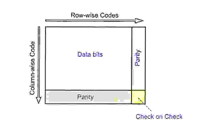
Некоторые производители предлагают в дополнение к коду «Рида-Соломона» более сложные схемы кодирования второго поколения FEC, например, превентивный параметр для оптических интерфейсов 10G и 40G. Данные алгоритмы, называемые «ультра» FEC или «усиленный» FEC (EFEC), также используют не более 7% объема передаваемого кадра, но в них заложены более сложные алгоритмы кодирования/декодирования, которые и обеспечивают бОльший выигрыш по OSNR — от 2 до 3 дБ, нежели код «Рида-Соломона».
Наряду с разработками первого поколения — «Рида-Соломона FEC» и второго поколения — «EFEC», которые позволили существенно улучшить производительность для 10G- и 40G-сигналов, было разработано более производительное FEC-решение третьего поколения, обеспечивающее увеличенную дальность и оптимальную производительность для высокоскоростных каналов передачи данных 100G.
FEC-решение третьего поколения основано на еще более мощных алгоритмах кодирования/декодирования и итеративного кодирования. В hard decision FEC —блок декодирования определяет «твердое» решение на основе входящего сигнала и иницилизирует один бит информации как «1» или «0» путем сравнения с пороговым значением. Значения выше установленного порога определяются «1», а значения ниже определяются как «0». В декодере используются дополнительные биты для обеспечения более детальной и точной индикации входящего сигнала. Иными словами, декодер не только определяет на основе порогового значения — является ли входящий сигнал «1» или «0», но и обеспечивает фактор надежности «принятия решения». Коэффициент надежности определяется индикатором, показывающим насколько сигнал выше или ниже порогового значения.
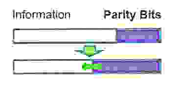
Использование коэффициента надежности или «вероятности» битов вместе с более сложными алгоритмами FEC-кодирования третьего поколения позволяет декодеру SD-FEC обеспечить дополнительное повышение OSNR на 1-2 дБ. В то время как увеличение OSNR на 1-2 дБ не звучит внушительно, оно может интерпретироваться как возможное увеличение расстояния на 20-40%, что является существенным показателем для 100G.
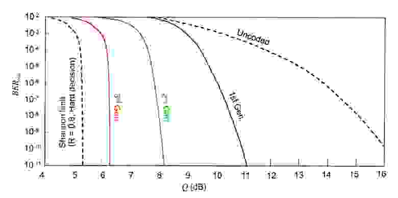
Одним из недостатков soft decision FEC является тот факт, что для него требуется ~20 % объема передаваемого кадра, а это более чем в два раза больше, чем занимаемый объем FEC первого и второго поколения.
С увеличением скорости в канале передачи данных с 10G до 100G, требование к OSNR увеличилось на 10 дБ. Без определенного вида компенсации или коррекции протяженность трасс с канальной скоростью 100G будет весьма ограниченной и неэкономичной.
Алгоритмы FEC первого и второго поколения были использованы на 10G и 40G для снижения BER и увеличения расстояния. SD-FEC является алгоритмом кодирования третьего поколения, обеспечивая передачу данных для оптических сетей 100G на бо́льшие расстояния и с бо́льшим ретрансляционным участком.
 Прямая коррекция ошибок (FEC) это метод, который использовался в течении нескольких лет в подводных оптоволоконных системах, проложенных по морскому дну. Этот метод позволяет с почти идеальной точностью передать данные, даже если передача осуществляется по каналу с большим количеством шумов. В настоящее время используется несколько алгоритмов FEC, таких как код Хэмминга, кода Рида-Соломона и код БЧХ.
В качестве примера, рассмотрим работу вашего мобильного телефона в условиях слабого сигнала сотовой сети. Допустим, вы хотели сказать человеку на другом конце линии некую последовательность чисел. Есть несколько методов, которые можно использовать для повышения точности. Предположим, что список чисел, которые вы хотите передать, это 7, 3, 8, 10, 12 и 21. Одним из способов может быть повтор списка чисел два раза. Запишите каждый список и сравните их, если они совпадают, передача данных, вероятно, корректна. Основным недостатком такого метода является то, что, поскольку данные передаются дважды, пропускная способность системы делится пополам и, если списки не совпадают, у вас не будет ни малейшего представления, который из них верный. Используя этот метод, для того, чтобы убедиться в хорошем качестве передачи и исправить некоторые ошибки, вам придется отправить данные три раза и проверить, что два из трех списков полностью совпадают. Второй способ будет выглядеть примерно так: в первую очередь, вы будете отправлять количество чисел, которые необходимо принять, затем саму последовательно, и в конце последует передача числа, являющегося суммой последовательности. Передаваемое сообщение при этом примет следующий вид: 6, 7, 3, 8, 10, 12, 21, и 67. Человек, принимающий сообщение, будет смотреть на первое число, чтобы затем убедится, что будет получено правильное количество чисел в сообщении, а затем проверит, что число в конце последовательности, действительно является суммой переданных чисел. Этот метод требует отправки значительно меньшего количества дополнительных данных. Если любое полученное число неверно или пропущено, то число контрольной суммы в конце передачи не будет соответствовать сумме, передаваемых чисел. Показанные выше методы представляют собой примеры кода обнаружения ошибок. Они позволяют определить, была ли передача точной, но не позволяют исправлять ошибки.
Примечание: Термин «Forward» в аббревиатуре FEC означает, что исправление ошибок осуществляется путем передачи некоторой информации вместе с передачей данных.
Код исправления ошибок считаются более сложными, в сравнении с кодом обнаружения ошибок и используются почти в каждом современном коммуникационном приложении. Также, коды исправления ошибок нашли широкое применение в CD и DVD проигрывателях. Для того, чтобы привести пример кода исправления ошибок, нужно ввести и объяснить два термина: двоичность и чётность. В предыдущих примерах кода обнаружения ошибок, мы использовали такие числа, как 7, 3, 8, и т.д. Это базовые числа системы исчисления, знакомой нам в повседневной жизни. Двоичные числа в основе имеют два числа, которые могут иметь только два возможных значения – 0 или 1. Бинарная система используется почти во всех коммуникационных и компьютерных системах. Второе определение, которое необходимо разобрать, называется четность. Чётность — термин, который используется в двоичных системах связи, чтобы указать, является ли число единиц в передаче четным или же нет. Если число единиц является четным, то чётность совпадает и наоборот.
Код Хэмминга
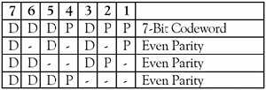
Рассмотрим сообщение, имеющее четыре бита данных (D), которое должно быть передано в 7-битной кодировке с добавлением трёх битов данных для поиска и устранения ошибок. Этот код будет называться (7, 4). Это означает, что общая длина кода составляет семь битов, но только четыре из них на самом деле данные. Три добавленных бита — это три бита проверки на четность (Р), где чётность каждого вычисляется в разных группах битов сообщения, как показано на рисунке 1.
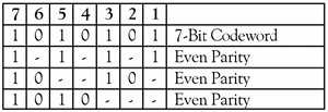
Например, сообщение 1011 будут направлено, как 1010101, как показано на рисунке 2.
Можно заметить, что в случае возникновения ошибки в любом из семи битов, эта ошибка оказывает влияние на различные комбинации трех битов четности в зависимости от битовой позиции.
Например, предположим, что вышеупомянутое сообщение 1010101 передаётся и возникает один бит ошибки, так что получено кодовое слово 1110101:
Передача Приём
Сообщение Сообщение
1 0 1 0 1 0 1 ————> 1 1 1 0 1 0 1
Эта ошибка может быть исправлена путем определения, какой из трех битов четности пострадал, как показано на рисунке ниже:
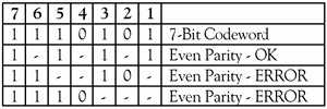
Характер ошибок четности битов указывает, какой бит в кодовом слове с ошибкой, таким образом, он может быть исправлен.
Основные функции кода Хэмминга можно резюмировать:
- Обнаружение 2-битовых ошибок (при условии отсутствия ошибок корректировка не выполняется)
- Коррекция единичных ошибочных битов
- 3 проверочных бита добавляется к 4-битовому сообщению
Способность корректировать одиночные ошибочные биты приводит к снижению себестоимости передачи, которая получается меньше, чем в случае отправки сообщения дважды целиком. (Напомним, что, просто отправив сообщение дважды коррекция ошибок не выполняется.) К тому же, при увеличении размера кодового слова, дополнительная нагрузка исправления ошибочных битов уменьшается. Например, одним из возможных вариантов кода Хэмминга для передачи по морским подводным оптоволоконным системам является код (18880, 18865). Это означает, что кодовое слово 18880 в действительности содержит 18,865 бит данных и 15 бит коррекции ошибок. Более надежные методы прямой коррекции ошибок (FEC) могут содержать гораздо больше битов коррекции ошибок, так что несколько ошибочных битов могут быть обнаружены и исправлены в каждом кодовом слове.
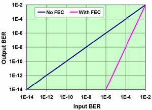 Существует метод прямой коррекции ошибок (FEC), аналогичный коду Хемминга. Как правило, в системах с оптической несущей ОС-192, накладывается около 7% дополнительной нагрузки на систему за счёт процесса коррекции ошибок (FEC). Допустим, базовая скорость передачи данных 10 Гбит/с, с учётом дополнительной нагрузки будет увеличена до 10,7 Гбит/с. Таким образом, с каждой 1000 бит передаваемых данных, отправляется ещё 70 бит коррекции ошибок, чтобы позволить провести проверку целостности полученных данных и исправить ошибки, которые могут возникнуть при передаче по оптическому каналу связи. На рисунке 4 показано влияние прямой коррекции (FEC) на системный коэффициент ошибочных битов (BER). Этот коэффициент является показателем числа ошибок в битах, деленное на общее число переданных битов в исследуемом временном интервале. BER 10-3 означает, что один из каждых 1000 бит будет передан некорректно. Синий график наглядно отображает количество передаваемых данных, если система не имеет FEC. Входной коэффициент BER (input BER) – это показатель ошибок, возникающих в канале передачи. Пока в системе отсутствует FEC, любые ошибки, которые происходят во время передачи появляются на выходе системы. Фиолетовый график показывает, что может произойти, если в системе используется FEC. В отсутствии FEC в системе входной коэффициент BER 10-6 даст аналогичное значение выходного BER 10-6, а в случае использования данной технологии происходит значительное улучшение выходной величины BER 10-14 (output BER).
Таким образом, интеграция прямой коррекции ошибок в систему позволяет разработчику увеличивать расстояние и скорости передачи данных значительнее, чем при использовании любой другой технологии, а также увеличит срок службы системы.
Контроль ошибок — комплекс методов обнаружения и исправления ошибок в данных (b) при их записи и воспроизведении или передаче по линиям связи.
Контроль целостности данных и исправление ошибок — важные задачи на многих уровнях работы с информацией (в частности, физическом (b) , канальном (b) , транспортном (b) уровнях сетевой модели OSI (b) ) в связи с тем, что в процессе хранения данных и передачи информации по сетям связи неизбежно возникают ошибки. Различные области применения контроля ошибок диктуют различные требования к используемым стратегиям и кодам.
В системах связи возможны несколько стратегий борьбы с ошибками:
- обнаружение ошибок в блоках данных и автоматический запрос повторной передачи[⇨] повреждённых блоков — этот подход применяется, в основном, на канальном и транспортном уровнях;
- обнаружение ошибок в блоках данных и отбрасывание повреждённых блоков — такой подход иногда применяется в системах потокового мультимедиа, где важна задержка передачи и нет времени на повторную передачу;
- упреждающая коррекция ошибок добавляет к передаваемой информации такие дополнительные данные, которые позволяют исправить ошибки без дополнительного запроса.
В контроле ошибок, как правило, используется помехоустойчивое кодирование (b) — кодирование данных при записи или передаче и декодирование (b) при считывании или получении при помощи корректирующих кодов (b) , которые и позволяют обнаружить и, возможно, исправить ошибки в данных. Алгоритмы помехоустойчивого кодирования в различных приложениях могут быть реализованы как программно, так и аппаратно.
Современное развитие корректирующих кодов (b) приписывают Ричарду Хэммингу (b) с 1947 года (b) [1]. Описание кода Хэмминга (b) появилось в статье Клода Шеннона (b) «Математическая теория связи (b) »[2] и было обобщено Марселем Голеем (b) [3].
Стратегии исправления ошибок
Упреждающая коррекция ошибок
Упреждающая коррекция ошибок (также прямая коррекция ошибок, англ. (b) Forward Error Correction, FEC) — техника помехоустойчивого кодирования и декодирования (b) , позволяющая исправлять ошибки методом упреждения. Применяется для исправления сбоев и ошибок при передаче данных путём передачи избыточной служебной информации, на основе которой может быть восстановлено первоначальное содержание. На практике широко используется в сетях передачи данных (b) , телекоммуникационных технологиях. Коды, обеспечивающие прямую коррекцию ошибок, требуют введения большей избыточности в передаваемые данные, чем коды, которые только обнаруживают ошибки.
Например, в спутниковом телевидении (b) при передаче цифрового сигнала с FEC 7/8 передаётся восемь бит информации: 7 бит полезной информации и 1 контрольный бит[4]; в DVB-S (b) используется всего 5 видов: 1/2, 2/3, 3/4 (наиболее популярен), 5/6 и 7/8. При прочих равных условиях, можно утверждать, что чем ниже значение FEC, тем меньше пакетов допустимо потерять, и, следовательно, выше требуемое качество сигнала.
Техника прямой коррекции ошибок широко применяется в различных устройствах хранения данных — жёстких дисках, флеш-памяти, оперативной памяти. В частности, в серверных приложениях применяется ECC-память (b) — оперативная память, способная распознавать и исправлять спонтанно возникшие ошибки.
Автоматический запрос повторной передачи
Системы с автоматическим запросом повторной передачи (b) (англ. (b) Automatic Repeat Request, ARQ) основаны на технологии обнаружения ошибок. Распространены следующие методы автоматического запроса:
Идея запроса ARQ с остановками (англ. (b) stop-and-wait ARQ) заключается в том, что передатчик ожидает от приемника подтверждения успешного приема предыдущего блока данных перед тем, как начать передачу следующего. В случае, если блок данных был принят с ошибкой, приемник передает отрицательное подтверждение (negative acknowledgement, NAK), и передатчик повторяет передачу блока. Данный метод подходит для полудуплексного (b) канала связи. Его недостатком является низкая скорость из-за высоких накладных расходов на ожидание.
Для метода непрерывного запроса ARQ с возвратом (continuous ARQ with pullback) необходим полнодуплексный (b) канал. Передача данных от передатчика к приемнику производится одновременно. В случае ошибки передача возобновляется, начиная с ошибочного блока (то есть передается ошибочный блок и все последующие).
При использовании метода непрерывного запроса ARQ с выборочным повторении (continuous ARQ with selective repeat) осуществляется передача только ошибочно принятых блоков данных.
Сетевое кодирование
Раздел теории информации (b) , изучающий вопрос оптимизации передачи данных по сети с использованием техник изменения пакетов данных на промежуточных узлах называют сетевым кодированием (b) . Для объяснения принципов сетевого кодирования используют пример сети «бабочка», предложенной в первой работе по сетевому кодированию «Network information flow»[5]. В отличие от статического сетевого кодирования, когда получателю известны все манипуляции, производимые с пакетом, также рассматривается вопрос о случайном сетевом кодировании, когда данная информация неизвестна. Авторство первых работ по данной тематике принадлежит Кёттеру, Кшишангу и Силве[6]. Также данный подход называют сетевым кодированием со случайными коэффициентами — когда коэффициенты, под которыми начальные пакеты, передаваемые источником, войдут в результирующие пакеты, принимаемые получателем, с неизвестными коэффициентами, которые могут зависеть от текущей структуры сети и даже от случайных решений, принимаемых на промежуточных узлах. Для неслучайного сетевого кодирования можно использовать стандартные способы защиты от помех и искажений, используемых для простой передачи информации по сети.
Энергетический выигрыш
При передаче информации по каналу связи вероятность ошибки зависит от отношения сигнал/шум (b) на входе демодулятора, таким образом, при постоянном уровне шума решающее значение имеет мощность передатчика. В системах спутниковой и мобильной, а также других типов связи остро стоит вопрос экономии энергии. Кроме того, в определённых системах связи (например, телефонной) неограниченно повышать мощность сигнала не дают технические ограничения.
Поскольку помехоустойчивое кодирование позволяет исправлять ошибки, при его применении мощность передатчика можно снизить, оставляя скорость передачи информации неизменной. Энергетический выигрыш определяется как разница отношений с/ш при наличии и отсутствии кодирования.
Примечания
- ↑ Thompson, Thomas M. (1983), From Error-Correcting Codes through Sphere Packings to Simple Groups, The Carus Mathematical Monographs (#21), The Mathematical Association of America, с. vii, ISBN 0-88385-023-0
- ↑ Shannon, C.E. (1948), A Mathematical Theory of Communication, Bell System Technical Journal (p. 418) Т. 27 (3): 379–423, PMID 9230594, DOI 10.1002/j.1538-7305.1948.tb01338.x
- ↑ Golay, Marcel J. E. (1949), Notes on Digital Coding, Proc.I.R.E. (I.E.E.E.) (p. 657) Т. 37
- ↑ Understanding Digital Television: An Introduction to Dvb Systems With … — Lars-Ingemar Lundström — Google Книги. Дата обращения: 19 мая 2020. Архивировано 11 ноября 2021 года.
- ↑ Ahlswede, R.; Ning Cai; Li, S.-Y.R.; Yeung, R.W., «Network information flow», Information Theory, IEEE Transactions on, vol.46, no.4, pp.1204-1216, Jul 2000
- ↑ Статьи:
- Koetter R., Kschischang F.R. Coding for errors and erasures in random network coding// IEEE International Symposium on Information Theory. Proc.ISIT-07.-2007.- P. 791—795.
- Silva D., Kschischang F.R. Using rank-metric codes for error correction in random network coding // IEEE International Symposium on Information Theory. Proc. ISIT-07. — 2007.
- Koetter R., Kschischang F.R. Coding for errors and erasures in random network coding // IEEE Transactions on Information Theory. — 2008- V. IT-54, N.8. — P. 3579-3591.
- Silva D., Kschischang F.R., Koetter R. A Rank-Metric Approach to Error Control in Random Network Coding // IEEE Transactions on Information Theory.- 2008- V. IT-54, N. 9.- P.3951-3967.
Литература
 |
Имеется викиучебник (b) по теме «Помехоустойчивое кодирование» |
|---|
- Блейхут Р. (b) Теория и практика кодов, контролирующих ошибки = Theory and Practice of Error Control Codes. — М.: Мир (b) , 1986. — 576 с.
- Мак-Вильямс Ф. Дж., Слоэн Н. Дж. А. Теория кодов, исправляющих ошибки. М.: Радио и связь, 1979.
- Морелос-Сарагоса Р. (b) Искусство помехоустойчивого кодирования. Методы, алгоритмы, применение / пер. с англ. В. Б. Афанасьева (b) . — М.: Техносфера, 2006. — 320 с. — (Мир связи). — 2000 экз. — ISBN 5-94836-035-0.
- Clark, George C., Jr., and J. Bibb Cain. Error-Correction Coding for Digital Communications. New York: Plenum Press, 1981. ISBN 0-306-40615-2.
- Lin, Shu, and Daniel J. Costello, Jr. «Error Control Coding: Fundamentals and Applications». Englewood Cliffs, N.J.: Prentice-Hall, 1983. ISBN 0-13-283796-X.
- Mackenzie, Dana. «Communication speed nears terminal velocity». New Scientist 187.2507 (9 июля (b) 2005 (b) ): 38-41. ISSN 0262-4079.
- Wicker, Stephen B. Error Control Systems for Digital Communication and Storage. Englewood Cliffs, N.J.: Prentice-Hall, 1995. ISBN 0-13-200809-2.
- Wilson, Stephen G. Digital Modulation and Coding, Englewood Cliffs, N.J.: Prentice-Hall, 1996. ISBN 0-13-210071-1.
Ссылки
- Charles Wang, Dean Sklar, and Diana Johnson. Forward Error-Correction Coding. The Aerospace Corporation. — Volume 3, Number 1 (Winter 2001/2002). Дата обращения: 24 мая 2009. Архивировано из оригинала 20 февраля 2005 года. (англ.)
- Charles Wang, Dean Sklar, and Diana Johnson. How Forward Error-Correcting Codes Work (недоступная ссылка — история). The Aerospace Corporation. Дата обращения: 24 мая 2009. Архивировано 25 февраля 2012 года. (англ.)
- Morelos-Zaragoza, Robert The Error Correcting Codes (ECC) Page (недоступная ссылка — история) (2004). Дата обращения: 24 мая 2009. Архивировано 25 февраля 2012 года. (англ.)
High-capacity long-haul optical fiber transmission
Xiang Liu, in Optical Communications in the 5G Era, 2022
8.4.4 Capacity-approaching FEC
Forward-error correction is an important technology to enable a communication link to approach the Shannon limit. The use of FEC in optical fiber communication links has gone through three generations [94]
- •
-
The first generation of FEC codes appeared in the 1987–93 period, and the representative FEC code is Reed–Solomon (RS) code (255,239) with a FEC overhead of 6.7% and a net coding gain (NCG) of 5.8 dB at an output BER of 10−15.
- •
-
The second generation of FEC codes in the 2000–04 period, and the representative FEC codes are the concatenated codes, showing an NCG of 9.4 dB at an FEC overhead of ~25%.
- •
-
The third generation of FEC codes started to be adopted in real systems around 2006, and the representative FEC codes are SD decoding enabled low-density parity check (LDPC) codes, turbo codes, etc., showing an NCG of over 10 dB at an FEC overhead of between ~15% and ~25%. The key feature of the third generation of FEC codes is the use of SD decoding [94].
A key performance indicator of FEC is its NCG, which is defined as
(8.27)NCGdB=10log10SNRBERout−10log10SNRBERin+10log10(R)
where BERin is the maximally allowed input BER to the FEC to achieve a reference output BER of BERout, SNR(x) is the SNR needed for a given modulation format to reach a BER of x without coding, and R is the FEC code rate. For BPSK modulation format, we have
(8.28)SNRBPSKBER=erfc−1(2BER)
where erfc−1() is the inverse complementary error function. For QPSK modulation format, we have
(8.29)SNRQPSKBER=2erfc−1(2BER)
For 16-QAM modulation format, we have
(8.30)SNR16QAMBER=10erfc−1(83BER)
For high-speed transmission based on 16-QAM, multiple high-performance FEC codes have been studied. Table 8.1 shows some of the FEC codes and their performances. The first code is the concentrated FEC (CFEC) code adopted by the Optical Internetworking Forum (OIF) for 400ZR [95,96]. Its required BERin for a BERout of 10−15 is 1.22×10⁻², and its code rate is 0.871, leading to an NCG of 11.76 dB. The second code is an enhanced version of CFEC, named as CFEC+, which offers an increased NCG of 11.45 dB [97]. The third code is referred to as open FEC (OFEC), which was adopted by the Open ROADM Multisource Agreement (MSA) and was proposed to the ITU project on 200 G/400 G FlexO-LR for 450 km black link applications [98]. The OFEC offers a further increased NCG of 11.6 dB.
Table 8.1. High-performance FEC codes used for 16-QAM based high-speed transmission.
| FEC code | BERin (SNRin) for BERout=10−15* | Code rate | NCG |
|---|---|---|---|
| CFEC [95,96] | 1.22×10⁻² (13.6 dB) | 0.871 | 10.76 dB |
| CFEC+ [97] | 1.81×10⁻² (12.9 dB) | 0.871 | 11.45 dB |
| OFEC [98] | 1.98×10⁻² (12.7 dB) | 0.867 | 11.60 dB |
| A 20%-OH LDPC [57] | ~2.76×10⁻² (12.0 dB) | 0.833 | 12.12 dB |
| A 25%-OH LDPC [99] | ~3.45×10⁻² (11.5 dB) | ~0.8 | ~12.5 dB |
FEC, forward-error correction; BER, bit error ratio; SNR, signal-to-noise ratio; NCG, net coding gain; LDPC, low-density parity check.
- *
- At the reference BERout of 10−15, the corresponding SNR for 16-QAM is ~24.95 dB.
In a recent 800-Gb/second-per-wavelength demonstration, a 20% overhead (OH) LDPC code was used, and a high NCG of 12.12 dB was achieved [57]. Finally, a 25%-OH FEC was demonstrated in real-time 200-Gb/second coherent transceivers, achieving a remarkably high NCG of 12.5 dB [99]. Similar performance has also been shown in the 800-Gb/second demonstration when the LDPC FEC OH was increased to 25% [57].
It is worthwhile to compare the above FEC performances with the theoretical limit. The ultimate NCG can be derived from the Shannon’s capacity theorem. The channel capacity C of a binary symmetric channel with HD decoding is given as
(8.31)CHD=1+BERin·log2BERin+1−BERin·log21−BERin
where BERin is the input BER threshold and the channel capacity CHD can be set to the FEC code rate R [94]. For a given FEC code rate R, we can calculate BERin. Together with Eqs. (8.27–8.30), we can then calculate the NCG for a given modulation format at a given reference BERout.
For SD decoding, the capacity of a binary symmetric channel, which has two possible inputs X=A and X=−A, can be expressed as [35]
(8.32)CSD=12∫−∞+∞p(y|A)log2p(y|A)p(y)dy+12∫−∞+∞p(y|−A)log2p(y|−A)p(y)dy
where p(y|A) is the conditional probability of getting y at the receiver when the input is A, and p(y) is the probability of receiving y. Similar to the case with HD, for a given FEC code rate R=CSD, we can calculate BERin, from which we can then calculate the NCG for a given modulation format at a given reference BERout. In the idealized case of SD decoding with infinite quantization bits, the NCG obtained by SD decoding is π/2 times as large as (or ~2 dB higher than) that obtained by HD decoding when R approaches zero.
Fig. 8.13 shows the Shannon limits of HD and SD NCGs for BPSK/QPSK, together with some recently demonstrated high-performance FEC codes. For HD decoding, KP4 and staircase FEC [100] are widely used in the optical communication industry. Remarkably, the staircase FEC offers a NCG of 9.41 dB, which is only 0.56 dB away from the HD Shannon limit [100]. For SD decoding, NCGs of 11.6 and 12.25 dB have been achieved with 20% and 33% OHs, respectively [57]. These SD NCGs are only about 1 dB away from the SD Shannon limit.

Figure 8.13. The Shannon limits of HD and SD NCGs for BPSK/QPSK and some recently demonstrated FEC codes [57,96,100]. The reference output BER (BERout) is set at 10−15.
Fig. 8.14 shows the Shannon limits of HD and SD NCGs for 16-QAM, together with some recently demonstrated high-performance FEC codes. The Shannon limits of NCGs for 16-QAM are slightly higher than those for BPSK/QPSK. This can be understood by the slightly flatter BER curve of 16-QAM at high BER values as compared to BPSK/QPSK, as shown in Figure 7.6. For HD decoding, the staircase FEC is again only ~0.6 dB away from the HD Shannon limit. For SD decoding, the CFEC+, OFEC, 20%-OH LDPC, and 25%-OH LDPC described in Table 8.1 are all within 1.4 dB away from the SD Shannon limit. In terms of the absolute NCG, it increases as the OH increases. This offers the flexibility of adjusting the system performance and throughput based on link conditions.

Figure 8.14. The Shannon limits of HD and SD NCGs for 16-QAM and some recently demonstrated FEC codes [57,96–99,100]. The reference output BER (BERout) is set at 10−15.
The above analysis and review have shown the remarkable works done by the optical communication industry in approaching the Shannon limit via advanced FEC coding designs and implementations.
Read full chapter
URL:
https://www.sciencedirect.com/science/article/pii/B9780128216279000140
Ultralong-distance undersea transmission systems
Jin-Xing Cai, … Neal S. Bergano, in Optical Fiber Telecommunications VII, 2020
13.2.3.1 Adaptive rate forward error correction
Using multiple FECs with different FEC thresholds in a WDM system can squeeze more capacity than using a single FEC. Ref. [43] designed a family of 52 Spatially-Coupled LDPC codes and studied the gain of using different number of FECs. Capacity increase due to using 8 FECs (with respect to single FEC, both without NLC) is between 15.5% and 21% for transmission distances from 10,200 to 6000 km. Further increase of the number of FECs used does not provide much more gain in capacity, as shown in Fig. 13.24. The shortcoming of this scheme is that the FEC implementation penalty increases for stronger FEC code. For example, the implementation penalty increases from 0.5 to >1 dB when the FEC code rate drops from 0.87 down to 0.52.

Figure 13.24. Net transmitted capacity versus number of forward error corrections (FECs), © [2015] IEEE. Reprinted, with permission, from [43].
Read full chapter
URL:
https://www.sciencedirect.com/science/article/pii/B9780128165027000154
Technique Developments and Market Prospects of Submarine Optical Cable Engineering
In Submarine Optical Cable Engineering, 2018
10.1.2 Development Trends of the Forward Error Correction Technique
FEC facilitates the development of 100 Gbps and super 100 Gbps technology discussed earlier. Soft decision (SD) is the latest evolution used in FEC application. SD FEC is named on the reference of traditional hard decision (HD). FEC decoding from the receiver is the difference between HD and SD. Threshold is the baseline for HD. The input signals will be determined as 0 or 1 arbitrarily. On the other hand, threshold is the reference for SD. The input signals will be speculated, and speculation credibility is provided. SD does not generate decisions but provides inspection and credibility for the further information process and decision-making with an error correction algorithm. The provided credibility will, furthermore, enhance FEC coding gain. Compared with HD, the coding gain of FEC generated from SD will improve 1.5–2.5 dB.
Read full chapter
URL:
https://www.sciencedirect.com/science/article/pii/B9780128134757000102
Communicating pictures: delivery across networks
David R. Bull, Fan Zhang, in Intelligent Image and Video Compression (Second Edition), 2021
Cross-packet FEC
If FEC is applied within a packet or appended to individual packets, in cases where packets are not just erroneous but are lost completely during transmission (e.g., over a congested internet connection), the correction capability of the code is lost. Instead, it is beneficial to apply FEC across a number of packets, as shown in Fig. 11.10. One problem with using FEC is that all the k data packets need to be of the same length, which can be an issue if GOB fragmentation is not allowed. The performance of cross-packet FEC for the case of different coding depths (8 and 32) is shown in Fig. 11.11. This clearly demonstrates the compromise between clean channel performance and error resilience for different coding rates.

Figure 11.10. Cross-packet FEC.

Figure 11.11. Performance of cross-packet FEC for a coding depth of 8 (left) and 32 (right) for various coding rates.
Read full chapter
URL:
https://www.sciencedirect.com/science/article/pii/B9780128203538000207
Error-Resilience Video Coding Techniques
Mohammed Ebrahim Al-Mualla, … David R. Bull, in Video Coding for Mobile Communications, 2002
9.6.1 Forward Error Correction (FEC)
Forward error correction works by adding redundant bits to a bitstream to help the decoder detect and correct some transmission errors without the need for retransmission. The name forward stems from the fact that the flow of data is always in the forward direction (i.e., from encoder to decoder).
For example, in block codes the transmitted bitstream is divided into blocks of k bits. Each block is then appended with r parity bits to form an n-bit codeword. This is called an (n, k) code.
For example, Annex H of the H.263 standard provides an optional FEC mode. This mode uses a (511,493) BCH (Bose-Chaudhuri-Hocquenghem) code. Blocks of k = 493 bits (consisting of 492 video bits and 1 fill indicator bit) are appended with r = 18 parity bits to form a codeword of n = 511 bits. Use of this mode allows the detection of double-bit errors and the correction of single-bit errors within each block.
Read full chapter
URL:
https://www.sciencedirect.com/science/article/pii/B9780120530793500111
Applications to Communication Systems
Yasuo Hirata, Osamu Yamada, in Essentials of Error-Control Coding Techniques, 1990
6.2.2 Recent Trends in Operational Systems
FEC techniques have been introduced in a variety of satellite communication systems. This section briefly surveys recent trends in FEC application to the operational systems, focusing on the International Telecommunications Satellite Organization (INTELSAT), which has been taking the leading position in the area of commercial satellite communications, and on International Maritime Satellite Organization (INMARSAT), which offers mobile satellite communication service on an international basis.
Table 6.2 summarizes the FEC codes applied to the INTELSAT system. In the INTELSAT system, the double error-correcting self-orthogonal convolutional codes with the code rate of 3/4 and 7/8 are adopted in the single channel per carrier (SCPC) data-transmission system for 48-kbit/sec and 56-kbit/sec user rates. Since the decoder of the self-orthogonal code is simply implemented by using the threshold decoding technique, it has been widely utilized for data transmission in satellite communication systems. In addition to self-orthogonal codes, the (120, 112) modified BCH code with the code rate of 14/15 which is derived from (127, 119) single-error-correcting/double-error-detecting BCH code is also specified in the INTELSAT SCPC system to transmit the voice-band data of higher than 4.8 kbit/sec through the 56-kbit/sec PCM voice channel.
Table 6.2. FEC Codes Applied for INTELSAT System
| Systems | Applied FEC Codes | |
|---|---|---|
| SCPC | 3/4 self-orthogonal code (double-error correction) 7/8 self-orthogonal code (120, 112) modified BCH code | for 48-kbit/sec, 50-kbit/sec data for 56-kbit/sec data for voice-band data transmission above 4.8 kbit/sec |
| TDMA/DSI | (128,112) BCH code | for TDMA data burst (120 Mbit/sec) |
| (24, 12) Golay code | for DSI assignment message | |
| IBS, IDR | 1/2 and 3/4 convolutional coding/soft decision Viterbi decoding (K = 7, punctured) |
In the time division multiple access/digital speech interpolation (TDMA/DSI) system (Pontano et al., 1981), the (128, 112) modified BCH code with the code rate of 7/8, which consists of (127, 112) double-error-correcting/triple-error-detecting BCH code and one dummy bit, is adopted in communication channels. The INTELSAT TDMA system has several tight constraints in selecting the FEC codes to be applied. One of the most significant constraints is that the very high speed data must be transmitted in burst mode. Another requirement is to keep the reduction of channel-utilization efficiency due to applying FEC as low as possible. In view of those requirements, the BCH code mentioned previously has been selected as the standard FEC code (Muratani et al., 1978; Koga et al., 1979, 1980). In addition to that, the (24,12) modified Golay code is applied to the assignment control channel for the DSI system to improve the reliability of assignment message. This modified Golay code is constructed by adding one dummy bit to the (23,12) triple-error-correcting Golay code.
Recently, a new service called INTELSAT Business Services (IBS) has commenced (Lee et al,1983), in which the digital-communication networks can be established among earth stations with small dish antennas. In order to overcome the severe power limitation due to reduction of the antenna size, the soft decision Viterbi decoding for the rate 1/2 or 3/4 convolutional code with the constraint length of 7 is applied, which can offer high coding gain as stated in Section 6.2.1 of Chapter 6. As for the code with a code rate of 3/4, the punctured coding is applied. These FEC codes using Viterbi decoding are also going to be applied to the new data transmission service called intermediate data rate (IDR). Table 6.3, Table 6.4, and Table 6.5 summarize the specifications of FEC codes applied to INTELSAT SCPC, TDMA/DSI, and IBS systems, respectively.
Table 6.3. Specification of FEC Codes Applied to INTELSAT SCPC System
| Data | FEC Code Applied | Generator Polynomial |
|---|---|---|
| 48-kbit/sec | 3/4 self-orthogonal code | g1 = 1 + x3 + x15 + x19 |
| 50-kbit/sec data | (double-error correction) | g2 = 1 + x8 + x17 + x18 |
| (constraint length = 80 bits) | g3 = 1 + x6 + x11 + x13 | |
| 56-kbit/sec data | 7/8 self-orthogonal code | g1 = 1 + x3 + x19 + x42, |
| (constraint length = 384 bits) | g2 = 1 + x21 + x34 + x43 | |
| g3 = 1 + x29 + x33 + x47, g4 = 1 + x25 + x36 + x37, g5 = 1 + x15 + x20 + x46, g6 = 1 + x2 + x8 + x32, g7 = 1 + x7 + x17 + x45 |
||
| Voice-band data transmission above | (120, 112) modified BCH codea | g (x) = (x + 1)(x7 + x3 + 1) = x8 + x7 + x4 + x3 + x + 1 |
| 48 kbit/sec |
- a
- BCH code is applied after 56-kbit/sec PCM encoding. The error-correcting process is inhibited when the double-bit error is detected within a block.
Table 6.4. Specification of FEC Codes Applied to INTELSAT TDMA/DSI System
| Data | FEC Code Applied | Generator Polynomial |
|---|---|---|
| TDMA data burst (120 Mbit/sec) | (128,112) BCH code (d =6, t = 2)a | G(x) = (x + 1)(x14 + x12 + x10 + x6 + x5 + x4 + x3 + x2 + 1) = x15 + x14 + x13 + x12 + x11 + x10 + x7 + x2 + x + 1 |
| DSI assignment message | (24,12) Golay code (d =7, t = 3)b | G(x) = x11 + x9 + x7 + x6 + x5 + x + 1 |
- a
- One dummy bit is added to the (127,112) BCH code
- b
- One dummy bit is added to the (23,12) Golay code.
Table 6.5. Specification of FEC Codes Applied to INTELSAT IBS System
| Data | FEC Code Applieda | Generator Polynomial |
|---|---|---|
| 64 kbit/sec, ∼ 10 Mbit/sec | 1/2, K = 7 convolutional code/Viterbi decoding | g1 = 1 + x2 + x3 + x5 + x6 g2 = 1 + x + x2 + x3 + x6 bit deleting pattern |
| 3/4 punctured code (d = 5)/Viterbi decoding derived from 1/2 code | 110101(1: send0: delete) |
- a
- One dummy bit is added to the (23,12) Golay code.
Furthermore, several new coding schemes are also being studied and partly developed in INTELSAT for future application. A viable coding scheme under development is the coded 8-phase PSK combined with the rate 2/3 convolutional coding-soft decision Viterbi decoding. It is reported that the signal-power requirement can be reduced by around 4 dB compared with the conventional 4-phase PSK applied to TDMA and SCPC systems, while keeping the bandwidth requirement constant (Rhodes et al., 1983; Ungerboeck et al., 1986).
Table 6.6 summarizes the FEC codes applied to the INMARSAT system. In the INMARSAT system, the (63,57) and (63,39) BCH codes are used to detect the bit errors in the access control channels for the Standard-A system. Also, the rate 1/2 convolutional code with constraint length of 7/Viterbi decoding is adopted to the 56-kbit/sec data channel in the ship-to-shore direction. INMARSAT is now planning to introduce a new ship earth station standard called Standard-B system which is based on digital-transmission techniques in the second generation starting in 1991 (Hirata et al, 1984). In order to save transmission power, the Standard-B system is designed based on use of Viterbi decoding for codes similar to the ones employed in the INTELSAT systems. Figures 6.6, 6.7, and 6.8 show the BER performances of self-orthogonal code, BCH code, and soft decision Viterbi decoding, respectively, all of which are already used in INTELSAT and/or INMARSAT systems.
Table 6.6. FEC Codes Applied to INMARSAT System
| Systems | Applied FEC Codes |
|---|---|
| Assignment/request channel | (63,57) BCH code for assignment message |
| (63,39) BCH code for request message | |
| High-speed data transmission (ship-to-shore) | 1/2 conventional coding/soft decision Viterbi decoding (K = 7) for 56-kbit/sec data |
| Digital ship earth station standard (Standard B) | 1/2 and/or 3/4 convolutional coding/soft decision Viterbi decoding (K = 7) for 9.6-kbit/sec data and 16-kbit/sec voice |

Fig. 6.6. BER versus Eb/No performance of self-orthogonal convolutional codes (double error-correcting).

Fig. 6.7. BER versus Eb/No performance of BCH codes applied to INTELSAT TDMA/DSI system.

Fig. 6.8. BER versus Eb/No performance of soft decision Viterbi decoding.
In addition to INTELSAT and INMARSAT systems, the FEC techniques are widely used in operational domestic and regional satellite communication systems to protect important messages against transmission errors. A variety of digital satellite communication systems presently planned or under development are being designed based on the use of FEC techniques in order to improve transmission quality and to economically create the digital networks.
As for the coding schemes under consideration, the soft decision Viterbi decoding which offers high coding gain is regarded as the most appropriate FEC and is going to be widely applied to the channel requiring high transmission quality, in addition to the partial use of block codes such as BCH and Golay codes. For example, the Viterbi decoding is used in the Japanese domestic satellite communication system via CS-2 (Kato et al., 1986). In the European regional satellite system called EUTELSAT, the rate 1/2 convolutional coding–Viterbi decoding, which is the same as those in INTELSAT and INMARSAT systems, is also specified as the standard FEC (Amadesi et al., 1985). In the ACTS-E project planned by NASA as the advanced domestic digital satellite communication system using the 30/20 GHz band, the soft decision Viterbi decoding is taken into consideration for application to the several-hundred–Mbit/s SS-TDMA system(Attwood and Sabourin, 1982), and a high-speed Viterbi decoder to be used in this system is being developed (Clark and McCallister, 1982). Furthermore, Viterbi decoding is already widely applied to the United States military satellite systems and to the NATO-III system in Europe (Celebiler et al., 1981).
As previously stated, soft decision Viterbi decoding tends to be most widely used in satellite communication systems, and this tendency will continue for the time being. The majority of the codes used in the late 1980s is the convolutional code with the code rate of 1/2 and with the constraint length of 7, because its codec can be realized with a reasonable amount of hardware. However, the low-cost Viterbi decoder also has become available for higher-rate codes based on a punctured coding technique as well as for the longer constraint-length codes, in conjunction with the remarkable progress of the IC/LSI technology. Therefore, Viterbi decoding for codes with higher code rate and longer constraint length will become widely applicable to various digital satellites communication systems in the near future.
Read full chapter
URL:
https://www.sciencedirect.com/science/article/pii/B9780123707208500106
50-Gb/s passive optical network (50G-PON)
Xiang Liu, in Optical Communications in the 5G Era, 2022
10.3.1 LDPC design considerations and performances
FEC is widely adopted in PON systems to improve receiver sensitivity and increase link budget. In GPON, the Reed–Solomon (RS) code (255,239) is used with a BER threshold of 1E-4 [3]. In XG(S)-PON, the downstream transmission adopts RS(248, 216), which is a truncated form of RS(255, 223), achieving an increased BER threshold of 1E-3 [4,5]. In the IEEE 802.3ca 50G-EPON standard, high-coding-gain LDPC is adopted, achieving a further increased BER threshold of 1E-2 [23]. The LDPC code matrix is a 12× 69 quasicyclic matrix with a circulant size of 256. For the mother code, the codeword length, payload length, and parity length are 256×69 (=17,664) bits, 256×57 (=14,592) bits, and 256×12 (=3072) bits, respectively, as illustrated in Fig. 10.19. The LDPC mother code is thus represented as LDPC(17,664, 14,592). The IEEE 802.3ca standard adopts this mother code but has 512 parity bits punctured and 200 payload bits shortened, resulting in LDPC(16,952, 14,392) with a code rate of 0.849. In the ITU-T 50G-PON standard, the same LDPC mother code is used but with 384-bit puncturing and no shortening, resulting in LDPC(17,280, 14,592) with a code rate of 0.844. This LDPC design choice was made based on the following considerations [40]:

Figure 10.19. Illustration of the mother code matrix structure of the low-density parity check adopted by both IEEE 50G-Ethernet PON and international telecommunications union telecommunication 50G-passive optical network.
- •
-
Inclusion of the physical synchronization block downstream (PSBd) in the first LPDC codeword
With the use of the high-coding-gain LDPC, the 50G-PON system is operating at a raw BER level that is too high for the 13-bit hybrid error control (HEC) to reliably protect the superframe counter (SFC) and the operation control (OC) structure inside the PSBd. This issue is resolved by including the PSBd in the first LPDC codeword to better protect the SFC and the OC structure.
- •
-
Integer number of codewords per 50G-PON frame
XG(S)-PON specifies that each downstream frame contains an integer number of FEC codewords, which makes the implementation easy and avoids the need to specify a fractional codeword. It is desired to have the same feature in 50G-PON. Given that the 125-μs downstream frame length in 50G-PON is 6,220,800 bits and PSBd is inside the first codeword, we only need to make the LDPC codeword length (in bits) to be a factor of 6,220,800. The five largest FEC codeword lengths that are both (1) factors of 6,220,800 and (2) not larger than the mother codeword length of the mother code (17,664) are 17,280, 16,200, 15,552, 15,360, and 14,400, from which we shall select an appropriate codeword length.
- •
-
Codeword length being a multiple of internal processing bus width
In high-speed ASIC implementations, it is desirable for the codeword length to be a multiple of the internal processing bus width. Assuming that a 10-Gb/s Serializer/Deserializer (SerDes) has a typical output bit width of 16 or 32 bit, the internal processing bus width for 50-Gb/s SerDes is expected to be increased to 64 or 128 bits. It is thus desired for the codeword length to be divisible by 128. Thus the codeword length options are narrowed down to 17,280 and 15,360.
- •
-
High code rate and low computational overhead
To achieve high code rate and low computational overhead for a given mother code, we shall select the largest possible codeword length. Thus it is appropriate to select the codeword length to be 17,280 bits, which is only 384 bits fewer than the codeword length of the mother code (17,664). The codeword length of 17,280 bits can be realized by (1) shortening the payload by 384 bits to have LPDC(17,280, 14,208) with a code rate of 0.822, (2) puncturing the parity by 384 bits to have LPDC(17,280, 14,592) with a code rate of 0.844, or something in between. To have the highest code rate, LDPC(17,280, 14,592) is preferred if its HD and SD decoding performances are satisfactory and do not exhibit error floors.
- •
-
Satisfactory HD and SD decoding performances
For PON systems, it is important to ensure that there is no error floor at the FEC output BER of 1E-12. For the LPDC without puncturing, it has been experimentally verified that no error floor at output BER of 1E-12 is present for both HD decoding [41] and SD decoding [42,43]. When the LPDC is punctured by 512 bits, error floor appears for SD decoding [44]. For the LDPC(17,280, 14,592) with 384-bit puncturing and no shortening, it has been verified that no error floor is present for both HD and SD deciding, as shown in Fig. 10.20 [45]. The HD and SD BER thresholds for an output BER of 1E-12 are measured to be 1.1E-2 and 2.4E-2, respectively, which are higher than those of the IEEE 50G-EPON LDPC(16,952, 14,392). Remarkably, the HD and SD decoding performances of the LDPC(17,280, 14,592) are less than 1.2 dB away from their respective Shannon limits, as shown in Fig. 10.21. This shows the superior HD and SD decoding performances of the LDPC(17,280, 14,592).

Figure 10.20. Output bit error ratio (BER) versus input BER for the international telecommunications union telecommunication 50G-passive optical network low-density parity check (17,280, 14,592) with hard-decision and soft-decision decoding.
After Han Y, Wilson B, Amitai A. HSP LDPC performance curves. In: Contribution D13, ITU-T SG15/Q2 Meeting; May 2020 [45].

Figure 10.21. The net coding gains the international telecommunications union telecommunication 50G-passive optical network (PON) low-density parity check LDPC(17,280, 14,592) with hard-decision (HD) and soft-decision (SD) decoding as compared to the Shannon limits.
In accordance with the above, the LDPC(17,280, 14,592), constructed from the mother code LDPC(17,664, 14,592) with 384 bit puncturing and no shortening, has been selected by the ITU-T 50G-PON standard [9].
The scope of ITU-T G.hsp.ComTC states that the TC layer will have support for a range of downstream and upstream line rates, such as 50, 25, and 12.5 Gb/s, as well as futuristic data rates such as 100 and 75 Gb/s. It is desirable for the ComTC specification to define the operation of HSP systems in a manner that is independent of a particular transmission rate. One way is to have a parameterized specification, where the parameter values can be set according to the requirements of a particular PMD recommendation. 50G-PON uses a parameterized specification based on the following method [9]:
- •
-
Setting 12.4416 Gb/s as a fundamental line rate, ρ0, and defining a line rate factor, ϕ (which is a positive integer), to represent a particular line rate of ρ0ϕ in the PON system.
Table 10.6 shows the number of LDPC(17,664, 14,592) codewords per 125-μs PON frame versus the line rate factor ϕ. Conveniently, each PON frame contains an integer number of LDPC codewords for all the data rates of interest, making it easy to scale line rate without worrying about shortening the last codeword of each PON frame and shortening different numbers of payload bits for different line rates. Thus the choice of LDPC(17,280, 14,592) additionally offers convenient line rate scaling in G.hsp.ComTC specifications.
Table 10.6. The number of low-density parity check (LDPC) codewords per passive optical network (PON) frame versus the line rate and the line rate factor.
| Line rate in Gb/s (R) | Line rate acronym | Line rate factor (ϕ) | No. of LDPC codewords per 125-μs PON frame |
|---|---|---|---|
| 12.4416 | 12.5G | 1 | 90 |
| 24.8832 | 25G | 2 | 180 |
| 49.7664 | 50G | 4 | 360 |
| 74.6496 | 75G | 6 | 540 |
| 99.5328 | 100G | 8 | 720 |
Read full chapter
URL:
https://www.sciencedirect.com/science/article/pii/B9780128216279000061
Coding and Error Correction in Optical Fiber Communications Systems
Vincen.W. S. Chan, in Optical Fiber Telecommunications (Third Edition), Volume A, 1997
3.4 Potential Role of Forward Error-Correcting Codes in Fiber Systems and Its Beneficial Ripple Effects on System and Hardware Designs
Forward error correction can be implemented simply in a lightwave system by encoding the information symbols into code words by means of an encoder (Fig. 3.1). At the receiver, two major types of decoding, hard and soft decisions decoding, can be used to recover the information bits. With hard decisions decoding, the receiver first makes tentative decisions on the channel symbols and then passes these decisions to the decoder, where errors are corrected. With soft decisions decoding, the receiver, in principle, would pass on to the decoder the analog signal at the output of the demodulator. The decoder would then make use of the information in the analog signal (rather than the hard decisions) to re-create the transmitted information bits. Soft decision decoding thus is always better performing than hard decisions decoding, usually by a couple of decibels.
With hard decision decoding, most lightwave channels can be modeled as binary symmetrical channels (BSCs) (Fig. 3.2). A BSC will make an error with the same probability p for inputs zero and one. The parameter p can be measured experimentally or derived using a model of the receiver via a similar process that leads to the expressions in Table 3.1. The capacity of the BSC is well known [3.4–3.6]:

Fig. 3.2. Binary symmetrical channel.
(3.6)Chard=1+plog2p+1−plog21−p.
The capacity Chard is for each use of the channel (per channel bit transmitted for the BSC). The error probabilities given in Table 3.1 can be used to find Chard for the various modulation and detection schemes.
Often it is difficult for implementable systems to work near capacity. A second quantity, Rcomp, the computation cutoff rate of the channel, is used as a convenient measure of the performance of the overall communication channel. Rcomp is usually less than the capacity of a channel and represents a soft upper limit of information rates for which moderate-size decoders are readily implementable. The Rcomp for hard decisions decoding is
(3.7)Rcomp,hard=1−log21+2p1−p.
Rcomp,hard is a realistically achievable performance to expect of a coded system with present-day electroncis technology. Later in this chapter, examples of practical coders and decoders are given.
To achieve the ultimate capacity of most communication systems, it can be shown that soft decisions decoding must be used. Soft decisions decoding is currently done for only modest-rate communication systems (e.g., 10 Mb/s) and is unlikely to be used soon in typically high-rate lightwave systems. For an appreciation of the potential gains, the capacity Csoft and the computation cutoff rate Rcomp,soft for binary PPM signaling (Manchester Coding) are given next:
(3.8)Csoft=1−12e−NsRcomp,soft=1−log21+e−Ns.
Figure 3.3 depicts a plot of the capacity and the cutoff rate in bits per use of the binary PPM channel for hard and soft decisions decoding. In most interesting regions of operations, Rcomp,hard is within 3–6 dB of Csoft. The added complexity of a soft decisions decoder makes it difficult to implement soft decisions decoding at high rates (> 100 Mb/s). Thus, only hard decisions decoding is used in the examples given subsequently.

Fig. 3.3. Csoft, Chard, Rcomp,soft, and Rcomp,hard versus the average number of photons per channel bit for quantum limited performance.
The ultimate performance limit of lightwave systems lies in nonbinary systems, where the signaling alphabet can be much larger than 2. The capacities and cutoff rates of direct and coherent detection systems are included in Table 3.2 for reference. Derivations can be found in Ref. 3.8, or from Eqs. (3.6) to (3.8). Note that the capacity for the direct detection channel with no additive noise and only quantum detection noise, given in Table 3.2, is infinite. This may sound counterintuitive at first, but this performance occurs in an unrealistic scenario, when the PPM signaling symbol size and the energy in the pulse both approach infinity. As is evident, current lightwave systems are very far away (> 20 dB) from these limits. Even for binary systems, current lightwave systems are about 10 dB away from the theoretical limits. To recover a few decibels of performance will require better optical devices and electronics, which can be expensive. Another way of recovering a few decibels (e.g., 5) is the use of forward error correction. Not only can error-correcting codes provide a few decibels of power efficiency, but they can also shift the operating point of a link from virtually error free for the uncoded channel to frequent errors for a coded channel. For example, a code with a modest coding gain of 3 dB (i.e., it can transmit at the performance of the uncoded channel with a factor of 2 better in power efficiency) can operate at a raw link bit error rate of 10− 6 but yields a delivered information bit error rate after decoding of 10− 12. The next section introduces some practical codes and a little more insight into the technique.
Table 3.2. Receiver Performance Comparison: Computation Cutoff Rate R0 and Capacity, C, of Coded Systemsa
| Detection Scheme | Direct Detection | Homodyne Detection |
|---|---|---|
| Computation cutoff rate R0 | 1 nat/photon | 1 nat/photon |
| Capacity, C | ∞ | 2 nat/photon |
- a
- 1 nat = log2e bits.
Read full chapter
URL:
https://www.sciencedirect.com/science/article/pii/B9780080513164500072
Video Transmission over Networks
John W. Woods, in Multidimensional Signal, Image, and Video Processing and Coding (Second Edition), 2012
Transport-Level Error Control
The preceding error-resilient features can be applied in the video coding or application layer. Then the packets are passed down to the transport level for transmission over the channel or network. We look at two powerful and somewhat complementary techniques, error control coding and acknowledgement-retransmission (ACK/NACK). Error control coding is sometimes called forward error correction (FEC) because only a forward channel is used. However, in a packet network there is usually a backward channel, so that acknowledgments can be fed back from receiver to transmitter, resulting in the familiar ACK/NAK signal. Using FEC we must know the present channel quality fairly well or risk wasting error control (parity) bits on the one hand, or not having enough parity bits to correct the error on the other hand. In the simpler ACK/NAK case, we do not compromise the forward channel bandwidth at all and only transmit on the backward channel a very small ACK/NAK packet, but we do need the existence of this backward channel. In delay-sensitive applications like visual conferencing, we generally cannot afford to wait for the ACK and the subsequent retransmission, due to stringent total delay requirements (≤250 msec [15]). Some data “channels” where there is no backward channel are the CD, the DVD, and TV broadcast. There is a back channel in Internet unicast, multicast, and broadcast. However, in the latter two, multicast and broadcast, there is the need to consolidate the user feedback at overlay nodes to make the system scale to possibilities of large numbers of users.
Forward Error Control Coding
The FEC technique is used in many communication systems. In the simplest case, it consists of a block coding wherein a number n − k of parity bits are added to k binary information bits to create a binary channel codeword of length n. The Hamming codes are examples of binary linear codes, where the codewords exist in n-dimensional binary space. Each code is characterized by its minimum Hamming distance dmin, defined as the minimum number of bit differences between two different codewords. Thus, it takes dmin bit errors to change one codeword into another. So the error detection capability of a code is dmin−1, and the error correction capability of a code is ⌊dmin/2⌋, where ⌊⋅⌋ is the least integer function. This last is so because if fewer than ⌊dmin/2⌋ errors occur, the received string is still closer (in Hamming distance) to its error-free version than to any other codeword. Reed-Solomon (RS) codes are also linear, but operate on symbols in a so-called Galois field with 2l elements. Codewords, parity words, and minimal distance are all computed using the arithmetic of this field. An example is l = 4, which corresponds to hexadecimal arithmetic with 16 symbols. The (n, k) = (15,9) RS code has hexadecimal symbols and can correct 3 symbol errors. It codes 9 hexadecimal information symbols (36 bits) into 15 symbol codewords (60 bits) [16]. The RS codes are perfect codes, meaning that the minimum distance between codewords attains the maximum value dmin = n − k + 1 [17]. Thus an (n, k) RS code can detect up to n − k symbol errors. The RS codes are very good for bursts of errors since a short symbol error burst translates into an l times longer binary error burst, when the symbols are written in terms of their l–bit binary code [18]. These RS codes are used in the CD and DVD standards to correct error bursts on decoding.
Automatic Repeat Request
A simple alternative to using error control coding is the automatic repeat request (ARQ) strategy of acknowledgement and retransmission. It is particularly attractive in the context of an IP network and is used exclusively by TCP in the transport layer. There is no explicit expansion needed in available bandwidth, as would be the case with FEC, and no extra congestion, unless a packet is not acknowledged (i.e., no ACK is received). TCP has a certain timeout interval [2], at which time the sender acts by retransmitting the unacknowledged packet. Usually the timeout is set to be larger than the RTT. (Note that this can lead to duplicate packets being received under some circumstances.) At the network layer, the IP protocol has a header check sum that can cause packets to be discarded there. While ARQ techniques typically result in too much delay for visual conferencing, they are quite suitable for video streaming, where playout buffers are typically 5 seconds or more in length.
Read full chapter
URL:
https://www.sciencedirect.com/science/article/pii/B9780123814203000138
Classical Error Correcting Codes
Ivan Djordjevic, in Quantum Information Processing and Quantum Error Correction, 2012
6.6 Concluding Remarks
The standard FEC schemes that belong to the class of hard decision codes have been described in this chapter. More powerful FEC schemes belong to the class of soft iteratively decodable codes, but their description is beyond the scope of this chapter. In recent books [37,38], the author and colleagues have described several classes of iteratively decodable codes, such as turbo codes, turbo-product codes, LDPC codes, GLDPC codes, and nonbinary LDPC codes. An FPGA implementation of decoders for binary LDPC codes has also been discussed. It was then explained how to combine multilevel modulation and channel coding optimally by using coded modulation. An LDPC-coded turbo equalizer was considered as a candidate for dealing with various channel impairments simultaneously.
In Section 6.1 classical channel coding preliminaries were introduced, namely basic definitions, channel models, the concept of channel capacity, and statement of the channel coding theorem. Section 6.2 covered the basics of linear block codes, such as definitions of generator and parity-check matrices, syndrome decoding, distance properties of LBCs, and some important coding bounds. In Section 6.3 cyclic codes were introduced. The BCH codes were described in Section 6.4. The RS, concatenated, and product codes were described in Section 6.5. After this short summary section, a set of problems is provided for readers to gain a deeper understanding of classical error correction concepts.
Read full chapter
URL:
https://www.sciencedirect.com/science/article/pii/B978012385491900006X
High-capacity long-haul optical fiber transmission
Xiang Liu, in Optical Communications in the 5G Era, 2022
8.4.4 Capacity-approaching FEC
Forward-error correction is an important technology to enable a communication link to approach the Shannon limit. The use of FEC in optical fiber communication links has gone through three generations [94]
- •
-
The first generation of FEC codes appeared in the 1987–93 period, and the representative FEC code is Reed–Solomon (RS) code (255,239) with a FEC overhead of 6.7% and a net coding gain (NCG) of 5.8 dB at an output BER of 10−15.
- •
-
The second generation of FEC codes in the 2000–04 period, and the representative FEC codes are the concatenated codes, showing an NCG of 9.4 dB at an FEC overhead of ~25%.
- •
-
The third generation of FEC codes started to be adopted in real systems around 2006, and the representative FEC codes are SD decoding enabled low-density parity check (LDPC) codes, turbo codes, etc., showing an NCG of over 10 dB at an FEC overhead of between ~15% and ~25%. The key feature of the third generation of FEC codes is the use of SD decoding [94].
A key performance indicator of FEC is its NCG, which is defined as
(8.27)NCGdB=10log10SNRBERout−10log10SNRBERin+10log10(R)
where BERin is the maximally allowed input BER to the FEC to achieve a reference output BER of BERout, SNR(x) is the SNR needed for a given modulation format to reach a BER of x without coding, and R is the FEC code rate. For BPSK modulation format, we have
(8.28)SNRBPSKBER=erfc−1(2BER)
where erfc−1() is the inverse complementary error function. For QPSK modulation format, we have
(8.29)SNRQPSKBER=2erfc−1(2BER)
For 16-QAM modulation format, we have
(8.30)SNR16QAMBER=10erfc−1(83BER)
For high-speed transmission based on 16-QAM, multiple high-performance FEC codes have been studied. Table 8.1 shows some of the FEC codes and their performances. The first code is the concentrated FEC (CFEC) code adopted by the Optical Internetworking Forum (OIF) for 400ZR [95,96]. Its required BERin for a BERout of 10−15 is 1.22×10⁻², and its code rate is 0.871, leading to an NCG of 11.76 dB. The second code is an enhanced version of CFEC, named as CFEC+, which offers an increased NCG of 11.45 dB [97]. The third code is referred to as open FEC (OFEC), which was adopted by the Open ROADM Multisource Agreement (MSA) and was proposed to the ITU project on 200 G/400 G FlexO-LR for 450 km black link applications [98]. The OFEC offers a further increased NCG of 11.6 dB.
Table 8.1. High-performance FEC codes used for 16-QAM based high-speed transmission.
| FEC code | BERin (SNRin) for BERout=10−15* | Code rate | NCG |
|---|---|---|---|
| CFEC [95,96] | 1.22×10⁻² (13.6 dB) | 0.871 | 10.76 dB |
| CFEC+ [97] | 1.81×10⁻² (12.9 dB) | 0.871 | 11.45 dB |
| OFEC [98] | 1.98×10⁻² (12.7 dB) | 0.867 | 11.60 dB |
| A 20%-OH LDPC [57] | ~2.76×10⁻² (12.0 dB) | 0.833 | 12.12 dB |
| A 25%-OH LDPC [99] | ~3.45×10⁻² (11.5 dB) | ~0.8 | ~12.5 dB |
FEC, forward-error correction; BER, bit error ratio; SNR, signal-to-noise ratio; NCG, net coding gain; LDPC, low-density parity check.
- *
- At the reference BERout of 10−15, the corresponding SNR for 16-QAM is ~24.95 dB.
In a recent 800-Gb/second-per-wavelength demonstration, a 20% overhead (OH) LDPC code was used, and a high NCG of 12.12 dB was achieved [57]. Finally, a 25%-OH FEC was demonstrated in real-time 200-Gb/second coherent transceivers, achieving a remarkably high NCG of 12.5 dB [99]. Similar performance has also been shown in the 800-Gb/second demonstration when the LDPC FEC OH was increased to 25% [57].
It is worthwhile to compare the above FEC performances with the theoretical limit. The ultimate NCG can be derived from the Shannon’s capacity theorem. The channel capacity C of a binary symmetric channel with HD decoding is given as
(8.31)CHD=1+BERin·log2BERin+1−BERin·log21−BERin
where BERin is the input BER threshold and the channel capacity CHD can be set to the FEC code rate R [94]. For a given FEC code rate R, we can calculate BERin. Together with Eqs. (8.27–8.30), we can then calculate the NCG for a given modulation format at a given reference BERout.
For SD decoding, the capacity of a binary symmetric channel, which has two possible inputs X=A and X=−A, can be expressed as [35]
(8.32)CSD=12∫−∞+∞p(y|A)log2p(y|A)p(y)dy+12∫−∞+∞p(y|−A)log2p(y|−A)p(y)dy
where p(y|A) is the conditional probability of getting y at the receiver when the input is A, and p(y) is the probability of receiving y. Similar to the case with HD, for a given FEC code rate R=CSD, we can calculate BERin, from which we can then calculate the NCG for a given modulation format at a given reference BERout. In the idealized case of SD decoding with infinite quantization bits, the NCG obtained by SD decoding is π/2 times as large as (or ~2 dB higher than) that obtained by HD decoding when R approaches zero.
Fig. 8.13 shows the Shannon limits of HD and SD NCGs for BPSK/QPSK, together with some recently demonstrated high-performance FEC codes. For HD decoding, KP4 and staircase FEC [100] are widely used in the optical communication industry. Remarkably, the staircase FEC offers a NCG of 9.41 dB, which is only 0.56 dB away from the HD Shannon limit [100]. For SD decoding, NCGs of 11.6 and 12.25 dB have been achieved with 20% and 33% OHs, respectively [57]. These SD NCGs are only about 1 dB away from the SD Shannon limit.
Figure 8.13. The Shannon limits of HD and SD NCGs for BPSK/QPSK and some recently demonstrated FEC codes [57,96,100]. The reference output BER (BERout) is set at 10−15.
Fig. 8.14 shows the Shannon limits of HD and SD NCGs for 16-QAM, together with some recently demonstrated high-performance FEC codes. The Shannon limits of NCGs for 16-QAM are slightly higher than those for BPSK/QPSK. This can be understood by the slightly flatter BER curve of 16-QAM at high BER values as compared to BPSK/QPSK, as shown in Figure 7.6. For HD decoding, the staircase FEC is again only ~0.6 dB away from the HD Shannon limit. For SD decoding, the CFEC+, OFEC, 20%-OH LDPC, and 25%-OH LDPC described in Table 8.1 are all within 1.4 dB away from the SD Shannon limit. In terms of the absolute NCG, it increases as the OH increases. This offers the flexibility of adjusting the system performance and throughput based on link conditions.
Figure 8.14. The Shannon limits of HD and SD NCGs for 16-QAM and some recently demonstrated FEC codes [57,96–99,100]. The reference output BER (BERout) is set at 10−15.
The above analysis and review have shown the remarkable works done by the optical communication industry in approaching the Shannon limit via advanced FEC coding designs and implementations.
Read full chapter
URL:
https://www.sciencedirect.com/science/article/pii/B9780128216279000140
Ultralong-distance undersea transmission systems
Jin-Xing Cai, … Neal S. Bergano, in Optical Fiber Telecommunications VII, 2020
13.2.3.1 Adaptive rate forward error correction
Using multiple FECs with different FEC thresholds in a WDM system can squeeze more capacity than using a single FEC. Ref. [43] designed a family of 52 Spatially-Coupled LDPC codes and studied the gain of using different number of FECs. Capacity increase due to using 8 FECs (with respect to single FEC, both without NLC) is between 15.5% and 21% for transmission distances from 10,200 to 6000 km. Further increase of the number of FECs used does not provide much more gain in capacity, as shown in Fig. 13.24. The shortcoming of this scheme is that the FEC implementation penalty increases for stronger FEC code. For example, the implementation penalty increases from 0.5 to >1 dB when the FEC code rate drops from 0.87 down to 0.52.
Figure 13.24. Net transmitted capacity versus number of forward error corrections (FECs), © [2015] IEEE. Reprinted, with permission, from [43].
Read full chapter
URL:
https://www.sciencedirect.com/science/article/pii/B9780128165027000154
Technique Developments and Market Prospects of Submarine Optical Cable Engineering
In Submarine Optical Cable Engineering, 2018
10.1.2 Development Trends of the Forward Error Correction Technique
FEC facilitates the development of 100 Gbps and super 100 Gbps technology discussed earlier. Soft decision (SD) is the latest evolution used in FEC application. SD FEC is named on the reference of traditional hard decision (HD). FEC decoding from the receiver is the difference between HD and SD. Threshold is the baseline for HD. The input signals will be determined as 0 or 1 arbitrarily. On the other hand, threshold is the reference for SD. The input signals will be speculated, and speculation credibility is provided. SD does not generate decisions but provides inspection and credibility for the further information process and decision-making with an error correction algorithm. The provided credibility will, furthermore, enhance FEC coding gain. Compared with HD, the coding gain of FEC generated from SD will improve 1.5–2.5 dB.
Read full chapter
URL:
https://www.sciencedirect.com/science/article/pii/B9780128134757000102
Communicating pictures: delivery across networks
David R. Bull, Fan Zhang, in Intelligent Image and Video Compression (Second Edition), 2021
Cross-packet FEC
If FEC is applied within a packet or appended to individual packets, in cases where packets are not just erroneous but are lost completely during transmission (e.g., over a congested internet connection), the correction capability of the code is lost. Instead, it is beneficial to apply FEC across a number of packets, as shown in Fig. 11.10. One problem with using FEC is that all the k data packets need to be of the same length, which can be an issue if GOB fragmentation is not allowed. The performance of cross-packet FEC for the case of different coding depths (8 and 32) is shown in Fig. 11.11. This clearly demonstrates the compromise between clean channel performance and error resilience for different coding rates.
Figure 11.10. Cross-packet FEC.
Figure 11.11. Performance of cross-packet FEC for a coding depth of 8 (left) and 32 (right) for various coding rates.
Read full chapter
URL:
https://www.sciencedirect.com/science/article/pii/B9780128203538000207
Error-Resilience Video Coding Techniques
Mohammed Ebrahim Al-Mualla, … David R. Bull, in Video Coding for Mobile Communications, 2002
9.6.1 Forward Error Correction (FEC)
Forward error correction works by adding redundant bits to a bitstream to help the decoder detect and correct some transmission errors without the need for retransmission. The name forward stems from the fact that the flow of data is always in the forward direction (i.e., from encoder to decoder).
For example, in block codes the transmitted bitstream is divided into blocks of k bits. Each block is then appended with r parity bits to form an n-bit codeword. This is called an (n, k) code.
For example, Annex H of the H.263 standard provides an optional FEC mode. This mode uses a (511,493) BCH (Bose-Chaudhuri-Hocquenghem) code. Blocks of k = 493 bits (consisting of 492 video bits and 1 fill indicator bit) are appended with r = 18 parity bits to form a codeword of n = 511 bits. Use of this mode allows the detection of double-bit errors and the correction of single-bit errors within each block.
Read full chapter
URL:
https://www.sciencedirect.com/science/article/pii/B9780120530793500111
Applications to Communication Systems
Yasuo Hirata, Osamu Yamada, in Essentials of Error-Control Coding Techniques, 1990
6.2.2 Recent Trends in Operational Systems
FEC techniques have been introduced in a variety of satellite communication systems. This section briefly surveys recent trends in FEC application to the operational systems, focusing on the International Telecommunications Satellite Organization (INTELSAT), which has been taking the leading position in the area of commercial satellite communications, and on International Maritime Satellite Organization (INMARSAT), which offers mobile satellite communication service on an international basis.
Table 6.2 summarizes the FEC codes applied to the INTELSAT system. In the INTELSAT system, the double error-correcting self-orthogonal convolutional codes with the code rate of 3/4 and 7/8 are adopted in the single channel per carrier (SCPC) data-transmission system for 48-kbit/sec and 56-kbit/sec user rates. Since the decoder of the self-orthogonal code is simply implemented by using the threshold decoding technique, it has been widely utilized for data transmission in satellite communication systems. In addition to self-orthogonal codes, the (120, 112) modified BCH code with the code rate of 14/15 which is derived from (127, 119) single-error-correcting/double-error-detecting BCH code is also specified in the INTELSAT SCPC system to transmit the voice-band data of higher than 4.8 kbit/sec through the 56-kbit/sec PCM voice channel.
Table 6.2. FEC Codes Applied for INTELSAT System
| Systems | Applied FEC Codes | |
|---|---|---|
| SCPC | 3/4 self-orthogonal code (double-error correction) 7/8 self-orthogonal code (120, 112) modified BCH code | for 48-kbit/sec, 50-kbit/sec data for 56-kbit/sec data for voice-band data transmission above 4.8 kbit/sec |
| TDMA/DSI | (128,112) BCH code | for TDMA data burst (120 Mbit/sec) |
| (24, 12) Golay code | for DSI assignment message | |
| IBS, IDR | 1/2 and 3/4 convolutional coding/soft decision Viterbi decoding (K = 7, punctured) |
In the time division multiple access/digital speech interpolation (TDMA/DSI) system (Pontano et al., 1981), the (128, 112) modified BCH code with the code rate of 7/8, which consists of (127, 112) double-error-correcting/triple-error-detecting BCH code and one dummy bit, is adopted in communication channels. The INTELSAT TDMA system has several tight constraints in selecting the FEC codes to be applied. One of the most significant constraints is that the very high speed data must be transmitted in burst mode. Another requirement is to keep the reduction of channel-utilization efficiency due to applying FEC as low as possible. In view of those requirements, the BCH code mentioned previously has been selected as the standard FEC code (Muratani et al., 1978; Koga et al., 1979, 1980). In addition to that, the (24,12) modified Golay code is applied to the assignment control channel for the DSI system to improve the reliability of assignment message. This modified Golay code is constructed by adding one dummy bit to the (23,12) triple-error-correcting Golay code.
Recently, a new service called INTELSAT Business Services (IBS) has commenced (Lee et al,1983), in which the digital-communication networks can be established among earth stations with small dish antennas. In order to overcome the severe power limitation due to reduction of the antenna size, the soft decision Viterbi decoding for the rate 1/2 or 3/4 convolutional code with the constraint length of 7 is applied, which can offer high coding gain as stated in Section 6.2.1 of Chapter 6. As for the code with a code rate of 3/4, the punctured coding is applied. These FEC codes using Viterbi decoding are also going to be applied to the new data transmission service called intermediate data rate (IDR). Table 6.3, Table 6.4, and Table 6.5 summarize the specifications of FEC codes applied to INTELSAT SCPC, TDMA/DSI, and IBS systems, respectively.
Table 6.3. Specification of FEC Codes Applied to INTELSAT SCPC System
| Data | FEC Code Applied | Generator Polynomial |
|---|---|---|
| 48-kbit/sec | 3/4 self-orthogonal code | g1 = 1 + x3 + x15 + x19 |
| 50-kbit/sec data | (double-error correction) | g2 = 1 + x8 + x17 + x18 |
| (constraint length = 80 bits) | g3 = 1 + x6 + x11 + x13 | |
| 56-kbit/sec data | 7/8 self-orthogonal code | g1 = 1 + x3 + x19 + x42, |
| (constraint length = 384 bits) | g2 = 1 + x21 + x34 + x43 | |
| g3 = 1 + x29 + x33 + x47, g4 = 1 + x25 + x36 + x37, g5 = 1 + x15 + x20 + x46, g6 = 1 + x2 + x8 + x32, g7 = 1 + x7 + x17 + x45 |
||
| Voice-band data transmission above | (120, 112) modified BCH codea | g (x) = (x + 1)(x7 + x3 + 1) = x8 + x7 + x4 + x3 + x + 1 |
| 48 kbit/sec |
- a
- BCH code is applied after 56-kbit/sec PCM encoding. The error-correcting process is inhibited when the double-bit error is detected within a block.
Table 6.4. Specification of FEC Codes Applied to INTELSAT TDMA/DSI System
| Data | FEC Code Applied | Generator Polynomial |
|---|---|---|
| TDMA data burst (120 Mbit/sec) | (128,112) BCH code (d =6, t = 2)a | G(x) = (x + 1)(x14 + x12 + x10 + x6 + x5 + x4 + x3 + x2 + 1) = x15 + x14 + x13 + x12 + x11 + x10 + x7 + x2 + x + 1 |
| DSI assignment message | (24,12) Golay code (d =7, t = 3)b | G(x) = x11 + x9 + x7 + x6 + x5 + x + 1 |
- a
- One dummy bit is added to the (127,112) BCH code
- b
- One dummy bit is added to the (23,12) Golay code.
Table 6.5. Specification of FEC Codes Applied to INTELSAT IBS System
| Data | FEC Code Applieda | Generator Polynomial |
|---|---|---|
| 64 kbit/sec, ∼ 10 Mbit/sec | 1/2, K = 7 convolutional code/Viterbi decoding | g1 = 1 + x2 + x3 + x5 + x6 g2 = 1 + x + x2 + x3 + x6 bit deleting pattern |
| 3/4 punctured code (d = 5)/Viterbi decoding derived from 1/2 code | 110101(1: send0: delete) |
- a
- One dummy bit is added to the (23,12) Golay code.
Furthermore, several new coding schemes are also being studied and partly developed in INTELSAT for future application. A viable coding scheme under development is the coded 8-phase PSK combined with the rate 2/3 convolutional coding-soft decision Viterbi decoding. It is reported that the signal-power requirement can be reduced by around 4 dB compared with the conventional 4-phase PSK applied to TDMA and SCPC systems, while keeping the bandwidth requirement constant (Rhodes et al., 1983; Ungerboeck et al., 1986).
Table 6.6 summarizes the FEC codes applied to the INMARSAT system. In the INMARSAT system, the (63,57) and (63,39) BCH codes are used to detect the bit errors in the access control channels for the Standard-A system. Also, the rate 1/2 convolutional code with constraint length of 7/Viterbi decoding is adopted to the 56-kbit/sec data channel in the ship-to-shore direction. INMARSAT is now planning to introduce a new ship earth station standard called Standard-B system which is based on digital-transmission techniques in the second generation starting in 1991 (Hirata et al, 1984). In order to save transmission power, the Standard-B system is designed based on use of Viterbi decoding for codes similar to the ones employed in the INTELSAT systems. Figures 6.6, 6.7, and 6.8 show the BER performances of self-orthogonal code, BCH code, and soft decision Viterbi decoding, respectively, all of which are already used in INTELSAT and/or INMARSAT systems.
Table 6.6. FEC Codes Applied to INMARSAT System
| Systems | Applied FEC Codes |
|---|---|
| Assignment/request channel | (63,57) BCH code for assignment message |
| (63,39) BCH code for request message | |
| High-speed data transmission (ship-to-shore) | 1/2 conventional coding/soft decision Viterbi decoding (K = 7) for 56-kbit/sec data |
| Digital ship earth station standard (Standard B) | 1/2 and/or 3/4 convolutional coding/soft decision Viterbi decoding (K = 7) for 9.6-kbit/sec data and 16-kbit/sec voice |
Fig. 6.6. BER versus Eb/No performance of self-orthogonal convolutional codes (double error-correcting).
Fig. 6.7. BER versus Eb/No performance of BCH codes applied to INTELSAT TDMA/DSI system.
Fig. 6.8. BER versus Eb/No performance of soft decision Viterbi decoding.
In addition to INTELSAT and INMARSAT systems, the FEC techniques are widely used in operational domestic and regional satellite communication systems to protect important messages against transmission errors. A variety of digital satellite communication systems presently planned or under development are being designed based on the use of FEC techniques in order to improve transmission quality and to economically create the digital networks.
As for the coding schemes under consideration, the soft decision Viterbi decoding which offers high coding gain is regarded as the most appropriate FEC and is going to be widely applied to the channel requiring high transmission quality, in addition to the partial use of block codes such as BCH and Golay codes. For example, the Viterbi decoding is used in the Japanese domestic satellite communication system via CS-2 (Kato et al., 1986). In the European regional satellite system called EUTELSAT, the rate 1/2 convolutional coding–Viterbi decoding, which is the same as those in INTELSAT and INMARSAT systems, is also specified as the standard FEC (Amadesi et al., 1985). In the ACTS-E project planned by NASA as the advanced domestic digital satellite communication system using the 30/20 GHz band, the soft decision Viterbi decoding is taken into consideration for application to the several-hundred–Mbit/s SS-TDMA system(Attwood and Sabourin, 1982), and a high-speed Viterbi decoder to be used in this system is being developed (Clark and McCallister, 1982). Furthermore, Viterbi decoding is already widely applied to the United States military satellite systems and to the NATO-III system in Europe (Celebiler et al., 1981).
As previously stated, soft decision Viterbi decoding tends to be most widely used in satellite communication systems, and this tendency will continue for the time being. The majority of the codes used in the late 1980s is the convolutional code with the code rate of 1/2 and with the constraint length of 7, because its codec can be realized with a reasonable amount of hardware. However, the low-cost Viterbi decoder also has become available for higher-rate codes based on a punctured coding technique as well as for the longer constraint-length codes, in conjunction with the remarkable progress of the IC/LSI technology. Therefore, Viterbi decoding for codes with higher code rate and longer constraint length will become widely applicable to various digital satellites communication systems in the near future.
Read full chapter
URL:
https://www.sciencedirect.com/science/article/pii/B9780123707208500106
50-Gb/s passive optical network (50G-PON)
Xiang Liu, in Optical Communications in the 5G Era, 2022
10.3.1 LDPC design considerations and performances
FEC is widely adopted in PON systems to improve receiver sensitivity and increase link budget. In GPON, the Reed–Solomon (RS) code (255,239) is used with a BER threshold of 1E-4 [3]. In XG(S)-PON, the downstream transmission adopts RS(248, 216), which is a truncated form of RS(255, 223), achieving an increased BER threshold of 1E-3 [4,5]. In the IEEE 802.3ca 50G-EPON standard, high-coding-gain LDPC is adopted, achieving a further increased BER threshold of 1E-2 [23]. The LDPC code matrix is a 12× 69 quasicyclic matrix with a circulant size of 256. For the mother code, the codeword length, payload length, and parity length are 256×69 (=17,664) bits, 256×57 (=14,592) bits, and 256×12 (=3072) bits, respectively, as illustrated in Fig. 10.19. The LDPC mother code is thus represented as LDPC(17,664, 14,592). The IEEE 802.3ca standard adopts this mother code but has 512 parity bits punctured and 200 payload bits shortened, resulting in LDPC(16,952, 14,392) with a code rate of 0.849. In the ITU-T 50G-PON standard, the same LDPC mother code is used but with 384-bit puncturing and no shortening, resulting in LDPC(17,280, 14,592) with a code rate of 0.844. This LDPC design choice was made based on the following considerations [40]:
Figure 10.19. Illustration of the mother code matrix structure of the low-density parity check adopted by both IEEE 50G-Ethernet PON and international telecommunications union telecommunication 50G-passive optical network.
- •
-
Inclusion of the physical synchronization block downstream (PSBd) in the first LPDC codeword
With the use of the high-coding-gain LDPC, the 50G-PON system is operating at a raw BER level that is too high for the 13-bit hybrid error control (HEC) to reliably protect the superframe counter (SFC) and the operation control (OC) structure inside the PSBd. This issue is resolved by including the PSBd in the first LPDC codeword to better protect the SFC and the OC structure.
- •
-
Integer number of codewords per 50G-PON frame
XG(S)-PON specifies that each downstream frame contains an integer number of FEC codewords, which makes the implementation easy and avoids the need to specify a fractional codeword. It is desired to have the same feature in 50G-PON. Given that the 125-μs downstream frame length in 50G-PON is 6,220,800 bits and PSBd is inside the first codeword, we only need to make the LDPC codeword length (in bits) to be a factor of 6,220,800. The five largest FEC codeword lengths that are both (1) factors of 6,220,800 and (2) not larger than the mother codeword length of the mother code (17,664) are 17,280, 16,200, 15,552, 15,360, and 14,400, from which we shall select an appropriate codeword length.
- •
-
Codeword length being a multiple of internal processing bus width
In high-speed ASIC implementations, it is desirable for the codeword length to be a multiple of the internal processing bus width. Assuming that a 10-Gb/s Serializer/Deserializer (SerDes) has a typical output bit width of 16 or 32 bit, the internal processing bus width for 50-Gb/s SerDes is expected to be increased to 64 or 128 bits. It is thus desired for the codeword length to be divisible by 128. Thus the codeword length options are narrowed down to 17,280 and 15,360.
- •
-
High code rate and low computational overhead
To achieve high code rate and low computational overhead for a given mother code, we shall select the largest possible codeword length. Thus it is appropriate to select the codeword length to be 17,280 bits, which is only 384 bits fewer than the codeword length of the mother code (17,664). The codeword length of 17,280 bits can be realized by (1) shortening the payload by 384 bits to have LPDC(17,280, 14,208) with a code rate of 0.822, (2) puncturing the parity by 384 bits to have LPDC(17,280, 14,592) with a code rate of 0.844, or something in between. To have the highest code rate, LDPC(17,280, 14,592) is preferred if its HD and SD decoding performances are satisfactory and do not exhibit error floors.
- •
-
Satisfactory HD and SD decoding performances
For PON systems, it is important to ensure that there is no error floor at the FEC output BER of 1E-12. For the LPDC without puncturing, it has been experimentally verified that no error floor at output BER of 1E-12 is present for both HD decoding [41] and SD decoding [42,43]. When the LPDC is punctured by 512 bits, error floor appears for SD decoding [44]. For the LDPC(17,280, 14,592) with 384-bit puncturing and no shortening, it has been verified that no error floor is present for both HD and SD deciding, as shown in Fig. 10.20 [45]. The HD and SD BER thresholds for an output BER of 1E-12 are measured to be 1.1E-2 and 2.4E-2, respectively, which are higher than those of the IEEE 50G-EPON LDPC(16,952, 14,392). Remarkably, the HD and SD decoding performances of the LDPC(17,280, 14,592) are less than 1.2 dB away from their respective Shannon limits, as shown in Fig. 10.21. This shows the superior HD and SD decoding performances of the LDPC(17,280, 14,592).
Figure 10.20. Output bit error ratio (BER) versus input BER for the international telecommunications union telecommunication 50G-passive optical network low-density parity check (17,280, 14,592) with hard-decision and soft-decision decoding.
After Han Y, Wilson B, Amitai A. HSP LDPC performance curves. In: Contribution D13, ITU-T SG15/Q2 Meeting; May 2020 [45].
Figure 10.21. The net coding gains the international telecommunications union telecommunication 50G-passive optical network (PON) low-density parity check LDPC(17,280, 14,592) with hard-decision (HD) and soft-decision (SD) decoding as compared to the Shannon limits.
In accordance with the above, the LDPC(17,280, 14,592), constructed from the mother code LDPC(17,664, 14,592) with 384 bit puncturing and no shortening, has been selected by the ITU-T 50G-PON standard [9].
The scope of ITU-T G.hsp.ComTC states that the TC layer will have support for a range of downstream and upstream line rates, such as 50, 25, and 12.5 Gb/s, as well as futuristic data rates such as 100 and 75 Gb/s. It is desirable for the ComTC specification to define the operation of HSP systems in a manner that is independent of a particular transmission rate. One way is to have a parameterized specification, where the parameter values can be set according to the requirements of a particular PMD recommendation. 50G-PON uses a parameterized specification based on the following method [9]:
- •
-
Setting 12.4416 Gb/s as a fundamental line rate, ρ0, and defining a line rate factor, ϕ (which is a positive integer), to represent a particular line rate of ρ0ϕ in the PON system.
Table 10.6 shows the number of LDPC(17,664, 14,592) codewords per 125-μs PON frame versus the line rate factor ϕ. Conveniently, each PON frame contains an integer number of LDPC codewords for all the data rates of interest, making it easy to scale line rate without worrying about shortening the last codeword of each PON frame and shortening different numbers of payload bits for different line rates. Thus the choice of LDPC(17,280, 14,592) additionally offers convenient line rate scaling in G.hsp.ComTC specifications.
Table 10.6. The number of low-density parity check (LDPC) codewords per passive optical network (PON) frame versus the line rate and the line rate factor.
| Line rate in Gb/s (R) | Line rate acronym | Line rate factor (ϕ) | No. of LDPC codewords per 125-μs PON frame |
|---|---|---|---|
| 12.4416 | 12.5G | 1 | 90 |
| 24.8832 | 25G | 2 | 180 |
| 49.7664 | 50G | 4 | 360 |
| 74.6496 | 75G | 6 | 540 |
| 99.5328 | 100G | 8 | 720 |
Read full chapter
URL:
https://www.sciencedirect.com/science/article/pii/B9780128216279000061
Coding and Error Correction in Optical Fiber Communications Systems
Vincen.W. S. Chan, in Optical Fiber Telecommunications (Third Edition), Volume A, 1997
3.4 Potential Role of Forward Error-Correcting Codes in Fiber Systems and Its Beneficial Ripple Effects on System and Hardware Designs
Forward error correction can be implemented simply in a lightwave system by encoding the information symbols into code words by means of an encoder (Fig. 3.1). At the receiver, two major types of decoding, hard and soft decisions decoding, can be used to recover the information bits. With hard decisions decoding, the receiver first makes tentative decisions on the channel symbols and then passes these decisions to the decoder, where errors are corrected. With soft decisions decoding, the receiver, in principle, would pass on to the decoder the analog signal at the output of the demodulator. The decoder would then make use of the information in the analog signal (rather than the hard decisions) to re-create the transmitted information bits. Soft decision decoding thus is always better performing than hard decisions decoding, usually by a couple of decibels.
With hard decision decoding, most lightwave channels can be modeled as binary symmetrical channels (BSCs) (Fig. 3.2). A BSC will make an error with the same probability p for inputs zero and one. The parameter p can be measured experimentally or derived using a model of the receiver via a similar process that leads to the expressions in Table 3.1. The capacity of the BSC is well known [3.4–3.6]:
Fig. 3.2. Binary symmetrical channel.
(3.6)Chard=1+plog2p+1−plog21−p.
The capacity Chard is for each use of the channel (per channel bit transmitted for the BSC). The error probabilities given in Table 3.1 can be used to find Chard for the various modulation and detection schemes.
Often it is difficult for implementable systems to work near capacity. A second quantity, Rcomp, the computation cutoff rate of the channel, is used as a convenient measure of the performance of the overall communication channel. Rcomp is usually less than the capacity of a channel and represents a soft upper limit of information rates for which moderate-size decoders are readily implementable. The Rcomp for hard decisions decoding is
(3.7)Rcomp,hard=1−log21+2p1−p.
Rcomp,hard is a realistically achievable performance to expect of a coded system with present-day electroncis technology. Later in this chapter, examples of practical coders and decoders are given.
To achieve the ultimate capacity of most communication systems, it can be shown that soft decisions decoding must be used. Soft decisions decoding is currently done for only modest-rate communication systems (e.g., 10 Mb/s) and is unlikely to be used soon in typically high-rate lightwave systems. For an appreciation of the potential gains, the capacity Csoft and the computation cutoff rate Rcomp,soft for binary PPM signaling (Manchester Coding) are given next:
(3.8)Csoft=1−12e−NsRcomp,soft=1−log21+e−Ns.
Figure 3.3 depicts a plot of the capacity and the cutoff rate in bits per use of the binary PPM channel for hard and soft decisions decoding. In most interesting regions of operations, Rcomp,hard is within 3–6 dB of Csoft. The added complexity of a soft decisions decoder makes it difficult to implement soft decisions decoding at high rates (> 100 Mb/s). Thus, only hard decisions decoding is used in the examples given subsequently.
Fig. 3.3. Csoft, Chard, Rcomp,soft, and Rcomp,hard versus the average number of photons per channel bit for quantum limited performance.
The ultimate performance limit of lightwave systems lies in nonbinary systems, where the signaling alphabet can be much larger than 2. The capacities and cutoff rates of direct and coherent detection systems are included in Table 3.2 for reference. Derivations can be found in Ref. 3.8, or from Eqs. (3.6) to (3.8). Note that the capacity for the direct detection channel with no additive noise and only quantum detection noise, given in Table 3.2, is infinite. This may sound counterintuitive at first, but this performance occurs in an unrealistic scenario, when the PPM signaling symbol size and the energy in the pulse both approach infinity. As is evident, current lightwave systems are very far away (> 20 dB) from these limits. Even for binary systems, current lightwave systems are about 10 dB away from the theoretical limits. To recover a few decibels of performance will require better optical devices and electronics, which can be expensive. Another way of recovering a few decibels (e.g., 5) is the use of forward error correction. Not only can error-correcting codes provide a few decibels of power efficiency, but they can also shift the operating point of a link from virtually error free for the uncoded channel to frequent errors for a coded channel. For example, a code with a modest coding gain of 3 dB (i.e., it can transmit at the performance of the uncoded channel with a factor of 2 better in power efficiency) can operate at a raw link bit error rate of 10− 6 but yields a delivered information bit error rate after decoding of 10− 12. The next section introduces some practical codes and a little more insight into the technique.
Table 3.2. Receiver Performance Comparison: Computation Cutoff Rate R0 and Capacity, C, of Coded Systemsa
| Detection Scheme | Direct Detection | Homodyne Detection |
|---|---|---|
| Computation cutoff rate R0 | 1 nat/photon | 1 nat/photon |
| Capacity, C | ∞ | 2 nat/photon |
- a
- 1 nat = log2e bits.
Read full chapter
URL:
https://www.sciencedirect.com/science/article/pii/B9780080513164500072
Video Transmission over Networks
John W. Woods, in Multidimensional Signal, Image, and Video Processing and Coding (Second Edition), 2012
Transport-Level Error Control
The preceding error-resilient features can be applied in the video coding or application layer. Then the packets are passed down to the transport level for transmission over the channel or network. We look at two powerful and somewhat complementary techniques, error control coding and acknowledgement-retransmission (ACK/NACK). Error control coding is sometimes called forward error correction (FEC) because only a forward channel is used. However, in a packet network there is usually a backward channel, so that acknowledgments can be fed back from receiver to transmitter, resulting in the familiar ACK/NAK signal. Using FEC we must know the present channel quality fairly well or risk wasting error control (parity) bits on the one hand, or not having enough parity bits to correct the error on the other hand. In the simpler ACK/NAK case, we do not compromise the forward channel bandwidth at all and only transmit on the backward channel a very small ACK/NAK packet, but we do need the existence of this backward channel. In delay-sensitive applications like visual conferencing, we generally cannot afford to wait for the ACK and the subsequent retransmission, due to stringent total delay requirements (≤250 msec [15]). Some data “channels” where there is no backward channel are the CD, the DVD, and TV broadcast. There is a back channel in Internet unicast, multicast, and broadcast. However, in the latter two, multicast and broadcast, there is the need to consolidate the user feedback at overlay nodes to make the system scale to possibilities of large numbers of users.
Forward Error Control Coding
The FEC technique is used in many communication systems. In the simplest case, it consists of a block coding wherein a number n − k of parity bits are added to k binary information bits to create a binary channel codeword of length n. The Hamming codes are examples of binary linear codes, where the codewords exist in n-dimensional binary space. Each code is characterized by its minimum Hamming distance dmin, defined as the minimum number of bit differences between two different codewords. Thus, it takes dmin bit errors to change one codeword into another. So the error detection capability of a code is dmin−1, and the error correction capability of a code is ⌊dmin/2⌋, where ⌊⋅⌋ is the least integer function. This last is so because if fewer than ⌊dmin/2⌋ errors occur, the received string is still closer (in Hamming distance) to its error-free version than to any other codeword. Reed-Solomon (RS) codes are also linear, but operate on symbols in a so-called Galois field with 2l elements. Codewords, parity words, and minimal distance are all computed using the arithmetic of this field. An example is l = 4, which corresponds to hexadecimal arithmetic with 16 symbols. The (n, k) = (15,9) RS code has hexadecimal symbols and can correct 3 symbol errors. It codes 9 hexadecimal information symbols (36 bits) into 15 symbol codewords (60 bits) [16]. The RS codes are perfect codes, meaning that the minimum distance between codewords attains the maximum value dmin = n − k + 1 [17]. Thus an (n, k) RS code can detect up to n − k symbol errors. The RS codes are very good for bursts of errors since a short symbol error burst translates into an l times longer binary error burst, when the symbols are written in terms of their l–bit binary code [18]. These RS codes are used in the CD and DVD standards to correct error bursts on decoding.
Automatic Repeat Request
A simple alternative to using error control coding is the automatic repeat request (ARQ) strategy of acknowledgement and retransmission. It is particularly attractive in the context of an IP network and is used exclusively by TCP in the transport layer. There is no explicit expansion needed in available bandwidth, as would be the case with FEC, and no extra congestion, unless a packet is not acknowledged (i.e., no ACK is received). TCP has a certain timeout interval [2], at which time the sender acts by retransmitting the unacknowledged packet. Usually the timeout is set to be larger than the RTT. (Note that this can lead to duplicate packets being received under some circumstances.) At the network layer, the IP protocol has a header check sum that can cause packets to be discarded there. While ARQ techniques typically result in too much delay for visual conferencing, they are quite suitable for video streaming, where playout buffers are typically 5 seconds or more in length.
Read full chapter
URL:
https://www.sciencedirect.com/science/article/pii/B9780123814203000138
Classical Error Correcting Codes
Ivan Djordjevic, in Quantum Information Processing and Quantum Error Correction, 2012
6.6 Concluding Remarks
The standard FEC schemes that belong to the class of hard decision codes have been described in this chapter. More powerful FEC schemes belong to the class of soft iteratively decodable codes, but their description is beyond the scope of this chapter. In recent books [37,38], the author and colleagues have described several classes of iteratively decodable codes, such as turbo codes, turbo-product codes, LDPC codes, GLDPC codes, and nonbinary LDPC codes. An FPGA implementation of decoders for binary LDPC codes has also been discussed. It was then explained how to combine multilevel modulation and channel coding optimally by using coded modulation. An LDPC-coded turbo equalizer was considered as a candidate for dealing with various channel impairments simultaneously.
In Section 6.1 classical channel coding preliminaries were introduced, namely basic definitions, channel models, the concept of channel capacity, and statement of the channel coding theorem. Section 6.2 covered the basics of linear block codes, such as definitions of generator and parity-check matrices, syndrome decoding, distance properties of LBCs, and some important coding bounds. In Section 6.3 cyclic codes were introduced. The BCH codes were described in Section 6.4. The RS, concatenated, and product codes were described in Section 6.5. After this short summary section, a set of problems is provided for readers to gain a deeper understanding of classical error correction concepts.
Read full chapter
URL:
https://www.sciencedirect.com/science/article/pii/B978012385491900006X
Введение
В качестве примера можно привести повсеместно распространенные технологии Ethernet+TCP/IP. В случае беспроводных сетей разработчики наряду с теми или иными способами обнаружения ошибок дополнительно применяют средства их исправления.
Общая идея как обнаружения, так и исправления ошибок основывается на использовании избыточных кодов. Простейший пример — это введение так называемого «бита четности» — такой прием позволяет обнаружить единичную ошибку.
На передающей стороне значение бита четности определяется следующим правилом: при четном количестве единиц в блоке информации проверочный бит должен быть равен нулю, в противном случае — единице. Таким образом, общее количество единиц в блоке (включая избыточный бит) должно быть четным. Если на приемной стороне количество единиц оказалось нечетным, этот блок считается поврежденным. Добавление одного бита фактически увеличивает число возможных кодовых слов в два раза, но при этом только половина из них является допустимо, разрешенными, а другая половина в силу обозначенных правил невозможна, запрещена.
Декодер, встретив какую-либо комбинацию битов, которая входит в число невозможных, делает вывод, что кодовое слово было передано с ошибкой. Более сложные схемы основаны на аналогичной идее, но подразумевают большее количество добавочных битов и более сложные правила формирования их комбинаций; при этом эти правила дают возможность на приемной стороне определить, какой именно бит (или биты) были повреждены.
Поскольку применение рассматриваемых методов обнаружения и/или коррекции ошибок связано с передачей дополнительных проверочных битов, то совершенно ясно, что применение средств такого рода оправданно именно в ситуациях, когда велика вероятность сбоя при передаче — в противном случае введение дополнительных данных приведет лишь к уменьшению полезной пропускной способности канала передачи.
Общая теория помехоустойчивых кодов (кодов с исправлением ошибок) изложена в книге [1]. В англоязычной литературе схемы кодирования с избыточностью с целью исправления ошибок называются FEC (сокращение от Forward Error Correction). С общими сведениями о способах обнаружения и коррекции ошибок можно ознакомиться, например, в RFC2354 [2].
В соответствии с описанием стандарта nanoNET [3] передаваемые данные подвергаются многоступенчатой побитовой обработке (рис. 1).

Рис. 1. Битовые преобразования в трансмиттере и ресивере
После формирования кадра (составления заголовков и записи данных в трансивер) и получения команды начать передачу вычисляются контрольные суммы заголовков кадра CRC1 и поля данных CRC2. Затем (при включении соответствующей опции) поле данных и контрольная сумма CRC2 шифруются с помощью 128-битного ключа. После этого весь кадр подвергается так называемому скремблированию (перемешиванию битов) — это делается для минимизации вероятности появления длинных цепочек нулей и повышения надежности передачи. Далее битовая последовательность проходит через описанную ниже схему помехоустойчивого кодирования FEC и только потом преобразуется в чирп-сигналы (импульсы длительностью 1 мкс с наполнением возрастающей и (или) убывающей частотой).
На приемной стороне процесс происходит в обратном порядке, то есть сначала из помехоустойчивого кода получаются информационные биты, возможно, с исправлением ошибок, затем производится процедура, обратная перемешиванию, расшифровка и проверка контрольных сумм. При этом контрольное суммирование и перемешивание являются обязательными стадиями (скремблирование рекомендовано к применению), в то время как шифрование и помехоустойчивое кодирование таковыми не являются (помечены на рис. 1 серым фоном).
Отметим, что трансиверы nanoNET можно конфигурировать на прием или передачу как с использованием корректирующих кодов, так и без их использования. При этом в передаваемом кадре не содержится никаких сведений о том, подвергался ли он такому кодированию FEC или нет. Это означает, что для того чтобы передатчик и приемник, выражаясь образно, «разговаривали на одном языке», нужно, чтобы они были одинаковым образом сконфигурированы в плане использования или неиспользования FEC.
Для кодирования FEC с возможностью исправления ошибок передачи трансиверы nanoNET используют классический код Хэмминга (7,4), то есть к каждой четверке информационных битов добавляется 3 проверочных, общая длина кодового слова равна 7. Из теории корректирующих кодов известно, что такой код имеет минимальное кодовое расстояние 3, и, следовательно, приемник способен либо исправить одиночную ошибку, либо обнаружить двойную. Особенностью реализации помехоустойчивого кодирования в передатчиках рассматриваемого стандарта является совместное кодирование двух соседних полубайтов за счет перемежения битов кодовых слов, полученных при кодировании этих двух полубайтов: сначала кодируется один полубайт, то есть из комбинации битов (b0, b1, b2, b3) получается кодовое слово:

(символами bi обозначены информационные биты, а символами Pk – проверочные биты), затем кодируется другой полубайт, получается кодовое слово:

далее эти два кодовых слова перемежаются следующим образом:

Это позволяет исправлять двойные ошибки в результирующем 14-разрядном кодовом слове даже в том случае, если эти ошибки произошли в соседних битах. Данное свойство особенно важно при использовании четверичной системы счисления, которая используется в nanoNET для кодирования одного символа данных двумя битами и позволяет передавать данные на скорости 2 Мбит/с.
Регистры модулей nanoPAN, связанные с FEC
FEC, CRC2 type, Symbols and Modulation (адрес 0х39 — регистр, отвечающий за включение FEC, тип контрольной суммы CRC2, систему модуляции и длину символа):

TxRxMode — выбор режима (Auto или Transparent, по умолчанию TxRxMode=0=Auto).
TxRxFwdEc — включение или выключение FEC, по умолчанию TxRxFwdEc=0, FEC отключен.
TxRxCrcType — указание типа контрольной суммы данных.
TxRxData Rate – выбор битовой скорости передачи (500 или 1000 Ksps, по умолчанию TxRxDataRate=0, 1000 Ksps).
TxRxMod System — выбор способа модуляции (двоичная или четверичная, по умолчанию TxRxModSystem=0, двоичная).
Receive FEC Single Bit Error Count (адреса 0х57 и 0х58 — регистры, в которых содержится число единичных ошибок, исправленных в предыдущем принятом кадре).
0x57:

0x57:

RxFec1BitErr — 15-разрядное число единичных ошибок, встретившихся в предыдущем принятом кадре. Этот регистр содержит корректную информацию только в случае, если бит TxRxFwdEc в регистре 0х39 выставлен в значение 1).
Регулирование амплитуды выходного сигнала
Для сбора статистики по функционированию режима FEC использовалась возможность управления силой выходного сигнала в трансиверах nanoPAN. Для этого перед стартом передачи необходимо было занести число от 0 до 63 в младшие шесть байтов регистров RfTxOutputPower с адресами 0x2A и 0x2B (первый соответствует управлению силой сигнала для кадров с данными, второй предназначен для служебных кадров). В документации на NA1TR8 [4] приводится зависимость выходной мощности сигнала от значения, записанного в указанном регистре (рис. 2).

Рис. 2. Зависимость мощности выходного сигнала от значения, записанного в регистр RfTxOutputPower
Таким образом, трансиверы поддерживают 19 градаций мощности сигнала, которые соответствуют значениям (0, 1, 2, 3, 4, 5, 21, 22, 23, 39, 40, 41, 57, 58, 59, 60, 61, 62, 63) в регистре RfTxOutputPower.
Порядок проведения экспериментов
В предыдущих статьях авторов [5, 6] было описано некоторое количество экспериментов по определению условий и качества радиосвязи с использованием трансиверов nanoNET. На основе программного обеспечения, использовавшегося ранее, для изучения условий применения коррекции ошибок FEC была создана новая версия программы. Она загружалась и исполнялась в микроконтроллерах ATmega32L и управляла работой двух радиомодулей nanoNET по интерфейсу SPI. Также с ее помощью результаты измерений отсылались по com-порту в персональный компьютер.
В начале цикла измерений узел-мастер в течение 10 секунд посылал узлу-слейву кадры длиной 128 байт на максимальной выходной мощности. В журнал работы заносилось как значение общего количества отосланных кадров, так и количество кадров, на которые удаленный узел прислал подтверждение о приеме. Каждый кадр передавался не более чем c тремя ретрансмиссиями, которые автоматически осуществлялись в случае неуспешного приема.
После 10-секундного периода узел-мастер последовательно посылал узлу-слейву кадры, постепенно уменьшая амплитуду сигнала со значения 63 до 0, и фиксировал количество ретрансмиссий. Если счетчик попыток передачи пакета для текущей мощности сигнала равнялся трем, это означало, что пакет так и не был доставлен адресату (узлу-слейву). Пакеты подтверждения о приеме посылались всегда на максимальной мощности (63).
Типичная запись в журнале эксперимента выглядела следующим образом.
FEC off и FEC on — выключение и включение режима коррекции ошибок соответственно.
SENT=3973 — количество отправленных за 10 секунд кадров по 128 байтов (на максимальной мощности сигнала).
OK=3973 — количество переданных пакетов, на которые было получено подтверждение о приеме.
RTC: 000004395914 — временная метка регистрации данных (аппаратная поддержка в трансиверах Nanonet).
Строчка, обозначенная синим цветом на рис. 3, содержит набор цифр, каждая из которых обозначает уровень мощности отправленного информационного кадра. Всего 19 градаций — от 18 (написана только восьмерка, а единица для компактности в записи в журнале опущена) до 0.

Рис. 3. Пример записей в журнале о двух последовательных измерениях
Следующие три (для увеличения достоверности) строки соответствуют сериям отправки кадров с уменьшающейся силой сигнала.
Каждый символ в этих строчках обозначает количество ретрансмиссий, которое потребовалось для подтвержденной передачи. Если их не было, то есть кадр был передан с первой попытки, вставлялся пробел.
Например, в первой серии кадры с уровнем мощности 18, 17, 16 и т. д. до 9 отсылались с первой попытки. А вот при уровне сигнала в 9 условных единиц потребовалась одна дополнительная ретрансмиссия; далее на восьмом уровне мощности две ретрансмиссии, а затем вообще не было зарегистрировано безошибочных передач.
Другими словами, пока сигнал узла-мастера был достаточно сильным (соответствующие значения регистра RfTxOutputPower лежали в диапазоне от 63 до 39), узел-слейв подтверждал прием каждого пакета. Как только уровень мощности стал равным 9, начали появляться проблемы с приемом. А для уровней сигнала от 7 до 0 вообще не было зарегистрировано ни одной успешной передачи.
То есть чем хуже были условия приема-передачи, тем ближе к началу третьей строки возникали цифры 1, 2 и 3.
Пользуясь таким журналом, можно ввести некий новый параметр, характеризующий необходимую (минимальную) амплитуду выходного сигнала, достаточную для успешной передачи в конкретных условиях. Его можно назвать пороговой мощностью между безошибочным и ошибочным приемом. Для приведенного выше примера (первая серия) таким порогом было 9. Чем ниже порог, тем более стабильная была передача при неизменной мощности радиосигнала.
Таким образом, качество радиосвязи в проведенных экспериментах контролировалось двумя параметрами: процентом безошибочных передач для кадров, отосланных на максимальной мощности, и усредненной по трем значениям пороговой мощностью успешной передачи.
Результаты экспериментов
-
- Сравнивая последовательные серии посылок с включенной (FEC on) и выключенной (FEC off, рис. 3) коррекцией ошибок, можно сразу заметить, что включение коррекции ошибок позволяет повысить надежность передачи при неизменном уровне мощности сигнала на стороне передатчика.
- На рис. 4 отражена диаграмма распределений процента успешных передач (отношение OK/SENT для кадров, отправленных на максимальной мощности) от пороговой мощности между безошибочным и ошибочным приемом (пороговая мощность выступает в качестве параметра условий радиопередачи «хорошо-плохо»). Данный график не имеет прямого отношения к коррекции данных, однако очень важен в практическом плане.

Рис. 4. Процент безошибочных передач кадров длиной 128 байтов в зависимости от порогового уровня выходного сигнала на передающей стороне и включения или выключения коррекции ошибок FEC
При построении сетей датчиков и других распределенных систем одним из актуальных вопросов оказывается управление энергопотреблением. Главным инструментом в этом случае является варьирование мощности выходного сигнала (чем больше его амплитуда и потребляемый ток, тем больше зона уверенного приема). Кроме этого, намеренное уменьшение мощности иногда используется для снижения вероятности возникновения коллизий и сетевых проблем типа «скрытый узел».
Для организации надежной радиосвязи по возможности без ретрансмиссий необходимо обеспечить уровень потерь не выше 5–10%. Тогда для осуществления передачи потребуется максимум одна ретрансмиссия.
Поэтому можно утверждать, что после тестирования канала радиосвязи и оценки пороговой мощности независимо от того, включена коррекция FEC или нет, если трансиверы связываются между собой в условиях с пороговыми уровнями сигнала не выше 10 в условных единицах, это почти гарантирует малоошибочную передачу. В случаях осуществления связи с уровнями сигнала 15–17 процент успешных передач резко падает, а при уровне 18 связь крайне нестабильная (рис. 4).
Использование тестирования линий таким способом может помочь при проектировании маршрутов в сложных радиосетях типа mesh (ячеистая).
-
- На рис. 5 представлены данные 64 измерений. Для каждой точки в обоих режимах (FEC on и FEC off) собиралась информация о количестве безошибочных передач и пороговом (минимальном) уровне мощности сигнала на передающей стороне, необходимом для успешной доставки кадра по назначению. Разница между измерениями заключалась в подборе внешних условий прохождения радиосигналов путем отключения антенн и изменения расстояния между источником и приемником кадров.

Рис. 5. Количество безошибочных передач кадров за 10 секунд (левая ось) и соответствующий ему пороговый уровень выходного сигнала на передающей стороне (правая ось) при включенной и выключенной коррекции ошибок FEC для 64 точек измерений
- На рис. 5 представлены данные 64 измерений. Для каждой точки в обоих режимах (FEC on и FEC off) собиралась информация о количестве безошибочных передач и пороговом (минимальном) уровне мощности сигнала на передающей стороне, необходимом для успешной доставки кадра по назначению. Разница между измерениями заключалась в подборе внешних условий прохождения радиосигналов путем отключения антенн и изменения расстояния между источником и приемником кадров.
После набора данных они были отсортированы по убыванию значений количества безошибочно переданных кадров для режима с выключенной коррекцией ошибок FEC (монотонно убывающая кривая из сплошных квадратов на рис. 5, левая ось). Ей соответствует почти монотонно возрастающая линия с полыми квадратами. При пороговых уровнях мощности до 10 (правая ось для полых квадратов), уровень безошибочных передач достаточно высок, а уже после 13-й точки по горизонтальной оси начинает снижаться.
Подобная картина наблюдается и для кривых с ромбами (включенный FEC). До 33-й точки количество успешных передач максимально, тогда как с увеличением пороговой мощности выше 10 процент потерь также увеличивается. Разница в максимальных значениях количества отосланных кадров за 10 секунд для включенного и выключенного режима коррекции ошибок составляет примерно 40%, что объясняется увеличением времени передачи из-за введенных в поток дополнительных битов, обеспечивающих избыточность. Другими словами, при включении опции FEC скорость передачи падает примерно в 1,4 раза, что, однако, резко повышает надежность связи и, соответственно, увеличивает зону уверенного приема. При сравнении значений двух кривых с полыми квадратами и ромбами можно отметить, что при одних и тех же условиях (для одной точки на графике) кривая с квадратами находится выше, в среднем, примерно на 4 деления по правой шкале. Это говорит о том, что благодаря коррекции ошибок можно из более слабого физического входного сигнала «добыть» информационную составляющую без использования дополнительных аппаратных усилителей и средств радиочастотной фильтрации.
Приняв во внимание график (рис. 6), полученный в ходе экспериментов [6], можно заметить, что уменьшение пороговой мощности, достаточной для установления связи, на 4 единицы примерно соответствует 60 метрам увеличения максимального расстояния между узлами, что предс тавляется очень серьезной цифрой.

Рис. 6. Зависимость минимального уровня мощности (в соответствии со значением регистра RfTxOutputPower)
Заключение
Как уже было показано, введение аппаратной коррекции ошибок практически всегда позволяет достичь более устойчивой связи. «Платой» за это является уменьшение пропускной способности радиоканала.
В заключение необходимо отметить, что включение опции FEС не избавляет от ошибок, оно лишь помогает некоторые из них исправить. Даже если FEC-декодер вследствие случайности помех не определит наличие ошибки (например, строенная, счетверенная), то это почти наверняка будет определено на приемной стороне при CRC-декодировании.
Авторы благодарят Д. А. Екимова (Петрозаводский государственный университет) за высказанные критические замечания.
Данное исследование проведено в рамках проекта «Научно-образовательный центр по фундаментальным проблемам приложений физики низкотемпературной плазмы» (RUX0-013-PZ-06), поддерживаемого Министерством образования и науки РФ, Американским фондом гражданских исследований и развития (CRDF) и Правительством Республики Карелия, а также частично финансировалось Техническим Научно-исследовательским Центром Финляндии (VTT) в рамках договорных работ.
Литература
- Мак-Вильямс Ф. Дж., Слоэн Н. Дж. А. Теория кодов, исправляющих ошибки. М.: Радио и связь, 1979.
- RFC 2354. Options for Repair of Streaming Media. June 1998.
- NanoNET PHY and MAC System Specifi cations, ver.1.04. Nanotron Technologies GmbH, Alt-Moabit 60, 10555 Berlin, Germany. NA-03-0101-0230-1.04.
- NanoNET TRX (NA1TR8) Transceiver Datasheet, ver. 2.07. Nanotron Technologies GmbH, Alt-Moabit 60, 10555 Berlin, Germany. NA-03-0111-0239-2.07.
- Мощевикин А. П. Исследование скорости передачи данных в беспроводных сетях Nanonet // Беспроводные технологии. 2006, № 3.
- Жиганов Е. Д., Красков С. Е., Мощевикин А. П. Исследование условий применимости приемопередатчиков стандарта Nanonet в беспроводных сетях датчиков // Беспроводные технологии. 2007, № 1, 2.
- Nanonet TRX (NA1TR8) Transceiver Register Description, ver. 1.06. Nanotron Technologies GmbH, Alt-Moabit 60, 10555 Berlin, Germany. NA-03-0100-0246-1.06.
4.3. Метод коррекции ошибок FEC (Forward Error Correction)
Транспортировка данных подвержена влиянию шумов и наводок, которые вносят искажения. Если вероятность повреждения данных мала, достаточно зарегистрировать сам факт искажения и повторить передачу поврежденного фрагмента.
Когда вероятность искажения велика, например, в каналах коммуникаций с геостационарными спутниками, используются методы коррекции ошибок. Одним из таких методов является FEC (Forward Error Correction, иногда называемое канальным кодированием ) [4.1]. Технология FEC в последнее время достаточно широко используется в беспроводных локальных сетях (WLAN). Существуют две основные разновидности FEC: блочное кодирование и кодирование по методу свертки.
Блочное кодирование работает с блоками (пакетами) бит или символов фиксированного размера. Метод свертки работает с потоками бит или символов произвольной протяженности. Коды свертки при желании могут быть преобразованы в блочные коды.
Существует большое число блочных кодов, одним из наиболее важных является алгоритм Рида-Соломона, который используется при работе с CD, DVD и жесткими дисками ЭВМ. Блочные коды и коды свертки могут использоваться и совместно.
Для FEC -кодирования иногда используется метод сверки, который впервые был применен в 1955 году. Главной особенностью этого метода является сильная зависимость кодирования от предыдущих информационных битов и высокие требования к объему памяти. FEC -код обычно просматривает при декодировании 2-8 бит десятки или даже сотни бит, полученных ранее.
В 1967 году Эндрю Витерби (Andrew Viterbi) разработал технику декодирования, которая стала стандартной для кодов свертки. Эта методика требовала меньше памяти. Метод свертки более эффективен, когда ошибки распределены случайным образом, а не группируются в кластеры. Работа же с кластерами ошибок более эффективна при использовании алгебраического кодирования.
Одной из широко применяемых разновидностей коррекции ошибок является турбо-кодирование, разработанное американской аэрокосмической корпорацией. В этой схеме комбинируется два или более относительно простых кодов свертки. В FEC, так же как и в других методах коррекции ошибок (коды Хэмминга, алгоритм Рида-Соломона и др.), блоки данных из k бит снабжаются кодами четности, которые пересылаются вместе с данными и обеспечивают не только детектирование, но и исправление ошибок. Каждый дополнительный (избыточный) бит является сложной функцией многих исходных информационных бит. Исходная информация может содержаться в выходном передаваемом коде, тогда такой код называется систематическим, а может и не содержаться.
В результате через канал передается n -битовое кодовое слово ( n>k ). Конкретная реализация алгоритма FEC характеризуется комбинацией ( n, k ). Применение FEC в Интернете регламентируется документом RFC3452. Коды FEC могут исключить необходимость обратной связи при потере или искажении доставленных данных (запросы повторной передачи). Особенно привлекательна технология FEC при работе с мультикастинг-потоками, где ретрансмиссия не предусматривается (см. RFC-3453).
В 1974 году Йозеф Оденвальдер (Joseph odenwalder) объединил возможности алгебраического кодирования и метода свертки. Хорошего результата можно добиться, введя специальную операцию псевдослучайного перемешивания бит (interleaver).
В 1993 году группой Клода Берроу (Claude Berrou) был разработан турбо-код. В кодеке, реализующем этот алгоритм, содержатся кодировщики как минимум двух компонент (реализующие алгебраический метод или свертку). Кодирование осуществляется для блоков данных. Здесь также используется псевдослучайное перемешивание бит перед передачей. Это приводит к тому, что кластеры ошибок, внесенных при транспортировке, оказываются разнесенными случайным образом в пределах блока данных.
На
рис.
4.8 проводится сравнение вариантов BER (Bit Error Rate) при обычной транспортировке данных через канал и при передаче тех же данных с использованием коррекции ошибок FEC для разных значений отношения сигнал-шум ( S/N ). Из этих данных видно, что при отношении S/N= 8 дБ применение FEC позволяет понизить BER примерно в 100 раз. При этом достигается результат, близкий (в пределах одного децибела) к теоретическому пределу Шеннона.
За последние пять лет были разработаны программы, которые позволяют оптимизировать структуры турбо-кодов. Улучшение BER для турбокодов имеет асимптотический предел, и дальнейшее увеличение S/N уже не дает никакого выигрыша. Но схемы, позволяющие смягчить влияние этого насыщения, продолжают разрабатываться.
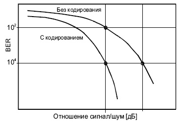
Рис.
4.8.
Турбо-кодек должен иметь столько же компонентных декодеров, сколько имеется кодировщиков на стороне передатчика. Декодеры соединяются последовательно.
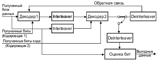
Рис.
4.9.
Турбо-декодер
Техника FEC находит все большее применение в телекоммуникациях, например, при передачи мультимедиа [2].
Следует помнить, что, как в случае FEC , так и в других известных методах коррекции ошибок ( BCH , Golay, Hamming и др.) скорректированный код является верным лишь с определенной конечной вероятностью.
Введение
Одной из ключевых задач, решаемых разработчиками любых систем связи (и в первую очередь систем радиосвязи) является задача обнаружения и исправления ошибок, количество которых в сотовых сетях определяется двумя факторами – внешними помехами, а также интерференцией, возникающей от передатчиков соседних базовых станций. Последний фактор является особенно важным для одночастотных систем мобильной связи, включая 4G—LTE и 5G.
Рассмотрим основные технологии и понятия, связанные с решением обозначенной задачи на сетях 4G-LTE и 5G:
Схема с прямой коррекцией ошибок – FEC (Forward Error Correction)
Суть схемы FEC заключается в преобразовании передатчиком передаваемых блоков данных в кодовые слова (путем канального кодирования и внесения избыточной информации) таким образом, чтобы предоставить приемнику возможность обнаруживать и восстанавливать определенное количество битов, искаженных при передаче – см. Рис. 1. Подобные системы характеризуются скоростью кодирования, представляющей собой отношение длины полезного блока данных к длине кодового слова. Недостатком является потеря функциональности при превышении кол-ва ошибок исправляющей способности кода.

Рис. 1 (FEC + Rate matching)
Выравнивание скорости – Rate matching
Выравнивание скорости представляет собой функциональный модуль, дополняющий технологию прямой коррекции ошибок. Данный модуль удаляет (или «выкалывает») часть битов из кодовых слов, формируемых схемой FEC, уменьшая их длину до требуемого размера транспортного блока. Тем самым, с одной стороны снижается объем данных, который передается по каналу связи, с другой – сохраняется достаточная исправляющая способность системы. На приемной стороне в выколотые передатчиком позиции вставляются фиктивные биты, после чего кодовые слова восстановленной длины направляются на канальный декодер.
Схема с автоматическим запросом повторной передачи – ARQ (Automatic Repeat request)
Суть схемы ARQ заключается в вычислении передатчиком циклического избыточного кода (CRC – Cyclic Redundancy Check) передаваемого блока данных, что позволяет приемнику путем сравнения вычисленного и принятого значений CRC обнаруживать пакеты, содержащие искаженные данные и запрашивать их повторную передачу – см. Рис. 2.
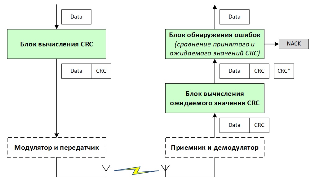
Рис. 2 (ARQ)
Обычно схема ARQ использует метод, называемый выборочной ретрансляцией (Рис. 3), в котором приемник ожидает получение нескольких блоков данных до их подтверждения. Этот метод с одной стороны позволяет передатчику продолжать отправлять пакеты, не дожидаясь их подтверждения, а с другой стороны вносит существенную задержку в случае необходимости повторной передачи. Следовательно, схема ARQ подходит только для потоков данных нереального времени, таких как веб-страницы и электронные письма. Кроме уже упомянутой задержки, недостатком схемы ARQ является дополнительная нагрузка на канал связи, поскольку даже единичная ошибка требует повторной передачи всего пакета данных.

Рис. 3 (метод выборочной ретрансляции ARQ)
Гибридная схема с автоматическим запросом повторной передачи – HARQ (Hybrid ARQ)
Hybrid ARQ комбинирует вышеописанные схемы, применяемые для коррекции ошибок (FEC, ARQ – см. Рис. 4). В соответствии с этим, передающая сторона:
- осуществляет кодирование передаваемых данных FEC кодом (с применением функции выравнивания скорости), что позволяет приемнику восстанавливать искаженные при передаче биты (в пределах исправляющей способности кода);
- вычисляет код CRC и добавляет его к передаваемым данным, давая возможность приемнику детектировать блоки, содержащие неисправленные посредством FEC ошибки, и запрашивать их повторную передачу.

Рис. 4 (HARQ)
Схемы HARQ могут быть синхронными и асинхронными. В синхронном режиме повторная передача блоков данных осуществляется в строго определенные интервалы времени. При этом не требуется передача номера HARQ процесса (см. п.3) и номера Redundancy version (RV – см. п.2), что снижает долю сигнального трафика. Так, каждый субфрейм (sub frame) планировщик базовой станции выделяет ресурс для передачи только одному предопределенному HARQ процессу с предопределенным RV, и в системе, содержащей 8 процессов, каждый процесс осуществляет передачу строго раз в 8мс.
В асинхронном режиме передача данных HARQ процессами может осуществляться в любое время, что дает возможность планировщику базовой станции более гибко распределять ресурсы сети. Плата за эту гибкость – увеличение накладных расходов на передачу сигнальной информации (номер HARQ процесса, а также номер RV включаются в блок управляющей информации – DCI, передаваемый по каналу PDCCH).
На восходящих линиях (Uplink) сетей 4G—LTE и 5G используется синхронный режим HARQ, на нисходящей (Downlink) – асинхронный.
Также алгоритмы HARQ могут функционировать в адаптивном и неадаптивном режимах. В адаптивном режиме при повторной передаче пакетов допускается изменение таких параметров как скорость кодирования, номера и кол-во выделенных ресурсных блоков, схема модуляции. По аналогии с асинхронной передачей адаптивный режим повышает гибкость распределения ресурсов сети, предоставляет механизмы для увеличения надежности приема данных (например, за счет понижения индекса модуляции), но при этом увеличивает долю сигнального трафика на канале PDCCH.
Неадаптивный режим не предполагает изменения параметров при повторной передаче пакетов.