 Loading…

|
õUNGHEINRICH |
System Messages |
08.06 |
1 |
G |
|||||||
|
Error |
Description |
Component |
Display text |
Cause / Action |
Effect |
||||||
|
1 |
Low voltage during |
F, H, L, |
Low voltage |
Check battery voltage, chargebattery; |
Travel is inhibited. |
||||||
|
system start |
F-AC, H-AC |
Checkwireconnectiontocontroller; |
|||||||||
|
ELECTRICAL SYSTEM |
check main current fuse; check main |
Reduced power for |
|||||||||
|
contactor; replace control part; |
travel and lifting. |
||||||||||
|
Replacecomponent; |
Warning symbol |
||||||||||
|
(Limit VN = 80V: VBatt < 64V or |
flashing (Else-Check). |
||||||||||
|
VCap. < 56V |
|||||||||||
|
Limit VN = 48V: VBatt < 34V or |
|||||||||||
|
VCap. < 34V |
|||||||||||
|
Limit VN = 24V: VBatt <17V) |
|||||||||||
|
2 |
Overvoltage |
F, H, L, |
Overvoltage |
Check battery voltage; replace |
No travel or hydraulic functions |
||||||
|
F-AC, H-AC |
BATTERY |
controllerpart; replace component; |
Warning symbol |
||||||||
|
CONTROLLER |
(Limit VN = 80V: VBatt > 92 V |
flashing (Else-Check). |
|||||||||
|
Limit VN = 48V: VBatt > 62 V |
|||||||||||
|
Limit VN = 24V: VBatt > 28 V) |
|||||||||||
|
3 |
Temperature limit for |
F, H, L, |
TEMPERATURE |
Check sensor and wire connections |
Reduced power for |
||||||
|
controllers |
F-AC, H-AC |
CONTROLLER |
Allow controllers to cool down; check |
travel and lifting. |
|||||||
|
> 80°C (>70°C MP1510C) |
fan operation, improve cooling. |
Warning symbol |
|||||||||
|
or |
Warm up the controller and operate at |
flashing (Else-Check). |
|||||||||
|
ACS only: |
reduced level until the controller has |
||||||||||
|
Info at > 85°C |
warmed up. |
||||||||||
|
Err at > 115°C |
|||||||||||
|
Err at < -20°C |
|||||||||||
|
4 |
Emergency Disconnect |
F |
POWER SUPPLY |
Warning |
Brake applies, travel inhibited |
||||||
|
applied during travel |
(V < 20V MP1510C) |
|
õUNGHEINRICH |
System Messages |
08.06 |
2 |
G |
|||||||
|
Error |
Description |
Component |
Display text |
Cause / Action |
Effect |
||||||
|
5 |
Overvoltage |
F, F-AC, H-AC |
ELECTRICAL SYSTEM |
Check wire connection to battery, |
Brake applies, travel inhibited |
||||||
|
checkBattery, replacecontroller part; |
|||||||||||
|
Replace component; |
|||||||||||
|
(Limit for Retrak: VBatt > 62 V |
|||||||||||
|
Limit for MP1510C: V > 32 V) |
|||||||||||
|
6 |
Wire breakage: |
C, I2, I3, I4, I5, |
TRAVEL SWITCH |
Check wire connection; |
Travel stop. “Warning” symbol flashes |
||||||
|
— Travel setpoint device |
Travel switch |
Replace travel setpoint device; |
(Else-Check). Hydraulic functions |
||||||||
|
Replace Canion/ Interface; |
possible |
||||||||||
|
7 |
Key switch applied |
F,F-AC,H-AC |
KEY SWITCH |
Warning |
Brake applies, travel inhibited |
||||||
|
duringtravel |
(V < 13V for 200ms MP1510C) |
||||||||||
|
8 |
2 travel directions applied |
F-AC, H-AC, C, |
ELECTRICAL SYSTEM |
Warning, replace travel direction |
Travel stop. “Warning” symbol |
||||||
|
simultaneously |
MP, S, I2, I3, I5, |
switch, replace Interface 7 Canion; |
flashing (Else-Check). |
||||||||
|
FS |
replace Multipilot / Solopilot |
Hydraulic functions possible |
|||||||||
|
For twin pedal, check the electrical |
|||||||||||
|
system. |
|||||||||||
|
9 |
Operator protection switch |
I2, FS |
ELECTRICAL SYSTEM |
Check switch, check wire connections |
|||||||
|
faulty |
|||||||||||
|
10 |
V Cap. <> V Batt; (main |
F, H, |
MAIN CONTACTOR |
Check main contactor, check wire |
No travel, hydraulics |
||||||
|
contactor jammed or not |
F-AC, H-AC |
connection; check output pin 2 (ACS) of |
Warning symbol |
||||||||
|
open) |
L |
traction controller; replace component |
Flashing warning (Else-Check). |
||||||||
|
11 |
Offset error armature / |
F, H, L, |
CONTROLLER |
Check main current wire, replace |
Travel no function |
||||||
|
field current (DC) |
F-AC, H-AC |
component |
|||||||||
|
Stator current (AC); |
|||||||||||
|
Current measurement |
|||||||||||
|
point |
|||||||||||
|
12 |
Disable driver field |
F, H |
CONTROLLER |
Replace component; |
No travel, hydraulics |
||||||
|
rheostat faulty for DC |
F-AC, H-AC |
for AC: Check flat belt wire connection; |
Warning symbol |
||||||||
|
Disable driver power |
L |
replace power part |
Flashing warning (Else-Check). |
||||||||
|
stage faulty (forAC) |
|||||||||||

|
õUNGHEINRICH |
System Messages |
08.06 |
3 |
G |
|||||||
|
Error |
Description |
Component |
Display text |
Cause / Action |
Effect |
||||||
|
13 |
Disable Watchdog field |
F, H |
CONTROLLER |
Replace components |
Travel no function |
||||||
|
faulty |
|||||||||||
|
14 |
— Main contactor notclosed |
F, H, |
CONTROLLER/ |
Check wire connection; check main |
No travel, hydraulics |
||||||
|
— Field power stage cannot |
F-AC, H-AC |
MAIN CONTACTOR |
contactor; check charging connection, |
Warning symbol |
|||||||
|
be switched on (DC) |
Check field supply fuse, |
Flashing warning (Else-Check). |
|||||||||
|
Replace component. |
|||||||||||
|
15 |
Disable field faulty; |
F, H, |
CONTROLLER |
Replace controlpart; replace |
Travel no function |
||||||
|
Illegal address (for AC) |
F-AC, H-AC |
component |
|||||||||
|
L |
|||||||||||
|
16 |
Disable driver armature |
F, H, |
CONTROLLER |
Replace controlpart (AC); replace |
Travel no function |
||||||
|
actuator faulty; |
F-AC, H-AC |
component |
|||||||||
|
Software reset (for AC) |
|||||||||||
|
17 |
Disable Watchdog |
F, H |
CONTROLLER |
Replace components |
Travel no function |
||||||
|
armature faulty |
|||||||||||
|
18 |
DC: Armature power |
F, H, F-AC, H-AC |
CONTROLLER |
Check armature wire connection; |
Travel no function |
||||||
|
stage cannot be switched |
L |
replace power part; replace component |
|||||||||
|
on |
|||||||||||
|
AC: one of the 3 phases |
|||||||||||
|
cannot be switched on |
|
õUNGHEINRICH |
System Messages |
08.06 |
4 |
G |
||||||
|
Error |
Description |
Component |
Display text |
Cause / Action |
Effect |
|||||
|
19 |
Disable armature faulty; |
F, H, F-AC ,H- |
CONTROLLER |
Replace power part; Replace |
Travel no function |
|||||
|
Power stage short circuit |
AC, |
component. |
||||||||
|
(for AC) |
L-AC |
Can occur in connection with error 70, |
||||||||
|
The error may be |
in this case: |
|||||||||
|
triggered by the faulty |
check power supply behind the main |
|||||||||
|
speed sensor in |
contactor contact, in the event of an |
|||||||||
|
connection with |
error the voltage will be much lower |
|||||||||
|
AS4814Plus controllers. |
here than the rated operating voltage. |
|||||||||
|
Sensor wheel wobbles |
Disconnect the positive supply from the |
|||||||||
|
(elliptical) or the sensor- |
components to target the error cause. |
|||||||||
|
sensor wheel gap is too |
The exception here is the F1 traction |
|||||||||
|
big. In this case the |
controller which must remain |
|||||||||
|
component is not faulty. |
connected. One component overloads |
|||||||||
|
A short circuit cannot be |
the testing voltage due to internal short |
|||||||||
|
resolved by switching the |
circuit. |
|||||||||
|
truck off/on. |
The testing voltage arises by charging |
|||||||||
|
the internal capacitor batteries via a |
||||||||||
|
resistor to the level of the control |
||||||||||
|
voltage supply. |
||||||||||
|
Check sensor, replace sensor and / or |
||||||||||
|
sensor wheel. |
||||||||||
|
20 |
Armature incorrectly |
F, H |
ELECTRICAL SYSTEM |
Check armature main current wire |
Travel no function |
|||||
|
connected |
connection |
|||||||||
|
21 |
Armature overvoltage |
F, H, F-AC, H-AC |
CONTROLLER/ |
Check main current wire to armature; |
||||||
|
(short circuit / high side |
L |
ELECTR |
check settings(for AC); |
|||||||
|
faulty) |
AArmature > 360A for 250ms (MP1510); |
|||||||||
|
Replace component. |
||||||||||

|
õUNGHEINRICH |
System Messages |
08.06 |
5 |
G |
|||||||
|
Error |
Description |
Component |
Display text |
Cause / Action |
Effect |
||||||
|
22 |
Watchdog error; |
F, H, L, M, S, A, |
CONTROLLER/ |
Truck reset, |
No travel, hydraulics |
||||||
|
Watchdog does not run |
I2, I3, I4, C, |
CANION |
Replace controlpart; replace |
Warning symbol |
|||||||
|
out |
F-AC, H-AC, FS |
component |
Flashing warning (Else-Check). |
||||||||
|
23 |
— Computer overload |
F, H, L, M, S, A, |
CONTROLLER / CAN |
Check CAN bus connection; |
No travel, hydraulics |
||||||
|
— Permanent interrupt |
I2, I3, I4, C, |
Check CANION connector and |
Warning symbol |
||||||||
|
— “ACS” timeout on |
F-AC, H-AC, FS |
component; |
Flashing warning (Else-Check). |
||||||||
|
CAN connection |
Replace component |
||||||||||
|
24 |
EEPROM cannot be |
F, H, L, I2, I3, I4, |
CONTROLLER/ |
Check battery cable; check VBatt; set |
Flashing warning symbol (Else- |
||||||
|
contacted / parameters |
C, |
CANION |
trucktype, set default parameters; |
Check). |
|||||||
|
not plausible / parameter |
F-AC, H-AC |
replace control part; replace |
|||||||||
|
set to default |
MFC brake |
component |
|||||||||
|
Faulty checksum |
MFC hydr. , travel |
Delete logbook, change parameters, |
|||||||||
|
switch |
set hourmeter, replace component |
||||||||||
|
25 |
No telegrams: |
F, H, I4, I8 |
INTERFACE / CAN |
Check CANBus connection, check wire |
|||||||
|
— no logon from |
F-AC, H-AC |
connection between proportional valve |
|||||||||
|
interface |
L |
– modulation; check fuse 1F8; replace |
|||||||||
|
iInterface (I2, I4, I8) ; replace lift |
|||||||||||
|
potentiometer, Multipilot, Solopilot or |
|||||||||||
|
interface; |
|||||||||||
|
MP1510C: Voltage collapses, controller |
|||||||||||
|
logs on again, interface does not, |
|||||||||||
|
controller remains blocked and waits for |
|||||||||||
|
interface. |
|||||||||||
|
Check battery voltage (with load!); |
|||||||||||
|
charge or replace battery if necessary; |
|||||||||||
|
— no telegrams from |
AS2409K: no “live” telegram received |
||||||||||
|
from CAN Bus travel switch for more |
|||||||||||
|
Can-Bus travel switch |
than 300 ms; replace travel switch |
|
õUNGHEINRICH |
System Messages |
08.06 |
6 |
G |
|||||||
|
Error |
Description |
Component |
Display text |
Cause / Action |
Effect |
||||||
|
26 |
Wire breakage: |
M, S, I2, I3 |
MULTIPILOT / |
Check wire connection |
Lift stop. “Warning” symbol flashes |
||||||
|
— Lift potentiometer |
SOLOPILOT / LIFT |
(Else-Check), travel enabled |
|||||||||
|
POTENTIOMETER |
|||||||||||
|
27 |
Wire breakage: |
C, L, I3, I4 |
STEER ACTUAL |
Check wire connection; |
Crawl speed, |
||||||
|
— Steering setpoint device; |
ANGLE |
Replace steer angle sensor / |
Flashing warning symbol (Else- |
||||||||
|
◊ Reach truck: for 45° |
potentiometer; |
Check), hydraulic functions enabled. |
|||||||||
|
steering bolster movement |
Replace Canion / Interface; |
This error produces an emergency |
|||||||||
|
no flank from proximity |
Replace steering; |
stop on the reach truck and the |
|||||||||
|
switch. |
PM2402L from software version 1.60: |
Juniors. |
|||||||||
|
◊ Canion: “Steer angle |
|||||||||||
|
acquire active” parameter |
set parameter P511 “operating mode” |
||||||||||
|
has incorrect value |
correctly ◊ 1 = analog sensor |
||||||||||
|
◊ Juniors PM2402L: |
(potentiometer), |
||||||||||
|
“Operating mode” |
2 = digital sensor on steer motor |
||||||||||
|
parameter incorrectly set |
|||||||||||
|
28 |
Wire breakage: |
C, L, I3, I4 |
STEER NOMINAL |
Check wire connection, replace |
Crawl speed, |
||||||
|
— Steering sensor |
ANGLE |
steering wheel sensor;replace Canion / |
Flashing warning symbol (Else- |
||||||||
|
interface; replace steering |
Check), hydraulic functions enabled. |
||||||||||
|
This error produces an emergency |
|||||||||||
|
stop on the reach |
truck |
||||||||||
|
29 |
Wire breakage: |
M |
Traverse nominal value |
Replace Multipilot |
|||||||
|
— Traverse potentiometer |
MULTIPILOT |
||||||||||
|
30 |
Wire breakage: |
M |
Tilt nominal value |
Replace Multipilot, |
|||||||
|
— Tilt potentiometer |
MULTIPILOT |
Teach Multipilot (Hall sensor 2003 only) |
|||||||||
|
31 |
Wire breakage: |
M, S |
Sideshift nominal value |
Replace Multipilot / Solopilot, |
Hydraulic functions stop, “Warning” |
||||||
|
— ZH1 setpoint device |
MULTIPILOT / |
Teach Multipilot (Hall sensor 2003 |
symbol flashes (Else-Check), travel |
||||||||
|
SOLOPILOT |
only); |
enabled |
|||||||||
|
— Initial lift / lower |
Travel switch |
Travel switch: Check / replace switch |
|||||||||
|
Setpoint device |
|||||||||||

|
õUNGHEINRICH |
System Messages |
08.06 |
7 |
G |
|||||||
|
Error |
Description |
Component |
Display text |
Cause / Action |
Effect |
||||||
|
32 |
Wire breakage: |
M, S |
MULTIPILOT / |
Replace Multipilot / Solopilot, |
Hydraulic functions stop, “Warning” |
||||||
|
— ZH2 setpoint device |
SOLOPILOT |
Teach Multipilot (Hall sensor 2003 only) |
symbol flashes (Else-Check), travel |
||||||||
|
enabled |
|||||||||||
|
33 |
Wire breakage: |
M, I8 |
MULTIPILOT |
Replace Multipilot |
|||||||
|
— ZH3 setpoint device |
|||||||||||
|
34 |
CANBus damaged |
F, H, L, M, S, A, |
CAN-BUS |
Check CAN bus connection; |
No travel, hydraulics |
||||||
|
I2, I3, I4, I5, C, F- |
replace faulty component; |
Warning symbol |
|||||||||
|
AC, H-AC |
Check terminal resistances |
Flashing warning (Else-Check). Only |
|||||||||
|
Travel switch |
stored in logbook (from 2004). |
||||||||||
|
35 |
No travel zero position |
I2, I3, I4, C |
TRAVEL ZERO |
Warning, check travel switch; |
Travel stop, |
||||||
|
Deadman and accelerator |
Travel switch |
POSITION |
Intermittent contact in interface power |
Flashing warning symbol (Else- |
|||||||
|
pedal applied when truck |
supply (12 volts) |
Check), hydraulic functions enabled. |
|||||||||
|
switched on |
Check Canion, for twin pedal check |
||||||||||
|
electrical system |
|||||||||||
|
36 |
No lift zero position |
M, I2, I3,FS |
LIFT ZERO POSITION |
Warning, check lift setpoint device. |
Hydraulic functions stop, “Warning” |
||||||
|
symbol flashes (Else-Check), travel |
|||||||||||
|
enabled |
|||||||||||
|
37 |
No steering angle nominal |
L |
CONTROLLER / CAN |
Check steering setpoint device;Check |
|||||||
|
value |
CANBus connection; check “steer type” |
||||||||||
|
parameter; Replace component (I5) |
|||||||||||
|
38 |
Component does not log |
F, H, L, I2, I3, I4, |
CONTROLLER / CAN |
Check CAN-Bus connection and |
No travel, lifting |
||||||
|
on, self test not |
C, A, M, S, F-AC, |
voltage; check DIL switch 7 encoding |
Warning symbol |
||||||||
|
concluded. |
H-AC |
(MP1510); steering controller |
Flashing warning (Else-Check). |
||||||||
|
monitoring activated? (AS2412F); |
|||||||||||
|
check ACS encoding; replace |
|||||||||||
|
component |

|
õUNGHEINRICH |
System Messages |
08.06 |
8 |
G |
||||||
|
Error |
Description |
Component |
Display text |
Cause / Action |
Effect |
|||||
|
39 |
Implausible truck type |
F, H, L, I2, I3, I4, |
TRUCK TYPE |
For 1. Set truck type; |
||||||
|
1. Discovered during the |
I5, A, M, |
For 2. Examine and if necessary |
||||||||
|
self test phase that at |
F-AC, H-AC |
replace switch (key switch) or rectify |
||||||||
|
least one component |
intermittent contact in power supply |
|||||||||
|
has a different truck |
plug connections. |
|||||||||
|
type as a parameter. |
Set truck type. |
|||||||||
|
A different truck type was |
||||||||||
|
discovered in operating |
||||||||||
|
mode. Caused by |
||||||||||
|
intermittent contacts in the |
||||||||||
|
power supply connections |
||||||||||
|
40 |
Motor overtemperature |
L, F, H |
TEMPERATURE |
Warning; check motor sensor system |
Reduced power for |
|||||
|
Traction motor |
F-AC, H-AC |
MOTOR |
and wire connections; |
travel and lifting. |
||||||
|
overtemperature in |
Check motor; traction motor brake |
Warning symbol |
||||||||
|
operating mode.> 150°C |
open? |
flashing (Else-Check). For steering |
||||||||
|
And travel speed < 1km/h |
only |
|||||||||
|
For ACS: |
warning symbol flashing. |
|||||||||
|
Info > 145°C |
||||||||||
|
Err > 165°C |
||||||||||
|
41 |
Brake magnet |
L |
BRAKE |
Check potentiometer; check |
||||||
|
potentiometer |
MAGNETPOTENTIOM |
potentiometer attachment; check wire |
||||||||
|
Potentiometer voltage less |
ETER |
connection |
||||||||
|
than 0.3 volts or greater |
||||||||||
|
than 2.7 volts for more |
||||||||||
|
than 500ms. |

|
õUNGHEINRICH |
System Messages |
08.06 |
9 |
G |
|||||
|
Error |
Description |
Component |
Display text |
Cause / Action |
Effect |
||||
|
42 |
— Short circuit between |
L,F |
BRAKE MAGNET |
Check wire connection, check brake |
|||||
|
the output and battery |
magnet; replace component |
||||||||
|
positive.(EJC, ELE) |
|||||||||
|
-Brake magnet control, |
|||||||||
|
below minimum difference |
|||||||||
|
on potentiometer for 500 |
|||||||||
|
ms when magnet applied. |
|||||||||
|
(150mV ) |
|||||||||
|
No brake pressure during |
|||||||||
|
initialization. |
|||||||||
|
Brake pressure after the |
|||||||||
|
Emergency Stop magnet |
|||||||||
|
has applied; |
|||||||||
|
43 |
Adjust brake |
L |
ADJUST BRAKE |
Adjust brake; check potentiometer |
|||||
|
44 |
—Brake not connected or |
L,F |
BRAKE FAULTY |
-Check brake wiring, replace brake if |
No release |
||||
|
connection wire short |
necessary |
||||||||
|
circuit |
-Replace brake cable, check |
||||||||
|
potentiometer; Check potentiometer |
|||||||||
|
-Brake cable torn |
attachment; |
||||||||
|
Only for steer category_3: |
Only for steer category_3: |
||||||||
|
Internal driver of failsafe |
|||||||||
|
brake cannot connect the |
-Check brake driver output, check |
||||||||
|
relay |
switch contact plausibility, |
||||||||
|
Or short circuit bypass |
Replace steer component. |
||||||||
|
(contact jams) on the |
|||||||||
|
output during power up |
|||||||||
|
test |
Password: https://www.pdfmanual4trucks.com/
|
Title |
File Size |
Download Links |
|
Jungheinrich EJC112 / E1202 Event Messages Codes List PDF |
619.4kb |
Download |
|
Jungheinrich Error Codes List PDF [PDF] |
199kb |
Download |
|
Jungheinrich Fault Codes [PDF] |
769kb |
Download |
|
Jungheinrich LISTADO ERRORES [PDF] |
199kb |
Download |
|
Jungheinrich System Error Codes list [PDF] |
162.7kb |
Download |
|
Display error code |
Cause |
Action |
|
1901 |
During system start-up, the accelerator pedal zero position could not |
Do not press the accelerator pedal during system start-up. |
|
1904 |
Accelerator pedal pressed, but no travel direction selected. |
Take your foot off the accelerator pedal, select a travel direction and set off. |
|
1909 |
Accelerator pedal pressed and parking brake not released via parking |
Release the parking brake by pressing the parking brake button. |
|
1917 |
Accelerator and brake pedals pressed simultaneously. |
Press one pedal at a time only. |
|
2951 |
Lift function activated on multi-/ solo PILOT during system start- up. |
Do not apply the multi-/ solo PILOT during system start- up.
–
–
– |
|
1952 |
Travel direction switch pressed during system start-up. |
Do not press the travel direction switch during system start-up |
|
9961 |
ISM (option) has detected a shock event in the vertical |
Obtain acknowledgement from authorized person (warehouse manager) and |
|
9962 |
ISM (option) has detected a shock event in the horizontal |
Obtain acknowledgement from authorized person (warehouse manager) and |
|
5990 |
The electrolyte level sensor check (battery-management option) on the |
Add electrolyte. |
|
5992 |
After switching on the truck, no radio network could be established |
–
–
–
– |
|
5408/ 5409 |
Lithium-ion battery overtemperature |
Stop work. |
|
5413 |
Lithium-ion battery low temperature |
Move truck to warm environment. |
For all other warning messages switch the truck off and on again. If the warning message appears again call the service department.
The code lock enables an operator or a group of operators to be assigned an individual user code. The user code is configured with a master code and is outlined in the following sections of this
chapter.
When you have entered the valid user code the truck will be operational. The truck will be able to perform travel, steering and hydraulic operations.
When you have entered the valid master code the truck will be switched on. Travel operations are inhibited. The truck will be able to perform steering and hydraulic operations. The code lock is
in programming mode. When you enter one of the following parameters the settings in the code lock can be changed.
|
Parameters |
Description |
|
0-0-0 |
– To change the master code |
|
0-0-1 |
– To add user codes |
|
0-0-2 |
– To change a user code |
|
0-0-3 |
– To clear a user code |
|
0-0-4 |
– To clear all user codes |
|
0-1-0 |
– To set the automatic cutout of the truck |
Newly supplied trucks have the code indicated on a sticker. When using the truck for the first time change the master and user codes and remove the sticker.
- User code factory setting: 2-5-8-0
- Master code factory setting: 7-2-9-5


Jungheinrich System Error Codes list.pdf
Adobe Acrobat Document
168.2 KB
Jungheinrich Fault Codes.pdf
Adobe Acrobat Document
720.8 KB
Jungheinrich Error Codes List PDF.pdf
Adobe Acrobat Document
191.8 KB
Jungheinrich EJC112 & E1202 Event Messag
Adobe Acrobat Document
582.8 KB
Event Messages
Z This display units shows a four-digit event message for every
event. Trucks that only use one luminous display (e.g. LED) show
the event through a flashing code (see «Display System”).
Each event message is also stored in the master logbook. The
master logbook describes the event in more detail through the sub
index behind the event message (FEXX).
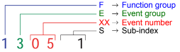
Event numbering display
F E XX S
F Function group; E Event group
XX Event number S Sub index
The first two characters “F, E” refer to the category. The middle
two digits “XX” refer to the event. From these two digits the range:
• 1 to 50 describes standard events (uniform basic events)
which can occur in any function group.
• 51 to 99 describes specific events.
The event is described in further detail through the last characters
“S” (single digit / multi-digit).
This process ensures that a unique number is assigned to each
event. Example:
0 Fault reset or
no fault
1 General fault / additional functions
Example:
Logic error, e.g. both directions selected simultaneously
2 Current
(input interface, device-internal, output interface)
3 Voltage
(input interface, device-internal, output interface)
4 Temperature
5 Hardware
Example: Output transformer short circuit, EEPROM not
responding, …
6 Software
(internal software, application software, data record /
parameters)
Example: EEPROM data error
7 Additional modules
8 CAN monitoring
9 External fault
Example: ISM

Powerful thanks to
maintenance-free 3-phase
AC drive motor
Electronically controlled
lift motor for sensitive
lifting and lowering
Smooth and safe travelling
position on sprung platform
with side arms (optional)
Fatigue-free, safe steering
with electrical tiller steering
and Curve Control
Fast lifting of light loads
with Lift-Plus (optional)
ERC 212/214/216/220
Electric pedestrian stacker (1,200/1,400/1,600/2,000 kg)
The ERC 212/214/216/220 elec-
tric pedestrian stacker combines the
manoeuvrability of a pedestrian stacker
with the option to work comfortably and
quickly as a ride-on truck.
The electronically controlled, powerful
lift motor ensures smooth and quiet
lifting or lowering of the load at the
touch of a button: From smooth deposi-
ting, rapid lifting/lowering or precisely
approaching the racking – the operator
has everything under control at all times.
There is also a powerful 24-volt 3-phase
AC drive motor. Its optimised efficiency
ensures high speeds and outstanding
acceleration coupled with the lowest
energy consumption.
With the ride-on option, the ERC offers
very cost-effective throughput/trans-
port of goods over longer distances. The
sprung stand-on platform relieves the
strain on the operator. LiftPlus (optional)
enables the ERC 214/216 to achieve a
significantly higher lift speed when lifting
the forks with a light load (up to 400
kg) in comparison with the production
version.
Depending on the application, the truck
is available with two additional speed
variants (optional): The 7-km/h version:
This model of the ERC comes with side
arms which keep the operator secure on
the stand-on platform even when cor-
nering. The 9-km/h version: It is ideal for
transport over longer distances.
Batteries with capacities of up to 375
Ah plus the option of lateral battery ex-
change for multishift operation (optional)
ensure that the ERC will not run out of
power even under the most challenging
conditions. A built-in charger (optional)
ensures easy, reliable battery charging at
any standard 240 V socket.