C6610 — «Ошибка датчика снижения давления фьюзера (блока термозакрепления)».
Актуальна для моделей лазерных принтеров Kyocera:
- TASKalfa 6002i
- и других.
Причины возникновения
Фьюзер (блок термозакрепления, термоблок, «печка») в лазерном картридже закрепляет тонер на бумаге с помощью нагрева и давления. Состоит, обычно, из двух роликов: верхний нагревает тонер, а нижний контролирует его прижимание к бумаге (подробнее об устройстве лазерного картриджа).
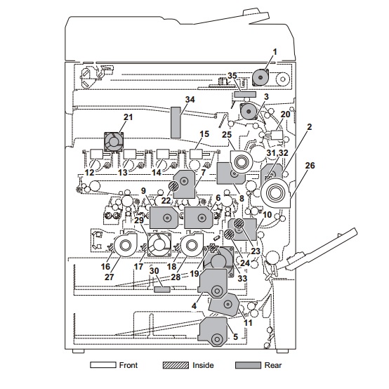
Прижимание, в зависимости от толщины бумаги, обеспечивает давление компрессора (Fuser Pressure Release Motor). За контроль давления отвечает специальный датчик (Pressure Release Sensor). Ошибка C6610 появляется, когда датчик не фиксирует необходимого для печати изменения давления. То есть, может быть как отказ работы компрессора, так и сбой в работе датчика.
Исправление
Ошибка C6610 говорит о поломке одного из элементов блока термозакрепления. Для её исправления необходимо либо менять его весь, либо проводить тщательную диагностику и менять неисправную деталь. В обоих случаях, процедуру лучше доверить сервисному инженеру. Попытки ремонтировать принтер своими руками, без специальных знаний о его устройстве, могут привести к выходу из строя и других элементов.
Выдержка из оригинальной инструкции по решению причинам и способам решения ошибки C6610.
1 Reinstalling the fuser unit (Переустановка блока фьюзера)
The drawer connector of the fuser unit is not properly inserted.
Соединитель ящика блока термозакрепления вставлен неправильно.
Check if the pins of the drawer connector of the fuser unit do not bend. If it bend, replace the fuser unit. When the pins are proper, reinstall the fuser unit so that the drawer connector firmly connects.
Проверьте, не согнуты ли контакты разъема ящика блока термозакрепления. Если он изгибается, замените блок термического закрепления. Когда штифты правильные, переустановите блок термоблока так, чтобы соединитель выдвижного ящика плотно соединялся.
2 Checking the wire (Проверка провода)
The wire is not properly connected or is faulty.
Провод неправильно подключен или неисправен.
Execute U030 [Fuser Release] to check the fuser release motor operation. If it does not operate properly, reinsert the following wire connectors. Then, replace the wires if there is no continuity.
Выполните U030 [Снятие фьюзера], чтобы проверить работу двигателя сблокировки термоблока. Если он не работает должным образом, вставьте следующие разъемы. Затем замените провода, если нет непрерывности.
3 Replacing the fuser unit (Замена блока термозакрепления)
The fuser unit is faulty at the fuser pressure release mechanism or the fuser pressure release sensor .
Блок термозакрепления неисправен в механизме сброса давления термофиксатора или в датчике сброса давления термофиксатора.
Replace the fuser unit.
Замените блок термозакрепления.
4 Firmware upgrade (Обновление прошивки)
The firmware is not the latest version.
Прошивка не последней версии.
Upgrade the engine firmware to the latest version
Обновите прошивку двигателя до последней версии.
5 Replacing the feed drive PWB (Замена подающего устройства PWB)
The feed drive PWB is faulty.
Неисправность PWB привода подачи.
Replace the feed drive PWB.
Неисправность PWB привода подачи.
6 Replacing the engine PWB (Замена двигателя PWB)
The engine PWB is faulty.
Двигатель PWB неисправен.
Replace the engine PWB.
Замените PWB двигателя.
7 Replacing the feed image PWB (Замена канала PWB)
The feed image PWB is faulty.
Ошибка PWB канала подачи.
Replace the feed image PWB.
Замените PWB изображения канала.
8 Replacing the fuser release motor (Замена двигателя для выпуска термоблока)
The fuser release motor is faulty.
Неисправен двигатель выпуска термоблока.
Replace the fuser release motor.
Замените двигатель выключения термоблока.
9 Replacing the gear in the fuser pressure releasing system at the main unit (Замена шестерни в системе выпуска давления фьюзера на основном блоке)
The gear of the fuser pressure releasing mechanism at the main unit is faulty.
Неисправны шестерни механизма выталкивания фьюзера на главном блоке.
Replace the gears in the fuser pressure releasing mechanism at the main unit.
Замените шестерни в механизме отпускания фьюзера на основном блоке.
- Code: 0030
- Description: FAX PWB system error The FAX process can not be continued due to the malfunction of the FAXPWB. *Only 4in1 models detect
- Remedy: FAX PWB 1. Unplug the power cord from the wall outlet, and reinstall the FAX controller PWB, and then plug the power cord and turn power on. 2. Reinstall the FAX firmware. 3. Replace the FAX PWB.
- Code: 0070
- Description: FAX PWB incompatible detection error In the initial communication with the FAX control PWB, any normal communication command is not transmitted. *Only 4in1 models detect
- Remedy: FAX PWB 1. Install the FAX system designed for the model. 2. Reinstall the FAX firmware.
- Code: 0100
- Description: Backup memory device error Outputs an abnormal status from the flash memory.
- Remedy: Flash memory (Main/Engine PWB) 1. Unplug the power cord from the wall outlet, and wait five seconds. Then plug the power cord and then turn on the power switch. 2. Check that the connectors on the Main/ Engine PWB are properly connected, and if not, re-connect them. 3. Replace the Main/Engine PWB.
- Code: 0120
- Description: MAC address data error In case MAC address is invalid data
- Remedy: Flash memory (Main/Engine PWB) 1. Unplug the power cord from the wall outlet, and wait five seconds. Then plug the power cord and then turn on the power switch. 2. Check the MAC address on the network status page. 3. Replace the Main/Engine PWB.
- Code: 0130
- Description: Backup memory read/write error (Main/Engine PWB) Read/write to the NAND memory can not be executed.
- Remedy: Flash memory (Main/Engine PWB) 1. Unplug the power cord from the wall outlet, and wait five seconds. Then plug the power cord and then turn on the power switch. 2. Check that the connectors on the Main/ Engine PWB are properly connected, and if not, re-connect them. 3. Replace the Main/Engine PWB.
- Code: 0140
- Description: Backup memory data error (Main/Engine PWB) At power up, the data that was read from the NAND memory has been determined to be a error.
- Remedy: Flash memory (Main/Engine PWB) 1. Unplug the power cord from the wall outlet, and wait five seconds. Then plug the power cord and then turn on the power switch. 2. Execute U021 initialize memory. 3. Replace the Main/Engine PWB.
- Code: 0150
- Description: EEPROM read/write error (Main/Engine PWB) 1. No response is issued from the device in reading/ writing for 5 ms or more and this problem is repeated 5 times successively. 2. Mismatch of reading data from two locations occurs 8 times successively. 3. Mismatch between writing data and reading data occurs 8 times successively.
- Remedy: EEPROM (Main/ Engine PWB) 1. Unplug the power cord from the wall outlet, and wait five seconds. Then plug the power cord and then turn on the power switch. 2. Check that the EEPROM is peroperly installed on the Main/Engine PWB and if not, reinstall it. 3. Replace the Main/Engine PWB. 4. Check the EEPROM and if it is damaged, contact the service support.
- Code: 0160
- Description: EEPROM data error (Main/ Engine PWB) Reading data from EEPROM is detected abnormal.
- Remedy: EEPROM (Main/ Engine PWB) 1. Unplug the power cord from the wall outlet, and wait five seconds. Then plug the power cord and then turn on the power switch. 2. Execute U021 initialize memory. 3. If the EEPROM data are currupted, contact the service support.
- Code: 0170
- Description: Billing counting error Mismatch between the value of the Main/Engine PWB and EEPROM, in one of the value of billing counter, life counter, or scanner counter.
- Remedy: EEPROM (Main/ Engine PWB) 1. Check that the EEPROM installed in the Main/Engine PWB is correct and, if not, install the correct EEPROM for the model. 2. Replace the Main/Engine PWB. 3. If the EEPROM data are currupted, contact the service support.
- Code: 0180
- Description: Machine number mismatch When the power is turned on, the machine number does not match the one stored in the Main/Engine PWB.
- Remedy: EEPROM (Main/ Engine PWB) 1. Check that the EEPROM installed in the Main/Engine PWB is correct and, if not, install the correct EEPROM for the model. 2. Confirm the serial number data for the Main/Engine PWB by using U004. If the mutually different machine number data between «Machine No. (Main)» and «Machine No. (Eng)» is displayed, or if there is a difference between the actual machine number and the number of «Machine No. (Eng)», install the correct EEPROM, and then execute U004.
- Code: 0190
- Description: Backup memory device error (Main/Engine PWB) At power up, read/write data from FRAM can not be performed. (retry: 3times)
- Remedy: FRAM (Main/ Engine PWB) 1. Unplug the power cord from the wall outlet, and wait five seconds. Then plug the power cord and then turn on the power switch. 2. Check that the connectors on the Main/ Engine PWB are properly connected, and if not, re-connect them. 3. Replace the Main/Engine PWB.
- Code: 0360
- Description: Communication error between the engine ASIC During the readback data checked after data transmission, the checksum error or the video signal is not inverted. (failed 10 consecutive times)
- Remedy: Defective connector cable or poor contact in the connector 1. Reinsert the connector. 2. Check continuity within the connector wire. If none, replace the wire. Engine relay PWB (YC1) and Main/Engine PWB (YC4)
Engine relay PWB Replace the engine relay PWB.
Main/Engine PWB Replace the Main/Engine PWB.
- Code: 0640
- Description: Hard disk (SSD) error During the file access after Ready, the I/O error of SSD is detected. (SSD format error after rebooting. For example, System initialization, Sanitization, Encrypted format when installing security kit.)
- Remedy: SSD (optional HD- 6/7) 1. Unplug the power cord from the wall outlet, and wait five seconds. Then plug the power cord and then turn on the power switch. 2. Unplug the power cord from the wall outlet, and reinstall the HD-6/7 (SSD). 3. Check that the connection between KUIO connector on the Main/Engine PWB and HD-6/7 (SSD) is proper, and if not, re-connect them. 4. Initialize the HD-6/7 (SSD). 5. Replace the Main/Engine PWB.
- Code: 0800
- Description: Image formation problems The printing sequence JAM (J010X) is detected for 2 consecutive times.
- Remedy: Main/Engine PWB 1. Check if the problem is a printing operation error detection in a particular file, and if it is possible to obtain the reproduction of phenomena by the identification of the job that detected the error, take the job log. 2. If the problem occurs in unspecified job, check the connectors on the Main/ Engine PWB, and reattach it. 3. Replace the Main/Engine PWB.
- Code: 0830
- Description: FAX PWB flash program area checksum error The program stored in the flash memory on the FAX control PWB is broken and can not be executed. *Only 4in1 models dete
- Remedy: FAX firmware 1. Reinstall the FAX firmware.
FAX PWB 1. Unplug the power cord from the wall outlet, and reinstall the FAX controller PWB, and then plug the power cord and turn power on. 2. Check that the connection between KUIO connector on the Main/Engine PWB and Fax PWB is proper, and if not, re-connect them. 3. Execute [Initializing] by U600. 4. Replace the FAX PWB.
- Code: 0840
- Description: Faults of RTC Check at power up. The RTC setting has reverted to a previous state. The machine has not been powered for 5 years (compared to the settings stored periodically in the EEPROM). The RTC setting is older than 00:01 on January 1, 2000. Checked periodically (at every 5 minutes) after power-up. The RTC setting has reverted to a state older than the last time it was checked. 10 minutes have been passed since the previous check.
- Remedy: Settings of RTC 1. Execute Date Setting using the system menu.
Backup battery (Main/Engine PWB) 1. Check if the backup battery on the Main/ Engine PWB is not short-circuited. 2. Unplug the power cord from the wall outlet, and wait five seconds. Then plug the power cord and then turn on the power switch. If the same service call error is displayed, replace the backup battery
Main/Engine PWB 1. If the communication error (due to a noise, etc.) is present with the RTC on the Main/Engine PWB, check that the PWB is properly grounded or secured by screws. 2. Replace the Main/Engine PWB.
- Code: 0870
- Description: FAX PWB to Main/Engine PWB image data transfer error High-capacity data transfer between the FAX PWB and the Main/Engine PWB was not normally performed even if the data transfer was retried the specified times. *Only 4in1 models detect
- Remedy: FAX PWB 1. Unplug the power cord from the wall outlet, and reinstall the FAX controller PWB, and then plug the power cord and turn power on. 2. Check that the connection between KUIO connector on the Main/Engine PWB and Fax PWB is proper, and if not, re-connect them. 3. Replace the FAX PWB.
Main/Engine PWB 1. Replace the Main/Engine PWB.
- Code: 0920
- Description: Fax file system error The backup data is not retained for file system abnormality of the flash memory of the FAX PWB. *Only 4in1 models detect
- Remedy: FAX PWB 1. Execute [Initializing] by U600. 2. Reinstall the FAX firmware. 3. Unplug the power cord from the wall outlet, and reinstall the FAX controller PWB, and then plug the power cord and turn power on. 4. Check that the connection between KUIO connector on the Main/Engine PWB and Fax PWB is proper, and if not, re-connect them. 5. Replace the FAX PWB.
- Code: 1010
- Description: Lift motor error (main unit) The following states have been detected 5 times in succession. The lift motor overcurrent is detected for 80 ms. After the cassette is installed, the upper limit detection sensor does not turn ON within 10 s. During printing, after the upper limit detection sensor detects off, and 1 s after ascending control, and the upper limit detection sensor does not detect on. The upper limit detection sensor does not turn off within 5 s after descending control.
- Remedy: Bottom plate 1. Check to see if the bottom plate can move smoothly and repair or replace it if any problem is found.
Defective connector cable or poor contact in the connector 1. Reinsert the connector. 2. If a wire is pinched by other component, or has defect conduction, replace it. Lift motor and Engine relay PWB (YC25) Engine relay PWB (YC1) and Main/Engine PWB (YC4) Llift sensor and Engine relay PWB
Drive transmission system for the lift motor 1. Check if the gears rotate smoothly. If not, clean or grease the bushes and gears. 2. Check broken gears and replace if any.
Lift motor Replace the lift motor.
Lift sensor (upper limit detection sensor) 1. Check if the actuator of the lift sensor can be turned ON/OFF to suit the rise of the cassette bottom plate. 2. Replace the lift sensor
Engine relay PWB 1. Replace the engine relay PWB.
Main/Engine PWB 1. Replace the Main/Engine PWB.
- Code: 1020
- Description: PF lift motor error (PF1) The following states have been detected 5 times in succession. The lift motor overcurrent is detected for 200 ms. After the cassette is installed, the upper limit detection sensor does not turn ON within 10 s. During printing, after the upper limit detection sensor detects off, and 1 s after ascending control, and the upper limit detection sensor does not detect on. The upper limit detection sensor does not turn off within 5 s after descending control.
- Remedy: Bottom plate Check to see if the bottom plate can move smoothly and repair or replace it if any problem is found.
Defective connector cable or poor contact in the connector 1. Reinsert the connector. 2. If a wire is pinched by other component, or has defect conduction, replace it. PF lift motor and PF main PWB (YC7) Llift sensor and PF main PWB (YC7) PF main PWB and Engine relay PWB (YC19)
Drive transmission system for the lift motor 1. Check if the gears rotate smoothly. If not, clean or grease the bushes and gears. 2. Check broken gears and replace if any.
PF lift motor Replace the PF lift motor 1.
PF lift sensor (upper limit detection sensor) 1. Check if the actuator of the PF lift sensor can be turned ON/OFF to suit the rise of the cassette bottom plate. 2. Replace the PF lift sensor.
PF main PWB Replace the PF main PWB.
Engine relay PWB Replace the engine relay PWB.
- Code: 1030
- Description: PF lift motor error (PF2) The following states have been detected 5 times in succession. The lift motor overcurrent is detected for 200 ms. After the cassette is installed, the upper limit detection sensor does not turn ON within 10 s. During printing, after the upper limit detection sensor detects off, and 1 s after ascending control, and the upper limit detection sensor does not detect on. The upper limit detection sensor does not turn off within 5 s after descending control.
- Remedy: Bottom plate Check to see if the bottom plate can move smoothly and repair or replace it if any problem is found.
Defective connector cable or poor contact in the connector 1. Reinsert the connector. 2. If a wire is pinched by other component, or has defect conduction, replace it. PF lift motor and PF main PWB (YC7) Llift sensor and PF main PWB (YC7) PF main PWB and Engine relay PWB (YC19)
Drive transmission system for the lift motor 1. Check if the gears rotate smoothly. If not, clean or grease the bushes and gears. 2. Check broken gears and replace if any.
PF lift motor Replace the PF lift motor 2.
PF lift sensor (upper limit detection sensor) 1. Check if the actuator of the PF lift sensor can be turned ON/OFF to suit the rise of the cassette bottom plate. 2. Replace the PF lift sensor.
PF main PWB Replace the PF main PWB.
Engine relay PWB Replace the engine relay PWB.
- Code: 1040
- Description: PF lift motor error (PF3) The following states have been detected 5 times in succession. The lift motor overcurrent is detected for 200 ms. After the cassette is installed, the upper limit detection sensor does not turn ON within 10 s. During printing, after the upper limit detection sensor detects off, and 1 s after ascending control, and the upper limit detection sensor does not detect on. The upper limit detection sensor does not turn off within 5 s after descending control.
- Remedy: Bottom plate Check to see if the bottom plate can move smoothly and repair or replace it if any problem is found.
Defective connector cable or poor contact in the connector 1. Reinsert the connector. 2. If a wire is pinched by other component, or has defect conduction, replace it. PF lift motor and PF main PWB (YC7) Llift sensor and PF main PWB (YC7) PF main PWB and Engine relay PWB (YC19)
Drive transmission system for the lift motor 1. Check if the gears rotate smoothly. If not, clean or grease the bushes and gears. 2. Check broken gears and replace if any.
PF lift motor Replace the PF lift motor.
PF lift sensor (upper limit detection sensor) 1. Check if the actuator of the PF lift sensor can be turned ON/OFF to suit the rise of the cassette bottom plate. 2. Replace the PF lift sensor.
PF main PWB Replace the PF main PWB.
Engine relay PWB Replace the engine relay PWB.
- Code: 1810
- Description: Paper feeder communication error (first cassette) A communication error from paper feeder is detected 10 times in succession.
- Remedy: Paper feeder 1 Check the wiring connection status with the main unit, and if necessary, reconnecting it.
PF1 main PWB 1. Confirm that the wiring connector is firmly connected, and if necessary, connect the connector all the way in. PF1 main PWB (YC3 and Engine relay PWB (YC19) 2. If the wiring is disconnected, short-circuited or has ground fault, replace the wire. 3. Reinstall the PF firmware. 4. Replace the PF main PWB. (Refer to the service manual for the paper feeder).
Engine relay PWB 1. Replace the engine relay PWB.
Main/Engine PWB 1. Check the engine firmware and upgrade to the latest version if necessary. 2. Replace the Main/Engine PWB.
- Code: 1820
- Description: Paper feeder communication error (second cassette) A communication error from paper feeder is detected 10 times in succession.
- Remedy: Paper feeder 2 Check the wiring connection status with PF1, and if necessary, reconnect it.
PF2 main PWB 1. Confirm that the wiring connector is firmly connected, and if necessary, connect the connector all the way in. PF1 main PWB (YC3)and PF2 main PWB (YC5,4) 2. If the wiring is disconnected, short-circuited or has ground fault, replace the wire. 3. Reinstall the PF firmware. 4. Replace the PF2 main PWB.
PF1 main PWB Replace the PF1 main PWB.
- Code: 1830
- Description: Paper feeder communication error (third cassette) A communication error from paper feeder is detected 10 times in succession.
- Remedy: Paper feeder 3 Check the wiring connection status with PF2, and if necessary, reconnect it.
PF3 main PWB 1. Confirm that the wiring connector is firmly connected, and if necessary, connect the connector all the way in. PF2 main PWB (YC3 and PF3 main PWB (YC5,4) 2. If the wiring is disconnected, short-circuited or has ground fault, replace the wire. 3. Reinstall the PF firmware. 4. Replace the PF3 main PWB.
PF2 main PWB Replace the PF2 main PWB.
- Code: 1900
- Description: Paper feeder 1 EEPROM error (first cassette) When writing the data, read and write data does not match 4 times in succession.
- Remedy: PF1 main PWB (EEPROM) 1. Unplug the power cord from the wall outlet, and wait five seconds. Then plug the power cord and then turn on the power switch. 2. Confirm that the wiring connector to the main unit is firmly connected, and if necessary, connect the connector all the way in. 3. Replace the PF1 main PWB.
- Code: 1910
- Description: Paper feeder 2 EEPROM error (second cassette) When writing the data, read and write data does not match 4 times in succession.
- Remedy: PF2 main PWB (EEPROM) 1. Unplug the power cord from the wall outlet, and wait five seconds. Then plug the power cord and then turn on the power switch. 2. Confirm that the wiring connector with the PF1 is firmly connected, and if necessary, connect the connector all the way in. 3. Replace the PF2 main PWB.
- Code: 1920
- Description: Paper feeder 3 EEPROM error (third cassette) When writing the data, read and write data does not match 4 times in succession.
- Remedy: PF3 main PWB 1. Unplug the power cord from the wall outlet, and wait five seconds. Then plug the power cord and then turn on the power switch. 2. Confirm that the wiring connector with the PF2 is firmly connected, and if necessary, connect the connector all the way in. 3. Replace the PF3 main PWB.
- Code: 2101
- Description: Developer motor steadystate error (C,M,Y) After motor is stabilized, the stable signal is turned OFF for continuous 2 s.
- Remedy: Developer unit 1. Check that the developer roller can be rotated by hand, and if it is locked, replace the developer unit.
Developer motor 1. Check if the couplings and gears rotate smoothly, and if necessary replace them. 2. Reinsert the connector. 3. Check continuity within the connector wire. If none, replace the wire. Developer motor and Engine relay PWB (YC12) Engine relay PWB (YC1) and Main/ Engine PWB (YC4) 4. Replace the developer motor
Engine relay PWB Replace the engine relay PWB.
Main/Engine PWB 1. Check the engine firmware and upgrade to the latest version if necessary. 2. Replace the Main/Engine PWB.
- Code: 2111
- Description: Developer motor startup error (C,M,Y) After the motor starting, the stable signal is not turned ON within 3 s.
- Remedy: Developer unit 1. Check that the developer roller can be rotated by hand, and if it is locked, replace the developer unit.
Developer motor 1. Check if the couplings and gears rotate smoothly, and if necessary replace them. 2. Reinsert the connector. 3. Check continuity within the connector wire. If none, replace the wire. Developer motor and Engine relay PWB (YC12) Engine relay PWB (YC1) and Main/ Engine PWB (YC4) 4. Replace the developer motor
Engine relay PWB Replace the engine relay PWB.
Main/Engine PWB 1. Check the engine firmware and upgrade to the latest version if necessary. 2. Replace the Main/Engine PWB.
- Code: 2201
- Description: Drum motor CY steadystate error After motor is stabilized, the stable signal is turned OFF for continuous 2 s.
- Remedy: Drum unit C or Drum unit Y Check that the drum can be rotated by hand, and if it is locked, replace the drum unit C or drum unit Y.
Defective connector cable or poor contact in the connector 1. Reinsert the connector. 2. Check continuity within the connector wire. If none, replace the wire. Drum motor CY and Engine relay PWB (YC13) Engine relay PWB (YC1) and Main/Engine PWB (YC4)
Drive transmission system for the drum motor CY 1. Check if the couplings and gears rotate smoothly, and if not, clean or grease the gears. 2. Check broken couplings and gears, and replace if any.
Drum motor CY Replace the drum motor CY.
Engine relay PWB Replace the engine relay PWB.
Main/Engine PWB Replace the Main/Engine PWB.
- Code: 2202
- Description: Drum motor KM steadystate error After motor is stabilized, the stable signal is turned OFF for continuous 2 s.
- Remedy: Drum unit K or Drum unit M Check that the drum can be rotated by hand, and if it is locked, replace the drum unit K or drum unit M.
Defective connector cable or poor contact in the connector 1. Reinsert the connector. 2. Check continuity within the connector wire. If none, replace the wire. Drum motor KM and Engine relay PWB (YC13) Engine relay PWB (YC1) and Main/Engine PWB (YC4)
Drive transmission system for the drum motor KM 1. Check if the couplings and gears rotate smoothly, and if not, clean or grease the gears. 2. Check broken couplings and gears, and replace if any.
Drum motor KM Replace the drum motor KM.
Engine relay PWB Replace the engine relay PWB.
Main/Engine PWB Replace the Main/Engine PWB.
- Code: 2211
- Description: Drum motor CY startup error After the motor starting, the stable signal is not turned ON within 3 s.
- Remedy: Drum unit C or Drum unit Y Check that the drum can be rotated by hand, and if it is locked, replace the drum unit C or drum unit Y.
Defective connector cable or poor contact in the connector 1. Reinsert the connector. 2. Check continuity within the connector wire. If none, replace the wire. Drum motor CY and Engine relay PWB (YC13) Engine relay PWB (YC1) and Main/Engine PWB (YC4)
Drive transmission system for the drum motor CY 1. Check if the couplings and gears rotate smoothly, and if not, clean or grease the gears. 2. Check broken couplings and gears, and replace if any.
Drum motor CY Replace the drum motor CY.
Engine relay PWB Replace the engine relay PWB.
Main/Engine PWB Replace the Main/Engine PWB.
- Code: 2212
- Description: Drum motor KM startup error After the motor starting, the stable signal is not turned ON within 3 s.
- Remedy: Drum unit K or Drum unit M Check that the drum can be rotated by hand, and if it is locked, replace the drum unit K or drum unit M.
Defective connector cable or poor contact in the connector 1. Reinsert the connector. 2. Check continuity within the connector wire. If none, replace the wire. Drum motor KM and Engine relay PWB (YC13) Engine relay PWB (YC1) and Main/Engine PWB (YC4)
Drive transmission system for the drum motor KM 1. Check if the couplings and gears rotate smoothly, and if not, clean or grease the gears. 2. Check broken couplings and gears, and replace if any.
Drum motor KM Replace the drum motor KM.
Engine relay PWB Replace the engine relay PWB.
Main/Engine PWB Replace the Main/Engine PWB.
- Code: 2500
- Description: Paper feed motor error After the motor starting, the stable signal is not turned ON within 3 s. After motor is stabilized, the stable signal is turned OFF for continuous 2 s.
- Remedy: Defective connector cable or poor contact in the connector 1. Reinsert the connector. 2. Check continuity within the connector wire. If none, replace the wire. Paper feed motor and Engine relay PWB (YC15) Engine relay PWB (YC1) and Main/Engine PWB (YC4)
Drive transmission system for the paper feed motor 1. Check if the rollers and gears rotate smoothly. If not, clean or grease the bushes and gears. 2. Replace the gears, if damaged.
Paper feed motor Replace the paper feed motor.
Engine relay PWB Replace the engine relay PWB.
Main/Engine PWB Replace the Main/Engine PWB.
- Code: 2600
- Description: PF drive motor 1 error (PF1) During the motor drive, the stable signal is not turned on for continuous 5 s.
- Remedy: Defective connector cable or poor contact in the connector 1. Reinsert the connector. 2. Check continuity within the connector wire. If none, replace the wire. PF drive motor 1 and PF main PWB (YC6)
Drive transmission system for the PF drive motor 1. Check if the rollers and gears rotate smoothly. If not, clean or grease the bushes and gears. 2. Replace the gears, if damaged.
PF drive motor Replace the PF drive motor 1.
PF main PWB Replace the PF main PWB.
- Code: 2610
- Description: PF drive motor 2 error (PF2) During the motor drive, the stable signal is not turned on for continuous 5 s.
- Remedy: Defective connector cable or poor contact in the connector 1. Reinsert the connector. 2. Check continuity within the connector wire. If none, replace the wire. PF drive motor 2 and PF main PWB (YC6)
Drive transmission system for the PF drive motor 1. Check if the rollers and gears rotate smoothly. If not, clean or grease the bushes and gears. 2. Replace the gears, if damaged.
PF drive motor Replace the PF drive motor 2.
PF main PWB Replace the PF main PWB.
- Code: 2620
- Description: PF drive motor 3 error (PF3) During the motor drive, the stable signal is not turned on for continuous 5 s.
- Remedy: Defective connector cable or poor contact in the connector 1. Reinsert the connector. 2. Check continuity within the connector wire. If none, replace the wire. PF drive motor 3 and PF main PWB (YC6)
Drive transmission system for the PF drive motor 1. Check if the rollers and gears rotate smoothly. If not, clean or grease the bushes and gears. 2. Replace the gears, if damaged.
PF drive motor Replace the PF drive motor 3.
PF main PWB Replace the PF main PWB.
- Code: 2760
- Description: Primary transfer belt motor startup error After the motor starting, the stable signal is not turned ON within 3 s.
- Remedy: Primary transfer unit 1. Check that the belt can be rotated by hand, and if it is locked, get rid of the factor. 2. Replace the primary transfer unit.
Defective connector cable or poor contact in the connector 1. Reinsert the connector. 2. Check continuity within the connector wire. If none, replace the wire. Transfer belt motor and Engine relay PWB (YC14) Engine relay PWB (YC1) and Main/Engine PWB (YC4)
Drive transmission system for the primary transfer belt motor 1. Check if the rollers and gears rotate smoothly. If not, clean or grease the bushes and gears. 2. Replace the gears, if damaged.
Primary transfer belt motor Replace the primary transfer belt motor.
Engine relay PWB Replace the engine relay PWB.
Main/Engine PWB Replace the Main/Engine PWB.
- Code: 2820
- Description: Primary transfer belt motor steady-state error After motor is stabilized, the stable signal is turned OFF for continuous 2 s.
- Remedy: Primary transfer unit 1. Check that the belt can be rotated by hand, and if it is locked, check if foreign objects such as jammed paper, and if jammed, get rid of it. 2. Replace the primary transfer unit.
Defective connector cable or poor contact in the connector 1. Reinsert the connector. 2. Check continuity within the connector wire. If none, replace the wire. Transfer belt motor and Engine relay PWB (YC14) Engine relay PWB (YC1) and Main/Engine PWB (YC4)
Drive transmission system for the primary transfer belt motor 1. Check if the rollers and gears rotate smoothly. If not, clean or grease the bushes and gears. 2. Replace the gears, if damaged.
Primary transfer belt motor Replace the primary transfer belt motor.
Engine relay PWB Replace the engine relay PWB.
Main/Engine PWB Replace the Main/Engine PWB.
- Code: 3100
- Description: Scanner carriage error When turning the power on, or when the reading of the original document by table or DP scanning has completed, the home position sensor is not turned off, even if the home position sensor is on and the scanner carriage moves to the scanning direction. Or, the home position sensor does not turn on, even if the home position sensor is in off and the scanner carriage move to the return direction.
- Remedy: Image scanner motor 1. Move the scanner by hand to check whether it smoothly moves, and if necessary, remedy it. 2. Check that the scanner drive belt is not disengaged, and if necessary, remedy it. 3. Confirm that the wiring connector is firmly connected, and if necessary, connect the connector all the way in. Image scanner motor and Main/Engine PWB (YC17) 4. If the wiring is disconnected, short-circuited or has ground fault, replace the wire. 5. Replace the image scanner motor.
Home position sensor 1. Check that the sensor is correctly positioned. 2. Confirm that the wiring connector is firmly connected, and if necessary, connect the connector all the way in. Home position sensor and CCD PWB (YC3) CCD PWB (YC1) and Main/Engine PWB (YC2014) 3. Replace the home position sensor.
CCD PWB Replace the scanner carriage and execute the U411.
Main/Engine PWB Replace the Main/Engine PWB.
- Code: 3200
- Description: LED lamp error The white standard data obtained when the lamp is turned on at the time of an initialization is lower than the rated value.
- Remedy: LED PWB 1. Confirm that the wiring connector is firmly connected, and if necessary, connect the connector all the way in. LED PWB and CCD PWB (YC2) CCD PWB (YC1) and Main/Engine PWB (YC2014)
Mirror Replace the image scanner unit and execute U411, if the mirror is dropped off by drop shock.
CCD PWB Replace the scanner carriage and execute the U411.
Main/Engine PWB Replace the Main/Engine PWB.
- Code: 3500
- Description: Communication error between scanner ASIC (MFP model only) A communication error is detected. (Read back values are different.)
- Remedy: CCD PWB 1. Confirm that the wiring connector is firmly connected, and if necessary, connect the connector all the way in. CCD PWB (YC1) and Main/Engine PWB (YC2014) 2. If the wiring is disconnected, short-circuited or has ground fault, replace the wire. 3. Replace the scanner carriage and execute the U411.
Main/Engine PWB 1. Upgrade the scanner firmware to the latest version. 2. Replace the Main/Engine PWB.
- Code: 4001
- Description: Polygon motor (Black, Magenta) startup error After the polygon motor starting, the motor stable signal is not turned ON after 6 s.
- Remedy: Polygon motor (Black, Magenta) 1. Confirm that the wiring connector is firmly connected, and if necessary, connect the connector all the way in. LSU and Main/Engine PBW (YC2016) 2. If the wiring is disconnected, short-circuited or has ground fault, replace the wire. 3. Replace the LSU.
Main/Engine PWB 1. Check the engine firmware and upgrade to the latest version if necessary. 2. Replace the Main/Engine PWB.
- Code: 4002
- Description: Polygon motor (Cyan, Yellow) startup error After the polygon motor starting, the motor stable signal is not turned ON after 6 s.
- Remedy: Polygon motor (Cyan, Yellow) 1. Confirm that the wiring connector is firmly connected, and if necessary, connect the connector all the way in. LSU and Main/Engine PBW (YC2017) 2. If the wiring is disconnected, short-circuited or has ground fault, replace the wire. 3. Replace the LSU.
Main/Engine PWB 1. Check the engine firmware and upgrade to the latest version if necessary. 2. Replace the Main/Engine PWB.
- Code: 4011
- Description: Polygon motor (Black, Magenta) steady error After the polygon motor stabilization, the motor stable signal is turned OFF for consecutive 6 s.
- Remedy: Polygon motor (Black, Magenta) 1. Confirm that the wiring connector is firmly connected, and if necessary, connect the connector all the way in. LSU and Main/Engine PBW (YC2016) 2. If the wiring is disconnected, short-circuited or has ground fault, replace the wire. 3. Replace the LSU.
Main/Engine PWB 1. Check the engine firmware and upgrade to the latest version if necessary. 2. Replace the Main/Engine PWB.
- Code: 4012
- Description: Polygon motor (Cyan, Yellow) steady error After the polygon motor stabilization, the motor stable signal is turned OFF for consecutive 6 s.
- Remedy: Polygon motor (Cyan, Yellow) 1. Confirm that the wiring connector is firmly connected, and if necessary, connect the connector all the way in. LSU and Main/Engine PBW (YC2017) 2. If the wiring is disconnected, short-circuited or has ground fault, replace the wire. 3. Replace the LSU.
Main/Engine PWB 1. Check the engine firmware and upgrade to the latest version if necessary. 2. Replace the Main/Engine PWB.
- Code: 4101
- Description: Laser BD (Black) error The laser can not be received for 1 s, after the Black laser emission starts.
- Remedy: LSU (Black,Magenta) 1. Confirm that the wiring connector is firmly connected, and if necessary, connect the connector all the way in. LSU and Main/Engine PBW (YC2016) 2. If the wiring is disconnected, short-circuited or has ground fault, replace the wire. 3. Replace the LSU.
Main/Engine PWB 1. Check both main and engine firmware, and upgrade to the latest version, if necessary. 2. Replace the Main/Engine PWB.
- Code: 4102
- Description: Laser BD (Cyan) error The laser can not be received for 1 s, after the Cyan laser emission starts.
- Remedy: LSU (Cyan, Yellow) 1. Confirm that the wiring connector is firmly connected, and if necessary, connect the connector all the way in. LSU and Main/Engine PBW (YC2017) 2. If the wiring is disconnected, short-circuited or has ground fault, replace the wire. 3. Replace the LSU.
Main/Engine PWB 1. Check both main and engine firmware, and upgrade to the latest version, if necessary. 2. Replace the Main/Engine PWB.
- Code: 4103
- Description: Laser BD (Magenta) error The laser can not be received for 1 s, after the Magenta laser emission starts.
- Remedy: LSU (Black,Magenta) 1. Confirm that the wiring connector is firmly connected, and if necessary, connect the connector all the way in. LSU and Main/Engine PBW (YC2016) 2. If the wiring is disconnected, short-circuited or has ground fault, replace the wire. 3. Replace the LSU.
Main/Engine PWB 1. Check both main and engine firmware, and upgrade to the latest version, if necessary. 2. Replace the Main/Engine PWB.
- Code: 4104
- Description: Laser BD (Yellow) error The laser can not be received for 1 s, after the Yellow laser emission starts.
- Remedy: LSU (Cyan, Yellow) 1. Confirm that the wiring connector is firmly connected, and if necessary, connect the connector all the way in. LSU and Main/Engine PBW (YC2017) 2. If the wiring is disconnected, short-circuited or has ground fault, replace the wire. 3. Replace the LSU.
Main/Engine PWB 1. Check both main and engine firmware, and upgrade to the latest version, if necessary. 2. Replace the Main/Engine PWB.
- Code: 4201
- Description: Laser BD (Black) steadystate error During the polygon motor steady rotation, the BD signal of Black is not detected.
- Remedy: LSU (Black,Magenta) 1. Confirm that the wiring connector is firmly connected, and if necessary, connect the connector all the way in. LSU and Main/Engine PBW (YC2016) 2. If the wiring is disconnected, short-circuited or has ground fault, replace the wire. 3. Replace the LSU.
Main/Engine PWB 1. Check both main and engine firmware, and upgrade to the latest version, if necessary. 2. Replace the Main/Engine PWB.
- Code: 4202
- Description: Laser BD (Cyan) steadystate error During the polygon motor steady rotation, the BD signal of Cyan is not detected.
- Remedy: LSU (Cyan,Yellow) 1. Confirm that the wiring connector is firmly connected, and if necessary, connect the connector all the way in. LSU and Main/Engine PBW (YC2017) 2. If the wiring is disconnected, short-circuited or has ground fault, replace the wire. 3. Replace the LSU.
Main/Engine PWB 1. Check both main and engine firmware, and upgrade to the latest version, if necessary. 2. Replace the Main/Engine PWB.
- Code: 4203
- Description: Laser BD (Magenta) steadystate error During the polygon motor steady rotation, the BD signal of Magenta is not detected.
- Remedy: LSU (Black,Magenta) 1. Confirm that the wiring connector is firmly connected, and if necessary, connect the connector all the way in. LSU and Main/Engine PBW (YC2016) 2. If the wiring is disconnected, short-circuited or has ground fault, replace the wire. 3. Replace the LSU.
Main/Engine PWB 1. Check both main and engine firmware, and upgrade to the latest version, if necessary. 2. Replace the Main/Engine PWB.
- Code: 4204
- Description: Laser BD (Yellow) steadystate error During the polygon motor steady rotation, the BD signal of Yellow is not detected.
- Remedy: LSU (Cyan,Yellow) 1. Confirm that the wiring connector is firmly connected, and if necessary, connect the connector all the way in. LSU and Main/Engine PBW (YC2017) 2. If the wiring is disconnected, short-circuited or has ground fault, replace the wire. 3. Replace the LSU.
Main/Engine PWB 1. Check both main and engine firmware, and upgrade to the latest version, if necessary. 2. Replace the Main/Engine PWB.
- Code: 4600
- Description: LSU cleaning motor error During driving the LSU cleaning motor, an over-current is detected for 5 s successively
- Remedy: LSU cleaning spiral 1. Execute [LSU cleaning] using [Adjustment/ Maintenance] of the system menu. 2. Check that the drive gear and cleaning spiral can rotate and they are not unusually loaded, and if necessary, clean and grease.
LSU cleaning motor 1. Confirm that the LSU cleaning motor has been firmly attached. 2. Replace the LSU cleaning motor.
Engine relay PWB 1. Reconnect the connector if its connection is loose. 2. If a wire is pinched by other component, or has defect conduction, replace it. LSU cleaning motor and Engine relay PWB (YC26) 3. Replace the engine relay PWB.
- Code: 4700
- Description: VIDEO_ASIC device error Communication with the video ASIC has failed 5 times successively. After writing to VIDEO ASIC, the error that the reading value from same address does not match occurs 8 times successively.
- Remedy: Main/Engine PWB 1. Unplug the power cord from the wall outlet, and wait five seconds. Then plug the power cord and then turn on the power switch. 2. Check that the connectors on the Main/ Engine PWB are properly connected, and if not, re-connect them. 3. Replace the Main/Engine PWB.
- Code: 6000
- Description: Broken fuser main heater wire During the warming up, the temperature detected by the center thermistor does not reach 100 °C/212.0 °F for 20 s. During the warming up, the temperature detected by the center thermistor does not reach the stable display temperature for 30 s successively, after it reach to 100 °C/212.0 °F.
- Remedy: Fuser unit 1. Check there is no paper jam. 2. Confirm that the wiring connector is firmly connected, and if necessary, connect the connector all the way in. Fuser unit and Eject PWB (YC2) Eject PWB (YC1) and Main/Engine PWB (YC11) 3. If the wiring is disconnected, short-circuited or has ground fault, replace the wire. 4. If the fuser heater is not turned on (broken thermostat wire), replace the fuser unit.
Power source PWB 1. Confirm that the wiring connector is firmly connected, and if necessary, connect the connector all the way in. Power source PWB (YC105) and Main/ Engine PWB (YC20) 2. Replace the power source PWB.
Eject PWB Replace the eject PWB.
Main/Engine PWB 1. Check the engine firmware and upgrade to the latest version if necessary. 2. Replace the Main/Engine PWB.
- Code: 6020
- Description: Abnormally high fuser center thermistor temperature The center thermistor detected the temperature exceeds 240 °C/464.0 °F. for 1 s successively.
- Remedy: Fuser unit 1. Check there is no paper jam. 2. Check if the fuser roller has foreign objects such as the toner contamination. 3. Confirm that the wiring connector is firmly connected, and if necessary, connect the connector all the way in. Fuser unit and Eject PWB (YC2) Eject PWB (YC1) and Main/Engine PWB (YC11) 4. If the wiring is disconnected, short-circuited or has ground fault, replace the wire. 5. Replace the fuser unit.
Power source PWB 1. Confirm that the wiring connector is firmly connected, and if necessary, connect the connector all the way in. Power source PWB (YC105) and Main/ Engine PWB (YC20) 2. If the fuser heater is turned on at all times, replace the power source PWB.
Main/Engine PWB 1. Check the engine firmware and upgrade to the latest version if necessary. 2. Check if the Main/Engine PWB is properly secured with screws. 3. Replace the Main/Engine PWB.
- Code: 6030
- Description: Broken fuser center thermistor wire During the edge thermistor detects more than 30 °C/86.0 °F, the center thermistor detects low temperature for 1.6 s.
- Remedy: Fuser unit 1. Check there is no paper jam. 2. Confirm that the wiring connector is firmly connected, and if necessary, connect the connector all the way in. Fuser unit and Eject PWB (YC2) Eject PWB (YC1) and Main/Engine PWB (YC11) 3. If the wiring is disconnected, short-circuited or has ground fault, replace the wire. 4. Replace the fuser unit.
Eject PWB Replace the eject PWB.
Main/Engine PWB 1. Check the engine firmware and upgrade to the latest version if necessary. 2. Replace the Main/Engine PWB.
- Code: 6040
- Description: Fuser heater error (35 ppm models) Input value from the fuser center thermistor is abnormal for 1 s successively.
- Remedy: Fuser unit 1. Check there is no paper jam. 2. Confirm that the wiring connector is firmly connected, and if necessary, connect the connector all the way in. Fuser unit and Eject PWB (YC2) Eject PWB (YC1) and Main/Engine PWB (YC11) 3. If the wiring is disconnected, short-circuited or has ground fault, replace the wire. 4. Replace the fuser unit.
Eject Main/Engine PWB 1. Check the engine firmware and upgrade to the latest version if necessary. 2. Replace the Main/Engine PWB.PWB Replace the eject PWB.
- Code: 6050
- Description: Abnormally low fuser center thermistor temperature During the warming up and the printing, the center thermistor has detected less than 100 °C/212.0 °F. for 1 s successively.
- Remedy: Reduction of the power supply voltage 1. Check that no voltage drop of more than 10% of the rated is caused during printing. 2. If the power is overloaded, change the AC outlet that supplies power.
Fuser unit 1. Check there is no paper jam. 2. Confirm that the wiring connector is firmly connected, and if necessary, connect the connector all the way in. Fuser unit and Eject PWB (YC2) Eject PWB (YC1) and Main/Engine PWB (YC11) 3. If the wiring is disconnected, short-circuited or has ground fault, replace the wire. 4. If the fuser heater is not turned on (broken thermostat wire), replace the fuser unit.
Power source PWB 1. Confirm that the wiring connector is firmly connected, and if necessary, connect the connector all the way in. Power source PWB (YC105) and Main/ Engine PWB (YC20) 2. Replace the power source PWB.
Eject PWB Replace the eject PWB.
Main/Engine PWB 1. Check the engine firmware and upgrade to the latest version if necessary. 2. Replace the Main/Engine PWB.
- Code: 6200
- Description: Fuser heater error (SUb heater: for 35ppm models) During the warming up, even if the main heater (sub heater for 35ppm models) is turned on for 30 s successively, the temperature detected by the edge thermistor does not reach 100 °C/212.0 °F. During the warming up, the temperature detected by the edge thermistor does not reach the stable display temperature, even if the main heater (sub heater for 35ppm models) is turned on for 30 s successively, after the temperature detected by the edge thermistor has reached to 100 °C/212.0 °F.
- Remedy: Fuser unit 1. Check there is no paper jam. 2. Confirm that the wiring connector is firmly connected, and if necessary, connect the connector all the way in. Fuser unit and Eject PWB (YC2) Eject PWB (YC1) and Main/Engine PWB (YC11) 3. If the wiring is disconnected, short-circuited or has ground fault, replace the wire. 4. If the fuser sub-heater is not turned on (broken thermostat wire), replace the fuser unit.
Power source PWB 1. Confirm that the wiring connector is firmly connected, and if necessary, connect the connector all the way in. Power source PWB (YC105) and Main/ Engine PWB (YC20) 2. Replace the power source PWB.
Eject PWB Replace the eject PWB.
Main/Engine PWB 1. Check the engine firmware and upgrade to the latest version if necessary. 2. Replace the Main/Engine PWB.
- Code: 6220
- Description: Abnormally high fuser heater temperature The temperature detected by the edge thermistor exceeds 240 °C/464.0 °F for 1 s successively.
- Remedy: Fuser unit 1. Check there is no paper jam. 2. Check if the fuser roller has foreign objects such as the toner contamination. 3. Confirm that the wiring connector is firmly connected, and if necessary, connect the connector all the way in. Fuser unit and Eject PWB (YC2) Eject PWB (YC1) and Main/Engine PWB (YC11) 4. If the wiring is disconnected, short-circuited or has ground fault, replace the wire. 5. Replace the fuser unit.
Power source PWB 1. Confirm that the wiring connector is firmly connected, and if necessary, connect the connector all the way in. Power source PWB (YC105) and Main/ Engine PWB (YC20) 2. If the fuser heater is turned on at all times, replace the power source PWB.
Main/Engine PWB 1. Check the engine firmware and upgrade to the latest version if necessary. 2. Check if the Main/Engine PWB is properly secured with screws. 3. Replace the Main/Engine PWB.
- Code: 6230
- Description: Broken fuser edge thermistor wire Fuser edge thermistor detects low temperature for 1.6 s.
- Remedy: Fuser unit 1. Check there is no paper jam. 2. Confirm that the wiring connector is firmly connected, and if necessary, connect the connector all the way in. Fuser unit and Eject PWB (YC2) Eject PWB (YC1) and Main/Engine PWB (YC11) 3. If the wiring is disconnected, short-circuited or has ground fault, replace the wire. 4. Replace the fuser unit.
Eject PWB Replace the eject PWB.
Main/Engine PWB 1. Check the engine firmware and upgrade to the latest version if necessary. 2. Replace the Main/Engine PWB.
- Code: 6250
- Description: Abnormally low fuser edge thermistor temperature During the warming up and the printing, the edge thermistor has detected less than 100 °C/212.0 °F for 1 s successively.
- Remedy: Reduction of the power supply voltage 1. Check that no voltage drop of more than 10% of the rated is caused during printing. 2. If the power is overloaded, change the AC outlet that supplies power.
Fuser unit 1. Check there is no paper jam. 2. Confirm that the wiring connector is firmly connected, and if necessary, connect the connector all the way in. Fuser unit and Eject PWB (YC2) Eject PWB (YC1) and Main/Engine PWB (YC11) 3. If the wiring is disconnected, short-circuited or has ground fault, replace the wire. 4. If the fuser heater is not turned on (broken thermostat wire), replace the fuser unit.
Power source PWB 1. Confirm that the wiring connector is firmly connected, and if necessary, connect the connector all the way in. Power source PWB (YC105) and Main/ Engine PWB (YC20) 2. Replace the power source PWB.
Eject PWB Replace the eject PWB.
Main/Engine PWB 1. Check the engine firmware and upgrade to the latest version if necessary. 2. Replace the Main/Engine PWB.
- Code: 6400
- Description: Zero-cross signal error During the fuser heater on, and no detection the disconnection 24V, the zero-cross signal is not input for 1 s successively.
- Remedy: Power source PWB 1. Confirm that the wiring connector is firmly connected, and if necessary, connect the connector all the way in. Power source PWB (YC105) and Main/ Engine PWB (YC20) 2. Replace the power source PWB.
Main/Engine PWB 1. Check the engine firmware and upgrade to the latest version if necessary. 2. Replace the Main/Engine PWB.
- Code: 6610
- Description: The fuser pressure release error The fuser release sensor does not turn on or off, after 30 s from starting pressurization or depressurization operation.
- Remedy: Fuser unit 1. Check there is no paper jam. 2. Check if the fuser pressure can be reduced by inverse rotation of the fuser gear by hand. 3. Check if the envelope sensor light is blocked out by the actuator during depressurization operation. 4. Confirm that the wiring connector is firmly connected, and if necessary, connect the connector all the way in. Fuser unit (Envelope sensor) and Eject PWB (YC2) Eject PWB (YC1) and Main/Engine PWB (YC11) 5. If the wiring is disconnected, short-circuited or has ground fault, replace the wire. 6. Replace the fuser unit.
Fuser motor 1. Check if the fuser motor is rotating. 2. When turning the power on, check if the fuser motor rotates reversely. 3. Confirm that the wiring connector is firmly connected, and if necessary, connect the connector all the way in. Fuser motor and Engine relay PWB (YC20) 4. If the wiring is disconnected, short-circuited or has ground fault, replace the wire. 5. Replace the fuser motor.
Eject PWB Replace the eject PWB.
Engine relay PWB Replace the engine relay PWB.
Main/Engine PWB 1. Check the engine firmware and upgrade to the latest version if necessary. 2. Replace the Main/Engine PWB.
- Code: 6910
- Description: Engine firmware unexpected error The drum motor drive continued more than 60 minutes except during printing. (engine lock) The charge bias is turned off, during the developer bias is on. If the writing operation to the EEPROM is locked for 30 sec. Fuser temperature is abnormal, for more than a predetermined time.
- Remedy: Main/Engine PWB 1. Unplug the power cord from the wall outlet, and wait five seconds. Then plug the power cord and then turn on the power switch. 2. Check if the Main/Engine PWB is properly secured with screws. (Grounding check) 3. Check that the connectors on the Main/ Engine PWB are properly connected, and if not, re-connect them. 4. Check the engine firmware and upgrade to the latest version if necessary. 5. Replace the Main/Engine PWB.
- Code: 7001
- Description: Toner motor K error During driving the toner motor, an over-current detection signal is detected for 40 ms successively. When detected during warming up The message of «Shake the toner container (K)» is displayed. (exited by the opening and closing of the inner tray) Repeat the operation above, for three times. Four times or more, if an over-current detection signal is detected for 5 s successively, a service call error message appears.
- Remedy: Toner container Black 1. Check that the spiral of the toner container can be rotated by hand 2. Replace the toner container.
Drive transmission system for the toner motor 1. Check if the couplings and gears rotate smoothly, and if not, clean or grease the gears. 2. Check broken couplings and gears, and replace if any.
Defective connector cable or poor contact in the connector 1. Reconnect the connector if its connection is loose. 2. If a wire is pinched by other component, or has defect conduction, replace it. Toner motor and Engine relay PWB (YC18) Engine relay PWB (YC1) and Main/Engine PWB (YC4)
Toner motor 1. Check how the toner motor is attached. 2. Replace the toner motor.
Engine relay PWB Replace the engine relay PWB.
Main/Engine PWB 1. Check the engine firmware and upgrade to the latest version if necessary. 2. Replace the Main/Engine PWB.
- Code: 7002
- Description: Toner motor C error During driving the toner motor, an over-current detection signal is detected for 40 ms successively. When detected during warming up The message of «Shake the toner container (C)» is displayed. (exited by the opening and closing of the inner tray) Repeat the operation above, for three times. Four times or more, if an over-current detection signal is detected for 5 s successively, a service call error message appears.
- Remedy: Toner container Cyan 1. Check that the spiral of the toner container can be rotated by hand 2. Replace the toner container.
Drive transmission system for the toner motor 1. Check if the couplings and gears rotate smoothly, and if not, clean or grease the gears. 2. Check broken couplings and gears, and replace if any.
Defective connector cable or poor contact in the connector 1. Reconnect the connector if its connection is loose. 2. If a wire is pinched by other component, or has defect conduction, replace it. Toner motor and Engine relay PWB (YC18) Engine relay PWB (YC1) and Main/Engine PWB (YC4)
Toner motor 1. Check how the toner motor is attached. 2. Replace the toner motor.
Engine relay PWB Replace the engine relay PWB.
Main/Engine PWB 1. Check the engine firmware and upgrade to the latest version if necessary. 2. Replace the Main/Engine PWB.
- Code: 7003
- Description: Toner motor M error During driving the toner motor, an over-current detection signal is detected for 40 ms successively. When detected during warming up The message of «Shake the toner container (M)» is displayed. (exited by the opening and closing of the inner tray) Repeat the operation above, for three times. Four times or more, if an over-current detection signal is detected for 5 s successively, a service call error message appears.
- Remedy: Toner container Magenta 1. Check that the spiral of the toner container can be rotated by hand 2. Replace the toner container.
Drive transmission system for the toner motor 1. Check if the couplings and gears rotate smoothly, and if not, clean or grease the gears. 2. Check broken couplings and gears, and replace if any.
Defective connector cable or poor contact in the connector 1. Reconnect the connector if its connection is loose. 2. If a wire is pinched by other component, or has defect conduction, replace it. Toner motor and Engine relay PWB (YC18) Engine relay PWB (YC1) and Main/Engine PWB (YC4)
Toner motor 1. Check how the toner motor is attached. 2. Replace the toner motor.
Engine relay PWB Replace the engine relay PWB.
Main/Engine PWB 1. Check the engine firmware and upgrade to the latest version if necessary. 2. Replace the Main/Engine PWB.
- Code: 7004
- Description: Toner motor Y error During driving the toner motor, an over-current detection signal is detected for 40 ms successively. When detected during warming up The message of «Shake the toner container (Y)» is displayed. (exited by the opening and closing of the inner tray) Repeat the operation above, for three times. Four times or more, if an over-current detection signal is detected for 5 s successively, a service call error message appears.
- Remedy: Toner container Yellow 1. Check that the spiral of the toner container can be rotated by hand 2. Replace the toner container.
Drive transmission system for the toner motor 1. Check if the gears rotate smoothly. If not, clean or grease the bushes and gears. 2. Check broken couplings and gears, and replace if any.
Defective connector cable or poor contact in the connector 1. Reconnect the connector if its connection is loose. 2. If a wire is pinched by other component, or has defect conduction, replace it. Toner motor and Engine relay PWB (YC18) Engine relay PWB (YC1) and Main/Engine PWB (YC4)
Toner motor 1. Check how the toner motor is attached. 2. Replace the toner motor.
Engine relay PWB Replace the engine relay PWB.
Main/Engine PWB 1. Check the engine firmware and upgrade to the latest version if necessary. 2. Replace the Main/Engine PWB.
- Code: 7101
- Description: Toner sensor K error For a certain period of time, the sensor output value is less than 0.1V, or more than 3.2V.
- Remedy: Toner container Black 1. Check that the toner container has been properly installed, and if necessary, reinstall. 2. Check that the toner supply inlet of the toner container can be opened by the lever operation. 3. Replace the toner container.
Primary transfer unit 1. Check whether the toner supply inlet at the upper side of the unit opens by attaching the toner container. 2. Check whether the toner supply inlet at the lower side of the unit is open by the lever operation. 3. Check if toner is clogged in the toner supplying pass in the cleaning section. 4. Replace the primary transfer unit.
Developer unit (toner sensor) 1. Confirm that the connector of the developer unit is firmly connected, and if necessary, push the unit all the way in. Developer unit (toner sensor) and Drum relay PWB (YC6) Drum relay PWB (YC1) and Main/Engine PWB (YC15) 2. If the wire is disconnected, short-circuited or has ground fault, or the connector pin is deformed, replace the wire. 3. Check if the gears and spirals in the developer unit rotate smoothly. 4. Replace the developer unit.
Toner motor 1. Check that the toner motor is properly attached. 2. Check the couplings and gears can rotate or they are not unusually loaded, and if necessary, replace. 3. Confirm that the wiring connector is firmly connected, and if necessary, connect the connector all the way in. Toner motor and Engine relay PWB (YC18) Engine relay PWB (YC1) and Main/Engine PWB (YC4) 4. If the wire is disconnected, short-circuited or has ground fault, or the connector pin is deformed, replace the wire. 5. Replace the toner motor.
Drum relay PWB Replace the drum relay PWB.
Engine relay PWB Replace the engine relay PWB.
Main/Engine PWB 1. Check the engine firmware and upgrade to the latest version if necessary. 2. Replace the Main/Engine PWB.
- Code: 7102
- Description: Toner sensor C error For a certain period of time, the sensor output value is less than 0.1V, or more than 3.2V.
- Remedy: Toner container Cyan 1. Check that the toner container has been properly installed, and if necessary, reinstall. 2. Check that the toner supply inlet of the toner container can be opened by the lever operation. 3. Replace the toner container.
Primary transfer unit 1. Check whether the toner supply inlet at the upper side of the unit opens by attaching the toner container. 2. Check whether the toner supply inlet at the lower side of the unit is open by the lever operation. 3. Check if toner is clogged in the toner supplying pass in the cleaning section. 4. Replace the primary transfer unit.
Developer unit (toner sensor) 1. Confirm that the connector of the developer unit is firmly connected, and if necessary, push the unit all the way in. Developer unit (toner sensor) and Drum relay PWB (YC8) Drum relay PWB (YC1) and Main/Engine PWB (YC15) 2. If the wire is disconnected, short-circuited or has ground fault, or the connector pin is deformed, replace the wire. 3. Check if the gears and spirals in the developer unit rotate smoothly. 4. Replace the developer unit.
Toner motor 1. Check that the toner motor is properly attached. 2. Check the couplings and gears can rotate or they are not unusually loaded, and if necessary, replace. 3. Confirm that the wiring connector is firmly connected, and if necessary, connect the connector all the way in. Toner motor and Engine relay PWB (YC18) Engine relay PWB (YC1) and Main/Engine PWB (YC4) 4. If the wire is disconnected, short-circuited or has ground fault, or the connector pin is deformed, replace the wire. 5. Replace the toner motor.
Drum relay PWB Replace the drum relay PWB.
Engine relay PWB Replace the engine relay PWB.
Main/Engine PWB 1. Check the engine firmware and upgrade to the latest version if necessary. 2. Replace the Main/Engine PWB.
- Code: 7103
- Description: Toner sensor M error For a certain period of time, the sensor output value is less than 0.1V, or more than 3.2V.
- Remedy: Toner container Magenta 1. Check that the toner container has been properly installed, and if necessary, reinstall. 2. Check that the toner supply inlet of the toner container can be opened by the lever operation. 3. Replace the toner container.
Primary transfer unit 1. Check whether the toner supply inlet at the upper side of the unit opens by attaching the toner container. 2. Check whether the toner supply inlet at the lower side of the unit is open by the lever operation. 3. Check if toner is clogged in the toner supplying pass in the cleaning section. 4. Replace the primary transfer unit.
Developer unit (toner sensor) 1. Confirm that the connector of the developer unit is firmly connected, and if necessary, push the unit all the way in. Developer unit (toner sensor) and Drum relay PWB (YC7) Drum relay PWB (YC1) and Main/Engine PWB (YC15) 2. If the wire is disconnected, short-circuited or has ground fault, or the connector pin is deformed, replace the wire. 3. Check if the gears and spirals in the developer unit rotate smoothly. 4. Replace the developer unit.
Toner motor 1. Check that the toner motor is properly attached. 2. Check the couplings and gears can rotate or they are not unusually loaded, and if necessary, replace. 3. Confirm that the wiring connector is firmly connected, and if necessary, connect the connector all the way in. Toner motor and Engine relay PWB (YC1) Engine relay PWB (YC1) and Main/Engine PWB (YC4) 4. If the wire is disconnected, short-circuited or has ground fault, or the connector pin is deformed, replace the wire. 5. Replace the toner motor.
Drum relay PWB Replace the drum relay PWB.
Engine relay PWB Replace the engine relay PWB.
Main/Engine PWB 1. Check the engine firmware and upgrade to the latest version if necessary. 2. Replace the Main/Engine PWB.
- Code: 7104
- Description: Toner sensor Y error For a certain period of time, the sensor output value is less than 0.1V, or more than 3.2V.
- Remedy: Toner container Yellow 3. Check that the toner container has been properly installed, and if necessary, reinstall. 4. Check that the toner supply inlet of the toner container can be opened by the lever operation. 5. Replace the toner container.
Primary transfer unit 1. Check whether the toner supply inlet at the upper side of the unit opens by attaching the toner container. 2. Check whether the toner supply inlet at the lower side of the unit is open by the lever operation. 3. Check if toner is clogged in the toner supplying pass in the cleaning section. 4. Replace the primary transfer unit.
Developer unit (toner sensor) 1. Confirm that the connector of the developer unit is firmly connected, and if necessary, push the unit all the way in. Developer unit (toner sensor) and Drum relay PWB (YC9) Drum relay PWB (YC1) and Main/Engine PWB (YC4) 2. If the wire is disconnected, short-circuited or has ground fault, or the connector pin is deformed, replace the wire. 3. Check if the gears and spirals in the developer unit rotate smoothly. 4. Replace the developer unit.
Toner motor 1. Check that the toner motor is properly attached. 2. Check the couplings and gears can rotate or they are not unusually loaded, and if necessary, replace. 3. Confirm that the wiring connector is firmly connected, and if necessary, connect the connector all the way in. Toner motor and Engine relay PWB (YC18) Engine relay PWB (YC1) and Main/Engine PWB (YC4) 4. If the wire is disconnected, short-circuited or has ground fault, or the connector pin is deformed, replace the wire. 5. Replace the toner motor.
Drum relay PWB Replace the drum relay PWB.
Engine relay PWB Replace the engine relay PWB.
Main/Engine PWB 1. Check the engine firmware and upgrade to the latest version if necessary. 2. Replace the Main/Engine PWB.
- Code: 7200
- Description: Broken inner thermistor wire (Developer) The sensor input sampling is greater than the reference value. (After detection, controlled at 25 °C/77.0 °F)
- Remedy: Developer unit K 1. Confirm that the connector of developer unit K is firmly connected, and if necessary, push the unit all the way in. Developer unit K (toner sensor) and Drum relay PWB (YC6) Drum relay PWB (YC1) and Main/Engine PWB (YC4) 2. If the wire is disconnected, short-circuited or has ground fault, or the connector pin is deformed, replace the wire. 3. Replace the developer unit K.
Drum relay PWB Replace the drum relay PWB.
Main/Engine PWB 1. Check the engine firmware and upgrade to the latest version if necessary. 2. Replace the Main/Engine PWB.
- Code: 7201
- Description: Short-circuited inner thermistor (Developer) The sensor input sampling is less than the reference value. (After detection, controlled at 25 °C/77.0 °F)
- Remedy: Developer unit K 1. Confirm that the connector of developer unit K is firmly connected, and if necessary, push the unit all the way in. Developer unit K (toner sensor) and Drum relay PWB (YC6) Drum relay PWB (YC1) and Main/Engine PWB (YC15) 2. If the wire is disconnected, short-circuited or has ground fault, or the connector pin is deformed, replace the wire. 3. Replace the developer unit K.
Drum relay PWB Replace the drum relay PWB.
Main/Engine PWB 1. Check the engine firmware and upgrade to the latest version if necessary. 2. Replace the Main/Engine PWB.
- Code: 7221
- Description: Broken inner thermistor wire (LSU Magenta & Black) The sensor input sampling is greater than the reference value. (After detection, controlled at 25 °C/77.0 °F)
- Remedy: LSU (Magenta & Black) 1. Confirm that the wiring connector of LSU (Magenta & Black) is firmly connected, and if necessary, connect the connector all the way in. LSU (Magenta & Black) and Main/ Engine PWB (YC2016) 2. If the wire is disconnected, short-circuited or has ground fault, or the connector pin is deformed, replace the wire. 3. Replace the LSU (Magenta & Black).
Main/Engine PWB 1. Check the engine firmware and upgrade to the latest version if necessary. 2. Replace the Main/Engine PWB.
- Code: 7222
- Description: Broken inner thermistor wire (LSU Cyan & Yellow) The sensor input sampling is greater than the reference value. (After detection, controlled at 25 °C/77.0 °F)
- Remedy: LSU (Cyan & Yellow) 1. Confirm that the wiring connector of LSU (Cyan & Yellow) is firmly connected, and if necessary, connect the connector all the way in. LSU (Cyan & Yellow) and Main/Engine PWB (YC2017) 2. If the wire is disconnected, short-circuited or has ground fault, or the connector pin is deformed, replace the wire. 3. Replace the LSU (Cyan & Yellow).
Main/Engine PWB 1. Check the engine firmware and upgrade to the latest version if necessary. 2. Replace the Main/Engine PWB.
- Code: 7401
- Description: Developer unit K type mismatch error (Black) Improper adaptation of the main unit and developer unit is detected.
- Remedy: Developer unit K Check if the developer unit of different models is mounted, and replace it to the correct one.
- Code: 7402
- Description: Developer unit C type mismatch error (Cyan) Improper adaptation of the main unit and developer unit is detected.
- Remedy: Developer unit C Check if the developer unit of different models is mounted, and replace it to the correct one.
- Code: 7403
- Description: Developer unit M type mismatch error (Magenta) Improper adaptation of the main unit and developer unit is detected.
- Remedy: Developer unit M Check if the developer unit of different models is mounted, and replace it to the correct one.
- Code: 7404
- Description: Developer unit Y type mismatch error (Yellow) Improper adaptation of the main unit and developer unit is detected.
- Remedy: Developer unit Y Check if the developer unit of different models is mounted, and replace it to the correct one.
- Code: 7411
- Description: Drum unit K type mismatch error (Black) Improper adaptation of the main unit and drum unit is detected.
- Remedy: Drum unit K Check if the drum unit of different models is attached, and replace it to the correct one.
- Code: 7412
- Description: Drum unit C type mismatch error (Cyan) Improper adaptation of the main unit and drum unit is detected.
- Remedy: Drum unit C Check if the drum unit of different models is attached, and replace it to the correct one.
- Code: 7413
- Description: Drum unit M type mismatch error (Magenta) Improper adaptation of the main unit and drum unit is detected.
- Remedy: Drum unit M Check if the drum unit of different models is attached, and replace it to the correct one.
- Code: 7414
- Description: Drum unit Y type mismatch error (Yellow) Improper adaptation of the main unit and drum unit is detected.
- Remedy: Drum unit Y Check if the drum unit of different models is attached, and replace it to the correct one.
- Code: 7601
- Description: ID sensor L error (Left side) When the measured value of the ID sensor matches any of the following. If the light potential P-wave is lower than the dark potential P-wave (+0.5V). If light potential S-wave is lower than the dark potential S-wave. The dark potential P/S-wave is greater than 0.8V, or less than 0.15V.
- Remedy: ID sensor L (Left side) 1. Clean the ID sensor surface. 2. Check how the ID sensor is attached. 3. Check if the error is detected after performing the calibration. 4. Confirm that the wiring connector is firmly connected, and if necessary, connect the connector all the way in. ID sensor and Main/Engine PWB (YC13) 5. If the wiring is disconnected, short-circuited or has ground fault, replace the wire. 6. Replace the ID sensor.
Main/Engine PWB 1. Check the engine firmware and upgrade to the latest version if necessary. Replace the Main/Engine PWB.
- Code: 7602
- Description: ID sensor R error (Right side) When the measured value of the ID sensor matches any of the following. If the light potential P-wave is lower than the dark potential P-wave (+0.5V). If light potential S-wave is lower than the dark potential S-wave. The dark potential P/S-wave is greater than 0.8V, or less than 0.15V.
- Remedy: ID sensor R (Right side) 1. Clean the ID sensor surface. 2. Check how the ID sensor is attached. 3. Check if the error is detected after performing the calibration. 4. Confirm that the wiring connector is firmly connected, and if necessary, connect the connector all the way in. ID sensor and Main/Engine PWB (YC14) 5. If the wiring is disconnected, short-circuited or has ground fault, replace the wire. 6. Replace the ID sensor.
Main/Engine PWB 1. Check the engine firmware and upgrade to the latest version if necessary. 2. Replace the Main/Engine PWB.
- Code: 7611
- Description: ID sensor density error (K) During the calibration, ID sensor cannot read a patch density on the primary transfer belt normally. (Black)
- Remedy: Primary transfer unit ID sensor Drum unit Developer unit LSU Main/Engine PWB 1. After turning OFF the power switch, disconnect the power plug and connect it again, then turning ON the power switch. 2. By adjustment / maintenance of the system menu, execute the color calibration. 3. Check the occurrence of this C call in the Event Log. 4. When the same C call is detected again, Clean if there are any dirt or stains on the primary transfer belt or the ID sensor surface. 5. Check whether the shutter of ID sensor is opened during closing the paper tray. 6. There is no improvement, replace the primary transfer unit. 7. After performing the test print, if the poor density occurs, check whether any failure in the drum unit, developer unit, LSU. 8. There is no improvement, replace the main / engine PWB.
- Code: 7612
- Description: ID sensor density error (C) During the calibration, ID sensor cannot read a patch density on the primary transfer belt normally. (Cyan)
- Remedy: Primary transfer unit ID sensor Drum unit Developer unit LSU Main/Engine PWB 1. After turning OFF the power switch, disconnect the power plug and connect it again, then turning ON the power switch. 2. By adjustment / maintenance of the system menu, execute the color calibration. 3. Check the occurrence of this C call in the Event Log. 4. When the same C call is detected again, Clean if there are any dirt or stains on the primary transfer belt or the ID sensor surface. 5. Check whether the shutter of ID sensor is opened during closing the paper tray. 6. There is no improvement, replace the primary transfer unit. 7. After performing the test print, if the poor density occurs, check whether any failure in the drum unit, developer unit, LSU. 8. There is no improvement, replace the main / engine PWB.
- Code: 7613
- Description: ID sensor density error (M) During the calibration, ID sensor cannot read a patch density on the primary transfer belt normally. (Magenta)
- Remedy: Primary transfer unit ID sensor Drum unit Developer unit LSU Main/Engine PWB 1. After turning OFF the power switch, disconnect the power plug and connect it again, then turning ON the power switch. 2. By adjustment / maintenance of the system menu, execute the color calibration. 3. Check the occurrence of this C call in the Event Log. 4. When the same C call is detected again, Clean if there are any dirt or stains on the primary transfer belt or the ID sensor surface. 5. Check whether the shutter of ID sensor is opened during closing the paper tray. 6. There is no improvement, replace the primary transfer unit. 7. After performing the test print, if the poor density occurs, check whether any failure in the drum unit, developer unit, LSU. 8. There is no improvement, replace the main / engine PWB.
- Code: 7614
- Description: ID sensor density error (Y) During the calibration, ID sensor cannot read a patch density on the primary transfer belt normally. (Yellow)
- Remedy: Primary transfer unit ID sensor Drum unit Developer unit LSU Main/Engine PWB 1. After turning OFF the power switch, disconnect the power plug and connect it again, then turning ON the power switch. 2. By adjustment / maintenance of the system menu, execute the color calibration. 3. Check the occurrence of this C call in the Event Log. 4. When the same C call is detected again, Clean if there are any dirt or stains on the primary transfer belt or the ID sensor surface. 5. Check whether the shutter of ID sensor is opened during closing the paper tray. 6. There is no improvement, replace the primary transfer unit. 7. After performing the test print, if the poor density occurs, check whether any failure in the drum unit, developer unit, LSU. 8. There is no improvement, replace the main / engine PWB.
- Code: 7620
- Description: ID sensor timing error The ID sensor does not properly read the patch printing position on the primary transfer belt or there is poor density. *: Automatic color registration correction does not succeed
- Remedy: Primary transfer unit ID sensor Drum unit Developer unit LSU Main/Engine PWB 1. After turning OFF the power switch, disconnect the power plug and connect it again, then turning ON the power switch. 2. By adjustment / maintenance of the system menu, execute the color calibration. 3. Check the occurrence of this C call in the Event Log. 4. When the same C call is detected again, Clean if there are any dirt or stains on the primary transfer belt or the ID sensor surface. 5. Check whether the shutter of ID sensor is opened during closing the paper tray. 6. There is no improvement, replace the primary transfer unit. 7. After performing the test print, if the poor density occurs, check whether any failure in the drum unit, developer unit, LSU. 8. When checking the printing position of the color, if there is any color shift occurs, re-install the LSU and the drum unit. 9. There is no improvement, replace the main / engine PWB.
- Code: 7800
- Description: Broken outer thermistor wire The sensor input sampling is greater than the reference value. (After detection, controlled at 25 °C/77.0 °F)
- Remedy: Temperature sensor 1. Confirm that the wiring connector is firmly connected, and if necessary, connect the connector all the way in. Outer temperature sensor and Main/Engine PWB (YC24) 2. If the wiring is disconnected, short-circuited or has ground fault, replace the wire. 3. Replace the temperature sensor PWB.
Main/Engine PWB 1. Check the engine firmware and upgrade to the latest version if necessary. 2. Replace the Main/Engine PWB.
- Code: 7901
- Description: Drum unit K EEPROM error No response is issued from the device in reading/writing for 5 ms or more and this problem is repeated 5 times successively. Mismatch of reading data from two locations occurs 8 times successively. Mismatch between writing data and reading data occurs 8 times successively.
- Remedy: Drum unit K 1. Unplug the power cord from the wall outlet, and wait five seconds. Then plug the power cord and then turn on the power switch. 2. Confirm that the connector of the drum unit is firmly connected, and if necessary, push the unit all the way in. 3. Confirm that the wiring connector is firmly connected, and if necessary, connect the connector all the way in. Drum unit and Drum relay PWB (YC2) Drum relay PWB (YC1) and Main/Engine PWB (YC15) 4. If the wire is disconnected, short-circuited or has ground fault, or the connector pin is deformed, replace the wire. 5. Replace the drum unit.
Drum relay PWB Replace the drum relay PWB.
Main/Engine PWB 1. Check the engine firmware and upgrade to the latest version if necessary. 2. Replace the Main/Engine PWB.
- Code: 7902
- Description: Drum unit C EEPROM error No response is issued from the device in reading/writing for 5 ms or more and this problem is repeated 5 times successively. Mismatch of reading data from two locations occurs 8 times successively. Mismatch between writing data and reading data occurs 8 times successively.
- Remedy: Drum unit C 1. Unplug the power cord from the wall outlet, and wait five seconds. Then plug the power cord and then turn on the power switch. 2. Confirm that the connector of the drum unit is firmly connected, and if necessary, push the unit all the way in. 3. Confirm that the wiring connector is firmly connected, and if necessary, connect the connector all the way in. Drum unit and Drum relay PWB (YC4) Drum relay PWB (YC1) and Main/Engine PWB (YC15) 4. If the wire is disconnected, short-circuited or has ground fault, or the connector pin is deformed, replace the wire. 5. Replace the drum unit.
Drum relay PWB Replace the drum relay PWB.
Main/Engine PWB 1. Check the engine firmware and upgrade to the latest version if necessary. 2. Replace the Main/Engine PWB.
- Code: 7903
- Description: Drum unit M EEPROM error No response is issued from the device in reading/writing for 5 ms or more and this problem is repeated 5 times successively. Mismatch of reading data from two locations occurs 8 times successively. Mismatch between writing data and reading data occurs 8 times successively.
- Remedy: Drum unit M 1. Unplug the power cord from the wall outlet, and wait five seconds. Then plug the power cord and then turn on the power switch. 2. Confirm that the connector of the drum unit is firmly connected, and if necessary, push the unit all the way in. 3. Confirm that the wiring connector is firmly connected, and if necessary, connect the connector all the way in. Drum unit and Drum relay PWB (YC3) Drum relay PWB (YC1) and Main/Engine PWB (YC15) 4. If the wire is disconnected, short-circuited or has ground fault, or the connector pin is deformed, replace the wire. 5. Replace the drum unit.
Drum relay PWB Replace the drum relay PWB.
Main/Engine PWB 1. Check the engine firmware and upgrade to the latest version if necessary. 2. Replace the Main/Engine PWB.
- Code: 7904
- Description: Drum unit Y EEPROM error No response is issued from the device in reading/writing for 5 ms or more and this problem is repeated 5 times successively. Mismatch of reading data from two locations occurs 8 times successively. Mismatch between writing data and reading data occurs 8 times successively.
- Remedy: Drum unit Y 1. Unplug the power cord from the wall outlet, and wait five seconds. Then plug the power cord and then turn on the power switch. 2. Confirm that the connector of the drum unit is firmly connected, and if necessary, push the unit all the way in. 3. Confirm that the wiring connector is firmly connected, and if necessary, connect the connector all the way in. Drum unit and Drum relay PWB (YC5) Drum relay PWB (YC1) and Main/Engine PWB (YC15) 4. If the wire is disconnected, short-circuited or has ground fault, or the connector pin is deformed, replace the wire. 5. Replace the drum unit.
Drum relay PWB Replace the drum relay PWB.
Main/Engine PWB 1. Check the engine firmware and upgrade to the latest version if necessary. 2. Replace the Main/Engine PWB.
- Code: 7911
- Description: Developer unit K EEPROM error No response is issued from the device in reading/writing for 5 ms or more and this problem is repeated 5 times successively. Mismatch of reading data from two locations occurs 8 times successively. Mismatch between writing data and reading data occurs 8 times successively.
- Remedy: Developer unit K 1. Unplug the power cord from the wall outlet, and wait five seconds. Then plug the power cord and then turn on the power switch. 2. Confirm that the connector of the developer unit is firmly connected, and if necessary, push the unit all the way in. 3. Confirm that the wiring connector is firmly connected, and if necessary, connect the connector all the way in. Developer unit and Drum relay PWB (YC6) Drum relay PWB (YC1) and Main/Engine PWB (YC15) 4. If the wire is disconnected, short-circuited or has ground fault, or the connector pin is deformed, replace the wire. 5. Replace the developer unit.
Drum relay PWB Replace the drum relay PWB.
Main/Engine PWB 1. Check the engine firmware and upgrade to the latest version if necessary. 2. Replace the Main/Engine PWB.
- Code: 7912
- Description: Developer unit C EEPROM error No response is issued from the device in reading/writing for 5 ms or more and this problem is repeated 5 times successively. Mismatch of reading data from two locations occurs 8 times successively. Mismatch between writing data and reading data occurs 8 times successively.
- Remedy: Developer unit C 1. Unplug the power cord from the wall outlet, and wait five seconds. Then plug the power cord and then turn on the power switch. 2. Confirm that the connector of the developer unit is firmly connected, and if necessary, push the unit all the way in. 3. Confirm that the wiring connector is firmly connected, and if necessary, connect the connector all the way in. Developer unit and Drum relay PWB (YC8) Drum relay PWB (YC1) and Main/Engine PWB (YC15) 4. If the wire is disconnected, short-circuited or has ground fault, or the connector pin is deformed, replace the wire. 5. Replace the developer unit.
Drum relay PWB Replace the drum relay PWB.
Main/Engine PWB 1. Check the engine firmware and upgrade to the latest version if necessary. 2. Replace the Main/Engine PWB.
- Code: 7913
- Description: Developer unit M EEPROM error (1)No response is issued from the device in reading/writing for 5 ms or more and this problem is repeated 5 times successively. (2)Mismatch of reading data from two locations occurs 8 times successively. (3)Mismatch between writing data and reading data occurs 8 times successively.
- Remedy: Developer unit M 1. Unplug the power cord from the wall outlet, and wait five seconds. Then plug the power cord and then turn on the power switch. 2. Confirm that the connector of the developer unit is firmly connected, and if necessary, push the unit all the way in. 3. Confirm that the wiring connector is firmly connected, and if necessary, connect the connector all the way in. Developer unit and Drum relay PWB (YC3) Drum relay PWB (YC1) and Main/Engine PWB (YC15) 4. If the wire is disconnected, short-circuited or has ground fault, or the connector pin is deformed, replace the wire. 5. Replace the developer unit.
Drum relay PWB Replace the drum relay PWB.
Main/Engine PWB 1. Check the engine firmware and upgrade to the latest version if necessary. 2. Replace the Main/Engine PWB.
- Code: 7914
- Description: Developer unit Y EEPROM error No response is issued from the device in reading/writing for 5 ms or more and this problem is repeated 5 times successively. Mismatch of reading data from two locations occurs 8 times successively. Mismatch between writing data and reading data occurs 8 times successively.
- Remedy: Developer unit Y 1. Unplug the power cord from the wall outlet, and wait five seconds. Then plug the power cord and then turn on the power switch. 2. Confirm that the connector of the developer unit is firmly connected, and if necessary, push the unit all the way in. 3. Confirm that the wiring connector is firmly connected, and if necessary, connect the connector all the way in. Developer unit and Drum relay PWB (YC9) Drum relay PWB (YC1) and Main/Engine PWB (YC15) 4. If the wire is disconnected, short-circuited or has ground fault, or the connector pin is deformed, replace the wire. 5. Replace the developer unit.
Drum relay PWB Replace the drum relay PWB.
Main/Engine PWB 1. Check the engine firmware and upgrade to the latest version if necessary. 2. Replace the Main/Engine PWB.
- Code: 9180
- Description: DP switchback motor error When the home position was not detected even if the processing was retried 3 consecutive times. Home position detection: When the home position is not detected by driving one rotation of the DP switchback motor.
- Remedy: DP switchback motor 1. Unplug the power cord from the wall outlet, and wait five seconds. Then plug the power cord and then turn on the power switch. 2. Confirm that the connector of the switchback motor is firmly connected, and if necessary, push the unit all the way in. 3. Confirm that the wiring connector is firmly connected, and if necessary, connect the connector all the way in. DP switchback motor and DP main PWB (YC2) DP main PWB (YC1) and Main/Engine PWB (YC2) 4. If the wire is disconnected, short-circuited or has ground fault, or the connector pin is deformed, replace the wire. 5. Replace the DP switchback motor.
DP switchback sensor 1. Rotate the switchback motor by hand to check that it is not unusually difficult to rotate. 2. Check that the DP switchback sensor is not disengaged and is correctly positioned. And check that the actuator correctly blocks the light. 3. Confirm that the wiring connector is firmly connected, and if necessary, connect the connector all the way in. DP switchback sensor and Main/Engine PWB (YC18) 4. If the wiring is disconnected, short-circuited or has ground fault, replace the wire. 5. DP switchback sensor (DPSBS)
Main/Engine PWB 1. Check the engine firmware and upgrade to the latest version if necessary. 2. Replace the Main/Engine PWB.
- Code: 9540
- Description: Backup data error The machine may not be recovered or may have trouble in its function with changes of the internal data when replacing some the parts at the same time.
- Remedy: PWBs Reattach the parts below in case of replacing 2 or more of them at the same time. Affected parts : Memory, PWBs * Do not replace two or more of the parts at the same time. * And, do not either execute the following works when replacing the above parts. Replace the drum unit or the developing unit. Replace the drum unit for the one color with another in the same machine.
- Code: F000
- Description: Communication error between Main/Engine PWB and Operation panel PWB
- Remedy: Main/Engine PWB 1. Unplug the power cord from the wall outlet, and wait five seconds. Then plug the power cord and then turn on the power switch. 2. Check the wirings and connectors between the Main/Engine PWB and the operation panel PWB. Operation panel PWB and Main/Engine PWB (YC2002). 3. Replace the Main/Engine PWB.
Operation panel PWB Replace the operation panel PWB.
- Code: F010
- Description: Program read error
- Remedy: Main/Engine PWB 1. Unplug the power cord from the wall outlet, and wait five seconds. Then plug the power cord and then turn on the power switch. 2. If not corrected, replace the Main/Engine PWB and check operation.
- Code: F020
- Description: Main/Engine PWB RAM checksum error
- Remedy: Main memory of the Main/Engine PWB (RAM) 1. Unplug the power cord from the wall outlet, and wait five seconds. Then plug the power cord and then turn on the power switch. 2. If not corrected, replace the Main/Engine PWB and check operation.
- Code: F040
- Description: Communication error between Main/Engine PWB and Print engine
- Remedy: Main/Engine PWB 1. Unplug the power cord from the wall outlet, and wait five seconds. Then plug the power cord and then turn on the power switch. 2. Repair or replace the wire from the Main/ Engine PWB that may be grounded. (Check short-circuit between 5V and 3.3V.) 3. Check both main and engine firmware, and upgrade to the latest version, if necessary. 4. If not corrected, replace the Main/Engine PWB.
- Code: F050
- Description: Print engine main program error
- Remedy: Main/Engine PWB 1. Unplug the power cord from the wall outlet, and wait five seconds. Then plug the power cord and then turn on the power switch. 2. Confirm that the EEPROM has been properly installed. 3. Check both main and engine firmware, and upgrade to the latest version, if necessary. 4. If not corrected, replace the Main/Engine PWB.
Модератор: vetal
-
-
Kyocera 1035 «бледная» печать
srMax в форуме Принтеры, МФУ, факсы, копиры формата A4
- 2
- 13540
srMax

Пт янв 23, 2015 2:49 pm
-
Kyocera 1035 «бледная» печать
-
-
[SCANNER ERROR] Lamp Error Kyocera FS-1016
мастерчип в форуме Принтеры, МФУ, факсы, копиры формата A4
- 3
- 6431
Усатый Полосатый
Вс окт 28, 2018 11:08 pm
-
[SCANNER ERROR] Lamp Error Kyocera FS-1016
-
-
Kyocera FS-1120d индикатор «Нет бумаги»
vs-dos в форуме Принтеры, МФУ, факсы, копиры формата A4
- 11
- 14578
СТРОНЦИЙ
Вт ноя 02, 2021 2:24 pm
-
Kyocera FS-1120d индикатор «Нет бумаги»
-
-
Стирание вала ведущей шестерни в «печке» Kyocera M2035dn
Грецкий орех в форуме Принтеры, МФУ, факсы, копиры формата A4
- 12
- 2898
СТРОНЦИЙ
Пн дек 13, 2021 3:35 pm
-
Стирание вала ведущей шестерни в «печке» Kyocera M2035dn
-
-
Kyocera taskalfa 3501 «открыта крышка основного блока»
Юрий Яраскин в форуме Принтеры, МФУ, копиры формата A3
- 3
- 2620
Goldwater
Пт сен 10, 2021 1:31 pm
-
Kyocera taskalfa 3501 «открыта крышка основного блока»
Вернуться в Принтеры, МФУ, факсы, копиры формата A4
Кто сейчас на форуме
Сейчас этот форум просматривают: нет зарегистрированных пользователей и гости: 69
В видеоролике к данной статье мы хотим показать способы проверки двигателя прижима печки печатающих устройств Kyocera серии M2040:
- МФУ M2135DN, M2635DN, M2735DW и принтеры P2235DN, P2235DW — со скоростью 35 ppm,
- МФУ M2040DN, M2540DN, M2640IDW и принтеры P2040DN, P2040DW — 40 ppm
Указанные машины вышли на рынок в конце 2016 года на смену серии M2030/2535, у которой наиболее популярной «болячкой» был разрыв тефлонового (нагревательного) вала блока фиксации FK-171E.

В обновленной линейке компания KYOCERA применила принципиально новую для себя технологию закрепления с терморемнем и галогеновой лампой нагрева.
Это решение позволило снизить энергопотребление и использовать тонер на основе полиэстера — температура его закрепления ниже, чем у предшественников.
Однако, спутником любой новой технологии являются и новые проблемы на начальных этапах эксплуатации. Судя по рекламациям клиентов, блок закрепления FK-1150 подвержен уже двум болезням: сервисной ошибке С6610 и замятию J4211.
С6610 – отказ двигателя прижима блока закрепления. Двигатель используется для изменения прижима резинового вала к терморемню в рабочем (печать) и холостом (ожидание) режимах. Работа двигателя, расположенного вне узла закрепления, отслеживается машиной по оптическому датчику прижима, установленному внутри печки.
Диагностика двигателя без нагрузки и с нагрузкой показана в данном видео:

(Видео также доступно на нашем youtube-канале)
 Если с аппаратом Kyocera TASKalfa 1800, Kyocera TASKalfa 2200 произошла проблема, откроется следующий экран с уведомлением.
• Индикатор [Внимание] на панели управления горит или мигает.
• На дисплее сообщений панели управления аппарата появилось сообщение об ошибке.
Если индикатор [Внимание] горит или мигает и на дисплее сообщений панели управления аппарата появилось сообщение об ошибке, проверьте KYOCERA Client Tool или Монитор состояния.
ПРИМЕЧАНИЕ Если индикаторы постоянно горят и мигают не так, как описано выше, вероятно, произошла ошибка службы. Выключите питание, отсоедините шнур питания и вставьте его обратно, после чего включите питание. Это может помочь сбросить ошибку. Если ошибка не исчезает, свяжитесь со своим представителем сервисной службы (тел. в Минске +375 17 291-28-24)
Ниже описаны неполадки, которые не могут быть устранены пользователем
|
Дисплей сообщений |
Описание |
Меры устранения |
|
Бункер отраб тонера перепол. или не уст. |
Бункер для отработанного тонера установлен неправильно |
Установите Бункер для отработанного тонера должным образом |
|
Бункер для отработанного тонера заполнен |
Замените бункер отработанного тонера |
|
|
Встряхните картр. с тонером |
Тонер слежался |
Откройте переднюю крышку аппарата и вытяните контейнер с тонером. Сильно встряхните контейнер с тонером и установите его на место |
|
Вызовите сервисный персонал. |
В аппарате произошла ошибка |
Обратите внимание на код ошибки, отображаемый в дисплее сообщений, и свяжитесь с представителем сервисной службы (тел. в Минске +375 17 291-28-24) |
|
Выньте бумагу с внутреннего лотка |
Извлеките бумагу из внутреннего лотка. Нажмите клавишу [OK], чтобы возобновить печать |
|
|
Добавьте тонер |
Закончился тонер |
Замените контейнер с тонером TK-4105 |
|
Загрузите бумагу в кассету # |
↑↓ (отображается попеременно) |
Загрузите бумагу. Нажмите клавишу [OK] и перейдите к следующему шагу. • Для выбора другого устройства подачи выберите [Выберите бумагу]. • Для печати на бумаге, в настоящее время находящейся в устройстве подачи, выберите [Продолж. без изм.] |
|
Загрузите бумагу в универсальный лоток |
↑↓ (отображается попеременно) |
Загрузите бумагу. Нажмите клавишу [OK] и перейдите к следующему шагу. • Для выбора другого устройства подачи выберите [Выберите бумагу]. • Для печати на бумаге, в настоящее время находящейся в устройстве подачи, выберите [Продолж. без изм.] |
|
Закройте автоподатчик оригиналов |
Открыт автоподатчик оригиналов |
Откройте и закройте автоподатчик оригиналов |
|
Закройте крышку автопод. оригиналов |
Открыта верхняя крышка автоподатчика оригиналов |
Откройте и закройте крышку автоподатчика оригинало |
|
Закройте переднюю крышку |
Открыта передняя крышка |
Откройте и закройте переднюю крышку |
|
Закройте правую крышку # |
Открыта какая-либо крышка |
Откройте и закройте крышку, обозначенную на экране |
|
Замятие бумаги. (DP) |
В автоподатчике произошло замятие бумаги. |
См. Устранение замятия бумаги в Руководстве по эксплуатации и извлеките замятую бумагу |
|
Замените МК |
Необходимо производить замену деталей комплекта техобслуживания MK-4105 (ремкомплекта) каждые 150 000 страниц печати. |
Данная операция должна производиться специалистом. Обратитесь к представителю сервисной службы (тел. в Минске +375 17 291-28-24) |
|
Замятие |
Произошло замятие бумаги в кассете или универсальном лотке |
См. Устранение замятия бумаги и извлеките замятую бумагу |
|
Извлеките оригиналы из автоподатчика |
Для продолжения работы необходимо извлечь оригиналы из автоподатчика оригиналов |
Извлеките оригиналы из автоподатчика оригиналов |
|
Кабель USB был отключен |
Кабель USB не подключен |
Нажмите клавишу [OK] и подключите кабель USB |
|
ПК выключен |
Нажмите клавишу [OK] и включите ПК |
|
|
Не удается найти KYOCERA Client Tool |
Нажмите клавишу [OK] и откройте KYOCERA Client Tool на ПК |
|
|
Макс. к-во сканируемых страниц |
Превышен предел сканирования |
Дальнейшее сканирование невозможно. Задание отменено. Нажмите клавишу [OK] |
|
Мало тонера. (Зам., когда законч.) |
Скоро понадобится заменить контейнер с тонером |
Получите новый контейнер с тонером TK-4105. |
|
Не оригинальный тонер |
Установлен контейнер с тонером не марки Kyocera |
Производитель не несет ответственности за повреждения, вызванные использованием неоригинального тонера. Мы рекомендуем использовать исключительно оригинальные контейнеры с тонером TK-4105. . |
|
Неверный ид. уч. зап. Задание отменено |
Указан неверный идентификатор учетной записи при внешней обработке задания. Задание отменено |
Нажмите клавишу [OK] |
|
Невозможна двусторонняя печать на этой бумаге |
Не возможна печать на бумаге выбранного формата или типа |
Нажмите клавишу [OK] и перейдите к следующему шагу: |
|
Недостаточно памяти. Невозможно начать выполнение задания |
Невозможно начать выполнение задания |
Повторите попытку позже |
|
Ограничено алгоритмом учета заданий(Печать) |
Задание отменено, поскольку его выполнение ограничено функцией учета заданий |
Нажмите клавишу [OK] |
|
Ограничено алгоритмом учета заданий(Сканер) |
Задание отменено, поскольку его выполнение ограничено функцией учета заданий |
Нажмите клавишу [OK] |
|
Очистите сканер |
Произошло загрязнение сканера |
Очистите щелевое стекло с помощью чистящей салфетки, поставляемой вместе с автоподатчиком оригиналов. |
|
Ошибка. Выключить |
— |
Отключите и снова включите аппарат с помощью выключателя питания |
|
Память переполнена |
Невозможно продолжить выполнение задания из-за отсутствия свободной памяти |
Измените разрешение печати с Быстр1200 до 600 dpi. См. Printer Driver User Guide |
|
Память сканера переполнена |
Дальнейшее сканирование невозможно из-за нехватки памяти сканера. |
Для отмены задания нажмите [OK] |
|
Перезагрузка печати. Задание отменено |
Предупреждение. Недостаточно памяти принтера. Задание отменено |
Нажмите клавишу [OK] |
|
Превышено ограничение учета заданий |
Превышено число распечаток из-за ограничения алгоритмом учета заданий. Достигнут предел печати |
Это задание отменено. Нажмите клавишу [OK] |
|
Уст.другую кассету |
Выбрано «Сдвиг» |
Для использования сдвига необходимо загрузить в другой лоток бумагу такого же формата, что и в выбранном устройстве подачи, но в другой ориентации |
|
Установите все оригиналы обратно и нажмите клавишу [Старт]. |
Возникает при печати двусторонних документов в режиме ручной двусторонней печати |
Извлеките оригиналы из автоподатчика оригиналов, расположите их в первоначальном порядке и положите обратно. Нажмите клавишу [OK], чтобы возобновить печать. Для отмены задания нажмите [Стоп] |
|
Установлен неизвестный тонер. ПК |
Региональная спецификация контейнера с тонером не соответствует спецификации аппарата |
Установите оригинальный контейнер с тонером Замените контейнер с тонером TK-4105 |

При первичном подключении или вдруг (после установки обновлений безопасности) на уже рабочих настройках сканирования по протоколу SMB могут возникать ошибки, когда, казалось, все сделано по инструкции.
Для начала, прочитайте Настройка МФУ Kyocera для сканирования в сетевую папку и инструкцию пользователя к МФУ, затем проверьте, что настройка прав доступа к папке Windows делалась именно через расширенные настройки:


Убедитесь, что в COMMAND CENTER включен протокол SMB. Значение сетевого пути занесите в настройки соединения, где Host Name — DEMO, а Path — Scanned Documents.
Возможно, вы уже потратили изрядное количество времени на подключение по SMB, и безуспешно. Прежде чем продолжить, подумайте, не будет ли проще просто настроить
- SMTP с отправкой сканированных изображений по электронной почте;
- FTP-сервер в сети и сканирование в папку сервера.
Если вы намерены заставить Kyocera работать с SMB, то продолжим …
К сожалению, в последнее время стало сложно настроить сканирование на компьютер через SMB. Это не вина Kyocera, МФУ этого производителя по-прежнему отлично работают с компьютерами под управлением Windows 7, и проблемы часто возникают из-за «улучшений безопасности». Вина Kyocera в медленной адаптации к изменениям, прошивки выходят с большим опозданием, и пользователи успевают «намучиться» с настройкой сетевых подключений.

Основная проблема часто связана с реализацией SMB в новых операционных системах и обновлениях. Если раньше Windows поддерживала SMB v1, то в новых версиях эта функция отключена. Некоторые принтеры Kyocera поддерживают только SMB v1, другие требуют обновления прошивки для поддержки SMB v2 / v3, а новые устройства поддерживают все три:
МФУ KYOCERA с поддержкой SMB v1/v2/v3
- ECOSYS M2040dn — ECOSYS M4025idn — ECOSYS M4032idn — ECOSYS M8024cidn — ECOSYS M8030cidn
- ECOSYS M2135dn
- ECOSYS M2635dn
- ECOSYS M2735dw — ECOSYS M2540dn — ECOSYS M2640idw —
- ECOSYS M5521cdn — ECOSYS M5521cdw — ECOSYS M5526cdn — ECOSYS M5526cdw
- TASKalfa 3211i — TASKalfa 4011i
- TASKalfa 5052ci — TASKalfa 4052ci. TASKalfa 6052ci
- TASKalfa 2552ci — TASKalfa 3252ci
- TASKalfa 4002i — TASKalfa 5002i — TASKalfa 6002i — TASKalfa 7002i — TASKalfa 8002i
- TASKalfa 7052ci — TASKalfa 8052ci
требуется обновление прошивки до 6 версии и выше
- ECOSYS M6030cdn — ECOSYS M6530cdn — ECOSYS M6035cidn — ECOSYS M6535cidn
- TASKalfa 3051ci
- TASKalfa 3501i — TASKalfa 4501i — TASKalfa 5501i — TASKalfa 6501i
- TASKalfa 3551ci — TASKalfa 4551ci — TASKalfa 5551ci
- TASKalfa 6551ci — TASKalfa 7551ci
- TASKalfa 6551ci — TASKalfa 7551ci
требуется обновление прошивки до 3 версии и выше
- TASKalfa 306ci — TASKalfa 356ci — TASKalfa 406ci
требуется обновление прошивки до 5 версии и выше
- ECOSYS M3040dn — ECOSYS M3540dn — ECOSYS M3040idn — ECOSYS M3540idn — ECOSYS M3550idn — ECOSYS M3560idn — ECOSYS M6026cdn — ECOSYS M6526cdn — ECOSYS M6026cidn — ECOSYS M6526cidn — ECOSYS M2030dn — ECOSYS M2530dn — ECOSYS M2035dn — ECOSYS M2535dn
- TASKalfa 266ci
- TASKalfa 3010i — TASKalfa 3510i
- TASKalfa 2551ci
МФУ KYOCERA с поддержкой SMB v1
- TASKalfa 3050ci — TASKalfa 3550ci — TASKalfa 4550ci — TASKalfa 5550ci
- TASKalfa 1800 — TASKalfa 2200
- FS-1220MFP — FS-1320MFP — FS-1325MFP — FS-6025MFP — FS-6030MFP — FS-6525MFP — FS-6530MFP — FS-C8020MFP — FS-C8025MFP — FS-C8520MFP — FS-C8525MFP
Проверьте текущую версию прошивки в Информации об устройстве и обновите МФУ при необходимости.
Если ваше оборудование не поддерживает современные версии протокола, то можно (но крайне не рекомендуется с точки зрения сетевой безопасности) включить поддержку SMB v1 в операционной системе. Это можно сделать временно, в качестве одного из шагов поиска причины ошибки соединения, как и временное отключение Брандмауэра и Антивируса.
Если перепробовали «уже все»…, а соединение все еще не настроено, проверьте следующее:
- IP-адрес машины вместо имени хоста.
- Исключения в брандмауэре Windows (входящие, принтеры и общий доступ к файлам, SMB)
- Включите общий доступ к папке
- Проверьте сетевой профиль сети, к которой вы подключены, и установите для него частный
- Установите флажок «Разрешить общий доступ к файлам для устройств, использующих 40- или 56-битное шифрование» в «Расширенных настройках общего доступа», также включите «Совместное использование, защищенное паролем».
Установите для этих служб значение «Автоматически»:
- Хост поставщика обнаружения функций
- Публикация ресурсов для обнаружения функций
- Обнаружение SSDP
- Хост устройства UPnP
Рекомендуем ознакомиться с полным списком наших статей на Яндекс Дзене. Мы будем признательны, если вы оставите в комментариях к статье ваш удачный или неудачный опыт решения данного вопроса. Значимая информация будет добавлена в публикацию.
Тэги: network, диагностика, МФУ, эксплуатация,