- Ответить с цитатой
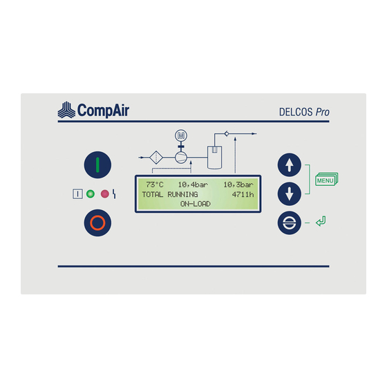
Панель управления Delcos 3100 setup code
Всем Добрый день!
Данная тема может будет уже заезженной, но тем неимения нужна помощь.
Столкнулся с такой проблемой, на воздушном компрессоре CompAir L45, необходимо поменять панель управления Delcos 3100.
Соответственно после установки и подключения новой панели запрашивает «Установочные коды» setup code 1,2,3″, сразу говорю в электрическом шкафу они не указанны и в комплекте поставки их тоже нет.
Добрые люди помогите, подскажите КОДЫ.
- Сообщений: 4
- Зарегистрирован: 07 мар 2019, 11:44
- Откуда (город): Москва
- Ответить с цитатой
Re: Панель управления Delcos 3100 setup code
 ASHKARUPA » 07 мар 2019, 16:23
А где ты возьмешь Delcos3100 ? их ещё продают? Так может у продавца спросить?
можно немцам написать. 
j-foreman@yandex.ru:::::::::::::::::::
- Авторитетный компрессорщик
- Сообщений: 1466
- Зарегистрирован: 27 окт 2014, 09:48
- Ответить с цитатой
Re: Панель управления Delcos 3100 setup code
Sure_man » 07 мар 2019, 19:15
Пробуй эти…
не смотри, что там написано 3000 — должно подойти…
- Вложения
-
- 3000.jpg (60.84 KiB) Просмотров: 819
- Ведущий специалист
- Сообщений: 80
- Зарегистрирован: 24 фев 2015, 17:45
- Ответить с цитатой
Re: Панель управления Delcos 3100 setup code
Влад » 08 мар 2019, 06:08
Панель новая уже установлена, вложение не открывается можете переслать на личку
Vladpervov@mail.ru
.
Нашел manual на 3100 там указаны КОДЫ: 0001, но под ними не заходит.
А поставщик панели ответил, что КОДЫ должны указываться вместе с компрессором, но у нас их почему то нет.
- Сообщений: 4
- Зарегистрирован: 07 мар 2019, 11:44
- Откуда (город): Москва
- Ответить с цитатой
Re: Панель управления Delcos 3100 setup code
Riga_meh » 09 мар 2019, 20:15
коды зависят от макс. допустимого давления компрессора и вариантов исполнения.
нужна инфо с шильдика.
- Сообщений: 31
- Зарегистрирован: 02 фев 2018, 23:19
- Откуда (город): Латвия
- Ответить с цитатой
Re: Панель управления Delcos 3100 setup code
Влад » 10 мар 2019, 09:29
Всем огромное спасибо! Коды подошли! Компрессор запущен!
- Сообщений: 4
- Зарегистрирован: 07 мар 2019, 11:44
- Откуда (город): Москва
- Ответить с цитатой
Re: Панель управления Delcos 3100 setup code
Влад » 10 мар 2019, 09:31
Огромное спасибо!
- Сообщений: 4
- Зарегистрирован: 07 мар 2019, 11:44
- Откуда (город): Москва
- Ответить с цитатой
Re: Панель управления Delcos 3100 setup code
andreymarygin » 06 май 2021, 12:08
Добрый день, как вызвать меню что бы ввести setup code 1,2,3. После скачка напряжения горит лампа h. И не могу запустить компрессор
- Сообщений: 1
- Зарегистрирован: 06 май 2021, 09:12
- Откуда (город): Krasnodar
Вернуться в Автоматизация, автоматика, программное обеспечение, применяемые в компрессорной отрасли, контроллеры
Перейти:
Кто сейчас на форуме:
Сейчас этот форум просматривают: нет зарегистрированных пользователей и гости: 1

В заводских условиях установленные величины интервалов между сеансами техобслуживания находятся под защитой в разделе меню «MAINTENANCE SCHED.» (График обслуживания), и на табло высвечивается: — — — -. Вы можете самостоятельно установить индивидуальный график техобслуживания для воздушных фильтров, масляных фильтров, сепараторов тонкой очистки, замены консистентной смазки и замены масла; в этих случаях можно не пользоваться Руководством. Можно задавать интервалы длительностью от 0 до 9999 часов.
В тех случаях, когда для какого-либо компонента установки не требуется техобслуживание и наблюдение, устанавливается интервал > 9999 часов. На дисплее появляется: — — — -, что означает: «Этот интервал(ы) заблокирован(ы)».
Когда запрограммированный интервал подходит к концу, на текстовом табло появляется сообщение: «MAINTENANCE ELAPSED» («Интервал истек»), и одновременно загорается диод f. Счетчик длительности интервалов между сеансами техобслуживания находится в меню [MAINTENANCE SCHED.]. Возможно отображение негативных, то есть превышенных интервалов. Если превышение интервала достигает -100 часов, то возможна активация / дезактивация автоотключения. Если один из интервалов достиг этого «порога автоотключения», автоотключения инициируется диодом h, сигнализирующим общий сбой и действующим совместно с диодом f. Сообщение [FAULT MAINTENANCE] присутствует как в памяти сбоев, так и на табло. После проведения техобслуживания назначьте новый интервал. а затем подтвердите сообщение о сбое ([FAULT MAINTENANCE] нажатием клавиши [O~].
Если код снят, любая величина, кроме «предельных величин», может быть изменена в любое время без запроса кода.
Найдите величину, которую следует изменить, с помощью клавиш <- и ->. Для изменения величины нажмите клавишу ENTER. Если код еще не снят, появится запрос кода. При активизации режима ввода величина будет мерцать.
-
Contents
-
Table of Contents
-
Bookmarks
Quick Links
Original User Manual
DELCOS Pro
electronics for stationary
rotary screw compressor
GB
Id. no. 100013596 / 03 — January 2010
1
Related Manuals for CompAir DELCOS Pro

Summary of Contents for CompAir DELCOS Pro
-
Page 1
Original User Manual DELCOS Pro electronics for stationary rotary screw compressor Id. no. 100013596 / 03 — January 2010… -
Page 3
German basis BA 100013595/03 Valid as of software version DPro-L-1.xx We reserve the right to modifications relating to technical advances. -
Page 4: Table Of Contents
5.5 [OPTIONAL IN-/OUTPUTS] sub-menu ……………………15 5.5.1 Inputs …………………………..15 5.5.2 Outputs …………………………..16 5.6 Locking / unlocking code ……………………….16 5.7 Replacing the DELCOS Pro (SETUP-CODE)………………….17 5.8 Remote control…………………………..18 5.8.1 Remote control for pressure changeover ………………….18 5.8.2 On-load/off-load remote control ……………………19 5.8.3 Remote start / stop……………………….20 6 Error rectification…………………………..21…
-
Page 5: Operator Controls / Arrangement
Switch to next sub-menu / menu item, messages. or reduce a value Light signals The DELCOS Pro is fitted with two light signals (red, Switch to previous sub-menu / menu item, green). or increase a value…
-
Page 6: Status Messages In Display
1. Operator controls / arrangement 1.2.1 Status messages in display WARNING START IN The status messages are shown in the 3rd row of the alternating with display. With longer texts, the indication may ‘alternate’..AFTER DRYER PRE-RUN Status messages: The unit has been switched on and is ready.
-
Page 7: Menu Structure (Values Are Examples)
1. Operator controls / arrangement Menu structure (values are examples) + TOTAL RUNNING 12345h [MAINTENANCE SCHED.] LOADED HOURS 10987h + AIR FILTER IN 2000h OIL FILTER IN 2000h …
-
Page 8: Displaying / Changing Values
1. Operator controls / arrangement Displaying / changing values 1.4.1 Selecting values You can display values, e.g. total hours, and set the control system, e.g. cut-in and cut-out times, in the sub- menu. To reach the main menu, you must press the …
-
Page 9: Default Settings
— have to be pressed at the same time to do this. You are The DELCOS Pro accumulator can bridge a loss of then taken to the main menu. Use to switch to the power lasting between around two to three weeks. If …
-
Page 10: Operations
The emergency off button is located above the ON-LOAD: DELCOS Pro. It is used to immediately shut down the unit. Only use the emergency off button to shut down If the unit is in ON-LOAD, air is pumped into the the unit in emergencies.
-
Page 11: Maintenance ([Maintenance Sched.] Sub-Menu)
The total hours counter states the time for which your conditions. unit has been in on-load and off-load. The DELCOS Pro allows the operator to program The load hours counter states the time for which your various maintenance intervals (see section 4.2).
-
Page 12: Extended Functions
5.1.2 Second pressure range (p The DELCOS Pro has a serial RS485 interface. This The range between the maximum and minimum interface can be used with the ModBus RTU protocol. network pressure is called the pressure range. The…
-
Page 13: Automatic Re-Start
Always fit the compressor with warning signs, lock automatic re-start by entering a code. the room containing the compressor and instruct Please request the required code from the CompAir your staff. customer service. Fit the main switch specified by EN60204 and fit the appropriate warning signs on it.
-
Page 14: Fault Memory ] Sub-Menu
5. Extended functions To access this information please use to go to [ FAULT MEMORY ] sub-menu the warning message or fault that you are interested in in the fault memory. Now press the key. The day of Warning messages and faults are stored in the fault memory.
-
Page 15: Pressure Changeover Setting
5. Extended functions If there are no days of the week selected in the Example 3: switching unit line, the switching unit is not active. The The unit is to run from Sunday 10 pm through switching unit only becomes active when the day of the continuously to Saturday 2 pm.
-
Page 16: Limit Values] Sub-Menu
5. Extended functions Seven timer units are again available here for the [Limit values] sub-menu setting (programming). The values that you have set for the second pressure range supersede the values for The [ LIMIT VALUES ] sub-menu is for information CUT-OUT POINT and CUT-IN POINT as soon as a only.
-
Page 17: Optional In-/Outputs] Sub-Menu
If the network pressure is ≥ 1.0 bar and the contact is opened for at least 250sec., BEKOMAT FAULT appears The DELCOS Pro has five programmable inputs. These on the display. This function results in the unit shutting inputs can be assigned (programmed) various down.
-
Page 18: Outputs
240V. The output (relay) is activated when there are no warnings, no maintenance messages and no faults on The DELCOS Pro has two programmable outputs. the compressor. Output 1 is a relay with changeover contact and output 2 is a relay with NO contact. You can assign (program) REM.STARTABLE…
-
Page 19: Replacing The Delcos Pro (Setup-Code)
The display then automatically jumps back to where it started from. Sticker Replacing the DELCOS Pro (SETUP- CODE) Once the new DELCOS Pro has been fitted in your compressor, switch the main switch back on. The following now appears on the display: COMPAIR SETUP-CODE 1: 0000 You will find the setup codes on a sticker (see Fig.
-
Page 20: Remote Control
But you can also activate the second pressure range remotely. This is done using a digital input (input X in Fig. 5) on the DELCOS Pro (see section 5.5.1 and circuit diagram). In the [OPTIONAL IN-/OUTPUTS] menu you have to program the inputs using the 2nd PR.
-
Page 21: On-Load/Off-Load Remote Control
(decoupled). If input 2 is now activated, the machine is control cabinet. in on-load. If input 2 is not activated, the machine is in The DELCOS Pro control system allows the operator to off-load. switch the compressor into on-load or off-load from a…
-
Page 22: Remote Start / Stop
If the remote start / stop function is activated, you can no longer control the machine using the On keys on the DELCOS Pro. Only the emergency off button remains activated. The machine can now only be switched on and off using the potential-free contact.
-
Page 23: Error Rectification
9. Do not connect up extra switching or measurement — Warning messages are shown in the 3rd display row. devices without the consent of CompAir. The red light signal on the DELCOS Pro also flashes 10. Do not route any measurement recorders out of the slowly.
-
Page 24
6. Error rectification [Indication] / Problem Possible cause Remedy Power loss Find cause FAULT POWER LOSS Voltage dip Find cause Cabling damaged Check, repair if necessary Loose terminals Check that all connecting terminals and plugs are tight, retighten if necessary FAULT EM-STOP Emergency off is being/has been activated Unlock… -
Page 25
Check dryer WARNING DRYER WARNING There is an external dryer error Check dryer FAULT DRYER FAULT DELCOS Pro hardware error Replace DELCOS Pro electronics FAULT DELCOS WARNING TIMER The real timer’s accumulator is flat The real timer must be reset (see section 2.3). -
Page 26
6. Error rectification [Indication] / Problem Possible cause Remedy Unit runs continuously in off- CONTINUOUS OPERATION operating mode Select AUTOMATIC OPERATION load without independently selected operating mode switching to readiness (standby) Very brief pressure requirements during the run-on time No compressed air Pressure changeover by timer or requirements within the external contact active… -
Page 28
Gardner Denver Deutschland GmbH Argenthaler Str. 11 55469 Simmern Germany Tel. ++49 (0)6761 832-0 www.compair.com e-mail: sales@compair.com…
-
Contents
-
Table of Contents
-
Bookmarks
Quick Links
Original User Manual
DELCOS Pro
electronics for stationary
rotary screw compressor
GB
Id. no. 100013596 / 03 — January 2010
1
Related Manuals for CompAir DELCOS Pro
Summary of Contents for CompAir DELCOS Pro
-
Page 1
Original User Manual DELCOS Pro electronics for stationary rotary screw compressor Id. no. 100013596 / 03 — January 2010… -
Page 3
German basis BA 100013595/03 Valid as of software version DPro-L-1.xx We reserve the right to modifications relating to technical advances. -
Page 4: Table Of Contents
5.5 [OPTIONAL IN-/OUTPUTS] sub-menu ……………………15 5.5.1 Inputs …………………………..15 5.5.2 Outputs …………………………..16 5.6 Locking / unlocking code ……………………….16 5.7 Replacing the DELCOS Pro (SETUP-CODE)………………….17 5.8 Remote control…………………………..18 5.8.1 Remote control for pressure changeover ………………….18 5.8.2 On-load/off-load remote control ……………………19 5.8.3 Remote start / stop……………………….20 6 Error rectification…………………………..21…
-
Page 5: Operator Controls / Arrangement
Switch to next sub-menu / menu item, messages. or reduce a value Light signals The DELCOS Pro is fitted with two light signals (red, Switch to previous sub-menu / menu item, green). or increase a value…
-
Page 6: Status Messages In Display
1. Operator controls / arrangement 1.2.1 Status messages in display WARNING START IN The status messages are shown in the 3rd row of the alternating with display. With longer texts, the indication may ‘alternate’..AFTER DRYER PRE-RUN Status messages: The unit has been switched on and is ready.
-
Page 7: Menu Structure (Values Are Examples)
1. Operator controls / arrangement Menu structure (values are examples) + TOTAL RUNNING 12345h [MAINTENANCE SCHED.] LOADED HOURS 10987h + AIR FILTER IN 2000h OIL FILTER IN 2000h …
-
Page 8: Displaying / Changing Values
1. Operator controls / arrangement Displaying / changing values 1.4.1 Selecting values You can display values, e.g. total hours, and set the control system, e.g. cut-in and cut-out times, in the sub- menu. To reach the main menu, you must press the …
-
Page 9: Default Settings
— have to be pressed at the same time to do this. You are The DELCOS Pro accumulator can bridge a loss of then taken to the main menu. Use to switch to the power lasting between around two to three weeks. If …
-
Page 10: Operations
The emergency off button is located above the ON-LOAD: DELCOS Pro. It is used to immediately shut down the unit. Only use the emergency off button to shut down If the unit is in ON-LOAD, air is pumped into the the unit in emergencies.
-
Page 11: Maintenance ([Maintenance Sched.] Sub-Menu)
The total hours counter states the time for which your conditions. unit has been in on-load and off-load. The DELCOS Pro allows the operator to program The load hours counter states the time for which your various maintenance intervals (see section 4.2).
-
Page 12: Extended Functions
5.1.2 Second pressure range (p The DELCOS Pro has a serial RS485 interface. This The range between the maximum and minimum interface can be used with the ModBus RTU protocol. network pressure is called the pressure range. The…
-
Page 13: Automatic Re-Start
Always fit the compressor with warning signs, lock automatic re-start by entering a code. the room containing the compressor and instruct Please request the required code from the CompAir your staff. customer service. Fit the main switch specified by EN60204 and fit the appropriate warning signs on it.
-
Page 14: Fault Memory ] Sub-Menu
5. Extended functions To access this information please use to go to [ FAULT MEMORY ] sub-menu the warning message or fault that you are interested in in the fault memory. Now press the key. The day of Warning messages and faults are stored in the fault memory.
-
Page 15: Pressure Changeover Setting
5. Extended functions If there are no days of the week selected in the Example 3: switching unit line, the switching unit is not active. The The unit is to run from Sunday 10 pm through switching unit only becomes active when the day of the continuously to Saturday 2 pm.
-
Page 16: Limit Values] Sub-Menu
5. Extended functions Seven timer units are again available here for the [Limit values] sub-menu setting (programming). The values that you have set for the second pressure range supersede the values for The [ LIMIT VALUES ] sub-menu is for information CUT-OUT POINT and CUT-IN POINT as soon as a only.
-
Page 17: Optional In-/Outputs] Sub-Menu
If the network pressure is ≥ 1.0 bar and the contact is opened for at least 250sec., BEKOMAT FAULT appears The DELCOS Pro has five programmable inputs. These on the display. This function results in the unit shutting inputs can be assigned (programmed) various down.
-
Page 18: Outputs
240V. The output (relay) is activated when there are no warnings, no maintenance messages and no faults on The DELCOS Pro has two programmable outputs. the compressor. Output 1 is a relay with changeover contact and output 2 is a relay with NO contact. You can assign (program) REM.STARTABLE…
-
Page 19: Replacing The Delcos Pro (Setup-Code)
The display then automatically jumps back to where it started from. Sticker Replacing the DELCOS Pro (SETUP- CODE) Once the new DELCOS Pro has been fitted in your compressor, switch the main switch back on. The following now appears on the display: COMPAIR SETUP-CODE 1: 0000 You will find the setup codes on a sticker (see Fig.
-
Page 20: Remote Control
But you can also activate the second pressure range remotely. This is done using a digital input (input X in Fig. 5) on the DELCOS Pro (see section 5.5.1 and circuit diagram). In the [OPTIONAL IN-/OUTPUTS] menu you have to program the inputs using the 2nd PR.
-
Page 21: On-Load/Off-Load Remote Control
(decoupled). If input 2 is now activated, the machine is control cabinet. in on-load. If input 2 is not activated, the machine is in The DELCOS Pro control system allows the operator to off-load. switch the compressor into on-load or off-load from a…
-
Page 22: Remote Start / Stop
If the remote start / stop function is activated, you can no longer control the machine using the On keys on the DELCOS Pro. Only the emergency off button remains activated. The machine can now only be switched on and off using the potential-free contact.
-
Page 23: Error Rectification
9. Do not connect up extra switching or measurement — Warning messages are shown in the 3rd display row. devices without the consent of CompAir. The red light signal on the DELCOS Pro also flashes 10. Do not route any measurement recorders out of the slowly.
-
Page 24
6. Error rectification [Indication] / Problem Possible cause Remedy Power loss Find cause FAULT POWER LOSS Voltage dip Find cause Cabling damaged Check, repair if necessary Loose terminals Check that all connecting terminals and plugs are tight, retighten if necessary FAULT EM-STOP Emergency off is being/has been activated Unlock… -
Page 25
Check dryer WARNING DRYER WARNING There is an external dryer error Check dryer FAULT DRYER FAULT DELCOS Pro hardware error Replace DELCOS Pro electronics FAULT DELCOS WARNING TIMER The real timer’s accumulator is flat The real timer must be reset (see section 2.3). -
Page 26
6. Error rectification [Indication] / Problem Possible cause Remedy Unit runs continuously in off- CONTINUOUS OPERATION operating mode Select AUTOMATIC OPERATION load without independently selected operating mode switching to readiness (standby) Very brief pressure requirements during the run-on time No compressed air Pressure changeover by timer or requirements within the external contact active… -
Page 28
Gardner Denver Deutschland GmbH Argenthaler Str. 11 55469 Simmern Germany Tel. ++49 (0)6761 832-0 www.compair.com e-mail: sales@compair.com…
-
Contents
-
Table of Contents
-
Bookmarks
Quick Links
User Manual
DELCOS 3100 Controller
for
GB
Id. No. 100016911 / 01 — October 2009
1
Related Manuals for Gardner Denver DELCOS 3100
Summary of Contents for Gardner Denver DELCOS 3100
-
Page 1
User Manual DELCOS 3100 Controller Id. No. 100016911 / 01 — October 2009… -
Page 3
SR version only: Attention: Risk of electric shock from charged capacitors! Always disconnect the system from the power supply and then wait a further 12 minutes before touching electrical components. The power capacitors take this time to discharge. Subject to modification in the course of technical progress. -
Page 4: Table Of Contents
1.4.9 Group-fault relay…………………………19 1.4.10 Speed ON message (version RS only)………………….19 1.4.11 Running-hours/loaded-hours counter ………………….19 1.4.12 Fault memory …………………………19 1.5 DELCOS 3100 fault table in the case of a fault or warning ………………20 1.5.1 Check-list ……………………………20 1.5.2 Faults/warnings table ……………………….20 1.6 Maintenance intervals…………………………32 1.7 Operating modes …………………………..32…
-
Page 5
Contents 2 DELCOS 3100 Base-Load Sequencing ……………………..41 2.1 Overview…………………………….41 2.2 Functional description / attributes ……………………..41 2.3 Connecting slaves to BLS ……………………….42 2.3.1 Load request…………………………42 2.3.2 Fault message…………………………42 2.4 Connecting the master to BLS ………………………42 2.5 Remote control…………………………..42 2.5.1 Remote-controlled pressure changeover…………………..42 2.5.2 Switching off by remote control [OPERATION ON] ………………42… -
Page 6: Delcos 3100 Electronics
ON-LOAD Figure 1 DELCOS 3100 Electron ics Controls Foreword 1.2.1 Keypad This manual describes the DELCOS 3100 compressor control system in various configuration levels: => switches system on Version FS Version for fixed-speed compressors => switches system off Version RS Version for speed-controlled, =>…
-
Page 7: Light-Emitting Diodes
1. DELCOS 3100 Electronics ON-LOAD Figure 1 1.2.2 Light-emitting diodes Messages: LED f => maintenance interval expired LED g => warning Operating messages: LED h => group fault LED a => flashing: system in standby mode, i.e. the motor can start automatically at…
-
Page 8: Changing Language
1. DELCOS 3100 Electronics The status displays below have the following meanings: 1.2.3 Changing language DELCOS 3100 is configured in 17 languages. To switch from one language to another, simultaneously press the All versions: keys. The international country identifiers show you the current configuration.
-
Page 9
1. DELCOS 3100 Electronics a value for the specific machine (example values) • WARNING <Warning text> If a warning is given, the status text is not – as in the OFF-LOAD (V = 0.0) 123s case of faults – generally overwritten by this message Machine is running off-load at minimum speed and but additionally shown every 12 seconds for 3 seconds. -
Page 10
1. DELCOS 3100 Electronics The arrow keys can additionally be used to display SR version only: • the drive motor’s current speed: INITIALIZATION SRD… Examples of speed displayed: The compressor’s supply voltage has been switched on. The control system is being initialised and is setting [ _________❚___ ] 3690rpm… -
Page 11: Delcos 3100 Menu Structure (Example Values)
1. DELCOS 3100 Electronics DELCOS 3100 menu structure (example values) DELCOS 3100 FS menu structure (example values) [MAINTENANCE SCHED.] [CONTROL MENU] [FAULT MEMORY] TOTAL RUNNING 12345 h CUT-OUT POINT 10.0 bar / 145 psi EXT FAULT 11438 h LOADED HOURS…
-
Page 12
1. DELCOS 3100 Electronics DELCOS 3100 RS menu structure (example values) [MAINTENANCE SCHED.] [CONTROL MENU] [FAULT MEMORY] TOTAL RUNNING 12345 h CUT-OUT POINT 10.0 bar / 145 psi 12! EXT FAULT 11438 h LOADED HOURS 10987 h CUT-IN POINT 9.5 bar / 138 psi… -
Page 13
1. DELCOS 3100 Electronics DELCOS 3100 SR menu structure (example values) [MAINTENANCE SCHED.] [CONTROL MENU] [FAULT MEMORY] TOTAL RUNNING 12345 h CUT-OUT POINT 10.0 bar / 145 psi EXT FAULT 11438 h LOADED HOURS 10987 h TARGET PRESSURE 9.5 bar / 138 psi… -
Page 14: Maintenance Sched.] Menu
1. DELCOS 3100 Electronics re 1.3 Menu structure 1.3.2 [CONTROL MENU] menu Menu prompting takes place in the 2nd line of the plaintext Using the keys, go to the [CONTROL MENU] field. To access the different menus, first press the menu option.
-
Page 15: Fault Memory] Menu
1. DELCOS 3100 Electronics 1.3.3 [FAULT MEMORY] menu 1.3.5 [OPTIONAL INPUTS] menu Using the keys, go to the [FAULT MEMORY] The software provides for the [OPTIONAL INPUTS] menu option. This is where you can then retrieve/select menu option. You can have the various additional individual entries using the keys.
-
Page 16: Timer Control] Menu
1. DELCOS 3100 Electronics Using the keys, select a timer block, e.g. • 1.3.7 [TIMER CONTROL] menu block no. 2 [2_______ 00:00 00:00] Danger Press the , the week day flashes (Sunday) • The machine can start at any time when programming Make the setting of your choice using the •…
-
Page 17: Changing Values
1. DELCOS 3100 Electronics These timer blocks define the periods in which the Note machine switches over to the second pressure level. Pressure changeover can also be activated through an Switching over to the second pressure range acts on the external, floating contact.
-
Page 18: Locking/Unlocking Code
You will find the setup codes in the switch cabinet. [CODE: UNLOCK] (for 1 second) You are then automatically returned to the starting point. If the DELCOS 3100 electronics malfunction or after changing them, the control system will request three Unlocking setup codes.
-
Page 19: Starting Up
To calculate the machine’s current delivery rate, its basic on start-up, the system goes to standby and LED a delivery rate values must be entered into DELCOS 3100. It flashes. The plaintext field reads [WARNING START is also necessary to know the delivery rate for base-load BY …] with the relevant message (see Chapter 1.2.5).
-
Page 20: Control (Version Rs And Sr Only)
1. DELCOS 3100 Electronics 1.4.3 Control (version RS and SR only) 1.4.5 Switching the system off Speed is controlled with the aid of a PI controller After pressing the key, a 30-second [SOFT STOP] implemented in the software and is matched to the period elapses before the motor shuts down.
-
Page 21: Group-Fault Relay
– with indication of The running and loaded-hours readings are lost on number. changing the DELCOS 3100 electronics. This means: when the fault/warning occurs again, the fault/warning message appears with the current number of fault/warning occurrences as well as with the hour during which the fault/warning re-occurred.
-
Page 22: Delcos 3100 Fault Table In The Case Of A Fault Or Warning
1. DELCOS 3100 Electronics 11. If you have any technical queries, keep the following DELCOS 3100 fault table in the case of information to hand so that a fault can be rectified a fault or warning quickly and methodically: For version SR only:…
-
Page 23
1. DELCOS 3100 Electronics [Display] / Problem Possible Cause Remedy [FAULT POWER LOSS] Power failure Search for cause Power drop Search for cause Damaged cables Check, repairing if necessary Detached/loose terminals Check all connection terminals and plugs for a tight fit, tightening if… -
Page 24
If applicable, switch over to [BYPASS REGULATION ON/OFF] mode OPERATION] (option, see 1.7.2) In version SR: communication failure Check between DELCOS 3100 and SR drive — SR system control voltages through CAN interface — SR system fuses — CAN interface wiring — If no fault can be found, notify Gardner Denver service engineer. -
Page 25
1. DELCOS 3100 Electronics [Display] / Problem Possible Cause Remedy [WARNING MS-BUS:A06] Module failed Check module power supply. Check fuse in module. [FAULT MS-BUS:A06] Module failed during [BYPASS OPERATION] Check module power supply. operating mode (option). Check fuse in module. -
Page 26
[* Wrong SR-Serial Number] The serial number of the SR drive resident [SETUP-CODE 1:_______?] in DELCOS 3100 does not concur with the serial number read out from the SR drive. The electronics PCB’s may have been swapped in the SR drive. -
Page 27
1. DELCOS 3100 Electronics [Display] / Problem Possible Cause Remedy Hardware fault DELCOS [GARDNER DENVER] DELCOS electronics must be changed [SETUP-CODE 1:_______?] as a temporary measure: enter setup codes, check all settings and re-set if (2)(3)(4)(5) necessary After changing the DELCOS electronics, the message shows no fault. -
Page 28
1. DELCOS 3100 Electronics [Display] / Problem Possible Cause Remedy [FAULT SR-DRIVE (5)] Ribbon cable faulty between control board Check ribbon cable between control Control board overvoltage (PCB94) and gate drive board (PCB95). board (PCB94) and gate drive board (-15V internal) (PCB95). -
Page 29
1. DELCOS 3100 Electronics [Display] / Problem Possible Cause Remedy [FAULT SR-DRIVE (18)] Motor cable incorrectly laid through current Check connection of motor phases at Negative current conversion sensor. power electronics and check for correct through current sensor. installation through the current sensor. -
Page 30
1. DELCOS 3100 Electronics [Display] / Problem Possible Cause Remedy [FAULT SR-DRIVE (26)] A braking resistor is not installed. Occurrence Make sure that the current sensor is Braking resistance over current of this fault, therefore, points to a wiring fault connected to phase A on the control or to a malfunction on the control board. -
Page 31
Otherwise contact Gardner Denver Service. Control board faulty. Contact Gardner Denver Service. [FAULT SR-DRIVE (46)] The motor temperature sensor is monitored Motor temperature sensor faulty by Delcos 3100. Occurrence of this fault, therefore, points to a malfunction on the control board. -
Page 32
Contact Gardner Denver Service. [FAULT SR-DRIVE (48)] The motor temperature sensor is monitored Motor temperature exceeded by Delcos 3100. Occurrence of this fault, therefore, points to a malfunction on the control board. [FAULT SR-DRIVE (49)] Motor cables not routed through the current… -
Page 33
(PCB94) and gate drive board (PCB95). Faulty cable or plug of CAN connection Check CAN connection from control from control board to Delcos 3100. board to Delcos 3100. Completely switch power supply off and back on Control board faulty. -
Page 34: Maintenance Intervals
1. DELCOS 3100 Electronics Maintenance intervals Operating modes 1.7.1 Automatic and continuous operation Danger For this, go to the [CONTROL MENU] menu and select When programming the system in standby mode, either [AUTOMATIC OPERATION] or [CONTINUOUS i.e. LED a flashing, the compressor can start OPERATION] (see Chapter 1.3.8 changing values).
-
Page 35
Switching over to bypass operation (option) max. network pressure, the machine is switched to off- load mode, if network pressure < target pressure, If the converter is malfunctioning, DELCOS 3100 shuts machine is switched to on-load mode. down the machine with [FAULT CONVERTER]. -
Page 36: Setting The Volumetric-Flow Unit For The Status Display (Version Rs And Sr Only)
1. DELCOS 3100 Electronics The system continues to run until the remote • 1.7.3 Setting the volumetric-flow unit for ON/OFF input is closed. the status display [DISPLAY UNITS = m3/min] (version RS and SR only) The system stops when the remote on/off input is •…
-
Page 37: Switching On-Load/Off-Load By Remote Control (Version Fs Only)
(2) may have to be reduced in the [CONTROL X3.23/X3.24) is always active, i.e. you do not need to MENU] menu. make any further settings in the DELCOS 3100 menu. To deactivate the internal electronic pressure switch (2) or connect an external floating contact for remote on- load in series, see Chapter 1.7.8.
-
Page 38: Remote Control For Enabling On-Load Operation
When the higher-order controller (8) is active and • not malfunctioning, it withdraws the on-load enable Connect the external switch (5) to the terminals (6). • from DELCOS 3100 at contact (7) and now controls the compressor autonomously through ist own load request (3).
-
Page 39: Automatic Restart After Power Failure
[CONTROL MENU] menu. The DELCOS protocol is used together with the Gardner Denver profibus module. Using the profibus module, DELCOS 3100 can be connected to a profibus master (e.g. PLC). Modbus interfaces and the associated drivers are available for almost all well-known makes of programmable logic controllers and PC visualisation software.
-
Page 40: Water Circuit
1. DELCOS 3100 Electronics The following is shown: Water circuit solenoid valve not triggered solenoid valve triggered 1.8.1 Electrical equipment 1.8.1.1 Relay module >–< Height of the water level The electrical equipment of the water circuit is The following is shown: connected to a relay module.
-
Page 41: Water Exchange
1. DELCOS 3100 Electronics 1.8.4 Water exchange Factory settings In order to guarantee a constant water quality, the water This menu provides you with the capability of checking is exchanged at specific intervals. This interval can be the factory settings programmed for your system, but…
-
Page 42
1. DELCOS 3100 Electronics Factory settings for version SR [LIMIT VALUES] 1/2) DESIGN PRESS bar / psi START PROTECT bar / psi EXT. LIMIT FINAL TEMP WARN °C / °F FINAL TEMP MAX °C / °F MIN START TEMP °C / °F… -
Page 43: Delcos 3100 Base-Load Sequencing
2. DELCOS 3100 Base-Load Sequencing DELCOS 3100 Base-Lo ad Seq uen cin g For version SR only: Overview CUT-OUT POINT: BLS setting that defines the Base-load sequencing (BLS) is set in the [BASE LOAD upper limit of the pressure band.
-
Page 44: Connecting Slaves To Bls
2.5.2 Switching off by remote control Version RS and SR only: [OPERATION ON] For compressors with DELCOS 3100, it makes sense to wire back the «operating» message. Otherwise, the BLS can be switched off temporarily via input E07.4 “disconnect” function faults and the analogue output (module A06).
-
Page 45: Overview Of [Base Load Select.] Menu
2. DELCOS 3100 Base-Load Sequencing Overview of [BASE LOAD SELECT.] menu All menu settings can be locked/unlocked again with code 3031. Version FS: BASE LOAD SELECT. {menu header} OPERATION {off, on, optional timer, fault} CUT-OUT POINT 9.7 bar {max. network pressure} CUT-IN POINT 9.3 bar…
-
Page 46: Setting [Operation]
2. DELCOS 3100 Base-Load Sequencing 2.6.3 Setting [OPERATION] 2.6.5 [CUT-OUT POINT / TARGET PRESSURE] setting (version RS and This is where BLS is activated and deactivated. If SR only) activated BLS fails as a result of any of the above- mentioned events, the display shows [OPERATION —]…
-
Page 47: Bls Status Display [123H K1 K3 K4 R2 R5]
2. DELCOS 3100 Base-Load Sequencing The same display procedure applies to the backup 2.6.7 BLS status display machines, however using the «R/r» (instead of «K/k»). [123h K1 K3 k4 r2 r5] To view BLS status quickly during normal machine The status display contains information on the current…
-
Page 48: Vol.comp2
2. DELCOS 3100 Base-Load Sequencing Solution: 2.6.11 [VOL.COMP2…5] setting (version RS and SR only) The master compressor is activated at 5:45 hrs by its timer for activating the BLS system. The BLS operating This is where to set the delivery rate for the slave mode is set to 15 min at [TIMER] and [LOAD NET IN].
-
Page 49: Progression Through The Bls Array
2. DELCOS 3100 Base-Load Sequencing Setting value too high (sensitive): the BLS system • Compressor fault disconnects compressors prematurely in the range between CUT-IN POINT and CUT-OUT POINT. Slave faults can only be taken into account if their fault- message contacts are wired to the relay module.
-
Page 50: Bls Active Message
2. DELCOS 3100 Base-Load Sequencing 1. Example for version RS and SR: BLS active message System with 4 compressors, 1 backup compressor, The slave compressors normally have their own or an [BASE LOAD COMP 3], fault K4 internal pressure switch for controlling on-load/off-load operation.
-
Page 51: Analogue Output
3. Analogue Output Analogu e Output Analogue output of delivered volumetric flow (version RS only) Using channel 2, the delivered volumetric flow can be output through the analogue-out module. This information is purely computational in nature and is governed by the correct setting of the speed-controlled compressors delivery rate in the [CONTROL MENU] menu (see Chapter 1.4.1).
-
Page 56
Gardner Denver Compressor Division, 1800 Gardner Expressway, Quincy, Illinois 62305 Telephone: (800) 682-9868 Fax: (217) 224-7814 Gardner Denver Deutschland GmbH Argenthaler Str. 11 55469 Simmern Deutschland Tel. ++49 (0)6761 832-0 Fax ++49 (0)6761 832-409…
- 30 Июл 2013
Доброго времени суток всем .Плата пришла изначально с такими симптомами : на лсд сообщение типа «ошибка процессора» , все светодиоды горят . Обнулил епромку (93с66) , теперь имеем : на лсд «Download V1.01 ready » , залил обратно слитый дамп с (93с66) ничего не поменялось . Слил прошивку с процика залил в at89С55wd — то-же самое . Пробовал менять оперативку — без изменений , копировал содержимое флешки на аналогичную всё без толку . Сигналы на некот. ногах процика вызывают противоречивые чувства (чуть позже выложу).
Прошу помочь у кого есть возможность, рабочими дампами на вышеуказанный девайс и (или) советами по его оживлению .
- 30 Июл 2013
а почему бы не проверить тщательно формирователи питания всей платы…….
какова приоритетная задача данного контролера???? управление агрегатом, или удаленный мониторинг по ModBus RS485….
- 31 Июл 2013
Фото платы, если можно,
Наличие батарейки на плате говорит о типичном исполнении для таких агрегатов — все ПО живет в оперативке — при просадке батареи — нужно или менять всю плату или вызывать сервисников для программирования с помощью спец софта.
Так реализовано большинство контроллеров для современных компрессоров.
- 31 Июл 2013
Скорее всего,слитый дамп,-кривой!На таких шаробайках,как правило,вешается блокировка .Она представляет из себя какой-то бит ,т.е. при видимой скачке дампа,на самом деле,-произвольная информация!Я на эти грабли уже наступал неодин раз.
- 31 Июл 2013
saltison2007 сказал(а):
а почему бы не проверить тщательно формирователи питания всей платы…….
первым делом именно это и сделал , никаких аномалий не заметил…
saltison2007 сказал(а):
какова приоритетная задача данного контролера???? управление агрегатом, или удаленный мониторинг по ModBus RS485….
управление агрегатом , RS485 не задействован .
kratmel сказал(а):
вечерком сфотаю
kratmel сказал(а):
Наличие батарейки на плате …
батарейки на плате нет , как уже говорил ПО живёт в двух микрах : в самом мк AT89C52 (начальная загрузка) и во флешке AM29F010B (основная прога) .
andreieinav сказал(а):
Скорее всего,слитый дамп,-кривой!На таких шаробайках,как правило,вешается блокировка .Она представляет из себя какой-то бит ,т.е. при видимой скачке дампа,на самом деле,-произвольная информация!Я на эти грабли уже наступал неодин раз.
тоже придерживаюсь этого мнения , только-б знать какой именно дамп кривой . С мк вроде норм. слил и залил . По крайней мере , поведение клона полностью аналогично исходному МК . Да и у данных МК невозмона защита определюнных участков флеши или всё — или ничего . Остаётся два варианта 93с66 или AM29F010B .
- 31 Июл 2013
отсутствие батарейки говорит о том что в контролеле нету счетчика реального времени и все ПО а точнее «дерево меню» хранится в AM29F010B.

- 31 Июл 2013
Вот ослограмки как обещал.
Добавлено 31-07-2013 08:25
saltison2007 , она самая . Один в один .
Добавлено 31-07-2013 08:27
картинки подписаны соотв. портам мк , обратите внимание на Р0_4 и Р0_5 .
► oscil.rar
- 31 Июл 2013
а как происходит запись уставок или параметров??? с помощью клавиш на лицевой панели, или загрузкой готового профиля с модуля Smart Air Master….?? может МК находится в режиме ожидания загрузки параметров (профиля), которые слетели или запоролись…..
- 2 Авг 2013
Уставки никто ни когда не менял , как пришел с завода так и пользовались , по крайней мере так они утверждают . Вот что имеем на сей момент . Опроса клавы не наблюдается, попыток обращения к eeprom не зафиксировано . Такое ощущение что проц ждёт , сигнала от переферии .
► DSC07482.rar
- 2 Авг 2013
попробуйте при зажатых кнопках «стрелочка вверх» и » стрелочка вниз» выключить и включить питание, одним словом по игратся с этой комбинацией кнопок…….может это выведет МК с режима програмирования
- 3 Авг 2013
Попробовал , ноль эмоций . Завтра попробую логер подвесить на АЦП , посмотрю чё там творится , других мыслей пока нет…
- 3 Авг 2013
какой еще ацп???? не тот, ли что пасет входные датчики давления 4…..20ма….
- 3 Авг 2013
дык , он там вроде один … :crazy:
Ремонт контроллеров (блоков управления) компрессоров
Мы осуществляем ремонт старых и поставки новых блоков управления компрессора (контроллеров)
различных производителей:
СMC Бельгия (для компрессоров Remeza, Ремеза, Ekomak, Экомак, Atmos): Air Master S1, AirMaster P1, Air Master Q1,
FIAC: Fiac Easy Air Control, Check Control, Air Energy Control,
Atmos: Logik 6-S, Logik 8, Logik 16-S, Logik 18, Logik 25-S, Logik 33-S, Logik 103,Pa 21mc.
Ceccato: Es99, Es3000, Airlogic, Multicontrol
Alup, Almig, Kraftmann, Dalva: Aircontrol 1, Aircontrol 2, Aircontrol 3, Aircontrol 4.
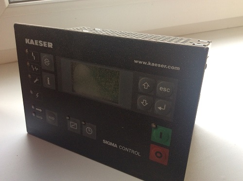
Kaeser: Sigma Control, Sigma Control Basic, Sigma Control 2, Sigma Air Manager (Германия)
Ingersoll Rand: X4i, X8i, X12
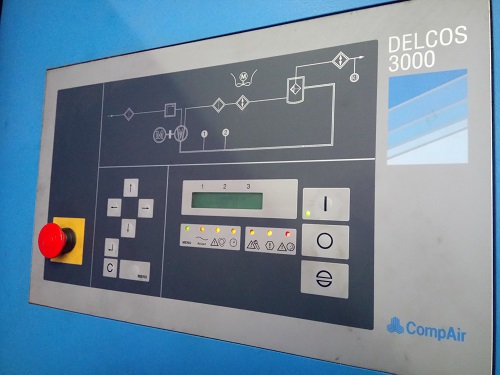
CompAir: Delcos 3000, Delcos 3100, Delcos 1000
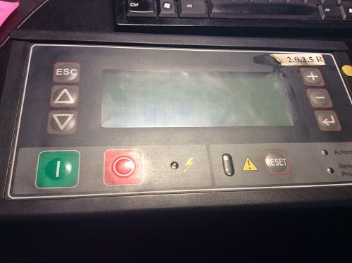
АBAC: Mc2
AtlasCopcо: Elektronikon
FINI: EasyTronic, EasyTronicII, EasyTronicIII
Ingro, Daly, Berg: MAM860, MAM (Китай)
Наиболее частыми причинами выхода из строя блоков управления являются:
— резкие перепады напряжений на входе в компрессорную станцию,
— повышенная запыленность помещения,
— содержание химически активных веществ в окружающей среде
— высокая температура в корпусе компрессора
После произведенного нами ремонта, каждый блок управления проверяется в тестовом режиме с подачей на него внешних сигналов по давлению сжатого воздуха по току или напряженю (в том числе от генератора «токовой петли» 4-20 мА), а также по температуре с моделированием всех возможных режимов работы компрессорной установки.