
-
Contents
-
Table of Contents
-
Bookmarks
Quick Links
OPERATOR’S MANUAL
Compact Genset Controller, CGC 400
● Push-buttons
● LEDs
● Display and menu structure
● Display readings
● Alarm handling and log list
DEIF A/S · Frisenborgvej 33 · DK-7800 Skive · Tel.: +45 9614 9614 · Fax: +45 9614 9615 · info@deif.com · www.deif.com
Document no.: 4189340787A
SW version: 1.00
Related Manuals for Deif CGC 400
Summary of Contents for Deif CGC 400
-
Page 1
● Alarm handling and log list DEIF A/S · Frisenborgvej 33 · DK-7800 Skive · Tel.: +45 9614 9614 · Fax: +45 9614 9615 · info@deif.com · www.deif.com isenborgvej 33 · DK-7800 Skive · Tel.: +45 9614 9614 · Fax: +45 9614 9615 · info@deif.com · www.deif.com Document no.: 4189340787A… -
Page 2: Table Of Contents
CGC 400 Operator’s manual 4189340787 1. General information 1.1. Warnings, legal information and safety………………..3 1.1.1. Warnings and notes ……………………3 1.1.2. Legal information and disclaimer ………………..3 1.1.3. Safety issues ……………………..3 1.1.4. Electrostatic discharge awareness ………………..3 1.1.5. Factory settings ……………………..4 1.2. About the operator’s manual……………………4 1.2.1.
-
Page 3: General Information
1.1.2 Legal information and disclaimer DEIF takes no responsibility for installation or operation of the generator set. If there is any doubt about how to install or operate the engine/generator controlled by the unit, the company responsible for the installation or the operation of the set must be contacted.
-
Page 4: Factory Settings
CGC 400 Operator’s manual 4189340787 General information 1.1.5 Factory settings The unit is delivered from factory with certain factory settings. These are based on average values and are not necessarily the correct settings for matching the engine/generator set in question. Precautions must be taken to check the settings before running the engine/generator set.
-
Page 5: Push-Buttons And Leds
CGC 400 Operator’s manual 4189340787 Push-buttons and LEDs 2. Push-buttons and LEDs 2.1 Push-button functions The push-buttons on the unit have the following functions: Function Secondary functionality Scroll the display up once Programming: Increase setpoint value Scroll the display down once…
-
Page 6: Led Functions
The display unit holds 10 LED functions. Dependent on the situation, the colour of the LEDs is green, red or a combination. The table below describes the functionality of the LEDs on the CGC 400: LED no. LED name LED function…
-
Page 7: Display And Menu Structure
CGC 400 Operator’s manual 4189340787 Display and menu structure 3. Display and menu structure 3.1 Menu 3.1.1 Menu system The display includes the menu systems listed below which can be used/viewed without password entry: View menu system: This is the commonly used menu system, which contains displaying of the measured values.
-
Page 8: Menu Structure Example
CGC 400 Operator’s manual 4189340787 Display and menu structure 3.1.3 Menu structure example The figure below is an example of how the menu structure is arranged, and it also shows the meaning of the entry symbols..(up to 20 views)
-
Page 9: Display Functions
CGC 400 Operator’s manual 4189340787 Display and menu structure 3.2 Display functions 3.2.1 Functional examples The display indicates both readings and alarms. The examples below are with icons and English language. View examples Service menu Appl. Ver.: 9.90.0 The software version can be found in the Service menu Appl.
-
Page 10
CGC 400 Operator’s manual 4189340787 Display and menu structure Edit value with up and down arrows and save the value by pressing the 1000 -P> OK button. Set point: -5.0% Timer: 0.5 sec Output A: Not used Output B: Not used For detailed information about changing parameters and setup, please see the Designer’s Ref- erence Handbook. -
Page 11: Status Line Text
CGC 400 Operator’s manual 4189340787 Status line text 4. Status line text 4.1 Status line text 4.1.1 Standard texts Condition Comment BLOCK Block mode is activated SIMPLE TEST Test mode is activated FULL TEST SIMPLE TEST ###.#min Test mode activated and test timer counting down FULL TEST ###.#min…
-
Page 12
CGC 400 Operator’s manual 4189340787 Status line text Condition Comment START RELAY OFF The start relay is deactivated during the start se- quence MAINS FAILURE Mains failure and mains failure timer expired MAINS FAILURE IN ###s Frequency or voltage measurement is outside the lim-… -
Page 13: Running Modes
CGC 400 Operator’s manual 4189340787 Running modes 5. Running modes 5.1 Running mode overview The unit has four different running modes and one block mode. The different running modes are selected via the display or the PC utility software. For detailed information please see Designer’s Reference Handbook.
-
Page 14: Alarm Handling And Log List
CGC 400 Operator’s manual 4189340787 Alarm handling and log list 6. Alarm handling and log list 6.1 Alarm handling When an alarm occurs, the unit will automatically go to the alarm list for display of the alarm. If reading of the alarms is not desired, use the BACK push-button to exit the alarm list.
This manual is also suitable for:
Agc 100
-
Contents
-
Table of Contents
-
Bookmarks
Quick Links
OPERATOR’S MANUAL
Compact Genset Controller, CGC 400
● Push-buttons
● LEDs
● Display and menu structure
● Display readings
● Alarm handling and log list
DEIF A/S · Frisenborgvej 33 · DK-7800 Skive · Tel.: +45 9614 9614 · Fax: +45 9614 9615 · info@deif.com · www.deif.com
Document no.: 4189340787A
SW version: 1.00
Related Manuals for Deif CGC 400
Summary of Contents for Deif CGC 400
-
Page 1
● Alarm handling and log list DEIF A/S · Frisenborgvej 33 · DK-7800 Skive · Tel.: +45 9614 9614 · Fax: +45 9614 9615 · info@deif.com · www.deif.com isenborgvej 33 · DK-7800 Skive · Tel.: +45 9614 9614 · Fax: +45 9614 9615 · info@deif.com · www.deif.com Document no.: 4189340787A… -
Page 2: Table Of Contents
CGC 400 Operator’s manual 4189340787 1. General information 1.1. Warnings, legal information and safety………………..3 1.1.1. Warnings and notes ……………………3 1.1.2. Legal information and disclaimer ………………..3 1.1.3. Safety issues ……………………..3 1.1.4. Electrostatic discharge awareness ………………..3 1.1.5. Factory settings ……………………..4 1.2. About the operator’s manual……………………4 1.2.1.
-
Page 3: General Information
1.1.2 Legal information and disclaimer DEIF takes no responsibility for installation or operation of the generator set. If there is any doubt about how to install or operate the engine/generator controlled by the unit, the company responsible for the installation or the operation of the set must be contacted.
-
Page 4: Factory Settings
CGC 400 Operator’s manual 4189340787 General information 1.1.5 Factory settings The unit is delivered from factory with certain factory settings. These are based on average values and are not necessarily the correct settings for matching the engine/generator set in question. Precautions must be taken to check the settings before running the engine/generator set.
-
Page 5: Push-Buttons And Leds
CGC 400 Operator’s manual 4189340787 Push-buttons and LEDs 2. Push-buttons and LEDs 2.1 Push-button functions The push-buttons on the unit have the following functions: Function Secondary functionality Scroll the display up once Programming: Increase setpoint value Scroll the display down once…
-
Page 6: Led Functions
The display unit holds 10 LED functions. Dependent on the situation, the colour of the LEDs is green, red or a combination. The table below describes the functionality of the LEDs on the CGC 400: LED no. LED name LED function…
-
Page 7: Display And Menu Structure
CGC 400 Operator’s manual 4189340787 Display and menu structure 3. Display and menu structure 3.1 Menu 3.1.1 Menu system The display includes the menu systems listed below which can be used/viewed without password entry: View menu system: This is the commonly used menu system, which contains displaying of the measured values.
-
Page 8: Menu Structure Example
CGC 400 Operator’s manual 4189340787 Display and menu structure 3.1.3 Menu structure example The figure below is an example of how the menu structure is arranged, and it also shows the meaning of the entry symbols..(up to 20 views)
-
Page 9: Display Functions
CGC 400 Operator’s manual 4189340787 Display and menu structure 3.2 Display functions 3.2.1 Functional examples The display indicates both readings and alarms. The examples below are with icons and English language. View examples Service menu Appl. Ver.: 9.90.0 The software version can be found in the Service menu Appl.
-
Page 10
CGC 400 Operator’s manual 4189340787 Display and menu structure Edit value with up and down arrows and save the value by pressing the 1000 -P> OK button. Set point: -5.0% Timer: 0.5 sec Output A: Not used Output B: Not used For detailed information about changing parameters and setup, please see the Designer’s Ref- erence Handbook. -
Page 11: Status Line Text
CGC 400 Operator’s manual 4189340787 Status line text 4. Status line text 4.1 Status line text 4.1.1 Standard texts Condition Comment BLOCK Block mode is activated SIMPLE TEST Test mode is activated FULL TEST SIMPLE TEST ###.#min Test mode activated and test timer counting down FULL TEST ###.#min…
-
Page 12
CGC 400 Operator’s manual 4189340787 Status line text Condition Comment START RELAY OFF The start relay is deactivated during the start se- quence MAINS FAILURE Mains failure and mains failure timer expired MAINS FAILURE IN ###s Frequency or voltage measurement is outside the lim-… -
Page 13: Running Modes
CGC 400 Operator’s manual 4189340787 Running modes 5. Running modes 5.1 Running mode overview The unit has four different running modes and one block mode. The different running modes are selected via the display or the PC utility software. For detailed information please see Designer’s Reference Handbook.
-
Page 14: Alarm Handling And Log List
CGC 400 Operator’s manual 4189340787 Alarm handling and log list 6. Alarm handling and log list 6.1 Alarm handling When an alarm occurs, the unit will automatically go to the alarm list for display of the alarm. If reading of the alarms is not desired, use the BACK push-button to exit the alarm list.
This manual is also suitable for:
Agc 100
-
Contents
-
Table of Contents
-
Bookmarks
Quick Links
DESIGNER’S REFERENCE HANDBOOK
Compact Genset Controller, CGC 400
● General product information
● Functional description
● Additional functions
● Protections
DEIF A/S · Frisenborgvej 33 · DK-7800 Skive · Tel.: +45 9614 9614 · Fax: +45 9614 9615 · info@deif.com · www.deif.com
Document no.: 4189340786B
SW version: 1.00
Related Manuals for Deif CGC 400
Summary of Contents for Deif CGC 400
-
Page 1
● Protections DEIF A/S · Frisenborgvej 33 · DK-7800 Skive · Tel.: +45 9614 9614 · Fax: +45 9614 9615 · info@deif.com · www.deif.com isenborgvej 33 · DK-7800 Skive · Tel.: +45 9614 9614 · Fax: +45 9614 9615 · info@deif.com · www.deif.com Document no.: 4189340786B… -
Page 2: Table Of Contents
CGC 400 DRH 4189340786 UK 1. General information 1.1. Warnings, legal information and safety………………..5 1.1.1. Warnings and notes ……………………5 1.1.2. Legal information and disclaimer ………………..5 1.1.3. Safety issues ……………………..5 1.1.4. Electrostatic discharge awareness ………………..5 1.1.5. Factory settings ……………………..6 1.2. About the designer’s reference handbook………………..6 1.2.1.
-
Page 3
CGC 400 DRH 4189340786 UK 4.7. Flowcharts……………………….20 4.7.1. Flowcharts………………………20 4.7.2. Mode shift……………………….21 4.7.3. MB open sequence……………………22 4.7.4. GB open sequence……………………23 4.7.5. Stop sequence……………………..24 4.7.6. Start sequence……………………..25 4.7.7. MB close sequence……………………26 4.7.8. GB close sequence……………………27 4.7.9. Load takeover……………………..28 4.7.10. Island operation…………………….29 4.7.11. -
Page 4
CGC 400 DRH 4189340786 UK 7.12.1. Max. ventilation alarm……………………65 7.13. Not in auto……………………….65 7.14. Fuel pump logic……………………..65 7.14.1. Fuel fill check……………………..66 7.15. Fail class……………………….67 7.15.1. Fail class……………………….67 7.15.2. Engine running………………………67 7.15.3. Engine stopped……………………..68 7.15.4. Fail class configuration………………….68 7.16. Service timers………………………..69 7.17. -
Page 5: General Information
1.1.2 Legal information and disclaimer DEIF takes no responsibility for installation or operation of the generator set. If there is any doubt about how to install or operate the engine/generator controlled by the unit, the company responsible for the installation or the operation of the set must be contacted.
-
Page 6: Factory Settings
CGC 400 DRH 4189340786 UK General information 1.1.5 Factory settings The unit is delivered from factory with certain factory settings. These are based on average values and are not necessarily the correct settings for matching the engine/generator set in question. Precautions must be taken to check the settings before running the engine/generator set.
-
Page 7: General Product Information
For detailed specifications of the hardware, please refer to the datasheet. 2.3 Options 2.3.1 Options When ordering the CGC 400, it comes with a number of features, which were options in the other DEIF prod- ucts. The customer cannot add or remove any of these features/options.
-
Page 8: Passwords
CGC 400 DRH 4189340786 UK Passwords 3. Passwords 3.1 Passwords and parameter access 3.1.1 Password The unit includes three password levels. All levels can be adjusted in the PC software. Available password levels: Password level Factory setting Access Customer Service…
-
Page 9: Parameter Access
CGC 400 DRH 4189340786 UK Passwords The password level can also be changed from the parameter view in the column «Level». 3.1.2 Parameter access To gain access to adjust the parameters, the password level must be entered: If the password level is not entered, it is not possible to enter the parameters.
-
Page 10: Functional Descriptions
CGC 400 DRH 4189340786 UK Functional descriptions 4. Functional descriptions 4.1 Standard functions 4.1.1 Standard functions This section includes functional descriptions of standard functions as well as illustrations of the relevant appli- cation types. Flowcharts and single-line diagrams will be used in order to simplify the information.
-
Page 11: Busbar Protection (Ansi)
Please see the Installation Instructions for terminal strip overview and rear side controller view. 4.3 Measurement systems The CGC 400 is designed for measurement of voltages between 100 and 480V AC. For further reference, the AC wiring diagrams are shown in the Installation Instructions. In menu 9130, the measurement principle can be changed between three-phase, single phase and split phase.
-
Page 12: Split Phase System
CGC 400 DRH 4189340786 UK Functional descriptions Setting Adjustment Description Adjust to value 6004 G nom. voltage Phase-neutral voltage of the generator 230V AC 6041 G transformer Primary voltage of the G voltage transformer (if installed) x √3 6042 G transformer Secondary voltage of the G voltage transformer (if installed) x √3…
-
Page 13: Applications
CGC 400 DRH 4189340786 UK Functional descriptions The following adjustments must be made to make the system ready for the three-phase measuring (example 400/230V AC): Setting Adjustment Description Adjust to value 6004 G nom. voltage Phase-phase voltage of the generator…
-
Page 14
The product will be automatically selected if you are currently connected to the unit when doing this configu- ration. When using the CGC 400, the plant type will be stuck to «Single DG». This means no CAN communication can be established with other units. -
Page 15: Amf (No Back Synchronisation)
CGC 400 DRH 4189340786 UK Functional descriptions For each area, it is defined whether a generator and a mains are present, and the number and type of break- ers. If a CGC 412 is currently connected, it will not be possible to draw an application with a mains or a mains breaker.
-
Page 16: Island Operation
2. Digital inputs 3. Modbus command at service port or RS485 The standard CGC 400 is only equipped with a limited number of digital inputs, please refer to «Digital inputs» in this document and the data sheet for additional information about availabili-…
-
Page 17: Test Mode
CGC 400 DRH 4189340786 UK Functional descriptions Command Description Comment Start The start sequence is initiated and continues until the genset starts or the maximum number of start attempts has been reached. If Hz/V OK the GB is ready to close.
-
Page 18: Block Mode
The genset can be started from the local engine control panel, if such is installed. Therefore, DEIF recommends avoiding local cranking and starting of the genset. The genset will shut down if block mode is selected while the genset is running.
-
Page 19: Automatic Mains Failure
CGC 400 DRH 4189340786 UK Functional descriptions 4.6.2 Automatic Mains Failure Load Controller 4.6.3 Island operation Load Controller DEIF A/S Page 19 of 96…
-
Page 20: Load Takeover
CGC 400 DRH 4189340786 UK Functional descriptions 4.6.4 Load takeover Load Controller 4.7 Flowcharts 4.7.1 Flowcharts Using flowcharts, the principles of the most important functions will be illustrated in the next sections. The functions included are: ● Mode shift ●…
-
Page 21: Mode Shift
CGC 400 DRH 4189340786 UK Functional descriptions 4.7.2 Mode shift Start Mode shift enabled Plant mode not Island and AMF Mains failure Initiate AMF sequence Mains OK timer Initiate mains MB close Continue in timed out return sequence sequence selected mode To enable mode shift, a digital input has to be set up.
-
Page 22: Mb Open Sequence
CGC 400 DRH 4189340786 UK Functional descriptions 4.7.3 MB open sequence Start MB closed Load take Mains failure over Open MB Alarm ”MB MB opened open failure” DEIF A/S Page 22 of 96…
-
Page 23: Gb Open Sequence
CGC 400 DRH 4189340786 UK Functional descriptions 4.7.4 GB open sequence Start Stop conditions Is GB closed Open GB GB opened Alarm DEIF A/S Page 23 of 96…
-
Page 24: Stop Sequence
CGC 400 DRH 4189340786 UK Functional descriptions 4.7.5 Stop sequence Start Stop conditions GB open seq OK AUTO mode Cooldown timer run out Run coil Stop relay Deactivate Activate stop run coil relay Genset Alarm stopped DEIF A/S Page 24 of 96…
-
Page 25: Start Sequence
CGC 400 DRH 4189340786 UK Functional descriptions 4.7.6 Start sequence Start Start condition Start prepare timer Start relay Start relay timer Genset started timeout Off relay Run feedback Alarm detected Stop relay timer F/U OK timed out Max start Ready to…
-
Page 26: Mb Close Sequence
CGC 400 DRH 4189340786 UK Functional descriptions 4.7.7 MB close sequence Start MB open GB open GB open GB open sequence failure Mains Mains failure MB close Close MB failure DEIF A/S Page 26 of 96…
-
Page 27: Gb Close Sequence
CGC 400 DRH 4189340786 UK Functional descriptions 4.7.8 GB close sequence Start GB open Start seq OK Volt/ freq MB open MB open MB open failure sequence Mains Mains failure GB close Close GB failure DEIF A/S Page 27 of 96…
-
Page 28: Load Takeover
CGC 400 DRH 4189340786 UK Functional descriptions 4.7.9 Load takeover Start Activate start input Start sequence MB open sequence Genset operation GB close sequence Deactivate start input GB open MB close Stop sequence sequence sequence DEIF A/S Page 28 of 96…
-
Page 29: Island Operation
CGC 400 DRH 4189340786 UK Functional descriptions 4.7.10 Island operation Start Start input active Start sequence GB close Operation sequence Start input deactivated GB open sequence Stop sequence DEIF A/S Page 29 of 96…
-
Page 30: Automatic Mains Failure, Amf
CGC 400 DRH 4189340786 UK Functional descriptions 4.7.11 Automatic Mains Failure, AMF Start Mains failure #7065: start eng + open MB Open MB Start sequence Start sequence Open MB GB close GB close sequence sequence Mains ok MB close Time out…
-
Page 31: Test Sequence
CGC 400 DRH 4189340786 UK Functional descriptions 4.7.12 Test sequence Start Select test mode Simpel test Full test Start Start sequence sequence Open MB Close GB Test timer Test timer sequence sequence Timer run out Stop sequence Return to running mode,…
-
Page 32: Sequences
CGC 400 DRH 4189340786 UK Functional descriptions 4.8 Sequences 4.8.1 Sequences The following contains information about the sequences of the engine, the generator breaker, and the mains breaker. These sequences are automatically initiated if the auto mode is selected. In the manual mode, the selected sequence is the only sequence initiated (e.g. press the START push-but- ton: the engine will start, but not close the breaker).
-
Page 33: Start Sequence
CGC 400 DRH 4189340786 UK Functional descriptions 4.8.2 Start sequence The following drawings illustrate the start sequences of the genset with normal start prepare and extended start prepare. No matter the choice of start prepare function, the run coil is activated before the start relay (starter). The time between the run coil and the start relay is setup in parameter 6151.
-
Page 34: Start Sequence Conditions
CGC 400 DRH 4189340786 UK Functional descriptions Start sequence: Extended start prepare Start prepare Crank (starter) Run coil 1 sec. Stop coil Running feedback 1st start attempt 2nd start attempt 3rd start attempt 4.8.3 Start sequence conditions The start sequence initiation can be controlled by the following conditions: ●…
-
Page 35: Running Feedback
CGC 400 DRH 4189340786 UK Functional descriptions The diagram below shows an example where the RMI signal builds up slowly, and starting is initiated at the end of the third start attempt. Start sequence Cranking depends on RMI Start prepare…
-
Page 36
CGC 400 DRH 4189340786 UK Functional descriptions The sequence is shown in the diagram below. Running feedback failure Primary running feedback Secondary running feedback 1sec Start relay (crank) Alarm Alarm Interruption of start sequence The start sequence is interrupted in the following situations:… -
Page 37
CGC 400 DRH 4189340786 UK Functional descriptions If MPU is chosen as the primary running feedback, this alarm will be raised if the specified rpm is not reached before the delay has expired. — Run feedback failure (4540 Run feedb. fail) If running is detected on the frequency (secondary), but the primary running feedback, e.g. -
Page 38: Stop Sequence
CGC 400 DRH 4189340786 UK Functional descriptions 4.8.5 Stop sequence The drawings illustrate the stop sequence. Stop sequence Run coil Cooling down time COOL stop Run coil Running feedback Sequence initiated Stop sequence Stop coil Cooling down time COOL Stop coil…
-
Page 39
CGC 400 DRH 4189340786 UK Functional descriptions Description Cooling Stop Comment down Auto mode stop Trip and stop alarm Stop button on display Manual. Cooling down is interrupted if the stop button is activated twice. Remove «auto start/stop» X Auto mode: island operation and load takeover. -
Page 40: Breaker Sequences
CGC 400 DRH 4189340786 UK Functional descriptions If the cooling-down temperature is set to 0 deg., the cooling-down sequence will be entirely controlled by the timer. 4.8.6 Breaker sequences The breaker sequences will be activated depending on the selected mode:…
-
Page 41
CGC 400 DRH 4189340786 UK Functional descriptions Timer Description Menu number Mains failure delay 7070 f mains failure 7060 U mains failure Frequency/voltage OK 6220 Hz/V OK Mains failure OK delay 7070 f mains failure 7060 U mains failure GB ON delay… -
Page 42
CGC 400 DRH 4189340786 UK Functional descriptions Example 2: 7065 Mains fail control: Start engine Mains OK MB On GB On Gen start seq Gen stop seq Gen running Gen f/U OK Mains failure Mains OK detected Conditions for breaker operations The breaker sequences react depending on the breaker positions and the frequency/voltage measurements. -
Page 43: Display And Menu Structure
5. Display and menu structure 5.1 Reference to operator’s manual Information about display and menu structure can be found in the «Operator’s manual», which is located on DEIF’s homepage under documentation for CGC 400. DEIF A/S Page 43 of 96…
-
Page 44: Engine Communication
6. Engine communication 6.1 Reference to H5 manual 6.1.1 Engine communication Information about engine communication can be found in the «Option H5 and H7» manual, which is located on DEIF’s homepage under documentation for CGC 400. DEIF A/S Page 44 of 96…
-
Page 45: Additional Functions
CGC 400 DRH 4189340786 UK Additional functions 7. Additional functions 7.1 Start functions 7.1.1 Start functions The controller will start the genset when the start command is given. The start sequence is deactivated when the remove starter event occurs or when the running feedback is present.
-
Page 46: Analogue Tacho Feedback
CGC 400 DRH 4189340786 UK Additional functions Run. feedback Firing speed The diagram illustrates how the digital running feedback is activated when the engine has reached its firing speed. Remove starter When the digital remove starter input is present, the start relay is deactivated, and the starter motor will be disengaged.
-
Page 47: Oil Pressure
CGC 400 DRH 4189340786 UK Additional functions Running feedback The diagram below shows how the running feedback is detected at the firing speed level. The factory setting is 1000 RPM (6170 Running detect.). Run. feedback, menu 4301 Firing speed Notice that the factory setting of 1000 RPM is higher than the RPM level of starter motors of typical design.
-
Page 48
CGC 400 DRH 4189340786 UK Additional functions Multi-input 58 and 59 cannot be used for this purpose. When the oil pressure increases above the adjusted value (6175 Pressure level), the running feedback is detected, and the start sequence is ended. -
Page 49: Phase Sequence Error
CGC 400 DRH 4189340786 UK Additional functions 7.2 Phase sequence error 7.2.1 Description of phase sequence error Prior to closing a breaker, the unit checks that the phase sequence is correct, depending on the chosen phase direction in parameter 2154: «phase rotation». If it is incorrect (reversed), an alarm will be issued, and the breaker in question will not be closed.
-
Page 50: Principle
CGC 400 DRH 4189340786 UK Additional functions A load time setpoint for the GB/TB and MB control for breakers with no feedback indicating that the spring is loaded. After the breaker has been opened, it will not be allowed to close again before the delay has expired.
-
Page 51: Alarm Inhibit
CGC 400 DRH 4189340786 UK Additional functions 7.5 Alarm inhibit In order to select when the alarms are to be active, a configurable inhibit setting for each alarm has been made. The inhibit functionality is a way to make an alarm inactive when the events, chosen in the menu be- low, are active.
-
Page 52
CGC 400 DRH 4189340786 UK Additional functions Selections for alarm inhibit: Function Description Inhibit 1 M-Logic outputs: Conditions are programmed in M-Logic Inhibit 2 Inhibit 3 GB ON (TB ON) The generator breaker is closed GB OFF (TB ON) The generator breaker is open… -
Page 53: Run Status (6160)
CGC 400 DRH 4189340786 UK Additional functions In this example, inhibit is set to Not run status and GB ON. Here, the alarm will only be active when the gen- erator is running and disabled again when the GB is closed.
-
Page 54: Access Lock
CGC 400 DRH 4189340786 UK Additional functions Run. feedback Alarms active The timer is ignored if digital running feedback is used. 7.6 Access lock The purpose of access lock is to deny the operator the possibility to configure the unit parameters and change the running modes from the display and digital inputs.
-
Page 55
CGC 400 DRH 4189340786 UK Additional functions Display Button Button icon Button status Comment START Not active STOP Not active GB ON Not active GB OFF Not active MB ON Not active MB OFF Not active TEST Not active AUTO… -
Page 56: Digital Mains Breaker Control
CGC 400 DRH 4189340786 UK Additional functions The following digital input functions are affected when access lock is activated: Digital input name Input status Comment Remote Start Not active Remote Stop Not active Remote GB ON Not active Remote GB OFF…
-
Page 57: Command Timers
CGC 400 DRH 4189340786 UK Additional functions The mains OK delay is not used at all when the «Mains Okay» input is configured. Mains OK MB input configured Mains OK MB control delay input Expired MB and GB operation Sequence 7.8 Command timers…
-
Page 58: Running Output
CGC 400 DRH 4189340786 UK Additional functions 7.9 Running output 6160 Run status can be adjusted to give a digital output when the genset is running. Select the correct relay number in output A and output B and enable the function. Change the relay function to limit in the I/O menu.
-
Page 59: Idle Running
CGC 400 DRH 4189340786 UK Additional functions 7.10 Idle running 7.10.1 Idle running The purpose of the idle run function is to change the start and stop sequences to allow the genset to operate under low temperature conditions. It is possible to use the idle run function with or without timers. Two timers are available. One timer is used in the start sequence, and one timer is used in the stop sequence.
-
Page 60: Examples
CGC 400 DRH 4189340786 UK Additional functions High/low Start/stop speed gen-set selection Low speed Idle run input input relay DEIF controller GOVERNOR Temperature control input Actuator 7.10.3 Examples Idle speed during starting and stopping In this example both the start and the stop timers are activated.
-
Page 61: Inhibit
CGC 400 DRH 4189340786 UK Additional functions 1500 Start Stop The oil pressure alarm (RMI oil) will be enabled during idle run if set to «ON». 7.10.4 Inhibit The alarms that are deactivated by the inhibit function are inhibited in the usual manner, except for the oil pressure alarms;…
-
Page 62: Start
CGC 400 DRH 4189340786 UK Additional functions 7.10.7 Start Start Auto start/stop No starting Temp control ON Start the Genset Start the Genset Idle timer on Lowspeed ON Timer expired Genset running at f Nom Genset running at idle speed…
-
Page 63: Stop
CGC 400 DRH 4189340786 UK Additional functions 7.10.8 Stop Start Auto Temp control Genset running start/stop at idle speed Genset stop sequence Idle timer on Lowspeed ON Genset running Idle timer at idle speed expired Genset stop sequence 7.11 Engine heater This function is used to control the temperature of the engine.
-
Page 64: Engine Heater Alarm
CGC 400 DRH 4189340786 UK Additional functions Setpoint: This setpoint +/- the hysteresis is the start and stop points for the engine heater. Output A: The relay output for the engine heater. Input type: Multi-input to be used for temperature measurement.
-
Page 65: Max. Ventilation Alarm
CGC 400 DRH 4189340786 UK Additional functions Setpoint: The limit for activation of the relay set in OA. Output A (OA): The relay activated when the setpoint is exceeded. Hysteresis: The number of degrees the temperature has to be below the setpoint in order to deacti- vate the relay set in OA.
-
Page 66: Fuel Fill Check
CGC 400 DRH 4189340786 UK Additional functions Parame- Name Function 6551 Fuel pump log. Fuel transfer pump start point in percentage. start 6552 Fuel pump log. Fuel transfer pump stopping point in percentage. stop 6553 Fuel fill check Delay timer before activating fuel fill check alarm.
-
Page 67: Fail Class
CGC 400 DRH 4189340786 UK Additional functions When the fuel pump is running, the fuel level must increase by 2% within the fuel fill check timer set in menu 6553. If the fuel level does not increase by 2% within the adjusted delay time, then the fuel pump relay deacti- vates and a Fuel fill alarm occurs.
-
Page 68: Engine Stopped
CGC 400 DRH 4189340786 UK Additional functions ● The alarm horn relay will activate ● The alarm will be displayed in the alarm info screen ● The generator breaker will open instantly ● The genset is stopped instantly ● The genset cannot be started from the unit (see next table) The fail class «Trip MB/GB»…
-
Page 69: Service Timers
CGC 400 DRH 4189340786 UK Additional functions 7.16 Service timers The unit is able to monitor the maintenance intervals. Two service timers are available to cover different inter- vals. The service timers are set up in menus 6110 and 6120.
-
Page 70: Wire Fail Detection
CGC 400 DRH 4189340786 UK Additional functions 7.17 Wire fail detection If it is necessary to supervise the sensors/wires connected to the multi-inputs and analogue inputs, then it is possible to enable the wire break function for each input. If the measured value on the input is outside the normal dynamic area of the input, it will be detected as if the wire has made a short-circuit or a break.
-
Page 71: Digital Inputs
CGC 400 DRH 4189340786 UK Additional functions 7.18 Digital inputs The unit has a number of binary inputs, some of which are configurable and some are not. Input function Auto Test Block Configurable Input type Shutdown override Configurable Constant Access lock…
-
Page 72: Functional Description
CGC 400 DRH 4189340786 UK Additional functions Input function Auto Test Block Configurable Input type Inhibit Engine alarms Configurable Constant 7.18.1 Functional description 1. Shutdown override This input deactivates all protections except the overspeed protection and the emergency stop input. The number of start attempts is seven by default, but it can be configured in parameter 6201.
-
Page 73
CGC 400 DRH 4189340786 UK Additional functions 14. Remote alarm acknowledge Acknowledges all present alarms, and the alarm LED on the display stops flashing. 15. Auto start/stop The genset will start when this input is activated. The genset will be stopped if the input is deactivated. The input can be used when the unit is in island operation, load takeover and the AUTO running mode is selected. -
Page 74: Outputs
CGC 400 DRH 4189340786 UK Additional functions 26. MB close inhibit When this input is activated, then the mains breaker cannot close. 27 Enable mode shift The input activates the mode shift function, and the controller will perform the AMF sequence in case of a mains failure.
-
Page 75: Functional Description
CGC 400 DRH 4189340786 UK Additional functions Output function Auto Test Block Configurable Output type Status OK Configurable Constant Run coil Configurable Constant Stop coil Configurable Constant Prepare Configurable Constant Starter (Crank) Configurable Constant Horn Configurable Constant GB on Configurable…
-
Page 76: Multi-Inputs
CGC 400 DRH 4189340786 UK Additional functions 7.20 Multi-inputs 7.20.1 Multi-inputs The CGC 412 unit has three multi-inputs which can be configured to be used as the following input types: 1. 4-20 mA 2. Pt100 3. Pt1000 4. RMI oil 5.
-
Page 77: Pt100/Pt1000
4-20 mA can be changed in the PC utility software in order to get the correct reading in the display. The CGC 400 handles an overcurrent protection for the multi-inputs. If configured as 4-20 mA, and the cur- rent flow is above 24 mA, the input will automatically switch to resistive mode, in order to protect the HW.
-
Page 78: Rmi Water
CGC 400 DRH 4189340786 UK Additional functions RMI sensor type Pressure Type 1 Type 2 Type 3 Ω Ω Ω 10.0 10.0 27.2 44.9 31.3 62.9 81.0 51.5 99.2 117.1 71.0 134.7 151.9 89.6 168.3 184.0 107.3 124.3 140.4 155.7 170.2…
-
Page 79: Rmi Fuel
CGC 400 DRH 4189340786 UK Additional functions RMI sensor type Temperature Type 1 Type 2 Type 3 Type 4 °C °F Ω Ω Ω Ω 291.5 480.7 69.3 197.3 323.6 134.0 222.5 36.0 97.1 157.1 70.1 113.2 19.8 51.2 83.2 38.5…
-
Page 80: Illustration Of Configurable Inputs
CGC 400 DRH 4189340786 UK Additional functions RMI sensor type Value Type configurable Resistance The configurable type is configurable with eight points in the range 0-2500 Ω. The value as well as the resistance can be adjusted. 7.20.8 Illustration of configurable inputs Resistance (Ω)
-
Page 81: Configuration
CGC 400 DRH 4189340786 UK Additional functions 7.20.9 Configuration The eight curve settings for the configurable RMI inputs cannot be changed in the display, but only in the PC utility software. In the PC utility software the configurable inputs are adjusted in this dialogue box: Adjust the resistance of the RMI sensor at the specific measuring value.
-
Page 82
CGC 400 DRH 4189340786 UK Additional functions 4. Adjust the input as required, e.g. 0-5 bar: The display will then show 0 at 4 mA. 5. If needed, it is possible to scale the input to fit the sensor (Parameter 11010). -
Page 83: Binary
CGC 400 DRH 4189340786 UK Additional functions 6. It is necessary to read the parameters from the device to the computer after changing the scale (1/1, 1/10 or 1/100) settings. This is in order to refresh the parameter list so the alarm settings present the correct value.
-
Page 84: Language Selection
CGC 400 DRH 4189340786 UK Additional functions This will initiate an alarm when the signal on the digital input appears. The relay output function can be selected to be ND (Normally Deenergised), NE (Normally Ener- gised), Limit or Horn. CGC 400…
-
Page 85: Standard Texts
CGC 400 DRH 4189340786 UK Additional functions 7.23.1 Standard texts Condition Comment BLOCK Block mode is activated SIMPLE TEST Test mode is activated FULL TEST SIMPLE TEST ###.#min Test mode activated and test timer counting down FULL TEST ###.#min ISLAND MAN…
-
Page 86: Counters
CGC 400 DRH 4189340786 UK Additional functions Condition Comment MAINS FAILURE IN Frequency or voltage measurement is outside the lim- The timer shown is ###s the Mains failure de- lay.Text in mains units MAINS U OK DEL ####s Mains voltage is OK after a mains failure…
-
Page 87: M-Logic
7.26.1 Buzzer The CGC 400 has a built-in buzzer. The buzzer is configured in M-Logic. This means that if the buzzer is going to be used as a horn annunciator, the input must be set to «Horn» and the output must be set to «Buz- zer».
-
Page 88: Nominal Settings
CGC 400 DRH 4189340786 UK Additional functions 7.28 Nominal settings 7.28.1 How to change the nominal settings The nominal settings can be changed to match different voltages and frequencies. The controller has four sets of nominal values for the generator, and they are adjusted in menus 6000 to 6030 (Nominal settings 1 to 4).
-
Page 89: Differential Measurement
CGC 400 DRH 4189340786 UK Additional functions Changing the voltage scaling will also influence the nominal power scaling: Scaling Nom. settings 1 to 4 Nom. settings 1 to 4 Transformer ratio set- parameter 9030 (power) will change ac- (voltage) will change ac-…
-
Page 90
CGC 400 DRH 4189340786 UK Additional functions Differential Differential Before filter limit Alarm ∆ P=P After filter Timer value Three different differential measurements between two analogue input values can be configured. Differential measurements between two sensors can be configured in menus 4600-4606. As an example the figure below shows the two parameters for input selection for differential measurement 1. -
Page 91: Filename Extension
1 stop bit 7.33 Battery low voltage alarm timer 7.33.1 Battery low voltage alarm timer The CGC 400 handles a big capacitor to be able to handle battery drop down during the cranking phase. DEIF A/S Page 91 of 96…
-
Page 92
CGC 400 DRH 4189340786 UK Additional functions In order to prevent some battery low voltage alarm to occur during the voltage decrease curve, when unplug- ging the unit, the range of timer for this alarm will be changed. It will not be possible to set a timer below 10 seconds for alarm. -
Page 93: Protections
When the timer runs out, the output is activated. The total delay will be the delay setting + the reaction time. When parameterising the DEIF controller, the measuring class of the controller and an ade- quate «safety» margin has to be taken into consideration.
-
Page 94
CGC 400 DRH 4189340786 UK Protections Phase-neutral Phase-phase L3-L1 L3-L1 L1-L2 L1-L2 L1-N L1-N L2-L3 L2-L3 As indicated in the vector diagram, there is a difference in voltage values at an error situation for the phase- neutral voltage and the phase-phase voltage. -
Page 95: Voltage-Dependent (Restraint) Overcurrent
CGC 400 DRH 4189340786 UK Protections 8.2 Voltage-dependent (restraint) overcurrent This protection is used when the generator must be tripped due to a fault situation that creates a reduced generator voltage, e.g. a voltage collapse. During the voltage collapse, the generator can only produce part of its usual rating.
-
Page 96: Parameter List
CGC 400 DRH 4189340786 UK Parameter list 9. Parameter list 9.1 Related parameters 9.1.1 Related parameters The Designer’s Reference Handbook relates to the parameters 1000-1990, 2010-2790, 3000-3610, 4120-4970, 5000-5070, 6000-6990, 7000-7680, 9000-9150. For further information, please see the separate parameter list, document number 4189340789.
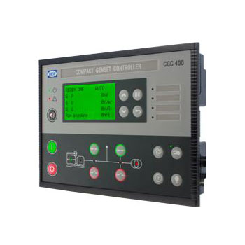
Контроллер генераторной установки
Контроллер CGC 400 представляет собой микропроцессорное устройство включающее все необходимые функции по управлению и защите генераторных агрегатов. Дополнительно устройство имеет входы измерения трехфазного напряжения. Прибор оснащен с ЖК-дисплеем для индикации рабочих параметров и неисправностей. CGC 400 представляет собой компактное и гибкое устройство, разработанное для решения следующих задач:
- Автоматический запуск / остановка двигателя
- Защита двигателя
- Управление выключателем
- Защита генератора
- Автоматическое резервирование сети (только для CGC413)
Конфигурация производится при подключении к ПК с ОС Windows® и сервисной утилиты (доступ защищен паролем). Помимо стандартных функций сервисная программа DEIF USW обеспечивает дополнительные возможности, например, вывод на экран всей необходимой информации для пусконаладочных работ, полное управление контроллером, сохранение и загрузку файлов настроек, а также обновление программного обеспечения контроллера. Кроме того, настройка параметров возможна с лицевой панели (доступ защищен паролем).
- Особенности
- Технические данные
- Габариты
- Узнать цену
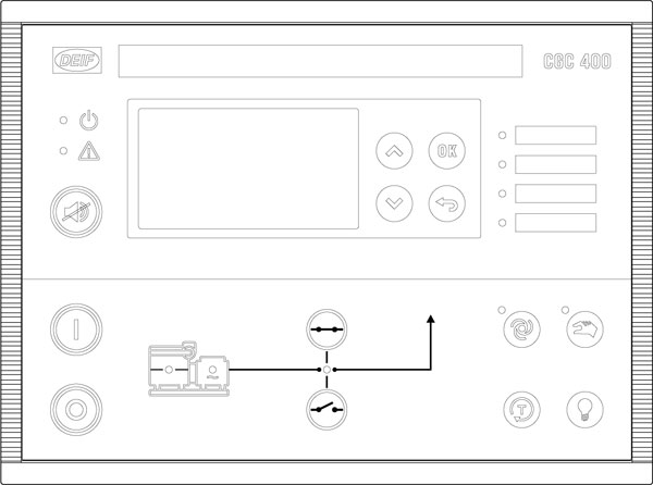
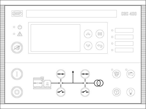
Типы лицевой панели
Лицевая панель CGC 412
Лицевая панель CGC 413
| Питание | 8.0 Vdc до 35,0 Vdc, длительно. Защита от обратной полярности -35 Vdc длительно |
| Провалы при работе стартера | До 0 V длительностью до 50 ms (при провале от 10 V с восстановлением до 8 V). Это обеспечивается без вспомогательных источников. |
| Потребление | <3 W |
| Быстродействие защит | (Срабатывание при минимальной уставке времени) генератора: Обратная мощность < 400 ms Перегрузка по мощности < 400 ms Перегрузка по току < 400 ms Высокое/низкое напряжение < 400 ms Высокая/низкая частота < 400 ms |
| Точность измерения 3-фазного напряжения | Класс 1.0 для IEC/EN 60688 Класс 2.0 в нижнем диапазоне (ниже 70 Vac) |
| Входное сопротивление | от 4 до 8 M ohm |
| Диапазон входа генератора 3-фазный 4 провода 3-фазный 3 провода 1-фазный 2 провода 2-фазный 3 провода |
15 Vac 277 Vac (ph-N) +/-25% 30 Vac 480 Vac (ph-ph) +/-25% 15 Vac 240 Vac (ph-N) +/-25% 15 Vac 240 Vac (ph-N) +/-25% |
| Вход измерения частоты | 50/60 Hz Диапазон 30-70 Hz **. В диапазоне: гарантируется соответствующее быстродействие для срабатывания защит. Во время работы стартера низкая частота будет использована для обнаружения работы двигателя. Минимальная частота 18 Hz. |
| Вход измерения оборотов (напряжение) | 1.5 V 24.0 V (RMS). Выдерживает до 28 Vdc длительно |
| Вход измерения оборотов (частота) | 10 до 10000 Гц Точность 1/10 [Hz] @ 10 до 99,9 [Hz], 1 [Hz] @ 100 до 10000 [Hz] |
| Пассивные дискретные входы | Активация замыканием на землю |
| Уровень сигнала для активации входа | Вход аварийного останова: Активирован от 0 до 3,4 Vdc Неактивирован от 3,5 до напряжения питания Остальные дискретные входы: Активирован от 0 до 1,6 Vdc Неактивирован от 1,7 до напряжения питания |
| Аналоговые входы | Вход измерения тока: 4-20 мА От активного датчика: 4-20 мА, +/-2% Сопротивление: 100 Ω Дискретный вход: сухой контакт 3 Vdc внутреннее питание с контролем подключения Максимальное сопротивление для активированного состояния: 100 Ω Pt100/Pt1000: от -40 до 250 ° C (от -40 до 482 ° F) +/-2% Согласно IEC/EN 60751 RMI: 0-2500 Ω, +/-2% Может выдерживать напряжение питания длительно |
| Статус реле (термин. 3-4) | 2 A @ 35 Vdc |
| Реле 21 | 3 A @ 35 Vdc |
| Реле 22 | 3 A @ 35 Vdc |
| Реле 23 | 3 A @ 35 Vdc |
| Реле 24 | 3 A @ 35 Vdc сухой контакт |
| Реле 26 | 8 A @ 250 Vac/30 Vdc, сухой контакт |
| Реле 45 | 8 A @ 250 Vac/30 Vdc, сухой контакт |
| Реле 47 | 8 A @ 250 Vac/30 Vdc, сухой контакт |
| Сервисный порт | Стандартный USB-B разъем (стандартный USB A / B кабель для подключения) |
| Ток ТТ вторичный | 5 A /1 А (номинал). Макс. потребление: 0,3 VA/фаза |
| Рабочие условия | Температура: (от -25 до + 70) ° C; влажность воздуха: (от 20 до 90) % |
| Условия хранения | Температура: (от -40 до + 70) ° C |
| Уровень защиты | IP65 Клеммы: IP20 Согласно IEC/EN 60529 |
| Материалы | Все пластмассовые части самозатухающие согласно UL94 (V1) |
| Терминалы подключения Момент затяжки |
Входы измерения переменного напряжения/тока: 3.5 mm2 (13 AWG)многожильный Остальные: 1.5 mm2 (16 AWG) многожильный 0,5 Nm (5-7 lb-in) |
| Маркировка CE/EMC | EMC/CE: согласно EN 61000-6-2, EN 61000-6-4 и IEC 60255-26 |
| Броски напряжения питания | ISO 7637-2 (24V DC системы — тестовый импульс 5) Терминалы питания: 123 V/1 Ω/100 ms 174 V/8 Ω/350 мс |
| Климат | 97% RH, IEC 60068-2-30 |
| Вибрации | 5-8 Hz: ±7.5 mm 8 до 150 Hz: 2 g IEC 60068-2-6 |
| Удар | 50 g, 11 ms, IEC 60068-2-27, тест Ea. Тестирование 3 воздействиями в каждом направлении, по всем трем осям. В общей сложности 18 воздействий при каждом тесте |
| Длительные вибрации | 25 g, 16 ms, IEC 60255-21-2 (класс 2) |
| Безопасность (изоляция) | Согласно EN 61010-1 Категория напряжения III, 300 V, степень загрязнения 2 IEC 60255-27 |
| Высота над уровнем моря | 3000 м |
| Вес | 695 г |
Прибор предназначен для панельного монтажа.
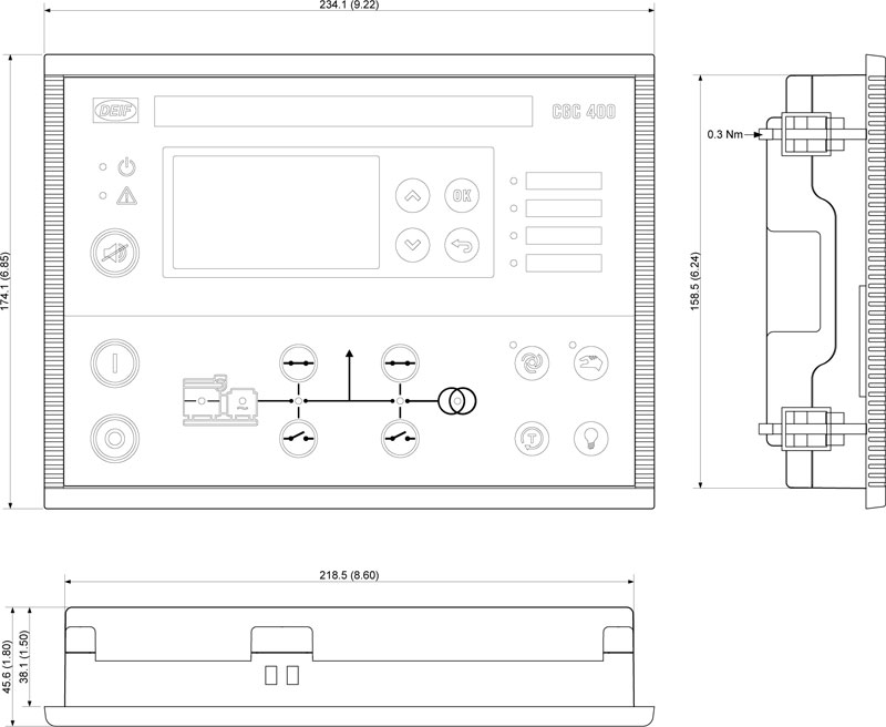
Чтобы обеспечить оптимальный монтаж, необходимо сделать следующий вырез в панели:
H × W = 151.00 × 211,00 + 1,00 мм
H × W = 5.94″ × 8.31″ + 0.04″

Служба оперативной помощи!
с 9:00 до 21:00 по МСК
info@mtu-ind.ru
Бесплатная консультация с нашими инженерами по вопросам эксплуатации генераторных установок и систем управления.
Новости
Контроллеры Atlas Copco
Контроллеры DEIF
- Notre entreprise
- Jobs

-
Home
-
Documentation
- CGC 400
Go to product page
About
Manuals
Installation Instructions
Reference
Other Technical Documentation