CGC 400 DRH 4189340786 UK
7.2.1 Description of phase sequence error
Prior to closing a breaker, the unit checks that the phase sequence is correct, depending on the chosen
phase direction in parameter 2154: «phase rotation». If it is incorrect (reversed), an alarm will be issued, and
the breaker in question will not be closed.
7.3 Breaker types
7.3.1 Breaker types
There are five possible selections for the setting of breaker type for both mains breaker and generator break-
er. The breaker type is selected in the application configuration.
Continuous NE and Continuous ND
This type of signal is most often used combined with a contactor. When using this type of signal, the control-
ler will only use the close breaker(e.g. GB On) relays. The relay will be closed for closing of the contactor and
will be opened for opening of the contactor. Continuous NE is a normally energised signal, and continuous
ND is a normally deenergised signal.
Pulse
This type of signal is most often used combined with circuit breaker. With the setting pulse, the controller will
use the close command(e.g. GB On) and the open command relay (e.g. GB Off). The close breaker relay will
close for a short time for closing of the circuit breaker. The open breaker relay will close for a short time for
opening of the breaker.
Compact
This type of signal will most often be used combined with a compact breaker, a direct controlled motor-driven
breaker. With the setting compact, the controller will need to use both a close command(e.g. GB On) and a
open command relay(e.g. GB Off). The close breaker relay will close for a short time for the compact breaker
to close. The breaker off relay will close for the compact breaker to open and hold it closed long enough for
the motor in the breaker to recharge the breaker. If the compact breaker is tripped externally, it is recharged
automatically before next closing.
If compact breaker is selected, the length of breaker open signal can be adjusted. This can be
done in menu 2160/2200 (GB open fail and MB open fail).
7.4 Breaker spring load time
To avoid breaker close failures in situations where breaker ON command is given before the breaker spring
has been loaded, the spring load time can be adjusted for GB/TB and MB.
The following describes a situation where you risk getting a close failure:
1. The genset is in auto mode, the auto start/stop input is active, the genset is running and the GB is closed.
2. The auto start/stop input is deactivated, the stop sequence is executed and the GB is opened.
3. If the auto start/stop input is activated again before the stop sequence is finished, the GB will give a GB
close failure as the GB needs time to load the spring before it is ready to close.
Different breaker types are used, and therefore there are two available solutions:
1. Timer-controlled
DEIF A/S
Additional functions
Page 49 of 96

-
Contents
-
Table of Contents
-
Bookmarks
Quick Links
OPERATOR’S MANUAL
Compact Genset Controller, CGC 400
● Push-buttons
● LEDs
● Display and menu structure
● Display readings
● Alarm handling and log list
DEIF A/S · Frisenborgvej 33 · DK-7800 Skive · Tel.: +45 9614 9614 · Fax: +45 9614 9615 · info@deif.com · www.deif.com
Document no.: 4189340787A
SW version: 1.00
Related Manuals for Deif CGC 400
Summary of Contents for Deif CGC 400
-
Page 1
● Alarm handling and log list DEIF A/S · Frisenborgvej 33 · DK-7800 Skive · Tel.: +45 9614 9614 · Fax: +45 9614 9615 · info@deif.com · www.deif.com isenborgvej 33 · DK-7800 Skive · Tel.: +45 9614 9614 · Fax: +45 9614 9615 · info@deif.com · www.deif.com Document no.: 4189340787A… -
Page 2: Table Of Contents
CGC 400 Operator’s manual 4189340787 1. General information 1.1. Warnings, legal information and safety………………..3 1.1.1. Warnings and notes ……………………3 1.1.2. Legal information and disclaimer ………………..3 1.1.3. Safety issues ……………………..3 1.1.4. Electrostatic discharge awareness ………………..3 1.1.5. Factory settings ……………………..4 1.2. About the operator’s manual……………………4 1.2.1.
-
Page 3: General Information
1.1.2 Legal information and disclaimer DEIF takes no responsibility for installation or operation of the generator set. If there is any doubt about how to install or operate the engine/generator controlled by the unit, the company responsible for the installation or the operation of the set must be contacted.
-
Page 4: Factory Settings
CGC 400 Operator’s manual 4189340787 General information 1.1.5 Factory settings The unit is delivered from factory with certain factory settings. These are based on average values and are not necessarily the correct settings for matching the engine/generator set in question. Precautions must be taken to check the settings before running the engine/generator set.
-
Page 5: Push-Buttons And Leds
CGC 400 Operator’s manual 4189340787 Push-buttons and LEDs 2. Push-buttons and LEDs 2.1 Push-button functions The push-buttons on the unit have the following functions: Function Secondary functionality Scroll the display up once Programming: Increase setpoint value Scroll the display down once…
-
Page 6: Led Functions
The display unit holds 10 LED functions. Dependent on the situation, the colour of the LEDs is green, red or a combination. The table below describes the functionality of the LEDs on the CGC 400: LED no. LED name LED function…
-
Page 7: Display And Menu Structure
CGC 400 Operator’s manual 4189340787 Display and menu structure 3. Display and menu structure 3.1 Menu 3.1.1 Menu system The display includes the menu systems listed below which can be used/viewed without password entry: View menu system: This is the commonly used menu system, which contains displaying of the measured values.
-
Page 8: Menu Structure Example
CGC 400 Operator’s manual 4189340787 Display and menu structure 3.1.3 Menu structure example The figure below is an example of how the menu structure is arranged, and it also shows the meaning of the entry symbols..(up to 20 views)
-
Page 9: Display Functions
CGC 400 Operator’s manual 4189340787 Display and menu structure 3.2 Display functions 3.2.1 Functional examples The display indicates both readings and alarms. The examples below are with icons and English language. View examples Service menu Appl. Ver.: 9.90.0 The software version can be found in the Service menu Appl.
-
Page 10
CGC 400 Operator’s manual 4189340787 Display and menu structure Edit value with up and down arrows and save the value by pressing the 1000 -P> OK button. Set point: -5.0% Timer: 0.5 sec Output A: Not used Output B: Not used For detailed information about changing parameters and setup, please see the Designer’s Ref- erence Handbook. -
Page 11: Status Line Text
CGC 400 Operator’s manual 4189340787 Status line text 4. Status line text 4.1 Status line text 4.1.1 Standard texts Condition Comment BLOCK Block mode is activated SIMPLE TEST Test mode is activated FULL TEST SIMPLE TEST ###.#min Test mode activated and test timer counting down FULL TEST ###.#min…
-
Page 12
CGC 400 Operator’s manual 4189340787 Status line text Condition Comment START RELAY OFF The start relay is deactivated during the start se- quence MAINS FAILURE Mains failure and mains failure timer expired MAINS FAILURE IN ###s Frequency or voltage measurement is outside the lim-… -
Page 13: Running Modes
CGC 400 Operator’s manual 4189340787 Running modes 5. Running modes 5.1 Running mode overview The unit has four different running modes and one block mode. The different running modes are selected via the display or the PC utility software. For detailed information please see Designer’s Reference Handbook.
-
Page 14: Alarm Handling And Log List
CGC 400 Operator’s manual 4189340787 Alarm handling and log list 6. Alarm handling and log list 6.1 Alarm handling When an alarm occurs, the unit will automatically go to the alarm list for display of the alarm. If reading of the alarms is not desired, use the BACK push-button to exit the alarm list.
This manual is also suitable for:
Agc 100
-
Contents
-
Table of Contents
-
Bookmarks
Quick Links
OPERATOR’S MANUAL
Compact Genset Controller, CGC 400
● Push-buttons
● LEDs
● Display and menu structure
● Display readings
● Alarm handling and log list
DEIF A/S · Frisenborgvej 33 · DK-7800 Skive · Tel.: +45 9614 9614 · Fax: +45 9614 9615 · info@deif.com · www.deif.com
Document no.: 4189340787A
SW version: 1.00
Related Manuals for Deif CGC 400
Summary of Contents for Deif CGC 400
-
Page 1
● Alarm handling and log list DEIF A/S · Frisenborgvej 33 · DK-7800 Skive · Tel.: +45 9614 9614 · Fax: +45 9614 9615 · info@deif.com · www.deif.com isenborgvej 33 · DK-7800 Skive · Tel.: +45 9614 9614 · Fax: +45 9614 9615 · info@deif.com · www.deif.com Document no.: 4189340787A… -
Page 2: Table Of Contents
CGC 400 Operator’s manual 4189340787 1. General information 1.1. Warnings, legal information and safety………………..3 1.1.1. Warnings and notes ……………………3 1.1.2. Legal information and disclaimer ………………..3 1.1.3. Safety issues ……………………..3 1.1.4. Electrostatic discharge awareness ………………..3 1.1.5. Factory settings ……………………..4 1.2. About the operator’s manual……………………4 1.2.1.
-
Page 3: General Information
1.1.2 Legal information and disclaimer DEIF takes no responsibility for installation or operation of the generator set. If there is any doubt about how to install or operate the engine/generator controlled by the unit, the company responsible for the installation or the operation of the set must be contacted.
-
Page 4: Factory Settings
CGC 400 Operator’s manual 4189340787 General information 1.1.5 Factory settings The unit is delivered from factory with certain factory settings. These are based on average values and are not necessarily the correct settings for matching the engine/generator set in question. Precautions must be taken to check the settings before running the engine/generator set.
-
Page 5: Push-Buttons And Leds
CGC 400 Operator’s manual 4189340787 Push-buttons and LEDs 2. Push-buttons and LEDs 2.1 Push-button functions The push-buttons on the unit have the following functions: Function Secondary functionality Scroll the display up once Programming: Increase setpoint value Scroll the display down once…
-
Page 6: Led Functions
The display unit holds 10 LED functions. Dependent on the situation, the colour of the LEDs is green, red or a combination. The table below describes the functionality of the LEDs on the CGC 400: LED no. LED name LED function…
-
Page 7: Display And Menu Structure
CGC 400 Operator’s manual 4189340787 Display and menu structure 3. Display and menu structure 3.1 Menu 3.1.1 Menu system The display includes the menu systems listed below which can be used/viewed without password entry: View menu system: This is the commonly used menu system, which contains displaying of the measured values.
-
Page 8: Menu Structure Example
CGC 400 Operator’s manual 4189340787 Display and menu structure 3.1.3 Menu structure example The figure below is an example of how the menu structure is arranged, and it also shows the meaning of the entry symbols..(up to 20 views)
-
Page 9: Display Functions
CGC 400 Operator’s manual 4189340787 Display and menu structure 3.2 Display functions 3.2.1 Functional examples The display indicates both readings and alarms. The examples below are with icons and English language. View examples Service menu Appl. Ver.: 9.90.0 The software version can be found in the Service menu Appl.
-
Page 10
CGC 400 Operator’s manual 4189340787 Display and menu structure Edit value with up and down arrows and save the value by pressing the 1000 -P> OK button. Set point: -5.0% Timer: 0.5 sec Output A: Not used Output B: Not used For detailed information about changing parameters and setup, please see the Designer’s Ref- erence Handbook. -
Page 11: Status Line Text
CGC 400 Operator’s manual 4189340787 Status line text 4. Status line text 4.1 Status line text 4.1.1 Standard texts Condition Comment BLOCK Block mode is activated SIMPLE TEST Test mode is activated FULL TEST SIMPLE TEST ###.#min Test mode activated and test timer counting down FULL TEST ###.#min…
-
Page 12
CGC 400 Operator’s manual 4189340787 Status line text Condition Comment START RELAY OFF The start relay is deactivated during the start se- quence MAINS FAILURE Mains failure and mains failure timer expired MAINS FAILURE IN ###s Frequency or voltage measurement is outside the lim-… -
Page 13: Running Modes
CGC 400 Operator’s manual 4189340787 Running modes 5. Running modes 5.1 Running mode overview The unit has four different running modes and one block mode. The different running modes are selected via the display or the PC utility software. For detailed information please see Designer’s Reference Handbook.
-
Page 14: Alarm Handling And Log List
CGC 400 Operator’s manual 4189340787 Alarm handling and log list 6. Alarm handling and log list 6.1 Alarm handling When an alarm occurs, the unit will automatically go to the alarm list for display of the alarm. If reading of the alarms is not desired, use the BACK push-button to exit the alarm list.
This manual is also suitable for:
Agc 100
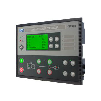
Контроллер генераторной установки
Контроллер CGC 400 представляет собой микропроцессорное устройство включающее все необходимые функции по управлению и защите генераторных агрегатов. Дополнительно устройство имеет входы измерения трехфазного напряжения. Прибор оснащен с ЖК-дисплеем для индикации рабочих параметров и неисправностей. CGC 400 представляет собой компактное и гибкое устройство, разработанное для решения следующих задач:
- Автоматический запуск / остановка двигателя
- Защита двигателя
- Управление выключателем
- Защита генератора
- Автоматическое резервирование сети (только для CGC413)
Конфигурация производится при подключении к ПК с ОС Windows® и сервисной утилиты (доступ защищен паролем). Помимо стандартных функций сервисная программа DEIF USW обеспечивает дополнительные возможности, например, вывод на экран всей необходимой информации для пусконаладочных работ, полное управление контроллером, сохранение и загрузку файлов настроек, а также обновление программного обеспечения контроллера. Кроме того, настройка параметров возможна с лицевой панели (доступ защищен паролем).
- Особенности
- Технические данные
- Габариты
- Узнать цену
Типы лицевой панели
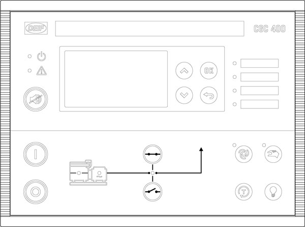
Лицевая панель CGC 412
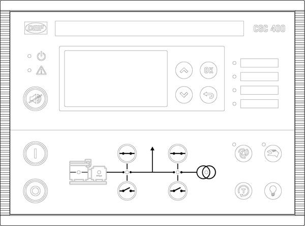
Лицевая панель CGC 413
| Питание | 8.0 Vdc до 35,0 Vdc, длительно. Защита от обратной полярности -35 Vdc длительно |
| Провалы при работе стартера | До 0 V длительностью до 50 ms (при провале от 10 V с восстановлением до 8 V). Это обеспечивается без вспомогательных источников. |
| Потребление | <3 W |
| Быстродействие защит | (Срабатывание при минимальной уставке времени) генератора: Обратная мощность < 400 ms Перегрузка по мощности < 400 ms Перегрузка по току < 400 ms Высокое/низкое напряжение < 400 ms Высокая/низкая частота < 400 ms |
| Точность измерения 3-фазного напряжения | Класс 1.0 для IEC/EN 60688 Класс 2.0 в нижнем диапазоне (ниже 70 Vac) |
| Входное сопротивление | от 4 до 8 M ohm |
| Диапазон входа генератора 3-фазный 4 провода 3-фазный 3 провода 1-фазный 2 провода 2-фазный 3 провода |
15 Vac 277 Vac (ph-N) +/-25% 30 Vac 480 Vac (ph-ph) +/-25% 15 Vac 240 Vac (ph-N) +/-25% 15 Vac 240 Vac (ph-N) +/-25% |
| Вход измерения частоты | 50/60 Hz Диапазон 30-70 Hz **. В диапазоне: гарантируется соответствующее быстродействие для срабатывания защит. Во время работы стартера низкая частота будет использована для обнаружения работы двигателя. Минимальная частота 18 Hz. |
| Вход измерения оборотов (напряжение) | 1.5 V 24.0 V (RMS). Выдерживает до 28 Vdc длительно |
| Вход измерения оборотов (частота) | 10 до 10000 Гц Точность 1/10 [Hz] @ 10 до 99,9 [Hz], 1 [Hz] @ 100 до 10000 [Hz] |
| Пассивные дискретные входы | Активация замыканием на землю |
| Уровень сигнала для активации входа | Вход аварийного останова: Активирован от 0 до 3,4 Vdc Неактивирован от 3,5 до напряжения питания Остальные дискретные входы: Активирован от 0 до 1,6 Vdc Неактивирован от 1,7 до напряжения питания |
| Аналоговые входы | Вход измерения тока: 4-20 мА От активного датчика: 4-20 мА, +/-2% Сопротивление: 100 Ω Дискретный вход: сухой контакт 3 Vdc внутреннее питание с контролем подключения Максимальное сопротивление для активированного состояния: 100 Ω Pt100/Pt1000: от -40 до 250 ° C (от -40 до 482 ° F) +/-2% Согласно IEC/EN 60751 RMI: 0-2500 Ω, +/-2% Может выдерживать напряжение питания длительно |
| Статус реле (термин. 3-4) | 2 A @ 35 Vdc |
| Реле 21 | 3 A @ 35 Vdc |
| Реле 22 | 3 A @ 35 Vdc |
| Реле 23 | 3 A @ 35 Vdc |
| Реле 24 | 3 A @ 35 Vdc сухой контакт |
| Реле 26 | 8 A @ 250 Vac/30 Vdc, сухой контакт |
| Реле 45 | 8 A @ 250 Vac/30 Vdc, сухой контакт |
| Реле 47 | 8 A @ 250 Vac/30 Vdc, сухой контакт |
| Сервисный порт | Стандартный USB-B разъем (стандартный USB A / B кабель для подключения) |
| Ток ТТ вторичный | 5 A /1 А (номинал). Макс. потребление: 0,3 VA/фаза |
| Рабочие условия | Температура: (от -25 до + 70) ° C; влажность воздуха: (от 20 до 90) % |
| Условия хранения | Температура: (от -40 до + 70) ° C |
| Уровень защиты | IP65 Клеммы: IP20 Согласно IEC/EN 60529 |
| Материалы | Все пластмассовые части самозатухающие согласно UL94 (V1) |
| Терминалы подключения Момент затяжки |
Входы измерения переменного напряжения/тока: 3.5 mm2 (13 AWG)многожильный Остальные: 1.5 mm2 (16 AWG) многожильный 0,5 Nm (5-7 lb-in) |
| Маркировка CE/EMC | EMC/CE: согласно EN 61000-6-2, EN 61000-6-4 и IEC 60255-26 |
| Броски напряжения питания | ISO 7637-2 (24V DC системы — тестовый импульс 5) Терминалы питания: 123 V/1 Ω/100 ms 174 V/8 Ω/350 мс |
| Климат | 97% RH, IEC 60068-2-30 |
| Вибрации | 5-8 Hz: ±7.5 mm 8 до 150 Hz: 2 g IEC 60068-2-6 |
| Удар | 50 g, 11 ms, IEC 60068-2-27, тест Ea. Тестирование 3 воздействиями в каждом направлении, по всем трем осям. В общей сложности 18 воздействий при каждом тесте |
| Длительные вибрации | 25 g, 16 ms, IEC 60255-21-2 (класс 2) |
| Безопасность (изоляция) | Согласно EN 61010-1 Категория напряжения III, 300 V, степень загрязнения 2 IEC 60255-27 |
| Высота над уровнем моря | 3000 м |
| Вес | 695 г |
Прибор предназначен для панельного монтажа.
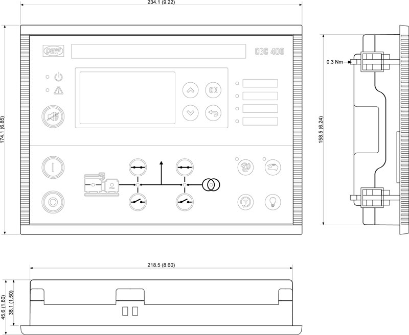
Чтобы обеспечить оптимальный монтаж, необходимо сделать следующий вырез в панели:
H × W = 151.00 × 211,00 + 1,00 мм
H × W = 5.94″ × 8.31″ + 0.04″

Служба оперативной помощи!
с 9:00 до 21:00 по МСК
info@mtu-ind.ru
Бесплатная консультация с нашими инженерами по вопросам эксплуатации генераторных установок и систем управления.
Новости
Контроллеры Atlas Copco
Контроллеры DEIF
- Über uns
- Offene Stellen

-
Home
-
Documentation
- CGC 400
Go to product page
About
Manuals
Installation Instructions
Reference
Other Technical Documentation