10 августа 2022
4297
Время чтения:
5 мин.
2
Перечислим основные ошибки весов CAS с кодами Err ××, дадим расшифровку и скажем, как исправить проблему.
Содержание
Весы не включаются
LobAt, batt, Err-b
Err 0, UNStA, UnS
Err 1
Err 3, OFL
Err 6, ovErr, Err 8, oF
Err 9
Err 2, 11, 12, 13, 22, Init, not Err CAL
Весы не включаются
Проверьте исправность сетевого адаптера и самой розетки. Для моделей с автономным питанием зарядите аккумулятор или поставьте новые батарейки.
Если проблема сохраняется, сдавайте весы в сервис.
Ошибка LobAt, batt, Err-b
Сокращение от слово батарея. Означает, что аккумулятор разрядился.
Что делать: зарядите АКБ. Если ошибка сохраняется, проблема в нем, купите и поставьте новый. Реже поломка в самих весах, тогда их нужно нести в ремонт.
Ошибка Err 0, UNStA, UnS
Весы не могут работать из-за нестабильности окружающей среды. Причины бывают разные, например, если на них дует сильный поток воздуха от вентилятора / из-за холодильника ощутимо вибрирует основание / стол шатается / какой-то предмет касается платформы / под платформу попала грязь. Попробуйте устранить факторы, которые мешают чувствительным датчикам.
Если вы все проверили и стабилизировали, но ошибка сохраняется, сдавайте весы инженерам. Они заменят неисправный элемент, обычно это датчик или преобразователь.
Ошибка весов Err 1
На CAS эта ошибка возникает, когда весы не могут установить нулевое состояние. Первым делом уберите груз и попробуйте обнулиться. На разных моделях предусмотрен значок >I<, 0, Zero и т.п.
Часто появляется из-за сильного удара или перегрузки. Можно попробовать провести калибровку.
Рекомендуем подобные работы доверить мастерам сервисного центра.
Если калибровка не помогает, то неисправен весоизмерительный датчик. Решением станет его замена в сервисном центре.

Ошибка весов Err 3, OFL
Означает перегрузку. В первую очередь освободите платформу. Если не помогает, необходима калибровка, её стоит проводить в сервисном центре.
Чаще всего калибровки достаточно, но иногда проблема в датчике, тогда его придётся заменить.
Ошибки Err 6, ovErr, Err 8, oF
Возникает у торговых весов с расчётом стоимости, если получились слишком большое число товаров (ошибка 6, ovErr) или слишком большая сумма. Нужно сбросить данные, для этого предусмотрены клавиши ОБН или С.
Ошибка Err 9
Весы CAS показывают её в счётном режиме, если на них не положили подсчитанное количество товаров. Нагрузите платформу образцами, и тогда ошибка должна пропасть.
Если вам нужен другой режим, выйдите из счетного, убрав груз с платформы и нажав кнопку М (либо М, а затем сброс тары).
Ошибки весов CAS Err 2, Err 11, Err 12, Err 13, Err 22, Init, not Err CAL
Вам даже не обязательно знать расшифровку, потому что с этими ошибками вам точно придётся нести весы в ремонт. Проблемы с настройками или электроникой устраняют исключительно в сервисной мастерской.
Весы CAS выдают ошибку?
Поможем разобраться с проблемой!
Оставьте заявку и получите консультацию инженера сервисного центра.
Заказать звонок
Ваша заявка принята
Наши консультанты перезвонят Вам
в течение 20 минут
Статью подготовила редакция блога portkkm.ru.
Если есть вопросы по работе и ремонту весов, оставляйте заявку на бесплатную консультацию инженеров АСЦ ПОРТ в Красноярске. Будем рады вам помочь.
КАЛИБРОВКА ВЕСОВ CAS
Во всех весах (кроме индустриальных) калибровка разбита на 4 важных подкалибровки: С-1цифровое значение датчика и аналогового модуля.
С-2время импульса запроса на аналоговый модуль(не важный параметр). С-3калибровка весом.
С-4опции настройки НВП и дискреты в восмибитном формате.(опция влияет только на арифметическое логическое устройство ,то есть если С3 калибровка не идет эту опцию трогать не следует ).
С-6 (только для 1Р-уег1.6)настройка датчиков термопринтера.
С-9 (только для ADH,1p-1.6)значение кофициента g притяжения земли.
Для весов у которых не более 4-х кнопок управления переключение подкалибровок происходит кнопкой ONOFF в обратном случае на бором на цифровой клавиатуре.
В весах с жидкокристаллическими дисплеями и светодиодными матрицами (тип sw,tp,em,mv,d1,bw,bi,ci) калибровочная кнопка, а если с вакуумным индикатором (тип ad,db,1p,adh,ap,tc,)зеленым то стоит калибровочный переключатель.
Подробное описание калибровок:
Весы CAS SW до 2006 года не пищащие
. Снять платформу открутить длинный болт под желтой наклейкой перевернуть весы открутить винт на железном ярлыке и снять его.
Нажмите кнопку и включите весы , подождите 30сек
Нажать ONOFF, на дисплее высветиться 1-ХХ , это первая опция настройки весов на нвп и дискрету .
Если нужно поменять опции используйте функции клавиш ;ZERO-переключает опцию(всего3),HOLD-сдвигает цифру в лево ,ТАЯА-набирает цифру.
Пример : набрать (1-21) нажимая тару набрать 1-Х2, нажать холд цифра2 сдвинется в лево, нажимая кнопку тара до единицы получаем 1-21. Для следующей опции нажимаем кнопку зеро и вводим вторую опцию, для сохранения опций надо ввести все три опции.
Sw2 :1-21; 2-61; 3-11
Sw5 :1-22: 2-61; 3-11
Sw10 :1-23: 2-61; 3-11
Sw20 :1-24: 2-61; 3-11
Если опции не нужно менять нажимаете ONOFF на дисплее высветиться 4XXX цифровое значение датчика, в исправных весах колеблется от 4000 до 8000, нажимаете ONOFF на дисплее высветиться 4XXX цифровое значение аналогового модуля. Нажимаете дальше ONOFF, на дисплее высветиться ULOAD ставите на место платформу без нагрузки, нажимаете ONOFF, на дисплее высветиться LOAD ставите на платформу НВП соответствующим нагрузке датчика(sw2=2kg) . Нажимаете ONOFF на дисплее высветиться END.
Калибровка завершена.
Весы CAS SW после 2006 года пищащие
Снять платформу открутить длинный болт под желтой наклейкой перевернуть весы открутить винт на железном ярлыке и снять его.
Нажмите кнопку и включите весы , подождите 30сек
На дисплее высветиться С-0. Если нужно поменять опции используйте функции клавиш ;ZERO-nереключает опцию(всего9),HOLD-выхоg из опции ,TARA-exog в опцию.
С-0 выход из опции
С-1 цифровое значение датчика С-2время импульса запроса на аналоговый модуль(не важный параметр). С-3калибровка весом.
С-4опции настройки НВП и дискреты в восмибитном формате. с С-5 поС-9 не используются.
Пример; нажимаем кнопку зеро пока на дисплее высветится С с нужной подкалибровкой С-3,нажимаем кнопку тара на дисплее, высветиться ULOAD ставите на место платформу без нагрузки, нажимаете зеро, на дисплее высветиться LOAD ставите на платформу НВП, нажимаете зеро на дисплее высветиться С-0, нажимаете зеро выходите полностью из калибровки.
Опции С-4
пример : набрать (41-01) нажимая тару набрать 41-Х1, нажать холд мерцающяя цифра переключится, нажимая кнопку тара до единицы получаем 41-01. Для следующей опции нажимаем кнопку зеро и вводим вторую опцию, для сохранения опций надо ввести все шесть опций.
SW2 :C4101,C4208,C4300,C4400,C4501,C4600 SW5: C4101,C4218,C4300,C4400,C4500,C4600 SW10: C4101,C4228,C4300,C4400,C4501,C4600 SW20: C4101,C4240,C4300,C4400,C4501,C4600
После введения всех опций ХОЛДОМ переключить на С-0.Нажать зеро.
Калибровка весов CAS SW самого нового образца (лето 2010)
- Снять калибровочную пластину, находящуюся снизу весов. Зажать калибровочную кнопку, расположенную под пластиной и одновременно включить весы кнопкой ВКЛ. На индикаторе загорится CAL 1 . Кнопкой тара листать до CAL Убедится, что весы стоят по уровню, на весах установлена платформа, и она разгружена. Нажать кнопку Zero (0), на индикаторе загорится Zero, нажать Zero (0) еще раз, начнется калибровка нуля и высветится цифровое значение нуля (для 10-ки около 15000). После появится надпись Midup. На платформу ставят половину НПВ (для 5 кг нужно ставить 2 кг) и нажимают Zero (0) . Появится цифровое значение для этой точки (для 10-ки около 45000) . После появится надпись Full, ставят на платформу НПВ и нажимают Zero (0). Появится цифровое значение для этой точки (для 10_ки около 75000). На индикаторе появится надпись Middn. На платформу ставят половину НПВ (для 5 кг нужно ставить 2 кг) и нажимают Zero (0). Вновь появляется цифровое значение для этой точки (у 10-ки — 45000) и весы выходят в CAL 3. Калибровка окончена. Выходят из нее кнопкой ВКЛ.
- Также можно откалибровать весы процентом от НПВ в CAL 7 . Кнопкой тара листать разряды кнопкой зеро листать числа. Таким образом, вводится процент, после нажимается Zero (0) появляется надпись Zero, нажать снова Zero (0) идет тест нуля, после поставить нужный вес и нажать Zero (0). Вновь появляется цифровое значение для этой точки, и весы выходят в CAL Калибровка окончена. Выходят из нее кнопкой ВКЛ.
Значение опций для CAL 4 — C41 b4; C43 0F, они универсальны для всех НПВ.
Значение дискреты выставляется в CAL 10, параметр id. Кнопкой тара листать разряды кнопкой зеро листать числа.
Цифровые значения для четырех точек: Zero, Midup, Full, Middn.
2
5 — 15500, 46300, 77000, 46300.
10 — 15000, 45000, 75000, 45000.
20 — 11600, 41700, 71800, 41700.
CAL 1 и CAL 5 — цифровое значение датчика.
CAL 6 — значение равно 5 для всех НПВ.
CAL 7 — калибровка процентом.
CAL 9 — Сила земного притяжения. Два параметра g-1 b g-2 имеют значение 9,7946. Они одинаковые для всех НПВ. Кнопкой тара листать разряды кнопкой зеро листать числа.
CAL 10 — UNIT -0 (для всех НПВ), CAPA (изменение НПВ) — 00020, 00010, 00005, 00002 соответственно для 20, 10, 5, 2кг. MID (изменение дискреты с изменением НПВ) — 00010, 00005, 00002, 00001. g — dp — 3 для всех Н11В.id — (дискрета) 0,010, 0,005, 0,002, 0,001 соответственно для 20, 10, 5, 2кг. DUAL — 0, TARE — 0 для всех НПВ по умолчанию.
CAL 11 — 00. ID весов (используется для подключения весов к компьютеру).
Весы CAS AP (m,ex)
Снять платформу, с лево от центра снять круглую крышечку . 1лоской маленькой отверткой переключить от себя красный переключатель . Включить вилку в розетку, нажать ONOFF, на дисплее высветиться CAL подождите 30сек.
Нажимаете на цифровой клавиатуре номер подкалибровки
С-1цифровое значение датчика и аналогового модуля.
С-2время импульса запроса на аналоговый модуль(не важный параметр).
С-3калибровка весом.
С-4опции настройки НВ1 и дискреты в восмибитном формате.(опция влияет только на арифметическое логическое устройство, то есть если С3 калибровка не идет эту опцию трогать не следует ).
Опции С-3
1ример калибровки весом ; нажимаем кнопку 3 на дисплее, высветиться ULOAD ставите на место платформу без нагрузки, нажимаете С , на дисплее высветиться LOAD ставите на платформу НВП, нажимаете С на дисплее высветиться ЕЫО.Если на дисплее HHHHHH или LLLLLLL значит НВ1 неправильное или есть неисправность.
Опции С-4
1ример : набрать (1-81) нажимаем на цифровой клавиатуре 8 потом 1 . Для следующей опции нажимаем кнопку С и вводим вторую опцию, для сохранения опций надо ввести все шесть опций
Опции ниже:
Ap6m: 1-81, 2-39, 3-00, 4-23, 5-07, 6-07 Ap15m: 1-81, 2-3a, 3-00, 4-23, 5-07, 6-07 Ap30m: 1-81, 2-38, 3-00, 4-23, 5-07, 6-07 Ap6ex: 1-81, 2-39, 3-80, 4-23, 5-07, 6-07 Ap15ex: 1-81, 2-3a, 3-80, 4-23, 5-07, 6-07 Ap30ex: 1-81, 2-38, 3-80, 4-23, 5-07, 6-07
После проведенной калибровки выключить весы из розетки , переключить переключатель калибровки на себя включить весы.
Весы CAS AD, ADH
Снять платформу, с лево от центра снять круглую крышечку . Плоской маленькой отверткой переключить от себя красный переключатель . Включить вилку в розетку, нажать ONOFF, на дисплее высветиться CAL подождите 30сек.
Переключение подпрограмм осуществляется кнопкой ONOFF
Нажать ONOFF, на дисплее высветиться 1-ХХ , это первая опция настройки весов на нвп и дискрету .
Если нужно поменять опции используйте функции клавиш ;ZERO-переключает опцию(всего3),HOLD-сgвигает цифру в лево ,ТАЯА-набирает цифру.
Пример программирования опций : набрать (1-81) нажимая тару набрать 1-Х8, нажать холд цифра8 сдвинется в лево, нажимая кнопку тара до еденицы получаем 1-81. Для следующей опции нажимаем кнопку зеро и вводим вторую опцию, для сохранения опций надо ввести все три опции для ADH и четыре AD.
Ad2.5:1-80, 2-52, 3-41, 4-01.
Ad5: 1-80, 2-50, 3-41, 4-03.
Ad10: 1-81, 2-51, 3-41, 4-03.
Ad25:1-80, 2-52, 3-40, 4-03
Ad30: 1-81, 2-24, 3-40, 4-03.
Adh5: 1-8A, 2-56, 3-01.
Adh10:1-88, 2-56, 3-03. Adh20:1-89, 2-55, 3-03.
Для АО:Если опции не нужно менять нажимаете ONOFF на дисплее высветиться 4ХХХцифровое значение датчика, в исправных весах колеблется от 1000 до 5000, нажимаете ONOFF на дисплее высветиться 4XXX цифровое значение аналогового модуля.
Нажимаете дальше ONOFF, на дисплее высветиться ULOAD ставите на место платформу без нагрузки, нажимаете ONOFF, на дисплее высветиться LOAD ставите на платформу НВП соответствующим нагрузке датчика^10=10кд) . Нажимаете ONOFF на дисплее высветиться END.
Для АРН:Если опции не нужно менять нажимаете ONOFF на дисплее высветиться 4ХХХцифровое значение датчика, в исправных весах колеблется от 1000 до 5000, нажимаете ONOFF на дисплее высветиться 4XXX цифровое значение аналогового модуля. Нажимаете дальше ONOFF на дисплее высветиться кооф д(не меняете). Нажимаете дальше ONOFF, на дисплее высветиться ULOAD ставите на место платформу без нагрузки, нажимаете ONOFF, на дисплее высветиться 50PER ставите на платформу 12НВП соответствующим нагрузке датчика(а01110 5kg) . , нажимаете ONOFF, на
дисплее высветиться 100PER ставите на платформуНВП соответствующим нагрузке датчика(ас11110 10kg) . Нажимаете ONOFF на дисплее высветиться END.Калибровка завершена.
После проведенной калибровки выключить весы из розетки , переключить переключатель калибровки на себя включить весы.
Весы CAS EM (R)
Перевернуть весы открутить два латунных винта на железном ярлычке и снять его. Нажмите кнопку и включите весы , подождите 30сек.
Нажимаете на цифровой клавиатуре номер подкалибровки С-1цифровое значение датчика и аналогового модуля.
С-2время импульса запроса на аналоговый модуль(не важный параметр). С-3калибровка весом.
С-4опции настройки НВП и дискреты в восмибитном формате.(опция влияет только на арифметическое логическое устройство, то есть если С3 калибровка не идет эту опцию трогать не следует ).
Опции С-3
Пример калибровки весом ; нажимаем кнопку 3 на дисплее, высветиться ULOAD ставите на место платформу без нагрузки, нажимаете С , на дисплее высветиться LOAD ставите на платформу НВП, нажимаете С на дисплее высветиться ЕЫО.Если на дисплее HHHH или LLLL значит НВП неправильное или есть неисправность.
Опции С-4
Пример программирования опций : нажимаем кнопку 4, для набора (1-81) нажимаем на цифровой клавиатуре 8 потом 1 . Для следующей опции нажимаем кнопку С и вводим вторую опцию, для сохранения опций надо ввести все восемь опций . Опции ниже: em6(r): 1-81, 2-39, 3-80, 4-23, 5-07, 6-07, 7-C0, 8-00.
em15(r): 1-81, 2-3a, 3-80, 4-23, 5-07, 6-07, 7-C0, 8-00.
em30(r): 1-81, 2-38, 3-80, 4-23, 5-07, 6-07, 7-C0, 8-00.
Весы CAS ER
Перевернуть весы открутить два латунных винта на железном ярлычке и снять его. Нажмите кнопку и включите весы , подождите 30сек.
Нажимаете на цифровой клавиатуре номер подкалибровки С-1цифровое значение датчика и аналогового модуля.
С-3калибровка весом.
С-4опции в восмибитном формате.(опция влияет только на арифметическое логическое устройство, то есть если С3 калибровка не идет эту опцию трогать не следует ).
Опции С-3
Пример калибровки весом ; листаем кнопкой «0» до С3, нажимаем «тара», на дисплее, высветиться ULOAD ставите на место платформу без нагрузки, нажимаете «тара» , на дисплее высветиться MIDD ставите на платформу 1/3НВП, нажимаете «тара» на дисплее высветиться FULL ставите на платформу НВП, нажимаете «тара» на дисплее высветиться MIDD ставите на платформу1/3 НВП ждете END.
Опции С-4
Пример программирования опций : листаем кнопкой «0» до С 4, нажимаем «тара», для набора (41-81) нажимаем на цифровой клавиатуре 8 потом 1 . Для следующей опции нажимаем кнопку «тара» и вводим вторую опцию, для сохранения опций надо ввести все 5 опций . Опции ниже:
| 41 | AC | 42 | 7F |
| 43 | 7F | 44 | 0B |
| 45 | AF |
нажимаем «тара», на дисплее, высветиться C4, кнопка «С» — выход.
Весы CAS LP
Снять платформу, открутить пластину и переключить переключатель в левое положение . Включите весы , подождите 30сек.
Опции для версии 1.5
С-0 выход из опции
С-1 цифровое значение датчика
С-2время импульса запроса на аналоговый модуль(не важный параметр).
С-3калибровка весом.
С-4опции настройки НВП
С-5 поС-9 не используются.
Опции С-3
Пример калибровки весом ; нажимаем кнопку 3 на дисплее, высветиться ULOAD ставите на место платформу без нагрузки, нажимаете ПЕЧ , на дисплее высветиться LOAD ставите на платформу НВП, нажимаете ПЕЧ на дисплее высветиться END.Eonn на дисплее HHHH или LLLL значит НВП неправильное или есть неисправность.
Опции С-4
Пример программирования опций на 15 кг: нажимаем кнопку 4 ,на дисплее высветиться REZ, нажать ПЕЧ, на дисплее высветиться 3000(7500для 30 кг,6000 для 6кг). Нажать ПЕЧ, на дисплее высветиться DUAL, нажать ПЕЧ, на дисплее высветиться 1(1-двухдиа- пазонная.0- однодиапазонная) . Нажать ПЕЧ, на дисплее высветиться CAPA, нажать ПЕЧ на дисплее высветиться 15(30-30кг,6-6кг).
Нажать ПЕЧ, на дисплее высветиться DP, нажать ПЕЧ на дисплее высветиться 433(количество нулей после запятой ). Нажать ПЕЧ, на дисплее высветиться UNIT , нажать ПЕЧ на дисплее высветиться1000(1кг-1000,100гр-100). ). Нажать ПЕЧ, на дисплее высветиться LBFG нажать ПЕЧ на дисплее высветиться 0(0-кг,1-фунты). Нажать ПЕЧ, на дисплее высветиться SNODE, нажать ПЕЧ, на дисплее высветиться 11111.Все
Весы CAS LP-1.6
Снять платформу, открутить пластину и переключить переключатель в левое положение . Включите весы , подождите 30сек.
Опции для версии 1.6
С-0 выход из опции
С-1 цифровое значение датчика
С-2время импульса запроса на аналоговый модуль(не важный параметр).
С-3калибровка весом.
С-4 не используются.
С-6 калибровка ИК датчиков термопринтера.
с С-5 поС-9 не используются.
Пример калибровки весом ; нажимаем кнопку 3 на дисплее, высветиться ULOAD ставите на место платформу без нагрузки, нажимаете ПЕЧ , на дисплее высветиться LOAD ставите на платформу НВП, нажимаете ПЕЧ на дисплее высветиться END^^u на дисплее HHHH или LLLL значит НВП неправильное или есть неисправность.
Нвп весов меняется перепрошивкой.
Опции С-6 калибровка ИК-датчиков.
Если какой либо датчик не работает, весы индицируют красным индикатором в бумажном отсеке.
Нажимаем 6 ,на дисплее высветится CAL6 130 PoFF 4(4-значение с датчика,130 порог срабатывания датчика ).Закрываете рукой датчик присутствия этикетки и смотрите значение PoFF X ,порог срабатывания датчика (Z) рассчитывается так Xmin+ (Xmax- Xmin)=Z ,полученный результат вводим на клавиатуре нажимаете ПЕЧ.
Нажимаем стрелку в верх ,на дисплее высветится CAL6 90 PEnd 148 (148-значение с датчика,90 порог срабатывания датчика ).Открываем бумажный отсек находим п- образный зеленый датчик ,двигаем бумагу вперед назад между просветом и этикеткой и смотрите значение PEnd X ,порог срабатывания датчика (Z) рассчитывается так Xmin+ (Xmax-Xmin)=Z, полученный результат вводим на клавиатуре нажимаете ПЕЧ.(неисправность в виде проскакивающих полторы этикетки).
Нажимаем стрелку в верх ,на дисплее высветится CAL6 128 HEAD144 (144-значение контраста головы термопечати , 128 текущее значение ). Вводим на клавиатуре значение контраста чем выше тем контрастней .СБР выход из калибровки.
Весы CAS DB
Калибровочный переключатель находится под бумажной пломбой ,отверткой переключить в право красный переключатель . Включить вилку в розетку, нажать ONOFF, на дисплее высветиться CAL подождите 30сек.
Переключение подпрограмм осуществляется кнопкой ONOFF
Нажать ONOFF, на дисплее высветиться 1-ХХ , это первая опция настройки весов на нвп и дискрету .
Если нужно поменять опции используйте функции клавиш ;ZERO-переключает опцию(всего4),HOLD-сgвигает цифру в лево ,ТАЯА-набирает цифру.
Пример программирования опций : набрать (1-81) нажимая тару набрать 1-Х8, нажать холд цифра8 сдвинется в лево, нажимая кнопку тара до еденицы получаем 1-81. Для следующей опции нажимаем кнопку зеро и вводим вторую опцию, для сохранения опций надо ввести все 4 опции .
Опции;
DB-60: 1-81, 2-39 , 3- 40 , 4-02
DB-150: 1-81, 2-3a , 3- 40 , 4-02
Если опции не нужно менять нажимаете ONOFF на дисплее высветиться 4ХХХцифровое значение датчика, в исправных весах колеблется от 1000 до 5000, нажимаете ONOFF на дисплее высветиться 4XXX цифровое значение аналогового модуля.
Нажимаете дальше ONOFF, на дисплее высветиться ULOAD ставите на место платформу без нагрузки, нажимаете ONOFF, на дисплее высветиться LOAD ставите на платформу НВП соответствующим нагрузке датчика^Ь150 = 150kg) . Нажимаете ONOFF на дисплее высветиться END.
После проведенной калибровки выключить весы из розетки , переключить переключатель калибровки в лево включить весы.
Весы серии CAS DB-II
Для того чтобы войти в режим калибровки необходимо одновременно нажать кнопку калибровки и клавишу ON/OFF, кнопка калибровки находиться под пластиной на задней панели индикатора.
- Нажимая клавишу „M” (MODE) дойти до надписи на индикаторе C-3.
- Нажать клавишу S (SET), после чего на дисплее высветиться надпись ULOUD, потом Stabl? после чего на дисплее высветиться надпись LOUD
- Устанавливается соответствующий вес по НПВ и нажимаем клавишу „S” (SET).
- Микропереключатель возвращаем в исходное положение. Калибровка окончена.
Весы CAS ND
Калибровочный переключатель находится под железным ярлыком на задней крышке ,отверткой переключить в центр весов красный переключатель . Включить вилку в розетку и нажать ONOFF, на дисплее высветиться CAL подождите 30сек.
Переключение подпрограмм осуществляется кнопкой ONOFF
Нажать ONOFF, на дисплее высветиться 1-ХХ , это первая опция настройки весов на нвп и дискрету .
Если нужно поменять опции используйте функции клавиш ;ZERO-переключает опцию(всего4),HOLD-сgвигает цифру в лево ,ТАЯА-набирает цифру.
Пример программирования опций : набрать (1-81) нажимая тару набрать 1-Х8, нажать холд цифра8 сдвинется в лево, нажимая кнопку тара до еденицы получаем 1-81. Для следующей опции нажимаем кнопку зеро и вводим вторую опцию, для сохранения опций надо ввести все 4 опции .
Опции;
nd-300: 1-81,2-20,3- 41,4-01
Если опции не нужно менять нажимаете ONOFF на дисплее высветиться 4ХХХцифровое значение датчика, в исправных весах колеблется от 1000 до 5000, нажимаете ONOFF на дисплее высветиться 4XXX цифровое значение аналогового модуля.
Нажимаете дальше ONOFF, на дисплее высветиться ULOAD ставите на место платформу без нагрузки, нажимаете ONOFF, на дисплее высветиться LOAD ставите на платформу НВП соответствующим нагрузке датчика(nd300 = 300kg) . Нажимаете ONOFF на дисплее высветиться END.
После проведенной калибровки выключить весы из розетки , переключить переключатель калибровки в лево включить весы.
Весы CAS DL до 2006г
В задней части головы открутить железный язычок , нажать на кнопку калибровки и включить весы . На дисплее высветится Set.
Вошли в калибровку!
Кнопкой ТАРА просматриваем установочные опции , они должны быть такими;
60kg =0-0,1-0,2-4,3-2,4-1,5-2,6-0,7-0,8-0,9-0. 150kg=0-0,1-0,2-4,3-2,4-2,5-2,6-0,7-3,8-0,9-0.
Если опции не соответствуют, меняем их кнопкой ЗЕРО. Если опции соответствуют Нажимает снова ТАРУ до значения 0-0, кнопкой ЗЕРО нажимаем до значения St 0-3. Убираем с платформы не нужный вес и нажимаем ЗЕРО, на дисплее высветится UNLOAD, нажимаем ЗЕРО, на дисплее высветится LOAD. Ставим на платформу вес НВП(весы на 150кг значит ставим 150кг) нажимаем ЗЕРО.На дисплее должно высветится END затем St,если это не так(пищет HHHH или ЬЬЬЬЬ)скорей всего не исправны весы. Для выхода из калибровки выключить затем включить весы.
Весы CAS DL (N) после 2006
В задней части головы открутить железный язычок , нажать на кнопку калибровки и включить весы . На дисплее высветится С-0.
Вошли в калибровку!
Опции для версии (N)
С-0 выход из опции
С-1 цифровое значение датчика С-2время импульса запроса на аналоговый модуль(не важный параметр). С-3калибровка весом.
С-4опции настройки НВП
С-5 поС-9 не используются.
Опции С-3
Кнопкой ТАРА нажимаем до С-3, нажимаем ЗЕРО, на дисплее высветится UNLOAD. Нажимаем ЗЕРО, на дисплее высветится LOAD. Ставим на платформу вес НВП(весы на 150кг значит ставим 150кг) нажимаем ЗЕРО. На дисплее высветится С-3.
Опции С-4
Кнопкой ТАРА нажимаем до С-4, нажимаем ЗЕРО, на дисплее высветится 150kg=4101,4268,4303,4400,4580,4600.
60kg=4101,4260,4303,4400,4580,4600.
Весы CAS CI-2001A, BI, BW
- 1. Для входа в режим калибровки следует включить питание на задней панели с одновременным нажатием кнопки под планкой с надписью Далее нужно нажать кнопку TARA, после чего высветится надпись < CAL 1 > устройство перейдет к первой (из пяти) калибровке.
Переход от одной калибровки к следующей по номеру выполняется нажатием клавиши ВВОД; одновременно сохраняется в памяти вновь введенное число.
- Установка наибольшего предела взвешивания (НПВ)
После высвечивания на индикаторе надписи < CAL 1 > устройство автоматически укажет запрограммированное ранее значение НПВ. Его новое значение в килограммах допускается вводить в интервале от 1 до 99999 .
- Установка дискретности
Завершив с помощью клавиши ВВОД предыдущую калибровку, переходят к следующей; на индикаторе автоматически выводится сначала надпись < CAL 2 >, а затем — прежнее значение дискретности. Его новое значение выбирают в килограммах из ряда: 0,001; 0,002; 0,005; 0,01; 0,02; 0,05; 0,1; 0,2; 0,5; 1; 2; 5 путем нажатия клавиши БРУТ/НЕТТ соответствующее число раз. При достижении значения 5 цикл повторяется вновь. Устанавливаемая дискретность не должна быть меньше, чем 0,0001 от величины НПВ.
- Выбор рабочей точки для калибровки.
При калибровке весов, т.е. выборе коэффициента усиления электронной схемы, может оказаться, что число эталонных гирь не достаточно для калибровки при наибольшем пределе взвешивания. В этом случае можно сместить рабочую точку на нагрузочной характеристике весов и калибровать при меньших нагрузках. Конечно, при этом гарантии на правильную калибровку нет, и необходимо после этого весы поверять. Завершив с помощью клавиши ВВОД предыдущую калибровку, переходят к следующей; на индикаторе автоматически выводится сначала надпись < CAL 3 >, а затем — прежнее положение рабочей точки на характеристике. Допускается устанавливать новую рабочую точку в пределах от 1 до 99 999 кг в абсолютном выражении или от 10 до 100% от наибольшего предела взвешивания в относительном. Если она установлена менее, чем на 10 %, появляется сообщение об ошибке < Err 22 >, а если выше наибольшего предела взвешивания — сообщение об ошибке < Err 23 >.
Правила ввода данной характеристики см. п. 1.и 5. Калибровка нуля Завершив с помощью клавиши ВВОД предыдущую калибровку, переходят к следующей калибровке нуля без ввода числовых данных. Предварительно платформа весов должна быть освобождена от груза. На индикаторе автоматически выводится сначала надпись < CAL 4 >, а затем будет показано оцифрованное значение текущего веса в единицах внутреннего разрешения, как при проверке АЦП,.
Калибровка нуля начинается после дополнительного нажатия клавиши ВВОД. В процессе ее проведения на индикаторе слева направо будут выводиться штрихи < — >. После 4-го штриха < — — — — > в случае успешного прохождения калибровки нуля произойдет автоматический переход к калибровке < CAL 5 >.
- Калибровка коэффициента усиления
После высвечивания на индикаторе надписи < CAL 5 > появится сообщение < LoAd >, означающее, что надо установить на платформу весов груз согласно п. 3 и нажать клавишу ВВОД. В процессе калибровки на дисплее будут высвечиваться штрихи < >, а после ее завершения — надпись < Good >.
Если весы не прошли калибровку, появляется сообщение об ошибке < Err24 >. Тогда надо попытаться перекалибровать весы с меньшим разрешением.
Весы CAS PDI
Индикатор PDI платформенных весов. Дисплей универсальный и предназначен для разных платформ с различным максимальным весом. Поэтому изначально выставляем в индикаторе максимальный вес исходя из характеристик тензодатчиков платформы и после этого калибруем.
На задней части дисплея откручивается болт, вытаскивается аккумулятор, под ним будет пластина, откручиваем два болта.
Зажимаем кнопку под пластиной и включаем дисплей.
На дисплее будет CAL-1, кнопкой T листаем до CAL-3 или CAL-7
1 вариант CAL-3
На дисплее будет CAL-1, кнопкой T листаем до CAL-3, нажимаем 0 (zero) для входа в режим калибровки. Переход кнопкой 0. Сначала пустая платформа — потом 1/3 максимального веса — полный вес — 1/3 максимального веса.
2 вариант CAL-7 (калибровка процентом от веса)
На дисплее будет CAL-1, кнопкой T листаем до CAL-7, нажимаем 0 (zero) для входа в режим калибровки. Указываем вес которым будем калибровать. Переход кнопкой 0. Сначала пустая платформа — потом указанный вес. После завершения калибровки выйдет в CAL-1.
Выключаем, включаем, проверяем.
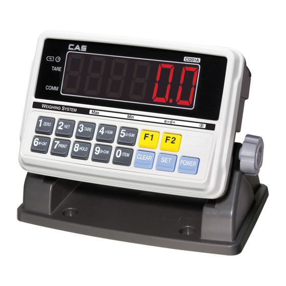
- Manuals
- Brands
- CAS Manuals
- Accessories
- CI-200 Series
- Manual
-
Contents
-
Table of Contents
-
Bookmarks
Quick Links
Related Manuals for CAS CI-200 Series
Summary of Contents for CAS CI-200 Series
-
Page 2
Cautions for Your Safety Please comply with ‘Cautions for Your Safety’, which will lead you to use the product safely and properly to prevent any dangerous situations. Cautions are divided into ‘Warning’ and ‘Alert’, which mean as follows. ■ Keep this manual in a place where product users can find out, after finish reading it. ■… -
Page 3
Warning Never disassemble, repair or retrofit the Ensure the power plug to be fully Ensure the grounding of the product. product. inserted to prevent shaking. Poor grounding might cause failure or It might exclude the product from the Any instable connection might cause electric shock upon electric leak. -
Page 4
Attention Check the weighing error anytime for Avoid any sudden shock to the product. Find a proper place to attach the rubber the accurate weighing. It might damage the product to fail the pad at the bottom of the indicator, Any use out of the allowed tolerance accurate weighing. -
Page 5: Table Of Contents
Contents 1. Features …………….1-1. Features………………9 1-2. Major Functions…………….9 1-3. Analog and A/D Conversion …………10 1-4. Digital and Display …………..10 1-5. General Specifications………….. 11 1-6. Communication and Option ……….. 11 ………..12 2. Specifications in Appearance 2-1. External Dimension …………..12 2-2.
-
Page 6
11-2. How to Connect Serial Communication Devices ….73 11-2-1. How to Connect an Auxiliary Display……….11-2-2. How to Connect a Label Printer …………11-3. RS-232 Communication Protocol……….73 11-3-1. 22 Bytes for CAS…………….11-3-2. 10 Bytes for CAS…………….11-3-3. A18 Bytes for AND……………………………76 12. -
Page 7
In addition, it is designed for the user-friendly programs for the easier use of indicator by any user with the built-in message display functions to help users understand the product. Please use the product right and sufficiently utilize functions of CI-200 series as you read this manual thoroughly before using CI-200 series. -
Page 8: Features
1. Features 1-1. Features Suitable for the platform and bench type scale and weighing system Easy operations Simple and prompt full digital calibration (automatic weight setup at once) Weight backup functions [restoring weight at the power supply On/Off] …
-
Page 9: Analog And A/D Conversion
1-3. Analog and A/D Conversion DC 5V (350Ω maximum 8 possible connections) Applied voltage for load cell 0 ~ 2mV/V Zeroing range 0.5 uV / D (OIML, )Ntep, KS Input sensitivity 0.5 uV / D (Non OIML, )Ntep, KS 0.01% Full Scale Non-straightness 1 / 520,000 A/D internal resolution…
-
Page 10: General Specifications
1-5. General Specifications AC 100~240 V (DC 12V, 1.25A) AC Adapter -10℃ ~ 40℃ Operating temperature CI-200A 139mm(H) x 206mm(L) x 91.05mm(W) CI-201A Product size CI-200S 169.5mm(H) x 250mm(L) x 83mm(W) CI-200SC CI-200A About 1.3kg CI-201A Product weight CI-200S About 1.5kg CI-200SC 1-6.
-
Page 11: Specifications In Appearance
2. Specifications in Appearance 2-1. External Dimension (CI-200A, CI-201A)
-
Page 12
(CI-200S, CI-200SC) -
Page 13: Front Panel Descriptions
2-2. Front Panel Descriptions CI-200A CI-201A…
-
Page 14
(1) Main Display (Weight Display) A. Displaying the value of gross or net weight. B. Displaying error messages for any abnormal motion or weigh setup error/ C. Displaying the status value for the Set Mode and weight setup mode. (2) Status Display (Lamp) LED Lamp LCD Status Display Descriptions… -
Page 15
CI-200S CI-200SC… -
Page 16
(1) Main Display (Weight Display) A. Displaying the value of gross or net weight. B. Displaying error messages for any abnormal motion or weigh setup error/ C. Displaying the status value for the Set Mode and weight setup mode. (2) Status Display (Lamp) The weighed weight is stable. -
Page 17
(3) Keyboard Function Key * Some functions can be defined to the needs. (The function set at F17 in the Set Mode will be operated.) * Some functions can be defined to the needs. (The function set at F18 in the Set Mode will be operated.) Number Key * It enters 1 in the input mode. -
Page 18
* It enters 9 in the input mode. * Use it to check the remaining capacity of battery. * Use it to correct any wrong input while entering data. * Use it to enter a decimal point (.) in the weight setup mode and weighing mode. -
Page 19: Rear Panel Descriptions
2-3. Rear Panel Descriptions CI-200A, CI-201A SEALING Use it to set the weight (calibration). (CAL S/W) POWER * Use it for the power supply. LOAD CELL A port to connect load cell. RS-232C Serial Com 1 and Com 2 port (connect PC or printer) It is a terminal for grounding to improve electric noises, which is connected to the grounding line upon any abnormalities in the product.
-
Page 20
CI-200S, CI-200SC SEALING, F/G RS-232C LOADCELL POWER SEALING Use it to set the weight (calibration). (CAL S/W) POWER * Use it for the power supply. A port to connect load cell. LOAD CELL RS-232C Serial Com 1 and Com 2 port (connect PC or printer) It is a terminal for grounding to improve electric noises, which is connected to the grounding line upon any abnormalities in the product. -
Page 21: How To Install
3. How to Install 3-1. How to Connect Load Cell Connect the load cell connector to the load cell port on the back of the indicator. * How to connect the load cell to the connector. Pin Function Number EXC+ SEN+ EXC- SEN-…
-
Page 22: Weight Setup Mode
4. Weight Setup (Calibration) Mode What is the weight setup? It refers to the calibration to set the displayed value to the actual weight in displaying weights. How to Access to the Weight Setup Mode Turn on the power supply to access to the weight setup mode while pressing Cal S/W after removing the sealing.
-
Page 23
CAL 1 (CAL 1 automatically starts.) Function: Setting Maximum Value Range of set value: 1 ~ 99,999 Used key Display Descriptions :Save and next C= 10000 Max. value = 10000kg Menu navigation : Set value change Max. value = 10kg :End Note 1. -
Page 24
3 CAL CAL 3-1 Function: Setting Multi Calibration Step Range of set value: 1 ~ 5 Used key Display Descriptions Setting multi calibration for step 1 STEP- 1 :Save and next (CAL3-3 and CAL 3-4 are carried out once) Menu navigation Setting multi calibration for step 3 STEP- 3 : Set value… -
Page 25
CAL 3-2 Function: Zero Calibration Used key Display Descriptions UnLoAd Empty the load tray and press the setup key. :Zeroing The current weight value is displayed. 1234 Confirm ‘Stable’ and press the setup key. :End — — — Zeroing in progress… Note 1. -
Page 26
CAL 3-4 Function: Weight Calibration) Used key Display Descriptions Load the weight set in CAL 4-3 and press the LoAd :Span adjustment setup key. The current weight value is displayed. 12345 Confirm ‘Stable’ and press the setup key. :End — — — Span adjustment in progress… -
Page 27
CAL 8 Function: Zero adjustment — calibration when any zeroing error occurs. Used key Display Descriptions 2-CAL Empty the load tray and press the setup key. :Zeroing The current weight value is displayed. 1234 Confirm ‘Stable’ and press the setup key. :End — — — Zero adjustment in progress… -
Page 28
CAL 10 CAL 10-1 Function: Setting Dual Range Range of set value: 0 ~ 1 Used key Display Descriptions :Save and next DUAL- 0 Menu navigation Dual range function is not used. : Set value change DUAL- 1 Dual range function is used. :End Note 1. -
Page 29: How To Seal The Indicator
4-2. How to Seal the Indicator (Sealing) After the calibration mode is carried out, proceed to the following step. 1. Tighten the CAL switch bolt. 2. Connect the sealing wire as shown in the picture. 3. Press the sealing wax as shown in the picture. Sealing Point…
-
Page 30: Set Mode
5. Set Mode 5-1. How to Enter the Set Mode Turn on the power while pressing key at the indicator front to start the Set Mode. Or, Hold key for about 3 seconds to move from other mode to the convesion mode. After finishing the setup in the Set Mode, press key for a long time 5-2.
-
Page 31: Set Menu Descriptions (F00 ~ F82)
5-3. Set Menu Descriptions (F00 ~ F99) General Function Date Change Time Change (00) Auto Power Off (10) A/D Converting Speed (10) Digital Filter (00) Vibration Filter (02) Motion Detection Condition (02) Automatic Zero Tracking Compensation (00) Weight Backup (00) Set Hold Type (00) Set Auto Hold Range…
-
Page 32
RS-232 Serial Communication Function (00) Device ID (00) Parity Bit (04) COM1 Baud Rate (00) COM1 Usage (00) COM1 Output Format (00) COM1 — Output Mode (04) COM2 Baud Rate (01) COM2 Usage (00) COM2 Output Format (00) COM2 — Output Mode Print Function (02) Set Printer in Use… -
Page 33
Checker Function (00) Measurement Mode (00) Checker Buzzer On/Off Set Mode Initialization Password Change Set the Set value of Set Mode to the Factory Default * Note. Number in () is the default at the factory shipment. -
Page 34: General Function
5-3-1. General Function Function Date Change Numeric key Display Meaning : assigning data 02.01.10 January 10, 2002 Function Time Change Numeric key Display Meaning : assigning data 11.30.10 11 o’clock 30 minutes and 10 seconds AM Function Auto Power OFF Display Meaning Setting range…
-
Page 35
Function Setting vibration filter Display Meaning Setting range Vibration filter OFF F06. 00 (00 ~ 99) F06. 10 Compensation for the vibration value of 5 divisions (0.5d * 10) F06. 99 Compensation for the vibration value of 49.5 divisions (0.5d * 99) Note 1. -
Page 36
Function Weight Backup Function Display Meaning Setting range Weight backup is not used. F09. 0 (0, 1) F09. 1 Weight backup is used. Note 1. As the backup state memorizes the initial status at zero for the weighing machine even during the blackout or when the power is turned off, the weight value is displayed if there is any weighing object in the weighing machine when the power is turned on. -
Page 37
Function Set the front key input to be allowed. Display Meaning Setting range The front keys are unlocked. F16. 0 (0 ~ 1) F16. 1 The front keys are locked. Note 1. If it is set to 1, some function keys among the front keys cannot be used. (Print, Hold, Tare, Step, Subtotal, Grand total, Weighing count, Item number, Setup, etc) Function Set the use of function key 1… -
Page 38
Function Set the initial zero range Display Meaning Setting range F21. 02 Set the initial zero up to 2% of the maximum weight (02~20) Set the initial zero up to 10% of the maximum weight F21. 10 F21. 20 Set the initial zero up to 20% of the maximum weight Note 1. -
Page 39
Function Set Backlight and LED Brightness Display Meaning F25 1 Set 10% of brightness F25 2 Set 30% of brightness Setting range Set 50% of brightness F25 3 (1~7) F25 4 Set 60% of brightness F25 5 Set 70% of brightness F25 6 Set 90% of brightness F25 7… -
Page 40: Rs-232 (Serial Communication) Function
5-3-2. RS-232 (Serial Communication) Function Function Set Device ID Display Meaning Setting range Device ID 00 F26. 00 (00 ~ 99) F26. 99 Device ID 99 Note 1. This function enables to use the unique indicator ID in the command mode. Function Set Parity Bit –…
-
Page 41
Serial Communication COM1 Function Function Set COM1 Baud Rate Display Meaning F28. 0 600 bps F28. 1 1200 bps F28. 2 2400 bps F28. 3 4800 bps Setting range (0 ~ 8) 9600 bps F28. 4 F28. 5 19200 bps F28. -
Page 42
Note 1. Command Mode Table Descriptions on CI-200 Data Request Signal of CI-200 Request Signal Output Signal Z CR Zero Point Key Received Data Return T CR Zero Point Key Received Data Return K G CR Gross Weight Key Received Data Return K N CR Net Weight Key Received Data Return… -
Page 43
Note 1. NT-200 Command Mode Table Command (ASCII Code) Description Status High Limit Read / Write Low Limit Read / Write Key Tare Value Read / Write Code Read / Write Current Weight Read Operation with ZERO Key Read Operation with TARE Key Read Operation with Gross/Net Key Read… -
Page 44
Serial Communication COM2 Function Function Set COM2 Baud Rate Display Meaning F32 0 600 bps F32 1 1200 bps F32 2 2400 bps F32 3 4800 bps Setting range (0 ~ 8) 9600 bps F32 4 F32 5 19200 bps F32 6 38400 bps F32 7… -
Page 45: Print Function
5-3-3. Print Function Function Set a printer to use Display Meaning Setting range F40 0 Not used. (0 ~ 2) F40 1 DLP (Label Printer) DEP (Roll Printer) F40 2 Function Set print format Display Meaning Setting range Set print format 0 F41 0 (0 ~ 2) F41 1…
-
Page 46
【 Print Format 0 】 【 Print Format 1 】 Date, Time, Weighing No. (Item No.), Net Weight Date, Time, Weighing No. (Item No.), Net Weight 2002. 1. 1 12:30 2002. 1. 1 12:30 0001 ID_01: 50.0 kg 0001 ID_01: 50.0 kg 0002 ID_01: 100.0 kg… -
Page 47
【 Total Print Format 】 Total Format — — — — — — — — — — — — — — — — — — — — — — — — — — — — — — — — — — — — — — — — — ID_01 TOTAL — — — — — — — — — — — — — — — — — — — — — — — — — — — — — — — — — — — — — — — — — 2004.06.24… -
Page 48
CAS DLP Protocol Variable Descriptions Gross Weight (8 bytes) Tare (8 bytes) Net Weight (8 bytes) Barcode (Net Weight) (8 bytes) Count in the Count Mode (8 bytes) Percent in the Percent Mode (8 bytes) The weight, count and percent cannot be printed at the same time. -
Page 49
1st data to the part right before the coordinate where data 255 is assigned. Note 3. If you want to add the company name “CAS” to the existing print format, you might assign as follows;… -
Page 50: Checker Function
5-3-4. Checker Function Function Select the weighing mode (LCD, SC Only) Display Meaning Setting range Not used. F50 0 (0 ~ 2) F50 1 Use as the checker mode F50 2 Use as the limit mode [CHECKER MODE] Weight (Low Limit) (High Limit) Comm 0 kg…
-
Page 51: Other Functions
Function Set Buzzer On/Off on the Checker Function (LCD, SC Only) Display Meaning Setting range General functions are operated as the buzzer. F51 0 (0, 1) F51 1 Buzzer ON when the checker function is OK. 5-3-5. Other Functions Function Password Change Display Meaning…
-
Page 52: Test Mode
6. Test Mode 6-1. How to Enter the Test Mode Test mode starts when the power is turned on while pressing key in the front of the indicator. Press the number for the test menu as you wish. To enter the weighing mode during test, press key for a long time.
-
Page 53
Test 1 Function: Key test Used key Display Descriptions When you press any key to test, the number : Higher Menu and code for the key are displayed on the Other keys: Test screen. <Key List> Number Code Number Code Number Code Test 2… -
Page 54
Test 3 Function: Load cell test and A/D conversion test Used key Display Descriptions The internal value for the current XXXXXX weight value is displayed. : Higher Menu X.XX The output value of the current load cell is displayed in mv/V. Note 1. -
Page 55
Note 1. Designate a printer used in the Set Mode (F30) in advance. Note 2. If the printer connection and the designation are done correctly, the following details will be shown in the printer. CAS Corporation Come And Succeed TEL 1577-5578… -
Page 56
Test 9 Function: Battery test Used key Display Descriptions b 6.15 Displaying the current voltage of battery (6.15V) : Higher Menu Test 10 Function: RTC Test Used key Display Descriptions SEC XX : Higher Menu XX : Displaying the progress of seconds (SEC) Note 1. -
Page 57: System Mode
7. System Mode 7-1. How to Enter the System Mode Load Descriptio Step Display Screen and Key Input Tray Press key for about 3 seconds in the weighing Empty mode. Screen display: “1. PCS” characters are blinking after “SYSTEM” is displayed. key is pressed, “1.
-
Page 58
Weighing Mode (I) Initial Screen Descriptions Weighing Mode Counting Mode (II) Initial Screen Descriptions Counting Mode Percent Mode (III) Initial Screen Descriptions Percent Mode… -
Page 59: Pcs Mode
7-2. PCS MODE 7-2-1. PCS MODE Sample Input Method Load Step Display Screen and Key Input Descriptions Tray Empty key for about 3 seconds in the PCS Mode. Press Screen display: “1.SAMPL” characters are blinking. Select the key is pressed , “1.
-
Page 60
7-2-2. PCS Mode Direct Input Method Load Step Display Screen and Key Input Descriptions Tray Empty key for about 3 seconds in the PCS Mode. Press Screen display: “1.SAMPL” characters are blinking. Select the key is pressed , “1. SAMPL” characters are blinking. input method as desired. -
Page 61: Percent Mode
7-3. PERCENT MODE 7-3-1. Percent Mode Sample Input Method Load Step Display Screen and Key Input Descriptions Tray Empty key for about 3 seconds in the Percent Mode. Press Screen display: “1.SAMPL” characters are blinking. Select the key is pressed , “1.
-
Page 62
7-3-2. Percent Mode Direct Input Method Load Step Display Screen and Key Input Descriptions Tray Empty key for about 3 seconds in the PCS Mode. Press Screen display: “1.SAMPL” characters are blinking. Select the key is pressed , “1. SAMPL” characters are blinking. input method as desired. -
Page 63: General Function Descriptions
8. General Function Descriptions 8-1. Item Number (Unique Number of Weighing Item: ID) Input Method Load Step Display Screen and Key Input Descriptions Tray “Meaning the value of Press the current item number” Screen display: “ID = XX” Enter a desired ID using number keys Input ID(=10) An item number is Item…
-
Page 64: How To Check Subtotal, Total And Weighing Count
8-3. How to Check Subtotal, Total and Weighing Count Descriptions The current subtotal (partial summation) is displayed. The current total (entire summation) is displayed. The current subtotal (partial summation) is printed. Subtotal is erased after it is printed. The current total (entire summation) is printed. Total is erased after it is printed.
-
Page 65: How To Enter High Limit
8-4. How to Enter High Limit Load Step Display Screen and Key Input Descriptions Tray It means the current Press high limit. Screen display: “H 0.000” Enter a desired value Change the high limit using keys The weight is displayed Item after the high limit is Press…
-
Page 66: Weighing Mode
9. Weighing Mode 9-1. Zeroing Function (used when the zero point changes) — LED ■ Range of zero point: within a range set in F13 Zero chanced. Press Zero Key to set the zero lamp on and 0. 9-2. Tare Function (used for weighing with a container) — LED ■…
-
Page 67: Hold Function — Led
9-3. Hold Function (used for weighing moving objects) — LED ■ Ordinary Hold Function (hold function is performed when the hold key is pressed.) Put an object on the load tray. Press the hold key. Hold message is The hold weight is calculated displayed for a second.
-
Page 68: Zeroing Function — Lcd
9-4. Zeroing Function (used when the zero point changes) — LCD ■ Range of zero point: within a range set in F13 Zero chanced. Press Zero Key to set the zero lamp on and 0. 9-5. Tare Function (used for weighing with a container) — LCD ■…
-
Page 69: Hold Function — Lcd
9-6. Hold Function (used for weighing moving objects) — LCD ■ Ordinary Hold Function (hold function is performed when the hold key is pressed.) Put an object on the load tray. Press the hold key. Hold message is The hold weight is calculated displayed for a second.
-
Page 70: Charge And Use Time
10. Charge and Use Time ■ Charge the battery sufficiently when you use the product after storing it for a long time. ■ During the use of device, sign is shown (LCD) or ‘LOW BAT’ sign (LED) on the upper right corner, and then the power is turned off after a specific time.
-
Page 71: Rs-232C Interface In Detail
11. RS-232C Interface in Detail 1. RS-232C Port Connection (1) COM1 — RXD: Pin No. 2, TXD: Pin No. 3, GND: Pin No. 7 —————- O 2 Transmit Data —————- O 3 Receive Data —————- O 7 Signal Ground ┌─ O 8 Carrier Detect ├─…
-
Page 72: How To Connect Serial Communication Devices
Serial port of DLP printer Note. Refer to page 38 (Set Mode) for RS-232C communication and setting method. 3. RS-232 Communication Protocol 11-3-1. 22 Bytes for CAS (1) Data bit: 8, Stop bit: 1, Parity bit: none (2) Code: ASCII (3) Set the time to send data to the computer in the Set Mode.
-
Page 73: Bytes For Cas
Stable Hold Printer Tare Zero Point Weight 11-3-2. 10 Bytes for CAS (1) Data bit: 8, Stop bit: 1, Parity bit: none (2) Code: ASCII (3) Transmission data format: (10 bytes) Data (8 bytes) 11-3-3. 18 Bytes for AND (1) Data bit: 7, Stop bit: 1, Parity bit: odd number / even number…
-
Page 74
RS-422 & 485 Serial Communications (COM2) RS-422 & 485 transmit signals with the voltage difference, which are more stable for electric noises than other communication methods. In addition, the AC Power Cable or other electric wires should be placed separately, and the shield cable (0.5Φ… -
Page 75: Error Message
12. Error Message 12-1. Error Message from the Weight Setup Mode Error Cause Solution Lower the resolution. The resolution was set in excess As the resolution = maximum tolerance / value of one Err 20 division, adjust the resolution to 1/10,000 or less by correcting of the tolerance 1/10,000.
-
Page 76: Error Message From The Weighing Mode
12-2. Error Message from the Weighing Mode Error Cause Solution The initialization of the scale cannot be done Turn on the power after placing the scale at a flat Err 01 because of the shaking weight. place with no vibration. Either the connection of load cell is wrong or Check the connection between the load tray and the there is abnormality in the A/D conversion…
-
Page 77
Descriptions on Abbreviation on the Display Abbreviation Descriptions Abbreviation Descriptions «LOCK» Key Lock «UnLoad» Unload the load tray «PASS» Enter Password «LoAd» Load a weight «Discord» Re-enter Password «Good» Successful Execution «»CAL Weight Set Mode «SyS» System Mode «SET» Set Mode «PCS»… -
Page 78
MEMO… -
Page 79
MEMO… -
Page 80
MEMO…
- Manuals
- Brands
- CAS Manuals
- Accessories
- CI-200 Series
- Manual
-
Contents
-
Table of Contents
-
Bookmarks
Quick Links
Related Manuals for CAS CI-200 Series
Summary of Contents for CAS CI-200 Series
-
Page 2
Cautions for Your Safety Please comply with ‘Cautions for Your Safety’, which will lead you to use the product safely and properly to prevent any dangerous situations. Cautions are divided into ‘Warning’ and ‘Alert’, which mean as follows. ■ Keep this manual in a place where product users can find out, after finish reading it. ■… -
Page 3
Warning Never disassemble, repair or retrofit the Ensure the power plug to be fully Ensure the grounding of the product. product. inserted to prevent shaking. Poor grounding might cause failure or It might exclude the product from the Any instable connection might cause electric shock upon electric leak. -
Page 4
Attention Check the weighing error anytime for Avoid any sudden shock to the product. Find a proper place to attach the rubber the accurate weighing. It might damage the product to fail the pad at the bottom of the indicator, Any use out of the allowed tolerance accurate weighing. -
Page 5: Table Of Contents
Contents 1. Features …………….1-1. Features………………9 1-2. Major Functions…………….9 1-3. Analog and A/D Conversion …………10 1-4. Digital and Display …………..10 1-5. General Specifications………….. 11 1-6. Communication and Option ……….. 11 ………..12 2. Specifications in Appearance 2-1. External Dimension …………..12 2-2.
-
Page 6
11-2. How to Connect Serial Communication Devices ….73 11-2-1. How to Connect an Auxiliary Display……….11-2-2. How to Connect a Label Printer …………11-3. RS-232 Communication Protocol……….73 11-3-1. 22 Bytes for CAS…………….11-3-2. 10 Bytes for CAS…………….11-3-3. A18 Bytes for AND……………………………76 12. -
Page 7
In addition, it is designed for the user-friendly programs for the easier use of indicator by any user with the built-in message display functions to help users understand the product. Please use the product right and sufficiently utilize functions of CI-200 series as you read this manual thoroughly before using CI-200 series. -
Page 8: Features
1. Features 1-1. Features Suitable for the platform and bench type scale and weighing system Easy operations Simple and prompt full digital calibration (automatic weight setup at once) Weight backup functions [restoring weight at the power supply On/Off] …
-
Page 9: Analog And A/D Conversion
1-3. Analog and A/D Conversion DC 5V (350Ω maximum 8 possible connections) Applied voltage for load cell 0 ~ 2mV/V Zeroing range 0.5 uV / D (OIML, )Ntep, KS Input sensitivity 0.5 uV / D (Non OIML, )Ntep, KS 0.01% Full Scale Non-straightness 1 / 520,000 A/D internal resolution…
-
Page 10: General Specifications
1-5. General Specifications AC 100~240 V (DC 12V, 1.25A) AC Adapter -10℃ ~ 40℃ Operating temperature CI-200A 139mm(H) x 206mm(L) x 91.05mm(W) CI-201A Product size CI-200S 169.5mm(H) x 250mm(L) x 83mm(W) CI-200SC CI-200A About 1.3kg CI-201A Product weight CI-200S About 1.5kg CI-200SC 1-6.
-
Page 11: Specifications In Appearance
2. Specifications in Appearance 2-1. External Dimension (CI-200A, CI-201A)
-
Page 12
(CI-200S, CI-200SC) -
Page 13: Front Panel Descriptions
2-2. Front Panel Descriptions CI-200A CI-201A…
-
Page 14
(1) Main Display (Weight Display) A. Displaying the value of gross or net weight. B. Displaying error messages for any abnormal motion or weigh setup error/ C. Displaying the status value for the Set Mode and weight setup mode. (2) Status Display (Lamp) LED Lamp LCD Status Display Descriptions… -
Page 15
CI-200S CI-200SC… -
Page 16
(1) Main Display (Weight Display) A. Displaying the value of gross or net weight. B. Displaying error messages for any abnormal motion or weigh setup error/ C. Displaying the status value for the Set Mode and weight setup mode. (2) Status Display (Lamp) The weighed weight is stable. -
Page 17
(3) Keyboard Function Key * Some functions can be defined to the needs. (The function set at F17 in the Set Mode will be operated.) * Some functions can be defined to the needs. (The function set at F18 in the Set Mode will be operated.) Number Key * It enters 1 in the input mode. -
Page 18
* It enters 9 in the input mode. * Use it to check the remaining capacity of battery. * Use it to correct any wrong input while entering data. * Use it to enter a decimal point (.) in the weight setup mode and weighing mode. -
Page 19: Rear Panel Descriptions
2-3. Rear Panel Descriptions CI-200A, CI-201A SEALING Use it to set the weight (calibration). (CAL S/W) POWER * Use it for the power supply. LOAD CELL A port to connect load cell. RS-232C Serial Com 1 and Com 2 port (connect PC or printer) It is a terminal for grounding to improve electric noises, which is connected to the grounding line upon any abnormalities in the product.
-
Page 20
CI-200S, CI-200SC SEALING, F/G RS-232C LOADCELL POWER SEALING Use it to set the weight (calibration). (CAL S/W) POWER * Use it for the power supply. A port to connect load cell. LOAD CELL RS-232C Serial Com 1 and Com 2 port (connect PC or printer) It is a terminal for grounding to improve electric noises, which is connected to the grounding line upon any abnormalities in the product. -
Page 21: How To Install
3. How to Install 3-1. How to Connect Load Cell Connect the load cell connector to the load cell port on the back of the indicator. * How to connect the load cell to the connector. Pin Function Number EXC+ SEN+ EXC- SEN-…
-
Page 22: Weight Setup Mode
4. Weight Setup (Calibration) Mode What is the weight setup? It refers to the calibration to set the displayed value to the actual weight in displaying weights. How to Access to the Weight Setup Mode Turn on the power supply to access to the weight setup mode while pressing Cal S/W after removing the sealing.
-
Page 23
CAL 1 (CAL 1 automatically starts.) Function: Setting Maximum Value Range of set value: 1 ~ 99,999 Used key Display Descriptions :Save and next C= 10000 Max. value = 10000kg Menu navigation : Set value change Max. value = 10kg :End Note 1. -
Page 24
3 CAL CAL 3-1 Function: Setting Multi Calibration Step Range of set value: 1 ~ 5 Used key Display Descriptions Setting multi calibration for step 1 STEP- 1 :Save and next (CAL3-3 and CAL 3-4 are carried out once) Menu navigation Setting multi calibration for step 3 STEP- 3 : Set value… -
Page 25
CAL 3-2 Function: Zero Calibration Used key Display Descriptions UnLoAd Empty the load tray and press the setup key. :Zeroing The current weight value is displayed. 1234 Confirm ‘Stable’ and press the setup key. :End — — — Zeroing in progress… Note 1. -
Page 26
CAL 3-4 Function: Weight Calibration) Used key Display Descriptions Load the weight set in CAL 4-3 and press the LoAd :Span adjustment setup key. The current weight value is displayed. 12345 Confirm ‘Stable’ and press the setup key. :End — — — Span adjustment in progress… -
Page 27
CAL 8 Function: Zero adjustment — calibration when any zeroing error occurs. Used key Display Descriptions 2-CAL Empty the load tray and press the setup key. :Zeroing The current weight value is displayed. 1234 Confirm ‘Stable’ and press the setup key. :End — — — Zero adjustment in progress… -
Page 28
CAL 10 CAL 10-1 Function: Setting Dual Range Range of set value: 0 ~ 1 Used key Display Descriptions :Save and next DUAL- 0 Menu navigation Dual range function is not used. : Set value change DUAL- 1 Dual range function is used. :End Note 1. -
Page 29: How To Seal The Indicator
4-2. How to Seal the Indicator (Sealing) After the calibration mode is carried out, proceed to the following step. 1. Tighten the CAL switch bolt. 2. Connect the sealing wire as shown in the picture. 3. Press the sealing wax as shown in the picture. Sealing Point…
-
Page 30: Set Mode
5. Set Mode 5-1. How to Enter the Set Mode Turn on the power while pressing key at the indicator front to start the Set Mode. Or, Hold key for about 3 seconds to move from other mode to the convesion mode. After finishing the setup in the Set Mode, press key for a long time 5-2.
-
Page 31: Set Menu Descriptions (F00 ~ F82)
5-3. Set Menu Descriptions (F00 ~ F99) General Function Date Change Time Change (00) Auto Power Off (10) A/D Converting Speed (10) Digital Filter (00) Vibration Filter (02) Motion Detection Condition (02) Automatic Zero Tracking Compensation (00) Weight Backup (00) Set Hold Type (00) Set Auto Hold Range…
-
Page 32
RS-232 Serial Communication Function (00) Device ID (00) Parity Bit (04) COM1 Baud Rate (00) COM1 Usage (00) COM1 Output Format (00) COM1 — Output Mode (04) COM2 Baud Rate (01) COM2 Usage (00) COM2 Output Format (00) COM2 — Output Mode Print Function (02) Set Printer in Use… -
Page 33
Checker Function (00) Measurement Mode (00) Checker Buzzer On/Off Set Mode Initialization Password Change Set the Set value of Set Mode to the Factory Default * Note. Number in () is the default at the factory shipment. -
Page 34: General Function
5-3-1. General Function Function Date Change Numeric key Display Meaning : assigning data 02.01.10 January 10, 2002 Function Time Change Numeric key Display Meaning : assigning data 11.30.10 11 o’clock 30 minutes and 10 seconds AM Function Auto Power OFF Display Meaning Setting range…
-
Page 35
Function Setting vibration filter Display Meaning Setting range Vibration filter OFF F06. 00 (00 ~ 99) F06. 10 Compensation for the vibration value of 5 divisions (0.5d * 10) F06. 99 Compensation for the vibration value of 49.5 divisions (0.5d * 99) Note 1. -
Page 36
Function Weight Backup Function Display Meaning Setting range Weight backup is not used. F09. 0 (0, 1) F09. 1 Weight backup is used. Note 1. As the backup state memorizes the initial status at zero for the weighing machine even during the blackout or when the power is turned off, the weight value is displayed if there is any weighing object in the weighing machine when the power is turned on. -
Page 37
Function Set the front key input to be allowed. Display Meaning Setting range The front keys are unlocked. F16. 0 (0 ~ 1) F16. 1 The front keys are locked. Note 1. If it is set to 1, some function keys among the front keys cannot be used. (Print, Hold, Tare, Step, Subtotal, Grand total, Weighing count, Item number, Setup, etc) Function Set the use of function key 1… -
Page 38
Function Set the initial zero range Display Meaning Setting range F21. 02 Set the initial zero up to 2% of the maximum weight (02~20) Set the initial zero up to 10% of the maximum weight F21. 10 F21. 20 Set the initial zero up to 20% of the maximum weight Note 1. -
Page 39
Function Set Backlight and LED Brightness Display Meaning F25 1 Set 10% of brightness F25 2 Set 30% of brightness Setting range Set 50% of brightness F25 3 (1~7) F25 4 Set 60% of brightness F25 5 Set 70% of brightness F25 6 Set 90% of brightness F25 7… -
Page 40: Rs-232 (Serial Communication) Function
5-3-2. RS-232 (Serial Communication) Function Function Set Device ID Display Meaning Setting range Device ID 00 F26. 00 (00 ~ 99) F26. 99 Device ID 99 Note 1. This function enables to use the unique indicator ID in the command mode. Function Set Parity Bit –…
-
Page 41
Serial Communication COM1 Function Function Set COM1 Baud Rate Display Meaning F28. 0 600 bps F28. 1 1200 bps F28. 2 2400 bps F28. 3 4800 bps Setting range (0 ~ 8) 9600 bps F28. 4 F28. 5 19200 bps F28. -
Page 42
Note 1. Command Mode Table Descriptions on CI-200 Data Request Signal of CI-200 Request Signal Output Signal Z CR Zero Point Key Received Data Return T CR Zero Point Key Received Data Return K G CR Gross Weight Key Received Data Return K N CR Net Weight Key Received Data Return… -
Page 43
Note 1. NT-200 Command Mode Table Command (ASCII Code) Description Status High Limit Read / Write Low Limit Read / Write Key Tare Value Read / Write Code Read / Write Current Weight Read Operation with ZERO Key Read Operation with TARE Key Read Operation with Gross/Net Key Read… -
Page 44
Serial Communication COM2 Function Function Set COM2 Baud Rate Display Meaning F32 0 600 bps F32 1 1200 bps F32 2 2400 bps F32 3 4800 bps Setting range (0 ~ 8) 9600 bps F32 4 F32 5 19200 bps F32 6 38400 bps F32 7… -
Page 45: Print Function
5-3-3. Print Function Function Set a printer to use Display Meaning Setting range F40 0 Not used. (0 ~ 2) F40 1 DLP (Label Printer) DEP (Roll Printer) F40 2 Function Set print format Display Meaning Setting range Set print format 0 F41 0 (0 ~ 2) F41 1…
-
Page 46
【 Print Format 0 】 【 Print Format 1 】 Date, Time, Weighing No. (Item No.), Net Weight Date, Time, Weighing No. (Item No.), Net Weight 2002. 1. 1 12:30 2002. 1. 1 12:30 0001 ID_01: 50.0 kg 0001 ID_01: 50.0 kg 0002 ID_01: 100.0 kg… -
Page 47
【 Total Print Format 】 Total Format — — — — — — — — — — — — — — — — — — — — — — — — — — — — — — — — — — — — — — — — — ID_01 TOTAL — — — — — — — — — — — — — — — — — — — — — — — — — — — — — — — — — — — — — — — — — 2004.06.24… -
Page 48
CAS DLP Protocol Variable Descriptions Gross Weight (8 bytes) Tare (8 bytes) Net Weight (8 bytes) Barcode (Net Weight) (8 bytes) Count in the Count Mode (8 bytes) Percent in the Percent Mode (8 bytes) The weight, count and percent cannot be printed at the same time. -
Page 49
1st data to the part right before the coordinate where data 255 is assigned. Note 3. If you want to add the company name “CAS” to the existing print format, you might assign as follows;… -
Page 50: Checker Function
5-3-4. Checker Function Function Select the weighing mode (LCD, SC Only) Display Meaning Setting range Not used. F50 0 (0 ~ 2) F50 1 Use as the checker mode F50 2 Use as the limit mode [CHECKER MODE] Weight (Low Limit) (High Limit) Comm 0 kg…
-
Page 51: Other Functions
Function Set Buzzer On/Off on the Checker Function (LCD, SC Only) Display Meaning Setting range General functions are operated as the buzzer. F51 0 (0, 1) F51 1 Buzzer ON when the checker function is OK. 5-3-5. Other Functions Function Password Change Display Meaning…
-
Page 52: Test Mode
6. Test Mode 6-1. How to Enter the Test Mode Test mode starts when the power is turned on while pressing key in the front of the indicator. Press the number for the test menu as you wish. To enter the weighing mode during test, press key for a long time.
-
Page 53
Test 1 Function: Key test Used key Display Descriptions When you press any key to test, the number : Higher Menu and code for the key are displayed on the Other keys: Test screen. <Key List> Number Code Number Code Number Code Test 2… -
Page 54
Test 3 Function: Load cell test and A/D conversion test Used key Display Descriptions The internal value for the current XXXXXX weight value is displayed. : Higher Menu X.XX The output value of the current load cell is displayed in mv/V. Note 1. -
Page 55
Note 1. Designate a printer used in the Set Mode (F30) in advance. Note 2. If the printer connection and the designation are done correctly, the following details will be shown in the printer. CAS Corporation Come And Succeed TEL 1577-5578… -
Page 56
Test 9 Function: Battery test Used key Display Descriptions b 6.15 Displaying the current voltage of battery (6.15V) : Higher Menu Test 10 Function: RTC Test Used key Display Descriptions SEC XX : Higher Menu XX : Displaying the progress of seconds (SEC) Note 1. -
Page 57: System Mode
7. System Mode 7-1. How to Enter the System Mode Load Descriptio Step Display Screen and Key Input Tray Press key for about 3 seconds in the weighing Empty mode. Screen display: “1. PCS” characters are blinking after “SYSTEM” is displayed. key is pressed, “1.
-
Page 58
Weighing Mode (I) Initial Screen Descriptions Weighing Mode Counting Mode (II) Initial Screen Descriptions Counting Mode Percent Mode (III) Initial Screen Descriptions Percent Mode… -
Page 59: Pcs Mode
7-2. PCS MODE 7-2-1. PCS MODE Sample Input Method Load Step Display Screen and Key Input Descriptions Tray Empty key for about 3 seconds in the PCS Mode. Press Screen display: “1.SAMPL” characters are blinking. Select the key is pressed , “1.
-
Page 60
7-2-2. PCS Mode Direct Input Method Load Step Display Screen and Key Input Descriptions Tray Empty key for about 3 seconds in the PCS Mode. Press Screen display: “1.SAMPL” characters are blinking. Select the key is pressed , “1. SAMPL” characters are blinking. input method as desired. -
Page 61: Percent Mode
7-3. PERCENT MODE 7-3-1. Percent Mode Sample Input Method Load Step Display Screen and Key Input Descriptions Tray Empty key for about 3 seconds in the Percent Mode. Press Screen display: “1.SAMPL” characters are blinking. Select the key is pressed , “1.
-
Page 62
7-3-2. Percent Mode Direct Input Method Load Step Display Screen and Key Input Descriptions Tray Empty key for about 3 seconds in the PCS Mode. Press Screen display: “1.SAMPL” characters are blinking. Select the key is pressed , “1. SAMPL” characters are blinking. input method as desired. -
Page 63: General Function Descriptions
8. General Function Descriptions 8-1. Item Number (Unique Number of Weighing Item: ID) Input Method Load Step Display Screen and Key Input Descriptions Tray “Meaning the value of Press the current item number” Screen display: “ID = XX” Enter a desired ID using number keys Input ID(=10) An item number is Item…
-
Page 64: How To Check Subtotal, Total And Weighing Count
8-3. How to Check Subtotal, Total and Weighing Count Descriptions The current subtotal (partial summation) is displayed. The current total (entire summation) is displayed. The current subtotal (partial summation) is printed. Subtotal is erased after it is printed. The current total (entire summation) is printed. Total is erased after it is printed.
-
Page 65: How To Enter High Limit
8-4. How to Enter High Limit Load Step Display Screen and Key Input Descriptions Tray It means the current Press high limit. Screen display: “H 0.000” Enter a desired value Change the high limit using keys The weight is displayed Item after the high limit is Press…
-
Page 66: Weighing Mode
9. Weighing Mode 9-1. Zeroing Function (used when the zero point changes) — LED ■ Range of zero point: within a range set in F13 Zero chanced. Press Zero Key to set the zero lamp on and 0. 9-2. Tare Function (used for weighing with a container) — LED ■…
-
Page 67: Hold Function — Led
9-3. Hold Function (used for weighing moving objects) — LED ■ Ordinary Hold Function (hold function is performed when the hold key is pressed.) Put an object on the load tray. Press the hold key. Hold message is The hold weight is calculated displayed for a second.
-
Page 68: Zeroing Function — Lcd
9-4. Zeroing Function (used when the zero point changes) — LCD ■ Range of zero point: within a range set in F13 Zero chanced. Press Zero Key to set the zero lamp on and 0. 9-5. Tare Function (used for weighing with a container) — LCD ■…
-
Page 69: Hold Function — Lcd
9-6. Hold Function (used for weighing moving objects) — LCD ■ Ordinary Hold Function (hold function is performed when the hold key is pressed.) Put an object on the load tray. Press the hold key. Hold message is The hold weight is calculated displayed for a second.
-
Page 70: Charge And Use Time
10. Charge and Use Time ■ Charge the battery sufficiently when you use the product after storing it for a long time. ■ During the use of device, sign is shown (LCD) or ‘LOW BAT’ sign (LED) on the upper right corner, and then the power is turned off after a specific time.
-
Page 71: Rs-232C Interface In Detail
11. RS-232C Interface in Detail 1. RS-232C Port Connection (1) COM1 — RXD: Pin No. 2, TXD: Pin No. 3, GND: Pin No. 7 —————- O 2 Transmit Data —————- O 3 Receive Data —————- O 7 Signal Ground ┌─ O 8 Carrier Detect ├─…
-
Page 72: How To Connect Serial Communication Devices
Serial port of DLP printer Note. Refer to page 38 (Set Mode) for RS-232C communication and setting method. 3. RS-232 Communication Protocol 11-3-1. 22 Bytes for CAS (1) Data bit: 8, Stop bit: 1, Parity bit: none (2) Code: ASCII (3) Set the time to send data to the computer in the Set Mode.
-
Page 73: Bytes For Cas
Stable Hold Printer Tare Zero Point Weight 11-3-2. 10 Bytes for CAS (1) Data bit: 8, Stop bit: 1, Parity bit: none (2) Code: ASCII (3) Transmission data format: (10 bytes) Data (8 bytes) 11-3-3. 18 Bytes for AND (1) Data bit: 7, Stop bit: 1, Parity bit: odd number / even number…
-
Page 74
RS-422 & 485 Serial Communications (COM2) RS-422 & 485 transmit signals with the voltage difference, which are more stable for electric noises than other communication methods. In addition, the AC Power Cable or other electric wires should be placed separately, and the shield cable (0.5Φ… -
Page 75: Error Message
12. Error Message 12-1. Error Message from the Weight Setup Mode Error Cause Solution Lower the resolution. The resolution was set in excess As the resolution = maximum tolerance / value of one Err 20 division, adjust the resolution to 1/10,000 or less by correcting of the tolerance 1/10,000.
-
Page 76: Error Message From The Weighing Mode
12-2. Error Message from the Weighing Mode Error Cause Solution The initialization of the scale cannot be done Turn on the power after placing the scale at a flat Err 01 because of the shaking weight. place with no vibration. Either the connection of load cell is wrong or Check the connection between the load tray and the there is abnormality in the A/D conversion…
-
Page 77
Descriptions on Abbreviation on the Display Abbreviation Descriptions Abbreviation Descriptions «LOCK» Key Lock «UnLoad» Unload the load tray «PASS» Enter Password «LoAd» Load a weight «Discord» Re-enter Password «Good» Successful Execution «»CAL Weight Set Mode «SyS» System Mode «SET» Set Mode «PCS»… -
Page 78
MEMO… -
Page 79
MEMO… -
Page 80
MEMO…
Весы Cas CI-200A — инструкция пользователя по применению, эксплуатации и установке на русском языке. Мы надеемся, она поможет вам решить возникшие у вас вопросы при эксплуатации техники.
Вы можете скачать инструкцию к Cas CI-200A по ссылке ниже, если не хотите ждать загрузки. Если остались вопросы, задайте их в комментариях после инструкции.
«Загружаем инструкцию», означает, что нужно подождать пока файл загрузится и можно будет его читать онлайн. Некоторые инструкции очень большие и время их появления зависит от вашей скорости интернета.
Остались вопросы?
Не нашли свой ответ в руководстве или возникли другие проблемы? Задайте свой вопрос в форме ниже с подробным описанием вашей ситуации, чтобы другие люди и специалисты смогли дать на него ответ. Если вы знаете как решить проблему другого человека, пожалуйста, подскажите ему 🙂
Часто задаваемые вопросы

Как посмотреть инструкцию к Cas CI-200A?
Необходимо подождать полной загрузки инструкции в сером окне на данной странице или скачать кликнув по специальной кнопке.
Руководство на русском языке?
Все наши руководства представлены на русском языке или схематично, поэтому вы без труда сможете разобраться с вашей моделью
Как можно распечатать инструкцию?
Скачайте ее по специальной кнопке над формой чтения на ваше устройства и отправьте на печать.
На дисплее 0 и ничего не функционирует