BECKHOFF
36
36.1
Error messages
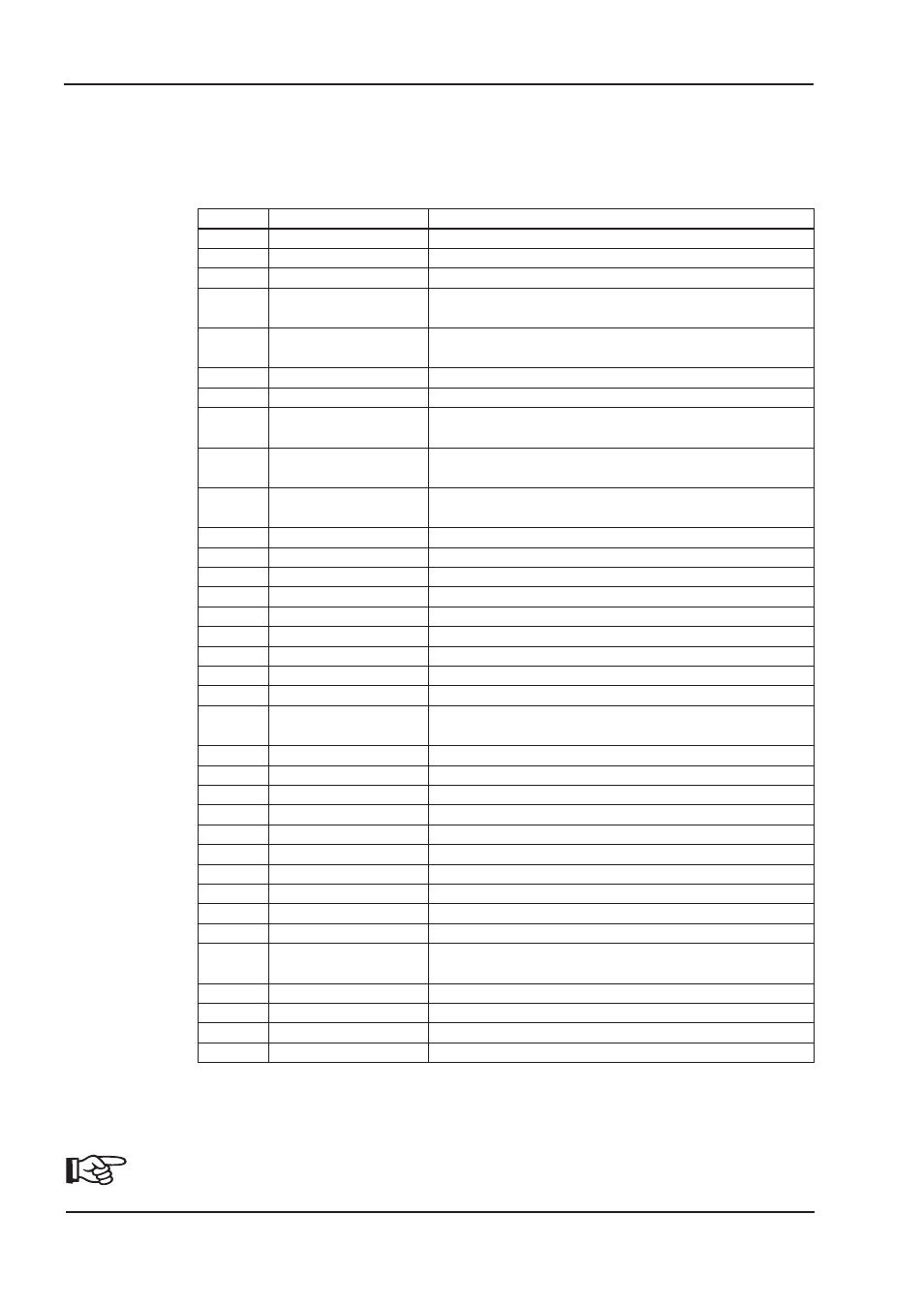
Errors that occur are displayed as a coded error number in the LED-display on the front panel, and in the
«STATUS» screen page. All error messages result in the BTB/RTO contact being opened and the output stage
of the amplifier being switched off (the motor loses all torque). The motor-holding brake is activated. Errors that
are recognized by the mains supply monitoring are only reported after the servo amplifier has been enabled.
* = These error messages can be canceled by the ASCII command CLRFAULT, without making a reset. If only
these errors are present, and the RESET button or the I/O-function RESET is used, the CLRFAULT command
is also all that is carried out.
Setup Software
Number
Designation
heat sink temperature
F01*
F02*
overvoltage
F03*
following error
F04
feedback
F05*
undervoltage
F06
motor temperature
F07
v_fault (int.supply)
F08*
overspeed
F09
EEPROM
F10
Flash-EPROM
brake
F11
motor phase
F12
F13*
internal temperature
F14
output stage
F15
I²t max.
F16*
mains BTB/RTO
F17
A/D converter
F18
regen
F19*
mains phase
F20
Slot error
F21
Handling error
F22
Short circuit to earth
F23
CAN bus off
Warning
F24
F25
Commutation error
F26
Limit switch
F27
AS-Option
F28
reserved
F29
Sercos
F30
Emerg. Stop Timeout
wrong Firmware-version
F31
F32
system fault
07/03
Explanation
heat sink temperature is too high,
the limit is set by the manufacturer to 80°C
overvoltage in the DC-link circuit,
the limit depends on the mains supply voltage
message from the position controller
cable break, short-circuit, short to ground
undervoltage in DC-link,
the limit is set by the manufacturer to 100V
temperature sensor faulty or motor temperature too high,
the limit is set by the manufacturer to 145°C
internal aux. voltage not OK
motor running away, the speed is higher than permitted
checksum error
checksum error
cable break, short-circuit, short to ground
motor phase missing (cable break or similar)
internal temperature too high
fault in the power output stage
I²t max. value exceeded
2 or 3 supply phases missing
error in the analog-digital conversion
regen circuit faulty or incorrect setting
a supply phase is missing
(can be switched off for 2-phase operation)
Hardware error on the expansion card
Software error on the expansion card
40/70 amps types only: Short circuit to earth
CAN bus total communication error
Warning display as error
Commutation error
Homing error (Hardware limit switch reached)
Operating error for AS-option
reserved
Sercos error
Emerg. Stop Timeout
wrong Firmware Version
system software not responding correctly
Error and warning messages
93
|
|
Особенности ремонта сервоприводов Beckhoff
 Ремонт сервоприводов Beckhoff известного европейского производителя, впрочем, как и ремонт приводов, выпущенных под другими брендами, имеет ряд особенностей в силу своего конструктива. Промышленные сервопривода, точнее их начинка делятся на две части:
- Аппаратная часть,
- Программная часть.
Приводы Beckhoff как и все остальные не являются исключением из правил, именно поэтому ремонт сервопривода Beckhoff имеет точно такой же ряд особенностей, как и у других преобразователей.
Диагностировать ту или иную неисправность помогают коды ошибок частотного преобразователя, которые отображаются на небольшом дисплее, расположенном на лицевой панели привода или выводятся на удаленный монитор.
Ремонт сервоприводов Beckhoff в , впрочем, как и любых других частотников выпущенных под другими брендами всегда начинается с аппаратной части, после успешного ремонта аппаратной части наступает очередь программной.
Настройка сервопривода Beckhoff прописана в инструкции завода производителя, для каждой серии приводов настройка будет индивидуальной, так как каждая линейка преобразователей решает свои собственные задачи, этим обусловливается широкая номенклатура данного промышленного оборудования. Но все же есть определенная последовательность настройки привода, которая относится ко всем преобразователям, независимо от бренда.
Программирование, настройка сервоприводов Beckhoff
Настройка сервопривода Beckhoff (программирование) происходит в рамках установленных производителем правил, существует общий алгоритм по программированию (настройке частотных преобразователей), относящийся ко всем производителям данного промышленного оборудования. Ниже представлена пошаговая инструкция по настройке сервоприводов Beckhoff и подобного промышленного оборудования других брендов.
- Выбор режима управления приводом (управление по показанию датчиков, дистанционное управление, дистанционное управление).
- В случае использования отдельного (выносного) монитора, настраивается вывод на него технической информации.
- Далее определяем конфигурацию подключения серводвигателя. На данной стадии задаются такие параметры как- возможность применения обратной связи либо без ее применения, а в память блока заносятся данные по: величине крутящего момента, мощности потребителей, номинальное значения частоты, напряжение, ток и скорости вращения ротора.
- Программируется минимально допустимая величина напряжения и частоты, а также время ускорения ротора от ноля до номинального значения.
- И в завершении, в программу управления сервопривода Beckhoff вносятся функциональные данные со значениями отдельных клемм и особенностями сигналов. Отмечаются действия оборудования, выполняющиеся автоматически при отсутствии информации поступающей в оперативном режиме с датчика.
Привод Beckhoff инструкция, скачать
Все настройки сервопривода Beckhoff приведены в технической документации ниже в удобном формате (PDF) который можно скачать на свой компьютер, распечатать или просто открыть на нашем сайте.
Промышленный сервопривод Beckhoff, инструкции, скачать в формате PDF.
|
Сервопривод Beckhoff AX2000, инструкция. |
|
|
Сервопривод Beckhoff AX2040 / AX2070, инструкция. |
|
|
Сервопривод Beckhoff AX2500, инструкция. |
|
|
Сервопривод Beckhoff AX5000, инструкция. |
|
|
Сервопривод Beckhoff AX5000 диагностические сообщения и коды ошибок. |
|
|
Сервопривод Beckhoff AX8000, инструкция. |
|
|
Сервопривод Beckhoff AX8000 диагностические сообщения и коды ошибок. |
|
 Скачать PDF
Подключение сервопривода Beckhoff
Схемы подключений приводов Beckhoff могут отличатся друг от друга даже если эти преобразователи относятся ко одной линейке. Схема подключения преобразователя зависит от потребляемой частотным преобразователем нагрузки или питающей сети к которой подключается частотник 200V – 380V, а также от оборудования с которым предполагается работа данного привода.
Ниже приведены схемы подключения привода Beckhoff AX2000; AX2500; AX
|
Схема подключения сервопривода Beckhoff AX2000 |
Схема подключения сервопривода Beckhoff AX2040/2070 |
|
|

|
|
Схема подключения сервопривода Beckhoff AX5000 |
|
|
|


Ремонт сервоприводов Beckhoff в сервисном центре
Сервисный центр «Кернел» производит ремонт сервоприводов Beckhoff в с 2002 года. За время существования компании наши сотрудники накопили колоссальный опыт в ремонте приводов такого известного производителя как Beckhoff.  Ремонт подобного промышленного оборудования ответственное и сложное занятие, требующие максимальной отдачи, профессионализма и максимально полной материальной базе.
Специалисты нашего сервисного центра максимальное внимание уделяют качеству исполнения ремонта, программирования и настройке сервоприводов, не зависимо от производителя данного промышленного оборудования. Именно поэтому мы смело даем гарантию на ремонт сервопривода Beckhoff и на запасные части замененные в процессе ремонта шесть месяцев.
Ремонт частотных преобразователей Beckhoff в производится исключительно с использованием оригинальных запасных частей, на компонентном уровне с применением высокотехнологичного оборудования, квалифицированным персоналом с инженерным образованием.
Мы ремонтируем все линейки сервоприводов, которые были выпучены за всю историю существования компании Beckhoff.
В случае выхода из строя преобразователя на вашем производстве либо появились проблемы с приводом, которые вы не можете решить самостоятельно, мы всегда рады вам помочь. Специалисты нашего сервисного центра в минимальные сроки проведут глубокую диагностику с последующим ремонтом сервопривода Beckhoff. Оставьте заказ на ремонт промышленного оборудования используя форму на сайте, либо свяжетесь с нашими менеджерами, сделать это очень просто.
Оставить заявку на ремонт сервопривода Beckhoff
У вас остались вопросы, связанные с ремонтом сервоприводов Beckhoff? Оставьте заявку на ремонт сервопривода Beckhoff в нашим менеджерам. Связаться с ними можно несколькими способами:

- Заказав обратный звонок (кнопка в правом нижнем углу сайта)
- Посредством чата (кнопка расположена с левой стороны сайта)
- Позвонив по номеру телефона: +7(8482) 79-78-54; +7(917) 121-53-01
- Написав на электронную почту: 89171215301@mail.ru
Далеко не полный список производителей промышленной электроники и оборудования, ремонтируемой в нашей компании.
9.6
Error messages
Any errors that occur are shown in coded form by an error number in the LED display on
the front panel. All error messages result in the BTB/RTO contact being opened, the out-
put stage being switched off (motor loses all torque), and the holding brake is activated.
Number Designation
Explanation
A/I/P/E
Status Messages
Status messages, no error, see p. 89
. . .
Status Message
Updating the startup configuration
F00
no error
no error on the selected axis module
F01*
Heat sink temperature
Heat sink temperature too high
limit is set by manufacturer to 80°
F02*
Overvoltage
Overvoltage in DC bus link
limit depends on the electrical supply voltage
F03*
Following error
Message from the position controller
F04
Feedback
Cable break, short-circuit, short to ground
F05*
Undervoltage
Undervoltage in DC bus link
limit is set by manufacturer to 100V
F06
Motor temperature
Motor temperature too high or temp. sensor defect
limit is set by manufacturer to 145°C
F07
Internal voltage
supply
Internal amplifier supply voltages are out of tolerance
F08*
Overspeed
Motor runs away, speed is too high
F09
EEPROM
Checksum error
F10
Flash-EPROM
Checksum error
F11
Brake
Cable break, short-circuit, short to ground
F12
Motor phase
Motor phase missing (cable break or similar)
F13*
Internal temperature
Internal temperature too high
F14
Output stage
Fault in the power output stage
F15
I²t max.
I²t maximum value exceeded
F16*
Supply BTB/RTO
2 or 3 phases missing in the mains supply feed
F17
A/D converter
Error in the analog-digital conversion, normally caused
by extreme electromagnetic interferences.
F18
Regen
Regen circuit faulty or incorrect setting
F19*
Supply phase
A phase is missing in the mains supply power feed
F20
Slot fault
Slot error (hardware fault on interface card)
F21
Handling error
Software error on the interface card
F22
reserved
reserved
F23
CAN-bus off
Severe CAN bus communication error
F24
Warning
Warning is displayed as fault
F25
Commutation error
Commutation error
F26
Limit switch
Homing error (hardware limit switch activated)
F27
reserved
reserved
F28
External Trajectory
External position profile generator created a step, that
exceeded the maximum value
F29
Sercos Error
only in SERCOS systems
F30
Emergency timeout
Timeout emergency stop
F31
Macro
Macro program error
F32
System Error
system software not responding correctly
* = these error messages can be cleared without a reset, by using the ASCII command
CLRFAULT. If only one of these errors is present and the RESET button or the I/O
RESET function is used, only the CLRFAULT command will be executed.
More information to the messages can be found in the ASCII Object Reference
(Online Help), see parameter ERRCODE. Hints for removal can be found in the
Online help chapter «Trouble-Shooting».
90
AX2500 Product Manual
Setup
06/2007
BECKHOFF
|
|
Ремонт сервоприводов Beckhoff в Калининграде
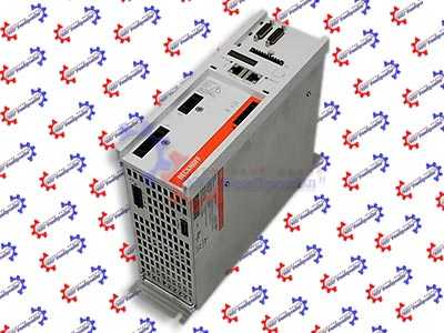
Ремонт сервоприводов Beckhoff в Калининграде, одна из многих услуг предлагаемых сервисным центром «РемПромЭл». Сервопривод относится к сложной промышленной электронике и состоит из двух взаимосвязанных составляющих- это электронная и силовая часть. Подобное конструктивное исполнение значительно усложняет ремонт сервоприводов Beckhoff.
Сервопривода достаточно распространенное промышленное оборудование, и как все подвержены износу. В зависимости от интенсивности использования, нагрузки, среды в которой работает оборудования сервопривода выходят из строя останавливая рабочий процесс.
В целях сомнительной «экономии» некоторые пытаются провести ремонт сервоусилителя Beckhoff самостоятельно на территории производства. Зачастую данные действия приводят к значительному удорожанию ремонта а при самом неблагоприятном исходе могут привести к не ремонтопригодности серводрайвера.
В виду вышесказанного, настоятельно рекомендуем, не пытайтесь проводить ремонт сервоприводов Beckhoff своими силами, обратитесь за помощью к специалистам. Современный специализированный сервисный центр имеет в наличии весь необходимый инструмент, включая специальное диагностическое оборудование, а компетентный персонал проведет качественный ремонт сервоприводов Beckhoff в Калининграде, дополнительно сервисные центры дают гарантию на проведенные ремонтные работы.
Ремонт сервоприводов Beckhoff в СЦ «РемПромЭл»
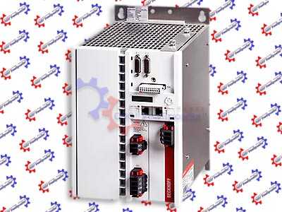
Ремонт сервоприводов Beckhoff в сервисном центре самое разумное и экономически выгодное решение. Грамотные специалисты со знанием дела проведут глубокую диагностику неисправного блока и последующий ремонт сервопривода Beckhoff в кратчайшие сроки. К написанному можно добавить то, что каждый без исключения ремонт сервопривода Beckhoff в СЦ «РемПромЭл» проводится с применением оригинальных запасных частей.
В 2013-ом году специалистами компании был проведен первый ремонт сервопривода Beckhoff положивший начало дальнейшему развитию в данном направлении. За прошедшее время были отремонтированы сотни единиц промышленного оборудования и накоплен колоссальный, бесценный опыт в ремонте сервоприводов различных производителей.
Сервисный центр «РемПромЭл» оснащен самым современным диагностическим и ремонтным оборудованием, имеются в наличии расходные материалы, а так же на складе компании богатый выбор оригинальных запасных частей, что дает возможность провести качественный ремонт сервоприводов Beckhoff.
Обратившись в СЦ за ремонтом сервоприводов вы получите:
- Глубокую диагностику с выявлением неисправного компонента;
- Чистку неисправного блока;
- Ремонт сервопривода Beckhoff в кратчайшие сроки;
- Настройка сервоусилителя;
- Проверку отремонтированного блока на специальном стенде в условиях максимально приближенных к реальным;
- Видео проверки отремонтированного серводрайвера.
Отдельное внимание мы уделяем качеству проведения ремонта и даем гарантию на ремонт сервоприводов Beckhoff, а так же на замененные в процессе ремонта запасные части и расходные материалы 6 месяцев.
Настройка сервоусилителей Beckhoff в Калининграде
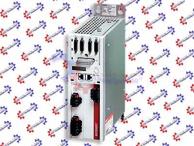
Настройка сервоприводов (сервоусилителей) — это заключительный этап ремонта и в тоже время очень важный. Для правильной работы восстановленного блока просто необходимо провести грамотное программирование сервоусилителя. Ремонт и дальнейшую настройку сервоприводов выполняют разные специалисты, так как подобная работа довольно сложная и имеет свою специфику.
Настройка сервоусилителей или как еще называют программирование сервоприводов Beckhoff, неотъемлемая часть процесса реанимирования, ввиду того, что ремонт силовой части это только половина мероприятий направленных на восстановление работоспособности сервоприводов.
В некоторых случаях возникает необходимость провести программирование сервоусилителя без его ремонта. Причин по которым может возникнуть подобная необходимость масса.
Настройка сервоуслилтелей Beckhoff в Калининграде может быть и отдельной услугой предоставляемой сервисным центром «РемПромЭл». Инженеры компании проведут необходимую настройку сервоприводов не только на территории сервисного центра, при необходимости можно заказать услугу выезда специалиста на территорию заказчика (по предварительной договоренности).
От качественной настройки сервоусилителя зависит правильная и безаварийная работа связки сервопривода и серводвигателя, а для этого требуется не много, просто программирование сервопривода Beckhoff должен проводить компетентный персонал с богатым опытом по настройке сервоуслилтелей.
Подключение сервопривода Beckhoff
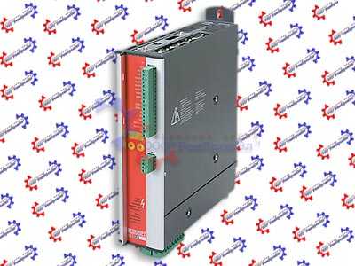
Подключение сервопривода Beckhoff к оборудованию заказчика это еще одна услуга предоставляемая нашей компанией.
При необходимости специалист центра выполнит подключение сервопривода Beckhoff с выездом на территорию заказчика.
В некоторых случаях на производстве может быть дефицит квалифицированны кадров которые могли бы произвести качественное подключение сервопривода, именно по этому мы предлагаем услуги нашего сервисного центра.
Свяжитесь с нашими менеджерами, закажите выезд специалиста, и подключением сервопривода Beckhoff займется инженер сервисного центра. В случае заказа на подключение сервопривода Beckhoff силами наших специалистов вы получаете гарантию качества и работоспособности вашего оборудования.
Доверяя работу по подключению сервопривода Beckhoff профессионалам, вы избавляетесь от головной боли и гарантированно получаете работающее оборудование в кратчайшие сроки за разумную цену.
Ошибки сервопривода Beckhoff
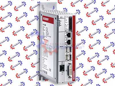
Многие сервопривода данного производителя, за редким исключением оснащен информационной панелью с помощью которой проходит процесс программирования сервоприводов, а так же на ней в случае нештатной ситуации отображается код ошибки которая привела к остановке оборудования.
У каждого производителя разные коды ошибок у кого то это могут быть цифровые обозначения у кого то буквенные, но вся прелесть заключается в том, что открыв документацию и расшифровав код ошибки сервопривода мы с большой долей вероятности можем исправить эту ошибку на месте, сбросить ее на сервоприводе и запустить оборудование заново.
К сожалению не все ошибки сервоприводов можно исправить и сбросить самостоятельно, в некоторых случаях придется обращаться к специалистам сервисного центра.
Самые распространенные ошибки сервоприводов:
- Превышение тока;
- Перенапряжение или недостаточное напряжение;
- Перегрузка;
- Ошибка сигнала энкодера;
- Превышение температуры IGBT-модуля ;
- Ошибка связи;
- Обрыв фазы питания;
- Короткое замыкание.
Это не полный список распространенных ошибок сервоприводов которые можно сбросить самостоятельно без обращения к специалистам.
Коды ошибок сервопривода Beckhoff AX2000
Для индикации отказа (ошибки) используется красный светодиод. Предупреждение или сообщение об отказе на дисплее панели управления указывает на нештатное состояние привода. Пользуясь информацией, приведенной в таблице ниже, можно определить причины большинства возникающих неисправностей и отказов и устранить их. При возникновении затруднений обратитесь в сервисный центр. Четырехзначный код в скобках после сообщения относится к интерфейсу Fieldbus.
| Код ошибки | Обозначение | Объяснение |
|---|---|---|
|
E / S / A / P |
Сообщения о состоянии. |
Сообщения о состоянии, ошибок нет. |
|
. . . |
Сообщения о состоянии. |
Обновление начальной конфигурации. |
|
— |
Сообщения о состоянии. |
Режим программирования. |
|
F01* |
Температура радиатора. | Слишком высокая температура радиатора ограничение установлено производителем на 80°. |
| F02* | Перенапряжение. | Перенапряжение в звене шины постоянного тока предел зависит от напряжения питания. |
| F03* | Следующая ошибка. |
Сообщение от регулятора положения. |
| F04 | Обратная связь. | Обрыв кабеля, короткое замыкание, замыкание на массу. |
| F05* | Пониженное напряжение. | Пониженное напряжение в звене шины постоянного тока ограничение установлено производителем на 100В. |
| F06 | Температура двигателя. | Слишком высокая температура двигателя или темп. дефект датчика ограничение установлено производителем на 145°C. |
| F07 | Внутреннее питание. | Напряжение питания внутреннего усилителя выходит за допустимые пределы. |
| F08* | Превышение скорости. | Скорость двигателя слишком высокая. |
| F09 | EEPROM. | Ошибка контрольной суммы. |
| F10 | Flash-EPROM. | Ошибка контрольной суммы. |
| F11 | Тормоз. | Обрыв кабеля, короткое замыкание, замыкание на массу. |
| F12 | Фаза двигателя. | Отсутствует фаза двигателя (обрыв кабеля или подобное). |
| F13* | Внутренняя температура. | Слишком высокая внутренняя температура. |
| F14 | Выходной каскад. | Неисправность выходного каскада мощности. |
| F15 | I²t макс. | I²t максимальное значение превышено. |
| F16* | Питание BTB/RTO. | Отсутствуют 2 или 3 фазы в питающей сети. |
| F17 | аналого-цифровой преобразователь. | Ошибка аналого-цифрового преобразования, вызванная экстремальными электромагнитными помехами. |
| F18 | Рекуперация. | Цепь рекуперации неисправна или неправильная настройка. |
| F19* | Питающая фаза. | Отсутствует фаза в подаче питания от сети (можно отключить для 2-фазного режима). |
| F20 | Ошибка слота. | Ошибка слота (аппаратный сбой на плате расширения). |
Все возможные ошибки сервопривода Beckhoff AX2000 — Скачать в формате PDF
Типы сервоприводов Beckhoff
| Сервопривод | Тип сервопривода |
|---|---|
|
Beckhoff |
AX2003-B900-0001; AX2006-6A S60600-520; AX2006-AS S60601-520; AX2516-B200 S406M; AX2003-B110-0000 S60300-520; AX2003-B110-0000 S60300-520; AX5203 AX5201-LT00-4-V2; AX5203 AX5203-LT00-3; AX2020-B900-0000; AX2513-B750-0000; AX2513-B750 S443M-SE-520; AX2503-S403-M-SE; Al2406-0001-0001; AX2516-B750; AX2513-B310; AX2523-B310; AX2020-B750-0000; AX2513-B900; AX2516-B900; AX2020-B110-0000; AX2003-AS-S60301-520; AX2020 S62000-520; AX2003-B110-0000; AX2503-B750; AX2503-B200; AX2523-B750-0000; AX5201-0000-FS; AX2003 S60300-520; AX2006 S60600-520; AX5021-0000; AX2526-B900; AX2523-B900 |
Указанные в таблице типы сервоприводов Beckhoff это далеко не все сервопривода данного производителя, ремонт которых производит наш сервисный центр. Мы предлагаем качественный ремонт сервоприводов в Калининграде выпущенных не только под брендом Beckhoff инженеры центра выполнят ремонт сервоприводов абсолютно любых производителей и года выпуска.
Оставить заявку на ремонт сервопривода Beckhoff
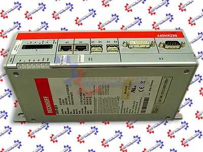
Вы заинтересованы в качественном ремонте дорогостоящего промышленного оборудования силами специалистов нашего сервисного центра, Вы сделали правильный выбор, мы приложим максимум усилий для скорейшего восстановления вышедшего из строя серводрайвера, что позволит Вам максимально сократить простой оборудования и сэкономить значительную сумму.
У вас есть проблемы с сервоприводом? Вам нужен срочный ремонт сервопривода Beckhoff или других серий? Оставьте заявку на ремонт сервопривода Beckhoff в Калининграде воспользовавшись одноименной кнопкой на сайте либо обратитесь к нашим менеджерам. Связаться с ними можно несколькими способами:

- Заказав обратный звонок (кнопка в правом верхнем углу сайта)
- Посредством чата (кнопка расположена с левой стороны сайта)
- Позвонив по номеру телефона: +7(927)610-78-70; +7(848)255-80-30
- Написав на электронную почту: Адрес электронной почты защищен от спам-ботов. Для просмотра адреса в вашем браузере должен быть включен Javascript.
- Перейти в начало статьи
roman_eremin
Напишу тут подробно, чтобы самому потом не забыть. Похоже, тут половина вещей из серии “Это нельзя понять – это надо запомнить”. Итак, я дошел до того, что софт видит контроллер и простейшая программа туда загружается и вроде бы работает. Вот как это делается.
Мы поставили TwinCAT. Для начала запускаем TwinCAT System Manager. В нем сначала найдем устройство:
В появившемся диалоге выбираем Search (Ethernet) и в диалоге поиска – Broadcast Search
Закрываем диалог, в предыдущем диалоге выделяем только что найденное устройство:
Теперь System Manager подключен к нашему контроллеру, о чем сообщает в статусбаре. Далее надо получить список устройств ввода-вывода. В ноде I/O – Configuration –> I/O Devices ткаем правой кнопкой и говорим Scan Devices:
В результате система получает полную конфигурацию устройств:
Как видно выше, перечислены все три блока подсоединенные к контроллеру, включая пустышку. Я даже могу отсюда управлять состоянием каналов вывода (выделить канал, справа закладка Online и там нажать кнопку Write):
Beckhoff Drive Check
Записал 1 в 4-й канал – на блоке вывода загорелся светодиод. Стало быть поменялось состояние. А вот канал ввода – не меняется так. Видимо, он проверяет физическое состояние (не замкнуто) и врать права не имеет. Ну да ладно.
Далее мне хочется написать простейшую программу. Если замкнут вход 1 – включить выход 1. Если разомкнут – выключить. Для этого нам понадобится другая программа – TwinCAT PLC Control (по сути – IDE CoDeSys). В ней мы создаем новый проект. Нас спрашивают под какое устройство будем писать.
Выбираем CX (ARM), потому что наш cx9010 построен на ARM процессоре. Проект состоит из программных блоков, один из которых – главный нам сразу предлагают создать:
Языков как видите может использоваться множество. Я выберу LD – язык лестничных диаграмм или релейно-контактной логики по-нашему. Сначала в верхнем окошке обьявляем переменные. Вот на этом этапе я и провел полдня. Похоже, для того, чтобы эти переменные были видны и к ним можно было привязать вводы-выводы, они должны иметь адрес.
Что конкретно это означает, я пока не понимаю, но вот это вот шаманство работает. То есть для обьявления булевской переменной In01, надо написать не вот так:
Волшебное заклинание %IX0.1 переводится так. %-значит это адрес. I – вход (Q-выход). X – тип данных бит (true/false). 0.1 – это месторасположение в некой области переменных. Это значит 1-й бит нулевого байта.
Пишем саму прогамму. На языке LD программа – это типа две шины (справа и слева) под напряжением. Между ними можно вставлять котакты (Contact) и реле (Coil). Контакт – это вход, Coil – это выход. Можно еще блоки вставлять, но это пока опустим.
Таких цепочек может быть много, но у нас пока одна будет. Вставляем контакт. И сверху пишем имя входной переменной In01.
Затем вставляем Coil и называет Out01. Вот такая получается программа:
Она как раз и говорит “Если In01 замкнут, то через Out01 идет ток и оно замыкается”. Ну и наоборот соответственно. Все, программа у нас написана. Говорим Project –> Build. Все компилится без ошибок. Рядом с файлом проекта появляется файл *.tpy который теперь можно загрузить в System Manager:
Beckhoff programmering #17 — Software opsætning af servo motor
Как видите, System Manager видит обе наши переменные:
Теперь в I/O Configuration мы можем привязать каналы ввода – вывода к переменным. Выбираем канал, нажимаем Linked to и выбираем переменную:
Теперь у меня физические входы-выходы приделаны к переменным в программе. Я иду в PLC Control. Там я тоже должен сказать что работаю с физическим контроллером (Online –> Choose Rintime System:). Выбираю свой контроллер:
Затем говорю Online –> Login. Система спрашивает загружать ли программу в контроллер. Загружаем. Далее я могу сказать Online –> Run – запустить программу в контроллере. И вроде как она выполняется.
Я могу поменять значение переменной In01 из PLC Control и выходная переменная Out01 тоже меняется. Только вот состояние выхода у контроллера – не меняется. Будем копать дальше.
На YouTube есть видео всего процесса и там у них все работает. Но там используется не железный контроллер, а SoftPLC – программный PLC который прямо на компе крутится.
Вот на этом этапе я, пожалуй, пока остановлюсь и пойду дегустировать разливной Newcastle – мозги беречь надо.
Источник: roman-eremin.livejournal.com
Ошибки и ремонт сервоприводов Beckhoff в Калининграде
Ремонт сервоприводов Beckhoff в Калининграде, одна из многих услуг предлагаемых сервисным центром «РемПромЭл». Сервопривод относится к сложной промышленной электронике и состоит из двух взаимосвязанных составляющих- это электронная и силовая часть. Подобное конструктивное исполнение значительно усложняет ремонт сервоприводов Beckhoff.
Сервопривода достаточно распространенное промышленное оборудование, и как все подвержены износу. В зависимости от интенсивности использования, нагрузки, среды в которой работает оборудования сервопривода выходят из строя останавливая рабочий процесс.
В целях сомнительной «экономии» некоторые пытаются провести ремонт сервоусилителя Beckhoff самостоятельно на территории производства. Зачастую данные действия приводят к значительному удорожанию ремонта а при самом неблагоприятном исходе могут привести к не ремонтопригодности серводрайвера.
В виду вышесказанного, настоятельно рекомендуем, не пытайтесь проводить ремонт сервоприводов Beckhoff своими силами, обратитесь за помощью к специалистам. Современный специализированный сервисный центр имеет в наличии весь необходимый инструмент, включая специальное диагностическое оборудование, а компетентный персонал проведет качественный ремонт сервоприводов Beckhoff в Калининграде, дополнительно сервисные центры дают гарантию на проведенные ремонтные работы.
Ремонт сервоприводов Beckhoff в СЦ «РемПромЭл»
Ремонт сервоприводов Beckhoff в сервисном центре самое разумное и экономически выгодное решение. Грамотные специалисты со знанием дела проведут глубокую диагностику неисправного блока и последующий ремонт сервопривода Beckhoff в кратчайшие сроки. К написанному можно добавить то, что каждый без исключения ремонт сервопривода Beckhoff в СЦ «РемПромЭл» проводится с применением оригинальных запасных частей.
В 2013-ом году специалистами компании был проведен первый ремонт сервопривода Beckhoff положивший начало дальнейшему развитию в данном направлении. За прошедшее время были отремонтированы сотни единиц промышленного оборудования и накоплен колоссальный, бесценный опыт в ремонте сервоприводов различных производителей.
Сервисный центр «РемПромЭл» оснащен самым современным диагностическим и ремонтным оборудованием, имеются в наличии расходные материалы, а так же на складе компании богатый выбор оригинальных запасных частей, что дает возможность провести качественный ремонт сервоприводов Beckhoff.
Обратившись в СЦ за ремонтом сервоприводов вы получите:
- Глубокую диагностику с выявлением неисправного компонента;
- Чистку неисправного блока;
- Ремонт сервопривода Beckhoff в кратчайшие сроки;
- Настройка сервоусилителя;
- Проверку отремонтированного блока на специальном стенде в условиях максимально приближенных к реальным;
- Видео проверки отремонтированного серводрайвера.
Отдельное внимание мы уделяем качеству проведения ремонта и даем гарантию на ремонт сервоприводов Beckhoff, а так же на замененные в процессе ремонта запасные части и расходные материалы 6 месяцев.
Настройка сервоусилителей Beckhoff в Калининграде
Настройка сервоприводов (сервоусилителей) — это заключительный этап ремонта и в тоже время очень важный. Для правильной работы восстановленного блока просто необходимо провести грамотное программирование сервоусилителя. Ремонт и дальнейшую настройку сервоприводов выполняют разные специалисты, так как подобная работа довольно сложная и имеет свою специфику.
Настройка сервоусилителей или как еще называют программирование сервоприводов Beckhoff, неотъемлемая часть процесса реанимирования, ввиду того, что ремонт силовой части это только половина мероприятий направленных на восстановление работоспособности сервоприводов.
В некоторых случаях возникает необходимость провести программирование сервоусилителя без его ремонта. Причин по которым может возникнуть подобная необходимость масса.
Настройка сервоуслилтелей Beckhoff в Калининграде может быть и отдельной услугой предоставляемой сервисным центром «РемПромЭл». Инженеры компании проведут необходимую настройку сервоприводов не только на территории сервисного центра, при необходимости можно заказать услугу выезда специалиста на территорию заказчика (по предварительной договоренности).
От качественной настройки сервоусилителя зависит правильная и безаварийная работа связки сервопривода и серводвигателя, а для этого требуется не много, просто программирование сервопривода Beckhoff должен проводить компетентный персонал с богатым опытом по настройке сервоуслилтелей.
Подключение сервопривода Beckhoff
Подключение сервопривода Beckhoff к оборудованию заказчика это еще одна услуга предоставляемая нашей компанией.
При необходимости специалист центра выполнит подключение сервопривода Beckhoff с выездом на территорию заказчика.
В некоторых случаях на производстве может быть дефицит квалифицированны кадров которые могли бы произвести качественное подключение сервопривода, именно по этому мы предлагаем услуги нашего сервисного центра.
Свяжитесь с нашими менеджерами, закажите выезд специалиста, и подключением сервопривода Beckhoff займется инженер сервисного центра. В случае заказа на подключение сервопривода Beckhoff силами наших специалистов вы получаете гарантию качества и работоспособности вашего оборудования.
Доверяя работу по подключению сервопривода Beckhoff профессионалам, вы избавляетесь от головной боли и гарантированно получаете работающее оборудование в кратчайшие сроки за разумную цену.
Ошибки сервопривода Beckhoff
Многие сервопривода данного производителя, за редким исключением оснащен информационной панелью с помощью которой проходит процесс программирования сервоприводов, а так же на ней в случае нештатной ситуации отображается код ошибки которая привела к остановке оборудования.
У каждого производителя разные коды ошибок у кого то это могут быть цифровые обозначения у кого то буквенные, но вся прелесть заключается в том, что открыв документацию и расшифровав код ошибки сервопривода мы с большой долей вероятности можем исправить эту ошибку на месте, сбросить ее на сервоприводе и запустить оборудование заново.
К сожалению не все ошибки сервоприводов можно исправить и сбросить самостоятельно, в некоторых случаях придется обращаться к специалистам сервисного центра.
Самые распространенные ошибки сервоприводов:
- Превышение тока;
- Перенапряжение или недостаточное напряжение;
- Перегрузка;
- Ошибка сигнала энкодера;
- Превышение температуры IGBT-модуля ;
- Ошибка связи;
- Обрыв фазы питания;
- Короткое замыкание.
Это не полный список распространенных ошибок сервоприводов которые можно сбросить самостоятельно без обращения к специалистам.
Коды ошибок сервопривода Beckhoff AX2000
Для индикации отказа (ошибки) используется красный светодиод. Предупреждение или сообщение об отказе на дисплее панели управления указывает на нештатное состояние привода. Пользуясь информацией, приведенной в таблице ниже, можно определить причины большинства возникающих неисправностей и отказов и устранить их. При возникновении затруднений обратитесь в сервисный центр. Четырехзначный код в скобках после сообщения относится к интерфейсу Fieldbus.
Сообщения о состоянии.
Сообщения о состоянии, ошибок нет.
Сообщения о состоянии .
Обновление начальной конфигурации.
Источник: remontservodrive.ru
Ремонт AX2003-AS — Beckhoff — 3A SERVO DRIVE

Ремонт AX2003-AS — Beckhoff* — 3A SERVO DRIVE. Диагностика и наладка на уровне компонентов плат выполняется в Санкт-Петербурге. Возможно выполнение диагностики с последующим ремонтом с доставкой оборудования в города России.
Устройства промышленной электроники включают в себя следующие части: схема управления (компоненты: микроЭВМ, кварцевый генератор, оперативная память, гальваническая развязка, модуль цифровых входов, шина данных, интерфейс связи, модуль выходов, постоянное запоминающее устройство, цифро-аналоговый преобразователь, устройство программирования) — является важной частью для реализации алгоритма работы микропроцессорного устройства в целом и обеспечивает предусмотренное выполнение нужных операций в соответствии с назначением; схема питания (основа: стабилизатор, выпрямительные диоды, трансформатор, сглаживающий фильтр) — гарантирует снабжение всех составляющих частей устройства стабильным электрическим питанием; схема индикации (на основе: токоограничительных резисторов, декодера, драйвера, светодиодов, ЖК дисплея) — формирует информацию о текущем состоянии устройства и присоединенных датчиков; схема автоматической диагностики (основа: модуль опроса датчиков, сторожевой таймер, интерфейс отладки, модуль внутрисхемного тестирования, модуль проверки контрольной суммы) — позволяет оценить состояние практически всех составных частей при запуске; схема определения характеристик (выполнена на основе: датчика тока, делителя напряжения, операционного усилителя, датчика температуры, источника опорного напряжения, аналого-цифрового преобразователя, активного фильтра, защитных диодов) — предназначена для регистрации отклонений контролируемых характеристик.
Условия ремонта
Общие условия выполнения диагностики и ремонта находятся на странице Условия.
Примеры серийных номеров на шильде
Чтобы получить самую актуальную информацию о точной стоимости и сроке осуществления услуг отправьте сообщение с описанием внешних признаков неисправностей на адрес электронной почты [email protected]
Время выполнения запроса: 0,00380301475525 секунды.
Источник: prom-electric.ru
Неисправность Beckhoff

Рассказываю все по порядку.
Есть стандартный щит на контроллере Beckhoff CX9010 + различные его модули (счетчики, дискретный ввод, интерфейс). Щит стандартный собираем. Щитов уже было много. Все было хорошо.
Но на одном объекте CX «сдох» — нет индикации при подаче питания. Сняли голову, привезли другую, проверили щит (220В не приходит куда не надо, питание 24В требуемое, провода все прозвонились нормально, нигде не коротит). Но при включении заметили странность — диод на контроллере 24В горит тускло (в нормальном состоянии оба 24В и 0В горят ярко одинаково). Потом не смогли найти программно подключенные к нему модули. Потом он вовсе отвалился для ПО (хотя в сети есть — пинг идет).
Сняли всю линейку. Контроллеру заново залил образ. Сам CX включился и работает без проблем. Однако, когда поставил всю линейку (CX + модули) при включении снова диод на 24В как то странно моргнул, а потом «запахло жареным», но то есть запахло горелой пластмассой. Выключил.
Проверил общую шину питания — звонится четко 24В и 0В по всей линейке, прозвонил отдельно эти контакты на каждом модуле — тоже все нормально. Включил один CX — проблем нет. Дальше звучит глупо, но нашел ,что пахнут два модуля. Исключил их из линейки — все заработало. На этом эксперименты кончились пока.
Возможно, кто-нибудь даст совет как можно проверить модули? Что могло с ними случиться? Да и вообще в них ли точно дело?
94731 / 64177 / 26122
Регистрация: 12.04.2006
Сообщений: 116,782
Ответы с готовыми решениями:
Как клонировать Beckhoff BC9000?
Есть несколько одинаковых агрегатов с контроллером на базе Beckhoff BC9000. У одного перестал.

Beckhoff PC9000, Обмен данными
Используется ПЛК Beckhoff PC9000 с модулями KL3458 и KL4408. Для связи используется TwinCAT. В.
Открыть проект с контроллера Beckhoff BX9000
Здравствуйте. Не могу открыть проект на контроллере BX9000 (с контроллера). ПОдключился через.
ПЛК Beckhoff ВС9120. Контроль и мониторинг по Modbus TCP
Доброе время суток . Прошу помочь знающим людям Как управлять (считывать записывать данные ) на.
10227 / 6606 / 497
Регистрация: 28.12.2010
Сообщений: 21,159
Записей в блоге: 1
. коротнули при монтаже (сами ж пишите, что провода прозвонились опосля тусклого свечения), чего-то не заметили, включили, чуть подпалили, потом оно себя окончательно проявило.
87844 / 49110 / 22898
Регистрация: 17.06.2006
Сообщений: 92,604
Помогаю со студенческими работами здесь
ПЛК Beckhoff CX9010. Реализация протокола Меркурий 230
Добрый день. Реализую протокол Меркурия. Проблема в том, что прибора под рукой нет. Нашел.
Heartbeat-сообщение (1Hz) через profibus beckhoff EL6731
Всем привет. Прошу помощи решения вопроса. Есть робот kuka и станок компании dmg они соединены.
Контроллеры Beckhoff+TwinCAT3 нужна помошь
Всем привет В обшем так случилось что нужно пересаживатся на Beckhoff+TwinCAT3/2. В принципе не.
Модули Beckhoff
Продам модули Beckhoff. Модули абсолютно новые в упаковке. Ни разу не устанавливались. Beckhoff.
Источник: www.cyberforum.ru
Вернее, чайником. То есть мною.
Напишу тут подробно, чтобы самому потом не забыть. Похоже, тут половина вещей из серии “Это нельзя понять – это надо запомнить”. Итак, я дошел до того, что софт видит контроллер и простейшая программа туда загружается и вроде бы работает. Вот как это делается.
Мы поставили TwinCAT. Для начала запускаем TwinCAT System Manager. В нем сначала найдем устройство:

В появившемся диалоге выбираем Search (Ethernet) и в диалоге поиска – Broadcast Search

Закрываем диалог, в предыдущем диалоге выделяем только что найденное устройство:

Теперь System Manager подключен к нашему контроллеру, о чем сообщает в статусбаре. Далее надо получить список устройств ввода-вывода. В ноде I/O – Configuration –> I/O Devices ткаем правой кнопкой и говорим Scan Devices:

В результате система получает полную конфигурацию устройств:

Как видно выше, перечислены все три блока подсоединенные к контроллеру, включая пустышку. Я даже могу отсюда управлять состоянием каналов вывода (выделить канал, справа закладка Online и там нажать кнопку Write):

Записал 1 в 4-й канал – на блоке вывода загорелся светодиод. Стало быть поменялось состояние. А вот канал ввода – не меняется так. Видимо, он проверяет физическое состояние (не замкнуто) и врать права не имеет. Ну да ладно.
Далее мне хочется написать простейшую программу. Если замкнут вход 1 – включить выход 1. Если разомкнут – выключить. Для этого нам понадобится другая программа – TwinCAT PLC Control (по сути – IDE CoDeSys). В ней мы создаем новый проект. Нас спрашивают под какое устройство будем писать.

Выбираем CX (ARM), потому что наш cx9010 построен на ARM процессоре. Проект состоит из программных блоков, один из которых – главный нам сразу предлагают создать:

Языков как видите может использоваться множество. Я выберу LD – язык лестничных диаграмм или релейно-контактной логики по-нашему. Сначала в верхнем окошке обьявляем переменные. Вот на этом этапе я и провел полдня. Похоже, для того, чтобы эти переменные были видны и к ним можно было привязать вводы-выводы, они должны иметь адрес. Что конкретно это означает, я пока не понимаю, но вот это вот шаманство работает. То есть для обьявления булевской переменной In01, надо написать не вот так:

А вот так:

Волшебное заклинание %IX0.1 переводится так. %-значит это адрес. I – вход (Q-выход). X – тип данных бит (true/false). 0.1 – это месторасположение в некой области переменных. Это значит 1-й бит нулевого байта.

Пишем саму прогамму. На языке LD программа – это типа две шины (справа и слева) под напряжением. Между ними можно вставлять котакты (Contact) и реле (Coil). Контакт – это вход, Coil – это выход. Можно еще блоки вставлять, но это пока опустим. Таких цепочек может быть много, но у нас пока одна будет. Вставляем контакт. И сверху пишем имя входной переменной In01.

Затем вставляем Coil и называет Out01. Вот такая получается программа:

Она как раз и говорит “Если In01 замкнут, то через Out01 идет ток и оно замыкается”. Ну и наоборот соответственно. Все, программа у нас написана. Говорим Project –> Build. Все компилится без ошибок. Рядом с файлом проекта появляется файл *.tpy который теперь можно загрузить в System Manager:

Как видите, System Manager видит обе наши переменные:

Теперь в I/O Configuration мы можем привязать каналы ввода – вывода к переменным. Выбираем канал, нажимаем Linked to и выбираем переменную:

Теперь у меня физические входы-выходы приделаны к переменным в программе. Я иду в PLC Control. Там я тоже должен сказать что работаю с физическим контроллером (Online –> Choose Rintime System:). Выбираю свой контроллер:

Затем говорю Online –> Login. Система спрашивает загружать ли программу в контроллер. Загружаем. Далее я могу сказать Online –> Run – запустить программу в контроллере. И вроде как она выполняется. Я могу поменять значение переменной In01 из PLC Control и выходная переменная Out01 тоже меняется. Только вот состояние выхода у контроллера – не меняется. Будем копать дальше.
На YouTube есть видео всего процесса и там у них все работает. Но там используется не железный контроллер, а SoftPLC – программный PLC который прямо на компе крутится.
Вот на этом этапе я, пожалуй, пока остановлюсь и пойду дегустировать разливной Newcastle – мозги беречь надо.
![6a00d8341c630a53ef0120a701fc57970b-800wi[1]](https://pics.livejournal.com/roman_eremin/pic/00029g5y "6a00d8341c630a53ef0120a701fc57970b-800wi[1]")
-
Contents
-
Table of Contents
-
Bookmarks
Quick Links
Digital Servo Amplifier
AX2000
Assembly, Installation, Setup
Keep all product manuals as a product component
during the life span of the servo amplifier.
Pass all product manuals to future
users / owners of the servo amplifier.
Edition 02/06
Related Manuals for Beckhoff AX2000
Summary of Contents for Beckhoff AX2000
-
Page 1
Digital Servo Amplifier AX2000 Assembly, Installation, Setup Keep all product manuals as a product component during the life span of the servo amplifier. Pass all product manuals to future users / owners of the servo amplifier. Edition 02/06… -
Page 2
Printed in the Federal Republic of Germany All rights reserved. No part of this work may be reproduced in any form (by printing, photocopying, microfilm or any other method) or stored, processed, copied or distributed by electronic means without the written permission of BECKHOFF Corporation. -
Page 3: Table Of Contents
The digital servo amplifiers of the series AX2000 ……. . .
-
Page 4
Mains supply circuit …………..69 AX2000 Installation manual… -
Page 5
Index ………………. . 96 AX2000 Installation manual… -
Page 6
BECKHOFF 02/06 This page has been deliberately left blank. AX2000 Installation manual… -
Page 7: General
/ drive technology Symbols used in this manual Danger to personnel Danger to maschinery, Important from electricity and its general warning notes effects ð p. see page special emphasis AX2000 Installation manual…
-
Page 8: Abbreviations Used In This Manual
Bext Internal regen resistor Bint Resolver ROD 426 (EEO) A quad B encoder Programmable logic controller SRAM Static RAM Synchronous serial interface Underwriters Laboratory AC voltage DC voltage Verein deutscher Elektrotechniker XGND Ground for the 24V supply AX2000 Installation manual…
-
Page 9: Technical Description
Capacitors can still have dangerous voltages present up to five minutes after switching off the supply voltages. To be sure, measure the voltage in the DC bus link circuit and wait until it has fallen below 40V. AX2000 Installation manual…
-
Page 10: Use As Directed
The AX2000 family of servo amplifiers can be connected directly to symmetrically earthed (grounded) three-phase industrial mains supply networks [TN-system, TT-system with earthed (grounded) neutral point, not more than 5000 rms symmetrical amperes, 480VAC maximum].
-
Page 11: European Directives And Standards
Any divergence from the configuration and installation described in this documentation means that you will be responsible for carrying out new measure- ments to ensure conformance with regulatory requirements. The standard EN 50178 is applied to ensure conformance with the Low Voltage Directive. AX2000 Installation manual…
-
Page 12: Ul And Cul- Conformance
UL 840 UL 840 describes the fulfilment by design of air and insulation creepage spacings for electrical equipment and printed circuit boards. AX2000 Installation manual…
-
Page 13: Nameplate
Installed load Instrument description 2.7.1 Package supplied When you order a AX2000 series amplifier, you will receive: — AX20xx — mating connectors X3, X4, X0A, X0B, X7, X8 The mating SubD connectors and motor connector X9 are not part of the package! —…
-
Page 14: The Digital Servo Amplifiers Of The Series Ax2000
BECKHOFF Technical Description 02/06 2.7.2 The digital servo amplifiers of the series AX2000 Standard version 6 current ratings (1.5 A , 3 A , 6 A , 10 A , 14 A, 20 A) three instrument widths : 70 mm for 1.5A up to 10A rated current…
-
Page 15
EtherCat expansion card ð p. 80 SynqNet expansion card ð p. 81 -2CAN- expansion module, separated connectors for CAN bus and RS232 ð p. 83 Third party expansion cards (ModBus, FireWire, LightBus etc. — contact distributors for furt- her information) AX2000 Installation manual… -
Page 16: Connection To Different Mains Supply Networks
On this page you’ll find all possible connection variations to different mains supply networks. An isolating transformer is always required for 400…480V mains networks without earth(ground) and for networks with asymmetrical earth(ground). — A.4.031.1/52 208V with 60Hz only 230…480V with 50Hz or 60Hz AX2000 Installation manual…
-
Page 17: Components Of A Servo System
BECKHOFF Technical Description 02/06 Components of a servo system Control / PLC Option -AS- AX2000 24V supply fuses drive contactor terminals motor AX2000 Installation manual…
-
Page 18: Technical Data
Resolver input — SubD 9pole (socket) Sine-cosine encoder input — SubD 15pole (socket) PC-interface, CAN — SubD 9pole (plug) Encoder simulation, ROD (EEO) / SSI — SubD 9pole (plug) Mechanical Weight Height without connectors Width Depth without connectors AX2000 Installation manual…
-
Page 19: Recommended Torque
Site altitude 1.5%/100m Pollution level Pollution level 2 to EN60204/EN50178 Enclosure protection IP 20 generally vertical. ð p.27 Mounting position forced convection by built-in fan Ventilation Make sure that there is sufficient forced ventilation within the switchgear cabinet. AX2000 Installation manual…
-
Page 20: Conductor Cross-Sections
DGND — ground for digital inputs/outputs, optically isolated XGND — ground for external 24V aux. voltage, optically and inductively isolated PGND — ground for encoder simulation, RS232, CAN, optically isolated The potential isolation is shown in the block diagram (ð p. 37). AX2000 Installation manual…
-
Page 21: Control For Motor-Holding Brake
A description of the interface can be found on page 39 . A safe (for personnel) operation of the holding brake requires an additional “make” (n.o.) contact in the brake circuit and a suppressor device (varistor) for the recommended brake circuit diagram : A.4.031.3/01, 1/35 AX2000 Installation manual…
-
Page 22: Regen Circuit
(resulting from tolerances). The RTO (BTB) contact of this ampli- fier (terminals X3/2,3) will be opened at the same time (ð p.48). Technical Data The technical data depend on the used servo amplifier type and on the mains voltage. See table on the next page. AX2000 Installation manual…
-
Page 23: Switch-On And Switch-Off Behavior
1s) 10.5 Bint Pulse power, external (R max. 1s) Bext External regen resistor 2.14 Switch-on and switch-off behavior The diagram below illustrates the correct functional sequence for switching the servo amplifier on and off. DC bus link AX2000 Installation manual…
-
Page 24: Stop Function To En 60204 (Vde 0113)
Safe shut-down can be achieved, when the loss of the mains supply is not rated as a fault and the control takes over the disabling of the servoamplifier. In the normal situation, only the supply power is switched off in a safe manner. The 24V auxiliary supply remains switched on. AX2000 Installation manual…
-
Page 25: Installation
Measure the bus voltage at the DC bus link pins (+DC/-DC), and wait until the voltage has fallen below 40V. Control and power connections can still be live, even when the motor is not rotating. AX2000 Installation manual…
-
Page 26: Guide To Installation And Wiring
— Connect main power supply (for max. permissible voltage values ð p. 19) — Connect PC (ð p. 55). — Final check of the implementation of the wiring, Final check — according to the wiring diagrams which have been used. AX2000 Installation manual…
-
Page 27: Assembly
BECKHOFF Installation 02/06 Assembly Material : 2 or 4 hexagon socket screws to DIN 912, M5 Tool required : 4 mm Allen key — A.4.031.4/15 AX2001-10 AX2001-10 AX2014 AX2020 AX2000 AX2000 Installation manual…
-
Page 28: Dimensions
BECKHOFF Installation 02/06 3.3.1 Dimensions — A.4.031.4/14 AX2001/2003/2006/2010 AX2014 AX2020 AX2000 Installation manual…
-
Page 29: Wiring
Restart lock option -AS- : page 67 Expansion cards: I/O-14/08 : page 73 PROFIBUS : page 74 SERCOS : page 76 DeviceNet : page 77 EtherCat : page 80 SynqNet : page 82 -2CAN- : page 84 AX2000 Installation manual…
-
Page 30: Connection Diagram
Use As Directed (ð p.10) ! — A.4.031.1/02 ð p.45 ð p.42ff ð p.46 ð p.40 ð p.47 ð p.39 ð p.48 ð p.39 ð p.49 ð p.50 ð p.51 ð p.53 ð p.38 ð p.56 ð p.38 ð p.55 ð p.38 AX2000 Installation manual…
-
Page 31: Example Of Connections For Multi-Axis System
BECKHOFF Installation 02/06 3.4.2 Example of connections for multi-axis system — A.4.031.1/19 Reference Safety Instructions (ð p.9) and Use As Directed (ð p.10) ! AX2000 AX2000 AX2000 AX2000 Installation manual…
-
Page 32: Pin Assignments
BECKHOFF Installation 02/06 3.4.3 Pin assignments — A.4.031.4/21 AX2000 Installation manual…
-
Page 33: Notes On Connection Techniques
Pull a cable tie through the slot in the shielding rail (front panel) of the servo amplifier. Use the cable tie to clamp the shielding braid of the cable firmly to the shielding rail. AX2000 Installation manual…
-
Page 34: Technical Data For Connecting Cables
100* Motor incl. Brake -30 / +80 10,5 (4×1,5+(2×0,75)) 100* Motor incl. Brake -30 / +80 11,5 (4×2,5+(2×1)) 100* Motor incl. Brake -30 / +80 14,2 (4x(2×0.25)) 100* Resolver -30 / +80 (7x(2×0,25)) Encoder -30 / +80 AX2000 Installation manual…
-
Page 35: Setup Software
The setup software is intended to be used for setting up and storing the operating parameters for the AX2000 series of servo amplifiers. The attached servo amplifier can be setup with the assis- tance of the software — during this process the drive can be controlled directly by the service func- tions.
-
Page 36: Hardware Requirements
Click OK and proceed as described above. Connection to the serial interface of the PC Connect the interface cable to a serial interface on your PC and the PC interface (X6) of the AX2000 (ð p. 55). AX2000 Installation manual…
-
Page 37: Interfaces
Interfaces 02/06 Interfaces All important interfaces are shown in this Chapter. The precise location of the connectors and terminals can be seen on page 32. The block diagram below is just an overview. Block diagram — A.4.031.1/47 AX2000 Installation manual…
-
Page 38: Power Supply
Can be connected in parallel. A patented circuit distributes the regen power among all the amplifiers connected to the same DC bus link circuit. (Connection example ð p.31). Only servo amplifiers with mains supply from the same mains (identical mains supply voltage) may be connected by the DC bus link. — A.4.031.1/21,25 AX2000 Installation manual…
-
Page 39: Motor Connection With Brake (X9)
For lead lengths above 25m the choke box 3YLN ( ð p.88) must be wired into the motor lead, close to the amplifier. AX2000 External regen resistor (X8) Remove the plug-in link between the terminals X8/1 (-R ) and X8/2 (+R bint — A.4.031.1/17,18 AX2000 AX2000 Installation manual…
-
Page 40: Feedback
2…36-pole resolvers to the AX2000. If lead lengths of more than 100m are planned, please contact our customer service. The thermostat contact in the motor is connected via the resolver cable to the AX2000 and evalu- ated there. — A.4.031.1/26…
-
Page 41: Incremental Encoder / Sine Encoder With Hall (X1)
Encoder types with a power consumption of more than 150mA can also be connected using our external power supply (ð p. 89). For encoders that do not have integrated terminating resistors, we offer an optional terminating adapter (ð p. 89) Frequency limit (A, B): 250 kHz. AX2000 AX2000 Installation manual…
-
Page 42: Sine Encoder With Endat Or Hiperface (X1)
As an option, our servomotors can be fit with a single-turn or multiturn sine-cosine encoder. Pre- ferred types are ECN1313 and EQN1325. This encoder is used by the AX2000 as a feedback device for drive tasks which require highly pre- cise positioning or extremely smooth running.
-
Page 43: Incremental Encoder (X5)
The thermostat contact in the motor is connected to X1 (see p.42) or X2 (see p.40). AGND and DGND (connector X3) must be joined together ! Frequency limit: 1.5 MHz Don’t use this feedback type with vertical load (hanging load). SubD 9 AX2000 AX2000 Installation manual…
-
Page 44: Sine Encoder Without Data Channel (X1)
(ð p. 89). For encoders that do not have integrated terminating resistors, we offer an optional terminating adapter (ð p. 89). Frequency limit (A, B): 250 kHz Don’t use this feedback type with vertical load (hanging load). AX2000 AX2000 Installation manual…
-
Page 45: Digital And Analog Inputs And Outputs
Positive voltage between terminal X3/6 (+ ) and terminal X3/7 ( — ) To reverse the direction of rotation, swap the connections to terminals X3/4-5 and. X3/6-7 or change the ROT. DIRECTION parameter in the “Speed controller” screen. — A.4.031.1/23 AX2000 Installation manual…
-
Page 46: Analog Outputs (X3)
You can use the terminals X3/8 (Analog-Out 1) or X3/9 (Analog-Out 2) to output converted analog values for digital measurements which are contained in the servo amplifier. You can find a list of pre-programmed functions on the «Analog I/O» screen of our setup software. A.031.1/22 AX2000 Installation manual…
-
Page 47: Digital Inputs (X3)
A low signal (open) inhibits the corresponding direction of rotation, the ramp function remains effective. DIGITAL-IN 1 / DIGITAL-IN 2 The digital inputs on terminal X3/11 (DIGITAL-IN 1) or terminal X3/12 (DIGITAL-IN 2) can be logi- cally combined in a pre-programmed function. — A.4.031.1/24 AX2000 Installation manual…
-
Page 48: Digital Outputs (X3)
Phönix DEK-REL-24/I/1 (turn-on delay 6 ms, turn-off delay 16ms). The described logic in the SETUP SOFTWARE manual and the online help refers to the output of the inverting interface relays. Consider the delay of the applied relay ! — A.4.031.1/20 AX2000 Installation manual…
-
Page 49: Encoder Emulations
The max. admissible cable length is 10 m. Connections and signal description for incremental-encoder interface : Default count direction: upwards when the motor shaft is rotating clockwise (looking at the shaft end). — A.4.031.1/11 AX2000 AX2000 Installation manual…
-
Page 50: Ssi Output (X5)
Drivers are supplied from internal supply voltage. PGND must always be connected. Connection and signal description for SSI interface : Default count direction: upwards when the motor shaft is rotating clockwise (looking at the shaft end). — A.4.031.1/12 AX2000 AX2000 Installation manual…
-
Page 51: Master-Slave Operation, Encoder Master Control
Interfaces 02/06 Master-slave operation, encoder master control This interface can be used to link several AX2000 amplifiers together in master-slave operation. The parameters for the slave amplifiers are set up with the aid of the setup software. The resolution (no. of pulses/turn) can be adjusted. The analog setpoint inputs are out of action.
-
Page 52: Connection To Encoders With 24V Signal Level (X3)
150mA can also be connected using our external power supply (ð p.89). For encoders that do not have integrated terminating resistors, we offer an optional terminating adapter (ð p. 89). Frequency limit: 250 kHz AGND and DGND (connector X3) must be joined together ! — A.4.031.1/44,43 AX2000 AX2000 Installation manual…
-
Page 53: Interface For Stepper-Motor Controls (Pulse-Direction)
The analog setpoint inputs are out of action. AGND and DGND (connector X3) must be joined together! Observe the frequency limit! Speed profile and signal diagram Encoder Input A quad B offers more EMI suppression. — A.4.031.3/2 AX2000 Installation manual…
-
Page 54: Connection To Stepper-Motor Controller With 5V Signal Level (X5)
This interface can be used to connect the servo amplifier to a stepper-motor controller with 24V signal level. The digital inputs DIGITAL-IN 1 and 2 at connector X3 must be used. Frequency limit: 250 kHz AGND and DGND (connector X3) must be joined together ! — A.4.031.1/10,45 AX2000 AX2000 Installation manual…
-
Page 55: Rs232 Interface, Pc Connection (X6)
X6, are separated onto two connectors (ð p.83). AX2000 Interface cable between the PC and servo amplifiers of the AX2000 series: (View : looking at the face of the built-in SubD connectors, this corresponds to the solder side of the SubD sockets on the cable) — A.4.031.1/13,14…
-
Page 56: Canopen Interface (X6)
(Characteristic impedance 150 ± 5W Þ terminating resistor 150 ± 5W). For EMC reasons, the SubD connector housing must fulfill the following conditions: — metal or metallised housing — provision for cable shielding connection in housing, large-area connection A.4.031.1/15, 1/36 AX2000 Installation manual…
-
Page 57: Setup
The setup of the expansion card (if present) is described in the corresponding manual on the CD-ROM. We can provide further know-how through training courses (on request). AX2000 Installation manual…
-
Page 58: Guide To Setup
If the motor oscillates, the parameter Kp in the menu page “speed controller” must be reduced. — the motor is endangered! Optimization Optimize speed, current and position controllers see setup instructions in the corresponding Setup the expansion card manual on the CD-ROM AX2000 Installation manual…
-
Page 59: Parameter Setting
After changing the station address and baud rate you must turn the 24V auxiliary supply of the servo amplifier off and on again. Coding of the baud rate in the LED display : Coding Baud rate in kbit/s Coding Baud rate in kbit/s 1000 — A.4.031.4/37 AX2000 Installation manual…
-
Page 60: Key Operation / Led Display
In this chapter the two possible operation menus and the use of the keys in the front panel are shown. Normally, the AX2000 only places the standard menu at your disposal. If you want to attend the amplifier via the detailed menu, you must keep the right key pressed while switching on the 24V-supply.
-
Page 61: Standard Menu Structure
BECKHOFF Setup 02/06 5.3.2.3 Standard menu structure ð p.59 5.3.2.4 Extended menu structure — A.4.031.3/3 ð p.59 ð p.59 AX2000 Installation manual…
-
Page 62: Error Messages
RESET button or the I/O-function RESET is used, the CLRFAULT com- mand is also all that is carried out. More information about faults and hints for removal can be found on page 92 AX2000 Installation manual…
-
Page 63: Warning Messages
RESET is present on input DIGITAL INx * = These warning messages lead to a controlled shut-down of the drive (braking with the emergency ramp) More information about faults and hints for removal can be found on page 92 AX2000 Installation manual…
-
Page 64
BECKHOFF Setup 02/06 This page has been deliberately left blank. AX2000 Installation manual… -
Page 65: Expansions / Accessories
Trade Liability Association. 6.1.2 Functional description An additional connector (X10) is mounted on the front panel of the AX2000. The coil connections and a make (n.o.) contact of a safety relay are made available through 4 terminals on this connec- tor.
-
Page 66: Block Diagram
BECKHOFF Expansions / Accessories 02/06 6.1.3 Block diagram 6.1.4 Signal diagram (sequence) — A.4.031.1/32,30 AX2000 Installation manual…
-
Page 67: Installation / Setup
Pull off the X10 connector from an amplifier: the mains contactor must drop out Reconnect X10. Switch on mains contactor again. Repeat steps 4 and 5 for each individual servo amplifier. 6.1.5.3 Connection diagram — A.4.031.1/30 AX2000 AX2000 Installation manual…
-
Page 68: Application Examples
Switching off grouped axes with separate working areas Even when several AX2000 are operating off a common mains supply and DC bus link, it is possi- ble to set up groups for separate working areas. These groups can then be switched off separately for personnel safety.
-
Page 69: Mains Supply Circuit
BECKHOFF Expansions / Accessories 02/06 6.1.6.2.2 Mains supply circuit — A.4.031.3/05 AX2000 Installation manual…
-
Page 70: Expansion Cards
Press the expansion card firmly into the slot, until the front cover touches the fixing lugs. This ensures that the connectors make good contact. Screw the screws on the front cover into the threads in the fixing lugs. AX2000 Installation manual…
-
Page 71: Expansion Card -I/O-14/08
The functions of the inputs and signal outputs correspond exactly to the functions that can be assigned to the digital-I/O on connector X3 of the AX2000. The 24VDC supply for the expansion card is taken from the controller. All inputs and outputs are electrically isolated from the servo amplifier by optocoupler.
-
Page 72: Connector Assignments
PosReg1 PosReg2 The preset function of the corresponding position register is indi- PosReg3 cated by a HIGH-signal. PosReg4 PosReg5 Can only be adjusted by ASCII commands. Supply 24VDC auxiliary supply voltage Supply I/O-GND Digital-GND for the controls AX2000 Installation manual…
-
Page 73: Connection Diagram
BECKHOFF Expansions / Accessories 02/06 6.2.2.6 Connection diagram AX2000 AGND and DGND (connector X3) must be joined together ! — A.4.012.4/33 AX2000 Installation manual…
-
Page 74: Expansion Cards -Profibus
6.2.3 Expansion cards -PROFIBUS- This chapter describes the PROFIBUS expansion card for the AX2000. Information on the range of functions and the software protocol can be found in the manual «Communication profile PROFIBUS DP». The PROFIBUS expansion card has two 9-pin Sub-D sockets wired in parallel.
-
Page 75: Expansion Card -Sercos
Expansions / Accessories 02/06 6.2.4 Expansion card -SERCOS- This chapter describes the SERCOS expansion card for AX2000. Information on the range of functions and the software protocol can be found in the manual «IDN Reference Guide SERCOS». 6.2.4.1 Front view 6.2.4.2…
-
Page 76: Connection Diagram
The parameters can be modified in the setup software, “SERCOS” screen. For additional informa- tion, please refer to the “Setup software” user manual and the online help. Alternatively, the com- mands SBAUD # and SLEN # can be entered in the “Terminal” screen. — A.4.038.4/24 AX2000 Installation manual…
-
Page 77: Expansion Card -Devicenet
BECKHOFF Expansions / Accessories 02/06 6.2.5 Expansion card -DEVICENET- This section describes the DeviceNet expansion card for AX2000. Information on the range of functions and the software protocol can be found in our manual “DeviceNet Communication Profile”. 6.2.5.1 Front view 6.2.5.2…
-
Page 78: Combined Module/Network Status-Led
0 and 2. This is normally carried out with the help of a DeviceNet software setup tool. You must save the parameters in non-volatile memory (Class 0x25, Attribute 0x65) and then restart the drive after altering the baud rate. AX2000 Installation manual…
-
Page 79: Bus Cable
Stub cables are permitted up to a length of 6 meters, so that at least one node can be connected. Termination resistors: DeviceNet requires a termination at each end of the connecting cable. These resistors must meet the following requirements: 120W, 1% metal-film, 1/4 W A.4.031.1/55 AX2000 Installation manual…
-
Page 80: Expansion Card -Ethercat
6.2.6 Expansion card -ETHERCAT- This section describes the EtherCat expansion card for AX2000. Information on the range of functions and the software protocol can be found in the EtherCat documentation. This expansion cards enables the servo amplifier to be connected to the EtherCat network.
-
Page 81: Expansion Card -Synqnet
Expansions / Accessories 02/06 6.2.7 Expansion card -SYNQNET- This section describes the SynqNet expansion card for AX2000. Information on the range of func- tions and the software protocol can be found in the SynqNet documentation. 6.2.7.1 Front view LED2 LED1 LED4 LED3 6.2.7.2…
-
Page 82: Digital Inputs/Outputs, Connector X21A (Subd 15-Pin, Socket)
IN_01 digital input NEGLIM direction NODE- HOME reference switch disables Node DISABLE limit switch, positive di- POSLIM rection 6.2.7.6 Connection diagram digital inputs/outputs, connector X21A AX2000 AGND and DGND (connector X3) must be joined together ! AX2000 Installation manual…
-
Page 83: Expansion Module -2Can
6.2.8 Expansion module -2CAN- Connector X6 of the AX2000 is assigned to the signals for the RS232 interface and the CAN inter- face. It is therefore not the standard pin assignment for these interfaces, and a special cable is required to be able to use both interfaces simultaneously.
-
Page 84: Connector Assignments
BECKHOFF Expansions / Accessories 02/06 6.2.8.4 Connector assignments RS232 CAN1=CAN2 X6A Pin Signal X6B=X6C Pin Signal CAN-Low CAN-GND CAN-High 6.2.8.5 Connection diagram AGND and DGND (connector X3) must be joined together ! — A.4.037.4/08 AX2000 Installation manual…
-
Page 85: Accessories
<150 mVss Switching peaks <240 mVss Output fuse short circuit proof Temperature range 0…+60 °C (140°F) DIN-rails, vertical mounting Type of mounting Keep a clear space of 50mm above and below the device Weight 0,75 kg — A.4.037.4/07 AX2000 Installation manual…
-
Page 86: External 24V Dc / 20A Supply
Residual ripple <0,1% Output fuse short circuit proof Test voltage acc. to VDE 0550 Temperature range -20…+60°C (-4…140°F) on the supplied mounting plate Type of mounting Keep the required space clear Weight 3,5kg — A.4.012.4/33 AX2000 Installation manual…
-
Page 87: External Regen Resistor Bar(U)
BECKHOFF Expansions / Accessories 02/06 6.3.3 External regen resistor BAR(U) Caution: Surface temperature may exceed 200°C. Observe the requested free space. Do not mount to combustible surface — A.4.947.4/25 AX2000 Installation manual…
-
Page 88: Motor Choke Box 3Yln
Test voltage Phase<->PE 2700V DC 1s Overload 1,5 x Inom, 1 min/h Climatic category DIN IEC 68 Part 1 25/085/21 Weight mm² Connection diameter 5,5 x 8 5,5 x 8 6,5 x 10 6,5 x 10 — A.4.030.4/10 AX2000 Installation manual…
-
Page 89: Power Supply Sincos
X1 with a power consumption of up to 400mA DC. This power supply is switched between X1 and the encoder and supplied by AX2000. The connection between the amplifier and the power supply requires a 1:1 pro- tected data cable with a maximum length of 2m.
-
Page 90: Hall Dongle
2m. Encoders that require a supply current of more than 150mA can be operated using the extended power supply «Power Supply SINCOS» (see p.89). X1.2 X1.3 to Encoder to Hall feedback (analog signals) X1.1 to AX2000, X1 AX2000 Installation manual…
-
Page 91: Appendix
— the servo amplifier can be reduced to its principal components by removing the screws (aluminum heat sink and front panel steel housing sections, electronics boards) — disposal should be carried out by a certified disposal company. — We can give you suitable addresses. AX2000 Installation manual…
-
Page 92: Removing Faults/Warnings
— improve ventilation output stage — output stage is faulty — return the servo amplifier to the fault manufacturer for repair — short-circuit / short to ground in the — remove short-circuit / ground external regen resistor short AX2000 Installation manual…
-
Page 93
Motor Motor default val- what drive is configured for number will be automatically ues loaded stored in EEPROM with SAVE. n14 message: Wake & shake — Wake & shake not executed — Enable the drive active AX2000 Installation manual… -
Page 94: Glossary
Data packet with all the position control parameters which are required for a motion task Multi-axis system Machine with several independently driven axes Natural convection Free movement of air for cooling Optocoupler Optical connection between two electrically independent systems AX2000 Installation manual…
-
Page 95
Voltage proportional to the actual speed Thermostat Temperature-sensitive switch built into the motor winding Tn, I-integration time Integral section of a control loop Zero pulse Output once per turn from incremental encoders, used to zero the machine AX2000 Installation manual… -
Page 96: Index
….39 mounting position ….19 multi-axis systems, connection example ..31 AX2000 Installation manual…
-
Page 97
BECKHOFF Appendix 02/06 This page has been deliberately left blank. AX2000 Installation manual…
-
Contents
-
Table of Contents
-
Bookmarks
Quick Links
Digital Servo Amplifier
AX2000
Assembly, Installation, Setup
Keep all product manuals as a product component
during the life span of the servo amplifier.
Pass all product manuals to future
users / owners of the servo amplifier.
Edition 02/06
Related Manuals for Beckhoff AX2000
Summary of Contents for Beckhoff AX2000
-
Page 1
Digital Servo Amplifier AX2000 Assembly, Installation, Setup Keep all product manuals as a product component during the life span of the servo amplifier. Pass all product manuals to future users / owners of the servo amplifier. Edition 02/06… -
Page 2
Printed in the Federal Republic of Germany All rights reserved. No part of this work may be reproduced in any form (by printing, photocopying, microfilm or any other method) or stored, processed, copied or distributed by electronic means without the written permission of BECKHOFF Corporation. -
Page 3: Table Of Contents
The digital servo amplifiers of the series AX2000 ……. . .
-
Page 4
Mains supply circuit …………..69 AX2000 Installation manual… -
Page 5
Index ………………. . 96 AX2000 Installation manual… -
Page 6
BECKHOFF 02/06 This page has been deliberately left blank. AX2000 Installation manual… -
Page 7: General
/ drive technology Symbols used in this manual Danger to personnel Danger to maschinery, Important from electricity and its general warning notes effects ð p. see page special emphasis AX2000 Installation manual…
-
Page 8: Abbreviations Used In This Manual
Bext Internal regen resistor Bint Resolver ROD 426 (EEO) A quad B encoder Programmable logic controller SRAM Static RAM Synchronous serial interface Underwriters Laboratory AC voltage DC voltage Verein deutscher Elektrotechniker XGND Ground for the 24V supply AX2000 Installation manual…
-
Page 9: Technical Description
Capacitors can still have dangerous voltages present up to five minutes after switching off the supply voltages. To be sure, measure the voltage in the DC bus link circuit and wait until it has fallen below 40V. AX2000 Installation manual…
-
Page 10: Use As Directed
The AX2000 family of servo amplifiers can be connected directly to symmetrically earthed (grounded) three-phase industrial mains supply networks [TN-system, TT-system with earthed (grounded) neutral point, not more than 5000 rms symmetrical amperes, 480VAC maximum].
-
Page 11: European Directives And Standards
Any divergence from the configuration and installation described in this documentation means that you will be responsible for carrying out new measure- ments to ensure conformance with regulatory requirements. The standard EN 50178 is applied to ensure conformance with the Low Voltage Directive. AX2000 Installation manual…
-
Page 12: Ul And Cul- Conformance
UL 840 UL 840 describes the fulfilment by design of air and insulation creepage spacings for electrical equipment and printed circuit boards. AX2000 Installation manual…
-
Page 13: Nameplate
Installed load Instrument description 2.7.1 Package supplied When you order a AX2000 series amplifier, you will receive: — AX20xx — mating connectors X3, X4, X0A, X0B, X7, X8 The mating SubD connectors and motor connector X9 are not part of the package! —…
-
Page 14: The Digital Servo Amplifiers Of The Series Ax2000
BECKHOFF Technical Description 02/06 2.7.2 The digital servo amplifiers of the series AX2000 Standard version 6 current ratings (1.5 A , 3 A , 6 A , 10 A , 14 A, 20 A) three instrument widths : 70 mm for 1.5A up to 10A rated current…
-
Page 15
EtherCat expansion card ð p. 80 SynqNet expansion card ð p. 81 -2CAN- expansion module, separated connectors for CAN bus and RS232 ð p. 83 Third party expansion cards (ModBus, FireWire, LightBus etc. — contact distributors for furt- her information) AX2000 Installation manual… -
Page 16: Connection To Different Mains Supply Networks
On this page you’ll find all possible connection variations to different mains supply networks. An isolating transformer is always required for 400…480V mains networks without earth(ground) and for networks with asymmetrical earth(ground). — A.4.031.1/52 208V with 60Hz only 230…480V with 50Hz or 60Hz AX2000 Installation manual…
-
Page 17: Components Of A Servo System
BECKHOFF Technical Description 02/06 Components of a servo system Control / PLC Option -AS- AX2000 24V supply fuses drive contactor terminals motor AX2000 Installation manual…
-
Page 18: Technical Data
Resolver input — SubD 9pole (socket) Sine-cosine encoder input — SubD 15pole (socket) PC-interface, CAN — SubD 9pole (plug) Encoder simulation, ROD (EEO) / SSI — SubD 9pole (plug) Mechanical Weight Height without connectors Width Depth without connectors AX2000 Installation manual…
-
Page 19: Recommended Torque
Site altitude 1.5%/100m Pollution level Pollution level 2 to EN60204/EN50178 Enclosure protection IP 20 generally vertical. ð p.27 Mounting position forced convection by built-in fan Ventilation Make sure that there is sufficient forced ventilation within the switchgear cabinet. AX2000 Installation manual…
-
Page 20: Conductor Cross-Sections
DGND — ground for digital inputs/outputs, optically isolated XGND — ground for external 24V aux. voltage, optically and inductively isolated PGND — ground for encoder simulation, RS232, CAN, optically isolated The potential isolation is shown in the block diagram (ð p. 37). AX2000 Installation manual…
-
Page 21: Control For Motor-Holding Brake
A description of the interface can be found on page 39 . A safe (for personnel) operation of the holding brake requires an additional “make” (n.o.) contact in the brake circuit and a suppressor device (varistor) for the recommended brake circuit diagram : A.4.031.3/01, 1/35 AX2000 Installation manual…
-
Page 22: Regen Circuit
(resulting from tolerances). The RTO (BTB) contact of this ampli- fier (terminals X3/2,3) will be opened at the same time (ð p.48). Technical Data The technical data depend on the used servo amplifier type and on the mains voltage. See table on the next page. AX2000 Installation manual…
-
Page 23: Switch-On And Switch-Off Behavior
1s) 10.5 Bint Pulse power, external (R max. 1s) Bext External regen resistor 2.14 Switch-on and switch-off behavior The diagram below illustrates the correct functional sequence for switching the servo amplifier on and off. DC bus link AX2000 Installation manual…
-
Page 24: Stop Function To En 60204 (Vde 0113)
Safe shut-down can be achieved, when the loss of the mains supply is not rated as a fault and the control takes over the disabling of the servoamplifier. In the normal situation, only the supply power is switched off in a safe manner. The 24V auxiliary supply remains switched on. AX2000 Installation manual…
-
Page 25: Installation
Measure the bus voltage at the DC bus link pins (+DC/-DC), and wait until the voltage has fallen below 40V. Control and power connections can still be live, even when the motor is not rotating. AX2000 Installation manual…
-
Page 26: Guide To Installation And Wiring
— Connect main power supply (for max. permissible voltage values ð p. 19) — Connect PC (ð p. 55). — Final check of the implementation of the wiring, Final check — according to the wiring diagrams which have been used. AX2000 Installation manual…
-
Page 27: Assembly
BECKHOFF Installation 02/06 Assembly Material : 2 or 4 hexagon socket screws to DIN 912, M5 Tool required : 4 mm Allen key — A.4.031.4/15 AX2001-10 AX2001-10 AX2014 AX2020 AX2000 AX2000 Installation manual…
-
Page 28: Dimensions
BECKHOFF Installation 02/06 3.3.1 Dimensions — A.4.031.4/14 AX2001/2003/2006/2010 AX2014 AX2020 AX2000 Installation manual…
-
Page 29: Wiring
Restart lock option -AS- : page 67 Expansion cards: I/O-14/08 : page 73 PROFIBUS : page 74 SERCOS : page 76 DeviceNet : page 77 EtherCat : page 80 SynqNet : page 82 -2CAN- : page 84 AX2000 Installation manual…
-
Page 30: Connection Diagram
Use As Directed (ð p.10) ! — A.4.031.1/02 ð p.45 ð p.42ff ð p.46 ð p.40 ð p.47 ð p.39 ð p.48 ð p.39 ð p.49 ð p.50 ð p.51 ð p.53 ð p.38 ð p.56 ð p.38 ð p.55 ð p.38 AX2000 Installation manual…
-
Page 31: Example Of Connections For Multi-Axis System
BECKHOFF Installation 02/06 3.4.2 Example of connections for multi-axis system — A.4.031.1/19 Reference Safety Instructions (ð p.9) and Use As Directed (ð p.10) ! AX2000 AX2000 AX2000 AX2000 Installation manual…
-
Page 32: Pin Assignments
BECKHOFF Installation 02/06 3.4.3 Pin assignments — A.4.031.4/21 AX2000 Installation manual…
-
Page 33: Notes On Connection Techniques
Pull a cable tie through the slot in the shielding rail (front panel) of the servo amplifier. Use the cable tie to clamp the shielding braid of the cable firmly to the shielding rail. AX2000 Installation manual…
-
Page 34: Technical Data For Connecting Cables
100* Motor incl. Brake -30 / +80 10,5 (4×1,5+(2×0,75)) 100* Motor incl. Brake -30 / +80 11,5 (4×2,5+(2×1)) 100* Motor incl. Brake -30 / +80 14,2 (4x(2×0.25)) 100* Resolver -30 / +80 (7x(2×0,25)) Encoder -30 / +80 AX2000 Installation manual…
-
Page 35: Setup Software
The setup software is intended to be used for setting up and storing the operating parameters for the AX2000 series of servo amplifiers. The attached servo amplifier can be setup with the assis- tance of the software — during this process the drive can be controlled directly by the service func- tions.
-
Page 36: Hardware Requirements
Click OK and proceed as described above. Connection to the serial interface of the PC Connect the interface cable to a serial interface on your PC and the PC interface (X6) of the AX2000 (ð p. 55). AX2000 Installation manual…
-
Page 37: Interfaces
Interfaces 02/06 Interfaces All important interfaces are shown in this Chapter. The precise location of the connectors and terminals can be seen on page 32. The block diagram below is just an overview. Block diagram — A.4.031.1/47 AX2000 Installation manual…
-
Page 38: Power Supply
Can be connected in parallel. A patented circuit distributes the regen power among all the amplifiers connected to the same DC bus link circuit. (Connection example ð p.31). Only servo amplifiers with mains supply from the same mains (identical mains supply voltage) may be connected by the DC bus link. — A.4.031.1/21,25 AX2000 Installation manual…
-
Page 39: Motor Connection With Brake (X9)
For lead lengths above 25m the choke box 3YLN ( ð p.88) must be wired into the motor lead, close to the amplifier. AX2000 External regen resistor (X8) Remove the plug-in link between the terminals X8/1 (-R ) and X8/2 (+R bint — A.4.031.1/17,18 AX2000 AX2000 Installation manual…
-
Page 40: Feedback
2…36-pole resolvers to the AX2000. If lead lengths of more than 100m are planned, please contact our customer service. The thermostat contact in the motor is connected via the resolver cable to the AX2000 and evalu- ated there. — A.4.031.1/26…
-
Page 41: Incremental Encoder / Sine Encoder With Hall (X1)
Encoder types with a power consumption of more than 150mA can also be connected using our external power supply (ð p. 89). For encoders that do not have integrated terminating resistors, we offer an optional terminating adapter (ð p. 89) Frequency limit (A, B): 250 kHz. AX2000 AX2000 Installation manual…
-
Page 42: Sine Encoder With Endat Or Hiperface (X1)
As an option, our servomotors can be fit with a single-turn or multiturn sine-cosine encoder. Pre- ferred types are ECN1313 and EQN1325. This encoder is used by the AX2000 as a feedback device for drive tasks which require highly pre- cise positioning or extremely smooth running.
-
Page 43: Incremental Encoder (X5)
The thermostat contact in the motor is connected to X1 (see p.42) or X2 (see p.40). AGND and DGND (connector X3) must be joined together ! Frequency limit: 1.5 MHz Don’t use this feedback type with vertical load (hanging load). SubD 9 AX2000 AX2000 Installation manual…
-
Page 44: Sine Encoder Without Data Channel (X1)
(ð p. 89). For encoders that do not have integrated terminating resistors, we offer an optional terminating adapter (ð p. 89). Frequency limit (A, B): 250 kHz Don’t use this feedback type with vertical load (hanging load). AX2000 AX2000 Installation manual…
-
Page 45: Digital And Analog Inputs And Outputs
Positive voltage between terminal X3/6 (+ ) and terminal X3/7 ( — ) To reverse the direction of rotation, swap the connections to terminals X3/4-5 and. X3/6-7 or change the ROT. DIRECTION parameter in the “Speed controller” screen. — A.4.031.1/23 AX2000 Installation manual…
-
Page 46: Analog Outputs (X3)
You can use the terminals X3/8 (Analog-Out 1) or X3/9 (Analog-Out 2) to output converted analog values for digital measurements which are contained in the servo amplifier. You can find a list of pre-programmed functions on the «Analog I/O» screen of our setup software. A.031.1/22 AX2000 Installation manual…
-
Page 47: Digital Inputs (X3)
A low signal (open) inhibits the corresponding direction of rotation, the ramp function remains effective. DIGITAL-IN 1 / DIGITAL-IN 2 The digital inputs on terminal X3/11 (DIGITAL-IN 1) or terminal X3/12 (DIGITAL-IN 2) can be logi- cally combined in a pre-programmed function. — A.4.031.1/24 AX2000 Installation manual…
-
Page 48: Digital Outputs (X3)
Phönix DEK-REL-24/I/1 (turn-on delay 6 ms, turn-off delay 16ms). The described logic in the SETUP SOFTWARE manual and the online help refers to the output of the inverting interface relays. Consider the delay of the applied relay ! — A.4.031.1/20 AX2000 Installation manual…
-
Page 49: Encoder Emulations
The max. admissible cable length is 10 m. Connections and signal description for incremental-encoder interface : Default count direction: upwards when the motor shaft is rotating clockwise (looking at the shaft end). — A.4.031.1/11 AX2000 AX2000 Installation manual…
-
Page 50: Ssi Output (X5)
Drivers are supplied from internal supply voltage. PGND must always be connected. Connection and signal description for SSI interface : Default count direction: upwards when the motor shaft is rotating clockwise (looking at the shaft end). — A.4.031.1/12 AX2000 AX2000 Installation manual…
-
Page 51: Master-Slave Operation, Encoder Master Control
Interfaces 02/06 Master-slave operation, encoder master control This interface can be used to link several AX2000 amplifiers together in master-slave operation. The parameters for the slave amplifiers are set up with the aid of the setup software. The resolution (no. of pulses/turn) can be adjusted. The analog setpoint inputs are out of action.
-
Page 52: Connection To Encoders With 24V Signal Level (X3)
150mA can also be connected using our external power supply (ð p.89). For encoders that do not have integrated terminating resistors, we offer an optional terminating adapter (ð p. 89). Frequency limit: 250 kHz AGND and DGND (connector X3) must be joined together ! — A.4.031.1/44,43 AX2000 AX2000 Installation manual…
-
Page 53: Interface For Stepper-Motor Controls (Pulse-Direction)
The analog setpoint inputs are out of action. AGND and DGND (connector X3) must be joined together! Observe the frequency limit! Speed profile and signal diagram Encoder Input A quad B offers more EMI suppression. — A.4.031.3/2 AX2000 Installation manual…
-
Page 54: Connection To Stepper-Motor Controller With 5V Signal Level (X5)
This interface can be used to connect the servo amplifier to a stepper-motor controller with 24V signal level. The digital inputs DIGITAL-IN 1 and 2 at connector X3 must be used. Frequency limit: 250 kHz AGND and DGND (connector X3) must be joined together ! — A.4.031.1/10,45 AX2000 AX2000 Installation manual…
-
Page 55: Rs232 Interface, Pc Connection (X6)
X6, are separated onto two connectors (ð p.83). AX2000 Interface cable between the PC and servo amplifiers of the AX2000 series: (View : looking at the face of the built-in SubD connectors, this corresponds to the solder side of the SubD sockets on the cable) — A.4.031.1/13,14…
-
Page 56: Canopen Interface (X6)
(Characteristic impedance 150 ± 5W Þ terminating resistor 150 ± 5W). For EMC reasons, the SubD connector housing must fulfill the following conditions: — metal or metallised housing — provision for cable shielding connection in housing, large-area connection A.4.031.1/15, 1/36 AX2000 Installation manual…
-
Page 57: Setup
The setup of the expansion card (if present) is described in the corresponding manual on the CD-ROM. We can provide further know-how through training courses (on request). AX2000 Installation manual…
-
Page 58: Guide To Setup
If the motor oscillates, the parameter Kp in the menu page “speed controller” must be reduced. — the motor is endangered! Optimization Optimize speed, current and position controllers see setup instructions in the corresponding Setup the expansion card manual on the CD-ROM AX2000 Installation manual…
-
Page 59: Parameter Setting
After changing the station address and baud rate you must turn the 24V auxiliary supply of the servo amplifier off and on again. Coding of the baud rate in the LED display : Coding Baud rate in kbit/s Coding Baud rate in kbit/s 1000 — A.4.031.4/37 AX2000 Installation manual…
-
Page 60: Key Operation / Led Display
In this chapter the two possible operation menus and the use of the keys in the front panel are shown. Normally, the AX2000 only places the standard menu at your disposal. If you want to attend the amplifier via the detailed menu, you must keep the right key pressed while switching on the 24V-supply.
-
Page 61: Standard Menu Structure
BECKHOFF Setup 02/06 5.3.2.3 Standard menu structure ð p.59 5.3.2.4 Extended menu structure — A.4.031.3/3 ð p.59 ð p.59 AX2000 Installation manual…
-
Page 62: Error Messages
RESET button or the I/O-function RESET is used, the CLRFAULT com- mand is also all that is carried out. More information about faults and hints for removal can be found on page 92 AX2000 Installation manual…
-
Page 63: Warning Messages
RESET is present on input DIGITAL INx * = These warning messages lead to a controlled shut-down of the drive (braking with the emergency ramp) More information about faults and hints for removal can be found on page 92 AX2000 Installation manual…
-
Page 64
BECKHOFF Setup 02/06 This page has been deliberately left blank. AX2000 Installation manual… -
Page 65: Expansions / Accessories
Trade Liability Association. 6.1.2 Functional description An additional connector (X10) is mounted on the front panel of the AX2000. The coil connections and a make (n.o.) contact of a safety relay are made available through 4 terminals on this connec- tor.
-
Page 66: Block Diagram
BECKHOFF Expansions / Accessories 02/06 6.1.3 Block diagram 6.1.4 Signal diagram (sequence) — A.4.031.1/32,30 AX2000 Installation manual…
-
Page 67: Installation / Setup
Pull off the X10 connector from an amplifier: the mains contactor must drop out Reconnect X10. Switch on mains contactor again. Repeat steps 4 and 5 for each individual servo amplifier. 6.1.5.3 Connection diagram — A.4.031.1/30 AX2000 AX2000 Installation manual…
-
Page 68: Application Examples
Switching off grouped axes with separate working areas Even when several AX2000 are operating off a common mains supply and DC bus link, it is possi- ble to set up groups for separate working areas. These groups can then be switched off separately for personnel safety.
-
Page 69: Mains Supply Circuit
BECKHOFF Expansions / Accessories 02/06 6.1.6.2.2 Mains supply circuit — A.4.031.3/05 AX2000 Installation manual…
-
Page 70: Expansion Cards
Press the expansion card firmly into the slot, until the front cover touches the fixing lugs. This ensures that the connectors make good contact. Screw the screws on the front cover into the threads in the fixing lugs. AX2000 Installation manual…
-
Page 71: Expansion Card -I/O-14/08
The functions of the inputs and signal outputs correspond exactly to the functions that can be assigned to the digital-I/O on connector X3 of the AX2000. The 24VDC supply for the expansion card is taken from the controller. All inputs and outputs are electrically isolated from the servo amplifier by optocoupler.
-
Page 72: Connector Assignments
PosReg1 PosReg2 The preset function of the corresponding position register is indi- PosReg3 cated by a HIGH-signal. PosReg4 PosReg5 Can only be adjusted by ASCII commands. Supply 24VDC auxiliary supply voltage Supply I/O-GND Digital-GND for the controls AX2000 Installation manual…
-
Page 73: Connection Diagram
BECKHOFF Expansions / Accessories 02/06 6.2.2.6 Connection diagram AX2000 AGND and DGND (connector X3) must be joined together ! — A.4.012.4/33 AX2000 Installation manual…
-
Page 74: Expansion Cards -Profibus
6.2.3 Expansion cards -PROFIBUS- This chapter describes the PROFIBUS expansion card for the AX2000. Information on the range of functions and the software protocol can be found in the manual «Communication profile PROFIBUS DP». The PROFIBUS expansion card has two 9-pin Sub-D sockets wired in parallel.
-
Page 75: Expansion Card -Sercos
Expansions / Accessories 02/06 6.2.4 Expansion card -SERCOS- This chapter describes the SERCOS expansion card for AX2000. Information on the range of functions and the software protocol can be found in the manual «IDN Reference Guide SERCOS». 6.2.4.1 Front view 6.2.4.2…
-
Page 76: Connection Diagram
The parameters can be modified in the setup software, “SERCOS” screen. For additional informa- tion, please refer to the “Setup software” user manual and the online help. Alternatively, the com- mands SBAUD # and SLEN # can be entered in the “Terminal” screen. — A.4.038.4/24 AX2000 Installation manual…
-
Page 77: Expansion Card -Devicenet
BECKHOFF Expansions / Accessories 02/06 6.2.5 Expansion card -DEVICENET- This section describes the DeviceNet expansion card for AX2000. Information on the range of functions and the software protocol can be found in our manual “DeviceNet Communication Profile”. 6.2.5.1 Front view 6.2.5.2…
-
Page 78: Combined Module/Network Status-Led
0 and 2. This is normally carried out with the help of a DeviceNet software setup tool. You must save the parameters in non-volatile memory (Class 0x25, Attribute 0x65) and then restart the drive after altering the baud rate. AX2000 Installation manual…
-
Page 79: Bus Cable
Stub cables are permitted up to a length of 6 meters, so that at least one node can be connected. Termination resistors: DeviceNet requires a termination at each end of the connecting cable. These resistors must meet the following requirements: 120W, 1% metal-film, 1/4 W A.4.031.1/55 AX2000 Installation manual…
-
Page 80: Expansion Card -Ethercat
6.2.6 Expansion card -ETHERCAT- This section describes the EtherCat expansion card for AX2000. Information on the range of functions and the software protocol can be found in the EtherCat documentation. This expansion cards enables the servo amplifier to be connected to the EtherCat network.
-
Page 81: Expansion Card -Synqnet
Expansions / Accessories 02/06 6.2.7 Expansion card -SYNQNET- This section describes the SynqNet expansion card for AX2000. Information on the range of func- tions and the software protocol can be found in the SynqNet documentation. 6.2.7.1 Front view LED2 LED1 LED4 LED3 6.2.7.2…
-
Page 82: Digital Inputs/Outputs, Connector X21A (Subd 15-Pin, Socket)
IN_01 digital input NEGLIM direction NODE- HOME reference switch disables Node DISABLE limit switch, positive di- POSLIM rection 6.2.7.6 Connection diagram digital inputs/outputs, connector X21A AX2000 AGND and DGND (connector X3) must be joined together ! AX2000 Installation manual…
-
Page 83: Expansion Module -2Can
6.2.8 Expansion module -2CAN- Connector X6 of the AX2000 is assigned to the signals for the RS232 interface and the CAN inter- face. It is therefore not the standard pin assignment for these interfaces, and a special cable is required to be able to use both interfaces simultaneously.
-
Page 84: Connector Assignments
BECKHOFF Expansions / Accessories 02/06 6.2.8.4 Connector assignments RS232 CAN1=CAN2 X6A Pin Signal X6B=X6C Pin Signal CAN-Low CAN-GND CAN-High 6.2.8.5 Connection diagram AGND and DGND (connector X3) must be joined together ! — A.4.037.4/08 AX2000 Installation manual…
-
Page 85: Accessories
<150 mVss Switching peaks <240 mVss Output fuse short circuit proof Temperature range 0…+60 °C (140°F) DIN-rails, vertical mounting Type of mounting Keep a clear space of 50mm above and below the device Weight 0,75 kg — A.4.037.4/07 AX2000 Installation manual…
-
Page 86: External 24V Dc / 20A Supply
Residual ripple <0,1% Output fuse short circuit proof Test voltage acc. to VDE 0550 Temperature range -20…+60°C (-4…140°F) on the supplied mounting plate Type of mounting Keep the required space clear Weight 3,5kg — A.4.012.4/33 AX2000 Installation manual…
-
Page 87: External Regen Resistor Bar(U)
BECKHOFF Expansions / Accessories 02/06 6.3.3 External regen resistor BAR(U) Caution: Surface temperature may exceed 200°C. Observe the requested free space. Do not mount to combustible surface — A.4.947.4/25 AX2000 Installation manual…
-
Page 88: Motor Choke Box 3Yln
Test voltage Phase<->PE 2700V DC 1s Overload 1,5 x Inom, 1 min/h Climatic category DIN IEC 68 Part 1 25/085/21 Weight mm² Connection diameter 5,5 x 8 5,5 x 8 6,5 x 10 6,5 x 10 — A.4.030.4/10 AX2000 Installation manual…
-
Page 89: Power Supply Sincos
X1 with a power consumption of up to 400mA DC. This power supply is switched between X1 and the encoder and supplied by AX2000. The connection between the amplifier and the power supply requires a 1:1 pro- tected data cable with a maximum length of 2m.
-
Page 90: Hall Dongle
2m. Encoders that require a supply current of more than 150mA can be operated using the extended power supply «Power Supply SINCOS» (see p.89). X1.2 X1.3 to Encoder to Hall feedback (analog signals) X1.1 to AX2000, X1 AX2000 Installation manual…
-
Page 91: Appendix
— the servo amplifier can be reduced to its principal components by removing the screws (aluminum heat sink and front panel steel housing sections, electronics boards) — disposal should be carried out by a certified disposal company. — We can give you suitable addresses. AX2000 Installation manual…
-
Page 92: Removing Faults/Warnings
— improve ventilation output stage — output stage is faulty — return the servo amplifier to the fault manufacturer for repair — short-circuit / short to ground in the — remove short-circuit / ground external regen resistor short AX2000 Installation manual…
-
Page 93
Motor Motor default val- what drive is configured for number will be automatically ues loaded stored in EEPROM with SAVE. n14 message: Wake & shake — Wake & shake not executed — Enable the drive active AX2000 Installation manual… -
Page 94: Glossary
Data packet with all the position control parameters which are required for a motion task Multi-axis system Machine with several independently driven axes Natural convection Free movement of air for cooling Optocoupler Optical connection between two electrically independent systems AX2000 Installation manual…
-
Page 95
Voltage proportional to the actual speed Thermostat Temperature-sensitive switch built into the motor winding Tn, I-integration time Integral section of a control loop Zero pulse Output once per turn from incremental encoders, used to zero the machine AX2000 Installation manual… -
Page 96: Index
….39 mounting position ….19 multi-axis systems, connection example ..31 AX2000 Installation manual…
-
Page 97
BECKHOFF Appendix 02/06 This page has been deliberately left blank. AX2000 Installation manual…