|
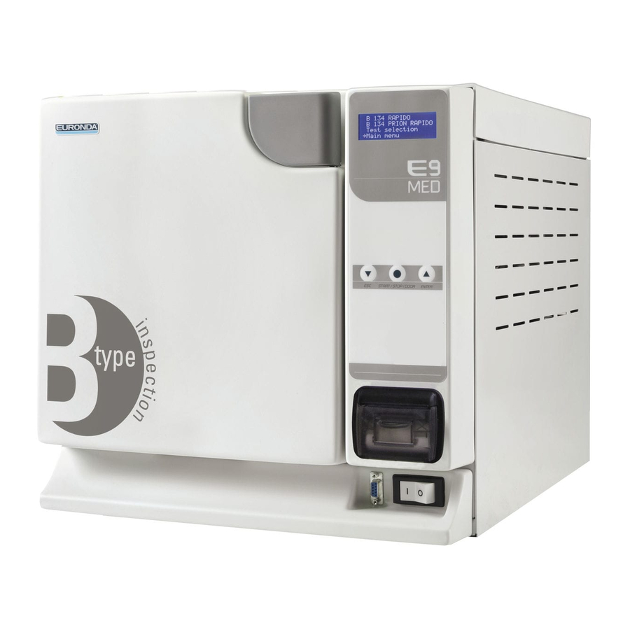
Стерилизатор паровой Euronda E9 |
||||||
|
||||||
|
||||||
|
||||||
|
||||||
|
||||||
|
||||||
|
||||||
|
||||||
|
||||||
|
||||||
|
||||||
|
||||||
|
||||||
|
||||||
|
||||||
|
||||||
|
||||||
|
||||||
|
||||||
|
||||||
|
||||||
|
||||||
|
||||||
|
||||||
|
||||||
|
||||||
|
||||||
|
||||||
|
||||||
|
||||||
|
||||||
|
||||||
|
||||||
|
||||||
|
||||||
|
||||||
|
||||||
|
||||||
|
||||||
|





















-
Contents
-
Table of Contents
-
Troubleshooting
-
Bookmarks
Quick Links
Steam Sterilizer
E9 INSPECTION
E9 RECORDER
E9 MED
s e r v i c e m a n u a l
ENGLISH
0051
Related Manuals for Euronda E9 INSPECTION
Summary of Contents for Euronda E9 INSPECTION
-
Page 1
Steam Sterilizer E9 INSPECTION E9 RECORDER E9 MED s e r v i c e m a n u a l ENGLISH 0051… -
Page 3: Table Of Contents
4.7 DELIVERY OF TECHNICAL DOCUMENTATION ………………..28 5 — DESCRIPTION OF CYCLE AND MAIN PERFORMANCE DATA ……..29 5.1 E9 INSPECTION COMPONENTS ……………………..29 5.2 CYCLE FOR E9 INSPECTION WITH SEPARATOR DRAINING PUMP …………31 5.2.1 Phase 0: Turning on the sterilizer ……………………..32…
-
Page 4
5.2.16 Vacuum phase II …………………………47 5.2.17 Pressure levelling phase II ……………………….48 5.2.18 End of cycle phase …………………………49 5.3 CYCLE FOR E9 INSPECTION/RECORDER WITH CIRCUIT U-234 (since firmware 7.01) ……50 5.3.1 Turning on the sterilizer ……………………….50 5.3.2 Phase 1: Start, water outgas system emptying and steam generator filling (U-234 circuit) …….. -
Page 5
9.2.6.2 TAB. 06: TANK SUPPORT AND SICCE MICROPUMP ASSEMBLY …………115 9.2.6.3 TAB. 06: TANK SUPPORT AND MICROPUMP ASSEMBLY E9 U-234 / RECORDER / MED ….116 9.2.7.1 TAB. 07: CHASSIS, WATER OUTGAS SYSTEM AND CROSSPIECE ASSEMBLY E9 INSPECTION / RECORDER …………………………..117 9.2.7.2 TAB. -
Page 6
ONTENTS AUTOCLAVE 9.2.9.1 TAB. 09: BOILER/ELECTROMAGNET ASSEMBLY E9 INSPECTION / RECORDER ……. 127 9.2.9.2 TAB. 09: BOILER/ELECTROMAGNET ASSEMBLY E9 MED …………..129 9.2.10 TAB. 10: FRONT PANEL ASSEMBLY E9 ………………….131 9.2.11 TAB. KIT: ACCESSORIES KIT E9 ……………………132 10 — PRODUCT VERSIONS ………………..133 10.1 REGISTRATIONS OF MODIFICATIONS TO E9 HARDWARE ………….. -
Page 7: Introduction
Euronda S.p.A. is the sole owner and reserves all rights to them. Euronda S.p.A. reserves the right to make modifications or improvements to the manual or the unit without notice and without being obliged to update previous production and manuals.
-
Page 8: How To Obtain A New Copy Of The Manual
NTRODUCTION AUTOCLAVE HOW TO OBTAIN A NEW COPY OF THE MANUAL If the manual is lost or destroyed, ask Euronda S.p.A. for a new copy. Provide the following information: name and model of the unit; name and address where the manual should be sent.
-
Page 9: Safety
2 — Safety GENERAL SAFETY WARNINGS Before using the equipment, read the safety information carefully. Non-observance could cause accidents or damage to the machine or injure the operator. Before using the unit, operators must have perfectly understood the meanings and functions of all the controls.
-
Page 10: Safety Devices
2 — S AFETY AUTOCLAVE 2.2 SAFETY DEVICES Electrical safety Description Effect Double-pole thermal safety switch for protecting the Disconnects main electrical power supply device against short-circuits. Protection of the electronic board against short- Disconnects one or more low-voltage circuits circuits: both the transformer and the entire low- voltage circuit are self-protected Thermal protection…
-
Page 11: Residue Risks
It is forbidden to remove, modify, tamper with or in any way neutralize the safety devices. Euronda S.p.A. declines all liability for accidents to people or damage or malfunctions of the unit if the above instruction is not observed. Periodically check the safety systems (see chap. 8 “Maintenance”).
-
Page 12: Safety Signs On The Unit
2 — S AFETY AUTOCLAVE Danger of contamination. The water used in the discharge tank may, if not properly sterilized, contain contaminated residues: wear latex safety gloves when draining. Danger of injury to hands. Even if the unit is not in operation, its cooling fan is always on if power supply to the machine is connected.
-
Page 13: Technical Data
3 — Technical data 3.1 OVERALL SPACE REQUIRED Fig. 3.1-1 Overall dimensions of the unit with the door closed (Fig. 3.1-1): E9 INSPECTION/RECORDER/MED 18 E9 INSPECTION/RECORDER/MED 24 L = 450 mm H = 445 mm P = 610 mm Overall dimensions of the unit with the door open (Fig. 3.1-1):…
-
Page 14: Technical Data And Noise
3 — T ECHNICAL DATA AUTOCLAVE 3.2 TECHNICAL DATA AND NOISE CHARACTERISTICS E9 INSPECTION 18 E9 INSPECTION 24 230 V Power supply voltage 50 Hz Mains frequency 2300 W Power output 10 A Absorbed current 3 sterilization cycles Sterilization cycles Vacuum test — Bowie &…
-
Page 15: Quality Of Water
3 — T ECHNICAL DATA AUTOCLAVE 3.3 QUALITY OF WATER With reference to standard EN 13060, the table below indicates the recommended limit values (maximum) for contaminating agents, as well as the chemical-physical characteristics of the water used for condensate* and inlet water.
-
Page 16: Serial Numbers Coding
3 — T ECHNICAL DATA AUTOCLAVE 3.4 SERIAL NUMBERS CODING Autoclaves serial number is made of a combination of three letters and six numbers. The serial number identifies the autoclave model and the chamber capacity. E9 18 (half band heater) EDI000000 E9 24 (half band heater) EDK000000…
-
Page 17: Installation
4 — Installation 4.1 POSITIONING THE UNIT Lift the unit with care and do not turn it upside down. The packaging and the equipment are fragile, handle with care. Transport as fragile. THE HANDLES ON THE PACKAGING (1 of Fig. 4.1-1) MUST ONLY BE USED FOR VERTICAL LIFTING.
-
Page 18: Installing The Unit
4 — I NSTALLATION AUTOCLAVE Fig. 4.1-3 Fig. 4.1-4 INSTALLING THE UNIT Installation is a fundamental operation for the subsequent use and correct functioning of the unit. ATTENTION: the unit MUST be installed by specialised technicians. First, update the service booklet by writing the date of installation in the relative box and signing it.
-
Page 19
Making the electrical connections: Check that the power supply voltage indicated on the rear label (Fig. 4.2.1-2) corresponds to that available at the point of installation. E9 INSPECTION 18 E9 INSPECTION 24 Fig. 4.2.1-2 The unit must be connected with an overload cut-out switch to a system fitted with an adequate earth system that conforms to the standards applicable in the country of installation. -
Page 20
4 — I NSTALLATION AUTOCLAVE Only use the original lead. ONLY USE ORIGINAL SPARE PARTS. After making the electrical connections, remove the clamp holding the electromagnet in place and install any accessory devices. Filling the tanks: The unit features two separate tanks: one for the clean water required for the cycles, and one for the used water that is collected at the end of the cycles. -
Page 21
Installation registration The functioning of Settings, Maintenance, Service and Diagnostic menus in E9 MED is the same as the E9 INSPECTION / RECORDER menus. The only difference is in the display’s graphics. Register the date of installation from the control panel. -
Page 22
4 — I NSTALLATION AUTOCLAVE — If YES is pressed, the Date/time setting Setting Date and Time screen appears. Using the keys, select the correct — If NO is pressed, you go to the Program day, press OK to pass on to the choice of Menu;… -
Page 23: Operator Registration
4 — I NSTALLATION AUTOCLAVE User Registration E.g.: Name Registration With the keys, select the After selecting the item Name from User registration, a screen appears in which the respective item and complete registration three items present are selected one by one: using the small keyboard, as in the example the screens used for registering the user’s indicated below.
-
Page 24: Performing The Vacuum Test
4 — I NSTALLATION AUTOCLAVE SELECT OPERATOR The cycle that follows the operator selection, the last XXXXX———————— selected voice remains highlighted. YYYYY ZZZZZ VVVVV KKKKK ▼ ▲ 3.1.1 Note : this screen appears only if at least one operators name is set up . Please see User’s Manual for more informations.
-
Page 25: Performing The B134 Cycle
4 — I NSTALLATION AUTOCLAVE Starting the Vacuum Test If required, press INFO to open the test Press START to begin the test; the control screen. following screen appears. This screen appears when the test finishes. The door release symbol indicates that the door can be opened, and you return to the Programme Menu. If the test is completed but gives a negative outcome, the E34 alarm message appears (see Chap.
-
Page 26: Labels Printing (Only E9 Recorder)
4 — I NSTALLATION AUTOCLAVE When the cycle has finished, the Cycle End Maintaining drying screen appears. At this point, the door This operation is performed automatically to release symbol indicates that the door can prevent condensation from forming inside be opened;…
-
Page 27
4 — I NSTALLATION AUTOCLAVE Now must be setted the type of paper in use. In the initial screen select “Main menu”, then in the following screens select: “Service”, “Memory-print functions”, “Kind of print” and finally “Labels”. To label the sterilized material with its expiration date the expire period must be setted. In the initial screen select “Main menu”, then in the following screens select: “Service”, “Memory-print functions”, “Expire period”… -
Page 28: Delivery Of Technical Documentation
4 — I NSTALLATION AUTOCLAVE ATTENTION: DANGER OF BURNS. When the unit finishes the sterilisation cycle and the door is opened to remove the sterilised instruments, the inner parts of the boiler and door are still very hot. These must not be touched directly in order to avoid getting burnt. Use the relative extractor tool (see Chap.
-
Page 29: Description Of Cycle And Main Performance Data
5 — Description of cycle and main performance data 5.1 E9 INSPECTION COMPONENTS The E9 Inspection sterilizer comprises the following elements: NAME OF SIGNAL DESCRIPTION Characteristics COMPONENTS Main switch 250V 12A Two-way solenoid valve for discharging steam at the OD6A/OD6B 24 VDC end of the cycle, power draw 9 W;…
-
Page 30
5 — D ESCRIPTION OF CYCLE AND MAIN PERFORMANCE DATA AUTOCLAVE Manually resettable safety thermostat (band heater for 230 VAC chamber), calibrated to 200°C FAN1 OD17A/OD17B Radiator fan, power draw 35 W 230 VAC PT1000 probe inside boiler (working space inside PTC1 chamber) PT1000 probe outside boiler (mounted on external… -
Page 31: Cycle For E9 Inspection With Separator Draining Pump
5 — D ESCRIPTION OF CYCLE AND MAIN PERFORMANCE DATA AUTOCLAVE 5.2 CYCLE FOR E9 INSPECTION WITH SEPARATOR DRAINING PUMP E9 service manual GB r7…
-
Page 32: Phase 0: Turning On The Sterilizer
The unit can be filled with water either manually or using the mains water function with the support of a deionizer (see Appendix 10 “Euronda Aquafilter” and Chap. 6.7 “Tanks: instructions for filling and emptying” in the instructions manual). When the minimum water level sensor trips, the deionizer solenoid valve EV6 is powered and opens to let the water flow into the tank until the maximum level sensor trips.
-
Page 33: Start-Vacuum Phase V1/I
5 — D ESCRIPTION OF CYCLE AND MAIN PERFORMANCE DATA AUTOCLAVE 5.2.2 Start-Vacuum phase V1/I Pressure Discharge START-VACUUM PHASE V The following are powered: 1. EV1: closes the pressure discharge circuit 2. EV3: closes the bacteriological filter 3. EV4: opens the water inlet to the air separator 4.
-
Page 34: Vacuum Phase V1/Ii
5 — D ESCRIPTION OF CYCLE AND MAIN PERFORMANCE DATA AUTOCLAVE 5.2.3 Vacuum phase V1/II Pressure Discharge VACUUM PHASE V 3 seconds after WP1 stops working, EV2 is powered and EV4 and EV1 are de-energised. This allows the vacuum pump to create a depression inside the chamber by pumping air through EV1 ed EV2, hence by-passing the water circuit the air separator is connected to.
-
Page 35: Vacuum Phase V1/Iii
5 — D ESCRIPTION OF CYCLE AND MAIN PERFORMANCE DATA AUTOCLAVE 5.2.4 Vacuum phase V1/III Pressure Discharge VACUUM PHASE V When the pressure inside the chamber reaches -0.82 bar, EV2 is de-energised and the pump continues to pump from EV1 to separate the air from the water in the air separator. If in 4 minutes the pressure inside the chamber does not reach to -0.86 bar, EV3 ON for 15 sec, in order to clean the hydraulic circuit from E9 service manual GB r7…
-
Page 36: Water Inlet Phase
5 — D ESCRIPTION OF CYCLE AND MAIN PERFORMANCE DATA AUTOCLAVE 5.2.5 Water inlet phase Pressure Air tap WATER INLET PHASE When a pressure of -0.86 bar is reached, EV1 and EV4 are powered while EV5 is de-energised. The vacuum pump stops working and the generator heater R1 is powered at 50%.
-
Page 37: Water Outgas System Drain Phase
5 — D ESCRIPTION OF CYCLE AND MAIN PERFORMANCE DATA AUTOCLAVE 5.2.6 Water outgas system drain phase Draining Svuotamento Air tap Presa aria WATER OUTGAS SYSTEM (W.O.S.) DRAIN PHASE After EV4 is de-energized, pump WP2 works for 120 seconds (NME up to EEG060999/EEH060999) for 8 seconds (SICCE from EEG061000/EEH061000) (draining any water remaining in the water outgas system).
-
Page 38: Pressure Increase Phase P
5 — D ESCRIPTION OF CYCLE AND MAIN PERFORMANCE DATA AUTOCLAVE 5.2.7 Pressure increase phase P Pressione Pressure Recupero Recovery PHASE P — PRESSURE INCREASE After further 15 seconds, R1 Resistance is supplied at 80%, after 80 seconds at 100%; this permits to generate steam.
-
Page 39: Water Transfer Phase
5 — D ESCRIPTION OF CYCLE AND MAIN PERFORMANCE DATA AUTOCLAVE 5.2.8 Water transfer phase Pressure Pressione Air tap Presa aria WATER TRANSFER PHASE When the pressure reaches +0.40 bar, the heater R1 is disconnected from the power supply; after 1 second, EV4 is powered to allow the water to be transferred from the chamber to the air separator and pump WP1 is powered for 2 seconds to prevent the PTC3 probe from detecting an elevated temperature during transfer.
-
Page 40: Vacuum — Thermodynamic Vacuum Phase V
5 — D ESCRIPTION OF CYCLE AND MAIN PERFORMANCE DATA AUTOCLAVE 5.2.9 Vacuum — Thermodynamic vacuum phase V Scarico pressione Pressure discharge Air vent Scarico aria PHASE V – VACUUM – THERMODYNAMIC VACUUM After 18 seconds, the fan is powered at 100%, EV4 and EV1 are de-energised, while EV5 is powered. After another 5 seconds, the vacuum pump starts working and EV2 is powered.
-
Page 41: Vacuum 2,3,4 Phase V2
5 — D ESCRIPTION OF CYCLE AND MAIN PERFORMANCE DATA AUTOCLAVE 5.2.10 Vacuum 2,3,4 phase V2 Vuoto Vacuum Scarico aria Air vent PHASE V — VACUUM 2, 3, 4 If the temperature detected by the PTC4 probe is greater than 60°C, the vacuum pump stops working and EV2 and EV5 are de-energised.
-
Page 42: Pressure Increase/Sterilization Phase P
5 — D ESCRIPTION OF CYCLE AND MAIN PERFORMANCE DATA AUTOCLAVE 5.2.11 Pressure increase/Sterilization phase P Pressure Pressione PHASE P — PRESSURE INCREASE/ STERILIZATION The fourth rising of pressure brings to sterilization. 4°C below set-point value, WP1 pump makes four water injections (1 second ON, alternated with 2 seconds’…
-
Page 43: Sterilization Phase
5 — D ESCRIPTION OF CYCLE AND MAIN PERFORMANCE DATA AUTOCLAVE 5.2.12 Sterilization phase Pressione Pressure Scarico pressione Pressure discharge STERILIZATION PHASE If inside the chamber is signalled a pressure of +0,2 bar higher than set point, EV2 and EV5 electro-valves are supplied for about 600 ms to allow the discharge of superfluous pressure.
-
Page 44: Steam Discharge Phase
5 — D ESCRIPTION OF CYCLE AND MAIN PERFORMANCE DATA AUTOCLAVE 5.2.13 Steam discharge phase Scarico pressione Pressure discharge STEAM DISCHARGE PHASE When the sterilization phase is finished (4, 18, 20 minutes according to the selected cycle) there takes place the pressure discharge and consequently the drying phase, whose duration time can be set up by user (auto = 15, 20, 25, 30 minutes;…
-
Page 45: Steam Discharge Phase I
5 — D ESCRIPTION OF CYCLE AND MAIN PERFORMANCE DATA AUTOCLAVE 5.2.14 Steam discharge phase I Vuoto Vacuum Scarico aria Air vent STEAM DISCHARGE PHASE I After 8 seconds WP2 stop working, EV2 is de-energized, EV5 is supplied and VP1 pump begins to create vacuum inside the chamber.
-
Page 46: Pressure Levelling Phase I
5 — D ESCRIPTION OF CYCLE AND MAIN PERFORMANCE DATA AUTOCLAVE 5.2.15 Pressure levelling phase I Scarico Separator Separatore discharge Pressure levelling Livellamento barico Aspirazione aria Air intake PRESSURE LEVELLING PHASE I After 4 minutes takes place the drying pause phase. EV3 is de-energized, supplied and then de-energized with intervals of one second (to avoid any sudden pressure variation), the fan is supplied at 40%, EV5 is de- energized, the vacuum pump is not supplied any longer, while WP2 pump works for 5 seconds (WP1= OFF).
-
Page 47: Vacuum Phase Ii
5 — D ESCRIPTION OF CYCLE AND MAIN PERFORMANCE DATA AUTOCLAVE 5.2.16 Vacuum phase II Vuoto Pressure levelling Air intake Scarico aria VACUUM PHASE II After 60 seconds, EV3 is powered, EV1 de-energised and the pump (WP1=ON) recreates a vacuum. EV5 is powered three seconds after the pump starts.
-
Page 48: Pressure Levelling Phase Ii
5 — D ESCRIPTION OF CYCLE AND MAIN PERFORMANCE DATA AUTOCLAVE 5.2.17 Pressure levelling phase II Livellamento barico Pressure levelling Aspirazione aria Air intake PRESSURE LEVELLING PHASE II After 8 minutes have elapsed (if set up to auto= 15 min) or 13, 18, 23 respectively for drying period of 20, 25, 30 minutes, the ventilation phase takes place: RES2 is supplied no more, EV3 is de-energized and allows the air to enter from the bacteriological filter.
-
Page 49: End Of Cycle Phase
5 — D ESCRIPTION OF CYCLE AND MAIN PERFORMANCE DATA AUTOCLAVE 5.2.18 End of cycle phase Separator discharge Scarico separatore END OF CYCLE PHASE After further 2 seconds, VP1 stops working, WP2 works for 5 seconds (in order to discharge water from separator) and when the pressure in the chamber reaches ±…
-
Page 50: Cycle For E9 Inspection/Recorder With Circuit U-234 (Since Firmware 7.01)
The unit can be filled with water either manually or using the mains water function with the support of a deionizer (see Appendix 10 “Euronda Aquafilter” and Chap. 6.7 “Tanks: instructions for filling and emptying” in the instructions manual). When the minimum water level sensor trips, the deionizer solenoid valve EV6 is powered and opens to let the water flow into the tank until the maximum level sensor trips.
-
Page 51: Phase 1: Start, Water Outgas System Emptying And Steam Generator Filling (U-234 Circuit)
5 — D ESCRIPTION OF CYCLE AND MAIN PERFORMANCE DATA AUTOCLAVE 5.3.2 Phase 1: Start, water outgas system emptying and steam generator filling (U-234 circuit) W.O.S. PHASE 1 Vacuum pump takes external air from the bacteriological filter and pushes it into the water outgas system (W.O.S.) through EV8 and EV2.
-
Page 52: Phase 2: Steam Generator Emptying (U-234 Circuit)
5 — D ESCRIPTION OF CYCLE AND MAIN PERFORMANCE DATA AUTOCLAVE 5.3.3 Phase 2: Steam generator emptying (U-234 circuit) W.O.S. PHASE 2 Vaccum pump reduces pressure in the water outgas system in order to move water from the steam generator to the water separator through EV1. Energized components: 1.
-
Page 53: Phase 3: Water Outgas System Filling (U-234 Circuit)
5 — D ESCRIPTION OF CYCLE AND MAIN PERFORMANCE DATA AUTOCLAVE 5.3.4 Phase 3: Water outgas system filling (U-234 circuit) W.O.S. PHASE 3 Vacuum pump begins reduce pressure into the W.O.S. in order to move water (pumped by WP1 for 30 seconds) into the W.O.S.
-
Page 54: Phase 4: Vacuum Into Chamber And Water Outgas System (U-234 Circuit)
5 — D ESCRIPTION OF CYCLE AND MAIN PERFORMANCE DATA AUTOCLAVE 5.3.5 Phase 4: Vacuum into chamber and water outgas system (U-234 circuit) W.O.S. PHASE 4 After 30 seconds, WP1 stops working. Vacuum pump continues in reducing pressure into the chamber (through EV1) and into W.O.S.
-
Page 55: Phase 5: Water Separator Emptying And Steam Generator Filling (U-234 Circuit)
5 — D ESCRIPTION OF CYCLE AND MAIN PERFORMANCE DATA AUTOCLAVE 5.3.6 Phase 5: Water separator emptying and steam generator filling (U-234 circuit) W.O.S. PHASE 5 When pressure is lowered down to -0.80 bar (0.2 absolute bar), vacuum pump suction is moved to the bacteriological filter by EV7 switching and so water flows from the W.O.S.
-
Page 56: Phase 6: Pressure Rise (U-234 Circuit)
5 — D ESCRIPTION OF CYCLE AND MAIN PERFORMANCE DATA AUTOCLAVE 5.3.7 Phase 6: Pressure rise (U-234 circuit) W.O.S. PHASE 6 When the steam generator is full, it starts the water heating till the pressure into the chamber reaches the value +0.3 bar (1.3 absolute bar).
-
Page 57: Phase 7: Emptying And Vacuum (U-234 Circuit)
5 — D ESCRIPTION OF CYCLE AND MAIN PERFORMANCE DATA AUTOCLAVE 5.3.8 Phase 7: Emptying and vacuum (U-234 circuit) W.O.S PHASE 7 Once the pressure reaches +0.3 bar (1.3 absolute bar), EV4 is opened and water is pushed by pressure to the W.O.S.
-
Page 58: Pressure Rise (U-234 Circuit)
5 — D ESCRIPTION OF CYCLE AND MAIN PERFORMANCE DATA AUTOCLAVE 5.3.9 Pressure rise (U-234 circuit) W.O.S. PHASE P3 – PRESSURE RISE/STERILIZATION The third pressure rise takes to the sterilization phase. 4 °C before the temperature setpoint the water pump WP1 injects water four times following the procedure 1 second ON, 2 seconds OFF so that the temperature setpoint is reached smoothly.
-
Page 59: Cycle For E9 Med (Up To Ego090100 18 L And Up To Egp090080 24 L)
The unit can be filled with water either manually or using the mains water function with the support of a deionizer (see Appendix 10 “Euronda Aquafilter” and Chap. 6.7 “Tanks: instructions for filling and emptying” in the instructions manual). When the minimum water level sensor trips, the deionizer solenoid valve EV6 is powered and opens to let the water flow into the tank until the maximum level sensor trips.
-
Page 60: Phase 1: Vacuum Into Chamber
5 — D ESCRIPTION OF CYCLE AND MAIN PERFORMANCE DATA AUTOCLAVE 5.4.2 Phase 1: Vacuum into chamber PHASE 1 Vacuum pump continues in reducing pressure into the chamber (through EV1). Energized components: 1. VACUUM PUMP 2. EV7 3. EV8 -0,5 -1,5 E9 service manual GB r7…
-
Page 61: Phase 2: Steam Generator Filling
5 — D ESCRIPTION OF CYCLE AND MAIN PERFORMANCE DATA AUTOCLAVE 5.4.3 Phase 2: Steam generator filling PHASE 2 When pressure is lowered down to -0.80 bar (0.2 absolute bar), vacuum pump stops and the water pump injects the water into the steam generator. Energized components: 1.
-
Page 62: Phase 3: Pressure Rise
5 — D ESCRIPTION OF CYCLE AND MAIN PERFORMANCE DATA AUTOCLAVE 5.4.4 Phase 3: Pressure rise PHASE 3 When the steam generator is full, it starts the water heating till the pressure into the chamber reaches the value +0.3 bar (1.3 absolute bar). If necessary, water injections are executed. Energized components: 1.
-
Page 63: Phase 4: Water Separator Emptying And Vacuum
5 — D ESCRIPTION OF CYCLE AND MAIN PERFORMANCE DATA AUTOCLAVE 5.4.5 Phase 4: Water separator emptying and vacuum PHASE 4 Once the pressure reaches 0 bar (1 absolute bar) the vacuum pump switches on and so pushes the water into the separator to the used water tank.
-
Page 64: Third Pressure Rise And Sterilisation
5 — D ESCRIPTION OF CYCLE AND MAIN PERFORMANCE DATA AUTOCLAVE 5.4.6 Third pressure rise and sterilisation PHASE P3 – PRESSURE RISE/STERILIZATION The third pressure rise takes to the sterilization phase. 4 °C before the temperature setpoint the water pump WP1 injects water four times following the procedure 1 second ON, 2 seconds OFF so that the temperature setpoint is reached smoothly.
-
Page 65: Drying Phase
5 — D ESCRIPTION OF CYCLE AND MAIN PERFORMANCE DATA AUTOCLAVE 5.4.7 Drying phase DRYING PHASE When the sterilisation period ends, EV1 opens and the steam flows through the radiator. The vacuum pump keeps working for 15 minutes so to get the complete drying. Energized components: 1.
-
Page 66: Cycle For E9 Med (Since Ego090101 18 L And Since Egp090081 24 L)
The unit can be filled with clean water either manually or using the mains water function with the support of a deionizer (see Appendix 10 “Euronda Aquafilter” and Chap. 6.7 “Tanks: instructions for filling and emptying” in the instructions manual). When the minimum water level sensor trips, the deionizer solenoid valve EV6 is powered and opens to let the water flow into the tank until the maximum level sensor trips.
-
Page 67: Phase 1: Start And Chamber Emptying
5 — D ESCRIPTION OF CYCLE AND MAIN PERFORMANCE DATA AUTOCLAVE 5.5.2 Phase 1: Start and chamber emptying PHASE 1 When the preheating is finished, the vacuum pump begins the air removal from the chamber. The vacuum pump works until the pressure is lowered to -0,80 bar (0,2 bar absolute). Are energized: 1.
-
Page 68: Phase 2: Water Injection Into The Chamber
5 — D ESCRIPTION OF CYCLE AND MAIN PERFORMANCE DATA AUTOCLAVE 5.5.3 Phase 2: Water injection into the chamber PHASE 2 When the vacuum setpoint is reached (-0,80 bar for V and for V ) the water is injected into the chamber.
-
Page 69: Phase 3: Pressure Rise
When the chamber is filled with the necessary quantity of water, the band heater is supplied at its maximum in order to vaporize the water. During the pressure rise, differently from E9 INSPECTION and RECORDER, no more water injections are executed. The pressure rises up to +0,2 bar in P…
-
Page 70: Phase 4: Pressure Discharge And Emptying
5 — D ESCRIPTION OF CYCLE AND MAIN PERFORMANCE DATA AUTOCLAVE 5.5.5 Phase 4: Pressure discharge and emptying PHASE 4 When the pressure into the chamber reaches +0,2 bar (1,2 bar absolute) at the end of P , EV1 switches and the steam is pushed out, condensed into the radiator, then the condensed water is stored into the separator.
-
Page 71: Phase 5: Pressure Rise And Separator Emptying
5 — D ESCRIPTION OF CYCLE AND MAIN PERFORMANCE DATA AUTOCLAVE 5.5.6 Phase 5: Pressure rise and separator emptying PHASE 5 At the end of V and V the pressure is -0,80 bar, the vacuum pump is working and the separator is full of water. Switching EV1 the chamber is sealed and the following pressure rise begins.
-
Page 72: Phase 6: Pressure Balancing
5 — D ESCRIPTION OF CYCLE AND MAIN PERFORMANCE DATA AUTOCLAVE 5.5.7 Phase 6: Pressure balancing PHASE 6 At the cycle end the pressure into the chamber is lower than the external pressure because the drying phase is carried out in vacuum conditions. For the final pressure balancing EV2 opens and the external air flows through the bacteriological filter into the chamber.
-
Page 73: Examples Of Sterilization Cycle Reports
5 — D ESCRIPTION OF CYCLE AND MAIN PERFORMANCE DATA AUTOCLAVE 5.6 EXAMPLES OF STERILIZATION CYCLE REPORTS E9 service manual GB r7…
-
Page 74: Description Of Test And Main Performance Data
6 — Description of test and main performance data 6.1 GRAPH OF COMPLETE VACUUM TEST This test is performed in order to check the performance of the unit, in particular: the efficiency of the vacuum pump; the seal of the pneumatic circuit.
-
Page 75: Phase 0: Starting
6 — D ESCRIPTION OF TEST AND MAIN PERFORMANCE DATA AUTOCLAVE In order to obtain a correct result, the test must be performed “cold”, i.e.: within 3 minutes of switching on the unit. If the test is selected when PTC2 has reached a temperature greater than or equal to 50°C, or if 3 minutes or more minutes elapse before the test is selected, the display will inform you that the Vacuum test is no longer available.
-
Page 76: Vacuum Phase
6 — D ESCRIPTION OF TEST AND MAIN PERFORMANCE DATA AUTOCLAVE 6.1.2 Vacuum phase Pressione Pressure VACUUM PHASE After the START button is pressed, the following are powered: mechanical safety electromagnet EV2: opened to allow the air to be pumped from the chamber EV3: closed to close the bacteriological filter EV5: opened to allow the air to be pumped from the chamber Vacuum pump, to pump the air from the sterilization chamber…
-
Page 77: Pressure Levelling/Maintenance Phase
6 — D ESCRIPTION OF TEST AND MAIN PERFORMANCE DATA AUTOCLAVE 6.1.3 Pressure levelling/Maintenance phase Pressione Pressure PRESSURE LEVELLING/MAINTENANCE PHASE After reaching a depression of -0.86 bar, the following are powered: EV1: to close the pressure discharge circuit EV2 is de-energised EV5 is de-energised The vacuum pump also stops working During this phase, the pressure is levelled for 5 minutes and then maintained for 10 minutes.
-
Page 78: Pressure Levelling Phase
6 — D ESCRIPTION OF TEST AND MAIN PERFORMANCE DATA AUTOCLAVE 6.1.4 Pressure levelling phase Pressure levelling Livellamento barico PRESSURE LEVELLING PHASE After the vacuum has been maintained for 10 minutes and the system has checked the seal of the pneumatic circuit (otherwise an alarm message is displayed), EV3 is opened: the air enters from the bacteriological circuit and the system returns to its initial pressure.
-
Page 79: Bowie&Dick Test
6 — D ESCRIPTION OF TEST AND MAIN PERFORMANCE DATA AUTOCLAVE 6.2 BOWIE&DICK TEST This is a chemical-physical test that is also known as the Brown test: the indicator is a heat-sensitive sheet that is placed in the middle of a packet made up of various layers of paper and foam rubber. The B&D test simulates the performance of the unit with regard to the sterilization of porous loads, in particular: the efficiency of the preliminary vacuum and the penetration of steam within the pores;…
-
Page 80
6 — D ESCRIPTION OF TEST AND MAIN PERFORMANCE DATA AUTOCLAVE Preliminary vacuum steps Sterilization phase WARNING: only perform the Helix test after a sterilisation cycle. Test results must be assessed on the basis of the instructions provided by the Producer of the test. -
Page 81: Maintenance
OR BY THE TECHNICIANS AUTHORISED BY THE ASSISTANCE SERVICE OF EURONDA S.p.A. Observe the intervals prescribed or shown in this manual. The E9 INSPECTION activates memorandum messages to assist the user in performing both the ordinary and the extraordinary maintenance operations.
-
Page 82
7 — M AINTENANCE AUTOCLAVE From the Main Menu, use the key to Maintenance select the item Maintenance, then press OK Use the keys to select the item to confirm. desired, and press OK to confirm. If Periodic maintenance, see chap. 8.2; If Extraordinary maintenance: see chap. -
Page 83: Periodic Maintenance
Activate Counters: the number of cycles to perform before the message appears begins from the value the counters stopped at. The periodic maintenance operations are described and illustrated in the “E9 INSPECTION” user instruction manual. — With or OK, you go back to the previous screen.
-
Page 84: Extraordinary Maintenance
7.3 EXTRAORDINARY MAINTENANCE WARNING: extraordinary maintenance must only be performed by specialists authorised by Euronda S.p.A. Any jobs not included in the periodic maintenance section in the instruction manual provided with the unit are considered as extraordinary maintenance.
-
Page 85
After 1000 cycles or after two years from installation (the date can be seen at the bottom of the screen), a memorandum message appears recommending a general overhaul of the unit. This can only be performed by specialists authorised by Euronda S.p.A. The reminder message appears each time the unit is switched on, until the overhaul has been performed. -
Page 86: Technical Menu
7 — M AINTENANCE AUTOCLAVE Replacing the bacteriological filter Unscrew the bacteriological filter (1 of Fig. 8.3 — 1) by turning it anticlockwise; Screw on the new filter by turning it clockwise until it is tight. Fig. 8.3-1 Replancing the door seal Grip the lip of the seal with two fingers and remove it;…
-
Page 87
7 — M AINTENANCE AUTOCLAVE In case of wrong password: This screenshot disappears after 3 seconds and returns to main Menu Process Controller Wrong password ▼ ▲ 7.4.1 Set water input Insert serial number Reset cycles Hydraulic leakage Insert serial number Probes adjustment Hydraulic leakage Test components… -
Page 88
7 — M AINTENANCE AUTOCLAVE Reset cycles Push YES and return to 7.4.2 This function reset the counter at the first level, it doesn’t reset the main counter. Reset cycles counter? CONFIGURATION. Push YES and return to 7.4.2 and the cycles will be deleted. -
Page 89
7 — M AINTENANCE AUTOCLAVE Hydraulic Leakage +0.00 bar At cycle end, appears 7.4.2.4.1 If you push the INFO button 110.0 °C If you push the STOP button from 3.2 mm:ss Stop Info Hydraulic Leakage Unlock door and go to 7.4.2 Process Controller Cycle end Open the door… -
Page 90
7 — M AINTENANCE AUTOCLAVE Hydraulic Leakage Push Door 7.4.2 This test made it possibile to increase pressure up to 2,05 bar for 30’ without active alarms. Process Controller In case of Leackage, perform thist test cycle. Manual stop Unlock the door Door 7.4.2.4.2 Probes Adjustment… -
Page 91
7 — M AINTENANCE AUTOCLAVE Probes Adjustment If you push STOP from 3.2 OR 3.4 3.3, +10.00 Kpa If you push NO 3.2 OR 3.4 ELSE 3.8 AND 7.4.2.5.2 Phase V1 – 2c mm:ss Return Stop Probes Adjustment Ti (valore reale) (valore reale) Manual stop Pleas wait… -
Page 92
7 — M AINTENANCE AUTOCLAVE Push RETURN 7.4.2 Test Items (all components are set to normal values) ▼ ▲ 7.4.2.6 Visualize parameters This screenshot shows the machine instant function arameters. Push RETURN 7.4.2 RMS +230.6 V mm:ss Return 7.4.2.7 E9 service manual GB r7… -
Page 93
7 — M AINTENANCE AUTOCLAVE CONFIGURATION: this screenshot show how to select and print: — operators setup — past cycles parameters — ordinary and extraordinary maintenance period — probes correction range — instant parameters Cycles stop: For marketing and law agreements reasons, it is possible to inhibit certain cycles, by factory programming. -
Page 94: Components List E9 Inspection (U-234 / Recorder Circuit)
7 — M AINTENANCE AUTOCLAVE 7.5 COMPONENTS LIST E9 INSPECTION (U-234 / RECORDER CIRCUIT) NAME OF COMPONENTS DESCRIPTION Characteristics SIGNAL Main switch 250V 12A Two-way solenoid valve for discharging steam at the end OD6A/OD6B 24 VDC of the cycle, power draw 9 W; normally open (NO)
-
Page 95
7 — M AINTENANCE AUTOCLAVE NAME OF COMPONENTS DESCRIPTION Characteristics SIGNAL PTC4 NTC10000 temperature probe mounted on radiator PTC5 Temperature probe mounted on CPU card Pressure sensor Float sensor for MIN distilled water level, contact normally closed (NC) Float sensor for MAX distilled water level, contact normally closed (NC) Float sensor for MAX used water level, contact normally closed (NC) -
Page 96: Components And Diagrams
8 — Components and diagrams 8.1 WIRING DIAGRAM…
-
Page 97
8 — C OMPONENTS AND DIAGRAMS AUTOCLAVE ITEM DESCRIPTION ITEM DESCRIPTION Manually resettable safety thermostat Main switch (steam generator) Solenoid valve for discharging pressure Manually resettable safety thermostat at the end of the cycle (band heater on chamber) Solenoid valve for air prevacuum and PTC1 Probe inside boiler water-air separation Solenoid valve for bacteriological filter… -
Page 98: Hydraulic Diagram
8 — C OMPONENTS AND DIAGRAMS AUTOCLAVE 8.2 HYDRAULIC DIAGRAM 8.2.1 Hydraulic diagram E9 W.O.S. ITEM DESCRIPTION ITEM DESCRIPTION Solenoid valve for discharging pressure at Electronic pressure sensor the end of the cycle Solenoid valve for air prevacuum and water- Safety valve air separation Solenoid valve for bacteriological filter.
-
Page 99: Hydraulic Diagram E9 U-234
8 — C OMPONENTS AND DIAGRAMS AUTOCLAVE 8.2.2 Hydraulic diagram E9 U-234 W.O.S. 8.2.3 Hydraulic diagram E9 MED (since EGO090101 18 L and since EGP090081 24 L) E9 service manual GB r7…
-
Page 100: Spare Parts Catalogue
9 — S PARE PARTS CATALOGUE AUTOCLAVE 9 — Spare parts catalogue 9.1 EXPLODED GENERAL DIAGRAM OF E9 INSPECTION E9 service manual GB r7…
-
Page 101: Index Of Tables
9 — S PARE PARTS CATALOGUE AUTOCLAVE 9.2 INDEX OF TABLES Tab. 01 Safety housing assembly Tab. 02 Door assembly Tab. 03 Control panel assembly Tab. 04 Tank and power board + pressure transducer Tab. 05 Vacuum pump and radiator assembly Tab.
-
Page 102: Tab. 01: Safety Housing Assembly E9
9 — S PARE PARTS CATALOGUE AUTOCLAVE 9.2.1 TAB. 01: SAFETY HOUSING ASSEMBLY E9 REF. ITEM N° DESCRIPTION 533798 tank cover door 572385 button-head screw 4×6 531507 tank cover 524724 painted LH side panel 572487 button-head screw 4×10 524722 painted RH side panel 530668 yellow adhesive warning label 524726…
-
Page 103: Tab. 02: Door Assembly E9 Inspection / Recorder
9 — S PARE PARTS CATALOGUE AUTOCLAVE 9.2.2.1 TAB. 02: DOOR ASSEMBLY E9 INSPECTION / RECORDER REF. ITEM N° DESCRIPTION door assembly 532946 handle A.1.1 570719 dowel 5×10 533480 E9 door 530682 «EURONDA» adhesive label 530669 lagging 571730 «B type inspection» adhesive label…
-
Page 104: Tab. 02: Door Assembly E9 Med
ITEM N° DESCRIPTION door assembly 910412 532946 handle A.1.1 570719 dowel 5×10 533484 E9 door 530682 «EURONDA» adhesive label 590831 lagging 530669 «B type inspection» adhesive label 571730 washer 5×15 572363 screw 3.5×13 arm + porthole assembly 320263 572504 screw 5×12…
-
Page 105: Tab. 03: Control Panel Assembly E9 Inspection
9 — S PARE PARTS CATALOGUE AUTOCLAVE 9.2.3.1 TAB. 03: CONTROL PANEL ASSEMBLY E9 INSPECTION REF. ITEM N° DESCRIPTION complete control panel 330056 563240 micro-switch 533153 control panel 532266 adhesive for control panel 564645 complete printer 815002 thermal paper 57 mm…
-
Page 106: Tab. 03: Control Panel Assembly E9 Recorder
9 — S PARE PARTS CATALOGUE AUTOCLAVE 9.2.3.2 TAB. 03: CONTROL PANEL ASSEMBLY E9 RECORDER REF. ITEM N° DESCRIPTION complete control panel 563240 micro-switch 533165 control panel 532324 adhesive for control panel 572373 3×8 TB screw 564645 complete printer 815005 labels roll (10 rolls pack) 562216 display…
-
Page 107: Tab. 03: Control Panel Assembly E9 Med
9 — S PARE PARTS CATALOGUE AUTOCLAVE 9.2.3.3 TAB. 03: CONTROL PANEL ASSEMBLY E9 MED REF. ITEM N° DESCRIPTION complete control panel 563240 micro-switch 561180 26-way flat cable 561182 40-way flat cable 533166 E9 MED control panel 532325 E9 MED control panel sticker (item removed) 523524 brass spacer…
-
Page 108: Tab. 04: Tank And Power Card + Pressure Transducer Assembly E9
9 — S PARE PARTS CATALOGUE AUTOCLAVE 9.2.4.1 TAB. 04: TANK AND POWER CARD + PRESSURE TRANSDUCER ASSEMBLY E9 REF. ITEM N° DESCRIPTION 330112 E9 tank assembly 533693 tank 540052 white silicone tank gasket 564401 level sensor 523740 tank water supply filter fixing nut (supplied with sensor 564401) black washer (supplied with sensor 564401) O-ring (supplied with sensor 564401)
-
Page 109
9 — S PARE PARTS CATALOGUE AUTOCLAVE REF. ITEM N° DESCRIPTION – card + pressure transducer assembly 570497 nut M3 523519 spacer for main card 571728 flat washer M3 572373 screw 3×8 571148 elbow union 1/4-6/4 522026 pressure transducer fixing ring 571133 union nut 1/4 527071… -
Page 110: Med
9 — S PARE PARTS CATALOGUE AUTOCLAVE 9.2.4.2 TAB. 04: TANK AND POWER CARD + PRESSURE TRANSDUCER ASSEMBLY E9 U-234 / RECORDER / MED REF. ITEM N° DESCRIPTION tank assembly E9 U-234 / RECORDER / MED 533693 tank E9 540528 tank silicone gasket 564401 level sensor…
-
Page 111
9 — S PARE PARTS CATALOGUE AUTOCLAVE REF. ITEM N° DESCRIPTION A.23 571743 OR gasket A.24 571199 union M/F 1/8 A.25 571165 union M1/8 PG A.26 572286 check valve 1/4 A.27 571208 union F1/4 for tube Ø 6/8 A.28 571123 union M1/8 for tube Ø… -
Page 112: Tab. 05: Vacuum Pump And Radiator Assembly E9
9 — S PARE PARTS CATALOGUE AUTOCLAVE 9.2.5.1 TAB. 05: VACUUM PUMP AND RADIATOR ASSEMBLY E9 REF. ITEM N° DESCRIPTION 320829 vacuum pump assembly 525099 vacuum pump A.2 + A.3 540655 pump gasket kit 541146 silicone tube Ø 6/10 571119 elbow union M 1/4 7 540871 black adj.
-
Page 113: Tab. 05: Vacuum Pump And Radiator Assembly E9 U-234 / Recorder / Med
9 — S PARE PARTS CATALOGUE AUTOCLAVE 9.2.5.2 TAB. 05: VACUUM PUMP AND RADIATOR ASSEMBLY E9 U-234 / RECORDER / MED REF. ITEM N° DESCRIPTION vacuum pump assembly 571119 elbow union M1/4 PG7 571114 T-shaped union F/M/F (no E9 MED) 541146 silicone tube Ø…
-
Page 114: Tab. 06: Tank Support And Nme Micropump Assembly
9 — S PARE PARTS CATALOGUE AUTOCLAVE 9.2.6.1 TAB. 06: TANK SUPPORT AND NME MICROPUMP ASSEMBLY REF. ITEM N° DESCRIPTION 321192 tank support assembly 526289 tank support 572487 screw 4×10 533320 santoprene pipette for vibrating pump 541146 silicone tube Ø 6/10 541080 rubber vibration-proof support for vibrating pump 525104…
-
Page 115: Tab. 06: Tank Support And Sicce Micropump Assembly
9 — S PARE PARTS CATALOGUE AUTOCLAVE 9.2.6.2 TAB. 06: TANK SUPPORT AND SICCE MICROPUMP ASSEMBLY RIF. CODICE DESCRIZIONE Q.TÀ 321192 tank support assembly 526289 tank support 572487 TS screw 4×10 533320 santoprene pipette for vibrating pump 541146 silicone tube Ø 6/10 541080 rubber vibration-proof support for vibrating pump 525104…
-
Page 116: Tab. 06: Tank Support And Micropump Assembly E9 U-234 / Recorder / Med
9 — S PARE PARTS CATALOGUE AUTOCLAVE 9.2.6.3 TAB. 06: TANK SUPPORT AND MICROPUMP ASSEMBLY E9 U-234 / RECORDER / MED REF. ITEM N° DESCRIPTION tank support assembly 526289 tank support 572487 screw TS 4×10 533320 santropene pipette for vibrating pump 541146 silicone tube Ø…
-
Page 117: Recorder
9 — S PARE PARTS CATALOGUE AUTOCLAVE 9.2.7.1 TAB. 07: CHASSIS, WATER OUTGAS SYSTEM AND CROSSPIECE ASSEMBLY E9 INSPECTION / RECORDER REF. ITEM N° DESCRIPTION frame assembly 526007 E9 autoclave chassis 571729 flat stainless steel washer 571721 notched washer ext. 4 mm…
-
Page 118
9 — S PARE PARTS CATALOGUE AUTOCLAVE REF. ITEM N° DESCRIPTION A.18 816047 teflon tube Ø 6/8 A.20 571120 elbow union PG F 1/4 A.21 816011 Aquafilter socket A.22 571720 stainless steel notched washer 3 A.23 572373 button-head screw 3×8 A.24 571162 elbow union PG M 1/4… -
Page 119: Tab. 07: Chassis And Crosspiece Assembly E9 Med
9 — S PARE PARTS CATALOGUE AUTOCLAVE 9.2.7.2 TAB. 07: CHASSIS AND CROSSPIECE ASSEMBLY E9 MED REF. ITEM N° DESCRIPTION frame assembly 526007 E9 MED painted chassis 571729 flat washer 571721 notched washer 4 mm 572432 screw 4×8 523262 base-plate SMF 18 litres 523262 base-plate SMF 24 litres 562550…
-
Page 120
9 — S PARE PARTS CATALOGUE AUTOCLAVE REF. ITEM N° DESCRIPTION A.18 816047 teflon tube Ø 6/8 A.20 571120 elbow union F 1/4 Ø 6/8 A.21 816011 Aquafilter socket A.22 571720 notched washer Ø 3 A.23 572373 screw 3×8 A.24 571162 straight union M 1/4 571140… -
Page 121: Tab. 08: Solenoid Valve Assembly E9
9 — S PARE PARTS CATALOGUE AUTOCLAVE 9.2.8.1 TAB. 08: SOLENOID VALVE ASSEMBLY E9 REF. ITEM N° DESCRIPTION 360946 premounted EV3 valve 570109 hose clip 816047 teflon tube Ø 6/8 571148 elbow union PG F 1/4-7 572286 one-way valve M/F 1/4 571127 elbow union M/F 1/4 571183…
-
Page 122
9 — S PARE PARTS CATALOGUE AUTOCLAVE REF. ITEM N° DESCRIPTION 541146 silicone tube Ø 6/10 B.10 572432 cheese-head socket screw M4x8 B.11 571146 elbow union M/F 1/4 B.12 572286 check valve M/F 1/4 B.13 816047 teflon tube Ø 6/8 360945 EV1-EV4 assembly (serial numer EEG and EEH) 360944… -
Page 123: Tab. 08: Solenoid Valve Assembly E9 U-234 / Recorder
9 — S PARE PARTS CATALOGUE AUTOCLAVE 9.2.8.2 TAB. 08: SOLENOID VALVE ASSEMBLY E9 U-234 / RECORDER REF. ITEM N° DESCRIPTION Q.TÀ 360943 premounted EV2 valve 541146 silicone tube Ø 6/10 571119 elbow union PG M 1/4 562330 solenoid valve EV2 A.3.1 solenoid valve body A3.2…
-
Page 124
9 — S PARE PARTS CATALOGUE AUTOCLAVE REF. ITEM N° DESCRIPTION Q.TÀ premounted EV1-EV4 valves 541146 silicone tube Ø 6/10 571119 elbow union PG M 1/4 562331 solenoid valve EV4 C.3.1 solenoid valve body C.3.2 solenoid valve piston 523519 spacer M/F M3x12 572432 screw TCCE M4x8 562322… -
Page 125: Tab. 08: Solenoid Valve Assembly E9 Med
9 — S PARE PARTS CATALOGUE AUTOCLAVE 9.2.8.3 TAB. 08: SOLENOID VALVE ASSEMBLY E9 MED REF. ITEM N° DESCRIPTION 360963 premounted EV2 valve 816046 teflon tube Ø 4/6 571127 elbow union M1/4 for tube Ø 4/6 562331 solenoid valve EV2 A.3.1 solenoid valve body A3.2…
-
Page 126
9 — S PARE PARTS CATALOGUE AUTOCLAVE REF. ITEM N° DESCRIPTION 360961 premounted EV1 valve 571207 union F1/8G for tube Ø 6/8 571124 union M1/4 for tube Ø 6/8 816047 teflon tube Ø 6/8 572175 plug M1/4 572432 screw M4x8 562330 solenoid valve EV1 C.6.1… -
Page 127: Tab. 09: Boiler/Electromagnet Assembly E9 Inspection / Recorder
9 — S PARE PARTS CATALOGUE AUTOCLAVE 9.2.9.1 TAB. 09: BOILER/ELECTROMAGNET ASSEMBLY E9 INSPECTION / RECORDER REF. ITEM N° DESCRIPTION 320332 (18l) – 320334 (24l) boiler/electromagnet assembly (s.n. EEG e EEH) 320333 (18l) – 320335 (24l) boiler/electromagnet assembly (s.n. EDI e EDK) 522495 aut.
-
Page 128
9 — S PARE PARTS CATALOGUE AUTOCLAVE REF. ITEM N° DESCRIPTION A.24 570498 stainless steel hex nut M4 A.25 571729 flat washer 4x9x0.8 A.26 564479 generator temperature probe PTC3 A.27 527222 copper tube A.28 564059 generator heater w/shell A.29 571188 water inlet union (with generator) 18 l 571123 + 572175… -
Page 129: Tab. 09: Boiler/Electromagnet Assembly E9 Med
9 — S PARE PARTS CATALOGUE AUTOCLAVE 9.2.9.2 TAB. 09: BOILER/ELECTROMAGNET ASSEMBLY E9 MED REF. ITEM N° DESCRIPTION 320352 (18 litri) – 320353 (24 litri) boiler/electromagnet assembly 522502 boiler E9 MED 18 litres 522503 boiler E9 MED 24 litres 572175 cap M 1/4 572488 screw 6×18…
-
Page 130
9 — S PARE PARTS CATALOGUE AUTOCLAVE REF. ITEM N° DESCRIPTION A.24 570498 nut M4 A.25 571729 flat washer 4/9/0,8 360266 electromagnet assembly 572507 screw 3×16 563238 lever micro-switch 531822 plastic spacer 526398 electromagnet bracket 562438 electromagnet 572432 screw M4x8 571721 notched washer Ø… -
Page 131: Tab. 10: Front Panel Assembly E9
Ø 4/6 A.13 A.14 + A.15 572229 turret kit for E9 A.16 563723 serial connector 523961 front panel E9 INSPECTION / RECORDER A.17 523972 painted front panel E9 MED 572339 black 4×12 screw 533159 lower panel 563722 serial connector…
-
Page 132: Tab. Kit: Accessories Kit E9
9 — S PARE PARTS CATALOGUE AUTOCLAVE 9.2.11 TAB. KIT: ACCESSORIES KIT E9 REF. ITEM N° DESCRIPTION accessory kit E9 561727 power cable (Europe) 523526 + 531300 metal spacers with PVC cap Ø 8 H16 340060 CPC M union + PVC tube 1.5 mt A.3.1 571130 CPC M union…
-
Page 133: Product Versions
10 — Product versions 10.1 REGISTRATIONS OF MODIFICATIONS TO E9 HARDWARE Please visit: www.eurondatec.com…
-
Page 134: Troubleshooting
11 — Troubleshooting 11.1 SUMMARY OF ALARM SIGNALS NOTE for reading this chapter. The following table summarises all the alarms that can appear on the E9 INSPECTION display: the second column (PHASE) of the table refers to the above diagram.
-
Page 135
11 — T ROUBLESHOOTING AUTOCLAVE CODE PHASE DESCRIPTION POSSIBLE REASON ACTION BRIEF Main power supply: voltage Sudden drop in mains Check voltage level Brief 1-17 drop. voltage of ±10%. Blackout 1 Momentary cut-out of 1 Wait for mains voltage to Brief mains voltage. -
Page 136
11 — T ROUBLESHOOTING AUTOCLAVE CODE PHASE DESCRIPTION POSSIBLE REASON ACTION BRIEF Prevacuum time-out if -0.86 1 Leak from hydraulic circuit. Inspect the pneumatic Brief (-0,80 form 6.05 ) bar is not (Please go to circuit for leaks and reached in 10’ (1st vacuum www.eurondatec.com) check the vacuum pump. -
Page 137
11 — T ROUBLESHOOTING AUTOCLAVE CODE PHASE DESCRIPTION POSSIBLE REASON ACTION BRIEF Vacuum test: leak during Leak from hydraulic circuit Check the tubes, unions, Brief maintenance phase. porthole and solenoid Vacuum Rate of leak ::::::::: valves for leaks. test If ∆P/∆t = p3-p2/10 ≥ 13 mbar. -
Page 138
11 — T ROUBLESHOOTING AUTOCLAVE CODE PHASE DESCRIPTION POSSIBLE REASON ACTION BRIEF Chamber heater: high PTC2 temperature probe out Replace temperature Brief temperature is the PTC2 of calibration. probe. 2-17 sensor measures a temperature higher than 190°C. Chap. 8 Boiler heater not working if 1 Safety thermostat tripped. -
Page 139
11 — T ROUBLESHOOTING AUTOCLAVE CODE PHASE DESCRIPTION POSSIBLE REASON ACTION BRIEF External memory: data 1 Bad connection between 1 Check the connection transfer error, data not serial port and power card. between the serial port downloaded to logger. and the power card. Out of 2 Bad connection between 2 Check the connection… -
Page 140: Repair Briefs
: Checking and/or replacing the level sensor : Checking and/or replacing the fan : Replacing the door gasket : Updating the E9 Inspection firmware : Removing and replacing the vacuum pump heads : Removing and replacing the safety thermostat : Replacing the front panel assembly…
-
Page 141
11 — T ROUBLESHOOTING AUTOCLAVE CHECKING THE VOLTAGE LEVEL brief Maintenance tools required — Voltmeter Procedure — Connect a voltmeter in parallel to the mains power supply, start a sterilization cycle and check voltage fluctuation: the voltage level must remain within 10% of the rated input voltage. — If the above fluctuations exceed ±10%, check that there are no other appliances with high power draws (aspirators, compressors, casting machines, etc.) connected to the same power supply. -
Page 142
11 — T ROUBLESHOOTING AUTOCLAVE REPLACING THE DISPLAY BOARD brief Maintenance tools required — Socket wrench M3 — Medium Philips screwdriver — Small Philips screwdriver Procedure — Remove the right-hand panel by unscrewing the 3 Philips screws (1) and remove the flat cables (2 and 3) connecting the display to the power card and the micro-switch (6). -
Page 143
11 — T ROUBLESHOOTING AUTOCLAVE CALIBRATING THE TEMPERATURE PROBE brief — If the temperature probe needs calibrating, get in touch with the Euronda S.p.A. technical assistance service. REPLACING THE EV2 AND EV5 SOLENOID VALVE COILS brief Maintenance tools required — Tester… -
Page 144
N.B.: Make sure that the probe (4) enters 55 mm into its housing. CALIBRATING THE PRESSURE TRANSDUCER brief — If the pressure transducer needs calibrating, get in touch with the Euronda S.p.A. technical assistance service. E9 service manual GB r7… -
Page 145
11 — T ROUBLESHOOTING AUTOCLAVE PERFORMING THE VACUUM TEST brief Procedure — Disconnect the unit from the mains power supply and remove the left-hand panel. — Perform a vacuum test as shown in Chap. 6 and make sure that the pressurised components do not leak and that there are no overflows into the tubes or components. -
Page 146
11 — T ROUBLESHOOTING AUTOCLAVE CHECKING AND/OR REPLACING THE EV1 SOLENOID VALVE brief Maintenance tools required — Medium Philips screwdriver — Seeger wrench — Adjustable wrench Procedure — Disconnect the unit from the mains power supply and remove the left- hand panel. -
Page 147
11 — T ROUBLESHOOTING AUTOCLAVE CHECKING AND/OR REPLACING THE PTC1 PROBE brief Maintenance tools required — Small Philips screwdriver — Adjustable wrench — Tester — Loctite thread sealant 542 Procedure — Disconnect the unit from the mains power supply and remove the right-hand panel. — Disconnect the probe (1) from the card: the wires are the first two from the top on the terminal board (see wiring diagram Chap. -
Page 148
11 — T ROUBLESHOOTING AUTOCLAVE CHECKING AND/OR REPLACING THE PTC2 PROBE brief Maintenance tools required — Permanent marker pen — Small Philips screwdriver — Medium Philips screwdriver — Cutter — Tester — Socket wrench Procedure — Disconnect the unit from the mains power supply and remove the right, left and rear panels. — Disconnect the probe from the power card (wires 3 and 4 from the top, see wiring diagram Chap. -
Page 149
11 — T ROUBLESHOOTING AUTOCLAVE CHECKING AND/OR REPLACING THE PTC3 PROBE brief Maintenance tools required — Small Philips screwdriver — Medium Philips screwdriver — Tester Procedure — Disconnect the unit from the mains power supply and remove the right and left panels. — Disconnect the probe (1) from the card (wires 5 and 6 from the top on the terminal board, see wiring diagram Chap. -
Page 150
11 — T ROUBLESHOOTING AUTOCLAVE CHECKING AND/OR REPLACING THE PS1 PRESSURE TRANSDUCER brief Maintenance tools required — Small Philips screwdriver — Medium Philips screwdriver — Tester Procedure — Disconnect the unit from the mains power supply and remove the right and rear panels. — Check the connections (last three cables from the bottom of the terminal board, see wiring diagram Chap. -
Page 151
11 — T ROUBLESHOOTING AUTOCLAVE CHECKING AND/OR REPLACING THE ELECTROMAGNET brief Maintenance tools required — Allen key n°3 — Medium Philips screwdriver — Small Philips screwdriver — Plastic clamp Procedure — Disconnect the unit from the mains power supply and remove the right-hand panel. — Reconnect the unit to the mains and run a cycle: when it starts, check that the pin of the electromagnet (1) leaves its housing, in other words, the tip of the electromagnet must be flush with the coil after the cycle starts. -
Page 152
11 — T ROUBLESHOOTING AUTOCLAVE CHECKING AND/OR REPLACING THE SW2 MICRO-SWITCH brief Maintenance tools required — Allen key n°3 — Medium Philips screwdriver — Small Philips screwdriver — Plastic clamp Procedure — Disconnect the unit from the mains power supply and remove the right panel and the control panel guard. To do this, remove the flat cables from the card and push in the microswitch before pushing up the panel. -
Page 153
11 — T ROUBLESHOOTING AUTOCLAVE DISMOUNTING THE MAIN CARD brief Maintenance tools required — Small Philips screwdriver — Medium Philips screwdriver — Plastic clamp — Cutting nippers Procedure — Disconnect the unit from the mains power supply and remove the right-hand panel. — Disconnect the mains power supply and remove all the flat cables and electrical connections. -
Page 154
11 — T ROUBLESHOOTING AUTOCLAVE CHECKING AND/OR REPLACING THE RES2 BAND HEATER brief Maintenance tools required — Permanent marker pen — Small Philips screwdriver — Medium Philips screwdriver — Plastic clamp — Tester — Adjustable wrench — Cutting nippers Procedure — Disconnect the unit from the mains power supply and remove the right, left and rear panels. -
Page 155
11 — T ROUBLESHOOTING AUTOCLAVE CHECKING AND/OR REPLACING THE WATER INJECTION PUMP brief Maintenance tools required — Medium Philips screwdriver — External power unit (200V) — Plastic and metal clamps Procedure — Disconnect the unit from the mains power supply and remove the rear panel. -
Page 156
11 — T ROUBLESHOOTING AUTOCLAVE CHECKING AND/OR REPLACING THE LEVEL SENSOR brief Maintenance tools required — Tester — Medium Philips screwdriver — Universal adjustable wrench — Plastic clamp Procedure — Disconnect the unit from the mains power supply and remove the right and rear panels. — Unscrew the 5 screws (1) and remove the cover. -
Page 157
11 — T ROUBLESHOOTING AUTOCLAVE CHECKING AND/OR REPLACING THE FAN brief Maintenance tools required — Medium Philips screwdriver — Plastic clamp Procedure — Disconnect the unit from the mains power supply and remove the right and rear panels. — Power the unit and makes sure the fan is truly blocked. Disconnect the power supply. -
Page 158
11 — T ROUBLESHOOTING AUTOCLAVE UPDATING THE E9 INSPECTION FIRMWARE brief Maintenance tools required — Medium Philips screwdriver Procedure — Disconnect the unit from the mains power supply and remove the right-hand panel. — Connect the PC to the serial socket inside the autoclave (1) with a 9-way serial cable — Run the “xc16xflash”… -
Page 159
11 — T ROUBLESHOOTING AUTOCLAVE REMOVING AND REPLACING THE SAFETY THERMOSTAT brief Maintenance tools required — Medium Philips screwdriver — Small Philips screwdriver — Standard pliers Procedure — Disconnect the unit from the mains power supply and remove the right and left panels. — Undo the projecting black cap (1), unscrew the two fixing screws (2);… -
Page 160
11 — T ROUBLESHOOTING AUTOCLAVE REPLACING THE SAFETY VALVE brief Maintenance tools required — Pliers for metal clamps — Open-ended wrench n° 20 — Adjustable wrench — Loctite thread sealant 542 (red) Procedure — Disconnect the unit from the mains power supply and remove the rear and left panels. -
Page 161
11 — T ROUBLESHOOTING AUTOCLAVE REPLACING THE INTEGRATED PRINTER brief Maintenance tools required — Socket wrench M3 — Medium Philips screwdriver — Small Philips wrench Procedure — Remove the right-hand panel by unscrewing the 3 Philips screws (1) and remove the flat cables (2 and 3) connecting the display to the power card and the micro-switch (6). -
Page 162: Required Maintenance Tools
11 — T ROUBLESHOOTING AUTOCLAVE 11.3 REQUIRED MAINTENANCE TOOLS The following pages show a list of all the tools required by maintenance men together with photos to make it easier to identify the tool or instrument. Only use good quality tools. Regularly check the tools for wear and replace worn or damaged ones.
-
Page 163
11 — T ROUBLESHOOTING AUTOCLAVE Fig. Description Figure Set of Philips screwdrivers Standard hammer Standard pliers Green Loctite Cutting nippers Pin punch D 5 BETA pliers for metal clamps Up to s/n EEG060999 EEH060999 E9 service manual GB r7… -
Page 164
11 — T ROUBLESHOOTING AUTOCLAVE Fig. Description Figure Multimeter T-wrench D 18 Cutter Red Loctite 542 Serial – USB adapter E9 service manual GB r7… -
Page 165: Demolition
If the unit is sold, hand over all the technical documentation to the new purchaser, inform him/her about any repair work carried out and how to use and service the machine. Also inform Euronda S.p.A. of the sale and provide it with data about the new purchaser.
-
Page 166: Appendix
Deionizer is a device that makes it possible to obtain water for feeding the tank of the unit by connecting directly to the main water supply system. The water thus obtained has characteristics that comply with the table shown in Appendix 8. The interface between the E9 INSPECTION autoclave and ®…
-
Page 167
The external printer is equipped with an 8-needle impact printing mechanism, of the rapid type, that uses plain paper. On the other hand, the printer that is integrated in the E9 INSPECTION uses thermal paper and, therefore, the data on the print reports is destined to fade gradually and to disappear over time. -
Page 168
EURONDA S.p.A. via dell’Artigianato, 7 — 36030 Montecchio Precalcino (VI) — ITALY Tel. +39 0445 329811 — Fax +39 0445 865246 — Internet: www.euronda.com — E-mail: info@euronda.com…
This manual is also suitable for:
E9 med
-
Contents
-
Table of Contents
-
Troubleshooting
-
Bookmarks
Quick Links
Steam Sterilizer
E9 INSPECTION
E9 RECORDER
E9 MED
s e r v i c e m a n u a l
ENGLISH
0051
Related Manuals for Euronda E9 INSPECTION
Summary of Contents for Euronda E9 INSPECTION
-
Page 1
Steam Sterilizer E9 INSPECTION E9 RECORDER E9 MED s e r v i c e m a n u a l ENGLISH 0051… -
Page 3: Table Of Contents
4.7 DELIVERY OF TECHNICAL DOCUMENTATION ………………..28 5 — DESCRIPTION OF CYCLE AND MAIN PERFORMANCE DATA ……..29 5.1 E9 INSPECTION COMPONENTS ……………………..29 5.2 CYCLE FOR E9 INSPECTION WITH SEPARATOR DRAINING PUMP …………31 5.2.1 Phase 0: Turning on the sterilizer ……………………..32…
-
Page 4
5.2.16 Vacuum phase II …………………………47 5.2.17 Pressure levelling phase II ……………………….48 5.2.18 End of cycle phase …………………………49 5.3 CYCLE FOR E9 INSPECTION/RECORDER WITH CIRCUIT U-234 (since firmware 7.01) ……50 5.3.1 Turning on the sterilizer ……………………….50 5.3.2 Phase 1: Start, water outgas system emptying and steam generator filling (U-234 circuit) …….. -
Page 5
9.2.6.2 TAB. 06: TANK SUPPORT AND SICCE MICROPUMP ASSEMBLY …………115 9.2.6.3 TAB. 06: TANK SUPPORT AND MICROPUMP ASSEMBLY E9 U-234 / RECORDER / MED ….116 9.2.7.1 TAB. 07: CHASSIS, WATER OUTGAS SYSTEM AND CROSSPIECE ASSEMBLY E9 INSPECTION / RECORDER …………………………..117 9.2.7.2 TAB. -
Page 6
ONTENTS AUTOCLAVE 9.2.9.1 TAB. 09: BOILER/ELECTROMAGNET ASSEMBLY E9 INSPECTION / RECORDER ……. 127 9.2.9.2 TAB. 09: BOILER/ELECTROMAGNET ASSEMBLY E9 MED …………..129 9.2.10 TAB. 10: FRONT PANEL ASSEMBLY E9 ………………….131 9.2.11 TAB. KIT: ACCESSORIES KIT E9 ……………………132 10 — PRODUCT VERSIONS ………………..133 10.1 REGISTRATIONS OF MODIFICATIONS TO E9 HARDWARE ………….. -
Page 7: Introduction
Euronda S.p.A. is the sole owner and reserves all rights to them. Euronda S.p.A. reserves the right to make modifications or improvements to the manual or the unit without notice and without being obliged to update previous production and manuals.
-
Page 8: How To Obtain A New Copy Of The Manual
NTRODUCTION AUTOCLAVE HOW TO OBTAIN A NEW COPY OF THE MANUAL If the manual is lost or destroyed, ask Euronda S.p.A. for a new copy. Provide the following information: name and model of the unit; name and address where the manual should be sent.
-
Page 9: Safety
2 — Safety GENERAL SAFETY WARNINGS Before using the equipment, read the safety information carefully. Non-observance could cause accidents or damage to the machine or injure the operator. Before using the unit, operators must have perfectly understood the meanings and functions of all the controls.
-
Page 10: Safety Devices
2 — S AFETY AUTOCLAVE 2.2 SAFETY DEVICES Electrical safety Description Effect Double-pole thermal safety switch for protecting the Disconnects main electrical power supply device against short-circuits. Protection of the electronic board against short- Disconnects one or more low-voltage circuits circuits: both the transformer and the entire low- voltage circuit are self-protected Thermal protection…
-
Page 11: Residue Risks
It is forbidden to remove, modify, tamper with or in any way neutralize the safety devices. Euronda S.p.A. declines all liability for accidents to people or damage or malfunctions of the unit if the above instruction is not observed. Periodically check the safety systems (see chap. 8 “Maintenance”).
-
Page 12: Safety Signs On The Unit
2 — S AFETY AUTOCLAVE Danger of contamination. The water used in the discharge tank may, if not properly sterilized, contain contaminated residues: wear latex safety gloves when draining. Danger of injury to hands. Even if the unit is not in operation, its cooling fan is always on if power supply to the machine is connected.
-
Page 13: Technical Data
3 — Technical data 3.1 OVERALL SPACE REQUIRED Fig. 3.1-1 Overall dimensions of the unit with the door closed (Fig. 3.1-1): E9 INSPECTION/RECORDER/MED 18 E9 INSPECTION/RECORDER/MED 24 L = 450 mm H = 445 mm P = 610 mm Overall dimensions of the unit with the door open (Fig. 3.1-1):…
-
Page 14: Technical Data And Noise
3 — T ECHNICAL DATA AUTOCLAVE 3.2 TECHNICAL DATA AND NOISE CHARACTERISTICS E9 INSPECTION 18 E9 INSPECTION 24 230 V Power supply voltage 50 Hz Mains frequency 2300 W Power output 10 A Absorbed current 3 sterilization cycles Sterilization cycles Vacuum test — Bowie &…
-
Page 15: Quality Of Water
3 — T ECHNICAL DATA AUTOCLAVE 3.3 QUALITY OF WATER With reference to standard EN 13060, the table below indicates the recommended limit values (maximum) for contaminating agents, as well as the chemical-physical characteristics of the water used for condensate* and inlet water.
-
Page 16: Serial Numbers Coding
3 — T ECHNICAL DATA AUTOCLAVE 3.4 SERIAL NUMBERS CODING Autoclaves serial number is made of a combination of three letters and six numbers. The serial number identifies the autoclave model and the chamber capacity. E9 18 (half band heater) EDI000000 E9 24 (half band heater) EDK000000…
-
Page 17: Installation
4 — Installation 4.1 POSITIONING THE UNIT Lift the unit with care and do not turn it upside down. The packaging and the equipment are fragile, handle with care. Transport as fragile. THE HANDLES ON THE PACKAGING (1 of Fig. 4.1-1) MUST ONLY BE USED FOR VERTICAL LIFTING.
-
Page 18: Installing The Unit
4 — I NSTALLATION AUTOCLAVE Fig. 4.1-3 Fig. 4.1-4 INSTALLING THE UNIT Installation is a fundamental operation for the subsequent use and correct functioning of the unit. ATTENTION: the unit MUST be installed by specialised technicians. First, update the service booklet by writing the date of installation in the relative box and signing it.
-
Page 19
Making the electrical connections: Check that the power supply voltage indicated on the rear label (Fig. 4.2.1-2) corresponds to that available at the point of installation. E9 INSPECTION 18 E9 INSPECTION 24 Fig. 4.2.1-2 The unit must be connected with an overload cut-out switch to a system fitted with an adequate earth system that conforms to the standards applicable in the country of installation. -
Page 20
4 — I NSTALLATION AUTOCLAVE Only use the original lead. ONLY USE ORIGINAL SPARE PARTS. After making the electrical connections, remove the clamp holding the electromagnet in place and install any accessory devices. Filling the tanks: The unit features two separate tanks: one for the clean water required for the cycles, and one for the used water that is collected at the end of the cycles. -
Page 21
Installation registration The functioning of Settings, Maintenance, Service and Diagnostic menus in E9 MED is the same as the E9 INSPECTION / RECORDER menus. The only difference is in the display’s graphics. Register the date of installation from the control panel. -
Page 22
4 — I NSTALLATION AUTOCLAVE — If YES is pressed, the Date/time setting Setting Date and Time screen appears. Using the keys, select the correct — If NO is pressed, you go to the Program day, press OK to pass on to the choice of Menu;… -
Page 23: Operator Registration
4 — I NSTALLATION AUTOCLAVE User Registration E.g.: Name Registration With the keys, select the After selecting the item Name from User registration, a screen appears in which the respective item and complete registration three items present are selected one by one: using the small keyboard, as in the example the screens used for registering the user’s indicated below.
-
Page 24: Performing The Vacuum Test
4 — I NSTALLATION AUTOCLAVE SELECT OPERATOR The cycle that follows the operator selection, the last XXXXX———————— selected voice remains highlighted. YYYYY ZZZZZ VVVVV KKKKK ▼ ▲ 3.1.1 Note : this screen appears only if at least one operators name is set up . Please see User’s Manual for more informations.
-
Page 25: Performing The B134 Cycle
4 — I NSTALLATION AUTOCLAVE Starting the Vacuum Test If required, press INFO to open the test Press START to begin the test; the control screen. following screen appears. This screen appears when the test finishes. The door release symbol indicates that the door can be opened, and you return to the Programme Menu. If the test is completed but gives a negative outcome, the E34 alarm message appears (see Chap.
-
Page 26: Labels Printing (Only E9 Recorder)
4 — I NSTALLATION AUTOCLAVE When the cycle has finished, the Cycle End Maintaining drying screen appears. At this point, the door This operation is performed automatically to release symbol indicates that the door can prevent condensation from forming inside be opened;…
-
Page 27
4 — I NSTALLATION AUTOCLAVE Now must be setted the type of paper in use. In the initial screen select “Main menu”, then in the following screens select: “Service”, “Memory-print functions”, “Kind of print” and finally “Labels”. To label the sterilized material with its expiration date the expire period must be setted. In the initial screen select “Main menu”, then in the following screens select: “Service”, “Memory-print functions”, “Expire period”… -
Page 28: Delivery Of Technical Documentation
4 — I NSTALLATION AUTOCLAVE ATTENTION: DANGER OF BURNS. When the unit finishes the sterilisation cycle and the door is opened to remove the sterilised instruments, the inner parts of the boiler and door are still very hot. These must not be touched directly in order to avoid getting burnt. Use the relative extractor tool (see Chap.
-
Page 29: Description Of Cycle And Main Performance Data
5 — Description of cycle and main performance data 5.1 E9 INSPECTION COMPONENTS The E9 Inspection sterilizer comprises the following elements: NAME OF SIGNAL DESCRIPTION Characteristics COMPONENTS Main switch 250V 12A Two-way solenoid valve for discharging steam at the OD6A/OD6B 24 VDC end of the cycle, power draw 9 W;…
-
Page 30
5 — D ESCRIPTION OF CYCLE AND MAIN PERFORMANCE DATA AUTOCLAVE Manually resettable safety thermostat (band heater for 230 VAC chamber), calibrated to 200°C FAN1 OD17A/OD17B Radiator fan, power draw 35 W 230 VAC PT1000 probe inside boiler (working space inside PTC1 chamber) PT1000 probe outside boiler (mounted on external… -
Page 31: Cycle For E9 Inspection With Separator Draining Pump
5 — D ESCRIPTION OF CYCLE AND MAIN PERFORMANCE DATA AUTOCLAVE 5.2 CYCLE FOR E9 INSPECTION WITH SEPARATOR DRAINING PUMP E9 service manual GB r7…
-
Page 32: Phase 0: Turning On The Sterilizer
The unit can be filled with water either manually or using the mains water function with the support of a deionizer (see Appendix 10 “Euronda Aquafilter” and Chap. 6.7 “Tanks: instructions for filling and emptying” in the instructions manual). When the minimum water level sensor trips, the deionizer solenoid valve EV6 is powered and opens to let the water flow into the tank until the maximum level sensor trips.
-
Page 33: Start-Vacuum Phase V1/I
5 — D ESCRIPTION OF CYCLE AND MAIN PERFORMANCE DATA AUTOCLAVE 5.2.2 Start-Vacuum phase V1/I Pressure Discharge START-VACUUM PHASE V The following are powered: 1. EV1: closes the pressure discharge circuit 2. EV3: closes the bacteriological filter 3. EV4: opens the water inlet to the air separator 4.
-
Page 34: Vacuum Phase V1/Ii
5 — D ESCRIPTION OF CYCLE AND MAIN PERFORMANCE DATA AUTOCLAVE 5.2.3 Vacuum phase V1/II Pressure Discharge VACUUM PHASE V 3 seconds after WP1 stops working, EV2 is powered and EV4 and EV1 are de-energised. This allows the vacuum pump to create a depression inside the chamber by pumping air through EV1 ed EV2, hence by-passing the water circuit the air separator is connected to.
-
Page 35: Vacuum Phase V1/Iii
5 — D ESCRIPTION OF CYCLE AND MAIN PERFORMANCE DATA AUTOCLAVE 5.2.4 Vacuum phase V1/III Pressure Discharge VACUUM PHASE V When the pressure inside the chamber reaches -0.82 bar, EV2 is de-energised and the pump continues to pump from EV1 to separate the air from the water in the air separator. If in 4 minutes the pressure inside the chamber does not reach to -0.86 bar, EV3 ON for 15 sec, in order to clean the hydraulic circuit from E9 service manual GB r7…
-
Page 36: Water Inlet Phase
5 — D ESCRIPTION OF CYCLE AND MAIN PERFORMANCE DATA AUTOCLAVE 5.2.5 Water inlet phase Pressure Air tap WATER INLET PHASE When a pressure of -0.86 bar is reached, EV1 and EV4 are powered while EV5 is de-energised. The vacuum pump stops working and the generator heater R1 is powered at 50%.
-
Page 37: Water Outgas System Drain Phase
5 — D ESCRIPTION OF CYCLE AND MAIN PERFORMANCE DATA AUTOCLAVE 5.2.6 Water outgas system drain phase Draining Svuotamento Air tap Presa aria WATER OUTGAS SYSTEM (W.O.S.) DRAIN PHASE After EV4 is de-energized, pump WP2 works for 120 seconds (NME up to EEG060999/EEH060999) for 8 seconds (SICCE from EEG061000/EEH061000) (draining any water remaining in the water outgas system).
-
Page 38: Pressure Increase Phase P
5 — D ESCRIPTION OF CYCLE AND MAIN PERFORMANCE DATA AUTOCLAVE 5.2.7 Pressure increase phase P Pressione Pressure Recupero Recovery PHASE P — PRESSURE INCREASE After further 15 seconds, R1 Resistance is supplied at 80%, after 80 seconds at 100%; this permits to generate steam.
-
Page 39: Water Transfer Phase
5 — D ESCRIPTION OF CYCLE AND MAIN PERFORMANCE DATA AUTOCLAVE 5.2.8 Water transfer phase Pressure Pressione Air tap Presa aria WATER TRANSFER PHASE When the pressure reaches +0.40 bar, the heater R1 is disconnected from the power supply; after 1 second, EV4 is powered to allow the water to be transferred from the chamber to the air separator and pump WP1 is powered for 2 seconds to prevent the PTC3 probe from detecting an elevated temperature during transfer.
-
Page 40: Vacuum — Thermodynamic Vacuum Phase V
5 — D ESCRIPTION OF CYCLE AND MAIN PERFORMANCE DATA AUTOCLAVE 5.2.9 Vacuum — Thermodynamic vacuum phase V Scarico pressione Pressure discharge Air vent Scarico aria PHASE V – VACUUM – THERMODYNAMIC VACUUM After 18 seconds, the fan is powered at 100%, EV4 and EV1 are de-energised, while EV5 is powered. After another 5 seconds, the vacuum pump starts working and EV2 is powered.
-
Page 41: Vacuum 2,3,4 Phase V2
5 — D ESCRIPTION OF CYCLE AND MAIN PERFORMANCE DATA AUTOCLAVE 5.2.10 Vacuum 2,3,4 phase V2 Vuoto Vacuum Scarico aria Air vent PHASE V — VACUUM 2, 3, 4 If the temperature detected by the PTC4 probe is greater than 60°C, the vacuum pump stops working and EV2 and EV5 are de-energised.
-
Page 42: Pressure Increase/Sterilization Phase P
5 — D ESCRIPTION OF CYCLE AND MAIN PERFORMANCE DATA AUTOCLAVE 5.2.11 Pressure increase/Sterilization phase P Pressure Pressione PHASE P — PRESSURE INCREASE/ STERILIZATION The fourth rising of pressure brings to sterilization. 4°C below set-point value, WP1 pump makes four water injections (1 second ON, alternated with 2 seconds’…
-
Page 43: Sterilization Phase
5 — D ESCRIPTION OF CYCLE AND MAIN PERFORMANCE DATA AUTOCLAVE 5.2.12 Sterilization phase Pressione Pressure Scarico pressione Pressure discharge STERILIZATION PHASE If inside the chamber is signalled a pressure of +0,2 bar higher than set point, EV2 and EV5 electro-valves are supplied for about 600 ms to allow the discharge of superfluous pressure.
-
Page 44: Steam Discharge Phase
5 — D ESCRIPTION OF CYCLE AND MAIN PERFORMANCE DATA AUTOCLAVE 5.2.13 Steam discharge phase Scarico pressione Pressure discharge STEAM DISCHARGE PHASE When the sterilization phase is finished (4, 18, 20 minutes according to the selected cycle) there takes place the pressure discharge and consequently the drying phase, whose duration time can be set up by user (auto = 15, 20, 25, 30 minutes;…
-
Page 45: Steam Discharge Phase I
5 — D ESCRIPTION OF CYCLE AND MAIN PERFORMANCE DATA AUTOCLAVE 5.2.14 Steam discharge phase I Vuoto Vacuum Scarico aria Air vent STEAM DISCHARGE PHASE I After 8 seconds WP2 stop working, EV2 is de-energized, EV5 is supplied and VP1 pump begins to create vacuum inside the chamber.
-
Page 46: Pressure Levelling Phase I
5 — D ESCRIPTION OF CYCLE AND MAIN PERFORMANCE DATA AUTOCLAVE 5.2.15 Pressure levelling phase I Scarico Separator Separatore discharge Pressure levelling Livellamento barico Aspirazione aria Air intake PRESSURE LEVELLING PHASE I After 4 minutes takes place the drying pause phase. EV3 is de-energized, supplied and then de-energized with intervals of one second (to avoid any sudden pressure variation), the fan is supplied at 40%, EV5 is de- energized, the vacuum pump is not supplied any longer, while WP2 pump works for 5 seconds (WP1= OFF).
-
Page 47: Vacuum Phase Ii
5 — D ESCRIPTION OF CYCLE AND MAIN PERFORMANCE DATA AUTOCLAVE 5.2.16 Vacuum phase II Vuoto Pressure levelling Air intake Scarico aria VACUUM PHASE II After 60 seconds, EV3 is powered, EV1 de-energised and the pump (WP1=ON) recreates a vacuum. EV5 is powered three seconds after the pump starts.
-
Page 48: Pressure Levelling Phase Ii
5 — D ESCRIPTION OF CYCLE AND MAIN PERFORMANCE DATA AUTOCLAVE 5.2.17 Pressure levelling phase II Livellamento barico Pressure levelling Aspirazione aria Air intake PRESSURE LEVELLING PHASE II After 8 minutes have elapsed (if set up to auto= 15 min) or 13, 18, 23 respectively for drying period of 20, 25, 30 minutes, the ventilation phase takes place: RES2 is supplied no more, EV3 is de-energized and allows the air to enter from the bacteriological filter.
-
Page 49: End Of Cycle Phase
5 — D ESCRIPTION OF CYCLE AND MAIN PERFORMANCE DATA AUTOCLAVE 5.2.18 End of cycle phase Separator discharge Scarico separatore END OF CYCLE PHASE After further 2 seconds, VP1 stops working, WP2 works for 5 seconds (in order to discharge water from separator) and when the pressure in the chamber reaches ±…
-
Page 50: Cycle For E9 Inspection/Recorder With Circuit U-234 (Since Firmware 7.01)
The unit can be filled with water either manually or using the mains water function with the support of a deionizer (see Appendix 10 “Euronda Aquafilter” and Chap. 6.7 “Tanks: instructions for filling and emptying” in the instructions manual). When the minimum water level sensor trips, the deionizer solenoid valve EV6 is powered and opens to let the water flow into the tank until the maximum level sensor trips.
-
Page 51: Phase 1: Start, Water Outgas System Emptying And Steam Generator Filling (U-234 Circuit)
5 — D ESCRIPTION OF CYCLE AND MAIN PERFORMANCE DATA AUTOCLAVE 5.3.2 Phase 1: Start, water outgas system emptying and steam generator filling (U-234 circuit) W.O.S. PHASE 1 Vacuum pump takes external air from the bacteriological filter and pushes it into the water outgas system (W.O.S.) through EV8 and EV2.
-
Page 52: Phase 2: Steam Generator Emptying (U-234 Circuit)
5 — D ESCRIPTION OF CYCLE AND MAIN PERFORMANCE DATA AUTOCLAVE 5.3.3 Phase 2: Steam generator emptying (U-234 circuit) W.O.S. PHASE 2 Vaccum pump reduces pressure in the water outgas system in order to move water from the steam generator to the water separator through EV1. Energized components: 1.
-
Page 53: Phase 3: Water Outgas System Filling (U-234 Circuit)
5 — D ESCRIPTION OF CYCLE AND MAIN PERFORMANCE DATA AUTOCLAVE 5.3.4 Phase 3: Water outgas system filling (U-234 circuit) W.O.S. PHASE 3 Vacuum pump begins reduce pressure into the W.O.S. in order to move water (pumped by WP1 for 30 seconds) into the W.O.S.
-
Page 54: Phase 4: Vacuum Into Chamber And Water Outgas System (U-234 Circuit)
5 — D ESCRIPTION OF CYCLE AND MAIN PERFORMANCE DATA AUTOCLAVE 5.3.5 Phase 4: Vacuum into chamber and water outgas system (U-234 circuit) W.O.S. PHASE 4 After 30 seconds, WP1 stops working. Vacuum pump continues in reducing pressure into the chamber (through EV1) and into W.O.S.
-
Page 55: Phase 5: Water Separator Emptying And Steam Generator Filling (U-234 Circuit)
5 — D ESCRIPTION OF CYCLE AND MAIN PERFORMANCE DATA AUTOCLAVE 5.3.6 Phase 5: Water separator emptying and steam generator filling (U-234 circuit) W.O.S. PHASE 5 When pressure is lowered down to -0.80 bar (0.2 absolute bar), vacuum pump suction is moved to the bacteriological filter by EV7 switching and so water flows from the W.O.S.
-
Page 56: Phase 6: Pressure Rise (U-234 Circuit)
5 — D ESCRIPTION OF CYCLE AND MAIN PERFORMANCE DATA AUTOCLAVE 5.3.7 Phase 6: Pressure rise (U-234 circuit) W.O.S. PHASE 6 When the steam generator is full, it starts the water heating till the pressure into the chamber reaches the value +0.3 bar (1.3 absolute bar).
-
Page 57: Phase 7: Emptying And Vacuum (U-234 Circuit)
5 — D ESCRIPTION OF CYCLE AND MAIN PERFORMANCE DATA AUTOCLAVE 5.3.8 Phase 7: Emptying and vacuum (U-234 circuit) W.O.S PHASE 7 Once the pressure reaches +0.3 bar (1.3 absolute bar), EV4 is opened and water is pushed by pressure to the W.O.S.
-
Page 58: Pressure Rise (U-234 Circuit)
5 — D ESCRIPTION OF CYCLE AND MAIN PERFORMANCE DATA AUTOCLAVE 5.3.9 Pressure rise (U-234 circuit) W.O.S. PHASE P3 – PRESSURE RISE/STERILIZATION The third pressure rise takes to the sterilization phase. 4 °C before the temperature setpoint the water pump WP1 injects water four times following the procedure 1 second ON, 2 seconds OFF so that the temperature setpoint is reached smoothly.
-
Page 59: Cycle For E9 Med (Up To Ego090100 18 L And Up To Egp090080 24 L)
The unit can be filled with water either manually or using the mains water function with the support of a deionizer (see Appendix 10 “Euronda Aquafilter” and Chap. 6.7 “Tanks: instructions for filling and emptying” in the instructions manual). When the minimum water level sensor trips, the deionizer solenoid valve EV6 is powered and opens to let the water flow into the tank until the maximum level sensor trips.
-
Page 60: Phase 1: Vacuum Into Chamber
5 — D ESCRIPTION OF CYCLE AND MAIN PERFORMANCE DATA AUTOCLAVE 5.4.2 Phase 1: Vacuum into chamber PHASE 1 Vacuum pump continues in reducing pressure into the chamber (through EV1). Energized components: 1. VACUUM PUMP 2. EV7 3. EV8 -0,5 -1,5 E9 service manual GB r7…
-
Page 61: Phase 2: Steam Generator Filling
5 — D ESCRIPTION OF CYCLE AND MAIN PERFORMANCE DATA AUTOCLAVE 5.4.3 Phase 2: Steam generator filling PHASE 2 When pressure is lowered down to -0.80 bar (0.2 absolute bar), vacuum pump stops and the water pump injects the water into the steam generator. Energized components: 1.
-
Page 62: Phase 3: Pressure Rise
5 — D ESCRIPTION OF CYCLE AND MAIN PERFORMANCE DATA AUTOCLAVE 5.4.4 Phase 3: Pressure rise PHASE 3 When the steam generator is full, it starts the water heating till the pressure into the chamber reaches the value +0.3 bar (1.3 absolute bar). If necessary, water injections are executed. Energized components: 1.
-
Page 63: Phase 4: Water Separator Emptying And Vacuum
5 — D ESCRIPTION OF CYCLE AND MAIN PERFORMANCE DATA AUTOCLAVE 5.4.5 Phase 4: Water separator emptying and vacuum PHASE 4 Once the pressure reaches 0 bar (1 absolute bar) the vacuum pump switches on and so pushes the water into the separator to the used water tank.
-
Page 64: Third Pressure Rise And Sterilisation
5 — D ESCRIPTION OF CYCLE AND MAIN PERFORMANCE DATA AUTOCLAVE 5.4.6 Third pressure rise and sterilisation PHASE P3 – PRESSURE RISE/STERILIZATION The third pressure rise takes to the sterilization phase. 4 °C before the temperature setpoint the water pump WP1 injects water four times following the procedure 1 second ON, 2 seconds OFF so that the temperature setpoint is reached smoothly.
-
Page 65: Drying Phase
5 — D ESCRIPTION OF CYCLE AND MAIN PERFORMANCE DATA AUTOCLAVE 5.4.7 Drying phase DRYING PHASE When the sterilisation period ends, EV1 opens and the steam flows through the radiator. The vacuum pump keeps working for 15 minutes so to get the complete drying. Energized components: 1.
-
Page 66: Cycle For E9 Med (Since Ego090101 18 L And Since Egp090081 24 L)
The unit can be filled with clean water either manually or using the mains water function with the support of a deionizer (see Appendix 10 “Euronda Aquafilter” and Chap. 6.7 “Tanks: instructions for filling and emptying” in the instructions manual). When the minimum water level sensor trips, the deionizer solenoid valve EV6 is powered and opens to let the water flow into the tank until the maximum level sensor trips.
-
Page 67: Phase 1: Start And Chamber Emptying
5 — D ESCRIPTION OF CYCLE AND MAIN PERFORMANCE DATA AUTOCLAVE 5.5.2 Phase 1: Start and chamber emptying PHASE 1 When the preheating is finished, the vacuum pump begins the air removal from the chamber. The vacuum pump works until the pressure is lowered to -0,80 bar (0,2 bar absolute). Are energized: 1.
-
Page 68: Phase 2: Water Injection Into The Chamber
5 — D ESCRIPTION OF CYCLE AND MAIN PERFORMANCE DATA AUTOCLAVE 5.5.3 Phase 2: Water injection into the chamber PHASE 2 When the vacuum setpoint is reached (-0,80 bar for V and for V ) the water is injected into the chamber.
-
Page 69: Phase 3: Pressure Rise
When the chamber is filled with the necessary quantity of water, the band heater is supplied at its maximum in order to vaporize the water. During the pressure rise, differently from E9 INSPECTION and RECORDER, no more water injections are executed. The pressure rises up to +0,2 bar in P…
-
Page 70: Phase 4: Pressure Discharge And Emptying
5 — D ESCRIPTION OF CYCLE AND MAIN PERFORMANCE DATA AUTOCLAVE 5.5.5 Phase 4: Pressure discharge and emptying PHASE 4 When the pressure into the chamber reaches +0,2 bar (1,2 bar absolute) at the end of P , EV1 switches and the steam is pushed out, condensed into the radiator, then the condensed water is stored into the separator.
-
Page 71: Phase 5: Pressure Rise And Separator Emptying
5 — D ESCRIPTION OF CYCLE AND MAIN PERFORMANCE DATA AUTOCLAVE 5.5.6 Phase 5: Pressure rise and separator emptying PHASE 5 At the end of V and V the pressure is -0,80 bar, the vacuum pump is working and the separator is full of water. Switching EV1 the chamber is sealed and the following pressure rise begins.
-
Page 72: Phase 6: Pressure Balancing
5 — D ESCRIPTION OF CYCLE AND MAIN PERFORMANCE DATA AUTOCLAVE 5.5.7 Phase 6: Pressure balancing PHASE 6 At the cycle end the pressure into the chamber is lower than the external pressure because the drying phase is carried out in vacuum conditions. For the final pressure balancing EV2 opens and the external air flows through the bacteriological filter into the chamber.
-
Page 73: Examples Of Sterilization Cycle Reports
5 — D ESCRIPTION OF CYCLE AND MAIN PERFORMANCE DATA AUTOCLAVE 5.6 EXAMPLES OF STERILIZATION CYCLE REPORTS E9 service manual GB r7…
-
Page 74: Description Of Test And Main Performance Data
6 — Description of test and main performance data 6.1 GRAPH OF COMPLETE VACUUM TEST This test is performed in order to check the performance of the unit, in particular: the efficiency of the vacuum pump; the seal of the pneumatic circuit.
-
Page 75: Phase 0: Starting
6 — D ESCRIPTION OF TEST AND MAIN PERFORMANCE DATA AUTOCLAVE In order to obtain a correct result, the test must be performed “cold”, i.e.: within 3 minutes of switching on the unit. If the test is selected when PTC2 has reached a temperature greater than or equal to 50°C, or if 3 minutes or more minutes elapse before the test is selected, the display will inform you that the Vacuum test is no longer available.
-
Page 76: Vacuum Phase
6 — D ESCRIPTION OF TEST AND MAIN PERFORMANCE DATA AUTOCLAVE 6.1.2 Vacuum phase Pressione Pressure VACUUM PHASE After the START button is pressed, the following are powered: mechanical safety electromagnet EV2: opened to allow the air to be pumped from the chamber EV3: closed to close the bacteriological filter EV5: opened to allow the air to be pumped from the chamber Vacuum pump, to pump the air from the sterilization chamber…
-
Page 77: Pressure Levelling/Maintenance Phase
6 — D ESCRIPTION OF TEST AND MAIN PERFORMANCE DATA AUTOCLAVE 6.1.3 Pressure levelling/Maintenance phase Pressione Pressure PRESSURE LEVELLING/MAINTENANCE PHASE After reaching a depression of -0.86 bar, the following are powered: EV1: to close the pressure discharge circuit EV2 is de-energised EV5 is de-energised The vacuum pump also stops working During this phase, the pressure is levelled for 5 minutes and then maintained for 10 minutes.
-
Page 78: Pressure Levelling Phase
6 — D ESCRIPTION OF TEST AND MAIN PERFORMANCE DATA AUTOCLAVE 6.1.4 Pressure levelling phase Pressure levelling Livellamento barico PRESSURE LEVELLING PHASE After the vacuum has been maintained for 10 minutes and the system has checked the seal of the pneumatic circuit (otherwise an alarm message is displayed), EV3 is opened: the air enters from the bacteriological circuit and the system returns to its initial pressure.
-
Page 79: Bowie&Dick Test
6 — D ESCRIPTION OF TEST AND MAIN PERFORMANCE DATA AUTOCLAVE 6.2 BOWIE&DICK TEST This is a chemical-physical test that is also known as the Brown test: the indicator is a heat-sensitive sheet that is placed in the middle of a packet made up of various layers of paper and foam rubber. The B&D test simulates the performance of the unit with regard to the sterilization of porous loads, in particular: the efficiency of the preliminary vacuum and the penetration of steam within the pores;…
-
Page 80
6 — D ESCRIPTION OF TEST AND MAIN PERFORMANCE DATA AUTOCLAVE Preliminary vacuum steps Sterilization phase WARNING: only perform the Helix test after a sterilisation cycle. Test results must be assessed on the basis of the instructions provided by the Producer of the test. -
Page 81: Maintenance
OR BY THE TECHNICIANS AUTHORISED BY THE ASSISTANCE SERVICE OF EURONDA S.p.A. Observe the intervals prescribed or shown in this manual. The E9 INSPECTION activates memorandum messages to assist the user in performing both the ordinary and the extraordinary maintenance operations.
-
Page 82
7 — M AINTENANCE AUTOCLAVE From the Main Menu, use the key to Maintenance select the item Maintenance, then press OK Use the keys to select the item to confirm. desired, and press OK to confirm. If Periodic maintenance, see chap. 8.2; If Extraordinary maintenance: see chap. -
Page 83: Periodic Maintenance
Activate Counters: the number of cycles to perform before the message appears begins from the value the counters stopped at. The periodic maintenance operations are described and illustrated in the “E9 INSPECTION” user instruction manual. — With or OK, you go back to the previous screen.
-
Page 84: Extraordinary Maintenance
7.3 EXTRAORDINARY MAINTENANCE WARNING: extraordinary maintenance must only be performed by specialists authorised by Euronda S.p.A. Any jobs not included in the periodic maintenance section in the instruction manual provided with the unit are considered as extraordinary maintenance.
-
Page 85
After 1000 cycles or after two years from installation (the date can be seen at the bottom of the screen), a memorandum message appears recommending a general overhaul of the unit. This can only be performed by specialists authorised by Euronda S.p.A. The reminder message appears each time the unit is switched on, until the overhaul has been performed. -
Page 86: Technical Menu
7 — M AINTENANCE AUTOCLAVE Replacing the bacteriological filter Unscrew the bacteriological filter (1 of Fig. 8.3 — 1) by turning it anticlockwise; Screw on the new filter by turning it clockwise until it is tight. Fig. 8.3-1 Replancing the door seal Grip the lip of the seal with two fingers and remove it;…
-
Page 87
7 — M AINTENANCE AUTOCLAVE In case of wrong password: This screenshot disappears after 3 seconds and returns to main Menu Process Controller Wrong password ▼ ▲ 7.4.1 Set water input Insert serial number Reset cycles Hydraulic leakage Insert serial number Probes adjustment Hydraulic leakage Test components… -
Page 88
7 — M AINTENANCE AUTOCLAVE Reset cycles Push YES and return to 7.4.2 This function reset the counter at the first level, it doesn’t reset the main counter. Reset cycles counter? CONFIGURATION. Push YES and return to 7.4.2 and the cycles will be deleted. -
Page 89
7 — M AINTENANCE AUTOCLAVE Hydraulic Leakage +0.00 bar At cycle end, appears 7.4.2.4.1 If you push the INFO button 110.0 °C If you push the STOP button from 3.2 mm:ss Stop Info Hydraulic Leakage Unlock door and go to 7.4.2 Process Controller Cycle end Open the door… -
Page 90
7 — M AINTENANCE AUTOCLAVE Hydraulic Leakage Push Door 7.4.2 This test made it possibile to increase pressure up to 2,05 bar for 30’ without active alarms. Process Controller In case of Leackage, perform thist test cycle. Manual stop Unlock the door Door 7.4.2.4.2 Probes Adjustment… -
Page 91
7 — M AINTENANCE AUTOCLAVE Probes Adjustment If you push STOP from 3.2 OR 3.4 3.3, +10.00 Kpa If you push NO 3.2 OR 3.4 ELSE 3.8 AND 7.4.2.5.2 Phase V1 – 2c mm:ss Return Stop Probes Adjustment Ti (valore reale) (valore reale) Manual stop Pleas wait… -
Page 92
7 — M AINTENANCE AUTOCLAVE Push RETURN 7.4.2 Test Items (all components are set to normal values) ▼ ▲ 7.4.2.6 Visualize parameters This screenshot shows the machine instant function arameters. Push RETURN 7.4.2 RMS +230.6 V mm:ss Return 7.4.2.7 E9 service manual GB r7… -
Page 93
7 — M AINTENANCE AUTOCLAVE CONFIGURATION: this screenshot show how to select and print: — operators setup — past cycles parameters — ordinary and extraordinary maintenance period — probes correction range — instant parameters Cycles stop: For marketing and law agreements reasons, it is possible to inhibit certain cycles, by factory programming. -
Page 94: Components List E9 Inspection (U-234 / Recorder Circuit)
7 — M AINTENANCE AUTOCLAVE 7.5 COMPONENTS LIST E9 INSPECTION (U-234 / RECORDER CIRCUIT) NAME OF COMPONENTS DESCRIPTION Characteristics SIGNAL Main switch 250V 12A Two-way solenoid valve for discharging steam at the end OD6A/OD6B 24 VDC of the cycle, power draw 9 W; normally open (NO)
-
Page 95
7 — M AINTENANCE AUTOCLAVE NAME OF COMPONENTS DESCRIPTION Characteristics SIGNAL PTC4 NTC10000 temperature probe mounted on radiator PTC5 Temperature probe mounted on CPU card Pressure sensor Float sensor for MIN distilled water level, contact normally closed (NC) Float sensor for MAX distilled water level, contact normally closed (NC) Float sensor for MAX used water level, contact normally closed (NC) -
Page 96: Components And Diagrams
8 — Components and diagrams 8.1 WIRING DIAGRAM…
-
Page 97
8 — C OMPONENTS AND DIAGRAMS AUTOCLAVE ITEM DESCRIPTION ITEM DESCRIPTION Manually resettable safety thermostat Main switch (steam generator) Solenoid valve for discharging pressure Manually resettable safety thermostat at the end of the cycle (band heater on chamber) Solenoid valve for air prevacuum and PTC1 Probe inside boiler water-air separation Solenoid valve for bacteriological filter… -
Page 98: Hydraulic Diagram
8 — C OMPONENTS AND DIAGRAMS AUTOCLAVE 8.2 HYDRAULIC DIAGRAM 8.2.1 Hydraulic diagram E9 W.O.S. ITEM DESCRIPTION ITEM DESCRIPTION Solenoid valve for discharging pressure at Electronic pressure sensor the end of the cycle Solenoid valve for air prevacuum and water- Safety valve air separation Solenoid valve for bacteriological filter.
-
Page 99: Hydraulic Diagram E9 U-234
8 — C OMPONENTS AND DIAGRAMS AUTOCLAVE 8.2.2 Hydraulic diagram E9 U-234 W.O.S. 8.2.3 Hydraulic diagram E9 MED (since EGO090101 18 L and since EGP090081 24 L) E9 service manual GB r7…
-
Page 100: Spare Parts Catalogue
9 — S PARE PARTS CATALOGUE AUTOCLAVE 9 — Spare parts catalogue 9.1 EXPLODED GENERAL DIAGRAM OF E9 INSPECTION E9 service manual GB r7…
-
Page 101: Index Of Tables
9 — S PARE PARTS CATALOGUE AUTOCLAVE 9.2 INDEX OF TABLES Tab. 01 Safety housing assembly Tab. 02 Door assembly Tab. 03 Control panel assembly Tab. 04 Tank and power board + pressure transducer Tab. 05 Vacuum pump and radiator assembly Tab.
-
Page 102: Tab. 01: Safety Housing Assembly E9
9 — S PARE PARTS CATALOGUE AUTOCLAVE 9.2.1 TAB. 01: SAFETY HOUSING ASSEMBLY E9 REF. ITEM N° DESCRIPTION 533798 tank cover door 572385 button-head screw 4×6 531507 tank cover 524724 painted LH side panel 572487 button-head screw 4×10 524722 painted RH side panel 530668 yellow adhesive warning label 524726…
-
Page 103: Tab. 02: Door Assembly E9 Inspection / Recorder
9 — S PARE PARTS CATALOGUE AUTOCLAVE 9.2.2.1 TAB. 02: DOOR ASSEMBLY E9 INSPECTION / RECORDER REF. ITEM N° DESCRIPTION door assembly 532946 handle A.1.1 570719 dowel 5×10 533480 E9 door 530682 «EURONDA» adhesive label 530669 lagging 571730 «B type inspection» adhesive label…
-
Page 104: Tab. 02: Door Assembly E9 Med
ITEM N° DESCRIPTION door assembly 910412 532946 handle A.1.1 570719 dowel 5×10 533484 E9 door 530682 «EURONDA» adhesive label 590831 lagging 530669 «B type inspection» adhesive label 571730 washer 5×15 572363 screw 3.5×13 arm + porthole assembly 320263 572504 screw 5×12…
-
Page 105: Tab. 03: Control Panel Assembly E9 Inspection
9 — S PARE PARTS CATALOGUE AUTOCLAVE 9.2.3.1 TAB. 03: CONTROL PANEL ASSEMBLY E9 INSPECTION REF. ITEM N° DESCRIPTION complete control panel 330056 563240 micro-switch 533153 control panel 532266 adhesive for control panel 564645 complete printer 815002 thermal paper 57 mm…
-
Page 106: Tab. 03: Control Panel Assembly E9 Recorder
9 — S PARE PARTS CATALOGUE AUTOCLAVE 9.2.3.2 TAB. 03: CONTROL PANEL ASSEMBLY E9 RECORDER REF. ITEM N° DESCRIPTION complete control panel 563240 micro-switch 533165 control panel 532324 adhesive for control panel 572373 3×8 TB screw 564645 complete printer 815005 labels roll (10 rolls pack) 562216 display…
-
Page 107: Tab. 03: Control Panel Assembly E9 Med
9 — S PARE PARTS CATALOGUE AUTOCLAVE 9.2.3.3 TAB. 03: CONTROL PANEL ASSEMBLY E9 MED REF. ITEM N° DESCRIPTION complete control panel 563240 micro-switch 561180 26-way flat cable 561182 40-way flat cable 533166 E9 MED control panel 532325 E9 MED control panel sticker (item removed) 523524 brass spacer…
-
Page 108: Tab. 04: Tank And Power Card + Pressure Transducer Assembly E9
9 — S PARE PARTS CATALOGUE AUTOCLAVE 9.2.4.1 TAB. 04: TANK AND POWER CARD + PRESSURE TRANSDUCER ASSEMBLY E9 REF. ITEM N° DESCRIPTION 330112 E9 tank assembly 533693 tank 540052 white silicone tank gasket 564401 level sensor 523740 tank water supply filter fixing nut (supplied with sensor 564401) black washer (supplied with sensor 564401) O-ring (supplied with sensor 564401)
-
Page 109
9 — S PARE PARTS CATALOGUE AUTOCLAVE REF. ITEM N° DESCRIPTION – card + pressure transducer assembly 570497 nut M3 523519 spacer for main card 571728 flat washer M3 572373 screw 3×8 571148 elbow union 1/4-6/4 522026 pressure transducer fixing ring 571133 union nut 1/4 527071… -
Page 110: Med
9 — S PARE PARTS CATALOGUE AUTOCLAVE 9.2.4.2 TAB. 04: TANK AND POWER CARD + PRESSURE TRANSDUCER ASSEMBLY E9 U-234 / RECORDER / MED REF. ITEM N° DESCRIPTION tank assembly E9 U-234 / RECORDER / MED 533693 tank E9 540528 tank silicone gasket 564401 level sensor…
-
Page 111
9 — S PARE PARTS CATALOGUE AUTOCLAVE REF. ITEM N° DESCRIPTION A.23 571743 OR gasket A.24 571199 union M/F 1/8 A.25 571165 union M1/8 PG A.26 572286 check valve 1/4 A.27 571208 union F1/4 for tube Ø 6/8 A.28 571123 union M1/8 for tube Ø… -
Page 112: Tab. 05: Vacuum Pump And Radiator Assembly E9
9 — S PARE PARTS CATALOGUE AUTOCLAVE 9.2.5.1 TAB. 05: VACUUM PUMP AND RADIATOR ASSEMBLY E9 REF. ITEM N° DESCRIPTION 320829 vacuum pump assembly 525099 vacuum pump A.2 + A.3 540655 pump gasket kit 541146 silicone tube Ø 6/10 571119 elbow union M 1/4 7 540871 black adj.
-
Page 113: Tab. 05: Vacuum Pump And Radiator Assembly E9 U-234 / Recorder / Med
9 — S PARE PARTS CATALOGUE AUTOCLAVE 9.2.5.2 TAB. 05: VACUUM PUMP AND RADIATOR ASSEMBLY E9 U-234 / RECORDER / MED REF. ITEM N° DESCRIPTION vacuum pump assembly 571119 elbow union M1/4 PG7 571114 T-shaped union F/M/F (no E9 MED) 541146 silicone tube Ø…
-
Page 114: Tab. 06: Tank Support And Nme Micropump Assembly
9 — S PARE PARTS CATALOGUE AUTOCLAVE 9.2.6.1 TAB. 06: TANK SUPPORT AND NME MICROPUMP ASSEMBLY REF. ITEM N° DESCRIPTION 321192 tank support assembly 526289 tank support 572487 screw 4×10 533320 santoprene pipette for vibrating pump 541146 silicone tube Ø 6/10 541080 rubber vibration-proof support for vibrating pump 525104…
-
Page 115: Tab. 06: Tank Support And Sicce Micropump Assembly
9 — S PARE PARTS CATALOGUE AUTOCLAVE 9.2.6.2 TAB. 06: TANK SUPPORT AND SICCE MICROPUMP ASSEMBLY RIF. CODICE DESCRIZIONE Q.TÀ 321192 tank support assembly 526289 tank support 572487 TS screw 4×10 533320 santoprene pipette for vibrating pump 541146 silicone tube Ø 6/10 541080 rubber vibration-proof support for vibrating pump 525104…
-
Page 116: Tab. 06: Tank Support And Micropump Assembly E9 U-234 / Recorder / Med
9 — S PARE PARTS CATALOGUE AUTOCLAVE 9.2.6.3 TAB. 06: TANK SUPPORT AND MICROPUMP ASSEMBLY E9 U-234 / RECORDER / MED REF. ITEM N° DESCRIPTION tank support assembly 526289 tank support 572487 screw TS 4×10 533320 santropene pipette for vibrating pump 541146 silicone tube Ø…
-
Page 117: Recorder
9 — S PARE PARTS CATALOGUE AUTOCLAVE 9.2.7.1 TAB. 07: CHASSIS, WATER OUTGAS SYSTEM AND CROSSPIECE ASSEMBLY E9 INSPECTION / RECORDER REF. ITEM N° DESCRIPTION frame assembly 526007 E9 autoclave chassis 571729 flat stainless steel washer 571721 notched washer ext. 4 mm…
-
Page 118
9 — S PARE PARTS CATALOGUE AUTOCLAVE REF. ITEM N° DESCRIPTION A.18 816047 teflon tube Ø 6/8 A.20 571120 elbow union PG F 1/4 A.21 816011 Aquafilter socket A.22 571720 stainless steel notched washer 3 A.23 572373 button-head screw 3×8 A.24 571162 elbow union PG M 1/4… -
Page 119: Tab. 07: Chassis And Crosspiece Assembly E9 Med
9 — S PARE PARTS CATALOGUE AUTOCLAVE 9.2.7.2 TAB. 07: CHASSIS AND CROSSPIECE ASSEMBLY E9 MED REF. ITEM N° DESCRIPTION frame assembly 526007 E9 MED painted chassis 571729 flat washer 571721 notched washer 4 mm 572432 screw 4×8 523262 base-plate SMF 18 litres 523262 base-plate SMF 24 litres 562550…
-
Page 120
9 — S PARE PARTS CATALOGUE AUTOCLAVE REF. ITEM N° DESCRIPTION A.18 816047 teflon tube Ø 6/8 A.20 571120 elbow union F 1/4 Ø 6/8 A.21 816011 Aquafilter socket A.22 571720 notched washer Ø 3 A.23 572373 screw 3×8 A.24 571162 straight union M 1/4 571140… -
Page 121: Tab. 08: Solenoid Valve Assembly E9
9 — S PARE PARTS CATALOGUE AUTOCLAVE 9.2.8.1 TAB. 08: SOLENOID VALVE ASSEMBLY E9 REF. ITEM N° DESCRIPTION 360946 premounted EV3 valve 570109 hose clip 816047 teflon tube Ø 6/8 571148 elbow union PG F 1/4-7 572286 one-way valve M/F 1/4 571127 elbow union M/F 1/4 571183…
-
Page 122
9 — S PARE PARTS CATALOGUE AUTOCLAVE REF. ITEM N° DESCRIPTION 541146 silicone tube Ø 6/10 B.10 572432 cheese-head socket screw M4x8 B.11 571146 elbow union M/F 1/4 B.12 572286 check valve M/F 1/4 B.13 816047 teflon tube Ø 6/8 360945 EV1-EV4 assembly (serial numer EEG and EEH) 360944… -
Page 123: Tab. 08: Solenoid Valve Assembly E9 U-234 / Recorder
9 — S PARE PARTS CATALOGUE AUTOCLAVE 9.2.8.2 TAB. 08: SOLENOID VALVE ASSEMBLY E9 U-234 / RECORDER REF. ITEM N° DESCRIPTION Q.TÀ 360943 premounted EV2 valve 541146 silicone tube Ø 6/10 571119 elbow union PG M 1/4 562330 solenoid valve EV2 A.3.1 solenoid valve body A3.2…
-
Page 124
9 — S PARE PARTS CATALOGUE AUTOCLAVE REF. ITEM N° DESCRIPTION Q.TÀ premounted EV1-EV4 valves 541146 silicone tube Ø 6/10 571119 elbow union PG M 1/4 562331 solenoid valve EV4 C.3.1 solenoid valve body C.3.2 solenoid valve piston 523519 spacer M/F M3x12 572432 screw TCCE M4x8 562322… -
Page 125: Tab. 08: Solenoid Valve Assembly E9 Med
9 — S PARE PARTS CATALOGUE AUTOCLAVE 9.2.8.3 TAB. 08: SOLENOID VALVE ASSEMBLY E9 MED REF. ITEM N° DESCRIPTION 360963 premounted EV2 valve 816046 teflon tube Ø 4/6 571127 elbow union M1/4 for tube Ø 4/6 562331 solenoid valve EV2 A.3.1 solenoid valve body A3.2…
-
Page 126
9 — S PARE PARTS CATALOGUE AUTOCLAVE REF. ITEM N° DESCRIPTION 360961 premounted EV1 valve 571207 union F1/8G for tube Ø 6/8 571124 union M1/4 for tube Ø 6/8 816047 teflon tube Ø 6/8 572175 plug M1/4 572432 screw M4x8 562330 solenoid valve EV1 C.6.1… -
Page 127: Tab. 09: Boiler/Electromagnet Assembly E9 Inspection / Recorder
9 — S PARE PARTS CATALOGUE AUTOCLAVE 9.2.9.1 TAB. 09: BOILER/ELECTROMAGNET ASSEMBLY E9 INSPECTION / RECORDER REF. ITEM N° DESCRIPTION 320332 (18l) – 320334 (24l) boiler/electromagnet assembly (s.n. EEG e EEH) 320333 (18l) – 320335 (24l) boiler/electromagnet assembly (s.n. EDI e EDK) 522495 aut.
-
Page 128
9 — S PARE PARTS CATALOGUE AUTOCLAVE REF. ITEM N° DESCRIPTION A.24 570498 stainless steel hex nut M4 A.25 571729 flat washer 4x9x0.8 A.26 564479 generator temperature probe PTC3 A.27 527222 copper tube A.28 564059 generator heater w/shell A.29 571188 water inlet union (with generator) 18 l 571123 + 572175… -
Page 129: Tab. 09: Boiler/Electromagnet Assembly E9 Med
9 — S PARE PARTS CATALOGUE AUTOCLAVE 9.2.9.2 TAB. 09: BOILER/ELECTROMAGNET ASSEMBLY E9 MED REF. ITEM N° DESCRIPTION 320352 (18 litri) – 320353 (24 litri) boiler/electromagnet assembly 522502 boiler E9 MED 18 litres 522503 boiler E9 MED 24 litres 572175 cap M 1/4 572488 screw 6×18…
-
Page 130
9 — S PARE PARTS CATALOGUE AUTOCLAVE REF. ITEM N° DESCRIPTION A.24 570498 nut M4 A.25 571729 flat washer 4/9/0,8 360266 electromagnet assembly 572507 screw 3×16 563238 lever micro-switch 531822 plastic spacer 526398 electromagnet bracket 562438 electromagnet 572432 screw M4x8 571721 notched washer Ø… -
Page 131: Tab. 10: Front Panel Assembly E9
Ø 4/6 A.13 A.14 + A.15 572229 turret kit for E9 A.16 563723 serial connector 523961 front panel E9 INSPECTION / RECORDER A.17 523972 painted front panel E9 MED 572339 black 4×12 screw 533159 lower panel 563722 serial connector…
-
Page 132: Tab. Kit: Accessories Kit E9
9 — S PARE PARTS CATALOGUE AUTOCLAVE 9.2.11 TAB. KIT: ACCESSORIES KIT E9 REF. ITEM N° DESCRIPTION accessory kit E9 561727 power cable (Europe) 523526 + 531300 metal spacers with PVC cap Ø 8 H16 340060 CPC M union + PVC tube 1.5 mt A.3.1 571130 CPC M union…
-
Page 133: Product Versions
10 — Product versions 10.1 REGISTRATIONS OF MODIFICATIONS TO E9 HARDWARE Please visit: www.eurondatec.com…
-
Page 134: Troubleshooting
11 — Troubleshooting 11.1 SUMMARY OF ALARM SIGNALS NOTE for reading this chapter. The following table summarises all the alarms that can appear on the E9 INSPECTION display: the second column (PHASE) of the table refers to the above diagram.
-
Page 135
11 — T ROUBLESHOOTING AUTOCLAVE CODE PHASE DESCRIPTION POSSIBLE REASON ACTION BRIEF Main power supply: voltage Sudden drop in mains Check voltage level Brief 1-17 drop. voltage of ±10%. Blackout 1 Momentary cut-out of 1 Wait for mains voltage to Brief mains voltage. -
Page 136
11 — T ROUBLESHOOTING AUTOCLAVE CODE PHASE DESCRIPTION POSSIBLE REASON ACTION BRIEF Prevacuum time-out if -0.86 1 Leak from hydraulic circuit. Inspect the pneumatic Brief (-0,80 form 6.05 ) bar is not (Please go to circuit for leaks and reached in 10’ (1st vacuum www.eurondatec.com) check the vacuum pump. -
Page 137
11 — T ROUBLESHOOTING AUTOCLAVE CODE PHASE DESCRIPTION POSSIBLE REASON ACTION BRIEF Vacuum test: leak during Leak from hydraulic circuit Check the tubes, unions, Brief maintenance phase. porthole and solenoid Vacuum Rate of leak ::::::::: valves for leaks. test If ∆P/∆t = p3-p2/10 ≥ 13 mbar. -
Page 138
11 — T ROUBLESHOOTING AUTOCLAVE CODE PHASE DESCRIPTION POSSIBLE REASON ACTION BRIEF Chamber heater: high PTC2 temperature probe out Replace temperature Brief temperature is the PTC2 of calibration. probe. 2-17 sensor measures a temperature higher than 190°C. Chap. 8 Boiler heater not working if 1 Safety thermostat tripped. -
Page 139
11 — T ROUBLESHOOTING AUTOCLAVE CODE PHASE DESCRIPTION POSSIBLE REASON ACTION BRIEF External memory: data 1 Bad connection between 1 Check the connection transfer error, data not serial port and power card. between the serial port downloaded to logger. and the power card. Out of 2 Bad connection between 2 Check the connection… -
Page 140: Repair Briefs
: Checking and/or replacing the level sensor : Checking and/or replacing the fan : Replacing the door gasket : Updating the E9 Inspection firmware : Removing and replacing the vacuum pump heads : Removing and replacing the safety thermostat : Replacing the front panel assembly…
-
Page 141
11 — T ROUBLESHOOTING AUTOCLAVE CHECKING THE VOLTAGE LEVEL brief Maintenance tools required — Voltmeter Procedure — Connect a voltmeter in parallel to the mains power supply, start a sterilization cycle and check voltage fluctuation: the voltage level must remain within 10% of the rated input voltage. — If the above fluctuations exceed ±10%, check that there are no other appliances with high power draws (aspirators, compressors, casting machines, etc.) connected to the same power supply. -
Page 142
11 — T ROUBLESHOOTING AUTOCLAVE REPLACING THE DISPLAY BOARD brief Maintenance tools required — Socket wrench M3 — Medium Philips screwdriver — Small Philips screwdriver Procedure — Remove the right-hand panel by unscrewing the 3 Philips screws (1) and remove the flat cables (2 and 3) connecting the display to the power card and the micro-switch (6). -
Page 143
11 — T ROUBLESHOOTING AUTOCLAVE CALIBRATING THE TEMPERATURE PROBE brief — If the temperature probe needs calibrating, get in touch with the Euronda S.p.A. technical assistance service. REPLACING THE EV2 AND EV5 SOLENOID VALVE COILS brief Maintenance tools required — Tester… -
Page 144
N.B.: Make sure that the probe (4) enters 55 mm into its housing. CALIBRATING THE PRESSURE TRANSDUCER brief — If the pressure transducer needs calibrating, get in touch with the Euronda S.p.A. technical assistance service. E9 service manual GB r7… -
Page 145
11 — T ROUBLESHOOTING AUTOCLAVE PERFORMING THE VACUUM TEST brief Procedure — Disconnect the unit from the mains power supply and remove the left-hand panel. — Perform a vacuum test as shown in Chap. 6 and make sure that the pressurised components do not leak and that there are no overflows into the tubes or components. -
Page 146
11 — T ROUBLESHOOTING AUTOCLAVE CHECKING AND/OR REPLACING THE EV1 SOLENOID VALVE brief Maintenance tools required — Medium Philips screwdriver — Seeger wrench — Adjustable wrench Procedure — Disconnect the unit from the mains power supply and remove the left- hand panel. -
Page 147
11 — T ROUBLESHOOTING AUTOCLAVE CHECKING AND/OR REPLACING THE PTC1 PROBE brief Maintenance tools required — Small Philips screwdriver — Adjustable wrench — Tester — Loctite thread sealant 542 Procedure — Disconnect the unit from the mains power supply and remove the right-hand panel. — Disconnect the probe (1) from the card: the wires are the first two from the top on the terminal board (see wiring diagram Chap. -
Page 148
11 — T ROUBLESHOOTING AUTOCLAVE CHECKING AND/OR REPLACING THE PTC2 PROBE brief Maintenance tools required — Permanent marker pen — Small Philips screwdriver — Medium Philips screwdriver — Cutter — Tester — Socket wrench Procedure — Disconnect the unit from the mains power supply and remove the right, left and rear panels. — Disconnect the probe from the power card (wires 3 and 4 from the top, see wiring diagram Chap. -
Page 149
11 — T ROUBLESHOOTING AUTOCLAVE CHECKING AND/OR REPLACING THE PTC3 PROBE brief Maintenance tools required — Small Philips screwdriver — Medium Philips screwdriver — Tester Procedure — Disconnect the unit from the mains power supply and remove the right and left panels. — Disconnect the probe (1) from the card (wires 5 and 6 from the top on the terminal board, see wiring diagram Chap. -
Page 150
11 — T ROUBLESHOOTING AUTOCLAVE CHECKING AND/OR REPLACING THE PS1 PRESSURE TRANSDUCER brief Maintenance tools required — Small Philips screwdriver — Medium Philips screwdriver — Tester Procedure — Disconnect the unit from the mains power supply and remove the right and rear panels. — Check the connections (last three cables from the bottom of the terminal board, see wiring diagram Chap. -
Page 151
11 — T ROUBLESHOOTING AUTOCLAVE CHECKING AND/OR REPLACING THE ELECTROMAGNET brief Maintenance tools required — Allen key n°3 — Medium Philips screwdriver — Small Philips screwdriver — Plastic clamp Procedure — Disconnect the unit from the mains power supply and remove the right-hand panel. — Reconnect the unit to the mains and run a cycle: when it starts, check that the pin of the electromagnet (1) leaves its housing, in other words, the tip of the electromagnet must be flush with the coil after the cycle starts. -
Page 152
11 — T ROUBLESHOOTING AUTOCLAVE CHECKING AND/OR REPLACING THE SW2 MICRO-SWITCH brief Maintenance tools required — Allen key n°3 — Medium Philips screwdriver — Small Philips screwdriver — Plastic clamp Procedure — Disconnect the unit from the mains power supply and remove the right panel and the control panel guard. To do this, remove the flat cables from the card and push in the microswitch before pushing up the panel. -
Page 153
11 — T ROUBLESHOOTING AUTOCLAVE DISMOUNTING THE MAIN CARD brief Maintenance tools required — Small Philips screwdriver — Medium Philips screwdriver — Plastic clamp — Cutting nippers Procedure — Disconnect the unit from the mains power supply and remove the right-hand panel. — Disconnect the mains power supply and remove all the flat cables and electrical connections. -
Page 154
11 — T ROUBLESHOOTING AUTOCLAVE CHECKING AND/OR REPLACING THE RES2 BAND HEATER brief Maintenance tools required — Permanent marker pen — Small Philips screwdriver — Medium Philips screwdriver — Plastic clamp — Tester — Adjustable wrench — Cutting nippers Procedure — Disconnect the unit from the mains power supply and remove the right, left and rear panels. -
Page 155
11 — T ROUBLESHOOTING AUTOCLAVE CHECKING AND/OR REPLACING THE WATER INJECTION PUMP brief Maintenance tools required — Medium Philips screwdriver — External power unit (200V) — Plastic and metal clamps Procedure — Disconnect the unit from the mains power supply and remove the rear panel. -
Page 156
11 — T ROUBLESHOOTING AUTOCLAVE CHECKING AND/OR REPLACING THE LEVEL SENSOR brief Maintenance tools required — Tester — Medium Philips screwdriver — Universal adjustable wrench — Plastic clamp Procedure — Disconnect the unit from the mains power supply and remove the right and rear panels. — Unscrew the 5 screws (1) and remove the cover. -
Page 157
11 — T ROUBLESHOOTING AUTOCLAVE CHECKING AND/OR REPLACING THE FAN brief Maintenance tools required — Medium Philips screwdriver — Plastic clamp Procedure — Disconnect the unit from the mains power supply and remove the right and rear panels. — Power the unit and makes sure the fan is truly blocked. Disconnect the power supply. -
Page 158
11 — T ROUBLESHOOTING AUTOCLAVE UPDATING THE E9 INSPECTION FIRMWARE brief Maintenance tools required — Medium Philips screwdriver Procedure — Disconnect the unit from the mains power supply and remove the right-hand panel. — Connect the PC to the serial socket inside the autoclave (1) with a 9-way serial cable — Run the “xc16xflash”… -
Page 159
11 — T ROUBLESHOOTING AUTOCLAVE REMOVING AND REPLACING THE SAFETY THERMOSTAT brief Maintenance tools required — Medium Philips screwdriver — Small Philips screwdriver — Standard pliers Procedure — Disconnect the unit from the mains power supply and remove the right and left panels. — Undo the projecting black cap (1), unscrew the two fixing screws (2);… -
Page 160
11 — T ROUBLESHOOTING AUTOCLAVE REPLACING THE SAFETY VALVE brief Maintenance tools required — Pliers for metal clamps — Open-ended wrench n° 20 — Adjustable wrench — Loctite thread sealant 542 (red) Procedure — Disconnect the unit from the mains power supply and remove the rear and left panels. -
Page 161
11 — T ROUBLESHOOTING AUTOCLAVE REPLACING THE INTEGRATED PRINTER brief Maintenance tools required — Socket wrench M3 — Medium Philips screwdriver — Small Philips wrench Procedure — Remove the right-hand panel by unscrewing the 3 Philips screws (1) and remove the flat cables (2 and 3) connecting the display to the power card and the micro-switch (6). -
Page 162: Required Maintenance Tools
11 — T ROUBLESHOOTING AUTOCLAVE 11.3 REQUIRED MAINTENANCE TOOLS The following pages show a list of all the tools required by maintenance men together with photos to make it easier to identify the tool or instrument. Only use good quality tools. Regularly check the tools for wear and replace worn or damaged ones.
-
Page 163
11 — T ROUBLESHOOTING AUTOCLAVE Fig. Description Figure Set of Philips screwdrivers Standard hammer Standard pliers Green Loctite Cutting nippers Pin punch D 5 BETA pliers for metal clamps Up to s/n EEG060999 EEH060999 E9 service manual GB r7… -
Page 164
11 — T ROUBLESHOOTING AUTOCLAVE Fig. Description Figure Multimeter T-wrench D 18 Cutter Red Loctite 542 Serial – USB adapter E9 service manual GB r7… -
Page 165: Demolition
If the unit is sold, hand over all the technical documentation to the new purchaser, inform him/her about any repair work carried out and how to use and service the machine. Also inform Euronda S.p.A. of the sale and provide it with data about the new purchaser.
-
Page 166: Appendix
Deionizer is a device that makes it possible to obtain water for feeding the tank of the unit by connecting directly to the main water supply system. The water thus obtained has characteristics that comply with the table shown in Appendix 8. The interface between the E9 INSPECTION autoclave and ®…
-
Page 167
The external printer is equipped with an 8-needle impact printing mechanism, of the rapid type, that uses plain paper. On the other hand, the printer that is integrated in the E9 INSPECTION uses thermal paper and, therefore, the data on the print reports is destined to fade gradually and to disappear over time. -
Page 168
EURONDA S.p.A. via dell’Artigianato, 7 — 36030 Montecchio Precalcino (VI) — ITALY Tel. +39 0445 329811 — Fax +39 0445 865246 — Internet: www.euronda.com — E-mail: info@euronda.com…
This manual is also suitable for:
E9 med
- Manuals
- Brands
- Euronda Manuals
- Dental equipment
- E9 INSPECTION
- Instruction manual
-
Contents
-
Table of Contents
-
Troubleshooting
-
Bookmarks
Quick Links
Related Manuals for Euronda E9 Inspection

Summary of Contents for Euronda E9 Inspection
-
Page 2
Please also note that Euronda S.p.A. declines all liability for incorrect or insufficient interpretations of the translations of this manual: in the event of a dispute, only the manual written in the Italian language shall apply. -
Page 3: Table Of Contents
Aquafilter INDEX CHAPTER 1 …………………………. 5 GUARANTEE ……………………..5 CERTIFICATE OF GUARANTEE (facsimile)…………….5 CHAPTER 2 …………………………. 6 REFERENCE STANDARDS ………………….6 STAFF REQUIREMENTS ………………….6 USING AND STORING THE MANUAL ………………6 READING THE MANUAL: SYMBOLS AND CONVENTIONS …………7 HOW TO OBTAIN A NEW COPY OF THE MANUAL …………..
-
Page 4
Aquafilter CHAPTER 7 …………………………35 PROGRAM MENU ……………………35 SELECTING A STERILIZATION CYCLE ……………….36 7.2.1 Start-up, execution and end of a cycle………………38 7.2.2 Information on process parameters …………………40 SELECTING A TEST ……………………41 7.3.1 Start-up, execution and end of a test ………………41 7.3.2 Information on test parameters ………………..44 MANUALLY STOPPING A CYCLE OR A TEST …………….45 7.4.1 Manually stopping a cycle before or during the sterilization phase ……….45 7.4.2 Manually stopping a cycle after the sterilization phase ……………46… -
Page 5
Aquafilter APPENDIX 3 …………………………72 Positioning the load ……………………..72 APPENDIX 4 …………………………73 Unloading and preserving sterilized instruments ……………….73 APPENDIX 5 …………………………74 Description of programs …………………….74 APPENDIX 6 …………………………76 Description of Tests ……………………..76 APPENDIX 7 …………………………79 Validating the cycles ……………………..79 APPENDIX 8 …………………………80 Quality of process water …………………….80 APPENDIX 9 …………………………81 Troubleshooting ……………………….81… -
Page 6: Chapter 1
CHAPTER 1 GUARANTEE Euronda S.p.A. guarantees the quality of its equipment, if used in accordance with the instructions contained in this manual, according to the conditions indicated in the Certificate of Guarantee (see chap. 1.2). ATTENTION: the CUSTOMER must fill in all parts of the COUPON in the certificate of guarantee and send it to EURONDA S.p.A.
-
Page 7: Chapter 2
The responsible authority is legally responsible for the installation, operation and use of the unit. USING AND STORING THE MANUAL This manual refers to the following series and models of appliance: Series Model ® E9 INSPECTION ® E9 INSPECTION ® E9 INSPECTION ®…
-
Page 8: Reading The Manual: Symbols And Conventions
The partial or total photocopying of the text and illustrations is strictly forbidden. Euronda S.p.A. reserves the right to make modifications or improvements to the manual or equipment without notice and without being obliged to update previous production and manuals. The information contained in this manual refers to the unit the characteristics of which are specified in chap.
-
Page 9
Aquafilter Send your request to the following address: EURONDA SPA Via dell’Artigianato, 7 I- 36030 Montecchio Precalcino Vicenza — Italy Tel. 0039 – (0)445 329811 Fax 0039 – (0)445 865246 E-mail info@euronda.com E9_InspectionRecMed_Ing_rev12 – 07/05/13… -
Page 10: Chapter 3
Aquafilter CHAPTER 3 GENERAL SAFETY WARNINGS Before using the equipment, read the safety information carefully. Non-observance could cause accidents or damage to the machine. Before using the unit, operators must have perfectly understood the meanings and functions of all the controls.
-
Page 11: Intended Use
Disconnection of power supply to the resistances resistance heating the chamber (mod. E9 ® ® Inspection and E9 Inspection Recorder) Safety valve, complying with the PED 97/23/CE Discharge of steam and re-balancing of pressure to standards, for protecting the unit from over-pressure safety values E9_InspectionRecMed_Ing_rev12 –…
-
Page 12
It is forbidden to remove, modify, tamper with or in any way neutralize the safety devices. Euronda S.p.A. declines all liability for accidents to people or damage or malfunctions of the unit if the above instruction is not observed. -
Page 13: Residue Risks
Aquafilter RESIDUE RISKS During the normal work cycle, the operator is exposed to certain risks that cannot be completely eliminated due to the nature of the unit. Danger of contamination. In case of unsuccessful sterilisation or a possible fault, the used water and any parts directly or indirectly in contact with the load may contain contaminating residues.
-
Page 14: Chapter 4
(chap. 4.3 “Description of contents”); there is no evident damage. If any damage or missing parts are discovered, inform the hauler, wholesaler or Euronda S.p.A immediately, providing all details. Handle the packed unit as described in chap. 6.1. “Work environment: positioning” (Fig. 6.1-1).
-
Page 15: Chapter 5
Aquafilter CHAPTER 5 DESCRIPTION OF UNIT totally automatic steam sterilizer for sterilizing instruments both loose and packed in bags. 5.1.1 Front elements 1. Control panel. Used to set, visualize and control all the functions of the unit and to print useful information. The functions of the various buttons explained…
-
Page 16: Upper Elements
Aquafilter 5.1.3 Upper elements 1. Manual filling inlet for distilled water. 2. Compartment for storing objects. 3. Tank, situated inside the unit, under the object-storage compartment Fig. 5.1.3-1 5.1.4 Description of control panel LCD graphic display (320×240 dots). Includes a control bar, always present, that refers directly to the 3-button pushbutton panel situated beneath it.
-
Page 17: Overall Space Required
Aquafilter OVERALL SPACE REQUIRED Overall dimensions of the machine with door closed (fig. 5.2-1): E9 Inspection® — Recorder — Med 18 E9 Inspection® — Recorder — Med 24 L = 450 mm H = 445 mm D = 610 mm Overall dimensions of the machine with door open (fig.5.2-1):…
-
Page 18: Technical Data And Noise
Aquafilter TECHNICAL DATA AND NOISE E9 Inspection ® — Recorder — Med E9 Inspection ® — Recorder — Med CHARACTERISTICS 230 V, 200 V Power supply voltage 50 / 60 Hz Mains frequency 2300 W / 2300 W / 1400 W…
-
Page 19: Rating Plate
Aquafilter Fig. 5.3-1 5.3.1 Rating plate The rating plate (Fig. 5.3.1-1) lists the main data and characteristics of the unit, the information required to identify it when ordering spare parts and/or when requesting information. E9 18 L E9 24 L Fig.
-
Page 20
Aquafilter regardless of whether the cycle was successful or not and regardless of whether it was stopped manually or an alarm was generated. The function of printing the summary report can be excluded if desired (chap. 9.3.1 “Inactivating the internal printer”). The printer only works if paper is inserted. -
Page 21: Integrated Printer For The Recorder Version
Aquafilter Rolls should be kept in a dry place with humidity of no more than 70% and direct temperature lower than 35° centigrade. 5.4.2 Integrated printer for the RECORDER version The RECORDER version of the E9 autoclave features a thermal printer integrated in the front panel and issues self-adhesive labels providing traceability for the material in pouches.
-
Page 22
Aquafilter Avoid direct contact with materials in polyvinyl, as well as solvents and various derivatives (filing envelopes in PVC, acrylics and paper treated with ammonia vapours). Rolls should be kept in a dry place with humidity of no more than 70% and direct temperature lower than 35°… -
Page 23
Aquafilter Select the number of labels: the number of labels to print at the end of the sterilisation process can be selected. If the process is unsuccessful, just the report showing the fault error code is printed. E9_InspectionRecMed_Ing_rev12 – 07/05/13… -
Page 24: Chapter 6
Aquafilter CHAPTER 6 WORK ENVIRONMENT: POSITIONING The unit is packed as follows: covered with a hood in polyethylene with blisters, protected by totally recyclable mouldings in foamed polyethylene, and placed inside a corrugated cardboard box, certified for transportation by sea. Lift the unit with care and do not turn it upside down.
-
Page 25: Installing The Unit
Aquafilter Fig. 6.1-3 Fig. 6.1-4 INSTALLING THE UNIT Installation is a fundamental operation for the subsequent use and correct functioning of the unit. ATTENTION: the unit MUST be installed by specialised technicians. After installing the unit, always fill out the installation sheet and update the service booklet, completing the space for installation with the respective date and signature.
-
Page 26: Electrical Connections
(see chap. 5.3.1 “Rating plate”). Have the system checked by qualified personnel. EURONDA S.p.A DECLINES ALL LIABILITY IF THE ABOVE IS NOT OBSERVED. E9_InspectionRecMed_Ing_rev12 – 07/05/13…
-
Page 27: First Start-Up
6.5.1 Using the control panel for the INSPECTION version ® The E9 INSPECTION steam sterilizer is complete with an LCD graphic user interface (1 of Fig.6.5-1), with a control bar (2 of Fig. 6.5-1) that is always situated in its lower section, in correspondence with the 3-button pushbutton panel situated beneath it (3-4-5 of Fig.
-
Page 28
Aquafilter In lists that contain several items, if the first or the last item is selected, the two or scroll arrows disappear from the control bar, indicating that one of the two items has been selected. When the words “PROCESS CONTROLLER” appear in the screens, it means that the management system of the unit wants to “warn or inform”… -
Page 29: Using The Control Panel For The Med Version
Aquafilter 6.5.2 Using the control panel for the MED version ® The E9 MED steam sterilizer is supplied complete with an alphanumeric LCD user interface (1 of Fig. 6.5.4) with function buttons located in the centre of the control panel. The three buttons on the pushbutton panel (2, 3, 4 of Fig.
-
Page 30: Installation Menu
INSTALLATION MENU This menu is to be used by a specialised technician authorised by Euronda S.p.A, who registers the date of installation of the unit. However, in order to run a work test cycle before actually installing the unit, proceed as follows.
-
Page 31
Aquafilter Setting Date and Time — If YES is pressed, the Date/time setting Using the and keys, select the correct screen appears. — If NO is pressed, you go to the Program day, press OK to pass on to the choice of Menu (chap. -
Page 32
Aquafilter User Registration Complete the fields, using the and keys to scroll through the letters of the alphabet (for the procedure, see the screens to be completed in chap. 8.1.2 “User Registration”), then press OK to move on to the Program Menu (chap. 7.1). The Installation Menu will no longer appear the next time the unit is switched on. -
Page 33: Tanks: Instructions For Filling And Draining
Aquafilter TANKS: INSTRUCTIONS FOR FILLING AND DRAINING The unit features two separate tanks: one for the clean water required for the cycles, and one for the used water that is collected at the end of the cycles. Both tanks are connected with drain valves. Filling with distilled water for the first time 1.
-
Page 34
Aquafilter Adding clean water 1. Empty the inner tank for collecting used water as described below in the par. “Emptying used water”. 2. Fill the clean water tank with fresh clean water, using the respective inlet (2 of Fig. 6.7-1). WARNING: always use good quality clean water (Appendix 8 “Quality of process water”). -
Page 35
Maximum load Never exceed the max. load specified in Appendix 5 “Description of Programs”. Always observe the maximum load, established and checked by Euronda S.p.A., for each solid material to sterilize. The maximum internal load of the unit is shown in Appendix 5. -
Page 36: Chapter 7
Aquafilter CHAPTER 7 PROGRAM MENU Before beginning to operate the unit, carefully read all the warnings indicated in this manual, especially chap. 3 “Safety”. NEVER LIFT the upper cover that covers the object-storage compartment and the water inlet during the sterilization cycle. Once the installation procedure has been carried out (chap.
-
Page 37: Selecting A Sterilization Cycle
Aquafilter SELECTING A STERILIZATION CYCLE From the Program Menu, use the and keys to select the program desired (one of the first three items), then press OK to confirm. This screen appears only if the name of the operator is recorded following the instructions of chap.
-
Page 38
Aquafilter For solid loads not exceeding 0,6 kg and for porous loads not exceeding 0,2 kg is possible to execute a swift cycle that allows to sterilize the load in a time of 25-28 minutes. The RAPIDO cycle includes 5 fixed minutes of drying that allows the load to get dried even if put into envelopes. -
Page 39: Start-Up, Execution And End Of A Cycle
Aquafilter 7.2.1 Start-up, execution and end of a cycle If the AFNOR block is enabled, the machine is programmed to perform cycle B 134 PRION. A password must be entered to perform the other cycles (see annex 11). After pressing the START button to begin the selected cycle, the screen below appears that in this case, purely as an example, refers to cycle B 134, The same procedures and the same type of information indicated below also apply to the other two cycles B 134 PRION, B 121, B134 RAPIDO.
-
Page 40
Aquafilter Pressure levelling For optimum drying, open the door at the Once this has been performed, the Cycle end of the cycle and leave the sterilized End screen appears again. objects on the trays for about 5 minutes before removing them. When the door is opened, the Program Menu screen appears. -
Page 41: Information On Process Parameters
Aquafilter 7.2.2 Information on process parameters Additional information on the parameters of a cycle in course can be obtained by pressing INFO from the Cycle in progress screen. With INFO, the cycle control screen opens. Description of screen P: In this screen, the unit of measure for pressure P is expressed in absolute terms in kPa.
-
Page 42: Selecting A Test
Aquafilter SELECTING A TEST In order to constantly verify the efficiency of the unit, it is extremely important to perform certain tests, at the times recommended in Appendix 6 “Description of tests”. In order to assist the user in periodically performing these tests, the unit can activate memorandum messages.
-
Page 43
Aquafilter Start test Description of Test in progress screen — With , you return to the Test selection P: In this screen, the unit of measure for screen. pressure P is expressed in relative terms in — With START, you begin the test, and the bar. -
Page 44
Aquafilter If, however, the test is completed, with a positive outcome, the following screen appears: At this point, the door release symbol indicates that the door can be opened, and you return to the Program Menu. If the test is completed but gives a negative outcome, the E34 alarm message appears (see “Appendix 9”). -
Page 45: Information On Test Parameters
Aquafilter 7.3.2 Information on test parameters Additional information on the parameters of a test in course can be obtained by pressing INFO from the Test in progress screen. With INFO, the test control screen opens. Description of screen P: In this screen, the unit of measure for pressure P is expressed in absolute terms in kPa.
-
Page 46: Manually Stopping A Cycle Or A Test
Aquafilter MANUALLY STOPPING A CYCLE OR A TEST A cycle or a test can be stopped at any time, both whether it is still in progress and if it has already been completed. 7.4.1 Manually stopping a cycle before or during the sterilization phase In the Cycle in progress screen that, solely as an example, refers to cycle B 134 in the figure below, press the STOP button.
-
Page 47: Manually Stopping A Cycle After The Sterilization Phase
Aquafilter 7.4.2 Manually stopping a cycle after the sterilization phase With STOP, the screen for manually Stop cycle stopping the cycle in progress opens. — With NO, you return to the previous Start Cycle screen. — With YES, the following screens for manually stopping the cycle are activated.
-
Page 48: Manually Stopping A Test In Progress
Aquafilter Maintain drying Pressure levelling With OK, the maintain drying operation is Once this has been performed, the end-of- interrupted and the unit performs the cycle screen appears again. pressure levelling. For optimum drying, open the door at the end of the cycle and leave the sterilized objects on the trays for about 5 minutes before removing them.
-
Page 49: Power Blackouts
Aquafilter A phase lasting a few minutes follows, to — With DOOR, consent is given to open the eliminate the steam from the sterilization door (the symbol changes to ), and you chamber restore pressure return to the Program Menu. atmospheric level.
-
Page 50: Chapter 8
3. SERVICE: management of the cycles and of the printing functions (see chap. 9 “Managing the counter menu and memory and printing functions”). 4. DIAGNOSTICS: section reserved to specialized technicians authorized by Euronda S.p.A., protected by a password. If the user accidentally enters the respective screen, he must go back by means of the specific return button.
-
Page 51: Selecting The Language
Aquafilter 8.1.1 Selecting the language After selecting the item Language from the Settings Menu, the screen below appears. The tick symbol appears automatically on the language selected during the first start-up of the unit (chap. 6.6 “Installation Menu”). With the and keys, select the new language, then press OK to confirm;…
-
Page 52: Setting Date And Time
Aquafilter 8.1.3 Setting date and time After selecting the item Date/Time from the Settings Menu, the screen below appears. Setting Date and Time Using the and keys, choose the correct day, press OK to move to the choice of the month and so on up to the minutes.
-
Page 53: Adjusting The Contrast On The Lcd Display
Aquafilter If you possess the “E-Memory-System” optional, all the data can be registered directly in the software and then exported to the unit, thus making it possible to avoid writing all the data using the small keyboard on the screen. Name operator 1 After the record of the operator, the display shows Name operator 2…
-
Page 54: Selecting Active Cycles
Aquafilter Temperature The first time you access this screen, the Tick symbol appears next to the item °C; use the and keys to select the new unit of measure and then press OK. — With you go back to the previous screen. In the screen regarding the INFO of the cycle, pressure is always expressed in kPa, and the temperature in °C, regardless of the unit of measure selected.
-
Page 55: Setting The Water Supply System
Aquafilter Example for the Vacuum test. Using the Memorandum Test Using the and keys, select the item and keys, select the interval of time desired, then press OK to confirm. between one memorandum and the next — With …
-
Page 56: Chapter 9
Aquafilter CHAPTER 9 SERVICE MENU From the Main Menu, use the key to — Use the and keys to choose Cycle select the item Service, then press OK to counters to display the number of cycles confirm. performed, or — Memory-print functions to print the data regarding one or more of the last 40 cycles.
-
Page 57: Memory And Print Functions
Aquafilter MEMORY AND PRINT FUNCTIONS — Use the and keys to choose the item This screen appears if one of the following items has been selected: Total cycles — OK desired and confirm the choice with OK. — With you go back to the Service Menu. cycles — Stop cycles or Alarm cycles.
-
Page 58: Inactivating The Internal Printer
Aquafilter 9.3.1 Inactivating the internal printer — Use the and key to select the item — The unit has been pre-set on Active (prints Print and confirm with OK. at the end of each cycle); select Inactive to exclude these print-outs.
-
Page 59: Chapter 10
ALL MAINTENANCE OPERATIONS MAY ONLY BE PERFORMED BY THE RESPONSIBLE AUTHORITY OR BY THE TECHNICIANS AUTHORISED BY THE ASSISTANCE SERVICE OF EURONDA S.p.A. Observe the intervals prescribed or shown in this manual. The E9 activates memorandum messages to assist the user in performing both the ordinary and the extraordinary maintenance operations.
-
Page 60: Periodic Maintenance
Aquafilter 10.2 PERIODIC MAINTENANCE Just like all electric units, this unit must be correctly used, serviced and checked at regular intervals. These precautions will ensure the unit works continuously, safely and effectively. To prevent operator hazards, the unit must be subject to regular checks and servicing by the technical assistance service.
-
Page 61
Aquafilter Cleaning the sterilization chamber, accessories, door and seal If the counters are active, the following memorandum message appears when the number of cycles pre-set by the manufacturer is reached: WARNING: DISCONNECT THE POWER SUPPLY BEFORE STARTING WORK. Non- observance may cause serious injury to people and may seriously damage the unit. Sterilization chamber Clean the sterilization chamber thoroughly (Fig. -
Page 62
Aquafilter Fig. 10.2-3 To maintain the unit in good working order, periodically clean all the external parts using a soft cloth and normal neutral detergents or just water (do not use abrasive products). Do NOT wash the unit with direct sprays or high-pressure jets or water, since any infiltration into the electrical components could prejudice the working of the machine and the safety systems. -
Page 63
Aquafilter Fig. 10.2-4 4. Remove the cover in order to access the tanks: unscrew the 5 screws (Fig. 10.2-5); lift the cover by 45° (Fig. 10.2-6) and pull it towards you (Fig. 10.2.7). Fig. 10.2-5 Fig. 10.2-6 Fig. 10.2-7 5. Carefully clean the tanks with the sponge supplied and water, using it on the spongy side and not on the abrasive side. -
Page 64: Periodic Maintenance
Aquafilter 7. Rinse thoroughly and empty the water used for this operation. 8. Run a sterilization cycle without loading the unit. WARNING: while performing all cleaning operations, be careful not to damage the floating sensors situated in the tanks. 10.2.1 Periodic maintenance WARNING: DISCONNECT POWER SUPPLY BEFORE STARTING WORK.
-
Page 65: Adjusting The Closing Mechanism
Aquafilter 10.2.2 Adjusting the closing mechanism WARNING: HIGH TEMPERATURE. Only perform this operation when the machine is cold. The closing mechanism of the unit occasionally requires adjusting due to normal settling of mechanical parts and wear on the seal gasket. This is particularly important as a poor seal may prevent the pressure from increasing to the level set for the selected program and therefore jeopardise the result of the cycle.
-
Page 66: Extraordinary Maintenance
Service. Do not reset the thermostat again. PERFORM THIS OPERATION JUST ONCE. 10.3 EXTRAORDINARY MAINTENANCE Any jobs not mentioned above are considered as extraordinary maintenance. In these cases, contact specialists authorised by Euronda S.p.A. ATTENTION: extraordinary maintenance must be performed by qualified staff only.
-
Page 67
After 1000 cycles or after two years from installation (the date can be seen at the bottom of the screen), a memorandum message appears recommending a general overhaul of the unit. This can only be performed by specialists authorised by Euronda S.p.A. The reminder message appears each time the unit is switched on, until the overhaul has been performed. -
Page 68: Rusting
Aquafilter Cleaning the steam generator filter (E9 Inspection and E9 Inspection Recorder) If necessary, cleaning the steam generator filter. Unscrew the filter as showed in the picture and clean it with water. Take care that the screw or other object fall down into the generator.
-
Page 69
Aquafilter WARNING: DISCONNECT POWER SUPPLY BEFORE STARTING WORK. Non-observance may cause serious injury to people or may seriously damage the unit. If rust forms in the unit, clean the walls of the sterilization chamber and the tray holder using special products for stainless steel, as described previously in the paragraph “Cleaning the sterilization chamber, accessories, door and gasket”. -
Page 70: Chapter 11
If the unit is sold, hand over all the technical documentation to the new purchaser, inform him/her about any repair work carried out and how to use and service the machine. Also inform Euronda S.p.A. of the sale and provide it with data about the new purchaser. E9_InspectionRecMed_Ing_rev12 – 07/05/13…
-
Page 71: Preparing The Instruments For Sterilization
Aquafilter APPENDIX 1 Preparing the instruments for sterilization A correct sterilization depends on the processes described below being carried out correctly; these are all equally important and, therefore, care must be taken while performing them. 1. Preparing the instruments to sterilize 2.
-
Page 72: Packaging
Packaging methods that make it possible to avoid partial withdrawals and that allow for mono-patient use are optimum. ® WARNING: use Euronda Eurosteril sterilization tape rolls to wrap objects or use pouches or rolls marked CE in accordance with Directive 93/42.
-
Page 73: Positioning The Load
Aquafilter APPENDIX 3 Positioning the load The way in which the load to sterilize is arranged is also considerably important to the sterilization process. Always observe the maximum load indicated in this manual, a value that has been tested by the manufacturer and that is therefore valid.
-
Page 74: Unloading And Preserving Sterilized Instruments
Aquafilter APPENDIX 4 Unloading and preserving sterilized instruments The material is at the greatest risk of contamination while it is still hot, because the barrier capabilities of the packaging materials are much lower in the presence of residual humidity, compared to an ambient temperature situation.
-
Page 75: Description Of Programs
Aquafilter APPENDIX 5 Description of programs The E9 unit can perform three sterilization cycles; the parameters of each cycle are summarised in the table below: Cycle B134 RAPIDO Parameters B134 B134 PRION B121 / B134 PRION RAPIDO 18 litres – 24 18 litres –…
-
Page 76
Aquafilter The symbols (2b, 3b, etc.) after the code of the phase refer to the software instructions. The various sterilisation cycles are now described one by one: as they are all B-type cycles, they can sterilise any type of load, whether it be porous, solid or hollow. In all cases, the recommendations given by the manufacturer regarding sterilization methods and times should be followed. -
Page 77: Description Of Tests
Aquafilter APPENDIX 6 Description of Tests It is important to periodically verify the performance of the unit by performing the appropriate tests; E9 can perform three different ones: B&D test Vacuum test Helix test The parameters of the respective cycles are as follows: Parameter Cycles VACUUM…
-
Page 78
Aquafilter In order to achieve a correct result, the test must be carried out with the unit cold, i.e. within 3 minutes from machine start-up. If the test is selected when the device has already reached a sufficiently high temperature, the message indicating that the vacuum test can no longer be carried out will appear in the display. -
Page 79
Aquafilter Helix test The Helix test represents a hollow A-type load, i.e. the load with the most critical characteristics. The test consists of a tube in polytetrafluoroethylene (PTFE) with a length of 150mm and internal diameter of 2mm The Helix test simulates the performance of the unit with respect to the sterilization of hollow loads, in particular: the efficiency of the preliminary vacuum and the penetration of steam within the pores the temperature and pressure values of the saturated steam during the sterilization phase… -
Page 80: Validating The Cycles
Aquafilter APPENDIX 7 Validating the cycles With reference to standard EN 13060, the following cycles have been validated: B134 B134 PRION B121 B134 RAPIDO B134 PRION RAPIDO Dynamic pressure chamber of the sterilizer Air leakage Empty chamber Solid load Small porous articles Light porous loads Full porous loads Hollow load B…
-
Page 81: Quality Of Process Water
Aquafilter APPENDIX 8 Quality of process water With reference to standard EN 13060, the table below indicates the recommended limit values (maximum) for contaminating agents, as well as the chemical-physical characteristics of the water used for condensate* and inlet water. * Condensate is produced by the steam that was formed by the empty chamber of the sterilizer.
-
Page 82: Troubleshooting
APPENDIX 9 Troubleshooting Euronda E9 is equipped with a system for controlling all the components of the unit; when the Process Controller detects a fault either in a component or in the overall behaviour of the machine, an error message appears, preceded by an intermediate “Please wait”…
-
Page 83
Aquafilter 1 Pressure leak from hydraulic 1 Check for leaks Insufficient pressure circuit. during the sterilisation 2 Safety thermostat tripped 2 Reset safety thermostat phase 3 Heater faulty 3 Check generator heater. Pressure sensor out of calibration Check the probe and recalibrate Elevated temperature if necessary. -
Page 84
Aquafilter Leak from hydraulic circuit Check the tubes, unions, porthole Vacuum test: leak during and electrovalves for leaks hold phase Rate of leak ::::::::: Incorrect heating during test Repeat the test. If the problem Vacuum test: temperature persists, contact an authorised out of set values technician 1 Electrovalve faulty… -
Page 85
Aquafilter 1 Maximum level sensor faulty 1 Replace sensor Clean water tank: 2 Aquafilter electrovalve faulty 2 Replace Aquafilter MAX level sensor inactive electrovalve Data not transferred to external Check the external memory is External memory: data memory correctly connected to the serial transfer error port, disconnect and reconnect the external memory… -
Page 86: Description Of Optional Devices
Aquafilter APPENDIX 10 Description of optional devices Aquafilter Deionizer The Aquafilter Deionizer is a device that makes it possible to obtain water for feeding the tank of the unit by connecting directly to the main water supply system. The water thus obtained has characteristics that comply with the table shown in Appendix 8.
-
Page 87: Afnor Block
Aquafilter APPENDIX 11 AFNOR block If the AFNOR block is enabled (for France), the machine is programmed to perform the B 134 PRION cycle. A password must be entered to perform the other cycles. Running the cycle After selecting the cycle, the run screen is displayed (in this case it is cycle B 134) — press …
-
Page 88
Aquafilter EURONDA S.p.A. Via dell’Artigianato, 7 — 36030 Montecchio Precalcino (VI) — ITALY Tel. +39 0445 329811 — Fax +39 0445 865246 — Internet: www.euronda.com — E-mail: info@euronda.com E9_InspectionRecMed_Ing_rev12 – 07/05/13…
- Manuals
- Brands
- Euronda Manuals
- Dental equipment
- E9 INSPECTION
- Instruction manual
-
Contents
-
Table of Contents
-
Troubleshooting
-
Bookmarks
Quick Links
Related Manuals for Euronda E9 Inspection
Summary of Contents for Euronda E9 Inspection
-
Page 2
Please also note that Euronda S.p.A. declines all liability for incorrect or insufficient interpretations of the translations of this manual: in the event of a dispute, only the manual written in the Italian language shall apply. -
Page 3: Table Of Contents
Aquafilter INDEX CHAPTER 1 …………………………. 5 GUARANTEE ……………………..5 CERTIFICATE OF GUARANTEE (facsimile)…………….5 CHAPTER 2 …………………………. 6 REFERENCE STANDARDS ………………….6 STAFF REQUIREMENTS ………………….6 USING AND STORING THE MANUAL ………………6 READING THE MANUAL: SYMBOLS AND CONVENTIONS …………7 HOW TO OBTAIN A NEW COPY OF THE MANUAL …………..
-
Page 4
Aquafilter CHAPTER 7 …………………………35 PROGRAM MENU ……………………35 SELECTING A STERILIZATION CYCLE ……………….36 7.2.1 Start-up, execution and end of a cycle………………38 7.2.2 Information on process parameters …………………40 SELECTING A TEST ……………………41 7.3.1 Start-up, execution and end of a test ………………41 7.3.2 Information on test parameters ………………..44 MANUALLY STOPPING A CYCLE OR A TEST …………….45 7.4.1 Manually stopping a cycle before or during the sterilization phase ……….45 7.4.2 Manually stopping a cycle after the sterilization phase ……………46… -
Page 5
Aquafilter APPENDIX 3 …………………………72 Positioning the load ……………………..72 APPENDIX 4 …………………………73 Unloading and preserving sterilized instruments ……………….73 APPENDIX 5 …………………………74 Description of programs …………………….74 APPENDIX 6 …………………………76 Description of Tests ……………………..76 APPENDIX 7 …………………………79 Validating the cycles ……………………..79 APPENDIX 8 …………………………80 Quality of process water …………………….80 APPENDIX 9 …………………………81 Troubleshooting ……………………….81… -
Page 6: Chapter 1
CHAPTER 1 GUARANTEE Euronda S.p.A. guarantees the quality of its equipment, if used in accordance with the instructions contained in this manual, according to the conditions indicated in the Certificate of Guarantee (see chap. 1.2). ATTENTION: the CUSTOMER must fill in all parts of the COUPON in the certificate of guarantee and send it to EURONDA S.p.A.
-
Page 7: Chapter 2
The responsible authority is legally responsible for the installation, operation and use of the unit. USING AND STORING THE MANUAL This manual refers to the following series and models of appliance: Series Model ® E9 INSPECTION ® E9 INSPECTION ® E9 INSPECTION ®…
-
Page 8: Reading The Manual: Symbols And Conventions
The partial or total photocopying of the text and illustrations is strictly forbidden. Euronda S.p.A. reserves the right to make modifications or improvements to the manual or equipment without notice and without being obliged to update previous production and manuals. The information contained in this manual refers to the unit the characteristics of which are specified in chap.
-
Page 9
Aquafilter Send your request to the following address: EURONDA SPA Via dell’Artigianato, 7 I- 36030 Montecchio Precalcino Vicenza — Italy Tel. 0039 – (0)445 329811 Fax 0039 – (0)445 865246 E-mail info@euronda.com E9_InspectionRecMed_Ing_rev12 – 07/05/13… -
Page 10: Chapter 3
Aquafilter CHAPTER 3 GENERAL SAFETY WARNINGS Before using the equipment, read the safety information carefully. Non-observance could cause accidents or damage to the machine. Before using the unit, operators must have perfectly understood the meanings and functions of all the controls.
-
Page 11: Intended Use
Disconnection of power supply to the resistances resistance heating the chamber (mod. E9 ® ® Inspection and E9 Inspection Recorder) Safety valve, complying with the PED 97/23/CE Discharge of steam and re-balancing of pressure to standards, for protecting the unit from over-pressure safety values E9_InspectionRecMed_Ing_rev12 –…
-
Page 12
It is forbidden to remove, modify, tamper with or in any way neutralize the safety devices. Euronda S.p.A. declines all liability for accidents to people or damage or malfunctions of the unit if the above instruction is not observed. -
Page 13: Residue Risks
Aquafilter RESIDUE RISKS During the normal work cycle, the operator is exposed to certain risks that cannot be completely eliminated due to the nature of the unit. Danger of contamination. In case of unsuccessful sterilisation or a possible fault, the used water and any parts directly or indirectly in contact with the load may contain contaminating residues.
-
Page 14: Chapter 4
(chap. 4.3 “Description of contents”); there is no evident damage. If any damage or missing parts are discovered, inform the hauler, wholesaler or Euronda S.p.A immediately, providing all details. Handle the packed unit as described in chap. 6.1. “Work environment: positioning” (Fig. 6.1-1).
-
Page 15: Chapter 5
Aquafilter CHAPTER 5 DESCRIPTION OF UNIT totally automatic steam sterilizer for sterilizing instruments both loose and packed in bags. 5.1.1 Front elements 1. Control panel. Used to set, visualize and control all the functions of the unit and to print useful information. The functions of the various buttons explained…
-
Page 16: Upper Elements
Aquafilter 5.1.3 Upper elements 1. Manual filling inlet for distilled water. 2. Compartment for storing objects. 3. Tank, situated inside the unit, under the object-storage compartment Fig. 5.1.3-1 5.1.4 Description of control panel LCD graphic display (320×240 dots). Includes a control bar, always present, that refers directly to the 3-button pushbutton panel situated beneath it.
-
Page 17: Overall Space Required
Aquafilter OVERALL SPACE REQUIRED Overall dimensions of the machine with door closed (fig. 5.2-1): E9 Inspection® — Recorder — Med 18 E9 Inspection® — Recorder — Med 24 L = 450 mm H = 445 mm D = 610 mm Overall dimensions of the machine with door open (fig.5.2-1):…
-
Page 18: Technical Data And Noise
Aquafilter TECHNICAL DATA AND NOISE E9 Inspection ® — Recorder — Med E9 Inspection ® — Recorder — Med CHARACTERISTICS 230 V, 200 V Power supply voltage 50 / 60 Hz Mains frequency 2300 W / 2300 W / 1400 W…
-
Page 19: Rating Plate
Aquafilter Fig. 5.3-1 5.3.1 Rating plate The rating plate (Fig. 5.3.1-1) lists the main data and characteristics of the unit, the information required to identify it when ordering spare parts and/or when requesting information. E9 18 L E9 24 L Fig.
-
Page 20
Aquafilter regardless of whether the cycle was successful or not and regardless of whether it was stopped manually or an alarm was generated. The function of printing the summary report can be excluded if desired (chap. 9.3.1 “Inactivating the internal printer”). The printer only works if paper is inserted. -
Page 21: Integrated Printer For The Recorder Version
Aquafilter Rolls should be kept in a dry place with humidity of no more than 70% and direct temperature lower than 35° centigrade. 5.4.2 Integrated printer for the RECORDER version The RECORDER version of the E9 autoclave features a thermal printer integrated in the front panel and issues self-adhesive labels providing traceability for the material in pouches.
-
Page 22
Aquafilter Avoid direct contact with materials in polyvinyl, as well as solvents and various derivatives (filing envelopes in PVC, acrylics and paper treated with ammonia vapours). Rolls should be kept in a dry place with humidity of no more than 70% and direct temperature lower than 35°… -
Page 23
Aquafilter Select the number of labels: the number of labels to print at the end of the sterilisation process can be selected. If the process is unsuccessful, just the report showing the fault error code is printed. E9_InspectionRecMed_Ing_rev12 – 07/05/13… -
Page 24: Chapter 6
Aquafilter CHAPTER 6 WORK ENVIRONMENT: POSITIONING The unit is packed as follows: covered with a hood in polyethylene with blisters, protected by totally recyclable mouldings in foamed polyethylene, and placed inside a corrugated cardboard box, certified for transportation by sea. Lift the unit with care and do not turn it upside down.
-
Page 25: Installing The Unit
Aquafilter Fig. 6.1-3 Fig. 6.1-4 INSTALLING THE UNIT Installation is a fundamental operation for the subsequent use and correct functioning of the unit. ATTENTION: the unit MUST be installed by specialised technicians. After installing the unit, always fill out the installation sheet and update the service booklet, completing the space for installation with the respective date and signature.
-
Page 26: Electrical Connections
(see chap. 5.3.1 “Rating plate”). Have the system checked by qualified personnel. EURONDA S.p.A DECLINES ALL LIABILITY IF THE ABOVE IS NOT OBSERVED. E9_InspectionRecMed_Ing_rev12 – 07/05/13…
-
Page 27: First Start-Up
6.5.1 Using the control panel for the INSPECTION version ® The E9 INSPECTION steam sterilizer is complete with an LCD graphic user interface (1 of Fig.6.5-1), with a control bar (2 of Fig. 6.5-1) that is always situated in its lower section, in correspondence with the 3-button pushbutton panel situated beneath it (3-4-5 of Fig.
-
Page 28
Aquafilter In lists that contain several items, if the first or the last item is selected, the two or scroll arrows disappear from the control bar, indicating that one of the two items has been selected. When the words “PROCESS CONTROLLER” appear in the screens, it means that the management system of the unit wants to “warn or inform”… -
Page 29: Using The Control Panel For The Med Version
Aquafilter 6.5.2 Using the control panel for the MED version ® The E9 MED steam sterilizer is supplied complete with an alphanumeric LCD user interface (1 of Fig. 6.5.4) with function buttons located in the centre of the control panel. The three buttons on the pushbutton panel (2, 3, 4 of Fig.
-
Page 30: Installation Menu
INSTALLATION MENU This menu is to be used by a specialised technician authorised by Euronda S.p.A, who registers the date of installation of the unit. However, in order to run a work test cycle before actually installing the unit, proceed as follows.
-
Page 31
Aquafilter Setting Date and Time — If YES is pressed, the Date/time setting Using the and keys, select the correct screen appears. — If NO is pressed, you go to the Program day, press OK to pass on to the choice of Menu (chap. -
Page 32
Aquafilter User Registration Complete the fields, using the and keys to scroll through the letters of the alphabet (for the procedure, see the screens to be completed in chap. 8.1.2 “User Registration”), then press OK to move on to the Program Menu (chap. 7.1). The Installation Menu will no longer appear the next time the unit is switched on. -
Page 33: Tanks: Instructions For Filling And Draining
Aquafilter TANKS: INSTRUCTIONS FOR FILLING AND DRAINING The unit features two separate tanks: one for the clean water required for the cycles, and one for the used water that is collected at the end of the cycles. Both tanks are connected with drain valves. Filling with distilled water for the first time 1.
-
Page 34
Aquafilter Adding clean water 1. Empty the inner tank for collecting used water as described below in the par. “Emptying used water”. 2. Fill the clean water tank with fresh clean water, using the respective inlet (2 of Fig. 6.7-1). WARNING: always use good quality clean water (Appendix 8 “Quality of process water”). -
Page 35
Maximum load Never exceed the max. load specified in Appendix 5 “Description of Programs”. Always observe the maximum load, established and checked by Euronda S.p.A., for each solid material to sterilize. The maximum internal load of the unit is shown in Appendix 5. -
Page 36: Chapter 7
Aquafilter CHAPTER 7 PROGRAM MENU Before beginning to operate the unit, carefully read all the warnings indicated in this manual, especially chap. 3 “Safety”. NEVER LIFT the upper cover that covers the object-storage compartment and the water inlet during the sterilization cycle. Once the installation procedure has been carried out (chap.
-
Page 37: Selecting A Sterilization Cycle
Aquafilter SELECTING A STERILIZATION CYCLE From the Program Menu, use the and keys to select the program desired (one of the first three items), then press OK to confirm. This screen appears only if the name of the operator is recorded following the instructions of chap.
-
Page 38
Aquafilter For solid loads not exceeding 0,6 kg and for porous loads not exceeding 0,2 kg is possible to execute a swift cycle that allows to sterilize the load in a time of 25-28 minutes. The RAPIDO cycle includes 5 fixed minutes of drying that allows the load to get dried even if put into envelopes. -
Page 39: Start-Up, Execution And End Of A Cycle
Aquafilter 7.2.1 Start-up, execution and end of a cycle If the AFNOR block is enabled, the machine is programmed to perform cycle B 134 PRION. A password must be entered to perform the other cycles (see annex 11). After pressing the START button to begin the selected cycle, the screen below appears that in this case, purely as an example, refers to cycle B 134, The same procedures and the same type of information indicated below also apply to the other two cycles B 134 PRION, B 121, B134 RAPIDO.
-
Page 40
Aquafilter Pressure levelling For optimum drying, open the door at the Once this has been performed, the Cycle end of the cycle and leave the sterilized End screen appears again. objects on the trays for about 5 minutes before removing them. When the door is opened, the Program Menu screen appears. -
Page 41: Information On Process Parameters
Aquafilter 7.2.2 Information on process parameters Additional information on the parameters of a cycle in course can be obtained by pressing INFO from the Cycle in progress screen. With INFO, the cycle control screen opens. Description of screen P: In this screen, the unit of measure for pressure P is expressed in absolute terms in kPa.
-
Page 42: Selecting A Test
Aquafilter SELECTING A TEST In order to constantly verify the efficiency of the unit, it is extremely important to perform certain tests, at the times recommended in Appendix 6 “Description of tests”. In order to assist the user in periodically performing these tests, the unit can activate memorandum messages.
-
Page 43
Aquafilter Start test Description of Test in progress screen — With , you return to the Test selection P: In this screen, the unit of measure for screen. pressure P is expressed in relative terms in — With START, you begin the test, and the bar. -
Page 44
Aquafilter If, however, the test is completed, with a positive outcome, the following screen appears: At this point, the door release symbol indicates that the door can be opened, and you return to the Program Menu. If the test is completed but gives a negative outcome, the E34 alarm message appears (see “Appendix 9”). -
Page 45: Information On Test Parameters
Aquafilter 7.3.2 Information on test parameters Additional information on the parameters of a test in course can be obtained by pressing INFO from the Test in progress screen. With INFO, the test control screen opens. Description of screen P: In this screen, the unit of measure for pressure P is expressed in absolute terms in kPa.
-
Page 46: Manually Stopping A Cycle Or A Test
Aquafilter MANUALLY STOPPING A CYCLE OR A TEST A cycle or a test can be stopped at any time, both whether it is still in progress and if it has already been completed. 7.4.1 Manually stopping a cycle before or during the sterilization phase In the Cycle in progress screen that, solely as an example, refers to cycle B 134 in the figure below, press the STOP button.
-
Page 47: Manually Stopping A Cycle After The Sterilization Phase
Aquafilter 7.4.2 Manually stopping a cycle after the sterilization phase With STOP, the screen for manually Stop cycle stopping the cycle in progress opens. — With NO, you return to the previous Start Cycle screen. — With YES, the following screens for manually stopping the cycle are activated.
-
Page 48: Manually Stopping A Test In Progress
Aquafilter Maintain drying Pressure levelling With OK, the maintain drying operation is Once this has been performed, the end-of- interrupted and the unit performs the cycle screen appears again. pressure levelling. For optimum drying, open the door at the end of the cycle and leave the sterilized objects on the trays for about 5 minutes before removing them.
-
Page 49: Power Blackouts
Aquafilter A phase lasting a few minutes follows, to — With DOOR, consent is given to open the eliminate the steam from the sterilization door (the symbol changes to ), and you chamber restore pressure return to the Program Menu. atmospheric level.
-
Page 50: Chapter 8
3. SERVICE: management of the cycles and of the printing functions (see chap. 9 “Managing the counter menu and memory and printing functions”). 4. DIAGNOSTICS: section reserved to specialized technicians authorized by Euronda S.p.A., protected by a password. If the user accidentally enters the respective screen, he must go back by means of the specific return button.
-
Page 51: Selecting The Language
Aquafilter 8.1.1 Selecting the language After selecting the item Language from the Settings Menu, the screen below appears. The tick symbol appears automatically on the language selected during the first start-up of the unit (chap. 6.6 “Installation Menu”). With the and keys, select the new language, then press OK to confirm;…
-
Page 52: Setting Date And Time
Aquafilter 8.1.3 Setting date and time After selecting the item Date/Time from the Settings Menu, the screen below appears. Setting Date and Time Using the and keys, choose the correct day, press OK to move to the choice of the month and so on up to the minutes.
-
Page 53: Adjusting The Contrast On The Lcd Display
Aquafilter If you possess the “E-Memory-System” optional, all the data can be registered directly in the software and then exported to the unit, thus making it possible to avoid writing all the data using the small keyboard on the screen. Name operator 1 After the record of the operator, the display shows Name operator 2…
-
Page 54: Selecting Active Cycles
Aquafilter Temperature The first time you access this screen, the Tick symbol appears next to the item °C; use the and keys to select the new unit of measure and then press OK. — With you go back to the previous screen. In the screen regarding the INFO of the cycle, pressure is always expressed in kPa, and the temperature in °C, regardless of the unit of measure selected.
-
Page 55: Setting The Water Supply System
Aquafilter Example for the Vacuum test. Using the Memorandum Test Using the and keys, select the item and keys, select the interval of time desired, then press OK to confirm. between one memorandum and the next — With …
-
Page 56: Chapter 9
Aquafilter CHAPTER 9 SERVICE MENU From the Main Menu, use the key to — Use the and keys to choose Cycle select the item Service, then press OK to counters to display the number of cycles confirm. performed, or — Memory-print functions to print the data regarding one or more of the last 40 cycles.
-
Page 57: Memory And Print Functions
Aquafilter MEMORY AND PRINT FUNCTIONS — Use the and keys to choose the item This screen appears if one of the following items has been selected: Total cycles — OK desired and confirm the choice with OK. — With you go back to the Service Menu. cycles — Stop cycles or Alarm cycles.
-
Page 58: Inactivating The Internal Printer
Aquafilter 9.3.1 Inactivating the internal printer — Use the and key to select the item — The unit has been pre-set on Active (prints Print and confirm with OK. at the end of each cycle); select Inactive to exclude these print-outs.
-
Page 59: Chapter 10
ALL MAINTENANCE OPERATIONS MAY ONLY BE PERFORMED BY THE RESPONSIBLE AUTHORITY OR BY THE TECHNICIANS AUTHORISED BY THE ASSISTANCE SERVICE OF EURONDA S.p.A. Observe the intervals prescribed or shown in this manual. The E9 activates memorandum messages to assist the user in performing both the ordinary and the extraordinary maintenance operations.
-
Page 60: Periodic Maintenance
Aquafilter 10.2 PERIODIC MAINTENANCE Just like all electric units, this unit must be correctly used, serviced and checked at regular intervals. These precautions will ensure the unit works continuously, safely and effectively. To prevent operator hazards, the unit must be subject to regular checks and servicing by the technical assistance service.
-
Page 61
Aquafilter Cleaning the sterilization chamber, accessories, door and seal If the counters are active, the following memorandum message appears when the number of cycles pre-set by the manufacturer is reached: WARNING: DISCONNECT THE POWER SUPPLY BEFORE STARTING WORK. Non- observance may cause serious injury to people and may seriously damage the unit. Sterilization chamber Clean the sterilization chamber thoroughly (Fig. -
Page 62
Aquafilter Fig. 10.2-3 To maintain the unit in good working order, periodically clean all the external parts using a soft cloth and normal neutral detergents or just water (do not use abrasive products). Do NOT wash the unit with direct sprays or high-pressure jets or water, since any infiltration into the electrical components could prejudice the working of the machine and the safety systems. -
Page 63
Aquafilter Fig. 10.2-4 4. Remove the cover in order to access the tanks: unscrew the 5 screws (Fig. 10.2-5); lift the cover by 45° (Fig. 10.2-6) and pull it towards you (Fig. 10.2.7). Fig. 10.2-5 Fig. 10.2-6 Fig. 10.2-7 5. Carefully clean the tanks with the sponge supplied and water, using it on the spongy side and not on the abrasive side. -
Page 64: Periodic Maintenance
Aquafilter 7. Rinse thoroughly and empty the water used for this operation. 8. Run a sterilization cycle without loading the unit. WARNING: while performing all cleaning operations, be careful not to damage the floating sensors situated in the tanks. 10.2.1 Periodic maintenance WARNING: DISCONNECT POWER SUPPLY BEFORE STARTING WORK.
-
Page 65: Adjusting The Closing Mechanism
Aquafilter 10.2.2 Adjusting the closing mechanism WARNING: HIGH TEMPERATURE. Only perform this operation when the machine is cold. The closing mechanism of the unit occasionally requires adjusting due to normal settling of mechanical parts and wear on the seal gasket. This is particularly important as a poor seal may prevent the pressure from increasing to the level set for the selected program and therefore jeopardise the result of the cycle.
-
Page 66: Extraordinary Maintenance
Service. Do not reset the thermostat again. PERFORM THIS OPERATION JUST ONCE. 10.3 EXTRAORDINARY MAINTENANCE Any jobs not mentioned above are considered as extraordinary maintenance. In these cases, contact specialists authorised by Euronda S.p.A. ATTENTION: extraordinary maintenance must be performed by qualified staff only.
-
Page 67
After 1000 cycles or after two years from installation (the date can be seen at the bottom of the screen), a memorandum message appears recommending a general overhaul of the unit. This can only be performed by specialists authorised by Euronda S.p.A. The reminder message appears each time the unit is switched on, until the overhaul has been performed. -
Page 68: Rusting
Aquafilter Cleaning the steam generator filter (E9 Inspection and E9 Inspection Recorder) If necessary, cleaning the steam generator filter. Unscrew the filter as showed in the picture and clean it with water. Take care that the screw or other object fall down into the generator.
-
Page 69
Aquafilter WARNING: DISCONNECT POWER SUPPLY BEFORE STARTING WORK. Non-observance may cause serious injury to people or may seriously damage the unit. If rust forms in the unit, clean the walls of the sterilization chamber and the tray holder using special products for stainless steel, as described previously in the paragraph “Cleaning the sterilization chamber, accessories, door and gasket”. -
Page 70: Chapter 11
If the unit is sold, hand over all the technical documentation to the new purchaser, inform him/her about any repair work carried out and how to use and service the machine. Also inform Euronda S.p.A. of the sale and provide it with data about the new purchaser. E9_InspectionRecMed_Ing_rev12 – 07/05/13…
-
Page 71: Preparing The Instruments For Sterilization
Aquafilter APPENDIX 1 Preparing the instruments for sterilization A correct sterilization depends on the processes described below being carried out correctly; these are all equally important and, therefore, care must be taken while performing them. 1. Preparing the instruments to sterilize 2.
-
Page 72: Packaging
Packaging methods that make it possible to avoid partial withdrawals and that allow for mono-patient use are optimum. ® WARNING: use Euronda Eurosteril sterilization tape rolls to wrap objects or use pouches or rolls marked CE in accordance with Directive 93/42.
-
Page 73: Positioning The Load
Aquafilter APPENDIX 3 Positioning the load The way in which the load to sterilize is arranged is also considerably important to the sterilization process. Always observe the maximum load indicated in this manual, a value that has been tested by the manufacturer and that is therefore valid.
-
Page 74: Unloading And Preserving Sterilized Instruments
Aquafilter APPENDIX 4 Unloading and preserving sterilized instruments The material is at the greatest risk of contamination while it is still hot, because the barrier capabilities of the packaging materials are much lower in the presence of residual humidity, compared to an ambient temperature situation.
-
Page 75: Description Of Programs
Aquafilter APPENDIX 5 Description of programs The E9 unit can perform three sterilization cycles; the parameters of each cycle are summarised in the table below: Cycle B134 RAPIDO Parameters B134 B134 PRION B121 / B134 PRION RAPIDO 18 litres – 24 18 litres –…
-
Page 76
Aquafilter The symbols (2b, 3b, etc.) after the code of the phase refer to the software instructions. The various sterilisation cycles are now described one by one: as they are all B-type cycles, they can sterilise any type of load, whether it be porous, solid or hollow. In all cases, the recommendations given by the manufacturer regarding sterilization methods and times should be followed. -
Page 77: Description Of Tests
Aquafilter APPENDIX 6 Description of Tests It is important to periodically verify the performance of the unit by performing the appropriate tests; E9 can perform three different ones: B&D test Vacuum test Helix test The parameters of the respective cycles are as follows: Parameter Cycles VACUUM…
-
Page 78
Aquafilter In order to achieve a correct result, the test must be carried out with the unit cold, i.e. within 3 minutes from machine start-up. If the test is selected when the device has already reached a sufficiently high temperature, the message indicating that the vacuum test can no longer be carried out will appear in the display. -
Page 79
Aquafilter Helix test The Helix test represents a hollow A-type load, i.e. the load with the most critical characteristics. The test consists of a tube in polytetrafluoroethylene (PTFE) with a length of 150mm and internal diameter of 2mm The Helix test simulates the performance of the unit with respect to the sterilization of hollow loads, in particular: the efficiency of the preliminary vacuum and the penetration of steam within the pores the temperature and pressure values of the saturated steam during the sterilization phase… -
Page 80: Validating The Cycles
Aquafilter APPENDIX 7 Validating the cycles With reference to standard EN 13060, the following cycles have been validated: B134 B134 PRION B121 B134 RAPIDO B134 PRION RAPIDO Dynamic pressure chamber of the sterilizer Air leakage Empty chamber Solid load Small porous articles Light porous loads Full porous loads Hollow load B…
-
Page 81: Quality Of Process Water
Aquafilter APPENDIX 8 Quality of process water With reference to standard EN 13060, the table below indicates the recommended limit values (maximum) for contaminating agents, as well as the chemical-physical characteristics of the water used for condensate* and inlet water. * Condensate is produced by the steam that was formed by the empty chamber of the sterilizer.
-
Page 82: Troubleshooting
APPENDIX 9 Troubleshooting Euronda E9 is equipped with a system for controlling all the components of the unit; when the Process Controller detects a fault either in a component or in the overall behaviour of the machine, an error message appears, preceded by an intermediate “Please wait”…
-
Page 83
Aquafilter 1 Pressure leak from hydraulic 1 Check for leaks Insufficient pressure circuit. during the sterilisation 2 Safety thermostat tripped 2 Reset safety thermostat phase 3 Heater faulty 3 Check generator heater. Pressure sensor out of calibration Check the probe and recalibrate Elevated temperature if necessary. -
Page 84
Aquafilter Leak from hydraulic circuit Check the tubes, unions, porthole Vacuum test: leak during and electrovalves for leaks hold phase Rate of leak ::::::::: Incorrect heating during test Repeat the test. If the problem Vacuum test: temperature persists, contact an authorised out of set values technician 1 Electrovalve faulty… -
Page 85
Aquafilter 1 Maximum level sensor faulty 1 Replace sensor Clean water tank: 2 Aquafilter electrovalve faulty 2 Replace Aquafilter MAX level sensor inactive electrovalve Data not transferred to external Check the external memory is External memory: data memory correctly connected to the serial transfer error port, disconnect and reconnect the external memory… -
Page 86: Description Of Optional Devices
Aquafilter APPENDIX 10 Description of optional devices Aquafilter Deionizer The Aquafilter Deionizer is a device that makes it possible to obtain water for feeding the tank of the unit by connecting directly to the main water supply system. The water thus obtained has characteristics that comply with the table shown in Appendix 8.
-
Page 87: Afnor Block
Aquafilter APPENDIX 11 AFNOR block If the AFNOR block is enabled (for France), the machine is programmed to perform the B 134 PRION cycle. A password must be entered to perform the other cycles. Running the cycle After selecting the cycle, the run screen is displayed (in this case it is cycle B 134) — press …
-
Page 88
Aquafilter EURONDA S.p.A. Via dell’Artigianato, 7 — 36030 Montecchio Precalcino (VI) — ITALY Tel. +39 0445 329811 — Fax +39 0445 865246 — Internet: www.euronda.com — E-mail: info@euronda.com E9_InspectionRecMed_Ing_rev12 – 07/05/13…
Паровой стерилизатор euronda e9 — устройство, спроектированное и созданное для стерилизации медицинских, стоматологических, ветеринарных и ортопедических инструментов, которые можно подвергать стерилизации паром при температуре от 121°C до 134°C.
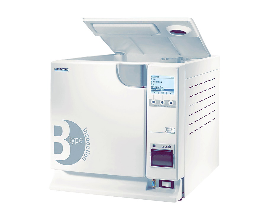
Автоматический скоростной автоклав euronda e9 класса «B» с предвакуумом и вакуумной помпой.
- Тройная система защиты: автономный защитный клапан, защитный термостат, система электронного отключения при нештатной ситуации.
- Система электронной блокировки двери автоклава во время цикла стерилизации.
- Возможность подключения к системе канализации для обеспечения автоматического слива отработанной воды.
- Возможность подключения деионизатора воды Aquafilter, позволяющего производить автоматическое наполнение емкости чистой воды.
- Раздельные емкости чистой и отработанной воды.
- Предусмотрено подключение внешнего запоминающего устройства E-Memory.
- Встроенный сепаратор пара.
- Бактериологический фильтр.
Автоклав euronda e9 описание
Автоклав евронда е9 полностью автоматический паровой стерилизатор для стерилизации инструментов в упаковке и без упаковки.
Передние элементы
1) Панель управления. Используется для установки, визуализации и управления всеми функциями устройства, а также для распечатки полезной информации оборудования.
2) Ручка для открытия двери. Внутри находится блок безопасности.
3) Порт для внешней памяти “E- Memory — System” или внешний принтер.
4) Кнопка включения-выключения ВКЛ.-ВЫКЛ. (ONOFF).
Устройства фронтальной части при открытой двери
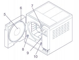
5) Круглая дверь.
6) Прокладка.
7) Бактериологический фильтр.
8) Патрубок для слива отработанной воды.
9) Закрывающий механизм с электромагнитным стержнем и внутренним микровыключателем безопасности.
10) Патрубок для слива чистой воды.
Устройства на задней панели
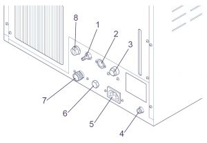
1) Выпускное отверстие при переполнении.
2) Электрический интерфейс деионизатора.
3) Предохранительный термостат (только для euronda e9 MED, начиная с № серии EGO090101 18 литров и EGP090081 24 литра).
4) Патрубок для слива воды дегазатора.
5) Розетка питания.
6) Гидравлическое соединение деионизатора.
7) Предохранительный клапан.
8) Патрубок для слива отработанной воды.
Верхние элементы
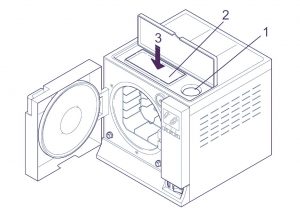
1) Клапан ручной заливки дистиллированной воды.
2) Отделение для хранения предметов.
3) Бак, расположенный внутри устройства, под отделением для хранения предметов.
Описание панели управления евронда е9
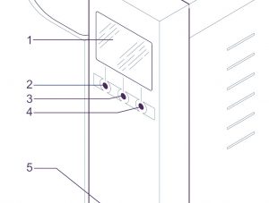
1) Графический ЖК-дисплей (320×240 точек). Включает линейку управления, всегда находящуюся на экране, и напрямую связанную с тремя кнопками под линейкой.
2,3,4) Кнопки выбора и передвижения. Эти кнопки имеют не одну функцию, а зависят от линейки управления на экране (1).
5) Встроенный принтер.
Автоклав euronda e9 размеры и вес
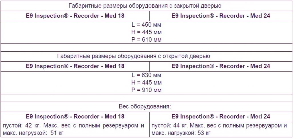
Автоклав euronda e9 технические характеристики
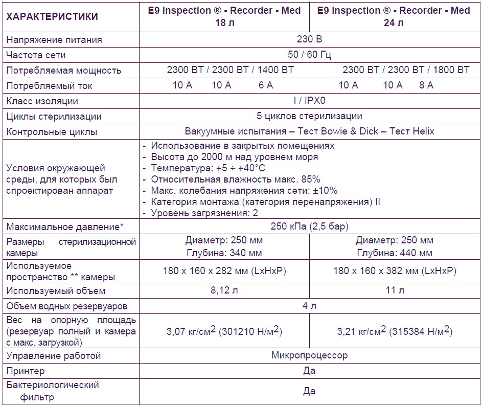
Euronda e9 размер камеры
Внутренний размер камеры стерилизации, доступный для стерилизации материалов.
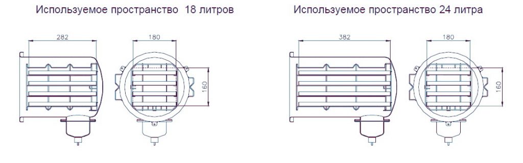
Встроенный принтер euronda e9
Встроенный принтер для моделей euronda e9 inspection и euronda e9 med
Автоклавы euronda e9 med и euronda e9 inspection настроен таким образом, чтобы данные о продолжающемся процессе стерилизации всегда распечатывались вместе с типом выбранного цикла стерилизации, фазой цикла, значениями температуры и давления, временными интервалами и общей продолжительностью в минутах. После завершения каждого цикла, принтер также распечатывает итоговый отчет о результате цикла и общей продолжительности, независимо от того, удачно ли прошел цикл или нет, и независимо от того, был ли он прекращен оператором или был подан сигнал тревоги. Функция печати итогового отчета может быть отключена по желанию
- Принтер работает только при условии наличия в нем заправленной бумаги.
- Если не поместить рулон бумаги, принтер не работает.
- Зеленый светодиод POWER, имеющийся на принтере, всегда горит, когда принтер работает.
- Красный светодиод ERROR, имеющийся на принтере, горит, когда есть проблема, например, закончилась бумага, крышка закрыта неверно и т д.
- Кнопка FEED, имеющаяся на принтере, служит для протягивания бумаги.
- Нажать один раз на кнопку для продвижения вперед бумаги на одну строку.
- Можно держать кнопку нажатой для постоянного продвижения вперед бумаги.
Для заправки нового рулона бумаги:
- Откройте крышку бумажного рулона, придерживая обе стороны пальцами и немного потянув ее на себя.
- Выньте использованный рулон.
- Вставьте новый рулон бумаги, как показано на рисунке; убедитесь, что бумага разматывается в нужном направлении.
- Вытяните наружу небольшой край бумаги и закройте крышку.
- Оторвите лишнюю бумагу.
Используйте рулоны с термобумагой со следующими характеристиками: ширина: 57 — 58 мм, макс. диаметр: 40 мм
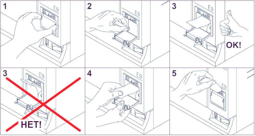
Встроенный принтер для модели euronda e9 recorder
Автоклав euronda E9 recorder оборудован встроенным термическим принтером на передней панели и выдает наклейки для идентификации пакетов. Оборудование настроено таким образом, чтобы при положительном результате цикла, распечатывались данные о номере серии автоклава, номере цикла стерилизации, операторе, дате стерилизации и дате срока годности стерилизации (выбирается оператором). Количество этикеток выбирается оператором перед запуском цикла. Помимо количества этикеток, выбранного оператором, автоклав всегда выдает конечную обобщающую этикетку об изменении состояния.
Если цикл стерилизации прошел с отрицательным результатом, принтер выдает обобщающую этикетку о том, что изменение состояния не произошло. Принтер работает только при условии наличия в нем заправленной бумаги.
Для заправки нового рулона бумаги:
- Откройте крышку бумажного рулона, придерживая обе стороны пальцами и немного потянув ее на себя.
- Выньте использованный рулон.
- Вставьте новый рулон бумаги, так, чтобы боковые суппорты с держателем рулона принтера совпали с самой трубкой держателя рулона; убедитесь, что бумага разматывается в направлении сверху вниз, а не наоборот.
- Вытяните наружу небольшой край бумаги и закройте крышку.
- Оторвите лишнюю бумагу.
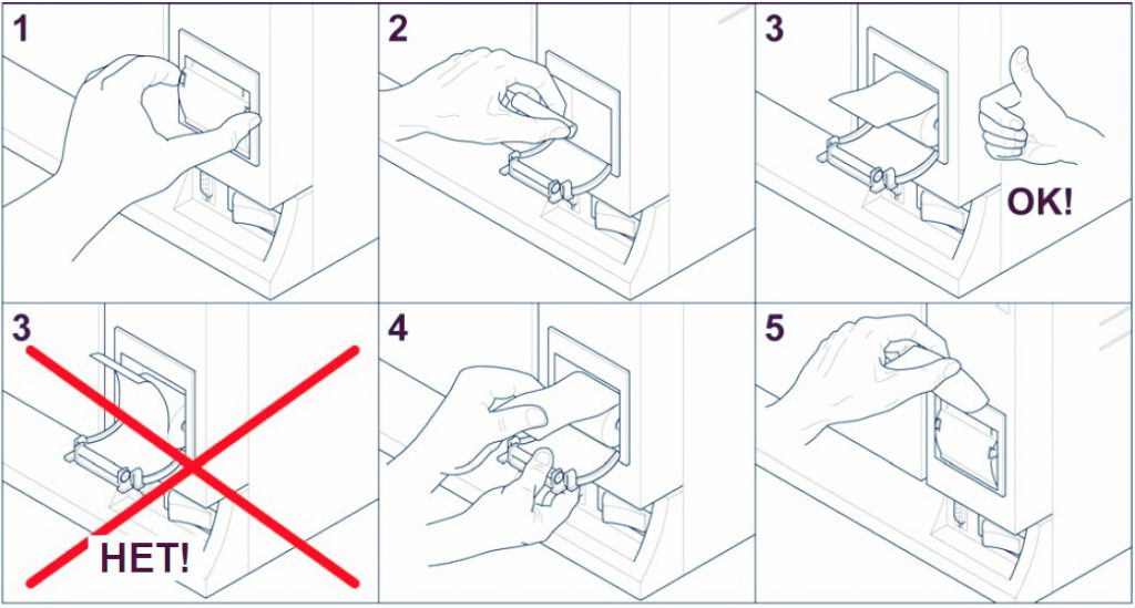
Автоклав euronda e9 техническое обслуживание
Как и вся медицинская техника, данный аппарат должен использоваться надлежащим образом, нуждается в регулярном ТО. Это обеспечит длительную эксплуатацию аппарата, безопасность и эффективность оборудования.
Чтобы предупредить возникновение потенциально опасных для оператора ситуаций, техническая служба должна осуществлять регулярное техническое обслуживание и проверки аппарата.
- Чтобы поддерживать оборудование в хорошем рабочем состоянии, периодически протирайте все наружные части мягкой влажной тканью, смоченной в нейтральном моющем средстве (не используйте коррозийные или абразивные средства).
- Не используйте обычные грубые ткани или металлические (или абразивные) щетки для очистки металлов.
- Перед началом каждого цикла, тщательно протирайте влажной тряпкой прокладки люка.
- Образование пятен белого цвета на дне камеры указывает на то, что используемая деминерализованная вода плохого качества.
Периодичность технического обслуживания
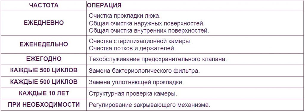
Скачать инструкцию на автоклав euronda e9
Скачать инструкцию и другую документацию на автоклав euronda e9 можно здесь.
Руководство пользователя ( user manual ) на русском языке автоклав euronda e9 скачать.
Сервисная инструкция ( service manual ) на английском языке автоклав euronda e9 скачать.
Регистрационное удостоверение автоклав euronda e9 скачать.
Декларация о соответствии автоклав евронда е9 скачать.
Так же смотрите автоклав MELAG MELAtronic 23, 17, 15.
Если в процессе работы автоклава возникают ошибки, встроенная система блокирует часть функций, отключает режимы. В большинстве случаев при наличии ошибок нормального пользоваться стерилизатором невозможно. Более того — это может быть опасно не только для стерилизуемой загрузки, но и для оператора автоклава.
Ремонт и устранение ошибок автоклава — задача квалифицированного инженера, профильного сервисного центра. Для успешного восстановления функциональности и безопасности автоклава необходимо не только общее понимание принципов работы паровых стерилизаторов, но и знание особенностей конкретных моделей, типовых проблем и методов их решения.
Одна из наших специализаций — сложный ремонт стерилизационного оборудования.
Обращайтесь, мы оперативно решим все возможные проблемы с вашим оборудованием.

В данном материале собраны списки кодов ошибок различных автоклавов и описаны самые распространенные из них.
Важно. Если вы видите на экране (или в распечатке встроенного принтера автоклава) ошибку — сработала система защиты и самодиагностики стерилизатора.
Система контроля ошибок работы автоклава. Самодиагностика паровых стерилизаторов.
В современные автоклавы устанавливается огромное количество датчиков для всех систем: от закрытия и блокировки двери во время стерилизации до качества используемой воды, температуры и давления на различных этапах стерилизационного цикла в рабочей камере, парогенераторе и других частях автоклава.
Встроенный контроллер на основной плате управления постоянно мониторит все эти параметры, а также — динамику (скорость) их изменения. Например, если температура или давление в камере для основного цикла стерилизации поднимаются или сбрасываются очень медленно, автоклав не перейдет к следующему этапу.
Как отображаются ошибки на экране автоклава
Автоклав выдает ошибку? Как правило, даже самые дорогие и многофункциональные премиум-стерилизаторы оснащаются не очень большим дисплеем (а модели среднего и начального уровня могут иметь только цифровое табло), поэтому общепринятая практика — отображать на дисплее численно-буквенный код ошибки работы автоклава. Часто — с буквенным обозначением E, Err, ERROR, например E5, E7, Er02, Err5 и т.д.
Расшифровку возможных ошибок можно найти в сервисных инструкциях или на сайтах производителей стерилизаторов. В данном материале мы также приводим официальные расшифровки самых “популярных” ошибок автоклавов.
При этом важно понимать, что формулировка ошибки указывает инженеру только направление поиска неисправности (а в некоторых случаях истинная причина может скрываться в совершенно другом блоке, поэтому даже зная код ошибки и его точное значение, всегда необходимо проводить полную диагностику всего автоклава для выявления всех неисправностей.

Какие ошибки при работе автоклава появляются чаще всего
У каждого производителя и каждой модели автоклава есть своя специфика, но по статистике основные (распространенные) типы ошибок чаще всего следующие:
- Ошибка качества воды: используется некачественная, не дистиллированная вода, неисправен датчик воды или внутренние поверхности трактов, фильтры содержат инородные элементы, биоматериал.
- Ошибка блокировки двери автоклава: не закрыта дверь, не работает механизм электронной блокировки, не срабатывают концевые датчики и т.д.
- Ошибки температуры парогенератора и рабочей камеры автоклава: слишком высокая температура парогенератора, камеры, слишком быстро / медленно падает или поднимается температура. Причин этой группы ошибок может быть множество: от неисправностей самих датчиков но проблем с терморегуляторами и нагревательными элементами / ТЭНами.
- Утечка вакуума, давления: отдельный и очень распространенный вид ошибок. Чаще всего связан с проблемами герметичности двери, уплотнителем, работой компрессоров и т.д.
- Ошибки давления в рабочей камере автоклава: автоклав не держит давление, давление не поднимается, давление в камере сбрасывается слишком медленно и т.д.
- Ошибки рабочих режимов автоклава: например, температура и давление не соответствуют друг другу, отсутствует предварительное вакуумирование, предварительный нагрев
- Ошибки, прямо указывающие на неисправность автоклава: Например, сломан микровыключатель двери (концевой датчик), загрязнен фильтр и т.д.
Не важно, какую ошибку выдает автоклав, помните то, о чем мы писали выше: даже при явном указании на неисправность необходима полная проверка всего аппарата.
Коды ошибок популярных паровых стерилизаторов
Далее приводим таблицы — списки ошибок популярных автоклавов. Данная информация поможет сориентироваться в направлении поиска неисправностей, если вы видите одну из таких ошибок на дисплее своего автоклава — сообщите ее сервисному инженеру, это поможет в подготовке к ремонту / выезду.
Ошибки автоклавов Woson (Восон)
Очень часто к нам обращаются за помощью по ошибкам автоклавов Woson (например, TanzoC23). Ниже приводим список кодов ошибок на основе этой модели. Для многих автоклавов производителя описание схожее, но рекомендуем каждый раз сверяться с соответствующим руководством.
Вы также можете написать нам на Email, Whatsapp, позвонить по номерам в контактах.
|
E01 |
Медленный нагрев |
|
E02 |
Ошибка сброса давления |
|
E03 |
Открытая дверь |
|
E04 |
Низкое давление |
|
E05 |
Медленный спад давления |
|
E06 |
Медленное вакуумирование |
|
E07 |
Окружающее давление |
|
E08, E09 |
Микропереключатели передней и задней двери сломаны |
|
E10 |
Низкий предварительный нагрев |
|
E11 |
Высокая температура |
|
E12 |
Низкая температура |
|
E13 |
Ошибка автоматической подачи воды |
|
E17 |
Ошибка качества воды |
|
E23 |
Давление и температура не совпадают |
|
E24 |
Вока не стерильна |
|
E25 |
Ошибка воздушного фильтра |
|
E27 |
Серьезная утечка |
|
E31, E32, E33 E34 |
Ошибка термодатчиков 1 — 4 |
|
E51, E52, E53, E54 |
Датчик температуры высокий уровень выхода |
|
E71 |
Сенсор давления низкий уровень выхода |
|
E72 |
Сенсор давления высокий уровень выхода |
|
E14 |
Ошибка несоответствия внутренних сенсоров / Повреждение сигнала |
|
E99 |
Автоклав не набирает температуру в 134 градуса. / Экстренный выход (зависит от версии микропрограммы и других особенностей) |
Еще один вариант индикации ошибок автоклава Woson: с обозначениями Err / Er. Характерны для многих моделей.
|
Err7 |
Переработка по времени / Сверхурочная работа — одна из самых распространенных ошибок, возникающих при работе автоклавов Woson. Необходима последовательная проверка герметичности камеры, клапанов, всех датчиков, помп и компрессоров, полная диагностика автоклава. |
|
Err12 |
Ошибка вакуума (вакуумирования / вакуумной системы) |
|
Er98 |
Электропитание автоклава было отключено во время выполнения рабочего цикла. Необходимо проверить силовые и управляющие цепи, уточнить, не было ли внеплановых / веерных отключений, колебаний парамертов электросети. |
|
Er99 / Er00 |
Принудительный выход. Нормальный ход выполнения цикла был прерван оператором |
Ошибки автоклава Woson Tanzo-E
Альтернативный вариант таблицы с кодами ошибок автоклавов Woson Tanzo-E
|
Er01 |
Превышены допустимые температуры парогенератора |
|
Er02 |
Превышен температурный режим нагревательного кольца |
|
Er03 |
Температура рабочей камеры за пределами нормы |
|
Er04 |
Возникла ошибка в настройках параметров температуры и давления |
|
Er05 |
Ошибка сброса давления (повышенное) |
|
Er06 |
Ошибка двери рабочей камеры (открыта во время рабочего цикла) |
|
Er07 |
Аналогично параметру Err07. Переработка по времени |
|
Er08 |
Высокое давление |
|
Er09 |
Датчик температуры рабочей камеры фиксирует температуру за пределами нормы (низкая или высокая). Ошибка характерна для сисетм с двойными сенасорами. |
|
Er10 |
Температурный режим не соответстует давлению |
|
E12 |
Вакуумирование выполнено с ошибкой |
|
Er14 |
Показатели двойных сенсоров температуры находятся в слишком широком диапазоне (не соответствуют друг другу) |
Ошибки автоклава DGM
Ошибки автоклавов производства DGM рассматриваем на примере популярной модели DGM 130. Данный производитель обозначает сообщения о сбоях как Er
|
Er2 |
Давление пара в системе подачи низкое |
|
Er3 |
Высокая температура рабочей камеры |
|
Er4 |
Слишком высокое давление рабочей камеры |
|
Er5 |
Ошибка вакуумного насоса |
|
Er6 |
Контактор PP выключен, нет питания |
|
Er7 |
Ошибка температурного датчика в рабочей камере |
|
Er8 |
Ошибка датчика давления в рабочей камере |
|
Er9 |
Ошибка датчика давления в рубашке |
|
Er12 |
Нет пара на входе стерилизатора |
|
Er14 |
Ошибка температурного датчика в емкости PP |
|
Er15 |
Низкий уровень воды в емкости PP |
|
Er16 |
Ошибка защиты от пара |
|
Er31 — 38 |
Ошибки двери |
Дополнительно, на стерилизаторах со встроенным парогенератором возможны следующие сообщения:
|
Er21 |
Отсутствует вода для парогенератора |
|
E22 |
Ошибка насоса или датчика воды парогенератора |
|
E23 |
Ошибка времени прогрева |
|
Er24 |
Ошибка отключения нагревателей |
|
Er25 |
Ошибка термореле генератора |
Ошибки автоклавов MELAG (Мелаг)
Современные серии автоклавов Melag Euroklav, Vacuklav в зависимости от модели могут комплектоваться как простым двухстрочным дисплеем для отображения текста, так и полноценным цветным экраном с довольно хорошим разрешением.
Помимо непосредственно кодов ошибок на дисплее могут отображаться системные сообщения, рекомендации и предупреждения (то есть неисправность еще не зафиксирована, но продолжение работы невозможно до принятия соответствующих действий).
Предупреждения
|
Warning! Door open |
Неплотно закрыта дверца |
|
Warning! No water |
Уровень воды при внутренней подаче ниже минимальной отметки |
|
Warning! No feed water |
Вода не достигла датчика воды (при внешней подаче) |
|
Wastewater tank Full |
Заполнена камера отработанной воды |
|
Water quality Poor |
Низкое качество воды, но возможен ручной старт |
|
Water quality Bad |
Неприемлемое, опасное качество воды, старт невозможен |
|
Exchange Sterile filter |
Требуется замена фильтров (возможны и другие причины этого сообщения) |
|
Printer is not ready / Printer memory full |
нет связи с принтером / заполнена память встроенного принтера |
|
Please service |
Необходимо сервисное обслуживание |
Информация об ошибках автоклавов Melag
|
Malfunction 1: Vacuum system |
Ошибка скорости набора вакуума |
|
Malfunction 2: Steam generator |
Длительный нагрев, ошибка парогенератора |
|
Malfunction 4: Pressure release |
Давление долго не нормализуется |
|
Malfunction 8: Timebase |
Ошибка таймера, системный сбой |
|
Malfunction 9: Door open |
Открыта дверь |
|
Malfunction 10: Steamgen. Too hot |
Ошибка температуры или алгоритма работы парогенератора |
|
Malfunction 12 Door lock |
Проблемы с открытием дверцы |
|
Malfunction 14: Water supply |
Ошибка подачи воды |
|
Malfunction 18: Sens. Defect Nr |
Ошибки датчиков температуры, давления и качества воды |
|
Malfunction 21: Preheating |
Ошибка предварительного прогрева |
|
Malfunction 22: Overheating |
Слишком сильный предварительный прогрев |
|
Malfunction 23: Current |
Время нормализации давления больше максимального |
|
Malfunction 26: A/D-Converting |
Ошибка контроллегра / датчиков, платы управления |
|
Malfunction 27: Temp. sens. def 1,2 |
Ошибка разницы температур термодатчиков |
|
Malfunction 29: Battery RAM |
Проблема на плате управления |
|
Malfunction 33: Pressure drop |
Длительный набор давления |
|
Malfunction 34: Sterilization TU |
Температура стерилизации недостаточная |
|
Malfunction 35: Sterilization TO |
Температура стерилизации превышает максимальную |
|
Malfunction 36: Sterilization PU |
Слишком низкое давление |
|
Malfunction 37: Sterilization PO |
Слишком высокое давление |
|
Malfunction 38: Sterilization TD |
Ошибка вычисления температуры |
|
Malfunction 41: Flow drying |
Время нормализации давления при сушке больше максимального |
|
Malfunction 42: Drying press.-pump |
Время набора давления при сушке больше максимального |
|
Malfunction 43: Drying Vac.-pump |
Время создания вакуума больше максимального |
Ошибки автоклавов MOCOM (Моком)
Ошибки автоклавов производства Mocom рассмотрим на примере серии, Neutra Vacuum/ Частично эти расшифровки применимы и к Mocom Exacta
В автоклавах Mocom все нештатные ситуации обозначаются сообщениями трех категорий: ошибки (E), аварийные ситуации (A), опасные ситуации (H)
|
E 010 |
DOOR OPEN / Открыта дверь |
|
E 020 |
DOOR UNLOCKED / Дверь не закрылась вовремя |
|
E 021 |
DOOR LOCKED / Дверь не открылась вовремя |
|
E 030 |
WATER MIN / Низкий уровень воды |
|
E 031 |
EXHAUST MAX / Бак отработанной воды заполнен |
|
E 041 |
FILLING PROBLEM / Слишком интенсивная подача воды в бак |
|
E 900 |
TEST FAILED / Ошибка вакуума (утечка) |
|
E 901 |
TEST FAILED / Ошибка вакуума (ожидание) |
|
E 902 |
TEST FAILED / Ошибка вакуума (таймаут импульса) |
|
E 999 |
MANUAL STOP / Цикл остановлен вручную |
|
A 022 |
LOCKING PROBLEM / Ошибка микровыключателей сдвери (Выкл) |
|
A 023 |
LOCKING PROBLEM / Ошибка микровыключателей сдвери (Вкл) |
|
A 024 |
LOCKING PROBLEM / Ошибка микровыключателей сдвери (Вкл / Выкл) |
|
A 032 |
LEVEL PROBLEM / Ошибка датчика уровня |
|
A 040 |
FILLING PROBLEM / Невозможна автоматическая заправка |
|
A 101 |
PTC BROKEN / Повреждение в рабочей камере |
|
A 102 |
PTC BROKEN / Повреждение в парогенераторе |
|
A 111 |
PTC SHORTCIRCUIT / Короткое замыкание в рабочей камере |
|
A 112 |
PTC SHORTCIRCUIT / Короткое замыкание в парогенераторе |
|
A200 |
HEATING PROBLEM / Ошибка предварительного нагрева |
|
A 250 |
PV1 TIMEOUT / 1 вакуумный импульс |
|
A 251 |
ATM1 TIMEOUT / 1 поднятие давления до атмосферного |
|
A 258 |
PPP TIMEOUT / 3 пульсовое колебание |
|
A 259 |
PROCESS TIMEOUT / Ошибка фазы стерилизации |
|
A 260 |
PPD TIME-OUT / Сброс давления слишком медленный |
|
H 150 |
MPX BROKEN / Сломан датчик давления |
|
H 992 |
OVERHEATING PT2 / Избыточный нагрев парогенератора |
В таблице указаны не все коды ошибок. Если вы не нашли здесь свой код ошибки — свяжитесь с нами.
Ошибки автоклавов Runeys
Ошибки автоклавов китайского производителя Runeys разберем на примере модели TINHERO 16L/B. Индикация ошибок данного автоклава очень простая, указывает только на неисправный блок, далее нужна диагностика.
|
E1 |
Неполадки сенсора |
|
E2 |
Очень высокое давление |
|
E3 |
Температура камеры больше 145 градусов |
|
E4 |
Нестабильная температура и давление |
|
E5 |
Ошибка подачи пара |
|
E6 |
Ошибка двери |
|
E7 |
Температура парогенератора |
|
E8 |
Предварительный нагрев |
|
E9 |
Ошибка подачи пара |
Ошибки автоклавов Youjoy
Китайский производитель стерилизационного оборудования Yoyjoy также оснащает свои автоклавы системой самодиагностики. Она довольно простая и позволяет в общем виде определиться с направлением поиска. Ошибки рассматриваем на примере автоклава BES-12L-B-LED
|
Е1 |
Ошибка сенсора температуры |
|
Е2 |
Повышенное давление |
|
Е3 |
Повышенная температура |
|
Е4 |
Нет постоянной температуры |
|
Е5 |
Блокировка паровой трубы |
|
Е6 |
Ошибка двери |
|
Е7 |
Перегрев генератора пара |
|
Е8 |
Избыточное время нагрева |
|
Е9 |
Избыточное время выдержки давления |
Ошибки автоклавов Tuttnauer
Израильский производитель автоклавов Tuttnauer известен довольно высокой надежностью, и большим количеством встроенной электроники, систем защиты. Ниже приводится таблица ошибок настольного автоклава Tuttnauer 2540 NOVA-3. В других моделях система контроля и структура ошибок могут быть намного сложнее (особенно это касается серии Hospital, проходных автоклавов большого объема).
|
Low Temp. |
Температура не соответствует параметрам стерилизации |
|
Low Heat |
Невозможно достичь температуры стерилизации в течение 60 минут |
|
High Temp |
Температура на 3°C (и более) выше температуры стерилизации при цикле, поврежден датчик температуры |
|
Low Pres |
Давление ниже соответствующего температуре стерилизации |
|
High Pres |
Слишком высокое давление |
|
Low Vacuum |
Недостаточный уровень вакуума на стадии предварительного вакуумирования (менее 15 кПа) |
|
Man. Stop |
Ручная остановка цикла |
|
Power Dn |
Незапланированное отключение питания во время цикла стерилизации |
|
Add Water, Low Water |
В резервуаре низкий уровень воды, отключение нагревателя по иным причинам |
|
Door Unlock |
Проблема с герметичностью двери |
Ошибки автоклавов PT Medical
Ошибки паровых стерилизаторов производителя PT Medical рассмотрим на примерах автоклавов серии BTD: BTD23L-A, BTD17L-A.
|
Е1 |
Длительный набор давления |
|
Е2 |
Давление выше допустимого |
|
Е3 |
Открыта дверь |
|
Е4 |
Сбой давления в автоклаве |
|
Е5 |
Длительный сброс давления |
|
Е6 |
Дверной переключатель открыт или неисправен |
|
Е7 |
Давление близко к атмосферному |
|
Е8 |
Ошибка замка блокировки двери |
|
Е9 |
Ошибка двигателя двери |
|
Е10 |
Длительный нагрев |
|
Е11 |
Нарушение автоматической подачи воды |
|
Е12 |
Короткое замыкание внутреннего датчика температуры |
|
Е13 |
Короткое замыкание внешнего датчика температуры |
|
Е14 |
Короткое замыкание датчика парогенератора |
|
Е15 |
Обрыв в цепи внутреннего датчика температуры |
|
Е16 |
Обрыв в цепи внешнего датчика температуры |
|
Е17 |
Обрыв в цепи температурного датчика парогенератора |
|
Е18 |
Температура с внутреннего термодатчика выше 150℃ |
|
Е19 |
Температура с внешнего термодатчика выше 170℃ |
|
Е20 |
Температура парогенератора выше 230℃ |
В некоторых моделях (например у PT Medical BTD 23 количество сообщений больше. На дисплее может отображаться ошибка 31.
Если вы встретились с незнакомой ошибкой на своем автоклаве или устранить проблему самостоятельно не удается — свяжитесь с нами по телефону или электронной почте- поможем оперативно найти причину и восстановить функциональность стерилизатора.
Все автоклавы для ЦСО, хирургии, стоматологии и других областей в едином каталоге Cordismed с описанием и характеистиками.
Паровые стерилизаторы
CONTENTS
1 — INTRODUCTION …………………………………………………………………………………………………. 7
1.1 GENERAL PRECAUTIONS ………………………………………………………………………………………………………………………… 7
2 — SAFETY …………………………………………………………………………………………………………….. 9
2.1 GENERAL SAFETY WARNINGS ……………………………………………………………………………………………………………….. 9
2.2 SAFETY DEVICES …………………………………………………………………………………………………………………………………….. 10
2.3 RESIDUE RISKS ……………………………………………………………………………………………………………………………………….. 11
2.4 SAFETY SIGNS ON THE UNIT …………………………………………………………………………………………………………………. 12
3 — TECHNICAL DATA ……………………………………………………………………………………………. 13
3.1 OVERALL SPACE REQUIRED …………………………………………………………………………………………………………………. 13
3.2 TECHNICAL DATA AND NOISE ………………………………………………………………………………………………………………. 14
3.3 QUALITY OF WATER ……………………………………………………………………………………………………………………………… 15
3.4 SERIAL NUMBERS CODING ………………………………………………………………………………………………………………….. 16
4 — INSTALLATION ………………………………………………………………………………………………… 17
4.1 POSITIONING THE UNIT …………………………………………………………………………………………………………………………. 17
4.2 INSTALLING THE UNIT …………………………………………………………………………………………………………………………… 18
4.2.1 Installation and adjustement …………………………………………………………………………………………………………………….. 18
4.3 OPERATOR REGISTRATION …………………………………………………………………………………………………………………… 23
4.4 PERFORMING THE VACUUM TEST ……………………………………………………………………………………………………….. 24
4.5 PERFORMING THE B134 CYCLE …………………………………………………………………………………………………………….. 25
5.1 E9 INSPECTION COMPONENTS ……………………………………………………………………………………………………………… 29
5.2.1 Phase 0: Turning on the sterilizer ……………………………………………………………………………………………………………… 32
Steam Sterilizer
E9 INSPECTION
E9 RECORDER
E9 MED
s e r v i c e m a n u a l
ENGLISH
0051
CONTENTS
1 - INTRODUCTION ................................................................................................................ 7
1.1
GENERAL PRECAUTIONS .......................................................................................................................................... 7
1.2
READING THE MANUAL: SYMBOLS AND CONVENTIONS ............................................................................... 7
1.3
HOW TO OBTAIN A NEW COPY OF THE MANUAL ............................................................................................. 8
2 - SAFETY ............................................................................................................................. 9
2.1
GENERAL SAFETY WARNINGS ................................................................................................................................ 9
2.2 SAFETY DEVICES ........................................................................................................................................................ 10
2.3
RESIDUE RISKS ........................................................................................................................................................... 11
2.4
SAFETY SIGNS ON THE UNIT .................................................................................................................................. 12
3 - TECHNICAL DATA .......................................................................................................... 13
3.1 OVERALL SPACE REQUIRED .................................................................................................................................. 13
3.2 TECHNICAL DATA AND NOISE ............................................................................................................................... 14
3.3
QUALITY OF WATER ................................................................................................................................................ 15
3.4
SERIAL NUMBERS CODING ................................................................................................................................... 16
4 - INSTALLATION ............................................................................................................... 17
4.1 POSITIONING THE UNIT ........................................................................................................................................... 17
4.2 INSTALLING THE UNIT ............................................................................................................................................. 18
4.2.1 Installation and adjustement ...................................................................................................................................... 18
4.3 OPERATOR REGISTRATION .................................................................................................................................... 23
4.4 PERFORMING THE VACUUM TEST ....................................................................................................................... 24
4.5 PERFORMING THE B134 CYCLE ............................................................................................................................. 25
4.6 LABELS PRINTING (ONLY E9 RECORDER) ......................................................................................................... 26
4.7 DELIVERY OF TECHNICAL DOCUMENTATION ................................................................................................ 28
5 - DESCRIPTION OF CYCLE AND MAIN PERFORMANCE DATA ................................... 29
5.1 E9 INSPECTION COMPONENTS .............................................................................................................................. 29
5.2
CYCLE FOR E9 INSPECTION WITH SEPARATOR DRAINING PUMP ........................................................... 31
5.2.1 Phase 0: Turning on the sterilizer .............................................................................................................................. 32
E9 service manual GB r7
4
C
ONTENTS
AUTOCLAVE E9
5.2.2 Start-Vacuum phase V1/I .......................................................................................................................................... 33
5.2.2 Start-Vacuum phase V1/I .......................................................................................................................................... 33
5.2.3 Vacuum phase V1/II ................................................................................................................................................. 34
5.2.3 Vacuum phase V1/II ................................................................................................................................................. 34
5.2.4 Vacuum phase V1/III ................................................................................................................................................ 35
5.2.5 Water inlet phase ....................................................................................................................................................... 36
5.2.6 Water outgas system drain phase .............................................................................................................................. 37
5.2.7 Pressure increase phase P
1
........................................................................................................................................ 38
5.2.8 Water transfer phase.................................................................................................................................................. 39
5.2.9 Vacuum - Thermodynamic vacuum phase V
2
........................................................................................................... 40
5.2.10 Vacuum 2,3,4 phase V2 .......................................................................................................................................... 41
5.2.11 Pressure increase/Sterilization phase P
4
.................................................................................................................. 42
5.2.12 Sterilization phase ................................................................................................................................................... 43
5.2.13 Steam discharge phase ............................................................................................................................................ 44
5.2.14 Steam discharge phase I .......................................................................................................................................... 45
5.2.15 Pressure levelling phase I ........................................................................................................................................ 46
5.2.16 Vacuum phase II ..................................................................................................................................................... 47
5.2.17 Pressure levelling phase II ...................................................................................................................................... 48
5.2.18 End of cycle phase .................................................................................................................................................. 49
5.3 CYCLE FOR E9 INSPECTION/RECORDER WITH CIRCUIT U-234
(since firmware 7.01) ........................ 50
5.3.1 Turning on the sterilizer ............................................................................................................................................ 50
5.3.2 Phase 1: Start, water outgas system emptying and steam generator filling (U-234 circuit) ...................................... 51
5.3.3 Phase 2: Steam generator emptying (U-234 circuit) ................................................................................................. 52
5.3.4 Phase 3: Water outgas system filling (U-234 circuit) ............................................................................................... 53
5.3.5 Phase 4: Vacuum into chamber and water outgas system (U-234 circuit) ................................................................ 54
5.3.6 Phase 5: Water separator emptying and steam generator filling (U-234 circuit) ...................................................... 55
5.3.7 Phase 6: Pressure rise (U-234 circuit) ....................................................................................................................... 56
5.3.8 Phase 7: Emptying and vacuum (U-234 circuit) ....................................................................................................... 57
5.3.9 Pressure rise (U-234 circuit) ..................................................................................................................................... 58
5.4 CYCLE FOR E9 MED (up to EGO090100 18 L and up to EGP090080 24 L) ......................................................... 59
5.4.1 Turning on the sterilizer ............................................................................................................................................ 59
5.4.2 Phase 1: Vacuum into chamber ................................................................................................................................. 60
5.4.3 Phase 2: Steam generator filling ............................................................................................................................... 61
5.4.4 Phase 3: Pressure rise ................................................................................................................................................ 62
5.4.5 Phase 4: Water separator emptying and vacuum ....................................................................................................... 63
5.4.6 Third pressure rise and sterilisation .......................................................................................................................... 64
5.4.7 Drying phase ............................................................................................................................................................. 65
5.5 CYCLE FOR E9 MED (since EGO090101 18 L and since EGP090081 24 L) ......................................................... 66
5.5.1 Phase 0: Turning on the sterilizer.............................................................................................................................. 66
5.5.2 Phase 1: Start and chamber emptying ....................................................................................................................... 67
5.5.3 Phase 2: Water injection into the chamber ................................................................................................................ 68
5.5.4 Phase 3: Pressure rise ................................................................................................................................................ 69
5.5.5 Phase 4: Pressure discharge and emptying ................................................................................................................ 70
5.5.6 Phase 5: Pressure rise and separator emptying .......................................................................................................... 71
5.5.7 Phase 6: Pressure balancing ...................................................................................................................................... 72
5.6 EXAMPLES OF STERILIZATION CYCLE REPORTS ......................................................................................... 73
6 - DESCRIPTION OF TEST AND MAIN PERFORMANCE DATA ...................................... 74
6.1 GRAPH OF COMPLETE VACUUM TEST............................................................................................................... 74
6.1.1 Phase 0: Starting ....................................................................................................................................................... 75
E9 service manual GB r7
5
C
ONTENTS
AUTOCLAVE E9
6.1.2 Vacuum phase ............................................................................................................................................................ 76
6.1.3 Pressure levelling/Maintenance phase ....................................................................................................................... 77
6.1.4 Pressure levelling phase ............................................................................................................................................. 78
6.2 BOWIE&DICK TEST ................................................................................................................................................... 79
6.3
HELIX TEST ................................................................................................................................................................. 79
7 - MAINTENANCE ............................................................................................................... 81
7.1 SAFETY WARNINGS ................................................................................................................................................... 81
7.2 PERIODIC MAINTENANCE ....................................................................................................................................... 83
7.3 EXTRAORDINARY MAINTENANCE ....................................................................................................................... 84
7.4 TECHNICAL MENU ..................................................................................................................................................... 86
7.5 COMPONENTS LIST E9 INSPECTION (U-234 / RECORDER CIRCUIT) .......................................................... 94
8 - COMPONENTS AND DIAGRAMS ................................................................................... 96
8.1 WIRING DIAGRAM ..................................................................................................................................................... 96
8.2 HYDRAULIC DIAGRAM ............................................................................................................................................. 98
8.2.1 Hydraulic diagram E9 ................................................................................................................................................ 98
8.2.2 Hydraulic diagram E9 U-234 ..................................................................................................................................... 99
8.2.3 Hydraulic diagram E9 MED (since EGO090101 18 L and since EGP090081 24 L) ................................................ 99
9 - SPARE PARTS CATALOGUE ...................................................................................... 100
9.1 EXPLODED GENERAL DIAGRAM OF E9 INSPECTION ................................................................................... 100
9.2 INDEX OF TABLES .................................................................................................................................................... 101
9.2.1 TAB. 01: SAFETY HOUSING ASSEMBLY E9 .................................................................................................... 102
9.2.2.1 TAB. 02: DOOR ASSEMBLY E9 INSPECTION / RECORDER ....................................................................... 103
9.2.2.2 TAB. 02: DOOR ASSEMBLY E9 MED.............................................................................................................. 104
9.2.3.1 TAB. 03: CONTROL PANEL ASSEMBLY E9 INSPECTION .......................................................................... 105
9.2.3.2 TAB. 03: CONTROL PANEL ASSEMBLY E9 RECORDER ............................................................................ 106
9.2.3.3 TAB. 03: CONTROL PANEL ASSEMBLY E9 MED ........................................................................................ 107
9.2.4.1 TAB. 04: TANK AND POWER CARD + PRESSURE TRANSDUCER ASSEMBLY E9 ................................ 108
9.2.4.2 TAB. 04: TANK AND POWER CARD + PRESSURE TRANSDUCER ASSEMBLY E9 U-234 / RECORDER /
MED ............................................................................................................................................................................ 110
9.2.5.1 TAB. 05: VACUUM PUMP AND RADIATOR ASSEMBLY E9 ...................................................................... 112
9.2.5.2 TAB. 05: VACUUM PUMP AND RADIATOR ASSEMBLY E9 U-234 / RECORDER / MED ....................... 113
9.2.6.1 TAB. 06: TANK SUPPORT AND NME MICROPUMP ASSEMBLY .............................................................. 114
9.2.6.2 TAB. 06: TANK SUPPORT AND SICCE MICROPUMP ASSEMBLY ............................................................ 115
9.2.6.3 TAB. 06: TANK SUPPORT AND MICROPUMP ASSEMBLY E9 U-234 / RECORDER / MED ................... 116
9.2.7.1 TAB. 07: CHASSIS, WATER OUTGAS SYSTEM AND CROSSPIECE ASSEMBLY E9 INSPECTION /
RECORDER ............................................................................................................................................................... 117
9.2.7.2 TAB. 07: CHASSIS AND CROSSPIECE ASSEMBLY E9 MED ...................................................................... 119
9.2.8.1 TAB. 08: SOLENOID VALVE ASSEMBLY E9 ................................................................................................ 121
9.2.8.2 TAB. 08: SOLENOID VALVE ASSEMBLY E9 U-234 / RECORDER ............................................................. 123
9.2.8.3 TAB. 08: SOLENOID VALVE ASSEMBLY E9 MED....................................................................................... 125
E9 service manual GB r7
6
C
ONTENTS
AUTOCLAVE E9
9.2.9.1 TAB. 09: BOILER/ELECTROMAGNET ASSEMBLY E9 INSPECTION / RECORDER ............................... 127
9.2.9.2 TAB. 09: BOILER/ELECTROMAGNET ASSEMBLY E9 MED ...................................................................... 129
9.2.10 TAB. 10: FRONT PANEL ASSEMBLY E9 ........................................................................................................ 131
9.2.11 TAB. KIT: ACCESSORIES KIT E9 .................................................................................................................... 132
10 - PRODUCT VERSIONS ................................................................................................ 133
10.1 REGISTRATIONS OF MODIFICATIONS TO E9 HARDWARE ...................................................................... 133
11 - TROUBLESHOOTING ................................................................................................. 134
11.1 SUMMARY OF ALARM SIGNALS ....................................................................................................................... 134
11.2 REPAIR BRIEFS ....................................................................................................................................................... 140
Index of repair briefs ........................................................................................................................................................ 140
11.3 REQUIRED MAINTENANCE TOOLS .................................................................................................................. 162
12 - DEMOLITION .............................................................................................................. 165
12.1 DEMOLITION INSTRUCTIONS ........................................................................................................................... 165
12.2 RESALE ..................................................................................................................................................................... 165
APPENDIX .......................................................................................................................... 166
APPENDIX 1 ....................................................................................................................... 166
1 - Introduction
1.1 GENERAL PRECAUTIONS
Before performing any maintenance operations, carefully read the instructions manual
supplied with the unit.
WARNING: When replacing components that directly or indirectly affect safety, it is essential to
only use ORIGINAL SPARE PARTS.
WARNING: DISCONNECT THE POWER SUPPLY BEFORE STARTING WORK. Non-
observance may cause serious injury to people.
DANGER: HIGH INTERNAL VOLTAGE.
ALL MAINTENANCE OPERATIONS MAY ONLY BE PERFORMED BY THE RESPONSIBLE AUTHORITY
OR THE TECHNICAL ASSISTANCE SERVICE.
Have repairs carried out by EURONDA S.p.A. authorised centres using calibrated and certified instruments.
Otherwise, send the autoclaves directly to EURONDA S.p.A..
The drawings and any other documents delivered with the unit may not be divulged to third parties in that
Euronda S.p.A. is the sole owner and reserves all rights to them.
Euronda S.p.A. reserves the right to make modifications or improvements to the manual or the unit
without notice and without being obliged to update previous production and manuals.
1.2 READING THE MANUAL: SYMBOLS AND CONVENTIONS
In this manual symbols are placed beside certain descriptions, notes, etc.. These symbols are used to attract
the attention of readers to a particular note or explanation. Their meaning is explained below.
SYMBOL
DESCRIPTION
IMPORTANT SAFETY INFORMATION
This symbol is used to draw the attention of the reader to particularly important
notions for operator safety.
INFORMATION AND PRECAUTIONS
This symbol refers to general indications and advice.
STRICTLY FORBIDDEN
This symbol means it is strictly forbidden to perform the operation in question. Non-
observance may cause serious harm to the operator or damage to the equipment.
The manual is divided into chapters and subchapters; the figures are numbered with to chapter to which they
refer, with the addition of a progressive number. E.g.: Fig. 3.4-1 (figure n°1 relative to chap. 3.4).
E9 service manual GB r7
8
1
-
I
NTRODUCTION
AUTOCLAVE E9
1.3 HOW TO OBTAIN A NEW COPY OF THE MANUAL
If the manual is lost or destroyed, ask Euronda S.p.A. for a new copy.
Provide the following information:
- name and model of the unit;
- name and address where the manual should be sent.
Send your request to the following address:
EURONDA SPA
Via dell’Artigianato, 7
36030 Montecchio Precalcino
Vicenza - Italy
Tel. 0445 329811 - Fax 0445 865246
E-mail [email protected]
2 - Safety
2.1 GENERAL SAFETY WARNINGS
Before using the equipment, read the safety information carefully. Non-observance could
cause accidents or damage to the machine or injure the operator.
- Before using the unit, operators must have perfectly understood the meanings and functions of all the
controls.
- Operators must be aware of and know how to apply the safety regulations governing the use of the unit.
- Operators must know and correctly interpret all the indications contained in this manual and those applied
to the unit.
- Operators must not perform operations on their own initiative or operations that are not part of their job.
- The responsible authority is responsible for the professional training of operators.
- In the event of malfunctions or potentially dangerous situations, operators MUST immediately report the
situation to the responsible authority.
- It is strictly forbidden to use or neutralize the safety devices.
- Make sure the unit is powered at the correct voltage.
- Make sure the unit is earthed and conforms to the standards applicable in the country of installation.
- Never dismantle the unit.
- Do not remove the outer safety guard. Even if the unit is not in operation, its cooling fan is always on if
power supply to the machine is connected. Danger of injury to hands (see chap. 2.3 “Residue risks”).
- The high voltages inside the unit are dangerous.
- If it is not possible to disconnect the power supply, disconnect the mains supply. If this is distant or not
visible by the person carrying out the maintenance work, place the sign, “Work in progress” on the mains
switch after it has been turned “OFF”.
- Keep the area around the unit clean and dry.
- Do not use solvents on the label.
- Do not remove the label on the unit. If necessary, ask for a new one.
- Clean the unit with a damp cloth after checking that the power lead is not connected (before using the unit
again, remove any traces of moisture).
- Do not pour water onto the unit or any other liquids that could cause short circuits or corrosion.
- Do not touch the unit with wet hands or if it is wet; always follow the precautions required for the use of
electrical equipment.
- The unit was not designed for use in the presence of gas or explosive vapours.
- Do not submit the unit to excessive mechanical stress such as impacts or strong vibrations.
- Do not lean over or stand in front of the door when opening it as there is a risk of scalding from escaping
steam (see chap. 2.3 “Residue risks”).
- The water used in the discharge tank could contain, in the case of incomplete or failed sterilisation,
contaminated residues; it is therefore advisable to use protective rubber gloves when unloading (see
chap. 6.7 “Tanks: instructions for filling and emptying” in the instructions manual supplied with the
unit and chap. 2.3 “Residue risks” in this manual).
- Before transporting the machine, drain both water tanks. Use the supplied drain tube and follow the
instructions for draining (see chap. 6.7 “Tanks: instructions for filling and emptying” in the
instructions manual supplied with the unit).
E9 service manual GB r7
10
2 - S
AFETY
AUTOCLAVE E9
2.2 SAFETY DEVICES
Electrical safety
Description
Effect
Double-pole thermal safety switch for protecting the
device against short-circuits.
Disconnects main electrical power supply
Protection of the electronic board against short-
circuits: both the transformer and the entire low-
voltage circuit are self-protected
Disconnects one or more low-voltage circuits
Thermal protection
Description
Effect
The electronic board, the vacuum pump and the
vibration pump are all protected by a thermostat
Temporary cut-off to permit cooling
Thermal protection of the unit: the device is blocked
if made to work under conditions that do not fall
within the ambient temperature range
Alarm message and use of the machine is prevented
due to unsuitable environmental parameters
Resettable safety thermostat, complying with PED
97/23/CE standards, for protecting the steam
generator from over-heating
Disconnection of power supply to the steam
generator
Resettable safety thermostat, for protecting the
heating resistance of the chamber
Disconnection of power supply to the resistances
Safety valve, complying with the PED 97/23/CE
standards, for protecting the unit from over-pressure
Discharge of steam and re-balancing of pressure to
safety values
Mechanical safety devices
Description
Effect
Door safety micro-switch: ensures that the door
closes correctly
Message indicating wrong door position
Door lock micro-switch: shows the correct position of
the locking system
Indication that the door is not locked
Door lock: electro-mechanical device that prevents
the door from being opened accidentally
Prevents the door from being opened while the unit
is in operation
Attempting to open the door with the door
safety device applied may seriously
damage the closing system
Extractor tool. It allows not to touch the inner hot
parts. It avoids incidental burns while extracting the
trays containing the sterilized tools.
Door regulation tool
E9 service manual GB r7
11
2 - S
AFETY
AUTOCLAVE E9
Control devices
Description
Effect
Pressure levelling: restores the system to its normal
pressure values, in the event of manual stops or
alarms and/or warnings during the cycle
Automatic pressure re-balancing inside the
sterilization chamber.
System for evaluating process parameters,
managed entirely by the microprocessor
In the event of faults during the cycle, the program in
progress is stopped immediately and alarms are
generated
Constant monitoring of the device: the components
of the autoclave are constantly monitored during
operation
Generation of alarm messages and/or warnings in
the event of faults
It is forbidden to remove, modify, tamper with or in any way neutralize the safety
devices. Euronda S.p.A. declines all liability for accidents to people or damage or
malfunctions of the unit if the above instruction is not observed.
Periodically check the safety systems (see chap. 8 “Maintenance”).
2.3 RESIDUE RISKS
During the normal work cycle, the operator is exposed to certain risks that cannot be completely eliminated
due to the nature of the unit.
- Danger of burns.
1. When the sterilizer finishes the sterilization cycle and the door is opened to remove the sterilized
instruments, the inner parts of the boiler and door are still very hot. Do not touch these directly in order
to avoid getting burnt (Fig. 2.3-1). Use the relative extractor tool (chap. 2.2 “Safety devices”).
2. When opening the door, do not stand over or in front of it as you may be scalded by the steam (Fig.
2.3-2).
NO!
NO!
Fig. 2.3-1 Fig. 2.3-2
E9 service manual GB r7
12
2 - S
AFETY
AUTOCLAVE E9
- Danger of contamination.
The water used in the discharge tank may, if not properly sterilized, contain contaminated residues: wear
latex safety gloves when draining.
- Danger of injury to hands. Even if the unit is not in operation, its cooling fan is always on if power
supply to the machine is connected. Do not remove the outer safety guard before disconnecting
power supply.
2.4 SAFETY SIGNS ON THE UNIT
Safety signs on the unit:
WARNING: DISCONNECT FROM THE POWER SUPPLY
BEFORE OPENING THE SAFETY GUARD
ATTENTION: HOT SURFACE
These signs must not be removed, covered or damaged.
3 - Technical data
3.1 OVERALL SPACE REQUIRED
Fig. 3.1-1
Overall dimensions of the unit with the door closed (Fig. 3.1
-
1):
E9 INSPECTION/RECORDER/MED 18 E9 INSPECTION/RECORDER/MED 24
L = 450 mm
H = 445 mm
P = 610 mm
Overall dimensions of the unit with
the door open (Fig. 3.1
-
1):
E9 INSPECTION/RECORDER/MED 18 E9 INSPECTION/RECORDER/MED 24
L = 630 mm
H = 445 mm
P = 910 mm
Weight of unit:
E9 INSPECTION/RECORDER/MED 18 E9 INSPECTION/RECORDER/MED 24
Empty: 42 kg. Maximum weight with full tank and
maximum load: 51 kg
Empty: 44 kg. Maximum weight with full tank and
maximum load: 53 kg
E9 service manual GB r7
14
3 - T
ECHNICAL DATA
AUTOCLAVE E9
3.2 TECHNICAL DATA AND NOISE
CHARACTERISTICS E9 INSPECTION 18 E9 INSPECTION 24
Power supply voltage
230 V
Mains frequency
50 Hz
Power output
2300 W
Absorbed current
10 A
Sterilization cycles
3 sterilization cycles
Control cycles
Vacuum test - Bowie & Dick test - Helix test
Range of environmental
conditions in which the unit
was designed to operate
- Indoor use
- Altitude up to 2000 m
- Temperature: +5 ÷ +40°C
- Max. relative humidity 85%
- Max. variation in mains voltage: ±10%
- Installation category (overvoltage category) II
Maximum pressure *
250 kPa (2.5 bar)
Dimensions of sterilization
chamber
Diameter: 250 mm
Depth: 370 mm
Diameter: 250 mm
Depth: 470 mm
Chamber capacity
18 litres 24 litres
Usable space** of chamber
180 x 160 x 282 mm (LxHxD) 180 x 160 x 382 mm (LxHxD)
Usable capacity of chamber
8.12 litres 11 litres
Capacity of water tanks
4 litres
Weight for support area (full
tank and chamber with
maximum weight)
3.07 kg/cm
2
(301210N/m
2
) 3.21 kg/cm
2
(315384N/m
2
)
Operation control
Microprocessor
Printer
Yes
Bacteriological filter Yes
Pollution level 2
Note: E9 MED has the built-in steam generator up to serial number EGO090101 18 litres e EGP090081 24
litres; the following E9 MED have no steam generator.
*Note:
In this manual, the word “pressure” always refers to gauge pressure.
**Usable space: This is the internal capacity of the sterilization chamber available for material to sterilize
(Fig. 3.2.1): Usable space 18 l (180x160x282 =8121600 mm
3
= 8,12 l )
Usable space 24 l (180x160x382 =11001600 mm
3
= 11 l )
Fig. 3.2-1
Usable space 18 litres:
180x160x282=8121600 mm³ = 8.12 l
Usable space 24 litres:
180x160x382=11001600 mm³ = 11 l
E9 service manual GB r7
15
3 - T
ECHNICAL DATA
AUTOCLAVE E9
3.3 QUALITY OF WATER
With reference to standard EN 13060, the table below indicates the recommended limit values (maximum)
for contaminating agents, as well as the chemical-physical characteristics of the water used for condensate*
and inlet water.
* Condensate is produced by the steam that was formed by the empty chamber of the sterilizer.
Inlet water Condensate
Evaporated residue <10 mg/l <1 mg/l
Silicon oxide ≤1 mg/l ≤0.1 mg/l
Iron ≤0.2 mg/l ≤0.1 mg/l
Cadmium ≤ 0.005 mg/l ≤ 0.005 mg/l
Lead ≤0.05 mg/l ≤0.05 mg/l
Heavy metal residues ≤0.1 mg/l ≤0.1 mg/l
Chlorides ≤2 mg/l ≤0.1 mg/l
Phosphates ≤0.5 mg/l ≤0.1 mg/l
Conductivity at 20°C ≤15 µS/cm ≤3 µS/cm
PH 5-7 5-7
Appearance
colourless, clean,
sediment-free
colourless, clean,
sediment-free
Hardness ≤ 0.02 mmol/l ≤ 0.02 mmol/l
The use of water for generating steam containing contaminants at higher levels than those shown
in this table may considerably shorten the working life of a sterilizer and may invalidate the
maker’s guarantee.
E9 service manual GB r7
16
3 - T
ECHNICAL DATA
AUTOCLAVE E9
3.4 SERIAL NUMBERS CODING
Autoclaves serial number is made of a combination of three letters and six numbers. The serial number identifies the
autoclave model and the chamber capacity.
E9 18 (half band heater)
EDI000000
E9 24 (half band heater)
EDK000000
E9 18
EEG000000
E9 24
EEH000000
E9 18 200V 50 Hz
EFB000000
E9 24 200V 50 Hz
EFC000000
E9 18 200V 60 Hz
EEM000000
E9 24 200V 60 Hz
EEN000000
E9 18 230V 60 Hz
EEW000000
E9 24 230V 60 Hz
EEX000000
E9 18 SERVICE 230v 50 Hz
SER000000
E9 24 SERVICE 230v 50Hz
SET000000
E9 18 U
-
234 circuit
EGA080000
E9 24 U
-
234 circuit
EGB080000
E9 18 U
-
234 circuit Afnor
EEZ080000
E9 24 U
-
234 circui
t Afnor
EFA080000
E9 18 U
-
234 circuit Recorder
EGM080000
E9 24 U
-
234 circuit Recorder
EGN080000
E9
MED
18
with steam generator
EGO090000
E9
MED
24
with steam generator
EGP090000
E9
MED
18
without steam generator since
EGO090101
E9
MED
24
without stea
m generator since
EGP090081
E9 MED 18 with steam generator
EHC000000
E9 MED 24 with steam generator
EHD000000
4 - Installation
4.1 POSITIONING THE UNIT
Lift the unit with care and do not turn it upside down.
The packaging and the equipment are f
ragile, handle with care. Transport as fragile.
THE
HANDLES ON THE PACKAGING (1 of Fig. 4.1-1) MUST ONLY BE USED FOR VERTICAL
LIFTING. Keep in a dry and protected place. The packaging must be kept for the whole
guarantee period.
NOTE: keep the original packaging and use it to transport the unit. The use of different
packaging may damage the product during transport.
The unit must be removed from its packaging using the straps provided for the purpose: this operation must
be carried out by two people at the same time (Fig. 4.1-2):
- Remove the upper protecting piece(s);
- Two people must then lift the unit out, keeping it in a horizontal position all the time;
- Place the unit on the work surface and then remove the straps by lifting it up slightly.
ATTENTION: follow the indications shown in figure 4.1-2.
1
Fig. 4.1-1 Fig. 4.1-2
- The unit should be installed inside a laboratory, which is accessible only to authorised personnel.
- Position the unit on a flat and horizontal surface (Fig. 4.1-3).
- Leave at least 8 cm of distance from the back of the machine (as required by the bulk pins provided) to
allow a sufficient aeration (Fig. 4. 1-3)
- Do not place the unit near sources of steam or where it could be splashed by water, which could damage
the internal electronic circuitry.
- Do not install the unit where there is poor air circulation (Fig. 4.1-4).
- Do not place the unit near sources of heat (Fig. 4.1-4).
- The area where the unit is placed must be lit in accordance with standard UNIT 10380.
- Acceptable environmental conditions: temperature from 5 to 40°C – max. humidity 85% without
condensation – max. altitude 2000 m.
E9 service manual GB r7
18
4 - I
NSTALLATION
AUTOCLAVE E9
Fig. 4.1-3 Fig. 4.1-4
4.2
INSTALLING THE UNIT
Installation is a fundamental operation for the subsequent use and correct functioning of the unit.
ATTENTION: the unit MUST be installed by specialised technicians.
First, update the service booklet by writing the date of installation in the relative box and
signing it.
The service booklet is inside the unit (1 in Fig. 4.2-1); remove the rear panel and fill in the installation box.
Put back the service booklet and close the machine
.
Do not leave the unit without the rear panel.
4.2.1 Installation and adjustement
To install the unit, proceed as follows:
- Install the unit so that the power lead does not kink or become squashed but has a free run to the socket.
- The unit must be placed so that the plug is accessible.
- Place the unit at a height that will allow the user to inspect the entire sterilization chamber and clean it
with ease.
1
Fig. 4.2-1
E9 service manual GB r7
19
4 - I
NSTALLATION
AUTOCLAVE E9
- Connect the overflow connector (1 of Fig. 4.2.1-1) to allow the unit to drain any excess water created
mistakenly.
1
Fig. 4.2.1-1
- Do not place trays, newspapers, containers of liquids, etc. on the unit: the ventilation grilles must not be
blocked.
- Do not lean on the door when it is open.
- When emptying the discharge tank directly into the waste pipes, position the unit at a height above the
drain.
Making the electrical connections:
- Check that the power supply voltage indicated on the rear label (Fig. 4.2.1-2) corresponds to that
available at the point of installation.
E9 INSPECTION 24
E9 INSPECTION 18
Fig. 4.2.1-2
- The unit must be connected with an overload cut-out switch to a system fitted with an adequate earth
system that conforms to the standards applicable in the country of installation.
- The system must be connected according to current standards.
- Max. variation in mains voltage: +/- 10%.
- A differential switch featuring the following characteristics must be installed upstream of the power socket
of the unit:
nominal current: 10 A
differential sensitivity: 0.03 A.
- Connect the supplied cable to the rear of the unit.
- Position the unit so that the plug is accessible.
Do not allow the lead to bend tightly and do not place any object on it.
Do not use extension leads.
E9 service manual GB r7
20
4 - I
NSTALLATION
AUTOCLAVE E9
Only use the original lead.
ONLY USE ORIGINAL SPARE PARTS.
After making the electrical connections, remove the clamp holding the electromagnet in place and install
any accessory devices.
Filling the tanks:
The unit features two separate tanks: one for the clean water required for the cycles, and one for the used
water that is collected at the end of the cycles. Both tanks are connected with drain valves.
Filling with distilled water for the first time
1
.
Switch on the unit with the ON-OFF button (1 of Fig. 4.2.1-3). The following message will appear on the
display:
2
a
. Manual filling: lift the upper cover (2 of Fig. 4.2.1-3) and pour distilled water in through the inlet (3 in Fig.
4.2.1-3), observing the amounts indicated in chap. 3.2 “Technical data and noise”.
2
b
. Automatic filling: the water can be supplied totally automatically using a special dionizer (see Appendix 1
“Description of optional devices”). To install this optional, consult the respective “Aquafilter
®
” instruction
manual supplied with the deonizer.
1
3
2
Fig. 4.2.1-3
WARNING: only use good quality clean water (Chap. 3.3 “Quality of process water”).
3. Once filling is complete, that can also be confirmed by the level indicator situated next to the inlet (3 of
Fig. 4.2.1-3), the following screen appears on the display:
Fill water tank
with clean water
E9 service manual GB r7
21
4 - I
NSTALLATION
AUTOCLAVE E9
Installation registration
Register the date of installation from the control panel.
The first time the unit is switched on using the ON-OFF key (1 of Fig. 4.2.1-3), the LCD display turns on and
the following welcome message appears:
After 5”, select the language desired.
Confirm the choice of the language with OK.
Note: The default language is English (this
item cannot be de-selected).
The functioning of Settings, Maintenance, Service and Diagnostic menus in E9 MED is the same as
the E9 INSPECTION / RECORDER menus. The only difference is in the display’s graphics.
E9 service manual GB r7
22
4 - I
NSTALLATION
AUTOCLAVE E9
- If YES is pressed, the Date/time setting
screen appears.
- If NO is pressed, you go to the Program
Menu; the Installation Menu will appear
again the next time the unit is switched on.
Setting Date and
Time
Using the and keys, select the correct
day, press OK to pass on to the choice of
the month and so on until the minutes have
been selected. When OK is pressed, the
screen for confirming the date and time
appears.
Confirm date/time
- If YES is pressed, the date is registered
as the date of installation, from which
the timer for maintenance, etc. begins.
- If NO is pressed, you move on to the
Program Menu; the Installation Menu will
appear the next time the unit is switched on.
Confirm Us
er Registration
Press YES to access the User Registration
screen on the Main Menu.
E9 service manual GB r7
23
4 - I
NSTALLATION
AUTOCLAVE E9
User Registration
With the and keys, select the
respective item and complete registration
using the small keyboard, as in the example
indicated below.
E.g.
: Name Registration
After selecting the item Name from User
registration, a screen appears in which the
three items present are selected one by one:
the screens used for registering the user’s
name and surname and the name of the
company appear.
With the / and ►/◄ keys, select the
respective letters and numbers; confirm with
OK. Proceed in the same way with the other
items in the Name Registration screen.
This registration determines the header that
appears on the printer report: the name of
the company appears if just the name of the
company is registered or when all the fields
available are filled out.
If you have the optional “
E
-
memory
®
“ (see Appendix 1 “Descrition of optional devices”), you can
register all the data directly to the software and then export it to the unit without having to use the
buttons on the display. All previous data is overwritten.
After installation, always complete all parts of the
INSTALLATION CARD
and
UPDATE THE
SERVICE BOOKLET BY WRITING THE DATE AND SIGNING ON THE INSTALLATION
LINE.
After installation has been completed, the following welcome screen will appear the next time the unit is
switched on:
5” later, the Programme Menu automatically appears from which the required programme or test can be
selected.
4.3 OPERATOR REGISTRATION
Since software version 6.01 it is possibile to register up to 10 different sterilization cycle operator’s name.
See underlying display’s screenshots for examples:
E9 service manual GB r7
24
4 - I
NSTALLATION
AUTOCLAVE E9
SELECT OPERATOR
XXXXX----------------------- -
YYYYY
ZZZZZ
VVVVV
KKKKK
▼
OK
▲
The cycle that follows the operator selection, the last
selected voice remains highlighted.
3.1.1
Note : this screen appears only if at least one operators name is set up . Please see User’s
Manual for more informations.
4.4 PERFORMING THE VACUUM TEST
ATTENTION:
the
VACUUM TEST
can only be activated with the machine cold, i.e. WITHIN 3
MINUTES FROM SWITCHING ON THE UNIT, in that once this time has elapsed, the unit starts
pre-heating.
If three or minutes elapse from when the unit was switched on before the test is selected or if the
temperature of the band heater is greater than or equal to 50°C, switch off the unit and wait a few
minutes for it to cool down.
From the Program Menu, use the key
to select Test selection.
The Test Selection screen shows Vacuum
Test by default; press OK.
E9 service manual GB r7
25
4 - I
NSTALLATION
AUTOCLAVE E9
Starting the Vacuum Test
Press START to begin the test; the
following screen appears.
If required, press INFO to open the test
control screen.
This screen appears when the test finishes.
The door release symbol indicates that the door can be opened, and you return to the Programme Menu.
If the test is completed but gives a negative outcome, the E34 alarm message appears (see Chap. 12.1
“Summary of alarm signals”).
ATTENTION: Keep the results printout and attach it to the installation card.
4.5 PERFORMING THE B134 CYCLE
Starting the B134 cycle.
Starting the B134 cycle
After selecting the cycle, a presentation screen appears. Press START to begin the cycle. If required,
press INFO to open the cycle control screen.
E9 service manual GB r7
26
4 - I
NSTALLATION
AUTOCLAVE E9
When the cycle has finished, the
Cycle End
screen appears. At this point, the door
release symbol indicates that the door can
be opened; if the door is not opened within
10 minutes, the unit performs a maintain
drying operation.
Maintaining drying
This operation is performed automatically to
prevent condensation from forming inside
the chamber as a result of cooling.
With OK, the maintain drying operation is
interrupted and the unit carries out the
pressure levelling.
Pressure levelling
Once this has been performed, the Cycle
End screen appears again.
For optimum drying, open the door at the
end of the cycle and leave the sterilised
objects on the trays for about 5 minutes
before removing them. When the door is
opened, the Programme Menu screen
appears.
4.6 LABELS PRINTING (ONLY E9 RECORDER)
For printing labels, it is necessary to set the printer. In the initial screen select “Main menu”, then in the
following screens select: “Service”, “Memory-print functions”, “Label printer” and finally “Active”.
E9 service manual GB r7
27
4 - I
NSTALLATION
AUTOCLAVE E9
Now must be setted the type of paper in use. In the initial screen select “Main menu”, then in the following
screens select: “Service”, “Memory-print functions”, “Kind of print” and finally “Labels”.
To label the sterilized material with its expiration date the expire period must be setted. In the initial screen
select “Main menu”, then in the following screens select: “Service”, “Memory-print functions”, “Expire period”
and finally enter the number of days.
To print labels of an ok cycle in the initial screen select “Main menu”, then in the following screens select:
“Service”, “Memory-print functions”, “Ok cycles”, then select the desired cycle and finally the number of labels
to be printed.
ATTENTION: To open the printer DO NOT pull the paper.
ATTENTION: Keep the results printout and attach it to the installation card.
E9 service manual GB r7
28
4 - I
NSTALLATION
AUTOCLAVE E9
ATTENTI
ON: DANGER OF BURNS.
When the unit finishes the sterilisation cycle and the door is
opened to remove the sterilised instruments, the inner parts of the boiler and door are still very
hot. These must not be touched directly in order to avoid getting burnt. Use the relative extractor
tool (see Chap. 2.2 “Safety devices”).
ATTENTION: DANGER OF BURNS. Do not lean over or stand in front of the door when opening
it as there is a risk of scalding from escaping steam. Use the relative extractor tool (see Chap. 2.2
“Safety devices”).
NO!
NO!
ATTENTION
: a safety pin automatically locks the door when the cycle starts. The pin returns to its
home position only at the end of the cycle. Attempting to open the door with the door safety
device applied may seriously damage the closing system. Always wait for the end of cycle
signal on the LCD before opening the door.
In the event of an alarm, the door can only be opened after the relative consent button is pressed.
4.7 DELIVERY OF TECHNICAL DOCUMENTATION
After installing the unit, hand over all the technical documentation contained inside the box to the customer:
Qty Technical documentation to deliver
1
Certificate of guarantee
1
Instructions manual
1
Sheet for rapid use
2
Declaration of conformity for Autoclave and Boiler
If any optional accessories are installed (Appendix 1 “Description of optional accessories”), hand
over the relative instructions manuals to the customer.
5 - Description of cycle and main performance data
5.1 E9 INSPECTION COMPONENTS
The E9 Inspection sterilizer comprises the following elements:
COMPONENTS
NAME OF SIGNAL DESCRIPTION Characteristics
MSW
Main switch 250V 12A
EV1
OD6A/OD6B
Two-way solenoid valve for discharging steam at the
end of the cycle, power draw 9 W; normally open (NO)
24 VDC
EV2 OD5A/OD6B
Three-way solenoid valve for air prevacuum and
water-air separation, power draw 12 W; normally
closed (NC)
24 VDC
EV3 OD4A/OD6B
Two-way solenoid valve for bacteriological filter, power
draw 9 W; normally open (NO)
24 VDC
EV4 OD3A/OD6B
Two-way solenoid valve for water exchange (steam
gen. ~ drip collector), power draw 6 W; normally
closed (NC)
24 VDC
EV5 OD2A/OD6B
Three-way solenoid valve for vacuum pump, power
draw 12 W; normally closed (NC)
24 VDC
EV6 OD1A/OD1B
Solenoid valve for connection to water supply
24 VDC
(outside unit)
EV7 (U-234) OD4A/OD6B
Three-way solenoid valve vacuum pump suction,
power draw 12W; normally closed (NC)
EV8 (U-234) OD2A/OD6B
Three-way solenoid valve vacuum pump delivery,
power draw 12W; normally closed (NC)
EM1 OD8A/OD8B
Door lock electromagnet, power draw 6 W
24 VDC
WP1 OD9A/OD9B
Boiler water inlet pump, power draw 48 W
230 VAC
WP2 OD10A/OD10B
Separator discharge water pump (SICCE), energy
absorbed 16 W (Up to EEG060999 for 18 l) (Up to
EEH060999 for 24 l)
230 VAC
WP2 OD12A/OD12B
Separator discharge water pump (SICCE), energy
absorbed 10 W (From EEG061000 for 18 l) (From
EEH061000 for 24 l)
230 VAC
VP1 OD11A/OD11B
Vacuum pump, impedance 90 Ohms
230 VAC
RES1 OD14A/OD14B Heater for steam generator, power draw 1800 W 230 VAC
TS1
Manually resettable safety thermostat for generator
heater, calibrated to mid-range, approx. 180°C
230 VAC
RES2 OD15A/OD15B
Stainless steel band heater for chamber, power draw
840 W for the 24 l version and 600 W for the 18 l
version
230 VAC
E9 service manual GB r7
30
5 - D
ESCRIPTION OF CYCLE AND MAIN PERFORMANCE DATA
AUTOCLAVE E9
TS2
Manually resettable safety thermostat (band heater for
chamber), calibrated to 200°C
230 VAC
FAN1 OD17A/OD17B
Radiator fan, power draw 35 W
230 VAC
PTC1 IA1
PT1000 probe inside boiler (working space inside
chamber)
PTC2 IA2
PT1000 probe outside boiler (mounted on external
band heater)
PTC3 IA3
PT1000 probe for steam generator (located on the
steam generator coil heater)
COMPONENTS
NAME OF SIGNAL DESCRIPTION Characteristics
PTC4 IA4
NTC10000 temperature probe mounted on radiator
PTC5
Temperature probe mounted on CPU card
PS1 IA5
Pressure sensor
LS1 ID4
Float sensor for MIN distilled water level, contact
normally closed (NC)
LS2 ID5
Float sensor for MAX distilled water level, contact
normally closed (NC)
LS3 ID6
Float sensor for MAX used water level, contact
normally closed (NC)
SW1 ID7
Door closed micro-switch, contact normally open (NO)
SW2 ID8
Door lock micro-switch
SW3 ID9
External Aquafilter signal (indicates the conductivity
limit of the water produced by the deionizer)
SERIAL 1
Software port
Main serial port (cpu flash software update, probe and
sensor calibration, etc.)
SERIAL 2
Printer port
Secondary serial port (external printer, external
memory, etc.)
E9 service manual GB r7
31
5 - D
ESCRIPTION OF CYCLE AND MAIN PERFORMANCE DATA
AUTOCLAVE E9
5.2 CYCLE FOR E9 INSPECTION WITH SEPARATOR DRAINING PUMP
E9 service manual GB r7
32
5 - D
ESCRIPTION OF CYCLE AND MAIN PERFORMANCE DATA
AUTOCLAVE E9
5.2.1 Phase 0: Turning on the sterilizer
PHASE 0: TURNING ON THE STERILIZER
When the unit is turned on with the ON-OFF switch, atmospheric pressure is measured with the pressure
transducer if the door is open, otherwise the previous measurement is maintained. The R2 heater (band) is
not powered for the first three minutes. This allows the Vacuum Test to be performed (this test cycle is
performed within 3 minutes of when the unit is switched on or if the PTC2 probe detects a temperature of
less than 50°C. See Appendix 6 “Test description” in the instructions manual). After the first three minutes
have elapsed, the preheating phase begins during which the R2 heater is powered at 40% with a set point
of 110°C. If the unit remains inactive for a certain period of time (the user can select the duration of this
period: off, 30 minutes, 2, 4, 6 hours) the preheating phase terminates and the display goes blank. The
preheating phase starts again if a button is pressed or if the door is opened.
The unit can be filled with water either manually or using the mains water function with the support of a
deionizer (see Appendix 10 “Euronda Aquafilter” and Chap. 6.7 “Tanks: instructions for filling and emptying”
in the instructions manual). When the minimum water level sensor trips, the deionizer solenoid valve EV6 is
powered and opens to let the water flow into the tank until the maximum level sensor trips.
When the door has been closed and the Start Key has been pressed, R2, supplied at 30% and checked by
PTC2, is brought to 30°C beyond the set up cycle set-point. If the temperature surveyed by PTC2 at the
Start is lower than 110°C, on the display will appear “Cycle in progress, please wait”, otherwise the cycle
begins.
The following are powered:
1. mechanical safety electromagnet (electrical safety is provided by the door micro-switch).
E9 service manual GB r7
33
5 - D
ESCRIPTION OF CYCLE AND MAIN PERFORMANCE DATA
AUTOCLAVE E9
5.2.2 Start-Vacuum phase V1/I
START-VACUUM PHASE V
1
/I
The following are powered:
1. EV1: closes the pressure discharge circuit
2. EV3: closes the bacteriological filter
3. EV4: opens the water inlet to the air separator
4. EV5: opens to allow the vacuum pump to start smoothly by pumping air
5. Vacuum pump which starts pumping air
6. WP1 water pump which starts pumping water from the clean water tank to the air separator.
The vacuum pump begins to create a vacuum inside the air separator and then starts delivering water
(pumped by WP1 for 30 seconds) to the air separator.
Pressure
Discharge
E9 service manual GB r7
34
5 - D
ESCRIPTION OF CYCLE AND MAIN PERFORMANCE DATA
AUTOCLAVE E9
5.2.3 Vacuum phase V1/II
VACUUM PHASE V
1
/
II
3 seconds after WP1 stops working, EV2 is powered and EV4 and EV1 are de-energised.
This allows the vacuum pump to create a depression inside the chamber by pumping air through EV1 ed EV2, hence
by-passing the water circuit the air separator is connected to.
EV2= ON
EV4= OFF
EV1= OFF
Pressure
Discharge
E9 service manual GB r7
35
5 - D
ESCRIPTION OF CYCLE AND MAIN PERFORMANCE DATA
AUTOCLAVE E9
5.2.4 Vacuum phase V1/III
VACUUM PHASE V
1
/
III
When the pressure inside the chamber reaches -0.82 bar, EV2 is de-energised and the pump continues to
pump from EV1 to separate the air from the water in the air separator. If in 4 minutes the pressure inside
the chamber does not reach to -0.86 bar, EV3 ON for 15 sec, in order to clean the hydraulic circuit from
Pressure
Discharge
E9 service manual GB r7
36
5 - D
ESCRIPTION OF CYCLE AND MAIN PERFORMANCE DATA
AUTOCLAVE E9
5.2.5 Water inlet phase
WATER INLET PHASE
When a pressure of -0.86 bar is reached, EV1 and EV4 are powered while EV5 is de-energised. The vacuum pump
stops working and the generator heater R1 is powered at 50%. The water flows from the air separator to the steam
generator by depression. After 15 seconds EV4 is de-energised (the air separator is disconnected from the chamber)
(see next phase).
EV1= ON VP1= OFF
EV4= ON FAN= 30%
EV5=OFF RES1= 50%
Pressure
Air tap
E9 service manual GB r7
37
5 - D
ESCRIPTION OF CYCLE AND MAIN PERFORMANCE DATA
AUTOCLAVE E9
5.2.6 Water outgas system drain phase
WP2
T2
T1
WS
SV
VRT
U4
WP1
FT2
EV1
EV4
EV5
EV2
EV3
U2
U1
U3
PS
SG.
VP
BF
Svuotamento
Presa aria
WATER OUTGAS SYSTEM (W.O.S.) DRAIN PHASE
After EV4 is de-energized, pump WP2 works for 120 seconds (NME up to EEG060999/EEH060999) for 8 seconds
(SICCE from EEG061000/EEH061000) (draining any water remaining in the water outgas system).
Draining
Air tap
E9 service manual GB r7
38
5 - D
ESCRIPTION OF CYCLE AND MAIN PERFORMANCE DATA
AUTOCLAVE E9
5.2.7 Pressure increase phase P
1
WP2
T2
T1
WS
SV
VRT
U4
WP1
FT2
EV1
EV4
EV5
EV2
EV3
U2
U1
U3
PS
SG.
VP
BF
Pressione
Recupero
PHASE P
1
-
PRESSURE INCREASE
After further 15 seconds, R1 Resistance is supplied at 80%, after 80 seconds at 100%; this permits to
generate steam. The temperature control in this phase takes place according to the following formula:
(
T
G
-
T
T
)-(T
G
1
-T
T
1
) ≤ 0,4 where T
G
and T
T
stand for the temperature in the selected moment, while T
G
1
and T
T
1
stand for the temperature after 1 second.
The difference between T
G
and T
T
must not be higher than 0,4 per second. If this value is not respected
and: PHASE 3e : Se T
G
> T
T
+ 4
◦
C
PHASE 3d : Se T
G
> 2
◦
C/sec or if T
G
> T
T
+ 10
◦
C
then the WP1 pump executes 5 water recalls (it alternates 2.5 seconds of working and 2 of inactivity, for
five times).
Pressure
Recovery
E9 service manual GB r7
39
5 - D
ESCRIPTION OF CYCLE AND MAIN PERFORMANCE DATA
AUTOCLAVE E9
5.2.8 Water transfer phase
WP2
T2
T1
WS
SV
VRT
U4
WP1
FT2
EV1
EV4
EV5
EV2
EV3
U2
U1
U3
PS
SG.
VP
BF
Pressione
Presa aria
WATER TRANSFER PHASE
When the pressure reaches +0.40 bar, the heater R1 is disconnected from the power supply; after 1 second, EV4 is
powered to allow the water to be transferred from the chamber to the air separator and pump WP1 is powered for 2
seconds to prevent the PTC3 probe from detecting an elevated temperature during transfer.
Pressure
Air tap
E9 service manual GB r7
40
5 - D
ESCRIPTION OF CYCLE AND MAIN PERFORMANCE DATA
AUTOCLAVE E9
5.2.9 Vacuum - Thermodynamic vacuum phase V
2
WP2
T2
T1
WS
SV
VRT
U4
WP1
FT2
EV1
EV4
EV5
EV2
EV3
U2
U1
U3
PS
SG.
VP
BF
Scarico pressione
Scarico aria
PHASE V
2
– VACUUM –
THERMODYNAMIC VACUUM
After 18 seconds, the fan is powered at 100%, EV4 and EV1 are de-energised, while EV5 is powered. After another 5
seconds, the vacuum pump starts working and EV2 is powered.
Pressure discharge
Air vent
E9 service manual GB r7
41
5 - D
ESCRIPTION OF CYCLE AND MAIN PERFORMANCE DATA
AUTOCLAVE E9
5.2.10 Vacuum 2,3,4 phase V2
WP2
T2
T1
WS
SV
VRT
U4
WP1
FT2
EV1
EV4
EV5
EV2
EV3
U2
U1
U3
PS
SG.
VP
BF
Vuoto
Scarico aria
PHASE V
2
-
VACUUM 2, 3, 4
If the temperature detected by the PTC4 probe is greater than 60°C, the vacuum pump stops working and EV2 and
EV5 are de-energised. The vacuum is now only created by the fan. When the temperature falls below 60°C the pump
starts working again. When a pressure of -0.80 bar is reached, the water is transferred again from the air separator to
the chamber. During transfer, pump WP1 is powered for 3 seconds to offset any water leaks during the process, while
pump WP2 works for 5 seconds. This sequence of decreasing and increasing pressure takes place four times with the
difference that the first depression reaches -0.86 bar while the others reach -0.80 bar.
Vacuum
Air vent
E9 service manual GB r7
42
5 - D
ESCRIPTION OF CYCLE AND MAIN PERFORMANCE DATA
AUTOCLAVE E9
5.2.11 Pressure increase/Sterilization phase P
4
WP2
T2
T1
WS
SV
VRT
U4
WP1
FT2
EV1
EV4
EV5
EV2
EV3
U2
U1
U3
PS
SG.
VP
BF
Pressione
PHASE P
4
-
PRESSURE INCREASE/
STERILIZATION
The fourth rising of pressure brings to sterilization. 4°C below set-point value, WP1 pump makes four water injections
(1 second ON, alternated with 2 seconds’ pause), in order to reach the sterilization temperature in the most graduated
way. Sterilization begins in the moment when the temperature value is reached, or when the established pressure
value is reached.
Pressure
E9 service manual GB r7
43
5 - D
ESCRIPTION OF CYCLE AND MAIN PERFORMANCE DATA
AUTOCLAVE E9
5.2.12 Sterilization phase
WP2
T2
T1
WS
SV
VRT
U4
WP1
FT2
EV1
EV4
EV5
EV2
EV3
U2
U1
U3
PS
SG.
VP
BF
Pressione
Scarico pressione
STERILIZATION PHASE
If inside the chamber is signalled a pressure of +0,2 bar higher than set point, EV2 and EV5 electro-valves are
supplied for about 600 ms to allow the discharge of superfluous pressure. If during sterilization phase the PTC3 probe
surveys a temperature 2°C higher than the temperature surveyed by PTC1 probe, WP1 executes 4 water recalls ( it
alternates 1.5 sec of working with 15 seconds of inactivity for 4 times).
Pressure
Pressure discharge
E9 service manual GB r7
44
5 - D
ESCRIPTION OF CYCLE AND MAIN PERFORMANCE DATA
AUTOCLAVE E9
5.2.13 Steam discharge phase
WP2
T2
T1
WS
SV
VRT
U4
WP1
FT2
EV1
EV4
EV5
EV2
EV3
U2
U1
U3
PS
SG.
VP
BF
Scarico pressione
STEAM DISCHARGE PHASE
When the sterilization phase is finished (4, 18, 20 minutes according to the selected cycle) there takes place the
pressure discharge and consequently the drying phase, whose duration time can be set up by user (auto = 15, 20, 25,
30 minutes; see chapter 8.9.1 “Drying time set up” from User manual). RES2 resistance is supplied at 50% in
proportion to V
1
– V
4
time, superior to the set point value of the established time, R1 is not supplied, the fan is supplied
at 100% and EV1 is de-energised (it allows the pressure discharge inside the condensation battery), WS2 is supplied
for 8 seconds in order to empty the separator.
Pressure discharge
E9 service manual GB r7
45
5 - D
ESCRIPTION OF CYCLE AND MAIN PERFORMANCE DATA
AUTOCLAVE E9
5.2.14 Steam discharge phase I
WP2
T2
T1
WS
SV
VRT
U4
WP1
FT2
EV1
EV4
EV5
EV2
EV3
U2
U1
U3
PS
SG.
VP
BF
Vuoto
Scarico aria
STEAM DISCHARGE PHASE I
After 8 seconds WP2 stop working, EV2 is de-energized, EV5 is supplied and VP1 pump begins to create vacuum
inside the chamber. If during the pressure discharge the temperature surveyed by PTC4 is higher than 80°C, the
vacuum pump does not work and, as in the previous depression phases, vacuum is executed only by the fan. The
vacuum pump VP and the water pump WP2 never work together.
Vacuum
Air vent
E9 service manual GB r7
46
5 - D
ESCRIPTION OF CYCLE AND MAIN PERFORMANCE DATA
AUTOCLAVE E9
5.2.15 Pressure levelling phase I
WP2
T2
T1
WS
SV
VRT
U4
WP1
FT2
EV1
EV4
EV5
EV2
EV3
U2
U1
U3
PS
SG.
VP
BF
Livellamento barico
Scarico
Separatore
Aspirazione aria
PRESSURE LEVELLING PHASE I
After 4 minutes takes place the drying pause phase. EV3 is de-energized, supplied and then de-energized
with intervals of one second (to avoid any sudden pressure variation), the fan is supplied at 40%, EV5 is de-
energized, the vacuum pump is not supplied any longer, while WP2 pump works for 5 seconds (WP1=
OFF).
Pressure levelling
Air intake
Separator
discharge
E9 service manual GB r7
47
5 - D
ESCRIPTION OF CYCLE AND MAIN PERFORMANCE DATA
AUTOCLAVE E9
5.2.16 Vacuum phase II
WP2
T2
T1
WS
SV
VRT
U4
WP1
FT2
EV1
EV4
EV5
EV2
EV3
U2
U1
U3
PS
SG.
VP
BF
Vuoto
Scarico aria
VACUUM PHASE II
After 60 seconds, EV3 is powered, EV1 de-energised and the pump (WP1=ON) recreates a vacuum. EV5 is powered
three seconds after the pump starts. This allows the pump to pump both from the condensation coil and from the
chamber.
Pressure levelling
Air intake
E9 service manual GB r7
48
5 - D
ESCRIPTION OF CYCLE AND MAIN PERFORMANCE DATA
AUTOCLAVE E9
5.2.17 Pressure levelling phase II
WP2
T2
T1
WS
SV
VRT
U4
WP1
FT2
EV1
EV4
EV5
EV2
EV3
U2
U1
U3
PS
SG.
VP
BF
Livellamento barico
Aspirazione aria
PRESSURE LEVELLING PHASE
II
After 8 minutes have elapsed (if set up to auto= 15 min) or 13, 18, 23 respectively for drying period of 20, 25, 30
minutes, the ventilation phase takes place: RES2 is supplied no more, EV3 is de-energized and allows the air to enter
from the bacteriological filter. EV5=OFF. After 2 minutes the fan is switched off.
RES1=OFF WP2=OFF
RES2=OFF EV1=ON
WP1=OFF EV2, EV3, EV4, EV5=OFF
Pressure levelling
Air intake
E9 service manual GB r7
49
5 - D
ESCRIPTION OF CYCLE AND MAIN PERFORMANCE DATA
AUTOCLAVE E9
5.2.18 End of cycle phase
WP2
T2
T1
WS
SV
VRT
U4
WP1
FT2
EV1
EV4
EV5
EV2
EV3
U2
U1
U3
PS
SG.
VP
BF
Scarico separatore
END OF CYCLE PHASE
After further 2 seconds, VP1 stops working, WP2 works for 5 seconds (in order to discharge water from separator) and
when the pressure in the chamber reaches ± 100 mbar in comparison to the value that appears when the machine is
switched on (atmospheric pressure) the cycle terminates. If the door is not opened in 10 minutes, the machine
executes a vacuum for a minute (EV2, EV5 and VP1 are supplied). This phase is repeated for 10 times. When the
door is opened, the R2 resistance is supplied to bring the machine to the pre-heating phase.
Separator discharge
E9 service manual GB r7
50
5 - D
ESCRIPTION OF CYCLE AND MAIN PERFORMANCE DATA
AUTOCLAVE E9
5.3 CYCLE FOR E9 INSPECTION/RECORDER WITH CIRCUIT U-234 (since firmware 7.01)
5.3.1 Turning on the sterilizer
PHASE 0: TURNING ON THE STERILIZER
When the unit is turned on with the ON-OFF switch, atmospheric pressure is measured with the pressure
transducer if the door is open, otherwise the previous measurement is maintained. The R2 heater (band) is not
powered for the first three minutes. This allows the Vacuum Test to be performed (this test cycle is performed
within 3 minutes of when the unit is switched on or if the PTC2 probe detects a temperature lower than 50°C.
See Appendix 6 “Test description” in the instructions manual). After the first three minutes have elapsed, the
preheating phase begins during which the R2 heater is powered at 40% with a set point of 110°C. If the unit
remains inactive for a certain period of time (the user can select the duration of this period: off, 30 minutes, 2,
4, 6 hours) the preheating phase terminates and the display goes blank. The preheating phase starts again if a
button is pressed or if the door is opened.
The unit can be filled with water either manually or using the mains water function with the support of a
deionizer (see Appendix 10 “Euronda Aquafilter” and Chap. 6.7 “Tanks: instructions for filling and emptying” in
the instructions manual). When the minimum water level sensor trips, the deionizer solenoid valve EV6 is
powered and opens to let the water flow into the tank until the maximum level sensor trips.
When the door has been closed and the Start Key has been pressed, R2, supplied at 30% and checked by
PTC2, is brought to 30°C beyond the set up cycle set-point. If the temperature surveyed by PTC2 at the Start is
lower than 110°C, on the display will appear “Cycle in progress, please wait”, otherwise the cycle begins.
The following are powered:
1. mechanical safety electromagnet (electrical safety is provided by the door micro-switch).
E9 service manual GB r7
51
5 - D
ESCRIPTION OF CYCLE AND MAIN PERFORMANCE DATA
AUTOCLAVE E9
5.3.2 Phase 1: Start, water outgas system emptying and steam generator filling (U-234 circuit)
PHASE 1
Vacuum pump takes external air from the bacteriological filter and pushes it into the water outgas system
(W.O.S.) through EV8 and EV2. Since EV4 is energized (open), residual water from previous cycle is
pushed into the steam generator. Energized components:
1. VACUUM PUMP
2. EV1
3. EV2
4. EV4
-1,5
-1
-0,5
0
0,5
1
1,5
2
2,5
0 5 10 15 20 25 30 35 40 45 50
t
P
W.O.S.
E9 service manual GB r7
52
5 - D
ESCRIPTION OF CYCLE AND MAIN PERFORMANCE DATA
AUTOCLAVE E9
5.3.3 Phase 2: Steam generator emptying (U-234 circuit)
-1,5
-1
-0,5
0
0,5
1
1,5
2
2,5
0 5 10 15 20 25 30 35 40 45 50
t
P
PHASE 2
Vaccum pump reduces pressure in the water outgas system in order to move water from the steam
generator to the water separator through EV1. Energized components:
1. VACUUM PUMP
2. EV2
3. EV7
4. EV8
W.O.S.
E9 service manual GB r7
53
5 - D
ESCRIPTION OF CYCLE AND MAIN PERFORMANCE DATA
AUTOCLAVE E9
5.3.4 Phase 3: Water outgas system filling (U-234 circuit)
-1,5
-1
-0,5
0
0,5
1
1,5
2
2,5
0 5 10 15 20 25 30 35 40 45 50
t
P
PHASE
3
Vacuum pump begins reduce pressure into the W.O.S. in order to move water (pumped by WP1 for 30
seconds) into the W.O.S. Energized components:
1. VACUUM PUMP 6.EV7
2. WP1 7.EV8
3. EV1
4. EV2
5. EV4
W.O.S.
E9 service manual GB r7
54
5 - D
ESCRIPTION OF CYCLE AND MAIN PERFORMANCE DATA
AUTOCLAVE E9
5.3.5 Phase 4: Vacuum into chamber and water outgas system (U-234 circuit)
-1,5
-1
-0,5
0
0,5
1
1,5
2
2,5
0 5 10 15 20 25 30 35 40 45 50
t
P
PHASE
4
After 30 seconds, WP1 stops working. Vacuum pump continues in reducing pressure into the chamber
(through EV1) and into W.O.S. (so air dissolved in water is pumped out). Energized components:
1. VACUUM PUMP
2. EV2
3. EV7
4. EV8
W.O.S.
E9 service manual GB r7
55
5 - D
ESCRIPTION OF CYCLE AND MAIN PERFORMANCE DATA
AUTOCLAVE E9
5.3.6 Phase 5: Water separator emptying and steam generator filling (U-234 circuit)
-1,5
-1
-0,5
0
0,5
1
1,5
2
2,5
0 5 10 15 20 25 30 35 40 45 50
t
P
PH
ASE 5
When pressure is lowered down to -0.80 bar (0.2 absolute bar), vacuum pump suction is moved to the
bacteriological filter by EV7 switching and so water flows from the W.O.S. to the steam generator. Moreover,
rising pressure into the water separator allows its emptying and the residual water it contains is forced to flow
to the USED WATER tank. Energized components:
1. VACUUM PUMP
2. EV1
3. EV2
4. EV4
W.O.S.
E9 service manual GB r7
56
5 - D
ESCRIPTION OF CYCLE AND MAIN PERFORMANCE DATA
AUTOCLAVE E9
5.3.7 Phase 6: Pressure rise (U-234 circuit)
-1,5
-1
-0,5
0
0,5
1
1,5
2
2,5
0 5 10 15 20 25 30 35 40 45 50
t
P
PH
ASE 6
When the steam generator is full, it starts the water heating till the pressure into the chamber reaches the
value +0.3 bar (1.3 absolute bar). If necessary, water injections are executed as in the preceding version.
Energized components:
1. EV1
2. EV2
W.O.S.
E9 service manual GB r7
57
5 - D
ESCRIPTION OF CYCLE AND MAIN PERFORMANCE DATA
AUTOCLAVE E9
5.3.8 Phase 7: Emptying and vacuum (U-234 circuit)
-1,5
-1
-0,5
0
0,5
1
1,5
2
2,5
0 5 10 15 20 25 30 35 40 45 50
t
P
PH
ASE 7
Once the pressure reaches +0.3 bar (1.3 absolute bar), EV4 is opened and water is pushed by pressure to
the W.O.S. Vacuum pump starts working and reduces pressure into the chamber till the value -0.75 bar (0.25
absolute bar). Energized components:
1° PHASE: 2° PHASE:
1. WP1 1. VACUUM PUMP
2. EV2 2. EV1
3. EV4 3. EV2
4. EV7
5. EV8
W
.O.S
.
E9 service manual GB r7
58
5 - D
ESCRIPTION OF CYCLE AND MAIN PERFORMANCE DATA
AUTOCLAVE E9
5.3.9 Pressure rise (U-234 circuit)
-1,5
-1
-0,5
0
0,5
1
1,5
2
2,5
0 5 10 15 20 25 30 35 40 45 50
t
P
PHASE P3
–
PRESSURE RISE/STERILIZATION
The third pressure rise takes to the sterilization phase. 4 °C before the temperature setpoint the water
pump WP1 injects water four times following the procedure 1 second ON, 2 seconds OFF so that the
temperature setpoint is reached smoothly. The sterilization phase starts when the pressure or the
temperature measured value reaches the setpoint value.
W.O.S.
E9 service manual GB r7
59
5 - D
ESCRIPTION OF CYCLE AND MAIN PERFORMANCE DATA
AUTOCLAVE E9
5.4 CYCLE FOR E9 MED (up to EGO090100 18 L and up to EGP090080 24 L)
5.4.1 Turning on the sterilizer
PHASE 0: TURNING ON THE STERILIZER
When the unit is turned on with the ON-OFF switch, atmospheric pressure is measured with the pressure
transducer if the door is open, otherwise the previous measurement is maintained. The R2 heater (band) is not
powered for the first three minutes. This allows the Vacuum Test to be performed (this test cycle is performed
within 3 minutes of when the unit is switched on or if the PTC2 probe detects a temperature lower than 50°C.
See Appendix 6 “Test description” in the instructions manual). After the first three minutes have elapsed, the
preheating phase begins during which the R2 heater is powered at 40% with a set point of 110°C. If the unit
remains inactive for a certain period of time (the user can select the duration of this period: off, 30 minutes, 2,
4, 6 hours) the preheating phase terminates and the display goes blank. The preheating phase starts again if a
button is pressed or if the door is opened.
The unit can be filled with water either manually or using the mains water function with the support of a
deionizer (see Appendix 10 “Euronda Aquafilter” and Chap. 6.7 “Tanks: instructions for filling and emptying” in
the instructions manual). When the minimum water level sensor trips, the deionizer solenoid valve EV6 is
powered and opens to let the water flow into the tank until the maximum level sensor trips.
When the door has been closed and the Start Key has been pressed, R2, supplied at 30% and checked by
PTC2, is brought to 30°C beyond the set up cycle set-point. If the temperature surveyed by PTC2 at the Start is
lower than 110°C, on the display will appear “Cycle in progress, please wait”, otherwise the cycle begins.
The following are powered:
2. mechanical safety electromagnet (electrical safety is provided by the door micro-switch).
E9 service manual GB r7
60
5 - D
ESCRIPTION OF CYCLE AND MAIN PERFORMANCE DATA
AUTOCLAVE E9
5.4.2 Phase 1: Vacuum into chamber
-1,5
-1
-0,5
0
0,5
1
1,5
2
2,5
0 5 10 15 20 25 30 35 40 45 50
t
P
PHASE
1
Vacuum pump continues in reducing pressure into the chamber (through EV1). Energized components:
1. VACUUM PUMP
2. EV7
3. EV8
E9 service manual GB r7
61
5 - D
ESCRIPTION OF CYCLE AND MAIN PERFORMANCE DATA
AUTOCLAVE E9
5.4.3 Phase 2: Steam generator filling
-1,5
-1
-0,5
0
0,5
1
1,5
2
2,5
0 5 10 15 20 25 30 35 40 45 50
t
P
PH
ASE 2
When pressure is lowered down to -0.80 bar (0.2 absolute bar), vacuum pump stops and the water pump
injects the water into the steam generator. Energized components:
1. WATER PUMP
2. EV1
E9 service manual GB r7
62
5 - D
ESCRIPTION OF CYCLE AND MAIN PERFORMANCE DATA
AUTOCLAVE E9
5.4.4 Phase 3: Pressure rise
-1,5
-1
-0,5
0
0,5
1
1,5
2
2,5
0 5 10 15 20 25 30 35 40 45 50
t
P
PH
ASE 3
When the steam generator is full, it starts the water heating till the pressure into the chamber reaches the
value +0.3 bar (1.3 absolute bar). If necessary, water injections are executed. Energized components:
1. EV1
E9 service manual GB r7
63
5 - D
ESCRIPTION OF CYCLE AND MAIN PERFORMANCE DATA
AUTOCLAVE E9
5.4.5 Phase 4: Water separator emptying and vacuum
-1,5
-1
-0,5
0
0,5
1
1,5
2
2,5
0 5 10 15 20 25 30 35 40 45 50
t
P
PH
ASE 4
Once the pressure reaches 0 bar (1 absolute bar) the vacuum pump switches on and so pushes the water
into the separator to the used water tank. When the pressure reaches +0,3 bar (1,3 absolute bar), EV1
opens and water is pushed by pressure to the separator. Vacuum pump starts working and reduces pressure
into the chamber till the value -0.75 bar (0.25 absolute bar). Energized components:
1. VACUUM PUMP
2. EV1
3. EV7
4. EV8
E9 service manual GB r7
64
5 - D
ESCRIPTION OF CYCLE AND MAIN PERFORMANCE DATA
AUTOCLAVE E9
5.4.6 Third pressure rise and sterilisation
-1,5
-1
-0,5
0
0,5
1
1,5
2
2,5
0 5 10 15 20 25 30 35 40 45 50
t
P
PHASE P3
–
PRESSURE RISE/STERILIZATION
The third pressure rise takes to the sterilization phase. 4 °C before the temperature setpoint the water
pump WP1 injects water four times following the procedure 1 second ON, 2 seconds OFF so that the
temperature setpoint is reached smoothly. The sterilization phase starts when the pressure or the
temperature measured value reaches the setpoint value.
E9 service manual GB r7
65
5 - D
ESCRIPTION OF CYCLE AND MAIN PERFORMANCE DATA
AUTOCLAVE E9
5.4.7 Drying phase
-1,5
-1
-0,5
0
0,5
1
1,5
2
2,5
0 5 10 15 20 25 30 35 40 45 50
t
P
DRYING PHASE
When the sterilisation period ends, EV1 opens and the steam flows through the radiator. The vacuum
pump keeps working for 15 minutes so to get the complete drying. Energized components:
1. VACUUM PUMP
2. EV7
3.
EV8
E9 service manual GB r7
66
5 - D
ESCRIPTION OF CYCLE AND MAIN PERFORMANCE DATA
AUTOCLAVE E9
5.5 CYCLE FOR E9 MED (since EGO090101 18 L and since EGP090081 24 L)
5.5.1 Phase 0: Turning on the sterilizer
PHASE 0: TURNING ON THE STERILIZER
When the unit is turned on with the ON-OFF switch, the atmospheric pressure is measured with the pressure
transducer if the door is open, otherwise the previous measurement is maintained. The R1 and R2 (lower and
upper) band heaters are not powered for the first 3 minutes. This allows the Vacuum Test to be performed (is
possible to perform this test cycle within 3 minutes since the unit is turned on or if the PTC2 probe detects a
temperature lower than 50°C. See Appendix 6 “Test description” in the instructions manual). After 3 minutes
have elapsed, the preheating phase begins during which the R2 heater is powered at 40% with a set point of
80°C. If the unit remains inactive for a certain period of time (the user can select the duration of this period: off,
30 minutes, 2, 4, 6 hours) the preheating phase terminates and the display goes blank. The preheating phase
starts again if a button is pressed or if the door is opened.
The unit can be filled with clean water either manually or using the mains water function with the support of a
deionizer (see Appendix 10 “Euronda Aquafilter” and Chap. 6.7 “Tanks: instructions for filling and emptying” in
the instructions manual). When the minimum water level sensor trips, the deionizer solenoid valve EV6 is
powered and opens to let the water flow into the tank until the maximum level sensor trips.
When the door has been closed and the Start Key has been pressed, R2 is supplied and checked by PTC2. If
the temperature surveyed by PTC2 at the Start is lower than 80°C, on the display will appear “Cycle in
progress, please wait”, otherwise the cycle begins.
The following are powered:
1. mechanical safety electromagnet (electrical safety is provided by the door micro-switch).
E9 service manual GB r7
67
5 - D
ESCRIPTION OF CYCLE AND MAIN PERFORMANCE DATA
AUTOCLAVE E9
5.5.2 Phase 1: Start and chamber emptying
PH
ASE 1
When the preheating is finished, the vacuum pump begins the air removal from the chamber. The vacuum
pump works until the pressure is lowered to -0,80 bar (0,2 bar absolute). Are energized:
1. VACUUM PUMP
2. EV2
3. EV7
4. EV8
-1
-0,5
0
0,5
1
1,5
2
2,5
t
P [bar]
E9 service manual GB r7
68
5 - D
ESCRIPTION OF CYCLE AND MAIN PERFORMANCE DATA
AUTOCLAVE E9
5.5.3 Phase 2: Water injection into the chamber
-1
-0,5
0
0,5
1
1,5
2
2,5
t
P [bar]
PH
ASE 2
When the vacuum setpoint is reached (-0,80 bar for V
1
and for V
2
e V
3
) the water is injected into the
chamber. During the injection before P
1
and P
2
the water pump works for 20 seconds, whereas before P
3
water is injected during 35 seconds. Are energized:
1. WATER PUMP
2. EV1
3. EV2
E9 service manual GB r7
69
5 - D
ESCRIPTION OF CYCLE AND MAIN PERFORMANCE DATA
AUTOCLAVE E9
5.5.4 Phase 3: Pressure rise
-1
-0,5
0
0,5
1
1,5
2
2,5
t
P [bar]
PH
ASE 3
When the chamber is filled with the necessary quantity of water, the band heater is supplied at its maximum in
order to vaporize the water. During the pressure rise, differently from E9 INSPECTION and RECORDER, no
more water injections are executed. The pressure rises up to +0,2 bar in P
1
e P
2
, whereas P
3
leads to the
sterilization phase, in which the setpoint is 135,5°C (corresponding to a pressure of +2,16 bar) for the 134°C
cycle and 122,5°C (corresponding to a pressure of +1,13 bar) for the 121°C cycle. Are energized:
1. EV1
2.
EV2
3.
R1
4. R2
E9 service manual GB r7
70
5 - D
ESCRIPTION OF CYCLE AND MAIN PERFORMANCE DATA
AUTOCLAVE E9
5.5.5 Phase 4: Pressure discharge and emptying
-1
-0,5
0
0,5
1
1,5
2
2,5
t
P [bar]
PH
AS
E 4
When the pressure into the chamber reaches +0,2 bar (1,2 bar absolute) at the end of P
1
, EV1 switches and
the steam is pushed out, condensed into the radiator, then the condensed water is stored into the separator.
The vacuum pump works in order to transport the water to the separator and to restart the chamber
emptying. Are energized:
1. VACUUM PUMP
2. EV2
3. EV7
4. EV8
5. RADIATOR FAN
E9 service manual GB r7
71
5 - D
ESCRIPTION OF CYCLE AND MAIN PERFORMANCE DATA
AUTOCLAVE E9
5.5.6 Phase 5: Pressure rise and separator emptying
-1
-0,5
0
0,5
1
1,5
2
2,5
t
P [bar]
PH
ASE 5
At the end of V
2
and V
3
the pressure is -0,80 bar, the vacuum pump is working and the separator is full of water.
Switching EV1 the chamber is sealed and the following pressure rise begins. Switching EV7 the vacuum pump
suction is moved to the bacteriological filter and so the external air is pushed into the separator through EV8. Rising
the pressure into the separator, the water there stored is pushed to the USED WATER tank. Are energized:
1. VACUUM PUMP
2. EV1
3. EV2
4. R1
5. R2
E9 service manual GB r7
72
5 - D
ESCRIPTION OF CYCLE AND MAIN PERFORMANCE DATA
AUTOCLAVE E9
5.5.7 Phase 6: Pressure balancing
-1
-0,5
0
0,5
1
1,5
2
2,5
t
P [bar]
PH
ASE 6
At the cycle end the pressure into the chamber is lower than the external pressure because the drying phase
is carried out in vacuum conditions. For the final pressure balancing EV2 opens and the external air flows
through the bacteriological filter into the chamber. During this phase no element is energized.
E9 service manual GB r7
73
5 - D
ESCRIPTION OF CYCLE AND MAIN PERFORMANCE DATA
AUTOCLAVE E9
5.6 EXAMPLES OF STERILIZATION CYCLE REPORTS
6 - Description of test and main performance data
6.1 GRAPH OF COMPLETE VACUUM TEST
This test is performed in order to check the performance of the unit, in particular:
- the efficiency of the vacuum pump;
- the seal of the pneumatic circuit.
E9 service manual GB r7
75
6 - D
ESCRIPTION OF TEST AND MAIN PERFORMANCE DATA
AUTOCLAVE E9
In order to obtain a correct result, the test must be performed “cold”, i.e.: within 3 minutes of
switching on the unit. If the test is selected when PTC2 has reached a temperature greater
than or equal to 50°C, or if 3 minutes or more minutes elapse before the test is selected,
the display will inform you that the Vacuum test is no longer available.
The test involves the following:
The time and pressure at the outset of the test are recorded; a vacuum is created to -0.86 bar (P1): this
value must be reached within 8 minutes from the start of the test.
Then the pressure levelling phase begins: this lasts five minutes after which the pressure P
2
is recorded.
If (P
2
-P
1
) ≤ 0.1(P
0
-P
1
), the pressure is maintained for 10 minutes, after which the pressure P
3
is recorded.
The test is successful if:
∆P = P3-P2 ≤ 13mbar
∆t 10
6.1.1 Phase 0: Starting
PHASE 0: STARTING
The vacuum test starts after the door has been closed and the Start button pressed (within 3 minutes from switching
on and with PTC2 ≤ 50°C).
E9 service manual GB r7
76
6 - D
ESCRIPTION OF TEST AND MAIN PERFORMANCE DATA
AUTOCLAVE E9
6.1.2 Vacuum phase
WP2
T2
T1
WS
SV
VRT
U4
WP1
FT2
EV1
EV4
EV5
EV2
EV3
U2
U1
U3
PS
SG.
VP
BF
Pressione
T ambient
P Barom e tr ic
-
0
,
86
31
32 33
30A
30B
31A
31B 3 1C
32A 33A
300 sec
600 sec
power
30
PHASE N°
SUB-PHASE
VACUUM PHASE
After the START button is pressed, the following are powered:
1. mechanical safety electromagnet
2. EV2: opened to allow the air to be pumped from the chamber
3. EV3: closed to close the bacteriological filter
4. EV5: opened to allow the air to be pumped from the chamber
5. Vacuum pump, to pump the air from the sterilization chamber
The heaters are both switched off, of course. This phase continues until a depression of -0.86 bar is reached.
Pressure
E9 service manual GB r7
77
6 - D
ESCRIPTION OF TEST AND MAIN PERFORMANCE DATA
AUTOCLAVE E9
6.1.3 Pressure levelling/Maintenance phase
WP2
T2
T1
WS
SV
VRT
U4
WP1
FT2
EV1
EV4
EV5
EV2
EV3
U2
U1
U3
PS
SG.
VP
BF
Pressione
T ambient
P Barom e tr ic
-
0
,
86
31
32 33
30A
30B
31A
31B 3 1C
32A 33A
300 sec
600 sec
power
30
PHASE N°
SUB-PHASE
PRESSURE LEVELLING/MAINTENANCE PHASE
After reaching a depression of -0.86 bar, the following are powered:
1. EV1: to close the pressure discharge circuit
2. EV2 is de-energised
3. EV5 is de-energised
4. The vacuum pump also stops working
During this phase, the pressure is levelled for 5 minutes and then maintained for 10 minutes.
Pressure
E9 service manual GB r7
78
6 - D
ESCRIPTION OF TEST AND MAIN PERFORMANCE DATA
AUTOCLAVE E9
6.1.4 Pressure levelling phase
WP2
T2
T1
WS
SV
VRT
U4
WP1
FT2
EV1
EV4
EV5
EV2
EV3
U2
U1
U3
PS
SG.
VP
BF
Livellamento barico
T ambient
P Barom e tr ic
-
0
,
86
31
32 33
30A
30B
31A
31B 3 1C
32A 33A
300 sec
600 sec
power
30
PHASE N°
SUB-PHASE
PRESSURE LEVELLING PHASE
After the vacuum has been maintained for 10 minutes and the system has checked the seal of the pneumatic circuit
(otherwise an alarm message is displayed), EV3 is opened: the air enters from the bacteriological circuit and the
system returns to its initial pressure.
If an alarm message appears during the test cycle, consult Chapter 12 “Troubleshooting” to discover the reason for the
problem and how to eliminate it.
Pressure levelling
E9 service manual GB r7
79
6 - D
ESCRIPTION OF TEST AND MAIN PERFORMANCE DATA
AUTOCLAVE E9
6.2 BOWIE&DICK TEST
This is a chemical-physical test that is also known as the Brown test: the indicator is a heat-sensitive sheet
that is placed in the middle of a packet made up of various layers of paper and foam rubber.
The B&D test simulates the performance of the unit with regard to the sterilization of porous loads, in
particular:
- the efficiency of the preliminary vacuum and the penetration of steam within the pores;
- the temperature and pressure values of the saturated steam during the sterilization phase.
The various test phases correspond to those of a cycle (e.g.: B134); consult the information indicated in
Chapter 5.
Test results must be assessed on the basis of the instructions provided by the Producer of
the test.
6.3 HELIX TEST
The Helix test represents a hollow A-type load, i.e. the load with the most critical characteristics.
The test consists of a tube in
polytetrafluoroethylene (PTFE)
with a length of 150mm and
internal diameter of 2mm
The Helix test simulates the performance of the unit with respect to the sterilization of hollow loads, in
particular:
- the efficiency of the preliminary vacuum and the penetration of steam within the pores
- the temperature and pressure values of the saturated steam during the sterilization phase
The various test phases correspond to those of a cycle (e.g.: B134); consult the information indicated in
Chapter 5.
Preliminary vacuum steps Sterilization phase
E9 service manual GB r7
80
6 - D
ESCRIPTION OF TEST AND MAIN PERFORMANCE DATA
AUTOCLAVE E9
WARNING: only perform the Helix test after a sterilisation cycle.
Test results must be assessed on the basis of the instructions provided by the Producer of
the test.
Autoclaves with U-234 circuit have 4 preliminary vacuum phases till the 7.04 firmware
version, since version 7.05 the cycle is carried out with 3 preliminary vacuum phases.
Preliminary vacuum steps Sterilization phase
7 - Maintenance
7.1 SAFETY WARNINGS
Before performing any maintenance operations, carefully read the following safety
instructions and, especially, chap. 2 “Safety”.
WARNING: when replacing components that directly or indirectly affect safety, it is essential to
only use ORIGINAL SPARE PARTS.
DANGER: HIGH INTERNAL VOLTAGE.
WARNING: DISCONNECT THE POWER SUPPLY BEFORE STARTING WORK. Non-
observance may cause serious injury to people and seriously damage the unit.
ALL MAINTENANCE OPERATIONS MAY ONLY BE PERFORMED BY THE RESPONSIBLE AUTHORITY
OR BY THE TECHNICIANS AUTHORISED BY THE ASSISTANCE SERVICE OF EURONDA S.p.A.
- Observe the intervals prescribed or shown in this manual. The E9 INSPECTION activates memorandum
messages to assist the user in performing both the ordinary and the extraordinary maintenance
operations.
- It is forbidden to eliminate the safety devices installed on the machine (see chap. 2.2 “Safety devices”).
Check them at regular intervals.
- If an effective danger situation arises, press the ON-OFF button (1 of Fig. 4.2.1-3) immediately.
- Unauthorised people must stay at a safe distance from the machine during maintenance operations.
After maintenance and before starting the unit, the responsible authority must make sure that work has been
done correctly, that the safety devices are active and that no-one is already working the unit.
To access the Maintenance page, turn on the unit with the ON-OFF switch and proceed as follows:
After turning on the unit, this welcome message appears. After 5”, a menu automatically appears. Select
Main Menu.
E9 service manual GB r7
82
7 - M
AINTENANCE
AUTOCLAVE E9
From the
Main Menu
, use the
key to
select the item Maintenance, then press OK
to confirm.
Maintenance
Use the and keys to select the item
desired, and press OK to confirm.
If Periodic maintenance, see chap. 8.2;
If Extraordinary maintenance: see chap. 8.3
- With or OK, you go back to the previous
screen.
Periodic maintenance programme
FREQUENCY
OPERATION
DAILY
Cleaning of the door seal.
General cleaning of the external surfaces.
General cleaning of the internal surfaces.
WEEKLY
Cleaning of the sterilization chamber.
Cleaning of the trays and the support.
EVERY 500 CYCLES
Replacement of the bacteriological filter.
EVERY 500 CYCLES
Replacement of the seals.
AFTER 10 YEARS
Request a structural check of the chamber.
WHEN NECESSARY
Adjustment of the closing mechanism.
E9 service manual GB r7
83
7 - M
AINTENANCE
AUTOCLAVE E9
7.2 PERIODIC MAINTENANCE
Deactivating the counters
From the Maintenance screen, select the item Periodic maintenance. This screen shows how many
cycles are left before the reminder message appears for the maintenance operation indicated.
Only for periodic maintenance, the cycle counters can be inactivated: in this way, no reminder
messages appear (select Inactivate Counters using the and keys, then press OK to confirm). If you
later decide to re-activate the counters, select the item Activate Counters: the number of cycles to
perform before the message appears begins from the value the counters stopped at. The periodic
maintenance operations are described and illustrated in the “E9 INSPECTION” user instruction manual.
- With or OK, you go back to the previous screen.
Safety valve maintenance
ATTENTION: HIGH TEMPERATURE. Carry out this operation only when the machine is
cold.
ATTENTION: DETACH THE POWER CORD BEFORE ANY INTERVENTION ON THE
AUTOCLAVE. If this indication is not respected serious injuries may occur on persons
and the machine may be seriously damaged.
1. The safety valve is located in the autoclave’s back side.
2. Unscrew counter clockwise the cap (Fig. 7.2-1) until it can turn free.
3. Screw in again the cap and repeat the procedure two times more.
Fig. 7.2-1
ATTENTION: This operation is necessary in order to ensure the safety valve correct functioning.
Make sure that the cap is correctly screwed in at the end of the maintenance.
E9 service manual GB r7
84
7 - M
AINTENANCE
AUTOCLAVE E9
Closing system maintenance
Door blocking system micro-switch: verifies the
correct position of the blocking system
Warns fails in door blocking
Door blocking: electro-mechanic system protecting
from accidental door opening
For verifying see the procedure in the test Items.
Verify the correct functioning and positioning of the
blocking piston.
Avoid the door to be opened during the cycle.
7.3 EXTRAORDINARY MAINTENANCE
WARNING: extraordinary maintenance must only be performed by specialists authorised by
Euronda S.p.A.
Any jobs not included in the periodic maintenance section in the instruction manual provided with the unit are
considered as extraordinary maintenance.
Extraordinary maintenance
From the Maintenance screen, select the item Extraordinary Maintenance. The number of cycles left to
go before the memorandum message for the indicated maintenance operation appears is displayed in
this screen.
Contrary to the routine maintenance screen, in this case the cycle counters cannot be inactivated.
The memorandum messages appear each time the unit is switched on, until the maintenance operation
has been performed.
- With you go back to the previous screen.
After all the three operations shown on the screen have been performed, reset the counters by pressing
the buttons in a determined sequence (in the extraordinary maintenance template):
Counter to reset
Button sequence
Replacement of the bacteriological filter Central button three times
Replacement of the door seal Right-hand button three times
Service maintenance Central button two times + right-hand button 2 times
The bacteriological filter and the gasket are components that are not covered by the
guarantee.
E9 service manual GB r7
85
7 - M
AINTENANCE
AUTOCLAVE E9
Service maintenance
After 1000 cycles or after two years from installation (the date can be seen at the bottom of the screen), a
memorandum message appears recommending a general overhaul of the unit. This can only be
performed by specialists authorised by Euronda S.p.A. The reminder message appears each time the
unit is switched on, until the overhaul has been performed.
- With OK, you go back to the Program Menu.
Up to EEG060999 Up to EEH060999
Starting EEG061000 Starting EEH061000
1000 Cycles
- replace bacteriological filter;
- replace door seal;
- clean the inside of the chamber, the seal and the door;
- drain the tanks and clean them together with the level sensors;
- check and clean if necessary the power mother board;
- Verify the condition of FT1 and FT2 filters and, if necessary, clean them;
- Verify visually the condition of separator gasket and W.O.S. gasket;
- Oil the door hinge;
- Execute a B134 cycle and verify the calibration of the temperature probe, sending the PIN 5 of the internal
serial socket in short circuit,
- Verify the correct functioning of the ULKA pump, (200ml in the W.O.S. in V1 PHASE starting up a cycle) as
in the picture 7.4.2.1 (if necessary add water by technical menu);
- Verify the proper functioning and the good condition of the U4 separator one-way valve;
- Verify that the TS1 safety thermostat is adjusted at maximum (4/4) (till EEG 060999 and EEH 060999);
- Verify which software version is set up and, if necessary, update with the latest available one in
www.eurondatec.com .
- verify possible maintenance kit in www.eurondatec.com .
2000 Cycles
Same as 1000 cycles but replacing:
- WOS (Water Outgas System);
- WP2 pump (E9 INSPECTION up to EEG060999, up to EEH060999);
- Separator valve U4;
- water pump valve VRT;
- safety valve SV;
- verify EV1 and EV4 dismounting and cleaning them.
- verify possible maintenance kit in www.eurondatec.com .
Remember to update the service booklet (located inside the machine at the rear) whenever the
unit is serviced.
E9 service manual GB r7
86
7 - M
AINTENANCE
AUTOCLAVE E9
Replacing the bacteriological filter
- Unscrew the bacteriological filter (1 of Fig. 8.3 - 1) by turning it anticlockwise;
- Screw on the new filter by turning it clockwise until it is tight.
1
Fig. 8.3-1
Replancing the door seal
- Grip the lip of the seal with two fingers and remove it;
- Clean the seat of the seal with a cloth soaked in alcohol;
- Fit the new seal into the seat located in the door and distribute it evenly around the circumference by
applying the same pressure on the entire gasket with your fingers. Then lift up the lip of the gasket to
make sure no points have been badly fitted;
- Switch on the unit, close the door making sure the correct closing force is required; if necessary, adjust
the closing force with the relative adjustment wrench.
Power board fuse
The fuse on the internal card is of the type: 5x20 F2A.
7.4 TECHNICAL MENU
From main menù select diagnosys, and insert password:
INSERT PASSWORD
XXXXXXXXXXXXXXX
▼
OK
▲
If password is correct 7.4.2 ELSE 7.4.1
7.4
E9 service manual GB r7
87
7 - M
AINTENANCE
AUTOCLAVE E9
In case of wrong password:
Process Controller
Wrong password
▼
OK
▲
This screenshot disappears after 3 seconds and returns
to main Menu
7.4.1
Set water input
Reset cycles
Insert serial number
Hydraulic leakage
Probes adjustment
▼
OK
▲
Insert serial number
Hydraulic leakage
Probes adjustment
Test components
Display parameters
▼
OK
▲
7.4.2
SET WATER INPUT
Duration: 30 sec
▼
OK
▲
With Up and Down arrows, you can modify the WP1
pump intervention time. Setup time for WP1 (water
injection pump) is up to 30 seconds.
Aged WP1pumps, may inject fewer water quantity. In
this case, calibrate water injection time with 1 second
steps, until 200 ml are stored. (which cause alarm E61)
Confirm with OK button and return to 7.4.2
7.4.2.1
IF you select Set water input and then OK
IF you select Reset cycles and then OK
IF you select Insert serial number and then OK
IF you select Hydraulic leakage and then OK
IF you select Probes adjustment and then OK
IF you select Test components and then OK
IF you select Display parameters and then OK
IF you select Return button and then OK
7.4.2.1
7.4.2.2
7.4.2.3
7.4.2.4
7.4.2.5
7.4.2.6
7.4.2.7
return 7.4
E9 service manual GB r7
88
7 - M
AINTENANCE
AUTOCLAVE E9
Reset cycles
Reset cycles counter?
NO
YES
Push YES and return to 7.4.2
This function reset the counter at the first level, it
doesn’t reset the main counter.
CONFIGURATION.
Push YES and return to 7.4.2 and the cycles will be
deleted.
7.4.2.2
Insert serial number
EEG 050010
Return
YES
This screenshot shows the current serial number.
If you push YES, a keyboard will appear to set a new
serial number. With ENTER, you confirm the operation,
and new informations are stored on returning to 7.4.2.3
which shows the new serial number.
Push RETURN to return to 7.4.2
7.4.2.3
Cycles “Hydraulic leakage” and “Probes adjustment” are
counter free.
Hydraulic Leakage
If vacuum test turns out negative, carry out
this cycle in order to verify the hydraulic
leakage throughout the circuit, connectors
and valves.
The autoclave doesn’t do the pre-vacuum.
Total time 30 min
Return
Start
Push RETURN to return to 7.4.2
Push START and the machine performs the Hydraulic
Leakage test, at the end appears 3.2
7.4.2.4
E9 service manual GB r7
89
7 - M
AINTENANCE
AUTOCLAVE E9
Hydraulic Leakage
+0.00 bar
110.0 °C
mm:ss
Stop
Info
At cycle end, appears 7.4.2.4.1
If you push the INFO button 3.4
If you push the STOP button from 3.2 3.3
3.2
Hydraulic Leakage
Process Controller
Cycle end
Open the door
Unlock door and go to 7.4.2
7.4.2.4.1
Hydraulic Leakage
Ti
Tt
Tg
Te
Tr
Ta
Phase
V1 – 2c
mm:ss
Return
Stop
If you push STOP from 3.2 OR 3.4 3.3,
If you push NO 3.2 OR 3.4
Else 3.8 AND 7.4.2.4.2
3.4
Hydraulic Leakage
Ti (valore reale)
(valore reale)
Manual stop
Pleas wait
Return
Stop
3.8
E9 service manual GB r7
90
7 - M
AINTENANCE
AUTOCLAVE E9
Hydraulic Leakage
Process Controller
Manual stop
Unlock the door
Door
Push Door 7.4.2
This test made it possibile to increase pressure up to
2,05 bar for 30’ without active alarms.
In case of Leackage, perform thist test cycle.
7.4.2.4.2
Probes Adjustment
Cycle to adjust internal chamber temperature and
steam generator temperature with the theoretic
temperature.
Carry out this cycle after the replacement of the
above probes, then carry out a B134 PRION cycle
in order to verify the adjustment.
Total time 45 min
Return
Start
On replacing PTC1, OR PTC3, you should perform this
test cycle. Allows thermal chain automatic temperature
probes calibration: transducer - Internal probe -
generator probe.
It is not necessary if you replace PTC2 or PTC4.
If pushing RETURN 7.4.2
If pushing START 3.2
7.4.2.5
Probe Adjustment
+0.00 bar
110.0 °C
mm:ss
Stop
Info
If you push INFO 3.4
3.2
Probe Adjustment
Carried out adjustment
Ti =
Tg =
OK
If you push OK data are stored 7.4.2
IF in 3.2 you push INFO 3.4
7.4.2.5.1
E9 service manual GB r7
91
7 - M
AINTENANCE
AUTOCLAVE E9
Probes Adjustment
+10.00 Kpa
Ti
Tt
Tg
Te
Tr
Ta
Phase
V1 – 2c
mm:ss
Return
Stop
If you push STOP from 3.2 OR 3.4 3.3,
If you push NO 3.2 OR 3.4
ELSE 3.8 AND 7.4.2.5.2
3.4
Probes Adjustment
Ti (valore reale)
(valore reale)
Manual stop
Pleas wait
Return
Stop
3.8
Probes Adjustment
Process Controller
Manual stop
Unlock the door
Door
Push Door 7.4.2
7.4.2.5.2
Test Items
EV1 ON
EV2 OFF
EV3 OFF
EV4 OFF
EV5 OFF
▼
OK
▲
With Up and Down arrows you can electrically
test each component.
At the beginning all components are OFF,
selecting the component and pushing OK, it
goes to ON.
E9 service manual GB r7
92
7 - M
AINTENANCE
AUTOCLAVE E9
Test Items
EV6 ON
EM1 OFF
WP1 ON
WP2 OFF
VP OFF
▼
OK
▲
Push RETURN 7.4.2
(all components are set to normal values)
7.4.2.6
Visualize parameters
=
ref
Ti
Tt
Tg
Te
Tr
Ta
RMS
+230.6 V
mm:ss
Return
This screenshot shows the machine instant function
arameters.
Push RETURN 7.4.2
7.4.2.7
E9 service manual GB r7
93
7 - M
AINTENANCE
AUTOCLAVE E9
CONFIGURATION:
this screenshot show how to select and print:
- operators setup
- past cycles parameters
- ordinary and extraordinary maintenance period
- probes correction range
- instant parameters
Cycles stop:
For marketing and law agreements reasons, it is possible to
inhibit certain cycles, by factory programming.
In case of blocked cycles push 3 times the right side button.
E9 service manual GB r7
94
7 - M
AINTENANCE
AUTOCLAVE E9
7.5 COMPONENTS LIST E9 INSPECTION (U-234 / RECORDER CIRCUIT)
COMPONENTS
NAME OF
SIGNAL
DESCRIPTION Characteristics
MSW
Main switch 250V 12A
EV1
OD6A/OD6B
Two-way solenoid valve for discharging steam at the end
of the cycle, power draw 9 W; normally open (NO)
24 VDC
EV2 OD5A/OD6B
Three-way solenoid valve for air prevacuum and water-air
separation, power draw 12 W; normally closed (NC)
24 VDC
EV7 OD4A/OD6B
Three-way solenoid valve for bacteriological filter, power
draw 9 W; normally open (NO)
24 VDC
EV4 OD3A/OD6B
Two-way solenoid valve for water exchange (steam gen. ~
drip collector), power draw 6 W; normally closed (NC)
24 VDC
EV8 OD2A/OD6B
Three-way solenoid valve for vacuum pump, power draw
12 W; normally closed (NC)
24 VDC
EV6 OD1A/OD1B
Solenoid valve for connection to water supply
24 VDC
(outside unit)
EM1 OD8A/OD8B
Door lock electromagnet, power draw 6 W
24 VDC
WP1 OD9A/OD9B
Boiler water inlet pump, power draw 48 W
230 VAC
VP1 OD11A/OD11B Vacuum pump, impedance 90 Ohms 230 VAC
RES1 OD14A/OD14B
Heater for steam generator, power draw 1800 W
230 VAC
TS1
Manually resettable safety thermostat for generator heater,
calibrated to mid-range, approx. 180°C
230 VAC
RES2 OD15A/OD15B
Stainless steel band heater for chamber, power draw 840
W for the 24 l version and 600 W for the 18 l version
230 VAC
TS2
Manually resettable safety thermostat (band heater for
chamber), calibrated to 200°C
230 VAC
FAN1 OD17A/OD17B
Radiator fan, power draw 35 W
230 VAC
PTC1 IA1
PT1000 probe inside boiler (working space inside
chamber)
PTC2 IA2
PT1000 probe outside boiler (mounted on external band
heater)
PTC3 IA3
PT1000 probe for steam generator (located on the steam
generator coil heater)
E9 service manual GB r7
95
7 - M
AINTENANCE
AUTOCLAVE E9
COMPONENTS
NAME OF
SIGNAL
DESCRIPTION Characteristics
PTC4 IA4 NTC10000 temperature probe mounted on radiator
PTC5
Temperature probe mounted on CPU card
PS1 IA5
Pressure sensor
LS1 ID4
Float sensor for MIN distilled water level, contact normally
closed (NC)
LS2 ID5
Float sensor for MAX distilled water level, contact normally
closed (NC)
LS3 ID6
Float sensor for MAX used water level, contact normally
closed (NC)
SW1 ID7
Door closed micro-switch, contact normally open (NO)
SW2 ID8
Door lock micro-switch
SW3 ID9
External Aquafilter signal (indicates the conductivity limit of
the water produced by the deionizer)
SERIAL 1
Software port
Main serial port (cpu flash software update, probe and
sensor calibration, etc.)
SERIAL 2
Printer port
Secondary serial port (external printer, external memory,
etc.)
8 - Components and diagrams
8.1 WIRING DIAGRAM
E9 service manual GB r7
97
8 - C
OMPONENTS AND DIAGRAMS
AUTOCLAVE E9
Key
ITEM DESCRIPTION ITEM DESCRIPTION
MSW Main switch TS1
Manually resettable safety thermostat
(steam generator)
EV1
Solenoid valve for discharging pressure
at the end of the cycle
TS2
Manually resettable safety thermostat
(band heater on chamber)
EV2
Solenoid valve for air prevacuum and
water-air separation
PTC1
Probe inside boiler
EV3 Solenoid valve for bacteriological filter PTC2
Probe outside boiler
EV4 Solenoid valve for exchanging water PTC3
Steam generator probe
EV5 Vacuum pump probe PTC4
Temp. probe mounted on radiator
EV6
Sole
noid valve for connection to water
supply
PS1
Pressure sensor
Pay attention to correct connection:
Brown – blank – White – Green/Blue
EM1 Door lock electromagnet LS1 Float sensor for MIN distilled water level
WP1 Boiler water inlet pump LS2 Float sensor for MAX distilled water level
VP1 Vacuum pump LS3 Float sensor for MAX used water level
RES1 Steam generator heater SW1 Door closed microswitch
RES2 Stainless steel band heater for chamber SW2 Door lock microswitch
FAN1 Radiator fan SW3
Microswitch en
abling inlet from water
supply
E9 service manual GB r7
98
8 - C
OMPONENTS AND DIAGRAMS
AUTOCLAVE E9
8.2 HYDRAULIC DIAGRAM
8.2.1 Hydraulic diagram E9
Key
ITEM DESCRIPTION ITEM DESCRIPTION
EV1
Solenoid valve for discharging pressure at
the end of the cycle
PS Electronic pressure sensor
EV2
Solenoid valve for air prevacuum and water-
air separation
SV Safety valve
EV7 Solenoid valve for bacteriological filter. WP1 Boiler water inlet pump
EV4 Solenoid valve for exchanging water VP Vacuum pump
EV8 Vacuum pump solenoid valve FT1 Water filter
LS1 Float sensor for MIN distilled water level FT2 Steam filter
LS2 Float sensor for MAX distilled water level U1 One-way valve
LS3 Float sensor for MAX used water level U2 One-way valve
PTC1 Probe inside boiler U3 One-way valve
PTC2 Probe outside boiler U4 One-way valve
PTC3 Steam generator probe VRT Check valve
WS Water-steam separator BF Bacteriological filter
T1 Distilled water tank SG Steam generator
T2 Used water tank
EV7
W.O.S.
E9 service manual GB r7
99
8 - C
OMPONENTS AND DIAGRAMS
AUTOCLAVE E9
8.2.2 Hydraulic diagram E9 U-234
8.2.3 Hydraulic diagram E9 MED (since EGO090101 18 L and since EGP090081 24 L)
W.O.S.
E9 service manual GB r7
100
9 - S
PARE PARTS CATALOGUE
AUTOCLAVE E9
9 - Spare parts catalogue
9.1 EXPLODED GENERAL DIAGRAM OF E9 INSPECTION
E9 service manual GB r7
101
9 - S
PARE PARTS CATALOGUE
AUTOCLAVE E9
9.2 INDEX OF TABLES
Tab. 01 Safety housing assembly
Tab. 02 Door assembly
Tab. 03 Control panel assembly
Tab. 04 Tank and power board + pressure transducer
Tab. 05 Vacuum pump and radiator assembly
Tab. 06 Tank support and micropump / U-234 circuit assembly
Tab. 07 Chassis, air-water separator and crosspiece assembly
Tab. 08 Solenoid valve assembly
Tab. 09 Boiler/electromagnet assembly
Tab. 10 Front panel assembly
Tab. Kit Accessories kit
HOW TO READ THE SPARE PARTS CODES TABLES
All the various assemblies with the relative tables for ordering spare parts are shown in the following tables.
Some pieces are part of a single kit (e.g.: Table 01 item A: kit comprising 5 different pieces) that can also be
ordered separately (e.g.: Table 01 item A.1).
E9 service manual GB r7
102
9 - S
PARE PARTS CATALOGUE
AUTOCLAVE E9
9.2.1 TAB. 01: SAFETY HOUSING ASSEMBLY E9
REF.
ITEM N°
DESCRIPTION
QTY
1
533798 tank cover door 1
2
572385 button-head screw 4x6 5
3
531507 tank cover 1
4
524724 painted LH side panel 1
5
572487 button-head screw 4x10 4
6
524722 painted RH side panel 1
7
530668 yellow adhesive warning label 1
8
524726 painted rear panel 1
9
571733 stainless steel washer 4
E9 service manual GB r7
103
9 - S
PARE PARTS CATALOGUE
AUTOCLAVE E9
9.2.2.1 TAB. 02: DOOR ASSEMBLY E9 INSPECTION / RECORDER
REF.
ITEM N°
DESCRIPTION
QTY
A
door assembly
A.1
532946
handle
1
A.1.1 570719
dowel 5x10
1
A.2 533480
E9 door
1
A.3 530682
"EURONDA" adhesive label
1
A.4 530669
lagging
1
A.5 571730
"B type inspection" adhesive label
4
A.6 572363
washer 5x15
4
B
320263
arm + porthole assembly
B.1 572455 screw TCCE 5x10 4
B.2 571730 washer 5x15 1
B.3 570380 cylindrical bushing 4
B.4 521973 shaft for handle 1
B.5 570730 5x6 dowel 1
B.6 524020 catch 1
B.7 572455 screw 5x10 1
B.8 570974 torsion spring 1
B.9 570499 nut M5 2
B.10 570973 compression spring 2
B.11 572454 screw 5x45 2
B.12 540867 rubber foot 1
B.13 522442
arm
1
B.14 524817
fulcrum pin
1
B.15 572069 cylindrical peg 1
B.16 523211 door cover 1
B.17 571176
snap-on union
2
B.18 816046
teflon tube Ø 4/6
1
B.19 524658
porthole
1
B.20 540523
silicone gasket
1
E9 service manual GB r7
104
9 - S
PARE PARTS CATALOGUE
AUTOCLAVE E9
9.2.2.2 TAB. 02: DOOR ASSEMBLY E9 MED
REF.
ITEM
N°
DESCRIPTION
QTY
A
910412
door assembly
A.1
532946
handle
1
A.1.1 570719
dowel 5x10
1
A.2 533484
E9 door
1
A.3 530682
"EURONDA" adhesive label
1
A.4 590831
lagging
1
A.5 530669
"B type inspection" adhesive label
1
A.6 571730
washer 5x15
4
A.7 572363
screw 3.5x13
4
B
320263
arm + porthole assembly
B.1 572504
screw 5x12
4
B.2 526393
RH door bracket
1
B.3 570380
cylindrical bushing
4
B.4 521973
shaft for handle
1
B.5 570730
5x6 dowel
1
B.6 524020
catch
1
B.7
572455 screw 5x10 1
B.8 570974
torsion spring
1
B.9 570499 M5 nut 2
B.10 570973
compression spring
2
B.11 572454 screw 5x45 2
B.12 540867
rubber foot
1
B.13 522442
arm
1
B.14 524817
fulcrum pin
1
B.15 572069
cylindrical peg
1
B.16 526394
LH door bracket
1
B.17 571176
snap-on union
2
B.18 541141
silicone tube
1
B.19 524658
porthole
1
B.20 540523
silicone gasket
1
E9 service manual GB r7
105
9 - S
PARE PARTS CATALOGUE
AUTOCLAVE E9
9.2.3.1 TAB. 03: CONTROL PANEL ASSEMBLY E9 INSPECTION
REF.
ITEM N°
DESCRIPTION
QTY
A
330056
complete control panel
A.1
563240
micro-switch
1
A.2 533153
control panel
1
A.3 532266
adhesive for control panel
1
A.4 564645 complete printer 1
A.5 815002 thermal paper 57 mm 1
A.6 572373 TB screw 3x8 3
A.8 562216 display 1
A.9 564226 panel card 1
A.10 541145 silicone tube Ø 5/8 1
A.11 571729 washer 2
A.12 572491 3x20 screw 2
A.13 572348 self-tapping button-head screw 2.9x12.5 stainless steel 2
A.14 570497 M3 nut 1
A.15 561180
26-way flat cable
1
A.16 561181
40-way flat cable
1
A.17
564645
complete printer 1
E9 service manual GB r7
106
9 - S
PARE PARTS CATALOGUE
AUTOCLAVE E9
9.2.3.2 TAB. 03: CONTROL PANEL ASSEMBLY E9 RECORDER
REF.
ITEM N°
DESCRIPTION
QTY
A
complete control panel
A.1
563240 micro-switch 1
A.2 533165 control panel 1
A.3 532324 adhesive for control panel 1
A.4 572373 3x8 TB screw 3
A.5 564645 complete printer 1
A.6 815005 labels roll (10 rolls pack) 1
A.7 562216 display 1
A.8 564226 panel card 1
A.9 541145 Ø 5/8 silicone tube 1
A.10 571729 washer 2
A.11 572490 3x20 screw 2
A.12 572348 self-tapping button-head screw 2.9x12.5 stainless steel 2
A.13 561038 lithium battery 1
A.14 570497 M3 nut 1
A.15 561180 26-way flat cable 1
A.16 561182 40-way flat cable 1
E9 service manual GB r7
107
9 - S
PARE PARTS CATALOGUE
AUTOCLAVE E9
9.2.3.3 TAB. 03: CONTROL PANEL ASSEMBLY E9 MED
REF.
ITEM N°
DESCRIPTION
QTY
A
complete control panel
A.1
563240 micro-switch 1
A.2 561180 26-way flat cable 1
A.3 561182 40-way flat cable 1
A.4 533166 E9 MED control panel 1
A.5 532325 E9 MED control panel sticker 1
A.6 (item removed)
A.7 523524 brass spacer 2
A.8 572348 screw 2,9x12,5 2
A.9 (item removed)
A.10 572348 screw 2,9x12,5 2
A.11 display (supplied with the panel card) 1
A.12 564260 E9 MED panel card with display 1
A.13 570497 nut M3 4
A.14 571720 notched washer 2
A.15 541145 silicone tube Ø 5/8 2
A.16 572490 screw TS+ 3x20 2
A.17 printer card (supplied with the printer) 1
A.18
564645 KF complete printer (white) 1
564651 CUSTOM miniplus printer (black) 1
A.19 815002 thermal paper 57 mm 1
E9 service manual GB r7
108
9 - S
PARE PARTS CATALOGUE
AUTOCLAVE E9
9.2.4.1 TAB. 04: TANK AND POWER CARD + PRESSURE TRANSDUCER ASSEMBLY E9
REF.
ITEM N°
DESCRIPTION
QTY
A
330112 E9 tank assembly
A.1
533693
tank
1
A.2 540052
white silicone tank gasket
1
A.3 564401
level sensor
3
A.4 523740
tank water supply filter
1
A.5
fixing nut (supplied with sensor 564401)
3
A.6
black washer (supplied with sensor 564401)
3
A.7
O-ring (supplied with sensor 564401)
3
A.8 590623
sound-absorbing filter
1
A.9 572363 screw 3.5x13 5
A.10 531505
tank outlet cover
1
A.11 531506 air separator cover 1
A.12 591039
separator O-ring
4
A.13 541140
separator tube 6 mm
1
A.14 572339 4x12 screw 4
A.15 526499
card support
1
A.16 531987
self-adhesive cable clamps
2
A.17 521870
tank clip
1
A.18 572339 4x12 screw 1
A.19 571729 Ø 4 washer 4
A.20 531300 Ø 8 H16 PVC cover 1
(cont. on next page)
E9 service manual GB r7
109
9 - S
PARE PARTS CATALOGUE
AUTOCLAVE E9
REF.
ITEM N°
DESCRIPTION
QTY
–
card + pressure transducer assembly
1 570497 nut M3 1
2 523519
spacer for main card
1
3 571728
flat washer M3
1
4 572373 screw 3x8 1
5 571148
elbow union 1/4-6/4
1
6 522026
pressure transducer fixing ring
1
7 571133
union nut 1/4
1
8 527071
pressure transducer
1
9 531824
plastic spacer for power card
4
10 564225
E9 power card
1
11 562669
fuse 5x20 2A (supplied with card A03030700)
1
E9 service manual GB r7
110
9 - S
PARE PARTS CATALOGUE
AUTOCLAVE E9
9.2.4.2 TAB. 04: TANK AND POWER CARD + PRESSURE TRANSDUCER ASSEMBLY E9 U-234 /
RECORDER / MED
REF.
ITEM N°
DESCRIPTION
QTY
A
tank assembly E9 U-234 / RECORDER / MED
A.1
533693 tank E9 1
A.2 540528 tank silicone gasket 1
A.3 564401 level sensor 3
A.4 523740 tank water supply filter 1
A.5
fixing nut (supplied with sensor 564401)
3
A.6
black washer (supplied with sensor 564401)
3
A.7
O-ring (supplied with sensor 564401)
3
A.8 572339 screw 4x12 4
A.9 526499 power card support 5
A.10 572363 screw 3,5x13 1
A.11 571729 flat washer Ø 4 1
A.12 531506 separator cover 1
A.13 591039 separator OR 4
A.14 816047 teflon tube Ø 6/8 1
A.15 531987 self-adhesive cable clamps 2
A.16 521870 tank clip 1
A.17 572339 screw 4x12 1
A.18 541148 silicone tube Ø 6/10 1
A.19 571108 T-shaped plastic union 1
A.20 571200 brass silencer 1
A.21 571103 elbow union F/F 1/8 1
A.22 571202 nut 1/8 1
(cont. on next page)
E9 service manual GB r7
111
9 - S
PARE PARTS CATALOGUE
AUTOCLAVE E9
REF.
ITEM N°
DESCRIPTION
QTY
A
A.23
571743 OR gasket 1
A.24 571199 union M/F 1/8 1
A.25 571165 union M1/8 PG 1
A.26 572286 check valve 1/4 1
A.27 571208 union F1/4 for tube Ø 6/8 1
A.28 571123 union M1/8 for tube Ø 6/8 1
–
card + pressure transducer assembly
1 570497 nut M3 1
2 523519 spacer for power card 1
3 571728 flat washer M3 1
4 572373 screw 3x8 1
5 571148 elbow union F1/4 for tube Ø 6/4 1
6 522026 pressure transducer fixing ring 1
7 571133 nut union 1/4 1
8 360870 pressure transducer (teflon) 1
9 531824 plastic spacer for power card 4
10 564225 power card E9 1
11 562669 fuse 5x20 2A (supplied with the power card) 1
E9 service manual GB r7
112
9 - S
PARE PARTS CATALOGUE
AUTOCLAVE E9
9.2.5.1 TAB. 05: VACUUM PUMP AND RADIATOR ASSEMBLY E9
REF.
ITEM N°
DESCRIPTION
QTY
A
320829 vacuum pump assembly
A.1 525099
vacuum pump
1
A.2 + A.3
540655 pump gasket kit
1
A.4 541146
silicone tube Ø 6/10
1
A.5 571119
elbow union M 1/4 7
2
A.6 540871
black adj. foot
4
A.7 571722
notched washer 5 mm
4
A.8 570499
hex nut M5
4
B
320912 radiator assembly
B.1 816047
teflon tube Ø 6/8
2
B.2 571144
union for radiator copper tube Ø 9,5
2
B.3 572374
4x10 screw
2
B.4 525608 radiator 1
B.5 571721
notched washer 4mm
2
B.6 572381 screw 4x16 2
B.7 571743
silicone washer
2
B.8
565274
fan
1
360998
fan with pre-assembled cable harness
1
B.9 564472
fan temperature probe PTC4
1
B.10
seeger ring for PTC4 probe (supplied with probe)
1
B.11 571721
notched washer M4
1
E9 service manual GB r7
113
9 - S
PARE PARTS CATALOGUE
AUTOCLAVE E9
9.2.5.2 TAB. 05: VACUUM PUMP AND RADIATOR ASSEMBLY E9 U-234 / RECORDER / MED
REF.
ITEM N°
DESCRIPTION
QTY
vacuum pump assembly
1 571119 elbow union M1/4 PG7 4
2 571114 T-shaped union F/M/F (no E9 MED) 2
3 541146 silicone tube Ø 6/10 1
4 534134 check valve (no E9 MED) 1
5 571729 flat washer Ø 4 4
6 571721 notched washer Ø 4 4
7 572433 screw TCCE 4x10 4
8 525113 vacuum pump 1
A
320912 radiator assembly
A.1 816047 teflon tube Ø 6/8 2
A.2 571144 union for radiator copper tube Ø 9,5 2
A.3 572374 screw 4x10 2
A.4 525608 radiator 1
A.5 571721 notched washer 4 mm 2
A.6 572381 screw 4x16 2
A.7 571743 silicone washer 2
A.8
565274 fan 1
360998 fan with pre-assembled cable harness 1
A.9 564472 fan temperature probe PTC4 1
A.10 seeger ring for PTC4 probe (supplied with probe) 1
A.11 571721 notched washer M4 1
E9 service manual GB r7
114
9 - S
PARE PARTS CATALOGUE
AUTOCLAVE E9
9.2.6.1 TAB. 06: TANK SUPPORT AND NME MICROPUMP ASSEMBLY
REF.
ITEM N°
DESCRIPTION
QTY
A
321192 tank support assembly
A.1 526289
tank support
1
A.2 572487 screw 4x10 4
A.3 533320
santoprene pipette for vibrating pump
1
A.4 541146
silicone tube Ø 6/10
2
A.5 541080
rubber vibration-proof support for vibrating pump
2
A.6 525104
EX5 220V 50/60 Hz pump
1
A.7 572495 screw 4x12 2
A.8 571730 washer 5/15 2
A.9 570498 nut M4 2
A.10 565222 valve s22 1
A.11 572287
piped discharge valve 1/8
1
A.12 570109
stainless steel hose clip
1
A.13 541141
sheathed black silicone tube Ø 3/5
1
A.14 541147
silicone tube Ø 8/12
3
A.15 571118
Y-shaped union for tube Ø 8/10
1
A.16 541146
silicone tube Ø 6/10
3
A.17 571108
plastic T-shaped union 8 mm
1
A.18 541146
silicone tube Ø 6/10
1
A.19 534134
check valve
1
B
320674 NME micropump assembly
B.1 541144
silicone tube Ø 5/10
1
B.2 524552
NME1 micropump
1
B.3 541145
silicone tube Ø 5/8
1
B.4 534134
check valve
1
B.5 541144
silicone tube Ø 5/10
1
E9 service manual GB r7
115
9 - S
PARE PARTS CATALOGUE
AUTOCLAVE E9
9.2.6.2 TAB. 06: TANK SUPPORT AND SICCE MICROPUMP ASSEMBLY
RIF.
CODICE
DESCR
I
ZIONE
Q.TÀ
A
321192 tank support assembly
A.1 526289 tank support 1
A.2 572487 TS screw 4x10 4
A.3 533320 santoprene pipette for vibrating pump 1
A.4 541146 silicone tube Ø 6/10 2
A.5 541080 rubber vibration-proof support for vibrating pump 2
A.6 525104 EX5 220V 50/60 Hz pump 1
A.7 572495 screw 4x12 2
A.8 571730 washer 5/15 2
A.9 570498 M4 nut 2
A.10 565222 s22 valve 1
A.11 572287 discharge valve 1/8 1
A.12 541146 silicone tube Ø 6/10 1
A.13 541141 sheathed black silicone tube Ø 3/5 1
A.14 541147 silicone tube Ø 8/12 3
A.15 571118 Y-shaped union for tube Ø 18 1
A.16 541146 silicone tube Ø 6/10 3
A.17 571108 plastic T-shaped union 8 mm 1
A.18 541146 silicone tube Ø 6/10 1
A.19 534134 check valve 1
B
sicce micropump assembly
B.1 541146 silicone tube Ø 6/10 1
B.2 534134 check valve 1
B.3 541147 silicone tube Ø 8/12 1
B.4 541147 silicone tube Ø 8/12 1
B.5 816044 micropump 1
B.6 572487 TS screw 4x10 4
E9 service manual GB r7
116
9 - S
PARE PARTS CATALOGUE
AUTOCLAVE E9
9.2.6.3 TAB. 06: TANK SUPPORT AND MICROPUMP ASSEMBLY E9 U-234 / RECORDER / MED
REF.
ITEM N°
DESCRIPTION
QTY
A
tank support assembly
A.1 526289 tank support 1
A.2 572487 screw TS 4x10 4
A.3 533320 santropene pipette for vibrating pump 1
A.4 541146 silicone tube Ø 6/10 2
A.5 541080 rubber vibration-proof support for vibrating pump 2
A.6 525104 EX5 220V 50/60 Hz pump 1
A.7 572495 screw TS 4x12 2
A.8 571730 washer 5/15 2
A.9 570498 nut M4 2
A.10 565222 s22 valve 1
A.11 572291 check valve 1
A.12 541141 sheathed black silicone tube Ø 3/5 1
A.13 541147 silicone tube Ø 8/12 1
A.14 571118 plastic Y-shaped union 1
A.15 571108 plastic T-shaped union 2
A.16 534134 check valve 1
E9 service manual GB r7
117
9 - S
PARE PARTS CATALOGUE
AUTOCLAVE E9
9.2.7.1 TAB. 07: CHASSIS, WATER OUTGAS SYSTEM AND CROSSPIECE ASSEMBLY E9 INSPECTION
/ RECORDER
REF.
ITEM N°
DESCRIPTION
QTY
A
frame assembly
A.1 526007
E9 autoclave chassis
1
A.2 571729
flat stainless steel washer
1
A.3 571721
notched washer ext. 4 mm
1
A.4 572432
cheese-head socket screw 4x8
4
A.5
523262
base-plate SMF 18l
1
523262
base-plate SMF 24l
1
A.6 562550
DEM filter
1
A.7 570498 hex nut M4 2
A.8 572374 screw TB 4x10 2
A.9 571720
stainless steel notched washer 3 mm
2
A.10 564956
manually resettable thermostat
1
A.11 541146
silicone tube Ø 6/10
1
A.12 571161
elbow union PG F 1/4
1
A.13 541146
silicone tube Ø 6/10
1
A.14 572385
4x6 TB button-head screw
2
A.15 571721
stainless steel notched washer ext. 4
2
A.16 570497
hex nut M3
2
A.17 571131
F CPC Tres union
1
E9 service manual GB r7
118
9 - S
PARE PARTS CATALOGUE
AUTOCLAVE E9
REF.
ITEM N°
DESCRIPTION
QTY
A.18 816047
teflon tube Ø 6/8
1
A.20 571120
elbow union PG F 1/4
1
A.21 816011
Aquafilter socket
1
A.22 571720
stainless steel notched washer 3
2
A.23 572373
button-head screw 3x8
2
A.24 571162
elbow union PG M 1/4
1
A.25
571140
straight cylindrical union M 1/4 - F 1/8
1
572178
connector cap 1/8 with O-ring
1
A.26 530675
"USED WATER" label
1
A.27 572283
safety valve
1
A.28 572374
button-head screw 4x10
2
A.29 571721
stainless steel notched washer ext. 4
2
A.30 570496
M8 hex nut
4
A.31 540871
black adjustable foot
4
A.32
525553
safety valve guard
1
A.33 570497
M3 Nut
2
A.34 572493
TS 3x8 screw
2
A.35 561957
filter plugin
1
B
330001 air separator assembly
B.1 531765
E9 air separator
1
B.2 541146
silicone tube Ø 6/10
1
B.3 571157
elbow union PG M 1/8-7 short
2
B.4 571967
condensate drain M1/8
1
B.5 523521
M/F spacer 4x15
1
B.6 571721
stainless steel notched washer ext.
1
B.7 572385
4x6 button-head screw
1
–
crosspiece assembly
1 527131
LH crosspiece
1
2 572487
button-head screw 4x10
2
3 571721
notched washer Ø 4
2
4 527129
RH crosspiece
1
E9 service manual GB r7
119
9 - S
PARE PARTS CATALOGUE
AUTOCLAVE E9
9.2.7.2 TAB. 07: CHASSIS AND CROSSPIECE ASSEMBLY E9 MED
REF.
ITEM N°
DESCRIPTION
QTY
A
frame assembly
A.1 526007 E9 MED painted chassis 1
A.2 571729 flat washer 4
A.3 571721 notched washer 4 mm 4
A.4 572432 screw 4x8 4
A.5
523262 base-plate SMF 18 litres 1
523262 base-plate SMF 24 litres 1
A.6 562550 DEM filter 1
A.7 570498 nut M4 2
A.8 572374 screw 4x10 2
A.9 571720 notched washer 3 mm 2
A.10 564956 safety thermostat manually resettable 1
A.11 541146 silicone tube Ø 6/10 1
A.12 571161 elbow union F 1/4 PG 1
A.13 541146 silicone tube Ø 6/10 1
A.14 572385 screw 4x6 2
A.15 571721 notched washer 4 2
A.16 570497 nut M3 2
A.17 571131 CPC union 1
E9 service manual GB r7
120
9 - S
PARE PARTS CATALOGUE
AUTOCLAVE E9
REF.
ITEM N°
DESCRIPTION
QTY
A.18 816047 teflon tube Ø 6/8 1
A.20 571120 elbow union F 1/4 Ø 6/8 1
A.21 816011 Aquafilter socket 1
A.22 571720 notched washer Ø 3 2
A.23 572373 screw 3x8 2
A.24 571162 straight union M 1/4 1
A.25
571140 straight union M 1/4 F 1/8 1
572178 plug 1/8 with OR 1
A.26 530675 label "USED WATER" 1
A.27 572283 safety valve 1
A.28 572374 screw 4x10 2
A.29 571721 notched washer Ø 4 2
A.30 570496 nut M8 4
A.31 540871 black adjustable foot 4
A.32 525553 safety valve guard 1
A.33 570497 nut M3 2
A.34 572493 screw 3x8 2
A.35 561957 filter plugin 1
A.36 526293 boiler support E9 MED 1
–
crosspiece assembly
1 527131 LH crosspiece 1
2 572487 screw 4x10 2
3 571721 notched washer Ø 4 2
4 527129 RH crosspiece 1
E9 service manual GB r7
121
9 - S
PARE PARTS CATALOGUE
AUTOCLAVE E9
9.2.8.1 TAB. 08: SOLENOID VALVE ASSEMBLY E9
REF.
ITEM
N°
DESCRIPTION
QTY
A
360946 premounted EV3 valve
A.1 570109
hose clip
2
A.2 816047
teflon tube Ø 6/8
2
A.3 571148
elbow union PG F 1/4-7
1
A.4 572286
one-way valve M/F 1/4
1
A.5 571127
elbow union M/F 1/4
2
A.6 571183
reducer M 1/4 - F 1/4
1
A.7 571111
T-shaped union M/M/F 1/4
1
A.8 562322
solenoid valve 1/4x3.2 24V
1
A.8.1
solenoid valve coil
1
A.8.2
solenoid valve body
1
A.9 572281
straight union 1/4 male 1/8 female
1
A.10 572432
cheese-head socket screw M 4x8
2
A.11 571124
male elbow union PG 1/4-7
1
A.12 541151
check valve 6/4 NO
1
A.13 541141
sheathed black silicone tube Ø 3/5
1
B
360947 EV2-EV5 assembly
B.1 816046
teflon tube Ø 4/6
1
B.2 571124
union Ø 6/8 M 1/4
1
B.3 571127
elbow union PG M1/4
1
B.4 562330
3-way solenoid valve
1
B.4.1
solenoid valve coil
1
B.4.2
solenoid valve body
1
B.5 541146
silicone tube Ø 6/10
1
B.6 571161
elbow union PG F 1/4-7
1
B.7 571107
T-shaped union F/M/F 1/4
1
B.8 571124
elbow union PG M 1/4
1
E9 service manual GB r7
122
9 - S
PARE PARTS CATALOGUE
AUTOCLAVE E9
REF.
ITEM N°
DESCRIPTION
QTY
B.9 541146
silicone tube Ø 6/10
1
B.10 572432
cheese-head socket screw M4x8
2
B.11 571146
elbow union M/F 1/4
1
B.12 572286
check valve M/F 1/4
1
B.13 816047
teflon tube Ø 6/8
1
C
360945 EV1-EV4 assembly (serial numer EEG and EEH)
360944 EV1-EV4 assembly (serial number EDI and EDK)
C.1 541146
silicone tube Ø 6/10
1
C.2 571121
elbow union PG M 8/6 short
1
562331
solenoid valve EV4 (serial number EEG and EEH)
1
C.3
562324
solenoid valve EV4 (serial number EDI and EDK)
1
C.3.1
solenoid valve body
1
C.3.2
solenoid valve piston
1
C.4 523519
M/F spacer M3x12
2
C.5 572432
cheese-head socket screw M4x8
2
C.6 562322
EV1 solenoid valve
1
C.6.1
solenoid valve body
1
C.6.1
solenoid valve piston
1
C.7 571154
reducer M 1/4 – M 1/8
1
C.8 571106
T-shaped union M/F/F 1/4
1
C.9 571153
elbow union PG M 1/4
1
C.10 571120
elbow union Ø 6/8 F 1/4
1
C.11 816047
teflon tube Ø 6/8
1
C.12 572432
cheese-head socket screw 4x8
2
C.13 571147
elbow connector M 1/4 – M 1/4
1
C.14 523742
steam filter FF 1/4
1
C.15 562552
steam filter net (with filter)
1
C.16
steam filter cap (with filter)
1
C.17 816046
teflon tube Ø 4/6
1
C.18 571127 elbow union Ø 4/6 M 1/4 1
E9 service manual GB r7
123
9 - S
PARE PARTS CATALOGUE
AUTOCLAVE E9
9.2.8.2 TAB. 08: SOLENOID VALVE ASSEMBLY E9 U-234 / RECORDER
REF.
ITEM N°
DESCRIPTION
Q.TÀ
A
360943 premounted EV2 valve
A.1 541146 silicone tube Ø 6/10 2
A.2 571119 elbow union PG M 1/4 1
A.3
A.3.1
562330 solenoid valve EV2 1
solenoid valve body 1
A3.2 solenoid valve piston 1
A.4 571125 elbow union Ø 4/6 F 1/4 1
A.5 816046 teflon tube Ø 4/6 1
A.6 571106 T-shaped union M/F/F 1/4 1
A.7 572286 check valve M/F 1/4 1
A.8 571124 union Ø 6/8 M 1/4 1
A.9 816047 teflon tube Ø 6/8 1
A.10 572432 screw TCCE 4x8 2
A.11 571119 elbow union PG M 1/4 1
B
premounted EV7 valve
B.1
B.1.1
562330 solenoid valve EV7 1
solenoid valve body 1
B.1.2 solenoid valve piston 1
B.2 571119 elbow union PG M 1/4 2
B.3 541146 silicone tube Ø 6/10 2
B.4 572432 screw TCCE 4x8 2
B.5 571125 elbow union Ø 4/6 F 1/8 1
B.6 816046 teflon tube Ø 4/6 2
B.7 572288 check valve 1
(cont. on next page)
E9 service manual GB r7
124
9 - S
PARE PARTS CATALOGUE
AUTOCLAVE E9
REF.
ITEM N°
DESCRIPTION
Q.TÀ
C
premounted EV1-EV4 valves
C.1 541146 silicone tube Ø 6/10 1
C.2 571119 elbow union PG M 1/4 1
C.3
C.3.1
562331 solenoid valve EV4 1
solenoid valve body 1
C.3.2 solenoid valve piston 1
C.4 523519 spacer M/F M3x12 2
C.5 572432 screw TCCE M4x8 2
C.6 562322 solenoid valve EV1 1
C.6.1 solenoid valve body 1
C.6.2 solenoid valve piston 1
C.7 571107 T-shaped union M/F/F 1/4 1
C.8 571153 union M 1/4 1
C.9 571120 elbow union Ø 6/8 F 1/4 1
C.10 816047 teflon tube Ø 6/8 2
C.11 571147 elbow union M 1/4 1
C.12 523742 steam filter FF 1/4 1
C.13
steam filter net (with filter)
1
C.14
steam filter cap (with filter)
1
C.15 571121 elbow union Ø 6/8 M 1/4 1
D
premounted EV8 valve
D.1 541146 silicone tube Ø 6/10 3
D.2 571119 elbow union PG M 1/4 1
D.3 572432 screw TCCE M4x8 2
D.4 571166 union PG M 1/4 1
D.5 571156 elbow union PG F 1/8 1
D.6
562330 solenoid valve EV8 1
D.6.1
solenoid valve body 1
D.6.2 solenoid valve piston 1
E9 service manual GB r7
125
9 - S
PARE PARTS CATALOGUE
AUTOCLAVE E9
9.2.8.3 TAB. 08: SOLENOID VALVE ASSEMBLY E9 MED
REF.
ITEM N°
DESCRIPTION
QTY
A
360963 premounted EV2 valve
A.1 816046 teflon tube Ø 4/6 2
A.2 571127 elbow union M1/4 for tube Ø 4/6 2
A.3
A.3.1
562331 solenoid valve EV2 1
solenoid valve body 1
A3.2 solenoid valve piston 1
A.10 572432 screw M4x8 2
B
360962 premounted EV7 valve
B.1
B.1.1
562330 solenoid valve EV7 1
solenoid valve body 1
B.1.2 solenoid valve piston 1
B.2 571119 elbow union M 1/4 PG 2
B.3 541146 silicone tube Ø 6/10 2
B.4 572432 screw M4x8 2
B.5 571113 T-shaped union F/F/F 1/8 1
B.6 816046 teflon tube Ø 4/6 2
B.7 571181 union M1/8 for tube Ø 4/6 2
E9 service manual GB r7
126
9 - S
PARE PARTS CATALOGUE
AUTOCLAVE E9
REF.
ITEM N°
DESCRIPTION
QTY
C
360961 premounted EV1 valve
C.1 571207 union F1/8G for tube Ø 6/8 1
C.2 571124 union M1/4 for tube Ø 6/8 1
C.3 816047 teflon tube Ø 6/8 2
C.4 572175 plug M1/4 1
C.5 572432 screw M4x8 2
C.6 562330 solenoid valve EV1 1
C.6.1 solenoid valve body 1
C.6.2 solenoid valve piston 1
D
360960 premounted EV8 valve
D.1 541146 silicone tube Ø 6/10 3
D.2 571119 elbow union M 1/4 PG 1
D.3 572432 screw M4x8 2
D.4 571166 straight union M 1/4 PG 1
D.5 571156 elbow union F 1/8 PG 1
D.6
562330 solenoid valve EV8 1
D.6.1 solenoid valve body 1
D.6.2 solenoid valve piston 1
E9 service manual GB r7
127
9 - S
PARE PARTS CATALOGUE
AUTOCLAVE E9
9.2.9.1 TAB. 09: BOILER/ELECTROMAGNET ASSEMBLY E9 INSPECTION / RECORDER
REF.
ITEM N°
DESCRIPTION
QTY
A
320332 (18l) – 320334 (24l) boiler/electromagnet assembly (s.n. EEG e EEH)
320333 (18l) – 320335 (24l) boiler/electromagnet assembly (s.n. EDI e EDK)
A.1
522495
aut. boiler w/generator 18l
1
522496
aut. boiler w/generator 24l
1
A.2 572175
union with male cylindrical cap 1/4
1
A.3 572488
hex socket countersunk head screw 6x18 stainless steel
3
A.4 572371
knurled boiler filter cap
1
A.5 523737
boiler filter
1
A.6 570606
black clamp 9x508
4
A.7
590829
lagging for boiler w/generator 18l
1
590830
lagging for boiler w/generator 24l
1
A.8 571121
elbow union M 1/4 -7
1
A.10 541142
sheathed black silicone tube Ø 6/12
1
A.11
resettable safety thermostat (with heater)
1
A.12
564053
band heater 18l (serial number EEG)
1
560724
band heater 18l (serial number EDI)
1
564057
band heater 24l (serial number EEH)
1
560725
band heater 24l (serial number EDK)
1
A.14 816047
teflon tube Ø 6/8
1
A.15 570498
stainless steel hex nut M4
2
A.16 571729
stainless steel flat washer 4/9/0.8
2
A.17
racket for PTC2 temperature probe (with heater)
1
A.18 571120
elbow union F 1/4
1
A.19 571111
T-shaped union M/M/F 1/4
1
A.20 564469
temperature probe inside chamber PTC1
1
A.21 564467
temperature probe on band heater PTC2
1
A.22 571180
snap-on union 1/4 6-4
1
A.23 816046
teflon tube Ø 4/6
1
E9 service manual GB r7
128
9 - S
PARE PARTS CATALOGUE
AUTOCLAVE E9
REF.
ITEM N°
DESCRIPTION
QTY
A.24 570498
stainless steel hex nut M4
6
A.25 571729
flat washer 4x9x0.8
6
A.26 564479
generator temperature probe PTC3
1
A.27 527222
copper tube
1
A.28 564059
generator heater w/shell
1
A.29 571188
water inlet union (with generator)
1
A.30
18 l 571123 + 572175
union Ø 6/8 M 1/8-7
1
24 l 571124 + 572177
union Ø 6/8 M 1/4-7
1
A.31 816047
teflon tube Ø 6/8
1
A.32 570500
nut M6
1
A.33 540517
steam generator gasket
1
A.34 571731
flat washer 6/12/1.5
6
A.35 571723
notched washer ext. 6
6
A.36 572457
cheese-head screw 6x12
6
A.37 523518
spacer
1
A.38 571730
flat washer M5
1
A.39 571722
notched washer M5
1
A.40 570499
nut M5
1
A.41 571183
coupler M/F 1/4
1
B
360266
electromagnet assembly
B.1 572507
button-head screw 3x16
2
B.2 563238
lever microswitch
1
B.3 531822
plastic spacer
4
B.4 526398
electromagnet bracket
1
B.5 562438 electromagnet 1
B.6 572432
cheese-head socket screw M4x8
2
B.7 571721
stainless steel notched washer ext. 4
2
B.8 571721
stainless steel notched washer ext. 4
4
B.9 572432
cheese-head socket screw M4x8
4
E9 service manual GB r7
129
9 - S
PARE PARTS CATALOGUE
AUTOCLAVE E9
9.2.9.2 TAB. 09: BOILER/ELECTROMAGNET ASSEMBLY E9 MED
REF.
ITEM N°
DESCRIPTION
QTY
A
320352 (18 litri) – 320353 (24 litri) boiler/electromagnet assembly
A.1
522502 boiler E9 MED 18 litres 1
522503 boiler E9 MED 24 litres 1
A.2 572175 cap M 1/4 1
A.3 572488 screw 6x18 3
A.4 571121 elbow union M1/4 for tube Ø 6/8
A.5 571127 elbow union M1/4 for tube Ø 4/6 1
A.6 570606 black clamp 9x508 4
A.7
590833 lagging for boiler 18l 1
590834 lagging for boiler 24l 1
A.8 571206 T-shaped union F/M/F 1/4 1
A.9 816047 teflon tube Ø 6/8 1
A.10 541141 sheathed black silicone tube Ø 3/5 1
A.11 816046 teflon tube Ø 4/6 2
A.12
564069 band heater 18l 1
564070 band heater 24l 1
A.13 571181 union M1/4 for tube Ø 4/6 2
A.14 571124 union M1/4 for tube Ø 6/8 1
A.15 570498 nut M4 2
A.16 571729 flat washer 4/9/0,8 2
A.17 racket for PTC2 temperature probe (with heater) 1
A.18 571111 T-shaped union M/M/F 1/4 1
A.19 571110 T-shaped union 1/4 F/F/F 1/4 1
A.20 564469
temperature probe inside chamber PTC1
1
A.21 564467
temperature probe on band heater PTC2
1
E9 service manual GB r7
130
9 - S
PARE PARTS CATALOGUE
AUTOCLAVE E9
REF.
ITEM N°
DESCRIPTION
QTY
A.24 570498 nut M4 6
A.25 571729 flat washer 4/9/0,8 6
B
360266 electromagnet assembly
B.1 572507 screw 3x16 2
B.2 563238
lever micro-switch
1
B.3 531822 plastic spacer 4
B.4 526398 electromagnet bracket 1
B.5 562438 electromagnet 1
B.6 572432 screw M4x8 2
B.7 571721 notched washer Ø 4 2
B.8 571721 notched washer Ø 4 4
B.9 572432 screw M4x8 4
E9 service manual GB r7
131
9 - S
PARE PARTS CATALOGUE
AUTOCLAVE E9
9.2.10 TAB. 10: FRONT PANEL ASSEMBLY E9
REF.
ITEM N°
DESCRIPTION
QTY
A
front panel assembly
A.1 572495
countersunk head screw +4x12
4
A.2 571131
CPC Tres female union
2
A.3
530690
heat symbol adhesive label
1
A.4
571170
bacteriological filter holder union
1
A.5
532199
OEM bacteriological filter
1
532200
Retail bacteriological filter
1
A.6
541146
silicone tube Ø 6/10
1
A.7
530675
"USED WATER" label
1
A.8
571730
stainless steel flat washer M5
2
A.9
572375
button-head screw 5x16
2
A.10
530671
"CLEAN WATER" label
1
A.11
522389
bacteriological filter holder block
1
A.12
571181
straight snap-on union M 1/8-6/4
1
A.13
816046
teflon tube Ø 4/6
1
A.14 + A.15
572229 turret kit for E9 1
A.16
563723 serial connector 1
A.17
523961 front panel E9 INSPECTION / RECORDER 1
523972 painted front panel E9 MED 1
1
572339
black 4x12 screw
1
2
533159
lower panel
1
3
563722
serial connector
1
4
562853
double-pole thermal switch E9 INSPECTION /RECORDER
1
562864
double-pole thermal switch E9 MED
5 + 6
572229 turret kit 1
7
570380
bushing H15
2
8
522386
hinge block
1
9
524872
LH support plate
1
10
571733
flat washer M10
4
11
572452 screw 10x60 4
12
524814
closing pin
1
13
522442
closing hinge block
1
14
572018
pin safety seeger ring
1
15
524871
RH support plate
1
16
563723
shielded serial port
1
E9 service manual GB r7
132
9 - S
PARE PARTS CATALOGUE
AUTOCLAVE E9
9.2.11 TAB. KIT: ACCESSORIES KIT E9
REF.
ITEM N°
DESCRIPTION
QTY
A
accessory kit E9
A.1
561727
power cable (Europe)
1
A.2
523526 + 531300 metal spacers with PVC cap Ø 8 H16 1
A.3
340060 CPC M union + PVC tube 1.5 mt 2
A.3.1 571130 CPC M union 1
A.4
591404 sponge for cleaning chamber 1
A.5
541133 tube PVC Ø 8/12 2 m 1
541133 tube PVC Ø 8/12 1.5 m 1
A.6 524439 adjusting lever 1
A.7 590154 screwdriver 1
A.8 524499 tray lever 1
1
420186 aluminium tray 18l 4
420185 aluminium tray 24l 4
2
525287 tray holder 18l 1
525288 tray holder 24l 1
3
241001 vertical pouches holder 18l (optional) 1
241002 vertical pouches holder 24l (optional) 1
10 - Product versions
10.1 REGISTRATIONS OF MODIFICATIONS TO E9 HARDWARE
Please visit: www.eurondatec.com
11 - Troubleshooting
11.1 SUMMARY OF ALARM SIGNALS
NOTE for reading this chapter.
The following table summarises all the alarms that can appear on the E9 INSPECTION display:
the second column (PHASE) of the table refers to the above diagram.
E9 service manual GB r7
135
11 - T
ROUBLESHOOTING
AUTOCLAVE E9
CODE PHASE
DESCRIPTION POSSIBLE REASON ACTION
BRIEF
E01
1-17
Main power supply: voltage
drop.
Sudden drop in mains
voltage of ±10%.
Check voltage level
Brief
1
E02
1-17
Blackout 1 Momentary cut-out of
mains voltage.
2 Double-
pole thermal safety
switch tripped.
(Please go to
www.eurondatec.com)
1 Wait for mains voltage to
return.
2 Turn the unit back on
again from the main
switch.
3 Make sure the main
switch is ON.
Brief
2
E11
1-17
Ambient temperature
higher than 70°C.
Consult the “E9
INSPECTION” instructions
manual.
1 Card temperature sensor
faulty.
2 Unit not properly
ventilated.
1 Replace the control card.
2 Make sure the unit has
the minimum ventilation
space around it: 20 cm.
Brief
3
E12
Ambient temperature less
than 0°C.
Wait until heating module
starts
1 Card temperature sensor
faulty.
2 Stored at low
temperatures.
1 Replace the control card.
2 Wait for the ambient
temperature to reach the
parameters indicated in
chap. 5.3 of the
instructions manual (+5
°C-+40°C).
Brief
3
E21
10-11
High pressure during the
sterilization phase P > 0.26
bar compared with
sterilization P:
(1.31 bar for
121°C, 2.31 bar for 134°C)
1 Probe out of calibration 1
Check the probe and
recalibrate if necessary.
Brief
4
2 EV2 and EV5 not working.
2 Che
ck the solenoid
valves and replace if
necessary.
Brief
5
E22
10-11
Insufficient pressure during
sterilization phase. Min.
internal pressure compared
with sterili
zation P (1.05 bar
for 121°C, 2.05 bar for
134°C).
1 Pressure leak from
hydraulic circuit.
1 Check for leaks
Brief
6
2 Heater faulty (only in
sterilization phase).
2 Check generator heater
during sterilization phase
and replace if necessary.
Brief
7
E23
10-11
High temperature during
sterilization phase, > 3°C.
1 Pressure sensor out of
calibration
1 Check and recalibrate
pressure sensor if
necessary.
Brief
8
2 Temperature probe out of
calibration.
2 Check and recalibrate
temperature sensor if
necessary.
Brief
4
E24
10-11
Insufficient temperature
during sterilization phase.
Internal temperature less
than sterilization T (121°C
for B121 and 134°C for
B134).
1 Pressure leak from
hydraulic circuit.
Insulation of PTc1-PTc3
1 Check for leaks.
Brief
6
2 Heater faulty.
(Please go to
www.eurondatec.com)
2 Check generator heater
during sterilization phase
and replace if necessary.
Brief
7
E25
10-11
Theoretical temperature
differs from internal
temperature by ±2 °C.
Water leaks in system.
(Please go to
www.eurondatec.com)
Bad insulation of Ptc1, Ptc3
Perform the vacuum test
and check for leaks.
Brief
6
E9 service manual GB r7
136
11 - T
ROUBLESHOOTING
AUTOCLAVE E9
CODE
PHASE
DESCRIPTION POSSIBLE REASON ACTION
BRIEF
E26
2-9
Prevacuum time-out if -0.86
(-0,80 form 6.05 )
bar is not
reached in 10’ (1st
vacuum
phase) or if -0.80 (-
0,75
from 6.05)
bar is not
reached in 10’ (2nd, 3rd
and 4th vacuum phase).
1 Leak from hydraulic circuit.
(Please go to
www.eurondatec.com)
1
a
Inspect the pneumatic
circuit for leaks and
check the vacuum pump.
Brief
6
1
b
Perform the vacuum
test.
Brief
9
2 Vacuum pump not
working.
2 Replace vacuum pump
Brief
10
E27
2-9
Steam impulse time-out if
set point pressure is not
reached in the following
conditions:
P1=+0.40 bar in 15’
P2=+0.40 bar in 10’
P3=+0.40 bar in 10’
P4=+1.05 (or 2.05 bar)
in 15’
1 Safety thermostat tripped. 1 Reset safety thermostat.
Chap.
8
2 Generator heater not
working.
(Please go to
www.eurondatec.com)
2 Check heater.
Brief
7
E28
2÷16
Pressure variation greater
than 10 bar/min during
vacuum phase
1 No bacteriological filter. 1 Install bacteriological
filter.
Chap. 8
2 Bacteriological filter badly
positioned
2 Move the bacteriological
filter to the right position.
Chap. 8
E29
11÷13
Pressure discharge time-
out during drying phase; if
P> 0.7 bar (in absolute
terms) after 4 minutes.
1 Part of the hydraulic circuit
is clogged.
1 Check the filter FT2.
Brief
11
2 EV1 clogged.
(Please go to
www.eurondatec.com)
2 Check EV1.
Brief
12
E30
13÷14
and
15÷16
Pressure levelling time-out;
if the internal pressure is
less than -0.03 bar (in
absolute terms) after 2
minutes.
1 EV3 solenoid valve faulty. 1 Make sure EV3 opens
during the levelling
phase.
Brief
13
2 Bacteriological filter
clogged.
3 Reference atmospheric
pressure differs from real
atmospheric pressure.
2 Replace the
bacteriological filter
3 Turn off the autoclave
leaving the door open
and then turn it back on
again.
Chap.
8
E31
Vacuum
test
Vacuum test: minimum
vacuum not reached if P>-
0.4 bar after 3 minutes
1 Leak from hydraulic circuit.
1 Check the tubes, unions,
porthole and solenoid
valves for leaks.
Brief
6
2 Vacuum pump not
working.
2 Replace vacuum pump.
Brief
10
E32
Vacuum
test
Vacuum test: maximum
vacuum not reached if P= -
0.86 bar (-0.80 bar in 7.0.6
firmware version) is not
reached after 8 minutes.
1 Leak from hydraulic circuit.
1 Check the tubes, unions,
porthole and solenoid
valves for leaks.
Brief
6
2 Vacuum pump not
working.
2 Replace vacuum pump
Brief
10
E33
Vacuum
test
Vacuum test: leak during
balancing phase. If the
difference between P1 (-
0.86)
and the pressure in that
moment is > 13 mbar after
5’.
Leak from hydraulic circuit
Check the tubes, unions,
porthole and
solenoid
valves for leaks.
Brief
6
E9 service manual GB r7
137
11 - T
ROUBLESHOOTING
AUTOCLAVE E9
CODE
PHASE
DESCRIPTION POSSIBLE REASON ACTION
BRIEF
E34
Vacuum
test
Vacuum test: leak during
maintenance phase.
Rate of leak :::::::::
If ∆P/∆t = p3-p2/10 ≥ 13
mbar.
Leak from hydraulic circuit Check the tubes, unions,
porthole and solenoid
valves for leaks.
Brief
6
E35
Vacuum
test
Vacuum test: temperature
outside set range.
This occurs if the internal
temperature probe detects
a temperature ± 3°C higher
than the initial temperature
1 Irregular heating during
test due to a sudden
change in temperature if
the unit was stored at
temperatures.
2 PTC1 temperature probe
faulty, though neither in an
open nor a closed circuit.
1 Turn off the unit, wait for
it to adjust to ambient
temperature and then
repeat the test.
2 Check probe operation
and replace if necessary
Brief
14
E41
2-17
Internal boiler temperature
sensor not working if the
PTC1 sensor measures a
full-scale value
PTC1 probe faulty: circuit
open, short circuit or false
contacts
1 Check contacts with
card.
Brief
14
2 Replace the PTC1
probe.
Brief
14
E42
2-17
External boiler temperature
sensor not working if the
PTC2 sensor measures a
full-scale value
PTC2 probe faulty: circuit
open, short circuit or false
contacts
1 Check contacts with
card.
2 Replace the PTC2
probe.
Brief
15
E43
2-17
Generator temperature
sensor not working if the
PTC3 sensor measures a
full-scale value
PTC3 probe faulty: circuit
open, short circuit or false
contacts
1 Check contacts with
card.
2 Replace the PTC3
probe.
Brief
16
E44
2-17
Cooling system
temperature sensor not
working if the PTC4 sensor
measures a full-scale value
PTC4 probe faulty: circuit
open, short circuit or false
contacts
1 Check contacts with
card.
2 Replace the PTC4
probe.
Brief
17
E45
2-17
Ambient temperature
sensor not working if the
PTC5 sensor measures a
full-scale value
PTC5 probe faulty: circuit
open, short circuit or false
contacts
Replace the display card.
Brief
3
E46
2-17
Pressure sensor not
working if the PS1 pressure
transducer measures a full-
scale value
Sensor faulty Replace sensor and check
contacts with card.
Brief
18
E47
2-17
Sensor for detecting closed
door not working if the
SW1 micro-switch fails to
detect the closed door
during the sterilization
cycle.
1 False contact between
cables or flat cable
disconnected.
2 SW1 micro-switch faulty.
1 Check micro-switch
connections.
2 Check and/or replace
micro-switch.
Brief
19
E48
2-17
Sensor for detecting door
safety not working if the
SW2 micro-switch fails to
detect the door safety lock
during the sterilization
cycle.
1 False contact between
cables or flat cable
disconnected.
2 SW2 micro-switch faulty.
1 Check micro-switch
connections.
2 Make sure the
electromagnet comes
out upon start-up.
Brief
20
3 Check and/or replace
micro-switch SW2.
Brief
21
E9 service manual GB r7
138
11 - T
ROUBLESHOOTING
AUTOCLAVE E9
CODE
PHASE
DESCRIPTION POSSIBLE REASON ACTION
BRIEF
E51
2-17
Chamber heater: high
temperature is the PTC2
sensor measures a
temperature higher than
190°C.
PTC2 temperature probe out
of calibration.
Replace temperature
probe.
Brief
15
E52
2-17
Boiler heater not working if
PTC2 is still less than 50°C
ten minutes after the
preheating phase begins
1 Safety thermostat tripped. 1 Reset thermostat.
Chap. 8
2 Band heater faulty. 2 Replace power card.
Brief
22
3 Power card faulty. 3 Replace heater.
Brief
23
4 PTC2 temperature probe
faulty.
4 Replace temperature
probe.
Brief
12
E53
2-17
Steam generator heater:
high temperature if PTC3
measures a temperature >
160°C.
1 Water injection pump not
working.
1 Replace water injection
pump.
Brief
24
2 LS1 minimum level sensor
faulty and therefore no
water in tank.
2 Replace level sensor
Brief
25
E54
2-17
Steam generator not
working if PTC3 does not
measure a temperature
increase of at least 10°C 3
minutes after steam
injection.
1 Safety thermostat tripped 1 Reset thermostat.
Chap.
8
2 Steam generator heater
faulty.
2 Replace generator.
Brief
7
3 Power card faulty 3 Replace power card
Brief
22
E61
2-11
Water injection pump not
working if the temperature
of PTC3 does not decrease
after water is injected.
1 Water injection pump not
working.
1 Replace water injection
pump.
Brief
24
2 LS1 minimum level sensor
faulty and therefore no
water in tank.
2 Replace level sensor.
Brief
25
E71
2-17
Fan not working if PTC4 >
95 °C from 2 to 11 or if
PTC4 >120°C from 11 to
14, or if PTC4 > 95°C from
15 to 17.
1 Fan faulty.
1 Replace fan.
Brief
26
2 PTC4 probe out of
calibration.
3 No ventilation.
2 Replace PTC4 probe.
3 Check ventilation around
unit.
Brief
14
E81
Out of
cycle
Clean water tank: water
supply error if the LS1 level
sensor does not detect a
change in status within 2
minutes (4 minutes since
7.0.6 firmware version)
after EV6 starts.
1 Aquafilter disconnected or
water supply tap closed.
2 LS1 level sensor faulty.
Only in water supply mode.
3 Aquafilter solenoid valve
(EV6) faulty.
1 Check the Aquafilter and
relative tubes
2 Replace level sensor.
3 Replace Aquafilter
solenoid valve
Brief
25
E82
Out of
cycle
Clean water tank:
MAX level sensor not
working if the LS2 level
sensor does not detect
maximum level has been
reached within 5 minutes
(10 minutes since 7.0.6
firmware version).
LS2 level sensor faulty. Only
in water supply mode.
Replace level sensor.
Brief
25
E9 service manual GB r7
139
11 - T
ROUBLESHOOTING
AUTOCLAVE E9
CODE
PHASE
DESCRIPTION POSSIBLE REASON ACTION
BRIEF
E83
Out of
cycle
External memory: data
transfer error, data not
downloaded to logger.
1 Bad connection between
serial port and power card.
2 Bad connection between
serial port and external
memory.
3 “E-memory” faulty.
1 Check the connection
between the serial port
and the power card.
2 Check the connection
between the serial port
and the external
memory.
3 Replace E-memory.
E84
Out of
cycle
Replace demineralizer
filters or select water
supply OFF mode.
1 Ionic exchange resins
exhausted.
2 Deionizer probe-card faulty
1 Replace deionizer filters.
2 Check conductivity of
outlet water. If it is lower
than 15 µS/cm replace
the deionizer probe.
A51
Vacuum
test
Attention
Vacuum test not working.
Consult the “E9
INSPECTION” instructions
manual.
Do this if PTC2 > 50°C or if
more than 3 minutes have
elapsed since the unit was
switched on.
Temperature in chamber
higher than 50°C.
Turn off the unit, open the
door, wait for the chamber
to cool and start the cycle.
E9 service manual GB r7
140
11 - T
ROUBLESHOOTING
AUTOCLAVE E9
11.2 REPAIR BRIEFS
Index of repair briefs
1 : Checking the voltage level
2 : Checking the main switch is ON
3 : Replacing the display board
4 : Calibrating the temperature probe
5 : Replacing the EV2 and EV5 solenoid valve coils
6 : Checking the hydraulic circuit for leaks
7 : Checking and/or replacing the steam generator
8 : Calibrating the pressure transducer
9 : Performing the Vacuum test
10 : Checking and/or replacing the vacuum pump
11 : Checking the FT2 filter
12 : Checking and/or replacing the EV1 solenoid valve
13 : Checking and/or replacing the EV3 solenoid valve
14 : Checking and/or replacing the PTC1 probe
15 : Checking and/or replacing the PTC2 probe
16 : Checking and/or replacing the PTC3 probe
17 : Checking and/or replacing the PTC4 probe
18 : Checking and/or replacing the PS1 pressure transducer
19 : Checking and/or replacing the SW1 micro-switch
20 : Checking and/or replacing the electromagnet
21 : Checking and/or replacing the SW2 micro-switch
22 : Dismounting the main card
23 : Checking and/or replacing the RES2 band heater
24 : Checking and/or replacing the water injection pump
25 : Checking and/or replacing the level sensor
26 : Checking and/or replacing the fan
27 : Replacing the door gasket
28 : Updating the E9 Inspection firmware
29 : Removing and replacing the vacuum pump heads
30 : Removing and replacing the safety thermostat
31 : Replacing the front panel assembly
32 : Replacing the safety valve
33 : Replacing the integrated printer
E9 service manual GB r7
141
11 - T
ROUBLESHOOTING
AUTOCLAVE E9
brief
1
CHECKING THE VOLTAGE LEVEL
Maintenance tools required
- Voltmeter
Procedure
- Connect a voltmeter in parallel to the mains power supply, start a sterilization cycle and check voltage
fluctuation: the voltage level must remain within 10% of the rated input voltage.
- If the above fluctuations exceed ±10%, check that there are no other appliances with high power draws
(aspirators, compressors, casting machines, etc.) connected to the same power supply.
- If other pieces of equipment are connected, the problem lies in the mains power supply; upgrade the supply or
make sure other equipment is not working when you use the machine.
brief
2
CHECKING THE MAIN SWITCH IS ON
Procedure
If the main switch stays ON following a black-out, check the power rating of the switch. The rated current required
to power the unit correctly is 10 A, while the differential sensitivity is 0.03 A. If these parameters are not satisfied,
get in touch with the system manager.
If the main switch is OFF, this is due to a short circuit in the unit: check the internal devices running on 230 V (see
table in Chap. 5.3).
E9 service manual GB r7
142
11 - T
ROUBLESHOOTING
AUTOCLAVE E9
brief
3
REPLACING THE DISPLAY BOARD
Maintenance tools required
- Socket wrench M3
- Medium Philips screwdriver
- Small Philips screwdriver
Procedure
- Remove the right-hand panel by unscrewing the 3 Philips screws (
1
) and remove the flat cables (
2
and
3
)
connecting the display to the power card and the micro-switch (6).
- Remove the fixing screw (4) from inside the unit. Grip the display panel (5) with both hands and while pressing in
the micro-switch (6) with a finger push the panel into the unit and then slide it up until the three brass spacers
come out of the main frame.
- Remove the M3 nuts (7) fixing the card to the display support;
- Remove the LCD (8) by unscrewing the screws (9) and removing the flat cable connecting it to the control card.
To do this, lift the white lever fixing the flat cable to the control card.
Mounting the new display card
- When fixing the display card, exploit the elasticity of the rubber spacers (10).
- Tighten the M3 nuts (7) until there is sufficient distance between the ON and OFF positions of the buttons on the
front panel.
N.B.: If the nuts are overtightened the buttons may remain permanently pressed down.
E9 service manual GB r7
143
11 - T
ROUBLESHOOTING
AUTOCLAVE E9
brief
4
CALIBRATING THE TEMPERATURE PROBE
- If the temperature probe needs calibrating, get in touch with the Euronda S.p.A. technical assistance service.
brief
5
REPLACING THE EV2 AND EV5 SOLENOID VALVE COILS
Maintenance tools required
- Tester
- Permanent marker pen
- Medium Philips screwdriver
- Universal wrench
- Loctite thread sealant 542
- Cutting nippers
Procedure
- Disconnect the unit from the mains power supply and remove the
left-hand panel.
- Make sure the impedance of the solenoid valves is 50 ohms.
- If a coil has shorted or is open, replace the solenoid valve.
- Mark the electrical connections to the solenoid valves with a
permanent marker pen in order to repeat the same connections on
the new coil;
- Disconnect the electrical connections.
- Cut the plastic clamp (1) fixing the water tube to the hose
connector with the cutting nippers and disconnect it.
- Unscrew the union (2) with the universal wrench. Pull out the coil
upwards (3).
- Fit the new coil and seal the union with a few drops of LOCTITE
thread sealant 542.
- Restore the electrical and water connections of the solenoid valves
and put back the panels.
brief
6
CHECKING THE HYDRAULIC CIRCUIT FOR LEAKS
Maintenance tools required
- Medium Philips screwdriver
Procedure
- Remove the left-hand panel.
- Perform the vacuum test as shown in Chap. 4.3..
- Make sure the hydraulic circuit does not leak under pressure (see Chaps. 6.1.2 and 6.1.3) to identify which
components are pressurised.
- Use the transparent tubes connected to the solenoid valve to assess any leaks.
E9 service manual GB r7
144
11 - T
ROUBLESHOOTING
AUTOCLAVE E9
brief
7
CHECKING AND/OR REPLACING THE STEAM GENERATOR
Maintenance tools required
- Torque wrench
- Medium Philips screwdriver
- Tester
- 5 mm hex wrench
- Cutting nippers
Procedure
- Disconnect the unit from the mains power supply and remove the left-hand panel.
- Use a tester to check that the impedance of the component is 28 ohms. Replace the generator if it is open or
shorted.
- Drain the water tanks.
- Turn the unit upside-down, unscrew the 4 screws (1) and remove the cover.
- Remove the generator terminal clips and the tubes attached to the unions (2) and (3).
- Remove the steam generator probe (4) and the safety thermostat bulb (5).
- Unscrew the 6 hex screws (6) with a hex wrench; check the gasket and replace if necessary.
- Position the new steam generator and centre the gasket.
- Tighten the 6 screws (6) with a torque wrench set to 6 N/m.
- Connect up all the wires.
N.B.: Make sure that the probe (4) enters 55 mm into its housing.
brief
8
CALIBRATING THE PRESSURE TRANSDUCER
- If the pressure transducer needs calibrating, get in touch with the Euronda S.p.A. technical assistance service.
E9 service manual GB r7
145
11 - T
ROUBLESHOOTING
AUTOCLAVE E9
brief
9
PERFORMING THE VACUUM TEST
Procedure
- Disconnect the unit from the mains power supply and remove the left-hand panel.
- Perform a vacuum test as shown in Chap. 6 and make sure that the pressurised components do not leak and
that there are no overflows into the tubes or components.
brief
10
CHECKING AND/OR REPLACING THE VACUUM PUMP
Maintenance tools required
- Medium Philips screwdriver
- 4 mm hex wrench
- Adjustable wrench
Procedure
- Disconnect the unit from the mains power supply and remove the
right-hand panel.
- Disconnect the pump from the power card (terminals OD11A and
OD11B).
- Power the pump with a voltage (external) of 220V.
- Disconnect the delivery tube (1) (towards the radiator) at the end of
the air-water separator; start the pump and, keeping this tube blocked,
check that the pump creates a vacuum inside the tube.
- If a vacuum is not created, replace the pump heads only: to do this,
follow the instruction given in brief 29.
- If the pump does not work at 220V, replace it.
- Remove the two tubes (1 and 3) from their respective unions.
- Disconnect the two terminal clips. Unscrew the 4 nuts (2) with the
relative wrench and then pull our the pump.
- Position the new pump, secure it and restore all the connections.
- Perform a vacuum test can make sure the vacuum pump works
correctly.
brief
11
CHECKING THE FT2 FILTER
Maintenance tools required
- Adjustable wrench
Procedure
- Disconnect the unit from the mains power supply, drain the tanks and
then turn it upside-down.
- Unscrew the cap (1) and remove the filter (2).
- Make sure the filter is not clogged and clean it if necessary.
- Reposition the filter and cap and then put the unit back into working
order.
E9 service manual GB r7
146
11 - T
ROUBLESHOOTING
AUTOCLAVE E9
brief
12
CHECKING AND/OR REPLACING THE EV1 SOLENOID VALVE
Maintenance tools required
- Medium Philips screwdriver
- Seeger wrench
- Adjustable wrench
Procedure
- Disconnect the unit from the mains power supply and remove the left-
hand panel.
- Disconnect the two power input terminal clips and remove the coil (1)
with the relative seeger pliers.
- Pull out the coil, unscrew the piston housing, check that the piton
slides smoothly and is not clogged by impurities.
- If it is clogged, remove the impurities (use compressed air if
necessary).
- Mount the solenoid valve components following the above instructions
in reverse order.
brief
13
CHECKING AND/OR REPLACING THE EV3 SOLENOID VALVE
Maintenance tools required
- Medium Philips screwdriver
- Seeger wrench
- Adjustable wrench
- Tester
Procedure
- Disconnect the unit from the mains power supply and remove the left-
hand panel.
- Disconnect the tube (1) from the elbow hose connector (2) and
remove the tube (3) (fixed with the ring nut).
- Disconnect the power input terminal clips for the solenoid valve and
remove the two screws (4).
- Pull the solenoid valve slightly and remove the tube (5) connected to
the union (6) with great care.
- Remove the seeger ring and pull out the coil; unscrew the mechanical
part of the solenoid valve and check the stroke of the piston.
If the stroke of the piston is incorrect make sure the impedance is 64
Ohms.
- If the impedance is incorrect, replace the EV3 solenoid valve and
mount the components following the above instructions in reverse
order in order to ensure the connections in the unit are made
correctly.
E9 service manual GB r7
147
11 - T
ROUBLESHOOTING
AUTOCLAVE E9
brief
14
CHECKING AND/OR REPLACING THE PTC1 PROBE
Maintenance tools required
- Small Philips screwdriver
- Adjustable wrench
- Tester
- Loctite thread sealant 542
Procedure
- Disconnect the unit from the mains power supply
and remove the right-hand panel.
- Disconnect the probe (1) from the card: the wires
are the first two from the top on the terminal board
(see wiring diagram Chap. 9.1).
- Use the tester to check that impedance is 1000
Ohms at ambient temperature.
- If there are any fluctuations in impedance, replace
the probe.
- To replace the PTC1 probe (1), remove the rear
panel and unscrew the probe from the boiler using
the relative wrench.
- Position the probe in its housing using LOCTITE
thread sealant 542.
- Then connect the probe to the card and put back
the panel.
E9 service manual GB r7
148
11 - T
ROUBLESHOOTING
AUTOCLAVE E9
brief
15
CHECKING AND/OR REPLACING THE PTC2 PROBE
Maintenance tools required
- Permanent marker pen
- Small Philips screwdriver
- Medium Philips screwdriver
- Cutter
- Tester
- Socket wrench
Procedure
- Disconnect the unit from the mains power supply and remove the right, left and rear panels.
- Disconnect the probe from the power card (wires 3 and 4 from the top, see wiring diagram Chap. 9.1).
- Use a tester to check that the impedance of the ambient temperature probe is approx. 1000 Ohms. If there are
any fluctuations in impedance, replace the probe.
- Drain the tank.
- Remove the screw fixing the tank (1).
- Mark the hydraulic connections to the tank drains with a permanent marker pen and then disconnect them.
- Remove the terminal clips connecting the three level sensors to the electronic card after marking them with a
permanent marker pen.
- Pull the tank out of the rear door and remove it from the unit.
- Cut out a 3x3 cm square of lagging near the probe (2) taking care not to cut the probe cable.
- Loosen the nuts (3) enough to pull the probe out at the rear.
- Disconnect the probe from the power card (wires 3 and 4 from the top, see wiring diagram Chap. 9.1).
- Position the new probe and fasten sufficiently to ensure an adequate mechanical contact. The tip of the probe
must stick out 2 cm from the neck. Connect the probe to the power card.
- Put back the tank and connect up the level sensors.
- Secure the cover with the screw (1) and put back the panels.
E9 service manual GB r7
149
11 - T
ROUBLESHOOTING
AUTOCLAVE E9
brief
16
CHECKING AND/OR REPLACING THE PTC3 PROBE
Maintenance tools required
- Small Philips screwdriver
- Medium Philips screwdriver
- Tester
Procedure
- Disconnect the unit from the mains power
supply and remove the right and left panels.
- Disconnect the probe (1) from the card
(wires 5 and 6 from the top on the terminal
board, see wiring diagram Chap. 9.1).
- Use the tester to check that impedance is
1000 Ohms at ambient temperature. If there
are any fluctuations in impedance, replace
the probe.
- To replace the PTC3 probe (1), pull it off the
generator.
- Position the new probe in its housing making
sure to push it 55 mm into the generator.
- Then connect the probe to the card and put
back the panels.
brief
17
CHECKING AND/OR REPLACING THE PTC4 PROBE
Maintenance tools required
- Small Philips screwdriver
- Medium Philips screwdriver
- Tester
Procedure
- Disconnect the unit from the mains power supply and remove the right
and rear panels.
- Check the connection (wires 7 and 8 from the top on the terminal
board, see wiring diagram Chap. 9.1).
- Use the tester to check that impedance is 1000 Ohms at ambient
temperature. If there are any fluctuations in impedance, replace the
probe.
- To replace the PTC4 probe (1), pull it off the radiator.
- Position the new probe in its housing and attach the bushing (2).
- Restore the connections and put back the panels.
E9 service manual GB r7
150
11 - T
ROUBLESHOOTING
AUTOCLAVE E9
brief
18
CHECKING AND/OR REPLACING THE PS1 PRESSURE TRANSDUCER
Maintenance tools required
- Small Philips screwdriver
- Medium Philips screwdriver
- Tester
Procedure
- Disconnect the unit from the mains power
supply and remove the right and rear panels.
- Check the connections (last three cables from
the bottom of the terminal board, see wiring
diagram Chap. 9.1).
- Replace the PS1 transducer (1): pull it off its
fork gripping it with one hand and disconnect
it from the union (2).
- Disconnect the transducer from the power
card and install a new one.
- Restore the connections and put back the
panels.
brief
19
CHECKING AND/OR REPLACING THE SW1 MICRO-SWITCH
Maintenance tools required
- Small Philips screwdriver
- Medium Philips screwdriver
- Tester
- Adjustable wrench
- Plastic clamp
Procedure
- Disconnect the unit from the mains power
supply and remove the right panel and the
control panel.
- To remove the control panel, unscrew the
screw (1), remove the flat cables from the
card and push in the microswitch (2) before
pushing up the panel.
- Remove the two flat cables from the power
card.
- Close the micro-switch (2) and use the tester
to check that the contact is closed.
- If the contact is open, replace the micro-
switch.
- Unscrew the nut towards the piston,
disconnect the micro-switch and remove it.
- Take care not to unscrew the internal nut;
when installing the new micro-switch keep
the internal nut at the same distance
(approx. 3 mm), then position the micro-
switch in the control panel and secure it with
the other nut. Restore the connections and
put back the panels.
E9 service manual GB r7
151
11 - T
ROUBLESHOOTING
AUTOCLAVE E9
brief
20
CHECKING AND/OR REPLACING THE ELECTROMAGNET
Maintenance tools required
- Allen key n°3
- Medium Philips screwdriver
- Small Philips screwdriver
- Plastic clamp
Procedure
- Disconnect the unit from the mains power supply and remove the right-hand panel.
- Reconnect the unit to the mains and run a cycle: when it starts, check that the pin of the electromagnet (1)
leaves its housing, in other words, the tip of the electromagnet must be flush with the coil after the cycle starts. If
the electromagnet stays where it is, replace it; is the electromagnet leaves its housing read the instructions in
brief 21.
- To replace the electromagnet, disconnect the mains power supply and remove the control panel guard (remove
the flat cable from the card and push in the micro-switch before pushing up the panel).
- Remove the three screws with an Allen key (2).
- Pull off the electromagnet support (3) and remove it from the front.
- Now remove the electromagnet from the support by unscrewing the two screws (4); remove the power input
terminal clips, install the new electromagnet and connect the power input terminal clips.
ATTENTION: connect the red wire to the positive pin.
- With the door closed, attach the electromagnet to the bracket with the two screws. Fix the electromagnet to the
bracket so that the pin of the electromagnet is perfectly centred with the hole in the L-shaped bracket connected
to the closing shaft. If necessary, mark the position of the electromagnet and fully tighten the fixing screws.
- Check: after assembly, push the pin of the electromagnet to check that the micro switch makes its characteristic
"click", a sign that it works correctly both in its outward and return strokes (about 1 or 2 mm at the end of the
stroke).
E9 service manual GB r7
152
11 - T
ROUBLESHOOTING
AUTOCLAVE E9
brief
21
CHECKING AND/OR REPLACING THE SW2 MICRO-SWITCH
Maintenance tools required
- Allen key n°3
- Medium Philips screwdriver
- Small Philips screwdriver
- Plastic clamp
Procedure
- Disconnect the unit from the mains power supply and remove the right panel and the control panel guard. To do
this, remove the flat cables from the card and push in the microswitch before pushing up the panel.
- To replace the SW2 micro-switch (1), disconnect the mains power supply and remove the control panel guard.
Remove the three screws with an Allen key (2).
- Remove the micro-switch from the support by unscrewing the two screws (3); remove the power input terminal
clips, install the new micro-switch and connect the power input terminal clips. Make sure that the lever of the
micro-switch is perfectly controlled by the lever of the electromagnet.
- With the door closed, mount the bracket so that the pin is perfectly centred with the hole in the L-shaped bracket
connected to the closing shaft. If necessary, mark the position of the electromagnet and fully tighten the fixing
screws.
- Check: after assembly, push the pin of the electromagnet to check that the micro switch makes its characteristic
"click", a sign that it works correctly both in its outward and return strokes (about 1 or 2 mm at the end of the
stroke).
E9 service manual GB r7
153
11 - T
ROUBLESHOOTING
AUTOCLAVE E9
brief
22
DISMOUNTING THE MAIN CARD
Maintenance tools required
- Small Philips screwdriver
- Medium Philips screwdriver
- Plastic clamp
- Cutting nippers
Procedure
- Disconnect the unit from the mains power
supply and remove the right-hand panel.
- Disconnect the mains power supply and
remove all the flat cables and electrical
connections.
- Mark the position of the connections with an
permanent market pen.
- Unscrew the 5 fixing screws (2) and pull the
card towards you; place the new on in its slot,
secure it and restore the connections. Consult
the wiring diagram in the manual (Chap. 9.1)
if necessary.
E9 service manual GB r7
154
11 - T
ROUBLESHOOTING
AUTOCLAVE E9
brief
23
CHECKING AND/OR REPLACING THE RES2 BAND HEATER
Maintenance tools required
- Permanent marker pen
- Small Philips screwdriver
- Medium Philips screwdriver
- Plastic clamp
- Tester
- Adjustable wrench
- Cutting nippers
Procedure
- Disconnect the unit from the mains power supply and remove the right, left and rear panels.
- Drain the tank and tighten the fixing screw (1).
- Mark the hydraulic connections to the tank drains with a permanent marker pen and then disconnect them.
- Remove the terminal clips connecting the three level sensors to the electronic card after marking them with a
permanent marker pen.
- Disconnect the cables connecting the band heater to the electronic card (ODB15A and ODB15B) and check the
impedance of the heater. This must be 78 Ohms for the 18 litre unit and 58 Ohms for the 24 litre unit. If the
measured value does not correspond, replace the band heater.
- Pull the tank out of the rear door and remove it by turning it to the right with respect to the unit.
- Cut the plastic clamps (2) securing the lagging and unwind the lagging.
- Remove the tie-rods securing the band heater to the chamber with the nuts (3).
- Position the new heater (4) on the upper part of the chamber, taking care to put it the right way round: the safety
thermostat must be on the LH panel side.
- Clean the upper part of the chamber and the inside of the heater so that the contact between the two parts is as
easy and precise as possible.
- Fix and tighten the tie-rods sufficiently to ensure that the heater adheres completely to the sterilization chamber.
- Remount the lagging and secure it with the clamps provided.
- Secure the cover with the screw (1), restore the connections and put back the panels.
E9 service manual GB r7
155
11 - T
ROUBLESHOOTING
AUTOCLAVE E9
brief
24
CHECKING AND/OR REPLACING THE WATER INJECTION PUMP
Maintenance tools required
- Medium Philips screwdriver
- External power unit (200V)
- Plastic and metal clamps
Procedure
- Disconnect the unit from the mains power supply and
remove the rear panel.
- Drain the water tanks.
- Power the pump (1) with 220V from an external
source and check whether it works. If the pump does
not work, replace it.
- Disconnect the two tubes (2) and the tube (3).
- Remove the two cables and the heat sensor; unscrew
the pump (1) from the valve (4), remove it and
replace it with a new one.
- Restore the electrical and water connections and put
back the panel.
E9 service manual GB r7
156
11 - T
ROUBLESHOOTING
AUTOCLAVE E9
brief
25
CHECKING AND/OR REPLACING THE LEVEL SENSOR
Maintenance tools required
- Tester
- Medium Philips screwdriver
- Universal adjustable wrench
- Plastic clamp
Procedure
- Disconnect the unit from the mains power supply and remove the right and rear panels.
- Unscrew the 5 screws (1) and remove the cover.
- Disconnect the terminal connecting the float to the circuit and check the contacts with a tester. Enable the
sensor (2) manually and check it works properly.
- If the float is faulty, drain the water tank, undo the nut (3) and remove the sensor.
- Place the new sensor in the same position as the old one, restore the connections and close the panel.
E9 service manual GB r7
157
11 - T
ROUBLESHOOTING
AUTOCLAVE E9
brief
26
CHECKING AND/OR REPLACING THE FAN
Maintenance tools required
- Medium Philips screwdriver
- Plastic clamp
Procedure
- Disconnect the unit from the mains power supply and remove the
right and rear panels.
- Power the unit and makes sure the fan is truly blocked. Disconnect
the power supply.
- Remove the PTC4 probe (1), loosen the plastic clamps (2) and
disconnect the tubes (3).
ATTENTION: Make sure that the Teflon bushings (4) do not
remain inside the tube.
- Disconnect the power supply from the fan (OD17A and OD17B), and
unscrew and remove the three screws (5) from under the unit.
- Remove the entire radiator-fan assembly: unscrew the screws (6)
and replace the fan (7).
- Put back the assembly, restore the connections and put back the
panels.
brief
27
REPLACING THE DOOR GASKET
Maintenance tools required
- Cloth or absorbent paper soaked in alcohol.
Procedure
- Disconnect the unit from the mains power supply.
- Grip the lip of the gasket (1) with two fingers and remove it.
- Clean the seat of the gasket with a cloth soaked in alcohol.
- Fit the new gasket into the door bracket (2) and distribute it
evenly around the circumference by applying the same
pressure on the entire gasket with your fingers.
- Then lift up the lip of the gasket to make sure no points
have been badly fitted.
- Turn on the unit, close the door and check the closing
force is correct.
- If necessary, adjust the flossing force with the relative door
adjustment wrench.
E9 service manual GB r7
158
11 - T
ROUBLESHOOTING
AUTOCLAVE E9
brief
28
UPDATING THE E9 INSPECTION FIRMWARE
Maintenance tools required
- Medium Philips screwdriver
Procedure
- Disconnect the unit from the mains power supply and
remove the right-hand panel.
- Connect the PC to the serial socket inside the autoclave
(1) with a 9-way serial cable
- Run the “xc16xflash” programme on the PC and check in
the Setting section that the functions are: baudrate=
57600, system clock=40,
erase mode=sector erase
- Power the unit and start it.
ATTENTION: within 2 seconds from switching on
(during which the display is completely blank), click on
Connect in the programme.
- Check the connection status and in case of faults call in
the Euronda technical assistance service.
- Select the updating file and click on the Flash Device
programme.
- After the update, disconnect the cable and switch on the
unit.
brief
29
REMOVING AND REPLACING VACUUM PUMP HEADS
Maintenance tools required
- Medium Philips screwdriver
- 4 mm hex wrench
- Plastic clamps
Procedure
- Disconnect the unit from the mains power supply and
remove the panels.
- Remove the two tubes (1) from their respective unions.
- Disconnect the two terminal clips. Unscrew the 4 nuts (2)
with the relative wrench and then pull out the pump (3).
- Turn the pump upside-down with the heads facing up,
remove the pump heads with the 4x2 hex screws. Remove
the heads (4) and then fit the new heads and reset the
vacuum pump.
- Tighten the 8 screws well and put back the panels.
E9 service manual GB r7
159
11 - T
ROUBLESHOOTING
AUTOCLAVE E9
brief
30
REMOVING AND REPLACING THE SAFETY THERMOSTAT
Maintenance tools required
- Medium Philips screwdriver
- Small Philips screwdriver
- Standard pliers
Procedure
- Disconnect the unit from the mains power supply and
remove the right and left panels.
- Undo the projecting black cap (1), unscrew the two
fixing screws (2); take care not to loose the knurled
washers (3).
- Disconnect the cables connected to the thermostat.
- Remove the copper probe from the bulb with a
standard pair of pliers and remove the thermostat
(4).
- Install the new thermostat following the above
instructions in reverse order and put back the panels.
N.B.: That the thermostat is adjusted to half the
available stroke.
brief
31
REPLACING THE FRONT PANEL ASSEMBLY
Maintenance tools required
- Medium Philips screwdriver
- Hex wrench n°3
- Standard hammer
- Pin pinch D 6 mm
Procedure
- Disconnect the unit from the mains power supply.
- Unscrew the dowel (1) with the hex wrench and pull the handle (2) up and off;
- Unscrew the 4 screws (3); take care not to loose the knurled washers (4).
- Remove the panel upwards from the closing pin.
- Remove the hinge peg (5) using a pin punch and hammer.
- Mount the new arm/porthole assembly by inserting the peg from above with a hammer.
- Check the catch (6) is correctly centred onto the bracket block and the door micro switch.
- Remount the panel following the above instructions in reverse order.
E9 service manual GB r7
160
11 - T
ROUBLESHOOTING
AUTOCLAVE E9
brief
32
REPLACING THE SAFETY VALVE
Maintenance tools required
- Pliers for metal clamps
- Open-ended wrench n° 20
- Adjustable wrench
- Loctite thread sealant 542 (red)
Procedure
- Disconnect the unit from the mains power supply and
remove the rear and left panels.
- Unscrew the two fixing screws (1), pull out the safety
valve (2) mounted on the cover inside the unit.
- Use an adjustable wrench and an open-ended
wrench n°21 to loosen the valve of the union (3).
- Remove the protective cage (4), unscrew the valve
and install the new one adding a few drops of
LOCTITE thread sealant 542.
E9 service manual GB r7
161
11 - T
ROUBLESHOOTING
AUTOCLAVE E9
brief
33
REPLACING THE INTEGRATED PRINTER
Maintenance tools required
- Socket wrench M3
- Medium Philips screwdriver
- Small Philips wrench
Procedure
- Remove the right-hand panel by unscrewing the 3 Philips screws (
1
) and remove the flat cables (
2
and
3
)
connecting the display to the power card and the micro-switch (6).
- Remove the fixing screw (4) from inside the unit. Grip the display panel (5) with both hands and while pressing in
the micro-switch (6) with a finger push the panel into the unit and then slide it up until the three brass spacers
come out of the main frame.
- Disconnect the flat cables connecting the printer to the display card.
- Press in the two plastic tabs of the printer and push out from the panel.
- Fit and connect the new printer and then close the panels.
E9 service manual GB r7
162
11 - T
ROUBLESHOOTING
AUTOCLAVE E9
11.3 REQUIRED MAINTENANCE TOOLS
The following pages show a list of all the tools required by maintenance men together with photos to make it
easier to identify the tool or instrument.
-
Only use good qu
ality tools.
- Regularly check the tools for wear and replace worn or damaged ones.
- Store tools in suitable containers (e.g. a case).
Take care when handling the electronic validation board as this contains components
that are subject to electrostatic discharge; always put the board back into its antistatic
bag after use.
Fig.
Description Figure
1
Set of hex wrenches
2
Set of combination wrenches
3
Pliers with straight jaws for retaining
rings
4
Set of slotted screwdrivers
E9 service manual GB r7
163
11 - T
ROUBLESHOOTING
AUTOCLAVE E9
Fig.
Description Figure
5
Set of Philips screwdrivers
6
Standard hammer
7
Standard pliers
8
Green Loctite
9
Cutting nippers
10
Pin punch D 5
11
BETA pliers for metal clamps
Up to s/n
EEG060999
EEH060999
E9 service manual GB r7
164
11 - T
ROUBLESHOOTING
AUTOCLAVE E9
Fig.
Description Figure
12
Multimeter
13
T-wrench D 18
14
Cutter
15
Red Loctite 542
16
Serial – USB adapter
12 - Demolition
12.1 DEMOLITION INSTRUCTIONS
The E9 INSPECTION unit has been manufactured using ferrous materials, electrical components and
plastics. To scrap the unit, separate the various components according to the material they are made of in
order to simplify reuse or differentiated disposal.
No particular operations are required after demolition.
Do not dump the unit.
Take it to a disposal company.
Always comply with the current laws governing the scrapping of material in the country of use.
12.2 RESALE
If the unit is sold, hand over all the technical documentation to the new purchaser, inform him/her about any
repair work carried out and how to use and service the machine.
Also inform Euronda S.p.A. of the sale and provide it with data about the new purchaser.
Appendix
APPENDIX 1
DESCRIPTION OF OPTIONAL DEVICES
Euronda Aquafilter Deionizer
The Euronda Aquafilter
®
Deionizer is a device that makes it possible to obtain water for feeding the tank of
the unit by connecting directly to the main water supply system. The water thus obtained has characteristics
that comply with the table shown in Appendix 8. The interface between the E9 INSPECTION autoclave and
the Aquafilter
®
deionizer makes it possible for the deionizer to be controlled directly from the autoclave.
The principle on which the system is based is that of ionic exchange: a synthetic matrix is “charged” with
groups that are capable of exchanging hydrogen ions (H
+
) and hydroxide ions (OH
-
) with the cations and
anions present in the water. The deionizer contains a probe used for reading the specific conductivity and is
therefore capable of indicating when the characteristics of the water produced are no longer acceptable for
the system. The resins are capable of producing approximately 120 litres of water, but this value is strictly
dependant on the salinity of the inlet water, i.e. on the region in which the deionizer is installed. When the
active sites of the resin are saturated, and the probe detects that the quality of the outlet water has a higher
value than a certain pre-set value, a message for replacing the resins will appear on the display of the E9
INSPECTION autoclave. The quality of the water produced is also indicated by a led on the deionizer; as
well as the message on the display of the unit, therefore, the red light in the led also indicates that the quality
of the water produced by the deionizer is not suitable.
E-memory external memory
The E9 INSPECTION autoclave is capable of memorizing the last 40 cycles performed. This means that
inevitably the initial cycles will gradually be replaced by the last ones performed. The external memory E-
memory
®
(supplied with its specific software) makes it possible to memorize a few thousands of cycles and
to transfer them to a Personal Computer by means of a USB cable.
With the E-memory
®
software, therefore, it becomes possible to manage the cycles, to print and/or send data
that refers to one or more cycles via e-mail.
The connection between the E9 INSPECTION autoclave and the external memory is made using the front
serial port.
In the following tables is represented the led lighting during E-memory connection to the E9 autoclave or a
PC. A square equals approximately one second (for example, in the standby phase the led is 7 seconds
green and 1 second red).
CONNECTED TO THE AUTOCLAVE
data download at connection
cycles data download
standby, disconnect only with green led
CONNECTED TO THE PC
communication: do not remove
now possible to disconnect the unit
E-memory works either connected to an E9 autoclave or a PC.
E9 service manual GB r7
167
A
PPENDIX
AUTOCLAVE E9
External printer
The external printer is equipped with an 8-needle impact printing mechanism, of the rapid type, that uses
plain paper. On the other hand, the printer that is integrated in the E9 INSPECTION uses thermal paper and,
therefore, the data on the print reports is destined to fade gradually and to disappear over time.
The external printer makes it possible to print the data regarding the cycle performed on plain paper and,
therefore, to avoid the problems mentioned above. The connection between the E9 INSPECTION autoclave
and the external printer is made by means of the front serial port (rear if U-234 circuit).
EURONDA S.p.A.
via dell'Artigianato, 7 - 36030 Montecchio Precalcino (VI) - ITALY
Tel. +39 0445 329811 - Fax +39 0445 865246 - Internet: www.euronda.com - E-mail: [email protected]